Honeywell Aquastat L6188A C Users Manual 68 0061 1 L4188A,B; L4189A,B; C; L6189A Aquastat® Controllers
L4189A 68-0061
B to the manual c0bd3a0c-b556-46f5-9e5a-6505522afa29
2015-01-23
: Honeywell Honeywell-Aquastat-L6188A-C-Users-Manual-262662 honeywell-aquastat-l6188a-c-users-manual-262662 honeywell pdf
Open the PDF directly: View PDF ![]() .
.
Page Count: 8
PRODUCT DATA
68-0061—1
L4188A,B; L4189A,B; L6188A-C;
L6189A-C Aquastat® Controllers
APPLICATION
Aquastat® Controllers are bulb-type providing operating or
limit control of water temperature in hot water heating systems
and water heaters.
FEATURES
• L4188 and L4189 provide spst switching for high and
low limit control.
• L6188 and L6189 provide spst switching for low limit
and circulator control.
• L4188, L6188 models are direct-mounted.
• L4189, L6189 models are remote bulb.
• Diaphragm-operated switch breaks on temperature
rise (spst and normally closed spdt contacts).
• Compact controller case for application flexibility.
• 3/16 in. diameter bulb for faster response.
• All models available with or without setting knob.
Models without knob are adjusted with screwdriver.
• Choice of manual or auto reset. Auto reset models
available with fixed or adjustable differential.
• 1/4 in. male quick-connects standard; combination
screw and 1/4 in. quick-connects available.
• Field adjustable high or low limit stop available.
• Bracket for surface mounting available on remote bulb
models.
• Capillary on remote bulb models available in several
lengths.
• Immersion well with 1/2 in. NPT spud available as
accessory.
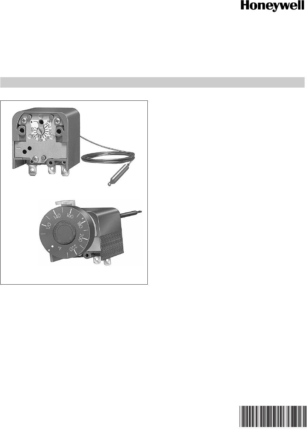
Direct Mount with
Setting Knob
Contents
Application......................................................................... 1
Features ............................................................................ 1
Specifications .................................................................... 2
Ordering Information ......................................................... 2
Installation ......................................................................... 4
Wiring ................................................................................ 6
Operation........................................................................... 7
Adjustments....................................................................... 7
Checkout ........................................................................... 8
Remote Bulb with
Screwdriver Slot
L4188A,B; L4189A,B; L6188A-C; L6189A-C AQUASTAT® CONTROLLERS
68-0061—1 2
ORDERING INFORMATION
When purchasing replacement and modernization products from your TRADELINE® wholesaler or distributor, refer to the
TRADELINE® Catalog or price sheets for complete ordering number.
If you have additional questions, need further information, or would like to comment on our products or services, please write or
phone:
1. Your local Honeywell Automation and Control Products Sales Office (check white pages of your phone directory).
2. Honeywell Customer Care
1885 Douglas Drive North
Minneapolis, Minnesota 55422-4386
In Canada—Honeywell Limited/Honeywell Limitée, 35 Dynamic Drive, Toronto, Ontario M1V 4Z9.
International Sales and Service Offices in all principal cities of the world. Manufacturing in Australia, Canada, Finland, France,
Germany, Japan, Mexico, Netherlands, Spain, Taiwan, United Kingdom, U.S.A.
SPECIFICATIONS
Electrical Ratings:
Switching: Diaphragm-operated, snap-acting switch.
L4188, L4189: Switch breaks on temperature rise to set
point, remakes when temperature drops below set point
and through differential.
L6188, L6189: Switch breaks C-1 and makes C-2 on
temperature rise to set point; switches back when
temperature drops below set point and through
differential.
Terminals: 1/4 in. male quick-connects standards. Options
(specify when ordering):
Combination screw and 1/4 in. quick connects.
Separate grounding terminal.
Temperature Setting Range: 80° to 200° F (27° to 93° C),
110° to 230° F (43° to 110° C), and 160° to 280° F (71° to
138° C) available. Specify when ordering.
Temperature setting minus differential must be no more
than 9° F (-13° C) below bottom of setting range.
Setting Scale: Marked every 20° F (-7° C), with subdivisions
every 10° F (-12° C), includes OFF setting.
Limit Stop: Limits dial rotation beyond desired high or low
limit temperature. Can be set at 5° F (2.5° C) intervals.
Optional, available on models with knob only. Specify when
ordering.
IMPORTANT
The specifications given in this publication do not include normal manufacturing tolerances. Therefore, this unit may not
match the listed specifications exactly. Also, this product is tested and calibrated under closely controlled conditions,
and some minor differences in performance can be expected if those conditions are changed.
MODELS: See Table 1.
Table 1. Aquastat® Controller Selection Guide
a Specify when ordering.
24 Vac 120 Vac 240 Vac
Full Load 2.0 A 8.0 A 5.1 A
Locked Rotor 48.0 A 30.6 A
Model Application Switching Mounting Setting Differentiala
L4188A High or low limit Spst, breaks on
temp. rise
Direct Knob 7°, 14° or 22° F (-14°, -10° or -6° C),
fixeda
L4188B Screwdriver slot
L4189A Remote bulb Knob
L4189B Screwdriver slot
L6188A Low limit and
circulator
Spdt, breaks C-1,
makes C-2 on
temp. rise.
Direct Knob 7°, 14° or 22° F (-14°, -10° or -6° C),
fixeda, 7° - 18° F (-16° - -8° C),
adjustablea
L6188B Screwdriver slot
L6188C Manual reset
L6189A Remote bulb Knob 7°, 14° or 22° F (-14°, -10° or -6° C),
fixeda, 7° - 18° F (-16° - -8° C),
adjustablea
L6189B Screwdriver slot
L6189C Manual reset
L4188A,B; L4189A,B; L6188A-C; L6189A-C AQUASTAT® CONTROLLERS
368-0061—1
Ambient Temperature Range: 32° to 158° F (0° to 70° C).
Mounting: Must be mounted in an enclosure that meets local
electrical codes.
Direct: Unit mounts on immersion well at desired sensing
location.
Remote bulb: Sensing bulb is inserted into immersion well
at desired sensing location. Controller case mounts
behind remote panel with two self-tapping M4 or No. 8
sheetmetal screws (supplied). Optional mounting bracket
allows mounting on front of panel. Specify bracket when
ordering.
Dimensions: See Fig. 1.
Sensing Bulb: Liquid-filled copper (See Fig. 1).
Underwriters Laboratories Inc. Component Recognized:
File No. MP466, Guide No. MBPR.
Canadian Standards Association Listed:
File No. LR62051-1.
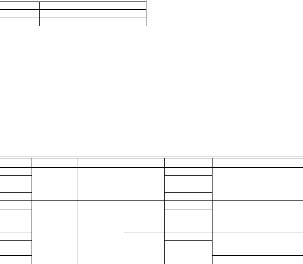
Fig. 1. Dimensions in in. [mm in brackets] of Aquastat Controller and Immersion Well.
7/16
(11)
19/32
(15)
1-7/8
(48)
3/8
(9)
2-11/16
(68)
1-1/4
(32)
1-7/8
(48)
5/8
(16)
1
1
HOLE FOR
UP TO NO. 10
SCREW
19/32
(15)
1/2
(13)
11/16
(17)
1-7/8
(48)
4 (101)
SEE
TABLE
3/16
(5)
KNOB MODEL
SCREWDRIVER SLOT MODEL
1-1/4
(32)
1-7/8
(48)
1-7/8
(48)
5/8
(16)
1-7/8
(48)
3/8
(9)
1-7/8
(48)
1/2
(13)
4 (101)
SEE
TABLE
3/16
(5)
IMMERSION WELLS
INSERTION
INSULATION
OPTIONAL MOUNTING BRACKET
MODEL CAPILLARY LENGTH MOUNTING
DIRECT MOUNT
L4188, L5188
30 MM USE IMMERSION WELLS SHOWN AT RIGHT1-3/16 IN.
REMOTE MOUNT
L4189, L5189
USE IMMERSION WELLS SHOWN AT RIGHT
OR CAPILLARY COMPRESSION FITTINGS
50 MM2-5/16 IN.
1000 MM39-3/8 IN.
1500 MM50 IN.
2000 MM78-11/16 IN.
PART NO. SPUD INSULATION INSERTION
45900409-003B 1/2 in. BSPT 1 in. 3-1/2 in.
45900409-009B 1/2 in. NPT 1-1/2 in. 3 in.
45900409-010B 3/4 in. NPT 1-1/2 in. 3 in.
M25414
L4188A,B; L4189A,B; L6188A-C; L6189A-C AQUASTAT® CONTROLLERS
68-0061—1 4
Accessories (order separately):
Capillary compression fittings.
Part No. 104484A: 1/2 in. NPT spud.
Part No. 104484B: 3/4 in. NPT spud.
Immersion well: Pressure rating 255 psi [1760 kPa].
Part No. 45900409-003B: 1/2 in. BSPT spud, 1 in.
insulation, 3-1/2 in. insertion.
Part No. 45900409-009B: 1/2 in. NPT spud, 1-1/2 in.
insulation, 3 in. insertion.
Part No. 45900409-010B: 3/4 in. NPT spud, 1-1/2 in.
insulation, 3 in. insertion.
Optional Specifications (Specify when ordering):
• Combination screw and 1/4 in. male quick-connect
terminals.
• High or low limit stop (models with knob only).
• Mounting bracket (remote bulb models only).
INSTALLATION
When Installing This Product...
1. Read these instructions carefully. Failure to follow them
could damage the product or cause a hazardous
condition.
2. Check the ratings given in the instructions and on the
product to make sure the product is suitable for your
application.
3. Installer must be a trained, experienced service
technician.
4. After installation is complete, check out product
operation as provided in these instructions.
CAUTION
Disconnect power supply before wiring to avoid
electrical shock or equipment damage.
Terminal connections must be inside an enclosure
that meets local electrical codes.
Location
The equipment manufacturer generally provides a tapping for
insertion of the temperature controller sensing element. The
tapping should be located at a point where average system
temperature will be measured. Never locate the sensing
element close to a hot or cold water inlet or a steam coil, or
where the well’s pressure rating will be exceeded.
Turn off power and, if the system is filled, drain to a point below
the boiler tapping or wherever the sensing element is to be
located. If no tapping is provided, prepare one, properly
threaded, at the desired location.
If this is a remote bulb unit, the controller case can be mounted
in a panel or, with the optional bracket, on any flat surface.
Choose a location within reach of the sensing element. Allow
for gradual bends and some slack in the capillary.
Mount the Immersion Well
1. Coat the well threads with a moderate amount of pipe
dope, leaving two end threads bare. Teflon® tape may
also be used.
2. Screw the immersion well into the tapping and tighten
securely.
3. Refill the system. Check for and correct any leaks.
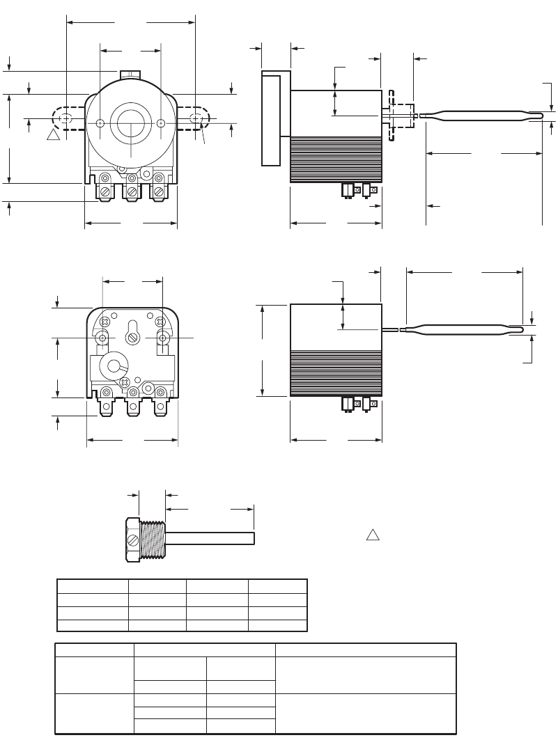
Fig. 2. Use good Piping Practice when Installing
Immersion Well.
To Install Direct Mount Controller
1. Slide the sensing bulb all the way into the well. The metal
collar around the capillary should slip into the well spud.
2. Line up the case so the setting indicator is on top.
3. Tighten the setscrew in the well spud snugly against the
metal collar.
Fig. 3. The Direct Mount Model is held in place by the
Setscrew in the Well Spud.
To Mount Remote Bulb Controller
Insert Sensing Bulb in Well
1. Slide sensing bulb into well. Make sure bulb rests
against the bottom of the well. Don’t bend the capillary
where it connects to the bulb.
2. Hold bulb in place and tighten setscrew all the way
down. It won’t fit tight against the capillary, but it will keep
the bulb from sliding out.
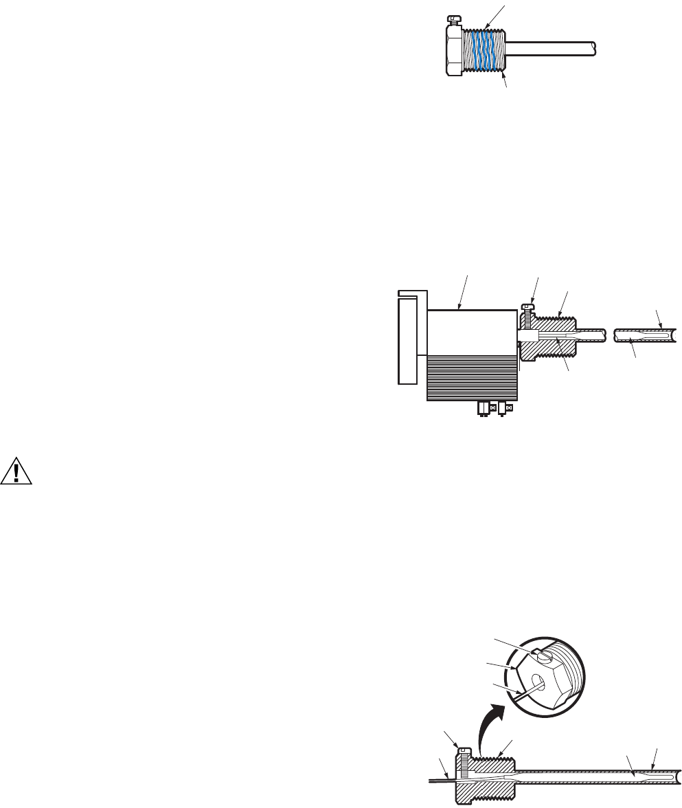
Fig. 4. The Setscrew keeps the Remote Sensing Bulb in
the Well.
USE MODERATE AMOUNT
OF PIPE COMPOUND
LEAVE 2 END THREADS BARE
M25415
CONTROLLER SETSCREW
SPUD
WELL
BULB
CAPILLARY
METAL
COLLAR
M25416
SETSCREW
SPUD
CAPILLARY
CAPILLARY
SETSCREW SPUD
BULB
WELL
M25417
L4188A,B; L4189A,B; L6188A-C; L6189A-C AQUASTAT® CONTROLLERS
568-0061—1
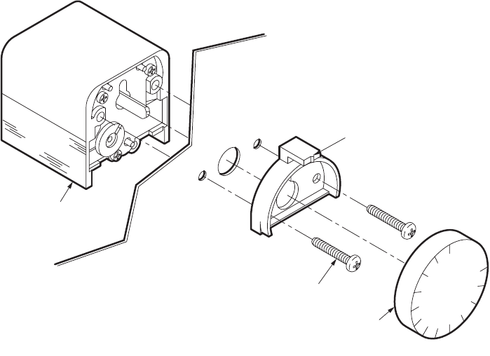
Mounting Behind Panel-Controller with Knob
NOTE: The panel can be up to 5/64 in. thick.
1. Uncoil capillary, starting at bulb. Avoid sharp bends or
kinks in the capillary. Leave excess capillary loosely
coiled below controller case.
2. Remove the setting knob by pulling straight off.
3. Remove the two screws that hold the setting indicator in
place and remove the setting indicator (See Fig. 5).
4. ADJUSTABLE DIFFERENTIAL MODELS ONLY: Set
differential. See Adjustment and Checkout section.
5. Using setting indicator as a template, mark and drill
holes in the panel for the mounting screws and for the
knob shaft.
6. Mount the controller behind, and the setting indicator in
front of, the panel using the two screws removed earlier
(See Fig. 5).
7. MODELS WITH TEMPERATURE LIMIT STOP ONLY:
Adjust to desired setting, as described under “To Set
Temperature Limit Stop,” page 8.
8. Replace knob on shaft.
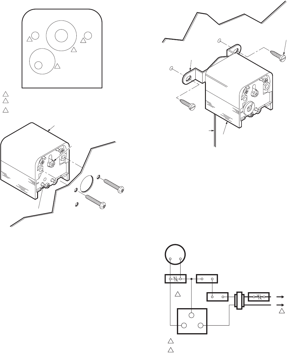
Fig. 5. The Mounting Screws hold the Setting Indicator and Controller in place.
Mounting Behind Panel-Controller with Screwdriver Slot
1. Mark and drill three holes in the panel, using the tem-
plate in Fig. 6 as a guide.
2. MANUAL RESET MODELS ONLY: Drill a fourth hole to
make the manual reset button accessible.
3. ADJUSTABLE DIFFERENTIAL MODELS ONLY: Drill a
hole for the differential dial, if desired, Set the differential.
See Adjustment and Checkout section.
4. Hold controller against back of panel with terminals
pointed down and fasten with two No. 8 sheetmetal
screws (not supplied) (Refer to Fig. 6).
CONTROLLER
PANEL
(MAX. 5/64 IN. THICK) NO. 8
MOUNTING
SCREWS (2)
KNOB
SETTING
INDICATOR
M25418
L4188A,B; L4189A,B; L6188A-C; L6189A-C AQUASTAT® CONTROLLERS
68-0061—1 6
Fig. 6. Drill holes in the Panel as shown.
Mounting on Panel-Controller with Bracket
1. Using controller bracket as a template, mark and drill two
holes in the panel.
2. Mount controller with terminals down.
3. Run capillary neatly along panel, avoiding sharp bends
and interference with other components on the panel.
4. MODELS WITH TEMPERATURE LIMIT STOP ONLY:
Adjust to desired setting, as described under “To Set
Temperature Limit Stop,” page 8.
Fig. 7. The Controller with Bracket Mounts on the Front of
the Panel.
WIRING
All wiring must comply with applicable codes and ordinances,
Disconnect power before beginning wiring.
Connect as shown in equipment manufacturer’s instructions, if
provided. Otherwise, use the typical hookups shown
(See Fig. 8) (refer to Figures 9 and 10).
Fig. 8. Low and High Limit Application on a Gas-Fired
System with Domestic Hot Water.
DRILL 2 MOUNTING SCREW HOLES.
1
1
2
3
3/16 5/16
3/4
1
3/16
3/16
5/8
DRILL HOLE FOR SLOTTED SHAFT. USE SMALL HOLE FOR SHAFT
ONLY; LARGE HOLE SHAFT PLUS SETTING SCALE.
2
DRILL SMALL HOLE FOR MODEL WITH MANUAL RESET BUTTON OR
LARGE HOLE FOR MODEL WITH DIFFERENTIAL ADJUSTMENT.
3
MOUNTING TEMPLATE
CONTROLLER
SLOTTED
SHAFT
MANUAL
RESET
BUTTON
PANEL
NO. 8
MOUNTING SCREWS (2)
(OBTAIN LOCALLY)
M25419
MOUNTING
BRACKET
PANEL
NO. 10
SHEETMETAL
SCREWS (2)
(OBTAIN LOCALLY)
CAPILLARY
CONTROLLER
M25420
POWER SUPPLY. PROVIDE DISCONNECT MEANS AND OVERLOAD
PROTECTION AS REQUIRED.
1
USE L6188.9C (C-1 CONTACTS) IF MANUAL RESET IS REQUIRED.
2
24V
THERMOSTAT
1
2
LOW WATER
CUTOFF
PRESSURE
CONTROLLER L4188.9
HIGH LIMIT
24V
GAS VALVE
TH-TR
TH TR
L1
(HOT)
L2
L4188.9
LOW LIMIT
M25421
L4188A,B; L4189A,B; L6188A-C; L6189A-C AQUASTAT® CONTROLLERS
768-0061—1
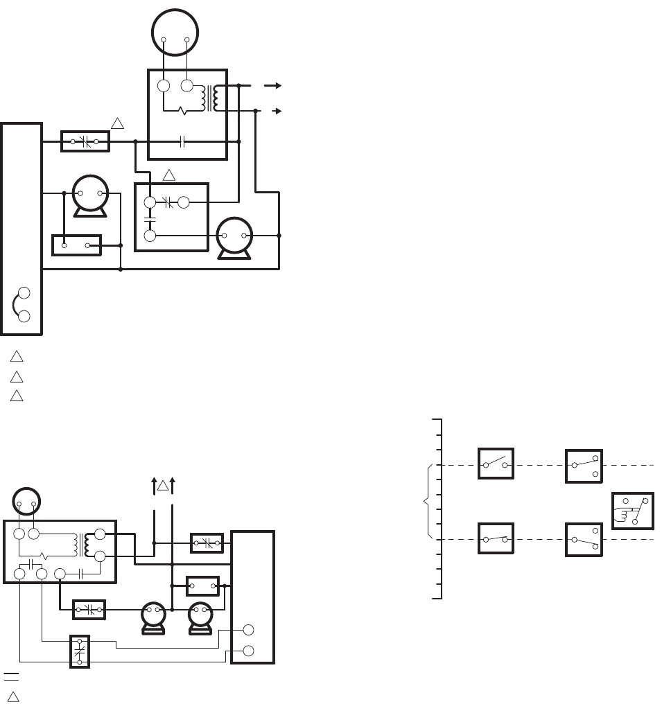
Fig. 9. High Limit and Low Limit/Circulator Application in
an Oil-Fired Hydronic System with domestic hot water.
Fig. 10. High Limit and Separate Low Limit and Circulator
Application in an Oil-Fired Hydronic System with
Domestic Hot Water.
OPERATION
As the liquid filing the sensing bulb and capillary expands and
contracts, it moves a diaphragm. Movement of the diaphragm
is transferred by a lever to the snap-acting switch in the
controller.
High or Low Limit Action (L4188, L4189)
The normally closed C-1 contacts open on temperature rise to
the set point, shutting off power to the controlled circuit. On
auto recycle models, the switch closes C-1 after the
temperature falls past the set point and through the differential
(See Fig. 11).
Low Limit/Circulator Action (L6188, L6189)
The low limit is connected to the normally closed C-1 contacts,
and the circulator to the normally open C-2 contacts. As long
as the temperature at the sensing bulb is above set point, the
circulator runs. If sensing bulb temperature falls past the set
point and through the differential, the switch breaks C-2 to turn
off the circulator, and makes C-1 to turn on the burner. When
the temperature rises to the set point, C-2 makes to turn on the
circulator, and C-1 breaks to turn off the burner.
On manual reset models, the reset button must be pushed
before contacts C-1 will close (See Fig. 11).
Fig. 11. Aquastat Controller Switch Action on Temperature
Change.
ADJUSTMENTS
To Set Temperature
KNOB MODELS
Line up the desired temperature setting with the temperature
setting indicator behind the knob.
SCREWDRIVER SLOT MODELS
Line up the pointer on the shaft with the desired temperature
setting printed on the case.
POWER SUPPLY. PROVIDE DISCONNECT MEANS AND OVERLOAD
PROTECTION AS REQUIRED.
1
L4188 OR L4189 USED AS HIGH LIMIT.
2
24V THERMOSTAT
PROTECTORELAY
CONTROL
BLACK
T
CIRCULATOR
L1
(HOT)
L2
2
3
HIGH LIMIT
BURNER MOTOR
IGNITION
ORANGE
WHITE
T
LOW LIMIT
RELAY CENTER
CIRCULATOR
MOTOR
RG
C1
2
L6188 OR L6189 USED AS LOW LIMIT/CIRCULATOR CONTROLLER.
3
M25422
PROVIDE DISCONNECT MEANS AND OVERLOAD PROTECTION AS
REQUIRED.
1
24V
THERMOSTAT
PROTECTORELAY
CONTROL
BLACK
T
CIRCULATOR
L1
(HOT)
L2
BURNER
IGNITION
ORANGE
WHITE
T
TT
XX4
1
2
L4188.9
CIRCULATOR
L4188.9
LOW LIMIT
L4188.9
HIGH LIMIT
SWITCHING RELAY
RA832A
LINE VOLTAGE
LOW VOLTAGE
1
M25423
SET POINT
DIFFERENTIAL
TEMPERATURE
SETTING
SCALE L4188.9
HIGH OR LOW
LIMIT
L6188.9
LOW LIMIT/
CIRCULATOR
SET POINT
SET POINT
LESS
DIFFER-
ENTIAL
BREAKS
MAKES
AUTO
RECYCLE
C-1 BREAKS
C-2 MAKES
C-1 MAKES
C-2 BREAKS
MANUAL
RESET
MAKES C-1
C1 C1
2
C1 C1
2
2
C
1
220 F
100 F
M25424
Automation and Control Solutions
Honeywell International Inc. Honeywell Limited-Honeywell Limitée
1985 Douglas Drive North 35 Dynamic Drive
Golden Valley, MN 55422 Toronto, Ontario M1V 4Z9
customer.honeywell.com
L4188A,B; L4189A,B; L6188A-C; L6189A-C AQUASTAT® CONTROLLERS
® U.S. Registered Trademark
© 2007 Honeywell International Inc.
68-0061—1 J.I. Rev. 10-07
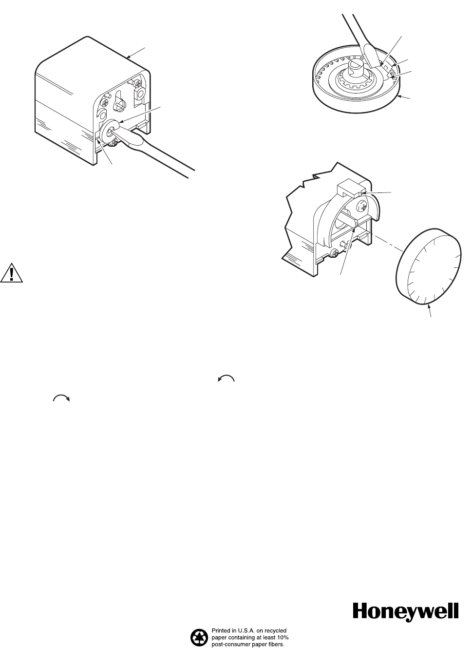
To Set Adjustable Differential (if provided)
Use a screwdriver to turn the differential dial until the slot
molded into the case lines up with the desired degrees of
differential.
Fig. 12. Twist the Screwdriver Slightly to turn the
Differential Dial.
To Set Temperature Limit Stop (if provided)
CAUTION
Follow these instructions carefully to avoid
placing the limit stop pointer on the wrong side of
the setting indicator. In a high limit application,
incorrect positioning of the pointer will cause
system operation above the limit stop setting,
potentially resulting in overheating or related
conditions.
• Remove the knob.
• Turn the controller shaft all the way counterclockwise
when setting a high limit. Turn it all the way
clockwise when setting a low limit.
• Find the metal limit stop on the back of the knob.
• Lift the limit stop slightly with a pencil or screwdriver and
push to move to desired setting.
• Read the setting from the front of the knob.
• Place the knob on the shaft.
• Turn the knob to make sure it: (1) turns through the desired
adjustment range, and (2) stops at the limit setting.
DO NOT FORCE.
• Return knob to desired setting.
Fig. 13. Adjust the Limit Stop with a Screwdriver and
check Orientation when Replacing Knob on Shaft.
CHECKOUT
Turn the system on and observe it through several cycles to
make sure the controller operates as desired.
Teflon® is a registered trademark for E.I. Du Pont De Nemours and Company.
CONTROLLER
SETTING
INDICATOR
DIFFERENTIAL
ADJUSTMENT
DIAL
M25425
LIFT AND PUSH
TO CHANGE LIMIT
SETTING
AJUST LIMIT STOP
REPLACE KNOB ON SHAFT
LIMIT STOP
POINTER
KNOB
KNOB
SHAFT
SETTING INDICATOR:
LIMIT STOP MUST
BE ON RIGHT SIDE OF
SETTING INDICATOR FOR
HIGH LIMIT; ON LEFT
SIDE FOR LOW LIMIT
FOR LOW LIMIT STOP:
TURN SHAFT
FULL COUNTERCLOCKWISE
(SHOWN) BEFORE
REPLACING KNOB.
FOR HIGH LIMIT STOP:
TURN SHAFT
FULL CLOCKWISE
BEFORE REPLACING
KNOB. M25426
