Honeywell Bendix King Kln 94 Users Manual PG
KLN 94 to the manual a076656a-5016-4ab0-bc5b-df35db028a3a
KLN94UserGuide
2015-01-23
: Honeywell Honeywell-Bendix-King-Kln-94-Users-Manual-261432 honeywell-bendix-king-kln-94-users-manual-261432 honeywell pdf
Open the PDF directly: View PDF ![]() .
.
Page Count: 284 [warning: Documents this large are best viewed by clicking the View PDF Link!]
- Table of Contents
- INTRODUCTION
- KLN 94 SNEAK PREVIEW
- HOW-TO INDEX
- 1. KLN 94 SYSTEM COMPONENTS
- 2. DATABASE
- 3. BASIC GPS OPERATION
- 3.1. COVERAGE AREA
- 3.2. TURN-ON AND SELF TEST
- 3.3. DISPLAY FORMAT
- 3.4. BASIC OPERATION OF PANEL CONTROLS
- 3.5. MESSAGE PAGE
- 3.6 SCRATCHPAD MESSAGES
- 3.7. INITIALIZATION AND TIME TO FIRST FIX
- 3.8. SELECTING AND SCANNING WAYPOINTS
- 3.9. “NEAREST” FUNCTIONS
- 3.10. DIRECT TO OPERATION
- 3.11. NAVIGATION PAGES
- 3.11.1. THE NAVIGATION 1 (NAV 1) PAGE
- 3.11.2. THE NAVIGATION 2 (NAV 2) PAGE
- 3.11.3. THE NAVIGATION 3 (NAV 3) PAGE
- 3.11.4. THE NAVIGATION 4 (NAV 4) PAGE – MOVING MAP
- 3.11.4.1 Selecting The NAV 4 (Map) Page
- 3.11.4.2 NAV 4 Page Format
- 3.11.4.3. Selecting What Is Shown On The Map
- 3.11.4.4. Configuring Aeronautical Data For The Map
- 3.11.4.5. Runway Diagrams
- 3.11.4.6. Configuring Land Data On The Map
- 3.11.4.7. Symbols Used On The Map
- 3.11.4.8. Selecting The Map Orientation
- 3.11.4.9. Changing the Map Range Scale
- 3.11.4.10 Decluttering The Screen
- 3.11.4.11. Waypoint Scan Feature
- 3.11.4.12. Holding Patterns And Procedure Turns (ORS 02 and higher)
- 3.12. WAYPOINT PAGES
- 3.13. SPECIAL USE AIRSPACE ALERTING
- 3.14. REMOTE MOUNTED ANNUNCIATORS
- 3.15 QUICKTUNE TM NAV/COMM FREQUENCY SELECTION
- 3.16. USING THE TAKE-HOME MODE
- 3.17 SAMPLE TRIP
- 4. FLIGHT PLAN OPERATION
- 4.1. CREATING AND MODIFYING FLIGHT PLANS
- 4.1.1. CREATING A FLIGHT PLAN
- 4.1.2. VIEWING DISTANCE AND DESIRED TRACK BETWEEN STORED FLIGHT PLAN WAYPOINTS
- 4.1.3. ACTIVATING A NUMBERED FLIGHT PLAN
- 4.1.4. ADDING A WAYPOINT TO A FLIGHT PLAN
- 4.1.5. DELETING A WAYPOINT FROM A FLIGHT PLAN
- 4.1.6. DELETING FLIGHT PLANS
- 4.1.7. STORING FPL 0 AS A NUMBERED FLIGHT PLAN
- 4.2. OPERATING FROM THE ACTIVE FLIGHT PLAN
- 4.2.1. GENERAL PROCEDURES
- 4.2.2. TURN ANTICIPATION AND WAYPOINT ALERTING
- 4.2.3. VIEWING THE WAYPOINT PAGES FOR THE ACTIVE FLIGHT PLAN WAYPOINTS
- 4.2.4. COMBINING DIRECT TO AND FLIGHT PLAN OPERATION
- 4.2.5. VIEWING DISTANCE, ETE, ETA, OR DESIRED TRACK TO FLIGHT PLAN WAYPOINTS
- 4.2.6 CHANGING THE SYSTEM TIME ZONE
- 4.1. CREATING AND MODIFYING FLIGHT PLANS
- 5. INTERMEDIATE OPERATION
- 5.1. ALTITUDE PAGES
- 5.2. ADVISORY VNAV OPERATION
- 5.3. ALTITUDE ALERTING
- 5.4. CREATING USER-DEFINED WAYPOINTS
- 5.5. NAVIGATION MODES
- 5.6. CHANGING THE CDI SCALE FACTOR
- 5.7. AVIONICS BUS VOLTAGE ALERTING
- 5.8. THE AUXILARY (AUX) PAGES
- 5.9. DETERMINING THE STATUS OF THE GPS SIGNALS
- 5.10. CALCULATOR (AUX 4 – AUX 11) PAGES
- 5.10.1. THE AUXILARY 4 (AUX 4) TRIP PLANNING PAGE
- 5.10.2. THE AUXILARY 5 (AUX 5) TRIP PLANNING PAGE
- 5.10.3. THE AUXILARY 6 (AUX 6) PRESSURE ALTITUDE PAGE
- 5.10.4. THE AUXILARY 7 (AUX 7) DENSITY ALTITUDE PAGE
- 5.10.5. THE AUXILARY 8 (AUX 8) TRUE AIRSPEED PAGE
- 5.10.6. THE AUXILARY 9 (AUX 9) WIND PAGE
- 5.10.7. THE AUXILARY 10 (AUX 10) ALARM PAGE
- 5.10.8. THE AUXILARY 11 (AUX 11) SUNRISE/SUNSET PAGE
- 5.11. VIEWING AND DELETING USER WAYPOINTS AND WAYPOINT REMARKS (AUX 12 AND AUX 13 PAGES)
- 5.12. VIEWING THE KLN 94 SOFTWARE STATUS (AUX 14 PAGE)
- 5.13. THE FUEL MANAGEMENT (AUX 15 – AUX 19)PAGES
- 5.14. THE AIR DATA (AUX 20 – AUX 21) PAGES
- 5.15 VIEWING AND SETTING THE DATE AND TIME PAGE
- 5.16. MANUAL MAGNETIC VARIATION SELECTION
- 5.17. SETTING THE UNITS OF MEASURE
- 6. APPROACHES AND DP/STARS
- 6.1. PROCEDURE (PROC) PAGES
- 6.2. NON-PRECISION APPROACH OPERATIONS
- 6.2.1. APPROACH MODE ANNUNCIATIONS
- 6.2.2. GENERAL PROCEDURE FOR NON-PRECISION APPROACHES
- 6.2.3. SELECTING AND LOADING AN APPROACH
- 6.2.4. INTERPRETING WHAT YOU SEE
- 6.2.5. CHANGING OR DELETING AN APPROACH ONCE LOADED INTO THE FLIGHT PLAN
- 6.2.6. GPS APPROACH EXAMPLES
- 6.2.7. APPROACH EXAMPLE 1: NO PROCEDURE TURN
- 6.2.8. APPROACH EXAMPLE 2: RADAR VECTORS
- 6.2.9. APPROACH EXAMPLE 3: COURSE REVERSAL WITH OFF-AIRPORT IAF
- 6.2.10. APPROACH EXAMPLE 4: COURSE REVERSAL WITH ON-AIRPORT IAF
- 6.2.11. APPROACH EXAMPLE 5: DME ARC
- 6.2.12. ILS AND OTHER NON-APPROVED APPROACHES
- 6.2.13. USING GPS DISTANCE AS A SUBSTITUTE FOR DME ON LOCALIZER-TYPE APPROACHES
- 6.2.14. APPROACH PROBLEMS
- 6.3. DP/STAR PROCEDURES
- APPENDIX A - NAVIGATION TERMS
- APPENDIX B - MESSAGE PAGE MESSAGES
- APPENDIX C - SCRATCHPAD MESSAGES
- APPENDIX D - ABBREVIATIONS
- APPENDIX E - LAT/LON CONVERSIONS
- APPENDIX F - GPS PRIMER
- APPENDIX G - OPERATIONAL COMPARISON: KLN 94 VS. KLN 89B
- KLN 94 INDEX
Pilot’s Guide
ORS 01, 02 and 03
KLN 94
Bendix/King®
GPS Navigation System
N

WARNING
Prior to export of this document, review for export license requirement is needed.
COPYRIGHT NOTICE
Copyright ©2000-2002 Honeywell International Inc. All rights reserved.
Reproduction of this publication or any portion thereof by any means without the
express written permission of Honeywell International Inc. is prohibited. For fur-
ther information contact the Manager, Technical Publications; Honeywell; One
Technology Center; 23500 West 105th Street; Olathe, Kansas 66061.
Telephone: (913) 782-0400.

KLN 94 Pilot’s Guide
006-18207-0000
Operational Revision Status
ORS 01, 02 and 03
July 2002
The ORS level is annunciated on the Turn-on page each time power is
applied to the KLN 94 (see figure 3-3). Features limited to specific ORS
levels are so designated in the text of this manual. The operational differ-
ences between ORS levels are described below.
ORS 02: Operational characteristics are similar to ORS 01 with the excep-
tion of the following primary differences:
(1) Enhanced waypoint scanning on the Nav 4 map page encircles the way-
point whose identifier is contained in the waypoint scan field. In addition,
pressing the ENT button brings up the waypoint page for the selected
waypoint. See section 3.11.4.11.
(2) Procedure turns and holding patterns associated with approaches, DPs,
and STARs are displayed on the map. See section 3.11.4.12.
(3) New airport map icons now distinguish between airports having hard sur-
face runways vs. soft surface runways and show the orientation of the
longest runway if available. See section 3.11.4.7.
(4) New highway map icons are used for the Atlantic International and
Pacific International databases. See section 3.11.4.7.
(5) There is a new message that appears if the database card is removed
while the KLN 94 is operational. See Appendix B.
(6) The default value for intersections has been changed from 2NM to OFF
on the SET 7 page.
(7) A software problem was fixed which now allows updating of the
Aeronautical database with a computer via diskettes or the Internet. See
sections 2.4.1 and 2.4.2.
(8) The Database page has been modified to display the region for the Land
database. See section 3.2.
(9) Approaches which have the format of “RNAV # 18L” can now be acco-
modated. The “#” is a letter or number that designates there is more than
one approach of a given type (i.e. RNAV) to the same runway. This for-
mat has been adopted by the FAA and other international aviation
agencies.
Example 1: There could be RNAV Y 18L and RNAV Z 18L
approaches at the same airport.
Example 2: There could be RNAV 1 09L and RNAV 2 09L
approaches at the same airport
ORS 03: Operational characteristics are similar to ORS 02 with the excep-
tion that Special Use Airspace inner rings may be displayed on the Nav 4
map page. See section 3.11.4.4.

NOTE: A white border is used around
data on some of the figures in this Pilot's
Guide to indicate that the data inside the
border is flashing.
WARNING: The KLN 94 displays GPS-derived altitude on the AUX 1
page. Due to many factors, GPS altitude may typically be several
hundred feet in error. Do not use the GPS-derived altitude for naviga-
tion.
IMPORTANT: Special installation procedures must be followed in order
for the KLN 94 to be certified for IFR En route, Terminal and Non-precision
Approach use. If these procedures are followed, the KLN 94 can be used
for IFR use. Consult the aircraft’s KLN 94 Flight Manual Supplement for
the operating limitations of this unit.
IMPORTANT: The KLN 94 has two software configuration numbers, one
for the boot software and one for the application software. It may be useful
for you to obtain these software configuration numbers to aid maintenance
personnel if service is required on your KLN 94. The boot software config-
uration number is displayed on a label located on the KLN 94’s top cover.
The bottom of the label reads “BOOT SOFTWARE MOD” followed by the
four digit configuration number. The application software configuration
number is available on the top line of the Auxiliary (AUX) 14 page. It reads
“SW REVISION” followed by a four digit configuration number. These soft-
ware configuration numbers should have been recorded in the aircraft’s
logbook at the time of KLN 94 installation or time of a later software
update.

Revision History and Instructions
Manual KLN 94 Pilot’s Guide
Revision 2, July 2002
Part Number 006-18207-0000
This revision incorprates software changes for ORS 03.
R-1

Revision History and Instructions
Manual KLN 94 Pilot’s Guide
Revision 1, March 2001
Part Number 006-18207-0000
This revision incorprates software changes for ORS 02.
R-2

R-3
Revision History and Instructions
Manual KLN 94 Pilot’s Guide
Revision 0, September 2000
Part Number 006-18207-0000
This is the original version of this publication.

This page intentionally left blank.
R-4

KLN 94 Pilot’s Guide Table of Contents
TOC-1
INTRODUCTION ............................................................................i
KLN 94 SNEAK PREVIEW ...............................................................ii
HOW-TO INDEX ..........................................................................iv
1. KLN 94 System Components ..................................................1-1
2. Database ........................................................................2-1
2.1. Functions of the Database ................................................2-1
2.2. Database Contents and Coverage Areas .........................2-1
2.3. ICAO Identifiers .................................................................2-4
2.4. Updating the Database .....................................................2-4
2.4.1. Computer Updating of the Database (diskettes) ...2-6
2.4.2. Computer Updating of the Database (internet) ......2-8
2.4.3. Card Exchange Updating of the Database ............2-8
2.5. User Defined Database .....................................................2-9
2.6. Database Update Service Options ...................................2-9
3. Basic GPS Operation ................................................................3-1
3.1. Coverage Area ..................................................................3-1
3.2. Turn-on and Self Test .......................................................3-1
3.3. Display Format ..................................................................3-9
3.4. Basic Operation of Panel Controls ..................................3-12
3.4.1. Page Selection ......................................................3-12
3.4.2. Data Entry ..............................................................3-14
3.4.3. The Duplicate Waypoint Page ..............................3-16
3.5. Message Page ................................................................3-18
3.6 Scratchpad Messages .....................................................3-18
3.7. Initialization and Time to First Fix ...................................3-19
3.8. Selecting and Scanning Waypoints ................................3-21
3.8.1. Selecting Waypoints by Identifier ..........................3-21

Table of Contents
TOC-2
3.8.2. Selecting Waypoints by Scanning .........................3-23
3.8.3. Selecting Waypoints by Name or City ..................3-24
3.9. “Nearest” Functions ........................................................3-27
3.9.1. Viewing the Nearest Waypoints ............................3-28
3.9.1.1 Nearest Airport Criteria ................................3-28
3.9.1.2 Continuous Display of Nearest Airport ........3-29
3.9.2. Viewing the Nearest Special Use Airspaces ........3-30
3.9.3. Viewing the Nearest Flight Service Station
Frequencies .....................................................................3-31
3.9.4. Viewing the Nearest Center Frequencies .............3-32
3.10. Direct To Operation .......................................................3-33
3.10.1. Initiating a Direct To ............................................3-34
3.10.2. Cancelling a Direct To .........................................3-36
3.10.3. Waypoint Alerting for Direct To Operation ..........3-36
3.11. Navigation Pages ..........................................................3-37
3.11.1. The Navigation 1 (NAV 1) Page ..........................3-37
3.11.2. The Navigation 2 (NAV 2) Page ..........................3-39
3.11.3. The Navigation 3 (NAV 3) Page ..........................3-40
3.11.4. The Navigation 4 (NAV 4) Page – Moving Map .3-40
3.11.4.1 Selecting The NAV 4 (Map) Page ............3-40
3.11.4.2 NAV 4 Page Format .................................3-41
3.11.4.3. Selecting What Is Shown On The Map ...3-42
3.11.4.4. Configuring Aeronautical Data For
The Map ....................................................................3-42
3.11.4.5. Runway Diagrams ..................................3-44
3.11.4.6. Configuring Land Data On The Map .......3-44
3.11.4.7. Symbols Used On The Map ....................3-46
3.11.4.8. Selecting The Map Orientation ................3-46

3.11.4.9. Changing the Map Range Scale .............3-47
3.11.4.10 Decluttering The Screen .........................3-48
3.11.4.11. Waypoint Scan Feature .........................3-48
3.11.4.12. Holding Patterns and Procedure Turns .3-50
3.12. Waypoint Pages ............................................................3-51
3.12.1. Airport Pages .......................................................3-51
3.12.1.1. The Airport 1 (APT 1) Page .......................3-51
3.12.1.2. The Airport 2 (APT 2) Page .......................3-52
3.12.1.3. The Airport 3 (APT 3) Page .......................3-53
3.12.1.4. The Airport 4 (APT 4) Page ......................3-54
3.12.1.5. The Airport 5 (APT 5) Page ......................3-55
3.12.1.6. The Airport 6 (APT 6) Page .......................3-57
3.12.1.7. The Airport 7 (APT 7) Page ......................3-58
3.12.1.8. The Airport 8 (APT 8) Page .......................3-59
3.12.2. VOR Pages .........................................................3-60
3.12.2.1. The VOR 1 Page ......................................3-60
3.12.2.2. The VOR 2 Page ......................................3-61
3.12.3. NDB Page ...........................................................3-61
3.12.3.1. The NDB 1 Page ......................................3-61
3.12.4. Intersection Pages ...............................................3-62
3.12.4.1. The Intersection 1 (INT 1) Page ...............3-62
3.12.4.2. The Intersection 2 (INT 2) Page ...............3-63
3.12.5. User Waypoint Pages ........................................3-63
3.12.5.1. The User 0 (USR 0) Page .........................3-63
3.12.5.2. The User 1 (USR 1) Page ........................3-64
3.12.5.3. The User 2 (USR 2) Page ........................3-64
3.12.5.4. The User 3 (USR 3) Page .........................3-64
KLN 94 Pilot’s Guide Table of Contents
TOC-3

3.13. Special Use Airspace Alerting ......................................3-66
3.14. Remote Mounted Annunciators ....................................3-69
3.15 QuickTune™ Nav/Comm Frequency Selection .........3-70
3.15.1. Quicktune™ Operation with One
Compatible NAV/COMM .................................................3-71
3.15.2. Quicktune™ Operation with More Than One
Compatible NAV/COMM .................................................3-72
3.16. Using the Take-home Mode .........................................3-72
3.17 Sample Trip ...................................................................3-74
3.17.1 Pre-departure ......................................................3-74
3.17.2 En route ...............................................................3-75
3.17.3 Terminal Area ......................................................3-76
4. Flight Plan Operation ...............................................................4-1
4.1. Creating and Modifying Flight Plans .................................4-1
4.1.1. Creating a Flight Plan .............................................4-1
4.1.2. Viewing Distance and Desired Track Between
Stored Flight Plan Waypoints ............................................4-4
4.1.3. Activating a Numbered Flight Plan .........................4-4
4.1.4. Adding a Waypoint to a Flight Plan ........................4-5
4.1.5. Deleting a Waypoint from a Flight Plan ..................4-6
4.1.6. Deleting Flight Plans ..............................................4-7
4.1.7. Storing FPL 0 as a Numbered Flight Plan ..............4-7
4.2. Operating from the Active Flight Plan ...............................4-8
4.2.1. General Procedures ................................................4-8
4.2.2. Turn Anticipation and Waypoint Alerting ...............4-10
4.2.3. Viewing the Waypoint Pages for the Active
Flight Plan Waypoints ......................................................4-11
4.2.4. Combining Direct To and Flight Plan Operation ...4-12
4.2.4.1 Direct To Operation From The Map .............4-12
Table of Contents
TOC-4

4.2.4.2 Direct To Operation From Any Page ...........4-12
4.2.4.3 Direct To Operation From The FPL 0 Page 4-13
4.2.4.4 Cancelling Direct To Operation ....................4-13
4.2.5. Viewing Distance, ETE, ETA, or Desired Track to
Flight Plan Waypoints ......................................................4-14
4.2.6 Changing The System Time Zone ........................4-15
5. Intermediate Operation ............................................................5-1
5.1. Altitude pages ...................................................................5-1
5.2. Advisory VNAV Operation .................................................5-3
5.2.1. VNAV for Direct To Operation .................................5-3
5.2.2. VNAV for Flight Plan Operation ..............................5-6
5.3. Altitude Alerting .................................................................5-6
5.4. Creating User-defined Waypoints ....................................5-9
5.4.1. Creating a Waypoint at Your Present Position .....5-10
5.4.2. Creating a Waypoint at a Certain Latitude/
Longitude ......................................................................5-11
5.4.3. Creating a Waypoint Referenced from Another
Waypoint ......................................................................5-12
5.5. Navigation Modes ...........................................................5-14
5.5.1. Selecting the Leg Mode or the OBS mode ...........5-14
5.5.2. The Leg Mode .......................................................5-14
5.5.3. The OBS Mode ......................................................5-15
5.5.4. Switching From the Leg Mode to the OBS mode .5-17
5.5.5. Effects of Switching From OBS Mode to
Leg Mode ......................................................................5-17
5.5.6. Going Direct To a Waypoint While in the
OBS Mode .....................................................................5-18
5.5.7. Activating a Waypoint While in the OBS Mode .....5-18
5.6. Changing the CDI Scale Factor ......................................5-19
5.7. Avionics Bus Voltage Alerting ........................................5-20
KLN 94 Pilot’s Guide Table of Contents
TOC-5

5.8. The Auxilary (AUX) Pages ..............................................5-21
5.9. Determining the Status of the GPS Signals ....................5-21
5.10. Calculator (AUX 4 – AUX 11) pages ............................5-24
5.10.1. The Auxilary 4 (AUX 4) Trip Planning Page .......5-24
5.10.2. The Auxilary 5 (AUX5) Trip Planning Page ........5-26
5.10.3. The Auxilary 6 (AUX 6) Pressure Altitude Page .5-27
5.10.4. The Auxilary 7 (AUX 7) Density Altitude Page ...5-28
5.10.5. The Auxilary 8 (AUX 8) True Airspeed Page ......5-29
5.10.6. The Auxilary 9 (AUX 9) Wind Page ....................5-30
5.10.7. The Auxilary 10 (AUX 10) Alarm Page ...............5-30
5.10.8. The Auxilary 11 (AUX 11) Sunrise/Sunset Page 5-31
5.11. Viewing and Deleting User Waypoints and Waypoint
Remarks (AUX 12 and AUX 13 pages) .................................5-32
5.11.1. The AUX 12 Page ...............................................5-32
5.11.2. The AUX 13 Page ...............................................5-33
5.12. Viewing the KLN 94 Software Status (AUX14 page) .5-34
5.13. The Fuel Management (AUX 15 – AUX 19) Pages .....5-34
5.13.1. The Auxilary 15 (AUX 15)Fuel Management
Page ......................................................................5-35
5.13.2 The Auxilary 16 (AUX 16) Fuel Management
Page ......................................................................5-36
5.13.3. The Auxilary 17 (AUX 17)Fuel Management
Page ......................................................................5-36
5.13.4. The Auxilary (AUX 18)Fuel Management Page .5-37
5.13.5. The Auxilary (AUX 19) Fuel Management Page 5-37
5.14. The Air Data (AUX 20 – AUX 21) Pages ......................5-37
5.14.1. The Auxilary 20 (AUX 20) Air Data Page ...........5-38
5.14.2. The Auxilary 21 (AUX 21) Air Data Page ............5-38
5.15 Viewing and Setting the Date and TimePage ................5-39
Table of Contents
TOC-6

5.16. Manual Magnetic Variation Selection ...........................5-41
5.17. Setting the Units of Measure ........................................5-42
6. APPROACHES and DP/STARs ..............................................6-1
6.1. Procedure (PROC) Pages ...............................................6-1
6.2. Non-Precision Approach Operations ................................6-2
6.2.1. Approach Mode Annunciations ..............................6-3
6.2.2. General Procedure for Non-Precision Approaches 6-4
6.2.3. Selecting and Loading An Approach .....................6-6
6.2.4. Interpreting What You See .....................................6-9
6.2.5. Changing Or Deleting An Approach Once
Loaded Into The Flight Plan ............................................6-11
6.2.6. GPS Approach Examples ....................................6-13
6.2.7. Approach Example 1: No Procedure Turn .........6-13
6.2.8. Approach Example 2: Radar Vectors ................6-20
6.2.9. Approach Example 3: Course Reversal with
Off-Airport IAF ...............................................................6-24
6.2.10. Approach Example 4: Course Reversal with
On-Airport IAF .................................................................6-26
6.2.11. Approach Example 5: DME Arc ......................6-30
6.2.12. ILS and other Non-Approved Approaches .........6-35
6.2.13. Using GPS Distance as a Substitute for DME
on Localizer-type Approaches .........................................6-36
6.2.14. Approach Problems ...........................................6-37
6.3. DP/STAR PROCEDURES .............................................6-39
6.3.1. Selecting a DP ......................................................6-40
6.3.2. Selecting a STAR ................................................6-42
6.3.3. Editing a DP or STAR ..........................................6-43
6.3.4. Example of a DP Procedure ................................6-45
6.3.5. Example of a STAR Procedure ............................6-47
KLN 94 Pilot’s Guide Table of Contents
TOC-7

APPENDIX A - NAVIGATION TERMS .........................................A-1
APPENDIX B - MESSAGE PAGE MESSAGES ..........................B-1
APPENDIX C - SCRATCHPAD MESSAGES ..............................C-1
APPENDIX D - ABBREVIATIONS ................................................D-1
STATE ABBREVIATIONS .......................................................D-1
CANADIAN PROVINCE ABBREVIATIONS ...........................D-2
COUNTRY ABBREVIATIONS ................................................D-2
ARTCC ABBREVIATIONS ......................................................D-8
OTHER ABBREVIATIONS USED ON KLN 94 PAGES .......D-17
APPENDIX E - LAT/LON CONVERSIONS ..................................E-1
APPENDIX F - GPS PRIMER ........................................................F-1
BACKGROUND .......................................................................F-1
GPS POSITION DETERMINING CONCEPT .........................F-1
GPS DATA SIGNALS ..............................................................F-1
GPS SYSTEM SEGMENTS ....................................................F-2
RAIM ........................................................................F-3
GPS XPRESS™ CARD 8-CHANNEL RECEIVER .................F-3
APPENDIX G- OPERATIONAL COMPARISON WITH KLN 89B G-1
Table of Contents
TOC-8

KLN 94 Pilot’s Guide Introduction
i
INTRODUCTION
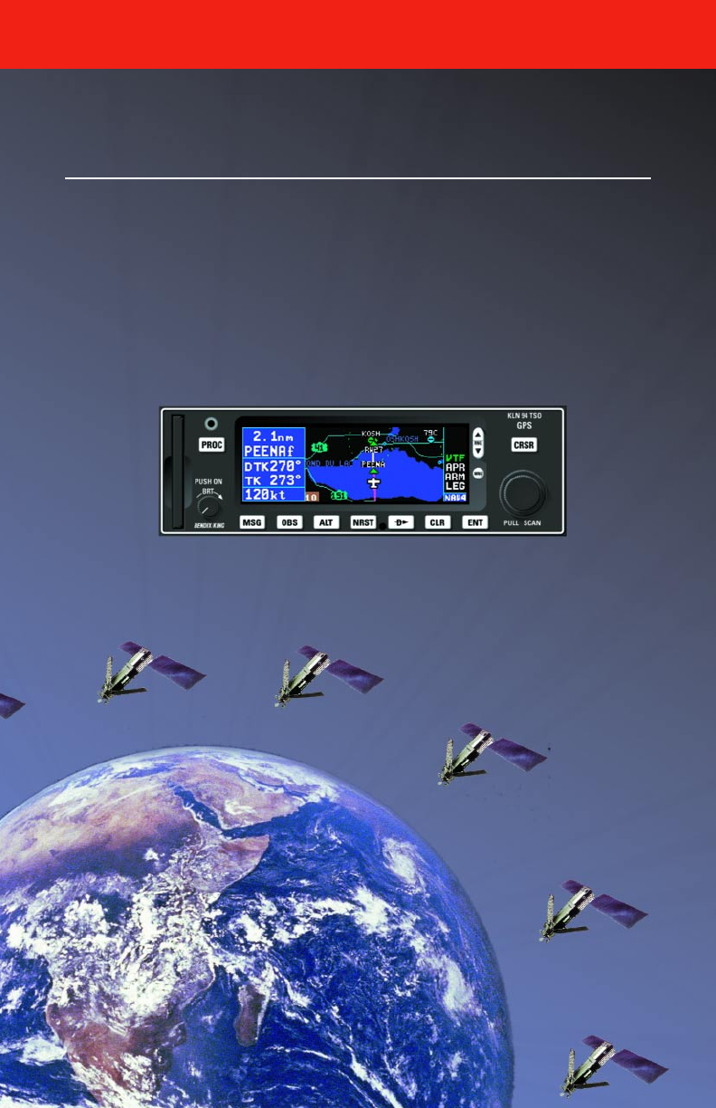
Congratulations for choosing the Bendix/King KLN 94 GPS! Celestial
navigation will now be a way of life for you. The phenomenal accuracy of
GPS, along with the KLN 94’s user-friendly operation and color graphics
display will make flying a delight. Not only will the KLN 94 help you to
navigate more easily and more accurately, its trip planning features, air
data calculations, and other useful features will make you feel like you’re
flying with a true flight management system.
In addition, KLN 94 may be IFR approved for En route, Terminal, and
Non-precision Approach operations. We think you’ll find that having an
abundance of navigational data (not to mention a moving map!) available
to you will make non-precision approaches more precise and more enjoy-
able.
This Pilot’s Guide will be of great help to you. It is written in plain, simple
English and it assumes you are not an experienced user of GPS or other
type of long range navigation equipment. If you are experienced, so much
the better. This Pilot’s Guide also includes hundreds of sample screen fig-
ures and other illustrations to make your learning easier. It is designed so
that you can start at the front and progress in the order presented; howev-
er, you may want to skip around and learn things in your own order. Also,
on page iv, there is an index of frequently used procedures which will help
you find the page that describes how to do exactly what you want to do.
There are also several appendices in the back of the manual that you may
find useful from time to time.
If you are an experienced KLN 89B user, Appendix G outlines the
KLN 94’s new features and operational enhancements.
Be sure to keep this Pilot’s Guide handy with you in the airplane. It is
designed to fit easily in the glove box, or in the seat pocket.
One last thing. Don’t get so involved in learning to use the KLN 94 that
you forget to fly the airplane. Be careful, and remember to keep a close
eye out for other aircraft.

KLN 94 SNEAK PREVIEW
If you absolutely can’t wait to use your KLN 94 until you’ve read this Pilot’s
Guide, this section is for you. This short section will teach you just enough
to get going and then learn by doing. This operational preview assumes
the KLN 94 has been properly installed, the unit was previously opera-
tional in the same general geographical location, and that no peripheral
equipment interfaced with the KLN 94 (such as external HSI’s, CDI’s,
autopilots, moving map display, etc.) is to be used at this time. If you are
using this operational preview in flight, do so only in good VFR conditions
and only with an alternate means of navigation available to cross-check
position.
1. Turn the unit on by pressing the On/Off/Brightness knob (the small
knob in lower left hand corner). After the screen changes to full color,
rotate the knob to adjust the display brightness to the desired level.
2. For about 50 seconds the Power On Page is displayed while the unit
runs a self-test. (If the unit is in the Take-Home mode a Take-Home
page is displayed. Press the Fbutton to acknowledge the Take-
Home mode). Afterwards, the Self-test Page is displayed. If the
KLN 94 is receiving an altitude from an encoding altimeter, the present
indicated altitude will be displayed on line 2. The bottom line should
display Pass with the cursor over a flashing Ok?. Press the Fbut-
ton to approve the Self-test Page.
3. The Initialization Page will now be displayed. If the date and time are
incorrect by more than 10 minutes, refer to section 3.2 of this Pilot’s
Guide. The right side of the screen should show the identifier of the
nearest airport to the initial position, along with a radial and distance
from that airport waypoint. Press Fwith the cursor flashing over
Ok? to approve the Initialization Page.
4. If your KLN 94 has been configured for VFR use only, the VFR page
will now be displayed to notify you of the VFR limitation. Press Fto
approve this page.
5. The Database Page is now displayed showing the date the database
expires or the date it expired. Press Fto acknowledge the informa-
tion displayed on this page.
Introduction
ii

6. Use the right outer knob to turn to the NAV page type. Watch the
page bar at the very bottom of the screen. As the outer knob is turned
the selected page type becomes reverse video (white letters on a blue
background). Turn until NAV is selected. Then use the right inner
knob to select the NAV 2 page if not already there. The NAV 2 page
shows your present position relative to a nearby VOR. It may take a
couple minutes for the GPS receiver to “wake-up” and determine a
position. Verify that this position is correct before proceeding.
7. Press the Dbutton. A page with the words DIRECT TO: is now dis-
played on the screen.
In step 8 you will enter the ICAO identifier of the airport. The identifier will
have a “K” prefix for a Continental U.S. airport, a “C” prefix for a Canadian
airport, or a “P” prefix (in some cases) for an Alaskan airport if the identifier
is all letters. For example, LAX becomes KLAX. For these countries if the
identifier contains any numbers, there is no prefix. For example, TX04 is
entered TX04. For other areas of the world the airport identifier should be
entered identically to how it is charted.
8. Rotate the right inner knob until the first character of the airport identi-
fier is displayed. Turn the right outer knob one step clockwise to move
the flashing segment to the second character position. Rotate the right
inner knob to select the second character of the identifier. Use this
procedure to enter the complete airport identifier.
9. Press F. The display will change to a page showing the identifier,
name, city, and state/country of the airport just entered. Confirm that
the correct airport is displayed. Press Fa second time to approve
the airport data.
10. A Navigation page (specifically the NAV 1 page) is now on the screen.
The left side of the display (blue background) shows distance, ground-
speed, desired track (DTK is the course to be flown), and actual track
(TK is the actual course the aircraft is currently tracking over the
ground). The large middle section of the display shows the active
waypoint, a course deviation indicator (CDI), bearing to the waypoint,
and estimated time en route (ETE). Beneath the CDI are located a
digital display of the deviation and the CDI scale.
KLN 94 Pilot’s Guide Introduction
iii

HOW-TO INDEX
This index will help you quickly find important procedures at a glance. The
list is alphabetized by action words.
TO: SEE Section:
Activate one of the previously created numbered flight plans . . . . . . . . . . . . .4.1.3
Add a waypoint to a flight plan . . . . . . . . . . . . . . . . . . . . . . . . . . . . . . . . . . . . .4.1.4
Add an individual waypoint in the DP or STAR procedure . . . . . . . . . . . . . . . .6.3.3
Calculate distance, time, and ESA for a flight plan . . . . . . . . . . . . . . . . . . . .5.10.1
Calculate distance, bearing, and time from waypoint to waypoint . . . . . . . . .5.10.1
Calculate fuel requirements for a flight plan . . . . . . . . . . . . . . . . . . . . . . . . . .5.10.2
Calculate fuel requirements from waypoint to waypoint . . . . . . . . . . . . . . . . .5.10.2
Calculate sunrise/sunset times . . . . . . . . . . . . . . . . . . . . . . . . . . . . . . . . . . . .5.10.8
Calculate the density altitude . . . . . . . . . . . . . . . . . . . . . . . . . . . . . . . . . . . . .5.10.4
Calculate the pressure altitude . . . . . . . . . . . . . . . . . . . . . . . . . . . . . . . . . . . .5.10.3
Calculate the true airspeed (TAS) . . . . . . . . . . . . . . . . . . . . . . . . . . . . . . . . . .5.10.5
Calculate the winds aloft . . . . . . . . . . . . . . . . . . . . . . . . . . . . . . . . . . . . . . . . .5.10.6
Cancel Direct To operation . . . . . . . . . . . . . . . . . . . . . . . . . . . . . . . . . . . . . . .3.10.2
Change between distance and desired track display on a numbered flight
plan page . . . . . . . . . . . . . . . . . . . . . . . . . . . . . . . . . . . . . . . . . . . . . . . . . . . . . .4.1.2
Change between distance, ETE, ETA, and desired track on the FPL 0 page .4.2.5
Change course modes . . . . . . . . . . . . . . . . . . . . . . . . . . . . . . . . . . . . . . . . . . . . .5.5
Change or delete an entire DP or STAR procedure from the active
flight plan . . . . . . . . . . . . . . . . . . . . . . . . . . . . . . . . . . . . . . . . . . . . . . . . . . . . . .6.3.3
Change the baro setting . . . . . . . . . . . . . . . . . . . . . . . . . . . . . . . . . . . . . . . . . . . .5.1
Change the CDI scale factor . . . . . . . . . . . . . . . . . . . . . . . . . . . . . . . . . . . . . . . .5.6
Change the default first waypoint character . . . . . . . . . . . . . . . . . . . . . . . . . . .3.4.2
Change the NAV 2 page present position reference waypoint . . . . . . . . . . .3.11.2
Change the present fuel on board . . . . . . . . . . . . . . . . . . . . . . . . . . . . . . . . .5.13.1
Change the selected course in OBS mode . . . . . . . . . . . . . . . . . . . . . . . . . . .5.5.3
Create a flight plan . . . . . . . . . . . . . . . . . . . . . . . . . . . . . . . . . . . . . . . . . . . . . . . .4.1
Create a user-defined waypoint at your present position . . . . . . . . . . . . . . . . .5.4.1
Create a user-defined waypoint using the radial/distance method . . . . . . . . .5.4.3
Create a user-defined waypoint with latitude/longitude . . . . . . . . . . . . . . . . . .5.4.2
Delete a flight plan which is no longer required . . . . . . . . . . . . . . . . . . . . . . . .4.1.6
Delete a user-defined waypoint from the AUX 12 page . . . . . . . . . . . . . . . . .5.11.1
Delete a waypoint from a flight plan . . . . . . . . . . . . . . . . . . . . . . . . . . . . . . . . .4.1.5
Introduction
iv

TO: SEE Section:
Delete a waypoint remark from the AUX 13 page . . . . . . . . . . . . . . . . . . . . .5.11.2
Delete an approach from FPL 0 . . . . . . . . . . . . . . . . . . . . . . . . . . . . . . . . . . . .6.2.5
Delete an individual waypoint in a DP or STAR procedure . . . . . . . . . . . . . . .6.3.3
Display the nearest airport continuously . . . . . . . . . . . . . . . . . . . . . . . . . . . .3.9.1.2
Enable the voltage alert feature . . . . . . . . . . . . . . . . . . . . . . . . . . . . . . . . . . . . . .5.7
Enter a user-defined waypoint remark on the USR 3 page . . . . . . . . . . . . .3.12.5.4
Enter a waypoint identifier . . . . . . . . . . . . . . . . . . . . . . . . . . . . . . . . . . . . . . . . .3.4.2
Enter an airport remark on the APT 6 page . . . . . . . . . . . . . . . . . . . . . . . . .3.12.1.6
Enter the local magnetic variation manually on the SET 2 page . . . . . . . . . . . .5.16
Fly direct to a waypoint . . . . . . . . . . . . . . . . . . . . . . . . . . . . . . . . . . . . . . . . . . . .3.10
Fly direct to a waypoint in the active flight plan (FPL 0) . . . . . . . . . . . . . . . . . .4.2.4
Initialize the position from the SET 1 page . . . . . . . . . . . . . . . . . . . . . . . . . . . . .3.7
Perform a manual RAIM calculation . . . . . . . . . . . . . . . . . . . . . . . . . . . . . . . .6.2.14
Recenter the D-Bar by going direct to the active waypoint . . . . . . . . . . . . . .3.10.1
Replace an existing approach, or delete an approach . . . . . . . . . . . . . . . . . . .6.2.5
Select a DP . . . . . . . . . . . . . . . . . . . . . . . . . . . . . . . . . . . . . . . . . . . . . . . . . . . .6.3.1
Select a STAR . . . . . . . . . . . . . . . . . . . . . . . . . . . . . . . . . . . . . . . . . . . . . . . . . .6.3.2
Select a VOR or NDB by navaid name . . . . . . . . . . . . . . . . . . . . . . . . . . . . . . .3.8.3
Select a waypoint by identifier from a waypoint page . . . . . . . . . . . . . . . . . . . .3.8.1
Select a waypoint by scanning . . . . . . . . . . . . . . . . . . . . . . . . . . . . . . . . . . . . .3.8.2
Select an airport by scanning the airport name . . . . . . . . . . . . . . . . . . . . . . . .3.8.3
Select an approach . . . . . . . . . . . . . . . . . . . . . . . . . . . . . . . . . . . . . . . . . . . . . .6.2.3
Set the alarm . . . . . . . . . . . . . . . . . . . . . . . . . . . . . . . . . . . . . . . . . . . . . . . . . .5.10.7
Set the date on the SET 2 page . . . . . . . . . . . . . . . . . . . . . . . . . . . . . . . . . . . . .5.15
Set the time on the SET 2 page . . . . . . . . . . . . . . . . . . . . . . . . . . . . . . . . . . . . .5.15
Specify the nearest airport criteria . . . . . . . . . . . . . . . . . . . . . . . . . . . . . . . . .3.9.1.1
Store the active flight plan as a numbered flight plan . . . . . . . . . . . . . . . . . . . .4.1.7
Turn on and initialize the KLN 94 . . . . . . . . . . . . . . . . . . . . . . . . . . . . . . . . . . . . .3.2
Update the KLN 94 database by computer . . . . . . . . . . . . . . . . . . . . . . . . . . .2.4.1
Use altitude alerting . . . . . . . . . . . . . . . . . . . . . . . . . . . . . . . . . . . . . . . . . . . . . . .5.3
Use VNAV on a Direct To . . . . . . . . . . . . . . . . . . . . . . . . . . . . . . . . . . . . . . . . . .5.2
View a message . . . . . . . . . . . . . . . . . . . . . . . . . . . . . . . . . . . . . . . . . . . . . . . . . .3.5
View the waypoints in the flight plan that are not the active waypoint. . . . . . .4.2.3
View VNAV status . . . . . . . . . . . . . . . . . . . . . . . . . . . . . . . . . . . . . . . . . . . . . . . .5.2
KLN 94 Pilot’s Guide Introduction
v
Chapter 1 System Components
1-0
AIRCRAFT
POWER
ALTITUDE
11-33V
GRAY CODE
WPT ALERT
MESSAGE
KA 92 GPS ANTENNA
HSI CDI
AUTOPILOT
REMOTE
ANNUNCIATORS
RS-232
OUTPUT
KLN 94 SYSTEM
REQUIRED FOR ALL INSTALLATIONS
INSTALLATION DEPENDENT
OR
KI 525A KI 206
COMPATIBLE
FUEL
MANAGEMENT
SYSTEM
REQUIRED FOR IFR APPROACH INSTALLATIONS
RS-232
INPUT
RS-232
INPUT
HEADING RS-232
INPUT GPS
NAV GPS/NAV SWITCH/
ANNUNCIATOR
KI 229 KNI 582
OR
COMPATIBLE
AIR
DATA
COMPUTER
LEFT/RIGHT
D-BAR
SELECTED
COURSE
RMI
ı
N
S
E
W
33
30
24
21
15
12
6
3
A
D
F
N
3
3
3
0
W
2
4
2
1
S
1
5
1
2
E
6
3
A
D
F
A
D
F
NAV NAV
B
GKX 155A TSO
COMM NAV
CHAN
PULL
TEST PULL
IDENT
STBY
MODE
STBY
PULL OBS
TIMER
PULL 25K
KX 155A or KX 165A
QuickTune™
EHSI
OR
KI 825
KMD 550 & 850 MFDs
AND OTHER MOVING
MAP DISPLAYS
ALT HDG NAV APR APGS
ALT HDG NAV APR BC AP
ENG
TEST
KC 193
YD
RN RC PC
BC
ı
DN
UP
N
S
E
W
TO
F
3
3
2
2
1
1
6
3
N
A
V
B
OBS
GS
N
GS GS
33
30
W
24
21
S
15
12
E
6
3
ı
NAV HDG
GPS
PROC
KLN 94 TSO
CRSR
PULL SCAN
PUSH ON
ENTCLRMSG NRSTALTOBS
ıD
RNG
MNU
BRT

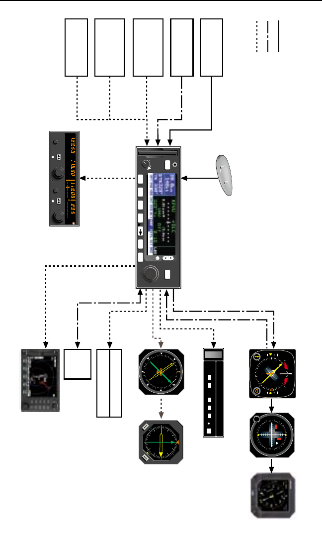
1. KLN 94 SYSTEM COMPONENTS
A basic KLN 94 system consists of a panel mounted KLN 94 GPS and a
KA 92 GPS antenna. An altitude input is required to obtain full navigation
and operational capabilities. Additional system components may be added
or interfaced to the KLN 94 which increase its features and capabilities.
Some of these optional components include an external course deviation
indicator (CDI) or horizontal situation indicator (HSI), autopilot, and exter-
nal annunciators. Typically, an altitude input and an external indicator are
required for IFR approach certification.
The KLN 94 panel mounted unit contains the GPS sensor, the navigation
computer, a color LCD Display, and all controls required to operate the
unit. It also includes the database card which slides into the left side of the
front panel.
The KA 92 GPS “patch” antenna is available for use with the KLN 94. It is
designed to always be mounted on the top of the aircraft.
The KLN 94 has analog outputs to drive the left-right deviation bar of most
mechanical CDI’s and HSI’s. In addition, the NAV mode of the
Bendix/King KAP 140, KFC 150, KAP 150, KAP 150H, KAP 100, KFC
200, KAP 200, KFC 225, KFC 250, KFC 275, KFC 300, and KFC 325
flight control systems may be coupled to the KLN 94. ORS 03 and higher
KLN 94 units have a DC roll steering output capable of interfacing with all
KFC 225 and some versions of KAP 140 flight control systems. Many
other autopilots may also be coupled to the KLN 94. Actual autopilot per-
formance and capability when coupled to the KLN 94 may vary
significantly from one autopilot model to another.
Altitude may be provided to the KLN 94 from an encoding altimeter or
blind encoder. Altitude is used as an aid in position determination when
not enough satellites are in view.
Depending on where the KLN 94 is mounted in the instrument panel,
some IFR installations may require remote annunciators to be mounted in
the aircraft panel in order to indicate the status of certain KLN 94 func-
tions. En route and terminal IFR certifications require annunciators for
message (MSG) and waypoint alert (WPT). Non-precision approach certi-
fications may also require an annunciator to display when the approach
mode is armed or active.
KLN 94 Pilot’s Guide Chapter 1 System Components
1-1

Each KLN 94 system includes a configuration module which is attached to
the KLN 94 mounting rack. The module allows the KLN 94 to be config-
ured for the unique characteristics of your equipment installation.
Parameters that are set by the configuration module include:
• Whether the KLN 94 may be used for IFR operations or not, and if it
may be used for non-precision approach IFR operations.
• Whether or not the altitude alert function in enabled. See section
5.3.
• Whether or not an external fuel management system is interfaced to
the KLN 94. See section 5.13.
• Whether or not an external air data computer is interfaced to the
KLN 94. See section 5.14.
• The conditions for the aircraft bus voltage alert to activate. See sec-
tion 5.7.
• Whether there are Communication and Navigation radios interfaced
with the QuickTune™ feature which allows tuning of the radio from
the KLN 94. See section 3.15.
The configuration information is stored both in the module and in the
KLN 94 internal memory. If the KLN 94 detects a difference between the
configuration stored in the module and the configuration stored in the
internal memory (which should only occur following the exchange of a
KLN 94), the configuration information will automatically be updated to the
configuration specified in the configuration module.
If an error is detected in the configuration data, a warning page stating
Configuration Mem Error will be displayed during the KLN 94 start-up
sequence, and the configuration memory will be set to arbitrary default
values. See an authorized Honeywell Service center to correct the config-
uration memory error.
Chapter 1 System Components
1-2

KLN 94 Pilot’s Guide Chapter 1 System Components
1-3
This page intentionally left blank
Chapter 2 Data Base
2-0
CANADA
USA
LATIN AM
PACIFIC
SOUTH PAC
SOUTH AM
EUROPE
EAST EUR
MID EAST
AFRICA
SOUTH PAC
PACIFIC
75°
60°
45°
30°
15°
0°
15°
30°
45°
60°
75°
60°
45°
30°
15°
0°
15°
30°
45°
60°
165°150°135°120°105°90°75°60°45°30°15°0°15°30°45°60°75°90°105°120°135°150°165°180°
Pacific Database
coverage area
Overlap in Pacific & Atlantic
Database coverage areas
Atlantic Database
coverage area
Americas Database
coverage area
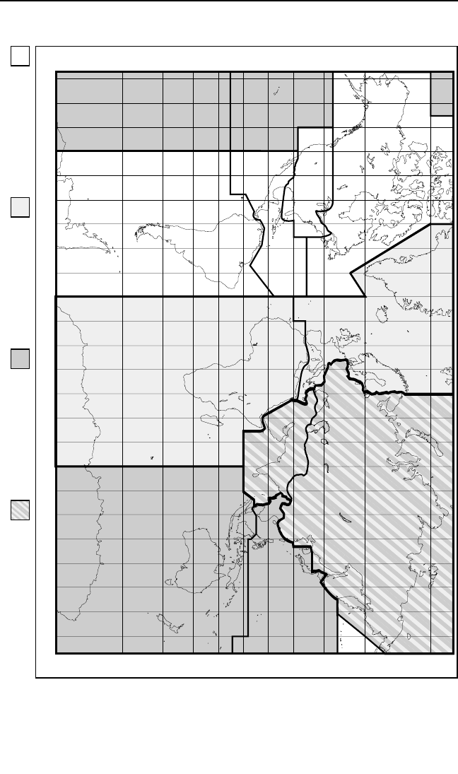
Figure 2-1 KLN 94 Database Geographical Region

2. DATABASE
2.1. FUNCTIONS OF THE DATABASE
The database provides four primary functions. First, it makes pilot inter-
face with the GPS sensor much easier. Rather than having to manually
look up and then enter the latitude and longitude for a specific waypoint, it
allows you to merely enter a simple waypoint identifier. The database
automatically looks up and displays the latitude and longitude associated
with the identifier. It should be obvious that the database saves a lot of
tedious latitude/longitude entry and also greatly reduces the potential for
data input mistakes.
The second function of the database is that it serves as a very convenient
means to store and easily access aeronautical information. Want to know
the name of the airport, the tower frequency, or the airport elevation? Just
turn the knobs and display the information right on the screen.
Thirdly, the KLN 94 database stores the waypoints in their proper
sequence that comprise most approaches, arrival procedures, and depar-
ture procedures. This allows you to select an approach, STAR, and DP by
name as a whole, rather than entering them waypoint by waypoint.
And last but not least, the database furnishes the aeronautical and land
data that is displayed on the color moving map display. It is a great aid in
providing situational awareness to the pilot.
2.2. DATABASE CONTENTS AND COVERAGE AREAS
There are three database coverage areas available for the KLN 94. They
are referred to as the “Americas” database, the “Atlantic International”
database, and the “Pacific International” database.
The International Civil Aviation Organization (ICAO) and Aeronautical
Radio, Inc. (ARINC) break the world into the ten geographic regions
shown in figure 2-1. The KLN 94 Americas database contains aeronauti-
cal information for the group of ICAO regions consisting of Canada, USA,
Latin America, and South America. The KLN 94 Atlantic International
database provides information for the ICAO regions Europe, Africa, East
Europe, and Mid East. Likewise, the Pacific International database con-
tains information for East Europe, Mid East, Pacific, and South Pacific.
The KLN 94 database contains three types of data - aeronautical, carto-
graphic (land), and user. Only the aeronautical data is sourced from
Jeppesen Sanderson, Inc. It includes information for airports, navigational
aids, navigational procedures (approaches, STARs, and DPs), and other
aviation specific data. The cartographic data includes land items such as
roads and rivers that can be displayed on the moving map display. User
data is the list of waypoints created by the pilot.
KLN 94 Pilot’s Guide Chapter 2 Data Base
2-1

The following is a listing of the KLN 94 database contents:
AERONAUTICAL DATA
AIRPORTS
Identifier
Name
City, State or Country
Use type (if heliports, military, or private)
Latitude and Longitude
Elevation
Runway numbers, lengths, surfaces, and lighting
Fuel availability
Approach types available (precision, non-precision, or none)
Radar approach/departure environment
Time difference relative to UTC.
Airport Communication & Approach frequencies:
ATIS
Clearance delivery
Tower
Ground control
Unicom
Multicom
Approach (IFR)
Departure (IFR)
Class B, Class C, TRSA, CTA, TMA (VFR)
Center (when used for approach)
Arrival
Radar
Director
AWOS (automatic weather observing station)
ASOS (automatic surface observation system)
AAS (aeronautical advisory service)
AFIS (aerodrome flight information service)
ATF (aerodrome traffic frequency)
CTAF (common traffic advisory frequency)
RDO (radio frequency)
MF (mandatory frequency)
Ramp control
PCL (pilot-controlled lighting)
GCO (ground communication outlet)
ILS & LOC type approach
VORs
Identifier
Name
Frequency
Latitude and Longitude
Magnetic variation
Chapter 2 Data Base
2-2

NDBs (En Route and Terminal)
Identifier
Name
Frequency
Latitude and Longitude
(Note - Outer Compass Locators may be stored as an NDB by their NDB
identifier or as an intersection by their intersection name)
DMEs associated with ILS/LOC type approaches – Stored with
Intersections by the approach identifier (e.g. IJFK)
Identifier
Latitude and Longitude
Intersections (low altitude, high altitude, DP/STAR, approach, and outer
markers). Also includes DMEs associated with ILS/LOC type approaches.
See DMEs
Identifier
Latitude and Longitude
DP/STAR/Approach Procedures
All compatible pilot-nav DP/STAR procedures
All compatible non-precision and precision approaches. Includes all pub-
lic GPS-only approaches. Only those non-precision approaches
designated on the Airport 8 page with “GPS” may be used to actually exe-
cute an approach with the KLN 94.
Miscellaneous
Air Route Traffic Control Center (ARTCC and FIR) frequencies
Flight Service Stations (location of points of communication and associat-
ed frequencies)
Minimum Safe Altitudes
Special Use Airspace (SUA) boundaries-Outer and inner* rIngs
(Prohibited, Restricted, Alert, Class B, Class C, CTA, TMA, TRSA,
Caution, Danger, MOA, Training, Warning)
*ORS 01 and 2 have outer rings only.
LAND DATA
Lakes, rivers, oceans
Roads
Population areas (cities, towns)
Railroads
Political boundaries
Obstacles (towers)
500 USER DEFINED WAYPOINTS
Identifier
Latitude and Longitude
KLN 94 Pilot’s Guide Chapter 2 Data Base
2-3

2.3. ICAO IDENTIFIERS
Waypoints are stored in the KLN 94 database almost exclusively by their
ICAO identifiers. ICAO (International Civil Aviation Organization) is an
internationally accepted reference for the data. In almost all cases the
proper ICAO identifiers may be taken directly from Jeppesen-Sanderson
or NOS aeronautical charts.
Airport identifiers in the contiguous United States, Alaska, and Canada are
special cases in the ICAO system. Many airport identifiers for these areas
have four letters beginning with a prefix letter that corresponds to the geo-
graphic area in which it is located. The prefix letter for the contiguous U.S.
is “K”. Thus, the identifier for Orlando Executive Airport is KORL while the
VOR identifier is ORL. The prefix letter for Canada is “C” and for Alaska is
“P”.
NOTE: There are several exceptions in Alaska. In many cases, airports
with three letter identifiers receive the prefix “P”, but there are many that
don’t. The most reliable method of determining an Alaska airport identifier
is to look it up from the airport name or city. See section 3.8.3, “Selecting
Waypoints by Name or City”.
Incidentally, you can program the KLN 94 to default to a certain letter
(such as “K”) when you are entering a waypoint identifier. See section
3.4.2, “Data Entry” to learn about this handy feature.
Not all airport identifiers receive the prefix letter. Airport identifiers which
are combinations of letters and numbers do not apply to the prefix rule.
Examples of airport identifiers not using the prefix are 3C2, 70R5, and
M33.
So remember, if you are entering or looking for an airport identifier
that is all letters (no numbers) then it will begin with a “K” prefix in
the contiguous U.S., a “P” in Alaska (in some cases), or a “C” in
Canada. If there are numbers in the identifier then a prefix is not
used. For other areas of the world the airport identifier stored in the
KLN 94 database is identical to how it is charted.
2.4. UPDATING THE DATABASE
The information stored in the database would eventually become obsolete
if there wasn’t some means to update it. For example, new airports open,
navaids can move or change frequency, communication frequencies can
change, new roads are built, and on and on.
NOTE: By FAA regulation, you are required to have a current navigation
database in order to use the KLN 94 for a non-precision approach.
Chapter 2 Data Base
2-4

A KLN 94 data card plugs into the left side of the KLN 94 front panel. The
land data resides full time in the data card. The KLN 94 accesses the
land data directly from the data card. The land data can only be updated
by inserting a new data card. New land data is generally available from
Honeywell about once a year.
The aeronautical data is initially contained in the data card. However, this
data is then downloaded automatically into an another memory area inter-
nal to the KLN 94. The aeronautical data may be updated by inserting a
new data card or by using a personal computer (PC) to update the internal
memory directly through the data port on the front of the KLN 94. New
aeronautical data is available from Honeywell every 28 days.
The user data is kept in a separate area of internal memory and is not
affected by updating of the aeronautical or land database.
The aeronautical database is designed so that there are three ways for
the user to keep the database current. The first method of database
update is to remove the old data card and insert a current card. This
method involves returning the old card to Honeywell.
The second and third methods involve electronically updating the data-
base by using an IBM-compatible personal computer to update the
internal memory directly via an interface cable that plugs into the data port
on the front of the KLN 94. Method two utilizes Honeywell supplied 3.5-
inch diskettes with the PC. The diskettes are not returned to Honeywell.
Method three allows for acquiring the update data from the Internet.
Every 28 days, Honeywell receives new NavData™ information from
Jeppesen Sanderson. This information is processed and downloaded
onto both diskettes and database cards. It is also made available to
Internet subscribers. Honeywell makes these three types of update ser-
vices available to you in a choice of several subscription or random
update programs. See section 2.6 for details on these programs.
NOTE: Honeywell sends the update so that it arrives prior to the next
effective date. The new update may be installed any time prior to the
effective date and the KLN 94 will use the previous data up to the effective
date and automatically begin using the new data on the effective date.
WARNING: The accuracy of the database information is only
assured if it is used before the end of the effectivity period. Use of
out of date database information is done entirely at the user’s own
risk.
KLN 94 Pilot’s Guide Chapter 2 Data Base
2-5

2.4.1. COMPUTER UPDATING OF THE DATABASE USING
DISKETTES (ORS 02 AND HIGHER UNITS ONLY)
Update information is sent to you on 3.5” disks. In order to use the update
program you must have access to a computer having a disk drive capable
utilizing 3.5-inch 1.44 megabyte high density diskettes. This computer also
needs to have an available COM 1 or COM 2 serial port. If you wish to
perform updates in the cockpit, an optional PC Interface kit must be used.
Included in the kit is an interface cable that plugs into both the computer
and into the data loader jack located on the KLN 94 front panel.
CAUTION: The database must be updated only while the aircraft is
on the ground. The KLN 94 does not perform any navigation func-
tion while the database is being updated. Since a database update
takes approximately 8 minutes it is a good idea to turn off all electri-
cal equipment on the aircraft except for the KLN 94 to avoid running
down the aircraft battery.
NOTE: The diskettes sent to you can only be used to update one KLN 94,
although they can update that specific unit numerous times. The first time
the diskettes are used in an update operation, a unique identification code
from the KLN 94 being used is uploaded to the diskettes. These diskettes
may be used in this specific KLN 94 an unlimited number of times which
could be required if you switch back and forth between the Americas,
Atlantic, and Pacific databases during one update cycle. These diskettes
may not, however, be used to update other KLN 94s. This update protec-
tion ensures that Jeppesen Sanderson is properly compensated for the
use of their NavData™.
To update the KLN 94 database by computer using diskettes:
1. Plug the 9 pin female connector end of the interface cable into a COM
serial port of the computer. If the computer has COM 1 and COM 2
serial ports, either may be used.
2. If you are using the PC interface kit in the cockpit, plug the other end
of the interface cable (3 conductor male connector) into the data
loader jack that is located on the upper left corner of the KLN 94 front
panel.
3. Insert the diskette into the computer’s disk drive. Turn on the comput-
er being used for the database update. The program on the disk will
automatically “boot” (load) and the computer screen will display
“Ready” when the computer is ready to continue with the database
update operation.
Chapter 2 Data Base
2-6
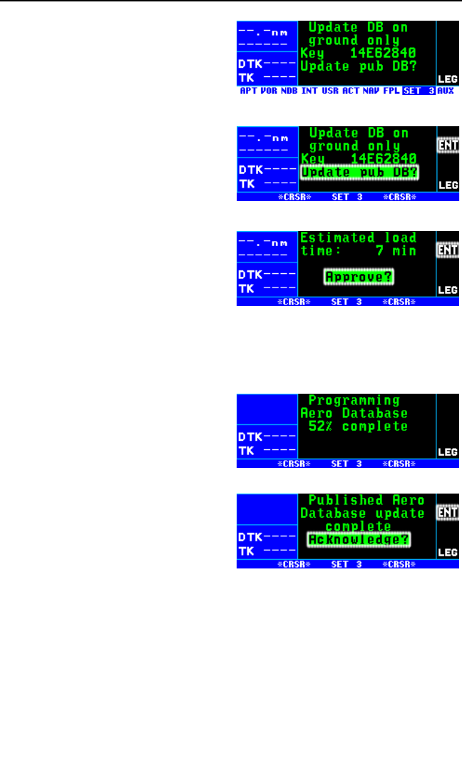
4. Turn on the KLN 94. Press F
as required to approve the Self
Test, Initialization, and Database
pages. Use the right outer knob
to select the Setup (SET) type
pages and the right inner knob to
select the SET 3 page (figure 2-
2).
5. Press B. Update Pub DB?
will now be flashing as in figure
2-3.
6. Press F. The estimated load
time in minutes is now displayed
(figure 2-4).
NOTE: In step 6, repeatedly press-
ing Ewill terminate the update
process and bring the display back
to the original SET 3 page shown in
figure 2-2.
7. Press Fto acknowledge the estimated load time and begin the
erasing of the existing database.
The unit will now display
Erasing database. After the
database has been erased, the
loading of the new data automat-
ically begins. As the new data is
being loaded, the percentage of
transfer is displayed (figure 2-5).
8. The KLN 94 will indicate when
the database update is complete
as shown in figure 2-6. You may
either turn the KLN 94 off at this
point or press Fto restart the
KLN 94.
9. Remove the interface cable. Remove the disk from the computer.
Turn off the computer.
KLN 94 Pilot’s Guide Chapter 2 Data Base
2-7
Figure 2-2
Figure 2-3
Figure 2-4
Figure 2-5
Figure 2-6

The chances are small of having difficulty updating the database but—
If you have a problem:
• First check that the interface cable is properly connected and that
the computer is turned on. If there is a problem with the connection
or the computer, the KLN 94 will display Data Loader Not Ready.
When the problem is corrected this prompt is removed and the
update operation can continue from where it left off.
• If an internal test fails after the data has been loaded, the KLN 94
will display Checksum Error, Database Invalid. Press Fto
acknowledge. The KLN 94 will then display Database Update
Failed, Retry? Use the right outer knob to position the cursor over
the desired choice and press F.
• There are other error messages that may be displayed. If you have
a problem that you can’t resolve, write down any error messages to
aid your Honeywell Service Center in identifying the problem.
2.4.2 COMPUTER UPDATING OF THE DATABASE USING THE
INTERNET (ORS 02 AND HIGHER UNITS ONLY)
Updates from the Internet can be obtained directly by logging onto the
Honeywell Internet site: www.gpsdatabase.com and following the instruc-
tions provided for setting up an account and for doing the update. You
may also call the following telephone numbers to set up an account:
(800) 247-0230
(913) 712-3145
2.4.3 CARD EXCHANGE UPDATING OF THE DATABASE
Having the front-loading data card makes KLN 94 very easy to update the
database by exchanging cards.
Enclose the expired database card in the mailer that the new card was
sent to you in. A return shipping label is included in the mailer. Please
affix this label to the outside of the mailer. Also, peel off the protective
backing from the adhesive on the end flap of the mailer. Press the flap
against the adhesive to seal the container.
Please return the expired card promptly by mailing immediately at any
mailbox. No postage is required if mailed from within the U.S. Users will
be billed for cards not returned and no additional cards will be sent until
either the expired card or payment for the expired card is received.
Chapter 2 Data Base
2-8

KLN 94 Pilot’s Guide Chapter 2 Data Base
2-9
2.5. USER DEFINED DATABASE
In addition to the aeronautical and land databases, you may create up to
500 other user-defined waypoints. Section 5.4, “Creating User-defined
waypoints” describes this further.
The KLN 94 contains an internal lithium battery that is used to “keep-alive”
the user-defined database as well as flight plans. This battery has a typi-
cal life of three to five years. It is highly recommended that the battery be
replaced every three years at an authorized Honeywell Service Center.
2.6. DATABASE UPDATE SERVICE OPTIONS
The following tear-out page can be used for ordering Americas, Atlantic
International, and Pacific International database update services from
Honeywell. The forms may be mailed or FAXed for your convenience.

Chapter 2 Data Base
2-10
This page intentionally left blank

BUSINESS REPLY MAIL
FIRST-CLASS MAIL PERMIT NO. 121 OLATHE, KANSAS
POSTAGE WILL BE PAID BY ADDRESSEE
Fold here
NO POSTAGE
NECESSARY
IF MAILED
IN THE
UNITED STATES
HONEYWELL INTERNATIONAL INC.
M D66 - NAVIGATION SERVICES
23500 W. 105 STREET
OLATHE, KS 66061
Tape here

Name:
Company:
Address:
City:
State: Zip Code:
Country:
Telephone: ( )
FAX: ( )
Aircraft Make:
Aircraft Model: ______
Please set up the service under:
MasterCard/VISADiscover/AMEX
Method of Payment
Check/Money order enclosed
Wire Transfer:
Chase Manhattan Bank, NY
Acct #910-2-538734
Include sales tax for your state.
Number
Expires
Signature
Honeywell offers several update service
options to suit your requirements. Please
select the service desired, then fill out
and mail this order form. Credit card
orders may be faxed.
Database updates are also available at
www.gpsdatabase.com
Note: Updates are current for 28 days
after effective date on diskette. If you
select any service other than the com-
plete 13-time service, your KLN 94 will
begin alerting you after 28 days that
your data base is out of date.
Send to:
Honeywell
Mail Drop #66 - Navigation Services
23500 W. 105th Street
Olathe KS 66061
Phone: 913.712.3145 Fax: 913.712.3904
Toll Free: 800.247.0230
E-mail: nav.database@honeywell.com
www.gpsdatabase.com
Check One:
Complete Update Service.
Provides 13 updates–one every 28
days for one year.
Six-time Update Service. Provides
six updates–one every 56 days for
one year.
Four-time Update Service.
Provides four updates–one during
each quarter for one year.
Single Update. Provides one
update upon receipt of order.
Check Requested Data Base:
Americas Database
Atlantic International Database
Pacific International Database
Check One:
Card Format
Diskette Format
(Laptop Computer Required. See
section 2 of KLN 94 Pilot’s Guide
for details.)
KLN 94 Database Update Service Order Form
Consult Pricing Sheet (006-08794-0007) for Service Prices
N

KLN 94 Pilot’s Guide Chapter 3 Basic GPS Operation
This page intentionally left blank
Chapter 3 Basic GPS Operation
GPS
PROC
KLN 94 TSO
CRSR
PULL SCAN
PUSH ON
ENTCLRMSG NRSTALTOBS
ıD
RNG
MNU
BRT
1 4 5 6 7 8 9 2 3
10
111213151416
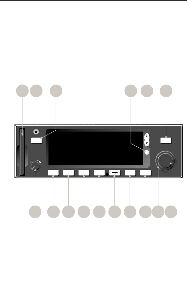
Figure 3-1 KLN 94 Controls

Chapter 3 Basic GPS Operation
3-0
1. On/Off/Brightness knob – Used to turn the unit on and off and adjust
display brightness.
2. Right outer knob – When the cursor is off, used to select the page
type (e.g. APT, NAV, FPL, etc.). When the cursor is on, used to move
the cursor from one position to another on the display.
3. Right inner knob – When the cursor is off, used to select the specific
page number for a page type (e.g. APT 1, APT 2, APT 3, etc.). When
the cursor is on, used to select alphanumerics or other applicable data
for the field the cursor is on.
4. Message button – Used to view messages.
5. OBS button – Used to select between LEG mode and OBS modes
6. Altitude button – Used to select the two Altitude pages where baro
settings are made and VNAV operation is set up.
7. Nearest button – Used to bring up a menu of nearest functions
(Airports, VORs, NDBs, Intersections, etc.) that may be selected.
8. Direct To button – Used to initiate Direct To operation.
9. Clear button – Used to delete data from a data field. Also used to
back up to a previous step in some instances such as selecting
approaches/STARs/DPs
10. Enter button – Used to approve or acknowledge data.
11. Cursor button – Used to turn the cursor on and off.
12. Range button – Used to change the map scale if the map page (Nav
4) page is being displayed. Used to select the map page if it is not
already on the map page.
13. Menu button – Used to display the map menu if the map page (Nav
4) page is being displayed. The map menu is used to initiate chang-
ing what is displayed on the map as well as select the map
orientation. Used to select the map page if it is not already on the map
page.
14. Data loader jack – Used when updating the Aeronautical database
from a computer.
15. Procedure button – Used to initiate the loading of approaches, arrival
procedures, and departure procedures. Also used to activate
vector–to–final (VTF) for approaches when an approach with
“Vectors” has been loaded into the active flight plan.
16. Data card – Contains the KLN 94 database.

3. BASIC GPS OPERATION
This is the first of four chapters specifically dealing with operating the
KLN 94. In this chapter you will learn the basic operation of the front
panel controls and then how to perform Direct To navigation (navigating
from your present position direct to your desired location).
3.1. COVERAGE AREA
The KLN 94 was designed to provide worldwide navigation coverage from
North 74° latitude to South 60° Latitude (figure 3-2). Outside this area,
magnetic variation must be manually entered as discussed in section
4.10, “Operation Outside the Primary Coverage Area”. See section 2.2
for the database geographical regions.
3.2. TURN-ON AND SELF TEST
Well, it’s time to get down to business and actually use the KLN 94!
Figure 3-1 can be folded out and used as a reference during the following
procedures. This is especially handy if you’re learning while away from
your GPS. The steps below take a lot of words to explain, but before you
know it, you will be “flying” through them.
NOTE: When power is applied to the KLN 94 it always “wakes up” in the
Leg mode. Only the Leg mode is described in this chapter. In this mode
the KLN 94 performs great circle navigation (the shortest distance
between two points located on the earth’s surface). The course deviation
KLN 94 Pilot’s Guide Chapter 3 Basic GPS Operation
3-1
74°
60°
45°
30°
15°
0°
15°
30°
45°
60°
74°
60°
45°
30°
15°
0°
15°
30°
45°
60°
Figure 3-2 KLN 94 Navigation Coverage Area

output displayed on the unit’s internal course deviation indicator (CDI) and
provided to an external horizontal situation indicator (HSI) or CDI is five
nautical miles (full scale sensitivity) left and right in Leg mode. The other
modes are described in section 5.5 and chapter 6.
To turn on and initialize the KLN 94:
1. Turn on the KLN 94 by pushing in the On/Off/Brightness knob. For the
first few seconds a single color Power-On page is displayed at a fixed
brightness. When the screen changes to full color, rotate the knob to
adjust display brightness to the desired level.
After an additional few seconds,
the operational revision status
(ORS) level number is displayed
on the Power-On page (figure 3-
3). The ORS level displayed
should match the ORS level indi-
cated on the cover of this Pilot’s
Guide .
NOTE: If the temperature is very cold when the KLN 94 is turned on, a
Warm Up screen is displayed after the Power-On screen. Line 4 will dis-
play the approximate time the Warm Up screen will be displayed prior to
automatically changing to the Power-On screen. The E button may be
pressed to bypass the Warm Up screen but the display may be extremely
sluggish until it warms up.
When an extensive internal test
is complete, the Power-On page
will automatically be replaced by
the Self Test page (figure 3-4).
NOTE: If the KLN 94 is operating in
the Take-Home Mode, the Take-
Home Warning Page (figure 3-5) is
displayed first and must be acknowl-
edged by pressing F. See section
3.16 for more information on the
Take-Home mode.
NOTE: A warning page (figure 3-6)
is displayed if the unit is turned on
without a database card.
Chapter 3 Basic GPS Operation
3-2
Figure 3-3
Figure 3-4
Figure 3-5
Figure 3-6

2. Use the right inner knob to enter the current altimeter setting into the
“Baro” field and then press the Fbutton. (If the KLN 94 is inter-
faced to a compatible airdata system you will not be able to enter data
into this field. Verify that the data displayed on the Self Test page is
the same as is being displayed on the appropriate equipment in the
aircraft which is interfaced to the KLN 94. If the KLN 94 is not con-
nected to any other equipment in the aircraft, you may skip to step 3.
The distance field in the upper left corner always displays 34.5 NM (or
63.9 km). If the KLN 94 is interfaced to a compatible indicator that dis-
plays DME distance, the indicator should be displaying 34.5 nautical
miles.
If the KLN 94 is interfaced with a NAV indicator such as an HSI or a
course deviation indicator (CDI), the deviation bar (D-bar) should be
indicating a half scale deviation to the right. The TO/FROM indicator
should be showing FROM.
If the KLN 94 is interfaced with a NAV indicator such that the KLN 94
can “read” the selected course from the NAV indicator, then the OBS
field should display the same selected course as on the NAV indica-
tor.
The RMI field always displays 130 degrees. If the KLN 94 is connect-
ed to a compatible RMI in the aircraft, the RMI should indicate a
bearing to the station of 130 degrees.
If any of the above checks fail, do not use the associated indicator
with the KLN 94.
3. If the KLN 94 has passed the internal self test, the bottom of the Self
Test page will display Pass and all external annunciators (if any
installed) should be illuminated. If instead, Fail is displayed, recycle
power to the KLN 94. If the Self Test page still displays Fail, the
KLN 94 requires repair and should not be used for navigation.
4. Use the right outer knob to position the cursor over OK? if it is not
already there. When you are ready to approve the Self-test page,
press the Fbutton.
5. The next page displayed will be
the Initialization page (figure 3-
7). Verify that the date displayed
in the top left corner of the
Initialization page is correct.
KLN 94 Pilot’s Guide Chapter 3 Basic GPS Operation
3-3
Figure 3-7
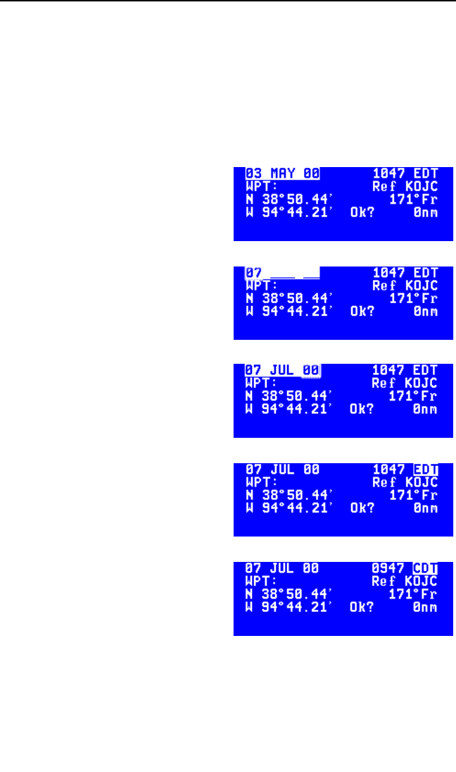
The KLN 94 has an internal battery powered calendar/clock, so the
date and time normally don’t require setting. The battery has a life of
approximately 3 years. In addition, the KLN 94’s system date and time
are automatically updated very precisely when at least one satellite is
being received. However, if for some reason the date or time are
incorrect, it is necessary to enter the correct date or time so that the
KLN 94 can reach the navigation mode quickly. The date should be
correct and the time should be correct within ten minutes so that the
KLN 94 will start looking for the correct satellites.
If the date is incorrect, rotate the
right outer knob counterclock-
wise until the cursor is over the
entire date field (figure 3-8).
Rotate the right inner knob until
the correct day of the month is
displayed (figure 3-9). Then,
move the cursor to the month
field by rotating the outer knob
one click clockwise and change
the month as necessary. Use the
same methods to select the cor-
rect year (figure 3-10). When
the date is correct, press F.
6. Verify that the time displayed in
the upper right corner of the
Initialization page is correct to
within ten minutes of the actual
time. Remember, once the
KLN 94 receives the first satel-
lite, it will automatically be very
accurately updated by the satel-
lite to the correct time. However,
you are responsible for assuring
the desired time zone is selected
on the KLN 94. If it is necessary
to reset the time, position the
cursor over the time zone field
(figure 3-11) and select the
desired time zone (figure 3-12).
Chapter 3 Basic GPS Operation
3-4
Figure 3-8
Figure 3-9
Figure 3-10
Figure 3-11
Figure 3-12

The KLN 94 is capable of displaying the following time zones:
UTC Coordinated Universal Time (Zulu)
GST Greenland Standard Time (UTC - 3)
GDT Greenland Daylight Time (UTC - 2)
ATS Atlantic Standard Time (UTC - 4)
ATD Atlantic Daylight Time (UTC - 3)
EST Eastern Standard Time (UTC - 5)
EDT Eastern Daylight Time (UTC - 4)
CST Central Standard Time (UTC - 6)
CDT Central Daylight Time (UTC - 5)
MST Mountain Standard Time (UTC - 7)
MDT Mountain Daylight Time (UTC - 6)
PST Pacific Standard Time (UTC - 8)
PDT Pacific Daylight Time (UTC - 7)
AKS Alaska Standard Time (UTC - 9)
AKD Alaska Daylight Time (UTC - 8)
HAS Hawaii Standard Time (UTC - 10)
HAD Hawaii Daylight Time (UTC - 9)
SST Samoa Standard Time (UTC - 11)
SDT Samoa Daylight Time (UTC - 10)
LCL Local Time Zone (user-defined)
You will be able to change the time zone any time you desire on sev-
eral other pages, so don’t worry if you’re not sure which time zone to
choose. UTC—Coordinated Universal Time (also called “Zulu”) is
always a safe choice.
The local time zone (LCL) is selected on the SET 2 page, and is
defined to be a certain time offset from Zulu (UTC).
Once you have selected the desired time zone, position the cursor
over the entire time field and select the correct hour with the right
inner knob (figure 3-13). Since
24 hour time is used, be sure to
add 12 if the time is after 1:00
P.M. (2:30 P.M. becomes 1430).
Now move the cursor to the tens
of minutes position and select
the desired value, and repeat
KLN 94 Pilot’s Guide Chapter 3 Basic GPS Operation
3-5
Figure 3-13
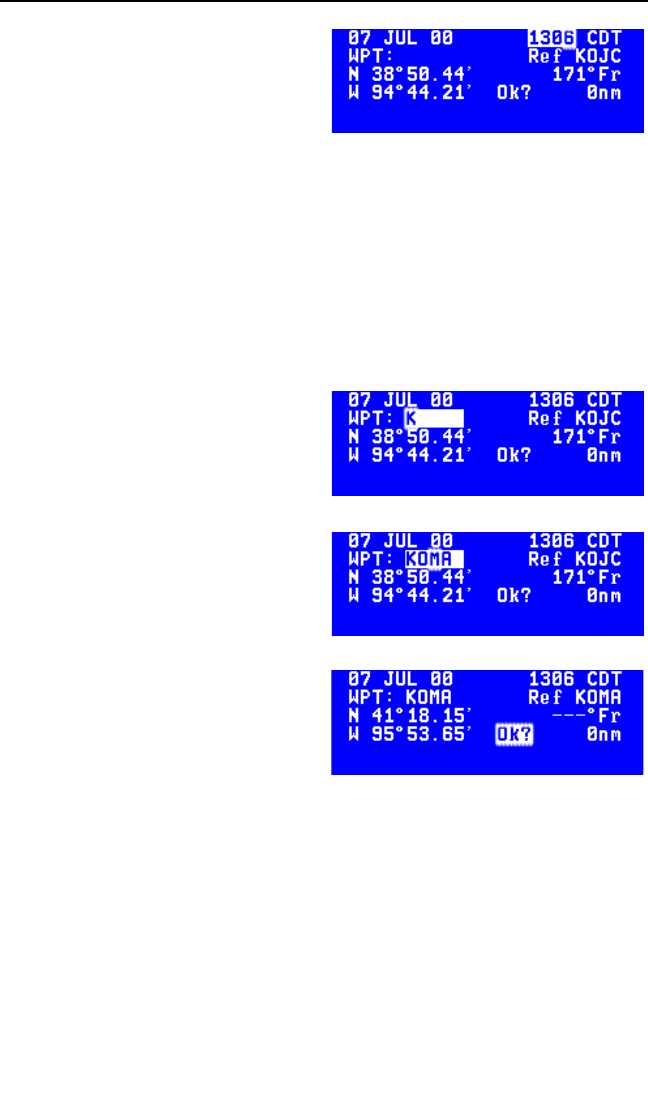
this process for the last digit of
the time field. When the correct
time has been entered (figure 3-
14), press Fto start the clock
running. Don’t worry that you
can’t update the seconds. The
KLN 94 system time will auto-
matically be corrected very precisely once a satellite is received.
7. To aid the GPS receiver in acquiring your position, it helps to have a
reasonable idea of where you are, and the Initialization page is where
you have the chance to set this initial position. Check to see if the dis-
played initial position is where you actually are. This latitude/longitude
is the last known position before the power was shut down the last
time. Unless the unit has been moved since its last use, this position
should be correct. On the right side of the screen will be the identifier
of the nearest airport in the data-
base, with a radial and distance
from that airport. If you need to
change the initial position to—
let’s say—Omaha Eppley
(KOMA), move the cursor to the
WPT: field and use the right
inner knob to select a K as the
first character of the identifier
(figure 3-15). Move the cursor to
the right one character and
select an O and then right again
to select an M. The final A
should be filled in by the data-
base (figure 3-16). When you
press F, the latitude and longi-
tude fields will change to those
of KOMA (figure 3-17). If neces-
sary, the latitude and longitude
may be entered manually.
8. When all information on the Initialization page is correct, move the
cursor to Ok? using the right outer knob and press Fto move on.
9. If the KLN 94 installation is approved for VFR use only or for IFR use
without approach capability, a page will be displayed after the
Initialization page to notify you of this.
NOTE: In some installations, KLN 94 is configured for use in IFR En route
and Terminal operations, but not for non-precision approaches. If this is
the case, line 3 will read GPS Approaches Disabled and you will not
have access to approaches in the database.
Chapter 3 Basic GPS Operation
3-6
Figure 3-15
Figure 3-16
Figure 3-17
Figure 3-14
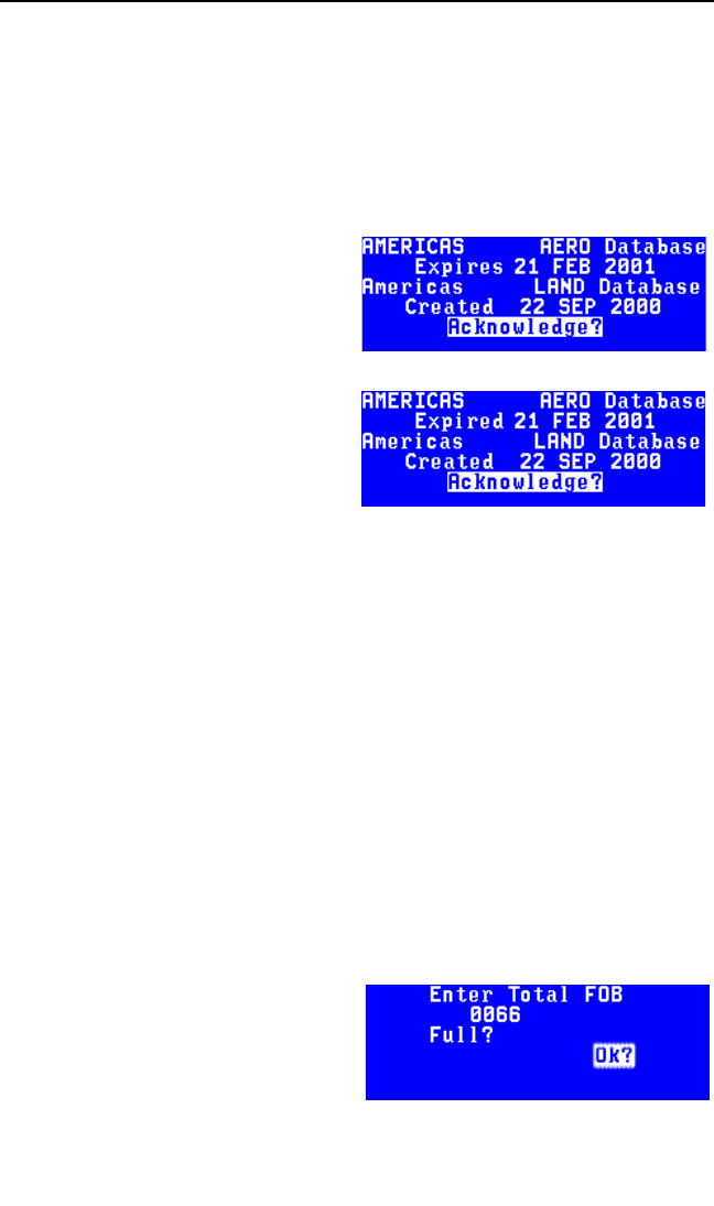
10. The Database page will now be displayed with the cursor over
Acknowledge?. Line 1 indicates whether an Americas, Atlantic
International, or Pacific International aeronautical database is being
used. If the aeronautical database (airports, navaids, approaches, etc)
is current, line 2 will show the date when the aeronautical database
expires (figure 3-18). If the aeronautical database is out of date, line 2
shows the date that it expired (figure 3-19). The KLN 94 will still func-
tion with an out-of-date aeronautical database; however, you must
exercise extreme caution and
always verify that the database
information is correct before
using information from an out-of-
date aeronautical database.
Line 3 indicates which database
region is used for the LAND
database (roads, rivers, etc) on
ORS 02 and higher units. Line 4
displays the date that the land
database was created. The
land database has no expiration
date and new data is available
approximately once a year.
Press Fto acknowledge the information on the Database page.
The first time the KLN 94 is turned on after a new database card was
inserted, it takes approximately seven minutes to download data from the
card to internal memory. During this time the Database page will tem-
porarily display:
*STANDBY*
Database being
Updated
When the download is complete the normal database page will be dis-
played.
WARNING: The accuracy of the database information is assured
only if the database is current. Operators using an out-of-date data-
base do so entirely at their own risk.
NOTE: If your KLN 94 is interfaced
with a remote Shadin fuel/air data
computer but no fuel flow indicator,
the Fuel on Board page will be dis-
played following the Database page
(figure 3-20). This page allows you to
KLN 94 Pilot’s Guide Chapter 3 Basic GPS Operation
3-7
Figure 3-18
Figure 3-19
Figure 3-20
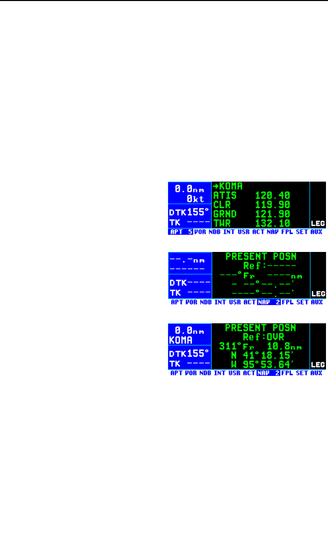
set the amount of fuel on board (FOB) and initializes the Auxiliary (AUX)
15 and 16 fuel calculator pages. Possible units are gallons (GAL), pounds
(LB), imperial gallons (IMP), liters (L), or kilograms (KG). If you wish to
manually set the FOB, use the right outer knob to move the cursor to line
2 and use the right inner knob to select the desired value. Another option
is to move the cursor to Full? and press F, which will update the FOB
to the tanks-full value set at the time of installation. To go on, move the
cursor to Ok? and press F.
Either the APT 5 or NAV 1 page will now be displayed on the screen. If
the last active waypoint was an airport, the APT 5 page showing the air-
port’s communications frequencies will be displayed (figure 3-21). Almost
always, the waypoint which was active when you last turned the KLN 94
off is the airport where you landed. Therefore, when you get ready to
depart, the airport communication
frequencies for that airport will auto-
matically be displayed for you!
Next, you may want to check the
NAV 2 page to see your present
position. Use the right outer knob to
select the NAV page type and then
the right inner knob, if necessary, to
select the NAV 2 page. It is quite
likely that the present position will be
dashed at first (figure 3-22). It takes
the KLN 94 a couple of minutes to
acquire the GPS satellites and to
make its initial calculation of your
position. When the KLN 94 reaches
a NAV ready status and is able to
navigate, the NAV 2 page will display
your present position relative to the
nearest VOR (figure 3-23). Verify
that the present position shown on the NAV 2 page is correct.
NOTE: In order to reach a Nav ready status, the aircraft must be away
from obstructions blocking the GPS antenna’s view of required satellites.
If the KLN 94 fails to reach a Nav ready status within five minutes refer to
section 3.7, “Initialization And Time To First Fix”.
Chapter 3 Basic GPS Operation
3-8
Figure 3-21
Figure 3-22
Figure 3-23
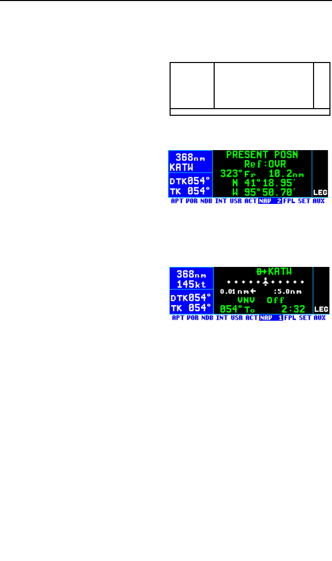
3.3. DISPLAY FORMAT
The KLN 94 uses a color LCD. In normal operation, the display screen is
divided into four segments (figure 3-24). When the map page (NAV 4)
page is displayed the page bar is
removed to maximize the height of
the map. Also, in some cases such
as the display of system messages
the segment dividers disappear and
you have a “full-screen” page.
Display Segment 1 (Navigation Data)
A typical display screen is shown in
figure 3-26. Display segment 1 is
the Navigation Data segment. On all
normal pages segment 1 consists of
four lines of data.
• The top line of segment 1
always displays distance to the active waypoint.
• The identifier of the active waypoint is usually displayed on the sec-
ond line.
NOTE: In cases when the active
waypoint identifier is displayed on a
segment 2 page, line 2 will display
the current groundspeed (figure 3-
27).
• The third line of segment 1 displays the desired track (DTK) when
the KLN 94 is in the LEG mode, its normal mode of operation. DTK
is the course to the active waypoint the aircraft should be flying.
The DTK value will flash if the course selected on the external CDI
or HSI differs from the desired track by more than 10 degrees.
When the KLN 94 is in OBS mode of operation the OBS course is
displayed on line 3. See section 5.5 for modes of operation.
• The aircraft’s actual track (TK) over the ground is displayed on line
four. Displaying the DTK and TK together like this makes it easy to
determine the proper heading to fly in order to make the TK match
the DTK. As long as they match the aircraft will remain on course. If
the TK begins to differ from the DTK it won’t be long until the devia-
tion needle on the CDI or HSI will start be move off center. See
Appendix A for a graphical description of navigation terminology
such as DTK and TK.
KLN 94 Pilot’s Guide Chapter 3 Basic GPS Operation
3-9
124
3
Figure 3-24
Figure 3-26
Figure 3-27

Display segment 1 changes somewhat when the map page (NAV 4) is
being displayed. See section 3.11.4.
Display Segment 2 (Page)
Aeronautical information is presented on the screen in the form of “pages”.
Segment 2 is where these pages are displayed. A page is a presentation
of specific data in an organized format. Various page “types” are used to
display related kinds of data. For example, one page type is NAV (naviga-
tion). NAV pages show information such as distance, groundspeed,
bearing, course, and other data relating to navigation. Another page type
is APT (airport). APT pages contain information pertinent to a specific air-
port such as name, city, state, elevation, runways, and communication
frequencies.
Display Segment 3 (Page Bar)
The specific page type and number is shown on the page bar at the bot-
tom of the display. Ten page types are shown on the page bar; however,
only the selected page type is shown in reverse video (white characters
on a blue background). In figure 3-27, the NAV 1 (Navigation 1) page is
being displayed in segment 2 and is annunciated as such on the segment
3 page bar.
You might think of the page types as the chapters in a book and the page
numbers as the pages within a chapter. Just as a chapter in a book may
have from one to many pages, a KLN 94 page type may have from one to
26 pages associated with it. There are, for example, 26 flight plan pages
(FPL 0, FPL 1, FPL 2, … FPL 25) in the flight plan page type and up to
eight airport pages (APT 1, APT 2, … APT 8) in the airport page type.
Figure 3-28 shows an example of an
APT 5 page. Notice the “+” sign in
the page identification. Whenever a
“+” sign is part of a page identifier
there will be two or more pages, all
having the same page number, used
to present all of the required informa-
tion. That is, all of the information
associated with a particular page
number doesn’t fit on the page being
viewed. In this case the “+” sign indi-
cates that there are two or more APT
5 pages. Figure 3-29 shows the sec-
ond of 10 APT 5 pages for KICT
(Wichita Mid-Continent Airport).
Chapter 3 Basic GPS Operation
3-10
Figure 3-28
Figure 3-29

Display Segment 4 (Annunciations)
Segment 4 displays annunciations
associated with the operation of the
KLN 94 (figures 3-30 and 3-31).
Line one shows the WPT (waypoint
alert) annunciation when approach-
ing the active waypoint (see sections
3.10.3 and 4.2.2) or the SCAN
annunciation when the scan function
has been enabled. The scan function
is enabled by pulling the right inner
knob to the “out” position on pages
that allow waypoint lists to be
scanned by turning the right inner
knob.
Line two shows the message prompt, a large “M”, when the KLN 94 has a
message for you to view on the message page (see section 3.5 “Message
Page”). This line is also used to indicate that the KLN 94 is ready for you
to press the Fbutton to approve something, such as a selected way-
point, by flashing the ENT (enter) prompt.
Line three displays a white “VTF” when a vectors-to-final approach has
been loaded into the active flight plan (but not yet activated) and a green
“VTF” when the vectors-to-final approach has been activated (see section
6.2.8).
Lines four and five display if the unit is in either the approach arm (APR
ARM) or approach active (APR ACTV) modes (see section 6.2.1). The
KLN 94 may also be configured at the time of installation to display termi-
nal (TERM) and approach (APR), respectively, in lieu of APR ARM and
APR ACTV. If the KLN 94 is in the en route mode these lines are blank.
Line six will normally display “LEG” which is the default mode. “OBS” is
displayed when the pilot has selected the OBS mode (see section 5.5
“Navigation Modes”).
Either “LEG” or “OBS” is always displayed on line six. The other lines in
the annunciation segment will be blank unless the annunciation is active.
NOTE: The waypoint alert, message, and approach annunciations may
also be displayed on remote annunciators. See section 3.14 “Remote
Mounted Annunciators”.
KLN 94 Pilot’s Guide Chapter 3 Basic GPS Operation
3-11
Figure 3-30
Figure 3-31

3.4. BASIC OPERATION OF PANEL CONTROLS
Remember that figure 3-1 is a fold-out page that you may want to refer to
as you read this chapter.
The KLN 94 has three knobs and eleven buttons which are used to per-
form all operations. Most of the page selection and data entry is done
with the knobs on the right side of the front panel and the cursor (B) but-
ton immediately above them.
The cursor position is indicated by an area of reverse video. For exam-
ple, if the characters are normally green on a black background, the
characters change to black on a green background when the cursor is on.
In figure 3-32 the cursor is over
3000. Many pages allow you to
add, delete, or change data on the
screen by first pressing the Bbut-
ton to turn the cursor function on
and bring the cursor on the screen.
The right knobs are then used to
enter or change data. When the cursor is turned on, the page bar
changes to only show the actual page being displayed in the middle with
*CRSR * on either side. In some cases the cursor will flash to indicate
that the Fbutton must be pressed to approve the data.
3.4.1. PAGE SELECTION
It is now time to learn to select a desired page.
NOTE: The cursor function is not used in selecting pages and the Bbut-
ton should not be pressed at this time. If CRSR is annunciated in page
bar, press the Bbutton to turn the cursor function off.
The right outer knob is rotated to select one of ten page types for the dis-
play. These ten page types are the following:
Chapter 3 Basic GPS Operation
3-12
Figure 3-32
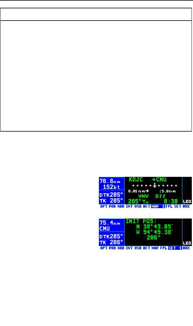
The ten page types are listed across the page bar at the bottom of the
screen. Remember that the page type/number of the page actually select-
ed is shown in reverse video (white characters on a blue background).
The page bar works kind of like a map to get you from one page type to
another. To change page types turn the right outer knob either direction.
The area of reverse video moves across the page bar so that it is always
over one of them. For example, let’s
say you were on a NAV page (figure
3-33) and you wanted to select a
SET page. You would look at the
page bar and see that the SET
pages are two places to the right of
the NAV pages. Therefore, turning
the right outer knob two clicks clock-
wise will get you to the SET pages
(figure 3-34). The page type selec-
tion wraps around from Auxiliary
(AUX) to Airport (APT); that is, the
knob has no mechanical stops.
Once you have selected the desired page type using the right outer knob,
you may select the page number by rotating the right inner knob. So to
change from the SET 1 page to the SET 4 page turn the right inner knob
clockwise three clicks.
Let’s use an example to make sure you understand. You are presently
viewing the APT 2 page and you wish to view the NAV 3 page. Rotating
the right outer knob six clicks clockwise will display the NAV page that you
KLN 94 Pilot’s Guide Chapter 3 Basic GPS Operation
3-13
Chapter Name/
Page # Range Page Type Page Functions
APT 1-8* Airport Directory of published airports
VOR 1-2 VOR Directory of published VOR stations
NDB 1 NDB Directory of published non-directional beacons (NDB)
INT 1-2 Intersections Directory of published named intersections
USR 0-3 User Waypoint Directory of user-defined waypoints
ACT ** Active Waypoints Information about the active flight plan waypoints
NAV 1-4 Navigation Navigation data
FPL 0-25 Flight Plan Active and stored flight plans
SET 1-14 Setup Setting initial position and date/time, updating the data
base, and selecting certain features
AUX 1-14*** Auxiliary Status reports, distance, bearing, time and fuel
calculator; air data calculations based on pilot-entered
inputs and deleting user wpts and remarks
* KLN 94's which are not approved for IFR have 6 airport pages.
** Varies with the type of waypoints in the active flight plan.
*** Up to 21 with fuel management system and air data interfaces.
Figure 3-33
Figure 3-34
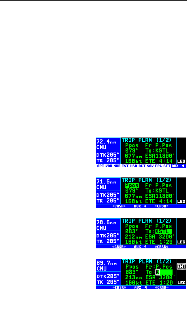
last viewed—we’ll say the NAV 2 page. Turning the right inner knob one
click clockwise or three clicks counterclockwise will bring you to the NAV 3
page. Or, from the APT 2 page you could turn the right outer knob four
clicks counter-clockwise to get to the NAV pages. Got it?
NOTE: In this Pilot’s Guide the right smaller knob is assumed to be in the
“in” position unless it specifically states that the knob should be in the “out”
position. Therefore, the words “rotate the right inner knob” mean to turn
the right inner knob while the knob is in the “in” position.
3.4.2. DATA ENTRY
Now that you’ve learned how to select the desired page, you’re ready to
learn the means of entering data. It is necessary to enter data, for exam-
ple, in order to specify a waypoint of your choice to go Direct To. The
general procedure for entering a waypoint identifier is described below
and is shown in figures 3-35 through 3-43 for entering a waypoint (in this
case, First Flight airport in North Carolina, identifier KFFA) on the Auxiliary
4 (AUX 4) page.
To enter a waypoint identifier:
1. If the cursor is not on the screen
(figure 3-35), press Bto turn
on the cursor function (figure 3-
36).
2. If required, rotate the right outer
knob to position the cursor (fig-
ure 3-37).
3. Rotate the right inner knob to
select the first character of the
waypoint identifier (figure 3-38).
Chapter 3 Basic GPS Operation
3-14
Figure 3-35
Figure 3-36
Figure 3-37
Figure 3-38
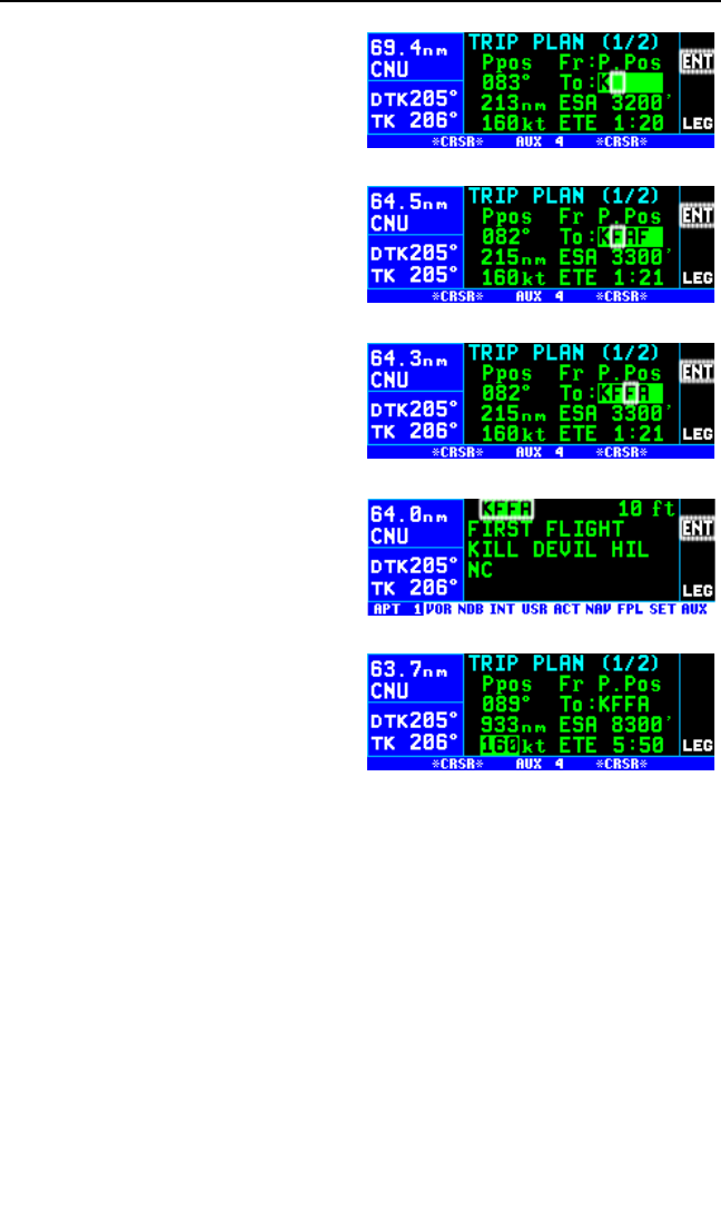
4. Turn the right outer knob one
click clockwise to move the cur-
sor to the second character
position (figure 3-39).
5. Rotate the right inner knob to
select the second character (fig-
ure 3-40).
6. Use the right outer and inner
knobs in this manner until the
complete waypoint identifier is
displayed (figure 3-41). Note that
you may not have to enter the
last characters of the identifier
because each time you enter a
character, the KLN 94 offers you
the first identifier in the database
beginning with the characters
you have entered.
7. If ENT is flashing on the right
side of the screen, then press
F. This will prompt the
KLN 94 to display a waypoint
page for the waypoint identifier
you just entered (figure 3-42).
8. Verify the waypoint information
displayed, and then press F
again to approve the waypoint
page. The display will return to
the page previously displayed
(figure 3-43).
Often, you will find yourself entering airports that begin with the same
character over and over again. In section 2.3, you learned how the
KLN 94 uses ICAO identifiers, which means that many U.S. airport identi-
fiers begin with the letter K. Also, many airport identifiers in Europe begin
with the letter E or the letter L. Especially when flying VFR, you will mostly
want to enter Direct To or Flight Plan waypoints which are airports. You
can set the default first waypoint identifier character on the SET 11 page.
KLN 94 Pilot’s Guide Chapter 3 Basic GPS Operation
3-15
Figure 3-39
Figure 3-40
Figure 3-41
Figure 3-42
Figure 3-43
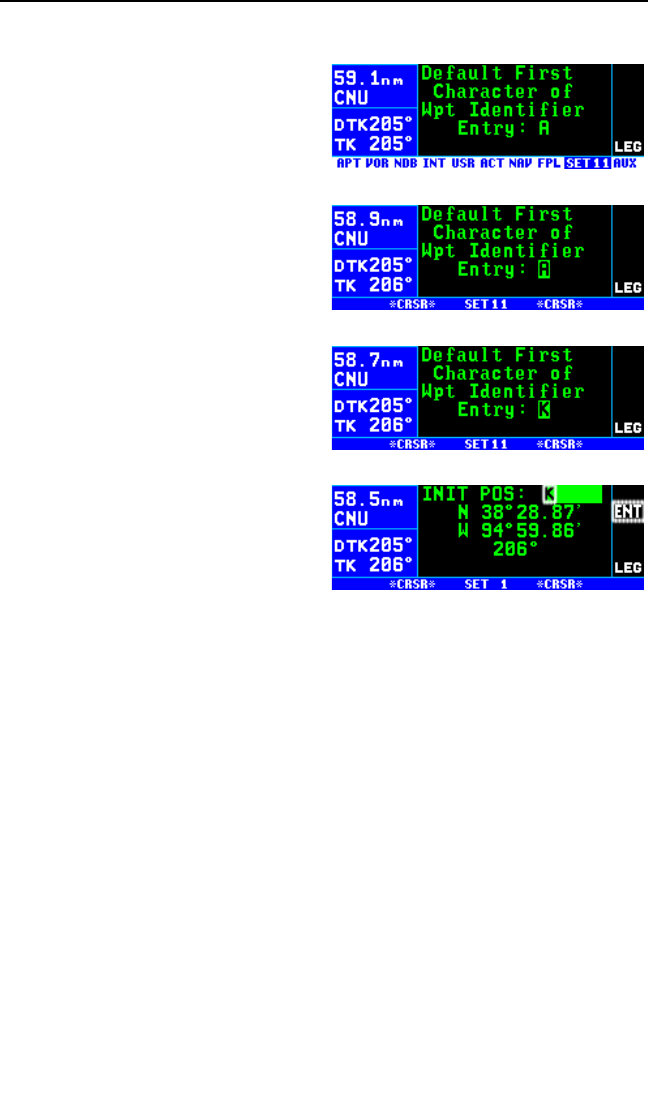
To change the default first waypoint identifier character:
1. Select the SET 11 page (figure
3-44) and turn on the cursor by
pressing the Bbutton (figure
3-45).
2. Use the right inner knob to select
the desired character (figure 3-
46), such as a K in the U.S., a C
in Canada, a P in Alaska, an E
or an L in Europe, etc.
3. Turn off the cursor. To try it out,
proceed to the SET 1 page (ini-
tial position). Turn the cursor
(B) on (it will come on over the
waypoint field). Try turning the
right inner knob one click clock-
wise (figure 3-47). There’s the
character you just selected on
the SET 11 page!
4. Turn off the cursor.
3.4.3. THE DUPLICATE WAYPOINT PAGE
There are some waypoints in the database whose identifiers are not
unique. That is, more than one waypoint has the same identifier. When a
waypoint identifier has been entered which is not unique to a single way-
point, a Duplicate Waypoint page appears on the screen. The Duplicate
Waypoint page is then used to select which of the waypoints having the
same identifier is actually desired.
The waypoint identifier is displayed on the top left of the page. Below the
identifier is the number of waypoints in the database having the identifier.
A list of the waypoint types (APT, VOR, NDB, INT, USR) and the associat-
ed countries which use the identifier is shown. Some countries such as
the USA are further regionalized (e.g. “NE USA”) to aid in making the cor-
rect selection.
NOTE: The duplicate waypoints are displayed in order of closeness to the
aircraft’s present position, the closest being displayed first.
Chapter 3 Basic GPS Operation
3-16
Figure 3-44
Figure 3-45
Figure 3-46
Figure 3-47
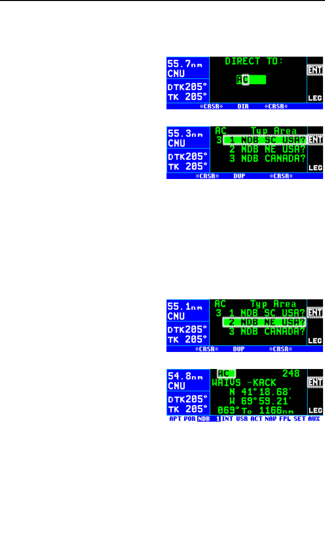
To see an example of a Duplicate Waypoint page, try entering the identifi-
er “AC” as a Direct To waypoint:
1. Press D.
2. Select “AC” as the waypoint
identifier (figure 3-48). AC is the
full identifier of several waypoints
in the KLN 94 database.
3. Press F. The Duplicate
Waypoint page will be displayed
on the screen (figure 3-49). At
the time of this writing, there
were three waypoints in the
Americas database having the
identifier AC. The list includes an
NDB in the southcentral U.S., an
NDB in the northeast U.S., and an NDB in Canada. The cursor will be
over the first waypoint listed. On the screen in figure 3-49, the NDB in
SC USA is closest to the aircraft’s present position since it is listed
first.
If there are more than four duplicates, view the rest of the choices by rotat-
ing the right outer knob clockwise. Doing so will move the flashing cursor
over waypoints two, three, and four and then will cause the waypoint list to
“scroll” so that the other waypoints in the list may be seen.
4. To select the desired waypoint,
move the cursor over the appro-
priate choice (figure 3-50).
5. Press Fand the display will
change to the waypoint page for
the selected waypoint (figure 3-
51).
6. Press Fagain to approve the
waypoint page.
KLN 94 Pilot’s Guide Chapter 3 Basic GPS Operation
3-17
Figure 3-48
Figure 3-49
Figure 3-50
Figure 3-51
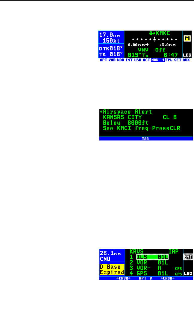
3.5. MESSAGE PAGE
Whenever the KLN 94 wants to get your attention, the message prompt (a
large yellow “M” on the right side of
the screen) begins flashing (figure 3-
52). If you have a remote message
annunciator in your aircraft, it will
also begin flashing at that time. You
should view the message at your
earliest opportunity because the unit
may be alerting you to some situation of immediate concern to its condi-
tion or to your flight. A description of each possible message is included in
Appendix B of this Pilot’s Guide.
To view a message:
1. Press the Cbutton. The MSG
page will appear and show the
new message (figure 3-53).
NOTE: It is possible that several
messages are displayed at one time
on the Message page. The newest
message appears first and the rest in reverse chronological order.
2 After reading the message, press Cagain to return to the page pre-
viously in view. If all of the messages cannot be displayed on one
Message page, repeated presses of Cwill show the other mes-
sages before returning to normal operation. If a message condition
exists which requires a specific action by you, the message prompt
will remain on but will not flash.
3.6 SCRATCHPAD MESSAGES
The lower left corner of the display can also display short operational mes-
sages to the user called “scratchpad messages”. These messages are
displayed for approximately five seconds, then this area returns to a dis-
play of the page type and number.
Figure 3-54 shows an example of a
scratchpad message indicating an
expired database. A complete listing
of scratchpad messages is available
in Appendix C of this Pilot’s Guide.
Chapter 3 Basic GPS Operation
3-18
Figure 3-52
Figure 3-53
Figure 3-54

3.7. INITIALIZATION AND TIME TO FIRST FIX
Since the KLN 94 stores its position and other required parameters in
memory when power to the unit is removed, it is seldom necessary to aid
the unit in reaching a NAV ready condition. The time required from power
on until the KLN 94 determines its present position and is therefore ready
to navigate is called “time to first fix.” The time to first fix is normally a few
minutes or less. In order for the KLN 94 to reach a NAV ready condition, it
is necessary to meet the following conditions:
1. The KLN 94’s “almanac” data should be current. Almanac data is
orbital information for all the satellites and is used for initial acquisition
when the KLN 94 is first turned on. This data is stored in the
KLN 94’s non-volatile memory and is considered current for up to six
months. Each satellite sends almanac data for all satellites. Since
the KLN 94 routinely updates the almanac data during normal opera-
tion, the almanac data will become out of date only if the KLN 94
hasn’t been used for the previous six months or longer. Collecting
new almanac data takes place automatically if the data is more than
six months old. If the almanac data is out of date and needs to be col-
lected, the KLN 94 will take approximately 12 minutes to acquire your
present position. The Self Test, Initialization, and Database pages
should be approved.
2. The aircraft must be located such that the GPS antenna has an unob-
structed view of the sky so that required satellite signals are not being
blocked. If possible, position the aircraft away from hangars or other
obstructions.
3. It is very helpful for the KLN 94 to have the correct time, date and
position to be able to determine which satellites should be in view.
This information is stored in the battery backed memory of the KLN 94
so it is not normally required to update it. If the KLN 94 has the correct
time, date and position, then the time to first fix will usually be less
than two minutes. If this information is not correct, then the KLN 94
will start to look for any satellites. Eventually, the KLN 94 will find
enough satellites to determine the position of the aircraft. This process
can take as long as 12 minutes. It is possible for you to update this
information manually, which will allow the KLN 94 to reach a NAV
ready status much faster. To set the time and date follow steps 5 and
6 in section 3.2, “Turn-On and Self-Test.” The initial position is usually
set during turn-on and self-test, but if for some reason it is necessary
to update the position after the power-on sequence, then use the fol-
lowing steps. Remember, if acquisition time is not important then it is
not necessary to update the time, date or position.
KLN 94 Pilot’s Guide Chapter 3 Basic GPS Operation
3-19
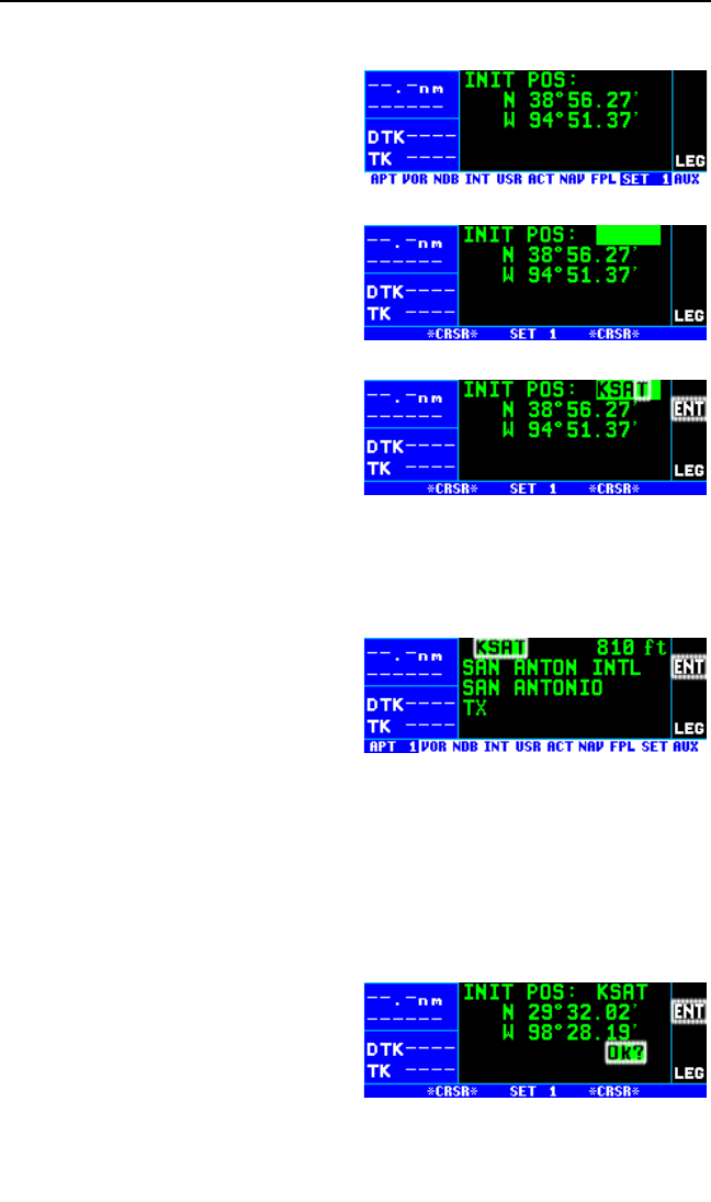
To initialize the position from the SET 1 page:
1. If the cursor is not on the screen
(figure 3-55), press the Bbut-
ton to bring it on the page over
the INIT POS field (figure 3-56).
2. Using the right inner and outer
knobs, enter the identifier for the
airport where you are presently
located or the identifier of a
navaid or other airport which is
close to your present position
(figure 3-57). Any waypoint in
the database which is within 60
miles is acceptable, but the clos-
er the better. Remember, if you
are entering an airport identifier
that is all letters (no numbers),
then it will begin with a “K” prefix
in the contiguous U.S., a “P” in
Alaska (in some cases; in oth-
ers, the prefix is not added), or a “C” in Canada. If there are numbers
in the identifier then a prefix is not used. Outside the contiguous U.S.,
Alaska, and Canada, use the airport identifiers as they are charted.
3. Once you have entered the com-
plete identifier, press F. The
display will change to the way-
point page for the waypoint you
entered (figure 3-58).
4. If this is the waypoint you intended to enter, press Fagain. The
display will change back to the SET 1 page.
NOTE: As an alternative, you can also enter the approximate latitude and
longitude of your present position directly on the SET 1 page instead of
entering a waypoint.
5. With the right inner knob, posi-
tion the cursor over Ok? if it is
not already there (figure 3-59).
6. Press Fto approve the initial
position. The cursor will auto-
matically be removed from the
screen.
Chapter 3 Basic GPS Operation
3-20
Figure 3-55
Figure 3-56
Figure 3-57
Figure 3-58
Figure 3-59
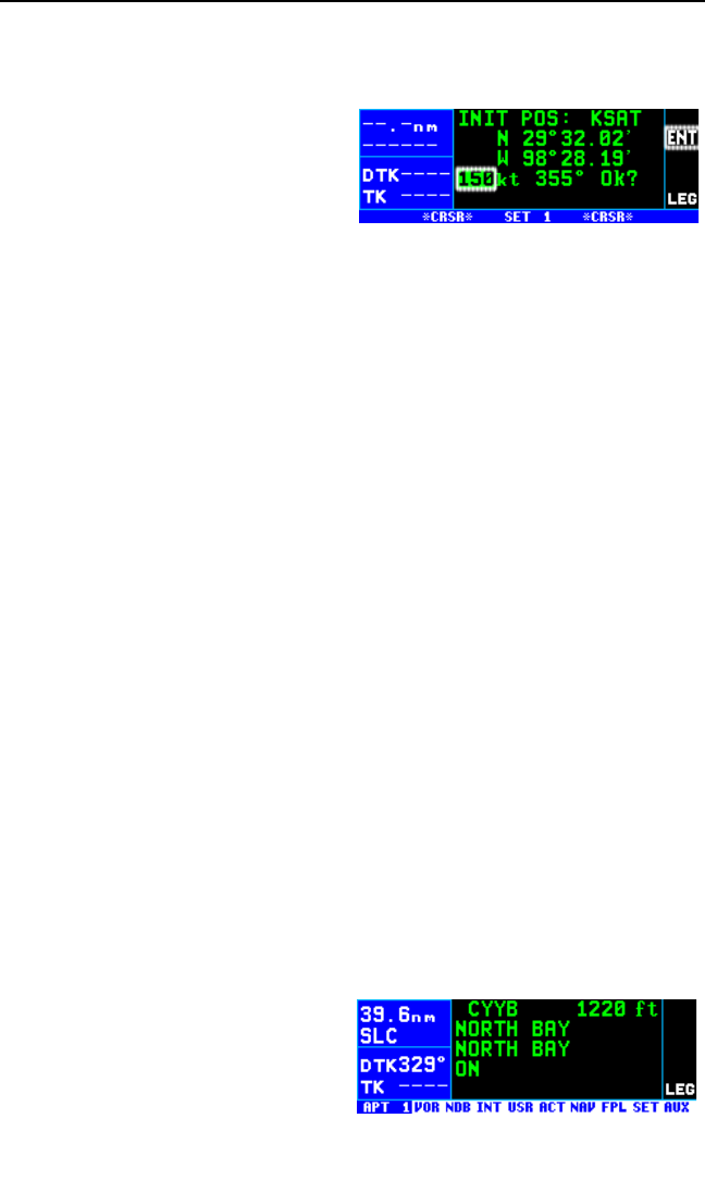
NOTE: If the KLN 94 is in the Take-Home mode, you are allowed to enter
the groundspeed (kt) and heading (°) fields in order to simulate flight (fig-
ure 3-60). They are not used for actual initialization in an aircraft.
However, entering a groundspeed
will allow the KLN 94 to “fly” along
the active flight plan (or to a direct to
waypoint) starting from the initializa-
tion waypoint. A heading may be
entered in the initial heading field
while in the Take-Home mode if the
one offered is not desired. See section 3.16 for more details on the Take-
Home mode.
7. Select the NAV 2 page. When the KLN 94 reaches the NAV ready
status and is therefore able to navigate, the NAV 2 page will display
the present position. Verify that the latitude and longitude or the way-
point, radial, and distance display of present position are correct.
3.8. SELECTING AND SCANNING WAYPOINTS
There are five types of waypoints: airports, VORs, NDBs, intersections,
and user waypoints. Waypoints in the published database fall into one of
the first four types. You can create up to 500 user waypoints to supple-
ment the waypoints in the database (see section 5.4 to create a user
waypoint).
There are three methods you may use to select a specific waypoint for
viewing. You may enter the waypoint’s identifier directly, you may scan
through the waypoint identifiers in alphabetical order, or you may enter the
waypoint’s name. If the waypoint is an airport, you may also select it by
entering the city where the airport is located.
3.8.1. SELECTING WAYPOINTS BY IDENTIFIER
The most direct way of selecting a specific waypoint is to simply enter the
waypoint’s identifier directly on the appropriate waypoint page type (APT,
for example). Let’s use Chicago O’Hare International Airport whose iden-
tifier is KORD as an example.
To select a waypoint by identifier from a waypoint page:
1. Use the right outer and inner
knobs to select the Airport 1
(APT 1) page (figure 3-61).
(Actually, the airport identifier
can be entered on any of the
KLN 94 Pilot’s Guide Chapter 3 Basic GPS Operation
3-21
Figure 3-60
Figure 3-61
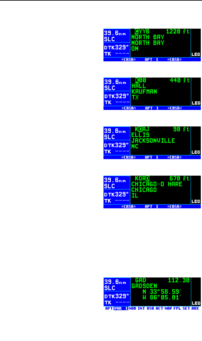
Airport pages but we’ll use the APT 1 since it displays the airport
name and city).
2. Turn on the cursor (B) and
make sure the right inner knob is
pushed in. The cursor will
appear over the first character of
the airport identifier (figure 3-62).
3. Turn the right inner knob to
select a “K” as the first character
(figure 3-63). You may turn the
knob either clockwise or counter-
clockwise, and the letters and
numbers wrap around with a
blank character separating the
“9” and the “A”. Notice that as
you turn through letters, the
KLN 94 automatically fills in the
identifier of the first waypoint in
alphanumeric order in the data-
base which matches what you’ve
entered so far (in this case, Hall
Airport in Kaufman, Texas). Go
ahead and experiment a little bit.
4. Use the right outer knob to move
the cursor to the second charac-
ter and then select an “O” with
the right inner knob (figure 3-64).
5. Use the same process to select
an “R” and then a “D” (figure 3-65). You are now viewing the APT 1
page for KORD.
The KLN 94 feature of filling in characters of the identifier can be a time
saver! For a second example, let’s select Bloomington VOR whose identi-
fier is BMI.
More selecting a waypoint by identifier:
1. Make sure you have turned the
cursor off from the previous
example. With the right knobs,
select the VOR 1 page (figure 3-
66).
2. Turn the cursor (B) on.
Chapter 3 Basic GPS Operation
3-22
Figure 3-62
Figure 3-63
Figure 3-64
Figure 3-65
Figure 3-66
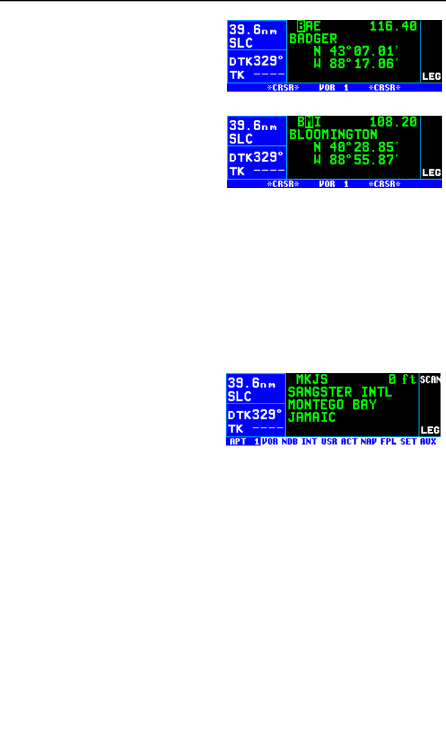
3. Change the first character to a
“B” (figure 3-67).
4. Move the cursor to the second
character and select “M” (figure
3-68). Eureka! When you
entered the “M”, the KLN 94
searched its database for the
first VOR identifier beginning
with the letters “BM” and found
BMI. Many times you will only
have to enter two or three char-
acters of the waypoint identifier
and the KLN 94 will furnish the rest.
5. Turn off the cursor (B).
3.8.2. SELECTING WAYPOINTS BY SCANNING
You may also select waypoints by scanning through them. This may be
done with the cursor either on or off.
To select a waypoint by scanning with the cursor off:
1. Select the page type for the
waypoint you are looking for
(APT, VOR, NDB, INT or USR).
2. Pull the right inner knob to the
“out” position. The SCAN
annunciator will appear (figure 3
– 69).
3. Turn the right inner knob clockwise to scan through the waypoints in
alphabetical order, or counterclockwise to scan in reverse alphabetical
order. Remember that numbers are considered lower in order than
letters. Thus, the airport identifier KA2 comes before KAAF.
NOTE: The faster you turn the knob while scanning, the larger the step
through the waypoints. This variable rate scanning allows you to get from
one end of the list to the other very quickly. When the knob is turned
slowly, you will go through the waypoints one at a time.
You may also want to scan waypoints with the cursor on. This is especial-
ly useful if you remember the first part of the identifier, or if you wanted to
scan all airports that start with a KL, for example. Let’s give it a try.
KLN 94 Pilot’s Guide Chapter 3 Basic GPS Operation
3-23
Figure 3-67
Figure 3-68
Figure 3-69
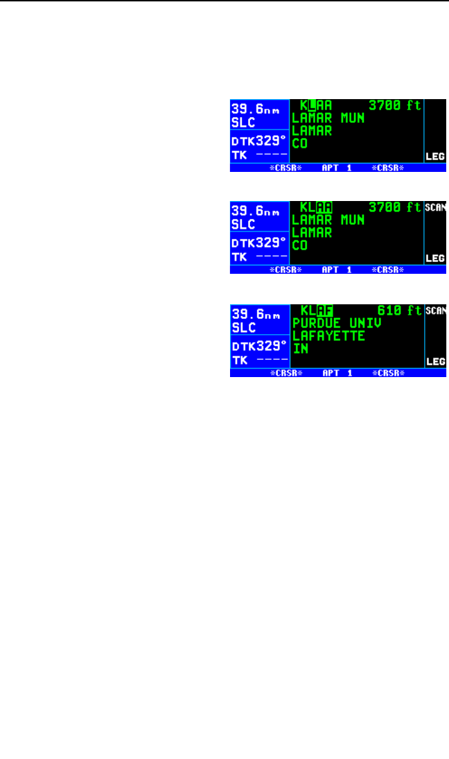
To select a waypoint by scanning with the cursor on:
1. Select the page type for the waypoint you are looking for (APT, VOR,
NDB, INT or USR). In this case, we want the APT 1 page.
2. Turn on the cursor (B). It will
appear over the first character of
the waypoint identifier. Select a
Kwith the right inner knob.
3. Move the cursor one place to the
right and select an L(figure 3-
70).
4. Move the cursor one place to the
right and pull the right inner knob
out. The cursor will by over the
last two characters of the way-
point identifier (figure 3-71).
5. Use the right inner knob to leaf
through all the database airports
whose identifiers begin with KL.
You will see KLAA, Lamar
Municipal in Lamar, CO, and
KLAF (figure 3-72), Purdue
University in Lafayette, IN
among others.
3.8.3. SELECTING WAYPOINTS BY NAME OR CITY
When you know the identifier of the desired waypoint you will use one of
the two methods just described to select it. However, what if you know
the name but you don’t know the identifier of your desired waypoint?
You’re in luck because the KLN 94 will allow you to enter the first few
characters of the name to help you find it in the database. We will use a
couple of examples to illustrate how this is done. For VORs and NDBs,
you may use the navaid name. For airports, you may use the airport
name or the city name (where the airport is located).
In this first example we want to view the information in the KLN 94 data-
base for Napoleon VOR (located just east of Kansas City) but we don’t
remember the identifier for it.
Chapter 3 Basic GPS Operation
3-24
Figure 3-70
Figure 3-71
Figure 3-72
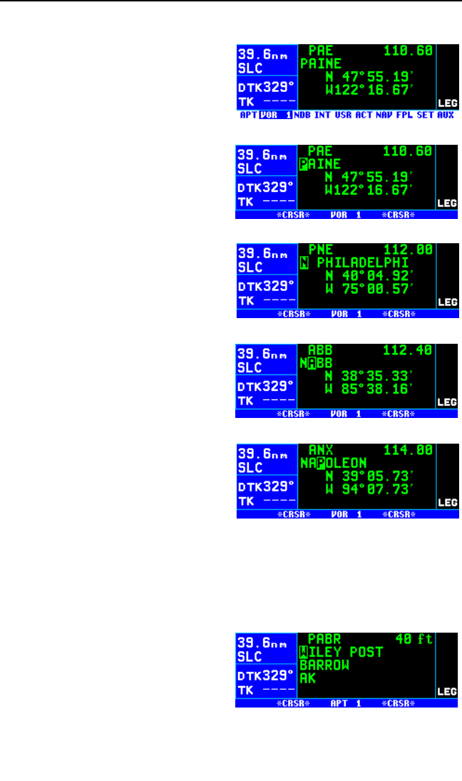
To select a VOR or NDB by navaid name:
1. With the cursor off, use the right
knobs to select the VOR 1 page
(figure 3-73). The VOR waypoint
in view is not important.
2. Press Band then make sure
the right inner knob is pushed to
the “in” position.
3. With the right outer knob, move
the cursor over the first charac-
ter in the VOR name which is
being displayed (figure 3-74).
4. Change this first character to an
“N” in this case (figure 3-75).
5. Move the cursor one space to
the right and select the second
character, “A” (figure 3-76).
6. Select the third character, “P”
(figure 3-77). Up pops Napoleon
and its identifier, ANX!
7. Turn off the cursor (B) so you
can view other pages.
We will now use another example to
show how we may enter a few char-
acters and then scan through all the
waypoints in the database beginning
with those characters. Let’s use this
method to find Newport News airport
in Newport News, VA.
To select an airport by scanning the airport name:
1. With the cursor off and the right inner knob in the “in” position, select
the APT (Airport) 1 page. The airport displayed at this time is not
important.
2. Turn on the cursor (B).
3. Move the cursor over the first
character in the airport name
(figure 3-78).
4. Change the first character to an “N”.
KLN 94 Pilot’s Guide Chapter 3 Basic GPS Operation
3-25
Figure 3-73
Figure 3-74
Figure 3-75
Figure 3-76
Figure 3-77
Figure 3-78
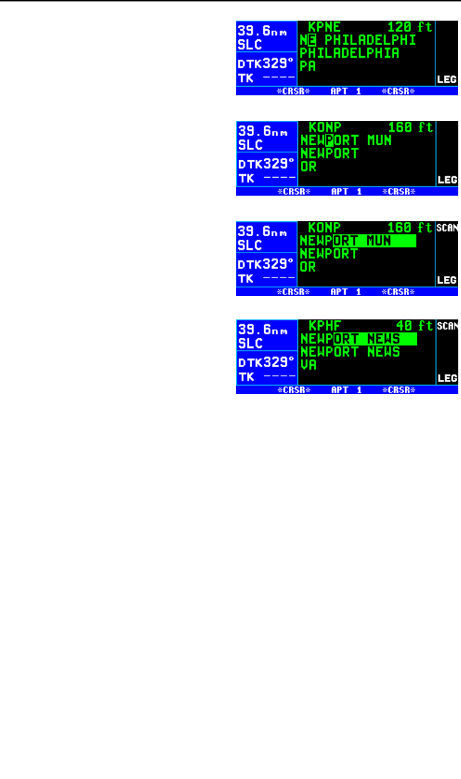
5. Move the cursor one place to the
right, and select an “E” (figure 3-
79).
6. Enter the “W” and “P” in a similar
manner (figure 3-80).
7. Now, move the cursor one place
to the right of the “P” and pull the
right inner knob out. The rest of
the airport name field will be in
reverse video (figure 3-81).
8. Turn the right inner knob clock-
wise, scanning through Newport
Municipal in Newport, OR; then
Newport Municipal in Newport,
AR; and then our desired
Newport News, in Newport
News, VA. whose identifier is
KPHF (figure 3-82). By turning
off the cursor (B), pushing the
right inner knob in and turning it,
you can leaf through the remain-
der of the pages for KPHF.
NOTE: This same method may be used with the name of the city where
the airport is located.
There are a few changes made to names in order to accommodate the
KLN 94 display and to make the names easier to find.
1. Names which are too long to fit on the display are abbreviated.
The first six characters are usually exactly correct, but the
following are exceptions:
North, Northern, East, Eastern, etc.—uses N, E
Southeast, Northwest, etc.—uses SE, NW
Point—uses PT
Port—uses PT
Fort—uses FT
Saint—uses ST
General—Deleted, or uses GEN
Person’s name—uses initials for other than last name
unless very well known (Will Rogers World airport)
Delete “City of” (City of Colorado Springs Municipal)
Delete “Greater” (Greater Buffalo Int’l)
Delete “The” (The Hartsfield Atlanta Int’l)
Chapter 3 Basic GPS Operation
3-26
Figure 3-79
Figure 3-80
Figure 3-81
Figure 3-82
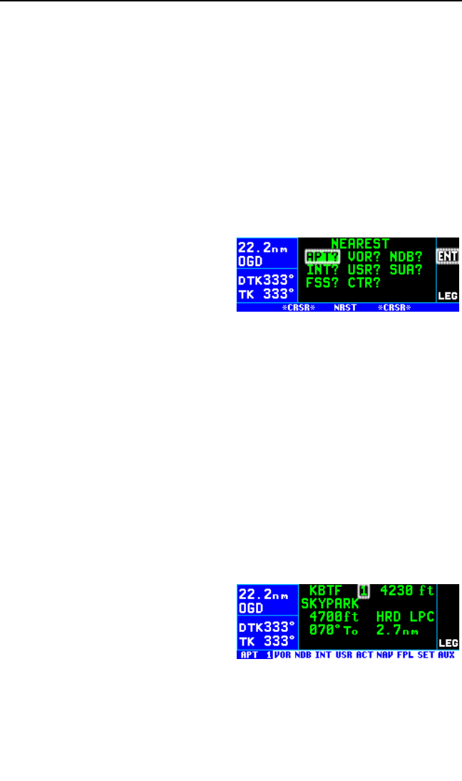
2. Unless the first word is greater than eight characters, it is usually
not abbreviated.
3. Delete most punctuation such as periods and apostrophes.
4. Abbreviations for International are INTL, INT, and IN.
5. Abbreviations for Regional are REGL and REG.
3.9. “NEAREST” FUNCTIONS
At any time, you can have access to the nearest airports, waypoints,
Special Use Airspace (SUA), Flight Service Station (FSS) frequencies,
and Center frequencies to your position. Your ticket to do this is the
handy Gbutton.
When you first press the Gbutton,
a page is displayed asking which
nearest function you would like to
select (figure 3-83). The choices
are:
APT Airports
VOR VORs
NDB NDBs
INT Intersections
USR User-defined waypoints
SUA Special Use Airspaces
FSS Flight Service Station Frequencies
CTR Center Frequencies
To select the desired nearest function, use the right outer knob to move
the cursor to the desired selection and press F. Notice that the cursor
is initially over the APT field, so you may press Gthen press Fimme-
diately to access the nearest airports.
Selecting any of the waypoint types
(APT, VOR, NDB, INT, or USR)
takes you immediately to the way-
point page for the first nearest
waypoint of that type, for example,
the nearest airport (figure 3-84). The
right inner knob may be pulled to the
“out” position and the inner knob used to scan through the other nearest
waypoints in the list.
KLN 94 Pilot’s Guide Chapter 3 Basic GPS Operation
3-27
Figure 3-83
Figure 3-84
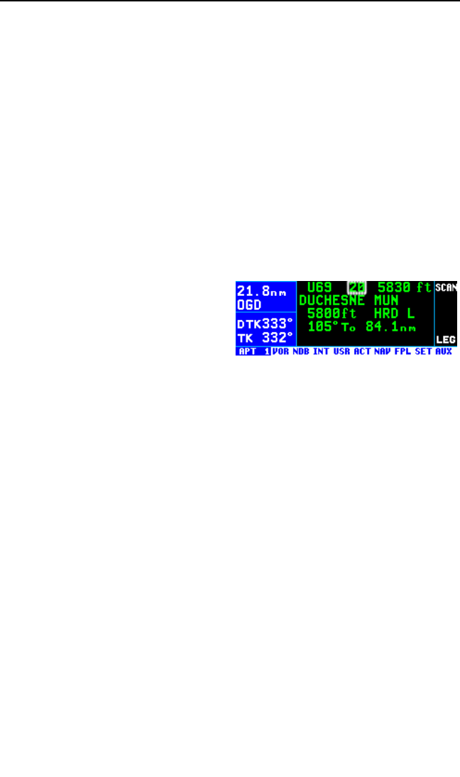
3.9.1. VIEWING THE NEAREST WAYPOINTS
There are actually two waypoint scan lists for airports, VORs, NDBs, inter-
sections and user-defined waypoints. These two lists are the “complete”
list and the “nearest” list. The complete list contains all of the waypoints in
the database for a waypoint type (all the airports, for example). The near-
est list consists of the 20 nearest waypoints (of that type) to your present
position. Therefore, if you are in the nearest airport list, it will contain the
20 nearest airports relative to your location.
The nearest list is positioned in front of the complete list. That is, instead
of using the Gbutton, you may also scan backwards (turn the right inner
knob counterclockwise while in the “pulled out” position) through the com-
plete list to reach the nearest list. You will know when you have reached
the nearest list because the top middle portion of the waypoint page will
flash the relative position of the waypoint to your position. “1” indicates
nearest (figure 3-84) while “20” indicates the twentieth nearest (figure 3-
85). As you scan clockwise with the
right inner knob “1, 2, 3, ..., 20”, the
next scan position is the beginning of
the complete list. The nearest list can
only be reached by scanning back-
wards. It does not wrap around after
the last waypoint in the complete list.
Waypoint pages displayed in the nearest list do not contain a latitude and
longitude position as they do in the complete list. Instead, the bearing and
distance to the waypoint (or the radial and distance from the waypoint) are
displayed. In addition, nearest airport pages display the length, surface,
and lighting of the longest runway. Once the nearest waypoint is being
displayed, the other waypoint pages (for example, APT 2 and APT 3) for
that airport are available for display by making sure the right inner knob is
pushed in and then turning it to select the desired airport page.
The nearest list is limited to 200 NM of the aircraft’s present position for all
nearest items except for special use airspace (SUA) which is limited to
175 NM.
3.9.1.1 Nearest Airport Criteria
The 20 airports in the nearest list are the 20 airports which meet the crite-
ria selected on the Setup 4 (SET 4) page. For example, you probably
wouldn’t want to take a turboprop into a 1500 foot grass strip! The SET 4
page allows you to specify what criteria you want an airport to meet before
it is considered for the nearest airport list.
Chapter 3 Basic GPS Operation
3-28
Figure 3-85

To specify the nearest airport criteria:
1. Select the SET 4 page and turn on the cursor (B).
2. Use the right inner knob to
select the minimum length run-
way desired for the airport to
qualify for the nearest airport list
(figure 3-86). Values between
1000 feet and 5000 feet or
between 300m and 1500m in
100 foot or meter increments may be selected.
3. Rotate the right outer knob clockwise to move the cursor over the run-
way surface criteria.
4. Turn the right inner knob to select either HRD or ANY. If ANY is cho-
sen, then both hard and soft surface runways meeting the required
runway length will be included in the nearest airport list. If HRD is
chosen, then only hard surface runways will be included. Hard surface
runways include concrete, asphalt, pavement, tarmac, brick, bitumen,
and sealed. Soft surface runways include turf, gravel, clay, sand, dirt,
ice, steel matting, shale, and snow.
For example, if the minimum runway criteria selected is 2200 feet in length
and HRD surface, then only airport having a hard surface runway at least
2200 feet in length will be displayed in the nearest airport list.
3.9.1.2 Continuous Display of Nearest Airport
When the nearest airport page is initially displayed, “1” is displayed imme-
diately to the right of the airport identifier to designate this airport as the
nearest airport. However, if you continue to fly along your flight plan with
this page selected, the same airport will be displayed and its position in
the nearest airport list will change from 1to 2, 3, 4... 20 until finally it won’t
be in the nearest airport list at all. The reason for this is that in the event
of an actual emergency once you have determined which airport you are
heading for, you don’t want the nearest airport list to update while you are
maneuvering or looking up data on the other airport pages for that airport.
There may be times, however, when you’re flying over “unfriendly” terrain
when you wish to always have the nearest airport displayed on the
screen.
To display the nearest airport continuously:
1. Display the nearest airport page by pressing Gfollowed by pressing
F.
2. Turn on the cursor (B).
KLN 94 Pilot’s Guide Chapter 3 Basic GPS Operation
3-29
Figure 3-86
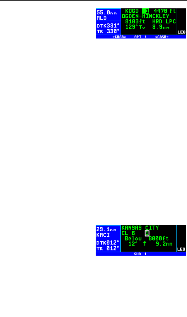
3. Rotate the right outer knob
clockwise to position the cursor
over “1” (figure 3-87). As long as
the cursor is left in this position,
this page will update so that the
nearest airport is always shown
as the flight progresses.
3.9.2. VIEWING THE NEAREST SPECIAL USE AIRSPACES
The KLN 94 database stores the locations of areas of special use air-
space (SUA). The types of SUA areas stored in the database and the
abbreviations used to denote these areas are the following:
Class B CL B
Class C CL C
Control Area (used outside USA) CTA
Terminal Area (used outside USA) TMA
Alert Area ALRT
Caution Area CAUT
Danger Area DNGR
Military Operations Area MOA
Prohibited Area PROH
Restricted Area REST
Training Area TRNG
Warning Area WARN
Terminal Radar Service Area TRSA
The nearest special use airspace feature is constantly keeping track of the
10 nearest areas of SUA within 175 NM of the aircraft’s present position.
Pressing the Gbutton and selecting the SUA option will display the
SUA 1 page for the nearest SUA to your location, including those which
you are inside (figure 3-88). Turn to
section 3.13 “Special Use Airspace
Alerting” to learn more about how an
altitude input affects special use air-
space sensing and how the KLN 94
determines if you are inside special
use airspace or not.
The SUA 1 page displays the following information:
Line 1: The name of the special use airspace area.
Line 2: The SUA type (see the list of abbreviations above, this particular
SUA is Class B airspace), and the sequence number (1st nearest, 2nd
nearest, etc.).
Chapter 3 Basic GPS Operation
3-30
Figure 3-87
Figure 3-88
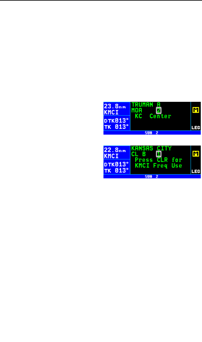
Line 3: The altitude limits of the SUA.
Line 4: The proximity of the nearest point on the border of the SUA, in the
form of the absolute bearing, relative bearing, and distance to the SUA
border. The absolute bearing is the approximate heading you would fly to
most quickly get into the SUA. The relative bearing arrow in the middle of
this line points to the SUA border, telling you if it is directly ahead of you
(↑), straight off your left wing (←), etc. The bearing and distance are not
displayed if the aircraft is inside, above or below an SUA. Finally, the dis-
tance to the SUA is displayed on the right side of line 4.
If the aircraft is inside the SUA, line 4 will read *A/C INSIDE SUA*, if you
are above or below the SUA, as indicated by the encoding altimeter, line 4
will indicate this (*A/C ABOVE SUA* or *A/C BELOW SUA*).
A single clockwise turn of the right
inner knob selects the SUA 2 page,
which displays either the controlling
ATC facility (figure 3-89), or if the
special use airspace is a Class B,
Class C, CTA, or TMA, the page will
be displayed as in figure 3-90,
instructing you to press Eto see
the APT 5 page (airport communica-
tions) for the primary airport so that
the correct communications frequen-
cy may be determined.
To scan through the remainder of the nearest SUA areas, pull the right
inner knob to the “out” position and turn it clockwise to view the SUA
pages for the second nearest through tenth nearest SUAs.
NOTE: The KLN 94 displays the ten nearest SUAs regardless of your
present altitude and the altitude limits of the SUA. For instance, it will
include SUAs specified as “Below 6000ft” even if you are cruising at
10,000 feet.
3.9.3. VIEWING THE NEAREST FLIGHT SERVICE STATION
FREQUENCIES
The KLN 94 stores in its database the locations of Flight Service Stations
(FSS) and their remote communications sites. In addition, the KLN 94
determines which two of these FSS points of communication are closest
to your present location. What a convenience for you! Next time you
want to file a flight plan from the air or contact an FSS for some other rea-
son, you can easily use the KLN 94 to determine a suitable FSS and the
appropriate frequency.
KLN 94 Pilot’s Guide Chapter 3 Basic GPS Operation
3-31
Figure 3-89
Figure 3-90
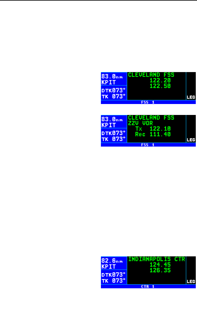
NOTE: In some areas of the world the KLN 94 provides the location of
the nearest point of communication with a facility providing information
(INF) or radio (RDO) services.
Pressing the Gbutton and selecting the FSS option will display two of
the nearest points of communication with Flight Service Stations. There
will normally be two FSS 1 pages, one for each of the two points of con-
tact. The name of the FSS is at the top of the page. There can be from
one to three frequencies included for a point of contact (figure 3-91).
Remember that in the U.S. the fre-
quency 122.00 MHz is used for
“Flight Watch” and the frequency
123.60 MHz is used for Aeronautical
Advisory Service. As you know, it is
often possible to communicate with
an FSS by transmitting on 122.10
MHz and listening on the VOR fre-
quency. In cases like this, the FSS 1
page displays the frequencies to use
for transmit and receive and also the
name of the VOR through which you
are communicating (figure 3-92).
The frequencies displayed on the nearest FSS page are QuickTuneTM fre-
quencies. When the cursor is positioned over a frequency displayed on
this page and the Fbutton is pressed, the frequency is automatically
inserted into the standby window of a Bendix/King KX 155A or KX 165A
Nav/Comm. (QuickTuneTM must be enabled in the installation for this to be
operational). QuickTuneTM is described in section 3.15.
3.9.4. VIEWING THE NEAREST CENTER FREQUENCIES
The KLN 94 also stores in its database the low altitude transmitter loca-
tions of each of the ARTCC “Centers”. The KLN 94 determines the proper
Center to contact and the appropriate frequencies to use for the aircraft’s
present position. Pressing the Gbutton and selecting the CTR option
will display this information to you (figure 3-93). Next time you wish to
obtain VFR flight following or com-
municate with Center for any reason,
you have a quick way to get a fre-
quency for establishing contact!
Appendix D contains a listing of
Center abbreviations used on the
CTR page.
NOTE: Frequencies for Area Control Centers are displayed on the CTR
page for some areas of the world.
Chapter 3 Basic GPS Operation
3-32
Figure 3-91
Figure 3-92
Figure 3-93

The frequencies displayed on the nearest Center page are QuickTuneTM
frequencies. When the cursor is positioned over a frequency displayed on
this page and the Fbutton is pressed, the frequency is automatically
inserted into the standby window of a Bendix/King KX 155A or KX 165A
Nav/Comm. (QuickTuneTM must be enabled in the installation for this to be
operational). QuickTuneTM is described in section 3.15.
3.10. DIRECT TO OPERATION
The Dbutton is used to initiate Direct To operation (navigation from
your present position direct to your destination). When Dis pressed, the
Direct To page will be displayed with
a flashing cursor over a waypoint
identifier (figure 3-94). The waypoint
identifier which appears on the
Direct To page is chosen by the
KLN 94 according to the following
rules:
1. If the Flight Plan 0 (FPL 0) page is displayed on the screen and the
cursor is over one of the waypoint identifiers in FPL 0 when Dis
pressed, then that waypoint identifier will appear on the DIR page.
You will appreciate this feature when you learn to use flight plans in
section 4.2.
2. If the KLN 94 is displaying the NAV 4 page and the right inner knob is
in the “out” position, then the waypoint highlighted in the lower right
hand corner of the NAV 4 map display will be the default waypoint.
You will also find this feature useful when operating from the active
flight plan especially during approaches with the KLN 94.
OR . . .
3. If there is any waypoint page (APT, VOR, NDB, INT, USR, or ACT
page) in view when Dis pressed, then the DIR page will contain the
identifier for the waypoint just viewed.
If none of the conditions above are occurring, then:
4. When Dis pressed, the waypoint identifier for the current active
waypoint will be displayed. However, if the KLN 94’s active waypoint
is the Missed Approach Point and the aircraft has flown past the MAP,
then the KLN 94 will display the first waypoint of the missed approach
procedure on the Direct To page.
If there is no active waypoint when Dis pressed, then:
5. The Direct To page displays a blank cursor field. In order for there not
to be an active waypoint, there is no Direct To waypoint and there are
no waypoints in Flight Plan 0.
KLN 94 Pilot’s Guide Chapter 3 Basic GPS Operation
3-33
Figure 3-94
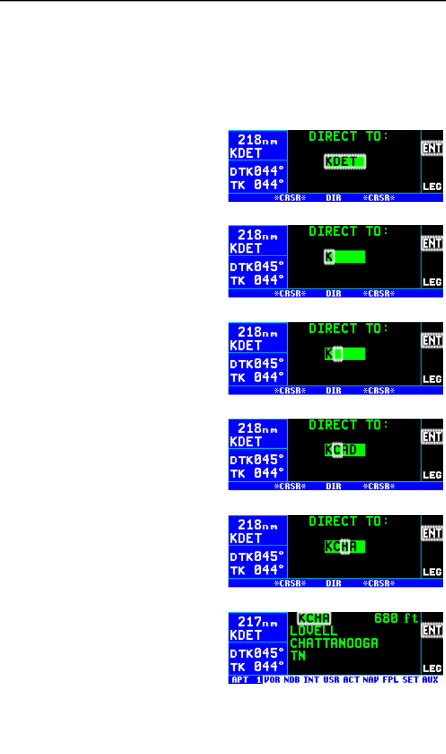
3.10.1. INITIATING A DIRECT TO
Now that you know the ground rules, let’s go ahead and try some practical
examples. First, let’s say we wanted to fly directly to Lovell Airport in
Chattanooga, TN. Its ICAO identifier is KCHA.
To fly Direct To a waypoint (procedure 1):
1. Press D. The Direct To page
is displayed (figure 3-95). The
cursor will already be on. A way-
point identifier may or may not
be displayed, it doesn’t matter at
this point.
2. Rotate the right inner knob to
select the first character of the
desired waypoint’s identifier, in
this case, a “K” (figure 3-96).
Remember to enter the “K”, “C”,
or “P” prefix for certain airports in
North America, if required (see
section 2.3, “ICAO Identifiers”).
3. Turn the right outer knob one
click clockwise to move the
flashing portion of the cursor
over the second character posi-
tion (figure 3-97).
4. Rotate the right inner knob to
select the second character of
the identifier (figure 3-98).
5. Use the right outer and inner
knobs as in the previous steps
until the desired identifier is com-
pletely displayed (figure 3-99).
6. Press Fto display the way-
point page for the selected
waypoint (figure 3-100).
Chapter 3 Basic GPS Operation
3-34
Figure 3-95
Figure 3-96
Figure 3-97
Figure 3-98
Figure 3-99
Figure 3-100
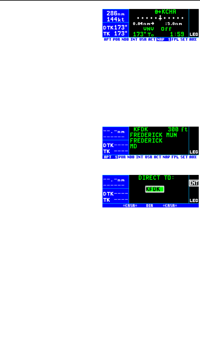
7. Press Fagain to approve the
displayed waypoint page. The
screen will change to the NAV 1
page, and the selected waypoint
will now be the active Direct To
waypoint (figure 3-101).
NOTE: In some cases during approach operations, the KLN 94 presents a
page asking how a waypoint is used when the waypoint identifier is
entered character by character. When this page is presented, simply
choose the desired use of the waypoint (e.g. FAF or MAHP) by moving
the cursor with the right outer knob and pressing F. Choosing the cor-
rect use of the waypoint is required to ensure proper waypoint sequencing
once the aircraft reaches the waypoint.
To fly Direct To a waypoint (procedure 2):
1. Select the desired waypoint
page (APT, VOR, NDB, INT, or
USR) on the screen (figure 3-
102) using one of the three
procedures explained in section
3.8.
2. Press D. The Direct To page
is displayed and it contains the
desired waypoint identifier (fig-
ure 3-103).
3 Press F. The display will
revert to the NAV 1 page with
the selected waypoint as the
Direct To waypoint.
NOTE: There are additional means of more efficiently initiating Direct To
operation when operating from a flight plan. See sections 3.11.4, section
4.2.4.2, and section 4.2.4.3.
To recenter the D-Bar by going direct to the active waypoint:
If you get off course and wish to recenter the left/right deviation bar (D-
Bar) to proceed to the same waypoint, use the following procedure.
1. Select a non-waypoint page (NAV, FPL, SET, or AUX) on the screen.
2. Press D. The Direct To page is displayed on the left, containing the
active waypoint identifier.
3. Press F.
KLN 94 Pilot’s Guide Chapter 3 Basic GPS Operation
3-35
Figure 3-101
Figure 3-102
Figure 3-103
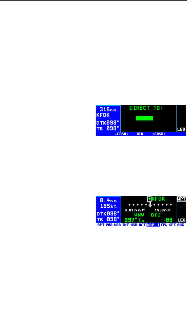
NOTE: If the KLN 94 is in the approach mode and this method is used to
center the D-bar when the missed approach point is the active waypoint,
then the approach mode will be cancelled and the KLN 94B will revert to
the approach arm mode.
3.10.2. CANCELLING A DIRECT TO
The primary reason for wanting to cancel Direct To operation is to return
to flight plan operation which is described later in section 4.2.4 “Combining
Direct To and Flight Plan Operation”. When the Direct To operation is
cancelled the KLN 94 orients itself on the closest leg of the active flight
plan (FPL 0).
To cancel Direct To operation:
1. Press D.
2. Press Eto blank out the way-
point identifier field (figure
3-104).
3. Press F.
3.10.3. WAYPOINT ALERTING FOR DIRECT TO OPERATION
The purpose of waypoint alerting is to notify you that you are approaching
the active waypoint (the Direct To waypoint in this case). Approximately
36 seconds prior to reaching a Direct To waypoint the WPT annunciation
at the top of the annunciation display segment will begin flashing (figure 3-
105). If an external waypoint alert (WPT) annunciator is mounted in the
aircraft, this annunciator will begin
flashing at the same time. In addi-
tion, the arrow preceding the
waypoint identifier on the waypoint
page for the active waypoint will
begin flashing. This arrow will also
be flashing on any NAV or FPL page
displaying the active waypoint identifier.
Chapter 3 Basic GPS Operation
3-36
Figure 3-104
Figure 3-105
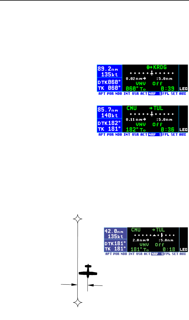
3.11. NAVIGATION PAGES
As you would expect, the NAV (navigation) pages contain information
relating specifically to the KLN 94’s navigation capabilities. The KLN 94
has four NAV pages. The procedure for selecting specific pages, including
the NAV pages, was described in section 3.4.1, “Page Selection”.
3.11.1. THE NAVIGATION 1 (NAV 1) PAGE
The NAV 1 page is shown in figure
3-106.
Line 1: The active navigation leg.
For Direct To operation this consists
of the Direct To symbol, $, followed
by the active Direct To waypoint
identifier (figure 3-106). For the leg of
a flight plan this consists of the
“from” waypoint identifier and the
active “to” waypoint identifier (figure
3-107). An arrow ∆precedes the
active waypoint identifier.
Line 2: A course deviation indicator (CDI) that graphically displays left
and right deviation from desired course. The CDI’s vertical bar operates
like a navigation deviation needle on a conventional CDI or HSI using
VOR/Localizer navigation. An on-course indication is displayed when the
vertical deviation bar is centered on the triangle in the middle of the CDI.
In en route use, each dot represents one nautical mile deviation from the
desired track (full scale deviation is ± 5 NM). Different CDI scales are used
during terminal and non-precision approach flight with KLN 94. For now,
let’s talk only about en route operations. A vertical deviation bar posi-
tioned two dots to the
right of the center tri-
angle indicates the
aircraft is two nautical
miles to the left of
course (figure 3-108).
The center triangle
also serves as the
CDI’s TO/FROM indi-
cator and operates in
the same manner as a
conventional CDI
TO/FROM indicator; a
triangle pointing up
indicates “to” the
KLN 94 Pilot’s Guide Chapter 3 Basic GPS Operation
3-37
Figure 3-106
Figure 3-107
TUL
CNU
2 NM
Figure 3-108
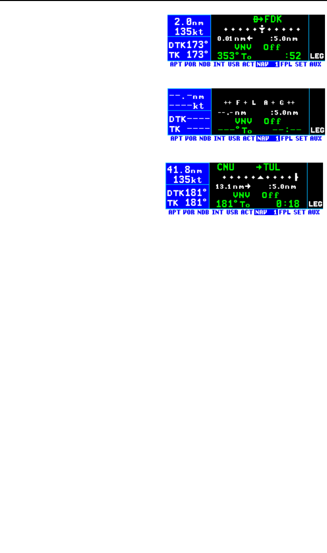
active waypoint while a “down” trian-
gle (figure 3-109) indicates “from” the
active waypoint. The word FLAG is
displayed over the CDI when the
KLN 94 is not usable for navigation
(figure 3-110).
Line 3: Numeric crosstrack correc-
tion – the crosstrack distance (how
far off course) and direction to fly to
intercept the desired track. The
numeric crosstrack correction dis-
tance display is especially handy
when more than five nautical miles
off of course. If your crosstrack dis-
tance was 13.1 nautical miles left of
course, the graphic CDI needle will
be pegged on the right side (which
doesn’t tell you much). But this pre-
sentation will show you exactly how
far off course you are (figure 3-111).
The CDI scale factor is also displayed on line 3. This is the full scale devi-
ation. Normal en route CDI scale factor is ± 5 NM which means each dot
represents 1 NM of deviation off course. The CDI scale factor may be
changed as described in section 5.6. “Changing The CDI Scale Factor.”
Line 4: VNAV status, which will either by Off, Armed, time until VNAV
begins, or the suggested VNAV altitude (see section 5.2. “Advisory VNAV
Operation.”
Line 5: A data field which can display either bearing to the active way-
point (To) or radial from the active waypoint (Fr). By placing the cursor
over this field and turning the right inner knob you may select which of
these is displayed. Line 5 also displays the estimated time en route (ETE)
from present position to active waypoint.
NOTE: Due to “great circle” courses and magnetic variation differences
between present position and the active waypoint, the To bearing and
From radial may not be exactly 180° different from each other when the
system is in the Leg mode. This condition is most likely to occur when
long distances are involved, and/or you are operating in very northerly or
southerly latitudes. See figure 3-112 for an example depicting a case like
this. The aircraft is somewhere over Georgia, and the active waypoint is
KPHX. The bearing to steer is 269°, and radial is 72°. Generally, you will
want to use bearing (not radial) when long distances are involved.
Chapter 3 Basic GPS Operation
3-38
Figure 3-110
Figure 3-111
Figure 3-109
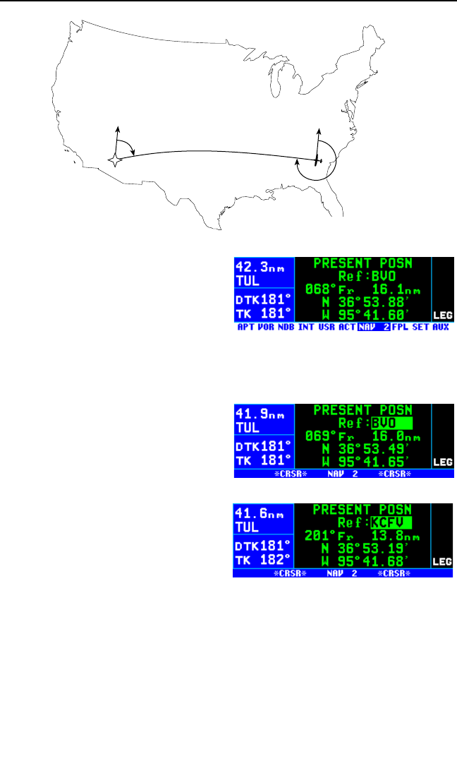
3.11.2. THE NAVIGATION 2 (NAV 2) PAGE
The NAV 2 page in figure 3-113 dis-
plays the aircraft’s present position in
two formats: (1) the radial and dis-
tance from a nearby VOR and (2)
latitude and longitude. You can
change the reference waypoint from
the nearby VOR to any waypoint in the published or user database.
To change the NAV 2 page present position reference waypoint:
1. Turn on the cursor (B). It will
be over the Ref: field (figure 3-
114).
2. Use the right inner and outer
knobs to enter the waypoint you
wish to use as a reference.
3. Press F. The waypoint page
for the identifier just entered will
be displayed.
4. If this is the waypoint you intend-
ed, press Fagain. The
display will return to the NAV 2 page (figure 3-115).
NOTE: If you change the reference waypoint, change to a page other than
the NAV 2 page, then turn back to the NAV 2 page, the reference way-
point will revert back to a nearby VOR.
NOTE: Your present position may be easily stored as a user-defined way-
point by pressing Fwhile viewing the NAV 2 page. See section 5.4.1,
“Creating A Waypoint At Your Present Position.”
KLN 94 Pilot’s Guide Chapter 3 Basic GPS Operation
3-39
NN
KPHX
72°
269°
Figure 3-112
Figure 3-113
Figure 3-114
Figure 3-115

3.11.3. THE NAVIGATION 3 (NAV 3) PAGE
The Navigation (NAV) 3 page shows
you several important times pertain-
ing to your flight (figure 3-116).
Line 1: The current system time
zone and the actual time. The time
zone may be changed by turning the cursor (B) on over it and turning
the right inner knob. All times shown on the NAV 3 page are in terms of
the system time zone (except for the flight time and ETE, which are peri-
ods of time).
Line 2: The time of departure. This is the time when a valid groundspeed
was first greater than 30 knots (typically during takeoff).
Line 3: The elapsed flight time, which will be the hours and minutes since
the departure time.
Line 4: The estimated time en route to the destination.
Line 5: Estimated time of arrival (ETA) at your destination. If the active
waypoint is not part of the active flight plan, the active waypoint will be the
destination. Otherwise, the last waypoint in your active flight plan will be
the destination.
3.11.4. THE NAVIGATION 4 (NAV 4) PAGE – MOVING MAP
The NAV 4 page is a graphical moving map which offers you excellent
“bird’s-eye-view” situational awareness. This page shows the aircraft’s
present position relative to the route of flight, aeronautical data, and carto-
graphic (land) data. The aeronautical data includes things like airports,
VORs, NDBs, intersections, and special use airspace. Land data includes
items such as cities, roads, bodies of water, geographical boundaries,
obstacles, and railroad tracks. User waypoints may also be displayed on
the map.
CAUTION: There are land data items that may not be dispayed on the
map or may not be displayed accurately in position. Do not depend
on the land data displayed on the map as the sole means of identify-
ing or avoiding land data items.
3.11.4.1 Selecting The NAV 4 (Map) Page
In addition to the normal way of selecting pages with the right knobs, the
NAV 4 page may be instantly displayed by pressing either the map range
(R) button or the map menu (M) button. Once the NAV 4 page is dis-
played these buttons are used to change the map scale and to bring up
the map menu, respectively.
Chapter 3 Basic GPS Operation
3-40
Figure 3-116
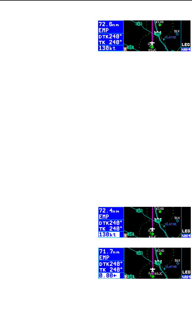
3.11.4.2 NAV 4 Page Format
The NAV 4 page has a unique for-
mat unlike any other KLN 94 page
(figure 3-117). The page bar is
removed on the NAV 4 page to uti-
lize the maximum screen height for
the map. The page being displayed,
NAV 4, is shown in the bottom right
corner of the screen.
Display segment one, on the far left side of the screen, now has five lines
rather than four lines on the other pages. It displays the following:
• Line 1 - Distance to the active waypoint
• Line 2 - Active waypoint identifier
• Line 3 - Desired track (DTK) in the LEG mode or OBS course in the
OBS mode. The DTK value flashes if the course selected on the
external CDI or HSI differs from the desired track by more than 10
degrees.
• Line 4 - Actual track (TK), bearing to active waypoint (BRG), radial
from active waypoint (RAD), or groundspeed
• Line 5 - Groundspeed, estimated time en route (ETE) to active way-
point, cross track error, or vertical navigation (VNAV) status
Lines 4 and 5 can be configured by the pilot to display any of the items
listed.
To configure lines 4 and 5 to display the desired Navigation items:
1. Press Bto turn on the cursor.
2. Rotate the right outer knob coun-
terclockwise to position the
cursor over the desired line (fig-
ure 3-118)
3. Rotate the right inner knob to
select the desired item (figure 3-
119).
4. Press Bto turn off the cursor
when done
KLN 94 Pilot’s Guide Chapter 3 Basic GPS Operation
3-41
Figure 3-117
Figure 3-118
Figure 3-119

3.11.4.3. Selecting What Is Shown On The Map
The aircraft’s present position symbol and route of flight are always select-
ed for display on the map. The map range scale will determine how much
of the route is displayed.
When operating Direct To a waypoint which is not in the active flight plan,
the Direct To waypoint and its associated course line are shown on the
map, and although the waypoints of
the active flight plan (FPL 0) are
shown on the screen, they are not
connected by course lines (figure 3-
120).
When you are navigating with a flight
plan the NAV 4 page displays the
waypoints of the active flight plan
with their waypoint identifiers (figure
3-121). Course lines connect the
flight plan waypoints. The course line
to the active waypoint is magenta,
other course lines are white.
Other items of interest to the pilot may also be selected for display on the
map. These fall into two basic categories, aeronautical (aero) data and
land data. It would be easy to put so much on the map that it is impossi-
ble to read. Therefore it is important to configure the map to display those
items which are most important to you.
3.11.4.4. Configuring Aeronautical Data For The Map
The SET 7 page is used to configure the aeronautical data for the map.
The following items may be configured on this page:
• Nearest 10 areas of special use airspace (SUA) within 175 NM of
the aircraft. Only those SUA types selected on the SET 6 page will
be displayed. See section 3.13 “Special Use Airspace Alerting.”
Inner rings for Class B, Class C, TMA and CTA airspace are dis-
played up to the 30 NM range (ORS 03 and higher units).
• Nearest 20 VORs within 200 NM of the aircraft
• Nearest 20 airports (APT) within 200 NM of the aircraft. Only those
airports meeting the criteria selected on the SET 4 page are dis-
played.
• Nearest 20 intersections (INT) within 200 NM of the aircraft. (The
default setting for intersections is “OFF” to avoid clutter. This may
be changed as described below.)
• Nearest 20 NDBs within 200 NM of the aircraft
Chapter 3 Basic GPS Operation
3-42
Figure 3-121
Figure 3-120
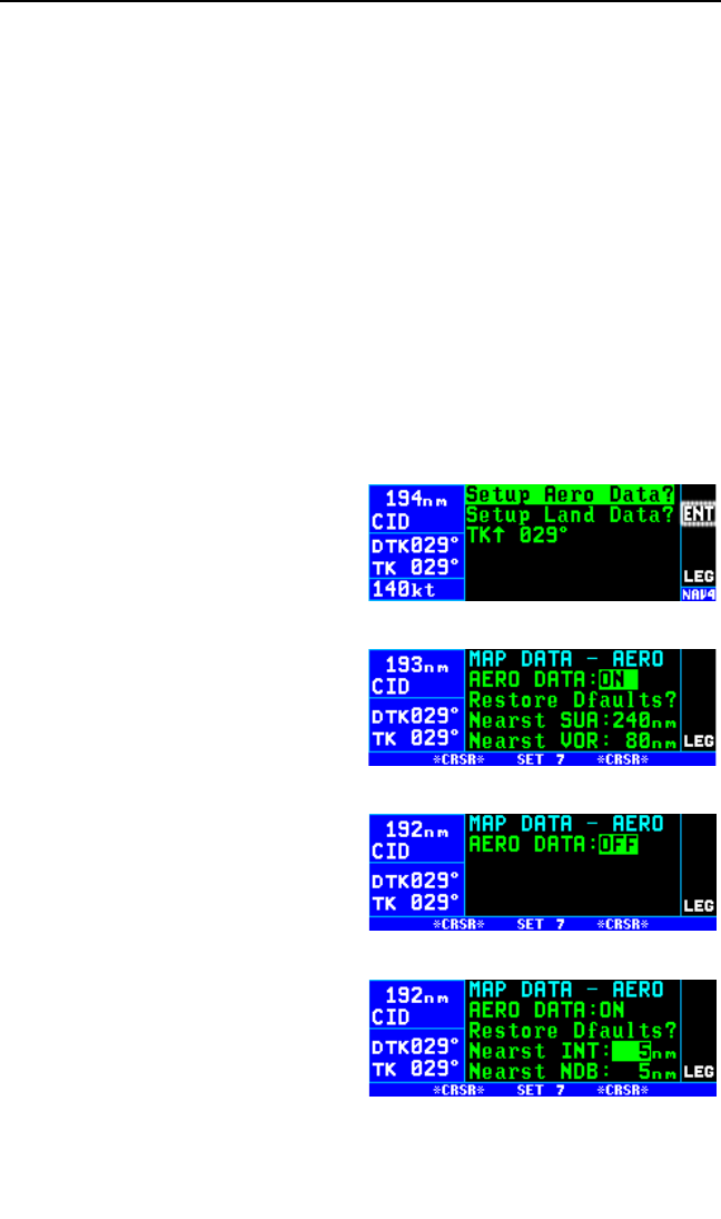
• Nearest 20 user defined waypoints (USR) within 200 NM of the air-
craft
• Tower rings (TWR Rings). A tower ring is a 4 NM radius circle
drawn around airports having a control tower that operates at least
part time. Note that a tower ring is not Class D airspace which
usually consists of a 3 to 7 NM radius ring plus additional
extensions. Tower rings are not displayed for the primary airport
associated with class B, class C, CTA, or TMA airspace.
• Holding Patterns and Procedure Turns (Hold Pat) associated with
approaches, DPs and STARs. (ORS 02 and higher)
Each of the above items may be turned on or off individually. The item is
turned on by selecting the maximum map range scale you want the item
to be displayed. Therefore if the 5 NM map range scale is selected for
intersections, the intersections will be displayed on the map for range
scales 5 NM and smaller and will not be displayed on the map for range
scales greater than 5 NM.
To configure aeronautical data for the map:
1. Press the Mbutton while view-
ing the NAV 4 map page to bring
up the map menu. The cursor
will already be over “Setup Aero
Data?” (figure 3-122).
2. Press the Fbutton. This
brings up the SET 7 page (figure
3-123).
NOTE: All aeronautical data may
be turned off by using the right outer
knob to position the cursor over the
field to the right of “AERO DATA: “
and then using the right inner knob
to select “OFF” (figure 3-124).
3. Use the right outer knob to posi-
tion the cursor over the field next
to the item to be configured.
Lines 4 and 5 are a scrolling
region so after positioning the
cursor over the VOR field, fur-
ther clockwise turns of the knob
will scroll down the list. To con-
figure intersections, position the
cursor over the distance field to
the right of INT (figure 3-125).
KLN 94 Pilot’s Guide Chapter 3 Basic GPS Operation
3-43
Figure 3-122
Figure 3-123
Figure 3-124
Figure 3-125

4. Rotate the right inner knob to
select the desired range (figure
3-126). Range scales greater
than that selected will not display
the selected item. Range scales
equal to or less than that select-
ed will display the item.
5. Use the right inner and outer knobs to finish configuring the rest of the
aeronautical items for the map.
6. Press the Rbutton or Mbutton to return to the map.
NOTE: Each aeronautical item has a factory set default range value. To
change an individual item to the default value place the cursor over the
range field to the right of the desired item and press the Ebutton. To
change all aeronautical items to their default ranges, place the cursor over
“Restore Dfaults?” on line 3 and press the Fbutton.
3.11.4.5. Runway Diagrams
If the selected map range scale is 5 NM (7 km) or less, runway diagrams
are depicted along with the airport symbol.
3.11.4.6. Configuring Land Data On The Map
The SET 8 page is used to configure the land data for the map. The fol-
lowing items may be configured on this page:
• Cities/towns – large, medium, and small
• Roads – freeways, national highways, local highways
• Lakes and Rivers
• Railroads
• Geographical boundary lines
• Obstacles – towers less than1000 ft. AGL and those 1000 ft. AGL
and greater
NOTE: At the time this Pilot’s Guide was written, obstacle data is only
available for the United States.
Each of the above items may be turned on or off individually. The item is
turned on by selected the maximum map range scale you want the item to
be displayed.
Chapter 3 Basic GPS Operation
3-44
Figure 3-126
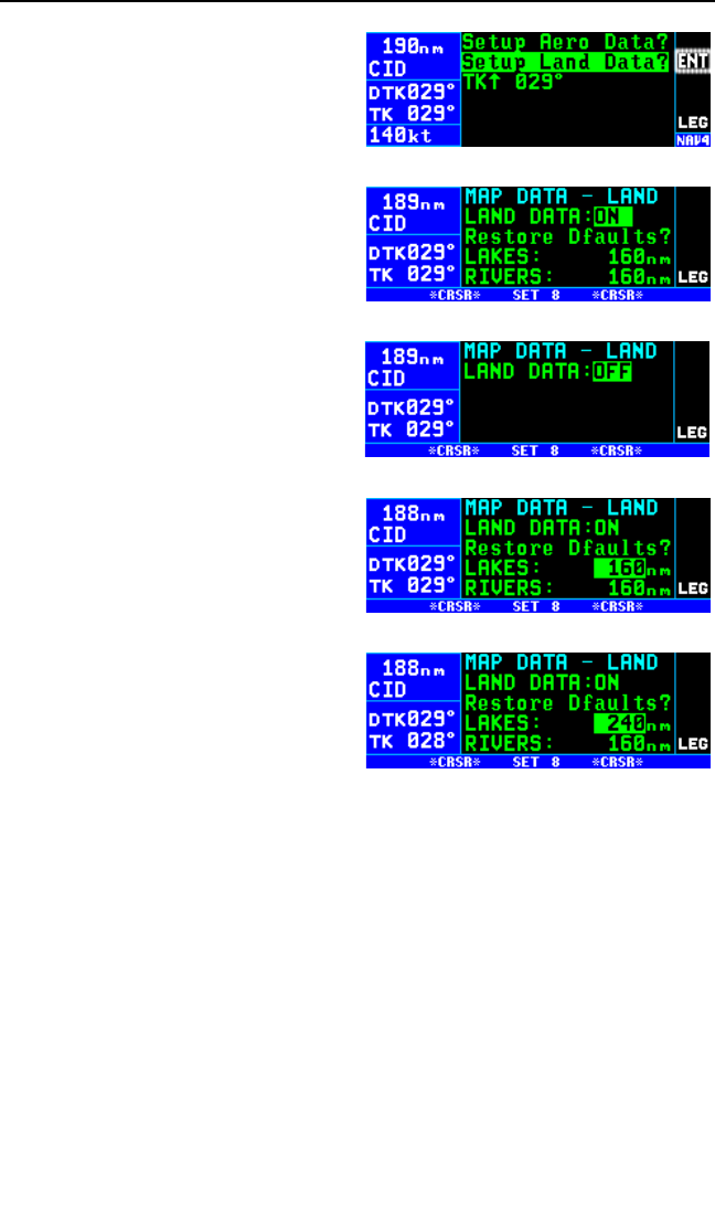
To configure land data for the map:
1. Press the Mbutton while view-
ing the NAV 4 map page to bring
up the map menu.
2. Turn the right outer knob clock-
wise to position the cursor over
“Setup Land Data?” (figure 3-
127).
3. Press the Fbutton. This
brings up the SET 8 page (figure
3-128).
NOTE: All land data may be turned
off by using the right outer knob to
position the cursor over the field to
the right of “LAND DATA: “ and then
using the right inner knob to select
“OFF” (figure 3-129).
4. Use the right outer knob to posi-
tion the cursor over the field next
to the item to be configured.
Lines 4 and 5 are a scrolling
region so after positioning the
cursor over the Med City field,
further clockwise turns of the
knob will scroll down the list. To
configure Lakes, position the
cursor over the distance field to
the right of Lakes: (figure 3-130).
5. Rotate the right inner knob to select the desired range (figure 3-131).
Range scales greater than that selected will not display the selected
item. Range scales equal to or less than that selected will display the
item.
6. Use the right inner and outer knobs to finish configuring the rest of the
land items for the map.
7. Press the Rbutton or Mbutton to return to the map.
NOTE: Each land item has a factory set default range value. To change
an individual item to the default value place the cursor over the range field
to the right of the desired item and press the Ebutton. To change all
land items to their default ranges, place the cursor over “Restore Dfaults?”
on line 3 and press the Fbutton.
KLN 94 Pilot’s Guide Chapter 3 Basic GPS Operation
3-45
Figure 3-127
Figure 3-128
Figure 3-129
Figure 3-130
Figure 3-131
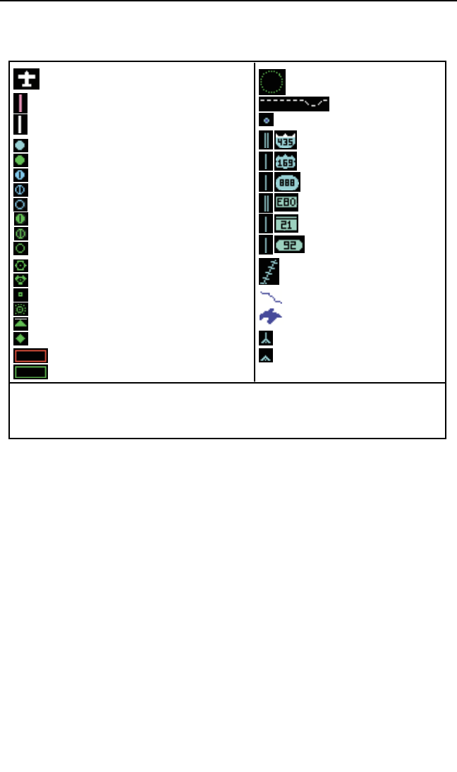
3.11.4.7. Symbols Used On The Map
The following symbols are used on the Nav 4 map page:
3.11.4.8. Selecting The Map Orientation
All KLN 94 installations are capable of three map orientations: actual track
up (TK↑), North up (N↑), and desired track up (DTK↑). In addition, if the
KLN 94 is interfaced with a compatible source of heading then a heading
up presentation (HDG↑) may also be selected.
In the actual track up orientation, viewing the map is like looking at a chart
that is turned so that the direction the aircraft is tracking over the ground is
pointing up. In a no-wind condition actual track is identical to the aircraft’s
heading. The aircraft must be moving at least two knots to calculate the
actual track. The map will be blank at any speed less than two knots.
When the North up orientation is selected, viewing the map is like looking
at a navigation chart with North at the top. The aircraft symbol rotates
based on the aircraft’s actual track (or heading if available). If the KLN 94
does not have a heading input and the aircraft is not moving the aircraft
symbol is replaced by a “+” symbol.
If desired track is selected, the map is like looking at a chart that is turned
so that the course line is always pointing up.
Chapter 3 Basic GPS Operation
3-46
Aircraft symbol
Active flight plan or direct to leg (magenta)
Inactive flight plan leg (white)
VFR airport (cyan)- ORS O1 only
IFR airport (green)- ORS 01 only
VOR with no distance
VOR/DME or VORTAC
DME-usually assoc. with ILS/LOC type procedures
NDB
Intersection
User waypoint
Special Use Airspace-Prohibited/Restricted areas (red)
Special Use Airspace-other (green)
Tower ring
Geographical boundary
City
Freeway (Americas Database)
National highway (Americas Database)
Local highway (Americas Database)
Railroad
River
Lake
Obstacle 1000 ft. or greater AGL
Obstacle less than 1000 ft. AGL
IFR airport (green) One or more hard surface runways
IFR airport (green) No hard surface runway
IFR airport (green) No runway information
VFR airport (cyan) One or more hard surface runways
VFR airport (cyan) No hard surface runway
VFR airport (cyan) No runway information Freeway (Intl Databases)
National highway (Intl Databases)
Local highway (Intl Databases)
Notes
Shows approximate orientation of longest hard surface runway. ORS 02 and higher.
Shows approximate orientation of longest runway. ORS 02 and higher.
These airports will not be displayed on map unless they are part of active flight plan. ORS 02 and higher.
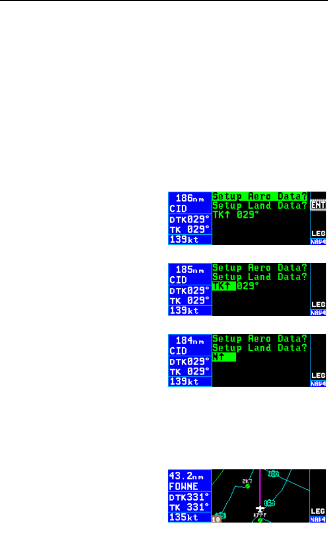
The heading up mode orients the map with the aircraft’s heading as up.
The heading up orientation is not presented as a choice if heading is not
provided to the KLN 94.
If a heading input is available to the KLN 94 then heading up is usually the
best map orientation to select. Otherwise, actual track up display is usual-
ly preferred for use in flight. However, since the track up display is only
usable when the aircraft is moving two knots or more the North up display
may be a good choice if you are stationary.
CAUTION: When using the actual track up format it is typical for
there to be a slight delay from the time a heading change is made
until the correct map orientation is displayed. Be careful when using
either the desired track up display or the actual track up display to
not think that a heading up display is being used.
To change the map orientation:
1. Select the NAV 4 (map) page if
not already displayed. The easi-
est way to do this is to press
either the map range (R) button
or the map menu (M) button.
2. Press the Mbutton to display
the Map Menu page (figure 3-
132).
3. Rotate the right outer knob
clockwise to position the cursor
over the map orientation (figure
3-133).
4. Select the desired map orienta-
tion by turning the right inner
knob (figure 3-134).
5. Press the Rbutton or Mbut-
ton to return to the map using the selected orientation.
3.11.4.9. Changing the Map Range Scale
The map range scale is displayed in the bottom left corner of the map.
The number displayed is the distance in nautical miles from the aircraft’s
present position symbol to the top of
the screen. The 10 NM scale is
selected in figure 3-135. Press the
upper portion of theRbutton to
increase the range scale and the
bottom portion to decrease the range
KLN 94 Pilot’s Guide Chapter 3 Basic GPS Operation
3-47
Figure 3-132
Figure 3-133
Figure 3-134
Figure 3-135
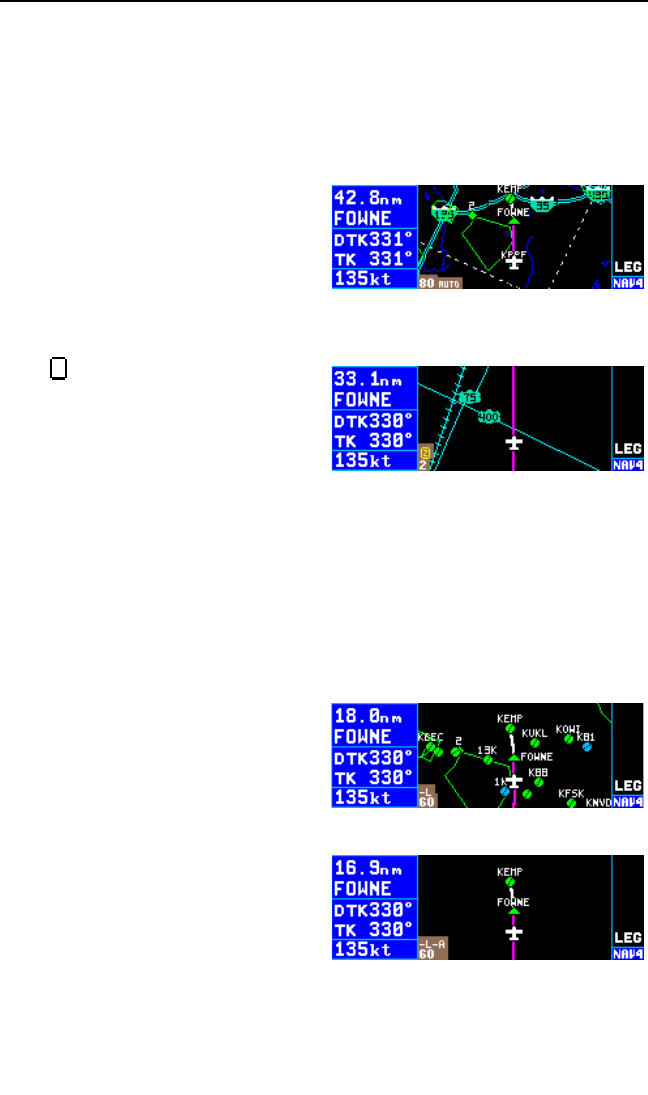
scale. The scale may be changed from 1/2 NM to 1000 NM (or 1 km to
2000 km if km selected as distance unit on SET 12 page).
In addition, an “AUTO” scale mode may be selected so that the map scale
automatically changes to display the active waypoint and, if there is one,
the next waypoint after the active waypoint (figure 3-136).The AUTO map
scale may be selected in two ways: 1) by pressing either portion of the R
button continuously for 2 seconds, or
2) by repetitively pressing the R
button either one step “below” the
1/2 NM (1 km) or “above” 1000 NM
(2000 km) until “AUTO” is displayed.
The AUTO scale mode is especially
useful when using the KLN 94 for
approaches.
The overzoom icon is displayed
when the selected map scale range
is beyond the accuracy of the stored
land data (figure 3-137). This occurs
at small map scale ranges and
means that land data positions may
not be accurately displayed.
Remember, it is easy to clutter the display with so much data that it is
unusable. Select a range scale that allows an uncluttered presentation of
the chosen aeronautical and land data. Or, select another combination of
these starting from the Map Menu page. Experiment and continue to
make new selections for different phases of your trip.
3.11.4.10 Decluttering The Screen
The map may be temporarily declut-
tered by pressing the Ebutton to
make it easier to view the active
flight plan waypoints or the Direct To
waypoint. The first press of the E
button turns off the land data and an
“-L” annunciation is shown above the
map range scale (figure 3-138). A
second press of the Ebutton
removes the aeronautical data and
an “-A” annunciation is also dis-
played (figure 3-139). The land and
aeronautical data may be brought
back by pressing the Ebutton
again or by leaving the map page and returning to it. The Ebutton only
declutters what has been turned on from the SET 7 and SET 8 pages.
Z
Chapter 3 Basic GPS Operation
3-48
Figure 3-138
Figure 3-139
Figure 3-136
Figure 3-137
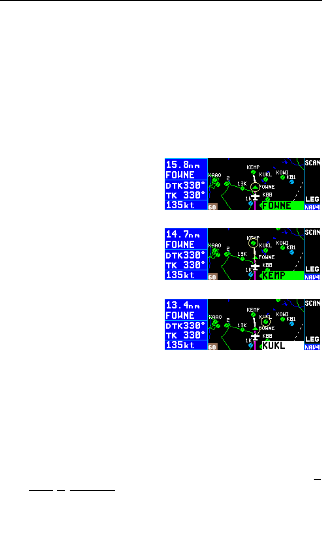
When the KLN 94 goes into the approach active mode all land data,
except for bodies of water, is automatically decluttered from the map. A
“-L” is then annunciated. In the approach active mode the first press of
the Ebutton restores land data and subsequent presses work as
described in the previous paragraph.
3.11.4.11. Waypoint Scan Feature
The NAV 4 page’s waypoint scan feature may be used as an easy way to
initiate Direct To operation to the active waypoint, active flight plan (FPL 0)
waypoints, or waypoints from the nearest list without leaving the map
page. This feature is also useful for quickly accessing a waypoint page for
a waypoint displayed on the map. To utilize the waypoint scan feature:
1. Pull the right inner knob to the
“out” position. The identifier of
the active waypoint will be dis-
played in the waypoint scan field
located in thethe lower right cor-
ner of the map (figure 3-140).
2. Rotate the right inner knob
clockwise or counter-clockwise
to select the desired waypoint
(figure 3-141). FPL 0 waypoints
and the Direct To waypoint are
displayed in green while other
waypoints are displayed in white
to make it easy to determine the
break from the FPL 0 list to the
nearest list (figure 3-142). The
waypoints are displayed in the
following order.
• A Direct To waypoint not in FPL 0 (if one exists)
• The FPL 0 waypoints
• A list of the nearest waypoints viewable on the map (airports,
VORs, NDBs, intersections, user waypoints). This list includes only
those that meet the requirements specified on the SET 6 and SET 7
pages. For example, if the map scale is currently at 60 NM but you
chose to view NDBs only up to 5 NM on the SET 7 page, the NDBs
will not appear on the map and will not be in the waypoint scan list.
These nearest waypoints are all grouped together and presented in
order of closeness to the aircraft’s present position. Therefore,
when scanning through the nearest list you may go from an airport,
to an intersection, to a VOR, etc.
KLN 94 Pilot’s Guide Chapter 3 Basic GPS Operation
3-49
Figure 3-140
Figure 3-141
Figure 3-142
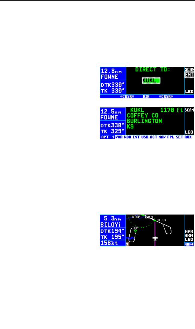
3. (ORS 02 and higher) If the waypoint displayed in the scan field is
actually displayed on the map, its map icon is encircled on the map
(figures 3-141 and 3-142). Waypoints that are located close together
on the map are easy to uniquely identify using this feature. In addition,
a line is drawn from the aircraft symbol toward the waypoint even if
the waypoint is not actually displayed on the map.
4. To initiate a Direct To operation to the waypoint in the scan field press
the Dbutton (figure 3-143). Press the Fbutton to complete the
Direct To operation. Press the
inner knob back to the “in” posi-
tion. This procedure may be
used on any waypoint in the
scan field.
OR
5. To bring up the waypoint page
for the waypoint in the scan field,
press the Fbutton (figure 3-
144). This feature is nice if you
want to identify an airport or
navaid that appears on the map but is not in your flight plan.
NOTE: This feature is not available for waypoints associated with DPs,
STARs, and approaches. If the Fbutton is pressed while a DP, STAR,
or approach waypoint is in the waypoint scan field a scratchpad message
stating “NO WPT Page” will be displayed.
6. Press the Ror Mbutton to return to the map.
3.11.4.12. Holding Patterns And Procedure Turns (ORS 02 and
higher)
The KLN 94 map is capable of dis-
playing holding patterns associated
with DPs, STARs, and approaches
as well as procedure turns associat-
ed with approaches (figure 3-145).
The KLN 94 does NOT provide complete navigational guidance for these
procedures. It is necessary to use the OBS mode to navigate relative to
the inbound leg of holding patterns and the inbound/outbound legs of pro-
cedure turns. The pilot is required to fly the headings published on the
instrument approach charts for the other parts of the holding pattern or
procedure turn.
Holding patterns and procedure turns associated with approaches are
only displayed on the map when the appropriate approach transition or
missed approach procedure has been loaded into the active flight plan.
Chapter 3 Basic GPS Operation
3-50
Figure 3-143
Figure 3-144
Figure 3-145

For example if an approach has three IAFs but only one of the IAFs uti-
lizes a procedure turn, the procedure turn will only be displayed when the
one IAF is selected. In addition it is necessary to select a maximum map
range scale to display holding patterns and procedure turns on the SET 7
page (see section 3.11.4.4).
CAUTION: Fly the published procedure for conducting procedure
turns and holding patterns. Do not rely solely on the depicted proce-
dure on the map as it may not be depicted to the proper scale.
Holding patterns and procedure turns are sized on the map according to
the aircraft’s groundspeed. The radius of turns is based on standard rate
turn using the aircraft’s groundspeed. Therefore as the aircraft’s ground-
speed changes due to the aircraft’s configuration or the effect of the wind
the size of the pattern will change. Holding patterns defined with fixed dis-
tance legs (e.g. 2 NM legs) are depicted with the defined leg length.
3.12. WAYPOINT PAGES
NOTE: Each of the waypoint page types includes a field which displays
present magnetic bearing to or magnetic heading from the waypoint. Due
to “great circle” courses and magnetic variation differences between pre-
sent position and the active waypoint, the To bearing and From radial may
not be exactly 180° different from each other. This condition is most likely
to occur when long distances are involved, and/or you are operating in
very northerly or southerly latitudes. See section 3.11.1 and figure 3-112
for more details.
3.12.1. AIRPORT PAGES
3.12.1.1. The Airport 1 (APT 1) Page
See figure 3-146.
Line 1: The ICAO identifier (see
section 2.3) of the airport; an arrow
precedes the identifier if it is the
active waypoint. The airport eleva-
tion above MSL in feet or meters,
which is rounded to the nearest 10 feet or nearest meter.
Line 2: The name of the airport.
Line 3: The city where the airport is located.
Line 4: The state if the airport is located in the U.S., the Province if locat-
ed in Canada, or the country if outside the U.S. and Canada. A listing of
the abbreviations used for States, Provinces, and countries is contained in
KLN 94 Pilot’s Guide Chapter 3 Basic GPS Operation
3-51
Figure 3-146
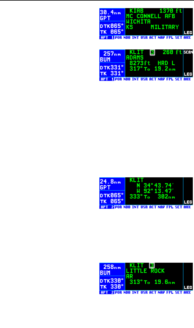
Appendix D. The right side of line 4
will read HELIPORT if applicable,
MILITARY if it is a military airport
(Figure 3-147), and PRIVATE if it is
a private use airport.
If the airport is being viewed as part
of the nearest airports list (see sec-
tion 3.9.1, “Viewing the Nearest
Waypoints”), the APT 1 page format
will differ as follows (see figure 3-
148):
Line 1: After the airport identifier,
the number designating the airport’s position in the nearest airport list is
displayed. In figure 3-148, KLIT is the third nearest airport.
Line 2: Same as a normal APT 1 page.
Line 3: The length, surface and lighting of the longest runway.
Line 4: The magnetic bearing to or the magnetic radial from the airport
and the distance. Placing the cursor over the radial/bearing field and turn-
ing the right inner knob changes it between radial from and bearing to the
airport.
3.12.1.2. The Airport 2 (APT 2) Page
See figure 3-149.
Line 1: The ICAO identifier (see
section 2.3) of the airport; an arrow
precedes the identifier if it is the
active waypoint.
Lines 2-3: The latitude and longitude of the airport reference point (the
“official” location of the airport).
Line 4: The magnetic bearing to or the magnetic radial from the airport
and the distance. Placing the cursor over the radial/bearing field and turn-
ing the right inner knob changes it between radial from and bearing to the
airport.
If the airport is being viewed as part
of the nearest airports list (see sec-
tion 3.9.1, the APT 2 page format
will differ as follows (see figure 3-
150):
Line 1: After the airport identifier, the number designating the airport’s
position in the nearest airport list is displayed.
Chapter 3 Basic GPS Operation
3-52
Figure 3-149
Figure 3-150
Figure 3-148
Figure 3-147
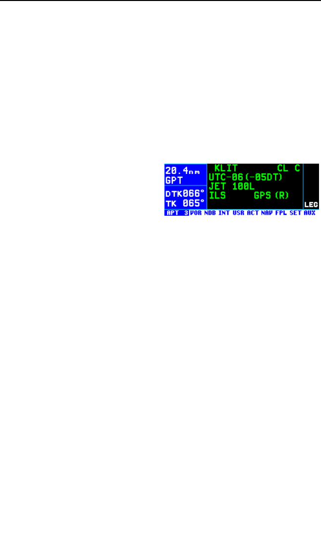
Line 2: The city where the airport is located.
Line 3: The state if the airport is located in the U.S., the Province if locat-
ed in Canada, or the country if outside the U.S. and Canada. A listing of
the abbreviations used for States, Provinces, and countries is contained in
Appendix D. The right side of line 3 displays HELIPORT, MILITARY, or
PRIVATE as appropriate.
Line 4: The magnetic bearing to or the magnetic radial from the airport
and the distance. Placing the cursor over the radial/bearing field and turn-
ing the right inner knob changes between radial from and bearing to the
airport.
3.12.1.3. The Airport 3 (APT 3) Page
See figure 3-151.
Line 1: The ICAO identifier (see
section 2.3) of the airport; an arrow
precedes the identifier if it is the
active waypoint. Also on line 1 is the
environment. For example, the air-
port in figure 3-151 has overlying Class C airspace. The possible
environments are:
CL B Class B airspace
CL C Class C airspace
CTA Control area
TMA Terminal area
TRSA Terminal radar service area
Line 2: The airport’s time difference from UTC during standard time and
during daylight time (in parentheses).
Line 3: Fuel types available at the airport. This line will be blank if there
is no fuel available at the airport.
80 80 octane
100 100 octane
100L 100 octane, low-lead
JET Jet fuel (of any type)
AUTO Automotive fuel (also known as MOGAS)
Line 4: Approach type(s) available at the airport. If an airport has an ILS
approach and/or an MLS approach, no indication of non-precision
approach availability will be given.
NO APR No IFR approach
NP APR Non-precision approach(es) only
ILS ILS approach
KLN 94 Pilot’s Guide Chapter 3 Basic GPS Operation
3-53
Figure 3-151

MLS MLS approach
ILS/MLS ILS and MLS approaches
If the airport has a GPS approved non-precision approach included in the
KLN 94 database, GPS will also be displayed on line 4.
The lower right corner will display (R) if the airport has an approach/depar-
ture radar environment.
3.12.1.4. The Airport 4 (APT 4) Page
See figure 3-152
The APT 4 page displays the runway
designation, length, surface, and
lighting for up to five runways in
order of length, beginning with the
longest runway. Since there are
many times when all of an airport’s runway information does not fit on one
page, additional APT 4 pages are used to display the data. Remember
that a “+” inserted between the page type and the number (APT+4 in this
case) is used to indicate that there is more than one Airport 4 page.
Line 1: The ICAO identifier (see section 2.3) of the airport; an arrow pre-
cedes the identifier if it is the active waypoint.
Line 2: The runway designation for the first runway on the page.
NOTE: In some parts of the world, runway numbers are based on true
runway heading rather than magnetic. These runways are prevalent in
northern Canada, where there is a large magnetic variation gradient. For
these runways, a Tsymbol separates the two runway numbers (example
14T32).
Line 3: The runway length for the first runway listed on the page, the run-
way surface type and the type of lighting (blank if none).
Runway surface abbreviations:
HRD Hard surface
TRF Turf
GRV Gravel
CLY Clay
SND Sand
DRT Dirt
SNW Snow
ICE Ice
SHL Shale
MAT Steel mat
Chapter 3 Basic GPS Operation
3-54
Figure 3-152

Runway Lighting Abbreviations:
LSunset to sunrise
LPC Pilot controlled lighting
LPT Part-time or on-request lighting
Lines 4-5: Runway information for the next shortest runway (if any), in
the same format as lines 1 and 2.
In the event that there is no runway information for an airport, the following
message is displayed on the APT 4 page:
No Runway Data
3.12.1.5. The Airport 5 (APT 5) Page
See figure 3-153.
Line 1: The ICAO identifier (see
section 2.3) of the airport; an arrow
precedes the identifier if it is the
active waypoint.
Lines 2-5: The VHF communication frequencies associated with the air-
port. Also, frequencies for ILS and LOC-type approaches at the airport.
The type and frequency are listed.
All communication and navigation frequencies are QuickTuneTM frequen-
cies which means that pressing the Fbutton with the cursor over the
frequency sends the frequency to the standby window of a KX 155A or
KX 165A Nav/Com if this feature is enabled in the installation (see section
3.15 “QuickTuneTM Nav/Com Frequency Selection”). In order to make the
QuickTuneTM feature even easier to use, lines 2-5 are a scrolling region
when there is more than one APT 5 page (designated by APT+5). What
this means is that you can turn on the cursor on the first APT 5 page and
use the right outer knob to move the cursor through all the frequencies for
all this airport’s APT 5 pages without having to turn the cursor on and off
while you change between APT 5 pages.
The communication abbreviations are:
AAS aeronautical advisory service
AFIS aerodrome flight information service
ARVL arrival
APR approach
ASOS automated surface observation system
ATF aerodrome traffic frequency
ATIS automatic terminal information service
AWOS automatic weather observing station
CL B class B airspace (VFR frequency)
KLN 94 Pilot’s Guide Chapter 3 Basic GPS Operation
3-55
Figure 3-153

CL C class C airspace (VFR frequency)
CLR clearance delivery
CTA control area (VFR frequency used outside the U.S.)
CTAF common traffic advisory frequency
CTR center (when center is used for approach/departure
control)
DEP departure
DIR director (approach control/radar)
GCO ground communications outlet
GRND ground control
MCOM multicom
MF mandatory frequency
PCL pilot-controlled lighting
PTAX pre-taxi clearance
RAMP ramp/taxi control
RDO radio
RDR radar-only frequency
TMA terminal area (VFR frequency used outside the U.S.)
TWR control tower
UNIC unicom
The Navigation abbreviations are:
ILS Instrument landing system approach
LOC Localizer approach
LBC Localizer back course
LDA Localizer type directional aid approach
SDF Simplified directional facility approach
Part-time operation, such as for a control tower, is indicated with an aster-
isk (*) to the right of an airport frequency.
The frequencies associated with class B or C airspace, CTA or TMA are
VFR frequencies. Airports which have one of these categories of frequen-
cies also have APR and DEP which are IFR frequencies.
Where required, APR, DEP, CL B, CL C, CTA, and TMA frequencies are
sectorized. That is, a frequency may be used only within a certain range
of radials from a designated reference location. The format for displaying
the sectorization is to show the frequency first, followed by the identifier of
the associated reference point, fol-
lowed next by the associated altitude
restrictions. For example, figure 3-
154 shows that the Orlando
approach control frequency 121.10
MHz is used between the 311° radial
Chapter 3 Basic GPS Operation
3-56
Figure 3-154
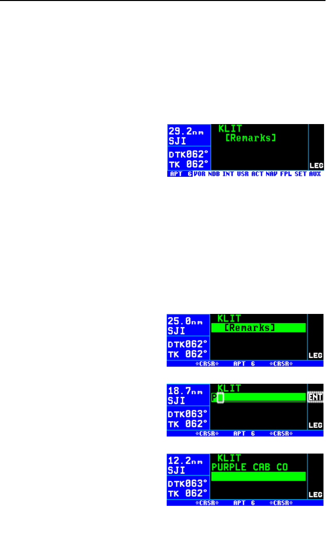
and the 60° radial from KMCO (Orlando International Airport) for altitudes
at and below 5500 feet.
In a few cases, APR, DEP, CL B, CL C, CTA, and TMA frequencies are
sectorized such that the restrictions cannot be displayed on a single page.
When this occurs the following message is displayed on the APT 5 page:
Text Of Freq Use
Not Displayed
3.12.1.6. The Airport 6 (APT 6) Page
The Airport 6 page is used to store
and display user-entered remarks.
These remarks might include infor-
mation on lodging, dining, airport
services, etc. Up to 200 waypoints
(airports and user waypoints com-
bined) may include remarks. See figure 3-155.
Line 1: The ICAO identifier (see section 2.3) of the airport; an arrow pre-
cedes the identifier if it is the active waypoint.
Lines 2-4: The pilot-entered remarks for the airport. Three lines of 16
characters each are available for the remarks. Letters, numbers, hyphens,
and spaces may be used in the remark. If no remarks have been entered
for the airport, line 2 will display “[Remarks]”.
To enter an airport remark on the APT 6 page:
1. Turn on the cursor and move it
until the cursor fills line 2 of the
screen (figure 3-156).
2. Select the desired character with
the right inner knob and move
the cursor to the next character
on the line with the right outer
knob (figure 3-157).
3. Repeat step 2 as necessary to
complete line 2.
4. Press Fto approve line 2. The
cursor will automatically move to
the next line (see figure 3-158).
5. Use the right inner and outer
knobs to complete line 3. The
Fbutton must be pressed to
approve line 3 separately.
KLN 94 Pilot’s Guide Chapter 3 Basic GPS Operation
3-57
Figure 3-155
Figure 3-156
Figure 3-157
Figure 3-158
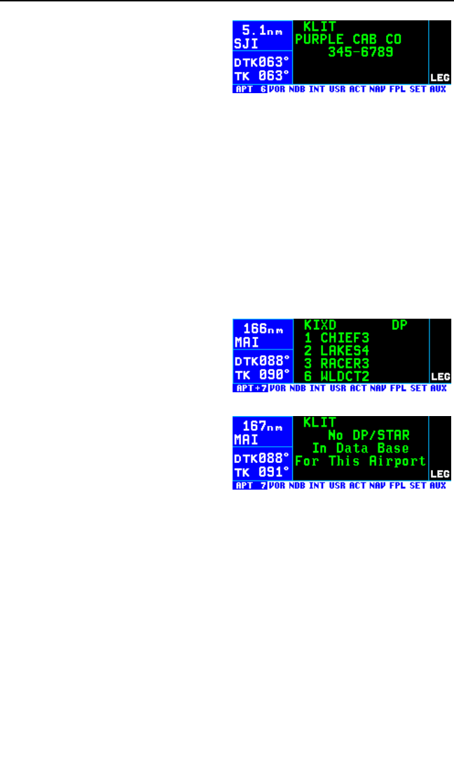
6. Use the right inner and outer
knobs to complete line 4. The
Fbutton must be pressed to
approve line 4 separately.
7. Turn the cursor off when you are
finished creating the remark (fig-
ure 3-159).
NOTE: If there are already 200 waypoints with remarks and an attempt is
made to enter a remark for a waypoint, a scratchpad message “Remarks
Full” is displayed. It is then necessary to delete remarks using the AUX
13 page before new remarks can be entered.
The Auxiliary 13 (AUX 13) page is a list of waypoints with associated
remarks. If you wish to delete a waypoint remark for an airport it is done
from the AUX 13 page, see section 5.11.
3.12.1.7. The Airport 7 (APT 7) Page
The APT 7 page shows the depar-
ture (DP) and arrival (STAR)
procedures that are available for the
selected airport. If both DP and
STAR procedures are available then
there will be two APT 7 pages indi-
cated by APT+7 (figure 3-160). If
there are no DP or STAR procedures
in the database then this page will be
as shown in figure 3-161.
NOTE: If the KLN 94 is configured
for VFR use only there will not be an
APT 7 page.
Line 1: The ICAO identifier (see section 2.3) of the airport; an arrow pre-
cedes the identifier if it is the active waypoint. “DP” is displayed for the list
of departure procedures and “STAR” is displayed for the list of arrival pro-
cedures.
Lines 2-5: List of the DPs or STARs. If there are more than four proce-
dures, the final one in the list is on line 5 on the screen. To view the
procedures that are not in view, turn on the cursor with the Bbutton and
turn the right outer knob clockwise.
Chapter 3 Basic GPS Operation
3-58
Figure 3-160
Figure 3-161
Figure 3-159
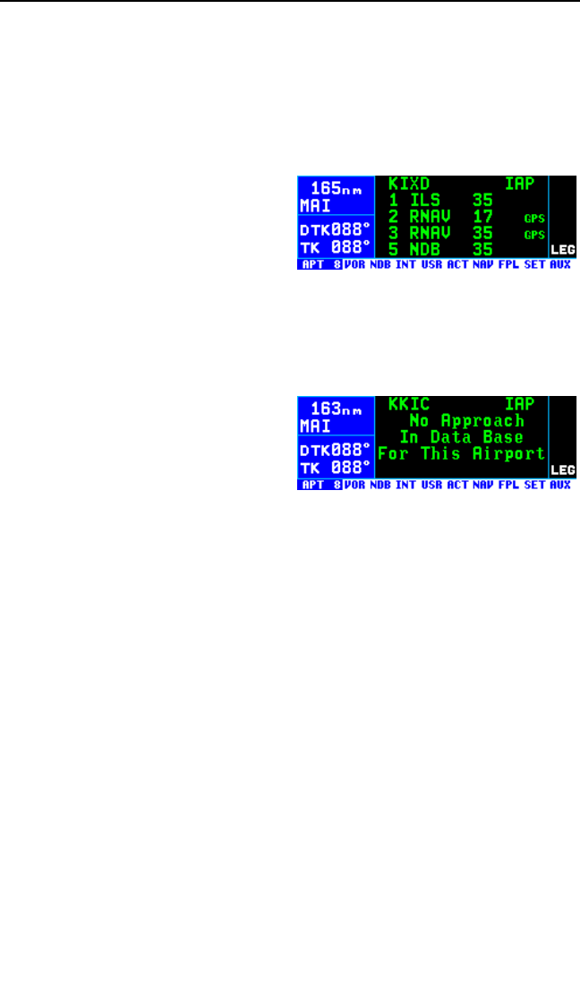
The APT 7 page is also used to load DPs and STARs into the active flight
plan. This page may be accessed using the manual method of selecting
pages using the right inner and outer knobs; however the preferred way of
loading DPs and STARs is via the P(procedure) button. See section
6.3.
3.12.1.8. The Airport 8 (APT 8) Page
See figure 3-162.
The APT 8 page is used to display
IAPs (Instrument Approach
Procedures) available for the select-
ed airport and also to load an
approach into the active flight plan.
While the manual method of selecting pages using the right inner and
outer knobs may be used, the preferred method of selecting and loading
approaches is via the P(procedure) button. To learn how to select an
approach, see section 6.2.3.
Remember that the desired
approach must be in the published
database in order to be used by KLN
94. If there are no approaches for
this airport in the database then this
page will be as shown in figure 3-
163.
The APT 8 page displays approaches approved for use with an approach
approved KLN 94 as well as approaches where the KLN 94 may only be
used to provide situational awareness monitoring. Approaches approved
for GPS have a “GPS” symbol to the right of the approach name such as
the RNAV 17 and RNAV 35 approaches in figure 3-162.
NOTE: If the KLN 94 is configured for VFR use or IFR en route use only,
the APT 8 page is not displayed.
Line 1: The ICAO identifier (see section 2.3) of the airport; an arrow pre-
cedes the identifier if it is the active waypoint. “IAP” designates that a list
of instrument approach procedures is being displayed.
Lines 2-5: Listing of the instrument approach procedures for the airport. If
there are more than four IAPs, the final one in the list is on line 5 of the
screen. To view the IAPs that are not in view, turn on the cursor using the
Bbutton and turn the right outer knob clockwise.
KLN 94 Pilot’s Guide Chapter 3 Basic GPS Operation
3-59
Figure 3-162
Figure 3-163
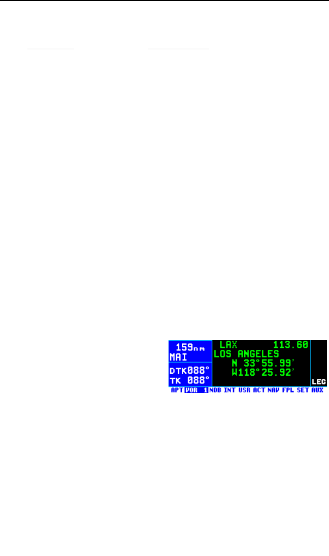
The different types of IAPs and the abbreviations used on the APT 8 page
are:
Approach Abbreviation
ILS & ILS DME ILS
LOC & LOC DME LOC
LOC BC & LOC DME BC LBC
LDA & LDA DME LDA
SDF SDF
RNAV RNAV & RNV
TACAN TACAN
VOR/DME VOR/D
VOR VOR
NDB/DME NDB/D
NDB NDB
GPS GPS
Helicopter HEL
3.12.2. VOR PAGES
Two pages of information may be displayed for each VOR in the KLN 94.
Sample VOR pages are shown in figures 3-164 through 3-166).
3.12.2.1. The VOR 1 Page
See figure 3-164.
Line 1: The VOR identifier, preced-
ed by an arrow if it is the active
waypoint. To the right of the identifier
is the frequency of the VOR in mega-
hertz. This frequency is a
QuickTuneTM frequency which means
that pressing the Fbutton with the cursor over the frequency sends the
frequency to the standby window of a KX 155A or KX 165A Nav/Com if
the feature is enabled in the installation (see section 3.15 describing
QuickTuneTM operation).
Line 2: The name of the VOR.
Lines 3-4: The latitude and longitude of the VOR
Chapter 3 Basic GPS Operation
3-60
Figure 3-164
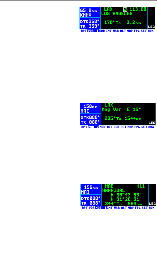
If the VOR is being viewed as part of
the nearest VORs list (see section
3.9.1), the VOR 1 page format will
differ as follows (see figure 3-165).
Line 1: After the VOR identifier, the
number designating the VOR’s posi-
tion in the nearest VOR list is displayed. In figure 3-165, LAX is the
second nearest VOR.
Lines 3-4: In place of the latitude/longitude, line 3 is blank and line 4 dis-
plays the magnetic bearing to or the magnetic radial from the VOR and
the distance. Placing the cursor over the radial/bearing field and turning
the right inner knob changes it between radial from and bearing to the sta-
tion.
3.12.2.2. The VOR 2 Page
See figure 3-166.
Line 1: The VOR identifier, preced-
ed by an arrow if it is the active
waypoint.
Line 2: The published magnetic sta-
tion declination of the VOR.
Magnetic station declination is
another way to say the published magnetic variation for the VOR.
Line 4: The magnetic bearing to or the magnetic radial from the VOR and
the distance. Placing the cursor over the radial/bearing field and turning
the right inner knob changes it between radial from and bearing to the sta-
tion.
3.12.3. NDB PAGE
There is one page of information dis-
played for each NDB in the KLN 94.
A sample NDB page is shown in fig-
ure 3-167.
3.12.3.1. The NDB 1 Page
The NDB 1 page format for an en route NDB is shown in figure 3-167.
NOTE: Outer markers and outer compass locators (LOM) may be stored
by their NDB identifier or as an intersection by their intersection name.
Line 1: The NDB identifier, preceded by an arrow if it is the active way-
KLN 94 Pilot’s Guide Chapter 3 Basic GPS Operation
3-61
Figure 3-165
Figure 3-166
Figure 3-167
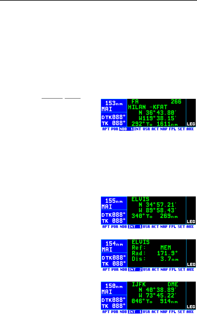
point. To the right of the identifier is the frequency of the NDB in kilohertz.
If the NDB is being viewed as part of the nearest NDBs list (see section
3.9.1) the number designating the NDB’s position in the nearest NDB list
is displayed after the NDB identifier.
Line 2: The name of the NDB.
Lines 3-4: The latitude and longitude of the NDB.
Line 5: The magnetic bearing to or the magnetic radial from the NDB and
the distance. Placing the cursor over the radial/bearing field and rotating
the right inner knob changes it between radial from and bearing to the sta-
tion.
The format for terminal NDBs (those
NDBs only associated with an
approach) is shown in figure 3-168.
The NDB 1 page for terminal NDBs
shows the airport identifier associat-
ed with the NDB to the right of the
name on line 2.
3.12.4. INTERSECTION PAGES
The Intersection pages contain low altitude, high altitude, approach, and
DP/STAR intersections as well as outer markers and outer compass loca-
tors. Outer markers and outer compass locators may be stored by their
NDB identifier or as an intersection by their intersection name. In addition
DMEs associated with ILS and Localizer-type approaches are stored
with intersections.
3.12.4.1. The Intersection 1 (INT
1) Page
The Intersection pages for the way-
point ELVIS (figures 3-169 and
3-170) are used as an example of
what is displayed for an actual inter-
section. The intersection page for
IJFK (figure 3-171) is used to show
how the page appears for a DME
associated with an ILS or Localizer-
type approach.
Line 1: The intersection identifier,
preceded by an arrow if it is the
active waypoint. If the waypoint is a
DME the letters “DME” appear to the
right of the identifier.
Chapter 3 Basic GPS Operation
3-62
Figure 3-168
Figure 3-169
Figure 3-170
Figure 3-171

Lines 2-3: The latitude and longitude of the intersection.
Line 4: The magnetic bearing to or the magnetic radial from the user-
defined waypoint and the distance. Placing the cursor over the
radial/bearing field and turning the right inner knob changes it between
radial from and bearing to the station.
3.12.4.2. The Intersection 2 (INT 2) Page
See figure 3-170.
Line 1: The intersection identifier, preceded by an arrow if it is the active
waypoint. If the waypoint is a DME the letters “DME” appear to the right of
the identifier.
Line 2: The identifier of the intersection’s reference waypoint. When this
page is first viewed, the reference waypoint is the nearest VOR to the
intersection. The reference waypoint may be changed by the pilot to any
waypoint (published or user-defined). However, once you leave this page
and come back, the reference waypoint reverts back to a nearby VOR.
Line 3: The magnetic radial from the reference waypoint to the intersec-
tion.
Line 4: The distance from the reference waypoint to the intersection.
3.12.5. USER WAYPOINT PAGES
The User waypoint pages (USR 0, USR 1, USR 2, and USR 3) allow you
to create “custom” waypoints for use in navigation. A crop sprayer might
want to create a waypoint on a field that is sprayed regularly, for instance.
Another candidate might be a small private airport which is not included in
the KLN 94 database. To learn how to create a user-defined waypoint,
see section 5.4.
3.12.5.1. The User 0 (USR 0) Page
See figure 3-172.
NOTE: The USR 0 page is only dis-
played for waypoint identifiers that do
not have a previously defined posi-
tion.
Line 1: The identifier for the as-yet-undefined waypoint.
Lines 2-4: Cursor fields for the three possible user-defined waypoint cre-
ation methods. For information on creating user-defined waypoints, see
section 5.4.
KLN 94 Pilot’s Guide Chapter 3 Basic GPS Operation
3-63
Figure 3-172
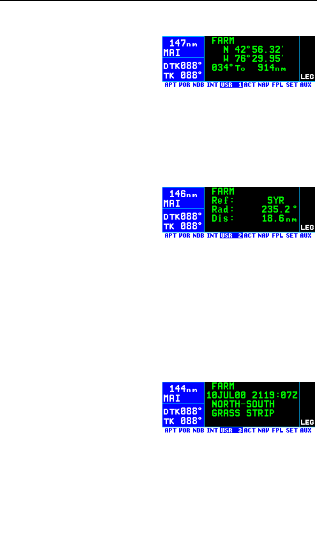
3.12.5.2. The User 1 (USR 1) Page
See figure 3-173.
Line 1: The user-defined waypoint
identifier, preceded by an arrow if it
is the active waypoint.
Lines 2-3: The latitude and longitude
of the user-defined waypoint.
Line 4: The magnetic bearing to or the magnetic radial from the user-
defined waypoint and the distance.Placing the cursor over the
radial/bearing field and turning the right inner knob changes it between
radial from and bearing to station.
3.12.5.3. The User 2 (USR 2) Page
See figure 3-174.
Line 1: The user-defined waypoint
identifier, preceded by an arrow if it
is the active waypoint.
Line 2: The identifier of the user-
defined waypoint’s reference waypoint. When this page is first viewed,
the reference waypoint is the nearest VOR to the user waypoint. The ref-
erence waypoint may be changed by the pilot to any waypoint (published
or user-defined). However, once you leave this page and come back, the
reference waypoint reverts back to a nearby VOR.
Line 3: The magnetic radial from the reference waypoint to the user way-
point.
Line 4: The distance from the reference waypoint to the user waypoint.
3.12.5.4. The User 3 (USR 3) Page
See figure 3-175.
Line 1: The identifier of the user-
defined waypoint; an arrow precedes
the identifier if it is the active way-
point.
Lines 2-4: If the user waypoint was created from the NAV 2 page (see
5.4.1 “Creating A Waypoint At Your Present Position”) line 2 displays the
date and time that the user waypoint was created. Otherwise, all three
line may be used for pilot-entered remarks for the user waypoint. Three
Chapter 3 Basic GPS Operation
3-64
Figure 3-173
Figure 3-174
Figure 3-175
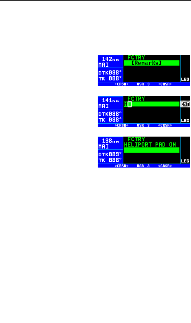
KLN 94 Pilot’s Guide Chapter 3 Basic GPS Operation
3-65
lines of 16 characters each are available for the remarks. A combination
of up to 200 user-defined waypoints and airports may include remarks.
Letters, numbers, hyphens, and spaces may be used in the remark. If no
remarks have been entered for the user-defined waypoint, line 2 will dis-
play [Remarks].
To enter a user-defined waypoint remark on the USR 3 page:
1. Turn on the cursor and move it
until the cursor fills line 2 of the
screen (figure 3-176).
2. Select the desired character with
the right inner knob and use the
right outer knob to move the cur-
sor to the next character on the
line (figure 3-177).
3. Repeat step 2 as necessary to
complete line 2.
4. Press Fto approve line 2. The
cursor will automatically move to
the next line (see figure 3-178).
5. Use the right inner and outer
knobs to enter the text for line 3.
Press Fto approve line 3.
6. Use the same procedure to enter text and press Fto approve line
4.
7. Turn the cursor off when you are finished creating the remark.
NOTE: If there are already 200 waypoints with remarks and an attempt is
made to enter a remark for a waypoint, a scratchpad message “Remarks
Full” is displayed. It is then necessary to delete remarks using the AUX 13
page before new remarks can be entered.
The Auxiliary 13 (AUX 13) page is a list of waypoints with associated
remarks. If you wish to delete a waypoint remark for a user-defined way-
point, see section 5.11.
Figure 3-176
Figure 3-177
Figure 3-178
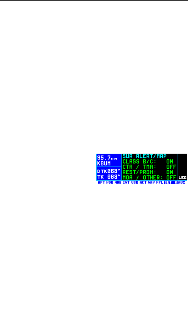
3.13. SPECIAL USE AIRSPACE ALERTING
The KLN 94 database contains the location of areas of special use air-
space (SUA). The types of SUA areas stored in the database and the
abbreviations used to denote these areas are the following:
Class B CL B
Class C CL C
Control Area (used outside USA) CTA
Terminal Area (used outside USA) TMA
Alert Area ALRT
Caution Area CAUT
Danger Area DNGR
Military Operations Area MOA
Prohibited Area PROH
Restricted Area REST
Training Area TRNG
Warning Area WARN
Terminal Radar Service Area TRSA
The Setup 6 (SET 6) page shown in
figure 3-179 is used to chose the
types of SUA for which SUA alerting
shall be given. These SUA type are
divided into four groups as follows:
CLASS B/C: Class B, Class C, and Terminal Radar Service
Areas (TRSA)
CTA/ TMA: Control Areas and Terminal Areas (used only
internationally outside the U.S.)
REST/PROH: Restricted and Prohibited Areas
MOA /Other: Military Operation Areas, Alert Areas, Warning
Areas, Danger Areas, Caution Areas, Training
Areas
NOTE: The SUA types selected on the SET 6 page also determine which
ones are displayed on the NAV 4 map page.
To select the SUA types for SUA alerting and for display on the
NAV 4 page map:
1. Select the SET 6 page.
Chapter 3 Basic GPS Operation
3-66
Figure 3-179
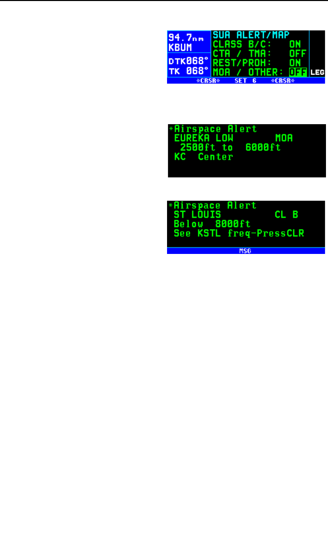
2. Press the Bbutton to turn on the cursor.
3. Use the right outer knob to move
the cursor over the desired SUA
group (figure 3-180).
4. Use the right inner knob to
select ON or OFF.
5. Turn the cursor off with the Bbutton.
The KLN 94 will normally alert you
prior to entering one of these areas
with a message prompt. When the
Message page is viewed it will dis-
play Airspace Alert and will also
display the name and type of the
special use airspace (figure 3-181).
If the special use airspace is a Class
B, Class C, CTA, or TMA, the mes-
sage page will also instruct you to
press the Ebutton if you wish to
see the Airport 5 page (airport com-
munications) for the primary airport
so that the correct communications
frequency may be determined (figure 3-182).
NOTE: In addition to the message page messages that alert you to spe-
cial use airspace, the KLN 94 can also display the ten nearest areas of
SUA. It will even give you the direction and distance to the nearest edge
of the SUA. See section 3.9.2. “Viewing The Nearest Special Use
Airspaces.”
The SUA alert feature is three dimensional. The SUA areas are stored in
the KLN 94 database with regard to altitude when the actual SUA altitude
limitations are charted in terms of mean sea level (MSL). Therefore, if you
are flying either above or below an SUA area you won’t be inconve-
nienced with nuisance alert messages. However, if the actual lower limit of
an SUA is charted in terms of an altitude above ground level (AGL), then it
is stored in the KLN 94 as all altitude below the upper limit of the SUA. If
the actual upper limit of an SUA is charted in terms of AGL, it is stored in
the KLN 94 as “unlimited”.
Only the outer lateral boundaries are used for SUA alerting of Class B,
Class C, CTA, and TMA airspace (although the inner rings are displayed
on the map on ORS 03 and higher units). These SUA areas are stored as
“cylinders” of airspace so all altitudes below the upper limit of these areas
are considered to be in the SUA.
KLN 94 Pilot’s Guide Chapter 3 Basic GPS Operation
3-67
Figure 3-180
Figure 3-181
Figure 3-182
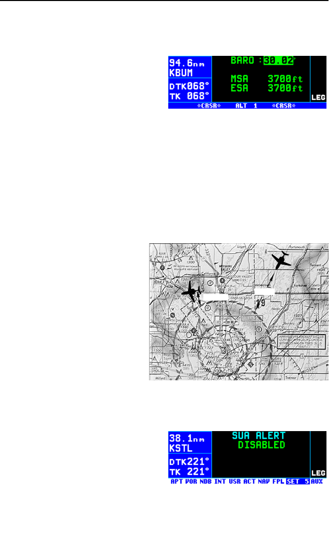
Chapter 3 Basic GPS Operation
3-68
If the altitude input to the KLN 94 is pressure altitude from an altitude
encoder or air data computer, then you must manually update the KLN 94
with an altimeter setting (baro correction in order to receive accurate SUA
alerting. You may easily update the
altimeter setting by pressing the A
button to display the Altitude 1 (ALT
1) page (figure 3-183) The right inner
knob is used to change the altimeter
setting. When the setting is com-
plete, press Atwice to return to the
page previously in view.
CAUTION: Failure to keep the altimeter baro setting updated will
result in inaccurate special use airspace alerting. If this feature is
used, it is a good idea to update the altimeter baro setting on the
ALT 1 page each time you make a change to an aircraft’s altimeter
setting.
NOTE: If there is no altitude input to the KLN 94, all altitudes will be
regarded as being within the boundary of the SUA area.
The message prompt for a spe-
cial use airspace alert will occur
when the aircraft’s position is at a
point such that a projection of the
aircraft’s existing track over the
ground is approximately 10 min-
utes from penetrating the outer
boundary of one of these areas.
It will also occur if the aircraft is
within approximately two nautical
miles of one of these areas even
if the aircraft’s projected track
over the ground won’t actually
penetrate the SUA area (figure 3-
184). If one of the SUA areas is penetrated, another message will state:
Inside SUA.
The SUA alert feature may be dis-
abled (or enabled) on the Setup 5
(SET 5) page, shown in figure 3-185.
Select the SET 5 page, turn on the
cursor (B). The right inner knob is
used to choose between SUA
ALERT ENABLED and SUA ALERT
DISABLED.
Figure 3-183
10 MIN
2 MILES
Figure 3-184
Figure 3-185

If the SUA alert feature has been enabled, the KLN 94 allows you to select
a vertical buffer on the SET 5 page in order to provide an additional layer
of protection from inadvertently
entering an SUA. To select a vertical
buffer, make sure the SUA alert fea-
ture has been enabled. Turn on the
cursor (B) and use the right outer
knob to position the cursor over the
Buffer altitude field (figure 3-186).
Then use the right inner knob to
select the buffer (figure 3-187). The
buffer may be selected in one hun-
dred foot or ten meter increments.
After the desired selection has been
made, turn the cursor off.
The vertical buffer serves to “stretch” the SUA area in both directions (up
and down) by the selected buffer altitude. For example, let’s say you have
selected a buffer of 1,000 feet and the actual SUA area exists from 5,000
feet MSL to 12,000 feet MSL. In this case you will receive SUA alert mes-
sages if you fly at any altitude between 4,000 and 13,000 feet MSL.
CAUTION: It is the pilot’s responsibility to avoid those areas of spe-
cial use airspace where ATC clearance to penetrate is required but
has not been obtained. The KLN 94’s special use airspace alert is
only a tool to assist the pilot and should never be relied upon as the
sole means of avoiding these areas.
NOTE: Special Use Airspace alerting is disabled when the KLN 94 is in
the approach arm or approach active modes.
3.14. REMOTE MOUNTED ANNUNCIATORS
The KLN 94 has outputs capable of driving several remote annunciator
lights. Since the KLN 94 is capable of displaying many of these annuncia-
tions on the unit itself, a particular installation may or may not include
remote annunciators.
These annunciators should be
mounted in the pilot’s normal scan
area so that they are easily seen. A
typical annunciator unit integrating
several of the annunciators is shown
in figure 3-188; however, actual
annunciation abbreviations and con-
figurations may be different.
KLN 94 Pilot’s Guide Chapter 3 Basic GPS Operation
3-69
Figure 3-186
Figure 3-187
Figure 3-188

Waypoint Alert: The remote waypoint alert annunciator is on whenever
waypoint alerting is occurring. See sections 3.10.3. “Waypoint Alerting for
Direct To Operation” and 4.2.2. “Turn Anticipation and Waypoint Alerting.”
Message: The remote message annunciator is on whenever the mes-
sage prompt is on. See section 3.5. “Message Page.”
NAV/GPS: There may be a NAV/GPS switch/annunciator to switch a CDI
or HSI indicator’s navigation source between the KLN 94 and a VOR/ILS
system.
GPS APR: An optional GPS APR switch/annunciator allows display
and control of the KLN 94 approach modes (see section 6.2.1).
3.15 QUICKTUNETM NAV/COMM FREQUENCY SELECTION
When the KLN 94 is interfaced with either of Bendix/King’s KX 155A or
KX 165A Nav/Comms, it is capable of providing QuickTuneTM frequency
selection for both VHF communication and navigation frequencies. This
allows you to place the cursor over a frequency displayed on the APT 5,
VOR 1, FSS 1 (nearest FSS), or CTR 1 (nearest “Center”) pages and
automatically transfer the frequency to the appropriate comm or nav
standby window by pressing the Fbutton.
In addition, if a localizer-type approach (ILS, LOC, SDF, or LDA) or VOR
approach is loaded into the KLN 94’s active flight plan, the frequency
associated with the approach is automatically sent to the nav standby win-
dow of the KX 155A or KX 165A. This applies regardless of whether or
not the approach is approved for GPS.
At the time of installation the KLN 94 may be configured for QuickTuneTM
with compatible Nav/Comms in the aircraft. It may be configured for up to
four comms and four navs (four KX 155A’s or four KX 165A’s), although
one or two is more common.
To determine how many Nav/Comms are configured into the KLN 94
QuickTuneTM system:
1. Select the SET 14 page. If the
word “disabled” appears as in
figure 3-189 then the KLN 94 is
not capable of providing
QuickTune™frequency selection.
If a number appears as in figure
3-190 then the KLN 94 is config-
ured to provide QuickTune™
and you may continue with step
2.
Chapter 3 Basic GPS Operation
3-70
Figure 3-189
Figure 3-190
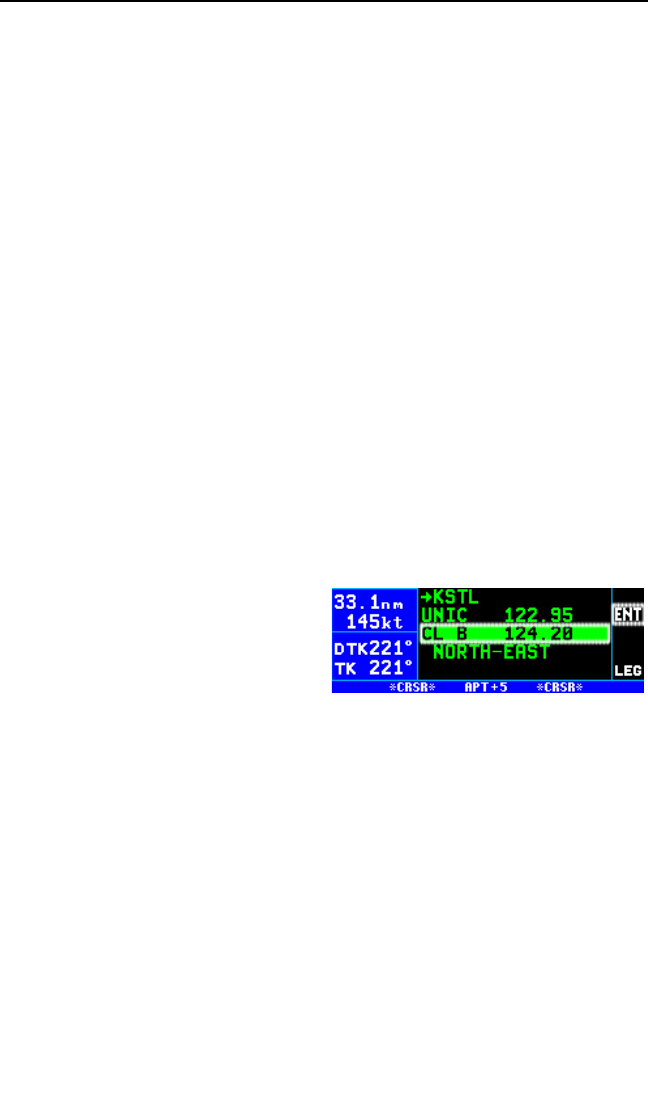
KLN 94 Pilot’s Guide Chapter 3 Basic GPS Operation
3-71
2. Note what the default number is next to “Comm” and “Nav”. In figure
3-190, the default number is 1 for both Comm and Nav.
3. Press the Bbutton to turn on the cursor.
4. Rotate the right inner knob to view the comms configured for
QuickTune™. If only one number is displayed then it is the only comm
configured for QuickTune™.
5. Rotate the inner knob if necessary to display the number that was dis-
played in step 2 above.
6. Rotate the right outer knob to position the cursor over the number next
to “Nav”.
7. Rotate the right inner knob to view the navs configured for
QuickTune™. Select the number that was displayed in step 2.
8. Turn off the cursor.
3.15.1. QUICKTUNE™ OPERATION WITH ONE COMPATIBLE
NAV/COMM
To use the QuickTune™ feature when the KLN 94 is configured with
only one compatible Nav/Comm:
1. Turn on the cursor and use the right outer knob to position the cursor
over the desired frequency on an
APT 5, VOR 1, FSS 1, or CTR 1
page (figure 3-191). Remember
that on the APT 5 page you can
scroll the cursor through all of the
airport frequencies without hav-
ing to turn the cursor off and
back on to change pages.
2. Press the Fbutton to send the frequency to the KX 155A (or
KX 165A) comm or nav frequency standby window.
3. Press the appropriate comm or nav frequency transfer button when
ready to activate the frequency.
Figure 3-191
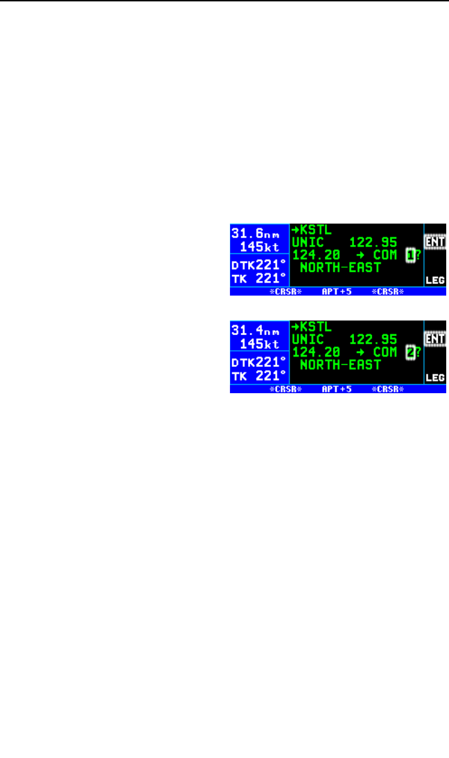
Chapter 3 Basic GPS Operation
3-72
3.15.2. QUICKTUNE™ OPERATION WITH MORE THAN ONE COM-
PATIBLE NAV/COMM
In order to use QuickTune™ when there is more than one Nav/Comm
configured with the KLN 94 it is necessary to specify a default
QuickTune™ receiver for both comm and nav. This action is accom-
plished on the SET 14 page by turning on the cursor and selecting the
desired default unit for both comm and nav.
To use the QuickTune™ feature when the KLN 94 is configured for
more than one Nav/Comm:
1. Position the cursor over the desired frequency on an APT 5, VOR 1,
FSS 1 or CTR 1 page as in figure 3-191.
2. Press the Fbutton. The fre-
quency and the default unit the
frequency will be sent to is dis-
played as shown in figure 3-192.
Remember the default unit can
be changed on the SET 14 page.
3. If desired, turn the right inner
knob to select another unit to
send the frequency to (figure 3-
193).
4. Press the Fbutton again to
send the frequency to the selected comm or nav standby window.
5. Press the appropriate comm or nav frequency transfer button on the
KX 155A (or KX 165A) when ready to activate the frequency.
3.16. USING THE TAKE-HOME MODE
It is very likely that the KLN 94 will become your “best friend” in the cock-
pit. As with any good friend, you may need some time to get
well-acquainted. This will allow you to utilize it to the maximum extent. A
great way to get to know the KLN 94 is to use it outside the airplane, using
the take-home mode.
When the KLN 94 is in the take-home mode, it performs as if it is receiving
adequate satellite signals to determine its position. It displays the latitude
and longitude of its last known position or of whatever position it is initial-
ized to on the Setup 1 (SET 1) page (see section 3.7, “Initialization and
Time to First Fix”). In addition, a groundspeed may be entered on the
SET 1 page and the KLN 94 will track a flight plan or a direct to waypoint
Figure 3-192
Figure 3-193
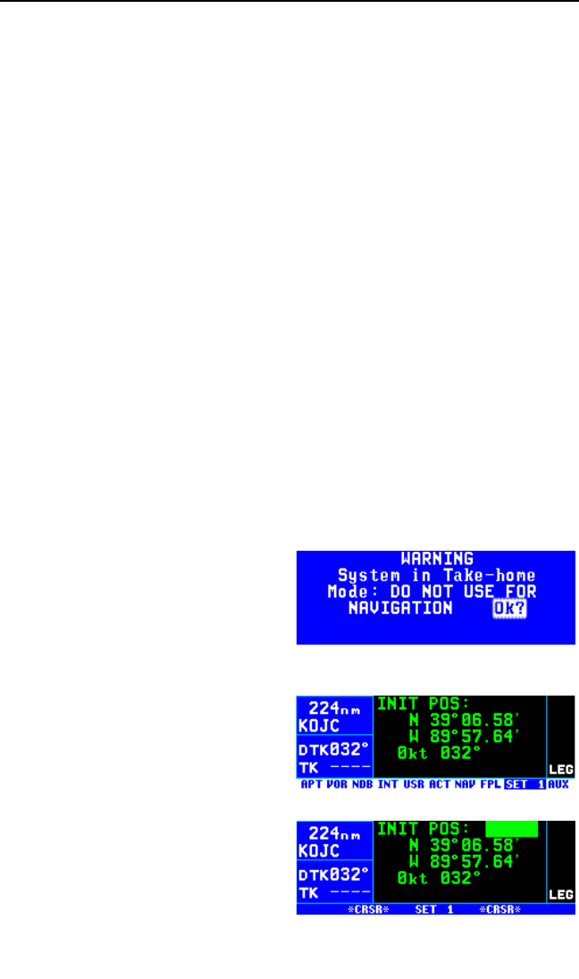
just as if it was actually functioning in an aircraft. Distances count down,
waypoints sequence, and the deviation bar follows the progress of the
simulated flight. Using the take-home mode is an excellent way to learn
the operation of the KLN 94 without worrying about the engine running,
other traffic, or even terrain.
There are products available which allow you to use the KLN 94 at your
home, office, or hotel to have get-acquainted time in the take-home mode,
for instance the Commander 2000 from Lone Star Aviation. It is also help-
ful to do flight planning and perform database updates outside the
airplane, perhaps with a home personal computer.
For more information on the Commander 2000, or to place an order, con-
tact:
Lone Star Aviation Corp.
804 North Great S.W. Pkwy
Arlington, TX 76011
Phone: (817) 633-6103
FAX: (817) 633-6208
lonestaraviation.com
The KLN 94 is automatically put into the take-home mode when it is used
with a Commander 2000. In addition, an authorized Honeywell Service
Center may also arrange for you to put the KLN 94 into the take-home
mode by grounding the appropriate pin at the back of the unit while it is
removed from the aircraft and is connected to an appropriate power sup-
ply. The KLN 94 must never be put into the take-home mode when it
is installed in the aircraft. A special
page is displayed shortly after turn
on when the unit is in the take-home
mode (figure 3-194). Press the F
button to acknowledge the take-
home mode.
To use the take-home mode:
1. Make sure the unit is in the take-
home mode.
2. Select the SET 1 page (figure 3-
195).
3. Press the Bbutton to turn on
the cursor (figure 3-196).
4. To start from the last position
skip to step 6. To change the
starting location enter the identi-
KLN 94 Pilot’s Guide Chapter 3 Basic GPS Operation
3-73
Figure 3-194
Figure 3-195
Figure 3-196
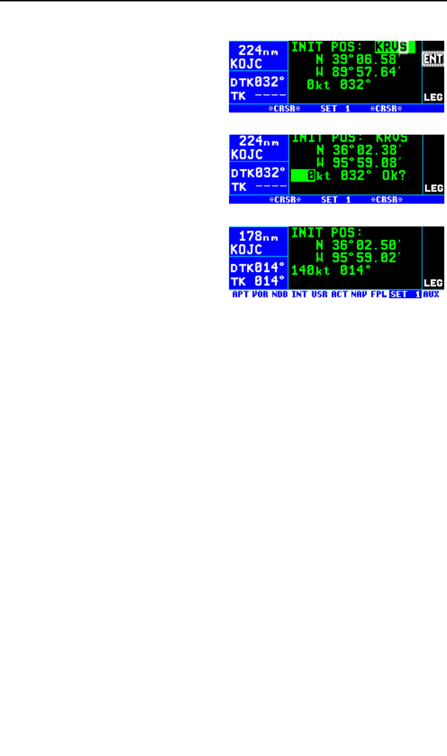
fier of the starting point of the trip (figure 3-197).
5. Press Fonce to view the way-
point page and a second time to
approve the waypoint page.
6. Rotate the right outer knob to
position the cursor over the
groundspeed field (figure 3-198)
and then turn the right inner
knob to select the desired
groundspeed (it must be above
30 knots).
7. Press the Fbutton.
8. Use the right outer knob to posi-
tion the cursor over the OK?
field and then press the Fbut-
ton (figure 3-199). You are now
flying!
3.17 SAMPLE TRIP
We’ve talked a lot about the features of the KLN 94, and now it’s time to
put those features to work for us and try a sample trip! Our trip will be
from Adams field (KLIT) in Little Rock, Arkansas to Mueller Municipal air-
port (KAUS) in Austin, Texas. The weather is perfect and we decide to
make the trip VFR and fly direct to Austin.
3.17.1 PRE-DEPARTURE
1. Apply power to the KLN 94 by pushing the On/Off/Brightness knob to
the “in” position. Rotate the knob to adjust the display brightness to
the desired level.
2. Enter the current altimeter setting on the Self Test page and press the
Fbutton. The cursor will move over OK?. Verify that the informa-
tion on the Self Test page is correct and press F.
3. Verify that the information on the Initialization pages is correct, includ-
ing the time and date. Position the cursor over Ok? and press Fto
approve the Initialization page.
4. Read the Database page and acknowledge it by pressing F.
5. The APT 5 page for Adams field (KLIT), which shows the communica-
tions frequencies, is now displayed on the screen since KLIT was the
active waypoint when you last removed power from the KLN 94. The
first APT 5 page indicates
Chapter 3 Basic GPS Operation
3-74
Figure 3-198
Figure 3-199
Figure 3-197

KLN 94 Pilot’s Guide Chapter 3 Basic GPS Operation
3-75
that the ATIS frequency is 125.65 MHz, the pre-taxi clearance delivery
frequency is 118.95 MHz, and the ground control frequency is 121.90
MHz. After listening to ATIS, we contact clearance delivery for our
clearance out of the Little Rock Class C airspace. Next, we give
ground control a call and receive our taxi clearance.
6. By this time the KLN 94 has reached a NAV ready status. We can ver-
ify this by turning to the NAV 2 page. It shows a valid present
position, in this case 3.8 nautical miles on the 320 degree radial from
Little Rock (LIT) VOR.
7. Press Dto bring up the Direct To page. Use the right inner and
outer knobs to enter the identifier of Mueller Municipal airport (KAUS)
by using the right inner knob to select the characters and the right
outer knob to move the flashing part of the cursor to the desired cursor
location.
8. Press F. The APT 1 page for Mueller Municipal is now displayed on
the screen.
9. Press Fagain to approve the waypoint page. The NAV 1 page is
now displayed. The NAV 1 page indicates it is 387 nautical miles to
Austin and that the desired track (DTK) is 225 degrees. After take-off,
the NAV 1 page will also display groundspeed, actual track (TK), and
estimated time en route.
3.17.2 EN ROUTE
1. We depart from runway 36 at Little Rock and are told to “maintain run-
way heading.” After several radar vectors for traffic avoidance we are
finally cleared on course. The D-Bar indicates that the radar vectors
have taken us north of the original course and we decide to proceed
Direct To Austin from our present position. To recenter the D-Bar,
press D, and then press F.
2. After departure control has directed “squawk 1200, frequency change
approved,” we decide it would be a good idea to obtain VFR flight fol-
lowing. To obtain the frequency for Center, press the Gbutton,
move the cursor to the CTR? selection, and press F. The KLN 94
indicates that for our position, we should be able to contact Memphis
Center on 135.80 MHz.
3. We’ve only flown about 100 nautical miles, but we begin wondering
where we would go if an engine suddenly started running rough. We
decide to use the KLN 94 to determine where the nearest airports are
from our present location. To view the nearest airports press G, and
then press F. The nearest airport is Hope Municipal (M18) which is
eight nautical miles from our position on a bearing to the airport of 11
degrees. You now rotate the right inner knob to view the other APT

Chapter 3 Basic GPS Operation
3-76
pages for Hope Municipal. We learn, for example, that it is located in
Hope, Arkansas, and has two hard surface runways that are each
5500 feet in length. By pulling the right inner knob to the “out” position,
you may now scan clockwise through the remaining 19 airports in the
nearest airport list.
4. For the majority of the en route portion of the flight, you select the
NAV 4 page’s moving map display by pressing the map range scale
(R) button. You continue to press the Rbutton up or down to select
the 30 nautical mile range scale. Press the Mbutton to display the
map menu. From this map menu page you may quickly get to the SET
7 page to configure the aeronautical data or the SET 8 page to config-
ure the land data as desired. In addition you can change the map
orientation from the map menu page.
5. Since it is a good idea to not rely on just one navigation source, we
cross check the KLN 94 position against other equipment in the air-
craft. The NAV 2 page indicates we are presently located on the
Texarkana (TXK) VOR 68 degree radial at a distance of 19 nautical
miles. By tuning our NAV receiver and DME to TXK, we are able to
confirm that this is the correct position.
3.17.3 TERMINAL AREA
1. About 50 nautical miles from Austin’s Mueller airport we start prepar-
ing for our arrival. Viewing the APT 5 page for KAUS you determine
that the ATIS frequency is 124.40 MHz and tower is 121.00 MHz.
2. A few minutes later, the message prompt begins flashing. When you
press C, the message page advises Airspace Alert - Austin CL C
- Below 4500 ft - See KAUS freq-Press CLR. The Special Use
Airspace Alert feature has determined that you are within 10 minutes
of penetrating the Austin Class C airspace. When you press Eand
view the APT 5 page for KAUS, you see that the Class C airspace fre-
quencies are sectorized. You determine from the APT 5 page that the
proper frequency to use is 118.80 MHz since we are Northeast of
Austin and 118.80 MHz is the appropriate frequency to use from 355
degrees to 175 degrees. You turn to the NAV 4 page so that you can
see the outer boundary of the Austin Class C airspace relative to your
location and route.
3. After you call Austin approach control for clearance into the Class C
airspace, you view the rest of the APT pages for KAUS to determine
the field elevation and available runways.
6. After landing, the KLN 94 is turned off either by pulling the
On/Off/Brightness knob out to the Off position, or with the avionics
master switch if one is installed.

4. FLIGHT PLAN OPERATION
If you are going to use your KLN 94 for more than just flying VFR, direct
from one airport to the next, it will be well worth your while to learn its flight
plan capabilities. This section of the Pilot’s Guide describes how to cre-
ate, edit, and fly flight plans.
4.1. CREATING AND MODIFYING FLIGHT PLANS
The following rules and considerations apply to KLN 94 flight plans:
• The KLN 94 is capable of storing in its memory 25 flight plans plus
an active flight plan (FPL 0).
• Each of the flight plans may contain up to 20 waypoints. The way-
points may consist of any combination of published waypoints from
the database or user created waypoints. The active flight plan may
contain up to 35 waypoints if it includes approach and DP/STAR
waypoints.
• The flight plans are numbered 0 through 25 (FPL 0, FPL 1, FPL 2, .
. . , FPL 25).
• The active flight plan is always FPL 0. The standard procedure is
to create a flight plan using one of the flight plans numbered as FPL
1, FPL 2, etc. When one of these numbered flight plans is activated,
it becomes FPL 0, the active flight plan. This Pilot’s Guide will refer
to FPL 0 as the “active flight plan” and FPL 1 through FPL 25 as the
“numbered flight plans.” If desired, a flight plan can be created
directly in the active flight plan. This avoids creating the flight plan in
a numbered flight plan and then having to activate it. The disadvan-
tage is that if a numbered flight plan is subsequently made active,
the one programmed directly into FPL 0 will be lost.
• Modifications may be made to FPL 0 without affecting the way it is
stored as a numbered flight plan.
• Unless Direct To operation is being used, the active flight plan (FPL
0) must contain at least two waypoints. Otherwise, the KLN 94 nav-
igation system will be flagged.
• The first waypoint in the flight plan should always be the departure
airport.
4.1.1. CREATING A FLIGHT PLAN
A flight plan for a flight from Lakefront airport in New Orleans, LA to St.
Petersburg/Clearwater, FL International airport will be used as an exam-
ple of how to create a flight plan. The waypoints making up the flight plan
KLN 94 Pilot’s Guide Chapter 4 Flight Plan Operation
4-1
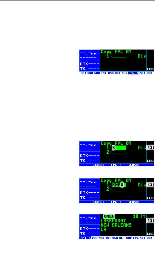
Chapter 4 Flight Plan Operation
4-2
are: KNEW (Lakefront airport), GPT (Gulfport VOR), SJI (Semmes VOR),
CEW (Crestview VOR), MAI (Marianna VOR), SZW (Seminole VOR),
CTY (Cross City VOR), and KPIE (St. Petersburg/Clearwater International
airport).
To create a flight plan:
1. Select the flight plan (FPL) pages with the right outer knob.
2. Select a flight plan page (prefer-
ably other than FPL 0) which
does not contain a flight plan (fig-
ure 4-1). If all of the flight plan
pages contain flight plans, refer
to section 4.1.6, “Deleting Flight
Plans”.
3. Turn on the cursor with the Bbutton.
NOTE: The KLN 94 flight plan operation is designed so that the first way-
point in the flight plan should always be the departure airport. Remember
to enter the K, P, or Cprefix for certain airports in the United States,
Alaska (some, but not all cases), or Canada, respectively. See section 2.3,
“ICAO Identifiers”.
4. Use the right inner knob to select the first character of the departure
waypoint identifier (figure 4-2). If you have set the default first way-
point character to Kon the
SET 11 page, you will just need
one turn clockwise (see section
3.4.2, “Data Entry”).
5. Turn the right outer knob to
move the flashing part of the cur-
sor over the second character,
then select the desired charac-
ter.
6. Use the above procedure to
select the entire identifier for the
first waypoint (figure 4-3).
7. Press F. A waypoint page for
the identifier just entered will be
displayed on the screen (figure
4-4). If a mistake was made and
the wrong waypoint identifier was
entered, press Eand begin
Figure 4-1
Figure 4-2
Figure 4-3
Figure 4-4
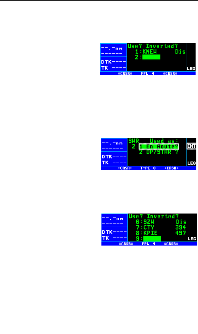
KLN 94 Pilot’s Guide Chapter 4 Flight Plan Operation
4-3
again. If no mistake was made but the waypoint identifier just entered
isn’t in the database, a page allowing creation of a user defined way-
point will appear on the screen. Refer to section 5.4 for instructions on
how to create a user-defined waypoint.
8. Press Fagain to approve the
waypoint page being displayed.
The cursor will move automati-
cally to the second waypoint
position (figure 4-5).
NOTE: A small number of waypoints are stored in the database as “fly-
over” waypoints. These waypoints are associated with DP/STAR
procedures. “Fly-over” means that, for some reason, the governing agen-
cies have decided that it is important to fly directly over the waypoint
instead of being able to “cut the corner” by using turn anticipation (see
section 4.2.2. “Turn Anticipation And Waypoint Alerting”). In these cases
the KLN 94 will present a waypoint type identification page (figure 4-6).
Simply select the way in which the
waypoint is intended to be used with
the right outer knob and press F. If
the DP/STAR choice is selected, the
KLN 94 will disable turn anticipation
for that waypoint (if previously
enabled). The KLN 94 will enable
turn anticipation after the waypoint has been passed (if turn anticipation
was previously enabled). If En Route is selected, then normal turn antici-
pation occurs.
9. Use the same procedure to enter
the rest of the waypoints in the
flight plan (figure 4-7). If the
flight plan consists of four or
more waypoints, the waypoints
will automatically scroll as neces-
sary to allow entry of the next
waypoint.
10. When all of the waypoints have been entered in the flight plan, the
right outer knob may be rotated to move the cursor up and down and
manually “scroll” through the waypoints making up this flight plan.
This is useful if the flight plan contains five or more waypoints since
not all of the waypoints can be displayed at one time. When the right
outer knob is rotated counterclockwise, the cursor may be positioned
over Use?. If there are more than four waypoints in the flight plan, the
Figure 4-5
Figure 4-6
Figure 4-7
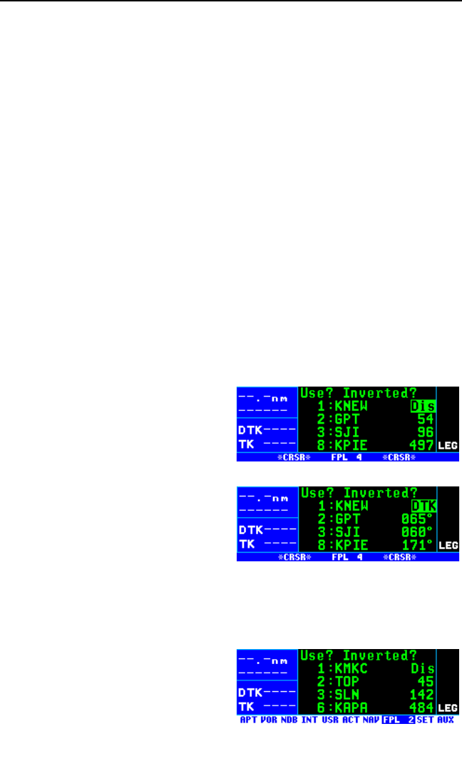
Chapter 4 Flight Plan Operation
4-4
first three waypoints will then be displayed followed by the last way-
point in the flight plan. Rotate the right outer knob to move the cursor
and manually scroll to see the missing intermediate waypoints.
11. Turn off the cursor with the Bbutton. Additional flight plans may
now be created in the same manner.
4.1.2. VIEWING DISTANCE AND DESIRED TRACK BETWEEN
STORED FLIGHT PLAN WAYPOINTS
The stored flight plan (FPL 1-25) pages have a field to the right of each
waypoint in the flight plan. This field may be used to display the cumula-
tive distance (Dis) to each waypoint or the desired track (DTK) from the
previous waypoint.
If you have more than four waypoints in the stored flight plan, you may
wish to view flight data for waypoints which are not displayed on the
screen. If this is the case, turn on the cursor (B) and use the right outer
knob to scroll down the flight plan until the waypoint of interest is on the
screen.
This display will default to the distance presentation at power-on.
To change between distance and desired track display on a num-
bered flight plan page:
1. Turn on the cursor (B); it will
come up over the USE? field
near the upper left corner of the
screen. Rotate the outer knob to
position the cursor over the dis-
tance (Dis) field (figure 4-8).
2. Turn the right inner knob one
click to change to desired track
(DTK) (figure 4-9). An additional
click changes back to Dis.
4.1.3. ACTIVATING A NUMBERED FLIGHT PLAN
To activate one of the previously created numbered flight plans:
1. Use the right outer and inner
knobs to select the desired flight
plan page (figure 4-10).
Figure 4-8
Figure 4-9
Figure 4-10
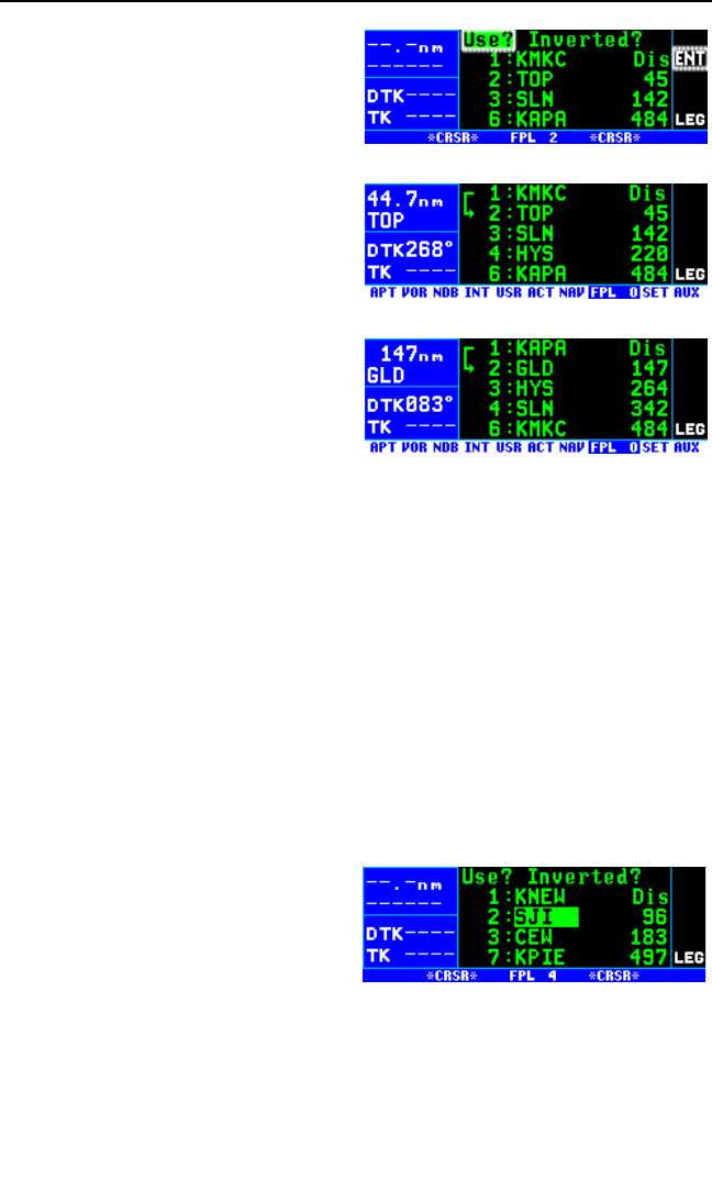
2. Press Bto turn on the cursor.
It will appear over Use? (figure
4-11). If you haven’t left the
numbered flight plan since creat-
ing this flight plan, rotate the
outer knob counterclockwise to
position the cursor over Use?.
3. Press Fto activate the flight
plan in the order shown (figure
4-12). To activate the flight plan
in inverse order (first waypoint
becomes last and last waypoint
becomes first), rotate the outer
knob one step clockwise to posi-
tion the cursor over Use?
Inverted? before pressing F.
The result is shown in figure 4-
13.
4. The selected flight plan is now displayed as FPL 0, the active flight
plan. Any changes made to FPL 0 will not affect how this flight plan is
stored as the numbered flight plan.
4.1.4. ADDING A WAYPOINT TO A FLIGHT PLAN
A waypoint may be added to any flight plan containing fewer than 20 way-
points.
To add a waypoint to a flight plan:
1. Turn on the cursor with the Bbutton.
2. With the outer knob, position the cursor over the waypoint identifier
which you desire to follow the waypoint being added. Another way to
think of this is to position the cursor over the location in the flight plan
you wish the new waypoint to be
added. For example, if SJI is
presently the second waypoint in
the flight plan and you wish to
insert GPT in the number 2 posi-
tion in front of SJI, move the
cursor over SJI (figure 4-14).
3. Use the inner knob to enter the first character of the waypoint being
inserted. As you begin to turn the knob, the existing waypoint in this
KLN 94 Pilot’s Guide Chapter 4 Flight Plan Operation
4-5
Figure 4-11
Figure 4-12
Figure 4-13
Figure 4-14
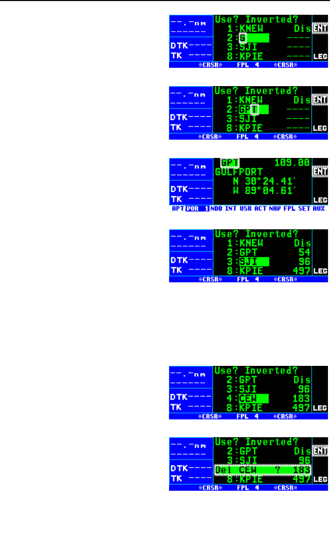
position automatically jumps
down to the next position. In this
case, SJI automatically moves to
waypoint 3 and KPIE changes to
waypoint 8 (figure 4-15).
4. Complete the waypoint entry
operation (figure 4-16).
NOTE: If adding a waypoint or way-
points (such as adding DP/STAR/
Approach procedures) would exceed
the capacity of FPL 0, KLN 94 will
notify you that it is deleting waypoints
from the beginning of FPL 0 to make
room for the addition.
5. Press Fto display the way-
point page on the right side for
the identifier just entered (figure
4-17).
6. Press Fagain to approve the
waypoint page (figure 4-18).
7. Turn off the cursor (B).
4.1.5. DELETING A WAYPOINT FROM A FLIGHT PLAN
To delete a waypoint from a flight plan:
1. Press Bto enable the cursor if it is not on already.
2. Move the cursor over the way-
point you wish to delete (figure
4-19).
3. Press E. The letters Del
(delete) will appear to the left of
the identifier and a question
mark will appear to the right of
the identifier (figure 4-20). If a
mistake was made and you do
not wish to delete this waypoint,
press E.
Chapter 4 Flight Plan Operation
4-6
Figure 4-15
Figure 4-16
Figure 4-17
Figure 4-18
Figure 4-19
Figure 4-20
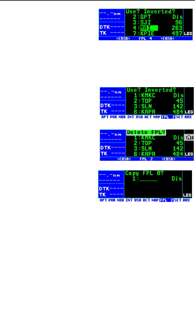
4. Press Fand the waypoint will
be deleted from the flight plan.
The other waypoints in the flight
plan will be correctly reposi-
tioned (figure 4-21).
5. Turn off the cursor with the B
button.
4.1.6. DELETING FLIGHT PLANS
To delete a flight plan which is no longer required:
1. Display the flight plan (FPL 0,
FPL 1, . . ., or FPL 25) which is
to be cleared (figure 4-22).
2. Make sure that the cursor is
turned off, and use the Bbut-
ton if it is not.
3. Press E. The words Delete
FPL? will appear at the top of
the page (figure 4-23). If a mis-
take was made and you do not
wish to clear this flight plan,
press Eagain.
4. Press Fto clear the flight
plan. The flight plan page will
appear as in figure 4-24.
4.1.7. STORING FPL 0 AS A NUMBERED FLIGHT PLAN
The active flight plan may be loaded into a numbered flight plan so that it
can be recalled for later use. This may be desirable, for example, if the
active flight plan was originally created on the FPL 0 page and not as a
numbered flight plan.
To store the active flight plan as a numbered flight plan:
1. Select a numbered flight plan page which does not contain any way-
points (figure 4-24). If none exist, use the procedure described in
section 4.1.6, “Deleting Flight Plans,” to clear a flight plan which is no
longer required.
KLN 94 Pilot’s Guide Chapter 4 Flight Plan Operation
4-7
Figure 4-21
Figure 4-22
Figure 4-23
Figure 4-24
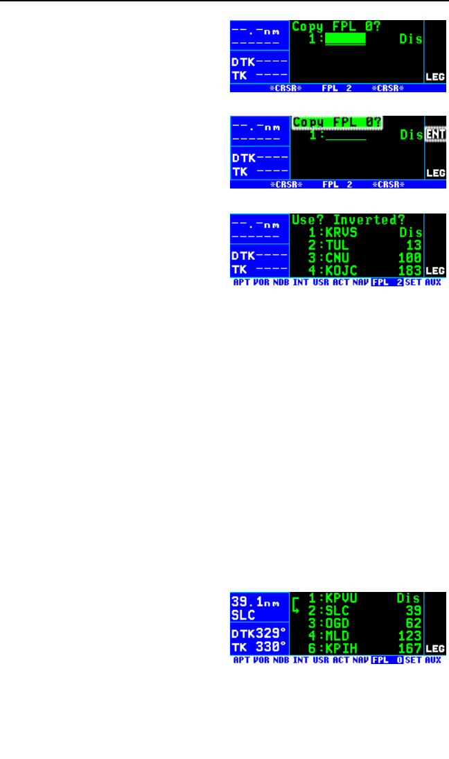
2. Turn on the cursor with the B
button. It will appear over the
blank first waypoint position (fig-
ure 4-25).
3. Rotate the right outer knob coun-
terclockwise to position the
cursor over Copy FPL 0? (figure
4-26).
4. Press Fto load the active
flight plan into this numbered
flight plan (figure 4-27).
4.2. OPERATING FROM THE ACTIVE FLIGHT PLAN
4.2.1. GENERAL PROCEDURES
Everything you have learned in this Pilot’s Guide thus far is applicable to
using the KLN 94 for flight plan operation. The following rules and consid-
erations apply for flight plan operation while the KLN 94 is in the Leg
mode:
• Always verify that you are viewing the active flight plan page
(FPL 0) and not one of the other numbered flight plan pages.
• The active leg of the flight plan is designated with a symbol. A
leg is defined as the course line between a pair of waypoints (a
“from” waypoint and a “to” waypoint). The head of the arrow is posi-
tioned to the left of and points to the active “to” waypoint. In figure
4-28, SLC (Salt Lake City VOR) is the “to” waypoint. The tail of the
symbol is positioned to the left
of the “from” waypoint. KPVU
(Provo Municipal) is the “from”
waypoint in figure 4-28. The
symbol is not displayed unless
the KLN 94 is actually receiv-
≤≤
≥≥
Chapter 4 Flight Plan Operation
4-8
Figure 4-25
Figure 4-26
Figure 4-27
Figure 4-28
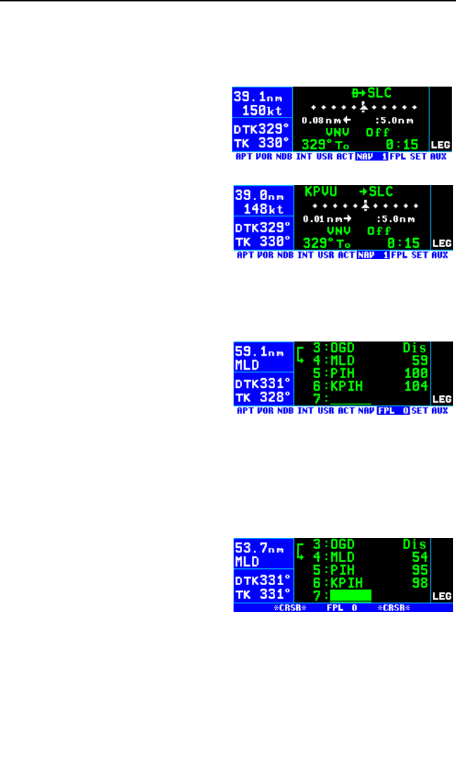
ing GPS signals suitable for navigation. (Note: If the unit is in the
take-home mode, it has been “tricked” into thinking it is receiving
signals and therefore the symbol can be displayed). Also, the sym-
bol will not be displayed if Direct To navigation is occurring and the
Direct To waypoint is not in
FPL 0. If in doubt as to
whether or not Direct To oper-
ation is occurring, view the
NAV 1 page. If the top line
shows the $symbol (figure
4-29) instead of a “from” way-
point (figure 4-30), then Direct
To navigation is occurring. If it
is desired to cancel the Direct
To operation and operate from
the active flight plan, press
D, E, and then F.
• As flight plan waypoints are reached, the active leg symbol auto-
matically shifts to the next leg.
• If the flight plan contains more
waypoints than can be dis-
played on the screen at one
time, the page will automatical-
ly scroll as progress is made
along the flight plan so that the
active leg is always displayed
(figure 4-31).
• The last waypoint in the flight plan is always displayed at the bottom
of the FPL 0 page, even if all of the waypoints in the flight plan can’t
be displayed on the page at one time. To view intermediate way-
points, turn the cursor on and use the right outer knob to manually
scroll through all of the way-
points, as desired. If scrolling
is performed all the way to the
end of the flight plan, a blank
waypoint position will exist so
that a waypoint may be added
to the end of the flight plan
(figure 4-32).
KLN 94 Pilot’s Guide Chapter 4 Flight Plan Operation
4-9
Figure 4-29
Figure 4-30
Figure 4-31
Figure 4-32
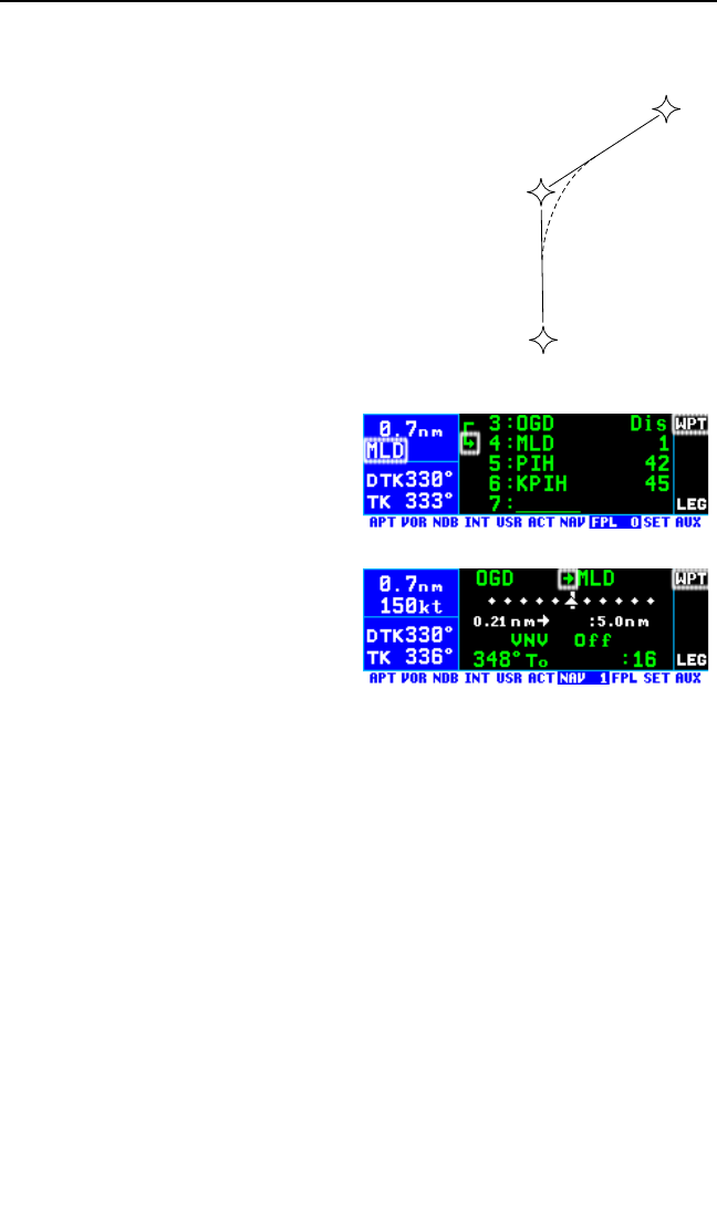
4.2.2. TURN ANTICIPATION AND WAYPOINT ALERTING
Prior to reaching a waypoint in the active flight
plan, the KLN 94 will provide navigation along a
curved path segment to ensure a smooth transition
between two adjacent legs in the flight plan. That
is, the CDI or HSI left/right deviation will be refer-
enced to the dashed line in figure 4-33. This
feature is called turn anticipation. The transition
course is based upon the aircraft’s actual ground-
speed and the amount of course angle change
between the two legs. The KLN 94 automatically
sequences to the next leg after passing the mid-
point in the transition segment.
Approximately 20 seconds prior to the beginning of
turn anticipation, the WPT (waypoint
alert) annunciator starts flashing in
the upper right section of the screen.
In addition, the arrow preceding the
active waypoint identifier will begin
flashing on the FPL 0 page and on
any Navigation page or waypoint
page displaying the active waypoint
identifier (figures 4-34 and 4-35).
This is called “waypoint alerting”. If
an external waypoint alert annuncia-
tor is mounted in the aircraft, this
annunciator will begin flashing at the
same time.
To utilize the turn anticipation feature, start the turn transition to the next
leg in the flight plan at the very beginning of turn anticipation. This occurs
when the waypoint alert annunciator stops flashing and goes on steady.
At this time, the KLN 94 will notify you with a message on the Message
page of the new desired track to select on your HSI or CDI.
Adj Nav Crs to 123°
A message will not be given if the change in desired track (course
change) is less than 5°.
The desired track (DTK), displayed in the middle of the left side of the
screen, also changes to the value for the next leg at the beginning of turn
anticipation. Turn anticipation becomes inactive when transition to the
next leg has been made.
Chapter 4 Flight Plan Operation
4-10
WPT 1
WPT 2
WPT 3
Figure 4-33
Figure 4-34
Figure 4-35
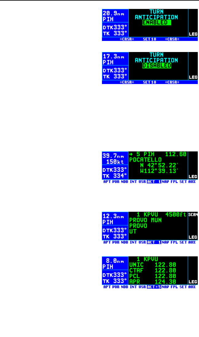
Although normally not recommend-
ed, turn anticipation may be disabled
on the Setup 10 (SET 10) page by
pressing the Bbutton and then
rotating the right inner knob to
change back and forth between
ENABLED (figure 4-36) and DIS-
ABLED (figure 4-37). If turn
anticipation is disabled, navigation is
provided all the way to the waypoint,
and waypoint alerting occurs approx-
imately 36 seconds prior to actually
reaching the waypoint.
4.2.3. VIEWING THE WAYPOINT PAGES FOR THE ACTIVE
FLIGHT PLAN WAYPOINTS
The waypoint pages for each of the waypoints in the active flight plan may
be easily displayed by selecting the Active (ACT) Waypoint page type.
When the ACT page type is first selected, the waypoint page for the active
waypoint will be displayed (figure 4-38). The location of the waypoint in
the flight plan (waypoint 1, waypoint
2, etc.) is annunciated with a number
to the left of the identifier. In addi-
tion, an arrow to the left of the
waypoint number designates the
active waypoint.
To view the waypoints in the flight plan that are not the active way-
point:
1. From the ACT page, pull the
right inner knob to the “out” posi-
tion and turn it to scan through
each of the waypoints in the
order they are contained in the
flight plan (figure 4-40).
2. Once the desired waypoint is
found, the right inner knob may
be pushed back to the “in” posi-
tion and rotated to display any of
the other waypoint pages for that
waypoint (figure 4-41).
3. Pulling the knob back out will allow further scanning of the waypoints
in the active flight plan.
KLN 94 Pilot’s Guide Chapter 4 Flight Plan Operation
4-11
Figure 4-36
Figure 4-37
Figure 4-38
Figure 4-40
Figure 4-41

4.2.4. COMBINING DIRECT TO AND FLIGHT PLAN OPERATION
It is very common when using flight plan operation to use the Direct To
function to proceed directly to a waypoint which exists in the active flight
plan. For example, after takeoff on an IFR flight plan, it is common to
receive vectors in the terminal area and then be given a clearance direct
to the first waypoint in the flight plan that was filed. The KLN 94 makes
this kind of operation very easy to accomplish. Whenever you do a Direct
To operation to a waypoint which is in the active flight plan (FPL 0), the
system will provide navigation to the waypoint and then automatically
resume navigation along the flight plan when the Direct To waypoint is
reached. Waypoints which exist prior to the Direct To waypoint in the
active flight plan are bypassed. Of course, the active flight plan will never
be resumed if the Direct To operation is to a waypoint which is not in the
active flight plan.
Any of the several methods previously described for initiating Direct To
operation may be used. However, there are several methods for Direct
To operation optimized for flight plan operation.
4.2.4.1 Direct To Operation From The Map
When operating from the Nav 4 map page the method described in sec-
tion 3.11.4.11. “Waypoint Scan Feature” will often be the most convenient
because your don’t have to leave the map to initiate the Direct To opera-
tion. As described in that section, this involves pulling the right inner knob
out to the “scan” position and then turning this knob to display the desired
flight plan waypoint identifier in the lower right corner of the map. The D
button is then pressed to bring up the Direct To page with the selected
waypoint identifier already displayed. Pressing the Fbutton approves
the Direct To waypoint and returns the unit to the map page. Press the
right inner knob back to the “in” position.
4.2.4.2 Direct To Operation From Any Page
Another good method of selecting a FPL 0 waypoint as the Direct To way-
point is to press the Dbutton from any page to bring up the Direct To
page. Then pull the right inner knob out to the “scan” position and rotate it
to scan though the active flight plan waypoints until the desired FPL 0
waypoint is displayed. Press the Fbutton to complete the operation.
Press the right inner knob back to the “in” position.
Chapter 4 Flight Plan Operation
4-12
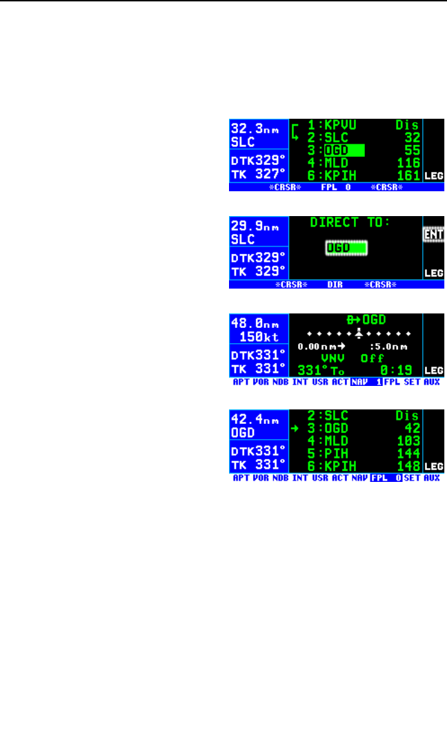
4.2.4.3 Direct To Operation From The FPL 0 Page
If you are presently viewing the active flight plan page there is an easy
method of selecting the Direct To waypoint.
To fly direct to a waypoint in the active flight plan while viewing the
FPL 0 page:
1. Select the FPL 0 page.
2. Turn on the cursor with the B
button and use the left outer
knob to position the cursor over
the desired waypoint (figure 4-
42).
3. Press D. The display will
change to the Direct To page
(figure 4-43), with the identifier of
the selected waypoint.
4. Press Fto approve the Direct
To. The NAV 1 page will be dis-
played (figure 4-44) reflecting the
new active waypoint.
5. If you now turn back to the
FPL 0 page, you will see that the
active waypoint is now preceded
by an arrow only, instead of the
(figure 4-45). This is because
there is no “from” waypoint in the
flight plan.
4.2.4.4 Cancelling Direct To Operation
If it is desired to cancel the Direct To operation prior to reaching the Direct
To waypoint in order to proceed along the flight plan leg, press D, then
press E, then F. The unit will orient itself on the closest leg of the
flight plan.
≤≤
≥≥
KLN 94 Pilot’s Guide Chapter 4 Flight Plan Operation
4-13
Figure 4-42
Figure 4-43
Figure 4-44
Figure 4-45
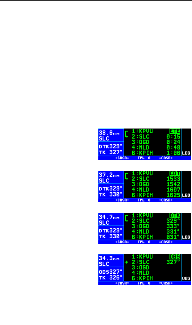
4.2.5. VIEWING DISTANCE, ETE, ETA, OR DESIRED TRACK TO
FLIGHT PLAN WAYPOINTS
The right side of the active flight plan (FPL 0) page may be used to display
(1) the cumulative distance (Dis) along the flight plan route from the pre-
sent position to each flight plan waypoint, (2) the estimated time en route
(ETE) to each waypoint, (3) the estimated time of arrival (ETA) at each
waypoint, or (4) the magnetic desired track (DTK) for each waypoint.
If you have more than five waypoints in FPL 0, you may wish to view flight
data for waypoints which are not displayed on the screen. If this is the
case, turn on the cursor (B) and use the right outer knob to scroll down
the flight plan until the waypoint of interest is on the screen.
This display will default to the distance (Dis) presentation at power-on (fig-
ure 4-45).
To change between distance, ETE, ETA, and desired track on the
FPL 0 page:
1. Turn on the cursor with the B
button; it will come up initially
over the distance (Dis) field.
2. Turn the right inner knob to
change the field from distance
(Dis), to ETE in hours:minutes
(figure 4-46), to ETA in terms of
the system time zone (figure 4-
47), to DTK (figure 4-48) and
then back to Dis. Note that the
system time zone abbreviation
(e.g. CDT) is used to annunciate
when ETA is selected.
3. Press the Bbutton to turn the
cursor off.
NOTE: When the KLN 94 is in OBS
mode, the FPL 0 page will present
OBS selected course (OBS) as an
option instead of magnetic desired
track (DTK). The selected course
will be displayed to the right of the
active waypoint, and the OBS fields
for all other waypoints will be blank
(figure 4-49).
Chapter 4 Flight Plan Operation
4-14
Figure 4-47
Figure 4-46
Figure 4-48
Figure 4-49

4.2.6 CHANGING THE SYSTEM TIME ZONE
The ETA shown on the FPL 0 page is the for the system time zone. The
system time zone may be changed from either the NAV 3 or SET 2 page.
Section 3.2 gives a list of available time zones.
To change the system time zone:
1. Select either the NAV 3 or SET 2
page.
2. Turn on the cursor with the B
button and use the right outer
knob to position the cursor over
the time zone field (figure 4-50).
3. Rotate the right inner knob to
select the desired time zone (fig-
ure 4-51).
4. Turn off the cursor.
KLN 94 Pilot’s Guide Chapter 4 Flight Plan Operation
4-15
Figure 4-50
Figure 4-51

Chapter 4 Flight Plan Operation
4-16
This page intentionally left blank
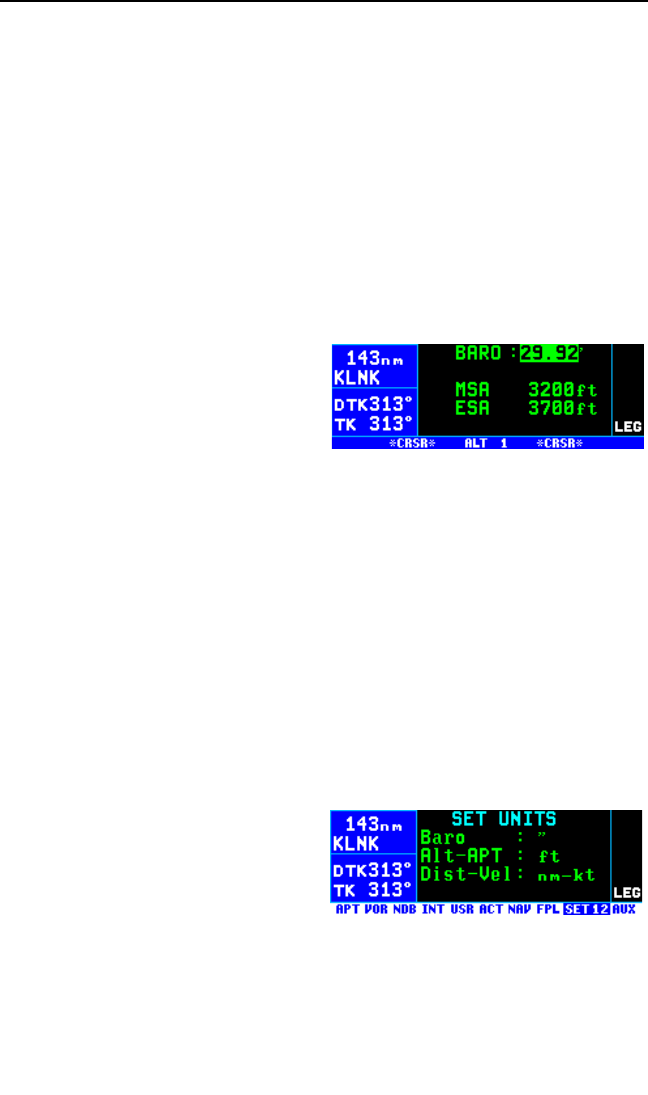
5. INTERMEDIATE OPERATION
Many of the KLN 94’s advanced features and functions are covered in this
section of the Pilot’s Guide. You may pick and choose which of these fea-
tures are applicable to the type of flying you do. If you are a serious IFR
pilot be sure to learn the information presented on the KLN 94’s navigation
modes described in section 5.5.
5.1. ALTITUDE PAGES
The ALT (altitude) pages are used to control and display most of the alti-
tude-related functions of the KLN 94, including minimum safe altitudes
and vertical navigation (VNAV). The ALT pages are accessed by pressing
the Abutton. The first time the Abutton is pressed, the ALT 1 page is
displayed (figure 5-1). If the Abut-
ton is pressed again while the ALT 1
page is displayed, the display
changes to the ALT 2 page. Pressing
Aa third time goes back to the
page which you were on before you
changed to the ALT pages.
The ALT 1 page is used to set the current barometric pressure or “baro
setting” which is displayed on line 1. Since all encoding altimeters and
some air data computers output pressure altitude, it is often required that
you manually input the proper baro setting in order to get accurate altitude
functions. The KLN 94 functions which use the altitude input are special
use airspace (SUA) alerting, altitude alerting, vertical navigation (VNAV),
and the GPS approach mode. It is a good idea to update the altimeter
baro setting on the ALT 1 page each time you make a change to the air-
craft’s altimeter setting.
To Change the Baro Setting:
1. Press A. The ALT 1 page will be displayed with the cursor over the
altimeter baro setting field (figure 5-1).
NOTE: The SET 12 page (figure 5-
2) is used to set the unit of measure
for various parameters. The altimeter
barometric setting can be set to inch-
es of Mercury (“), millibars (mB), or
hectopascals (hP). Altitude, airport
elevation, and runway lengths can
be set to feet (ft) or meters (m). Finally, distances and velocities can be
set to nautical miles (NM) and knots (kt) or kilometers (km) and kilome-
ters/hour (k/h). To change a unit of measure: select the SET 12 page; turn
on the cursor (B) and move it over the desired unit of measure using the
KLN 94 Pilot’s Guide Chapter 5 Intermediate Operation
5-1
Figure 5-1
Figure 5-2

right outer knob; turn the right inner knob to select the desired unit of mea-
sure; and turn the cursor off again.
2. Use the right inner knob to
update the altimeter baro setting
(figure 5-3).
3. Press Atwice to return to the
page previously being viewed.
Line 3 displays the Minimum Safe Altitude (MSA)
IMPORTANT: The minimum safe altitude displayed is the altitude defined
by Jeppesen as “Grid Minimum Off-Route Altitude (Grid MORA)”. This alti-
tude is derived by Jeppesen for sectors which are one degree of latitude
by one degree of longitude in size. One degree of latitude is 60 nautical
miles. One degree of longitude is 60 nautical miles at the equator and pro-
gressively less than 60 nautical miles as one travels away from the
equator. One degree of longitude is approximately 50 nautical miles at the
southern most parts of the U.S. and is approximately 40 nautical miles at
the northern most parts of the U.S. The MSA altitude information is con-
tained in the database and is updated when the database cartridge is
updated.
The minimum safe altitude (MSA) provides “reference point” clearance
within these one degree latitude by one degree longitude sectors.
Jeppesen defines a reference point as “a natural (Peak, Knoll, Hill, etc.) or
man-made (Tower, Stack, Tank, Building, etc.) object”. Jeppesen states
the following about the Grid Minimum Off-Route altitude: “Grid MORA val-
ues clear all reference points by 1000 feet in areas where the highest
reference points are 5000 feet MSL or lower. MORA values clear all refer-
ence points by 2000 feet in areas where the highest reference points are
5001 feet MSL or higher”. The KLN 94 displays dashes for areas outside
the database coverage area or for areas where the Grid MORA is not
defined.
Line 4 displays the Minimum En route Safe Altitude (ESA).
IMPORTANT: When the KLN 94 is in the Leg mode, the minimum en
route safe altitude is the highest MSA sector altitude from the present
position to the active waypoint, then to the destination waypoint along the
active flight plan. See figure 5-4. When the KLN 94 is in the OBS mode,
the minimum en route safe altitude is the highest MSA sector altitude from
the present position to the active waypoint.
WARNING: The MSA and ESA altitudes displayed are advisory in
nature only. They should not be relied upon as the sole source of
obstacle and terrain avoidance information. Refer to current aero-
nautical charts for appropriate minimum clearance altitudes.
Chapter 5 Intermediate Operation
5-2
Figure 5-3
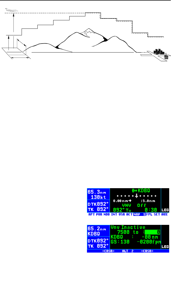
5.2. ADVISORY VNAV OPERATION
The KLN 94’s advisory vertical navigation (VNAV) feature allows you to
program a descent or ascent path, and then provides you with an advisory
altitude to fly that will provide guidance along the vertical path. For exam-
ple, you can program the VNAV to provide descent guidance so that you
arrive at your active waypoint or a waypoint in the active flight plan at an
altitude that you specify. The KLN 94 will alert you of when to start the
descent, and display the advisory altitudes to fly throughout the descent.
Vertical navigation is always set up on the ALT 2 page but may then be
viewed on the NAV 1, NAV 4 (map), or ALT 2 pages.
5.2.1. VNAV FOR DIRECT TO OPERATION
The Altitude 2 (ALT 2) page is used to program the KLN 94 for vertical
navigation. To get to the ALT 2 page from any non-altitude page, press
the Abutton twice. The following example will be used to illustrate how
to use the VNAV feature. You are using the KLN 94 to fly direct to your
destination airport, Dubuque Municipal airport (KDBQ) located in
Dubuque, Iowa. You are presently about 65 nautical miles west of
Dubuque, flying at 7500 feet MSL
(figure 5-5). You desire to use the
VNAV to provide vertical guidance to
Dubuque’s traffic pattern altitude of
1900 feet MSL.
To use VNAV on a Direct To:
1. Select the ALT 2 page by press-
ing the Abutton twice (figure
5-6). The aircraft’s actual alti-
tude (7500 feet) is displayed on
the left side of line 2. If the dis-
played altitude is incorrect it is
probably because you have not recently updated the KLN 94’s altime-
ter baro setting on the ALT 1 page.
KLN 94 Pilot’s Guide Chapter 5 Intermediate Operation
5-3
MSA (MSL)
ESA (MSL)
1° LONG.
1°
LAT.
Figure 5-4
Figure 5-5
Figure 5-6
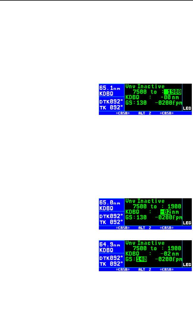
NOTE: There may be some difference (less than 100 feet) between the
indicated altitude and the aircraft’s actual altitude if the altitude input to the
KLN 94 is from an altitude encoder because these encoders only provide
altitude in 100 foot increments.
The identifier for the active waypoint (KDBQ) is automatically displayed on
the ALT 2 page. Prior to programming a VNAV operation, the top of the
page displays that the VNAV is inactive (Vnv Inactive).
2. The cursor should be on and over the selected altitude field on the
right side of line 2. If the cursor is not on, press B.
3. Enter the desired altitude of
1900 feet in the selected altitude
field, using the right inner knob.
The altitude may be entered in
100 foot or 10 meter increments
(figure 5-7).
NOTE: If the KLN 94 does not have an altitude input, the indicated alti-
tude field on the left side of line 2 will be preceded by a colon (:), indicating
that you should manually enter the aircraft’s present altitude, as well as
the desired altitude.
4. Use the right outer knob to move the cursor to the offset field adjacent
to the active waypoint identifier. Entering an offset allows you to reach
the desired altitude a specified distance before or after reaching the
waypoint. If you wished to reach a certain altitude 5 miles after pass-
ing a waypoint, you would enter +05. In this example you desire to
reach traffic pattern altitude two
nautical miles prior to the airport,
which allows sufficient time to
slow down and prepare for the
landing. Enter an offset of -02
NM (figure 5-8).
5. Use the right outer knob to move
the cursor to the groundspeed
(GS:) field. Use the right inner
knob to select your anticipated
groundspeed for the descent
(figure 5-9), remembering that it
may increase from your current
groundspeed when you start descending.
Notice that the bottom right corner of the ALT 2 page now displays a verti-
cal speed. If you wish to start your descent now using the displayed
Chapter 5 Intermediate Operation
5-4
Figure 5-7
Figure 5-8
Figure 5-9
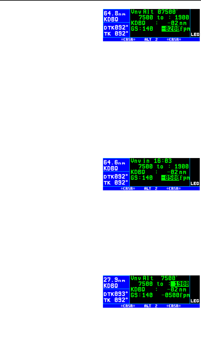
vertical speed, use the outer knob to
position the cursor over the vertical
speed field (figure 5-10). VNAV oper-
ation is initiated by bringing the
cursor over the vertical speed field.
Or, by leaving the cursor off of this
field, you may watch the required
vertical speed increase as you fly toward your waypoint. When the desired
vertical speed is reached, position the cursor over the vertical speed field
and VNAV will commence. When VNAV begins, the top of the page dis-
plays an advisory altitude. Descending at the vertical speed displayed on
line 4 should keep you very close to the VNAV advisory altitude, but you
may need to make slight adjustments to stay right on pace.
A better way yet to initiate VNAV is to program a desired vertical speed to
use for the descent, after you have entered the desired altitude, waypoint,
offset, and groundspeed. To program a vertical speed, do the following
step:
6. Use the right outer knob to move the cursor to the vertical speed field,
and then enter the desired value (figure 5-11). Vertical speed may be
selected in increments of 100 feet per minute or 10 meters per
minute. If the time to begin your
descent is greater than one
hour, Vnv Armed will now be
displayed on the top line of the
page. If the time is less than one
hour, the top line displays a
countdown to the time to begin
the descent.
7. Return to any desired page for now by pressing the Abutton once.
Alternatively, you may turn off the Band use the outer knob to
change pages. Approximately 90 seconds before the time to begin
descent, the message prompt will flash. When you view the Message
page, it will display Vnv Alert. This is notification for you to view the
NAV 1, NAV 4 (map), or ALT 2 page because it is getting close to the
time to begin your descent. All three of these pages are capable of
displaying VNAV data.
8. When the countdown timer
reaches 0:00, the time will be
replaced with an advisory alti-
tude (figure 5-12). Begin your
descent at a rate such that the
altitude displayed on your altime-
ter matches the advisory
altitude.
KLN 94 Pilot’s Guide Chapter 5 Intermediate Operation
5-5
Figure 5-10
Figure 5-11
Figure 5-12

NOTE: During your descent, check your actual groundspeed to verify that
it is similar to the one you entered on the ALT 2 page. If it is different, you
should enter your actual groundspeed so that the VNAV function will work
properly.
If you make any changes to the “from” or “to” altitudes, the VNAV way-
point, or the waypoint offset once VNAV has been armed, or is actually in
progress, the VNAV status will change to “Inactive”. Additionally, you may
force the VNAV into “Inactive” status by changing the vertical speed to
+0000fpm. To reactivate VNAV after changing a parameter, simply move
the cursor to the vertical speed field, or select the new desired vertical
speed.
If you make a change to the groundspeed during the time VNAV is active,
VNAV will remain active, and a new vertical speed will be calculated and
displayed. If you wish to change this vertical speed, go ahead and do so
and the VNAV descent or ascent will be modified for the new parameters.
CAUTION: Advisory VNAV operation will only be accurate if the
altimeter baro correction is kept updated. If advisory VNAV is used,
it is a good idea to update the altimeter baro set on the ALT page
each time you make a change to the aircraft’s altimeter setting.
5.2.2. VNAV FOR FLIGHT PLAN OPERATION
Using the vertical navigation function when flying via a flight plan is virtual-
ly the same as for the previous Direct To example. The ALT 2 page will
initially contain the identifier for the active “to” waypoint in the flight plan.
You may program the vertical ascent or descent referencing this waypoint
or you may use the right inner knob to cycle through the waypoints in the
active flight plan (FPL 0) which are still in front of the aircraft’s position.
When another valid waypoint in the flight plan is entered on the ALT 2
page, the aircraft’s lateral flight path is not altered. This means that you
may program a vertical flight path having an ascent or descent point that
begins prior to the flight plan leg containing the selected VNAV waypoint.
5.3. ALTITUDE ALERTING
If your aircraft does not already have an altitude alerting capability you
may wish to use the KLN 94’s capability of assisting you with altitude man-
agement during your flying. Altitude alerting allows you to select a target
altitude and it then provides you with an aural alarm 1000 feet prior to
reaching the selected altitude, another aural alarm upon reaching the
selected altitude, and another aural alarm if you deviate from the selected
altitude.
Chapter 5 Intermediate Operation
5-6
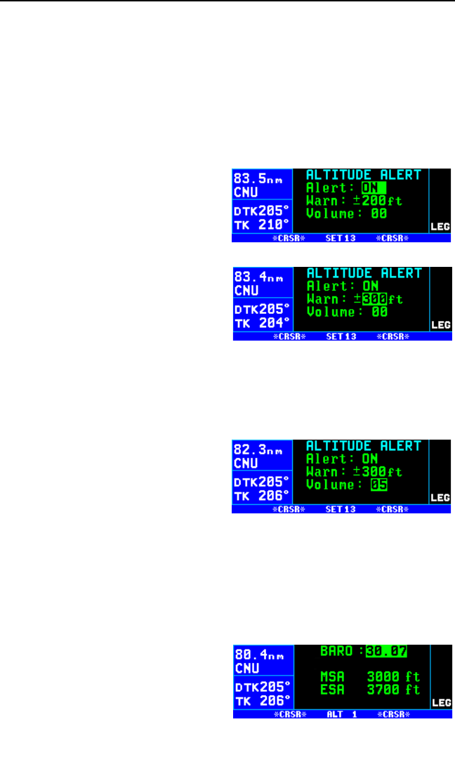
NOTE: The altitude alerting function of the KLN 94 does not meet FAR
Part 91 for turbojet-powered civil airplanes.
NOTE: Before you use the altitude alerting function, it is a good idea to
make sure that the KLN 94 baro setting is current. To do this, press the
A button and use the right inner knob to modify the baro setting.
To Use Altitude Alerting:
1. Select the Setup 13 (SET 13)
page and turn on the cursor
(B). It will come on over the
Alert: field. If OFF is displayed,
turn the right inner knob to select
ON (figure 5-13).
2. Select a warn altitude deviation
by positioning the cursor over
the Warn: field. Use the right
inner knob to select the desired
value (figure 5-14). It is selec-
table in one hundred foot
increments from 200 feet up to
900 feet or in ten meter increments from 60 meters to 270 meters.
Normally, you will use the same value all the time so you only have to
enter this the first time you use altitude alerting. The recommended
warn altitude deviation is 300 feet or 100 meters.
3. If necessary, adjust the altitude
alert audio volume by moving
the cursor to the Volume: field.
Use the left inner knob to select
a desired volume between 00
and 99. The larger the number,
the louder the volume (figure 5-15).
4. Press A. The Altitude 1 (ALT 1) page will be displayed with the cur-
sor over the altimeter baro set field.
NOTE: The altimeter baro set units may be changed between inches, mil-
libars and hectopascals on the SET 12 page).
5. Use the right inner knob to
update the altimeter baro setting
if required (figure 5-16).
KLN 94 Pilot’s Guide Chapter 5 Intermediate Operation
5-7
Figure 5-13
Figure 5-14
Figure 5-15
Figure 5-16
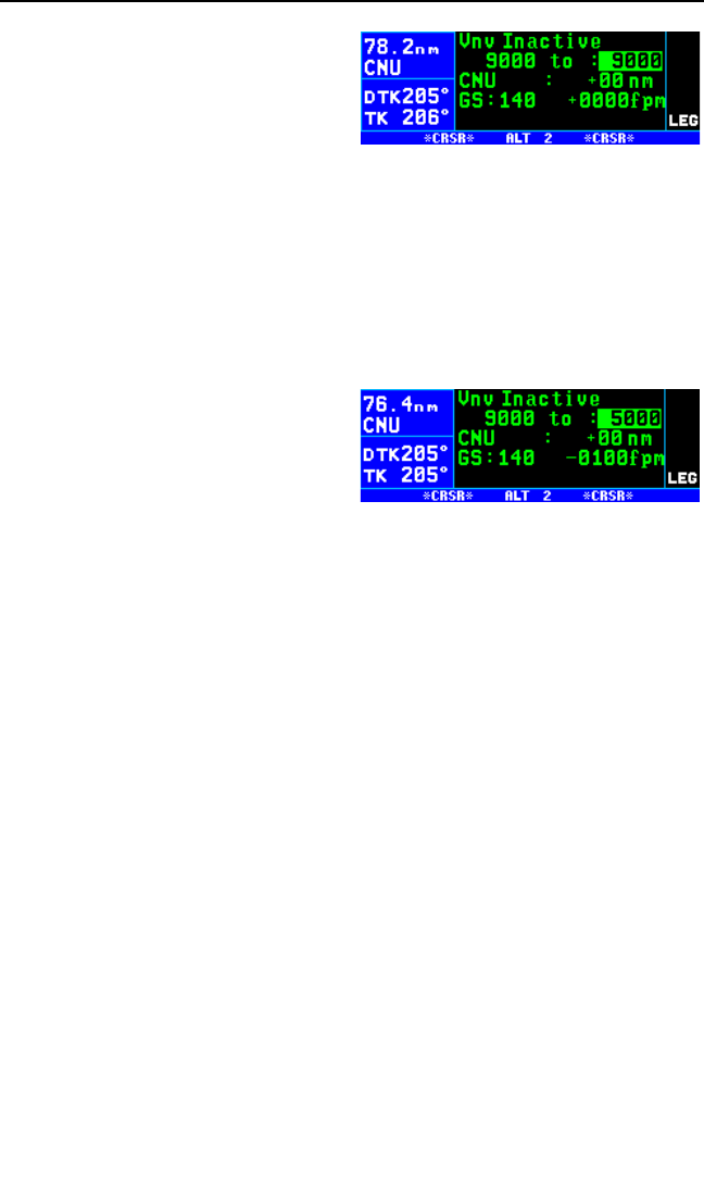
6. Press the Abutton again to
move on to the ALT 2 page (fig-
ure 5-17). Only line 2 of the
ALT 2 page is used for altitude
alerting. The remainder of the
ALT 2 page is used only for ver-
tical navigation, or VNAV. The
first altitude displayed on line 2 is the current indicated altitude (9000
feet in figure 5-17). With the proper altimeter baro setting, the indicat-
ed altitude should be the same as the aircraft’s actual altimeter.
NOTE: There may be some difference (less than 100 feet) between the
indicated altitude and the aircraft’s actual altitude if the altitude input to the
KLN 94 is from an altitude encoder because these encoders only provide
altitude in 100 foot increments.
7. The cursor should be positioned
on the selected (or to) altitude
field (figure 5-17). Enter the
selected altitude using the right
inner knob (figure 5-18).
8. Press Ato return to the page which was previously displayed.
Notice that when you are on an ordinary (non-altitude) page, the first
press of the Abutton brings up the ALT 1 page, the second press of
Abrings up the ALT 2 page, and the third press takes you back to
the original page.
9. The aural alarm activates as follows:
•1000 feet prior to reaching the selected altitude—three short
tones
•Upon reaching the selected altitude—two short tones
•Deviating above or below the selected altitude by more than the
warn altitude—four short tones
NOTE: Due to the resolution of the altitude input, it may be necessary to
descend slightly below or climb slightly above the selected altitude before
the two tones are activated indicating that the selected altitude has been
reached. This selected altitude alert must be activated to arm the system
for providing the altitude deviation alert.
The KLN 94 can provide the aural alarm tones in either of two ways: it
may be connected to an audio input of an audio amplifier contained in an
audio panel so that the aural alarm is heard through the aircraft’s speaker
Chapter 5 Intermediate Operation
5-8
Figure 5-18
Figure 5-17

and headphones. Or the KLN 94 may be interfaced with an external tone
generator installed in the aircraft.
In order to use altitude alerting, the KLN 94 must have an altitude input. If
the altitude input is from an altitude encoder or from an air data computer
not having a baro altitude output, then it will be necessary for you to man-
ually input the proper altimeter setting in order to get accurate alerting.
Remember, the altitude coming from an encoder is pressure altitude and
must be corrected with the proper altimeter setting to convert to actual alti-
tude. This altimeter setting is easily accomplished by entering the
altimeter baro setting on the Altitude (ALT) 1 page. Press Atwice more
to return to the page previously displayed. It’s so easy you have no excus-
es for not keeping the baro setting updated!
CAUTION: The altitude alerting feature will only be accurate if the
altimeter baro correction is kept updated. If altitude alerting is used,
it is a good idea to update the altimeter baro set on the ALT 1 page
each time you make a change to the aircraft’s altimeter setting.
NOTE: The altitude alerting feature can be disabled in the KLN 94 at the
time of installation so that these features are not selectable by the pilot.
When this has been done, the SET 13 page displays Feature Disabled.
5.4. CREATING USER-DEFINED WAYPOINTS
You may create and store up to 500 user-defined waypoints. These way-
points will be very helpful to you. One major application is private use
airstrips, which are not included in the Jeppesen database. They are also
handy for points which you fly over frequently, and wish to navigate to. For
example, a crop sprayer would want to store the locations of the fields he
or she dusts often.
There are three ways to create a user-defined waypoint. If you happen to
know the latitude and longitude of the point, that is one option. The way-
point can also be defined as a radial and distance from another waypoint.
A third choice is just to store your present position under the identifier you
have chosen.
NOTE: Whenever you are in a waypoint entry situation, such as a Direct
To waypoint or flight plan, and you enter an identifier which is not in the
database, the KLN 94 will automatically start the user-defined waypoint
creation process.
To delete a user-defined waypoint that is no longer needed, see section
5.11. “Viewing and Deleting User Waypoints and Waypoint Remarks”.
KLN 94 Pilot’s Guide Chapter 5 Intermediate Operation
5-9
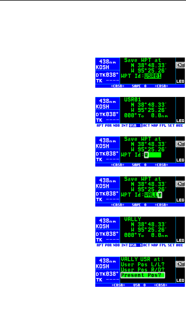
5.4.1. CREATING A WAYPOINT AT YOUR PRESENT POSITION
Creating a waypoint at your present position is the simplest possible way
to create a user-defined waypoint. This is nice for “remembering” a spot
you are at. Let’s suppose you’re at a private strip that you want to name
“VALLY”
To create a user-defined waypoint at your present position:
1. Select the NAV 2 page (present
position) and press the Fbut-
ton. A page like the one in figure
5-19 will be displayed with your
latitude and longitude at the time
you pressed the button. The
user-defined waypoint is initially
given the name USR##, where
## is the first available number
between 01 and 99.
2. If you wish to use this waypoint
name, press Fand the way-
point creation is complete (figure
5-20). If you want to choose your
own name for it, turn the right
inner knob to select the first
character of the identifier (figure
5-21). Remember that when the
cursor is on, the right inner knob
changes the character and the
right outer knob moves the cur-
sor around.
3. Spell out the rest of the identifier
using the right inner and outer
knobs (figure 5-22).
4. Press F. The USR 1 page for
your new waypoint will be dis-
played with its latitude and
longitude (figure 5-23). The cur-
sor is turned off automatically.
NOTE: Another way to create a
user-defined waypoint at your pre-
sent position is to select the USR
pages, spell out the identifier letter
by letter (see next section), and then
select the Present Pos? option (figure 5-24) and press F.
Chapter 5 Intermediate Operation
5-10
Figure 5-19
Figure 5-20
Figure 5-21
Figure 5-22
Figure 5-23
Figure 5-24
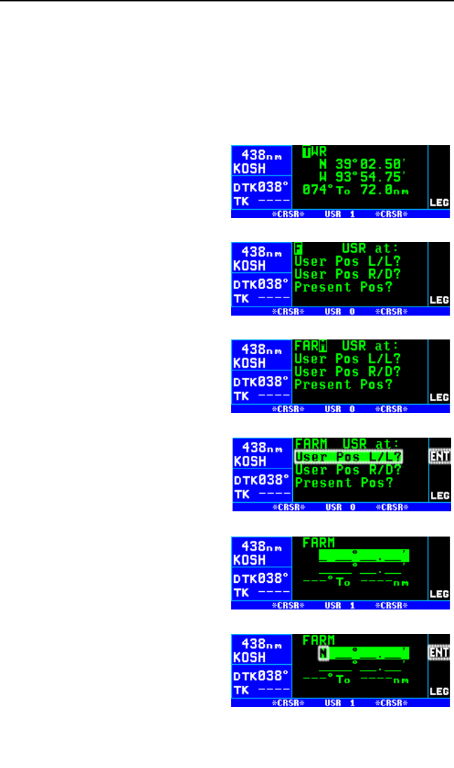
5.4.2. CREATING A WAYPOINT AT A CERTAIN
LATITUDE/LONGITUDE
It is also possible to create a user-defined waypoint by manually entering
a latitude and longitude. Let’s say you wanted to create a user waypoint
over your hypothetical farm at N 42°56.32’, W 76°29.95’
To create a user-defined waypoint with latitude/longitude:
1. From any user waypoint (USR)
page, turn on the cursor (B).
It will be over the first character
in the waypoint identifier field
(figure 5-25).
2. Use the right inner knob to
select the first character of the
identifier (figure 5-26).
Remember that when the cursor
is on, the right inner knob
changes the character and the
right outer knob moves the cur-
sor around.
3. Spell out the rest of the identifier
using the right inner and outer
knobs (figure 5-27).
4. Move the cursor down to the
second line, over User Pos L/L?
(figure 5-28).
5. Press F. The display will
change to a format like figure 5-
29.
6. Use the right inner knob to
select N for north or S for south
(figure 5-30).
KLN 94 Pilot’s Guide Chapter 5 Intermediate Operation
5-11
Figure 5-25
Figure 5-26
Figure 5-27
Figure 5-28
Figure 5-29
Figure 5-30
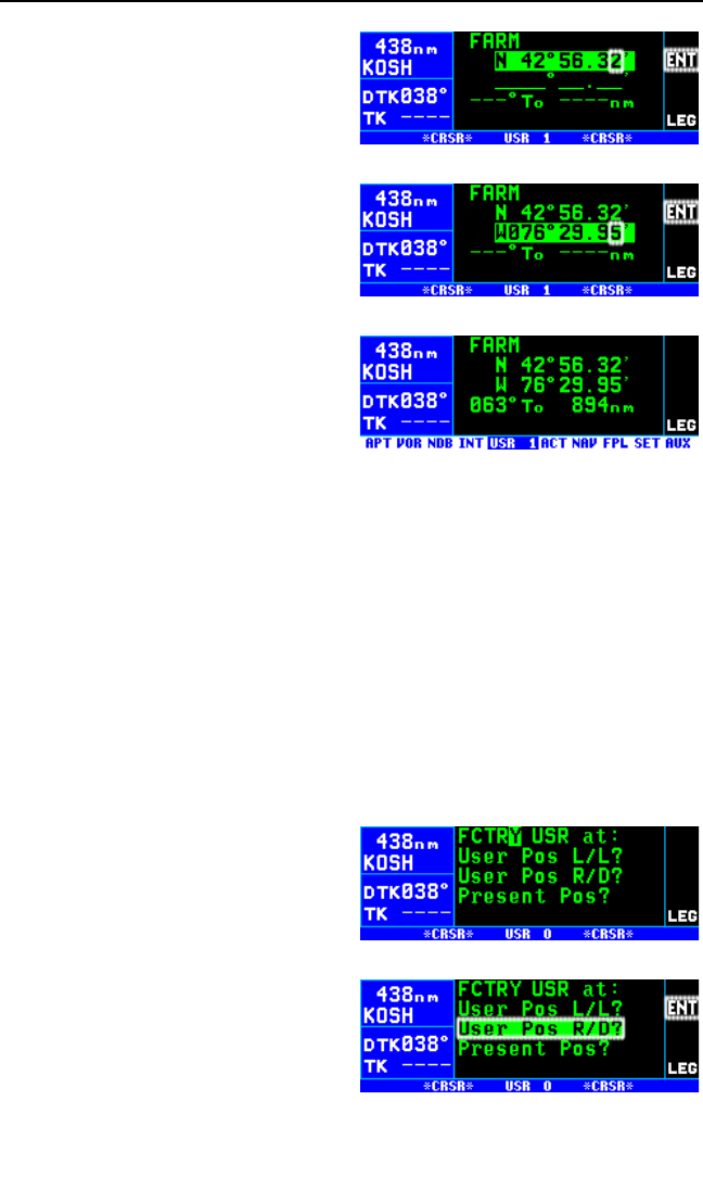
7. Use the right outer knob to move
the cursor, and the right inner
knob to select the proper num-
bers to complete the latitude
entry (figure 5-31).
8. Press F. The cursor will move
to the longitude field.
9. Enter the longitude in the same
manner as the latitude (figure 5-
32).
10. Press Fto approve this posi-
tion. The cursor will
automatically turn off (figure 5-
33).
5.4.3. CREATING A WAYPOINT REFERENCED FROM ANOTHER
WAYPOINT
The third method of creating a user-defined waypoint is as a radial and
distance from a known waypoint.
To create a user-defined waypoint using the radial/distance method:
1. From any user waypoint (USR) page, turn on the cursor (B). It will
be over the first character in the waypoint identifier field.
2. Use the right inner knob to select the first character of the identifier.
Remember that when the cursor is on, the right inner knob changes
the character and the right outer knob moves the cursor around.
3. Spell out the rest of the identifier
using the right inner and outer
knobs (figure 5-34).
4. Move the cursor down to the
third line, over User Pos R/D?
(figure 5-35).
Chapter 5 Intermediate Operation
5-12
Figure 5-31
Figure 5-32
Figure 5-33
Figure 5-34
Figure 5-35
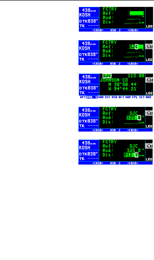
5. Press F. The display will
change to a format like figure 5-
36 with the cursor over the
reference waypoint field.
6. Use the right inner and outer
knobs to select the identifier of
the desired reference waypoint
(figure 5-37).
7. Press F. The waypoint page
for the waypoint you just entered
will be displayed (figure 5-38).
8. Press Fagain to approve the
waypoint. You will be returned to
the waypoint creation page.
9. Use the right inner and outer
knobs to select the desired radi-
al. Notice that you may enter
the angle down to the tenth of a
degree (figure 5-39).
10. Press Fto approve the radial.
The cursor will move to line 4.
11. Use the right inner and outer
knobs to select the desired dis-
tance from the reference
waypoint (figure 5-40).
12. Press Fto approve the dis-
tance. The cursor will
automatically be removed from
the screen.
KLN 94 Pilot’s Guide Chapter 5 Intermediate Operation
5-13
Figure 5-36
Figure 5-37
Figure 5-38
Figure 5-39
Figure 5-40
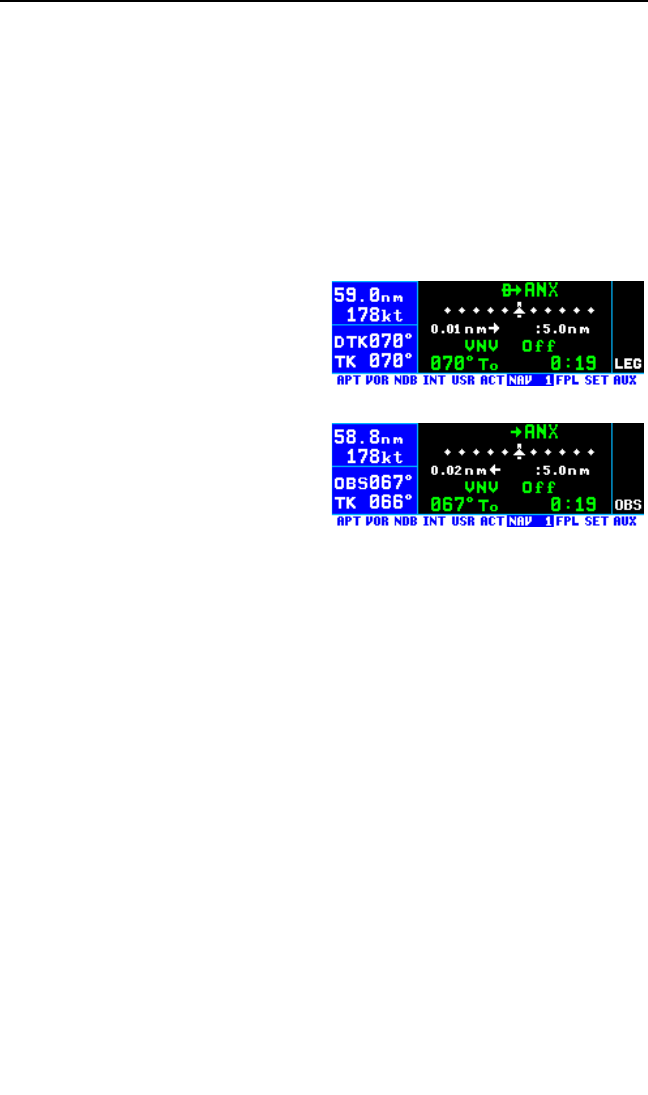
5.5. NAVIGATION MODES
The KLN 94 allows you to choose how the course to the active waypoint is
defined. This is done by selecting between the two course modes, LEG
and OBS. The LEG mode means that the course to the active waypoint is
selected by the KLN 94, and is the default mode when the KLN 94 starts
up. The other course mode, OBS, is the mode that allows you to select
the course to or from the active waypoint. In this mode, the KLN 94 oper-
ates very much like a VOR receiver. This is the mode that you will use
quite often if you conduct non-precision approaches with a course rever-
sal (procedure turn or holding pattern) using the KLN 94.
The KLN 94 also has three modes
that are associated with approach
operations. These are En route,
Approach Arm and Approach Active.
These modes will be explained in
Chapter 6.
The course mode is annunciated in
the bottom right corner of the screen.
When in the Leg mode, it displays
LEG (figure 5-41), and when in the
OBS mode, it displays OBS (figure
5-42).
5.5.1. SELECTING THE LEG MODE OR THE OBS MODE
To change course modes:
1. Press the Hbutton.
2. If the KLN 94 was previously in the Leg mode, it will now be in the
OBS mode, and vice versa.
5.5.2. THE LEG MODE
The following are the characteristics of the Leg Mode:
1. The default course deviation indicator (CDI) sensitivity for en route
mode is plus and minus five nautical miles, full scale. This applies to
the CDI on the NAV 1 page as well as any external CDIs or HSIs
interfaced to the KLN 94. If the CDI or HSI has five dots left and right
of the center position, then each dot represents one nautical mile of
deviation.
2. Navigation is provided along the great circle path between two way-
points. As you probably know, great circle navigation is the shortest
Chapter 5 Intermediate Operation
5-14
Figure 5-41
Figure 5-42

distance between two points located on the earth’s surface. In the
case of Direct To operation, the “from” waypoint is not displayed but it
is the point where Direct To operation was initiated. The course to fly
while in this mode is referred to as the desired track (DTK). Knowing
the proper course to be flown is so important that the desired track is
displayed on the left side of the screen (third line) on every page
except the message page. To fly a great circle course between two
points, the desired track may be constantly changing. A good way to
illustrate this concept is with a world globe and a piece of string. You
can determine the great circle path between Denver, Colorado and
Manila, Philippines by stretching the string over the globe between
these two points. Notice that you would start the flight with a north-
westerly desired track, which gradually becomes due westerly, and
finally southwesterly by the time you reach Manila. Of course, your
trips with the KLN 94 will be substantially shorter and the desired track
will probably change only a few degrees.
3. Automatic waypoint sequencing is provided during flight plan opera-
tion. As you reach a waypoint in your flight plan, the next leg of the
flight plan automatically becomes active. There are some situations
during approach operations in which automatic leg sequencing is
automatically disabled. See Chapter 6.
4. Turn anticipation may be utilized in flight plan operation as described
in section 4.2.2.
5. The Minimum En route Safe Altitude (ESA) displayed on the ALT 1
page is the highest MSA sector altitude from the present position to
the destination waypoint along the active flight plan or Direct To route
(whichever is in use). See section 5.1. “Altitude Pages” for a descrip-
tion of ESA and MSA.
5.5.3. THE OBS MODE
The following are characteristics of the OBS mode.
1. The course deviation indicator (CDI) sensitivity for en route mode is
plus and minus five nautical miles, full scale. This applies to the CDI
on the NAV 1 page as well as any external CDIs or HSIs interfaced to
the KLN 94. If the CDI or HSI has five dots left and right of the center
position, then each dot represents one nautical mile of deviation.
2. The course is defined by the active waypoint and the selected mag-
netic course. A course “to” or “from” the active waypoint may be
selected.
3. The course selection is normally made by changing the selected
course displayed on an external indicator such as an HSI or CDI.
KLN 94 Pilot’s Guide Chapter 5 Intermediate Operation
5-15

When this is done, the pilot must verify that the proper course has
been selected by confirming the digital selected course readout dis-
played on the KLN 94. In the OBS mode the selected course is
always displayed on line 3 of the left side of the KLN 94 screen (in
place of DTK). In many installations, two or more navigation sources
can be displayed on one indicator. In these situations there is a switch
in the aircraft panel which will determine what navigation source is
displayed. For the KLN 94 to properly read the external indicator the
KLN 94 must be the displayed navigation source on the external indi-
cator.
4. There is no automatic leg sequencing or turn anticipation.
5. The Minimum En route Safe Altitude (ESA) displayed on the ALT 1
page is the highest MSA sector altitude between the present position
and the active waypoint. See section 5.1. for an explanation of ESA
and MSA. Other waypoints in the active flight plan do not affect the
ESA.
6. When the active waypoint is a VOR, and the AUTO magnetic variation
mode is active (see section 5.16), the published magnetic variation for
the VOR is utilized rather than the calculated magnetic variation, so
that the KLN 94 indication will be identical to a NAV receiver indica-
tion.
When the KLN 94 is not the displayed navigation source on the external
indicator, it is possible to change the selected course from the KLN 94
screen using the procedure below.
To change the selected course in OBS mode (not connected to
external CDI):
1. If the KLN 94 is not in OBS
mode, select OBS mode by
pressing the Hbutton. The
cursor will automatically be
turned on over the OBS selected
course field (figure 5-43). If
already in OBS mode, turn on
the cursor(B).
2. Turn the right inner knob until the
correct selected course is dis-
played (figure 5-44).
3. Turn off the cursor (B).
Chapter 5 Intermediate Operation
5-16
Figure 5-43
Figure 5-44

5.5.4. SWITCHING FROM THE LEG MODE TO THE OBS MODE
The following mode transition occurs if the KLN 94 is in the Leg mode and
the mode is changed to the OBS mode:
1. The waypoint that was active in Leg mode prior to the mode change
remains the active waypoint in OBS mode.
2. The selected course is defined by two different methods depending
on the installation and the status of the unit.
i. If the KLN 94 is the displayed navigation source when the change is
made to OBS mode, then the selected course becomes whatever was
set on the external indicator prior to changing to the OBS mode. This
value should normally be the desired track to the active waypoint if
you had the external indicator set to the correct value prior to switch-
ing to the OBS mode.
ii. If the KLN 94 is not displayed on the external indicator, then the
selected course is chosen such that the deviation from the selected
course remains the same.
3. If the OBS value chosen by default from rule 2 above is unacceptable,
you can always define the desired course by the methods described
in section 5.5.3.
5.5.5. EFFECTS OF SWITCHING FROM OBS MODE TO LEG
MODE
The following mode transition occurs if the KLN 94 is in the OBS mode
with a TO indication and the mode is switched to the Leg mode:
1. The waypoint that was active while in the OBS mode remains the
active waypoint when the Leg mode is activated. The system does
not attempt to orient itself on a leg of the active flight plan unless the
TO/FROM indicator is indicating FROM. In the FROM case, the
KLN 94 will reorient on the active flight plan.
2. The selected course (OBS) that was active in the OBS mode prior to
switching to Leg mode becomes the desired track (DTK) in the Leg
mode, unless the mode change was made on the “from” side in which
case the KLN 94 will calculate the correct desired track for the new
leg.
3. With the exception of #2 above, the characteristics of normal Direct
To operation apply.
4. If the active waypoint was part of the active flight plan (FPL 0), the
system will revert to normal flight plan operation once the active way-
point is reached.
KLN 94 Pilot’s Guide Chapter 5 Intermediate Operation
5-17
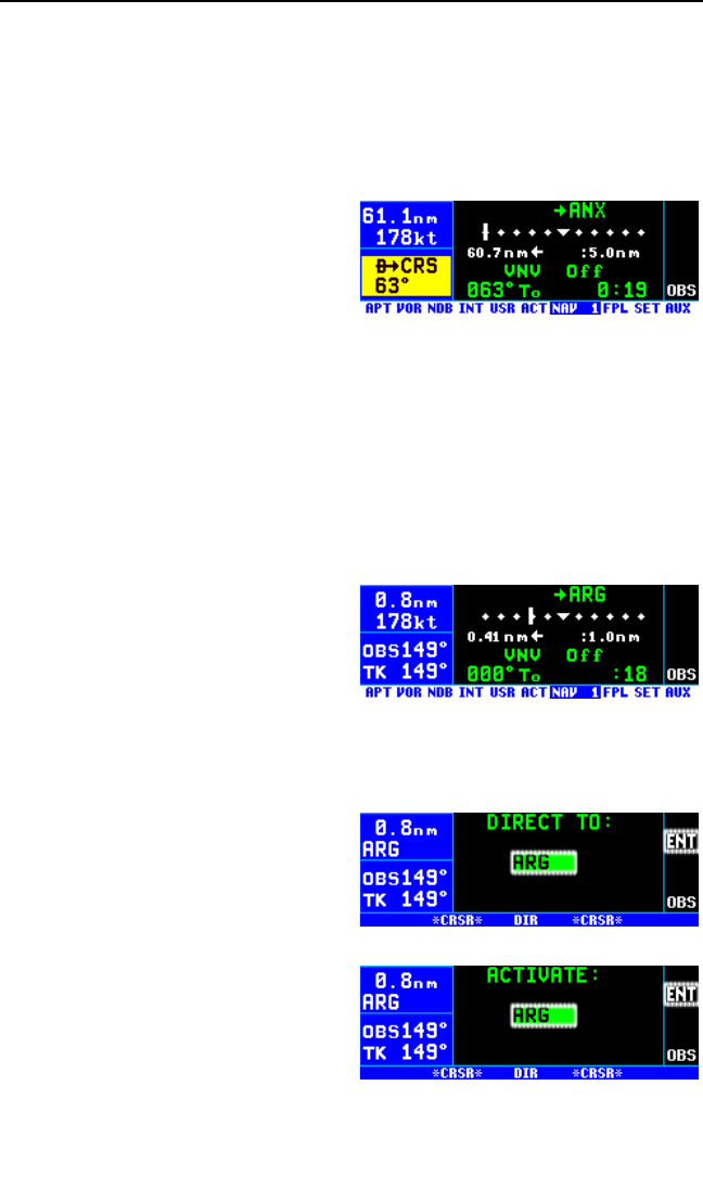
5.5.6. GOING DIRECT TO A WAYPOINT WHILE IN THE OBS
MODE
The direct-to function will select the OBS value that will take the aircraft
from the present position direct to the active waypoint when the KLN 94 is
not the displayed navigation source on the external indicator.
If the KLN 94 is the displayed navi-
gation source on an HSI or CDI it is
not possible for the KLN 94 to
change the OBS value. In these sit-
uations the KLN 94 will provide a
scratchpad message that will tell you
what OBS value should be selected
to go direct to the active waypoint (figure 5-45).
5.5.7. ACTIVATING A WAYPOINT WHILE IN THE OBS MODE
While in the OBS mode, when the KLN 94 is not the displayed navigation
source on the external indicator, you may activate another waypoint by
using the normal Direct To method or by using a second method. This
second method activates another waypoint without changing the selected
course (OBS). In other words, when the new waypoint is activated, the D-
Bar is not necessarily recentered. In
figure 5-46 the KLN 94 is in the OBS
mode and the selected course is
149°. You have just crossed ARG
and desire to activate the next way-
point in the flight plan, GQE, without
recentering the D-Bar.
To activate a waypoint in OBS mode without changing the selected
course (not connected to external CDI):
1. Press D(figure 5-47). The
rules described in section 3.10,
“Direct To Operation”, dictate
which waypoint identifier will be
initially displayed on the Direct
To page.
2. Press Da second time. The
annunciation DIRECT TO
changes to ACTIVATE (figure 5-
48). Repeated presses of D
cause the annunciation to alter-
nate between DIRECT TO and
ACTIVATE. Make sure ACTIVATE is displayed.
Chapter 5 Intermediate Operation
5-18
Figure 5-45
Figure 5-46
Figure 5-47
Figure 5-48
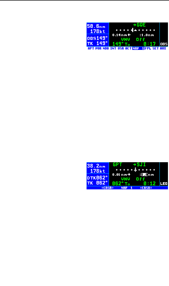
3. If the desired waypoint is not the one that was suggested by the
KLN 94, enter the desired identifier. Press F.
4. Press Fto approve the way-
point page and activate the
waypoint (figure 5-49). The
selected course does not
change, therefore this method
does not center the D-Bar like a
Direct To operation does.
5.6. CHANGING THE CDI SCALE FACTOR
The CDI scale factor can be changed by using the NAV 1 page. In normal
operations it is possible to select a CDI scale factor which is plus or minus
5 NM, 1 NM or 0.3 NM full scale deflection. This means that if the scale
factor was ± 5 NM and the needle was deflected four dots to the right, the
aircraft would be 4 NM left of course. The default CDI scale factor is ± 5
NM. The default scale factor is automatically selected each time the
KLN 94 is turned on. Changing the scale factor on the NAV 1 page also
changes the scale factor on the remote CDI or HSI.
To change the CDI scale factor:
1. Select the NAV 1 page.
2. Turn on the cursor (B). It will appear over the CDI scale number
below the right side of the CDI.
3. Rotate the right inner knob to
select the desired CDI scale fac-
tor (figure 5-50). The valid
choices are 5.0 NM, 1.0 NM, and
0.3 NM or 9.3 km, 1.9 km, and
.56 km.
4. Turn off the B. The CDI scale factor change is complete.
NOTE: The KLN 94 will automatically select a scale factor as part of the
GPS approach process. When the KLN 94 selects a CDI scale factor it is
not possible to select a scale factor that is less sensitive than what the
KLN 94 has automatically chosen. For example, as you will see in the
next chapter, the approach-arm (or terminal) mode usually has a scale
factor of ± 1 NM. While in the approach-arm mode it is not possible for
you to select the ± 5 NM scale factor. This is to ensure proper operation
of the approach modes.
KLN 94 Pilot’s Guide Chapter 5 Intermediate Operation
5-19
Figure 5-49
Figure 5-50
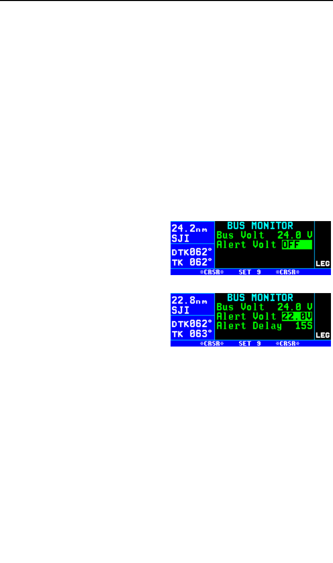
5.7. AVIONICS BUS VOLTAGE ALERTING
The SET 9 page serves as a monitor of your avionics power bus. It gives
you a digital readout of the voltage supplied to your avionics, down to
tenths of volts. You will find this feature valuable as an extra layer of
security in cases of electrical or charging system problems.
A voltage alert feature is also available on this page, to warn you of an
electrical system problem, regardless of whether you are viewing the
SET 9 page or not. It is set up so that the avionics bus voltage must drop
below the alert limit for a certain length of time. This time delay is so that
brief power interruptions don’t trigger the voltage alert.
The alert voltage and the alert delay are set at the time of installation and
stored in the KLN 94 configuration module. As the pilot, your two options
are to have the voltage alert disabled, or to have it enabled with the prede-
fined voltage and time delay values.
To enable the voltage alert feature:
1. Select the SET 9 page (figure 5-
51) and turn on the cursor (B).
2. Turn the right inner knob one
step to enable the alert feature.
The alert voltage and alert delay
will be displayed on lines 2 and 3
(figure 5-52).
3. Turn off the cursor (B).
If the avionics bus voltage drops
below the alert voltage for the speci-
fied delay time, the message
Low Bus Voltage
Check Charging System
will be displayed. This message may be indicative of a problem with the
aircraft’s charging system. Consult your aircraft’s Pilot Operating
Handbook to troubleshoot the problem. You may desire to turn off some
of the aircraft’s electrical devices which are non-essential for your particu-
lar phase(s) of flight, so that the battery will not discharge as quickly.
Appropriate alert voltage and alert delays will vary from aircraft to aircraft.
If your KLN 94 is frequently giving you this alert message, it may become
a nuisance, and you may desire to have your Honeywell Service Center
adjust the voltage alert parameters.
Chapter 5 Intermediate Operation
5-20
Figure 5-51
Figure 5-52

5.8. THE AUXILARY (AUX) PAGES
The KLN 94 may have up to 21 Auxiliary pages which are used for a
multitude of miscellaneous functions. The table below summarizes the
function of these pages.
Page Function
AUX 1 and AUX 2 . . . . . . . . . . . . . . . . . . . . . . . . . . . . . . . . . . . . . .GPS Status
AUX 3 . . . . . . . . . . . . . . . . . . . . . . . . . . . . . . . . . . . . . . . . . . . .RAIM Prediction
AUX 4 and AUX 5 . . . . . . . . . . . . . . . . . . . . . .Calculator pages -Trip Planning
AUX 6 . . . . . . . . . . . . . . . . . . . . . . . . . . . .Calculator page – Pressure Altitude
AUX 7 . . . . . . . . . . . . . . . . . . . . . . . . . . . . . .Calculator page – Density Altitude
AUX 8 . . . . . . . . . . . . . . . . . . . . . . . . . . . . . . .Calculator page – True Airspeed
AUX 9 . . . . . . . . . . . . . . . . . . . . . . . . . . . . . . . . . . . . . . .Calculator page - Wind
AUX 10 . . . . . . . . . . . . . . . . . . . . . . . . . . . . . . .Calculator page - Timed Alarm
AUX 11 . . . . . . . . . . . . . . . . . . . . . . . . . . . . .Calculator page – Sunrise/Sunset
AUX 12 . . . . . . . . . . . . . . . . . . . . . . . . . . . . . .View and delete User waypoints
AUX 13 . . . . . . . . . . . .View and delete APT 6 page and USR 3 page remarks
AUX 14 . . . . . . . . . . . . . . . . . . . . . . . . . . . . . . . . . . . . . . . . . . .Software status
AUX 15 – AUX 19 . . . . . . . . . . . . . . . . . . . . . . . . . . . . . . . . .Fuel Management
AUX 20 – AUX 21 . . . . . . . . . . . . . . . . . . . . . . . . . . . . . . . . . . . . . . . . .Air Data
The AUX 15 – AUX 19 pages only appear if a compatible fuel manage-
ment system is installed with the KLN 94. The AUX 20 – AUX 21 pages
only appear if a compatible air data system is installed with the KLN 94. If
no fuel management system is installed but there is an air data system,
the air data pages become AUX 15 and AUX 16.
5.9. DETERMINING THE STATUS OF THE GPS SIGNALS
The Auxiliary (AUX) 1 and AUX 2 pages may be viewed at any time to
determine the status of the GPS receiver and the GPS satellites being
received. This includes which satellites are being tracked, the satellites’
health, the signal strength for each of these satellites, the elevation of
each satellite above the horizon, the azimuth of each satellite referenced
to your present position, the estimated position error, and the present
GPS-derived altitude.
The GPS receiver in the KLN 94 is capable of using signals from up to
eight satellites to determine its position. A valid position may be deter-
mined using as few as four satellites alone or three satellites with a valid
electronic altitude input. However, four satellites alone or three satellites
with an altitude input do not necessarily ensure that navigation can take
place. The satellites must be positioned relative to your location such that
KLN 94 Pilot’s Guide Chapter 5 Intermediate Operation
5-21

sufficient “geometry” exists to determine an accurate position. The satellite
constellation geometry is continually changing as each satellite, “rises”,
travels across the sky, and eventually “sets” relative to your position. The
GPS satellites are not in geosynchronous orbits positioned over the same
spot on earth at all times like some television communication satellites
with which you may be familiar. Rather, the GPS satellites are in orbits
that allow them to circle the earth about two times each day.
A representative AUX 1 page is
shown in figure 5-53. The AUX 1
page displays the GPS receiver state
and the system’s estimate of the
position error expressed in nautical
miles or kilometers.
The GPS state is indicated on line 2. The possibilities are:
INIT initialization
ACQ acquisition
TRAN transition
NAV navigation
NAV A navigation with altitude aiding
NAV D navigation with data collection
DEGRD navigation with position degradation
FAILR receiver failure
In the initialization state the GPS receiver is in the process of initializing
itself, collecting information such as the date, time, and last present posi-
tion. Next, the receiver collects data from its own memory to determine
which satellites should be visible. After completing the initialization
process the receiver begins the acquisition process. During this time, the
visible satellites are being acquired and data is obtained from them.
The transition state indicates an adequate number of satellites for naviga-
tion has been acquired and is being tracked but no position data can yet
be produced.
Normal navigation is indicated by a NAV, NAV A, or NAV D GPS state.
NAV A indicates that the altitude input is being used in the position solu-
tion. NAV D indicates that besides calculation position, the receiver is
collecting and storing in its memory additional data from the satellites
(called ephemeris and almanac data).
Line 3 of the AUX 1 page displays the present GPS-derived altitude, that
is, the altitude that is being indicated by the GPS position solution.
Chapter 5 Intermediate Operation
5-22
Figure 5-53
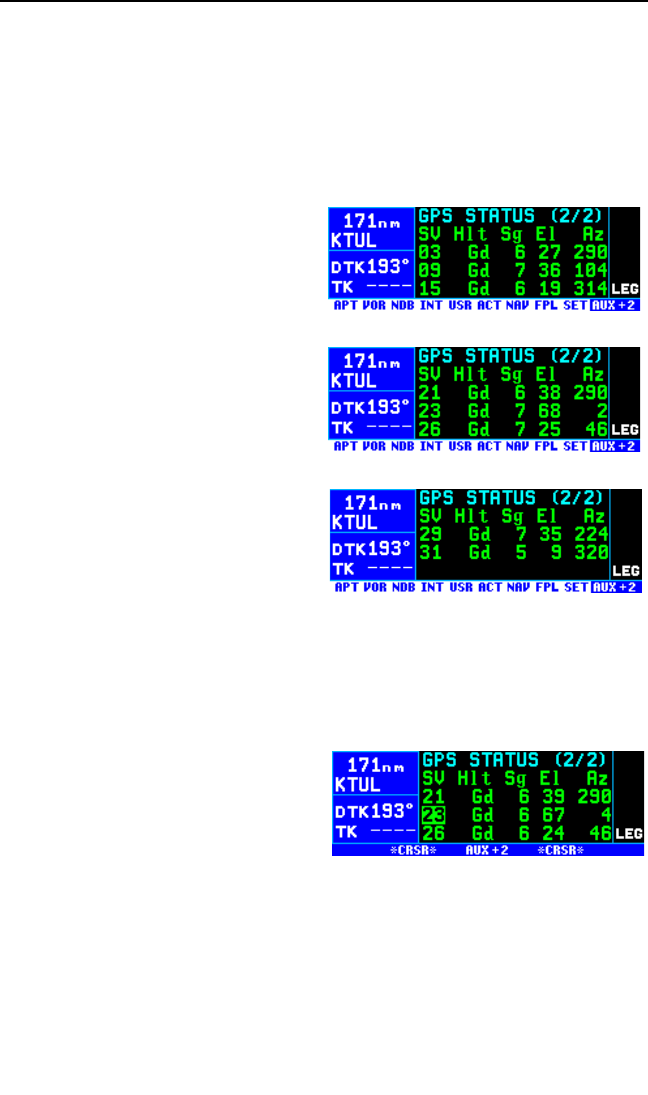
WARNING: Do not use the GPS-derived altitude for navigation. Due
to many factors, the GPS altitude may be 300 feet or more in error,
which is unacceptable for navigation.
Lines 4 and 5 of the AUX 1 page display the KLN 94’s estimated position
error. The KLN 94’s position error depends upon such factors as the
number of satellites being received, the strength of the GPS signals, and
the geometry of the satellites presently being used for navigation.
Figures 5-54, 5-55 and 5-56 show a
representative example of a set of
AUX 2 pages. There will be three
AUX 2 pages if more than six satel-
lites are being received as in this
example.
The following information is dis-
played for each satellite on the
AUX 2 pages:
•The specific GPS satellites or
“space vehicles” (SV) being
received are displayed in the
left column. Each satellite has
its own identification number.
A *symbol to the right of the
satellite number indicates this
particular satellite is not
presently being tracked by the
receiver.
NOTE: At some times, you may desire to deselect certain satellites if you
know them to be inaccurate, so that they are not used to determine the
GPS position. Should a satellite be inaccurate, it could cause a RAIM fail-
ure, rendering the system unusable
for primary IFR navigation. To dese-
lect a specific satellite, turn on the
cursor (B) and move it over the
desired SV number (figure 5-57).
Turn the right inner knob to deselect
(or reselect) the desired satellite.
•The satellite’s “health” (Hlt) is indicated to the right of the satellite
number. The health of the satellite can be described as Gd for
Good, Wk for Weak, and Bd for Bad. Ds indicates the satellite was
deselected by the pilot. Fd indicates the receiver detected a fault
and excluded that satellite.
KLN 94 Pilot’s Guide Chapter 5 Intermediate Operation
5-23
Figure 5-54
Figure 5-55
Figure 5-56
Figure 5-57

•The signal strength (Sg) for each satellite is displayed next and indi-
cates the signal strength for each satellite in the range of 0 (zero) to
9 (nine). The higher the value the stronger the signal.
•The elevation (El) above the horizon for each satellite is provided in
the right column and will range from 5°to 90°.
•The local azimuth (Az) of the satellite relative to your present posi-
tion, referenced to true north (rather than magnetic north). For
example, in figure 5-57 satellite (SV) number 26 has an azimuth of
46°and is therefore northeast of you.
NOTE: The AUX 3 page predicts if and when RAIM (Receiver
Autonomous Integrity Monitoring) capability will be available when you are
ready to shoot a non-precision approach at your destination airport. If the
unit is configured for VFR use only the AUX 3 page will display No RAIM
Function In This Unit. See section 6.2.14 for more information on using
AUX 3 page.
5.10. CALCULATOR (AUX 4 – AUX 11) PAGES
The AUX 4 – AUX 11 pages are calculator pages used for trip planning
and calculation of a variety of flight-related information. They are conve-
nient both on the ground before you begin your flight, and in the air.
Data entered on any of the these pages has no effect on navigation data
provided on any Navigation (NAV) or Flight Plan (FPL) pages. You may
perform trip calculations without disturbing ongoing navigation.
NOTE: The AUX 4 – AUX 11 pages rely on pilot enterable inputs for
groundspeed, fuel flow, fuel reserve requirements, altitudes, temperature,
airspeed, etc. These pages do not utilize inputs from fuel flow or air data
sensors.
5.10.1. THE AUXILARY 4 (AUX 4) TRIP PLANNING PAGE
The AUX 4 page allows you to do distance, bearing, time, and minimum
en route safe altitude (ESA) calculations that you might otherwise need a
chart, ruler, and pocket calculator for. The KLN 94 will perform these cal-
culations either from present position to waypoint, waypoint to waypoint,
or for one of your flight plans (active or stored).
Chapter 5 Intermediate Operation
5-24
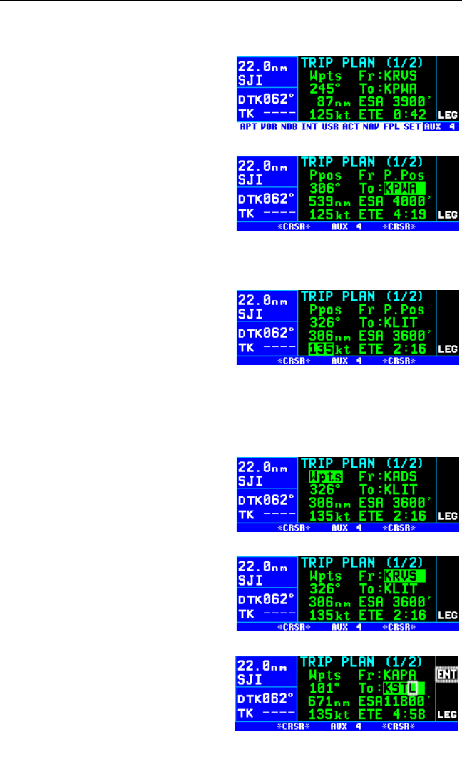
To calculate distance, bearing, time, and ESA from present position
to another waypoint:
1. From the AUX 4 page (figure 5-
58), turn on the cursor (B). It
will appear over a field that either
displays Ppos, Fpl, or Wpts.
2. Turn the right inner knob to
change this field to Ppos.
3. Turn the right outer knob to
move the cursor over the To
waypoint field (figure 5-59)
4. Enter the desired “to” identifier
and press F. You will be
shown the waypoint page for the waypoint you entered. Press F
again to approve.
5. Select your estimated ground-
speed for the trip. As you
change it, the estimated time en
route (ETE) calculation will be
updated (figure 5-60).
To calculate distance, bearing, time , and ESA from waypoint to way-
point:
1. From the AUX 4 page, turn on the cursor (B) and use the right inner
knob to select Wpts (figure 5-
61).
2. Turn the right outer knob clock-
wise to move the cursor to the
“from” waypoint in the upper
right corner of the screen (figure
5-62).
3. Enter the desired identifier for
the “from” waypoint and press
F. You will be shown the way-
point page for the waypoint you
entered. Press Fagain to
approve.
4. With the cursor over the “to”
waypoint, enter the desired iden-
tifier (figure 5-63) and press F
twice. The bearing will be dis-
KLN 94 Pilot’s Guide Chapter 5 Intermediate Operation
5-25
Figure 5-58
Figure 5-59
Figure 5-60
Figure 5-61
Figure 5-62
Figure 5-63
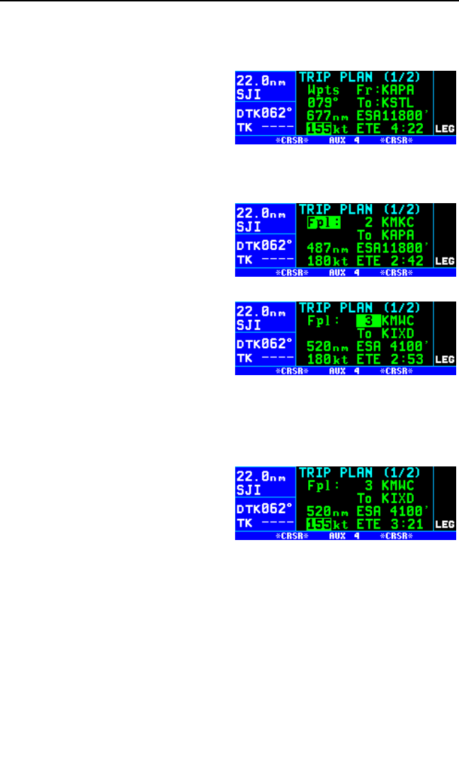
played on line 3, and the distance will be displayed on line 4.
5. Use the right outer knob to move the cursor over the groundspeed
field on line 5.
6. Select your estimated ground-
speed for the trip. As you
change it, the estimated time en
route (ETE) calculation will be
updated (figure 5-64).
To calculate distance, time and ESA for a flight plan:
1. From the AUX 4 page, turn on
the cursor (B) and use the
right inner knob to select Fpl (fig-
ure 5-65).
3. Turn the right outer knob clock-
wise to place the cursor over the
flight plan number. As you cycle
through the flight plans by turn-
ing the right inner knob, the first
and last waypoints of each flight
plan will be displayed, along with
the total distance and the mini-
mum en route safe altitude for
the flight plan (figure 5-66).
4. Once you have selected the desired flight plan, move the cursor to the
groundspeed field on line 5.
5. Select your estimated ground-
speed for the trip. As you
change it, the estimated time en
route (ETE) calculation will be
updated (figure 5-67).
5.10.2. THE AUXILARY 5 (AUX 5) TRIP PLANNING PAGE
The AUX 5 page is for calculating fuel requirements for the trip selected
on the AUX 4 page. To use this page, you need to have a good idea what
the typical fuel flow rate for your aircraft is. This information can often be
found for given cruise power settings in a “performance” section of the
Pilot’s Operating Handbook for the aircraft. The units for fuel are not speci-
fied on this page, but the units of time are always hours. This means that
you can use gallons per hour, pounds per hour, kilograms per hour, etc.
Like with the AUX 4 page, the fuel calculations can be done from present
position to waypoint, waypoint to waypoint, or for one of your flight plans.
Chapter 5 Intermediate Operation
5-26
Figure 5-64
Figure 5-65
Figure 5-66
Figure 5-67
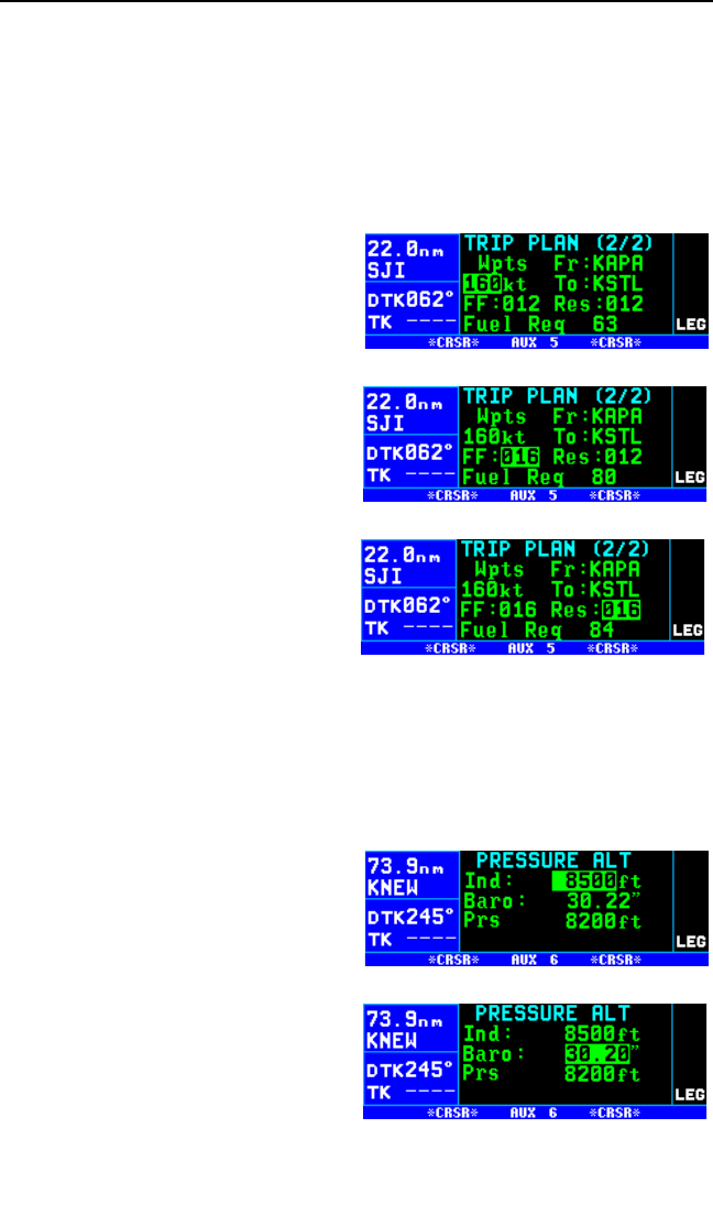
To calculate fuel requirements:
1. The waypoints entered on the AUX 4 page are automatically brought
forward on the AUX 5 page. You may also change the trip planning
type and the specific waypoints on the AUX 5 page in the same way
they were selected on the AUX 4 page.
2. Turn on the cursor with the Bbutton and use the right outer knob to
move the cursor to the groundspeed field on line 3.
3. Select your estimated ground-
speed for the trip (figure 5-68).
4. Move the cursor to the fuel flow
rate field and use the right inner
knob to select the desired value
(figure 5-69). Remember that
this can be in any units you
desire (as long as it’s per hour),
but the same fuel units must
carry through the calculations.
5. Move the cursor to the fuel
reserve requirement field and
enter the desired value. As you
do, watch the calculation of fuel
required on line 5 change (figure
5-70).
5.10.3. THE AUXILARY 6 (AUX 6) PRESSURE ALTITUDE PAGE
The AUX 6 page is used to determine pressure altitude.
To calculate the pressure altitude:
1. Turn on the cursor (B).
2. Enter the altitude indicated on
the aircraft’s altimeter (Ind) to
the nearest hundred feet or ten
meters by using the right inner
knob to select the desired value
(figure 5-71).
3. Use the right outer knob to move
the cursor to the Baro field, and
then use the right inner knob to
enter the current altimeter set-
ting (figure 5-72). The pressure
altitude (Prs) is now displayed.
KLN 94 Pilot’s Guide Chapter 5 Intermediate Operation
5-27
Figure 5-68
Figure 5-69
Figure 5-70
Figure 5-71
Figure 5-72
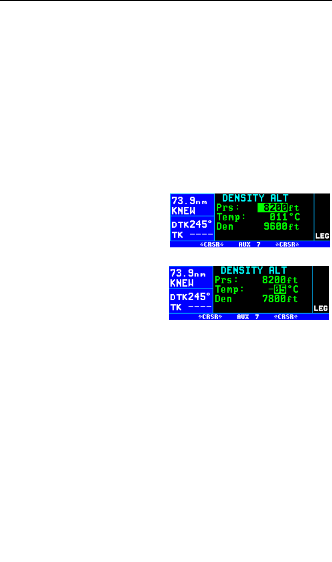
NOTE: The altimeter baro set units may be changed between inches, mil-
libars and hectopascals on the SET 12 page).
5.10.4. THE AUXILARY 7 (AUX 7) DENSITY ALTITUDE PAGE
The AUX 7 page is used to determine density altitude.
To calculate the density altitude:
1. Turn on the cursor (B).
2. The pressure altitude (Prs) displayed will be either the last entered
pressure altitude on this page, or the last calculated pressure altitude
from the AUX 6 page. If you desire to change it, enter the current
pressure altitude to the nearest hundred feet or ten meters by using
the right inner knob (figure 5-73).
3. Use the right outer knob to move
the cursor to the first Temp:
field, and then use the right inner
and outer knobs to enter the out-
side air temperature (degrees
Celsius) (figure 5-74). The first
digit of the temperature is either
“0” if the temperature is above
zero or “-” if the temperature is
below zero. For maximum accu-
racy, the static air temperature
should be entered. This is the
temperature of air without the
effect of heating due to the aircraft’s movement through the air. For
the airspeeds of most piston aircraft, the difference between static air
temperature and the observed air temperature (or “total air tempera-
ture”) is negligible. The density altitude (Den) is now displayed.
NOTE: If a compatible air data system is interfaced to the KLN 94, the
AUX 21 page displays pressure and density altitude directly for the pre-
sent conditions.
Chapter 5 Intermediate Operation
5-28
Figure 5-73
Figure 5-74
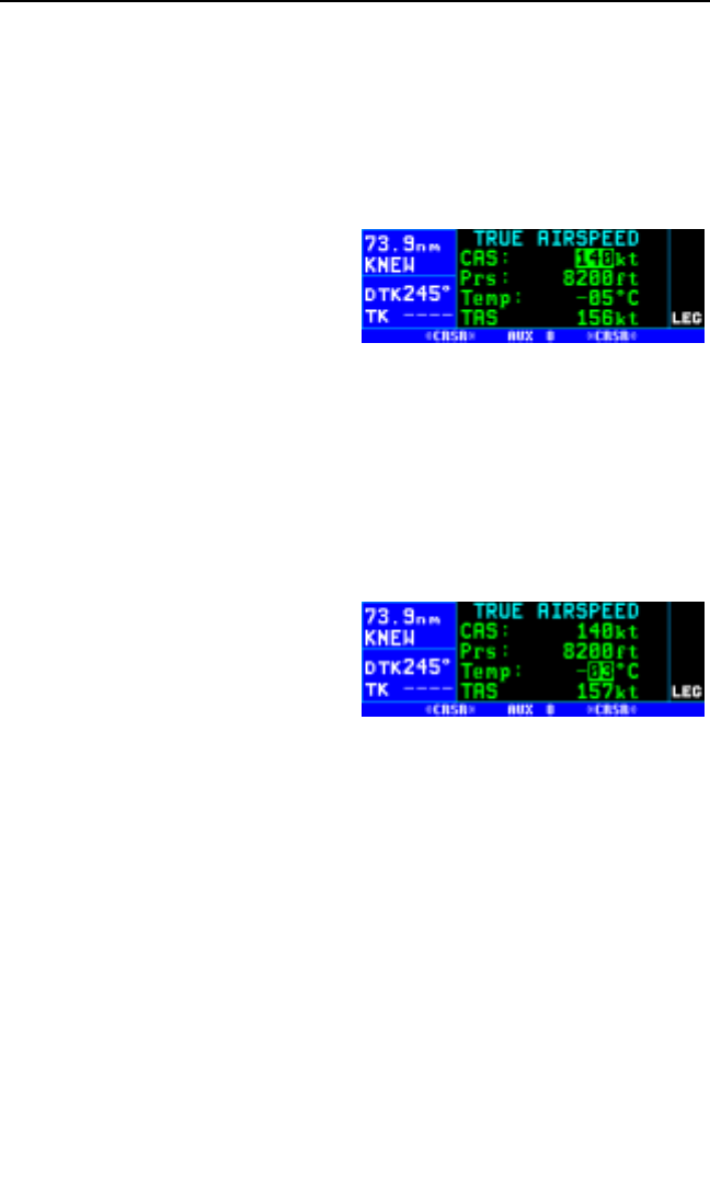
5.10.5. THE AUXILARY 8 (AUX 8) TRUE AIRSPEED PAGE
The AUX 8 page is used to determine the true airspeed (TAS) of the air-
craft.
To calculate the true airspeed (TAS):
1 Turn on the cursor (B).
2. Enter the aircraft’s calibrated air-
speed by using the right inner
knob (figure 5-75). If the calibrat-
ed airspeed isn’t known, use the
indicated airspeed. For most
aircraft the difference between
the calibrated airspeed and the
indicated airspeed is small at cruise airspeeds.
3. Use the right outer knob to move the cursor to the Prs field, and then
use the right inner knob to enter the aircraft’s pressure altitude. If the
pressure altitude was previously calculated on the AUX 6 page, or
entered on the AUX 7 page, it will already be displayed.
4. Move the cursor to the first Temp position, and then enter the outside
air temperature (degrees C) by using the right inner and outer knobs
(figure 5-76). The first digit of
the temperature is either “0” if
the temperature is above zero or
“-” if the temperature is below
zero. For maximum accuracy,
the total air temperature should
be entered. This is the tempera-
ture of air including the effect of heating due to the aircraft’s
movement through the air. The temperature read on a standard out-
side air temperature gauge found on most piston aircraft is “total air
temperature”. Since the difference between static air temperature and
the observed air temperature (or “total air temperature”) is usually
negligible, any temperature entered on the AUX 7 page is transferred
to this page. The true airspeed (TAS) is now displayed.
NOTE: If a compatible air data system is interfaced to the KLN 94, true
airspeed (TAS) is displayed directly on the AUX 20 page for the present
conditions.
KLN 94 Pilot’s Guide Chapter 5 Intermediate Operation
5-29
Figure 5-75
Figure 5-76
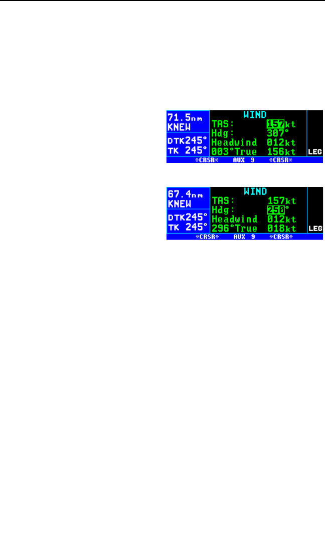
5.10.6. THE AUXILARY 9 (AUX 9) WIND PAGE
The AUX 9 page is used to determine the present wind direction and
speed. In addition, the headwind or tailwind component of the wind is dis-
played.
To calculate the winds aloft:
1. Turn on the cursor (B).
2. Enter the aircraft’s true airspeed
by using the right inner knob (fig-
ure 5-77). If the AUX 8 page was
previously used to calculate true
airspeed, it will already be dis-
played.
3. Use the right outer knob to move
the cursor to the Hdg field, and
then use the right inner knob to
enter the aircraft’s heading (fig-
ure 5-78). The headwind or
tailwind and the wind direction
and speed are now displayed.
The wind direction is relative to true North.
NOTE: The wind calculations are only correct when you have entered the
correct aircraft heading and true airspeed. Make sure to re-enter new val-
ues if you change airspeed or heading.
NOTE: If the KLN 94 is interfaced with a compatible source of heading
input, this heading is automatically used in the wind calculation displayed
on the AUX 9 page. If the KLN 94 is interfaced with a compatible air data
system in addition to a compatible heading source, the AUX 20 page dis-
plays wind information directly.
5.10.7. THE AUXILARY 10 (AUX 10) ALARM PAGE
The AUX 10 page may be used to set a timed alarm. Instances where
you might want to use it include as a reminder to switch between left and
right fuel tanks or maybe just to remind you to eat lunch! Line 2 of the
AUX 10 page shows the current time in the system time zone. The alarm
may be set by either of two methods: entering the time of day you wish the
alarm to activate, or the time interval from present time (i.e. twenty min-
utes from now). Line 5 displays the elapsed time since the KLN 94 was
turned on.
Chapter 5 Intermediate Operation
5-30
Figure 5-77
Figure 5-78
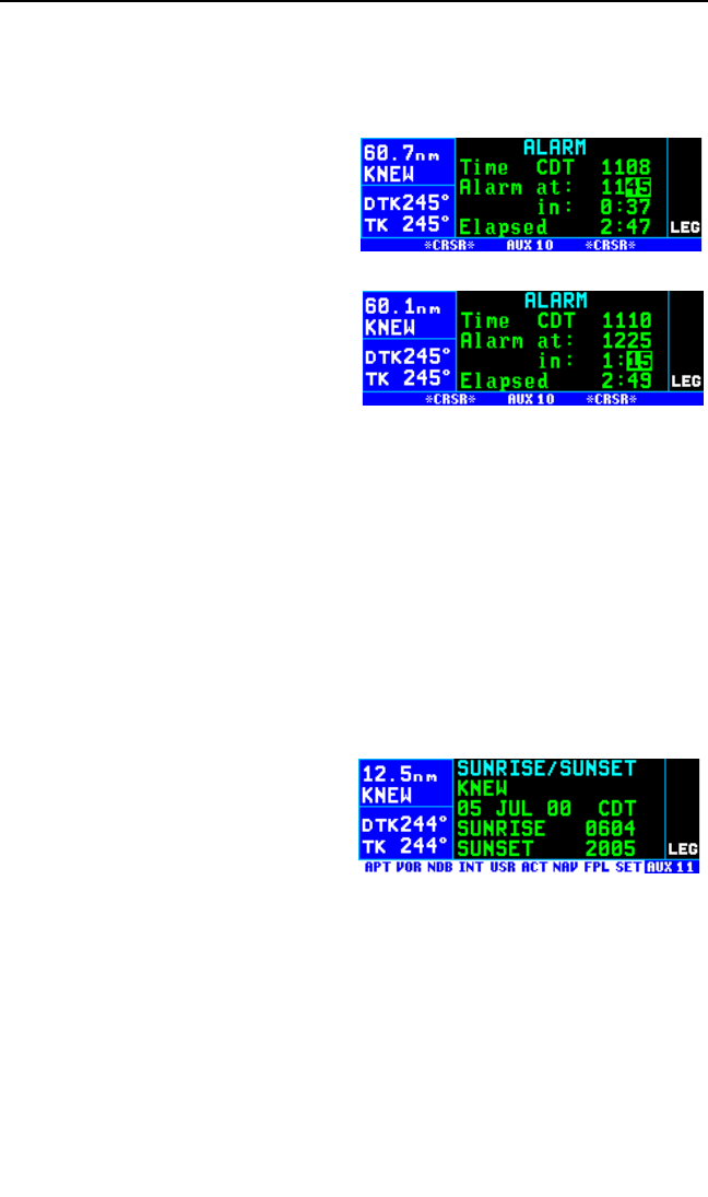
To set the alarm:
1. Turn on the cursor (B). If necessary, change the system time zone
to the desired one on line 2 of the AUX 10 page.
2. To set the alarm to activate at a
certain time, move the cursor to
the at: field on line 3. Select the
desired hours, and then minutes
(figure 5-79). Notice that as you
change it, the interval from pre-
sent time to alarm time is
updated on line 4.
3. To set the alarm to activate in a
certain length of time, move the
cursor to the in: field on line 4
and select the desired hours and
minutes, up to 9 hours and 59
minutes (figure 5-80). Turn off the cursor.
4. When the alarm goes off, the KLN 94 will display the message page
message:
*Timer expired
5.10.8. THE AUXILARY 11 (AUX 11) SUNRISE/SUNSET PAGE
The AUX 11 page is used to determine the times of sunrise and sunset for
any waypoint in the published or user database.
To calculate sunrise/sunset times:
1. Select the AUX 11 page (figure
5-81). The first time the AUX 11
page is selected after the
KLN 94 is turned on, the way-
point identifier defaults to the
current destination, the date
defaults to the current date, and
the time zone defaults to the system time zone. Each of these three
items may, however, be changed. The sunrise and sunset are dis-
played at the bottom of the page.
NOTE: The time zone initially displayed is the system time zone. This is
the same as the one on the SET 2 page. Note that the time zone dis-
played may not be appropriate for the waypoint shown. For example, the
waypoint shown could be KLAX and the time zone may be Eastern
Standard Time (EST) Make sure you select the appropriate time zone for
the displayed waypoint.
KLN 94 Pilot’s Guide Chapter 5 Intermediate Operation
5-31
Figure 5-79
Figure 5-80
Figure 5-81
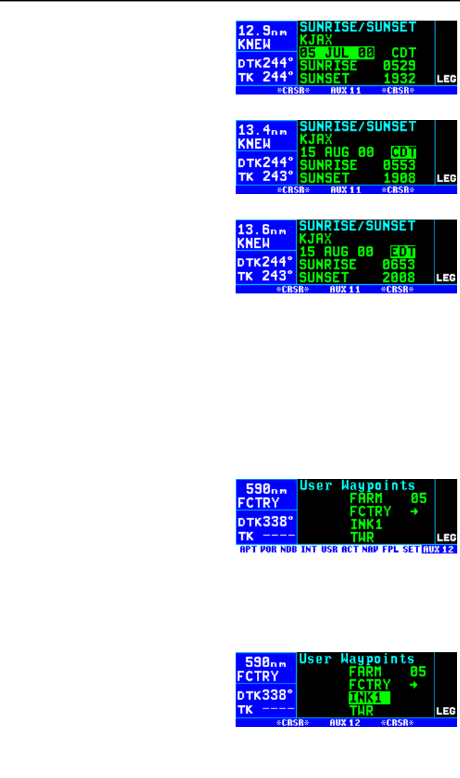
2. Turn on the cursor (B).
3. If desired, select another way-
point identifier using the right
inner and outer knobs. Press
Fto view the waypoint page
for the waypoint entered. Press
Fagain to approve the way-
point page (figure 5-82).
4. If desired, select another date
using the right inner and outer
knobs. You must press Fto
enter the date (figure 5-83).
5. If desired, select another time
zone. The sunrise and sunset
times for the selected waypoint,
date, and time zone are now dis-
played (figure 5-84).
5.11. VIEWING AND DELETING USER WAYPOINTS AND
WAYPOINT REMARKS (AUX 12 AND AUX 13 PAGES)
The AUX 12 and AUX 13 pages list the user-defined waypoints and way-
point remarks, respectively, which are currently stored in the KLN 94’s
memory.
5.11.1.THE AUX 12 PAGE
An example of an AUX 12 page is
shown in figure 5-85. All currently
stored user-defined waypoints are
listed in alphanumeric order. If the
user-defined waypoint is the active
waypoint, an arrow (→) follows the
identifier. If the waypoint is used in
one or more flight plans, then the number of the first flight plan in which it
is used is displayed on the right side. If there are more than four user
waypoints in storage, you can see the rest of the list by turning on the cur-
sor (B) and turning the right outer knob to scroll through the list.
To delete a user-defined waypoint
from the AUX 12 page:
1. Turn on the cursor and position it
over the desired waypoint (figure
5-86). If there are more than four
Chapter 5 Intermediate Operation
5-32
Figure 5-82
Figure 5-83
Figure 5-84
Figure 5-85
Figure 5-86
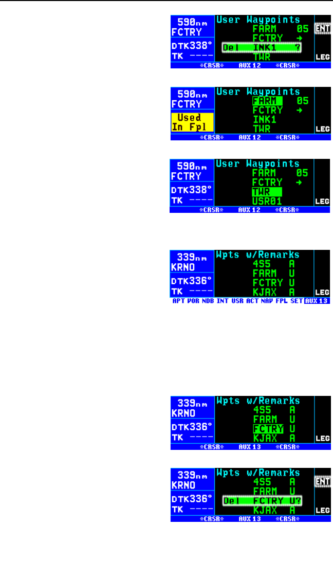
user-defined waypoints, you will
have to scroll the cursor down
the list.
2. Press E. The KLN 94 will ask
if you wish to delete that user-
waypoint (figure 5-87). If the
waypoint is active or used in a
flight plan, the deletion will not
be allowed and you will receive a
scratchpad message telling you
this (figure 5-88).
3. Press Fto approve the dele-
tion (figure 5-89).
5.11.2. THE AUX 13 PAGE
An example of an AUX 13 page is
shown in figure 5-90. All waypoints
with remarks are listed in alphanu-
meric order. Remarks can be stored
for airports (on the APT 6 page) or
user-defined waypoints (on the USR
3 page). If the waypoint is an airport,
then an “A” is displayed on the right side; likewise, a “U” represents a
user-defined waypoint. If there are more than four waypoints, you can see
the rest of the list by turning on the cursor (B) and turning the right outer
knob to scroll through the list.
To delete a waypoint remark from the AUX 13 page:
1. Turn on the cursor and position it
over the desired waypoint (figure
5-91). If there are more than four
airports with remarks, you will
have to scroll the cursor down
the list.
2. Press E. The KLN 94 will ask
if you wish to delete that remark
(figure 5-92).
3. Press Fto approve the dele-
tion.
KLN 94 Pilot’s Guide Chapter 5 Intermediate Operation
5-33
Figure 5-87
Figure 5-88
Figure 5-89
Figure 5-90
Figure 5-91
Figure 5-92

5.12. VIEWING THE KLN 94 SOFTWARE STATUS (AUX 14
PAGE)
The AUX 14 page (figure 5-93)
shows the application software revi-
sion (line 1), the software status of
the KLN 94 host computer (line 2),
graphics engine computer (line 3),
the GPS receiver (line 4), aeronauti-
cal database (line 5), and land –
cartographic database (line 6).
5.13. THE FUEL MANAGEMENT (AUX 15 – AUX 19)PAGES
Certain models of fuel management computers manufactured by Shadin
Company, ARNAV Systems, Inc., and Sheltech Ltd. May be interfaced
with the KLN 94. The primary benefit of having the KLN 94 interfaced with
a “real time” fuel management computer is that the system can continu-
ously compute the amount of fuel required to reach the destination and
the amount of fuel that will be on board upon reaching the destination. The
concept is the following. The fuel management computer continuously
sends the rate of fuel flow and the amount of fuel remaining to the
KLN 94. The KLN 94 continuously calculates the aircraft’s distance,
groundspeed, and estimated time en route (ETE) to the destination way-
point. The fuel required to reach the destination waypoint is the ETE
multiplied by the current rate of fuel flow. The amount of fuel that will be
remaining at the destination is the amount of fuel presently remaining
minus the fuel required to reach the destination.
CAUTION: The KLN 94 fuel calculations are based on the present
rate of fuel flow, the present groundspeed, the present distance to
destination along the programmed route, and the amount of fuel
presently remaining. Before take-off, the fuel flow computer must be
properly initialized with the amount of fuel on board (FOB) the air-
craft. For some Shadin fuel computers without display units, you
may enter the initial FOB during the KLN 94 Turn-on and Self Test
(see section 3.2). Since many factors influence the required amount
of fuel to reach the destination, it is the pilot’s responsibility to view
the fuel management pages often to check for any significant
changes. Some factors affecting the amount of fuel required are
power changes, altitude changes, headwind/tailwind component
changes, fuel/air mixture adjustments, and routing changes.
The AUX 15 – AUX 19 pages are used to display fuel management infor-
mation for KLN 94s interfaced with compatible fuel management
computers. If there is no fuel management computer interface, these fuel
management pages are not displayed.
Chapter 5 Intermediate Operation
5-34
Figure 5-93
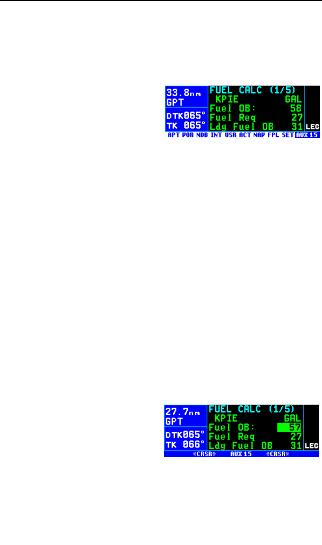
5.13.1. THE AUXILARY 15 (AUX 15) FUEL MANAGEMENT PAGE
NOTE: The AUX 15 – AUX 19 pages are only displayed when the KLN 94
is interfaced with a compatible fuel management system.
The AUX 15 page displays the following information (figures 5-94):
•The destination waypoint (the
final waypoint in FPL 0 or a
direct to waypoint if the way-
point is not included in FPL 0).
An arrow is displayed to the
left of the identifier if the way-
point is the active waypoint.
•The fuel units as received from the fuel management computer.
GAL gallons
LB pounds
IMP imperial gallons
Lliters
KG kilograms
•The fuel presently on board (Fuel OB). In most installations this is
defined by using the fuel flow computer’s control unit. However, if
the KLN 94 is interfaced with a compatible Shadin fuel flow comput-
er, it is possible to define the fuel on board by using the KLN 94. In
these installations it is not required to have the fuel flow computer’s
control head installed in the aircraft.
To change the present fuel on board:
1. Select the AUX 15 page and turn on the cursor B.
2. If it is possible to enter the present fuel on board by using the KLN 94
there will be a colon (:) following
Fuel OB on the display. If the
colon exists press the left B
(figure 5-95), if the colon does
not exist it is not possible to
change the fuel on board
through the KLN 94.
3. Enter the current fuel on board using the right inner knob. Make sure
the amount entered is consistent with the units used by the fuel flow
computer.
KLN 94 Pilot’s Guide Chapter 5 Intermediate Operation
5-35
Figure 5-94
Figure 5-95
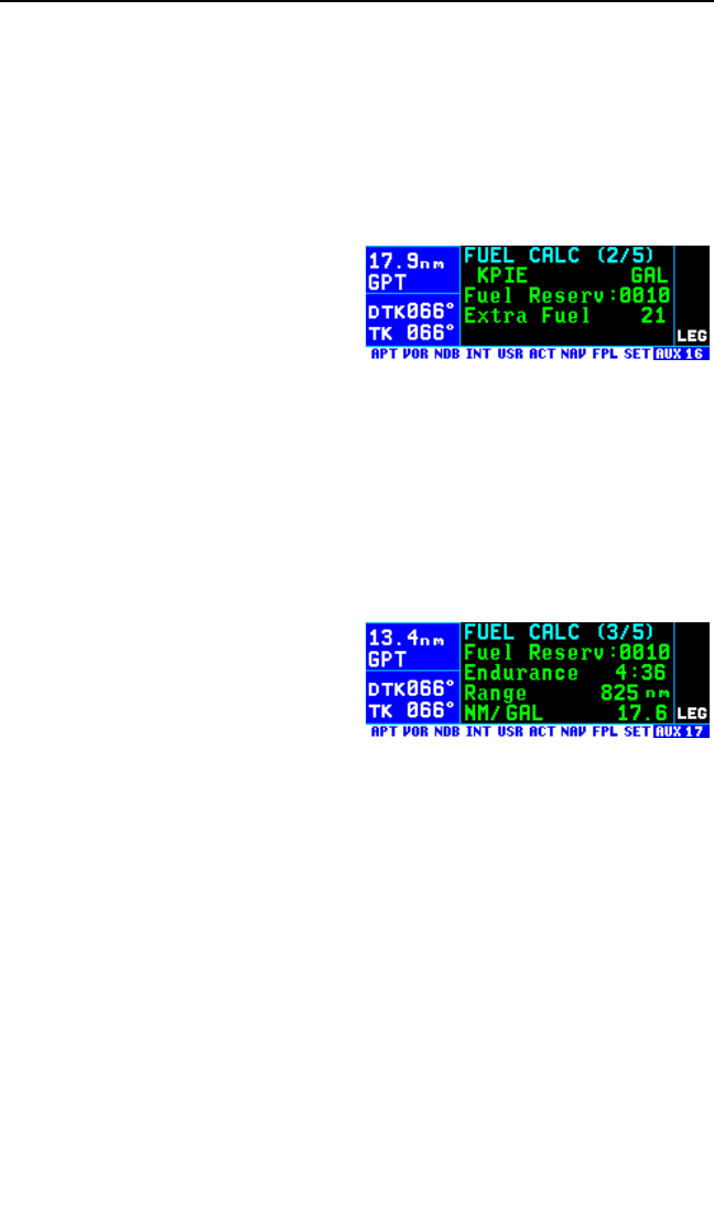
•The fuel required to reach the destination waypoint at the current
rate of fuel flow and the present groundspeed (Fuel Reqd).
•The landing fuel on board (Ldg Fuel OB) is the fuel presently on
board minus the fuel required to reach the destination.
5.13.2 THE AUXILARY 16 (AUX 16) FUEL MANAGEMENT PAGE
The AUX 16 page (figure 5-96) displays:
•The desired fuel reserve. You
may enter here the amount of
reserve fuel you wish to have
upon landing. The fuel must
be entered in the same units
as displayed on the first line.
To enter the reserve, press the Band use the right inner knob to
select the desired value. Turn off the Bwhen finished.
•The calculated extra fuel. This is the landing fuel on board minus
the fuel reserve you entered.
5.13.3. THE AUXILARY 17 (AUX 17) FUEL MANAGEMENT PAGE
The AUX 17 page displays the following information (figure 5-97):
•The desired fuel reserve.
Same as displayed on the
AUX 16 page. Changing the
reserve on one of the two
pages also changes it on the
other page.
•The endurance in hours and minutes. The endurance is calculated
based on the amount of fuel remaining after subtracting out the
reserve you entered on the AUX 16 or the AUX 17 page from the
present fuel on board.
•The range, which is the distance (nautical miles or kilometers) that
could be flown based on the endurance calculated above and the
present groundspeed.
•The fuel efficiency in nautical miles or kilometers per fuel unit (gal-
lons in this case), which is the groundspeed divided by the present
fuel flow.
Chapter 5 Intermediate Operation
5-36
Figure 5-96
Figure 5-97
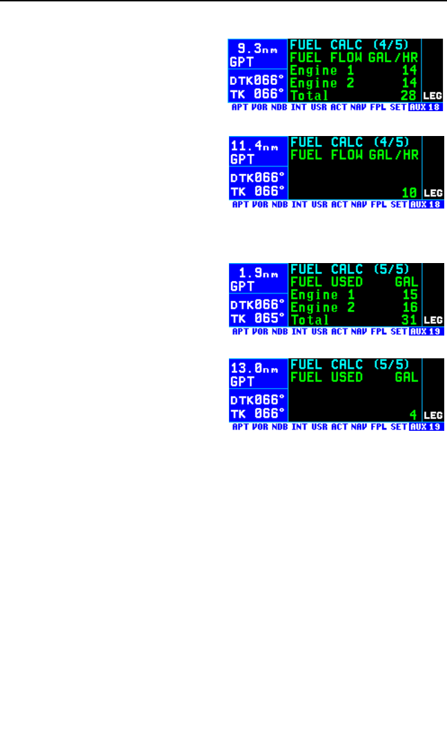
5.13.4. THE AUXILARY (AUX 18) FUEL MANAGEMENT PAGE
The AUX 18 page displays rate of
fuel flow. It has two formats depend-
ing on whether the aircraft is a twin
engine (figure 5-98) or a single
engine (figure 5-99).
5.13.5. THE AUXILARY (AUX 19) FUEL MANAGEMENT PAGE
The AUX 19 page displays the
amount of fuel used. If interfaced
with the ARNAV fuel management
computer, this page displays dashes
since the ARNAV system does not
output fuel used. There are two for-
mats depending on whether the
aircraft is a twin engine (figure 5-100)
or a single engine (figure 5-101).
5.14. THE AIR DATA (AUX 20 – AUX 21) PAGES
Specific models of Shadin Company air data systems may be interfaced
to the KLN 94. When interfaced with one of these systems, the KLN 94
will display real time air data parameters such as true airspeed (TAS), sta-
tic air temperature (SAT), total air temperature (TAT), Mach number,
density altitude, and pressure altitude. With a TAS input from an air data
computer and a compatible heading input, the KLN 94 will calculate and
display real time wind data (magnitude and direction).
NOTE: Heading information inputs to the KLN 94 must be in a format
which is different than available from most mechanical compass systems,
including the Bendix/King KCS 55A (KI 525A HSI with bootstrap heading
synchro) and KCS 305 compass systems. However, the compatible
Shadin air data system will convert three wire analog heading information
from these mechanical systems into the proper format.
KLN 94 Pilot’s Guide Chapter 5 Intermediate Operation
5-37
Figure 5-98
Figure 5-99
Figure 5-100
Figure 5-101
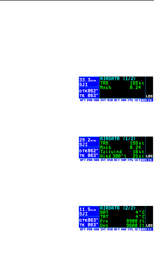
Chapter 5 Intermediate Operation
5-38
The Auxiliary 20 and Auxiliary 21 (AUX 20 and AUX 21) pages are used
to display air data information if both a fuel management system and an
air data system are interfaced to the KLN 94. If there is no fuel manage-
ment system, air data information is displayed on the AUX 15 and AUX 16
pages. If there is no air data system interface, these pages are not dis-
played.
NOTE: These air data pages receive inputs from air data sensors and dis-
play real time air data information. They are independent of the AUX 6,
AUX 7, AUX 8, and AUX 9 pages which rely on manual pilot inputs to cal-
culate air data information.
5.14.1. THE AUXILARY 20 (AUX 20) AIR DATA PAGE
Without a fuel management system
this becomes the AUX 15 page. The
following information is displayed (fig-
ure 5-102):
TAS True airspeed (the true speed of an aircraft through
the surrounding air mass).
Mach Mach number (the ratio of the true airspeed to the
speed of sound at a particular flight condition).
If a compatible source of heading
information is provided to the
KLN 94, the following wind data is
also displayed (figure 5-103):
Tailwind Tailwind component of the wind.
Headwind Headwind component of the wind.
Wind The wind direction relative to true North and the
wind speed.
5.14.2. THE AUXILARY 21 (AUX 21)AIR DATA PAGE
Without a fuel management system
this becomes the AUX 16 page. The
following information is displayed (fig-
ure 5-104):
Figure 5-102
Figure 5-103
Figure 5-104
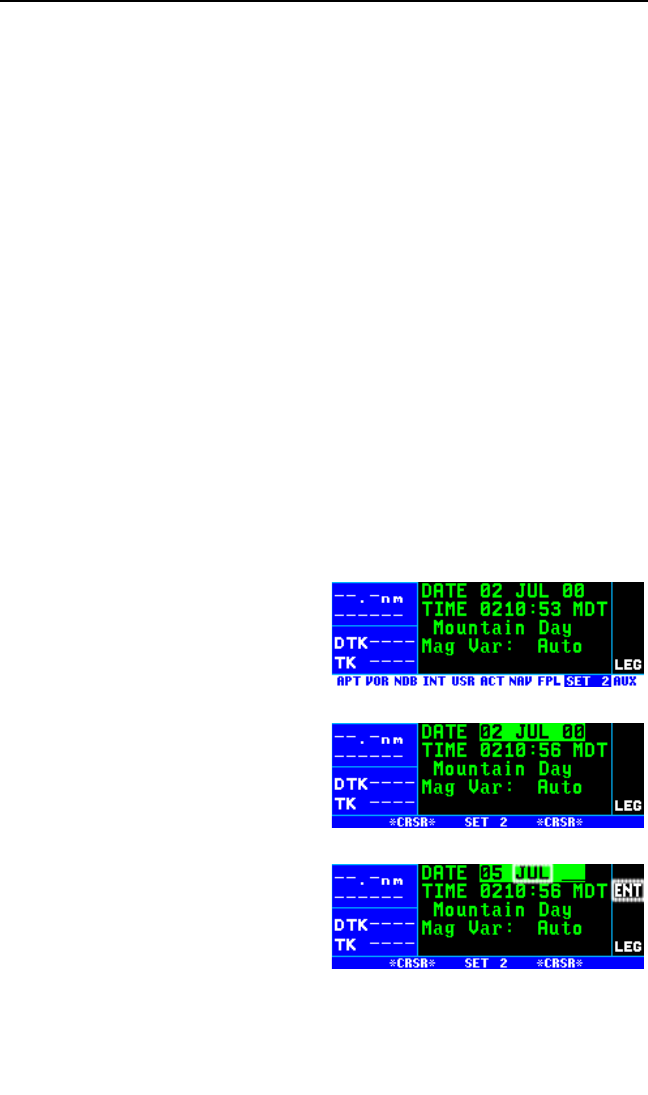
KLN 94 Pilot’s Guide Chapter 5 Intermediate Operation
5-39
SAT Static air temperature (the actual temperature of the
surrounding air mass).
TAT Total air temperature (the air temperature including heat rise
due to compressibility. This is the temperature measured
directly by the outside air temperature (OAT) probe.
Prs Pressure altitude (to nearest 100 feet or 10 meters).
Den Density altitude (to nearest 100 feet 10 meters).
5.15 VIEWING AND SETTING THE DATE AND TIME PAGE
The KLN 94 system time and date should seldom, if ever, require updating
because they are automatically updated when at least one satellite is
received. In addition, the KLN 94 contains an internal battery powered
calendar/clock to keep system time and date when the unit is not being
used. You will normally check to make sure the KLN 94 is set to the cor-
rect time and date shortly after you turn the unit on while you verify the
Initialization Page. You can, however, also check the time and date on the
Setup 2 (SET 2) page anytime you desire. There are several pages as
well as some internal functions of the KLN 94, such as magnetic variation
and proper use of database information, that depend on having the proper
time and date.
NOTE: You will not be able to update the time or date if the KLN 94 is
receiving a time and date from a satellite.
To set the date on the SET 2 page:
1. Select the SET 2 page (figure 5-
105).
2. Turn on the cursor. The cursor
will be over the entire date field
(figure 5-106).
3. Select the correct day of the
month with the right inner knob.
4. Move the flashing part of the cur-
sor to the month field (middle
three dashes) with the right outer
knob, and select the proper
month (figure 5-107).
Figure 5-105
Figure 5-106
Figure 5-107
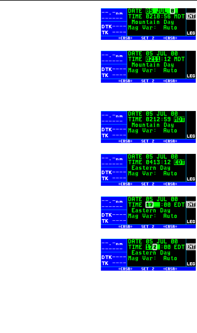
Chapter 5 Intermediate Operation
5-40
5. Move the flashing part of the cur-
sor to the tens digit of the year
field, and select the proper num-
ber (figure 5-108).
6. Repeat step 5 for the ones digit
of the year field.
7. Press Fto start the KLN 94
using the newly entered date
(figure 5-109).
To set the time on the SET 2 page:
1. Select the SET 2 page if it is not already selected.
2. Turn on the cursor and move it to
the time zone field (figure 5-110).
3. Change the time zone with the
right inner knob, if desired (figure
5-111). A listing of the time
zones and their abbreviations is
contained in section 3.2, “Turn-
on and Self Test”.
4. Move the cursor to the time field.
The hours and minutes will
appear in inverse video.
5. Select the correct hour (figure 5-
112). Remember, the KLN 94
uses 24 hour time. If it is 1:00
P.M. or later, add 12 hours (for
example, 2:30 P.M. becomes
14:30).
6. Move the flashing part of the cur-
sor to the tens of minutes, select
the proper number (figure 5-
113), then move on to the last
digit and set it.
7. Press Fto start the clock.
Figure 5-108
Figure 5-109
Figure 5-110
Figure 5-111
Figure 5-112
Figure 5-113

KLN 94 Pilot’s Guide Chapter 5 Intermediate Operation
5-41
5.16. MANUAL MAGNETIC VARIATION SELECTION
The KLN 94’s primary coverage area is from N 74°to S 60°as was shown
in figure 3-1. Magnetic variation is automatically computed within this cov-
erage area when Mag Var is in the default AUTO mode on the SET 2
page. Navigation outside this area is automatically referenced to true
North unless a manual input of magnetic variation is made on the SET 2
page. The following message will be displayed on the Message page:
*Magnetic Var Invalid
Nav Data Referenced
To True North
A user-defined magnetic variation may be entered on the SET 2 page.
When a user-entered magnetic variation of 0 degrees is being used, the
following message will be displayed on the Message page:
*Nav Data Referenced
To True North
When a user-defined magnetic variation other than 0 degrees is being
used, the following message will be displayed:
*Nav Data Referenced To
User-Defined Mag Var
There are two exceptions when a user-defined magnetic variation will not
be used for navigation. When the active waypoint is part of an approach
procedure, the magnetic variation for the published approach will be used
and the following message will be displayed:
*Mag Var for Published
Approach Being Used
Also, when the unit is in the OBS mode and the active waypoint is a VOR,
the magnetic variation associated with the VOR station will be used and
the following message will be displayed:
*Mag Var for Published
VOR Being Used
NOTE: A user-entered magnetic variation will not be retained if power is
off for more than 5 minutes. Use of automatically computed magnetic vari-
ation will be restored if power is off for more than 5 minutes and the unit is
within the primary coverage area.
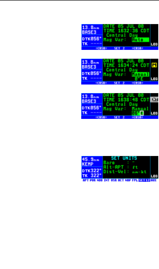
Chapter 5 Intermediate Operation
5-42
To enter the local magnetic variation manually on the SET 2 page:
1. Turn on the cursor (B).
2. Move the cursor over the field on
line 4 (figure 5-114).
3. Turn the right inner knob to
change the magnetic variation
field from Auto to Manual if
required (figure 5-115).
4. Use the right outer knob to move
the cursor over the numerical
value on line 5.
5. Use the right inner and outer
knobs to select the magnetic
variation, from 0 to 99 degrees.
6. Move the flashing part of the cur-
sor to the E/W (east/west) field
and select whether the magnetic
variation is easterly or westerly
(figure 5-116).
7. Press Fto approve and turn the cursor (B) off.
5.17. SETTING THE UNITS OF MEASURE
The SET 12 page (figure 5-117) is
used to set the unit of measure for
various parameters. The altimeter
barometric setting can be set to inch-
es of Mercury (“), millibars (mB), or
hectopascals (hP). Altitude, airport
elevation, and runway lengths can be
set to feet (ft) or meters (m). Finally, distances and velocities can be set to
nautical miles (NM) and knots (kt) or kilometers (km) and kilometers/hour
(k/h). To change a unit of measure: select the SET 12 page; turn on the
cursor (B) and move it over the desired unit of measure using the right
outer knob; turn the right inner knob to select the desired unit of measure;
and turn the cursor off again.
Figure 5-114
Figure 5-115
Figure 5-116
Figure 5-117
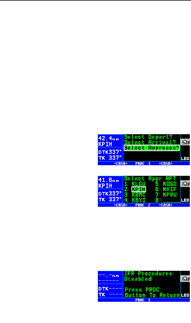
6. APPROACHES AND DP/STARS
This is the last chapter on the operation of the KLN 94. In this chapter you
will learn how to use the KLN 94 for non-precision approach procedures
as well as departure (DP) and arrival (STAR) procedures. Note that only
KLN 94s which are configured for IFR approaches are capable of perform-
ing the procedures discussed in this chapter. KLN 94s which are
configured for en route and terminal operations only will give you access
to DP/STAR procedures but not non-precision procedures. All of these
procedures require that you are comfortable with the operation of the unit
as presented up to this point. In particular, you need to be comfortable
with flight plan operation (sections 4.1. and 4.2.) and the Navigation
modes (section 5.5).
6.1. PROCEDURE (PROC) PAGES
The two Procedure pages (PROC 1 and PROC 2) are used to initiate
loading approach, departure (DP), and arrival (STAR) procedures into the
active flight plan (FPL 0). Examples of these pages are shown in figure 6-
1 and 6-2. A single press of the
Procedure button (P) is used to
display the PROC 1 page. The right
outer knob is used to move the cur-
sor over the desired option and then
the Fbutton is pressed to bring up
a PROC 2 page. When the PROC 1
page is displayed, pressing the P
button a second time returns the dis-
play to the page that was previously
being viewed. When the PROC 2
page is being displayed, pressing the
Pbutton returns the display to the
PROC 1 page.
The PROC pages provide a quick and efficient means of accessing the
desired airport’s APT 7 page (for a DP or a STAR) or the APT 8 page (for
an approach). If radar vectors are being provided for intercepting the
course to the final approach fix, the PROC 1 page is used for “activating”
vectors-to-final. Examples of using the PROC pages and Pbutton are
provided throughout this chapter.
If the KLN 94 is configured for VFR
use only it is not possible to gain
access to the approach, DP, and
STAR procedures and pressing the
Pbutton will bring up a PROC 1
page as shown in figure 6-3. If the
KLN 94 Pilot’s Guide Chapter 6 Approaches and DP/STARs
6-1
Figure 6-1
Figure 6-2
Figure 6-3

KLN 94 is configured for IFR en
route only, pressing the Pbutton
allows access to DP and STAR pro-
cedures but not approaches (figure
6-4).
6.2. NON-PRECISION APPROACH OPERATIONS
Flying non-precision approaches using the KLN 94 is not in itself very diffi-
cult. However, the procedures are different than using traditional
equipment such as VORs and NDBs. With this in mind, make sure that
you practice with the KLN 94 in VFR weather with a check pilot before
attempting to use the KLN 94 in actual IFR conditions.
CAUTION: The KLN 94 obtains approach information from the data-
base.Therefore, it is extremely important that the database is
current. The KLN 94 is approved for IFR non-precision approaches
only when the database is current. If you select an approach when
the database is out of date, you will be given the scratchpad mes-
sage: “D Base Expire” in the bottom left portion of the screen as a
reminder.
The following sections assume that your KLN 94 is properly installed in
the aircraft with all of the necessary accessories to fly non-precision
approaches. This will include an external HSI or CDI at a minimum and
may include some external annunciator/switches. In many installations the
aircraft will have a NAV/GPS switch to select which navigation source is
displayed on the primary HSI or CDI.
The NAV 4 page has been specifically designed to provide most of the
functions needed for non-precision approaches. This page provides an
interface that presents pertinent navigation information, a way to access
the flight plan waypoints, and a graphic presentation of the present posi-
tion relative to the flight plan waypoints. You will find this page to be a
good friend while performing GPS based non-precision approaches.
NOTE: There are a small number of approach procedures in the world
that are not suited for the operational characteristics of the KLN 94. These
procedures are not included in the database. Therefore it is not possible to
use the KLN 94 for these approaches. It is good preflight practice to
ensure that the KLN 94 contains anticipated procedures for the flight.
Chapter 6 Approaches and DP/STARs
6-2
Figure 6-4

6.2.1. APPROACH MODE ANNUNCIATIONS
In addition to the two course modes (Leg and OBS) described in section
5.5, there are also two approach related modes. At the time of the
KLN 94 installation in the aircraft these two modes may be configured to
be annunciated as one of the following two ways:
APR ARM (approach arm)
APR ACTV (approach active)
OR
TERM (terminal)
APR (approach)
These annunciations are displayed on the right side annunciator section of
the KLN 94 display.
NOTE: Approach arm is exactly the same as terminal mode and
approach active is exactly the same as approach mode. In this pilot’s
guide APR ARM / APR ACTV will be used for consistency but your
KLN 94 may annunciate TERM / APR.
One difference of these modes from the normal en route mode is that the
CDI scale factor changes from ±5 NM for en route mode to ±1.0 NM for
APR ARM and to ±0.3 NM when in the APR ACTV mode. Another differ-
ence between these modes and the en route mode is that the GPS
integrity monitoring (RAIM) is set to a tighter level.
The APR ARM mode will be selected automatically by the KLN 94 when
the aircraft is within 30 NM of an airport and an approach is loaded in the
flight plan for that airport. The APR ACTV mode can only be engaged
automatically by the KLN 94 when 2 NM inbound to the final approach fix
(FAF).
NOTE: If an optional external GPS approach switch is installed it is possi-
ble to arm the approach mode at a distance greater than 30 NM from the
airport by pressing the external GPS approach switch, but the KLN 94 will
not change the CDI scale factor until the aircraft reaches the 30 NM point.
If the external GPS approach switch is pressed while the approach mode
is armed, then the KLN 94 will disarm the approach and change back to
en route mode. The approach can be re-armed by simply pressing the
GPS APR switch again. If the KLN 94 is in the APR ACTV mode, press-
ing the external GPS APR switch will change the mode to APR ARM.
Once past the FAF, it is not possible to return to the approach active
mode without conducting a missed approach and flying back to the FAF.
KLN 94 Pilot’s Guide Chapter 6 Approaches and DP/STARs
6-3
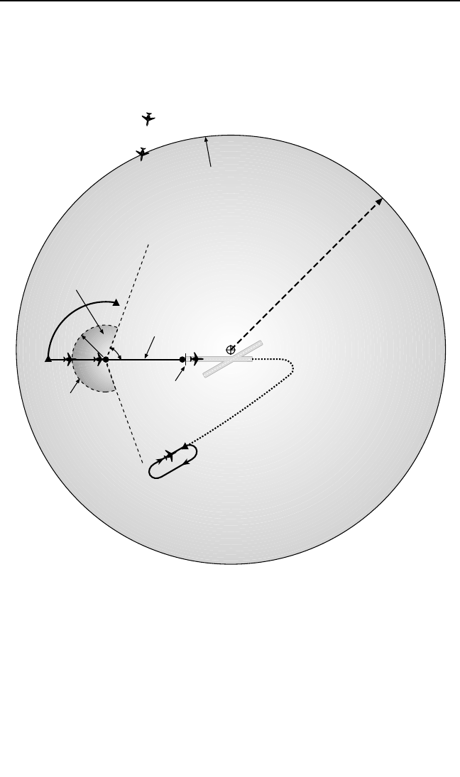
6.2.2. GENERAL PROCEDURE FOR NON-PRECISION
APPROACHES
Non-precision approaches will all have the general flow of events as fol-
lows. Refer to figure 6-5.
1. Select and load the approach into the active flight plan.
Approaches are always conducted from FPL 0. The approach can be
loaded at almost any time but must be completed before reaching the
Final Approach Fix and should be done as soon as possible. This
corresponds to point A in figure 6-5. If the aircraft is greater than 30
NM from the airport, then the CDI scale factor will remain at the
default ±5 NM full scale deflection. Only one approach can be loaded
in FPL 0.
Chapter 6 Approaches and DP/STARs
6-4
17
35
14
32
MAP
FAF
IAF
ARP
Approach Arm
CDI Scale Factor
±1.0 nm
CDI Scale Factor
±5.0 nm
CDI Scale Factor
constant at ±0.3 nm
CDI Scale Factor
changing from
±1.0 nm to ±0.3 nm
70°
30 nm
2 nm
Transition to approach
ACTV if:
- LEG mode is selected
- Integrity checks OK
- Aircraft heading
towards the FAF
- FAF or co-located
IAF/FAF is active
waypoint
Load approach
into flight plan
Approach automatically
arms when within 30 nm
of the airport and an
approach is loaded into
the active flight plan
FAF - Final Approach Fix
MAP - Missed Approach Point
ARP - Airport Reference Point
IAF - Initial Approach Fix
MAHP -Missed Approach Holding
Point
N
O
T
T
O
S
C
A
L
E
N
O
TF
OR
NA
V
I
GAT
IO
N
(A)
(B)
(C) (D)
(E)
MAHP
(F)
Automatic Waypoint
sequencing stops
Figure 6-5

2. Transition to the approach arm mode. This will occur automatically
when the aircraft is within 30 NM of the airport and there is an
approach loaded into the flight plan (position B in figure 6-5). The CDI
scale factor will change to ±1.0 NM over the next 30 seconds and the
annunciator will indicate APR ARM (or TERM - see first note in sec-
tion 6.2.1).
3. Get established on the final approach course.
• Radar vectors (select “Vectors” as an IAF, leave unit in Leg mode)
• NoPT arrival route (leave unit in Leg mode)
• DME arc (leave unit in Leg mode)
• Procedure turn or holding pattern (requires OBS mode)
4. Transition to the approach active mode. This mode change is auto-
matic and occurs at position C in figure 6-5 when:
• the aircraft is 2 NM from the FAF and the approach mode is armed
• the LEG mode is selected
• the aircraft is heading towards the FAF
• the FAF or a co-located IAF/FAF is the active waypoint
• the KLN 94 confirms that adequate integrity monitoring is available
to complete the approach.
• RAIM is available at FAF & MAP
If any of these conditions are not met, the KLN 94 will not transition to the
approach active mode and a missed approach will be required if the con-
ditions do not change before reaching the FAF. If all of these conditions
are met then the CDI scale factor will start to change to ±0.3 NM and the
annunciator will indicate APR ACTV (or APR – see first note in section
6.2.1).
5. At the FAF (position D in figure 6-5) the CDI scale factor will be at
±0.3 NM and will remain at this scale factor until you manually cancel
the approach mode by either initiating a direct to operation, by loading
another approach, by changing to OBS mode, or by pressing the
optional external GPS APR button to change to the APR ARM mode.
WARNING: It is not approved to conduct the final portion of the
approach unless the KLN 94 is in the approach active mode.
6. Fly to the Missed Approach Point. (position E in figure 6-5).
7. If necessary conduct the missed approach procedure. The
KLN 94 will not automatically sequence to the next waypoint. You
must manually change to the appropriate waypoint according to the
KLN 94 Pilot’s Guide Chapter 6 Approaches and DP/STARs
6-5
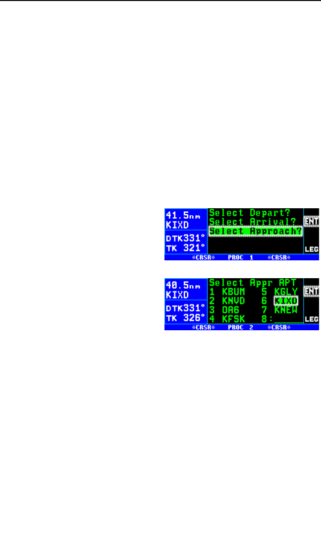
situation. By default, the KLN 94 will nominate the first waypoint of
the published missed approach procedure when you have flown past
the MAP and the Dbutton is pressed. Remember to always refer to
the paper chart when conducting a missed approach. The OBS mode
is often needed at some point during a missed approach and is
always required to fly the holding pattern (position F in figure 6-5).
The details of the above operations as well as several examples of how to
conduct non-precision approaches using the KLN 94 are given in the fol-
lowing sections.
6.2.3. SELECTING AND LOADING AN APPROACH
The Pbutton is used to initiate loading an approach into the active flight
plan. The following example will use the RNAV Rwy 17 approach to New
Century Aircenter airport (KIXD) in Olathe, KS.
To select and load an approach into the active flight plan (FPL 0):
1. Press the Pbutton to bring up
the PROC 1 page (figure 6-6).
The cursor will already be over
Select Approach?.
2. Press the Fbutton to display
the PROC 2 page (figure 6-7).
The PROC 2 page shows a list
of up to 7 airport identifiers. The
list includes:
•Airports in FPL 0 (up to 6)
•A Direct To airport not in FPL
0 (if one exists)
•Other airports closest to the aircraft’s present position. Therefore, if
you have to execute a missed approach at your intended destina-
tion airport or in case on an en route emergency, the PROC 2 page
lists nearby airports with instrument approaches.
•The airports are listed in the order of closest proximity to the aircraft.
All of the airports shown have an approach in the database,
although not necessarily one approved for GPS.
NOTE: While on the PROC 1 page, pressing the PROC button will return
the display to the page that was previously being displayed. While on the
PROC 2 page, pressing the PROC button will return the display to the
PROC 1 page.
Chapter 6 Approaches and DP/STARs
6-6
Figure 6-6
Figure 6-7
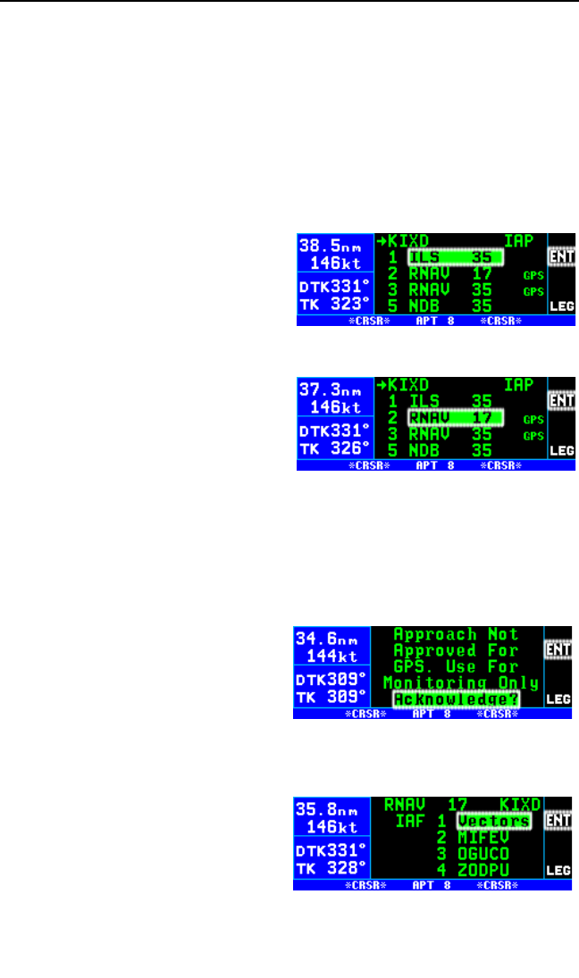
3. The cursor will normally already be over the desired airport but if you
wish to select another airport from the list use the right outer knob to
move the cursor to the desired airport. Press F.
NOTE: If the desired airport is not in the list, turn the right outer knob
clockwise to move the cursor to the blank position at the end of the list.
Enter the airport identifier of the airport where the approach is to be con-
ducted. Press the Fbutton once to view the APT 1 page and a second
time to approve it.
4. The APT 8 page is displayed showing a list of approaches for the
selected airport (figure 6-8).
Those approaches approved for
GPS have the letters GPS to the
right of the approach name. The
cursor will be on the first
approach in the list. Use the right
inner knob to move the cursor
over the desired approach. If
there are more than 4 approach-
es for the airport, the first three
approaches and the last one are
initially shown. Turn the right
outer knob to move the cursor
through the entire list and over
RNAV 17 (figure 6-9). Press F.
NOTE: Those approaches not having the letters GPS to the right of the
approach name are not approved for GPS. Therefore, the KLN 94 may
ONLY be used to provide situational awareness and monitoring for these
approaches. When a non-approved approach is selected a page is dis-
played for the pilot to acknowledge
by pressing the Fbutton (figure 6-
10). When a non-approved
approach is selected the unit will
remain in approach arm mode (or
terminal mode) and will not transition
to the approach active mode.
5. A list of initial approach fixes
(IAFs) for the RNAV 17
approach in shown (figure 6-11).
In most cases Vectors, used
when radar vectors will be
received, is the first choice in
the list. In this example we want
the MIFEV IAF. Select this by
KLN 94 Pilot’s Guide Chapter 6 Approaches and DP/STARs
6-7
Figure 6-8
Figure 6-9
Figure 6-10
Figure 6-11
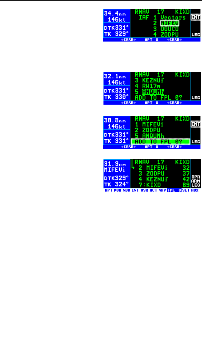
pressing Fwhen the cursor is
over MIFEV (figure 6-12).
NOTE: If there is only one IAF for a
procedure, then the KLN 94 will skip
this step and go on to the next step
6. The KLN 94 next presents a list of waypoints that make up the
approach. If desired, review these waypoints to make sure that you
have selected the correct IAF. If
there are more than three way-
points in the approach you can
move the cursor up to “scroll” the
other waypoints into view by
rotating the right outer knob (fig-
ure 6-13).
7. Move the cursor over ADD TO
FPL 0? (figure 6-14) and press
F.
8. The KLN 94 will then bring up the
FPL 0 page and put the
sequence of approach waypoints
in front of the associated airport
identifier (figure 6-15). If an
approach is loaded for an airport
not in FPL 0 the approach is
added to the end of the flight
plan and does not include the associated airport identifier.
NOTE: While on the APT 8 page showing the list of IAFs or the list of
approach waypoints (figure 6-11 or 6-14), you may back up one step in
the selection process by pressing the Ebutton. Anytime you want to
start over in the approach selection process, press the Pbutton.
NOTE: When FPL 0 is modified in any way, including adding an
approach, the KLN 94 reorients itself on the nearest leg of the modified
flight plan. When the approach is added to FPL 0, check to make sure the
desired leg of the flight plan is active. If necessary, do a Direct To opera-
tion to the desired waypoint.
The waypoints that make up the approach procedure are loaded into the
active flight plan. At the top of the list of approach waypoints is a “header”
that describes the approach that follows. An example of this is shown on
line 1 of figure 6-15, which indicates that the RNAV 17 approach for KIXD
is in the active flight plan (FPL 0).
Chapter 6 Approaches and DP/STARs
6-8
Figure 6-15
Figure 6-12
Figure 6-13
Figure 6-14

After the approach has been entered into the flight plan the KLN 94
checks to make sure that the resulting flight plan “makes sense”. If the
KLN 94 detects any waypoints that are in both the en route portion of the
flight plan and the portion that makes up the approach, then the following
message will be given:
*Redundant Wpts in FPL
Edit En Route Wpts
As Necessary
Examine the flight plan and delete those en route waypoints that are not
necessary.
NOTE: Approaches can only be entered into FPL 0, the active flight plan.
If the KLN 94 is turned off for more than 5 minutes, then the approach is
deleted when power is turned back on.
You can get a good idea as to whether you will receive radar vectors for
the approach by viewing the APT 3 page. An (R) is displayed on the right
side of line 4 when the approach/departure is in a radar environment. If
you’re not sure whether you will receive radar vectors, select an actual
IAF when the approach is loaded into FPL 0. You can easily activate vec-
tors from the PROC 1 page even when an actual IAF (other than Vectors)
was selected.
6.2.4. INTERPRETING WHAT YOU SEE
You may have noticed that some waypoints in the approach have a small
letter at the end of the waypoint name. The small letter is an aid that we
have added to the name of some waypoints to help you recognize impor-
tant points in the approach. These suffixes are displayed on many of the
KLN 94 pages. The definitions of these suffixes are:
i - The Initial Approach Fix (IAF) of the approach.
f - The Final Approach Fix (FAF) of the approach
m - The Missed Approach Point (MAP) of the approach
h - The Missed Approach Holding Point (MAHP) for the approach
Every approach will have a FAF and a MAP. Almost all will have an IAF
and missed approach holding point. You may see the same waypoints
multiple times in an approach, each with a different suffix letter. For exam-
ple, an approach could include the waypoints ABCi, ABCm, and ABCh
which would indicate that the waypoint ABC is used as an IAF, the MAP,
and the MAHP. It is important that you select the correct usage of the
waypoint. So if you are cleared direct to ABC as an IAF, make sure you
select ABCi when doing the direct to operation.
KLN 94 Pilot’s Guide Chapter 6 Approaches and DP/STARs
6-9

Another item that you should notice
in the flight plan is the line that has
*NO WPT SEQ on it (figure 6-16).
This is what is referred to as a fence
and the purpose of this line is to tell
you that the KLN 94 will not automat-
ically sequence past the waypoint
that precedes the fence. The waypoint before the fence is always the
missed approach point. The reason that waypoint sequencing is not
allowed is that many missed approach procedures require specific actions
before going to the missed approach holding point (e.g., climbing on a
fixed heading until reaching an altitude).
You may notice waypoints with somewhat strange names. For example
LAX18 has a name that is not normal for a waypoint. This is an example
of what are called “terminal” waypoints. These are waypoints that are
associated with a specific airport. They are used to define a spot on the
ground that does not have a normal waypoint name. In the case of
“LAX18” this point is 18 NM from the LAX VOR on the 68°radial. Another
waypoint, MA25B, is also a type of terminal waypoint. In this case this
point is the missed approach point for runway 25. This approach applies
to both the left and right runways so the letter B is used to mean “both”.
There are a few other types of terminal waypoints that will help you to fully
understand GPS non-precision approaches. The naming convention for
these waypoints are as follows:
Fxyyy • F stands for Final Approach Fix
Ixyyy • I stands for Intermediate Fix
Cxyyy • C stands for Course Fix
Mxyyy • M stands for Missed Approach Point
RWzzz • RW stands for Runway Fix. This is usually the MAP for
the approach
• zzz will be a runway number possibly including L for
Left, R for Right, C for Center, or B for Both.
Daaab • D stands for DME arc waypoint. Some DME arc way
points use the following convention for waypoint names
while other DME arc waypoints use normal five letter
identifiers.
• aaa is the radial that the fix is on from the reference
VOR
Chapter 6 Approaches and DP/STARs
6-10
Figure 6-16

• b will be a letter corresponding to the distance from
the reference VOR. For example, G is the seventh letter
of the alphabet so D234G would be a point on the 234°
radial 7 NM from the reference VOR. DME arcs greater
than 26 NM will have waypoints where the first two char
acters are the first two letters of the DME identifier. The
next three characters will be the radial that the arc way
point is on.
In the rules above x and yyy are defined as follows. For runways with only
one approach, x will be replaced with an “A” or a “F”. For runways that
have multiple approaches, x will be replaced with “V” for VOR, “N” for
NDB, or “R” for RNAV. The letters yyy will be replaced with either the run-
way identifier (e.g., FF25L is the FAF for runway 25L) or, for circling
approaches, the inbound course to the missed approach point (e.g.,
MA259).
Waypoints along a given radial will be named such that the first three let-
ters are the reference VOR/DME and the next two are the DME distance.
If the distance is greater than 100 NM the order is reversed. For example,
LAX18 is 18 NM from LAX while 26FLW is 126 NM from FLW.
If the aircraft is not too far from the destination airport, the NAV 4 page
can be used to determine where some of these waypoints are relative to
others in the approach. At the time of this writing most of the Jeppesen
charts and some of the NOS charts show the special terminal waypoints
that are required for GPS approaches. For this reason it is a good idea to
understand what the special waypoints are used for and what they mean.
6.2.5. CHANGING OR DELETING AN APPROACH ONCE LOADED
INTO THE FLIGHT PLAN
The sequence of waypoints that are retrieved from the database of the
KLN 94 define the approach procedures as they are charted. To ensure
that the proper path over the ground is followed, it is not possible to either
delete or add waypoints to the approach section of the flight plan. To help
you see which waypoints are en route waypoints and which are approach
waypoints, the KLN 94 does not display a colon next to the waypoint num-
ber on the FPL 0 page if the waypoint is an approach waypoint.
It is only possible to replace the existing approach with another one, or
delete the entire approach from the flight plan. FPL 0 can only contain
one approach. The procedure for replacing an approach in FPL 0 is virtu-
ally the same as initially loading an approach. Use this procedure whether
you are changing the IAF for the approach already loaded, for changing to
a different approach at the same airport, or selecting an approach at
another airport.
KLN 94 Pilot’s Guide Chapter 6 Approaches and DP/STARs
6-11
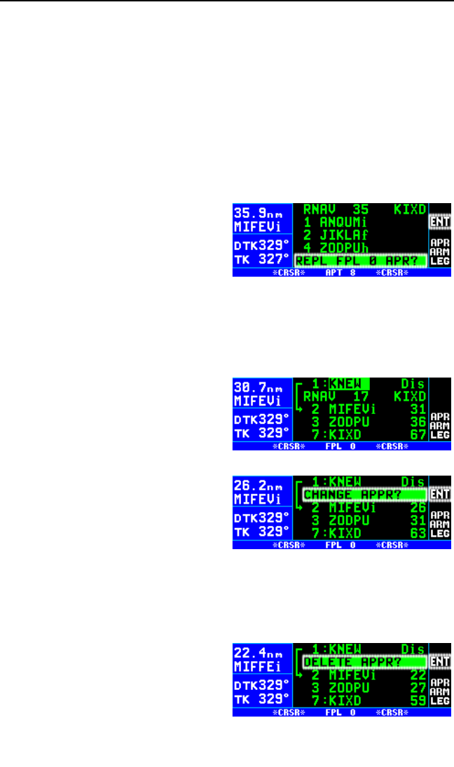
To replace an existing approach:
1. Press the Pbutton. If necessary move the cursor over Select
Approach? and press Fto bring up the PROC 2 page.
2. The cursor will already be over the airport associated with the
approach loaded in FPL 0. If you wish to select another airport for an
approach move the cursor over the desired airport identifier in the list.
Or, you always have the option of moving the cursor to the blank field
at the end of the list and entering another airport identifier. Press F.
3. Select the desired approach and IAF as before.
4. The APT 8 page showing the
approach waypoints now dis-
plays REPL FPL 0 APR? at the
bottom of the page (figure 6-17).
Press Fto acknowledge and
load the new approach into the
active flight plan.
An approach is deleted from the active flight plan using the FPL 0 page. It
is also possible to replace an existing approach from this page.
To delete an existing approach:
1. With the active flight plan (FPL
0) page being displayed, turn the
cursor on by pressing B (fig-
ure 6-18).
2. Move the cursor so that it covers
the approach header at the top
of the approach procedure.
Once the cursor comes over the
approach header, it will automat-
ically change to read CHANGE
APPR? (figure 6-19). If you
press Fin this condition the
KLN 94 will bring up the APT 8 page that corresponds to the current
approach. At this point it is possible to select a different approach pro-
cedure for this airport, a different IAF, or both.
3. If you press the Ebutton while
the cursor is over the approach
header it will change to read
DELETE APPR? (figure 6-20). If
you press Fnow, the KLN 94
will remove the entire approach
Chapter 6 Approaches and DP/STARs
6-12
Figure 6-18
Figure 6-19
Figure 6-20
Figure 6-17

procedure from the active flight plan. If the KLN 94 was in the
approach arm or the approach active mode, then deleting the
approach will cause the KLN 94 to change back to en route mode.
This means that the CDI scale factor will change back to the default
±5.0 NM scale.
6.2.6. GPS APPROACH EXAMPLES
Now that you know the basics of inserting an approach into the flight plan,
we can now show the approach operation of the unit by using examples of
actual approaches. There are four basic categories of GPS approach. Or
more specifically, there are four basic procedures used to get established
inbound to the final approach fix (FAF):
•No procedure turn
•Radar vectors to the FAF inbound course
•A course reversal (procedure turn or holding pattern)
•DME arc
GPS approaches for the four categories are the same from the FAF to the
missed approach point (MAP). Examples of each of these categories of
approach will now be presented. More detail is included in the first exam-
ple so read it first.
NOTE: If necessary for visual clarity during an approach, declutter Land
and Aero from the map by using the Ebutton (section 3.11.4.10) or the
SET 7 and SET 8 pages (sections 3.11.4.4 and 3.11.4.6).
6.2.7. APPROACH EXAMPLE 1: NO PROCEDURE TURN
The KLN 94 will remain in the familiar Leg mode for this category of
approach from the IAF to the MAP so there will be no need to change
between Leg and OBS. The RNAV 17 approach at KIXD (figure 6-21) is
an example of the classic “T” approach utilizing terminal arrival areas
(TAA) where there is normally no procedure turn required to get estab-
lished on the inbound course to the FAF. This is the approach that was
loaded into the flight plan in section 6.2.3. Another example of where no
procedure turn is required is shown in the NDB or GPS 15 approach at
KMSV (figure 6-22). No procedure turn is required when arriving from the
Hancock (HNK) VOR IAF according to the “NoPT” nomenclature on the
chart.
We will use the RNAV 17 approach at KIXD as an example to show how
the KLN 94 sequences through an approach and what type of annuncia-
tions and scale factor changes can be expected. Refer to the approach
KLN 94 Pilot’s Guide Chapter 6 Approaches and DP/STARs
6-13
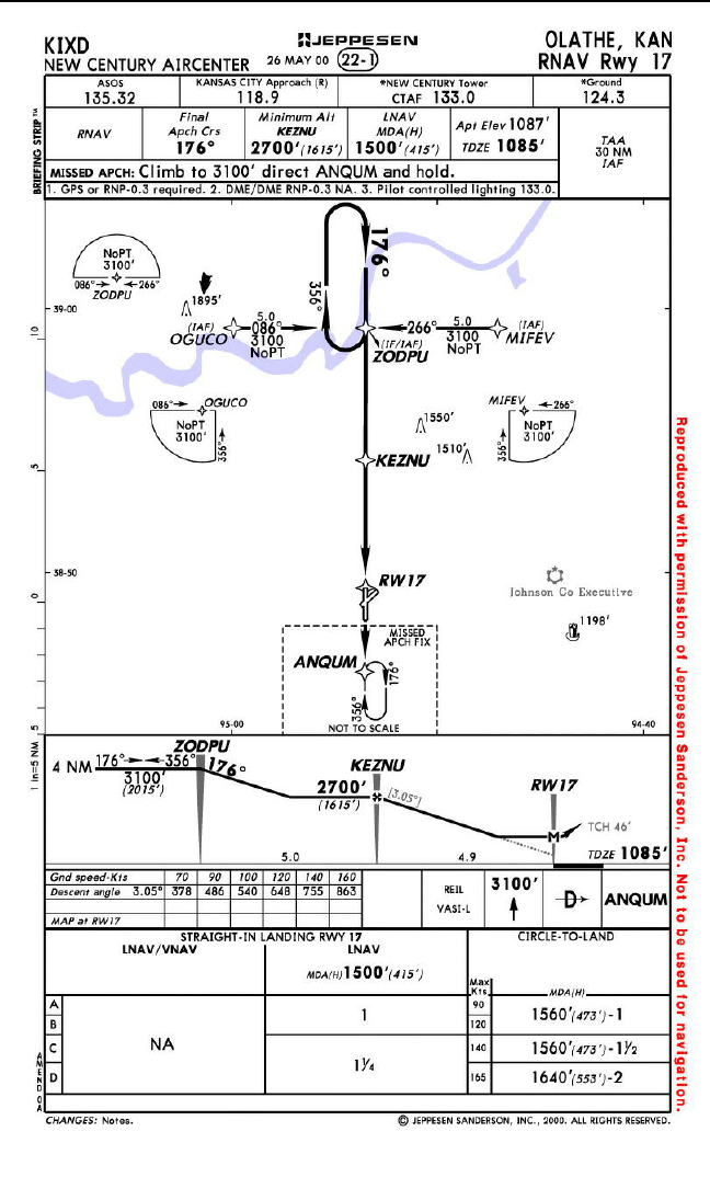
Chapter 6 Approaches and DP/STARs
6-14
Figure 6-21
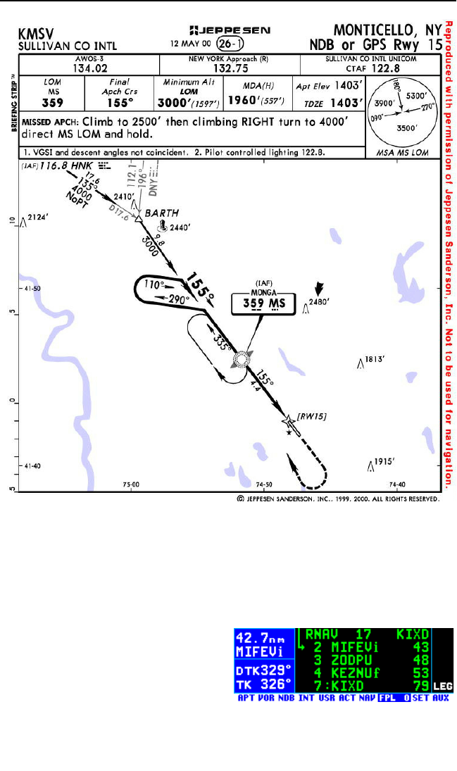
plate for this approach (figure 6-21) to see what the procedure looks like.
For this example it is assumed that you are on an active flight plan from
Lakefront airport (KNEW) in New Orleans, LA with the final destination
being the New Century Aircenter (KIXD) in Olathe, KS. Approximately 40
NM southeast of the airport you are told to expect the RNAV 17 approach.
1. Load the RNAV 17 approach to
KIXD as demonstrated in section
6.2.3. Since we are arriving from
the southeast, MIFEV is selected
as the IAF. The approach way-
points are automatically added
before the airport identifier in
FPL 0 (figure 6-23).
KLN 94 Pilot’s Guide Chapter 6 Approaches and DP/STARs
6-15
Figure 6-22
Figure 6-23
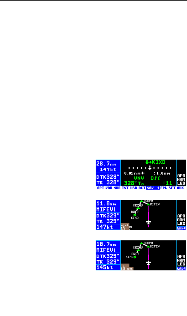
NOTE: When FPL 0 is modified in any way, the KLN 94 orients itself on
the nearest leg of the modified flight plan. In this case the leg from KNEW
to MIFEV has become active. Since we have not yet been cleared to
MIFEV it is necessary to do a Direct To operation to KIXD. The easiest
way to do this is normally using the waypoint scan feature of the map (see
section 4.2.4.1.)
2. When you are within 30 NM of the airport (not the IAF), the KLN 94
will automatically arm the approach mode and provide the following
message:
*Press ALT To Set Baro
The message acts as a reminder to make sure the KLN 94 is using the
correct barometric pressure. If the barometric information is not correct,
then the integrity monitoring provided by the KLN 94 may not be as good
as it could be. Press Ato bring up the ALT 1 page and verify that the
barometric pressure is correct.
NOTE: If the KLN 94 is interfaced with a compatible air data computer
that provides the correct barometric pressure to the KLN 94, then the pre-
vious message is not displayed and it is not necessary to update the
barometric pressure.
At this time the KLN 94 will smoothly
change the CDI scale factor to ±1.0
NM. APR ARM (or TERM see first
note in section 6.2.1.) is now annun-
ciated (figure 6-24).
3. Approximately 8 NM from KIXD
you are cleared direct to MIFEV,
the IAF. You are probably
already viewing the Nav 4 map
page but if not, now is a good
time to display the map by
momentarily pressing either por-
tion of the Rbutton (figure
6-25). Once viewing the map
page, press and hold the Rbut-
ton for 2 seconds to select auto
scaling (figure 6-26). Auto scal-
ing is especially useful during an
approach. Remember, you can
press the Ebutton, if necessary, to temporarily declutter the map.
4. Approximately 3 NM from MIFEV you are cleared for the approach. It
is a good idea to check over the status of the KLN 94. Look at the
Chapter 6 Approaches and DP/STARs
6-16
Figure 6-24
Figure 6-25
Figure 6-26
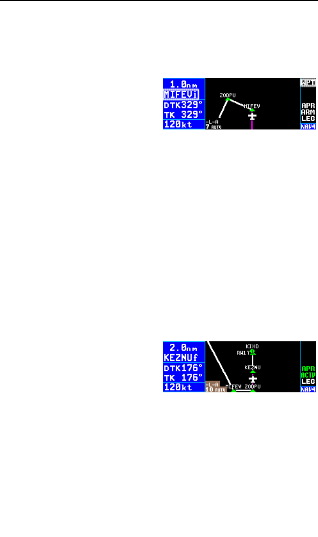
KLN 94 screen to verify that LEG sequencing is selected. If the
KLN 94 shares an HSI or CDI with other NAV sources, it is also good
to verify that the NAV/GPS switch is set to GPS.
As you approach MIFEV, the KLN 94 will provide waypoint alerting as
indicated by the flashing WPT annunciation on the right side of the
screen and the flashing waypoint
identifier on the left side of the
screen (figure 6-27). Turn antici-
pation will occur just prior to
reaching MIFEV; the DTK will
change to 266°and the WPT
annunciation will stop flashing
and be steadily annunciated. This is the time to begin the turn to inter-
cept the 266°course to the next waypoint in the approach, ZODPU.
Once you pass MIFEV the KLN 94 will automatically sequence to
ZODPU. If the course selected on the external CDI or HSI is not with-
in 10°of the 266°desired track, the DTK value on the KLN 94 will
flash and a message will be provided telling you to set the external
Nav indicator to the correct value.
5. As the aircraft approaches the ZODPU waypoint, the KLN 94 will
again provide waypoint alerting and turn anticipation. As the aircraft
passes ZODPU it will sequence to KEZNU. Select 176°on the exter-
nal Nav indicator.
6. As the aircraft approaches KEZNU, the final approach fix, it is a good
idea to check the status of the KLN 94 one more time. Make sure that
LEG mode is selected and that the NAV/GPS switch is set to GPS.
Remember, the KLN 94 will not transition to the approach active
mode if the OBS mode is selected.
7. By the time the aircraft is 2 NM
from KEZNU (figure 6-28), the
FAF, the KLN 94 will make a
prediction to see if integrity will
be available at the FAF and at
the MAP. If the prediction indi-
cates that integrity monitoring will be available, and RAIM is currently
available, the KLN 94 will annunciate APR ACTV (or APR). At this
time the KLN 94 will also start to change the CDI scale factor. By the
time the aircraft reaches the FAF the CDI scale factor will be down to
±0.3 NM full scale deflection.
8. Normal waypoint alerting will occur approaching KEZNU and the
KLN 94 will sequence to RW17 passing KEZNU.
9. The KLN 94 will again provide waypoint alerting as you approach
RW17, the missed approach point (MAP).
KLN 94 Pilot’s Guide Chapter 6 Approaches and DP/STARs
6-17
Figure 6-27
Figure 6-28

The following steps would need to be performed if a missed approach is
required.
10. Upon reaching RW17 and not seeing the runway you decide to per-
form a missed approach. Remember, the KLN 94 will not
automatically sequence past the missed approach point. This is
shown on the NAV 4 page by not showing any lines connecting way-
points that are past the MAP. Until the missed approach procedure is
initiated the KLN 94 will continue to provide guidance along the 176°
FAF to MAP course and the To/Fr indicator will indicate “From.” To
perform the published missed approach procedure, press Dto bring
up the direct-to page. The default waypoint will usually be the first
waypoint of the missed approach procedure. In this case the first way-
point is the missed approach holding point ANQUM. Confirm this
waypoint as the direct to waypoint and press F.
NOTE: If ATC gives you instructions for a missed approach that is differ-
ent from the published missed approach procedure, it is always possible
for you to select a different direct to waypoint than the default direct to
waypoint.
11. Since you are going to enter a holding pattern at ANQUM it is neces-
sary to use the OBS mode. Press the OBS button to enter the OBS
mode. In the OBS mode the KLN 94 uses the course selected on the
external CDI or HSI. Since the external indicator was already set to
176° for the final approach course it is set to provide guidance to
ANQUM.
NOTE: A message is provided 4 NM from ANQUM if the KLN 94 is still in
Leg mode as a reminder: “If Required Select OBS”.
12. Upon reaching ANQUM select the 356° inbound course on the exter-
nal HSI or CDI and enter the holding pattern using standard entry
procedures. Since the unit is in OBS mode you will fly as if using a
VOR receiver to hold at a VOR. When passing inbound over ANQUM
there will be no waypoint sequencing and the To/From indicator on
the HSI or CDI will change to “From.” When leaving the holding pat-
tern for another approach or another airport, remember to put the unit
back into Leg mode.
NOTE: If another attempt at the approach is desired after holding, it is
necessary to manually change the active waypoint. On approaches
where the FAF and the missed approach holding point are at the same
place then the KLN 94 will automatically change the active waypoint to the
FAF when you change from OBS to LEG. Make sure to make this change
as soon as possible to ensure you get into the approach active mode.
Chapter 6 Approaches and DP/STARs
6-18
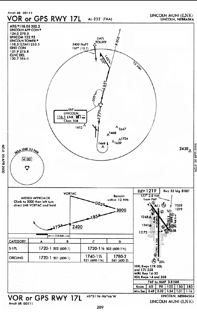
KLN 94 Pilot’s Guide Chapter 6 Approaches and DP/STARs
6-19
Figure 6-29
NOT FOR
NOT FOR
NA
NAVIGA
VIGATION
TION
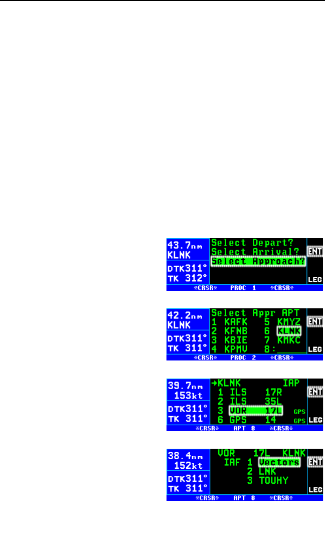
6.2.8. APPROACH EXAMPLE 2: RADAR VECTORS
When airports have an approach control that is in a radar environment it is
likely you will receive radar vectors from the approach controller to inter-
cept the course inbound to the final approach fix (FAF). The KLN 94
makes it easy to conduct approaches where vectors are provided. There
is no need to change to OBS mode in order to get established inbound to
the FAF.
We will use the VOR 17L approach at Lincoln Municipal (KLNK) as an
example of an approach where vectors are provided (figure 6-29). Notice
that Lincoln VOR (LNK) is the FAF and that the inbound course to LNK is
185°and the course from LNK to RW17L, the MAP, is 177°. The ATC
controller will provide vectors to intercept the 185°course to LNK.
Loading an approach in FPL 0 where vectors are going to be provided is
similar to the example of loading an approach provided in section 6.2.3.
However, there are a few minor differences so we’ll go through an exam-
ple of loading an approach for radar vectors.
To select an approach for radar vectors:
1. Press the Pbutton to bring up
the PROC 1 page (figure 6-30).
The cursor will already be over
Select Approach?.
2. Press Fto display the
PROC 2 page (figure 6-31). If
KLNK is in FPL 0 or is our Direct
To waypoint then KLNK will be in
the list. Use the right outer knob
to move the cursor over KLNK if
it is not already there.
3. Press Fto display a list of
approaches for KLNK. Use the
right outer knob to move the cur-
sor over VOR 17L (figure 6-32).
4. Press Fto display a list of ini-
tial approach fixes (IAFs). The
cursor is already over Vectors
(figure 6-33).
NOTE: If you know radar vectors will
be provided, select Vectors. If you
are not sure, select the IAF waypoint
appropriate for your route. If you later
Chapter 6 Approaches and DP/STARs
6-20
Figure 6-30
Figure 6-31
Figure 6-32
Figure 6-33
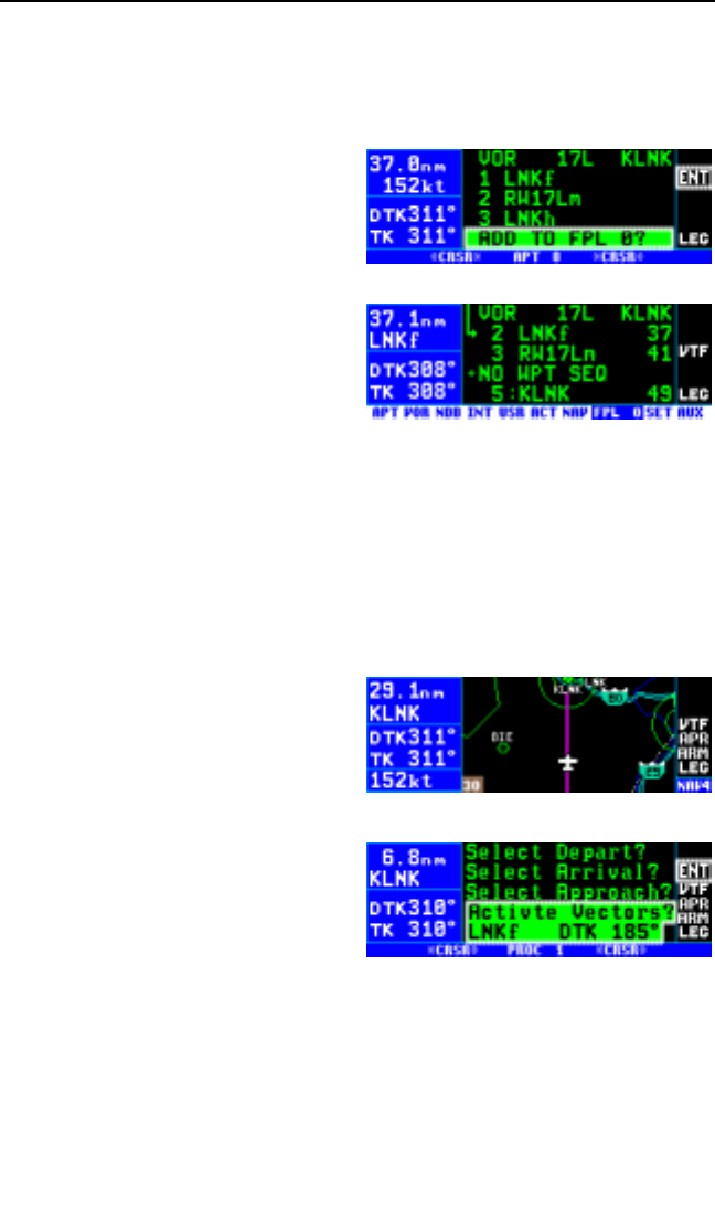
find out that vectors will be provided you can still easily activate the
Vectors feature of the KLN 94 with the waypoint IAF loaded in FPL 0.
5. Press Fto display the list of waypoints for the approach (figure 6-
34). When Vectors is selected
the first waypoint will be the FAF.
6. Press Fto load the approach
into FPL 0. As before, the
approach waypoints are inserted
prior to the airport identifier (fig-
ure 6-35). The vectors-to-final
(VTF) annunciation is now dis-
played on the right side of the
screen. The VTF annunciation
is white at this time to indicate
that a radar vector approach has
been loaded into FPL 0 but has
not yet been activated.
Now that the approach has been loaded into the active flight plan you can
return to the map page. If your clearance is to KLNK, you will have to do a
Direct To KLNK. As you near the Lincoln area you are eventually given
vectors (headings) to fly that will get you established on the charted
inbound course to the FAF. We are now ready to conduct the approach.
1. When you are within 30 NM of the airport, the KLN 94 will automati-
cally arm the approach mode
and provide the following mes-
sage: *Press ALT To Set Baro.
At this time the KLN 94 will
smoothly change the CDI scale
factor to ±1.0 NM. APR ARM
(or TERM) is now annunciated
(figure 6-36).
2. When you start receiving vectors
for the approach it is time to
“activate vectors.” Press the
Pbutton to display the
PROC 1 page (figure 6-37). If
you chose vectors from the IAF list then the cursor will already be
over Activate Vectors? on line 4 as well as over the FAF (LNK in this
case) and inbound course to the FAF on line 5.
NOTE: If a waypoint IAF (instead of Vectors) was initially selected when
the approach was loaded into FPL 0 it will be necessary to use the right
outer knob to move the cursor over lines 4 and 5.
KLN 94 Pilot’s Guide Chapter 6 Approaches and DP/STARs
6-21
Figure 6-34
Figure 6-35
Figure 6-36
Figure 6-37
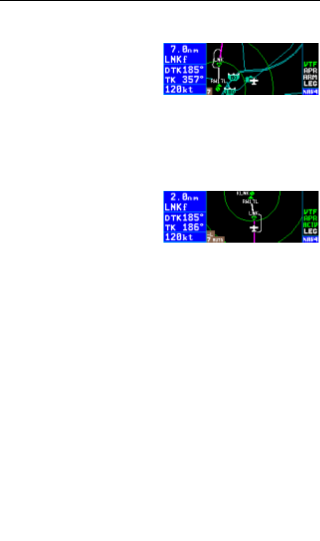
3. Press Fto activate vectors. Activating vectors makes the FAF the
active waypoint with the proper inbound course to the FAF (figure 6-
38). The VTF annunciation turns
green when vectors has been
activated. At this time the exter-
nal Nav indicator should be set
to 185° and the NAV/GPS
switch checked to make sure it is
set to GPS.
4. Fly the headings given by the controller in a normal manner and inter-
cept the course to the FAF.
5. By the time the aircraft is 2 NM from LNK (figure 6-39), the FAF, the
KLN 94 will make a prediction to see if integrity will be available at the
FAF and at the MAP. If the prediction indicates that integrity monitor-
ing will be available and RAIM is
currently available, the KLN 94
will annunciate APR ACTV (or
APR). At this time the KLN 94
will also start to change the CDI
scale factor. By the time the air-
craft reaches the FAF the CDI
scale factor will be down to ±0.3
NM full scale deflection.
6. Normal waypoint alerting and turn anticipation will occur prior to
reaching LNK. The DTK will change from 185° to 177° and the new
course should be selected on the external Nav indicator. The KLN 94
will sequence to the missed approach point, RW17L, upon passing
LNK. The VTF annunciation will return to white.
7. The KLN 94 will again provide waypoint alerting as you approach
RW17L, the missed approach point (MAP).
8. Upon reaching RW17L and not seeing the runway you decide to per-
form a missed approach. Remember, the KLN 94 will not
automatically sequence past the missed approach point. This is
shown on the NAV 4 page by not showing any lines connecting way-
points that are past the MAP. Until the missed approach procedure is
initiated the KLN 94 will continue to provide guidance along the 177°
FAF to MAP course and the To/Fr indicator will indicate “From.”
9. After declaring the missed approach you request vectors to try the
approach again. Press the Pbutton to bring up the PROC 1 page
and press Fto re-activate vectors for another try. The VTF annun-
ciation turns green to indicate that vectors-to-final is once again
activated.
Chapter 6 Approaches and DP/STARs
6-22
Figure 6-38
Figure 6-39
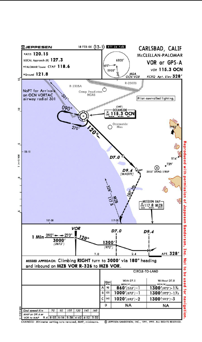
10. After a second missed approach you may select another approach at
Lincoln or some other airport by pressing the Pbutton to display the
PROC 1 page. Since you don’t want to activate vectors this time use
the right outer knob to move the cursor over Select Approach? and
load an approach in the normal manner.
KLN 94 Pilot’s Guide Chapter 6 Approaches and DP/STARs
6-23
Figure 6-40
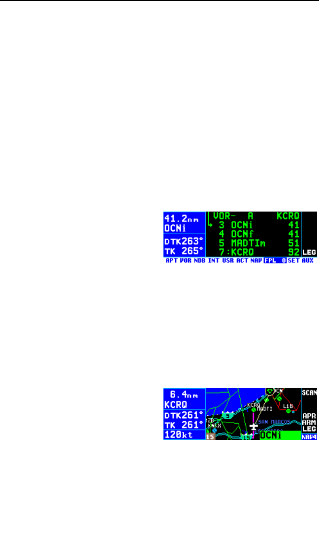
6.2.9. APPROACH EXAMPLE 3: COURSE REVERSAL WITH OFF-
AIRPORT IAF
In the previous two approach examples we were able to leave the KLN 94
in the Leg mode all the way to the missed approach point. However, when
the approach procedure includes a course reversal in order to get estab-
lished inbound to the FAF it is necessary to utilize the OBS mode.
Remember, when the unit is in the OBS mode it acts similar to a VOR
receiver in that it uses the OBS course selected on the external Nav indi-
cator (CDI or HSI) and there is no waypoint sequencing. Both approach
example 3 and example 4 demonstrate how to use the KLN 94 when a
course reversal is required.
An approach that is quite common is an approach that is based off of an
off-airport IAF with a course reversal. An example of this is the VOR - A
approach to McClellan-Palomar airport, KCRQ. To fly this procedure as
published use the following steps and refer to figure 6-40 for the proce-
dure. For this example assume that the aircraft is approaching from the
east.
1. Load the approach into the flight
plan as described in section
6.2.3. Select OCN as the IAF
(figure 6-41).
2. When you are within 30 NM of
the airport, the KLN 94 will automatically arm the approach mode and
provide the following message: *Press ALT To Set Baro. At this time
the KLN 94 will smoothly change the CDI scale factor to ±1.0 NM.
APR ARM (or TERM) is now annunciated.
3. Approaching the area ATC tells you to go direct-to the OCN VOR and
clears you for the VOR or GPS 22 approach to KCRQ. This is easy to
do from the NAV 4 page by pulling out on the right inner knob and
scanning through the active flight plan by turning the inner knob.
Since OCN is both the IAF and
the FAF make sure you select
the IAF which is indicated by the
“i” suffix after OCN (OCNi).
Once OCN is displayed in the
scanning window (figure 6-42),
press Dand then F to initi-
ate a direct to operation to the
OCN IAF.
4. At a distance of 4 NM to the OCN VOR, the KLN 94 will give the fol-
lowing message:
*If Required Select OBS
Chapter 6 Approaches and DP/STARs
6-24
Figure 6-41
Figure 6-42
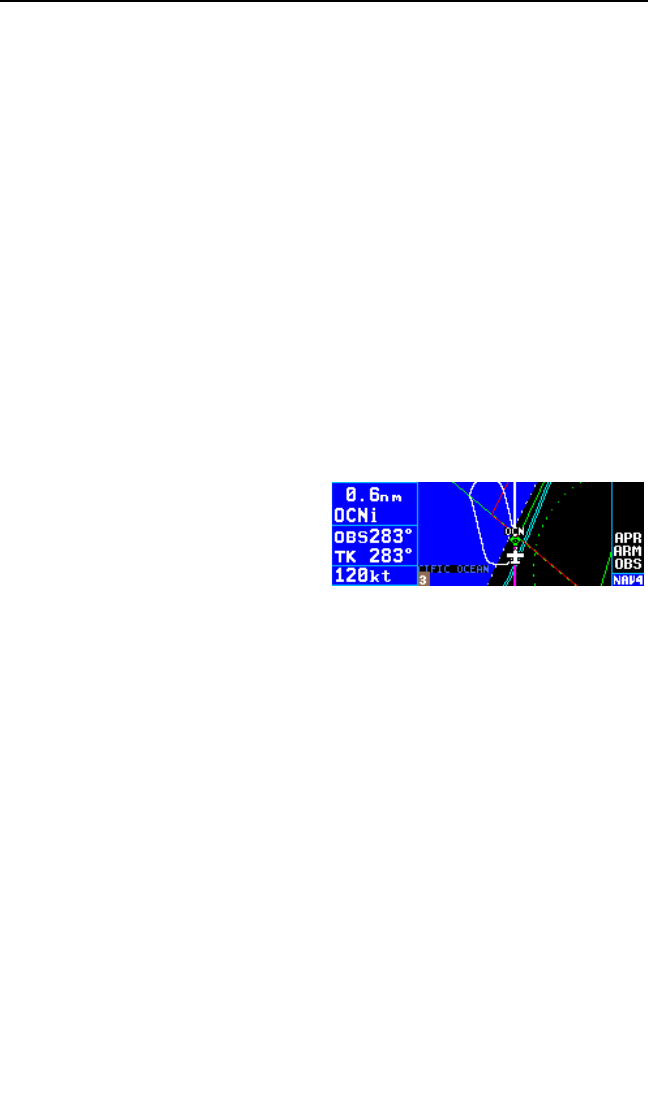
This message provides a reminder that to fly a course reversal the OBS
mode needs to be selected. Note from the approach chart that there is a
NoPT Arrival for this approach if arriving on airway radial 301. If you are
approaching OCN along this airway radial there is no need to perform a
course reversal and you need to ignore this message. The NoPT sector is
not stored in the database so it is not possible for the KLN 94 to know if a
course reversal is required or not; as a result, the KLN 94 will always give
this message whenever an IAF waypoint could be used for a course
reversal. If arriving along the airway radial the KLN 94 will properly
sequence to the FAF to MAP leg and transition to the approach mode
when 2 NM from the OCN IAF/FAF.
If, however, you are approaching from any other direction a course rever-
sal is required and the OBS mode will need to be selected by pressing the
Hbutton. If the OBS mode is not selected before reaching OCN the
KLN 94 will automatically sequence to the missed approach point. This is
not desirable when performing a course reversal so the OBS mode must
be selected before reaching OCN.
NOTE: The KLN 94 will only remind you to select OBS mode if the IAF is
the active waypoint. Therefore if a course reversal is required, make sure
the IAF is the selected waypoint. For
ORS 02 and higher units the holding
pattern will be displayed on the map
(figure 6-42a) if configured to do so
on the SET 7 page. See section
3.11.4.12 for information on display-
ing holding patterns on the map.
5. Upon reaching OCN perform the appropriate holding pattern entry
and set the inbound course on the external CDI or HSI. In this exam-
ple the inbound course is 90°. At this point the KLN 94 works very
similar to a conventional VOR/DME.
6. Once established on the inbound course of 90°, switch back to the
Leg mode. When Leg mode is selected the FAF is automatically
made the active waypoint when the IAF and the FAF are at the same
waypoint. This is indicated by the active waypoint with an “f” suffix
(OCNf).
NOTE: It is mandatory that the unit be in LEG mode with the FAF as the
active waypoint before crossing the FAF to activate the approach active
mode and change to ±0.3 NM scale factor. The CDI scale factor changes
from ±1.0 NM to ±0.3 NM over the two miles to the FAF. Delaying the
switch from OBS to Leg mode compresses the scale factor change. This
will make the transition more abrupt. If the switch from OBS to Leg is
delayed too long it will not be possible for the KLN 94 to change to the
approach active mode.
KLN 94 Pilot’s Guide Chapter 6 Approaches and DP/STARs
6-25
Figure 6-42a

7. When the aircraft is 2 NM from the FAF, the KLN 94 will verify that the
proper integrity is available. If integrity monitoring is available for the
approach, then the KLN 94 will change to the Approach Active mode.
This will be annunciated on the right side of the KLN 94 by APR
ACTV (or APR). The CDI scale factor will also start to change from
±1.0 NM to ±0.3 NM.
8. Upon reaching OCN, the KLN 94 will automatically sequence to
MADTI, the missed approach point. Notice that there is a 30°course
change at OCN to 120°inbound. The DTK will flash on the left side of
the KLN 94 until the external Nav indicator is reset to 120°.
9. The step down fix at 7 DME from OCN along the final approach
course is not included in the waypoints that come from the database.
Since the distance that the KLN 94 is giving you is distance to MADTI,
the MAP, you will need to determine when the aircraft has reached
this point by looking at the along track distances given in the profile
view of the approach. In this case the fix is 2.4 NM from MADTI.
Upon reaching this distance you can descend to the MDA for this
approach.
If a missed approach is required for this approach, then the following
steps would be required.
10. The published missed approach procedure for this approach is to
make a climbing right turn to 3000 feet via a180°heading and then
inbound on the MZB 326°radial to MZB. After flying past the MAP
press Dto display MZB as the default direct to waypoint. Press F
to make MZB the active waypoint.
11. Since the published procedure is to intercept the MZB 326°radial
(146°inbound) it is necessary to put the KLN 94 into the OBS mode
and select 146°on the external Nav indicator. Fly a heading of 180°
until the needle centers and track to MZB.
NOTE: If ATC gives you instructions for a missed approach that are dif-
ferent from the published missed approach procedure, it is always
possible for you to select a different direct to waypoint than the default
direct to waypoint.
6.2.10. APPROACH EXAMPLE 4: COURSE REVERSAL WITH ON-
AIRPORT IAF
Another common type of approach is an approach that is based on an on-
airport IAF. These are typically GPS overlays of VOR or NDB approaches.
An example of this type of approach is the NDB 35 approach to Mount
Pleasant, TX (figure 6-43). The airport identifier for this airport is KMSA.
Chapter 6 Approaches and DP/STARs
6-26
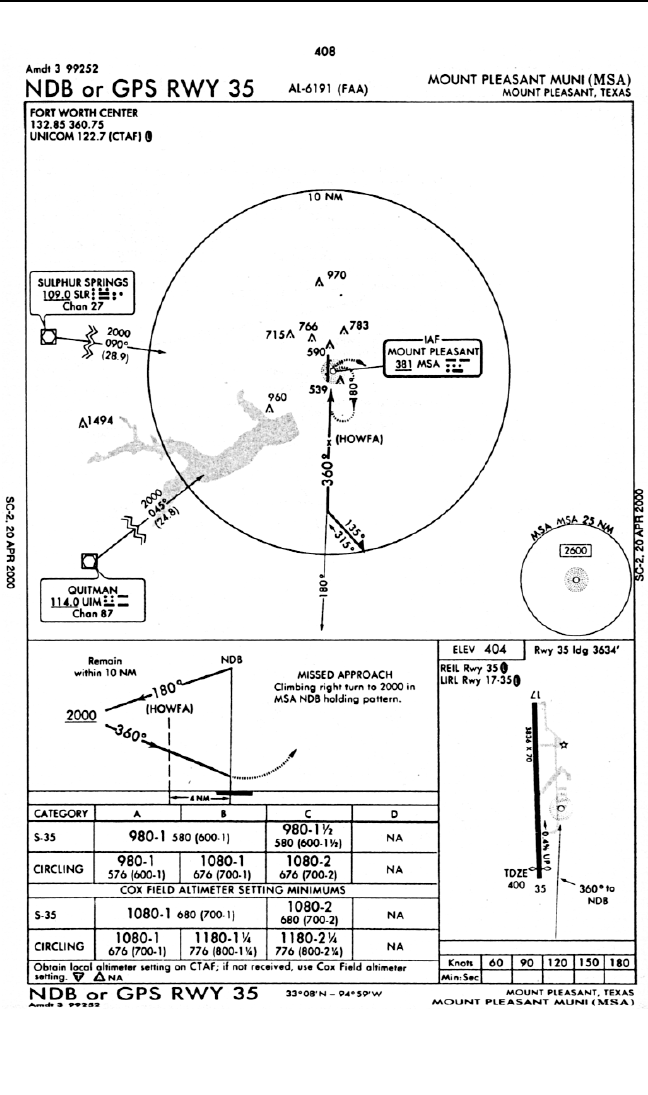
KLN 94 Pilot’s Guide Chapter 6 Approaches and DP/STARs
6-27
Figure 6-43
NOT FOR
NOT FOR
NA
NAVIGA
VIGATION
TION

For this example assume that the aircraft is approaching KMSA from the
southwest.
1. Approximately 40 NM from the airport, load the approach using the
procedure described in section 6.2.3.
2. When the distance from the present position to the destination airport
reaches 30 NM, the KLN 94 will automatically arm the approach
mode. The CDI scale factor will transition to ±1.0 NM and the KLN 94
will provide tighter integrity monitoring. You also press Ato update
the barometric information.
3. About 15 NM out you are cleared Direct MSA, cleared for the NDB or
GPS 35 approach. From the Nav 4 map page you pull the right inner
knob out and turn the knob to display MSAi, the IAF. Note that MSA
is also used for the missed approach point (MAP) and the missed
approach holding point so if MSAm or MSAh is displayed you’ve got
the wrong waypoint! With the knob out, press Dto bring up the
Direct To page with MSAi already displayed and then press Fto
proceed direct to the IAF.
4. When the aircraft is 4 NM from the MSA IAF, the KLN 94 will give a
message reminding you to select the OBS mode. Press the Hbut-
ton to select the OBS mode. The OBS mode is required for the
procedure turn. After passing MSA, select the outbound course of
180°on the external CDI or HSI.
5. The aircraft is now headed outbound for the procedure turn. As soon
a practical, you will need to change the active waypoint to HOWFA,
the final approach fix. From the map page this is done by pulling out
on the right inner knob and scan-
ning until HOWFA is displayed in
the window (figure 6-44). Then
press Dand then press F.
The OBS course will still be what
is selected on the external CDI
or HSI, 180°.
NOTE: HOWFA was added as an FAF for using GPS receivers for this
approach. The basic NDB approach has no FAF. On some approaches
like this one where the IAF is based on a navaid on the airport, the FAF is
identified by nomenclature such as “FF35” instead of a 5 letter waypoint
name.
6. With the OBS mode selected and HOWFA as the active waypoint, it is
possible to fly the procedure turn.
Chapter 6 Approaches and DP/STARs
6-28
Figure 6-44
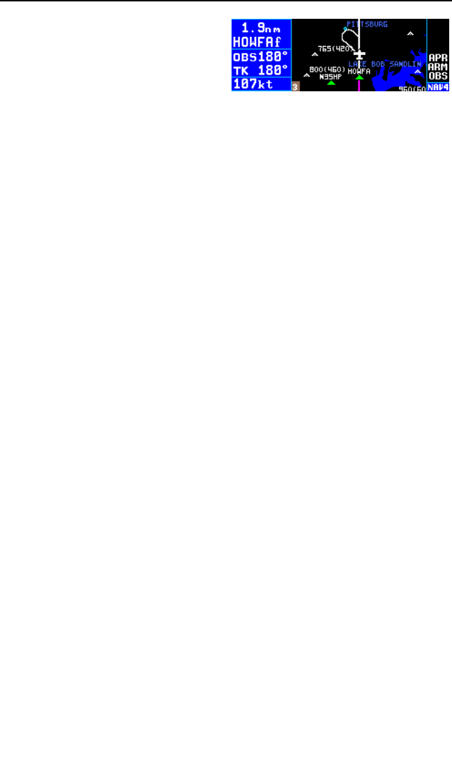
NOTE: For ORS 02 and higher units
the procedure turn will be displayed
on the map (figure 6-44a) if config-
ured to do so on the SET 7 page.
See section 3.11.4.12 for information
on displaying procedure turns on the
map.
Allow enough distance past HOWFA to complete the procedure turn
and still be 2 NM away before reaching the FAF. Remember to
remain within 10 NM of MSA per the chart. After completing the out-
bound portion of the procedure turn, change the selected course to
the inbound course of 360°on the external CDI or HSI.
7. Once established on the inbound course press the Hbutton to
select the Leg mode so that proper approach operation and waypoint
sequencing will occur.
NOTE: It is mandatory that the unit be in LEG mode with the FAF as the
active waypoint before crossing the FAF to activate the approach active
mode and change to ±0.3 NM scale factor. The CDI scale factor changes
from ±1.0 NM to ±0.3 NM over the two miles to the FAF. Delaying the
switch from OBS to Leg mode compresses the scale factor change. This
makes the transition more abrupt. If the switch from OBS to Leg is
delayed too long it will not be possible for the KLN 94 to change to the
approach active mode.
8. When the aircraft is 2 NM from the FAF, the KLN 94 will verify that the
proper GPS integrity is available. If integrity monitoring is available for
the approach, then the KLN 94 will change to the Approach Active
mode. This will be annunciated on the right side of the KLN 94 by
APR ACTV (or APR). The CDI scale factor will also start to change
from ±1.0 NM to ±0.3 NM.
9. Normal waypoint alerting will occur as the aircraft passes the final
approach fix. The leg from the final approach fix to the missed
approach point (MSAm) will become active and the CDI scale factor
will remain at ±0.3 NM. If the AUTO scale factor was selected on the
NAV 4 page, then the scale factor will zoom in on the airport as the
aircraft gets closer and closer to the missed approach point.
Eventually the map scale changes to 1/2 NM.
The following steps are followed if a missed approach is required.
10. The missed approach instructions call for a climbing right turn to 2000’
in the MSA holding pattern. After passing the MAP press the Dbut-
ton to bring up the direct to page showing the first waypoint in the
KLN 94 Pilot’s Guide Chapter 6 Approaches and DP/STARs
6-29
Figure 6-44a

missed approach procedure. In this case the waypoint N35HP is dis-
played. This is a point located on the outbound leg of the holding
pattern. We will not use it in this example. Pull the right inner knob out
and turn it to display MSAh, the missed approach holding point.
Press Fto activate MSA as the hold point.
11. Press Hto put the unit in OBS mode and select 360°on the exter-
nal Nav indicator.
NOTE: On some approaches, an additional waypoint is added to the
missed approach sequence by the provider of the navigation data for the
database. At the time this pilot’s guide is written, this waypoint is not
depicted on either Jeppesen or NOS charts. It may be used as an aid in
establishing the holding pattern, especially where the MAP and MAHP are
the same waypoint. To use N35HP in this example put the unit in the OBS
mode and select 180° on the external Nav indicator. After passing N35HP
activate MSAh and select 360° on the external Nav indicator.
6.2.11. APPROACH EXAMPLE 5: DME ARC
DME arc procedures with the KLN 94 are completely different from using
traditional VOR and DME equipment. Don’t worry though because DME
arc procedures using the KLN 94 are also much easier than using tradi-
tional equipment. This is because the KLN 94 provides left/right guidance
around the arc. No more having to watch distance in one place and radial
in another!
In many cases you do not actually fly to the beginning of an arc, especially
in a radar environment. Instead, the flight path of the aircraft generally
intersects the arc at some point. Once the aircraft is near the arc, it is then
possible to turn so that the arc distance is maintained until time to turn to
the inbound fix.
The following example will show how
DME arc procedures are flown using
the KLN 94. This example approach
will be to use the VOR/DME 22
approach at Rocky Mount, NC
(KRWI). The approach plate for this
approach is in figure 6-45. Assume
that the aircraft is approaching from
the southeast of TYI VOR and it includes TYI in FPL 0 (figure 6-46).
1. ATC assigns the VOR/DME RWY 22 approach. Press the Pbutton
to bring up the PROC 1 page. The cursor is already over Select
Approach so press Fto bring up the PROC 2 page. Select KRWI
Chapter 6 Approaches and DP/STARs
6-30
Figure 6-46
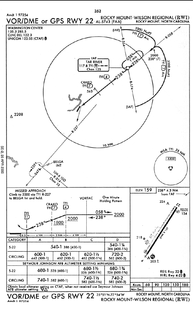
KLN 94 Pilot’s Guide Chapter 6 Approaches and DP/STARs
6-31
Figure 6-45
NOT FOR
NOT FOR
NA
NAVIGA
VIGATION
TION
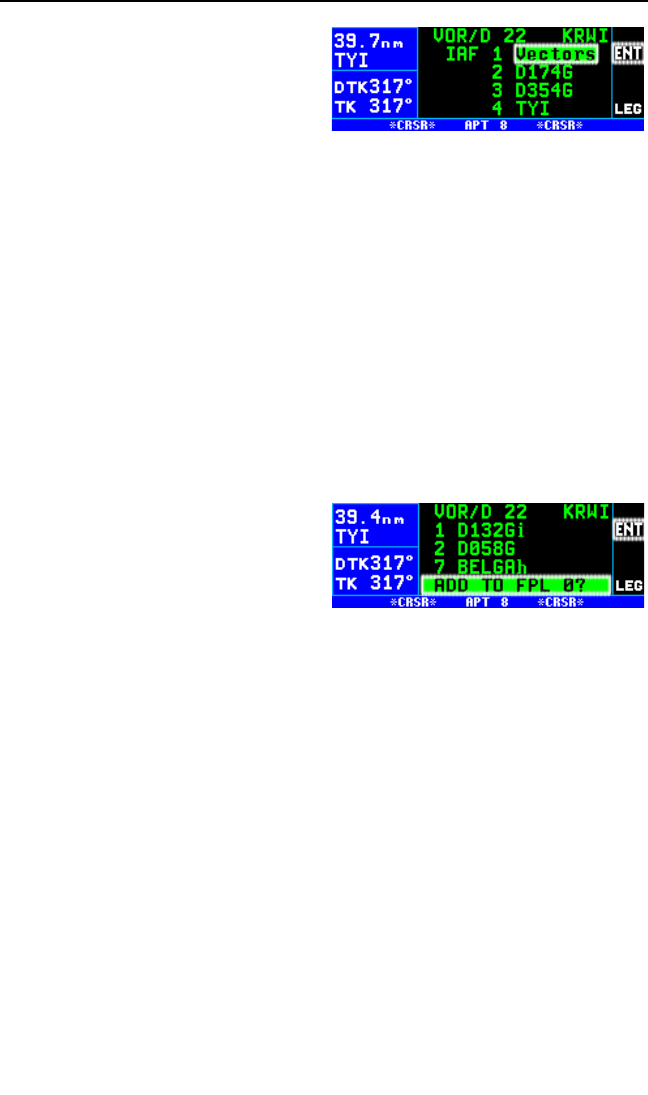
and press Fto display the list
of approaches for KRWI. Move
the cursor over VOR/D 22 and
press Fto bring up the list of
IAFs (figure 6-47).
2. There are four choices for the
IAF including Vectors. Two of these choices you can recognize but
the other two, D174G and D354G, are unfamiliar and not shown on
this chart (however they shown on the respective Jeppesen chart).
These two waypoints are the database identifiers for the ends of the
arc as explained in section 6.2.4. D174G means DME arc point, 174
is the radial on which the waypoint lies, and G indicates the distance
of the arc. G is the seventh letter of the alphabet so the G indicates
that this is a 7 DME arc. In a similar manner D354G can also be
decoded. In this example the aircraft is approaching from the south-
east so the D174G IAF will be selected.
3. The KLN 94 knows that this point is associated with a DME arc. Once
an arc IAF waypoint is chosen, the KLN 94 determines what radial of
the reference VOR the aircraft is presently located on. A waypoint is
created that is located at the intersection of the present radial and the
DME arc. This waypoint is first in
the list of waypoints presented
on the APT 8 page before load-
ing the approach into the flight
plan (figure 6-48). Since the air-
craft was located on the 132
radial of TYI when the approach
was loaded into FLP 0, the waypoint loaded into the approach is
D132G. This waypoint is named using the same convention dis-
cussed earlier.
NOTE: If the present radial from the reference VOR is outside of the
defined arc, then the KLN 94 will default to the beginning of the arc.
CAUTION: The KLN 94 does not take into account the geometry of
the active flight plan when determining the arc intercept point. This
point is defined solely on the present radial and the defined arc dis-
tance from the reference VOR. For this reason it is better to delay
selecting approaches that contain DME arcs until the aircraft is clos-
er to the destination.
4. With the cursor over ADD TO FPL 0?, Press F. The approach will
be loaded into the active flight plan just like any other approach would
be.
Chapter 6 Approaches and DP/STARs
6-32
Figure 6-48
Figure 6-47
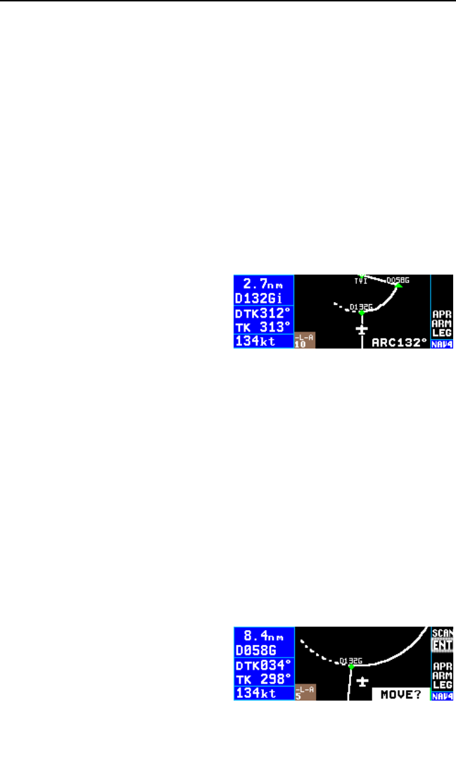
5. After the approach is loaded into the flight plan the KLN 94 may give
the message:
*Redundant Wpts In FPL
Edit En Route Wpts
As Necessary
This message is given because very often it will be necessary to edit
the active flight plan to ensure that proper waypoint sequencing
occurs. Examine the flight plan and, if practical, observe the NAV 4
page to make sure that the sequence of waypoints does not have any
unnecessary legs in it. In our example TYI was in the original flight
plan and TYI was added as one of the approach waypoints. Delete
the en route TYI from the flight plan.
6. The KLN 94 will now provide guidance to the arc intercept point,
D132G. The NAV 4 page displays the entire arc on the screen. The
portion that is between the
beginning of the arc and the arc
intercept is drawn with a dashed
line. The part that is between the
arc intercept point and the end of
the arc is drawn with the normal
solid line (figure 6-49).
7. In some cases ATC may provide radar vectors to the arc. The KLN 94
provides a means to define a new intercept point based on where the
aircraft’s current track over the ground intercepts the DME arc. This
can be done from either the NAV 4 page or from the FPL 0 page. The
dashed line displayed on the NAV 4 page will help you to determine if
ATC is giving you correct vectors.
•From the NAV 4 page, pull out the right inner knob to bring up the
waypoint scanning window.
•Turn the right inner knob until the first waypoint of the arc is dis-
played, D132Gi in this example. For approaches this will have a
small “i” appended to the waypoint name since it’s serving as an
IAF. If the recalculation is to be done from the FPL 0 page, then turn
on the cursor and move it over the first waypoint of the arc.
•From either page press E.
This will change the waypoint
to read MOVE? (figure 6-50).
To recompute the arc intercept
point then press F. If a new
arc intercept point is not
desired then press Eagain.
KLN 94 Pilot’s Guide Chapter 6 Approaches and DP/STARs
6-33
Figure 6-49
Figure 6-50

•If Fwas pressed, then the KLN 94 will calculate an arc inter-
cept point based on the point where the aircraft’s present track over
the ground intercepts the DME arc. If necessary, do a Direct To
operation to the new arc intercept point.
NOTE: If the present track does not intercept the arc, then the KLN 94 will
display No Intcpt in the scratchpad area of the screen.
8. When the aircraft approaches the arc the KLN 94 will provide way-
point alerting and turn anticipation to join the arc.
9. Once established on the arc the KLN 94 provides left/right guidance
relative to the curved arc. Distance to the active waypoint is the dis-
tance from the present position to the active waypoint, NOT the
distance along the arc. Refer to Appendix A for the geometry of the
arc.
10. During the arc, the desired track will be constantly changing. To help
you keep the orientation, pay close attention to the DTK on line 3. The
value displayed for the desired track will flash when the difference
between the CDI or HSI and the current desired track is greater than
10°.
11. Some DME arcs have defined radials that serve as step down fixes.
These points are not stored in the database. To help you determine
your position relative to these step-down points along the arc, the
KLN 94 will display a new value in the bottom right corner of the dis-
play on the NAV 4 page. This new bit of information is denoted by the
letters ARC followed by three numbers. The three numbers represent
the current radial that you are on relative to the reference VOR/DME.
The arc radial is forced into this position when the aircraft is 30 NM
from the arc. The ARC display is shown in figure 6-49. Just watch this
value and when it reads the same as one of the step-down points you
can descend as necessary. This particular example does not have
such points, but there are quite a few approaches that do.
NOTE: Autopilot performance may not be satisfactory if coupled in the
NAV mode while flying the arc. Many autopilots were never designed to fly
curved paths. If autopilot performance is not satisfactory while flying DME
arcs, select the HDG mode and keep changing the heading bug to keep
the D-bar centered.
12. As the aircraft approaches the turn-in point of the arc (D058G), the
KLN 94 will provide waypoint alerting and turn anticipation to the next
leg to TYI.
Chapter 6 Approaches and DP/STARs
6-34

13. Passing TYI the KLN 94 will sequence to CF22 which is depicted on
the U.S. Government chart as 4 NM from TYI. The CF22 designation
is shown on the Jeppesen chart.
14. After passing CF22 the KLN 94 will sequence to CRAKO the FAF.
15. When the aircraft is 2 NM from CRAKO, the KLN 94 will transition to
the approach active mode. Since the DME arc procedure is flown
entirely in the LEG mode the only possible problem would be if the
integrity monitoring did not check out.
16. Passing CRAKO the KLN 94 sequences to MA22, the MAP.
If a missed approach is needed use the following steps:
17. The KLN 94 will not automatically sequence past the MAP. After
passing the MAP press the Dbutton to bring up the Direct To page
with BELGA already entered. Press Fto activate BELGA.
18. Press Hto put the KLN 94 into the OBS mode and select 227°on
the external Nav indicator.
19. After crossing BELGA, select 47°on the external Nav indicator and
enter the holding pattern in the conventional manner.
NOTE: If ATC gives you instructions for a missed approach that is differ-
ent from the published missed approach procedure, it is always possible
for you to select a different direct to waypoint than the default direct to
waypoint.
6.2.12. ILS AND OTHER NON-APPROVED APPROACHES
The KLN 94 may be used to provide situational awareness for approach-
es, such as an ILS, not approved for GPS. Using the map with the
approach loaded can provide the same excellent orientation that it pro-
vides for an approved approach. Operation of the approach is similar to
approved GPS non-precision approaches with the following differences:
•On the APT 8 page showing
the list of approaches, remem-
ber that non-approved
approaches do not have the
letters “GPS” after the
approach name. In figure 6-
51, the ILS 01L and the VOR
01L approaches are not
approved for GPS.
KLN 94 Pilot’s Guide Chapter 6 Approaches and DP/STARs
6-35
Figure 6-51

•When a non-approved
approach is selected, a page
as shown in figure 6-52 is dis-
played to remind you that the
KLN 94 can only be used to
provide situational awareness
for monitoring the approach.
You must acknowledge the page by pressing F. Approved navi-
gation equipment such as VOR/ILS, DME, ADF, etc. must be used
as the primary source of navigation.
•Since another navigation source is providing primary navigation
guidance, the KLN 94 may not be driving the CDI or HSI. One con-
sequence of this is that if the OBS mode is used, such as for a
missed approach procedure, the selected OBS course will have to
be manually entered by pressing Band using the right inner knob
to enter the desired value.
•The unit will NOT enter the approach active mode. It will remain in
approach arm (APR ARM) or terminal (TERM) mode depending on
how the unit has been configured (see section 6.2.1).
6.2.13. USING GPS DISTANCE AS A SUBSTITUTE FOR DME ON
LOCALIZER-TYPE APPROACHES
The FAA allows the use of GPS distance as a substitute for DME on local-
izer-type approaches when the DME facility is stored in the GPS
database. The KLN 94 stores DME’s associated with localizer-type
approaches using the navaid identifier of the approach. For example, the
DME facility associated with the ILS DME Rwy 33 approach for Burlington
International airport is stored in the KLN 94’s database as IVOE (figure 6-
53). These DME’s are stored in the intersection part of the database.
NOTE: Approach DME facilities are not stored as waypoints that are part
of an approach procedure so you can not gain access to them by calling
up the associated approach. For example, IVOE is not included in the
waypoints that would be loaded into FPL 0 if you selected the ILS 33 for
Burlington International. To get distance from the IVOE DME facility enter
IVOE as a normal flight plan waypoint or direct to waypoint.
NOTE: If outside the U.S. check with authorities for compliance with local
regulations.
Chapter 6 Approaches and DP/STARs
6-36
Figure 6-52
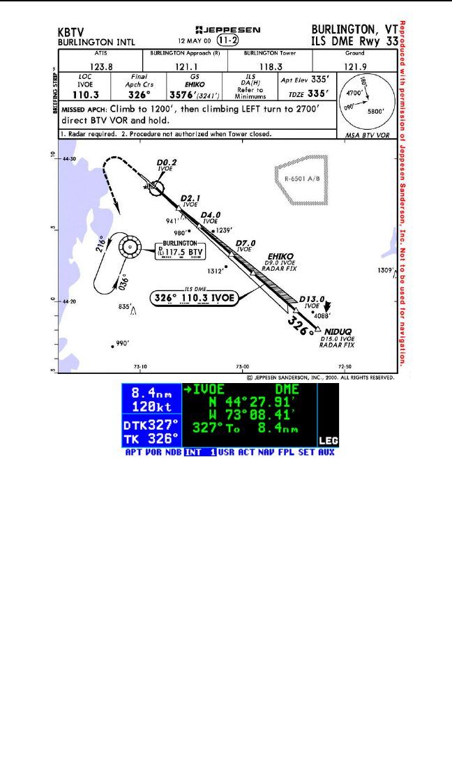
6.2.14. APPROACH PROBLEMS
Very rarely there will be a problem with the integrity of the GPS system
while you are conducting non-precision approaches with the KLN 94. In
some cases the KLN 94 will determine that there will not be sufficient
integrity monitoring for the leg between the FAF and the MAP, or RAIM is
not currently available. In these cases the KLN 94 will not go into the
approach active mode and will present the following message:
*RAIM Not Available
APR Mode Inhibited
Predict RAIM on AUX 3
In these cases you will not be able to finish the approach because there is
insufficient integrity monitoring. The AUX 3 (Auxiliary 3) page provides a
means for you to predict when RAIM will be available if the KLN 94 is con-
figured for IFR approach operation.
KLN 94 Pilot’s Guide Chapter 6 Approaches and DP/STARs
6-37
Figure 6-53

To perform a RAIM prediction on the AUX 3 page three pieces of informa-
tion are needed. The first is the location that the prediction will be for and
the second is the time for the prediction.
The destination waypoint will, by default, be the missed approach point of
an approach loaded in the flight plan. If there is no approach in the flight
plan, then the default waypoint is the last waypoint in the active flight plan.
Of course it is possible for you to enter any waypoint in this field.
The time used for the RAIM prediction will be the current ETA to the desti-
nation airport or the MAP. This time is automatically updated by the
KLN 94 so there is usually no need to enter a value. If you are making a
RAIM calculation for planning purposes, it is also possible to enter a time
in this field. An important point about this time is that the time used for
RAIM prediction is always in the future and limited to 24 hours from the
present time. For example, if the time is now 19:30 and the time entered
for the ETA is 18:30, then the prediction will be made for the next day not
one hour ago.
The third piece of information is to deselect a satellite (SV) if you know
from some official source that it is unusable. A satellite entered on the
AUX 3 page is ONLY deselected for RAIM prediction.
To perform a manual RAIM calculation:
1. Turn the left outer and inner knobs to select the AUX 3 page.
2. Press B. The cursor will be over the RAIM @Dest field.
3. If the default waypoint is not the one desired, enter the desired way-
point identifier by using the inner and outer knobs just like you do for
any other waypoint entry.
4. Once the desired waypoint iden-
tifier is entered (figure 6-54),
press F. Press Fagain to
approve the waypoint page.
5. The cursor will now be over the ETA field. Use the inner knob to enter
the desired hour. Note that the system time zone is displayed next to
the ETA field. Use the outer knob to move the cursor over the minutes
field. Use the inner and outer knobs to select tens of minutes and sin-
gle minutes as required. When the desired time is selected press F.
The RAIM calculations will start.
NOTE: If you wish to deselect a satellite from the RAIM calculation, move
the cursor to the Deselect SV field and turn the right inner knob to select
the satellite (SV) number. Unless you know otherwise, leave this field as
NONE.
Chapter 6 Approaches and DP/STARs
6-38
Figure 6-54
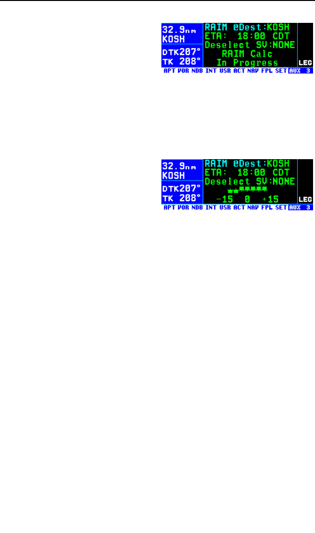
6. Turn the cursor off.
7. The RAIM calculation will usually
take a few seconds before an
answer is reached. During this
time the AUX 3 page will be as
shown in figure 6-55.
8. Once the RAIM calculation is complete, the AUX 3 page will indicate
the results of the test graphically in a bar graph format. The center of
the graph represents the ETA. Each bar represents five minutes of
time. The RAIM calculation is good for ±15 minutes of ETA. Bars
above the line indicate RAIM is available and bars below the line indi-
cate when RAIM is not available.
An example is shown in figure 6-56.
There can be two AUX 3 pages if
necessary to display all the informa-
tion. RAIM is not available from 15
minutes before ETA until 5 minutes
before ETA. However, RAIM is pre-
dicted to be available from then until 15 minutes after the ETA. By
showing the times when RAIM will be available it is possible for you to
alter your ETA to ensure that there will not be any RAIM problems.
Even more rare will be the case when the KLN 94 cannot provide suffi-
cient integrity monitoring or if there is an actual satellite failure while the
aircraft is on the leg from the FAF to the MAP. In these cases the KLN 94
will FLAG the navigation solution and a missed approach will have to be
flown. The KLN 94 will provide the following message:
*Press PROC Button Now For NAV
This message is telling you to cancel the approach mode by pressing the
PROC button. This will change the unit to the approach-arm (or TERM)
mode and navigation information will usually be restored.
6.3. DP/STAR PROCEDURES
The KLN 94 allows access to navigation DPs (Departure Procedures) and
STARs (Standard Terminal Arrival Routes) by DP/STAR name. DP/STAR
procedures stored in the database can only be considered accurate as
long as the database is current. Even though the database contains DP
and STAR procedures, there is a lot of information that is not included in
the database. Therefore, the paper chart is still the primary source of infor-
mation. For example, many procedures require the aircraft to fly to a
certain altitude, along a heading until intercepting a course, and many
other procedures that the KLN 94 can not automatically accomplish. Many
KLN 94 Pilot’s Guide Chapter 6 Approaches and DP/STARs
6-39
Figure 6-55
Figure 6-56

procedures require pilot action to ensure that the proper path is flown over
the ground. The main purpose of loading a DP or a STAR into the active
flight plan is to provide you with a quick way of loading a potentially large
number of waypoints.
It is mandatory that you are comfortable with the operation of the KLN 94
before attempting to fly DP and STAR procedures. In particular, flight plan
operation and the OBS mode should be second nature to you.
NOTE: There are some DP/STAR procedures in the world that are not
suited for the operational characteristics of the KLN 94. These procedures
are not included in the database and therefore the waypoints that make up
these procedures would have to be entered manually. It is good preflight
practice ensure that the KLN 94 contains anticipated procedures for the
flight.
DP and STAR procedures are accessed through the Procedure (PROC)
pages using the Pbutton. The PROC pages provide quick access to
the APT 7 pages where the DP and STAR procedures are stored with the
airport for which they apply.
DP and STAR procedures are defined in three parts. The parts are the DP
or STAR name (e.g., PORTE3), a transition (e.g., Fellows), and a runway
specific component (e.g., RW 01L). The PROC and APT 7 pages lead you
through the selection process.
6.3.1. SELECTING A DP
Use the following procedure to select a DP. Some steps may not be nec-
essary depending on the procedure that you wish to fly. For this example,
the PORTE three departure from San Francisco International (KSFO) will
be used.
To select a DP:
1. Make sure the departure airport
has been entered as the first
waypoint in FPL 0.
2. Press the Pbutton to bring up
the PROC 1 page. Turn the right
outer knob counter-clockwise to
position the cursor over Select
Depart? (figure 6-58).
3. Press Fto display the PROC
2 page (figure 6-59).
Chapter 6 Approaches and DP/STARs
6-40
Figure 6-58
Figure 6-59
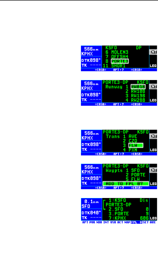
NOTE: Normally, the desired departure airport will already be displayed
with the cursor on it. In case it is not, move the cursor over the desired
airport or, if necessary, enter the airport identifier in the blank field on the
page and press Fonce to bring up the waypoint page for the airport
and a second time to approve it. If an airport is entered that doesn’t have
a DP the scratchpad message No DP at APT will be displayed.
4. Press Fto bring up the APT 7
page for KSFO which displays a
list of DPs for KSFO. At the time
of this writing there are 11 DPs
for KSFO. Rotate the right outer
knob until the cursor is over
PORTE3 (figure 6-60). With the
cursor over PORTE3, press F.
5. The KLN 94 will now ask which
runway that you will be using.
For this example select RW01B
(figure 6-61) and press F. The
“B” stands for “Both” so selecting RW01B means it is applicable to
runways 1L and 1R.
6. The last bit of information need-
ed to define this DP is the
transition. This example uses the
Fellows transition. To select the
Fellows transition, move the cur-
sor down to FLW (figure 6-62)
and press F.
7. The KLN 94 now presents a list
of waypoints that make up the
DP (figure 6-63). Review these
waypoints if desired. If the way-
points look correct then press
Fwith the cursor over ADD
TO FPL 0? to load the DP into
the active flight plan.
8. The KLN 94 will then add the DP
procedure after the airport refer-
ence point in the active flight
plan (figure 6-64). If the airport reference point is not included in the
active flight plan, then the KLN 94 will ask to add this waypoint to the
active flight plan.
Section 6.3.4 gives the actions required to fly this DP.
KLN 94 Pilot’s Guide Chapter 6 Approaches and DP/STARs
6-41
Figure 6-62
Figure 6-63
Figure 6-64
Figure 6-60
Figure 6-61
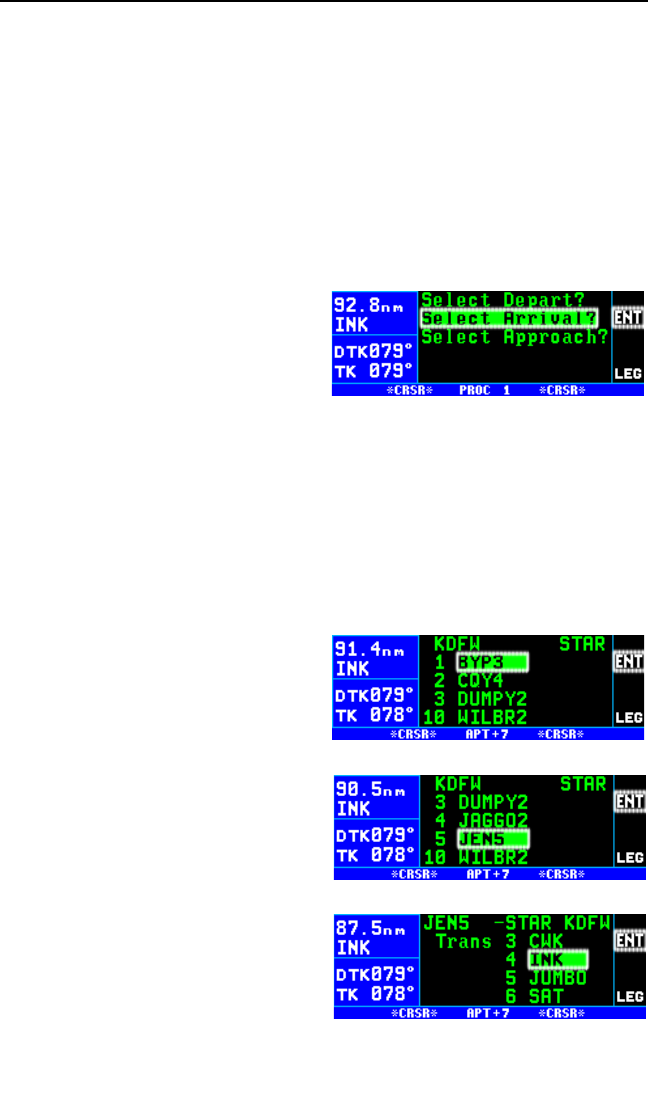
6.3.2. SELECTING A STAR
The steps required to select a STAR are very similar to those required to
select a DP. The only difference is the order of the steps to define the
STAR and where the STAR is loaded into the flight plan. The steps
required to define the Glen Rose Five arrival (coded JEN5) with the Wink
transition serve as an example of how to select a STAR. This STAR is to
the Dallas/Fort Worth International airport (KDFW).
To select a STAR:
1. Make sure the arrival airport, KDFW, is in FPL 0 or is the direct to
waypoint.
2. Press the Pbutton to display
the PROC 1 page. Turn the
right outer knob counter-clock-
wise to position the cursor over
Select Arrival? (figure 6-65).
3. Press Fto display the PROC 2 page.
NOTE: Normally, the desired arrival airport will already be displayed with
the cursor on it. In case it is not, move the cursor over the desired airport
or, if necessary, enter the airport identifier in the blank field on the page
and press Fonce to bring up the waypoint page for the airport and a
second time to approve it. If an airport is entered that doesn’t have a
STAR the scratchpad message No STAR at APT will be displayed.
4. With the cursor over KDFW,
press F. The APT 7 page for
KDFW is displayed showing a
list of STARs for KDFW (figure
6-66).
5. Rotate the outer knob to move
the cursor over JEN5 (figure 6-
67). Press F.
6. The KLN 94 will now ask which
transition you want to use. For
this example we want INK so
move the cursor over INK (fig-
ure 6-68). Press F.
7. In cases such as this one, the
STAR procedure requires you
to select a specific runway. In
this example we will land on
Chapter 6 Approaches and DP/STARs
6-42
Figure 6-66
Figure 6-67
Figure 6-68
Figure 6-65

runway 17R so move the cursor
over RW17R (figure 6-69). Press
F. If the STAR does not
require a specific runway the
KLN 94 skips this step.
8. The KLN 94 now presents a list
of waypoints that make up the
STAR (figure 6-70). Review
these waypoints if desired and
then press Fto load the STAR
into the active flight plan.
9. The KLN 94 will then add the
STAR procedure before the air-
port identifier in the active flight
plan (figure 6-71). If the airport is
not included in the active flight
plan, then the KLN 94 will ask to
add this waypoint to the active
flight plan.
NOTE: It is not possible to load a DP or STAR into a flight plan other than
FPL 0. Furthermore, DP and STAR procedures are deleted from FPL0
after the power is off for more than 5 minutes.
6.3.3. EDITING A DP OR STAR
From the proceeding two examples you may have noticed that DP and
STAR procedures have procedure “headers” just as approaches do. It is
possible to use these headers to delete and change the entire procedure
just like is done with approach procedures. One difference between DP
and STAR procedures and approaches is that it is possible to add way-
points to and delete waypoints from the published procedure. To help you
differentiate between approaches (no adding or deleting waypoints
allowed) and DP or STAR procedures (adding and deleting waypoints
allowed) the waypoint number for a DP or STAR waypoint has a period (.)
next to it instead of a blank space. The period also differentiates a DP or
STAR waypoint from a “regular” waypoint that has a colon (:) next to the
waypoint number.
To add an individual waypoint in the DP or STAR procedure:
1. Use the right knobs to select the FPL 0 page.
2. Turn the cursor on by pressing the B. Rotate the right outer knob as
necessary to position the cursor over the waypoint identifier which you
desire to follow the waypoint being added.
KLN 94 Pilot’s Guide Chapter 6 Approaches and DP/STARs
6-43
Figure 6-69
Figure 6-70
Figure 6-71

3. Use the right inner and outer knobs in the normal manner to define
the desired waypoint.
4. Press Fto display the waypoint page for this identifier. If the way-
point is correct, then press Fa second time to confirm the waypoint
page. The new waypoint is added to the waypoints that make up the
DP or STAR procedure.
To delete an individual waypoint in a DP or STAR procedure:
1. Use the right knobs to select the FPL 0 page.
2. Rotate the right outer knob to place the cursor over the waypoint to be
deleted.
3. Press E. The letters DEL (delete) will appear to the left of the identi-
fier and a question mark will appear to the right of the identifier.
4. If this is the desired waypoint to delete, then press F. If it is not the
desired waypoint, press E.
NOTE: Adding waypoints to or deleting waypoints from DP or STAR pro-
cedures does not change the way that they are stored in the published
database.
To delete an entire DP or STAR procedure from the active flight plan:
1. Use the right knobs to select the FPL 0 page.
2. Turn the cursor on by pressing the B. Move the cursor over the DP
or STAR procedure header by using the left outer knob. When the
cursor is moved over the header it changes to read CHANGE STAR?
or CHANGE DP?.
3. With the cursor over the procedure header, press Fto change the
DP or STAR, or press Eand then Fto delete the entire proce-
dure.
NOTE: Any waypoints manually added to a DP or STAR will be deleted if
the DP or STAR is changed or deleted using the above procedure.
To change a DP or STAR procedure in the active flight plan:
1. Press the Pbutton to bring up the PROC 1 page. Move the cursor
over Select Depart? or Select Arrival? as appropriate. Press Fto
display the PROC 2 page.
2. With the cursor over the desired airport, press Fto display the
APT 7 page showing the list of DPs or STARs. Select the new DP or
STAR, transition, and runway in the normal manner.
Chapter 6 Approaches and DP/STARs
6-44

3. When the list of DP or STAR waypoints is displayed, the bottom of the
page will now show REPL FPL 0 DP? for a DP or REPL FPL 0
STAR? for a STAR. Press Fto replace the DP or STAR in FPL 0.
6.3.4. EXAMPLE OF A DP PROCEDURE
To illustrate the use of the KLN 94 with a DP, the Porte Three departure
loaded into the flight plan in section 6.3.1 will be used. Remember that
“RW01B” was selected meaning that the procedure is applicable to both
runways 1L and 1R. The Fellows (FLW) transition was also selected. This
procedure is one of the more difficult that you may encounter. Most pro-
cedures are not this difficult, but this DP serves as a good example for
what steps to take when you encounter a difficult procedure.
To fly this procedure use the following steps and refer to the chart for this
DP (figure 6-72):
1. Load the DP as described in section 6.3.1.
2. The procedure states “Intercept and proceed via SFO R-350, cross
the 4 DME fix at or above 1600’...”. To accomplish this portion of the
DP, put the KLN 94 into the OBS mode with SFO as the active way-
point and make 350°the selected course on the external Nav
indicator. It is easiest to accomplish these steps before take-off. After
take-off intercept the SFO 350°radial and climb to 1600’ as required
by the DP.
3. Once the aircraft reaches the SFO 4 DME fix, turn left to a heading of
200°. At this point it is necessary to manually change the active way-
point to “PORTE”. This is done easily from either the NAV 4 page or
from the FPL 0 page. In either case, once PORTE is highlighted by
the cursor, press Dto bring up the direct to page.
4. Press Fto confirm PORTE as the direct to waypoint.
5. Change the selected course on the HSI or CDI to the new value of
135°. As required by the DP, continue flying a heading of 200°until
the HSI or CDI needle centers and then fly to keep the needle cen-
tered and fly to PORTE.
6. Before reaching PORTE, change back to the Leg mode to enable
automatic waypoint sequencing. Once the aircraft reaches PORTE
the KLN 94 will automatically sequence to the next waypoint, PESCA.
7. After passing PESCA, the procedure calls for a 090°heading until
intercepting the 116°course to WAGES intersection. To do this with
the KLN 94, change back to the OBS mode and make sure that
WAGES is the active waypoint. Set the selected course to 116°on the
HSI or CDI.
KLN 94 Pilot’s Guide Chapter 6 Approaches and DP/STARs
6-45
Chapter 6 Approaches and DP/STARs
6-46
Figure 6-72

8. Before reaching WAGES change to the Leg mode. This will allow
automatic waypoint sequencing upon reaching WAGES.
9. Once the aircraft reaches FLW, proceed on with the rest of the flight
plan as required.
6.3.5. EXAMPLE OF A STAR PROCEDURE
To illustrate the use of the KLN 94 with STAR procedures the steps
required to fly the Glen Rose Five arrival to Dallas/Fort Worth International
will be shown in this section. This procedure, while lengthy, is consider-
ably simpler than the previous DP example.
For this example assume that the aircraft departs from El Paso, Texas
and files for the Glen Rose Five arrival (coded JEN5) with the Wink tran-
sition. Use the following steps to fly this procedure with the KLN 94 and
refer to the chart for this STAR (figure 6-73):
1. Load the STAR into the flight plan as described in section 6.3.2.
Remember, we selected runway 17R when we selected the STAR.
2. For this STAR the KLN 94 will automatically guide the aircraft along
the proper route from INK until the JEN VOR.
3. Long before reaching JEN examine this procedure and notice that
landing south, turbojets fly to DELMO intersection while non-turbojets
fly to CURLE intersection. The database in the KLN 94 has the
sequence of waypoints for the turbojet procedure NOT the sequence
for non-turbojets.
NOTE: It is rare to have a different path over the ground for turbojets and
non-turbojets, but be sure to cross check with your paper charts.
If the aircraft you are flying in is a turbojet, then fly the STAR all the way to
DELMO with no changes to the flight plan. Remember you can edit DPs
and STARs by adding and deleting waypoints.
4. If the aircraft is not a turbojet you may wish to delete DELMO from
FPL 0. To do this, turn on the cursor and rotate the right outer knob
until the cursor is over DELMO.
5. Press Eand then Fto delete a waypoint.
6. The rest of the STAR can now be flown.
KLN 94 Pilot’s Guide Chapter 6 Approaches and DP/STARs
6-47
Chapter 6 Approaches and DP/STARs
6-48
Figure 6-73
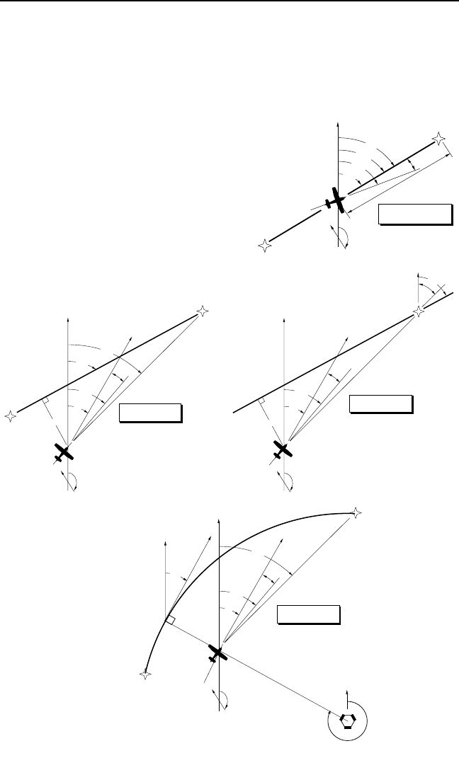
APPENDIX A - NAVIGATION TERMS
KLN 94 Pilot’s Guide Appendix A Navigation Terms
A-1
ARC - Radial from reference VOR when executing an approach procedure
with a DME arc.
BRG - Bearing to waypoint (degrees)
DA - Drift Angle (degrees)-not displayed on KLN 94
DIS - Distance to waypoint (nm)
DTK - Desired Track (degrees)
ETE - Estimated Time Enroute (hrs:min)
ETA - Estimated Time of Arrival
GS - Groundspeed (nm/hr)
HDG - Heading (degrees)
OBS - Selected Course
POS - Present position
TK - Actual Track (degrees)
WPT - Waypoint
XTK - Cross Track Error Correction (nm)
displayed as “FLY L 2.3 nm”
WPT 1
WIND
POS
HDG DA
NORTH
WPT 2
DIS/ETE/ETA/GS
ON TRACK
Enroute-Leg Mode
BRG
TK
DTK
WPT 1
WIND
POS
XTK
TK
HDG
BRG
GS
NORTH
WPT 2
DA
OFF TRACK-DME ARC
Leg Mode
DIS/ETE/ETA
ARC
Reference
VOR
NORTH
NORTH
DTK
NORTH
BRG
OBS
OFF TRACK
Enroute-OBS Mode
WIND
POS
XTK
TK
HDG
GS
NORTH
ACTIVE WPT
DA
DIS/ETE/ETA
WPT 1
WIND
POS
XTK
TK
HDG
DTK
BRG
GS
NORTH
WPT 2
DA
OFF TRACK
Enroute Leg Mode
DIS/ETE/ETA

Appendix A Navigation Terms
A-2
This page intentionally left blank

APPENDIX B - MESSAGE PAGE MESSAGES
XXXXX Deleted
From FPL 0 - The displayed waypoint has been deleted from the active
flight plan (FPL 0) when an approach, DP or STAR was added to FPL 0.
The pre-existing waypoint was deleted because adding the
APR/DP/STAR to the flight plan caused the same waypoint to be listed
consecutively in FPL 0. If the APR/DP/STAR is later deleted from FPL 0
the original waypoint can only be restored by manual re-entry.
Adj Nav Crs to XXX° - (Adjust navigation indicator course to XXX°)
When this message appears, you should select the suggested course on
the HSI or CDI. When the KLN 94 is in the Leg mode, this message
occurs during turn anticipation (prior to reaching the active waypoint) if the
upcoming course change is greater than 5°and anytime the indicator’s
selected course needs to be adjusted to match the KLN 94 desired track.
This message will only be displayed if the KLN 94 is installed such that it
can “read” the selected HSI or CDI course. See section 4.2.2.
Aero Database Outdated,
All Data Must be
Confirmed Before Use - This message appears when the aeronautical
database is out of date as a result of a date and time entered on the SET
2 page or Self-Test page or as a result of a pilot-entered date being over-
ridden by a date from the GPS receiver.
Airspace Alert
[name and type of special use airspace]
[altitude boundaries]
[responsible ATC facility] — This message appears when the estimated
time to enter a special use airspace (SUA) is approximately 10 minutes or
when the distance from an area of special use airspace is less than two
nautical miles. See section 3.13.
All Wpt Remarks Used,
Delete on AUX 13 Page - This message will be displayed if you attempt
to enter a waypoint remark and the user database already contains 100
waypoint remarks.
Altitude Fail - This message will be displayed if the altitude input
becomes invalid during operation.
APR ACTV Annunciator
Fail — This message appears when there is a failure of the KLN 94 exter-
nal ACTV annunciator drive circuitry. Service unit as soon as possible.
APR ARM Annunciator
Fail — This message appears when there is a failure of the KLN 94 exter-
nal ARM annunciator drive circuitry. Service unit as soon as possible.
KLN 94 Pilot’s Guide Appendix B Message Page Messages
B-1

Arm GPS Approach — If the approach ARM mode has been disarmed
with the optional external GPS Approach switch, the KLN 94 will remind
you to arm the approach mode when the aircraft is 3 nautical miles from
the Final Approach Fix (FAF). Arm the approach mode with the GPS
Approach switch if it is desired to use the KLN 94 for conducting an
approach.
Bad Satellite Geometry
And RAIM Not Available — This message appears only when the
KLN 94 is in the approach active mode, RAIM is not available and the
satellite geometry has further degraded to cause more uncertainty of the
aircraft position. This message may be followed by a NAV flag (in a couple
of minutes) if conditions continue to degrade.
Bad Satellite Geometry
See EPE on AUX 1 page — This message appears following a message
that RAIM is not available. This means that the geometry of the satellites
is such that the possible error in position is greater than allowed for IFR
use. Cross check the position of the aircraft with other means of naviga-
tion every 15 minutes to verify that the position is still accurate.
Check APR ACTV
Annunciator — This message appears when an overcurrent condition is
detected on the external ACTV annunciator output. It is usually indicative
of a failure of the wiring between the KLN 94 and the ACTV annunciator.
Have the installation checked to determine the problem.
Check APR ARM
Annunciator — This message appears when an overcurrent condition is
detected on the external ARM annunciator output. It is usually indicative
of a failure of the wiring between the KLN 94 and the ARM annunciator.
Have the installation checked to determine the problem.
Check MSG Annunciator — This message appears when an overcurrent
condition is detected on the external MSG annunciator output. It is usually
indicative of a failure of the wiring between the KLN 94 and the MSG
annunciator. Have the installation checked to determine the problem.
Check Real Time Clock — This message appears when a possible fault
is detected with the KLN 94’s internal real time clock. This condition does
not require immediate service. Manually initialize the time on the
Initialization Page to minimize the time to first fix (see section 3.7).
Check WPT Annunciator — This message appears when an overcurrent
condition is detected on the external WPT annunciator output. It is usually
indicative of a failure of the wiring between the KLN 94 and the WPT
annunciator. Have the installation checked to determine the problem.
Appendix B Message Page Messages
B-2

Database Error: AERO
Data Not Useable - This message appears if the aeronautical database
fails an internal test when the KLN 94 is turned on.
Database Error: LAND
Data Not Useable - This message appears if the land database fails an
internal test when the KLN 94 is turned on
Enable Turn Anticipation For GPS Approach - This message is dis-
played if an approach has been loaded into FPL 0, the aircraft is within 30
NM of the approach airport, AND turn anticipation has been disabled on
the SET 10 page. For proper approach operation, enable turn anticipation
on the SET 10 page per section 4.2.2.
GEN RS-232 Data In
Error — This message appears when an error is detected in the received
RS-232 data such as from a fuel management or air data system.
GPS Course is XXX° — This message is displayed to notify the user that
the GPS desired track (DTK) has changed. This message will only be dis-
played when the KLN 94 is not “reading” selected course from an external
HSI or CDI. When the KLN 94 is in Leg mode, this message occurs if the
course change is greater than 5°.
If Required Select OBS — This message appears when the aircraft is 4
nautical miles from a waypoint which could be used as the basis for either
a procedure turn or a holding pattern and the KLN 94 is in the LEG mode.
Select the OBS mode when flying procedure turns or holding patterns.
This message is advisory only. If no procedure turn is required then no
action is required.
If Using Procedure
Turn Reduce Speed
To Remain Within
Protected Area— The aircraft’s flight path may extend beyond the pro-
tected airspace for the procedure turn if the aircraft’s present ground
speed is maintained. It is always the pilot’s responsibility to stay within the
airspace specified on the instrument approach chart for the procedure
turn.
Inside SUA
[name and type of special use airspace]
[altitude boundaries]
[responsible ATC facility] — (Inside Special Use Airspace) This message
appears when the aircraft is inside special use airspace (SUA). See sec-
tion 3.13.
KLN 94 Pilot’s Guide Appendix B Message Page Messages
B-3

Internal Battery Low:
Service Required to
Prevent Data Loss— This message appears when the KLN 94’s internal
battery is low and needs replacing at an authorized Bendix/King service
center. The battery should be replaced within a week to prevent the loss
of all user-defined data including waypoint, airport remarks, flight plans,
etc. Typical battery life is approximately three to five years.
Low Bus Voltage
Check Charging System — This message appears when the voltage on
the aircraft power bus drops below the alert voltage for longer than the
alert delay time. Both the alert voltage and alert delay time are displayed
on the SET 9 page and set at the time of KLN 94 installation. In addition,
the SET 9 page displays the present power bus voltage. This message
may be indicative of a problem with the aircraft’s charging system.
Consult your aircraft’s Pilot Operating Handbook to troubleshoot the prob-
lem. You may desire to turn off some of the aircraft’s electrical devices
which are non-essential for your particular phase(s) of flight, so that the
battery will not discharge as quickly.
Magnetic Var for Published
Approach Being Used -This message appears when a user-defined
magnetic variation has been selected on the SET 2 page and an
approach waypoint is active. The KLN 94 will use the magnetic variation
association with the approach waypoint.
Magnetic Var Invalid
Nav Data Referenced
To True North - This message appears when the magnetic variation is
invalid due to operation outside of the database magnetic variation area
without having a pilot-entered magnetic variation. See section 5.16.
Mag Var for Published
VOR Being Used - This message appears when a user-defined magnetic
variation has been selected on the SET 2 page; the unit is in OBS mode:
and the active waypoint is a VOR. In this case, the magnetic variation
associated with the VOR station will be used.
MSG Annunciator Fail — This message appears when there is a failure
of the KLN 94 external MSG annunciator drive circuitry. To determine if
there are any messages to be viewed you will need to look at the internal
KLN 94 message display because the annunciator will not be working if
this message has been given. Service the KLN 94 as soon as possible.
Nav Data Referenced
To True North - This message appears when a user-defined magnetic
variation of 0 degrees is being used for navigation data.
Appendix B Message Page Messages
B-4

Nav Data Referenced To
User-Defined Mag Var - This message appears when a user-defined
magnetic variation other than 0 degrees is being used for navigation data.
NAV Super Flag Failure — This message appears when an internal test
fails for a specific NAV flag output. The KLN 94 is still usable, but any-
thing connected to the super flag (such as some HSIs and autopilots)
should not be used with the KLN 94.
No Database Card. LAND
Data Removed On Map.
Insert Card And
Cycle Power.— This message appears if the database card is removed
while the KLN 94 is operating. The land data (rivers, roads, cities, etc.) will
no longer be displayed on the map with the card removed. However, the
aeronautical data (airports, navaids, special use airspace, flight plan way-
points, etc.) will continue to be properly displayed on the map and the unit
will otherwise work normally. To display land data the database card must
be re-inserted and the power must be turned off and then back on.
Applicable to ORS 02 and higher units only.
No GEN RS-232 In Data — This message appears when no input is
received on the RS-232 input (such as from a fuel management or air
data system).
No GPS Receiver Data - This message appears when the KLN 94 fails a
specific internal test for the GPS receiver. This failure will prevent the unit
from providing any navigation capability.
OBS Waypoint > 200nm - (or OBS Waypoint >370 km) This message
is displayed when the KLN 94 is in the OBS mode and the distance to the
active waypoint is more than 200 nautical miles or 370 kilometers.
Other WPTs Deleted - (Other waypoints deleted) This message is dis-
played whenever more than 10 waypoints used in a flight plan (including
the active waypoint) have been deleted.
Position of _______ has Changed — This message appears when
either the latitude or the longitude of a waypoint used in a flight plan or the
active waypoint has changed by more than .33 minutes as a result of
updating the database.
Positions of Other WPTs Have Changed — This message appears
when the above message “ Position of _______ has Changed” would be
effective for more than ten waypoints.
Press ALT To Set Baro — This message appears when the approach
mode is armed. Press the Abutton to update the barometric pressure
for proper integrity monitoring.
KLN 94 Pilot’s Guide Appendix B Message Page Messages
B-5

Appendix B Message Page Messages
B-6
Press PROC Button Now For Navigation — This message appears
after the NAV flag has been set due to a RAIM problem while the KLN 94
is in the approach mode. By pressing the Procedure (P) button, the
KLN 94 may be able to restore navigation information so that you can con-
duct a missed approach based on navigation information provided by the
KLN 94.
RAIM Not Available
APR Mode Inhibited
Predict RAIM on AUX 3 — This message appears when integrity moni-
toring (RAIM) is predicted to not be available at either the FAF or the
MAP. The KLN 94 will not go into the approach active mode until condi-
tions improve. Turn to the AUX 3 (Auxiliary 3) page to perform a RAIM
prediction. The AUX 3 page will give an indication of how long it will be
until RAIM is available so that the approach can be flown using the KLN
94 (see section 6.2.14 on performing a RAIM prediction).
RAIM Not Available
Cross Check Position — This message appears when there are not
enough received GPS satellite signals to compute integrity (RAIM). Cross
check the position of the aircraft with other means of navigation every 15
minutes to verify that the position is still accurate.
RAIM Position Error
Cross Check Position — This message appears when the KLN 94 has
detected a problem with one of the satellites and the position can not be
assured to be within IFR limits for the particular mode of flight. Cross
check the position of the aircraft with other means of navigation every 15
minutes to verify that the position is still accurate.
RCVR HW Error:_____— (Receiver Hardware Error) This message
appears when the KLN 94 fails a specific internal test for the GPS receiv-
er. The blanks will contain a value which may provide assistance to
maintenance personnel.
Recycle Power to Use
Valid Database Data — This message appears when the date entered
on the Initialization page is before the database effective date and the
date entered later on the SET 2 page is after the database effective date,
or vice versa. Turn the KLN 94 off and back on so that the correct data-
base data is utilized.

KLN 94 Pilot’s Guide Appendix B Message Page Messages
B-7
Redundant WPTs In FPL
Edit Enroute WPTs
As Necessary — This message appears after the pilot inserts an
approach, DP, or STAR in the flight plan and the KLN 94 determines that
some waypoints that were in the flight plan are no longer needed.
Examine the active flight plan and remove those waypoints that occur both
in the en route and the approach/DP/STAR sections of the flight plan.
Search the Sky — The message appears when the GPS receiver is
unable to locate satellites in the normal startup mode. It may take an
extended period of time (15-20 minutes) to reach navigation capability.
Timer Expired — This message appears when the alarm time on the
AUX 10 page is reached.
User Database Lost — This message appears when the KLN 94 deter-
mines that the internal memory backup battery is dead or that some other
internal failure has occurred which has caused user-entered waypoints,
flight plans, and waypoint remarks to be lost.
User Data Lost — This message appears when the KLN 94 determines
that the internal memory backup battery is dead or that some other inter-
nal failure has occurred which has caused user data such as page setups
to be lost.
Using Emergency
Battery — This message appears when an emergency back-up battery is
installed and it is supplying power to the KLN 94.
Vnv Alert — (Vertical Navigation Alert) This message appears when a
VNAV operation has been programmed on the ALT 2 page and the esti-
mated time to start the climb or descent is approximately 90 seconds.
This message serves as notification to view VNAV status so that the
VNAV operation may be executed. VNAV status can be displayed on the
NAV 1, NAV 4, and ALT pages.
WPT Annunciator Fail — This message appears when there is a failure
of the KLN 94 external WPT annunciator drive circuitry. To determine if
waypoint alerting is being given you will need to look at the KLN 94 dis-
play because the annunciator will not be working if this message has been
given. Service the KLN 94 as soon as possible.
WPT _____ Deleted — This message appears when a waypoint used in
a flight plan, or the active waypoint, no longer exists as a result of updat-
ing the database. The blank space is filled in with the waypoint identifier.
The waypoint is deleted from flight plans in which it was used.

Appendix B Message Page Messages
B-8
This page intentionally left blank

APPENDIX C - SCRATCHPAD MESSAGES
Active
Wpt - (Active Waypoint) Appears when you attempt to delete a user-
defined waypoint on the AUX 12 page if the waypoint is the active
waypoint (the waypoint you are navigating to). Another waypoint must be
made the active waypoint before this waypoint can be deleted from the
user-defined waypoint list.
D Base
Expired- (Database Expired) Appears whenever the pilot attempts to
select an approach from the database on the APT 8 or ACT 8 page and
the database has expired.
∂∂∆∆ CRS
XXX° - (Direct To Course XXX°) Appears when the KLN 94 is in the OBS
mode and is interfaced with an external indicator for which the KLN 94
cannot change the selected course and the pilot performs a Direct To
operation. Since the KLN 94 cannot change the selected course to the
direct to course, the KLN 94 gives you this message telling you the OBS
value that will take the aircraft direct to the active waypoint.
Dup
Ident - (Duplicate Identifier) Appears when you select a waypoint identifier
on one of the waypoint type pages if there is more than one waypoint of
that waypoint type having the same identifier.
Freq To NAV X - (frequency to navigation receiver X) Appears when a
KLN 94 is configured for QuickTuneTM operation and an approach is
loaded into the active flight plan. The approach frequency is sent to the
standby window of the navigation receiver (KX 155A or KX 165A). The
approach frequency must be a valid VHF navigation frequency (108.00
MHz - 117.95 MHz) associated with a VOR or localizer-type approach.
“X” is the number of the receiver (e.g. NAV 1 is navigation receiver #1)
where the frequency has been sent to.
Fpl Is
Full - (Flight Plan is Full) Appears when an attempt is made to add a new
waypoint to the active flight plan (FPL 0) when it already contains 20 way-
points and the first waypoint is part of the active leg. Change the active
waypoint or delete another waypoint before adding any more waypoints.
Invalid
Add - (Invalid Add) Appears when an attempt is made to add a new way-
point into the approach. Approach procedures must be flown as they are
stored in the database.
KLN 94 Pilot’s Guide Appendix C Scratchpad Messages
C-1

Invalid
Del - (Invalid Delete) Appears when an attempt is made to delete an
approach waypoint. Individual approach waypoints cannot be deleted,
you must delete or replace the entire approach.
Invalid
Ent - (Invalid Entry) Appears when you attempt to enter data which is not
a valid entry. For example, trying to enter a date of 30 FEB 95.
Invalid Freq — Appears if you attempt a QuickTuneTM operation for a fre-
quency outside the normal VHF communications and navigation
frequency range (108.000 MHz - 136.990 MHz).
Invalid Rcvr — Appears if you attempt a QuickTuneTM operation when
QuickTuneTM has been disabled on a configuration page at the time of
installation. The QuickTuneTM is operable with Bendix/King KX 155A and
KX 165A NavComms only and requires wiring between the NavComm
and the KLN 94.
No Act
Wpt - (No Active Waypoint) Appears when you attempt to activate the
OBS mode if there is no active waypoint. To have an active waypoint, a
flight plan must be activated or a Direct To must be initiated.
No Appr at Apt - (No approach at airport) Appears when attempting to
select an approach if you manually enter an airport on the Procedure
(PROC) 2 page that doesn’t have an approach in the database
No Apr
In Fpl - (No Approach in Flight Plan) Appears when an attempt is made
to arm the GPS approach mode when there is no approach loaded into
the active flight plan. Load an approach into the flight plan before trying to
arm the approach mode.
No DP at Apt - (No departure procedure at airport) Appears when
attempting to select a DP if you manually enter an airport on the
Procedure (PROC) 2 page that doesn’t have a departure procedure in the
database.
No STAR at Apt — (No arrival procedure at airport) Appears when
attempting to select a STAR if you manually enter an airport on the
Procedure (PROC) 2 page that doesn’t have an arrival procedure in the
database.
No
Intcpt - (No Intercept) Appears when an attempt is made to recalculate
the intercept point on a DME arc and the actual track does not intercept
with the arc. Change the track (heading) of the aircraft so that the actual
track does intercept the DME arc and try again.
Appendix C Scratchpad Messages
C-2

No
Nrst - (No Nearest) Appears when the pilot selects a nearest list (APT,
VOR, NDB, INT, USR, SUA, FSS or CTR), and there are no nearest items
of that type within a 200 nm radius of the aircraft’s present position.
No Such
Wpt - (No Such Waypoint) Appears when there is no waypoint in the data-
base corresponding to the entered identifier on the Supplemental
Waypoint page.
No Wpt
Page - (No waypoint page) Appears when an approach, DP or STAR
waypoint is displayed in the waypoint scan window of the NAV 4 page and
the Fbutton is pressed. For waypoints that are not part of an approach,
a waypoint page is displayed when the Fbutton is pressed but this fea-
ture is not available for approach, DP and STAR waypoints. (ORS 02 and
higher)
Not an Apt — (Not an airport) Appears when you manually enter a way-
point identifier on the Procedure (PROC) 2 page which is not an airport.
Remarks
Full - (Remarks Full) Appears when you attempt to create a user-entered
Airport or Supplemental Waypoint remark on the APT 6 or SUP 3 page if
100 user-entered remarks already exist. In order to create additional air-
port remarks, some existing remarks must be deleted on the AUX 12
page.
Used
In Fpl - (Used in Flight Plan) Appears when you attempt to delete a user-
defined waypoint on the AUX 12 page if the waypoint is used in a flight
plan. Either this waypoint must be deleted from the flight plan or the entire
flight plan must be deleted before this waypoint can be deleted from the
user-defined waypoint list.
USR DB
Full - (User Database Full) Appears when you attempt to create a user-
defined waypoint if the user database already contains 500 waypoints. In
order to create additional user-defined waypoints, it will first be necessary
to delete existing user-defined waypoints on the AUX 12 page.
KLN 94 Pilot’s Guide Appendix C Scratchpad Messages
C-3

Appendix C Scratchpad Messages
C-4
This page intentionally left blank

APPENDIX D - ABBREVIATIONS
STATE ABBREVIATIONS
ABBREVIATION STATE
AK Alaska
AL Alabama
AR Arkansas
AZ Arizona
CA California
CO Colorado
CT Connecticut
DC District of Columbia
DE Delaware
FL Florida
GA Georgia
IA Iowa
ID Idaho
IL Illinois
IN Indiana
KS Kansas
KY Kentucky
LA Louisiana
MA Massachusetts
MD Maryland
ME Maine
MI Michigan
MN Minnesota
MO Missouri
MS Mississippi
MT Montana
NC North Carolina
ND North Dakota
NE Nebraska
NH New Hampshire
NJ New Jersey
NM New Mexico
NV Nevada
NY New York
OH Ohio
OK Oklahoma
KLN 94 Pilot’s Guide Appendix D Abbreviations
D-1

STATE ABBREVIATIONS (Cont’d)
OR Oregon
PA Pennsylvania
RI Rhode Island
SC South Carolina
SD South Dakota
TN Tennessee
TX Texas
UT Utah
VA Virginia
VT Vermont
WA Washington
WI Wisconsin
WV West Virginia
WY Wyoming
CANADIAN PROVINCE ABBREVIATIONS
ABBREVIATION PROVINCE
AB Alberta
BC British Columbia
MB Manitoba
NB New Brunswick
NF Newfoundland
NS Nova Scotia
NT & NU Northwest Territory
ON Ontario
PE Prince Edward Island
PQ Quebec
SK Saskatchewan
YK Yukon
COUNTRY ABBREVIATIONS
ABBREV. COUNTRY
AFGHAN AFGHANISTAN
ALASKA ALASKA (AK)
ALBANI ALBANIA
ALGERI ALGERIA
ANGOLA ANGOLA
ANGUIL ANGUILLA I.
Appendix D Abbreviations
D-2

COUNTRY ABBREVIATIONS (Cont’d)
ANTARC ANTARCTICA (E. SPA REGION)
ANTIGU ANTIGUA / BARBUDA
ANTILL NETHERLANDS ANTILLES / ARUBA
ARGENT ARGENTINA
ARMENI ARMENIA / GEORGIA
ASCENS ASCENSION ISLAND / ST. HELENA
AUSTRA AUSTRALIA
AUSTRI AUSTRIA
AZERBA AZERBAIJAN
BAHAMA BAHAMAS
BAHRAI BAHRAIN
BAKER BAKER ISLANDS
BANGLA BANGLADESH
BARBAD BARBADOS
BELARU BELARUS / LATVIA / LITHUANIA / RUSSIA
BELGIU BELGIUM
BELIZE BELIZE
BENIN BENIN
BERMUD BERMUDA
BHUTAN BHUTAN
BOLIVI BOLIVIA
BOSNIA BOSNIA AND HERZEGOVIA
BOTSWA BOTSWANA
BRAZIL BRAZIL
BRUNE BRUNEI
BULGAR BULGARIA
BURKIN BURKINA FASO
BURUND BURUNDI
C AFRI CENTRAL AFRICAN REPUBLIC
C USA USA (IA,KS,MN,MO,NE,ND,SD)
C VERD CAPE VERDE
CAMBOD CAMBODIA / KAMPUCHEA
CAMERO CAMEROON
CANADA CANADA
CANARY CANARY ISLANDS
CAROLI CAROLINE ISLAND / MICRONESIA
CAYMAN CAYMAN ISLANDS
CHAD CHAD
CHILE CHILE / EASTER I.
CHINA CHINA
COLUMB COLUMBIA / SAN ANDRES
KLN 94 Pilot’s Guide Appendix D Abbreviations
D-3

COUNTRY ABBREVIATIONS (Cont’d)
CONGO CONGO
COOK I COOK ISLANDS
COSTA COSTA RICA
CROATI CROATIA
CUBA CUBA
CYPRES CYPRESS
CZECHO CZECHOSLOVAKIA
DENMAR DENMARK
DJIBOU DJIBOUTI
DOM RE DOMINICAN REPUBLIC
DOMINI DOMINICA
ECUADO ECUADOR
EGYPT EGYPT
EL SAL EL SALVADOR
EQ GUI EQUATORIAL GUINEA
ERITRE ERITREA
ESTONI ESTONIA / RUSSIA
ETHIOP ETHIOPIA
FALKLA FALKLAND ISLANDS
FIJI FIJI / TONGA
FINLAN FINLAND
FRANCE FRANCE
GABON GABON
GAMBIA GAMBIA
GAZA GAZA
GBRIT UNITED KINGDOM
GERMAN GERMANY
GHANA GHANA
GIBRAL GIBRALTAR
GN BIS GUINEA-BISSAU
GREECE GREECE
GREENL GREENLAND
GRENAD GRENADA
GUADEL GUADELOUPE / MARTINIQUE
GUATEM GUATEMALA
GUIANA FRENCH GUIANA
GUINEA GUINEA
GUYANA GUYANA
HAITI HAITI
HAWAII HAWAII (HI)
HONDUR HONDURAS
Appendix D Abbreviations
D-4

COUNTRY ABBREVIATIONS (Cont’d)
HONG K HONG KONG
HUNGAR HUNGARY
ICELAN ICELAND
IND OC BRITISH INDIAN OCEAN TERRITORY
INDIA INDIA
INDONE INDONESIA
IRAN IRAN
IRAQ IRAQ
IRELAN IRELAND
ISRAEL ISRAEL
ITALY ITALY
IVORY IVORY COAST
JAMAIC JAMAICA
JAPAN JAPAN / OKINAWA
JOHNST JOHNSTON ISLAND
JORDAN JORDAN
KAZ KY KAZAKHSTAN / KYRGYZSTAN
KAZ RU KAZAKHSTAN / RUSSIA
KAZ TA KAZAKHSTAN / TAJIKISTAN /
TURKMENISTAN / UZBEKISTAN
KENYA KENYA
KIRIBA KIRIBATI / TUVALU / PHEONIX I. / LINE I.
KITTS ST. KITTS / NEVIS
KOR PR KOREA (DEMO. PEOPLES REPUBLIC)
KOREA KOREA
KUWAIT KUWAIT
LAOS LAOS
LATVIA LATVIA
LEBANO LEBANON
LESOTH LESOTHO
LIBER LIBERIA
LIBYA LIBYA / SPA JAMAHIRIYA
LUCIA ST. LUCIA
LUXEMB LUXEMBOURG
MACAU MACAU
MACEDO MACEDONIA
MADAGA MADAGASCAR / COMOROS / MAYOTTE I. /
REUNION
MALAWI MALAWI
MALAYS MALAYSIA
KLN 94 Pilot’s Guide Appendix D Abbreviations
D-5

COUNTRY ABBREVIATIONS (Cont’d)
MALDIV MALDIVES
MALI MALI
MALTA MALTA
MARIAN MARIANA ISLANDS
MARSHA MARSHALL ISLAND
MELILL MELILLA (SPAIN)
MEXICO MEXICO
MIDWAY MIDWAY ISLAND
MOLDOV MOLDOVA
MONSER MONSERRAT I.
MOROCC MOROCCO
MOZAMB MOZAMBIQUE
MRTIUS MAURITIUS
MRTNIA MAURITANIA
MW USA USA (IL,IN,KY,MI,OH,WI)
MYANMA MYANMAR
NAMIBI NAMIBIA
NAURA NAURA
NE USA USA (CT,DE,DC,ME,MD,MA,NH,NJ,NY,PA,RI,
VA,VT,WV)
NEPAL NEPAL
NETHER NETHERLANDS
NEW ZE NEW ZEALAND
NEWCAL NEW CALENDONIA
NICARA NICARAGUA
NIGER NIGER
NIGERI NIGERIA
NIUE I NIUE ISLAND
NORWAY NORWAY
NW USA USA (ID,MT,OR,WA,WY)
OAKLAN OAKLAND OTCA (PACIFIC)
OMAN OMAN
P RICO PUERTO RICO
PAKIST PAKISTAN
PANAMA PANAMA
PARAGU PARAGUAY
PERU PERU
PHILIP PHILIPPINES
PNEWG PAPUA NEW GUINEA
POLAND POLAND
POLYNE FRENCH POLYNESIA / SOCIETY I. /
TUAMOTU
Appendix D Abbreviations
D-6

COUNTRY ABBREVIATIONS (Cont’d)
PORTUG PORTUGAL / AZORES / MADEIRA I.
QATAR QATAR
ROMANI ROMANIA
RUSSIA RUSSIA
RWANDA RWANDA
S AFRI SOUTH AFRICA
SAO TO SAO TOME / PRINCIPE
SAUDI SAUDI ARABIA
SC USA USA (AR,LA,OK,TX)
SE USA USA (AL,FL,GA,MS,NC,SC,TN)
SENEGA SENEGAL
SEYCHE SEYCHELLES
SIERRA SIERRA LEONE
SINGAP SINGAPORE
SLOVAK SLOVAKIA
SLOVEN SLOVENIA
SOLO I SOLOMON ISLANDS
SOMALI SOMALIA
SPAIN SPAIN
SRI LA SRI LANKI
STPIER ST. PIERRE AND MIQUELON
SUDAN SUDAN
SURINA SURINAME
SW USA USA (AZ,CA,CO,NV,NM,UT)
SWAZIL SWAZILAND
SWEDEN SWEDEN
SWITZE SWITZERLAND
SYRIA SYRIA
TAIWAN TAIWAN
TANZAN TANZANIA
THAILA THAILAND
TOGO TOGO
TRINID TRINIDAD/TABAGO
TUNIS TUNISIA
TURK I TURKS AND CAICOS ISLANDS (UK)
TURKEY TURKEY
UARABE UNITED ARAB EMIRATES
UGANDA UGANDA
UKRAIN UKRAINE / MOLDOVA
URUGUA URUGUAY
VANAUT VANAUTU
KLN 94 Pilot’s Guide Appendix D Abbreviations
D-7

COUNTRY ABBREVIATIONS (Cont’d)
VENEZU VENEZUELA
VIETNA VIETNAM
VINCEN ST. VINCENT
VIR UK VIRGIN ISLANDS (U.K.)
VIR US VIRGIN ISLANDS (U.S.)
W SOMO AMERICAN/WESTERN SAMOA
WAKE I WAKE ISLAND
WALLIS WALLIS/FUTUNA ISLANDS
YEMEN YEMEN (ARAB REPUBLIC)
YUGOSL YUGOSLAVIA
ZAIRE FORMER ZAIRE
ZAMBIA ZAMBIA
ZIMBAB ZIMBABWE
ARTCC ABBREVIATIONS
ABBREVIATION ARTCC
ABQ ALBUQUERQUE
ACC ACCRA
ADD ADDIS ABABA
ADE ADELAIDE
ADN ADEN
AKM AKMOLA
AKT AKTYUBINSK
AKU AKTAU
ALG ALGIERS
ALM ALMATY
AMD AMDERMA
AMM AMMAN
AMS AMSTERDAM
ANA ANADYR
ANC ANCHORAGE
ANK ANKARA
ANT ANTANANARIVO
ARA ARALSK
ARK ARKHANGELSK
ARY ARKAKYK
ASH ASHGABAT
ASM ASMARA
AST ASTRAKHAN
ASU ASUNCION
ATF ANTOFAGASTA
Appendix D Abbreviations
D-8

ARTCC ABBREVIATIONS (Cont’d)
ATH ATHENS
ATL ATLANTA
ATN ASTANA
ATY ATYRAU
AUC AUCKLAND
AYA AYAGUS
BAG BAGHDAD
BAH BAHRAIN
BAK BAKU
BAL BALI
BAN BANGKOK
BAR BARCELONA
BAS BALKHASH
BAT BATAGAY
BEI BEIJING
BEL BELEM
BER BERMUDA
BIA BIAK
BIS BISHKEK
BLA BLAGOVESCHENSK
BLG BELGRADE
BLO BLOEMFONTEIN
BOD BODO
BOG BOGOTA
BOM BOMBAY
BOR BORDEAUX
BOS BOSTON
BRA BEIRA
BRD BRINDISI
BRE BREMEN
BRI BRISBANE
BRL BERLIN
BRN BARNAUL
BRR BARRANQUILLA
BRS BRASILIA /UTA
BRT BEIRUT
BRU BRUSSELS
BRV BRATISLAVA
BRY BERYOZOVO
BRZ BRAZZAVILLE
BSK BRATSK
KLN 94 Pilot’s Guide Appendix D Abbreviations
D-9

ARTCC ABBREVIATIONS (Cont’d)
BST BREST
BUC BUCHAREST
BUD BUDAPEST
BUJ BUJUMBURA
CAI CAIRO
CAL CALCUTTA
CAM CAMPO GRANDE
CAM CENTRAL AMERICA
CAN CANARIES
CAP CAPE TOWN
CAS CASABLANCA
CHA CHAYBUKHA
CHE CHELYABINSK
CHI CHICAGO
CHN CHENNAI
CHO CHOKURDAKH
CHR CHERSKY
CHT CHITA
CHU CHULMAN
CLE CLEVELAND
COC COCOS I
COL COLOMBO
COM COMODORO RIVADAVIA
COP COPENHAGEN
COR CORDOBA
CRT CURITIBA
CRZ CHARDZHEV
CUR CURACAO
DAK DAKAR
DAM DAMASCUS
DAR DARWIN
DAS DASHKHOVUZ
DEL DELHI
DEN DENVER
DES DAR-ES-SALAAM
DHA DHAKA
DIK DIKSON
DOR DORNOD
DSS DUSSELDORF
DUR DURBAN
DUS DUSHANBE
Appendix D Abbreviations
D-10

ARTCC ABBREVIATIONS (Cont’d)
EDM EDMONTON
EMI EMIRATES
ENT ENTEBBE
EZE EZEIZA
FRA FRANKFURT
FW FT WORTH
GAB GABORONE
GAN GANDER DOMESTIC
GEN GENEVA
GEO GEORGETOWN
GUA GUANGZHOU
GUY GUAYAQUIL
HAN HANOI
HAR HARARE
HAV HAVANA
HK HONG KONG
HNR HONIARA
HOC HOCHIMINH
HON HONOLULU CERAP
HOU HOUSTON
IND INDIANAPOLIS
IRK IRKUTSK
ISL ISLA DE PASCUA
IST ISTANBUL
JAK JAKARTA
JAX JACKSONVILLE
JED JEDDAH
JOH JOHANNESBURG
KAB KABUL
KAG KARAGANDA
KAL KALININGRAD
KAM KAMENNYI MYS
KAN KANO
KAR KARACHI
KAT KATHMANDU
KAZ KAZAN
KC KANSAS CITY
KHA KHABAROVSK
KHR KHARKIV
KHT KHATANGA
KIE KIEV
KLN 94 Pilot’s Guide Appendix D Abbreviations
D-11

ARTCC ABBREVIATIONS (Cont’d)
KIG KIGALI
KIN KINGSTON
KIR KIRENSK
KIS KISANGANI
KK KOTA KINABALU
KL KUALA LUMPUR
KM KHANTY-MANSIYSK
KNS KINSHASA
KO KZYL-ORDA
KO KYZYLORDA
KOL KOLPASHEVO
KOS KOSTANAY
KOT KOTLAS
KRA KRASNOVODSK
KRK KARAKOL
KRS KRASNOYARSK
KRV KIROV
KSH CHISINAU
KSH KISHINAU
KTM KHARTOUM
KUN KUNMING
KUR KURGAN
KUW KUWAIT
KYI KYIV
LAH LAHORE
LAP LA PAZ
LAX LOS ANGELES
LIL LILONGWE
LIM LIMA
LIS LISBON
LJU LJUBLJANA
LON LONDON
LUA LUANDA
LUB LUBUMBASHI
LUS LUSAKA
LVO LVOV
MAD MADRID
MAG MAGADAN
MAI MAIQUETIA
MAL MALE
MAN MANILA
Appendix D Abbreviations
D-12

ARTCC ABBREVIATIONS (Cont’d)
MAR MARSEILLE
MAU MAURITIUS
MAZ MAZATLAN
MDR MADRAS
MEL MELBOURNE
MEM MEMPHIS
MEN MENDOZA
MER MERIDA
MEX MEXICO
MGD MAGDAGACHI
MIA MIAMI
MIL MILAN
MIN MINNEAPOLIS
MIR MIRNY
MLM MALMO
MLT MALTA
MNC MONCTON NORTHERN
MNS MANAUS
MNT MONTERREY
MOG MOGADISHU
MON MONTREAL
MOS MOSCOW
MRM MURMANSK
MS MYS SHMIDTA
MS MYS KAMENNY
MSK MINSK
MTV MONTEVIDEO
MUM MUMBAI
MUN MUNICH
MUR MUREN
MUS MUSCAT
NAD NADI
NAH NAHA
NAI NAIROBI
NAS NASSAU
NDJ N’DJAMENA
NIC NICOSIA
NIK NIKOLAEVSK-NA-AMURE
NMY NIAMEY
NOR NORILSK
KLN 94 Pilot’s Guide Appendix D Abbreviations
D-13

ARTCC ABBREVIATIONS (Cont’d)
NOV NOVOSIBIRSK
NUK NUKUS
NY NEW YORK
NZE NEW ZEALAND
OAK OAKLAND
ODE ODESSA
OKH OKHA
OMS OMSK
ORN ORENBURG
OSH OSH
OSK OKHOTSK
OSL OSLO
PA PUNTA ARENAS
PAN PANAMA
PAP PORT-AU-PRINCE
PAR PARIS
PAV PAVLODAR
PE PORT ELIZABETH
PEC PECHORA
PEM PERM
PEN PENZA
PEP PETROPAVLOVSK
PER PERTH
PET PETERSBURG
PET SAINT PETERSBURG
PET SANKT PETERSBURG
PEV PEVEK
PHN PHNOM PENH
PIA PIARCO
PM PORT MORESBY
PMT PUERTO MONTT
PRA PRAGUE
PRM PARAMARIBO /UTA
PTR PETROPAVLOVSK-KAM.
PV PORTO VELHO
PYO PYONGYANG
REC RECIFE
RES RESISTENCIA
REY REYKJAVIK
RIG RIGA
RIV RIVADAVIA
Appendix D Abbreviations
D-14

ARTCC ABBREVIATIONS (Cont’d)
RMS REIMS
ROB ROBERTS
ROC ROCHAMBEAU
ROM ROME
ROS ROSTOV
ROV ROVANIEMI
SAI SAINSHAND
SAL SAL
SAM SAMARA
SAN SANTIAGO
SAR SARAJEVO
SCO SCOTTISH
SDO SANTO DOMINGO
SEA SEATTLE
SEM SEMIPALATINSK
SEY SEYCHELLES
SHA SHANGHAI
SHE SHENYANG
SHN SHANNON
SHW SHANWICK
SHY SHYMKENT
SIM SIMFEROPOL
SIN SINGAPORE
SJU SAN JUAN
SKO SKOPJE
SLC SALT LAKE CITY
SLK SALEKHARD
SM SANTA MARIA
SMR SAMARKAND
SNA SANAA
SOF SOFIA
SON SONDRESTROM
STA STAVANGER
STO STOCKHOLM
SUK SUKHUMI
SUN SUNDSVALL
SUR SURGUT
SWI SWITZERLAND
SYD SYDNEY
SYK SYKTYVKAR
KLN 94 Pilot’s Guide Appendix D Abbreviations
D-15

ARTCC ABBREVIATIONS (Cont’d)
SYM SEYMCHAN
TAE TAEGU
TAH TAHITI
TAI TAIPEI
TAL TALLINN
TAM TAMPERE
TAR TARAZ
TAS TASHKENT
TAZ TASHAUZ
TBI TBILISI
TEH TEHRAN
TEL TEL AVIV
TIK TIKSI
TIL TILICHIKI
TIR TIRANA
TKB TURKMENABAT
TOK TOKYO
TOR TORONTO
TRI TRIPOLI
TRO TRONDHEIM
TUK TURKMENBASHI
TUN TUNIS
TUR TURUKHANSK
TYU TYUMEN
UFA UFA
UJU UJUNG PANDANG
ULA ULAANBAATAR
UND UNDERHAAN
URA URALSK
URU URUMQI
VAN VANCOUVER
VAR VARNA
VEL VELIKIYE LUKI
VIE VIENNA
VIL VILNIUS
VLA VLADIVOSTOK
VLO VOLOGDA
VNT VIENTIANE
VOL VOLGOGRAD
VRK VORKUTA
WAR WARSAW
Appendix D Abbreviations
D-16

ARTCC ABBREVIATIONS (Cont’d)
WAS WASHINGTON
WEL WELLINGTON
WIN WINNIPEG
WND WINDHOEK
WUH WUHAN
YAK YAKUTSK
YAN YANGON
YEK YEKATERINBURG
YEN YENISEYSK
YER YEREVAN
YS YUZHNO-SAKHALINSK
ZAG ZAGREB
ZHA ZHAMBYL
ZHK ZHEZKAZGAN
ZHY ZHIGANSK
ZUR ZURICH
ZYR ZYRYANKA
OTHER ABBREVIATIONS USED ON KLN 94 PAGES
A Airport waypoint
A/C Aircraft
ACQ Acquisition
ACT Active flight plan waypoints
ADJ Adjust
AKD Alaska Daylight Time
AKS Alaska Standard Time
ALT Altitude
APT Airport
ATD Atlantic Daylight Time
ATS Atlantic Standard Time
BRG Bearing
CAL Calculator
CDT Central Daylight Time
CHAR Character
CRS Course
CRSR Cursor
CST Central Standard Time
DB Database
DEGRD Degraded navigation
DIS Distance
KLN 94 Pilot’s Guide Appendix D Abbreviations
D-17

OTHER ABBREVIATIONS (Cont’d)
DTK Desired track
DUP Duplicate
E East
EDT Eastern Daylight Time
ELE Elevation
ENT Enter
EST Eastern Standard Time
ETA Estimated time of arrival
ETE Estimated time en route
FAILR Failure of receiver
FPL Flight plan
FPM Feet per minute
FR From
GDT Greenland Daylight Time
GS Groundspeed
GST Greenland Standard Time
HAD Hawaii Daylight Time
HAS Hawaii Standard Time
HLT Health of space vehicle signal
IDENT Identifier
INIT Initialization
KM Kilometers
KT Knots
L Left
LCL Local
M Meters
MAG VAR Magnetic variation
MDT Mountain Daylight Time
MPM Meters per minute
MSG Message
MST Mountain Standard Time
N NDB waypoint
N North
NAV Navigation
NAV A Navigation with altitude aiding
NAV D Navigation with data collection
NM Nautical miles
OBS Omni bearing selection
ORS Operational Revision Status
OTH Other
Appendix D Abbreviations
D-18

OTHER ABBREVIATIONS (Cont’d)
P.POS Present position
PDT Pacific Daylight Time
POS Position
POSN Position
PRES Present
PRS Pressure
PST Pacific Standard Time
PUB Published
PWR Power
RAD Radial
RCVR Receiver
REF Reference
REQ Required
RES Reserve fuel
S South
S Supplemental waypoint
SDT Samoa Daylight Time
SET Setup
SNR Signal-to-noise ratio
SST Samoa Standard Time
SUP Supplemental
SV Space vehicle
SW Software
TK Actual track
TOT Total
U User-defined waypoint
USR User-defined waypoint
UTC Coordinated Universal Time (Zulu)
V VOR waypoint
W West
WPT Waypoint
Z Zulu time
KLN 94 Pilot’s Guide Appendix D Abbreviations
D-19

Appendix D Abbreviations
D-20
This page intentionally left blank

APPENDIX E - LAT/LON CONVERSIONS
The KLN 94 utilizes latitude and longitude expressed in degrees, minutes,
and hundredths of a minute. You may occasionally see a document
expressing latitude and longitude in degrees, minutes, and seconds. This
table may be used to convert seconds to hundredths of a minute.
SECONDS (“) HUNDREDTHS OF AMINUTE (‘)
00 .00
01 .02
02 .03
03 .05
04 .07
05 .08
06 .10
07 .12
08 .13
09 .15
10 .17
11 .18
12 .20
13 .22
14 .23
15 .25
16 .27
17 .28
18 .30
19 .32
20 .33
21 .35
22 .37
23 .38
24 .40
25 .42
26 .43
27 .45
28 .47
29 .48
30 .50
31 .52
32 .53
KLN 94 Pilot’s Guide Appendix E Lat/Lon Conversions
E-1

LAT/LON CONVERSIONS (Cont’d)
SECONDS (“) HUNDREDTHS OF AMINUTE (‘)
33 .55
34 .57
35 .58
36 .60
37 .62
38 .63
39 .65
40 .67
41 .68
42 .70
43 .72
44 .73
45 .75
46 .77
47 .78
48 .80
49 .82
50 .83
51 .85
52 .87
53 .88
54 .90
55 .92
56 .93
57 .95
58 .97
59 .98
For example:
35° 46’ 24” is the same as 35° 46.40’
32° 15’ 58” is the same as 32° 15.97’
Appendix E Lat/Lon Conversions
E-2

APPENDIX F - GPS PRIMER
BACKGROUND
The Global Positioning System (GPS) is a satellite-based navigation sys-
tem that was originally conceived and implemented by the United States
Department of Defense (DoD). The system is, however, available to all
civilian users free of charge. GPS provides extremely precise position,
velocity, and time information.
The satellites are not geosynchronous, as is the case with many weather
and television satellites. That is, each satellite is not above a fixed spot on
the Earth all the time, but rather is continuously moving across the sky. In
fact, each satellite completely orbits the Earth two times per day.
The Department of Defense has the capability to impose an intentional
accuracy degradation of the GPS system. This degradation is known as
Selective Availability (SA). When SA is active, only U.S. military users
have access to full GPS accuracy. For civilian users, position accuracy is
degraded to no worse than 100 meters 95% of the time. At the time of
this writing, Selective Availability has been turned off by the DOD but it
could be turned back on at another time .
GPS POSITION DETERMINING CONCEPT
The technique used to determine position is fundamentally very simple.
The complicated part is accounting for and correcting all the possible
errors in the position.
The GPS receiver is able to determine the time it takes a radio signal to
travel from the satellite to the GPS antenna. Since this radio signal travels
at the speed of light (approximately 186,000 statute miles per second), the
time delay can very easily be used to determine the receiver’s distance
from a given satellite. If measurements are taken from four satellites (or
three satellites and an input from an aircraft altimeter), the receiver can
identify its position very precisely.
For example, the GPS receiver might determine that it is exactly 12,000
miles from satellite A, 12,700 miles from satellite B, and 13,100 miles from
satellite C. At the same time, the aircraft’s encoding altimeter might be
indicating an altitude of 9,500 feet MSL. There is only one point in space
that satisfies these four measurements.
GPS DATA SIGNALS
Two of the primary types of signals that the GPS satellites broadcast are
almanac and ephemeris data. These signals enable the GPS receiver to
KLN 94 Pilot’s Guide Appendix F GPS Primer
F-1

quickly lock on to the satellites in view. Otherwise, the receiver would
have to look for each of the 24 satellites to determine which ones could be
used.
Almanac data is very crude data which describes the approximate orbital
position of the satellites. Each of the 24 satellites transmits the almanac
data for all satellites, so a GPS receiver has only to listen to one satellite
in order to know which satellites are “visible” (in the sky) at that particular
time. Almanac data is good for about six months, so when you turn the
receiver off, then back on a month later, it will know what satellites to look
for.
Ephemeris data is very precise data which each satellite transmits to tell
the GPS receiver exactly where it is and what its orbital parameters will be
for about the next four hours. Each satellite transmits its own unique
ephemeris data.
GPS SYSTEM SEGMENTS
The GPS system is composed of three segments: the Space Segment,
the Control Segment, and the User Segment.
The Space Segment consists of the 24 NAVSTAR satellites which orbit
the earth at an altitude of 10,898 nautical miles. The satellite orbits are
very precisely planned so that the entire surface of the earth may use the
GPS system 24 hours a day, every day. There are almost always more
than six satellites in view from anywhere on Earth.
The Control Segment consists of a network of ground-based monitoring
and control stations. The Master Control Station is located in Colorado
Springs, Colorado. All satellite data which is collected by the other ground
stations is assimilated and analyzed at Colorado Springs. Based on these
analyses, ephemeris updates (such as system clock corrections) are sent
(uplinked) to the satellites through radio transmitters at the ground sta-
tions. These ground stations are located at Kwajalein (west of Hawaii in
the central Pacific Ocean), Diego Garcia (in the Indian Ocean), and
Ascension (in the south Atlantic Ocean).
As an owner of a GPS system, you can now claim to be a certified mem-
ber of the GPS User Segment! GPS has many users and uses, and more
are being dreamed up all the time. Not only are aircraft using GPS navi-
gation, so are military systems and personnel, boaters, hikers, and
surveyors. Personal automobiles and transport trucks use Intelligent
Transportation Systems, or ITS, to find their destinations, and track their
movements. Some biologists attach GPS receivers to animals to monitor
their movement and migration patterns. Geologists even use GPS to
track the movement of glaciers and to analyze plate tectonics (movements
of the Earth’s crust).
Appendix F GPS Primer
F-2

RAIM
Receiver Autonomous Integrity Monitoring (RAIM) is a function that every
IFR-certified GPS receiver must continuously perform to assure an accu-
rate position. One characteristic of the GPS Space and Control Segments
is that they can’t instantly fix a satellite if it begins sending misleading
positioning information. For this reason, a GPS receiver can’t rely on the
GPS satellites to tell it when there is a possible error. The words “receiver
autonomous” indicate that the GPS receiver, on it’s own, can detect an
inaccuracy in the GPS system. It does this by using distance measure-
ments from as many satellites as possible to check the consistency of the
position (this is called an over-determined position solution).
If there are not enough satellites in view to assure the position integrity,
the KLN 94 notifies the pilot. Five measurements with good geometry (rel-
ative positions of the satellites) are needed to provide RAIM. This means
that at least five satellites or four satellites and a pressure altitude input
from the aircraft’s altimeter are required to assure RAIM availability.
Likewise, if this check shows some inconsistency in the position, the KLN
94 notifies the user that other navigation sources should be used to cross-
check the position. Additionally, sometimes the receiver is unable to
assure the position to enough accuracy for the phase of flight, due to the
location of the satellites at that instant.
RAIM availability is very seldom a difficulty when in the en route and termi-
nal phases of navigation. The allowable limits are much tighter when a
non-precision approach is performed with a KLN 94. For this reason, the
KLN 94 Auxiliary (AUX) 3 page allows the pilot to enter a time and loca-
tion, and the GPS receiver will predict if RAIM will be available to shoot
the non-precision approach. See section 6.2.14 for more information
about the RAIM prediction capability.
GPS XPRESS™ CARD 8-CHANNEL RECEIVER
The KLN 94 and KLN 94 use a Honeywell Bendix/King GPS receiver
known as the GPS Xpress™ card. It was dubbed this way because it is
identical in size to an everyday credit card, and its faster acquisition time
than previous single-channel designs. The GPS receiver has eight paral-
lel channels, which means each channel can continuously track a satellite,
for continuous tracking of up to eight GPS satellites. The parallel receiver
design has several advantages:
• Excellent performance during high dynamic conditions (high velocity
and/or acceleration).
• Improved position acquisition time (also known as time-to-first-fix)
over single-channel designs.
KLN 94 Pilot’s Guide Appendix F GPS Primer
F-3

• Improved position accuracy.
• The ability of the GPS receiver to perform the RAIM calculations is
enhanced without degrading position tracking.
Appendix F GPS Primer
F-4

APPENDIX G - OPERATIONAL COMPARISON: KLN 94
VS. KLN 89B
If you are an experienced user of the KLN 89B GPS this appendix is for
you. It identifies most of the significant operational enhancements of the
KLN 94 compared to the KLN 89B. Not only have new features been
added to the KLN 94, but shortcut methods have been added to make
existing features even easier to use. The section number of this Pilot’s
Guide is included, where applicable, so that you may quickly find and
learn the changes.
• Color display vs. monochrome. The use of color significantly aides
your ability to visually retrieve the desired data from the screen.
• Five lines of data displayed (only four for KLN 89B). This will be
especially helpful on the NAV 4 (Map) page, Flight Plan pages and
APT 5 page (Communication frequencies).
• Improved display format (section 3.3).
• Annuciations (MSG, WPT, GPS APR/ GPS ARM) on dedicated
area of display means remote annunciator/switch may not be
required in many installations. Note: GPS/NAV annunciator
switch will still be required.
• Page annunciation along bottom of display instead of on bezel.
• “SCAN” annunciator on display when the small inner knob is
pulled out.
• “VTF” annunciation on display when Vectors-To-Final loaded or
activated (section 3.3 and 6.2.8).
• Full time display of DTK and TK on all pages except map page
(section 3.3). DTK is displayed full time on map page and TK is an
option (section 3.11.4.2).
• A new procedure (PROC) button and associated means of loading
approaches, DPs and STARS, into Flight Plan 0. The Procedure
button significantly improves the ease of loading these procedures.
(Section 6.2.3 for approach, section 6.3.1 for DP, and section 6.3.2
for STAR).
• Vector-To-Final (VTF) feature. Allows activation of the FAF and the
associated inbound course to the FAF. Eliminates having to put the
unit into OBS to get established on final approach course and then
having to reselect Leg mode. (Sections 6.2.3 and 6.2.8).
• Inclusion of ILS, localizer, and other non-GPS approved approach-
es. These are selected like other approaches and loaded into FPL
0. The unit doesn’t go into approach mode on these approaches but
the map provides excellent situational awareness. (Section 6.2.12)
KLN 94 Pilot’s Guide Appendix G KLN 89B Operational Comparison
G-1

• QuickTune™ Comm and Nav frequencies into KX 155A and
KX 165A (section 3-15). Note: Additional wires must be installed
between the KLN 94 and the KX 155A or KX 165A for QuickTune™
to be operational.
• Manually from cursor over frequency and press ENT
• Automatically when ILS, LOC, VOR approach loaded into active
flight plan
• A new dedicated Map Range (RNG) button
• To change map range scale (section 3.11.4.9).
• A quick way to select “auto” map range (section 3.11.4.9)
• A quick way to bring up map page from any other page (section
3.11.4.1). Really nice, read this!
• A new dedicated map menu (MNU button)
• To bring up a list of high level choices for reconfiguring map
(aeronautical data – section 3.11.4.4, land data – section
3.11.4.6, map orientation – section 3.11.4.8).
• To bring up the NAV 4 (Map) page from any other page (section
3.11.4.1).
• Land data shown on map (section 3.11.4.6)
• Roads
• Rivers and lakes
• Railroads
• Cities
• Boundaries (country, state)
• Obstacles
• Nearest aeronautical information shown on map (sections 3.11.4.4
and 3.11.4.5) and in nearest waypoint lists (section 3.9.1)
• 20 nearest airports and VORs (only 9 in KLN 89B)
• 20 nearest NDBs and Intersections (none in KLN 89B)
• 20 nearest user defined waypoints (none in KLN 89B)
• 10 nearest SUAs (only 5 in KLN 89B)
• Four nm “Tower Rings” shown around airports having a control
tower (not in KLN 89B).
• Runway diagram (not in KLN 89B)
• Additional levels of map decluttering with the CLR button (section
3.11.4.10)
Appendix G KLN 89B Operational Comparison
G-2

• “AUTO” is shown next to the map scale when automatic range scal-
ing has been selected (section 3.11.4.9).
• Added waypoints from the “nearest list” to the active flight plan way-
points on the NAV 4 (map) scan list (section 3.11.4.11).
• Rotatable aircraft symbol on map in place of diamond symbol for
North-up and DTK-up map orientations (section 3.11.4.8).
• ILS, LOC, LOC BC, LDA, and SDF approach frequencies added to
airport frequency page -APT 5 page (section 3.12.1.5).
• Combined Calculator (CAL) and Other (OTH) pages of KLN 89B
into Auxiliary (AUX) pages of KLN 94 (section 3.4.1)
• A full time display of cross-track error (example 2.3nm←) and CDI
scale ( 5.0, 1.0 or 0.3) has been added below the CDI on the NAV 1
page (section 3.11.1). On the KLN 89B there was a cyclic field and
only one of these parameters was displayed at a time.
• Removed all “cyclic” fields (those fields changed by CLR button).
These are replaced with just changeable fields using cursor and
small inner knob. Examples are the NAV 1 page (section 3.11.1)
and the FPL 0 page (section 4.2.5).
• Data loader jack built into front panel instead of having to mount in
instrument panel (section 2.4.1 and figure 3.1).
• Added most DMEs associated with ILS and LOC to the intersection
section of the database (section 6.2.13). Note: This has also been
added to the KLN 89B also.
• Added most terminal NDBs to the database. Note: These have also
been added to the KLN 89B.
• Aeronautical data downloaded from data card to internal memory
(section 3.2, item #10).
• A means to select what types of Special Use Airspace are used for
SUA Alerting and are displayed on the map (section 3.13).
• The format for the display of RAIM prediction was changed to a
graphical format (section 6.2.14).
Additional Operational Differences Incorporated In KLN 94 ORS 02 Units
• Enhanced waypoint scanning on the Nav 4 map page encircles the
waypoint whose identifier is contained in the waypoint scan field. In
addition, pressing the ENT button brings up the waypoint page for
the selected waypoint (section 3.11.4.11).
KLN 94 Pilot’s Guide Appendix G KLN 89B Operational Comparison
G-3

• Procedure turns and holding patterns associated with approaches,
DPs, and STARs are displayed on the map (section 3.11.4.12).
• New airport map icons now distinguish between airports having
hard surface runways vs. soft surface runways and show the orien-
tation of the longest runway if available (section 3.11.4.7).
• New highway map icons are used for the Atlantic International and
Pacific International databases (section 3.11.4.7).
• Approaches which have the format of “RNAV # 18L” can now be acco-
modated. The “#” is a letter or number that designates there is more
than one approach of a given type (i.e. RNAV) to the same runway.
This format has been adopted by the FAA and other international avia-
tion agencies.
Example 1: There could be RNAV Y 18L and RNAV Z 18L
approaches at the same airport.
Example 2: There could be RNAV 1 09L and RNAV 2 09L
approaches at the same airport.
Additional Operational Differences Incorporated In KLN 94 ORS 03 Units
• The inner rings of Class B, Class C, TMA and CTA airspace are dis-
played on the Nav 4 map page (section 3.11.4.4).
Appendix G KLN 89B Operational Comparison
G-4

KLN 94 Pilot’s Guide Index
I-1
KLN 94 INDEX
A
Abbreviations
Airport names . . . . . . . . . . . . . . . . . . . . . . . . . . . . . . . . .3-24, 3-51
Approach . . . . . . . . . . . . . . . . . . . . . . . . . . . . . . . . . . . . . . . . .3-60
ARTCC/FIR . . . . . . . . . . . . . . . . . . . . . . . . . . . . . . . . . . . . . . . .D-8
Canadian Province . . . . . . . . . . . . . . . . . . . . . . . . . . . . . . . . . .D-2
Communication frequencies . . . . . . . . . . . . . . . . . . . . . . . . . .3-55
Country . . . . . . . . . . . . . . . . . . . . . . . . . . . . . . . . . . . . . . . . . . .D-2
GPS receiver state . . . . . . . . . . . . . . . . . . . . . . . . . . . . . . . . . .5-22
Other abbreviations . . . . . . . . . . . . . . . . . . . . . . . . . . . . . . . . .D-17
Special Use Airspace . . . . . . . . . . . . . . . . . . . . . . . . . . . . . . . .3-66
State . . . . . . . . . . . . . . . . . . . . . . . . . . . . . . . . . . . . . . . . . . . . .D-1
Time zones . . . . . . . . . . . . . . . . . . . . . . . . . . . . . . . . . . . . . . . . .3-5
ACT (Active flight plan waypoint pages) . . . . . . . . . . . . . . . . .4-11
Activating
Numbered flight plan . . . . . . . . . . . . . . . . . . . . . . . . . . . . . . . . .4-4
Vectors to final . . . . . . . . . . . . . . . . . . . . . . . . . . . . . . . . . . . . .6-20
VTF . . . . . . . . . . . . . . . . . . . . . . . . . . . . . . . . . . . . . . . . . . . . .6-20
Waypoint in the OBS mode . . . . . . . . . . . . . . . . . . . . . . . . . . . . .5-18
Aeronautical data on map . . . . . . . . . . . . . . . . . . . . . . . . . . . . . . .3-42
Actual track . . . . . . . . . . . . . . . . . . . . . . . . . . . . . . . . . .3-9, 3-41, A-1
Adding waypoints to flight plan . . . . . . . . . . . . . . . . . . . . . . . . . . . .4-5
Air data pages . . . . . . . . . . . . . . . . . . . . . . . . . . . . . . . . . . . . . . . .5-37
Airport data
Bearing and distance . . . . . . . . . . . . . . . . . . . . . . . . . . .3-51, 3-52
City, State (or country) . . . . . . . . . . . . . . . . . . . . . . . . . . . . . . .3-51
Communication frequencies . . . . . . . . . . . . . . . . . . . . . . . . . .3-55
Fuel availability . . . . . . . . . . . . . . . . . . . . . . . . . . . . . . . . . . . . .3-53
Identifier . . . . . . . . . . . . . . . . . . . . . . . . . . . . . . . . . . . . . . . . . . .2-4
Instrument approach availability . . . . . . . . . . . . . . . . . . .3-53, 3-59
Latitude / longitude . . . . . . . . . . . . . . . . . . . . . . . . . . . . . . . . . .3-52
Military . . . . . . . . . . . . . . . . . . . . . . . . . . . . . . . . . . . . . . . . . . .3-51
Name . . . . . . . . . . . . . . . . . . . . . . . . . . . . . . . . . . . . . . . . . . . .3-51
Nearest . . . . . . . . . . . . . . . . . . . . . . . . . . . . . . . . . . . . . .3-27, 3-51
Radar capability . . . . . . . . . . . . . . . . . . . . . . . . . . . . . . . . . . . .3-53
Remarks . . . . . . . . . . . . . . . . . . . . . . . . . . . . . . . . . . . . . . . . . .3-57
Runway information . . . . . . . . . . . . . . . . . . . . . . . . . . . . . . . . .3-54
Airports on map display . . . . . . . . . . . . . . . . . . . . . . . . . . . . . . . .3-42
Airport waypoint pages . . . . . . . . . . . . . . . . . . . . . . . . . . . . . . . . .3-51
Airspeed . . . . . . . . . . . . . . . . . . . . . . . . . . . . . . . . . . . . . . . .5-29, 5-30
Alarm . . . . . . . . . . . . . . . . . . . . . . . . . . . . . . . . . . . . . . . . . . . . . . .5-30

Alerting
Altitude . . . . . . . . . . . . . . . . . . . . . . . . . . . . . . . . . . . . . . . . . . . .5-6
Special Use Airspace (SUA) . . . . . . . . . . . . . . . . . . . . . . . . . .3-66
Voltage, avionics bus . . . . . . . . . . . . . . . . . . . . . . . . . . . . . . . .5-20
Waypoint . . . . . . . . . . . . . . . . . . . . . . . . . . . . . . . . . . . . .3-36, 4-10
Almanac . . . . . . . . . . . . . . . . . . . . . . . . . . . . . . . . . . . .3-19, 5-22, F-2
Altitude
Alerting . . . . . . . . . . . . . . . . . . . . . . . . . . . . . . . . . . . . . . . . . . . .5-6
Density . . . . . . . . . . . . . . . . . . . . . . . . . . . . . . . . . . . . . . . . . . .5-28
GPS . . . . . . . . . . . . . . . . . . . . . . . . . . . . . . . . . . . . . . . . . . . . .5-22
Indicated . . . . . . . . . . . . . . . . . . . . . . . . . . . . . . .3-2, 5-1, 5-3, 5-27
Input . . . . . . . . . . . . . . . . . . . . . . . . . . . . . . . . . . . . . . . . . .1-1, 5-1
Minimum en route safe (ESA) . . . . . . . . . . . . . . . . . . . . . . . . . .5-2
Minimum safe (MSA) . . . . . . . . . . . . . . . . . . . . . . . . . . . . . . . . .5-2
Pages . . . . . . . . . . . . . . . . . . . . . . . . . . . . . . . . . . . . . . . . . . . . .5-1
Pressure . . . . . . . . . . . . . . . . . . . . . . . . . . . . . . . . .5-1, 5-27, 5-28
Annunciations, approach . . . . . . . . . . . . . . . . . . . . . . . . . . . .3-11, 6-3
Annunciators, internal . . . . . . . . . . . . . . . . . . . . . . . . . . . . . . . . . .3-11
Annunciators, remote . . . . . . . . . . . . . . . . . . . . . . .1-1, 3-69, 6-2, 6-3
Antenna . . . . . . . . . . . . . . . . . . . . . . . . . . . . . . . . . . . . . . . . . . . . . .1-1
Approach active (ACTV) mode . . . . . . . . . . . . . . . . . . . . . . . . . . . .6-3
Approach armed (ARM) mode . . . . . . . . . . . . . . . . . . . . . . . . . . . .6-3
Approach frequencies . . . . . . . . . . . . . . . . . . . . . . . . . . . . . . . . . .3-55
Approaches
Annunciations . . . . . . . . . . . . . . . . . . . . . . . . . . . . . . . . . . . . . .6-3
Changing . . . . . . . . . . . . . . . . . . . . . . . . . . . . . . . . . . . . . . . . .6-11
Deleting . . . . . . . . . . . . . . . . . . . . . . . . . . . . . . . . . . . . . . . . . .6-11
Examples . . . . . . . . . . . . . . . . . . . . . . . . . . . . . . . . . . . . . . . . .6-13
Loading . . . . . . . . . . . . . . . . . . . . . . . . . . . . . . . . . . . . . . . . . . .6-6
Non-approved . . . . . . . . . . . . . . . . . . . . . . . . . . . . . . . . . . . . .6-35
Problems . . . . . . . . . . . . . . . . . . . . . . . . . . . . . . . . . . . . . . . . .6-37
Selecting . . . . . . . . . . . . . . . . . . . . . . . . . . . . . . . . . . . . . . . . . .6-6
APT 1 Name, City page . . . . . . . . . . . . . . . . . . . . . . . . . . . . . . . .3-51
APT 2 Lat, Lon, distance page . . . . . . . . . . . . . . . . . . . . . . . . . . .3-52
APT 3 Airspace, timezone, apr type page . . . . . . . . . . . . . . . . . .3-53
APT 4 Runways, Rnwy length page . . . . . . . . . . . . . . . . . . . . . . .3-54
APT 5 VHF frequencies page . . . . . . . . . . . . . . . . . . . . . . . . . . . .3-55
APT 6 Pilot remarks page . . . . . . . . . . . . . . . . . . . . . . . . . . . . . . .3-57
APT 7 Departures, arrivals page . . . . . . . . . . . . . . . .3-58, 6-40, 6-41
APT 8 Approaches page . . . . . . . . . . . . . . . . . . . . . . . . . . . .3-59, 6-6
ARTCC “Center”
Abbreviations . . . . . . . . . . . . . . . . . . . . . . . . . . . . . . . . . . . . . . .D-8
Frequencies . . . . . . . . . . . . . . . . . . . . . . . . . . . . . . . . . . . . . . .3-22
AUTO map scale . . . . . . . . . . . . . . . . . . . . . . . . . . . . . . . . .3-48, 6-16
Autopilot . . . . . . . . . . . . . . . . . . . . . . . . . . . . . . . . . . . . . . . . . . . . .1-1
Index
I-2

AUX 1 GPS status . . . . . . . . . . . . . . . . . . . . . . . . . . . . . . . . . . . .5-21
AUX 2 GPS status . . . . . . . . . . . . . . . . . . . . . . . . . . . . . . . . . . . .5-23
AUX 3 RAIM prediction . . . . . . . . . . . . . . . . . . . . . . . . . . . . . . . . .6-37
AUX 4 Trip planning . . . . . . . . . . . . . . . . . . . . . . . . . . . . . . . . . . .5-24
AUX 5 Trip planning . . . . . . . . . . . . . . . . . . . . . . . . . . . . . . . . . . .5-26
AUX 6 Pressure altitude . . . . . . . . . . . . . . . . . . . . . . . . . . . . . . . .5-27
AUX 7 Density altitude . . . . . . . . . . . . . . . . . . . . . . . . . . . . . . . . .5-28
AUX 8 True airspeed . . . . . . . . . . . . . . . . . . . . . . . . . . . . . . . . . .5-29
AUX 9 Wind calculation . . . . . . . . . . . . . . . . . . . . . . . . . . . . . . . .5-30
AUX 10 Time alarm . . . . . . . . . . . . . . . . . . . . . . . . . . . . . . . . . . .5-30
AUX 11 Sunrise / sunset . . . . . . . . . . . . . . . . . . . . . . . . . . . . . . . .5-31
AUX 12 Delete user waypoints . . . . . . . . . . . . . . . . . . . . . . . . . . .5-32
AUX 13 Delete user remarks . . . . . . . . . . . . . . . . . . . . . . . . . . . .5-33
AUX 14 Software status . . . . . . . . . . . . . . . . . . . . . . . . . . . . . . . .5-34
AUX 15 Fuel management . . . . . . . . . . . . . . . . . . . . . . . . . . . . . .5-35
AUX 16 Fuel management . . . . . . . . . . . . . . . . . . . . . . . . . . . . . .5-36
AUX 17 Fuel management . . . . . . . . . . . . . . . . . . . . . . . . . . . . . .5-36
AUX 18 Fuel management . . . . . . . . . . . . . . . . . . . . . . . . . . . . . .5-37
AUX 19 Fuel management . . . . . . . . . . . . . . . . . . . . . . . . . . . . . .5-37
AUX 20 Air data . . . . . . . . . . . . . . . . . . . . . . . . . . . . . . . . . . . . . .5-38
AUX 21 Air data . . . . . . . . . . . . . . . . . . . . . . . . . . . . . . . . . . . . . .5-38
B
Baro set . . . . . . . . . . . . . . . . . . . . . . . . . . . . . . . . . . . . .3-3, 5-1, 6-16
Battery . . . . . . . . . . . . . . . . . . . . . . . . . . . . . . . . . . . . . . . . . . . . . . .2-9
Boundary lines on map display . . . . . . . . . . . . . . . . . . . . . . . . . . .3-44
Bearing to waypoints . . . . . . . . . . . . . . . . . . . . . . . . .3-37, 3-41, 3-51
Brightness; See Display brightness
C
Canadian province abbreviations . . . . . . . . . . . . . . . . . . . . . . . . . .D-2
Cancel Direct To operation . . . . . . . . . . . . . . . . . . . . . . . . .3-36, 4-13
CDI
External . . . . . . . . . . . . . . . . . . . . . . . . . . . . . . . . . . . . . . . . . . .1-1
Internal . . . . . . . . . . . . . . . . . . . . . . . . . . . . . . . . . . . . . . . . . . .3-37
Scale factor . . . . . . . . . . . . . . . . . . . . . . . . . . . . . . .3-37, 5-19, 6-4
Changing
Approaches . . . . . . . . . . . . . . . . . . . . . . . . . . . . . . . . . . . . . . .6-11
DPs . . . . . . . . . . . . . . . . . . . . . . . . . . . . . . . . . . . . . . . . . . . . .6-44
STARs . . . . . . . . . . . . . . . . . . . . . . . . . . . . . . . . . . . . . .5-33, 6-44
Characters
→ . . . . . . . . . . . . . . . . . . . . . . . . . . . . . . . . . . . . . . .3-37, 3-51, 4-8
* . . . . . . . . . . . . . . . . . . . . . . . . . . . . . . . . . . . . . . . . . . . .5-23, 3-56
+ . . . . . . . . . . . . . . . . . . . . . . . . . . . . . . . . . . . . . . . . . . . . . . . .3-10
KLN 94 Pilot’s Guide Index
I-3

Index
I-4
Cities on map display . . . . . . . . . . . . . . . . . . . . . . . . . . . . . . . . . .3-44
City of airport . . . . . . . . . . . . . . . . . . . . . . . . . . . . . . . . . . . . . . . . .3-51
Clear button . . . . . . . . . . . . . . . . . . . . . . . . . . . . . . . . . . . . . . . . . . .3-0
Communication frequencies
Airports . . . . . . . . . . . . . . . . . . . . . . . . . . . . . . . . . . . . . . . . . . .3-55
Centers . . . . . . . . . . . . . . . . . . . . . . . . . . . . . . . . . . . . . . . . . . .3-32
Flight Service Stations . . . . . . . . . . . . . . . . . . . . . . . . . . . . . . .3-31
Computer data base, updating . . . . . . . . . . . . . . . . . . . . . . . . . . . .2-6
Configuration module . . . . . . . . . . . . . . . . . . . . . . . . . . . . . . . . . . .1-2
Controls . . . . . . . . . . . . . . . . . . . . . . . . . . . . . . . . . . . . . . . . . . . . . .3-0
Country abbreviations . . . . . . . . . . . . . . . . . . . . . . . . . . . . . . . . . .D-2
Course fix . . . . . . . . . . . . . . . . . . . . . . . . . . . . . . . . . . . . . . . . . . . .6-9
Course reversal . . . . . . . . . . . . . . . . . . . . . . . . . . . . . . . . . .6-24, 6-26
Coverage area
Data base . . . . . . . . . . . . . . . . . . . . . . . . . . . . . . . . . . . . . . . . . .2-0
GPS . . . . . . . . . . . . . . . . . . . . . . . . . . . . . . . . . . . . . . . . .3-1, 5-41
Change first waypoint identifier character . . . . . . . . . . . . . . . . . .3-16
Creating
Flight plans . . . . . . . . . . . . . . . . . . . . . . . . . . . . . . . . . . . . . . . . .4-1
User waypoint at know latitude/longitude . . . . . . . . . . . . . . . .5-11
User waypoint at present position . . . . . . . . . . . . . . . . . . . . . .5-10
User waypoint from another waypoint . . . . . . . . . . . . . . . . . . .5-12
Cross track distance . . . . . . . . . . . . . . . . . . . . . . . . . .3-37, 3-41, A-1
CRSR button . . . . . . . . . . . . . . . . . . . . . . . . . . . . . . . . . . . . . . . . .3-12
CTA . . . . . . . . . . . . . . . . . . . . . . . . . . . . . . . . . . . . . . . . . . . . . . . .3-55
Cursor . . . . . . . . . . . . . . . . . . . . . . . . . . . . . . . . . . . . . . . . . . . . . .3-12
D
Database
Airports . . . . . . . . . . . . . . . . . . . . . . . . . . . . . . . . . . . . . . .2-2, 3-51
Card . . . . . . . . . . . . . . . . . . . . . . . . . . . . . . . . . . . . . . . . . . . . . .2-5
Contents . . . . . . . . . . . . . . . . . . . . . . . . . . . . . . . . . . . . . . . . . . .2-1
Currency requirements for approach use . . . . . . . . . . . . . . . . .6-2
DMEs . . . . . . . . . . . . . . . . . . . . . . . . . . . . . . . . . . . . . . . .2-3, 6-36
Functions . . . . . . . . . . . . . . . . . . . . . . . . . . . . . . . . . . . . . . . . . .2-1
Geographical regions . . . . . . . . . . . . . . . . . . . . . . . . . . . . . . . . .2-0
ICAO identifiers . . . . . . . . . . . . . . . . . . . . . . . . . . . . . . . . . . . . .2-4
Intersections . . . . . . . . . . . . . . . . . . . . . . . . . . . . . . . . . . .2-2, 3-62
NDBs . . . . . . . . . . . . . . . . . . . . . . . . . . . . . . . . . . . . . . . . .2-3, 3-61
Outer markers . . . . . . . . . . . . . . . . . . . . . . . . . . . . . . . . . . . . . .2-3
PC interface kit . . . . . . . . . . . . . . . . . . . . . . . . . . . . . . . . . . . . . .2-6
Subscriptions and update options . . . . . . . . . . . . . . . . . . . . . . .2-9
User waypoints . . . . . . . . . . . . . . . . . . . . . . . . . . . . . . . . . . . .3-63
VORs . . . . . . . . . . . . . . . . . . . . . . . . . . . . . . . . . . . . . . . .2-2, 3-60

Data entry . . . . . . . . . . . . . . . . . . . . . . . . . . . . . . . . . . . . . . . . . . .3-14
Date and time . . . . . . . . . . . . . . . . . . . . . . . . . . . . . . . . . . . .3-4, 5-39
Decluttering map . . . . . . . . . . . . . . . . . . . . . . . . . . . .3-43, 3-45, 3-48
Default first waypoint identifier character . . . . . . . . . . . . . . . . . . .3-16
Deleting
Airport and user waypoint remarks . . . . . . . . . . . . . . . . . . . . .5-33
Approach . . . . . . . . . . . . . . . . . . . . . . . . . . . . . . . . . . . . . . . . .6-11
Direct To operations . . . . . . . . . . . . . . . . . . . . . . . . . . . .3-36, 4-13
DP . . . . . . . . . . . . . . . . . . . . . . . . . . . . . . . . . . . . . . . . . . . . . .6-44
Flight plans . . . . . . . . . . . . . . . . . . . . . . . . . . . . . . . . . . . . . . . . .4-7
STAR . . . . . . . . . . . . . . . . . . . . . . . . . . . . . . . . . . . . . . . . . . . .6-44
Updating . . . . . . . . . . . . . . . . . . . . . . . . . . . . . . . . . . .2-4, 2-6, 3-7
User waypoints . . . . . . . . . . . . . . . . . . . . . . . . . . . . . . . . . . . .5-32
Waypoints from flight plan . . . . . . . . . . . . . . . . . . . . . . . . . . . . .4-6
Departure time . . . . . . . . . . . . . . . . . . . . . . . . . . . . . . . . . . . . . . .3-40
Desired track (DTK) . . . . . . . . . . . . . . . . . . . .3-9, 3-38, 4-4, 4-14, A-1
Direct To operation
Canceling Direct To . . . . . . . . . . . . . . . . . . . . . . . . . . . .3-36, 4-13
From NAV 4 (map) page . . . . . . . . . . . . . . . . . . . . . . . . . . . . .3-49
NAV 1 page to Direct To . . . . . . . . . . . . . . . . . . . . . . . .3-35, 3-37
Procedures . . . . . . . . . . . . . . . . . . . . . . . . . . . . . . . . . . .3-33, 3-49
Recenter D-bar . . . . . . . . . . . . . . . . . . . . . . . . . . . . . . . . . . . .3-35
Using with flight plan operation . . . . . . . . . . . . . . . . . . . . . . . .4-12
VNAV . . . . . . . . . . . . . . . . . . . . . . . . . . . . . . . . . . . . . . . . . . . . .5-3
Waypoint alerting . . . . . . . . . . . . . . . . . . . . . . . . . . . . . . . . . . .3-36
Disable turn anticipation . . . . . . . . . . . . . . . . . . . . . . . . . . . . . . . .4-11
Display brightness . . . . . . . . . . . . . . . . . . . . . . . . . . . . . . . . . . . . . .3-2
Display format . . . . . . . . . . . . . . . . . . . . . . . . . . . . . . . . . . . . . . . . .3-9
Display Segments . . . . . . . . . . . . . . . . . . . . . . . . . . . . . . . . . . . . . .3-9
Distance . . . . . . . . . . . . . . . . . . . . . . . . . . . . . . . . . . . . .3-9, 6-36, A-1
DME, using GPS as substitute . . . . . . . . . . . . . . . . . . . . . . . . . . .6-36
DME arcs . . . . . . . . . . . . . . . . . . . . . . . . . . . . . . . . . . . . . . . . . . .6-30
DP (departure procedure)
Changing . . . . . . . . . . . . . . . . . . . . . . . . . . . . . . . . . . . . . . . . .6-44
Deleting . . . . . . . . . . . . . . . . . . . . . . . . . . . . . . . . . . . . . . . . . .6-44
Editing . . . . . . . . . . . . . . . . . . . . . . . . . . . . . . . . . . . . . . . . . . .6-43
Example . . . . . . . . . . . . . . . . . . . . . . . . . . . . . . . . . . . . . . . . . .6-45
Loading . . . . . . . . . . . . . . . . . . . . . . . . . . . . . . . . . . . . . . . . . .6-40
Selecting . . . . . . . . . . . . . . . . . . . . . . . . . . . . . . . . . . . . . . . . .6-40
DP / STAR . . . . . . . . . . . . . . . . . . . . . . . . . . . . . . . . . . . . . . . . . . .6-39
Duplicate waypoint page . . . . . . . . . . . . . . . . . . . . . . . . . . . . . . . .3-16
KLN 94 Pilot’s Guide Index
I-5

Index
I-6
E
Editing
Flight plans . . . . . . . . . . . . . . . . . . . . . . . . . . . . . . . . . . . . .4-5, 4-6
DP . . . . . . . . . . . . . . . . . . . . . . . . . . . . . . . . . . . . . . . . . . . . . .6-43
STAR . . . . . . . . . . . . . . . . . . . . . . . . . . . . . . . . . . . . . . . . . . . .6-43
Emergency nearest airport . . . . . . . . . . . . . . . . . . . . . . . . . . . . . .3-27
Enter (ENT) button and prompt . . . . . . . . . . . . . . . . . . . . . . . . . .3-11
Entering
Airport remarks . . . . . . . . . . . . . . . . . . . . . . . . . . . . . . . . . . . .3-57
User waypoint remarks . . . . . . . . . . . . . . . . . . . . . . . . . . . . . .3-64
Waypoint identifiers . . . . . . . . . . . . . . . . . . . . . . . . . . . . . . . . .3-14
Waypoint in flightplan . . . . . . . . . . . . . . . . . . . . . . . . . . . . . . . . .4-2
Estimated position error (EPE) . . . . . . . . . . . . . . . . . . . . . . . . . . .5-23
Erase; See Delete
ESA; See Minimum en route safe altitude
ETA (Estimated time of arrival) . . . . . . . . . . . . . . . . . . . . . . . . . . .3-40
ETE (Estimate time en route) . . . . . . . . . . . . . . . . . . .3-38, 3-40, 3-41
F
f (final approach fix identifier suffix) . . . . . . . . . . . . . . . . . . . . . . . .6-9
FAF (final approach fix) . . . . . . . . . . . . . . . . . . . . . . . . . . . . . .6-4, 6-9
Fence . . . . . . . . . . . . . . . . . . . . . . . . . . . . . . . . . . . . . . . . . . . . . .6-10
Flight plans
Activating . . . . . . . . . . . . . . . . . . . . . . . . . . . . . . . . . . . . . . . . . .4-4
Active flight plan . . . . . . . . . . . . . . . . . . . . . . . . . . . . .4-1, 4-5, 4-8
Adding waypoints . . . . . . . . . . . . . . . . . . . . . . . . . . . . . . . . . . . .4-5
Creating . . . . . . . . . . . . . . . . . . . . . . . . . . . . . . . . . . . . . . . . . . .4-1
Deleting . . . . . . . . . . . . . . . . . . . . . . . . . . . . . . . . . . . . . . . . . . .4-7
Deleting waypoints . . . . . . . . . . . . . . . . . . . . . . . . . . . . . . . . . . .4-6
Direct to operation in flight plans . . . . . . . . . . . . . . . . . .3-49, 4-12
Editing . . . . . . . . . . . . . . . . . . . . . . . . . . . . . . . . . . . . . . . . .4-5, 4-6
Flight plan O (active flight plan) . . . . . . . . . . . . . . . . . .4-1, 4-5, 4-8
Inverting . . . . . . . . . . . . . . . . . . . . . . . . . . . . . . . . . . . . . . . . . . .4-5
Operating from the active flight plan . . . . . . . . . . . . . . . . . . . . .4-8
Rules of use of . . . . . . . . . . . . . . . . . . . . . . . . . . . . . . . . . . . . . .4-8
Storing active flight plan as a numbered flight plan . . . . . . . . . .4-7
Viewing distance, ETE, ETA, and DTK of flight plan
waypoints . . . . . . . . . . . . . . . . . . . . . . . . . . . . . . . . . . . . .4-4, 4-14
Viewing waypoint pages for active flight plan . . . . . . . . . . . . .4-11
VNAV operation . . . . . . . . . . . . . . . . . . . . . . . . . . . . . . . . . . . . .5-6
Flight time . . . . . . . . . . . . . . . . . . . . . . . . . . . . . . . . . . . . . . . . . . .3-40
Fly-by/Fly-over waypoints . . . . . . . . . . . . . . . . . . . . . . . . . . . . . . . .4-3
FPL 0 page . . . . . . . . . . . . . . . . . . . . . . . . . . . . . . . . . . . . . . . . . . .4-8
FPL 1-25 pages . . . . . . . . . . . . . . . . . . . . . . . . . . . . . . . . . . . . . . .4-1

Frequencies, QuickTune™ . . . . . . . . . . . . . . . . . . . . . . . . . . . . . .3-70
Frequencies for airport communications . . . . . . . . . . . . . . . . . . .3-55
FSS frequencies . . . . . . . . . . . . . . . . . . . . . . . . . . . . . . . . . . . . . .3-31
Fuel availability . . . . . . . . . . . . . . . . . . . . . . . . . . . . . . . . . . . . . . .3-53
Fuel management pages . . . . . . . . . . . . . . . . . . . . . . . . . . . .3-7, 5-34
Fuel on board . . . . . . . . . . . . . . . . . . . . . . . . . . . . . . . . . . . . .3-7, 5-34
Fuel planning . . . . . . . . . . . . . . . . . . . . . . . . . . . . . . . . . . . .5-27, 5-34
G
Geographic boundary lines . . . . . . . . . . . . . . . . . . . . . . . . . . . . . .3-44
GPS
Coverage area . . . . . . . . . . . . . . . . . . . . . . . . . . . . . . . . .3-1, 5-41
Panel controls . . . . . . . . . . . . . . . . . . . . . . . . . . . . . . . . . . . . . .3-0
Receiver status . . . . . . . . . . . . . . . . . . . . . . . . . . . . . . . .5-21, 5-23
Theory of operation . . . . . . . . . . . . . . . . . . . . . . . . . . . . . . . . . .F-1
GPS APR switch/annunciator . . . . . . . . . . . . . . . . . . . . . . . .3-69, 6-3
Groundspeed . . . . . . . . . . . . . . . . . . . . . . . . . . . . . . . . . . . . . . . . .3-9
H
h (missed approach holding point identifier suffix) . . . . . . . . . . . . .6-9
Heading . . . . . . . . . . . . . . . . . . . . . . . . . . . . . . . . . . .3-46, 5-30, 5-38
Holding pattern . . . . . . . . . . . . . . . .3-50, 6-18, 6-24, 6-25, 6-29, 6-35
How-To Index . . . . . . . . . . . . . . . . . . . . . . . . . . . . . . . . . . . . . . . . . .iv
HSI . . . . . . . . . . . . . . . . . . . . . . . . . . . . . . . . . . . . . . . . . . . . . . . . .1-1
I
i (initial approach fix identifier suffix) . . . . . . . . . . . . . . . . . . . . . . . .6-9
IAF (initial approach fix) . . . . . . . . . . . . . . . . . . . . . . . . . . . . . . . . .6-9
Selecting . . . . . . . . . . . . . . . . . . . . . . . . . . . . . . . . . . . . . . . . . .6-7
ICAO identifiers . . . . . . . . . . . . . . . . . . . . . . . . . . . . . . . . . . . . . . . .2-4
Initial position . . . . . . . . . . . . . . . . . . . . . . . . . . . . . . . . . . . . .3-6, 3-20
Initialization . . . . . . . . . . . . . . . . . . . . . . . . . . . . . . . . . . . . . .3-3, 3-19
INT page (Intersection page) . . . . . . . . . . . . . . . . . . . . . . . . . . . .3-62
Integrity monitoring; See RAIM
Intercept DME arc . . . . . . . . . . . . . . . . . . . . . . . . . . . . . . . . . . . . .6-30
Moving the intercept point . . . . . . . . . . . . . . . . . . . . . . . . . . . .6-33
Interfaces . . . . . . . . . . . . . . . . . . . . . . . . . . . . . . . . . . . . . . . . . . . .1-1
Intermediate fix . . . . . . . . . . . . . . . . . . . . . . . . . . . . . . . . . . . . . . .6-10
Intersections . . . . . . . . . . . . . . . . . . . . . . . . . . . . . . . . . . . . . . . . .3-42
Inverting flight plans . . . . . . . . . . . . . . . . . . . . . . . . . . . . . . . . . . . .4-5
J
Jeppesen charts . . . . . . . . . . . . . . . . . . . . . . . . . . . . . . . . . . . . . .6-11
KLN 94 Pilot’s Guide Index
I-7

K
KA 92 antenna . . . . . . . . . . . . . . . . . . . . . . . . . . . . . . . . . . . . . . . .1-1
Kilometers . . . . . . . . . . . . . . . . . . . . . . . . . . . . . . . . . . . . . . . . . . .5-14
KLN 89B Operational comparison . . . . . . . . . . . . . . . . . . . . . . . . .G-1
L
Lakes on map display . . . . . . . . . . . . . . . . . . . . . . . . . . . . . . . . . .3-44
Land data on map . . . . . . . . . . . . . . . . . . . . . . . . . . . . . . . . . . . . .3-44
Latitude/longitude conversion table . . . . . . . . . . . . . . . . . . . . . . . .E-1
Leg mode . . . . . . . . . . . . . . . . . . . . . . . . . . . . . . . . . . . . . . . . . . .5-14
Lighting, runway . . . . . . . . . . . . . . . . . . . . . . . . . . . . . . . . . . . . . .3-54
Loading
Approach . . . . . . . . . . . . . . . . . . . . . . . . . . . . . . . . . . . . . . . . . .6-6
DP . . . . . . . . . . . . . . . . . . . . . . . . . . . . . . . . . . . . . . . . . . . . . .6-40
STAR . . . . . . . . . . . . . . . . . . . . . . . . . . . . . . . . . . . . . . .5-32, 6-42
Locator outer marker (LOM) . . . . . . . . . . . . . . . . . . . . . . . . . . . . .3-62
M
m (missed approach point identifier suffix) . . . . . . . . . . . . . . . . . . .6-9
Mach . . . . . . . . . . . . . . . . . . . . . . . . . . . . . . . . . . . . . . . . . . . . . . .5-38
Magnetic variation . . . . . . . . . . . . . . . . . . . . . . . . . . . . . . . . . . . . .5-41
Map
Configuring aeronautical data . . . . . . . . . . . . . . . . . . . . . . . . .3-42
Configuring land data . . . . . . . . . . . . . . . . . . . . . . . . . . . . . . . .3-44
Configuring navigation data . . . . . . . . . . . . . . . . . . . . . . . . . . .3-41
Decluttering . . . . . . . . . . . . . . . . . . . . . . . . . . . . . .3-43, 3-45, 3-48
Direct To From map page . . . . . . . . . . . . . . . . . . . . . . . . . . . .3-49
Format . . . . . . . . . . . . . . . . . . . . . . . . . . . . . . . . . . . . . . . . . . .3-41
Orientation . . . . . . . . . . . . . . . . . . . . . . . . . . . . . . . . . . . . . . . .3-46
Overzoom icon . . . . . . . . . . . . . . . . . . . . . . . . . . . . . . . . . . . . .3-48
Range scale . . . . . . . . . . . . . . . . . . . . . . . . . . . . . . . . . . . . . . .3-47
Symbols . . . . . . . . . . . . . . . . . . . . . . . . . . . . . . . . . . . . . . . . . .3-46
Waypoint scanning . . . . . . . . . . . . . . . . . . . . . . . . . . . . . . . . .3-49
MAP (missed approach holding point) . . . . . . . . . . . . .3-33, 3-35, 6-9
MAHP (missed approach holding point) . . . . . . . . . . . . . . . . . . . . .6-9
Message (MSG) button, prompt, and page . . . . . . . . . . . . .3-11, 3-18
Messages – Appendix B
Meters . . . . . . . . . . . . . . . . . . . . . . . . . . . . . . . . . . . . . . . . . . . . . .5-42
Metric units . . . . . . . . . . . . . . . . . . . . . . . . . . . . . . . . . . . . . . . . . .5-42
Minimum safe altitude (MSA) . . . . . . . . . . . . . . . . . . . . . . . . . . . . .5-2
Missed approach procedure . . . . . . . . . . . . . . . .6-9, 6-18, 6-29, 6-34
Modes, navigation
Approach Arm . . . . . . . . . . . . . . . . . . . . . . . . . . . . . . . . . . . . . .6-3
Approach Active . . . . . . . . . . . . . . . . . . . . . . . . . . . . . . . . . . . . .6-3
Index
I-8

OBS . . . . . . . . . . . . . . . . . . . . . .5-15, 6-18, 6-26, 6-29, 6-34, 6-45
Leg . . . . . . . . . . . . . . . . . . . . . . . . . . . . . . . . . . . . . . . . . . . . . .5-14
Selecting Leg or OBS mode . . . . . . . . . . . . . . . . . . . . . . . . . .5-14
MOVE? . . . . . . . . . . . . . . . . . . . . . . . . . . . . . . . . . . . . . . . . . . . . .6-33
MSA; See Minimum safe altitude
N
Name of navaid or airport . . . . . . . . . . . . . . . . . . . . . .3-51, 3-60, 3-61
NAV 1 primary navigation page . . . . . . . . . . . . . . . . . . . . . . . . . .3-37
NAV 2 present position page . . . . . . . . . . . . . . . . . . . . . . . . . . . .3-39
NAV 3 departure, arrival time page . . . . . . . . . . . . . . . . . . . . . . .3-40
NAV 4 Graphical MAP page . . . . . . . . . . . . . . . . . . . . . . . . . . . . .3-40
NAV / GPS switch / annunciator . . . . . . . . . . . . . . . . . .3-69, 6-2, 6-3
Navigation map display . . . . . . . . . . . . . . . . . . . . . . . . . . . . . . . . .3-40
Navigation pages
Moving map (NAV 4 page) . . . . . . . . . . . . . . . . . . . . . . . . . . .3-40
Present position (NAV 2 page) . . . . . . . . . . . . . . . . . . . . . . . .3-39
Primary navigation (NAV 1 page) . . . . . . . . . . . . . . . . . . . . . .3-37
Times relating to navigation (NAV 3) . . . . . . . . . . . . . . . . . . . .3-39
Navigation terminology . . . . . . . . . . . . . . . . . . . . . . . . . . . . . . . . . .A-1
NDB 1 page . . . . . . . . . . . . . . . . . . . . . . . . . . . . . . . . . . . . . . . . .2-61
NDB data
Bearing and distance . . . . . . . . . . . . . . . . . . . . . . . . . . . . . . . .3-62
Frequency . . . . . . . . . . . . . . . . . . . . . . . . . . . . . . . . . . . . . . . .3-62
Identifier . . . . . . . . . . . . . . . . . . . . . . . . . . . . . . . . . . . . . . . . . .3-61
Latitude / longitude . . . . . . . . . . . . . . . . . . . . . . . . . . . . . . . . . .3-62
Name . . . . . . . . . . . . . . . . . . . . . . . . . . . . . . . . . . . . . . . . . . . .3-62
Nearest . . . . . . . . . . . . . . . . . . . . . . . . . . . . . . . . . . . . . . . . . . .3-27
NDBs on map display . . . . . . . . . . . . . . . . . . . . . . . . . . . . . . . . . .3-42
Nearest
Airports . . . . . . . . . . . . . . . . . . . . . . . . . . . . . . . . . . . . . . . . . . .3-29
Centers . . . . . . . . . . . . . . . . . . . . . . . . . . . . . . . . . . . . . . . . . . .3-32
Flight Service Stations . . . . . . . . . . . . . . . . . . . . . . . . . . . . . . .3-31
Special Use Airspace . . . . . . . . . . . . . . . . . . . . . . . . . . . . . . . .3-30
Waypoints . . . . . . . . . . . . . . . . . . . . . . . . . . . . . . . . . . . . . . . .3-27
NOS charts . . . . . . . . . . . . . . . . . . . . . . . . . . . . . . . . . . . . . . . . . .6-11
NO WPT SEQ . . . . . . . . . . . . . . . . . . . . . . . . . . . . . . . . . . . . . . . .6-10
Non-precision approaches; See Approaches
O
OBS mode . . . . . . . . . . . . . . . . . . .5-15, 6-18, 6-26, 6-29, 6-34, 6-45
OBS to leg transition . . . . . . . . . . . . . . . . . . . . . . . . . . . . . . . . . . .5-17
Obstacles on map display . . . . . . . . . . . . . . . . . . . . . . . . . . . . . . .3-44
Operating from active flight plan . . . . . . . . . . . . . . . . . . . . . . . . . . .4-8
KLN 94 Pilot’s Guide Index
I-9

ORS (Operational Revision Status) . . . . . . . . . . . . . . . . . .Cover, 3-2
Outer markers (OM) . . . . . . . . . . . . . . . . . . . . . . . . . . .2-3, 3-61, 3-62
Overzoom icon . . . . . . . . . . . . . . . . . . . . . . . . . . . . . . . . . . . . . . .3-48
P
Page bar . . . . . . . . . . . . . . . . . . . . . . . . . . . . . . . . . . . . . . . .3-9, 3-13
Page number on display . . . . . . . . . . . . . . . . . . . . . . . . . . . . . . . .3-10
Page organization . . . . . . . . . . . . . . . . . . . . . . . . . . . . . . . . . . . . . .3-9
Page selection . . . . . . . . . . . . . . . . . . . . . . . . . . . . . . . . . . . . . . .3-12
PC interface kit . . . . . . . . . . . . . . . . . . . . . . . . . . . . . . . . . . . . . . . .2-6
PC requirements for updating database . . . . . . . . . . . . . . . . . . . . 2-6
Plus sign (+) meaning . . . . . . . . . . . . . . . . . . . . . . . . . . . . . . . . . .3-10
Power-on page . . . . . . . . . . . . . . . . . . . . . . . . . . . . . . . . . . . . . . . .3-2
Prefixes for airport identifiers . . . . . . . . . . . . . . . . . . . . . . . . . . . . .2-4
Present position . . . . . . . . . . . . . . . . . . . . . . . . . . . . . . . . . . .3-8, 3-39
PROC 1 page . . . . . . . . . . . . . . . . . . . . . . . . . . . . . . . . .6-1, 6-6, 6-40
PROC 2 page . . . . . . . . . . . . . . . . . . . . . . . . . . . . . . . . .6-1, 6-6, 6-40
Procedure (PROC) button . . . . . . . . . . . . . . . . . .6-1, 6-6, 6-39, 6-40
Procedure turns . . . . . . . . . . . . . . . . . . . . . . . . . . . . .3-50, 6-26, 6-29
Q
QuickTune™ . . . . . . . . . . . . . . . . . . . . . . . . . . . . . . . . . . . . . . . . .3-70
R
Radar vectors . . . . . . . . . . . . . . . . . . . . . . . . . . . . . . . . . . . .6-7, 6-20
Radial from a waypoint . . . . . . . . . . . . . . . . . . . . . . . . . . . .3-38, 3-41
Railroad on map display . . . . . . . . . . . . . . . . . . . . . . . . . . . . . . . .3-44
RAIM (receiver autonomous integrity monitoring) . . . . . . .6-17, 6-37
Prediction . . . . . . . . . . . . . . . . . . . . . . . . . . . . . . . . . . . . . . . . .6-37
Range scale for map . . . . . . . . . . . . . . . . . . . . . . . . . . . . . . . . . . .3-48
Receiver status . . . . . . . . . . . . . . . . . . . . . . . . . . . . . . . . . .5-21, 5-23
Remarks
Airport page . . . . . . . . . . . . . . . . . . . . . . . . . . . . . . . . . . . . . . .3-57
User waypoint page . . . . . . . . . . . . . . . . . . . . . . . . . . . . . . . . .3-64
Rivers on map display . . . . . . . . . . . . . . . . . . . . . . . . . . . . . . . . .3-44
RMI . . . . . . . . . . . . . . . . . . . . . . . . . . . . . . . . . . . . . . . . . . . . .1-0, 3-3
Roads on map display . . . . . . . . . . . . . . . . . . . . . . . . . . . . . . . . .3-44
Runway diagram . . . . . . . . . . . . . . . . . . . . . . . . . . . . . . . . . . . . . .3-44
Runway fix . . . . . . . . . . . . . . . . . . . . . . . . . . . . . . . . . . . . . . . . . . .6-10
Runway information . . . . . . . . . . . . . . . . . . . . . . . . . . . . . . . . . . .3-54
S
Sample trip . . . . . . . . . . . . . . . . . . . . . . . . . . . . . . . . . . . . . . . . . .3-74
Satellite status . . . . . . . . . . . . . . . . . . . . . . . . . . . . . . . . . . .5-21, 5-23
Index
I-10

Scanning waypoint names . . . . . . . . . . . . . . . . . . . . . . . . . . . . . .3-23
Scratchpad messages . . . . . . . . . . . . . . . . . . . . . . . . . . . . . . . . .3-18
Screen organization . . . . . . . . . . . . . . . . . . . . . . . . . . . . . . . . . . . .3-9
Selected course, See “OBS mode”
Selecting
Approach . . . . . . . . . . . . . . . . . . . . . . . . . . . . . . . . . . . . . . . . . .6-6
DP . . . . . . . . . . . . . . . . . . . . . . . . . . . . . . . . . . . . . . . . . . . . . .6-40
IAF . . . . . . . . . . . . . . . . . . . . . . . . . . . . . . . . . . . . . . . . . . . . . . .6-7
Pages . . . . . . . . . . . . . . . . . . . . . . . . . . . . . . . . . . . . . . . . . . . .3-12
STAR . . . . . . . . . . . . . . . . . . . . . . . . . . . . . . . . . . . . . . . . . . . .6-42
Transition (DP / STAR) . . . . . . . . . . . . . . . . . . . . . . . . . .6-41, 6-42
Waypoints . . . . . . . . . . . . . . . . . . . . . . . . . . . . . . . . . . . . . . . .3-21
Self-test page . . . . . . . . . . . . . . . . . . . . . . . . . . . . . . . . . . . . . . . . .3-1
SET 1 Initialize position page . . . . . . . . . . . . . . . . . . . . . . . . . . . .3-20
SET 2 Date, Time, Mag Var. page . . . . . . . . . . . . . . . . . . .5-39, 5-41
SET 3 Database update page . . . . . . . . . . . . . . . . . . . . . . . . . . . .2-7
SET 4 Nearest APT criteria page . . . . . . . . . . . . . . . . . . . . . . . . .3-28
SET 5 SUA Alerting page . . . . . . . . . . . . . . . . . . . . . . . . . . . . . . .3-68
SET 6 SUA types for alert /map . . . . . . . . . . . . . . . . . . . . . . . . . .3-66
SET 7 Map data – aeronautical . . . . . . . . . . . . . . . . . . . . . . . . . .3-42
SET 8 Map data – land . . . . . . . . . . . . . . . . . . . . . . . . . . . . . . . . .3-44
SET 9 Voltage BUS Alerting page . . . . . . . . . . . . . . . . . . . . . . . .5-20
SET 10 Turn Anticipation page . . . . . . . . . . . . . . . . . . . . . . . . . . .4-11
SET 11 Default 1st character page . . . . . . . . . . . . . . . . . . . . . . .3-16
SET 12 Set units . . . . . . . . . . . . . . . . . . . . . . . . . . . . . . . . . . . . . .5-42
SET 13 Altitude Alerting page . . . . . . . . . . . . . . . . . . . . . . . . . . . . .5-7
Simulator (Take-Home mode) . . . . . . . . . . . . . . . . . . . . . . . .3-2, 3-72
Sneak Preview of operation . . . . . . . . . . . . . . . . . . . . . . . . . . . . . . . .ii
SNR (signal-to-noise ratio) . . . . . . . . . . . . . . . . . . . . . . . . . . . . . .5-23
Software configuration . . . . . . . . . . . . . . . . . . . . . . . . . . .Inside cover
Software status . . . . . . . . . . . . . . . . . . . . . . . . . . . . . . . . . . . . . . .5-34
Special use airspace
Alerting . . . . . . . . . . . . . . . . . . . . . . . . . . . . . . . . . . . . . . . . . . .3-66
Map display of . . . . . . . . . . . . . . . . . . . . . . . . . . . . . . . .3-42, 3-66
Nearest page . . . . . . . . . . . . . . . . . . . . . . . . . . . . . . . . . . . . . .3-30
Types . . . . . . . . . . . . . . . . . . . . . . . . . . . . . . . . . . . . . . . . . . . .3-66
STAR (standard terminal arrival route)
Changing . . . . . . . . . . . . . . . . . . . . . . . . . . . . . . . . . . . . . . . . .6-44
Deleting . . . . . . . . . . . . . . . . . . . . . . . . . . . . . . . . . . . . . . . . . .6-44
Editing . . . . . . . . . . . . . . . . . . . . . . . . . . . . . . . . . . . . . . . . . . .6-43
Example . . . . . . . . . . . . . . . . . . . . . . . . . . . . . . . . . . . . . . . . . .6-47
Loading . . . . . . . . . . . . . . . . . . . . . . . . . . . . . . . . . . . . . . . . . .6-42
Selecting . . . . . . . . . . . . . . . . . . . . . . . . . . . . . . . . . . . . . . . . .6-42
State abbreviations . . . . . . . . . . . . . . . . . . . . . . . . . . . . . . . . . . . . .D-1
Step-down fix . . . . . . . . . . . . . . . . . . . . . . . . . . . . . . . . . . . . . . . .6-26
KLN 94 Pilot’s Guide Index
I-11

Sunrise / Sunset . . . . . . . . . . . . . . . . . . . . . . . . . . . . . . . . . . . . . .5-31
Surface, runway . . . . . . . . . . . . . . . . . . . . . . . . . . . . . . . . . . . . . .3-54
System components . . . . . . . . . . . . . . . . . . . . . . . . . . . . . . . .1-0, 1-1
T
Take-Home mode . . . . . . . . . . . . . . . . . . . . . . . . . . . . . . . . .3-2, 3-72
Take-Home warning page . . . . . . . . . . . . . . . . . . . . . . . . . . . . . . .3-2
Terminal mode . . . . . . . . . . . . . . . . . . . . . . . . . . . . . . . . . . . . . . . .6-3
Terminal waypoints . . . . . . . . . . . . . . . . . . . . . . . . . . . . . . . . . . . . .6-9
Time
Actual . . . . . . . . . . . . . . . . . . . . . . . . . . . . . . . . . . . .3-4, 3-40, 5-39
Departure . . . . . . . . . . . . . . . . . . . . . . . . . . . . . . . . . . . . . . . . .3-40
ETA . . . . . . . . . . . . . . . . . . . . . . . . . . . . . . . . . . . . . . . . . . . . .3-40
ETE . . . . . . . . . . . . . . . . . . . . . . . . . . . . . . . . . . . .3-38, 3-40, 3-41
Flight . . . . . . . . . . . . . . . . . . . . . . . . . . . . . . . . . . . . . . . . . . . . .3-40
Setting . . . . . . . . . . . . . . . . . . . . . . . . . . . . . . . . . . . . . . . .3-4, 5-39
Time to first fix . . . . . . . . . . . . . . . . . . . . . . . . . . . . . . . . . . . . . . . .3-19
Time zones . . . . . . . . . . . . . . . . . . . . . . . . . . . . . . . . . . . . . . . . . . .3-5
Timer . . . . . . . . . . . . . . . . . . . . . . . . . . . . . . . . . . . . . . . . . . . . . . .5-30
TMA . . . . . . . . . . . . . . . . . . . . . . . . . . . . . . . . . . . . . . . . . . . . . . . .3-55
To / From indicator . . . . . . . . . . . . . . . . . . . . . . . . . . . . . . . . . . . .3-37
Tower rings . . . . . . . . . . . . . . . . . . . . . . . . . . . . . . . . . . . . . . . . . .3-43
Towers (obstacles); see obstacles on map display
Track; See Actual Track
Transitions (DP / STAR), selecting . . . . . . . . . . . . . . . . . . .6-41, 6-42
True airspeed . . . . . . . . . . . . . . . . . . . . . . . . . . . . . . .5-29, 5-30, 5-37
Turn anticipation . . . . . . . . . . . . . . . . . . . . . . . . . . . . . . . . . . . . . .4-10
Turn-0n . . . . . . . . . . . . . . . . . . . . . . . . . . . . . . . . . . . . . . . . . . . . . .3-1
Trip planning . . . . . . . . . . . . . . . . . . . . . . . . . . . . . . . . . . . .5-24, 5-26
U
Updating the database . . . . . . . . . . . . . . . . . . . . . . . . . . . . . . . . . .2-4
User waypoints . . . . . . . . . . . . . . . . . . . . . . . . . . . . . . . . . .3-42, 5-32
USR 0 page . . . . . . . . . . . . . . . . . . . . . . . . . . . . . . . . . . . . . . . . .3-63
USR 1 page . . . . . . . . . . . . . . . . . . . . . . . . . . . . . . . . . . . . . . . . .3-64
USR 2 page . . . . . . . . . . . . . . . . . . . . . . . . . . . . . . . . . . . . . . . . .3-64
USR 3 page . . . . . . . . . . . . . . . . . . . . . . . . . . . . . . . . . . . . . . . . .3-64
UTC; See Time zone
V
Vectors To Final . . . . . . . . . . . . . . . . . . . . . . . . . . . . . . . . . . .6-7, 6-20
VNAV (vertical navigation) . . . . . . . . . . . . . . . . . . . . . .3-37, 3-41, 5-3
Voltage alerting . . . . . . . . . . . . . . . . . . . . . . . . . . . . . . . . . . . . . . .5-20
VOR 1 page . . . . . . . . . . . . . . . . . . . . . . . . . . . . . . . . . . . . . . . . .3-60
Index
I-12

VOR 2 page . . . . . . . . . . . . . . . . . . . . . . . . . . . . . . . . . . . . . . . . .3-61
VOR data
Bearing and distance . . . . . . . . . . . . . . . . . . . . . . . . . . . . . . . .3-61
Frequency . . . . . . . . . . . . . . . . . . . . . . . . . . . . . . . . . . . . . . . .3-60
Identifier . . . . . . . . . . . . . . . . . . . . . . . . . . . . . . . . . . . . . . . . . .3-60
Latitude / longitude . . . . . . . . . . . . . . . . . . . . . . . . . . . . . . . . . .3-60
Magnetic station declination . . . . . . . . . . . . . . . . . . . . . . . . . .3-61
Map display of . . . . . . . . . . . . . . . . . . . . . . . . . . . . . . . . . . . . .3-42
Name . . . . . . . . . . . . . . . . . . . . . . . . . . . . . . . . . . . . . . . . . . . .3-60
Nearest . . . . . . . . . . . . . . . . . . . . . . . . . . . . . . . . . . . . . . . . . . .3-27
VTF . . . . . . . . . . . . . . . . . . . . . . . . . . . . . . . . . . . . . . . . . . . .6-7, 6-20
W
Warm up screen . . . . . . . . . . . . . . . . . . . . . . . . . . . . . . . . . . . . . . .3-2
Waypoint alerting . . . . . . . . . . . . . . . . . . . . . . . . . . . . . . . . .3-36, 4-10
Waypoint identifier entry . . . . . . . . . . . . . . . . . . . . . . . . . . . . . . . .3-14
Waypoint identifiers . . . . . . . . . . . . . . . . . . . . . . . . . . . . . . . . . . . . .2-4
Waypoint pages
Active waypoint . . . . . . . . . . . . . . . . . . . . . . . . . . . . . . . . . . . .4-11
Airport . . . . . . . . . . . . . . . . . . . . . . . . . . . . . . . . . . . . . . . . . . . .3-51
Duplicate . . . . . . . . . . . . . . . . . . . . . . . . . . . . . . . . . . . . . . . . .3-16
Intersection . . . . . . . . . . . . . . . . . . . . . . . . . . . . . . . . . . . . . . . .3-62
NDB . . . . . . . . . . . . . . . . . . . . . . . . . . . . . . . . . . . . . . . . . . . . .3-61
Selecting waypoint pages . . . . . . . . . . . . . . . . . . . . . . . . . . . .3-21
User-defined waypoint . . . . . . . . . . . . . . . . . . . . . . . . . . .3-63, 5-9
VOR . . . . . . . . . . . . . . . . . . . . . . . . . . . . . . . . . . . . . . . . . . . . .3-60
Waypoint scanning window . . . . . . . . . . . . . . . . . . . . . . . . . . . . .3-49
Waypoints
Adding to flight plan . . . . . . . . . . . . . . . . . . . . . . . . . . . . . . . . . 4-5
Creating user waypoint . . . . . . . . . . . . . . . . . . . . . . . . . . . . . . .5-9
Deleting from flight plan . . . . . . . . . . . . . . . . . . . . . . . . . . . . . . .4-6
Deleting user waypoint . . . . . . . . . . . . . . . . . . . . . . . . . . . . . .5-32
Duplicate . . . . . . . . . . . . . . . . . . . . . . . . . . . . . . . . . . . . . . . . .3-16
“From” and “To” waypoints . . . . . . . . . . . . . . . . . . .3-33, 3-37, 4-8
Selecting and scanning . . . . . . . . . . . . . . . . . . . . . . . . . . . . . .3-21
Viewing user waypoints . . . . . . . . . . . . . . . . . . . . . . . . .3-63, 5-32
Viewing waypoint pages in active plan (FPL 0) . . . . . . . . . . . .4-11
Wind . . . . . . . . . . . . . . . . . . . . . . . . . . . . . . . . . . . . . . . . . . .5-30, 5-38
X
Y
Z
KLN 94 Pilot’s Guide Index
I-13

Index
I-14
This page intentionally left blank

Honeywell International Inc.
One Technology Center
23500 West 105th Street
Olathe, Kansas 66061
FAX 913-791-1302
Telephone: (913) 782-0400
Copyright © 2000-2002 Honeywell International Inc.
All rights reserved.
006-18207-0000
Rev 2 7/02 N
