Honeywell Ct50A Installation Instructions 69 0265ES CT50A, CT51A, CT53A Thermostats English Spanish
Honeywell-Ct50A-Ct51A-Ct53A-Owner-S-Manual honeywell-ct50a-ct51a-ct53a-owner-s-manual
CT51A 69-0265ES
2015-08-26
: Honeywell Honeywell-Ct50A-Installation-Instructions-803116 honeywell-ct50a-installation-instructions-803116 honeywell pdf
Open the PDF directly: View PDF ![]() .
.
Page Count: 8
INSTALLATION INSTRUCTIONS
69-0265ES
CT50A, CT51A, CT53A
Thermostats
CT51A
CT50A Heating only
Compatible with most 2 wire gas and oil heating systems.
CT51A Heating/Cooling
Compatible with most 4 wire gas and oil heating systems
and electric heat. Will not work on Heat Pump systems.
CT53A Millivolt heating only
For 250, 500, 750 millivolt systems.
PREPARATION FOR INSTALLATION
Assemble tools required; screwdriver, level, wire stripper.
REMOVING OLD THERMOSTAT
!Begin by turning off power to the heating system at
the main fuse panel. Most residential systems have a
separate switch box or circuit breaker for
disconnecting power to the furnace.
!Remove cover of old thermostat. Cover normally
snaps off when pulled firmly from the bottom. If it
resists, check for a screw that locks the cover on.
MERCURY NOTICE
If this product is replacing a control that contains
mercury in a sealed tube, do not place the old
control in the trash. Contact your local waste
management authority for instructions regarding
recycling and proper disposal.
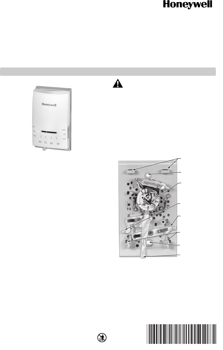
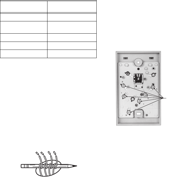
For CT50A, CT51A Installation
!Before removing the old thermostat from the wall, look
at it carefully to locate the heat anticipator adjustment
mechanism. See illustration below to help you
recognize the heat anticipator. Make a note
here _____ of the anticipator setting.
IMPORTANT
Setting the heat anticipator allows the thermo-
stat to maintain accurate temperature control.
MOUNTING CLIPS
(FOR COVER)
MOUNTING CLIPS
(FOR COVER)
TOP MOUNTING
HOLE
ADJUSTABLE HEAT
ANTICIPATOR
SETTING LEVER
(CT50A, CT51A ONLY)
FAN SWITCH
(CT51A ONLY)
SYSTEM SWITCH
(CT51A ONLY)
BOTTOM
MOUNTING HOLE
TEMPERATURE
SETTING LEVER
M11901
CT50A, CT51A, CT53A THERMOSTATS
69-0265ES 2
!Using a pencil point, move the heat anticipator pointer
to the number it was set to on the old thermostat. If you
could not find the anticipator setting on the old
thermostat, use the setting for your type of system
shown in the table below.
NOTES: If the furnace stays on beyond the thermostat set
temperature, move the anticipator pointer down
by 0.1 ampere.
If the furnace shuts off before the set tempera-
ture is reached, move the anticipator pointer up
by 0.1 ampere.
Never adjust the anticipator below 0.3 ampere.
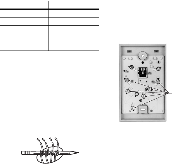
!Loosen screws holding thermostat to the wall and
lift away.
!Disconnect wires from old thermostat or subbase. If
your thermostat has more than 2 wires, as you
disconnect each wire, tape the end and label it with the
letter of the terminal designation to make reconnection
to new thermostat easier. Take care that these wires
do not fall back into the wall opening.
!Retain the old thermostat for reference purposes until
your new thermostat is functioning smoothly.
WIRE AND MOUNT
NEW THERMOSTAT
For CT50A
!Connect one of the 2 wires from the wall to each of the
two terminals on the back of the thermostat. Tighten
the screws.
For CT51A
!Connect 4 wires from the wall to matching terminals on
back of thermostat. Tighten the screws.
!If using CT51A for ELECTRIC heat systems, you must
install a jumper between thermostat terminals 1 and 2.
CT53A
!Connect wires to R and W for 750 mV systems.
Connect to R and Y for 250 or 500 mV systems.
Tighten the screws.
!Grasp the thermostat cover at the top and bottom with
one hand. Pull outward on the top edge of the
thermostat cover until it snaps free of the thermostat
base.
!Carefully remove and discard the red plastic pin
located above the mercury switch. This pin protects
this switch during shipment.
!Fasten thermostat to the wall with one of the screws
supplied, using the top mounting hole.
!Place your level across the top of the thermostat and
level it. Start the second screw, supplied, in the center
of the bottom mounting hole.
!Recheck for level positioning, then firmly tighten both
mounting screws.
Table 1. Heat Anticipator Settings.
Your heating system Heat anticipator setting
Steam 1.2
Hot water heat 0.8
High-efficiency warm air 0.8
Standard warm air 0.4
Electric heat 0.3
M3775
TERMINAL
SCREWS
(CT51A SHOWN)
M11902
CT50A, CT51A, CT53A THERMOSTATS
3 69-0265ES
THERMOSTAT OPERATION
!On the CT51A, the system switch controls as follows:
HEAT—heating system only operates.
OFF—heating and cooling systems are disconnected.
COOL—cooling system only operates.
!The fan switch controls as follows:
AUTO—fan on when heating or cooling system
operates.
ON—fan operates continuously.
NOTE: In the following instruction, disregard cooling
directions if not applicable to your system.
!Turn on power to the heating/cooling system.
!Observe system operation for at least one cycle on
both heating and cooling.
!To observe: Place the system switch at HEAT position
and fan switch at AUTO.
!Move the temperature sensing lever to 10° F (6° C)
above room temperature. The furnace should turn on.
A short warm-up period may be required before the
system fan turns on.
!Place system switch at COOL position and move
temperature sensing lever 10° F (6°C) below room
temperature. The cooling equipment should turn on
and the system fan should turn on.
NOTE: Some systems have a time delay that can pre-
vent operation up to 5 minutes.
!Turn the fan switch to ON. The system fan should turn
on, and operate continuously. The fan should continue
to operate at any system switch or thermostat setting.
CT50A, CT51A, CT53A THERMOSTATS
Automation and Control Solutions
Honeywell International Inc. Honeywell Limited-Honeywell Limitée
1985 Douglas Drive North 35 Dynamic Drive
Golden Valley, MN 55422 Scarborough, Ontario M1V 4Z9
customer.honeywell.com
® U.S. Registered Trademark
© 2005 Honeywell International Inc.
69-0265ES M.S. 12-05 http://yourhome.honeywell.com
LIMITED 1-YEAR WARRANTY
Honeywell warrants this product to be free from defects
in the workmanship or materials, under normal use and
service, for a period of one (1) year from the date of
purchase by the consumer. If at any time during the
warranty period the product is determined to be defective
or malfunctions, Honeywell shall repair or replace it (at
Honeywell's option).
If the product is defective,
(i) return it, with a bill of sale or other dated proof of
purchase, to the place from which you purchased it; or
(ii) call Honeywell Customer Care at 1-800-468-1502.
Customer Care will make the determination whether the
product should be returned to the following address:
Honeywell Return Goods, Dock 4 MN10-3860, 1885
Douglas Dr.N., Golden Valley, MN 55422, or whether a
replacement product can be sent to you.
This warranty does not cover removal or reinstallation
costs. This warranty shall not apply if it is shown by
Honeywell that the defect or malfunction was caused by
damage which occurred while the product was in the
possession of a consumer.
Honeywell's sole responsibility shall be to repair or
replace the product within the terms stated above.
HONEYWELL SHALL NOT BE LIABLE FOR ANY LOSS
OR DAMAGE OF ANY KIND, INCLUDING ANY
INCIDENTAL OR CONSEQUENTIAL DAMAGES
RESULTING, DIRECTLY OR INDIRECTLY, FROM ANY
BREACH OF ANY WARRANTY, EXPRESS OR
IMPLIED, OR ANY OTHER FAILURE OF THIS
PRODUCT. Some states do not allow the exclusion or
limitation of incidental or consequential damages, so this
limitation may not apply to you.
THIS WARRANTY IS THE ONLY EXPRESS
WARRANTY HONEYWELL MAKES ON THIS
PRODUCT. THE DURATION OF ANY IMPLIED
WARRANTIES, INCLUDING THE WARRANTIES OF
MERCHANTABILITY AND FITNESS FOR A
PARTICULAR PURPOSE, IS HEREBY LIMITED TO
THE ONE-YEAR DURATION OF THIS WARRANTY.
Some states do not allow limitations on how long an
implied warranty lasts, so the above limitation may not
apply to you.
This warranty gives you specific legal rights, and you
may have other rights which vary from state to state.
If you have warranty questions, please write
Honeywell Customer Relations, 1985 Douglas Dr,
Golden Valley, MN 55422 or call 1-800-468-1502. In
Canada, write Retail Products ON15-02H, Honeywell
Limited/Honeywell Limitée, 35 Dynamic Drive,
Scarborough, Ontario M1V4Z9.
INSTRUCCIONES DE INSTALACION
69-0265ES
Termostatos
CT50A, CT51A, CT53A
CT51A
Modelo CT50A, sólo calefacción
Compatible con la mayoría de los sistemas de calefacción
a gas y aceite con conexión de dos hilos.
Modelo CT51A, calefacción/refrigeración
Compatible con la mayoría de los sistemas de calefacción
a gas y aceite con conexión de cuatro hilos. No funcionará
con sistemas de bomba de calor.
Modelo CT53A, sólo calefacción milivoltio
Para sistemas de 250, 500, 750 milivoltios.
PREPARACION PARA
LA INSTALACION
Se requieren herramientas de montaje; destornillador,
nivel, pelacables.
EXTRACCION DEL
TERMOSTATO VIEJO
!Comience por apagar el sistema de calefacción
en el panel principal de fusibles. La mayoría de los
sistemas residenciales tienen una caja de interruptores
o un interruptor de circuito para desconectar la
electricidad del calentador.
!Extraiga la tapa del termostato viejo. La tapa
normalmente se levanta cuando se tira firmemente
desde la parte inferior. Si se resiste, busque
el tornillo que traba la tapa.
ADVERTENCIA SOBRE
EL MERCURIO
Si este producto está reemplazando un control
que contiene mercurio en un tubo sellado, no tire
el control viejo a la basura. Comuníquese con
su autoridad local de gestión de desperdicios
para obtener instrucciones respecto del reciclado
y la forma de disposición adecuada.
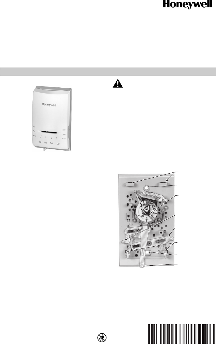
Instalación de los modelos CT50A, CT51A
!Antes de extraer el termostato viejo de la pared,
obsérvelo con cuidado para ubicar el mecanismo
de ajuste del anticipador térmico. Vea la ilustración
que aparece a continuación para reconocer
el anticipador térmico. Haga una nota
aquí _____ del ajuste del anticipador.
IMPORTANTE
Ajustar el anticipador de calor permite que
el termostato mantenga un control preciso
de la temperatura.
SUJETADORES
DE MONTAJE
(PARA LA TAPA)
ORIFICIO DE
MONTAJE INFERIOR
(PARA LA TAPA)
ORIFICIO DE
MONTAJE SUPERIOR
PALANCA DE AJUSTE
DEL ANTICIPADOR
TERMICO AJUSTABLE
(SOLO EN LOS
MODELOS CT50A, CT51A)
INTERRUPTOR DEL
VENTILADOR (SOLO
EN EL MODELO CT51A)
INTERRUPTOR DEL
SISTEMA (SOLO
EN EL MODELO CT51A)
ORIFICIO DE MONTAJE
INFERIOR
PALANCA DE AJUSTE
DE TEMPERATURA
M11901
TERMOSTATOS CT50A, CT51A, CT53A
69-0265ES 2
!Con la punta de un lápiz, mueva el puntero del anticipador
hacia el número en el que estaba el termostato viejo.
Si no puede encontrar el ajuste del anticipador en el
termostato viejo, use el ajuste para su tipo de sistema
que se muestra en la tabla que aparece a continuación.
NOTAS: Si el calentador permanece encendido indepen-
dientemente de la temperatura del termostato,
baje el puntero del anticipador 0,1 amperios.
Si el calentador se apaga antes de llegar
a la temperatura establecida, suba el puntero
del anticipador 0,1 amperios.
Nunca ajuste el anticipador por debajo de los
0,3 amperios.
!Afloje los tornillos que sostienen el termostato
a la pared y levántelo.
!Desconecte los cables del termostato viejo o su base.
Si su termostato tiene más de 2 hilos, cuando desconecta
cada cable, sujete el extremo con cinta adhesiva
y colóquele una etiqueta con la letra de la designación
de la terminal para facilitar la reconexión al nuevo
termostato. Controle que estos cables queden dentro
del orificio de la pared.
!Retenga el termostato viejo a fines de referencia hasta
que su nuevo termostato esté funcionando sin problemas.
CABLES Y MONTAJE DEL
NUEVO TERMOSTATO
Para el modelo CT50A
!Conecte uno de los 2 cables que vienen de la pared
a cada una de las dos terminales de la parte posterior
del termostato. Ajuste los tornillos.
Para el modelo CT51A
!Conecte los 4 cables que vienen de la pared a las
terminales correspondientes que se encuentran
en la parte posterior del termostato. Ajuste los tornillos.
!Si utiliza el modelo CT51A para sistemas de calefacción
ELÉCTRICA debe instalar un puente entre las terminales
1 y 2 del termostato.
Para el modelo CT53A
!Conecte los cables a R y W en los sistemas de 750 mV.
Conecte a R y a Y en los sistemas de 250 ó 500 mV.
Ajuste los tornillos.
!Tome la tapa del termostato por la parte superior
e inferior con una mano. Empuje hacia afuera
en el borde superior de la tapa del termostato hasta
que se suelte de la base del termostato.
!Con cuidado, extraiga la clavija de plástico roja ubicada
encima del interruptor de mercurio. Esta clavija protege
al interruptor durante el envío.
!Ajuste el termostato a la pared con uno de los tornillos
suministrados, utilizando el orificio de montaje superior.
!Coloque su nivel en la parte superior del termostato
y nivélelo. Ajuste el segundo tornillo, suministrado, en la
parte central del orificio de montaje de la parte inferior.
!Vuelva a verificar la posición del nivel, y después ajuste
firmemente ambos tornillos de montaje.
Tabla 1. Ajustes del anticipador térmico.
Su sistema
de calefacción
Ajustes del
anticipador térmico
Vapor 1.2
Calefacción que funciona
con agua caliente
0.8
Aire tibio de alta eficacia 0.8
Aire tibio estándar 0.4
Calefacción eléctrica 0.3
M3775
M11902
TORNILLOS DE
LAS TERMINALES
(SE MUESTRA EL
MODELO CT51A)
TERMOSTATOS CT50A, CT51A, CT53A
3 69-0265ES
FUNCIONAMIENTO DEL TERMOSTATO
!En el modelo CT51A, los interruptores del sistema
controlan lo siguiente:
HEAT—opera el sistema de calefacción.
OFF—desconecta los sistemas de calefacción
y de refrigeración.
COOL—sólo opera el sistema de refrigeración.
!Los interruptores del ventilador controlan lo siguiente:
AUTO—ventilador encendido cuando funciona
el sistema de calefacción o de refrigeración.
ON—el ventilador funciona continuamente.
NOTA: En la siguiente directiva, no considere las
instrucciones de refrigeración si no son aplicables
a su sistema.
!Encienda el sistema de calefacción/refrigeración.
!Observe el funcionamiento del sistema durante por
lo menos un ciclo con ambos sistemas, de calefacción
y de refrigeración.
!Siga los siguientes pasos: Coloque el interruptor del
sistema en la posición CALEFACCION y el interruptor
del ventilador en AUTO.
!Mueva la palanca de la temperatura a 10 ºF (6 ºC)
sobre temperatura ambiente. Debería encenderse
el calentador. Puede ser necesario esperar un período
corto de calentamiento antes de encender el ventilador
del sistema.
!Coloque el interruptor del sistema en la posición
REFRIGERACION y mueva la palanca de temperatura
a 10 ºF (6 ºC) por debajo de la temperatura ambiente.
Se debe encender el equipo de refrigeración y también
el ventilador.
NOTA: Algunos sistemas tienen una demora que puede
impedir su funcionamiento hasta durante 5 minutos.
!Coloque el interruptor del ventilador en ENCENDIDO.
El ventilador del sistema debería encenderse y funcionar
continuamente. El ventilador debe seguir funcionando
con cualquier interruptor del sistema o ajuste del
termostato.
TERMOSTATOS CT50A, CT51A, CT53A
Soluciones para automatización y control
Honeywell International Inc. Honeywell Limited-Honeywell Limitée
1985 Douglas Drive North 35 Dynamic Drive
Golden Valley, MN 55422 Scarborough, Ontario M1V 4Z9
customer.honeywell.com
® Marca registrada de los EE. UU.
© 2005 Honeywell International Inc.
69-0265ES M.S. 12-05 http://yourhome.honeywell.com
GARANTIA LIMITADA A 1 ANO
Honeywell garantiza que este producto no tiene defectos
relativos a la fabricación o a los materiales, si se hace
un uso y se presta un servicio normales, durante un período
de un (1) año a partir de la fecha de compra por el
consumidor. Si en cualquier momento durante el período
de garantía se verifica que el producto tiene un defecto
o mal funcionamiento, Honeywell lo reparará o reemplazará
(a elección de Honeywell).
Si el producto tiene defectos,
(i) devuélvalo, con la factura de venta u otra prueba
de compra fechada, en el lugar donde lo compró; o
(ii) comuníquese con el Centro de atención al cliente
de Honeywell al 1-800-468-1502. Atención al cliente
decidirá si se debe devolver el producto a la siguiente
dirección: Devolución de mercaderías de Honeywell,
Dock 4 MN10-3860, 1885 Douglas Dr. N., Golden Valley,
MN 55422, o si se le puede enviar un producto en reemplazo.
Esta garantía no cubre los costos de extracción
o reinstalación. Esta garantía no se aplicará si Honeywell
demuestra que el defecto o mal funcionamiento estaba
causado por daños ocurridos mientras el producto estaba
en posesión de un consumidor.
La única responsabilidad de Honeywell será reparar
o reemplazar el producto dentro de los plazos establecidos
anteriormente. HONEYWELL NO RESPONDERA POR
LA PERDIDA O DANO DE NINGUN TIPO, INCLUIDO
EL DANO INCIDENTAL O INDIRECTO QUE DERIVADO,
DIRECTA O INDIRECTAMENTE, DEL INCUMPLIMIENTO
DE LAS GARANTIAS, EXPRESAS O IMPLICITAS,
O DE OTRAS FALLAS DE ESTE PRODUCTO. Algunos
estados no permiten la exclusión o limitación del daño
incidental o indirecto, entonces esta limitación puede
no resultar aplicable a su caso.
LA PRESENTE GARANTIA ES LA UNICA GARANTIA
EXPRESA QUE HONEYWELL PROPORCIONA
RESPECTO DE ESTE PRODUCTO. LA DURACION
DE LAS GARANTIAS IMPLICITAS, INCLUIDAS LAS
GARANTIAS DE COMERCIABILIDAD Y APTITUD
PARA UN OBJETIVO PARTICULAR, ESTA LIMITADA
A LA DURACION DE UN ANO DE LA PRESENTE
GARANTIA. Algunos estados no permiten las limitaciones
sobre la duración del período de una garantía implícita,
entonces la limitación anterior puede no resultar aplicable
a su caso.
Esta garantía le brinda derechos legales específicos,
y usted podrá tener otros derechos que varían según
el estado.
Si tiene preguntas sobre la garantía, sírvase escribir
a Honeywell Customer Relations, 1985 Douglas Dr,
Golden Valley, MN 55422 o llamar al 1-800-468-1502.
En Canadá, escriba a Retail Products ON15-02H,
Honeywell Limited/Honeywell Limitée, 35 Dynamic Drive,
Scarborough, Ontario M1V4Z9.
