Honeywell Electronic Fan Coil T6380 Users Manual 95C 10758 Series Thernostat
Electronic Fan Coil T6380 95c-10758
2015-01-23
: Honeywell Honeywell-Electronic-Fan-Coil-T6380-Users-Manual-262063 honeywell-electronic-fan-coil-t6380-users-manual-262063 honeywell pdf
Open the PDF directly: View PDF ![]() .
.
Page Count: 6
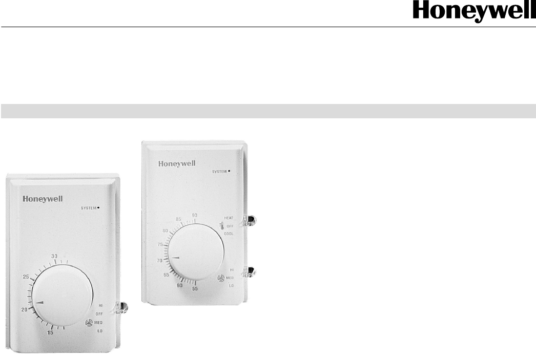
T6380 Series
Electronic Fan Coil Thermostats
APPLICATION
The T6380 series of electronic fan coil thermostats provide
precision line voltage control of fan-forced Heating, Ventilat-
ing and Air Conditioning equipment. Models are available for
cooling-only, manual heat-cool changeover, or remote heat-
cool changeover systems. Hydronic source heat-cool
systems may be two or four-pipe configuration with 0, 1, or 2
valves. Fan control options include constant, cycled, or user-
selectable "On-Auto" operation. Manual fan speed selection
is standard. All models feature an “Off” switch.
PRODUCT DATA
FEATURES
• Electronic temperature sensing provides energy-
efficient, precision operation for maximum comfort.
• Contemporary white sculpted styling.
• Vertical or horizontal mounting configurations.
• Adjustment ranges 55° to 90°F or 13° to 32°C.
• Easy-to-use set point knob.
• LED system status indicator. "OFF" de-energizes all
connected loads.
• Three level fan speed selection.
• Constant, cycled, or on-auto selectable fan operation
available.
• Models for manual or remote heat-cool changeover,
heating-only, or cooling-only systems.
• Models for 2 or 4-pipe systems.
• Rugged molded thermoplastic housing with captive
mounting screws, mounts on single-gang NEMA-
standard (U.S.) electrical box.
• Screw terminal block connections.
• Suitable for inductive-rated loads such as valves,
relays, contactors and fans.
• Range stops and cover locking kit available.
• UL Listed. CSA Certified.
Contents
Specifications .................................................................. 2
Ordering Information ....................................................... 2
Installation ....................................................................... 3
Wiring .............................................................................. 3
Operations .................................................................... 5
Check-out ..................................................................... 5
M.O'D. 8/98 © Honeywell Ltd.—Honeywell Ltée. 1998 Printed in Canada Form Number 95C-10758
T6380 - SPECIFICATIONS, ORDERING INFORMATION
SPECIFICATIONS
MODELS:
Fan Coil System
2-pipe System
• Cooling only
• Heating only
2-pipe Heat-Cool
• Manual Change/Over
• Seasonal, auto C/O
• Seasonal, auto C/O
with aux. electric heat
4-pipe Heat-Cool
• Manual C/O
Electrical Ratings:
3-Speed Fan Operation
Constant Cycled On-Auto
T6383A T6381A T6387A
Fig. 2a Fig. 5a Fig. 8a
T6383A T6381A T6387A
Fig. 2b Fig. 5b Fig. 8a
T6383B T6381B N/A
Fig. 3 Fig. 6
T6383A T6387A
T6381A
Fig. 2c Fig. 5c Fig. 8c
T6383B T6381B N/A
Fig. 4b Fig. 7b
T6383B T6381B N/A
Fig. 4a Fig. 7a
T6380 Series - Power Supply: 110-130 or 208-277 Vac
+10/-15%, 50-60 Hz.
T6381, T6387 - Output Rating, cycled (“Auto”) fan control
50-60 Hz 120 V 208 V 230 V 277 V
Full Load Amps* 3.8 2.1 1.9 1.6
Locked Rotor 22.8 12.6 11.4 9.5
Pilot Duty 125 VA
* Equivalent to NEMA 1/8 horsepower rating for a hermetically-sealed
motor such as a compressor. Allowable connected load must be
determined by adding nameplate full load and locked rotor (inrush) ratings
of all loads.
T6383 – Output Rating, constant fan operation
Thermostat (Heat and Cool outputs):
50-60 Hz 120 V 208 V 230 V 277 V
Full Load Amps 3.8 2.1 1.9 1.6
Locked Rotor A 22.8 12.6 11.4 9.5
Pilot Duty 125 VA
Resistive (heat only) 10.0 A N/A N/A 5.6
Fan (Air Handler):
Operating range:
32 to + 104 F [0 to +40 C], 5 to 95% RH, non-condensing.
Performance Specifications:
Precision: ±1°F temperature swing [0.9°C differential].
Accuracy: 2°F [1°C] droop with 4 A load.
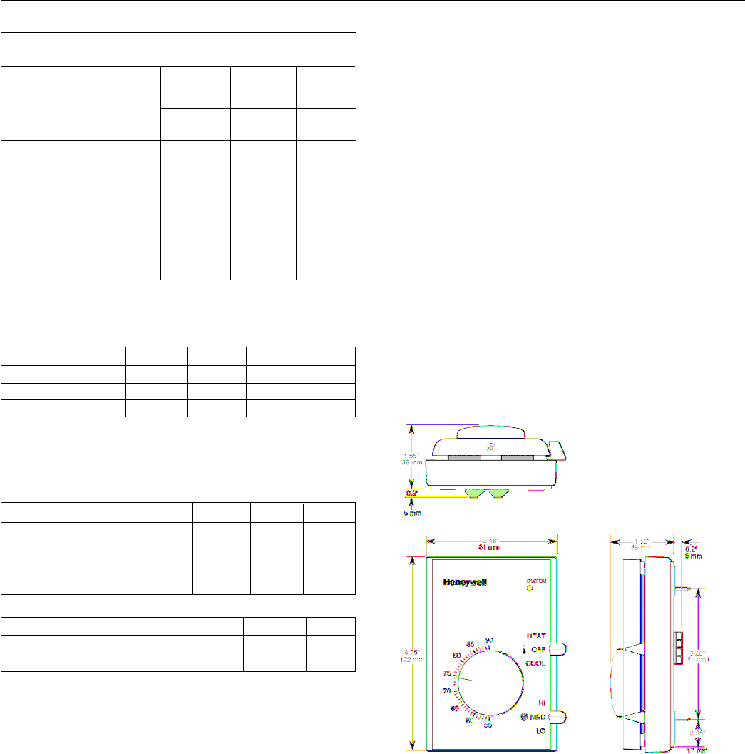
Dimensions:
See Fig. 1 - Nominal Dimensions.
Mounting:
Direct mounting on single-gang NEMA 2" x 3" flush-mount
or 2" x 4" surface-mount electrical box, or on 4" x 4" box
Models available for vertical or horizontal mount.
Wiring Connections:
Screw terminal block suitable for 1 – 14 AWG, 2 – 18 AWG,
or 1 – 1.5 mm2 copper wire.
Approvals:
CSA Certified LR1322
Underwriters Laboratories Listed E47434.
Accessories:
272824A-T6380 Range stop/cover locking kit.
272827A-T6380 replacement cover with Cool-Warmer
Fig. 1 — Nominal dimensions in inches and
millimetres
50-60 Hz 110-130V 208 V 220-240V 277 V
Full Load Amps** 5.8 3.2 2.9 2.4
Locked Rotor 34.8 19.2 17.4 14.4
** Equivalent to NEMA 1/4 horsepower rating for a hermetically-sealed
motor. Allowable load must be determined from fan nameplate
ratings .
† North American national electrical codes require all ungrounded
conductors to electric resistance heating to be broken at the thermostat
OFF setting. The 208V and 230V resistive ratings are not UL approved.
The 230V rating is site-approveable in Canada on 416V 4-wire Wye
distributed systems. The non-inductive rating for 230V “a.c. mains”
with one ungrounded conductor is 6.0A.
ORDERING INFORMATION
Before ordering please determine the following:
1. The body type: 2-way or 3-way
2. The actuator voltage : 24V/50-60Hz
3. The pipe fitting, size, and flow capacity rating (Cv) required.
4. Order Specification Number
5. Accessories, if desired.
If you have additional questions, need further information, or would like to comment on our products or services, please write or phone:
1. Your local Home and Building Control Sales Office (please check the white pages of your phone directory).
2. Honeywell Limited, 155 Gordon Baker Rd., North York, ON M2H 3N7.
In U.S.A. - Honeywell Inc., 1885 Douglas Drive North, Minneapolis, Minnesota 55422-4386 (612) 951-1000. International Sales and Service
Offices in all principal cities of the world. Manufacturing in Australia, Canada, Finland, France, Germany, Japan, Mexico, Netherlands, Spain,
Taiwan, United Kingdom, U.S.A.
2
T6380 - INSTALLATION, WIRING
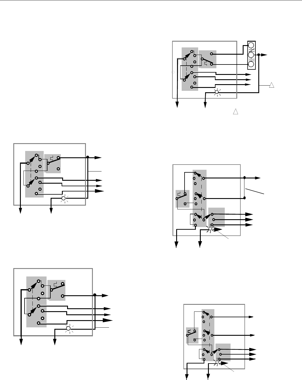
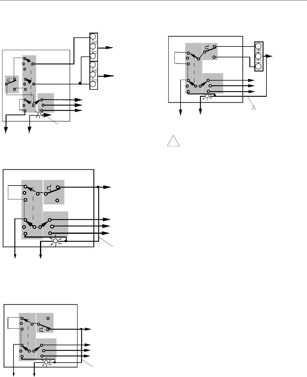
Fig. 2c – T6383A: 2-pipe, heat/cool, seasonal auto-changeover,
INSTALLATION constant fan
.
MOUNTING: T6383A
Mount the thermostat on an inside wall 4’ to 5' [1.5 m] above
the floor. Do not mount where thermostat can be affected by
1
L2
L1(HOT)
FAN
Heat (ORG)
Cool (YEL)
Off
WHT
(VIO)
TOHEAT/COOL
VALVE
FAN
BLK
W
R
B
AQUASTAT
(RED) LO
(BRN) HI
1
2
3
(BLU) MED
1
External jumper
drafts, radiant heat from the sun, or other sources of heat.
T6380's mount on NEMA standard 2"x3" single gang flush or
2"x4" surface mount electrical box, or on 4"x4" box with mud
ring adaptor (not provided).
WIRING
3Internal schematic and external wiring connections are
shown in Fig. 2a through Fig. 8c. Wiring connections may be
made to the 8 position screw terminal block with 1- 14 AWG,
or 2- 18 AWG, solid or stranded copper wires.
(NEUTRAL)
Fig. 2a – T6383A for 2-pipe, constant fan, cooling only
T6383A
Fig. 3 – T6383B: 2-pipe, heat/cool, manual changeover, constant
L2
L1(HOT)
(NEUTRAL)
FAN
(RED)
(BLU)
(BRN)
Heat (ORG)
Cool (YEL)
Off 1
2
3
WHT
(VIO)
BLK
fan
TO COOLING
VALVE
T6383B
WHT
L2
(
NEUTRAL
)
L1
(
HOT
)
Med (BLU)
Hi (BRN)
Lo (RED)
BLK
SYSTEM
FAN
Heat
Off
Cool Heat (ORG)
Cool (YEL) TOHEATING/
COOLING
VALVE
To internal heat/cool
circuits
HI
MED
LO
FAN
External jumper
HI
MED
LO
FAN
External jumpe
r
Fig. 2b – T6383A for 2-pipe, constant fan, heating only
T6383A
L2
L1(HOT)
FAN
(RED)
(BLU)
(BRN)
Heat (ORG)
Cool (YEL)
Off 1
2
3
WHT
(VIO)
BLK
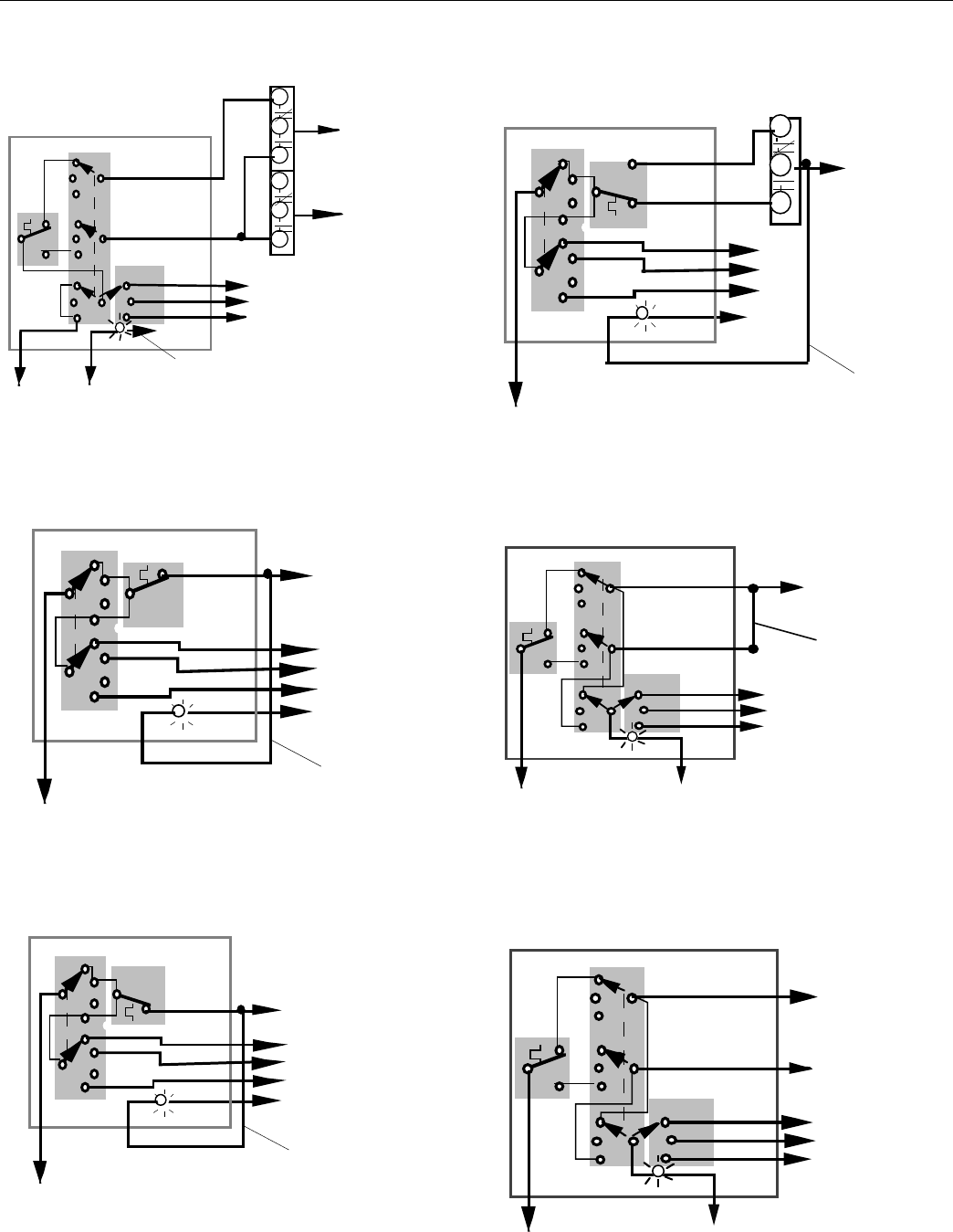
Fig. 4a – T6383B: 4-pipe, heat/cool, manual changeover,
constant fan
TO HEATING
VALVE
T6383B
WHT
L2
(
NEUTRAL
)
L1
(
HOT
)
Med (BLU)
Hi (BRN)
Lo (RED)
BLK
SYSTEM
FAN
Heat
Off
Cool Heat (ORG)
Cool (YEL)
TO COOLING
VALVE
To internal heat/cool
circuits
HI
MED
LO
FAN
External jumper
TO HEATING
VALVE
HI
FAN
MED
(NEUTRAL)
LO
3
T6380
Fig. 4b – T6383B: 2-pipe, heat/cool, auto changeover, with aux. Fig. 5c – T6381A: 2-pipe, heat/cool, auto-changeover, cycled fan
electric heat, constant fan
.
AQUASTAT
T6381A
TO HEAT/ COOL
VALVE
WHT
L2(NEUTRAL)L1(HOT)
Med (BLU)
Hi (BRN)
Lo (RED)
BLK
SYSTEM
FAN
Heat
Off
Cool Heat (ORG)
Cool (YEL)
To internal heat/cool
circuits
HI
MED
LO
FAN
.
W
R
B
W
R
B
T6383B
TO SUPPLEMENTARY
HEAT
FAN
(RED)
(BRN)
Off 1
2
3
WHT
(VIO)
FAN
External jumper
(BLU)
L2 (NEUTRAL)
HI
MED
LO
L1 (HOT)
Heat (ORG)
Cool (YEL)
W
R
B
TO HEATING
/
COOLING VALVE
Fig. 5a – T6381A: 2-pipe, cooling only, cycled fan Fig. 6 – T6381B: 2-pipe, heat/cool, manual changeover, cycled
fan
T6381A T6381B
FAN
(RED)
(BRN)
Heat (ORG)
Cool (YEL)
Off 1
2
3
WHT
(VIO)
TO COOLING
VALVE
BLK
External jumper
(BLU)
L2
HI
MED
LO
L1 (HOT)
.
WHT
L2(NEUTRAL)
L1(HOT)
(BLU)
(BRN)
(RED)
BLK
SYSTEM
FAN
Heat
Off
Cool
Heat (ORG)
Cool (YEL)
FAN
HI
MED
LO
TO HEATING/COOLING
VALVE
External jumper
FAN
(NEUTRAL)
Fig. 5b – T6381A: 2-pipe, heating only, cycled fan Fig. 7a – T6381B: 4-pipe, heat/cool, manual changeover, cycled
fan
T6381A
T6381B
FAN
(RED)
(BRN)
Heat (ORG)
Cool (YEL)
Off 1
2
3
WHT
(VIO)
TO HEATING
VALVE
BLK
(BLU)
L2
(NEUTRAL)
HI
MED
LO
.
WHT
L2(NEUTRAL)
L1(HOT)
(BLU)
(BRN)
(RED)
BLK
SYSTEM
FAN
Heat
Off
Cool
Heat (ORG)
Cool (YEL)
HI
MED
LO
TO COOLING
VALVE
L1 (HOT)
FAN
TO HEATING
VALVE
External jumper
FAN
4
T6380 - OPERATION
Fig. 7b – T6381B: 2-pipe, heat/cool, auto-changeover, cycled fan Fig. 8c – T6387A: 2-pipe, heat/cool, auto-changeover, on–
with aux. heat auto fan
.
T6387A
AQUASTAT
WHT
L2(NEUTRAL)L1(HOT)
Med (BLU)
Hi (BRN)
Lo (RED)
BLK
SYSTEM
FAN
Heat
Off
Cool Heat (ORG)
Cool (YEL)
To internal heat/cool
circuits
HI
MED
LO
FAN
.
W
R
B
W
R
B
T6381B
1
WHT
(BLU)
(BRN)
(RED)
BLK
SYSTEM
FAN
Auto
Off
On
(VIO)
FAN
Cool (YEL)
Heat (ORG)
W
R
B
HI
MED
LO
TO HEAT/ COOL
VALVE
TO SUPPLEMENTARY
HEAT
TOHEAT/COOL
VALVE
External jumper
L1(HOT) L2(NEUTRAL)
! CAUTION
1. Disconnect power supply before connecting
Fig. 8a – T6387A: 2-pipe, cooling only on–auto fan wiring to prevent electrical shock and equipment
damage.
T6387A 2. Never jumper the supply wires or actuator terminals
even temporarily. This may damage the thermostat.
WHT
L2
(
NEUTRAL
)
L1
(
HOT
)
(BLU)
(BRN)
(RED)
BLK
SYSTEM
FAN
Auto
Off
On
(VIO)
Cool (YEL)
Heat (ORG)
External jumper
TO COOLING
VALVE
OPERATION
As the temperature changes, the thermostat makes to
open a valve and/or power a blower to provide heating or
cooling. The speed at which the air is circulated is con-
trolled by the FAN switch. Continuous (ON) or intermittent
HI
FAN
MED
LO
(AUTO) fan operation is determined by model number.
CHECK-OUT
Turn power on. Check out operation according to the
SYSTEM switch present.
• SYSTEM switch OFF de-energizes valve and fan
circuits.
Fig. 8b – T6387A: 2-pipe, heating only on–auto fan Models T6381B,: T6383B
• SYSTEM: HEAT - OFF - COOL
Set the SYSTEM switch to HEAT. Rotate the
T6387A
thermostat knob clockwise to energize the heating
WHT
(BLU)
(BRN)
(RED)
BLK
SYSTEM
FAN
Auto
Off
On
(VIO)
Cool (YEL)
Heat (ORG)
valve and/or fan (fan auto/cycled mode). The
system LED on the thermostat will light when the
heating circuit is energized.
TO HEATING
VALVE
Set the SYSTEM switch to COOL. Rotate the thermo
stat knob counter-clockwise to energize the cooling
valve and/or fan (fan auto/cycled mode). The
system LED on the thermostat will light.
HI
FAN
MED
LO
Model T6387A
• SYSTEM: ON -AUTO - OFF
External jumper
• Set the SYSTEM switch to ON. The valve will
operate on heating or cooling cycle depending on
L1
(
HOT
)
L2
(
NEUTRAL
)
whether hot or chilled water is being supplied. The
fan will run continuously.
Set the SYSTEM to AUTO. The fan will cycle with the
heating or cooling operation.
5

T6380
Models: T6381A; T6383A
• SYSTEM: HI-OFF-MED-LO
• Set the SYSTEM switch to HI. Rotate the thermostat
knob clockwise to energize the heating\cooling valve
and/or fan ( constant or cycled fan). The system
LED on the thermostat will light when the heating or
cooling circuit is energized.
SETTING:
The T6380 temperature scale is marked 55 to 90°F or 13 to
32°C, depending on the model. Set the dial indicator marker
to the desired temperature.
CALIBRATION:
T6380 thermostats are accurately calibrated at the factory
under controlled conditions. Do not attempt to field calibrate
this device.This thermostat has line voltage connections.
Home and Building Control In U.S.A. Helping You Control Your World
Honeywell Ltd. Honeywell Inc.
155 Gordon Baker Road 1985 Douglas Drive North
North York, Ontario M2H 3N7 Golden Valley, MN 55422-3992
Printed in Canada
