Honeywell He360 Installation Information 69 1572 Humidifier Kit
2015-08-26
: Honeywell Honeywell-He360-Installation-Information-803054 honeywell-he360-installation-information-803054 honeywell pdf
Open the PDF directly: View PDF ![]() .
.
Page Count: 8

® U.S. Registered Trademark
Copyright © 2001 Honeywell • •All Rights Reserved
INSTALLATION INSTRUCTIONS
69- 1572
HE360 Humidifier
Installation Kit
WELCOME
To the comfortable world of humidified air. When you use
your Honeywell humidifier, you notice that your skin is not
as dry, and that your scratchy throat and irritated nasal
passages that aggravate allergies and asthma are
steadily improving.
You have also taken the first step in reducing the
zapping
you create when you walk on your carpet and then touch
your TV, computer, metal door knob or your pet. Your
furniture and woodwork are also benefitting from the
difference that humidified air makes.
Congratulations! You have just made a great investment
in improving the comfort of your home.
APPLICATION
This installation kit contains all the parts necessary to
install your new Honeywell HE360 Humidifier.
INSTALLATION
Preparing for the Installation
Be sure to identify all the required (Table 1) accessories
(included) and make sure the appropriate tools are
available before beginning the installation.
Required Accessories (Included)
Required Tools
Tools required for installation include:
• Tin snip.
• Screwdriver.
• Adjustable or open-end wrench.
• Drill, punch or awl.
•Level.
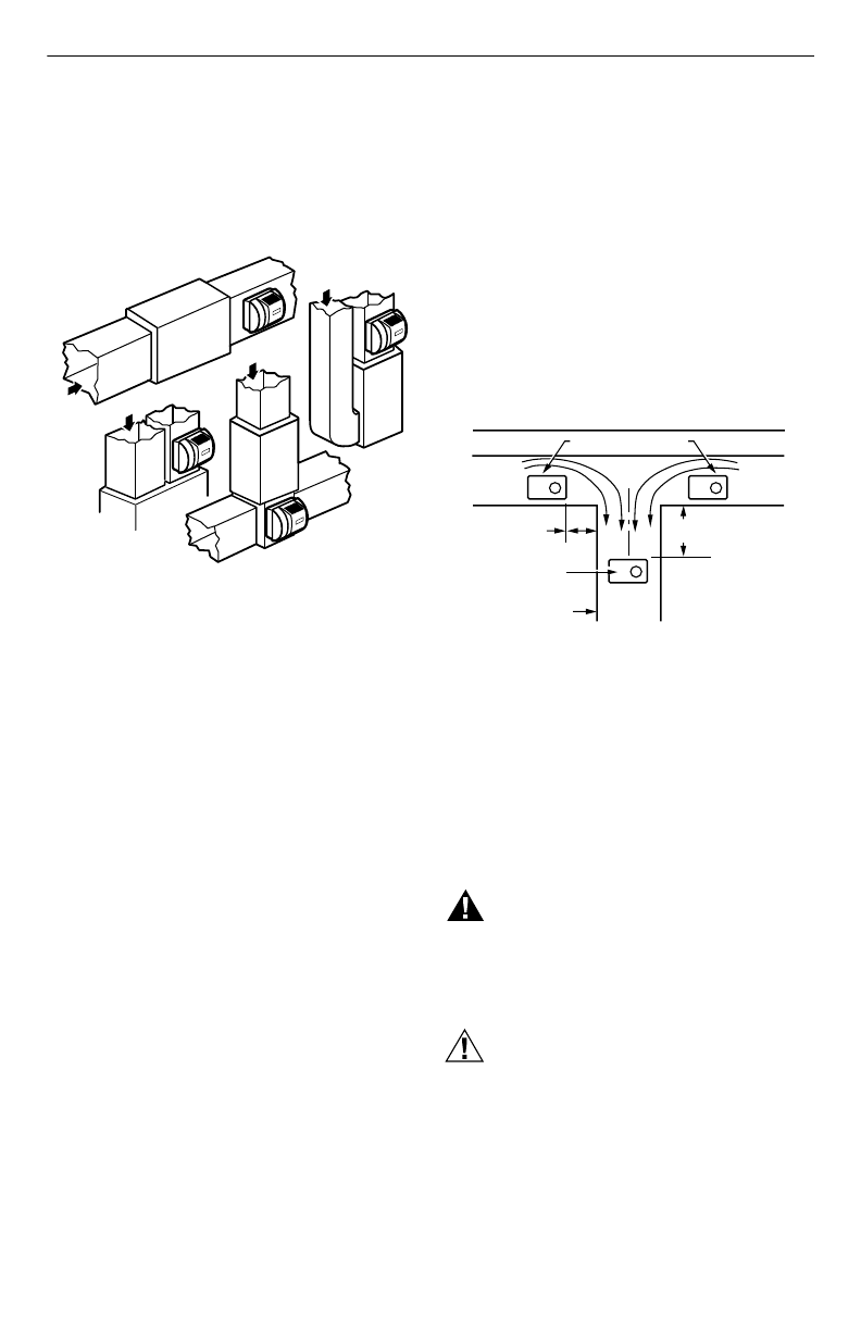
Determining Best Location for Humidifier
• Select a location for the humidifier on the supply
(warm air stream) plenum. See Fig. 1.
• Select a location that cannot damage the air
conditioner A-coil during installation.
• Do not locate the humidifier on the furnace body.
Table 1. Required Accessories.
Quantity Accessory
20 ft (6.2m) 18 gauge, two-strand thermostat wire
20 ft (6.2m) 1/4 in. (6.35 mm) OD feed water tubing
10 ft (3.1m) 1/2 in (12.7 mm) ID drain tubing
1 bag Connecting and mounting hardware:
Wire nuts (4)
No. 8 sheet metal screws (18)
Drain tube clamp
Feed tube mounting clamps (6)
Brass inserts (2)
Plastic compression rings (2)
1 Sail switch
1 roll Duct tape
HE360 HUMIDIFIER INSTALLATION KIT
69-1572 2
• Allow adequate clearance in front of and above the
humidifier so you can easily remove the cover to
perform routine maintenance.
— Mount the humidifier at least 3 in. (78 mm) above
the furnace body to allow adequate space for the
solenoid valve and drain line.
— Mount the humidifier in a conditioned space to
prevent freezing.
Fig. 1. Typical humidifier installation locations.
Selecting Water Supply Location
• Use either hard or soft water in the humidifier and
either hot or cold water. The water flow rate, with the
humidifier running, is 3.5 gal/hr (13 liters/hr) to flush
the pad and provide moisture for evaporation.
• Make sure that the 20 ft (6.2m) of feed water tubing
provided is adequate to connect the water supply
(saddle valve) with the humidifier solenoid valve.
Locating Closest Floor Drain
• Select location with access to a floor drain to provide
drainage for air conditioner condensation and
humidifier drainage.
• If you do not have a drain available, we recommend
that you install the Honeywell Whole House Drum or
Disk Humidifier. Make sure that the 10 ft (3.1m) of
drain tubing is adequate to reach from the humidifier
drain connection to the floor drain.
Selecting Location for Sail Switch
• Select a location for the sail switch in the cold air
return duct where the sail is in the direct path of an
unrestricted air stream.
— Sail switch detects when furnace fan is operating.
• Select a location where the air duct is at least 12 in.
(305 mm) deep and 8 in. (203 mm) wide to allow
operation of the sail without affecting the smooth flow
of air in the duct.
— Airflow at the location can be vertical (up or
down) or horizontal.
IMPORTANT
Mounting the S688 in warm air supply duct can
reduce the sail life.
• Mount the switch at least 6 in. (152 mm) upstream
from an elbow or junction, and at least 15 in.
(381 mm) downstream from an elbow or junction.
• Locate the switch on the opposite side of the duct
from the air entrance. (See Fig. 1-3 in S688
Installation Instructions.)
Selecting Location for Humidistat
• Select a location for the humidistat on the return
plenum or on the wall in the living space.
— Mounting on the return plenum is the easiest
installation for the control wiring circuit.
For return duct mounting, the humidistat should be
mounted upstream from the humidifier or bypass so that
it is properly sensing the relative humidity of the living
space. Locate the control at least 8 in. (203 mm)
upstream from the humidifier in the return air duct. (See
Fig 2.)
Fig. 2. Selecting duct location for humidistat.
Locating Closest 120V Electrical Outlet
• Select location with access to an outlet. If not
available, contact an electrician to have one installed.
• Make sure that the humidifier cord is adequate to
reach from the humidifier to the outlet.
• Make sure that the 20 ft (6.2m) of thermostat wire is
adequate to reach from the humidifier solenoid, to the
sail switch, to the humidistat.
INSTALLING HUMIDIFIER
WARNING
Hazardous Voltage
Can cause personal injury or equipment
damage.
Do not cut or drill into any air conditioning or
electrical accessory.
CAUTION
Sharp Edges Installation Hazard.
Can cause personal injury.
Wear gloves and safety glasses.
1. Turn off power to the air handing system at the cir-
cuit breaker.
2. Draw a level line on the plenum in the location
chosen for the humidifier. (Leveling assures opti-
mal humidifier performance.)
3. Locate the template in the Humidifier Installation
Instructions.
M12808A
HORIZONTAL
DOWN
FLO
LOWBOY
RETURN
RETURN
RETURN
HIGHBOY
RETURN
ALTERNATE LOCATION
RETURN
AIR
RETURN
AIR
6 in. (152 mm)
MINIMUM 15 in. (381 mm)
MINIMUM
BEST
LOCATION
RETURN AIR DUCT M12831
HE360 HUMIDIFIER INSTALLATION KIT
3 69-1572
4. Tape the template in position and trace around the
template.
5. Remove the template and carefully cut the rectan-
gular opening.
6. Disassemble the humidifier; remove the cover and
take out the humidifier pad assembly. See Fig. 3.
Fig. 3. Disassembling humidifier.
7. Make sure the humidifier housing is level, then
position it in the opening so the plastic tabs are in
place on the
lower sheet metal edge
of the open-
ing. Use pliers, as necessary, to flatten cut edges.
See Fig. 4.
8. Secure the humidifier housing to the opening at the
top and bottom using sheet metal screws.
Fig. 4. Installing humidifier on duct.
9. Reinstall the humidifier pad assembly in the humid-
ifier housing.
IMPORTANT
Be sure to reconnect the water feed tube and
ensure that the tube is not pinched or kinked.
10. Hinge the cover in place and secure with the
thumbscrew located at the bottom of the cover.
CONNECTING PLUMBING
Use hot or cold water and either hard or softened water
in the humidifier.
1. Shut off the water.
CAUTION
Chemical Hazard.
Can cause personal injury or equipment
damage.
Do not use any line connected to an air
conditioner.
Do not use gas line.
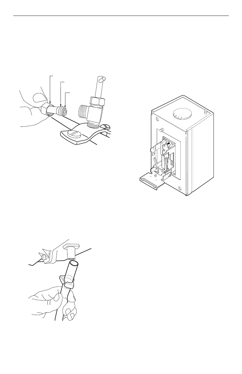
2. Use the self-piercing saddle valve (included) to tap
into the water supply line at the location selected.
See Fig. 5. If tapping into galvanized pipe, drain
line and pre-drill 3/17 in. tap for saddle valve.
NOTE: The saddle valve is not designed to regulate
water flow. The valve is either open or closed.
IMPORTANT
To prevent debris from clogging the solenoid in-
line filter, be sure to install the saddle valve han-
dle pointing toward the ceiling.
Fig. 5. Installing saddle valve.
3. Use 1/4 in. (6 mm) OD tubing and connect the sad-
dle valve to the inlet side of the solenoid valve (see
Fig. 6).
a. Place the brass compression nut over the
tubing.
b. Install brass insert into end of tubing.
c. Slide the plastic compression ring over the
tubing. (Discard copper compression ring pro-
vided with valve.)
NOTE: To prevent leaking, use plastic (Delrin) sleeve
rings with plastic tubing. Use copper sleeve
rings only with copper tubing.
M12809
COVER
ASSEMBLY
HUMIDIFIER
PAD ASSEMBLY
FEED TUBE NOZZLE
WATER
DISTRIBUTION TRAY
HUMIDIFIER
HOUSING
THUMB
SCREW
DUCT
LEVEL
SHEET METAL
SCREWS (4)
PLASTIC
TABS (2)
DRAIN TUBING M20204
OPENING
TO AIR DUCT
M20175
SCREW DRIVER
WATER LINE
HE360 HUMIDIFIER INSTALLATION KIT
69-1572 4
d. Insert the tubing into the solenoid valve fitting
and support the valve while tightening the com-
pression nut.
NOTE: Do not over-tighten the compression nut. Mod-
erate tightness prevents leaking.
e. Repeat steps a. through d. for solenoid valve
fitting.
f. Secure tubing with clamps provided.
Fig. 6. Installing feed tubing.
4. Connect a 1/2 in. (13 mm) drain tube to the humid-
ifier drain fitting and run to the floor drain (see Fig.
7).
a. Slide the drain clamp over the tubing.
b. Push the tubing over the drain nipple on the
humidifier.
c. Hand-tighten the clamp around the tubing to
secure the humidifier drain.
d. Fasten the drain tubing (can use duct tape)
along the route to prevent movement and
ensure downward slope for correct drainage.
NOTE: Cut tubing to correct length so the tubing termi-
nates at the drain.
Fig. 7. Installing drain tubing.
Installing Sail Switch
Adapting Switch to Air Flow Direction
The S688A Sail Switch is provided with two
counterbalancing springs in place as shown in Fig 8.
These springs offset the effect of gravity for air flow
direction.
IMPORTANT:
Do not use the sail switch with both springs
attached. Be sure to select air flow direction and
remove spring(s) not required for installation.
Fig. 8. Adapting sail switch to air flow direction or
mounting position.
•Vertical
downward
air flow: Leave the spring in
place that is attached to the bracket marked Down.
Remove the spring that is attached to the bracket
marked Up.
•Vertical
upward
air flow: Leave the spring in place
that is attached to the bracket marked Up. Remove
the spring that is attached to the bracket marked
Down.
•Horizontal air flow: Remove both springs.
1. Mount the template (provided with the sail switch)
at the desired location.
NOTE: Be sure the arrow (indicating air flow) points in
the correct direction.
a. For horizontal mounting,
level
the long dimen-
sion shown on the template.
b. For vertical mounting,
plumb
the long dimen-
sion.
2. Cut the hole (indicated on the template) in the duct-
work.
3. Center punch the screw holes indicated and drill
out with a 1/8 in. (13 mm) drill.
4. Attach the sail to the switch as shown in Fig 9.
M20176
BRASS COMPRESSION NUT
PLASTIC
COMPRESSION RING
BRASS INSERT
M20177
UP
M3014
HE360 HUMIDIFIER INSTALLATION KIT
5 69-1572
Fig. 9. Attaching sail to switch.
5. Press together the sides of the wire loop. Insert the
sail into the duct. (When in the Off position, the sail
should point into the direction of airflow as shown
in Fig.10.)
Fig. 10. Inserting sail switch in direction of airflow.
6. Secure the switch by using the sheet metal screws
provided.
7. After wiring, snap on the cover.
INSTALLING HUMIDISTAT
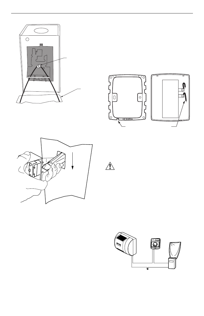
Mounting Duct
1. Apply the template to the duct location chosen for
the humidistat. Make sure the template is level
before drilling the holes.
2. Refer to the template (provided with the H8908
Humidistat Installation Instructions) to drill the con-
trol assembly opening and mounting holes for the
H8908.
3. Remove the H8908 case from the base.
4. Position the foam gasket on the H8908 base.
5. Position the base on the duct with the arrow up.
6. Secure the base to the duct using the four
1 in. (25 mm) mounting screws provided with humi-
distat.
7. Connect the low-voltage wires to the leads and
replace the H8908 case. See Fig. 11.
NOTE: For wall mounting instructions, see the H8908
Installation Instructions.
Fig. 11. Humidistat base and rear view.
WIRING
CAUTION
Hazardous Voltage.
Can cause personal injury or equipment
damage.
Disconnect power supply before installing or
servicing equipment.
IMPORTANT
All wiring must comply with applicable local
code, ordinances and regulations.
Wire the humidifier solenoid valve, sail switch, humidistat
and transformer.See Fig. 12.
Fig. 12. Wiring the controls.
– LOOSEN SETSCREW
– INSERT SAIL
– TIGHTEN SETSCREW
SAIL
M20181
M20178
AIRFLOW
M20179
WIRE SLOT HUMIDISTAT WIRES
HUMIDISTAT BASE REAR OF HUMIDISTAT
Humidity Control
Régulateur d'humidité
-20 ¡F
-10 ¡F
0 ¡F
+10 ¡F
+20 ¡F
Over 20 ¡F
15%
20%
25%
30%
35%
40%
HUMIDITY
SETTING
OUTDOOR
TEMPERATURE
-30 ¡C
-25 ¡C
-20 ¡C
-10 ¡C
-5 ¡C
Over 0 ¡C
M20205
BLACK
WHITEWHITE
HUMIDIFIER
SOLENOID
VALVE
HUMIDISTAT SAIL
SWITCH

HE360 HUMIDIFIER INSTALLATION KIT
69-1572 6
1. Run the two-strand thermostat wire from the
humidifier to the humidistat, and from the humidis-
tat to the sail switch.
2. Cut lengths of thermostat wire to reach between
components, leaving adequate wire at both ends
for connections.
NOTE: Humidistat and sail switch can be wired in any
order.
3. At the humidifier, connect the black and white con-
ductors to the two yellow humidifer wires. (The red
wires from the humidifier are not used.)
4. At the humidistat, connect both black conductors to
the two humidistat terminals. Use a wire nut to con-
nect together the two white conductors.
5. At the sail switch, connect the black and white con-
ductors to the Com and NO sail switch terminals
(NC terminal is not used).
TESTING HUMIDIFIER OPERATION
Checklist
❑Humidifier is level.
❑Control wiring was reviewed using circuit diagram.
❑Humidifier is plugged in.
❑Feed line has no kinks.
❑Drain line slopes continuously down and ends at floor
drain.
❑Water hose inside humidifier is connected to
PerfectFlow™ water distribution tray.
After installation use the following steps to check the
humidifier operation:
1. Turn on the power and the water supply
2. Turn the H8908 Humidity Control to On and turn on
the heat by setting the thermostat to 10ºF (6ºC)
above room temperature.
IMPORTANT
The furnace blower must be on to activate the
humidifier.
3. Make sure that water is flowing out of the drain
hose. If water does not flow, see Troubleshooting
Your Humidifier section.
4. Check for leaks.
5. Reset the thermostat and H8908 Humidity Control
to a comfortable setting for automatic operation.

HE360 HUMIDIFIER INSTALLATION KIT
7 69-1572
TROUBLESHOOTING YOUR HUMIDIFIER (TABLE 2)
Table 2. Troubleshooting Humidifier.
Problem What to look for What to do
Water leakage Leaking joints. Shut off water.
Tighten connections.
Brass tubing inserts Verify that brass tubing inserts are
used.
Saddle valve leaking. Verify rubber pad is installed on
saddle valve.
No water to drain. Electrical Verify control circuit wiring.
Check all connections.
Humidistat Turn humidistat up and down and
listen for contact to click.
Humidifier power Verify that outlet has power.
Sail switch Remove sail cover; turn on furnace
fan and listen for faint click.
Verify that sail can move freely in
duct; check sail switch instructions
to trim sail, if necessary.
Solenoid After verifying other wiring
components, turn on furnace fan,
turn humidistat up and down, and
listen for solenoid to click.
Plumbing Verify plumbing connections.
Check for kinks.
Saddle valve Verify that needle pierces water
line and then backs out needle to
open valve.
Humidifier Remove cover and verify that water
flows into distribution tray.
Drain tubing Verify no obstructions.

69-1572 G.H. 09-01 www.honeywell.com/yourhome
HE360 HUMIDIFIER INSTALLATION KIT
Printed in U.S.A. on recycled
paper containing at least 10%
post-consumer paper fibers.
Home and Building Control Home and Building Control
Honeywell Honeywell Limited-Honeywell Limitée
1985 Douglas Drive North 35 Dynamic Drive
Golden Valley, MN 55422 Scarborough, Ontario
M1V 4Z9
