Honeywell Smoke Alarm Ms 9600Ls Users Manual 52646
Honeywell Smoke Alarm MS-9600UDLSE 52646
MS-9600LSC to the manual e6e24c5e-8765-418f-8e2c-08cf313555fe
2015-01-23
: Honeywell Honeywell-Honeywell-Smoke-Alarm-Ms-9600Ls-Users-Manual-261864 honeywell-honeywell-smoke-alarm-ms-9600ls-users-manual-261864 honeywell pdf
Open the PDF directly: View PDF ![]() .
.
Page Count: 208 [warning: Documents this large are best viewed by clicking the View PDF Link!]
- Table of Contents
- Section 1: Product Description
- 1.1 Inventory
- 1.2 Features and Options
- 1.3 Specifications
- 1.4 Controls and Indicators
- 1.5 Circuits
- 1.6 Components
- 1.7 Optional Modules
- 1.8 Accessories
- 1.9 Getting Started
- Section 2: Installation
- Section 3: Programming
- 3.1 Programming Data Entry
- 3.2 User Programming
- 3.3 Initial Power-up
- 3.4 Programming Screens Description
- 3.5 Programming and Passwords
- 3.6 Master Programming Level
- 3.7 Maintenance Programming Level
- Section 4: Operating Instructions
- 4.1 Panel Control Buttons
- 4.2 LED Indicators
- 4.3 Normal Operation
- 4.4 Trouble Operation
- 4.5 Alarm Operation
- 4.6 Supervisory Operation
- 4.7 Process Monitor Operation
- 4.8 Hazard Condition Operation
- 4.9 Medical Alert Condition Operation
- 4.10 Programmed Zone Operation
- 4.11 Disable/Enable Operation
- 4.12 Waterflow Circuits Operation
- 4.13 Detector Functions
- 4.14 Time Functions: Real-Time Clock
- 4.15 NAC Operation
- 4.16 Synchronized NAC Operation
- 4.17 Coded Operation
- 4.18 Presignal
- 4.19 Positive Alarm Sequence
- 4.20 Special System Timers
- 4.21 Walktest
- 4.22 Read Status
- Section 5: Power Supply Calculations
- Appendix A: Software Zones
- Appendix B: Default Programming
- Appendix C: NFPA Standard-Specific Requirements
- Appendix D: FACP with Keltron
- Appendix E: Wire Requirements
- Appendix F: HVAC Control
- Appendix G: Canadian Application
- Index

B2
P/N 52646:B2 ECN 10-098
Document 52646
2/12/2010 Rev:
Addressable Fire Alarm Control Panel
MS-9600LS/MS-9600LSE
MS-9600UDLS/MS-9600UDLSE
MS-9600LSC
Manual
2MS-9600LS Series Manual — P/N 52646:B2 2/12/2010
Fire Alarm System Limitations
While a fire alarm system may lower insurance rates, it is not a substitute for fire insurance!
An automatic fire alarm system—typically made up of
smoke detectors, heat detectors, manual pull stations, audible
warning devices, and a fire alarm control panel with remote
notification capability—can provide early warning of a develop-
ing fire. Such a system, however, does not assure protection
against property damage or loss of life resulting from a fire.
The Manufacturer recommends that smoke and/or heat detec-
tors be located throughout a protected premise following the
recommendations of the National Fire Protection Association
Standard 72 (NFPA 72), manufacturer's recommendations,
State and local codes, and the recommendations contained in
the Guides for Proper Use of System Smoke Detectors, which
are made available at no charge to all installing dealers.
These documents can be found at http://www.systemsen-
sor.com/html/applicat.html. A study by the Federal Emer-
gency Management Agency (an agency of the United States
government) indicated that smoke detectors may not go off in
as many as 35% of all fires. While fire alarm systems are
designed to provide early warning against fire, they do not
guarantee warning or protection against fire. A fire alarm sys-
tem may not provide timely or adequate warning, or simply
may not function, for a variety of reasons:
Smoke detectors may not sense fire where smoke cannot
reach the detectors such as in chimneys, in or behind walls, on
roofs, or on the other side of closed doors. Smoke detectors
also may not sense a fire on another level or floor of a building.
A second-floor detector, for example, may not sense a first-
floor or basement fire.
Particles of combustion or “smoke” from a developing fire
may not reach the sensing chambers of smoke detectors
because:
• Barriers such as closed or partially closed doors, walls, or
chimneys may inhibit particle or smoke flow.
• Smoke particles may become “cold,” stratify, and not reach
the ceiling or upper walls where detectors are located.
• Smoke particles may be blown away from detectors by air
outlets.
• Smoke particles may be drawn into air returns before
reaching the detector.
The amount of “smoke” present may be insufficient to alarm
smoke detectors. Smoke detectors are designed to alarm at
various levels of smoke density. If such density levels are not
created by a developing fire at the location of detectors, the
detectors will not go into alarm.
Smoke detectors, even when working properly, have sensing
limitations. Detectors that have photoelectronic sensing
chambers tend to detect smoldering fires better than flaming
fires, which have little visible smoke. Detectors that have ion-
izing-type sensing chambers tend to detect fast-flaming fires
better than smoldering fires. Because fires develop in different
ways and are often unpredictable in their growth, neither type
of detector is necessarily best and a given type of detector
may not provide adequate warning of a fire.
Smoke detectors cannot be expected to provide adequate
warning of fires caused by arson, children playing with
matches (especially in bedrooms), smoking in bed, and violent
explosions (caused by escaping gas, improper storage of
flammable materials, etc.).
Heat detectors do not sense particles of combustion and
alarm only when heat on their sensors increases at a predeter-
mined rate or reaches a predetermined level. Rate-of-rise
heat detectors may be subject to reduced sensitivity over time.
For this reason, the rate-of-rise feature of each detector
should be tested at least once per year by a qualified fire pro-
tection specialist. Heat detectors are designed to protect
property, not life.
IMPORTANT! Smoke detectors must be installed in the
same room as the control panel and in rooms used by the sys-
tem for the connection of alarm transmission wiring, communi-
cations, signaling, and/or power. If detectors are not so
located, a developing fire may damage the alarm system, crip-
pling its ability to report a fire.
Audible warning devices such as bells may not alert people
if these devices are located on the other side of closed or
partly open doors or are located on another floor of a building.
Any warning device may fail to alert people with a disability or
those who have recently consumed drugs, alcohol or medica-
tion. Please note that:
• Strobes can, under certain circumstances, cause seizures
in people with conditions such as epilepsy.
• Studies have shown that certain people, even when they
hear a fire alarm signal, do not respond or comprehend the
meaning of the signal. It is the property owner's responsi-
bility to conduct fire drills and other training exercise to
make people aware of fire alarm signals and instruct them
on the proper reaction to alarm signals.
• In rare instances, the sounding of a warning device can
cause temporary or permanent hearing loss.
A fire alarm system will not operate without any electrical
power. If AC power fails, the system will operate from standby
batteries only for a specified time and only if the batteries have
been properly maintained and replaced regularly.
Equipment used in the system may not be technically com-
patible with the control panel. It is essential to use only equip-
ment listed for service with your control panel.
Telephone lines needed to transmit alarm signals from a
premise to a central monitoring station may be out of service
or temporarily disabled. For added protection against tele-
phone line failure, backup radio transmission systems are rec-
ommended.
The most common cause of fire alarm malfunction is inade-
quate maintenance. To keep the entire fire alarm system in
excellent working order, ongoing maintenance is required per
the manufacturer's recommendations, and UL and NFPA stan-
dards. At a minimum, the requirements of NFPA 72 shall be
followed. Environments with large amounts of dust, dirt or
high air velocity require more frequent maintenance. A main-
tenance agreement should be arranged through the local man-
ufacturer's representative. Maintenance should be scheduled
monthly or as required by National and/or local fire codes and
should be performed by authorized professional fire alarm
installers only. Adequate written records of all inspections
should be kept.
Limit-C1-2-2007

MS-9600LS Series Manual — P/N 52646:B2 2/12/2010 3
Installation Precautions
Adherence to the following will aid in problem-free installation with long-term reliability:
WARNING - Several different sources of power can be
connected to the fire alarm control panel. Disconnect all
sources of power before servicing. Control unit and associ-
ated equipment may be damaged by removing and/or insert-
ing cards, modules, or interconnecting cables while the unit is
energized. Do not attempt to install, service, or operate this
unit until manuals are read and understood.
CAUTION - System Re-acceptance Test after Software
Changes: To ensure proper system operation, this product
must be tested in accordance with NFPA 72 after any pro-
gramming operation or change in site-specific software. Re-
acceptance testing is required after any change, addition or
deletion of system components, or after any modification,
repair or adjustment to system hardware or wiring. All compo-
nents, circuits, system operations, or software functions known
to be affected by a change must be 100% tested. In addition,
to ensure that other operations are not inadvertently affected,
at least 10% of initiating devices that are not directly affected
by the change, up to a maximum of 50 devices, must also be
tested and proper system operation verified.
This system meets NFPA requirements for operation at 0-49º
C/32-120º F and at a relative humidity 93% ± 2% RH (non-
condensing) at 32°C ± 2°C (90°F ± 3°F). However, the useful
life of the system's standby batteries and the electronic com-
ponents may be adversely affected by extreme temperature
ranges and humidity. Therefore, it is recommended that this
system and its peripherals be installed in an environment with
a normal room temperature of 15-27º C/60-80º F.
Verify that wire sizes are adequate for all initiating and indi-
cating device loops. Most devices cannot tolerate more than a
10% I.R. drop from the specified device voltage.
Like all solid state electronic devices, this system may
operate erratically or can be damaged when subjected to light-
ning induced transients. Although no system is completely
immune from lightning transients and interference, proper
grounding will reduce susceptibility. Overhead or outside aerial
wiring is not recommended, due to an increased susceptibility
to nearby lightning strikes. Consult with the Technical Ser-
vices Department if any problems are anticipated or encoun-
tered.
Disconnect AC power and batteries prior to removing or
inserting circuit boards. Failure to do so can damage circuits.
Remove all electronic assemblies prior to any drilling, filing,
reaming, or punching of the enclosure. When possible, make
all cable entries from the sides or rear. Before making modifi-
cations, verify that they will not interfere with battery, trans-
former, or printed circuit board location.
Do not tighten screw terminals more than 9 in-lbs. Over-
tightening may damage threads, resulting in reduced terminal
contact pressure and difficulty with screw terminal removal.
This system contains static-sensitive components.
Always ground yourself with a proper wrist strap before han-
dling any circuits so that static charges are removed from the
body. Use static suppressive packaging to protect electronic
assemblies removed from the unit.
Follow the instructions in the installation, operating, and pro-
gramming manuals. These instructions must be followed to
avoid damage to the control panel and associated equipment.
FACP operation and reliability depend upon proper installation.
Precau-D1-9-2005
FCC Warning
WARNING: This equipment generates, uses, and can
radiate radio frequency energy and if not installed and
used in accordance with the instruction manual may
cause interference to radio communications. It has been
tested and found to comply with the limits for class A
computing devices pursuant to Subpart B of Part 15 of
FCC Rules, which is designed to provide reasonable
protection against such interference when devices are
operated in a commercial environment. Operation of this
equipment in a residential area is likely to cause interfer-
ence, in which case the user will be required to correct
the interference at his or her own expense.
Canadian Requirements
This digital apparatus does not exceed the Class A limits
for radiation noise emissions from digital apparatus set
out in the Radio Interference Regulations of the Cana-
dian Department of Communications.
Le present appareil numerique n'emet pas de bruits
radioelectriques depassant les limites applicables aux
appareils numeriques de la classe A prescrites dans le
Reglement sur le brouillage radioelectrique edicte par le
ministere des Communications du Canada.
LiteSpeed™ is a trademark; and FireLite® Alarms is a registered trademark of Honeywell International Inc. Microsoft® and Windows® are registered
trademarks of the Microsoft Corporation.
©Tuesday, August 14, 2012 9:31 am by Honeywell International Inc. All rights reserved. Unauthorized use of this document is strictly prohibited.
4MS-9600LS Series Manual — P/N 52646:B2 2/12/2010
Software Downloads
In order to supply the latest features and functionality in fire alarm and life safety technology to our customers, we make
frequent upgrades to the embedded software in our products. To ensure that you are installing and programming the latest
features, we strongly recommend that you download the most current version of software for each product prior to
commissioning any system. Contact Technical Support with any questions about software and the appropriate version for
a specific application.
Documentation Feedback
Your feedback helps us keep our documentation up-to-date and accurate. If you have any comments or suggestions about
our online Help or printed manuals, you can email us.
Please include the following information:
•Product name and version number (if applicable)
•Printed manual or online Help
•Topic Title (for online Help)
•Page number (for printed manual)
•Brief description of content you think should be improved or corrected
•Your suggestion for how to correct/improve documentation
Send email messages to:
FireSystems.TechPubs@honeywell.com
Please note this email address is for documentation feedback only. If you have any technical issues, please contact
Technical Services.
MS-9600LS Series Manual — P/N 52646:B2 2/12/2010 5
Table of Contents
Section 1: Product Description .............................................................................................13
1.1: Inventory......................................................................................................................................................13
1.2: Features and Options ...................................................................................................................................13
1.3: Specifications...............................................................................................................................................15
1.3.1: Current Availability...........................................................................................................................17
1.4: Controls and Indicators................................................................................................................................17
1.5: Circuits.........................................................................................................................................................18
1.6: Components .................................................................................................................................................19
1.6.1: Intelligent Addressable Detectors: Newer Series ..............................................................................20
1.6.2: Intelligent Addressable Modules: Newer Series ...............................................................................20
1.6.3: 300 Series Intelligent Addressable Devices ......................................................................................20
1.6.4: Addressable Device Accessories .......................................................................................................20
1.7: Optional Modules ........................................................................................................................................21
1.8: Accessories ..................................................................................................................................................21
1.8.1: PS-Tools Programming Utility..........................................................................................................21
1.8.2: Dress Panel: DP-9692........................................................................................................................22
1.8.3: TR-CE Trim Ring..............................................................................................................................22
1.8.4: Battery Box........................................................................................................................................22
1.8.5: Battery Charger..................................................................................................................................22
CHG-75 Battery Charger......................................................................................................................22
CHG-120 Battery Charger....................................................................................................................22
1.8.6: New ANN-BUS Annunciators/Devices ............................................................................................23
ANN-BUS Wiring ................................................................................................................................23
ANN-BUS Device Addressing.............................................................................................................26
ANN-80 Remote Fire Annunciator ......................................................................................................27
ANN-S/PG Serial/Parallel Interface Installation..................................................................................30
ANN-I/O LED Driver Module* ...........................................................................................................32
ANN-LED Annunciator Module*........................................................................................................34
ANN-RLY Annunciator Module..........................................................................................................36
ANN-BUS Audio Panel Control ..........................................................................................................38
1.8.7: Legacy ACS Annunciators ................................................................................................................40
1.9: Getting Started .............................................................................................................................................40
Section 2: Installation............................................................................................................. 42
2.1: Mounting......................................................................................................................................................42
2.2: Power ...........................................................................................................................................................46
2.2.1: AC Power and Earth Ground Connection .........................................................................................46
2.2.2: Battery Power ....................................................................................................................................46
2.2.3: Special Application DC Power Output Connection ..........................................................................47
2.3: Relays ..........................................................................................................................................................47
2.4: Notification Appliance Circuits...................................................................................................................47
2.4.1: Configuring NACs.............................................................................................................................48
2.4.2: Style Y (Class B) NAC Wiring .........................................................................................................49
2.4.3: Style Z (Class A) NAC Wiring..........................................................................................................49
2.5: Power-limited Wiring Requirements ...........................................................................................................50
2.6: Optional Modules and Devices....................................................................................................................51
2.6.1: DACT-UD2 Installation ...................................................................................................................52
2.6.2: 4XTMF Transmitter Module Installation ..........................................................................................55
2.6.3: Auxiliary Trouble Input (J16 & J17).................................................................................................57
2.6.4: SLC-2LS Expander Module ..............................................................................................................57
2.6.5: Printer/PC ..........................................................................................................................................58
2.6.6: Annunciators......................................................................................................................................59
Legacy ACM-8RF Relay Control Module...........................................................................................59
Legacy ACM Series Annunciators.......................................................................................................60

Table of Contents
6MS-9600LS Series Manual — P/N 52646:B2 2/12/2010
Section 3: Programming ........................................................................................................ 61
3.1: Programming Data Entry .............................................................................................................................61
3.2: User Programming .......................................................................................................................................62
3.3: Initial Power-up............................................................................................................................................63
3.4: Programming Screens Description ..............................................................................................................63
3.5: Programming and Passwords.......................................................................................................................63
3.6: Master Programming Level .........................................................................................................................65
3.6.1: Autoprogram......................................................................................................................................66
3.6.2: Point Program ....................................................................................................................................67
Detector Programming..........................................................................................................................67
Module Programming...........................................................................................................................78
3.6.3: Zone Setup .........................................................................................................................................95
Enable ...................................................................................................................................................95
Disable ..................................................................................................................................................96
Zone 97, 98 and 99 ...............................................................................................................................96
Zones Installed......................................................................................................................................97
Zones Enabled ......................................................................................................................................97
Zones Disabled .....................................................................................................................................97
Zone Type.............................................................................................................................................98
Zones Available....................................................................................................................................99
3.6.4: Loop Setup.........................................................................................................................................99
Loop Selection ......................................................................................................................................99
Loop Protocol .....................................................................................................................................100
3.6.5: System Setup ...................................................................................................................................100
Trouble Reminder...............................................................................................................................101
Banner.................................................................................................................................................101
Time-Date...........................................................................................................................................103
Timers.................................................................................................................................................105
NAC (Notification Appliance Circuit) ...............................................................................................107
Relays .................................................................................................................................................112
Canadian Option .................................................................................................................................113
Waterflow Silenceable........................................................................................................................114
3.6.6: Verify Loops....................................................................................................................................114
3.6.7: History .............................................................................................................................................115
View Events........................................................................................................................................115
Erase History ......................................................................................................................................115
3.6.8: Walktest ...........................................................................................................................................116
3.6.9: Option Modules ..............................................................................................................................117
Annunciators/UDACT........................................................................................................................118
On Board DACT.................................................................................................................................134
Printer/PC ...........................................................................................................................................134
3.6.10: Password Change...........................................................................................................................135
3.6.11: Clear Program................................................................................................................................136
3.6.12: Program Check ..............................................................................................................................137
3.7: Maintenance Programming Level..............................................................................................................138
3.7.1: Disable Point....................................................................................................................................139
3.7.2: History .............................................................................................................................................140
3.7.3: Program Check ................................................................................................................................141
3.7.4: Walktest ...........................................................................................................................................142
3.7.5: System..............................................................................................................................................143
3.7.6: Zone Setup .......................................................................................................................................144
Zones Installed....................................................................................................................................146
Zones Enabled ....................................................................................................................................146
Zones Disabled ...................................................................................................................................147
Zone Type...........................................................................................................................................147
Zones Available..................................................................................................................................148
Zone Message .....................................................................................................................................149

Table of Contents
MS-9600LS Series Manual — P/N 52646:B2 2/12/2010 7
Section 4: Operating Instructions .......................................................................................150
4.1: Panel Control Buttons................................................................................................................................150
4.1.1: Acknowledge/Step...........................................................................................................................150
4.1.2: Alarm Silence ..................................................................................................................................150
4.1.3: Drill/Hold 2 Sec...............................................................................................................................150
4.1.4: Reset ................................................................................................................................................150
4.2: LED Indicators...........................................................................................................................................150
4.3: Normal Operation ......................................................................................................................................151
4.4: Trouble Operation......................................................................................................................................152
4.5: Alarm Operation ........................................................................................................................................153
4.6: Supervisory Operation ...............................................................................................................................154
4.7: Process Monitor Operation ........................................................................................................................155
4.8: Hazard Condition Operation......................................................................................................................155
4.9: Medical Alert Condition Operation ...........................................................................................................156
4.10: Programmed Zone Operation ..................................................................................................................156
4.11: Disable/Enable Operation ........................................................................................................................156
4.12: Waterflow Circuits Operation..................................................................................................................156
4.13: Detector Functions...................................................................................................................................156
4.14: Time Functions: Real-Time Clock...........................................................................................................157
4.15: NAC Operation ........................................................................................................................................157
4.16: Synchronized NAC Operation .................................................................................................................157
4.17: Coded Operation......................................................................................................................................157
4.18: Presignal ..................................................................................................................................................158
4.19: Positive Alarm Sequence.........................................................................................................................158
4.20: Special System Timers.............................................................................................................................159
4.20.1: Silence Inhibit Timer.....................................................................................................................159
4.20.2: Autosilence Timer .........................................................................................................................159
4.20.3: Trouble Reminder..........................................................................................................................159
4.20.4: Waterflow Retard Timer................................................................................................................159
4.20.5: Alarm Verification.........................................................................................................................159
4.21: Walktest ...................................................................................................................................................160
4.22: Read Status ..............................................................................................................................................160
4.22.1: System Point..................................................................................................................................162
4.22.2: Zones .............................................................................................................................................163
4.22.3: Power.............................................................................................................................................164
4.22.4: Trouble Reminder..........................................................................................................................165
4.22.5: Timers............................................................................................................................................165
4.22.6: NAC...............................................................................................................................................166
4.22.7: Relays ............................................................................................................................................166
4.22.8: Program Check ..............................................................................................................................167
4.22.9: History ...........................................................................................................................................167
4.22.10: Annunciators................................................................................................................................167
4.22.11: Phone Line...................................................................................................................................169
4.22.12: Central Station .............................................................................................................................169
4.22.13: Service Terminal..........................................................................................................................170
4.22.14: Printer/PC ....................................................................................................................................170
4.22.15: Print .............................................................................................................................................171
4.22.16: Time-Date....................................................................................................................................173
Section 5: Power Supply Calculations................................................................................ 174
5.1: Overview....................................................................................................................................................174
5.2: Calculating the AC Branch Circuit............................................................................................................174
5.3: Calculating the System Current Draw .......................................................................................................174
5.3.1: Overview .........................................................................................................................................174
5.3.2: How to Use Table 5.3 on page 176 to Calculate System Current Draw .........................................175
5.4: Calculating the Battery Size ......................................................................................................................177
5.4.1: NFPA Battery Requirements ...........................................................................................................177

Table of Contents
8MS-9600LS Series Manual — P/N 52646:B2 2/12/2010
5.4.2: Selecting and Locating Batteries .....................................................................................................177
Appendix A: Software Zones............................................................................................... 178
A.1: Correlations...............................................................................................................................................178
Appendix B: Default Programming ..................................................................................... 186
Appendix C: NFPA Standard-Specific Requirements ....................................................... 187
C.1: Central Station/Remote Station Transmitter: Connection to FACP Dry Contacts ....................................193
C.2: MBT-1 Municipal Box Trip - Silenceable.................................................................................................194
Appendix D: FACP with Keltron .......................................................................................... 195
Appendix E: Wire Requirements ......................................................................................... 196
E.1: NAC Wiring...............................................................................................................................................197
Appendix F: HVAC Control .................................................................................................. 198
F.1: Control Module Operation .........................................................................................................................198
F.1.1: HVAC SHUTDN.............................................................................................................................198
F.2: Monitor Module Operation ........................................................................................................................198
F.2.1: HVAC RESTART ...........................................................................................................................198
F.2.2: HVAC OVRRIDE ...........................................................................................................................199
Appendix G: Canadian Application..................................................................................... 200
Index ...................................................................................................................................... 201

MS-9600LS Series Manual — P/N 52646:B2 2/12/2010 9
It is imperative that the installer understand the requirements of the Authority Having Jurisdiction
(AHJ) and be familiar with the standards set forth by the following regulatory agencies:
• Underwriters Laboratories Standards
• NFPA 72 National Fire Alarm Code
• CAN/ULC - S527-99 Standard for Control Units for Fire Alarm Systems
NFPA Standards
NFPA 72 National Fire Alarm Code
NFPA 70 National Electrical Code
Underwriters Laboratories Documents:
UL 38 Manually Actuated Signaling Boxes
UL 217 Smoke Detectors, Single and Multiple Station
UL 228 Door Closers–Holders for Fire Protective Signaling Systems
UL 268 Smoke Detectors for Fire Protective Signaling Systems
UL 268A Smoke Detectors for Duct Applications
UL 346 Waterflow Indicators for Fire Protective Signaling Systems
UL 464 Audible Signaling Appliances
UL 521 Heat Detectors for Fire Protective Signaling Systems
ANSI/UL 864, Control Units and Accessories for Fire Alarm Systems
UL 1481 Power Supplies for Fire Protective Signaling Systems
UL 1610 Central Station Burglar Alarm Units
UL 1638 Visual Signaling Appliances
UL 1971 Signaling Devices for Hearing Impaired
UL 2017 General-Purpose Signaling Devices and System
CAN/ULC - S524-01 Standard for Installation of Fire Alarm Systems
CAN/ULC - S527-99 Standard for Control Units for Fire Alarm Systems
CAN\ULC - S559-04 Equipment for Fire Signal Receiving Centers and Systems
CAN\ULC - S561-03 Installation and Services for Fire Signal Receiving Centers and Systems
Note: MS-9600LSE/MS-9600UDLSE is not ULC listed for Canadian applications
This Class (A) digital apparatus complies with Canadian ICES-003.
Cet appareil numérique de la classe (A) est conforme à la norme NMB-003 du Canada.
FM Approved to ANSI/UL 864
Other:
EIA-232E Serial Interface Standard
EIA-485 Serial Interface Standard
NEC Article 250 Grounding
NEC Article 300 Wiring Methods
NEC Article 760 Fire Protective Signaling Systems
Applicable Local and State Building Codes
Requirements of the Local Authority Having Jurisdiction (LAHJ)
Fire-Lite Documents:
Fire-Lite Device Compatibility Document #15384
SLC Wiring Manual Document #51309
ACS Series Annunciators Document #51480
411UD Communicator/Transmitter Document #50759
411UDAC Communicator/Transmitter Document #51073
CHG-120F Battery Charger Document #50888
CHG-75 Battery Charger Document #51315
LDM Series Lamp Driver Modules Document #50055
LCD-80F Remote Fire Annunciator Document #51338
ACM-8RF Relay Control Module Document #50362
DACT-UD2 Manual Document #53037
IDACT Communicator/Transmitter Document #53109
ANN-80 Installation Document Document #52749
ANN-(R)LED Installation Document Document #53032
ANN-I/O Installation Document Document #151416
ANN-RLY Installation Document Document #53033
ANN-S/PG Installation Document Document #151417
ACC-25/50(ZS/T) Manual Document #51889
This product has been certified to comply with the requirements in the ANSI/UL 864, Standard for Control
Units and Accessories for Fire Alarm Systems, 9th Edition. Operation of this product with products not tested
for ANSI/UL 864, 9th Edition has not been evaluated. Such operation requires the approval of the local
Authority Having Jurisdiction (AHJ).
Before proceeding, the installer should be familiar with the following documents.
10 MS-9600LS Series Manual — P/N 52646:B2 2/12/2010
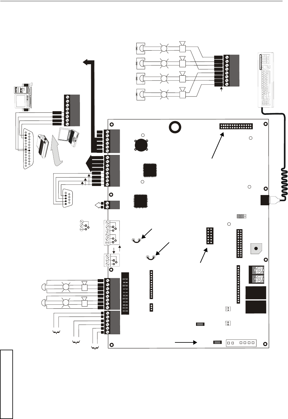
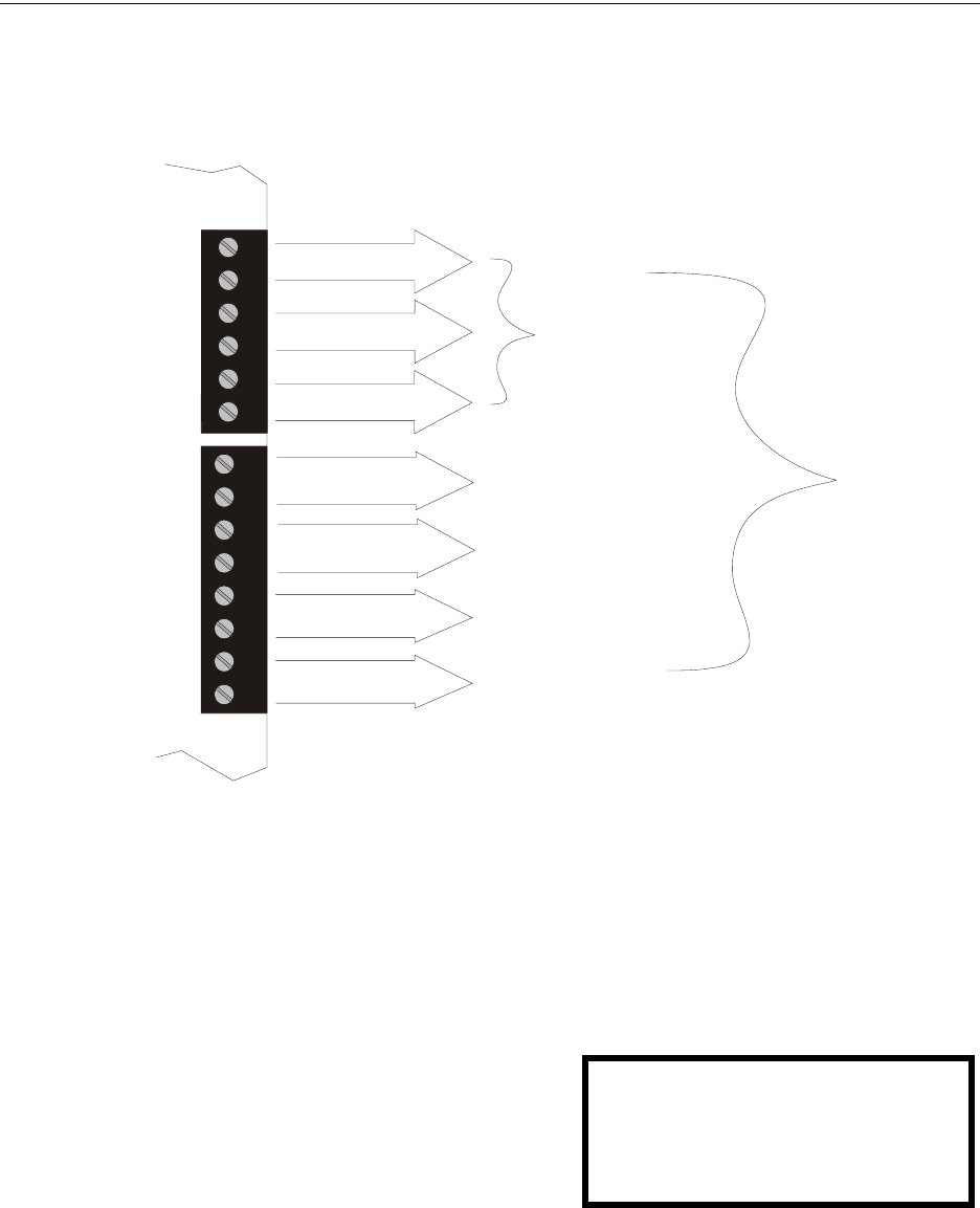
+BATTERY-
LCD DISPLAY
KEYPAD I/F
OPT DACT
J
3
J2
TB2
TB3
JP3
JP2
S
W
1
JP5
JP6
J17
J16
J6
J8
J
7
J10
J11
REMOVE TO
DISABLE
LOCAL
CHARGER
DISABLE
GND FLT
S
L
C
O
P
T
4XTMF OPT BD
TB4
T
B
4
JP8
TB5
T
B
6
T
B
7
D
B
9
F
T
B
8
2
1
4
3
6
5
+++B
+
B
+
B
+
B
+
B
-
B
-
B
-
B
-
1
1
A
+A
+
A
-
A
-
s
h
i
e
l
d
---
-
NO NC C NC NO C NO NC C
5 4 3 2 1
9 8 7 6
T
XR
C
V
D
T
R
5 4 3 2 1
25 24 23 22 21 20 19 18 17 16 15 14
9 8 7 613 12 11 10
+
-
I
N
+
O
U
T
+
I
N
-
O
U
T
-
B
+
B
-
BA
+
A
-
A
NC NO C
+
+
+
+
+
+
+
+
+
+
+
+
+
+
+
+
+
+
T
X
R
C
V
D
T
R
G
N
D
G
N
D
B
+
B
-
B
+
B
-
3
3
2
2
4
4
TB1
J1
9600udleslayout.wmf
PS2 Keyboard Interface
Flash Memory Load Enable Switch
UP is normal position for switch
DOWN position allows loading of
factory software upgrades
Connector for Optional 2nd
Signaling Line Circuit
Connector for Optional
Onboard DACT-UD
Battery
24 VDC, 26 Amp Hour maximum
(supervised, nonpower-limited)
Auxiliary
Trouble Inputs
#1 2
To disable ground fault detection,
remove jumper/shunt from JP2.
Remove JP3 jumper to disable the FACP
battery charger when using external charger.
JP8- Install NACKEY board in proper
orientation to configure NACs 4
StyleY or 2 Style Z circuits
Connectors for 4XTMF Option Module
Cut this jumper to enable
Supervisory relay when
4XMTF is installed.
Cut this jumper to supervise
the 4XMTF when installed
(see J10 & J11)
(*Factory default relay programming
as shown on circuit board)
circuit number
ELRs 4.7K, 1/2W
NAC #1 NAC #2 NAC #3 NAC #4
Notification Applicance Circuits
Power-limited, supervised circuits
NAC #1, #2, #3, & #4, Style Y (Class B)
3.0 amps max per circuit
JP8 configured for Class B
using NACKEY card
(factory default configuration)
SLC Loop
(Supervised Power-limited)
Refer to the SLC Wring
Manual for detailed
information on wiring
addressable devices for
Style 4, 6, and 7
TERM
(EIA-485)
to LCD-80F
EIA-232 to printer or
personal computer
Power-limited
for EDP-listed equipment
or personal computer with
FACP Upload/Downlad
Utility. 50 foot maximum
within same room.
OR
2 Programmable Relays &
1 Fixed Trouble Relay
(nonsupervised)
Contact Ratings:
2.0 amps @ 30VDC (resistive)
0.5 amp @ 30 VAC (resistive)
Contacts show in normal condi-
tion (AC power with no alarm,
trouble, or supervisory activity).
A fail-safe trouble relay switches
to the NO position during
trouble conditions and
under loss all power.
ACN/ANN-BUS
(EIA-485)
to annunciators
(power-limited,
supervised)
Red
White
Green
Black
Alarm*
NO NC C
Trouble Supervisory*
NO NC C NO NC C
Notification Appliance Circuits
Special Application Power
Power-limited, supervised circuits
NAC #1 & #2 Sytle Z (Class A)
3.0 amps max per circuit
JP8 configured for Class A
using NACKEY card
(See Style Y illustrated
near right edge of board)
NAC #1 NAC #2
Special Application Power
DC Power Outputs (24 VDC)
Power-limited, nonsupervised circuits
Supervise with a power supervision
relay EOLR-1
Nonresettable Power #2 - 24 VDC
filtered, power-limited, (1.5 amps
maximum) Supervision required.
Suitable for powering annunciators.
Nonresettable Power #1 - 24 VDC
filtered, power-limited, (1.5 amps
maximum) Supervision required.
Suitable for powering annunciators.
Resettable Power - 24 VDC filtered,
power-limited, (1.5 amps maximum)
to smoke detectors.
Supervision required.
Important: Removing Ground
Fault Disable jumper JP2 voids
UL/NFPA Style/Class
identification for circuits.
Remove jumper JP2 only with
AHJ (Authority Having
Jurisdiction) approval
Basic System Connections
MS-9600LS Series Manual — P/N 52646:B2 2/12/2010 11
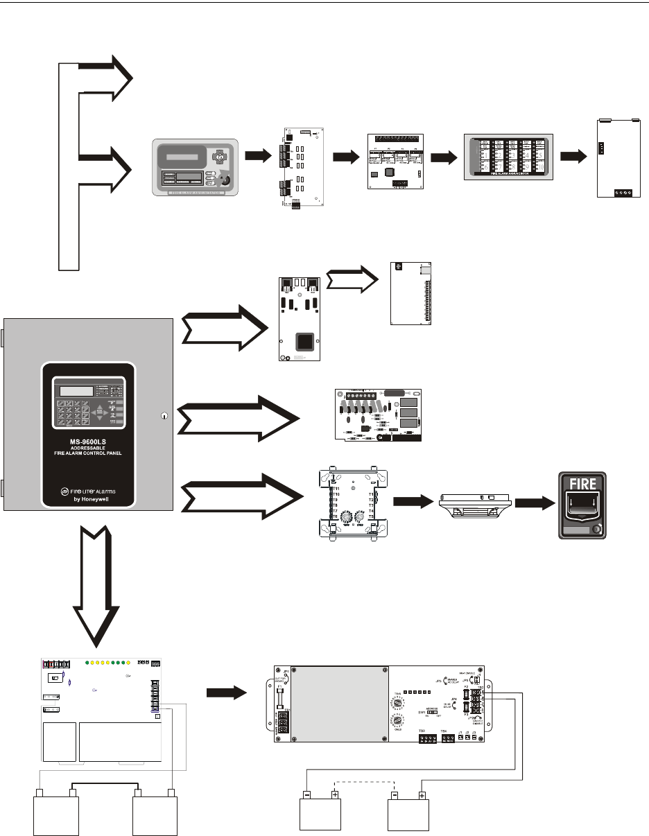
Peripheral Devices and Their Documents:
Addressable Devices and SLC Wiring
Doc. # 51309
CHG-120F Charger
Doc. # 50888
SLC Loop
Battery Connector TB2
9600LSperi.wmf
CHG-75 Charger
Doc. # 51315
DACT-UD2
Communicator
Doc. # 53037
J2 Connector
ANN (EIA-485) TB6
ANN-(R)LED
LED Display
Doc. #53032
ANN-I/O
LED Driver
Doc. #151416
ANN-RLY
Form-C Relay Card
Doc. #53033
ANN-S/PG
Printer Driver
Doc. #151417
ANN-80
Text Annunciator
Doc. #52749
4XTMF
Reverse Polarity
module
J10, J11 Connectors
IPDACT
Internet Communicator
Doc. # 53109
Audio Control for ACC-25/50(ZS/T) Audio-Command-Center Doc. #51889
12 MS-9600LS Series Manual — P/N 52646:B2 2/12/2010
Notes

MS-9600LS Series Manual — P/N 52646:B2 2/12/2010 13
Section 1: Product Description
The MS-9600LS and MS-9600UDLS are compact, cost effective, intelligent addressable FACPs
(Fire Alarm Control Panels) with an extensive list of powerful features. The combination of
Fire•Lite’s newer series devices and legacy 300 Series devices, along with the MS-9600LS or MS-
9600UDLS FACP, offer the latest in fire protection technology. The FLPS-7 power supply is a sep-
arate board while all other electronics are contained on a single main circuit board. Both boards are
mounted to a chassis and housed in a metal cabinet, providing a complete fire control system for
most applications. Optional modules, which plug into the main circuit board, are available for spe-
cial functions. Available accessories include LED, graphic and LCD annunciators, reverse polar-
ity/city box transmitter, digital alarm communicator/transmitter, SLC expansion module, local and
remote upload/download software and remote power expansion.
The MS-9600UDLS includes a factory installed DACT-UD2 Digital Alarm Communicator Trans-
mitter. Refer to “DACT-UD2 Installation” on page 52 and to the DACT-UD2 Manual Document
#53037, which is supplied with the FACP, for DACT wiring and programming information. The
DACT transmits system status (alarm, troubles, AC loss, etc.) to a Central Station via the public
switched telephone network. It also allows remote programming or interrogation of the control
panel using the PS-Tools Upload/Download utility via the public switched telephone network.
Local programming and interrogation is also possible for the MS-9600UDLS using the PS-Tools
and the USB port J4 on the DACT-UD2. The MS-9600LS can be programmed and interrogated
locally using the serial port at TB7. Any personal computer with Windows® XP or greater and
compatible modem with a speed of 2400 baud or faster and PS-Tools software may serve as a Ser-
vice Terminal. This allows download of the entire program or upload of the entire program, history
file, walktest data, current status and system voltages.
The MS-9600LSC is a ULC approved Canadian version of the FACP which offers the same fea-
tures as the MS-9600LS, but is supplied standard with a DP-9692 dress panel. Refer to “Canadian
Option” on page 113 for a full description.
The MS-9600LSE and MS-9600UDLSE offer the same features as the MS-9600LS and MS-
9600UDLS but allow connection to 220/240 VAC input.
1.1 Inventory
When the FACP shipment is received, check to make certain that all parts have been included in the
shipment. The FACP shipment should consist of one of each of the following:
• main circuit board with display
• FLPS-7 Power Supply
• chassis (with main circuit board and power supply mounted)
• backbox with door and dress panel
• plastic bag containing screws, cables, key, etc.
• manual
1.2 Features and Options
• New LiteSpeed™ polling protocol for faster SLC response time
• SLC operates up to 10,000 ft. (3,000 m) in LiteSpeed mode with twisted, unshielded wire or
3,000 ft (900 m) with untwisted, unshielded wire
• Single standard addressable SLC loop which meets NFPA Style 4, 6 and 7 requirements
NOTE: Unless otherwise specified, the terms FACP, MS-9600LS and MS-9600UDLS are used
in this manual to refer to all versions of the FACPs.

14 MS-9600LS Series Manual — P/N 52646:B2 2/12/2010
Product Description Features and Options
• Optional module for adding a second SLC loop which meets NFPA Style 4, 6 and 7
requirements
• 318 addressable device capacity for each SLC loop (159 detectors and 159 control/monitor
modules)
• 99 software zones
• Up to four onboard NACs (Notification Appliance Circuits):
four Style Y (Class B) or two Style Z (Class A)
• Additional NAC capability using control modules
• 7.0 amps total power for NACs and 24 VDC auxiliary power outputs in alarm
• Two programmable relay outputs and one fixed trouble relay
• EIA-232 Printer/PC interface (variable baud rate)
• 80-character LCD display (backlit)
• Real-time clock/calendar with daylight savings time control
• History file with 1,000 event capacity
• Advanced fire technology features:
• Automatic drift compensation
• Maintenance alert
• Detector sensitivity test capability (NFPA 72 compliant)
• Automatic device type-code verification
• Point trouble identification
• Waterflow selection per module point
• Alarm verification selection per detector point
• Walktest, silent or audible
• PAS (Positive Alarm Sequence) and Pre-signal per point (NFPA 72 compliant)
• New ANN-BUS Annunciators/Modules (ACS annunciators cannot be used when ANN-BUS
annunciators/modules are connected)
• ANN-80 Remote Liquid Crystal Display point annunciator
• ANN-I/O LED Driver Module
• ANN-LED Alarm, Trouble, Supervisory Annunciator (minimum of one required for
Canadian applications)
• ANN-RLED Alarm Annunciator
• ANN-S/PG Serial/Parallel Printer Module
• ANN-RLY Form-C Relay Module
• Automated activation of the ACC-25/50(ZS/T) Audio-Command-Center
• Legacy ACS/Term Annunciators: (ANN-BUS annunciator/modules cannot be used when
ACS/Term annunciators are connected)
• ACM Series-LED Zone Annunciators
• LDM Graphic Annunciator Series
• LCD-80F Liquid Crystal Display point annunciator (LCD-80FC for Canadian applications)
• ACM-8RF Relay Module
• Silence inhibit timer option per NAC
• Autosilence timer option per NAC
• Continuous, March Time, Temporal or California code for main circuit board NACs with two-
stage capability
• Selectable strobe synchronization per NAC
• Remote Acknowledge, Alarm Silence, Reset and Drill via addressable modules, legacy ACS
annunciators or ANN-80 Remote annunciator

MS-9600LS Series Manual — P/N 52646:B2 2/12/2010 15
Specifications Product Description
• Auto-program (learn mode) reduces installation time. Reports two devices set to the same
address
• Password and key-protected nonvolatile memory
• User programmable password
• Fully programmable from local keypad or keyboard or local PC
• Compatible with Fire•Lite’s newer series addressable devices (LiteSpeed and CLIP Mode) -
Refer to SLC Wiring Manual for listing of all compatible addressable devices
• Compatible with legacy Fire•Lite’s 300 Series devices (CLIP Mode only) - Refer to SLC
Wiring Manual for listing of all compatible addressable devices
• Optional 4XTMF module (conventional reverse polarity/city box transmitter)
• Optional DACT-UD2 Digital Alarm Communicator Transmitter, reports up to 99 zones or 636
points (all devices) to a UL listed Central Station. The DACT-UD2 is supplied standard with
the MS-9600UDLS/E
• Optional PK-CD (contains PS-Tools utility) for local or remote Upload/Download of program
and data.
• Optional DP-9692 dress panel (required for Canadian applications)
1.3 Specifications
AC Power - TB1 of Power Supply Board
MS-9600LS(C) & MS-9600UDLS: 120 VAC, 50/60 Hz, 3.0 amps (L1=Hot, L2=Neutral)
MS-9600LSE & MS-9600UDLSE: 240 VAC, 50 Hz, 1.5 amps (L1=Hot Leg 1, L2=Hot Leg 2)
Wire size: minimum 14 AWG (2.00 mm2) with 600 V insulation
Battery (Sealed Lead Acid Only) - TB2
Maximum Charging Circuit: Normal Flat Charge - 27.6 VDC @ 1.00 amp
Maximum Battery Size: 26 Amp Hour
Minimum Battery Size: 12 Amp Hour
(FACP cabinet holds maximum of two 18 Amp Hour batteries. For greater than 18 Amp Hour up
to 26 Amp Hour batteries, use BB26 Battery Box)
For greater than 26 Amp Hour up to 75 Amp Hour batteries, use the CHG-75 Battery Charger and
BB26 or BB-55F Battery Box. For greater than 75 Amp Hour up to 120 Amp Hour batteries, use
the CHG-120F Battery Charger and BB-55F Battery Box.
Jumper JP3, on the FACP main circuit board, must be removed to disable the FACP battery char-
ger when using the CHG-75 or CHG-120F.
Communication Loop - (Standard ) TB8 and (Optional SLC Expander Module) J3
24 VDC nominal, 27.6 VDC maximum
Maximum length - refer to “Wire Requirements” on page 196
Maximum loop current is 400 mA (short circuit) or 100 mA (normal)
Maximum loop resistance is 40 ohms
Supervised and power-limited
Refer to SLC Wiring Manual for wiring information
Notification Appliance Circuits - TB4
Special Application power
Power-limited circuitry, supervised
NAC wiring requirements, refer to “NAC Wiring” on page 197
Nominal operating voltage: 24 VDC
Current-limit: fuseless, electronic, power-limited circuitry
NOTE: When installing SLC wiring in conduit, each loop must be installed in separate conduit.

16 MS-9600LS Series Manual — P/N 52646:B2 2/12/2010
Product Description Specifications
Maximum signaling current per circuit: 3.00 amps (see Figure 1.1 on page 17)
End-of-Line Resistor: 4.7 k, ½ watt (P/N 71252 UL listed) for NACs
Refer to Device Compatibility Document for listed compatible devices
Two Programmable and One Fixed Output Relay - TB1 & TB5
Contact rating: 2.0 amps @ 30 VDC (resistive), 0.5 amps @ 30 VAC (resistive)
Form-C relays
Refer to Figure 2.5 on page 47 for information on power-limited wiring for relay circuits
Four-Wire Resettable Special Application Smoke Detector Power (24 VDC nominal) -
TB3, Terminals 1 (+) & 2 (-)
Maximum ripple voltage: 10 mVRMS
Up to 1.5 amps is available for powering 4-wire smoke detectors (see Figure 1.1)
Power-limited circuit, nonsupervised
Refer to Device Compatibility Document for listed compatible devices
Nonresettable Special Application Power #1 (24 VDC Nominal) -
TB3, Terminals 3 (+) & 4 (-)
Maximum ripple voltage: 10mVRMS
Total DC current available from each output is up to 1.5 amps (see Figure 1.1)
Power-limited circuit, nonsupervised
Nonresettable Special Application Power #2 (24 VDC Nominal) -
TB3, Terminals 5 (+) & 6 (-)
Maximum ripple voltage: 10mVRMS
Total DC current available from each output is up to 1.5 amps (see Figure 1.1)
Power-limited circuit, nonsupervised
EIA-485 (ACS/ANN-BUS) - TB6
ACS/ANN annunciator connector, Terminal 1 (+) and Terminal 2 (-)
EIA-485 (TERM) - TB7
Terminal Mode annunciator connector, Terminal 5 (In +), 6 (In -), 7 (Out +), 8 (Out -)
Supervised, power-limited.
EIA-232 Serial - TB7
Local serial PC/Printer Connector, Terminal 1 (Transmit), 2 (Receive), 3 (DTR), 4 (Ground)
Non-supervised, power-limited.
MS-9600LS Series Manual — P/N 52646:B2 2/12/2010 17
Controls and Indicators Product Description
1.3.1 Current Availability
The following figure illustrates the maximum current that is possible for each panel circuit and the
total current available from the FACP power supply.
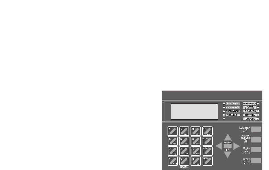
1.4 Controls and Indicators
LCD Display
The FACP uses an 80-character (4 lines X 20
characters) high viewing angle LCD display.
The display includes a long life LED backlight
that remains illuminated. If AC power is lost and
the system is not in alarm, the LED backlight will
turn off to conserve batteries.
LED Indicators
LED indicators are provided to annunciate the following conditions:
• AC Power (green)
• Fire Alarm (red)
• Supervisory (yellow)
• Trouble (yellow)
1
2
3
4
5
6
7
8
1
2
3
4
5
6
TB4
TB3
Figure 1.1 Current Availability
powerdist9600ls2.wmf
*The combined output current of all Special Applications Power circuits cannot exceed 1.5 amps in standby. Each
circuit is capable of delivering the full 1.5 amps individually.
Refer to the battery calculations section for additional information.
1.5 amps max
per circuit
1.5 amps max
per circuit
1.5 amps max
per circuit
3 amps max
per circuit
3 amps max
per circuit
3 amps max
per circuit
3 amps max
per circuit
Standby
1.5 Amps Max*
per panel
Resettable Special
Application Power
for 4-wire smoke detectors
Alarm
7 Amps Max
per panel
Resettable Special
Application Power
Power #1
Resettable Special
Application Power
Power #2
NAC 1
Style Y or Z
NAC 2
Style Y or Z
NAC 3
Style Y only
NAC 4
Style Y only
HONEYWELL
LIFE SAFETY
SYSTEM ALL NORMAL
10:00A 020102
18 MS-9600LS Series Manual — P/N 52646:B2 2/12/2010
Product Description Circuits
• Maintenance/presignal (yellow)
• Alarm Silenced signals (yellow)
• Disabled (yellow)
• Battery fault (yellow)
• Ground fault (yellow)
Key Panel
Mounted on the main circuit board, the key panel includes a window for the LCD display and LED
indicators as listed above. The key panel, which is visible with the cabinet door closed, has 25
keys, including a 16 key alpha-numeric pad similar to a telephone keypad.
Function keys:
• Acknowledge/Step
• Alarm Silence
• Drill
• Reset (lamp test)
Service/program keys:
• Keys labeled 1 to 9
• * key
• # key
• 0 (recall) key
• 1st Event key
• Clear key
• Escape key
• Mode key
• Four cursor keys (up, down, left and right)
• Enter key
Local Piezo Sounder
A piezo sounder provides separate and distinct pulse rates for alarm, trouble and supervisory condi-
tions.
1.5 Circuits
SLC Communication Loop
One SLC loop is provided standard on the FACP main circuit board. A second SLC loop is avail-
able by plugging the optional SLC module into connector J3 on the main circuit board. SLC loops,
configurable for NFPA Style 4, 6 or 7, provide communication to addressable detectors, monitor
(initiating device) and control (output device) modules. Refer to the SLC Wiring Manual for infor-
mation on wiring devices.
Output Circuits
The following output circuits are available on the FACP:
• Special Application Power
• 24 VDC Resettable (smoke detector power) output - 1.5 amps maximum
• 24 VDC Nonresettable power output #1 - 1.5 amps maximum
• 24 VDC Nonresettable power output #2 - 1.5 amps maximum
• 24 VDC Battery Charger (up to 26 AH batteries)
Figure 1.2 Membrane/Display Panel
9600kypd.wmf

MS-9600LS Series Manual — P/N 52646:B2 2/12/2010 19
Components Product Description
NAC (Notification Appliance Circuits)
Up to four NACs are provided with various programmable features:
• four Style Y (Class B) NACs
OR
• two Style Z (Class A) NACs
Relays
One fixed and two fully programmable Form-C dry contact relays are provided. The fixed fail-safe
relay monitors system trouble and the two programmable relays are factory default programmed for
system alarm and system supervisory. Contacts are rated 2.0 amps @ 30 VDC (resistive) and 0.5
amps @ 30 VAC (resistive). The programmable relays can be programmed for the following oper-
ations:
• fire alarm
• trouble
• supervisory
• supervisory auto-resettable
• DACT communication failure
• process monitor
• process monitor auto-resettable
• hazard alert
• medical alert
•AC loss
Auxiliary Trouble Inputs
Auxiliary Trouble Inputs can be connected to trouble bus outputs from auxiliary equipment, such as
power supplies or normally-open dry contacts of a trouble relay to allow monitoring by the FACP.
1.6 Components
Main Circuit Board
The main circuit board contains the system’s CPU and other primary components and wiring inter-
face connectors. Optional modules plug in and are mounted to the main circuit board. The circuit
board is delivered mounted to a chassis which must be mounted to the backbox. Refer to the circuit
board illustration on Page 10.
FLPS-7 Power Supply
The FLPS-7 Power Supply is provided as a separate module which is delivered mounted to a chas-
sis which must be mounted to the backbox and connected to the main circuit board.
Cabinet
The FACP cabinet is red with a navy blue front overlay.
The backbox provides space for two batteries (up to 18 Amp Hour).
Ample knockouts are provided for system wiring. Also available is an
optional dress panel DP-9692, which mounts to the inside of the cabinet
(required by ULC for Canadian applications).
Batteries
Batteries must be sealed lead acid type. The FACP cabinet provides space for two batteries (up to
18 Amp Hour). Batteries larger than 18 Amp Hour up to 26 Amp Hour require use of the BB-26 or
similar UL listed battery cabinet. The CHG-75 can be used for charging 26 to 75 AH batteries and
ms-9600LS.wmf

20 MS-9600LS Series Manual — P/N 52646:B2 2/12/2010
Product Description Components
the BB-26 can be used for housing the batteries. The CHG-120F can be used for charging 26 to 120
AH batteries and the BB-55F can be used for housing the batteries. Batteries must be ordered sep-
arately.
1.6.1 Intelligent Addressable Detectors: Newer Series
Intelligent, addressable detectors provide information to the control panel on an SLC Signaling
Line Circuit (refer to the SLC Wiring Manual for detailed information on device installation, wir-
ing and operation). This allows the control panel to continually process the information to deter-
mine the status (alarm, trouble, maintenance or normal) of each detector. Each detector responds to
an SLC address that is set in the detector head using built-in rotary decimal switches with the abil-
ity to select up to 159 addresses. Note that a blinking LED on an intelligent detector indicates com-
munication between the detector and the control panel.
These devices (350 Series or newer) can operate in CLIP mode (Classic Loop Interface Protocol) or
LiteSpeed mode to provide a quicker response. They are also compatible with older 300 Series
devices. If a mix of old and new series devices are installed on the same loop, that loop must be
programmed to operate in CLIP mode. Refer to the SLC Wiring Manual for a complete list of com-
patible addressable detectors.
1.6.2 Intelligent Addressable Modules: Newer Series
The newer series of Control Modules and Monitor Modules provide an interface between the con-
trol panel and conventional notification and initiating devices. Each module can be set to respond
to an address with built-in rotary switches with the ability to select up to 159 addresses (a tab on the
address switch must be broken off to use addresses 100-159). A blinking LED on a monitor mod-
ule indicates communication between the module and the control panel.
These devices (350 Series or newer) can operate in CLIP mode (Classic Loop Interface Protocol) or
LiteSpeed mode to provide a quicker response. They are also compatible with older 300 Series
devices. If a mix of old and new series devices are installed on the same loop, the loop must be pro-
grammed to operate in CLIP mode. Refer to the SLC Wiring Manual for a complete list of compat-
ible addressable modules. Refer to the Device Compatibility Document for a list of approved
notification and initiating devices.
1.6.3 300 Series Intelligent Addressable Devices
Fire•Lite’s 300 Series Intelligent Addressable Devices are fully compatible with the MS-9600LS
FACP. The FACP must be configured for CLIP Mode operation if the control panel is installed in
an existing system with 300 Series devices. The address of 300 Series devices cannot be set above
99. Refer to the SLC Wiring Manual for a complete list of compatible addressable devices.
1.6.4 Addressable Device Accessories
End-of-Line Resistor Assembly P/N R-47K
The 47 K End-of-Line Resistor assembly (P/N: R-47K) is used to supervise the MMF-300,
MDF-300, MMF-301 and CMF-300 module circuits. The 3.9 K End-of-Line Resistor assembly
is used to supervise the MMF-302 module circuit. The resistors are included with each module.
Power Supervision Relay
The UL listed End-of-Line power supervision relay (P/N: EOLR-1) is used to supervise the power
to 4-wire smoke detectors and notification appliances.

MS-9600LS Series Manual — P/N 52646:B2 2/12/2010 21
Optional Modules Product Description
N-ELR Mounting Plate
The N-ELR is a single End-of-Line resistor plate which is required for use in Canada. An ELR,
which is supplied with each module and fire alarm control panel, is mounted to the ELR plate.
Resistors mounted to the N-ELR plate can be used for the supervision of a monitor and control
module circuit.
1.7 Optional Modules
The FACP main circuit board includes option module connectors for the following modules:
4XTMF Transmitter Module
The 4XTMF provides a supervised output for local energy municipal box transmitter, alarm and
trouble reverse polarity. It includes a disable switch and disable trouble LED. A jumper on the
module is used to select an option which allows the reverse polarity circuit to open with a system
trouble condition if no alarm condition exists. The module plugs into connectors J10 and J11
which are located near the top left of the main circuit board. When the 4XTMF module is installed,
Jumper JP6, on the main circuit board, must be cut to allow supervision of the module.
SLC-2LS Expander Module
The SLC-2LS Expander Module allows expansion of the FACP from one SLC circuit to two SLC
circuits. The module plugs into connector J3 which is located in the lower right corner of the main
circuit board. The wiring for the second SLC connects to terminals located on the expander mod-
ule.
DACT-UD2 Digital Alarm Communicator/Transmitter
The DACT-UD2 is used to transmit system status to UL-listed Central Station receivers via the
public switched telephone network. All circuitry and connectors are contained on a compact mod-
ule which plugs into connector J2, which is located near the bottom center of the main circuit
board.
The MS-9600UDLS/E is provided with a factory installed DACT-UD2. Refer to “DACT-UD2
Installation” on page 52 and to the DACT-UD2 manual, which is included with the FACP, for
DACT-UD2 wiring and programming information.
IPDACT - Internet Protocol DACT
The IPDACT is a compact, Internet Protocol Digital Alarm Communicator/Transmitter designed to
allow FACP status communication to a Central Station via the internet. No telephone lines are
required when using the IPDACT. Using Contact ID protocol from the FACP, the IPDACT con-
verts the standard DACT phone communication to a protocol that can be transmitted and received
via the internet. It also checks connectivity between the FACP and Central Station. Refer to the
IPDACT Product Installation Document P/N 53109 for additional information.
1.8 Accessories
1.8.1 PS-Tools Programming Utility
The PS-Tools Programming Utility can be used to locally or remotely program the FACP directly
from most IBM compatible computers (PC), running Windows™ XP or newer. FACP program
files can also be created and stored on the PC and then downloaded later to the control panel. The
P/N: PK-CD Kit includes the FACP Windows-based Programming Utility software on CD-ROM
with on-line help file. A standard USB cable with male-A to male-B connectors, which must be
purchased separately, is required by the MS-9600UDLS for local connection of the PC to the USB
port J4 on the DACT-UD2. The MS-9600LS requires connection to the Serial Port on FACP con-
nector TB7. Remote programming requires that the PC have a 2400 baud or faster modem.

22 MS-9600LS Series Manual — P/N 52646:B2 2/12/2010
Product Description Accessories
Important: Remote modification of FACP programming requires that the panel be enabled for
remote download (refer to the DACT-UD2 manual). Remote interrogation of panel programming,
history logs, detector status, etc., is possible without enabling the remote download option.
1.8.2 Dress Panel: DP-9692
A DP-9692 dress panel is available for the FACP (required for Canadian installations). The dress
panel restricts access to the system wiring while allowing access to the key panel.
The MS-9600LSC has received ULC approval. ULC approval is contingent on the proper installa-
tion of the dress panel which is provided with the FACP
1.8.3 TR-CE Trim Ring
An optional TR-CE trim ring is available for semi-flush mounting the FACP backbox.
1.8.4 Battery Box
BB-26
The BB-26 battery box may be used to house up to two 26 AH batteries and the CHG-75 Battery
Charger. The battery box is red and is provided with knockouts.
BB-55F
The BB-55F battery box may be used to house two 26 AH batteries, two 60 AH batteries or one
100 AH battery. When the CHG-120 is mounted in the BB-55F, two 26 AH or one 60 AH battery
may also be housed in the battery box.
1.8.5 Battery Charger
CHG-75 Battery Charger
The CHG-75 is capable of charging up to 75 AH lead-acid batteries with the MS-9600LS FACP.
The FACP battery charger must be disabled when using the CHG-75. The charger and up to 26 AH
batteries can be housed in the BB-26 battery box. Larger batteries and the charger can be housed in
the BB-55F battery box which can be mounted up to 20 feet away from the control panel. Refer to
the CHG-75 Manual for additional information.
CHG-120 Battery Charger
The CHG-120 is capable of charging up to 120 AH lead-acid batteries with the FACP. The FACP
battery charger must be disabled when using the CHG-120. The batteries and charger can be
housed in the BB-55F battery box which can be mounted up to 20 feet away from the control panel.
Note that when using the BB-55F for housing the charger and batteries greater than 26AH, multiple
BB-55Fs are required. Refer to the CHG-120 Manual for additional information.
dp9600.wmf
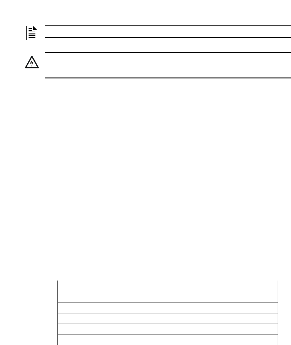
MS-9600LS Series Manual — P/N 52646:B2 2/12/2010 23
Accessories Product Description
1.8.6 New ANN-BUS Annunciators/Devices
The legacy ACS annunciators may not be used if new ANN-BUS annunciators are being used due
to incompatible serial communication protocols.
A variety of optional devices can be connected to the FACP EIA-485 ANN-BUS communication
circuit. Compatible devices include:
• ANN-80 LCD Annunciator
• ANN-S/PG Serial/Parallel Printer Interface Module
• ANN-I/O LED Driver Module
• ANN-LED Annunciator Module (alarm, trouble, supervisory LEDs)
• ANN-RLED Annunciator Module (red alarm LEDs only)
• ANN-RLY Relay Module
ANN-BUS Wiring
This section contains information on calculating ANN-BUS wire distances and the types of wiring
configurations (Class B).
Calculating Wiring Distance for ANN-BUS Modules
The following instructions will guide the installer in determining the type of wire and the maximum
wiring distance that can be used with FACP ANN-BUS accessory modules.
To calculate the wire gauge that must be used to connect ANN-BUS modules to the FACP, it is nec-
essary to calculate the total worst case current draw for all modules on a single 4-conductor bus.
The total worst case current draw is calculated by adding the individual worst case currents for each
module. The individual worst case values are shown in the following table:
After calculating the total worst case current draw, Table 1.1 specifies the maximum distance the
modules can be located from the FACP on a single wire run. The table ensures 6.0 volts of line
drop maximum. In general, the wire length is limited by resistance, but for heavier wire gauges,
NOTE: Refer to “Canadian Application” on page 200 for specific Canadian requirements.
!
WARNING: RISK OF ELECTRICAL SHOCK AND EQUIPMENT DAMAGE
DISCONNECT ALL SOURCES OF POWER (AC AND DC) BEFORE INSTALLING OR REMOVING
ANY MODULES OR WIRING.
Model Number Worst Case Current Draw1
1Total worst case current draw on a single ANN-BUS cannot exceed 0.5 amp. If
current draw exceeds 0.5 amps, refer to “Powering ANN-BUS Devices from
Auxiliary Power Supply” on page 26.
ANN-80 LCD Annunciator 0.040 amps
ANN-S/PG Serial/Parallel Printer Interface Module 0.040 amps
ANN-I/O LED Driver Module 0.200 amps
ANN-(R)LED Annunciator Module 0.068 amps
ANN-RLY Relay Module 0.075 amps

24 MS-9600LS Series Manual — P/N 52646:B2 2/12/2010
Product Description Accessories
capacitance is the limiting factor. These cases are marked in the chart with an asterisk (*). Maxi-
mum length can never be more than 6,000 feet (1,800 m), regardless of gauge used. The formula
used to generate this chart is shown in the note below.
The following formulas were used to generate the wire distance chart:
Exception: When using the ANN-RLY module, the installer must ensure that the maximum
24VDC power line drop does not exceed 0.3 volts. This results in the following wiring limitations:
Wiring Distance Calculation Example:
Suppose a system is configured with the following ANN-BUS modules:
• 3 ANN-80 Remote Fire Annunciators
• 1 ANN-S/PG Serial/Parallel Printer Interface Module
• 1 ANN-I/O LED Driver Module
Wiring Distance: ANN-BUS Modules to FACP
Total Worst Case Current
Draw (amps) 22 Gauge 18 Gauge 16 Gauge 14 Gauge
0.100 1,852 ft. 4,688 ft. * 6,000 ft. *6,000 ft.
0.200 926 ft. 2,344 ft. 3,731 ft. 5,906 ft.
0.300 617 ft. 1,563 ft. 2,488 ft. 3,937 ft.
0.400 463 ft. 1,172 ft. 1,866 ft. 2,953 ft.
0.500 370 ft. 938 ft. 1,493 ft. 2,362 ft.
Table 1.1 Wiring Distances
Maximum Resistance (Ohms) =
6.0 volts
Total Worst Case Current Draw (amps)
Maximum Wire Length (feet)
(6,000 feet maximum) =
Maximum Resistance (Ohms)
*500
Rpu
where: Rpu = Ohms per 1,000 feet for various Wire Gauges (see table below)
Wire Gauge Ohms per 1,000 feet (Rpu)
22 16.2
18 6.4
16 4.02
14 2.54
Wire Gauge Maximum Wire Length
18 312 feet
16 497 feet
14 787 feet
12 1,250 feet
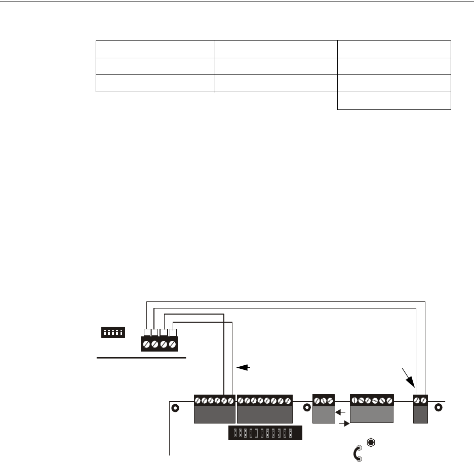
MS-9600LS Series Manual — P/N 52646:B2 2/12/2010 25
Accessories Product Description
The total worst case current is calculated as follows:
Using this value and referring to the Wiring Distance Table 1.1 on page 24, it can be found that the
available options are:
• 463 feet maximum using 22 Gauge wire
• 1,172 feet maximum using 18 Gauge wire
• 1,866 feet maximum using 16 Gauge wire
• 2,953 feet maximum using 14 Gauge wire
Wiring Configuration
Figure 1.3 illustrates the wiring between the FACP and ANN-BUS devices.
ANN-80 Current Draw = 3 X 0.040 amps = 0.120 amps
ANN-S/PG Current Draw = 1 X.0.040 amps = 0.040 amps
ANN-I/O Current Draw = 1 X.0.200 amps = 0.200 amps
Total Worst Case Current Draw = 0.360 amp
TB1
B A (+) (-)
4 3 2 1
TB3
JP5
TB4
JP8
TB5
TB6
TB1
+ - + - + -
A B
+ -
Figure 1.3 FACP wiring to ANN-BUS Device
ANN-BUS Device
FACP
ANN-BUS and power wiring are
supervised and power-limited
24 VDC
nonresettable
ANN-BUS/
ACS BUS
9600lstoann80.wmf
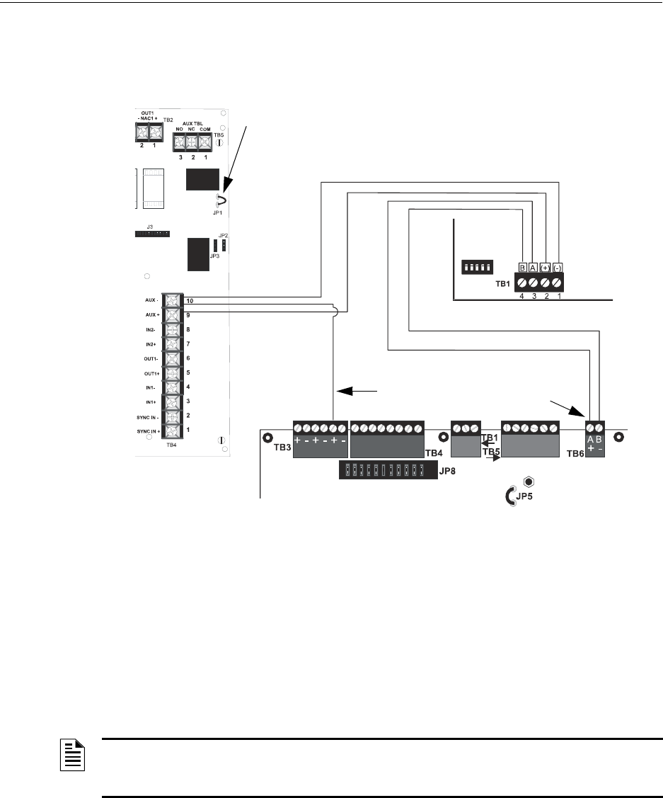
26 MS-9600LS Series Manual — P/N 52646:B2 2/12/2010
Product Description Accessories
Powering ANN-BUS Devices from Auxiliary Power Supply
Figure 1.4 illustrates the powering of ANN-BUS devices from an auxiliary power supply such as
the FCPS-24FS6/8, when the total ANN-BUS power requirement exceeds the capability of the
FACP’s DC Power Output circuit.
ANN-BUS Device Addressing
Each ANN-BUS device requires a unique address (ID Number) in order to communicate with the
FACP. A 5-position DIP switch on each device is used to set this address. The address set for these
devices must also be programmed at the FACP for the specific device (refer to the programming
section titled “ANN-BUS Options” on page 121).
A maximum of 8 devices can be connected to the FACP ANN-BUS communication circuit. Device
addresses do not need to be sequential and can be set to any number between 01 and 08. Note that
00 is not a valid address. The following table shows the DIP switch setting for each address.
Figure 1.4 Powering ANN-BUS Devices from FCPS-24FS6/8
ANN-80
FACP
FCPS-24FS6/8
-24 VDC
+24 VDC
nonresettable
ANN-BUS
Cut Ground Fault Detection jumper JP1 (FACP monitors for ground faults)
ANN-BUS and power wiring are
supervised and power-limited
9600lstofcpstoann.wmf
ANN-BUS/
ACS BUS
NOTE: Address (ID Number) DIP switches on some devices may have more than 5 switch
positions. Unless otherwise specified in the documentation supplied with each device, switch
positions 6 and above must be set to OFF.

MS-9600LS Series Manual — P/N 52646:B2 2/12/2010 27
Accessories Product Description
ANN-80 Remote Fire Annunciator
The ANN-80(-W) Annunciator is a compact, 80 character, backlit LCD remote fire annunciator. It
mimics the display on the control panel and will annunciate device type, point alarm, trouble or
supervisory condition, zone assignment plus any custom alpha labels programmed into the FACP.
The annunciator also provides system status LEDs to display AC Power, Alarm, Trouble, Supervi-
sory and Alarm Silenced conditions. Additionally, the annunciator is capable of remotely perform-
ing critical system functions such as Acknowledge, Silence, Reset and Drill. Communication
between the ANN-80 and FACP is accomplished over a two wire RS-485 serial interface employ-
ing the ANN-BUS communication format. The devices are powered, via two additional wires,
from either the host FACP or remote UL-listed, filtered, power supply.
The function buttons, keyswitch and piezo sounder may be individually enabled and disabled
through the FACP software. Refer to “ANN-BUS Options” on page 121 for a description of this
feature and programming information.
Note that if the keyswitch is enabled and remains in the unlocked position for more than two min-
utes without any buttons being pressed on the annunciator, a trouble indication will be annunciated.
Specifications
• Operating Voltage Range: 18 VDC to 28 VDC
• Current Consumption @ 24 VDC nominal (filtered and nonresettable):
• Normal/Standby (no activity): 37.0 mA
• Trouble: 39.0 mA
• Alarm: 40.0 mA
• AC Fail ( not backlit): 15.0 mA
• For use indoors in a dry location
Installation
Ensure that all power (AC and DC) has been removed from the FACP before installing the annunci-
ator.
Opening/Closing Annunciator
The following procedure details the steps used to open the annunciator in order to access the termi-
nal block and DIP switches (refer to Figure 1.5 on page 28):
1. Turn the key switch to the ON (Unlocked) position by turning the key counter-clockwise.
2. Push in the snap latch located on the right side of the unit while pulling the cover open.
3. To close the cover, make certain the key switch is in the ON (Unlocked) position. Swing the
cover closed, snapping it shut.
4. Turn the key switch to the OFF (Locked) position by turning clockwise and remove the key.
Address Switch 51
1 Switch 5 must be set to OFF for ANN-BUS devices to be recognized.
Switch 4 Switch 3 Switch 2 Switch 1
not valid OFF OFF OFF OFF OFF
01 OFF OFF OFF OFF ON
02 OFF OFF OFF ON OFF
03 OFF OFF OFF ON ON
04 OFF OFF ON OFF OFF
05 OFF OFF ON OFF ON
06 OFF OFF ON ON OFF
07 OFF OFF ON ON ON
08 OFF ON OFF OFF OFF
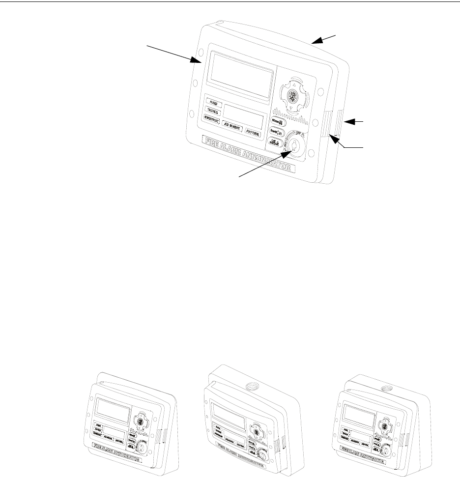
28 MS-9600LS Series Manual — P/N 52646:B2 2/12/2010
Product Description Accessories
Mounting
TheANN-80 can be surface or semi-flush mounted to a single, double or 4” square electrical box.
Select and remove the appropriate knockout(s), pull the necessary wires through the knockouts and
mount the annunciator in or on the wall depending on the type of installation desired.
The ANN-SB80KIT(-R/-B/-W) is an available mounting kit for the ANN-80 annunciator. The kit
comes with a surface backbox and surface wedge for angled viewing. The two pieces can be used
separately or can be stacked together.
The ANN-80 cover must be attached to the annunciator backplate before mounting the annunciator
to the electrical box/wall. The cover cannot be reattached or removed after the annunciator has
been mounted.
Key switch shown in OFF/Locked position
Press in latch
and
Pull annunciator
cover open
Annunciator cover
with LCD display
Annunciator backplate
Figure 1.5 ANN-80
ann80_iso.wmf
aann80kitmount.wmf
Annunciator mounted on
surface wedge from the
ANN-SB80KIT
Annunciator mounted on stacked
surface wedge and backbox from
the ANN-SB80KIT
Annunciator mounted on
surface backbox from the
ANN-SB80KIT
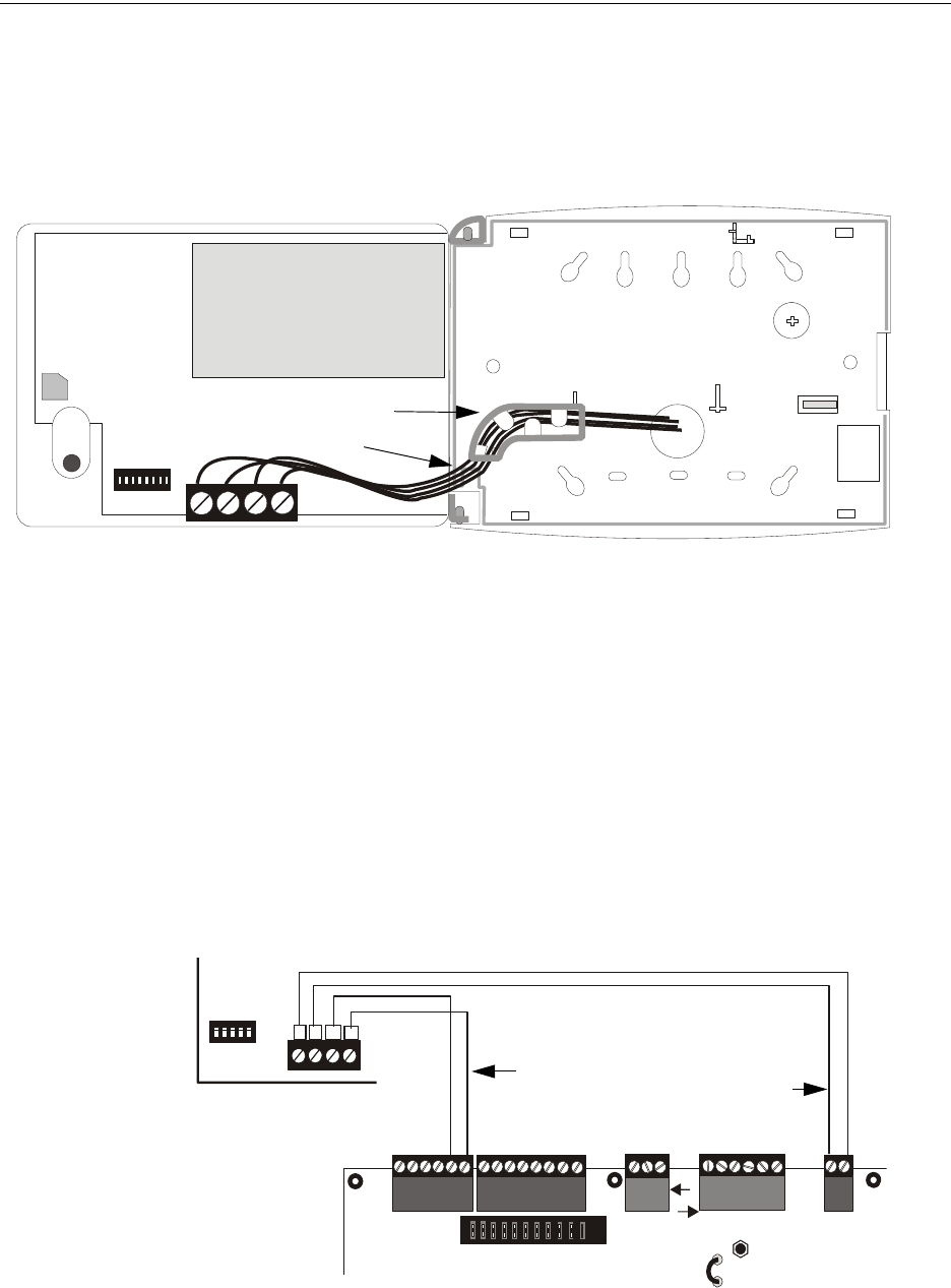
MS-9600LS Series Manual — P/N 52646:B2 2/12/2010 29
Accessories Product Description
Wiring ANN-80 to FACP
The following steps can be used as a guide to wire the annunciator. Make certain all power has
been removed from the FACP prior to annunciator installation.
1. Route wires from hole in backplate, through wiring channel and then to ANN-80 terminal
block TB1.
2. Remove appropriate amount of wire insulation.
3. Connect the wiring from the FACP ANN-BUS to annunciator TB1 terminals 3 (A) & 4 (B).
Make certain to connect A to A and B to B.
4. If appropriate, connect the wiring going to the next device on the ANN-BUS to TB1 terminals
3 & 4. Make certain to connect A to A and B to B.
5. Connect the wiring from the 24 VDC power source to annunciator TB1 terminals 1 (-) & 2 (+).
Make certain to observe proper polarity.
6. If appropriate, connect the power wiring going to the next device to terminals
1 (-) & 2 (+). Make certain to observe proper polarity.
7. After all connections are made, remove extra wire from inside of annunciator by dressing it
neatly through wire channel, with any excess wire pushed back through hole into electrical
box.
wiring channel
wires
TB1
ann-80boxinside.wmf
TB1
B A (+) (-)
4 3 2 1
TB3
JP5
TB4
JP8
TB5
TB6
TB1
+ - + - + -
A B
+ -
Figure 1.6 ANN-80 Wiring to FACP
FACP
ANN-80
ANN-BUS and power wiring are
supervised and power-limited
24 VDC
nonresettable
ANN-BUS
9600lstoann80.cdr
ANN-BUS/
ACS BUS
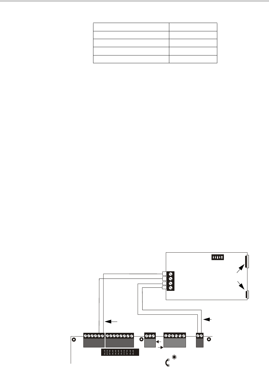
30 MS-9600LS Series Manual — P/N 52646:B2 2/12/2010
Product Description Accessories
The following table shows the ANN-80 connections to the FACP
Programming
Following installation and wiring of the ANN-80 LCD annunciator to the FACP, the annunciator
must added to the system via FACP programming. Refer to the programming section titled “ANN-
BUS Options” on page 121 in this manual for detailed programming information. Select the LCD
option for programming.
Trouble Response
If the ANN-80 is installed but the ANN-BUS is not enabled at the FACP, the ANN-80 will indicate
a trouble condition by NOT turning on its AC Power indicator. The LCD will also display Key Bus
Trouble and the piezo will sound approximately once every 10 seconds. Note that the FACP will
provide no indication of an ANN-80 trouble.
To clear the ANN-80 trouble condition, enable the ANN-BUS and program the address correspond-
ing to the address set on the ANN-80 at the FACP.
If the Keyswitch on the ANN-80 is left in the unlocked position for more than 2 minutes, a trouble
condition will be indicated at the FACP.
ANN-S/PG Serial/Parallel Interface Installation
The ANN-S/PG Serial/Parallel Interface module allows the connection of a remote serial or parallel
printer to the FACP for a real-time log of system events, detector status reports and event history.
The module is provided with a plastic enclosure for surface mounting. Proceed with the installation
as described in the following:
1. Ensure that all power (AC and DC) has been removed from the FACP.
2. Connect the ANN-S/PG to the FACP as illustrated in Figure 1.7.
3. Using the DIP switches on the back of the ANN-S/PG module, assign an ID number (address)
to the module.
FACP ANN-80 (TB1)
Terminal GND (-) on TB3 Terminal 1 (-)
Terminal PWR (+)TB3 Terminal 2 (+)
Terminal ACS on TB6 Terminal 3 (A)
Terminal ACS on TB6 Terminal 4 (B)
(-)
(+)
A
B
TB3
JP5
TB4
JP8
TB5
TB6
TB1
+ - + - + - + -
A B
Figure 1.7 ANN-S/PG Connection to FACP
ANN-S/PG Module
FACP
Cable Connectors for
connection to printer
Parallel
Serial
ANN-BUS and power wiring are
supervised and power-limited
24 VDC
nonresettable
ANN-BUS/
ACS BUS
9600lstospg.wmf

MS-9600LS Series Manual — P/N 52646:B2 2/12/2010 31
Accessories Product Description
4. Select the address and configuration options for the ANN-S/PG module as described in the
Programming section of this manual (refer to “ANN-BUS Options” on page 121).
Note that the Auto-configure feature allows the programmer to quickly bring all installed
ANN-BUS modules online (refer to “Auto-Configure” on page 131).
5. Connect a printer to the ANN-S/PG Parallel or Serial connectors (refer to Figure 1.7). Only
one printer can be connected.
Specifications
• Operating Voltage: 24 VDC
• Current (Alarm and Standby): 45 mA
• Ambient Temperature: 32oF to 120oF (0oC to 49oC)
• Max. Wiring Distance from FACP: 6,000 ft. (1,800 m)
• Mounting: Surface
• Dimensions: 6”W x 7-3/4”H x 1-7/16”D (15.2 cm W x 19.7 cm H x 3.7 cm D)
• For indoor use in a dry location only
PRN 6F Printer Installation
When connected to the FACP via the ANN-S/PG module, the PRN-6F prints the status changes
within the control panel and time-stamps the printout with the time of day and date that the event
occurred. It provides 80 columns of data on standard 9” x 11” tractor-feed paper. This section con-
tains information on connecting a printer to the control panel and setting the printer options.
Connecting PRN-6F Printer
Remote printers require a primary AC power source. If required for the fire alarm system configu-
ration (for example, a Proprietary Fire Alarm System), a remote printer requires a secondary power
source (battery backup). Since a secondary power source is not provided as a standard feature, a
separate UL-listed Uninterruptible Power Supply (UPS) should be used. The building emergency
power supply may be used, as long as it meets the power continuity requirements of NFPA 72.
Refer to NFPA 72 for further details.
Connect the remote printer to the FACP via the ANN-S/PG module using a standard DB-25 cable.
One end of the cable will plug into the DB-25 connector on the PRN printer and the other end plugs
into the parallel connector on the ANN-S/PG module. Note that the 9-pin DB-9 port on the ANN-
S/PG is used to connect a serial printer. The 25-pin port is used for a Centronics parallel printer
cable. Connect either a serial or parallel printer, but not both at the same time.
Setting Printer Options
Refer to the documentation supplied with the PRN-6F printer for instructions on using the printer
menu controls. Set the printer options (under the menu area) as shown in the following table:
Option Setting Option Setting
Font HS Draft CPI 10CPI
LPI 6 LPI Skip 0.5
ESC Character ESC Emulate Epson FX-850
Bidirectional Copy ON I/O
CG-TAB Graphic Buffer 40K
Country E-US ASCII Serial
Auto CR OFF Baud 9600 or 2400
Color Option Not Installed Format 7 Bit, Even, 1 Stop
Formien Protocol XON/XOFF
Lines 6LPI=60 Character Set Standard
Table 1.2 PRN-6F Setup Options
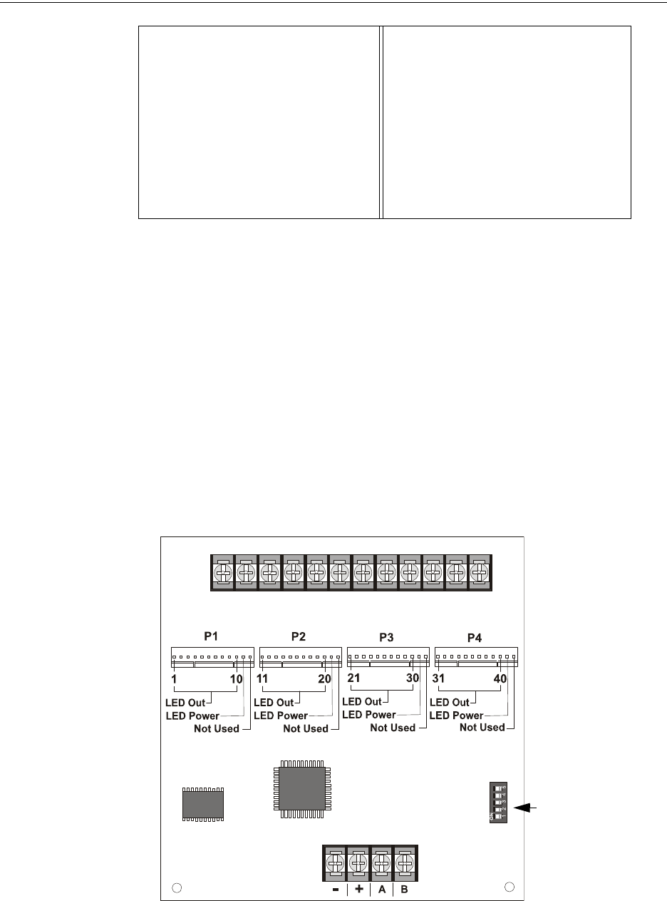
32 MS-9600LS Series Manual — P/N 52646:B2 2/12/2010
Product Description Accessories
ANN-I/O LED Driver Module*
The ANN-I/O is an LED driver module that can be used in a wide variety of applications, including
as an interface with most customized graphic annunciators. The ANN-I/O can drive up to 40 LEDs
The module is provided with a plastic enclosure for mounting inside the annunciator or accessory
box. The following sections describe hardware installation. Refer to the section titled “ANN-BUS
Options” on page 121 for programming information.
*In Canada, the color red must be used to indicate active alarm inputs. Yellow indicates supervi-
sory, burglary or trouble signals. Green indicates the presence of power or an activated output.
ANN-I/O Board Layout
Figure 1.8 illustrates the ANN-I/O board showing locations of screw terminals for connection to
the FACP, pin connectors for connecting LEDs and the DIP switch for selecting the ANN-BUS ID
number.
Standard Exec 10.5 SI.Zero On
Auto LF On
PAPER
BIN 1 12/72”
BIN 2 12/72”
SINGLE 12/72”
PUSH TRA 12/72”
PULL TRA 12/72”
PAP ROLL 12/72”
Table 1.2 PRN-6F Setup Options
Figure 1.8 ANN-I/O Board Layout
ANN-BUS (ID#)
Address DIP
switch
ANN-BUS Connector
Terminals not used (future)
ann-IObrd.wmf
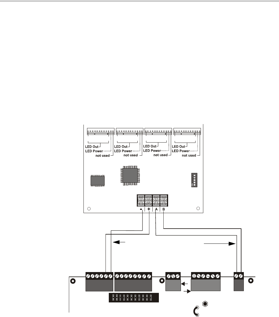
MS-9600LS Series Manual — P/N 52646:B2 2/12/2010 33
Accessories Product Description
Specifications
• Max. ANN-BUS Voltage: 28 VDC
• Max. Current:
• Alarm: 200 mA
• Standby: 35 mA
• Each LED: 10 mA
• Operating Temperature: 32oF to 120oF (0oC to 49oC)
• For indoor use in a dry location only
ANN-I/O Connection to FACP
The ANN-I/O connects to the FACP via the ANN-BUS as illustrated in Figure 1.9. After the
ANN-I/O is connected to the panel, it must be added to the system via FACP programming. Refer
to the section titled “ANN-I/O Options” on page 123.
ANN-I/O Module LED Wiring
There are four 12-pin connectors on the ANN-I/O module for connecting LEDs. Each set of 10
LEDs get their power from Pin 11 of the corresponding connector. Internal resistors are sized so
that there is approximately 10 mA of current for each LED. No series resistors are required. Refer
to the programming section titled “ANN-I/O Options” on page 123 of this manual.
The LEDs are wired as illustrated in Figure 1.10. Note that the illustration depicts only connectors
P1 and P2. Wiring is identical for P3 (LEDs 21-30) and P4 (LEDs 31-40).
P1 P2 P3 P4
110
11 20 21 30 31 40
1 2 3 4 5
TB3
JP5
TB4
JP8
TB5
TB6
TB1
+ - + - + - + -
A B
Figure 1.9 ANN-I/O Connection to FACP
ANN-I/O Module
FACP
ANN-BUS and power wiring are
supervised and power-limited
9600lstoannio.wmf
ANN-BUS/
ACS BUS
24 VDC
nonresettable
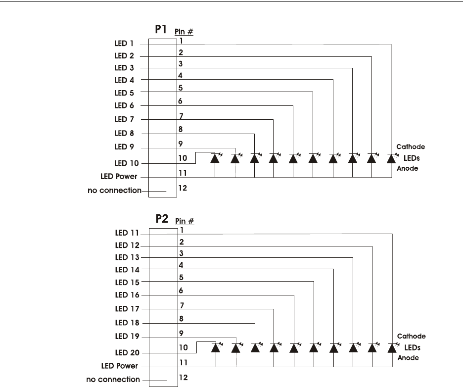
34 MS-9600LS Series Manual — P/N 52646:B2 2/12/2010
Product Description Accessories
ANN-LED Annunciator Module*
The ANN-LED and ANN-RLED annunciator modules provide LED annunciation of general sys-
tem faults and input zones/points when used with a compatible FACP. The ANN-LED module pro-
vides alarm (red), trouble (yellow) and supervisory (yellow) indication for up to ten input zones or
addressable points. The ANN-LEDR provides alarm (red) indication for up to 30 input zones or
addressable points. Multiple ANN-(R)LED modules may be used for full system coverage.
Figure 1.10 ANN-I/O Board Layout
ann-ioleds.wmf
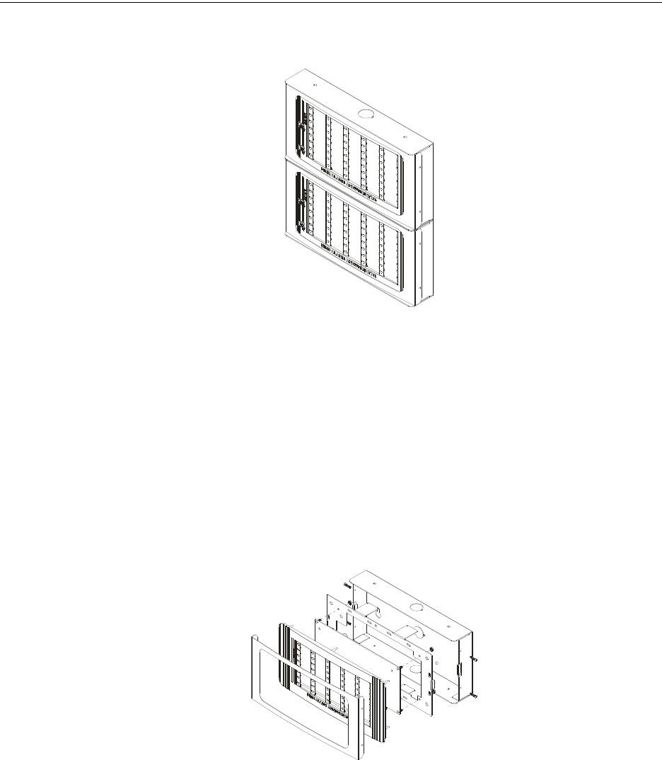
MS-9600LS Series Manual — P/N 52646:B2 2/12/2010 35
Accessories Product Description
*In Canada, the color red must be used to indicate active alarm inputs. Yellow indicates supervi-
sory, burglary or trouble signals. Green indicates the presence of power or an activated output.
Specifications
• Max. ANN-BUS Voltage: 24 VDC
• Max. Current:
• Alarm: 68 mA
• Standby: 28 mA
• Operating Temperature: 32o F to 120o F (0o C to 49o C)
• For indoor use in a dry location only
Mounting/Installation
Refer to the documentation supplied with the ANN-LED module for mounting information.
Figure 1.11 ANN-LEDs (shown in possible stacked configuration)
ann-ledistacked.wmf
ann-led.wmf
Figure 1.12 Exploded View of ANN-LED
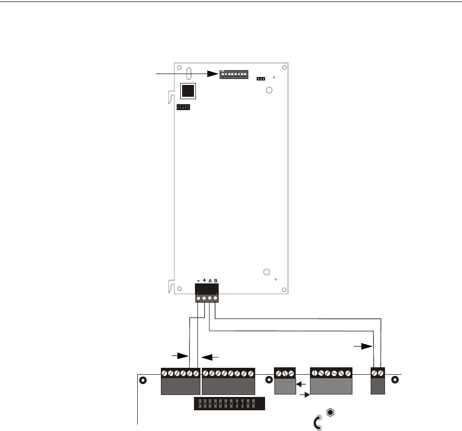
36 MS-9600LS Series Manual — P/N 52646:B2 2/12/2010
Product Description Accessories
ANN-LED Board Layout and Connection to FACP
Figure 1.13 illustrates the ANN-LED board showing locations of screw terminals for connection to
the FACP and the DIP switches for selecting the ANN-BUS ID number.
ANN-RLY Annunciator Module
The ANN-RLY relay module provides 10 programmable Form-C relays when used with a
compatible FACP.
Specifications
• Operating Voltage: 24 VDC
• Max. Current:
• Alarm: 75 mA
• Standby: 15 mA
• Relay Contact Ratings
• 2 amps @ 30 VDC (resistive)
• 0.5 amps @ 30 VAC (resistive)
• Operating Temperature: 32o F to 120o F (0o C to 49o C)
• For indoor use in a dry location only
TB1
J1
SW1
JP2
ANN-BUS
1 2 3 4 5 6 7 8
TB3
JP5
TB4
JP8
TB5
TB6
TB1
+ - + - + - + -
A B
Figure 1.13 ANN-LED Connection to FACP
FACP
ANN-LED
ANN-BUS/
ACS BUS
+24 VDC -24 VDC
9600lstoled.wmf
ANN-BUS and power wiring are
supervised and power-limited
ANN-BUS (ID#)
Address DIP switch
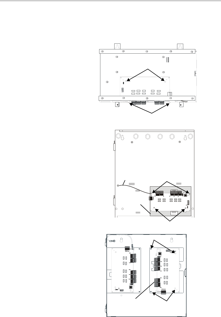
MS-9600LS Series Manual — P/N 52646:B2 2/12/2010 37
Accessories Product Description
Mounting/Installation
The ANN-RLY relay module can be mounted inside the FACP main circuit board chassis or inside
the ROME Series enclosure. Refer to the ANN-RLY Installation Document #53033 for instructions
on chassis mounting or to the ROME Series Installation Document #53530 for mounting in the sep-
arate backbox.
mounting holes
mounting hooks through
mounting slots
grounding wire
ANN-RLY
ANN-MBRLY
mounting bracket
mounting holes
mounting holes
FACP Backbox Installation
using ANN-MBRLY mounting bracket
FACP Chassis Installation
mounting holes
mounting holes
ANN-RLY on ANN-
MBRLY mounting
bracket
ROME Series Installation
using ANN-MBRLY mounting bracket
Figure 1.14 ANN-RLY Mounting Options
ann-rlyinchassis.wmf
ann_mbriyincab3.wmf
rome-relay-plate3.wmf
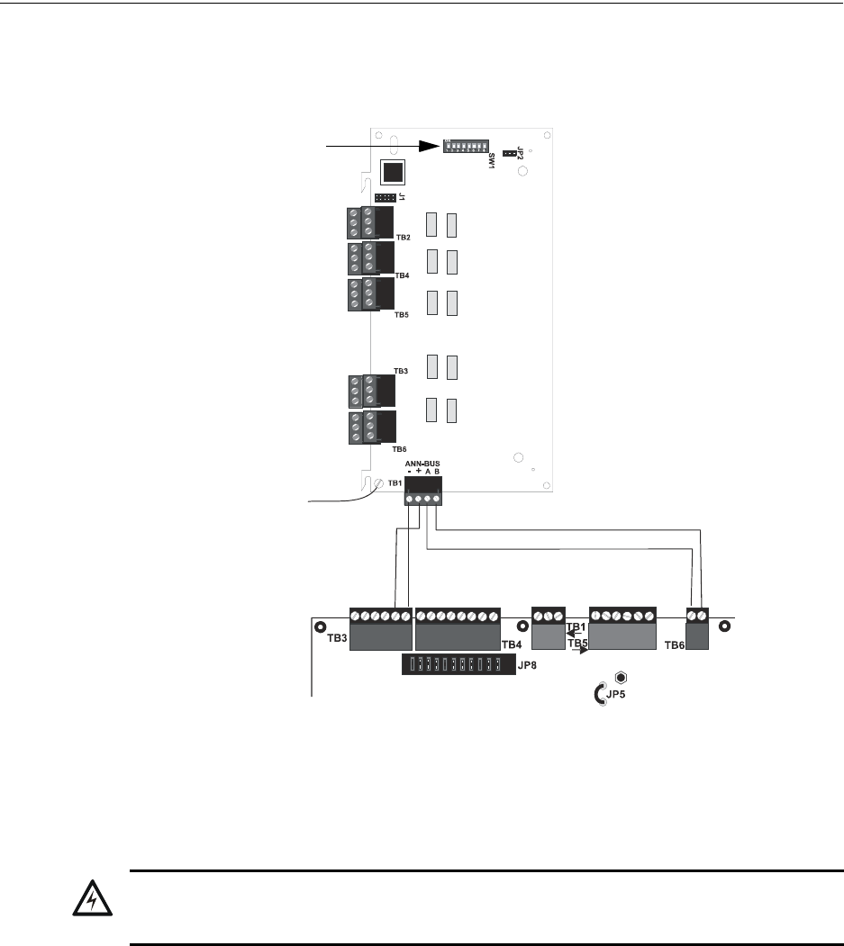
38 MS-9600LS Series Manual — P/N 52646:B2 2/12/2010
Product Description Accessories
ANN-RLY Board Layout and Connection to FACP
Figure 1.15 illustrates the ANN-RLY board showing locations of screw terminals for connection to
the FACP and the DIP switches for selecting the ANN-BUS ID number.
ANN-BUS Audio Panel Control
The FACP is capable of providing automated activation of the ACC-25/50(ZS/T) zoned system
speaker circuits. To do this, the FACP must be enabled to communicate with the ACC-25/50ZS
Audio Panel over the ANN-BUS (refer to “ANN-BUS Enabled” on page 121). This is accom-
plished by programming the Audio Panel ANN-BUS address into the FACP (refer to “Modules
Installed” on page 121). For details on setting the ANN-BUS address and programming the audio
panel, refer to the ACC-25/50ZS Series Audio Panel manual (document #51889).
The ACC-25/50ZS Series audio panel connects to the FACP via the ACS/ANN-BUS communica-
tion circuit. Zones 33 - 56 on the FACP correspond to the ACC-25/50ZS Series audio circuits
1 - 24. Zone 32 on the FACP serves as the All-Call zone and will activate all audio panel output
circuits. The programmer can select which of the five audio messages at the audio panel will play
when an FACP input zone goes into alarm (refer to “Zone Message” on page 149). The message
will play over the corresponding audio panel output circuit.
Figure 1.15 ANN-RLY Board Layout and Connection to FACP
FACP
ANN-RLY
ANN-BUS
+24 VDC -24 VDC
Ground Wire
attaches to chassis
(see documentation
supplied with module)
9600lstorly.wmf
ANN-BUS (ID#)
Address DIP switch
!
WARNING: RISK OF ELECTRICAL SHOCK AND EQUIPMENT DAMAGE
DISCONNECT ALL SOURCES OF POWER (AC AND DC) BEFORE INSTALLING OR REMOVING
ANY MODULES OR WIRING.
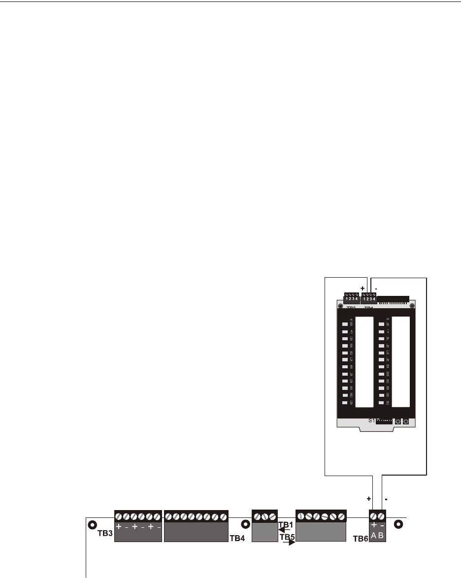
MS-9600LS Series Manual — P/N 52646:B2 2/12/2010 39
Accessories Product Description
Examples:
• FACP Input programmed to Zone 33 goes into alarm, the programmed message for Zone 33
[Message 1, 2, 3, 4 or 5] will play over the ACC-25/50ZS Series output circuit 1 which
corresponds to FACP Zone 33.
• FACP Input programmed to Zone 1 and Zone 34 (Zone 1 is programmed for a Message [1, 2,
3, 4 or 5] and Zone 34 is programmed for No Message) goes into alarm, the programmed
message for Zone 1 will play over the ACC-25/50ZS Series output circuit 2 which corresponds
to FACP Zone 34.
• If two or more input zones are active at the same time, the highest priority message will turn on
(Message 1 is highest priority and Message 5 is lowest) and play over the corresponding audio
panel output circuit(s).
• Zone 32 is an All-Call zone. All audio panel output circuits will turn on if Zone 32 is activated
and its programmed message will play (or the highest priority message currently being
played).
A fault at the ACC-25/50ZS Series panel will cause the FACP to indicate a System Trouble and the
display will indicate a Voice Evac Fault.
The only connection between the FACP and ACC-25/50ZS Series audio panel is a pair of commu-
nication wires connected between the A(+)/B(-) terminals on TB9 of the FACP and TB1 terminals
2 & 3 of the ACC-ZPMK module on the audio panel.
A (+) B (-)
FACP
ACC-ZPMK
on ACC-25/50ZS Series
Figure 1.16 FACP Connection to ACC-25/50ZS Series Audio Panel
ANN-BUS
acczpmtoms9600udls.wmf

40 MS-9600LS Series Manual — P/N 52646:B2 2/12/2010
Product Description Getting Started
1.8.7 Legacy ACS Annunciators
The legacy ACS annunciators may not be used if new ANN-BUS annunciators are being used due
to incompatible serial communication protocols.
ACM Series LED Zone Type Annunciators
The ACM Series Annunciators remotely display alarm and trouble status as well as system status.
For more detailed information, refer to the appropriate annunciator manual. Following is a list of
annunciators which can be used with the FACP.
•ACM-16ATF - Annunciator Control Module annunciates 16 zones with 16 red alarm LEDs
and 16 yellow trouble LEDs. In addition, it has a System Trouble LED, an On Line/Power
LED and a local piezo sounder. *In Canada, this module must be used to annunciate the fire
alarm input points/zones only.
•AEM-16ATF - Annunciator Expander Module annunciates 16 zones with 16 red alarm LEDs
and 16 yellow trouble LEDs. *In Canada, this module must be used to annunciate the fire
alarm input points/zones only.
•ACM-32A - Annunciator Control Module annunciates 32 alarm zones with 32 red LEDs. In
addition, it has a System Trouble LED, an On Line/Power LED and a local piezo sounder. It
also has a switch for local piezo silence. *In Canada, this module must be used to annunciate
the fire alarm input points/zones only.
•AEM-32AF - Annunciator Expander Module annunciates 32 alarm zones with 32 red LEDs.
*In Canada, this module must be used to annunciate the fire alarm input points/zones only.
LCD-80F Remote Fire Annunciator
The LCD-80F annunciator is an 80-character backlit LCD remote fire annunciator that is capable of
displaying English language text. Tactile switches provide remote system Acknowledge, Silence,
Drill and Reset functions. A keyswitch allows enabling/disabling of the tactile switches. Commu-
nications between the control panel and the annunciator is accomplished over a serial interface
employing the EIA-485 communication standard. Up to 32 LCD-80F annunciators may be con-
nected to the EIA-485 circuit. The annunciators may be powered from the host FACP or a remote
UL listed filtered power supply such as the FCPS Series. For more detailed information, refer to
the LCD-80F manual.
The LCD-80F is not for use in Canadian applications.
LCD-80FC Remote Fire Annunciator (for use in Canadian applications)
The LCD-80FC is identical to the LCD-80F except for the tactile switches and keyswitch. There is
no keyswitch, and tactile switches are provided for local silence and lamp test only. No remote sys-
tem functions can be performed from the LCD-80FC annunciator.
LDM Series Lamp Driver Modules (Graphic Annunciator)
The LDM Series Lamp Driver Modules, which consist of the LDM-32F master and LDM-E32F
expander modules, are used to provide an interface to a custom graphic LED annunciator.
1.9 Getting Started
The following is a brief summary of the minimal steps involved in bringing an MS-9600LS/MS-
9600UDLS on-line:
• Install Backbox, Power Supply and Main Circuit Board (refer to “Mounting” on page 42).
• Address and Install Intelligent Devices (refer to the SLC Wiring Manual).
!
WARNING: RISK OF ELECTRICAL SHOCK AND EQUIPMENT DAMAGE
DISCONNECT ALL SOURCES OF POWER (AC AND DC) BEFORE INSTALLING OR REMOVING
ANY MODULES OR WIRING.

MS-9600LS Series Manual — P/N 52646:B2 2/12/2010 41
Getting Started Product Description
• Enter Autoprogramming (refer to “Autoprogram” on page 66).
• Resolve Programming Conflicts.
• Go to Point Program to Enter Specific Data (refer to “Point Program” on page 67). Use the
right and left arrow keys to navigate between devices.
42 MS-9600LS Series Manual — P/N 52646:B2 2/12/2010
Section 2: Installation
The cabinet may be either semi-flush or surface mounted. The cabinet mounts using key slots and
two 0.250” (6.35 mm) diameter holes located in the backbox. The key slots are located at the top of
the backbox and the two securing holes at the bottom.
Carefully unpack the system and check for shipping damage. Mount the cabinet in a clean, dry,
vibration-free area where extreme temperatures are not encountered. The area should be readily
accessible with sufficient room to easily install and maintain the panel. Locate the top of the cabi-
net approximately 5 feet (1.5 m) above the floor with the hinge mounting on the left. Determine the
number of conductors required for the devices to be installed. Sufficient knockouts are provided
for wiring convenience. Select the appropriate knockout(s) and pull the conductors into the box.
All wiring should be in accordance with the National and/or Local codes for fire alarm systems.
2.1 Mounting
The circuit board contains static-sensitive components. Always ground yourself with a proper
wrist strap before handling any boards so that static charges are removed from the body. Use static
suppressive packaging to protect electronic assemblies.
• Mark and predrill holes in the wall for the center top keyhole mounting bolt using the dimen-
sions illustrated in Figure 2.2 on page 44.
• Install center top fastener in the wall with the screw head protruding.
• Place backbox over the top screw, level, and secure.
• Mark and drill the left and right upper and lower mounting holes.
Note: outer holes (closest to sidewall) are used for 16” O.C. stud mounting.
• Install remaining fasteners and tighten.
• Attach solid earth ground wire to grounding stud as indicated in Figure 2.1.
• When the location is dry and free of construction dust, install the main circuit board chassis by
positioning the two mounting tab holes on the top of the chassis over the mounting studs in the
top of the backbox and sliding the mounting tabs at the bottom of the chassis into the mounting
slots in the bottom of the backbox as illustrated below.
• Secure the chassis to the mounting studs with the supplied nuts.
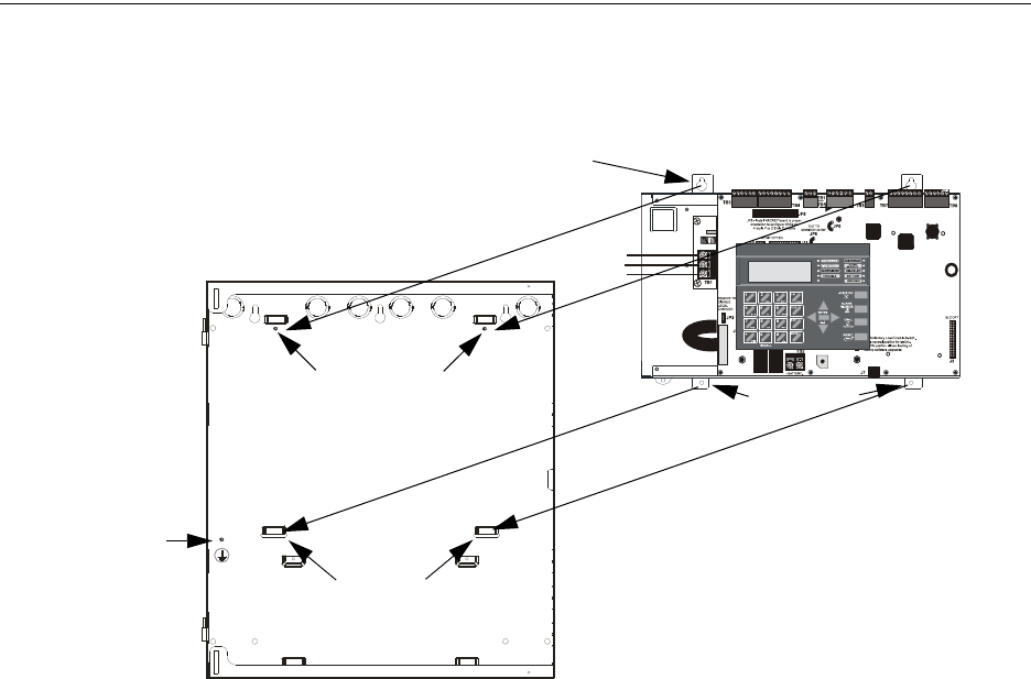
MS-9600LS Series Manual — P/N 52646:B2 2/12/2010 43
Mounting Installation
1
2
6
#
1
st
EVENT
ABC DEF
JKL MNO
TUV WXY
-/.
CLR
9
ESC
ENTER
RECALL
ACK/STEP
ALARM
SILENCE
DRILL
HOLD 2 SEC
RESET
MODE
Figure 2.1 FACP Main Circuit Board Installation
9600lsbrdinbox.wmf
grounding stud:
attach solid earth
ground wire (refer to
“AC Power and
Earth Ground
Connection” on
page 46)
FACP Backbox
Main Circuit Board on Chassis
mounting studs
mounting slots
mounting tabs
mounting tab holes
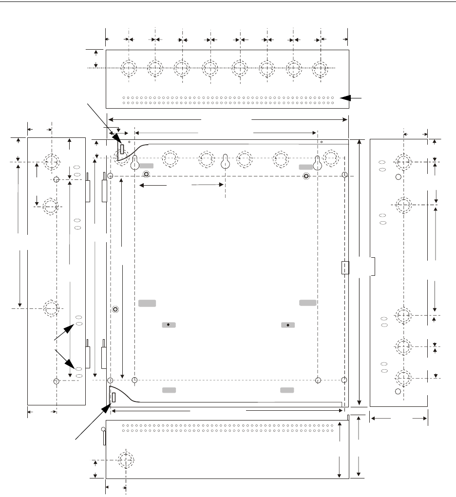
44 MS-9600LS Series Manual — P/N 52646:B2 2/12/2010
Installation Mounting
3.37 cm
1.325“
3.37 cm
4.13 cm 4.1 cm
1.625“ (4.128 cm)
1.625“
16.65“ (42.29 cm)
2.00“
4.128 cm
1.00“ (2.54 cm)
1.30“
3.30 cm
13.23 cm
5.207“
12.00“ (30.48 cm)
2.325“ (5.91 cm)
1.625“
4.13 cm
1.625“
1.325“
2.00“
2.00“
2.00“
2.00“
2.00“
5.1 cm
2.00“
16.0“
40.64 cm
5.207“
13.23 cm
29.95 cm
11.792“
4.45cm
1.75“
4.45cm
1.75“
17.83cm
7.02“
2.00“
16.00“ (40.64 cm)
4.1cm
1.625“
12.13cm
4.775"
38.1 cm
15.00“
7.0 cm
2.75“
1.25“ (3.2 cm)
15.0“
38.1 cm
4.535“
11.52 cm
12.13 cm
4.775“
6.0“
15.24 cm
48.37cm
19.0“
Figure 2.2 FACP Cabinet Mounting
9050udencl.wmf
Semi-Flush Mounting
Do not recess box
more than 3.875” into
wall to avoid covering
venting holes on top of
box.
Hinge Slot for
optional Dress Panel
Hinge Slot for
optional Dress Panel
Semi-flush
mounting
hole
Mounting
slots for
optional
Trim Ring
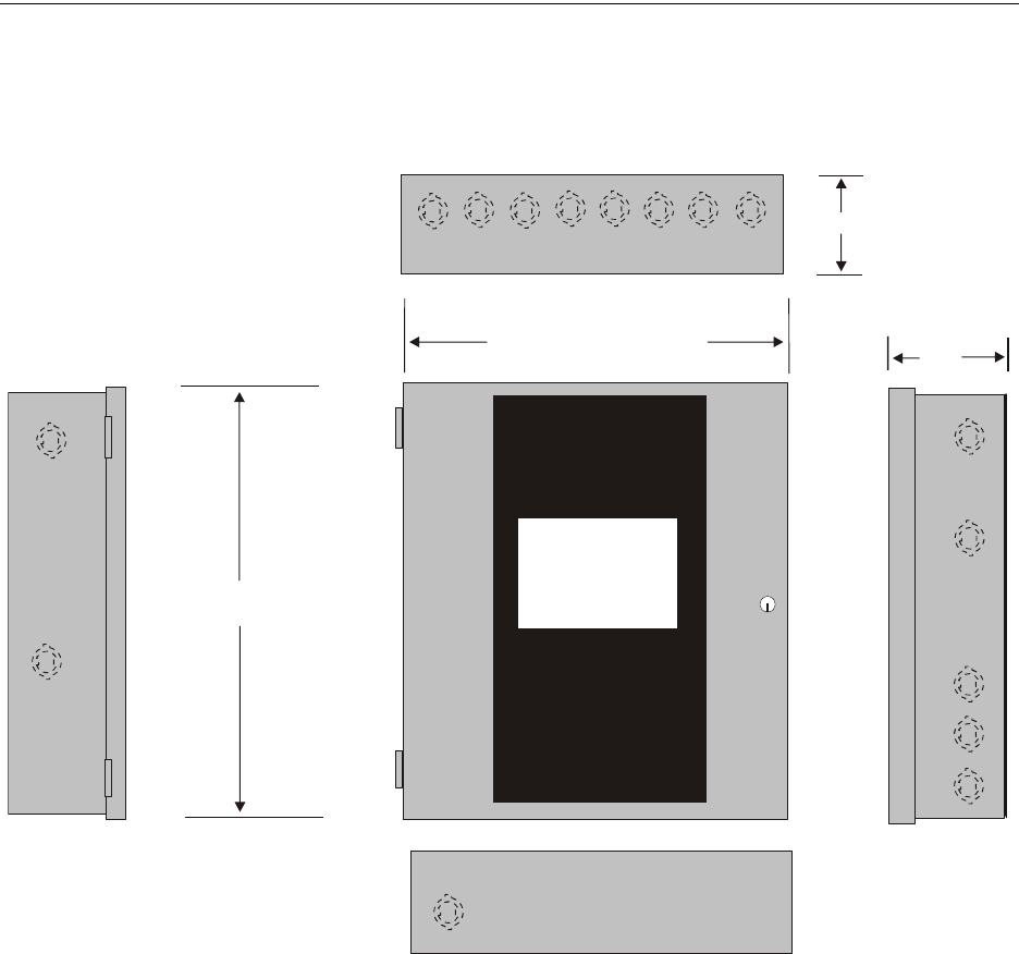
MS-9600LS Series Manual — P/N 52646:B2 2/12/2010 45
Mounting Installation
= 19.26" (48.92 cm)
= 19.0" (48.26 cm)
5.325"
(13.526 cm)
= 16.821" (42.73 cm)
= 16.65" (42.29 cm)
= 5.207" (13.23 cm)
Figure 2.3 FACP Cabinet Dimensions
9600cabnew.wmf
Door
Backbox
Left Side
Door
Backbox
Bottom
Right Side
Top Depth
Depth =
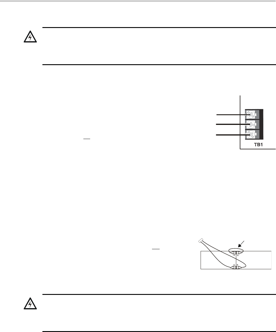
46 MS-9600LS Series Manual — P/N 52646:B2 2/12/2010
Installation Power
2.2 Power
2.2.1 AC Power and Earth Ground Connection
Primary power required for the FACP is 120 VAC, 60 Hz, 3.0 amps for
the MS-9600LS(C) and MS-9600UDLS or 240 VAC, 50 Hz, 1.5 amps
for the MS-9600LSE and MS-9600UDLSE. Overcurrent protection for
this circuit must comply with Article 760 of the National Electrical
Code (NEC) and/or local codes. Use 14 AWG (2.00 mm2) or larger
wire with 600 volt insulation rating. Make certain that the AC mains
circuit breaker is off before wiring any connections between the mains
and the control panel. Connect wiring from the AC mains to TB1 on
the FLPS-7 Power Supply, being careful to observe proper connections.
Illustration depicts connection of 120 VAC to TB1. Note that the FLPS-7 Power Supply is con-
nected to the main circuit board by a cable connected to J1. Ensure that this cable is connected.
Connect a wire from the grounding stud in the cabinet to a known solid earth ground (refer to Fig-
ure 2.1 on page 43). This connection is vital for maintaining the control panel’s immunity to
unwanted transients generated by lightning and electrostatic discharge. Apply AC power to the
panel only after the system is completely installed and visually checked. Note that AC power must
be applied to the panel before installing the battery interconnect cable (refer to the following sec-
tion).
2.2.2 Battery Power
Before connecting the batteries to the FACP, make certain that
the interconnect cable between the batteries is not connected.
Do not connect the interconnect cable until the system is com-
pletely installed. Observe polarity when connecting the batter-
ies. Connect the battery cable to TB2 on the main circuit board.
Refer “Power Supply Calculations” on page 174, for calculation
of the correct battery rating.
!
WARNING: RISK OF ELECTRICAL SHOCK AND EQUIPMENT DAMAGE
SEVERAL DIFFERENT SOURCES OF POWER CAN BE CONNECTED TO THIS PANEL. DISCON-
NECT ALL SOURCES OF POWER BEFORE SERVICING. THE PANEL AND ASSOCIATED
EQUIPMENT MAY BE DAMAGED BY REMOVING AND/OR INSERTING CARDS, MODULES OR
INTERCONNECTING CABLES WHILE THIS UNIT IS ENERGIZED.
Hot L1
Neut L2
EARTH
120 VAC
tb1.wmf
Interconnect
Cable
!
WARNING: RISK OF PERSONAL INJURY
BATTERY CONTAINS SULFURIC ACID WHICH CAN CAUSE SEVERE BURNS TO THE SKIN
AND EYES AND CAN DESTROY FABRICS. IF CONTACT IS MADE WITH SULFURIC ACID,
IMMEDIATELY FLUSH THE SKIN OR EYES WITH WATER FOR 15 MINUTES AND SEEK
IMMEDIATE MEDICAL ATTENTION.
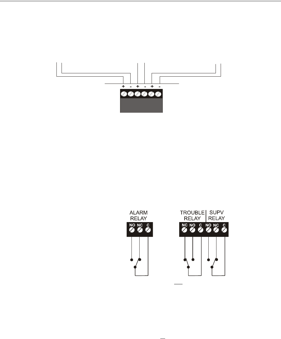
MS-9600LS Series Manual — P/N 52646:B2 2/12/2010 47
Relays Installation
2.2.3 Special Application DC Power Output Connection
All Special Application DC power outputs are power-limited.
2.3 Relays
The FACP provides two programmable Form-C relays and one fixed fail-safe Form-C trouble
relay, all with contacts rated for 2.0 amps @ 30 VDC (resistive) or 0.5 amps @ 30 VAC (resistive).
The Alarm and Supervisory silk-screen labels reflect the factory default programming for the two
programmable relays.
Note that relay connections must be power-limited. Refer to Power-limited wiring requirements.
2.4 Notification Appliance Circuits
The control panel provides four Style Y/Class B or two Style Z/Class A NACs (Notification Appli-
ance Circuits). Each circuit is capable of 3.0 amps of current. Total system current in alarm cannot
exceed 7.0 amps (refer to “Calculating the System Current Draw” on page 174). Use UL listed 24
VDC notification appliances only. Circuits are supervised and power-limited. Refer to the Device
Compatibility Document for a listing of compatible notification appliances. The NACs, which are
located on the main circuit board, may be expanded via the FCPS Series field charger/power sup-
plies.
Figure 2.4 Special Application Power Outputs - 24 VDC
1 2 3 4 5 6
Power-limited Resettable Power
1.5 amperes max., 24 VDC nominal
filtered, resettable power can be drawn
from TB3 Terminals 1(+) and 2(-)
Power-limited Nonresettable Power #1
1.5 amperes max., 24 VDC nominal
filtered, nonresettable power can be
drawn from TB3 Terminals 3(+) and 4(-)
Power-limited Nonresettable Power #2
1.5 amperes max. , 24 VDC nominal
filtered, nonresettable power can be drawn
from TB3 Terminals 5(+) and 6(-)
9600tb3.wmf
Figure 2.5 Relay Terminals
Relay contacts shown with power applied to panel
and no active troubles, alarms or supervisories
TB5
Note that the relays labeled as Alarm
Relay (Relay 1) and Supervisory Relay
(Relay 3) reflect the factory default
programming for these relays which are
programmable.
The relay labeled Trouble Relay (Relay 2)
is fixed and cannot be changed. It is a fail-
safe relay which will transfer on any trouble
or total power failure.
9600reyp.wmf
TB1
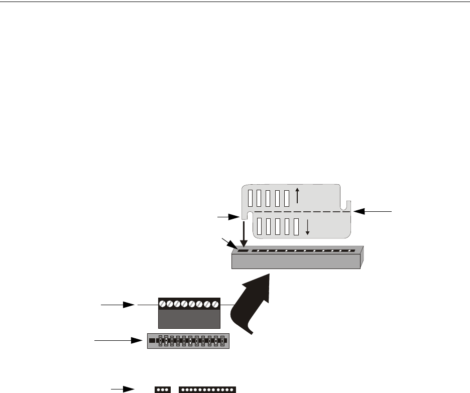
48 MS-9600LS Series Manual — P/N 52646:B2 2/12/2010
Installation Notification Appliance Circuits
The following sections describe the configuration and wiring of Style Y and Style Z Notification
Appliance Circuits on the FACP main circuit board. The NACs are configured for Style Y (Class
B) from the factory. Refer to “Configuring NACs” on page 48 for information on changing the
NAC configuration to Style Z (Class A) and preparing the NACKEY configuration card located in
JP8, when installing a 4XTMF Transmitter Module.
2.4.1 Configuring NACs
The Notification Appliance Circuits on the main circuit board are configured for Style Y or Style Z
by properly orienting the NACKEY card in JP8 which is located at the top of the main circuit board
near the NAC Terminal TB4. The default configuration is for Style Y (Class B). Refer to Figure
2.6 for information on installing the NACKEY card.
J10 J11
4XTMF OPT BD
JP8
CLASS A
CLASS B
NACKEY -PCA
NACKEY -PCA
Figure 2.6 NAC Configuration Using NACKEY
NACKEY Card
JP8
Top edge of FACP
Main Circuit Board
• Style Z (Class A) - install NACKEY into JP8
with Class A pointing down toward circuit board
as illustrated to the right.
• Style Y (Class B) - install NACKEY into JP8
with Class B pointing down toward circuit board .
NACKEY must be inserted with text side facing
in toward center of main circuit board and key
into key-slot as illustrated to the right. It is keyed
to prevent incorrect insertion.
TB4 If the 4XTMF Option Module is to be installed in
connectors J10 and J11, the NACKEY card must be
carefully separated at the scored mark and only the
required half installed into JP8. This will allow room
for the 4XTMF module.
scored mark
4XTMF Module connectors
NACKEY card slot
Key
Key-slot
connectors for 4XTMF option module
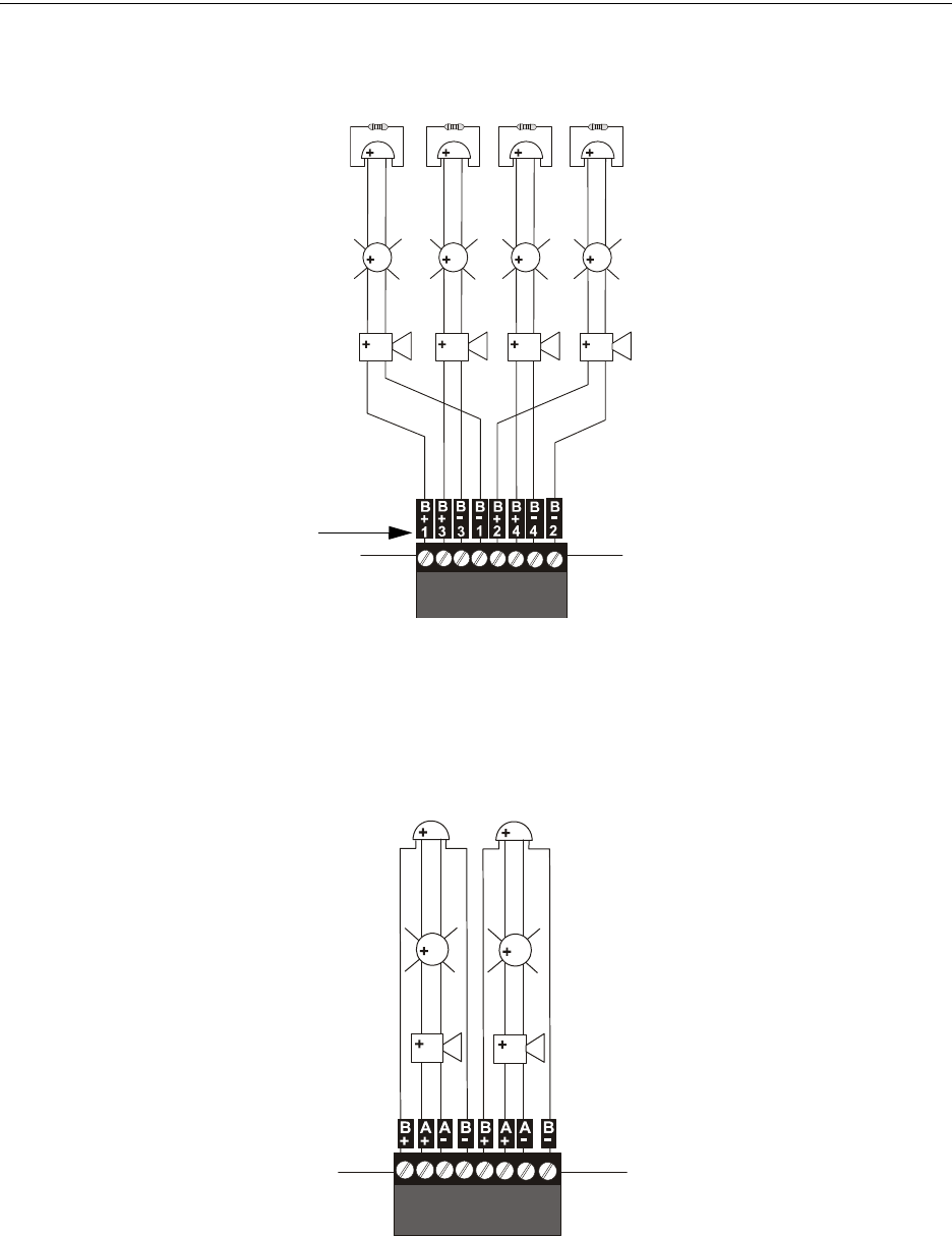
MS-9600LS Series Manual — P/N 52646:B2 2/12/2010 49
Notification Appliance Circuits Installation
2.4.2 Style Y (Class B) NAC Wiring
2.4.3 Style Z (Class A) NAC Wiring
Figure 2.7 NAC Style Y (Class B) Wiring
4 Style Y (Class B) Notification Appliance Circuits, supervised and power-limited - 4.7K ohm, ½ watt P/N:71252 UL-listed
Polarized Bells Polarized Bells
Polarized Horns
Polarized Horns
Polarized Strobes
Notification Appliance Circuit
polarity shown in alarm state
Dummy Load all unused circuit
TB4
9600nacy.wmf
Polarized Strobes
circuit number
NAC 1 NAC 3 NAC 4 NAC 2
2 Style Z (Class A) Notification Appliance
Circuits, supervised and power-limited
Polarized Bell
Polarized Horn
Polarized Horn
Notification Appliance Circuit
polarity shown in alarm state
Polarized Bell
Polarized Strobe Polarized Strobe
Figure 2.8 NAC Style Z (Class A) Wiring
9600nacz.cdr
NAC 1 NAC 2
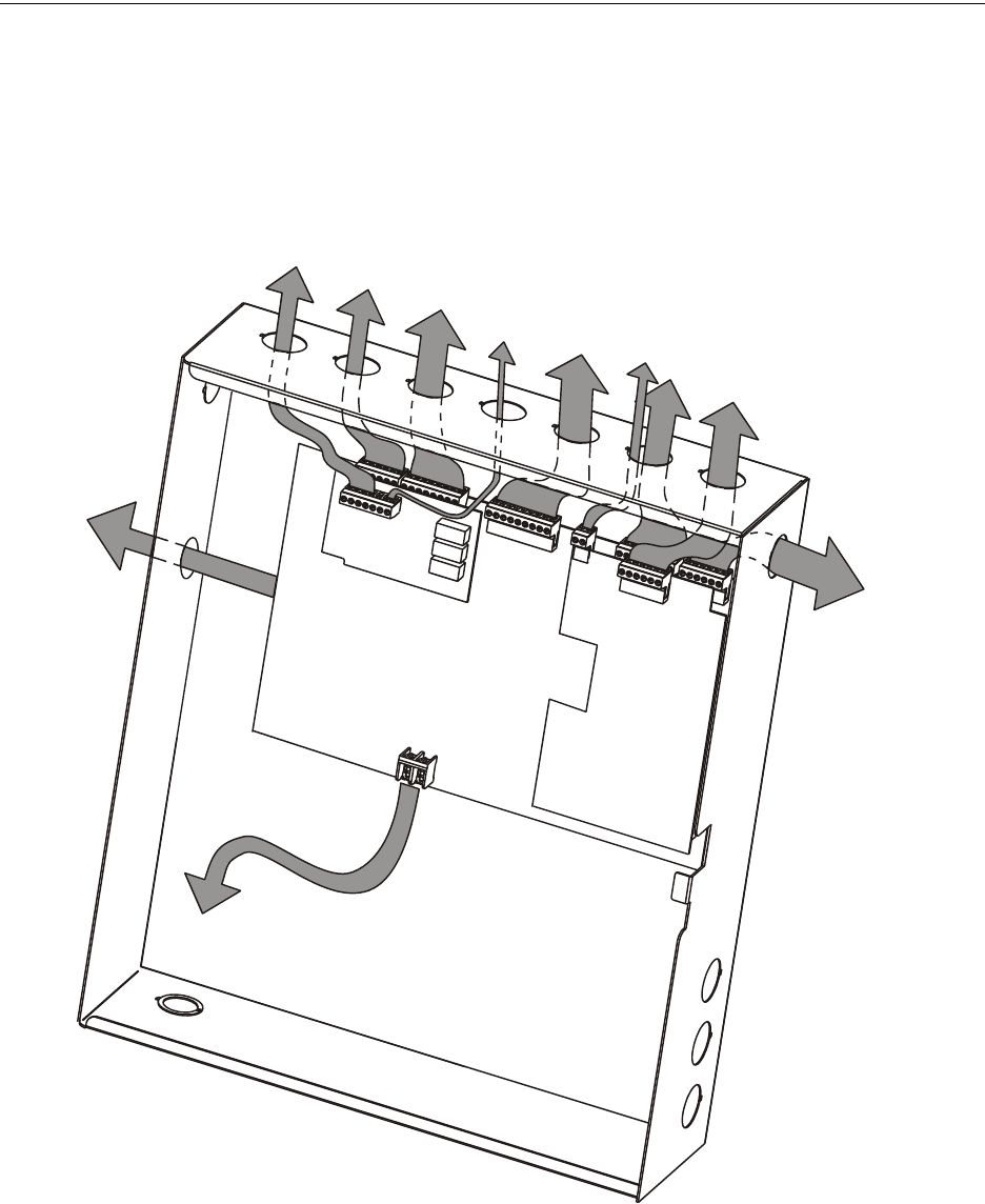
50 MS-9600LS Series Manual — P/N 52646:B2 2/12/2010
Installation Power-limited Wiring Requirements
2.5 Power-limited Wiring Requirements
Power-limited and nonpower-limited circuit wiring must remain separated in the cabinet. All
power-limited circuit wiring must remain at least 0.25” (6.35 mm) away from any nonpower-lim-
ited circuit wiring and nonpower-limited circuit wiring must enter and exit the cabinet through dif-
ferent knockouts and/or conduits. A typical wiring diagram for the FACP is shown below.
Figure 2.9 Typical Power-limited Wiring Requirements
Power-limited Circuits
(Class 2)
Power-limited Circuits
(Class 2)
Nonpower-limited
Circuits
Power-limited
Circuits
(Class 2)
4XTMF
SLC-2LS
AC Power
Nonpower-limited
To Batteries
ms-9600wireroute2.wmf
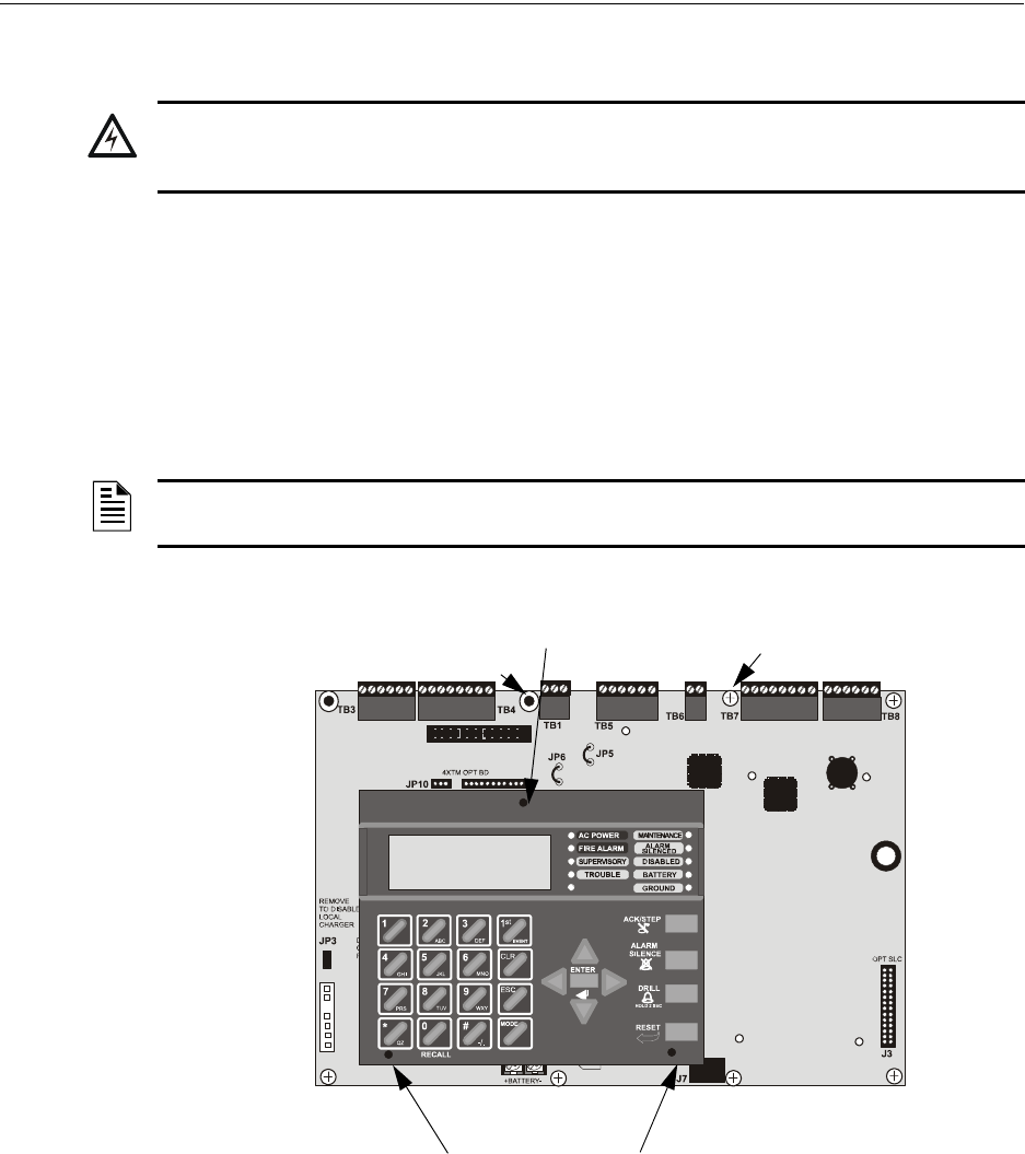
MS-9600LS Series Manual — P/N 52646:B2 2/12/2010 51
Optional Modules and Devices Installation
2.6 Optional Modules and Devices
FACP Keypad/Display Removal
Removal of the keypad/display is normally not necessary. If, however, it becomes necessary to
replace the keypad/display, access the auxiliary trouble bus connectors at J16 and J17 or install the
DACT-UD2 option module on J2, the Keypad/Display can be removed by inserting a Phillips
screwdriver into each of the three holes located in the flexible covering of the Keypad/Display and
loosening the three mounting screws. Note that it is not necessary to disconnect the cables between
the Keypad/Display and the main circuit board unless the unit itself is being replaced. Carefully lift
the Keypad/Display and rest the unit at the bottom of the main circuit board.
!
WARNING: RISK OF ELECTRICAL SHOCK AND EQUIPMENT DAMAGE
DISCONNECT ALL SOURCES OF POWER (AC AND DC) BEFORE INSTALLING OR REMOVING
ANY MODULES OR WIRING.
NOTE: When installing the DACT-UD2, the main motherboard must be removed from the
chassis. Unplug the power supply cable from J1 before proceeding.
Figure 2.10 Keypad/Display Removal
Keypad/Display Mounting
Screw Access Hole
Keypad/Display Mounting
Screw Access Holes
96dact1.wmf
standoff
screw screw
screw
standoff
screw
screw
screw
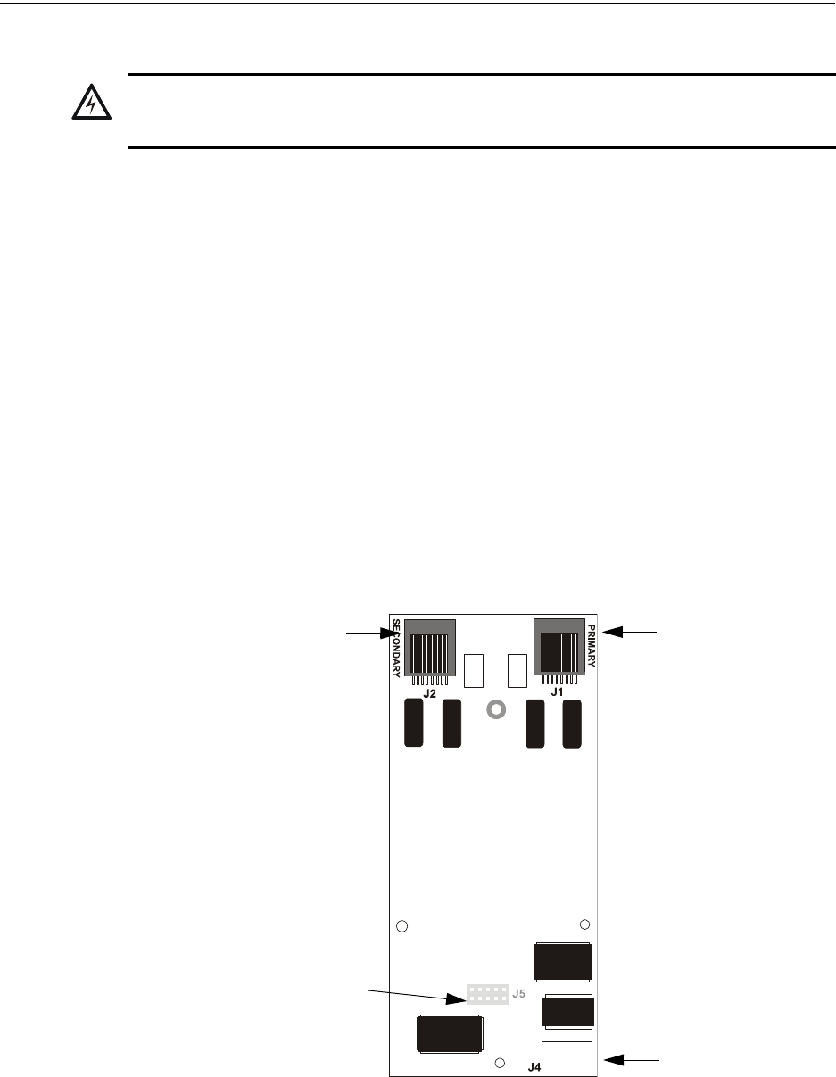
52 MS-9600LS Series Manual — P/N 52646:B2 2/12/2010
Installation Optional Modules and Devices
2.6.1 DACT-UD2 Installation
The DACT-UD2 Digital Alarm Communicator/Transmitter, which is supplied standard with the
MS-9600UDLS/E, transmits system status to UL listed Central Station receivers via the public
switched telephone network. It is capable of reporting up to 99 software zones or up to 636
addressable points. Two modular phone jacks, labeled PRI for Primary phone line and SEC for
Secondary phone line, allow easy connection of two independent telephone lines to the DACT-
UD2. The following functions have been incorporated into the DACT-UD2:
• Line Seizure - takes control of phone lines disconnecting any premises phones
• Off/On Hook - performs on and off-hook status to the phone lines
• Listen for dial tone - 440 hertz tone typical in most networks
• Dialing Central Station(s) number - default is Touch-Tone®, programmable to rotary
• For tone burst or touchtone type formats: determine proper ‘Acknowledge’ and ‘Kissoff’
tone(s) - the frequency and time duration of the tone(s) varies with the transmission format.
The control panel will adjust accordingly
• Communicate in the following formats:
• Ademco Contact ID
•SIA
The DACT-UD2 module plugs into connector J2 on the FACP main circuit board.
!
WARNING: RISK OF ELECTRICAL SHOCK AND EQUIPMENT DAMAGE
DISCONNECT ALL SOURCES OF POWER (AC AND DC) BEFORE INSTALLING OR REMOVING
ANY MODULES OR WIRING.
Figure 2.11 DACT-UD2 Module
SEC
Secondary Phone Line
J5 Connector (located on
back of module) plugs into J2
on FACP main circuit board
PRI
Primary Phone Line
DIALX.wmf
J4
USB Port
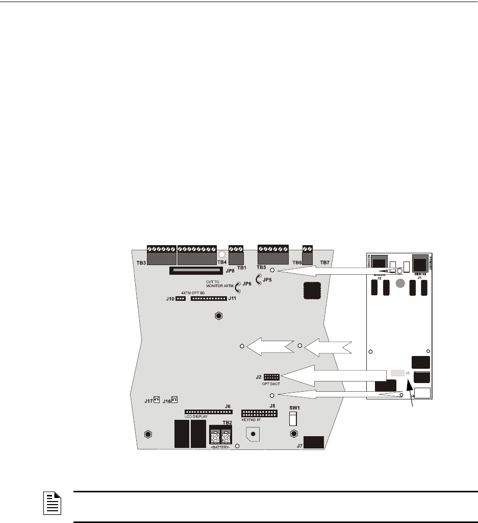
MS-9600LS Series Manual — P/N 52646:B2 2/12/2010 53
Optional Modules and Devices Installation
The following steps must be followed when installing the DACT-UD2 module:
1. Remove all power (AC and DC) from FACP before proceeding with installation
2. Remove all main circuit board mounting screws (6 locations) and the 4XTMF module
standoffs (2 locations), unplug the power supply cable from J1 and lift the main circuit board
assembly off the chassis (refer to Figure 2.10)
3. Remove the Keypad/Display from the main circuit board as described in the beginning of this
section
4. Remove and discard the Keypad/Display support standoff that presently occupies DACT-UD2
standoff location #3 (refer to Figure 2.12)
5. Install the supplied DACT-UD2 female/female standoffs in the three locations shown in Figure
2.12 and secure with the three supplied screws, inserted from the bottom side of the main
circuit board. Be sure to tighten them fully.
6. Carefully plug connector J5 on back of the DACT-UD2 module into connector J2 on the FACP
main circuit board, being careful not to bend any pins
7. Align the mounting holes in the DACT-UD2 module with the newly installed standoffs on the
FACP main circuit board
Secure the mod ule to the standoffs on the main circuit board with tw o of the screws supplie d with the DACT-UD2 and the supplie d male/female standoff wh ich becomes the new Keyp ad/Display support in th at locatio n ( see Figure 2.13)
Figure 2.12 DACT-UD2 J1 Connector to FACP J2 Connector
J5
J2
Standoff 3
Standoff 2
Standoff 1
J1 Connector located on
back of DACT-UD2 module
96dialx2.wmf
NOTE: It is important that the supplied hardware be used to secure the module in order to help
protect against electrical transients.
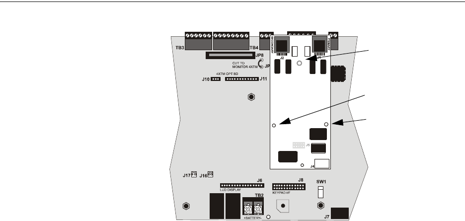
54 MS-9600LS Series Manual — P/N 52646:B2 2/12/2010
Installation Optional Modules and Devices
8. Reinstall Keypad/Display on the main circuit board by positioning the unit over the
appropriate standoffs and securing with screws which were loosened in step 3
9. Remount the main circuit board assembly to the chassis using screws and standoffs in their
original locations. Plug in the power supply cable at J1 on the main circuit board
10. Make certain to program the control panel for DACT-UD2 operation
11. Refer to the Telephone Requirement and Warnings section of the DACT-UD2 Installation and
Programming Manual Document #53037, before proceeding with this step. Connect the
premises primary and secondary phone lines to the DACT-UD2 as illustrated in Figure 2.14
and test the system for correct operation
Figure 2.13 DACT-UD2 Installation on Standoffs
Mounting Screw
male/female standoff
96dialx3.wmf
Mounting Screw
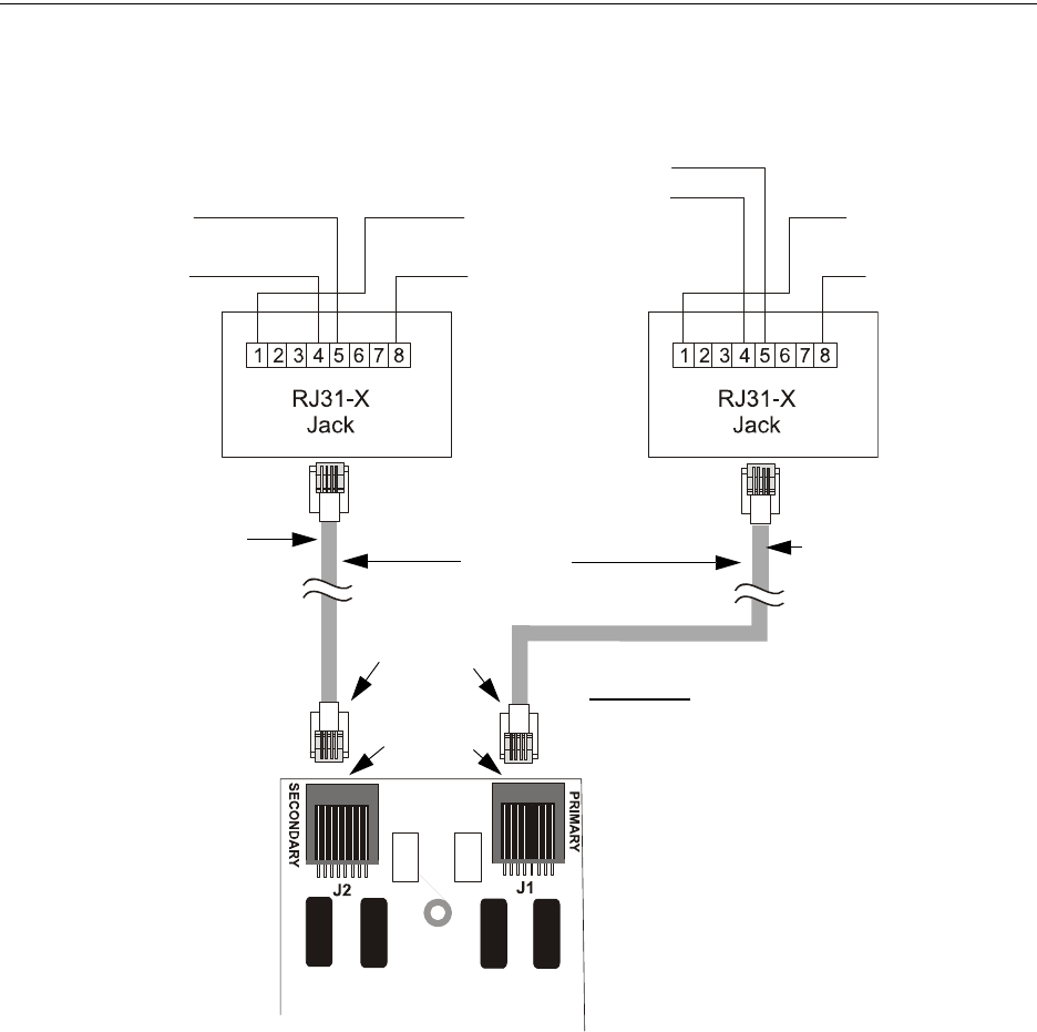
MS-9600LS Series Manual — P/N 52646:B2 2/12/2010 55
Optional Modules and Devices Installation
2.6.2 4XTMF Transmitter Module Installation
The 4XTMF provides a supervised output for a local energy municipal box transmitter in addition
to alarm and trouble reverse polarity. A jumper option allows the reverse polarity circuit to open
with a system trouble condition if no alarm condition exists. A disable switch allows disabling of
the transmitter output during testing to prevent accidental calling of the monitoring service.
Local Energy Municipal Box Service (NFPA 72 Auxiliary Fire Alarm Systems):
Supervisory Current: 5.0 mA
Trip Current: 350 mA (subtracted from notification appliance power)
Coil Voltage: 3.65 VDC
Maximum Coil Resistance: 14.6 ohms
Maximum allowable wire resistance between panel and trip coil: 3 ohms
Municipal Box wiring can leave the building
Figure 2.14 Wiring Phone Jacks
Green Wire
Red Wire
Green Wire
Red Wire
Tip
Ring
Ring
Tip
Ring
Tip Tip
Ring
To premises phones To premises phones
Secondary Lines
Incoming Telco
Phone Lines
Primary Lines
Incoming Telco Phone
Lines
Note: Shorting bars inside RJ31X Jack
removed during male plug insertion
Primary Phone Line PRI
Secondary Phone Line SEC
Male Plug
Connectors
Female
Connectors
7 foot cable
(MCBL-7)
order separately
DACT-UD2
CAUTION: It is critical that the
DACT-UD2 be located as the first
device on the incoming telephone
circuit to properly function
9600jacj.wmf
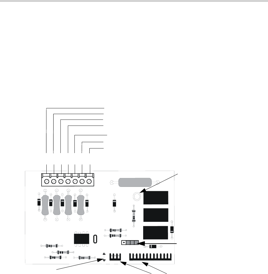
56 MS-9600LS Series Manual — P/N 52646:B2 2/12/2010
Installation Optional Modules and Devices
Remote Station Service (NFPA 72 Remote Station Fire Alarm Systems) - Intended for connec-
tion to a polarity reversal circuit or a Remote Station receiving unit having compatible rat-
ings:
Maximum load for each circuit: 10 mA
Reverse polarity output voltage: 24 VDC
Remote Alarm and Remote Trouble wiring can leave the building
Before installing the module, place the disconnect switch to the right (disconnect) position to pre-
vent accidental activation of the municipal box. Note that a Disconnect LED will illuminate after
the module is installed in the FACP. In addition, the System Trouble LED will turn on to indicate
the Disconnect condition.
The following steps must be followed when installing the 4XTMF module:
1. Remove all power (AC and DC) from the FACP before installing 4XTMF
2. Cut jumper JP6 on the main circuit board to allow the control panel to supervise the 4XTMF
module
3. The NACKEY Card must be separated at the score mark to allow connection of the 4XTMF
module (refer to Figure 2.6 on page 48 for complete information)
4. Carefully plug the connectors on the 4XTMF module into connectors J10 and J11 on the FACP
main circuit board, being careful not to bend any pins
5. Secure 4XTMF module to standoffs with supplied screws.
6. Reapply power to the FACP
7. For proper 4XTMF operation, the output relays must be programmed for the factory default
settings as shown on the PC board silkscreen: Alarm Relay, Trouble Relay and Supervisory
Relay
Figure 2.15 4XTMF Transmitter Module
Connect to FACP J10 & J11
Disconnect Switch
shown in disconnect
position
TBL Jumper
Remote Alarm (power-limited)*
Remote Trouble (power-limited)*
No connection
Municipal Box (nonpower-limited)*
1 2 3 4 5 6 7
+ - + - + -
Polarities are shown for module activation
Note: 4XTMF Module is not suitable for transmitting reverse
polarity supervisory signal.
* Wiring from these terminals
can exit the protected
premises. Dummy load
terminals 6 and 7 (4.7K, ¼
watt resistor) if Municipal Box
is not connected.
Disconnect LED
4xtmfl.wmf
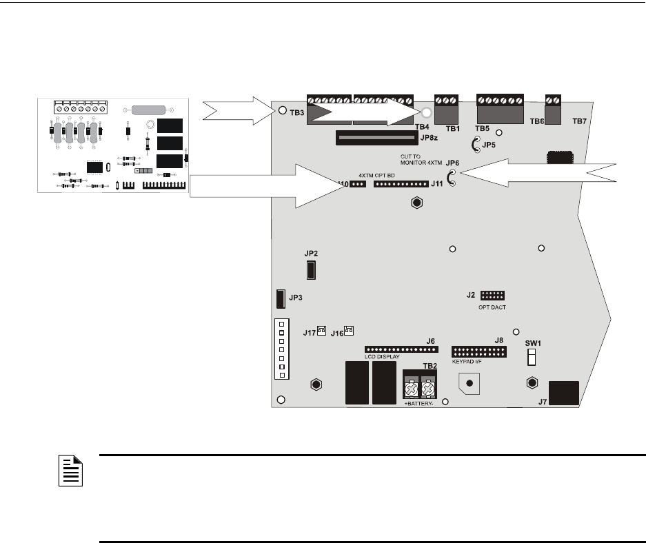
MS-9600LS Series Manual — P/N 52646:B2 2/12/2010 57
Optional Modules and Devices Installation
8. When the installation has been complete, enable the 4XTMF module by sliding the disconnect
switch to the left
9. Test system for proper operation
2.6.3 Auxiliary Trouble Input (J16 & J17)
Auxiliary Trouble Inputs 1 (J17) and 2 (J16), which are located on the FACP main circuit board,
can be used to monitor for trouble conditions on auxiliary equipment such as power supplies. J16
and/or J17 can be connected to any open collector trouble output on the auxiliary equipment. The
control panel will indicate a trouble condition if a trouble is sensed at the Auxiliary Trouble Inputs.
If the 4XTMF Module is installed and FACP jumper JP6 has been cut to supervise it, Auxiliary
Trouble Input 1 (J17) will monitor the 4XTMF for trouble conditions.
2.6.4 SLC-2LS Expander Module
The optional SLC-2LS Expander Module provides a second SLC loop for the FACP control panel.
This allows connection of an additional 318 addressable devices, bringing the total to 636 address-
able devices which can be connected to the FACP. Refer to the SLC Wiring Manual for informa-
tion on connecting devices to the SLC.
IMPORTANT! When SLC wiring is run in conduit, each SLC loop must be installed in separate
conduit.
The following steps must be followed when installing the SLC-2LS Expander Module:
1. Remove all power (AC and DC) from the FACP before installing the SLC-2LS module
2. Remove four screws from main FACP motherboard, from locations indicated in following
illustration, and replace with four supplied metal standoffs
NOTE: Jumper JP5 on the FACP main circuit board can be used to configure the FACP
supervisory relay for operation with the 4XTMF module. The supervisory relay must be
programmed as shown on the main circuit board silk-screen (TB5, Terminals 4, 5 & 6).
Cutting JP5 will allow the 4XTMF to generate a trouble if the supervisory contact opens
Leaving JP5 in will prevent generation of a trouble if the supervisory contact opens
Figure 2.16 4XTMF Connectors to FACP Connectors
J10 & J11 Connectors
Cut Jumper JP6
Standoff Standoff
4XTMF
FACP
9604xtm1.wmf

58 MS-9600LS Series Manual — P/N 52646:B2 2/12/2010
Installation Optional Modules and Devices
3. Carefully plug connector J3 on the SLC-2LS module into connector J3 on the
MS-9600LS/MS-9600UDLS main circuit board, being careful not to bend any pins
4. Secure the SLC-2LS Expander Module to the four standoffs installed in step 2 with the four
supplied screws (or the screws removed in step 2)
5. Connect the SLC wiring and devices to TB8 on the SLC Expander Module. Refer to the SLC
Wiring Manual for wiring information
6. Reapply power to the control panel
7. Program the addressable devices connected to the SLC-2LS Expander Module as detailed in
“Master Programming Level” on page 65
8. Test the system for proper operation
2.6.5 Printer/PC
A serial printer or a PC (personal computer) may be connected to TB7 Terminals 1 - 4 on the FACP.
The printer can be used to provide a hard-copy printout of real-time events, history file and walktest
data. An IBM compatible PC can be connected to provide local FACP programming capabilities
using the PS-Tools programming utility. Installation of either device requires panel programming
to allow the FACP to communicate with the device.
A parallel printer may also be connected to the FACP using the optional ANN-S/PG Serial/Parallel
Interface Module. Refer to “ANN-S/PG Serial/Parallel Interface Installation” on page 30 for
Figure 2.17 SLC-2LS Expander Module Installation
SLC-2LS Expander Module
FACP
SLC Loop 2
Shield B
Shield A
SLC A-
SLC B-
SLC A+
SLC B+
SLC Loop 1
Shield B
Shield A
SLC A-
SLC B-
SLC A+
SLC B+
96optslc.wmf
Remove four screws and replace
with four supplied metal standoffs
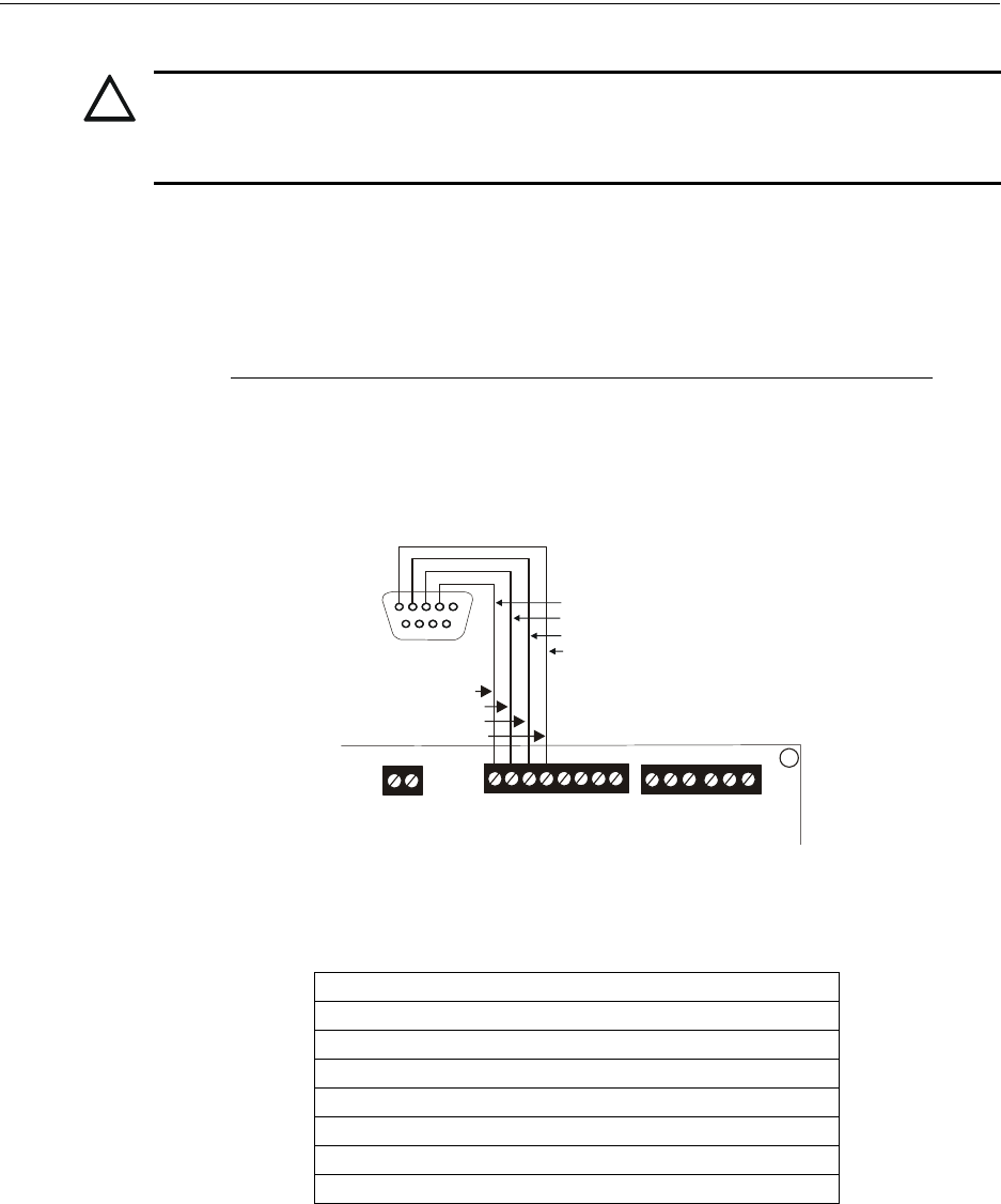
MS-9600LS Series Manual — P/N 52646:B2 2/12/2010 59
Optional Modules and Devices Installation
installation details. Refer to “ANN-BUS Options” on page 121 for programming information.
Installation
Remote printers and PCs require separate primary power. Also required is the PRT/PK-CABLE
which is an interface cable prewired to a DB9F connector. Wire the PRT/PK-CABLE to TB7 Ter-
minals 1 - 4 as illustrated in the following figure. Connect the DB9F connector to the printer or PC
serial EIA-232 port. If a nine-pin serial connector is not available on the printer or PC, use a DB25
adapter. Make certain that the DB25 adapter does not swap the Transmit and Receive lines. Apply
power to the FACP and printer or PC. Note that a ground fault (zero impedance to ground) may
occur on the FACP, dependent on the printer or PC being used, due to this connection. For this rea-
son, it is important that there be no preexisting ground fault on the panel.
Note that the printer may or may not be supervised as determined by user programming. Refer to
“Printer/PC” on page 134.
Printer Configuration
Refer to the documentation supplied with the printer for pertinent information about printer setup.
Set the printer’s options as listed in the following table:
PC Configuration
The Windows-based PK-CD Programming Utility Kit contains a CD-ROM with on-line help file.
2.6.6 Annunciators
Legacy ACM-8RF Relay Control Module
The ACM-8RF module provides eight Form-C relays with contacts rated for 5 amps.
!
CAUTION: POSSIBLE EQUIPMENT DAMAGE
DO NOT CONNECT A PRINTER OR PC TO THE FACP IF A GROUND FAULT (ZERO IMPED-
ANCE TO GROUND) EXISTS ON THE CONTROL PANEL. CIRCUIT DAMAGE MAY RESULT.
REMOVE ALL POWER (AC AND DC) BEFORE INSTALLING OR REMOVING ANY WIRING.
COMMUNICATION SETUP
BUFFER: LARGE
DATA BITS: 7
PARITY: EVEN
STOP BIT: 1 STOP
BAUD RATE: 2400/4800/9600
AUTOMATIC LINE FEED NO
AUTOMATIC CARRIAGE RETURN NO
RS-232 PC/PRINTER
B+ A+ B- A- B A
1 COMM 2
ACS SHIELD
SLC SLC
XMT RCV DTR GRND
T
B
7
T
B
6
T
B
8
RCV
DTR
GRND
TX
5 4 3 2 1
9 8 7 6
Figure 2.18 Serial Printer and Computer Connections
PRT/PK-CABLE
9600tb7a.wmf
Red
White
Green
Black

60 MS-9600LS Series Manual — P/N 52646:B2 2/12/2010
Installation Optional Modules and Devices
Legacy ACM Series Annunciators
ACM and AFM Series Annunciators provide visual indications of FACP status in remote locations.
Refer to the appropriate annunciator manual for information on installation, wiring and operation.

MS-9600LS Series Manual — P/N 52646:B2 2/12/2010 61
Section 3: Programming
3.1 Programming Data Entry
Programming can be accomplished using the FACP keypad or by connecting an optional standard
computer keyboard. The keyboard can be connected to the PS-2 connector J7 on the control panel
main circuit board.
Local or remote programming and editing can also be accomplished using the DACT-UD2 Digital
Alarm Communicator/Transmitter which is optional for the MS-9600LS and supplied standard
with the MS-9600UDLS. Refer to the DACT-UD2 Manual P/N 53037 for detailed information.
The information presented in this section refers to programming the FACP via the onboard keypad.
If an optional computer keyboard is connected to the FACP main circuit board, the following table
describes the keyboard keys which correspond to the onboard keypad keys.
Keypad Keys Computer Keyboard Keys
1st Event Home
CLR Delete
ESC Esc
RECALL Insert
**
##
A - Z A - Z
0 - 9 0 - 9
(on QZ key) Space bar
——
//
••
ENTER Enter
ACK/STEP F1
SILENCE F2
DRILL F3
RESET F4

62 MS-9600LS Series Manual — P/N 52646:B2 2/12/2010
Programming User Programming
3.2 User Programming
The FACP is completely field programmable and requires no special software skills. While pro-
gramming the FACP, the fire protection capabilities of the control panel are enabled. Program-
ming mode will time-out following 10 minutes of inactivity.
Site-specific programming may be accomplished in three ways:
•Autoprogramming Feature - This is a convenient method for quickly bringing the FACP
addressable SLC devices on-line without the necessity of programming each device
individually. Refer to “Autoprogram” on page 66 for a detailed description of
Autoprogramming
• Manual programming or editing, using the FACP keypad or a PC keyboard
• Remote Programming and Editing Feature - allows creation and editing of site-specific custom
programs using a Windows-based computer and modem. For programs requiring a large
amount of data entry, this method may be preferred. A PK-CD programming CD-ROM can be
ordered for this purpose
• Local Programming and Editing Feature - allows creation and editing of site-specific custom
programs using a Windows-based computer and the DACT-UD2 USB connection on the
MS-9600UDLS or Serial Port connection on TB7 of the MS-9600LS. For programs requiring
a large amount of data entry, this method may be preferred. A PK-CD programming CD-ROM
can be ordered for this purpose
The System All Normal screen will be displayed in a programmed system with no active alarms,
troubles or supervisories, as illustrated below:
Read Status mode can be entered while the panel is in any mode of operation. If an alarm or super-
visory event exists at the panel, the event must be cleared before entering Programming mode. To
access any of the programming or read status features, the Enter or Mode key must be pressed,
which will cause the LCD to display the following:
Pressing 1, while this screen is being displayed, will cause the control panel to enter the Read Sta-
tus feature which allows the user to view the programmed features and status of the control panel
The Read Status feature is not password protected. Refer to “Read Status” on page 160 for a
detailed description of this feature.
Pressing 2 will select user Programming which may only be accomplished by an authorized person.
After pressing 2, a screen will prompt for a password. After entering the correct password, the user
may select from a list of programming options.
Pressing 3 will select Remote Download which allows the user to enable the remote programming
option. Refer to the DACT-UD2 manual P/N 53037.
SYSTEM ALL NORMAL
10:00A 010807
1=READ STATUS
2=PROGRAMMING
3=REMOTE DOWNLOAD

MS-9600LS Series Manual — P/N 52646:B2 2/12/2010 63
Initial Power-up Programming
Exit Programming or Read Status
The programmer can exit Read Status or Programming mode by repeatedly pressing the keypad
ESC (Escape) key until the display reads System All Normal. Ten minutes of inactivity will also
cause the FACP to exit Programming mode. Note that the data which is entered during Program-
ming mode is not saved until the programmer exits this mode by repeatedly pressing the ‘ESC’ key.
If the Reset key is pressed or power is lost before exiting Programming mode, all data which was
just entered will be lost.
User Programming Levels
There are two user programming levels:
• User Master Program Level 1 is used for programming panel specific data relating to device
types, zoning, messages, control panel functions, etc.
• User Maintenance Program Level 2 is used by a qualified operator to access features such as
Disable/Enable, View and Clear History, Walktest and System Time Change.
3.3 Initial Power-up
The following sections describe the initial programming procedures for a new system. The same
procedures are used to modify programming in an existing system.
After completing the wiring of addressable devices to the SLC, apply power to the control panel. If
the addressable devices have not yet been programmed into the FACP, their LEDs will not flash and
the following trouble message will be displayed.
3.4 Programming Screens Description
The main options available when the Enter key is pressed are: Read Status, Programming Mode.
Each option has multiple functions or features which may be chosen. To view all of the choices, it
is necessary that the programmer scroll through a number of additional subscreens. These selec-
tions are displayed on multiple screens to make them more readable for the programmer. Refer to
“Master Programming Level” on page 65, for additional information on the various screens.
The title of the main option screen will always be displayed at the top of the subscreens for the pro-
grammer’s convenience. If additional subscreens exist, an Up or Down arrow will be displayed in
the upper right corner of the screen being viewed. The programmer can then press the keypad Up
or Down arrow key to view the new subscreen. To select one of the choices in a screen, the pro-
grammer presses the keypad numerical key corresponding to the desired choice.
Note that subscreens may also have multiple options which require viewing more than one screen.
The same process, as detailed in the previous paragraphs, is followed to view all option choices.
3.5 Programming and Passwords
There are two factory set programming passwords which will access the Programming screens as
indicated in the following examples. From either of the screens, access to specific system and
device features or programming may be obtained. All user programming entries are stored in non-
volatile memory. The factory set passwords can be changed by the user as described in “Password
TROUBL IN SYSTEM
NO DEVICES INSTALLED
09:03A 020410
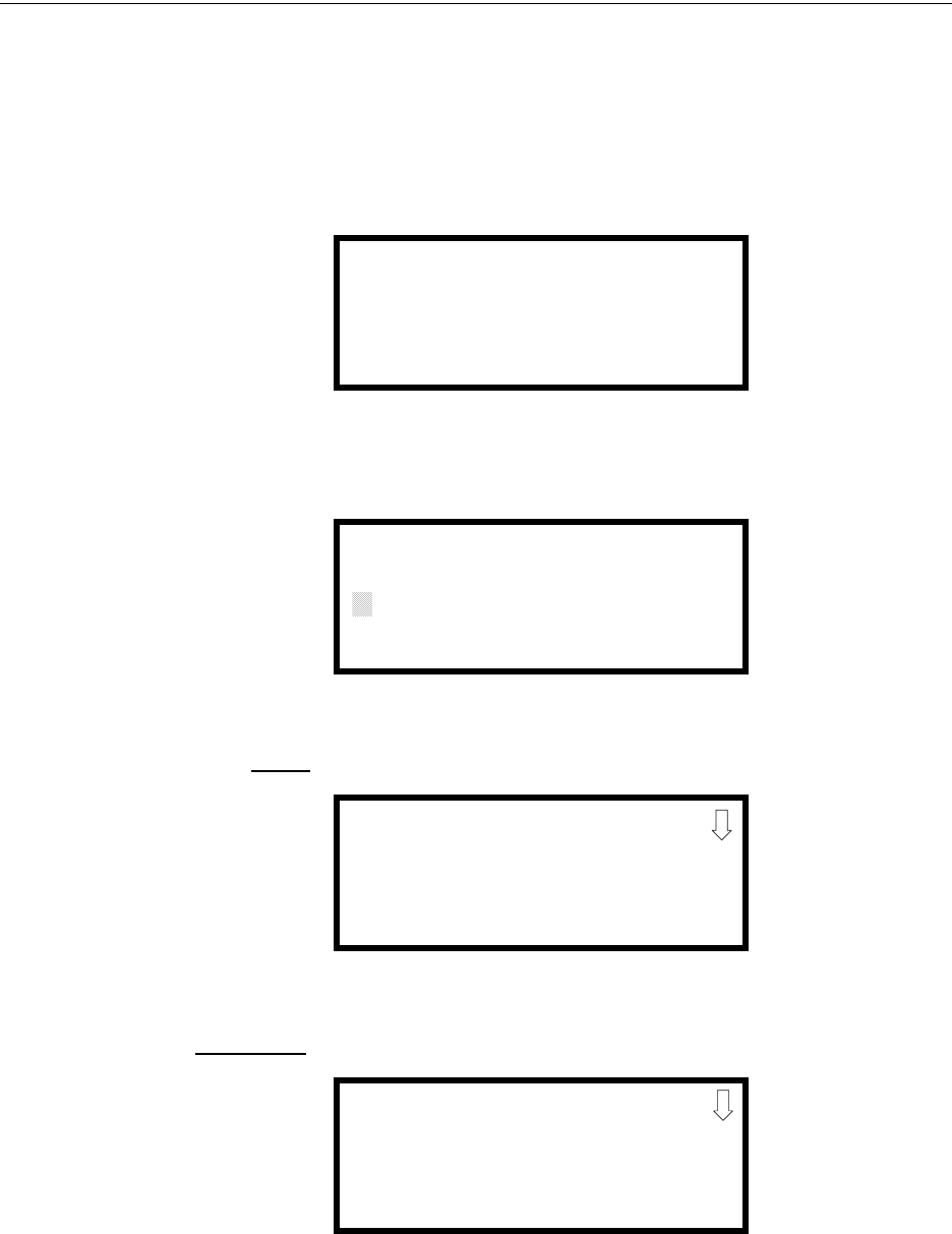
64 MS-9600LS Series Manual — P/N 52646:B2 2/12/2010
Programming Programming and Passwords
Change” on page 135. If an invalid password is entered, the blinking cursor will return to the first
password character position. To exit Programming or Read Status mode at any time, press the ESC
(Escape) key repeatedly. Note that Programming mode must be exited using the ESC key in order
to store the program data entered during this mode. If the Reset key is pressed or power is lost
before exiting Programming mode, the data just entered will not be saved.
To access user Programming mode, press the Enter or Mode key. The LCD will display the follow-
ing:
To enter the user Programming mode, press 2. The display will read as follows:
Entering the Master level password (default 00000) will cause the following screen to appear:
If the Maintenance level password (default 11111) is entered, the following screen will appear:
Note that in the two preceding screens, an arrow appears to inform the programmer that additional
options can be viewed by pressing the keypad down arrow key.
1=READ STATUS
2=PROGRAMMING
3=REMOTE DOWNLOAD
PROGRAMMING
ENTER PASSWORD
*****
PROGRAMMING
1=AUTOPROGRAM
2=POINT PROGRAM
3=ZONE SETUP
PROGRAMMING
1=POINT PROGRAM
2=HISTORY
3=PROGRAM CHECK

MS-9600LS Series Manual — P/N 52646:B2 2/12/2010 65
Master Programming Level Programming
3.6 Master Programming Level
When the Master Program Level password is entered, the control panel will enter user Program-
ming mode. In this mode, the piezo sounder remains off, the trouble relay is activated and the sys-
tem Trouble LED flashes until Programming mode is exited. The following display will appear:
The down arrow which appears in the display indicates that additional programming choices can be
viewed by pressing the down arrow key on the keypad. If a down and up arrow appear in the dis-
play, pressing the ‘down’ arrow key will display the subsequent Programming Screens as illustrated
below while pressing the ‘up’ arrow key will display the previous screen.
PROGRAMMING
1=AUTOPROGRAM
2=POINT PROGRAM
3=ZONE SETUP
Programming Screen #1
PROGRAMMING
1=LOOP SETUP
2=SYSTEM SETUP
3=VERIFY LOOPS
PROGRAMMING
1=HISTORY
2=WALKTEST
3=OPTION MODULES
PROGRAMMING
1=PASSWORD CHANGE
2=CLEAR PROGRAM
3=PROGRAM CHECK
Programming Screen #2
Programming Screen #3
Programming Screen #4

66 MS-9600LS Series Manual — P/N 52646:B2 2/12/2010
Programming Master Programming Level
3.6.1 Autoprogram
Pressing 1 while viewing Programming Screen #1, will select the Autoprogram option, which
prompts the control panel to poll all devices installed on one or both SLC loops. The primary pur-
pose of autoprogramming is to allow the installer a fast and easy way to bring the system on-line as
quickly as possible. The first time the system is powered-up, it should be autoprogrammed.
If the system is already programmed and Autoprogram is initiated, the system will only add default
values for newly installed devices.
When Autoprogram is selected, the programmer is given the option of autoprogramming all loops,
only loop 1 or only loop 2. The following will be displayed on the LCD:
After selecting one of the Autoprogram options, the control panel will begin autoprogramming the
system by communicating with each addressable device installed on one or both loops. While auto-
programming, the panel will display the following:
When Autoprogramming is completed, the control panel will display the type and quantity of each
device installed on the SLC loop(s) similar to the following display:
In the preceding example, the first display indicates that Loop 1 has 55 addressable detectors, 35
monitor modules and 30 control modules installed. The second display indicates that Loop 2 has
no devices installed.
PROGRAMMING
1=AUTOPROGRAM
2=POINT PROGRAM
3=ZONE SETUP
Programming Screen #1
AUTOPROGRAM
1=LOOP 1
2=LOOP 2
3=ALL LOOPS
Autoprogram Loop Select Screen
AUTOPROGRAM
AUTOPROGRAMMING!
PLEASE WAIT
Autoprogram Progress Screen
# OF DET LOOP1 055
# OF MON LOOP1 035
# OF CON LOOP1 030
# OF DET LOOP2 000
# OF MON LOOP2 000
# OF CON LOOP2 000
Autoprogram Result Screen #1
Autoprogram Result Screen #2

MS-9600LS Series Manual — P/N 52646:B2 2/12/2010 67
Master Programming Level Programming
3.6.2 Point Program
The Point Program option allows the programmer to add a new addressable device to an SLC loop,
delete an existing device from a loop or change the programming for an existing device. Pressing
2, while viewing Programming Screen #1, will select the Point Program option and display the fol-
lowing screen:
The programmer selects the desired SLC loop by pressing 1 or 2 in Point Program Screen #1,
which causes the panel to display the following screen:
Detector Programming
Pressing 1, while viewing Point Program Screen #2, will allow the programmer to add, delete or
change the programming of an addressable detector. The following screen will be displayed by the
control panel:
Add Detector
Pressing 1 while viewing the Detector Screen will display the following screen which allows the
programmer to add a new detector address to programming:
PROGRAMMING
1=AUTOPROGRAM
2=POINT PROGRAM
3=ZONE SETUP
Programming Screen #1
POINT PROGRAM
SELECT LOOP
1=LOOP 1
2=LOOP 2
Point Program Screen #1
POINT PROGRAM
SELECT TYPE
1=DETECTOR
2=MODULE
Point Program Screen #2
DETECTOR
1=ADD
2=DELETE
3=EDIT
Detector Screen
ADD DETECTOR
ENTER DETECTOR#
***
Add Detector Screen
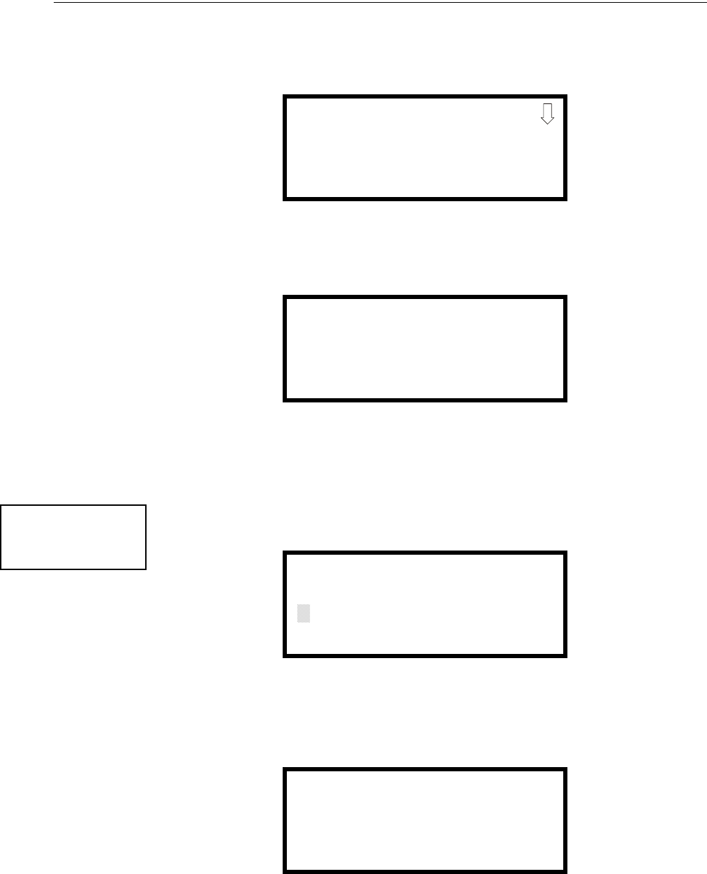
68 MS-9600LS Series Manual — P/N 52646:B2 2/12/2010
Programming Master Programming Level
A flashing cursor will appear in the position of the first asterisk to the left. The programmer keys in
the three digit detector address, such as 005.
When the last digit is keyed-in, the following screen will be displayed:
Press the down arrow key to view additional choices. Press the number corresponding to the
desired selection to program that type to the newly added detector.
When the type has been selected, the following screen will be displayed:
The programmer can continue adding detectors by pressing the ESC or left arrow key which will
return the display to the Add Detector Screen.
Delete Detector
Pressing 2 in the Detector Screen will display the Delete Detector Screen which allows the pro-
grammer to delete a specific detector:
A flashing cursor will appear in the position of the first asterisk to the left. The programmer keys in
the three digit detector address, such as 005. When the last digit is keyed-in, the following screen
will be displayed:
The programmer can continue deleting detectors by pressing the ESC or left arrow key which will
return the display to the Delete Detector Screen.
DETECTOR TYPE
1=SMOKE(PHOTO)
2=USER-DEFINED-1
3=SMOKE(ION)
ADD DETECTOR
DETECTOR# 005
IS ADDED
DETECTOR
1=ADD
2=DELETE
3=EDIT
Detector Screen
DELETE DETECTOR
ENTER DETECTOR#
***
Delete Detector Screen
DELETE DETECTOR
DETECTOR# 005
IS DELETED

MS-9600LS Series Manual — P/N 52646:B2 2/12/2010 69
Master Programming Level Programming
Edit Detector
The programmer can change a detectors existing or factory default programming by pressing 3 in
the Detector Screen. The following screen will be displayed:
A flashing cursor will appear in the position of the first asterisk to the left. The programmer keys in
the three digit detector address, such as 017.
When the last digit is keyed-in, if the selected address has not been added to programming, a screen
showing information about a device that is installed with a lower address, closest to the selected
address, will be displayed.
If no detectors have been installed on the loop, the following will be displayed:
If the selected address has been added to programming, device summary screens will be displayed.
These screens allow the programmer to view all device settings at a single glance. Pressing the left
or right arrow keys will allow the programmer to rapidly view the devices at the previous or next
address (if installed).
If a detector (such as a photoelectric detector) with the selected address is not physically installed
on the SLC or has a communication fault but the address is programmed in the system, the follow-
ing screen will be displayed:
EDIT DETECTOR
ENTER POINT ADDRESS
***
Edit Detector Screen
NO DETECTOR
INSTALLED
Edit Detector Screen #1
TROUBL SMOKE(PHOTO)
********************
ZNNN
* 1D017
Edit Detector Screen #1

70 MS-9600LS Series Manual — P/N 52646:B2 2/12/2010
Programming Master Programming Level
If the selected address has been added to programming and a detector (such as a photoelectric
detector) with the selected address is physically installed on the SLC and is communicating with
the control panel, the following will be displayed:
To change the programming for the displayed detector, press the keyboard ‘down’ arrow key to
view the Edit Detector screens.
In the preceding example:
• Normal - indicates that the detector with the selected address is physically installed on the
SLC and communicating with the control panel (enabled)
• <ADJ><NOUN> - represents the adjective and noun, which have been programmed,
describing the location of the displayed device
• ZNNN - represents the first of five possible software zones that the detector is assigned to
(NNN = the three digit zone number from 000 - 099)
• V or * - indicates whether or not alarm verification is enabled (V = alarm verification
enabled and * = alarm verification disabled)
• 1D017 - represents the Loop, Device type and Device address (1 = SLC Loop 1, D=Detector
and 017 = Detector Address 017)
NORMAL SMOKE (PHOTO)
*********************
ZNNN
V 1D017
Edit Detector Screen #1
MS-9600LS Series Manual — P/N 52646:B2 2/12/2010 71
Master Programming Level Programming
The following examples show the editing of a photoelectric smoke detector with address 017,
located on the first SLC loop:
Enable/Disable Detector
To Enable or Disable the detector, press the 1 key while viewing the Edit Detector Screen #2. Each
press of the key will toggle the screen between Enabled Yes and Enabled No. If Enabled No is
selected, the detector will not be polled by the control panel, preventing the detector from reporting
alarms and troubles to the panel. The control panel will display the device type and address which
has been disabled and will turn on the Trouble LED and Disable LED.
Type
To select the type of detector being programmed, press the 2 key while viewing the Edit Detector
Screen #2. This will cause the control panel to display the following Detector Type Screens:
EDIT DETECTOR 1D017
1=ENABLED YES
2=TYPE SMOKE(PHOTO)
3=VERIFICATION OFF
Edit Detector Screen #2
EDIT DETECTOR 1D017
1=WALKTEST NO
2=PAS NO
3=PRE-SIGNAL NO
Edit Detector Screen #3
EDIT DETECTOR 1D017
1=ZONE ASSIGNMENT
00 ** ** ** **
Edit Detector Screen #4
Edit Detector Screen #5
EDIT DETECTOR 1D017
1=NOUN/ADJECTIVE
2=DESCRIPTION
********************
EDIT DETECTOR
1=ENABLED
2=TYPE
3=VERIFICATION
Edit Detector Screen #2
DETECTOR TYPE
1=SMOKE PHOTO
2=USER DEFINED-1
3=SMOKE (ION)
Detector Type Screen #1
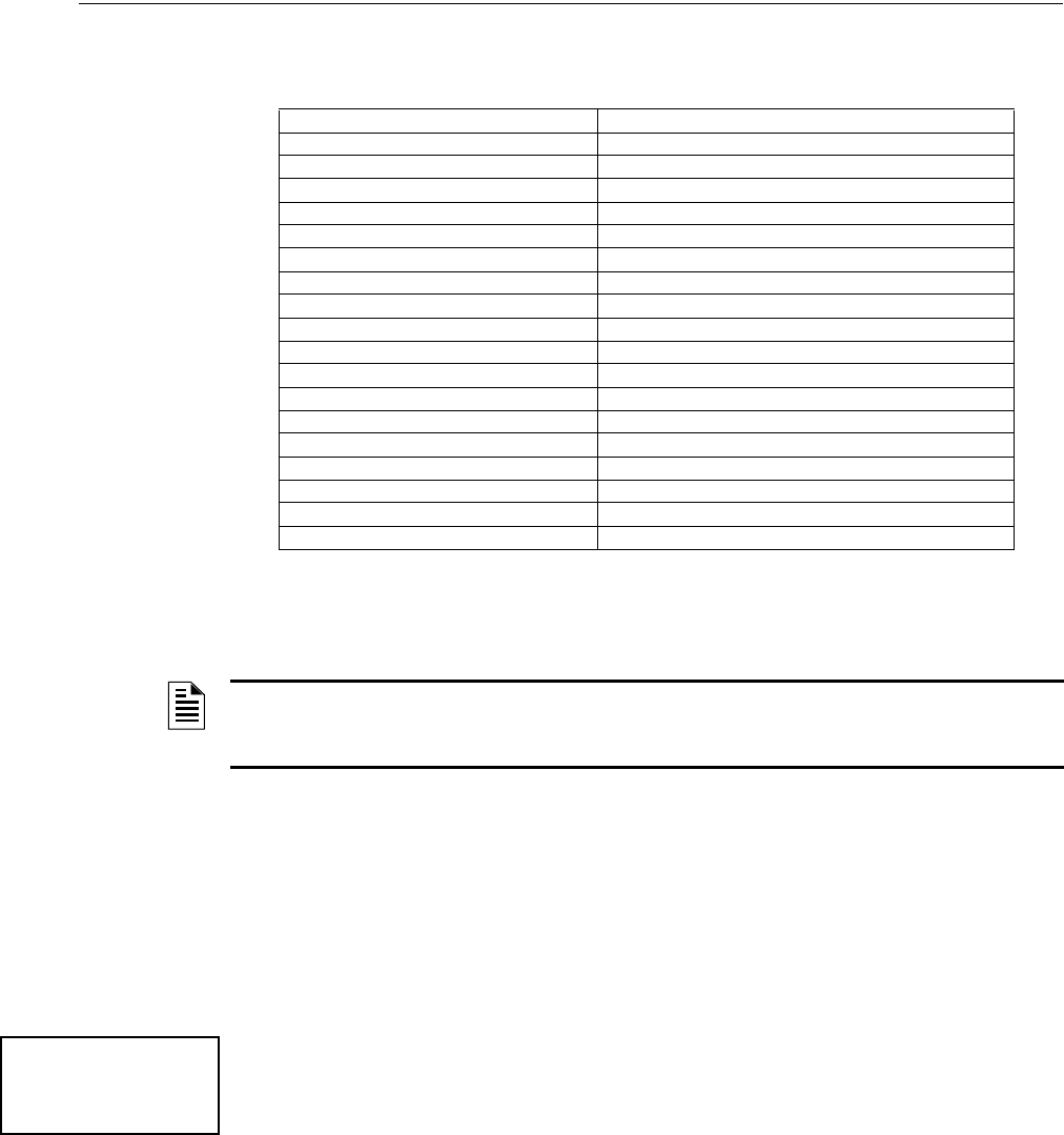
72 MS-9600LS Series Manual — P/N 52646:B2 2/12/2010
Programming Master Programming Level
Pressing the down arrow key will display additional detector types as indicated in the following
table:
While viewing any Detector Type screen, select the type of detector being programmed by pressing
the corresponding keyboard number key. The display will return to Edit Detector Screen #2 and
indicate the selection next to the Type option.
Verification
Alarm verification is used to confirm that a smoke detector activation is a true alarm condition and
not a false alarm. This feature is selected by pressing 3 while viewing the Edit Detector Screen #2
so that the display reads Verification On. Each time the 3 key is pressed, the display will toggle
between Verification On and Verification Off. For a detailed description, refer to “Alarm Verifica-
tion” on page 159.
Walktest
The Walktest feature allows one person to test the system devices without the necessity of manually
resetting the control panel after each device activation. To enable a device for the Walktest feature,
press 1 while viewing the Edit Detector Screen #3 until the display reads Walkt est Yes. Each press
of the 1 key will cause the display to toggle between Walk test Yes and Walktest No. Refer to “Walk-
test” on page 160.
PAS
The PAS (Positive Alarm Sequence) option will program the detector to delay panel activation
(including alarm relay and communicator) for a period of 15 seconds plus a programmable time of
up to 3 minutes. Zone 97, however, will activate immediately and may be used to connect a signal-
ing device to indicate PAS activation (do not use a Notification Appliance Circuit for this purpose).
To enable the PAS feature, press 2 while viewing the Edit Detector Screen #3 until the display reads
PAS Yes. Each press of the 2 key will cause the display to toggle between PAS Yes and PA S N o .
Refer to “Positive Alarm Sequence” on page 158.
For example, if a detector with address 005 is to be configured for PAS operation:
• Select PAS Yes when editing the detector set to address 005
Detector Type Action When Activated
Smoke Photo Fire Alarm
User-Defined-1 same as previous (Smoke Photo)
Smoke Ion Fire Alarm
User-Defined-2 same as previous (Smoke Ion)
Heat Detect Fire Alarm
User-Defined-3 same as previous (Heat Detect)
Smoke DuctP Fire Alarm
User-Defined-4 same as previous (Smoke DuctP)
Photo w/Heat Fire Alarm
User-Defined-5 same as previous (Photo w/Heat)
Duct-Superv Supervisory, latching
User-Defined-6 same as previous (Superv DuctP)
Photo-SupervAR Supervisory, nonlatching (works only in LiteSpeed)
User-Defined-7 same as previous (Photo-SupervAR)
ADAPT Fire Alarm
User-Defined-8 same as previous (ADAPT)
Beam Fire Alarm
User-Defined-9 same as previous (Beam)
NOTE: If a detector is selected as a SUPERV DUCTP type, it will function like a supervisory point,
not a fire alarm point. The supervisory LED and supervisory relay will activate, not the fire alarm LED
or alarm relay, if smoke is sensed.
EDIT DETECTOR
1=WALKTEST
2=PAS
3=PRE-SIGNAL
Edit Detector Screen #3

MS-9600LS Series Manual — P/N 52646:B2 2/12/2010 73
Master Programming Level Programming
• Program the desired zone or zones to be activated by this detector, in this example Z001
• Program an output, such as a control module that is to be activated by detector 005 by
assigning the same zone to it; in this example Z001
• Program an output, such as a control module, for PAS activation by assigning zone Z97 to it.
This control module may be connected to a signaling device used to indicate a PAS
condition (do not use a Notification Appliance Circuit for this purpose)
• Enable zones Z001 and Special Purpose Zone PAS 97 and set the PAS delay timer to some
value
With the preceding program settings, when the detector with address 005 is activated, zone Z97
will cause its associated control module to activate immediately, sounding the connected PAS sig-
naling device. Following the PAS delay time, zone Z001 will cause its associated control module
to activate and the control panel will initiate an alarm condition.
Note that a detector can be enabled for either PAS or Pre-signal but not both.
Pre-signal
The Pre-signal option programs the detector to delay panel activation for a preprogrammed time
delay of up to three minutes while allowing for visual verification by a person. Note that the alarm
relay and communicator will respond to the initial alarm immediately. In addition, Zone 98 will
activate. This zone can be programmed to a control module which may be used to activate a
sounder or indicator which the installer designates as a Presignal indication (do not use a Notifica-
tion Appliance Circuit for this purpose). To enable the Pre-signal feature, press 3 while viewing
Edit Detector Screen #3 until the display reads Pre-signal Yes. Each press of the 3 key will cause
the display to toggle between Pre-signal Yes and Pre-signal No. Refer to “Presignal” on page 158.
For example, if a detector with address 005 is to be configured for Pre-Signal operation:
• Select Pre-signal Yes when editing the detector set to address 005.
• Program the desired zone or zones to be activated by this detector, in this example Z001.
• Program an output, such as a control module that is to be activated by detector 005 by
assigning the same zone to it; in this example Z001.
• Program an output, such as a control module, for Pre-signal activation by assigning zone
Z98 to it. This control module may be connected to a signaling device used to indicate a
Pre-signal condition (do not use a Notification Appliance Circuit for this purpose).
• Enable zones Z001 and Special Purpose Zone Pre-signal 98 and set the Pre-signal delay
timer to some value.
With the preceding program settings, when the detector with address 005 is activated, zone Z98
will cause its associated control module to activate immediately, sounding the connected signaling
device to indicate the Pre-signal condition. Following the Pre-signal delay time, zone Z001 will
cause its associated control module to activate and the control panel will initiate an alarm condition.
Note that a detector can be enabled for either PAS or Pre-signal but not both.
Zone Assignment
A maximum of five zones can be programmed to each addressable detector. Pressing 1 while view-
ing Edit Detector Screen #4 displays the following screen:
EDIT DETECTOR
1=WALKTEST
2=PAS
3=PRE-SIGNAL
Edit Detector Screen #3
EDIT DETECTOR
1=ZONE ASSIGNMENT
00 ** ** ** **
Edit Detector Screen #4
ZONE ASSIGNMENT
Z00 Z** Z** Z** Z**
Zone Assignment Screen

74 MS-9600LS Series Manual — P/N 52646:B2 2/12/2010
Programming Master Programming Level
Note that Z** represents the Zone Number(s) corresponding to this device. The factory default for
an unprogrammed device is Z00 for general alarm zone. A flashing cursor will appear on the first 0
to the left. Enter the two digit number corresponding to the zone that is to be assigned to this
device. The cursor moves to the next Z** designation. Continue entering zone assignments or the
remaining zones can be left blank or programmed as general alarm zone Z00. When all desired
changes have been made, press the Enter key to store the zone assignments. The display will return
to the Edit Detector Screen #4. Note that the left and right arrow keys can be used to navigate
through the zones and the CLEAR key can be used to quickly clear a zone.
Noun/Adjective
The Noun/Adjective selection allows the programmer to enter specific descriptors about the detec-
tor currently being programmed. Pressing 1 while viewing Edit Detector Screen #5 will cause the
following screen to be displayed:
EDIT DETECTOR
1=NOUN/ADJECTIVE
2=DESCRIPTION
*****************
Edit Detector Screen #5
1=STANDARD ADJECTIVE
2=STANDARD NOUN
3=CUSTOM ADJECTIVE
4=CUSTOM NOUN
Noun/Adjective Screen
MS-9600LS Series Manual — P/N 52646:B2 2/12/2010 75
Master Programming Level Programming
Pressing 1 while viewing the Noun/Adjective Screen will cause the following screen(s) to be dis-
played. Note that the keyboard down arrow key must be pressed to see all the Adjective screens.
Press the number corresponding to the adjective that is to be used as a descriptor for the location of
the detector currently being programmed. When an adjective has been selected, it will appear at the
top of the display as indicated by the asterisks.
1=STANDARD ADJECTIVE
2=STANDARD NOUN
3=CUSTOM ADJECTIVE
4=CUSTOM NOUN
Noun/Adjective Screen
**********************
1=NORTH
2=SOUTH
3=EAST
Adjective Screen #1
**********************
1=WEST
2=FRONT
3=CENTER
Adjective Screen #3
**********************
1=REAR
2=UPPER
3=LOWER
Adjective Screen #5
*********************
1=MAIN
2=FIRST
3=2ND
Adjective Screen #7
**********************
1=3RD
2=4TH
3=5TH
Adjective Screen #2
**********************
1=FLOOR4
2=FLOOR5
3=ROOM
Adjective Screen #6
**********************
1=FLOOR1
2=FLOOR2
3=FLOOR3
Adjective Screen #4

76 MS-9600LS Series Manual — P/N 52646:B2 2/12/2010
Programming Master Programming Level
Pressing 2 while viewing the Noun/Adjective Screen will cause the following screen(s) to be dis-
played. Note that the keyboard down arrow key must be pressed to see all the Noun screens. Press
the number corresponding to the noun that is to be used as a descriptor for the location of the detec-
tor currently being programmed. When a noun has been selected, it will appear at the top of the
display as indicated by the asterisks.
1=STANDARD ADJECTIVE
2=STANDARD NOUN
3=CUSTOM ADJECTIVE
4=CUSTOM NOUN
Noun/Adjective Screen
**********************
1=BASEMENT
2=BOILER RM
3=CLASSROOM
Noun Screen #1
**********************
1=CLOSET
2=CORRIDOR
3=ELECTRIC RM
Noun Screen #3
**********************
1=ELEVATOR
2=ENTRANCE
3=FLOOR
Noun Screen #5
**********************
1=GARAGE
2=HALLWAY
3=HVAC RM
Noun Screen #7
**********************
1=KITCHEN
2=LOBBY
3=OFFICE
Noun Screen #2
**********************
1=STAIRWAY
2=STOREROOM
3=WING
Noun Screen #6
**********************
1=PATIENT
2=RESTROOM
3=ROOM
Noun Screen #4
**********************
1=ZONE
Noun Screen #8
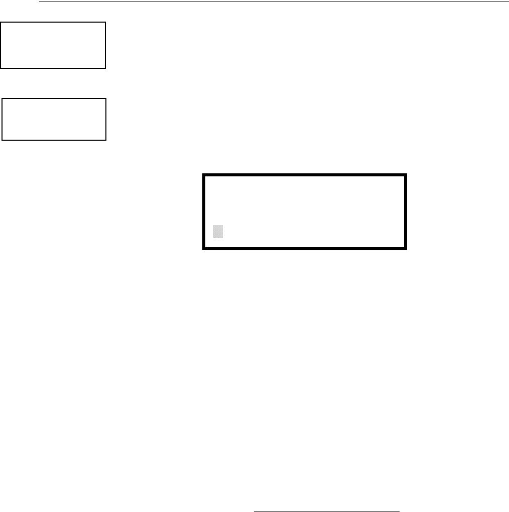
MS-9600LS Series Manual — P/N 52646:B2 2/12/2010 77
Master Programming Level Programming
Pressing 3 or 4 while viewing the Noun/Adjective Screen will display screens similar to the previ-
ous Adjective and Noun Screens. The new screens will list custom Adjectives and Nouns which
have been programmed into the control panel using the PS-Tools programming kit. These descrip-
tors are selected as described in the previous sections.
Description
The Description selection allows the programmer to enter additional information about the detector
currently being programmed. This information will be displayed as part of the device label on the
display. Pressing 2 while viewing Edit Detector Screen #5 will cause the following screen to be
displayed:
A flashing cursor will appear at the first asterisk to the left. The programmer can enter additional
descriptive information about the device being programmed. This information will appear on the
display along with the standard device label information.
A maximum of 20 characters (including spaces) can be entered. To enter alphanumeric characters
from the keypad, repeatedly press the appropriate key until the desired character is displayed in the
first position. For example, to enter the letter B, press the 2 (ABC) key three times to toggle
through the characters 2, A, and B. Press the right arrow key to move the cursor one position to the
right and repeat the process to enter the next character. To enter a space, press the * (QZ) key four
times until a blank appears in the desired position. When all characters have been entered, press the
Enter key to store the information. The display will return to the Edit Detector Screen #5, display-
ing the new information at the bottom of the screen.
Recall/Increment Function
In addition, the user may use the Recall/Increment function at any time when the cursor is on the
first letter of the Description, Adjective or Noun field as follows:
• If the zero key is pressed, a 0 is placed in the first letter position.
• If the zero key is then pressed a second time with no intervening key actions, the entire field is
replaced with the field entered for the previous device programmed, and the cursor moves to
the last character of the field (Recall function). The Recalled Adjective or Noun field may
now be changed letter-by-letter.
• If the zero key is pressed again with no other intervening key actions and the last character in
the field is a number 0-9, the number is incremented by one. If the last character is a letter, it
changes to a 0. If the last character is 9 it goes to 0.
• The above increment function may be repeated with each press of the zero key.
As an example, the user could quickly enter ‘FLR_3_ROOM_305’ as follows:
1. The cursor is on the first letter of the Adjective field. Press the zero key twice to display
FLR_3.
2. With the cursor on the first letter of the Noun field, press the zero key twice to recall the
display ROOM_304. The cursor automatically jumps from the first to the last letter of the
Noun field.
1=STANDARD ADJECTIVE
2=STANDARD NOUN
3=CUSTOM ADJECTIVE
4=CUSTOM NOUN
Noun/Adjective Screen
EDIT DETECTOR
1=NOUN/ADJECTIVE
2=DESCRIPTION
Edit Detector Screen #5
DESCRIPTION 1D002
NOUN/ADJECTIVE
********************
Adjective/Noun Screen

78 MS-9600LS Series Manual — P/N 52646:B2 2/12/2010
Programming Master Programming Level
3. With the cursor on the last letter of the Noun field, press the zero key again to increment the
room number to 305.
4. Press the right arrow key to advance the zone field.
5. Select a zone number from 00 to 99. Z00 (default zone) is the general alarm zone. Z01
through Z99 may be selected to link software zones.
Module Programming
Pressing 2, while viewing Point Program Screen #2, will allow the programmer to add, delete or
change the programming of an addressable module. The following screen will be displayed by the
control panel:
Add Module
Pressing 1 while viewing the Modules Screen will display the following screen which allows the
programmer to add a new module address to programming:
A flashing cursor will appear in the position of the first asterisk to the left. The programmer keys in
the three digit module address, such as 005.
When the last digit is keyed-in, the following screen will be displayed:
POINT PROGRAM
SELECT TYPE
1=DETECTOR
2=MODULE
Point Program Screen #2
MODULES
1=ADD
2=DELETE
3=EDIT
Modules Screen
ADD MODULE
ENTER MODULE#
***
Add Module Screen #1
ADD MODULE
1=CONTROL
2=MONITOR
Add Module Screen #2

MS-9600LS Series Manual — P/N 52646:B2 2/12/2010 79
Master Programming Level Programming
Pressing 1 for Control Module or 2 for Monitor Module will cause the following screen to be dis-
played:
The programmer can continue adding modules by pressing the ESC or left arrow key which will
return the display to the Add Module Screen #1.
Delete Module
Pressing 2 in the Modules Screen will display the Delete Module Screen which allows the program-
mer to delete a specific module:
A flashing cursor will appear in the position of the first asterisk to the left. Using the panel keypad,
key in the module address such as 005. When the last digit is keyed in, the following confirmation
that the module has been deleted will be displayed:
Edit Module Screen for Monitor Module
The programmer can change a modules existing or factory default programming by pressing 3 in
the Modules Screen. The following screen will be displayed:
ADD MODULE
MODULE# 005
IS ADDED
Add Module Screen #3
MODULES
1=ADD
2=DELETE
3=EDIT
Modules Screen
DELETE MODULE
ENTER MODULE#
***
Delete Module Screen
DELETE MODULE
MODULE# 005
IS DELETED
EDIT MODULE
ENTER MODULE ADDRESS
***
Edit Module Screen

80 MS-9600LS Series Manual — P/N 52646:B2 2/12/2010
Programming Master Programming Level
A flashing cursor will appear in the position of the first asterisk to the left. The programmer keys in
the three digit module address, such as 012. When the last digit is keyed-in, if the selected address
has not been added to programming, a screen showing information about a device that is installed
with a lower address, closest to the selected address, will be displayed. If no modules are installed
on the loop, the following screen will be displayed:
If the selected address has been added to programming but a module (such as a monitor module)
with the selected address is not physically installed on the SLC or has a communication fault, the
following screen will be displayed:
If the selected address has been added to programming and a module (such as a monitor module)
with the selected address is physically installed on the SLC and is communicating with the control
panel, the following screen will be displayed:
To change the programming for the displayed module, press the keyboard down arrow key to view
the following Edit Monitor screens. In the preceding example:
• Normal - indicates that the module with the selected address is physically installed on the
SLC and communicating with the control panel (enabled).
• <ADJ><NOUN> - represents the adjective and noun, which have been programmed,
describing the location of the displayed device.
• ZNNN - represents the first of five possible software zones that the module is assigned to
(NNN = the two digit zone number from 000 - 099).
• 1M012 - represents the Loop, Device type and Device address (1 = SLC Loop 1, M=Module
and 012 = Module Address 012).
If the selected address corresponds to a control module, a screen displaying information about the
control module with the selected address will be displayed as shown in “Edit Module Screen for
Control Modules” on page 88.
NO MODULE
INSTALLED
Edit Module Screen
TROUBL MONITOR
<ADJ><NOUN>
ZNNN
1M012
NORMAL MONITOR
<ADJ><NOUN>
ZNNN
1M012

MS-9600LS Series Manual — P/N 52646:B2 2/12/2010 81
Master Programming Level Programming
If the selected address corresponds to a monitor module, a screen displaying information about the
module with the selected address will be displayed as illustrated in the following:
Enable/Disable Module
To Enable or Disable the monitor module, press the 1 key while viewing the Edit Module Screen
#2. Each press of the key will toggle the screen between Enabled Yes and Enabled No. If Enabled
No is selected, the module will not be polled by the control panel, preventing the module from
reporting alarms and troubles to the panel. The control panel will indicate a system trouble condi-
tion and the Disable LED with turn on if any devices are disabled.
NORMAL MONITOR
<ADJ><NOUN>
ZNNN
1M012
EDIT MONITOR 1M012
1=ENABLED YES
2=TYPE MONITOR
Edit Monitor Screen #2
EDIT MONITOR 1M012
1=PRE-SIGNAL NO
Edit Monitor Screen #3
EDIT MONITOR 1M012
1=WALKTEST YES
2=ZONE ASSIGNMENT
00 ** ** ** **
Edit Monitor Screen #4
EDIT MONITOR 1M012
1=ADJECTIVE/NOUN
2=DESCRIPTION
********************
Edit Monitor Screen #5
82 MS-9600LS Series Manual — P/N 52646:B2 2/12/2010
Programming Master Programming Level
Type Monitor
The FACP response to the activation of a user-defined type is the same as most previous standard
types in the list, thus allowing a variety of user-defined types and responses. To select the type of
monitor module being programmed, press the 2 key while viewing the Edit Monitor Screen #2.
This will cause the control panel to display the following Monitor Type Screens:
Pressing the down arrow key will display additional Monitor Type screens. While viewing one of
the Monitor Type screens, select the type of monitor module being programmed by pressing the
corresponding keypad number key. The display will return to the Edit Monitor Screen #2 which
will show the new type selection.
Table 3.1 lists the Monitor Types and their respective functions.
EDIT MONITOR
1=ENABLED
2=TYPE MONITOR
Edit Monitor Screen #2
MONITOR TYPE
1=PULL-STATION
2=USER-DEFINED-1
3=WATERFLOW
Monitor Type Screen #1

MS-9600LS Series Manual — P/N 52646:B2 2/12/2010 83
Master Programming Level Programming
Monitor module type selection will affect the function of the point as follows:
Monitor Type Action When Activated
Pull-Station Fire Alarm
User-Defined-1 same as previous (Pull-Station)
Waterflow Fire Alarm Delayed
User-Defined-2 same as previous (Waterflow)
Monitor Fire Alarm
User-Defined-3 same as previous (Monitor)
Future not used
Future not used
Smoke-Conventional1
1 Conventional 2-wire smoke detectors may be powered using an external power supply
with an SLC Control Relay Module programmed for Resettable Power operation (refer
to note 1 on page page 89).
Fire Alarm
User-Defined-5 same as previous (Smoke-Conventional)
Heat-Conventional Fire Alarm
User-Defined-6 same as previous (Heat-Detector)
Medic-Alert2
2 Combination systems employing these non-fire monitor types require the SLC loop to
be programmed by the installer for Style 4 operation and isolator modules must be
employed on each non-fire branch of the SLC as per Figure 13 in the Fire-Lite SLC
Wiring Manual (document number 51309). Fire and non-fire devices must not be used
on the same SLC branch.
Supervisory, latching
User-Defined-7 same as previous (Medic-Alert)
Hazard-Alert2Supervisory, latching
User-Defined-8 same as previous (Hazard-Alert)
Tornado-Alert2Supervisory, latching
User-Defined-9 same as previous (Tornado-Alert)
Phone Active Phone (LCD display only)
User-Defined-10 same as previous (Phone)
Tamper Supervisory, nonlatching (tracking)
User-Defined-11 same as previous (Tamper)
Supervisory Supervisory, latching
User-Defined-12 same as previous (Supervisory)
Supervisory-AR3
3 For all entries ending in AR, AR refers to AutoResettable.
Supervisory, nonlatching (tracking)
User-Defined-13 same as previous (Supervisory-AR)
HVAC OVRRIDE4
4 For HVAC RESTART and HVAC OVRRIDE descriptions, refer to “Monitor Module
Operation” on page 198.
Switch Supervisory, nonlatching (tracking)
Power-Monitor Power Fault
User-Defined-14 same as previous (Power Monitor)
Trouble-Monitor Trouble
User-Defined-15 same as previous (Trouble Monitor)
Process-Monitor2Piezo
User-Defined 16 same as previous (Process-Monitor)
Process-Monitor-AR2, 3 Piezo, nonlatching (tracking)
User-Defined-17 same as previous (Process-Monitor-AR)
Future not used
Future not used
Ack-Switch Acts like panel Acknowledge Key
Sil-Switch Acts like panel Silence Key
Reset-Switch Acts like panel Reset Key
Drill-Switch Acts like panel Drill Key
PAS-Bypass PAS Disable
HVAC RESTART4Switch
Drill-Switch-AR3Drill Switch, nonlatching (tracking)
Table 3.1 Monitor Types
84 MS-9600LS Series Manual — P/N 52646:B2 2/12/2010
Programming Master Programming Level
Pre-signal
To enable the Pre-signal feature, press 1 while viewing Edit Monitor Screen #3 until the display
reads Pre-signal Yes. Each press of the 1 key will cause the display to toggle between Pre-signal
Yes and Pre-signal No. Refer to “Presignal” on page 158 for additional information.
Walktest
The Walktest feature allows one person to test the system devices without the necessity of manually
resetting the control panel after each device activation. To enable devices, which are connected to
a monitor module, for the Walktest feature, press 1 while viewing the Edit Monitor Screen #4 until
the display reads Walktest Yes. Each press of the 1 key will cause the display to toggle between
Walktest Yes and Walktest N o . Refer to “Walktest” on page 160 for additional information.
Zone Assignment
A maximum of five zones can be programmed to each addressable monitor module. Pressing 2
while viewing Edit Monitor Screen #4 displays the following screen:
Note that Z** represents the Zone Number(s) corresponding to this device. The factory default for
an unprogrammed device is Z00 for general alarm zone. A flashing cursor will appear on the first 0
to the left. Enter the two digit number corresponding to the zone that is to be assigned to this
device. The cursor moves to the next Z** designation. Continue entering zone assignments or the
remaining zones can be left blank or programmed as general alarm zones Z00. When all desired
changes have been made, press the Enter key to store the zone assignments. The display will return
to the Edit Monitor Screen #4.
Noun/Adjective
The Noun/Adjective selection allows the programmer to enter specific descriptors about the moni-
tor module currently being programmed. Pressing 1 while viewing Edit Monitor Screen #5 will
cause the following screen to be displayed:
EDIT MONITOR
1=PRE-SIGNAL
Edit Monitor Screen #3
EDIT MONITOR
1=WALKTEST
2=ZONE ASSIGNMENT
00 ** ** ** **
Edit Monitor Screen #4
MON ZONE ASSIGN
Z00 Z** Z** Z** Z**
Zone Assignment Screen
EDIT MONITOR
1=NOUN/ADJECTIVE
2=DESCRIPTION
*****************
Edit Monitor Screen #5
1=STANDARD ADJECTIVE
2=STANDARD NOUN
3=CUSTOM ADJECTIVE
4=CUSTOM NOUN
Noun/Adjective Screen
MS-9600LS Series Manual — P/N 52646:B2 2/12/2010 85
Master Programming Level Programming
Pressing 1 while viewing the Noun/Adjective Screen will cause the following screen(s) to be dis-
played. Note that the keyboard down arrow key must be pressed to see all the Adjective screens.
Press the number corresponding to the adjective that is to be used as a descriptor for the location of
the monitor module currently being programmed.
1=STANDARD ADJECTIVE
2=STANDARD NOUN
3=CUSTOM ADJECTIVE
4=CUSTOM NOUN
Noun/Adjective Screen
**********************
1=NORTH
2=SOUTH
3=EAST
Adjective Screen #1
**********************
1=WEST
2=FRONT
3=CENTER
Adjective Screen #3
**********************
1=REAR
2=UPPER
3=LOWER
Adjective Screen #5
**********************
1=MAIN
2=FIRST
3=2ND
Adjective Screen #7
**********************
1=3RD
2=4TH
3=5TH
Adjective Screen #2
**********************
1=FLOOR 4
2=FLOOR 5
3=ROOM
Adjective Screen #6
**********************
1=FLOOR 1
2=FLOOR 2
3=FLOOR 3
Adjective Screen #4
86 MS-9600LS Series Manual — P/N 52646:B2 2/12/2010
Programming Master Programming Level
Pressing 2 while viewing the Noun/Adjective Screen will cause the following screen(s) to be dis-
played. Note that the keyboard down arrow key must be pressed to see all the Noun screens. Press
the number corresponding to the noun that is to be used as a descriptor for the location of the mon-
itor module currently being programmed.
Pressing 3 or 4 while viewing the Noun/Adjective Screen will display screens similar to the previ-
ous Adjective and Noun Screens. The new screens will list Custom Adjectives and Nouns which
have been programmed into the control panel using the PS-Tools programming kit.
1=STANDARD ADJECTIVE
2=STANDARD NOUN
3=CUSTOM ADJECTIVE
4=CUSTOM NOUN
Noun/Adjective Screen
**********************
1=BASEMENT
2=BOILER RM
3=CLASSROOM
Noun Screen #1
**********************
1=CLOSET
2=CORRIDOR
3=ELECTRIC RM
Noun Screen #3
**********************
1=ELEVATOR
2=ENTRANCE
3=FLOOR
Noun Screen #5
**********************
1=GARAGE
2=HALLWAY
3=HVAC RM
Noun Screen #7
**********************
1=KITCHEN
2=LOBBY
3=OFFICE
Noun Screen #2
**********************
1=STAIRWAY
2=STOREROOM
3=WING
Noun Screen #6
**********************
1=PATIENT
2=RESTROOM
3=ROOM
Noun Screen #4
**********************
1=ZONE
Noun Screen #8

MS-9600LS Series Manual — P/N 52646:B2 2/12/2010 87
Master Programming Level Programming
Description
The Description selection allows the programmer to enter additional information about the monitor
module currently being programmed. This information will be displayed as part of the device label
on the LCD display. Pressing 2 while viewing Edit Monitor Screen #5 will cause the following
screen to be displayed:
A flashing cursor will appear at the first asterisk to the left. The programmer can enter additional
descriptive information about the device being programmed. This information will appear on the
LCD display along with the standard device label information.
A maximum of 20 characters (including spaces) can be entered. To enter alphanumeric characters
from the keypad, repeatedly press the appropriate key until the desired character is displayed in the
first position. For example, to enter the letter B, press the 2 (ABC) key three times to toggle
through the characters 2, A, and B. Press the right arrow key to move the cursor one position to the
right and repeat the process to enter the next character. To enter a space, press the * (QZ) key four
times until a blank appears in the desired position. When all characters have been entered, press the
Enter key to store the information. The display will return to the Edit Monitor Screen #4, display-
ing the new information at the bottom of the screen.
Recall/Increment Function
In addition, the user may use the Recall/Increment function at any time when the cursor is on the
first letter of the Adjective or Noun field as follows:
• If the zero key is pressed, a 0 is placed in the first letter position.
• If the zero key is then pressed a second time with no intervening key actions, the entire
Adjective field is replaced with the field entered for the previous device programmed, and the
cursor moves to the last character of the field (Recall function). The Recalled Adjective or
Noun field may now be changed letter-by-letter.
• If the zero key is pressed again with no other intervening key actions and the last character in
the field is a number 0-9, the number is incremented by one. If the last character is a letter, it
changes to a 0. If the last character is 9 it goes to 0.
• The above increment function may be repeated with each press of the zero key.
As an example, the user could quickly enter ‘FLR_3_ROOM 305’ as follows:
1. The cursor is on the first letter of the Adjective field. Press the zero key twice to display
FLR_3.
2. With the cursor on the first letter of the Noun field, press the zero key twice to recall the
display ROOM_304. The cursor automatically jumps from the first to the last letter of the
Noun field.
3. With the cursor on the last letter of the Noun field, press the zero key again to increment the
room number to 305.
4. Press the right arrow key to advance the zone field.
5. Select a zone number from 00 to 99. Z00 (default zone) is the general alarm zone. Z01
through Z99 may be selected to link software zones.
EDIT MONITOR
1=NOUN/ADJECTIVE
2=DESCRIPTION
*****************
Edit Monitor Screen #5
DESCRIPTION 1M012
NOUN/ADJECTIVE
********************
Noun/Adjective Screen

88 MS-9600LS Series Manual — P/N 52646:B2 2/12/2010
Programming Master Programming Level
Edit Module Screen for Control Modules
The programmer can change a module’s existing or factory default programming by pressing 3 in
the Modules Screen. The following screen will be displayed:
A flashing cursor will appear in the position of the first asterisk to the left.
The programmer keys in the three digit module address, such as 002. When the last digit is keyed
in, if the selected address corresponds to a control module, a screen displaying information about
the control module with the selected address will be displayed as illustrated in the following:
In the preceding example:
• Normal - indicates that the module with the selected address is physically installed on the SLC
and communicating with the control panel (enabled).
• <ADJ><NOUN> - represents the adjective and noun, which have been programmed,
describing the location of the displayed device.
• Control - indicates that the selected module is a control module.
• S or * - represents Silenceable (S) or Nonsilenceable (*).
• W or * - represents Waterflow Timer Delay (W = Waterflow Timer Delay enabled, * =
Waterflow Timer Delay disabled).
• ZNNN - represents the first of five possible software zones that the module is assigned to
(NNN = the three digit zone number from 000 - 099).
• 1M002 - represents the Loop, Device type and Device address (1 = SLC Loop 1, M=Module
and 002 = Module Address 02).
MODULES
1=ADD
2=DELETE
3=EDIT
Modules Screen
EDIT MODULE
ENTER MODULE ADDRESS
***
Edit Module Screen
NORMAL CONTROL
<ADJ><NOUN>
SW ZNNN
1M002
Edit Control Screen #1
MS-9600LS Series Manual — P/N 52646:B2 2/12/2010 89
Master Programming Level Programming
To change the programming for the displayed module, press the keyboard down arrow key to view
the following Edit Control screens:
Enable/Disable Module
To Enable or Disable the control module, press the 1 key while viewing the Edit Control Screen #2.
Each press of the key will toggle the screen between Enabled Yes and Enabled No. If Enabled No
is selected, the module will not be polled by the control panel, preventing the module from activat-
ing its output devices. The control panel will indicate a system trouble condition and the Disable
LED will turn on if any devices are disabled.
Type
To select the type of control module being programmed, press the 2 key while viewing the Edit
Control Screen #2. This will cause the control panel to display the following Control Type Screens.
Press the down arrow key to view additional screens and selections.
While viewing one of the Control Type screens, select the type of control module being pro-
grammed by pressing the corresponding keypad number key. The display will return to the Edit
Control Screen #2 and indicate the new type selection.
EDIT CONTROL
1=ENABLED YES
2=TYPE CONTROL
3=SILENCEABLE YES
Edit Control Screen #2
EDIT CONTROL
1=WALKTEST YES
2=ZONE ASSIGNMENT
00 ** ** ** **
Edit Control Screen #3
EDIT CONTROL
1=NOUN/ADJECTIVE
2=DESCRIPTION
********************
Edit Control Screen #4
EDIT CONTROL
1=ENABLED
2=TYPE
3=SILENCEABLE
Edit Control Screen #2
CONTROL TYPE
1=BLANK
2=BELL-CIRCUIT
3=HORN-CIRCUIT
Control Type Screen #1
NOTE: A control relay module set to the Resettable Power type will follow the main circuit board
24 VDC resettable power unless the control relay module is disabled.
90 MS-9600LS Series Manual — P/N 52646:B2 2/12/2010
Programming Master Programming Level
The following table contains control module type codes and their functions which are displayed in
the Control Type screens:
Silenceable
The Silenceable selection allows the programmer to select whether output devices connected to the
control module can be silenced, either by pressing the Alarm Silence key or by enabling Autosi-
lence. Pressing the 3 key while viewing Edit Control Screen #2 will enable the Silenceable feature
causing the display to read Silenceable Yes. Repeated presses of the 3 key will cause the display to
toggle between Silenceable Yes and Silenceable No.
Note that nonsilenceable outputs will not be activated for Fire Drill.
Walktest
The Walktest feature allows one person to test the system devices without the necessity of manually
resetting the control panel after each device activation. To enable devices, which are connected to
a control module, for the Walktest feature, press 1 while viewing the Edit Control Screen #3 until
the display reads Walktest Yes. Each press of the 1 key will cause the display to toggle between
Walktest Yes and Walktest N o . Refer to “Walktest” on page 160 for additional information.
Zone Assignment
A maximum of five zones can be programmed to each addressable control module. Pressing 2
while viewing Edit Control Screen #3 displays the following screen:
Note that Z** represents the Zone Number(s) corresponding to this device. The factory default for
an unprogrammed device is Z00 for general alarm zone. A flashing cursor will appear on the first 0
to the left. Enter the two digit number corresponding to the zone that is to be assigned to this
device. The cursor moves to the next Z** designation. Continue entering zone assignments or the
Control Type Special Function
Bell Circuit NAC Type - supervised
Horn Circuit NAC Type - supervised
Sounders NAC Type - supervised
Relay Ignore Open Circuit
Strobe Circuit NAC Type - supervised
Control NAC Type - supervised
Resettable Power1
1 When using a control relay module to supply resettable power to conventional 2-
wire smoke detectors, the MMF-302 monitor module must be set for smoke-
conventional operation.
Relay Type - Ignore Open Circuit
HVAC SHUTDN 2
2 For HVAC SHUTDN description, refer to “Control Module Operation” on
page 198.
Relay Type - Ignore Open Circuit
EDIT CONTROL
1=ENABLED
2=TYPE
3=SILENCEABLE
Edit Control Screen #2
EDIT CONTROL
1=WALKTEST
2=ZONE ASSIGNMENT
00 ** ** ** **
Edit Control Screen #3
ZONE ASSIGNMENT
Z00 Z** Z** Z** Z**
Zone Assignment Screen

MS-9600LS Series Manual — P/N 52646:B2 2/12/2010 91
Master Programming Level Programming
remaining zones can be left blank or programmed as general alarm zones Z00. When all desired
changes have been made, press the Enter key to store the zone assignments. The display will return
to the Edit Control Screen #3.
Noun/Adjective
The Noun/Adjective selection allows the programmer to enter specific descriptors about the control
module currently being programmed. Pressing 1 while viewing Edit Control Screen #4 will cause
the following screen to be displayed:
EDIT CONTROL
1=NOUN/ADJECTIVE
2=DESCRIPTION
Edit Control Screen #4
1=STANDARD ADJECTIVE
2=STANDARD NOUN
3=CUSTOM ADJECTIVE
4=CUSTOM NOUN
Noun/Adjective Screen

92 MS-9600LS Series Manual — P/N 52646:B2 2/12/2010
Programming Master Programming Level
Pressing 1 while viewing the Noun/Adjective Screen will cause the following screen(s) to be dis-
played. Note that the keyboard down arrow key must be pressed to see all the Adjective screens.
Press the number corresponding to the adjective that is to be used as a descriptor for the location of
the control module currently being programmed.
1=STANDARD ADJECTIVE
2=STANDARD NOUN
3=CUSTOM ADJECTIVE
4=CUSTOM NOUN
Noun/Adjective Screen
**********************
1=NORTH
2=SOUTH
3=EAST
Adjective Screen #1
**********************
1=WEST
2=FRONT
3=CENTER
Adjective Screen #3
**********************
1=REAR
2=UPPER
3=LOWER
Adjective Screen #5
**********************
1=MAIN
2=FIRST
3=2ND
Adjective Screen #7
**********************
1=3RD
2=4TH
3=5TH
Adjective Screen #2
**********************
1=FLOOR 4
2=FLOOR 5
3=ROOM
Adjective Screen #6
**********************
1=FLOOR 1
2=FLOOR 2
3=FLOOR 3
Adjective Screen #4

MS-9600LS Series Manual — P/N 52646:B2 2/12/2010 93
Master Programming Level Programming
Pressing 2 while viewing the Noun/Adjective Screen will cause the following screen(s) to be dis-
played. Note that the keyboard down arrow key must be pressed to see all the Noun screens. Press
the number corresponding to the noun that is to be used as a descriptor for the location of the con-
trol module currently being programmed.
Pressing 3 or 4 while viewing the Noun/Adjective Screen will display screens similar to the previ-
ous Adjective and Noun Screens. The new screens will list Custom Adjectives and Nouns which
have been programmed into the control panel using the PS-Tools programming kit.
1=STANDARD ADJECTIVE
2=STANDARD NOUN
3=CUSTOM ADJECTIVE
4=CUSTOM NOUN
Noun/Adjective Screen
**********************
1=BASEMENT
2=BOILER RM
3=CLASSROOM
Noun Screen #1
**********************
1=CLOSET
2=CORRIDOR
3=ELECTRIC RM
Noun Screen #3
**********************
1=ELEVATOR
2=ENTRANCE
3=FLOOR
Noun Screen #5
**********************
1=GARAGE
2=HALLWAY
3=HVAC RM
Noun Screen #7
**********************
1=KITCHEN
2=LOBBY
3=OFFICE
Noun Screen #2
**********************
1=STAIRWAY
2=STOREROOM
3=WING
Noun Screen #6
**********************
1=PATIENT
2=RESTROOM
3=ROOM
Noun Screen #4
**********************
1=ZONE
Noun Screen #8
94 MS-9600LS Series Manual — P/N 52646:B2 2/12/2010
Programming Master Programming Level
Description
The Description selection allows the programmer to enter additional information about the control
module currently being programmed. This information will be displayed as part of the device label
on the display. Pressing 2 while viewing Edit Control Screen #4 will cause the following screen to
be displayed:
A flashing cursor will appear at the first asterisk to the left. The programmer can enter additional
descriptive information about the device being programmed. This information will appear on the
display along with the standard device label information.
A maximum of 20 characters (including spaces) can be entered. To enter alphanumeric characters
from the keypad, repeatedly press the appropriate key until the desired character is displayed in the
first position. For example, to enter the letter B, press the 2 (ABC) key three times to toggle
through the characters 1, A, and B. Press the right arrow key to move the cursor one position to the
right and repeat the process to enter the next character. To enter a space, press the * (QZ) key four
times until a blank appears in the desired position. When all characters have been entered, press the
Enter key to store the information. The display will return to the Edit Control Screen #4, displaying
the new information at the bottom of the screen.
Recall/Increment Function
In addition, the user may use the Recall/Increment function at any time when the cursor is on the
first letter of the Adjective or Noun field as follows:
• If the zero key is pressed, a 0 is placed in the first letter position.
• If the zero key is then pressed a second time with no intervening key actions, the entire
Adjective field is replaced with the field entered for the previous device programmed, and the
cursor moves to the last character of the field (Recall function). The Recalled Adjective or
Noun field may now be changed letter-by-letter.
• If the zero key is pressed again with no other intervening key actions and the last character in
the field is a number 0-9, the number is incremented by one. If the last character is a letter, it
changes to a 0. If the last character is 9 it goes to 0.
• The above increment function may be repeated with each press of the zero key.
As an example, the user could quickly enter ‘FLR_3_ROOM 305’ as follows:
1. The cursor is on the first letter of the Adjective field. Press the zero key twice to display
FLR_3.
2. With the cursor on the first letter of the Noun field, press the zero key twice to recall the
display ROOM_304. The cursor automatically jumps from the first to the last letter of the
Noun field.
3. With the cursor on the last letter of the Noun field, press the zero key again to increment the
room number to 305.
4. Press the right arrow key to advance the zone field.
5. Select a zone number from 00 to 99. Z00 (default zone) is the general alarm zone. Z01
through Z99 may be selected to link software zones.
EDIT CONTROL
1=ADJECTIVE/NOUN
2=DESCRIPTION
Edit Control Screen #4
DESCRIPTION 1M002
NOUN/ADJECTIVE
********************
Adjective/Noun Screen
MS-9600LS Series Manual — P/N 52646:B2 2/12/2010 95
Master Programming Level Programming
3.6.3 Zone Setup
Pressing 3 while viewing Programming Screen #1 will access the Zone Setup screens as illustrated
below:
Enable
Pressing 1 for Enable, while viewing Zone Setup Screen #1, will display the following screen:
This screens allows the programmer to enable zones, one at a time. A flashing cursor appears next
to the Z, prompting the programmer to enter a two digit zone number (01 - 99). When the second
digit is entered, the zone will be enabled and the cursor returns to the original position next to the Z.
Another zone can then be enabled.
PROGRAMMING
1=AUTOPROGRAM
2=POINT PROGRAM
3=ZONE SETUP
Programming Screen #2
ZONE SETUP
1=ENABLE
2=DISABLE
3=ZONE 97 98 99
Zone Setup Screen #1
ZONE SETUP
1=ZONES INSTALLED
2=ZONES ENABLED
3=ZONES DISABLED
Zone Setup Screen #2
ZONE SETUP
1=ZONE TYPES
2=ZONES AVAILABLE
3=ZONE MESSAGE
Zone Setup Screen #3
ZONE SETUP
1=ENABLE
2=DISABLE
3=ZONE 97 98 99
Zone Setup Screen #1
ZONE TO ENABLE
Z
Enable Screen

96 MS-9600LS Series Manual — P/N 52646:B2 2/12/2010
Programming Master Programming Level
Disable
Pressing 2 for Disable, while viewing Zone Setup Screen #1, will display the following screen:
This screen allows the programmer to disable zones, one at a time. A flashing cursor appears next
to the Z, prompting the programmer to enter a two digit zone number (01 - 99). When the second
digit is entered, the zone will be disabled and the cursor will return to the original position next to
the Z. Another zone can then be disabled.
Zone 97, 98 and 99
Pressing 3 for Zone 97, 98 and 99, while viewing Zone Setup Screen #1, will display the following
screen:
Zones 97, 98 and 99 can be programmed for normal zone operation or for special purpose applica-
tions. In the above illustration, the three zones are shown Off, which means they can be pro-
grammed to function in the same manner as all other zones, by assigning them to input and output
devices in the Programming Zone Assignment Screen.
Pressing 1 will cause the display to change to PA S 9 7 O n . Each press of the 1 key will cause the
display to toggle between PAS 97 On and PAS 97 Off. When Zone 97 is programmed On, a PAS
(Positive Alarm Sequence) activation of any detector will cause Zone 97 to activate. By assigning
Zone 97 to a control module in the Programming Zone Assignment Screen, an output device con-
nected to the control module can be used to indicate a PAS condition in the control panel. Do not
assign Zone 97 to a Notification Appliance Circuit when using this zone to indicate a PAS condi-
tion.
Pressing 2 will cause the display to change to Pre-signal 98 On. Each press of the 2 key will cause
the display to toggle between Pre-signal 98 On and Pre-signal 98 Off. When Zone 98 is pro-
grammed On, a Pre-signal activation of any device will cause Zone 98 to activate. By assigning
Zone 98 to a control module in the Programming Zone Assignment Screen, an output device con-
nected to the control module can be used to indicate a Pre-signal condition in the control panel. Do
not assign Zone 98 to a Notification Appliance Circuit when using this zone to indicate a Pre-signal
condition.
Pressing 3 will cause the display to change to Two Stage 99 On. Each press of the 3 key will cause
the display to toggle between Two Stage 99 On and Two Stage 99 Off. Refer to “Two Stage Opera-
tion” on page 111 for a description of this feature.
ZONE SETUP
1=ENABLE
2=DISABLE
3=ZONE 97 98 99
Zone Setup Screen #1
ZONE TO DISABLE
Z
Disable Screen
SPEC PURPOSE ZONE
1=PAS 97 OFF
2=PRESIGNAL 98 OFF
3=TWO STAGE 99 OFF
Zone 97, 98 and 99 Screen

MS-9600LS Series Manual — P/N 52646:B2 2/12/2010 97
Master Programming Level Programming
Zones Installed
Pressing 1 for Zones Installed, while viewing Zone Setup Screen #2, will display a screen similar to
the following:
This display will show all of the zones that have been programmed into the control panel. Note that
an up and/or down arrow may appear in the upper right corner of the display, indicating that addi-
tional screens of zone information exists. Press the up or down arrow keys to view the additional
zones.
Zones Enabled
Pressing 2 for Zones Enabled, while viewing Zone Setup Screen #2, will display a screen similar to
the following:
This display will show all of the zones that are enabled in the control panel. Note that an up and/or
down arrow may appear in the upper right corner of the display, indicating that additional screens
of zone information exists. Press the up or down arrow keys to view the additional zones.
Zones Disabled
Pressing 3 for Zones Disabled, while viewing Zone Setup Screen #2, will display a screen similar
to the following:
This display will show all of the zones that are disabled in the control panel. Note that an up and/or
down arrow may appear in the upper right corner of the display, indicating that additional screens
of zone information exists. Press the up or down arrow keys to view the additional zones.
ZONE SETUP
1=ZONES INSTALLED
2=ZONES ENABLED
3=ZONES DISABLED
Zone Setup Screen #2
ZONES INSTALLED
00 01 02 03 04 05
Zones Installed Screen
ZONES ENABLED
00 01 02 04 05 06 07
08 09 10 11 12 13 14
15 16 17 18 19 20 21
Zones Enabled Screen
ZONES DISABLED
03
Zones Disabled Screen
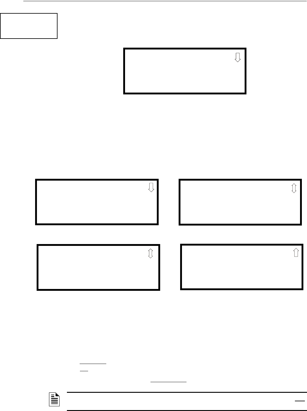
98 MS-9600LS Series Manual — P/N 52646:B2 2/12/2010
Programming Master Programming Level
Zone Type
Zone Types must be programmed only if a DACT, programmed for zone reporting, is installed on
the control panel. Pressing 1 for Zone Types, while viewing Zone Setup Screen #3, will display a
screen similar to the following:
This display will show the system zones (default and user programmed) and their associated types.
Note that an up and/or down arrow will appear in the upper right corner of the display, indicating
that additional screens of zone information exists. Press the up or down arrow keys to view zones
Z00 through Z99.
Zone types can be changed by pressing the keypad number key corresponding to the zone in each
Zones Installed Screen. Available zone types will be displayed in the resultant screens. For exam-
ple, to change the zone type for zone Z02 in the screen illustrated above, press 3. The following
screens will be displayed:
To change the zone type for Z02 to Pull Station, scroll the display until Zone Type Program Screen
#2 is displayed. Press 2 to program zone Z02 as a Pull Station zone. The display will return to the
Zones Installed Screen showing zone Z02 and the Pull Station program type. Repeat the procedure
for each zone to be changed.
IMPORTANT! In Zone Type Program Screen #1, selecting WATERFLOW will assign a Water-
flow silenceable zone type to the selected zone. Any signaling devices programmed to the same
zone can be silenced by pressing the Alarm Silence key or by using the auto-silence feature.
To program a waterflow circuit as nonsilenceable, refer to “System Setup” on page 100.
ZONE SETUP
1=ZONE TYPES
2=ZONES AVAILABLE
3=ZONE MESSAGE
Zone Setup Screen #3
ZONE TYPE PROG
1=Z00 MONITOR
2=Z01 MONITOR
3=Z02 MONITOR
Zones Installed Screen
ZONE TYPE PROG
1=MONITOR
2=SMOKE PHOTO
3=WATERFLOW
Zone Type Program Screen #1
ZONE TYPE PROG
1=MEDICAL
2=HAZARD
3=TAMPER
Zone Type Program Screen #2
ZONE TYPE PROG
1=SUPERVISORY
2=PROC. MON
3=SMOKE ION
Zone Type Program Screen #4
ZONE TYPE PROG
1=HEAT
2=PULL STATION
3=DUCT
Zone Type Program Screen #3
NOTE: Zone Types are only relevant for Central Station reporting. Changing a zone type will only
change how it is reported to the Central Station.

MS-9600LS Series Manual — P/N 52646:B2 2/12/2010 99
Master Programming Level Programming
Zones Available
Pressing 2 while viewing Zone Setup Screen #3 will display the following screen:
The display will show all of the zones that are still available for programming. Note that an up
and/or down arrow may appear in the upper right corner of the display, indicating that additional
screens of zone information exists. Press the up or down arrow key to view additional screens.
3.6.4 Loop Setup
Loop Setup allows the programmer to configure the SLC Loop(s) for NFPA Style 4, 6 or 7 wiring
and to select the protocol for each loop. Pressing 1 while viewing Programming Screen #2 will
cause the following screen to be displayed:
Loop Selection
Press 1 while viewing the Loop Selection Screen to configure Loop1 or 2 to configure Loop 2. The
following screens will appear for each loop.
Style
To program the SLC Style for the selected loop, press 1 for Style, while viewing Loop Setup
Screen. In the preceding example, the control panel is programmed for Style 4 SLC wiring as indi-
cated by the 4 to the right of Style in the display. To change the wiring style, press 1 to toggle the
display to read Style 6. Each press of the 1 key will cause the display to toggle between Style 4 and
Style 6. Note that, when programming the Loop Style, the programmer can only select between
Style 4 and Style 6. To program a system for Style 7 wiring, the programmer must select the Loop
Setup for Style 6. Style 7 wiring is the same as Style 6 with the added requirement that each
addressable device on the loop must have a pair of isolator modules, one on each side.
Note on SLC Troubles: If the FACP reports an open fault on an SLC Loop programmed for Style
6, the trouble condition will latch at the FACP. When the SLC Loop has been repaired, the Reset
button must be pressed at the FACP (at least 2 minutes after the trouble has been repaired) to clear
the SLC trouble.
ZONE SETUP
1=ZONE TYPES
2=ZONES AVAILABLE
3=ZONE MESSAGE
Zone Setup Screen #3
ZONES AVAILABLE
01 02 03 04 05 06 07
08 09 10 11 12 13 14
15 16 17 18 19
PROGRAMMING
1=LOOP SETUP
2=SYSTEM SETUP
3=VERIFY LOOPS
Programming Screen #2
LOOP SETUP
1=LOOP 1
2=LOOP 2
3-PROTOCOL CLIP
Loop Selection Screen
LOOP # SETUP
1=STYLE 4
Loop Setup Screen

100 MS-9600LS Series Manual — P/N 52646:B2 2/12/2010
Programming Master Programming Level
Loop Protocol
Loop Protocol refers to the SLC loop mode of operation. Refer to “Wire Requirements” on
page 196 for wire specifications based upon SLC protocol. Two modes of operation are available:
LiteSpeed and CLIP mode. CLIP mode (Classic Loop Interface Protocol) is used for the older leg-
acy addressable devices such as the M300 Series modules and detectors. LiteSpeed mode is used
for newer addressable devices such as the 350 series (or newer) for quicker response times. Note
that the legacy devices can operate only in CLIP mode while the newer devices are compatible with
both modes of operation. Pressing 3 while viewing the Loop Setup Screen will allow the program-
mer to select between CLIP and LiteSpeed mode. Each press of the 3 key will toggle the setting
between CLIP and LiteSpeed mode.
Device Addressing
It is important to note that the FACP addressable device capacity is 159 detectors and 159 con-
trol/monitor modules per SLC loop. Since older legacy addressable devices cannot be set to
addresses above 099, the newer series devices must be used when addresses 100 to 159 are to be
installed. It is permissible to mix old and new devices in the same panel, however, the FACP must
be programmed for CLIP mode.
3.6.5 System Setup
System Setup allows the programmer to configure the following control panel features:
•Trouble Reminder: This feature, when enabled, provides an audible reminder that an alarm or
trouble still exists on the FACP after the control panel has been silenced. The control panel
piezo sounder will pulse once every 15 seconds during an alarm and every two minutes during
a trouble condition, after the Alarm Silence or Acknowledge key is pressed. The piezo will
continue to sound at these rates until the alarm or trouble condition is cleared. If the trouble
condition is not cleared within 24 hours, the panel will reactivate the trouble sounder and
retransmit the trouble condition to the central station if connected.
•Banner: This option allows the user to change the top line of the LCD display from the blank
factory default readout to a user defined readout when the control panel is in Normal condition.
•Time-Date: This feature allows the programmer to set the time, display format (24 hr or 12 hr),
date and daylight savings time feature into the FACP memory
•Timers: This option allows the programmer to set the PAS (Positive Alarm Sequence) time
delay, Pre-Signal time delay and Waterflow time delay.
•NACs: This feature allows the programmer to configure the control panel Notification
Appliance Circuits for a variety of options, such as circuit type, silenceable/nonsilenceable,
autosilence, coding, silence inhibit, zone assignment and enable/disable.
•Relays: This option allows programming of two onboard relays for activation by various
control panel events, such as alarm, trouble, supervisory, etc.
•Canadian Option: This option allows the automatic programming of the FACP to Canadian
specifications (refer to “Canadian Option” on page 113).
Important! For Canadian Applications, this option must be set to ON prior to any other panel
programming.
•Waterflow Silenceable: This option provides the ability to silence any output circuit activated
by a monitor module programmed as a waterflow type.
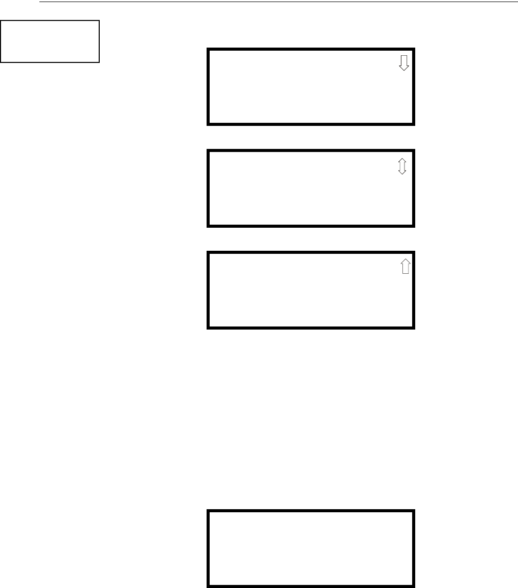
MS-9600LS Series Manual — P/N 52646:B2 2/12/2010 101
Master Programming Level Programming
Pressing 2 for System Setup, while viewing Programming Screen #2, will cause the following
screens to be displayed:
Trouble Reminder
The Trouble Reminder features causes the control panel piezo to sound a reminder ‘beep’ for
alarms and troubles, after the panel has been silenced. Refer to “System Setup” on page 100, for a
detailed description of this feature. Pressing 1 while viewing System Setup Screen #1 will cause
the display to toggle to Trouble Rem On, which enables this feature. Each press of the 1 key will
cause the display to toggle between Trouble Rem On and Trouble Rem Off.
Banner
The top line of the display, which appears when the control panel is in normal mode, can be
changed by using the Banner option. Pressing 2 while viewing System Setup Screen #1 will cause
the following to be displayed:
PROGRAMMING
1=LOOP SETUP
2=SYSTEM SETUP
3=VERIFY LOOPS
Programming Screen #2
SYSTEM SETUP
1=TROUBLE REM OFF
2=BANNER
3=TIME-DATE
System Setup Screen #1
SYSTEM SETUP
1=TIMERS
2=NAC
3=RELAYS
System Setup Screen #2
SYSTEM SETUP
1=CANADIAN OPT. OFF
2=WATERFLOW SIL. NO
System Setup Screen #3
BANNER
1=FACTORY
2=USER DEFINED
Banner Screen

102 MS-9600LS Series Manual — P/N 52646:B2 2/12/2010
Programming Master Programming Level
Pressing 1 while viewing the Banner Screen will select the blank factory default banner setting and
display the following screen:
Pressing the Enter key will store this selection in nonvolatile memory and return the display to the
Banner Screen.
Pressing 2 while viewing the Banner Screen will display the following screens :
These screens allow the programmer to enter a two line custom banner. A flashing cursor will
appear in the bottom left corner of each display. A maximum of 20 characters (including spaces)
can be entered into each screen for a total of two lines with 40 characters. After entering up to 20
characters in the first screen, press Enter to view the second screen. Enter up to 20 characters in the
second screen in the same manner or just press Enter if a second banner line is not being entered.
To quickly clear the current banner, press the CLR key.
To enter alphanumeric characters from the keypad, repeatedly press the appropriate key until the
desired character is displayed in the first position. For example, to enter the letter B, press the 2
(ABC) key three times to toggle through the characters 1, A, and B. Press the right arrow key to
move the cursor one position to the right and repeat the process to enter the next character. To enter
a space, press the * (QZ) key four times to place a blank in the desired position. When all charac-
ters have been entered, press Enter to store the information and return to the Banner Screen.
BANNER
1=FACTORY
2=USER DEFINED
Banner Screen
FACTORY BANNER
Factory Banner Screen
USER DEFINED BANNER
PRESS ENTER IF OK
User Defined Banner Screen #1
USER BANNER - LINE 2
PRESS ENTER IF OK
************
User Defined Banner Screen #2
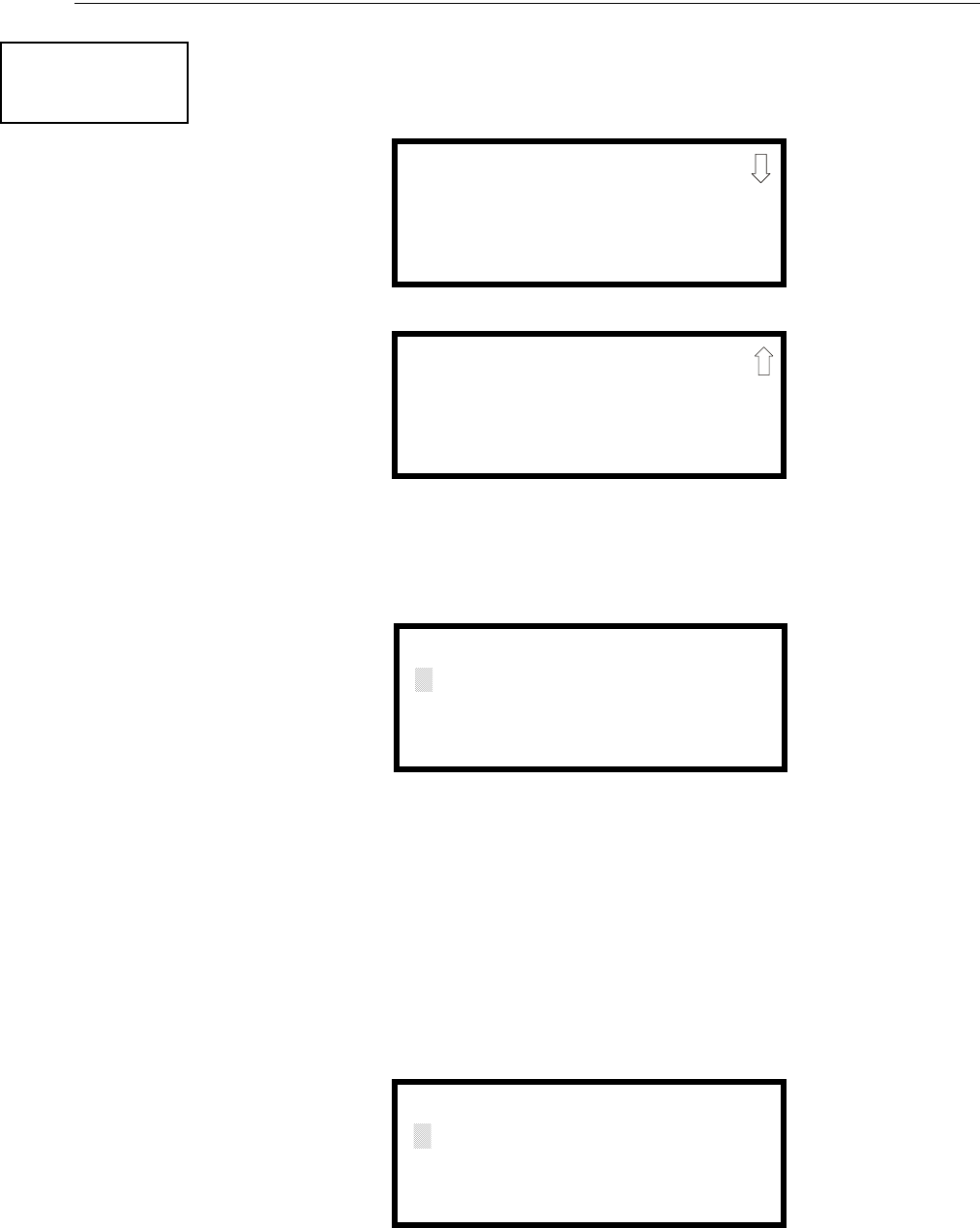
MS-9600LS Series Manual — P/N 52646:B2 2/12/2010 103
Master Programming Level Programming
Time-Date
The control panel time and date can be changed by pressing 3 while viewing the System Setup
Screen #1. The following screen will be displayed:
Time
To change the time, press 1 while viewing the Time-Date Screen. The following screen will be dis-
played:
A flashing cursor is located toward the top left of the display. Below the cursor is the current time.
To change the time, enter the two-digit hours followed by the two-digit minutes. The cursor will
move one position to the right each time a digit is entered. After the last minutes digit is entered,
the cursor will again move one position to the right. At this point enter 1 for AM or 2 for PM. The
display will then return to the Time-Date Screen which will show the new time entry. If an error is
made while entering a digit, press the CLR key to delete the entire entry and beginning again.
Date
To change the date, press 2 while viewing the Time-Date Screen. The following screen will be dis-
played:
A flashing cursor is located toward the top left of the display. Below the cursor is the current date.
To change the date, enter the two-digit month followed by the two-digit day and then the two-digit
year (09 for 2009, 10 for 2010, etc.). The cursor will move one position to the right each time a
SYSTEM SETUP
1=TROUBLE REM
2=BANNER
3=TIME-DATE
System Setup Screen #1
TIME AND DATE
1=TIME 10:00 AM
2=DATE 02-04-2010
3=CLOCK FORMAT 12HR
Time-Date Screen #1
TIME AND DATE
1=DAYLIGHT SAVINGS
Time-Date Screen #2
ENTER TIME
10:00 AM
1=AM 2=PM
Time Screen
ENTER DATE
MONTH DAY YEAR
02-04-2010
Date Screen
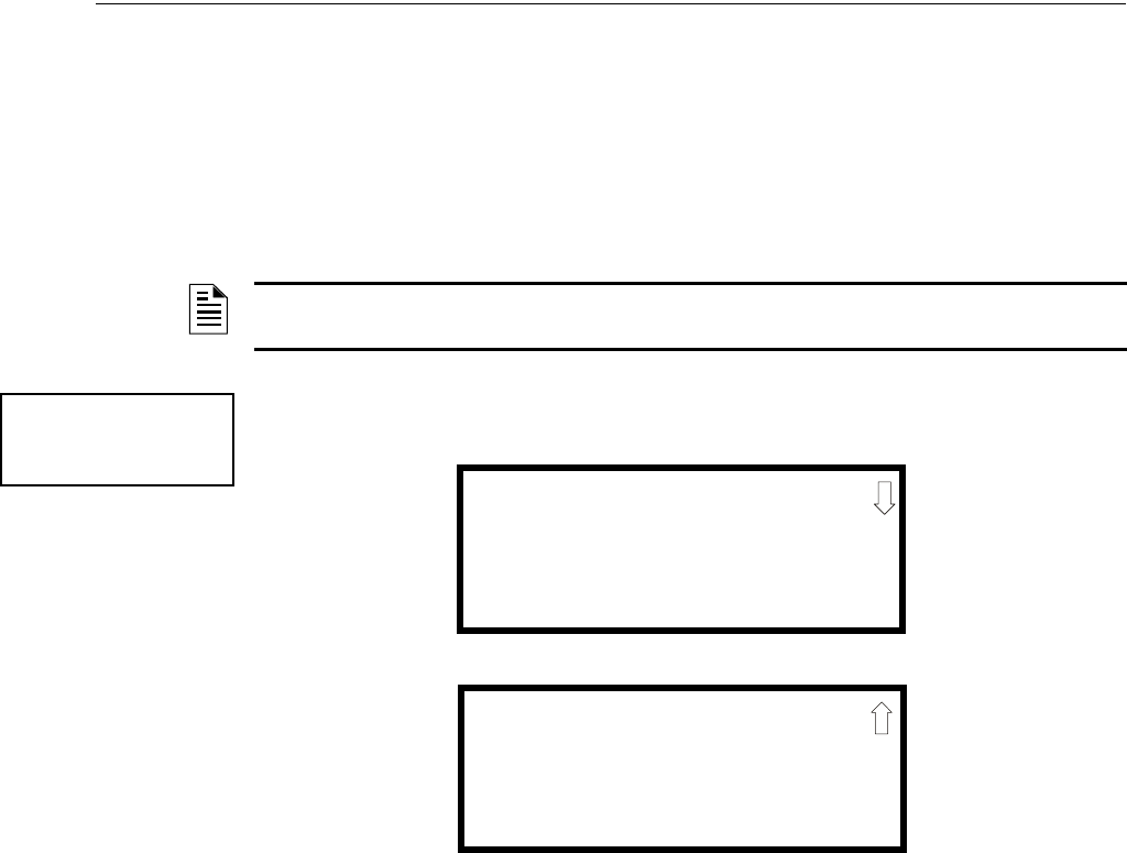
104 MS-9600LS Series Manual — P/N 52646:B2 2/12/2010
Programming Master Programming Level
digit is entered. After the last year digit is entered, the display will return to the Time-Date Screen
which will show the new date entry. If an error is made while entering a digit, press the CLR key to
delete the entire entry and beginning again.
Clock Format
The clock can be configured to display 12 hour (AM & PM) or 24 hour (military) time. Pressing 3
while viewing the Time-Date screen will cause the display to toggle between 12HR and 24HR.
Select 12HR for 12 hour display or 24HR for 24 hour display.
Daylight Savings Time
Pressing 1 while viewing Time-Date Screen #2 will cause the following screens to be displayed:
Pressing 1 while viewing Daylight Savings Screen #1 will cause the display to toggle between
Enabled Yes and Enabled No. The control panel will automatically update the time for daylight
savings time when Enabled Yes is selected.
Pressing 2 while viewing Daylight Savings Screen #1 will display another screen which allows the
programmer to select the month that daylight savings time will begin. In this sub-screen, pressing
1 will select March, 2 will select April, and 3 will select May.
Pressing 3 while viewing Daylight Savings Screen #1 will display two sub-screens which allow the
programmer to select the week of the month that daylight savings time will begin. In the first sub-
screen, pressing 1 will select the first week, 2 will select the second week, and 3 will select the third
week, while in the second sub-screen, pressing 1 will select the fourth week and 2 will select the
last week of the selected month.
Pressing 1 while viewing Daylight Savings Screen #2 will display another screen which allows the
programmer to select the month that daylight savings time will end. In this sub-screen, pressing 1
will select September, 2 will select October, and 3 will select November.
Pressing 2 while viewing Daylight Savings Screen #2 will display two sub-screens which allow the
programmer to select the week of the month that daylight savings time will end. In the first sub-
screen, pressing 1 will select the first week, 2 will select the second week, and 3 will select the third
week, while in the second sub-screen, pressing 4 will select the fourth week and 5 will select the
last week of the selected month.
NOTE: If the clock is changed to 24 hour (military) format, the date will change to the European
standard of Day-Month-Year (for display purposes only).
TIME AND DATE
1=DAYLIGHT SAVINGS
Time & Date Screen #2
DAYLIGHT SAVINGS
1=ENABLED YES
2=START MONTH MAR
3=START WEEK WEEK-2
Daylight Savings Screen #1
Daylight Savings Screen #2
DAYLIGHT SAVINGS
1=END MONTH NOV
2=END WEEK WEEK-1
MS-9600LS Series Manual — P/N 52646:B2 2/12/2010 105
Master Programming Level Programming
Timers
Timer delays for PAS, Pre-signal and waterflow activation can be programmed by pressing 1 while
viewing System Setup Screen #2. The following screen will be displayed:
PAS (Positive Alarm Sequence) Delay
The factory default setting for PAS is 000 for no delay. To select a PAS delay of 001 to 180 seconds
for all devices programmed for PAS, press 1 while viewing Timer Screen #1. The following dis-
play will appear:
A flashing cursor is positioned in the lower left corner of the display. Enter a delay time consisting
of three digits, such as 005 for five seconds. Upon entering the third digit, the time delay will be
stored in the control panel memory and the display will return to the Delay Screen which will indi-
cate the new delay time.
Pre-signal Delay
The factory default setting for Pre-signal delay is 000 for no delay. To select a Pre-signal delay of
001 to 180 seconds for all devices programmed for Pre-signal, press 2 while viewing Timer Screen
#1. The following screen will be displayed:
SYSTEM SETUP
1=TIMERS
2=NAC
3=RELAYS
System Setup Screen #2
TIMERS
1=PAS DELAY 000
2=PRE SIGNAL 000
3=WATERFLOW 000
Timer Screen #1
TIMERS
1=AC LOSS DELAY 000
Timer Screen #2
TIMERS
1=PAS DELAY 000
2=PRE SIGNAL 000
3=WATERFLOW 000
Timer Screen #1
PAS DELAY
RANGE 0-180 SECONDS
PAS Delay Screen
PRESIGNAL DELAY
RANGE 0-180 SECONDS
Pre-signal Delay Screen

106 MS-9600LS Series Manual — P/N 52646:B2 2/12/2010
Programming Master Programming Level
A flashing cursor is positioned in the lower left corner of the display. Enter a delay time consisting
of three digits, such as 009 for nine seconds. Upon entering the third digit, the time delay will be
stored in the control panel memory and the display will return to the Delay Screen which will indi-
cate the new delay time.
Note that the FACP can be programmed for either PAS or Pre-signal operation, not both. Refer to
“Edit Detector” on page 69 for programming details.
Waterflow Delay
A delay can be added prior to declaring a waterflow type of alarm. Be careful to include any built-
in delays of the waterflow device. The factory default setting for Waterflow delay is 000 for no
delay. To select a Waterflow delay of 01 to 90 seconds for all devices programmed for Waterflow
delay, press 3 while viewing Timer Screen #1. The following screen will be displayed:
A flashing cursor is positioned in the lower left corner of the display. Enter a delay time consisting
of two digits, such as 25 for twenty-five seconds. Upon entering the second digit, the time delay
will be stored in the control panel memory and the display will return to the Delay Screen which
will indicate the new delay time.
AC Loss Delay
The reporting of a loss of AC power to a central station can be delayed by programming the length
of the desired delay. The factory default setting is 2 hours. Press 1 while viewing Timer Screen #2
to display the following:
Pressing 1 while viewing AC Loss Delay Screen #1 will program the FACP to transmit an AC Loss
report immediately to the central station.
TIMER
1=PAS DELAY 000
2=PRE SIGNAL 000
3=WATERFLOW 000
Timer Screen #1
WATERFLOW DELAY
RANGE 0-90 SECONDS
Waterflow Delay Screen
TIMER
1=AC LOSS DELAY
Timer Screen #2
AC LOSS DELAY
1=NO DELAY
2=ENTER DELAY
AC Loss Delay Screen #1

MS-9600LS Series Manual — P/N 52646:B2 2/12/2010 107
Master Programming Level Programming
Pressing 2 while viewing AC Loss Delay Screen #1 will display the following screen:
A flashing cursor will appear in the lower left corner of the display. The factory default setting is
02 hours. Type the two digit AC loss reporting delay in hours (00 to 23 hour delay). When the sec-
ond digit is entered, the display will return to AC Loss Delay Screen #1.
NAC (Notification Appliance Circuit)
The options for the NACs on the control panel main circuit board can be set by pressing 2 while
viewing System Setup Screen #2. The following screens will be displayed:
The Notification Appliance Circuits can be configured independently by pressing 1 for NAC 1, 2
for NAC 2, 3 for NAC 3, or 4 for NAC 4.
Note that 3=NAC 3 and 4=NAC 4 will only be displayed if the NACKEY NAC option card is
installed, in JP8 of the main circuit board, for Class B operation.
AC LOSS DELAY
RANGE 00-23
AC Loss Delay Screen #2
SYSTEM SETUP
1=TIMERS
2=NAC
3=RELAYS
System Setup Screen #2
NACS
1=NAC 1 3=NAC 3
2=NAC 2 4=NAC 4
NAC Selection Screen

108 MS-9600LS Series Manual — P/N 52646:B2 2/12/2010
Programming Master Programming Level
The following screens will be displayed for either selection:
Enabled
Pressing 1 while viewing NAC Screen #1 will cause the display to change to Enabled No. This will
prevent the selected main circuit board NAC from activating its devices. Each press of the 1 key
will cause the display to toggle between Enabled Yes and Enabled No.
NAC #
1=ENABLED YES
2=TYPE BELL
3=SILENCEABLE YES
NAC Screen #1
NAC #
1=ZONE
00 00 00 00 00
2=SIL INHIBITED NO
NAC Screen #2
NAC #
1=AUTO SILENCE 00
2=CODING
TEMPORAL
NAC Screen #3
NAC #
1=SYNC TYPE S
NAC Screen #4
MS-9600LS Series Manual — P/N 52646:B2 2/12/2010 109
Master Programming Level Programming
Type
The main circuit board NAC type can be programmed by pressing 2 while viewing NAC Screen #1.
The following screen will be displayed. Press the down arrow key to view additional screens:
Select the NAC device type by pressing the number corresponding to the type in the appropriate
screen. When the selection is made, the display will return to NAC Screen #1.
The following table contains NAC type codes and their functions:
Silenceable
Pressing 3 while viewing NAC Screen #1 will cause the display to change to Silenceable No. This
will prevent the selected main circuit board NAC from being silenced by pressing the Alarm
Silence key or by the Auto Silence feature. Each press of the 3 key will cause the display to toggle
between Silenceable Yes and Silenceable No.
Important: When a Notification Appliance Circuit with a mix of audible and visual devices is
programmed for silenceable and the Synced Strobe feature is selected, only the audible devices
will be turned off if the Silence key is pressed. The visual devices (strobes, etc.) will continue to
operate. If the Strobe Sil Sync feature is selected, Silence will turn off both audible and visual
devices.
NAC Type Code Special Function
Bell None
Horn None
Strobe None
Synced Strobe Synchronized to manufacturer
Strobe Sil Sync Same as Synced Strobe but Silence turns off audible & visual devices
Future Use None
Future Use None
Future Use None
Blank None
NAC #
1=ENABLED
2=TYPE
3=SILENCEABLE
NAC Screen #1
NAC TYPE
1=BELL
2=HORN
3=STROBE
Type Screen #1
110 MS-9600LS Series Manual — P/N 52646:B2 2/12/2010
Programming Master Programming Level
Auto Silence
The Auto Silence feature, when enabled, automatically silences all main circuit board silenceable
notification appliances after a programmed length of time. To enable this feature and program the
time delay before Auto Silence activation, press 1 while viewing NAC Screen #2. The following
screens will be displayed:
To disable the Auto Silence feature, press 1 for No while viewing Auto Silence Screen #1. To
enable the Auto Silence feature, press the number corresponding to the time delay which will
elapse before Auto Silence activates. When a time delay is selected, the information will be stored
in memory and the display will return to NAC Screen #2.
Coding
The Coding feature allows the programmer to select the type of output that the main circuit board
notification appliances will generate when activated. Pressing 2 while viewing NAC Screen #2
will cause the following displays to appear:
NAC #
1=AUTO SILENCE
2=CODING
TEMPORAL
NAC Screen #2
AUTO SILENCE
1=NO
2=5 MINUTES
3=10 MINUTES
Auto Silence Screen #1
AUTO SILENCE
1=30 MINUTES
Auto Silence Screen #2
AUTO SILENCE
1=15 MINUTES
2=20 MINUTES
3=25 MINUTES
Auto Silence Screen #3
CODING
1=STEADY
2=MARCH TIME
3=CALIFORNIA
Coding Screen #1
CODING
1=TEMPORAL
2=TWO STAGE 3 MIN
3=TWO STAGE 5 MIN
Coding Screen #2

MS-9600LS Series Manual — P/N 52646:B2 2/12/2010 111
Master Programming Level Programming
The programmer can select the notification appliance output by pressing the number corresponding
to the desired output. The coding selections are:
• Steady - a continuous output with no coding
• March Time - 120 ppm (pulse-per-minute) output
• California - 10 seconds on and 5 seconds off
• Temporal - ½ second on, ½ second off, ½ second on, ½ second off, ½ second on, 1½ second off
• Two Stage - refer to “Two Stage Operation” on page 111 for description
Selection of one of the above options will cause the control panel to store the information in mem-
ory and return the display to NAC Screen #2, which will display the new coding choice.
Two Stage Operation
Two Stage operation consists of the following:
• 1st stage output - 20 ppm (pulse-per-minute) coding
• 2nd stage output - Temporal coding as described above
If Two Stage operation is programmed as the Coding option, the following sequence of events will
occur during an alarm.
1. The on-board NACs which are programmed to General Alarm Zone 0 will activate with a 1st
stage output upon activation of any alarm point.
2. If the activated alarm point is directly mapped to a zone which is programmed to an on-board
NAC, that NAC will go directly to 2nd stage coding output. All other NACs not directly
mapped to the activated alarm point’s zone but assigned to Zone 0 will activate with a 1st stage
output.
3. If, after the programmed time of 3 or 5 minutes, the Acknowledge switch has not been pressed,
all NACs presently in 1st stage activation will go to 2nd stage activation.
4. If an Acknowledge switch has been pressed, any NACs currently in 1st stage activation will
remain in 1st stage. Pressing the Acknowledge switch does not affect NACs already in 2nd
stage activation.
5. If another alarm point is activated and the countdown timer is counting, the alarm point will
have no effect on the NACs unless the alarm point’s zones are directly mapped to one of the
NACs, in which case it will follow the procedure outlined in step 2.
6. If another alarm point is activated and the countdown timer has stopped counting due to the
Acknowledge switch being pressed, the countdown timer will restart and the NACs will
respond as outlined in step 2. NACs already in 2nd stage activation will not be affected.
7. Any control modules assigned to special Zone 99 will be activated either by direct mapping of
an input device programmed to Zone 99 or if the timer counts down to zero and the NAC goes
into 2nd stage coding.
8. Control modules that are programmed to the same zone as the activated input device will not
be delayed for activation.
Zone
A maximum of five zones can be programmed to each main circuit board NAC. Pressing 1 while
viewing NAC Screen #3 displays the following screen:
NAC #
1=ZONE
00 00 00 00 00
2=SIL INHIBITED NO
NAC Screen #3
ZONE ASSIGNMENT
Z00 Z** Z** Z** Z**
Zone Screen

112 MS-9600LS Series Manual — P/N 52646:B2 2/12/2010
Programming Master Programming Level
Note that Z** represents the Zone Number(s) corresponding to the selected NAC. The factory
default for an unprogrammed device is Z00 for general alarm zone. A flashing cursor will appear
on the first 0 to the left. Enter the two digit number corresponding to the zone that is to be assigned
to this NAC. The cursor moves to the next Z** designation. Continue entering zone assignments
or the remaining zones can be left blank or programmed as general alarm zone Z00. When all
desired changes have been made, press the Enter key to store the zone assignments. The display
will return to the NAC Screen #3 which will show the zone assignments just entered.
Silence Inhibited
The Silence Inhibit feature, when enabled, prevents the silencing of the selected main circuit board
NAC for a period of one minute. Pressing 2 while viewing NAC Screen #3 will cause the display
to change from the factory default of Silence Inhibit No to Silence Inhibit Yes. Each press of the 2
key will cause the display to toggle between the two options.
Synced Type
If synchronized strobes were selected as the Type of device installed, the type of synchronization
must be selected in this option. Pressing 1 while viewing NAC Screen #4 will cause the following
screen to be displayed:
Pressing 1 while viewing this screen will select System Sensor synchronization, 2 will select Whee-
lock, and 3 will select Gentex.
Maximum Number of Strobes for Synchronization
The total current draw for each Notification Appliance Circuit cannot exceed 3.0 amps. Refer to
the manufacturer’s documentation supplied with the Strobes to determine the maximum current
draw for each strobe and ensure that the circuit maximum is not exceeded.
To ensure proper strobe and circuit operation, there is also a limit to the number of strobes that can
be attached to each circuit. Following is a list of the strobes that have been tested with this FACP
and the maximum number that can be connected to each NAC. Make sure that the NAC maximum
current is not exceeded:
• System Sensor: 46 Strobes
• Wheelock: 42 Strobes
• Gentex: 39 Strobes
Relays
Pressing 3 while viewing System Setup Screen #2 allows the programmer to configure two of the
main circuit board Form-C relays from the following screen:
NAC #
1=SYNC TYPE
NAC Screen #4
NAC SYNC TYPE
1=SYSTEM SENSOR
2=WHEELOCK
3=GENTEX
SYSTEM SETUP
1=TIMERS
2=NAC
3=RELAYS
System Setup Screen #2
RELAYS
1=RELAY 1
2=RELAY 2
3=RELAY 3
Relays Selection Screen
MS-9600LS Series Manual — P/N 52646:B2 2/12/2010 113
Master Programming Level Programming
To program Relay 1 or Relay 3, press the number corresponding to the selected relay. Note that
Relay 2 is fixed as a Trouble relay. Selecting Relay 2 will have no effect on its programming. The
following screen will appear for each relay to be programmed:
Pressing 1 for Type while viewing the Relay Screen will cause the following screens to be dis-
played:
While viewing the selected screen, press the number corresponding to the desired relay type to pro-
gram the main circuit board relay. The choice will be stored in memory and the display will return
to the Relay Type Screen which will show the programmed type choice. Press the Escape key to
return to the Relays Selection Screen and repeat the preceding procedure for the remaining relays.
Note the following:
1. AR (AutoResettable) in SUPERVISORY AR and PROCESS MON AR means that a relay with
the Supervisory and/or Process Monitor type code, when activated, will automatically reset
when the corresponding condition is cleared.
2. A relay programmed with the Silenceable Alarm type will activate upon any alarm and
deactivate when the FACP Alarm Silenced LED is illuminated.
Canadian Option
Pressing 1 while viewing System Setup Screen #3 will configure the FACP to comply with Cana-
dian requirements. The display will change to Canadian Opt. On. Each press of the 1 key will
cause the display to toggle between Canadian Opt. On and Canadian Opt. Off.:
Important! For Canadian Applications, this option must be set to ON prior to any other panel pro-
gramming.
RELAY #
1=TYPE
ALARM
Relay Type Screen
RELAY
1=ALARM
2=SUPERVISORY
3=SUPERVISORY AR
Relay Screen #1
RELAY
1=TROUBLE
2=COMM FAIL
3=PROCESS MON
Relay Screen #3
RELAY
1=PROCESS MON AR
2=AC LOSS
3=HAZARD
Relay Screen #2
RELAY
1=MEDICAL
2=SILENCEABLE ALARM
Relay Screen #4
SYSTEM SETUP
1=CANADIAN OPT. OFF
2=WATERFLOW SIL. NO
System Setup Screen #3
SYSTEM SETUP
1=CANADIAN OPT. OFF
2=WATERFLOW SIL. NO

114 MS-9600LS Series Manual — P/N 52646:B2 2/12/2010
Programming Master Programming Level
The Canadian Options configures the FACP with the following as required by Canada:
• The following monitor module type codes are not available:
•monitor
• non-latching supervisory
• non-latching drill
• non-latching process monitor
• process monitor
• hazard
• tornado
• medical alert
• The auto-silence timer is fixed at 20 minutes and cannot be changed.
• Addressable ionization smoke detector sensitivity is automatically monitored using Canadian
specifications.
Waterflow Silenceable
Pressing 2 while viewing System Setup Screen #3 will allow the programmer to configure the sys-
tem for silenceable on nonsilenceable waterflow circuits. Each press of the 2 key will toggle the
display between Waterflow Sil. No and Waterflow Sil. Yes. When Waterflow Sil. No is selected, all
output devices associated with a waterflow type input device, will be nonsilenceable. When Water-
flow Sil. Yes is selected, all output devices associated with a waterflow type input device, will be
silenceable.
3.6.6 Verify Loops
Pressing 3 while viewing Programming Screen #2, will select the Verify Loops option and display
the following screen:
During loop verification, the FACP polls each device on the selected SLC to determine if the device
is communicating and whether or not it responds with the proper type identification. The program-
mer can choose to verify one or both loops by pressing the number corresponding to the choices
shown above.
When the selection is made, the following screen will be displayed while verification is in progress:
When Loop verification has been completed, the display will indicate that the system is OK or, if
problems have been detected, any device type programming errors. Use the up and down arrow
keys to view all detected errors.
PROGRAMMING
1=LOOP SETUP
2=SYSTEM SETUP
3=VERIFY LOOPS
Programming Screen #2
VERIFY LOOPS
1=LOOP 1
2=LOOP 2
3=BOTH LOOPS
Verify Loop Select Screen
VERIFYING LOOPS
PLEASE WAIT
Verification Progress Screen

MS-9600LS Series Manual — P/N 52646:B2 2/12/2010 115
Master Programming Level Programming
3.6.7 History
The History option allows an authorized user to view or erase events which have occurred in the
control panel. Pressing 1 while viewing Programming Screen #3 will display the History options
as shown in the following display:
View Events
Pressing 1 while viewing the History Screen will allow the user to select the events to be viewed as
illustrated in the following:
While displaying the View Events screen, press 1 to view all events, 2 to view only alarms, or 3 to
view other events. Use the up and down arrow keys to scroll through all of the displayed events.
Erase History
The Erase History option allows a user to erase all events from the history file. This will provide a
clean slate in order to use the history file to track future events. Pressing 2 while viewing the His-
tory Screen will cause the following screen to be displayed:
Pressing 1 while viewing the Erase History Screen will erase all events from the History file. Dur-
ing this process, the display will read as follows:
After the History file has been erased, the display will return to the History Screen.
PROGRAMMING
1=HISTORY
2=WALKTEST
3=OPTION MODULES
Programming Screen #3
HISTORY
1=VIEW EVENTS
2=ERASE HISTORY
History Screen
HISTORY
1=VIEW EVENTS
2=ERASE HISTORY
History Screen
HISTORY
1=VIEW ALL
2=VIEW ALARMS
3=VIEW OTHER EVENTS
View Events Screen
ERASE HISTORY
PROCEED ?
1=YES 2=NO
Erase History Screen
ERASING HISTORY
PLEASE WAIT
Erase History Wait Screen

116 MS-9600LS Series Manual — P/N 52646:B2 2/12/2010
Programming Master Programming Level
3.6.8 Walktest
Walktest allows an individual to test the fire alarm system without the necessity to reset the control
panel after each device activation. Pressing 2 while viewing the Programming Screen #3 will cause
the following Walktest options to be displayed:
To perform a silent walktest which will not sound the NACs, press 1 while viewing the Walktest
Screen. To perform an audible walktest, which will sound the NACs, press 2 while viewing the
Walktest Screen. When either option is chosen, the panel will enter Walktest Mode and the follow-
ing screen will be displayed::
From this screen, it is possible to view the walktest log, untested system points or a summary of the
addressable devices tested during the current walktest. The user can select between any of these
screens without interrupting the current walktest session. The walktest session will not end until
the Unit In Walktest screen is exited by pressing the Escape key.
Pressing 1 for View Walktest Log while viewing the Unit In Walktest screen will cause a screen sim-
ilar to one of the following two screens to be displayed:
If there are no events in the current walktest session, the first screen will be displayed, indicating no
events have been stored in the walktest log. If any events have been stored, a screen similar to the
second will be displayed indicating the latest event. As walktest events occur, the display will
change to indicate the latest event. All stored events can be scrolled on the screen by pressing the
up or down arrow keys. To return to the first event, press the 1st Event key.
PROGRAMMING
1=HISTORY
2=WALKTEST
3=OPTION MODULES
Programming Screen #3
WALKTEST
1=SILENT
2=AUDIBLE
3=VIEW RESULT
Walktest Screen
UNIT IN WALKTEST
1=VIEW WALKTEST LOG
2=VIEW POINTS
3=VIEW SUMMARY
Unit In Walktest Screen
NO EVENTS IN
WALKTEST LOG
ALARM: MONITOR
NORTH CLASSROOM
Z001
10*15A 020510 1M006
OR

MS-9600LS Series Manual — P/N 52646:B2 2/12/2010 117
Master Programming Level Programming
Pressing 2 for View Points while viewing the Unit In Walktest screen will display one of the follow-
ing screens:
If the system has no points installed, the first screen will be displayed. If points are installed, the
second screen will be displayed, which allows the viewing of all untested system points and their
status relating to the current walktest session. The up and down arrow keys will allow viewing of
all untested points. If a point is tested while it is being displayed, the screen will update and display
the next untested point. The first line indicates the total number of untested points. The second line
displays information about an untested point. A description on the bottom of the screen will indi-
cate if the displayed point has been disabled, if the Walktest option has been disabled for that point
or if the point is not yet tested. The up and down arrow keys allow the user to scroll through all
untested points.
Pressing 3 for View Summary while viewing the Unit In Walktest screen will display a new screen
which will show a total of the tested detectors, tested modules, untested detectors and untested
modules for the current walktest session. If more than one SLC loop is installed on the FACP,
pressing the down arrow key will display the Walktest summary for each SLC loop.
The user can perform a one-person walktest by activating devices throughout the system. As each
device is activated, the information about the activated device is stored in the Walktest Log. The
information can be viewed by choosing one of the options from the Unit In Walktest screen.
To end the Walktest session, press the Escape key to return to the Walktest screen. Pressing 3 for
View Results while viewing the Walktest screen, after a walktest session has been completed, will
allow the operator to view the final results of the most recent walktest. The following screen will
be displayed:
Use the up and down arrow keys to view all of the walktest results which will be displayed. Note
that the Walktest log is stored in RAM. If all power (AC and DC) is removed from the FACP, the
Walktest log information will be lost. This information is also overwritten when subsequent walk-
tests are performed.
3.6.9 Option Modules
Options available for the FACP include ACS, Graphic, LED, Relay and LCD annunciators, printer
connection for acquiring hardcopy printouts of panel data and PC (Personal Computer) connection
for uploading and downloading panel data.
NO POINTS IN
SYSTEM OR
UNTESTED POINTS 010
1D001 SMOKE (PHOTO)
*********************
NOT TESTED
WALKTEST RESULTS
View Result Screen
PROGRAMMING
1=HISTORY
2=WALKTEST
3=OPTION MODULES
Programming Screen #3

118 MS-9600LS Series Manual — P/N 52646:B2 2/12/2010
Programming Master Programming Level
Pressing 3 while viewing Programming Screen #3 will display the following screen:
Note that PR4800 in the display indicates that a supervised printer, configured for 4800 baud, has
been previously programmed into the system.
Annunciators/UDACT
Pressing 1 while viewing the Options Screen will cause the control panel to display the following
screens:
A Terminal Mode annunciator, ACS Mode annunciator or ANN-BUS annunciator/module can be
installed in the system. Do not use a mix of ACS annunciators and ANN annunciators since they
use different communication protocols. ACS or ANN annunciators use the same TB6 terminal
block connection. To install any of these devices, press the number corresponding to the desired
device shown in the Annunciator Screen.
Term Options
While viewing the Annunciators Screen, each press of the 1 key for Term Options, will cause the
display to toggle between Term Enabled No and Term Enabled Yes.
OPTION MODULES
1=ANNUNCIATORS/UDACT
2=ONBOARD DACT
3=PRINTER/PC PR4800
Options Screen
ANNUNCIATORS
1=TERM ENABLED NO
2=ACS OPTIONS
3=ANN-BUS OPTIONS
Annunciator Screen
NOTE: The LCD-80F is a Terminal Mode annunciator. To enable the FACP for LCD-80F
operation, press 1 for Term Enabled Yes.

MS-9600LS Series Manual — P/N 52646:B2 2/12/2010 119
Master Programming Level Programming
ACS Options
Pressing 2 for ACS Options while viewing the Annunciators screen, will display the following
screen:
Pressing 1 while viewing the ACS Options screen will cause the display to toggle between ACS
Enabled Yes and ACS Enabled No. To install an ACS annunciator, the display must read ACS
Enabled Yes.
If ACS has been enabled, press 2 while viewing the ACS Options screen to select addresses for the
ACS annunciators. The following screen will be displayed:
Pressing the down arrow key will allow the programmer to view additional screens displaying
Addresses 1 -31. Each screen will indicate if an address has been used for an installed ACS annun-
ciator. To select one or more addresses for the installed ACS annunciator(s), press the number key
corresponding to the address in each screen. The display for the selected address will change from
No to Yes. Each press of the number key will cause the display to toggle between No and Yes. The
address of each installed annunciator must be enabled to allow communication between the FACP
and annunciator.
ANNUNCIATORS
1=TERM OPTIONS
2=ACS OPTIONS
3=ANN-BUS OPTIONS
Annunciator Screen
ACS OPTIONS
1=ACS ENABLED NO
2=ACS INSTALLED
3=UDACT NO
ANNUNCIATOR
1=ADDRESS 1 YES
2=ADDRESS 2 NO
3=ADDRESS 3 NO
ACS Installed Screen

120 MS-9600LS Series Manual — P/N 52646:B2 2/12/2010
Programming Master Programming Level
Annunciator addressing is specific to the FACP control panel. The following table describes the
annunciator addresses and the corresponding addressable devices that will be annunciated at each
annunciator address.
The 8 General System Status Points include the following:
• General Alarm
• General Trouble
• General Supervisory
• Alarm Silenced
• System Off Normal
•AC Loss
• Battery Fault
• NAC Fault
Pressing 3 while viewing the ACS Options screen will toggle the display between UDACT NO and
UDACT YES. This allows the connection of an external UDACT (Universal Digital Alarm Com-
municator/Transmitter).
ACS Annunciator Address Annunciator Displays the Following Points
1 8 General System Status Points & Zones 1 - 56
2 Zones 57 - 99 & 4 NACs
3 Loop 1, Module Addresses 1 - 64
4 Loop 2, Module Addresses 1 - 64
5 Loop 1, Module Addresses 65 - 128
6 Loop 2, Module Addresses 65 - 128
7 Loop 1, Module Addresses 129 - 159 & Loop 2 Module Addresses 129 - 159
8 Loop 1, Detector Addresses 1 - 64
9 Loop 2, Detector Addresses 1 - 64
10 Loop 1, Detector Addresses 65 - 128
11 Loop 2, Detector Addresses 65 - 128
12 Loop 1 Detector Addresses 129 - 159 & Loop 2 Detector Addresses 129 - 159
13 not used
14 not used
15 not used
16 not used
17 not used
18 not used
19 not used
20 8 General System Status Points & Zones 1 - 56
21 Zones 57 - 99 & 4 NACs
22 Loop 1, Module Addresses 1 - 64
23 Loop 2, Module Addresses 1 - 64
24 Loop 1, Module Addresses 65 - 128
25 Loop 2, Module Addresses 65 - 128
26 Loop 1, Module Addresses 129 - 159 & Loop 2 Module Addresses 129 - 159
27 Loop 1, Detector Addresses 1 - 64
28 Loop 2, Detector Addresses 1 - 64
29 Loop 1, Detector Addresses 65 - 128
30 Loop 2, Detector Addresses 65 - 128
31 Loop 1 Detector Addresses 129 - 159 & Loop 2 Detector Addresses 129 - 159
32 not used
MS-9600LS Series Manual — P/N 52646:B2 2/12/2010 121
Master Programming Level Programming
ANN-BUS Options
Pressing 3 for ANN-BUS Options, while viewing the Annunciators screen, will cause the following
screens to be displayed:.
A printer module, graphic annunciator module, LCD annunciator module, LED annunciator mod-
ule and relay module can be programmed into the system. These devices communicate with the
FACP over the ANN-BUS terminals on the control panel.
ANN-BUS Enabled
The ANN-BUS must be enabled if any modules are connected to the ANN-BUS terminals. To
enable the ANN-BUS, press 1 while viewing ANN-BUS screen #1 so that the display reads
Enabled Yes. Each press of the 1 key will cause the display to toggle between Enabled Yes and
Enabled No.
Modules Installed
If an ANN-BUS module is installed, press 2 while viewing ANN-BUS screen #1 to select ANN-
BUS addresses for the module(s). The following screen will be displayed.
Pressing the down arrow key will allow the programmer to view additional screens displaying
Addresses 1-8. To program an ANN-BUS module to a specific address, press the number key cor-
responding to the desired address in each screen. The following screen will be displayed for each
address:
ANNUNCIATORS
1=TERM OPTIONS
2=ACS OPTIONS
3=ANN-BUS OPTIONS
Annunciator Screen
ANN-BUS
1=ENABLED NO
2=MODULES INSTALLED
3=AUTO-CONFIGURE
ANN-BUS Screen #1
ANN-BUS
1=ANN-S/PG OPTIONS
2=ANN-80 OPTIONS
ANN-BUS Screen #2
ANN-BUS MODULES
1=ADDR. 1 NONE
2=ADDR. 2 NONE
3=ADDR. 3 NONE
ANN-BUS Modules Screen #1
ANN-BUS MODULES
ANN-BUS ADDRESS #
1=TYPE NONE
ANN-BUS Address Screen
122 MS-9600LS Series Manual — P/N 52646:B2 2/12/2010
Programming Master Programming Level
Pressing 1 for Type will display the following screens:
Press the number corresponding to the module type that is installed with the selected address.
If ANN-I/O, ANN-LED or ANN-RLY is the selected module type, the following ANN-BUS
Address Screen will be displayed:
Since the options for each of these module types can be individually set, pressing 2 for Module
Options, while viewing the ANN-BUS Address Screen will display the available options as
described below.
ANN-BUS MODULE TYPE
1=NOT INSTALLED
2=ANN-80 MODULE
3=ANN-I/O MODULE
Module Type Screen #1
ANN-BUS MODULE TYPE
1=ANN-S/PG MODULE
2=ANN-LED MODULE
3=ANN-RLY MODULE
Module Type Screen #2
ANN-BUS MODULE TYPE
1=ANN-AUDIO
Module Type Screen #3
NOTE: If the module type selected is the ANN-80, ANN-S/PG, or ANN-AUDIO or if Not Installed
is selected, the ANN-BUS Address Screen shown on the previous page will be displayed following
the module selection. The options selected for each of these modules will be the same for all
modules of the same type (refer to “ANN-S/PG (Print) Options” on page 132 and “ANN-80
Options” on page 133).
ANN-BUS MODULES
ANN-BUS ADDRESS #
1=TYPE ANN-I/O
2=MODULE OPTIONS
ANN-BUS Address Screen

MS-9600LS Series Manual — P/N 52646:B2 2/12/2010 123
Master Programming Level Programming
ANN-I/O Options
Pressing 2 for Module Options while viewing ANN-BUS Address Screen when the ANN-I/O
option is selected will display the following screen:
The first screen indicates that the ANN-I/O at the selected ANN-BUS address is programmed to
annunciate SLC Loop #1 addressable modules with addresses 1 through 30. The programming can
be changed using ANN-I/O Address Screens 2 and 3.
Pressing 1 while viewing ANN-I/O Address Screen #2 will program the annunciator module to
annunciate either Point (addressable device address) information or Zone information.
Pressing 1 while viewing ANN-I/O Address Screen #3 will select the Point or Zone range to be
annunciated (refer to the tables in “ANN-I/O Zone Option” on page 123 and “ANN-I/O Point
Option” on page 125).
Pressing 2 while viewing ANN-I/O Address Screen #3 will select either addressable detectors or
addressable modules to be annunciated.
Pressing 3 while viewing ANN-I/O Address Screen #3 will select the SLC loop with the address-
able devices to be annunciated.
ANN-I/O Zone Option
If Zone is selected as the module option, the first ten LEDs on the first ANN-I/O module will dis-
play the system status information. The remaining 30 LEDs on the first module and 40 LEDs on
the remaining modules will display the active/alarm status of each zone in the Zone Range pro-
grammed for that particular module. The LED assignments for each ANN-I/O module will be as
follows.
Module LED ANN-I/O Module #1
Function
ANN-I/O Module #2
Function
ANN-I/O Module #3
Function
1 AC Fault Zone 30 Zone 70
2 Fire Alarm Zone 31 Zone 71
3 Supervisory Zone 32 Zone 72
ANN-I/O ADDR #
SLC 1 MOD 001-030
ACTIVE LEDS ONLY
ANN-I/O Address Screen #1
ANN-I/O ADDR #
1=POINT/ZONE POINT
ANN-I/O Address Screen #2
ANN-I/O ADDR #
1=RANGE PT001-030
2=DET/MOD MOD
3=SLC LOOP # 2
ANN-I/O Address Screen #3

124 MS-9600LS Series Manual — P/N 52646:B2 2/12/2010
Programming Master Programming Level
4 Trouble Zone 33 Zone 73
5 Alarm Silenced Zone 34 Zone 74
6 Earth Fault Zone 35 Zone 75
7 Battery Fault Zone 36 Zone 76
8 Charger Fault Zone 37 Zone 77
9 NAC Fault Zone 38 Zone 78
10 Disabled Zone 39 Zone 79
11 Zone 00 Zone 40 Zone 80
12 Zone 01 Zone 41 Zone 81
13 Zone 02 Zone 42 Zone 82
14 Zone 03 Zone 43 Zone 83
15 Zone 04 Zone 44 Zone 84
16 Zone 05 Zone 45 Zone 85
17 Zone 06 Zone 46 Zone 86
18 Zone 07 Zone 47 Zone 87
19 Zone 08 Zone 48 Zone 88
20 Zone 09 Zone 49 Zone 89
21 Zone 10 Zone 50 Zone 90
22 Zone 11 Zone 51 Zone 91
23 Zone 12 Zone 52 Zone 92
24 Zone 13 Zone 53 Zone 93
25 Zone 14 Zone 54 Zone 94
26 Zone 15 Zone 55 Zone 95
27 Zone 16 Zone 56 Zone 96
28 Zone 17 Zone 57 Zone 97
29 Zone 18 Zone 58 Zone 98
30 Zone 19 Zone 59 Zone 99
31 Zone 20 Zone 60 Not Used
32 Zone 21 Zone 61 Not Used
33 Zone 22 Zone 62 Not Used
34 Zone 23 Zone 63 Not Used
35 Zone 24 Zone 64 Not Used
36 Zone 25 Zone 65 Not Used
37 Zone 26 Zone 66 Not Used
38 Zone 27 Zone 67 Not Used
39 Zone 28 Zone 68 Not Used
40 Zone 29 Zone 69 Not Used

MS-9600LS Series Manual — P/N 52646:B2 2/12/2010 125
Master Programming Level Programming
ANN-I/O Point Option
If Point is selected as the module option, the first ten LEDs on the first ANN-I/O module will
display the system status information. The remaining 30 LEDs on the first module and 40 LEDs on
each additional module will display the active/alarm status of each point in the Point Range
programmed for that particular module. The points that will be annunciated on a particular ANN-
I/O module depend on the programming options selected as far as which SLC loop and the device
type (detector or module) to be annunciated. The LED assignments for each ANN-I/O module will
be as follows.
Module LED
ANN-I/O
Module #1
Function
ANN-I/O
Module #2
Function
ANN-I/O
Module #3
Function
ANN-I/O
Module #4
Function
ANN-I/O
Module #5
Function
1 AC Fault Point 31 Point 71 Point 111 Point 151
2 Fire Alarm Point 32 Point 72 Point 112 Point 152
3 Supervisory Point 33 Point 73 Point 113 Point 153
4 Trouble Point 34 Point 74 Point 114 Point 154
5 Alarm Silenced Point 35 Point 75 Point 115 Point 155
6 Earth Fault Point 36 Point 76 Point 116 Point 156
7 Battery Fault Point 37 Point 77 Point 117 Point 157
8 Charger Fault Point 38 Point 78 Point 118 Point 158
9 NAC Fault Point 39 Point 79 Point 119 Point 159
10 Disabled Point 40 Point 80 Point 120 Not Used
11 Point 01 Point 41 Point 81 Point 121 Not Used
12 Point 02 Point 42 Point 82 Point 122 Not Used
13 Point 03 Point 43 Point 83 Point 123 Not Used
14 Point 04 Point 44 Point 84 Point 124 Not Used
15 Point 05 Point 45 Point 85 Point 125 Not Used
16 Point 06 Point 46 Point 86 Point 126 Not Used
17 Point 07 Point 47 Point 87 Point 127 Not Used
18 Point 08 Point 48 Point 88 Point 128 Not Used
19 Point 09 Point 49 Point 89 Point 129 Not Used
20 Point 10 Point 50 Point 90 Point 130 Not Used
21 Point 11 Point 51 Point 91 Point 131 Not Used
22 Point 12 Point 52 Point 92 Point 132 Not Used
23 Point 13 Point 53 Point 93 Point 133 Not Used
24 Point 14 Point 54 Point 94 Point 134 Not Used
25 Point 15 Point 55 Point 95 Point 135 Not Used
26 Point 16 Point 56 Point 96 Point 136 Not Used
27 Point 17 Point 57 Point 97 Point 137 Not Used
28 Point 18 Point 58 Point 98 Point 138 Not Used
29 Point 19 Point 59 Point 99 Point 139 Not Used
30 Point 20 Point 60 Point 100 Point 140 Not Used
31 Point 21 Point 61 Point 101 Point 141 Not Used
32 Point 22 Point 62 Point 102 Point 142 Not Used
33 Point 23 Point 63 Point 103 Point 143 Not Used
34 Point 24 Point 64 Point 104 Point 144 Not Used
35 Point 25 Point 65 Point 105 Point 145 Not Used
36 Point 26 Point 66 Point 106 Point 146 Not Used
37 Point 27 Point 67 Point 107 Point 147 Not Used
38 Point 28 Point 68 Point 108 Point 148 Not Used
39 Point 29 Point 69 Point 109 Point 149 Not Used
40 Point 30 Point 70 Point 110 Point 150 Not Used

126 MS-9600LS Series Manual — P/N 52646:B2 2/12/2010
Programming Master Programming Level
ANN-LED Options
Pressing 2 for Module Options while viewing ANN-BUS Address Screen when the ANN-LED
option is selected will display the following screen:
The first screen indicates that the ANN-LED at the selected ANN-BUS address is programmed to
annunciate Alarms, Supervisories and Troubles for SLC Loop #1 addressable Detectors with
addresses 1 through 10. The programming can be changed using ANN-LED Address Screens 2
and 3.
Pressing 1 while viewing ANN-LED Address Screen #2 will program the annunciator module to
annunciate either Point (addressable device address) information or Zone information.
Pressing 2 while viewing ANN-LED Address Screen #2 will program the annunciator module to
annunciate only Alarms for addressable device addresses 1-30 or Alarms, Supervisories and Trou-
bles for addressable device addresses 1-10.
Pressing 1 while viewing ANN-LED Address Screen #3 will select the Point or Zone range to be
annunciated (refer to the tables in “ANN-LED Zone Option - Alarm Only (for use with ANN-
RLED module)” on page 127 and “ANN-LED Point Option - Alarm Only (for use with ANN-
RLED module)” on page 129).
Pressing 2 while viewing ANN-LED Address Screen #3 will select either addressable detectors or
addressable modules to be annunciated.
Pressing 3 while viewing ANN-LED Address Screen #3 will select the SLC loop with the address-
able devices to be annunciated.
ANN-LED ADDR #
LOOP1 DET 1-10
ALARM,SUPERV,TBL
ANN-LED Address Screen #1
ANN-LED ADDR #
1=POINT/ZONE
2=ALARM/ATS
ANN-LED Address Screen #2
ANN-LED ADDR #
1=RANGE
2=DET/MOD
3=LOOP#
ANN-LED Address Screen #3

MS-9600LS Series Manual — P/N 52646:B2 2/12/2010 127
Master Programming Level Programming
ANN-LED Zone Option - Alarm Only (for use with ANN-RLED module)
If Zone is selected as the module option, and the module is programmed to annunciate alarms only,
the first ten LEDs on the first ANN-LED module will display the system status information. The
remaining 30 LEDs on the first module and the last 30 LEDs on the remaining modules will display
the active/alarm status of each zone in the Zone Range programmed for that particular module. The
LED assignments for each ANN-LED module will be as follows.
The LED assignments for the modules annunciating Zone Ranges 60 - 89 and 90 - 99, will follow
the same pattern as the second ANN-RLED module.
Alarm Silenced NAC 1 Fault NAC 2 Fault NAC 3 Fault NAC 4 Fault
Earth Fault Battery Fault Charger Fault Disabled Maintenance
Zone 00
Active/Alarm
Zone 01
Active/Alarm
Zone 02
Active/Alarm
Zone 03
Active/Alarm
Zone 04
Active/Alarm
Zone 05
Active/Alarm
Zone 06
Active/Alarm
Zone 07
Active/Alarm
Zone 08
Active/Alarm
Zone 09
Active/Alarm
Zone 10
Active/Alarm
Zone 11
Active/Alarm
Zone 12
Active/Alarm
Zone 13
Active/Alarm
Zone 14
Active/Alarm
Zone 15
Active/Alarm
Zone 16
Active/Alarm
Zone 17
Active/Alarm
Zone 18
Active Alarm
Zone 19
Active/Alarm
Zone 20
Active/Alarm
Zone 21
Active/Alarm
Zone 22
Active/Alarm
Zone 23
Active/Alarm
Zone 24
Active/Alarm
Zone 25
Active/Alarm
Zone 26
Active/Alarm
Zone 27
Active/Alarm
Zone 28
Active/Alarm
Zone 29
Active/Alarm
ANN-RLED Module #1
Not Used Not Used Not Used Not Used Not Used
Not Used Not Used Not Used Not Used Not Used
Zone 30
Active/Alarm
Zone 31
Active/Alarm
Zone 32
Active/Alarm
Zone 33
Active/Alarm
Zone 34
Active/Alarm
Zone 35
Active/Alarm
Zone 36
Active/Alarm
Zone 37
Active/Alarm
Zone 38
Active/Alarm
Zone 39
Active/Alarm
Zone 40
Active/Alarm
Zone 41
Active/Alarm
Zone 42
Active/Alarm
Zone 43
Active/Alarm
Zone 44
Active/Alarm
Zone 45
Active/Alarm
Zone 46
Active/Alarm
Zone 47
Active/Alarm
Zone 48
Active Alarm
Zone 49
Active/Alarm
Zone 50
Active/Alarm
Zone 51
Active/Alarm
Zone 52
Active/Alarm
Zone 53
Active/Alarm
Zone 54
Active/Alarm
Zone 55
Active/Alarm
Zone 56
Active/Alarm
Zone 57
Active/Alarm
Zone 58
Active/Alarm
Zone 59
Active/Alarm
ANN-RLED Module #2

128 MS-9600LS Series Manual — P/N 52646:B2 2/12/2010
Programming Master Programming Level
ANN-LED Zone Option - Alarm, Trouble and Supervisory
If Zone is selected as the module option, and the module is programmed to annunciate alarms,
troubles and supervisories, the first ten LEDs on the first ANN-LED module will display the sys-
tem status information. The remaining 30 LEDs on the first module and the last 30 LEDs on the
remaining modules will display the alarm, trouble and supervisory status for each of the ten zones
in the Zone Range programmed for that particular module. The LED assignments for each ANN-
LED module will be as follows.
The LED assignments for the modules annunciating Zone Ranges 20 - 29, 30 - 39, 40 - 49, 50 - 59,
60 - 69, 70 - 79, 80 - 89 and 90 - 99, will follow the same pattern as the second ANN-LED module.
Alarm Silenced NAC 1 Fault NAC 2 Fault NAC 3 Fault NAC 4 Fault
Earth Fault Battery Fault Charger Fault Disabled Maintenance
Zone 00
Active/Alarm
Zone 01
Active/Alarm
Zone 02
Active/Alarm
Zone 03
Active/Alarm
Zone 04
Active/Alarm
Zone 00
Trouble
Zone 01
Trouble
Zone 02
Trouble
Zone 03
Trouble
Zone 04
Trouble
Zone 00
Supervisory
Zone 01
Supervisory
Zone 02
Supervisory
Zone 13
Supervisory
Zone 04
Supervisory
Zone 05
Active/Alarm
Zone 06
Active/Alarm
Zone 07
Active/Alarm
Zone 08
Active Alarm
Zone 09
Active/Alarm
Zone 05
Trouble
Zone 06
Trouble
Zone 07
Trouble
Zone 08
Trouble
Zone 09
Trouble
Zone 05
Supervisory
Zone 06
Supervisory
Zone 07
Supervisory
Zone 08
Supervisory
Zone 09
Supervisory
ANN-LED Module #1
Not Used Not Used Not Used Not Used Not Used
Not Used Not Used Not Used Not Used Not Used
Zone 10
Active/Alarm
Zone 11
Active/Alarm
Zone 12
Active/Alarm
Zone 13
Active/Alarm
Zone 14
Active/Alarm
Zone 10
Trouble
Zone 11
Trouble
Zone 12
Trouble
Zone 13
Trouble
Zone 14
Trouble
Zone 10
Supervisory
Zone 11
Supervisory
Zone 12
Supervisory
Zone 13
Supervisory
Zone 14
Supervisory
Zone 15
Active/Alarm
Zone 16
Active/Alarm
Zone 17
Active/Alarm
Zone 18
Active/Alarm
Zone 19
Active/Alarm
Zone 15
Trouble
Zone 16
Trouble
Zone 17
Trouble
Zone 18
Trouble
Zone 19
Trouble
Zone 15
Supervisory
Zone 16
Supervisory
Zone 17
Supervisory
Zone 18
Supervisory
Zone 19
Supervisory
ANN-LED Module #2

MS-9600LS Series Manual — P/N 52646:B2 2/12/2010 129
Master Programming Level Programming
ANN-LED Point Option - Alarm Only (for use with ANN-RLED module)
If Point is selected as the module option and the module is programmed to annunciate alarms only,
the first ten LEDs on the first ANN-LED module will display the system status information. The
remaining 30 LEDs on the first module and the last 30 LEDs on each additional module will dis-
play the active/alarm status of each point in the Point Range programmed for that particular mod-
ule. The points that will be annunciated on a particular ANN-LED module depend on the
programming options selected as far a which SLC loop and the device type (detector or module) to
be annunciated. The LED assignments for each ANN-LED module will be as follows.
The LED assignments for the modules annunciating Point Ranges 61 - 90, 91 - 120, 121 - 150, and
151 - 159, will follow the same pattern as the second ANN-RLED module.
Alarm Silenced NAC 1 Fault NAC 2 Fault NAC 3 Fault NAC 4 Fault
Earth Fault Battery Fault Charger Fault Disabled Maintenance
Point 01
Active/Alarm
Point 02
Active/Alarm
Point 03
Active/Alarm
Point 04
Active/Alarm
Point 05
Active/Alarm
Point 06
Active/Alarm
Point 07
Active/Alarm
Point 08
Active/Alarm
Point 09
Active/Alarm
Point 10
Active/Alarm
Point 11
Active/Alarm
Point 12
Active/Alarm
Point 13
Active/Alarm
Point 14
Active/Alarm
Point 15
Active/Alarm
Point 16
Active/Alarm
Point 17
Active/Alarm
Point 18
Active/Alarm
Point 19
Active/Alarm
Point 20
Active/Alarm
Point 21
Active/Alarm
Point 22
Active/Alarm
Point 23
Active/Alarm
Point 24
Active/Alarm
Point 25
Active/Alarm
Point 26
Active/Alarm
Point 27
Active/Alarm
Point 28
Active/Alarm
Point 29
Active/Alarm
Point 30
Active/Alarm
ANN-RLED Module #1 (Point Range 01 - 30)
Not Used Not Used Not Used Not Used Not Used
Not Used Not Used Not Used Not Used Not Used
Point 31
Active/Alarm
Point 32
Active/Alarm
Point 33
Active/Alarm
Point 34
Active/Alarm
Point 35
Active/Alarm
Point 36
Active/Alarm
Point 37
Active/Alarm
Point 38
Active/Alarm
Point 39
Active/Alarm
Point 40
Active/Alarm
Point 41
Active/Alarm
Point 42
Active/Alarm
Point 43
Active/Alarm
Point 44
Active/Alarm
Point 45
Active/Alarm
Point 46
Active/Alarm
Point 47
Active/Alarm
Point 48
Active/Alarm
Point 49
Active/Alarm
Point 50
Active/Alarm
Point 51
Active/Alarm
Point 52
Active/Alarm
Point 53
Active/Alarm
Point 64
Active/Alarm
Point 55
Active/Alarm
Point 56
Active/Alarm
Point 57
Active/Alarm
Point 58
Active/Alarm
Point 59
Active/Alarm
Point 60
Active/Alarm
ANN-RLED Module #2 (Point Range 31 - 60)

130 MS-9600LS Series Manual — P/N 52646:B2 2/12/2010
Programming Master Programming Level
ANN-LED Point Option - Alarm, Trouble and Supervisory
If Point is selected as the module option, and the module is programmed to annunciate alarms,
troubles and supervisories, the first ten LEDs on the first ANN-LED module will display the sys-
tem status information. The remaining 30 LEDs on the first module and the last 30 LEDs on the
remaining modules will display the alarm, trouble and supervisory status for each of the ten zones
in the Point Range programmed for that particular module. The LED assignments for each ANN-
LED module will be as follows.
The LED assignments for the modules annunciating Point Ranges 21 - 30, 31 - 40 and 41 - 50, 51 -
60, 61 - 70, 71 - 80, 81 - 90, 91 - 100, 101 - 110, 111, 120, 121 - 130, 131 - 140, 141 - 150 and
151 - 159, will follow the same pattern as the second ANN-LED Module.
Alarm Silenced NAC 1 Fault NAC 2 Fault NAC 3 Fault NAC 4 Fault
Earth Fault Battery Fault Charger Fault Disabled Maintenance
Point 01
Active/Alarm
Point 02
Active/Alarm
Point 03
Active/Alarm
Point 04
Active/Alarm
Point 05
Active/Alarm
Point 01
Trouble
Point 02
Trouble
Point 03
Trouble
Point 04
Trouble
Point 05
Trouble
Point 01
Supervisory
Point 02
Supervisory
Point 03
Supervisory
Point 04
Supervisory
Point 05
Supervisory
Point 06
Active/Alarm
Point 07
Active/Alarm
Point 08
Active/Alarm
Point 09
Active/Alarm
Point 10
Active/Alarm
Point 06
Trouble
Point 07
Trouble
Point 08
Trouble
Point 09
Trouble
Point 10
Trouble
Point 06
Supervisory
Point 07
Supervisory
Point 08
Supervisory
Point 09
Supervisory
Point 10
Supervisory
ANN-LED Module #1 (Point Range 01 - 10)
Not Used Not Used Not Used Not Used Not Used
Not Used Not Used Not Used Not Used Not Used
Point 11
Active/Alarm
Point 12
Active/Alarm
Point 13
Active/Alarm
Point 14
Active/Alarm
Point 15
Active/Alarm
Point 11
Trouble
Point 12
Trouble
Point 13
Trouble
Point 14
Trouble
Point 15
Trouble
Point 11
Supervisory
Point 12
Supervisory
Point 13
Supervisory
Point 14
Supervisory
Point 15
Supervisory
Point 16
Active/Alarm
Point 17
Active/Alarm
Point 18
Active/Alarm
Point 19
Active/Alarm
Point 20
Active/Alarm
Point 16
Trouble
Point 17
Trouble
Point 18
Trouble
Point 19
Trouble
Point 20
Trouble
Point 16
Supervisory
Point 17
Supervisory
Point 18
Supervisory
Point 19
Supervisory
Point 20
Supervisory
ANN-LED Module #2 (Point Range 11 - 20)
MS-9600LS Series Manual — P/N 52646:B2 2/12/2010 131
Master Programming Level Programming
ANN-RLY Options
Pressing 2 for Module Options while viewing ANN-BUS Address Screen when the ANN-RLY
option is selected will cause the following screen to be displayed:
The ANN-RLY module provides ten Form-C relays which can be programmed for various func-
tions. The initial screen displays Relays 1 through 3. Pressing the down arrow key will display the
remaining relays for this module.
To program any of the ANN-RLY relays, while viewing the appropriate ANN-RLY Option screen,
press the number key corresponding to the relay to be programmed. Following is a list of the avail-
able programming options for each relay:
•Alarm
• Supervisory
• Supervisory AR
• Trouble
• Comm Fail
• Process Mon
• Process Mon AR
•AC Loss
• Hazard
• Medical
• Silenceable Alarm
• Zone Active XX
Auto-Configure
The ANN-BUS Auto-Configure features allows the programmer to quickly bring all installed
ANN-BUS modules online. The software will search for all ANN-BUS modules and automatically
program the device type and address into the system. The ANN-BUS must be enabled for the Auto-
Configure feature to work.
Pressing 3 while viewing ANN-BUS Screen #1 will begin the Auto-Configure process and cause
the following screen to be displayed:
ANN-RLY - ADDR. #
1=RELAY 1 ZONE 00
2=RELAY 2 ZONE 01
3=RELAY 3 ZONE 02
ANN-RLY Options Screen
ANN-BUS
1=ANN ENABLED
2=OPTIONS INSTALLED
3=AUTO-CONFIGURE
ANN-BUS Screen #1
ANN-BUS
AUTO-CONGFIGURE
IN PROGRESS
PLEASE WAIT
Auto-Configure Screen

132 MS-9600LS Series Manual — P/N 52646:B2 2/12/2010
Programming Master Programming Level
ANN-S/PG (Print) Options
The Print option allows the programmer to configure the optional printer. Pressing 1 while viewing
ANN-BUS screen #2 will display the following screens:
Pressing 1 for Port while viewing ANN-S/PG Options screen #1 will allow the programmer to
select between a Parallel and Serial Port for printer connection. Each press of the 1 key will cause
the display to toggle between Port PAR (parallel) and Port SER (serial). It is important to note that
the interface selected determines which options are available to the user.
If the Parallel Port option is selected, the user has the option to supervise the printer and select an
offline timer for the supervision by pressing 2 for Printer Supervision while viewing Print Options
screen #1. Each press of the 2 key will cause the display to toggle between Printer Supv NO for no
supervision and Printer Supv YES for printer supervision. Note that this option is not selectable if
the Serial Port option has been selected.
If the Parallel Port option is selected, the user has the ability to select an Offline Timer by pressing
3 while viewing Print Options screen #1. The resultant screen allows the programmer to program
the Offline Timer for a delay of between 0 and 255 seconds before loss of printer supervision is
reported as a trouble.
If the Serial Port option is selected, the Printer Supv and Offline Timer options will not be available.
The Baud Rate, Data Bits, Parity and Stop Bits options are only available when the Serial Port
option has been selected.
Pressing 1 for Baud Rate while viewing ANN-S/PG Options screen #2 will cause a screen to appear
which allow the user to select a Baud Rate of 19200, 9600, or 2400.
Pressing 2 for Data Bits while viewing ANN-S/PG Options screen #2 will cause a screen to appear
which allows the user to select 7 or 8 Data Bits.
Pressing 3 for Parity while viewing ANN-S/PG Options screen #2 will cause a screen to appear
which allows the user to select between No Parity, Even Parity, or Odd Parity.
Pressing 1 for Stop Bits while viewing ANN-S/PG Options screen #3 will cause a screen to appear
which allows the user to select between 1.0 or 2.0 Stop Bits.
ANN-BUS
1=ANN-S/PG OPTIONS
2=ANN-80 OPTIONS
ANN-BUS Screen #2
ANN-S/PG OPTIONS
1=PORT PAR
2=PRINTER SUPV NO
3=OFFLINE TIMER 60
ANN-S/PG Options Screen #1
ANN-S/PG OPTIONS
1=BAUD RATE N/A
2=DATA BITS N/A
3=PARITY N/A
ANN-S/PG Options Screen #2
ANN-S/PG OPTIONS
1=STOP BITS N/A
ANN-S/PG Options Screen #3

MS-9600LS Series Manual — P/N 52646:B2 2/12/2010 133
Master Programming Level Programming
ANN-80 Options
Pressing 2 while viewing ANN-BUS screen #2 will display the following screen:
The Piezo Enable option allows the programmer to select whether the piezo sounder on any
installed ANN-80 module will ever sound. Pressing 1 while viewing the ANN-80 Options Screen
#1 causes the display to toggle between Piezo Enable Yes and Piezo Enable No.
The Lock Enable option allows the programmer to select whether or not any installed ANN-80
annunciator must be unlocked by its key before any annunciator key presses will function. Pressing
2 while viewing the ANN-80 Options Screen #1 causes the display to toggle between Lock Enable
Yes (annunciator must be unlocked for keys to function) and Lock Enable No (lock position is
ignored).
The Acknowledge Button Enable (ACK BTN ENABLE) option allows the programmer to select
whether the Ack/Step button on any installed ANN-80 annunciator will function normally or
always be ignored. Pressing 3 while viewing the ANN-80 Options Screen #1 causes the display to
toggle between Ack Btn Enable Yes (Ack/Step button functions normally) and Ack Btn Enable No
(Ack/Step button never functions).
The Silence Button Enable (SIL BTN ENABLE) option allows the programmer to select whether the
Silence button on any installed ANN-80 annunciator will function normally or always be ignored.
Pressing 1 while viewing the ANN-80 Options Screen #2 causes the display to toggle between Sil
Btn Enable Yes (Silence button functions normally) and Sil Btn Enable No (Silence button never
functions).
The Reset Button Enable (RST BTN ENABLE) option allows the programmer to select whether the
Reset button on any installed ANN-80 annunciator will function normally or always be ignored.
Pressing 2 while viewing the ANN-80 Options Screen #2 causes the display to toggle between Rst
Btn Enable Yes (Reset button functions normally) and Rst Btn Enable No (Reset button never func-
tions).
The Drill Button Enable (DRL BTN ENABLE) option allows the programmer to select whether the
Drill button on any installed ANN-80 annunciator will function normally or always be ignored.
Pressing 3 while viewing the ANN-80 Options Screen #2 causes the display to toggle between Drl
Btn Enable Yes (Drill button functions normally) and Drl Btn Enable No (Drill button never func-
tions).
ANN-BUS
1=ANN-S/PG OPTIONS
2=ANN-80 OPTIONS
ANN-BUS Screen #2
ANN-80 OPTIONS
1=PIEZO ENABLE
2=LOCK ENABLE
3=ACK BTN ENABLE
ANN-80 Options Screen #1
ANN-80 OPTIONS
1=SIL BTN ENABLE
2=RST BTN ENABLE
3=DRL BTN ENABLE
ANN-80 Options Screen #2

134 MS-9600LS Series Manual — P/N 52646:B2 2/12/2010
Programming Master Programming Level
On Board DACT
The Onboard DACT (Digital Alarm Communicator/Transmitter) provides communication to a
Central Station. Pressing 2 while viewing the Option Module Screen will allow programming of
the Onboard DACT. Refer to the DACT-UD2 Installation and Programming Manual Document
#53037 for detailed information on installing and programming this option.
Printer/PC
A Printer or a PC can be connected to the control panel. Pressing 3 while viewing the Option Mod-
ule Screen will cause the following screen to appear:
Pressing 1 while viewing the Printer-PC Screen will program the control panel for an unsupervised
(NO SU) printer. The display will change to the Printer Baud Rate Screen as shown below.
Pressing 2 while viewing the Printer-PC Screen will program the control panel for a supervised
(SU) printer. Printer supervision, when enabled, will typically detect the removal of the printer
cable and will detect when the printer power has been turned off. Depending upon the brand of
printer, other errors such as paper empty or printer off-line may be detected.
Enabling either printer option will cause the following screen to appear, which allows the program-
mer to select the baud rate for the printer communication:
Pressing the number key corresponding to the desired baud rate (2 for 4800 Baud for example) will
program the control panel for the selected baud rate and return the display to the Option Module
Screen which will indicate Printer/PC PR4800 for a supervised printer installed at 4800 baud rate.
Pressing 3 while viewing the Printer-PC Screen will program the control panel for a PC connection.
The display will return to the Option Module Screen which will indicate Printer/PC PC for per-
sonal computer installed.
OPTION MODULES
1=ANNUNCIATORS/UDACT
2=ON BOARD DACT
3=PRINTER/PC NO
Option Module Screen
PRINTER-PC
1=PRINTER NO SU NO
2=PRINTER SU YES
3=PC NO
Printer-PC Screen
PRINTER BAUD RATE
1=2400 BAUD
2=4800 BAUD
3=9600 BAUD
Printer Baud Rate Screen
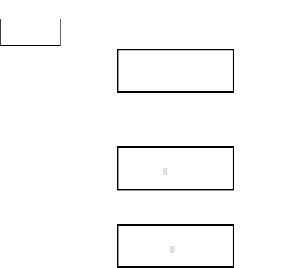
MS-9600LS Series Manual — P/N 52646:B2 2/12/2010 135
Master Programming Level Programming
3.6.10 Password Change
The factory set passwords, which have been programmed into the control panel, can be changed by
selecting the Password Change option. Pressing 1 while viewing Programming Screen #4 will
cause the following screen to be displayed:
Press 1 to change the Master Programming Level password, 2 to change the Maintenance Level
password, or 3 to change the Remote Download password. Note that the passwords will not be dis-
played on LCD annunciators.
The following screen will appear when either change option is selected:
A flashing cursor will appear in the center of the display. Enter a new five digit password (such as
10101 for the Master Level). After the fifth digit is entered, the following screen will be displayed:
Re-enter the new password to accept the change. The display will return to the initial Password
Change Screen.
PROGRAMMING
1=PASSWORD CHANGE
2=CLEAR PROGRAM
3=PROGRAM CHECK
Programming Screen #4
PASSWORD CHANGE
1=MASTER
2=MAINTENANCE
3=REMOTE DOWNLOAD
Password Change Screen
ENTER NEW FIVE DIGIT
PASSWORD
Enter Password Screen
VERIFY NEW
PASSWORD
Password Change Screen
136 MS-9600LS Series Manual — P/N 52646:B2 2/12/2010
Programming Master Programming Level
3.6.11 Clear Program
Pressing 2 while viewing Programming Screen #4, will select the Clear Program option. This will
cause the LCD to display the following screens:
Pressing 1, for Whole System while viewing the Clear Program Screen #1, will clear all general
system programming options and all programmed addressable devices from the nonvolatile mem-
ory of the FACP. This function is useful when the control panel is first installed, prior to autopro-
gramming. Note that it is necessary to autoprogram after using the Clear Whole System function.
Pressing 2, for All Loops while viewing the Clear Program Screen #1, will clear all programming
related to all SLC loops and connected addressable devices.
Pressing 3, for Loop 1 while viewing the Clear Program Screen #1, will clear only the program-
ming related to SLC Loop 1 and the connected addressable devices.
Pressing 1, for Loop 2 while viewing the Clear Program Screen #2, will clear only the program-
ming related to SLC Loop 2 and the connected addressable devices.
Before executing any of the Clear commands listed above, the control panel will provide a warning
to the user by prompting with the following display:
Pressing 1 will cause the control panel to carry out the selected clear option. Pressing 2 will pre-
vent programming from being cleared.
PROGRAMMING
1=PASSWORD CHANGE
2=CLEAR PROGRAM
3=PROGRAM CHECK
Programming Screen #4
CLEAR PROGRAM
1=WHOLE SYSTEM
2=ALL LOOPS
3=LOOP1
CLEAR PROGRAM
1=LOOP2
Clear Program Screen #1
Clear Program Screen #2
WARNING!
SYSTEM CHANGE
PROCEED?
1=YES 2=NO
MS-9600LS Series Manual — P/N 52646:B2 2/12/2010 137
Master Programming Level Programming
3.6.12 Program Check
The Program Check feature allows the programmer to view the zones which have been pro-
grammed to the Notification Appliance Circuits on the control panel but have not been pro-
grammed to Initiating Devices as well as other circuits with no input or output correlations.
Pressing 3 while viewing Programming Screen #4 will cause the following screen to be displayed:
Pressing 1 while viewing the Program Check screen will display an NAC screen similar to the fol-
lowing.
The example above indicates that NAC 1 has been programmed to Zones 25, 31, 44, 55 and 67 but
no input devices have been programmed to any of these zones. Use the up and down arrow keys to
view all the NAC zones without input assignments for NAC 1, NAC 2, NAC 3, and NAC 4.
Pressing 2 while viewing the Program Check screen will display a screen similar to the following:
The Zone No Input screen allows the programmer to view the zones which have not been pro-
grammed to at least one input device (not including general alarm Zone 00). The example in the
preceding screen indicates that Zones 05, 07, 09, 10, and 11 have been programmed to an address-
able module (control module in this example) with an address of 001 on loop 1 but have not been
programmed to any input devices. Use the up and down arrow keys to view all the zones without
input assignments.
PROGRAMMING
1=PASSWORD CHANGE
2=CLEAR PROGRAM
3=PROGRAM CHECK
Programming Screen #4
PROGRAM CHECK
1=NACS NO INPUT
2=ZONES NO INPUT
3=ZONES NO OUTPUT
PROGRAM CHECK
1=NACS NO INPUT
2=ZONES NO INPUT
3=ZONES NO OUTPUT
Program Check Screen
NACS NO INPUT
NAC 1
25 31 44 55 67
NOTE: If the NACs have been configured for Class Ain the setup option, only NAC1 and NAC2 will
display test information. NAC3 and NAC4 will display asterisks (*) and will not be included in the test.
ZONES NO INPUT
05 07 09 10 11 1M001

138 MS-9600LS Series Manual — P/N 52646:B2 2/12/2010
Programming Maintenance Programming Level
Pressing 3 while viewing Program Check screen will cause a screen similar to the following to be
displayed:
The Zone No Output feature allows the programmer to view the zones which have not been pro-
grammed to at least one output device (not including general alarm Zone 00). The example in the
preceding screen indicates that Zones 05, 07, 09, 10, and 11 have been programmed to an address-
able detector with an address of 001 on loop 1 but have not been programmed to any output
devices. Use the up and down arrow keys to view all the zones without output assignments.
3.7 Maintenance Programming Level
To access Maintenance Programming mode, press the Enter key. The LCD will display the follow-
ing:
To enter the Maintenance Programming mode, press 2. The display will read as follows:
When the Maintenance level password (default 11111) is entered, the following screen will appear:
ZONES NO OUTPUT
05 07 09 10 11 1D001
1=READ STATUS
2=PROGRAMMING
3=REMOTE DOWNLOAD
PROGRAMMING
ENTER PASSWORD
PROGRAMMING
1=POINT PROGRAM
2=HISTORY
3=PROGRAM CHECK
MS-9600LS Series Manual — P/N 52646:B2 2/12/2010 139
Maintenance Programming Level Programming
Note that in the preceding screens, an arrow appears to inform the programmer that additional
options can be viewed by pressing the keypad down arrow key, as shown in the following screen.
3.7.1 Disable Point
Pressing 1 for Point Program, while viewing Maintenance Screen #1 will cause the following
screens to be displayed:
Select the Loop, containing the device to be disabled, by pressing 1 for Loop 1 or 2 for Loop 2. A
screen will then be displayed, allowing the operator to select the type of addressable device to be
disabled as shown in the following display:
Select the device type by pressing 1 for an addressable detector or 2 for an addressable module.
The operator will be prompted to enter the three digit device address as shown in the following
example for a detector:
PROGRAMMING
1=WALKTEST
2=SYSTEM
3=ZONE SETUP
PROGRAMMING
1=POINT PROGRAM
2=HISTORY
3=PROGRAM CHECK
Maintenance Screen #1
POINT PROGRAM
1=LOOP 1
2=LOOP 2
Loop Select Screen
POINT PROGRAM
1=DETECTOR
2=MODULE
Device Select Screen
EDIT DETECTOR
ENTER POINT ADDRESS
***
Address Select Screen

140 MS-9600LS Series Manual — P/N 52646:B2 2/12/2010
Programming Maintenance Programming Level
A flashing cursor will appear in the bottom left corner of the display, prompting for the three digit
device address. When the third digit is enter, 001 for example, a screen will appear which will
allow enabling or disabling of the selected point, as illustrated in the following example:
Pressing 1 repeatedly will cause the display to toggle between Enabled Yes and Enabled No.
3.7.2 History
Pressing 2 while viewing Maintenance Screen #1 will cause the following screen to be displayed:
The History feature allows the operator to view control panel events which have been stored in a
history file in memory and erase the contents of the history file
Pressing 1 while viewing the History screen will cause the following screen to be displayed:
To view all the events which have occurred in the control panel since the history file was last
erased, press 1 while viewing the Events screen. To view only alarms which have occurred, press 2
while viewing the Events screen. To view events other than alarms, press 3. The most recent event
will be displayed on the screen. To view all of the selected events, press the up or down arrow keys
to scroll through the list of events. If no events have occurred, the display will read NO EVENTS
IN HISTORY.
EDIT DETECTOR 1D001
1=ENABLED YES
Enable/Disable Select Screen
PROGRAMMING
1=POINT PROGRAM
2=HISTORY
3=PROGRAM CHECK
Maintenance Screen #1
HISTORY
1=VIEW EVENTS
2=ERASE HISTORY
History Screen
HISTORY
1=VIEW ALL
2=VIEW ALARMS
3=VIEW OTHER EVENTS
Events Screen
MS-9600LS Series Manual — P/N 52646:B2 2/12/2010 141
Maintenance Programming Level Programming
Pressing 2 while viewing the History Screen will cause the following screen to be displayed:
Pressing 1 while viewing the Erase History Screen will cause the message ERASING HISTORY,
PLEASE WAIT to be displayed. The display will then return to the History Screen. Pressing 2 will
cause the display to return to the History Screen without erasing the History file.
3.7.3 Program Check
Pressing 3 while viewing Maintenance Screen #1 will cause the following screen to be displayed:
The Program Check feature allows the programmer to view the zones which have been pro-
grammed to the Notification Appliance Circuits on the control panel but have not been pro-
grammed to Initiating Devices as well as other circuits with no input or output correlations.
Pressing 1 while viewing Program Check screen will cause a screen similar to the following to be
displayed.
The example above indicates that NAC 1 has been programmed to Zones 25, 31, 44, 55, and 67 but
no input devices have been programmed to any of these zones. Use the up and down arrow keys to
view all the NAC zones without input assignments for NAC1, NAC2, NAC3, and NAC4.
ERASE HISTORY
PROCEED ?
1=YES 2=NO
Erase History Screen
PROGRAMMING
1=POINT PROGRAM
2=HISTORY
3=PROGRAM CHECK
Maintenance Screen #1
PROGRAM CHECK
1=NACS NO INPUT
2=ZONES NO INPUT
3=ZONES NO OUTPUT
Program Check Screen
NACS NO INPUT
NAC 1
25 31 44 55 67
NOTE: If the NACs have been configured for Class A in the Setup option, only NAC1 and NAC2 will
display test information. NAC3 and NAC4 will display asterisks (*) and will not be included in the test.

142 MS-9600LS Series Manual — P/N 52646:B2 2/12/2010
Programming Maintenance Programming Level
Pressing 2 while viewing the Program Check screen will display a screen similar to the following:
The Zone No Input screen allows the programmer to view the zones which have not been pro-
grammed to at least one input device (not including general alarm Zone 00). The example in the
preceding screen indicates that Zones 05, 07, 09, 10, and 11 have been programmed to an address-
able module (control module in this example) with an address of 001 on loop 1 but have not been
programmed to any input devices. Use the up and down arrow keys to view all the zones without
input assignments.
Pressing 3 while viewing Program Check screen will cause a screen similar to the following to be
displayed:
The Zone No Output feature allows the programmer to view the zones which have not been pro-
grammed to at least one output device (not including general alarm Zone 00). The example in the
preceding screen indicates that Zones 05, 07, 09, 10, and 11 have been programmed to an address-
able detector with an address of 001 on loop 1 but have not been programmed to any output
devices. Use the up and down arrow keys to view all the zones without output assignments.
3.7.4 Walktest
To perform a walktest, press 1 while viewing Maintenance Screen #2. The following screen will be
displayed:
The operator can press 1 to perform a silent walktest or 2 to perform an audible walktest. The dis-
play will read UNIT IN WALKTEST. To end the Walktest, press the Esc (Escape) key.
Pressing 3 after the walktest has been completed, will allow the operator to view the results of the
walktest.
ZONES NO INPUT
05 07 09 10 11 1M001
ZONES NO OUTPUT
05 07 09 10 11 1D001
PROGRAMMING
1=WALKTEST
2=SYSTEM
3=ZONE SETUP
Maintenance Screen #2
WALKTEST
1=SILENT
2=AUDIBLE
3=VIEW RESULT
Walktest Screen

MS-9600LS Series Manual — P/N 52646:B2 2/12/2010 143
Maintenance Programming Level Programming
3.7.5 System
To program the time and date into the control panel, press 2 while viewing Maintenance Screen #2.
The following display will appear:
Pressing 1 while viewing the System Screen will cause the following screen to be displayed:
To change the time, press 1 to display the following screen:
A flashing cursor will appear on the left side of the display. Enter the four digit number corre-
sponding to the time (0000 - 1259). When the fourth digit is entered, the cursor will move one
position to the right. Press 1 for AM or 2 for PM to complete entering the time. The display will
return to the Time and Date Screen displaying the new time.
SYSTEMS
1=TIME/DATE
System Screen
TIME AND DATE
1=TIME 01:00 AM
2=DATE 01-01-2007
12HR
Time and Date Screen
ENTER TIME
01:00 AM
1=AM 2=PM
Time Screen
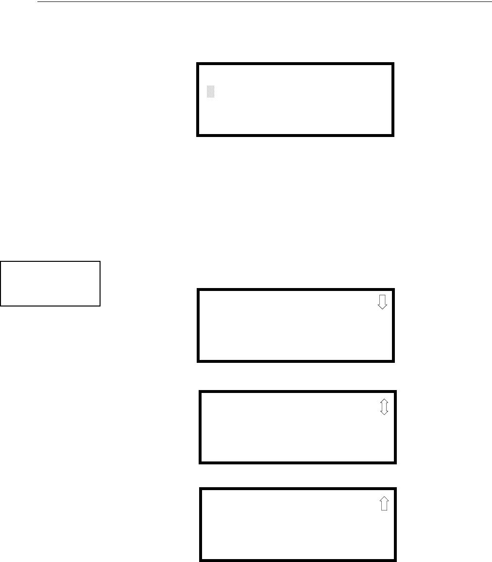
144 MS-9600LS Series Manual — P/N 52646:B2 2/12/2010
Programming Maintenance Programming Level
To change the date, press 2 while viewing the Time and Date Screen. The following screen will be
displayed:
A flashing cursor will appear on the left side of the display. Enter the two digit month, two digit
day and four digit year. The cursor will move one position to the right after each entry. When the
fourth digit of the year has been entered, the display will return to the Time and Date Screen which
will show the new date.
3.7.6 Zone Setup
Pressing 3 while viewing Maintenance Screen #2 will display the following screen:
ENTER DATE
MONTH DAY YEAR
01-01-2010
Date Screen
PROGRAMMING
1=WALKTEST
2=SYSTEM
3=ZONE SETUP
Maintenance Screen #2
ZONE SETUP
1=ENABLE
2=DISABLE
3=ZONE 97 98 99
Zone Setup Screen #1
ZONE SETUP
1=ZONES INSTALLED
2=ZONES ENABLED
3=ZONES DISABLED
Zone Setup Screen #2
ZONE SETUP
1=ZONE TYPES
2=ZONES AVAILABLE
3=ZONE MESSAGE
Zone Setup Screen #3
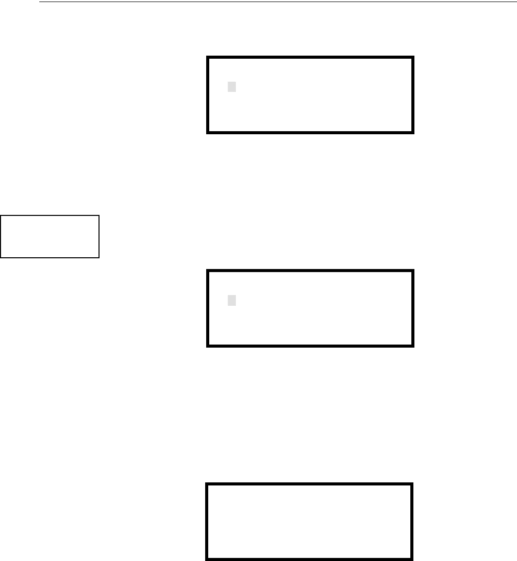
MS-9600LS Series Manual — P/N 52646:B2 2/12/2010 145
Maintenance Programming Level Programming
Pressing 1 while viewing Zone Setup screen #1 will display the following screen:
A flashing cursor appears to the right of the Z. To enable a zone, enter the two digit zone number
(00 - 99). After the second digit is entered, the zone will be enabled and the cursor will return to the
original position. The next zone to be enabled can then be entered. Press Esc (Escape) to return to
the previous screen.
Pressing 2 while viewing Zone Setup screen #1 will display the following screen:
A flashing cursor appears to the right of the Z. To disable a zone, enter the two digit zone number
(00 - 99). After the second digit is entered, the zone will be disabled and the cursor will return to
the original position. The next zone to be disabled can then be entered. Press Esc (Escape) to
return to the previous screen.
Pressing 3 while viewing Zone Setup screen #1 will display the following screen:
Zones 97, 98, and 99 can be programmed for normal zone operation or for special purpose applica-
tions. In the above illustration, the three zones are shown Off, which means they can be pro-
grammed to function in the same manner as all other zones, by assigning them to input and output
devices in the Programming Zone Assignment Screen.
Pressing 1 will cause the display to change to PA S 9 7 O n . Each press of the 1 key will cause the
display to toggle between PAS 97 On and PAS 97 Off. When Zone 97 is programmed On, a PAS
(Positive Alarm Sequence) activation of any detector will cause Zone 97 to activate. By assigning
Zone 97 to a control module in the Programming Zone Assignment Screen, an output device con-
ZONE TO ENABLE
Z
Enable Screen
ZONE SETUP
1=ZONES INSTALLED
2=ZONES ENABLED
3=ZONES DISABLED
Zone Setup Screen #2
ZONE TO DISABLE
Z
Disable Screen
SPEC PURPOSE ZONE
1=PAS 97 OFF
2=PRE-SIGNAL 98 OFF
3=FUTURE 99 OFF
Disable Screen

146 MS-9600LS Series Manual — P/N 52646:B2 2/12/2010
Programming Maintenance Programming Level
nected to the control module can be used to indicate a PAS condition in the control panel. Do not
assign Zone 97 to a Notification Appliance Circuit when using this zone to indicate a PAS condi-
tion.
Pressing 2 will cause the display to change to Pre-signal 98 On. Each press of the 2 key will cause
the display to toggle between Pre-signal 98 On and Pre-signal 98 Off. When Zone 98 is pro-
grammed On, a Pre-signal activation of any device will cause Zone 98 to activate. By assigning
Zone 98 to a control module in the Programming Zone Assignment Screen, an output device con-
nected to the control module can be used to indicate a Pre-signal condition in the control panel. Do
not assign Zone 98 to a Notification Appliance Circuit when using this zone to indicate a Pre-signal
condition.
Zone 99, in special purpose mode, is reserved for future use and has no effect.
Zones Installed
Pressing 1 for Zones Installed, while viewing Zone Setup Screen #2, will display a screen similar to
the following:
This display will show all of the zones that have been programmed into the control panel. Note that
an up and/or down arrow may appear in the upper right corner of the display, indicating that addi-
tional screens of zone information exists. Press the up or down arrow keys to view the additional
zones.
Zones Enabled
Pressing 2 for Zones Enabled, while viewing Zone Setup Screen #2, will display a screen similar to
the following:
This display will show all of the zones that are enabled in the control panel. Note that an up and/or
down arrow may appear in the upper right corner of the display, indicating that additional screens
of zone information exists. Press the up or down arrow keys to view the additional zones.
ZONE SETUP
1=ZONES INSTALLED
2=ZONES ENABLED
3=ZONES DISABLED
Zone Setup Screen #2
ZONES INSTALLED
00 01 02 03 04 05
Zones Installed Screen
ZONES ENABLED
00 01 02 04 05 06 07
08 09 10 11 12 13 14
15 16 17 18 19 20 21
Zones Enabled Screen

MS-9600LS Series Manual — P/N 52646:B2 2/12/2010 147
Maintenance Programming Level Programming
Zones Disabled
Pressing 3 for Zones Disabled, while viewing Zone Setup Screen #2, will display a screen similar
to the following:
This display will show all of the zones that are disabled in the control panel. Note that an up and/or
down arrow may appear in the upper right corner of the display, indicating that additional screens
of zone information exists. Press the up or down arrow keys to view the additional zones.
Zone Type
Zone Types must be programmed only if a DACT, programmed for zone reporting, is installed on
the control panel. Pressing 1 for Zone Types, while viewing Zone Setup Screen #3, will display a
screen similar to the following:
This display will show the system zones (default and user programmed) and their associated types.
Note that an up and/or down arrow will appear in the upper right corner of the display, indicating
that additional screens of zone information exists. Press the up or down arrow keys to view zones
Z00 through Z99.
ZONES DISABLED
03
Zones Disabled Screen
ZONE SETUP
1=ZONE TYPES
2=ZONES AVAILABLE
3=ZONE MESSAGE
Zone Setup Screen #3
ZONE TYPE PROG
1=Z00 MONITOR
2=Z01 MONITOR
3=Z02 MONITOR
Zones Installed Screen
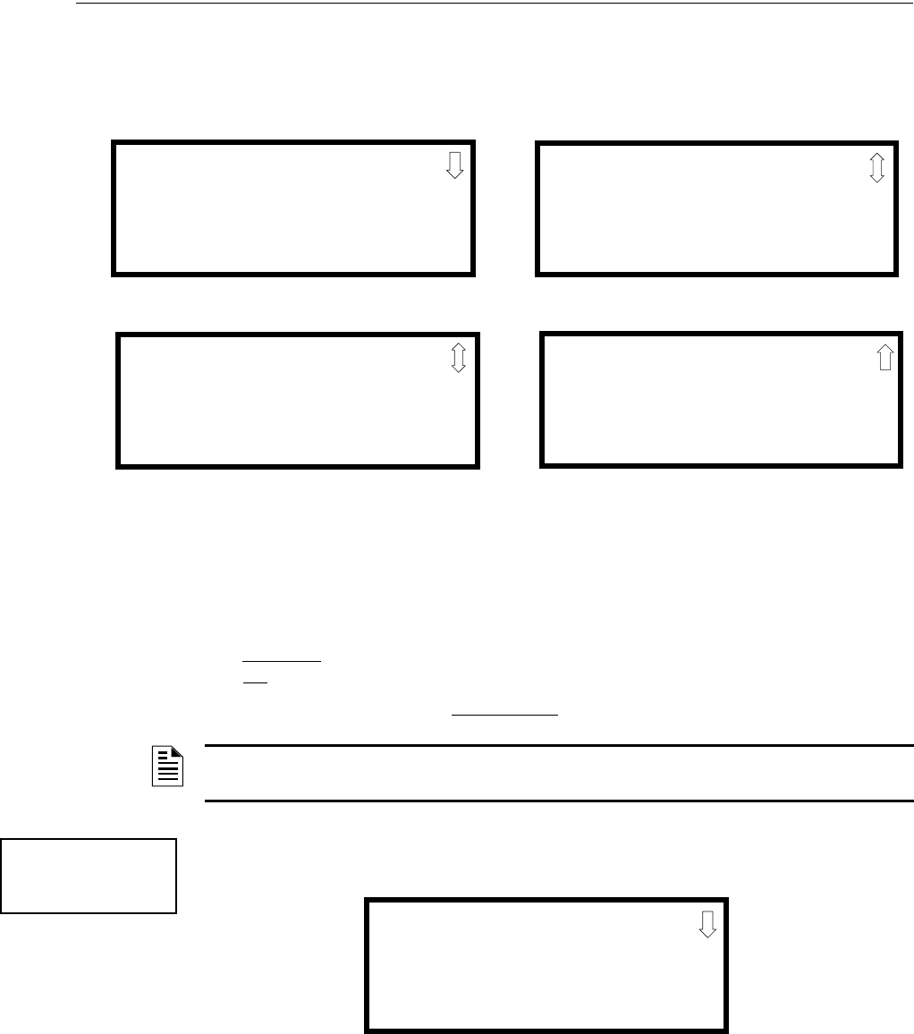
148 MS-9600LS Series Manual — P/N 52646:B2 2/12/2010
Programming Maintenance Programming Level
Zone types can be changed by pressing the keypad number key corresponding to the zone in each
Zones Installed Screen. Available zone types will be displayed in the resultant screens. For exam-
ple, to change the zone type for zone Z02 in the screen illustrated above, press 3. The following
screens will be displayed:
To change the zone type for Z02 to Pull Station, scroll the display until Zone Type Program Screen
#2 is displayed. Press 2 to program zone Z02 as a Pull Station zone. The display will return to the
Zones Installed Screen showing zone Z02 and the Pull Station program type. Repeat the procedure
for each zone to be changed.
IMPORTANT! In Zone Type Program Screen #1, selecting WATERFLOW will assign a Water-
flow silenceable zone type to the selected zone. Any signaling devices programmed to the same
zone can be silenced by pressing the Alarm Silence key or by using the auto-silence feature.
To program a waterflow circuit as nonsilenceable, refer to “System Setup” on page 100.
Zones Available
Pressing 2 while viewing Zone Setup Screen #3 will display the following screen:
The display will show all of the zones that are still available for programming. Note that an up
and/or down arrow may appear in the upper right corner of the display, indicating that additional
screens of zone information exists. Press the up or down arrow key to view additional screens.
ZONE TYPE PROG
1=MONITOR
2=SMOKE PHOTO
3=WATERFLOW
Zone Type Program Screen #1
ZONE TYPE PROG
1=MEDICAL
2=HAZARD
3=TAMPER
Zone Type Program Screen #2
ZONE TYPE PROG
1=SUPERVISORY
2=PROC. MON
3=SMOKE ION
Zone Type Program Screen #4
ZONE TYPE PROG
1=HEAT
2=PULL STATION
3=DUCT
Zone Type Program Screen #3
NOTE: Zone Types are only relevant for Central Station reporting. Changing a zone type will only
change how it is reported to the Central Staion.
ZONE SETUP
1=ZONE TYPES
2=ZONES AVAILABLE
3=ZONE MESSAGE
Zone Setup Screen #3
ZONES AVAILABLE
01 02 03 04 05 06 07
08 09 10 11 12 13 14
15 16 17 18 19 20 21

MS-9600LS Series Manual — P/N 52646:B2 2/12/2010 149
Maintenance Programming Level Programming
Zone Message
Pressing 3 while viewing Zone Setup Screen #3 will display the following screen:
Pressing the down arrow key will display additional screens for Zones up to Z99. Press the number
key corresponding to the Zone to be programmed. Screens will be displayed allowing the program-
mer to select Messages 1 through 5. When a message is selected, the display will return to the Zone
Message screen, showing the message selected for that particular zone. In the example above,
Zone 01 has been programmed for Message 1.
ZONE MESSAGE
1=Z00 NO MESSAGE
2=Z01 MESSAGE 1
3=Z02 NO MESSAGE
150 MS-9600LS Series Manual — P/N 52646:B2 2/12/2010
Section 4: Operating Instructions
4.1 Panel Control Buttons
4.1.1 Acknowledge/Step
The first press of the Acknowledge/Step key silences the piezo sounder, changes flashing LEDs to
steady and also changes the status field on the LCD display from capital letters to small letters.
When the piezo is silenced, an acknowledge message is sent to the printer and the history file.
Acknowledge also sends a silence piezo command to the optional annunciators connected to the
FACP.
When more than one event exists, the first press of the Acknowledge/Step key functions as
described in the preceding paragraph. Subsequent pressing of the key steps through each off-nor-
mal active event, with alarm events having a higher priority than trouble and supervisory events.
4.1.2 Alarm Silence
The Alarm Silence key performs the same functions as Acknowledge/Step. In addition, if an alarm
exists, it turns off all silenceable NACs (Notification Appliance Circuits) and causes the Alarm
Silenced LED to turn on. It also sends an ‘alarm silenced’ message to the printer, history file and
optional annunciators. A subsequent new alarm will resound the system NACs. Note that the
Alarm Silenced LED is turned off by pressing the Reset key, the Drill key or subsequent activation
of the NACs.
4.1.3 Drill/Hold 2 Sec
When the Drill key is held for a minimum of two seconds (time required to prevent accidental acti-
vations), the FACP turns on all main panel NAC outputs and all silenceable circuits such as control
modules that are programmed as silenceable, and turns off the Alarm Silenced LED if it was previ-
ously on. The EVAC IN SYSTEM message is shown on the LCD display. The same message is sent
to the printer and history file. The Alarm Silence key can be used to turn off all silenceable NAC
outputs following activation by the Drill key.
4.1.4 Reset
Pressing and releasing the Reset key turns off all control modules and NACs, temporarily turns off
resettable power to 4-wire detectors, causes a RESET IN SYSTEM message to be displayed on the
LCD and sends the same message to the printer and history file. It also performs a lamp test by
turning on all LEDs (except the Ground LED), piezo sounder and LCD display segments after the
Reset key is released. Any alarm or trouble that exists after a reset will resound the system.
4.2 LED Indicators
The nine LED indicators, which are located on the front panel, operate as follows:
AC Power
This is a green LED which illuminates if AC power is applied to the FACP. A loss of AC power
will turn off this LED
Fire Alarm
This red LED flashes when one or more alarms occur. It illuminates steady when the Acknowl-
edge/Step or Alarm Silence key is pressed. The Fire Alarm LED turns off when the Reset key is
pressed. The LED will remain off if all alarms have been cleared.

MS-9600LS Series Manual — P/N 52646:B2 2/12/2010 151
Normal Operation Operating Instructions
Supervisory
This is a yellow LED that flashes when one or more supervisory conditions occur, such as a sprin-
kler valve tamper condition. It illuminates steady when the Acknowledge/Step or Alarm Silence
key is pressed. It turns off when the Reset key is pressed and remains off if all supervisory alarms
have been cleared.
Trouble
This is a yellow LED that flashes when one or more trouble conditions occur. It stays on steady
when the Acknowledge/Step or Alarm Silence key is pressed. The LED turns off when all trouble
conditions are cleared. This LED will also illuminate if the microprocessor watchdog circuit is
activated.
Maintenance
This is a yellow LED that flashes to indicate that a smoke detector requires cleaning or replacement
due to an invalid chamber reading or excessive drift.
Alarm Silenced
This is a yellow LED that turns on after the Alarm Silence key is pressed while an alarm condition
exists. It turns off when the Drill or Reset key is pressed.
Disabled
This is a yellow LED that flashes to indicate that a zone, NAC, detector or module has been tempo-
rarily disabled in programming by the user.
Battery
This is a yellow LED that flashes to indicate a low battery voltage condition.
Ground
This is a yellow LED that turns on steady to indicate a ground fault condition (zero impedance
between FACP and ground).
4.3 Normal Operation
With no alarms or troubles in the system, the display message is System All Normal along with the
current time and date as shown below. To set the time and date, refer to the appropriate section in
this manual.
The FACP performs the following functions at regular intervals while in Normal mode:
• Monitors AC input voltage and battery voltage
• Monitors and reports status of SLC loop(s), option cards and control panel
• Polls all devices on the SLC loop(s) and flashes each device LED while checking for valid
replies, alarms, troubles, etc.
• Refreshes LCD display and updates time
• Scans control panel keypad for key presses
• Performs autotest for all SLC devices
• Tests memory
• Updates and reads all communications busses (EIA-485, EIA-232, etc.)
HONEYWELL
LIFE SAFETY
SYSTEM ALL NORMAL
10:00A 010810

152 MS-9600LS Series Manual — P/N 52646:B2 2/12/2010
Operating Instructions Trouble Operation
4.4 Trouble Operation
With no alarms in the system, the detection of a trouble will cause the following:
• The piezo to pulse 1 second On and 1 second Off
• The system Trouble LED to flash one second On and one second Off
• The trouble relay to activate
•TROUBL with device type, noun/adjective, address and trouble description will appear on the
LCD display
• The same message, along with the time and date, is sent to the history buffer and optional
printer
• Terminate upload or download communications
Note that specific troubles will initiate additional actions; for example, loss of AC power will turn
off the AC Power LED, a ground fault will turn on the Ground LED, etc.
Addressable Smoke Detectors, Monitor Modules and Control Modules
For addressable devices connected to the SLC loop, the following is a typical message that could
appear on the LCD display for a device trouble:
The information displayed in the above example provides the following information:
• First line in display:
– The type of event; in this example TROUBL indicating a device trouble
– Device type identifier; in this example, SMOKE (PHOTO) indicates a Photoelectric smoke
detector. Other device type identifiers which can be displayed include SMOKE (ION) for
Ionization Detector, HEAT for Heat Detector, CONTROL for Control Module and
MONITOR for Monitor Module, PULL STATION for a manual pull box, etc. Refer to “Edit
Detector” on page 69, “Edit Module Screen for Monitor Module” on page 79, and “Edit
Module Screen for Control Modules” on page 88 for information on additional device types.
• Second line in display:
– <ADJ>; refers to the user programmed adjective descriptor from library list resident in the
control panel or custom entry via PC.
– <NOUN>; refers to the user programmed noun descriptor from library list resident in the
control panel or custom entry via PC.
• Third line in display: INVREP indicates an invalid reply from the addressable device. Other
possible troubles include:
SHORT - indicating a shorted circuit on an addressable device
OPEN - indicating an open circuit on an addressable device
DIRTY1 - maintenance alert indicating that a detector is near but below the allowed alarm
limit and is in need of maintenance before the performance is compromised
DIRTY2 - maintenance alert indicating that a detector needs immediate maintenance since it
has been within 80% of its alarm threshold for 24 hours
INVREP - maintenance alert indicating a hardware problem in the detector
TEST F - indicating a detector has failed the automatic test operation which functionally
checks its sensing chamber and electronics
TROUBL SMOKE (PHOTO)
<ADJ> <NOUN>
INVREP
10:00A 010810 1D001

MS-9600LS Series Manual — P/N 52646:B2 2/12/2010 153
Alarm Operation Operating Instructions
INV ID - indicating that an incorrect device code (Type ID) has been programmed for an
installed device (for example, Photo has been programmed but an Ion detector has been
installed)
SW TBL - indicating a module has failed the testing of its Class A switching relay
• Fourth line in display:
– Time; the current time in this example is 10:00A which represents 10:00 AM
– Date; the current month, day and year in this example is 01 for January, 08 for the 8th day of
the month, and 10 for the year 2010
– Device Address; 1D001 in this example 1 represents SLC Loop1, D represents a detector,
and 001 represents device address 001
Pressing the Acknowledge/Step or Alarm Silence key will cause the pulsing piezo to silence and the
system Trouble LED to change from flashing to on steady. This block acknowledgment occurs
regardless of the number of troubles, alarms and supervisory events active in the system. When the
Acknowledge/Step key is pressed and at least one new alarm or trouble exists in the system, the
‘acknowledge’ message is sent to the printer and history file. If the trouble clears, either before or
after the Acknowledge/Step key is pressed, the ‘clear trouble’ message is sent to the printer and his-
tory file.
If all troubles clear and there are no supervisory or fire conditions active in the system, the system
returns to normal mode operation and the System All Normal message is shown on the LCD display
and sent to the history and printer files. The auto-restore feature will restore cleared troubles even
if the troubles were never acknowledged. Note that pressing the Alarm Silence key when only trou-
bles exist in the system will have the same effect as pressing the Acknowledge/Step key.
If multiple trouble conditions exist in the system, they will be automatically scrolled on the LCD
display at a three second rate. If a combination of alarms, troubles and/or supervisory conditions
simultaneously occur in the system, only the alarms are scrolled on the display.
4.5 Alarm Operation
Alarm operation is similar to trouble operation with the following differences:
• The piezo sounder produces a steady output as opposed to a pulsed output
• The Fire Alarm LED flashes 1 second On and 1 second Off
• The LCD displays Alarm along with the device name, type, address, adjective/noun, associated
zones and time/date
• Alarms latch and are not allowed to clear automatically
• Alarms activate software zones if so programmed
• Timers for Silence Inhibit, Autosilence and Trouble Reminder are started
• Alarms activate the general alarm relay and general alarm zone Z00
• The trouble relay is not activated
• Store event in history buffer
• Terminate upload or download communications
• Alarms must be Acknowledged before the FACP can be reset
A typical alarm display would be as illustrated below:
ALARM PULL STATION
<ADJ> <NOUN>
Z000
10:00A 010810 1M001

154 MS-9600LS Series Manual — P/N 52646:B2 2/12/2010
Operating Instructions Supervisory Operation
Note that the device type, which in this example is PULL STATION, can be any other programma-
ble alarm type.
The information displayed in the above example provides the following information:
• First line in display:
– The type of event; in this example ALARM indicating an alarm condition
– Device type identifier; in this example, PULL STATION indicates a manual pull box. Other
device type identifiers which can be displayed include SMOKE (ION) for Ionization
Detector, HEAT for Heat Detector, CONTROL for Control Module and MONITOR for
Monitor Module, PULL STATION for a manual pull box, etc. Refer to “Edit Detector” on
page 69, “Edit Module Screen for Monitor Module” on page 79, and “Edit Module Screen
for Control Modules” on page 88 for information on additional device types.
• Second line in display:
– <ADJ>; refers to the user programmed adjective descriptor from library list resident in the
control panel or custom entry via PC.
– <NOUN>; refers to the user programmed noun descriptor from library list resident in the
control panel or custom entry via PC.
• Third line in display: Z000 indicates the zone programmed to this device which, in this
example, is general alarm Zone 000. Note that a single device can be programmed to five
different zones but only the first zone will be displayed.
• Fourth line in display:
– Time; the current time in this example is 10:00A which represents 10:00 AM
– Date; the current month, day and year in this example is 01 for January, 08 for the 8th day of
the month, and 10 for the year 2010
– Device Address; 1M001 in this example 1 represents SLC Loop1, M represents a module,
and 001 represents device address 001
4.6 Supervisory Operation
Supervisory operation is similar to alarm operation but with the following differences:
• The piezo sounder pulses ½ second On and ½ second Off
• The Supervisory LED flashes ½ second On and ½ second Off
• The LCD displays the status label Active Supervisory along with the device name, type,
address, adjective/noun, associated zones and time/date
• The supervisory relay is activated
• The alarm relay is not activated
• Silenced alarms are not resounded
• Timers are not started
• Store event in history buffer
• Terminate upload or download communications
• Supervisory condition must be Acknowledged before the FACP can be reset

MS-9600LS Series Manual — P/N 52646:B2 2/12/2010 155
Process Monitor Operation Operating Instructions
A typical Supervisory event would be displayed as illustrated in the following:
Note that, like alarms, supervisory signals latch (except when programmed for supervisory autore-
settable) and can be assigned to software zones. Supervisory alarms do not cause resound as do
other alarm conditions. Open circuits in supervisory wiring are processed by the control panel the
same way as other trouble conditions. Refer to “Alarm Operation” on page 153, for a description
of the information displayed on the control panel LCD.
4.7 Process Monitor Operation
Process Monitor operation will initiate the following events:
• The piezo sounder pulses ¼ second On and ¼ second Off
• The LCD displays a process monitor message along with the device name, type, address,
adjective/noun, associated zones and time/date
• Relays programmed for process monitoring will be activated
• The alarm relay is not activated
• Silenced alarms are not resounded
• Timers are not started
• Store event in history buffer
• Process Monitor condition must be Acknowledged before the FACP can be reset
Note that, like supervisories, process monitor signals latch (except when programmed for process
monitor autoresettable) and can be assigned to software zones.
4.8 Hazard Condition Operation
Hazard Condition operation will initiate the following events:
• The piezo sounder turns on steady
• The LCD displays a hazard message along with the device name, type, address,
adjective/noun, associated zones and time/date
• Relays programmed for process monitoring will be activated
• The alarm relay is not activated
• Silenced alarms are not resounded
• Timers are not started
• Store event in history buffer
• Hazard condition must be Acknowledged before the FACP can be reset
Hazard conditions latch and will therefore clear only when the hazard condition is cleared and the
panel reset. They can be assigned to software zones.
ACTIVE SUPERVISORY
<ADJ> <NOUN>
Z000
10:00A 010810 1M001

156 MS-9600LS Series Manual — P/N 52646:B2 2/12/2010
Operating Instructions Medical Alert Condition Operation
4.9 Medical Alert Condition Operation
Medical Alert Condition operation will initiate the following events:
• The piezo sounder turns on steady
• The LCD displays a medical alert message along with the device name, type, address,
adjective/noun, associated zones and time/date
• Relays programmed for medical alert will be activated
• The alarm relay is not activated
• Silenced alarms are not resounded
• Timers are not started
• Store event in history buffer
• Medical Alert condition must be Acknowledged before the FACP can be reset
Medical alert conditions latch and will therefore clear only when the medical alert condition is
cleared and the panel reset. They can be assigned to software zones.
4.10 Programmed Zone Operation
Each addressable detector and monitor module can be assigned to a maximum of five software
alarm zones. A general alarm zone Z00 may be listed for output (control) points, but it is not nec-
essary to list Z00 for input points, since this is the default zone for all alarm input devices. Zone
Z00 is also activated by supervisory points.
When an input device alarms and is not disabled, it activates all software zones assigned to it. An
output device that is not disabled is turned on when any of the software zones to which it is pro-
grammed become active.
4.11 Disable/Enable Operation
Input points which are disabled do not cause an alarm or any zone activation. Disabled output
points are held in the off state. All disabled points are treated as if they were in trouble, with the
exception being the status label that will be displayed is DISABL.
4.12 Waterflow Circuits Operation
If an alarm exists from a monitor module point that has a waterflow type code and its mapped NAC
control module outputs are programmed for nonsilenceable operation, the Alarm Silence key will
not function.
4.13 Detector Functions
Maintenance Alert
Each addressable detector is monitored by the control panel for its maintenance status. If a detector
is near but below the allowed alarm limit, a ‘maintenance alert’ message will automatically be dis-
played, signaling that the detector is in need of servicing.
Automatic Test Operation
An automatic test of an addressable detector is performed each minute, resulting in a complete SLC
loop test in approximately 5 hours (if the loop has the maximum number of devices installed). The
detector’s sensing chamber and electronics are functionally tested for normal, safe operation. A
trouble message is displayed upon failure of this test. A System Reset will clear this trouble.

MS-9600LS Series Manual — P/N 52646:B2 2/12/2010 157
Time Functions: Real-Time Clock Operating Instructions
Type Code Supervision
The FACP monitors addressable hardware device codes at slow intervals. Mismatch of any type
code, compared to the system program, will cause a device trouble.
System Alarm Verification
The control panel may be programmed to perform alarm verification to help eliminate the nuisance
of false alarms. Alarm verification applies to smoke detectors only.
Smoke Detector Data
Smoke detector data is monitored by the FACP, eliminating the need to test the sensitivity of each
detector at its location. A printout of each detector’s data can be retrieved from the FACP using an
optional printer or Windows© HyperTerminal. Detector sensing ability can decrease with age and
should be monitored as part of a system’s routine maintenance.
4.14 Time Functions: Real-Time Clock
The FACP includes a crystal-based clock that provides time of day, date and day of week. Time is
displayed as 12 or 24 hour time with month/day/year and is stored in RAM. Daylight savings time
change-over is programmable and automatic. If both AC and battery are lost, the time must be
reset.
4.15 NAC Operation
There are up to four programmable NACs (Notification Appliance Circuits) resident on the FACP
main circuit board. The NACs may be programmed as silenceable or nonsilenceable and may also
be programmed for steady or coded operation. Coded operation provides a choice between March
Time, Temporal, California coding and two-stage operation.
4.16 Synchronized NAC Operation
Synchronization is a panel feature that controls the activation of notification appliances in such a
way that all devices will turn on and off at exactly the same time. This is particularly critical when
activating strobes which must be synchronized to avoid random activation and a potential hazard or
confusion. The FACP can be programmed to operate with a variety of manufacturer’s devices.
Important: When a Notification Appliance Circuit with a mix of audible and visual devices is
programmed for silenceable and the synchronization feature is selected, only the audible devices
will be turned off if the Silence key is pressed. The visual devices (strobes, etc.) will continue to
operate.
4.17 Coded Operation
The NAC circuits resident on the control panel main circuit board can be programmed for coded
operation. The available pulse rates which can be programmed for coded operation are as follows:
• Continuous: Steady output with no pulsing
• March Time: Pulses at 120 ppm (pulses per minute)
• Temporal Code: Pulses at ½ second On, ½ second Off, ½ second On, ½ second Off,
½ second On, 1½ second Off
• California Code: 10 seconds On, 5 seconds Off
• Two-Stage Pulses at 20 ppm (pulses per minute) for 5 minutes and
then changes to Temporal

158 MS-9600LS Series Manual — P/N 52646:B2 2/12/2010
Operating Instructions Presignal
4.18 Presignal
Presignal option programs an initiating device to delay the activation of NACs and/or control mod-
ules while allowing visual verification by a person. Once a detector or monitor module triggers an
alarm, the onboard piezo sounds immediately, but the NACs are not activated for a user pro-
grammed time duration of up to three minutes. Note that the alarm relay and communicator will
respond to the initial alarm immediately. In addition, Zone 98 will activate. This zone can be pro-
grammed to a control module which may be used to activate a sounder or indicator which the
installer designates as a Presignal indication. Do not assign Zone 98 to a Notification Appliance
Circuit when using this zone to indicate a Pre-signal condition.
After the programmed delay, the NACs will activate if the source of the alarm is not cleared. Note
that if a second alarm occurs during the programmed time delay, the alarm will be processed imme-
diately, causing activation of the appropriate output zones. The events which occur upon Presignal
activation are as follows:
• onboard piezo sounds immediately
• control panel LCD display will indicate a presignal event and the active point
• control points programmed to Zone 98 will activate
• annunciators (if enabled) will sound the local piezo, and pulse the alarm LED and zone LED
• outputs (NACs and control modules) of associated zones will be inhibited from activating
for a user programmed time delay of up to three minutes
• second alarm occurring anytime during the time delay will cause immediate activation of all
associated outputs
Presignal does not affect monitor modules programmed as waterflow, supervisory, process moni-
toring or remote switches. Presignal operation requires the approval of the local Authority Having
Jurisdiction.
4.19 Positive Alarm Sequence
PAS (Positive Alarm Sequence) option will program a smoke detector to delay panel activation
(including alarm relay and communicator) for a period of 15 seconds. Zone 97, however, will acti-
vate immediately and may be used to connect a signaling device to indicate PAS activation. Do not
assign Zone 97 to a Notification Appliance Circuit when using this zone to indicate a PAS condi-
tion.
When a detector triggers an alarm, the onboard piezo sounds immediately, but the NACs are pre-
vented from activating for 15 seconds. This inhibit time is factory set and cannot be changed.
Pressing the Alarm Silence or Acknowledge/Step key during the 15 second inhibit time will silence
the piezo sounder and start a timer which prevents activation of NACs for an additional time dura-
tion which can be user programmed for up to three minutes. After the programmed delay, the
NACs will activate if the source of the alarm is not cleared. Note that if a second alarm occurs dur-
ing either time delay, the alarm will be processed immediately, causing activation of the appropriate
output zones. The events which occur upon PAS activation are as follows:
• onboard piezo sounds immediately
• control panel LCD display will indicate a presignal event and the active point
• control points programmed to Zone 97 will activate
• ACS annunciators (if enabled) will pulse the Zone 97 PAS LED immediately upon PAS
activation. They will sound the local piezo, and pulse the alarm, associated zone and
detector address point LEDs after 15 seconds of an unacknowledged PAS activation. Note
that if the Alarm Silence or Acknowledge/Step button is pressed, the annunciators will be
inhibited from activating for an additional time delay
• outputs (NACs and control modules) of associated zones will be inhibited from activating
for a factory set duration of 15 seconds

MS-9600LS Series Manual — P/N 52646:B2 2/12/2010 159
Special System Timers Operating Instructions
• pressing the Alarm Silence or Acknowledge/Step key will start a timer which inhibits output
activation for additional time delay of up to three minutes which is user programmable
• second alarm occurring anytime during either time delay will cause immediate activation of
all associated outputs
PAS operation requires the approval of the local Authority Having Jurisdiction.
Note that the PAS BYPASS monitor type code, when activated, will inhibit the PAS capability until
the PAS BYPASS monitor is deactivated. While PAS is inhibited, signaling devices will immedi-
ately place the control panel into alarm. This feature may be employed by wiring a normally open
device, such as a switch, to a monitor module which has been programmed for PA S B Y PA S S .
4.20 Special System Timers
4.20.1 Silence Inhibit Timer
This option, if selected, prevents the Alarm Silence and Reset keys from functioning for 60 seconds
following an alarm. A second alarm during this 60 second period will not cause the timer to restart
with a new 60 seconds. Silence Inhibit operation requires the approval of the local Authority Hav-
ing Jurisdiction.
4.20.2 Autosilence Timer
If Autosilence is selected, the notification appliances, programmed as silenceable, will automati-
cally be silenced after a programmable duration of from 5 to 30 minutes. Pressing the Drill key
will restart the timer. Autosilence operation requires the approval of the local Authority Having
Jurisdiction.
4.20.3 Trouble Reminder
If selected, this feature causes a reminding ‘beep’ every 15 seconds during an alarm (after the
Alarm Silence key is pressed) and every two minutes during a trouble condition (after the Acknowl-
edge/Step or Alarm Silence key is pressed). The ‘beeps’ from the onboard piezo sounder will occur
until the alarm or fault is cleared.
Note that if the trouble is not cleared within 24 hours, the piezo will resound, indicating that the
trouble condition still exists.
4.20.4 Waterflow Retard Timer
If selected, this option will delay the activation of a waterflow type alarm for a programmable time
duration from 1 to 90 seconds. This delay is in addition to any time delay inherent in the waterflow
device. This feature requires the approval of the local Authority Having Jurisdiction.
4.20.5 Alarm Verification
If alarm verification is selected, an addressable smoke detector's alarm is ignored for a Retard time
of 13 seconds and the detector’s alarm condition is automatically reset. There will be no alarm
indication at the FACP during the Retard period. A Confirmation period of 60 seconds follows,
during which a subsequent alarm from the same detector will cause the panel to immediately acti-
vate the appropriate outputs and indicate the alarm condition at the FACP. If a different detector
alarms any time during the first detector's verification period, the panel will immediately activate
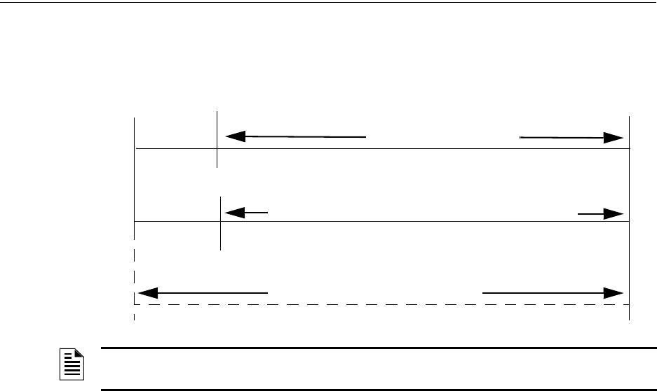
160 MS-9600LS Series Manual — P/N 52646:B2 2/12/2010
Operating Instructions Walktest
all appropriate outputs and indicate the alarm condition at the FACP. If no additional detector
alarms occur within 73 seconds of the first alarm (13 second Retard plus 60 second Confirmation),
the timer resets and the panel is ready to verify any new detector alarms which may occur.
4.21 Walktest
Walktest is a feature which allows one person to test the fire alarm system. An audible walktest
will momentarily sound the Notification Appliance Circuits in the building and store the walktest
information in a file at the panel. A silent walktest will not sound the NACs but will store the walk-
test information in a file which can be viewed at the panel. Disabled NAC devices will not activate
during walktest.
Alarm/Shorted Condition
When in audible Walktest, the panel responds to each new alarm and activates its programmed con-
trol outputs for four seconds, if those outputs have been programmed for silenceable activation. It
also stores each alarm in the walktest history file which can be sent to an optional printer. The
stored display will be the same as if the device actually activated except the colon (:) in the time
stamp is replaced with an asterisk (*).
Open Condition
Addressable devices are monitored for fault conditions during Walktest mode. When a new trouble
condition occurs, the FACP will activate all NACs and control modules programmed for Walktest
and mapped to the faulted device, then shut them off after eight seconds.
While in Walktest, the trouble relay is activated and the system Trouble LED flashes (as in all of
the Program and status change operations). The alarm relay is not activated.
4.22 Read Status
Read Status functions do not require a password. The control panel will continue to provide fire
protection while in Read Status mode. This mode can be entered while the control panel is in alarm
or trouble. If a new alarm or trouble occurs during these functions, the Read Status is exited to pre-
vent confusion.
NOTE: Alarm Verification is available only for addressable smoke detectors, not conventional
smoke detectors.
73 sec.
13 sec.
0 sec.
CONFIRMATION (60 seconds)
Alarm Ignored Control Panel Processes Alarm if Same Detector is Still in Alarm
Control Panel Immediately Processes Alarm
Detector Alarm
Verification (Retard +
Confirmation)
Detector Goes Into Alarm
Different Detector Alarms
During First Detector's
Verification Period
RETARD

MS-9600LS Series Manual — P/N 52646:B2 2/12/2010 161
Read Status Operating Instructions
Read Status Entry
When the operator presses the control panel Enter key, the LCD will display the following:
Pressing 1, while this screen is being displayed, will cause the control panel to enter the Read Sta-
tus mode which allows the user to view and print the programmed features and status of the control
panel.
The following screens will be displayed:
1=READ STATUS
2=PROGRAMMING
3=REMOTE
DOWNLOAD
READ STATUS
1=SYSTEM POINT
2=ZONES
3=POWER
READ STATUS
1=TROUBLE REMINDER
2=TIMERS
3=NACS
Read Status Screen #1
Read Status Screen #3
READ STATUS
1=RELAYS
2=PROGRAM CHECK
3=HISTORY
Read Status Screen #5
READ STATUS
1=ANNUNCIATORS
2=PHONE LINE
3=CENTRAL STATION
Read Status Screen #2
READ STATUS
1=SERVICE TERMINAL
2=PRINTER/PC
3=PRINT
Read Status Screen #4
READ STATUS
1=TIME-DATE
Read Status Screen #6
162 MS-9600LS Series Manual — P/N 52646:B2 2/12/2010
Operating Instructions Read Status
4.22.1 System Point
Pressing 1 while viewing Read Status Screen #1 will cause the following screen to be displayed:
The operator selects the loop containing the device to be read by pressing 1 for Loop 1 or 2 for
Loop 2. The following screen will then be displayed:
The operator now selects the type of device which is to be viewed by pressing 1 for Detector or 2
for Module. If 1 is pressed, the display will change to the following screen:
Entering the three digit detector address will cause the control panel to display the current status of
the selected device. For example, if a detector with address 001 on loop 1 is entered, a display sim-
ilar to the following will appear:
The information in the preceding display includes:
•NORMAL - the present status (could also be ALARM, TROUBL, DISABL, etc.)
•SMOKE (PHOTO) - the device type which is a photoelectric smoke detector (could also be
ION for ionization smoke detector)
•NORTH CLASSROOM - the Adjective/Noun label for this device
•Z005 - the first of five possible assigned software zones
•1D001 - 1 = Loop 1, D = Detector, 001 = Address 001
READ STATUS
1=SYSTEM POINT
2=ZONES
3=POWER
Read Status Screen #1
READ SYSTEM POINT
SELECT LOOP
1=LOOP 1
2=LOOP 2
READ SYSTEM POINT
SELECT TYPE
1=DETECTOR
2=MODULE
READ SYSTEM POINT
ENTER DETECTOR#
***
NORMAL SMOKE(PHOTO)
NORTH CLASSROOM
Z005
1D001
MS-9600LS Series Manual — P/N 52646:B2 2/12/2010 163
Read Status Operating Instructions
Pressing the down arrow key, while viewing the screen shown on the previous page, will allow the
operator to view additional programming information about the selected device, such as:
• Enable/Disable Status
• Device Type
• Alarm Verification On/Off
• Walktest Yes/No
• PAS (Positive Alarm Sequence) Yes/No
• Pre-Signal Yes/No
• Zone Assignments (five maximum)
• Chamber Reading
• Adjective/Noun descriptor
• Silenceable Yes/No (for control modules)
4.22.2 Zones
Pressing 2 while viewing Read Status Screen #1 will cause the following screens to be displayed:
From the preceding screens, the control panel operator can view:
•Zones Installed - all software zones programmed into the system (99 maximum)
•Zones Enabled - all software zones that are enabled
•Zones Disabled - all software zones that have been disabled
•Special Purpose - on or off programming for Special Purpose Zones 97 reserved for PAS, 98
reserved for Pre-signal and 99 reserved for future use
•Zone Type - the Type assigned to each installed zone (default is Alarm)
•Zone Message - the message assigned to each installed zone
READ STATUS
1=SYSTEM POINT
2=ZONES
3=POWER
Read Status Screen #1
ZONES
1=ZONES INSTALLED
2=ZONES ENABLED
3=ZONES DISABLED
Zones Screen #1
ZONES
1=SPECIAL PURPOSE
2=ZONE TYPE
3=ZONE MESSAGE
Zones Screen #2

164 MS-9600LS Series Manual — P/N 52646:B2 2/12/2010
Operating Instructions Read Status
4.22.3 Power
Pressing 3 while viewing Read Status Screen #1 will display the following screens:
A real-time display of control panel voltages can be used to determine if system problems exist.
Note that Zones Screen #3 will only be displayed if the NACKEY NAC option card is installed, in
JP8 of the main circuit board, for Class B operation.
The following table lists the circuit being measured, possible conditions and their respective volt-
age ranges:
Circuit Condition Voltage Range
Battery
Normal Battery (nominal) 27.05 to 28.15 VDC
Low Battery 20.0 to 20.8 VDC
No Battery 0 to 18.36 VDC
24V Resettable Normal 21.25 to 27.50 VDC
24V Nonresettable Normal 21.25 to 27.50 VDC
Charger Normal 27.05 to 28.15 VDC
NACs
Normal -1.3 to -1.6 VDC
Open Circuit -2.3 to -2.5 VDC
Short Circuit 0 to 1.0 VDC
POWER
BATTERY 27.21V
24 V RST 25.31V
Zones Screen #1
POWER
CHARGER 28.36V
NAC 1 -2.39V
NAC 2 -2.39V
Zones Screen #2
POWER
NAC 3 -2.39V
NAC 4 -2.39V
Zones Screen #3
MS-9600LS Series Manual — P/N 52646:B2 2/12/2010 165
Read Status Operating Instructions
4.22.4 Trouble Reminder
Pressing 1 while viewing Read Status Screen #2 will display the following screen:
The screen indicates whether the Trouble Reminder feature is On or Off.
4.22.5 Timers
Pressing 2 while viewing Read Status Screen #2 will cause the following Timer screens to be dis-
played:
These screens indicate the delay time, in seconds, for each of four possible delay options.
READ STATUS
1=TROUBLE REMINDER
2=TIMERS
3=NACS
Read Status Screen #2
TROUBLE REMINDER
TROUBLE REM ON
TIMERS
PAS DELAY 000
PRE SIGNAL 000
WATERFLOW 000
TIMERS
AC LOSS DELAY 4

166 MS-9600LS Series Manual — P/N 52646:B2 2/12/2010
Operating Instructions Read Status
4.22.6 NAC
Pressing 3 while viewing Read Status Screen #2 will display the following screen:
Note that 3=NAC 3 and 4=NAC 4 will only be displayed if the NACKEY NAC option card is
installed, in JP8 of the main circuit board, for Class B operation.
The operator can press 1 to view the programmed options for NAC 1, 2 to view the programmed
options for NAC 2, 3 to view the programmed options for NAC 3, or 4 to view the programmed
options for NAC 4. The resulting screens will display the following information:
• Enable/Disable Status
• Circuit Type (Bell, Strobe, etc.)
• Silenceable/Nonsilenceable
• Auto Silence Enable/Disable and time delay
• Coding Selection (Temporal, Steady, etc.)
• Zone Assignments
• Silence Inhibit Enabled/Disabled
• Synchronization Type (System Sensor, Wheelock or Gentex)
4.22.7 Relays
Pressing 1 while viewing Read Status Screen #3 will display the following screen:
The operator can view the programmed option for each relay by pressing the corresponding number
key.
NAC
1=NAC 1 3=NAC 3
2=NAC 2 4=NAC 4
READ STATUS
1=RELAYS
2=PROGRAM CHECK
3=HISTORY
Read Status Screen #3
RELAYS
1=RELAY 1
2=RELAY 2
3=RELAY 3

MS-9600LS Series Manual — P/N 52646:B2 2/12/2010 167
Read Status Operating Instructions
4.22.8 Program Check
Pressing 2 while viewing Read Status Screen #3 will cause a screen similar to the following to be
displayed:
Pressing 1 while viewing the Program Check screen will display a screen which will indicate if any
input zones have not been programmed to one of the Notification Appliance Circuits. Use the up
and down arrow keys to view all NACs.
Pressing 2 while viewing the Program Check screen will display a screen which will indicate if any
output zones have not been programmed to at least one input zone. Use the up and down arrow
keys to view all zones.
Pressing 3 while viewing the Program Check screen will display a screen which will indicate if any
input zones have not been programmed to at least one output zone. Use the up and down arrow
keys to view all zones.
4.22.9 History
Pressing 3 while viewing Read Status Screen #3 will display the following screen:
The operator can view all events which have been stored in the history file, only alarms or other
events, such as troubles or supervisories, by pressing the corresponding number key.
4.22.10 Annunciators
Pressing 1 while viewing Read Status Screen #4 will display the following screens:
PROGRAM CHECK
1=NACS NO INPUT
2=ZONES NO INPUT
3=ZONES NO OUTPUT
HISTORY
1=VIEW ALL
2=VIEW ALARMS
3=VIEW OTHER EVENTS
READ STATUS
1=ANNUNCIATORS
2=PHONE LINES
3=CENTRAL STATION
Read Status Screen #4
ANNUNCIATORS
TERM ENABLED YES
2=ACS OPTIONS
3=ANN-BUS OPTIONS
Annunciator Screen

168 MS-9600LS Series Manual — P/N 52646:B2 2/12/2010
Operating Instructions Read Status
The Annunciator Screen indicates if Terminal mode options are enabled or disabled.
Pressing 2 for ACS Options while viewing the Annunciator Screen allows the operator to view the
ACS Options screen:
The ACS Options screen indicates if the ACS option has been enabled YES or disabled NO.
Pressing 2 for ACS Addresses while viewing the ACS Options screen will display screens with
ACS addresses 1 -31 and whether a device is installed at that address YES or not installed NO.
The ACS Options screen indicates if a UDACT is installed YES or if a UDACT is not installed NO.
Pressing 3 for ANN-BUS Options while viewing the Annunciator Screen will display the following
screens:
The ANN-BUS Screen #1 indicates if the ANN-BUS has been enabled YES or disabled NO.
Pressing 2 for Modules Installed while viewing ANN-BUS Screen #1 will display screens for
ANN-BUS Addresses 1 -8 and the devices installed at each address. Subscreen will display the
options that have been programmed for each device.
Pressing 3 for ANN-S/PG Options while viewing ANN-BUS Screen #1 will display the options
selected for the installed serial or parallel printer.
Pressing 1 for ANN-80 Options while viewing ANN-BUS Screen #2 will display the options
selected for the installed ANN-80 annunciators.
ACS OPTIONS
ACS ENABLED NO
2=ACS ADDRESSES
UDACT ENABLED NO
ACS Options Screen
ANN-BUS
ENABLED NO
2=MODULES INSTALLED
3=ANN-S/PG OPTIONS
ANN-BUS Screen #1
ANN-BUS
1=ANN-80 OPTIONS
ANN-BUS Screen #2

MS-9600LS Series Manual — P/N 52646:B2 2/12/2010 169
Read Status Operating Instructions
4.22.11 Phone Line
Pressing 2 while viewing Read Status Screen #4 will display the following screen:
The second and third lines of this screen indicate that both the Primary and Secondary phone lines
have been configured for touchtone dialing operation.
Pressing 3 while viewing the Phone Line screen will cause the following screen to be displayed:
This screen indicates whether or not Phone Line 2 is being supervised. In this example, PHONE
LINE 2 NO indicates the phone line is not being supervised.
4.22.12 Central Station
Pressing 3 while viewing Read Status Screen #4 will display the following screens:
Central Station Screen #1 indicates whether the Central Station Reporting is enabled or disabled, if
the Reports will be sent to the First Available or Backup Primary and Secondary Central Station
phone numbers and Call Limit for DACT trouble calls within a 24 hour period. Central Station
Screen #2 provides information on the Report Style (Zone or Point) as well as the Primary and Sec-
ondary Central Station programming which includes:
• Test Time Interval
• Account Code
• 24 Hour Test Time
• Phone Number
• Communication Format
• Event Codes
PHONE LINE
PRIMARY TOUCHTONE
SECONDARY TOUCHTONE
3=SUPERV PHONE LINE
SUPERVISE PHONE LINE
PHONE LINE 2 NO
READ STATUS
1=ANNUNCIATORS
2=PHONE LINE
3=CENTRAL STATION
Read Status Screen #4
CENTRAL STATION
REPORTING ENABLED
REPORT FIRST AVAIL
CALL LIMIT 10
Central Station Screen #1
CENTRAL STATION
1=PRIMARY
2=SECONDARY
REPORT STYLE ZONE
Central Station Screen #2

170 MS-9600LS Series Manual — P/N 52646:B2 2/12/2010
Operating Instructions Read Status
4.22.13 Service Terminal
Pressing 1 while viewing Read Status Screen #5 will display the following screens:
The Ring Count is displayed in the Service Terminal Screen. A Ring Count value of 00 would indi-
cate that calling is disabled.
4.22.14 Printer/PC
Pressing 2 while viewing Read Status Screen #5 will display the following screen:
The display will inform the operator as to whether the control panel is configured for a printer or a
PC and if the printer is supervised. In the example above, PR4800 indicates that the panel is con-
figured for a printer with a baud rate of 4800 and PR indicates that the printer is being supervised.
If NS appeared in place of PR, it would indicate that the printer is not supervised.
READ STATUS
1=SERVICE TERMINAL
2=PRINTER/PC
3=PRINT
Read Status Screen #5
SERVICE TERMINAL
RING COUNT 05
Service Terminal Screen
PRINTER PC
PRINTER PC PR4800
Printer/PC Screen

MS-9600LS Series Manual — P/N 52646:B2 2/12/2010 171
Read Status Operating Instructions
4.22.15 Print
To print program data or control panel status, press 3 while viewing Read Status Screen #5. The
following screens will be displayed:
Pressing 1 while viewing Print Screen #1 allows the user to print the History file which will detail
all of the system activities since the file was last cleared from memory.
Pressing 2 while viewing Print Screen #1 allows the user to print the Walktest log which will detail
all of the system activations during walktest since the log was last cleared. Refer to “Walktest” on
page 160 for additional information on the display.
Pressing 3 while viewing Print Screen #1 allows the user to print the detector data for each address-
able smoke detector connected to the system. A printout, similar to the following example, will be
generated if an optional printer is connected to the FACP.
Chamber Value
The Chamber value should be within the indicated range for the following smoke detectors:
• SD350(T), SD355(T), D350P(R), SD300(T), AD350 and AD355 Addressable Photoelectric
Smoke Detectors: 405 - 2100 (obscuration of 1.00%/ft to 3.66%/ft.)
• CP350, CP355 and CP300 Addressable Ionization Smoke Detectors: 750 - 2100 (obscuration
of 0.50%/ft. to 1.44%/ft.)
If the addressable smoke detector’s Chamber reading is not within the acceptable range, clean the
detector and check the Chamber value again. If the reading is still not within the acceptable range,
immediately replace the detector.
READ STATUS
1=SERVICE TERMINAL
2=PRINTER/PC
3=PRINT
Read Status Screen #5
PRINT
1=HISTORY
2=WALKTEST LOG
3=DETECTOR DATA
PRINT
1=EXIT PRINTING
Print Screen #2
Print Screen #1
DEVICE # DEVICE TYPE %DRIFT COMP CHAMBER TIME/DATE
1D001 SMOKE (PHOTO) 20 1281 12:01AM 01-08-2001
1D002 SMOKE (PHOTO) 20 1281 12:01AM 01-08-2001
1D003 SMOKE (PHOTO) 21 1259 12:01AM 01-08-2001
1D004 SMOKE (PHOTO) 20 1309 12:02AM 01-08-2001
1D005 SMOKE (PHOTO) 21 1281 12:02AM 01-08-2001
1D006 SMOKE (PHOTO) 20 1322 12:02AM 01-08-2001
1D007 SMOKE (PHOTO) 20 1280 12:02AM 01-08-2001
1D008 SMOKE (PHOTO) 20 1215 12:02AM 01-08-2001
1D009 SMOKE (PHOTO) 20 1310 12:02AM 01-08-2001
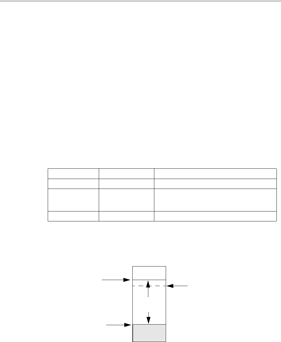
172 MS-9600LS Series Manual — P/N 52646:B2 2/12/2010
Operating Instructions Read Status
Drift Compensation
Drift compensation uses software algorithms that identify and compensate for long-term changes in
the data readings from each addressable smoke detector. These long-term changes in detector data
readings are typically caused by dirt and dust accumulation inside the smoke chamber. Drift com-
pensation performs the following functions:
• Samples each photoelectric smoke detector every 6 seconds and each ionization smoke
detector every 3 seconds
• Allows a smoke detector to retain its original ability to detect actual smoke and resist false
alarms, even as dirt and dust accumulate
• Reduces maintenance requirements by allowing the control panel to automatically perform the
periodic sensitivity measurements required by NFPA Standard 72
The FACP software also provides filters to remove transient noise signals, usually caused by elec-
trical interference.
Maintenance Alert
The software determines when the drift compensation for a detector reaches an unacceptable level
that can compromise detector performance. When a detector reaches an unacceptable level, the
control panel indicates a maintenance alert. Table 4.1 summarizes the three levels of maintenance
alert:
Figure 4.1 illustrates a graphic representation of the maintenance levels:
Maintenance Level FACP Status Displays Indicates
Low Chamber Value INVREP A hardware problem in the detector
Maintenance Alert DIRTY1 Dust accumulation that is near but below the allowed
limit. DIRTY 1 indicates the need for maintenance
before the performance of the detector is compromised
Maintenance Urgent DIRTY2 Dust accumulation above the allowed limit.
Table 4.1 Maintenance Alert Levels
Figure 4.1 Diagram of Maintenance Levels
DIRTY
Acceptable
Range
Maintenance
Urgent Maintenance
Alert
Low Chamber
Reading LOW
VALUE

MS-9600LS Series Manual — P/N 52646:B2 2/12/2010 173
Read Status Operating Instructions
4.22.16 Time-Date
The operator can view the daylight savings time and the month and week when daylight savings
time will begin and end. Pressing 1 while viewing Read Status Screen #6 will display the following
screens:
READ STATUS
1=TIME-DATE
Read Status Screen #6
DAYLIGHT SAVINGS
ENABLED YES
START MONTH MAR
START WEEK WEEK-2
DAYLIGHT SAVINGS
END MONTH NOV
END WEEK WEEK-1

174 MS-9600LS Series Manual — P/N 52646:B2 2/12/2010
Section 5: Power Supply Calculations
5.1 Overview
This section contains instructions and tables for calculating power supply currents in alarm and
standby conditions. This is a four-step process, consisting of the following:
1. Calculating the total amount of AC branch circuit current required to operate the system
2. Calculating the power supply load current for non-fire and fire alarm conditions and
calculating the secondary (battery) load
3. Calculating the size of batteries required to support the system if an AC power loss occurs
4. Selecting the proper batteries for your system
5.2 Calculating the AC Branch Circuit
The control panel requires connection to a separate, dedicated AC branch circuit, which must be
labeled FIRE ALARM. This branch circuit must connect to the line side of the main power feed
of the protected premises. No other non-fire alarm equipment may be powered from the fire alarm
branch circuit. The branch circuit wire must run continuously, without any disconnect devices,
from the power source to the control panel. Overcurrent protection for this circuit must comply
with Article 760 of the National Electrical Codes as well as local codes. Use 14 AWG (2.00 mm2)
wire with 600 volt insulation for this branch circuit.
Use Table 5.1, to determine the total amount of current, in AC amperes (A), that must be supplied
to the system.
5.3 Calculating the System Current Draw
5.3.1 Overview
The control panel must be able to power all internal and external devices continuously during the
non-fire alarm condition. To calculate the non-fire alarm load on the system power supply when
primary power is applied, use Calculation Column 1 in Table 5.3 on page 176. The control panel
must support a larger load current during a fire alarm condition. To calculate the fire alarm load on
the power supply, use Calculation Column 2 in Table 5.3 on page 176. The secondary power
source (batteries) must be able to power the system during a primary power loss. To calculate the
non-fire alarm load on the secondary power source, use Calculation Column 3 in Table 5.3 on
page 176.
When calculating current draw and the battery size, note the following:
• ‘Primary’ refers to the main power source for the control panel
Device Type Number of
Devices
Current Draw
(AC amps)
Total Current per
Device
MS-9600LS(C)
MS-9600UDLS
or
MS-9600LSE
MS-9600UDLSE
1X
3.0
or
1.5
=
CHG-120F [ ] X 2.0 =
[ ] X [ ] =
Sum Column for AC Branch Current Required =
Table 5.1 AC Branch Circuit Requirements

MS-9600LS Series Manual — P/N 52646:B2 2/12/2010 175
Calculating the System Current Draw Power Supply Calculations
• ‘Secondary’ refers to the control panel’s backup batteries
• All currents are given in amperes (A). Table 5.2 shows how to convert milliamperes and
microamperes to full amperes.
5.3.2 How to Use Table 5.3 on page 176 to Calculate System
Current Draw
Use Table 5.3 on page 176 to calculate current draws as follows:
1. Enter the quantity of devices in all three columns.
2. Enter the current draw where required. Refer to the Device Compatibility Document for
compatible devices and their current draw.
3. Calculate the current draws for each in all columns.
4. Sum the total current for each column.
5. Copy the totals from Column 2 and Column 3 to Table 5.4 on page 177.
Following are the types of current that can be entered into Table 5.3 on page 176:
Calculation Column 1 - The primary supply current load that the control panel must
support during a non-fire alarm condition, with AC power applied.
Calculation Column 2 - The primary supply current load that the control panel must
support during a fire alarm condition, with AC power applied.
Calculation Column 3 - The standby current drawn from the batteries in a non-fire alarm
condition during a loss of AC power.
To convert... Multiply Example
Milliamperes (mA) to
amperes (A)
mA x 0.001 3 mA x 0.001 = 0.003A
Microamperes (µA) to
amperes (A)
µA x 0.000001 300 µA x 0.000001 = 0.0003 A
Table 5.2 Converting to Full Amperes
176 MS-9600LS Series Manual — P/N 52646:B2 2/12/2010
Power Supply Calculations Calculating the System Current Draw
Table 5.3 contains columns for calculating current draws. For each column, calculate the current
and enter the total (in amperes) in the bottom row. When finished, copy the totals from Calculation
Column 2 and Calculation Column 3 to Table 5.4 on page 177.
Calculation Column 1
Primary, Non-Fire Alarm Current (amps)
Calculation Column 2
Primary, Fire Alarm Current (amps)
Calculation Column 3
Secondary, Non-Fire Alarm Current (amps)
Device Type Qty X[current draw]= Total Qty X [current draw] = Total Qty X[current draw]= Total
Main Circuit Board 1 X[0.160]= 0.160 1 X[0.253]= 0.253 1 X[0.103]= 0.103
ANN-80 [ ] X[0.037]= [ ] X[0.040]= [ ] X[0.015]=
ANN-(R)LED [ ] X[0.028]= [ ] X[0.068]= [ ] X[0.028]=
ANN-RLY [ ] X[0.015]= [ ] X[0.075]= [ ] X[0.015]=
ANN-I/O [ ] X[0.035]= [ ] X[0.200]= [ ] X[0.035]=
ANN-S/PG [ ] X[0.045]= [ ] X[0.045]= [ ] X[0.045]=
ACM-8RF [ ] X[0.030]= [ ] X[0.158]1= [ ] X[0.030]=
ACM-16ATF
ACM-32AF
[ ] X[0.040] [ ] X[0.056]2= [ ] X[0.040]=
AEM-16ATF
AEM-32AF
[ ] X[0.002] [ ] X[0.018]2= [ ] X[0.002]=
AFM-16ATF
AFM-32AF
[ ] X[0.040] [ ] X[0.056]2= [ ] X[0.040]=
AFM-16AF [ ] X[0.025] [ ] X[0.065]2= [ ] X[0.025]=
DACT-UD2 [ ] X[0.020] [ ] X[0.029]= [ ] X[0.017]=
LDM-32F [ ] X[0.040] [ ] X[0.056]3= [ ] X[0.040]=
LDM-E32F [ ] X[0.002] [ ] X[0.018]= [ ] X[0.002]=
LCD-80F & LCD-80FC [ ] X[0.064] [ ] X[0.064]= [ ] X[0.025]=
4XTMF [ ] X[0.005]= [ ] X[0.011]4= [ ] X[0.005]=
4-wire Detector Heads [ ] X[ ]5= [ ] X[ ]= [ ] X[ ]=
Power Supervision Relays6[ ] X[0.025]= [ ] X[0.025]= [ ] X[0.025]=
SLC-2LS Expander [ ] X[0.02500]= X[0.02600]= [ ] X[0.01900]=
CP350 & CP355 [ ] X[0.00030]=
maximum alarm draw
for all devices:
with one (1) SLC Loop
with two (2) SLC Loops
0.400
0.800
[ ] X[0.00030]=
SD350 & SD355 [ ] X[0.00030]= [ ] X[0.00030]=
SD350T & SD355T [ ] X[0.00030]= [ ] X[0.00030]=
AD350 & AD355 [ ] X[0.00030]= [ ] X[0.00030]=
H350 & H355 [ ] X[0.00030]= [ ] X[0.00030]=
H350R & H355R [ ] X[0.00030]= [ ] X[0.00030]=
H355HT [ ] X[0.00030]= [ ] X[0.00030]=
D350P & D350PL [ ] X[0.00030]= [ ] X[0.00030]=
D350RP & D350RPL [ ] X[0.00030]= [ ] X[0.00030]=
B501BH & B501BHT7 [ ] X[0.001]= [ ] X[0.001]=
B224RB Relay Base [ ] X[0.00050]= [ ] X[0.00050]=
B224BI Isolator Base [ ] X[0.00045]= [ ] X[0.00045]=
MMF-300 [ ] X[0.00040]= [ ] X[0.00040]=
MMF-300-10 [ ] X[0.00350]= [ ] X[0.00350]=
MDF-300 [ ] X[0.00075]= [ ] X[0.00075]=
MMF-301 [ ] X[0.000375]= [ ] X[0.000375]=
MMF-302 [ ] X[0.00027]= [ ] X[0.00027]=
MMF-302-6 [ ] X[0.00200]= [ ] X[0.00200]=
BG-12LX [ ] X[0.00030]= [ ] X[0.00030]=
CMF-300 [ ] X[0.00039]= [ ] X[0.00039]=
CMF-300-6 [ ] X[0.00225]= [ ] X[0.00225]=
CRF-300 [ ] X[0.00027]= [ ] X[0.00027]=
CRF-300-6 [ ] X[0.00145]= [ ] X[0.00145]=
I300 [ ] X[0.00040]= [ ] X[0.00040]=
NAC #18[ ] X[ ]=
NAC #2 [ ] X[ ]=
NAC #3 [ ] X[ ]=
NAC #4 [ ] X[ ]=
Current Draw from TB3
(nonalarm9)
[ ]= [ ] [ ]= [ ] [ ]=
Sum each column10 for
totals Primary Non-Alarm = Primary Alarm = Secondary Non-Alarm =
Table 5.3 System Current Draw Calculations
1 All eight ACM-8RF relays activated on a single module.
2 All annunciator LEDs on
3 LDM-32F with LEDs on
4 If using the Reverse Polarity Alarm output, add 0.005 amps; if using the Reverse Polarity Trouble output, add
another 0.005 amps.
5 Refer to the Device Compatibility Document for standby current.
6 Must use compatible listed Power Supervision Relay.
7 Maximum alarm current for each sounder base is 0.015 amps which must be supplied by aux. 24VDC source.
8 Current limitation of Terminal TB4 circuits is 3.00 amps per NAC.
9 The total standby current must include both the resettable (TB3 Terminals 1 & 2) and nonresettable (TB3 Terminals
3 & 4, 5 & 6) power. Caution must be taken to ensure that current drawn from these outputs during alarm does not
exceed maximum ratings specified. Current limitations of TB3 circuits is 3.0 amps per output
10 Total current draw listed above cannot exceed 7.0 amps in alarm.

MS-9600LS Series Manual — P/N 52646:B2 2/12/2010 177
Calculating the Battery Size Power Supply Calculations
5.4 Calculating the Battery Size
Use Table 5.4 to calculate the total Standby and Alarm load in ampere hours (AH). This total load
determines the battery size (in AH), required to support the control panel under the loss of AC
power. Complete Table 5.4 as follows:
1. Enter the totals from Table 5.3 on page 176, Calculation Columns 2 and 3 where shown.
2. Enter the NFPA Standby and Alarm times (refer to ‘NFPA Requirements’ below).
3. Calculate the ampere hours for Standby and Alarm, then sum the Standby and Alarm ampere
hours.
4. Multiply the sum by the derating factor of 1.2 to calculate the proper battery size (in AH).
5. Write the ampere hour requirements on the Protected Premises label located inside the cabinet
door.
5.4.1 NFPA Battery Requirements
• NFPA 72 Local, Proprietary, Central, Auxiliary and Remote Station Fire Alarm Systems
require 24 hours of standby power followed by 5 minutes in alarm
• NFPA requires 24 hours of standby plus 15 minutes activation for audio systems. The total
ampere hours required cannot exceed 26 AH with an internal charger
5.4.2 Selecting and Locating Batteries
Select sealed lead acid batteries that meet or exceed the total ampere hours calculated in Table 5.4.
The control panel can charge batteries in the 12 AH to 26 AH range. The control panel cabinet is
capable of housing batteries up to 18 AH. Batteries larger than 18 AH require the BB-26, BB-55F,
or other UL-listed external battery cabinet.
Secondary Standby Load
(total from Table 5.3 Calculation
Column 3)
[ ]
Required Standby Time
(24 hours)
X[ ] = AH
Primary Alarm Load
(total from Table 5.3 Calculation
Column 2)
[ ]
Required Alarm Time
(for 5 min., enter 0.084,
for 10 min., enter 0.168)
X[ ] = AH
Sum of Standby and Alarm Ampere Hours = AH
Multiply by the Derating Factor X 1.2
Battery Size, Total Ampere Hours Required = AH
Table 5.4 Total Secondary Power Requirements at 24 VDC

178 MS-9600LS Series Manual — P/N 52646:B2 2/12/2010
Appendix A: Software Zones
A.1 Correlations
Setup and configuration of an addressable system is different than a conventional system. In a
conventional system, assignment of input devices (smoke detectors, pull stations, heat detectors,
etc.) to zones is accomplished through wiring. The wiring is direct from clearly marked panel
terminals to any device assigned to a particular zone. Connection of output devices (horns, bells,
strobes, etc.) in a conventional system is accomplished by direct wiring of the output devices to
Notification Appliance Circuit terminals.
In an addressable system, a minimum of a single pair of wires (SLC communication loop) is used
to connect all addressable input and output devices. Communications between the FACP (Fire
Alarm Control Panel) and all addressable devices takes place over the wire pair which originates
from the FACP. Software programming is used to configure the system as opposed to direct wiring.
Zone assignments are created via software means, hence the term software zones.
Setup of an FACP software zone is accomplished by panel programming. Each addressable device
can be assigned to a maximum of five software zones. Each software zone, however, may have
from 1 to 991 addressable input devices assigned to it and from 1 to 991 addressable output devices
assigned to it.
Monitor and control modules comprise one group of 991 addresses, with each module having a
unique address from 1 to 991. Detectors comprise a separate group of 991 addresses, each detector
having a unique address from 1 to 991 in its group. Be careful not to duplicate addresses within any
one group (modules and detectors). Refer to the following page for an example of zoning.
In the example on the following page:
• Zone 01 has the following addressable devices assigned to it:
• SD350 smoke detectors with addresses 01 and 02
• MMF-300 monitor module with address 01
• MMF-302 monitor module with address 02 and 03
• CMF-300 control modules with addresses 05, 06, 07, 09, and 13
• Zone 02 has the following addressable devices assigned to it:
• MMF-302 monitor module with addresses 02 and 03
• CP350 smoke detectors with addresses 03 and 04
• CMF-300 control modules with addresses 08, 09, and 10
• Zone 03 has the following addressable devices assigned to it:
• SD350 smoke detectors with addresses 05, 06, and 07
• MMF-302 control module with address 04
• CMF-300 control modules with addresses 09, 11, and 12
The example points out some of the key assignment features of the FACP. Addresses of detectors
are not duplicated. Addresses of monitor and control modules are not duplicated. The control
module with address 09 is assigned to three software zones (providing floor above and floor
below). Be careful to properly plan the installation prior to installing any devices.
1. CLIP or Classic Loop Interface Protocol devices (modules and detectors) can only have
unique addresses of 1 to 99. Newer LiteSpeed devices (modules and detectors) can have
unique addresses of 1 to 159 which means each zone can have up to 159 input and output
devices assigned to it.
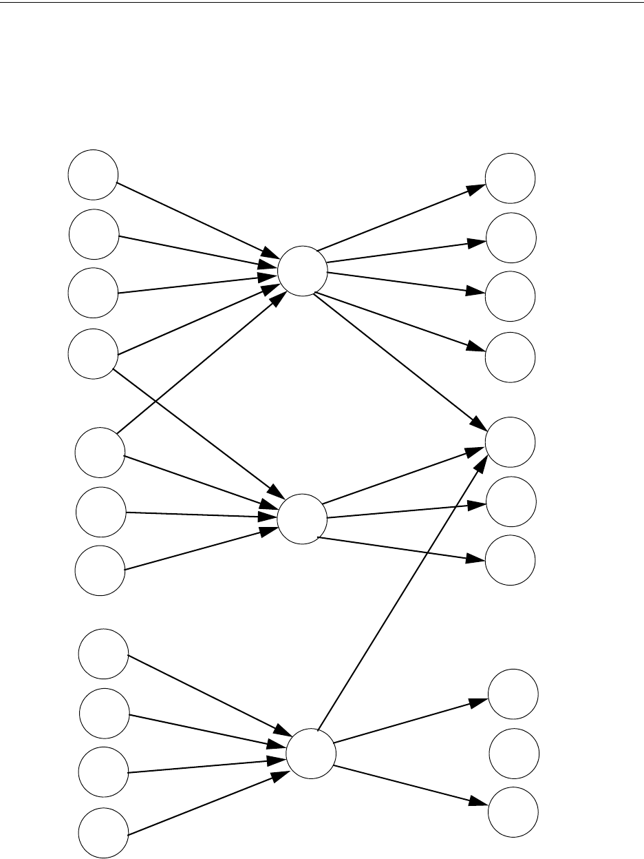
MS-9600LS Series Manual — P/N 52646:B2 2/12/2010 179
Correlations Software Zones
Correlation of Input and Output Zones
The zone correlations which are shown graphically above are also presented in Table A.1 on
page 180 and Table A.2 on page 181.
Input Devices Zones Output Devices
ZONE
01
ZONE
02
ZONE
03
SD350
01
SD350
02
MMF-300
01
MMF-302
02
MMF-302
03
CP350
03
CP300
04
SD350
05
SD350
06
SD350
07
MMF-302
04
CMF-300
06
CMF-300
05
CMF-300
07
CMF-300
09
CMF-300
08
CMF-300
10
CMF-300
11
CMF-300
12
CMF-300
13

180 MS-9600LS Series Manual — P/N 52646:B2 2/12/2010
Software Zones Correlations
DETECTOR ZONE ASSIGNMENT
Address Device
Type
Zone
Number ADJ/NOUN Address Device
Type
Zone
Number ADJ/NOUN
01 SD350 1 FIRST HALL 51
02 SD350 1 ELEV. LOBBY 52
03 CP350 2 2ND FLOOR 53
04 CP350 2 ROOM 210 54
05 SD350 3 3RD FLOOR 55
06 SD350 3 MEZZANINE 56
07 SD350 3 MECH. ROOM 57
08 58
09 59
10 60
11 61
12 62
13 63
14 64
15 65
16 66
17 67
18 68
19 69
20 70
21 71
22 72
23 73
24 74
25 75
26 76
27 77
28 78
29 79
30 80
31 81
32 82
33 83
34 84
35 85
36 86
37 87
38 88
39 89
40 90
41 91
42 92
43 93
44 94
45 95
46 96
47 97
48 98
49 99
50 100
Table A.1 Detector Programming Sheet Example

MS-9600LS Series Manual — P/N 52646:B2 2/12/2010 181
Correlations Software Zones
MONITOR/CONTROL MODULE ZONE ASSIGNMENT
Address Device Type Zone
Number ADJ/NOUN Address Device
Type
Zone
Number ADJ/NOUN
01 MMF-300 1 51
02 MMF-302 1, 2 52
03 MMF-302 1, 2 53
04 MMF-302 3 54
05 CMF-300 1 55
06 CMF-300 1 56
07 CMF-300 1 57
08 CMF-300 2 58
09 CMF-300 1, 2, 3 59
10 CMF-300 2 60
11 CMF-300 3 61
12 CMF-300 3 62
13 CMF-300 1 63
14 64
15 65
16 66
17 67
18 68
19 69
20 70
21 71
22 72
23 73
24 74
25 75
26 76
27 77
28 78
29 79
30 80
31 81
32 82
33 83
34 84
35 85
36 86
37 87
38 88
39 89
40 90
41 91
42 92
43 93
44 94
45 95
46 96
47 97
48 98
49 99
50 100
Table A.2 Module Programming Sheet Example

182 MS-9600LS Series Manual — P/N 52646:B2 2/12/2010
Software Zones Correlations
DETECTOR ZONE ASSIGNMENT
Address Device
Type
Zone
Number ADJ/NOUN Address Device
Type
Zone
Number ADJ/NOUN
01 51
02 52
03 53
04 54
05 55
06 56
07 57
08 58
09 59
10 60
11 61
12 62
13 63
14 64
15 65
16 66
17 67
18 68
19 69
20 70
21 71
22 72
23 73
24 74
25 75
26 76
27 77
28 78
29 79
30 80
31 81
32 82
33 83
34 84
35 85
36 86
37 87
38 88
39 89
40 90
41 91
42 92
43 93
44 94
45 95
46 96
47 97
48 98
49 99
50 100
Table A.3 Blank Detector Programming Sheet - 1 of 2

MS-9600LS Series Manual — P/N 52646:B2 2/12/2010 183
Correlations Software Zones
DETECTOR ZONE ASSIGNMENT
Address Device
Type
Zone
Number ADJ/NOUN Address Device
Type
Zone
Number ADJ/NOUN
101 151
102 152
103 153
104 154
105 155
106 156
107 157
108 158
109 159
110
111
112
113
114
115
116
117
118
119
120
121
122
123
124
125
126
127
128
129
130
131
132
133
134
135
136
137
138
139
140
141
142
143
144
145
146
147
148
149
150
Table A.4 Blank Detector Programming Sheet - 2 of 2

184 MS-9600LS Series Manual — P/N 52646:B2 2/12/2010
Software Zones Correlations
MONITOR/CONTROL MODULE ZONE ASSIGNMENT
Address Device
Type
Zone
Number ADJ/NOUN Address Device
Type
Zone
Number ADJ/NOUN
01 51
02 52
03 53
04 54
05 55
06 56
07 57
08 58
09 59
10 60
11 61
12 62
13 63
14 64
15 65
16 66
17 67
18 68
19 69
20 70
21 71
22 72
23 73
24 74
25 75
26 76
27 77
28 78
29 79
30 80
31 81
32 82
33 83
34 84
35 85
36 86
37 87
38 88
39 89
40 90
41 91
42 92
43 93
44 94
45 95
46 96
47 97
48 98
49 99
50 100
Table A.5 Blank Module Programming Sheet - 1 of 2

MS-9600LS Series Manual — P/N 52646:B2 2/12/2010 185
Correlations Software Zones
MONITOR/CONTROL MODULE ZONE ASSIGNMENT
Address Device
Type
Zone
Number ADJ/NOUN Address Device
Type
Zone
Number ADJ/NOUN
101 151
102 152
103 153
104 154
105 155
106 156
107 157
108 158
109 159
110
111
112
113
114
115
116
117
118
119
120
121
122
123
124
125
126
127
128
129
130
131
132
133
134
135
136
137
138
139
140
141
142
143
144
145
146
147
148
149
150
Table A.6 Blank Module Programming Sheet - 2 of 2

186 MS-9600LS Series Manual — P/N 52646:B2 2/12/2010
Appendix B: Default Programming
The following table provides a list of the programming options and their factory default settings.
Program Option Factory Default Program Option Factory Default
Master Password 00000 NAC Enable Enabled
Maintenance Password 11111 NAC Silenceable Yes
Detector Programming Not Installed NAC Type Bell
Detector Type Smoke-Photo NAC Sync Type System Sensor
Detector Verification Off NAC Autosilence 0
Detector Walktest Yes NAC Coding Steady
Detector PAS No NAC Zones Zone 000 only
Detector Presignal No NAC Silence Inhibit 0
Detector Zone Assign. 000 only Relay 1 Alarm
Detector Adj/Noun none Relay 2 Trouble
Module Programming Not Installed Relay 3 Supervisory
Module Type Monitor On Board DACT No
Module Walktest Yes Annunciator Terminal Mode No
(not used) Annunciator ACS Mode No
Module Presignal No UDACT No
Module Zone Assign. 000 only ACS Installed No
Module Adj/Noun none Printer-PC No
Zone 0 Enable Enabled Printer Baud 9600
Zone 1 Enable Enabled Canadian Option Off
Zone 2 Enable Enabled Waterflow Silenceable No
Zone 3 Enable Enabled ANN-BUS Enabled No
.........................through.......... ..................... Central Station Reporting Disabled
Zone 99 Enable Enabled AC Loss Delay 2 Hours
Special Zones 97, 98 & 99 Disabled DACT Backup Reporting First Available
Zones 0 - 99 Type Monitor DACT Report Style By Point
Loop 1 & 2 Style Style 4 ANN Enabled No
Loop 1 & 2 Protocol LiteSpeed ANN-BUS Modules Addr. 1 - 8 None
Trouble Reminder Off ANN-S/PG Port Parallel
Banner ANN-S/PG Baud 9600
Time Format 12 Hr ANN-S/PG Data Bits 7
Hours Setting 12 ANN-S/PG Parity Even
Minutes Setting 00 ANN-S/PG Stop Bits 1
Second Settings 00 ANN-S/PG Offline Timer 60
AM-PM Setting AM ANN-S/PG Printer Supervision No
Month Setting 01 ANN-80 Piezo Enabled Yes
Day Setting 01 ANN-80 Lock Enabled Yes
Year Setting 00 ANN-80 Acknowledge Button Enabled Yes
PK-Plus Secret Code 00000000 ANN-80 Silence Button Enabled Yes
Trouble Call Limit 0 ANN-80 Reset Button Enabled Yes
Daylight Savings Yes ANN-80 Drill Button Enabled Yes
Month Start Daylight Savings March ANN-I/O Point/Zone Zone
Week Start Daylight Savings 2nd Week ANN-I/O Range 00-29
Month End Daylight Savings November ANN-I/O Active LEDs Only
Week End Daylight 1st Week ANN-RLY Relay 1 Zone 1
Verification No ................through....................... ............
Ring Count 0 ANN-RLY Relay 10 Zone 10
PAS Timer 0 ANN-LED Point/Zone Zone
Presignal Timer 0 ANN-LED Alarms/ATS (Alarm, Trbl, Supv) ATS
Waterflow Retard Timer 0 ANN-LED Range 0 - 9
MS-9600LS Series Manual — P/N 52646:B2 2/12/2010 187
Appendix C: NFPA Standard-Specific Requirements
The FACP has been designed for use in commercial, industrial and institutional applications and
meets the requirements for service under the National Fire Protection Association (NFPA)
Standards outlined in this Appendix. The minimum system components required for compliance
with the appropriate NFPA standard are listed below:
Fire Alarm Control Panel
Contains the main control board, cabinet (backbox and door), main power supply transformer and
power supply.
Batteries
Refer to “Power Supply Calculations” on page 174, for Standby Power Requirements.
Initiating Devices
Connected to one of the control panel's Initiating Device Circuits.
Notification Appliances
Connected to the control panel's Notification Appliance Circuits via a control module.
The following additional equipment is needed for compliance with the NFPA 72 standards listed
below:
NFPA 72 NATIONAL FIRE ALARM STANDARDS FOR:
NFPA 72 Central Station Service (Protected Premises Unit) or Remote Station
Service
411UDAC for connection to a compatible listed Central Station DACR or Protected Premises
Receiving Unit. This unit must be installed as outlined in Figure C.1, “Central Station Service
Using 411UDAC,” on page 188.
OR
411UD may be installed as illustrated in Figure C.2, “FACP Connection to 411UD,” on page
189.
OR
4XTMF Transmitter Module for connection to the RS82 Remote Station Receiver. See Figure
C.4, “Remote Station Connection Using 4XTMF Module,” on page 191, for installation
instructions for this unit.
NFPA 72 Auxiliary Fire Alarm System
4XTMF Transmitter Module for connection to a compatible listed Local Energy Municipal Box.
This unit must be installed as illustrated in the section titled “4XTMF Transmitter Module
Installation” on page 55 and as outlined in Figure C.3, “Municipal Box Connected to 4XTMF
Transmitter Module,” on page 190.
NFPA 72 Proprietary Fire Alarm System
FACP Alarm, Trouble and Supervisory contacts connected to Transmitter(s). See Figure C.5,
“Proprietary Protective Signaling System,” on page 192, for installation instructions for this unit.
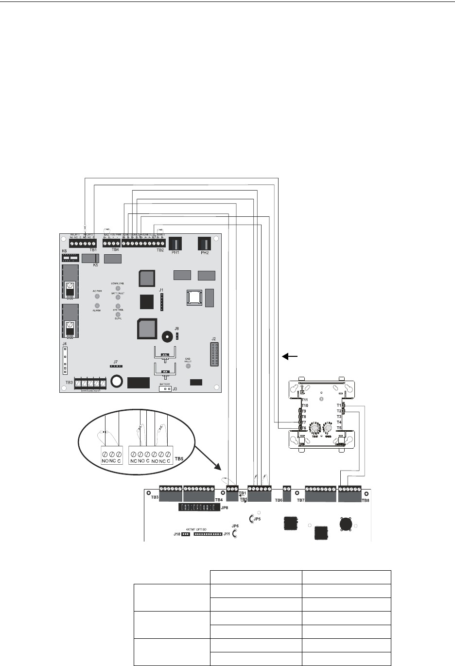
188 MS-9600LS Series Manual — P/N 52646:B2 2/12/2010
NFPA Standard-Specific Requirements
NFPA Signaling Systems for Central Station Service (Protected Premises
Unit)/Remote Station
The following figure illustrates an example of Central Station/Remote Station Reporting using a
411UDAC. The relay contacts from the FACP may be used to trip any dialer UL listed for Central
Station/Remote Station Services.
Notes:
1. Reference the 411UDAC Manual for additional information
2. Program the 411UDAC for slave operation
3. The FACP must be programmed for AC Loss Reporting Delay This prevents the transmission
of a trouble on the loss of AC power
TB1
Figure C.1 Central Station Service Using 411UDAC
2.2K
ELR
AC wiring for
411UDAC/FACP must
be connected to the
same branch circuit.
FACP
411UDAC
Alarm Relay
Trouble Relay
Supv. Relay
Monitor Module
ELR resistor
SLC Loop
Monitor Module*
Monitor Module Circuit Input
411UDAC Relay 2 Output (DACT Trouble)
Channel 1/Zone 1
Channel 3/Zone 3
Channel 2/Zone 2
2.2K EOLR
UL listed 2.2K ELRs (P/N 27070)
Program the 411UDAC as follows:
Channel 1 - Normally Open Contact
Device (alarm)
Channel 2 - Host Panel Trouble
Channel 3 - Supervisory
Note: The Monitor Module input,
which is being used to monitor the
411UDAC Relay Output
programmed for DACT Trouble
(requires optional 411RK Relay Kit),
must be programmed as ‘Trouble’ at
the FACP. The 411UDAC must be
programmed as a Slave
Communicator (programming
address 64 set to 2).
123
1 2 3 4 5 6 7 8 9 10
123456
9600411a.wmf
*If the SLC device does
not match the one in this
figure, refer to the SLC
manual appendix, which
contains wiring conversion
charts for type V and type
H modules.
411UDAC FACP
Alarm TB2-1 TB1-3
TB2-2 TB1-1
Trouble TB2-3 TB5-3
TB2-4 TB5-2
Supervisory TB2-5 TB5-6
TB2-8 TB5-4
Table C.1 411UDAC Connections to FACP
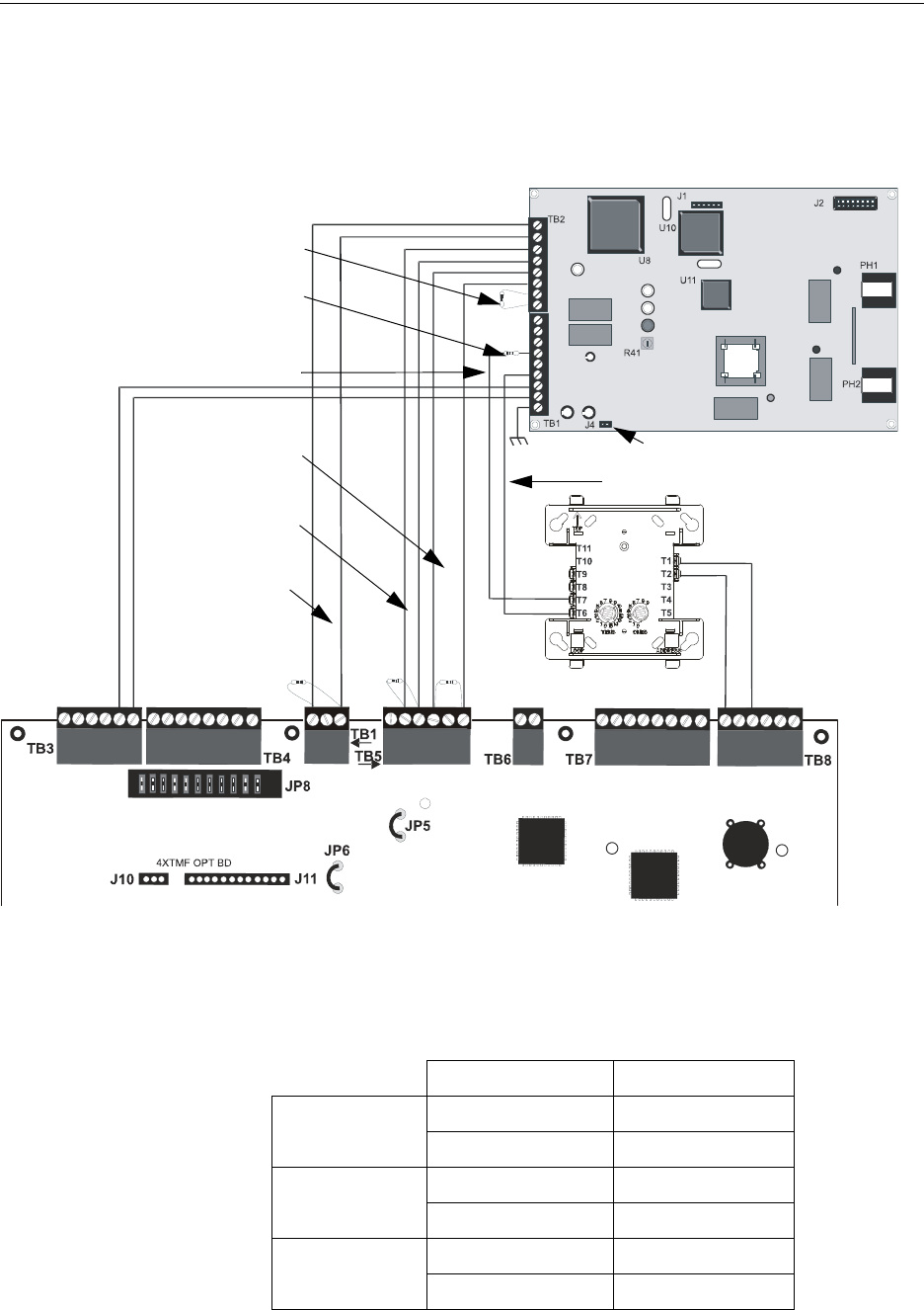
MS-9600LS Series Manual — P/N 52646:B2 2/12/2010 189
NFPA Standard-Specific Requirements
The following figure illustrates an example of Central Station/Remote Station Reporting using a
411UD. The relay contacts from the FACP may be used to trip any dialer UL listed for Central
Station/Remote Station Reporting Services.
Figure C.2 FACP Connection to 411UD
Note: The Monitor Module input, which is being used to monitor
the 411UD Relay #2 Output (programmed for DACT Trouble),
must be programmed as ‘Trouble’ at FACP.
Channel1
Channel 2
Channel 3
Channel 4 (2.2K ELR)
Relay Output (DACT Trouble)
Monitor Module ELR resistor
FACP
Supervisory Relay
FACP
Alarm Relay
(2.2K ELRs
P/N 27070)
J4 Not Installed
411UD
Monitor Module Circuit Input
SLC Loop
+ -
FACP
9600411u.wmf
24 VDC
nonresettable
power
1 2 3 4 5 6
1
2
3
4
5
6
7
8
1
2
3
4
5
6
7
8
9
1 2 3
Monitor Module*
FACP
Trouble Relay *If the SLC device does
not match the one in this
figure, refer to the SLC
manual appendix, which
contains wiring conversion
charts for type V and type
H modules.
411UD FACP
Alarm TB2-1 TB1-1
TB2-2 TB1-3
Trouble TB2-3 TB5-2
TB2-4 TB5-3
Supervisory TB2-5 TB5-4
TB2-6 TB5-6
Table C.2 411-UD Connections to FACP
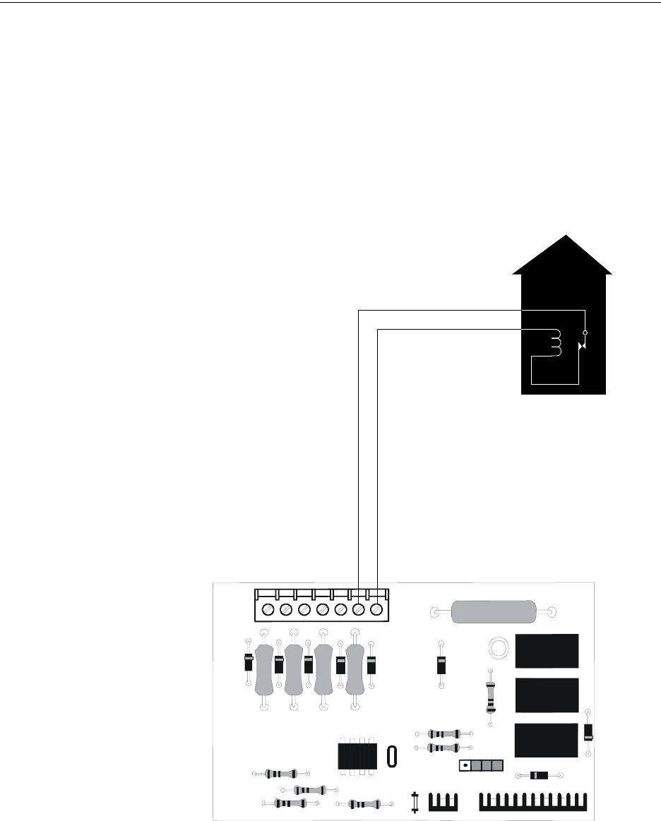
190 MS-9600LS Series Manual — P/N 52646:B2 2/12/2010
NFPA Standard-Specific Requirements
NFPA 72 Auxiliary Fire Alarm System
All connections are power-limited and supervised. This application is not suitable for separate
transmission of sprinkler supervisory or trouble conditions.
Notes:
1. 3 ohms maximum loop resistance allowed for wiring from control panel to Municipal Box.
2. Cut JP6 on the FACP main circuit board to supervise placement of 4XTMF module and circuit.
3. Cut JP5 on the FACP main circuit board to enable FACP Supervisory relay.
4. Refer to “4XTMF Transmitter Module Installation” on page 55 for detailed information.
Figure C.3 Municipal Box Connected to 4XTMF Transmitter Module
FIRE
Gamewell Model M34-56
Local Energy Municipal Box
Polarities shown in alarm condition
+
Nonpower-limited
Municipal Box Circuit
+
-
-
4XTMF
4xtmfl.wmf
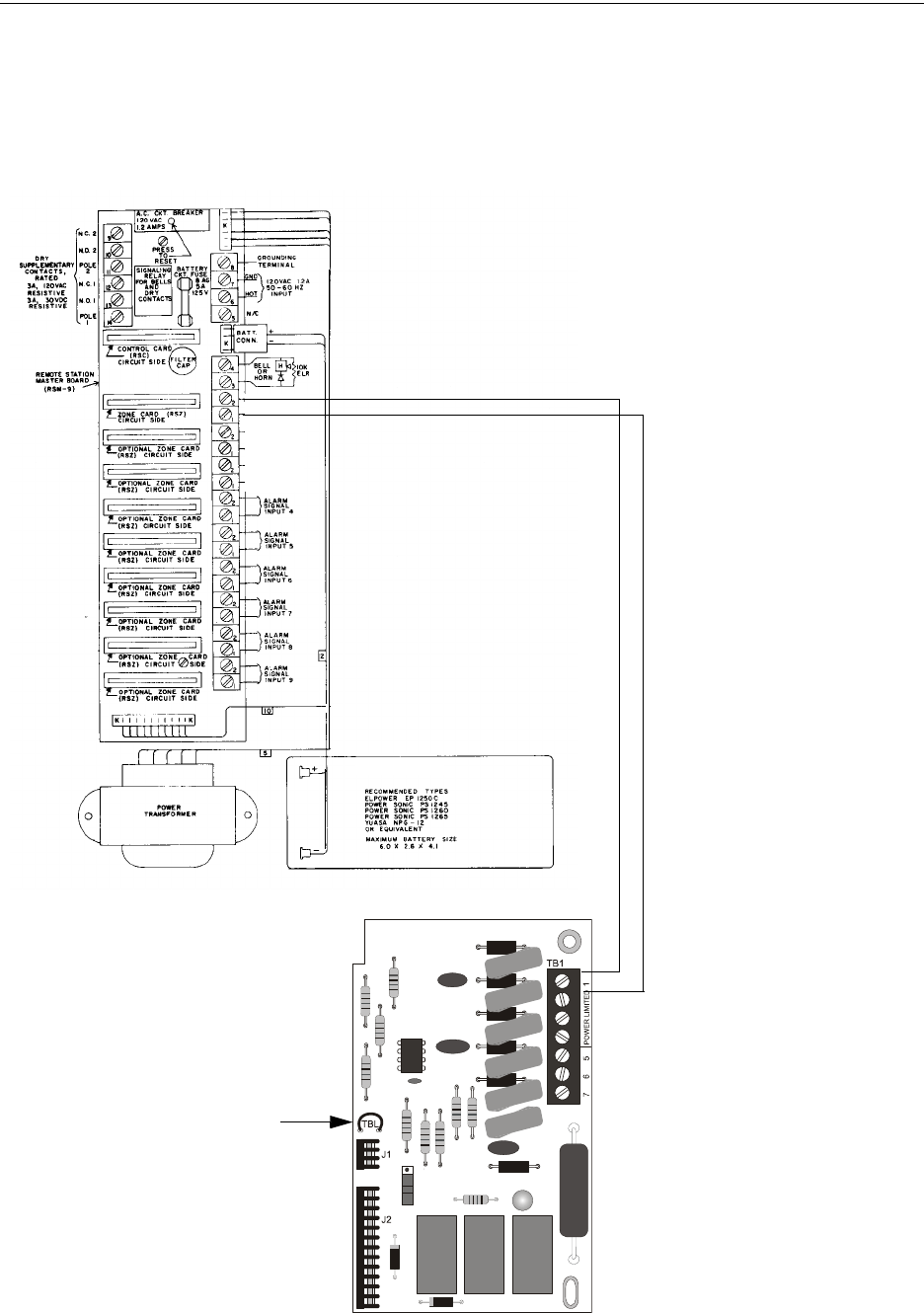
MS-9600LS Series Manual — P/N 52646:B2 2/12/2010 191
NFPA Standard-Specific Requirements
NFPA 72 Remote Station Protective Signaling System
Notes:
1. Cut Jumper JP6 on the FACP main circuit board to supervise placement of the 4XTMF
module.
2. Refer to “4XTMF Transmitter Module Installation” on page 55 for detailed information.
RS82 Remote Station Receiver UL listed.
Refer to Fire•Lite Alarms, Inc., Instruction Manual for Remote
Station Receiver Model RS82.
+ -
Polarity Shown is
Normal Standby
4XTMF Transmitter Module
Cutting TBL Jumper allows the
reverse polarity circuit to open with
a system trouble condition if no
alarm condition exists.
Power-limited
Figure C.4 Remote Station Connection Using 4XTMF Module
+
-
(Dummy load with a 4.7K, ¼ watt resistor
when no connection is made)
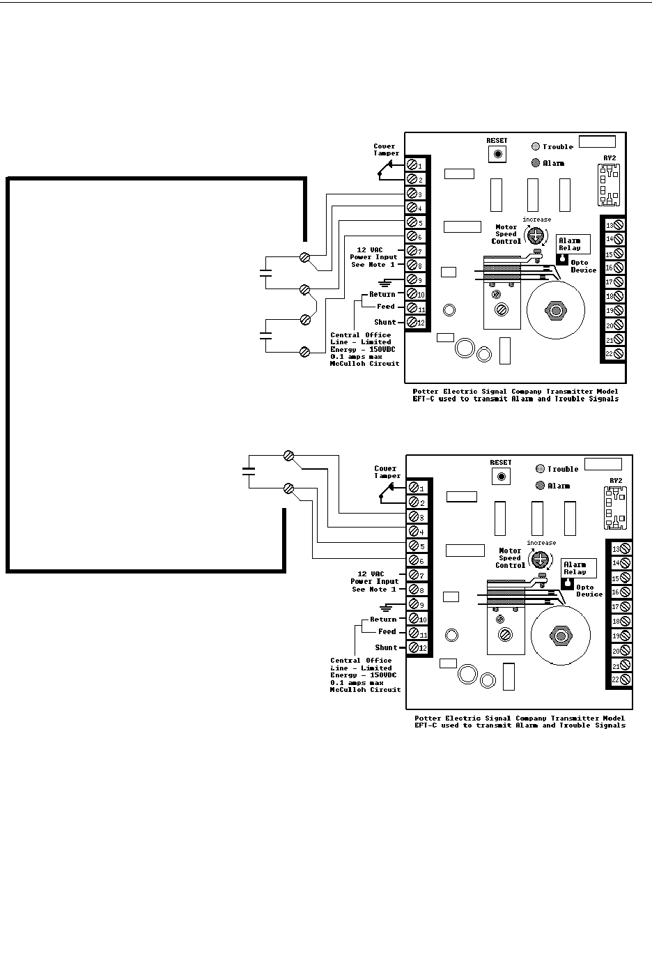
192 MS-9600LS Series Manual — P/N 52646:B2 2/12/2010
NFPA Standard-Specific Requirements
NFPA 72 Proprietary Protective Signaling Systems
Figure C.5 Proprietary Protective Signaling System
Form-C relay contact programmed to
activate on Supervisory condition.
Form-C Trouble contact which will automat-
ically activate on any Trouble condition.
Form-C Alarm contact programmed to
activate on General Alarm.
FACP Main Board
FACP Addressable Fire Control Panel
Notes:
1. Connection between the FACP and the
transmitter are supervised by the transmitter.
2. This FACP/Transmitter arrangement can be
employed for NFPA 72 Proprietary Protective
Signaling System.
3. Potter Electric Model EFT-C has not been
tested for UL 864 9th Edition and is for use in
retrofit applications only.
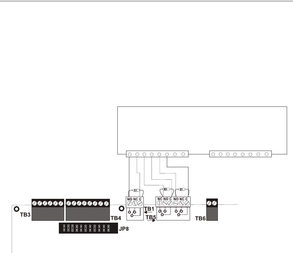
MS-9600LS Series Manual — P/N 52646:B2 2/12/2010 193
Central Station/Remote Station Transmitter: Connection to FACP Dry Contacts NFPA Standard-Specific Requirements
C.1 Central Station/Remote Station Transmitter: Connection
to FACP Dry Contacts
The dry contacts of the FACP programmable relays can be used to trip a UL-864 Listed Central
Station/Remote Station Transmitter. The FACP contacts must be supervised by the Central
Station/Remote Station Transmitter module using End-of-Line Resistors (ELRs) with a value
determined by the Transmitter manufacturer. Power is also provided by the Central Station/Remote
Station Transmitter manufacturer. Refer to the Central Station/Remote Station Transmitter
manufacturer’s manual for details.
Figure C.6 FACP Dry Contacts Connection to Central Station/Remote Station Transmitter
Typical Central Station/Remote Station Transmitter Module
Typical Input Zone Triggers
FACP Main Circuit Board
Alarm
Trouble*
Supervisory
*Note: The Trouble Relay is a fail-
safe relay. With power applied to
the FACP and no troubles in the
panel, the wiring should be
connected to the NO and C contacts
as indicated in the illustration.
ms9600lsdryxmit.wmf
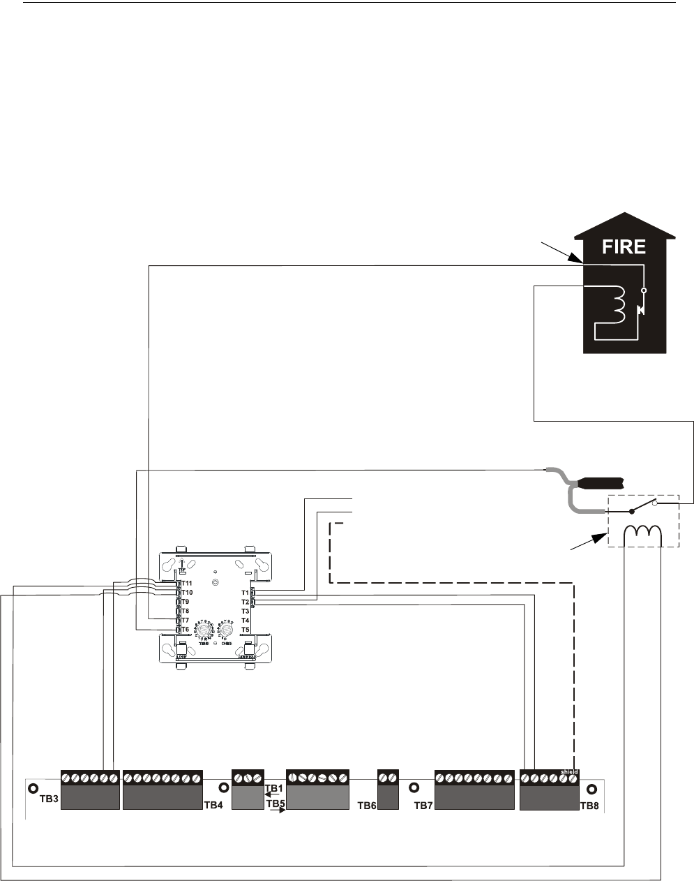
194 MS-9600LS Series Manual — P/N 52646:B2 2/12/2010
NFPA Standard-Specific Requirements MBT-1 Municipal Box Trip - Silenceable
C.2 MBT-1 Municipal Box Trip - Silenceable
The following figure illustrates the connection of the MBT-1 (Municipal Box Trip) between the
FACP and a Local Energy Municipal Box. The use of an addressable control module programmed
for General Alarm and Silenceable allows silencing of the Municipal Box without resetting the
panel or box.
FACP
CMF-300
24 VDC, Nonresettable
+ - SLC Loop B+ -B Shield
red black
MBT-1
brown wire
white wire
EOLR-1 Power
Supervision Relay
Alarm polarity shown!
-
+
- To next device
+ on SLC Loop
Braided-shield/Drain Wire
The CMF-300 must be
programmed as Silenceable
and General Alarm.
Gamewell Model
M34-56 Local Energy
Municipal Box
Note: 10 maximum loop
resistance due to wiring from
power supply to Municipal Box.
Connect wires to two
red terminals on box.
(All contacts shown in energized position)
MBT-1_MS-9600LS.wmf
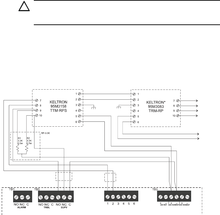
MS-9600LS Series Manual — P/N 52646:B2 2/12/2010 195
Appendix D: FACP with Keltron
The following figure illustrates the connections between the FACP and Keltron
Receiver/Transmitter.
IMPORTANT! All connections between the FACP and Keltron modules must be made within 20
feet and enclosed within conduit or equivalently protected against mechanical injury.
!
CAUTION: POSSIBLE EQUIPMENT DAMAGE
FOR REASONS OF WIRING DIAGRAM CLARITY, TERMINAL DESIGNATIONS OF KELTRON
MODULES ARE NOT SHOWN IN ACTUAL ORDER. FOLLOW KELTRON MANUAL AND MODULE
MARKINGS FOR EXACT TERMINAL LOCATIONS TO PREVENT SEVERE MODULE DAMAGE!
Fire Alarm Control Panel
(terminal blocks are not shown in their actual
positions in order to clarify wiring connections)
Keltron 95M3158 TTM-RPS
1. Terminals 7 and 8: Remote station alarm/trouble inputs.
2. Terminals 9 and 10: Sprinkler supervisory input.
Note: Cut TBL jumper on 4XTMF module to send
alarm/trouble signal from the same pair or terminals.
Alarm/Trouble Signal
Sprinkler
Supervisory Signal
*Note: For more
information, refer to
Keltron manual.
4XTMF Module
24 VDC
nonresettable power
UL Listed
8th Edition Only
UL Listed
8th Edition Only
Tip Tip
Ring Ring
Earth Earth
Telephone Line
Figure D.1 Wiring to Keltron Printer
To Power
Supply
To Central/
Remote
Station

196 MS-9600LS Series Manual — P/N 52646:B2 2/12/2010
Appendix E: Wire Requirements
T-tapping of the SLC loop wiring is allowed for 2-wire (Style 4) configurations. The total
resistance of any branch cannot exceed 40 ohms. The total wire length of all branches cannot
exceed 10,000 feet (3,000 m).
Connecting external system accessories to the FACP main circuits must be carefully considered to
ensure proper operation. It is important to use the correct type of wire, wire gauge and wire run
length for each FACP circuit. Reference the chart below to specify wire requirements and
limitations for each FACP circuit.
Note:
1. If the SLC loop is to be run in conduit with Notification Appliance Circuits, the risk of
encountering problems can be greatly reduced by exclusively employing electronic sounders
instead of more electronically noisy notification appliances such as electromechanical bells or
horns.
2. If two SLC loops are to be installed in conduit, each loop must be installed in separate conduit.
3. The SLC can be programmed to operate in LiteSpeed mode (factory default setting) for a
quicker device response time. While shielded wire is not required in LiteSpeed mode, it is
recommended that all SLC wiring be twisted-pair to minimize the effects of electrical
interference. Use the following table to determine the specific wiring requirements for the
SLC when unshielded wire is used:
CIRCUIT CONNECTIONS WIRE REQUIREMENTS
Circuit Type Circuit Function Wire Type and Limitations
Recommended Max.
Distance
Feet (meters)
Wire Gauge and Compatible Brands
SLC loop
(power-limited)
Connects to
Addressable Devices
CLIP MODE
Twisted, shielded pair
40 ohms maximum per length
of Style 6 and 7 loops. 40 ohms
per branch maximum for Style 4
loops
10,000 (3,000 m)
8,000 (2,400 m)
4,875 (1,450 m)
3,225 (980 m)
12 AWG (3.25 mm2): Genesis 4410,
Signal 98230, Belden 9583, WPW999
14 AWG (2.00 mm2):Genesis 4408 & 4608
Signal 98430, Belden 9581, WPW995
16 AWG (1.30 mm2): Genesis 4406 & 4606
Signal 98630, Belden 9575, WPW991
Direct Burial Cable Isotec NP713110VNQ-S
18 AWG (0.75 mm2): Genesis 4402 & 4602
Signal 98300, Belden 9574, WPW975
Direct Burial Cable Isotec NP714110VNQ-S
LITESPEED MODE
Twisted, unshielded pair
40 ohms maximum per length
of Style 6 and 7 loops. 40 ohms
per branch maximum for Style 4
loops
10,000 (3,000 m)
8,000 (2,400 m)
4,875 (1,450 m)
3,225 (980 m)
12 AWG (3.25 mm2): Belden 5020UL &
6020UL, Genesis WG-4315 & WG-4515
14 AWG (2.00 mm2):Belden 5120UL &
6120UL, Genesis WG-4313 & WG-4513
16 AWG (1.30 mm2): Belden 5220UL &
6220UL, Genesis WG-4311 & WG-4511
18 AWG (0.75 mm2): Belden 5320UL &
6320UL, Genesis WG-4306 & WG-4506
Untwisted, unshielded pair13,000 (900 m) 12-18 AWG (3.25 - 0.75 mm2) using listed wire
ACS-BUS
(EIA-485)
(power-limited)
Connects to
annunciator modules
Twisted pair with characteristic
impedance of 120 ohms
6,000 (1,800 m) 12 AWG (3.25 mm2)
ANN-BUS
(EIA-485)
(Power-limited)
Connects to
annunciator modules
Twisted pair 6,000 (1,800 m) Refer to “ANN-BUS Wiring” on page 23 for wire
requirements.
EIA-232
(power-limited)
connects to remote
PC computer
Twisted, shielded pair 50 (15 m) 18 AWG (0.75 mm2) minimum
MMF-300 and
MMF-301
(power-limited)
Initiating Device
Circuit
Maximum loop wire resistance
is 40 ohms for the MMF-300
and 20 ohms for the MMF-301
2,500 (760 m) 12-18 AWG (3.25 - 0.75 mm2)
MMF-302
(power-limited)
Initiating Device
Circuit
No more than a 2.4 volt drop
allowed at end of circuit.
Maximum loop wire resistance
is 25 ohms
2,500 (760 m) 12-18 AWG (3.25 - 0.75 mm2)
CMF-300
(power-limited)
Notification Appliance
Circuit
In alarm, no more than a 1.2
volt drop allowed at end of
circuit
Distance limitation set
by 1.2 volt maximum
line drop
12-18 AWG (3.25 - 0.75 mm2)
Table E.1 FACP Wire Specifications
1 When using untwisted, unshielded wire, full conduit is recommended for optimum EMI/RFI protection.

MS-9600LS Series Manual — P/N 52646:B2 2/12/2010 197
NAC Wiring Wire Requirements
E.1 NAC Wiring
The following table lists NAC wiring requirements for the FACP.
Notes:
1. Calculations are based on Direct-Current Resistance data for uncoated copper wire, per
National Electrical Code (2005 Edition) Table 8, Conductor Properties.
NAC Load
(Amps)
Max.
allowable
total loop
resistance
(ohms)
CLASS-B
Max. allowable wire pair length
(feet)
CLASS-A
Max. allowable wire pair length
(feet)
AWG 12
solid
AWG 14
solid
AWG 16
solid
AWG 18
solid
AWG 12
solid
AWG 14
solid
AWG 16
solid
AWG 18
solid
0.25 12.72 3295 2072 1301 819 1648 1036 650 409
0.5 6.36 1648 1036 650 409 824 518 325 205
0.75 4.24 1098 691 434 273 549 345 217 136
1 3.18 824 518 325 205 412 259 163 102
1.25 2.54 659 414 260 164 330 207 130 82
1.5 2.12 549 345 217 136 275 173 108 68
1.75 1.82 471 296 186 117 235 148 93 58
2 1.59 412 259 163 102 206 129 81 511
2.25 1.41 366 230 145 91 183 115 72 45
2.5 1.27 330 207 130 82 165 104 65 41
Table E.2 NAC Wiring Requirements for FACP

198 MS-9600LS Series Manual — P/N 52646:B2 2/12/2010
Appendix F: HVAC Control
The FACP can be programmed to shut down a building’s HVAC fans in the event of a fire. The
fans cannot be restarted until the fire alarm condition has been cleared and the FACP has been reset
to a normal (non-alarm) condition.
IMPORTANT! This HVAC feature is not to be used for smoke control. It is only designed to shut
down fans during a fire alarm condition.
F.1 Control Module Operation
F.1.1 HVAC SHUTDN
The HVAC SHUTDN type code can be assigned to any addressable control relay module for the
purpose of shutting down HVAC fans during a fire alarm condition. Devices connected to a
module with this type code are unsupervised. To program this feature in the FACP:
• Program the HVAC SHUTDN type code to the control module which will be used to shut
down the fans (refer to Type under the section titled “Edit Module Screen for Control
Modules” on page 88).
• Program the control module to a software zone and program alarm input devices which, when
activated are to cause fan shutdown, to the same software zone (refer to Zone Assignment
under the section titled “Edit Module Screen for Control Modules” on page 88).
• Monitor the control module using an addressable monitor module programmed for Trouble
Monitor. The monitor module label should be programmed to indicate HVAC SHUTDOWN.
When the control module is active (HVAC SHUTDN), the monitor module will indicate a
trouble condition at the FACP and the display should indicate the HVAC is shut down.
Once activated, the HVAC SHUTDN control module remains activated, even if the FACP is
silenced or reset. After the alarm condition on the FACP has been cleared and the panel reset, the
HVAC SHUTDN control module remains activated and the fans remain off. The monitor module
programmed for Trouble Monitor which is being used to supervise the control module, will indicate
a trouble condition at the control panel and the LCD should display that the HVAC is shut down.
The fans can only be restarted when the HVAC SHUTDN control module is deactivated by the
HVAC RESTART module.
F.2 Monitor Module Operation
F.2.1 HVAC RESTART
The HVAC RESTART type code can be assigned to any addressable monitor module for the
purpose of resetting (deactivating) the HVAC SHUTDN control module and turning the fans back
on. The HVAC RESTART monitor module acts globally throughout the FACP system and
therefore is not programmed to a particular software zone. To program this feature in the FACP:
• Program the HVAC RESTART type code to the monitor module which will be used to
deactivate the HVAC SHUTDN control module and restart the fans (refer to Type Monitor
under the section titled “Edit Module Screen for Monitor Module” on page 79).
The HVAC RESTART monitor module does not latch when activated. Pressing a switch connected
to the monitor module will deactivate the HVAC SHUTDN control relay module only if there are
no alarm conditions. The HVAC SHUTDN control relay module can be deactivated if trouble
conditions exist on the FACP.

MS-9600LS Series Manual — P/N 52646:B2 2/12/2010 199
Monitor Module Operation HVAC Control
F.2.2 HVAC OVRRIDE
The HVAC OVRRIDE type code can be assigned to any addressable monitor module for the
purpose of overriding or preventing the HVAC SHUTDN control modules from activating. The
HVAC OVRRIDE monitor module acts globally throughout the FACP system and therefore is not
programmed to a particular software zone. To program this feature in the FACP:
• Program the HVAC OVRRIDE type code to the monitor module which will be used to
override the HVAC SHUTDN control module and prevent the fans from turning off (refer to
Type Monitor under the section titled “Edit Module Screen for Monitor Module” on page 79).
The HVAC OVRRIDE monitor module does not latch when activated. Activating a switch
connected to the monitor module will override all HVAC SHUTDN control relay modules in the
system, preventing the HVAC SHUTDN modules from activating and causing the FACP LCD to
display an active HVAC OVRRIDE module and turn on the Supervisory LED. Releasing the
switch will allow the HVAC SHUTDN control relay modules to activate with subsequent alarms,
turning off the fans.
As an example, pressing the HVAC OVRRIDE switch with no alarms in the system will prevent the
fans from being turned off when an alarm does occur. As long as the switch is activated, the fans
will not shutdown for any alarms. If the system is still in alarm when the switch is released, the
fans will not shutdown unless another alarm occurs after the switch is released.
Important! If an alarm exists in the system and HVAC Shutdown has already occurred, HVAC
OVRRIDE will have no effect on the HVAC SHUTDN control relay modules. HVAC OVRRIDE
will prevent HVAC Shutdown from occurring only if it is initiated prior to an alarm condition.
NOTE: Activation of the HVAC OVRRIDE module causes a supervisory event that will be
communicated to the Central Station if enabled.
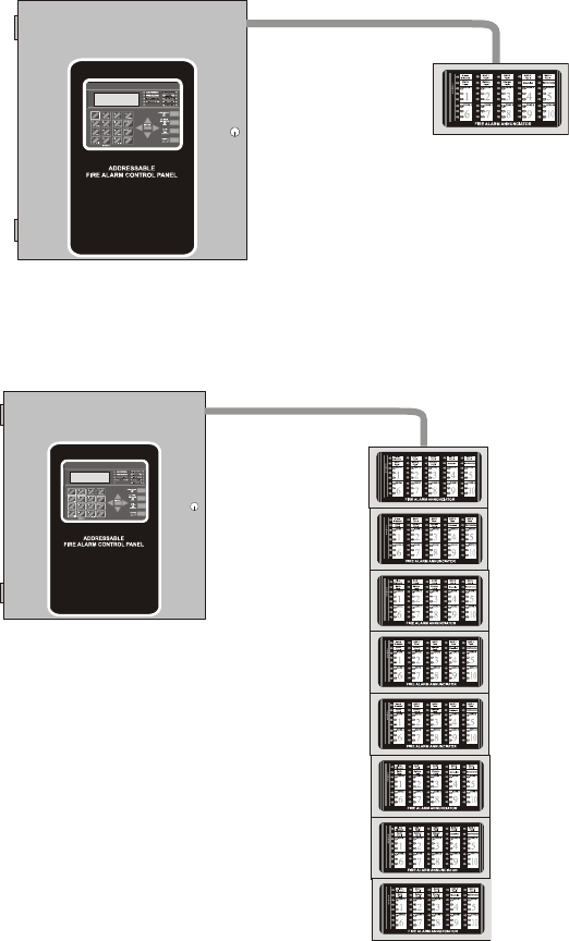
200 MS-9600LS Series Manual — P/N 52646:B2 2/12/2010
Appendix G: Canadian Application
• The MS-9600LSC is supplied with the DP-9692 Dress Panel.
• When installing and programming the FACP, the Canadian Option must be set to ON prior to
any other panel programming (refer to “Canadian Option” on page 113 of the Programming
Section of this manual).
• ACS Series annunciators are not compatible for Canadian applications.
• The LCD-80FC annunciator can be used for optional ancillary annunciation.
• The ANN-LED annunciator must be installed in the same room as the FACP. All wiring
between the FACP and ANN-LED must be in metal conduit no longer than 20 feet.
• The installer must write in the Date of Final Assembly on the Master Marking and Warranty
Label located on the FACP backbox door.
• To comply with CAN/ULC - S559-04, the DACT-UD2 and 4XTMF must both be utilized.
Figure G.1 FACP Minimum Configuration - Single ANN-LED Annunciator
FACP
ANN-LED Annunciator
metal conduit
(max. 20 ft.)
ANN-LED annunciator must
be in same room as FACP
Figure G.2 FACP Maximum Configuration - Eight ANN-LED Annunciators
metal conduit
(max. 20 ft.)
FACP
ANN-LED Annunciators
ANN-LED annunciators must
be in same room as FACP
MS-9600LS Series Manual — P/N 52646:B2 2/12/2010 201
Index
Numerics
300 Series addressable devices 20
4XTMF module 190, 191
coil resistance 55
current 55
installation 55
installation steps 56
see also Transmitter Module 15, 21
voltage 55
A
AC Branch Circuit
calculations 174
AC Loss Delay 106
AC Power 46
current 15
current, maximum 46
voltage 15
wiring 15, 46
Acknowledge/Step 18, 150
ACM LED annunciator 60
ACM Series
see also annunciator 40
ACM-16ATF Annunciator 40
ACM-32AF Annunciator 40
ACM-8RF 14
contact rating 59
see also Relay Control Module 59
ACS LED annunciator 14
add Detector 67
add Module 78
address range 20
addressable 13
addressable detectors
see also detectors 15
Addressable Device Accessories 20
addressable modules 20
see also modules 15
addressing
annunciators 120
see also device addressing 100
see also module or detector addressing 20
Adjective
control module 92
monitor module 85
multiple entries 77
Adjective list 75
AEM-16ATF Annunciator 40
AEM-32AF Annunciator 40
Alarm 153
Alarm Silence 18, 150
alarm verification 14, 72, 157, 159
ANN-RLY Annunciator Module 36
ANN-SB80KIT Mounting Kit 28
annunciator 40
ACM 14, 120
ACM-8RF 14
graphic, see also LDM Series 14, 40
annunciator addressing 120
annunciator, remote
see also LCD-80F 40
Auto Silence
NAC 110
Automatic Test Operation 156
Autoprogramming 15, 62, 66
Autosilence 14, 159
auxiliary DC power 47
Auxiliary Trouble Input 19, 57
B
backbox 19
see also cabinet 45
Banner 100
Banner setting 101
battery 19
cable connection 46
charger 18, 22
charger capacity 15
charger, disable 15
charger, external 22
Charging Circuit 15
see also secondary power 15, 46
battery box 22
baud rate 134
BB-55F
see also battery box 20, 22
C
cabinet 19
dimensions 44, 45
mounting 42
Calculate System Current Draw 175
Calculating the Battery Size 177
Canadian Option 100, 113
Central Station/Remote Station Reporting 189
CHG-120F
see also battery charger 22
see also remote battery charger 15
CHG-75
see also battery charger 22
see also remote battery charger 15
Class A 47
Class B 47
NAC wiring 49

202 MS-9600LS Series Manual — P/N 52646:B2 2/12/2010
D–E Index
Classic Loop Interface Protocol 100
CLIP Mode
see also Classic Loop Interface Protocol
100
Clock Format 104
Coded Operation 157
Coding
NAC 110
coding
two stage operation 111
control buttons 150
control module 20
description display 94
display 88
edit 88
enable/disable 89
noun 93
noun/adjective 91, 92
silenceable 90
type 89
type codes 90
Correlations 178
current
AC Power 46
availability 17
maximum 17
Current Draw Calculations 176
D
DACT 134
DACT-UD2 15
functions 52
installation 52
option module installation 52, 53
phone lines 54
see also Digital Alarm Communicator/
Transmitter 21
data
see also detector data and sensitivity 157
values 14
Data Entry
via computer keyboard 61
via keypad 61
Date setting 103
Daylight Savings Time 104
DC power
nonresettable 47
resettable 47
see also auxiliary DC power 47
Default Programming 186
Delete Detector 68
Delete Module 79
Description
control module 94
detector label 77
monitor module 87
Detector
add 67
adding description 74
delete 68
edit 69
enable/disable 71
screen display 70
type 71
verification 72
detector data 157, 171, 172
acceptable range 171
printout 171
Detector Programming 67
device addressing 100
Digital Alarm Communicator/Transmitter
see also DACT-UD2 21
dimensions
cabinet 44
DIRTY1 172
DIRTY2 172
Disable 96
Disable Point
Maintenance Level 139
dress panel 19, 22
drift compensation 14, 172
definition 172
Drill 18, 150
E
earth ground 46
edit
control module 88
detector 69
detector screens 70
module, monitor 79
EIA-232 59
for PC/Printer connection 16
see also Printer/PC interface 14
EIA-485
for ACS annunciators 16
for LCD-80F 16
Enable 95
Enable/Disable
control module 89
detector 71
module, monitor 81
End-of-Line Resistor Assembly 20
Enter key 64
Erase History 115
exiting
programming 63, 64
Read Status 63, 64
Expander Module 57
see also SLC-2 21

MS-9600LS Series Manual — P/N 52646:B2 2/12/2010 203
Index F–N
F
FACP
see also Fire Alarm Control Panel 13
Features 13
Fire Alarm Control Panel
see also FACP 13
Form-C relay 19, 47, 59
G
general alarm zone 84
see also zone Z00 74
ground fault 59
H
Hazard Condition 155
History 115
erase 115
Maintenance Level 140
view events 115
History file 14
HVAC Control 198
HVAC OVRRIDE 199
HVAC RESTART 198
HVAC SHUTDN 198
I
Indicators 17
Installation 42
intelligent 13
Inventory 13
INVREP 172
K
Key Panel 18
function keys 18
service/program keys 18
keyboard and keypad 61
Keypad/Display
removal and installation 51
L
lamp test 18
LCD display 14, 17
LCD-80F annunciator 14, 40
LDM Series annunciator 40
LDM-32 Graphic Annunciator 14
LED
AC Power 150
Alarm Silenced 151
Battery 151
Disabled 151
Fire Alarm 150
Ground 151
Maintenance 151
see also Indicators 17
Supervisory 151
Trouble 151
LED annunciator 40
Local Energy Municipal Box Service 55
Local Programming 62
Loop Setup 99
M
main circuit, mounting 42
Maintenance Alert 14, 156
levels 172
maintenance alert 172
Maintenance Program Level 2 63, 138
Manual programming 62
Master Program Level 1 63, 65
Medical Alert 156
Mode key 64
Module
add 78
addressing 20
delete 79
edit monitor 79
enable/disable 81
see also addressable modules 20
Module Programming 78
Monitor module 20
adjective 85
enable/disable 81
noun 86
noun/adjective 84
type 82
type action 83
Type list 82
type selection 83
Mounting
cabinet 42
main circuit board 42
municipal box transmitter
see also 4XTMF module 55
N
NAC 15, 19, 107, 157
Auto Silence 110
coded 157
coding 110
current 16
End-of-Line Resistor 16
power 14
see also Notification Appliance Circuit 14,
47
silence inhibit 112
silenceable 109
Style configuration 48
Style Y wiring diagram 49

204 MS-9600LS Series Manual — P/N 52646:B2 2/12/2010
O–P Index
synchronized 157
voltage drop 15
voltage, operating 15
wiring Style 47
NAC enable/disable 108
NAC options 100
NAC type 109
NACKEY card 48
N-ELR Mounting Plate 21
NFPA 72 Auxiliary Fire Alarm System 187, 190
NFPA 72 Central Station Service (Protected
Premises Unit) or Remote Station Service 187
NFPA 72 Proprietary Fire Alarm System 187
NFPA 72 Proprietary Protective Signaling Sys-
tems 192
NFPA 72 Remote Station Protective Signaling
System 191
NFPA Battery Requirements 177
NFPA Signaling Systems for Central Station Ser-
vice (Protected Premises Unit)/Remote Station
188
NFPA Standard 187
Nonresettable Power 18, 47
current 16, 47
nonsilenceable
waterflow 114, 148
nonsilenceable waterflow 98
normal display 62, 151
Notification Appliance Circuit 15, 107
see also NAC 14, 47
Noun
monitor module 86
multiple entries 77
Noun list 76
Noun/Adjective 74, 76
control module 91
monitor module 84
O
Operating Instructions 150
Operation
alarm 153
disable/enable 156
hazard condition 155
medical alert 156
NAC 157
normal 151
process monitor 155
programmed zone 156
supervisory 154
trouble 152
waterflow 156
Option Modules 21, 51, 117
annunciators/UDACT 118
Printer/PC 134
Options 13
Output Circuits 18
P
PAS 72, 96, 158
see also Positive Alarm Sequence 14, 72
PAS BYPASS 159
PAS timer 105
Password 15, 63
change 135
Maintenance Level 2 64, 138
Master Level 1 64
PC (personal computer)
configuration 59
connection 58
ground fault 59
Phone Line 2
supervision 169
phone lines
DACT installation 54
Piezo
see also sounder 18
Point Program 67
Positive Alarm Sequence 72, 158
see also PAS 14
power
NAC 14
nonresettable 16
resettable 89
resettable smoke 16
power supply calculations 174
power-limited
relay connections 47
power-limited wiring requirements 50
Power-up
first time 63
Pre-signal 14, 73, 96
function 158
selection 84
Pre-signal Delay timer 105
primary power
see also AC Power 46
printer
baud rate 134
configuration 59
connection 58
ground fault 59
setup 59
Printer/PC interface 14
Process Monitor 155
PROCMON AR 113
Program
check 137
check correlations 137
clear 136
Program Check
Maintenance Level 141

MS-9600LS Series Manual — P/N 52646:B2 2/12/2010 205
Index R–S
program keys
see also Key Panel 18
Programming 61, 62
autoprogramming 62
exiting 63
factory default 186
Level 1 63
Level 2 63
manual 62
Master Level 1 65
modules 78
off-line computer 62
via computer keyboard 61
via panel keypad 61
Programming Levels 63
Programming Screens 63
Programming Sheet 180, 181, 182, 183, 185
Programming Utility
see also PS-Tools 21
PRT/PK-CABLE
for PC/Printer connection 59
PS-Tools Programming Utility 21
R
Read Status 62, 161
annunciators 167, 169
exiting 63
history 167
NAC 166
power 164
Print 171
printer/PC 170
program check 167
relay 166
system point 162
Time-Date 173
timers 165
trouble reminder 165
zones 163
Real-Time Clock 157
Recall/Increment Function 77, 87, 94
Relay 16, 19, 47, 112
connections 47
contact rating 16, 19, 47
fixed 47
Form-C 16, 112
programmable 14, 19, 47
programming 113
selections 113
trouble 14, 19, 47
Relay Control Module
see also ACM-8RF 59
Relay options 100
Remote Programming 62
Remote Station Service 56
remote switch functions 14
Reset 18, 150
Resettable Power 18, 47, 89
current 47
see also Smoke Detector Power 16
S
Secondary Power Requirements 177
sensitivity 157, 172
see also smoke detector sensitivity 157
Signal rate 14
Signaling Line Circuit
see also SLC 15
Silence Inhibit 14, 112, 159
silenceable
control module 90
NAC 109
waterflow 98, 100, 114
Silenceable Alarm Relay 113
silenceable circuits
synchronized signals 109
Silenceable waterflow 148
SLC 13, 15, 18
current 15
reference manual 15
resistance 15
see also Signaling Line Circuit 13
Style 18
voltage 15
wiring length 15
SLC Loop Protocol 100
SLC loop selection 67
SLC Style 99
SLC-2 57
installation 57
wiring 58
SLC-2 Expander Module 21
smoke detector
chamber reading 171
data 157, 171
sensitivity 157
Smoke Detector Power
current 16
smoke detector sensitivity 14
Software Zones 14, 178
sounder 18
Specifications 15
strobe synchronization 14
Style 13
Style Y 47
NAC wiring 49
NC configuration 48
Style Z 47
NAC configuration 48
wiring 49
subscreen 63
supervise

206 MS-9600LS Series Manual — P/N 52646:B2 2/12/2010
T–Z Index
Phone Line 2 169
Supervisory 154
SUPERVISORY AR 113
sync
programming 108
see also synchronization 112
synchronization 157, 166
by manufacturer 112
programming 112
see also strobe synchronization 14
synchronized 157
Synchronized Signals 157
and silenceable circuits 109
System
Maintenance Level 143
System Point 162
System Setup 100
T
Time and Date
Maintenance Level 143
Time setting 103
Time-Date setting 100, 103
Timers 100
Transmitter Module 55
see also 4XTMF module 21
TR-CE trim ring 22
Trouble 152
trouble display 152
trouble relay 14
Trouble Reminder 100, 159, 165
trouble responses 152
Two Stage 96
two stage operation 111
Type
control module 89
detector 71
monitor module 82
NAC 109
type code
control module 90
supervision 157
verification 14
U
UL power-limited wiring requirements
see also power-limited and nonpower-lim-
ited 47
V
Verification
detector 72
Verify Loops 114
View Events 115
voltage
measurements 164
ranges 164
W
Walktest 14, 72, 90, 116
audible 116
Maintenance Level 142
operation 160
selection 84
silent 116
waterflow
nonsilenceable 98, 114, 148
silenceable 98, 100, 114, 148
Waterflow Delay timer 105, 106
Waterflow Retard Timer 159
Wire Requirements 196
wiring
AC Power 46
earth ground 46
NAC Style Y 49
NAC Style Z 49
SLC-2 58
wiring Style 13
Z
Z00 74, 84
Z97
PAS zone 73
Z98 73
Zone 97 96
Zone 98 96
Zone Assignment 73, 84, 112
control module 90
Zone Setup 95
Maintenance Level 144
zone type 98, 147
list 98, 148
Zone Z97 73
Zone Z98
pre-signal zone 73
Zones 163, 178
see also software zones 14
Zones Disabled 97, 147
Zones Enabled 97, 146
Zones Installed 97, 146
zones per device 73
Manufacturer Warranties and Limitation of Liability
Manufacturer Warranties. Subject to the limitations set forth herein,
Manufacturer warrants that the Products manufactured by it in its
Northford, Connecticut facility and sold by it to its authorized
Distributors shall be free, under normal use and service, from defects
in material and workmanship for a period of thirty six months (36)
months from the date of manufacture (effective Jan. 1, 2009). The
Products manufactured and sold by Manufacturer are date stamped at
the time of production. Manufacturer does not warrant Products that
are not manufactured by it in its Northford, Connecticut facility but
assigns to its Distributor, to the extent possible, any warranty offered
by the manufacturer of such product. This warranty shall be void if a
Product is altered, serviced or repaired by anyone other than
Manufacturer or its authorized Distributors. This warranty shall also
be void if there is a failure to maintain the Products and the systems in
which they operate in proper working conditions.
MANUFACTURER MAKES NO FURTHER WARRANTIES, AND
DISCLAIMS ANY AND ALL OTHER WARRANTIES, EITHER
EXPRESSED OR IMPLIED, WITH RESPECT TO THE PRODUCTS,
TRADEMARKS, PROGRAMS AND SERVICES RENDERED BY
MANUFACTURER INCLUDING WITHOUT LIMITATION,
INFRINGEMENT, TITLE, MERCHANTABILITY, OR FITNESS FOR
ANY PARTICULAR PURPOSE. MANUFACTURER SHALL NOT BE
LIABLE FOR ANY PERSONAL INJURY OR DEATH WHICH MAY
ARISE IN THE COURSE OF, OR AS A RESULT OF, PERSONAL,
COMMERCIAL OR INDUSTRIAL USES OF ITS PRODUCTS.
This document constitutes the only warranty made by Manufacturer
with respect to its products and replaces all previous warranties and is
the only warranty made by Manufacturer. No increase or alteration,
written or verbal, of the obligation of this warranty is authorized.
Manufacturer does not represent that its products will prevent any loss
by fire or otherwise.
Warranty Claims. Manufacturer shall replace or repair, at
Manufacturer's discretion, each part returned by its authorized
Distributor and acknowledged by Manufacturer to be defective,
provided that such part shall have been returned to Manufacturer with
all charges prepaid and the authorized Distributor has completed
Manufacturer's Return Material Authorization form. The replacement
part shall come from Manufacturer's stock and may be new or
refurbished. THE FOREGOING IS DISTRIBUTOR'S SOLE AND
EXCLUSIVE REMEDY IN THE EVENT OF A WARRANTY CLAIM.
Warn-HL-08-2009.fm
MS-9600LS Series Manual — P/N 52646:B2 2/12/2010 207

World Headquarters
1 Firelite Place
Northford, CT 06472-1653 USA
203-484-7161
fax 203-484-7118
www.firelite.com
