Honeywell Universal Remote Udc3200 Users Manual Operator
UDC3200 to the manual b5aab3d3-92d1-44ca-9b40-803341ff2e75
2015-01-23
: Honeywell Honeywell-Honeywell-Universal-Remote-Udc3200-Users-Manual-262614 honeywell-honeywell-universal-remote-udc3200-users-manual-262614 honeywell pdf
Open the PDF directly: View PDF ![]() .
.
Page Count: 90
- Contacts
- Symbol Definitions
- Contents
- 1 Introduction
- 2 Installation
- 3 Configuration
- 3.1 Configuration Prompt Hierarchy
- 3.2 Configuration Procedure
- 3.3 Tuning Set Up Group
- 3.4 SP Ramp Set Up Group
- 3.5 Accutune Set Up Group
- 3.6 Algorithm Set Up Group
- 3.7 Output Set Up Group
- 3.8 Input 1 Set Up Group
- 3.9 Input 2 Set Up Group
- 3.10 Control Set Up Group
- 3.11 Options Group
- 3.12 Communications Group
- 3.13 Alarms Set Up Group
- 3.14 Display Set Up Group
- 4 Monitoring and Operating the Controller
- 5 Troubleshooting/Service
- 6 Sales and Service

Honeywell Process Solutions
UDC3200
Universal Digital Controller
Operator Manual
51-52-25-143
April 2008

4/08 UDC3200 Universal Digital Controller Operator Manual ii
Notices and Trademarks
Copyright 2008 by Honeywell
April 2008
WARRANTY/REMEDY
Honeywell warrants goods of its manufacture as being free of defective materials and faulty workmanship.
Contact your local sales office for warranty information. If warranted goods are returned to Honeywell during the
period of coverage, Honeywell will repair or replace without charge those items it finds defective. The foregoing
is Buyer's sole remedy and is in lieu of all other warranties, expressed or implied, including those of
merchantability and fitness for a particular purpose. Specifications may change without notice. The
information we supply is believed to be accurate and reliable as of this printing. However, we assume no
responsibility for its use.
While we provide application assistance personally, through our literature and the Honeywell web site, it is up to
the customer to determine the suitability of the product in the application.
Contacts
World Wide Web
The following lists Honeywell’s World Wide Web sites that will be of interest to our customers.
Honeywell Organization WWW Address (URL)
Corporate http://www.honeywell.com
Honeywell Process Solutions http://hpswebhoneywell.com
Telephone
Contact us by telephone at the numbers listed below.
Organization Phone Number
United States and Canada Honeywell 1-800-423-9883 Tech. Support
1-800-525-7439 Service
Web
http://content.honeywell.com/ipc/faq/
Honeywell Process Solutions
512 Virginia Drive
Fort Washington, PA 19034
UDC3200 is a U.S. registered trademark of Honeywell
Other brand or product names are trademarks of their respective owners.
4/08 UDC3200 Universal Digital Controller Operator Manual iii
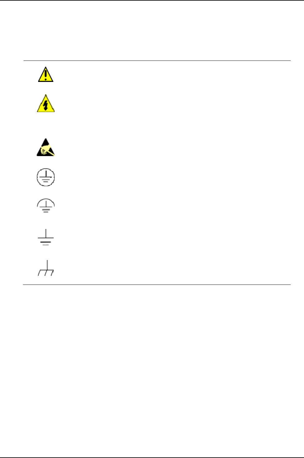
Symbol Definitions
The following table lists those symbols used in this document to denote certain conditions.
Symbol Definition
This CAUTION symbol on the equipment refers the user to the Product Manual for
additional information. This symbol appears next to required information in the manual.
WARNING
PERSONAL INJURY: Risk of electrical shock. This symbol warns the user of a
potential shock hazard where HAZARDOUS LIVE voltages greater than 30 Vrms, 42.4
Vpeak, or 60 VDC may be accessible. Failure to comply with these instructions
could result in death or serious injury.
ATTENTION, Electrostatic Discharge (ESD) hazards. Observe precautions for
handling electrostatic sensitive devices
Protective Earth (PE) terminal. Provided for connection of the protective earth (green
or green/yellow) supply system conductor.
Functional earth terminal. Used for non-safety purposes such as noise immunity
improvement. NOTE: This connection shall be bonded to protective earth at the source
of supply in accordance with national local electrical code requirements.
Earth Ground. Functional earth connection. NOTE: This connection shall be bonded to
Protective earth at the source of supply in accordance with national and local electrical
code requirements.
Chassis Ground. Identifies a connection to the chassis or frame of the equipment shall
be bonded to Protective Earth at the source of supply in accordance with national and
local electrical code requirements.

4/08 UDC3200 Universal Digital Controller Operator Manual iv
Contents
1 INTRODUCTION ...................................................................................................1
1.1 Operator Interface ...........................................................................................................................1
1.2 Function of Displays and Keys .......................................................................................................1
1.3 CE Conformity (Europe).................................................................................................................2
2 INSTALLATION.....................................................................................................5
2.1 Pre-installation Information ............................................................................................................5
2.2 Model Number Interpretation .........................................................................................................5
2.3 Control and Alarm Relay Contact Information...............................................................................6
2.4 Mounting.........................................................................................................................................7
2.5 Wiring .............................................................................................................................................9
2.5.1 Electrical Considerations .....................................................................................................9
2.6 Wiring Diagrams...........................................................................................................................10
3 CONFIGURATION...............................................................................................24
3.1 Configuration Prompt Hierarchy ..................................................................................................24
3.2 Configuration Procedure...............................................................................................................25
3.3 Tuning Set Up Group....................................................................................................................26
3.4 SP Ramp Set Up Group ................................................................................................................29
3.5 Accutune Set Up Group ................................................................................................................32
3.6 Algorithm Set Up Group...............................................................................................................33
3.7 Output Set Up Group ....................................................................................................................39
3.8 Input 1 Set Up Group....................................................................................................................42
3.9 Input 2 Set Up Group....................................................................................................................45
3.10 Control Set Up Group ...............................................................................................................48
3.11 Options Group ...........................................................................................................................53
3.12 Communications Group ............................................................................................................57
3.13 Alarms Set Up Group ................................................................................................................59
3.14 Display Set Up Group ...............................................................................................................63
4 MONITORING AND OPERATING THE CONTROLLER.....................................65
4.1 Operator Interface .........................................................................................................................65
4.2 Entering a Security Code ..............................................................................................................65
4.3 Individual key lockout ..................................................................................................................66
4.4 Monitoring Your Controller..........................................................................................................67
4.4.1 Annunciators ......................................................................................................................67
4.4.2 Viewing the operating parameters......................................................................................68
4.4.3 Diagnostic Messages..........................................................................................................69
4.5 Accutune III ..................................................................................................................................71
4.5.1 Tune for Simplex Outputs..................................................................................................72

v UDC3200 Universal Digital Controller Operator Manual 4/08
4.5.2 Tune for Duplex (Heat/Cool) .............................................................................................73
4.5.3 Using AUTOMATIC TUNE at start-up for Duplex (Heat/Cool) ......................................74
4.5.4 Using BLENDED TUNE at start-up for Duplex (Heat/Cool) ...........................................75
4.5.5 Using MANUAL TUNE at start-up for Duplex (Heat/Cool).............................................75
4.5.6 Error Codes ........................................................................................................................77
4.6 Fuzzy Overshoot Suppression.......................................................................................................78
5 TROUBLESHOOTING/SERVICE........................................................................79
5.1 Background Tests..........................................................................................................................79
5.2 Controller Failure Symptoms........................................................................................................81
6 SALES AND SERVICE........................................................................................82
04/08 UDC3200 Universal Digital Controller Operator Manual 1
1 Introduction
1.1 Operator Interface
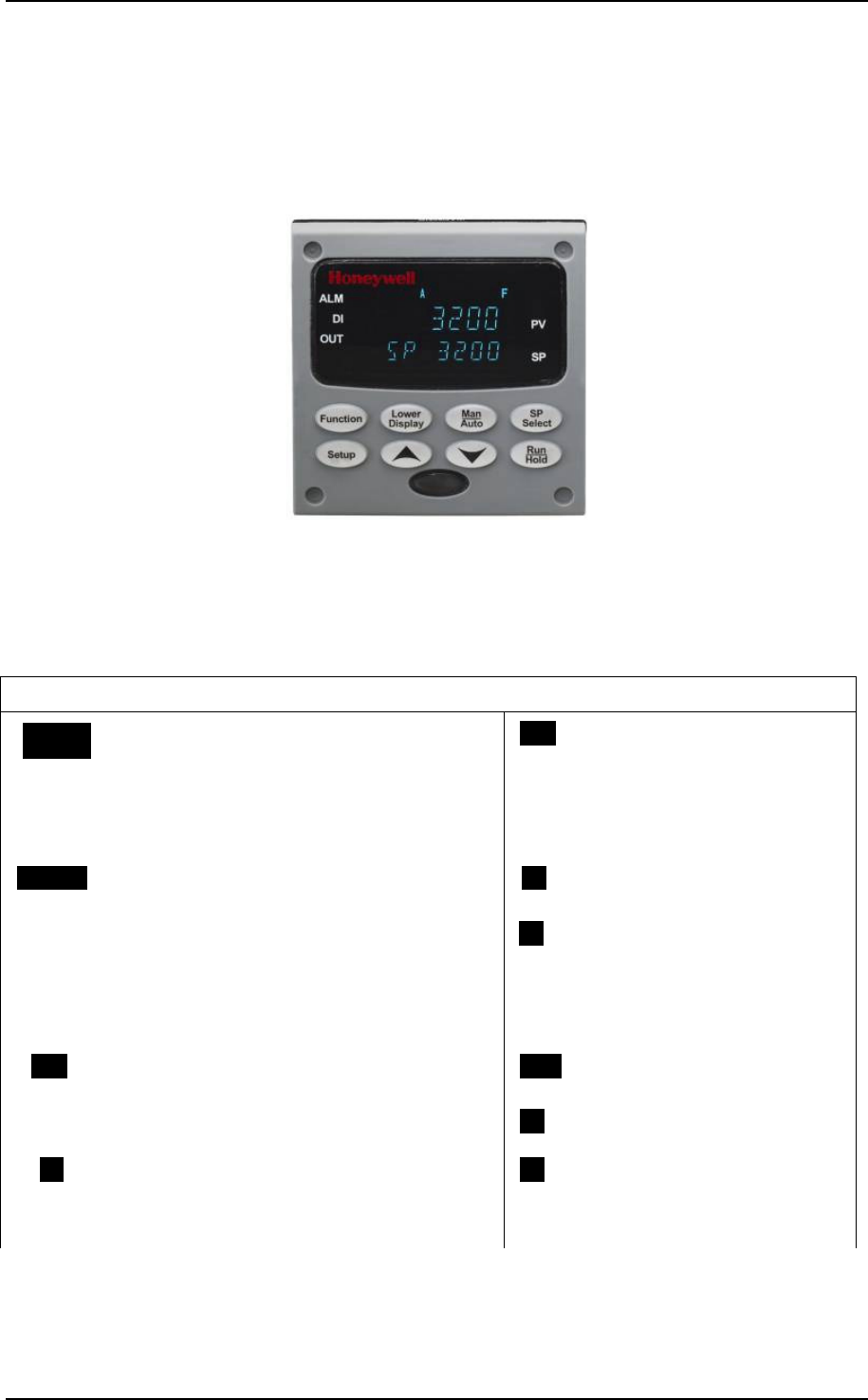
Figure 1-1 UDC3200 Operator Interface
1.2 Function of Displays and Keys
Table 1-1 Function of Displays and Keys
Display Indicators
32003200 Upper display with 4 large digits shows
Process Variable value (normal operation)
and special annunciator features. During
Configuration, the upper display provides
guidance for the operator through prompts (7
– characters)
OUTOUT Indicates Control Relay 1 and/or
2 on.
SP 3200SP 3200 During normal operation, the lower display
shows key-selected operating parameters
such as Output, Setpoints, Inputs, Deviation,
active Tuning Parameter Set, Timer Status, or
minutes remaining in a setpoint ramp (4
digits). During configuration, the lower display
provides guidance for the operator through
prompts (8-characters).
FF
Or
CC
Indicates either degrees
Fahrenheit or Centigrade.
ALMALM Indicates Alarm 1 and/or Alarm 2 conditions
exist. MANMAN
Or
AA
Indicates either Manual or Auto
mode.
DIDI Indicates Digital Input 1 and/or 2 on. SPSP Indicates Local Setpoint #1.
Also, a bar is lighted when the
setpoint being used is shown on
the lower display.

2 UDC3200 Universal Digital Controller Operator Manual 04/08
Keys and Functions
FunctionFunctionFunction
Selects functions within each
configuration group. Man
Auto
Man
Auto
Man
Auto
Selects Manual or Auto mode.
SetupSetup
Scrolls through the configuration
groups.
SP
Select
SP
Select
SP
Select
Hold key down to cycle through
configured setpoints.
Lower
Display
Lower
Display
Lower
Display
Returns Controller to normal display
from Set Up mode. Toggles various
operating parameters for display.
Run
Hold
Run
Hold
Run
Hold
Enables Run/Hold of the SP
Ramp or Program plus Timer
start.
Increases setpoint or output value.
Increases the configuration values or
changes functions in Configuration
mode groups.
Decreases setpoint or output
value. Decreases the
configuration values or changes
functions in Configuration mode
groups.
Infrared transceiver
NEMA4X and IP66 screw
attachment (each corner)
1.3 CE Conformity (Europe)
This product is in conformity with the protection requirements of the following
European Council Directives: 73/23/EEC, the Low Voltage Directive, and
89/336/EEC, the EMC Directive. Conformity of this product with any other “CE
Mark” Directive(s) shall not be assumed.
Product Classification: Class I: Permanently connected, panel-mounted Industrial
Control Equipment with protective earthing (grounding) (EN61010-1).
Enclosure Rating: This controller must be panel-mounted with the rear terminals
enclosed within the panel. The front panel of the controller is rated at NEMA4X and
IP66 when properly installed.
Installation Category (Overvoltage Category): Category II (EN61010-1)
Pollution Degree: Pollution Degree 2: Normally non-conductive pollution with
occasional conductivity caused by condensation. (Ref. IEC 664-1)
EMC Classification: Group 1, Class A, ISM Equipment (EN61326, emissions),
Industrial Equipment (EN61326, immunity)
Method of EMC Assessment: Technical File (TF)
Declaration of Conformity: 51453663
Deviation from the installation conditions specified in this manual, and the special
conditions for CE conformity in Subsection 2, may invalidate this product’s
conformity with the Low Voltage and EMC Directives.

04/08 UDC3200 Universal Digital Controller Operator Manual 3
ATTENTION
The emission limits of EN61326 are designed to provide reasonable protection
against harmful interference when this equipment is operated in an industrial
environment. Operation of this equipment in a residential area may cause harmful
interference. This equipment generates, uses, and can radiate radio frequency
energy and may cause interference to radio and television reception when the
equipment is used closer than 30 meters (98 feet) to the antenna(e). In special
cases, when highly susceptible apparatus is used in close proximity, the user may
have to employ additional mitigating measures to further reduce the
electromagnetic emissions of this equipment.
WARNING
If this equipment is used in a manner not specified by the manufacturer, the
protection provided by the equipment may be impaired.
04/08 UDC3200 Universal Digital Controller Operator Manual 5
2 Installation
2.1 Pre-installation Information
If the controller has not been removed from its shipping carton, inspect the carton for
damage then remove the controller.
• Inspect the unit for any obvious shipping damage and report any damage due to
transit to the carrier.
• Make sure a bag containing mounting hardware is included in the carton with the
controller.
• Check that the model number shown on the inside of the case agrees with what
you have ordered.
2.2 Model Number Interpretation
Write your controller’s model number in the spaces provided below and circle the
corresponding items in each table. This information will also be useful when you wire your
controller.
Instructions
Select the desired key number. The arrow to the right marks the selection available.
Make the desired selections from Tables I through VI using the column below the
proper arrow. A dot ( ) denotes availability.
Key Number -- - -
_
_ _ _
_
-
_
_
_ _ _ _
_
_
_
I
_
_
_
IIIII IV
_
_
V
_
_ _
_
VI
KEY NUMBER - UDC3200 Single Loop Controller
Selection
Digital Controller for use with 90 to 264Vac Power DC3200
Digital Controller for use with 24Vac/dc Power DC3201
TABLE I - Specify Control Output and/or Alarms
TABLE II - Communications and Software Selections
0 _ _ _
1 _ _ _
2 _ _ _
3 _ _ _
_ 0 _ _
_ A _ _
_ B _ _
_ C _ _
No Selection _ _ 0 _
_ _ _ R
C _
E _
Math Option
Set Point Programming (1 Program, 12 Segments)
Set Point Programming Plus Math
Current Output (4 to 20ma, 0 to 20 ma)
T _
R _
_ E
_ A
No Additional Outputs or Alarms
Output #1
Software Selections
Standard Functions, Includes Accutune
Open Collector Plus Alarm 1 (5 Amp Form C Relay) _ T
Output #2 and Alarm
#1 or Alarms 1 and 2
_ B
One Alarm Relay Only
Availability
Infrared Interface Included (Can be used with a Pocket PC)
_ 0
E-M Relay (5 Amp Form C) Plus Alarm 1 (5 Amp Form C Relay)
Solid State Relay (1 Amp) Plus Alarm 1 (5 Amp Form C Relay)
Electro Mechanical Relay (5 Amp Form C)
Solid State Relay (1 Amp)
None
A _
Description
Infrared interface
Reserved
Open Collector transistor output
Dual 2 Amp Relays (Both are Form A) (Heat/Cool Applications)
Communications Auxiliary Output/Digital Inputs (1 Aux and 1 DI or 2 DI)
RS-485 Modbus Plus Auxiliary Output/Digital Inputs
10 Base-T Ethernet (Modbus RTU) Plus Auxiliary Output/Digital Inputs
TABLE III - Input 1 can be changed in the field using external resistors
1 _ _
2 _ _
3 _ _
Carbon, Oxygen or Dewpoint (Requires Input 2) 1 6 0
_ 00
_ 10
_ 20
Slidewire Input (Requires two Relay Outputs) _ 40
None
TC, RTD, mV, 0-5V, 1-5V, 0-20mA, 4-20mA
TC, RTD, mV, 0-5V, 1-5V, 0-20mA, 4-20mA
TC, RTD, mV, 0-5V, 1-5V, 0-20mA, 4-20mA, 0-10V
Input 1
Input 2
TC, RTD, mV, 0-5V, 1-5V
TC, RTD, mV, 0-5V, 1-5V, 0-20mA, 4-20mA, 0-10V
6 UDC3200 Universal Digital Controller Operator Manual 04/08
TABLE IV - Options
0 _ _ _ _
1 _ _ _ _
_ 0 _ _ _
_ T _ _ _
_ S _ _ _
_ _ 0 _ _
_ _ _ 0 _
_ _ _ _ 0
TABLE V - Product Manuals
Product Information on CD - All Languages 0 _
English Manual E _
French Manual F _
German Manual G _
Italian Manual I _
Spanish Manual S _
_ 0
_ C
TABLE VI
None 0 _
Linen Customer ID Tag - 3 lines w/22 characters/line
Certificate of Conformance (F3391)
Certificate
None
None
None
Stainless Steel Customer ID Tag - 3 lines w/22 characters/line
Approvals CE (Standard)
No Selection
Manuals
Tags
None
None
CE, UL and CSA
Future Options
Figure 2-1 Model Number Interpretation
2.3 Control and Alarm Relay Contact Information
Control Relays
ATTENTION
Control relays operate in the standard control mode (that is, energized when output state is on).
Table 2-1 Control Relay Contact Information
Unit Power Control Relay
Wiring Control Relay
Contact Output #1 or #2
Indicator Status
N.O. Open
Off N.C. Closed
Off
Open Off
N.O.
Closed On
Closed Off
On
N.C.
Open On
Alarm Relays
ATTENTION
Alarm relays are designed to operate in a failsafe mode (that is, de-energized during alarm
sate). This results in alarm actuation when power is OFF or when initially applied, until the unit
completes self-diagnostics. If power is lost to the unit, the alarms will de-energize and thus the
alarm contacts will close.
Table 2-2 Alarm Relay Contact Information
Variable NOT in Alarm State Variable in Alarm State Unit
Power Alarm Relay
Wiring Relay
Contact Indicators Relay
Contact Indicators
N.O. Open Open
Off N.C. Closed Off Closed Off
N.O. Closed Open
On N.C. Open
Off Closed
On
04/08 UDC3200 Universal Digital Controller Operator Manual 7
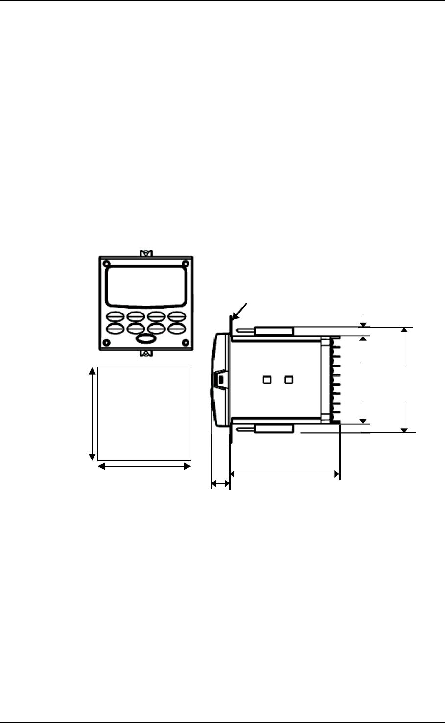
2.4 Mounting
Physical Considerations
The controller can be mounted on either a vertical or tilted panel using the mounting
kit supplied. Adequate access space must be available at the back of the panel for
installation and servicing activities.
• Overall dimensions and panel cutout requirements for mounting the controller are
shown in Figure 2-2.
• The controller’s mounting enclosure must be grounded according to CSA standard
C22.2 No. 0.4 or Factory Mutual Class No. 3820 paragraph 6.1.5.
• The front panel is moisture rated NEMA3 and IP55 rated and can be easily
upgraded to NEMA4X and IP66.
Overall Dimensions
Max. panel thickness
19,1
.75
Panel
Cutout
92,0 + 0,8
-0,00
3,62 + 0,03
-0,00
92,0 + 0,8
-0,00
3,62 + 0,03
-0,00
mm
inches
17,9
0,70
113,1
4,45
90,6
3,57 108,6
4,28
9,0
0,35
Figure 2-2 Mounting Dimensions (not to scale)
8 UDC3200 Universal Digital Controller Operator Manual 04/08
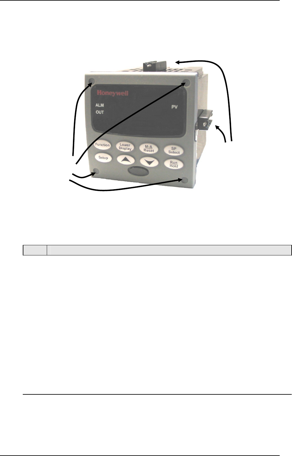
Mounting Method
Before mounting the controller, refer to the nameplate on the outside of the case and
make a note of the model number. It will help later when selecting the proper wiring
configuration.
Figure 2-3 Mounting Methods
Mounting Procedure
Table 2-3 Mounting Procedure
Step Action
1 Mark and cut out the controller hole in the panel according to the dimension
information in Figure 2-2.
2 Orient the case properly and slide it through the panel hole from the front.
3 Remove the mounting kit from the shipping container and install the kit as follows:
• For normal installation two mounting clips are required. Insert the prongs of
the clips into the two holes in the top and bottom center of the case
• For water-protected installation four mounting clips are required. There are
two options of where to install the mounting clips:
1) Insert the prongs of the clips into the two holes on the left and right side of the
top and bottom of the case or
2) on the center on each of the four sides.
• Tighten screws to 2 lb-inch (22 N•cm) to secure the case against the panel.
CAUTION: Over tightening will cause distortion and the unit may not seal properly.
4 For water-protected installation, install four screws with washers into the four recessed
areas in the corners of the front bezel (Figure 2-3). Push the point of the screw
through the center piercing the elastomeric material and then tighten screws to 5 lb-in
(56 N•cm).
Attach screws and
washers here for
water protection
Mounting clips

04/08 UDC3200 Universal Digital Controller Operator Manual 9
2.5 Wiring
2.5.1 Electrical Considerations
Line voltage wiring
This controller is considered “rack and panel mounted equipment” per EN61010-1,
Safety Requirements for Electrical Equipment for Measurement, Control, and
Laboratory Use, Part 1: General Requirements. Conformity with 72/23/EEC, the Low
Voltage Directive requires the user to provide adequate protection against a shock
hazard. The user shall install this controller in an enclosure that limits OPERATOR
access to the rear terminals.
Mains Power Supply
This equipment is suitable for connection to 90 to 264 Vac or to 24 Vac/dc 50/60 Hz,
power supply mains. It is the user’s responsibility to provide a switch and non-time
delay (North America), quick-acting, high breaking capacity, Type F (Europe), 1/2A,
250V fuse(s), or circuit-breaker for 90-264 Vac applications; or 1 A, 125 V fuse or
circuit breaker for 24 Vac/dc applications, as part of the installation. The switch or
circuit-breaker shall be located in close proximity to the controller, within easy reach
of the OPERATOR. The switch or circuit-breaker shall be marked as the
disconnecting device for the controller.
CAUTION Applying 90-264 Vac to an instrument rated for 24 Vac/dc will
severely damage the instrument and is a fire and smoke hazard.
When applying power to multiple instruments, make certain that sufficient current is
supplied. Otherwise, the instruments may not start up normally due to the voltage
drop caused by the in-rush current.
Controller Grounding
PROTECTIVE BONDING (grounding) of this controller and the enclosure in which
it is installed shall be in accordance with National and Local electrical codes. To
minimize electrical noise and transients that may adversely affect the system,
supplementary bonding of the controller enclosure to a local ground, using a No. 12
(4 mm2) copper conductor, is recommended.
Control/Alarm Circuit Wiring
The insulation of wires connected to the Control/Alarm terminals shall be rated for
the highest voltage involved. Extra Low Voltage (ELV) wiring (input, current output,
and low voltage Control/Alarm circuits) shall be separated from HAZARDOUS LIVE
(>30 Vac, 42.4 Vpeak, or 60 Vdc) wiring per Permissible Wiring Bundling, Table
2-4.
Electrical Noise Precautions
Electrical noise is composed of unabated electrical signals which produce undesirable
effects in measurements and control circuits.
Digital equipment is especially sensitive to the effects of electrical noise. Your
controller has built-in circuits to reduce the effect of electrical noise from various
sources. If there is a need to further reduce these effects:

10 UDC3200 Universal Digital Controller Operator Manual 04/08
• Separate External Wiring—Separate connecting wires into bundles
(See Permissible Wiring Bundling - Table 2-4) and route the individual bundles
through separate conduit metal trays.
Use Suppression Devices—For additional noise protection, you may want to add
suppression devices at the external source. Appropriate suppression devices are
commercially available.
ATTENTION
For additional noise information, refer to document number 51-52-05-01, How to Apply Digital
Instrumentation in Severe Electrical Noise Environments.
Permissible Wiring Bundling
Table 2-4 Permissible Wiring Bundling
Bundle No. Wire Functions
1 • Line power wiring
• Earth ground wiring
• Line voltage control relay output wiring
• Line voltage alarm wiring
2 Analog signal wire, such as:
• Input signal wire (thermocouple, 4 to 20 mA, etc.)
• 4-20 mA output signal wiring
Digital input signals
3 • Low voltage alarm relay output wiring
• Low voltage wiring to solid state type control circuits
• Low voltage wiring to open collector type control circuits
2.6 Wiring Diagrams
Universal Output Functionality and Restrictions
Instruments with multiple outputs can be configured to perform a variety of output
types and alarms. For example, an instrument with a current output and two relays
can be configured to perform any of the following:
1) Current Simplex with two alarm relays;
2) Current Duplex 100% with two alarm relays;
3) Time Simplex with one alarm relay;
4) Time Duplex with no alarm relays; or
5) Three Position Step Control with no alarm relays.
These selections may all be made via the keyboard and by wiring to the appropriate
output terminals; there are no internal jumpers or switches to change. This flexibility
allows a customer to stock a single instrument which is able to handle a variety of
applications.
Table 2-5 shows what control types and alarms are available based upon the installed
outputs. In this table, when Duplex Control and Reverse Action are configured,
“Output 1” is HEAT while “Output 2” is COOL. When Three Position Step Control
is configured, “Output 1” is OPEN while “Output 2” is CLOSE. The Output 1/2
option “Single Relay” can be any of the following selections: Electro-Mechanical
Relay, Solid-State Relay or Open Collector Output.
Table 2-5 Universal Output Functionality and Restrictions
04/08 UDC3200 Universal Digital Controller Operator Manual 11
Function of Other Outputs Output Algorithm
Type Output 1/2
Option Function of
Output 1/2 Output #3 Output #4 Auxiliary Output
Single Relay Output 1 Alarm 2 Alarm 1 Not Needed
Current Output INU Output 1 Alarm 1 Not Needed
Time Simplex
Dual Relay Output 1 Alarm 2 Alarm 1 Not Needed
Single Relay Output 1 Output 2 Alarm 1 Not Needed
Current Output INU Output 2 Output 1 Not Needed
Time Duplex or
TPSC or Position
Proportional Dual Relay Outputs 1 and
2 Alarm 2 Alarm 1 Not Needed
Single Relay INU Alarm 2 Alarm 1 Output 1
Current Output Output 1 Alarm 2 Alarm 1 Not Needed
Current Simplex
Dual Relay INU Alarm 2 Alarm 1 Output 1
Single Relay INU Alarm 2 Alarm 1 Outputs 1 and 2
Current Output Outputs 1 and
2 Alarm 2 Alarm 1 Not Needed
Current Dup. 100%
Current = COOL
and HEAT
Dual Relay INU Alarm 2 Alarm 1 Outputs 1 and 2
Single Relay N/A N/A N/A N/A
Current Output Output 1 Alarm 2 Alarm 1 Output 2
Current Duplex
50%
Current = HEAT
Aux Out = COOL Dual Relay N/A N/A N/A N/A
Single Relay * Output 1 Output 2 Alarm 1 Output 2
Current Output Output 2 Output 2 Alarm 1 Not Needed
Current/Time
Current = COOL
Time = HEAT Dual Relay * Outputs 1 & 2 Alarm 2 Alarm 1 Output 2
Single Relay * Output 1 Output 2 Alarm 1 Output 1
Current Output Output 1 Output 2 Alarm 1 Not Needed
Time/Current
Time = COOL
Current = HEAT Dual Relay * Outputs 1 & 2 Alarm 2 Alarm 1 Output 1
TPSC = Three Position Step Control
N/A = Not Available – This output algorithm type cannot be performed with this Output 1/2
option.
INU = Installed, Not Used – The installed Output 1/2 option is not used for the configured
output algorithm type.
Not Needed = Auxiliary Output is Not Needed to provide the desired output algorithm and
can be used for another purpose. With the proper configuration, Auxiliary
Output could also be used as a substitute for the Current Output.
* To obtain this output algorithm type with these Output 1/2 Options: 1) Configure the
OUTALG selection as “TIME D”; 2) Configure Auxiliary Output for “OUTPUT” and; 3)
Scale the Auxiliary Output as necessary for the desired output algorithm type. For these
selections, the Output 1 (HEAT) and Output 2 (COOL) signals will be present both on the
Auxiliary Output and on the two relays normally used for Time Duplex.
12 UDC3200 Universal Digital Controller Operator Manual 04/08
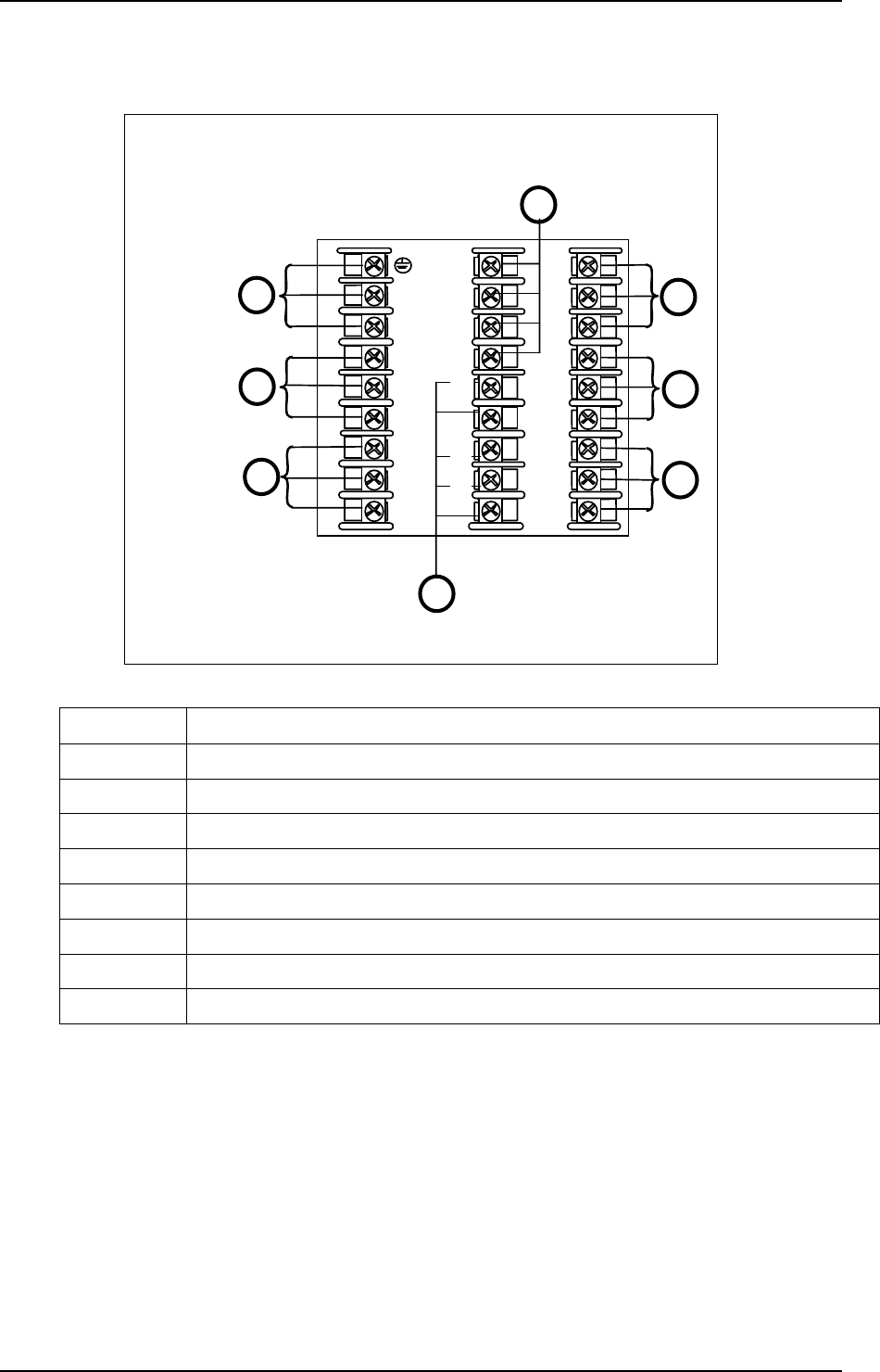
Wiring the Controller
L1
L2/N
4
5
6
7
1
10
11
12
13
14
15
16
17
7
8
9
20
21
22
23
24
25
26
27
18
19
See table for callout details
2
3
4
5
6
8
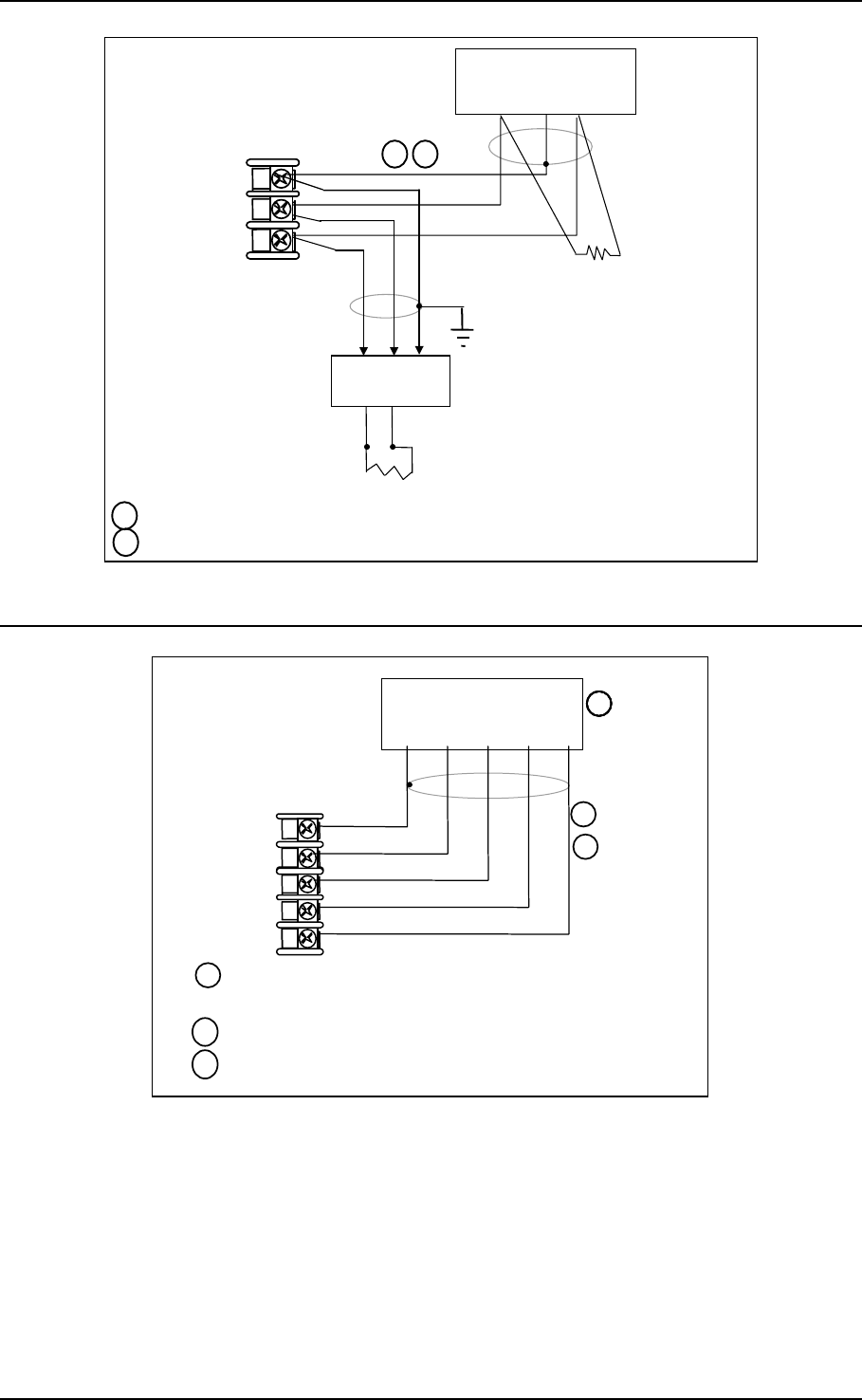
Figure 2-4 Composite Wiring Diagram
Callout Details
1 AC/DC Line Voltage Terminals. See Figure 2-5.
2 Output 3 Terminals. See Figure 2-8 through Figure 2-14.
3 Output 4 Terminals. See Figure 2-8 through Figure 2-14.
4 Outputs 1 and 2 Terminals. See Figure 2-8 through Figure 2-14.
5 Input #2 Terminals. See Figure 2-7.
6 Input #1 Terminals. See Figure 2-6.
7 Aux. Output and Digital Inputs Terminals. See Figure 2-17.
8 Communications Terminals. See Figure 2-15 and Figure 2-16.
04/08 UDC3200 Universal Digital Controller Operator Manual 13
4
5
6
7
8
9
10
11
12
13
14
15
16
17
L1
L2/N
22
23
24
25
26
27
Earth
Ground
Hot
Neutral
A
C/DC
Line
Voltage
1
2
PROTECTIVE BONDING (grounding) of this controller and the enclosure in which it is
installed, shall be in accordance with National and local electrical codes. To minimize
electrical noise and transients that may adversely affect the system, supplementary
bonding of the controller enclosure to local ground using a No. 12 (4 mm2) copper
conductor is recommended. Before powering the controller, see “Prelimnary Checks”
in this section of the Product Manual.
1
It is the user’s responsibility to provide a switch and non-time delay (North America),
quick-acting, high breaking capacity, Type F (Europe), 1/2A, 250V fuse(s), or circuit-
breaker for 90-264 Vac applications; or 1 A, 125 V fuse or circuit breaker for 24 Vac/dc
applications, as part of the installation.
18
19
20
21
CAUTION Applying 90-264 Vac to an instrument rated for 24 Vac/dc will severely
damage the instrument and is a fire and smoke hazard.
3
2
3
Figure 2-5 Mains Power Supply
14 UDC3200 Universal Digital Controller Operator Manual 04/08
25
26
27
Use Thermocouple
extension wire only
Thermocouple RTD Millivolt or Volts
except 0-10 Volts
source
0-10 Volts Milliamps
–
+
+
R
–
1
2
3
–
0–10
Volt
source
+ 100K
100K Power
Supply
–+
Xmitter
+
–
250
Ω
25
26
27
+
R
–
25
26
27
+
R
–
25
26
27
+
R
–
1
25
26
27
+
R
–
1
Input #1
mV or
Volt
source
25
26
27
Use Thermocouple
extension wire only
+
R
–
Thermocouple Differential
+
+
–
–
The 250 ohm resistor for milliamp inputs or the voltage divider for 0-10 Volt inputs are supplied
with the controller when those inputs are specified. These items must be installed prior to start
up when the controller is wired. For 0-20 mA applications, the resistor should be located at the
transmitter terminals if Burnout detection is desired.
1
2
Splice and tape this junction between the two thermocouples. This junction may be located
anywhere between the thermocouples and the instrument terminals, it does not need to be close
to the other thermocouple junctions. Both thermocouples must be of the same type. For best
accuracy, the two thermocouples should be matched or, preferably, made from the same batch
of wire.
2
This controller does not produce a steady current for burnout detection. For that reason, when a
thermocouple is used in parallel with another instrument, it may be desirable to configure the
burnout selection for this controller to “NOFS” and use the burnout current from the other
instrument to also drive this controller.
3
3
4
The millivolt values for the Thermocouple Differential Input are for a pair of J thermocouples at
an ambient temperature mean of 450°F / 232°C.
4
Figure 2-6 Input 1 Connections
04/08 UDC3200 Universal Digital Controller Operator Manual 15
22
23
24
Use Thermocouple
extension wire only
Thermocouple RTD Millivolt or Volts
except 0-10 Volts
source
0-10 Volts Milliamps
–
+
+
R
–
1
2
3
–
0–10
Volt
source
+100K
100K Power
Supply
–+
Xmitter
+
–
250 Ω
22
23
24
+
R
–
22
23
24
+
R
–
1
22
23
24
+
R
–
1
Input #2
mV or
Volt
source
22
23
24
Use Thermocouple
extension wire only
+
R
–
Thermocouple Differential
+
+
–
–2
322
23
24
+
R
–
Input 2 is used to measure the Slidewire Input for Position Proportional Control.
4
Slidewire Input
(for Position Proportional Control or Three Position Step Control)
22
23
24
+
R
–
Open
Wiper
Close
4
xxxx
The 250 ohm resistor for milliamp inputs or the voltage divider for 0-10 Volt inputs are supplied
with the controller when those inputs are specified. These items must be installed prior to start
up when the controller is wired. For 0-20 mA applications, the resistor should be located at the
transmitter terminals if Burnout detection is desired.
1
Splice and tape this junction between the two thermocouples. This junction may be located
anywhere between the thermocouples and the instrument terminals, it does not need to be close
to the other thermocouple junctions. Both thermocouples must be of the same type. For best
accuracy, the two thermocouples should be matched or, preferably, made from the same batch
of wire.
2
This controller does not produce a steady current for burnout detection. For that reason, when a
thermocouple is used in parallel with another instrument, it may be desirable to configure the
burnout selection for this controller to “NOFS” and use the burnout current from the other
instrument to also drive this controller.
3
22
23
24
Use Thermocouple
extension wire only
Thermocouple RTD Millivolt or Volts
except 0-10 Volts
source
0-10 Volts Milliamps
–
+
+
R
–
1
2
3
–
0–10
Volt
source
+100K
100K Power
Supply
–+
Xmitter
+
–
250 Ω
22
23
24
+
R
–
22
23
24
+
R
–
1
22
23
24
+
R
–
1
Input #2
mV or
Volt
source
22
23
24
Use Thermocouple
extension wire only
+
R
–
Thermocouple Differential
+
+
–
–2
322
23
24
+
R
–
Input 2 is used to measure the Slidewire Input for Position Proportional Control.
4
Slidewire Input
(for Position Proportional Control or Three Position Step Control)
22
23
24
+
R
–
Open
Wiper
Close
4
xxxx
The 250 ohm resistor for milliamp inputs or the voltage divider for 0-10 Volt inputs are supplied
with the controller when those inputs are specified. These items must be installed prior to start
up when the controller is wired. For 0-20 mA applications, the resistor should be located at the
transmitter terminals if Burnout detection is desired.
1
Splice and tape this junction between the two thermocouples. This junction may be located
anywhere between the thermocouples and the instrument terminals, it does not need to be close
to the other thermocouple junctions. Both thermocouples must be of the same type. For best
accuracy, the two thermocouples should be matched or, preferably, made from the same batch
of wire.
2
This controller does not produce a steady current for burnout detection. For that reason, when a
thermocouple is used in parallel with another instrument, it may be desirable to configure the
burnout selection for this controller to “NOFS” and use the burnout current from the other
instrument to also drive this controller.
3
Figure 2-7 Input 2 Connections
16 UDC3200 Universal Digital Controller Operator Manual 04/08
A
larm
Relay#1
Output
Relay#1
L1
L2/N
4
5
8
9
N.O.
N.C.
N.O.
Relay Load Load
Supply
Power
Time Simplex
1
2
2
A
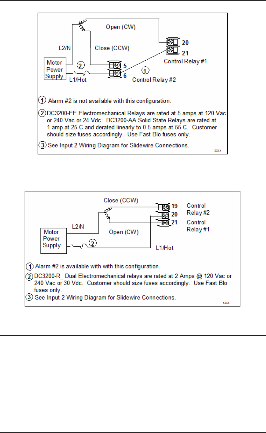
larm #2 is not available with Time Proportional Duplex or Three Position Step Control unless the Dual Relay Option is used.
Electromechanical relays are rated at 5 Amps @ 120 Vac or 240 Vac or 30 Vdc.
Customer should size fuses accordingly. Use Fast Blo fuses only.
N.C.19
20
21
22
23
24
25
26
27
Time Duplex
A
larm
Relay#2
N.C.
N.O.
6
To terminal
19 or 21
A
larm
Relay#1
Output
Relay#1
L1
L2/N
4
5
7
8
9
N.O.
N.C.
N.O.
N.C.19
20
21
22
23
24
25
26
27
Output
Relay#2
N.C.
N.O.
6
Relay Load Load
Supply
Power
2
To terminal
19 or 21
7
To terminal
4 or 6
Relay Load
To terminal
7 or 9
Relay Load
2
2
Load
Supply
Power
Load
Supply
Power
To terminal
4 or 6
Relay Load
To terminal
7 or 9
Relay Load
2
2
Load
Supply
Power
Load
Supply
Power
1
Figure 2-8 Electromechanical Relay Output
See Table 2-5 for relay terminal connections for other Output Algorithm Types.
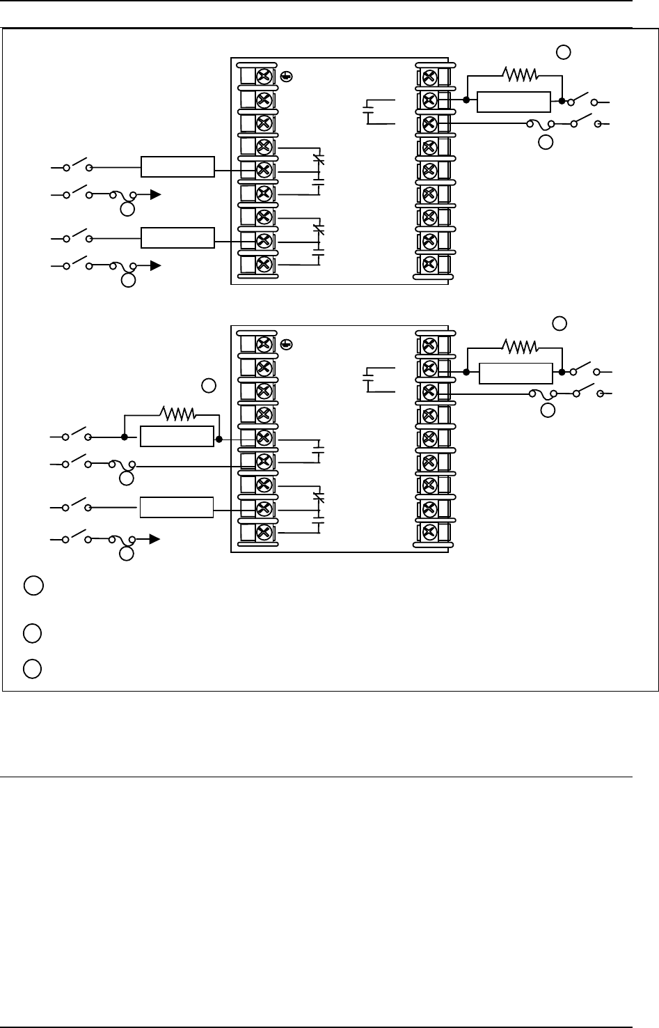
04/08 UDC3200 Universal Digital Controller Operator Manual 17
If the load current is less than the minimum rated value of 20 mA, then there may be residual voltage across both
ends of the load even if the relay is turned off. Use a dummy resistor as shown to counteract this. The total
current through the resistor and the the load must exceed 20 mA. Solid State Relays are zero-crossing type.
2
1
Solid State relays are rated at 1 Amp at 25°C and derated linearly to 0.5 Amp at 55°C. Customer should size
fuse accordingly. Use Fast Blo fuses only.
Dummy Resistor
2
A
larm
Relay#1
Output
Relay#1
L1
L2/N
4
5
7
8
9
N.O.
N.C.
N.O.
Relay Load Load
Supply
Power
Time Simplex
19
20
21
22
23
24
25
26
27
Time Duplex
A
larm
Relay#2
N.C.
N.O.
6
A
larm
Relay#1
Output
Relay#1
L1
L2/N
4
5
7
8
9
N.O.
N.C.
N.O.
19
20
21
22
23
24
25
26
27
2
Output
Relay#2
N.O.
6
Relay Load
To terminal
7 or 9
Relay Load
Load
Supply
Power
2
3
Load
Supply
Power
Load
Supply
Power
Dummy Resistor
Dummy Resistor
1
Relay Load
Electromechanical relays are rated at 5 Amps @ 120 Vac or 240 Vac or 30 Vdc.
Customer should size fuses accordingly. Use Fast Blo fuses only.
3
1
1
To terminal
4 or 6
Relay Load
To terminal
7 or 9
Relay Load
3
3
Load
Supply
Power
Load
Supply
Power
Figure 2-9 Solid State Relay Output
See Table 2-5 for relay terminal connections for other Output Algorithm Types.
18 UDC3200 Universal Digital Controller Operator Manual 04/08
A
larm
Relay#1
L1
L2/N
4
5
7
8
9
N.C.
N.O.
Time Simplex
2
3
A
larm #2 is not available with Time Proportional Duplex or Three Position Step Control unless the Dual Relay option is used.
Electromechanical relays are rated at 5 Amps @ 120 Vac or 240 Vac or 30 Vdc.
Customer should size fuses accordingly. Use Fast Blo fuses only.
19
20
21
22
23
24
25
26
27
Time Duplex
A
larm
Relay#2
N.C.
N.O.
6
A
larm
Relay#1
L1
L2/N
4
5
7
8
9
N.C.
N.O.
19
20
21
22
23
24
25
26
27
6
To terminal
7 or 9
Relay Load
3
Load
Supply
Power
–
++
–
Output #1
1
+
–
Customer Supplied
Electromechanical relay
Customer Supplied
Solid-State relay
–
++
–
Output #1
1
+
–
Customer Supplied
Electromechanical relay
Customer Supplied
Solid-State relay
–
+
+
– Output #2
1
+
–
Customer Supplied
Electromechanical relay
Customer Supplied
Solid-State relay
CAUTION Open collector outputs are internally powered at +30 Vdc. Connecting an external
power supply will damage the controller.
1
2
To terminal
4 or 6
Relay Load
To terminal
7 or 9
Relay Load
3
3
Load
Supply
Power
Load
Supply
Power
Figure 2-10 Open Collector Output
See Table 2-5 for relay terminal connections for other Output Algorithm Types.
04/08 UDC3200 Universal Digital Controller Operator Manual 19
A
larm
Relay#1
Out Relay#1
L1
L2/N
4
5
7
8
9
N.O.
N.C.
N.O.
Cool Relay Load Load
Supply
Power
Time Duplex with a Dual Relay Board
1
1
Dual Electromechanical relays are rated at 2 Amps @120 Vac or 240 Vac or 30 Vdc. Customer should size
fuses accordingly. Use Fast Blo fuses only.
N.O.19
20
21
22
23
24
25
26
27
To terminal
4 or 6
A
larm
Relay#2
N.C.
N.O.
6
Relay Load
To terminal
7 or 9
Relay Load
2
2
Load
Supply
Power
Load
Supply
Power
Heat Relay Load
Out Rela
y
#2
2 Electromechanical relays are rated at 5 Amps @120 Vac or 240 Vac or 30 Vdc.
Customer should size fuses accordingly. Use Fast Blo fuses only.
Figure 2-11 Dual Electromechanical Relay Option Output
See Table 2-5 for relay terminal connections for other Output Algorithm Types.
A
larm
Relay#1
L1
L2/N
4
5
7
8
9
N.C.
N.O.
2
When the instrument has the Current Output as shown, no Alarms are available when using the Time Proportional Duplex or
Three Position Step Control Output Algorithms, as these outputs require both available relays.
Electromechanical relays are rated at 5 Amps @120 Vac or 240 Vac or 30 Vdc
Customer should size fuses accordingly. Use Fast Blo fuses only.
19
20
21
22
23
24
25
26
27
6
To terminal
7 or 9
Relay Load
2
Load
Supply
Power
+
Controller Load
0-1000 ohms
–
Current Output
4–20 mA
1
1
To terminal
4 or 6
A
larm
Relay#2
N.C.
N.O.
Relay Load
2
Load
Supply
Power
Figure 2-12 Current Output
See Table 2-5 for relay terminal connections for other Output Algorithm Types.
20 UDC3200 Universal Digital Controller Operator Manual 04/08
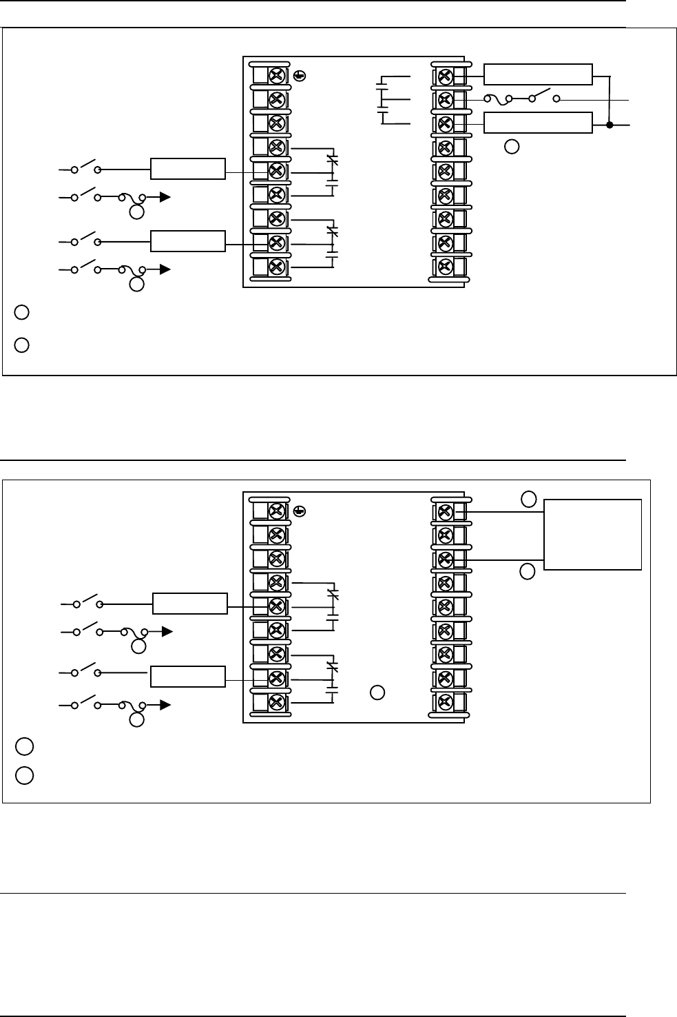
Figure 2-13 Position Proportional or Three Position Step Control
Connection, Models DC3200-EE or DC3200-AA
Figure 2-14 Position Proportional or Three Position Step Control
Connections, Model DC3200-R_
04/08 UDC3200 Universal Digital Controller Operator Manual 21
1 Do not run the communications lines in the same conduit as AC power.
D–
D+
COMMUNICATION MASTER
D+ (B) SHLD D– (A)
120 OHMS
TO OTHER
COMMUNICATION
CONTROLLERS
D+D–
120 OHMS ON LAST LEG
16 SHLD
17 D+ (B)
18 D– (A)
Connect shield
to ground at one
end only.
SHLD
2 Use shielded twisted pair cables (Belden 9271 Twinax or equivalent).
2
1
Figure 2-15 RS-422/485 Communications Option Connections
1Do not run the communications lines in the same conduit as AC
power. Correct connections may require the use of an Ethernet
cross-over cable.
COMMUNICATION MASTER
OR SWITCH
RXD+SHLD
16 RXD-
17 TXD+
18 TXD-
14 SHLD
15 RXD+
RXD- TXD+ TXD-
1
2Use Shielded twisted-pair, Category 5 (STP CAT5) Ethernet cable.
2
3Use Switch rather than Hub to maximize performance.
3
1Do not run the communications lines in the same conduit as AC
power. Correct connections may require the use of an Ethernet
cross-over cable.
COMMUNICATION MASTER
OR SWITCH
TXD–SHLD
16 RXD –
17 TXD +
18 TXD –
14 SHLD
15 RXD +
TXD+ RXD– RXD+
1
2Use Shielded twisted-pair, Category 5 (STP CAT5) Ethernet cable.
2
3Use Switch rather than Hub to maximize performance.
3
3
1Do not run the communications lines in the same conduit as AC
power. Correct connections may require the use of an Ethernet
cross-over cable.
COMMUNICATION MASTER
OR SWITCH
RXD+SHLD
16 RXD-
17 TXD+
18 TXD-
14 SHLD
15 RXD+
RXD- TXD+ TXD-
1
2Use Shielded twisted-pair, Category 5 (STP CAT5) Ethernet cable.
2
3Use Switch rather than Hub to maximize performance.
3
3
1Do not run the communications lines in the same conduit as AC
power. Correct connections may require the use of an Ethernet
cross-over cable.
COMMUNICATION MASTER
OR SWITCH
TXD–SHLD
16 RXD –
17 TXD +
18 TXD –
14 SHLD
15 RXD +
TXD+ RXD– RXD+
1
2Use Shielded twisted-pair, Category 5 (STP CAT5) Ethernet cable.
2
3Use Switch rather than Hub to maximize performance.
3
333
Figure 2-16 Ethernet Communications Option Connections
Figure 2-16 and Table 2-6 shows how to connect a UDC to a MDI Compliant Hub or
Switch utilizing a straight-through cable or for connecting a UDC to a PC utilizing a
crossover cable.
22 UDC3200 Universal Digital Controller Operator Manual 04/08
Table 2-6 Terminals for connecting a UDC to a MDI Compliant Hub or Switch
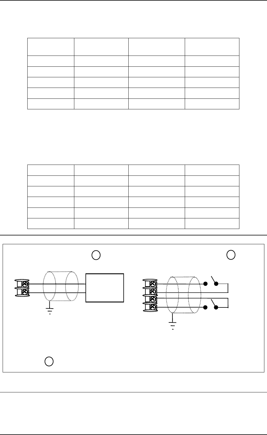
UDC Terminal UDC Signal Name RJ45 Socket Pin # Switch Signal
Name
Position 14 Shield Shield Shield
Position 15 RXD- 6 TXD-
Position 16 RXD+ 3 TXD+
Position 17 TXD- 2 RXD-
Position 18 TXD+ 1 RXD+
Table 2-7 shows how to connect a UDC directly to a PC utilizing a straight-through
cable (wiring the UDC cable this way makes the necessary cross-over connections)
Table 2-7 Terminals for connecting a UDC directly to a PC utilizing a straight-
through cable
UDC Terminal UDC Signal Name RJ45 Socket Pin # PC Signal Name
Position 14 Shield Shield Shield
Position 15 RXD- 2 TXD-
Position 16 RXD+ 1 TXD+
Position 17 TXD- 6 RXD-
Position 18 TXD+ 3 RXD+
12
13
+
_
A
uxiliary
Load
0 - 1000
Ω
Connect shield
to ground at one
end only.
1
1
A
uxiliary Output and Digital Input 2 are mutually exclusive.
Auxiliary Output
10
11
+
_
Digital
Input #1
Connect shield
to ground at one
end only.
Digital Inputs 1
12
13
+
_
Digital
Input #2
Figure 2-17 Auxiliary Output and Digital Inputs Option Connections
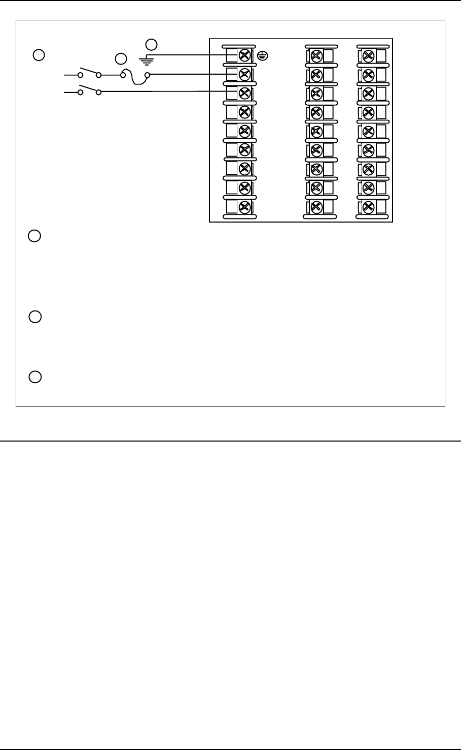
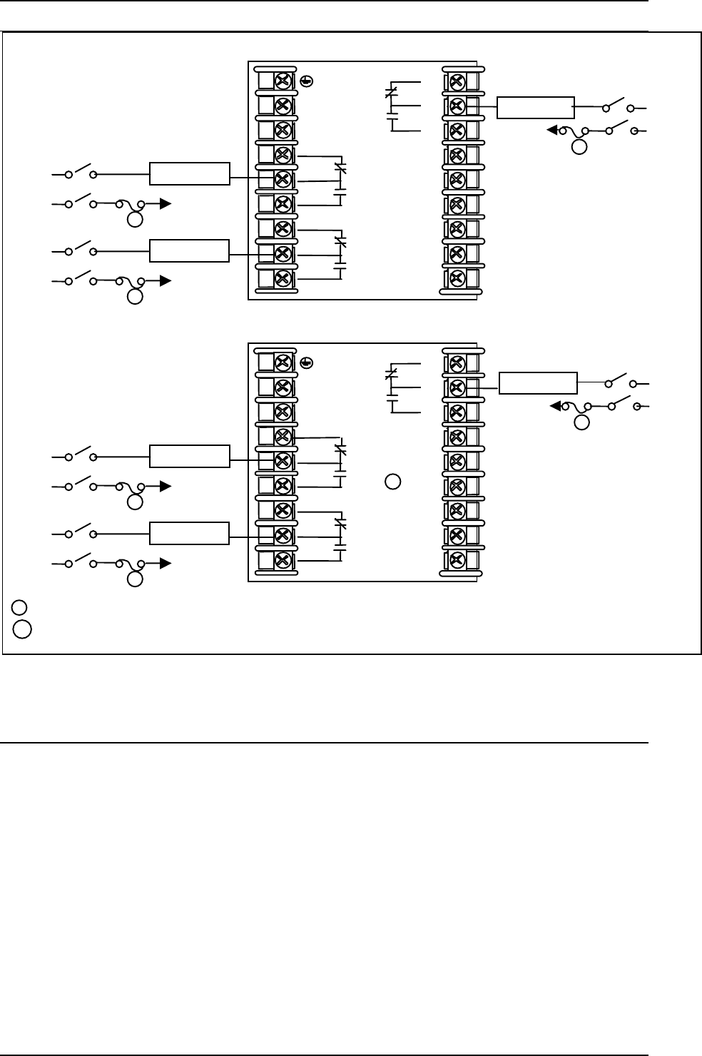
04/08 UDC3200 Universal Digital Controller Operator Manual 23
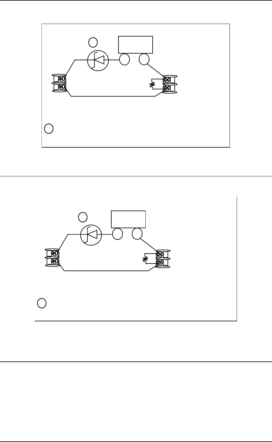
Configure:
A
2S1TY = NONE
A
2S2TY = NONE
2 Wire Transmitter
_
+
INPUT 1OUTPUT 3
250
Ω
26 +
27 -
5 +
6 -
If necessary, install a zener diode here to reduce voltage at the
transmitter. A 1N4733 will reduce the voltage at the transmitter to
approximately 25 Vdc.
1
1
Figure 2-18 Transmitter Power for 4-20 mA — 2 wire Transmitter Using Open
Collector Alarm 2 Output
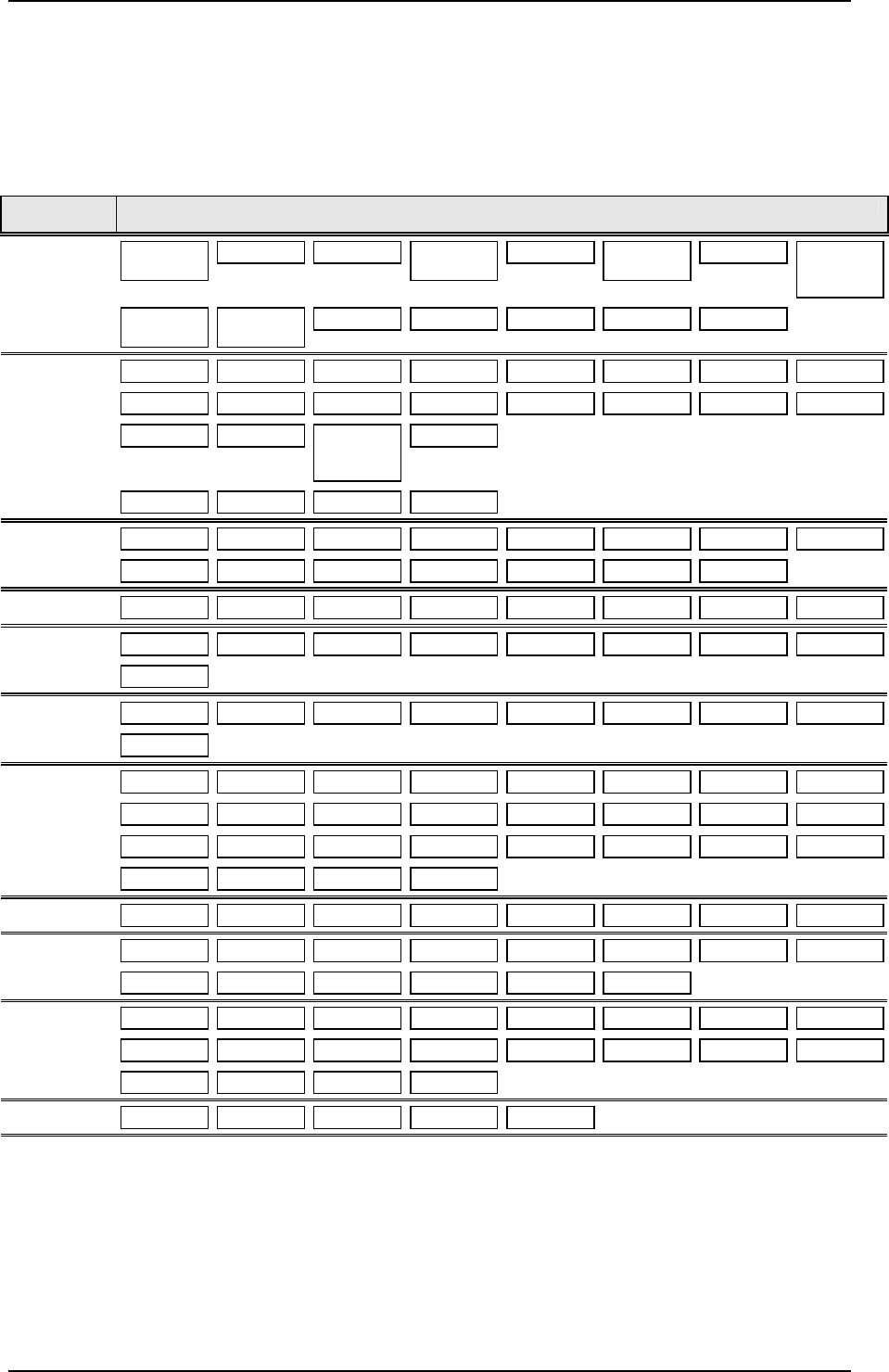
2 Wire Transmitter
_
+
INPUT 1
A
UXILIARY OUTPUT
250
Ω
26 +
27 -
12 +
13 -
Configure:
AUXOUT = OUT
A
uxiliary Output Calibration
ZEROVAL = 16383
SPANVAL = 16383
If necessary, install a zener diode here to reduce voltage at the
transmitter. A 1N4733 will reduce the voltage at the transmitter to
approximately 25 Vdc.
1
1
Figure 2-19 Transmitter Power for 4-20 mA — 2 Wire Transmitter
Using Auxiliary Output
24 UDC3200 Universal Digital Controller Operator Manual 04/08
3 Configuration
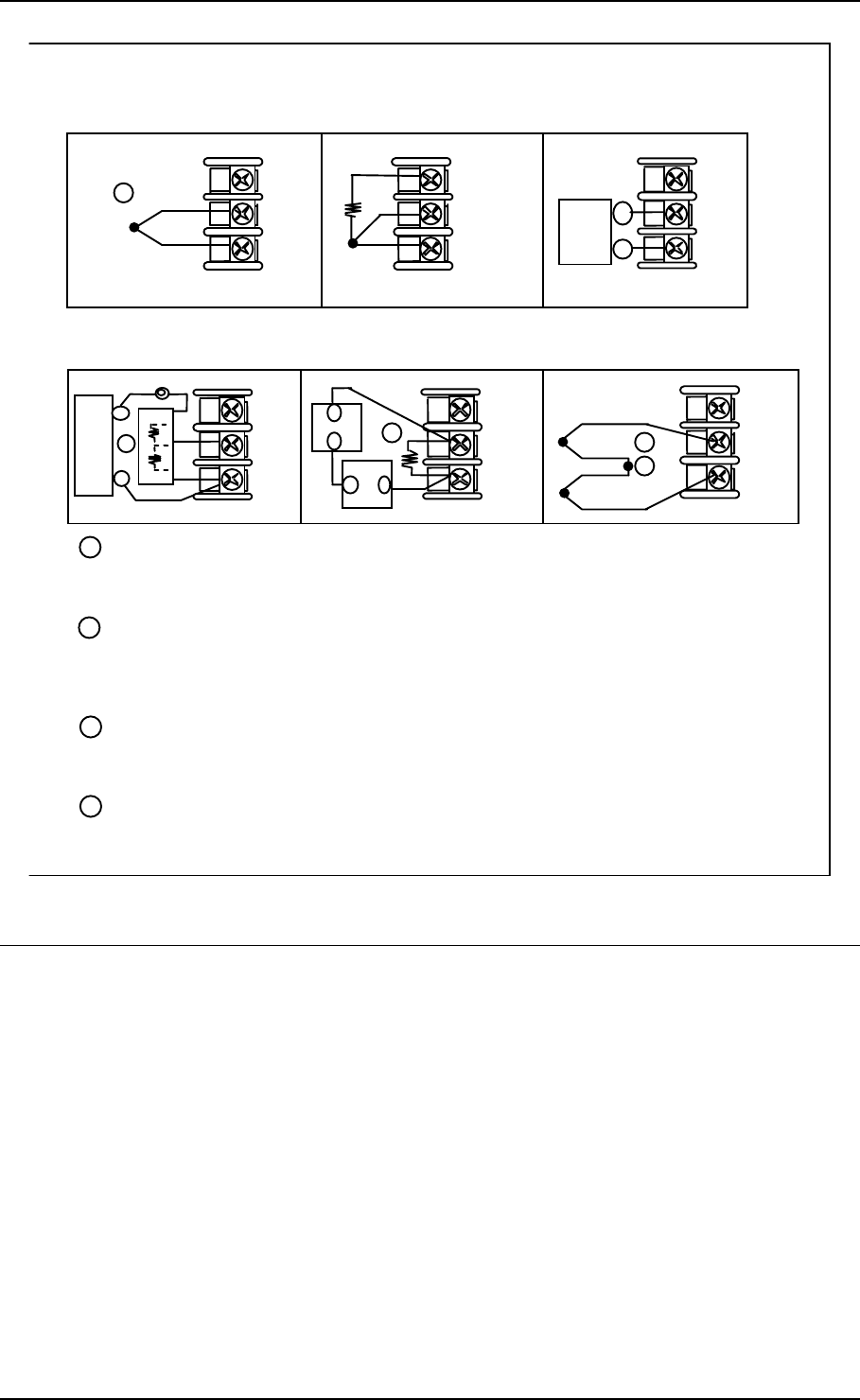
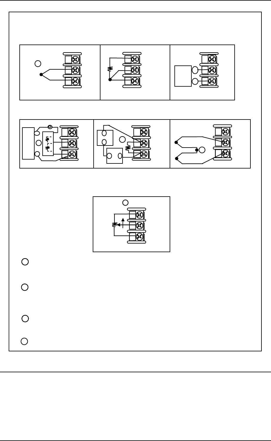
3.1 Configuration Prompt Hierarchy
Set Up
Group
Function Prompts
TUNING PROP BD or
GAIN GAINVALn RATE MIN RSET MIN or
RSET RPM MAN RSET PROPBD2 or
GAIN 2 RATE2MIN RSET2MIN
or
RSET2RPM
CYC SEC or
CYC SX3 CYC2 SEC or
CYC2 SX3 SECURITY LOCKOUT AUTO MAN SP SEL RUN HOLD
SPRAMP SP RAMP TIME MIN FINAL SP SP RATE EU/HR UP EU/HR DN EUHRUP2 EUHRDN2
SP PROG STRT SEG END SEG RAMPUNIT RECYCLES SOAK DEV PROG END STATE
KEYRESET HOTSTART SEGxRAMP
or
SEGxRATE
SEGx SP* * x = 1 to 12. Program concludes after segment 12
ACCUTUNE FUZZY ACCUTUNE DUPLEX AT ERROR
ALGORTHM CONT ALG TIMER PERIOD START LOW DISP INP ALG1 MATH K CALC HI
CALC LO ALG1 INA ALG1 INB ALG1 INC PCT CO PCT H2 ALG1BIAS
OUT ALG OUT ALG RLYSTATE RLY TYPE CUR OUT LOW VAL HIGH VAL CO RANGE MOTOR TI
INPUT1 IN1 TYPE XMITTER1 IN1 HIGH IN1 LOW RATIO 1 BIAS IN1 FILTER 1 BURNOUT1
EMISSIV1
INPUT2 IN2 TYPE XMITTER2 IN2 HIGH IN2 LOW RATIO 2 BIAS IN2 FILTER 2 BURNOUT2
EMISSIV2
CONTRL PV SOURC PID SETS SW VALUE LSP'S RSP SRC AUTOBIAS SP TRACK PWR MODE
PWR OUT SP HiLIM SP LoLIM ACTION OUT RATE PCT/M UP PCT/M DN OUTHiLIM
OUTLoLIM I Hi LIM I Lo LIM DROPOFF DEADBAND OUT HYST FAILSAFE FAILMODE
MAN OUT AUTO OUT PBorGAIN MINorRPM
OPTIONS AUX OUT LOW VAL HIGH VAL CORANGE DIG1 INP DIG1 COM DIG2 INP DIG2 COM
COM Com ADDR ComSTATE IR ENABLE BAUD TX DELAY WSFLOAT SHEDENAB SHEDTIME
SHEDMODE SHEDSP UNITS CSP RATO CSP BIAS LOOPBACK
ALARMS A1S1TYPE A1S1 VAL A1S1 H L A1S1 EV A1S2 TYPE A1S2 VAL A1S2 H L A1S2 EV
A2S1TYPE A2S1 VAL A2S1 H L A2S1 EV A2S2TYPE A2S2 VAL A2S2 H L A2S2 EV
AL HYST ALM OUT1 BLOCK DIAGNOST
DISPLAY DECIMAL TEMPUNIT PWR FREQ RATIO 2 LANGUAGE
CALIB USED FOR FIELD CALIBRATION
04/08 UDC3200 Universal Digital Controller Operator Manual 25
3.2 Configuration Procedure
Introduction
Each of the Set Up groups and their functions are pre-configured at the factory. If you
want to change any of these selections or values, follow the procedure in Table 3-1.
This procedure tells you the keys to press to get to any Set Up group and any
associated Function parameter prompt.
Procedure
ATTENTION
The prompting scrolls at a rate of 2/3 seconds when the SET UP or FUNCTION key is held in.
Also, or keys will move group prompts forward or backward at a rate twice as fast.
Table 3-1 Configuration Procedure
Step Operation Press Result
1 Enter Set Up
Mode SetupSetup
Upper Display = SETUP
Lower Display = TUNING (This is the first Set Up Group title)
2 Select any Set
Up Group SetupSetup
Sequentially displays the other Set Up group titles. You can also
use the or keys to scan the Set Up groups in both
directions. Stop at the Set Up group title that describes the group of
parameters you want to configure. Then proceed to the next step.
3 Select a Function
Parameter FunctionFunctionFunction
Upper Display = the current value or selection for the first function
prompt of the selected Set Up group.
Lower Display = the first Function prompt within that Set Up group.
Sequentially displays the other function prompts of the Set Up
group you have selected. Stop at the function prompt that you want
to change, then proceed to the next step.
4 Change the
Value or
Selection
or Increments or decrements the value or selection that appears for
the selected function prompt. If you change the value or selection
of a parameter while in Set Up mode but then decide not to enter it,
press the MAN/AUTO key once. This will recall the original
configuration. This “recall” procedure does not work for a Field
Calibration process. Field Calibration is a one-way operation.
5 Enter the Value
or Selection FunctionFunctionFunction
Enters value or selection made into memory after another key is
pressed.
6 Exit Configuration Lower
Display
Lower
Display
Lower
Display
Exits configuration mode and returns controller to the same state it
was in immediately preceding entry into the Set Up mode. It stores
any changes you have made.
If you do not press any keys for 30 seconds, the controller times out
and reverts to the mode and associated display used prior to entry
into Set Up mode.

26 UDC3200 Universal Digital Controller Operator Manual 04/08
3.3 Tuning Set Up Group
Function
Prompt
Lower Display
Selections or
Range of Setting
Upper Display
Parameter Definition
PROP BD
or
GAIN
0.1 to 9999 %
or
0.001 to 1000
PROPORTIONAL BAND (simplex) is the percent of the range of
the measured variable for which a proportional controller will
produce a 100 % change in its output.
GAIN is the ratio of output change (%) over the measured variable
change (%) that caused it.
G = 100 / %PB where PB is the proportional band(in %)
If the PB is 20 %, then the Gain is 5. And, at those settings, a 3 %
change in the error signal (SP-PV) will result in a 15 % change in
the controller's output due to proportional action. If the Gain is 2,
then the PB is 50 %.
Also defined as "HEAT" Gain on Duplex models for variations of
Heat/Cool applications.
The selection of Proportional Band or Gain is made in the
CONTROL parameter group under prompt PBorGAIN.
RATE MIN 0.00 to 10.00
minutes
RATE action, in minutes, affects the controller's output whenever
the deviation is changing; and affects it more when the deviation is
changing faster.
RSET MIN
or
RSET RPM
0.02 to 50.00 RSET MIN = Reset in Minutes per Repeat
RSET RPM = Reset in Repeats per Minute
RESET (or Integral Time) adjusts the controller's output in
accordance with both the size of the deviation (SP–PV) and the
time that it lasts. The amount of the corrective action depends on
the value of Gain. The Reset adjustment is measured as how many
times proportional action is repeated per minute or how many
minutes before one repeat of the proportional action occurs.
Used with control algorithm PID-A or PID-B.
Also defined as "HEAT" Reset on Duplex models for variations of
Heat/Cool applications.
ATTENTION The selection of whether Minutes per Repeat or
Repeats per Minute is used is made in the CONTROL parameters
group under the prompt MINorRPM.
MAN RSET –100 to +100
(in % output) MANUAL RESET is only applicable if you use control algorithm PD
WITH MANUAL RESET in the Algorithm Set Up group. Because a
proportional controller will not necessarily line out at setpoint, there
will be a deviation (offset) from setpoint. This eliminates the offset
and lets the PV line out at setpoint.
ATTENTION Bias is shown on the lower display.
PROPBD2
or
GAIN 2
0.1 to 9999 %
or
0.001 to 1000
PROPORTIONAL BAND 2 or GAIN 2, RATE 2, and RESET 2
parameters are the same as previously described for “Heat” except
that they refer to the cool zone tuning constants on duplex models
or the second set of PID constants, whichever is pertinent.
RATE2MIN 0.00 to 10.00
minutes
This is the same as above except that it applies to Duplex models
for the "COOL" zone of Heat/Cool applications or for the second
set of PID constants.
04/08 UDC3200 Universal Digital Controller Operator Manual 27
Function
Prompt
Lower Display
Selections or
Range of Setting
Upper Display
Parameter Definition
RSET2MIN
RSET2RPM 0.02 to 50.00 These are the same as above except that they apply to Duplex
models for the "COOL" zone of Heat/Cool applications or for the
second set of PID constants.
CYC SEC
or
CYC SX3
1 to 120 CYCLE TIME (HEAT) determines the length of one time
proportional output relay cycle. Defined as "HEAT" cycle time for
Heat/Cool applications.
CYC SEC—Electromechanical relays
CYC SX3—Solid state relays
ATTENTION Cycle times are in either second or 1/3-second
increments depending upon the configuration of RLY TYPE in the
Output Algorithm Set Up group.
CYC2 SEC
or
CYC2 SX3
1 to 120 CYCLE TIME 2 (COOL) is the same as above except it applies to
Duplex models as the cycle time in the "COOL" zone of Heat/Cool
applications or for the second set of PID constants.
CYC2 SEC—Electromechanical relays
CYC2 SX3—Solid state relays
ATTENTION Cycle times are in either second or 1/3-second
increments depending upon the configuration of RLY TYPE in the
Output Algorithm Set Up group.
SECURITY 0 to 9999 SECURITY CODE—The level of keyboard lockout may be
changed in the Set Up mode. Knowledge of a security code may
be required to change from one level to another. This configuration
should be copied and kept in a secure location.
NOTE: The Security Code is for keyboard entry only and is not
available via communications.
ATTENTION Can only be changed if LOCKOUT selection is
NONE.
LOCKOUT LOCKOUT applies to one of the functional groups: Configuration,
Calibration, Tuning, Accutune. DO NOT CONFIGURE UNTIL ALL
CONFIGURATION IS COMPLETE.
NONE NONE—No lockout; all groups are read/write.
CALIB CALIB—All groups are available for read/write except for the
Calibration and Keyboard Lockout groups.
+ CONF + CONF—Tuning, SP Ramp, and Accutune groups are read/write.
All other groups are read only. Calibration and Keyboard Lockout
groups are not available.
+ VIEW + VIEW—Tuning and Setpoint Ramp parameters are read/write.
No other parameters are viewable.
MAX MAX—Tuning and Setpoint Ramp parameters are available for
read only. No other parameters are viewable.
28 UDC3200 Universal Digital Controller Operator Manual 04/08
Function
Prompt
Lower Display
Selections or
Range of Setting
Upper Display
Parameter Definition
AUTO MAN
DISABLE
ENABLE
MANUAL/AUTO KEY LOCKOUT—Allows you to disable the
Manual/Auto key
DISABLE
ENABLE
ATTENTION Can only be viewed if LOCKOUT is configured for
NONE.
RUN HOLD
DISABLE
ENABLE
RUN/HOLD KEY LOCKOUT—Allows you to disable the Run/Hold
key, for either SP Ramp or SP Program. The Run/Hold key is
never disabled when used to acknowledge a latched alarm 1
DISABLE
ENABLE
ATTENTION Can only be viewed if LOCKOUT is configured for
NONE.
SP SEL
DISABLE
ENABLE
SETPOINT SELECT KEY LOCKOUT—Allows you to disable the
Setpoint Select key
DISABLE
ENABLE
ATTENTION Can only be viewed if LOCKOUT is configured for
NONE.
04/08 UDC3200 Universal Digital Controller Operator Manual 29
3.4 SP Ramp Set Up Group
Function
Prompt
Lower Display
Selections or
Range of Setting
Upper Display
Parameter Definition
SINGLE SETPOINT RAMP—Make a selection to enable or disable
the setpoint ramp function. Make sure you configure a ramp time
and a final setpoint value.
SP Programming must be disabled.
SP RAMP
SP Program
must be
disabled for SP
Ramp prompts
to appear DISABLE
ENABLE
DISABLE SETPOINT RAMP—Disables the setpoint ramp option.
ENABLE SETPOINT RAMP—Allows the single setpoint ramp
prompts to be shown.
TIME MIN 0 to 255 minutes SETPOINT RAMP TIME—Enter the number of minutes desired to
reach the final setpoint. A ramp time of “0” implies an immediate
change of setpoint.
FINAL SP Within setpoint
limits SETPOINT RAMP FINAL SETPOINT—Enter the value desired for
the final setpoint. The controller will operate at the setpoint set here
when ramp is ended.
ATTENTION If the ramp is on HOLD, the held setpoint can be
changed by the ▲ and ▼ keys. However, the ramp time remaining
and original ramp rate is not changed. Therefore, when returning to
RUN mode, the setpoint will ramp at the same rate as previous to
the local setpoint change and will stop if the final setpoint is
reached before the time expires. If the time expires before the final
setpoint is reached, it will jump to the final setpoint.
ATTENTION SP RAMP and SP RATE will cause the SP portion
of Accutune to abort. PV Tune will continue to function normally.
Ramp is placed into HOLD while tuning (TUNE configuration).
HOTSTART DISABLE
ENABLE DISABLE—LSP1 is used as the initial ramp setpoint.
ENABLE—Current PV value is used as the initial ramp setpoint.
SP RATE
DISABLE
ENABLE
SETPOINT RATE—Lets you configure a specific rate of change for
any local setpoint change.
DISABLE SETPOINT RATE—Disables the setpoint rate option.
ENABLE SETPOINT RATE—Allows the SP rate feature.
SP Rate operates only when both SP Ramp and SP Programing
are in HOLD mode or when both SP Ramp and SP Programming
are disabled.
EU/HR UP 0 to 9999 in
engineering units
per hour
RATE UP—Rate up value. When making a setpoint change, this is
the rate at which the controller will change from the original
setpoint up to the new one. The ramping (current) setpoint can be
viewed as SPn in the lower display.
Entering a 0 will imply an immediate step change in Setpoint (i.e.,
no rate applies).

30 UDC3200 Universal Digital Controller Operator Manual 04/08
Function
Prompt
Lower Display
Selections or
Range of Setting
Upper Display
Parameter Definition
EU/HR DN 0 to 9999 in
engineering units
per hour
RATE DOWN—Rate down value. When making a setpoint change,
this is the rate at which the controller will change from the original
setpoint down to the new one. The ramping (current) setpoint can
be viewed as SPn in the lower display.
Entering a 0 will imply an immediate step change in Setpoint (i.e.,
no rate applies).
SP PROG
(optional
feature)
DISABLE
ENABLE
SETPOINT RAMP/SOAK PROGRAM—Available only with
controllers that contain this option.
SP RAMP must be disabled.
DISABLE—Disables setpoint programming.
ENABLE—Enables setpoint programming.
SP Ramp must be disabled for SP Program prompts to appear. If
SP Rate is enabled, it does not operate while an SP Program is
running
STRT SEG 1 to 11 Start Segment Number
END SEG 2 to 12 even
numbers End Segment Number, always end in a soak segment (2, 4, ... 12)
RAMPUNIT
TIME
EU/MIN
EU/HR
RAMPUNIT—Engineering Units for Ramp Segments
TIME in hours: minutes
RATE in Enineering units per minute
RATE in Enineering units per hour
RECYCLES 0 to 99 recycles Number of Program Recycles
SOAK DEV 0 to 99
Guaranteed Soak Deviation Value
The number selected will be the PV value (in engineering units)
above or below the setpoint outside of which the timer halts.
PROG END
LASTSP
F SAFE
Program Termination State
Hold at last setpoint in the program
Manual mode/Failsafe output
STATE DISABLE
HOLD Program State at Program End
KEYRESET DISABLE
ToBEGIN
RERUN
Reset/Rerun SP Program
HOTSTART DISABLE
ENABLE Hot Start
SEG1RAMP or
SEG1RATE 0-99 hours.0-59
minutes
Engineering
units/minute or
Engineering
units/hour
Segment #1 Ramp Time or
Segment #1 Ramp Rate
Select TIME, EU/MIN, or EU/HR at prompt RAMPUNIT. All
ramps will use the same selection.
SEG2 SP Within the Setpoint
limits Segment #2 Soak Setpoint Value

04/08 UDC3200 Universal Digital Controller Operator Manual 31
Function
Prompt
Lower Display
Selections or
Range of Setting
Upper Display
Parameter Definition
SEG2TIME 0-99 hours.0-59
minutes Segment #2 Soak Duration
SEG3RAMP or
SEG3RATE
SEG4 SP
SEG4TIME
SEG5RAMP or
SEG5RATE
SEG6 SP
SEG6TIME
SEG7RAMP or
SEG7RATE
SEG8 SP
SEG8TIME
SEG9RAMP or
SEG9RATE
SG10 SP
SG10TIME
SG11RAMP or
SG11RATE
SG12 SP
SG12TIME
Selections are
same as above. Same as above

32 UDC3200 Universal Digital Controller Operator Manual 04/08
3.5 Accutune Set Up Group
Function
Prompt
Lower Display
Selections or
Range of Setting
Upper Display
Parameter Definition
FUZZY FUZZY OVERSHOOT SUPPRESSION—Can be enabled or
disabled independently of whether Demand Tuning or SP Tuning is
enabled or disabled.
DISABLE
ENABLE
DISABLE—Disables Fuzzy Overshoot Suppression.
ENABLE—The instrument uses Fuzzy Logic to suppress or
minimize any overshoot that may occur when PV approaches SP. It
will not recalculate any new tuning parameters.
ACCUTUNE ACCUTUNE III
DISABLE
TUNE
DISABLE —Disables the Accutune function.
DEMAND TUNING—If TUNE is selected, and tuning is initiated
through the operator interface or digital input (if configured), the
algorithm calculates new tuning parameters and enters them into
the tuning group. This tuning requires no process knowledge and
does not require line out for initialization.
DUPLEX ACCUTUNING III – These prompts only appear when a
duplex output type has been configured.
MANUAL MANUAL – Tune manually using LSP 1 and LSP 2 values. LSP 1
is used to derive tuning parameters associated with HEAT (output
> 50 %). LSP 2 is used to derive tuning parameters associated
with COOL (output < 50 %).
AUTO AUTOMATIC – Tuning is performed automatically on both HEAT
and COOL sequentially. LSP 1 is used for HEAT tuning and LSP 2
is used for COOL tuning. To initiate tuning, either LSP 1 or LSP 2
must be in use.
DUPLEX
This prompt
only appears
when a Duplex
Control
Algorithm has
been
configured
DISABLE DISABLE – The current SetPoint is used to derive a single set of
blended tuning parameters. This tuning is performed over the
range of the output limits similar to Simplex Tuning. The Tuning
Parameters derived are placed into both the HEAT and COOL tune
sets (PID 1 and PID 2).
AT ERROR
(Read Only)
ACCUTUNE ERROR STATUS—When an error is detected in the
Accutune process, an error prompt will appear.
NONE NONE—No errors occurred during last Accutune procedure.
RUNNING RUNNING—An Accutune process is still active checking process
gain, even though “T” is not lit. It does not affect keyboard
operation.
ABORT CURRENT ACCUTUNE PROCESS ABORTED—Caused by one
of the following conditions: changing to manual mode, digital input
detected, in heat region of output but a cool output was calculated,
or vice versa.
SP2 SP2—LSP2 not configured or a Setpoint other than LSP1 or LSP2
is in use.
04/08 UDC3200 Universal Digital Controller Operator Manual 33
3.6 Algorithm Set Up Group
Function
Prompt
Lower Display
Selections or
Range of Setting
Upper Display
Parameter Definition
CONT ALG The CONTROL ALGORITHM lets you select the type of control
that is best for your process.
ON-OFF ON/OFF is the simplest control type. The output can be either ON
(100 %) or OFF (0 %). The Process Variable (PV) is compared with
the setpoint (SP) to determine the sign of the error (ERROR = PV–
SP). The ON/OFF algorithm operates on the sign of the error
signal.
In Direct Acting Control, when the error signal is positive, the
output is 100 %; and when the error signal is negative, the output is
0 %. If the control action is reverse, the opposite is true. An
adjustable overlap (Hysteresis Band) is provided between the on
and off states.
ATTENTION Other prompts affected: OUT HYST
DUPLEX ON/OFF is an extension of this algorithm when the output
is configured for a Duplex control algorithm. It allows the operation
of a second ON/OFF output. There is a deadband between the
operating ranges of the two inputs and an adjustable overlap
(hysteresis) of the on and off states of each output. Both Deadband
and Hysteresis are separately adjustable. With no relay action the
controller will read 50 %.
ATTENTION Other prompts affected: OUT HYST and
DEADBAND
PID A
ATTENTION
PID A should not
be used for
Proportional only
action; i.e., no
integral (reset)
action. Instead,
use PD+MR with
rate set to 0.
PID A is normally used for three-mode control. This means that the
output can be adjusted somewhere between 100 % and 0 %. It
applies all three control actions—Proportional (P), Integral (I), and
Derivative (D)—to the error signal.
Proportional (Gain)—Regulates the controller’s output in
proportion to the error signal (the difference between Process
Variable and Setpoint).
Integral (Reset)—Regulates the controller’s output to the size of
the error and the time the error has existed. (The amount of
corrective action depends on the value of proportional Gain.)
Derivative (Rate)—Regulates the controller’s output in proportion
to the rate of change of the error. (The amount of corrective action
depends on the value of proportional Gain.)
PID B PID B—Unlike the PID A equation, the controller gives only an
integral response to a setpoint change, with no effect on the output
due to the gain or rate action, and it gives full response to PV
changes. Otherwise controller action is as described for the PID A
equation. See note on PID A.
34 UDC3200 Universal Digital Controller Operator Manual 04/08
Function
Prompt
Lower Display
Selections or
Range of Setting
Upper Display
Parameter Definition
CONT ALG
(continued) PD+MR PD WITH MANUAL RESET is used whenever integral action is not
wanted for automatic control. The equation is computed with no
integral contribution. The MANUAL RESET, which is operator
adjustable, is then added to the present output to form the
controller output.
Switching between manual and automatic mode will be bumpless.
If you select PD with Manual Reset you can also configure the
following variations:
• PD (Two Mode) control,
• P (Single Mode) control.
Set Rate (D) to 0.
ATTENTION Other prompts affected: MAN RSET in the Tuning
Set Up group
3PSTEP THREE POSITION STEP—The Three Position Step Control
algorithm allows the control of a valve (or other actuator) with an
electric motor driven by two controller relay outputs; one to move
the motor upscale, the other downscale without a feedback
slidewire linked to the motor shaft. The deadband is adjustable in
the same manner as the duplex output algorithm.
The Three Position Step Control algorithm provides an output
display (OUT) which is an estimated motor position, since the
motor is not using any slidewire feedback. Although this output
indication is only an approximation, it is “corrected” each time the
controller drives the motor to one of its stops (0 % or 100 %). It
avoids all the control problems associated with the feedback
slidewire (wear, dirt, noise). When operating in this algorithm, the
estimated OUT display is shown to the nearest percent (i.e., no
decimal). This selection forces the Output Algorithm selection to
“POSITON”.
Refer to the Operation section for motor position displays.
As a customer configurable option, when a second input board is
installed, the motor slidewire can be connected to the controller.
The actual slidewire position is then shown on the lower display as
POS. This value is used for display only. It is NOT used in the
Three Position Step algorithm. To configure this option, set Input
2 actuation to SLIDEW and then calibrate Input 2.
ATTENTION Other prompts affected: DEADBAND
TIMER DISABLE
ENABLE
TIMER allows you to enable or disable the timer option.
The timer option allows you to configure a timeout period and to
select timer start by either the keyboard (RUN/HOLD key) or Alarm
2. A digital input can also be configured to start the timer.
When the timer is enabled, it has exclusive control of the alarm 1
relay; any previous alarm configuration is ignored. At timeout, the
timer is ready to be re-activated by whatever action has been
configured. Alarm 1 is activated at the end of the timeout period.

04/08 UDC3200 Universal Digital Controller Operator Manual 35
Function
Prompt
Lower Display
Selections or
Range of Setting
Upper Display
Parameter Definition
PERIOD 0:00 to 99:59 PERIOD allows you to configure the length of timeout period (from
0 to 99 hours: 59 minutes).
START KEY
ALARM 2 START allows you to select whether the timer starts with the
keyboard (Run/Hold key) or Alarm 2.
LOW DISP TI REM
E TIME LOW DISP allows you to select whether time remaining (TI REM)
or elapsed time (E TIME) is displayed for the timer option.
The time is shown on the lower display in HH:MM format along with
a rotating “clock” character.
• If the “clock” rotation is clockwise, elapsed time is indicated.
• If the “clock” rotation is counterclockwise, time remaining is
indicated.
INPUT MATH ALGORITHMS—Controllers with two inputs are provided with one input algorithm. Unless
otherwise noted, these selections are provided only as part of the Math Options package. Each algorithm
can be configured to provide a derived (calculated) PV or a derived Remote Setpoint. Up to three inputs
may be applied to the calculation. See Inputs A, B, and C for definitions per equation.
All algorithms operate in engineering units except Feedforward (F FWRD) which operates in percent of
output units.
ATTENTION When the Input C configuration is set to NONE, the value of Input C used in the functions
is automatically set to 1.0, except for the Summer algorithm, where it is set to 0.0.
INP ALG1 INPUT ALGORITHM 1 has the following selections from which to
choose:
NONE NONE—No algorithm configured
W AVG
(See Note 2)
(Standard feature
on controllers with
two analog inputs)
WEIGHTED AVERAGE—When you configure for Weighted
Average, the controller will compute a PV or SP for the control
algorithm from the following equation:
Alg1 = [(InpA x Ratio A + Bias A) + (K x InpB x Ratio B + Bias B)] / (1 + K)] + Alg1Bias
F FWRD
(Standard feature
on controllers with
two analog inputs)
FEEDFORWARD SUMMER—Feedforward uses Input A, following
a Ratio and Bias calculation as a value summed directly with the
PID computed output value and sent, as an output value, to the
final control element.
This algorithm will only function in automatic mode and is not used
for Three Position Step Control applications.
The following formula applies:
Controller Output = PID Output + (Input A x Ratio A + Bias A ) x (100 / Input A Range)
FFWDMu
(Standard feature
on controllers with
two analog inputs)
FEEDFORWARD MULTIPLIER—Feedforward uses Input A,
following a Ratio and Bias calculation as a value multiplied directly
with the PID computed output value and sent, as an output value,
to the final control element.
This algorithm will only function in automatic mode and cannot be
used for Three Position Step Control applications.
The following formula applies:
Controller Output = PID Output x (Input A x Ratio A + Bias A ) / Input A Range
36 UDC3200 Universal Digital Controller Operator Manual 04/08
Function
Prompt
Lower Display
Selections or
Range of Setting
Upper Display
Parameter Definition
SUMMER
(See Note 2) SUMMER WITH RATIO AND BIAS—The following formula
applies:
Alg1=(InpAxRatioA+BiasA)+(InpBxRatioB+BiasB)+(InpCxRatioC+BiasC)+Alg1Bias
HI SEL
(See Note 2) INPUT HIGH SELECT WITH RATIO AND BIAS—This selection
specifies the PV or SP as the higher of Input 1 or Input 2. The
following formula applies:
Alg1 = higher of (Input A x Ratio A + Bias A) or (Input B x Ratio B + Bias B)
LO SEL
(See Note 2) INPUT LOW SELECT WITH RATIO AND BIAS—This selection
specifies the PV or SP as the lower of Input 1 or Input 2. The
following formula applies:
Alg1 = lower of (Input A x Ratio A + Bias A) or (Input B x Ratio B + Bias B)
√MuDIV
(See Note 1) MULTIPLIER DIVIDER WITH SQUARE ROOT—The following
formula applies:
Alg1=K*SqRt{(InpAxRatioA+BiasA)x(InpCxRatioC+BiasC)/(InpB*RatioB+BiasB)}
x (CalcHi-CalcLo)+Alg1Bias
√MULT
(See Note 1) MULTIPLIER WITH SQUARE ROOT—The following formula
applies:
Alg1 =K x Sq.Rt.{(InputA x Ratio A + Bias A) x (InputB x Ratio B + Bias B) x (InputC x Ratio C + Bias C)}
x (Calc Hi – Calc Lo) + Alg1Bias
MuDIV
(See Note 1) MULTIPLIER DIVIDER—The following formula applies:
Alg1 = K x [{(Input A x Ratio A + Bias A) x (Input C x Ratio C + Bias C)} / (Input B x Ratio B + Bias B)]
x (Calc Hi – Calc Lo) + Alg1Bias
MULT
(See Note 1) MULTIPLIER—The following formula applies:
Alg1 = K x [(Input A x Ratio A + Bias A) x (Input C x Ratio C + Bias C) x (Input B x Ratio B + Bias B)]
x (Calc Hi – Calc Lo) + Alg1Bias
CARB A CARBON POTENTIAL A—Make this selection if you have a
Cambridge or Marathon monitor type Zirconium Oxide sensor. See
Note 3.
CARB B CARBON POTENTIAL B—Make this selection if you have a
Corning type Zirconium Oxide sensor. This algorithm requires a
temperature range within the region of 1380 to 2000°F. See Note
3.
CARB C CARBON POTENTIAL C—Make this selection if you have an
A.A.C.C. type Zirconium Oxide sensor. This algorithm requires a
temperature range within the region of 1380 °F to 2000 °F. See
Note 3.
CARB D CARBON POTENTIAL D—Make this selection if you have a
Barber Coleman, MacDhui, or Bricesco type Zirconium Oxide
sensor. This algorithm requires a temperature range within the
region of 1380 to 2000°F. See Note 3.

04/08 UDC3200 Universal Digital Controller Operator Manual 37
Function
Prompt
Lower Display
Selections or
Range of Setting
Upper Display
Parameter Definition
FCC CARBON POTENTIAL FCC—Make this selection if you have a
Furnace Controls Corp Accucarb type Zirconium Oxide sensor.
This algorithm requires a temperature range within the region of
1380 °F to 2000 °F. See Note 3.
DEW PT DEWPOINT OF CARBONIZING ATMOSPHERE—Use this
selection if you are using any Zirconium Oxide Carbon Probe and
you want to measure the atmosphere in terms of Dewpoint. The
range is –50 °F to 100 °F or –48 °C to 38 °C. This algorithm
requires a temperature range within the region of 1000 °F to 2200
°F and a minimum carbon probe value of 800 millivolts.
OXYGEN PERCENT OXYGEN RANGE—Make this selection if you are using
a Zirconium Oxide Oxygen Probe to measure Percent of Oxygen in
a range of 0 to 40 % O2. This algorithm requires a temperature
range within the region of 800 °F to 3000 °F.
ATTENTION The Carbon and Dewpoint selections will automatically set the first input actuation to
Carbon. The Oxygen selection will automatically set the first input actuation to Oxygen. Input 2 can be
any input actuation, but it is normally a type K, R or S thermocouple input, depending upon the probe type
selected. All calculations are performed by the Controller with Percent Carbon shown as the PV display.
The actual value of each analog input may be viewed on the lower display. For all Carbon Types, if the
value of Percent Carbon falls below 0.1% - such as can happen when the Carbon Probe voltage output
falls below 900 mVdc – then the Controller will continue to update the PV display, but the accuracy is
unspecified. Likewise, if the measured temperature falls outside of the specified ranges as noted above
for the Carbon, Oxygen and Dewpoint input types, then the Controller will continue to update the PV
display, but the accuracy is unspecified. For the Dewpoint algorithm, if the Carbon Sensor voltage falls
below 800 mVdc, then the Dew Point is calculated as if the sensor voltage was at 800 mVdc.
MATH K 0.001 to 1000
floating WEIGHTED AVERAGE RATIO OR MASS FLOW ORIFICE
CONSTANT (K) FOR MATH SELECTIONS—Only applicable for
algorithms W AVG or General Math selections √MuDIV, √MULT,
MuDIV, or MULT.
CALC HI –999. To 9999.
Floating
(in engineering
units)
CALCULATED VARIABLE HIGH SCALING FACTOR FOR
INPUT ALGORITHM 1—Used only when either Summer, Input
Hi/Lo, or one of the General Math functions was selected as the
Input Algorithm. See Note 2.
CALC LO –999. To 9999.
Floating
(in engineering
units)
CALCULATED VARIABLE LOW SCALING FACTOR FOR INPUT
ALGORITHM 1—Used only when either Summer, Input Hi/Lo, or
one of the General Math functions was selected as the Input
Algorithm. See Note 2.
ALG1 INA
INPUT 1
INPUT 2
OUTPUT
ALGORITHM 1, INPUT A SELECTION will represent one of the
available selections.
Input 1
Input 2
Output – Should not be used for Three Position Step Control
applications)

38 UDC3200 Universal Digital Controller Operator Manual 04/08
Function
Prompt
Lower Display
Selections or
Range of Setting
Upper Display
Parameter Definition
ALG1 INB
INPUT 1
INPUT 2
OUTPUT
ALGORITHM 1, INPUT B SELECTION will represent one of the
available selections.
Input 1
Input 2
Output – Should not be used for Three Position Step Control
applications)
ALG1 INC
NONE
INPUT 1
INPUT 2
OUTPUT
ALGORITHM 1, INPUT C SELECTION will represent one of the
available selections.
None
Input 1
Input 2
Output – Should not be used for Three Position Step Control
applications)
PCT CO 0.020 to 0.350
(fractional percent
of CO)
PERCENT CARBON is only applicable when Carbon Potential is
selected. Enter the value in percent carbon monoxide that is
applicable for the enriching gas used in fractional form.
FOR EXAMPLE:
Natural Gas = 20.0 % CO, then setting is 0.200
Propane Gas = 23.0 % CO, setting is 0.230
ALG1 BIAS -999 to 9999
floating (in
engineering units)
INPUT ALGORITHM 1 BIAS—Does not apply to selections:
FFWRD, FFWDMU, HISEL or LOSEL.
PCT H2 1.0 to 99.0 (% H2) HYDROGEN CONTENT FOR DEWPOINT is only applicable when
Dewpoint is selected. Enter a value for the percentage of Hydrogen
content that is applicable.
Math Algorithm Notes:
1. Calculation ranges for the Math Algorithms are set via CALC HI and CALC LO parameters and
are between –999. and 9999. The SP High and Low values (SP Range) are independent of
these settings and can be any value between –999. and 9999.
2. The CALC HI and CALC LO values determine the range limits for the SP High and Low values
for the Weighted Average, Summer, Hi Select and Low Select algorithms.
3. If the Ratio for Input 2 is set to 0.0, then a constant value may be used for the Input 2 value via
the Input 2 Bias setting. For this configuration, the Input 2 low range and the Sooting diagnostic
messages are disabled.
04/08 UDC3200 Universal Digital Controller Operator Manual 39
3.7 Output Set Up Group
Function
Prompt
Lower Display
Selections or
Range of Setting
Upper Display
Parameter Definition
OUT ALG The OUTPUT ALGORITHM lets you select the type of output you
want. Not applicable with Control algorithm prompt 3PSTEP.
Selections are hardware dependent.
ATTENTION For all Duplex Output forms, PID heat parameters
apply for controller output greater than 50 %; PID cool parameters
apply for controller output less than 50 %.
TIME TIME SIMPLEX—This output algorithm uses Digital Output 1 for
Time Proportional Control. The output is updated per the Loop
sampling rate selection. Time Proportional Output has a resolution
of 4.44 msec. Cycle Time is adjustable from 1 to 120 seconds.
CURRENT CURRENT SIMPLEX—Type of output using one 4 mA to 20 mA
signal that can be fed into a positive or negative grounded load of 0
to 1000 ohms. This signal can easily be configured for 4-20 mA or
0-20 mA operation via the CO RANGE configuration, below.
POSITON POSITION PROPORTIONAL—Type of output using two relays
and a motor that has a 100 to 1000 ohms feedback slidewire.
This output algorithm selection forces Input 2 to the SLIDEW
selection when the Control Algorithm is any selection other than
3PSTEP.
ATTENTION Other prompts affected: DEADBAND, IN2 TYPE
TIME D TIME DUPLEX—This output algorithm uses Digital Outputs 1 and
2 for Duplex Time Proportional Control. The outputs are updated
per the Loop sampling rate selection. Time Proportional Output has
a resolution of 4.44 msec. Cycle Time is adjustable from 1 second
to 120 seconds.
CUR D CURRENT DUPLEX is similar to current simplex but uses a
second current output. The second output is usually scaled so that
zero and span correspond with 0 % and 50 % output (cool zone).
When the output is 0 % to 50 %, the controller uses tuning
parameter set #2, when the output is 50 % to 100 % it uses set #1.
ATTENTION Other prompts affected: OUT RNG
CUR TI CURRENT/TIME DUPLEX is a variation of duplex with current
active for 0 % to 50 % output (tuning set 2) and time is active 50 %
to 100 % output (tuning set 1).
Relay controls heat, current controls cool.
ATTENTION Other prompts affected: OUT RNG
TI CUR TIME CURRENT DUPLEX is similar to CUR TI except that current
is active for 50 % to 100 % and time is active for 0 % to 50 %.
Relay controls cool, current controls heat.
ATTENTION Other prompts affected: OUT RNG
OUT RNG CURRENT DUPLEX RANGE ALGORITHM — Used with Output
Algorithm selections CUR D, CUR TI, or TI CUR.
50 PCT CURRENT DUPLEX RANGE (SPLIT)—This setting should be

40 UDC3200 Universal Digital Controller Operator Manual 04/08
Function
Prompt
Lower Display
Selections or
Range of Setting
Upper Display
Parameter Definition
used for Relay/Current and Current/Relay Duplex Outputs. It can
also be used for Current Duplex when an Auxiliary Output board is
present. This enables the normal control current output to provide
heat control and the auxiliary current output to provide cool control.
To enable this:
• AUX OUT in the Options Set Up group must be selected for
Output.
• The Auxiliary Current Output is scaled as desired for 0-50 %
controller output.
• Deadband for this configuration only applies to the Current
Output. The Auxiliary Output must have the Deadband scaled in.
FOR EXAMPLE:
If a 2 % Deadband is desired, then enter 2.0 for the Deadband
selection in the Control Algorithm group. This will apply Deadband
to the Current Output. In the Options group, set the Auxiliary
Output LOW VAL selection to 49.0 and the HIGH VAL selection to
0.0.
100PCT CURRENT DUPLEX RANGE (FULL) enables the Current Output
to provide both heat and cool functions for control over 0-100 % of
the controller output. The PID heat parameters apply when the
output is greater than 50 % and the PID cool parameters apply
when the output is less than 50 %. The second current output is
not required for this type of duplex operation.
RLYSTATE
1OF 2OF
1ON 2OF
1OF 2ON
1ON 2ON
DIGITAL OUTPUT STATUS AT 0 % OUTPUT allows the following
selections:
1OF 2OF Output 1 de-energized
Output 2 de-energized
1ON 2OF Output 1 energized
Output 2 de-energized
1OF 2ON Output 1 de-energized
Output 2 energized
1ON 2ON Output 1 energized
Output 2 energized
RLY TYPE RELAY CYCLE TIME INCREMENT selection is used only for Time
Simplex and Duplex output configurations. This configuration sets
the increment size of the relay cycle times in the Tuning and
Tuning 2 Set Up groups.
MECHAN ELECTROMECHANICAL RELAY—Cycle time in one-second
increments.
SOL ST SOLID STATE RELAY—Cycle time in 1/3 second increments. This
is useful for solid state relay applications that require shorter cycle
times. DO NOT use this setting unless cycle times of less than 1
second are required.
ATTENTION The Lockout selection must be set to NONE in order
to view this selection.

04/08 UDC3200 Universal Digital Controller Operator Manual 41
Function
Prompt
Lower Display
Selections or
Range of Setting
Upper Display
Parameter Definition
MOTOR TI 5 to 1800 seconds MOTOR TIME – Appears only when “POSITON” is selected as the
Output algorithm. This is the time it takes the motor to travel from 0
to 100% (fully closed to fully open). This time can usually be found
on the nameplate of the motor.
CUR OUT
DISABLE
INPUT 1
INPUT 2
PV
DEV
OUTPUT
SP
LSP
RSP
IN ALG 1
CURRENT OUTPUT – If Current Output #1 is not used to perform
one of the above output algorithms, it may be used to perform an
Auxiliary Output function.
DISABLE
INPUT 1
INPUT 2
PV (Process Variable)
DEVIATION
OUTPUT
SETPOINT
LOCAL SETPOINT
REMOTE
INPUT ALGORITHM 1
LOW VAL Low Scale Value
within the range of
the selected
variable to
represent the
minimun output (0
or 4 mA)
CURRENT OUTPUT LOW SCALING FACTOR—Used only when
CUR OUT is any selection other than DISABLE. This is a value in
engineering units used to represent all CUR OUT parameters
except Output.
For Output, this is a value in percent and can be any value
between –5 % and +105 %. However, keep in mind that relay
output types can only be scaled 0 % to 100 %.
HIGH VAL High Scale Value
within the range of
the selected
variable to
represent the
maximum output
(20 mA)
CURRENT OUTPUT HIGH SCALING FACTOR—Used only when
CUR OUT is any selection other than DISABLE. This is a value in
engineering units used to represent all CUR OUT parameters
except Output.
For Output, this is a value in percent and can be any value
between –5 % and +105 %. However, keep in mind that relay
output types can only be scaled 0 % to 100 %.
CO RANGE 4-20mA
0-20mA
CURRENT OUTPUT RANGE allows the user to easily select 4-20
mA output or 0-20 mA output operation without the need for
recalibration of the instrument.
ATTENTION Changing the Current Output Range will result in
the loss of Field Calibration values and will restore Factory
Calibration values.

42 UDC3200 Universal Digital Controller Operator Manual 04/08
3.8 Input 1 Set Up Group
Function
Prompt
Lower Display
Selections or
Range of Setting
Upper Display
Parameter Definition
IN1 TYPE
ATTENTION
Changing the
input type will
result in the
loss of Field
Calibration
values and will
restore Factory
Calibration
values.
DISABLE
B TC
E TC H
E TC L
J TC H
J TC M
J TC L
K TC H
K TC M
K TC L
NNM H
NNM L
NIC H
NIC L
R TC
S TC
T TC H
T TC L
W TC H
W TC L
100 PT
100 LO
200 PT
500 PT
RAD RH
RAD RI
0-20mA
4-20mA
0-10mV
0-50mV
0-100mV
0-5 V
1-5 V
0-10 V
TC DIFF
CARBON
OXYGEN
INPUT 1 ACTUATION TYPE – This selection determines what
actuation you are going to use for Input 1.
DISABLE—Disables Input.
B TC—B Thermocouple
E TC H—E Thermocouple High
E TC L—E Thermocouple Low
J TC H—J Thermocouple High
J TC M—J Thermocouple Med
J TC L—J Thermocouple Low
K TC H—K Thermocouple High
K TC M—K Thermocouple Med
K TC L—K Thermocouple Low
NNM H—Ni-Ni-Moly Thermocouple High
NNM L—Ni-Ni-Moly Thermocouple Low
NIC H—Nicrosil-Nisil Thermocouple High
NIC L—Nicrosil-Nisil Thermocouple Low
R TC—R Thermocouple
S TC—S Thermocouple
T TC H—T Thermocouple High
T TC L—T Thermocouple Low
W TC H—W5W26 Thermocouple High
W TC L—W5W26 Thermocouple Low
100 PT—100 Ohm RTD High
100 LO—100 Ohm RTD Low
200 PT—200 Ohm RTD
500 PT—500 Ohm RTD
RAD RH—Radiamatic RH
RAD RI—Radiamatic RI
0-20mA—0 to 20 Milliamperes
4-20mA—4 to 20 Milliamperes
0-10mV—0 to 10 Millivolts
0-50mV—0 to 50 Millivolts
0-100mV—0 to 100 Millivolts
0-5 V—0 to 5 Volts
1-5 V—1 to 5 Volts
0-10 V—0 to 10 Volts
TC DIFF—Thermocouple Differential
Carbon—Carbon Probe Input
Oxygen—Oxygen Probe Input
04/08 UDC3200 Universal Digital Controller Operator Manual 43
Function
Prompt
Lower Display
Selections or
Range of Setting
Upper Display
Parameter Definition
XMITTER B TC
E TC H
E TC L
J TC H
J TC M
J TC L
K TC H
K TC M
K TC L
NNM H
NNM L
NIC H
NIC L
R TC
S TC
T TC H
T TC L
W TC H
W TC L
100 PT
100 LO
200 PT
500 PT
RAD RH
RAD RI
LINEAR
SQROOT
TRANSMITTER CHARACTERIZATION—This selection lets you
instruct the controller to characterize a linear input to represent a
non-linear one. If characterization is performed by the transmitter
itself, then select LINEAR.
ATTENTION Prompt only appears when a linear actuation is
selected at prompt IN1 TYPE.
FOR EXAMPLE:
If input 1 is a 4 to 20 mA signal, but the signal represents a type K
H thermocouple, then configure K TC H and the controller will
characterize the 4 to 20 mA signal so that it is treated as a type K
thermocouple input (high range).
Parameter definitions are the same as in IN1 TYPE.
IN1 HIGH –999. To 9999.
Floating
(in engineering
units)
INPUT 1 HIGH RANGE VALUE in engineering units is displayed
for all inputs but can only be configured for linear or square root
transmitter characterization.
Scale the #1 input signal to the display value you want for 100 %.
ATTENTION The control setpoint will be limited by the range of
units selected here.
IN1 LOW –999. To 9999.
Floating
(in engineering
units)
INPUT 1 LOW RANGE VALUE in engineering units is displayed
for all inputs but can only be configured for linear or square root
transmitter characterization. Scale the #1 input signal to the display
value you want for 0 %. See example above.
ATTENTION The control setpoint will be limited by the range of
units selected here.
RATIO 1 –20.00 to 20.00
Floats to 3 decimal
places
RATIO ON INPUT 1—Select the Ratio value you want on Input 1.
BIAS IN1 –999. to 9999.
(in engineering
units)
BIAS ON INPUT 1 — Bias is used to compensate the input for drift
of an input value due to deterioration of a sensor, or some other
cause. Select the bias value you want on Input 1.
FILTER 1 0 to 120 seconds
No filter = 0 FILTER FOR INPUT 1—A software digital filter is provided for Input
1 to smooth the input signal. You can configure the first order lag
time constant from 1 to 120 seconds. If you do not want filtering,
enter 0.
44 UDC3200 Universal Digital Controller Operator Manual 04/08
Function
Prompt
Lower Display
Selections or
Range of Setting
Upper Display
Parameter Definition
BURNOUT BURNOUT PROTECTION (SENSOR BREAK) provides most input
types with upscale or downscale protection if the input fails.
NONE NO BURNOUT—Pre-configured Failsafe output (selected in the
CONTROL Set up Group) applied if failed input is detected (does
not apply for an input out of range). Diagnostic message IN1 FAIL
is intermittently flashed on the lower display.
UP UPSCALE BURNOUT will force the Input 1 signal to the full scale
value when the sensor fails. Diagnostic message IN1 FAIL
intermittently flashed on the lower display.
The controller remains in Automatic control mode and adjusts the
controller output signal in response to the full scale Input 1 signal
developed by the Burnout circuitry.
DOWN DOWNSCALE BURNOUT will force the Input 1 signal to the lower
range value when the sensor fails. Diagnostic message IN1 FAIL
intermittently flashed on the lower display.
The controller remains in Automatic control mode and adjusts the
controller output signal in response to the lower range Input 1
signal developed by the Burnout circuitry.
NO FS NO FAILSAFE— This selection does not provide input failure
detection and should only be used when a thermocouple input is
connected to another instrument which supplies the Burnout
current. (For this selection, no burnout signal is sent to the sensor.)
ATTENTION For Burnout to function properly on a 0-20 mA input
type (or a 0-5V type that uses a dropping resistor), the dropping
resistor must be remotely located (across the transmitter
terminals). Otherwise, the input at the instrument terminals will
always be 0 mA (i.e., within the normal operating range) when the
0-20 mA line is opened.
EMISSIV1 0.01 to 1.00 EMISSIVITY is a correction factor applied to the Radiamatic input
signal that is the ratio of the actual energy emitted from the target
to the energy which would be emitted if the target were a perfect
radiator.
Available only for Radiamatic inputs.
04/08 UDC3200 Universal Digital Controller Operator Manual 45
3.9 Input 2 Set Up Group
Function Prompt
Lower Display Selections or
Range of Setting
Upper Display
Parameter
Definition
IN2 TYPE
ATTENTION
Changing the input
type will result in the
loss of Field
Calibration values and
will restore Factory
Calibration values.
Selecting Position
Proportional Control in
the Output Setup
Group forces Input 2
to the Slidewire
Selection.
DISABLE
B TC
E TC H
E TC L
J TC H
J TC M
J TC L
K TC H
K TC M
K TC L
NNM H
NNM L
NIC H
NIC L
R TC
S TC
T TC H
T TC L
W TC H
W TC L
100 PT
100 LO
200 PT
500 PT
RAD RH
RAD RI
0-20mA
4-20mA
0-10mV
0-50mV
0-100mV
0-5 V
1-5 V
0-10 V
TC DIFF
SLIDEW
INPUT 2 ACTUATION TYPE – This selection
determines what actuation you are going to use for
Input 2.
DISABLE—Disables Input.
B TC—B Thermocouple
E TC H—E Thermocouple High
E TC L—E Thermocouple Low
J TC H—J Thermocouple High
J TC M—J Thermocouple Med
J TC L—J Thermocouple Low
K TC H—K Thermocouple High
K TC M—K Thermocouple Med
K TC L—K Thermocouple Low
NNM H—Ni-Ni-Moly Thermocouple High
NNM L—Ni-Ni-Moly Thermocouple Low
NIC H—Nicrosil-Nisil Thermocouple High
NIC L—Nicrosil-Nisil Thermocouple Low
R TC—R Thermocouple
S TC—S Thermocouple
T TC H—T Thermocouple High
T TC L—T Thermocouple Low
W TC H—W5W26 Thermocouple High
W TC L—W5W26 Thermocouple Low
100 PT—100 Ohm RTD High
100 LO—100 Ohm RTD Low
200 PT—200 Ohm RTD
500 PT—500 Ohm RTD
RAD RH—Radiamatic RH
RAD RI—Radiamatic RI
0-20mA—0 to 20 Milliamperes
4-20mA—4 to 20 Milliamperes
0-10mV—0 to 10 Millivolts
0-50mV—0 to 50 Millivolts
0-100mV—0 to 100 Millivolts
0-5 V—0 to 5 Volts
1-5 V—1 to 5 Volts
0-10 V—0 to 10 Volts
TC DIFF—Thermocouple Differential
SLIDEW—Slidewire (For Position Proportional
Applications)
XMITTER2 B TC
E TC H
E TC L
J TC H
J TC M
J TC L
K TC H
K TC M
K TC L
NNM H
NNM L
NIC H
NIC L
R TC
S TC
T TC H
T TC L
W TC H
W TC L
100 PT
100 LO
200 PT
500 PT
RAD RH
RAD RI
LINEAR
SQROOT
TRANSMITTER CHARACTERIZATION—This
selection lets you instruct the controller to
characterize a linear input to represent a non-linear
one.
ATTENTION Prompt only appears when a linear
actuation is selected at prompt IN2 TYPE.
Parameter definitions are the same as in IN2 TYPE.

46 UDC3200 Universal Digital Controller Operator Manual 04/08
Function Prompt
Lower Display Selections or
Range of Setting
Upper Display
Parameter
Definition
IN2 HIGH –999. To 9999. Floating
(in engineering units) INPUT 2 HIGH RANGE VALUE in engineering units
is displayed for all inputs but can only be configured
for linear or square root transmitter characterization
See the example in IN1 HI.
IN2 LOW –999. To 9999. Floating
(in engineering units) INPUT 2 LOW RANGE VALUE in engineering units
is displayed for all inputs but can only be configured
for linear or square root transmitter characterization.
See the example in IN1 HI
RATIO 2 –20.00 to 20.00
Floats to 3 decimal places RATIO ON INPUT 2—Select the Ratio value you
want on Input 1.
BIAS IN2 –999. to 9999.
(in engineering units) BIAS ON INPUT 2 — Bias is used to compensate
the input for drift of an input value due to
deterioration of a sensor, or some other cause.
Select the bias value you want on Input 1.
FILTER 2 0 to 120 seconds
No filter = 0 FILTER FOR INPUT 2—A software digital filter is
provided for Input 1 to smooth the input signal. You
can configure the first order lag time constant from 1
to 120 seconds. If you do not want filtering, enter 0.
BURNOUT BURNOUT PROTECTION (SENSOR BREAK)
provides most input types with upscale or downscale
protection if the input fails.
NONE NO BURNOUT—If Input 2 is being used in the
Control Algorithm (such as the PV or RSP input
parameter), then the pre-configured Failsafe output
(selected in the CONTROL Set up Group) is applied
when a failed input is detected (does not apply for an
input out of range). Diagnostic message IN2 FAIL is
intermittently flashed on the lower display.
UP UPSCALE BURNOUT will force the Input 2 signal to
the full scale value when the sensor fails. Diagnostic
message IN2 FAIL intermittently flashed on the lower
display.
The controller remains in Automatic control mode
and adjusts the controller output signal in response
to the full scale Input 2 signal developed by the
Burnout circuitry.
DOWN DOWNSCALE BURNOUT will force the Input 2
signal to the lower range value when the sensor
fails. Diagnostic message IN2 FAIL intermittently
flashed on the lower display.
The controller remains in Automatic control mode
and adjusts the controller output signal in response
to the lower range Input 2 signal developed by the
Burnout circuitry.

04/08 UDC3200 Universal Digital Controller Operator Manual 47
Function Prompt
Lower Display Selections or
Range of Setting
Upper Display
Parameter
Definition
NO FS NO FAILSAFE—This selection does not provide
input failure detection and should only be used when
a thermocouple input is connected to another
instrument which supplies the Burnout current. (For
this selection, no burnout signal is sent to the
sensor.)
ATTENTION For Burnout to function properly on a
0-20 mA input type (or a 0-5V type that uses a
dropping resistor), the dropping resistor must be
remotely located (across the transmitter terminals).
Otherwise, the input at the instrument terminals will
always be 0 mA (i.e., within the normal operating
range) when the 0-20 mA line is opened.
EMISSIV2 0.01 to 1.00 EMISSIVITY is a correction factor applied to the
Radiamatic input signal that is the ratio of the actual
energy emitted from the target to the energy which
would be emitted if the target were a perfect radiator.
Available only for Radiamatic inputs.
48 UDC3200 Universal Digital Controller Operator Manual 04/08
3.10 Control Set Up Group
Function
Prompt
Lower Display
Selections or
Range of Setting
Upper Display
Parameter Definition
PV SOURCE
INPUT 1
INPUT 2
IN ALG1
PROCESS VARIABLE SOURCE —Selects the source of the
Process Variable.
INPUT 1
INPUT 2
INPUT ALGORITHM 1
PID SETS NUMBER OF TUNING PARAMETER SETS—This selection lets
you choose one or two sets of tuning constants (gain, rate, and
reset). NOTE: The Tuning Group is automatically configured to
have two PID sets when a Duplex Control Algorithm is configured.
1 ONLY ONE SET ONLY—Only one set of tuning parameters is available.
Configure the values for: Gain (proportional band), Rate, Reset
Time, and Cycle Time (if time proportional is used).
2KEYBD TWO SETS KEYBOARD SELECTABLE—Two sets of tuning
parameters can be configured and can be selected at the operator
interface or by using the Digital Inputs.
Press this key until you see PID SET1 or PID SET2 then press
or to switch between sets. Configure the values for: Gain,
Rate, Reset, Cycle Time, Gain #2, Rate #2, Reset #2, Cycle #2
Time
PID SETS
(continued) 2PV SW TWO SETS PV AUTOMATIC SWITCHOVER—When the process
variable is GREATER than the value set at prompt SW VALUE
(Switchover Value), the controller will use Gain, Rate, Reset, and
Cycle Time. The active PID SET can be read in the lower display.
When the process variable is LESS than the value set at prompt
SW VALUE, the controller will use Gain#2, Rate#2, Reset#2, and
Cycle#2 Time. The active PID SET can be read in the lower
display.
2SP SW TWO SETS SP AUTOMATIC SWITCHOVER—When the setpoint
is GREATER than the value set at prompt SW VALUE (Switchover
Value), the controller will use Gain, Rate, Reset, and Cycle. When
the setpoint is LESS than the value set at prompt SW VALUE, the
controller will use Gain #2, Rate #2, Reset #2, and Cycle #2.
ATTENTION Other prompts affected: SW VALUE
SW VALUE Value in
engineering units
within PV or SP
range limits
AUTOMATIC SWITCHOVER VALUE—This is the value of
Process Variable or Setpoint at which the controller will switch from
Tuning Constant Set #2 to Set #1.
LSP’S LOCAL SETPOINT SOURCE—This selection determines what
your local setpoint source will be.
1 ONLY LOCAL SETPOINT—The setpoint entered from the keyboard.
TWO TWO LOCAL SETPOINTS—This selection lets you switch
between two local setpoints using the SP
Select
SP
Select
SP
Select key.
THREE THREE LOCAL SETPOINTS—This selection lets you switch
between three local setpoints using the SP
Select
SP
Select
SP
Select key
Lower
Display
Lower
Display
Lower
Display
04/08 UDC3200 Universal Digital Controller Operator Manual 49
Function
Prompt
Lower Display
Selections or
Range of Setting
Upper Display
Parameter Definition
RSP SRC
REMOTE SETPOINT SOURCE—This selection determines what
your remote setpoint source will be when toggled by the SP Select
key or Digital Input.
NONE
INPUT 2
IN ALG1
NONE—No remote setpoint.
INPUT 2—Remote Setpoint is Input 2.
IN AL1—Remote Setpoint using Input 1 algorithm.
ATTENTION To cycle through the available local setpoints and
remote setpoint, press and hold in the SP
Select
SP
Select
SP
Select key. When the key is
released, the setpoint selection currently displayed will be the new
setpoint selection.
AUTOBIAS
DISABLE
ENABLE
AUTOBIAS is used for bumpless transfer when transferring from
local setpoint to remote setpoint. Auto Bias calculates and adds a
bias to remote setpoint input each time a transfer is made. Only
available if no tracking is selected.
DISABLE—Disables auto bias.
ENABLE—Enables auto bias.
SP TRACK SETPOINT TRACKING—The local setpoint can be configured to
track either PV or RSP as listed below. Not configurable when Auto
Bias is set.
ATTENTION For selections other than NONE, LSP is stored in
nonvolatile memory only when there is a mode change; i.e., when
switching from RSP to LSP or from Manual to Automatic. If power
is lost, then the current LSP value is also lost.
NONE NO TRACKING—If local setpoint tracking is not configured, the
LSP will not be altered when transfer from RSP to LSP is made.
PV PV—Local setpoint tracks the PV when in manual.
RSP RSP—Local setpoint tracks remote setpoint when in automatic.
When the controller transfers out of remote setpoint, the last value
of the remote setpoint (RSP) is inserted into the local setpoint.
PWR MODE POWER UP CONTROLLER MODE RECALL—This selection
determines which mode and setpoint the controller will use when
the controller restarts after a power loss.
MANUAL MANUAL, LSP—At power-up, the controller will use manual mode
with the local setpoint displayed.
A LSP AUTOMATIC MODE, LAST LSP—At power-up, the controller will
use automatic mode with the last local setpoint used before power
down displayed.
A RSP AUTOMATIC MODE, LAST RSP—At power-up, the controller will
use automatic mode with the last remote setpoint used before
power down displayed.
AM SP LAST MODE/LAST SETPOINT used before power down.
AM LSP LAST MODE/LAST LOCAL SETPOINT on power down.
PWR OUT
For Three
Position Step
Control Only
THREE POSITION CONTROL STEP OUTPUT START-UP
MODE—This selection determines what position the motor will be
in when powered up or in the failsafe position.

50 UDC3200 Universal Digital Controller Operator Manual 04/08
Function
Prompt
Lower Display
Selections or
Range of Setting
Upper Display
Parameter Definition
(Note 3) LAST LAST OUTPUT—At power-up in automatic mode, the motor
position will be the last one prior to power down. When the unit
goes into FAILSAFE, it will stay in automatic mode; motor will not
be driven to the configured failsafe position.
F’SAFE FAILSAFE OUTPUT—At power-up in manual mode, the motor will
be driven to either the 0 % or 100 % output position, whichever is
selected at prompt FAILSAFE. For Burnout/None, when the unit
goes into FAILSAFE, it will go to manual mode; motor will be driven
to the configured failsafe position.
SP HiLIM
(Note 4)
0 to 100 % of PV
span in
engineering units
SETPOINT HIGH LIMIT—This selection prevents the local and
remote setpoints from going above the value selected here. The
setting must be equal or less than the upper range of the PV.
SP LoLIM
(Note 4)
0 to 100 % of PV
span in
engineering units
SET POINT LOW LIMIT—This selection prevents the local and
remote setpoints from going below the value selected here. The
setting must be equal or greater than the lower range of the PV.
ACTION CONTROL OUTPUT DIRECTION—Select direct or reverse output
action.
DIRECT DIRECT ACTING CONTROL—The controller’s output increases
as the process variable increases.
REVERSE REVERSE ACTING CONTROL—The controller’s output
decreases as the process variable increases.
OUT RATE
ENABLE
DISABLE
OUTPUT CHANGE RATE—Enables or disables the Output
Change Rate. The maximum rate is set at prompt PCT/M UP or
PCT/M DN. Only available for PID-A, PID-B, PD+MR control
algorithms.
ENABLE—Allows output rate.
DISABLE—Disables output rate.
PCT/M UP 0 to 9999 % per
minute OUTPUT RATE UP VALUE—This selection limits the rate at which
the output can change upward. Enter a value in percent per
minute. Appears only if OUT RATE is enabled. “0” means no output
rate applied.
PCT/M DN 0 to 9999 % per
minute OUTPUT RATE DOWN VALUE—This selection limits the rate at
which the output can change downward. Enter a value in percent
per minute. Appears only if OUT RATE is enabled. “0” means no
output rate.
OUTHiLIM HIGH OUTPUT LIMIT—This is the highest value of output beyond
which you do not want the controller automatic output to exceed.
0 % to 100 %
–5 % to 105 %
For relay output types.
For current output types.
OUTLoLIM LOW OUTPUT LIMIT—This is the lowest value of output below
which you do not want the controller automatic output to exceed.
0 % to 100 %
–5 % to 105 %
For relay output types.
For current output types.
I Hi LIM
(Note 5)
Within the range of
the output limits HIGH RESET LIMIT—This is the highest value of output beyond
which you do not want reset action to occur
I Lo LIM
(Note 5)
Within the range of
the output limits LOW RESET LIMIT—This is the lowest value of output beyond
which you do not want reset action to occur.
DROPOFF
(Note 5)
–5 to 105 % of
output CONTROLLER DROPOFF VALUE—Output value below which
the controller output will drop off to the low output limit value set in
prompt OUTLoLIM.
04/08 UDC3200 Universal Digital Controller Operator Manual 51
Function
Prompt
Lower Display
Selections or
Range of Setting
Upper Display
Parameter Definition
DEADBAND DEADBAND is an adjustable gap between the operating ranges of
output 1 and output 2 in which neither output operates (positive
value) or both outputs operate (negative value).
–5.0 to 25.0 %
0.0 to 25.0 %
0.5 to 5.0 %
Time Duplex
On-Off Duplex
Position Proportional and Three Position Step
OUT HYST 0.0 to 100.0 % of
PV span HYSTERESIS (OUTPUT RELAY) is an adjustable overlap of the
ON/OFF states of each control output. This is the difference
between the value of the process variable at which the control
outputs energize and the value at which they de-energize.
Only applicable for ON/OFF control.
FAILMODE
NoLATCH
FAILSAFE MODE
NON LATCHING—Controller stays in last mode that was being
used (automatic or manual); If unit was in Automatic mode, then
the output goes to the failsafe value. (NOTE 1, NOTE 2)
LATCH LATCHING—Controller goes to manual mode; If unit was in
Automatic mode, then the output goes to the failsafe value. (NOTE
2)
FAILSAFE 0 to 100 % FAILSAFE OUTPUT VALUE—The value used here will also be
the output level when you have Communications SHED set to
failsafe or when NO BURNOUT is configured and Input 1 fails.
ATTENTION Applies for all output types except Three Position
Step Control.
0 PCT
100 PCT
THREE POSITION STEP FAILSAFE OUTPUT
0 PCT—Motor goes to closed position.
100 PCT—Motor goes to open position.
SW FAIL
0 PCT
100 PCT
Position Proportional motor position when slidewire fails.
0 PCT—Motor goes to closed position.
100 PCT—Motor goes to open position.
ATTENTION PWR OUT must be configured for FSAFE.
MAN OUT 0 to 100 % POWER-UP PRESET MANUAL OUTPUT—At power-up, the
controller will go to manual and the output to the value set here.
(NOTE 1)
AUTO OUT 0 to 100 % POWER-UP PRESET AUTOMATIC OUTPUT—At power-up, the
controller will begin its automatic control at the output value set
here. (NOTE 1)
PBorGAIN PROPORTIONAL BAND UNITS—Select one of the following for
the Proportional (P) term of the PID algorithm:
PB PCT PROPORTIONAL BAND selects units of percent proportional band
for the P term of the PID algorithm.
Where: PB % = 100 % FS
GAIN
GAIN GAIN selects the unitless term of gain for the P term of the PID
algorithm.
Where: GAIN = 100 % FS
PB%

52 UDC3200 Universal Digital Controller Operator Manual 04/08
Function
Prompt
Lower Display
Selections or
Range of Setting
Upper Display
Parameter Definition
MINUTESorRP
M RESET UNITS—Selects units of minutes per repeat or repeats per
minute for the I term of the PID algorithm.
20 Repeats per Minute = 0.05 Minutes per Repeat.
RPM REPEATS PER MINUTE—The number of times per minute that
the proportional action is repeated by reset.
MINUTES MINUTES PER REPEAT—The time between each repeat of the
proportional action by reset.
NOTE 1: Does not apply to Three Position Step Control.
NOTE 2: If controller is in Manual mode when a failure occurs, then the output will maintain its value.
NOTE 3:These selections appear when:
A) Control Algorithm is selected for 3PSTEP.
B) Control Algorithm is selected for PD+MR and Output Algorithm is selected for Position
Proportional.
NOTE 4: The local setpoint will automatically adjust itself to be within the setpoint limit range. For
example, if SP = 1500 and the SP HiLIM is changed to 1200, the new local setpoint will be 1200.
NOTE 5: Reset limits and Dropoff are not displayed when Three Position Step Control is configured.
04/08 UDC3200 Universal Digital Controller Operator Manual 53
3.11 Options Group
Function
Prompt
Lower Display
Selections or
Range of Setting
Upper Display
Parameter
Definition
AUX OUT
ATTENTION
Prompts for the
Auxiliary
Output
Selection
appear only if
one of the
Auxiliary
Output boards
is installed.
AUXILIARY OUTPUT SELECTION
This selection provides an mA output representing one of several
control parameters. The display for auxiliary output viewing will be
in engineering units for all but output. Output will be displayed in
percent.
ATTENTION Other prompts affected by these selections: 4mA VAL
and 20mA VAL.
ATTENTION Output cannot be configured when Three Position
Step Control is used.
DISABLE NO AUXILIARY OUTPUT
INPUT 1 INPUT 1—This represents the configured range of input 1.
INPUT 2 INPUT 2 represents the value of the configured range of input 2.
PV PROCESS VARIABLE—Represents the value of the Process
Variable. PV = Input XxRatioX + BiasX
DEV DEVIATION (PROCESS VARIABLE MINUS SETPOINT)—
Represents –100 % to +100 % of the selected PV span in
engineering units.
Zero deviation will produce a center scale (12 mA or 50 %) output.
A negative deviation equal in magnitude to the Auxiliary Output
High Scaling Factor will produce a low end output (4 mA or 0 %)
output. A positive deviation equal in magnitude to the Auxiliary
Output Low Scaling Factor will produce a high end output (20 mA
or 100 %).
OUTPUT OUTPUT—Represents the displayed controller output in percent
(%). Cannot be used with
Three Position Step Control.
SP SETPOINT—Represents the value of the setpoint currently in use
(LSP1, LSP2, LSP3, RSP or CSP) and is shown in the same units
as those used by the PV.
LSP 1 LOCAL SETPOINT ONE—Auxiliary output represents Local
Setpoint 1 regardless of active setpoint.
RSP REMOTE SETPOINT – Represents the configured RSP regardless
of the active SetPoint.
IN ALG1 INPUT ALGORITHM 1 OUTPUT—Represents the output from
input algorithm 1.
CO RANGE 4-20mA
0-20mA
AUXILIARY CURRENT OUTPUT RANGE—Allows the user to
easily select 4-20mA output or 0-20mA output operation without
the need for recalibration of the instrument.
ATTENTION Changing the Auxiliary Current Output Range will
result in the loss of Field Calibration values and will restore Factory
Calibration values.

54 UDC3200 Universal Digital Controller Operator Manual 04/08
Function
Prompt
Lower Display
Selections or
Range of Setting
Upper Display
Parameter
Definition
LOW VAL Low Scale Value
within the range of
the selected
variable to
represent the
minimun output (0
or 4 mA)
AUXILIARY OUTPUT LOW SCALING FACTOR— This is a value
in engineering units used to represent all AUX OUT parameters
except Output.
For Output, this is a value in percent and can be any value
between –5 % and +105 %. However, keep in mind that relay
output types can only be scaled 0 % to 100 %.
HIGH VAL High Scale Value
within the range of
the selected
variable to
represent the
maximum output
(20 mA)
AUXILIARY OUTPUT HIGH SCALING FACTOR— This is a value
in engineering units used to represent all AUX OUT parameters
except Output.
For Output, this is a value in percent and can be any value
between –5 % and +105 %. However, keep in mind that relay
output types can only be scaled 0 % to 100 %.
DIG INP1 DIGITAL INPUT 1 SELECTIONS—All selections are available for
Input 1. The controller returns to its original state when contact
opens, except when overruled by the keyboard.
NONE NO DIGITAL INPUT SELECTIONS
TO MAN TO MANUAL—Contact closure puts the affected loop into manual
mode. Contact open returns controller to former mode.
TO LSP TO LOCAL SETPOINT—When a remote setpoint is configured,
contact closure puts the controller into local setpoint 1. When
contact opens, the controller returns to former operation—local or
remote setpoint—unless SP Select key is pressed while digital
input is active. If this happens, the controller will stay in the local
setpoint mode when contact opens.
TO 2SP TO LOCAL SETPOINT TWO—Contact closure puts the controller
into local setpoint 2.
TO 3SP TO LOCAL SETPOINT THREE—Contact closure puts the
controller into local setpoint 3.
TO DIR TO DIRECT ACTION—Contact closure selects direct controller
action.
TO HOLD TO HOLD—Contact closure suspends Setpoint Program or
Setpoint Ramp. When contact reopens, the controller starts from
the Hold point of the Ramp/Program unless the Ramp/Program
was not previously started via the
Run
Hold
Run
Hold
Run
Hold key.
This selection applies to either loop.
TO PID2 TO PID2—Contact closure selects PID Set 2.
PV 2IN PV=INPUT 2—Contact closure selects PV = Input 2.
RERUN RERUN--Allows the Setpoint Programmer to be reset to the initial
segment of its current cycle, unit stays in previous mode.
04/08 UDC3200 Universal Digital Controller Operator Manual 55
Function
Prompt
Lower Display
Selections or
Range of Setting
Upper Display
Parameter
Definition
TO RUN RUN—Contact closure starts a stopped SP Ramp or Program.
Upper left character blinks “R”. Reopening the contact puts
controller in HOLD mode.
This selection applies to either loop.
ToBEGIN EXTERNAL SP PROGRAM RESET—Contact closure resets SP
Program back to the beginning of the first segment in the program
and places the program in the HOLD mode. Program cycle number
is not affected. Reopening switch has no effect.
This selection applies to either loop.
ATTENTION Once the last segment of the setpoint program has
timed out, the controller enters the mode of action specified in the
configuration data and the program cannot be reset to the
beginning of the first segment by digital input closure.
STOP I INHIBIT INTEGRAL (RESET)—Contact closure disables PID
Integral (Reset) action.
MAN FS MANUAL FAILSAFE OUTPUT—Controller goes to Manual mode,
output goes to the Failsafe value.
ATTENTION This will cause a bump in the output when switching
from Automatic to Manual. The switch back from Manual to
Automatic is bumpless. When the switch is closed, the output can
be adjusted from the keyboard.
TO LOCK KEYBOARD LOCKOUT—Contact closure disables all keys.
Lower display shows LOCKED if a key is pressed.
TO Aout AUTOMATIC OUTPUT—Contact closure sends output to the
value set at Control prompt AUTO OUT when the controller is in
the Automatic mode. Reopening the contact returns the controller
to the normal output.
ATTENTION Does not apply to Three Position Step Control.
TIMER TIMER—Contact closure starts timer, if enabled. Reopening the
switch has no effect.
AM STA TO AUTO/MANUAL STATION—Contact closure causes the
control loop to perform as follows:
PV = Input 2
Action = Direct
Control algorithm = PD+MR
PID SET = 2
SP = LSP 2
TO TUNE INITIATE LIMIT CYCLE TUNING—Contact closure starts the
tuning process. The lower display shows TUNE ON. Opening the
contact has no effect.
SP Init SETPOINT INITIALIZATION—Contact closure forces the setpoint
to the current PV value. Opening the contact has no effect.
56 UDC3200 Universal Digital Controller Operator Manual 04/08
Function
Prompt
Lower Display
Selections or
Range of Setting
Upper Display
Parameter
Definition
TRACK OUTPUT TRACKS INPUT 2—Contact closure allows Output to
track Input 2. While the switch is open, the output is in accordance
with its pre-defined functionality. When the switch is closed, the
output value (in percent) will track the Input 2 percent of range
value. When the switch is reopened, the output will start at this last
output value and normal PID action will then take over control. The
transfer is bumpless.
TO RSP TO REMOTE SETPOINT—Contact closure selects the Remote
setpoint.
RST FB EXTERNAL RESET FEEDBACK—Contact closure allows Input 2
to override the internal reset value.
To PURGE TO PURGE—Contact closure forces the loop to Manual mode with
the output set to the Output High Limit configuration. MAN lights
and the Output value is shown on the lower display. Opening the
switch has no effect.
ATTENTION Does not apply to Three Position Step Control.
Lo FIRE LOW FIRE—Contact closure forces the loop to Manual mode with
the output set to the Output Low Limit configuration. MAN lights
and the Output value is shown on the lower display. Opening the
switch has no effect.
ATTENTION Does not apply to Three Position Step Control.
MAN LAT MANUAL LATCHING—Contact closure transition forces the loop
to Manual mode. Opening the switch has no effect. If the
MAN/AUTO key is pressed while the switch is closed, the loop will
return to Automatic mode.
PV Hold PROCESS VARIABLE HOLD—when the switch is closed, PV is
frozen at last value. When switch opens, PV resumes.
DIG 1COMB DIGITAL INPUT 1 COMBINATION SELECTIONS —This selection
allows the specified function to occur in addition to the one chosen
for DIG IN 1.
DISABLE DISABLE—Disables combination function.
+PID2 PLUS PID2—Contact closure selects PID Set 2.
+TO DIR PLUS DIRECT ACTION—Contact closure selects direct controller
action.
+TO SP2 PLUS SETPOINT 2—Contact closure puts the controller into SP2.
+DIS AT PLUS DISABLE ADAPTIVE TUNE—Contact closure disables
Accutune process.
+TO SP1 PLUS SETPOINT 1—Contact closure puts the controller into SP1.
+RUN PLUS RUN SETPOINT PROGRAM/RAMP—Contact closure
starts SP Program/Ramp if enabled.
DIG INP2 Same selections
as for Digital Inp 1 DIGITAL INPUT 2 SELECTIONS
DIG2COMB Same selections
as Digital Input 1
Combinations
DIGITAL INPUT 2 COMBINATIONS

04/08 UDC3200 Universal Digital Controller Operator Manual 57
3.12 Communications Group
Function
Prompt
Lower Display
Selections or
Range of Setting
Upper Display
Parameter
Definition
Com ADDR 1 to 99 COMMUNICATIONS STATION ADDRESS—This is a number that
is assigned to a controller that is to be used with the
communications option. This number will be its address.
ComSTATE COMMUNICATIONS SELECTION
DISABLE DISABLE—Disables RS-485 communications option.
MODBUS MODBUS—Enables RS-485 Modbus RTU communication port.
IR ENABLE DISABLE
ENABLE IR ENABLE–Disable/Enables IR communications port.
ATTENTION If there are no IR communications transactions for
four minutes, then the IR port automatically shuts down. It can be
re-enabled by pressing any key on the front panel.
BAUD
4800
9600
19200
38400
BAUD RATE is the transmission speed in bits per second. This
value is used for both RS-485 and IR Communications, but for IR
Communications, values below 19200 baud are interpreted as
being 19200 baud.
4800 BAUD
9600 BAUD
19200 BAUD
38400 BAUD
TX DELAY 1 to 500
milliseconds TX DELAY—Configurable response-delay timer allows you to force
the instrument to delay its response for a time period of from 1 to
500 milliseconds compatible with the host system
hardware/software.
WS FLOAT
FP_B
FP_BB
FP_L
FP_LB
Defines word/byte order of floating point data for communications.
Byte values:
0 1 2 3
seeeeeee emmmmmmm mmmmmmmm mmmmmmmm
Where:
s = sign, e = exponent, m = mantissa bit
0 1 2 3
1 0 3 2
3 2 1 0
2 3 0 1
SHED ENAB DISABLE
ENABLE SHED ENABLE—Disables/enables shed functionaliy. Applies to
Modbus protocol only.
SHEDTIME 0 to 255 SHED TIME—The number that represents how many sample
periods there will be before the controller sheds from
communications. Each period equals 1/3 seconds; 0 equals No
shed.
Note: If ComSTATE is set to MODBUS or MB3K and if
SHEDENAB is set to DISABL, Shed Time will not be configurable.
SHEDMODE
SHED CONTROLLER MODE AND OUTPUT LEVEL—Determines
the mode of local control you want when the controller is shed from
the communications link.

58 UDC3200 Universal Digital Controller Operator Manual 04/08
Function
Prompt
Lower Display
Selections or
Range of Setting
Upper Display
Parameter
Definition
LAST LAST—SAME MODE AND OUTPUT—The controller will return to
the same mode (manual or automatic) at the same output level that
it had before shed.
TO MAN TO MAN—MANUAL MODE, SAME OUTPUT—The controller will
return to manual mode at the same output level that it had before
shed.
FSAFE FSAFE—MANUAL MODE, FAILSAFE OUTPUT—The controller
will return to manual mode at the output value selected at Control
prompt FAILSAFE.
TO AUTO TO AUTO—AUTOMATIC MODE, LAST SP—The controller will
return to the automatic mode and the last setpoint used before
shed.
SHED SP SHED SETPOINT RECALL
Note: If SHEDENAB=DISABLE, this prompt will not be
configurable.
TO LSP TO LSP—Controller will use last local or remote setpoint used.
TO CSP TO CSP—When in “slave” mode, the controller will store the last
host computer setpoint and use it at the Local setpoint. When in
“monitor” mode, the controller will shed to the last instrument Local
or Remote setpoint used, and the LSP is unchanged.
UNITS
ENG
PERCENT
COMPUTER SETPOINT UNITS
ENG — Engineering units
PERCENT — Percent of PV range
CSP RATO –20.0 to 20.0 COMPUTER SETPOINT RATIO—Computer setpoint ratio.
CSP BIAS –999. to 9999.
(engineering units) COMPUTER SETPOINT BIAS—Computer setpoint bias in
Engineering Units.
LOOPBACK
LOCAL LOOPBACK tests the RS-485 communications port. It is
not used for any other communications port.
DISABLE DISABLE—Disables the Loopback test.
ENABLE ENABLE—Allows loopback test. The instrument goes into
Loopback mode in which it sends and receives its own message.
The instrument displays PASS or FAIL status in the upper display
and LOOPBACK in the lower display while the test is running. The
instrument will go into manual mode when LOOPBACK is enabled
with the output at the Failsafe value. The test will run until the
operator disables it here, or until power is turned off and on.
ATTENTION The instrument does not have to be connected to
the external communications link in order to perform this test. If it is
connected, only one instrument should run the loopback test at a
time. The host computer should not be transmitting on the link
while the loopback test is active.

04/08 UDC3200 Universal Digital Controller Operator Manual 59
3.13 Alarms Set Up Group
Function
Prompt
Lower Display
Selections or
Range of Setting
Upper Display
Parameter Definition
A1S1 VAL Value in
engineering units ALARM 1 SETPOINT 1 VALUE—This is the value at which you
want the alarm type chosen in prompt A1S1TYPE to actuate. The
value depends on what the setpoint has been configured to
represent. No setpoint is required for alarms configured for
Communications SHED. For SP Programming the value is the
segment number for which the event applies.
This prompt does not appear for “Alarm on Manual” type alarm.
For example: A1S1TYPE = MANUAL.
A1S2 VAL Value in
engineering units ALARM 1 SETPOINT 2 VALUE—This is the value at which you
want the alarm type chosen in prompt A1S2TYPE to actuate.
The details are the same as A1S1 VAL.
A2S1 VAL Value in
engineering units ALARM 2 SETPOINT 1 VALUE—This is the value at which you
want the alarm type chosen in prompt A2S1TYPE to actuate.
The details are the same as A1S1 VAL.
A2S2 VAL Value in
engineering units ALARM 2 SETPOINT 2 VALUE—This is the value at which you
want the alarm type chosen in prompt A2S2TYPE to actuate.
The details are the same as A1S1 VAL.
A1S1TYPE
NONE
INPUT 1
INPUT 2
PV
DEV
OUTPUT
SHED
EV ON
EV OFF
MANUAL
REM SP
F SAFE
PV RATE
DIG INP 1
DIG INP 2
DEV 2
BREAK
TCWARN
TCFAIL
PVHOLD
ALARM 1 SETPOINT 1 TYPE—Select what you want Setpoint 1
of Alarm 1 to represent. It can represent the Process Variable,
Deviation, Input 1, Input 2, Output, and if you have a model with
communications, you can configure the controller to alarm on
SHED. If you have setpoint programming, you can alarm when a
segment goes ON or OFF.
NO ALARM
INPUT 1
INPUT 2
PROCESS VARIABLE
DEVIATION
OUTPUT (NOTE 1)
SHED FROM COMMUNICATIONS
EVENT ON (SP PROGRAMMING)
EVENT OFF (SP PROGRAMMING)
ALARM ON MANUAL MODE (NOTE 2)
REMOTE SETPOINT
FAILSAFE
PV RATE OF CHANGE
DIGITAL INPUT 1 ACTUATED (NOTE 7)
DIGITAL INPUT 2 ACTUATED (NOTE 7)
DEVIATION FROM LSP 2 (NOTE 3)
LOOP BREAK (NOTE 4)
THERMOCOUPLE WARNING (NOTE 5)
THERMOCOUPLE FAIL (NOTE 6)
PV HOLD
ATTENTION
NOTE 1. When the controller is configured for Three Position Step Control, alarms set for Output will not
function.
NOTE 2. Alarm 1 is not available if the Timer is enabled because Alarm 1 is dedicated to Timer output.
NOTE 3. This Deviation Alarm is based upon deviation from the 2nd Local Setpoint or Remote SP

60 UDC3200 Universal Digital Controller Operator Manual 04/08
Function
Prompt
Lower Display
Selections or
Range of Setting
Upper Display
Parameter Definition
regardless of whichever SP is active.
NOTE 4. Loop Break monitors the control loop to determine if it is working. When enabled, the control
output is checked against the minimum and maximum output limit settings. When the output reaches one
of these limits, a timer begins. If the timer expires and the output has not caused the PV to move by a pre-
determined amount, then the alarm activates, thus signalling that the loop is broken. The loop break timer
value must be configured by the operator as the AxSx VAL entry. This value is in seconds with a range of
0 to 3600 seconds. A setting of 0 is equivalent to an instantaneous loop break when the output reaches
one of its limit values.
The amount of PV Movement required is determined by the “UNITS” setting in the Display Setup Group.
For the Degrees F configuration, the PV must move by 3° in the desired direction in the time allowed. For
the Degrees C configuration, the PV must move by 2° in the desired direction in the time allowed. For the
“NONE” selection, the PV must move 1% of the PV range in the time allowed.
Loop Break alarms do not have a HIGH/LOW State configuration, they are always assumed to be a HIGH
state alarm.
NOTE 5. Thermocouple Warning means that the instrument has detected that the Thermocouple Input is
starting to fail. Not valid for other input types.
NOTE 6. Thermocouple Failing means that the instrument has detected that the Thermocouple Input is in
imminent danger of failing. Not valid for other input types.
NOTE 7: For the Digital Input selections, DIG INP1 can be either enabled or disabled in the Options
Group (See Sub-Section 3.11), but DIG INP2 must be enabled in the Options Group for the alarm to
function properly.
A1S1 H L
If Setpoint Programming is disabled or if the Alarm Type is
not configured for Event On/Off:
ALARM 1 SETPOINT 1 STATE—Select whether you want the
alarm type chosen in prompt A1S1TYPE to alarm High or Low.
HIGH
LOW HIGH ALARM
LOW ALARM
A1S1 EV
If Setpoint Programming is enabled and if the Alarm Type is
configured for Event On/Off:
ALARM 1 SEGMENT EVENT 1—Select whether you want the
alarm type chosen in prompt A1S1TYPE to alarm the beginning
or end of a segment in setpoint Ramp/Soak programming.
BEGIN
END BEGINNING OF SEGMENT
END OF SEGMENT
ATTENTION Alarms configured for events will not operate on
Setpoint Program segments of zero length.
A1S2TYPE Same as A1S1
TYPE ALARM 1 SETPOINT 2 TYPE—Select what you want Setpoint 2
of Alarm 1 to represent.
The selections are the same as A1S1TYPE.
A1S2 H L HIGH
LOW ALARM 1 SETPOINT 2 STATE—Same as A1S1 H L.

04/08 UDC3200 Universal Digital Controller Operator Manual 61
Function
Prompt
Lower Display
Selections or
Range of Setting
Upper Display
Parameter Definition
A1S2 EV BEGIN
END ALARM 1 SEGMENT EVENT 2—Same as A1S1 EV.
A2S1TYPE Same as A1S1
TYPE ALARM 2 SETPOINT 1 TYPE—Select what you want Setpoint 1
of Alarm 2 to represent.
The selections are the same as A1S1TYPE.
ATTENTION Not available with Relay Duplex or Position
Proportional output types unless using Dual Relay PWA.
A2S1 H L HIGH
LOW ALARM 2 SETPOINT 1 STATE—Same as A1S1 H L.
A2S1 EV BEGIN
END ALARM 2 SEGMENT EVENT 1—Same as A1S1 EV.
A2S2TYPE Same as A1S1
TYPE ALARM 2 SETPOINT 2 TYPE—Select what you want Setpoint 2
of Alarm 2 to represent.
The selections are the same as A1S1TYPE.
ATTENTION Not applicable with Relay Duplex or Position
Proportional output types unless using Dual Relay PWA.
A2S2 H L
HIGH
LOW ALARM 2 SETPOINT 2 STATE—Same as A1S1 H L.
A2S2 EV BEGIN
END ALARM 2 SEGMENT EVENT 2—Same as
A1S1 EV.
ALHYST 0.0 to 100.0 % of
span or full output
as appropriate
ALARM HYSTERESIS—A single adjustable hysteresis is
provided on alarms such that when the alarm is OFF it activates
at exactly the alarm setpoint; when the alarm is ON, it will not
deactivate until the variable is 0.0 % to 100 % away from the
alarm setpoint.
Configure the hysteresis of the alarms based on INPUT signals
as a % of input range span.
Configure the hysteresis of the alarm based on OUTPUT signals
as a % of the full scale output range.
ALM OUT1 LATCHING ALARM OUTPUT 1—Alarm output 1 can be
configured to be Latching or Non-latching.
NoLATCH
LATCH NoLATCH —Non-latching
LATCH—Latching
ATTENTION When configured for latching, the alarm will stay
active after the alarm condition ends until the RUN/HOLD key is
pressed.
BLOCK ALARM BLOCKING—Prevents nuisance alarms when the
controller is first powered up. The alarm is suppressed until the
parameter gets to the non-alarm limit or band. Alarm blocking
affects both alarm setpoints.

62 UDC3200 Universal Digital Controller Operator Manual 04/08
Function
Prompt
Lower Display
Selections or
Range of Setting
Upper Display
Parameter Definition
DISABLE
ALARM 1
ALARM 2
ALARM12
DISABLE—Disables blocking
ALARM 1—Blocks alarm 1 only
ALARM 2—Blocks alarm 2 only
ALARM12—Blocks both alarms
ATTENTION When enabled on power up or initial enabling via
configuration, the alarm will not activate unless the parameter
being monitored has not been in an alarm condition for a
minimum of one control cycle (167 ms).
DIAGNOST DIAGNOSTIC—Monitors the Current Output and/or Auxiliary
Output for an open circuit condition. If either of these two outputs
falls below about 3.5 mA, then an Alarm is activated. This
configuration is in addition to whatever was selected for
AxSxTYPE.
DISABLE
ALARM 1
ALARM 2
DISABLE—Disables Diagnostic Alarm
ALARM 1—Alarm 1 is diagnostic alarm
ALARM 2—Alarm 2 is diagnostic alarm
04/08 UDC3200 Universal Digital Controller Operator Manual 63
3.14 Display Set Up Group
Function
Prompt
Lower Display
Selections or
Range of Setting
Upper Display
Parameter Definition
DECIMAL DECIMAL POINT LOCATION—This selection determines where
the decimal point appears in the display.
NONE
ONE
TWO
THREE
NONE—No Decimal Place—fixed, no auto-ranging
ONE—One Place
TWO—Two Places
THREE—Three Places
ATTENTION Auto-ranging will occur for selections of one, two or
three decimal places. For example, should the instrument be
configured for two decimal places and the PV exceeds 99.99, then
the display will change to a single decimal place so that values of
100.0 and above can be shown.
TEMP UNIT TEMPERATURE UNITS—This selection will affect the indication
and operation.
DEG F DEG F—Degrees Fahrenheit – Degrees F Annunciator lighted
DEG C DEG C—Degrees Centigrade – Degrees C Annunciator lighted
NONE NONE—No temperature annunciators lighted. Upper and Lower
Displays will show temperature in Degrees Fahrenheit when inputs
are configured for Thermocouple or RTD types.
PWR FREQ 60 HZ
50 HZ POWER LINE FREQUENCY—Select whether your controller is
operating at 50 or 60 Hertz.
ATTENTION For controllers powered by +24 Vdc, this
configuration should be set to the AC line frequency used to
produce the +24 Vdc supply.
Incorrect setting of this parameter may cause normal mode noise
problems in the input readings.
RATIO 2 INPUT 2 RATIO—This enables the Ratio for Input 2 to be set from
the front panel. Input 2 must be installed and enabled for this
configuration to operate.
DISABLE DISABLE—Disables setting Ratio 2 from front panel.
ENABLE ENABLE—Allows the Ratio for Input 2 to be set through the
keyboard.
LANGUAGE
ENGLISH
FRENCH
GERMAN
SPANISH
ITALIAN
LANGUAGE—This selection designates the prompt language.
ENGLISH
FRENCH
GERMAN
SPANISH
ITALIAN
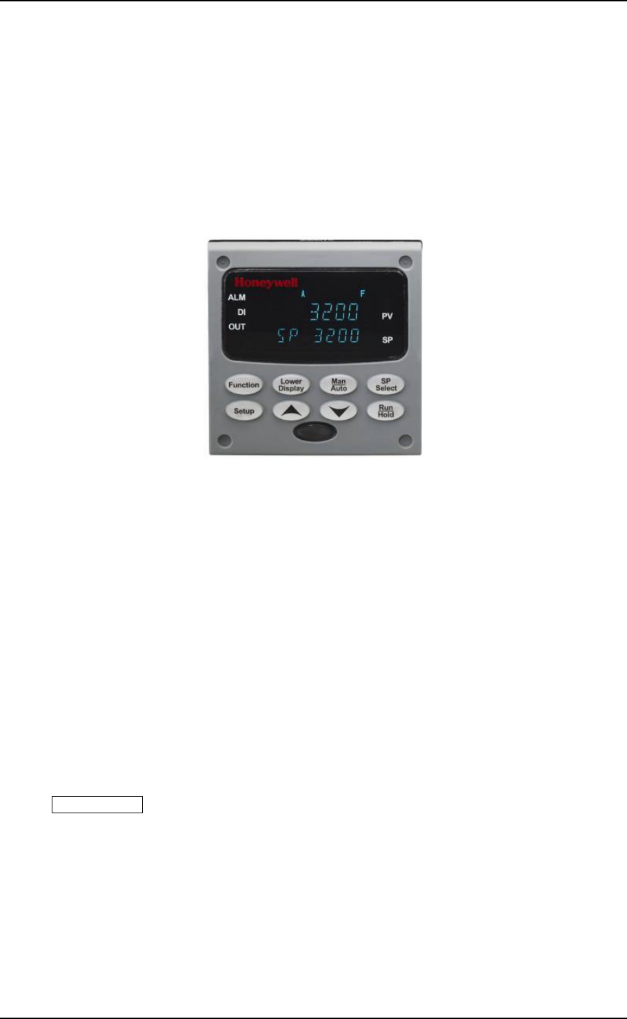
04/08 UDC3200 Universal Digital Controller Operator Manual 65
4 Monitoring and Operating the Controller
4.1 Operator Interface
Introduction
Figure 4-1 is a view of the Operator Interface.
Figure 4-1 Operator Interface
4.2 Entering a Security Code
Introduction
The level of keyboard lockout may be changed in the Set Up mode. However,
knowledge of a security code number (0 to 9999) may be required to change from one
level of lockout to another. When a controller leaves the factory, it has a security code
of 0 which permits changing from one lockout level to another without entering any
other code number.
Procedure
If you require the use of a security code, select a number from 0001 to 9999 and enter
it when the lockout level is configured as NONE. Thereafter, that selected number
must be used to change the lockout level from something other than NONE.
ATTENTION Write the number on the Configuration Record Sheet in the
configuration section so you will have a permanent record.
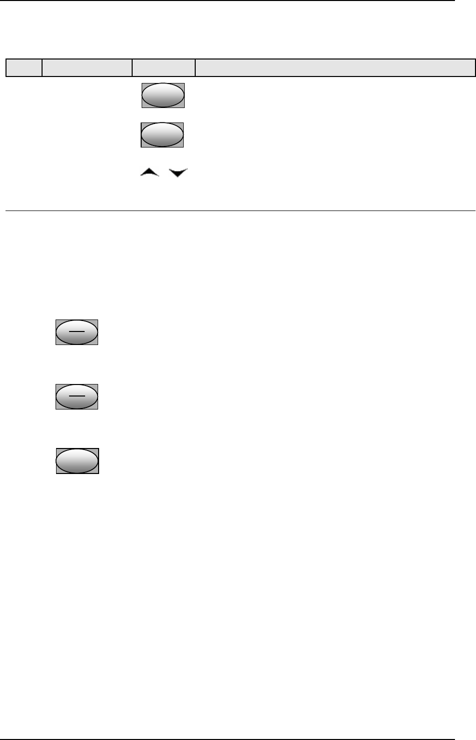
66 UDC3200 Universal Digital Controller Operator Manual 04/08
Table 4-1 Procedure to Enter a Security Code
Step Operation Press Result
1 Enter Set Up
Mode SetupSetup
Upper Display = SET UP
Lower Display = TUNING
2 Select any Set
Up Group FunctionFunctionFunction
Upper Display = 0
Lower Display = SECUR
3 Security Code
Entry or To enter a four digit number in the upper display
(0001 to 9999)
This will be your security code.
4.3 Individual key lockout
There are three keys that can be disabled to prevent unauthorized changes to the
parameters associated with these keys. First set the “Lock” prompt to NONE.
These keys are:
Run
Hold
Run
Hold
Run
Hold Key - you can disable the Run/Hold key for Set Point
Programming at configuration Set Up group prompt
“Tuning,” function prompt “RN HLD.”
Man
Auto
Man
Auto
Man
Auto Key - you can disable the Auto/Manual key at configuration
Set Up, group prompt “Tuning”, function prompt
“AUTOMA”
SP
Select
SP
Select
SP
Select Key - you can disable the Set Point Select function key at
configuration Set Up group prompt “Tuning,” function
prompt “SP SEL.”
See Subsection 3.3 - Tuning Parameters Set Up Group prompts to enable or disable
these keys.
Key error
When a key is pressed and the prompt “Key Error” appears in the lower display, it
will be for one of the following reasons:
• Parameter not available or locked out
• Not in setup mode, press SET UP key first
• Individual key locked out.

04/08 UDC3200 Universal Digital Controller Operator Manual 67
4.4 Monitoring Your Controller
4.4.1 Annunciators
The following annunciator functions have been provided to help monitor the
controller:
Table 4-2 Annunciators
Annunciator Indication
ALM 1 2
A visual indication of each alarm
Blinking 1 indicates an alarm latched condition. The blinking will
continue even after the alarm condition ends until it is acknowledged by
pressing the RUN/HOLD key.
OUT 1 2 A visual indication of the control relays
DI 1 2 A visual indication of each Digital Input
A or MAN A visual indication of the mode of the controller)
A—Automatic Mode
MAN—Manual Mode
[None], F or C A visual indication of the temperature units
[None]—No temperature unit annunciator
F—Degrees Fahrenheit
C—Degrees Celsius
n A visual Lamp to indicate when the lower display is showing the Active
Setpoint (Local 1, Local 2, Local 3, Remote Setpoint or Computer
Setpoint)
The upper left digit of the display is used to show other annunciator
functions
T—Accutuning in process
C—Computer overide active
O—Output override active

68 UDC3200 Universal Digital Controller Operator Manual 04/08
4.4.2 Viewing the operating parameters
Press the LOWER DISPLAY key to scroll through the operating parameters. The lower
display will show only those parameters and their values that apply to your specific
model.
Table 4-3 Lower Display Key Parameter Prompts
Lower Display Description
OUT XX.X OUTPUT—Output value is shown in percent with one decimal point for all output
types except Three Position Step Control (TPSC). For TPSC, when no slidewire is
connected, this display is an estimated motor position and is shown with no decimal
point. For Position Proportional Control, if the slidewire fails, then the instrument
automatically switches over to TPSC and the OUT display changes with it.
SP XXXX LOCAL SETPOINT #1—Also current setpoint when using SP Ramp.
2SP XXXX LOCAL SETPOINT #2
3SP XXXX LOCAL SETPOINT #3
RSP XXXX REMOTE SETPOINT
1IN XXXX INPUT 1—Used only with combinational input algorithms.
2IN XXXX INPUT 2
POS XX SLIDEWIRE POSITION—Used only with TPSC applications that use a slidewire input.
CSP XXXX COMPUTER SETPOINT—When SP is in override.
DEV XXXX DEVIATION—Maximum negative display is –999.9.
PIDSET X TUNING PARAMETER —where X is either 1 or 2.
ET HR.MN ELAPSED TIME—Time that has elapsed on the Timer in Hours.Minutes.
OTR HR.MN TIME REMAINING—Time remaining on the Timer in Hours.Minutes. The “O” is a
rotating clock face.
RAMPXXXM SETPOINT RAMP TIME—Time remaining in the Setpoint Ramp in minutes.
SPN XXXX SETPOINT NOW—Current Setpoint when SP Rate is enabled. The SP XXXX display
shows the “target” or final setpoint value.
XXRAHR.MN RAMP SEGMENT NUMBER AND TIME REMAINING—Set Point Programming
display. XX is the current segment number and HR.MN is the time remaining for this
segment in Hours.Minutes.
XXSKHR.MN SOAK SEGMENT NUMBER AND TIME REMAINING— Set Point Programming
display. XX is the current segment number and HR.MN is the time remaining for this
segment in Hours.Minutes.
RECYC XX NUMBER OF SP PROGRAM RECYCLES REMAINING
To BEGIN RESET SP PROGRAM TO START OF FIRST SEGMENT
RERUN RESET SP PROGRAM TO START OF CURRENT SEGMENT
AUX XXXX AUXILIARY OUTPUT—Displayed only when output algorithm is not Current Duplex.
BIA XXXX BIAS—Displays the manual reset value for algorithm PD+MR.
TUNE OFF LIMIT CYCLE TUNING NOT RUNNING—Appears when Accutune is enabled but not
operating.
DO FAST Limit Cycle Tuning with the objective of producing quarter-damped tuning parameters.
This tuning may result in PV overshoot of the SP setting.
DO SLOW Limit Cycle Tuning with the objective of producing damped or Dahlin tuning
parameters, depending upon the detected process deadtime. The tuning parameters
calculated by this selection are aimed at reducing PV overshoot of the SP setting.

04/08 UDC3200 Universal Digital Controller Operator Manual 69
4.4.3 Diagnostic Messages
The UDC3200 performs background tests to verify data and memory integrity. If
there is a malfunction, a diagnostic message will be shown on the lower display. In
the case of more than one simultaneous malfunction, only the highest priority
diagnostic message will be displayed. Table 4-4 shows the error messages in order by
priority.
Table 4-4 Diagnostic Messages
Prompt Description
EE FAIL Unable to write to nonvolatile memory. A subsequent successful write to
nonvolatile memory removes this message.
FAILSAFE This error message appears whenever the controller goes into a failsafe
mode of operation. Failsafe operation occurs when an analog input fails or
when configuration is corrupted.
INP1FAIL Two consecutive failures of input 1 integration or input value is outside of
Out-of-Range limits.
INP2FAIL Two consecutive failures of input 2 integration or input value is outside of
Out-of-Range limits.
SW FAIL Slidewire input failure. Position Proportional Control automatically switched
to Three Position Step Control.
CONF ERR Configuration Errors—Low limit greater than high limit for PV, SP, Reset, or
Output.
SOOTING Carbon Potential Problem—Percent Carbon outside of “sooting boundary.”
IN1 RNG Input 1 Out-of-Range—Input is outside of the High or Low Limits.
Out-of-range criteria:
Linear range: ± 10 %
Characterized range: ± 1 %
IN2 RNG Input 2 Out-of-Range—Same criteria as Input 1.
PV LIMIT PV beyond limits—PV outside of PV Hi/Low Limits.
PV = (PV source x PV source ratio) + PV source bias
FAILSAFE Failsafe—Check inputs or configuration.
RV LIMIT Remote Variable beyond limits—RSP outside of SP Hi/Low Limits.
RV = (RV source x RV source ratio) + RV source bias
SEG ERR Segment Error—SP Program starting segment number is less than ending
segment number.
CAL MTR Slidewire not calibrated. Perform Slidewire calibration.
SW FAIL Position Proportional slidewire input failure.
TC1 WARN The Thermocouple on Input 1 is starting to burnout.
TC2 WARN The Thermocouple on Input 2 is starting to burnout.
TC1 FAIL Thermocouple on Input 1 is in imminent danger of burning out.
TC2 FAIL Thermocouple on Input 2 is in imminent danger of burning out.
OUT1FAIL Current Output is less than 3.5 mA.
OUT2FAIL Current Output 2 is less than 3.5 mA.
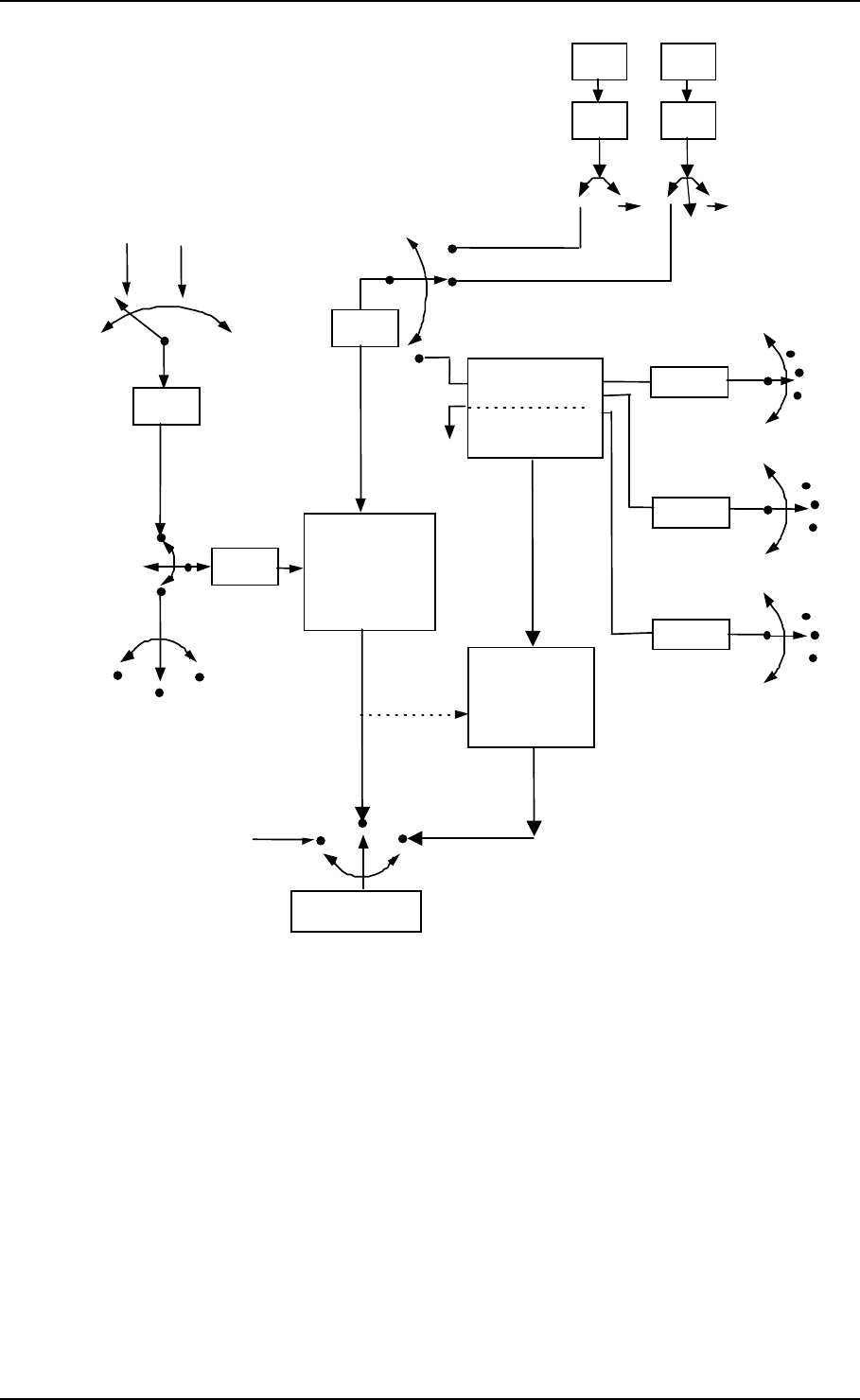
70 UDC3200 Universal Digital Controller Operator Manual 04/08
IN 1
Ratio
Bias
• •
IN 2
Ratio
Bias
• •
1 2
PV
Source
IN 2
RSP
Source
INPUT A
INPUT B
INPUT C
INPUT
ALGORITHM 1
FEEDFORWARD
INPUT A ONLY
To RSP
SP
Source
SP
PV
Remote SP
Local SP
LSP1
LSP2
LSP3
To RSP •
To RSP
CONTROL
ALGORITHM
OUTPUT
FEEDFO RWARD
SUMMER OR
MULTIPLIER
Manual Mode
Output
To Final
Control
Element
In Alg1
Input 1
Input 2
Output 1
Input 1
Input 2
Output 1
Input 1
Input 2
Output 1
Figure 4-2 Functional Overview Block Diagram of the UDC3200 Controller

04/08 UDC3200 Universal Digital Controller Operator Manual 71
4.5 Accutune III
Introduction
Accutune III (TUNE) may be used for self-regulating and single integrating
processes. This autotuning method is initiated on-demand, typically at initial start-up.
There are no other requirements necessary, such as prior knowledge to the process
dynamics or initial or post tune process line-out to setpoint or manual output.
Also, the setpoint value is not required to change in order to initiate the tuning
process, but the controller must be in the Automatic mode to start tuning. The process
need not be in a static (lined out) state and may be dynamic (changing with a steady
output).
Configuration check
Make sure:
• TUNE has been enabled see to Subsection 3.5 - Accutune Set Up Group for
details.
Tuning indicators
A “T” will show in the leftmost alphanumeric of the upper display until tuning is
completed.

72 UDC3200 Universal Digital Controller Operator Manual 04/08
Operation
The Accutune III algorithm provides user-friendly, on-demand tuning in this
controller. No knowledge of the process is required at start-up. The operator simply
initiates the tuning while in the automatic mode.
Once Accutune III has been enabled in the TUNE setup group, either “SLOW” or
“FAST” tuning may be used. Which one is used is selected via the lower display
during normal operation.
For the SLOW selection, the controller calculates conservative tuning constants with
the objective of minimizing overshoot. If the controller determines that the process
has appreciable dead time, it will automatically default to use Dahlin Tuning, which
produces very conservative tuning constants. The SLOW selection may be useful for
TPSC and Position Proportional applications, as it reduces “hunt” problems for the
motor. This selection is also recommended for applications that have significant
deadtimes.
For the FAST selection, the controller calculates aggressive tuning constants with the
objective of producing quarter damped response. Depending upon the process, this
selection will usually result in some overshoot. For this reason, it may be desireable
to enable the FUZZY tune selection. See Section 4.6. When Fuzzy tune is enabled, it
will work to suppress or eliminate any overshoot that may occur as a result of the
calculated tuning parameters as the PV approaches the setpoint. This selection is best
suited for processes with a single lag or for those that do not have any appreciable
deadtime. FUZZY tuning does not work well for processes that have appreciable
deadtime.
The Accutune III tuning process will cycle the controller’s output two full cycles
between the low and high output limits while allowing only a very small Process
Variable change above and below the SP during each cycle. A “T” shows in the upper
display until tuning is completed.
At the end of the tuning process, the controller immediately calculates the tuning
constants and enters them into the Tuning group, and begins PID control with the
correct tuning parameters. This works with any process, including integrating type
processes, and allows retuning at a fixed setpoint.
4.5.1 Tune for Simplex Outputs
After “TUNE” has been enabled, you can start Accutune as shown in Table 4-5.
Table 4-5 Procedure for Starting “TUNE”
Step Operation Press Result
1 Configure LSP1 Lower
Display
Lower
Display
Lower
Display
Until SP (Local Setpoint 1) shows
in the lower display.
2 or Until LSP1 is to the desired value.
3 Switch to
“Automatic” Mode Man
Auto
Man
Auto
Man
Auto
Until the “A” indicator is lighted (on
controllers with Manual option).
4 Show Tuning
Prompt Lower
Display
Lower
Display
Lower
Display
Until “TUNE OFF” is shown on
lower display.

04/08 UDC3200 Universal Digital Controller Operator Manual 73
5 Initiate Tuning Select “DO SLOW” or “DO FAST”
in lower display.
6 Tuning in operation Lower
Display
Lower
Display
Lower
Display
Upper display will show a “T” as
long as ACCUTUNE process is
operating. When process
completes, tuning parameters are
calculated and lower display will
show “NO TUNE” prompt.
ATTENTION
The Accutune process may be aborted at any time by changing the lower display back to “NoTUNE” or
by switching the controller into Manual Mode.
4.5.2 Tune for Duplex (Heat/Cool)
Accutune for applications using Duplex (Heat/Cool) control.
The controller must be configured to have two local setpoints unless Blended Tuning
is desired (see below). During tuning, the Accutune III process assumes that Local
Setpoint 1 will cause a Heating demand (output above 50%), and the tuning
parameters calculated for that setpoint are automatically entered as PID SET 1.
Likewise, Accutune III assumes that Local Setpoint 2 will cause a Cooling demand
(output less than 50%), and the tuning parameters calculated for that setpoint are
automatically entered as PID SET 2.
Configuration Check for Duplex
See Subsection 3.5 - Accutune Set Up Group for details.
Make sure:
• TUNE has been enabled
• DUPLEX has been configured to Manual, Automatic or Disabled
74 UDC3200 Universal Digital Controller Operator Manual 04/08
4.5.3 Using AUTOMATIC TUNE at start-up for Duplex (Heat/Cool)
Used when DUPLEX has been configured for AUTOMATIC. This is the preferred
selection for most Heat/Cool applications when tuning a new chamber. This selection
will sequentially perform both Heat and Cool tuning without further operator
intervention.
Table 4-6 Procedure for Using AUTOMATIC TUNE at Start-up for Duplex
Control
Step Operation Press Result
1 Configure LSP1 Lower
Display
Lower
Display
Lower
Display
Until SP (Local Setpoint 1) shows
in the lower display.
2 or Until LSP1 is a value within the
Heat Zone (output above 50%).
3 Configure LSP2 Lower
Display
Lower
Display
Lower
Display
Until 2SP (Local Setpoint 2) shows
in the lower display.
4 or Until LSP2 is a value within the
Cool Zone (output below 50%).
5 Switch to
“Automatic” Mode Man
Auto
Man
Auto
Man
Auto
Until the “A” indicator is lighted (on
controllers with Manual option).
6 Show Tuning
Prompt Lower
Display
Lower
Display
Lower
Display
Until “TUNE OFF” is shown on
lower display.
7 Initiate Tuning Select “DO SLOW” or “DO FAST”
in lower display.
Tuning in operation Lower
Display
Lower
Display
Lower
Display
Upper display will show a “T” as
long as ACCUTUNE process is
operating. When process
completes, tuning parameters are
calculated and lower display will
show “NO TUNE” prompt.
04/08 UDC3200 Universal Digital Controller Operator Manual 75
4.5.4 Using BLENDED TUNE at start-up for Duplex (Heat/Cool)
When DUPLEX has been configured for DISABLE. This is the preferred selection
for Heat/Cool applications which use a highly insulated chamber (a chamber which
will lose heat very slowly unless a cooling device is applied). Only one local setpoint
(LSP 1) is needed for this selection.
This selection results in performance tuning over the full range utilizing both Heat
and Cool outputs to acquire blended tune values that are then applied to both Heat and
Cool tuning parameters. Both PID sets are set to the same values.
Table 4-7 Procedure for Using BLENDED TUNE at Start-up for Duplex Control
Step Operation Press Result
1 Configure LSP1 Lower
Display
Lower
Display
Lower
Display
Until SP (Local Setpoint 1) shows
in the lower display.
2 or Until the Setpoint is to the desired
value.
3 Switch to
“Automatic” Mode Man
Auto
Man
Auto
Man
Auto
Until the “A” indicator is lighted (on
controllers with Manual option).
4 Show Tuning
Prompt Lower
Display
Lower
Display
Lower
Display
Until “TUNE OFF” is shown on
lower display.
5 Initiate Tuning Select “DO SLOW” or “DO FAST”
in lower display.
6 Tuning in operation Lower
Display
Lower
Display
Lower
Display
Upper display will show a “T” as
long as ACCUTUNE process is
operating. When process
completes, tuning parameters are
calculated and lower display will
show “NO TUNE” prompt.
4.5.5 Using MANUAL TUNE at start-up for Duplex (Heat/Cool)
When DUPLEX has been configured for MANUAL. This selection should be used
when tuning is needed only for the HEAT zone or only for the COOL zone but not
both. If Local Setpoint 1 is used, then the controller will perform a HEAT zone tune.
If Local Setpoint 2 is used, then the controller will perform a COOL zone tune.
Table 4-8 Procedure for Using MANUAL TUNE for Heat side of Duplex Control
Step Operation Press Result
1 Configure LSP1 Lower
Display
Lower
Display
Lower
Display
Until SP (Local Setpoint 1) shows
in the lower display.
2 or Until LSP1 is a value within the
Heat Zone (output above 50%).
3 Switch to
“Automatic” Mode Man
Auto
Man
Auto
Man
Auto
Until the “A” indicator is lighted (on
controllers with Manual option).
76 UDC3200 Universal Digital Controller Operator Manual 04/08
Step Operation Press Result
4 Show Tuning
Prompt Lower
Display
Lower
Display
Lower
Display
Until “TUNE OFF” is shown on
lower display.
5 Initiate Tuning Select “DO SLOW” or “DO FAST”
in lower display.
6 Tuning in operation Lower
Display
Lower
Display
Lower
Display
Upper display will show a “T” as
long as ACCUTUNE process is
operating. When process
completes, tuning parameters are
calculated and lower display will
show “NO TUNE” prompt.
Table 4-9 Procedure for Using MANUAL TUNE for Cool side of Duplex Control
Step Operation Press Result
1 Configure LSP2 Lower
Display
Lower
Display
Lower
Display
Until 2SP (Local Setpoint 2) shows
in the lower display.
2 or Until LSP2 is a value within the
Cool Zone (output below 50%).
3 Switch to
“Automatic” Mode Man
Auto
Man
Auto
Man
Auto
Until the “A” indicator is lighted (on
controllers with Manual option).
4 Show Tuning
Prompt Lower
Display
Lower
Display
Lower
Display
Until “TUNE OFF” is shown on
lower display.
5 Initiate Tuning Select “DO SLOW” or “DO FAST”
in lower display.
6 Tuning in operation Lower
Display
Lower
Display
Lower
Display
Upper display will show a “T” as
long as ACCUTUNE process is
operating. When process
completes, tuning parameters are
calculated and lower display will
show “NO TUNE” prompt.

04/08 UDC3200 Universal Digital Controller Operator Manual 77
4.5.6 Error Codes
Table 4-10 Procedure for Accessing Accutune Error Codes
Step Operation Press Result
1 Select Accutune
Set-up Group SetupSetup
Upper Display = SETUP
Lower Display = ACCUTUNE
2 Go to Error Code
Prompt FunctionFunctionFunction
Upper Display = (an error code)
Lower Display = AT ERROR
Table 4-11 lists all the error codes, definitions, and
fixes.
Table 4-11 Accutune Error Codes
Error Code
(Upper Display)
Definition
Fix
RUNNING ACCUTUNE RUNNING The Accutune process is still active (Read Only)
NONE NO ERRORS OCCURRED
DURING LAST ACCUTUNE
PROCEDURE
None
ID FAIL PROCESS IDENTIFICATION
FAILURE
Autotune has aborted
because an illegal value of
GAIN, RATE, or reset was
calculated.
• Illegal Values
– try Accutune again.
• untunable process -- contact local application
engineer.
ABORT CURRENT ACCUTUNE
PROCESS ABORTED
caused by the following
conditions:
a. Operator changed to
Manual mode
b. Digital Input detected
c. In Heat region of output
and a Cool output calculated
or vice versa.
Try Accutune again
SP2 LSP2 not enabled or LSP1 or
LSP2 not in use (only applies
to Duplex Tuning)
Enable LSP2 and configure the desired LSP1 and
LSP2 setpoints.
Aborting Accutune
To abort Accutune and return to the last previous operation (SP or output level), press
MAN-AUTO key to abort the Accutune process or increment from the “DO SLOW” or
“DO FAST” prompt to the “TUNE OFF” prompt.
Completing Accutune
When Accutune is complete, the calculated tuning parameters are stored in their
proper memory location and can be viewed in the TUNING Set up Group, and the

78 UDC3200 Universal Digital Controller Operator Manual 04/08
controller will control at the local setpoint using these newly calculated tuning
constants.
4.6 Fuzzy Overshoot Suppression
Introduction
Fuzzy Overshoot Suppression minimizes Process Variable overshoot following a
setpoint change or a process disturbance. This is especially useful in processes which
experience load changes or where even a small overshoot beyond the setpoint may
result in damage or lost product.
How it works
The Fuzzy Logic in the controller observes the speed and direction of the PV signal as
it approaches the setpoint and temporarily modifies the internal controller response
action as necessary to avoid an overshoot. There is no change to the PID algorithm,
and the fuzzy logic does not alter the PID tuning parameters. This feature can be
independently Enabled or Disabled as required by the application to work with the
Accutune algorithm. Fuzzy Tune should not be enabled for processes that have an
appreciable amount of deadtime.
Configuration
To configure this item, refer to Section 3 - Configuration:
Set Up Group “ACCUTUNE”
Function Prompt “FUZZY”
Select “ENABLE” or “DISABLE” - Use or .

04/08 UDC3200 Universal Digital Controller Operator Manual 79
5 Troubleshooting/Service
5.1 Background Tests
The UDC3200 performs ongoing background tests to verify data and memory integrity. If
there is a malfunction, a diagnostic message will be displayed (blinking) in the lower
display. In the case of simultaneous malfunctions, the messages will appear in sequence in
the lower display.
Diagnostic messages may be suppressed (stop the blinking) by pressing the RUN/HOLD
key. The messages will still be available for viewing by pressing the LOWER DISPLAY
key.
Table 5-1 Background Tests
Lower
Display Reason for Failure How to Correct the Problem
EE FAIL Unable to write to non-volatile memory.
Anytime you change a parameter and it is
not accepted, you will see E FAIL.
1. Check the accuracy of the parameter and re-enter.
2. Try to change something in configuration.
3. Run through Read STATUS tests to re-write to
EEPROM.
FAILSAFE This error message shows whenever the
controller goes into a failsafe mode of
operation. This will happen if:
• RAM test failed
• Configuration test failed
• Calibration test failed
• Burnout configured for none and
the input failed.
1. Run through STATUS check to determine the
reason for the failure.
2. Press the
SET UP key until STATUS appears in
the lower display.
3. Press the
FUNCTION key to see whether the tests
pass or fail, then run through the STATUS codes a
second time to see if the error cleared.
INP1 RNG Input 1 out of range. The process input is
outside the range limits.
1. Make sure the range and actuation are configured
properly.
2. Check the input source.
3. Restore the factory calibration.
4. Field calibrate.
INP1FAIL Two consecutive failures of input 1
integration; i.e., cannot make analog to
digital conversion. This will happen if:
• Upscale or Downscale burnout is
selected and the input is open
• Input not configured correctly for the
sensor being used
• Input source is grossly out of range.
1. Make sure the actuation is configured correctly.
See Section 3 - Configuration.
2. Make sure the input is correct and that it has not
burned-out (opened).
3. Check for gross over-ranging with a multimeter.
4. Restore factory calibration.
INP2 RNG Input 2 out of range. The remote input is
outside the range limits. Same as INP1RNG above.
INP2FAIL Two consecutive failures of input 2
integration. i.e., cannot make analog to
digital conversion.
Same as INP1FAIL above.
CONF ERR • PV low limit is > PV high limit
• SP low limit is > SP high limit
• Output low limit > Output high limit
1. Check the configuration for each item and
reconfigure if necessary.

80 UDC3200 Universal Digital Controller Operator Manual 04/08
Lower
Display Reason for Failure How to Correct the Problem
PV LIMIT PV out of range.
PV = INP1 x RATIO1+ INP1 BIAS 1. Make sure the input signal is correct.
2. Make sure the Ratio and Bias settings are correct.
3. Recheck the calibration. Use Bias of 0.0
RV LIMIT The result of the formula shown below is
beyond the range of the remote variable.
RV = INP2 X RATIO + BIAS
1. Make sure the input signal is correct.
2. Make sure the Ratio2 and Bias2 settings are
correct.
3. Recheck the calibration. Use a Ratio2 of 1.0 and a
Bias2 of 0.0.
SEGERR Setpoint Program start segment number is
less than ending segment number. Check SP Program configuration, subsection 3.4 Set
up Group SPPROG function prompts “STRSEG” and
“ENDSEG”.
CAL MTR Slidewire calibration never performed. Field Calibrate the slidewire.
SW FAIL Position Proportional slidewire input failure. Check the slidewire.
SOOTING Percent Carbon falls outside sooting
boundary
Check process for correct operation.
TCx WARN Thermocouple on Input x (1 or 2) is
starting to burnout. This diagnostic message means that the controller
has detected that the thermocouple is starting to
burnout. This error message may also be created if
the resistance of the wires used to connect the
thermocouple to the instrument is above 100 ohms.
TCxFAIL The Thermocouple on Input x (1 or 2) is in
imminent danger of burning out. This diagnostic message means that the controller
has detected that the thermocouple will soon fail. User
should consider replacing the thermocouple as soon
as possible. This message will also be generated if the
resistance of the wires used to connect the
thermocouple to the instrument is above 180 ohms.
CURFAIL Current Output is less than 3.5 mA. The current output is open circuit. Check the field
wiring.
AXFAIL Auxiliary Output is less than 3.5 mA. The auxiliary output is open circuit. Check the field
wiring.

04/08 UDC3200 Universal Digital Controller Operator Manual 81
5.2 Controller Failure Symptoms
Upper
Display Lower
Display Indicators Controller
Output Probable
Cause
Blank Blank Off None Power Failure
OK OK Current
Proportional Output
OK OK Position
Proportional or
TPSC Output
OK OK Time Proportional
Output
OK
Displayed
Output
disagrees
with Controller
Output
OK
Controller
Output
disagrees
with Displayed
Output
Current/Time
Proportional Output
OK OK OK External Alarm
function does
not operate
properly
Malfunction in
alarm output
Display does not change when a key is pressed Keyboard
Malfunction
Controller fails to go into “Slave” operation during communications Communications
Failure
OK Displayed
Output
disagrees with
Auxiliary Output
OK Controller
Auxiliary Output
disagrees
with Displayed
Auxiliary Output
Auxiliary Output
Other symptoms
If a set of symptoms or prompts other than the one you started with appears while
troubleshooting, re-evaluate the symptoms. This may lead to a different
troubleshooting procedure.
If the symptom still persists, refer to the installation section in this manual to ensure
proper installation and proper use of the controller in your system.

82 UDC3200 Universal Digital Controller Operator Manual 04/08
6 Sales and Service
For application assistance, current specifications, pricing, or name of the nearest Authorized Distributor,
contact one of the offices below.
ARGENTINA
Honeywell S.A.I.C.
Belgrano 1156
Buenos Aires
Argentina
Tel. : 54 1 383 9290
ASIA PACIFIC
Honeywell Asia
Pacific Inc.
Room 3213-3225
Sun Kung Kai Centre
N° 30 Harbour Road
Wanchai
Hong Kong
Tel. : 852 829 82 98
AUSTRALIA
Honeywell Limited
5 Thomas Holt Drive
North Ryde Sydney
Nsw Australia 2113
Tel. : 61 2 353 7000
AUSTRIA
Honeywell Austria
G.M.B.H.
Handelskai 388
A1020 Vienna
Austria
Tel. : 43 1 727 800
BELGIUM
Honeywell S.A.
3 Avenue De Bourget
B-1140 Brussels
Belgium
Tel. : 32 2 728 27 11
BRAZIL
HONEYWELL DO
Brazil
And Cia
Rua Jose Alves Da
Chunha
Lima 172
Butanta
05360.050 Sao Paulo
Sp
Brazil
Tel. : 55 11 819 3755
BULGARIA
HONEYWELL EOOD
14, Iskarsko Chausse
POB 79
BG- 1592 Sofia
BULGARIA
Tel : 359-791512/
794027/ 792198
CANADA
Honeywell Limited
The Honeywell Centre
300 Yorkland Blvd.
Toronto, Ontario
M2j 1s1
Canada
Tel.: 800 461 0013
Fax:: 416 502 5001
CZECH REPUBLIC
HONEYWELL,
Spol.S.R.O.
Budejovicka 1
140 21 Prague 4
Czech Republic
Tel. : 42 2 6112 3434
DENMARK
HONEYWELL A/S
Automatikvej 1
DK 2860 Soeborg
DENMARK
Tel. : 45 39 55 56 58
FINLAND
HONEYWELL OY
Ruukintie 8
FIN-02320 ESPOO 32
FINLAND
Tel. : 358 0 3480101
FRANCE
HONEYWELL S.A.
Bâtiment « le Mercury »
Parc Technologique de St
Aubin
Route de l’Orme
(CD 128)
91190 SAINT-AUBIN
FRANCE
Tel. from France:
01 60 19 80 00
From other countries:
33 1 60 19 80 00
GERMANY
HONEYWELL AG
Kaiserleistrasse 39
D-63067 OFFENBACH
GERMANY
Tel. : 49 69 80 64444
HUNGARY
HONEYWELL Kft
Gogol u 13
H-1133 BUDAPEST
HUNGARY
Tel. : 36 1 451 43 00
ICELAND
HONEYWELL
Hataekni .hf
Armuli 26
PO Box 8336
128 reykjavik
Iceland
Tel : 354 588 5000
ITALY
HONEYWELL S.p.A.
Via P. Gobetti, 2/b
20063 Cernusco Sul
Naviglio
ITALY
Tel. : 39 02 92146 1
MEXICO
HONEYWELL S.A. DE
CV
AV. CONSTITUYENTES
900
COL. LOMAS ALTAS
11950 MEXICO CITY
MEXICO
Tel : 52 5 259 1966
THE NETHERLANDS
HONEYWELL BV
Laaderhoogtweg 18
1101 EA AMSTERDAM
ZO
THE NETHERLANDS
Tel : 31 20 56 56 911
NORWAY
HONEYWELL A/S
Askerveien 61
PO Box 263
N-1371 ASKER
NORWAY
Tel. : 47 66 76 20 00
POLAND
HONEYWELL Sp.z.o.o
UI Domaniewksa 41
02-672 WARSAW
POLAND
Tel. : 48 22 606 09 00
PORTUGAL
HONEYWELL
PORTUGAL LDA
Edificio Suecia II
Av. do Forte nr 3 - Piso 3
2795 CARNAXIDE
PORTUGAL
Tel. : 351 1 424 50 00
REPUBLIC OF IRELAND
HONEYWELL
Unit 1
Robinhood Business
Park
Robinhood Road
DUBLIN 22
Republic of Ireland
Tel. : 353 1 4565944
REPUBLIC OF
SINGAPORE
HONEYWELL PTE LTD
BLOCK 750E CHAI
CHEE ROAD
06-01 CHAI CHEE IND.PARK
1646 SINGAPORE
REP. OF SINGAPORE
Tel. : 65 2490 100
REPUBLIC OF SOUTH
AFRICA
HONEYWELL
Southern Africa
PO BOX 138
Milnerton 7435
REPUBLIC OF SOUTH
AFRICA
Tel. : 27 11 805 12 01
ROMANIA
HONEYWELL Office
Bucharest
147 Aurel Vlaicu Str.,
Sc.Z.,
Apt 61/62
R-72921 Bucharest
ROMANIA
Tel : 40-1 211 00 76/
211 79
RUSSIA
HONEYWELL INC
4 th Floor Administrative
Builiding of AO "Luzhniki"
Management
24 Luzhniki
119048 Moscow
RUSSIA
Tel : 7 095 796 98 00/01
SLOVAKIA
HONEYWELL Ltd
Mlynske nivy 73
PO Box 75
820 07 BRATISLAVA 27
SLOVAKIA
Tel. : 421 7 52 47 400/425
SPAIN
HONEYWELL S.A
Factory
Josefa Valcarcel, 24
28027 MADRID
SPAIN
Tel. : 34 91 31 3 61 00
SWEDEN
HONEYWELL A.B.
S-127 86 Skarholmen
STOCKHOLM
SWEDEN
Tel. : 46 8 775 55 00
SWITZERLAND
HONEYWELL A.G.
Hertistrasse 2
8304 WALLISELLEN
SWITZERLAND
Tel. : 41 1 831 02 71
TURKEY
HONEYWELL A.S.
Caryiryolu Sok No. 7
Ucgen Plaza, Kat 5-6-7
Icerenkoy 81120 Instanbul
Turkey
Tel (90-216) 575 66 00
UNITED KINGDOM
HONEYWELL
Honeywell House
Arlington Business Park
Bracknell,
Berkshire
RG12 1EB
Tel: +44 (0) 1344 656000
U.S.A.
HONEYWELL INC.
INDUSTRIAL PROCESS
CONTROLS
1100 VIRGINIA DRIVE
PA 19034-3260
FT. WASHINGTON
U.S.A.
Tel. : 1-800-343-0228
VENEZUELA
HONEYWELL CA
APARTADO 61314
1060 CARACAS
VENEZUELA
Tel. : 58 2 239 021

Honeywell Process Solutions
512 Virginia Drive
Fort Washington, PA 19034
51-52-25-143 Rev. 1 0408 Printed in USA http://hpsweb.honeywell.com
