Honeywell Video Gaming Accessories W7750A Users Manual W7750A,B,C
W7750A to the manual f99a4ee8-f28c-4f6e-acd0-b33e8e48ca29
2015-01-23
: Honeywell Honeywell-Honeywell-Video-Gaming-Accessories-W7750A-Users-Manual-262653 honeywell-honeywell-video-gaming-accessories-w7750a-users-manual-262653 honeywell pdf
Open the PDF directly: View PDF ![]() .
.
Page Count: 116 [warning: Documents this large are best viewed by clicking the View PDF Link!]
- Contents
- List of Figures
- List of Tables
- Introduction
- Description of Devices
- Control Application
- Control Provided
- Products Covered
- Organization of Manual
- Applicable Literature
- Product Names
- Agency Listings
- Abbreviations and Definitions
- Construction
- Configurations
- Modes of Operation
- Application Steps
- Overview
- Step 1. Plan the System
- Step 2. Determine Other Bus Devices Required
- Step 3. Lay Out Communications and Power Wiring
- Step 4. Prepare Wiring Diagrams
- Step 5. Order Equipment
- Step 6. Configure Controllers
- Step 7. Troubleshooting
- Troubleshooting Excel 10 Controllers and Wall Modules
- Temperature Sensor and Setpoint Potentiometer Resistance Ranges
- Alarms
- Broadcasting the Service Message
- W7750 Controller Status LED
- T7770C,D Wall Module Bypass Pushbutton and Override LED
- T7560A,B Digital Wall Module Bypass Pushbutton and LCD Display Occupancy Symbols
- Appendices
- Appendix A. Using E-Vision to Commission a W7750 Controller.
- Appendix B. Sequences of Operation.
- Common Operations
- Room Temperature Sensor (RmTemp)
- Remote Setpoint (RmtStptPot)
- Setpoint Limits (LoSetptLim and HiSetptLim)
- Bypass Mode (StatusOvrd and StatusLed)
- BYPASSTIME
- OverrideType
- OverridePriority
- Cycles per Hour (ubHeatCph and ubCoolCph)
- T7770C,D or T7560A,B Wall Module Bypass Pushbutton Operation
- Standby Mode (StatusOcySen)
- Continuous Unoccupied Mode
- Occupancy Mode and Manual Override Arbitration
- Time Clock (Occ_Time_Clock)
- Schedule Master (Sched_Master)
- Setpoint Ramping
- Recovery Ramping for Heat Pump Systems
- Fan Operation
- Window Sensor (StatusWndw)
- Smoke Control
- Demand Limit Control (DLC)
- Dirty Filter Monitor
- Start-Up
- Temperature Control Operations
- Staged Cooling Control
- Staged Heating Control
- Cascade Control of Modulating Cooling/Heating
- Series 60 Modulating Control
- Pulse Width Modulating (PWM) Control
- Outdoor Air Lockout of Heating/Cooling
- Economizer Damper Control
- Indoor Air Quality (IAQ) Override
- Freeze Stat
- Discharge Air Low Limit Control
- Economizer Enable/Disable Control
- Common Operations
- Appendix C. Complete List of Excel 10 W7750 Controller User Addresses.
- Appendix D. Q7750A Excel 10 Zone Manager Point Estimating Guide.
- Appendix E. Sensor Data for Calibration.

SYSTEM ENGINEERING
7
4
-
2
9
5
8
-
1
® U.S. Re
g
istered Trademark
Cop
y
ri
g
ht © 2000 Hone
y
well Inc. • All Ri
g
hts Reserved
Excel 10
W7750A,B,C CONSTANT VOLUME AHU CONTROLLER
Contents
Introduction .................................................................................................................................. 6
Description of Devices.......................................................................................... 6
Control Application ............................................................................................... 7
Control Provided................................................................................................... 7
Products Covered................................................................................................. 8
Or
g
anization of Manual ........................................................................................ 8
Applicable Literature............................................................................................. 8
Product Names..................................................................................................... 9
A
g
enc
y
Listin
g
s .................................................................................................... 9
Abbreviations and Definitions............................................................................... 10
Construction ......................................................................................................... 11
Controllers ...................................................................................................... 11
PERFORMANCE SPECIFICATIONS ......................................................... 13
LONMARK® Functional Profile..................................................................... 17
Inputs/Outputs: ............................................................................................... 18
ANALOG INPUTS:...................................................................................... 18
DIGITAL INPUTS:....................................................................................... 19
TRIAC OUTPUTS ON THE
(
W7750B,C MODELS ONLY
)
:........................ 19
DIGITAL OUTPUTS:................................................................................... 19
Wall Modules .................................................................................................. 20
Duct Sensor .................................................................................................... 20
Confi
g
urations ...................................................................................................... 22
General ........................................................................................................... 22
Allowable Heatin
g
and Coolin
g
E
q
uipment Confi
g
urations ............................ 24
STAGED HEATING/COOLING CONTROL ................................................ 24
MODULATING HEATING/COOLING CONTROL ....................................... 24
HEAT PUMP CONTROL............................................................................. 24
ECONOMIZER CONTROL......................................................................... 25
PNEUMATIC ACTUATOR CONTROL........................................................ 25
MIXED-OUTPUT-TYPE CONTROL ........................................................... 26
Occupanc
y
Sensor ......................................................................................... 26
Window Open/Closed Di
g
ital Input ................................................................. 26
Wall Module Options ....................................................................................... 26
Dirt
y
Filter Monitor .......................................................................................... 27
Indoor Air Qualit
y
(
IAQ
)
Override ................................................................... 27
Smoke Control ................................................................................................ 27
Freeze Stat ..................................................................................................... 27
Modes of Operation.............................................................................................. 27
Application Steps .................................................................................................................................. 29
Overview .............................................................................................................. 29
Step 1. Plan the S
y
stem....................................................................................... 29
Step 2. Determine Other Bus Devices Re
q
uired.................................................. 29
Step 3. La
y
Out Communications and Power Wirin
g
........................................... 30
LONWORKS® Bus La
y
out ................................................................................ 30
Power Wirin
g
.................................................................................................. 32
POWER BUDGET CALCULATION EXAMPLE .......................................... 32
LINE LOSS ................................................................................................. 33
Step 4. Prepare Wirin
g
Dia
g
rams......................................................................... 35

EXCEL 10 W7750A,B,C CONSTANT VOLUME AHU CONTROLLER
72-2958—12
General Considerations .................................................................................. 35
W7750 Controllers .......................................................................................... 36
FACTORY DEFAULT DIGITAL OUTPUTS:................................................ 37
LONWORKS® Bus Termination Module ........................................................... 43
Step 5. Order E
q
uipment ..................................................................................... 45
Step 6. Confi
g
ure Controllers............................................................................... 48
Step 7. Troubleshootin
g
....................................................................................... 48
Troubleshootin
g
Excel 10 Controllers and Wall Modules ............................... 48
Temperature Sensor and Setpoint Potentiometer Resistance Ran
g
es .......... 49
Alarms ............................................................................................................ 49
Broadcastin
g
the Service Messa
g
e ................................................................ 50
W7750 Controller Status LED ........................................................................ 50
T7770C,D Wall Module B
y
pass Pushbutton and Override LED ..................... 51
T7560A,B Di
g
ital Wall Module B
y
pass Pushbutton and LCD Displa
y
Occupanc
y
S
y
mbols .......................................................................................................... 51
Appendices.................................................................................................................................. 51
Appendix A. Usin
g
E-Vision to Commission a W7750 Controller......................... 51
Sensor Calibration .......................................................................................... 51
Settin
g
the Pid Parameters ............................................................................ 51
Appendix B. Se
q
uences of Operation.................................................................. 52
Common Operations ...................................................................................... 53
Room Temperature Sensor
(
RmTemp
)
....................................................... 54
Remote Setpoint
(
RmtStptPot
)
................................................................... 55
Setpoint Limits
(
LoSetptLim and HiSetptLim
)
............................................. 55
B
y
pass Mode
(
StatusOvrd and StatusLed
)
................................................ 55
BYPASSTIME............................................................................................. 55
OverrideT
y
pe.............................................................................................. 55
OverridePriorit
y
........................................................................................... 55
C
y
cles per Hour
(
ubHeatCph and ubCoolCph
)
.......................................... 55
T7770C,D or T7560A,B Wall Module B
y
pass Pushbutton Operation......... 55
Standb
y
Mode
(
StatusOc
y
Sen
)
.................................................................. 56
Continuous Unoccupied Mode ................................................................... 56
Occupanc
y
Mode and Manual Override Arbitration.................................... 56
Time Clock
(
Occ_Time_Clock
)
................................................................... 57
Schedule Master
(
Sched_Master
)
.............................................................. 57
Setpoint Rampin
g
....................................................................................... 57
Recover
y
Rampin
g
for Heat Pump S
y
stems.............................................. 57
Fan Operation............................................................................................. 58
Window Sensor
(
StatusWndw
)
................................................................... 58
Smoke Control............................................................................................ 58
Demand Limit Control
(
DLC
)
...................................................................... 58
Dirt
y
Filter Monitor ...................................................................................... 59
Start-Up ...................................................................................................... 59
Temperature Control Operations .................................................................... 59
Sta
g
ed Coolin
g
Control .............................................................................. 60
Sta
g
ed Heatin
g
Control .............................................................................. 60
Cascade Control of Modulatin
g
Coolin
g
/Heatin
g
........................................ 61
Series 60 Modulatin
g
Control ..................................................................... 61
Pulse Width Modulatin
g
(
PWM
)
Control..................................................... 61
Outdoor Air Lockout of Heatin
g
/Coolin
g
..................................................... 61
Economizer Damper Control ...................................................................... 61
Indoor Air Qualit
y
(
IAQ
)
Override ............................................................... 62
Freeze Stat................................................................................................. 62
Dischar
g
e Air Low Limit Control ................................................................. 62
Economizer Enable/Disable Control........................................................... 62
Appendix C. Complete List of Excel 10 W7750 Controller User Addresses. ....... 62
User Address Indexes
(
all in alphabetical order
)
............................................ 63
Mappable User Addresses and Table Number ............................................... 64
Failure Detect User Addresses and Table Number ........................................ 65
Appendix D. Q7750A Excel 10 Zone Mana
g
er Point Estimatin
g
Guide...............109
Approximate Memor
y
Size Estimatin
g
Procedure. .........................................109
Appendix E. Sensor Data for Calibration. ............................................................ 110
Resistance Sensors. ...................................................................................... 110
Volta
g
e/Current Sensors. ............................................................................... 112

EXCEL 10 W7750A,B,C CONSTANT VOLUME AHU CONTROLLER
3 74-2958—1
List of Figures
Fi
g
. 1. T
y
pical s
y
stem overview. ................................................................................................................................................ 6
Fi
g
. 2. T
y
pical W7750 control application. ................................................................................................................................. 7
Fi
g
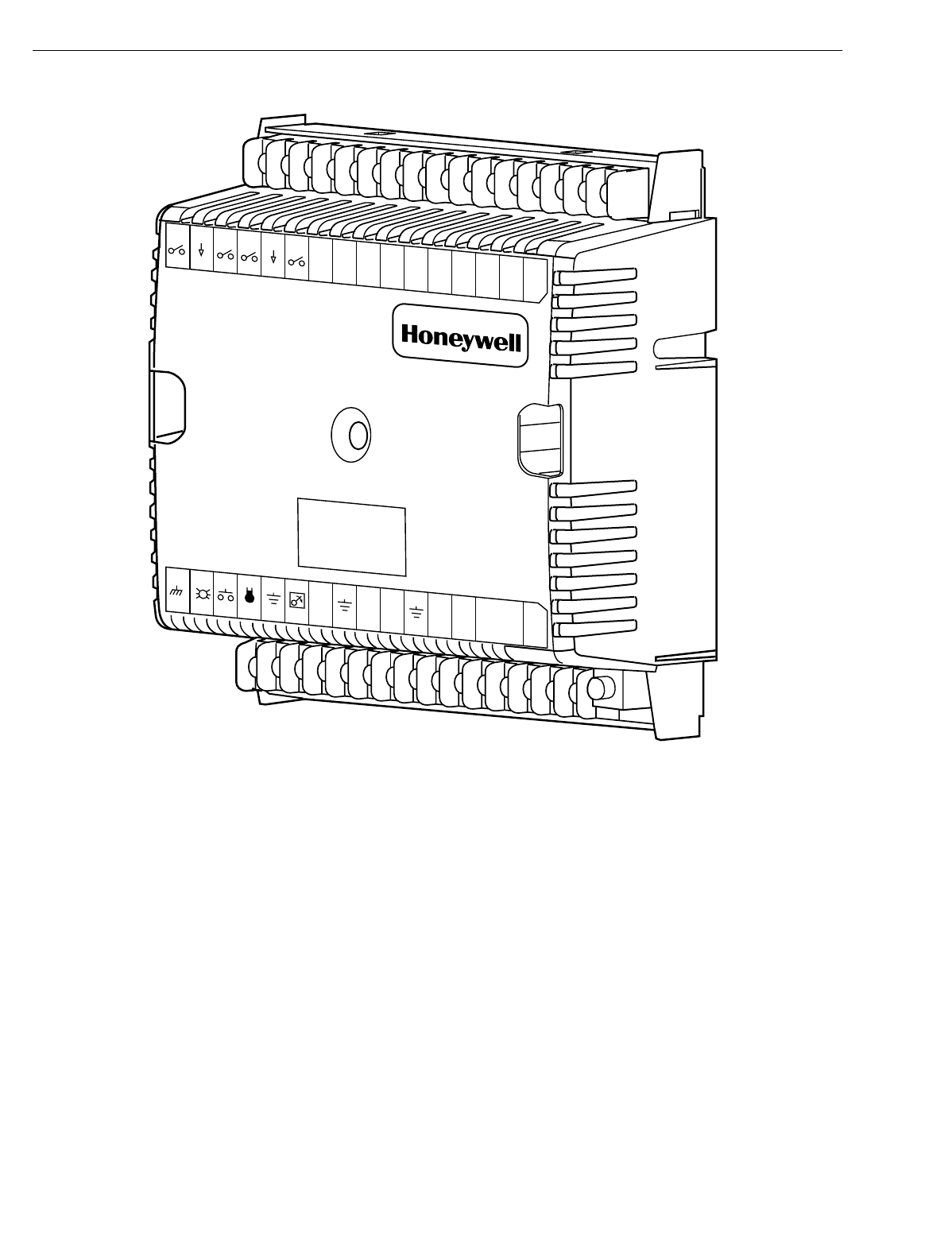
. 3. Excel 10 W7750A Constant Volume AHU Controller. ..................................................................................................... 12
Fi
g
. 4. W7750A construction in in.
(
mm
)
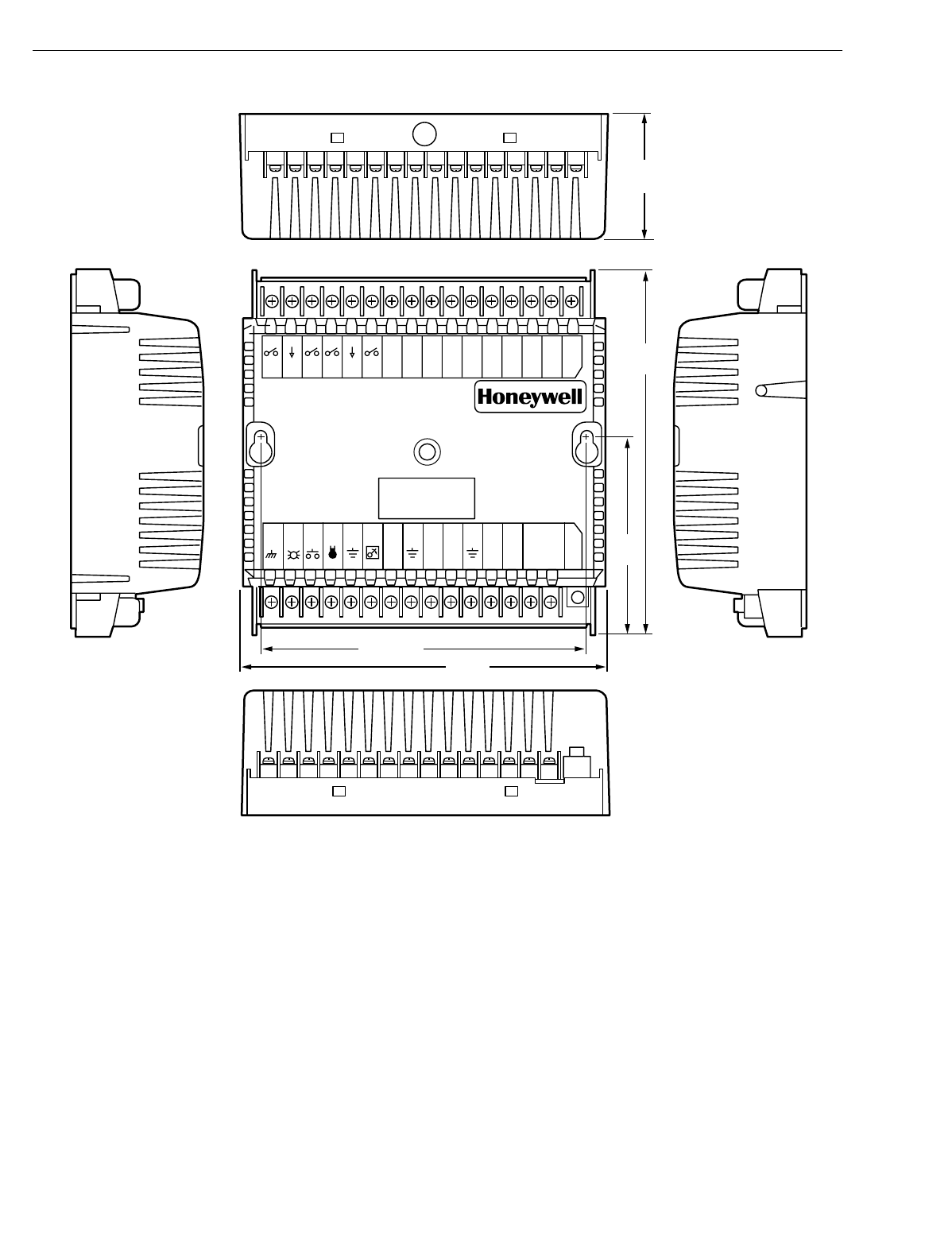
. ................................................................................................................................... 13
Fi
g
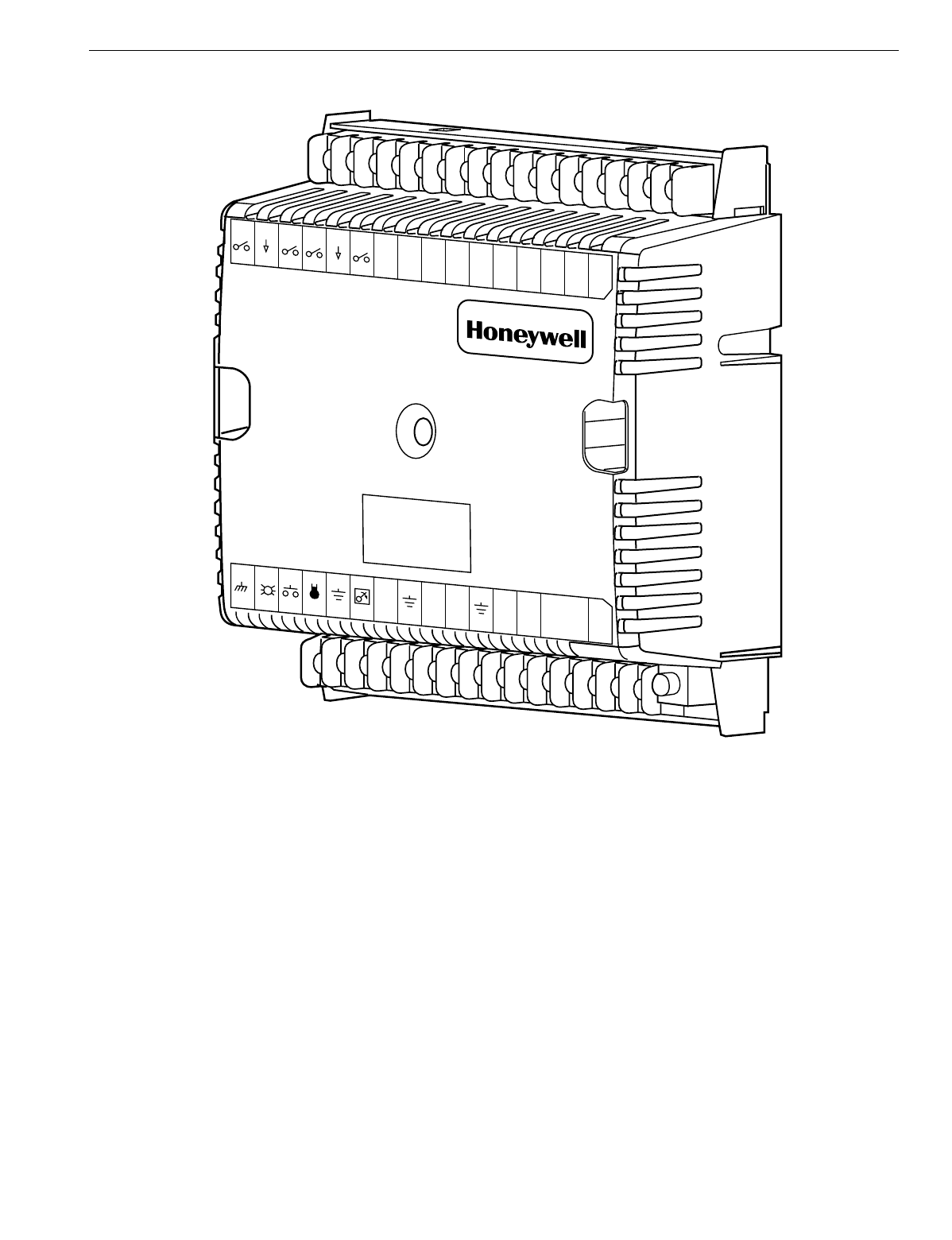
. 5. Excel 10 W7750B Constant Volume AHU Controller. ..................................................................................................... 14
Fi
g
. 6. Excel 10 W7750C Constant Volume AHU Controller. .................................................................................................... 15
Fi
g
. 7. W7750B,C construction in in.
(
mm
)
. W7750C
(
shown
)
has three 4 to 20 mA analo
g
outputs.
)
..................................... 16
Fi
g
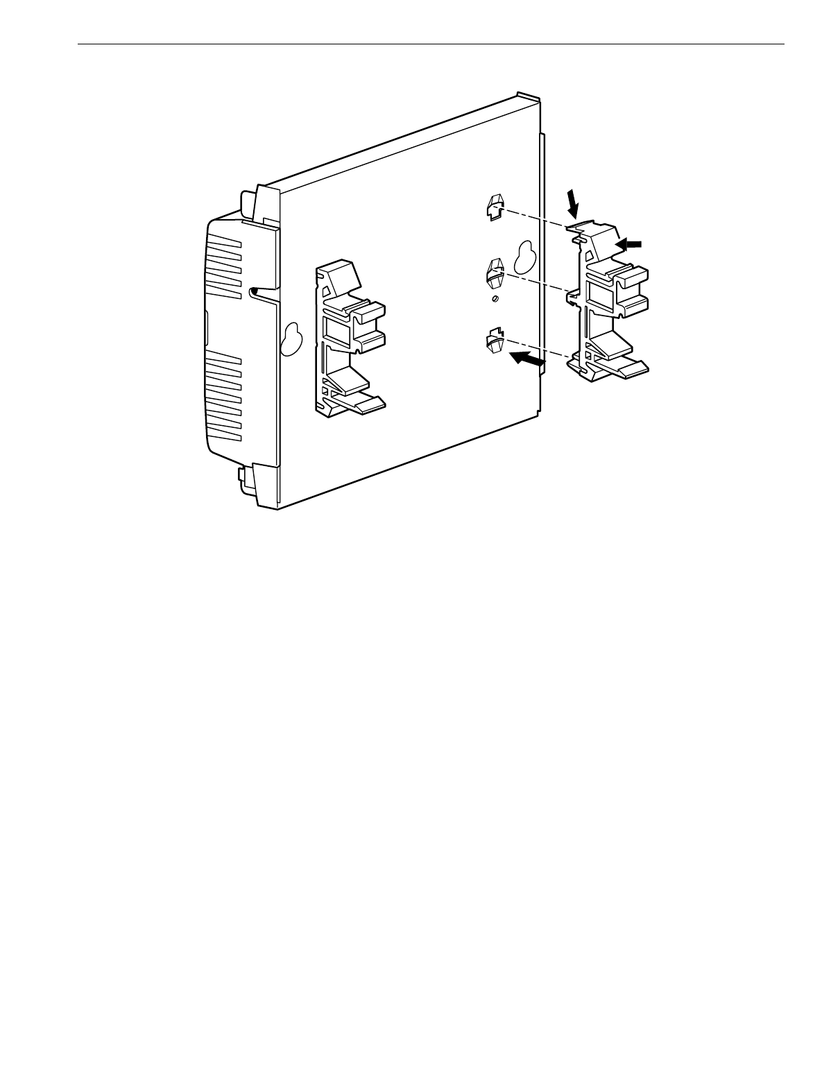
. 8. DIN rail adapters. ............................................................................................................................................................ 17
Fi
g
. 9. Functional profile of LONMARK® RTU ob
j
ect details
(
variables not implemented in Excel 10 CVAHU
are
g
re
y
ed
)
........................................................................................................................................................................ 18
Fi
g
. 10. T7770A,B,C,D construction in in.
(
mm
)
. ....................................................................................................................... 20
Fi
g
. 11. T7560A,B construction in in.
(
mm
)
. ............................................................................................................................... 21
Fi
g
. 12. C7770A construction in in.
(
mm
)
. .................................................................................................................................. 21
Fi
g
. 13. Fan with two sta
g
es of heatin
g
and two sta
g
es
of coolin
g
........................................................................................................................................................................... 24
Fi
g
. 14. Fan, modulatin
g
heatin
g
and modulatin
g
coolin
g
. ......................................................................................................... 24
Fi
g
. 15. Heat pump with two compressors and auxiliar
y
heat sta
g
e
(
s
)
....................................................................................... 25
Fi
g
. 16. Economizer control. ...................................................................................................................................................... 25
Fi
g
. 17. Modulatin
g
heat with pneumatic valve actuator............................................................................................................. 26
Fi
g
. 18. Connectin
g
the portable operator terminal
to the LONWORKS® Bus..................................................................................................................................................... 29
Fi
g
. 19. Wirin
g
la
y
out for one doubl
y
terminated dais
y
-chain LONWORKS® Bus se
g
ment. ........................................................ 31
Fi
g
. 20. Wirin
g
la
y
out for two sin
g
l
y
terminated LONWORKS® Bus se
g
ments............................................................................. 32
Fi
g
. 21. NEMA class 2 transformer volta
g
e output limits............................................................................................................ 34
Fi
g
. 22. Power wirin
g
details for one Excel 10 per transformer. ................................................................................................. 34
Fi
g
. 23. Power wirin
g
details for two or more Excel 10s per transformer. .................................................................................. 34
Fi
g
. 24. Transformer power wirin
g
details for one Excel 10 used in UL 1995 e
q
uipment
(
U.S. onl
y)
......................................... 35
Fi
g
. 25. Attachin
g
two or more wires at terminal blocks.............................................................................................................. 36
Fi
g
. 26. W7750B Hi
g
h-Side/Low-Side selectable switchin
g
and
j
umper location....................................................................... 36
Fi
g
. 27. T
y
pical W7750A Controller AHU application wirin
g
dia
g
ram.
(
For more information on note 2,
refer to Fi
g
. 25.
)
................................................................................................................................................................ 38
Fi
g
. 28. T
y
pical W7750A Controller with separate transformer application wirin
g
dia
g
ram.
(
For more information on note 2, refer to Fi
g
. 25.
)
............................................................................................................ 38
Fi
g
. 29. W7750A Controller floatin
g
economizer damper wirin
g
dia
g
ram.
(
For more information on note 2, refer to Fi
g
. 25.
)
... 39
Fi
g
. 30. T
y
pical W7750B Controller with sta
g
ed heatin
g
and coolin
g
wirin
g
dia
g
ram.
(
For more information on note 2, refer to Fi
g
.
25.
)
.................................................................................................................................................................................... 40
Fi
g
. 31. W7750B Controller with floatin
g
heatin
g
, coolin
g
and economizer wirin
g
dia
g
ram.
(
For more information on note 2, refer
to Fi
g
. 25.
)
......................................................................................................................................................................... 40
Fi
g
. 32. W7750B,C Controller PWM damper actuator wirin
g
dia
g
ram.
(
For more information on note 2, refer to
Fi
g
. 25.
)
............................................................................................................................................................................. 41
Fi
g
. 33. W7750B,C wirin
g
dia
g
ram with 4 to 20 mA enthalp
y
sensors and di
g
ital inputs.
(
For more information on note 2, refer to
Fi
g
. 25.
)
............................................................................................................................................................................. 41
Fi
g
. 34. W7750B,C wirin
g
dia
g
ram with C7600C 4 to 20 mA solid state humidit
y
sensor.
(
For more information on note 2, refer to
Fi
g
. 25.
)
............................................................................................................................................................................. 42
Fi
g
. 35. W7750C Controller with 4-to-20 mA heatin
g
, coolin
g
and economizer wirin
g
dia
g
ram. AOs must use terminals 16, 17 or
18. The AOs can be set to be reverse actin
g
.
(
For more information on note 2, refer to Fi
g
. 25.
)
.................................... 42
Fi
g
. 36. Pneumatic transducer to W7750B,C
(
B shown, see trian
g
le note 4
)
. ......................................................................................................................................... 43
Fi
g
. 37. RP7517,B pneumatic transducer to W7750C................................................................................................................ 43
Fi
g
. 38. T
y
pical doubl
y
terminated dais
y
-chain LONWORKS® Bus se
g
ment termination module wirin
g
dia
g
ram. ..................... 44
Fi
g
. 39. LONWORKS® Bus termination wirin
g
options. ............................................................................................................... 45
Fi
g
. 40. Temperature sensor resistance plots............................................................................................................................. 49
Fi
g
. 41. Location of the Service Pin Button................................................................................................................................. 50
Fi
g
. 42. LED location on W7750................................................................................................................................................. 51
Fi
g
. 43. The T7770C,D Wall Modules LED and B
y
pass pushbutton locations........................................................................... 51
Fi
g
. 44. The T7560A,B Di
g
ital Wall Module B
y
pass pushbutton location................................................................................... 51
Fi
g
. 45. LED and B
y
pass pushbutton operation. ....................................................................................................................... 56
Fi
g
. 46. Setpoint rampin
g
parameters with ramp rate calculation............................................................................................... 57
Fi
g
. 47. Setpoint rampin
g
parameters with setpoint calculation.................................................................................................. 58

EXCEL 10 W7750A,B,C CONSTANT VOLUME AHU CONTROLLER
74-2958—14
Fi
g
. 48. Setpoint rampin
g
parameters with ramp rate calculation............................................................................................... 58
Fi
g
. 49. Schematic dia
g
ram for a t
y
pical W7750B Unit. .............................................................................................................59
Fi
g
. 50. Sta
g
ed output control versus PID Error. ....................................................................................................................... 60
Fi
g
. 51. Point capacit
y
estimate for Zone Mana
g
er. ..................................................................................................................109
Fi
g
. 52. Graph of Sensor Resistance versus Temperature......................................................................................................... 110
Fi
g
. 53. Graph of Sensor Resistance versus Temperature......................................................................................................... 110
Fi
g
. 54. Graph of Sensor Resistance versus Temperature......................................................................................................... 111
Fi
g
. 55. Graph of Sensor Resistance versus Temperature......................................................................................................... 111
Fi
g
. 56. Graph of Sensor Resistance versus Temperature......................................................................................................... 112
Fi
g
. 57. Graph of Sensor Volta
g
e versus Humidit
y
..................................................................................................................... 112
Fi
g
. 58. C7600C output current vs. humidit
y
............................................................................................................................... 112
Fi
g
. 59. Graph of Sensor Current versus Enthalp
y
(
volts
)
. ......................................................................................................... 113
Fi
g
. 60. Partial ps
y
chometric chart for a C7400A Solid State Enthalp
y
Sensor. ........................................................................114
Fi
g
. 61. C7400A Solid State Enthalp
y
Sensor output current vs. relative humidit
y
. ................................................................... 114
Fi
g
. 62. Graph of Sensor Volta
g
e versus CO2 concentration..................................................................................................... 115
Fi
g
. 63. Graph of Sensor Volta
g
e versus input Volta
g
e to A/D.................................................................................................. 115
Fi
g
. 64. Graph of Sensor Volta
g
e
(
Vdc
)
versus Pressure
(
Inw
)
.................................................................................................. 116

EXCEL 10 W7750A,B,C CONSTANT VOLUME AHU CONTROLLER
5 74-2958—1
List of Tables
Table 1. A
g
enc
y
Listin
g
. ............................................................................................................................................................. 9
Table 2. List of Differences in W7750A and W7750B,C Controllers........................................................................................... 11
Table 3. Common Confi
g
uration Options Summar
y
For W7750A,B,C Controllers..................................................................... 22
Table 4. Confi
g
uration Options Summar
y
For W7750A,B,C Controllers. ................................................................................... 23
Table 5. Modes Of Operation For The Excel 10 W7750 Controller . .......................................................................................... 27
Table 6. Application Steps.......................................................................................................................................................... 29
Table 7. LONWORKS® Bus Confi
g
uration Rules And Device Node Numbers............................................................................. 30
Table 8. VA Ratin
g
s For Transformer Sizin
g
. ............................................................................................................................. 33
Table 9. Field Wirin
g
Reference Table
(
Hone
y
well listed as AK#### or e
q
uivalent
)
.................................................................. 36
Table 10. W7750A Version I/O Description. ............................................................................................................................... 37
Table 11. Excel 10 W7750 Controller Orderin
g
Information. ...................................................................................................... 46
Table 12. Excel 10 Alarms.......................................................................................................................................................... 49
Table 14. Common Confi
g
uration Options Summar
y
For W7750A,B,C Controllers................................................................... 53
Table 15. Confi
g
uration Options Summar
y
For W7750A,B,C Controllers. ................................................................................. 54
Table 16. B
y
pass Pushbutton Operation.................................................................................................................................... 55
Table 17. Intersta
g
e Minimum Times.......................................................................................................................................... 60
Table 18. Excel 10 W7750 Controller User
Address Point T
y
pes................................................................................................................................................................... 62
Table 20. Input/Output Points..................................................................................................................................................... 67
Table 21. Control Parameters..................................................................................................................................................... 73
Table 22. Ener
gy
Mana
g
ement Points........................................................................................................................................ 78
Table 23. Status Points............................................................................................................................................................... 81
Table 24. Calibration Points........................................................................................................................................................ 93
Table 25. Confi
g
uration Parameters........................................................................................................................................... 94
Table 26. LONMARK®/Open S
y
stem Points. ............................................................................................................................... 97
Table 27. Direct Access And Special Points............................................................................................................................... 106
Table 28. Data Share Points....................................................................................................................................................... 108
Table 29. Sensor Resistance Versus Temperature.................................................................................................................... 110
Table 30. Sensor Resistance Versus Temperature.................................................................................................................... 110
Table 31. Sensor Resistance Versus Temperature.................................................................................................................... 111
Table 32. Sensor Resistance Versus Temperature.................................................................................................................... 111
Table 33. Sensor Resistance Versus Temperature.................................................................................................................... 111
Table 34. Sensor Volta
g
e Versus Humidit
y
. ............................................................................................................................... 112
Table 35. Sensor Volta
g
e Versus Humidit
y
. ............................................................................................................................... 112
Table 36. Sensor Current Versus Enthalp
y
(
volts
)
...................................................................................................................... 113
Table 37. Sensor Volta
g
e Versus CO2 Concentration. .............................................................................................................. 115
Table 38. Sensor Volta
g
e Versus Input Volta
g
e To A/D............................................................................................................. 115
Table 39. Sensor Volta
g
e
(
Vdc
)
Versus Pressure
(
Inw
)
. ............................................................................................................ 116
EXCEL 10 W7750A,B,C CONSTANT VOLUME AHU CONTROLLER
74-2958—16
INTRODUCTION
Description of Devices
The W7750 is the Constant Volume Air Handlin
g
Unit
(
CVAHU
)
Controller in the Excel 10 product line famil
y
. The
CVAHU is a LONMARK compliant device desi
g
ned to control
sin
g
le zone and heat pump air handlers. W7750 s
y
stems
control the space temperature in a
g
iven zone b
y
re
g
ulatin
g
the heatin
g
and coolin
g
e
q
uipment in the air handler that
delivers air to that space. The W7750 air handler is t
y
picall
y
an all-in-one constant air volume packa
g
ed unit, located on
the roof of the buildin
g
. In addition to standard heatin
g
and
coolin
g
control, the W7750 provides man
y
options and
advanced s
y
stem features that allow state-of-the-art
commercial buildin
g
control. The W7750 Controller is capable
of stand-alone operation; however, optimum functional
benefits are achieved when the network communication
capabilities are used. The W7750 utilizes the Echelon
LONWORKS network
(
LONWORKS Bus
)
for communications,
and conforms with the LONMARK HVAC Interoperabilit
y
standard for Roof Top Unit Controllers
(
see Fi
g
. 9
)
.
The T7770 or T7560 direct-wired Wall Modules are used in
con
j
unction with W7750 Controllers. The zone controlled b
y
the W7750 Controller t
y
picall
y
can use a T7770A throu
g
h D or
a T7560A,B Wall Module. Additional features available in
T7770A throu
g
h D models include analo
g
setpoint input knob,
override di
g
ital input pushbutton, override status LED and
LONWORKS Bus network access
j
ack. Additional features
available in T7560A,B models include analo
g
setpoint input
knob, override di
g
ital input pushbutton, humidit
y
sensor
(
T7650B model
)
, override status LCD and di
g
ital displa
y
.
The Q7750A Excel 10 Zone Mana
g
er is a communications
interface that allows devices on the LONWORKS Bus network
to communicate with devices on the standard EXCEL 5000
S
y
stem C-Bus. Fi
g
. 1 shows an overview of a t
y
pical s
y
stem
la
y
out. The Q7750A also provides some control and
monitorin
g
functions.
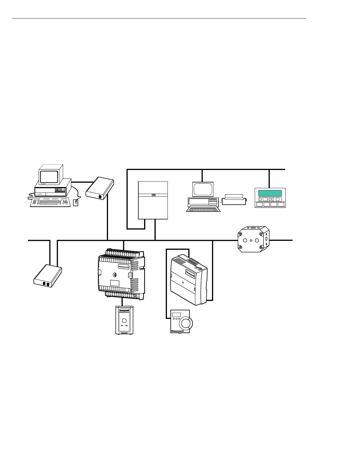
Fig. 1. Typical system overview.
PERSONAL COMPUTER TOOLS
E-VISION
CARE
Q7752A
LONWORKS BUS
SERIAL
ADAPTER
EXCEL 10
Q7750A
ZONE
MANAGER
C-BUS COMMUNICATION NETWORK
EXCEL 500
EXCEL BUILDING SUPERVISOR
C-BUS TO LONWORKS BUS
INTERFACE DEVICE
EXCEL 10 W7751F
PANEL PLENUM
MOUNT VERSION
VARIABLE AIR VOLUME
CONTROLLER
LONWORKS-BUS COMMUNICATIONS NETWORK LONWORKS BUS COMMUNICATIONS NETWORK
Q7751A
FTT
LONWORKS BUS
ROUTER
EXCEL 10 T7770
WALL MODULE EXCEL 10 T7560A, B
WALL MODULE
M17487
EXCEL 10
W7750B
CVAHU
CONTROLLER
123456789
10 11 12 13 1415J3
31 30 29 28 27 26 25 24 23 22 21 20 19 18 17 16
Q7740A
2-WAY
REPEATER
Excel 10 W7750A,B,C Constant Volume AHU Controller
EXCEL 10 W7750A,B,C CONSTANT VOLUME AHU CONTROLLER
7 74-2958—1
Control Application
W7750 s
y
stems in commercial buildin
g
s t
y
picall
y
incorporate
a packa
g
ed air handler s
y
stem that delivers a constant
volume of air at preconditioned temperatures to the zone
bein
g
served. Each zone is usuall
y
serviced b
y
a separate
AHU; however, sometimes two or more AHUs service the
same zone. Note that the W7750 is not desi
g
ned to control
Variable Air Volume
(
VAV
)
air handlers or Multi-Zone air
handlers, where one air handler simultaneousl
y
controls the
space temperature in man
y
zones.
The W7750 can control sta
g
ed or modulatin
g
heatin
g
and
coolin
g
coils, mixed air economizer dampers, and the s
y
stem
fan. Control of heat pump units, where the compressor
(
s
)
is
used for both coolin
g
and heatin
g
, is also provided. The zone
the W7750 services can use a T7770 or T7650 for space
temperature sensin
g
and an LONWORKS Bus network access
for users. Fi
g
. 2 shows a t
y
pical W7750 control application.
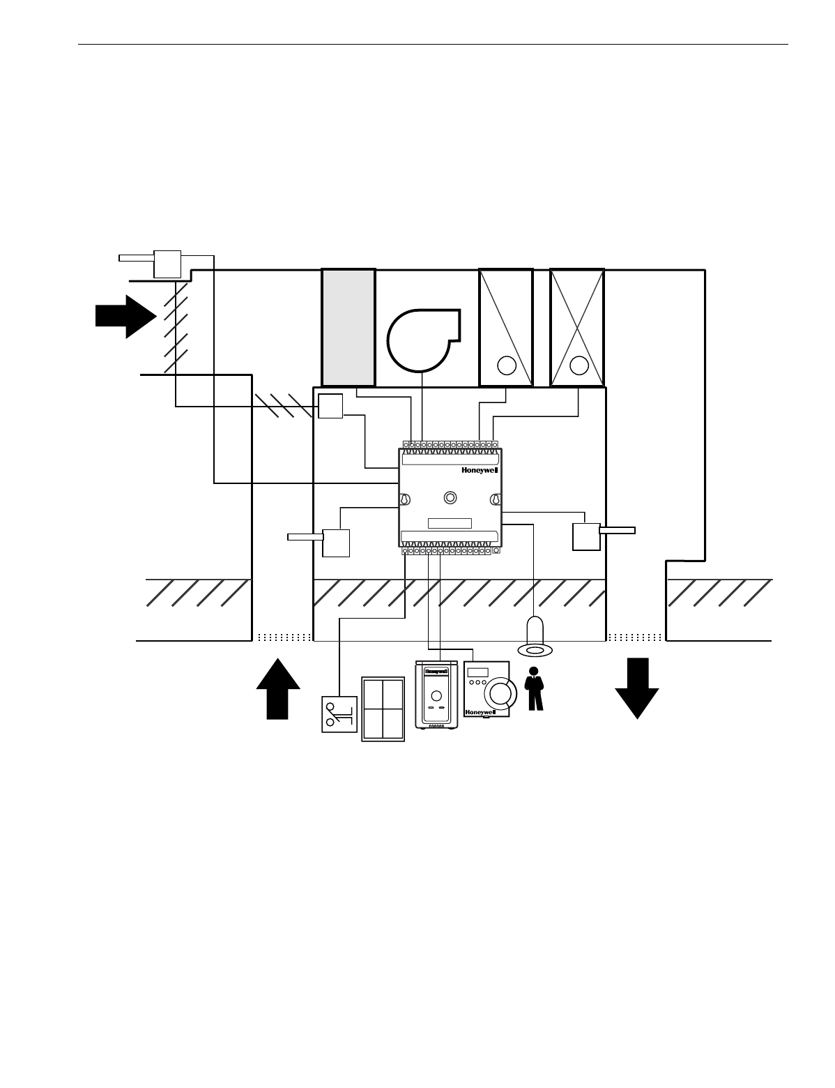
Fig. 2. Typical W7750 control application.
Control Provided
The W7750 Controller is desi
g
ned to control a sin
g
le air
handler to maintain the units space temperature at the current
setpoint. Heatin
g
and coolin
g
control is provided for either
sta
g
ed or modulatin
g
e
q
uipment. Up to four sta
g
es of
mechanical coolin
g
and up to four sta
g
es of heatin
g
are
allowed. Modulatin
g
outputs can be either
floating type
such
as a Series 60 control, or Pulse Width Modulated
(
PWM
W7750B,C onl
y)
control.
The economizer dampers can be controlled directl
y
with
floatin
g
or PWM outputs, or indirectl
y
usin
g
a di
g
ital output as
an enable/disable si
g
nal to a packa
g
ed economizer controller.
The economizer enable function, which decides when to allow
outdoor air to be used for free coolin
g
, can be confi
g
ured to
one of ten strate
g
ies based on the inputs. For more details,
see Appendix B—Se
q
uences of Operation. When the
economizer position is controlled from the W7750, the
minimum position settin
g
(
for ventilation re
q
uirements
)
can be
ad
j
usted based on indoor air
q
ualit
y
(
IAQ
)
needs in the space.
IAQ monitorin
g
is provided throu
g
h either a CO2 sensor or a
di
g
ital input from a space-mounted IAQ limit switch.
For heat pump confi
g
urations, up to four compressors can be
controlled, alon
g
with up to four sta
g
es of auxiliar
y
heat, and a
heat/cool chan
g
e over valve. Includin
g
the suppl
y
fan, the
combination of these items ma
y
not exceed ei
g
ht outputs if a
W7750B,C is used, or six outputs for a W7750A.
(
The ei
g
ht
outputs on the W7750C consist of five di
g
ital and three analo
g
outputs.
)
WINDOW CONTACT
OCCUPANCY
SENSOR
M
OA TEMP
FILTER
FAN
COOL
COIL
HEAT
COIL
DA TEMP
RA TEMP
EXCEL 10
W7750
CVAHU
T7770 OR T7560A,B
RETURN
AIR DISCHARGE
AIR
OUTDOOR
AIR
CEILING
ROOF
-+
M17488

EXCEL 10 W7750A,B,C CONSTANT VOLUME AHU CONTROLLER
74-2958—18
Like the W7751 VAV Box Controller, the W7750 Controller can
monitor a space-mounted occupanc
y
sensor, and a door/
window contact. These inputs affect the operational mode of
the controller
(
see Table 5 for a list of all possible modes of
operation
)
.
The W7750 Controller allows other controllers in the s
y
stem to
use the W7750s ph
y
sical inputs and outputs. A di
g
ital input
and an analo
g
input can be confi
g
ured to read switch states
and volta
g
e sensor values, respectivel
y
, and send them out
over the LONWORKS Bus network. The Q7750A Zone
Mana
g
er can use these values in custom control strate
g
ies.
Additionall
y
, two of the W7750 di
g
ital outputs are available for
control pro
g
ram use. These outputs onl
y
respond to si
g
nals
sent over the network, and are not controlled b
y
the W7750
internal control al
g
orithms.
Products Covered
This S
y
stem En
g
ineerin
g
Guide describes how to appl
y
the
Excel 10 famil
y
of W7750 CVAHU Controllers and related
accessories to t
y
pical applications. The specific devices
covered include:
•W7750A,B,C Controllers.
•T7770A throu
g
h D Wall Modules.
•T7560A,B Wall Modules.
•Q7750A Excel 10 Zone Mana
g
er.
•Q7751A,B Router
(
FTT to FTT and TPT to FTT
)
.
•Q7752A Serial Interface.
•Q7740A,B Repeaters
(
2-wa
y
and 4-wa
y)
.
•209541B FTT Termination Module.
Organization of Manual
This manual is divided into three basic parts: the Introduction,
the Application Steps, and the Appendices that provide
supportin
g
information. The Introduction and Application
Steps 1 throu
g
h 5 provide the information needed to make
accurate material orderin
g
decisions. Application Step 6 and
the Appendices include confi
g
uration en
g
ineerin
g
that can be
started usin
g
Excel E-Vision PC Software after the devices
and accessories are ordered. Application Step 7 is
troubleshootin
g
.
The or
g
anization of the manual assumes a pro
j
ect is bein
g
en
g
ineered from start to finish. If an operator is addin
g
to, or is
chan
g
in
g
an existin
g
s
y
stem, the Table of Contents can
provide the relevant information.
Applicable Literature
The followin
g
list of documents contains information related to
the Excel 10 W7750 CVAHU Controller and the EXCEL 5000
OPEN SYSTEM in
g
eneral.
Form No. Title
74-2956 Excel 10 W7750A,B,C Controller Specification
Data
74-2697 Excel 10 T7770A,B,C,D,E,F,G Wall Module
Specification Data
74-3097 T7560A,B Di
g
ital Wall Module Specification
Data
74-2950 Excel 10 Q7750A, Zone Mana
g
er Specification
Data
74-2952 Excel 10 Q7751A,B Router Specification Data
74-2954 Excel 10 Q7752A Serial Interface Specification
Data
74-3067 Q7752B PCMCIA LONWORKS PCC-10 Card
Specification Data
74-2858 Excel 10 Q7740A,B FTT Repeaters
Specification Data
74-2951 Excel 10 Q7750A Zone Mana
g
er Checkout
and Test Manual
95-7521 Excel 10 W7750A,B,C Controller Installation
Instructions
95-7538 Excel 10 T7770A,B,C,D,E,F,G Wall Module
Installation Instructions
95-7620 T7560A,B Di
g
ital Wall Module Installation
Instructions
95-7509 Excel 10 Q7750A Zone Mana
g
er Installation
Instructions
95-7510 Excel 10 Q7751A,B Router Installation
Instructions
95-7511 Excel 10 Q7752A Serial Interface Installation
Instructions
95-7613 Q7752B PCMCIA LONWORKS PCC-10 Card
Installation Instructions
95-7555 Excel 10 Q7740A,B FTT Repeaters Installation
Instructions
95-7554 Excel 10 209541B Termination Module
Installation Instructions
74-2588 Excel E-Vision User’s Guide
74-5587 CARE User’s Manual
74-1392 CARE Excel 10 Zone Mana
g
er User’s Guide
74-5577 CARE Icon Guide
74-2039 XBS User’s Manual
74-5018 XBS Application Guide

EXCEL 10 W7750A,B,C CONSTANT VOLUME AHU CONTROLLER
9 74-2958—1
Product Names
The W7750 Controller is available in three models:
•W7750A Constant Volume AHU Controller - W7750A
Version.
•W7750B Constant Volume AHU Controller - W7750B
Version.
•W7750C Constant Volume AHU Controller - W7750C
Version.
The T7770 Wall Module is available in four models. The
T7770 Wall Modules will work with all Excel 5000 and Excel
10 Controllers
(
except the W7751A,C,E,G
)
:
•T7770A1xxx Wall Module with nonlinearized 20 Kohm
NTC sensor onl
y
.
•T7770A2xxx Wall Module with nonlinearized 20 Kohm
NTC sensor and LONWORKS Bus
j
ack.
•T7770B1xxx Wall Module with nonlinearized 20 Kohm
NTC sensor, 10 Kohm setpoint, and LONWORKS Bus
j
ack.
•T7770C1xxx Wall Module with nonlinearized 20 Kohm
NTC sensor, 10 Kohm setpoint, b
y
pass button and LED,
and LONWORKS Bus
j
ack.
•T7770D1xxx Wall Module with nonlinearized 20 Kohm
NTC sensor, b
y
pass button and LED, and LONWORKS Bus
j
ack.
NOTE: The T7770B,C Models are available with a absolute
55 to 85°F
(
10 to 85°C
)
or a relative scale plate
ad
j
ustable in E-Vision to ± 18°F
(
± 5°C
)
.
The T7560A,B Wall Module is available in two models:
•T7560A Wall Module displa
y
s and provides space
temperature, setpoint, Occ/Unocc override, override status
LCD and di
g
ital displa
y
.
•T7560B Wall Module displa
y
s and provides space
temperature, humidit
y
sensor, setpoint, Occ/Unocc
override, override status LCD and di
g
ital displa
y
.
Other products:
•Q7750A Excel 10 Zone Mana
g
er.
•Q7751A,B Bus Router.
•Q7752A Serial Adapter.
•Q7740A,B FTT Repeaters.
•209541B FTT Termination Module.
Refer to Table 11 in Application Step 5. Order E
q
uipment for a
complete listin
g
of all available part numbers.
NOTE: The Q7750A Zone Mana
g
er is referred to as
(
E-Link
)
in internal software and CARE.
Agency Listings
Table 1 provides information on a
g
enc
y
listin
g
s for Excel 10
products. Be sure to alwa
y
s follow Local Electrical Codes.
Table 1. Agency Listing.
Device Agency Comments
W7750A,B,C Controllers UL Tested and listed under UL916
(
file number E87741
)
. The CVAHU W7750A,B,C
Controllers are UL94-5V listed and suitable for plenum mountin
g
.
cUL Listed
(
E87741
)
.
CE General Immunit
y
per European Consortium Standards EN50081-1
(
CISPR 22, Class B
)
and EN 50082-1:1992
(
based on Residential, Commercial, and Li
g
ht Industrial
)
.
EN 61000-4-2: IEC 1000-4-2
(
IEC 801-2
)
Electroma
g
netic Dischar
g
e.
EN 50140, EN 50204: IEC 1000-4-3
(
IEC 801-3
)
Radiated Electroma
g
netic Field.
EN 61000-4-4: IEC 1000-4-4
(
IEC 801-4
)
Electrical Fast Transient
(
Burst
)
. Radiated Emissions and
Conducted Emissions:
EN 55022: 1987 Class B.
CISPR-22: 1985.
FCC Complies with re
q
uirements in FCC Part 15 rules for a Class B Computin
g
Device.
Operation in a residential area can cause interference to radio or TV reception and re
q
uire
the operator to take steps necessar
y
to correct the interference.
T7770A,B,C,D and
T7560A,B Wall Modules UL
(
Not applicable.
)
cUL
(
Not applicable.
)
FCC
(
Not applicable.
)
Q7750A Excel 10
Zone Manager UL Tested and listed under UL916, file number S4804
(
QVAX, PAZY
)
.
CSA Listin
g
pendin
g
.
FCC Complies with re
q
uirements in FCC Part 15 rules for a Class A Computin
g
Device.
Operation in a residential area can cause interference to radio or TV reception and re
q
uire
the operator to take steps necessar
y
to correct the interference.
Q7740A,B FTT
Repeaters, Q7751A,B
Routers and
UL UL1784.
Q7752A Serial Adapter CSA Listed.
FCC Complies with re
q
uirements in FCC Part 15 rules for a Class B Computin
g
Device.

EXCEL 10 W7750A,B,C CONSTANT VOLUME AHU CONTROLLER
74-2958—110
Abbreviations and Definitions
AHUAir Handlin
g
Unit; the central fan s
y
stem that includes
the blower, heatin
g
e
q
uipment, coolin
g
e
q
uipment,
ventilation air e
q
uipment, and other related e
q
uipment.
COCarbon Monoxide. Occasionall
y
used as a measure of
indoor air
q
ualit
y
.
CO2Carbon Dioxide. Often used as a measure of indoor air
q
ualit
y
.
CAREComputer Aided Re
g
ulation En
g
ineerin
g
; the PC
based tool used to confi
g
ure C-Bus and LONWORKS Bus
devices.
C-BusHone
y
well proprietar
y
Control Bus for
communications between EXCEL 5000 S
y
stem
controllers and components.
CPUCentral Processin
g
Unit; an EXCEL 5000 OPEN
SYSTEM controller module.
cULUnderwriters Laboratories Canada
CVAHUConstant Volume AHU; refers to a t
y
pe of air
handler with a sin
g
le-speed fan that provides a constant
amount of suppl
y
air to the space it serves.
DDFDelta De
g
rees Fahrenheit.
D/XDirect Expansion; refers to a t
y
pe of mechanical coolin
g
where refri
g
erant is
(
expanded
)
to its cold state, within a
heat-exchan
g
in
g
coil that is mounted in the air stream
supplied to the conditioned space.
EchelonThe compan
y
that developed the LONWORKS Bus
and the Neuron chips used to communicate on the
LONWORKS Bus.
EconomizerRefers to the mixed-air dampers that re
g
ulate
the
q
uantit
y
of outdoor air that enters the buildin
g
. In
cool outdoor conditions, fresh air can be used to
supplement the mechanical coolin
g
e
q
uipment.
Because this action saves ener
gy
, the dampers are
often referred to as
economizer dampers
.
EMIElectroma
g
netic Interference; electrical noise that can
cause problems with communications si
g
nals.
E-LinkRefers to the Q7750A Zone Mana
g
er. This name is
used in internal software and in CARE software.
EMSEner
gy
Mana
g
ement S
y
stem; refers to the controllers
and al
g
orithms responsible for calculatin
g
optimum
operational parameters for maximum ener
gy
savin
g
s in
the buildin
g
.
EEPROMElectricall
y
Erasable Pro
g
rammable Read Onl
y
Memor
y
; the variable stora
g
e area for savin
g
user
setpoint values and factor
y
calibration information.
EnthalpyThe ener
gy
content of air measured in BTUs per
pound
(
KiloJoules per Kilo
g
ram
)
.
EPROMErasable Pro
g
rammable Read Onl
y
Memor
y
; the
firmware that contains the control al
g
orithms for the
Excel 10 Controller.
Excel 10 Zone ManagerA controller that is used to
interface between the C-Bus and the LONWORKS Bus.
The Excel 10 Zone Mana
g
er also has the functionalit
y
of an Excel 100 Controller, but has no ph
y
sical I/O
points.
NOTE: The Q7750A Zone Mana
g
er can be referred to as
E-Link in the internal software, CARE.
E-VisionUser interface software used with devices that
operate via the FTT LONWORKS Bus communications
protocol.
FirmwareSoftware stored in a nonvolatile memor
y
medium
such as an EPROM.
Floating ControlRefers to Series 60 Modulatin
g
Control of
a valve or damper. Floatin
g
Control utilizes one di
g
ital
output to pulse the actuator open, and another di
g
ital
output to pulse it closed.
FTTFree Topolo
gy
Transceiver.
IAQIndoor Air Qualit
y
. Refers to the
q
ualit
y
of the air in the
conditioned space, as it relates to occupant health and
comfort.
I/OInput/Output; the ph
y
sical sensors and actuators
connected to a controller.
I x RI times R or current times resistance; refers to Ohms
Law: V = I x R.
KDe
g
rees Kelvin.
Level IVRefers to a classification of di
g
ital communication
wire. Formerl
y
known as UL Level IV, but
not
e
q
uivalent
to Cate
g
or
y
IV cable. If there is an
y
q
uestion about wire
compatibilit
y
, use Hone
y
well-approved cables
(
see Step
5 Order E
q
uipment section
)
.
LONWORKS BusEchelons LONWORKS network for
communication amon
g
Excel 10 Controllers.
LONWORKS Bus SegmentAn LONWORKS Bus section
containin
g
no more than 60 Excel 10s. Two se
g
ments
can be
j
oined to
g
ether usin
g
a router.
NECNational Electrical Code; the bod
y
of standards for
safe field-wirin
g
practices.
NEMANational Electrical Manufacturers Association; the
standards developed b
y
an or
g
anization of companies
for safe field wirin
g
practices.
NodeA Communications Connection on a network; an
Excel 10 Controller is one node on the LONWORKS Bus
network.
NVNetwork Variable; an Excel 10 parameter that can be
viewed or modified over the LONWORKS Bus network.
PCAn Personal Computer with Pentium processor capable
of runnin
g
Microsoft Windows 95.
PotPotentiometer. A variable resistance electronic
component located on the T7770B,C or T7560A,B Wall
Modules; used to allow user-ad
j
usted setpoints to be
input into the Excel 5000 or Excel 10 Controllers.

EXCEL 10 W7750A,B,C CONSTANT VOLUME AHU CONTROLLER
11 74-2958—1
PWMPulse Width Modulated output; allows analo
g
modulatin
g
control of e
q
uipment usin
g
a di
g
ital output
on the controller.
RTDResistance Temperature Detector; refers to a t
y
pe of
temperature sensor whose resistance output chan
g
es
accordin
g
to the temperature chan
g
e of the sensin
g
element.
SubnetA LONWORKS Bus se
g
ment that is separated b
y
a
router from its Q7750A Zone Mana
g
er.
TODTime-Of-Da
y
; the schedulin
g
of Occupied and
Unoccupied times of operation.
TPTTwisted Pair Transceiver.
VAVolt Amperes; a measure of electrical power output or
consumption as applies to an ac device.
VacVolta
g
e alternatin
g
current; ac volta
g
e rather than dc
volta
g
e.
VAVVariable Air Volume; refers to either a t
y
pe of air
distribution s
y
stem, or to the W7751 Excel 10 VAV Box
Controller that controls a sin
g
le zone in a variable air
volume deliver
y
s
y
stem.
VOCVolatile Or
g
anic Compound; refers to a class of
common pollutants sometimes found in buildin
g
s.
Sources include out-
g
assin
g
of construction materials,
production-line b
y
-products, and
g
eneral cleanin
g
solvents. A VOC is occasionall
y
used as a measure of
indoor air
q
ualit
y
.
W7750The model number of the Excel 10 CVAHU
Controllers
(
also see CVAHU
)
.
W7751The model number of the Excel 10 VAV Box
Controllers
(
also see VAV
)
.
Wall ModuleThe Excel 10 Space Temperature Sensor and
other optional controller inputs are contained in the
T7770 or the T7560A,B Wall Modules. See Application
Step 5. Order E
q
uipment for details on the various
models of Wall Modules.
XBSExcel Buildin
g
Supervisor; a PC based tool for
monitorin
g
and chan
g
in
g
parameters in C-Bus devices.
Construction
Controllers
The Excel 10 W7750 Controller is available in three different
models. The W7750A Model, which is a low cost controller
made for simple sin
g
le zone air handlers and heat pump
controls. The W7750B,C Models are intended for more
complex applications.
The W7750B,C Models use Triacs for their di
g
ital outputs,
where as the W7750A Model uses dr
y
-contact rela
y
s. The
W7750C Model also has three analo
g
outputs available on
terminals 16, 17 and 18.
All wirin
g
connections to the controller are made at screw
terminal blocks. Connection for operator access to the
LONWORKS Bus is provided b
y
plu
gg
in
g
the SLTA connector
cable into the LONWORKS Bus communications
j
ack.
The W7750A,B,C Models consist of a sin
g
le circuit board that
is mounted in a sheet metal subbase and protected b
y
a
factor
y
snap-on cover. The three controllers have the same
ph
y
sical appearance except for terminals 16 throu
g
h 20
(
W7750A
)
and different labels next to the wirin
g
terminals
(
see Fi
g
. 3, 5 or 6
)
. Wires are attached to the screw terminal
blocks on both sides of the controller. The controllers mount
with two screws
(
see Fi
g
. 4 or 7
)
. The W7750 can also be
mounted usin
g
DIN rail. To mount the W7750 on DIN rail,
purchase two DIN rail adapters
(
obtain locall
y)
part number
TKAD, from Thomas and Betts, see Fi
g
. 8, then snap onto
standard EN 50 022 35 mm b
y
7.5 mm
(
1-3/8 in. b
y
5/16 in.
)
DIN rail. DIN rail is available throu
g
h local suppliers.
A channel in the cover allows the controller status LED to be
visible when the cover is in place. There are no field-
serviceable parts on the circuit board and, therefore,
it is
intended that the cover never be removed
.
The W7750A,B,C can be mounted in an
y
orientation.
Ventilation openin
g
s were desi
g
ned into the cover to allow
proper heat dissipation re
g
ardless of the mountin
g
orientation.
See Fi
g
. 4 and 7.
The input/output and control differences between the two
models are summarized in Table 2. The I/O points in Table 2
are the free I/O points that are not reserved for Wall Module
use.
Table 2. List of Differences in W7750A and W7750B,C Controllers.
*The T7770 or the T7560 Wall Modules includes I/O points for
two analo
g
inputs for the space temperature and the setpoint
knob, a di
g
ital input for the B
y
pass pushbutton, and a di
g
ital
output for the LED B
y
pass Indicator. These W7750 I/O
points are confi
g
urable, but are normall
y
used for the Wall
Module.
W7750A Model W7750B,C Models
Digital Outputs Six Rela
y
Outputs Ei
g
ht Triac Outputs
Digital Inputs Two Four
Wall Module One* One*
Analog Outputs None Three 4 to 20 mA Outputs
(
W7750C onl
y)
Analog Inputs One
(
Resistive Input Onl
y)
Four
(
Two Resistive and two Volta
g
e/Current Inputs
)
DC Power None 20 Vdc available to power optional sensors
Floating (Series 60) Control Economizer Onl
y
Heatin
g
, Coolin
g
, and/or Economizer
PWM Control None Heatin
g
, Coolin
g
, and/or Economizer
EXCEL 10 W7750A,B,C CONSTANT VOLUME AHU CONTROLLER
74-2958—112
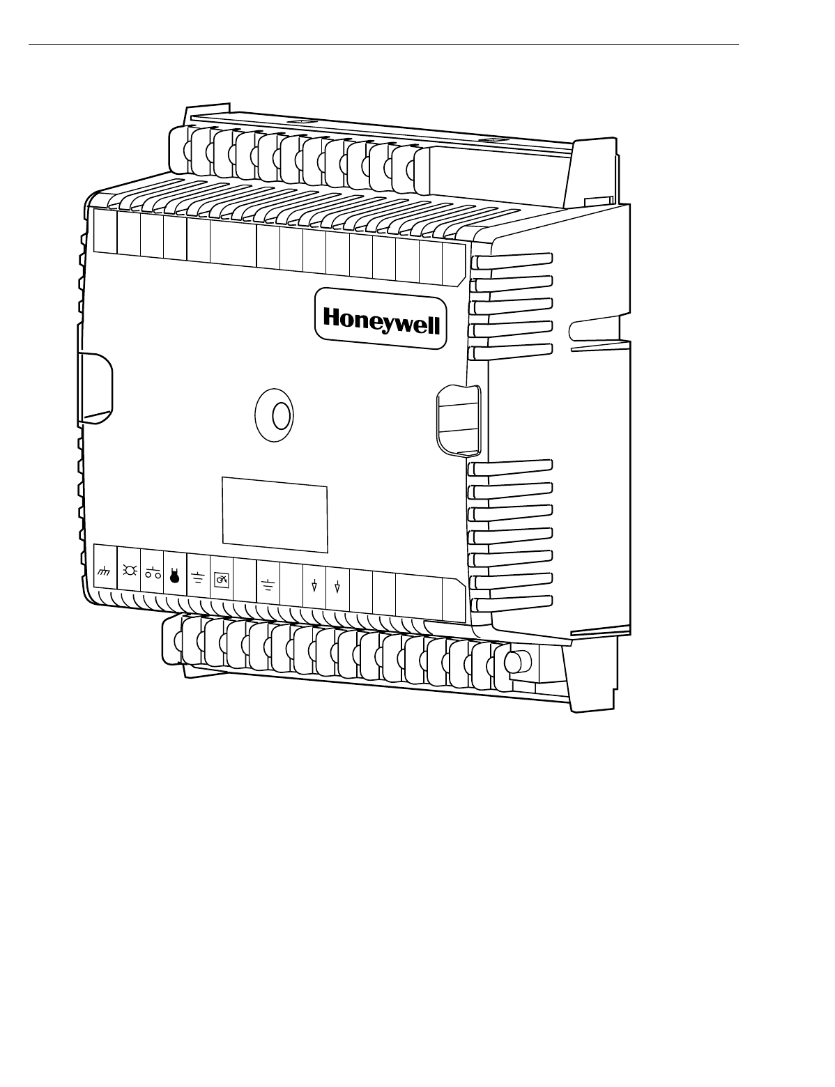
Fig. 3. Excel 10 W7750A Constant Volume AHU Controller.
123456789
10 11 12 13 14 15 J3
31 30 29 28 27 26 25 24 23 22 21 20 19 18 17 16
E
GND LED
SNSR
GND
SET PT
AI-1
OHM GND DI-1 GND GND DI-2
NOT
USED
L
ON
W
ORKS
BUS
L
ON
JACK
W1 W2Y1 Y2 GNETWORK
DO Rc Rh 24
VAC
W7750A
24
VAC
COM
NOT
USED NOT
USED
NOT
USED
NOT
USED
NOT
USED
BYPASS
EXCEL 10 W7750A,B,C CONSTANT VOLUME AHU CONTROLLER
13 74-2958—1
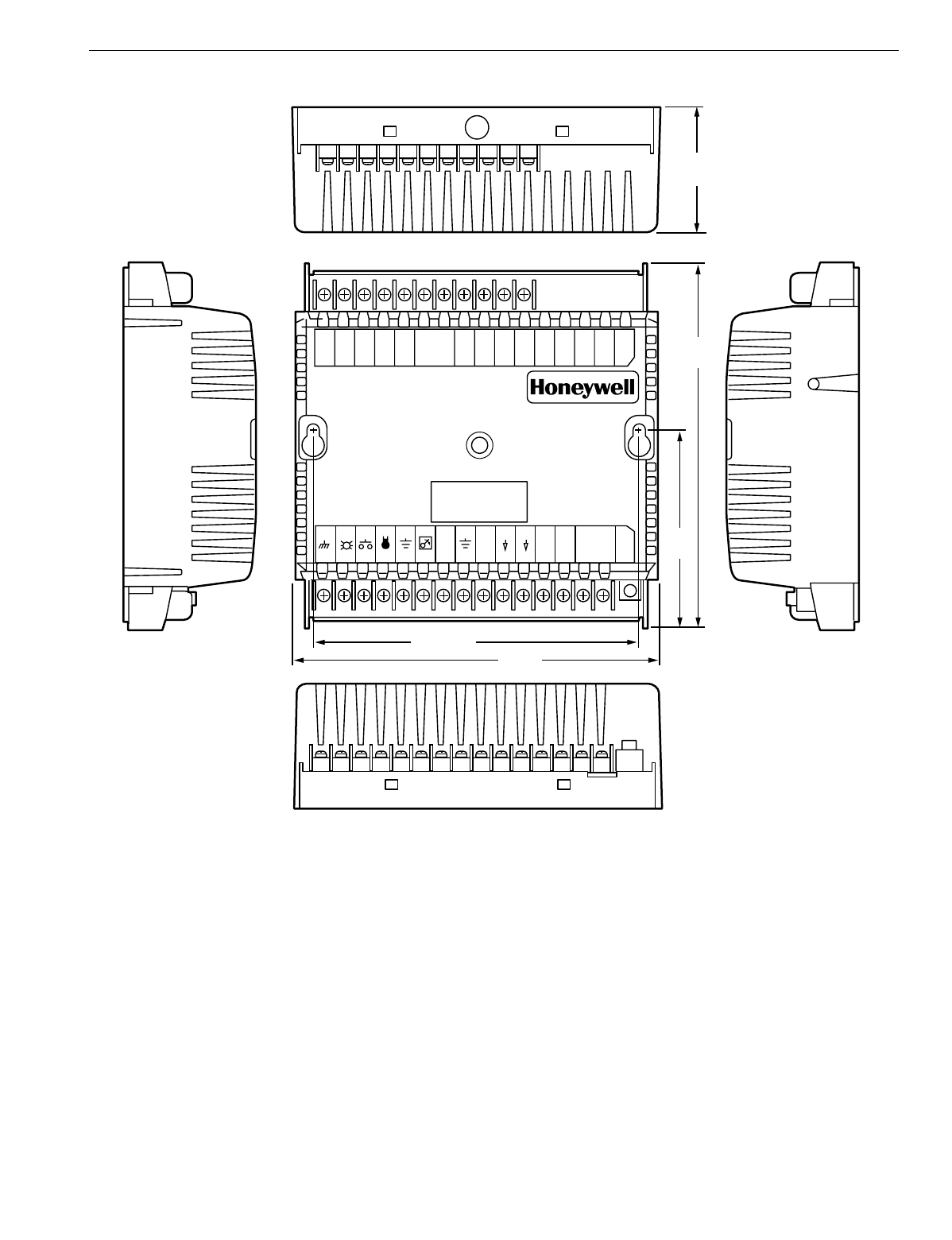
Fig. 4. W7750A construction in in. (mm).
PERFORMANCE SPECIFICATIONS
Power:
24 Vac with a minimum of 20 Vac and a maximum of 30 Vac at
either 50 or 60 Hz. The W7750A power consumption is 6 VA
maximum at 50 or 60 Hz. The W7750B,C power consumption
is 12 VA maximum at 50 or 60 Hz.The W7750A,B,C is a NEC
Class 2 rated device. This listin
g
imposes limits on the amount
of power the product can consume or directl
y
control to a total
of 100 VA.
Special Note for the W7750B,C Unit:
The individual Triac outputs incorporate an internal common
connection with the input power transformer. The Triacs
provide a switched path from the hot side
(
R
)
of the
transformer throu
g
h the load to the common of the
transformer. The W7750B,C Controller desi
g
n
must
use the
same power transformer for an
y
loads connected to that
controller; see Fi
g
. 30.
Each individual Triac is rated 1A at 30 Vac maximum. Under
all operatin
g
conditions, the maximum load/source power
bud
g
et for the W7750B,C Controller is 100 VA. Actual
allowable Triac current is 500 mA MAX.
123456789101112131415J3
E
GND LED BYPASS SNSR GND SET PT AI-1
OHM GND DI-1 GND GND DI-2 NOT
USED
L
ON
W
ORKS
BUS LON
JACK
31 30 29 28 27 26 25 24 23 22 21 20 19 18 17 16
WI W2 Y1 Y2 G
NEYWORK
DO Rc Rh 24
VAC
5-3/16 (132)
5-5/8
(143)
3-1/16
(77)
2-1/8
(54)
6 (152)
M10098B
24
VAC
COM
NOT
USED NOT
USED
NOT
USED NOT
USED
NOT
USED
EXCEL 10 W7750A,B,C CONSTANT VOLUME AHU CONTROLLER
74-2958—114
Fig. 5. Excel 10 W7750B Constant Volume AHU Controller.
CPU:
Motorola or Toshiba 3150 Neuron processor, containin
g
three
ei
g
ht-bit CPUs. Each Neuron has a uni
q
ue 48-bit network
identification number.
Memory Capacity:
64K ROM/PROM
(
6K reserved for network operations, 58K
usable for control al
g
orithm code
)
.
512 b
y
tes EEPROM.
2K RAM.
Specified Space Temperature Sensing Range:
45 to 99°F
(
7 to 37°C
)
with an allowable control setpoint ran
g
e
from 50 to 90°F
(
10 to 32°C
)
when initiated from the network
and 55 to 85°F
(
13 to 29°C
)
when confi
g
ured and connected
to T7770 or T7560 Wall Modules.
M6854B
123456789
10 11 12 13 14 15 J3
31 30 29 28 27 26 25 24 23 22 21 20 19 18 17 16
E
GND LED BYPASS SNSR SET PT AI-1
OHM A1-2
OHM AI-3
V/mA AI-4
V/mA 20VDC
OUT
DI-4
DI-3
DI-2 DI-1 VAC
24
VAC
24
COM 1
OUT 2
OUT 3
OUT
4
OUT
5
OUT 6
OUT 7
OUT 8
OUT
AI
GND AI
GND AI
GND
LONWORKS
BUS
LON
JACK
DI
GND DI
GND
EXCEL 10 W7750A,B,C CONSTANT VOLUME AHU CONTROLLER
15 74-2958—1
Fig. 6. Excel 10 W7750C Constant Volume AHU Controller.
M17489
123456789
10 11 12 13 14 15 J3
31 30 29 28 27 26 25 24 23 22 21 20 19 18 17 16
E
GND LED BYPASS SNSR SET PT AI-1
OHM A1-2
OHM AI-3
V/mA AI-4
V/mA 20VDC
OUT
DI-4
DI-3
DI-2 DI-1 VAC
24
VAC
24
COM 1
OUT 2
OUT 3
OUT
4
OUT
5
OUT A0
1A0
2A0
3
AI
GND AI
GND AI
GND
LONWORKS
BUS
LON
JACK
DI
GND DI
GND
EXCEL 10 W7750A,B,C CONSTANT VOLUME AHU CONTROLLER
74-2958—116
Fig. 7. W7750B,C construction in in. (mm). W7750C (shown) has three 4 to 20 mA analog outputs.)
Communications:
The W7750A,B,C Controller uses a Free Topolo
gy
Transceiver
(
FTT
)
transformer-coupled communications port
runnin
g
at 78 kilobits per second
(
kbps
)
. Usin
g
the
transformer-coupled communications interface offers a much
hi
g
her de
g
ree of common-mode noise re
j
ection while
ensurin
g
dc isolation.
Approved cable t
y
pes for LONWORKS Bus communications
wirin
g
is Level IV 22 AWG
(
0.34 mm2
)
plenum or nonplenum
rated unshielded, twisted pair, solid conductor wire. For
nonplenum areas, use Level IV 22 AWG
(
0.34 mm2
)
such as
U.S. part AK3781
(
one pair
)
or U.S. part AK3782
(
two pair
)
. In
plenum areas, use plenum-rated Level IV, 22 AWG
(
0.34
mm2
)
such as U.S. part AK3791
(
one pair
)
or U.S. part
AK3792
(
two pair
)
.
(
See Tables 9 and 11 for part numbers.
)
Contact Echelon Corp. Technical Support for the
recommended vendors of Echelon approved cables.
123456789101112131415J3
E
GND
LED
BYPASS
SNSR
AI
GND AI
GND AI
GND
SET PT
AI-1
OHM
AI-2
OHM
AI-3
V/mA
AI-4
V/mA
20VDC
OUT
L
ON
W
ORKS
BUS
L
ON
JACK
31 30 29 28 27 26 25 24 23 22 21 20 19 18 17 16
DI-4 DI
GND
DI-3 DI-2 DI
GND
DI-1VAC
24
VAC
24
COM
1
OUT
2
OUT
3
OUT
4
OUT
5
OUT
A0
1A0
2
A0
3
5-3/16 (132)
5-5/8
(143)
3-1/16
(77)
2-1/8
(54)
6 (152)
M17490
EXCEL 10 W7750A,B,C CONSTANT VOLUME AHU CONTROLLER
17 74-2958—1
Fig. 8. DIN rail adapters.
The FTT supports polarit
y
insensitive free topolo
gy
wirin
g
.
This frees the s
y
stem installer from wirin
g
usin
g
a specific bus
topolo
gy
. T-tap, star, loop, and mixed wirin
g
topolo
g
ies are all
supported b
y
this architecture. The maximum LONWORKS Bus
len
g
th when usin
g
a combination of T-tap, star, loop, and bus
wirin
g
(
sin
g
l
y
terminated
)
is 1640 ft.
(
500m
)
with the maximum
node-to-node len
g
th of 1312 ft.
(
400m
)
. In the event that the
total wire len
g
th is exceeded, then a Q7740A 2-Wa
y
Repeater
or a Q7740B 4-Wa
y
Repeater can be used to allow the
number of devices to be spread out as well as increasin
g
the
len
g
th of wire over which the
y
communicate. The maximum
number of repeaters per se
g
ment is one
(
on either side of the
router
)
. A Q7751A,B LONWORKS Bus Router can also be used
to effectivel
y
double the maximum LONWORKS Bus len
g
th.
The advanta
g
e of usin
g
the router is that it se
g
re
g
ates traffic
to a se
g
ment while when usin
g
the repeater, all traffic is
repeated on each se
g
ment. When utilizin
g
a doubl
y
terminated LONWORKS Bus structure, use a continuous dais
y
-
chain with no stubs or taps from the main backbone, The
maximum LONWORKS Bus len
g
th is 4593 ft.
(
1400m
)
with the
maximum node-to-node len
g
th of 3773 ft.
(
1150m
)
.
FTT networks are ver
y
flexible and convenient to install and
maintain, but it is imperative to carefull
y
plan the network
la
y
out and create and maintain accurate documentation. This
aids in compliance verification and future expansion of the
FTT network. This also keeps unknown or inaccurate wire run
len
g
ths, node-to-node
(
device-to-device
)
distances, node
counts, total wire len
g
th, inaccurate repeater/router locations,
and misplaced or missin
g
terminations minimized. Refer to
LONWORKS Bus Wirin
g
Guidelines form, 74-2865 for complete
description of network topolo
gy
rules.
LONMARK® FUNCTIONAL PROFILE
W7750 Controllers support the LONMARK Functional Profile
number 8030 Roof Top Unit Controller, version 1.0
(
see Fi
g
. 9
)
.
M6857
1
2
3
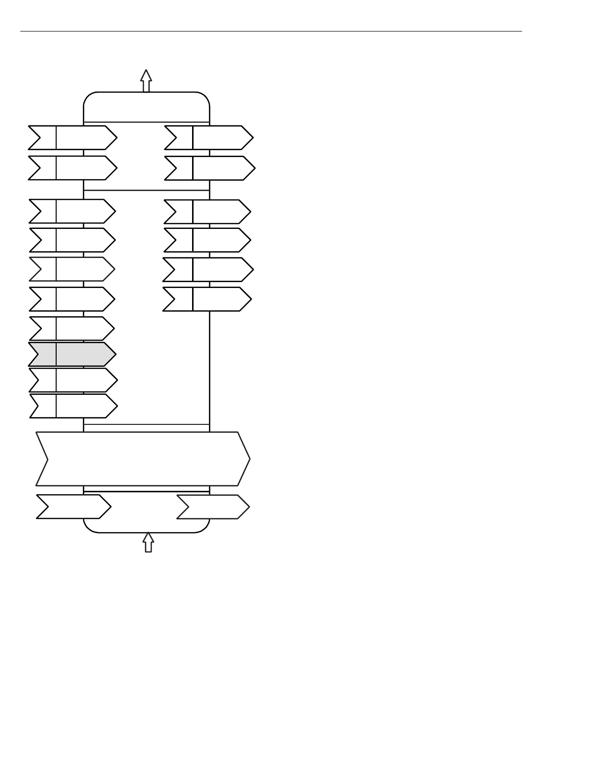
EXCEL 10 W7750A,B,C CONSTANT VOLUME AHU CONTROLLER
74-2958—118
Fig. 9. Functional profile of LONMARK® RTU object details
(variables not implemented in Excel 10 CVAHU
are greyed).
Environmental:
Operatin
g
Temperature: -40 to 150°F
(
-40 to 65.5°C
)
.
Shipping Temperature:
-40 to 150°F
(
-40 to 65.5°C
)
.
Relative Humidity:
5% to 95% noncondensin
g
.
Vibration:
Rated V2 level compliant.
Inputs/Outputs:
The W7750A Unit supports the followin
g
hardware features:
•Three 20 Kohm NTC
(
1000 throu
g
h 150,000 ohm
)
or
PT3000
(
250 throu
g
h 12,000 ohm
)
resistive analo
g
inputs
(
one reserved for space temperature and one reserved for
the setpoint knob
)
.
•Three dr
y
contact di
g
ital inputs
(
one reserved for the
B
y
pass pushbutton
)
.
•LED di
g
ital output
(
only
for the wall module LED
)
2.5V at 3
mA.
•Six 24 Vac rela
y
di
g
ital outputs
(
1.5A rela
y
s rated at 7.5A
inrush current
)
.
The W7750B,C Units support the followin
g
hardware features:
•Four 20 Kohm NTC
(
1000 throu
g
h 150,000 ohm
)
or
PT3000
(
250 throu
g
h 12,000 ohm
)
resistive analo
g
inputs
(
one reserved for space temperature and one reserved for
the setpoint knob
)
.
•Two 0.2 to 10 VDC or 2 to 20 mA
(
user selectable
)
analo
g
inputs.
•Five dr
y
contact di
g
ital inputs
(
one reserved for the B
y
pass
pushbutton
)
.
•Ei
g
ht on the W7750B
(
five on the W7750C
)
24 Vac Triac
di
g
ital outputs
(
500 mA MAX
)
. The W7750C Unit also
supports three 4 to 20 mA analo
g
outputs.
•LED di
g
ital output
(
only
for the wall module LED, T7770
models or LCD, T7560A,B
)
2.5V at 3 mA.
•One 20 Vdc power suppl
y
for auxiliar
y
devices with a
maximum current of 50 mA.
ANALOG INPUTS:
NOTE: Onl
y
one of each t
y
pe of input is allowed. For
example, onl
y
one Outdoor Air Temperature sensor
is allowed. No duplicate Outdoor Air Temperature
sensors are usable on the same controller.
Space Temperature:
T
y
pe: RTD.
Supported Sensors: T7770A,B,C,D; T7560A,B.
Discharge Air Temperature:
T
y
pe: RTD.
Supported Sensors: C7100A1015*, C7770A1006,
C7031B1033, C7031C1031, C7031D1062, C7031F1018
(
W7750B,C onl
y)
, C7031J1050, C7031K1017.
Outdoor Air Temperature:
T
y
pe: RTD.
Supported Sensors: C7170A1002.
Return Air Temperature:
T
y
pe: RTD.
Supported Sensors: C7100A1015*, C7770A1006,
C7031B1033, C7031C1031, C7031D1062, C7031F1018
(
W7750B,C onl
y)
, C7031J1050, C7031K1017.
*The PT3000 sensor is not recommended for floatin
g
control
(
real time - dischar
g
e or return confi
g
ured as space sensor
)
.
The PT3000 sensor is intended for monitorin
g
or differential
(
sta
g
ed
)
control
Hardware
Output
Roof Top Unit
Controller number 8030
Mandatory
Network
Variables
Manufacturer
Defined
Section
Optional
Network
Variables
nv9 nviOutsideRH
SNVT_lev_percent
nv8 nviOutsideTemp
SNVT_ temp_p
nv7 nviSetPtOffset
SNVT_ temp_p
nv6 nviOccCmd
SNVT_occupancy
nv5 nviApplicMode
SNVT_hvac_mode
nv16 nvoCO2
SNVT_ppm
nv12 nvoOutsideRH
SNVT_ lev_percent
nv11 nvoOutsideTemp
SNVT_ temp_p
nv10 nvoEffectSetPt
SNVT_ temp_p
nv2 nviSetPoint
SNVT_temp_p
nv1 nviSpaceTemp
SNVT_temp_p
nv4 nvoUnitStatus
SNVT_hvac_status
nv3 nvoSpaceTemp
SNVT_ temp_p
nv13 nviSpaceRH
SNVT_ lev_percent
nv14 nviCO2
SNVT_ppm
Hardware
Input
nc42 - CO2Limit
nc49 - Send Heartbeat (mandatory)
nc60 - Occupancy Temperature Setpoints (optional)nc48 - Maximum Receive Time
nc17 - Location
(mandatory)
(optional)
(mandatory)
Configuration Properties
nv15 nviEmergCmd
SNVT_hvac_emerg
M11580

EXCEL 10 W7750A,B,C CONSTANT VOLUME AHU CONTROLLER
19 74-2958—1
Outdoor Air Humidity (W7750B,C
only):
T
y
pe: Volta
g
e/Current.
Supported Sensors: C7600B1000 and C7600B1018
(
2 to 10V
)
, C7600C1008
(
4 to 20mA
)
.
Return Air Humidity (W7750B,C
only):
T
y
pe: Volta
g
e/Current.
Supported Sensors: C7600B1000 and C7600B1018
(
2 to 10V
)
, C7600C1008
(
4 to 20mA
)
.
Outdoor Air Enthalpy (W7750B,C
only):
T
y
pe: Current.
Supported Sensors: C7400A1004
(
4 to 20mA
)
.
Return Air Enthalpy (W7750B,C
only):
T
y
pe: Current.
Supported Sensors: C7400A1004
(
4 to 20mA
)
.
Air Filter Differential Pressure (W7750B,C
only):
T
y
pe: Volta
g
e.
Supported Sensors: Third part
y
2 to 10V, 0 to 5 inw
(
1.25 kPa
)
differential pressure sensors.
CO2 Sensor (W7750B,C
only):
T
y
pe: Volta
g
e.
Supported Sensors: Third part
y
0 to 10V, 0 to 2000 ppm
CO2 sensors.
Monitor Sensor for network use (W7750B,C
only):
T
y
pe: Volta
g
e.
Supported Sensors: Third part
y
2 to 10V, 2 to 10 volts
displa
y
ed.
DIGITAL INPUTS:
NOTE: Onl
y
one of each t
y
pe of input is allowed. For
example, onl
y
one Smoke Monitor is allowed. No
duplicate Smoke Monitors are usable on the same
controller.
Dr
y
-contact inputs are sensed usin
g
a 9 milliamp at 4.8 volts
detection circuit. It is ver
y
important that the device used
contains hi
g
h
q
ualit
y
, noncorrodin
g
contacts with resistivit
y
that does not de
g
rade; that is, increase over time. Use noble
metal
(
such as
g
old or silver
)
, or pimpled or sealed contacts to
assure consistent, lon
g
-term operation.
Two of the followin
g
Di
g
ital Inputs
(
DIs
)
can be confi
g
ured
when usin
g
the W7750A, and four of the followin
g
when usin
g
the W7750B,C:
—Fan Status:
Contact Closed = Fan on
—IAQ Switch:
Contact Closed = Poor Air Qualit
y
—Time Clock:
Contact Closed = Occupied Mode; Contact Open =
Unoccupied Mode
—Schedule Master:
Contact Closed = Local time clock is used as master time
clock
—Economizer Enable Si
g
nal:
Contact Closed = Economizer Enabled for coolin
g
use
—Smoke Monitor:
Contact Closed = Smoke Detected
—Dirt
y
Filter:
Contact Closed = Dirt
y
Filter
—Shutdown Si
g
nal:
Contact Closed = Shut off all e
q
uipment
—Occupanc
y
Switch:
Contact Closed = Room is Occupied; Contact Open =
Room is Unoccupied
—Window Monitor:
Contact Closed = Window is Closed
—Coil Freeze Stat:
(
Onl
y
use this DI when usin
g
E-Vision.
)
Contact Closed = Coil Freeze condition sensed
—Wall Module B
y
pass Pushbutton:
Momentar
y
DI
(
See Appendix B—Se
q
uences of Operation
for b
y
pass details.
)
TRIAC OUTPUTS ON THE (W7750B,C MODELS ONLY):
—Power ratin
g
s: 20 Vac to 30 Vac at 25 mA MIN to 500 mA
MAX current for an
y
volta
g
e.
CAUTION
When an
y
device is ener
g
ized b
y
a Triac, the device
must be able to sink a minimum of 25 mA.
NOTE: Triacs sink current to the 24 Vac common
(
COM
terminal on the W7750B,C Models
)
; see Fi
g
. 30 for
wirin
g
example.
IMPORTANT
If non-Honeywell motors, actuators, or transducers
are to be used with Excel 10 Controllers, Triac com-
patibility must be verified (see previous NOTE).
DIGITAL OUTPUTS:
COOL STAGE 1
COOL STAGE 2
COOL STAGE 3
COOL STAGE 4
HEAT STAGE 1
HEAT STAGE 2
HEAT STAGE 3
HEAT STAGE 4
CHANGE OVER RELAY
FAN
AUX ECON
OCCUPANCY STATUS
ECON OPEN
ECON CLOSE
COOL OPEN
COOL CLOSE
HEAT OPEN
HEAT CLOSE
HEAT COOL STAGE 1
HEAT COOL STAGE 2
HEAT COOL STAGE 3
HEAT COOL STAGE 4
FREE1
(
NOTE:
Free1
,
Free1 Pulse On
and
Free1 Pulse Off
are three separate and uni
q
ue di
g
ital output points. Because
the
y
are not related, the
y
all can be confi
g
ured in a CVAHU
controller at the same time.
)
FREE2
FREE1 PULSE ON
FREE1 PULSE OFF
ECON PWM
HEAT PWM
COOL PWM
UNUSED
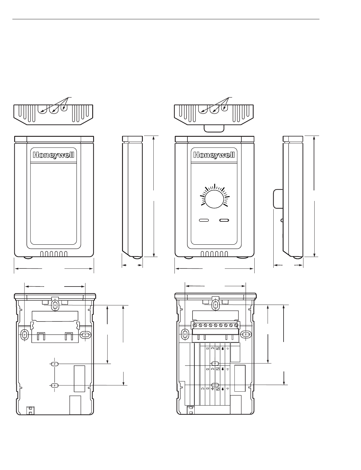
EXCEL 10 W7750A,B,C CONSTANT VOLUME AHU CONTROLLER
74-2958—120
Wall Modules
The T7770 or T7560 Wall Modules for the Excel 5000 and
Excel 10 Controllers are available in a variet
y
of
confi
g
urations. The models T7770A1006 and T7770C1002
are shown in Fi
g
. 10. The T7770B,D are the same ph
y
sical
size
(
see Product Names section for differences
)
. The models
T7560A1016 and T7560B1018 are shown in Fi
g
. 11. The
T7560A,B are the same ph
y
sical size.
Duct Sensor
The dimensions of the C7770A duct-mounted sensor are
shown in Fi
g
. 12.
Fig. 10. T7770A,B,C,D construction in in. (mm).
STANDARD
UTILITY
CONDUIT
BOX (2 X 4)
MOUNTING
HOLES
KNOCKOUTS FOR EUROPEAN
APPLICATIONS
3-5/32 (80)
2-3/8 (60)
29/32
(23)
5-1/16
(128)
2-3/8
(60)
T7770A1006
M15119
STANDARD
UTILITY
CONDUIT
BOX (2 X 4)
MOUNTING
HOLES
KNOCKOUTS FOR EUROPEAN
APPLICATIONS
3-5/32 (80)
2-3/8 (60)
1-1/4
(32)
5-1/16
(128)
2-3/8
(60)
T7770C
70
65
60
55 85
80
75
DIP Switch S4 Settings:
1,3,5=on; 2,4=off 2,4=on; 1,3,5=off 1,2,3,4=on; 5=0ff
W7753
XL600-XL20
W7752
LED RETURN
BYPASS
LED
FAN
SETPT
SENSOR
GND
LED
SETPT
SENSOR
AL COM
LED
SETPT
SENSOR
GND
BYPASS/FAN BYPASS/FAN
9 8 7 6 5 4 3 2 1
E-BUS
E-BUS
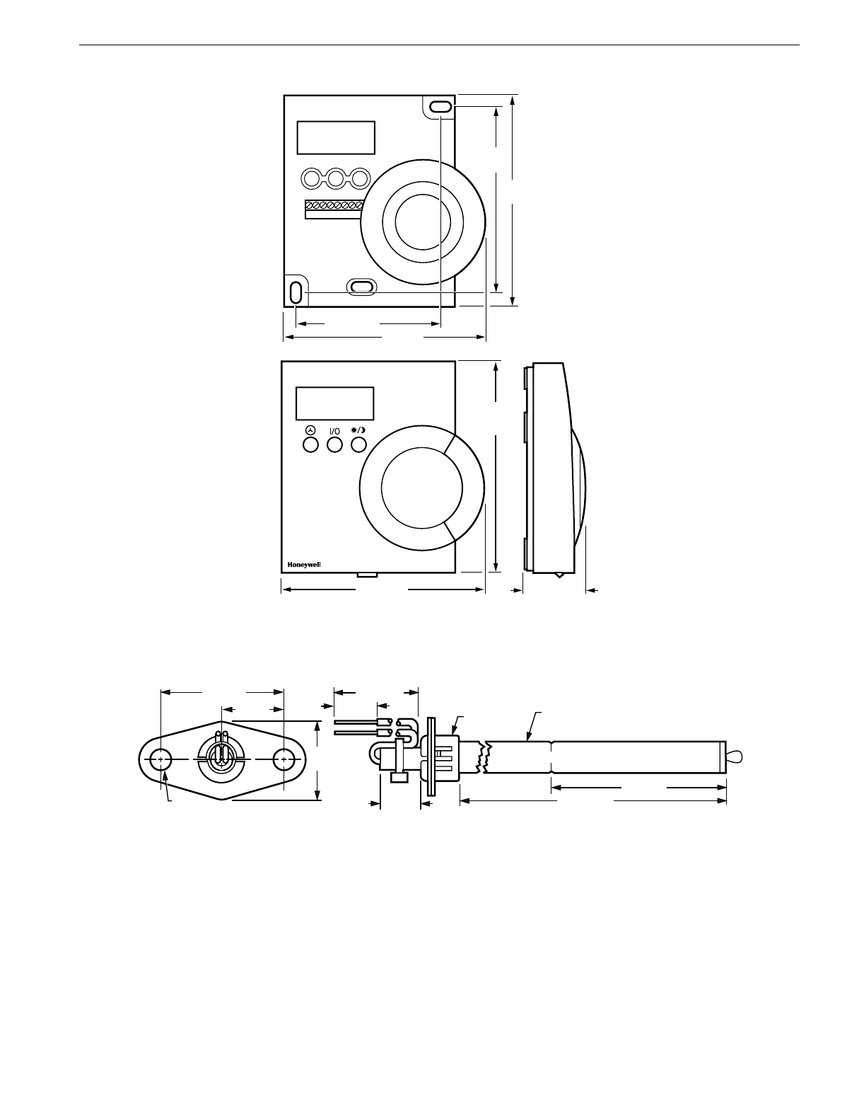
EXCEL 10 W7750A,B,C CONSTANT VOLUME AHU CONTROLLER
21 74-2958—1
Fig. 11. T7560A,B construction in in. (mm).
Fig. 12. C7770A construction in in. (mm).
3-15/16 (99) 1-3/16 (30)
4-1/8
(104)
M17479
3-7/8 (97)
2-11/16 (68)
4
(100)
3-7/16
(86)
12345678
1/2 IN. (13)
DIAMETER
1/4 (6)
DIAMETER (2 HOLES)
3/8 IN. (10)
DIAMETER
6-5/32 (156)
M7724
3-1/2 (89)
1/2 (13)
1/2 (13)
8-1/2 (216)
7/8
(22)
3/4 (19)
1-1/2 (38)

EXCEL 10 W7750A,B,C CONSTANT VOLUME AHU CONTROLLER
74-2958—122
Configurations
General
Tables 3 and 4 provide an overview of the Excel 10 W7750
confi
g
uration options. All W7750s are assumed to have a
suppl
y
fan di
g
ital output. Additionall
y
, Tables 3 and 4 list the
g
eneral mechanical e
q
uipment options available with the
W7750 Controller. See Application Step 6. Confi
g
ure
Controllers, for further information on confi
g
urations.
CAUTION
For floatin
g
control, the Excel 10 W7750 Controller is
desi
g
ned to work onl
y
with Series 60 valve and
damper actuators. Full stroke actuator drive-time must
be between 20 and 240 seconds
(
0.25 to 4.0 minutes
)
.
Table 3. Common Configuration Options Summary For W7750A,B,C Controllers.
Option Possible Configurations Common To All W7750 Models
Supply Fan 1. Mandator
y
Di
g
ital Output.
Type of Air Handler 1. Conventional.
2. Heat Pump.
Occupancy Sensor 1. None.
2. Connected: Contacts closed e
q
uals Occupied.
3. Network
(
Occ/Unocc si
g
nal received via the LONWORKS Bus network
)
.
Window Sensor 1. None.
2. Ph
y
sicall
y
Connected: Contacts closed e
q
uals window closed.
3. Network
(
Window Open/Closed si
g
nal received via the LONWORKS Bus
)
.
Wall Module Option 1. Local
(
direct wired to the controller
)
.
(
The T77560A,B has no LONWORKS Bus access
)
2. Network
(
sensor value received via the LONWORKS Bus
)
.
Wall Module Type 1. Sensor onl
y
.
(
All wall modules have a LONWORKS Bus access 2. Sensor and Setpoint ad
j
ust.
j
ack except T7560A,B
)
3. Sensor, Setpoint ad
j
ust and B
y
pass.
4. Sensor and B
y
pass.
Smoke Emergency Initiation 1. None.
2. Ph
y
sicall
y
Connected: Contacts closed e
q
uals smoke detected.
3. Network
(
Emer
g
enc
y
/Normal si
g
nal received via the LONWORKS Bus
)
.

EXCEL 10 W7750A,B,C CONSTANT VOLUME AHU CONTROLLER
23 74-2958—1
Table 4. Configuration Options Summary For W7750A,B,C Controllers.
Option Possible Configurations for the
W7750A Model Possible Configurations for the W7750B,C Models
Type of 1. One sta
g
e. 1. One sta
g
e.
Heating 2. Two sta
g
es. 2. Two sta
g
es.
3. Three sta
g
es. 3. Three sta
g
es.
4. Four sta
g
es. 4. Four sta
g
es.
5. None. 5. Series 60 Modulatin
g
electric valve, or pneumatic via transducer.
6. Pulse Width Modulatin
g
electric valve, or pneumatic via transducer.
7. None.
Type of 1. One sta
g
e. 1. One sta
g
e.
Cooling 2. Two sta
g
es. 2. Two sta
g
es.
3. Three sta
g
es. 3. Three sta
g
es.
4. Four sta
g
es. 4. Four sta
g
es.
5. None. 5. Series 60 Modulatin
g
electric valve, or pneumatic via transducer.
6. Pulse Width Modulatin
g
electric valve, or pneumatic via transducer.
7. None.
Type of
Economizer 1. Di
g
ital Output Enable/Disable
si
g
nal for controllin
g
an external
economizer packa
g
e.
1. Di
g
ital Output Enable/Disable si
g
nal for controllin
g
an external
economizer packa
g
e.
2. Series 60 Modulatin
g
electric
damper motor, or pneumatic via
transducer.
2. Series 60 Modulatin
g
electric damper motor, or pneumatic via
transducer.
3. None. 3. Pulse Width Modulatin
g
electric damper motor, or pneumatic via
transducer.
4. None.
IAQ Option 1. None. 1. None.
2. Local IAQ Di
g
ital Input—directl
y
wired to the controller.
(
Contacts
closed means poor IAQ is
detected.
)
2. Local IAQ Di
g
ital Input—directl
y
wired to the controller.
(
Contacts
closed means poor IAQ is detected.
)
3. Network
(
IAQ Override si
g
nal
received via the LONWORKS Bus
)
.3. Network
(
IAQ Override si
g
nal received via the LONWORKS Bus
)
.
4. Local CO2 Analo
g
Input—directl
y
wired to the controller.
(
The sensor
must be a 0 to 10V device representin
g
0 to 2000 PPM CO2.
)
Coil Freeze 1. None. 1. None.
Stat Option 2. Local Coil Freeze Stat Di
g
ital
Input—directl
y
wired to the controller.
(
Contacts closed means that coil
freeze condition is sensed.
)
2. Local Coil Freeze Stat Di
g
ital Input—directl
y
wired to the controller.
(
Contacts closed means that coil freeze condition is sensed.
)
Filter Monitor 1. None. 1. None.
Option 2. Local Dirt
y
Filter Di
g
ital
Input—directl
y
wired to the
controller.
(
Contacts closed means
that the filter is dirt
y
.
)
2. Local Dirt
y
Filter Di
g
ital Input—directl
y
wired to the controller.
(
Contacts closed means that the filter is dirt
y
.
)
3. Local Analo
g
Input for Differential Pressure across the Filter
(
directl
y
wired to the controller
)
. The sensor must be a 2 to 10V device
representin
g
0 to 5 inw
(
1.25 kPa
)
.
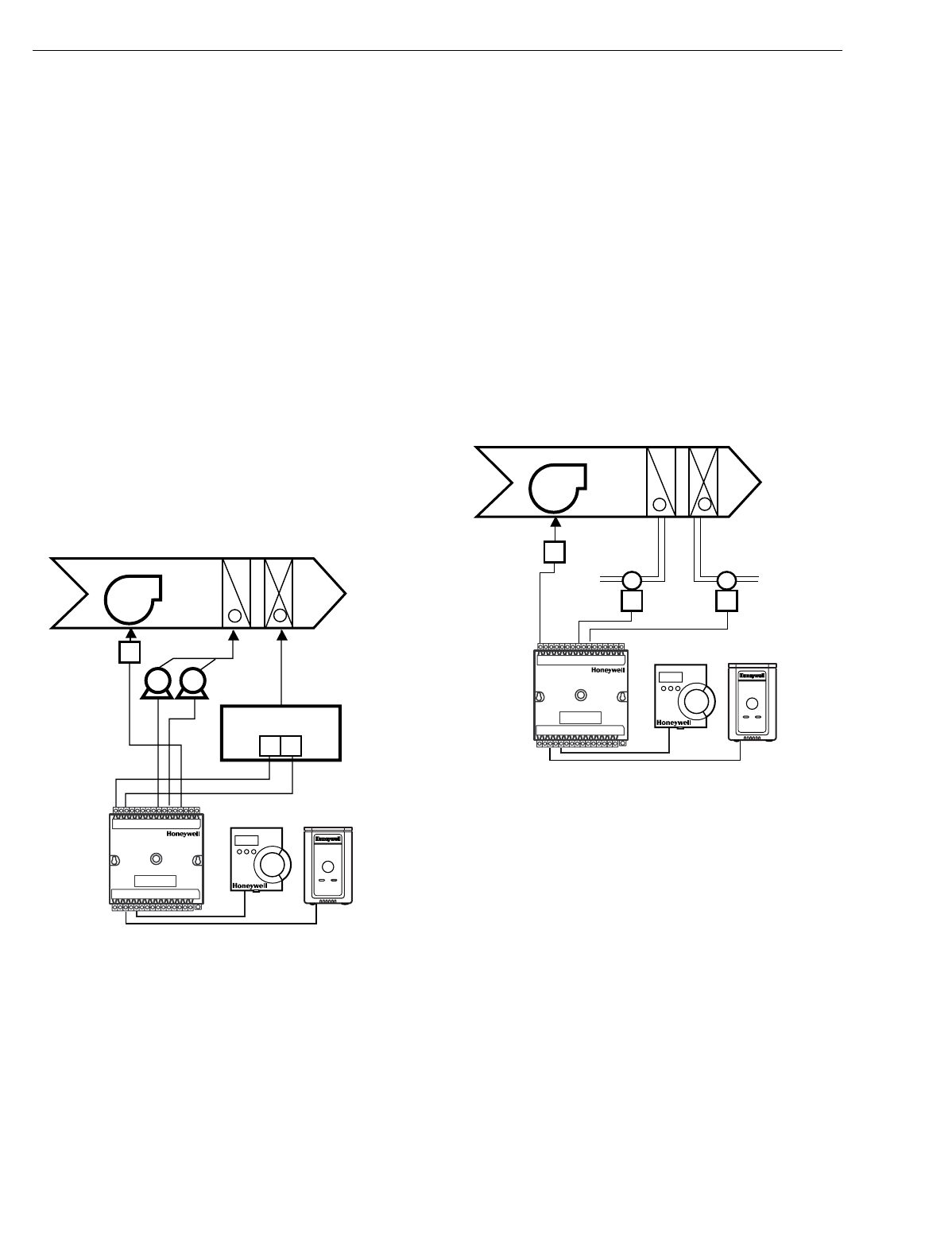
EXCEL 10 W7750A,B,C CONSTANT VOLUME AHU CONTROLLER
74-2958—124
Allowable Heating and Cooling Equipment
Configurations
Each W7750 device can control a variet
y
of different t
y
pes of
mechanical coolin
g
and heatin
g
e
q
uipment within roof top air
handlers. See Fi
g
. 13 throu
g
h 17 for a conceptual overview of
some t
y
pical confi
g
urations. For specific wirin
g
details, see
the Prepare Wirin
g
Dia
g
rams section.
STAGED HEATING/COOLING CONTROL
Sta
g
ed e
q
uipment control is available for up to four sta
g
es of
heatin
g
or four sta
g
es of coolin
g
. On the W7750, the sta
g
es
are activated throu
g
h di
g
ital outputs
(
Triacs on the W7750B,C
and dr
y
-contact rela
y
s on the W7750A
)
one for each sta
g
e
wired to 24 Vac contactors
(
see Fi
g
. 27 and 30 in Step 4.
Prepare Wirin
g
Dia
g
rams section for wirin
g
details
)
. Note that
the number of ph
y
sical Di
g
ital Outputs
(
DOs
)
on the controller
limits the total number of sta
g
es that can be controlled. For
example, the W7750A Model has six di
g
ital outputs, and
because one is used for the suppl
y
fan, there are five DOs
available for an
y
combination of heatin
g
and coolin
g
sta
g
es
(
with a maximum of four sta
g
es of heatin
g
and four sta
g
es for
coolin
g)
. The W7750B Model offers two additional DOs, for a
total of ei
g
ht. The W7750C offers five DOs and three Analo
g
Outputs
(
AOs
)
. Fi
g
. 13 shows a t
y
pical application of two
sta
g
es of heat and two sta
g
es of coolin
g
.
Fig. 13. Fan with two stages of heating and two stages
of cooling.
MODULATING HEATING/COOLING CONTROL
The W7750 Controller provides modulatin
g
e
q
uipment control
for heatin
g
and coolin
g
e
q
uipment
(
and economizer dampers,
see Fi
g
. 16
)
usin
g
either Series 60 Floatin
g
Control or Pulse
Width Modulated
(
PWM
)
control,
(
PWM control is available on
the W7750B,C
only
)
. The Series 60 Modulatin
g
Control is
provided throu
g
h two Rela
y
di
g
ital outputs on the W7750A or
two Triac di
g
ital outputs on the W7750B,C
(
one to pulse the
valve actuator open and one to pulse it closed
)
. PWM control
positions the actuator based on the len
g
th, in seconds, of the
pulse from the di
g
ital output. For PWM, the controller outputs
a pulse whose len
g
th consists of two parts, a minimum and a
maximum. The minimum pulse time represents the analo
g
value of 0 percent and the maximum pulse len
g
th that
represents an analo
g
value of 100 percent. If the analo
g
value
is
g
reater than 0 percent, an additional time is added to the
minimum pulse time. The len
g
th of time added is directl
y
proportional to the ma
g
nitude of the analo
g
value. The PWM
actuator will be
g
in to use the analo
g
value at the end of the
pulse and will continue to use this value until a new pulse is
received. Refer to Appendix B under PWM Control for an
example. Series 60 actuators are
g
enerall
y
less expensive
than those for PWM, but the trade-off is that PWM re
q
uires
onl
y
a sin
g
le controller di
g
ital output while floatin
g
control
uses two DOs. Refer to Appendix B under Series 60
Modulatin
g
Control for an example. Fi
g
. 14 illustrates a
s
y
stem with modulatin
g
heatin
g
and coolin
g
(
see Fi
g
. 29 and
31 in Step 4. Prepare Wirin
g
Dia
g
rams section.
Fig. 14. Fan, modulating heating and modulating cooling.
NOTE: Pneumaticall
y
actuated valves can be controlled
usin
g
a pneumatic transducer device. See Fi
g
. 17.
Also, transducer devices are available from third
part
y
vendors to convert PWM outputs to a volta
g
e
or current si
g
nal if desired.
HEAT PUMP CONTROL
The W7750 Controller handles heat pump applications
similarl
y
to sta
g
ed heatin
g
/coolin
g
control. Heat pump
applications are supported b
y
providin
g
outputs for up to four
compressor sta
g
es, a chan
g
e-over rela
y
for the refri
g
erant
reversin
g
valve, and up to four sta
g
es of auxiliar
y
heat. Note
that the W7750A Model has six di
g
ital outputs, and therefore,
with one DO used for the suppl
y
fan and one for the chan
g
e-
over rela
y
, there are four outputs available for an
y
combination of compressors and auxiliar
y
heat sta
g
es. The
W7750B Model offers two additional DOs for a total of ei
g
ht,
while the W7750C Model offers five DOs and 3 AOs. Fi
g
. 15
illustrates a t
y
pical heat pump s
y
stem with auxiliar
y
heat.
M17491
MIXED
AIR
HEAT
COIL
COOL
COIL
DISCHARGE
AIR
W1 W2
Y1 Y2
-+
FAN
FAN
STARTER
COMPRESSORS
GAS COMBUSTION
CONTROLS
EXCEL 10
CVAHU
W7750A,B,C
T7560A,B OR T7770
MIXED
AIR
HEAT
COIL
COOL
COIL
DISCHARGE
AIR
-+
FAN
FAN
STARTER
CHILLED
WATER
VALVE
HOT
WATER
VALVE
M17492
EXCEL 10
CVAHU
W7750A,B,C
T7560A,B OR T7770
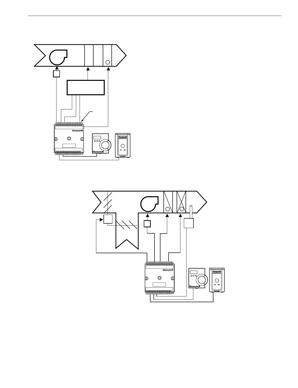
EXCEL 10 W7750A,B,C CONSTANT VOLUME AHU CONTROLLER
25 74-2958—1
Fig. 15. Heat pump with two compressors and auxiliary
heat stage(s).
ECONOMIZER CONTROL
Economizer control is available concurrentl
y
with an
y
confi
g
uration in the W7750 when DOs are not all used b
y
the
heatin
g
and coolin
g
e
q
uipment. Two t
y
pes of economizer
controls are supported b
y
the W7750 Controller, modulatin
g
control and enable/disable control. Modulatin
g
control can be
either Series 60 Floatin
g
Control or PWM control
(
PWM
control is available on the W7750B,C
only
)
. A dischar
g
e air
temperature sensor is re
q
uired for modulatin
g
economizer
damper control. Enable/disable control is provided to emulate
the Hone
y
well T7300 thermostat economizer operation,
where a DO tracks the occupanc
y
status of the controller. An
external packa
g
ed economizer control then modulates the
dampers. For modulatin
g
control, the economizer is enabled
or disabled based on one of ten available strate
g
ies
(
see
Appendix B—Se
q
uences of Operation—Economizer Enable/
Disable Control section, for further details
)
. Fi
g
. 16 illustrates
a s
y
stem with modulatin
g
economizer dampers
(
see Fi
g
. 29,
31, 32 and 35 in Step 4. Prepare Wirin
g
Dia
g
rams section, for
wirin
g
details
)
.
Fig. 16. Economizer control.
PNEUMATIC ACTUATOR CONTROL
The W7750B,C Controller can control pneumatic actuators for
an
y
or all of the three modulatin
g
outputs provided b
y
the
control al
g
orithm
(
heat, cool and economizer
)
. Control of
pneumatic water/steam valves and damper actuators is
provided throu
g
h a transducer device usin
g
either Series 60
Floatin
g
Control or PWM DOs. A floatin
g
-to-pneumatic, or a
PWM-to-pneumatic transducer is re
q
uired for each output
si
g
nal. The W7750A Controller can drive Series 60 Floatin
g
Control to modulate coolin
g
valves, heatin
g
valves and
economizers. There are no PWM outputs confi
g
urable on the
W7750A model.
For pro
j
ects with existin
g
pneumaticall
y
actuated reheat
valves, the Excel 10 W7750 Controller output must be
converted to a pneumatic si
g
nal usin
g
a transducer device
developed for use with Excel 10 Controllers. The transducer is
MIXED
AIR
AUXILIARY
HEAT
STAGE(S)
SHARED
HEAT AND
COOL COIL
DISCHARGE
AIR
+
FAN
FAN
STARTER
COMPRESSOR AND
CHANGEOVER VALVE
COMP 1
COMP 2
CHANGEOVER
RELAY
M17493
EXCEL 10
CVAHU
W7750A,B,C T7560A,B OR T7770
OUTDOOR
AIR
RETURN
AIR
HEAT
COIL
COOL
COIL
DISCHARGE
AIR
-+
FAN
FAN
STARTER
DISCHARGE
TEMPERATURE
SENSOR REQUIRED
FOR ECONOMIZER
CONTROL
M
PWM OR
SERIES 60
FLOATING
MOTOR
M17494
EXCEL 10
CVAHU
W7750A,B,C
T7560A,B OR T7770
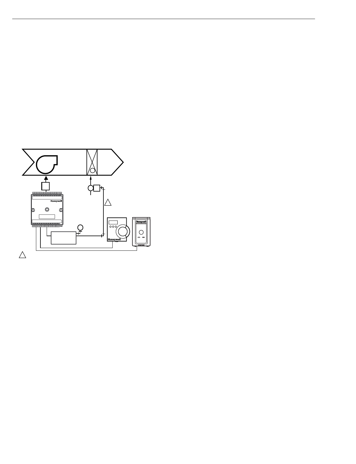
EXCEL 10 W7750A,B,C CONSTANT VOLUME AHU CONTROLLER
74-2958—126
available throu
g
h Hone
y
well, or directl
y
from the
manufacturer, Mamac S
y
stems
(
see Table 11 for orderin
g
information
)
.
Fi
g
. 17 depicts a t
y
pical W7750 S
y
stem with modulatin
g
heatin
g
valve usin
g
a pneumatic valve actuator. Also see Fi
g
.
36 for wirin
g
an MMC325 Pneumatic Transducer to a
W7750A,B,C Controller and Fi
g
. 37 for wirin
g
a RP7517B
Pneumatic Transducer to a W7750C Controller.
NOTE: When choosin
g
the pneumatic pressure ran
g
e, make
sure that the close-off pressure is 2 to 3 psi
g
reater
than that of the sprin
g
ran
g
e. When usin
g
a sprin
g
ran
g
e of 5 to 10 psi with 10 psi as the closed posi-
tion,
do not
use the 0 to 10 psi model of the MMC325
Transducer; use the 0 to 20 psi transducer as the
recommended selection.
Fig. 17. Modulating heat with pneumatic valve actuator.
MIXED-OUTPUT-TYPE CONTROL
The W7750B,C Controller provides control for mixed-output-
t
y
pes of applications such as PWM heatin
g
and sta
g
ed
coolin
g
control occurrin
g
simultaneousl
y
with Series 60
Floatin
g
Economizer Damper Control.
Occupancy Sensor
Excel 10 W7750 Controllers provide a di
g
ital input for
connection to an occupanc
y
sensor. This is a device, such as
a passive infrared motion detector, that contains a dr
y
contact
(
see followin
g
NOTE
)
closure to indicate whether or not
people are present in the space. The Excel 10 W7750
Controller expects a contact closure to indicate the space is
Occupied. See Fi
g
. 27 throu
g
h 35 in Application Step 4,
Prepare Wirin
g
Dia
g
rams, for details on wirin
g
connections.
The control al
g
orithm in the Excel 10 Controller uses the
occupanc
y
sensor, if confi
g
ured, to determine the Effective
Occupanc
y
(
see Table 5
)
mode of operation. If the Time Of
Da
y
(
TOD
)
schedule indicates an Occupied state, and the
occupanc
y
sensor contact is closed, the Effective Occupanc
y
mode is Occupied. However, if the TOD schedule indicates an
Occupied state and the occupanc
y
sensor contact is open,
then the Effective Occupanc
y
mode is STANDBY. The
temperature control al
g
orithm is then controlled to the
STANDBY Coolin
g
and Heatin
g
Setpoints.
If the occupanc
y
sensor is not confi
g
ured, a local controller
can be put in the STANDBY mode onl
y
b
y
either a one-to-one
association of the occupanc
y
sensor from another Excel 10
Controller to the local controller, or b
y
receivin
g
the STANDBY
mode si
g
nal via the LONWORKS Bus.
NOTE: The Excel 10 Controller has limited power available
(
onl
y
9 mA at 4.8 volts
)
for checkin
g
the di
g
ital inputs
for contact closures. It is ver
y
important that the
device used contains hi
g
h
q
ualit
y
, noncorrodin
g
contacts with resistivit
y
that does not de
g
rade; that
is, increase over time. Use noble metal
(
such as
g
old
or silver
)
, or pimpled or sealed contacts to assure
consistent, lon
g
-term operation.
The recommended devices for use with the Excel 10 W7750
Controllers are the EL7628A1007 Ceilin
g
Mounted Infrared or
the EL7680A1008 Wall Mounted Wide View Infrared
Occupanc
y
Sensors. If ultrasonic sensors are re
q
uired, the
EL7611A1003 and the EL7612A1001 Occupanc
y
Sensors are
recommended. An EL76XX Power Suppl
y
/Control Unit is
re
q
uired for use with these occupanc
y
sensors. The
EL7630A1003 can power up to four sensors, and is multi-
tapped for several line volta
g
es. The EL7621A1002 can
power three sensors and it connects to 120 Vac line volta
g
e.
The EL7621A1010 can also power three sensors but it
connects to 277 Vac line volta
g
e.
Window Open/Closed Digital Input
A di
g
ital input is also provided for detectin
g
whether a window
in the space was opened. The Excel 10 W7750 Controller can
be connected to a dr
y
contact
(
see the followin
g
NOTE and
Fi
g
. 27 throu
g
h 35 in Application Step 4. Prepare Wirin
g
Dia
g
rams, for details
)
or a set of contacts wired in series
(
for
monitorin
g
multiple windows
)
to verif
y
that the window
(
s
)
are
closed. The al
g
orithm expects a contact closure to indicate
the window is closed. If an open window is detected, the
al
g
orithm chan
g
es the mode of operation to
FREEZE_PROTECT, which shuts down the control functions,
and watches for low space temperature conditions. The frost
protection setpoint is 46.4°F
(
8°C
)
, and the frost alarm occurs
at 42.8°F
(
6°C
)
.
NOTE:
(
This is the same NOTE as in the Occupanc
y
Sensor
section.
)
The Excel 10 has limited power available
(
onl
y
9 mA at 4.8 volts
)
for checkin
g
the di
g
ital inputs
for contact closures. It is ver
y
important that the
device used contains hi
g
h
q
ualit
y
, noncorrodin
g
contacts with resistivit
y
that does not de
g
rade; that
is, increase over time. Use noble metal
(
such as
g
old
or silver
)
, or pimpled or sealed contacts to assure
consistent, lon
g
-term operation.
Wall Module Options
As previousl
y
discussed, there are four basic varieties of the
T7770 Wall Modules and two of the T7560 Di
g
ital Wall Module
(
see the Product Names and the Construction sections
)
. Also,
a T7770 and T7560 Wall Modules can be shared amon
g
two
or more W7750s. The control al
g
orithm must be
g
iven this
wall module information when confi
g
urin
g
the W7750
(
see
Excel E-Vision User’s Guide, form 74-2588
)
.
VALVE
PNEUMATIC
ACTUATOR
PNEUMATIC
TRANSDUCER
MMC325
M
1
1
PNEUMATIC MAIN OR BRANCH LINE MUST BE 1/4 IN. (6 MM)
OR LARGER TUBING. A MINIMUM OF 6 FT (1.8M) OF TUBING
IS NEEDED IN A BRANCH LINE.
MIXED
AIR
HEAT
COIL
DISCHARGE
AIR
+
FAN
FAN
STARTER
M17495
T7560A,B OR T7770

EXCEL 10 W7750A,B,C CONSTANT VOLUME AHU CONTROLLER
27 74-2958—1
Dirty Filter Monitor
The air filter in the air handler can be monitored b
y
the W7750
and an alarm is issued when the filter media needs
replacement. The two methods of monitorin
g
the filter are:
1. Connectin
g
a differential pressure switch to a di
g
ital
input on the W7750A or W7750B,C.
2. Wirin
g
a 2 to 10V differential pressure sensor to a
volta
g
e input on the W7750B,C. If the analo
g
input
sensor is used, its measured value 0 to 5 inw
(
0 to 1.25
kPa
)
is compared to a user-selectable setpoint
(
FltrPressStPt—valid ran
g
e: 0 to 5 inw
(
0 to 1.25 kPa
))
,
and the Dirt
y
Filter alarm is issued when the pressure
drop across the filter exceeds the setpoint.
Indoor Air Quality (IAQ) Override
The Excel 10 W7750 Controller provides IAQ ventilation
control usin
g
one of two different methods of detectin
g
poor
air
q
ualit
y
. The first is with an IAQ switch device connected to
a di
g
ital input on the W7750 Controller, where a contact
closure indicates poor air
q
ualit
y
, and initiates the IAQ
Override mode. The device can detect poor air
q
ualit
y
usin
g
an
y
desired measure such as CO2, VOC, CO, etc. The
second method, which is onl
y
available on the W7750B,C, is
throu
g
h an analo
g
input that connects to a CO2 sensor
(
2 to
10V
)
. The measured value of CO2 from this sensor
(
0 to 2000
PPM
)
is compared to the setpoint
(
IAQSetpt
)
. When the CO2
level is hi
g
her than the setpoint
(
800 PPM
adjustable
)
, the
IAQ Override is initiated. The IAQSetpt h
y
steresis is 50 PPM,
IAQ Override is deactivated at a CO2 level less than 50 PPM
below setpoint.
The effect of initiatin
g
the IAQ Override mode is that the
economizer dampers are allowed to open above the standard
minimum position settin
g
to allow more fresh air to enter the
buildin
g
. See Appendix B—Se
q
uences of Operation, for
further control details.
Smoke Control
The Excel 10 W7750 Controller supports smoke-related
control strate
g
ies that are initiated either via a network
command
(
DestEmer
g
Cmd
)
or from a local
(
ph
y
sicall
y
connected
)
smoke detector di
g
ital input. The details of the
W7750 smoke-related control operation are described in
Appendix B—Se
q
uences of Operation.
Freeze Stat
A freeze stat can be monitored b
y
the W7750 and issue a
freeze stat alarm indicatin
g
the CVAHU is in dan
g
er of
freezin
g
its coil. The details of the W7750 freeze stat related
control operation are described in Appendix B—Se
q
uences of
Operation.
Modes of Operation
The possible modes of operation for the W7750 Controller are
listed in Table 5.
Table 5. Modes Of Operation For The Excel 10 W7750 Controller .
Mode Description Events causing a controller to switch to this mode
Effective Occupancy (User Address: StatusOcc)
OCCUPIED Controller is in Occupied mode An
y
of the followin
g
: Network input
(
DestSchedOcc
)
containin
g
a
time-of-da
y
schedule fla
g
from either the Excel 10 Zone Mana
g
er or an
LONWORKS Bus Controller; Time Clock DI, Occupanc
y
Sensor DI; or
from Network input
(
DestManMode
)
for manual override to OCC mode.
DestManMode has the hi
g
hest priorit
y
, followed b
y
the Time Clock DI,
and then DestSchedOcc.
STANDBY Controller is in Standb
y
mode Either:
(
A
)
Network input
(
DestSchedOcc
)
containin
g
a time-of-da
y
schedule fla
g
from the Excel 10 Zone Mana
g
er or other LONWORKS
Bus node is STANDBY, or
(
B
)
Network input
(
DestSchedOcc
)
is
OCCUPIED and the Occupanc
y
Sensor DI is UNOCCUPIED.
UNOCCUPIED Controller is in Unoccupied mode Network input
(
DestSchedOcc
)
containin
g
a time-of-da
y
schedule fla
g
from the Excel 10 Zone Mana
g
er or LONWORKS Bus, or the network
input DestManOcc has a value of UNOCCUPIED.
BYPASS
OCCUPIED Controller is in Occupied mode throu
g
h
a B
y
pass command This mode is derived from the schedule occupanc
y
(
DestSchedOcc
)
havin
g
a state of UNOCCUPIED and a manual re
q
uest for occupanc
y
from one of three sources. Two of these are si
g
nals ori
g
inated external
to the unit, and received b
y
DestManOcc and DestB
y
pass. The third
source for an occupanc
y
re
q
uest is from an override button located on
a wall module. These three sources are arbitrated in a scheme
determined b
y
the confi
g
uration parameter
(
Network Wins or Last-in
Wins from OvrdPriorit
y)
.
Override Modes (User Address: StatusOvrd)
OCCUPIED Controller occupanc
y
mode was
overridden to Occupied mode Network input
(
DestManOcc
)
containin
g
a time-of-da
y
schedule
override si
g
nal of OCCUPIED from the Excel 10 Zone Mana
g
er or
other LONWORKS Bus device.
STANDBY Controller occupanc
y
mode was
overridden to Standb
y
mode Network input
(
DestManOcc
)
containin
g
a time-of-da
y
schedule
override si
g
nal of STANDBY from the Excel 10 Zone Mana
g
er or other
LONWORKS Bus device.

EXCEL 10 W7750A,B,C CONSTANT VOLUME AHU CONTROLLER
74-2958—128
NOTE: Durin
g
all modes all di
g
ital and analo
g
ph
y
sical
inputs are periodicall
y
read, the dia
g
nostic output
network variables can be polled, the input network
variables are received, and the output network
variables are sent periodicall
y
.
UNOCCUPIED Controller occupanc
y
mode was
overridden to Unoccupied mode Network input
(
DestManOcc
)
containin
g
a time-of-da
y
schedule
override si
g
nal of UNOCCUPIED from the Excel 10 Zone Mana
g
er or
other LONWORKS Bus device.
BYPASS Controller occupanc
y
mode was
overridden to B
y
pass the current
Unoccupied mode
DI
(
B
y
pass
)
was pressed, and the B
y
pass duration timer has not
y
et
expired, or the network input DestManOcc has a value of BYPASS.
NOT
ASSIGNED No B
y
pass action No Override input received.
Operational Modes (User Address: StatusMode)
START-UP
AND WAIT On power-up, provides a sta
gg
ered
start se
q
uence to evenl
y
appl
y
the load
to the electrical s
y
stem.
This mode occurs on controller power-up, and after downloadin
g
to the
controller from the confi
g
uration tool. Temperature control loops are
disabled.
COOLING The Excel 10 is controllin
g
the Coolin
g
mode. Space temperature has risen above the current coolin
g
setpoint, or the
network input
(
DestHvacMode
)
is COOL.
HEATING The Excel 10 is controllin
g
the Heatin
g
mode. Space temperature has fallen below the current heatin
g
setpoint, or the
network input
(
DestHvacMode
)
is HEAT.
EMERGENCY
HEAT Compressors are disabled and onl
y
Auxiliar
y
Heat sta
g
es are allowed to
operate.
The network input
(
DestManHvacMode
)
is EMERG_HEAT.
OFF MODE The heat/cool control is turned off
immediatel
y
. The node is not runnin
g
its
normal temperature control.
Network input
(
DestManMode
)
containin
g
AHU operational mode
information from C-Bus has value of MORNING WARM-UP.
DISABLED
MODE The heat/cool control and frost
protection are turned off immediatel
y
.
The node is not runnin
g
its normal
temperature control.
–
SMOKE
EMERGENCY The node has entered a smoke
emer
g
enc
y
. The fan and dampers are
then set to the conditions confi
g
ured b
y
SmkCtlMode. The control remains in
SMOKE_ EMERGENCY until power is
c
y
cled or the node receives
DestEmer
g
Cmd set to
EMERG_NORMAL.
Network input
(
DestEmer
g
Cmd
)
containin
g
smoke control si
g
nal from
another LONWORKS Bus device has value of SMOKE_EMERG.
FREEZE
PROTECT The temperature control is set to HEAT
with the setpoint set to the frost limit
setpoint 46.4°F
(
8°C
)
.
The Window di
g
ital input detects an open window.
MANUAL
POSITION The ph
y
sical outputs are bein
g
controlled manuall
y
. The temperature
control loop is turned off.
T
y
picall
y
this is done b
y
the user throu
g
h E-Vision or XBS b
y
settin
g
the point DestManMode to MANUAL mode.
FAN ONLY Control al
g
orithm is disabled, except
that the fan is turned on. The space temperature sensor has failed, or the network input
(
DestHvacMode
)
is FAN ONLY.
DISABLED Control al
g
orithm is shut off. Network input
(
DestManMode
)
containin
g
AHU operational mode
information from an operator or the network that has a value of
DISABLED.
Table 5. Modes Of Operation For The Excel 10 W7750 Controller (Continued).
Mode Description Events causing a controller to switch to this mode
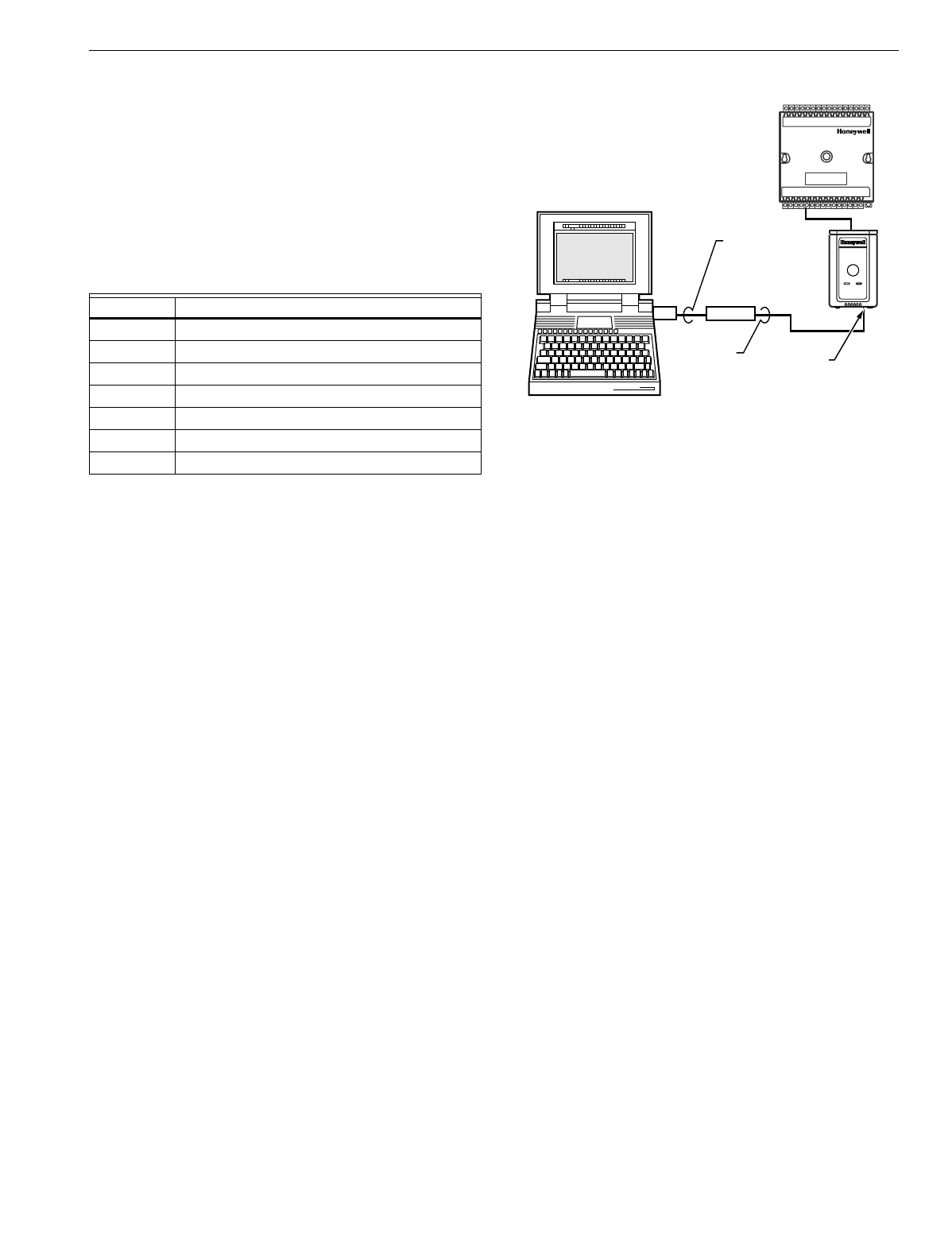
EXCEL 10 W7750A,B,C CONSTANT VOLUME AHU CONTROLLER
29 74-2958—1
APPLICATION STEPS
Overview
The seven application steps shown in Table 6 are plannin
g
considerations for en
g
ineerin
g
an Excel 10 W7750 S
y
stem.
These steps are
g
uidelines intended to aid understandin
g
of
the product I/O options, bus arran
g
ement choices,
confi
g
uration options and the Excel 10 W7750 Controller role
in the overall EXCEL 5000 OPEN SYSTEM architecture.
Table 6. Application Steps.
Step 1. Plan the System
Plan the use of the W7750 Controllers accordin
g
to the
j
ob
re
q
uirements. Determine the location, functionalit
y
and sensor
or actuator usa
g
e. Verif
y
the sales estimate of the number of
W7750 Controllers, T7770 and T7560 Wall Modules re
q
uired
for each model t
y
pe. Also check the number and t
y
pe of
output actuators and other re
q
uired accessories.
When plannin
g
the s
y
stem la
y
out, consider potential
expansion possibilities to allow for future
g
rowth. Plannin
g
is
ver
y
important to be prepared for addin
g
HVAC s
y
stems and
controllers in future pro
j
ects.
T7560 Wall Modules can onl
y
be hard-wired, the
y
have no
LONWORKS Bus access. T7770 Wall Modules can be installed
as either hard-wired I/O-onl
y
devices or additional wirin
g
can
be run to them
(
for the LONWORKS Bus network
)
to allow a
CARE/E-Vision operator terminal to have access to the
LONWORKS Bus. The application en
g
ineer needs to determine
how man
y
wall modules, T7770s and T7560s are re
q
uired. All
T7770 Wall Modules, except the T7770A1006 and the
T7770A1014, can be connected via the LONWORKS Bus
j
ack.
Also the application en
g
ineer needs to know how man
y
T7770s without LONWORKS Bus network connections are
bein
g
installed on the
j
ob, and then clearl
y
document which
wall modules
(
if an
y)
have network access. This information is
re
q
uired durin
g
installation to ensure that the proper number
and t
y
pe of wires are pulled to the wall modules, and the
buildin
g
operators are informed about where the
y
can plu
g
in
to the LONWORKS Bus network with a portable operator
terminal
(
see Fi
g
. 18, 19 and 20
)
. Refer to Step 4. Prepare
Wirin
g
Dia
g
rams for details, about the about the wirin
g
differences between the two t
y
pes.
Fig. 18. Connecting the portable operator terminal
to the LONWORKS® Bus.
The FTT communication wirin
g
,
(
LONWORKS Bus
)
between
controllers is a free topolo
gy
scheme that supports T-tap, star,
loop, and mixed wirin
g
architecture. Refer to the LONWORKS
Bus Wirin
g
Guidelines form, 74-2865 for complete description
of network topolo
gy
rules. See Application Step 3. La
y
Out
Communications and Power Wirin
g
, for more information on
bus wirin
g
la
y
out, and see Fi
g
. 27 throu
g
h 35 in Application
Step 4. Prepare Wirin
g
Dia
g
rams, for wirin
g
details.
The application en
g
ineer must review the Direct Di
g
ital
Control
(
DDC
)
j
ob re
q
uirements. This includes the Se
q
uences
of Operation for the W7750 units, and for the s
y
stem as a
whole. Usuall
y
there are variables that must be passed
between the W7750 Controllers and other zone controller
(
s
)
,
or central plant controller
(
s
)
that are re
q
uired for optimum
s
y
stem-wide operation. T
y
pical examples are the TOD Occ/
Unocc si
g
nal, the outdoor air temperature, the demand limit
control si
g
nal, and the smoke control mode si
g
nal.
It is important to understand these interrelationships earl
y
in
the
j
ob en
g
ineerin
g
process to ensure implemention when
confi
g
urin
g
the controllers.
(
See Application Step 6. Confi
g
ure
Controllers, for information on the various Excel 10
parameters and on Excel 10 point mappin
g
.
)
Step 2. Determine Other Bus Devices
Required
A maximum of 62 nodes can communicate on a sin
g
le
LONWORKS Bus se
g
ment. Each W7750
(
CVAHU
)
Controller
constitutes one node. If more nodes are re
q
uired, a Q7751A,B
Router is necessar
y
. Usin
g
a router allows up to 125 nodes,
divided between two LONWORKS Bus se
g
ments. The router
accounts for two of these nodes
(
one node on each side of the
router
)
; a Q7750A Excel 10 Zone Mana
g
er takes one node
and two nodes are available for operator terminal nodes,
leavin
g
120 nodes available for Excel 10 Controllers. All 120
controllers are able to talk to each other throu
g
h the router. A
Q7750A Excel 10 Zone Mana
g
er is re
q
uired to connect the
LONWORKS Bus to the standard EXCEL 5000 OPEN
S
y
stem C-Bus. Each Excel 10 Zone Mana
g
er supports up to
120 Excel 10 Controllers. This limit is set in the Excel 10 Zone
Mana
g
er database as an absolute maximum.
Step No. Description
1 Plan The S
y
stem
2 Determine Other Bus Devices Re
q
uired
3La
y
Out Communications and Power Wirin
g
4 Prepare Wirin
g
Dia
g
rams
5Order E
q
uipment
6Confi
g
ure Controllers
7 Troubleshootin
g
M15120A
NOTEBOOK PC
LONWORKS BUS
PORT
EIA-232
SERIAL
PORT
Q7752A
SLTA
CABLE
PART
NO. 205979
SHIELDED
INTERFACE
CABLE
EXCEL 10
W7750
CVAHU
CONTROLLER

EXCEL 10 W7750A,B,C CONSTANT VOLUME AHU CONTROLLER
74-2958—130
Each LONWORKS Bus se
g
ment is set up with two unused
nodes to allow for a CARE/E-Vision operator terminal to be
connected to the LONWORKS Bus. Multiple CARE/E-Vision
terminals can be connected to the LONWORKS Bus at the
same time. Table 7 summarizes the LONWORKS Bus se
g
ment
confi
g
uration rules.
Table 7. LONWORKS® Bus Configuration Rules And Device Node Numbers.
Refer to the LONWORKS Bus Wirin
g
Guidelines form, 74-2865
for complete description of network topolo
gy
rules and the
maximum wire len
g
th limitations. If lon
g
er runs are re
q
uired, a
Q7740A 2-Wa
y
or Q7740B 4-Wa
y
Repeater can be added to
extend the len
g
th of the LONWORKS Bus. A Q7751A,B Router
can be added to partition the s
y
stem into two se
g
ments and
effectivel
y
double the len
g
th of the LONWORKS Bus. Onl
y
one
router is allowed with each Excel 10 Zone Mana
g
er, and each
network se
g
ment can have a maximum of one repeater.
In addition, all LONWORKS Bus se
g
ments re
q
uire the
installation of a 209541B Termination Module for a sin
g
l
y
terminated LONWORKS Bus or two 209541B Termination
Modules for a doubl
y
terminated LONWORKS Bus. For more
details on LONWORKS Bus termination, refer to the LONWORKS
Bus Wirin
g
Guidelines form, 74-2865, or see Application Step
3. La
y
Out Communications and Power Wirin
g
, and the
LONWORKS Bus Termination Module subsection in Application
Step 4.
Step 3. Lay Out Communications and Power
Wiring
LONWORKS® Bus Layout
The communications bus, LONWORKS Bus, is a 78-kilobits per
second
(
kbps
)
serial link that uses transformer isolation and
differential Manchester encodin
g
. Approved cable t
y
pes for
LONWORKS Bus communications wirin
g
is Level IV 22 AWG
(
0.34 mm2
)
plenum or non-plenum rated unshielded, twisted
pair, solid conductor wire. For nonplenum areas, use Level IV
22 AWG
(
0.325 mm2
)
, such as U.S. part AK3781
(
one pair
)
or
U.S. part AK3782
(
two pair
)
. In plenum areas, use plenum-
rated Level IV, 22 AWG
(
0.325 mm2
)
such as U.S. part
AK3791
(
one pair
)
or U.S. part AK3792
(
two pair
)
. See Tables
9 and 11 for part numbers. Contact Echelon Corp. Technical
Support for the recommended vendors of Echelon approved
cables. The FTT communications bus, LONWORKS Bus,
supports a polarit
y
insensitive, free topolo
gy
wirin
g
scheme
that supports T-tap, star, loop, and mixed bus wirin
g
.
LONWORKS Bus networks can be confi
g
ured in a variet
y
of
wa
y
s, so refer to the LONWORKS Bus Wirin
g
Guidelines form,
74-2865 for complete description of network topolo
gy
rules
and Table 7. Fi
g
. 19 and 20 depict two t
y
pical LONWORKS Bus
network topolo
g
ies; One has onl
y
one doubl
y
terminated
LONWORKS Bus se
g
ment that has 60 nodes or less, and one
showin
g
two sin
g
l
y
terminated LONWORKS Bus se
g
ments that
has 120 nodes or less
(
60 MAX per each se
g
ment
)
. The bus
confi
g
uration is set up usin
g
the Network Mana
g
er tool from
within CARE
(
see the CARE Excel 10 Zone Mana
g
er User’s
Guide, form 74-1392
)
.
NOTE: For wirin
g
details see the LONWORKS Bus
Termination Module subsection in Step 4. For wall
module wirin
g
, U.S. part AK3782
(
non-plenum
)
or
U.S. part AK3792
(
plenum
)
can be used. For a
LONWORKS Bus that is a doubl
y
terminated dais
y
-
chain, these cables contain two twisted pairs
(
one for
the run down to the wall module, and one for the run
back up to the controller
)
for ease of installation.
One LONWORKS Bus Segment Example Maximum Number of Nodes Equals 62
One Q7750A Excel 10 Zone Mana
g
er 1 node
Port for operator terminal access
(
CARE/E-Vision
)
1 node
Maximum number of Excel 10s 60 nodes
Total 62 nodes
Two LONWORKS Bus Segments Example Maximum Number of Nodes Equals 125
One Q7750A Excel 10 Zone Mana
g
er 1 node
One Q7751A,B Router 2 nodes
(
1 in each Bus Se
g
ment
)
Ports for operator terminal access
(
two CARE/E-Vision
terminals
)
2 nodes
(
1 in each Bus Se
g
ment
)
Maximum number of Excel 10s in se
g
ment number one 60 nodes
Maximum number of Excel 10s in se
g
ment number two 60 nodes
Total 125 nodes
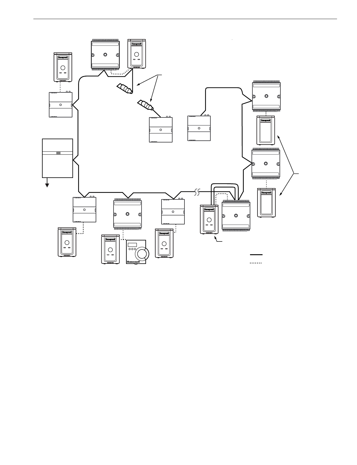
EXCEL 10 W7750A,B,C CONSTANT VOLUME AHU CONTROLLER
31 74-2958—1
Fig. 19. Wiring layout for one doubly terminated daisy-chain LONWORKS® Bus segment.
M17496
EXCEL 10
VAV
EXCEL 10
VAV
EXCEL 10
CVAHU
EXCEL 10
CVAHU
EXCEL 10
CVAHU
EXCEL 10
CVAHU
EXCEL 10
VAV
EXCEL 10
VAV
EXCEL 10
VAV
EXCEL 10
Q7750A
ZONE
MANAGER
TO C-BUS
(SEE FIG. 1)
LONWORKS BUS
LONWORKS BUS
LONWORKS BUS
UP TO 60
TOTAL NODES
T7770
T7770
T7770
T7770
JACK FOR
OPERATOR
TERMINAL
209541B
TERMINATION MODULES
(AT ENDS OF
LONWORKS BUS
DAISY-CHAIN)
T7770s
WITH
NO
LONWORKS BUS
ACCESS
LONWORKS BUS
I/O CONNECTIONS
EXCEL 10
CVAHU
T7770 OR T7560A,B
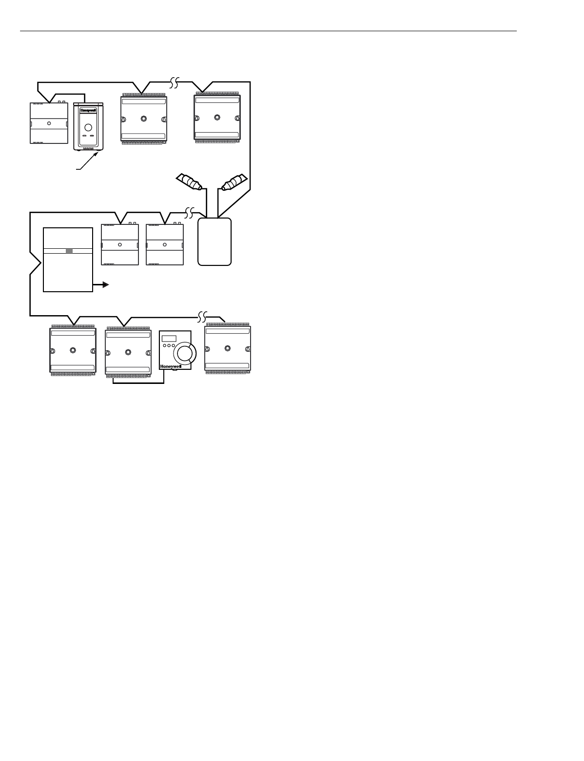
EXCEL 10 W7750A,B,C CONSTANT VOLUME AHU CONTROLLER
74-2958—132
Fig. 20. Wiring layout for two singly terminated
LONWORKS® Bus segments.
NOTE: See the LONWORKS Bus Termination Module section
for wirin
g
details.
IMPORTANT
Notes on communications wiring:
•All field wiring must conform to local codes and ordi-
nances or as specified on installation wiring dia-
grams.
•Approved cable types for LONWORKS
Bus communi-
cations wiring is Level IV 22 AWG (0.34 mm
2
) ple-
num or non-plenum rated unshielded, twisted pair,
solid conductor wire. For nonplenum areas, use
Level IV 22 AWG (0.34 mm
2
), such as U.S. part
AK3781 (one pair) or U.S. part AK3782 (two pair). In
plenum areas, use plenum-rated Level IV, 22 AWG
(0.34 mm
2
) such as U.S. part AK3791 (one pair) or
U.S. part AK3792 (two pair). See Tables 9 and 11 for
part numbers. Contact Echelon Corp. Technical Sup-
port for the recommended vendors of Echelon
approved cables.
•Unswitched 24 Vac power wiring can be run in the
same conduit as the LONWORKS
Bus cable.
•Do not use different wire types or gauges on the
same LONWORKS
Bus segment. The step change in
line impedance characteristics causes unpredictable
reflections on the bus. When using different types is
unavoidable, use a Q7751A,B Router at the junction.
•In noisy (high EMI) environments, avoid wire runs
parallel to noisy power cables, or lines containing
lighting dimmer switches, and keep at least 3 in.
(76 mm) of separation between noisy lines and the
LONWORKS
Bus cable.
•Make sure that neither of the LONWORKS
Bus wires
is grounded.
Power Wiring
A power bud
g
et must be calculated for each Excel 10 W7750
Controller to determine the re
q
uired transformer size for
proper operation. A power bud
g
et is simpl
y
the summin
g
of
the maximum power draw ratin
g
s
(
in VA
)
of all the devices to
be controlled b
y
an Excel 10 W7750 Controller. This includes
the controller itself, the e
q
uipment actuators
(
ML6161, or
other motors
)
and various contactors and transducers, as
appropriate, for the Excel 10 confi
g
uration.
POWER BUDGET CALCULATION EXAMPLE
The followin
g
is an example power bud
g
et calculation for a
t
y
pical Excel 10 W7750B Controller.
Assume a W7750 unit with a fan, two sta
g
es of D/X coolin
g
,
modulatin
g
steam valve for heatin
g
, and modulatin
g
economizer dampers. The power re
q
uirements are:
DeviceVA Information Obtained from
Excel 10 W7750B,C 12.0 W7750 Specification Data
Controller
ML6161 2.2 TRADELINE
Damper Actuator Catalo
g
R8242A 21.0 TRADELINE
Contactor for fan Catalo
g
in-rush ratin
g
D/X Sta
g
es 0.0
NOTE: For this example, assume the coolin
g
sta
g
e outputs
are wired into a compressor control circuit and,
therefore, have no impact on the power bud
g
et.
)
M6410A Steam 0.7 TRADELINE
Heatin
g
Coil Valve Catalo
g
, 0.32A at 24 Vac
TOTAL: 35.9 VA
The Excel 10 S
y
stem example re
q
uires 35.9 VA of peak
power; therefore, a 40 VA AT72D Transformer is able to
provide ample power for this controller and its accessories.
Alternativel
y
, a 75 VA AT88A Transformer could be used to
power two Excel 10 S
y
stems of this t
y
pe, or a 100 VA AT92A
Transformer could be used to power two of these Excel 10
S
y
stems and meet NEC Class 2 restrictions
(
no
g
reater than
100 VA
)
. See Fi
g
. 22 and 23 for illustrations of power wirin
g
details. See Table 8 for VA ratin
g
s of various devices.
EXCEL 10
VAV EXCEL 10
VAV
EXCEL 10
VAV
EXCEL 10
Q7750A
ZONE
MANAGER TO C-BUS
(SEE FIG. 1)
LONWORKS BUS
SEGMENT NUMBER 2
LONWORKS BUS
SEGMENT NUMBER 1
LONWORKS BUS
SEGMENT NUMBER 2
T7770
LONWORKS
BUS
ACCESS
Q7751A
FTT
LONWORKS
BUS
ROUTER
209541B
TERMINATION
MODULE
209541B
TERMINATION
MODULE
M17497
EXCEL 10
CVAHU
EXCEL 10
CVAHU
EXCEL 10
CVAHU
EXCEL 10
CVAHU
EXCEL 10
CVAHU
T7560A,B

EXCEL 10 W7750A,B,C CONSTANT VOLUME AHU CONTROLLER
33 74-2958—1
Table 8. VA Ratings For Transformer Sizing.
For contactors and similar devices, the in-rush power ratin
g
s
should be used as the worst case values when performin
g
power bud
g
et calculations. Also, the application en
g
ineer
must consider the possible combinations of simultaneousl
y
ener
g
ized outputs and calculate the VA ratin
g
s accordin
g
l
y
.
The worst case, that uses the lar
g
est possible VA load, should
be determined when sizin
g
the transformer.
LINE LOSS
Excel 10 Controllers must receive a minimum suppl
y
volta
g
e
of 20 Vac. If lon
g
power or output wire runs are re
q
uired, a
volta
g
e drop due to Ohms Law
(
I x R
)
line loss must be
considered. This line loss can result in a si
g
nificant increase in
total power re
q
uired and thereb
y
affect transformer sizin
g
.
The followin
g
example is an I x R line-loss calculation for a
200 ft.
(
61m
)
run from the transformer to a W7750 Controller
drawin
g
37 VA usin
g
two 18 AWG
(
1.0 mm2
)
wires.
The formula is:
Loss = [len
g
th of round-trip wire run
(
ft.
)
] X [resistance in
wire
(
ohms per ft.
)
] X [current in wire
(
amperes
)
]
From specification data:
18 AWG twisted pair wire has 6.52 ohms per 1000 feet.
Loss = [
(
400 ft.
)
X
(
6.52/1000 ohms per ft.
)
] X
[
(
37 VA
)
/
(
24V
)
] = 4.02 volts
This means that four volts are
g
oin
g
to be lost between the
transformer and the controller; therefore, to assure the
controller receives at least 20 volts, the transformer must
output more than 24 volts. Because all transformer output
volta
g
e levels depend on the size of the connected load, a
lar
g
er transformer outputs a hi
g
her volta
g
e than a smaller one
for a
g
iven load. Fi
g
. 21 shows this volta
g
e load dependence.
In the precedin
g
I x R loss example, even thou
g
h the
controller load is onl
y
37 VA, a standard 40 VA transformer is
not sufficient due to the line loss. From Fi
g
. 21, a 40 VA
transformer is
j
ust under 100 percent loaded
(
for the 37 VA
controller
)
and, therefore, has a secondar
y
volta
g
e of 22.9
volts.
(
Use the lower ed
g
e of the shaded zone in Fi
g
. 21 that
represents the worst case conditions.
)
When the I x R loss of
four volts is subtracted, onl
y
18.9 volts reaches the controller,
which is not enou
g
h volta
g
e for proper operation.
In this situation, the en
g
ineer basicall
y
has three alternatives:
1. Use a lar
g
er transformer; for example, if an 80 VA
model is used, see Fi
g
. 21, an output of 24.4 volts
minus the four volt line loss supplies 20.4V to the
controller. Althou
g
h acceptable, the four-volt line-loss in
this example is hi
g
her than recommended. See the
followin
g
IMPORTANT
.
2. Use heavier
g
au
g
e wire for the power run. 14 AWG
(
2.0
mm2
)
wire has a resistance of 2.57 ohms per 1000 ft.
which, usin
g
the precedin
g
formula,
g
ives a line-loss of
onl
y
1.58 volts
(
compared with 4.02 volts
)
. This would
allow a 40 VA transformer to be used. 14 AWG
(
2.0
mm2
)
wire is the recommended wire size for 24 Vac
wirin
g
.
3. Locate the transformer closer to the controller, thereb
y
reducin
g
the len
g
th of the wire run, and the line loss.
The issue of line-loss is also important in the case of the
output wirin
g
connected to the Triac di
g
ital outputs. The
same formula and method are used. The rule to
remember is to keep all power and output wire runs as
short as practical. When necessar
y
, use heavier
g
au
g
e
wire, a bi
gg
er transformer, or install the transformer
closer to the controller.
IMPORTANT
No installation should be designed where the line
loss is greater than two volts to allow for nominal
operation if the primary voltage drops to 102 Vac
(120 Vac minus 15 percent).
To meet the National Electrical Manufacturers Association
(
NEMA
)
standards, a transformer must sta
y
within the NEMA
limits. The chart in Fi
g
. 21 shows the re
q
uired limits at various
loads.
With 100 percent load, the transformer secondar
y
must
suppl
y
between 23 and 25 volts to meet the NEMA standard.
When a purchased transformer meets the NEMA standard
DC20-1986, the transformer volta
g
e-re
g
ulatin
g
abilit
y
can be
considered reliable. Compliance with the NEMA standard is
voluntar
y
.
The followin
g
Hone
y
well transformers meet this NEMA
standard:
Transformer Type VA Rating
AT20A 20
AT40A 40
AT72D 40
AT87A 50
AK3310 Assembl
y
100
Device Description VA
W7750A Excel 10 W7750 Controller 6.0
W7750B,C Excel 10 W7750 Controllers 12.0
ML6161A/B Damper Actuator, 35 lb-in. 2.2
R8242A Contactor 21.0
M6410A Valve Actuator 0.7
MMC325 Pneumatic Transducer 5.0
ML684 Versadrive Valve Actuator 12.0
ML6464 Damper Actuator, 66 lb-in. 3.0
ML6474 Damper Actuator, 132 lb-in. 3.0
ML6185 Damper Actuator SR 50 lb-in. 12.0
ML7984B PWM Valve Actuator 6.0
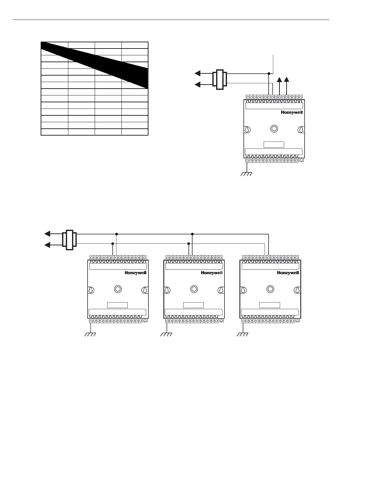
EXCEL 10 W7750A,B,C CONSTANT VOLUME AHU CONTROLLER
74-2958—134
Fig. 21. NEMA class 2 transformer voltage output limits.
Attach earth
g
round to W7750 Controller terminal 1. See Fi
g
.
22, 23 and 24, 27 throu
g
h 35.
Fig. 22. Power wiring details for one Excel 10 per
transformer.
See Fi
g
. 23. for wirin
g
more than one Excel 10 per
transformer.
Fig. 23. Power wiring details for two or more Excel 10s per transformer.
IMPORTANT
If the W7750 Controller is used on Heating and
Cooling Equipment (UL 1995 U.S. only
)
devices
and the transformer primary power is more than 150
volts, connect the transformer secondary to earth
ground, see Fig. 24.
27
26
25
24
23
22
21
20
19
18
17
16
15
14
0 50 100 150
% OF LOAD
SECONDARY VOLTAGE
200
M993
M10089B
CONNECT POWER TO
TERMINALS 24 AND 25
TRIAC LINES
TO ACTUATORS
AND CONTACTORS
TRANSFORMER
W7750B,C
EARTH
GROUND
2022
24
25
1
OUTPUT
DEVICE
POWER
M10090A
24 VAC
120/240 VAC
TRANSFORMER
W7750B,C
EARTH
GROUND
24
25
1
W7750B,C
EARTH
GROUND
24
25
1
W7750B,C
EARTH
GROUND
24
25
1
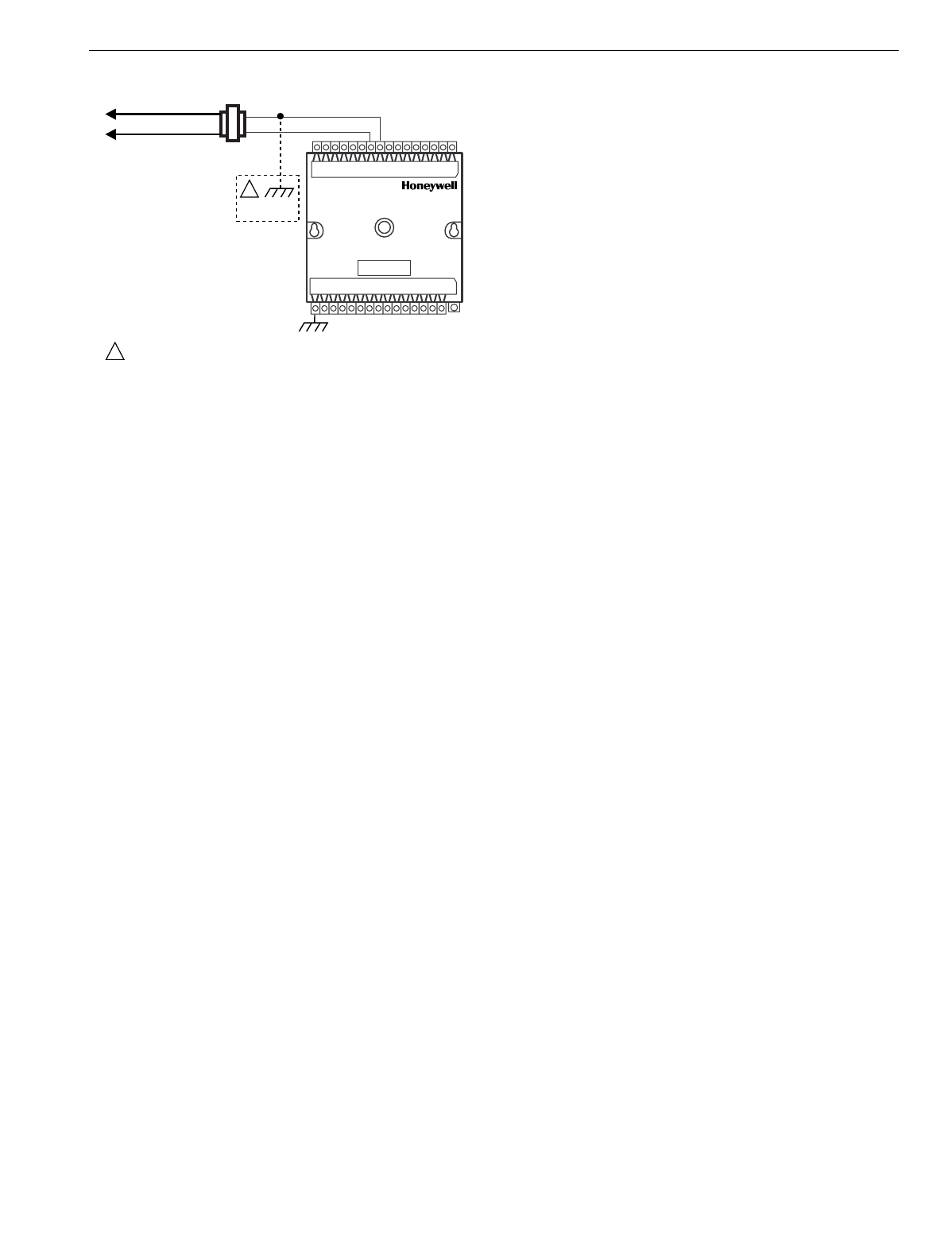
EXCEL 10 W7750A,B,C CONSTANT VOLUME AHU CONTROLLER
35 74-2958—1
Fig. 24. Transformer power wiring details for one Excel 10
used in UL 1995 equipment (U.S. only).
IMPORTANT
Notes on power wiring:
•All field wiring must conform to local codes and ordi-
nances or as specified on installation wiring dia-
grams.
•To maintain NEC Class 2 and UL ratings, the instal-
lation must use transformers of 100 VA or less
capacity.
•For multiple controllers operating from a single trans-
former, the same side of the transformer secondary
must be connected to the same input terminal in
each controller (21 on the W7750A and 24 on the
W7750B,C) and the ground terminals must be con-
nected to a verified earth ground for each controller
in the group. See Fig. 23. (Controller configurations
are not necessarily limited to three devices per trans-
former.)
•For the W7750B,C Controller (which has Triac out-
puts), all output devices must be powered from the
same transformer as the one powering the Excel 10
W7750 Controller.
•Use the heaviest gauge wire available, up to 14
AWG (2.0 mm
2
) with a minimum of 18 AWG (1.0
mm
2
) for all power and earth ground connections.
•To minimize EMI noise, do not run Triac output wires
in the same conduit as the input wires or the LON-
WORKS
Bus communications wiring.
•Unswitched 24 Vac power wiring can be run in the
same conduit as the LONWORKS
Bus cable.
•Make earth ground connections with the shortest
possible wire run using 14 AWG (2.0 mm
2
) wire. A
good earth ground is essential for W7750 operation.
Ideally, connect the earth ground to the ground bus
at a motor control center or circuit breaker panel.
However, if the nearest ideal earth ground is inac-
cessible, consider an alternate source for earth
ground. Metal water pipe is generally a good ground,
but do not use sprinkler pipe if prohibited by local
codes. Attention must be given when duct work, con-
duit, or rebar are to be considered as ground
sources. It is the responsibility of the installer to
assure that these structures are tied back to a known
earth ground.
Step 4. Prepare Wiring Diagrams
General Considerations
The purpose of this step is to assist the application en
g
ineer in
developin
g
j
ob drawin
g
s to meet
j
ob specifications. Wirin
g
details are included for the W7750A,B,C Controllers and the
T7770 and T7560A,B Wall Modules. The drawin
g
s detail I/O,
power, and LONWORKS Bus communication wirin
g
connections.
NOTE: For field wirin
g
, when two or more wires, other than
14 AWG
(
2.0 mm2
)
are to be attached to the same
connector block terminal, be sure to twist them
to
g
ether. Deviation from this rule can result in
improper electrical contact. See Fi
g
. 25.
The connector block terminals on the W7750 Controllers and
on the T7770 Wall Modules accept 14 throu
g
h 22 AWG
(
2.0 to
0.34 mm2
)
wire. The connector block terminals on the
T7560A,B Wall Modules accept 18 throu
g
h 22 AWG
(
1.0 to
0.34 mm2
)
wire. Table 9 lists wirin
g
t
y
pes, sizes, and len
g
th
restrictions for Excel 10 products.
M10088A
24 VAC
LINE VOLTAGE
GREATER
THAN 150 VAC
TRANSFORMER
W7750
EARTH
GROUND
EARTH
GROUND
IF THE W7750 CONTROLLER IS USED IN UL 1995 EQUIPMENT AND THE
PRIMARY POWER IS MORE THAN 150 VOLTS, GROUND 24 VAC COM
SIDE OF TRANSFORMER SECONDARY.
1
1
1
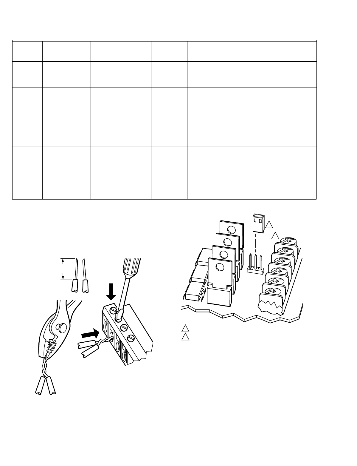
EXCEL 10 W7750A,B,C CONSTANT VOLUME AHU CONTROLLER
74-2958—136
Table 9. Field Wiring Reference Table (Honeywell listed as AK#### or equivalent).
W7750 Controllers
Fi
g
. 27 throu
g
h 35 illustrate W7750A,B,C Controller wirin
g
for
various confi
g
urations. Connections to the wall module
terminals
(
2 throu
g
h 6
)
and the communications terminals
(
14
and 15
)
are made at terminal blocks. Connection for access to
the LONWORKS Bus is provided b
y
plu
gg
in
g
the connector into
the communications
j
ack.
Fig. 25. Attaching two or more wires at terminal blocks.
The W7750B provides a
j
umper to select Hi
g
h-Side or Low-
Side switchin
g
of the di
g
ital outputs. Fi
g
. 26 shows the
W7750B Hi
g
h-Side/Low-Side selectable switchin
g
.
(
See
wirin
g
dia
g
rams, Fi
g
s. 30 throu
g
h 34.
)
Fig. 26. W7750B High-Side/Low-Side selectable switching
and jumper location.
NOTE: If an Excel 10 W7750A,B,C Controller or Zone
Mana
g
er is not connected to a
g
ood earth
g
round,
the controller internal transient protection circuitr
y
is
compromised and the function of protectin
g
the
controller from noise and power line spikes cannot
be fulfilled. This can result in a dama
g
ed circuit
board and re
q
uire replacin
g
the controller.
See Table 10 for a description of the W7750A terminals.
Wire
Function
Recommended
Minimum Wire
Size AWG (mm2) Construction
Specification
or
Requirement Vendor Wire Type Maximum Length ft.
(m)
LONWORKS
Bus
(Plenum)
22 AWG
(
0.34 mm2
)
Twisted pair solid
conductor, nonshielded
or Echelon approved
cable.
Level IV
140°F
(
60°C
)
ratin
g
Hone
y
well
AK3791
(
one twisted pair
)
AK3792
(
two twisted pairs
)
Refer to LONWORKS Bus
Wirin
g
Guidelines for
maximum len
g
th
LONWORKS
Bus (Non-
Plenum)
22 AWG
(
0.34 mm2
)
Twisted pair solid
conductor, nonshielded
or Echelon approved
cable.
Level IV
140°F
(
60°C
)
ratin
g
Hone
y
well
AK3781
(
one twisted pair
)
AK3782
(
two twisted pairs
)
Refer to LONWORKS Bus
Wirin
g
Guidelines for
maximum len
g
th
Input
Wiring
Sensors
Contacts
18 to 22 AWG
(
1.0 to 0.34 mm2
)
Multiconductor
(
usuall
y
five-wire cable bundle
)
.
For runs >200 ft.
(
61m
)
in nois
y
EMI areas, use
shielded cable.
140°F
(
60°C
)
ratin
g
Standard thermostat wire 1000 ft.
(
305m
)
for 18
AWG 200 ft.
(
61m
)
for 22
AWG
Output
Wiring
Actuators
Relays
14 AWG
(
2.0 mm2
)
18 AWG
(
1.0 mm2
)
acceptable for
short runs
)
An
y
pair nonshielded
(
use heavier wire for
lon
g
er runs
)
.
NEC Class 2
140°F
(
60°C
)
ratin
g
Hone
y
well
AK3702
(
18 AWG
)
AK3712
(
16 AWG
)
AK3754
(
14 AWG
)
Limited b
y
line-loss
effects on power
consumption.
(
See Line
Loss subsection.
)
Power
Wiring 14 AWG
(
2.0 mm2
)
An
y
pair nonshielded
(
use heavier wire for
lon
g
er runs
)
.
NEC Class 2
140°F
(
60°C
)
ratin
g
Hone
y
well
AK3754
(
14 AWG
)
twisted
pair AK3909
(
14 AWG
)
sin
g
le conductor
Limited b
y
line-loss
effects on power
consumption.
(
See Line
Loss subsection.
)
1/2
(13)
STRIP 1/2 IN. (13 MM)
FROM WIRES TO
BE ATTACHED AT
ONE TERMINAL.
1.
2. TWIST WIRES
TOGETHER WITH
PLIERS (A MINIMUM
OF THREE TURNS).
3. CUT TWISTED END OF WIRES TO 3/16 IN. (5 MM)
BEFORE INSERTING INTO TERMINAL AND
TIGHTENING SCREW. THEN PULL ON EACH
WIRE IN ALL TERMINALS TO CHECK FOR
GOOD MECHANICAL CONNECTION. M17207
U3
Q38
J2
JUMPER
TERMINAL 24
J2 IS LOCATED NEAR TERMINAL 24 (COVER REMOVED).
W7750B IS FACTORY-DELIVERED WITH JUMPER ON HIGH-SIDE
(PINS CLOSEST TO TERMINAL BLOCK). LOW-SIDE PINS ARE TWO
PINS CLOSEST TO Q38.
1
1
2
2
M16418A

EXCEL 10 W7750A,B,C CONSTANT VOLUME AHU CONTROLLER
37 74-2958—1
Table 10. W7750A Version I/O Description.
IMPORTANT
If the W7750A controller is configured by E-Vision,
the outputs may be assigned in different order than
the factory defaults. Use the Custom Wiring function
of E-Vision to re-assign the outputs to the desired
terminals.
The W7750B,C Versions are preconfi
g
ured with the same
factor
y
default setup as the W7750A Model; however, some
terminals for wirin
g
connections differ on the W7750B,C
Models. See Fi
g
. 30 for the terminal names on the W7750B
Model and Fi
g
. 35 for the terminal names on the W7750C
Model. The factor
y
default confi
g
uration of the di
g
ital output
points on the W7750B,C Models follow
(
terminal names are
from the W7750A
)
:
FACTORY DEFAULT DIGITAL OUTPUTS:
FREE 1
(
OUT 1
)
DO1—NETWORK DO
(
OUT 2
)
DO2—SUPPLY FAN START/STOP
(
OUT 3
)
DO3—COOL_STAGE_2
(
OUT 4
)
DO4—COOL_STAGE_1
(
OUT 5
)
DO5—HEAT_STAGE_2
(
OUT 6
)
DO6—HEAT_STAGE_1
DO7—UNUSED
DO8—UNUSED
The Wall Module terminals are identical for the W7750A,B,C
Models.
The W7750B,C Models offers two volta
g
e/current sensor
input terminals. When current-t
y
pe sensors
(
4 to 20 mA
)
are
confi
g
ured, the W7750B,C automaticall
y
switches a 249 ohm
resistor into the sensin
g
circuit; so no external resistor is
re
q
uired. The W7750A Model does not support volta
g
e or
current inputs.
NOTE: If usin
g
factor
y
defaults, DI-2 input is confi
g
ured for
ScheduleMaster
(
nvoIO.SchedMaster
)
. For a
stand-alone unit, either connect an external time
clock to terminals 9 and 10 or put a
j
umper on
terminals 9 and 10
(
usin
g
a
j
umper puts the
controller in continuous occupied mode
)
.
Terminal Terminal Number Description
DO6–
(
W1
)
31 Heat 1
(
or Reversin
g
Valve for a Heat Pump
)
DO5–
(
W2
)
30 Heat 2
(
or Aux. Heat for a Heat Pump
)
DO4–
(
Y1
)
29 Cool 1
(
or Compressor 1 for a Heat Pump
)
DO3–
(
Y2
)
28 Cool 2
(
or Compressor 2 for a Heat Pump
)
DO2–
(
G
)
27 Fan
DO1–NET 26 Network Di
g
ital Output
DO1–NET 25 Network Di
g
ital Output
(
connect to terminal number 22 +24Vac
)
Rc 24 Control power for rela
y
contacts DO2
(
G
)
, DO3
(
Y1
)
and DO4
(
Y2
)
Rh 23 Control power for rela
y
contacts DO5
(
W1
)
and DO6
(
W2
)
+24Vac
(
H
)
22 Power for the controller
COM
(
N
)
21 Return for power to controller
E-Bus 14 and 15 Echelon communications
(
LONWORKS Bus
)
screw terminals
DI - 2 12 Di
g
ital Input 2
DGND 11 Di
g
ital Ground
DGND 10 Di
g
ital Ground
DI - 1 9 Di
g
ital Input 1
AGND 8 Analo
g
g
round
AI - 1 OHM 7 Analo
g
Input 1
(
used for Dischar
g
e Air Temperature Sensor
)
SET PT 6 Space temperature setpoint potentiometer
GROUND 5 Wall Module
SENSOR 4 Space temperature sensor
BYPASS 3 Space override button
LED 2 Space LED for indication of manual occupanc
y
status
EARTH GND 1 Earth Ground
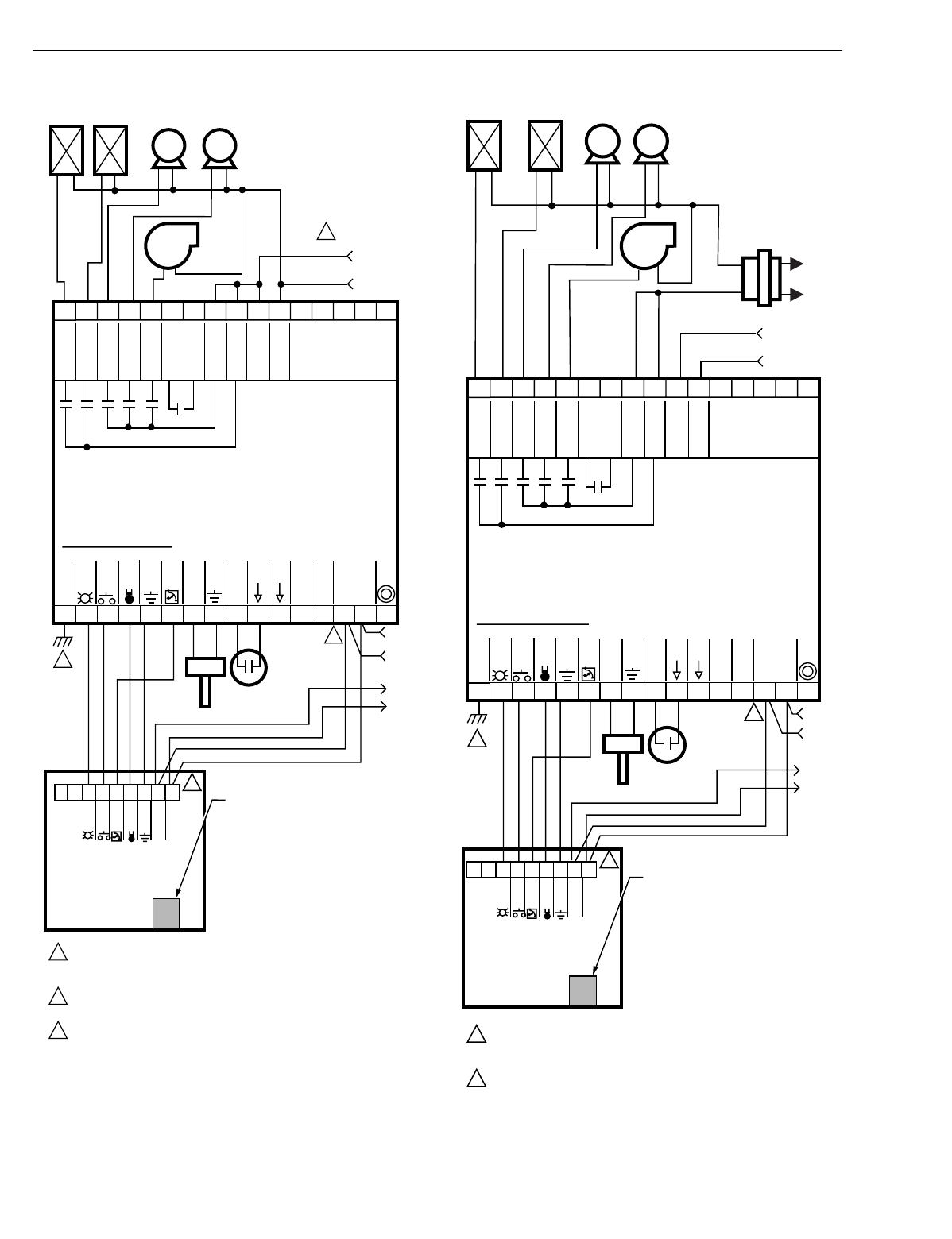
EXCEL 10 W7750A,B,C CONSTANT VOLUME AHU CONTROLLER
74-2958—138
Fig. 27. Typical W7750A Controller AHU application
wiring diagram. (For more information on note 2,
refer to Fig. 25.) Fig. 28. Typical W7750A Controller with separate
transformer application wiring diagram.
(For more information on note 2, refer to Fig. 25.)
12345678
1
3
2
2
1
2
3
EARTH GROUND WIRE LENGTH SHOULD BE HELD TO A MINIMUM.
USE THE HEAVIEST GAUGE WIRE AVAILABLE, UP TO 14 AWG (2.O MM2)
WITH A MINIMUM OF 18 AWG (1.O MM2), FOR EARTH GROUND WIRE.
TO ASSURE PROPER ELECTRICAL CONTACT, WIRES MUST BE TWISTED
TOGETHER BEFORE INSERTION INTO THE TERMINAL BLOCK.
LOAD POWER WIRE CAN BE CONNECTED TO TERMINAL 22.
LONWORKS-BUS
EARTH
GROUND
JACK FOR
LONWORKS-BUS
NETWORK
ACCESS
7654321
T7770C
WALL
MODULE
SET PT
GND
SENSOR
BYPASS
LED
E-BUS
E-BUS
9 101112 14 J315
31 30 29 28 27 26 25 24 23 22 21 20
WALL MODULE
SET PT
AI
GROUND
AI
GROUND
DI
GROUND
DI
GROUND
SENSOR
BYPASS
LED
LON
JACK
LONWORKS
BUS
NOT USED
9 8
19 18 17 16
AI-1 OHM
DI- 1
DI- 2
13
TIME CLOCK
M10085C
DISCHARGE
AIR TEMP
24 VAC
24 VAC COM
Rc
Rh
W1
W2
Y1
Y2
G
NOT USED
24 VAC
+
-
LOAD AND
CONTROLLER
POWER
FAN
COMP2COMP 1
HEAT 2HEAT 1
W7750A
CONSTANT
VOLUME AHU
CONTROLLER
NETWORK
DO
12345678
W7750A
CONSTANT
VOLUME AHU
CONTROLLER
1
2
2
1
2
EARTH GROUND WIRE LENGTH SHOULD BE HELD TO A MINIMUM.
USE THE HEAVIEST GAUGE WIRE AVAILABLE, UP TO 14 AWG (2.O MM
2
)
WITH A MINIMUM OF 18 AWG (1.O MM
2
), FOR EARTH GROUND WIRE.
TO ASSURE PROPER ELECTRICAL CONTACT, WIRES MUST BE TWISTED
TOGETHER BEFORE INSERTION INTO THE TERMINAL BLOCK.
L
ON
W
ORKS
-BUS
EARTH
GROUND
JACK FOR
L
ON
W
ORKS
-BUS
NETWORK
ACCESS
7 69 8 54321
T7770C
WALL
MODULE
SET PT
GND
SENSOR
BYPASS
LED
E-BUS
E-BUS
9101112 14 J315
31 30 29 28 27 26 25 24 23 22 21 20
WALL MODULE
SET PT
SENSOR
BYPASS
LED
NOT USED
19 18 17 16
AI-1 OHM
DI- 1
DI- 2
13
TIME CLOCK
M10084C
DISCHARGE
AIR TEMP
24 VAC
24 VAC COM
Rc
Rh
W1
W2
Y1
Y2
G
NOT USED
24 VAC
24 VAC LINE AC
+
-
CONTROLLER POWER
LOAD POWER
FAN
COMP2COMP 1
HEAT 2HEAT 1
H
C
NETWORK
DO
AI
GROUND
AI
GROUND
DI
GROUND
DI
GROUND
L
ON
JACK
L
ON
W
ORKS
BUS
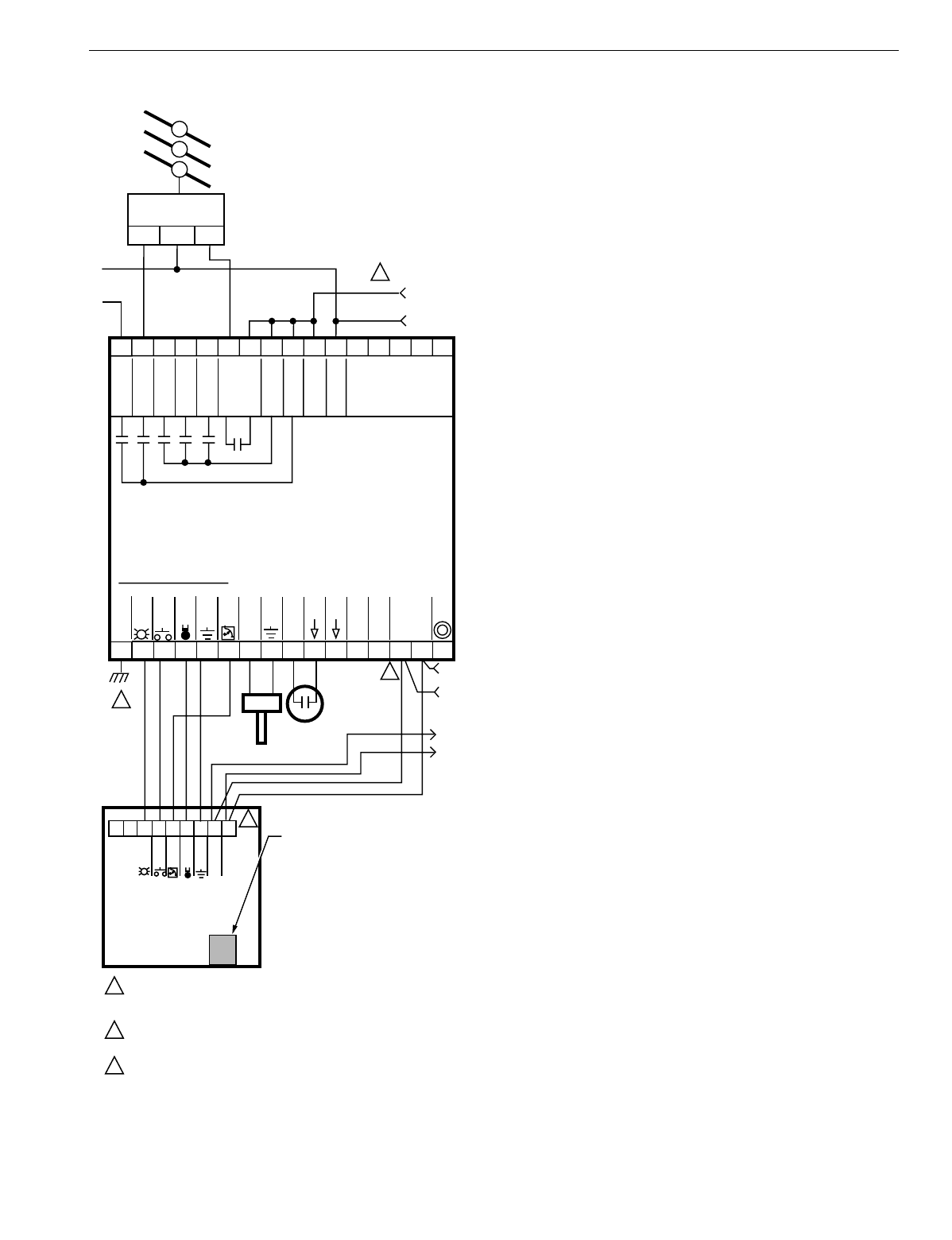
EXCEL 10 W7750A,B,C CONSTANT VOLUME AHU CONTROLLER
39 74-2958—1
Fig. 29. W7750A Controller floating economizer damper
wiring diagram. (For more information on note 2, refer to
Fig. 25.)
NOTE: Di
g
ital outputs are confi
g
urable. The terminal
locations for each function are user-selectable. The
Network DO is confi
g
ured to be economizer float
close in this fi
g
ure and W2 is confi
g
ured to be
economizer float open. Ph
y
sical output terminal
features are done in E-Vision b
y
the custom wirin
g
function.
12345678
W7750A
CONSTANT
VOLUME AHU
CONTROLLER
1
2
2
1
2
3
EARTH GROUND WIRE LENGTH SHOULD BE HELD TO A MINIMUM.
USE THE HEAVIEST GAUGE WIRE AVAILABLE, UP TO 14 AWG (2.O MM2)
WITH A MINIMUM OF 18 AWG (1.O MM2), FOR EARTH GROUND WIRE.
TO ASSURE PROPER ELECTRICAL CONTACT, WIRES MUST BE TWISTED
TOGETHER BEFORE INSERTION INTO THE TERMINAL BLOCK.
LOAD POWER WIRE CAN BE CONNECTED TO TERMINAL 22.
LONWORKS-BUS
EARTH
GROUND
JACK FOR
LONWORKS-BUS
NETWORK
ACCESS
7 69 8 54321
T7770C
WALL
MODULE
SET PT
GND
SENSOR
BYPASS
LED
E-BUS
E-BUS
9 101112 14 J315
31 30 29 28 27 26 25 24 23 22 21 20
WALL MODULE
SET PT
SENSOR
BYPASS
LED
NOT USED
19 18 17 16
AI-1 OHM
DI- 1
DI- 2
13
TIME CLOCK
M10083C
DISCHARGE
AIR TEMP
24 VAC
24 VAC COM
Rc
Rh
NETWORK
DO
W1
W2
Y1
Y2
G
24 VAC
+
-
3
LOAD AND
CONTROLLER
POWER
NOT USED
ML6161 FLOATING
ACTUATOR
CW COM CCW
HEAT 1
AI
GROUND
AI
GROUND
DI
GROUND
DI
GROUND
LON
JACK
LONWORKS
BUS
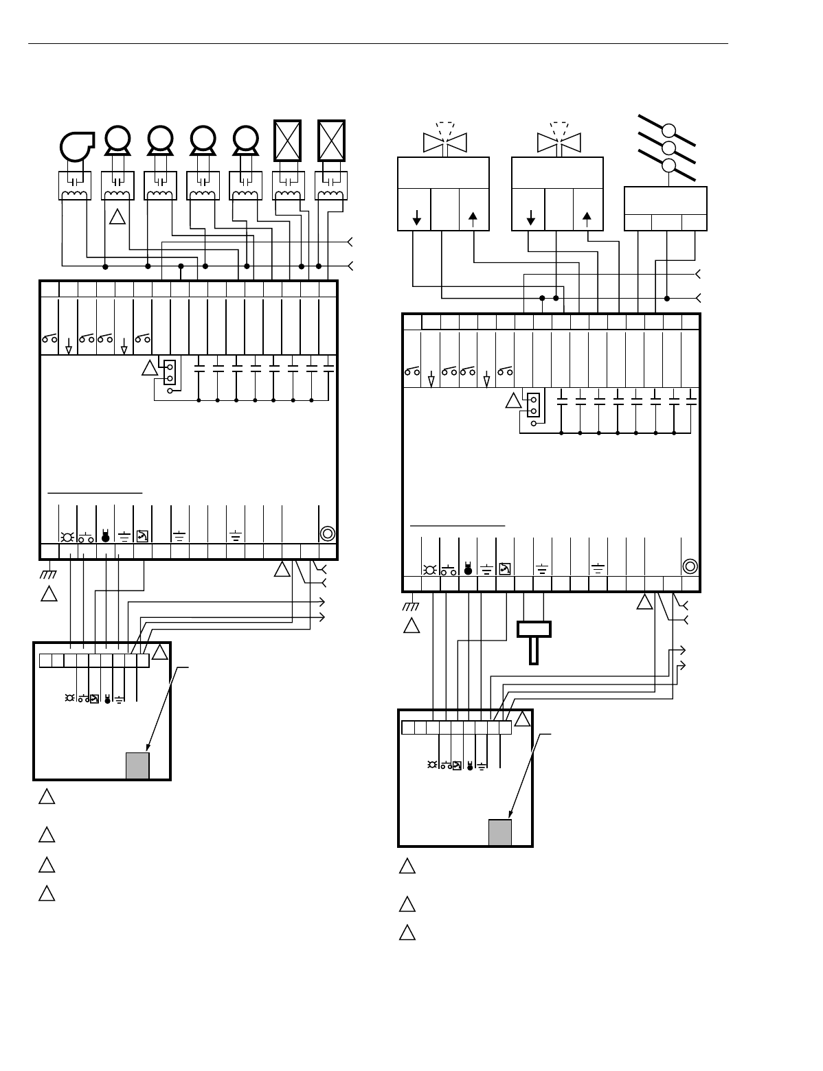
EXCEL 10 W7750A,B,C CONSTANT VOLUME AHU CONTROLLER
74-2958—140
Fig. 30. Typical W7750B Controller with staged heating
and cooling wiring diagram. (For more information on
note 2, refer to Fig. 25.) Fig. 31. W7750B Controller with floating heating, cooling
and economizer wiring diagram. (For more information on
note 2, refer to Fig. 25.)
12345678
24 VAC
W7750B CONSTANT
VOLUME AHU
CONTROLLER
1
2
2
1
2
3
4
3
4
EARTH GROUND WIRE LENGTH SHOULD BE HELD TO A MINIMUM.
USE THE HEAVIEST GAUGE WIRE AVAILABLE, UP TO 14 AWG (2.O MM2)
WITH A MINIMUM OF 18 AWG (1.O MM2), FOR EARTH GROUND WIRE.
TO ASSURE PROPER ELECTRICAL CONTACT, WIRES MUST BE TWISTED
TOGETHER BEFORE INSERTION INTO THE TERMINAL BLOCK.
WIRING DIAGRAM SHOWS JUMPER (FOR J2) IN FACTORY DEFAULT
HIGH-SIDE POSITION.
ISOLATING RELAYS MUST BE USED WHEN CONNECTING TO STAGED
HEAT/COOL EQUIPMENT.
LONWORKS-BUS
EARTH
GROUND
JACK FOR
LONWORKS-BUS
NETWORK
ACCESS
7 69 8 54321
T7770C
WALL
MODULE
SET PT
GND
SENSOR
BYPASS
LED
E-BUS
E-BUS
9 101112 14 J315
31 30 29 28 27 26 25 24 23 22 21 20
24 VAC COM
WALL MODULE
SET PT
SENSOR
BYPASS
LED
20 VDC OUT
19 18 17 16
AI-1 OHM
AI-2 OHM
AI-4 V/mA
OUT 7
OUT 6
OUT 5
OUT 4
OUT 8
OUT 1
OUT 3
OUT 2
AI-3 V/mA
13
DI-2
DI-4
DI-1
DI-3
DI
GROUND
M10082D
DI
GROUND
TRIAC EQUIVALENT CIRCUIT
24 VAC
+
-
HEAT
STAGE 1
HEAT
STAGE 2
COOL
STAGE 1FAN COOL
STAGE 2
COOL
STAGE 3
COOL
STAGE 4
AI
GROUND
AI
GROUND
AI
GROUND
LON
JACK
LONWORKS
BUS
12345678
24 VAC
W7750B CONSTANT
VOLUME AHU
CONTROLLER
1
2
2
1
2
3
EARTH GROUND WIRE LENGTH SHOULD BE HELD TO A MINIMUM.
USE THE HEAVIEST GAUGE WIRE AVAILABLE, UP TO 14 AWG (2.O MM2)
WITH A MINIMUM OF 18 AWG (1.O MM2), FOR EARTH GROUND WIRE.
TO ASSURE PROPER ELECTRICAL CONTACT, WIRES MUST BE TWISTED
TOGETHER BEFORE INSERTION INTO THE TERMINAL BLOCK.
WIRING DIAGRAM SHOWS JUMPER (FOR J2) IN FACTORY DEFAULT
HIGH-SIDE POSITION.
LONWORKS-BUS
EARTH
GROUND
JACK FOR
LONWORKS-BUS
NETWORK
ACCESS
7 69 8 54321
T7770C
WALL
MODULE
SET PT
GND
SENSOR
BYPASS
LED
E-BUS
E-BUS
9 101112 14 J315
31 30 29 28 27 26 25 24 23 22 21 20
24 VAC COM
WALL MODULE
SET PT
SENSOR
BYPASS
LED
20 VDC OUT
19 18 17 16
AI-1 OHM
AI-2 OHM
AI-4 V/mA
OUT 7
OUT 6
OUT 5
OUT 4
OUT 8
OUT 1
OUT 3
OUT 2
AI-3 V/mA
13
DI-2
DI-4
DI-1
DI-3
M10081C
TRIAC EQUIVALENT CIRCUIT
DISCHARGE
AIR TEMP
24 VAC
+
-
SERIES 60
VALVE ACTUATOR
SERIES 60
ACTUATOR
CW COM CCW
COM
STEM
UP
STEM
DOWN
SERIES 60
VALVE ACTUATOR
COM
STEM
UP
STEM
DOWN
ECONOMIZER
DAMPER
TWO - OR THREE-WAY
HOT WATER/STEAM VALVE
TWO - OR THREE-WAY
CHILLER WATER VALVE
3
DI
GROUND
DI
GROUND
AI
GROUND
AI
GROUND
AI
GROUND
LON
JACK
LONWORKS
BUS
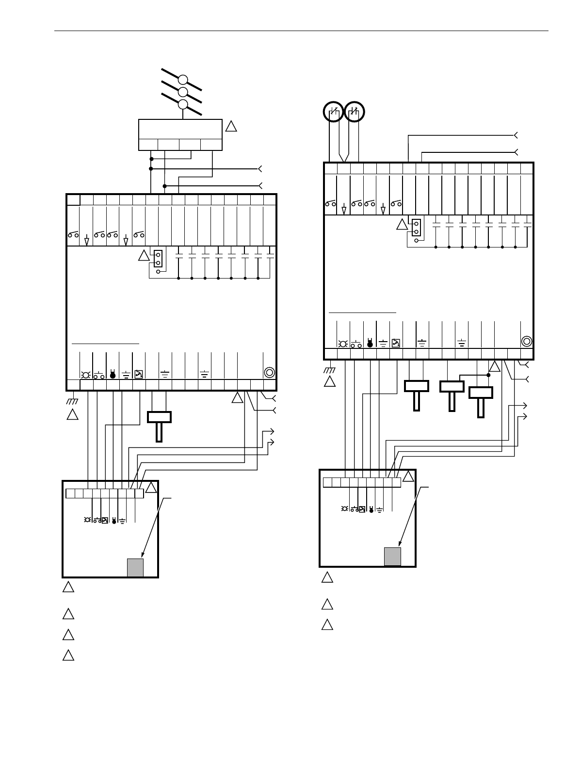
EXCEL 10 W7750A,B,C CONSTANT VOLUME AHU CONTROLLER
41 74-2958—1
Fig. 32. W7750B,C Controller PWM damper actuator
wiring diagram. (For more information on note 2, refer to
Fig. 25.)
Fig. 33. W7750B,C wiring diagram with 4 to 20 mA
enthalpy sensors and digital inputs. (For more
information on note 2, refer to Fig. 25.)
12345678
24 VAC
W7750B CONSTANT
VOLUME AHU
CONTROLLER
1
2
2
1
2
3
4
EARTH GROUND WIRE LENGTH SHOULD BE HELD TO A MINIMUM.
USE THE HEAVIEST GAUGE WIRE AVAILABLE, UP TO 14 AWG (2.O MM2)
WITH A MINIMUM OF 18 AWG (1.O MM2), FOR EARTH GROUND WIRE.
TO ASSURE PROPER ELECTRICAL CONTACT, WIRES MUST BE TWISTED
TOGETHER BEFORE INSERTION INTO THE TERMINAL BLOCK.
WIRING DIAGRAM SHOWS JUMPER (FOR J2) IN FACTORY DEFAULT
HIGH-SIDE POSITION.
FOR WIRING DETAILS FOR PWM DEVICES, REFER TO DOCUMENTATION
INCLUDED WITH PWM DEVICES.
EARTH
GROUND
7 69 8 54321
T7770C
WALL
MODULE
SET PT
GND
SENSOR
BYPASS
LED
E-BUS
E-BUS
9 101112 14 J315
31 30 29 28 27 26 25 24 23 22 21 20
24 VAC COM
WALL MODULE
SET PT
GROUND
SENSOR
BYPASS
LED
20 VDC OUT
19 18 17 16
AI-1 OHM
GROUND
GROUND
AI-2 OHM
AI-4 V/mA
OUT 7
OUT 6
OUT 5
OUT 4
OUT 8
OUT 1
OUT 3
OUT 2
AI-3 V/mA
13
DI-2
DI-4
DI-1
DI-3
DI
GROUND
M10080C
DI
GROUND
TRIAC EQUIVALENT CIRCUIT
DISCHARGE
AIR TEMP
24 VAC
+
-
4
PWM ACTUATOR
24V COM 24V
ECONOMIZER
DAMPER
POWER SIGNAL
SIG
LONWORKS
BUS
LON
JACK
LONWORKS-BUS
JACK FOR
LONWORKS-BUS
NETWORK
ACCESS
3
12345678
24 VAC
24 VAC
W7750B CONSTANT
VOLUME AHU
CONTROLLER
1
2
2
1
2
3
EARTH GROUND WIRE LENGTH SHOULD BE HELD TO A MINIMUM.
USE THE HEAVIEST GAUGE WIRE AVAILABLE, UP TO 14 AWG (2.O MM2)
WITH A MINIMUM OF 18 AWG (1.O MM2), FOR EARTH GROUND WIRE.
TO ASSURE PROPER ELECTRICAL CONTACT, WIRES MUST BE TWISTED
TOGETHER BEFORE INSERTION INTO THE TERMINAL BLOCK.
WIRING DIAGRAM SHOWS JUMPER (FOR J2) IN FACTORY DEFAULT
HIGH-SIDE POSITION.
LONWORKS-BUS
EARTH
GROUND
JACK FOR
LONWORKS-BUS
NETWORK
ACCESS
7 69 8 54321
T7770C
WALL
MODULE
SET PT
GND
SENSOR
BYPASS
LED
E-BUS
E-BUS
9 101112 14 J315
31 30 29 28 27 26 25 24 23 22 21 20
24 VAC COM
WALL MODULE
SET PT
SENSOR
BYPASS
LED
20 VDC OUT
19 18 17 16
AI-1 OHM
AI-2 OHM
AI-4 V/mA
+
-
OUT 7
OUT 6
OUT 5
OUT 4
OUT 8
OUT 1
OUT 3
OUT 2
AI-3 V/mA
13
DI-2
DI-4
DI-1
DI-3
OCCUPANCY SENSOR
(CONTACTS CLOSED
EQUALS OCCUPIED)
WINDOWS CONTACTS
(CONTACTS CLOSED
EQUALS WINDOW
CLOSED)
M10079C
TRIAC EQUIVALENT CIRCUIT
DISCHARGE
AIR TEMP OUTDOOR
ENTHALPY RETURN
ENTHALPY
3
DI
GROUND
DI
GROUND
AI
GROUND
AI
GROUND
AI
GROUND
LON
JACK
LONWORKS
BUS
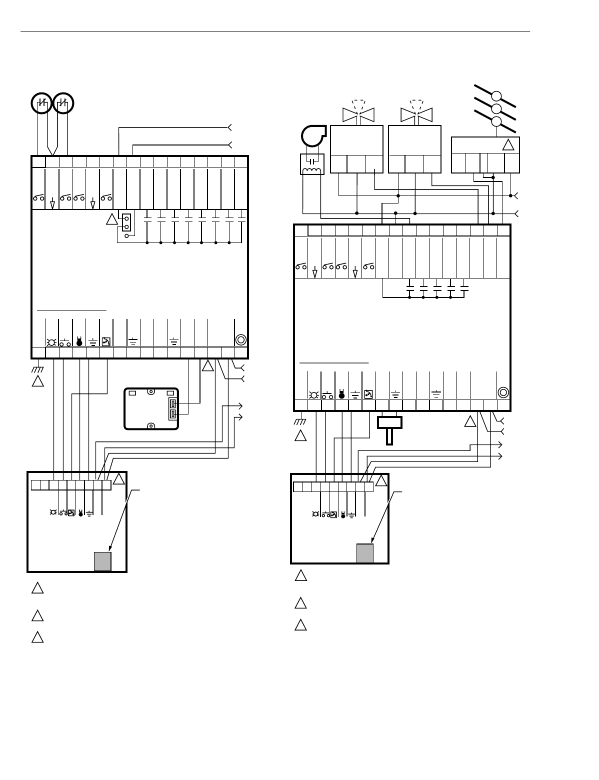
EXCEL 10 W7750A,B,C CONSTANT VOLUME AHU CONTROLLER
74-2958—142
Fig. 34. W7750B,C wiring diagram with C7600C 4 to 20 mA
solid state humidity sensor. (For more information on
note 2, refer to Fig. 25.)
Fig. 35. W7750C Controller with 4-to-20 mA heating,
cooling and economizer wiring diagram. AOs must use
terminals 16, 17 or 18. The AOs can be set to be reverse
acting. (For more information on note 2, refer to Fig. 25.)
See Fi
g
. 36 or 37 to wire a pneumatic transducer to a
W7750B or W7750C.
12345678
24 VAC
24 VAC
W7750B CONSTANT
VOLUME AHU
CONTROLLER
1
2
2
1
2
3
EARTH GROUND WIRE LENGTH SHOULD BE HELD TO A MINIMUM.
USE THE HEAVIEST GAUGE WIRE AVAILABLE, UP TO 14 AWG (2.O MM2)
WITH A MINIMUM OF 18 AWG (1.O MM2), FOR EARTH GROUND WIRE.
TO ASSURE PROPER ELECTRICAL CONTACT, WIRES MUST BE TWISTED
TOGETHER BEFORE INSERTION INTO THE TERMINAL BLOCK.
WIRING DIAGRAM SHOWS JUMPER (FOR J2) IN FACTORY DEFAULT
HIGH-SIDE POSITION.
EARTH
GROUND
7 69 8 54321
T7770C
WALL
MODULE
SET PT
GND
SENSOR
BYPASS
LED
E-BUS
E-BUS
9 101112 14 J315
31 30 29 28 27 26 25 24 23 22 21 20
24 VAC COM
WALL MODULE
SET PT
GROUND
SENSOR
BYPASS
LED
20 VDC OUT
19 18 17 16
AI-1 OHM
GROUND
GROUND
AI-2 OHM
AI-4 V/mA
+
-
OUT 7
OUT 6
OUT 5
OUT 4
OUT 8
OUT 1
OUT 3
OUT 2
AI-3 V/mA
13
DI-2
DI-4
DI-1
DI-3
DI
GROUND
OCCUPANCY SENSOR
(CONTACTS CLOSED
EQUALS OCCUPIED)
WIND
O
W
S
CO
NTA
C
T
S
(CONTACTS CLOSED
EQUALS WINDOW
CLOSED)
M11619B
DI
GROUND
TRIAC EQUIVALENT CIRCUIT
+
–
C7600C
HUMIDITY
(4 TO 20 MA)
LONWORKS
BUS
LON
JACK
LONWORKS-BUS
JACK FOR
LONWORKS-BUS
NETWORK
ACCESS
3
12345678
24 VAC
W7750C CONSTANT
VOLUME AHU
CONTROLLER
1
2
2
3
1
2
EARTH GROUND WIRE LENGTH SHOULD BE HELD TO A MINIMUM.
USE THE HEAVIEST GAUGE WIRE AVAILABLE, UP TO 14 AWG (2.O MM2)
WITH A MINIMUM OF 18 AWG (1.O MM2), FOR EARTH GROUND WIRE.
TO ASSURE PROPER ELECTRICAL CONTACT, WIRES MUST BE TWISTED
TOGETHER BEFORE INSERTION INTO THE TERMINAL BLOCK.
IF AN ANALOG OUTPUT DEVICE HAS A SIGNAL COM (-) TERMINAL,
CONNECT IT TO THE 24 VAC COM TERMINAL NUMBER 24.
LONWORKS-BUS
EARTH
GROUND
JACK FOR
LONWORKS-BUS
NETWORK
ACCESS
7 69 8 54321
T7770C
WALL
MODULE
SET PT
GND
SENSOR
BYPASS
LED
E-BUS
E-BUS
9 101112 14 J315
31 30 29 28 27 26 25 24 23 22 21 20
24 VAC COM
WALL MODULE
SET PT
SENSOR
BYPASS
LED
20 VDC OUT
19 18 17 16
AI-1 OHM
AI-2 OHM
AI-4 V/mA
AO 2
AO 1
OUT 5
OUT 4
AO 3
OUT 1
OUT 3
OUT 2
AI-3 V/mA
13
DI-2
DI-4
DI-1
DI-3
M16417B
TRIAC EQUIVALENT
CIRCUIT
DISCHARGE
AIR TEMP
24 Vac
+
++
-
-
3
SERIES 70
VALVE
ACTUATOR ML7161
4-20
mA
2-10
V
24
Vac
COM 24
Vac
T1
IN-
PUT
COM
SERIES 70
VALVE
ACTUATOR
24
Vac IN-
PUT
COM
ECONOMIZER
DAMPER
TWO - OR
THREE-WAY
HOT WATER/
STEAM VALVE
TWO - OR
THREE-WAY
CHILLER
WATER VALVE
FAN
T2
DI
GROUND
DI
GROUND
AI
GROUND
AI
GROUND
AI
GROUND
LON
JACK
LONWORKS
BUS
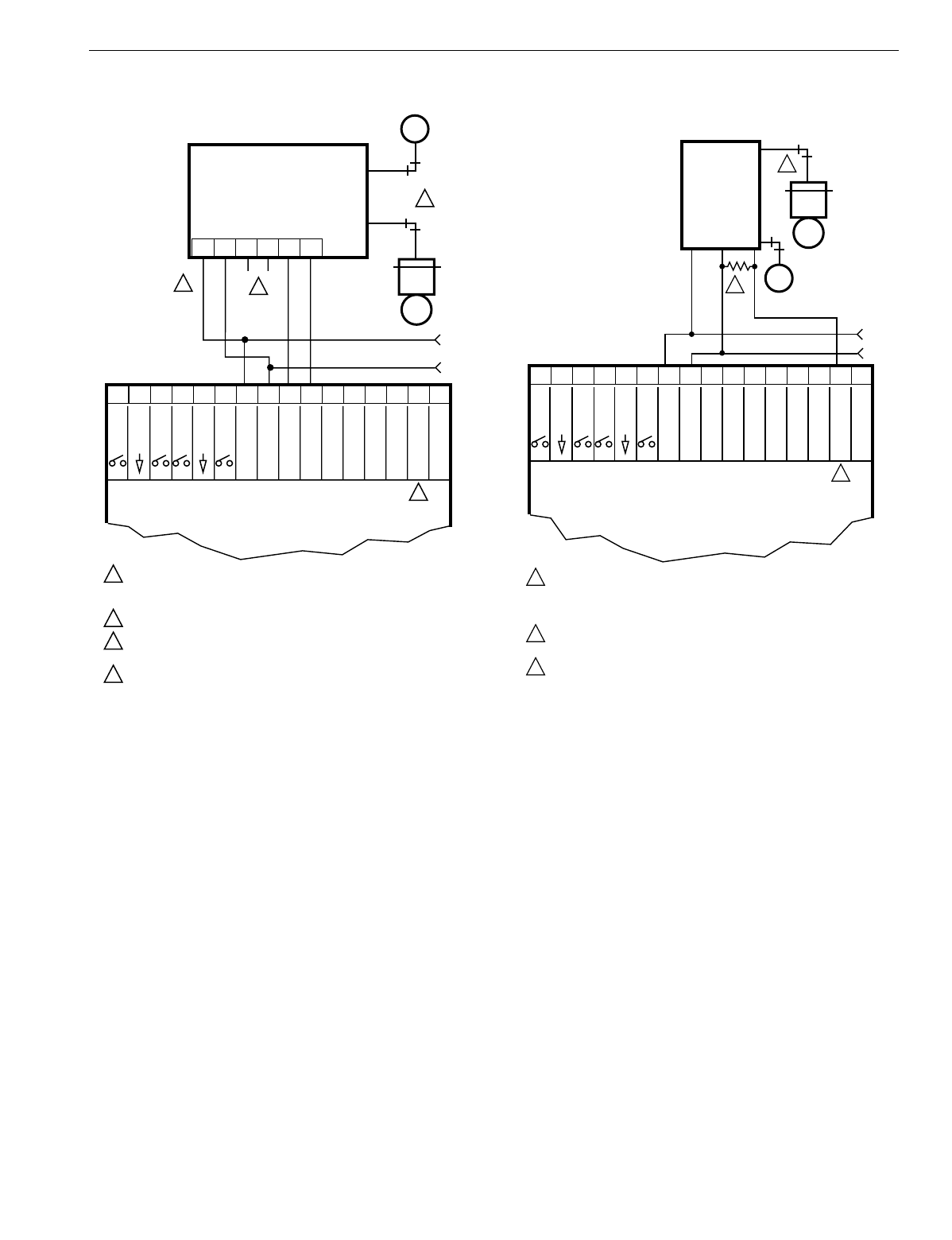
EXCEL 10 W7750A,B,C CONSTANT VOLUME AHU CONTROLLER
43 74-2958—1
Fig. 36. Pneumatic transducer to W7750B,C
(B shown, see triangle note 4).
To use the analo
g
outputs on the W7750C with 2-to-10V
actuators or transducers, a 500 ohm
(
1 percent or better
tolerance
)
resistor must be placed across the 2-to-10V
devices input and
g
round terminal. See Fi
g
. 37. for an
example. The resistor converts a 4 to 20 mA si
g
nal into a 2-to-
10V si
g
nal.
NOTE: Wire the 500 ohm resistor ph
y
sicall
y
as close as
possible to the driven device. If the resistor is located
far awa
y
from the driven device, it is possible that
noise will be added onto the 2-to-10V si
g
nal to
g
round line. This noise could cause an actuator to re-
position
(j
itter
)
and reduce the actuators life.
Fig. 37. RP7517,B pneumatic transducer to W7750C.
LONWORKS® Bus Termination Module
One 209541B Excel 10 FTT Termination Module is re
q
uired
for a sin
g
l
y
terminated LONWORKS Bus se
g
ment. Two
209541B Excel 10 FTT Termination Modules are re
q
uired for
a doubl
y
terminated dais
y
-chain LONWORKS Bus se
g
ment
(
see Fi
g
. 38
)
. Refer to LONWORKS Bus Wirin
g
Guidelines
form, 74-2865 for termination module placement rules.
For 209541B Excel 10 FTT Termination module placement
and wirin
g
options, see Fi
g
. 39.
24 VAC
24 (H)
24 (N)
24 (H)
24 (N)
INCREASE
DECREASE
24 VAC
W7750B,C CONSTANT
VOLUME AHU
CONTROLLER
MMC325 PNEUMATIC
TRANSDUCER
1
2
3
4
4
MAKE SURE ALL TRANSFORMER/POWER WIRING IS AS SHOWN;
REVERSING TERMINATIONS RESULTS IN EQUIPMENT
MALFUNCTION.
OPTIONAL 24 VAC WIRING TO NEXT CONTROLLER.
USE 1/4 IN (6 MM) PNEUMATIC TUBING. MINIMUM BRANCH LINE
MUST BE 6 FT. (1.8M) OR LONGER.
TERMINALS 16,17, 18 ARE ANALOG OUTPUTS (W7750C ONLY).
31 30 29 28 27 26 25 24 23 22 21 20
24 VAC COM
19 18 17 16
+
-
3
2
1
OUT 7
OUT 6
OUT 5
OUT 4
OUT 8
OUT 1
OUT 3
OUT 2
DI-2
DI-4
DI-1
DI-3
DI
GROUND
DI
GROUND
PNEUMATIC
VALVE
M10078C
M
B
M
24 VAC
24 VAC
W7750C CONSTANT
VOLUME AHU
CONTROLLER
RP7517B PNEUMATIC TRANSDUCER
1
2
3
3
ANALOG OUTPUTS FROM W7750C ARE 4 TO 20 mA SIGNALS. A 500 OHM
1% TOLERANCE (OR BETTER) PRECISION RESISTOR IS REQUIRED TO
DRIVE THIS (RP7517B) AND OTHER 2 TO 10V DEVICES. PLACE THIS
RESISTOR AS CLOSE AS POSSIBLE TO THE DRIVEN DEVICE.
USE 1/4 IN (6 MM) PNEUMATIC TUBING. MINIMUM BRANCH LINE
MUST BE 6 FT. (1.8M) OR LONGER.
TERMINALS 16 TO 18 ARE ANALOG OUTPUTS (W7750C ONLY).
31 30 29 28 27 26 25 24 23 22 21 20
24 VAC COM
19 18 17 16
+
-
2
1
AO 2
AO 1
BLACK
BLUE
BROWN
OUT 5
OUT 4
AO 3
OUT 1
OUT 3
OUT 2
DI-2
DI-4
DI-1
DI-3
PNEUMATIC
VALVE
ACTUATOR
500
M17368
RP7517B
1
M2
B
M
DI
GROUND
DI
GROUND
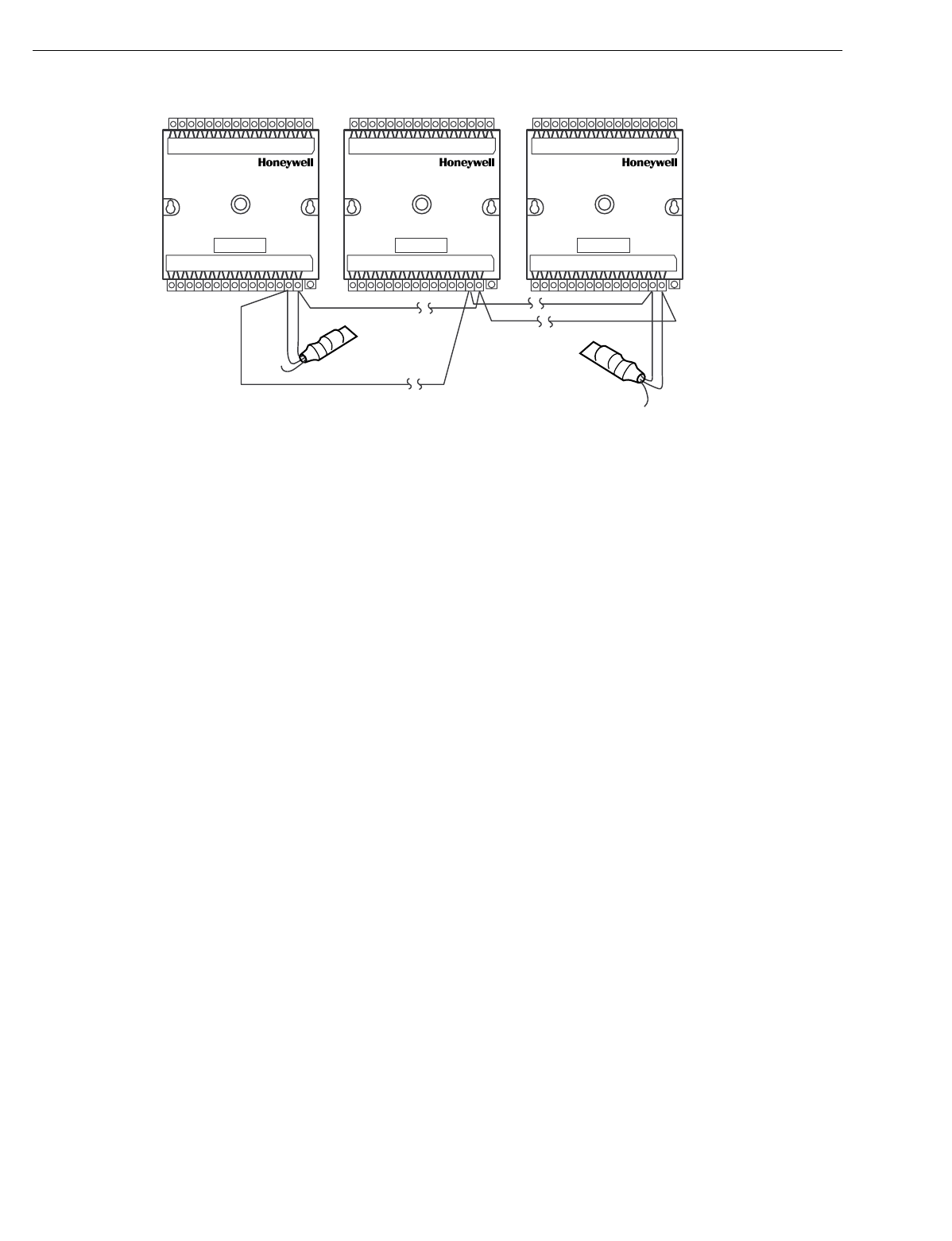
EXCEL 10 W7750A,B,C CONSTANT VOLUME AHU CONTROLLER
74-2958—144
Fig. 38. Typical doubly terminated daisy-chain LONWORKS® Bus segment termination module wiring diagram.
M10519A
PART NO. 209541B
TERMINATION
MODULE
PART NO. 209541B
TERMINATION
MODULE
W7750B, C
1415 1415
W7750B, C
1415
W7750B, C
BROWN BROWN
ORANGE
ORANGE
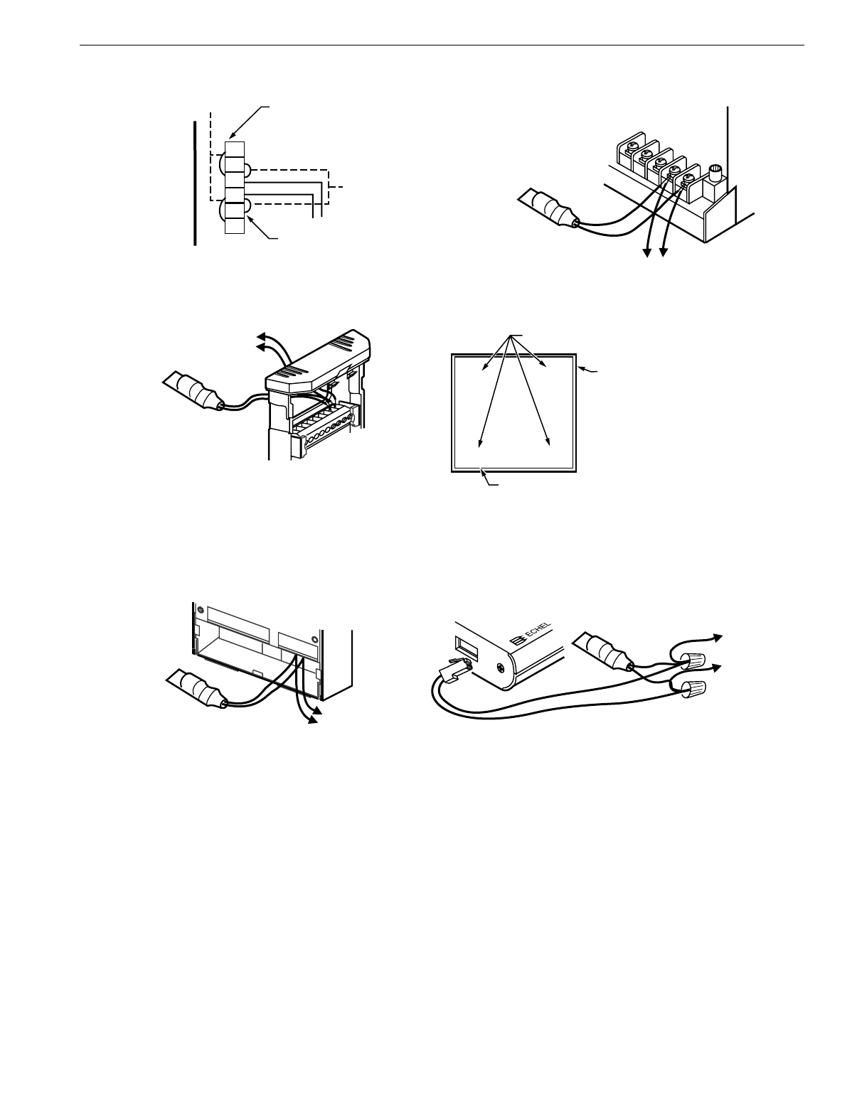
EXCEL 10 W7750A,B,C CONSTANT VOLUME AHU CONTROLLER
45 74-2958—1
Fig. 39. LONWORKS® Bus termination wiring options.
Step 5. Order Equipment
After compilin
g
a bill of materials throu
g
h completion of the
previous application steps, refer to Table 11 for orderin
g
information. Contact Hone
y
well for information about
Controllers and Wall Modules with no lo
g
o. See Table 11.
Excel 10 W7750 Controller Orderin
g
Information.
M11618A
W7750
(D) LONWORKS Bus Termination network
switches in the Q7740A, B Repeaters
(C) LONWORKS Bus Termination Module installed
at 2 x 4 or 60 mm box-mounted T7770
(E) Installing LONWORKS Bus Termination
Module at W7751H (terminals 11 and 12) (F) Twist wires and attach wire nuts to RJ-45 Adapter
cables, LONWORKS Bus segment wires and Termination
Module to connect to a Q7751A,B Router
(B) Installing LONWORKS Bus
Termination Module at W7750
(A) Enabling Internal Termination Network using
jumpers in the Q7750A Zone Manager
RJ-45
PLUG
PART NO. 209541B
TERMINATION
MODULE
LONWORKS
BUS
WIRE NUTS
LONWORKS BUS
TERMINAL BLOCK
FOR Q7750A
ZONE MANAGER
INSERT INTO TERMINALS 1 AND 2 WITH THE
LONWORKS BUS WIRE. TERMINATION MODULE IS
PHYSICALLY LOCATED BEHIND THE T7770
INSIDE THE 2 X 4 OR 60 MM BOX.
Q7751A LONWORKS BUS
ROUTER
LONWORKS BUS
8
7
6
5
4
3
LONWORKS BUS
LONWORKS BUS
INTERNAL
TERMINATION
NETWORK
INTERNAL
TERMINATION
NETWORK FIELD INSTALLED JUMPER
FIELD INSTALLED
JUMPER
LONWORKS BUS
NET 2
SINGLY
TERMINATED SEGMENT
USE FOR DOUBLY
TERMINATED
DAISY-CHAIN
SEGMENT
PART NO. 209541B
TERMINATION
MODULE
PART NO.
209541B
TERMINATION MODULE
PART NO.
209541B
TERMINATION
MODULE
O I II O I II
O I II O I II
AB
CD
SWITCHES ON SIDE, UNDER
Q7740A,B CIRCUIT BOARD.
USE SMALL FLAT OBJECT TO
MOVE THE SWITCHES
AS NEEDED FROM
POSITION O (NO TERMINATION)
POSITION I (SINGLY TERMINATED)
POSITION II (DOUBLY TERMINATED)
SEGMENTS
LABEL ON Q7740B 4 WAY REPEATER
Q7740B 4 WAY REPEATER SHOWN,
Q7740A 2 WAY REPEATER HAS TWO SWITCHES.
NOTE:

EXCEL 10 W7750A,B,C CONSTANT VOLUME AHU CONTROLLER
74-2958—146
Table 11. Excel 10 W7750 Controller Ordering Information.
Part Number Product Description Comments
Excel 10 W7750 Controllers:
W7750A2005 Constant Volume AHU Controller
(
W7750A
)
Three Analo
g
Inputs, Three Di
g
ital Inputs and
Six 24 Vac Rela
y
Outputs
W7750B2011 Constant Volume AHU Controller
(
W7750B
)
Six Analo
g
Inputs, Five Di
g
ital Inputs and Ei
g
ht
(
Hi
g
h-side Low-side switchable
)
Triac Outputs
W7750C2001 Constant Volume AHU Controller
(
W7750C
)
Six Analo
g
Inputs, Five Di
g
ital Inputs, Five Triac
Outputs and Three Analo
g
Outputs
T7770 and T7560 Wall Modules:
T7770A1006 Sensor with Hone
y
well Lo
g
o Used with Excel 5000 and Excel 10 Controllers
T7770A1014 Sensor with No Lo
g
o Used with Excel 5000 and Excel 10 Controllers
T7770A2004 Sensor, LONWORKS Jack and Hone
y
well Lo
g
o Used with Excel 5000 and Excel 10 Controllers
T7770A2012 Sensor with LONWORKS Jack and No Lo
g
o Used with Excel 5000 and Excel 10 Controllers
T7770B1004 Sensor with Setpoint and LONWORKS Jack,
Hone
y
well Lo
g
oDe
g
rees F Absolute
T7770B1046 Sensor with Setpoint and LONWORKS Jack,
Hone
y
well Lo
g
oRelative Setpoint
T7770B1012 Sensor with Setpoint and LONWORKS Jack, No
Lo
g
oDe
g
rees F Absolute
T7770B1020 Sensor with Setpoint and LONWORKS Jack,
Hone
y
well Lo
g
oDe
g
rees C Absolute
T7770B1053 Sensor with Setpoint and LONWORKS Jack, No
Lo
g
oRelative Setpoint
T7770B1038 Sensor with Setpoint and LONWORKS Jack, No
Lo
g
oDe
g
rees C Absolute
T7770C1002 Sensor with Setpoint, B
y
pass/LED and
LONWORKS Jack, Hone
y
well Lo
g
oDe
g
rees F Absolute
T7770C1044 Sensor with Setpoint, B
y
pass/LED and
LONWORKS Jack, Hone
y
well Lo
g
oRelative Setpoint
T7770C1010 Sensor with Setpoint, B
y
pass/LED and
LONWORKS Jack, No Lo
g
oDe
g
rees F Absolute
T7770C1028 Sensor with Setpoint, B
y
pass/LED and
LONWORKS Jack, Hone
y
well Lo
g
oDe
g
rees C Absolute
T7770C1051 Sensor with Setpoint, B
y
pass/LED and
LONWORKS Jack, No Lo
g
oRelative Setpoint
T7770C1036 Sensor with Setpoint, B
y
pass/LED and
LONWORKS Jack, No Lo
g
oDe
g
rees C Absolute
T7770D1000 Sensor with B
y
pass/LED and LONWORKS Jack,
Hone
y
well Lo
g
oDe
g
rees F Absolute
T7770D1018 Sensor with B
y
pass/LED and LONWORKS Jack,
No Lo
g
oDe
g
rees C Absolute
T7560A1018 Di
g
ital Wall Module with Sensor, Setpoint and
B
y
pass/LCD, Hone
y
well Lo
g
o
T7560A1016 Di
g
ital Wall Module with Sensor, Setpoint,
B
y
pass/LCD and Humidit
y
, Hone
y
well Lo
g
o
Sensors:
C7770A1006 Air Temperature Sensor. 20 Kohm NTC
nonlinearized Duct-mounted sensor that functions as a
primar
y
and/or secondar
y
sensor.
C7031J1050 Avera
g
in
g
Dischar
g
e/Return Air Temperature
Sensor. 20 Kohm NTC Duct element cord len
g
th 12 ft.
(
3.7m
)
.
C7031B1033 Dischar
g
e Air or Hot Water Temperature
Sensor. 20 Kohm NTC Use 112622AA Immersion Well.

EXCEL 10 W7750A,B,C CONSTANT VOLUME AHU CONTROLLER
47 74-2958—1
C7031C1031 Duct Dischar
g
e/Return Air Sensor. 20 Kohm 18 in.
(
457mm
)
insertion len
g
th.
C7031D1062 Hot or chilled Water Temperature Sensor. 20
Kohm NTC —
C7031F1018 Outside Air Temperature Sensor. 20 Kohm
NTC W7750B,C onl
y
C7031K1017 Hot or chilled Water Temperature Sensor. 20
Kohm NTC Strap-on
C7100A1015 Avera
g
in
g
Dischar
g
e/Return Air Temperature
Sensor. PT3000 13 in.
(
330mm
)
insertion len
g
th.
C7170A1002 Outdoor Air Temperature Sensor. PT3000 —
Echelon Based Components and Parts:
Q7750A2003 Excel 10 Zone Mana
g
er Free Topolo
gy
Tranceiver
(
FTT
)
Q7751A2002 Router
(
FTT
)
Q7751B2000 Router Twisted Pair Tranceiver
(
78 kbps
)
to FTT
Q7752A2001 Serial Interface
(
FTT
)
Q7752A2009 Serial Interface
(
PCMCIA card
)
(
FTT
)
Q7740A1008 Excel 10 2-Wa
y
Repeater Used to extend the len
g
th of the LONWORKS
Bus. Contains built in termination modules.
Q7740B1006 Excel 10 4-Wa
y
Repeater Used to extend the len
g
th of the LONWORKS
Bus. Contains built in termination modules.
XD 505A Standard C-Bus Communications Submodule —
XD 508 C-Bus Communications Submodule
(
1 me
g
abit
baud rate
)
—
209541B Termination Module One/two re
q
uired per LONWORKS Bus se
g
ment
205979 Operator Terminal Cable for LONWORKS Bus Serial interface to wall module or controller
Accessories (Sensors):
EL7680A1008 Wall Mounted Wide View Infrared Occupanc
y
Sensor —
EL7628A1007 Ceilin
g
Mounted Infrared Occupanc
y
Sensor —
EL7611A1003, EL7612A1001 Ultrasonic Occupanc
y
Sensors —
EL7630A1003,
EL7621A1002,
EL7621A1010
Power Suppl
y
/Control Units for Occupanc
y
sensors —
C7242A1006 CO2 Sensor/Monitor Use to measure the levels of carbon dioxide
C7400A1004 Solid State Enthalp
y
Sensor
(
4 to 20 mA
)
For outdoor and return air enthalp
y
C7600B1000 Solid State Humidit
y
Sensor
(
2 to 10 V
)
For outdoor and return air humidit
y
C7600C1008 Solid State Humidit
y
Sensor
(
4 to 20 mA
)
For outdoor and return air humidit
y
C7600C1018 Solid State Humidit
y
Sensor
(
2 to 10 V
)
For outdoor and return air humidit
y
Accessories:
MMC325-010, MMC325-020 Pneumatic Retrofit Transducers. Select
pressure ran
g
e:
(
010
)
0 to 10 psi
(
68.97 kPa
)
or
(
020
)
0 to 20 psi
(
137.93 kPa
)
.
Use to control Pneumatic reheat valves.
MMCA530 DIN rail adapter for MMC325 Transducers —
MMCA540 Metal enclosure for MMC325 Transducers —
ML7984B3000 Valve Actuator Pulse Width Modulation
(
PWM
)
Use with V5011 or V5013 F and G Valves
ML6161B1000 Damper Actuator Series 60 —
M6410A Valve Actuator Series 60 Use with V5852/V5853/V5862/V5863 Valves
ML684A1025 Versadrive Valve Actuator with linka
g
e, Series
60 Use with V5011 and V5013 Valves
Table 11. Excel 10 W7750 Controller Ordering Information. (Continued)
Part Number Product Description Comments

EXCEL 10 W7750A,B,C CONSTANT VOLUME AHU CONTROLLER
74-2958—148
Step 6. Configure Controllers
Excel E-Vision PC Software is used to confi
g
ure W7750
Controllers to match their intended application. The E-Vision
User Guide, form number 74-2588 provides details for
operatin
g
the PC software.
W7750 Controllers are shipped from the factor
y
with a default
hardware confi
g
uration. On power-up, the controller
confi
g
uration parameters are set to the default values listed in
Table 20 in Appendix C. The controller can operate normall
y
in this mode
(
if the e
q
uipment and wirin
g
match the default
setup
)
, and
g
iven valid sensor inputs, the outputs are
controlled appropriatel
y
to maintain space temperature at the
default setpoint. The default I/O arran
g
ement for the W7750A
is printed on the terminal labels. Also see the wirin
g
details in
Fi
g
. 27 in Step 4, Prepare Wirin
g
Dia
g
rams. The labeled I/O
terminals are defined in Table 10.
Step 7. Troubleshooting
Troubleshooting Excel 10 Controllers and Wall
Modules
In addition to the followin
g
information, refer to the Installation
Instructions and Checkout and Test manual for each product.
Most products have a Checkout and Test section in their
Installation Instructions manual. If not, look for a separate
Checkout and Test manual. See the Applicable Literature
section for form numbers.
ML6464A1009 Direct Coupled Actuator, 66 lb-in. tor
q
ue,
Series 60 —
ML6474A1008 Direct Coupled Actuator, 132 lb-in. tor
q
ue,
Series 60 —
ML6185A1000 Direct Coupled Actuator, 50 lb-in. sprin
g
return Series 60
V5852A/V5862A Two-wa
y
terminal unit water valve; 0.19, 0.29,
0.47, 0.74, 1.2, and 1.9 Cv 1/2 in. npt
(
13 mm
)
or 2.9 and 4.9 Cv 3/4 in. npt
(
19 mm
)
Use with M6410 Valve Actuator. Close-off ratin
g
for 0.19 to 1.9 Cv is 65 psi; for 2.9 and 4.9, Cv is
45 psi.
(
Coefficient of volume or capacit
y
index
Cv =
g
allons per minute divided b
y
the s
q
uare
root of the pressure drop across the valve.
)
V5853A/V5863A Three-wa
y
mixin
g
terminal unit hot water valve;
0.19, 0.29, 0.47, 0.74, 1.2, and 1.9 Cv 1/2 in.
npt
(
13 mm
)
or 2.9 and 4.9 Cv 3/4 in. npt
(
19
mm
)
Use with M6410 Valve Actuator. Close-off ratin
g
for 0.19 to 0.74 Cv is 55 psi; 1.2 and 1.9 Cv is 22
psi; 2.9 and 4.9 Cv is 26 psi.
R8242A Contactor, 24 Vac coil, DPDT —
AT72D, AT88A, AK3310, etc. Transformers —
EN 50 022 DIN rail 35 mm b
y
7.5 mm
(
1-3/8 in. b
y
5/16 in.
)
Obtain locall
y
: Each controller re
q
uires 5 in.
—Two DIN rail adapters Obtain locall
y
: Part number TKAD, from Thomas
and Betts, two for each controller.
Cabling:
—Serial Interface Cable, male DB-9 to female
DB-9 or female DB-25. Obtain locall
y
from an
y
computer hardware
vendor.
Hone
y
well
AK3791
(
one twisted pair
)
AK3792
(
two twisted pairs
)
LONWORKS Bus
(
plenum
)
: 22 AWG
(
0.34 mm2
)
twisted pair solid conductor, nonshielded or
Echelon approved cable.
Level IV 140°F
(
60°C
)
ratin
g
Hone
y
well AK3781
(
one
twisted pair
)
AK3782
(
two
twisted pairs
)
LONWORKS Bus
(
nonplenum
)
: 22 AWG
(
0.34
mm2
)
twisted pair solid conductor, nonshielded
or Echelon approved cable.
Level IV 140°F
(
60°C
)
ratin
g
Hone
y
well AK3725 Inputs: 18 AWG
(
1.0 mm2
)
five wire cable
bundle Standard thermostat wire
Hone
y
well AK3752
(
t
y
pical or
e
q
uivalent
)
Outputs/Power: 14 to 18 AWG
(
2.0 to 1.0 mm2
)
NEC Class 2 140°F
(
60°C
)
ratin
g
Hone
y
well AK3702
(
t
y
pical or
e
q
uivalent
)
18 AWG
(
1.0 mm2
)
twisted pair Non-plenum
Hone
y
well AK3712
(
t
y
pical or
e
q
uivalent
)
16 AWG
(
1.3 mm2
)
twisted pair Non-plenum
Hone
y
well AK3754
(
t
y
pical or
e
q
uivalent
)
14 AWG
(
2.0 mm2
)
two conductor Non-plenum
Table 11. Excel 10 W7750 Controller Ordering Information. (Continued)
Part Number Product Description Comments
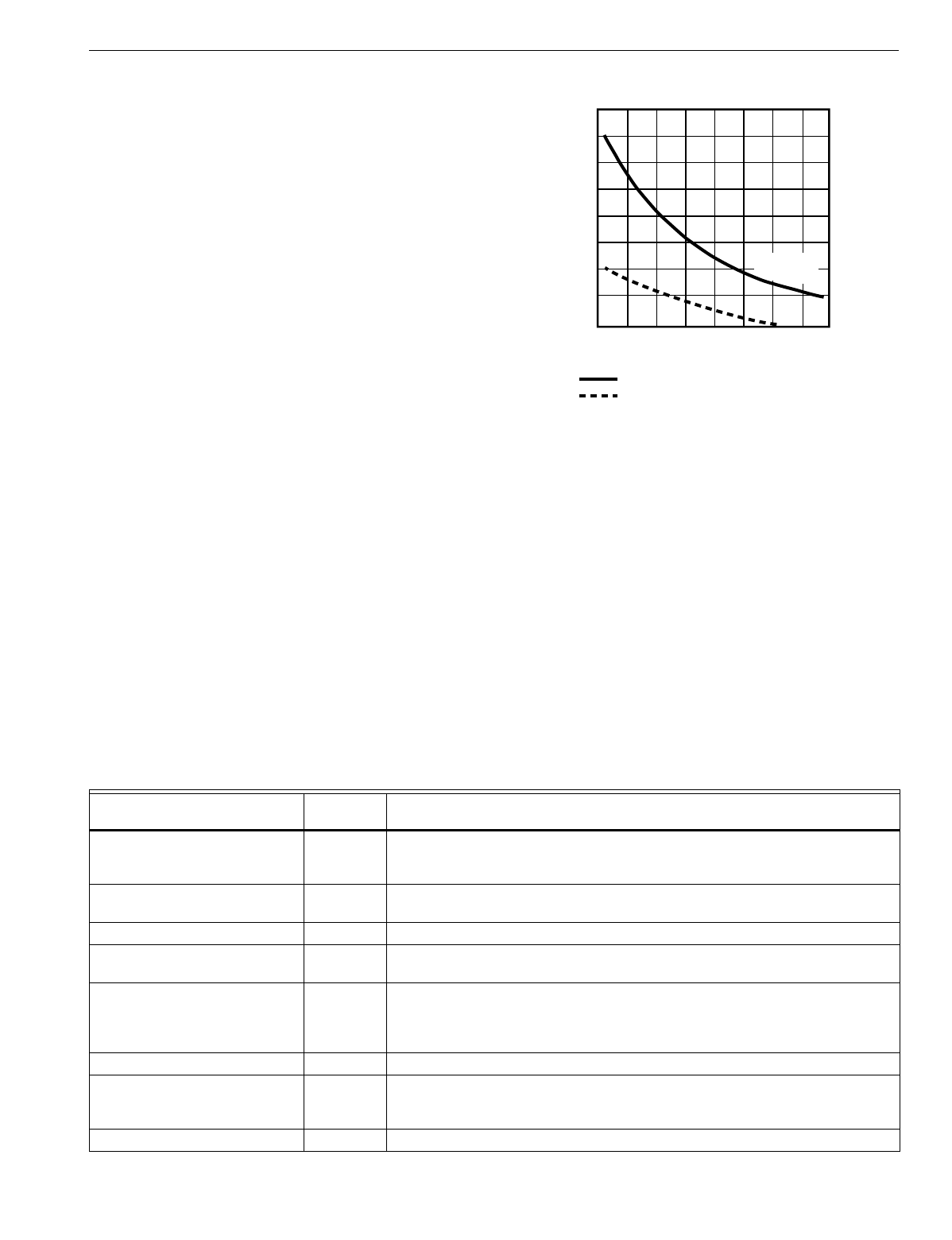
EXCEL 10 W7750A,B,C CONSTANT VOLUME AHU CONTROLLER
49 74-2958—1
1. Check the version numbers of the controller firmware,
E-Vision and the E-Vision script.
2. Check the wirin
g
to the power suppl
y
and make sure
there is a
g
ood earth
g
round to the controller.
3. Check the occupanc
y
and HVAC modes.
4. Compare the current actual setpoint with the actual
space temperature.
5. Check the desired confi
g
uration settin
g
s.
6. Check the network wirin
g
and t
y
pe of wire used.
7. Check the Zone Mana
g
er mappin
g
and referred points.
NOTE: If the fan shuts off periodicall
y
for no specific reason
and the controller restarts the fan b
y
itself after about
20 to 60 seconds, the cause could be a bad Air Flow
switch. If the controller has a di
g
ital input assi
g
ned
as a Proof of Air Flow input, tr
y
unconfi
g
urin
g
this
di
g
ital input to see if these shutdowns continue. If
not, ad
j
ust or replace the Air Flow switch to
g
et it
workin
g
.
Temperature Sensor and Setpoint Potentiometer
Resistance Ranges
The T7770 or T7560A,B Wall Modules or the C7770A Air
Temperature Sensor has the followin
g
specified calibration
points, which are plotted in Fi
g
. 40:
Temperature (°F) Resistance Value (ohms)
98 11755
80 18478
70 24028
60 31525
42 52675
The T7770 Wall Module setpoint potentiometers have the
followin
g
calibration points:
Temperature (°F) Resistance Value (ohms)
85 1290
70 5500
55 9846
Fig. 40. Temperature sensor resistance plots.
Alarms
When an Excel 10 has an alarm condition, it reports it to the
central node on the LONWORKS Bus
(
t
y
picall
y
, the Excel 10
Zone Mana
g
er
)
. See Table 12. Information contained in an
alarm messa
g
e is:
•Subnet Number:
LONWORKS Bus subnet that contains the Excel 10 node
that has the alarm condition. Subnet 1 is on the Zone
Mana
g
er side of the router; Subnet 2 is on the other
side.
•Node Number:
Excel 10 node that has the alarm condition
(
see
Network Alarm
)
.
•Alarm T
y
pe:
Specific alarm bein
g
issued. An Excel 10 can provide
the alarm t
y
pes listed in Table 12.
.
TEMPERATURE (DEGREES)
oF
30 40 50 60 70 80 90 100 110
010 20 30 40
RESISTANCE (OHMS)
20K OHM AT
77
o
F (25
o
C)
80K
70K
60K
50K
40K
30K
20K
10K
oC
M11620
AIR TEMPERATURE SENSOR
10K OHM SETPOINT POT
RESISTANCE VALUES
Table 12. Excel 10 Alarms.
Name of alarm or error bit Alarm type
number Meaning of alarm code or error bit
RETURN_TO_NORMAL 128U Return to no alarm after bein
g
in an alarm condition. This code is added
numericall
y
to another alarm code to indicate that the alarm condition has
returned to normal.
ALARM_NOTIFY_DISABLED 255U The alarm reportin
g
was turned off b
y
DestManMode. No more alarms are
reported until DestManMode turns on alarm reportin
g
or on application restart.
NO_ALARM 0 No alarms presentl
y
detected.
INPUT_NV_FAILURE 1 One or more NV inputs have failed in receivin
g
an update within their specified
FAILURE_DETECT_TIME.
NODE_DISABLED 2 The control al
g
orithm has stopped because the controller is in
DISABLED_MODE, MANUAL or FACTORY_TEST mode. No more alarms are
reported when the controller is in the DISABLED_MODE. Alarms continue to be
reported if the controller is in the MANUAL or FACTORY_TEST mode.
SENSOR_FAILURE 3 One or more sensors have failed.
FROST_PROTECTION_ALARM 4 The space temperature is below the frost alarm limit 42.8°F
(
6°C
)
when the
mode is FREEZE_PROTECT. The alarm condition remains until the temperature
exceeds the alarm limit plus h
y
sterisis.
INVALID_SET_POINT 5 One of the setpoints is not in the valid ran
g
e.
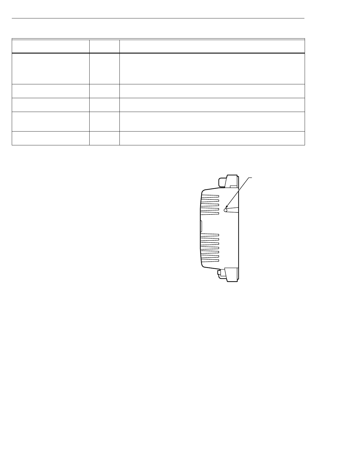
EXCEL 10 W7750A,B,C CONSTANT VOLUME AHU CONTROLLER
74-2958—150
NOTE: The node can be reset b
y
switchin
g
the node to
MANUAL and then to the normal operatin
g
mode
(
see Fan Operation in Appendix B
)
.
Also, the Excel 10 variables,
AlarmLogX
where
X
is 1 throu
g
h
5, that store the last five alarms to occur in the controller, are
available. These points can be viewed throu
g
h XBS or
E-Vision.
Certain alarm conditions are suppressed conditionall
y
as
follows:
Broadcasting the Service Message
The Service Messa
g
e allows a device on the LONWORKS Bus
to be positivel
y
identified. The Service Messa
g
e contains the
controller ID number and, therefore, can be used to confirm
the ph
y
sical location of a particular Excel 10 in a buildin
g
.
There are three methods of broadcastin
g
the Service
Messa
g
e from an Excel 10 W7750 Controller. One uses a
hardware service pin button on the side of the controller
(
see
Fi
g
. 41
)
. The second uses the wall module pushbutton
(
see
Fi
g
. 43 and 44
)
. B
y
pressin
g
the wall module pushbutton for
more than four seconds, the controller sends out the Service
Messa
g
e. The third involves usin
g
the PC Confi
g
uration tool,
as follows.
When an
Assign ID
command is issued from the
commissionin
g
tool, the node
g
oes into the
SERVICE_MESSAGE mode for five minutes. In the
SERVICE_MESSAGE mode, pressin
g
the Occupanc
y
Override button on the remote wall module
(
refer to Fi
g
. 43
and 44 for override button location
)
causes the Service
Messa
g
e to be broadcast on the network. All other functions
are normal in the SERVICE_MESSAGE mode. Even if an
Excel 10 W7750 Controller does not have an Override button
connected, it can broadcast the Service Messa
g
e on the
network b
y
temporaril
y
shortin
g
the Controller B
y
pass Input
terminal to the Sensor Ground terminal on the W7750A,B,C
(
short terminals 3 and 5
)
.
The commissionin
g
tool is used to perform the ID Assi
g
nment
task
(
see the E-Vision User’s Guide, form 74-2588
)
.
Fig. 41. Location of the Service Pin Button.
W7750 Controller Status LED
The LED on the front and center of a W7750 Controller
provides a visual indication of the status of the device. See
Fi
g
. 42. When the W7750 receives power, the LED should
appear in one of the followin
g
allowable states:
1. Off—no power to the processor.
2. Continuousl
y
On—processor is in initialized state.
3. Slow Blink—controllin
g
, normal state.
4. Fast Blink—when the Excel 10 has an alarm condition.
LOSS_OF_AIR_FLOW 6 The Fan Status DI indicates that there is no air flow when the node is
commandin
g
the fan to run. The control is shut down and disabled until power is
c
y
cled or the node is reset. See NOTE below. The alarm is not issued until
FanFailTime seconds have elapsed since the loss-of-flow condition was first
reported
DIRTY_FILTER 7 The pressure drop across the filter exceeds the limit and the filter re
q
uires
maintenance. The control runs normall
y
.
SMOKE_ALARM 8 The smoke detector has detected smoke and the node has entered an
emer
g
enc
y
state.
IAQ_OVERRIDE 9 The indoor air
q
ualit
y
sensor has detected that the indoor air
q
ualit
y
is less than
the desired standard and additional outdoor air is bein
g
brou
g
ht into the
conditioned space.
LOW_LIM_ECON_CLOSE 10 The economizer has to close be
y
ond the minimum position to prevent the
dischar
g
e air temperature from
g
oin
g
below the dischar
g
e temperature low limit.
Table 12. Excel 10 Alarms. (Continued)
Name of alarm or error bit Alarm type
number Meaning of alarm code or error bit
M10094
SERVICE
PIN
BUTTON
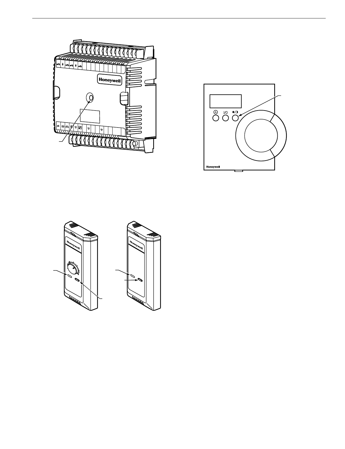
EXCEL 10 W7750A,B,C CONSTANT VOLUME AHU CONTROLLER
51 74-2958—1
Fig. 42. LED location on W7750.
T7770C,D Wall Module Bypass Pushbutton and
Override LED
Pressin
g
the b
y
pass pushbutton, located on the T7770C,D
Wall Modules in Fi
g
. 43, causes the override LED to displa
y
the Manual Override mode of the controller. The modes are:
Fig. 43. The T7770C,D Wall Modules LED and Bypass
pushbutton locations.
1. LED = Off. No override active.
2. LED = Continuousl
y
on. B
y
pass mode
(
timed Occupied
override
)
.
3. LED = One flash per second. Continuous Unoccupied
override.
4. LED = Two flashes per second. Remote onl
y
, continu-
ous Occupied override.
T7560A,B Digital Wall Module Bypass Pushbutton
and LCD Display Occupancy Symbols
See Fi
g
. 44 for the T7560A,B Di
g
ital Wall Module b
y
pass
pushbutton location.
Press and release the b
y
pass pushbutton, located on the
T7560A,B Di
g
ital Wall Modules in Fi
g
. 44 for more than one
second to cause the sun s
y
mbol on the bottom ri
g
ht side of
the LCD displa
y
to appear. Pressin
g
the b
y
pass pushbutton
for more than four seconds causes the controller, hard-wired
to the T7560A,B, to
g
o into continuous unoccupied override.
The T7560A,B displa
y
s the moon s
y
mbol.
Fig. 44. The T7560A,B Digital Wall Module Bypass
pushbutton location.
APPENDICES
Appendix A. Using E-Vision to Commission a
W7750 Controller.
NOTE: When commissionin
g
a CVAHU W7750 Controller,
E-Vision first checks that the actual hardware model
(
such as W7750A,B,C
)
is the same t
y
pe which was
selected from the Application Selection/Output tab. If
the t
y
pes do not match, the download does not occur
and the user-entered values in the Application
Selection screens all revert back to default values.
Sensor Calibration
The space temperature, the optional resistive and
voltage/
current
(
W7750B,C onl
y)
inputs can all be calibrated. The wall
module setpoint potentiometer
can not
be calibrated.
Perform the sensor calibration b
y
addin
g
an offset value
(
either positive or ne
g
ative
)
to the sensed value usin
g
E-Vision menus
(
see E-Vision user
g
uide, form number
74-2588
)
.
When calibratin
g
volta
g
e/current sensors on the
(
W7750B,C
)
,
the offset amount entered b
y
the user is in volts, re
g
ardless of
the inputs actual en
g
ineerin
g
units. See Appendix E for
information on how to derive the proper volta
g
e value to enter
as an offset durin
g
calibration.
Setting the Pid Parameters
The W7750 is desi
g
ned to control a wide variet
y
of
mechanical s
y
stems in man
y
t
y
pes of buildin
g
s. With this
flexibilit
y
, it is necessar
y
to verif
y
the stabilit
y
of the
temperature control in each different t
y
pe of application.
M10095A
W7750
123456789
10111
2131
415J3
31 30292
8272
625242
322 2
1201
91817 1
6
E
GND
LED BYPASS SNSR SET PT AI-1
OHM
A1-2
OHM
AI-3
V/mA
AI-4
V/mA
20VDC
OUT
DI-4
DI-3
DI-2 DI-1 VAC
24
VAC
24
COM
1
OUT
2
OUT
3
OUT
4
OUT
5
OUT
6
OUT
7
OUT
8
OUT
AI
GNDAI
GNDAI
GNDLONWORKS
-BUSLON
JACK
DI
GNDDI
GND
STATUS
LED
M11617
T7770C T7770D
OVERRIDE
LED
BYPASS
PUSHBUTTON
BYPASS
PUSHBUTTON
70
65
60
55
75
80
85
OVERRIDE
LED
M17500
BYPASS
PUSHBUTTON
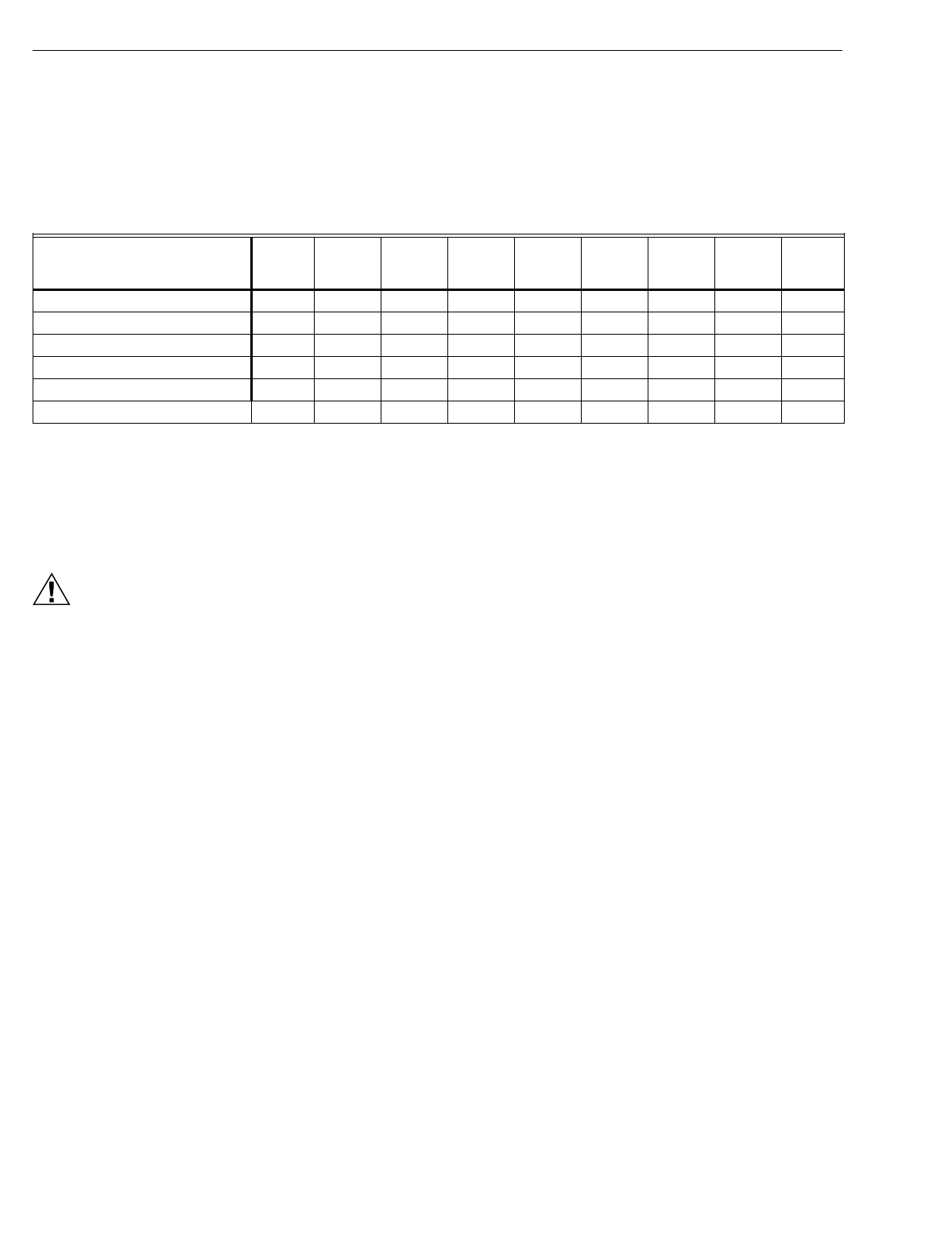
EXCEL 10 W7750A,B,C CONSTANT VOLUME AHU CONTROLLER
74-2958—152
Occasionall
y
, the PID parameters re
q
uire tunin
g
to optimize
comfort and smooth e
q
uipment operation. This applies to the
W7750A,B,C Controllers.
CVAHU Controllers are confi
g
ured b
y
E-Vision with default
values of PID parameters as shown in Appendix C Table 21. If
different values for these parameters are desired, Table 13
lists some recommended values to use as a startin
g
point.
These recommended values are based on past experience
with the applications and in most cases do not re
q
uire further
ad
j
ustment.
Table 13. Recommended Values For PID Parameters.
If the PID parameters re
q
uire ad
j
ustment awa
y
from these
values,
use caution
to ensure that e
q
uipment problems do not
arise
(
see CAUTION below
)
. If an
y
chan
g
e to PID control
parameters is made, the ad
j
ustments should be
g
radual. After
each chan
g
e, the s
y
stem should be allowed to stabilize so the
effects of the chan
g
e can be accuratel
y
observed. Then
further refinements can made, as needed, until the s
y
stem is
operatin
g
as desired.
CAUTION
If lar
g
e or fre
q
uent chan
g
es to PID control parameters
are made, it is possible to cause e
q
uipment problems
such as short c
y
clin
g
compressors
(
if the sta
g
e
minimum run times were disabled in User Addresses
DisMinClTime or DisMinHtTime
)
. Other problems that
can occur include wide swin
g
s in space temperature
and excessive overdrivin
g
of modulatin
g
outputs.
If ad
j
ustment of PID parameters is re
q
uired, use the followin
g
.
In the items that follow, the term, error, refers to the difference
between the measured space temperature and the current
actual space temperature setpoint.
—The Proportional Gain
(
also called Throttlin
g
Ran
g
e
)
determines how much impact the error has on the output
si
g
nal. Decreasin
g
the Proportional Gain amplifies the
effect of the error; that is, for a
g
iven error, a small
Proportional Gain causes a hi
g
her output si
g
nal value.
—The Integral Gain
(
also called Inte
g
ral Time
)
determines
how much impact the error-over-time has on the output
si
g
nal. Error-over-time has two components makin
g
up its
value: the amount of time the error exists; and the size of
the error. The hi
g
her the Inte
g
ral Gain, the slower the
control response. In other words, a decrease in Inte
g
ral
Gain causes a more rapid response in the output si
g
nal.
—The Derivative Gain
(
also called Derivative Time
)
determines how much impact the error rate has on the
output si
g
nal. The error rate is how fast the error value is
chan
g
in
g
. It can also be the direction the space
temperature is
g
oin
g
, either toward or awa
y
from the
setpoint, and its speed—
q
uickl
y
or slowl
y
. A decrease in
Derivative Gain causes a
g
iven error rate to have a lar
g
er
effect on the output si
g
nal.
—The Control Band is used onl
y
for dischar
g
e temperature
control of modulatin
g
outputs, which includes controllin
g
the economizer dampers, and heatin
g
and coolin
g
valves
usin
g
Cascade Control. The Control Band dictates the
span throu
g
h which the dischar
g
e temperature must travel
to cause the output si
g
nal to
g
o from full
y
closed to full
y
open. Also, 10 percent of the Control Band value is the size
of the
deadband
around the setpoint where no actuator
motion occurs. For example, if controllin
g
a coolin
g
valve
with Cascade Control enabled and with the dischar
g
e
temperature within 0.1 X DaTempClCtrlBd of the dischar
g
e
setpoint, there is no chan
g
e in the current valve position.
The smaller the Control Band, the more responsive the
control output. A lar
g
er Control Band causes more slu
gg
ish
control. Be careful not to set the Control Band too low and
cause lar
g
e over or under shoots
(
huntin
g)
. This can
happen if the space or dischar
g
e sensors or wirin
g
are in
nois
y
environments and the value reported to the controller
is not stable
(
such that it bounces
)
. The Control Band is
used onl
y
in modulatin
g
control, and has no purpose when
sta
g
ed control is confi
g
ured.
Appendix B. Sequences of Operation.
This Appendix provides the control se
q
uences of operation for
the models of the Excel 10 W7750 CVAHU Controller. The
W7750A,B,C Controllers can be confi
g
ured to control a wide
variet
y
of possible e
q
uipment arran
g
ements. Table 14 and 15
(
copied from Tables 3 and 4
)
summarize the available options.
This Appendix provides a more detailed discussion of these
options.
Equipment Configuration
Heat
Prop.
Gain
Heat
Integ.
Gain
Heat
Deriv.
Gain
Heat
Control
Band
Cool
Prop.
Gain
Cool
Integ.
Gain
Cool
Deriv.
Gain
Cool
Control
Band
Econ
Control
Band
Single Stage 2 3000 0 10 2 3000 0 10 10
Two Stages 3 2000 0 10 3 2000 0 10 10
Three Stages 4.5 1500 0 10 4.5 1500 0 10 10
Four Stages 6 1000 0 10 6 1000 0 10 10
Series 60 Modulating (Floating) 2 750 0 10 2 750 0 10 10
PWM Modulating 2 900 0 10 2 900 0 10 10

EXCEL 10 W7750A,B,C CONSTANT VOLUME AHU CONTROLLER
53 74-2958—1
Common Operations
The Excel 10 W7750 Controller applications have man
y
common operations that are applicable re
g
ardless of the t
y
pe
of heatin
g
, coolin
g
, or economizer e
q
uipment confi
g
uration.
These operations are available to the W7750A and the
W7750B,C Versions of the CVAHU Controller, and the I/O and
network confi
g
urations for them are summarized in Table 14.
Available input options are from the wall module and the
hard-wired analo
g
and di
g
ital inputs. Each application can
have onl
y
a subset of these devices confi
g
ured based on the
number of ph
y
sical I/O points available. However, some of the
inputs are available over the LONWORKS Bus network.
NOTE: Each W7750 Controller
must
have a space
temperature sensor input either wired directl
y
to the
controller, or shared from another LONWORKS Bus
device, and must have a di
g
ital output confi
g
ured for
controllin
g
the suppl
y
fan. In addition, if modulatin
g
economizer control is desired, a dischar
g
e air
temperature sensor
must
be ph
y
sicall
y
connected to
the Excel 10 W7750 Controller. A dischar
g
e
temperature si
g
nal
cannot
be brou
g
ht into the
controller throu
g
h the LONWORKS Bus network.
Table 14. Common Configuration Options Summary For W7750A,B,C Controllers.
Option Possible Configurations Common To All W7750 Models
Supply Fan 1. Mandator
y
Di
g
ital Output.
Type of Air Handler 1. Conventional.
2. Heat Pump.
Occupancy Sensor 1. None.
2. Connected: Contacts closed e
q
uals Occupied.
3. Network
(
Occ/Unocc si
g
nal received via the LONWORKS Bus network
)
.
Window Sensor 1. None.
2. Ph
y
sicall
y
Connected: Contacts closed e
q
uals window closed.
3. Network
(
Window Open/Closed si
g
nal received via the LONWORKS Bus
)
.
Wall Module Option 1. Local
(
direct wired to the controller
)
.
(
The T77560A,B has no LONWORKS Bus access
)
2. Network
(
sensor value received via the LONWORKS Bus
)
.
Wall Module Type 1. Sensor onl
y
.
(
All wall modules have a LONWORKS Bus access 2. Sensor and Setpoint ad
j
ust.
j
ack except T7560A,B
)
3. Sensor, Setpoint ad
j
ust and B
y
pass.
4. Sensor and B
y
pass.
Smoke Emergency Initiation 1. None.
2. Ph
y
sicall
y
Connected: Contacts closed e
q
uals smoke detected.
3. Network
(
Emer
g
enc
y
/Normal si
g
nal received via the LONWORKS Bus
)
.

EXCEL 10 W7750A,B,C CONSTANT VOLUME AHU CONTROLLER
74-2958—154
Table 15. Configuration Options Summary For W7750A,B,C Controllers.
ROOM TEMPERATURE SENSOR (RmTemp)
This is the room space temperature sensor. This sensor is the
T7770 or the T7560A,B Wall Module. When it is confi
g
ured, it
provides the temperature input for the W7750 temperature
control loop. If it is not confi
g
ured, it is re
q
uired that a room
temperature sensor value be transmitted from another
LONWORKS Bus device. If no valid room temperature value is
available to the W7750 Controller, the temperature control
al
g
orithm in the controller is disabled, causin
g
the heatin
g
,
coolin
g
, and economizer control outputs to be turned off. If the
W7750 Controller is confi
g
ured for Continuous Fan
(
rather
Option Possible Configurations for the
W7750A Model Possible Configurations for the W7750B,C Models
Type of 1. One sta
g
e. 1. One sta
g
e.
Heating 2. Two sta
g
es. 2. Two sta
g
es.
3. Three sta
g
es. 3. Three sta
g
es.
4. Four sta
g
es. 4. Four sta
g
es.
5. None. 5. Series 60 Modulatin
g
electric valve, or pneumatic via transducer.
6. Pulse Width Modulatin
g
electric valve, or pneumatic via transducer.
7. None.
Type of 1. One sta
g
e. 1. One sta
g
e.
Cooling 2. Two sta
g
es. 2. Two sta
g
es.
3. Three sta
g
es. 3. Three sta
g
es.
4. Four sta
g
es. 4. Four sta
g
es.
5. None. 5. Series 60 Modulatin
g
electric valve, or pneumatic via transducer.
6. Pulse Width Modulatin
g
electric valve, or pneumatic via transducer.
7. None.
Type of
Economizer 1. Di
g
ital Output Enable/Disable
si
g
nal for controllin
g
an external
economizer packa
g
e.
1. Di
g
ital Output Enable/Disable si
g
nal for controllin
g
an external
economizer packa
g
e.
2. Series 60 Modulatin
g
electric
damper motor, or pneumatic via
transducer.
2. Series 60 Modulatin
g
electric damper motor, or pneumatic via
transducer.
3. None. 3. Pulse Width Modulatin
g
electric damper motor, or pneumatic via
transducer.
4. None.
IAQ Option 1. None. 1. None.
2. Local IAQ Di
g
ital Input—directl
y
wired to the controller.
(
Contacts
closed means poor IAQ is
detected.
)
2. Local IAQ Di
g
ital Input—directl
y
wired to the controller.
(
Contacts
closed means poor IAQ is detected.
)
3. Network
(
IAQ Override si
g
nal
received via the LONWORKS Bus
)
.3. Network
(
IAQ Override si
g
nal received via the LONWORKS Bus
)
.
4. Local CO2 Analo
g
Input—directl
y
wired to the controller.
(
The sensor
must be a 0 to 10V device representin
g
0 to 2000 PPM CO2.
)
Coil Freeze 1. None. 1. None.
Stat Option 2. Local Coil Freeze Stat Di
g
ital
Input—directl
y
wired to the controller.
(
Contacts closed means that coil
freeze condition is sensed.
)
2. Local Coil Freeze Stat Di
g
ital Input—directl
y
wired to the controller.
(
Contacts closed means that coil freeze condition is sensed.
)
Filter Monitor 1. None. 1. None.
Option 2. Local Dirt
y
Filter Di
g
ital
Input—directl
y
wired to the
controller.
(
Contacts closed means
that the filter is dirt
y
.
)
2. Local Dirt
y
Filter Di
g
ital Input—directl
y
wired to the controller.
(
Contacts closed means that the filter is dirt
y
.
)
3. Local Analo
g
Input for Differential Pressure across the Filter
(
directl
y
wired to the controller
)
. The sensor must be a 2 to 10V device
representin
g
0 to 5 inw
(
1.25 kPa
)
.

EXCEL 10 W7750A,B,C CONSTANT VOLUME AHU CONTROLLER
55 74-2958—1
than Intermittent Fan
(
see Fan Operation in this Appendix
)
,
and the mode is Occupied when the RmTemp value becomes
invalid, the fan continues to run.
REMOTE SETPOINT (RmtStptPot)
This is the Setpoint Potentiometer contained in the T7770 or
the T7560A,B Wall Module. When confi
g
ured, this occupant
value is set to calculate the actual coolin
g
or heatin
g
Occupied Setpoint. There are two options for how to calculate
the actual setpoint to be used b
y
the temperature control
al
g
orithm:
(
Offset
)
and
(
Absolute Middle
)
. When SetPtKnob is
set to Offset, the Wall Module setpoint knob represents a
number from -9° to +9°F
(
-5° to +5°C
)
which is added to the
software occupied setpoints for the heat and the cool modes
(
CoolOccSpt and HeatOccSpt
)
. When SetPtKnob is set to
Absolute Middle, the setpoint knob becomes the center of the
Zero Ener
gy
Band
(
ZEB
)
between the coolin
g
and heatin
g
occupied setpoints. The size of the ZEB is found b
y
takin
g
the
difference between the software heatin
g
and coolin
g
occupied
setpoints; therefore, for Absolute Middle, the actual setpoints
are found as follows:
ActualCoolSpt
=
RmtStptPot +
(
CoolOccSpt - HeatOccSpt
)
/ 2
ActualHeatSpt
=
RmtStptPot -
(
CoolOccSpt - HeatOccSpt
)
/ 2
Durin
g
Standb
y
and Unoccupied times, the remote setpoint
pot is not referenced, and the software setpoints for those
modes are used instead.
SETPOINT LIMITS (LoSetptLim AND HiSetptLim)
Remote setpoint pot limits are provided b
y
LoSetptLim and
HiSetptLim. The occupied setpoints used in the control
al
g
orithms are limited b
y
these parameters. When the setpoint
knob is confi
g
ured to be of t
y
pe Absolute Middle, the lowest
actual setpoint allowed is e
q
ual to LoSetptLim, and the
hi
g
hest actual setpoint allowed is e
q
ual to HiSetptLim. When
the setpoint knob is confi
g
ured to be an Offset t
y
pe, the lowest
actual setpoint allowed is e
q
ual to HeatOccSpt - LoSetptLim,
and the hi
g
hest allowed is e
q
ual to CoolOccSpt + HiSetptLim.
BYPASS MODE (StatusOvrd AND StatusLed)
Durin
g
Unoccupied periods, the facilit
y
occupant can re
q
uest
that Occupied temperature control setpoints be observed b
y
depressin
g
the B
y
pass pushbutton on the wall module. When
activated, the controller remains in B
y
pass mode until:
1. B
y
pass Duration Settin
g
has timed out
(
B
y
pTime
)
, or
2. User a
g
ain presses the Wall Module pushbutton to
switch off B
y
pass mode, or
3. Occupanc
y
schedule
(
DestSchedOcc network input or
TimeClckOcc di
g
ital input
)
switches the mode to
Occupied.
4. User sets the DestManOcc network point to Not
Assi
g
ned.
The LED on the T7770 Wall Module
(
Override LED
)
indicates
the current b
y
pass mode status
(
see the T7770C,D Wall
Module B
y
pass Pushbutton and Override LED section
)
. The
LCD on the T7560 Di
g
ital Wall Module indicates the current
b
y
pass mode status
(
see the T7560A,B Di
g
ital Wall Module
B
y
pass Pushbutton and LCD Occupanc
y
S
y
mbols section
)
.
BypassTime
B
y
passTime is the time between the pressin
g
of the override
button at the wall module
(
or initiatin
g
OC_BYPASS via
nviManOcc
)
and the return to the ori
g
inal occupanc
y
state.
When the b
y
pass state has been activated, the b
y
pass timer
is set to B
y
passTime
(
default of 180 minutes
)
.
OverrideType
OverrideT
y
pe specifies the behavior of the override button on
the wall module. There are three possible states that have the
followin
g
meanin
g
s:
NONE disables the override button.
NORMAL causes the override button to set the OverRide
state to OC_BYPASS for B
y
passTime
(
default 180
minutes
)
, when the override button has been pressed
for approximatel
y
1 to 4 seconds, or to set the OverRide
state to UNOCC when the button has been pressed for
approximatel
y
4 to 7 seconds. When the button is
pressed lon
g
er than approximatel
y
7 seconds, then the
OverRide state is set to OC_NUL
(
no manual override is
active
)
.
BYPASS_ONLY causes the override button to set the
OverRide state to OC_BYPASS for B
y
passTime
(
default
180 minutes
)
, on the first press
(
1 to 7 seconds
)
. On the
next press, the OverRide state is set to OC_NUL
(
no
manual over ride is active
)
.
OverridePriority
OverridePriorit
y
confi
g
ures the override arbitration between
nviManOcc, nviB
y
pass.state, and the wall module override
button. There are two possible states which have the followin
g
meanin
g
s:
LAST specifies that the last command received from either
the wall module or nviManOcc determines the effective
override state.
NET specifies that when nviManOcc is not OC_NUL, then
the effective occupanc
y
is nviManOcc re
g
ardless of the
wall module override state.
CYCLES PER HOUR (ubHeatCph AND ubCoolCph)
ubHeatCph specifies the mid-load number of on / off c
y
cles
per hour
(
default is 6
)
, when the mode is HEAT. ubCoolCph
specifies the mid-load number of on / off c
y
cles per hour
(
default is 3
)
, when the mode is COOL. This is to protect the
mechanical e
q
uipment a
g
ainst short c
y
clin
g
causin
g
excessive wear. In addition the c
y
cle rate specifies the
minimum on and off time accordin
g
to Table 17.
T7770C,D OR T7560A,B WALL MODULE BYPASS PUSHBUTTON
OPERATION
The Wall Module B
y
pass pushbutton is located on both the
T7770C,D or the T7560A,B Wall Modules, see Fi
g
. 43 and 44.
The b
y
pass pushbutton can chan
g
e the controller into various
occupanc
y
modes, see Table 16.
Table 16. Bypass Pushbutton Operation.
NOTES: If the pushbutton is held down for lon
g
er than seven
seconds, the controller reverts back to No Override
and repeats the c
y
cle above. See Fi
g
. 45.
Continuous Occupied override mode can onl
y
be
initiated remotel
y
; that is, over the LONWORKS Bus
network.
If the pushbutton is
held down for But for not
more than The resulting mode is
Less than 1 second —No Override is active
1 second 4 seconds B
y
pass
(
a timed Occupied
Override
)
4 seconds 7 seconds Continuous Unoccupied
Override
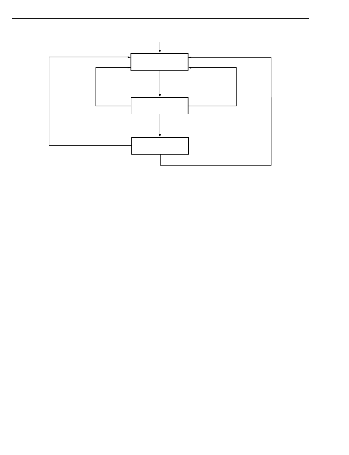
EXCEL 10 W7750A,B,C CONSTANT VOLUME AHU CONTROLLER
74-2958—156
Fig. 45. LED and Bypass pushbutton operation.
STANDBY MODE (StatusOcySen)
The di
g
ital input for an occupanc
y
sensor
(
usuall
y
a motion
detector or possibl
y
a time clock
)
provides the controller with a
means to enter an ener
gy
-savin
g
Standb
y
mode whenever
people are not in the room. Standb
y
mode occurs when the
scheduled occupanc
y
is Occupied, and the occupanc
y
sensor
detects no people currentl
y
in the room
(
di
g
ital input contacts
Closed means people are in the room, and contacts Open
means the room is Unoccupied
)
. When in Standb
y
mode, the
Excel 10 W7750 Controller uses the Standb
y
Coolin
g
Setpoint
for coolin
g
(
CoolStb
y
Spt
)
, or the Standb
y
Heatin
g
Setpoint for
Heatin
g
(
HeatStb
y
Spt
)
as the Actual Space Temperature
Setpoint. The occupanc
y
sensor si
g
nal can also be a network
input from another LONWORKS Bus device, so that no ph
y
sical
sensor is re
q
uired at the receivin
g
W7750 Controller.
IMPORTANT
When the W7750 Controller is in Standby mode, the
economizer minimum position setting is
not
observed. This means the fresh air dampers will go
fully closed if there is no call for cooling.
CONTINUOUS UNOCCUPIED MODE
This mode is entered when a wall module is confi
g
ured with a
B
y
pass pushbutton that was pressed for four to seven
seconds causin
g
the wall module LED/LCD to blink. This
mode can also be entered via a network command
(
ManualOcc set to Unoccupied
)
. If the controller is in this
mode, it reverts to the Unoccupied setpoints for temperature
control, and the economizer does not observe its minimum
position settin
g
. The controller remains in this mode
indefinitel
y
until the B
y
pass pushbutton is pressed to exit the
mode or a network command is sent to clear the mode. A
confi
g
uration parameter is available to disable wall-module
initiation of Continuous Unoccupied mode
(
OvrdT
y
pe
)
.
OCCUPANCY MODE AND MANUAL OVERRIDE ARBITRATION
The W7750 has multiple sources for occupanc
y
schedule
information and, therefore, it emplo
y
s an arbitration scheme to
determine the current actual mode. Time-of-da
y
(
TOD
)
schedule status comes from two sources, a confi
g
ured di
g
ital
input for OccTimeClock or the DestSchedOcc network input
received from a central control. If the di
g
ital input source is
confi
g
ured, it has hi
g
hest priorit
y
and determines the
Occupanc
y
mode. This di
g
ital input is either ON
(
shorted =
occupied
)
, OFF
(
open = unoccupied
)
, or not active
(
not
confi
g
ured
)
; otherwise, the status is determined b
y
the
DestSchedOcc input from the network source. The
DestSchedOcc has three possible states, occupied,
unoccupied or standb
y
.
Manual Override Status can be derived from three sources
and
g
overned b
y
two selectable arbitration schemes. The two
schemes are:
•Network Wins or Last-in Wins, as set in OvrdPriorit
y
.
The three sources of manual override status are:
DestManOcc - Has possible states: Occupied,
Unoccupied, B
y
pass, Standb
y
and Not
Assi
g
ned
(
not active
)
. This input source
has the hi
g
hest priorit
y
in determinin
g
manual override status for a Network
Wins arbitration scheme, and in the
event there is more than one source
chan
g
e at a time in the Last-in Wins
arbitration scheme. Here, b
y
pass
initiates a self-timed b
y
pass of the
control unit and expires upon
completion of the defined timed period.
The controller then treats the b
y
pass
status of this input as Not Assi
g
ned until
the next chan
g
e in status.
M8483A
RESET
NOT ASSIGNED
(LED OFF)
PRESS FOR ONE
TO FOUR SECONDS
BYPASS OCCUPIED
(LED ON)
BYPASS
TIMEOUT
PRESS FOR FOUR
TO SEVEN SECONDS
PRESS FOR LESS
THAN ONE SECOND
UNOCCUPIED
(LED BLINK)
PRESS FOR LESS THAN ONE SECOND
PRESS FOR MORE THAN SEVEN SECONDS
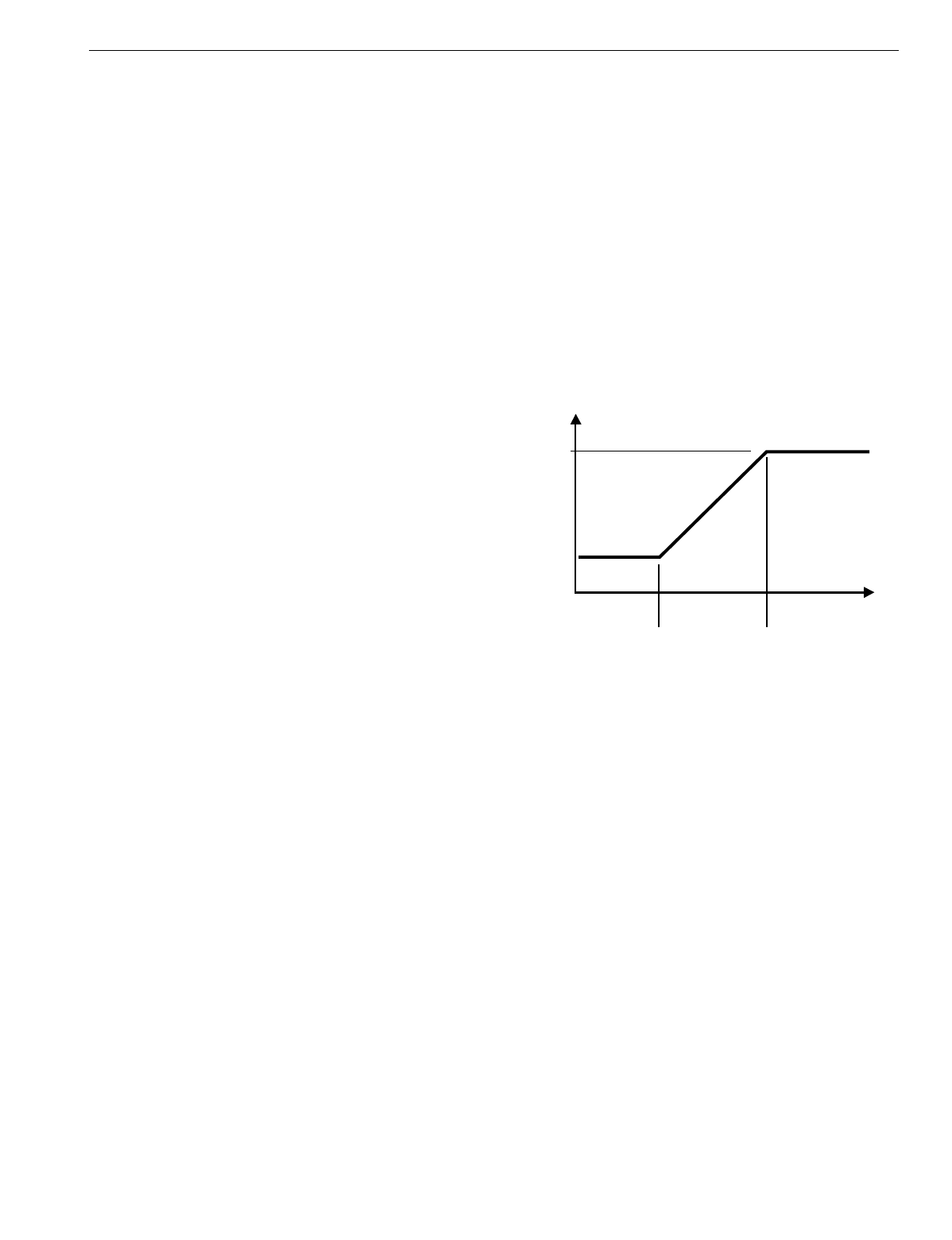
EXCEL 10 W7750A,B,C CONSTANT VOLUME AHU CONTROLLER
57 74-2958—1
DestB
y
pass - Has possible states: B
y
pass On,
B
y
pass Off or Not Assi
g
ned
(
not active
)
.
This input places the controller in an
untimed
b
y
pass state or turns off the
b
y
pass mode. This source is second in
priorit
y
to DestManOcc under the same
arbitration schemes mentioned above.
Override Button -The wall module Override pushbutton
can command status of B
y
pass,
Continuous Unoccupied and Not
Assi
g
ned. This source has the lowest
priorit
y
status in the above mentioned
schemes. The above mention sources
of override must be either Not Assi
g
ned
or Off before the Override pushbutton
affects the manual override status in the
Network Wins scheme. All actions, in
this case, taken from the Override
pushbutton are locked out.
B
y
pass status is a controller-timed
event whose duration is set in B
y
pTime.
Upon expiration of the timer, the status
returns to Not Assi
g
ned. The status of
this input can be overridden with the
receipt of Not Assi
g
ned from
DestManOcc. This, in effect, cancels a
timed b
y
pass or a continuous
unoccupied mode.
The Override pushbutton can be
confi
g
ured as Normal
(
all of the above
mentioned states are possible
)
, B
y
pass
Onl
y
(
B
y
pass and Not Assi
g
ned onl
y)
or
None
(
effectivel
y
Disablin
g
the Override
pushbutton
)
.
TIME CLOCK (Occ_Time_Clock)
OccTimeClock is the state of the di
g
ital input confi
g
ured and
wired to a time clock. When the di
g
ital input is detected to be
Closed
(
Occupied
)
, the scheduled occupanc
y
will be
OC_OCCUPIED. If the detected state of the di
g
ital input is
Open
(
Unoccupied
)
, then the scheduled occupanc
y
will be
OC_UNOCCUPIED. If the Occ_Time_Clock is not confi
g
ured,
then either the DestSchedOcc network input received from a
central control or the time clock that is broadcast from a
Sched_Master confi
g
ured W7750, controls the occupied
mode.
SCHEDULE MASTER (Sched_Master)
Sched_Master is the state of a di
g
ital input that is confi
g
ured
and wired to the W7750. If the Sched_Master input is closed
(
input shorted
)
, the node is the schedule master and the state
of the locall
y
connected time clock will be broadcast out over
the LONWORKS Bus to the other W7750 controllers. If the
Sched_Master input is open, then the node is not a schedule
master and the local time clock will not be sent out over the
LONWORKS Bus even if the time clock input is confi
g
ured.
However, the DestSchedOcc network input received from a
central control has a hi
g
her priorit
y
than the local time clock,
and therefore overrides the local time clock. The W7750
controllers automaticall
y
bind without the need for a
confi
g
uration tool.
SETPOINT RAMPING
The W7750 Controller incorporates a rampin
g
feature that
g
raduall
y
chan
g
es the space setpoints between occupanc
y
modes. This feature is onl
y
operational if the network variable
inputs DestSchedOcc, TodEventNext, and Time Until Next
Chan
g
e Of State
(
TUNCOS
)
are bein
g
used to chan
g
e the
W7750 Occupanc
y
mode. The applicable Setpoints are
OaTempMinHtRamp, OaTempMaxHtRamp, MinHtRamp and
MaxHtRamp
(
for HEAT mode operation
)
, and
OaTempMinClRamp, OaTempMaxClRamp, MinClRamp and
MaxClRamp
(
for the COOL mode operation
)
. See Fi
g
. 46 for a
pictorial representation of how these setpoints interact.
Durin
g
recover
y
operation, the setpoint chan
g
es at a rate in
de
g
rees per hour dependin
g
on the outdoor air temperature. If
there is no outdoor air temperature sensor available, then
MinHtRamp is used as the recover
y
rate.
Fig. 46. Setpoint ramping parameters with ramp rate
calculation.
NOTE: Recover
y
rampin
g
applies between scheduled
heatin
g
or coolin
g
setpoint chan
g
es from
UNOCCUPIED to STANDBY, UNOCCUPIED to
OCCUPIED, and STANDBY to OCCUPIED.
Scheduled setpoint chan
g
es from OCCUPIED to
UNOCCUPIED or OCCUPIED to STANDBY do not
use a ramped setpoint but instead use a step chan
g
e
in setpoint. Recover
y
ramps be
g
in before the next
scheduled occupanc
y
time and are ramped from the
setpoint for the existin
g
scheduled occupanc
y
state
to the setpoint for the next occupanc
y
state.
RECOVERY RAMPING FOR HEAT PUMP SYSTEMS
When the node is controllin
g
heat pump e
q
uipment, durin
g
the
recover
y
ramps, the heatin
g
setpoint is split into a heat pump
setpoint
(
for compressors
)
and an auxiliar
y
heat setpoint
(
for
auxiliar
y
heat sta
g
es
)
. The heat pump setpoint is a step
chan
g
e at the recover
y
time prior to the OCCUPIED time.
Recover
y
time is computed from the confi
g
ured heat recover
y
ramp rate. The recover
y
time is calculated:
Recover
y
time =
(
OCC setpoint - current setpoint
)
/ramp rate
See Fi
g
. 47 for the various setpoints.
HEAT RECOVERY
RAMP RATE
(DEGREES/HOUR)
MaxHtRam
MinHtRam
OaTempMinHtRa OaTempMaxHtRam
OUTDOOR AIR
TEMPERATURE
M10109
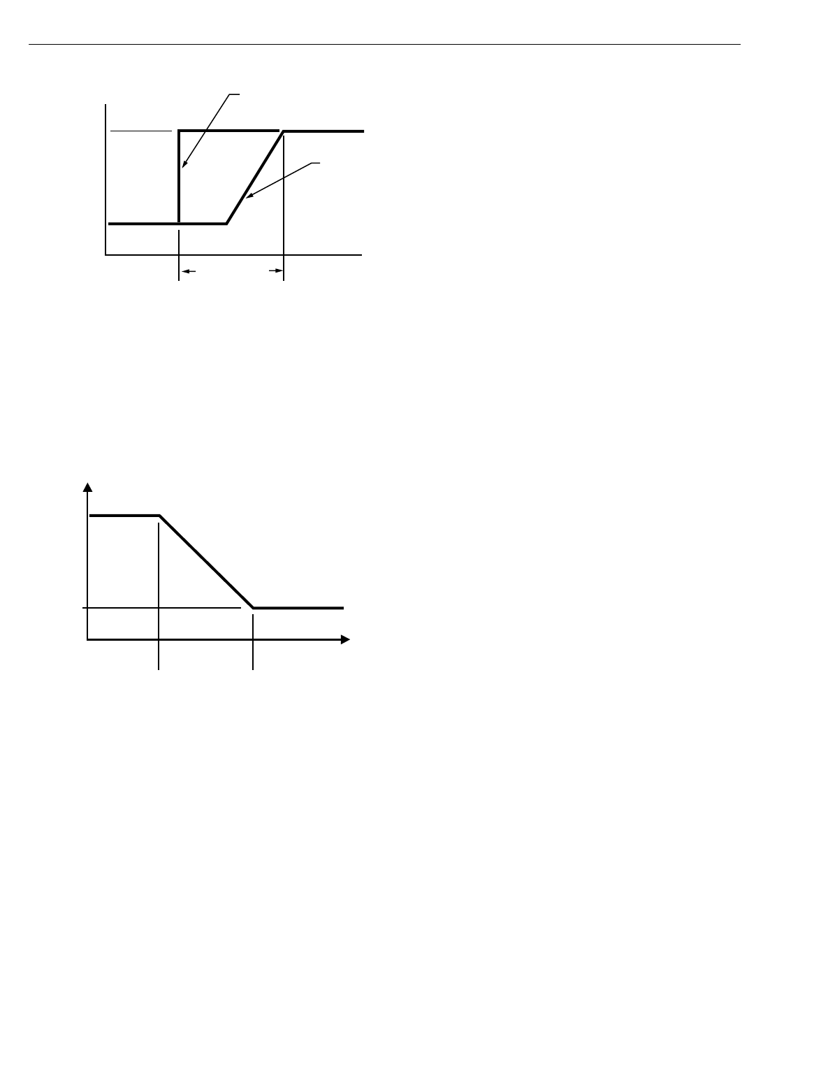
EXCEL 10 W7750A,B,C CONSTANT VOLUME AHU CONTROLLER
74-2958—158
Fig. 47. Setpoint ramping parameters with setpoint
calculation.
Durin
g
the COOL recover
y
period, the setpoint chan
g
es at a
rate in de
g
rees per hour relative to the outdoor air
temperature. If there is no outdoor air temperature sensor
available, the MinClRamp is used as the recover
y
rate.
See Fi
g
. 48 for the various setpoints.
Fig. 48. Setpoint ramping parameters with ramp rate
calculation.
NOTES: The setpoint used durin
g
the COOL recover
y
period
is similar to the heat mode in Fi
g
. 46, except the
slope of the line reverses for coolin
g
.
Recover
y
rampin
g
applies between scheduled heat-
in
g
or coolin
g
setpoint chan
g
es from UNOCCUPIED
to STANDBY, UNOCCUPIED to OCCUPIED, and
STANDBY to OCCUPIED. Scheduled setpoint
chan
g
es from OCCUPIED to UNOCCUPIED or
OCCUPIED to STANDBY do not use a ramped set-
point, but instead, use a step chan
g
e in setpoint.
Recover
y
ramps be
g
in before the next scheduled
occupanc
y
time and are ramped from the setpoint for
the existin
g
scheduled occupanc
y
state to the set-
point for the next occupanc
y
state.
FAN OPERATION
The W7750 suppl
y
fan can be controlled in one of two
different wa
y
s. In Continuous Fan mode, the fan runs
whenever the controller is in Occupied mode. When in
Standb
y
or Unoccupied modes, the fan c
y
cles on with a call
for coolin
g
(
or heatin
g
if the FanOnHtMode parameter is set
)
.
In Intermittent Fan mode, the fan c
y
cles on with a call for
coolin
g
(
or heatin
g
if the FanOnHtMode parameter is set
)
, and
c
y
cles off when the space temperature control is satisfied.
The fan control supports an optional
(
Proof of Air Flow
)
di
g
ital
input, that allows monitorin
g
of the suppl
y
fans status. If the
fan is commanded on, the Proof of Air Flow di
g
ital input is
checked up to three times to verif
y
that the fan is runnin
g
after
an initial dela
y
of FanOnDela
y
seconds
(
user-settable
)
. If the
fan fails to start the CVAHU must be reset b
y
first c
y
clin
g
CVAHU power. If this does not work, set DestManMode to
Manual and then back to Enable. After a reset the application
restarts—all outputs switch off and auto control is enabled.
Also, the W7750 Controller provides fan-run-on operation that
keeps the fan runnin
g
for a short time after heatin
g
or coolin
g
shuts off. The amount of time that the fan continues to run is
set in FanRunOnHeat for heatin
g
mode and FanRunOnCool
for coolin
g
mode.
WINDOW SENSOR (StatusWndw)
The di
g
ital input for a window contact provides the al
g
orithm
with a means to disable its temperature control activities if
someone has opened a window or door in the room. When a
window is detected to be Open
(
di
g
ital input contacts Open
e
q
uals window open
)
, the normal temperature control is
disabled, and the W7750 Controller enters the Freeze Protect
mode. Freeze Protect mode sets the space setpoint to 46.4 °F
(
8°C
)
and brin
g
s on the fan and heat if the space temperature
falls below this setpoint. Normal temperature control resumes
on window closure. The Window sensor si
g
nal can also be a
network input from another LONWORKS Bus device, so that no
ph
y
sical sensor is re
q
uired at the receivin
g
W7750 Controller.
SMOKE CONTROL
The Excel 10 W7750 Controller supports three smoke-related
control strate
g
ies:
1. Emer
g
enc
y
Shutdown
(
all outputs off
)
.
2. Depressurize
(
fan on, outdoor air damper closed
)
.
3. Pressurize
(
fan on, outdoor air damper open
)
.
The controller is placed in one of these three control states
whenever the W7750 mode becomes
SMOKE_EMERGENCY, which can be initiated via a network
command
(
DestEmer
g
Cmd
)
or from a local
(
ph
y
sicall
y
connected
)
smoke detector di
g
ital input. When in
SMOKE_EMERGENCY mode, the W7750 Controller uses the
control strate
gy
found in SmkCtlMode
(
one of the three listed
above
)
, and the normal temperature control function is
disabled. If a W7750 local smoke detector trips, the SrcEmer
g
network variable
(
for other LONWORKS Bus devices to receive
)
is set to the Emer
g
enc
y
state.
DEMAND LIMIT CONTROL (DLC)
When The LONWORKS Bus network receives a hi
g
h-electrical-
demand si
g
nal, the controller applies a DlcBumpTemp amount
to the current actual space temperature setpoint value. The
setpoint is alwa
y
s ad
j
usted in the ener
gy
-savin
g
direction.
This means that if the W7750 Controller is in Coolin
g
mode,
the DLC offset bumps the control point up, and when in
Heatin
g
mode, bumps the control point down.
OCC setpoint
UN_OCC setpoint
OR
STANDBY setpoint
M10110
AUX HEAT
SETPOINT
HEAT PUMP
SETPOINT
(FOR COMPRESSORS)
RECOVERY TIME
OCCUPIED TIME
COOL RECOVERY
RAMP RATE
(DEGREES/HOUR)
MaxClRam
MinClRam
OaTempMinClRa OaTempMaxClRam
OUTDOOR AIR
TEMPERATURE
M10111
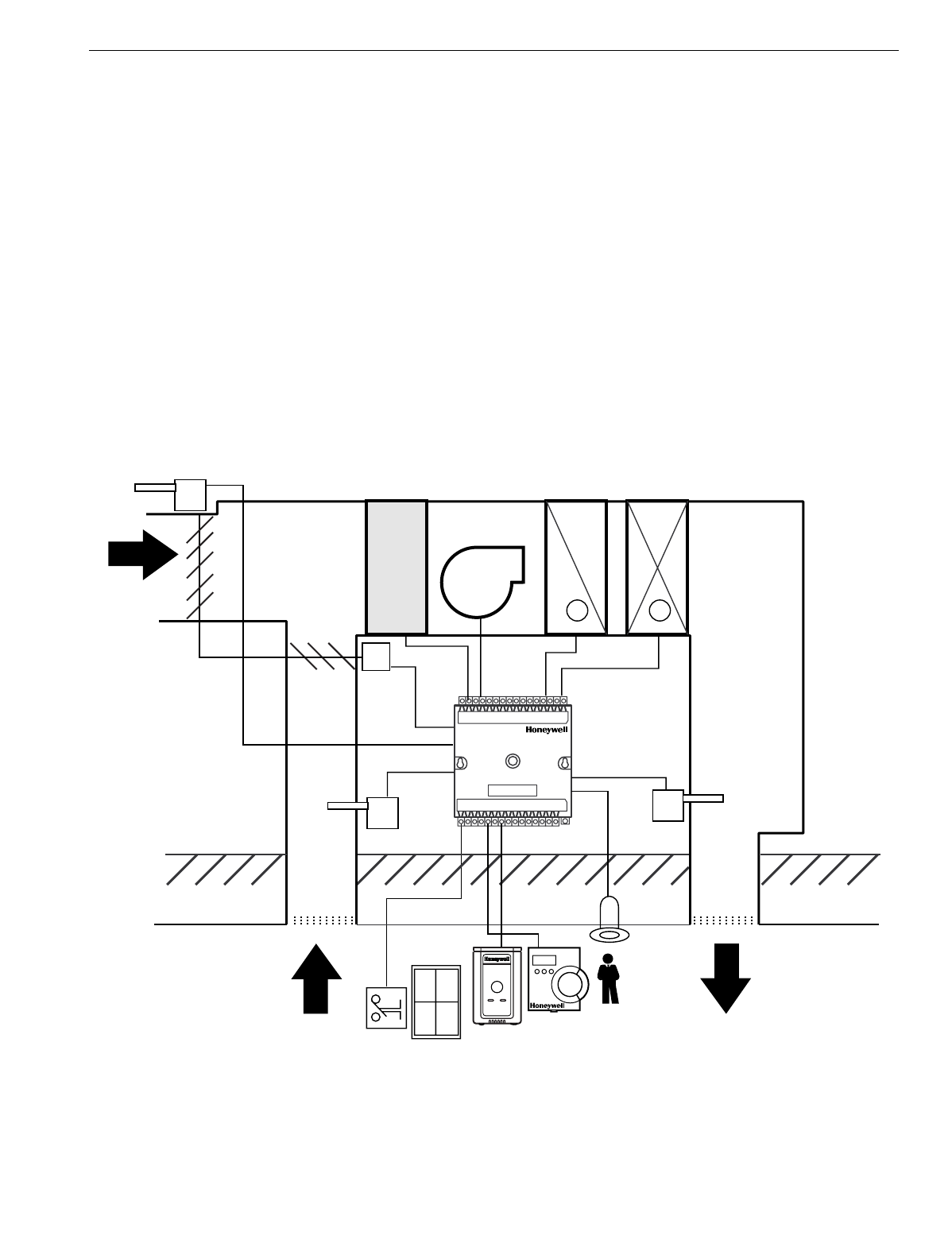
EXCEL 10 W7750A,B,C CONSTANT VOLUME AHU CONTROLLER
59 74-2958—1
DIRTY FILTER MONITOR
The air filter in the air handler can be monitored b
y
the W7750
and an alarm issued when the filter media needs replacement.
The two methods of monitorin
g
the filter are:
1. A differential pressure switch whose contacts are con-
nected to a di
g
ital input on the W7750A or W7750B,C;
and
2. A 2-to-10V differential pressure sensor wired to a
current input on the W7750B,C. If the analo
g
input
sensor is used, its measured value 0 to 5 inw
(
0 to 1.25 kPa
)
is compared to a user-selectable
setpoint
(
FltrPressStPt—valid ran
g
e: 0 to 5 inw
(
0 to 1.25 kPa
))
, and the Dirt
y
Filter alarm is issued
when the pressure drop across the filter exceeds the
setpoint.
START-UP
START_UP_WAIT is the first mode after application restart or
power-up. Durin
g
START_UP_WAIT, the analo
g
and di
g
ital
inputs are bein
g
read for the first time, no control al
g
orithms
are active, and the ph
y
sical outputs
(
fan and heat/coolin
g
sta
g
es
)
are in the de-ener
g
ized position. The node remains in
the START_UP_WAIT mode for a pseudo-random period
(
dependin
g
on neuron_id
)
between 12 and 22 seconds and
then transitions to one of the operatin
g
modes, dependin
g
on
the inputs that are read from the ph
y
sical and network inputs.
The pseudo random period prevents multiple controllers from
simultaneousl
y
startin
g
ma
j
or electrical loads when power is
restored to a buildin
g
.
NOTES: After a controller download via Care/E-Vision, the
dela
y
ed reset time is b
y
passed and the controller
starts after a 40-second initialization.
Not all network inputs can be received durin
g
the
START_UP_WAIT period because man
y
network
variables are updated at a slower rate; therefore
some control decisions can be considered tempo-
raril
y
inappropriate.
Temperature Control Operations
See Fi
g
. 49 for a dia
g
ram of a t
y
pical W7750 Unit.
Fig. 49. Schematic diagram for a typical W7750B Unit.
WINDOW CONTACT
OCCUPANCY
SENSOR
M
OA TEMP
FILTER
FAN
COOL
COIL
HEAT
COIL
DA TEMP
RA TEMP
EXCEL 10
W7750
CVAHU
T7770 OR T7560A,B
RETURN
AIR DISCHARGE
AIR
OUTDOOR
AIR
CEILING
ROOF
-+
M17488
EXCEL 10 W7750A,B,C CONSTANT VOLUME AHU CONTROLLER
74-2958—160
STAGED COOLING CONTROL
The Excel 10 W7750 Controller supports up to four sta
g
es of
D/X coolin
g
. As space temperature rises above the current
Coolin
g
Setpoint, the controllers mode of operation is
switched to the COOL mode. When in the COOL mode, all
heatin
g
outputs are driven closed or off
(
with the exception
that occurs durin
g
IAQ Override Operation, see above
)
, and
the sta
g
ed coolin
g
outputs are enabled for use. When in the
COOL mode, the PID coolin
g
control al
g
orithm compares the
current space temperature to the EffectiveCoolSetPt, and
calculates a PID error si
g
nal. This error si
g
nal causes the
coolin
g
sta
g
e outputs to be c
y
cled as re
q
uired to drive the
space temperature back to the setpoint. Fi
g
. 50 illustrates the
relationship between PID error and sta
g
ed output activit
y
. As
the error si
g
nal increases and the space temperature is
g
ettin
g
farther awa
y
from setpoint, or is remainin
g
above
setpoint as time elapses, additional sta
g
es of coolin
g
are
ener
g
ized until, if PID error reaches 100 percent, all
confi
g
ured sta
g
es are on.
Fig. 50. Staged output control versus PID Error.
If economizer dampers are confi
g
ured, and the outdoor air is
suitable for free coolin
g
, the economizer operates as the first
sta
g
e of coolin
g
. For example, if a controller was confi
g
ured
with two sta
g
es of mechanical coolin
g
and an economizer, the
application should be viewed in Fi
g
. 50 as a
three
-sta
g
e
s
y
stem.
Setpoints for the PID
g
ains allow for unit-b
y
-unit ad
j
ustment of
the control loop, if re
q
uired; however, an
y
chan
g
e from the
default values should be minimal.
The PID control al
g
orithm used to control sta
g
ed coolin
g
is
anticipator-driven, and is similar to the al
g
orithm used in the
T7300 commercial thermostat. All sta
g
in
g
events are sub
j
ect
to a minimum intersta
g
e time dela
y
, which is based on the
c
y
cles per hour user settin
g
(
CoolC
y
cHr
)
. The minimum
intersta
g
e time dela
y
ran
g
es from 90 seconds
(
at 12 c
y
cles
per hour
)
to 8.5 minutes
(
at two c
y
cles per hour
)
, see Table
17. The user has the option to disable the minimum run timer
(
DisMinClTimer for coolin
g)
. If the minimum run timer is
disabled, the intersta
g
e time dela
y
is fixed at 20 seconds. The
c
y
clin
g
rate is separatel
y
selectable for heatin
g
and coolin
g
between 2 and 12 c
y
cles per hour
(
cph
)
.
Table 17. Interstage Minimum Times
STAGED HEATING CONTROL
The Excel 10 W7750B,C Controller supports up to four sta
g
es
of heatin
g
. As space temperature falls below the current
Coolin
g
Setpoint, the controller mode of operation is switched
to the HEAT mode. When in the HEAT mode, all coolin
g
outputs are driven closed or off, and the sta
g
ed heatin
g
outputs are enabled for use. When in the HEAT mode, the PID
NO. STAGES
CONFIGURED
PID
ERROR
ONE STAGE
TWO STAGES
THREE STAGES
FOUR STAGES
0% 25% 33% 50% 66% 75% 100% > 100%
CYCLING
STAGE 1
CYCLING STAGE 1 LOCKED ON
STAGE 2 CYCLING
STAGE 1
CYCLING STAGE 1 LOCKED ON
STAGE 2 CYCLING STAGE 1,2 LOCKED ON
STAGE 3 CYCLING
ALL STAGES
LOCKED ON
ALL STAGES
LOCKED ON
ALL STAGES
LOCKED ON
ALL STAGES
LOCKED ON
STAGE 1
CYCLING
STAGE 1
LOCKED ON
STAGE 2
CYCLING
STAGE 1,2
LOCKED ON
STAGE 3
CYCLING
STAGE 1,2,3
LOCKED ON
STAGE 4
CYCLING
M10112
Cycles/Hour Selection Minimum On/Off time (Min.)
28.5
35.5
44.0
53.5
63.0
72.5
82.0
92.0
10 2.0
11 1.5
12 1.5

EXCEL 10 W7750A,B,C CONSTANT VOLUME AHU CONTROLLER
61 74-2958—1
coolin
g
control al
g
orithm compares the current space
temperature to the EffectiveHeatSetPt, and calculates a PID
error si
g
nal. This error si
g
nal causes the heatin
g
sta
g
e
outputs to be c
y
cled, as re
q
uired, to drive the space
temperature back to the Setpoint. Fi
g
. 50 illustrates the
relationship between PID error and sta
g
ed output activit
y
.
As the error si
g
nal increases, the space temperature
g
ets
further awa
y
from the setpoint, or is remainin
g
below the
setpoint as time elapses, additional sta
g
es of heatin
g
are
ener
g
ized until, if PID error reaches 100 percent, all
confi
g
ured sta
g
es are on.
The PID control al
g
orithm used to control sta
g
ed heatin
g
is
anticipator-driven, and is similar to the al
g
orithm used in the
T7300 commercial thermostat. All sta
g
in
g
events are sub
j
ect
to a minimum intersta
g
e time dela
y
, that is based on the
c
y
cles per hour user settin
g
(
HeatC
y
cHr
)
. The minimum
intersta
g
e time dela
y
ran
g
es from 90 seconds
(
at 12 c
y
cles
per hour
)
to ei
g
ht minutes
(
at two c
y
cles per hour
)
. See Table
17. The user has the option to disable the minimum run timer
for heatin
g
(
DisMinHtTimer
)
. If the minimum run timer is
disabled, the intersta
g
e time dela
y
is fixed at 20 seconds. The
c
y
clin
g
rate is separatel
y
selectable for heatin
g
and coolin
g
between two and 12 c
y
cles per hour
(
cph
)
.
Setpoints for the PID
g
ains allow for unit-b
y
-unit ad
j
ustment of
the control loop, if re
q
uired; however, an
y
chan
g
e from the
default values should be minimal.
CASCADE CONTROL OF MODULATING COOLING/HEATING
The Excel 10 W7750 Controller supports modulatin
g
coolin
g
and heatin
g
valves. These valves can be controlled directl
y
from the space temperature
(
like the sta
g
ed control
)
or, if the
CascCtrl fla
g
is set, the
y
are modulated to maintain the
dischar
g
e air temperature at its setpoint. The dischar
g
e air
setpoint is calculated based on the space temperature
deviation from the space setpoint. This is commonl
y
called
cascade control. In the W7750 Controller, cascade control is
available for use with PWM
(
W7750B,C onl
y)
and Series 60
modulatin
g
heatin
g
and coolin
g
, but not for use with sta
g
ed
heatin
g
/coolin
g
.
Setpoints for the PID
g
ains and for the control band allow for
unit-b
y
-unit ad
j
ustment of the control loops, if re
q
uired;
however, an
y
chan
g
e from the default values should be
minimal. Also, the W7750 Controller uses an adaptive
al
g
orithm
(
patent pendin
g)
to continuousl
y
assess the validit
y
of the calculated dischar
g
e setpoint, and ad
j
ust it, as needed,
to ensure precise, accurate control.
SERIES 60 MODULATING CONTROL
Series 60 Control is also commonl
y
referred to as Floatin
g
Control. The Excel 10 W7750A,B,C Controllers can drive
Series 60 t
y
pe actuators to control a modulatin
g
coolin
g
valve,
a heatin
g
valve, and economizer dampers. When floatin
g
control is used, the full-stroke motor drive time of the actuator
must be entered into the confi
g
uration parameter CoolMtrSpd
(
for coolin
g)
, HeatMtrSpd
(
for heatin
g)
, or EconMtrSpd
(
for the
economizer dampers
)
.
PULSE WIDTH MODULATING (PWM) CONTROL
The Excel 10 W7750B,C Controllers can drive a PWM-t
y
pe
actuator to control a modulatin
g
coolin
g
valve, a heatin
g
valve, and economizer dampers. PWM control positions the
actuator based on the len
g
th, in seconds, of the pulse from
the di
g
ital output. The controller outputs a pulse whose len
g
th
consists of two parts, a minimum and a maximum. The
minimum pulse time represents the analo
g
value of zero
percent
(
also indicates a si
g
nal presence
)
and the maximum
pulse len
g
th that represents an analo
g
value of 100 percent. If
the analo
g
value is
g
reater than zero percent, an additional
time is added to the minimum pulse time. The len
g
th of time
added is directl
y
proportional to the ma
g
nitude of the analo
g
value. If PWM control is used, the confi
g
uration parameters
for the PWM operation must be specified. These are
PwmPeriod, PwmZeroScale, and PwmFullScale. These three
parameters are shared b
y
all confi
g
ured PWM outputs; this
means the heatin
g
, coolin
g
, and economizer actuators must
be confi
g
ured to accept the same st
y
le of PWM si
g
nal.
Example: To find the pulse width of a valve actuator
(
for
example stroke mid position - 50 percent
)
with the
PwmZeroScale = 0.1 seconds, PwmFullScale = 25.5
seconds, and the PwmPeriod = 25.6 seconds. There are 256
increments available, so the number of increments re
q
uired
for 50 percent would be
(
0.5 X 256
)
or 128. The time for each
increment for this industr
y
standard pulse time is 0.1 seconds.
The pulse width is the minimum time
(
0.1 second
)
+ the
number of increments
(
128 times the
(
0.1 second
)
plus 0. 1
)
=
12.9 seconds. The W7750B,C Controllers would command
the valve output on for 12.9 seconds for the PwmPeriod of
25.6 seconds to maintain the valve position at 50 percent.
OUTDOOR AIR LOCKOUT OF HEATING/COOLING
A mechanism is provided in the W7750 to disable the heatin
g
e
q
uipment if the outdoor air temperature rises above the
OaTempHtLkOut setpoint. Similarl
y
, the coolin
g
e
q
uipment is
disabled if the outdoor air temperature falls below the
OaTempClLkOut setpoint. The al
g
orithm supplies a fixed 2°F
(
1.1°C
)
h
y
steresis with the lock-out control to prevent short
c
y
clin
g
of the e
q
uipment.
ECONOMIZER DAMPER CONTROL
A mixed-air economizer damper packa
g
e can be controlled to
assist mechanical coolin
g
in maintainin
g
the dischar
g
e air at
setpoint. Therefore, if modulatin
g
economizer damper control
is desired, a dischar
g
e air temperature sensor is re
q
uired. If
the outdoor air is not currentl
y
suitable for coolin
g
use
(
see the
Economizer Enable/Disable Control section
)
, the outdoor air
damper is held at the user-settable minimum position
(
EconMinPos
)
for ventilation purposes.
Because the outdoor air can be used to supplement
mechanical coolin
g
, the economizer operates as if it were the
first sta
g
e of coolin
g
. So, if the outdoor air is suitable for
coolin
g
use, the mechanical coolin
g
(
either sta
g
ed or
modulatin
g)
is held off until the economizer has reached its
full
y
open position. Then, if the dischar
g
e temperature
continues to be above setpoint, the mechanical coolin
g
is
allowed to come on. If the outdoor air is
not
suitable for
coolin
g
use, the economizer is set to its minimum position,
and mechanical coolin
g
is allowed to come on immediatel
y
.
When the controller is in the Heat mode, the economizer is
held at the minimum position settin
g
(
EconMinPos
)
. The
minimum position settin
g
is onl
y
used durin
g
Occupied mode
operation. When in Standb
y
or Unoccupied modes, the
outdoor air dampers are allowed to full
y
close if there is no call
for coolin
g
, or if the outside air is not suitable for coolin
g
use.

EXCEL 10 W7750A,B,C CONSTANT VOLUME AHU CONTROLLER
74-2958—162
INDOOR AIR QUALITY (IAQ) OVERRIDE
The Excel 10 W7750 Controller supports an IAQ override
feature that upon detection of poor air
q
ualit
y
in the space,
allows the economizer dampers to be opened above the
standard minimum position settin
g
to a value set in
EconIAQPos. Two different methods of detectin
g
poor air
q
ualit
y
are supported, The first is b
y
usin
g
an IAQ switch
device connected to a di
g
ital input on the W7750 Controller,
where a contact closure indicates poor air
q
ualit
y
and initiates
the IAQ override mode. The second, which is onl
y
available
on the W7750B,C is throu
g
h an analo
g
input that connects to
a CO2 Sensor
(
0 to 10V
)
. The measured value of CO2 from
this sensor
(
0 to 2000 ppm
)
is compared to the setpoint
IAQSetpt. When the CO2 level is hi
g
her than the setpoint
(
800
PPM
)
, the IAQ override is initiated. The IAQSetpt h
y
steresis is
50 PPM, IAQ override is deactivated at a CO2 level less than
750 PPM.
When the W7750 Controller is in the COOL mode durin
g
an
IAQ override, it is possible for the
heating
outputs to be
activated. This can occur if the outdoor air temperature is cold
enou
g
h to cause the dischar
g
e air temperature to drop below
the DaTempLoLim setpoint when the dampers open to the
EconIAQPos position,
and
the Ia
q
UseHeat fla
g
is set. If this
situation occurs, the heatin
g
is controlled to maintain the
dischar
g
e air temperature at 1°F
(
0.65°C
)
above the
DaTempLoLim setpoint.
FREEZE STAT
Upon receivin
g
a contact closure, the W7750 control
al
g
orithm will close the outdoor air damper and open the hot
water and chilled water valves
(
if available
)
to the full open
position as a safet
y
precaution. If
manual-reset
operation is
desired, the Freeze Stat device must provide the ph
y
sical
pushbutton, which the operator presses, to reset the s
y
stem
after a
freeze
condition has occurred.
DISCHARGE AIR LOW LIMIT CONTROL
If the dischar
g
e air temperature falls below the user-settable
dischar
g
e air low limit setpoint
(
DaTempLoLim
)
, an alarm is
issued, and the outdoor air damper is driven below the
minimum position settin
g
until the dischar
g
e temperature is up
to the low limit. If necessar
y
, the damper can
g
o completel
y
closed even durin
g
Occupied mode operation. As the
dischar
g
e temperature warms up, the economizer modulates
open until the minimum position settin
g
is reached. At this
point, the low limit alarm is cleared.
ECONOMIZER ENABLE/DISABLE CONTROL
The W7750 Controller has inputs to determine if the outdoor
air is suitable to au
g
ment coolin
g
. The economizer dampers
can be enabled/disabled for usin
g
outdoor air as the first
sta
g
e of coolin
g
based on one of ten allowable strate
g
ies:
1. Digital Input Enable/Disable—contact closure enables
economizer.
2. Outdoor Temperature—when the outdoor temperature
is less than OaEconEnTemp, then the outdoor air is
suitable to au
g
ment coolin
g
.
3. Outdoor Enthalpy, Type A—when the outdoor
enthalp
y
meets the H205 t
y
pe A re
q
uirements, the
outdoor air is suitable to au
g
ment coolin
g
.
4. Outdoor Enthalpy, Type B—when the outdoor
enthalp
y
meets the H205 t
y
pe B re
q
uirements, the
outdoor air is suitable to au
g
ment coolin
g
.
5. Outdoor Enthalpy, Type C—when the outdoor
enthalp
y
meets the H205 t
y
pe C re
q
uirements, the
outdoor air is suitable to au
g
ment coolin
g
.
6. Outdoor Enthalpy, Type D—when the outdoor
enthalp
y
meets the H205 t
y
pe D re
q
uirements, the
outdoor air is suitable to au
g
ment coolin
g
.
7. Differential Temperature—the difference between
outdoor temperature and return air temperature is
compared to DiffEconEnTemp to determine whether
outdoor air or return air is more suitable for use to
au
g
ment mechanical coolin
g
.
8. Single Calculated Enthalpy—the calculated outdoor
enthalp
y
in btu/lb is compared to the enthalp
y
setpoint
(
OaEnthEn
)
in btu/lb, and the outdoor temperature is
compared to the outdoor temperature limit setpoint
(
OaEconEnTemp
)
for a hi
g
h limit. The compared
difference determines whether outdoor air is suitable for
use to au
g
ment mechanical coolin
g
.
9. Differential Enthalpy, Either Sensed or Calculated—
the difference between outdoor enthalp
y
and return air
enthalp
y
determines whether outdoor air or return air is
more suitable to au
g
ment mechanical coolin
g
. When
enthalp
y
sensors are confi
g
ured, the
y
are used for
comparin
g
enthalp
y
. If no enthalp
y
sensors are
available, then enthalp
y
is calculated usin
g
outdoor and
return air humidit
y
and temperature sensors. The
switchin
g
differential is fixed at 1.0 mA for enthalp
y
sensors, and 0.25 btu/lb for calculated enthalp
y
.
NOTE: If no return temperature sensor is confi
g
ured,
space temperature is used to calculate return
air enthalp
y
.
10. Network Enabled—the network input
DestEconEnable
controls the enablin
g
and disablin
g
of the economizer.
When usin
g
the network input, select Econo Enable
T
y
pe:
No Economizer
in E-Vision. The network input
has priorit
y
over the other nine economizer control
selections.
Appendix C. Complete List of Excel 10
W7750 Controller User Addresses.
See Table 18 for W7750 Controller User Address table
numbers and point t
y
pes.
The
User Address Index
followin
g
Table 18 lists the User
Addresses alphabeticall
y
and
g
ives the pa
g
e number where
the Address is located in each Table Number/Point T
y
pe.
After Table 18 there is an alphabetical list of
Mappable User
Addresses and Table Numbers
. Followin
g
this is an
alphabetical list of
Failure Detect User Addresses and Table
Numbers
.
Table 18. Excel 10 W7750 Controller User
Address Point Types.
Table Number Point Types
Table 20 Input/Output
Table 21 Control Parameters
Table 22 Ener
gy
Mana
g
ement Points
Table 23 Status Points
Table 24 Calibration Points
Table 25 Confi
g
uration Parameters
Table 26 LONMARK/Open S
y
stem Points
Table 27 Direct Access and Special Manual Points
Table 28 Data Share Points

EXCEL 10 W7750A,B,C CONSTANT VOLUME AHU CONTROLLER
63 74-2958—1
User Address Indexes (all in alphabetical order)
Table 20. Input Output Points.
Address Page
CO2Sensr 71
CORMode 67
DaTempSensr 70
EconEnSw 72
FltrPressSensr 70
FltrPressSensr 70
Ia
q
OvrSw 72
Model 72
ModelSw 73
MonitorSensr 71
MonitorSw 73
OaEnthSensr 70
OaHumSensr 70
OaTempSensr 70
OccSensr 72
OvrdSw 72
RaEnthSensr 70
RaHumSensr 70
RaTempSensr 70
RmTempSensr 70
RmtStptPot 70
SmokeMonSw 72
StatusAirFlow 72
StatusDO1 71
StatusDO2 71
StatusDO3 71
StatusDO4 71
StatusDO5 71
StatusDO6 71
StatusDO7 71
StatusDO8 71
StatusDI1 71
StatusDI2 71
StatusDI3 72
StatusDI4 72
TimeClkSw 72
WindowSw 73
Table 21. Control Parameters.
Address Page
B
y
pTime 76
DaTempClCtrlBd 77
DaTempEcCtrlBd 77
DaTempHiLim 73
DaTempHtCtrlBd 77
DaTempLoLim 73
DiffEconEnTemp 75
DlcBumpTemp 73
EconIAQPos 76
EconMinPos 76
FltrPressStPt 76
GainCoolDer 77
GainCoolInt 77
GainCoolProp 77
GainHeatDer 77
GainHeatInt 77
GainHeatProp 77
IAQSetpt 76
MaxClRamp 75
MinClRamp 75
MaxHtRamp 74
MinHtRamp 74
OaEconEnTemp 75
OaEnthEn 76
OaTempClLkOut 74
OaTempHtLkOut 73
OaTempMaxClRp 75
OaTempMinClRp 75
OaTempMaxHtRp 74
OaTempMinHtRp 74
PwmFullScale 76
PwmPeriod 76
PwmZeroScale 76
StptKnobHiLim 76
StptKnobLowLim 76
Table 22. Energy Management Points.
Address Page
DestB
y
pass 78
DestDlcShed 78
DestFree1 79
DestFree2 79
DestTimeClk 80
DestWSHPEnable 79
DestSchedOcc 78
SrcB
y
pCt 78
SrcB
y
pass 78
SrcTimeClk 80
SrcTimeClkCt 80
TodEventNext 78
Tuncos 78
Table 23. Status Points.
Address Page
AlarmLo
g
1 83
B
y
pTimer 88
CO2Sens 89
CoolPos 90
CoolSt
g
sOn 86
DaSetpt 89
DaTemp 89
DlcShed 86
EconPos 90
FilterPress 89
Free1Stat 86
Free2Stat 86
HeatPos 90
HeatSt
g
sOn 86
MonitorSens 90
MonitorSw 87
NetConfi
g
93
OaEnth 89
OaEnthCalc 85
OaHum 89
OaTemp 89
OccStatOut 86
RaEnth 89
RaEnthCalc 85
RaHum 89
RaTemp 89
RmTemp 88
RmTempActSpt 88
SaFan 86
SaFanStatus 85
ShutDown 87
SrcEmer
g
81
SrcTimeClk 80
StatFreezeStat 87
StatusAlmT
y
p 81

EXCEL 10 W7750A,B,C CONSTANT VOLUME AHU CONTROLLER
74-2958—164
StatusEconEn 85
StatusEconOut 86
StatusError 90
StatusFilter 87
StatusIa
q
Ovr 87
StatusManOcc 85
StatusMode 84
StatusOcc 84
StatusOc
y
Sen 85
StatusOvrd 84
StatusSched 84
StatusSmoke 87
StatusWndw 87
TimeClckOcc 84
WSHPEnable 88
Table 24. Calibration Points.
Page 93
Table 25. Configuration Parameters.
Address Page
CascCntrl 96
CoolC
y
cHr 94
CoolMtrSpd 95
DisMinClTime 96
DisMinHtTime 96
EconMode 94
EconMtrSpd 95
FanFailTime 95
FanMode 94
FanOnHtMode 95
FanRunOnCool 94
FanRunOnHeat 94
HeatC
y
cHr 94
HeatMtrSpd 95
Ia
q
UseHeat 96
OvrdPriorit
y
97
OvrdT
y
pe 97
RmTempCal 95
SetPtKnob 97
SmkCtlMode 94
TempOffstCal1 95
TempOffstCal2 95
UseRaTempCtl 96
UseWallModStpt 97
VoltOffstCal1 95
VoltOffstCal2 95
Table 26. LONMARK/Open System Points.
Address Page
CoolOccSpt 98
CoolUnoccSpt 98
CoolStb
y
Spt 98
DestEconEnable 104
DestEmer
g
Cmd 101
DestHvacMode 99
DestManOcc 99
DestOaHum 100
DestOaTemp 100
DestOccSensor 103
DestRmTemp 100
DestRmTempSpt 99
DestSptOffset 99
DestWndw 104
HeatOccSpt 98
HeatStb
y
Spt 98
HeatUnoccSpt 98
SrcEconEnable 105
SrcEconEnCt 105
SrcOaHum 100
SrcOaTemp 100
SrcOccSensor 103
SrcRmTemp 100
SrcRmTempActSpt 99
SrcUnitStatus 101
SrcWndw 104
SrcWndwCt 104
Table 27. Direct Access and Special Manual Points.
Address Page
DestManMode 106
TestAuxEcon 107
TestAuxHt1 107
TestAuxHt2 107
TestAuxHt3 107
TestAuxHt4 107
TestEconPos 106
TestFree1 107
TestFree2 107
TestHCPos 106
TestHtClMode 107
TestHtClSt
g
1 107
TestHtClSt
g
2 107
TestHtClSt
g
3 107
TestHtClSt
g
4 107
TestMode 106
TestOccStat 107
TestSaFan 107
Table 28. Data Share Points.
Address Page
DestIa
q
Ovrd 108
DestOaEnth 108
SrcIa
q
Ovr 108
SrcIa
q
OvrCt 108
SrcMonSw 108
SrcMonSwCt 108
SrcOaEnth 108
Mappable User Addresses and Table Number
User Address Table Number
B
y
pTime 21
B
y
pTimer 23
CascCntrl 25
CO2Sen 23
CoolC
y
cHr 25
CoolMtrSpd 25
CoolOccSpt 26
CoolPos 23
CoolStb
y
Spt 26
CoolSt
g
sOn 23
CoolUnoccSpt 26
DaSetpt 23
DaTemp 23
DaTempClCtrlBd 21
DaTempEcCtrlBd 21
DaTempHiLim 21
DaTempHtCtrlBd 21
DaTempLoLim 21
DestDlcShed 22
DestEmer
g
Cmd 26
DestHvacMode 26
DestManMode 27
DestSchedOcc 22

EXCEL 10 W7750A,B,C CONSTANT VOLUME AHU CONTROLLER
65 74-2958—1
DiffEconEnTemp 21
DisMinHtTime 25
DisMinClTime 25
DlcBumpTemp 21
EconIAQPos 21
EconMinPos 21
EconMtrSpd 25
EconPos 23
EconMode 25
FanFailTime 25
FanMode 25
FanOnHtMode 25
FanRunOnCool 25
FanRunOnHeat 25
FilterPress 23
FltrPressStPt 21
Free1Stat 23
Free2Stat 23
GainCoolDer 21
GainCoolInt 21
GainCoolProp 21
GainHeatDer 21
GainHeatInt 21
GainHeatProp 21
HeatC
y
cHr 25
HeatMtrSpd 25
HeatOccSpt 26
HeatPos 23
HeatStb
y
Spt 26
HeatSt
g
sOn 23
HeatUnoccSpt 26
IAQSetpt 21
Ia
q
UseHeat 25
MaxClRamp 21
MinClRamp 21
MaxHtRamp 21
MinHtRamp 21
MonitorSens 23
MonitorSw 23
OaEconEnTemp 21
OaEnth 23
OaEnthCalc 23
OaEnthEn 21
OaHum 23
OaTemp 23
OaTempClLkOut 21
OaTempHtLkOut 21
OaTempMaxClRp 21
OaTempMinClRp 21
OaTempMaxHtRp 21
OaTempMinHtRp 21
OccStatOut 23
OvrdPriorit
y
25
OvrdT
y
pe 25
PwmFullScale 21
PwmPeriod 21
PwmZeroScale 21
RaEnth 23
RaEnthCalc 23
RaHum 23
RaTemp 23
RmTempActSpt 23
RmTempCal 25
RmtStptPot 20
SaFan 23
SaFanStatus 23
SetPtKnob 25
ShutDown 23
SmkCtlMode 25
StatFreezeStat 23
StatusAlmT
y
p 23
StatusEconEn 23
StatusEconOut 23
StatusFilter 23
StatusIa
q
Ovr 23
StatusManOcc 23
StatusMode 23
StatusOcc 23
StatusOc
y
Sen 23
StatusOvrd 23
StatusSched 23
StatusSmoke 23
StatusWndw 23
StptKnobHiLim 21
StptKnobLowLim 21
TimeClckOcc 23
UseRaTempCtl 25
UseWallModStpt 25
WSHPEnable 23
Failure Detect User Addresses and Table Number
User Address Table Number
DestB
y
pass 22
DestDlcShed 22
DestEconEnable 26
DestFree1 22
DestFree2 22
DestHvacMode 26
DestIa
q
Ovrd 28
DestOaEnth 28
DestOaHum 26
DestOaTemp 26
DestOccSensor 26
DestRmTemp 26
DestSchedOcc 22
DestSptOffset 26
DestTimeClk 22
DestWndw 26
DestWSHPEnable 22
Table 19 lists the applicable En
g
ineerin
g
Units for the analo
g
points found in the W7750.
Table 19. Engineering Units For Analog Points.
English Units (Inch-Pound) Standard International Units (SI)
Measured Item Description Abbreviation Description Abbreviation
Temperature De
g
rees Fahrenheit F De
g
rees Celsius C
Relative Temperature Delta De
g
rees Fahrenheit DDF De
g
rees Kelvin K
Relative Humidity Percent % Percent %
Air Flow Cubic Feet per Minute CFM Meters Cubed per Hour m3h
CO2 Concentration Parts Per Million PPM Parts Per Million PPM
Enthalpy British Thermal Units per Pound of Air btu/lb kiloJoules/kilo
g
ram k
j
/k
g
Differential Pressure Inches of Water Column inw kiloPascal kPa

EXCEL 10 W7750A,B,C CONSTANT VOLUME AHU CONTROLLER
74-2958—166
All of the NvName values that are stored in EEPROM memor
y
have a prefix of
nci
.
NOTE: These parameters are stored in EEPROM and are
limited to 10,000
writes
. Do NOT use them as
outputs from Control Strate
g
ies,Time Pro
g
rams, or
Switchin
g
Tables. If these points are chan
g
ed more
than 10,000 times, irreversible hardware failure
results
Tables 20 throu
g
h 28 provide point attributes as follows:
En
g
ineerin
g
Units—This field indicates the point valid ran
g
e and
displa
y
ed En
g
ineerin
g
Unit. For di
g
ital points,
the valid states and the correspondin
g
enumerated values are shown.
Default—The value or state of the point on controller
start-up.
E-Vision
(
M
)
Monitor—These points are viewable within the E-Vision
Controller Monitorin
g
on-line screen.
(
P
)
Parameter—These points refer to control parameters
settable in the Application Selection dialo
g
boxes in E-Vision.
(
S
)
Schematic—These points appear in E-Vision monitor
mode
g
raphics.
Shareable—These points can be set up for data sharin
g
in
Command Multiple Points, Read Multiple
Points, or Refer Excel 10 Points as either a
data source or a destination.
Mappable—These points can be converted into a C-Bus
point used b
y
C-Bus devices. A mappable point
has a one-to-one relationship with a C-Bus
User Address.
Direct
Access—These points are accessible throu
g
h the
Subs
y
stem Points mechanism in XBS.
Hardware
Confi
g
.—These are points that involve controller I/O
confi
g
uration. An
y
chan
g
e to Hardware Confi
g
.
points causes the W7750 to perform an
application reset; therefore, these points can
onl
y
be modified off-line.
Manual
Confi
g
.—These points are used to set the controller
outputs when in manual mode. The W7750 is
placed in manual mode throu
g
h a menu
selection in the E-Vision Controller Monitor
screen.
Test—These points can be controlled in E-Visions test
mode that is used for field checkout/ debu
g
in
g
.
Failure Detect
Input Point—These points need an update periodicall
y
or a
communication alarm is
g
enerated. The failure
detect mechanism is onl
y
active when the NV is
bound
(
bindin
g
s are confi
g
ured usin
g
Refer
Excel 10 points
)
. The time between the updates
is user settable.
Non-Failure Detect
Input Point—These points
(
which are NVs that are bound or
unbound
)
do not check for an update
periodicall
y
and do not
g
enerate an alarm.
NOTES: 1. Mapped points can be viewed and chan
g
ed,
if
needed
, on the XI581, XI582 and XI584 C-Bus
devices and on an XBS central and on E-Vision.
2. All Excel 10 points, mappable and calibration,
confi
g
uration and internal data sharin
g
points, can
be viewed and chan
g
ed,
as allowed
, via Direct
Access
(
DA
)
mode in the XBS subs
y
stem menu
or via XI584.

EXCEL 10 W7750A,B,C CONSTANT VOLUME AHU CONTROLLER
67 74-2958—1
Table 20. Input/Output Points.
User Address NvName Field Name Engineering Units: English
(Metric) or States plus Range
Digital State or
Value of State
Default
E-Vision (M, P, S)
Share
Map
Direct Access
Hardware Config.
Manual Config.
Test
E-Vision Legend: (M) Monitor, (P) Parameter, (S) Schematic
Comments
CORMode nciIoSelect CorOnMode COR_ON_HEAT
COR_ON_COOL 0
1COR_ON_COOL P X CorOnMode specifies the mode when the Change Over Relay (COR) is
energized.
nciIoSelect ResistiveIn[0] DISCHARGE_TEMP_PT3000
OUTDOOR_TEMP_PT3000
RETURN_TEMP_PT3000
DISCHARGE_TEMP_20KNTC
RETURN_TEMP_20KNTC
UNUSED_RAI
0
1
2
3
4
255
UNUSED_RAI X ResistiveIn[0] specifies which logical sensor is assigned to each physical
analog input sensor channel according to the enumerated list that is shown
in the Engineering Units/States column. ResistiveIn[0] is the only input
available in the W7750A controller.
nciIoSelect ResistiveIn[1] DISCHARGE_TEMP_PT3000
OUTDOOR_TEMP_PT3000
RETURN_TEMP_PT3000
DISCHARGE_TEMP_20KNTC
RETURN_TEMP_20KNTC
UNUSED_RAI
0
1
2
3
4
255
UNUSED_RAI X ResistiveIn[1] specifies which logical sensor is assigned to each physical
analog input sensor channel according to the enumerated list that is shown
in the Engineering Units/States column. ResistiveIn[0] is the only input
available in the W7750A controller.
nciIoSelect VoltageIn[0] RTN_HUM_C7600C
RETURN_ENTHALPY
OD_HUM_C7600C
OUTDOOR_ENTHALPY
FILTER_STATIC_PRESS_DIFF
SPACE_CO2
MONITOR_SENSOR1
RTN_HUM_C7600B
OD_HUM_C7600B
UNUSED_VAI
0
1
2
3
4
5
6
7
8
255
UNUSED_VAI X VoltageIn[0] specifies which logical sensor is assigned to each physical
analog input sensor channel according to the enumerated list that is shown
in the Engineering Units/States column. (Voltage inputs are not available in
the W7750A controller.)
nciIoSelect VoltageIn[1] RTN_HUM_C7600C
RETURN_ENTHALPY
OD_HUM_C7600C
OUTDOOR_ENTHALPY
FILTER_STATIC_PRESS_DIFF
SPACE_CO2
MONITOR_SENSOR1
RTN_HUM_C7600B
OD_HUM_C7600B
UNUSED_VAI
0
1
2
3
4
5
6
7
8
255
UNUSED_VAI X VoltageIn[1] specifies which logical sensor is assigned to each physical
analog input sensor channel according to the enumerated list that is shown
in the Engineering Units/States column. (Voltage inputs are not available in
the W7750A controller.)
nciIoSelect DigitalIn[0] OCC_SENSOR
OCC_TIME_CLOCK
PROOF_AIR_FLOW
ECON_ENABLE
IAQ_OVERRIDE
SMOKE_MONITOR
DIRTY_FILTER
SHUT_DOWN
WINDOW_OPEN
MONITOR
SCHED_MASTER
UNUSED_DI
2
3
4
5
6
7
8
9
10
11
12
255
OCC_TIME_CLOCK_IN X DigitalIn[0] specifies which logical switch type is connected to the flexible
digital input switch channel according to the enumerated list that is shown in
the Engineering Units/States column. DigitalIn[0] and DigitalIn[1] are the
only inputs available in the W7750A controller. The controller is configured
at the factory with this user address configured to OCC_TIME_CLOCK_IN.
EXCEL 10 W7750A,B,C CONSTANT VOLUME AHU CONTROLLER
74-2958—168
nciIoSelect DigitalIn[1] OCC_SENSOR
OCC_TIME_CLOCK
PROOF_AIR_FLOW
ECON_ENABLE
IAQ_OVERRIDE
SMOKE_MONITOR
DIRTY_FILTER
SHUT_DOWN
WINDOW_OPEN
MONITORS
CHED_MASTER
UNUSED_DI
2
3
4
5
6
7
8
9
10
11
12
255
SHCED_MASTER_IN X DigitalIn[1] specifies which logical switch type is connected to the flexible
digital input switch channel according to the enumerated list that is shown in
the Engineering Units/States column. DigitalIn[0] and DigitalIn[1] are the
only inputs available in the W7750A controller. The controller is configured
at the factory with this user address configured to SCHED_MASTER_IN.
nciIoSelect DigitalIn[2] OCC_SENSOR
OCC_TIME_CLOCK
PROOF_AIR_FLOW
ECON_ENABLE
IAQ_OVERRIDE
SMOKE_MONITOR
DIRTY_FILTER
SHUT_DOWN
WINDOW_OPEN
MONITOR
SCHED_MASTER
UNUSED_DI
2
3
4
5
6
7
8
9
10
11
12
255
UNUSED_DI X DigitalIn[2] specifies which logical switch type is connected to the flexible
digital input switch channel according to the enumerated list that is shown in
the Engineering Units/States column. DigitalIn[0] and DigitalIn[1] are the
only inputs available in the W7750A controller.
Table 20. Input/Output Points. (Continued)
User Address NvName Field Name Engineering Units: English
(Metric) or States plus Range
Digital State or
Value of State
Default
E-Vision (M, P, S)
Share
Map
Direct Access
Hardware Config.
Manual Config.
Test
E-Vision Legend: (M) Monitor, (P) Parameter, (S) Schematic
Comments
EXCEL 10 W7750A,B,C CONSTANT VOLUME AHU CONTROLLER
69 74-2958—1
nciIoSelect DigitalOut[0] COOL_STAGE_1
COOL_STAGE_2
COOL_STAGE_3
COOL_STAGE_4
HEAT_STAGE_1
HEAT_STAGE_2
HEAT_STAGE_3
HEAT_STAGE_4
CHANGE_OVER_RELAY
FAN_OUT
AUX_ECON
OCCUPANCY_STATUS
ECON_OPEN
ECON_CLOSE
COOL_OPEN
COOL_CLOSE
HEAT_OPEN
HEAT_CLOSE
HEAT_COOL_STAGE_1
HEAT_COOL_STAGE_2
HEAT_COOL_STAGE_3
HEAT_COOL_STAGE_4
FREE1
FREE2
FREE1_PULSE_ON
FREE1_PULSE_OFF
ECON_PWM
HEAT_PWM
COOL_PWM
UNUSED
1
2
3
4
5
6
7
8
9
10
11
12
13
14
15
16
17
18
19
20
21
22
25
26
27
28
29
30
31
255
NETWORK DO(FREE1)
(Value of State is 25) X DigitalOut[0] specifies which logical digital output function is assigned to the
digital physical output according to the enumerated list that is shown in the
Engineering Units/States column. The W7750 Controllers are configured at
the factory with the enumerated value in the Default column. Only
DigitalOut[0] through DigitalOut[5] are available in the W7750A model
which can configure staged outputs. The W7750A Controller can drive
Series 60 Floating Control to modulate cooling valves, heating valves and
economizers. (No PWM outputs are allowed in the W7750A model.) The
controller is configured at the factory with the enumerated value in the
Default column. The eight outputs on the W7750B are all digital outputs.
The eight outputs on the W7750C consist of five digital and three analog
outputs.
nciIoSelect DigitalOut[1] See DigitalOut[0] enumerated
values 1-31
,255 FAN_OUT
(Value of State is 10) X See DigitalOut[0] for enumerated names. The W7750 Controllers are
configured at the factory with the enumerated value in the Default column.
nciIoSelect DigitalOut[2] See DigitalOut[0] enumerated
values 1-31
,255 COOL_STAGE_2
(Value of State is 2) X See DigitalOut[0] for enumerated names. The W7750 Controllers are
configured at the factory with the enumerated value in the Default column.
nciIoSelect DigitalOut[3] See DigitalOut[0] enumerated
values 1-31
,255 HEAT_STAGE_1
(Value of State is 1) X See DigitalOut[0] for enumerated names. The W7750 Controllers are
configured at the factory with the enumerated value in the Default column.
nciIoSelect DigitalOut[4] See DigitalOut[0] enumerated
values 1-31
,255 HEAT_STAGE_2
(Value of State is 3) X See DigitalOut[0] for enumerated names. The W7750 Controllers are
configured at the factory with the enumerated value in the Default column.
nciIoSelect DigitalOut[5] See DigitalOut[0] enumerated
values 1-31
,255 HEAT_STAGE_1
(Value of State is 5) X See DigitalOut[0] for enumerated names. The W7750 Controllers are
configured at the factory with the enumerated value in the Default column.
nciIoSelect DigitalOut[6] See DigitalOut[0] enumerated
values 1-31
,255 UNUSED
(Value of State is 255) X See DigitalOut[0] for enumerated names. The W7750 Controllers are
configured at the factory with the enumerated value in the Default column.
nciIoSelect DigitalOut[7] See DigitalOut[0] enumerated
values 1-31
,255 UNUSED
(Value of State is 255) X See DigitalOut[0] for enumerated names. The W7750 Controllers are
configured at the factory with the enumerated value in the Default column.
nciIoSelect HtPump CONV
HP 0
1CONV P X HtPump specifies the type of equipment being controlled. When HtPump is
0 (CONV), the node is controlling conventional gas or electric heat. When
HtPump is 1 (HP), the node is controlling a heat pump.
Table 20. Input/Output Points. (Continued)
User Address NvName Field Name Engineering Units: English
(Metric) or States plus Range
Digital State or
Value of State
Default
E-Vision (M, P, S)
Share
Map
Direct Access
Hardware Config.
Manual Config.
Test
E-Vision Legend: (M) Monitor, (P) Parameter, (S) Schematic
Comments
EXCEL 10 W7750A,B,C CONSTANT VOLUME AHU CONTROLLER
74-2958—170
nciIoSelect FiftySixtyHz SIXTYFIFTY 01 SIXTY P X FiftySixtyHz specifies the frequency of the main power input for the
controller. Correctly selecting the FiftySixtyHz decreases the noise picked
up by analog switch wiring from the power mains. When FiftySixtyHz is 0
(SIXTY is the default), the mains frequency is sixty Hz and when
FiftySixtyHz is 1 (FIFTY), the mains frequency is fifty Hz.
nciIoSelect SpaceSensorType T7770 0 T7770 X SpaceSensorType specifies the type of space temperature sensor
connected to the node. When SpaceSensorType is 0, a T7770 sensor is
connected to the sensor terminals. No other options are currently valid.
RmtStptPot nvoIO siSetPointTempS7 Degrees F
-9 to 85
Degrees C
(-23 to 29)
SI_INVALID M,
SX X X SetPointTemp is the wall module setpoint temperature. When
nciConfig.SetPointTemp is ABSOLUTE_COOL or ABSOLUTE_MIDDLE,
the reported value is the absolute setpoint temperature. When
Config.SetPntKnob is OFFSET, the reported value is the offset (from the
current active TempSetPts) temperature. If the input is not configured or
has failed, the value is SI_INVALID.
RmTempSensr nvoIO siSpaceTempS7 Degrees F
40 to 100
Degrees C
(4 to 38)
SI_INVALID M,
SSpaceTemp is the measured space temperature. If the sensor is not
configured or has failed, the value is SI_INVALID.NOTE: The reported
temperatures includes the offset correction provided by
Config.ResistiveOffsetCal.
DaTempSensr nvoIO siDischargeTempS7 Degrees F Degrees C
30 to 122 (-1 to 50) SI_INVALID DischargeTemp is the measured discharge air temperature. If the sensor is
not configured or has failed, the value is SI_INVALID. Refer to the note on
SpaceTemp.
RaTempSensr nvoIO siReturnTempS7 Degrees F Degrees C
30 to 122 (-1 to 50) SI_INVALID ReturnTemp is the measured return air temperature. If the sensor is not
configured or has failed, the value is SI_INVALID. Refer to the note on
SpaceTemp.
RaHumSensr nvoIO ReturnHumidity Percentage
10 to 90 SI_INVALID ReturnHumidity is the measured return air humidity. If the sensor is not
configured or has failed, the value is UB_INVALID.NOTE: The reported
temperatures includes the offset correction provided by
Config.VoltageOffsetCal.
RaEnthSensr nvoIO siReturnEnthalpyS7 mA
4 to 20 SI_INVALID ReturnEnthalpy is the measured return air enthalpy. If the sensor is not
configured or has failed, the value is SI_INVALID. Since the C7400 reports
comfort due to enthalpy (btu/lb) in milliamps, enthalpy is also reported in
milliamps. Refer to the NOTE on ReturnHumidity.
OaTempSensr nvoIO siOutdoorTempS7 Degrees F Degrees C
-40 to 122 (-40 to 50) SI_INVALID M,
SOutdoorTemp is the measured outdoor air temperature. If the sensor is not
configured or has failed, the value is SI_INVALID. Refer to the NOTE on
ReturnHumidity.
OaHumSensr nvoIO OutdoorHumidity Percentage
10 to 90 SI_INVALID M,
SOutdoorHumidity is the measured outdoor air humidity. If the sensor is not
configured or has failed, the value is UB_INVALID. Refer to the NOTE on
ReturnHumidity.
OaEnthSensr nvoIO siOutdoorEnthalpyS7 mA
4 to 20 SI_INVALID M,
SOutdoorEnthalpy is the measured outdoor air enthalpy. If the sensor is not
configured or has failed, the value is SI_INVALID. Since the C7400 reports
comfort due to enthalpy (btu/lb) in milliamps, enthalpy is also reported in
milliamps. Refer to the NOTE on ReturnHumidity.
FltrPressSensr nvoIO siFilterPressureS10 inw (kPa)
0 to 5 (0 to 1.25) SI_INVALID FilterPressure is the measured differential pressure across the return air
filter. If the sensor is not configured or has failed, the value is the
SI_INVALID. Refer to the NOTE on ReturnHumidity.
Table 20. Input/Output Points. (Continued)
User Address NvName Field Name Engineering Units: English
(Metric) or States plus Range
Digital State or
Value of State
Default
E-Vision (M, P, S)
Share
Map
Direct Access
Hardware Config.
Manual Config.
Test
E-Vision Legend: (M) Monitor, (P) Parameter, (S) Schematic
Comments

EXCEL 10 W7750A,B,C CONSTANT VOLUME AHU CONTROLLER
71 74-2958—1
CO2Sensr nvoIO siSpaceCo2S0 PPM
150 to 2000 SI_INVALID SpaceCo2 is the measured CO2 in the conditioned air space. If the sensor
is not configured or has failed, the value is SI_INVALID. Refer to the NOTE
on ReturnHumidity.
MonitorSensr nvoIO siMonitorS10 volts
1 to 10 SI_INVALID Monitor is the voltage applied at the monitor inputs terminals. If the sensor
is not configured or has failed, the value is SI_INVALID. Refer to the NOTE
on ReturnHumidity.
StatusDO1 nvoIO ubOut
Byte Offset = 24
Bit Offset =
0(DigitalOut1)
FALSE
TRUE 0
1FALSE DigitalOut1 is a byte with a bit for every physical digital output. On is a 1
(TRUE) and off is a 0 (FALSE).
StatusDO2 nvoIO ubOut
Byte Offset = 24
Bit Offset =
1(DigitalOut2)
FALSE
TRUE 0
1FALSE DigitalOut2 is a byte with a bit for every physical digital output. On is a 1
(TRUE) and off is a 0 (FALSE).
StatusDO3 nvoIO ubOut
Byte Offset = 24
Bit Offset =
2(DigitalOut3)
FALSE
TRUE 0
1FALSE DigitalOut3 is a byte with a bit for every physical digital output. On is a 1
(TRUE) and off is a 0 (FALSE).
StatusDO4 nvoIO ubOut
Byte Offset = 24
Bit Offset =
3(DigitalOut4)
FALSE
TRUE 0
1FALSE DigitalOut4 is a byte with a bit for every physical digital output. On is a 1
(TRUE) and off is a 0 (FALSE).
StatusDO5 nvoIO ubOut
Byte Offset = 24
Bit Offset =
4(DigitalOut5)
FALSE
TRUE 0
1FALSE DigitalOut5 is a byte with a bit for every physical digital output. On is a 1
(TRUE) and off is a 0 (FALSE).
StatusDO6 nvoIO ubOut
Byte Offset = 24
Bit Offset =
5(DigitalOut6)
FALSE
TRUE 0
1FALSE DigitalOut6 is a byte with a bit for every physical digital output. On is a 1
(TRUE) and off is a 0 (FALSE).
StatusDO7 nvoIO ubOut
Byte Offset = 24
Bit Offset =
6(DigitalOut7)
FALSE
TRUE 0
1FALSE DigitalOut7 is a byte with a bit for every physical digital output. On is a 1
(TRUE) and off is a 0 (FALSE).
StatusDO8 nvoIO ubOut
Byte Offset = 24
Bit Offset =
7(DigitalOut8)
FALSE
TRUE 0
1FALSE DigitalOut8 is a byte with a bit for every physical digital output. On is a 1
(TRUE) and off is a 0 (FALSE).
StatusDI1 nvoIO ubDigitalIn
Byte Offset = 25
Bit Offset =
7(DigitalIn1)
FALSE
TRUE 0
1FALSE DigitalIn1 is a byte with a bit for every physical digital input. If the input is
shorted to ground, the bit is a zero or FALSE. If the input is open, the bit is
one or TRUE.
StatusDI2 nvoIO ubDigitalIn
Byte Offset = 25
Bit Offset =
6(DigitalIn2)
FALSE
TRUE 0
1FALSE DigitalIn2 is a byte with a bit for every physical digital input. If the input is
shorted to ground, the bit is a zero or FALSE. If the input is open, the bit is
one or TRUE.
Table 20. Input/Output Points. (Continued)
User Address NvName Field Name Engineering Units: English
(Metric) or States plus Range
Digital State or
Value of State
Default
E-Vision (M, P, S)
Share
Map
Direct Access
Hardware Config.
Manual Config.
Test
E-Vision Legend: (M) Monitor, (P) Parameter, (S) Schematic
Comments
EXCEL 10 W7750A,B,C CONSTANT VOLUME AHU CONTROLLER
74-2958—172
StatusDI3 nvoIO ubDigitalIn
Byte Offset = 25
Bit Offset =
5(DigitalIn3)
FALSE
TRUE 0
1FALSE DigitalIn3 is a byte with a bit for every physical digital input. If the input is
shorted to ground, the bit is a zero or FALSE. If the input is open, the bit is
one or TRUE.
StatusDI4 nvoIO ubDigitalIn
Byte Offset = 25
Bit Offset =
4(DigitalIn4)
FALSE
TRUE 0
1FALSE DigitalIn4 is a byte with a bit for every physical digital input. If the input is
shorted to ground, the bit is a zero or FALSE. If the input is open, the bit is
one or TRUE.
Model nvoIO ubDigitalIn
Byte Offset = 25
Bit Offset = 3
(ExtenedModelIn)
FALSE
TRUE 0
1FALSE X ExtenedModelIn is a byte with a bit for every physical digital input. If the
input is shorted to ground, the bit is a zero or FALSE. If the input is open,
the bit is one or TRUE.
OvrdSw nvoIO OverRide FALSE
TRUE 0
1FALSE OverRide indicates the status of the wall module override pushbutton. It is 1
(TRUE) if the button is pressed, and is 0 (FALSE) if it isn't pressed.
OccSensr nvoIO OccupancySensor FALSE
TRUE 0
1FALSE M,
SOccupancySensor is the state of the digital input configured and wired to
the local occupancy sensor. 1 means that occupancy is being sensed (input
circuit shorted) and 0 means that no occupancy is being sensed (input
circuit open).
TimeClkSw nvoIO OccTimeClock FALSE
TRUE 0
1FALSE M,
SOccTimeClock is the state of the digital input configured and wired to a time
clock. 1 (input shorted) means that the scheduled occupancy is
OC_OCCUPIED, and 0 (input open circuited) means that the scheduled
occupancy is OC_UNOCCUPIED.
StatusAirFlow nvoIO ProofAirFlow FALSE
TRUE 0
1FALSE ProofAirFlow is the state of the digital input configured and wired to the
proof of air flow switch. 1 (input shorted) means that air flow is detected and
0 (input open circuited) means that air flow is not detected.
EconEnSw nvoIO EconEnableIn FALSE
TRUE 0
1FALSE M,
SEconEnableIn is the state of the digital input configured and wired to the
outdoor air sensor that determines the suitably of outdoor air for free
cooling. 1 (input shorted) means that the outdoor air is suitable for cooling,
and 0 (input open) means that the outdoor air in not suitable for cooling.
IaqOvrSw nvoIO IaqOverRide FALSE
TRUE 0
1FALSE M,
SIaqOverRide is the state of the digital input configured and wired to the
indoor air quality sensor. 1 (input shorted) means that the indoor air quality
is poor, and 0 (input open) means that the indoor air quality is acceptable.
This input is used to cause the economizer to open to a predetermined
position when poor indoor air quality is detected.
SmokeMonSw nvoIO SmokeMonitor FALSE
TRUE 0
1FALSE M,
SSmokeMonitor is the state of the digital input configured and wired to the
indoor smoke sensor. 1 (input shorted) means that smoke is detected, and
0 (input open) means that no smoke is detected.
DrtyFilterSw nvoIO DirtyFilter FALSE
TRUE 0
1FALSE M,
SDirtyFilter is the state of the digital input configured and wired to the dirty
filter sensor. 1 (input shorted) means that filter is dirty, and 0 (input open)
means that the filter is not dirty.
ShutDownSw nvoIO ShutDown FALSE
TRUE 0
1FALSE ShutDown is the state of the digital input configured and wired to the shut
down switch. 1 (input shorted) means that equipment should be shut down,
and 0 (input open) means that the equipment should be running.
Table 20. Input/Output Points. (Continued)
User Address NvName Field Name Engineering Units: English
(Metric) or States plus Range
Digital State or
Value of State
Default
E-Vision (M, P, S)
Share
Map
Direct Access
Hardware Config.
Manual Config.
Test
E-Vision Legend: (M) Monitor, (P) Parameter, (S) Schematic
Comments
EXCEL 10 W7750A,B,C CONSTANT VOLUME AHU CONTROLLER
73 74-2958—1
WindowSw nvoIO WindowOpen FALSE
TRUE 0
1FALSE M,
SWindowOpen is the state of the digital input configured and wired to a
window open sensor switch. 1 (input open circuit) means that the window is
open, and 0 (input shorted) means that the window is closed.
MonitorSw nvoIO MonSwitch FALSE
TRUE 0
1FALSE MonSwitch is the state of the digital input configured and wired to a general
purpose monitor switch. 1 (input shorted) means that switch is closed, and
0 (input open) means that the switch is open.
ModelSw nvoIO Model FALSE
TRUE 0
1FALSE X Model indicates the Model of the node. One of the digital inputs is
connected to a printed wiring board trace to let the embedded software
know what kind of hardware is present. If Model is 1 (input held high), the
hardware is the W7750B Model. If Model is 0 (input shorted to ground), the
hardware is the W7750A Model.
nvoIO SchedMaster FALSE
TRUE 0
1FALSE M X If ScheduleMaster is 1 (input shorted), the node is the schedule master and
the locally connected time clock will be sent via TimeClk to other nodes on
the network. If ScheduleMaster is 0, (input open), the node is not a
schedule master and nvoTimeClk will not be sent on the network even if the
time clock input is configured. If the ScheduleMaster input is not configured
by Select, TimeClk reports the state of the locally connected time clock.
Table 20. Input/Output Points. (Continued)
User Address NvName Field Name Engineering Units: English
(Metric) or States plus Range
Digital State or
Value of State
Default
E-Vision (M, P, S)
Share
Map
Direct Access
Hardware Config.
Manual Config.
Test
E-Vision Legend: (M) Monitor, (P) Parameter, (S) Schematic
Comments
Table 21. Control Parameters.
User Address NvName Field Name Engineering Units: English
(Metric) or States plus Range
Digital State or
Value of State
Default
E-Vision (M, P, S)
Share
Map
Direct Access
Hardware Config.
Manual Config.
Test
E-Vision Legend: (M) Monitor, (P) Parameter, (S) Schematic
Comments
DaTempLoLim nciAux1SetPt siLowLimitDischAirTempS7 Degrees F
0 to 60
Degrees C
(-1 to 16)
45 P X X When the discharge air temperature falls below
LowLimitDischAirTemp, the outdoor air dampers are closed to a
position that corrects the low temperature problem. If mechanical
cooling is active when the discharge air falls below
LowLimitDischAirTemp, the mechanical cooling cycles off after the
minimum run times are obeyed to allow the dampers to return open
and provide free cooling.
DaTempHiLim nciAux1SetPt siMaxDisAirTempHeatS7 Degrees F Degrees C
65 to 135 (18 to 57) 100 P X X When the mode is HEAT, and the CascadeControl is enabled, the
discharge air temperature is controlled to a value not to exceed
MaxDisAirTempHeat.
DlcBumpTemp nciAux1SetPt siDlcBumpTempS7 Degrees F Degrees C
0 to +10 (-18 to -12) 3 P X X When DlcShed is not 0 then the setpoint is shifted by DlcBumpTemp
in the energy saving direction. When DlcShed changes from 1 to 0,
the setpoint shift ramps back to 0 over a 30 minute interval.
OaTempHtLkOut nciAux1SetPt ubOdHtLockOutTempS0 Degrees F Degrees C
0 to 90 (-18 to 32) 70 P X X When the outdoor air temperature is greater than
OdHtLockOutTemp, the heating is disabled.

EXCEL 10 W7750A,B,C CONSTANT VOLUME AHU CONTROLLER
74-2958—174
MaxHtRamp nciAux1SetPt ubMaxHtRampS0 Degrees F/Hr
0 to 20
Degrees C/Hr
(0 to 11)
8 P X X MaxHtRamp is the maximum heat recovery ramp rate in degrees F
per hour. This value is used to control the adaptive recovery ramp
rate during the HEAT recovery period. The setpoint is changed at a
rate in degrees F per hour depending on the outdoor air temperature
and the MinHtRamp, OdTempMaxHtRamp, and OaTempMinHtRamp
parameters. If there is no outdoor air temperature sensor available,
then ubMinHtRamp is used as the recovery rate.NOTE: Recovery
ramping applies between scheduled heating or cooling setpoint
changes from OC_UNOCCUPIED to OC_STANDBY,
OC_UNOCCUPIED to OC_OCCUPIED, and OC_STANDBY to
OC_OCCUPIED. Scheduled setpoint changes from OC_OCCUPIED
to OC_UNOCCUPIED or OC_OCCUPIED to OC_STANDBY do not
use a ramped setpoint but instead use a step change in setpoint.
Recovery ramps begin before the next scheduled occupancy time
and are ramped from the setpoint for the existing scheduled
occupancy state to the setpoint for the next occupancy state.
MinHtRamp nciAux1SetPt ubMinHtRampS0 Degrees F/Hr
0 to 20
Degrees C/Hr
(0 to 11)
3 P X X MinHtRamp is the minimum heat recovery ramp rate in degrees F
per hour. This value is used to control the adaptive recovery ramp
rate during the HEAT recovery period. The setpoint is changed at a
rate in degrees F per hour depending on the outdoor air temperature
and the MaxHtRamp, OdTempMaxHtRamp, and
OdTempMinHtRamp parameters. If there is no outdoor air
temperature sensor available, then MinHtRamp is used as the
recovery rate. Refer to the NOTE in the comments column for
MaxHtRamp for the conditions that recovery ramping applies to.
OaTempMaxHtRp nciAux1SetPt ubOdTempMaxHtRampS0 Degrees F
0 to 100
Degrees C
(-18 to 38)
40 P X X OdTempMaxHtRamp is the maximum outdoor air temperature
parameter that is used to calculate the heat recovery ramp rate
setpoint. This value is used to control the adaptive recovery ramp
rate during the HEAT recovery period. The setpoint is changed at a
rate in degrees F per hour depending on the outdoor air temperature
and the MaxHtRamp, MinHtRamp, and OdTempMinHtRamp
parameters. If there is no outdoor air temperature sensor available,
then MinHtRamp is used as the recovery rate. Refer to the NOTE in
the comments column for MaxHtRamp for what conditions that
recovery ramping applies to.
OaTempMinHtRp nciAux1SetPt ubOdTempMinHtRampS0 Degrees F
0 to 100
Degrees C
(-18 to 38)
0 P X X OdTempMinHtRamp is the minimum outdoor air temperature
parameter that is used to calculate the heat recovery ramp rate
setpoint. This value is used to control the adaptive recovery ramp
rate during the HEAT recovery period. The setpoint is changed at a
rate in degrees F per hour depending on the outdoor air temperature
and the MaxHtRamp, MinHtRamp, and OdTempMaxHtRamp
parameters. If there is no outdoor air temperature sensor available,
then MinHtRamp is used as the recovery rate. Refer to the NOTE in
the comments column for MaxHtRamp for what conditions that
recovery ramping applies to.
OaTempClLkOut nciAux1SetPt ubOdClLockOutTempS0 Degrees F Degrees C
0 to 90 (-18 to 32) 50 P X X When the outdoor air temperature is less than OdClLockOutTemp,
the cooling is disabled.
Table 21. Control Parameters. (Continued)
User Address NvName Field Name Engineering Units: English
(Metric) or States plus Range
Digital State or
Value of State
Default
E-Vision (M, P, S)
Share
Map
Direct Access
Hardware Config.
Manual Config.
Test
E-Vision Legend: (M) Monitor, (P) Parameter, (S) Schematic
Comments

EXCEL 10 W7750A,B,C CONSTANT VOLUME AHU CONTROLLER
75 74-2958—1
MaxClRamp nciAux1SetPt ubMaxClRampS0 Degrees F/Hr
0 to 20
Degrees C/Hr
(0 to 11)
6 P X X MaxClRamp is the maximum cool recovery ramp rate in degrees F
per hour. This value is used to control the adaptive recovery ramp
rate during the COOL recovery period. The setpoint is changed at a
rate in degrees F per hour depending on the outdoor air temperature
and the MinClRamp, OdTempMaxClRamp, and OdTempMinClRamp
parameters. If there is no outdoor air temperature sensor available,
then MinClRamp is used as the recovery rate. Refer to the NOTE in
the comments column for MaxHtRamp for the conditions that
recovery ramping applies to.
MinClRamp nciAux1SetPt ubMinClRampS0 Degrees F/Hr
0 to 20
Degrees C/Hr
(0 to 11)
2 P X X MinClRamp is the minimum cool recovery ramp rate in degrees F
per hour. This value is used to control the adaptive recovery ramp
rate during the COOL recovery period. The setpoint is changed at a
rate in degrees F per hour depending on the outdoor air temperature
and the MaxClRamp, OdTempMaxClRamp, and
OdTempMinClRamp parameters. If there is no outdoor air
temperature sensor available, then MinClRamp is used as the
recovery rate. Refer to the NOTE in the comments column for
MaxHtRamp for the conditions that recovery ramping applies to.
OaTempMaxClRp nciAux1SetPt ubOdTempMaxClRampS0 Degrees F
0 to 100
Degrees C
(-18 to 38)
70 P X X OdTempMaxClRamp is the maximum outdoor air temperature
parameter that is used to calculate the cool recovery ramp rate
setpoint. This value is used to control the adaptive recovery ramp
rate during the COOL recovery period. The setpoint is changed at a
rate in degrees F per hour depending on the outdoor air temperature
and the MaxClRamp, MinClRamp, and OdTempMinClRamp
parameters. If there is no outdoor air temperature sensor available,
then MinClRamp is used as the recovery rate. Refer to the NOTE in
the comments column for MaxHtRamp for the conditions that
recovery ramping applies to.
OaTempMinClRp nciAux1SetPt ubOdTempMinClRampS0 Degrees F
0 to 100
Degrees C
(-18 to 38)
90 P X X OdTempMinClRamp is the minimum outdoor air temperature
parameter that is used to calculate the cool recovery ramp rate
setpoint. This value is used to control the adaptive recovery ramp
rate during the COOL recovery period. The setpoint is changed at a
rate in degrees F per hour depending on the outdoor air temperature
and the MaxClRamp, MinClRamp, and OdTempMaxClRamp
parameters. If there is no outdoor air temperature sensor available,
then MinClRamp is used as the recovery rate. Refer to the NOTE in
the comments column for MaxHtRamp for the conditions that
recovery ramping applies to.
OaEconEnTemp nciAux1SetPt ubOdEconEnableTempS0 Degrees F
0 to 90
Degrees C
(-18 to 32)
70 P X X If Config.EconEnable is OD_TEMP, and the outdoor temperature is
less than OdEconEnableTemp, then outdoor air is judged suitable to
augment mechanical cooling. If Config.EconEnable is
SINGLE_ENTH and outdoor temperate is less than
ubOdEconEnableTemp (high limit), then outdoor air may be judged
suitable to augment mechanical cooling depending on the
relationship between calculated outdoor enthalpy and
OdEnthalpyEnable.
DiffEconEnTemp nciAux1SetPt ubDiffEconEnableTempS0 Degrees F Degrees C
0 to 90 (-18 to 32) 4 P X X If Config.EconEnable is DIFF_TEMP, and return air temperature
minus outdoor air temperature is greater than DiffEconEnableTemp,
then outdoor air is judged suitable to augment mechanical cooling.
Table 21. Control Parameters. (Continued)
User Address NvName Field Name Engineering Units: English
(Metric) or States plus Range
Digital State or
Value of State
Default
E-Vision (M, P, S)
Share
Map
Direct Access
Hardware Config.
Manual Config.
Test
E-Vision Legend: (M) Monitor, (P) Parameter, (S) Schematic
Comments

EXCEL 10 W7750A,B,C CONSTANT VOLUME AHU CONTROLLER
74-2958—176
OaEnthEn nciAux1SetPt ubOdEnthalpyEnableS2 btu/lb
0 to 65 25 P X X If Config.EconEnable is SINGLE_ENTH, and calculated outdoor
enthalpy is less than OdEnthalpyEnable, and outdoor temperature is
less than OdEconEnableTemp, then outdoor air is judged suitable to
augment mechanical cooling.
EconMinPos nciAux1SetPt ubEconMinPosS0 Percentage
0 to 100 0 P X X The minimum allowed position of the economizer damper for HEAT
and COOL is EconMinPos.
EconIAQPos nciAux1SetPt ubEconIaqPosS0 Percentage
0 to 100 80 P X X The control overrides the economizer damper to EconIaqPos when
poor indoor air quality is detected.
IAQSetpt nciAux1SetPt siCO2IaqLimitS0 PPM
0 to 2000 800 P X X When an analog CO2 sensor is configured and the sensed CO2 is
greater than CO2IaqLimit, then poor indoor air quality is detected
and Data1.OverRide is set to 1. When the sensed CO2 is less than
CO2IaqLimit, then the indoor air quality is considered acceptable
and Data1.IaqOverRide is set to 0. oData1.IaqOverRide is used to
set the economizer damper to Aux1SetPt. EconIaqPos and to
possibly turn on the heat according to the state of
Config.IaqUseHeat.
PwmPeriod nciAux1SetPt siPwmPeriodS4 100 P X X When pulse width modulation is used, the period of one pulse width
modulation cycle is PwmPeriod seconds. The smallest resolution is
0.1 seconds.
PwmZeroScale nciAux1SetPt siPwm0pcntS4 Seconds
0 to 2047 1 P X X When pulse width modulation is used, the period of a pulse for zero
percent output (damper or valve at open position) is Pwm0pcntS4
seconds. The smallest resolution is 0.1 seconds.
PwmFullScale nciAux1SetPt siPwm100pcntS4 Seconds
0 to 2047 99 P X X When pulse width modulation is used, the period of a pulse for full
scale output (damper or valve at open position) is Pwm100pcnt
seconds. The smallest resolution is 0.1 seconds.
BypTime nciAux2SetPt uiBypassTime minutes
0 to 1080 180 P X X uiBypassTime is the time between the pressing of the override
button at the wall module (or initiating OC_BYPASS via ManOcc)
and the return to the original occupancy state. When the bypass
state has been activated, the bypass timer is set to BypassTime.
FltrPressStPt nciAux2SetPt ubFilterPressStPtS5 inw (kPa)
0 to 5 (0 to 1.25) 0.5 P X X If a filter pressure sensor is configured by IoSelect and the filter
pressure reported in Data1 FilterPressure exceeds FilterPressStPt,
then a DIRTY_FILTER alarm is generated and Data1.DirtyFilter is
set to 1.
StptKnobLowLim nciAux2SetPt siLowStPtS7 Degrees F
-9 to 90
Degrees C
(-23 to 32)
55 P X X LowStPt is the lowest value reported for the setpoint knob.
Dependent on the configuration of the setpoint knob (see
Config.SetPntKnob) this setting is either absolute [degree
Fahrenheit (50 to 90)] in case of absolute setpoint knob configuration
or relative [delta degree Fahrenheit (-9 to +9)] in case of relative
setpoint knob configuration.
StptKnobHiLim nciAux2SetPt siHighStPtS7 Degrees F
-9 to 90
Degrees C
(-23 to 32)
85 P X X HighStPt is the highest value reported for the setpoint knob.
Dependent on the configuration of the setpoint knob (see
Config.SetPntKnob) this setting is either absolute [degree
Fahrenheit (50 to 90)] in case of absolute setpoint knob configuration
or relative [delta degree Fahrenheit (-9 to +9)] in case of relative
setpoint knob configuration.
Table 21. Control Parameters. (Continued)
User Address NvName Field Name Engineering Units: English
(Metric) or States plus Range
Digital State or
Value of State
Default
E-Vision (M, P, S)
Share
Map
Direct Access
Hardware Config.
Manual Config.
Test
E-Vision Legend: (M) Monitor, (P) Parameter, (S) Schematic
Comments
EXCEL 10 W7750A,B,C CONSTANT VOLUME AHU CONTROLLER
77 74-2958—1
GainCoolProp nciAux2SetPt ubKpCoolS2 Degrees F Degrees C
2 to 30 (1 to 30) 5 P X X This is the throttling range for the proportional portion of the PID loop
gain for the cooling control loop.
GainHeatProp nciAux2SetPt ubKpHeatS2 Degrees F Degrees C
2 to 30 (1 to 17) 5 P X X This is the throttling range for the proportional portion of the PID loop
gain for the heating control loop.
GainCoolInt nciAux2SetPt siKiCoolS0 Seconds
0 to 5000 2050 P X X This is the integral portion of the PID loop gain for the cooling control
loop.
GainHeatInt nciAux2SetPt siKiHeatS0 Seconds
0 to 5000 2050 P X X This is the integral portion of the PID loop gain for the heating control
loop.
GainCoolDer nciAux2SetPt siKdCoolS0 Seconds
0 to 9000 0 P X X This is the derivative portion of the PID loop gain for the cooling
control loop.
GainHeatDer nciAux2SetPt siKdHeatS0 Seconds
0 to 9000 0 P X X This is the derivative portion of the PID loop gain for the heating
control loop.
DaTempClCtrlBd nciAux2SetPt ubDisCbCoolS0 Degrees F Degrees C
5 to 30 (3 to 17) 10 P X X DisCbCool is the throttling range used for the cooling portion of the
discharge air temperature cascade control loop.
DaTempHtCtrlBd nciAux2SetPt ubDisCbHeatS0 Degrees F Degrees C
5 to 30 (3 to 17) 10 P X X DisCbHeat is the throttling range used for the heating portion of the
discharge air temperature cascade control loop.
DaTempEcCtrlBd nciAux2SetPt ubDisCbEconS0 Degrees F Degrees C
5 to 30 (3 to 17 10 P X X DisCbEcon is the throttling range used for the economizer control
loop.
Table 21. Control Parameters. (Continued)
User Address NvName Field Name Engineering Units: English
(Metric) or States plus Range
Digital State or
Value of State
Default
E-Vision (M, P, S)
Share
Map
Direct Access
Hardware Config.
Manual Config.
Test
E-Vision Legend: (M) Monitor, (P) Parameter, (S) Schematic
Comments

EXCEL 10 W7750A,B,C CONSTANT VOLUME AHU CONTROLLER
74-2958—178
Table 22. Energy Management Points.
User Address NvName Field Name Engineering Units: English
(Metric) or States plus Range
Digital State or
Value of State
Default
E-Vision (M, P, S)
Share
Map
Direct Access
Hardware Config.
Manual Config.
Failure Detect
E-Vision Legend: (M) Monitor, (P) Parameter, (S) Schematic
Comments
DestDlcShed nviDlcShed 0 to 1 0 M X X X X X DlcShed is an input from an energy management system. When DlcShed is
0, the temperature control algorithm operates in a normal mode. When
DlcShed is non-zero, the setpoint is shifted by Aux1SetPt.DlcBumpTemp in
the energy saving direction.
DestSchedOcc nviTodEvent CurrentState OC_OCCUPIED
OC_UNOCCUPIED
OC_BYPASS
OC_STANDBY
OC_NUL
0
1
2
3
255
OC_OCCUPIED M X X X X X CurrentState indicates the current scheduled occupancy state to the node.
CurrentState is used along with other occupancy inputs to calculate the
effective occupancy of the node. The valid states and meaning are as
follows: OC_OCCUPIED means the energy management system is
specifying occupied. OC_UNOCCUPIED means the energy management
system is specifying that the space is presently unoccupied. OC_BYPASS
states that the energy management system is in bypass. OC_STANDBY
states that the energy management system has the space presently is
between occupied and unoccupied. OC_NUL states that no occupancy
state has been specified.
TodEventNext nviTodEvent NextState OC_OCCUPIED
OC_UNOCCUPIED
OC_BYPASS
OC_STANDBY
OC_NUL
0
1
2
3
255
OC_OCCUPIED M X X NextState indicates the next scheduled occupancy state to the node. This
information is required by the Excel 10 to perform the optimum start
strategy. The space expected effective occupancy will be NextState in
uiTimeToNextState minutes. The valid states and meaning are the same as
for CurrentState.
Tuncos nviTodEvent uiTimeToNextState minutes
0 to 2880 0 M X X TimeToNextState is the time in minutes until the next change of scheduled
occupancy state.
nviBypass value 0 to 100 0 Bypass.value:The bypass state of one node may be shared with the bypass
state of another node using nviBypass and nvoBypass. This allows a wall
module at one node to be used to over ride the scheduled occupancy of
another node. The node with Bypass bound normally does not have a wall
module. See the Data1.EffectOcc and Data1.OverRide for more details.
The valid states are as follows: If the state is SW_ON and the value is not
zero then the node should bypass the time of day schedule (subject to
occupancy arbitration logic). If the state is SW_NUL, the input is not
available because it is not bound, the input is no longer being updated by
the sender, or OC_BYPASS is no longer being called. This means that the
same as SW_OFF. If the state is SW_OFF or other and the value is don’t
care, the node should not bypass the time of day schedule. If the state is
SW_ON and the value is 0, then the node should not bypass the time of day
schedule. If the node receives this combination of state and value, then
state is set to SW_OFF.
DestBypass nviBypass state SW_OFF
SW_ON
SW_NUL
0
1
255
SW_NUL M X X X X Refer to nviBypass.value.
SrcBypCt nvoBypass value 0 to 100 0 nvoBypass.value:nvoBypass is the current occupancy state of the node for
bypass schedule. The states have the following meanings: If the state is
SW_OFF and the value is 0, then Data1.EffectOcc is not OC_BYPASS. If
the state is SW_ON and the value is 100 percent, then Data1.EffectOcc is
OC_BYPASS.
SrcBypass nvoBypass state SW_OFF
SW_ON
SW_NUL
0
1
255
SW_NUL M X X Refer to nvoBypass.value.
EXCEL 10 W7750A,B,C CONSTANT VOLUME AHU CONTROLLER
79 74-2958—1
nviFree1 value 0 to 100 0 Free1.value network variable controls the spare or Free digital output for
auxiliary functions. nviFree1 controls the FREE1_OUT,
FREE1_OUT_PULSE_ON, and FREE1_OUT_PULSE_OFF outputs (only
one of these DO selections per controller is allowed). The states have the
following meaning: If the state is SW_OFF, the corresponding free logical
output (and therefore the physical output, if configured) is off. If the state is
SW_ON and the value is 0, then the corresponding free logical output (and
therefore the physical output, if configured) is off. If the node receives this
combination of state and value, then state is set to SW_OFF. If the state is
SW_ON and the value is not zero, then the corresponding free logical
output (and therefore the physical output, if configured) is on. If the state is
SW_NUL or other, then the network variable is not bound, the
communications path from the sending node has failed, or the sending node
has failed. The corresponding free logical output does not change if the
network variable input fails.
DestFree1 nviFree1 state SW_OFF
SW_ON
SW_NUL
0
1
255
SW_NUL M X X X X Refer to Free1.value.
nviFree2 value 0 to 100 0 Free2.value behaves the same as Free 1 value.
DestFree2 nviFree2 state SW_OFF
SW_ON
SW_NUL
0
1
255
SW_NUL M X X X X Refer to Free2.value.
nviWSHPEnable value 0 to 100 0 WSHPEnable.value is used to enable the compressor stages in heat pump
applications. Typically nviWSHPEnable is bound to a water flow sensor that
detects heating/cooling water supplied to the heat pump. If there is no water
flowing the compressor is disabled. If the state is SW_OFF, the compressor
is disabled in heat pump applications. If the state is SW_ON and the value
is 0, the compressor is disabled in heat pump applications. If the node
receives this combination of state and value, then state is set to SW_OFF. If
the state is SW_ON and the value is not zero, the compressor is enabled in
heat pump applications. If the state is SW_NUL or other, the network
variable is not bound and is ignored.
DestWSHPEnable nviWSHPEnable state SW_OFF
SW_ON
SW_NUL
0
1
255
SW_NUL X Refer to WSHPEnable.value.
Table 22. Energy Management Points. (Continued)
User Address NvName Field Name Engineering Units: English
(Metric) or States plus Range
Digital State or
Value of State
Default
E-Vision (M, P, S)
Share
Map
Direct Access
Hardware Config.
Manual Config.
Failure Detect
E-Vision Legend: (M) Monitor, (P) Parameter, (S) Schematic
Comments
EXCEL 10 W7750A,B,C CONSTANT VOLUME AHU CONTROLLER
74-2958—180
nviTimeClk value 0 to 100 0 nviTimeClk.value:nviTimeClk allows a time clock at one node to be shared
with other nodes over the network. nviTimeClk is ORed with the local time
clock sensor and the results are placed in Data1.OccTimeClock. TimeClk is
received from another node and may have the following values: If the state
is SW_OFF, the space is scheduled to be unoccupied. If the state is
SW_ON and the value is 0, the space is scheduled to be unoccupied. If the
node receives this combination of state and value, then state is set to
SW_OFF. If the state is SW_ON and the value is not zero, the space is
scheduled to be occupied. If the state is SW_NUL or other and the value is
don’t care, the network variable is not bound and is ignored.
DestTimeClk nviTimeClk state SW_OFF
SW_ON
SW_NUL
0
1
255
SW_NUL X Refer to nviTimeClk.value.
SrcTimeClkCt nvoTimeClk value 0 to 100 0 nvoTimeClk reports the current state of the physical time clock input. The
output values have the following meanings: If the state is SW_OFF and the
value is 0, the time clock input is configured and the input is open circuit. If
SCHEDULE_MASTER_IN is configured, then the schedule master input
must be shorted to ground to reach this state. If the state is SW_ON and the
value is 100 precent, the time clock input is configured and the input is a
closed circuit. If SCHEDULE_MASTER_IN is configured, then the schedule
master input must be shorted to ground to reach this state. If the state is
SW_NUL and the value is 0, the time clock input is not configured by Select
or the SCHEDULE_MASTER_IN physical input is configured and the input
is open (nvoIO.ScheduleMaster = 0).
SrcTimeClk nvoTimeClk state SW_OFF
SW_ON
SW_NUL
0
1
255
SW_NUL Refer to nvoTimeClk.value.
Table 22. Energy Management Points. (Continued)
User Address NvName Field Name Engineering Units: English
(Metric) or States plus Range
Digital State or
Value of State
Default
E-Vision (M, P, S)
Share
Map
Direct Access
Hardware Config.
Manual Config.
Failure Detect
E-Vision Legend: (M) Monitor, (P) Parameter, (S) Schematic
Comments
EXCEL 10 W7750A,B,C CONSTANT VOLUME AHU CONTROLLER
81 74-2958—1
Table 23. Status Points.
User Address NvName Field Name Engineering Units: English
(Metric) or States plus Range
Digital State or
Value of State
Default
E-Vision (M, P, S)
Share
Map
Direct Access
Hardware Config.
Manual Config.
Test
E-Vision Legend: (M) Monitor, (P) Parameter, (S) Schematic
Comments
nroPgmVer id[ RTU1 R
O
M
A four byte ASCII string indicating the type of node (model).
nroPgmVer major_ver 1 R
O
M
Software version.
nroPgmVer minor_ver 0 R
O
M
Software version.
nroPgmVer bug_ver 0 R
O
M
Software version.
nroPgmVer node_type 1 R
O
M
The NodeType is a numeric identifier that is stored in EPROM that identifies
the Excel 10 node type. Whenever a new software version or upgrade is
issued, this is reflected in nroPgmVer which typically is read by a network
management node to identify the node type. The contents of nroPgmVer
contain compatible model type information and is fixed at the time when the
node software is compiled.
SrcEmerg nvoEmerg EMERG_NORMAL
EMERG_PRESSURIZE
EMERG_DEPRESSURIZE
EMERG_PURGE
EMERG_SHUTDOWN
EMERG_NUL
0
1
2
3
4
255
EMERG_NORMAL M X X Emerg is an emergency output reflecting the state of the locally wired
smoke detector. If Emerg is EMERG_NORMAL, then no smoke is being
detected by the local sensor or that the smoke detector input is not
configured. If Emerg is EMERG_PURGE, the locally wired smoke sensor is
indicating a smoke condition.EMERG_PRESSURIZE,
EMERG_DEPRESSURIZE, and EMERG_SHUTDOWN are not supported
by Emerg. If Emerg is not configured then it is set to EMERG_NUL
nvoAlarm subnet 1 to 255 0 subnet is the LONWORKS subnet number (in domain entry 1 of the nodes
domain table) to which the node is assigned.
nvoAlarm node 0 to 127 0 node is the LONWORKS node number (in domain entry 1 of the nodes
domain table) assigned to the node.
nvoAlarm type 0 to 255 0 type is the alarm type being issued. When an alarm condition is no longer
TRUE, type is set to the sum of the alarm conditions numeric value and the
RETURN_TO_NORMAL numeric value. The type also is recorded in
AlarmLog. When a new alarm is detected, just the corresponding numeric
value for the alarm is reported. Refer to Table 12 (Excel 10 Alarms) in the
System Engineering Guide for all the error conditions that may be reported.
StatusAlmTyp nvoAlarmStatus alarm_bit[0]
Byte Offset = 0
Bit Offset =
0(InputNVFailAlrm)
FALSE
TRUE 0
1FALSE X X alarm_bit[0]Byte Offset = 0Bit Offset = 0(InputNVFailAlrm)alarm_bit [n]
contains a bit for every possible alarm condition. Each alarm type has a
corresponding bit in alarm_bit[n] (Alarm.type: 1.24, without
RETURN_TO_NORMAL).
nvoAlarmStatus alarm_bit[0]
Byte Offset = 0
Bit Offset = 1
(NodeDisableAlrm)
FALSE
TRUE 0
1FALSE alarm_bit[0]
Byte Offset = 0
Bit Offset = 1
(NodeDisableAlrm)
EXCEL 10 W7750A,B,C CONSTANT VOLUME AHU CONTROLLER
74-2958—182
nvoAlarmStatus alarm_bit[0]
Byte Offset = 0
Bit Offset = 2
(SensorFailAlrm)
FALSE
TRUE 0
1FALSE alarm_bit[0]
Byte Offset = 0
Bit Offset = 2
(SensorFailAlrm)
nvoAlarmStatus alarm_bit[0]
Byte Offset = 0
Bit Offset = 3
(FrostProtectAlrm)
FALSE
TRUE 0
1FALSE alarm_bit[0]
Byte Offset = 0
Bit Offset = 3
(FrostProtectAlrm)
nvoAlarmStatus alarm_bit[0]
Byte Offset = 0
Bit Offset = 4
(InvalidSetPtAlrm)
FALSE
TRUE 0
1FALSE alarm_bit[0]
Byte Offset = 0
Bit Offset = 4
(InvalidSetPtAlrm)
nvoAlarmStatus alarm_bit[0]
Byte Offset = 0
Bit Offset = 5
(LossAirFlowAlrm)
FALSE
TRUE 0
1FALSE alarm_bit[0]
Byte Offset = 0
Bit Offset = 5
(LossAirFlowAlrm)
nvoAlarmStatus alarm_bit[0]
Byte Offset = 0
Bit Offset = 6
(DirtyFilterAlrm)
FALSE
TRUE 0
1FALSE alarm_bit[0]
Byte Offset = 0
Bit Offset = 6
(DirtyFilterAlrm)
nvoAlarmStatus alarm_bit[0]
Byte Offset = 0
Bit Offset = 7
(SmokeAlrm)
FALSE
TRUE 0
1FALSE alarm_bit[0]
Byte Offset = 0
Bit Offset = 7
(SmokeAlrm)
nvoAlarmStatus alarm_bit[1]
Byte Offset = 1
Bit Offset = 0
(IaqOverRideAlrm)
FALSE
TRUE 0
1FALSE alarm_bit[1]
Byte Offset = 1
Bit Offset = 0
(IaqOverRideAlrm)
Table 23. Status Points. (Continued)
User Address NvName Field Name Engineering Units: English
(Metric) or States plus Range
Digital State or
Value of State
Default
E-Vision (M, P, S)
Share
Map
Direct Access
Hardware Config.
Manual Config.
Test
E-Vision Legend: (M) Monitor, (P) Parameter, (S) Schematic
Comments

EXCEL 10 W7750A,B,C CONSTANT VOLUME AHU CONTROLLER
83 74-2958—1
AlarmLog1 nvoAlarmLog type[0]
0 to 255
(AlarmTypeLog0)
(AlarmTypeLog1)
(AlarmTypeLog2)
(AlarmTypeLog3)
(AlarmTypeLog4)
NO_ALARM
INPUT_NV_FAILURE
NODE_DISABLED
SENSOR_FAILURE
FROST_PROTECTION
INVALID_SET_POINT
LOSS_OF_AIR_FLOW
DIRTY_FILTER
SMOKE_ALARM
IAQ_OVERRIDE
LOW_LIM_ECON_CLOSE
rINPUT_NV_FAILURE
rNODE_DISABLED
rSENSOR_FAILURE
rFROST_PROTECTION
rINVALID_SET_POINT
rLOSS_OF_AIR_FLOW
rDIRTY_FILTER
rSMOKE_ALARM
rIAQ_OVERRIDE
rLOW_LIM_ECON_CLOSE
ALARM_NOTIFY_DISABLED
0
1
2
3
4
5
6
7
8
9
10
129
130
131
132
133
134
135
136
137
138
255
NO_ALARM X ype[0]
0 to 255
(AlarmTypeLog0)
(AlarmTypeLog1)
(AlarmTypeLog2)
(AlarmTypeLog3)
(AlarmTypeLog4)
A supervisory node may poll the AlarmLog output for a short alarm history.
The last five alarm reports sent via nvoAlarm are reported via AlarmLog.
When ALARM_NOTIFY_DISABLED is entered into the log, further alarms
or return to normals are not entered into the log, until alarm reporting is
again enabled. If Alarm is bound and not being acknowledged, the last
alarm report entered into AlarmLog is the one that was not
acknowledged.See Alarm and AlarmStatus for related subjects.type [n]
specifies the alarm that was issued via Alarm. See Alarm for the alarm
types used in AlarmLog. The newest alarm is reported in type[0] and the
oldest is reported in type[4]. When a new entry is made to the log, the
oldest entry is lost.
nvoData1
(nvoCtlDataG1) FieldNo UPDATE_ALL_FIELDS
MODE_FIELD
EFFECT_OCC_FIELD
OVERRIDE_FIELD
SCHED_OCC_FIELD
OCC_TIME_CLOCK_FIELD
NET_MAN_OCC_FIELD
SEN_OCC_FIELD
ECON_ENABLE_FIELD
PROOF_AIR_FLOW_FIELD
CALC_OD_ENTHALPY_FIELD
CALC_RA_ENTHALPY_FIELD
HEAT_STAGES_ON_FIELD
COOL_STAGES_ON_FIELD
FREE1_OUT_FIELD
FREE2_OUT_FIELD
OCC_STATUS_OUT_FIELD
FAN_ON_FIELD
AUX_ECON_OUT_FIELD
ECON_FLOAT_SYNCH_FIELD
DLC_SHED_FIELD
IAQ_OVERRIDE_FIELD
SMOKE_MONITOR_FIELD
WINDOW_OPEN_FIELD
DIRTY_FILTER_FIELD
SHUTDOWN_FIELD
MON_SWITCH_FIELD
WSHP_ENABLE_FIELD
UPDATE_NO_FIELDS
0
1
2
3
4
5
6
7
8
9
10
11
12
13
14
15
16
17
18
19
20
21
22
23
24
25
26
27
127
UPDATE_ALL_FIELDS FieldNo: nvoData1 and nvoCtlDataG1 are output network variables
indicating the node status. The information contained in these network
variables are typically used to display the node status on an operator
terminal, used in a trend log, or used in a control process. The information
contained in nvoCtlDataG1 and nvoData1 are identical. nvoCtlDataG1 uses
the SGPUC mechanism to update the status or values. The fields in
nvoData are updated when network variables are polled by the receiver.
Then every six seconds the difference between the field in nvoData and
nvoCtlDataG is calculated. If the difference is significant the field is updated
according to the SGPUC mechanism. FieldNo indicates which other data
field in the SGPUC network variable has changed since the last time it was
sent on the network according to the SGPUC mechanism. If FieldNo is
UPDATE_ALL_FIELDS, then all fields have been updated. If FieldNo is
UPDATE_NO_FIELDS, then no fields have been updated recently.
Table 23. Status Points. (Continued)
User Address NvName Field Name Engineering Units: English
(Metric) or States plus Range
Digital State or
Value of State
Default
E-Vision (M, P, S)
Share
Map
Direct Access
Hardware Config.
Manual Config.
Test
E-Vision Legend: (M) Monitor, (P) Parameter, (S) Schematic
Comments

EXCEL 10 W7750A,B,C CONSTANT VOLUME AHU CONTROLLER
74-2958—184
StatusMode nvoData1
(nvoCtlDataG1) Mode START_UP_WAIT
HEAT
COOL
OFF_MODE
DISABLED_MODE
EMERG_HEAT
SMOKE_EMERGENCY
FREEZE_PROTECT
MANUAL
FACTORY_TEST
FAN_ONLY
0
1
2
3
4
5
6
7
8
9
10
START_UP_WAIT X Mode: The result of the controller determining which mode of operation it
currently is in. At each power-up, the controller remains in the Start-Up and
Wait mode (a random time from 0 to 20 minutes that is based on the units
network number). After that period, the mode changes to initialize actuators
that will fully close the damper and valve actuators to insure full travel when
under program control. The various other modes are due to normal
operation as well as manual and network commands.
StatusOcc nvoData1
(nvoCtlDataG1) EffectOcc OC_OCCUPIED
OC_UNOCCUPIED
OC_BYPASS
OC_STANDBY
OC_NUL
0
1
2
3
255
OC_NUL X EffectOcc: Result of controller supervising the various Occupied controlling
inputs and deciding which one to use. See StatusinOcy, DestSchedOcc,
ManualOcc and StatusOvrd.
StatusOvrd nvoData1
(nvoCtlDataG1) Override OC_OCCUPIE
DOC_UNOCCUPIED
OC_BYPASS
OC_STANDBY
OC_NUL
0
1
2
3
255
OC_NUL X Override: Is the effective manual override state arbitrated from NetManOcc,
the wall module override button and the Bypass Timer.
StatusSched nvoData1
(nvoCtlDataG1) SchedOcc OC_OCCUPIED
OC_UNOCCUPIED
OC_BYPASS
OC_STANDBY
OC_NUL
0
1
2
3
255
OC_NUL X DestSchedOcc: DestSchedOcc is calculated from OccTimeClock and
nviTodEvent.CurrentState using the following logic: If
nviTodEvent.CurrentState is OC_OCCUPIED and OccTimeClock is
ST_NUL, then DestSchedOcc is OC_OCCUPIED. If
nviTodEvent.CurrentState is OC_UNOCCUPIED and OccTimeClock is
ST_NUL, then DestSchedOcc is OC_UNOCCUPIED. If
nviTodEvent.CurrentState is OC_STANDBY and OccTimeClock is
ST_NUL, then DestSchedOcc is OC_STANDBY. If
nviTodEvent.CurrentState is don’t care and OccTimeClock is ST_ON, then
DestSchedOcc is OC_OCCUPIED. If nviTodEvent.CurrentState is don’t
care and OccTimeClock is ST_OFF, then DestSchedOcc is
OC_UNOCCUPIED. OC_OCCUPIED means the space is scheduled to be
occupied. OC_UNOCCUPIED means the space is scheduled to be
unoccupied. OC_STANDBY means the space is scheduled to be in a
standby state somewhere between OC_OCCUPIED and
OC_UNOCCUPIED.
TimeClckOcc nvoData1
(nvoCtlDataG1) OccTimeClock ST_OFF
ST_LOW
ST_MED
ST_HIGH
ST_ON
ST_NUL
0
1
2
3
4
255
ST_NUL X OccTimeClock: OccTimeClock shows the state of the physical time clock
input via nvoIO.OccTimeClock ORed with nviTimeClk. Valid enumerated
values are: ST_OFF means OC_UNOCCUPIED when either the time clock
input is configured and nvoIO.OccTimeClock is 0 and nviTimeClk is not
SW_ON or nviTimeClk.state is SW_OFF and nvoIO.OccTImeClock is not 1.
ST_ON means OC_OCCUPIED when either the time clock input is
configured and nvoIO.OccTimeClock is 1 or nviTimeClk.state is SW_ON.
ST_NUL means that the local time clock input is not configured by
nciIoSelect and nviTimeClk.state is SW_NUL. There is no time clock
configured or bound to the node.
Table 23. Status Points. (Continued)
User Address NvName Field Name Engineering Units: English
(Metric) or States plus Range
Digital State or
Value of State
Default
E-Vision (M, P, S)
Share
Map
Direct Access
Hardware Config.
Manual Config.
Test
E-Vision Legend: (M) Monitor, (P) Parameter, (S) Schematic
Comments

EXCEL 10 W7750A,B,C CONSTANT VOLUME AHU CONTROLLER
85 74-2958—1
StatusManOcc nvoData1
(nvoCtlDataG1) NetManOcc OC_OCCUPIED
OC_UNOCCUPIED
OC_BYPASS
OC_STANDBY
OC_NUL
0
1
2
3
255
OC_NUL X NetManOcc: NetManOcc reports the network manual occupancy state from
nviManOcc. The valid enumerated states are: OC_OCCUPIED indicates
occupied OC_UNOCCUPIED indicates not occupied OC_BYPASS
indicates that the space is bypass occupied for
nciAux2SetPt.uiBypassTime seconds after nviManOcc is first set to
OC_BYPASS OC_STANDBY indicates that the space is standby. OC_NUL
means that no manual override is active.
StatusOcySen nvoData1
(nvoCtlDataG1) SenOcc OC_OCCUPIED
OC_UNOCCUPIED
OC_BYPASS
OC_STANDBY
OC_NUL
0
1
2
3
255
OC_NUL X SenOcc: SenOcc indicates the current state of the sensed occupancy and
is calculated from nviSensorOcc and the local occupancy sensor via
nvoIO.OccupancySensor. The local sensor and nviSensorOcc are ORed
together. If either the local sensor or nviSensorOcc shows occupancy, then
SenOcc shows occupancy. The valid enumerated values are:
OC_OCCUPIED means that occupancy is sensed by one or more
sensor.OC_UNOCCUPIED means that no occupancy is sensed by any
sensors.OC_NUL means no local sensor is configured and nviSensorOcc
has failed to be received periodically (bound or not bound).
StatusEconEn nvoData1
(nvoCtlDataG1) EconEnable ST_OFF
ST_LOW
ST_MED
ST_HIGH
ST_ON
ST_NUL
0
1
2
3
4
255
ST_NUL X EconEnable: EconEnable indicates the current suitability of outdoor air for
use in cooling used by the control process EconEnable is periodically
calculated either from the sensor(s) specified by nciConfig.EconEnable or
from nviEcon. When nviEcon.state is not SW_NUL, then the local inputs
are ignored and nviEcon.state is used instead. See nciConfig.EconEnable.
The valid enumerated values are: ST_OFF means the outdoor air is not
suitable to augment cooling. ST_ON means the outdoor air is suitable to
augment cooling.ST_NUL means no local sensor is selected by
nciConfig.EconEnable, or the selected local sensor has failed or has not
been configured by nciIoSelect, and that nviEcon.state is SW_NUL. The
outdoor air is considered unsuitable for cooling.
SaFanStatus nvoData1
(nvoCtlDataG1) ProofAirFlow ST_OFF
ST_LOW
ST_MED
ST_HIGH
ST_ON
ST_NUL
0
1
2
3
4
255
ST_NUL X ProofAirFlow: ProofAirFlow indicates the current state of the ProofAirFlow
switch used by the control process and is read by the local sensor via
nvoIO.ProofAirFlow. The valid enumerated values are: ST_OFF means air
flow is not detected. ST_ON means air flow is detected. ST_NUL means no
air flow switch is configured.
OaEnthCalc nvoData1
(nvoCtlDataG1) siCalcODEnthalpyS7 btu/lb
0 to 100 SI_INVALID X siCalcODEnthalpyS7: siCalcODEnthalpyS7 is the calculated outdoor air
enthalpy in btu / lb calculated from the siOutdoorTempS7 and
ubOutdoorHumidityS1. siCalcODEnthalpyS7 is used to determine the
suitability of outside air for cooling when nciConfig.EconEnable is
SINGLE_ENTH and both outdoor temperature and humidity sensors are
present. siCalcODEnthalpyS7 is compared to the enthalpy setpoint stored
in nciAux1SetPts.ubOdEnthalpyEnableS2.
RaEnthCalc nvoData1
(nvoCtlDataG1) siCalcRAEnthalpyS7 btu/lb
0 to 100 SI_INVALID X siCalcRAEnthalpyS7: siCalcRAEnthalpyS7 is the calculated return air
enthalpy in btu / lb calculated from the siReturnTempS7 and
ubReturnHumidityS1. siCalcRAEnthalpyS7 is used to determine the
suitability of outside air for cooling when nciConfig.EconEnable is
DIFF_ENTH and both outdoor and return (or space) temperature sensors
and humidity sensors are present. Sensors may be physically connected to
the node or available over the network.
Table 23. Status Points. (Continued)
User Address NvName Field Name Engineering Units: English
(Metric) or States plus Range
Digital State or
Value of State
Default
E-Vision (M, P, S)
Share
Map
Direct Access
Hardware Config.
Manual Config.
Test
E-Vision Legend: (M) Monitor, (P) Parameter, (S) Schematic
Comments
EXCEL 10 W7750A,B,C CONSTANT VOLUME AHU CONTROLLER
74-2958—186
HeatStgsOn nvoData1
(nvoCtlDataG1) HeatStagesOn 0 to 4 0 X HeatStagesOn: HeatStagesOn indicates how many heating stages are on.
If the node is controlling a heat pump, HeatStagesOn indicates how many
auxiliary heating stages are turned on.
CoolStgsOn nvoData1
(nvoCtlDataG1) CoolStagesOn 0 to 4 0 X CoolStagesOn: CoolStagesOn indicates how many compressor stages are
on. If the node is controlling a heat pump, compressor stages are turned on
for both heating or cooling.
Free1Stat nvoData1
(nvoCtlDataG1) Free1Out FALSE
TRUE 0
1FALSE X Free1Out: Free1Out indicates the state of FREE1_OUT digital output. 1
means on, and 0 means off.
Free2Stat nvoData1
(nvoCtlDataG1) Free2Out FALSE
TRUE 0
1FALSE X Free2Out: Free2Out indicates the state of FREE2_OUT digital output. 1
means on, and 0 means off.
OccStatOut nvoData1
(nvoCtlDataG1) OccStatusOut FALSE
TRUE 0
1FALSE X OccStatusOut: OccStatusOut indicates the state of the
OCCUPANCY_STATUS_OUT digital output. 1 means on (not
OC_UNOCCUPIED), and 0 means off (OC_UNOCCUPIED).
SaFan nvoData1
(nvoCtlDataG1) FanOn FALSE
TRUE 0
1FALSE X FanOn: FanOn indicates the state of the FAN_OUT digital output. 1 means
on, and 0 means off.
StatusEconOut nvoData1
(nvoCtlDataG1) AuxEconOut FALSE
TRUE 0
1FALSE X AuxEconOut: AuxEconOut indicates the state of the AUX_ECON_OUT
digital output. 1 means that the packaged economizer is enabled, and 0
means the economizer is disabled. A packaged economizer is always
treated as the first stage of cooling when an economizer is configured by
nciIoSelect.
nvoData1
(nvoCtlDataG1) EconFloatSynch FALSE
TRUE 0
1FALSE EconFloatSynch: EconFloatSynch indicates that the economizer damper
motor is being synchronized with the reported economizer position by
driving the damper for a period longer than it takes to fully close the
damper. The reported economizer position is synchronized whenever an
endpoint is reached (full open or full close).and when the elapsed time
since the last synchronization is 24 hours.
DlcShed nvoData1
(nvoCtlDataG1) DlcShed FALSE
TRUE 0
1FALSE DlcShed: DlcShed indicates the state of nviDlcShed. When DlcShed is 1,
demand limit control set by an energy management node is active. If the
effective occupancy is OC_OCCUPIED or OC_STANDBY when demand
limit control is active, then the setpoint is shifted by
nciAux1SetPt.siDlcBumpTempS7 in the energy saving direction. When
DlcShed is 0, demand limit control is inactive. If nviDlcShed fails to be
received periodically or nviDlcShed becomes 0, then the setpoint is ramped
back to the original setpoint over a 30 minute interval.
Table 23. Status Points. (Continued)
User Address NvName Field Name Engineering Units: English
(Metric) or States plus Range
Digital State or
Value of State
Default
E-Vision (M, P, S)
Share
Map
Direct Access
Hardware Config.
Manual Config.
Test
E-Vision Legend: (M) Monitor, (P) Parameter, (S) Schematic
Comments

EXCEL 10 W7750A,B,C CONSTANT VOLUME AHU CONTROLLER
87 74-2958—1
StatusIaqOvr nvoData1
(nvoCtlDataG1) IaqOverRide FALSE
TRUE 0
1FALSE X IaqOverRide: When an economizer is configured, IaqOverRide indicates
the current state of the indoor air quality, an is used by the control process
to open the economizer damper to let in more outside air. 1 means poor
indoor air quality, and 0 means indoor air quality is OK. When IaqOverRide
is 1, the IAQ_OVERRIDE alarm is initiated. IaqOverRide indicates poor air
quality if the analog sensor OR a digital sensor (local or via network) shows
poor air quality. Specifically, if nvoData2.siSpaceCo2S0 is not SI_INVALID,
and exceeds nciAux1SetPt.siCO2IaqLimitS0, then poor air quality is
detected. Also if nviIaqOvr.state is SW_ON, then poor air quality is
detected. Or if a local digital input is configured as IAQ_OVERRIDE_IN and
nvoIO.IaqOverRide is 1 then poor air quality is also detected. When poor air
quality is detected, the economizer minimum position is set to
nciAux1SetPts.ubEconIaqPosS0, instead of
nciAux1SetPts.ubEconMinPosS0.When an economizer is not configured,
IaqOverRide is 0.
StatusSmoke nvoData1
(nvoCtlDataG1) SmokeMonitor FALSE
TRUE 0
1FALSE X SmokeMonitor: SmokeMonitor indicates the current state of the
SmokeMonitor input used by the control process and is read from another
node via nviEmerg or the local sensor via nvoIO.SmokeMonitor. If either
nviEmerg is not EMERG_NORMAL or nvoIO.SmokeMonitor is 1, then
SmokeMonitor is 1 meaning that smoke is detected. Otherwise
SmokeMonitor is 0, meaning smoke is not detected. When smoke monitor
is 1, the algorithm controls as per the settings found in
nciConfig.SmokeControl.
StatusWndw nvoData1
(nvoCtlDataG1) WindowOpen FALSE
TRUE 0
1FALSE X WindowOpen: WindowOpen indicates the current state of the window
sensors and is calculated from nviWindow state and the local occupancy
sensor via nvoIO.WindowOpen. The local sensor and nviWindow are ORed
together. If either the local sensor or nviWindow shows that the window is
open (nvoIO.WindowOpen = 1 or nviWindow.state = SW_ON), then
WindowOpen shows that the window is open. 1 means that the window is
open and 0 means that the window is closed. When the window is open, the
controller mode is switched to FREEZE_PROTECT.
StatusFilter nvoData1
(nvoCtlDataG1) DirtyFilter FALSE
TRUE 0
1FALSE X DirtyFilter: DirtyFilter indicates the state of the air filter via the
nvoIO.DirtyFilter digital input or the nvoData1.siFilterPressureS10 analog
input. If nvoData1.siFilterPressureS10 exceeds
nciAux2SetPt.ubFilterPressStPtS5, a dirty filter is indicated. DirtyFilter is set
to 1 when a dirty filter has been detected by either method for one minute.
DirtyFilter is set to 0 when a dirty filter has not been detected by either
method for one minute. When DirtyFilter is 1, a DIRTY_FILTER alarm is
generated.
ShutDown nvoData1
(nvoCtlDataG1) ShutDown FALSE
TRUE 0
1FALSE X ShutDown: ShutDown indicates the state of the ShutDown input via
nvoIO.ShutDown. 1 means a ShutDown is being commanded and 0 means
normal operation.
StatFreezeStat nvoData1
(nvoCtlDataG1) CoilFreezeStat FALSE
TRUE 0
1FALSE M X X StatFreezeStat: StatFreezeStat gives the state of the cooling coil controlled
by the CVAHU. False (0) it is not freezing or True (1) it is freezing.
NOTE: Only use this User Address when using E-Vision.
MonitorSw nvoData1
(nvoCtlDataG1) MonSwitch FALSE
TRUE 0
1FALSE X MonSwitch: MonSwitch is the state of the digital input wired to a general
purpose monitor switch via nvoIO.MonSwitch. 1 means that the switch is
closed and 0 means that the switch is open.
Table 23. Status Points. (Continued)
User Address NvName Field Name Engineering Units: English
(Metric) or States plus Range
Digital State or
Value of State
Default
E-Vision (M, P, S)
Share
Map
Direct Access
Hardware Config.
Manual Config.
Test
E-Vision Legend: (M) Monitor, (P) Parameter, (S) Schematic
Comments

EXCEL 10 W7750A,B,C CONSTANT VOLUME AHU CONTROLLER
74-2958—188
WSHPEnable nvoData1
(nvoCtlDataG1) WSHPEnable FALSE
TRUE 0
1FALSE X WSHPEnable: WSHPEnable reports the state of the current state of
nviWSHPEnable. The states for nviWSHPEnable are as follows: If
nviWSHPEnable.state is SW_OFF and the nviWSHPEnable.value is 0,
then WSHPEnable is 0 (Disable Water Source Heat Pump). If
nviWSHPEnable.state is SW_ON and the nviWSHPEnable.value is 0, then
WSHPEnable is 0 (Disable Water Source Heat Pump). If
nviWSHPEnable.state is SW_ON and the nviWSHPEnable.value is not 0,
then WSHPEnable is 1 (Enable Water Source Heat Pump). If
nviWSHPEnable.state is SW_NUL and the nviWSHPEnable.value is any
value, then WSHPEnable is 1 (Enable Water Source Heat Pump when
nviWSHPEnable is not bound to another node).
nvoData2
(nvoCtlDataG2) FieldNo UPDATE_ALL_FIELDS
BYPASS_TIMER_FIELD
TEMP_CONTROL_PT_FIELD
SPACE_TEMP_FIELD
DISCHARGE_TEMP_FIELD
DISCHARGE_SET_PT_FIELD
RETURN_TEMP_FIELD
RETURN_HUMIDITY_FIELD
RETURN_ENTHALPY_FIELD
OUTDOOR_TEMP_FIELD
OUTDOOR_HUMIDITY_FIELD
OUTDOOR_ENTHALPY_FIELD
FILTER_PRESSURE_FIELD
SPACE_CO2_FIELD
MONITOR_VOLTS_FIELD
COOL_POS_FIELD
HEAT_POS_FIELD
ECON_POS_FIELD
UPDATE_NO_FIELDS
UPDATE_ALL_FIELDS nvoData2. FieldNo: nvoData2 and nvoCtlDataG2 are output network
variables indicating the node status. The information contained in these
network variables are typically used to display the node status on an
operator terminal, used in a trend log, or used in a control process. The
information contained in nvoCtlDataG2 and nvoData2 are identical.
nvoData2 is a polled network variable and must be polled by the receiver.
nvoCtlDataG2 uses the SGPUC mechanism. FieldNo indicates which other
data field in the SGPUC network variable has changed since the last time it
was sent on the network according to the SGPUC mechanism.
BypTimer nvoData2
(nvoCtlDataG2) uiBypassTimer minutes
0 to 2880 0 X uiBypassTimer: The time left in the bypass timer is uiBypassTimer minutes.
If uiBypassTimer is zero, then the bypass timer is not running. If
uiBypassTimer is not zero, it is decremented every minute.
RmTempActSpt nvoData2
(nvoCtlDataG2) siTempControlPtS7 Degrees F
50 to 85
Degrees C
(10 to 29)
SI_INVALID X siTempControlPtS7: The current temperature control point (such that, the
current actual space temperature setpoint which the controller is presently
trying to maintain in the conditioned space) is calculated from the various
Setpoints, operating modes, network variable inputs, and optimum start-up
parameters. The final result is stored in siTempControlPtS7.
RmTemp nvoData2
(nvoCtlDataG2) siSpaceTempS7 Degrees F
40 to 100
Degrees C
(4 to 38)
SI_INVALID siSpaceTempS7: siSpaceTempS7 is the space temperature used by the
control process and is read from another node via nviSpaceTemp or a local
sensor via nvoIO.siSpaceTempS7 or nvoIO.siReturnTempS7. If the network
input is not SI_INVALID, then the network input has priority. The local
sensor is selected by nciConfig.ControlUsesRtnAirTemp. When
nciConfig.ControlUsesRtnAirTemp is 0, then the space temperature sensor
is selected. When nciConfig.ControlUsesRtnAirTemp is 1, then the return
temperature sensor is selected. If the network input and the selected local
sensor has failed or are not configured, siSpaceTempS7 is SI_INVALID.
Table 23. Status Points. (Continued)
User Address NvName Field Name Engineering Units: English
(Metric) or States plus Range
Digital State or
Value of State
Default
E-Vision (M, P, S)
Share
Map
Direct Access
Hardware Config.
Manual Config.
Test
E-Vision Legend: (M) Monitor, (P) Parameter, (S) Schematic
Comments

EXCEL 10 W7750A,B,C CONSTANT VOLUME AHU CONTROLLER
89 74-2958—1
DaTemp nvoData2
(nvoCtlDataG2) siDischargeTempS7 Degrees F
30 to 122
Degrees C
(-1 to 50)
SI_INVALID X siDischargeTempS7: siDischargeTempS7 is the discharge air temperature
used by the control process and is read from the local sensor via
nvoIO.siDischargeTempS7. If the sensor has failed or is not configured,
siDischargeTempS7 is SI_INVALID.
DaSetpt nvoData2
(nvoCtlDataG2) siDischargeSetPtS7 Degrees F
30 to 122
Degrees C
(-1 to 50)
SI_INVALID X siDischargeSetPtS7: siDischargeSetPtS7 is the calculated desired
discharge air temperature when cascade control is being used.
RaTemp nvoData2
(nvoCtlDataG2) siReturnTempS7 Degrees F
30 to 122
Degrees C
(-1 to 50)
SI_INVALID X siReturnTempS7: siReturnTempS7 is the return air temperature used by the
control process read from the local sensor via nvoIO.siReturnTempS7. If
the sensor has failed or is not configured, siReturnTempS7 is SI_INVALID.
RaHum nvoData2
(nvoCtlDataG2) ubReturnHumidityS1 Percentage
10 to 90 UB_INVALID X ubReturnHumidityS1: ubReturnHumidityS1 is the return air humidity used
by the control process and is read from the local sensor via
nvoIO.ReturnHumidity. If the sensor has failed or is not configured
ubReturnHumidityS1 is UB_INVALID.
RaEnth nvoData2
(nvoCtlDataG2) siReturnEnthalpyS7 mA
4 to 20 SI_INVALID X siReturnEnthalpyS7: siReturnEnthalpyS7 is the return air enthalpy used by
the control process and is read from the local sensor via
nvoIO.siReturnEnthalpyS7. If the sensor has failed or is not configured,
siReturnEnthalpyS7 is SI_INVALID.
OaTemp nvoData2
(nvoCtlDataG2) siOutdoorTempS7 Degrees F
-40 to 122
Degrees C
(-40 to 43)
SI_INVALID X siOutdoorTempS7: siOutdoorTempS7 is the outdoor air temperature used
by the control process and is read from another node via nviOdTemp or the
local sensor via nvoIO.siOutdoorTempS7. If the network input is not
SI_INVALID, then the network input has priority. If both the network input
and the local sensor have failed or are not configured, siOutdoorTempS7 is
SI_INVALID.
OaHum nvoData2
(nvoCtlDataG2) ubOutdoorHumidityS1 Percentage
10 to 90 UB_INVALID X ubOutdoorHumidityS1: ubOutdoorHumidityS1 is the outdoor air humidity
used by the control process and is read from another node via nviOdHum
or the local sensor via nvoIO.OutdoorHumidity. If the network is not
SI_INVALID, then the network input has priority. If both the network input
and the local sensor have failed or are not configured,
ubOutdoorHumidityS1 is UB_INVALID.
OaEnth nvoData2
(nvoCtlDataG2) siOutdoorEnthalpyS7 mA
4 to 20 SI_INVALID X siOutdoorEnthalpyS7: siOutdoorEnthalpyS7 is the outdoor air enthalpy
used by the control process and is read from another node via
nviOdEnthS7 or the local sensor via nvoIO.siOutdoorEnthalpyS7. If the
network input is not SI_INVALID, then the network input has priority. If both
the network input and the local sensor have failed or are not configured,
siOutdoorEnthalpyS7 is SI_INVALID.
FilterPress nvoData2
(nvoCtlDataG2) siFilterPressureS10 inw (kPa)
0 to 5 (0 to 1.25) SI_INVALID X siFilterPressureS10: siFilterPressureS10 is air pressure across the air filter
used by the control process and is read from the local sensor via
nvoIO.siFilterPressureS10. If the local sensor has failed or is not
configured, siFilterPressureS10 is SI_INVALID.
CO2Sens nvoCtlDataG2 siSpaceCo2S0 PPM
150 to 2000 SI_INVALID X siSpaceCo2S0: siSpaceCo2S0 is the indoor air CO2 content used by the
control process and read the local sensor via nvoIO.siSpaceCo2S0. If the
local sensor has failed or is not configured, siSpaceCo2S0 is SI_INVALID.
Table 23. Status Points. (Continued)
User Address NvName Field Name Engineering Units: English
(Metric) or States plus Range
Digital State or
Value of State
Default
E-Vision (M, P, S)
Share
Map
Direct Access
Hardware Config.
Manual Config.
Test
E-Vision Legend: (M) Monitor, (P) Parameter, (S) Schematic
Comments
EXCEL 10 W7750A,B,C CONSTANT VOLUME AHU CONTROLLER
74-2958—190
MonitorSens nvoCtlDataG2 siMonitor1S10 volts
1 to 10 SI_INVALID X siMonitor1S10: siMonitor1S10 is the voltage applied at the monitor input
terminals. If the sensor is not configured or has failed, the value is
SI_INVALID.
CoolPos nvoCtlDataG2 sbCoolPosS0 Percentage
0 to 100 0 X sbCoolPosS0: If the node is configured for modulating cool, sbCoolPosS0
shows the current position of the cooling modulating output.
HeatPos nvoCtlDataG2 sbHeatPosS0 Percentage
0 to 100 0 X sbHeatPosS0: If the node is configured for modulating heat, sbHeatPosS0
shows the current position of the heating modulating output.
EconPos nvoCtlDataG2 sbEconPosS0 Percentage
0 to 100 0 X sbEconPosS0: If the node is configured for modulating economizer,
sbEconPosS0 shows the current position of the economizer modulating
output.
StatusError nvoError error_bit[0]
Byte Offset = 0
Bit Offset = 0
(SpaceTempError)
FALSE
TRUE 0
1FALSE X For SpaceTempError, a value of 1 (TRUE) indicates that data was not
available from the sensor and will result in a SENSOR_FAILURE alarm. A
value of 0 (FALSE) indicates a normal condition. The heating and cooling
control loops will be turned off it there is a space temp sensor failure. The
fan will remain under normal control.
nvoError error_bit[0]
Byte Offset = 0
Bit Offset = 1
(SetPtError)
FALSE
TRUE 0
1FALSE For SetPtError, see preceding. Upon a failure of the local setpoint, the
control loop will use the default occupied setpoints to control space
temperature.
nvoError error_bit[0]
Byte Offset = 0
Bit Offset = 2
(OdTempError)
FALSE
TRUE 0
1FALSE For OdTempError, see preceding. All control functions associated with the
failed sensor are disabled as if the sensor was not configured.
nvoError error_bit[0]
Byte Offset = 0
Bit Offset = 3
(OdHumError)
FALSE
TRUE 0
1FALSE For OdHumError, see preceding. A value of 0 (FALSE) indicates a normal
condition. All control functions associated with the failed sensor are
disabled as if the sensor was not configured.
nvoError error_bit[0]
Byte Offset = 0
Bit Offset = 4
(OdEnthalpyError)
FALSE
TRUE 0
1FALSE OdEnthalpyError: All control functions associated with the failed sensor are
disabled as if the sensor was not configured.
nvoError error_bit[0]
Byte Offset = 0
Bit Offset = 5
(DischgTempError)
FALSE
TRUE 0
1FALSE DischgTempError: All control functions associated with the failed sensor are
disabled as if the sensor was not configured.
nvoError error_bit[0]
Byte Offset = 0
Bit Offset = 6
RtnTempError)
FALSE
TRUE 0
1FALSE RtnTempError: All control functions associated with the failed sensor are
disabled as if the sensor was not configured.
nvoError error_bit[0]
Byte Offset = 0
Bit Offset = 7
(RtnHumError)
FALSE
TRUE 0
1FALSE RtnHumError: All control functions associated with the failed sensor are
disabled as if the sensor was not configured.
Table 23. Status Points. (Continued)
User Address NvName Field Name Engineering Units: English
(Metric) or States plus Range
Digital State or
Value of State
Default
E-Vision (M, P, S)
Share
Map
Direct Access
Hardware Config.
Manual Config.
Test
E-Vision Legend: (M) Monitor, (P) Parameter, (S) Schematic
Comments

EXCEL 10 W7750A,B,C CONSTANT VOLUME AHU CONTROLLER
91 74-2958—1
nvoError error_bit[1]
Byte Offset = 1
Bit Offset = 0
(RtnEnthalpyError)
FALSE
TRUE 0
1FALSE RtnEnthalpyError: All control functions associated with the failed sensor are
disabled as if the sensor was not configured.
nvoError error_bit[1]
Byte Offset = 1
Bit Offset = 1
(MonitorSensorError)
FALSE
TRUE 0
1FALSE MonitorSensorError: All control functions associated with the failed sensor
are disabled as if the sensor was not configured.
nvoError error_bit[1]
Byte Offset = 1
Bit Offset = 2
(SpaceCO2Error)
FALSE
TRUE 0
1FALSE SpaceCO2Error: All control functions associated with the failed sensor are
disabled as if the sensor was not configured.
nvoError error_bit[1]
Byte Offset = 1
Bit Offset = 3
(FilterStaticPresError)
FALSE
TRUE 0
1FALSE FilterStaticPresError: All control functions associated with the failed sensor
are disabled as if the sensor was not configured.
nvoError error_bit[1]
Byte Offset = 1
Bit Offset = 4
(ADCalError)
FALSE
TRUE 0
1FALSE ADCalError: All control functions associated with the failed sensor are
disabled as if the sensor was not configured.
nvoError error_bit[1]
Byte Offset = 1
Bit Offset = 7
(nvApplModeError)
FALSE
TRUE 0
1FALSE ApplModeError: All control functions associated with the failed NV are
disabled as if the NV was not configured.
nvoError error_bit[2]
Byte Offset = 2
Bit Offset = 0
(nvSetPtOffsetError)
FALSE
TRUE 0
1FALSE SetPtOffsetError: All control functions associated with the failed NV are
disabled as if the NV was not configured.
nvoError error_bit[2]
Byte Offset = 2
Bit Offset = 1
(nvSpaceTempError)
FALSE
TRUE 0
1FALSE SpaceTempError: All control functions associated with the failed NV are
disabled as if the NV was not configured.
nvoError error_bit[2]
Byte Offset = 2
Bit Offset = 2
(nvOdTempError)
FALSE
TRUE 0
1FALSE OdTempError: All control functions associated with the failed NV are
disabled as if the NV was not configured.
nvoError error_bit[2]
Byte Offset = 2
Bit Offset = 3
(nvOdHumError)
FALSE
TRUE 0
1FALSE OdHumError: All control functions associated with the failed NV are
disabled as if the NV was not configured.
nvoError error_bit[2]
Byte Offset = 2
Bit Offset = 4
(nvSensorOccError)
FALSE
TRUE 0
1FALSE SensorOccError: All control functions associated with the failed NV are
disabled as if the NV was not configured.
Table 23. Status Points. (Continued)
User Address NvName Field Name Engineering Units: English
(Metric) or States plus Range
Digital State or
Value of State
Default
E-Vision (M, P, S)
Share
Map
Direct Access
Hardware Config.
Manual Config.
Test
E-Vision Legend: (M) Monitor, (P) Parameter, (S) Schematic
Comments
EXCEL 10 W7750A,B,C CONSTANT VOLUME AHU CONTROLLER
74-2958—192
nvoError error_bit[2]
Byte Offset = 2
Bit Offset = 5
(nvWindowError)
FALSE
TRUE 0
1FALSE WindowError: All control functions associated with the failed NV are
disabled as if the NV was not configured.
nvoError error_bit[2]
Byte Offset = 2
Bit Offset = 6
(nvDlcShedError)
FALSE
TRUE 0
1FALSE DlcShedError: All control functions associated with the failed NV are
disabled as if the NV was not configured.
nvoError error_bit[2]
Byte Offset = 2
Bit Offset = 7
(nvTodEventError)
FALSE
TRUE 0
1FALSE TodEventError: All control functions associated with the failed NV are
disabled as if the NV was not configured.
nvoError error_bit[3]
Byte Offset = 3
Bit Offset = 0
(nvByPassError)
FALSE
TRUE 0
1FALSE ByPassError: All control functions associated with the failed NV are
disabled as if the NV was not configured.
nvoError error_bit[3]
Byte Offset = 3
Bit Offset = 1
(nvOdEnthalpyError)
FALSE
TRUE 0
1FALSE OdEnthalpyError: All control functions associated with the failed NV are
disabled as if the NV was not configured.
nvoError error_bit[3]
Byte Offset = 3
Bit Offset = 2
(nvEconError)
FALSE
TRUE 0
1FALSE EconError: All control functions associated with the failed NV are disabled
as if the NV was not configured.
nvoError error_bit[3]
Byte Offset = 3
Bit Offset = 3
(nvIaqOverrideError)
FALSE
TRUE 0
1FALSE IaqOverrideError: All control functions associated with the failed NV are
disabled as if the NV was not configured.
nvoError error_bit[3]
Byte Offset = 3
Bit Offset = 4
(nvFree1Error)
FALSE
TRUE 0
1FALSE Free1Error: All control functions associated with the failed NV are disabled
as if the NV was not configured.
Table 23. Status Points. (Continued)
User Address NvName Field Name Engineering Units: English
(Metric) or States plus Range
Digital State or
Value of State
Default
E-Vision (M, P, S)
Share
Map
Direct Access
Hardware Config.
Manual Config.
Test
E-Vision Legend: (M) Monitor, (P) Parameter, (S) Schematic
Comments
EXCEL 10 W7750A,B,C CONSTANT VOLUME AHU CONTROLLER
93 74-2958—1
nvoError error_bit[3]
Byte Offset = 3
Bit Offset = 5
(nvFree2Error)
FALSE
TRUE 0
1FALSE Free2Error: All control functions associated with the failed NV are disabled
as if the NV was not configured.
nvoError error_bit[3]
Byte Offset = 3
Bit Offset = 6
(nvTimeClockError)
FALSE
TRUE 0
1FALSE TimeClockError: All control functions associated with the failed NV are
disabled as if the NV was not configured.
nvoError error_bit[3]
Byte Offset = 3
Bit Offset = 7
(nvWSHPEnError)
FALSE
TRUE 0
1FALSE WSHPEnError: All control functions associated with the failed NV are
disabled as if the NV was not configured.
NetConfig nciNetConfig CFG_LOCAL
CFG_EXTERNAL
CFG_NUL
0
1
255
CFG_LOCAL All nodes that support self-installation provide a configuration variable to
allow a network management tool to also install the node. nciNetConfig is
only used by a network management tool and may have the following
values: CFG_LOCAL - Node will use self installation functions to set its own
network image. CFG_EXTERNAL - The nodes network image has been set
by an external source.
Table 23. Status Points. (Continued)
User Address NvName Field Name Engineering Units: English
(Metric) or States plus Range
Digital State or
Value of State
Default
E-Vision (M, P, S)
Share
Map
Direct Access
Hardware Config.
Manual Config.
Test
E-Vision Legend: (M) Monitor, (P) Parameter, (S) Schematic
Comments
Table 24. Calibration Points.
User Address NvName Field Name Engineering Units: English
(Metric) or States plus Range
Digital State or
Value of State
Default
E-Vision (M, P, S)
Share
Map
Direct Access
Hardware Config.
Manual Config.
Test
E-Vision Legend: (M) Monitor, (P) Parameter, (S) Schematic
Comments
nvoRaw K1Raw
K2Raw
Ai1Resistive
Ai2Resistive
Ai3Voltage
Ai4Voltage
RawSpaceTemp
RawSetPoint
Counts
0 to 65535 0 raw_data contains the analog to digital converter counts measured from the
analog input channel.

EXCEL 10 W7750A,B,C CONSTANT VOLUME AHU CONTROLLER
74-2958—194
Table 25. Configuration Parameters.
User Address NvName Field Name Engineering Units: English
(Metric) or States plus Range
Digital State or
Value of State
Default
E-Vision (M, P, S)
Share
Map
Direct Access
Hardware Config.
Manual Config.
Test
E-Vision Legend: (M) Monitor, (P) Parameter, (S) Schematic
NOTE: Physical I/O points that are configurable are in Table 20.
Comments
nciDeviceName ASCII Blanks DeviceName is an 18 character field used to identify the node uniquely as
one object at the site or project. The contents of the DeviceName is
maintained by a management node. If DeviceName is all ASCII blanks, it is
considered unconfigured.
nciApplVer application_type 0 to 255 0 ApplicationType identifies the current application number of the Excel 10.
nciApplVer version_no 0 to 255 0 VersionNumber identifies the version number of the Excel 10 application.
nciApplVer time Seconds 0 The time stamp of the last change to the Excel 10 application
configuration. Time meets the ANSI C time stamp requirement specifying
the number of seconds elapsed since midnight (0:00:00), January 1, 1970.
It is represented in the Intel Format.
FanMode nciConfig FanMode AUTO_FAN
CONTINUOUS_FAN 0
1AUTO_FAN P X X FanMode specifies the operation of the fan. If the FanMode is 0
(AUTO_FAN), then the fan cycles on and off with demand for cooling and
may cycle with heating if FanOnHeat is TRUE. If the FanMode is 1
(CONTINUOUS_FAN), then the fan runs continuously when the effective
occupancy is OC_OCCUPIED or OC_BYPASS. The fan cycles on and off
with demand for cooling and may cycle with heating if FanOnHeat is TRUE
during the OC_UNOCCUPIED or OC_STANDBY modes.
EconMode nciConfig EconEnable DIGITAL_IN
OD_TEMP
OD_ENTH_A_TYPE
OD_ENTH_B_TYPE
OD_ENTH_C_TYPE
OD_ENTH_D_TYPE
DIFF_TEMP
SINGLE_ENTH
DIFF_ENTH
ECON_NUL
0
1
2
3
4
5
6
7
8
255
ECON_NUL P X X EconEnable specifies the method used to determine when outside air is
suitable for use to augment cooling. The valid values are according to the
enumerated list that is shown in the Engineering Units/States column.
SmkCtlMode nciConfig SmokeControl FAN_OFF_DAMPER_CLOSED
FAN_ON_DAMPER_OPEN
FAN_ON_DAMPER_CLOSED
0
1
2
FAN_OFF_DAMPER_
CLOSED P X X SmokeControl specifies the operation of the economizer damper and the
fan when the mode is SMOKE_EMERGENCY.
HeatCycHr nciConfig ubHeatCph 2 to 12 6 P X X HeatCph specifies the mid-load number of on/off cycles per hour when the
mode is HEAT. In addition the cycle rate specifies the minimum on and off
time. Refer to Table 17 Interstage Minimum Times of the System
Engineering Guide for the actual values.
CoolCycHr nciConfig ubCoolCph 2 to 12 3 P X X CoolCph specifies the mid-load number of on/off cycles per hour when the
mode is COOL. In addition the cycle rate specifies the minimum on and off
time. Refer to Table 17 Interstage Minimum Times of the System
Engineering Guide for the actual values.
FanRunOnCool nciConfig ubFanRunonCoolS0 Seconds
0 to 120 0 P X X FanRunonCool specifies how long the fan runs after all the cooling stages
have turned off. The fan is turned off FanRunonCool seconds after all the
cooling demand has turned off.
FanRunOnHeat nciConfig ubFanRunonHeatS0 Seconds
0 to 120 0 P X X FanRunonHeat specifies how long the fan runs after all the heating stages
have turned off. The fan is turned off FanRunonHeat seconds after all the
heating demand has turned off.

EXCEL 10 W7750A,B,C CONSTANT VOLUME AHU CONTROLLER
95 74-2958—1
EconMtrSpd nciConfig ubEconMtrTimeS0 Seconds
20 to 240 90 P X X EconMtrTime specifies how long it takes the economizer damper motor to
travel from fully closed to fully open. This time is used to calculate the
reported position of the damper and to determine the length of over drive
time required to assure the damper is fully closed or open.
CoolMtrSpd nciConfig ubCoolMtrTimeS0 Seconds
20 to 240 90 P X X CoolMtrTime specifies how long it takes the cooling damper or valve motor
to travel from fully closed to fully open. This time is used to calculate the
reported position of the cooling damper or valve and to determine the
length of over drive time required to assure that it is fully closed or open.
HeatMtrSpd nciConfig ubHeatMtrTimeS0 Seconds
20 to 240 90 P X X HeatMtrTime specifies how long it takes the heating damper or valve motor
to travel from fully closed to fully open. This time is used to calculate the
reported position of the heating damper or valve and to determine the
length of over drive time required to assure that it is fully closed or open.
FanFailTime nciConfig ubFanFailTimeS0 Seconds
1 to 255 10 P X X Each time FAN_OUT is energized, then the node waits for FanFailTime
seconds to sample the ProofAirFlow input. If ProofAirFlow shows that the
fan is not running for FanFailTime consecutive seconds, then the control is
shut down for the minimum off time. Then the control (including the fan) is
restarted and ProofAirFlow is again tested. If ProofAirFlow shows air flow,
then the control continues to operate, but if ProofAirFlow fails to show air
flow, then the control is again shut down for the minimum off time. After
three unsuccessful restarts, a LOSS_OF_AIR_FLOW alarm is issued and
the control stays in the DISABLED mode with the FAN_OUT off.
RmTempCal nciConfig siSpaceTempZeroCalS7 Degrees F
-5 to 5 (-3 to 3) 0 X X SpaceTempZeroCal provides offset calibration for the space analog sensor
input and is added to the sensed value. The range of SpaceTempZeroCal
is between -5 and 5 degrees F.
TempOffstCal1 nciConfig siResistiveOffsetCalS7[0] Degrees F
-15 to 15 (-9 to 9) 0 ResistiveOffsetCal[0] provides offset calibration for the resistive analog
sensor input and is added to the sensed value. The range of
ResistiveOffsetCal[0] is between -15 and 15 degrees F.
TempOffstCal2 nciConfig siResistiveOffsetCalS7[1] Degrees F
-15 to 15 (-9 to 9) 0 ResistiveOffsetCal[1] provides offset calibration for the resistive analog
sensor input and is added to the sensed value. The range of
ResistiveOffsetCal[1] is between -15 and 15 degrees F.
VoltOffstCal1 nciConfig siVoltageOffsetCalS12[0] volts
-1 to 1 0 VoltageOffsetCal[0] provides offset calibration for the voltage/current
analog sensor input and is added to the sensed value. The current analog
sensor is converted to a voltage by a 249 ohm resister wired across the
input terminals. The range of VoltageOffsetCal[0] is between -1 and 1 volt.
Voltage offsets are new in engineering units (not volts).
VoltOffstCal2 nciConfig siVoltageOffsetCalS12[1] volts
-1 to 1 0 VoltageOffsetCal[1] provides offset calibration for the voltage/current
analog sensor input and is added to the sensed value. The current analog
sensor is converted to a voltage by a 249 ohm resister wired across the
input terminals. The range of VoltageOffsetCal[1] is between -1 and 1 volt.
Voltage offsets are new in engineering units (not volts).
FanOnHtMode nciConfig FanOnHeat FALSE
TRUE 0
1TRUE P X X FanOnHeat specifies the operation of the fan during HEAT mode. If
FanOnHeat is 1(TRUE), then the fan is on when the mode is HEAT. If
FanOnHeat is a 0 (FALSE) the fan is never turned on when the mode is
HEAT, and typically a thermostatically controlled switch sensing heated air
temperature turns on the fan.
Table 25. Configuration Parameters. (Continued)
User Address NvName Field Name Engineering Units: English
(Metric) or States plus Range
Digital State or
Value of State
Default
E-Vision (M, P, S)
Share
Map
Direct Access
Hardware Config.
Manual Config.
Test
E-Vision Legend: (M) Monitor, (P) Parameter, (S) Schematic
NOTE: Physical I/O points that are configurable are in Table 20.
Comments
EXCEL 10 W7750A,B,C CONSTANT VOLUME AHU CONTROLLER
74-2958—196
DisMinHtTime nciConfig DisableHeatMinTime FALSE
TRUE 0
1FALSE P X X If DisableHeatMinTime is 0 (FALSE), the heating stages are on or off for a
minimum time determined by ubHeatCph (Refer to Table 17 Interstage
Minimum Times of the System Engineering Guide). If DisableHeatMinTime
is 1 (TRUE), the heating stages are on or off for a 30 second minimum
time.
DisMinClTime nciConfig DisableCoolMinTime FALSE
TRUE 0
1FALSE P X X If DisableCoolMinTime is 0 (FALSE), the cooling stages are on or off for a
minimum time determined by CoolCph (Refer to Table 17 Interstage
Minimum Times of the System Engineering Guide). If DisableCoolMinTime
is 1 (TRUE), the cooling stages are on or off for a 30 second minimum
time.
CascCntrl nciConfig CascadeControl FALSE
TRUE 0
1FALSE P X X When CascadeControl is 0 (FALSE), then the discharge air temperature is
not directly controlled and heating and cooling equipment are modulated to
maintain space temperature. When CascadeControl is 1 (TRUE), then the
discharge air temperature is controlled by an additional control loop based
on the error signal from the space temperature control loop. Cascade
Control is applicable to modulating heating/cooling only (not staged).
UseRaTempCtl nciConfig ControlUsesRtnAirTemp FALSE
TRUE 0
1FALSE P X X If ControlUsesRtnAirTemp is a 0 (FALSE), then Data2.SpaceTemp is set
equal either the space temperature sensor (IO.siSpaceTemp) or
SpaceTemp depending on the value of SpaceTemp. When
ControlUsesRtnAirTemp is 1 (TRUE) and SpaceTemp is SI_INVALID, then
Data2.SpaceTemp is set equal to return air sensor (IO.ReturnTemp) and
the control uses the return air sensor to control heating or cooling. When
ControlUsesRtnAirTemp is 1 (TRUE) and SpaceTemp is not SI_INVALID,
then Data2.siSpaceTemp is set equal to SpaceTemp and the control uses
SpaceTemp to control heating or cooling.
IaqUseHeat nciConfig IaqUseHeat FALSE
TRUE 0
1FALSE P X X When the effective occupancy is OC_OCCUPIED and IaqUseHeat is 0
(FALSE), then no heating stages or modulating heating are turned when
the discharge air temperature goes below the low limit. Energy has priority
over ventilation. When the effective occupancy is OC_OCCUPIED and
IaqUseHeat is 1 (TRUE), then the heating stages or modulating heating
are turned on to prevent the discharge air temperature from going below
the discharge air temperature low limit. Ventilation has priority over energy
cost.
Table 25. Configuration Parameters. (Continued)
User Address NvName Field Name Engineering Units: English
(Metric) or States plus Range
Digital State or
Value of State
Default
E-Vision (M, P, S)
Share
Map
Direct Access
Hardware Config.
Manual Config.
Test
E-Vision Legend: (M) Monitor, (P) Parameter, (S) Schematic
NOTE: Physical I/O points that are configurable are in Table 20.
Comments
EXCEL 10 W7750A,B,C CONSTANT VOLUME AHU CONTROLLER
97 74-2958—1
OvrdPriority nciConfig OverridePriority LAST
NET 0
1NET P X X OverridePriority configures the override arbitration between ManOcc,
Bypass.state, and the wall module override button. If OverridePriority is 0
(LAST), then the last command received from either the wall module or
iManOcc determines the effective override state. If OverridePriority is 1
(NET), this specifies that when ManOcc is not OC_NUL, that the effective
occupancy is ManOcc regardless of the wall module override state.
UseWallModStpt nciConfig UseWallModStPt FALSE
TRUE 0
1TRUE P X X UseWallModStpt specifies the OC_OCCUPIED temperature setpoint
source. If UseWallModStpt is 0 (FALSE), then the occupied TempSetPts
are used when the effective occupancy is OC_OCCUPIED. If
UseWallModStpt is 1 (TRUE), then the wall modules setpoint knob is used
when the effective occupancy is OC_OCCUPIED. SetPt overrides all.
SetPtKnob nciConfig SetPntKnob OFFSET
ABSOLUTE_MIDDLE 0
1ABSOLUTE_MIDDLE P X X SetPntKnob specifies the usage of the setpoint knob when
UseWallModStPt is TRUE. When SetPntKnob is 0 (ABSOLUTE_MIDDLE),
the setpoint knob directly determines the center point of between the
OC_OCCUPIED cooling and heating setpoints. When SetPntKnob is 1
(OFFSET), the effective setpoint is calculated by adding the remote
setpoint potentiometer value (center scale = 0) to the appropriate value of
TempSetPts.
OvrdType nciConfig OverrideType NONE
NORMAL
BYPASS_ONLY
0
1
2
NORMAL P X X OverrideType specifies the behavior of the override button. If the
OverrideType is 0 (NONE) then the override button is disabled. An
OverrideType of 1 (NORMAL), causes the override button to set the
OverRide state to OC_BYPASS for Aux2SetPt.BypassTime seconds when
the override button has been pressed for approximately 1 to 4 seconds, or
to set the OverRide state to UNOCC when the button has been pressed for
approximately 4 to 7 seconds. When the button is pressed longer than
approximately 7 seconds, then the OverRide state is set to OC_NUL. If the
OverrideType is 2 (BYPASS_ONLY), the override button sets the OverRide
state to OC_BYPASS for Aux2SetPt.BypassTime seconds on the first
press. On the next press, the OverRide state is set to OC_NUL.
Table 25. Configuration Parameters. (Continued)
User Address NvName Field Name Engineering Units: English
(Metric) or States plus Range
Digital State or
Value of State
Default
E-Vision (M, P, S)
Share
Map
Direct Access
Hardware Config.
Manual Config.
Test
E-Vision Legend: (M) Monitor, (P) Parameter, (S) Schematic
NOTE: Physical I/O points that are configurable are in Table 20.
Comments
Table 26. LONMARK®/Open System Points.
User Address NvName Field Name Engineering Units: English
(Metric) or States plus Range
Digital State or
Value of State
Default
E-Vision (M, P, S)
Share
Map
Direct Access
Hardware Config.
Manual Config.
Failure Detect
E-Vision Legend: (M) Monitor, (P) Parameter, (S) Schematic
Comments
nciNodeSendT
(SNVT_time_sec) Seconds 0 The maximum time between updates of network variable outputs from the
node object.
nciRtuSendT
(SNVT_time_sec) Seconds 0 The SGPUC and SGPU time (heart beat time) between updates of network
variable outputs.NOTE: RtuSendT should be set to 55 seconds by a
management node to be compatible with a Honeywell system.
nciRtuRcvT
(SNVT_time_sec) Seconds 0 This is the failure detection time for network SGPUC and SGPU variables
outputs.NOTE: RtuRcvT should be set to 300 seconds by a management
node to be compatible with a Honeywell system.

EXCEL 10 W7750A,B,C CONSTANT VOLUME AHU CONTROLLER
74-2958—198
CoolOccSpt nciTempSetPts
(SNVT_temp_setpt) occupied_cool Degrees F
50 to 95
Degrees C
(10 to 35)
23 P,
MX X The Cooling Occupied Setpoint is used if no wall module setpoint pot is
configured as the standard Occupied Cooling Setpoint. Actual Cooling
Setpoint can be affected by various control parameters (such as DlcShed,
SrcRmtTempSpt, etc.). Actual room temperature Setpoint is reflected in
RmTempActSpt. Overridden by nviSetPt. Used to compute ZEB.
CoolStbySpt nciTempSetPts
(SNVT_temp_setpt) standby_cool Degrees F
50 to 95
Degrees C
(10 to 35)
25 P,
MX X When the controller is in the Standby mode (typically via an occupancy
sensor), the base Cooling Setpoint is determined by the Cooling Standby
Setpoint value. Also, when a wall module setpoint pot is configured, this
value serves as the upper limit on the user adjustable remote setpoint pot
(wall module).
CoolUnoccSpt nciTempSetPts
(SNVT_temp_setpt) unoccupied_cool Degrees F
50 to 95
Degrees C
(10 to 35)
28 P,
MX X When the controller is in the Unoccupied mode, the unit responds to a call
for cooling based on the Cooling Unoccupied Setpoint.
HeatOccSpt nciTempSetPts
(SNVT_temp_setpt) occupied_heat Degrees F
50 to 95
Degrees C
(10 to 35)
21 P,
MX X When the controller is in the Occupied mode, if the space temperature
drops below the Heating Occupied Setpoint, the unit switches to the
Heating mode. This Setpoint is used only when there is no wall module
setpoint pot configured. Overridden by nviSetPt. Used to compute ZEB.
HeatStbySpt nciTempSetPts
(SNVT_temp_setpt) standby_heat Degrees F
50 to 95
Degrees C
(10 to 35)
19 P,
MX X When the controller is in the Standby mode (typically via an occupancy
sensor), the base Heating Setpoint is determined by the Heating Standby
Setpoint value. Also, when a wall module setpoint pot is configured, this
value serves as the lower limit on the user adjustable remote setpoint pot
(wall module).
HeatUnoccSpt nciTempSetPts
(SNVT_temp_setpt) unoccupied_heat Degrees F
50 to 95
Degrees C
(10 to 35)
16 P,
MX X When the controller is in the Unoccupied mode, the unit responds to a call
for heating based on the Heating Unoccupied Setpoint.
nviRequest
(SNVT_obj_request) object_id 0 to 65535 1 Request provides the mechanism to request a particular status report (via
Status) for a particular object within this node. Object_id selects the object
being referenced by nviRequest. The only valid value of object_id is 1 for
the RTU object and all others are invalid.
nviRequest
(SNVT_obj_request) object_request RQ_NORMAL
RQ_DISABLED
RQ_UPDATE_STATUS
RQ_SELF_TEST
RQ_UPDATE_ALARM
RQ_REPORT_MASK
RQ_OVERRIDE
RQ_ENABLE
RQ_RMV_OVERRIDE
RQ_CLEAR_STATUS
RQ_CLEAR_ALARM
RQ_NUL
0
1
2
3
4
5
6
7
8
9
10
255
RQ_NORMAL When object_request is RQ_NORMAL or RQ_UPDATE_STATUS then the
status (via Status) will be reported for the object addressed by object_id.
When object_request is RQ_REPORT_MASK then the status bits will be
reported that are supported in nvoStatus by the object addressed by
object_id. Bits that are supported by the object are set to one. All other
object_request items are not supported at this time and will return an
invalid_request (Status) in the object status.
Table 26. LONMARK®/Open System Points. (Continued)
User Address NvName Field Name Engineering Units: English
(Metric) or States plus Range
Digital State or
Value of State
Default
E-Vision (M, P, S)
Share
Map
Direct Access
Hardware Config.
Manual Config.
Failure Detect
E-Vision Legend: (M) Monitor, (P) Parameter, (S) Schematic
Comments

EXCEL 10 W7750A,B,C CONSTANT VOLUME AHU CONTROLLER
99 74-2958—1
DestHvacMode nviApplMode
(SNVT_hvac_mode) HVAC_AUTO
HVAC_HEAT
HVAC_MRNG_WRMUP
HVAC_COOL
HVAC_NIGHT_PURGE
HVAC_PRE_COOL
HVAC_OFF
HVAC_TEST
HVAC_EMERG_HEAT
HVAC_FAN_ONLY
HVAC_NUL
0
1
2
3
4
5
6
7
8
9
255
HVAC_AUTO M X X X X X ApplMode is an input that coordinates the roof top unit controller operation
with other controllers. HVAC_NIGHT_PURGE
HVAC_PRE_COOL
HVAC_MRNG_WRMUP
HVAC_NUL
HVAC_TEST are not supported and will default to the HVAC_AUTO setting
if received.
DestManOcc nviManOcc
(SNVT_occupancy) OC_OCCUPIED
OC_UNOCCUPIED
OC_BYPASS
OC_STANDBY
OC_NUL
0
1
2
3
255
OC_NUL X X X ManOcc is an input from a network connected operator interface or other
node that indicates the state of a manual occupancy control thus over
riding the scheduled occupancy state. ManOcc is used along with other
occupancy inputs to calculate the effective occupancy of the node. See the
Data1.EffectOcc and Data1.NetManOcc for more details.The valid
enumerated values have the following meanings: OC_OCCUPIED
indicates occupied. OC_UNOCCUPIED indicates not occupied.
OC_BYPASS indicates that the space is occupied for
Aux2SetPt.BypassTime seconds after ManOcc is first set to OC_BYPASS.
The timing is done by the bypass timer in this node. If ManOcc changes to
another value the timer is stopped.OC_STANDBY indicates that the space
is in standby mode.OC_NUL and all unspecified values means that no
manual occupancy control is requested. When ManOcc changes from
OC_OCCUPIED, OC_UNOCCUPIED, OC_BYPASS, or OC_STANDBY to
OC_NUL, any bypass condition is canceled.
DestRmTempSpt nviSetPoint
(SNVT_temp_p) Degrees F
50 to 95
Degrees C
(10 to 35)
SI_INVALID X X X SetPoint is an input network variable used to determine the temperature
control point of the node. If SetPoint is not SI_INVALID, then it is used to
determine the control point of the node. If SetPoint is SI_INVALID, then
other means are used to determine the control point. See
Data2.TempControlPt for more information.
DestSptOffset nviSetPtOffset
(SNVT_temp_p) Degrees F
-18 to 18
Degrees C
-10 to 10
0 X X X X SetPtOffset is input from an operator terminal or from an energy
management system used to shift the effective temperature setpoint by
adding SetPtOffset to the otherwise calculated setpoint. If the value is
outside the allowed range of -10 to +10 degrees C (-18 to 18 degrees F),
then the node uses the value of the nearest range limit.
SrcRmTempActSpt nvoEffectSetPt
(SNVT_temp_p) Degrees F
50 to 95
Degrees C
(10 to 35)
SI_INVALID X X EffectSetPt is the current temperature control point (such that the current
actual space temperature setpoint which the controller is presently trying to
maintain in the conditioned space). See Data2.TempControlPt for more
details. EffectSetPt is updated according to the SGPU mechanism where a
significant change is plus or minus 0.07 degrees C (0.13 degrees F).
Table 26. LONMARK®/Open System Points. (Continued)
User Address NvName Field Name Engineering Units: English
(Metric) or States plus Range
Digital State or
Value of State
Default
E-Vision (M, P, S)
Share
Map
Direct Access
Hardware Config.
Manual Config.
Failure Detect
E-Vision Legend: (M) Monitor, (P) Parameter, (S) Schematic
Comments
EXCEL 10 W7750A,B,C CONSTANT VOLUME AHU CONTROLLER
74-2958—1 100
DestRmTemp nviSpaceTemp
(SNVT_temp_p) Degrees F
14 to 122
Degrees C
(-10 to 50)
SI_INVALID X X X X SpaceTemp is the space temperature sensed by another node and is
typically bound to SpaceTemp of another node having a space temperature
sensor. If SpaceTemp has a value other than SI_INVALID it is used as the
sensed space temperature by the node rather than using any local hard-
wired sensor. If the value is outside the allowed range of -10 to 50 degrees
C (-18 to 90 degrees F), then the node uses the value of the nearest range
limit. When SpaceTemp is not bound to another node, SpaceTemp may be
used to fix the sensed temperature. A management node may write a value
other than SI_INVALID, causing the node to use SpaceTemp instead of the
hard-wired sensor. An application restart or power failure causes the fixed
sensor value to be forgotten and SpaceTemp to be returned to
SI_INVALID.
SrcRmTemp nvoSpaceTemp
(SNVT_temp_p) Degrees F
14 to 122
Degrees C
(-10 to 50)
SI_INVALID X X SpaceTemp is the sensed space temperature from the locally wired sensor.
SpaceTemp is typically bound to SpaceTemp of another node which may
not have its own space temperature sensor but control the same space.
The reported space temperature includes the offset correction
Config.SpaceTempZeroCal. If the space temperature sensor is not
connected or is shorted, or if SpaceTemp is bound to another node, then
SpaceTemp is set to SI_INVALID.
DestOaTemp nviOdTemp
(SNVT_temp_p) Degrees F
-40 to 122
Degrees C
(-40 to 50)
SI_INVALID M X X X X OdTemp allows one outside air temperature sensor at a node to be shared
by many other nodes. When OdTemp is not SI_INVALID, then any local
sensor is ignored by the local control algorithm and OdTemp is used
instead. If the value is outside the allowed range of -40 to 50 degrees C (-
72 to 90 degrees F), then the node uses the value of the nearest range
limit.
SrcOaTemp nvoOdTemp
(SNVT_temp_p) Degrees F
-40 to 122
Degrees C
(-40 to 50)
SI_INVALID M X X OdTemp allows the local outdoor temperature sensor to be shared with
other nodes and is typically bound to OdTemp on other nodes. If the local
sensor is configured by Select, OdTemp is periodically sent on the network.
If the local sensor is not configured or currently showing an error, the value
is SI_INVALID.
DestOaHum nviOdHum
(SNVT_lev_percent) Percentage
10 to 90 SI_INVALID M X X X X OdHum allows one outdoor humidity sensor at a node to be shared by
many other nodes. When nviOdHum is not SI_INVALID, then the local
sensor, is ignored by the local control algorithm and OdHum is used
instead. If the value is outside the allowed range (10 to 90 percent), then
the node uses the value of the nearest range limit.
SrcOaHum nvoOdHum
(SNVT_lev_percent) Percentage
10 to 90 SI_INVALID M X X OdHum allows the local outdoor humidity sensor to be shared with other
nodes and is typically bound to OdHum on other nodes. If the local sensor
is configured by Select, OdHum is periodically sent on the network. If the
local sensor is not configured or currently showing an error, the value is
SI_INVALID.
Table 26. LONMARK®/Open System Points. (Continued)
User Address NvName Field Name Engineering Units: English
(Metric) or States plus Range
Digital State or
Value of State
Default
E-Vision (M, P, S)
Share
Map
Direct Access
Hardware Config.
Manual Config.
Failure Detect
E-Vision Legend: (M) Monitor, (P) Parameter, (S) Schematic
Comments

EXCEL 10 W7750A,B,C CONSTANT VOLUME AHU CONTROLLER
101 74-2958—1
DestEmergCmd nviEmerg
(SNVT_hvac_emerg) EMERG_NORMAL
EMERG_PRESSURIZE
EMERG_DEPRESSURIZE
EMERG_PURGE
EMERG_SHUTDOWN
EMERG_NUL
0
1
2
3
4
255
EMERG_NORMAL M X X X X Emerg is an emergency input from a device that determines the correct
action during a given emergency (such as a fire). If Emerg is
EMERG_NORMAL the fan and economizer damper are controlled by the
heating and cooling control algorithm. If Emerg is EMERG_PRESSURIZE,
then the fan is controlled on and the economizer damper is open. If Emerg
is EMERG_DEPRESSURIZE, then the fan is controlled on and the
economizer damper is closed. If Emerg is EMERG_SHUTDOWN, then the
fan is controlled off and the economizer damper is closed. If Emerg is
EMERG_PURGE, the fan and damper go to the state specified by
Config.SmokeControl. If Emerg is not configured then it is set to
EMERG_NUL.
SrcUnitStatus nvoUnitStatus
(SNVT_hvac_status) mode HVAC_AUTO
HVAC_HEAT
HVAC_MRNG_WRMUP
HVAC_COOL
HVAC_NIGHT_PURGE
HVAC_PRE_COOL
HVAC_OFF
HVAC_TEST
HVAC_EMERG_HEAT
HVAC_FAN_ONLY
HVAC_NUL
0
1
2
3
4
5
6
7
8
9
255
HVAC_NUL M X X Mode is set according to the Data1.mode. If Data1.mode is
START_UP_WAIT, SMOKE_EMERGENCY, or FREEZE_PROTECT, mode
is set to HVAC_NUL which indicates that the node is in a mode not
supported by the SNVT_hvac_mode data type. If Data1.mode is HEAT,
then mode is set to HVAC_HEAT which indicates that heating energy is
being supplied to the controlled space. If Data1.mode is COOL, then mode
is set to HVAC_COOL, which indicates that cooling energy is being
supplied to the controlled space. If Data1.mode is OFF_MODE or
DISABLED_MODE, then mode is set to HVAC_OFF which indicates that
the node is not running its normal temperature control and the outputs are
not turned off. If Data1.mode is EMERG_HEAT, mode is set to
HVAC_EMERG_HEAT where, in a heat pump application, the compressor
stages are disabled and only auxiliary heating stages are turned on. If
Data1.mode is MANUAL or FACTORY_TEST, mode is set to HVAC_TEST
which indicates that the node is in a manual or test mode. If Data1.mode is
FAN_ONLY, mode is set to HVAC_FAN_ONLY which indicates that the fan
is running but the space temperature control is turned off.
nvoUnitStatus
(SNVT_hvac_status) heat_output_primary Percentage
0 to 100 0 heat_output_primary reports the current percentage of heating stages or
modulating heat turned on. If the node is controlling a heat pump,
heat_output_primary reports the current percentage of compressor stages
turned on when the node is in the HVAC_HEAT mode.
nvoUnitStatus
(SNVT_hvac_status) heat_output_secondary Percentage
0 to 100 0 If the node is controlling a heat pump, heat_output_secondary reports the
current percentage of auxiliary heating stages turned on when the node is
in the HVAC_HEAT or HVAC_EMERG_HEAT mode. If the node is not
controlling a heat pump, heat_output_secondary is set to zero.
nvoUnitStatus
(SNVT_hvac_status) cool_output Percentage
0 to 100 0 cool_output reports the current percentage of cooling stages or modulating
cool turned on. If the node is controlling a heat pump, cool_output reports
the current percentage of compressor stages turned on when the node is in
the HVAC_COOL mode.
nvoUnitStatus
(SNVT_hvac_status) econ_output Percentage
0 to 100 0 If there is a modulating economizer configured, econ_output reports the
percentage that the economizer damper is opened. If no economizer is
configured, econ_output reports 0.
nvoUnitStatus
(SNVT_hvac_status) fan_output Percentage
0 to 100 0 When the fan is running, fan_output is 100 percent, and when the fan is not
running, fan_output is 0 percent.
Table 26. LONMARK®/Open System Points. (Continued)
User Address NvName Field Name Engineering Units: English
(Metric) or States plus Range
Digital State or
Value of State
Default
E-Vision (M, P, S)
Share
Map
Direct Access
Hardware Config.
Manual Config.
Failure Detect
E-Vision Legend: (M) Monitor, (P) Parameter, (S) Schematic
Comments
EXCEL 10 W7750A,B,C CONSTANT VOLUME AHU CONTROLLER
74-2958—1 102
nvoUnitStatus
(SNVT_hvac_status) in_alarm FALSE
TRUE
ALARM_NOTIFY_DISABLED
0
1
255
FALSE When there is an alarm reported by AlarmStatus, then in_alarm is set to 1
(TRUE), else in_alarm is set to 0 (FALSE). If alarms reporting is
suppressed via ManualMode, then in_alarm is set to
ALARM_NOTIFY_DISABLED.
nviInUse(unsigned
long) 0 To 65535 0 to FFFF InUse is used by a management node to indicate to all other management
nodes that it is logged on to the Excel 10 node and that they should not try
to interact with any of the Excel 10s network variables. Before the
management node reads or writes any network variables, the management
node checks nviInUse for a zero value meaning no other management
nodes are already logged on and that a management node may log on to
the node. Then the management node writes a number, 1 through 65534,
to nviInUse and periodically writes the same value to indicate that the
management node is still logged on. If there are no writes made to
nviInUse for approximately 60 seconds, then the Excel 10 resets nviInUse
to zero to automatically log off the management node. Before interacting
with any network variables, the management node verifies that the
nviInUse has not changed. The management node logs off by writing 0 to
nviInUse.During power up, an application restart, or return to on-line from
off-line, the Excel 10 sets InUse to 65535 to indicate to the management
node that it has returned to on-line.
nvoStatus
(SNVT_obj_request) object_id 0 to 65535 0 M X object_id is set to the current value of nviRequest.object_id
nvoStatus
(SNVT_obj_request) invalid_id FALSE
TRUE 0
1FALSE If Request.Object_id is not a valid object, invalid_id is set to 1 (TRUE)
otherwise it is set to 0 (FALSE).
nvoStatus
(SNVT_obj_request) invalid_request FALSE
TRUE 0
1FALSE If Request.object_request is not a valid request for the object addressed,
invalid_request is set to 1 (TRUE) otherwise it is set to 0 (FALSE).
nvoStatus
(SNVT_obj_request) disabled FALSE
TRUE 0
1FALSE The disabled field is not supported and is set to 0 (FALSE) unless
Request.object_request is RQ_REPORT_MASK, then disabled and
in_alarm are set to 1 (TRUE) to indicate that these functions are supported
while all other fields are set to 0 (FALSE).
nvoStatus
(SNVT_obj_request) out_of_limits FALSE
TRUE 0
1FALSE The out_of_limits field is not supported and is set to 0 (FALSE).
nvoStatus
(SNVT_obj_request) open_circuit FALSE
TRUE 0
1FALSE The open_circuit field is not supported and is set to 0 (FALSE).
nvoStatus
(SNVT_obj_request) out_of_service FALSE
TRUE 0
1FALSE The out_of_service field is not supported and is set to 0 (FALSE).
nvoStatus
(SNVT_obj_request) mechanical_fault FALSE
TRUE 0
1FALSE The mechanical_fault field is not supported and is set to 0 (FALSE).
nvoStatus
(SNVT_obj_request) feedback_failure FALSE
TRUE 0
1FALSE The feedback_failure field is not supported and is set to 0 (FALSE).
nvoStatus
(SNVT_obj_request) over_range FALSE
TRUE 0
1FALSE The over_range field is not supported and is set to 0 (FALSE).
nvoStatus
(SNVT_obj_request) under_range FALSE
TRUE 0
1FALSE The under_range field is not supported and is set to 0 (FALSE).
Table 26. LONMARK®/Open System Points. (Continued)
User Address NvName Field Name Engineering Units: English
(Metric) or States plus Range
Digital State or
Value of State
Default
E-Vision (M, P, S)
Share
Map
Direct Access
Hardware Config.
Manual Config.
Failure Detect
E-Vision Legend: (M) Monitor, (P) Parameter, (S) Schematic
Comments
EXCEL 10 W7750A,B,C CONSTANT VOLUME AHU CONTROLLER
103 74-2958—1
nvoStatus
(SNVT_obj_request) electrical_fault FALSE
TRUE 0
1FALSE The electrical_fault field is not supported and is set to 0 (FALSE).
nvoStatus
(SNVT_obj_request) unable_to_measure FALSE
TRUE 0
1FALSE The unable_to_measure field is not supported and is set to 0 (FALSE).
nvoStatus
(SNVT_obj_request) comm_failure FALSE
TRUE 0
1FALSE The comm_failure field is not supported and is set to 0 (FALSE).
nvoStatus
(SNVT_obj_request) fail_self_test FALSE
TRUE 0
1FALSE The fail_self_test field is not supported and is set to 0 (FALSE).
nvoStatus
(SNVT_obj_request) self_test_in_progress FALSE
TRUE 0
1FALSE The self_test_in_progress field is not supported and is set to 0 (FALSE).
nvoStatus
(SNVT_obj_request) locked_out FALSE
TRUE 0
1FALSE The locked_out field is not supported and is set to 0 (FALSE).
nvoStatus
(SNVT_obj_request) manual_control FALSE
TRUE 0
1FALSE The manual_control field is not supported and is set to 0 (FALSE).
nvoStatus
(SNVT_obj_request) in_alarm FALSE
TRUE 0
1FALSE If there are currently any active alarms reported by SrcUnitStatus.in_alarm
or SrcUnitStatus.in_alarm is set to ALARM_NOTIFY_DISABLED,in_alarm
is set to 1 (TRUE), otherwise in_alarm is set to 0 (FALSE). When
Request.object_request is RQ_REPORT_MASK, then disabled and
in_alarm are set to 1 (TRUE) to indicate that these functions are supported
while all other fields are set to 0 (FALSE).
nvoStatus
(SNVT_obj_request) in_override FALSE
TRUE 0
1FALSE The in_override field is not supported and is set to 0 (FALSE).
DestOccSensor nviSensorOcc
(SNVT_occupancy) OC_OCCUPIED
OC_UNOCCUPIED
OC_BYPASS
OC_STANDBY
OC_NUL
0
1
2
3
255
OC_NUL M X X X X nviSensorOcc allows an occupancy sensor at another node to be used as
the occupancy sensor for this node and is typically bound to SensorOcc of
another node. The nviSensorOcc input must show OC_UNOCCUPIED for
300 seconds before it is used by the controller for triggering UN_OC
operation. This makes it possible for several occupancy sensors to be
ORed together by binding them all to nviSensorOcc. If any one bound
occupancy sensor shows occupancy, then SensorOcc shows occupancy
for up to 300 seconds after the last sensor shows OC_OCCUPIED. The
valid states have the following meanings: OC_OCCUPIED indicates
occupied. OC_BYPASS, OC_STANDBY, and all unspecified values
indicates the same as OC_OCCUPIED. OC_UNOCCUPIED or OC_NUL
indicates not occupied.
SrcOccSensor nvoSensorOcc
(SNVT_occupancy) OC_OCCUPIED
OC_UNOCCUPIED
OC_BYPASS
OC_STANDBY
OC_NUL
0
1
2
3
255
OC_NUL M X X nvoSensorOcc is an output showing the current state of the hard wired
occupancy sensor. The valid states are as follows: OC_OCCUPIED
indicates that the space is occupied. OC_UNOCCUPIED indicates that the
space is not occupied. OC_NUL means no output is available because it is
not configured.
Table 26. LONMARK®/Open System Points. (Continued)
User Address NvName Field Name Engineering Units: English
(Metric) or States plus Range
Digital State or
Value of State
Default
E-Vision (M, P, S)
Share
Map
Direct Access
Hardware Config.
Manual Config.
Failure Detect
E-Vision Legend: (M) Monitor, (P) Parameter, (S) Schematic
Comments
EXCEL 10 W7750A,B,C CONSTANT VOLUME AHU CONTROLLER
74-2958—1 104
nviWindow
(SNVT_switch) value 0 to 100 0 Window allows the window sensor from another node to be used as the
window sensor and is typically bound to nvoWindow of another node.
Window must show that the window is closed for 300 seconds before
Window is used as window closed. This makes it possible for several
window sensors to be ORed together by binding them all to nviWindow. If
any one bound window sensor shows window open, then Window shows
window open for up to 300 seconds after the last sensor shows window
closed. If the state is SW_OFF or SW_NUL, then the result is Window
Closed. If the state is SW_ON and the value is 0, then the result is Window
Closed. If the node receives this combination of state and value, then state
is set to SW_OFF. If the state is SW_ON and the value is not zero, then the
result is Window Open. NOTE: nviWindow is called nviEnergyHoldOff in
the LONMARK compliance profile.
DestWndw nviWindow
(SNVT_switch) state SW_OFF
SW_ON
SW_NUL
0
1
255
SW_NUL M X X X X See the preceding.
SrcWndwCt nvoWindow
(SNVT_switch) value 0 to 100 0 X See the preceding.NOTE: nvoWindow is called nviEnergyHoldOff in the
LonMark compliance profile.
SrcWndw nvoWindow
(SNVT_switch) state SW_OFF
SW_ON
SW_NUL
0
1
255
SW_NUL M X X Window allows the hard wired window sensor to be used by other nodes on
the network. The valid states are as follows: If the state is SW_OFF and the
value is 0 then the result is Window Closed. If the state is SW_ON and the
value is 100 percent, the result is Window Open. If the state is SW_NUL
and the value is 0, the result is Window Sensor Not Configured. NOTE:
nvoWindow is called nviEnergyHoldOff in the LonMark compliance profile.
nviEcon
(SNVT_switch) value 0 to 100 0 nviEcon allows one controller to determine the suitability of outdoor air for
free cooling and share this with many other nodes. When Econ.state is not
SW_NUL, then the local sensor selected by Config.EconEnable is ignored
and Econ is used instead. The inputs states have the following meanings: If
the state is SW_OFF or other and the value is don’t care, then the outdoor
air is not suitable for free cooling. If the state is SW_ON and the value is 0,
then the outdoor air is not suitable for free cooling. If the node receives this
combination of state and value, then state is set to SW_OFF. If the state is
SW_ON and the value is not zero, then outdoor is suitable for free cooling.
If the state is SW_NUL, then the network variable is not bound, the
communications path from the sending node has failed, or the sending
node has failed. Outdoor air is not suitable for free cooling.
DestEconEnable nviEcon
(SNVT_switch) state SW_OFF
SW_ON
SW_NUL
0
1
255
SW_NUL M X X X X For nviEcon.state, refer to nviEcon.value.
Table 26. LONMARK®/Open System Points. (Continued)
User Address NvName Field Name Engineering Units: English
(Metric) or States plus Range
Digital State or
Value of State
Default
E-Vision (M, P, S)
Share
Map
Direct Access
Hardware Config.
Manual Config.
Failure Detect
E-Vision Legend: (M) Monitor, (P) Parameter, (S) Schematic
Comments
EXCEL 10 W7750A,B,C CONSTANT VOLUME AHU CONTROLLER
105 74-2958—1
SrcEconEnCt nvoEcon
(SNVT_switch) value 0 to 100 0 X nvoEcon allows one controller to determine the suitability of outdoor air for
free cooling and share this with other nodes and is typically bound to Econ
on other nodes. If the economizer function is configured by
Config.EconEnable, Econ is periodically calculated from the local sensor
specified by Config.EconEnable and is sent on the network. Econ does not
affect Econ. The output has the following states: If the state is SW_OFF
and the value is 0, then the outdoor air is not suitable for free cooling. If the
state is SW_ON and the value is 100 percent, then the outdoor air is
suitable for free cooling. If the state is SW_NUL and the value is 0, the
corresponding economizer function is not enabled because
Config.EconEnable is ECON_NUL, DIFF_TEMP, or DIFF_ENTH or
because the selected sensor has failed.
SrcEconEnable nvoEcon
(SNVT_switch) state SW_OFF
SW_ON
SW_NUL
0
1
255
SW_NUL M X X For nvoEcon.state, refer to nvoEcon.value.
Table 26. LONMARK®/Open System Points. (Continued)
User Address NvName Field Name Engineering Units: English
(Metric) or States plus Range
Digital State or
Value of State
Default
E-Vision (M, P, S)
Share
Map
Direct Access
Hardware Config.
Manual Config.
Failure Detect
E-Vision Legend: (M) Monitor, (P) Parameter, (S) Schematic
Comments

EXCEL 10 W7750A,B,C CONSTANT VOLUME AHU CONTROLLER
74-2958—1 106
Table 27. Direct Access And Special Points.
User Address NvName Field Name Engineering Units: English
(Metric) or States plus Range
Digital State or
Value of State
Default
E-Vision (M, P, S)
Share
Map
Direct Access
Test
E-Vision Legend: (M) Monitor, (P) Parameter, (S) Schematic
Comments
DestManMode nviManualMode MODE_ENABLE
MODE_DISABLE
MODE_MANUAL
SUPPRESS_ALARMS
UNSUPPRESS_ALARMS
0
1
2
3
4
MODE_ENABLE X X X ManualMode is an input which is used to disable the Excel 10s control algorithms
and to manually set the physical outputs. ManualMode remains unchanged until
another mode has been commanded or an application restart has been performed.
See the Data1.mode for more details.The valid enumerated values are:
MODE_ENABLE enables the node so that the control algorithm determines the
operating mode, and controls the physical outputs. MODE_ENABLE is the default
state after power restore or application restart. If the mode was MANUAL and
nviManualMode is set to MODE_ENABLE, the node then goes through
application_restart.MODE_DISABLE sets the node to the DISABLED_MODE. The
alarm NODE_DISABLED is initiated, all control loops are disabled, and the physical
outputs are turned off. The physical inputs, network variable inputs, and network
variable outputs are still functioning when the node is in the DISABLED_MODE.
MODE_MANUAL sets the node into the MANUAL mode. If MANUAL is selected, the
controller enters Test Mode (manual override of outputs). The alarm
NODE_DISABLED is initiated, all control loops are disabled, and the physical
outputs are controlled manually as commanded by nviManValue. The nodes
configuration variables and nviManValue are used to set valves, dampers, and / or
digital output to the desired manual positions or state(s). The physical inputs,
network variable inputs, and network variable outputs are still functioning when the
node is in the MANUAL mode.SUPPRESS_ALARMS causes nvoAlarm.type to be
set to ALARM_NOTIFY_DISABLED, and AlarmLog to no longer record alarms. If
alarms are suppressed, UNSUPPRESS_ALARMS causes Alarm.type and
AlarmLog to be returned to reporting alarms. See Alarm for more details. All
unspecified values are the same as MODE_ENABLE.
TestMode nviManValue OutDrive NORMAL_OP
OUT_1_ON
OUT_2_ON
OUT_3_ON
OUT_4_ON
OUT_5_ON
OUT_6_ON
OUT_7_ON
OUT_8_ON
ALL_OUT_OFF
ALL_OUT_ON
DISABLE_OUT
0
1
2
3
4
5
6
7
8
9
10
11
NORMAL_OP OutDrive ManValue is used for Factory Testing only.
TestHCPos nviManValue sbManHeatCoolPosS0 percentage
-127 to 127 0 X During MANUAL mode, ManHeatCoolPos sets the modulating position of the
heating or cooling motor (if configured) to the specified position. If ManHeatCoolPos
is less than 0 or greater than 100, the motor is overdriven for a period longer than
the motor time to ensure that it is at the end of travel. The heat motor is driven when
HeatCoolMode is 1 and the cool motor is driven when HeatCoolMode is 0. At the
moment when the node transfers to MANUAL_MODE or HeatCoolMode is changed,
ManHeatCoolPos is set the current motor position.
TestEconPos nviManValue sbManEconPosS0 Percentage
-127 to 127 0 X During MANUAL mode, ManEconPos sets the modulating position of the
economizer motor (if configured) to the specified position. If ManEconPos is less
than 0 or greater than 100, the motor is overdriven for a period longer than the motor
time to ensure that it is at the end of travel. At the moment when the node transfers
to MANUAL_MODE, ManEconPos is set the current motor position.

EXCEL 10 W7750A,B,C CONSTANT VOLUME AHU CONTROLLER
107 74-2958—1
TestHtClStg1 nviManValue HeatCoolStage1 OFF
ON 0
1OFF X During MANUAL mode, HeatCoolStage1 parameters turn the corresponding heat,
or cool stage to on (1) or off (0). When HeatCoolMode is 0, then cooling loads are
controlled. When HeatCoolMode is 1 and the node is controlling conventional
equipment, then heating loads are controlled. When HeatCoolMode is 1 and the
node is controlling a heat pump, then cooling loads are controlled.
TestHtClStg2 nviManValue HeatCoolStage2 OFF
ON 0
1OFF X For HeatCoolStage2, refer to HeatCoolStage1.
TestHtClStg3 nviManValue HeatCoolStage3 OFF
ON 0
1OFF X For HeatCoolStage3, refer to HeatCoolStage1.
TestHtClStg4 nviManValue HeatCoolStage4 OFF
ON 0
1OFF X For HeatCoolStage4. refer to HeatCoolStage1.
TestAuxHt1 nviManValue AuxHeatCoolStage1 OFF
ON 0
1OFF X AuxHeatCoolStage1—During MANUAL mode when the node is configured to
control a heat pump and HeatCoolMode is 1, these parameters turn the
corresponding auxiliary heat stage on (1) or off (0).
TestAuxHt2 nviManValue AuxHeatCoolStage2 OFF
ON 0
1OFF X AuxHeatCoolStage2—During MANUAL mode when the node is configured to
control a heat pump and HeatCoolMode is 1, these parameters turn the
corresponding auxiliary heat stage on (1) or off (0).
TestAuxHt3 nviManValue AuxHeatCoolStage3 OFF
ON 0
1OFF X AuxHeatCoolStage3—During MANUAL mode when the node is configured to
control a heat pump and HeatCoolMode is 1, these parameters turn the
corresponding auxiliary heat stage on (1) or off (0).
TestAuxHt4 nviManValue AuxHeatCoolStage4 OFF
ON 0
1OFF X AuxHeatCoolStage4—During MANUAL mode when the node is configured to
control a heat pump and HeatCoolMode is 1, these parameters turn the
corresponding auxiliary heat stage on (1) or off (0).
TestHtClMode nviManValue HeatCoolMode OFF
ON 0
1OFF X During MANUAL mode, HeatCoolMode determines whether heating or cooling
outputs are turned on or off manually. When HeatCoolMode is 0, then cooling loads
are controlled. When HeatCoolMode is 1 and the node is controlling conventional
equipment, then heating loads are controlled. When HeatCoolMode is 1 and the
node is controlling a heat pump, then cooling loads are controlled by Heat / Cool
stages and heating stages are controlled by auxiliary heat stages. The
CHANGE_OVER_RELAY_OUT is affected by HeatCoolMode as configured in
Select.
TestSaFan nviManValue FanOut OFF
ON 0
1OFF X During MANUAL mode, FanOut turns the fan on (1) or off (0).
TestAuxEcon nviManValue AuxEconOut OFF
ON 0
1OFF X During MANUAL mode, AuxEconOut turns the AUX_ECON_OUT on(1) or off(0).
TestOccStat nviManValue OccStatusOut OFF
ON 0
1OFF X During MANUAL mode, OccStatusOut turns the OCCUPANCY_STATUS_OUT to
on(1 = not OC_UNOCCUPIED) or off (0).
TestFree1 nviManValue Free1Out OFF
ON 0
1OFF X During MANUAL mode, Free1Out turns the FREE1_OUT on(1) or off(0).
TestFree2 nviManValue Free2Out OFF
ON 0
1OFF X During MANUAL mode, Free2Out turns the FREE2_OUT on(1) or off(0).
Table 27. Direct Access And Special Points. (Continued)
User Address NvName Field Name Engineering Units: English
(Metric) or States plus Range
Digital State or
Value of State
Default
E-Vision (M, P, S)
Share
Map
Direct Access
Test
E-Vision Legend: (M) Monitor, (P) Parameter, (S) Schematic
Comments

EXCEL 10 W7750A,B,C CONSTANT VOLUME AHU CONTROLLER
74-2958—1 108
Table 28. Data Share Points.
User Address NvName Field Name Engineering Units: English
(Metric) or States plus Range
Digital State or
Value of State
Default
E-Vision (M, P, S)
Share
Map
Direct Access
Manual Config.
Failure Detect
E-Vision Legend: (M) Monitor, (P) Parameter, (S) Schematic
Comments
DestOaEnth nviOdEnthS7 mA
4 to 20 SI_INVALID X X X nviOdEnth allows one outdoor enthalpy sensor at a node to be shared by many
other nodes. When nviOdEnth is not SI_INVALID then any local sensor is
ignored by the local control algorithm and OdEnth is used instead. If the value is
outside the allowed range (4 to 20 mA), then the node uses the value of the
nearest range limit.
SrcOaEnth nvoOdEnthS7 mA
4 to 20 SI_INVALID M X X nvoOdEnth allows the local outdoor enthalpy sensor to be shared with other
nodes and is typically bound to OdEnth on other nodes. If the local sensor is
configured by Select, nviOdEnth is periodically sent on the network. If the local
sensor is not configured or currently showing an error, the value is SI_INVALID.
SrcMonSwCt nvoMonSw value 0 to 100 0 X MonSw value allows the monitor switch to be shared with another node. MonSw
is typically bound to an SBC to indicate a user defined alarm condition. The
output values have the following meanings: If the state is SW_OFF and the
value is 0, then the monitor switch is open. If the state is SW_ON and the value
is 100 percent, then the monitor switch is closed. If the state is SW_NUL and
the value is 0, then the monitor switch is not configured by Select.
SrcMonSw nvoMonSw state SW_OFF
SW_ON
SW_NUL
0
1
255
SW_NUL M X For MonSw.state, refer to MonSw.value.
nviIaqOvr value 0 to 100 0 IaqOvr allows an indoor air quality sensor to be shared by many other nodes.
The states are follows: If the state is SW_OFF and the value is don’t care, then
the indoor air quality is acceptable. If the state is SW_ON and the value is 0,
then the indoor air quality is acceptable. If the node receives this combination of
state and value, then state is set to SW_OFF. If the state is SW_ON and the
value is not zero, then the indoor air quality is not acceptable and additional
outdoor air is needed to bring it back to acceptable. If the state is SW_NUL and
the value is don’t care, then the indoor air quality is acceptable. If the state is
other, then the network variable is not bound, the communications path from the
sending node has failed, or the sending node has failed. The indoor air quality is
acceptable.
DestIaqOvrd nviIaqOvr state SW_OFF
SW_ON
SW_NUL
0
1
255
SW_NUL M X X X X For IaqOvr.state, refer to IaqOvr.value.
SrcIaqOvrCt nvoIaqOvr value 0 to 100 0 X X IaqOvr allows an indoor air quality sensor to be shared with other nodes and is
typically bound to IaqOvr on other nodes. If Data2.siSpaceCo2 is not
SI_INVALID, and exceeds Aux1SetPt.CO2IaqLimit, then poor air quality is
detected. In addition, if a local digital input is configured for IAQ_OVERRIDE_IN
and IO.IaqOverRide is 1 (TRUE) then poor air quality is also detected. The state
has the following meanings: If the state is SW_OFF and the value is 0, then the
indoor air quality is acceptable. If the state is SW_ON and the value is 100
percent, then the indoor air quality is not acceptable and additional outdoor air is
needed to bring it back to an acceptable state. If the state is SW_NUL and the
value is 0, then the economizer for this node has not been configured or there is
no sensor (via IO.SpaceDo2 or IO.IaqOverRide) configured or the only
configured sensor (via IO.SpaceCo2) has failed.
SrcIaqOvr nvoIaqOvr state SW_OFF
SW_ON
SW_NUL
0
1
255
SW_NUL M X X For IaqOvr.State, refer to IaqOvr.value.
EXCEL 10 W7750A,B,C CONSTANT VOLUME AHU CONTROLLER
109 74-2958—1
Appendix D. Q7750A Excel 10 Zone Manager
Point Estimating Guide.
Memor
y
size approximation is shown below:
(
all sizes in
b
y
tes
)
When
memory size
is less than 110,000 b
y
tes, the size is OK.
When
memory size
is between 110,000 and 128,000 b
y
tes,
the application ma
y
be too lar
g
e. The user must expect to
reduce the application complexit
y
, reduce the number of
attached Excel 10s or distribute the Excel 10s over more than
one Zone Mana
g
er.
When
memory size
is
g
reater than 128,000, the size is too
lar
g
e. The application size must be reduced as described
above.
Approximate Memory Size Estimating Procedure.
1. Determine the number of points per controller re
q
uired
at the Central
(
for example, XBS
)
.
NOTE: All remainin
g
points that are not mapped can
be accessed throu
g
h the
Direct Access
feature.
2. Calculate the number of Excel 10 Zone Mana
g
er pro-
g
ram points that are used in control lo
g
ic and in the
switchin
g
table.
3. Estimate the pro
g
ram complexit
y
of the Zone Mana
g
er
(
one of three levels
)
.
a. No time pro
g
rams, control lo
g
ic, or switchin
g
tables.
b. 10K of control lo
g
ic
(
one time pro
g
ram, five
switchin
g
tables, and five control loops
)
.
c. 20K of control lo
g
ic
(
multiple time pro
g
rams, ten
switchin
g
tables, and ten control loops
)
.
Use Fi
g
. 51 to determine the number of Excel 10s that
can be connected to the Zone Mana
g
er.
NOTE: More than 60 Excel 10s re
q
uires a Router.
4. Repeat for each Q7750A Excel 10 Zone Mana
g
er in a
pro
j
ect.
Fig. 51. Point capacity estimate for Zone Manager.
The exact e
q
uation for calculatin
g
memor
y
size follows:
Memor
y
size = 21,780
+ 4096
(
in case of a time pro
g
ram
)
.
+ CARE Control Pro
g
ram.
+ 14 x time points x Excel 10 units.
+ 50 x Excel 10 units.
+ map complexit
y
x Excel 10 units x mapped points.
+ 57 x C-Bus points.
+ 7488 x Excel 10 t
y
pes.
Where:
Time points = number of switch points in time pro
g
ram
per Excel 10.
Excel 10 units =number of attached Excel 10s.
C-Bus points = includin
g
mapped points and others; for
example, remote points.
Mapped points = number of mapped points per Excel 10,
includin
g
One-to-Man
y
and
Man
y
-to-One mechanism.
Excel 10 t
y
pes = number of different Excel 10 t
y
pes
(
currentl
y
three
)
Map complexit
y
=
20 =usin
g
One-to-Man
y
and not usin
g
points
with read/write.
30 = avera
g
e.
45 = man
y
points with read/write abilit
y
.
20 60 120
600
700
800
900
600
700
800
900
920
765
610
585
740
895
NUMBER OF
C-BUS POINTS
(EXCEL 10
MAPPED
POINTS
PLUS ZONE
MANAGER
POINTS)
(OR LESS) (ADD ROUTER)
NUMBER OF EXCEL 10s
(C)
(A)
NUMBER OF
C-BUS POINTS
(EXCEL 10
MAPPED
POINTS
PLUS ZONE
MANAGER
POINTS)
NO TIME PROGRAM,
NO CONTROL LOOPS,
NO SWITCHING TABLES.
20K CONTROL PROGRAM
(I.E., MULTIPLE TIME PROGRAMS,
10 CONTROL LOOPS,
10 SWITCHING TABLES.)
10K CONTROL PROGRAM
(FOR EXAMPLE,
1 TIME PROGRAM,
5 CONTROL LOOPS,
5 SWITCHING TABLES.)
(B)
M8729
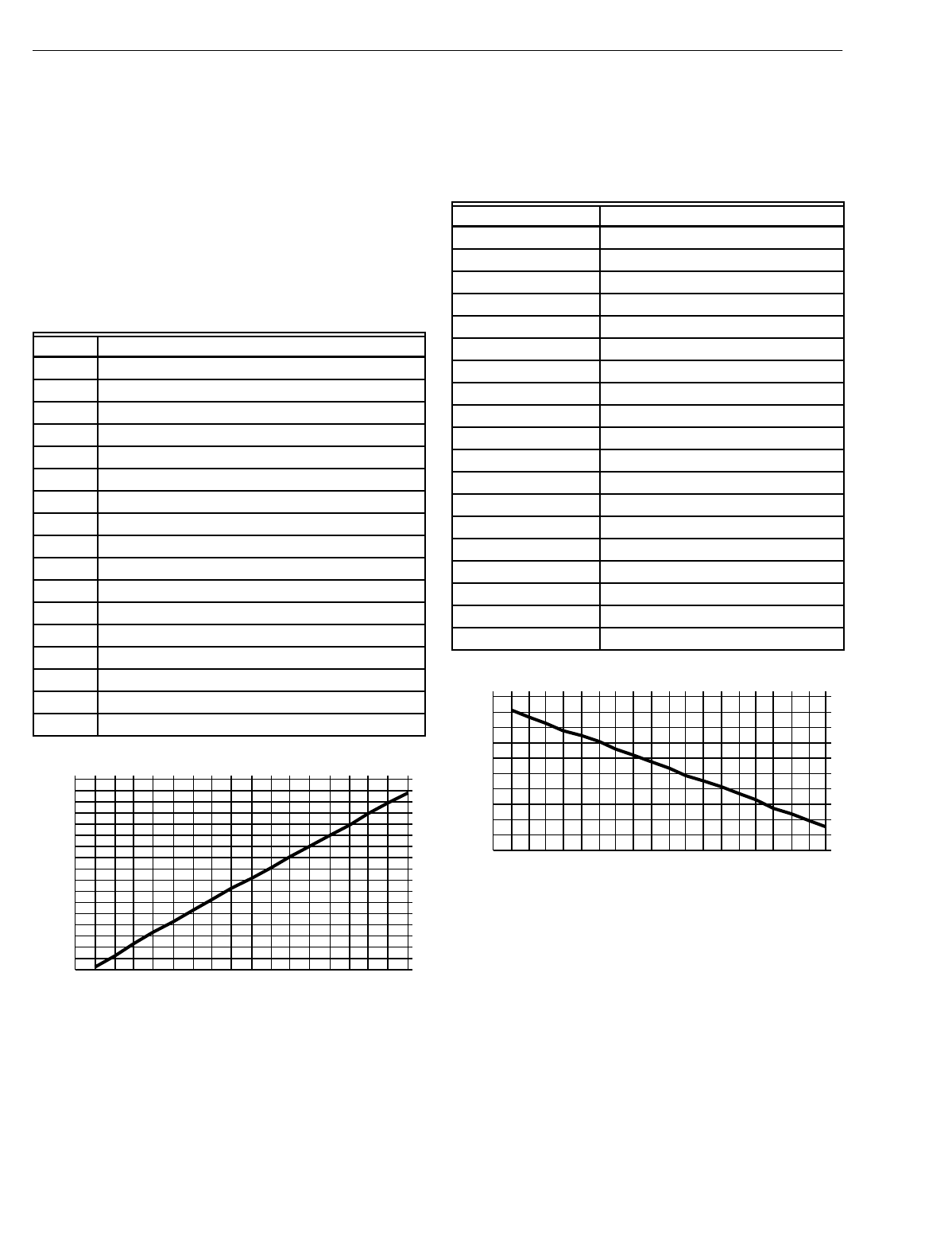
EXCEL 10 W7750A,B,C CONSTANT VOLUME AHU CONTROLLER
74-2958—1110
Appendix E. Sensor Data for Calibration.
Resistance Sensors.
Sensor Type:
C7100A,
(
and C7170A
)
Sensor Use:
Dischar
g
e air, Outdoor air
Table 29 lists the points for Sensor Resistance versus
Temperature. Fi
g
. 52 shows the
g
raph of these points.
Table 29. Sensor Resistance Versus Temperature.
Fig. 52. Graph of Sensor Resistance versus Temperature.
Sensor Type:
C7031B1033, C7031C1031 C7031D1062, C7031F1018
(
W7750B,C onl
y)
, C7031J1050, C7031K1017
Sensor Use:
Return Air, Dischar
g
e Air Temperature
Table 30 lists the points for Sensor Resistance versus
Temperature. Fi
g
. 53 shows the
g
raph of these points.
Table 30. Sensor Resistance Versus Temperature.
Fig. 53. Graph of Sensor Resistance versus Temperature.
Sensor Type:
T7770A,B,C,D the T7560A,B and C7770A
Sensor Use:
Space Temperature and Dischar
g
e/Return Air Temperature
Table 31 lists the points for Sensor Resistance versus
Temperature. Fi
g
. 54 shows the
g
raph of these points.
°FResistance Ohms
-40 2916.08
-30 2964.68
-20 3013.28
-10 3061.88
0 3110.48
10 3159.08
20 3207.68
30 3256.28
40 3304.88
50 3353.48
60 3402.08
70 3450.68
80 3499.28
90 3547.88
100 3596.48
110 3645.08
120 3693.68
3050
3000
2950
2900
3100
3150
3200
3250
3300
3350
3400
3450
3500
3550
3600
3650
3700
3750
50403020100-10-20-30-40 60 70 80 90 100 110 120
OHMS
DEGREES F
SENSOR RESISTANCE VERSUS TEMPERATURE
M11615
°FResistance Ohms
30 1956.79
35 1935.79
40 1914.79
45 1893.79
50 1872.79
55 1851.79
60 1830.79
65 1809.79
70 1788.79
75 1767.79
80 1746.79
85 1725.79
90 1704.78
95 1683.78
100 1662.78
105 1641.78
110 1620.78
115 1599.78
120 1578.78
1650
1600
1550
1500
1700
1750
1800
1850
1900
1950
2000
555045403530 60 65 70 75 80 85 90 95 100 105 110 115120
OHMS
DEGREES F
SENSOR RESISTANCE VERSUS TEMPERATURE
M11614
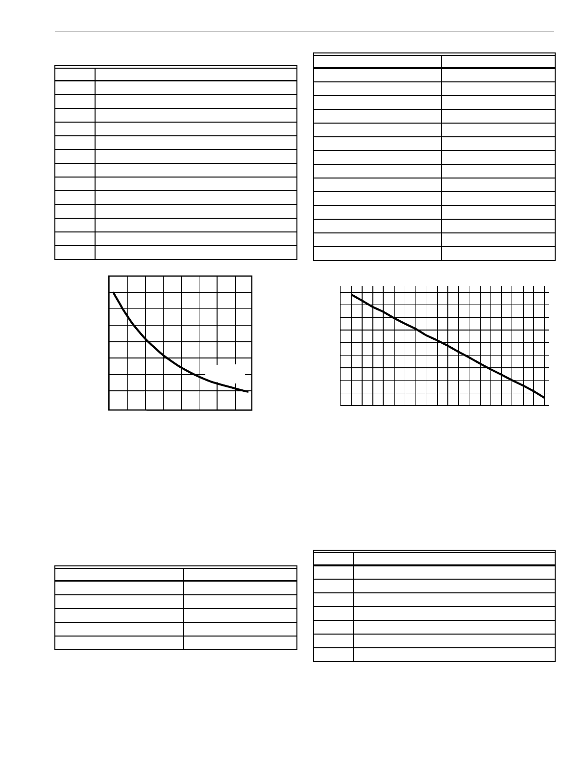
EXCEL 10 W7750A,B,C CONSTANT VOLUME AHU CONTROLLER
111 74-2958—1
Table 31. Sensor Resistance Versus Temperature.
Fig. 54. Graph of Sensor Resistance versus Temperature.
Sensor Type:
T7770B,C 10K ohm setpoint potentiometer
(
Relative
)
Sensor Use:
Offset Setpoint Temperature
Table 32 lists the points for Sensor Resistance versus
Temperature. Fi
g
. 55 shows the
g
raph of these points.
Table 32. Sensor Resistance Versus Temperature.
Fig. 55. Graph of Sensor Resistance versus Temperature.
Sensor Type:
T7770B,C 10 K ohm setpoint potentiometer
(
Absolute
)
Sensor Use:
Direct Setpoint Temperature
Table 33 lists the points for Sensor Resistance versus
Temperature. Fi
g
. 56 shows the
g
raph of these points.
Table 33. Sensor Resistance Versus Temperature.
°F Resistance Ohms
40 9961.09
45 9700.90
50 9440.72
55 9180.53
60 8920.35
65 8660.16
70 8399.98
75 8139.79
80 7879.61
85 7619.42
90 7359.24
95 7099.06
100 6838.87
°F Above and Below Setpoint Resistance Ohms
-9 8877.41
-8 8832.14
-7 8786.87
-6 8741.60
-5 8696.33
TEMPERAT
U
RE
(
DE
G
REE
S)
oF
30 40 50 60 70 80 90 100 110
010 20 30 40
RESISTANCE (OHMS)
20K OHM AT
77oF (25oC)
80K
70K
60K
50K
40K
30K
20K
10K
oC
M5874A
-4 8651.06
-3 8605.79
-2 8560.52
-1 8515.25
0 8469.98
1 8424.71
2 8379.45
3 8334.18
4 8288.91
5 8243.64
6 8198.37
7 8153.10
8 8107.83
9 8062.56
°F Resistance Ohms
55 8877.42
60 8741.62
65 8605.82
70 8470.02
75 8334.22
80 8198.42
85 8062.62
°F Above and Below Setpoint Resistance Ohms
8000
8100
8200
8300
8400
8500
8600
8700
8800
8900
9876543210-1-2-3-4-5-6-7-8-9
OHMS
DEGREES F
SENSOR RESISTANCE VERSUS TEMPERATURE
M11609
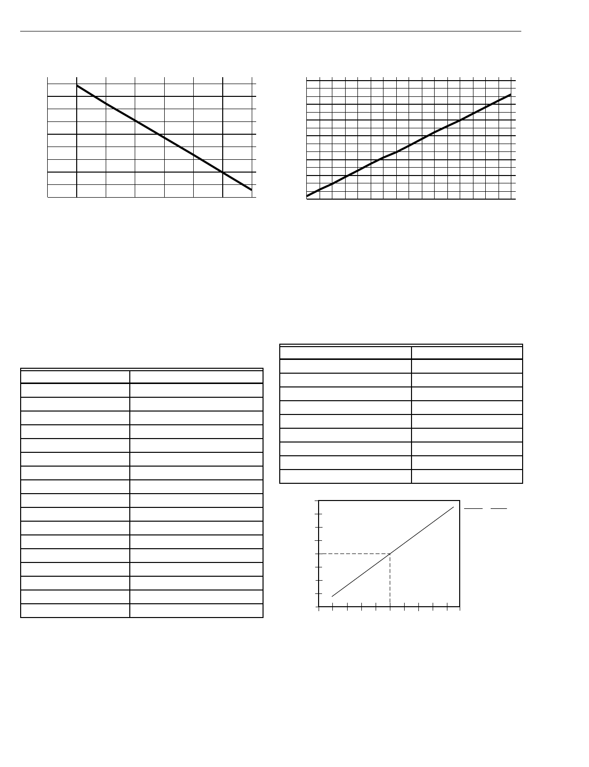
EXCEL 10 W7750A,B,C CONSTANT VOLUME AHU CONTROLLER
74-2958—1112
Fig. 56. Graph of Sensor Resistance versus Temperature.
Voltage/Current Sensors.
Sensor Type:
C7600B1000 2 to 10V
(
Decorative Wall Mount
)
Sensor Use:
Humidit
y
Table 34 lists the points for Sensor Volta
g
e versus Humidit
y
.
Fi
g
. 57 shows the
g
raph of these points.
Table 34. Sensor Voltage Versus Humidity.
Fig. 57. Graph of Sensor Voltage versus Humidity.
Sensor Type:
C7600C
(
4 to 20 mA
)
Sensor Use:
Humidit
y
Table 35 lists the points for Sensor Volta
g
e versus Humidit
y
.
Fi
g
. 58 shows the
g
raph of these points.
Table 35. Sensor Voltage Versus Humidity.
Fig. 58. C7600C output current vs. humidity.
Sensor Type:
T7400A1004
Sensor Use:
Enthalp
y
Humidity Percentage Sensor Voltage
10 2.67
15 3.08
20 3.48
25 3.88
30 4.28
35 4.68
40 5.08
45 5.48
50 5.88
55 6.28
60 6.69
65 7.09
70 7.49
75 7.89
80 8.29
85 8.69
90 9.09
8000
8100
8200
8300
8400
8500
8600
8700
8800
8900
55 60 65 70 75 80 85
OHMS
DEGREES F
SENSOR RESISTANCE VERSUS TEMPERATURE
M11608
Relative Humidity Percentage Sensor Voltage
10 5.6
20 7.2
30 8.8
40 10.4
50 12.0
60 13.6
70 15.2
80 16.8
90 18.4
2.50
3.00
3.50
4.00
4.50
5.00
5.50
6.00
6.50
7.00
7.50
8.00
8.50
9.00
9.50
10.00
10 15 20 25 30 35 40 45 50 55 60 65 70 75 80 85 90
VOLTS
PERCENTAGE
SENSOR VOLTAGE VERSUS HUMIDITY PERCENTAGE
M11610
HUMIDITY IN PERCENT RELATIVE HUMIDITY
CURRENT IN MILLIAMPS
4
18
8
16
6
14
12
20
10
10
M3131B
5.6
7.2
8.8
10.4
12.0
13.6
15.2
16.8
18.4
10
20
30
40
50
60
70
80
90
20 10090807060504030
RH (%) I (mA)
0

EXCEL 10 W7750A,B,C CONSTANT VOLUME AHU CONTROLLER
113 74-2958—1
Table 36 lists the points for Sensor Current versus Enthalp
y
(
volts
)
. Fi
g
. 59 shows the
g
raph of these points.
Table 36. Sensor Current Versus Enthalpy (volts).
Fig. 59. Graph of Sensor Current versus Enthalpy (volts).
See Fi
g
. 60 for partial ps
y
chometric chart for a C7400A Solid
State Enthalp
y
Sensor.
Enthalpy (mA) Sensor Current
41
51.25
61.49
71.74
81.99
92.24
10 2.49
11 2.74
12 2.99
13 3.24
14 3.49
15 3.74
16 3.98
17 4.23
18 4.48
19 4.73
20 4.98
1.00
1.25
1.50
1.75
2.00
2.25
2.50
2.75
3.00
3.25
3.50
3.75
4.00
4.25
4.50
4.75
5.00
4 5 6 7 8 9 10 11 12 13 14 15 16 17 18 19 20
ENTHALPY (VOLTS)
(MA)
SENSOR CURRENT VERSUS ENTHALPY (VOLTS)
M11607
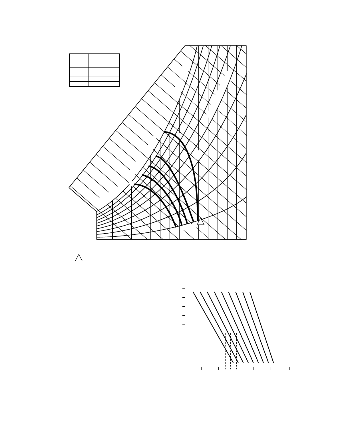
EXCEL 10 W7750A,B,C CONSTANT VOLUME AHU CONTROLLER
74-2958—1114
Fig. 60. Partial psychometric chart for a C7400A Solid State Enthalpy Sensor.
See Fi
g
. 61 for a C7400A Solid State Enthalp
y
Sensor output
current vs. relative humidit
y
.
Fig. 61. C7400A Solid State Enthalpy Sensor output
current vs. relative humidity.
Sensor Type: T7242 or e
q
uivalent
CONTROL
CURVE
A
B
C
D
CONTROL POINT
APPROX. °F (°C)
AT 50% RH
73 (23)
70 (21)
67 (19)
63 (17)
12 14 16 18 20 22 24 26 28 30 32 34 36 38 40 42 44 46
90
100
80
70
60
50
40
30
20
10
ENTHALPY—BTU PER POUND DRY AIR
85
(29) 90
(32) 95
(35) 100
(38) 105
(41) 110
(43)
35
(2)
35
(2)
40
(4)
40
(4)
105
(41) 110
(43)
45
(7)
45
(7)
50
(10)
50
(10)
55
(13)
55
(13)
60
(16)
60
(16)
65
(18)
65
(18)
70
(21)
70
(21)
75
(24)
75
(24)
80
(27)
80
(27)
85
(29) 90
(32) 95
(35) 100
(38)
APPROXIMATE DRY BULB TEMPERATURE—°F (°C)
A
A
B
B
C
C
D
D
M11160
RELATIVE HUMIDITY (%)
1
1
HIGH LIMIT CURVE FOR W6210D,W7210D.
20
10
30
40
50
60
70
80
90
100
605040 70 80 90 100
PERCENT RH
TEMPERATURE °F (°C)
M11605
C7400A OUTPUT CURRENT
4 mA
6 mA
8 mA
10 mA
20 mA
18 mA
16 mA
14 mA
12 mA
(4) (10) (16) (21) (27) (32) (38)
DC BA
D = 17 MA
C = 15.5 MA
B = 13.5 MA
A = 11 MA
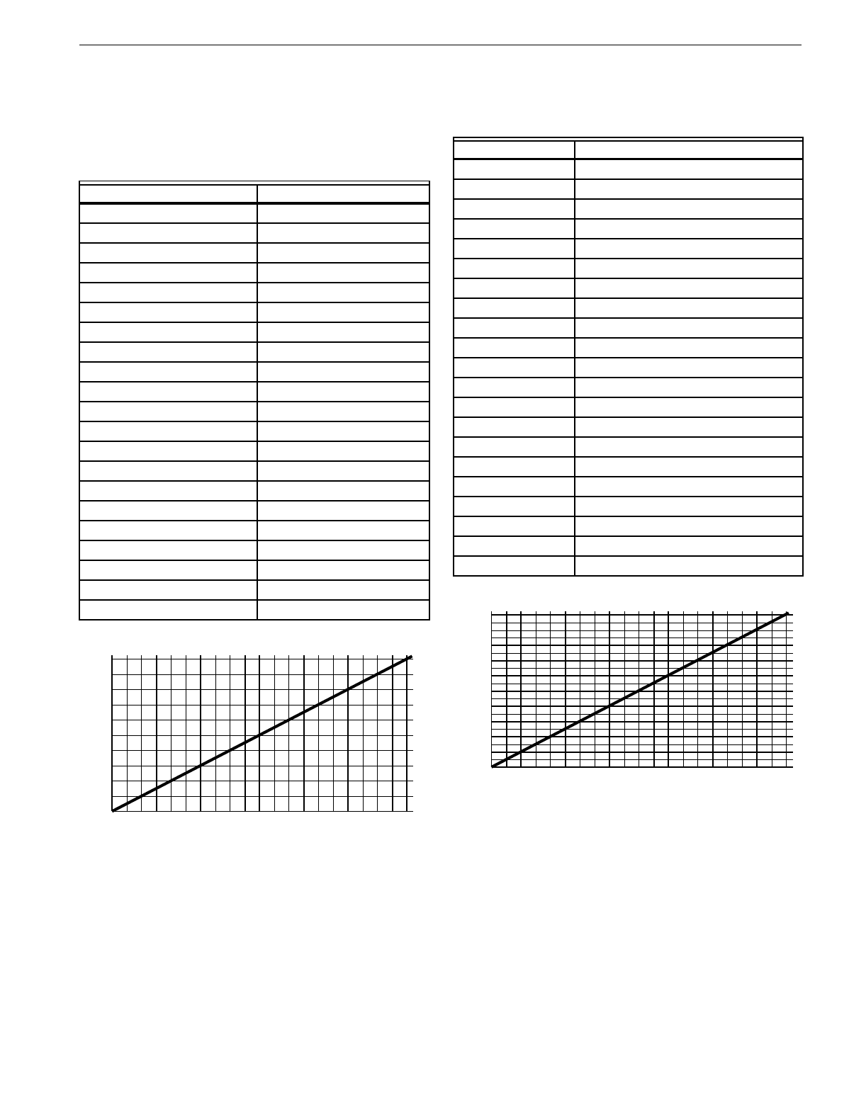
EXCEL 10 W7750A,B,C CONSTANT VOLUME AHU CONTROLLER
115 74-2958—1
Sensor Use:
CO2 concentration
Table 37 lists the points for Sensor Volta
g
e versus CO2
concentration. Fi
g
. 62 shows the
g
raph of these points.
Table 37. Sensor Voltage Versus CO2 Concentration.
Fig. 62. Graph of Sensor Voltage versus CO2
concentration.
Sensor Type:
Third part
y
(
2 to 10V
)
Sensor Use:
Monitor volta
g
e
Table 38 lists the points for Sensor Volta
g
e versus input
Volta
g
e to A/D. Fi
g
. 63 shows the
g
raph of these points.
Table 38. Sensor Voltage Versus Input Voltage To A/D.
Fig. 63. Graph of Sensor Voltage versus input Voltage to
A/D.
Sensor Type:
Third part
y
Sensor Use:
Sensor Volta
g
e
(
Vdc
)
/Pressure
(
Inw
)
2 to 10V, 0 to 5 inw
(
1.25 kPa
)
Table 39 lists the points for Sensor Volta
g
e
(
Vdc
)
versus
Pressure
(
Inw
)
. Fi
g
. 64 shows the
g
raph of these points.
CO2 Concentration PPM Sensor Voltage
00.00
100 0.50
200 1.00
300 1.50
400 2.00
500 2.50
600 3.00
700 3.50
800 4.00
900 4.50
1000 5.00
1100 5.50
1200 6.00
1300 6.50
1400 7.00
1500 7.50
1600 8.00
1700 8.50
1800 9.00
1900 9.50
2000 10.00
0
1
2
3
4
5
6
7
8
9
10
100 300 500 700 900 1100 1300 1500 1700 1900
200 400 600 800 1000 1200 1400 1600 1800 2000
VOLTS
PPM
SENSOR VOLTAGE VERSUS CO2 CONCENTRATION
M11611
Voltage to A/D Sensor Voltage
0.00 0.00
0.50 0.25
1.00 0.50
1.50 0.75
2.00 1.00
2.50 1.25
3.00 1.50
3.50 1.75
4.00 2.00
4.50 2.25
5.00 2.50
5.50 2.75
6.00 3.00
6.50 3.25
7.00 3.50
7.50 3.75
8.00 4.00
8.50 4.25
9.00 4.50
9.50 4.75
10.00 5.00
0
0.50
1.00
1.50
2.00
2.50
3.00
3.50
4.00
4.50
5.00
1000 300 500 700 900200 400 600 800 1000
A/D VOLTS
VOLTS
SENSOR VOLTAGE VERSUS INPUT VOLTAGE TO A/D
M11612
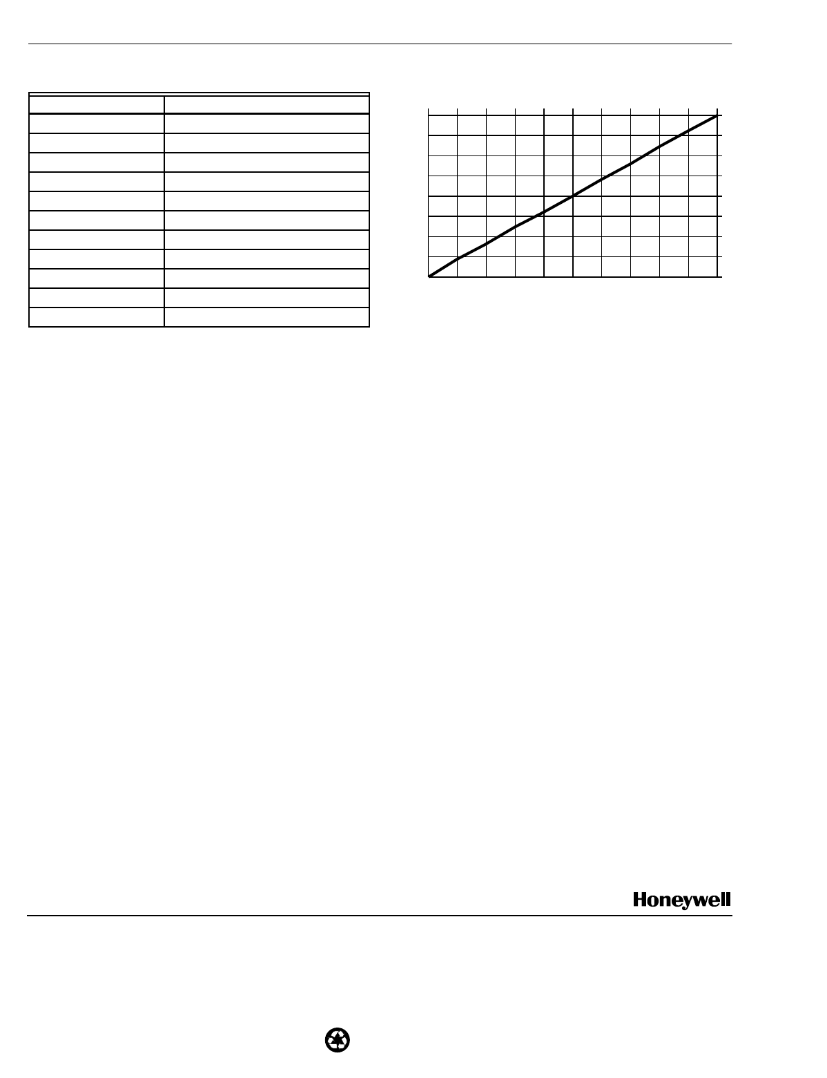
Home and Building Control Home and Building Control Home and Building Control Products
Honeywell Inc. Honeywell Limited-Honeywell Limitée Honeywell AG
Honeywell Plaza 155 Gordon Baker Road Böblinger Straße 17
P.O. Box 524 North York Ontario D-71101 Schönaich
Minneapolis, MN 55408-0524 M2H 3N7 Phone (49-7031) 637-01
Fax (49-7031) 637-493
Printed in U.S.A. on recycled
paper containing at least 10%
post-consumer paper fibers.
74-2958—1 J.D. Rev. 3-00 www.hone
y
well.com
EXCEL 10 W7750A,B,C CONSTANT VOLUME AHU CONTROLLER
Table 39. Sensor Voltage (Vdc) Versus Pressure (Inw).
Fig. 64. Graph of Sensor Voltage (Vdc) versus Pressure
(Inw).
LON
, Neuron
, and LONWORKS
are registered trademarks
of Echelon
Corporation. LONMARK
and LONMARK
logo are
registered trademarks of the LONMARK Interoperability
Association.
Pressure Inw (kPa) Sensor Voltage (Vdc)
0.00
(
0.00
)
2.00
0.50.
(
0.13
)
2.80
1.00
(
0.25
)
3.60
1.50
(
0.37
)
4.40
2.00
(
0.5
)
5.20
2.50
(
0.62
)
6.00
3.00
(
0.75
)
6.80
3.50
(
0.87
)
7.60
4.00
(
1.00
)
8.40
4.50
(
1.12
)
9.20
5.00
(
1.25
)
10.00
2.00
3.00
4.00
5.00
6.00
7.00
8.00
9.00
10.00
0 0.50 1.00 1.50 2.00 2.50 3.00 3.50 4.00 4.50 5.00
VOLTS (VDC)
INW
SENSOR VOLTAGE VERSUS PRESSURE
M11606
