Honeywell Notifier Ifs 2600 Users Manual Install V3_01
IFS-2600 to the manual 1e530b99-d5ae-4bcc-97f7-4c9b2f2572bf
2015-01-23
: Honeywell Honeywell-Notifier-Ifs-2600-Users-Manual-261874 honeywell-notifier-ifs-2600-users-manual-261874 honeywell pdf
Open the PDF directly: View PDF ![]() .
.
Page Count: 80

IFS-2600
Fire Indicator Panel
TECHNICAL, PROGRAMMING
& INSTALLATION MANUAL
P/N 10069 ECN08-0066
8/05/08
Rev:
3.01

Installation Precautions
Adherence to the following will aid in
problem-free installation with long-term
reliability:
WARNING - Several different sources of power
can be connected to the fire alarm control
panel. Disconnect all sources of power before
servicing. Control unit and associated equipment
may be damaged by removing and/or inserting
cards, modules, or interconnecting cables while the
unit is energized. Do not attempt to install, service,
or operate this unit until manuals are read and
understood.
Verify that wire sizes are adequate for all
initiating and indicating device loops. Most devices
cannot tolerate more than a 10% I.R. drop from the
specified device voltage.
Like all solid state electronic devices, this
system may operate erratically or can be damaged
when subjected to lightning induced transients.
Although no system is completely immune from
lightning transients and interference, proper
grounding will reduce susceptibility. Overhead or
outside aerial wiring is not recommended, due to
an increased susceptibility to nearby lightning
strikes. Consult with the Technical Services
Department if any problems are anticipated or
encountered.
Disconnect AC power and batteries prior to
removing or inserting circuit boards. Failure to do
so can damage circuits.
Remove all electronic assemblies prior to any
drilling, filing, reaming, or punching of the
enclosure. When possible, make all cable entries
from the sides or rear. Before making
modifications, verify that they will not interfere with
battery, transformer, or printed circuit board
location.
Do not over tighten screw terminals. Over
tightening may damage threads, resulting in
reduced terminal contact pressure and difficulty
with screw terminal removal.
This system contains static-sensitive
components. Always ground yourself with a
proper wrist strap before handling any circuits so
that static charges are removed from the body.
Use static suppressive packaging to protect
electronic assemblies removed from the unit.
Follow the instructions in the installation,
operating, and programming manuals. These
instructions must be followed to avoid damage to
the control panel and associated equipment.
FACP operation and reliability depend upon proper
installation.
This equipment must be correctly programmed
and installed to suit the specific application.
Please ensure correct operational parameters are
set prior to commissioning. If further details on
programming options are required, please consult
the programming manual or contact our helpful
technical support personnel.
EMC WARNING:
This equipment may radiate radio frequency energy. It may also be affected by radio frequency energy and, if
not installed and operated in accordance with the manufacturers instructions, may cause interference to radio
communications. It has been tested and found to comply with the Class A radiated and conducted EMI
requirements of AS/NZ 3548:1995 (including Amendments 1 & 2) as well as the EMI susceptibility
requirements of Clause C3.5 in AS4428.0:1997.
Radio communication devices should not be used in the vicinity of fire panels or associated ancillary devices
and systems.
Documentation Feedback
Your feedback helps us keep our documentation up to date and accurate. If you have any comments or suggestions about
our printed manuals you can email us.
Please include the following information:
Product name and version number (if applicable)
Manual part number and revision (found on the front cover)
Page number
Brief description of the content you think should be improved or corrected
Your suggestion for how to correct/improve documentation
Send email messages to:
techpubs@notifier.com.au
Please note this email address is for documentation feedback only. If you have any technical issues, please contact
you nearest branch for technical support.

IFS-2600 Installation & Programming Manual Page 1
P/N 10069 ECN08-0066
TABLE OF CONTENTS
COMPATIBLE DETECTORS................................................................................................5
OVERVIEW...........................................................................................................................6
CAUTION ........................................................................................................................................................................... 6
SPECIFICATION...................................................................................................................7
APPROVALS...................................................................................................................................................................... 7
ENVIRONMENTAL LIMITS........................................................................................................................................... 7
POWER SUPPLY RATINGS AND SETTINGS ............................................................................................................. 9
INTERNAL 24 VDC (nom) 3.0A MAIN POWER SUPPLY .......................................................................................... 9
INTERNAL 27.3V DC 1.5A BATTERY CHARGER..................................................................................................... 9
Internal 5VDC 2A Power Supply ..................................................................................................................................... 9
EXTERNAL 27VDC POWER SUPPLY....................................................................................................................... 10
BATTERY TYPE AND CAPACITIES .......................................................................................................................... 10
TECHNICAL DESCRIPTION ..............................................................................................11
GENERAL ........................................................................................................................................................................ 11
TRANSIENT SUPPRESSION......................................................................................................................................... 11
CURRENT CONSUMPTION ......................................................................................................................................... 11
AZF DESCRIPTION........................................................................................................................................................ 12
AZF SUPERVISORY CURRENT .................................................................................................................................. 12
OVERLOAD PROTECTION.......................................................................................................................................... 12
ZONE OVERLOAD SELF RESET ................................................................................................................................ 12
PRINTER OUTPUT......................................................................................................................................................... 13
CABLE CONNECTION.................................................................................................................................................. 13
PROGRAMMING BY COMPUTER............................................................................................................................. 13
ALIGNMENT AND ADJUSTMENT.....................................................................................14
PCB2006 POWER SUPPLY BOARD ............................................................................................................................ 14
INTERNAL 24VDC (nom) POWER SUPPLY.............................................................................................................. 14
INTERNAL 27.3 VDC BATTERY CHARGER............................................................................................................ 14
EXTERNAL 24VDC (nom) POWER SUPPLY (if fitted) ............................................................................................. 14

Page 2 IFS-2600 Installation & Programming Manual
P/N 10069 ECN08-0066
PCB2005 TERMINATION BOARD...............................................................................................................................14
INTERNAL 5VDC POWER SUPPLY TP8...................................................................................................................14
POWER SUPPLY COMPARATOR REFERENCE VOLTAGE TP10 .........................................................................14
NON ADJUSTABLE TEST POINTS..............................................................................................................................14
ALARM THRESHOLD COMPARATOR TP7.............................................................................................................15
FAULT THRESHOLD COMPARATOR TP6 ..............................................................................................................15
CONFIGURATION JUMPERS......................................................................................................................................16
IFS2004 - JP3 DEFAULT .............................................................................................................................................16
IFS2004 - JP4 PROGRAM DISABLE ..........................................................................................................................16
IFS2004 - JP5 CPU RESET...........................................................................................................................................16
IFS2005 – JP2 DOOR HOLDER BYPASS...................................................................................................................16
IFS2006 – JP1 EXTERNAL PS MONITORING..........................................................................................................16
IFS804 - JP1-7 ZONE BOARD ADDRESSING...........................................................................................................16
PLACING INTO OPERATION ............................................................................................ 17
EQUIPMENT AS FITTED..............................................................................................................................................17
INITIAL CHECKLIST ....................................................................................................................................................17
POWER UP CHECKLIST...............................................................................................................................................18
FUNCTIONAL TESTING...............................................................................................................................................18
FAULT RECORD.............................................................................................................................................................19
INSTRUCTIONS TO OPERATORS.................................................................................... 20
INDICATORS...................................................................................................................................................................20
SUGGESTED ALARM PROCEDURE..........................................................................................................................21
OPERATOR INSTRUCTIONS.......................................................................................................................................21
FIREFIGHTER FUNCTIONS........................................................................................................................................21
GLOBAL FUNCTIONS.................................................................................................................................................22
ZONE FUNCTIONS.......................................................................................................................................................24
PROGRAMMING................................................................................................................ 27
GLOBAL OPTIONS.........................................................................................................................................................27
ZONE OPTIONS ..............................................................................................................................................................27
OUTPUT RELAY OPTIONS..........................................................................................................................................28
DEFAULT SETTINGS.....................................................................................................................................................28
PROGRAM MODE..........................................................................................................................................................29
PROGRAMMING MODE..............................................................................................................................................29
PROGRAMMING HIERARCHY ..................................................................................................................................29
ZONES............................................................................................................................................................................29
RELAYS.........................................................................................................................................................................30
GLOBAL ........................................................................................................................................................................30
PRINT.............................................................................................................................................................................30

IFS-2600 Installation & Programming Manual Page 3
P/N 10069 ECN08-0066
MAIN MENU.................................................................................................................................................................... 30
EXIT PROGRAMMING MODE ................................................................................................................................... 31
ZONE PROGRAMMING................................................................................................................................................ 31
SELECT ZONE #........................................................................................................................................................... 31
ZONE SELECTED......................................................................................................................................................... 31
ZONE TYPE .................................................................................................................................................................. 31
ZONE OUTPUT CONFIGURATION ........................................................................................................................... 32
RELAY PROGRAMMING MODE................................................................................................................................ 32
SELECT RELAY # ........................................................................................................................................................ 32
RELAY SELECTED...................................................................................................................................................... 32
RELAY TYPE................................................................................................................................................................ 33
RELAY MAPPING........................................................................................................................................................ 33
GLOBAL PROGRAMMING.......................................................................................................................................... 33
ACF OUTPUT................................................................................................................................................................ 34
AVF ................................................................................................................................................................................ 34
RELAY (GLOBAL RELAY UNITY MAP) .................................................................................................................. 34
PRINT PROGRAMMING DATA .................................................................................................................................. 35
TIME (DATE & TIME)................................................................................................................................................... 35
APPENDIX A ......................................................................................................................36
DESCRIPTION OF ALARM ZONE TYPES ................................................................................................................ 36
LATCHING TYPE......................................................................................................................................................... 36
NON LATCHING TYPE ............................................................................................................................................... 36
TIME DELAY AZF........................................................................................................................................................ 37
APPENDIX B ......................................................................................................................38
ZONE OUTPUT CONFIGURATIONS.......................................................................................................................... 38
APPENDIX C ......................................................................................................................39
ALARM VERIFICATION FACILITY (AVF) .............................................................................................................. 39
GLOBAL PROGRAMMABLE OPTIONS.................................................................................................................... 39
APPENDIX D ......................................................................................................................40
ANCILLARY TRIP (ACF).............................................................................................................................................. 40
GLOBAL PROGRAMMABLE OPTIONS.................................................................................................................... 40
APPENDIX E.......................................................................................................................41
RELAY OUTPUT MAPPING......................................................................................................................................... 41
AND MAPPING ............................................................................................................................................................... 41
OR MAPPING.................................................................................................................................................................. 41
FAULT MAPPING........................................................................................................................................................... 41
FAULT/ISOLATE MAPPING........................................................................................................................................ 42
ISOLATE MAPPING ...................................................................................................................................................... 42

Page 4 IFS-2600 Installation & Programming Manual
P/N 10069 ECN08-0066
APPENDIX F ...................................................................................................................... 43
GLOSSARY OF TERMS.................................................................................................................................................43
APPENDIX G...................................................................................................................... 44
SUMMARY OF TERMINATIONS AND CAUTIONS.................................................................................................44
MCP LOOP.....................................................................................................................................................................44
DETECTION ZONES ....................................................................................................................................................44
RELAY OUTPUTS ........................................................................................................................................................44
BELL OUTPUTS ...........................................................................................................................................................44
ACF OUTPUTS..............................................................................................................................................................44
WARNING SYSTEM.....................................................................................................................................................44
DOOR HOLDER OUTPUTS .........................................................................................................................................44
AUXILIARY POWER & MIMIC POWER ...................................................................................................................44
MAF ISOL & TRANSPONDER 0V ..............................................................................................................................44
MIMIC DATA & CLOCK..............................................................................................................................................44
AC INPUT ......................................................................................................................................................................44
BATTERY......................................................................................................................................................................45
DOOR HOLDER AC INPUT.........................................................................................................................................45
OUTPUT RELAYS ........................................................................................................................................................45
APPENDIX H...................................................................................................................... 46
IFS-2600 PROGRAMMED OPTIONS...........................................................................................................................46
APPENDIX I........................................................................................................................ 53
TECHNICAL DRAWINGS ............................................................................................................................................. 53
MAIN KEYPAD AND DISPLAY..................................................................................................................................53
EXPANSION DISPLAY ................................................................................................................................................53
Block Connection Diagram.............................................................................................................................................54
System Sensor Conventional Detector Connection Diagram..........................................................................................54
System Sensor Conventional Detector Connection Diagram..........................................................................................55
Hochiki Conventional Detector Connection Diagram.....................................................................................................55
Hochiki Conventional Detector Connection Diagram.....................................................................................................56
Ancillary Connection Diagram........................................................................................................................................57
ASE Connection Diagram...............................................................................................................................................58
Auto Changeover Dual Sounder Connection Diagram....................................................................................................59
Auto Change Over Dual Sounder Connection Diagram..................................................................................................60
MIMIC Connection Diagram..........................................................................................................................................61
Single Fan Connection Diagram .....................................................................................................................................62
Dual Fan Connection Diagram........................................................................................................................................63
Exhaust Fan Connection Diagram...................................................................................................................................64
Supply Fan Connection Diagram ....................................................................................................................................65
Smoke Spill Fan Connection Diagram............................................................................................................................66
10W EVAC Connection Diagram...................................................................................................................................67
10W EVAC Slave Connection Diagram.........................................................................................................................68
30W EVAC Connection Diagram...................................................................................................................................69
30W EVAC Slave Connection Diagram.........................................................................................................................70
50W EVAC Connection Diagram...................................................................................................................................71
50W EVAC Slave Connection Diagram.........................................................................................................................72

IFS-2600 Installation & Programming Manual Page 5
P/N 10069 ECN08-0066
COMPATIBLE DETECTORS
Make Model Type Model Number
System Sensor Thermal Type A 5451 AUS
System Sensor Thermal Type A 51A51
System Sensor Thermal Type B 4451 AUS
System Sensor Thermal Type B 51B51
System Sensor Thermal Type B Sealed 51B51S
System Sensor Thermal Type C 51C51
System Sensor Thermal Type D 51D51
System Sensor Smoke Photo-Optical 2151 AUS
System Sensor Smoke Photo-Optical 2151B AUS
System Sensor Smoke Ionisation 1151 AUS
System Sensor Thermal Type D 51D51
System Sensor Smoke Beam BEAM1224
System Sensor Smoke Duct DHP-100
Apollo Thermal Type A Series 60
Apollo Thermal Type B Series 60
Apollo Thermal Type C Series 60
Apollo Thermal Type D Series 60
Apollo Smoke Ionisation Series 60
Apollo Smoke Photo Optical Series 60
Hochiki Thermal Type A DCA-B-60R MkV
Hochiki Thermal Type A DCC-A
Hochiki Thermal Type A DCD-A
Hochiki Thermal Type B DFE-60B
Hochiki Thermal Type B DFJ-60B
Hochiki Thermal Type C DCA-B-90R Mk1
Hochiki Thermal Type C DCC-C
Hochiki Thermal Type C DCD-C
Hochiki Thermal Type D DFE-90D
Hochiki Thermal Type D FDJ-90D
Hochiki Thermal Cool Room Type B sealed DFG-60BLKJ
Hochiki Smoke Ionisation SIH-AM
Hochiki Smoke Ionisation SIJ-ASN
Hochiki Smoke Photo Optical SLK-A
Hochiki Smoke Photo Optical SLR-AS
Olsen Thermal Type A T56B-T6A
Olsen Thermal Type B T56B-T6B
Olsen Thermal Type C T56B-T6C
Olsen Thermal Type D T56B-T6D
Olsen Smoke Ionisation C24B
Olsen Smoke Photo Optical P24B
Panelect Thermal Type A PFS-A
Panelect Thermal Type B PFS-B
Panelect Thermal Type C PFS-C
Panelect Thermal Type D PFS-D
Panelect Smoke Ionisation PFS-I
Panelect Smoke Ionisation PFS-I , MkII
Panelect Smoke Photo Optical PFS-P
Panelect Smoke Photo Optical PFS-P, MkII
IEI VESDA E700, E70D CONTACT DEVICE
Please contact NOTIFIER INERTIA for any additional detectors.

Page 6 IFS-2600 Installation & Programming Manual
P/N 10069 ECN08-0066
OVERVIEW
IFS-2600 Fire Indicator Panel (FIP) is designed to provide simplicity to the end user. The FIP uses both a liquid crystal
display and conventional LED displays for fast and accurate display of system status and changing events.
A custom designed membrane keypad is used together with the liquid crystal display and LED indicators to provide fast,
efficient and simple modes of operation. The keypad also provides the required flexibility for the programming of the
many user configurable options of this FIP. The FIP can be configured on-site without the need of expensive
programmers or components.
A serial printer can also be connected if required. The printer can be used to output programming information for ease of
modification, for safekeeping and to assist in the commissioning of the installation.
IFS-2600 uses serial chain mimic outputs which significantly saves time and costs of cabling to mimic panels.
A door holder power supply (using optional transformer) is incorporated into the system for the release of smoke and fire
doors on alarm.
IFS-2600 is available in a standard 8-zone configuration and can be expandable to its fully expanded state as required.
The IFS-2600 in its fully expanded state can;
• Monitor 64 detection zones
• Control 64 optional "mapped" relay outputs
• Output to a serial printer
• Output serially to a mimic panel
• Control to door holders
• Interface as required to any Australian Fire Brigade
IFS-2600 has been designed to be functional, flexible and reliable whilst maintaining a user-friendly interface.
CAUTION
IFS-2600 FIP has been tested and approved to AS4428.1 and meets the requirements of AS1670 and AS1668 Parts 1 &
2.
However, the equipment must be correctly programmed and installed to suit the specific application. Please ensure
correct operational parameters are set prior to commissioning. If further details on programming options are required,
please consult the programming manual or contact our helpful technical support personnel.
WARNING:
This equipment may radiate radio frequency energy. It may also be affected by radio frequency energy and, if
not installed and operated in accordance with the manufacturers instructions, may cause interference to radio
communications. It has been tested and found to comply with the Class A radiated and conducted EMI
requirements of AS/NZ 3548:1995 (including Amendments 1 & 2) as well as the EMI susceptibility
requirements of Clause C3.5 in AS4428.0:1997
CAUTION: Radio communication devices should not be used in the vicinity of fire panels or associated
ancillary devices and systems

IFS-2600 Installation & Programming Manual Page 7
P/N 10069 ECN08-0066
SPECIFICATION
Cabinet Zinc Sealed Steel 1.6mm
Powder Coated
Hinged Inner Door
Hinged Outer Door
Outside Dimensions 2608 (8 zones) 394mm H x 390mm W x 180mm D*
2624 (24 zones) 750mm H x 390mm W x 180mm D*
2600 (32 to 64 zones) 18U, 28U & 40U Cabinets
Battery Box
*Note: the depth quoted is including the door and break glass.
The internal cabinet depth not including he door and break glass
is 140mm.
AC Operational Voltage 240 VAC 50Hz + 10%
Internal Power Supplies Battery Charger 27.3 VDC 1.5AMP
Panel Supply 24 VDC(nom) 3.0AMP
Logic Supply 5 VDC 2.0AMP
Microprocessor 80C52
Memory Type Non-volatile E2ROM
Liquid Crystal Display 2 Lines x 16 Characters LED Backlit
Fuses F1: Panel Supply M205 5A
F2: Battery Charger M205 3A
F3: Battery Protection Polyfuse 3A
F4: External Supply M205 7A
F5: Door Holder M205 3A
F6: Aux Power Output M205 1A Slow Blow
F7: Bell M205 1A
F8: Warning System M205 1A
F9: ACF M205 1A
E.O.L Resistor On AZFs, monitored
outputs, Bells, Warning system, ACF 4K7 Ohms
APPROVALS
Australian Standard AS4428.1 1998
SSL Approval No AFP-1553
C-Tick Approval No. N1336
ENVIRONMENTAL LIMITS
-10 Deg. C to +55 Deg. C Dry heat.
+40 Deg. C @ 93% Relative Humidity.

Page 8 IFS-2600 Installation & Programming Manual
P/N 10069 ECN08-0066
SYSTEM EXPANSION
Zones Qty Hardware Required Product Code
8 1 Main Control Board PCB-2004
1 Main Termination board PCB-2005
1 Power Supply board PCB-2006
16 1 Main Control board PCB-2004
1 Main Termination board PCB-2005
1 Power Supply board PCB-2006
1 8 Zone Expansion board PCB-804G3
1 16 Zone Indicator board PCB-816
24 1 Main Control board PCB-2004
1 Main Termination board PCB-2005
1 Power Supply board PCB-2006
2 8 Zone Expansion board PCB-804G3
1 16 Zone Indicator board PCB-816
32 1 Main Control board PCB-2004
1 Main Termination board PCB-2005
1 Power Supply board PCB-2006
3 8 Zone Expansion board PCB-804G3
2 16 Zone Indicator board PCB-816
40 1 Main Control board PCB-2004
1 Main Termination board PCB-2005
1 Power Supply board PCB-2006
4 8 Zone Expansion board PCB-804G3
2 16 Zone Indicator board PCB-816
48 1 Main Control board PCB-2004
1 Main Termination board PCB-2005
1 Power Supply board PCB-2006
5 8 Zone Expansion board PCB-804G3
3 16 Zone Indicator board PCB-816
56 1 Main Control board PCB-2004
1 Main Termination board PCB-2005
1 Power Supply board PCB-2006
6 8 Zone Expansion board PCB-804G3
3 16 Zone Indicator board PCB-816
64 1 Main Control board PCB-2004
1 Main Termination board PCB-2005
1 Power Supply board PCB-2006
7 8 Zone Expansion board PCB-804G3
4 16 Zone Indicator board PCB-816
Additional relay outputs:
Relays Qty Hardware Required Product Code
8 1 Relay board containing 8 relays 24VDC 1A IFS-717
16 2 Relay board containing 8 relays 24VDC 1A IFS-717
24 3 Relay board containing 8 relays 24VDC 1A IFS-717
32 4 Relay board containing 8 relays 24VDC 1A IFS-717
40 5 Relay board containing 8 relays 24VDC 1A IFS-717
48 6 Relay board containing 8 relays 24VDC 1A IFS-717
56 7 Relay board containing 8 relays 24VDC 1A IFS-717
64 8 Relay board containing 8 relays 24VDC 1A IFS-717

IFS-2600 Installation & Programming Manual Page 9
P/N 10069 ECN08-0066
POWER SUPPLY RATINGS AND SETTINGS
INTERNAL 24 VDC (nom) 3.0A MAIN POWER SUPPLY
This supply's primary function is to power panel logic and all external operations of the FIP, i.e.: detection
circuits, ancillary circuits, etc. This supply meets the requirements of AS4428.5.
AC Input 30 VAC +10% - 15%
Output Current 3.0 AMPS
Output Voltage 26.5 VDC
Current Limit 3.0 AMPS
Output Ripple 50 mV
INTERNAL 27.3V DC 1.5A BATTERY CHARGER
Its primary function is to charge the batteries. This supply meets the requirements of AS4428.5.
AC Input 30 VAC +10% -15%
Output Current 1.5 AMPS
Output Voltage 27.3 VDC
Current Limit 1.5 AMPS
Output Ripple 200 mV
Important Note:
After a power failure, the battery will only reconnect to the charger if the battery voltage is above approximately
20V +/- 2V.
A battery fault will be generated in the event that the battery does not automatically reconnect. This is to ensure
that a faulty or dead flat battery (due to an extended power failure) does not bring the entire system down.
In order to reconnect a flat battery, it is necessary to disconnect the battery from the panel and charge it
externally. The battery should be thoroughly tested before returning it to service.
In the event that an external charger is not available, the battery may be trickle charged above 22V via a 30
ohm, 5W resistor connected between the 24v Aux Output and the battery positive terminal. A 1N4004 Diode
(Notifier part number #286) or similar should also be fitted in series with the resistor to stop the battery from
pulling down the main panel voltage. Trickle charging the battery by this method may take several hours to
bring it up to the minimum level.
The battery can then be reconnected to the panel for charging via the internal battery charger. It is important
that the voltage on the battery be monitored to ensure that it is charging. The battery should then be left for 24
hours and then fully tested to ensure that no damage has occurred due to the deep discharge.
Internal 5VDC 2A Power Supply
This supply's primary function is to power all internal operations of the FIP, i.e.: Microprocessor, liquid crystal
display, LED's keypad etc.
AC Input 30 VAC +15% or 27.6VDC+15%
Output Current 2.0 AMPS
Output Voltage 5.0 VDC
Current Limit 2.0 AMPS
Output Ripple 150 mV
Page 10 IFS-2600 Installation & Programming Manual
P/N 10069 ECN08-0066
EXTERNAL 27VDC POWER SUPPLY
This supply is used in addition to the internal power supply for large systems. Its primary function is to power
any additional ancillary loads of the FIP up to 7 amps. This supply meets the requirements of AS4428.5
Important Notes:
When using external power supply, JP1 link on IFS2006E must be fitted to enable external PSU monitoring.
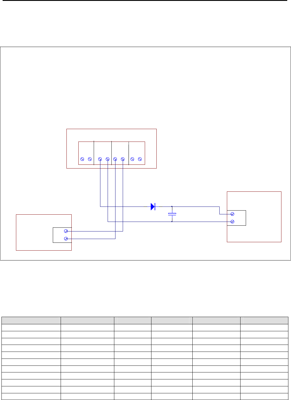
If this supply is used to power a NI-2008 gas module, the following additional components are required to
ensure a break free change over from the mains supply to the panel battery in case of mains fail condition.
1. A 6A4 or P600G rectifier diode (Notifier part number #266) is to be installed in series with the
external +27V output of the IFS-2600 termination board.
2. A 3300µF 50V Electrolytic Capacitor (Notifier part number #1248) should be installed across the
+27V and 0V of the ancillary device.
BATTERY TYPE AND CAPACITIES
In general, any Sealed Lead Acid Battery, or Wet Lead Acid Battery designed for stationary use is compatible
with the IFS-2600 Fire Indicator Panel. Automotive batteries must not be used. The use of Nickel Cadmium
batteries is not recommended.
Manufacturer Type Number Voltage Capacity (Ah) Qty Required
Best and Best Sealed LA BP17-12 12 17 2
Best and Best Sealed LA BP24-12 12 24 2
Best and Best Sealed LA BP40-12 12 40 2
Olympic Batteries Sealed LA CJ12-7 12 7 2
Olympic Batteries Sealed LA CJ12-12 12 12 2
Olympic Batteries Sealed LA CJ12-18 12 18 2
Olympic Batteries Sealed LA CJ12-26 12 26 2
Olympic Batteries Sealed LA CJ12-33 12 33 2
Olympic Batteries Sealed LA CJ12-40 12 40 2
Olympic Batteries Sealed LA CJ12-88 12 88 2
Olympic Batteries Sealed LA CJ12-100 12 100 2
AC
INPUT
24V 0V -+
24V 0V
REMOTE
OUTPUT REMOTE
INPUT
BATT
INPUT
EXTERNAL
POWER
SUPPLY 24V
0V
OUTPUT
+
24V
0
V
POWER IN
NI-2008 GAS
SUPPRESSION
MODULE
3300uF
6A4
IFS
-
2600 TERMINATION BOARD

IFS-2600 Installation & Programming Manual Page 11
P/N 10069 ECN08-0066
TECHNICAL DESCRIPTION
GENERAL
The IFS-2600 in its most basic form comprises of three boards, the main control board, the main termination
board and the power supply board.
The main control board contains the Microprocessor, EPROM, RAM and E2ROM. The main control board also
has the liquid crystal display and keypad attached. All of the "delicate" electronics have been placed on this
board. The main control board complete with the inner door is easily removed during installation to avoid
damage and allow greater access to the field terminals.
The main termination board contains the one power supply for 5V logic, and connectors for a Power Supply
and Battery Charger daughter board, the first eight zones, all common outputs and the printer interface. All
charger settings, fuses etc are located on this board. The Power Supply and Battery Charger board contains
two switch mode regulators, 26.5V for the panel power, 27.3V for the battery charger.
Up to seven (7) zone expansion boards can be added to the system to increase its detection capability. These
boards contain the same electronics as on the main termination board for zone scanning. Addressing is by a
jumper that selects which group of eight zones the board refers to.
Up to four (4) zone indicator boards can also be added. These boards will display the status of the zone
expansion boards fitted.
Up to eight (8) relay boards can be added. These boards contain 8 change-over relay contacts, each rated at
1 amp. These boards require no addressing, as they work on a serial data chain. Output 1 is the closest
output to the main board.
NOTE This product utilises state of the art components and materials and therefore boards must be returned
to our factory for proper troubleshooting, repair and retesting. Field component level repairs are not
recommended and would void all warranties on the product.
TRANSIENT SUPPRESSION
The IFS-2600's superior transient protection comprises of Dual Transorb input traps, inductive paths on
incoming PCB tracks, circuit board planes and metal oxide varistors on outputs. These devices are all self-
resetting.
CURRENT CONSUMPTION
Zones Fitted Quiescent Current Quiescent + 2 AZF'S in alarm +1A of Bell +1 Amp ACF
8 150 mA 2.23 AMPS
16 250 mA 2.33 AMPS
24 350 mA 2.43 AMPS
32 450 mA 2.53 AMPS
40 550 mA 2.63 AMPS
48 650 mA 2.73 AMPS
56 750 mA 2.83 AMPS
64 850 mA 2.93 AMPS
Note:
1: Each installation would require individual battery calculations to be performed for load capacity and
power supply capacity.
2: Each IFS-717 relay board, can add 370 mA (in alarm and quiescent) current per board.

Page 12 IFS-2600 Installation & Programming Manual
P/N 10069 ECN08-0066
AZF DESCRIPTION
The AZF's on the IFS-2600 are monitored and scanned by custom thick film hybrids. These hybrid IC's
significantly reduce the possibility of false alarms and improve product efficiency and reliability.
The total Alarm Zone loop resistance is the sum of the end of line resistor (EOLR 4K7) plus all the parallel
connected detector loads.
AZF SUPERVISORY CURRENT
The supervisory current flows through the external terminal AZF+, through the field cable and to the end of line
resistor (EOLR), returning to the panel at AZF- terminal. Parallel connected, across the 2-wire pair field cable,
are a number of the previously listed detectors. During the quiescent state there is essentially an open circuit
across the + and - terminals of the detector base. The maximum number of detectors that can be installed on
each AZF is dependant on the type of detector and is listed in the IFS-2600 ActivFire®listing.
In an alarm state, a 560-ohm resistor is connected across the detector base causing additional loop current to
flow. This is sensed by the AZF to produce an alarm output. Removal of the E.O.L. resistor (in a non alarm
state) or the interruption of the supervisory current will produce a fault signal in the AZF.
As described above, the level of current is used to define the status of the alarm zone: -
I = 3.5 mA and below FAULT
I = 4.0 - 5.0mA at 24V QUIESCENT
I = 16 mA to 40 mA (current limited) ALARM
The zone current is used by the hybrid IC to determine the condition of the zone as above. This information is
then transferred to the microprocessor for processing.
OVERLOAD PROTECTION
Panel Supply Fuse F1 M205 5A
Battery Charger Fuse F2 M205 3A
Battery Protection Fuse F3 Polyfuse 3A
External Supply Fuse F4 M205 7A
Door Holder Fuse F5 M205 3A
Aux Power Output Fuse F6 M205 1A Slow Blow
Bell Fuse F7 M205 1A
Warning System Fuse F8 M205 1A
ACF Fuse F9 M205 1A
AZF Circuits Current Limited 40mA
ZONE OVERLOAD SELF RESET
If a zone is overloaded by an accidental short to earth on an AZF circuit, the zone will automatically shut down
and produce a fault. Once this happens the panel will automatically recheck the zone every 60 seconds and
once the overload is removed, restore power and the fault will clear.
IFS-2600 Installation & Programming Manual Page 13
P/N 10069 ECN08-0066
PRINTER OUTPUT
The printer port is designed to be used during testing and commissioning of the panel. The serial printer will
report alarms and faults together with the date and time of the event. The printer can also be used during
“walk test” mode to produce a history of the test and can also be used to print current programming
configuration.
A DB9 plug male is provided at the top of the main termination board. This communication port will
communicate with an IBM compatible serial printer (ASCII printer) with the following settings.
Baud Rate 1200 bps
Data Bits 8
Stop Bits 1
Parity None
Handshaking DTR
CABLE CONNECTION
Cabling to the printer requires a 4-core telephone style cable with a maximum length of 10 metres. A DB9
socket is required at the panel end. The printer end is dependent on the type of printer used but is usually a
male DB25. Connection is as follows. A 5-core cable can be used for both comms and printer functions
IFS-2600 END PRINTER END
DB9 FEMALE DB25 MALE DB9 MALE
2 RX (only for programming) 2 3
3 TX 3 2
5 GND 7 5
7 RTS ( do not use) (5) (8)
8 CTS ( only for printer) 4 7
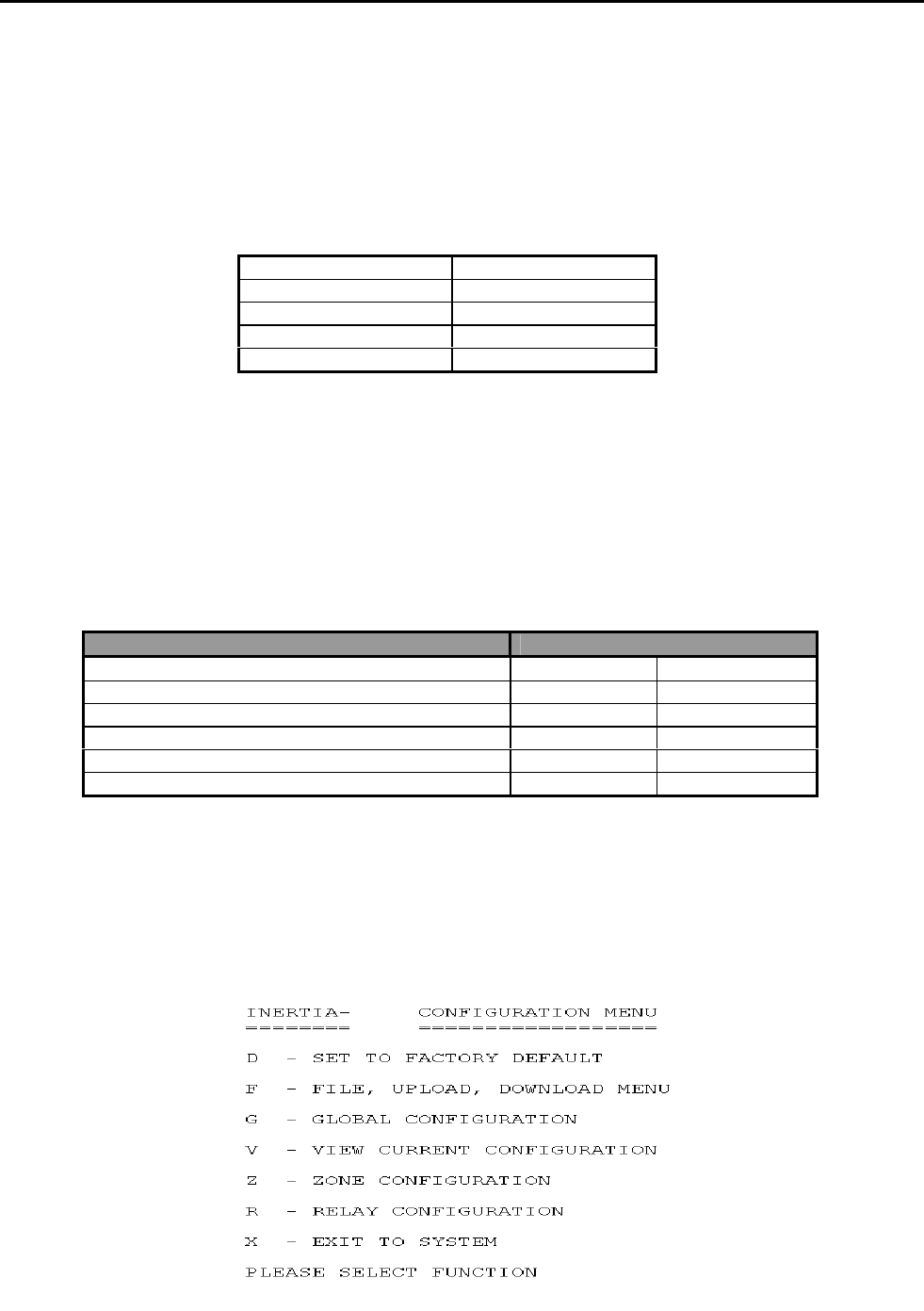
PROGRAMMING BY COMPUTER
Programming of the zones, relays, global functions and time can by set with the DOS based program
“2600/SW” using the printer port. (Cannot be used with Windows XP)
After the cable is installed, the program can be run and the menu will prompt for the available functions.
2600

Page 14 IFS-2600 Installation & Programming Manual
P/N 10069 ECN08-0066
ALIGNMENT AND ADJUSTMENT
PCB2006 POWER SUPPLY BOARD
INTERNAL 24VDC (nom) POWER SUPPLY
With batteries disconnected and no alarms present, measure voltage across the 0V and MAIN test
points on the 2006 power supply board and, if necessary, adjust the multi-turn potentiometer VR2 until
voltage is 26.5V 0.05V (26.45V – 26.55V).
Current limiting is fixed and field adjustment is not possible.
INTERNAL 27.3 VDC BATTERY CHARGER
With batteries disconnected and no alarms present, measure voltage across the 0V and CHARG test
points on the 2006 power supply board and, if necessary, adjust the multi-turn potentiometer VR1 until
voltage is 27.3V 0.05V (27.25V – 27.35V).
Current limiting is factory preset and field adjustment is not required.
EXTERNAL 24VDC (nom) POWER SUPPLY (if fitted)
With batteries disconnected and no alarms present, measure voltage across Remote Input terminals
on PCB2005 and adjust the voltage on the external power supply until the voltage is 26.5V 0.5V
(26.0V – 27.0V). Note: This voltage is not critical for the operation of the IFS-2600 panel, but the
voltage must not go outside the limits as specified for the field ancillaries that it powers.
PCB2005 TERMINATION BOARD
INTERNAL 5VDC POWER SUPPLY TP8
All parameters are fixed and field adjustment is not possible.
POWER SUPPLY COMPARATOR REFERENCE VOLTAGE TP10
With the panel in the quiescent mode, measure voltage between system 0V and TP10. Adjust multi-
turn potentiometer VR3 until voltage is 7.0V 1% (6.93V – 7.07V)
NON ADJUSTABLE TEST POINTS
TP8 = 5.0 VDC 5% 5VDC POWER SUPPLY
TP5 = 12.0 VDC 5% 12VDC POWER SUPPLY
(If these test point voltages are not correct, please return the main termination board to the factory for
repair.)

IFS-2600 Installation & Programming Manual Page 15
P/N 10069 ECN08-0066
ALARM THRESHOLD COMPARATOR TP7
With the panel in the quiescent mode, measure and take note of the INTERNAL 24V DC POWER
SUPPLY as above.
Measure voltage between system 0V and TP7. Adjust multi-turn potentiometer VR4, and adjust until
the voltage is as per the following table.
Rail Voltage 3.3V Setting Range
20.6 2.833 2.80 to 2.86
21.0 2.888 2.86 to 2.92
21.5 2.956 2.93 to 2.99
22.0 3.025 2.99 to 3.06
22.5 3.094 3.06 to 3.12
23.0 3.163 3.13 to 3.19
23.5 3.231 3.20 to 3.26
24.0 3.300 3.27 to 3.33
24.5 3.369 3.34 to 3.40
25.0 3.438 3.40 to 3.47
25.5 3.506 3.47 to 3.54
26.0 3.575 3.54 to 3.61
26.5 3.644 3.61 to 3.68
27.0 3.713 3.68 to 3.75
27.5 3.781 3.74 to 3.82
27.6 3.795 3.76 to 3.83
28.0 3.850 3.81 to 3.89
FAULT THRESHOLD COMPARATOR TP6
With the panel in the quiescent mode, measure and take note of the INTERNAL 24V DC POWER
SUPPLY as above.
Measure the voltage between system 0V and TP6. Adjust multi-turn potentiometer VR1, and adjust
until the voltage is as per the following table.
Rail Voltage 0.6V Setting Range
20.6 0.600 0.59 to 0.61
21.0 0.612 0.61 to 0.62
21.5 0.626 0.62 to 0.63
22.0 0.641 0.63 to 0.65
22.5 0.655 0.65 to 0.66
23.0 0.670 0.66 to 0.68
23.5 0.684 0.68 to 0.69
24.0 0.699 0.69 to 0.71
24.5 0.714 0.71 to 0.72
25.0 0.728 0.72 to 0.74
25.5 0.743 0.74 to 0.75
26.0 0.757 0.75 to 0.76
26.5 0.772 0.76 to 0.78
27.0 0.786 0.78 to 0.79
27.5 0.801 0.79 to 0.81
27.6 0.804 0.80 to 0.81
28.0 0.816 0.81 to 0.82
Page 16 IFS-2600 Installation & Programming Manual
P/N 10069 ECN08-0066
CONFIGURATION JUMPERS
IFS2004 - JP3 DEFAULT
Holding a short across these pins for 5 seconds during start-up causes the panel to reset to standard
factory defaults. The panel will give 4 beeps after reset, to acknowledge default on start-up.
IFS2004 - JP4 PROGRAM DISABLE
When fitted, jumper between these pins to inhibit program changes.
IFS2004 - JP5 CPU RESET
With panel operating, a momentary short across these pins will cause a CPU restart.
IFS2005 – JP2 DOOR HOLDER BYPASS
If zoned door holder outputs are required and is to be done external to the main termination board,
then the main door holder release needs to be disabled. Fitting a link across JP2 on IFS2005 PCB
does this.
Note: Door holder output is only enabled if optional door holder transformer is fitted. SW1 must be
linked on PCB2004 CPU board prior to Version 6 Firmware.
IFS2006 – JP1 EXTERNAL PS MONITORING
When using external power supply, JP1 link on IFS2006E must be fitted to enable external PSU
monitoring.
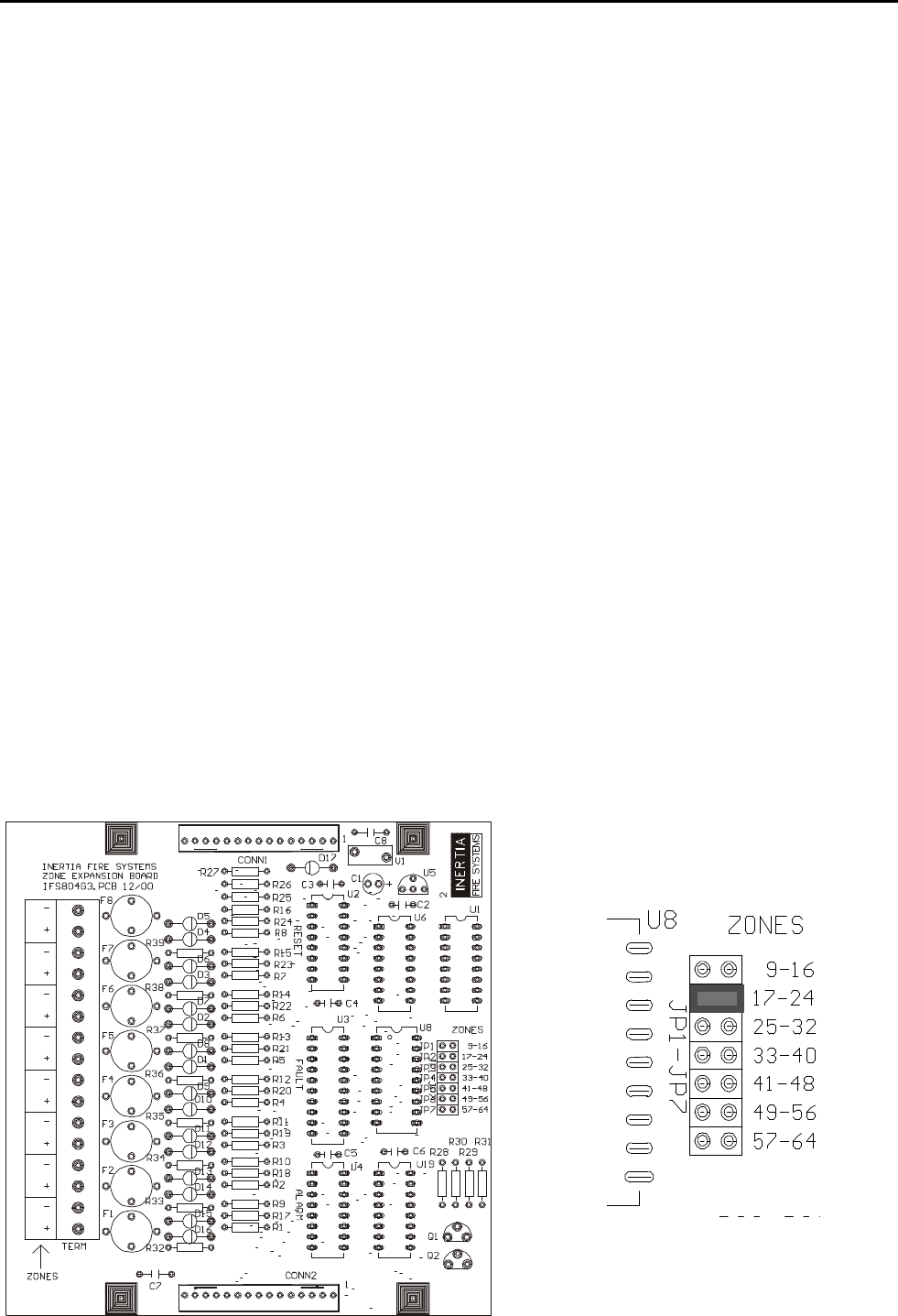
IFS804 - JP1-7 ZONE BOARD ADDRESSING
Jumper JP1 to JP7 on zone expansion board IFS-804 selects the addressing for the zones.
Place jumper in link position for the appropriate 8 zones to which the expansion board applies.

IFS-2600 Installation & Programming Manual Page 17
P/N 10069 ECN08-0066
PLACING INTO OPERATION
Suitably qualified technicians must install the panel. The following check procedures are recommended after
every installation and prior to initial power-up.
A thorough visual inspection should be made to every aspect of the fire panel. This includes loose wire, metal
filings, loose circuit boards, loose cabling, damage in transit etc.
All problems must be rectified immediately as they could cause incorrect operation or permanent damage to
the equipment.
EQUIPMENT AS FITTED
QTY Description Code
1 MAIN CONTROL BOARD IFS -2004
1 MAIN TERMINATION BOARD IFS -2005
1 MAIN POWER SUPPLY IFS -2006
8 ZONE EXPANSION BOARD IFS -804
16 ZONE INDICATOR BOARD IFS -816
ADD ON, 8 WAY RELAY BOARD IFS-717
EXTERNAL POWER SUPPLY BOOSTER PS244, PS249, NPS-3,
NPS-5, NPS-11
3A DOOR HOLDER P/SUPPLY TRANSFORMER 2600/DHTX
INITIAL CHECKLIST
System general appearance good
Cabinet colour and condition good
Cabinet keyed 003
All circuit boards firmly fastened
Manual call point fitted & functional
Viewing window clear and firmly secured
Cable entries adequately sealed
240VAC mains cabling is correctly terminated
All earthing secured
Transformer securely mounted
Transformer correctly wired
All ribbon cables firmly secured
All operational zones adequately identified
All fuses correct value and fitted properly
All other modules securely fitted
Manufacturing label affixed
You are now ready to power up the IFS-2600 Fire Indicator Panel.

Page 18 IFS-2600 Installation & Programming Manual
P/N 10069 ECN08-0066
POWER UP CHECKLIST
Ensure batteries are disconnected.
Turn mains switch to "on"
The "mains on" led should light.
Allow 15 seconds for the panel to perform its start up tests.
Connect batteries
FUNCTIONAL TESTING
Primary ac supply voltage: 200 or 220 or 240vac +10% as required
Charger output voltage without batteries: 27.3v dc
Keypad functional
Perform auto test
Led’s all functional
LCD backlighting functional
Liquid crystal display functional
Zone fault detection
Zone alarm detection
Internal sounder operating
MCP loop wired to zone number ______ (if applicable)
Test auxiliary power output
Test bell output
Test warning system output
Test ACF output
Test door holder output (optional)
Test bell output supervision
Test warning system output supervision
Test ACF output supervision
Test brigade alarm relay #1
Test brigade alarm relay #2
Test standby relay (normally energised)
Test fault relay (normally energised)
Test mains fail relay
Test isolate relay
Test general alarm relays (2)
Test relay boards (if fitted)
Test open collector output boards (if fitted)
Press "battery test" once
If batteries are flat, allow 24hrs to charge and then re-test.

IFS-2600 Installation & Programming Manual Page 19
P/N 10069 ECN08-0066
FAULT RECORD
FAULT CORRECTION DATE
TESTS SATISFACTORILY COMPLETED.
TESTED BY _______________________________
SIGNATURE _______________________________
DATE OF TEST ____________________________
If all faults have been rectified and all tests are completed satisfactorily, the 2600 fire indicator panel is now
ready for operation.

Page 20 IFS-2600 Installation & Programming Manual
P/N 10069 ECN08-0066
INSTRUCTIONS TO OPERATORS
INDICATORS
Qty Descriptor Colour Function Buzzer
1 MAINS ON Green Illuminates when there is 200/220/240 VAC supply to
the panel.
1 BATTERY
FAULT Yellow Illuminates if the battery fails a battery test.
Illuminates if batteries are disconnected >30
seconds.
Illuminates if batteries are short circuit >30 seconds.
Yes
1 PSU FAULT Yellow Illuminates if the power supply is outside the
manufacturers range. Yes
1 CHARGER
LOW Yellow Illuminates if the battery charger is outside the
recommended float charge voltage. Yes
1 COMMON
FAULT Yellow Illuminates if;
Any un-isolated zone goes into fault.
ACF output is open or short circuit
Bell output is open or short circuit
Warning System output is open or short circuit
Battery Fault
Charger Fault
Power Supply Fault
MAF Isolate Input is Open Circuit
Configuration Fault
Yes
1 ACF ACT Red Illuminates if the ACF output has been activated.
1 ACF FLT Yellow Illuminates if the ancillary circuit is open or short
circuit. The LED will extinguish when the load is
restored.
Yes
1 ACF ISO Yellow Illuminates if the ancillary output has been manually
isolated.
1 Bell ACT Red Illuminates when the bell output has been energised.
1 Bell FLT Yellow Illuminates if the bell circuit is open or short circuit.
The LED will extinguish when the load is restored. Yes
1 Bell ISO Yellow Illuminates if the bell output has been manually
isolated.
1 Warning
System ACT Red Illuminates if the Warning System output has been
energised.
1 Warning
System FLT Yellow Illuminates if the Warning System circuit is open or
short circuit. The LED will extinguish if the load is
restored.
Yes
1 Warning
System ISO Yellow Illuminates if the Warning System has been manually
isolated.
8 ALARM LEDS Red This LED will flash if it's corresponding zone goes
into alarm. It will remain flashing until it is
Acknowledged at which time it will go steady and
remain on until the alarm is reset. If the zone is
programmed as a time delay type, a steady LED
indicates the “pre-alarm” condition. If the zone is
isolated and in alarm it will also be steady.
Yes
8 FAULT LEDS Yellow This LED illuminates if it's corresponding zone goes
into fault. It will remain on until the fault is removed. Yes
8 ISOLATE LEDS Yellow This LED illuminates if its corresponding zone is
isolated. It will remain on until the zone is de-
isolated.

IFS-2600 Installation & Programming Manual Page 21
P/N 10069 ECN08-0066
SUGGESTED ALARM PROCEDURE
The following is a suggested alarm procedure for use by building fire officers or duty wardens. The fire
indicator panel is designed for use by qualified fire fighters and it is strongly recommended that the fire panel
not be operated in an emergency situation by anyone other than suitably qualified fire fighters.
Do not open fire indicator panel door or press any buttons until fire officers arrives.
Determine location of the fire by inspecting the label beside any lit red zone alarm LEDs on the panel.
Visually inspect area at a safe distance for actual fire or false alarm.
Notify fire-monitoring station of either result.
Perform evacuation and extinguishing operations as required.
IF a FIRE, direct fire fighters to the fire indicator panel and cause of alarm as they arrive.
IF a FALSE ALARM, advise maintenance technicians to determine and rectify cause.
Record all events in logbook.
NOTE A suitably qualified fire officer should perform the above procedure. These are suggested procedures
only, and if specific fire procedures are available or issued, they MUST prevail.
OPERATOR INSTRUCTIONS
The functions of the IFS-2600 are divided into three (3) categories
Fire Fighter Functions
Global Functions
Zone Functions
FIREFIGHTER FUNCTIONS
Fire Fighter Functions are those specifically used by the Fire Brigade on attendance. Following is an
explanation of their operation and the keystrokes required to perform the function required. These keys are
located at the top of the keypad marked FIREFIGHTER’S FACILITY and bordered in red.
ACKNOWLEDGE ACK
The purpose of the internal buzzer is to alert persons of a new event on the panel, and a new potential fire
danger. Once the fire's location has been determined, the fire-fighter may wish to silence the internal buzzer
without having to totally reset the alarm.
When the buzzer is operating, pressing the "ACK" key once will silence it, however the External Alarm Bell will
continue to sound. If a subsequent alarm arises, the buzzer will be reactivated and a second ACK operation
will be required to silence it.
When an alarm is acknowledged, the Alarm LED will stop flashing and light continuously.
RESET RESET
The reset function momentarily disconnects power, and resets all alarm parameters for the zone(s) that have
been acknowledged. This returns the zone back to its "normal" state. The reset key only operates on zones
with acknowledged alarms.
ISOLATE ISOLATE
The isolate function prevents the transmission of alarms or faults from the zones to the master alarm facility.
The isolate key only operates on zones with acknowledged alarms.

Page 22 IFS-2600 Installation & Programming Manual
P/N 10069 ECN08-0066
BELL ISOLATE
EXT BELL
ISOL
Depressing the "EXT BELL ISOLATE" key will isolate the bells. The "Ext Bells Isolate" LED will illuminate and
the bells will not sound until the bells are de-isolated. Pressing "EXT BELL ISOLATE" a second time will de-
isolate the bell.
WARN SYS ISOLATE WARN SYS
ISOL
Depressing the "WARN SYS ISOLATE" key will isolate the warning system. The "Warn Sys Isolate" LED will
illuminate and the warning system will not operate in the event of an alarm. Pressing "WARN SYS ISOLATE"
a second time will de-isolate the warning system.
GLOBAL FUNCTIONS
Global functions are those relating to the overall system and are not specific to particular zones. Following is
an explanation of their operation and the keystrokes required to perform the function.
BATTERY TEST BATT
TEST
This function tests the performance of the batteries fitted to the system. Pressing this button will initiate a
battery test as specified in AS4428. The test will temporarily disconnect the batteries from the panel and apply
load on the batteries for 15 seconds.
The result of the test will be displayed on the LED's. If the "Battery Fault" LED is on, only a successful battery
test will turn the LED off. The pressing of any key during the test period will abort the battery test and return
the system back to normal mode.
Battery test function is disabled when the panel is in alarm condition.
This function will perform a fixed automatic test procedure to the panel. This mode cannot be selected if any
zone(s) is in alarm. Auto test will perform the following test functions;
Turn on ALL LEDs for 0.5 seconds
Test LCD backlighting
Test panel memory (E2ROM & RAM)
Test LCD
Isolate all alarm zones
Fault test all alarm zones
Alarm test all alarm zones
Test buzzer
The pressing of any key during "AUTO TEST" will abort the tests and return the system back to normal mode
once the current test is complete.
Note During "AUTO TEST", all zones are treated as zone type #1 (standard latching type with 2 second
delay). Once AUTO TEST has finished, all zones will be reset and returned back to their previously
configured types.
AUTO TEST MODE
AUTO
TEST

IFS-2600 Installation & Programming Manual Page 23
P/N 10069 ECN08-0066
WALK TEST MODE WALK
TEST
This function will place the panel into "walk test" mode. Walk test mode is used for the on-site testing of
detector zones. This mode cannot be selected if any zone(s) is in alarm. Entry to walk test mode will be
acknowledged by three beeps and the LCD will display "WALK TEST MODE".
For the duration of walk test mode, all zones are changed to output configuration #2 (indicate and ring bells
only) and all zones are set to type #1 (standard latching, 2 second).
If the bells are not required to ring during walk test, simply press the "EXT BELL ISOLATE" key once. The EXT
BELL ISOLATE LED will illuminate to verify that the bells have been isolated.
Any alarm signal from detectors etc. will be received by the panel on its appropriate zone. The panel will beep
to acknowledge receipt of the alarm and indicate the alarm by illuminating the appropriate alarm LED for 4
seconds (the bells will also ring for a 3 second period unless previously isolated).
The zone and detector will then be automatically reset for 15 seconds
If the optional printer is connected, the alarm will be printed out as it is received. This can eliminate the need
for a second serviceman to record zone numbers during walk test and the printout can be retained for
verification at a later date.
Pressing any key will terminate the walk test mode and return the panel back to normal operation, restoring all
zone types and output configurations also ensuring that bell and ancillary outputs are de-isolated. The bells will
give three pulses of 1 second each to warn any testers still in the building that walk test mode has been
terminated.
Failure to receive any alarms or keystrokes within a 15 minutes period will result in the panel automatically
exiting walk test mode and returning back to normal as follows:
Bell outputs to be de-isolated.
Ancillary outputs to be de-isolated.
Bell will sound 3 times, each of 1-second duration.
Exit from walk test mode.
Zone types and output configurations restored
ACF ISOLATE ACF
ISOL
Depressing the "ACF ISOLATE" key will isolate the ACF (Ancillary output) and the Door Holder Output. The
ACF isolated LED will illuminate and the output will not operate until de-isolated. Pressing "ACF ISOLATE" for
a second time will de-isolate the output.
If the ancillary output has already been tripped and is programmed as latching, isolating the ACF will not affect
the existing ancillary output. If the ACF is isolated prior to the alarm, it will prevent the ancillary output from
tripping. This does not apply to the Door Holder output.
ACF RESET ACF
RESET
Resetting of the ancillary output (ACF) is only required if the ancillary output was programmed as latching.
The ancillary alarm will remain latched until manually reset. Pressing the "ACF RESET" button will extinguish
the 'ACF Activated' LED and de-energise the ancillary output. Pressing "ACF RESET" when the ACF is not
tripped will have no effect.

Page 24 IFS-2600 Installation & Programming Manual
P/N 10069 ECN08-0066
ZONE FUNCTIONS
Zone functions are those relating specifically to the detection zones. Following is an explanation of their
operation and the keystrokes required to perform the function required.
ALARM TEST ALARM TEST # ENT
The alarm test function momentarily disconnects the detector lines of the zone(s) under test and simulates a
detector going into alarm, therefore testing the zone(s) alarm detection capability.
A resistive load equal to worst case alarm condition is placed on the zone for a period of 120 seconds and
then removed, if the zone being tested is not a latching type, the alarm will reset automatically once the load is
removed. Acknowledging and resetting the alarm will terminate an alarm test.
Once the zone has alarmed, all outputs are initiated (as programmed) similar to a real alarm.
The zone may be isolated prior to an alarm test if desired; this will prevent any outputs from operating.
‘#’ in the above key sequence is the zone number.
If only one zone is to be tested, use the appropriate number. Alternatively the "ALL" button can be used to
simultaneously test all zones.
To perform an alarm test:
1. Press the "ALARM TEST" button once; the buzzer will give 2 short beeps to indicate that alarm test mode
has been entered.
2. The LCD display will read "ALARM TEST MODE, ENTER ZONE No.".
3. Now enter the zone number ("#") 1-64 or “all”
4. Press "ENT"
If a correct entry is made, alarm testing on the zone commences immediately. However remember there is a 2
second transient delay on all zones. It will therefore take approximately 2 seconds before the zone registers an
alarm (this could be longer, depending on zone type).
A long beep will signify an incorrect entry and will revert back to normal operating mode. The "ALARM TEST"
button will need to be depressed again to re-enter alarm test mode.

IFS-2600 Installation & Programming Manual Page 25
P/N 10069 ECN08-0066
FAULT TEST FAULT TEST # ENTER
The fault test function momentarily disconnects the detection zone(s) under test and simulates the worst-case
condition for fault.
A resistor load equal to worst case fault is placed on the zone continuously for 5 seconds then the zone is
returned back to its normal condition.
If several zones are being tested consecutively and are being entered at a rate faster than the 5-second fault
timer, the fault timeout will occur 5 seconds after the last entry was completed.
Once the zone has registered a fault, all outputs relating to that zone are initiated similar to a real fault.
The zone may be isolated prior to a fault test if desired. This will prevent any outputs from operating.
‘#’ in the above key sequence is the zone number.
If only one zone is to be tested, use the appropriate zone number. Alternatively the "ALL" button can be used
to simultaneously test all zones.
To perform a fault test on a particular zone or on all zones:
1. Press the "FAULT TEST" button once.
The buzzer will give 2 short beeps to indicate that fault test mode has been entered.
2. The LCD display will read "FAULT TEST MODE, ENTER ZONE No.".
3. Enter the zone number ("#") 1-64 or “all”.
4. Press "ENTER".
A long beep will signify an incorrect entry and the panel will revert back to normal operating mode. The
"FAULT TEST" button will need to be pressed again to re-enter fault test mode.
If a correct entry is made, fault testing on the zone commences and the fault LED will illuminate.

Page 26 IFS-2600 Installation & Programming Manual
P/N 10069 ECN08-0066
ISOLATE ISOLATE # ENTER
The isolate function prevents the transmission of alarms or faults from the zones, to the master alarm facility.
‘#’ in the above key sequence is the zone number.
If only one zone is to be isolated, use the appropriate zone number. Alternatively the "ALL" button can be used
to simultaneously isolate all zones.
To isolate a particular zone or all zones:
1. Press the "ISOLATE" button.
The buzzer will give 2 short beeps to indicate that isolate mode has been entered.
2. The LCD display will read "ALARM ISOL. MODE, ENTER ZONE No.".
3. Enter the zone number ("#")1-64 or “all”.
4. Press "ENTER".
A long beep will signify an incorrect entry and will revert back to normal operating mode. The "ISOLATE"
button will need to be depressed again to re-enter isolate mode.
If a correct entry is made, the zone is immediately isolated. If the zone is already in alarm, all of its alarm
outputs are isolated and indicators remain visible.
If the "ALL" function is performed, all zones will be isolated, regardless of their previous state. Performing the
"ALL" function for a second time will de-isolate all zones.
RESET RESET # ENTER
The reset function momentarily disconnects power, and resets all alarm parameters for the zone(s) being
reset. This returns the zone back to its "normal" state.
‘#’ in the above key sequence is the zone number.
If only one zone is to be reset, type in the zone number. Alternatively the "ALL" button can be used to
simultaneously reset all zones.
To perform a reset on a particular zone or on all zones:
1. Press the "RESET" button.
The buzzer will give 2 short beeps to indicate that reset mode has been entered.
2. The LCD display will read "ALARM RESET MODE, ENTER ZONE NO".
3. Enter the zone number ("#") 1-64 or “all”.
4. Press "ENTER".
A long beep will signify an incorrect entry and will revert back to normal operating mode. The "RESET" button
will need to be depressed again to re-enter reset mode.
If a correct entry is made, resetting of the zone begins immediately. Any alarm indication will be removed
immediately; also resetting the zone(s) programmed outputs.
IFS-2600 Installation & Programming Manual Page 27
P/N 10069 ECN08-0066
PROGRAMMING
GLOBAL OPTIONS
ANCILLARY TRIP
1 LATCHING NORMALLY DE-ENERGISED
2 NON-LATCHING NORMALLY DE-ENERGISED
3 LATCHING NORMALLY ENERGISED
4 NON-LATCHING NORMALLY ENERGISED
ALARM VERIFICATION
1 DISABLED
2 2 MINUTES
3 3 MINUTES
4 4 MINUTES
5 5 MINUTES
TIME
(DD) / (MM) / (YY)
(HH) : (MM)
ZONE OPTIONS
DESCRIPTION INPUT DELAY
1 Standard Latching 2 seconds
2 Standard Latching 2 seconds with AVF
3 Non Latching 2 seconds
4 Non Latching 20 seconds
5 Time Delay 10 seconds
6 Time Delay 20 seconds
7 Time Delay 30 seconds
8 Time Delay 40 seconds
9 Time Delay 50 seconds
10 Time Delay 60 seconds
Type Output Description
1 Indicate Only
2 Indicate, Bell
3 Indicate, Bell, General Alarm
4 Indicate, Bell, General Alarm, Ancillary
5 Indicate, Bell, General Alarm, Ancillary, Brigade Relay #1
6 Indicate, Bell, General Alarm, Ancillary Brigade Relay #2
7 Indicate, Bell, General Alarm, Ancillary, Brigade Relay #1, & Brigade Relay #2

Page 28 IFS-2600 Installation & Programming Manual
P/N 10069 ECN08-0066
OUTPUT RELAY OPTIONS
Optional Relays can be programmed to simulate: -
Isolate Relay
ACF Output
Brigade Relay #1
Brigade Relay #2
Fault Relay
Mains Fail Relay
General Alarm Relay
Bell Output
Door Holder Relay
Door Switch
Reset
Or Can Be Used To:
"MAP AND" Up to 5 Zones in Alarm
"MAP OR" Up to 5 Zones in Alarm
“MAP FAULT” Up to 5 Zones in Fault
“MAP ISOLATE” Up to 5 Zones in Isolate
“MAP ISO/FAULT” Up to 5 Zones in Isolate/Fault
DEFAULT SETTINGS
ACF OUTPUT NON-LATCHING, NORMALLY DE-ENERGISED
ALARM VERIFICATION (AVF) 3 MINUTES
TIME 1/1/11 11:11
ZONE TYPES STANDARD LATCH 2S
ZONE OUTPUT CONFIG I-B-G-A-BR1 & BR2
RELAY MAPPING MAP -OR-, MAPPING = 1 TO 1
IE: RELAY 1 = ZONE 1, RELAY 2 = ZONE 2.............
The 2600 PANEL is self-configuring on power-up therefore it is not necessary to program the number
of relay boards.
Zone expansion boards fitted must have the correct jumper selected.
IFS-2600 Installation & Programming Manual Page 29
P/N 10069 ECN08-0066
PROGRAM MODE
Press the following buttons in order shown to enter programming mode.
PREVIOUS →NEXT →SELECT →EXIT →ENTER
PROGRAMMING MODE
The liquid crystal display will display all messages and prompts required to program the 2600.
ONLY the "PREVIOUS","NEXT","SELECT","EXIT" AND "ENTER" keys are used in programming mode. All
other keys will give an error beep and are ignored.
Alarm detection is not affected during the programming function but you must exit programming mode if any
other panel functions are to be performed including acknowledge and reset of alarms.
Note: Refer to appendices for detailed explanation of functions
PROGRAMMING HIERARCHY
EXIT
SAVE CHANGES
YES NO
ZONES RELAY
GLOBAL PRINT
ZONES
TYPE OUTPUT
STD LATCHING INDICATE
STANDARD LATCHING AVF I BELL
NON LATCH IB GENERAL
NON LATCH 20S IBG ACF OUT
TIME DELAY 10S IBGA BRIGADE 1
TIME DELAY 20S IBGA BRIGADE 2
TIME DELAY 30S IBGA BRIGADE 1 & 2
TIME DELAY 40S
TIME DELAY 50S
TIME DELAY 60S

Page 30 IFS-2600 Installation & Programming Manual
P/N 10069 ECN08-0066
RELAYS
TYPE MAPPING
ISOLATE RELAY
ANCILLARY OUTPUT (ACF)
BRIGADE RELAY #1
BRIGADE RELAY #2
FAULT RELAY
MAINS FAIL RELAY
GENERAL ALARM RELAY
BELL OUTPUT
DOOR HOLDER RELAY
MAP - AND (00)(00)(00)(00)(00)
MAP - OR (00)(00)(00)(00)(00)
MAP - FAULT (00)(00)(00)(00)(00)
MAP – ISOLATE (00)(00)(00)(00)(00)
MAP – ISOLATE / FAULT (00)(00)(00)(00)(00)
DOOR SWITCH
RESET
GLOBAL
ACF AVF RELAY TIME
NON-LATCHING ND DISABLED MAP RELAY (XX) >>> (DD) / (MM) / (YY)
LATCHING ND 2 MINUTES FROM ZONE XX (HH) : (MM)
NON-LATCHING NE 3 MINUTES
LATCHING NE 4 MINUTES
5 MINUTES
ND: = NORMALLY DE-ENERGISED
NE: = NORMALLY ENERGISED
PRINT
PRINT
PRINTS OUT CURRENT CONFIGURATION
MAIN MENU
(ZONES) RELAYS
GLOBAL PRINT
Use the "NEXT" & "PREVIOUS" keys to scroll through "ZONES" "RELAYS" "GLOBAL" "PRINT" and wrap
around. Once the desired option has been highlighted, pressing the "SELECT" button will select it.
Pressing "EXIT" at this stage will exit programming mode.

IFS-2600 Installation & Programming Manual Page 31
P/N 10069 ECN08-0066
EXIT PROGRAMMING MODE
SAVE CHANGES
YES (NO)
Use the "NEXT" & "PREVIOUS" keys to scroll through "YES" & "NO". Once the desired option has been
highlighted, pressing the "SELECT" button will select it.
Highlighting "YES" and pressing "SELECT" will write all changes made to the system memory (E2ROM) and
the panel will then restart.
WARNING!! The above action cause the panel to drop any door holders / air-conditioning if connected.
Highlighting "NO" and pressing "SELECT" will ignore any changes made to the programming and exit back to
normal panel operation without restarting.
Note: This does not apply to saving changes to the time. Changes to time are saved immediately the
select key is pressed when in the time adjustment menu.
ZONE PROGRAMMING
SELECT ZONE #
SELECT ZONE #
(ALL)
Use the "NEXT" & "PREVIOUS" keys to scroll through "ALL" "1" "2" "3"
Up to the maximum number of zones fitted and then wrap around. Once the desired zone number has been
highlighted, pressing the "SELECT" button will select it. Pressing "EXIT" at this stage will return to main menu.
ZONE SELECTED
ZONE # ALL
(TYPE) OUTPUT
Use the "NEXT" & "PREVIOUS" keys to scroll through "TYPE" & "OUTPUT". Once the desired option has
been highlighted, pressing the "SELECT" button will select it. Pressing "EXIT" at this stage will return
"SELECT ZONE #".
ZONE TYPE
ZONE # ALL TYPE
STD LATCHING
Use the "NEXT" & "PREVIOUS" keys to scroll through
STD LATCHING
STD LATCHING AVF
NON LATCH
NON LATCH 20S
TIME DELAY 10S
TIME DELAY 20S
TIME DELAY 30S
TIME DELAY 40S
TIME DELAY 50S
TIME DELAY 60S

Page 32 IFS-2600 Installation & Programming Manual
P/N 10069 ECN08-0066
Once the desired option has been highlighted, pressing the "SELECT" button will select it. Making a selection
or pressing "EXIT" will return to zone selected.
Note: The option previously set is displayed in brackets and is the first to be displayed. Previously
set options will not be displayed if "ALL" is selected.
A function of “BELL” also operates the WARNING SYSTEM.
ZONE OUTPUT CONFIGURATION
ZONE #ALL OUTPUT
IBGA BRIG 1&2
Use the "NEXT" & "PREVIOUS" keys to scroll through:
INDICATE
I BELL
IB GENERAL
IBG ACF OUT
IBGA BRIGADE 1
IBGA BRIGADE 2
IBGA BRIG 1&2
Once the desired option has been highlighted, pressing the "SELECT" button will select it. Pressing "EXIT" at
this stage will return to "Zone Selected".
Note: The option previously set is displayed in brackets and is the first to be displayed. Previously
set options will not be displayed if "ALL" is selected.
A function of “BELL” also operates the WARNING SYSTEM.
RELAY PROGRAMMING MODE
SELECT RELAY #
SELECT RELAY#
(ALL)
Use the "NEXT" & "PREVIOUS" keys to scroll through "ALL" "1" "2" "3". Up to 64 and then wrap around.
Once the desired relay number has been selected, pressing the "SELECT" button will select it. Pressing
"EXIT" at this stage will return to main menu.
RELAY SELECTED
RELAY #ALL
(TYPE) MAPPING
Use the "NEXT" & "PREVIOUS" keys to scroll through "TYPE" & "MAPPING". Once the desired option has
been highlighted, pressing the "SELECT" button will select it. Pressing "EXIT" at this stage will return to
"Select Relay #".

IFS-2600 Installation & Programming Manual Page 33
P/N 10069 ECN08-0066
RELAY TYPE
RELAY #ALL TYPE
(GENERAL)
Use the "NEXT" & "PREVIOUS" keys to scroll through:
ISOLATE
ANCILLARY
BRIGADE 1
BRIGADE 2
FAULT
MAINS FAIL
GENERAL
BELL
DOOR HOLDER
MAP -AND-
MAP -OR-
MAP –FAULT-
MAP –ISOLATE-
MAP -ISOLATE/FLT-
DOOR SWITCH
RESET
Once the desired option has been highlighted, pressing the "SELECT" button will select it. Making a selection
or pressing "EXIT" will return to "Relay Selected".
Note: The option previously set is displayed in brackets and is the first to be displayed. Previously
set options will not be displayed if "ALL" is selected.
RELAY MAPPING
RELAY #1 MAP
(00) 00 00 00 00
** Relay mapping can only be selected if the relay is set as a MAP type.
These 5 entry fields represent the zone numbers that the relay is to be mapped to and will be activated from.
Use the "NEXT" and "PREVIOUS" keys to increment/decrement the zone number within the brackets.
Use the "ENTER" key to move to the next field. Fields may be changed as required and set by pressing
"SELECT".
Any fields left as (00) will be ignored.
Pressing "EXIT" at this stage will return to "RELAY # ".
Note: The option previously set is displayed in brackets and is the first to be displayed. Previously
set options will not be displayed if "ALL" is selected.
GLOBAL PROGRAMMING
(ACF) AVF
RELAY TIME
Use the "NEXT","PREVIOUS" & "SELECT" keys to select.
Pressing "EXIT" will return to "Main Menu".

Page 34 IFS-2600 Installation & Programming Manual
P/N 10069 ECN08-0066
ACF OUTPUT
ACF OUTPUT
(NON-LATCH ND)
Use the "NEXT" & "PREVIOUS" keys to scroll through:
LATCHING ND
NON-LATCH NE
LATCHING NE
Note: The option previously set is displayed in brackets and is the first to be displayed.
ND = Normally De-energised i.e.: Output is not energised until an alarm occurs.
NE = Normally energised i.e.: Output is energised and then is de-energised once an alarm occurs.
AVF
AVF TIMEOUT
(3 MINUTES)
Use the "NEXT" & "PREVIOUS" keys to scroll through:
DISABLED
2 MINUTES
3 MINUTES
4 MINUTES
5 MINUTES
Note: The option previously set is displayed in brackets and
is the first to be displayed.
RELAY (GLOBAL RELAY UNITY MAP)
MAP RELAY (XX) >>
FROM ZONE (XX)
Use the "NEXT" & "PREVIOUS" keys to change the first relay to start from, together with the matching zone.
Use the “ENTER” key to toggle between the two and press “SELECT” once finalised. “Exit” will abort unity
map.
This function will start programming relays starting from the relay number specified in a 1 to 1 configuration
with zones starting from the first zone number specified.
Example 1: if the above table was to look like this:
MAP RELAY (10) >>
FROM ZONE (01)
Then relay #10 would be set as MAP OR with its mapping as (01) 00 00 00 00, relay #11 would be set as MAP
OR with it’s mapping set as (02) 00 00 00 00 and so on all the way up to relay #64. Relays number 1-through
9 remains unaffected by this function.
Example 2: if the above table was to look like this:
MAP RELAY (01) >>
FROM ZONE (09)

IFS-2600 Installation & Programming Manual Page 35
P/N 10069 ECN08-0066
Then relay #1 would be set as MAP OR with its mapping as (09) 00 00 00 00, relay #2 would be set as MAP
OR with it’s mapping set as (10) 00 00 00 00 and so on all the way up to relay #64.
Note: In example 2, zone number 64 is reached and there are still more relays to go. (I.e. we are only at
relay #56) the programming stops at this point and any relays not yet programmed will be left in their
previous programmed mode and are unaffected by this function.
PRINT PROGRAMMING DATA
Prints the programming data currently stored in RAM, including all changes made (they may have not yet been
written to the E2ROM).
Output is printed directly onto the serial printer if fitted.
TIME (DATE & TIME)
The current DATE & TIME will be displayed as DD/MM/YY (in 24h format)
Use the PREVIOUS” & NEXT” keys to increment or decrement the number highlighted by brackets.
The ENTER key will move to the next field.
When finished, the SELECT key must be pushed to store the date/time.
Note: The Date/Time data is saved when the Select key is pushed.
DO NOT select “Save Changes “Y” as this will restart (and drop any door holders / air-
conditioning if connected).
Page 36 IFS-2600 Installation & Programming Manual
P/N 10069 ECN08-0066
APPENDIX A
DESCRIPTION OF ALARM ZONE TYPES
Different zone types can be selected using the programming mode. Each zone can be selected as any one of
the following:
Type Description Input Delay
1 Standard Latching 2 seconds
2 Standard Latching 2 seconds with AVF
3 Non Latching 2 seconds
4 Non Latching 20 seconds
5 Time Delay 10 seconds
6 Time Delay 20 seconds
7 Time Delay 30 seconds
8 Time Delay 40 seconds
9 Time Delay 50 seconds
10 Time Delay 60 seconds
LATCHING TYPE
Once an alarm condition is received from the detector, the alarm zone will start a timer, if after 2 seconds the
detector is still activated the alarm zone will register an alarm condition. Indicators will illuminate and alarm
functions are initiated immediately, unless zone is set as AVF - refer Appendix C. The alarm zone will remain
in alarm until manually reset.
A reset is performed by interrupting the power to the detector for 0.5 seconds and returning the alarm zone
back to its quiescent state. If an alarm is still present in the detector area, the detector will re-activate and the
2-second timer will be re-initiated.
NON LATCHING TYPE
A temporary actuation device (e.g. Flow Switch) is usually connected to this type of alarm zone. Once a
signal has been received CONTINUOUSLY for 2 seconds or 20 seconds (dependant on programming) an
alarm will be registered causing the alarm LED to flash and alarm functions will be performed as programmed.
The alarm group will remain in alarm until the actuating device no longer reports a signal. When actuating
device signal is clear, the alarm is cleared, causing the zone to power down for 0.5 seconds and return back to
normal state.

IFS-2600 Installation & Programming Manual Page 37
P/N 10069 ECN08-0066
TIME DELAY AZF
The time delay AZF zone can be preset to any one of 6 time delays in the initial setup. This type of zone is
used for AS1668 smoke detection zones. Zone timing etc is as per AS1668-1991.
Example: Timer #1 = 60 seconds
Once the first alarm is received, the alarm LED is turned on steady; this indicates "PARTIAL ALARM"
condition.
The detector is then reset (by removing its power for 0.5 seconds) and a timer is also started for 60 seconds
(TIMER#1). Another timer of 10 seconds (TIMER#2) is also started. The zone must respond again within this
10 seconds (TIMER#2) to register another alarm.
Failure to receive another alarm within this 10-second period will return the zone back to its normal state
immediately and extinguish the alarm LED.
If an alarm is received, the detector is reset again and TIMER#2 is also reset.
This monitoring continues until the 60-second timer (TIMER#1) has elapsed and then the NEXT alarm signal
will trip the zone into "FULL ALARM". This is the stage at which all mapped relays, bells etc. will operate.
When "FULL ALARM" condition is reached, a third timer (TIMER#3) of 70 seconds is started. This timer is
used to prevent "hunting" of air conditioning fans as specified in AS1668
TIMER#2 is kept operating and alarm signals are still to be received as per previous. Alarm signals are
required continually to keep the zone in "FULL ALARM". Each time another alarm is received Timer#3 is
restarted (i.e. 70 seconds)
Failure to comply with TIMER#2 will result in the zone being returned back to its NORMAL state once
TIMER#3 has elapsed.

Page 38 IFS-2600 Installation & Programming Manual
P/N 10069 ECN08-0066
APPENDIX B
ZONE OUTPUT CONFIGURATIONS
Once a zone has alarmed, its output functions as programmed to one of the following output types.
Type Output Description
1 Indicate Only
2 Indicate, Bell
3 Indicate, Bell, General Alarm
4 Indicate, Bell, General Alarm, Ancillary
5 Indicate, Bell, General Alarm, Ancillary, Brigade Relay #1
6 Indicate, Bell, General Alarm, Ancillary, Brigade Relay #2
7 Indicate, Bell, General Alarm, Ancillary, Brigade Relay #1, & Brigade Relay #2
NOTE: A function of “BELL” also operated the WARNING SYSTEM.
Refer to technical specification for descriptions of output types.
The zone can also be programmed to operate one (1) or more relay contacts through the use of the relay
mapping output feature.
IFS-2600 Installation & Programming Manual Page 39
P/N 10069 ECN08-0066
APPENDIX C
ALARM VERIFICATION FACILITY (AVF)
Alarm verification (AVF) is a facility used to minimise false alarms.
AVF only applies to the zones programmed for the AVF function.
GLOBAL PROGRAMMABLE OPTIONS
AVF TIMEOUT
Disabled
2 Minutes
3 Minutes
4 Minutes
5 Minutes
Operation is as follows:
If a zone is programmed as AVF and it registers an alarm, no alarm functions are performed, if it is the first
AVF zone in alarm.
This zone and all other zones programmed as AVF zones are reset by shutting down power to their detectors
for 12 seconds, the power is then restored and the zones are re- enabled.
The alarm verification zones are now in "alert" mode. Any AVF zone going into alarm within the pre-selected
timeout period (2,3,4,5 minutes) will then cause an immediate alarm condition with all the programmed output
functions being initiated.
If no alarm is received within this period, the AVF zones are removed from the "alert" mode and returned to
normal. A further alarm will re-initiate the reset sequence etc.
Other zones are unaffected by the actions of AVF zones. They will all function as normal, regardless of AVF
zone status.
If the timeout period is disabled, the alarm will transmit instantly thus making the AVF non-functional.

Page 40 IFS-2600 Installation & Programming Manual
P/N 10069 ECN08-0066
APPENDIX D
ANCILLARY TRIP (ACF)
The ancillary trip is used for the shutting down of air conditioning systems etc. in the event of a fire.
GLOBAL PROGRAMMABLE OPTIONS
ANCILLARY TRIP (ACF)
NON-LATCHING ND
LATCHING ND
NON-LATCHING NE
LATCHING NE
The ancillary trip can be programmed as latching or non- latching depending on the application.
It call also be programmed as normally energised or normally de-energised.
If a zone is programmed to operate the ancillary trip, an alarm condition will energise the ancillary trip until the
alarm is removed (if non-latching), or until the alarm is removed and the ACF is manually reset via the keypad
(latching).

IFS-2600 Installation & Programming Manual Page 41
P/N 10069 ECN08-0066
APPENDIX E
RELAY OUTPUT MAPPING
A total of 64 expansion relays can be fitted to the IFS-2600. Each relay can be individually programmed to
mimic any of the following;
STANDARD OUTPUTS WHICH MAY BE MIMICED
ANCILLARY OUTPUT (ACF)
BRIGADE ALARM RELAY #1
BRIGADE ALARM RELAY #2
*FAULT RELAY (NORMALLY ENERGISED)
*MAINS FAIL RELAY (NV) (NORMALLY ENERGISED)
ISOLATE RELAY
GENERAL ALARM RELAYS
BELL OUTPUT
DOOR SWITCH
RESET
DOOR HOLDER RELAY
FAULT/ISOLATE
When mapping to a normally energised relay, take care to ensure that connections take into account the
normally energised state of the relay.
Alternatively, the expansion relay(s) can be mapped to provide customised
logic to suit specific installations:
AND MAPPING
AND MAPPING allows the relay output to be programmed for a combination of up to 5 zones, and only
after they all go into alarm, will the relay operate.
AND MAPPING is useful for applications which have special shutdowns, multiple risk Gas Facilities
etc.
OR MAPPING
OR MAPPING works similarly. This function will cause the relay to operate if any one of up to five (5)
zones go into alarm, the relay will operate.
If the relay map options are set as "01" "02" "03" "00" "00", zones 1 or 2 or 3 in alarm will cause the
relay to operate.
OR MAPPING is useful for applications which have special shutdowns, zoned mimic outputs etc.
FAULT MAPPING
FAULT MAPPING works the same as OR mapping of alarm except it relates to the fault flag on each
zone instead of the alarm flag. This function will cause the relay to operate if any one of up to five (5)
zones go into fault.
If the relay map options are set as "01" "02" "03" "00" "00", then zones 1 or 2 or 3 going into fault, will
cause the relay to operate.

Page 42 IFS-2600 Installation & Programming Manual
P/N 10069 ECN08-0066
FAULT/ISOLATE MAPPING
FAULT/ISOLATE MAPPING works the same as OR mapping of alarm except it relates to the
fault/isolate flag on each zone instead of the alarm flag. This function will cause the relay to operate if
any one of up to five (5) zones go into fault/put in isolate.
If the relay map options are set as "01" "02" "03" "00" "00", then zones 1 or 2 or 3 going into fault/(or
are manually put in isolate) will cause the relay to operate.
ISOLATE MAPPING
ISOLATE MAPPING works the same as or mapping of alarm except it relates to the isolate flag on
each zone instead of the alarm flag. This function will cause the relay to operate if any one of up to
five zones is put in isolate.
If the relay map options are set as "01" "02" "03" "00" "00", then zones 1 or 2 or 3, if put in isolate will
cause the relay to operate.

IFS-2600 Installation & Programming Manual Page 43
P/N 10069 ECN08-0066
APPENDIX F
GLOSSARY OF TERMS
AS-4428.1 Australian standard for; -
Automatic Fire Detection and Alarm Systems Control and Indicating Equipment.
AS-4428.1 Australian standard for; -
Automatic Fire Detection and Alarm Systems Power Supply Units.
AS-1670 Australian standard for; -
Automatic Fire Detection and Alarm Systems System Design Installation and Commissioning.
AS-1668.1 Australian standard for; -
SAA Mechanical Ventilation and Air Conditioning Fire Precautions in Buildings with Air-
handling Systems.
AZF Alarm Zone Facility (zone)
MAF Master Alarm Facility
ACF Ancillary Control Facility
AVF Alarm Verification Facility
ISOL Isolate
FLT Fault
ZONE Alarm Zone Facility
DET Detector
LED Light Emitting Diode
LCD Liquid Crystal Display
A/C Air Conditioning
AC Alternating Current
DC Direct Current
V Voltage
A Amps
FIP Fire Indicator Panel
N/L Non Latching
TD Time Delay
STD Standard
SBY Standby
BR1 Brigade Relay 1
BR2 Brigade Relay 2
NV AC Fail Relay
IS Isolate
GEN General Alarm Contacts
D/H Door Holder
RLY Relay

Page 44 IFS-2600 Installation & Programming Manual
P/N 10069 ECN08-0066
APPENDIX G
SUMMARY OF TERMINATIONS AND CAUTIONS
MCP LOOP
Used for the looping of the manual call point to a particular zone chosen for indication. This is achieved by
wiring from the zone, to the MCP, to the MCP loop then out to the field with the EOL across the last detector.
The MCP is the first device on the circuit and both fault and alarm conditions will be indicated.
DETECTION ZONES
Refer to list of compatible actuation devices for detectors which may be used. Any other hard contact device
may be used on these detection zones. An end of line resistor (E.O.L) of 4K7 ohms is required.
RELAY OUTPUTS
Relay outputs are voltage free change over contacts rated at 24VDC 1Amp (resistive). DO NOT attempt to
switch 240VAC with these relay contacts.
Note: Relay Contacts Shown At Terminals (NC, C, NO) Are For The Relay In a De-energised State.
BELL OUTPUTS
This output is fused at 1 Amp and can drive up to 10 NIFS bells as specified. Output is also monitored and if
no bells are connected an EOL resistor (4K7 ohms) is required across the output terminals.
ACF OUTPUTS
This output is fused at 1 Amp. Output is also monitored and if no ancillary devices are connected, an EOL
resistor (4K7 ohms) is required across the output terminals.
WARNING SYSTEM
Connection for warning systems such as Occupant Warning System or electronic sounders.
DOOR HOLDER OUTPUTS
When a door holder transformer is fitted to the panel, this output becomes functional. Output is rated at 3
Amps maximum and can power up to 30 NIFS style door holders continuously. (Nom. 80mA each). Output is
separately fused at 3A (FS-1). Jumper JP3 if fitted will disable this output, i.e. 24V DC output all the time. The
Door Holder Output can be isolated using the ACF Isolate function.
AUXILIARY POWER & MIMIC POWER
A total auxiliary power draw of 500mA is available from the auxiliary power and mimic power terminals. This
output is fused at 1 Amp (FS-3) and is battery backed.
MAF ISOL & TRANSPONDER 0V
A 0V signal is switched back from the transponder test switch and is used for indication purposes at the FIP.
This will indicate as MAF ISOLATED and initiate a common fault. It can also used for an external device to
indicate a fault.
MIMIC DATA & CLOCK
These outputs together with the mimic power terminals are used to serially communicate with the mimic
panels when fitted. EOL resistor is not required on these lines.
NOTE: Firmware must be Version 6 or above for mimic operation
AC INPUT
Mains step down transformer output (30VAC) is connected at these terminals. DO NOT connect 240VAC to
these terminals.

IFS-2600 Installation & Programming Manual Page 45
P/N 10069 ECN08-0066
BATTERY
The 24V batteries are connected at these terminals. Reverse polarity will cause serious and permanent
damage to the equipment.
DOOR HOLDER AC INPUT
Terminate the door holder AC transformer at these terminals. 24 VAC is the only acceptable power source at
this point. DO NOT connect 240VAC at this point.
OUTPUT RELAYS
STANDBY (N) Normally energised, drops out when power supply (or battery supply) is below specified
voltage.
BRIGADE1 Brigade 1, defaults as energising on any alarm zone, programmable.
BRIGADE2 Brigade 2, defaults as energising on any alarm zone, programmable.
FAULT (N) Normally energised, drops out on any fault unless that function is isolated.
AC-FAIL (N) Normally energised, drops out if the mains power is lost.
ISOLATE Energised if any zone is isolated.
GENERAL1 Energised if any zone goes into alarm
GENERAL2 Energised if any zone goes into alarm

Page 46 IFS-2600 Installation & Programming Manual
P/N 10069 ECN08-0066
APPENDIX H
IFS-2600 PROGRAMMED OPTIONS
Global System Parameters Date: / /
Latch ND Non-Latch ND Latch NE Non-Latch NE
ACF Output
Disabled 2 min 3 min 4 min 5 min
Alarm Verification
(AVF)
Notes:
Programmed by
Place an "X" in the appropriate box = Default

IFS-2600 Installation & Programming Manual Page 47
P/N 10069 ECN08-0066
ZONE TYPE PROGRAMMING Date: / /
1 2 3 4 5 6 7 8 9 10
AZF No. STD STD N/L N/L T/D T/D T/D T/D T/D T/D
2S AVF 2S 20S 10S 20S 30S 40S 50S 60S
1
2
3
4
5
6
7
8
9
10
11
12
13
14
15
16
17
18
19
20
21
22
23
24
25
26
27
28
29
30
31
32
Place an "X" in the appropriate box = Default

Page 48 IFS-2600 Installation & Programming Manual
P/N 10069 ECN08-0066
1 2 3 4 5 6 7 8 9 10
AZF No. STD STD N/L N/L T/D T/D T/D T/D T/D T/D
2S AVF 2S 20S 10S 20S 30S 40S 50S 60S
33
34
35
36
37
38
39
40
41
42
43
44
45
46
47
48
49
50
51
52
53
54
55
56
57
58
59
60
61
62
63
64
Place an "X" in the appropriate box = Default

IFS-2600 Installation & Programming Manual Page 49
P/N 10069 ECN08-0066
ZONE OUTPUT PROGRAMMING Date: / /
AZF No. INDICATE I-
BELL IB-
GENERAL IBG-
ACF IBGA-
BR1 IBGA- BR2 IBGA-
BR1&BR2
1
2
3
4
5
6
7
8
9
10
11
12
13
14
15
16
17
18
19
20
21
22
23
24
25
26
27
28
29
30
31
32
Place an "X" in the appropriate box = Default

Page 50 IFS-2600 Installation & Programming Manual
P/N 10069 ECN08-0066
AZF No. INDICATE I-
BELL IB-
GENERAL IBG-
ACF IBGA-
BR1 IBGA-
BR2 IBGA-
BR1&BR2
33
34
35
36
37
38
39
40
41
42
43
44
45
46
47
48
49
50
51
52
53
54
55
56
57
58
59
60
61
62
63
64
Place an "X" in the appropriate box = Default

IFS-2600 Installation & Programming Manual Page 51
P/N 10069 ECN08-0066
RELAY OUTPUT MAPPING Date: / /
MAPPING
RLY ISO ACF BR1 BR2 FLT MAINS
FAIL GEN BELL D/H AND OR FLT ISO ISO/
FLT DO-
OR RE-
SET
1
2
3
4
5
6
7
8
9
10
11
12
13
14
15
16
17
18
19
20
21
22
23
24
25
26
27
28
29
30
31
32
Place an "X" in the appropriate box = Default

Page 52 IFS-2600 Installation & Programming Manual
P/N 10069 ECN08-0066
MAPPING
RLY ISO ACF BR1 BR2 FLT MAINS
FAIL GEN BELL D/H AND OR FLT ISO ISO/
FLT DO-
OR RE-
SET
33
34
35
36
37
38
39
40
41
42
43
44
45
46
47
48
49
50
51
52
53
54
55
56
57
58
59
60
61
62
63
64
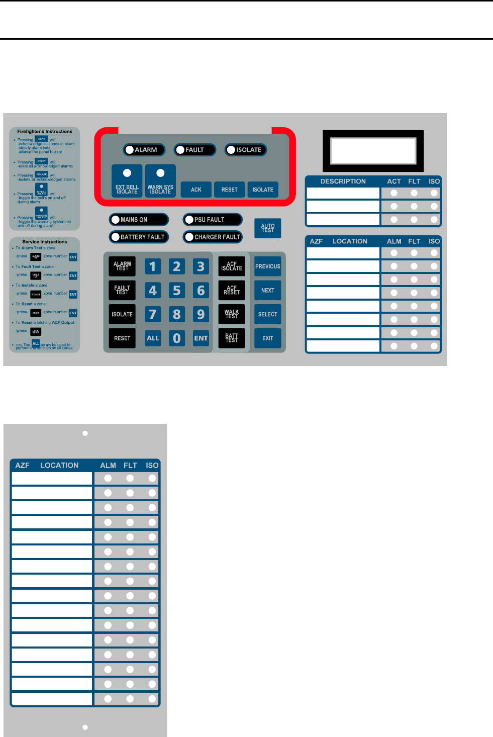
IFS-2600 Installation & Programming Manual Page 53
P/N 10069 ECN08-0066
APPENDIX I
TECHNICAL DRAWINGS
MAIN KEYPAD AND DISPLAY
EXPANSION DISPLAY
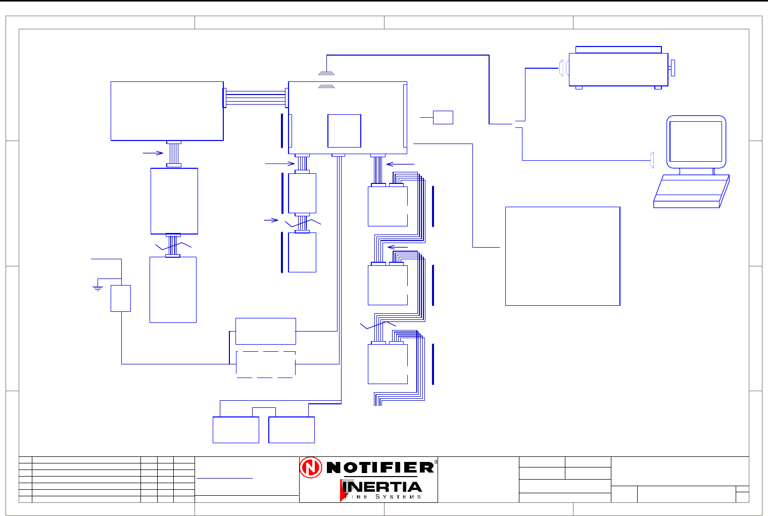
Page 54 IFS-2600 Installation & Programming Manual
P/N 10069 ECN08-0066
Block Connection Diagram
1
1
2
2
3
3
4
4
D D
C C
B B
A A
Rev
Size Drg.
No.
Title
Sheet:
Drawn/
Traced
Engineer
Design
Approved
This Drawing must not be used for Construction
unless signed as approved
7 Columbia Court,
Norwest Business Park
Baulkham Hills NSW 2153
AUSTRALIA
Tel
Fax
Email: support@inertia.com.au A4
No. Revision - revise on CAD. Do not amend by hand Eng. App. Date
Copyright
This document is & shall
remain the property of
Notifier Inertia Fire Systems
Unauthorised use of this
document in any way is
prohibited. Drawing File No.
C
O
61 2 9894 1444
61 2 9899 4156
=DocumentFullPathAndName
Of:
IFS PCB2005
1 1
14/08/03 I.P.
D
L2600-1
IFS2600
BLOCK CONNECTION DIAGRAM
DISP
PCB816
MIMIC PANEL
12V BATTERY 12V BATTERY
+ +
--
MAIN PROCESSOR BOARD MAIN TERMINATION BOARD
SERIAL PRINTER
240V/30V AC
100 VA
TRANSFORMER
2600/DHTX
100 VA
TRANSFORMER
240V
ISOL
S/W
MAINS SUPPLY
240 V AC
IFS PCB2004
RELAY
BOARD
IFS803
RELAY
BOARD
IFS803
RELAY
BOARD
IFS803
ZONE
EXP
PCB804
ZONE
EXP
PCB804
POWER
PCB2006
ZONE
INPUTS
1-8
ZONE
INPUTS
9-16
ZONE
INPUTS
32-40
8 RELAY
OUTPUTS
1-8
8 RELAY
OUTPUTS
9-16
8 RELAY
32-40
MAX 8 PCB803
OUTPUTS
CABLE C3
CABLE C5 CABLE C1
CABLE C3
CABLE C3
4 CORE CABLE
4 CORE CABLE
CABLE C8
MAX 120M
ZONE DISPLAYS 1-8
PANEL
POWER
D/HOLDER
POWER
OPTION
IN
IN
IN OUT
OUT
OUT
OUT
LAPTOP
P/N 130
16 ZONE
DISP
PCB816
IFS 810 MIMIC DRV
IFS 811B IND BRD
IFS 812 DISPLAY BRD
DB-9 FEMALE
(1 FOR EACH 8 ZONES)
OUTPUTS
8 ZONE
LAST DISPLAY CAN BE 8/16
OTHERS MUST BE 16 ZONE
CABLE C9
CABLE C32
B REVISED PART NUMBERS G.W. G.W. 9/3/04
PCB1125
BELL/ACF
3 CORE CABLE
SUPPLY
BOARD
RX, TX, GND
TX, CTS, GND
C Revised Printer Connection IP IP 18/8/05
D Removed Part Numbers IP IP 21/12/05
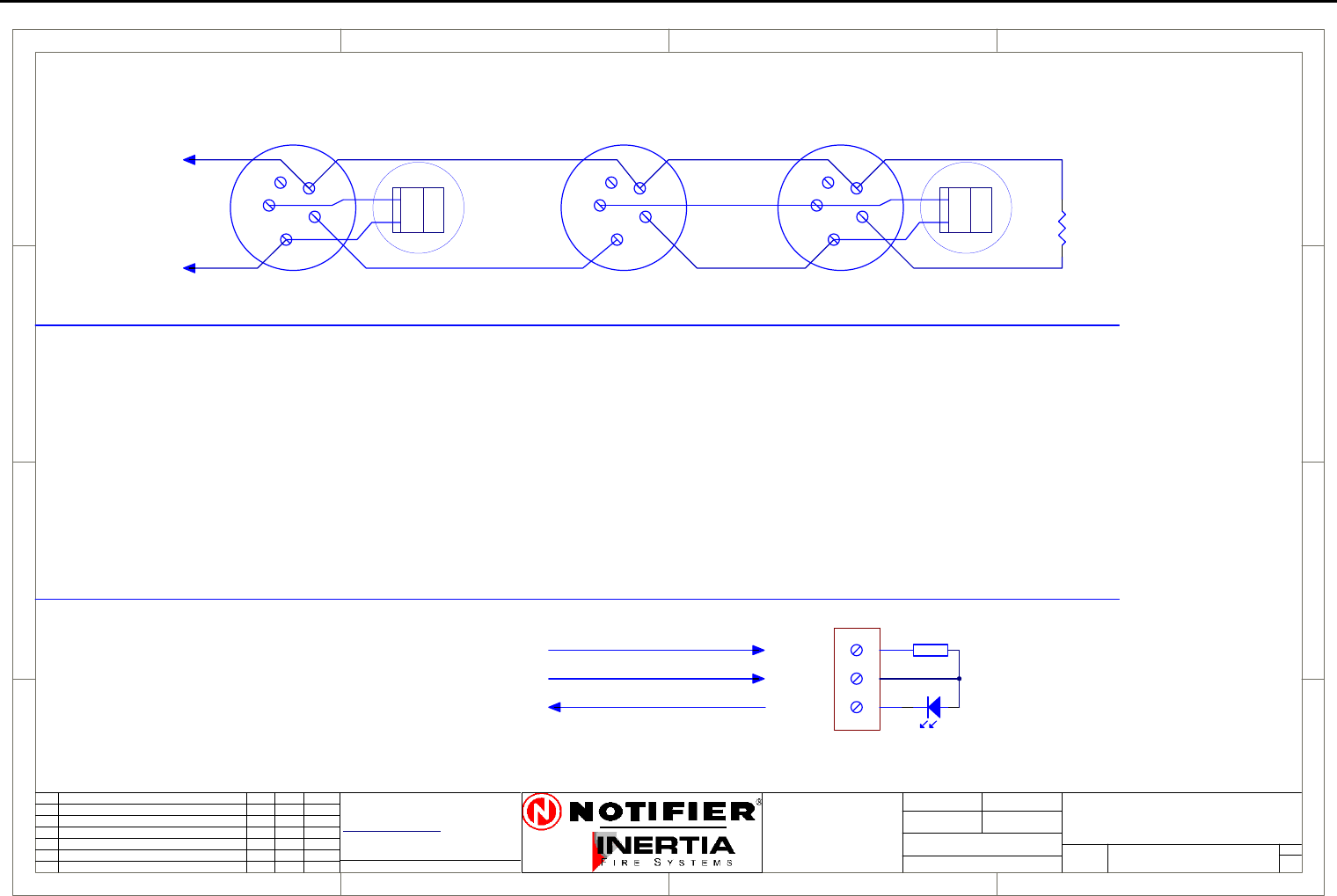
IFS-2600 Installation & Programming Manual Page 55
P/N 10069 ECN08-0066
System Sensor Conventional Detector Connection Diagram
1
1
2
2
3
3
4
4
D D
C C
B B
A A
Rev
Size Drg.
No.
Title
Sheet:
Drawn/
Traced
Engineer
Design
Approved
This Drawing must not be used for Construction
unless signed as approved
7 Columbia Court,
Norwest Business Park
Baulkham Hills NSW 2153
AUSTRALIA
Tel
Fax
Email: support@inertia.com.au A4
No. Revision - revise on CAD. Do not amend by hand Eng. App. Date
Copyright
This document is & shall
remain the property of
Notifier Inertia Fire Systems
Unauthorised use of this
document in any way is
prohibited. Drawing File No.
C
O
61 2 9894 1444
61 2 9899 4156
=DocumentFullPathAndName
Of:
+
-
TO PANEL
BASE B401
DET A DET B
-D
+D
+R
RIP
1
2
3
4
5
1
2
3
4
5
EOL
4K7
+
-
TO PANEL
EOL
4K7
DET B
-D
+D
+R
RIP
1
2
3
4
5
BASE B401R
1
2
3
4
5
BASE B401R
BASE B
1
2
3
4
5
PROBE
SEALED
PROBE
SEALED
PROBE B
BASE A PROBE A
SEALED DETECTOR CONNECTION DIAGRAM
CONVENTIONAL DETECTOR CONNECTION DIAGRAM
+R
+D
-D
470R
+R
+D
-D
Not current limited (3-24 V)
Current limited 10 mA
Common Return
BASE B401
REMOTE INDICATOR
SS-DET A
SYSTEM SENSOR
CONVENTIONAL DETECTOR
CONNECTION DIAGRAM
1 1
I PERRY I PERRY
I PERRY
( NORMAL HEAD NOT CONNECTED )
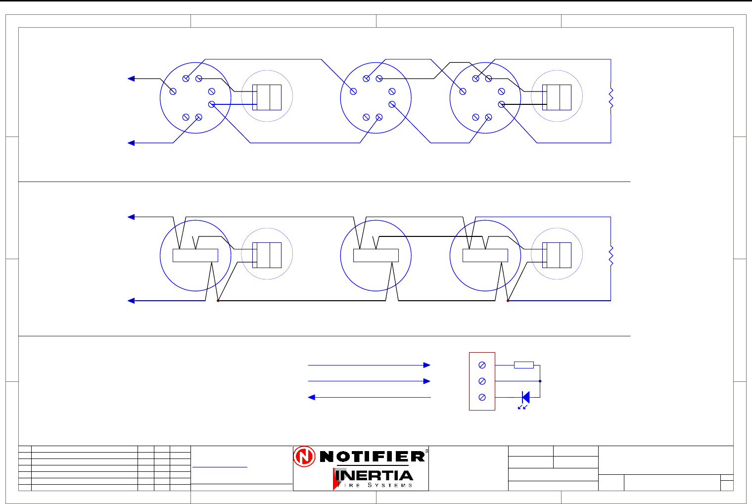
Page 56 IFS-2600 Installation & Programming Manual
P/N 10069 ECN08-0066
Hochiki Conventional Detector Connection Diagram
1
1
2
2
3
3
4
4
D D
C C
B B
A A
Rev
Size Drg.
No.
Title
Sheet:
Drawn/
Traced
Engineer
Design
Approved
This Drawing must not be used for Construction
unless signed as approved
7 Columbia Court,
Norwest Business Park
Baulkham Hills NSW 2153
AUSTRALIA
Tel
Fax
Email: support@inertia.com.au A4
No. Revision - revise on CAD. Do not amend by hand Eng. App. Date
Copyright
This document is & shall
remain the property of
Notifier Inertia Fire Systems
Unauthorised use of this
document in any way is
prohibited. Drawing File No.
C
O
61 2 9894 1444
61 2 9899 4156
=DocumentFullPathAndName
Of:
+
-
TO PANEL
1
23
4
5
67
DET A
-D
+D
+R
RIP
1
23
4
5
67
DET B
-D
+D
+R
RIP
EOL
4K7
1
23
4
5
67
DET C
+
-
TO PANEL
CONNECTION FOR DFG-60BLKJ SEALED DETECTOR
DET A
-D
+D
+R
RIP
-D
+D
+R
RIP
EOL
4K7
L CS
DET B
L CS
DET C
L CS
RED
BLUE
WHITE
CONNECTION FOR STANDARD DETECTORS AND BASES
+R
+D
-D
470R
+R
+D
-D
Not current limited (3-24 V)
Current limited 10 mA
Common Return
REMOTE INDICATOR
HOC-DET A
HOCHIKI
CONVENTIONAL DETECTOR
CONNECTION DIAGRAM
1 1
I PERRY I PERRY
I PERRY
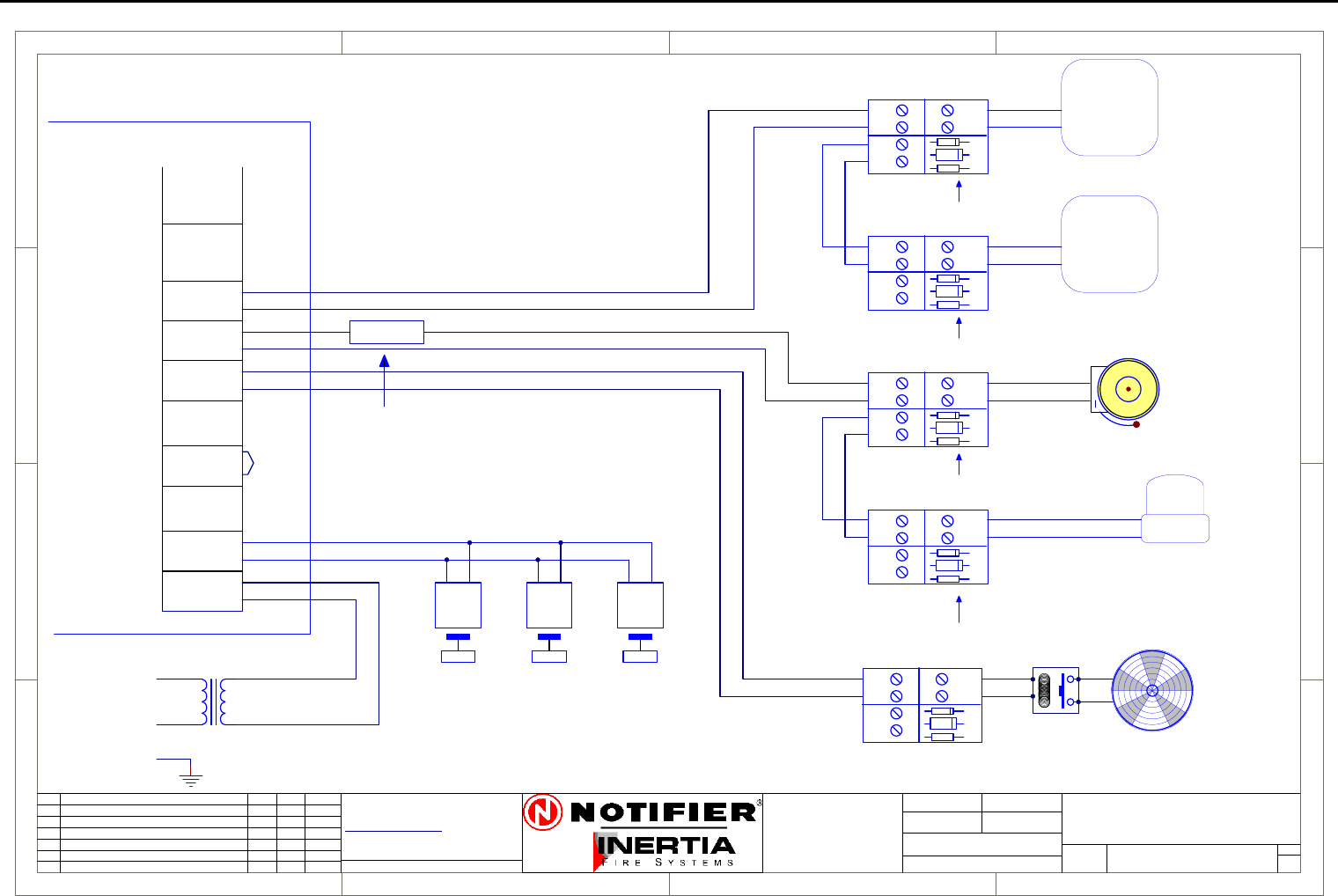
IFS-2600 Installation & Programming Manual Page 57
P/N 10069 ECN08-0066
Ancillary Connection Diagram
1
1
2
2
3
3
4
4
D D
C C
B B
A A
Rev
Size Drg.
No.
Title
Sheet:
Drawn/
Traced
Engineer
Design
Approved
This Drawing must not be used for Construction
unless signed as approved
7 Columbia Court,
Norwest Business Park
Baulkham Hills NSW 2153
AUSTRALIA
Tel
Fax
Email: support@inertia.com.au A4
No. Revision - revise on CAD. Do not amend by hand Eng. App. Date
Copyright
This document is & shall
remain the property of
Notifier Inertia Fire Systems
Unauthorised use of this
document in any way is
prohibited. Drawing File No.
C
O
61 2 9894 1444
61 2 9899 4156
=DocumentFullPathAndName
Of: IFS2600 TYPICAL
GEN2
N/C
COM
N/O
BELL
0V
+24
TP 0V
ACF
0V
+24
HOLD
0V
+24
AUX
MAF ISO
DOOR
DATA
CLK
DOOR
INPUT
IFS2600
ANCILLARY CONNECTION
26-ANC-CON A
WARN
0V
+24
MIMIC
+
-
DOOR HOLDER TRANSFORMER2600/DHTX
240 V AC
HOLD
1.5 OHM 5W
FITTED WHEN
STROBE USED
STROBE
1
2
3
4
2220
SOUNDER
2220
SOUNDER
1
2
3
4
1ST SOUNDER
LAST SOUNDER
PCB1125C
-
+
IN
OUT
LOAD
-
+-
+
D1
R1
REMOVE RESISTOR R1
EXCEPT ON LAST PCB
DOOR HOLDERS
PCB2004
TERMINATION
TRANSFORMER
240V/24V
A
N
E
D2
PCB1125C
-
+
IN
OUT
LOAD
-
+-
+
D1
R1
D2
PCB1125C
-
+
IN
OUT
LOAD
-
+-
+
D1
R1
D2
FAN
+
-
PCB1125C
-
+
IN
OUT
LOAD
-
+-
+
D1
R1 RELAY
D2
24VDC
+
BELL
PCB1125C
-
+
IN
OUT
LOAD
-
+-
+
D1
R1
D2
R1 TO BE FITTED ON
LAST PCB ONLY
R1 TO BE FITTED ON
LAST PCB ONLY
REMOVE RESISTOR R1
EXCEPT ON LAST PCB
1 1
I PERRY
I PERRY
23/8/05
NOTE:
PCB1125 may be omitted if the
ancillary device is high
impedance or contains an inbuilt
reverse protection diode.
In this case a 4K7 EOL must be
fitted to the last device on the
circuit.
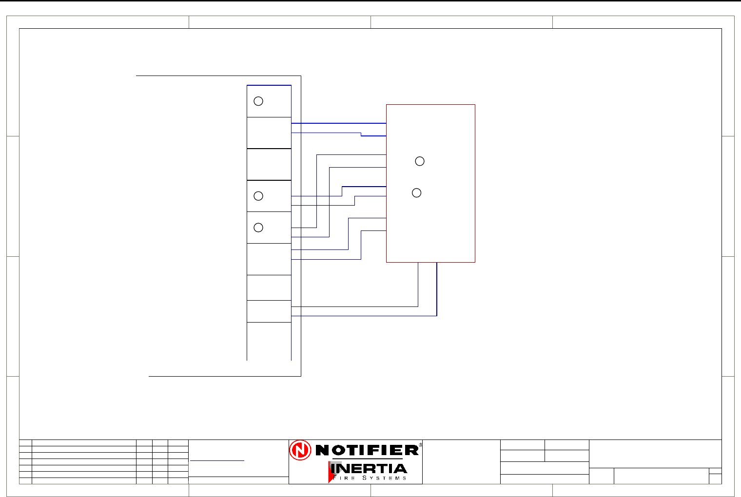
Page 58 IFS-2600 Installation & Programming Manual
P/N 10069 ECN08-0066
ASE Connection Diagram
1
1
2
2
3
3
4
4
D D
C C
B B
A A
Rev
Size Drg.
No.
Title
Sheet:
Drawn/
Traced
Engineer
Design
Approved
This Drawing must not be used for Construction
unless signed as approved
7 Columbia Court,
Norwest Business Park
Baulkham Hills NSW 2153
AUSTRALIA
Tel
Fax
Email: support@inertia.com.au A4
No. Revision - revise on CAD. Do not amend by hand Eng. App. Date
Copyright
This document is & shall
remain the property of
Notifier Inertia Fire Systems
Unauthorised use of this
document in any way is
prohibited. Drawing File No.
C
O
61 2 9894 1444
61 2 9899 4156
=DocumentFullPathAndName
Of: 2600
STANDBY
N/C
COM
N/O
BRIGADE 1
COM
BRIGADE 2
N/C
COM
N/O
FAULT
N/O
N/O
N/C
+24
0V
AUX
N
IFS2600
N/C
N/O
AC-FAIL
N/C
COM
N/C
COM
ISOLATE
COM
N/O
ASE CONNECTION
26-ASE A
1 1
22/8/05 I.P.
ASE
POWER
BRACKET
TYCO #10116
CODE RED #10115
ROMTEK 10117
AC FAIL
BR1
FAULT
ISOLATE
ASE
PCB2004
TERMINATION
N
N
N
N
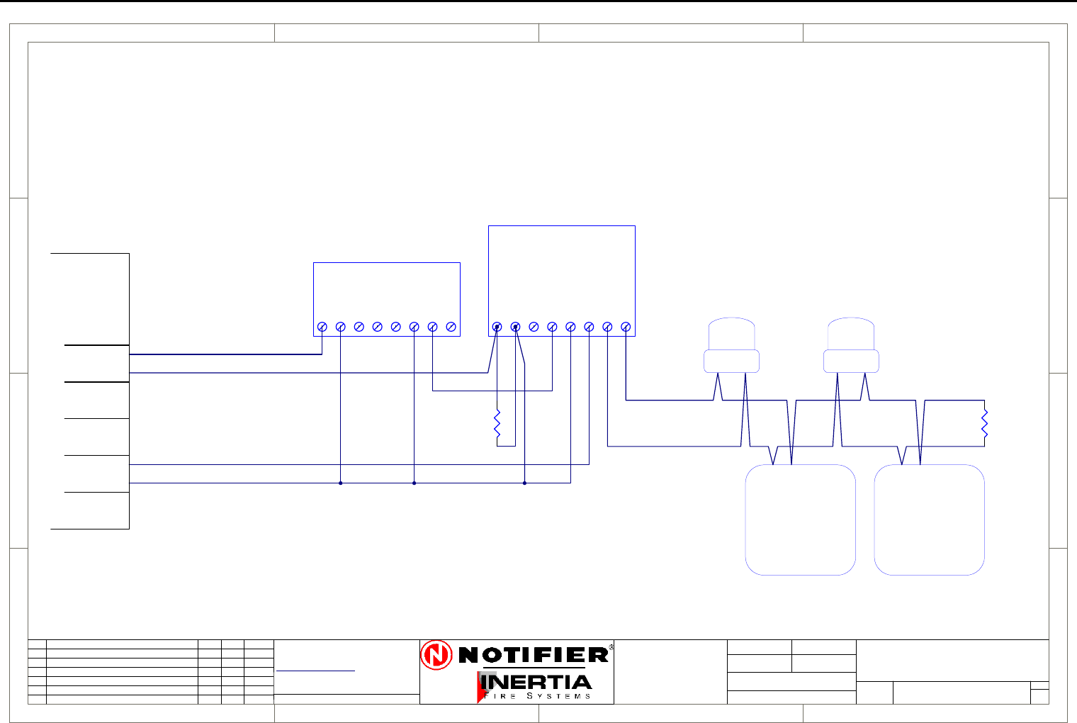
IFS-2600 Installation & Programming Manual Page 59
P/N 10069 ECN08-0066
Auto Changeover Dual Sounder Connection Diagram
1
1
2
2
3
3
4
4
D D
C C
B B
A A
Rev
Size Drg.
No.
Title
Sheet:
Drawn/
Traced
Engineer
Design
Approved
This Drawing must not be used for Construction
unless signed as approved
7 Columbia Court,
Norwest Business Park
Baulkham Hills NSW 2153
AUSTRALIA
Tel
Fax
Email: support@inertia.com.au A4
No. Revision - revise on CAD. Do not amend by hand Eng. App. Date
Copyright
This document is & shall
remain the property of
Notifier Inertia Fire Systems
Unauthorised use of this
document in any way is
prohibited. Drawing File No.
C
O
61 2 9894 1444
61 2 9899 4156
=DocumentFullPathAndName
Of:
A
IFS2600 MONITORED
2600-DUAL
DUAL SOUNDER
23/1/04B ADDED RELAY G.W. G.W.
IFS 993
AL
0V
EVAC
+24
TERM A
TERM B
FAULT COM
FAULT N/O
MONITORED DRIVER BOARD
EOL
1K8
1234
DUAL TONE AS2220
SOUNDER
1234
DUAL TONE AS2220
SOUNDER
ALERT STROBE (RED)
0V 0V+24V+24V
(AMBER) EVAC STROBE
NOTE:
CHANGEOVER FROM ALERT TO EVAC
INSTALL LINK JP1 FOR AUTO
+24V
0V
NO
COM
NC
NO
COM
NC
N/O
BELL
0V
+24
ACF
0V
+24
0V
+24
AUX WARN
0V
+24
WARN SYS EOL
4K7
IFS2600
PCB2004
TERMINATION
1 1
I PERRY
I PERRY
AUTO-SNDR
AUTO CHANGEOVER
23/8/05
IFS958 RELAY BOARD
NOTE:
Maximum capacity is 10 sounders
or 4 strobes
RED REDBLACK BLACK
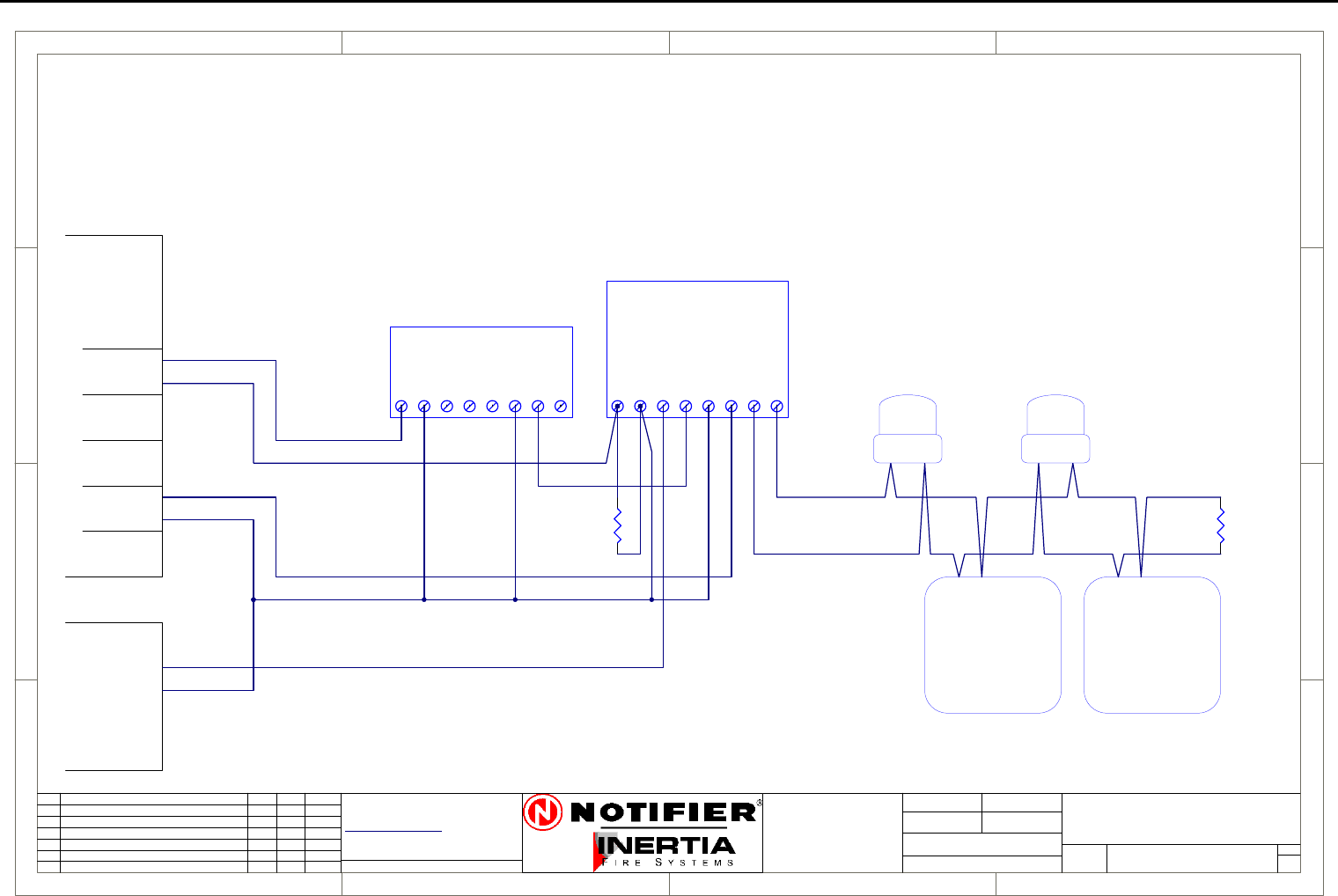
Page 60 IFS-2600 Installation & Programming Manual
P/N 10069 ECN08-0066
Auto Change Over Dual Sounder Connection Diagram
1
1
2
2
3
3
4
4
D D
C C
B B
A A
Rev
Size Drg.
No.
Title
Sheet:
Drawn/
Traced
Engineer
Design
Approved
This Drawing must not be used for Construction
unless signed as approved
7 Columbia Court,
Norwest Business Park
Baulkham Hills NSW 2153
AUSTRALIA
Tel
Fax
Email: support@inertia.com.au A4
No. Revision - revise on CAD. Do not amend by hand Eng. App. Date
Copyright
This document is & shall
remain the property of
Notifier Inertia Fire Systems
Unauthorised use of this
document in any way is
prohibited. Drawing File No.
C
O
61 2 9894 1444
61 2 9899 4156
=DocumentFullPathAndName
Of:
IFS 993
AL
0V
EVAC
+24
TERM A
TERM B
FAULT COM
FAULT N/O
MONITORED DRIVER BOARD
EOL
1K8
1234
SOUNDER
1234
SOUNDER
ALERT STROBE (RED)
0V 0V+24V+24V
(AMBER) EVAC STROBE
NOTE:
REMOVE LINK JP1 FOR MANUAL
CHANGEOVER FROM ALERT TO EVAC
+24V
0V
NO
COM
NC
NO
COM
NC
N/O
BELL
0V
+24
ACF
0V
+24
0V
+24
AUX WARN
0V
+24
WARN SYS EOL
4K7
IFS2600
PCB2004
TERMINATION
NC
COM
NO
IFS803
RELAY
BOARD
ALERT ACTIVATION
EVAC ACTIVATION
A
IFS2600 MONITORED
2600-DUAL
DUAL SOUNDER
1 1
I PERRY
I PERRY
MANUAL-SNDR
MANUAL CHANGEOVER
23/8/05
IFS958 RELAY BOARD
DUAL TONE AS2220 DUAL TONE AS2220
NOTE:
Maximum capacity is 10 sounders
or 4 strobes
RED REDBLACK BLACK
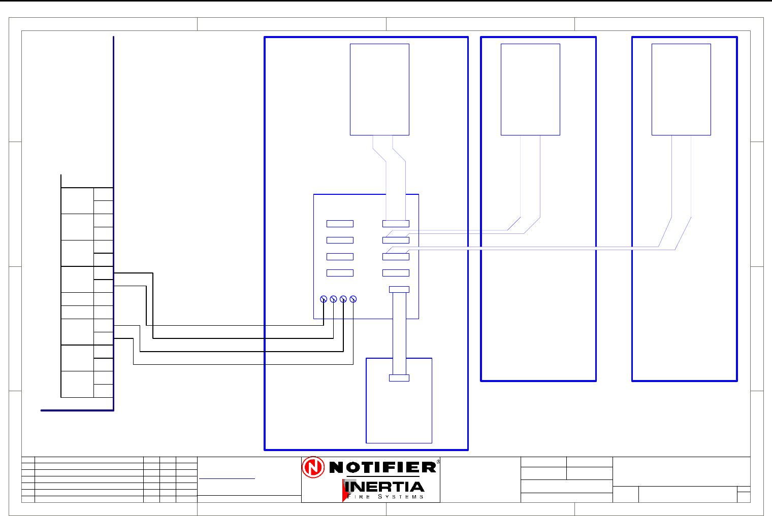
IFS-2600 Installation & Programming Manual Page 61
P/N 10069 ECN08-0066
MIMIC Connection Diagram
1
1
2
2
3
3
4
4
D D
C C
B B
A A
Rev
Size Drg.
No.
Title
Sheet:
Drawn/
Traced
Engineer
Design
Approved
This Drawing must not be used for Construction
unless signed as approved
7 Columbia Court,
Norwest Business Park
Baulkham Hills NSW 2153
AUSTRALIA
Tel
Fax
Email: support@inertia.com.au A4
No. Revision - revise on CAD. Do not amend by hand Eng. App. Date
Copyright
This document is & shall
remain the property of
Notifier Inertia Fire Systems
Unauthorised use of this
document in any way is
prohibited. Drawing File No.
C
O
61 2 9894 1444
61 2 9899 4156
=DocumentFullPathAndName
Of:
A
1 1
2/2/04 G.W.
ZONES 1-8 ZONES 9-16
PCB810
PCB811
PCB812 PCB812 PCB812
ZONES 17-24
SERIAL BUS
MIM/26/KIT
MIM/EXT/26 MIM/EXT/26
MIM/26/KIT
1-8
9-16
17-24
25-32
33-40
41-48
49-56
57-64
Max 120 Meters
26-MIM-CON
N/O
BELL
0V
+24
TP 0V
ACF
0V
+24
HOLD
0V
+24
AUX
MAF ISO
DOOR
DATA
CLK
DOOR
INPUT WARN
0V
+24
MIMIC
+
-
HOLD
DATA
CLK
+24
0V
FOR 8 ZONES
FOR EXTRA ZONES
STANDARD SIZES 8, 24 AND 64 ZONES
4/0.75mm cable
POWER AND SIGNAL RETURN
FITTED WITH
IFS2600 MIMIC
DRIVER
IFS2600
TERMINATION
BOARD
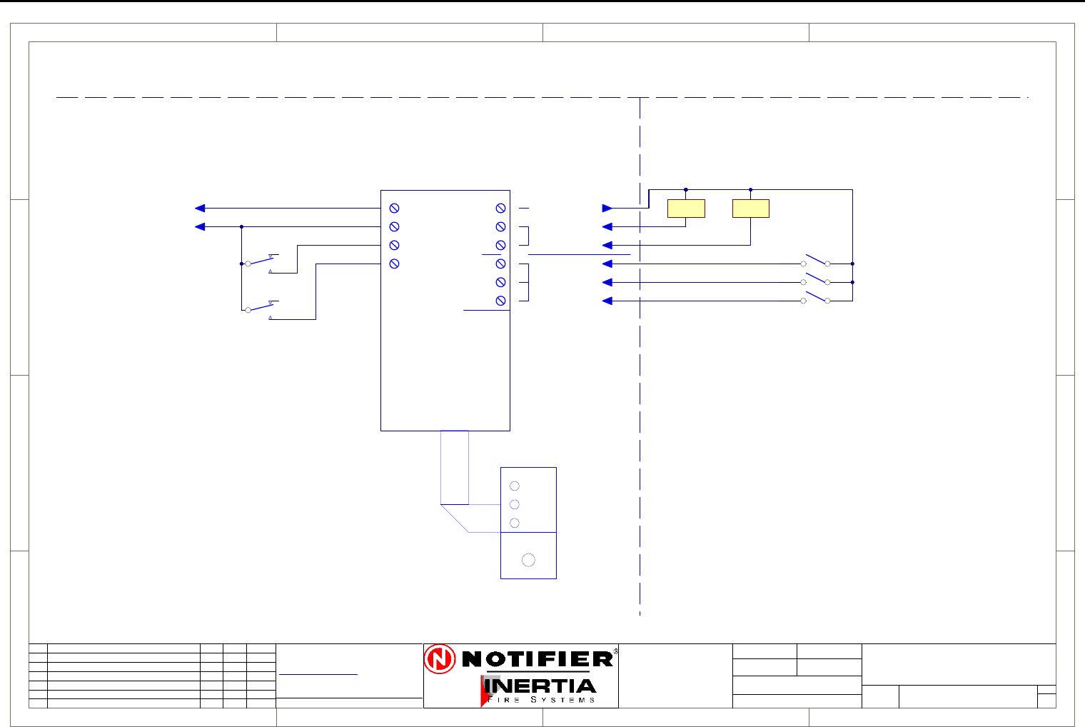
Page 62 IFS-2600 Installation & Programming Manual
P/N 10069 ECN08-0066
Single Fan Connection Diagram
1
1
2
2
3
3
4
4
D D
C C
B B
A A
Rev
Size Drg.
No.
Title
Sheet:
Drawn/
Traced
Engineer
Design
Approved
This Drawing must not be used for Construction
unless signed as approved
7 Columbia Court,
Norwest Business Park
Baulkham Hills NSW 2153
AUSTRALIA
Tel
Fax
Email: support@inertia.com.au A4
No. Revision - revise on CAD. Do not amend by hand Eng. App. Date
Copyright
This document is & shall
remain the property of
Notifier Inertia Fire Systems
Unauthorised use of this
document in any way is
prohibited. Drawing File No.
C
O
61 2 9894 1444
61 2 9899 4156
=DocumentFullPathAndName
Of:
OFF
AUTO
ON
RUN
STOP
FAULT
+24
0V
START1
STOP1
CONTROL
PCB1128
+24
START
STOP
RUN
STOP
FLT
INDICATION
FAN 1
COMMON +VE
FRONT PANEL CONTROL
FIRE PANEL FIELD WIRING
START STOP
* NOTE
THE MECHANICAL SERVICES BOARD
MUST BE CONFIGURED TO HAVE
THE STOP RELAY TO TAKE
PRECEDENCE OVER THE START RELAY
19/8/05 I PERRY
A
SINGLE FAN (GENERAL)
2600-DUAL FAN
FAN TERMINATION BOARD
AUX +24
AUX 0V
AUX POWER
CONTROL
FAN RUNNING
FAN STOPPED AND POWER AVAILABLE
FAN FAULT OR NO POWER AVAILABLE
FAN START RELAY
FAN STOP RELAY
RIBBON CABLE
1 1
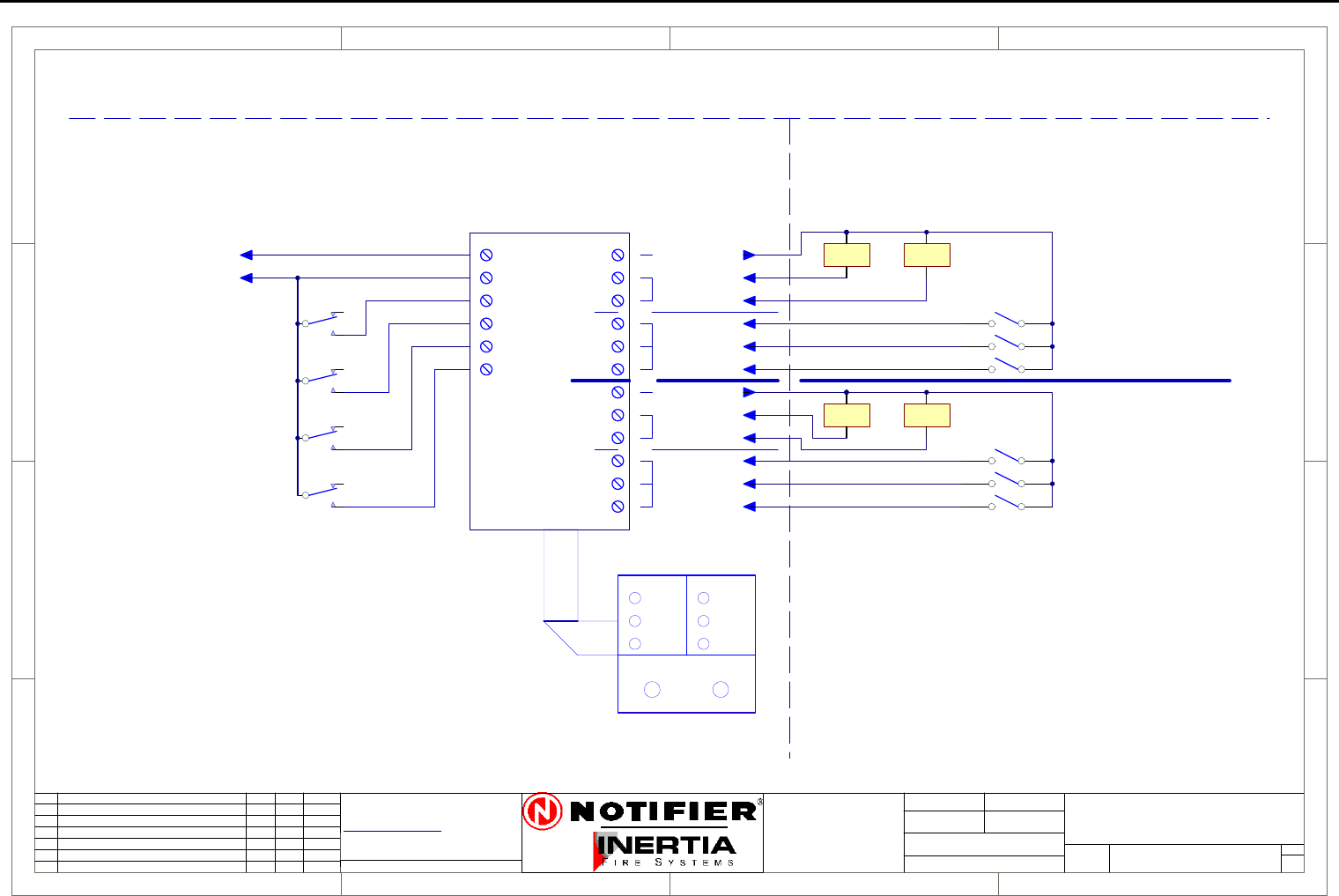
IFS-2600 Installation & Programming Manual Page 63
P/N 10069 ECN08-0066
Dual Fan Connection Diagram
1
1
2
2
3
3
4
4
D D
C C
B B
A A
Rev
Size Drg.
No.
Title
Sheet:
Drawn/
Traced
Engineer
Design
Approved
This Drawing must not be used for Construction
unless signed as approved
7 Columbia Court,
Norwest Business Park
Baulkham Hills NSW 2153
AUSTRALIA
Tel
Fax
Email: support@inertia.com.au A4
No. Revision - revise on CAD. Do not amend by hand Eng. App. Date
Copyright
This document is & shall
remain the property of
Notifier Inertia Fire Systems
Unauthorised use of this
document in any way is
prohibited. Drawing File No.
C
O
61 2 9894 1444
61 2 9899 4156
=DocumentFullPathAndName
Of:
OFF
AUTO
ON
RUN
STOP
FAULT
+24
0V
START1
START2
STOP1
STOP2
CONTROL
PCB1102
+24
START
+24
START
STOP
RUN
STOP
FLT
STOP
RUN
STOP
FLT
INDICATION
FAN 1
FAN 1
COMMON +VE
FAN 2
FAN 2
FRONT PANEL CONTROL
CONTROL
INDICATION
COMMON +VE
RUN
STOP
FAULT
FIRE PANEL FIELD WIRING
START STOP
* NOTE
THE MECHANICAL SERVICES BOARD
MUST BE CONFIGURED TO HAVE
THE STOP RELAY TO TAKE
PRECEDENCE OVER THE START RELAY
19/8/05 I PERRY
A
DUAL FAN (GENERAL)
2600-DUAL FAN
FAN TERMINATION BOARD
AUX +24
AUX 0V
AUX POWER
CONTROL
LINK SW1 A & B TO SW2 A, B
REMOVE SW2
FAN RUNNING
FAN STOPPED AND POWER AVAILABLE
FAN FAULT OR NO POWER AVAILABLE
FAN RUNNING
FAN STOPPED AND POWER AVAILABLE
FAN FAULT OR NO POWER AVAILABLE
OFF
AUTO
ON
FOR SINGLE CONTROL
*NOTE
FAN 1 START RELAY
FAN 2 START RELAY
FAN 1 STOP RELAY
FAN 2 STOP RELAY
RIBBON CABLE
1 1
START STOP
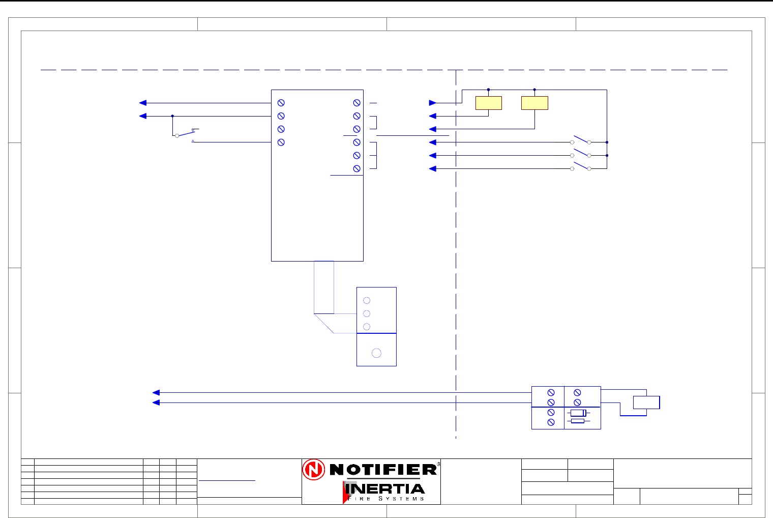
Page 64 IFS-2600 Installation & Programming Manual
P/N 10069 ECN08-0066
Exhaust Fan Connection Diagram
1
1
2
2
3
3
4
4
D D
C C
B B
A A
Rev
Size Drg.
No.
Title
Sheet:
Drawn/
Traced
Engineer
Design
Approved
This Drawing must not be used for Construction
unless signed as approved
7 Columbia Court,
Norwest Business Park
Baulkham Hills NSW 2153
AUSTRALIA
Tel
Fax
Email: support@inertia.com.au A4
No. Revision - revise on CAD. Do not amend by hand Eng. App. Date
Copyright
This document is & shall
remain the property of
Notifier Inertia Fire Systems
Unauthorised use of this
document in any way is
prohibited. Drawing File No.
C
O
61 2 9894 1444
61 2 9899 4156
=DocumentFullPathAndName
Of:
OFF
AUTO
ON
RUN
STOP
FAULT
+24
0V
START1
STOP1
CONTROL
PCB1128
+24
START
STOP
RUN
STOP
FLT
INDICATION
FAN 1
COMMON +VE
FRONT PANEL CONTROL
FIRE PANEL FIELD WIRING
START STOP
* NOTE
THE MECHANICAL SERVICES BOARD
MUST BE CONFIGURED TO HAVE
THE STOP RELAY TO TAKE
PRECEDENCE OVER THE START RELAY
19/8/05 I PERRY
A
EXHAUST FAN (TYPICAL)
2600-EXH
FAN TERMINATION BOARD
AUX +24
AUX 0V
AUX POWER
CONTROL
FAN RUNNING
FAN STOPPED AND POWER AVAILABLE
FAN FAULT OR NO POWER AVAILABLE
RIBBON CABLE
1 1
+24
0v
FIRE TRIP
ACF
PCB1125
-
+
IN
OUT
LOAD
-
+-
+
D1
R1
FROM FIP
RELAY
* NOTE
EITHER THE MAPPING ABOVE MAY
BE USED TO STOP THE EXHAUST FAN
OR THE GENERAL ACF TRIP BELOW,
BUT NOT BOTH.
USE OF THE FIRE TRIP RELAY BELOW
REQUIRES THAT THE MSSB
STOPS THE FAN.
FAN STOP RELAY
(MAPPED TO ACF FOR
GENERAL OR ZONED)
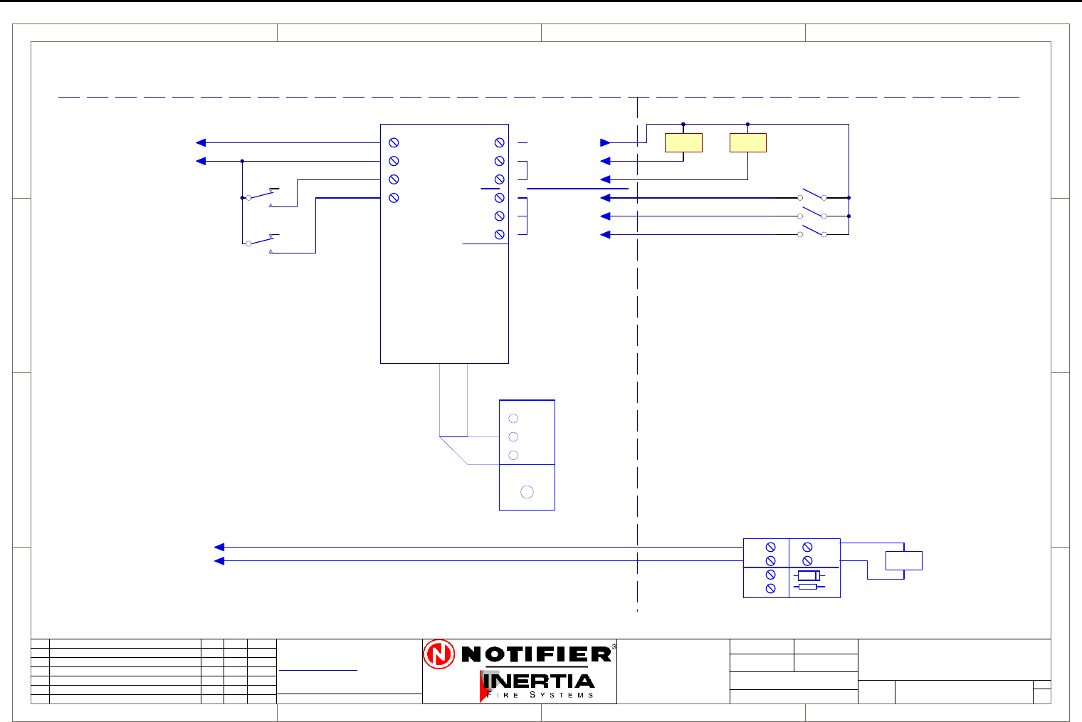
IFS-2600 Installation & Programming Manual Page 65
P/N 10069 ECN08-0066
Supply Fan Connection Diagram
1
1
2
2
3
3
4
4
D D
C C
B B
A A
Rev
Size Drg.
No.
Title
Sheet:
Drawn/
Traced
Engineer
Design
Approved
This Drawing must not be used for Construction
unless signed as approved
7 Columbia Court,
Norwest Business Park
Baulkham Hills NSW 2153
AUSTRALIA
Tel
Fax
Email: support@inertia.com.au A4
No. Revision - revise on CAD. Do not amend by hand Eng. App. Date
Copyright
This document is & shall
remain the property of
Notifier Inertia Fire Systems
Unauthorised use of this
document in any way is
prohibited. Drawing File No.
C
O
61 2 9894 1444
61 2 9899 4156
=DocumentFullPathAndName
Of:
OFF
AUTO
ON
RUN
STOP
FAULT
+24
0V
START1
STOP1
CONTROL
PCB1128
+24
START
STOP
RUN
STOP
FLT
INDICATION
FAN 1
COMMON +VE
FRONT PANEL CONTROL
FIRE PANEL FIELD WIRING
START STOP
* NOTE
THE MECHANICAL SERVICES BOARD
MUST BE CONFIGURED TO HAVE
THE STOP RELAY TO TAKE
PRECEDENCE OVER THE START RELAY
19/8/05 I PERRY
A
SUPPLY AIR FAN (TYPICAL)
2600-SAF
FAN TERMINATION BOARD
AUX +24
AUX 0V
AUX POWER
CONTROL
FAN RUNNING
FAN STOPPED AND POWER AVAILABLE
FAN FAULT OR NO POWER AVAILABLE
FAN START RELAY
RIBBON CABLE
1 1
(MAPPED TO ACF FOR
GENERAL OR ZONED)
+24
0v
FIRE TRIP
ACF
PCB1125
-
+
IN
OUT
LOAD
-
+-
+
D1
R1
FROM FIP
RELAY
* NOTE
EITHER THE MAPPING ABOVE MAY
BE USED TO START THE SAF
OR THE GENERAL ACF TRIP BELOW,
BUT NOT BOTH.
USE OF THE FIRE TRIP RELAY BELOW
REQUIRES THAT THE MSSB
STARTS THE FAN.
FAN STOP RELAY
(MAPPED TO AIR INTAKE
SMOKE DETECTOR)
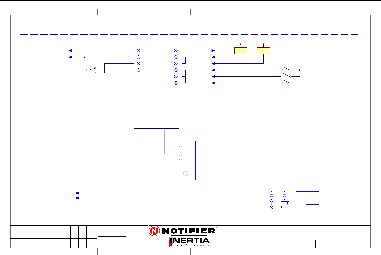
Page 66 IFS-2600 Installation & Programming Manual
P/N 10069 ECN08-0066
Smoke Spill Fan Connection Diagram
1
1
2
2
3
3
4
4
D D
C C
B B
A A
Rev
Size Drg.
No.
Title
Sheet:
Drawn/
Traced
Engineer
Design
Approved
This Drawing must not be used for Construction
unless signed as approved
7 Columbia Court,
Norwest Business Park
Baulkham Hills NSW 2153
AUSTRALIA
Tel
Fax
Email: support@inertia.com.au A4
No. Revision - revise on CAD. Do not amend by hand Eng. App. Date
Copyright
This document is & shall
remain the property of
Notifier Inertia Fire Systems
Unauthorised use of this
document in any way is
prohibited. Drawing File No.
C
O
61 2 9894 1444
61 2 9899 4156
=DocumentFullPathAndName
Of:
OFF
AUTO
ON
RUN
STOP
FAULT
+24
0V
START1
STOP1
CONTROL
PCB1128
+24
START
STOP
RUN
STOP
FLT
INDICATION
FAN 1
COMMON +VE
FRONT PANEL CONTROL
FIRE PANEL FIELD WIRING
START STOP
* NOTE
THE MECHANICAL SERVICES BOARD
MUST BE CONFIGURED TO HAVE
THE STOP RELAY TO TAKE
PRECEDENCE OVER THE START RELAY
19/8/05 I PERRY
A
SMOKE SPILL FAN (TYPICAL)
2600-SSF
FAN TERMINATION BOARD
AUX +24
AUX 0V
AUX POWER
CONTROL
FAN RUNNING
FAN STOPPED AND POWER AVAILABLE
FAN FAULT OR NO POWER AVAILABLE
FAN START RELAY
RIBBON CABLE
1 1
(MAPPED TO ACF FOR
GENERAL OR ZONED)
+24
0v
FIRE TRIP
ACF
PCB1125
-
+
IN
OUT
LOAD
-
+-
+
D1
R1
FROM FIP
RELAY
* NOTE
EITHER THE MAPPING ABOVE MAY
BE USED TO START THE SSF
OR THE GENERAL ACF TRIP BELOW,
BUT NOT BOTH.
USE OF THE FIRE TRIP RELAY BELOW
REQUIRES THAT THE MSSB
STARTS THE FAN.
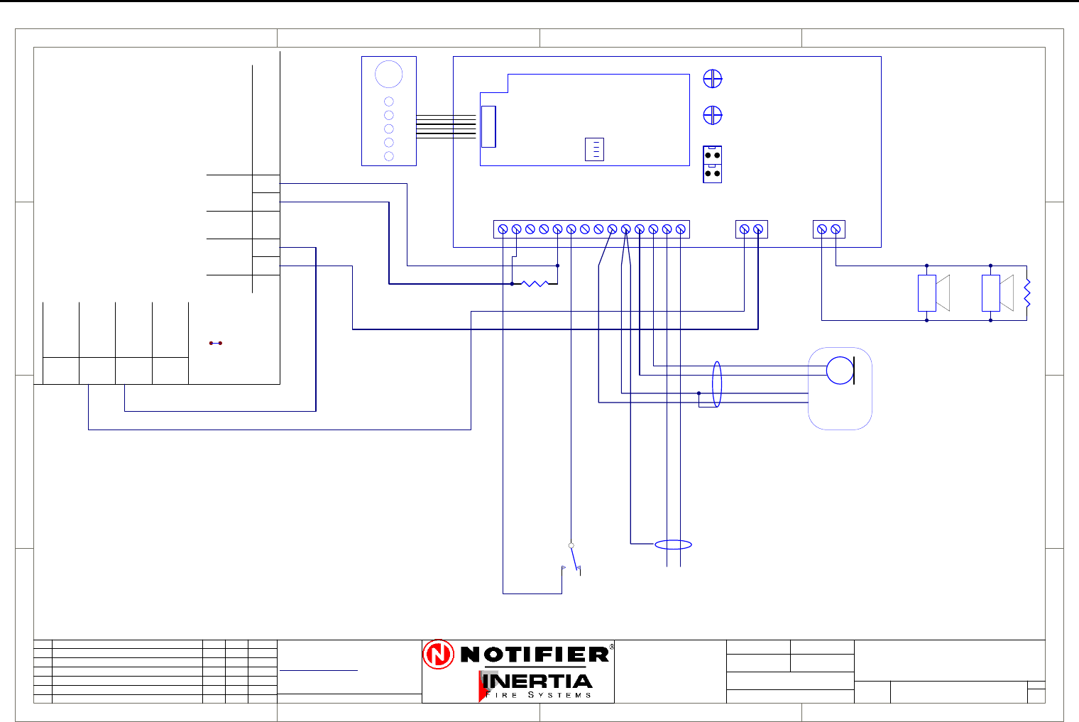
IFS-2600 Installation & Programming Manual Page 67
P/N 10069 ECN08-0066
10W EVAC Connection Diagram
1
1
2
2
3
3
4
4
D D
C C
B B
A A
Rev
Size Drg.
No.
Title
Sheet:
Drawn/
Traced
Engineer
Design
Approved
This Drawing must not be used for Construction
unless signed as approved
7 Columbia Court,
Norwest Business Park
Baulkham Hills NSW 2153
AUSTRALIA
Tel
Fax
Email: support@inertia.com.au A4
No. Revision - revise on CAD. Do not amend by hand Eng. App. Date
Copyright
This document is & shall
remain the property of
Notifier Inertia Fire Systems
Unauthorised use of this
document in any way is
prohibited. Drawing File No.
C
O
61 2 9894 1444
61 2 9899 4156
=DocumentFullPathAndName
Of:
+24
WARN
0V
REMOTE
REMOTE
OUTPUT
INPUT
+24V
0V
+24V
0V
EXTERNAL
POWER
MONITORJP1
AC INPUT
BATT
LINK JP1
+24
0V
AUX
+24V
0V
+24V COM
FAULT
ALERT OUT
EVAC OUT
ALARM
BGM EN
EVAC IN
ALERT IN
PTT
0V
PA+
PA -
BGM +
BGM -
VOLPA
+24
GND
COM
LINE +
10W EVAC
PCB 908
SHIELDED
BGM INPUT
1V P-P
BGM ENABLE
FRONT
PANEL
EVAC
CONTROL
EOL
47K 5%
SPEAKERS WITH
100V LINE TRANSFORMERS
AND ISOLATION CAPACITORS
( ENABLED ON
CLOSURE )
SHIELDED
WHITE
RED
BLACK/SHIELD
BLUE MICROPHONE
WITH PTT
4K7 5%
IFS-2600
10 WATT
CONNECTION DIAGRAM
1 1
I PERRYI PERRY
I PERRY
2600-10W A
IFS2600
TERMINATION
BOARD
NOTE:
TO SLAVE TWO AMPLIFIERS
TOGETHER, REMOVE THE IFS903
BOARD FROM THE SLAVE
AMPLIFIER AND CONNECT JP1
ON THE MASTER TO JP2 ON THE
SLAVE.
THE MICROPHONE AND BGM
MUST ONLY BE CONNECTED TO
THE MASTER AMPLIFIER.
CONNECT PIN 4, P12 ON MASTER
TO PIN4 P12 ON SLAVE.
JP2JP1
SOUND
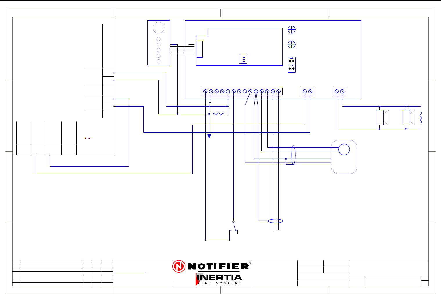
Page 68 IFS-2600 Installation & Programming Manual
P/N 10069 ECN08-0066
10W EVAC Slave Connection Diagram
1
1
2
2
3
3
4
4
D D
C C
B B
A A
Rev
Size Drg.
No.
Title
Sheet:
Drawn/
Traced
Engineer
Design
Approved
This Drawing must not be used for Construction
unless signed as approved
7 Columbia Court,
Norwest Business Park
Baulkham Hills NSW 2153
AUSTRALIA
Tel
Fax
Email: support@inertia.com.au A4
No. Revision - revise on CAD. Do not amend by hand Eng. App. Date
Copyright
This document is & shall
remain the property of
Notifier Inertia Fire Systems
Unauthorised use of this
document in any way is
prohibited. Drawing File No.
C
O
61 2 9894 1444
61 2 9899 4156
=DocumentFullPathAndName
Of:
+24
WARN
0V
REMOTE
REMOTE
OUTPUT
INPUT
+24V
0V
+24V
0V
EXTERNAL
POWER
MONITORJP1
AC INPUT
BATT
LINK JP1
+24
0V
AUX
+24V
0V
+24V COM
FAULT
ALERT OUT
EVAC OUT
ALARM
BGM EN
EVAC IN
ALERT IN
PTT
0V
PA+
PA -
BGM +
BGM -
VOLPA
+24
GND
COM
LINE +
10W EVAC
PCB 908
SHIELDED
BGM INPUT
1V P-P
BGM ENABLE
FRONT
PANEL
EVAC
CONTROL
EOL
47K 5%
SPEAKERS WITH
100V LINE TRANSFORMERS
AND ISOLATION CAPACITORS
( ENABLED ON
CLOSURE )
SHIELDED
WHITE
RED
BLACK/SHIELD
BLUE MICROPHONE
WITH PTT
4K7 5%
IFS-2600
10 WATT SLAVE
CONNECTION DIAGRAM
1 1
I PERRYI PERRY
I PERRY
2600-10W SLAVE A
IFS2600
TERMINATION
BOARD
JP2JP1
SOUND
CONNECT TO
FAULT OUT
FROM SLAVE
NOTE:
TO SLAVE TWO AMPLIFIERS
TOGETHER, REMOVE THE IFS903
BOARD FROM THE SLAVE
AMPLIFIER AND CONNECT JP1
ON THE MASTER TO JP2 ON THE
SLAVE.
THE MICROPHONE AND BGM
MUST ONLY BE CONNECTED TO
THE MASTER AMPLIFIER.
CONNECT FAULT OUTPUTS
TOGETHER AND MOVE THE
LAST WRE ON I/O PCB TO THE
FAULT TERMINAL ON THE
MASTER AMPLIFIER.
CONNECT PIN 4, P12 ON MASTER
TO PIN4 P12 ON SLAVE.
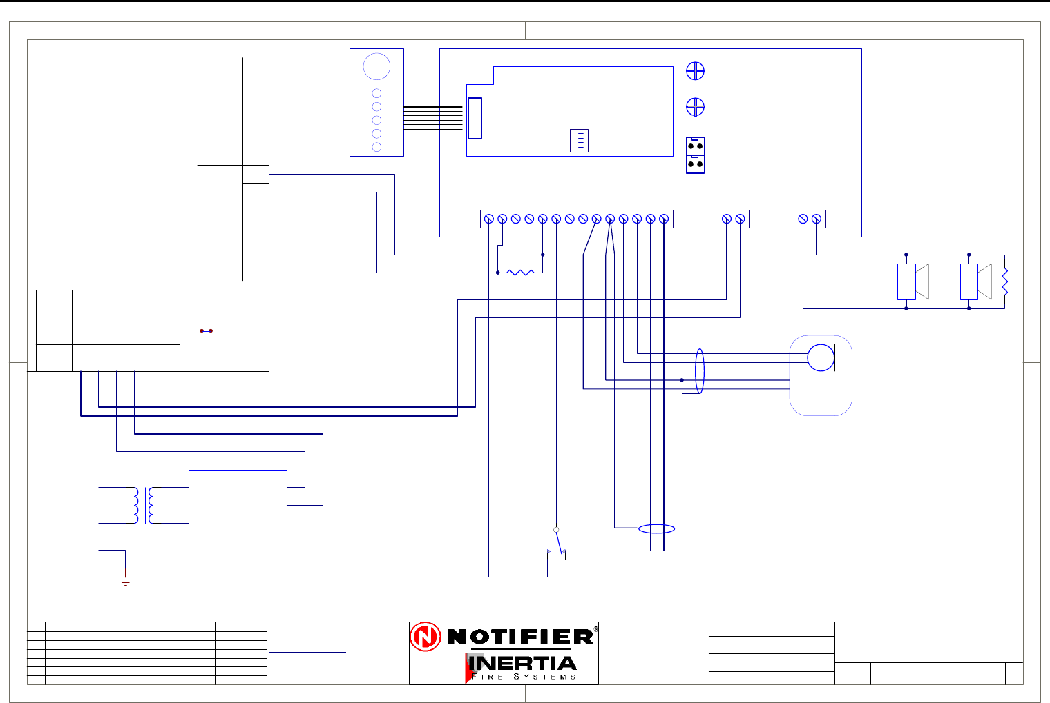
IFS-2600 Installation & Programming Manual Page 69
P/N 10069 ECN08-0066
30W EVAC Connection Diagram
1
1
2
2
3
3
4
4
D D
C C
B B
A A
Rev
Size Drg.
No.
Title
Sheet:
Drawn/
Traced
Engineer
Design
Approved
This Drawing must not be used for Construction
unless signed as approved
7 Columbia Court,
Norwest Business Park
Baulkham Hills NSW 2153
AUSTRALIA
Tel
Fax
Email: support@inertia.com.au A4
No. Revision - revise on CAD. Do not amend by hand Eng. App. Date
Copyright
This document is & shall
remain the property of
Notifier Inertia Fire Systems
Unauthorised use of this
document in any way is
prohibited. Drawing File No.
C
O
61 2 9894 1444
61 2 9899 4156
=DocumentFullPathAndName
Of:
+24
WARN
0V
REMOTE
REMOTE
OUTPUT
INPUT
+24V
0V
+24V
0V
EXTERNAL
POWER
MONITORJP1
AC INPUT
BATT
LINK JP1
+24
0V
AUX
+24V
0V
+24V COM
FAULT
ALERT OUT
EVAC OUT
ALARM
BGM EN
EVAC IN
ALERT IN
PTT
0V
PA+
PA -
BGM +
BGM -
VOLPA
+24
GND
COM
LINE +
30W EVAC
PCB 908
SHIELDED
BGM INPUT
1V P-P
FRONT
PANEL
EVAC
CONTROL
EOL
47K 5%
SPEAKERS WITH
100V LINE TRANSFORMERS
AND ISOLATION CAPACITORS
SHIELDED
WHITE
RED
BLACK/SHIELD
BLUE MICROPHONE
WITH PTT
4K7 5%
IFS-2600
30 WATT
CONNECTION DIAGRAM
1 1
I PERRY25/8/05
I PERRY
2600-30W A
TRANSFORMER
240V/20V
A
N
E
IFS1100
POWER SUPPLY
+24V
0V
AC1
AC2
IFS2600
TERMINATION
BOARD
NOTE:
TO SLAVE TWO AMPLIFIERS
TOGETHER, REMOVE THE IFS903
BOARD FROM THE SLAVE
AMPLIFIER AND CONNECT JP1
ON THE MASTER TO JP2 ON THE
SLAVE.
THE MICROPHONE AND BGM
MUST ONLY BE CONNECTED TO
THE MASTER AMPLIFIER.
CONNECT PIN 4, P12 ON MASTER
TO PIN4 P12 ON SLAVE.
JP2JP1
SOUND
BGM ENABLE
( ENABLED ON
CLOSURE )
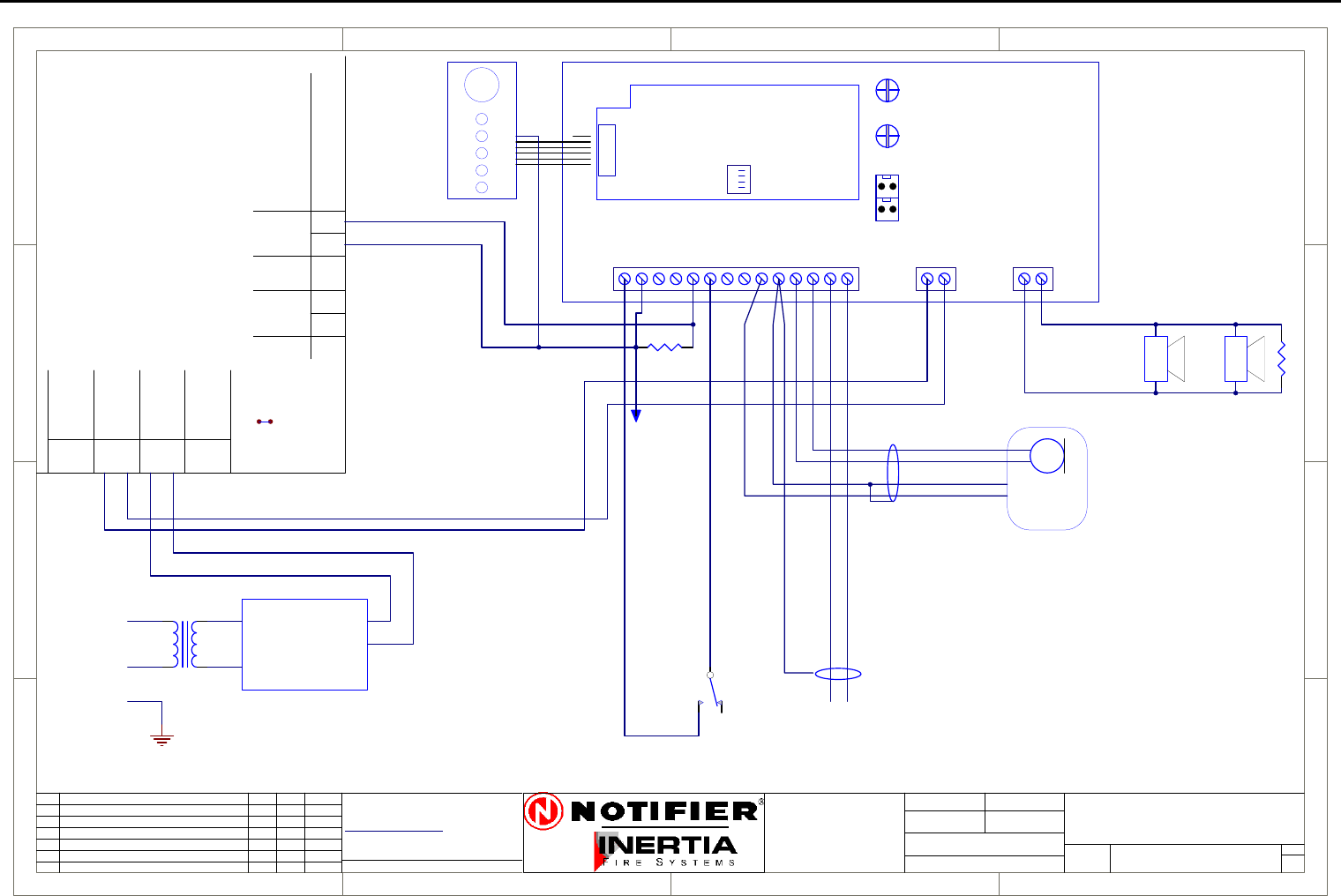
Page 70 IFS-2600 Installation & Programming Manual
P/N 10069 ECN08-0066
30W EVAC Slave Connection Diagram
1
1
2
2
3
3
4
4
D D
C C
B B
A A
Rev
Size Drg.
No.
Title
Sheet:
Drawn/
Traced
Engineer
Design
Approved
This Drawing must not be used for Construction
unless signed as approved
7 Columbia Court,
Norwest Business Park
Baulkham Hills NSW 2153
AUSTRALIA
Tel
Fax
Email: support@inertia.com.au A4
No. Revision - revise on CAD. Do not amend by hand Eng. App. Date
Copyright
This document is & shall
remain the property of
Notifier Inertia Fire Systems
Unauthorised use of this
document in any way is
prohibited. Drawing File No.
C
O
61 2 9894 1444
61 2 9899 4156
=DocumentFullPathAndName
Of:
+24
WARN
0V
REMOTE
REMOTE
OUTPUT
INPUT
+24V
0V
+24V
0V
EXTERNAL
POWER
MONITORJP1
AC INPUT
BATT
LINK JP1
+24
0V
AUX
+24V
0V
+24V COM
FAULT
ALERT OUT
EVAC OUT
ALARM
BGM EN
EVAC IN
ALERT IN
PTT
0V
PA+
PA -
BGM +
BGM -
VOLPA
+24
GND
COM
LINE +
30W EVAC
PCB 908
SHIELDED
BGM INPUT
1V P-P
FRONT
PANEL
EVAC
CONTROL
EOL
47K 5%
SPEAKERS WITH
100V LINE TRANSFORMERS
AND ISOLATION CAPACITORS
SHIELDED
WHITE
RED
BLACK/SHIELD
BLUE MICROPHONE
WITH PTT
4K7 5%
IFS-2600
30 WATT SLAVE
CONNECTION DIAGRAM
1 1
I PERRY25/8/05
I PERRY
2600-30W-SLAVE A
TRANSFORMER
240V/20V
A
N
E
IFS1100
POWER SUPPLY
+24V
0V
AC1
AC2
IFS2600
TERMINATION
BOARD
JP2JP1
SOUND
BGM ENABLE
( ENABLED ON
CLOSURE )
NOTE:
TO SLAVE TWO AMPLIFIERS
TOGETHER, REMOVE THE IFS903
BOARD FROM THE SLAVE
AMPLIFIER AND CONNECT JP1
ON THE MASTER TO JP2 ON THE
SLAVE.
THE MICROPHONE AND BGM
MUST ONLY BE CONNECTED TO
THE MASTER AMPLIFIER.
CONNECT FAULT OUTPUTS
TOGETHER AND MOVE THE
LAST WRE ON I/O PCB TO THE
FAULT TERMINAL ON THE
MASTER AMPLIFIER.
CONNECT PIN 4, P12 ON MASTER
TO PIN4 P12 ON SLAVE.
CONNECT TO
FAULT OUT
FROM SLAVE
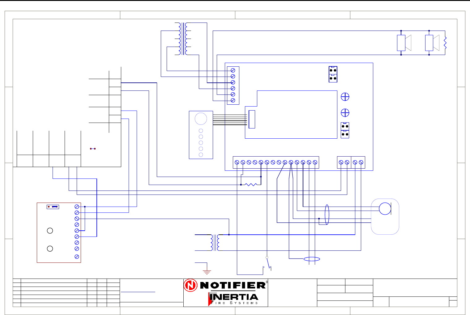
IFS-2600 Installation & Programming Manual Page 71
P/N 10069 ECN08-0066
50W EVAC Connection Diagram
1
1
2
2
3
3
4
4
D D
C C
B B
A A
Rev
Size Drg.
No.
Title
Sheet:
Drawn/
Traced
Engineer
Design
Approved
This Drawing must not be used for Construction
unless signed as approved
7 Columbia Court,
Norwest Business Park
Baulkham Hills NSW 2153
AUSTRALIA
Tel
Fax
Email: support@inertia.com.au A4
No. Revision - revise on CAD. Do not amend by hand Eng. App. Date
Copyright
This document is & shall
remain the property of
Notifier Inertia Fire Systems
Unauthorised use of this
document in any way is
prohibited. Drawing File No.
C
O
61 2 9894 1444
61 2 9899 4156
=DocumentFullPathAndName
Of:
PCB 974
0V
+24V
MAINS_ON
MF_N/C
MF_N/O
MF_COM
LOW_N/C
LOW_N/O
LOW_COM
CHGBAT
+24 COM
FAULT
ALERT OUT
EVAC OUT
ALARM
BGM EN
EVAC
ALERT
PTT
GND
PA+
PA -
0
2
4
6
8 0
10
20
30
60
AUDIO TRANSFORMER
BGM +
BGM -
+24 BAT
PA GAIN
BAT OV
MAIN
24V AC
24V AC
50W EVAC
PRI
PCB 905E
SECOUT
JP2JP1
SOUND
GND
AMP
LINE -
LINE +
LINE -
LINE +
FRONT
PANEL
EVAC
CONTROL
+24
WARN
0V
REMOTE
REMOTE
OUTPUT
INPUT
+24V
0V
+24V
0V
EXTERNAL
POWER
MONITORJP1
AC INPUT
BATT
LINK JP1
+24
0V
AUX
+24V
0V
N
N
240V/30V
TRANSFORMER
A
N
E
SHIELDED
WHITE
RED
BLACK/SHIELD
BLUE MICROPHONE
WITH PTT
SHIELDED
BGM INPUT
1V P-P
BGM ENABLE
( ENABLED ON
CLOSURE )
4K7 5%
EOL
47K 5%
SPEAKERS WITH
100V LINE TRANSFORMERS
AND ISOLATION CAPACITORS
IFS2600
TERMINATION
BOARD
IFS-2600
50 WATT
CONNECTION DIAGRAM
1 1
I PERRY25/8/05
I PERRY
2600-50W A
NOTE:
TO SLAVE TWO AMPLIFIERS
TOGETHER, REMOVE THE IFS903
BOARD FROM THE SLAVE
AMPLIFIER AND CONNECT JP1
ON THE MASTER TO JP2 ON THE
SLAVE.
THE MICROPHONE AND BGM
MUST ONLY BE CONNECTED TO
THE MASTER AMPLIFIER.
CONNECT JP3 MASTER TO JP4
SLAVE FOR FAN CONTROL
CONNECT PIN 4, P12 ON MASTER
TO PIN4 P12 ON SLAVE.
JP4JP3
FAN

Page 72 IFS-2600 Installation & Programming Manual
P/N 10069 ECN08-0066
50W EVAC Slave Connection Diagram
1
1
2
2
3
3
4
4
D D
C C
B B
A A
Rev
Size Drg.
No.
Title
Sheet:
Drawn/
Traced
Engineer
Design
Approved
This Drawing must not be used for Construction
unless signed as approved
7 Columbia Court,
Norwest Business Park
Baulkham Hills NSW 2153
AUSTRALIA
Tel
Fax
Email: support@inertia.com.au A4
No. Revision - revise on CAD. Do not amend by hand Eng. App. Date
Copyright
This document is & shall
remain the property of
Notifier Inertia Fire Systems
Unauthorised use of this
document in any way is
prohibited. Drawing File No.
C
O
61 2 9894 1444
61 2 9899 4156
=DocumentFullPathAndName
Of:
PCB 974
0V
+24V
MAINS_ON
MF_N/C
MF_N/O
MF_COM
LOW_N/C
LOW_N/O
LOW_COM
CHGBAT
+24 COM
FAULT
ALERT OUT
EVAC OUT
ALARM
BGM EN
EVAC
ALERT
PTT
GND
PA+
PA -
0
2
4
6
8 0
10
20
30
60
AUDIO TRANSFORMER
BGM +
BGM -
+24 BAT
PA GAIN
BAT OV
MAIN
24V AC
24V AC
50W EVAC
PRI
PCB 905E
SECOUT
JP2JP1
SOUND
GND
AMP
LINE -
LINE +
LINE -
LINE +
FRONT
PANEL
EVAC
CONTROL
+24
WARN
0V
REMOTE
REMOTE
OUTPUT
INPUT
+24V
0V
+24V
0V
EXTERNAL
POWER
MONITORJP1
AC INPUT
BATT
LINK JP1
+24
0V
AUX
+24V
0V
N
N
240V/30V
TRANSFORMER
A
N
E
SHIELDED
WHITE
RED
BLACK/SHIELD
BLUE MICROPHONE
WITH PTT
SHIELDED
BGM INPUT
1V P-P
BGM ENABLE
( ENABLED ON
CLOSURE )
4K7 5%
EOL
47K 5%
SPEAKERS WITH
100V LINE TRANSFORMERS
AND ISOLATION CAPACITORS
IFS2600
TERMINATION
BOARD
IFS-2600
50 WATT SLAVE
CONNECTION DIAGRAM
1 1
I PERRY25/8/05
I PERRY
2600-50W-SLAVE A
NOTE:
TO SLAVE TWO AMPLIFIERS
TOGETHER, REMOVE THE IFS903
BOARD FROM THE SLAVE
AMPLIFIER AND CONNECT JP1
ON THE MASTER TO JP2 ON THE
SLAVE.
THE MICROPHONE AND BGM
SHOULD ONLY BE CONNECTED
TO THE MASTER AMPLIFIER.
CONNECT JP3 MASTER TO JP4
SLAVE FOR FAN CONTROL
CONNECT FAULT OUTPUTS
TOGETHER AND MOVE THE
LAST WRE ON I/O PCB TO THE
FAULT TERMINAL ON THE
MASTER AMPLIFIER.
CONNECT PIN 4, P12 ON MASTER
TO PIN4 P12 ON SLAVE.
JP4JP3
FAN
CONNECT TO
FAULT OUT
FROM SLAVE
Notes
Notes

New South Wales
(Head Office)
7 Columbia Court
Baulkham Hills NSW 2153
ph +61 (02 9899-4155
fax +61 (0)2 9899-4156
Queensland
24 Potts Street
East Brisbane, QLD 4169
ph +61 (0)7 3391 5777
fax +61 (0)7 3391 5800
Victoria
32 Lambert Street
Richmond, VIC 3121
ph +61 (0)3 9421 5552
fax +61 (0)3 9421 5553
Western Australia
Unit 4, 283 Camboon Road
Malaga WA 6090
ph +61 (0)8 9270 6555
fax +61 (0)8 9270 6556
New Zealand
264 Mt Eden Road
Auckland
ph +64 (0)9 623 5275
fax +64 (0)9 623 5060
