Honeywell W8735B Operators Manual 69 1353 Telephone Access Module
Honeywell-W8735B-Owner-S-Manual honeywell-w8735b-owner-s-manual
2015-08-26
: Honeywell Honeywell-W8735B-Operators-Manual-803074 honeywell-w8735b-operators-manual-803074 honeywell pdf
Open the PDF directly: View PDF ![]() .
.
Page Count: 28
Place Bar Code Here
69- 1353
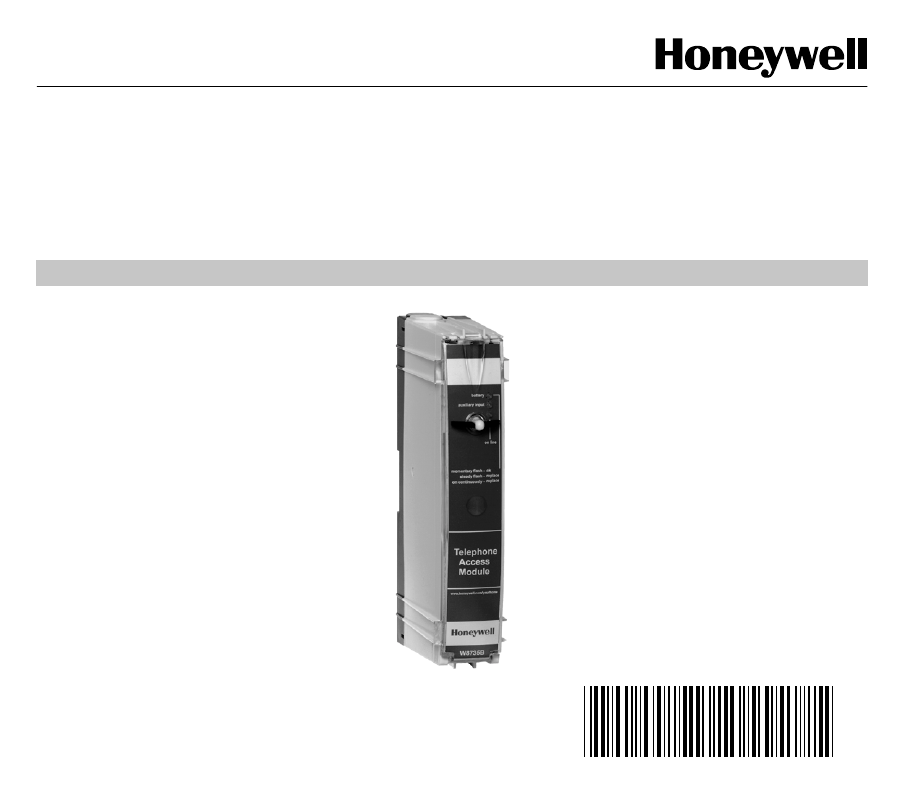
OWNER’S GUIDE
W8735B Telephone
Access Module

69-1353 2
CONTENTS
Using this guide ................................................................................................................................... 3
Features ................................................................................................................................................ 3
Telephone Access Module Description ............................................................................................. 4
Indicators ........................................................................................................................................... 4
Pass Code Reset Button ................................................................................................................... 4
Batter
y
Installation ............................................................................................................................. 5
Operatin
g
Your Telephone Access Module ....................................................................................... 8
Callin
g
Your Telephone Access Module........................................................................................ 8
Receivin
g
Dial-Out Alert Messa
g
es............................................................................................... 13
Configuring your telephone Access module ..................................................................................... 14
Enterin
g
the Confi
g
uration Menu ....................................................................................................... 14
Enterin
g
Your Identification
(
ID
)
Number....................................................................................... 15
Low Limit Settin
g
........................................................................................................................... 15
Hi
g
h Limit Settin
g
........................................................................................................................... 16
Rin
g
Settin
g
................................................................................................................................... 17
Chan
g
in
g
Your Pass Code ............................................................................................................ 17
Assi
g
nin
g
Zone Names.................................................................................................................. 18
Filter Alert Settin
g
(
Enable/Disable
)
............................................................................................... 19
Dial-out Alert Settin
g
(
Enable/Disable
)
.......................................................................................... 19
Pro
g
rammin
g
Dial-Out Telephone Number Settin
g
s ..................................................................... 20
Power Outa
g
e Settin
g
................................................................................................................... 22
To Chan
g
e the Power Outa
g
e Settin
g
........................................................................................... 23
Troubleshooting ................................................................................................................................... 24
Warranty ................................................................................................................................................ 25
Customer Assistance ........................................................................................................................... 26
3 69-1353
USING THIS GUIDE
The W8735B Telephone Access Module is a multi-
functional product. This means that it can be used in
man
y
different applications such as sin
g
le- or multi-zone
applications, conventional furnaces and heat pump
equipment.
Use the followin
g
s
y
mbols to help
y
ou identif
y
the
features that appl
y
to
y
our s
y
stem:
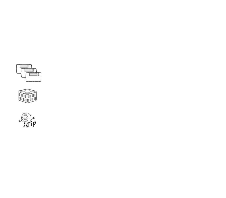
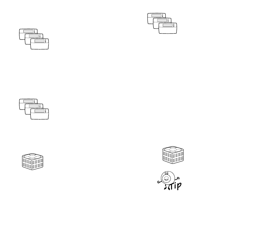
Triple la
y
er of thermostats with
the word, zonin
g
, below. These
features are available when used
with the optional Hone
y
well
Networked Zonin
g
S
y
stem.
Compressor with the word, heat
pump, below.These features are
available when used with a multi-
sta
g
e heat pump.
Tip s
y
mbol. Look for helpful tips
throu
g
hout the
g
uide when
y
ou
see this s
y
mbol.
FEATURES
Use the Telephone Access Module to:
• Check the temperature in your home remotely
using the telephone.
• Adjust your temperature setting remotely using
the telephone.
• Change your system from heat to cool remotely
using the telephone.
• Monitor the temperature in your home, and if the
temperature gets too hot or too cold, receive a
voice message remotely using the telephone.
• Check the outdoor temperature and Indoor
humidity remotely using the telephone (if
available).
• Monitor the performance of your heating and
cooling system and receive a remote message
(when an optional discharge temperature sensor
is installed).
• Receive a message remotely when your furnace
filter needs replacing or your electronic air
cleaner cells need cleaning.
• Receive notice when a detection is made from an
optional auxiliary sensor that detects situations
in your home such as water leakage, freezing
temperature, and open doors or windows.
• Receive a dialed alert if your power is interrupted
for an extended period of time.
• Name each zone from a prerecorded list when
used with the Honeywell Networked Zoning
System.
ZONING
HEAT PUMP
80
90
70
60
90
80
70
60
69-1353 4
TELEPHONE ACCESS MODULE
DESCRIPTION
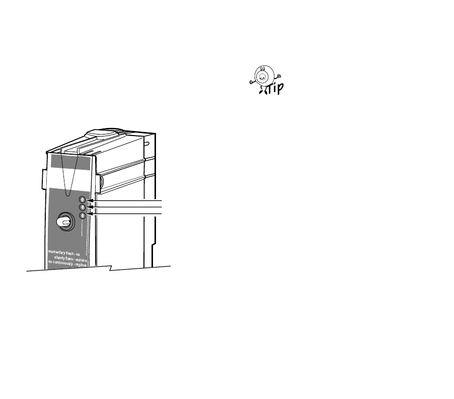
Indicators
The three li
g
ht emittin
g
diode (LED) indicators, see Fi
g
.
1, on the front panel illuminate to provide information
about the batter
y
, auxiliar
y
input, and phone line status:
Fig. 1. Status LED indicators.
• batter
y
– When the batter
y
is
g
ood, the LED
flashes momentaril
y
once ever
y
ten seconds.
When the batter
y
is weak, it flashes with a
stead
y
pulse; when the batter
y
is dead (or not
installed), the batter
y
LED is on continuousl
y
.
IMPORTANT:
If the battery indicator is on continuously or
indicates a steady flash, replace the battery
immediately (see Battery Installation section).
Replace the batter
y
annuall
y
and/or
before leavin
g
for an extended period
of time.
•auxiliar
y
input – If an auxiliar
y
sensor is
connected and has tripped, the auxiliar
y
input
LED illuminates.
IMPORTANT:
Determine the cause of the sensor trip and
resolve immediately.
•on line – When the Telephone Access Module
answers the phone line or is in the process of
dialin
g
out an alert messa
g
e, the on line LED
illuminates.
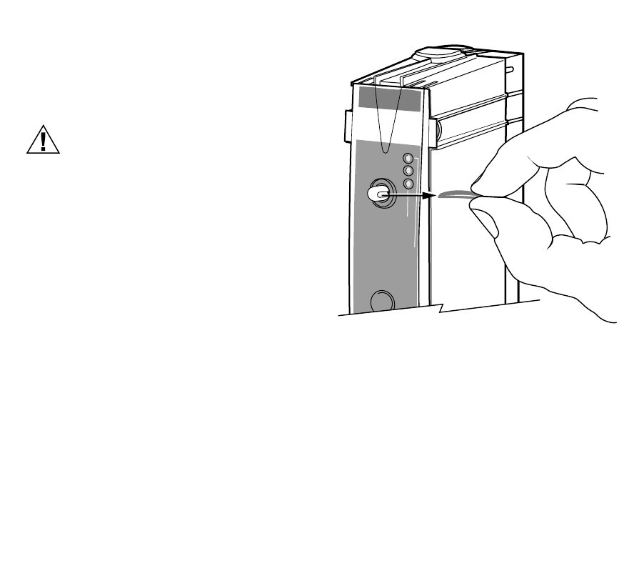
Pass Code Reset Button
If
y
ou have for
g
otten
y
our Pass Code, use the reset
button to reset the Pass Code to the ori
g
inal factor
y
settin
g
of 1 2 3 4.
To reset the Pass Code, Fi
g
. 4, to the factor
y
settin
g
,
press and hold the reset button for five seconds. After
five seconds, all three LEDs flash once.
M14812
on line
auxiliary input
battery
STATUS LEDs
BATTERY
AUXILIARY INPUT
ON LINE
80
90
70
60
90
80
70
60
5 69-1353
Battery Installation
The Telephone Access Module requires a 9-volt alkaline
batter
y
(not included) to provide the power to dial an
alert indicatin
g
an extended power interruption. (See
Power Outa
g
e Settin
g
discussion in Confi
g
urin
g
Your
Telephone Access Module section.)
CAUTION
Dead or Missing Battery Hazard.
Can prevent Telephone Access Module from
dialing power outage alert.
Check batter
y
annuall
y
or before leavin
g
for
extended absence.
To install or replace the batter
y
:
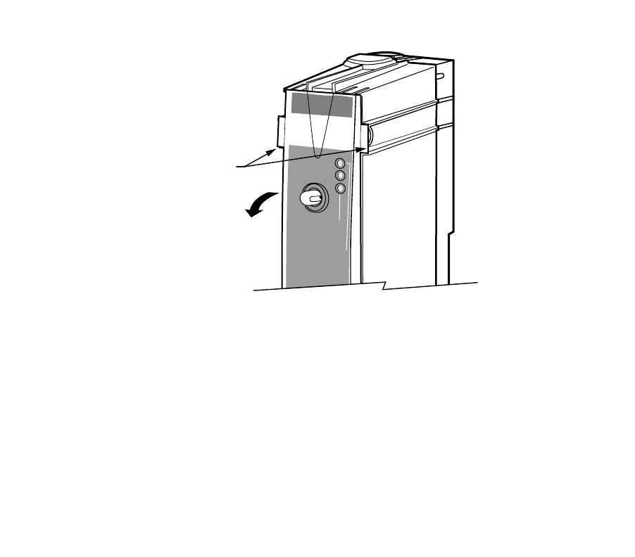
1. Remove the front cover latch pin (Fi
g
. 2).
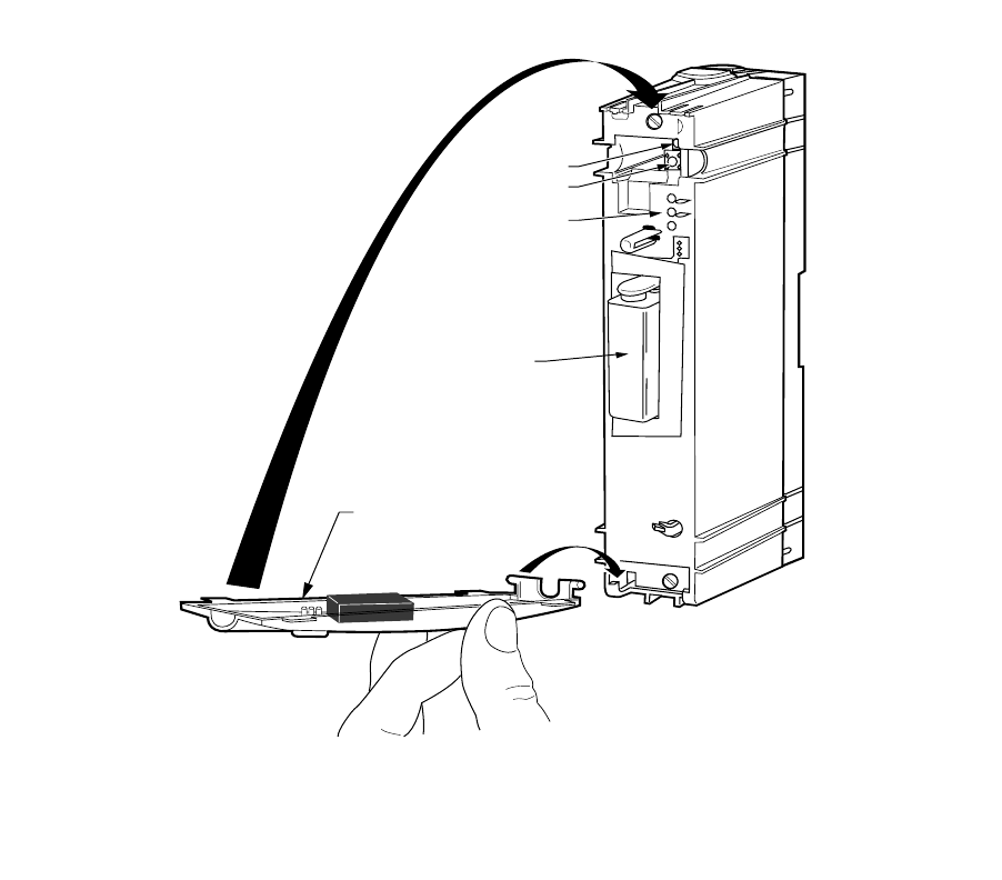
2. Grasp the top of the front cover and swin
g
it down
(Fi
g
. 3).
3. Connect the batter
y
leads to the batter
y
(Fi
g
. 4).
4. Insert the batter
y
in the slot.
5. Close the cover.
6. Re-insert the front cover latch pin.
Fig. 2. Removing front cover latch pin.
M14813
on line
momentary flash - ok
steady flash - replace
on continuously - replace
auxiliary input
battery
69-1353 6
Fig. 3. Removing front cover.
M14801
on line
momentary flash - ok
steady flash - replace
on continuously - replace
auxiliary input
battery
FRONT COVER TABS
GRASP TABS AND
SWING COVER DOWN
7 69-1353
Fig. 4. Replacing front cover.
M14770
HOOK IN BOTTOM
SWING UP
TO LATCH
BATTERY
COVER
COMMUNICATION LED
PASS CODE
RESET BUTTON
STATUS LEDs

69-1353 8
Operating Your Telephone Access Module
When installin
g
y
our Telephone Access Module,
y
our
installer used the telephone hookup connection practice
described in the CAUTION. Do not alter
y
our telephone
hookups without first consultin
g
y
our installer.
CAUTION
Incorrect Telephone Line Hookup Hazard.
Inability to call out can result in personal
injury or property damage.
Improper installation can result in blocked
phone lines and inability to make 911 and
other emergency-reporting phone calls.
Alwa
y
s connect the Telephone Access Module
first in line. When a monitored securit
y
s
y
stem
is installed, connect the Telephone Access
Module second in line.
Observin
g
this practice ensures that
theTelephone Access Module drops off the line
to allow priorit
y
to the house telephone.
Calling Your Telephone Access Module
Carefull
y
review the User and Confi
g
uration Menus
before operatin
g
y
our Telephone Access Module.
IMPORTANT:
The Telephone Access Module is designed to
provide remote access to your thermostat set-
tings and information. To access this informa-
tion or make changes, you must connect with
the Telephone Access Module from an out-
side line. If you want to access the Telephone
Access Module locally, you need to use a sec-
ond phone line or call from a cellular tele-
phone.
PASS CODE
You will be asked to respond to the quer
y
, “Enter
y
our
Pass Code followed b
y
the # ke
y
.”
You will be asked to enter a four-di
g
it Pass Code. The
default Pass Code is 1 2 3 4. You can chan
g
e this Pass
Code an
y
time b
y
enterin
g
the Confi
g
uration Menu. See
Confi
g
urin
g
Your Telephone Access Module section for
complete instructions.
If the pass code is not entered
within six seconds after the
Telephone Access Module
answers the telephone and
be
g
ins transmittin
g
data, han
g
up
and call a
g
ain after 30 seconds.
The transmission of data is for
future applications. Be sure to
send in the Re
g
istration Card to
receive notice of future updates.
ALERT MESSAGES
You will hear this messa
g
e, “A (alert messa
g
e) is active.”
The Telephone Access Module indicates an active alert
messa
g
e immediatel
y
after
y
ou enter
y
our Pass Code.
See Table 1 for a list of the alert messa
g
es and
correspondin
g
causes. For additional information, see
Confi
g
urin
g
Your Telephone Access Module section.
80
90
70
60
90
80
70
60

9 69-1353
Enter your Passcode
USER MENU
Room Temperature
To Change the Heat Setting
To Change the Cool Setting
To Hear Another Zone
To Change the System Mode
(System Mode must be Cool or Auto)
(System Mode must be Heat or Auto)
(if Zoning is installed)
To Hear the Outdoor
Temperature (when installed)
To Hear the Indoor Humidity
To Enter the
Configuration Menu
To Exit
(if available)
1
2
3
4
5
6
99
*
Listen for:
Enter:
Active Alert Message (If any)
Press 1 to Acknowledge the Active Alert
System Mode
(Heat, Cool, Off, Auto)
Temperature Setting
M17723
CONFIGURATION MENU
To Change ID
To Change Low Limit Setting
To Change Ring Setting
To Change High Limit Setting
To Change Passcode
To Name Zones
To Change Filter Change
Alert
To Change
Telephone Numbers
(if Zoning is installed)
(Enable/Disable)
To Change Dial-Out Alert
To Change
Power Outage Setting
(Enable/Disable)
1
2
3
4
5
6
7
8
9
10
Enter:
M17724
69-1353 10
Table 1. Alert Messages.
ACKNOWLEDGING ALERT MESSAGES
You will hear, “To acknowled
g
e the alert messa
g
e, press
1.”
After the alert messa
g
e is announced, the Telephone
Access Module prompts
y
ou to acknowled
g
e the alert
messa
g
e b
y
pressin
g
1. If there is more than one active
alert messa
g
e, the Telephone Access Module indicates
the next messa
g
e, and continues until all alerts are
announced.
When
y
ou acknowled
g
e the alert messa
g
e,
y
ou are
clearin
g
the dial-in alert messa
g
e and also clearin
g
the
dial-out alert.
IMPORTANT:
After receiving an alert, it is important to take
appropriate action immediately. See Receiv-
ing Dial-Out Messages section for more infor-
mation on dial-out alerts.
The Telephone Access Module continues throu
g
h the
menu after the alerts are announced.
To exit, press the * ke
y
at an
y
time.
Alert Message Possible Cause
Hi
g
h Temperature The room temperature exceeded the hi
g
h-limit temperature settin
g
.
Low Temperature The room temperature exceeded the low-limit temperature settin
g
.
Heat Pump A heat pump compressor fault occurred.
Heatin
g
S
y
stem The s
y
stem heat output is below the acceptable performance; possible heatin
g
s
y
stem failure.
Coolin
g
S
y
stem The s
y
stem cool output is below the acceptable performance; possible coolin
g
s
y
stem failure.
Auxiliar
y
Input The auxiliar
y
sensor connected to the auxiliar
y
input terminals tripped.
Filter Chan
g
e The thermostat is indicatin
g
that a filter chan
g
e is required for the heatin
g
/coolin
g
s
y
stem.
Power Outa
g
e A power outa
g
e exceeded the maximum allowable time.
80
90
70
60
90
80
70
60
11 69-1353
ROOM TEMPERATURE
You will hear, “The room temperature is (__de
g
rees).” or
“The zone (1-9) temperature is
(__ de
g
rees).”
Or if
y
ou have named the zones:
“The zone name (for example,
Great Room) temperature is (___
de
g
rees).”
The Telephone Access Module receives the thermostat
room temperature and provides that information when
y
ou call in.
The thermostat alwa
y
s provides
the room temperature of the last
zone queried. You can hear each
thermostat room temperature b
y
chan
g
in
g
zones. See Chan
g
in
g
to
Hear Another Zone section.
CHANGING THE TEMPERATURE SETTING
You will hear, “The heat (cool) settin
g
is (__de
g
rees).” or
“The (emer
g
enc
y
) heat settin
g
is
(__de
g
rees).”
“The zone 1 (1-9) settin
g
is (__
de
g
rees).”
or if
y
ou have named the zones:
“The zone name (for example,
Great Room) heat (cool) settin
g
is
(__ de
g
rees).”
The Telephone Access Module announces the s
y
stem
mode, then announces the current temperature settin
g
,
and then prompts
y
ou to chan
g
e the temperature
settin
g
:
“The s
y
stem mode is (heat, cool, off, auto, emer
g
enc
y
heat.”•If the thermostat is set to the heat mode,
y
ou
will hear: “To chan
g
e the heat settin
g
, press
1.”
•If the thermostat is set to the cool mode,
y
ou
will hear: “To chan
g
e the cool settin
g
, press
2.”
•If the thermostat is set to the auto mode,
y
ou
will hear: “To chan
g
e the heat settin
g
, press 1;
to chan
g
e the cool settin
g
, press 2.”
•If the thermostat is set to the
emer
g
enc
y
heat mode,
y
ou will
hear: “To chan
g
e the emer
g
enc
y
heat settin
g
, press 1.”
The thermostat must be in a
mode other than off to chan
g
e
the heat or cool settin
g
s.
•If the thermostat is set to the off mode,
y
ou will
hear, “To chan
g
e the s
y
stem mode, press 3.”
ZONING
ZONING
HEAT PUMP
ZONING
HEAT PUMP
80
90
70
60
90
80
70
60
69-1353 12
The Telephone Access Module
announces the temperature
settin
g
per zone. For example, “To
chan
g
e the zone 1 (1-9) heat
settin
g
, press 1“ or “To chan
g
e the
(Great Room), heat settin
g
, press
1.”
The Telephone Access module prompts
y
ou to enter a
new temperature settin
g
;
y
ou will hear:
“Enter the heat settin
g
followed b
y
the # ke
y
,” or “Enter
the cool settin
g
followed b
y
the # ke
y
.
Enter a temperature usin
g
the telephone ke
y
pad
followed b
y
the # si
g
n.
NOTE: For example, 7+2+# sets the temperature to
72° F (22°C).
If the temperature
y
ou enter is
outside of the thermostat
temperature ran
g
e, the Telephone
Access Module announces
y
ou
have entered an invalid settin
g
and prompts
y
ou to enter a new
settin
g
.
CHANGING THE SYSTEM MODE
You will hear, “To chan
g
e the s
y
stem mode, press 3.”
The Telephone Access Module chan
g
es the s
y
stem
mode to the next available settin
g
(Heat/Off/Cool/Auto).
The Telephone Access Module then announces the new
s
y
stem mode settin
g
. You will hear, “The s
y
stem mode
is ____(heat, off, cool, auto, emer
g
enc
y
heat).
The Telephone Access Module
will advance onl
y
to available
s
y
stem mode settin
g
s. For
example, if
y
our thermostat is set
for a heat onl
y
s
y
stem,
y
our
choices are Heat or Off.
CHANGING TO HEAR ANOTHER ZONE
You will hear, “To hear another
zone, press 4.”
The Telephone Access Module prompts
y
ou to press 4
to hear another zone. All active zones are announced in
order; for example, “For Zone 1, press one.” The
y
are
also announced b
y
name if the zone was assi
g
ned a
name; for example, “For the Great Room zone, press
one,” and so forth, until all active zones are listed.
It is not necessar
y
to listen to the
entire list of zones before makin
g
y
our selection. Press a valid zone
number at an
y
time, even if it was
not
y
et announced in the menu.
OUTDOOR TEMPERATURE
You will hear, “To hear the outdoor temperature, press
5.”
If an outdoor temperature sensor is installed, the
Telephone Access Module announces the outdoor
temperature; for example, “The outdoor temperature is
(__de
g
rees).” After indicatin
g
the outdoor temperature,
the Telephone Access Module returns to the be
g
innin
g
of the menu.
ZONING
80
90
70
60
90
80
70
60
80
90
70
60
90
80
70
60
ZONING
80
90
70
60
90
80
70
60
13 69-1353
INDOOR HUMIDITY
You will hear, “To hear the indoor humidit
y
, press 6.”
If
y
our thermostat or s
y
stem has the capabilit
y
to sense
the indoor humidit
y
, the Telephone Access Module
announces the indoor humidit
y
; for example, “The
indoor humidit
y
is (__ percent).” After indicatin
g
the
indoor humidit
y
, the Telephone Access Module returns
to the be
g
innin
g
of the menu.
Receiving Dial-Out Alert Messages
You will hear,”Hello, this is a Hone
y
well alert messa
g
e
from (
y
our ID here). A (alert messa
g
e) was observed”.
The Telephone Access Module dials the telephone
numbers from the Telephone Number Settin
g
Menu; see
Dial-out Telephone Number Settin
g
s description in
Confi
g
urin
g
Your Telephone Access Module section for
further information on enterin
g
phone numbers. See
Table 1 for the alerts that activate a dial-out procedure.
ACKNOWLEDGING DIAL-OUT ALERT MESSAGES
If
y
ou (or
y
our desi
g
nate) receive a dial-out alert
messa
g
e,
y
ou can choose to acknowled
g
e the messa
g
e
and take immediate and appropriate action.
You will hear, “To acknowled
g
e the alert messa
g
e, press
1.”
“To repeat the alert messa
g
e, press 2.”
“To exit, press the * ke
y
.”
If
y
ou press the * ke
y
to exit and
the Telephone Access does not
announce “Goodb
y
e,” there is
another alert present. Sta
y
on the
line. If
y
ou han
g
up before
acknowled
g
in
g
the alerts, the
Telephone Access Module
repeats the dial-out procedure.
•If an acknowled
g
ement is not received, the
Telephone Access Module continues callin
g
ever
y
30 minutes until an acknowled
g
ement is
received.
•If the Telephone Access Module left a
messa
g
e on an answerin
g
machine or voice
mail, call into the Telephone Access Module to
acknowled
g
e the alert and cancel the dial-out
alerts.
•If telephone number settin
g
#3 is pro
g
ram-
med, the desi
g
nate for that number must also
acknowled
g
e the alert separatel
y
with the
special code to clear the alert.
NOTE: The special code is the last five di
g
its of the
telephone number pro
g
rammed in telephone
number settin
g
three; see Pro
g
rammin
g
Dial-
Out Telephone Number section.
CAUTION
Property Loss Hazard.
Prepare to act promptly; time may be
critical.
Do not assume
y
our desi
g
nate received and
acted on the active alert.
80
90
70
60
90
80
70
60

69-1353 14
CONFIGURING YOUR TELEPHONE
ACCESS MODULE
IMPORTANT:
The Telephone Access Module is designed to
allow remote access to your thermostat set-
tings and information. To access this informa-
tion or make changes, you must connect with
the Telephone Access Module from an out-
side line. If you want to access the Telephone
Access Module locally, you must use a sec-
ond telephone line or a cellular telephone.
Entering the Configuration Menu
IMPORTANT
Your installer may have configured your Tele-
phone Access Module. Before changing the
configuration, discuss the changes with your
installer.
To enter the Confi
g
ration Menu:
1. Call the Telephone Access Module.
2. Enter
y
our Pass Code.
3. Listen for an
y
active alerts.
4. Press 99 an
y
time after the room temperature is
announced.
5. You will hear, “This is the Confi
g
uration Menu;
enter the Confi
g
uration Number followed b
y
the #
ke
y
.”
6. See Table 2 for confi
g
uration numbers.
Table 2. Configuration Numbers.
Configuration
Number Description
1 Enterin
g
Your Identification (ID)
Number
2 Low Limit Settin
g
3Hi
g
h Limit Settin
g
4Rin
g
Settin
g
5 Chan
g
in
g
Your Pass Code
6 Assi
g
nin
g
Zone Names (if zonin
g
is installed)
7 Filter Chan
g
e Settin
g
8 Alert Dial-out Settin
g
9 Telephone Numbers Settin
g
10 Power Outa
g
e Settin
g
11 For Installer Use Onl
y
15 69-1353
Entering Your Identification (ID) Number
Use
y
our home telephone number as
y
our ID number.
The ID is announced when a dial-out alert messa
g
e is
sent.
After
y
ou enter Confi
g
uration Number 1, if
y
our ID is not
y
et pro
g
rammed,
y
ou hear, “The ID is not pro
g
rammed.”
If
y
our ID is pro
g
rammed, and is correct, press the * ke
y
to return to the Confi
g
uration Menu.
You will hear, “To chan
g
e the ID number, press 1.”“Enter
the ID followed b
y
the # ke
y
.”
1. Enter an ID number with less than 25 di
g
its, fol-
lowed b
y
the # ke
y
. You will hear, “Your ID is
(
y
our ID number).”
2. If this is the ID
y
ou want pro
g
rammed, press the *
ke
y
to return to the Confi
g
uration Menu.
If the ID is not entered correctl
y
,
y
ou will hear, “Invalid
ID.” Follow the menu and these instructions and enter a
new ID.
Low Limit Setting
The Low Limit settin
g
is used to activate an alert when
the displa
y
ed temperature on the thermostat is lower
than the value
y
ou set. The settin
g
ran
g
e for the Low
Limit Settin
g
is 40oF (4°C) to 65oF (18°C) in 1oF (1°C)
increments. The factor
y
default settin
g
is 50oF (10°C).
If the thermostat displa
y
s a temperature lower than
y
our
low limit settin
g
and
y
our dial-out alert is active, the
Telephone Access Module dials out. When
y
ou answer
the phone,
y
ou will hear, ”Hello, this is a Hone
y
well alert
messa
g
e from (
y
our ID here). A Low Limit Alert was
observed.”
CAUTION
Property Loss Hazard.
Do not assume your designate received and
acted on the active alert.
Prepare to act promptl
y
; time ma
y
be critical.
CAUTION
Property Loss Hazard.
Do not rely only on the Telephone Access
Module to identify potential problems in
your home (like detecting low room
temperatures that can freeze water pipes).
Have someone periodicall
y
check
y
our home
while
y
ou are awa
y
.
Set the Low Limit settin
g
a few
de
g
rees below the settin
g
on
y
our
thermostat. This wa
y
y
ou can be
notified if the temperature drops
below
y
our thermostat settin
g
.
This provides an earl
y
notice.
After enterin
g
Confi
g
uration Number 2, if
y
our Low Limit
Settin
g
is set to the factor
y
settin
g
,
y
ou will hear, ”The
Low Limit Settin
g
is 50°F (°10C).”
If
y
our Low Limit settin
g
is correct, and the value
y
ou
want, press the * ke
y
to return to the Confi
g
uration
Menu.
You will hear, “To chan
g
e the Low Limit Settin
g
, press
1.” “Enter the Low Limit Settin
g
followed b
y
the # ke
y
.”
80
90
70
60
90
80
70
60

69-1353 16
1. Enter a Low Limit Settin
g
from 40° F (4°C) to
65°F (18°C) in 1°F (1°C) increments. You will
hear, “Your Low Limit Settin
g
is (
y
our low limit set-
tin
g
).”
2. If this is the Low Limit Settin
g
y
ou want pro-
g
rammed, press the * ke
y
to return to the Confi
g
-
uration Menu.
If the Low Limit Settin
g
is not entered correctl
y
,
y
ou will
hear, “Invalid Settin
g
.” Follow the menu and these
instructions and enter a new Low Limit Settin
g
.
High Limit Setting
The Hi
g
h Limit Settin
g
is used to activate an alert when
the displa
y
ed temperature on the thermostat is hi
g
her
than the value
y
ou set. The settin
g
ran
g
e for the Hi
g
h
Limit Settin
g
is 70°F (21°C) to 110°F (43°C) in 1 oF (1°C)
increments. The factor
y
default settin
g
is 100°F (38°C).
If the thermostat-displa
y
ed temperature is hi
g
her than
y
our Hi
g
h Limit Settin
g
and
y
our dial-out alert is active,
the Telephone Access Module dials out and when
y
ou
answer the telephone,
y
ou will hear, ”Hello, this is a
Hone
y
well alert messa
g
e from (
y
our ID here). A Hi
g
h
Limit Alert was observed.”
After enterin
g
Confi
g
uration Number 3, if
y
our Hi
g
h Limit
Settin
g
is set to the factor
y
settin
g
,
y
ou will hear: “The
Hi
g
h Limit Settin
g
is 100°F (38°C).”
If
y
our Hi
g
h Limit Settin
g
is correct and the value
y
ou
want, press the * ke
y
to return to the Confi
g
uration
Menu.
CAUTION
Property Loss Hazard.
Prepare to act promptly; time may be
critical.
Do not assume
y
our desi
g
nate received and
acted on the active alert.
CAUTION
Property Loss Hazard.
Do not rely only on the Telephone Access
Module to identify potential problems in
your home (like detecting high room
temperatures).
Have someone periodicall
y
check
y
our home
while
y
ou are awa
y
.
You will hear, “To chan
g
e the Hi
g
h Limit Settin
g
, press
1.” “Enter the Hi
g
h Limit Settin
g
followed b
y
the # ke
y
”
1. Enter a Hi
g
h Limit Settin
g
from 70°F (21°C) to
110°F (43 °C) in 1 oF (1°C) increments. You will
hear, “Your Hi
g
h Limit Settin
g
is (
y
our Hi
g
h Limit
Settin
g
).”
2. If this is the Hi
g
h Limit Settin
g
y
ou want pro-
g
rammed, press the * ke
y
to return to the Confi
g
-
uration Menu.
If the Hi
g
h Limit settin
g
is not entered correctl
y
,
y
ou will
hear, “Invalid Settin
g
.” Follow the menu and these
instructions and enter a new Hi
g
h Limit Settin
g
.

17 69-1353
Ring Setting
The rin
g
settin
g
determines how man
y
rin
g
s the
Telephone Access Module hears before answerin
g
.The
factor
y
default settin
g
is ten rin
g
s.
The Telephone Access Module can share the line with
y
our telephone answerin
g
machine. There are two wa
y
s
the Telephone Access Module can answer when an
answerin
g
machine is sharin
g
the same phone line:
1. Telephone Access Module answers the phone
line if it hears the set number of rin
g
s within 30
seconds. For example, if
y
our answerin
g
machine answers in four rin
g
s:
a. Set the rin
g
settin
g
to six rin
g
s.
b. Call the Telephone Access Module. (Let the
telephone rin
g
three times.)
c. Han
g
up.
d. Call a
g
ain within 30 seconds and allow the
telephone to rin
g
three more times.
e. Telephone Access module will pick up after
the third rin
g
on the second call.
2. As soon as
y
our answerin
g
machine answers,
enter
y
our pass code.
You will not be prompted to enter
y
our pass code usin
g
this method.
To chan
g
e the Rin
g
Settin
g
:
After
y
ou have entered Confi
g
uration Number 4,
y
ou will
hear, “The Rin
g
Settin
g
is 2 (if set at the factor
y
default
settin
g
).”
If
y
our Rin
g
Settin
g
is pro
g
rammed and is correct, press
the * ke
y
to return to the Confi
g
uration Menu.
You will hear, “To chan
g
e the Rin
g
Settin
g
, press 1.”
“Enter the Rin
g
Settin
g
followed b
y
the # ke
y
”
1. Enter a Rin
g
Settin
g
from 1 to 10. You will hear,
“Your Rin
g
Settin
g
is (1-10).”
2. If this is the Rin
g
Settin
g
y
ou want pro
g
rammed,
press the * ke
y
to return to the Confi
g
uration
Menu.
If the Rin
g
Settin
g
is not entered correctl
y
, Telephone
Access Module announces that
y
ou have entered an
“Invalid Settin
g
.” Follow the menu and these instructions
and enter a new Rin
g
Settin
g
.
Changing Your Pass Code
NOTE: The factor
y
default settin
g
is 1 2 3 4.
1. After
y
ou entered Confi
g
uration Number 5,
y
ou
will hear: “Enter new four di
g
it Pass Code fol-
lowed b
y
the # ke
y
.”
If
y
ou do not want to chan
g
e the Pass Code at this time,
press the * ke
y
to return to the Confi
g
uration Menu.
2. Enter
y
our new four di
g
it Pass Code followed b
y
pressin
g
the # ke
y
.” You will hear, “Re-enter
y
our
new four di
g
it Pass Code followed b
y
the Pass
Code.”
3. Re-enter
y
ou pass code followed b
y
the # ke
y
.
4. If the Pass Codes match,
y
ou will hear, ”Pass
Code chan
g
ed, the new Pass Code is (
y
our new
Pass Code).” You automaticall
y
return to the
Confi
g
uration menu after hearin
g
,
“The new Pass Code is “ mes-
sa
g
e.
80
90
70
60
90
80
70
60
69-1353 18
Assigning Zone Names
The Telephone Access Module
can announce the temperatures
and settin
g
s of up to nine zones.
These zones are announced as
“zone one,” “zone two.” “zone
three” and so forth. Usin
g
the
Assi
g
nin
g
Zone Names Menu,
y
ou can assi
g
n each zone a
name. See Table 3.
After enterin
g
Confi
g
uration Number 6,
y
ou will hear,
“Zone one is not pro
g
rammed.”
If
y
ou do not want to chan
g
e zone one name at this time,
press 1 to hear the next zone or press the * ke
y
to return
to the Confi
g
uration Menu.
You will hear, “To reassi
g
n this zone, press 2.”
1. Press 2. You will hear, “Zone one is Zone 1.”
Enter the new Zone ID Code for zone one fol-
lowed b
y
the # ke
y
”.
2. Enter the Zone ID Number from Table 3, and
press the # ke
y
.
Table 3. Assigning Zone Names.
Zone ID Number Zone Name
1 Basement
2 Bathroom
3 Bedroom
4Den
5Dinin
g
Room
6Fo
y
er
7 Game Room
8 Great Room
9 Guest Room
10 G
y
m
11 Kid’s Bedroom
12 Kitchen
13 Librar
y
14 Lower level
ZONING
15 Master Bedroom
16 Media Room
17 Nurser
y
18 Office
19 Pool Room
20 Porch
21 Spa
22 Sunroom
23 Theater
24 Upper Level
25 Wine Cellar
26 Workshop
Table 3. Assigning Zone Names. (Continued)
Zone ID Number Zone Name

19 69-1353
If the Zone ID Number is not
entered correctl
y
,
y
ou will hear,
“Invalid ID.” Follow the menu and
these instructions and enter a
new Zone ID Number.
You will hear, ”Zone one is the Great Room (if
y
ou
entered Zone ID Number 8, for example); to hear
another zone, press 1.”
3. If
y
our settin
g
is correct, press 1 to hear the next
zone.
4. Repeat the steps 1-3 to enter a zone name for
each zone.
Filter Alert Setting (Enable/Disable)
The Telephone Access Module activates a dial-out alert
if it receives a messa
g
e from the thermostat (if
y
our
thermostat has this capabilit
y
) indicatin
g
the furnace
filter needs chan
g
in
g
or
y
our electronic air cleaner cells
need cleanin
g
.
It is possible to enable or disable the Telephone Access
Module Filter Chan
g
e Dial-out feature. The factor
y
default settin
g
is enabled to activate an alert if
y
our filter
chan
g
e messa
g
e is received from the thermostat.
After
y
ou entered Confi
g
uration Number 7, and it is set
to the factor
y
settin
g
,
y
ou will hear: “The filter alert is
enabled.” If
y
our Filter Alert settin
g
is correct, press the *
ke
y
to return to the Confi
g
uration Menu.
You will hear, “To chan
g
e, press 1.”
1. Press 1 to chan
g
e. You will hear, “Your Filter
Alert Settin
g
is disabled.” This means the Tele-
phone Access Module will not activate an alert if
y
our filter chan
g
e messa
g
e is received from the
thermostat.
2. If this is the Settin
g
y
ou want pro
g
rammed, press
the * ke
y
to return to the Confi
g
uration Menu.
If the value entered is not a 1 or the * ke
y
,
y
ou hear,
“Invalid Settin
g
.” Follow the menu and these instructions
to chan
g
e the filter alert settin
g
or press the * ke
y
to exit.
Dial-out Alert Setting (Enable/Disable)
The option to have the Telephone Access Module dial-
out on an alert condition can be disabled. The factor
y
default settin
g
is enabled to dial out when an alert
condition is observed.
After
y
ou enter Confi
g
uration Number 8, and it is set to
the factor
y
settin
g
,
y
ou will hear, “The Alert Dial-out is
enabled.” If
y
our Alert Dial-out settin
g
is correct, press
the * ke
y
to return to the Confi
g
uration Menu.
You will hear, “To chan
g
e, press 1.”
1. Press 1 to chan
g
e. You will hear, “Your Alert Dial-
out is disabled.” This means the Telephone
Access Module will not dial-out on an alert condi-
tion.
2. If this is the settin
g
y
ou want pro
g
rammed, press
the * ke
y
to return to the Confi
g
uration Menu.
If the value entered is not a 1 or the * ke
y
,
y
ou will hear,
“invalid Settin
g
.” Follow the menu and these instructions
to chan
g
e the Alert Dial-out settin
g
or the * ke
y
to exit.
ZONING

69-1353 20
Programming Dial-Out Telephone Number Settings
The Telephone Access Module stores up to three dial-
out telephone numbers. Each telephone number can be
a maximum of 25 di
g
its in len
g
th. See Table 4.
•Telephone number settin
g
one: The homeowner
selects a number where the
y
can be contacted when
awa
y
from home (such as office, second home, or
cellular phone number).
•Telephone number settin
g
two: An alternate contact
when the homeowner cannot be reached (such as
relative, friend or nei
g
hbor).
•Telephone number settin
g
three (HVAC contractor is
providin
g
monitorin
g
service at homeowner’s
request): The HVAC contractor phone number.
IMPORTANT
If these numbers are not programmed, a dial-
out is not initiated on alert.
After
y
ou enter the confi
g
uration number 9,
y
ou will
hear:
• “Telephone Number Settin
g
Menu.”
•“To chan
g
e telephone number one, press 1.”
•“To chan
g
e telephone number two, press 2.”
•“To chan
g
e telephone number one, press 3.”
•“To return to the confi
g
uration menu, press the
* ke
y
”.”
As an example, follow the process to chan
g
e telephone
number 1:
1. Press 1.
2. You will hear, “Telephone number one is not pro-
g
rammed, enter the telephone number followed
b
y
the # ke
y
.”
3. Enter the telephone number
y
ou wish to desi
g
-
nate the Telephone Access Module to dial-out on
an alert condition for telephone settin
g
number
one.
4. Press the # ke
y
.
5. You will hear, “For Voice, press 1; for Data, press
2.”
The Telephone Access module has the built-in capabilit
y
to send data; this is considered a future application. Do
not select option 2. Please fill out and mail
y
our
Re
g
istration Card so
y
ou are re
g
istered to receive
information on this and other future capabilities and
enhancements.
IMPORTANT:
Do not select option 2. You will not receive the
alerts in a voice format so you cannot respond
immediately to an alert.
6. Press 1.
7. You will hear, “The alert settin
g
is voice.” “Tele-
phone number one is (telephone number
y
ou
entered).
8. Follow steps 1-7 to pro
g
ram telephone numbers
2 and 3.
9. When complete, press the * ke
y
to return to the
confi
g
uration menu.

21 69-1353
Table 4. Dial-Out Procedure.
a Telephone #3 settin
g
is intended for use when
y
ou have an a
g
reement with
y
our heatin
g
and air conditionin
g
con-
tractor to monitor the alerts
g
enerated b
y
y
our Telephone Access Module.
b The contractor uses a special code (last five di
g
its of the telephone number 3 settin
g
) to clear the alert. This code
does not clear the alert dial-out to telephone #1 or #2 number settin
g
s and onl
y
allows the contractor access to clear
the alert.
When these telephone number
settings are programmed Acknowledged Not Acknowledged
#1 or #2 - Telephone Access Module
dials-out to announce the alert. Alert is cleared. Dial-out procedure is attempted ever
y
30
minutes until the alert is acknowled
g
ed.
#1 and #2 - Telephone Access Module
dials-out to announce the alert. Alert is cleared if either #1
or #2 acknowled
g
es the
alert.
Dial-out procedure is attempted to #1
and #2 ever
y
30 minutes until the alert is
acknowled
g
ed b
y
either #1 or #2.
#3 a - Telephone Access Module
dials-out to announce the alert. Alert is cleared. b Dial-out procedure is attempted ever
y
30
minutes until the alert is acknowled
g
ed
b
y
#3.
#1 or #2, and #3 a - Telephone Access
Module dials-out to announce the
alert.
Alert is cleared if either #1
or #2 acknowled
g
es the
alert.
Alert sent to #3 will be
cleared once
acknowled
g
ed b
y
#3 b
Dial-out procedure is attempted to #1 or
#2 ever
y
30 minutes until the alert is
acknowled
g
ed b
y
either #1 or #2.
Dial-out procedure is attempted to #3
ever
y
30 minutes until the alert is
acknowled
g
ed b
y
#3.
#1, and #2, and #3 a - Telephone
Access Module dials-out to announce
the alert.
Alert is cleared if either #1
or #2 acknowled
g
es the
alert.
Alert sent to #3 will be
cleared once
acknowled
g
ed b
y
#3 b
Dial-out procedure is attempted to #1
and #2 ever
y
30 minutes until the alert is
acknowled
g
ed b
y
either #1 or #2.
Dial-out procedure is attempted to #3
ever
y
30 minutes until the alert is
acknowled
g
ed b
y
#3.
69-1353 22
Power Outage Setting
The Power Outa
g
e settin
g
determines how man
y
hours
the Telephone Access Module waits before activatin
g
a
dial-out alert when power is disconnected or a power
outa
g
e occurs.
CAUTION
Dead or Missing Battery Hazard.
Can prevent Telephone Access Module from
dialing power outage alert.
Check batter
y
annuall
y
or before leavin
g
for
extended absence.
Replace batter
y
immediatel
y
when batter
y
indicator is on or flashin
g
.
The factor
y
default settin
g
is 1 hour. The options are 1,
2, 3, or 4 hours.
The Telephone Access Module activates an alert when
the continuous power outa
g
e is equal to or lon
g
er than
the Power Outa
g
e Settin
g
.
CAUTION
Property Loss Hazard.
Prepare to act promptly; time may be
critical.
Do not assume
y
our desi
g
nate received and
acted on the active alert.
CAUTION
Property Loss Hazard.
Do not rely only on the Telephone Access
Module to identify potential problems in
your home.
Have someone periodicall
y
check
y
our home
while
y
ou are awa
y
.
If a power outa
g
e is equal to or lon
g
er than
y
our Power
Outa
g
e Settin
g
and
y
our dial-out alert is active, the
Telephone Access Module dials out and when
y
ou
answer the phone,
y
ou will hear, ”Hello, this is a
Hone
y
well alert messa
g
e from (
y
our ID). A Power
Outa
g
e Alert was observed.”

23 69-1353
To Change the Power Outage Setting
After
y
ou enter Confi
g
uration Number 10, if
y
our Power
Outa
g
e Settin
g
is set to the factor
y
settin
g
,
y
ou hear,
“The Power Outa
g
e Settin
g
is one.”
If
y
our Power Outa
g
e Settin
g
is correct, press the * ke
y
to return to the Confi
g
uration Menu.
“To chan
g
e the Power Outa
g
e Settin
g
, press 1.” “Enter
the Power Outa
g
e Settin
g
followed b
y
the # ke
y
.”
1. Enter a Power Outa
g
e Settin
g
from one to four
hours. You will hear, “Your Power Outa
g
e Settin
g
is (
y
our Power Outa
g
e Settin
g
).”
2. If this is the Power Outa
g
e Settin
g
y
ou want pro-
g
rammed, press the * ke
y
to return to the Confi
g
-
uration Menu.
If the Power Outa
g
e Settin
g
is not entered correctl
y
,
y
ou
will hear, “Invalid Settin
g
.”
Follow the menu and these instructions and enter a new
Power Outa
g
e Settin
g
.

69-1353 24
TROUBLESHOOTING
Table 5. Troubleshooting the W8735B.
Symptom Possible Cause Action
The batter
y
indicator is on
continuousl
y
.The batter
y
is either dead
or not installed. Install or replace the batter
y
.
The batter
y
indicator is
flashin
g
with a stead
y
on-off
pulse.
The batter
y
is weak. Replace the batter
y
.
The batter
y
indicator appears
to flash momentaril
y
ever
y
10
seconds.
The batter
y
is
g
ood. No action is required.
The online indicator is
illuminated. The telephone module is
currentl
y
in a dial-in or
dial-out sequence.
Wait for the call to end.
The auxiliar
y
input indicator is
illuminated The Telephone Access
Module detected a
contact closure on the
auxiliar
y
input terminals.
Determine the cause of the contact closure.
Remed
y
the problem accordin
g
to the contact
manufacturer instructions.
When I dial into the Telephone
Access Module, it indicates
“The s
y
stem is not
respondin
g
.”
The Telephone Access
Module is not receivin
g
data from the thermo-
stats.
Make sure all connections between the
communicatin
g
devices are
g
ood.
Contact
y
our installer.
M
y
password is not workin
g
. You ma
y
have for
g
otten
y
our pass code. Press and hold the passcode reset switch for ten
seconds. The pass code will be reset to 1-2-3-4.
Retr
y
with the default pass code.

25 69-1353
WARRANTY
Hone
y
well warrants this product, excludin
g
batter
y
, to be
free from defects in the workmanship or materials, under
normal use and service, for a period of one (1)
y
ear from
the date of purchase b
y
the consumer. If, at an
y
time
durin
g
the warrant
y
period, the product is defective or
malfunctions, Hone
y
well shall repair or replace it (at
Hone
y
well’s option) within a reasonable period of time.
If the product is defective,
(i) return it, with a bill of sale or other dated proof of
purchase, to the retailer from which
y
ou purchased it, or
(ii) packa
g
e it carefull
y
, alon
g
with proof of purchase
(includin
g
date of purchase) and a short description of
the malfunction, and mail it, posta
g
e prepaid, to the
followin
g
address:
Hone
y
well Return Goods
Dock 4 MN10-3860
1885 Dou
g
las Dr N
Golden Valle
y
, MN 55422
This warrant
y
does not cover removal or reinstallation
costs. This warrant
y
shall not appl
y
if it is shown b
y
Hone
y
well that the defect or malfunction was caused b
y
dama
g
e which occurred while the product was in the
possession of a consumer.
Hone
y
well’s sole responsibilit
y
shall be to repair or
replace the product within the terms stated above.
HONEYWELL SHALL NOT BE LIABLE FOR ANY
LOSS OR DAMAGE OF ANY KIND, INCLUDING ANY
INCIDENTAL OR CONSEQUENTIAL DAMAGES
RESULTING, DIRECTLY OR INDIRECTLY, FROM ANY
BREACH OF ANY WARRANTY, EXPRESS OR
IMPLIED, OR ANY OTHER FAILURE OF THIS
PRODUCT. Some states do not allow the exclusion or
limitation of incidental or consequential dama
g
es, so this
limitation ma
y
not appl
y
to
y
ou.
THIS WARRANTY IS THE ONLY EXPRESS
WARRANTY HONEYWELL MAKES ON THIS
PRODUCT. THE DURATION OF ANY IMPLIED
WARRANTIES, INCLUDING THE WARRANTIES OF
MERCHANTABILITY AND FITNESS FOR A
PARTICULAR PURPOSE, IS HEREBY LIMITED TO
THE ONE YEAR DURATION OF THIS WARRANTY.
Some states do not allow limitations on how lon
g
an
implied warrant
y
lasts, so the above limitation ma
y
not
appl
y
to
y
ou.
This warrant
y
g
ives
y
ou specific le
g
al ri
g
hts, and
y
ou
ma
y
have other ri
g
hts which var
y
from state to state.
If
y
ou have an
y
questions concernin
g
this warrant
y
,
please write Hone
y
well Customer Relations, 1985
Dou
g
las Dr N, MN10-1461, Golden Valle
y
, MN 55422 or
call 1-800-468-1502, Monda
y
-Frida
y
, 7:00 a.m. to 5:30
p.m., Central time. In Canada, write Retail Products
ON15-02H, Hone
y
well Limited/Hone
y
well Limitée, 155
Gordon Baker Road, North York, Ontario M2H 3N7.

69-1353 26
CUSTOMER ASSISTANCE
After readin
g
this
g
uide, if
y
ou have an
y
questions concernin
g
the operation of
y
our Telephone Access Module, please
call the Hone
y
well Customer Relations at 1-800-468-1502.
For service, contact
y
our local heatin
g
and coolin
g
contractor.
NOTICE: This equipment complies with Federal Communications Commission Part 15, Class B and Part 68
re
g
ulations.

27 69-1353
69-1353 G.H. 11-00 www.hone
y
well.com/
y
ourhome
Printed in U.S.A. on recycled
paper containing at least 10%
post-consumer paper fibers.
Home and Building Control Home and Building Control
Honeywell Honeywell Limited-Honeywell Limitée
1985 Douglas Drive North 35 Dynamic Drive
Golden Valley, MN 55422 Scarborough, Ontario
M1V 4Z9
