Honeywell KMH820 Multi-Hazard Awareness unit User Manual KTA870
Honeywell International Inc. Multi-Hazard Awareness unit KTA870
UserManual.wiki
>
Honeywell
>
KMH820 User Manual
Users Manual
Navigation menu
Upload a User Manual
Namespaces
Wiki Guide
HTML
PDF
Info
Views
User Manual
Discussion / Help
Navigation


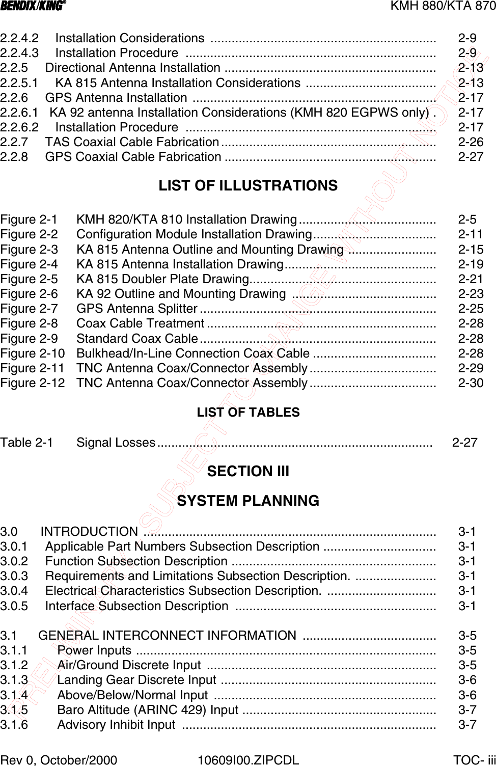
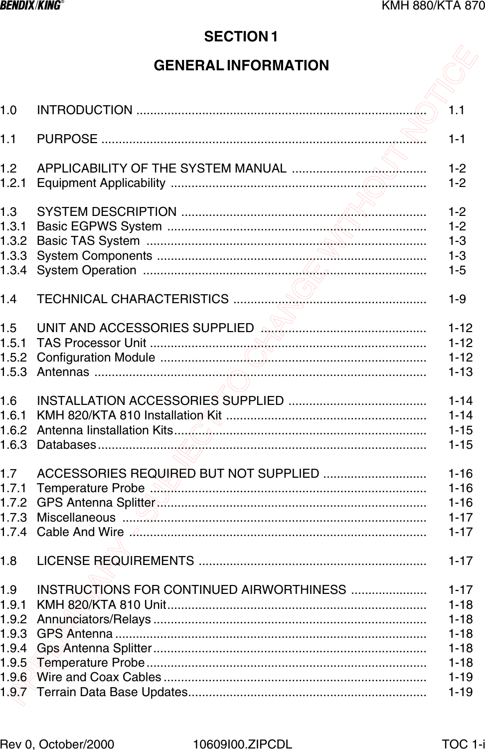

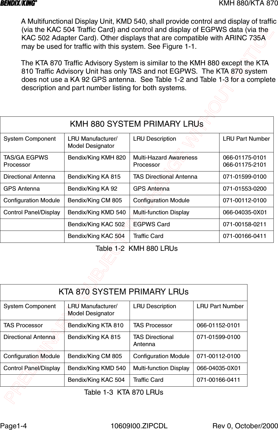
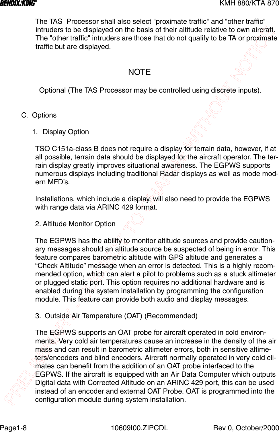


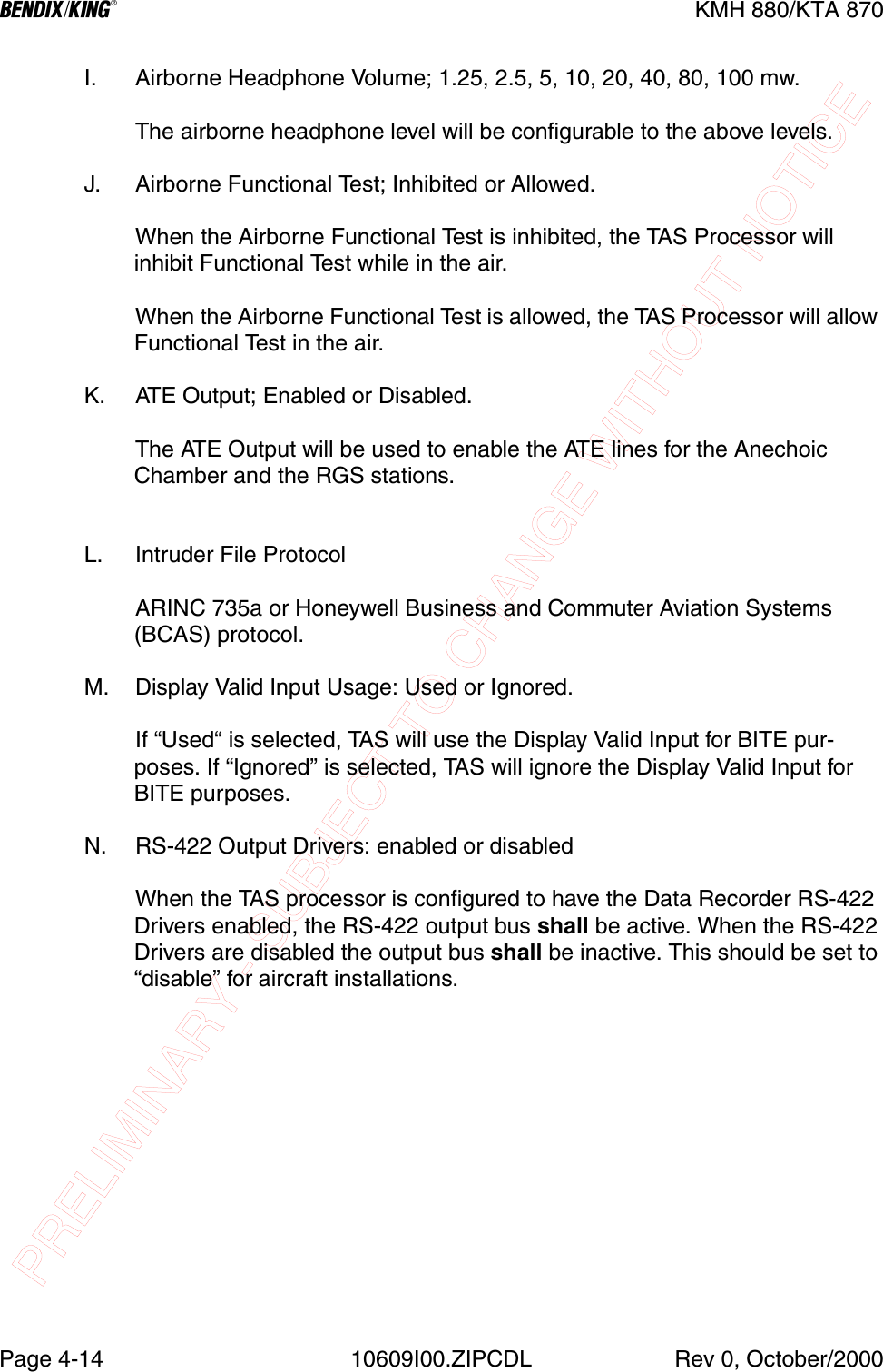
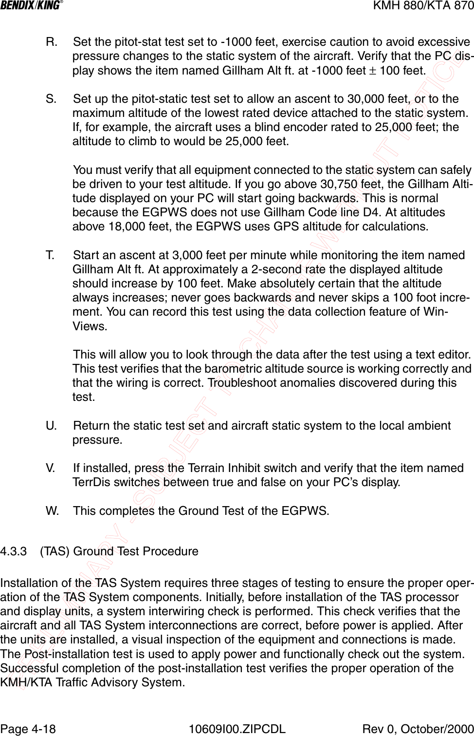
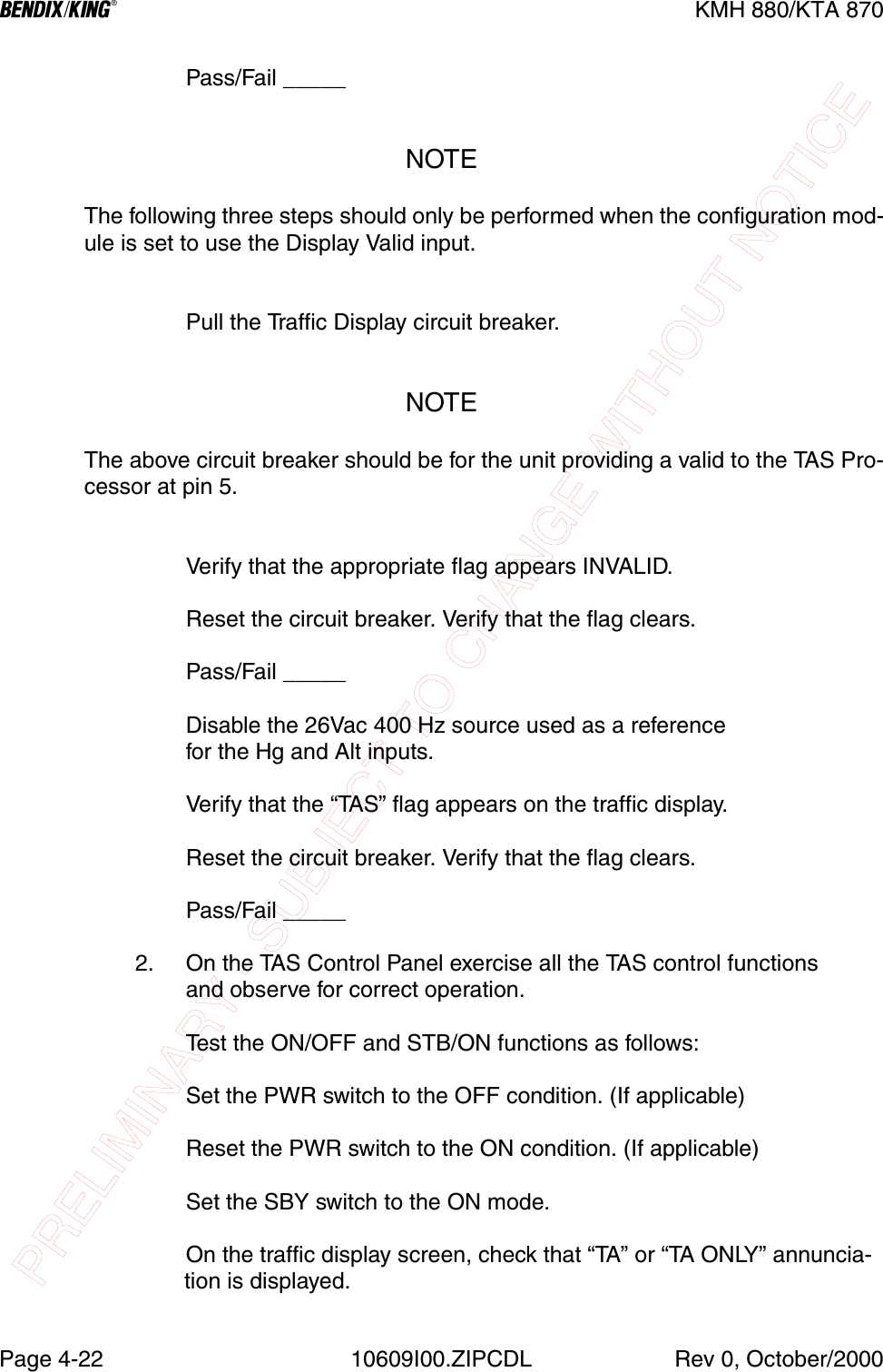
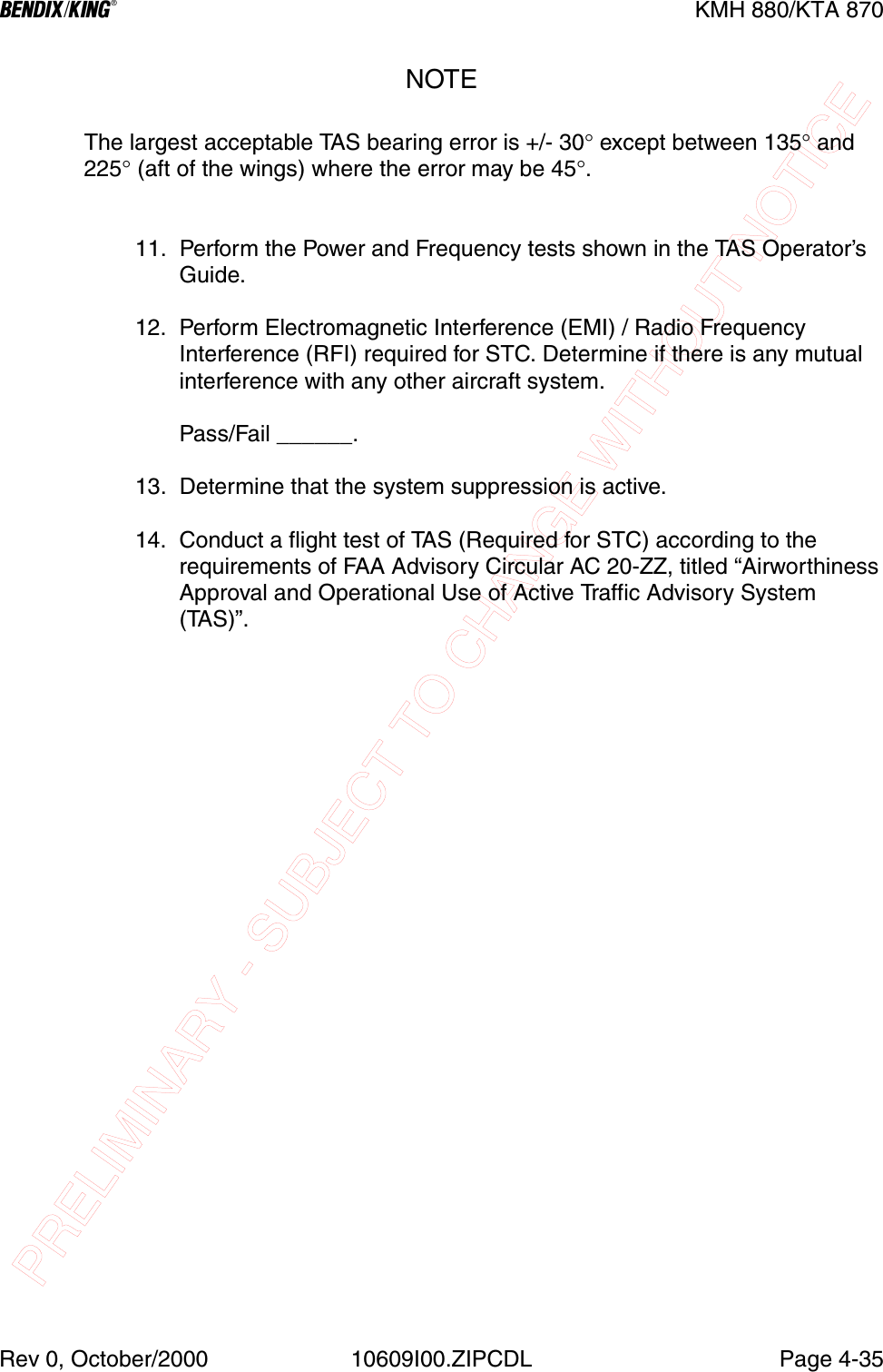
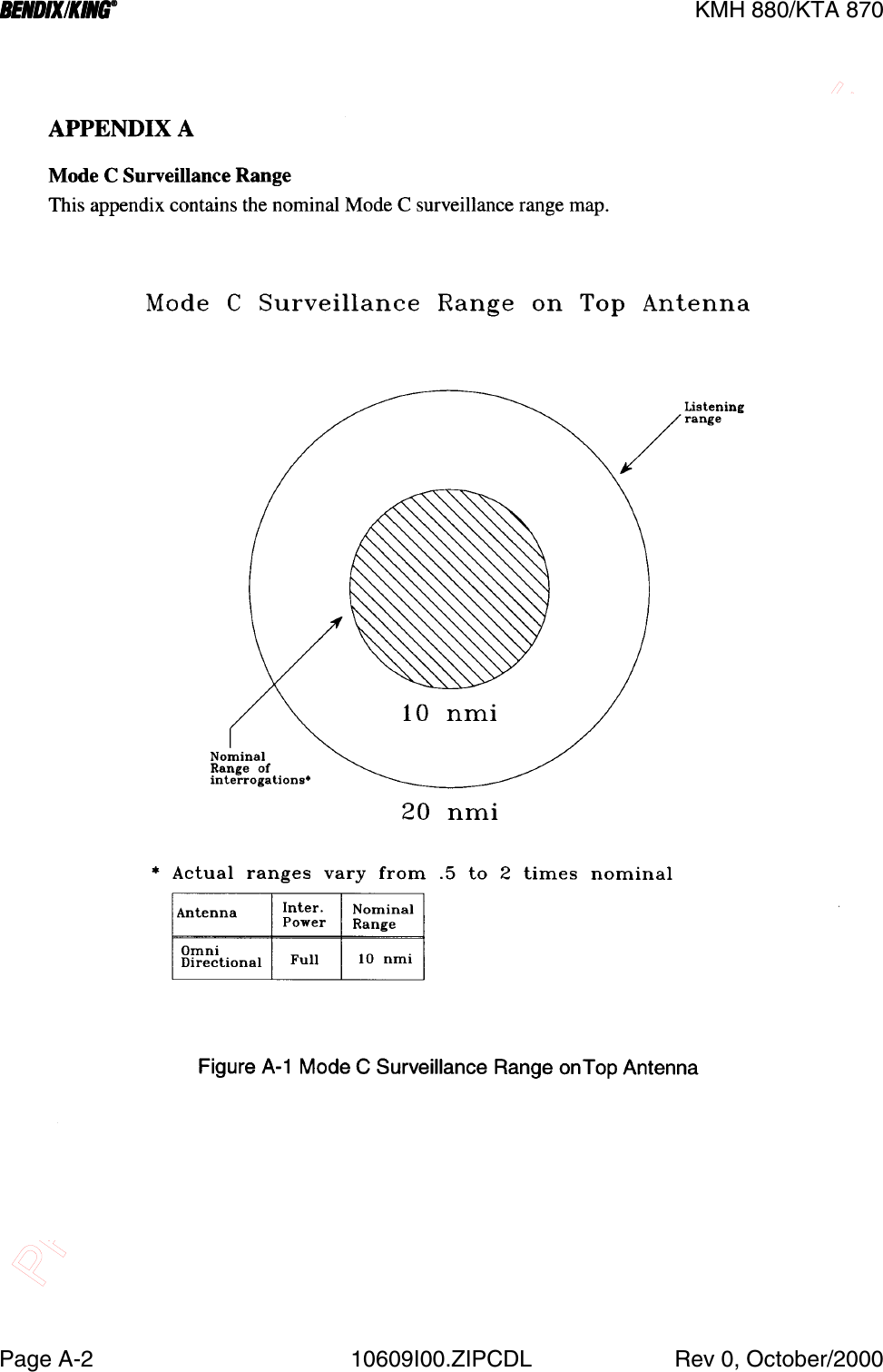
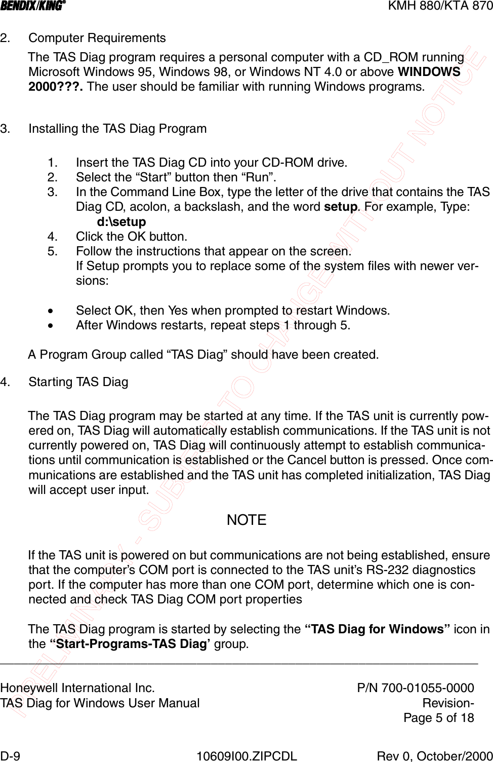
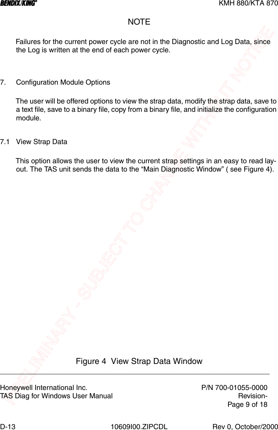
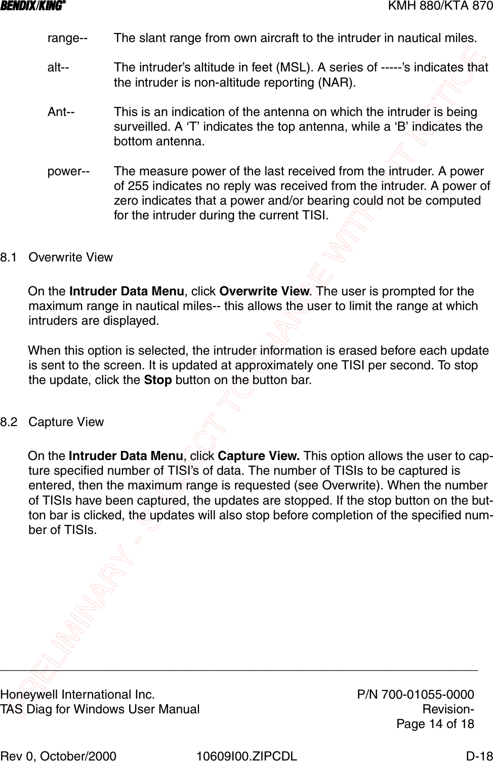
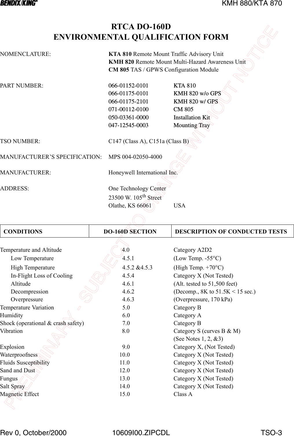
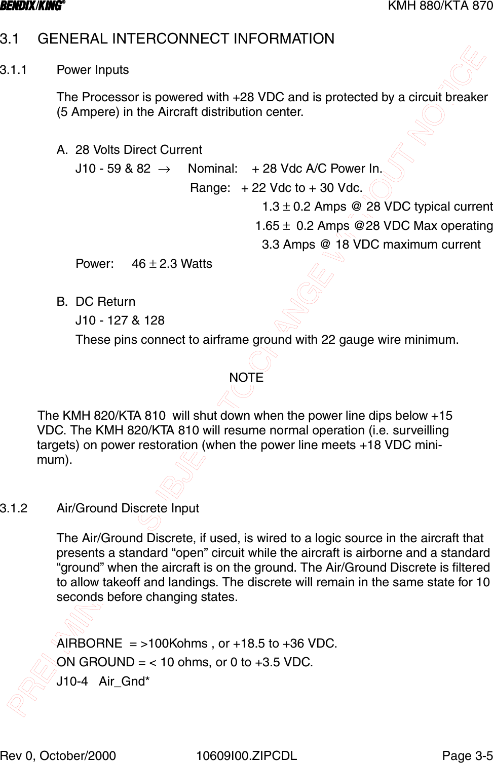
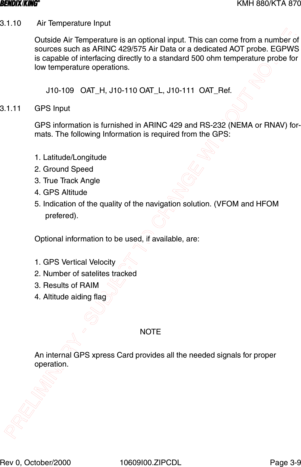
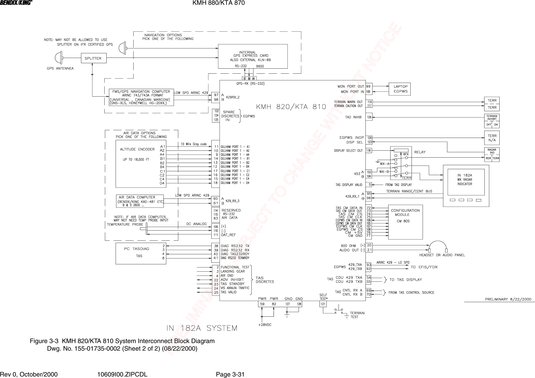
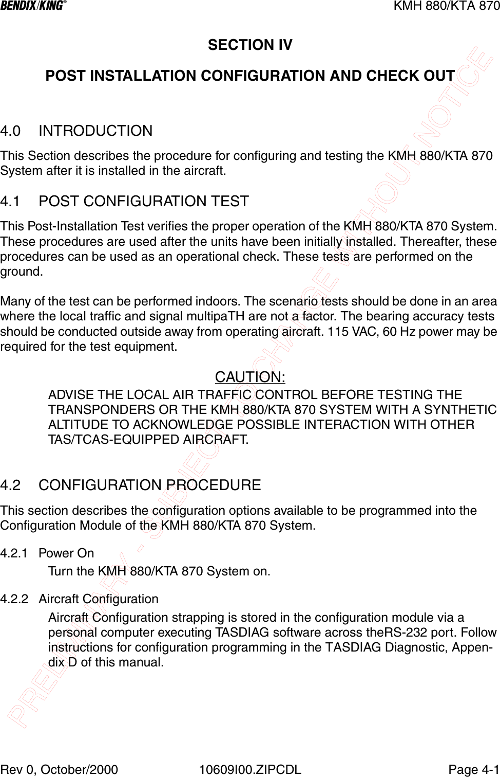
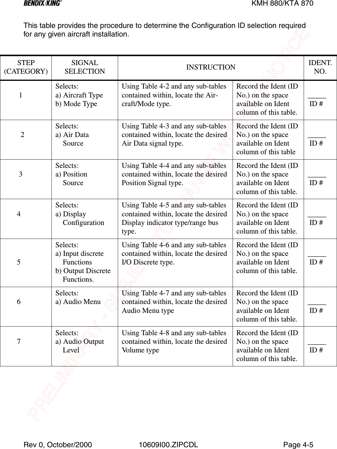
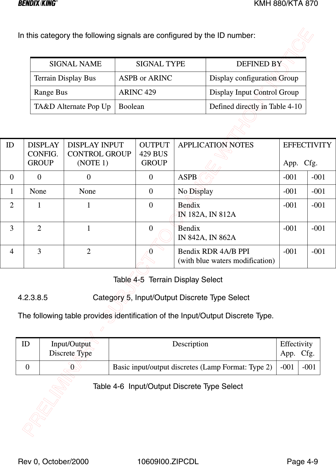
![PRELIMINARY - SUBJECT TO CHANGE WITHOUT NOTICEBBBBKMH 880/KTA 870Page1-14 10609I00.ZIPCDL Rev 0, October/20001.6 INSTALLATION ACCESSORIES SUPPLIED1.6.1 KMH 820/KTA 810 Installation Kit SYMBOL PART NUMBER DESCRIPTION [UOM] -0000200-09894-0000 Rack, KMH 820/ KTA 810 [EA] 1J10 D38999/26FJ35SN 128 Pin I/O Connector [EA] 1M85049/38-25N Strain Relief for 128 Pin I/O Connector [EA] 1J4,J8 030-00005-0002 TAS Antenna Ports, BNC Connectors [EA] 2J1-J3, J5-J7, J9030-00134-0000 Connector, TNC [EA] 7071-00112-0100 CM 805 Configuration Module [EA] 1 030-01171-0000 Conn Sub-D HSG 9S (Female Pins) [EA] 2010-00135-0000 Terminals [EA] 2010-00068-0026 Terminals [EA] 8150-00072-0000 Solder Sleeve [EA] 8030-01157-0011 Socket Contact [EA] 6030-01451-0000 Socket Contact 22 ga [EA] 15030-01464-0000 9 Pin Plastic Hood [EA] 2030-01428-0001 EMI Hood W/ Lock 15 Pin High Density [EA] 1030-03447-0001 High Density 15 Pin Female DSub [EA] 1155-06060-0000 KMH 820/KTA 810 Installation Drawing REFTable 1-14 KMH 820/KTA 810 Installation Kit P/N 050-03361-0000](https://usermanual.wiki/Honeywell/KMH820/User-Guide-146634-Page-28.png)
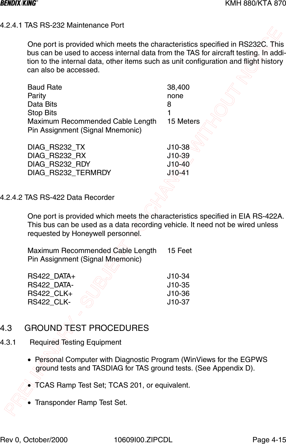
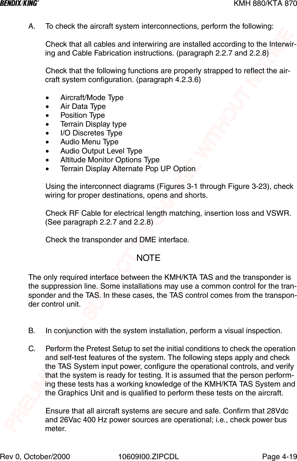
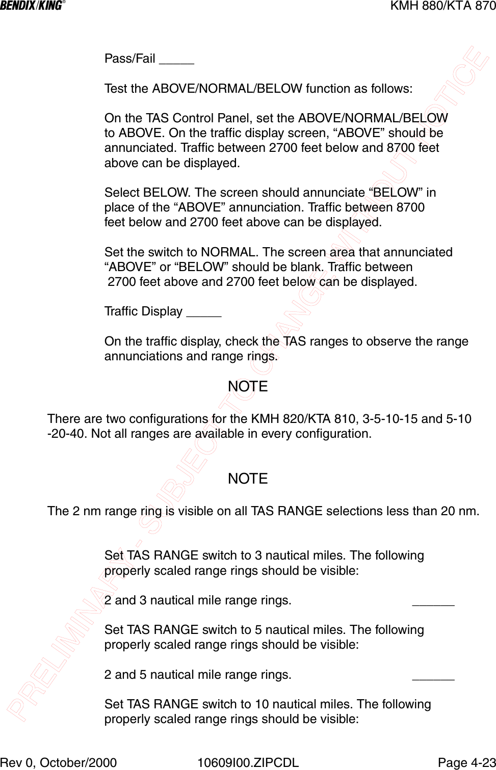
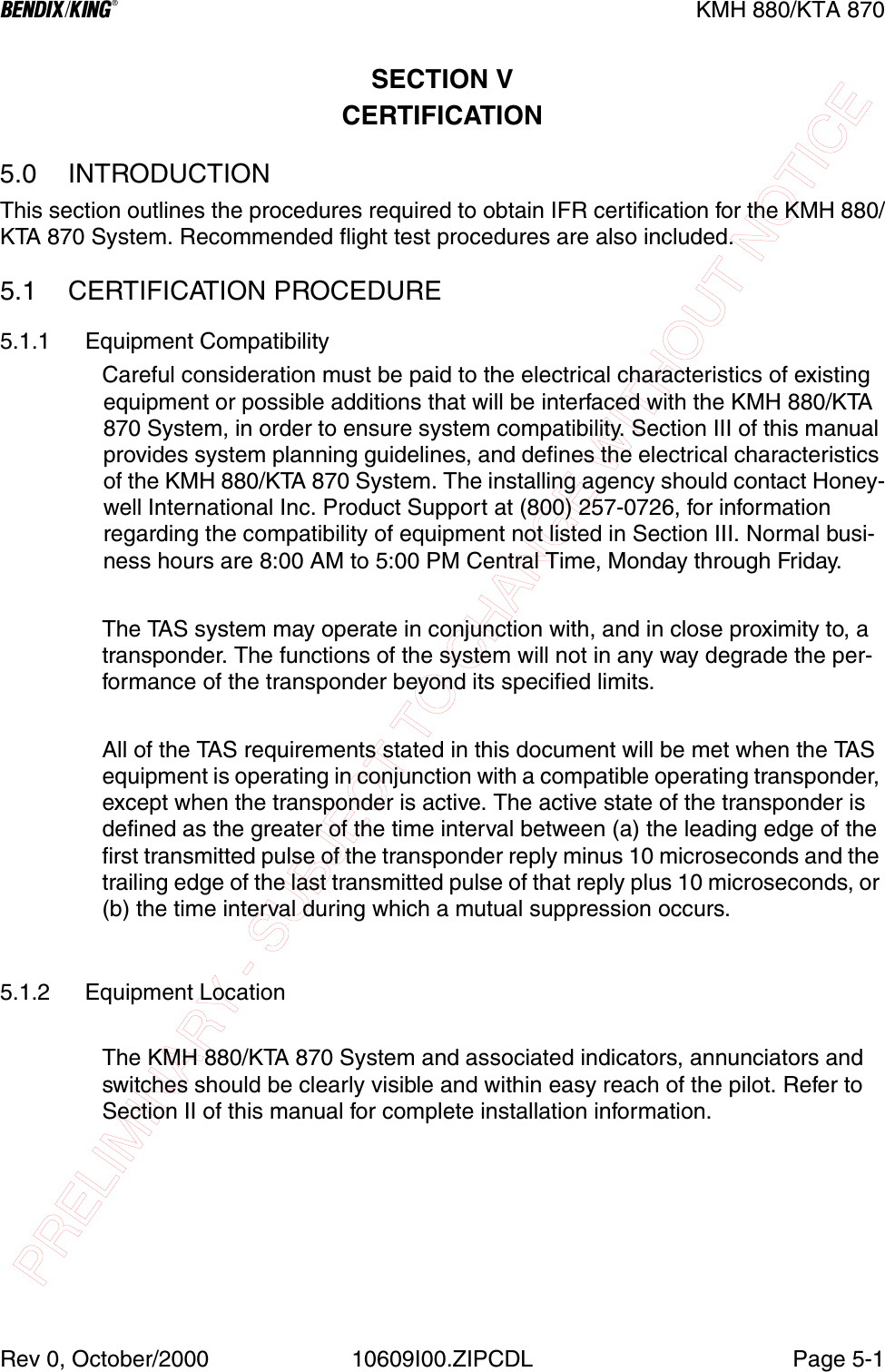
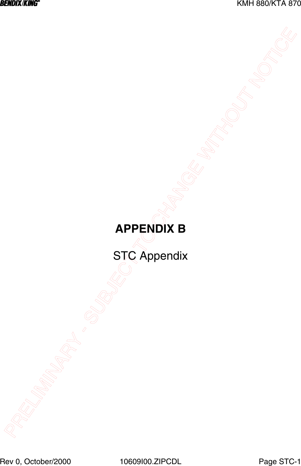
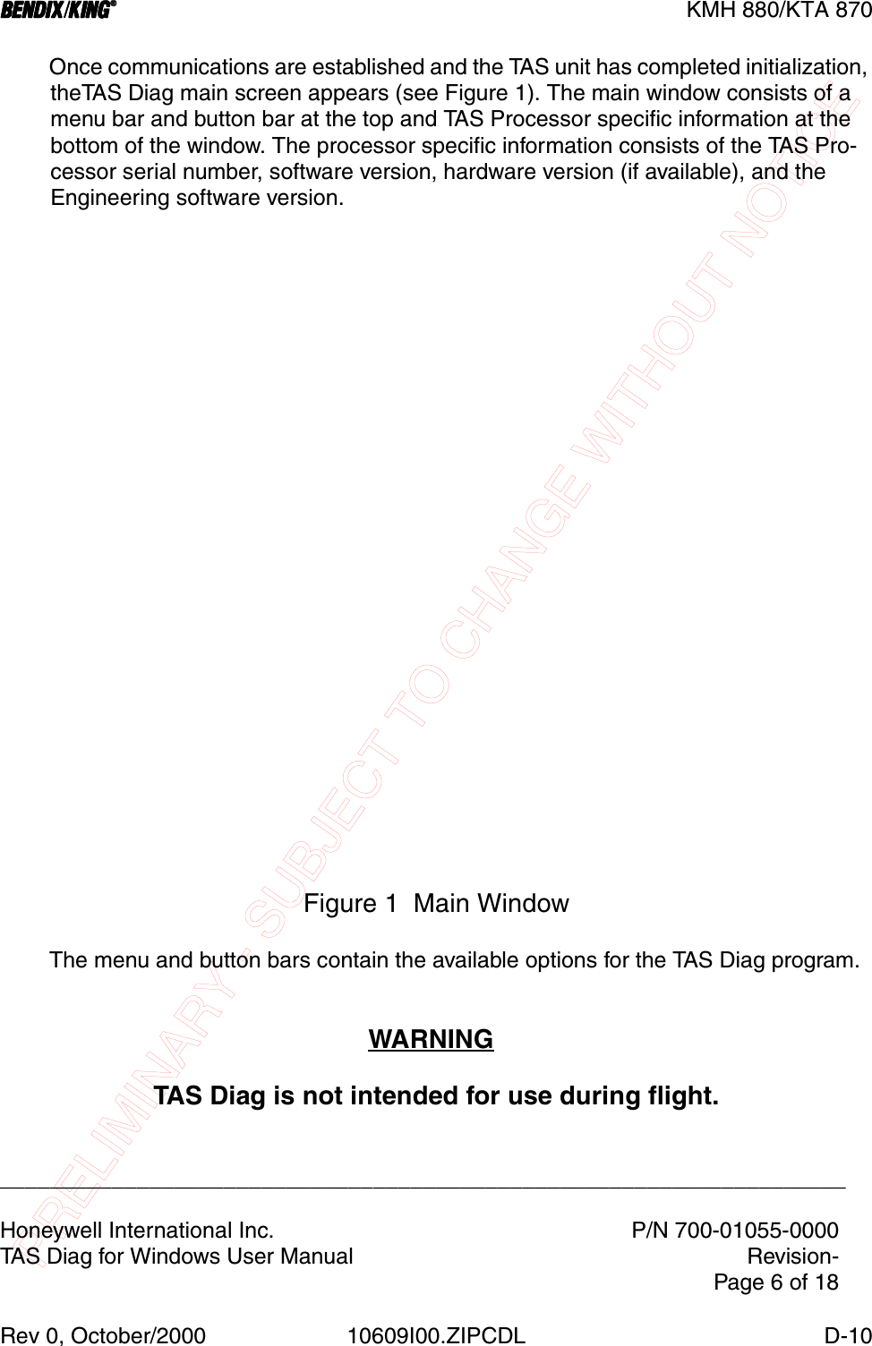
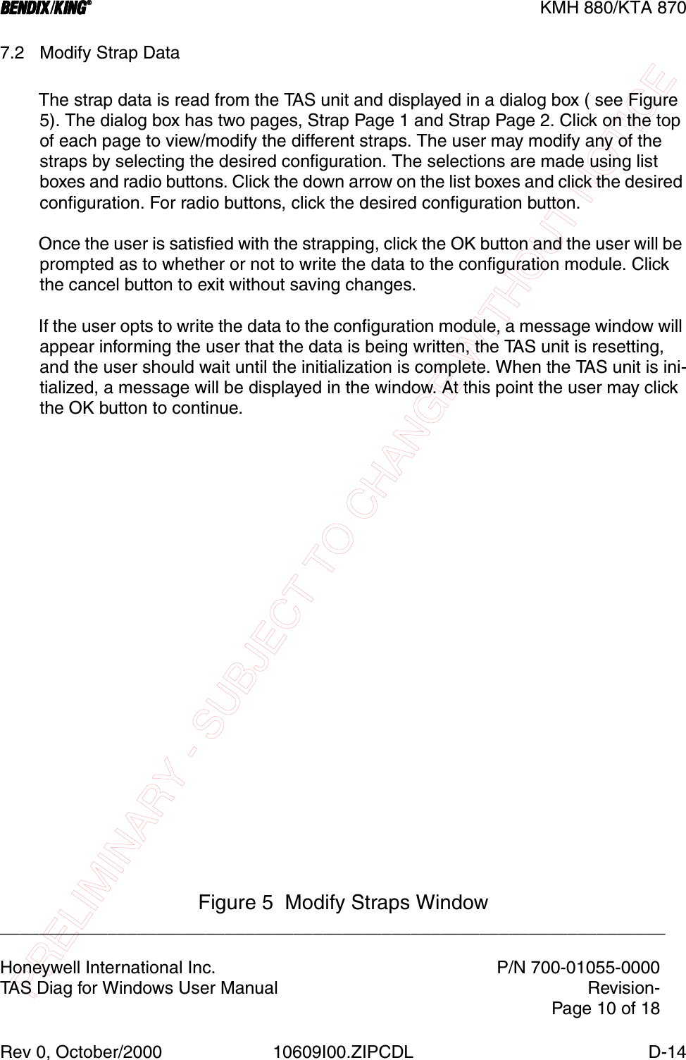
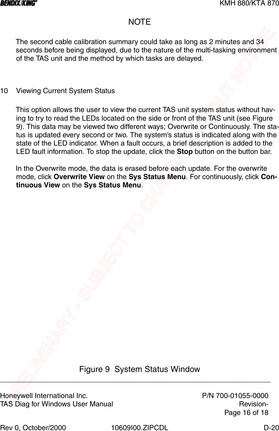
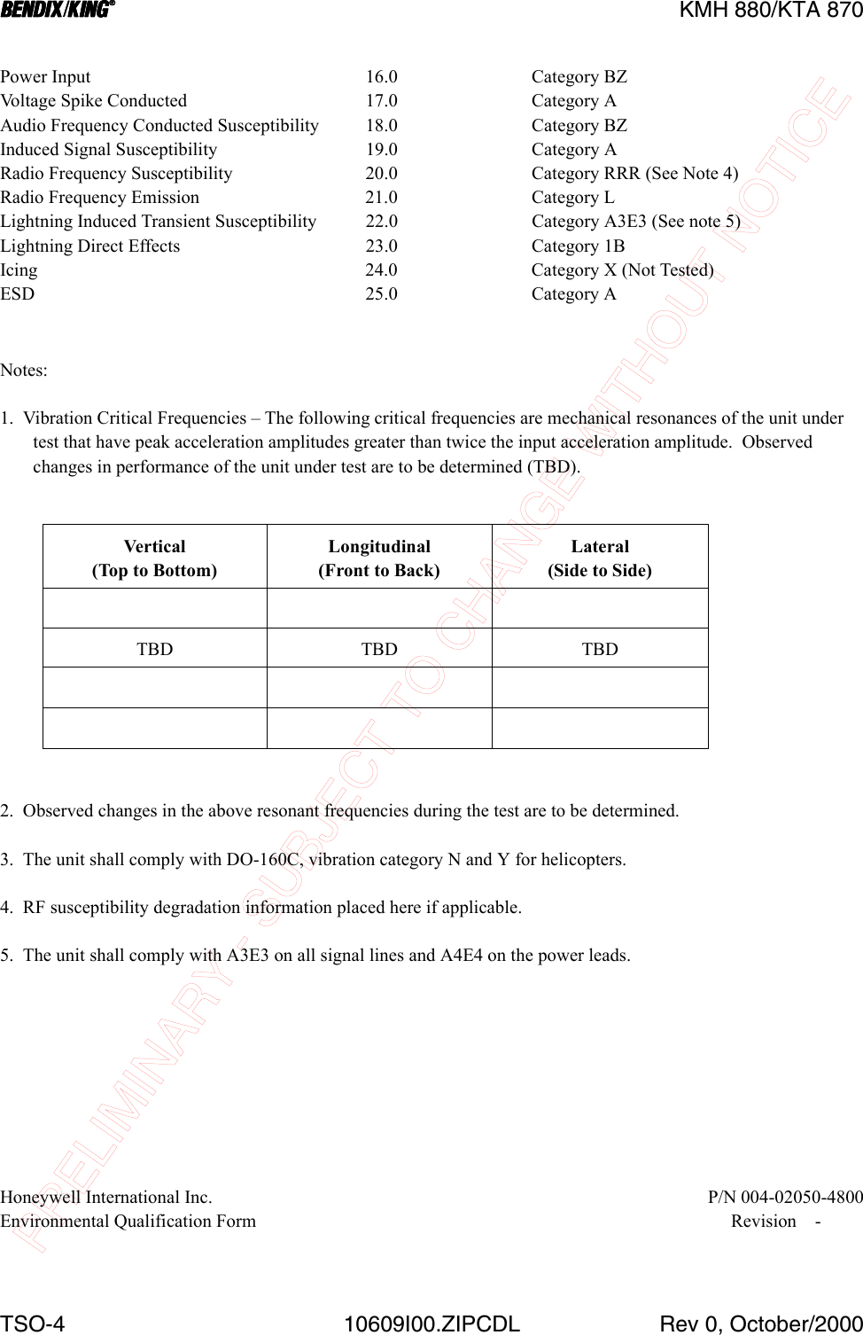
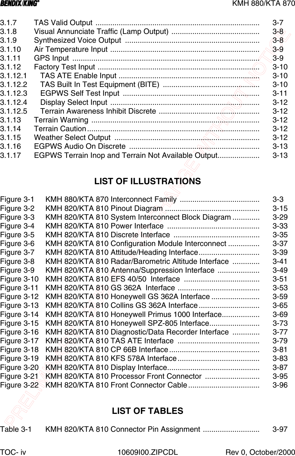
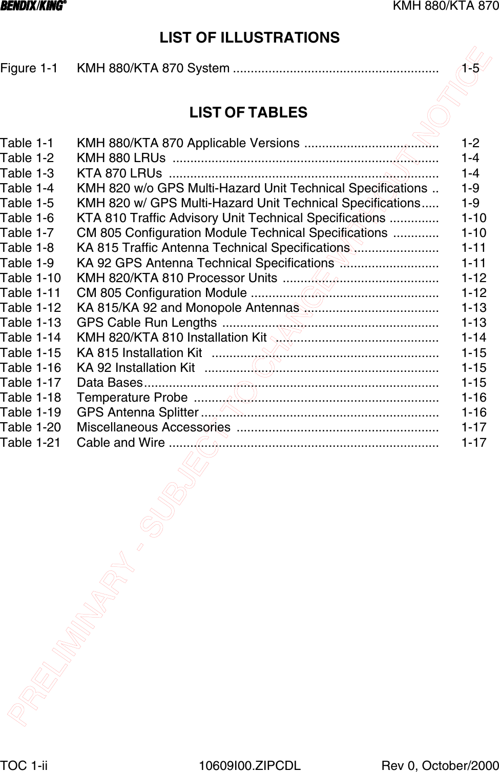
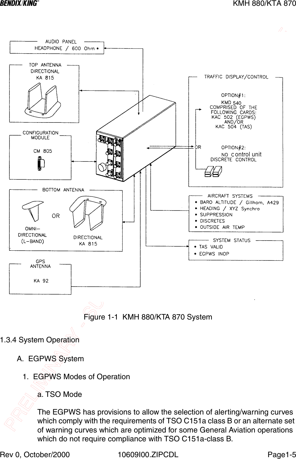
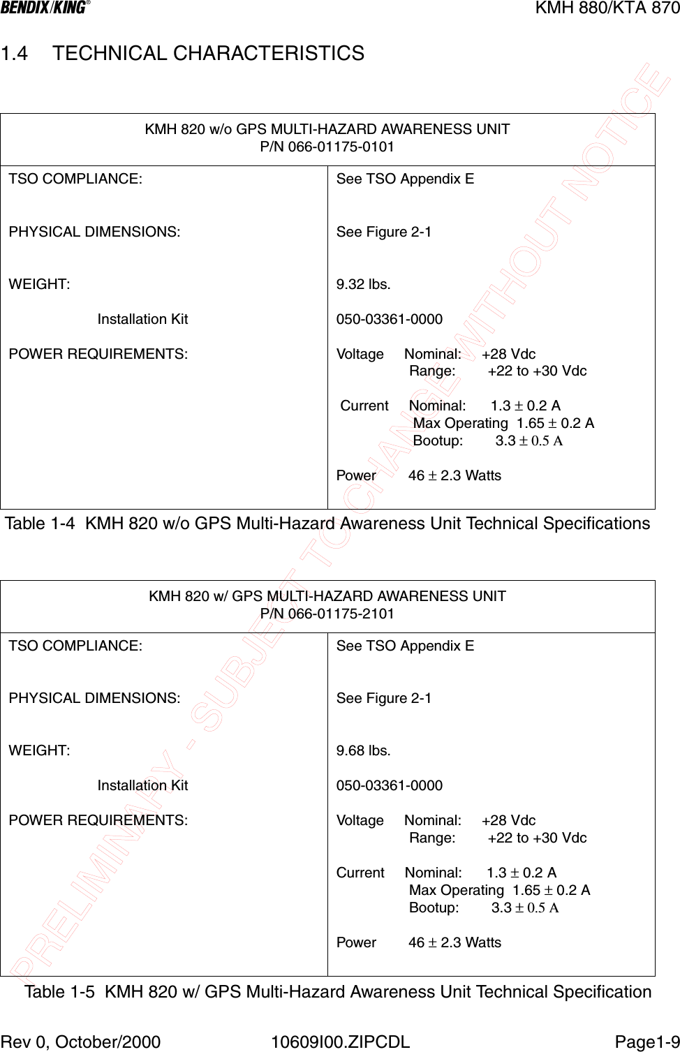
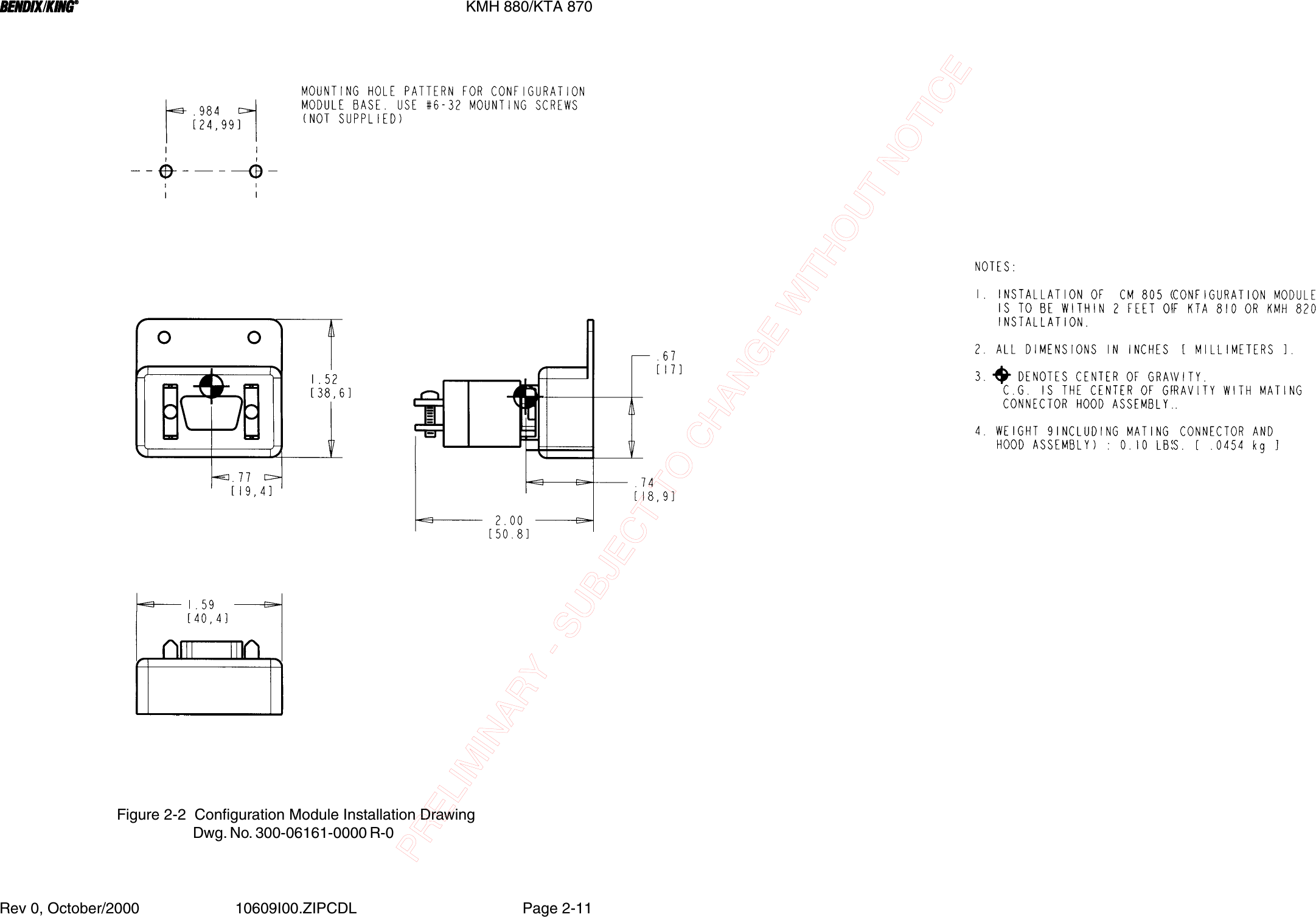
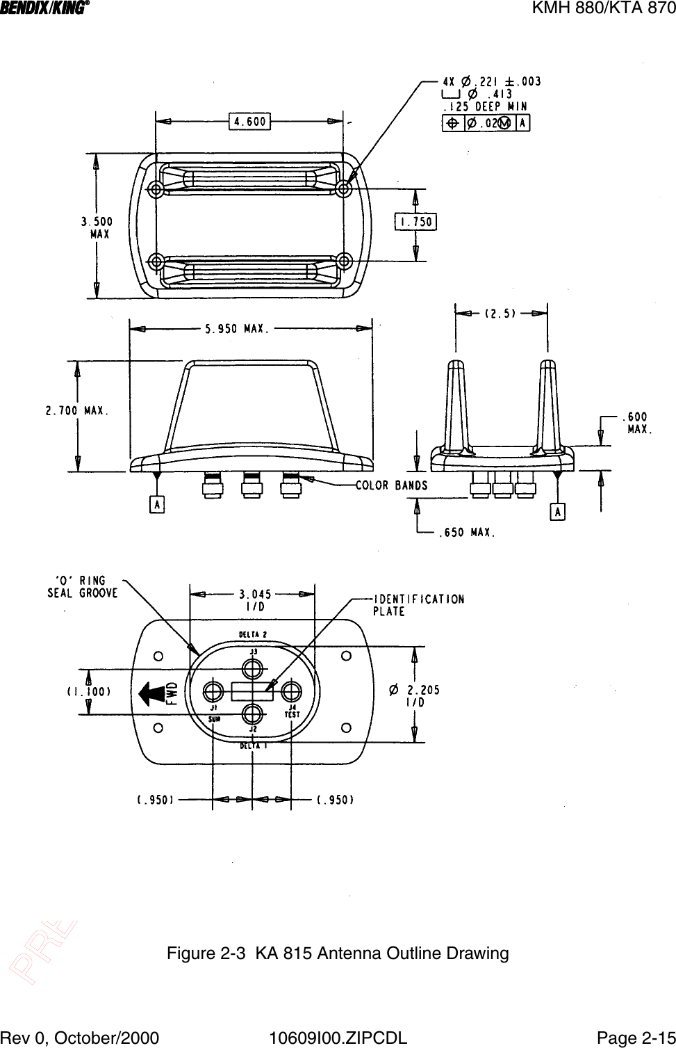
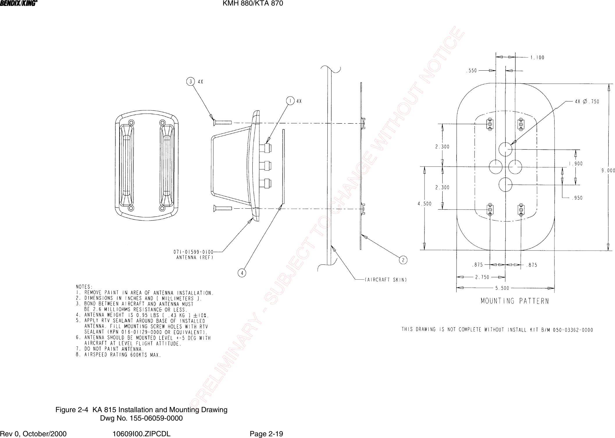
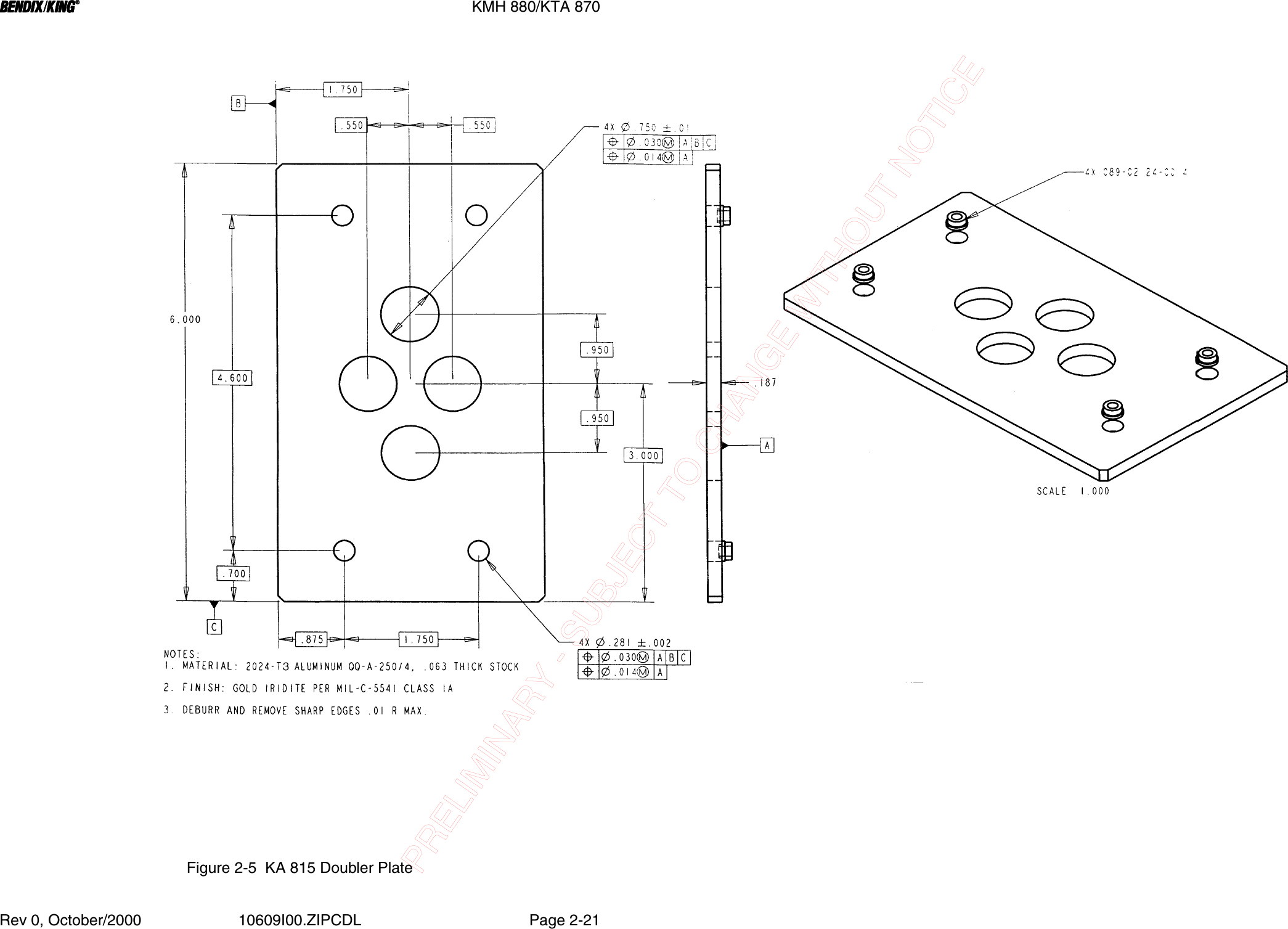
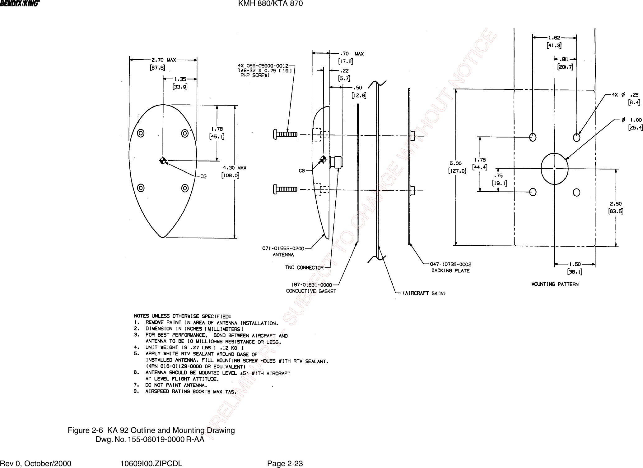
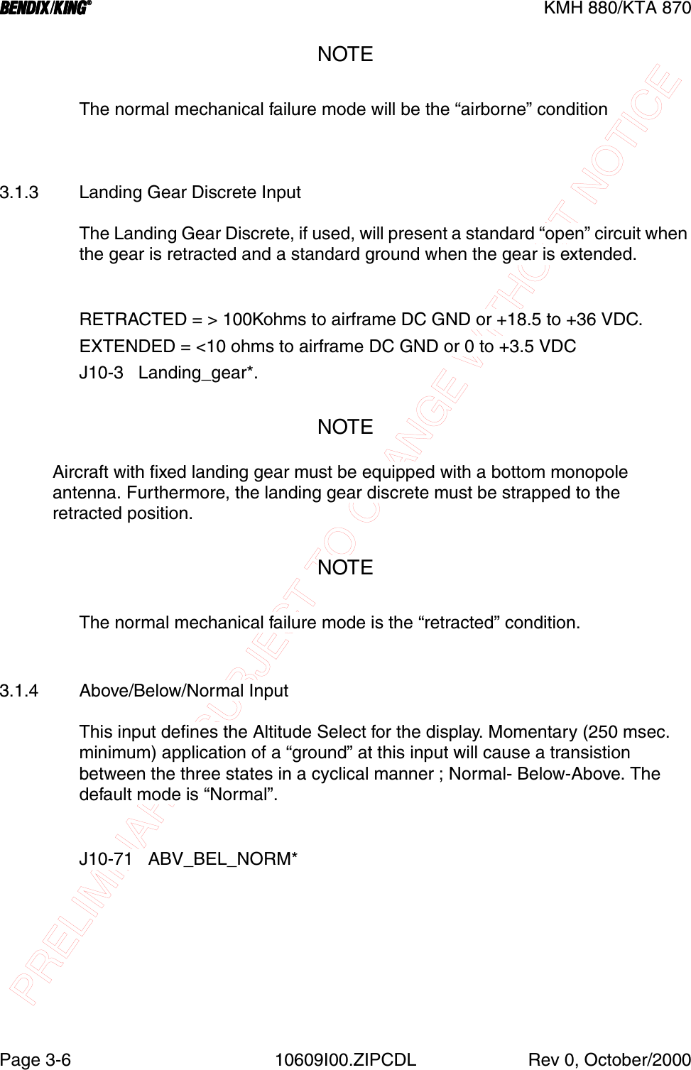
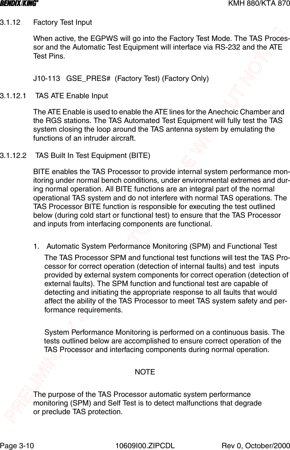
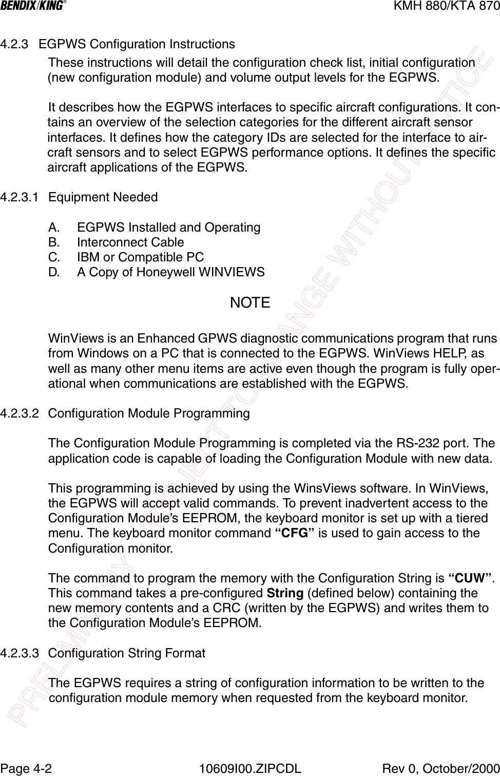
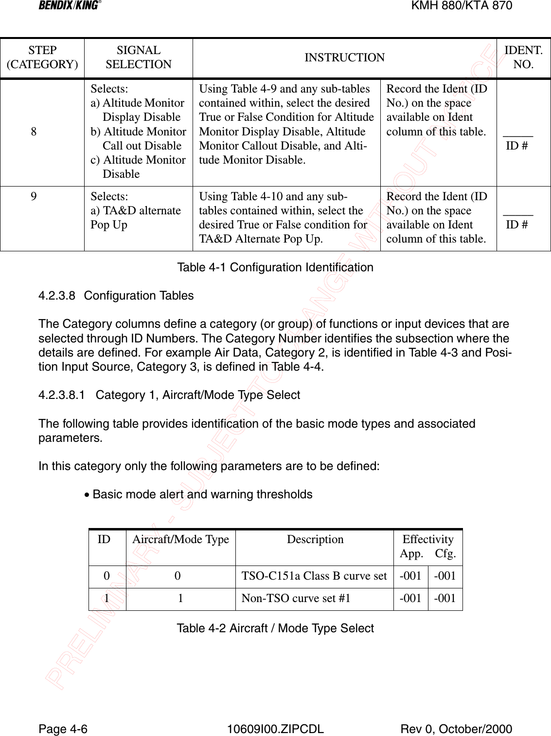
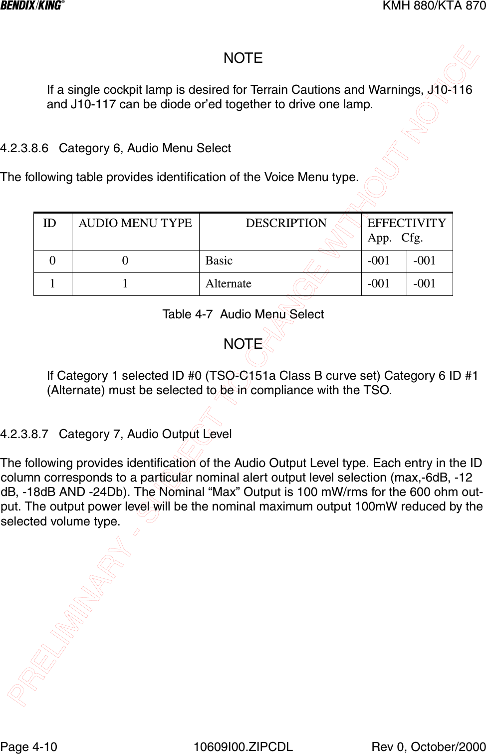
![PRELIMINARY - SUBJECT TO CHANGE WITHOUT NOTICEBKMH 880/KTA 870Rev 0, October/2000 10609I00.ZIPCDL Page1-151.6.2 Antenna Installation Kits1.6.3 DatabasesSYMBOL PART NUMBER DESCRIPTION [UOM] -0000071-01599-0100 KA 815 Antenna [EA] 1M39012/30-0101 Connector, TNC Rt Angle [EA] 4MS29513-148 KA 815 O-Ring [EA] 1MS24693-C54 Screw PHP 8-32x.875 [EA] 4155-06059-0000 KA 815 Installation Drawing REFTable 1-15 KA 815 Installation Kit P/N 050-03622-0000SYMBOL PART NUMBER DESCRIPTION [UOM] -0000030-00134-0001 Connector, TNC Rt Angle [EA] 1047-10735-0002 Antenna DBLR Complete [EA] 1089-05909-0012 Screw PHP 8-32x3/4 [EA] 4187-01831-0000 Antenna Gasket [EA] 1155-06019-0000 KA 92 INstallation Drawing REFTable 1-16 KA 92 Installation Kit P/N 050-03318-0000PART NUMBER DESCRIPTION [UOM]071- 00167-0101 America’s Database [EA]071-00167-0102 Atlantic Database [EA]071-00167-0103 Pacific Database [EA]Table 1-17 KMH 880/KTA 870 Databases](https://usermanual.wiki/Honeywell/KMH820/User-Guide-146634-Page-29.png)
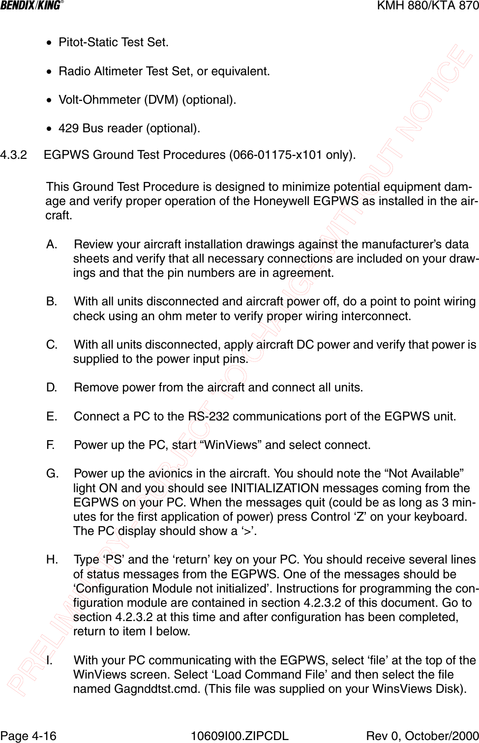
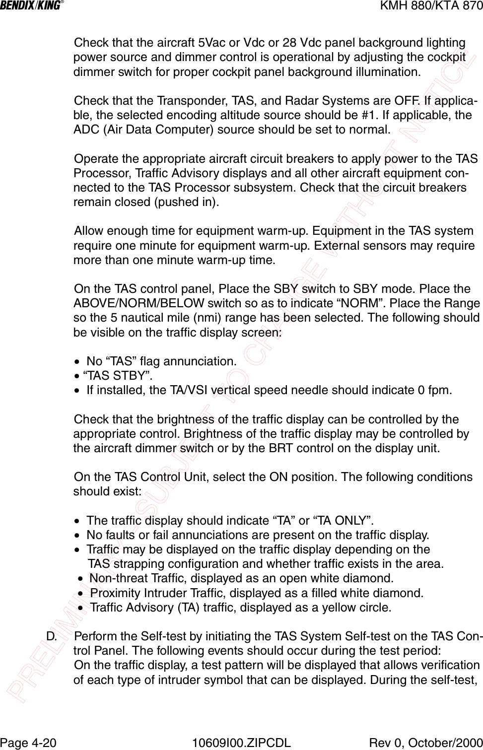
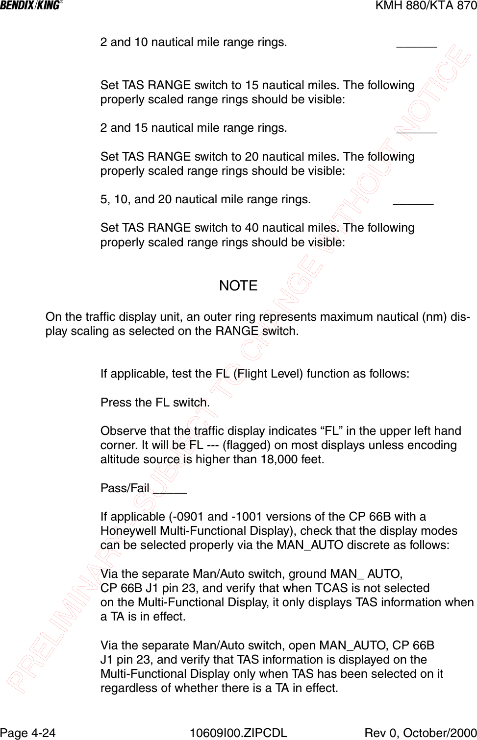
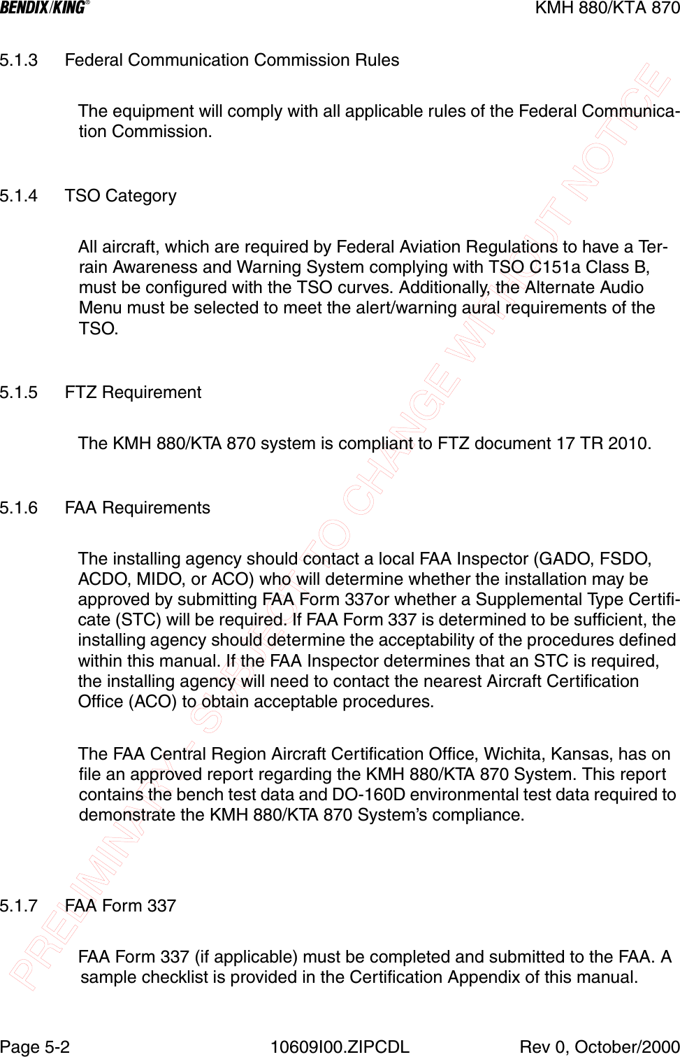
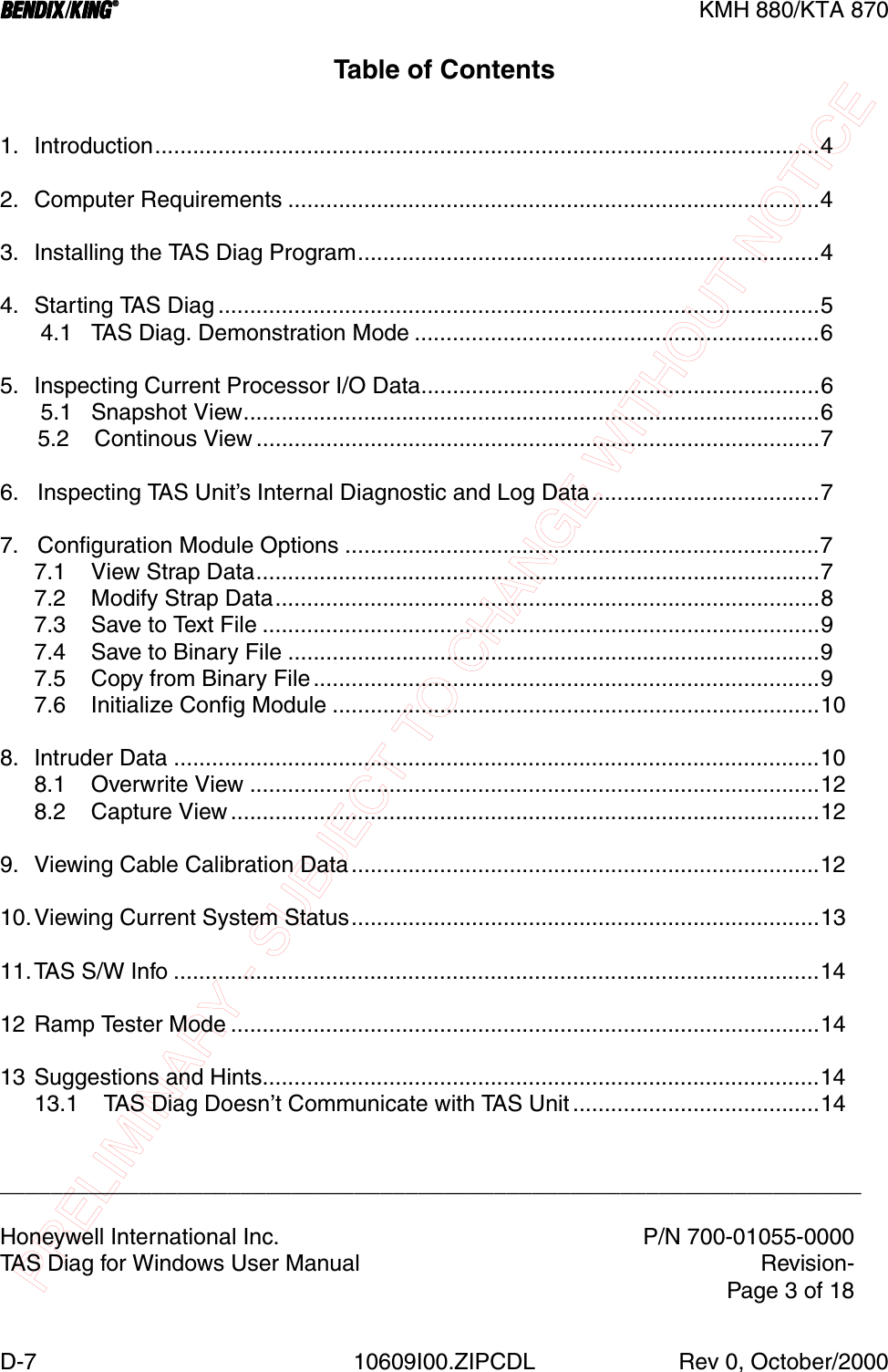
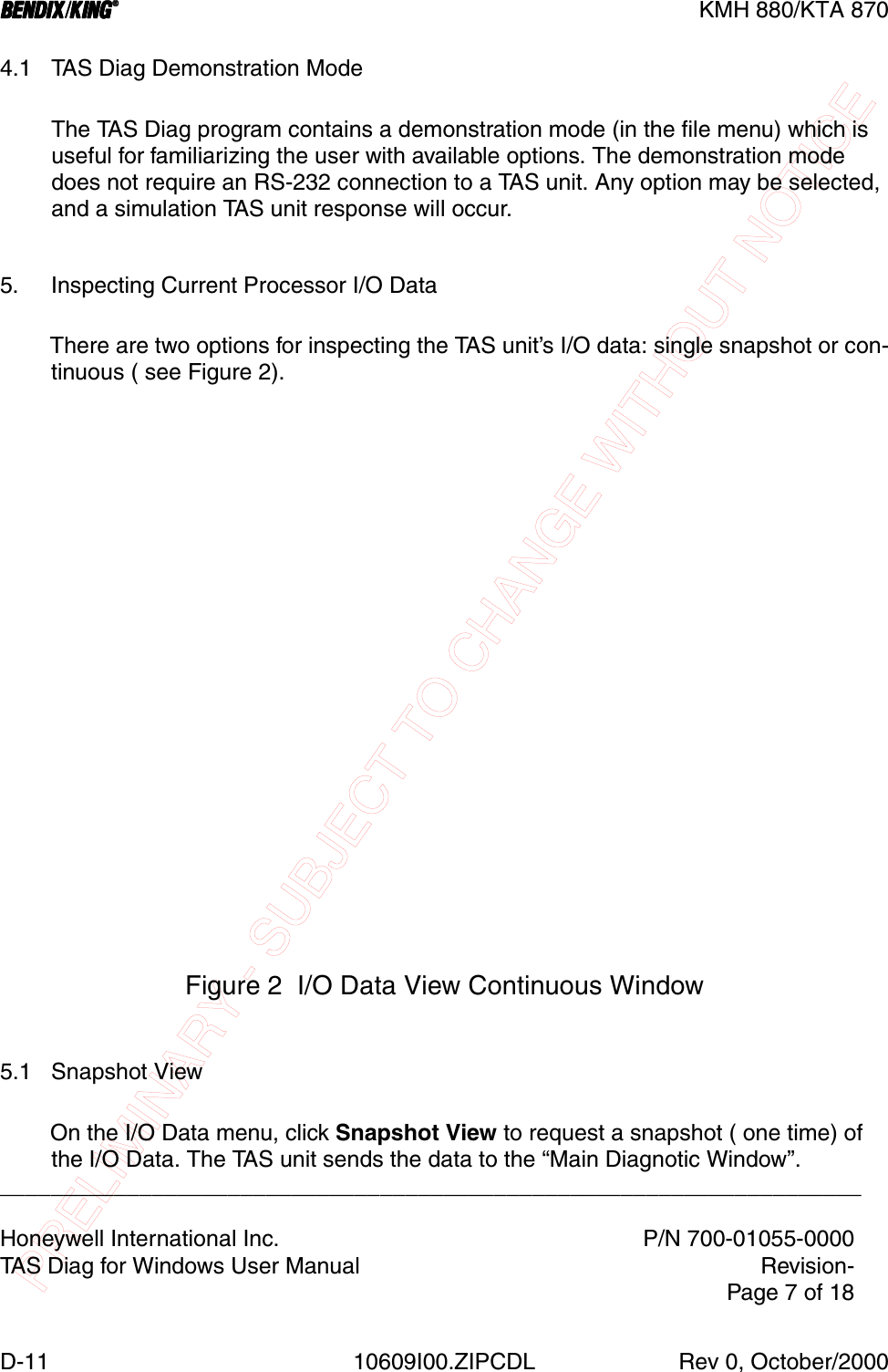
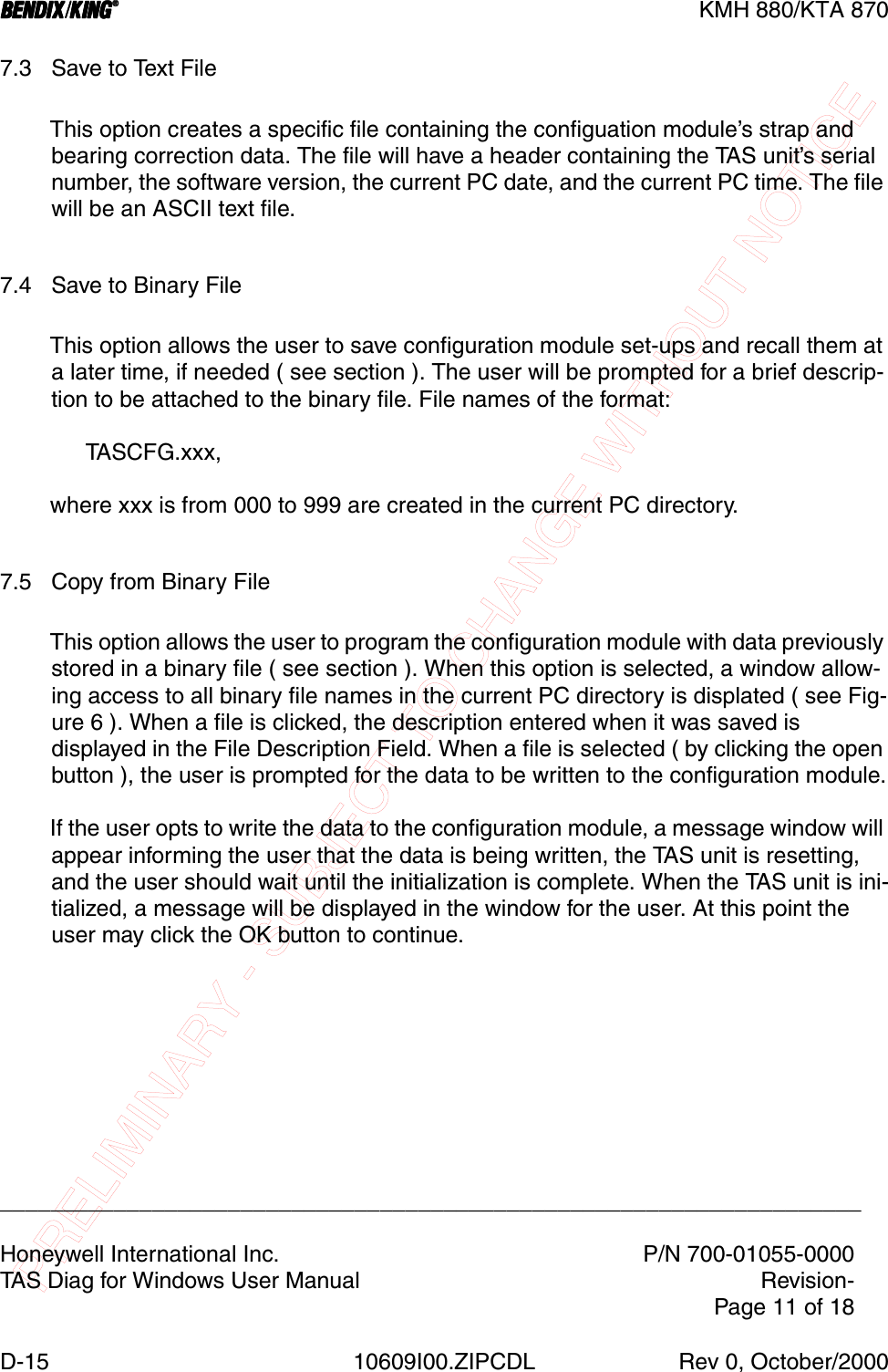
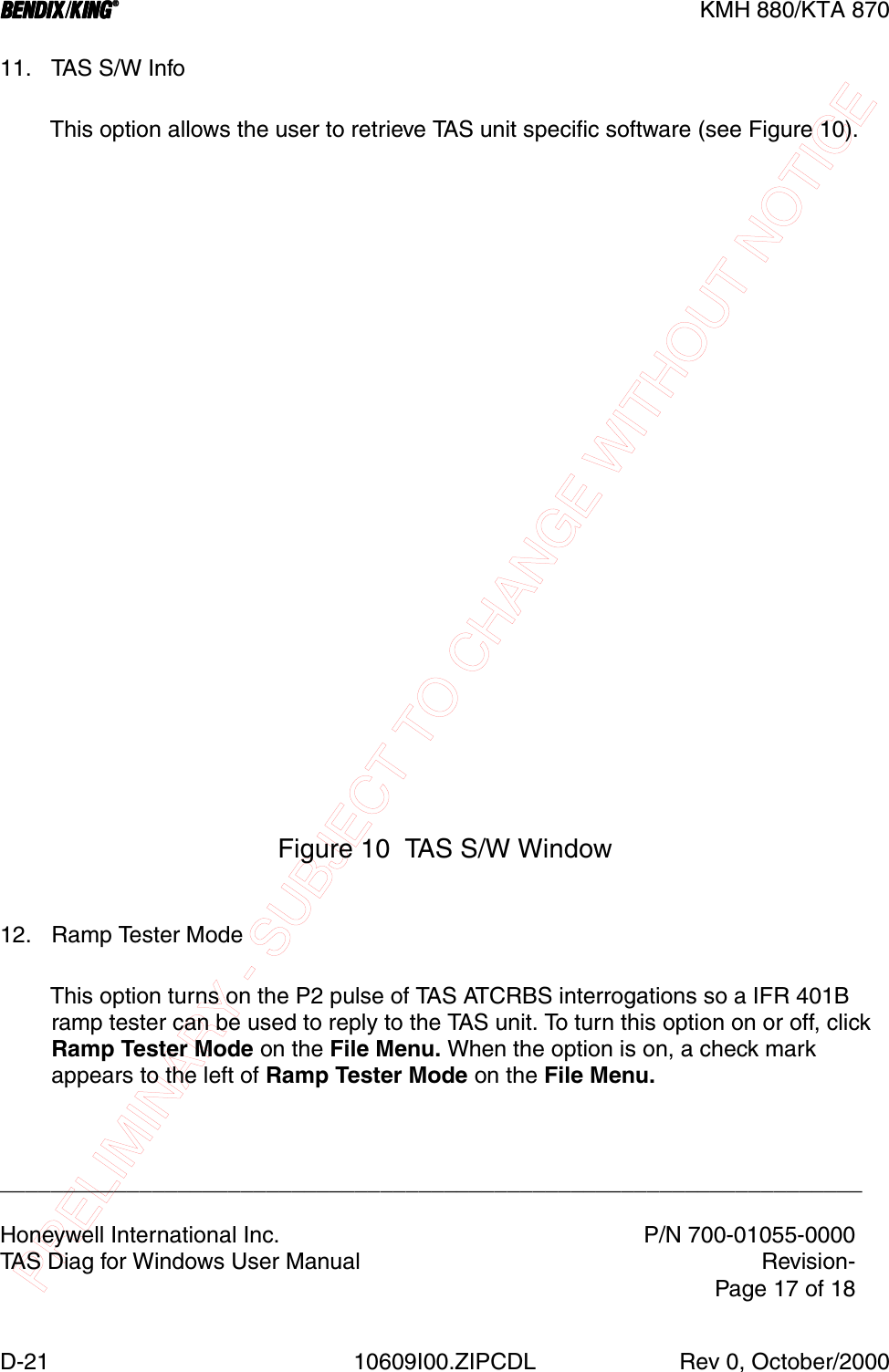
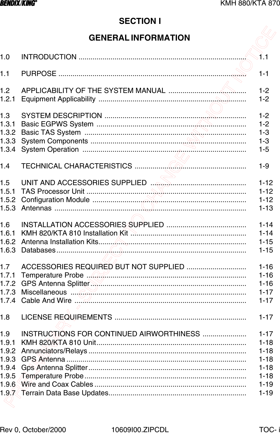
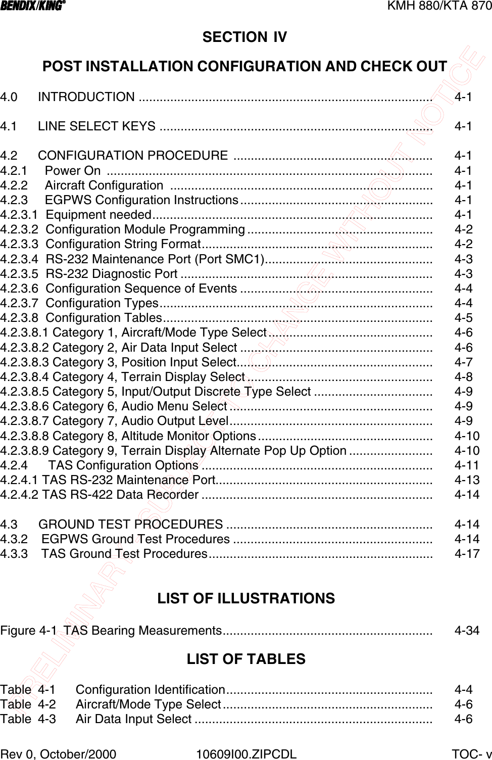
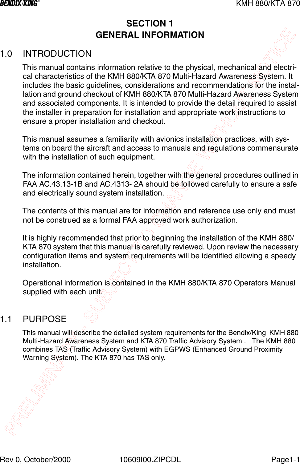
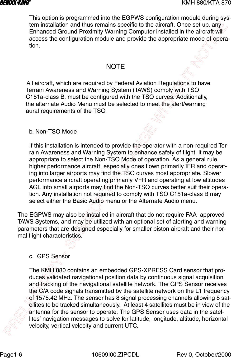
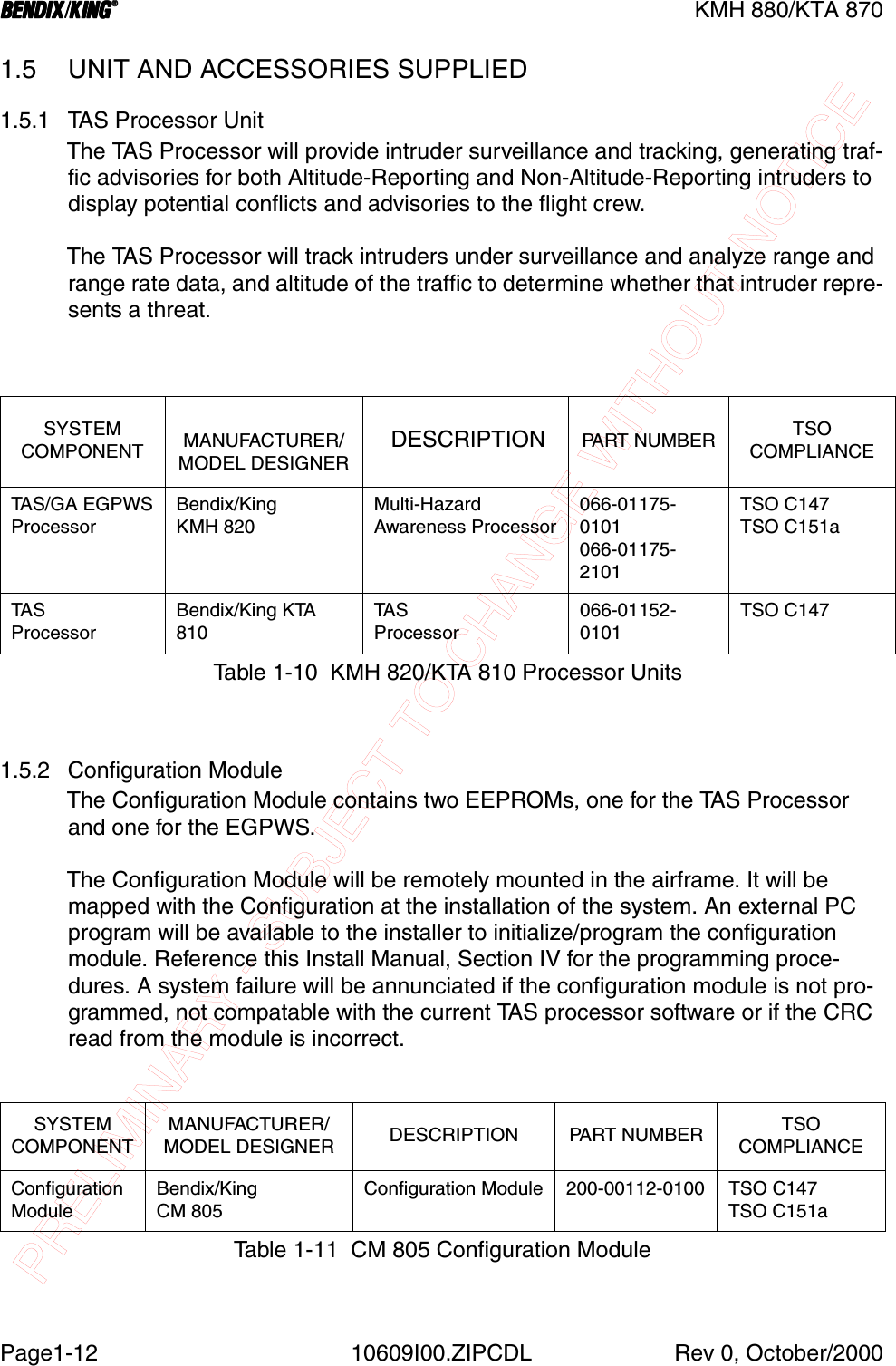
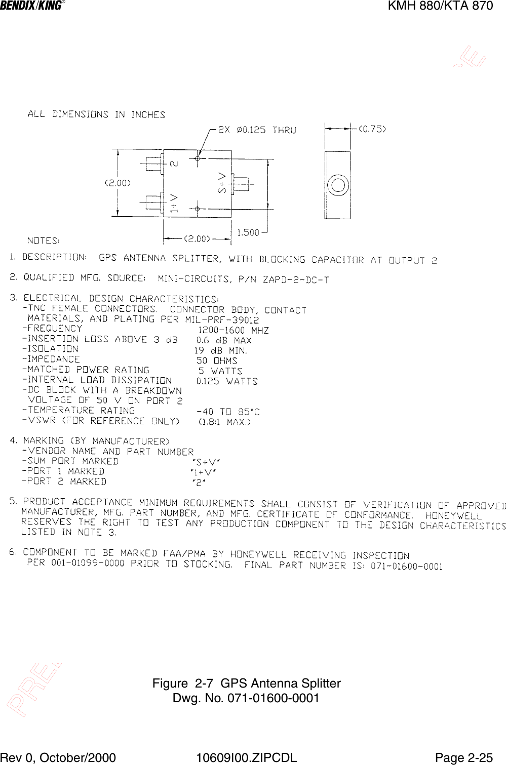
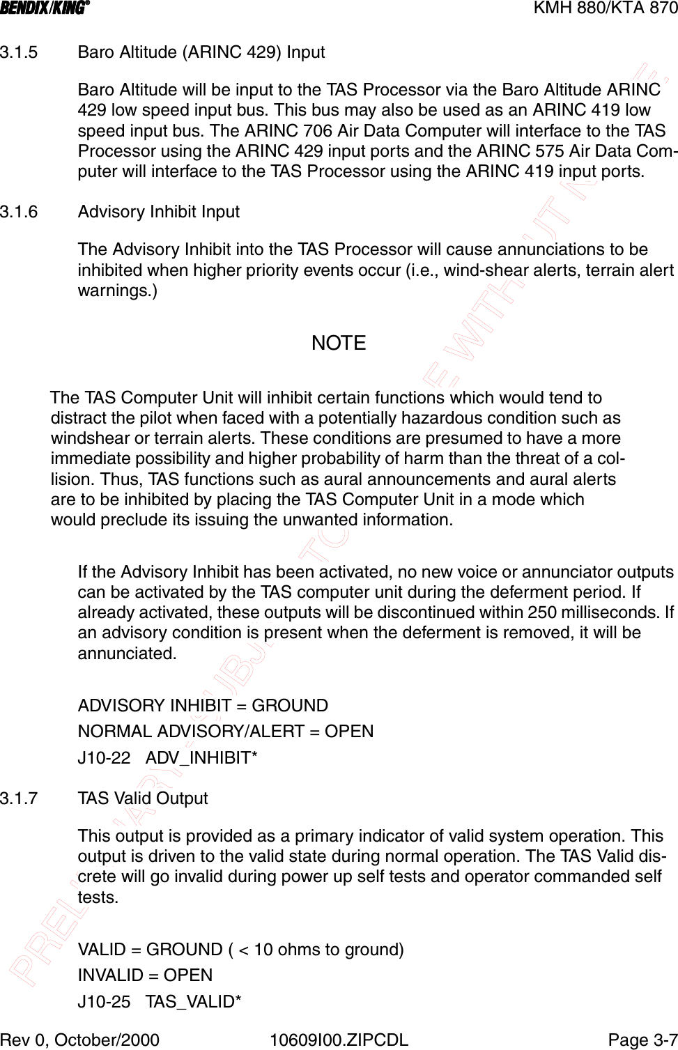
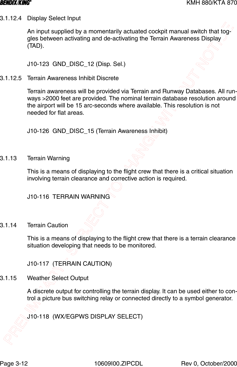
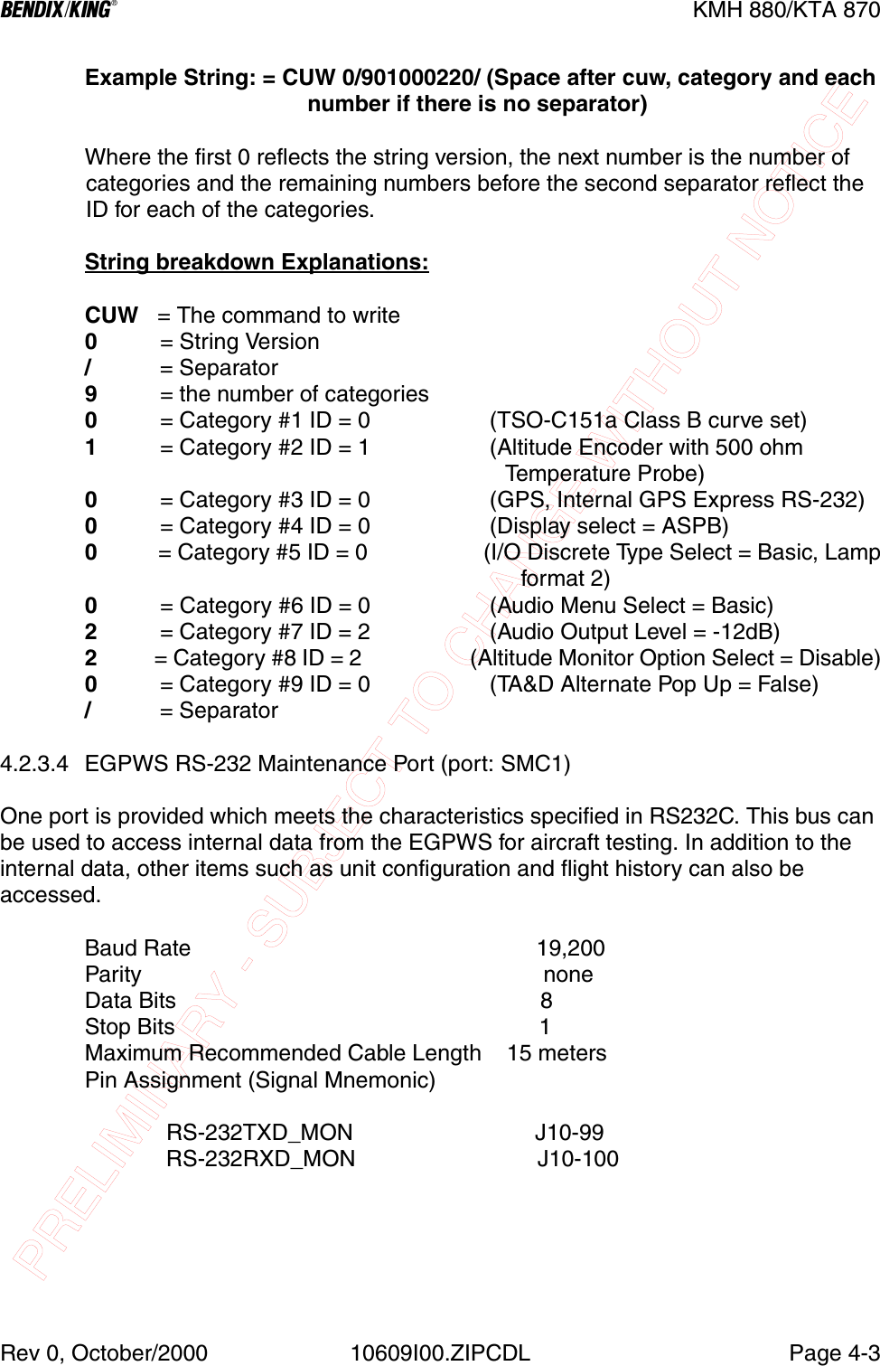
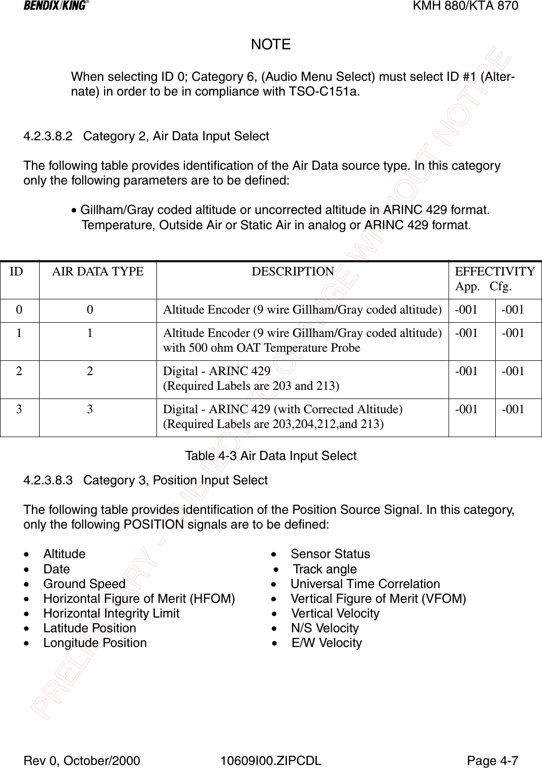
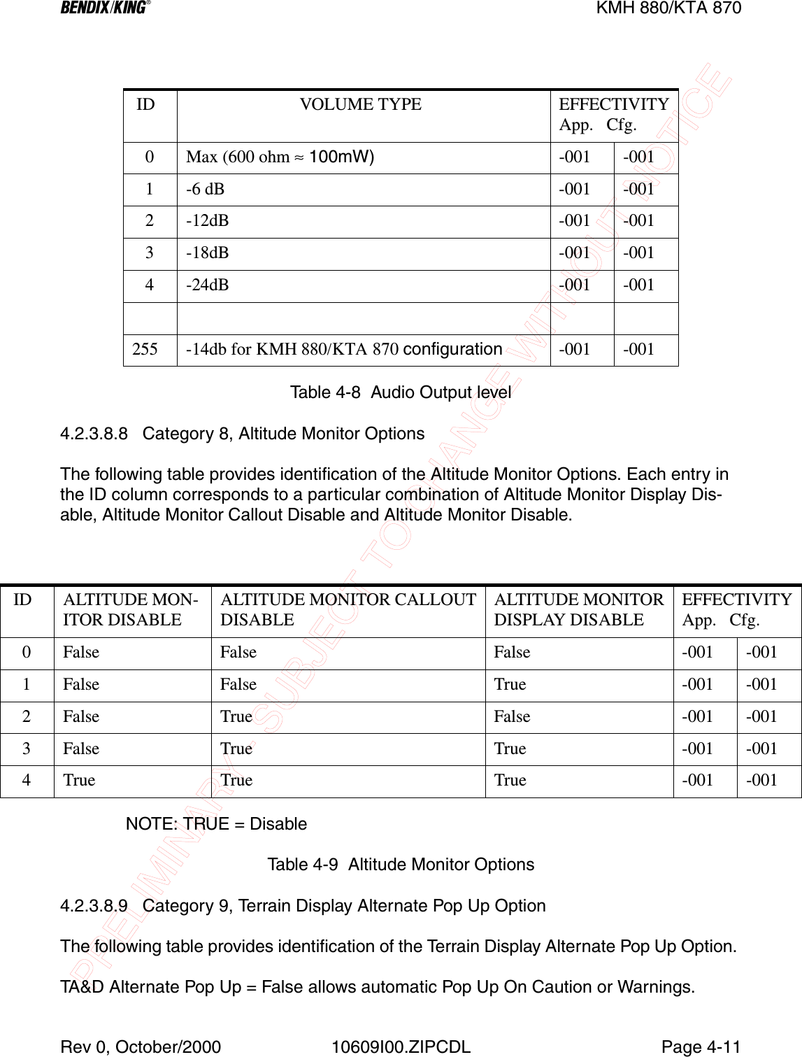
![PRELIMINARY - SUBJECT TO CHANGE WITHOUT NOTICEBBBBKMH 880/KTA 870Page1-16 10609I00.ZIPCDL Rev 0, October/20001.7 ACCESSORIES REQUIRED BUT NOT SUPPLIED 1.7.1 Temperature ProbeThe EGPWS is capable of interfacing directly to a standard 500 ohm temperature probe for aircraft operated in cold environments. Very cold air temperatures cause an increase in the density of the air mass and can result in barometric altimeter errors, both in sensitive altimeters/encoders and blind encoders. Aircraft normally operated in very cold climates can benefit from the addition of an OAT probe inter-faced to the EGPWSNOTEThe EGPWS Processor does not require a Temperature Probe input if a Digital Air Data Computer, with an OAT Label present on the bus, is available as an interface.1.7.2 GPS Antenna SplitterTo have the flexibility of using an existing KA 92 GPS Antenna, Honeywell offers a splitter that will greatly simplify the installation procedure. One of the split ports is DC blocked from the common port so that equipment voltage regulators do not conflict.SYMBOL PART NUMBER DESCRIPTION [UOM] -0001137-00042-0001 OAT Probe [EA] 1MS3106E12S-3S OAT Probe Connector [EA] 1090-01034-0001 OAT Probe Mounting Kit [EA] 1010-00068-0016 Crimp Terminal [EA] 1Table 1-18 Temperature Probe P/N 050-03610-0002SYMBOL PART NUMBER DESCRIPTION [UOM] QTY050-03610-0003 GPS Antenna Splitter Kit [EA] 1030-00134-0000 TNC Connector Straight [EA] 3030-00134-0001 TNC Connector Rt Angle [EA] 1Table 1-19 GPS Antenna Splitter P/N 071-01600-0001](https://usermanual.wiki/Honeywell/KMH820/User-Guide-146634-Page-30.png)
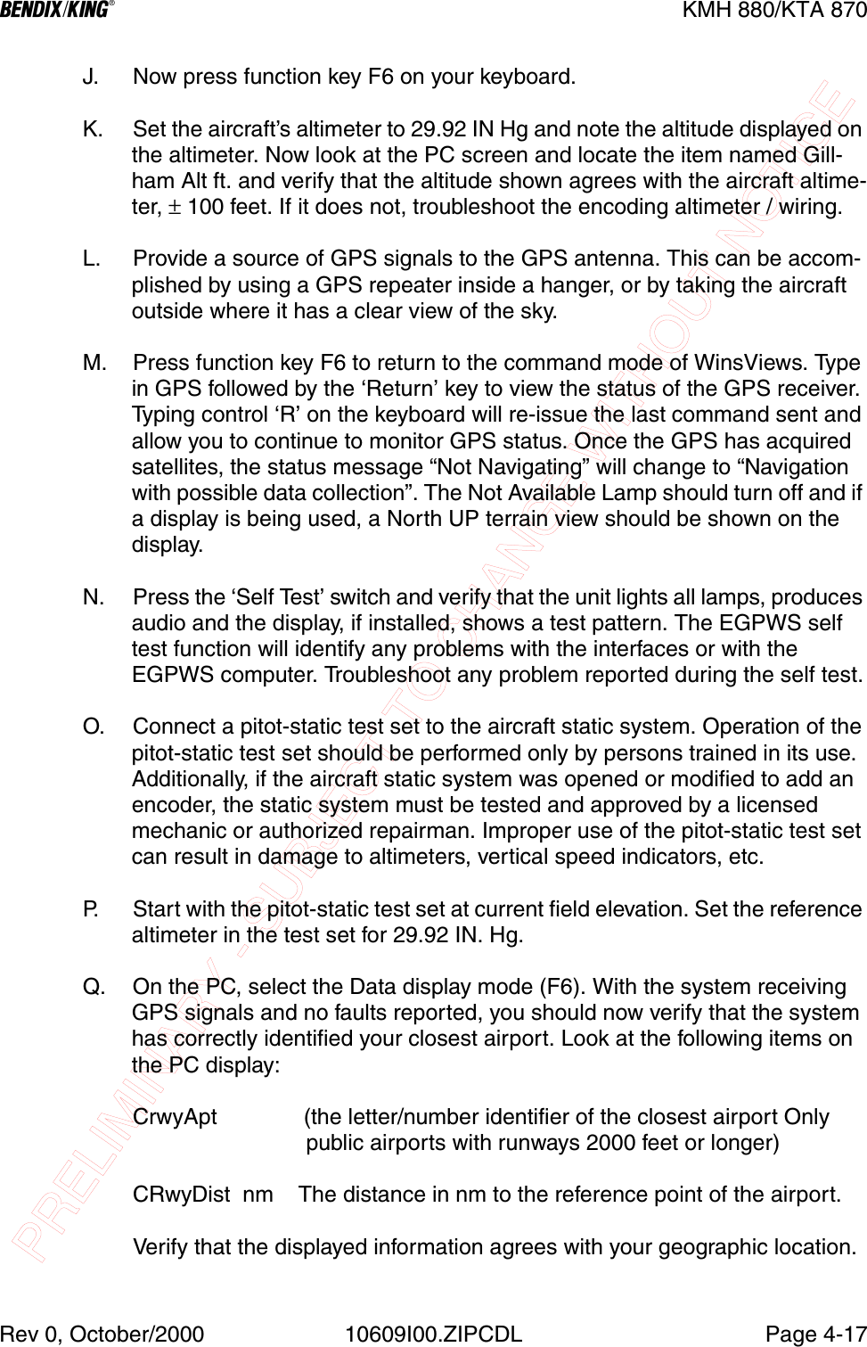
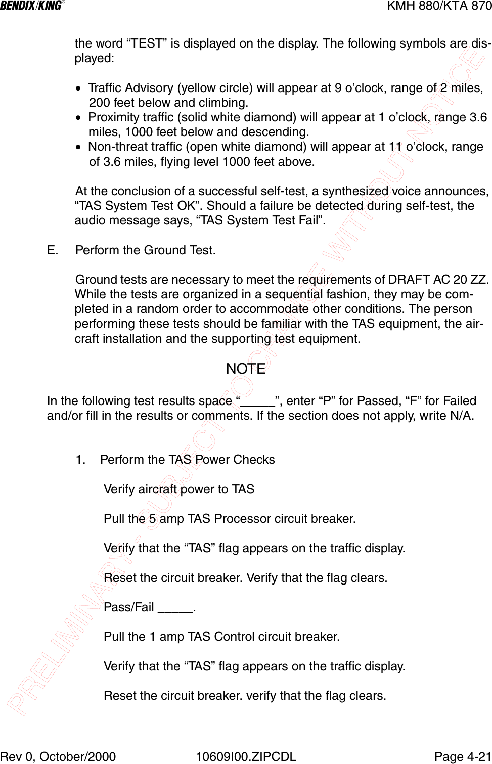
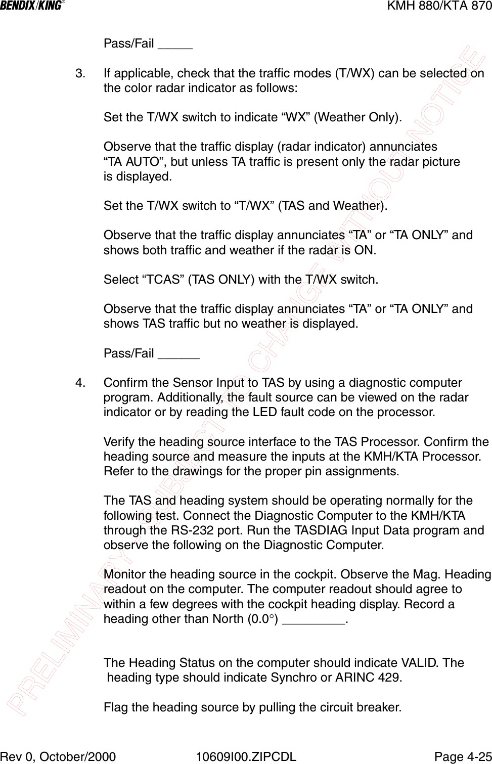
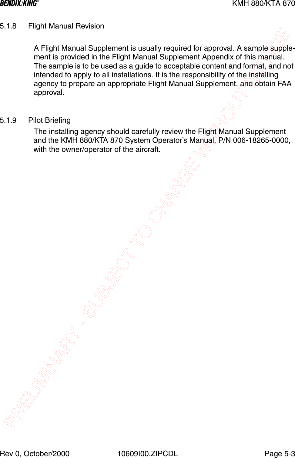
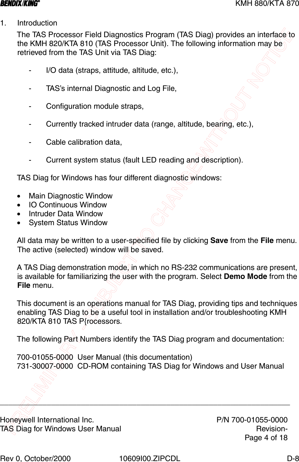
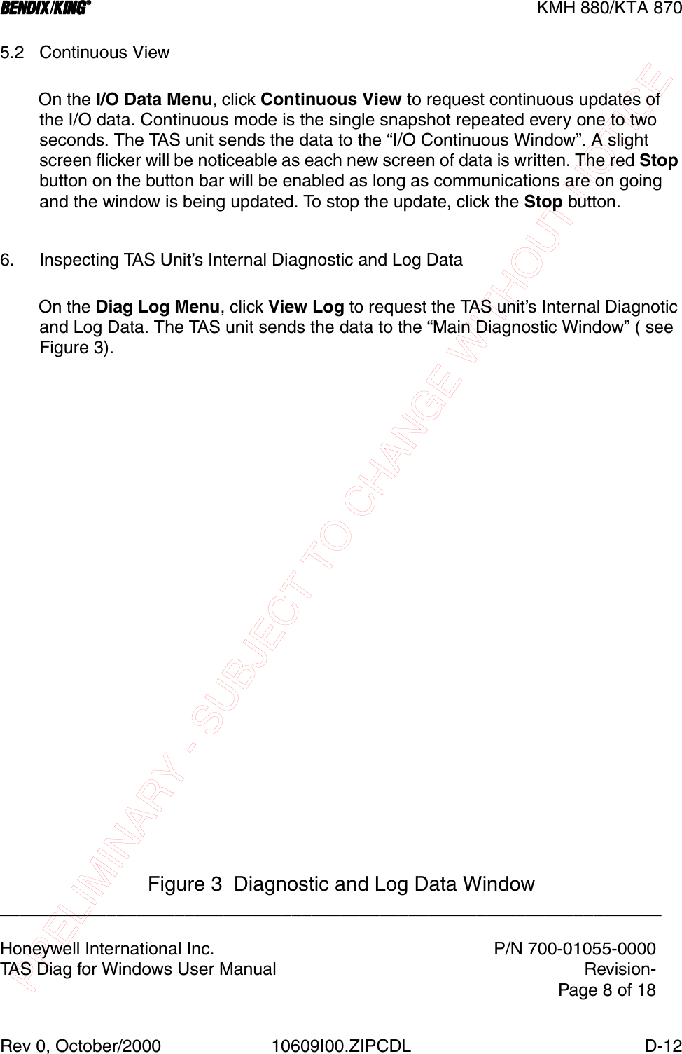
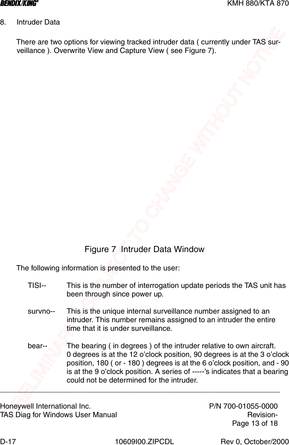
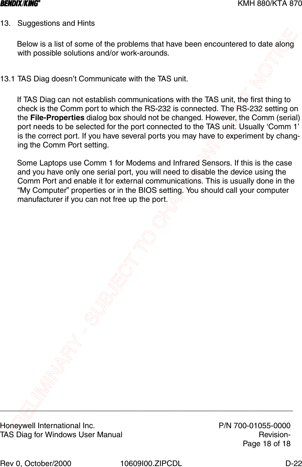
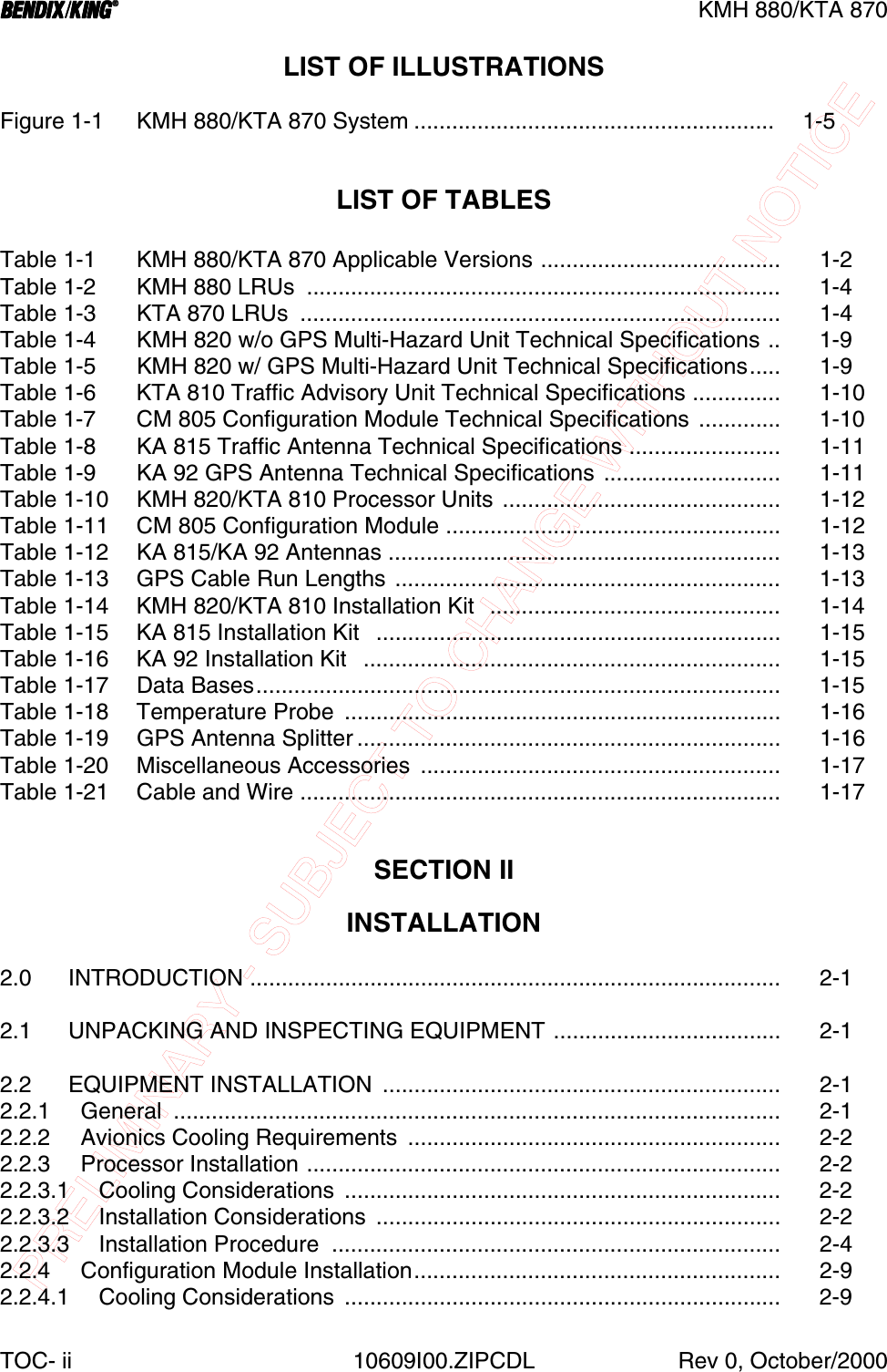
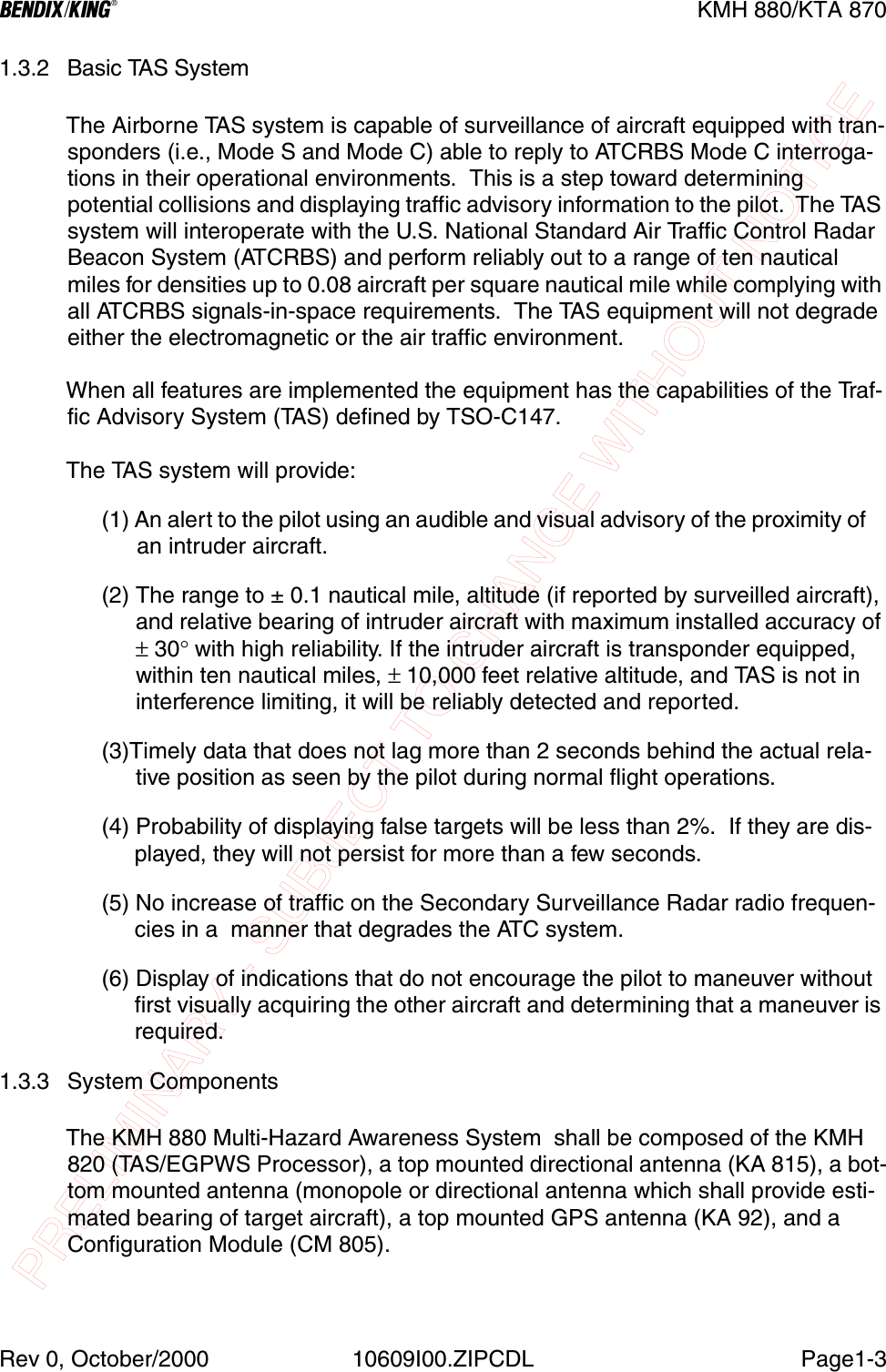
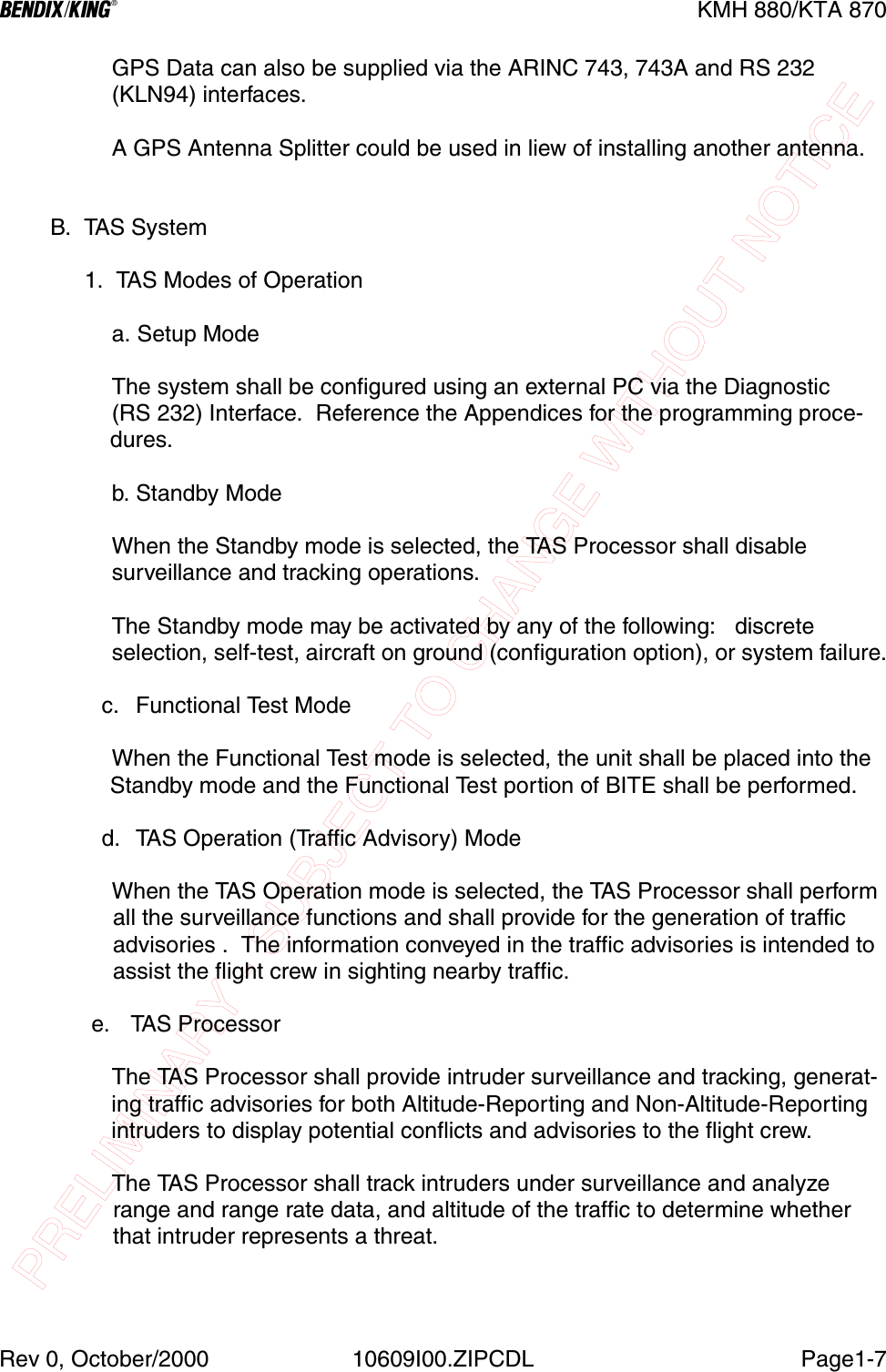
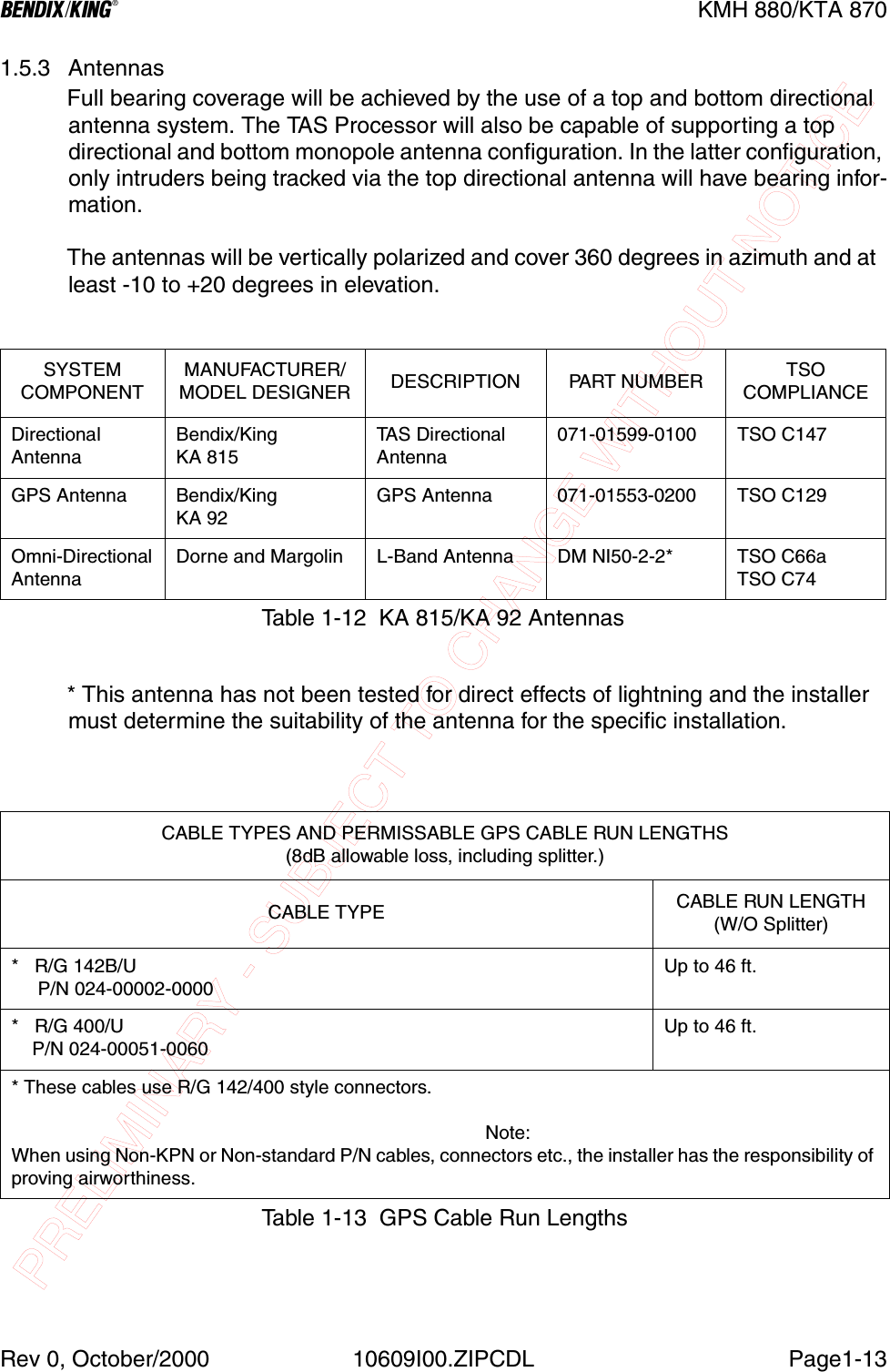
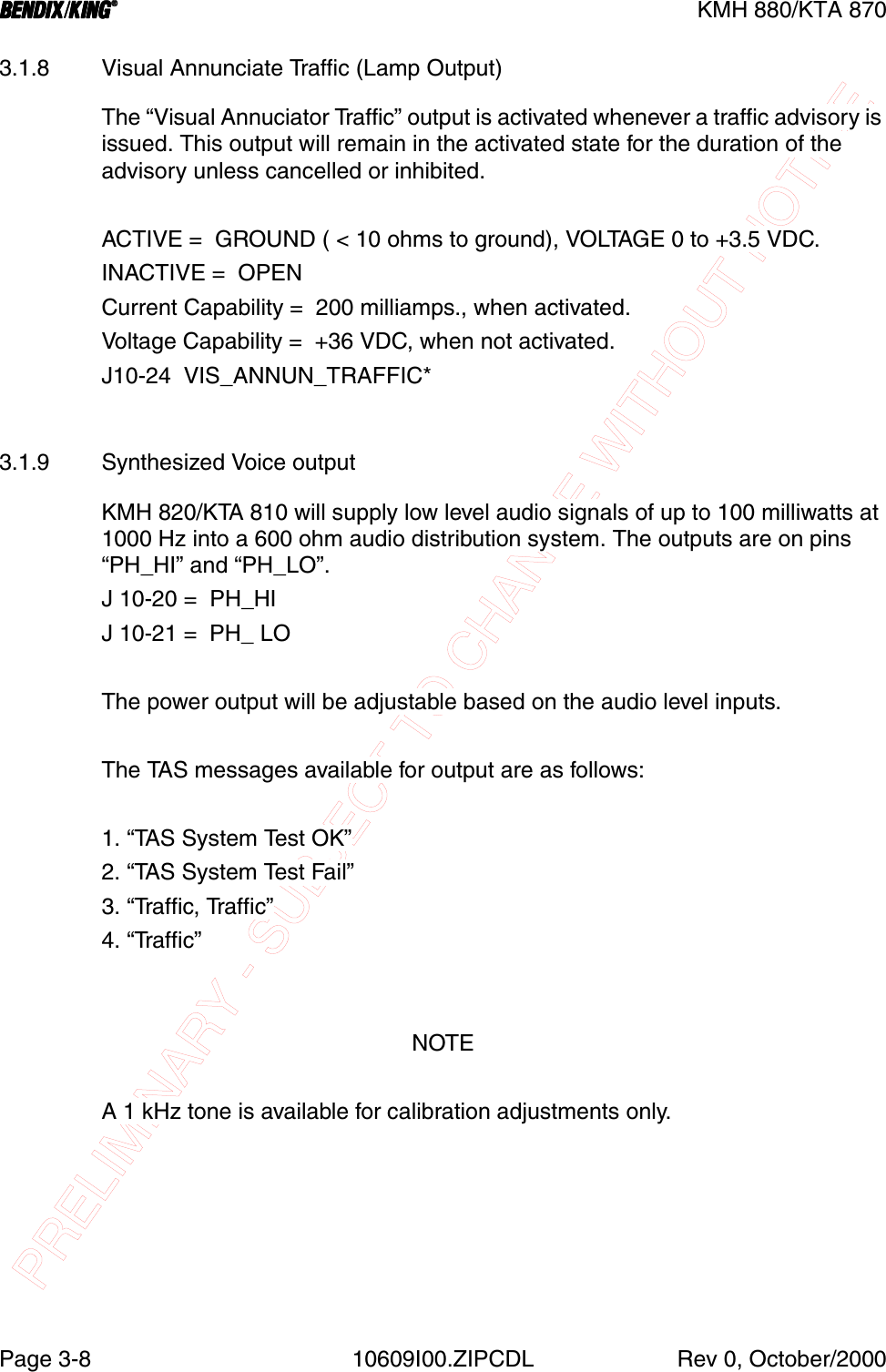
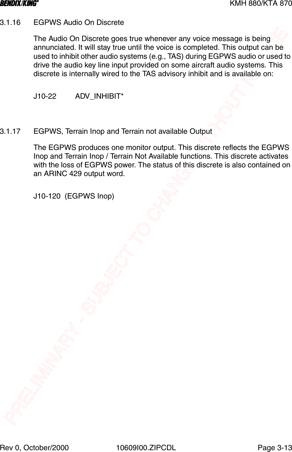
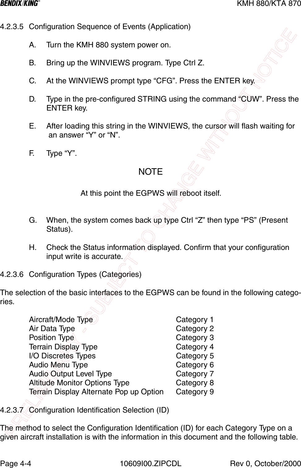
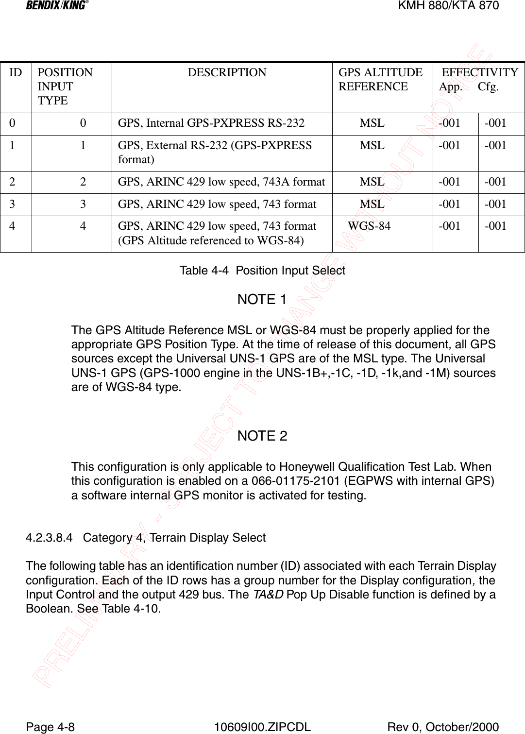
![PRELIMINARY - SUBJECT TO CHANGE WITHOUT NOTICEBKMH 880/KTA 870Rev 0, October/2000 10609I00.ZIPCDL Page1-171.7.3 MiscellaneousNOTE:Specification Drawing 031-00810-01 defines all of the sub-assembly partsand spacers to cover different panel thicknesses (Sheet 2). Artwork definitions for associated items are also covered (Sheet 3).1.7.4 CABLE AND WIRE1.8 LICENSE REQUIREMENTSThere are no license requirements for the KMH 880/KTA 870 Multi-Hazard/Traffic Advisory System.1.9 INSTRUCTIONS FOR CONTINUED AIRWORTHINESSFAR Part 23.1529, 25.1529, 27.1529, AND 29.1529 Instructions for Continued Airworthiness is met per the following Instructions:Design and manufacture of the equipment will provide for installation so as not to impair the airworthiness of the aircraft.SYMBOL PART NUMBER DESCRIPTION [UOM] QTY 050-03610-0000 Basic Annunciator Kit [EA] 1 050-03610-0001 Terrain Switching Kit [EA] 1Table 1-20 Miscellaneous AccessoriesSYMBOL PART NUMBER DESCRIPTION [UOM] QTYM17/158-RG400 Coaxial Cable [FT] ARMIL-W-22759/16 or Equivalent. Wire [FT] ARM17/176-00002 Shielded Wire [FT] ARMIL-C-27500 or Equivalent. Shielded Wire [FT] ARTable 1-21 Cable and Wire](https://usermanual.wiki/Honeywell/KMH820/User-Guide-146634-Page-31.png)


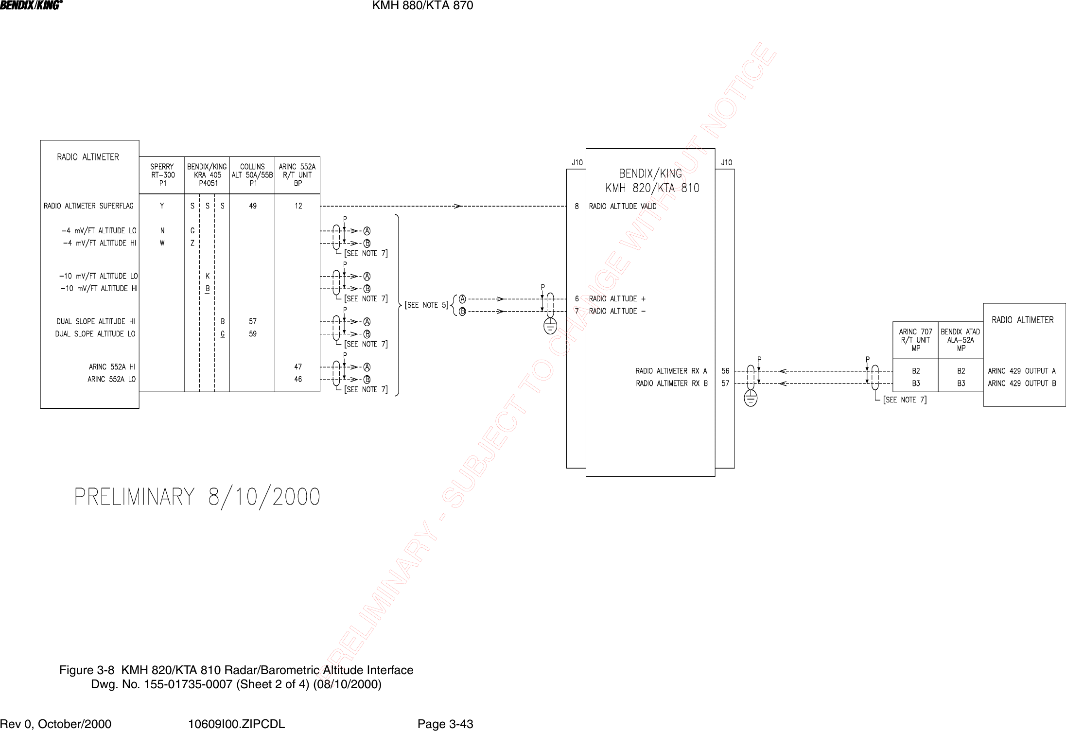

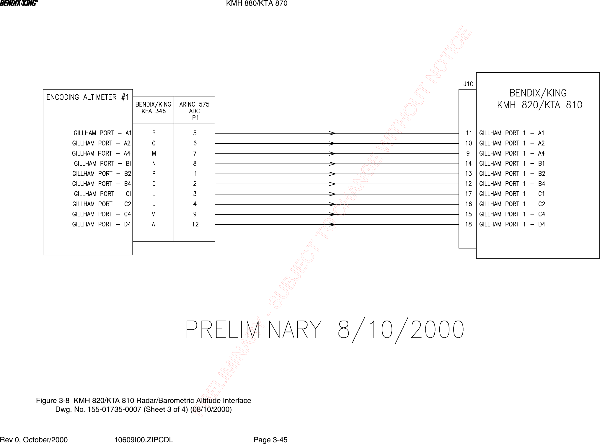


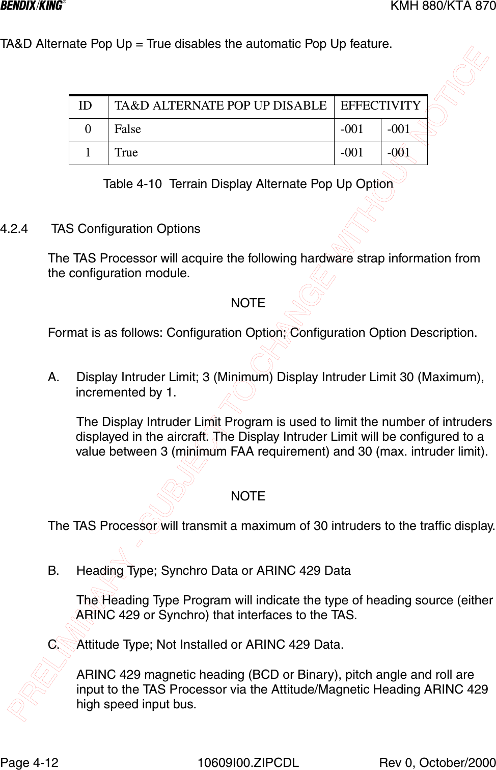
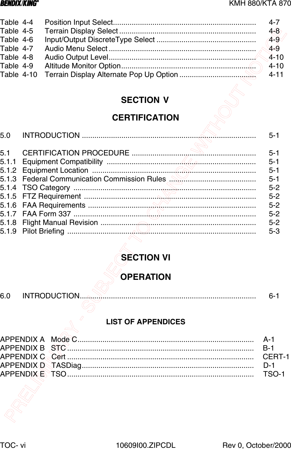
![PRELIMINARY - SUBJECT TO CHANGE WITHOUT NOTICEBKMH 880/KTA 870Rev 0, October/2000 10609I00.ZIPCDL Page 4-13D. Radio Altimeter Type; Not Installed, ARINC 429, Bendix/King Analog, Sperry Analog, Collins Analog or ARINC 552A.The Radio Altimeter Source Port will input to the TAS Processor. The input impedance into this port is 55 Kohms. The port has an associated Radio Altitude Valid flag input to the TAS Processor.Radio Altimeter Valid input will be 20 to 30 VDC during proper altimeter operation (if present). Any failure of the altimeter causes the flag signal to become an open circuit. The analog radio altimeter input (if present) will be considered failed if the altitude is within a valid range (-20 to 2500 feet) and the valid pin is in the invalid state.The Radio Altimeter Type Program will indicate which type of radio altime-ter input is used.NOTEDue to tolerances in the TAS Processor analog I/O hardware, the accuracy for the 0 - 100 foot range may be ± 10 feet.E. On Ground Display Mode; TAS in Standby Mode On-Ground or TAS in TA Only Mode On-Ground.The On Ground Display Mode will indicate to the processor whether the system will go to Standby Mode when on the ground or that the system will go to TA Mode (with aurals and voice inhibited due to altitude defined by TAS logic) when the aircraft is on the ground.F. Baro Altimeter Type; Gillham, ARINC 575, ARINC 706.The Barometric Altimeter Type program will indicate the type of barometric altimeter source [either Gillham/Gray Code, ARINC 575 (ARINC 419) or ARINC 706 (ARINC 429)] that interfaces to the TAS Processor.G. Controller Type; ARINC 735 Protocol, or Discrete Control.The Controller Type will determine the type of control data, either the Con-trol Panel to the TAS Processor via the CNTL HD RX (ARINC 429) input bus or via Discrete Control switches.H. Ground Headphone Volume; 1.25, 2.5, 5, 10, 20, 40, 80, 100 mw.The on ground headphone level will be configurable to the above levels.](https://usermanual.wiki/Honeywell/KMH820/User-Guide-146634-Page-183.png)