Honeywell KMH820 Multi-Hazard Awareness unit User Manual KTA870
Honeywell International Inc. Multi-Hazard Awareness unit KTA870
Users Manual

PRELIMINARY - SUBJECT TO CHANGE WITHOUT NOTICE
SYSTEM INSTALLATION
MANUAL
KMH 880/KTA 870
MULTI-HAZARD AWARENESS
SYSTEM/TRAFFIC ADVISORY
SYSTEM
MANUAL NUMBER 006-10609-0000
REVISION 0 OCTOBER, 2000
PRELIMINARY - SUBJECT TO CHANGE WITHOUT NOTICE
WARNING
PRIOR TO THE EXPORT OF THIS DOCUMENT, REVIEW FOR EXPORT LICENSE
REQUIREMENT IS NEEDED.
COPYRIGHT NOTICE
©2000 HONEYWELL INTERNATIONAL INC.
Reproduction of this publication or any portion thereof by any
means without the express written permission of Honeywell Interna-
tional Inc. is prohibited. For further information contact the
Manager, Technical Publications,Honeywell International Inc., ONE
TECHNOLOGY CENTER, 23500 West 105th Street, Olathe KS 66061 Tele-
phone: (913) 782-0400.

PRELIMINARY - SUBJECT TO CHANGE WITHOUT NOTICE
SYSTEM INSTALLATION
MANUAL
KMH 880/KTA870
MULTI-HAZARD AWARENESS
SYSTEM/TRAFFIC ADVISORY
SYSTEM
PRELIMINARY - SUBJECT TO CHANGE WITHOUT NOTICE
The binder(s) required to hold this publication(s) are available at an additional cost and
may be ordered from:
Honeywell
One Technology Center
23500 West 105th Street
Olathe, Kansas, 66061
Telephone 1-800-757-8999
Orders must specify part number, description, and the quantity. Use the following list to
complete the order
PART NUMBER DESCRIPTION
006-03140-0001 (1) inch Binder.
006-03140-0002 (1.5) inch Binder.
006-03140-0003 (2) inch Binder.
006-03140-0004 (3) inch Binder.
006-03140-0005 (4) inch Post Binder.
WARNING
Prior to Export of this Document, review for export license requirement is needed.
COPYRIGHT NOTICE
©2000 Honeywell International Inc.
Reproduction of this publication or any portion thereof by any means without the express written
permission of Honeywell International Inc. is prohibited. For further information contact the Man-
ager, Technical Publications, Honeywell International Inc., One Technology Center, 23500 West
105th Street Olathe KS 66061 Telephone: (913) 782-0400.

PRELIMINARY - SUBJECT TO CHANGE WITHOUT NOTICE
B
BB
BKMH880/KTA 870
Rev 0, October/2000 10609I00.ZIPCDL Page R- 1
REVISION HISTORY AND INSTRUCTIONS
MANUAL KMH 880/KTA 870 System Install Manual
REVISION 0, October, 2000
PART NUMBER 006-10609-0000
Add, delete or replace pages as indicated below and retain all tabs and dividers. Insert
this page immediately behind the title page as a record of revisions. This revision level of
this manual consists of the following individual publications:
PAGE ACTION
Initial Release Insert Entire Manual
PRELIMINARY - SUBJECT TO CHANGE WITHOUT NOTICE
B
BB
BKMH880/KTA 870
Page R- 2 10609I00.ZIPCDL Rev 0, October/2000
THIS PAGE IS RESERVED
PRELIMINARY - SUBJECT TO CHANGE WITHOUT NOTICE
B
BB
BKMH 880/KTA 870
Rev 0, October/2000 10609I00.ZIPCDL TOC- i
SECTION I
GENERAL INFORMATION
1.0 INTRODUCTION .................................................................................... 1.1
1.1 PURPOSE .............................................................................................. 1-1
1.2 APPLICABILITY OF THE SYSTEM MANUAL ....................................... 1-2
1.2.1 Equipment Applicability .......................................................................... 1-2
1.3 SYSTEM DESCRIPTION ....................................................................... 1-2
1.3.1 Basic EGPWS System ........................................................................... 1-2
1.3.2 Basic TAS System ................................................................................. 1-3
1.3.3 System Components .............................................................................. 1-3
1.3.4 System Operation .................................................................................. 1-5
1.4 TECHNICAL CHARACTERISTICS ........................................................ 1-9
1.5 UNIT AND ACCESSORIES SUPPLIED ................................................ 1-12
1.5.1 TAS Processor Unit ................................................................................ 1-12
1.5.2 Configuration Module ............................................................................. 1-12
1.5.3 Antennas ................................................................................................ 1-13
1.6 INSTALLATION ACCESSORIES SUPPLIED ........................................ 1-14
1.6.1 KMH 820/KTA 810 Installation Kit .......................................................... 1-14
1.6.2 Antenna Installation Kits.......................................................................... 1-15
1.6.3 Databases............................................................................................... 1-15
1.7 ACCESSORIES REQUIRED BUT NOT SUPPLIED .............................. 1-16
1.7.1 Temperature Probe ................................................................................ 1-16
1.7.2 GPS Antenna Splitter.............................................................................. 1-16
1.7.3 Miscellaneous ........................................................................................ 1-17
1.7.4 Cable And Wire ...................................................................................... 1-17
1.8 LICENSE REQUIREMENTS .................................................................. 1-17
1.9 INSTRUCTIONS FOR CONTINUED AIRWORTHINESS ...................... 1-17
1.9.1 KMH 820/KTA 810 Unit........................................................................... 1-18
1.9.2 Annunciators/Relays ............................................................................... 1-18
1.9.3 GPS Antenna .......................................................................................... 1-18
1.9.4 Gps Antenna Splitter............................................................................... 1-18
1.9.5 Temperature Probe................................................................................. 1-18
1.9.6 Wire and Coax Cables ............................................................................ 1-19
1.9.7 Terrain Data Base Updates..................................................................... 1-19
PRELIMINARY - SUBJECT TO CHANGE WITHOUT NOTICE
B
BB
BKMH 880/KTA 870
TOC- ii 10609I00.ZIPCDL Rev 0, October/2000
LIST OF ILLUSTRATIONS
Figure 1-1 KMH 880/KTA 870 System ......................................................... 1-5
LIST OF TABLES
Table 1-1 KMH 880/KTA 870 Applicable Versions ...................................... 1-2
Table 1-2 KMH 880 LRUs ........................................................................... 1-4
Table 1-3 KTA 870 LRUs ............................................................................ 1-4
Table 1-4 KMH 820 w/o GPS Multi-Hazard Unit Technical Specifications .. 1-9
Table 1-5 KMH 820 w/ GPS Multi-Hazard Unit Technical Specifications..... 1-9
Table 1-6 KTA 810 Traffic Advisory Unit Technical Specifications .............. 1-10
Table 1-7 CM 805 Configuration Module Technical Specifications ............. 1-10
Table 1-8 KA 815 Traffic Antenna Technical Specifications ........................ 1-11
Table 1-9 KA 92 GPS Antenna Technical Specifications ............................ 1-11
Table 1-10 KMH 820/KTA 810 Processor Units ............................................ 1-12
Table 1-11 CM 805 Configuration Module ..................................................... 1-12
Table 1-12 KA 815/KA 92 Antennas .............................................................. 1-13
Table 1-13 GPS Cable Run Lengths ............................................................. 1-13
Table 1-14 KMH 820/KTA 810 Installation Kit .............................................. 1-14
Table 1-15 KA 815 Installation Kit ................................................................ 1-15
Table 1-16 KA 92 Installation Kit .................................................................. 1-15
Table 1-17 Data Bases................................................................................... 1-15
Table 1-18 Temperature Probe ..................................................................... 1-16
Table 1-19 GPS Antenna Splitter ................................................................... 1-16
Table 1-20 Miscellaneous Accessories ......................................................... 1-17
Table 1-21 Cable and Wire ............................................................................ 1-17
SECTION II
INSTALLATION
2.0 INTRODUCTION .................................................................................... 2-1
2.1 UNPACKING AND INSPECTING EQUIPMENT .................................... 2-1
2.2 EQUIPMENT INSTALLATION ............................................................... 2-1
2.2.1 General ................................................................................................ 2-1
2.2.2 Avionics Cooling Requirements ........................................................... 2-2
2.2.3 Processor Installation ........................................................................... 2-2
2.2.3.1 Cooling Considerations ..................................................................... 2-2
2.2.3.2 Installation Considerations ................................................................ 2-2
2.2.3.3 Installation Procedure ....................................................................... 2-4
2.2.4 Configuration Module Installation.......................................................... 2-9
2.2.4.1 Cooling Considerations ..................................................................... 2-9
PRELIMINARY - SUBJECT TO CHANGE WITHOUT NOTICE
B
BB
BKMH 880/KTA 870
Rev 0, October/2000 10609I00.ZIPCDL TOC- iii
2.2.4.2 Installation Considerations ................................................................ 2-9
2.2.4.3 Installation Procedure ....................................................................... 2-9
2.2.5 Directional Antenna Installation ............................................................ 2-13
2.2.5.1 KA 815 Antenna Installation Considerations ..................................... 2-13
2.2.6 GPS Antenna Installation ..................................................................... 2-17
2.2.6.1 KA 92 antenna Installation Considerations (KMH 820 EGPWS only) . 2-17
2.2.6.2 Installation Procedure ....................................................................... 2-17
2.2.7 TAS Coaxial Cable Fabrication............................................................. 2-26
2.2.8 GPS Coaxial Cable Fabrication ............................................................ 2-27
LIST OF ILLUSTRATIONS
Figure 2-1 KMH 820/KTA 810 Installation Drawing....................................... 2-5
Figure 2-2 Configuration Module Installation Drawing................................... 2-11
Figure 2-3 KA 815 Antenna Outline and Mounting Drawing ......................... 2-15
Figure 2-4 KA 815 Antenna Installation Drawing........................................... 2-19
Figure 2-5 KA 815 Doubler Plate Drawing..................................................... 2-21
Figure 2-6 KA 92 Outline and Mounting Drawing ......................................... 2-23
Figure 2-7 GPS Antenna Splitter ................................................................... 2-25
Figure 2-8 Coax Cable Treatment ................................................................. 2-28
Figure 2-9 Standard Coax Cable................................................................... 2-28
Figure 2-10 Bulkhead/In-Line Connection Coax Cable ................................... 2-28
Figure 2-11 TNC Antenna Coax/Connector Assembly.................................... 2-29
Figure 2-12 TNC Antenna Coax/Connector Assembly.................................... 2-30
LIST OF TABLES
Table 2-1 Signal Losses.............................................................................. 2-27
SECTION III
SYSTEM PLANNING
3.0 INTRODUCTION ................................................................................... 3-1
3.0.1 Applicable Part Numbers Subsection Description ................................ 3-1
3.0.2 Function Subsection Description .......................................................... 3-1
3.0.3 Requirements and Limitations Subsection Description. ....................... 3-1
3.0.4 Electrical Characteristics Subsection Description. ............................... 3-1
3.0.5 Interface Subsection Description ......................................................... 3-1
3.1 GENERAL INTERCONNECT INFORMATION ...................................... 3-5
3.1.1 Power Inputs ..................................................................................... 3-5
3.1.2 Air/Ground Discrete Input ................................................................. 3-5
3.1.3 Landing Gear Discrete Input ............................................................. 3-6
3.1.4 Above/Below/Normal Input ............................................................... 3-6
3.1.5 Baro Altitude (ARINC 429) Input ....................................................... 3-7
3.1.6 Advisory Inhibit Input ........................................................................ 3-7
PRELIMINARY - SUBJECT TO CHANGE WITHOUT NOTICE
B
BB
BKMH 880/KTA 870
TOC- iv 10609I00.ZIPCDL Rev 0, October/2000
3.1.7 TAS Valid Output .............................................................................. 3-7
3.1.8 Visual Annunciate Traffic (Lamp Output) .......................................... 3-8
3.1.9 Synthesized Voice Output ................................................................ 3-8
3.1.10 Air Temperature Input ....................................................................... 3-9
3.1.11 GPS Input ......................................................................................... 3-9
3.1.12 Factory Test Input ............................................................................. 3-10
3.1.12.1 TAS ATE Enable Input ................................................................... 3-10
3.1.12.2 TAS Built In Test Equipment (BITE) .............................................. 3-10
3.1.12.3 EGPWS Self Test Input ................................................................. 3-11
3.1.12.4 Display Select Input ....................................................................... 3-12
3.1.12.5 Terrain Awareness Inhibit Discrete ................................................ 3-12
3.1.13 Terrain Warning ................................................................................ 3-12
3.1.14 Terrain Caution.................................................................................. 3-12
3.1.15 Weather Select Output ..................................................................... 3-12
3.1.16 EGPWS Audio On Discrete .............................................................. 3-13
3.1.17 EGPWS Terrain Inop and Terrain Not Available Output.................... 3-13
LIST OF ILLUSTRATIONS
Figure 3-1 KMH 880/KTA 870 Interconnect Family ...................................... 3-3
Figure 3-2 KMH 820/KTA 810 Pinout Diagram ............................................. 3-15
Figure 3-3 KMH 820/KTA 810 System Interconnect Block Diagram ............. 3-29
Figure 3-4 KMH 820/KTA 810 Power Interface ............................................ 3-33
Figure 3-5 KMH 820/KTA 810 Discrete Interface ......................................... 3-35
Figure 3-6 KMH 820/KTA 810 Configuration Module Interconnect ............... 3-37
Figure 3-7 KMH 820/KTA 810 Attitude/Heading Interface............................. 3-39
Figure 3-8 KMH 820/KTA 810 Radar/Barometric Altitude Interface ............. 3-41
Figure 3-9 KMH 820/KTA 810 Antenna/Suppression Interface .................... 3-49
Figure 3-10 KMH 820/KTA 810 EFS 40/50 Interface .................................... 3-51
Figure 3-11 KMH 820/KTA 810 GS 362A Interface ....................................... 3-53
Figure 3-12 KMH 820/KTA 810 Honeywell GS 362A Interface ....................... 3-59
Figure 3-13 KMH 820/KTA 810 Collins GS 362A Interface ............................. 3-65
Figure 3-14 KMH 820/KTA 810 Honeywell Primus 1000 Interface.................. 3-69
Figure 3-15 KMH 820/KTA 810 Honeywell SPZ-805 Interface........................ 3-73
Figure 3-16 KMH 820/KTA 810 Diagnostic/Data Recorder Interface ............. 3-77
Figure 3-17 KMH 820/KTA 810 TAS ATE Interface ....................................... 3-79
Figure 3-18 KMH 820/KTA 810 CP 66B Interface........................................... 3-81
Figure 3-19 KMH 820/KTA 810 KFS 578A Interface....................................... 3-83
Figure 3-20 KMH 820/KTA 810 Display Interface............................................ 3-87
Figure 3-21 KMH 820/KTA 810 Processor Front Connector .......................... 3-95
Figure 3-22 KMH 820/KTA 810 Front Connector Cable.................................. 3-96
LIST OF TABLES
Table 3-1 KMH 820/KTA 810 Connector Pin Assignment ........................... 3-97
PRELIMINARY - SUBJECT TO CHANGE WITHOUT NOTICE
B
BB
BKMH 880/KTA 870
Rev 0, October/2000 10609I00.ZIPCDL TOC- v
SECTION IV
POST INSTALLATION CONFIGURATION AND CHECK OUT
4.0 INTRODUCTION .................................................................................... 4-1
4.1 LINE SELECT KEYS .............................................................................. 4-1
4.2 CONFIGURATION PROCEDURE ......................................................... 4-1
4.2.1 Power On ............................................................................................. 4-1
4.2.2 Aircraft Configuration ........................................................................... 4-1
4.2.3 EGPWS Configuration Instructions....................................................... 4-1
4.2.3.1 Equipment needed................................................................................ 4-1
4.2.3.2 Configuration Module Programming ..................................................... 4-2
4.2.3.3 Configuration String Format.................................................................. 4-2
4.2.3.4 RS-232 Maintenance Port (Port SMC1)................................................ 4-3
4.2.3.5 RS-232 Diagnostic Port ........................................................................ 4-3
4.2.3.6 Configuration Sequence of Events ....................................................... 4-4
4.2.3.7 Configuration Types.............................................................................. 4-4
4.2.3.8 Configuration Tables............................................................................. 4-5
4.2.3.8.1 Category 1, Aircraft/Mode Type Select............................................... 4-6
4.2.3.8.2 Category 2, Air Data Input Select ....................................................... 4-6
4.2.3.8.3 Category 3, Position Input Select........................................................ 4-7
4.2.3.8.4 Category 4, Terrain Display Select ..................................................... 4-8
4.2.3.8.5 Category 5, Input/Output Discrete Type Select .................................. 4-9
4.2.3.8.6 Category 6, Audio Menu Select .......................................................... 4-9
4.2.3.8.7 Category 7, Audio Output Level.......................................................... 4-9
4.2.3.8.8 Category 8, Altitude Monitor Options.................................................. 4-10
4.2.3.8.9 Category 9, Terrain Display Alternate Pop Up Option ........................ 4-10
4.2.4 TAS Configuration Options .................................................................. 4-11
4.2.4.1 TAS RS-232 Maintenance Port.............................................................. 4-13
4.2.4.2 TAS RS-422 Data Recorder .................................................................. 4-14
4.3 GROUND TEST PROCEDURES ........................................................... 4-14
4.3.2 EGPWS Ground Test Procedures ......................................................... 4-14
4.3.3 TAS Ground Test Procedures................................................................ 4-17
LIST OF ILLUSTRATIONS
Figure 4-1 TAS Bearing Measurements............................................................ 4-34
LIST OF TABLES
Table 4-1 Configuration Identification........................................................... 4-4
Table 4-2 Aircraft/Mode Type Select............................................................ 4-6
Table 4-3 Air Data Input Select .................................................................... 4-6
PRELIMINARY - SUBJECT TO CHANGE WITHOUT NOTICE
B
BB
BKMH 880/KTA 870
TOC- vi 10609I00.ZIPCDL Rev 0, October/2000
Table 4-4 Position Input Select..................................................................... 4-7
Table 4-5 Terrain Display Select .................................................................. 4-8
Table 4-6 Input/Output DiscreteType Select ................................................ 4-9
Table 4-7 Audio Menu Select ....................................................................... 4-9
Table 4-8 Audio Output Level....................................................................... 4-10
Table 4-9 Altitude Monitor Option................................................................. 4-10
Table 4-10 Terrain Display Alternate Pop Up Option ..................................... 4-11
SECTION V
CERTIFICATION
5.0 INTRODUCTION .................................................................................... 5-1
5.1 CERTIFICATION PROCEDURE ............................................................ 5-1
5.1.1 Equipment Compatibility ........................................................................ 5-1
5.1.2 Equipment Location ............................................................................... 5-1
5.1.3 Federal Communication Commission Rules .......................................... 5-1
5.1.4 TSO Category ........................................................................................ 5-2
5.1.5 FTZ Requirement ................................................................................... 5-2
5.1.6 FAA Requirements ................................................................................. 5-2
5.1.7 FAA Form 337 ........................................................................................ 5-2
5.1.8 Flight Manual Revision ........................................................................... 5-2
5.1.9 Pilot Briefing ........................................................................................... 5-3
SECTION VI
OPERATION
6.0 INTRODUCTION..................................................................................... 6-1
LIST OF APPENDICES
APPENDIX A Mode C..................................................................................... A-1
APPENDIX B STC .......................................................................................... B-1
APPENDIX C Cert .......................................................................................... CERT-1
APPENDIX D TASDiag................................................................................... D-1
APPENDIX E TSO.......................................................................................... TSO-1
PRELIMINARY - SUBJECT TO CHANGE WITHOUT NOTICE
BKMH 880/KTA 870
Rev 0, October/2000 10609I00.ZIPCDL TOC 1-i
SECTION 1
GENERAL INFORMATION
1.0 INTRODUCTION .................................................................................... 1.1
1.1 PURPOSE .............................................................................................. 1-1
1.2 APPLICABILITY OF THE SYSTEM MANUAL ....................................... 1-2
1.2.1 Equipment Applicability .......................................................................... 1-2
1.3 SYSTEM DESCRIPTION ....................................................................... 1-2
1.3.1 Basic EGPWS System ........................................................................... 1-2
1.3.2 Basic TAS System ................................................................................. 1-3
1.3.3 System Components .............................................................................. 1-3
1.3.4 System Operation .................................................................................. 1-5
1.4 TECHNICAL CHARACTERISTICS ........................................................ 1-9
1.5 UNIT AND ACCESSORIES SUPPLIED ................................................ 1-12
1.5.1 TAS Processor Unit ................................................................................ 1-12
1.5.2 Configuration Module ............................................................................. 1-12
1.5.3 Antennas ................................................................................................ 1-13
1.6 INSTALLATION ACCESSORIES SUPPLIED ........................................ 1-14
1.6.1 KMH 820/KTA 810 Installation Kit .......................................................... 1-14
1.6.2 Antenna Iinstallation Kits......................................................................... 1-15
1.6.3 Databases............................................................................................... 1-15
1.7 ACCESSORIES REQUIRED BUT NOT SUPPLIED .............................. 1-16
1.7.1 Temperature Probe ................................................................................ 1-16
1.7.2 GPS Antenna Splitter.............................................................................. 1-16
1.7.3 Miscellaneous ........................................................................................ 1-17
1.7.4 Cable And Wire ...................................................................................... 1-17
1.8 LICENSE REQUIREMENTS .................................................................. 1-17
1.9 INSTRUCTIONS FOR CONTINUED AIRWORTHINESS ...................... 1-17
1.9.1 KMH 820/KTA 810 Unit........................................................................... 1-18
1.9.2 Annunciators/Relays ............................................................................... 1-18
1.9.3 GPS Antenna .......................................................................................... 1-18
1.9.4 Gps Antenna Splitter............................................................................... 1-18
1.9.5 Temperature Probe................................................................................. 1-18
1.9.6 Wire and Coax Cables ............................................................................ 1-19
1.9.7 Terrain Data Base Updates..................................................................... 1-19
PRELIMINARY - SUBJECT TO CHANGE WITHOUT NOTICE
B
BB
BKMH 880/KTA 870
TOC 1-ii 10609I00.ZIPCDL Rev 0, October/2000
LIST OF ILLUSTRATIONS
Figure 1-1 KMH 880/KTA 870 System .......................................................... 1-5
LIST OF TABLES
Table 1-1 KMH 880/KTA 870 Applicable Versions ...................................... 1-2
Table 1-2 KMH 880 LRUs ........................................................................... 1-4
Table 1-3 KTA 870 LRUs ............................................................................ 1-4
Table 1-4 KMH 820 w/o GPS Multi-Hazard Unit Technical Specifications .. 1-9
Table 1-5 KMH 820 w/ GPS Multi-Hazard Unit Technical Specifications..... 1-9
Table 1-6 KTA 810 Traffic Advisory Unit Technical Specifications .............. 1-10
Table 1-7 CM 805 Configuration Module Technical Specifications ............. 1-10
Table 1-8 KA 815 Traffic Antenna Technical Specifications ........................ 1-11
Table 1-9 KA 92 GPS Antenna Technical Specifications ............................ 1-11
Table 1-10 KMH 820/KTA 810 Processor Units ............................................ 1-12
Table 1-11 CM 805 Configuration Module ..................................................... 1-12
Table 1-12 KA 815/KA 92 and Monopole Antennas ...................................... 1-13
Table 1-13 GPS Cable Run Lengths ............................................................. 1-13
Table 1-14 KMH 820/KTA 810 Installation Kit .............................................. 1-14
Table 1-15 KA 815 Installation Kit ................................................................ 1-15
Table 1-16 KA 92 Installation Kit .................................................................. 1-15
Table 1-17 Data Bases................................................................................... 1-15
Table 1-18 Temperature Probe ..................................................................... 1-16
Table 1-19 GPS Antenna Splitter ................................................................... 1-16
Table 1-20 Miscellaneous Accessories ......................................................... 1-17
Table 1-21 Cable and Wire ............................................................................ 1-17
PRELIMINARY - SUBJECT TO CHANGE WITHOUT NOTICE
BKMH 880/KTA 870
Rev 0, October/2000 10609I00.ZIPCDL Page1-1
SECTION 1
GENERAL INFORMATION
1.0 INTRODUCTION
This manual contains information relative to the physical, mechanical and electri-
cal characteristics of the KMH 880/KTA 870 Multi-Hazard Awareness System. It
includes the basic guidelines, considerations and recommendations for the instal-
lation and ground checkout of KMH 880/KTA 870 Multi-Hazard Awareness System
and associated components. It is intended to provide the detail required to assist
the installer in preparation for installation and appropriate work instructions to
ensure a proper installation and checkout.
This manual assumes a familiarity with avionics installation practices, with sys-
tems on board the aircraft and access to manuals and regulations commensurate
with the installation of such equipment.
The information contained herein, together with the general procedures outlined in
FAA AC.43.13-1B and AC.4313- 2A should be followed carefully to ensure a safe
and electrically sound system installation.
The contents of this manual are for information and reference use only and must
not be construed as a formal FAA approved work authorization.
It is highly recommended that prior to beginning the installation of the KMH 880/
KTA 870 system that this manual is carefully reviewed. Upon review the necessary
configuration items and system requirements will be identified allowing a speedy
installation.
Operational information is contained in the KMH 880/KTA 870 Operators Manual
supplied with each unit.
1.1 PURPOSE
This manual will describe the detailed system requirements for the Bendix/King KMH 880
Multi-Hazard Awareness System and KTA 870 Traffic Advisory System . The KMH 880
combines TAS (Traffic Advisory System) with EGPWS (Enhanced Ground Proximity
Warning System). The KTA 870 has TAS only.

PRELIMINARY - SUBJECT TO CHANGE WITHOUT NOTICE
B
BB
BKMH 880/KTA 870
Page1-2 10609I00.ZIPCDL Rev 0, October/2000
1.2 APPLICABILITY OF THE SYSTEM MANUAL
1.2.1 Equipment Applicability
This manual is applicable only to KMH 880/KTA 870 Multi-Hazard Awareness Sys-
tem part numbers displayed in the table below:
1.3 SYSTEM DESCRIPTION
1.3.1 Basic EGPWS System
The KMH 880 EGPWS is a revolutionary new step in Controlled Flight Into Terrain
(CFIT) protection. It is capable of producing advanced alerting for prevention of
CFIT accidents. In addition to the alerting protection the system will also produce
a terrain display. This display depicts relative terrain in reference to the lateral and
vertical positions of the aircraft.
The EGPWS is intended for Light Turbine and Piston Aircraft Operations. It has
effective operational performance in providing timely alerts and operational terrain
display to enhance situational awareness. This performance, coupled to the sys-
tem's simplicity, practicality, small size and weight, with a minimum number of
required aircraft sensors, provides a formidable safety value.
NOTE
The EGPWS portion of the KMH 820 is not suitable for helicopter operation.
No Radio Altimeter, Landing Gear or Flap discretes, or Glideslope receiver are
necessary. This significantly lowers the installation costs.
The KMH 880 is a system designed to minimize the system requirements down to
a level economical to the private pilot. It is the central component in the system
providing timely alerts and optional display of impending terrain incursions.
The KMH 880 is a TSO C151A class B compliant system.
UNIT NOMENCLATURE PART NUMBER
KTA 810 Traffic Advisory Unit 066-01152-0101
KMH 820 w/o GPS Multi-hazard Awareness Unit 066-01175-0101
KMH 820 w/GPS Multi-hazard Awareness Unit 066-01175-2101
Table 1-1 KMH 880/KTA 870 Applicable Versions
PRELIMINARY - SUBJECT TO CHANGE WITHOUT NOTICE
BKMH 880/KTA 870
Rev 0, October/2000 10609I00.ZIPCDL Page1-3
1.3.2 Basic TAS System
The Airborne TAS system is capable of surveillance of aircraft equipped with tran-
sponders (i.e., Mode S and Mode C) able to reply to ATCRBS Mode C interroga-
tions in their operational environments. This is a step toward determining
potential collisions and displaying traffic advisory information to the pilot. The TAS
system will interoperate with the U.S. National Standard Air Traffic Control Radar
Beacon System (ATCRBS) and perform reliably out to a range of ten nautical
miles for densities up to 0.08 aircraft per square nautical mile while complying with
all ATCRBS signals-in-space requirements. The TAS equipment will not degrade
either the electromagnetic or the air traffic environment.
When all features are implemented the equipment has the capabilities of the Traf-
fic Advisory System (TAS) defined by TSO-C147.
The TAS system will provide:
(1) An alert to the pilot using an audible and visual advisory of the proximity of
an intruder aircraft.
(2) The range to ± 0.1 nautical mile, altitude (if reported by surveilled aircraft),
and relative bearing of intruder aircraft with maximum installed accuracy of
± 30° with high reliability. If the intruder aircraft is transponder equipped,
within ten nautical miles, ± 10,000 feet relative altitude, and TAS is not in
interference limiting, it will be reliably detected and reported.
(3)Timely data that does not lag more than 2 seconds behind the actual rela-
tive position as seen by the pilot during normal flight operations.
(4) Probability of displaying false targets will be less than 2%. If they are dis-
played, they will not persist for more than a few seconds.
(5) No increase of traffic on the Secondary Surveillance Radar radio frequen-
cies in a manner that degrades the ATC system.
(6) Display of indications that do not encourage the pilot to maneuver without
first visually acquiring the other aircraft and determining that a maneuver is
required.
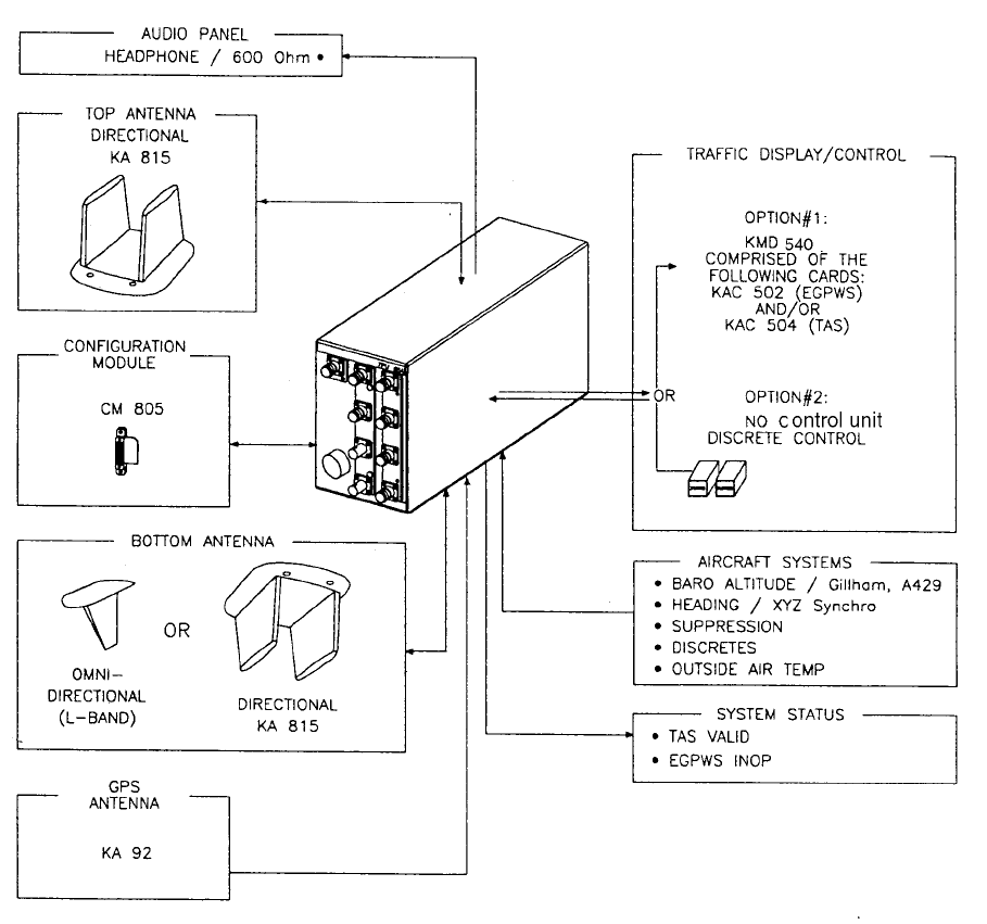
1.3.3 System Components
The KMH 880 Multi-Hazard Awareness System shall be composed of the KMH
820 (TAS/EGPWS Processor), a top mounted directional antenna (KA 815), a bot-
tom mounted antenna (monopole or directional antenna which shall provide esti-
mated bearing of target aircraft), a top mounted GPS antenna (KA 92), and a
Configuration Module (CM 805).

PRELIMINARY - SUBJECT TO CHANGE WITHOUT NOTICE
B
BB
BKMH 880/KTA 870
Page1-4 10609I00.ZIPCDL Rev 0, October/2000
A Multifunctional Display Unit, KMD 540, shall provide control and display of traffic
(via the KAC 504 Traffic Card) and control and display of EGPWS data (via the
KAC 502 Adapter Card). Other displays that are compatible with ARINC 735A
may be used for traffic with this system. See Figure 1-1.
The KTA 870 Traffic Advisory System is similar to the KMH 880 except the KTA
810 Traffic Advisory Unit has only TAS and not EGPWS. The KTA 870 system
does not use a KA 92 GPS antenna. See Table 1-2 and Table 1-3 for a complete
description and part number listing for both systems.
KMH 880 SYSTEM PRIMARY LRUs
System Component LRU Manufacturer/
Model Designator
LRU Description LRU Part Number
TA S / G A E G P W S
Processor
Bendix/King KMH 820 Multi-Hazard Awareness
Processor
066-01175-0101
066-01175-2101
Directional Antenna Bendix/King KA 815 TAS Directional Antenna 071-01599-0100
GPS Antenna Bendix/King KA 92 GPS Antenna 071-01553-0200
Configuration Module Bendix/King CM 805 Configuration Module 071-00112-0100
Control Panel/Display Bendix/King KMD 540 Multi-function Display 066-04035-0X01
Bendix/King KAC 502 EGPWS Card 071-00158-0211
Bendix/King KAC 504 Traffic Card 071-00166-0411
Table 1-2 KMH 880 LRUs
KTA 870 SYSTEM PRIMARY LRUs
System Component LRU Manufacturer/
Model Designator
LRU Description LRU Part Number
TAS Processor Bendix/King KTA 810 TAS Processor 066-01152-0101
Directional Antenna Bendix/King KA 815 TAS Directional
Antenna
071-01599-0100
Configuration Module Bendix/King CM 805 Configuration Module 071-00112-0100
Control Panel/Display Bendix/King KMD 540 Multi-function Display 066-04035-0X01
Bendix/King KAC 504 Traffic Card 071-00166-0411
Table 1-3 KTA 870 LRUs
PRELIMINARY - SUBJECT TO CHANGE WITHOUT NOTICE
BKMH 880/KTA 870
Rev 0, October/2000 10609I00.ZIPCDL Page1-5
Figure 1-1 KMH 880/KTA 870 System
1.3.4 System Operation
A. EGPWS System
1. EGPWS Modes of Operation
a. TSO Mode
The EGPWS has provisions to allow the selection of alerting/warning curves
which comply with the requirements of TSO C151a class B or an alternate set
of warning curves which are optimized for some General Aviation operations
which do not require compliance with TSO C151a-class B.
PRELIMINARY - SUBJECT TO CHANGE WITHOUT NOTICE
B
BB
BKMH 880/KTA 870
Page1-6 10609I00.ZIPCDL Rev 0, October/2000
This option is programmed into the EGPWS configuration module during sys-
tem installation and thus remains specific to the aircraft. Once set up, any
Enhanced Ground Proximity Warning Computer installed in the aircraft will
access the configuration module and provide the appropriate mode of opera-
tion.
NOTE
All aircraft, which are required by Federal Aviation Regulations to have
Terrain Awareness and Warning System (TAWS) comply with TSO
C151a-class B, must be configured with the TSO curves. Additionally,
the alternate Audio Menu must be selected to meet the alert/warning
aural requirements of the TSO.
b. Non-TSO Mode
If this installation is intended to provide the operator with a non-required Ter-
rain Awareness and Warning System to enhance safety of flight, it may be
appropriate to select the Non-TSO Mode of operation. As a general rule,
higher performance aircraft, especially ones flown primarily IFR and operat-
ing into larger airports may find the TSO curves most appropriate. Slower
performance aircraft operating primarily VFR and operating at low altitudes
AGL into small airports may find the Non-TSO curves better suit their opera-
tion. Any installation not required to comply with TSO C151a-class B may
select either the Basic Audio menu or the Alternate Audio menu.
The EGPWS may also be installed in aircraft that do not require FAA approved
TAWS Systems, and may be utilized with an optional set of alerting and warning
parameters that are designed especially for smaller piston aircraft and their nor-
mal flight characteristics.
c. GPS Sensor
The KMH 880 contains an embedded GPS-XPRESS Card sensor that pro-
duces validated navigational position data by continuous signal acquisition
and tracking of the navigational satellite network. The GPS Sensor receives
the C/A code signals transmitted by the satellite network on the L1 frequency
of 1575.42 MHz. The sensor has 8 signal processing channels allowing 8 sat-
ellites to be tracked simultaneously. At least 4 satellites must be in view of the
antenna for the sensor to operate. The GPS Sensor uses data in the satel-
lites’ navigation messages to solve for latitude, longitude, altitude, horizontal
velocity, vertical velocity and current UTC.
PRELIMINARY - SUBJECT TO CHANGE WITHOUT NOTICE
BKMH 880/KTA 870
Rev 0, October/2000 10609I00.ZIPCDL Page1-7
GPS Data can also be supplied via the ARINC 743, 743A and RS 232
(KLN94) interfaces.
A GPS Antenna Splitter could be used in liew of installing another antenna.
B. TAS System
1. TAS Modes of Operation
a. Setup Mode
The system shall be configured using an external PC via the Diagnostic
(RS 232) Interface. Reference the Appendices for the programming proce-
dures.
b. Standby Mode
When the Standby mode is selected, the TAS Processor shall disable
surveillance and tracking operations.
The Standby mode may be activated by any of the following: discrete
selection, self-test, aircraft on ground (configuration option), or system failure.
c. Functional Test Mode
When the Functional Test mode is selected, the unit shall be placed into the
Standby mode and the Functional Test portion of BITE shall be performed.
d. TAS Operation (Traffic Advisory) Mode
When the TAS Operation mode is selected, the TAS Processor shall perform
all the surveillance functions and shall provide for the generation of traffic
advisories . The information conveyed in the traffic advisories is intended to
assist the flight crew in sighting nearby traffic.
e. TAS Processor
The TAS Processor shall provide intruder surveillance and tracking, generat-
ing traffic advisories for both Altitude-Reporting and Non-Altitude-Reporting
intruders to display potential conflicts and advisories to the flight crew.
The TAS Processor shall track intruders under surveillance and analyze
range and range rate data, and altitude of the traffic to determine whether
that intruder represents a threat.
PRELIMINARY - SUBJECT TO CHANGE WITHOUT NOTICE
B
BB
BKMH 880/KTA 870
Page1-8 10609I00.ZIPCDL Rev 0, October/2000
The TAS Processor shall also select "proximate traffic" and "other traffic"
intruders to be displayed on the basis of their altitude relative to own aircraft.
The "other traffic" intruders are those that do not qualify to be TA or proximate
traffic but are displayed.
NOTE
Optional (The TAS Processor may be controlled using discrete inputs).
C. Options
1. Display Option
TSO C151a-class B does not require a display for terrain data, however, if at
all possible, terrain data should be displayed for the aircraft operator. The ter-
rain display greatly improves situational awareness. The EGPWS supports
numerous displays including traditional Radar displays as well as mode mod-
ern MFD’s.
Installations, which include a display, will also need to provide the EGPWS
with range data via ARINC 429 format.
2. Altitude Monitor Option
The EGPWS has the ability to monitor altitude sources and provide caution-
ary messages should an altitude source be suspected of being in error. This
feature compares barometric altitude with GPS altitude and generates a
“Check Altitude” message when an error is detected. This is a highly recom-
mended option, which can alert a pilot to problems such as a stuck altimeter
or plugged static port. This option requires no additional hardware and is
enabled during the system installation by programming the configuration
module. This feature can provide both audio and display messages.
3. Outside Air Temperature (OAT) (Recommended)
The EGPWS supports an OAT probe for aircraft operated in cold environ-
ments. Very cold air temperatures cause an increase in the density of the air
mass and can result in barometric altimeter errors, both in sensitive altime-
ters/encoders and blind encoders. Aircraft normally operated in very cold cli-
mates can benefit from the addition of an OAT probe interfaced to the
EGPWS. If the aircraft is equipped with an Air Data Computer which outputs
Digital data with Corrected Altitude on an ARINC 429 port, this can be used
instead of an encoder and external OAT Probe. OAT is programmed into the
configuration module during system installation.

PRELIMINARY - SUBJECT TO CHANGE WITHOUT NOTICE
BKMH 880/KTA 870
Rev 0, October/2000 10609I00.ZIPCDL Page1-9
1.4 TECHNICAL CHARACTERISTICS
Table 1-5 KMH 820 w/ GPS Multi-Hazard Awareness Unit Technical Specification
KMH 820 w/o GPS MULTI-HAZARD AWARENESS UNIT
P/N 066-01175-0101
TSO COMPLIANCE:
PHYSICAL DIMENSIONS:
WEIGHT:
Installation Kit
POWER REQUIREMENTS:
See TSO Appendix E
See Figure 2-1
9.32 lbs.
050-03361-0000
Voltage Nominal: +28 Vdc
Range: +22 to +30 Vdc
Current Nominal: 1.3 ± 0.2 A
Max Operating 1.65 ± 0.2 A
Bootup: 3.3 ± 0.5 Α
Power 46 ± 2.3 Watts
Table 1-4 KMH 820 w/o GPS Multi-Hazard Awareness Unit Technical Specifications
KMH 820 w/ GPS MULTI-HAZARD AWARENESS UNIT
P/N 066-01175-2101
TSO COMPLIANCE:
PHYSICAL DIMENSIONS:
WEIGHT:
Installation Kit
POWER REQUIREMENTS:
See TSO Appendix E
See Figure 2-1
9.68 lbs.
050-03361-0000
Voltage Nominal: +28 Vdc
Range: +22 to +30 Vdc
Current Nominal: 1.3 ± 0.2 A
Max Operating 1.65 ± 0.2 A
Bootup: 3.3 ± 0.5 Α
Power 46 ± 2.3 Watts

PRELIMINARY - SUBJECT TO CHANGE WITHOUT NOTICE
B
BB
BKMH 880/KTA 870
Page1-10 10609I00.ZIPCDL Rev 0, October/2000
KTA 810 TRAFFIC ADVISORY UNIT
P/N 066-01152-0101
TSO COMPLIANCE:
PHYSICAL DIMENSIONS:
WEIGHT:
Installation Kit
POWER REQUIREMENTS:
See TSO Appendix E
See Figure 2-1
8.75 lbs
050-03361-0000
Voltage Nominal: +28 Vdc
Range: +22 to +30 Vdc
Current Nominal: 1.15 ± 0.2 A
Max Operating 1.45 ± 0.2 A
Bootup: 2.9 ± 0.5 Α
Power 41 ± 2.3 Watts
Table 1-6 KTA 810 Traffic Advisory Unit Technical Specifications
CM 805 CONFIGURATION MODULE
P/N 071-00112-0100
TSO COMPLIANCE:
PHYSICAL DIMENSIONS:
WEIGHT:
POWER REQUIREMENTS
See TSO Appendix E
See Figure 2-2
0.1 lbs.
5 Vdc from KMH 820/KTA 810.
Table 1-7 CM 805 Configuration Module Technical Specifications

PRELIMINARY - SUBJECT TO CHANGE WITHOUT NOTICE
BKMH 880/KTA 870
Rev 0, October/2000 10609I00.ZIPCDL Page1-11
KA 815 TRAFFIC ANTENNA
P/N 071-01599-0100
TSO COMPLIANCE:
PHYSICAL DIMENSIONS:
WEIGHT:
Installation Kit
MOUNTING:
POWER REQUIREMENTS
See TSO Appendix E
See Figure 2-3
0.95 lbs.
050-03622-0000
See Figure 2-4 and 2-5
None
Table 1-8 KA 815 Traffic Antenna Technical Specifications
KA 92 GPS ANTENNA
P/N 071-01553-0200
TSO COMPLIANCE:
PHYSICAL DIMENSIONS:
WEIGHT:
Installation Kit
MOUNTING:
POWER REQUIREMENTS
See TSO Appendix E
See Figure 2-6
0.27 lbs.
050-03318-0000
See Figure 2-6
5v supplied by the GPS receiver.
Table 1-9 KA 92 GPS Antenna Technical Specifications

PRELIMINARY - SUBJECT TO CHANGE WITHOUT NOTICE
B
BB
BKMH 880/KTA 870
Page1-12 10609I00.ZIPCDL Rev 0, October/2000
1.5 UNIT AND ACCESSORIES SUPPLIED
1.5.1 TAS Processor Unit
The TAS Processor will provide intruder surveillance and tracking, generating traf-
fic advisories for both Altitude-Reporting and Non-Altitude-Reporting intruders to
display potential conflicts and advisories to the flight crew.
The TAS Processor will track intruders under surveillance and analyze range and
range rate data, and altitude of the traffic to determine whether that intruder repre-
sents a threat.
1.5.2 Configuration Module
The Configuration Module contains two EEPROMs, one for the TAS Processor
and one for the EGPWS.
The Configuration Module will be remotely mounted in the airframe. It will be
mapped with the Configuration at the installation of the system. An external PC
program will be available to the installer to initialize/program the configuration
module. Reference this Install Manual, Section IV for the programming proce-
dures. A system failure will be annunciated if the configuration module is not pro-
grammed, not compatable with the current TAS processor software or if the CRC
read from the module is incorrect.
SYSTEM
COMPONENT MANUFACTURER/
MODEL DESIGNER
DESCRIPTION PA RT N U M B E R TSO
COMPLIANCE
TA S / G A E G P W S
Processor
Bendix/King
KMH 820
Multi-Hazard
Awareness Processor
066-01175-
0101
066-01175-
2101
TSO C147
TSO C151a
TA S
Processor
Bendix/King KTA
810
TA S
Processor
066-01152-
0101
TSO C147
Table 1-10 KMH 820/KTA 810 Processor Units
SYSTEM
COMPONENT
MANUFACTURER/
MODEL DESIGNER DESCRIPTION PART NUMBER TSO
COMPLIANCE
Configuration
Module
Bendix/King
CM 805
Configuration Module 200-00112-0100 TSO C147
TSO C151a
Table 1-11 CM 805 Configuration Module

PRELIMINARY - SUBJECT TO CHANGE WITHOUT NOTICE
BKMH 880/KTA 870
Rev 0, October/2000 10609I00.ZIPCDL Page1-13
1.5.3 Antennas
Full bearing coverage will be achieved by the use of a top and bottom directional
antenna system. The TAS Processor will also be capable of supporting a top
directional and bottom monopole antenna configuration. In the latter configuration,
only intruders being tracked via the top directional antenna will have bearing infor-
mation.
The antennas will be vertically polarized and cover 360 degrees in azimuth and at
least -10 to +20 degrees in elevation.
* This antenna has not been tested for direct effects of lightning and the installer
must determine the suitability of the antenna for the specific installation.
SYSTEM
COMPONENT
MANUFACTURER/
MODEL DESIGNER DESCRIPTION PART NUMBER TSO
COMPLIANCE
Directional
Antenna
Bendix/King
KA 815
TAS Directional
Antenna
071-01599-0100 TSO C147
GPS Antenna Bendix/King
KA 92
GPS Antenna 071-01553-0200 TSO C129
Omni-Directional
Antenna
Dorne and Margolin L-Band Antenna DM NI50-2-2* TSO C66a
TSO C74
Table 1-12 KA 815/KA 92 Antennas
CABLE TYPES AND PERMISSABLE GPS CABLE RUN LENGTHS
(8dB allowable loss, including splitter.)
CABLE TYPE CABLE RUN LENGTH
(W/O Splitter)
* R/G 142B/U
P/N 024-00002-0000
Up to 46 ft.
* R/G 400/U
P/N 024-00051-0060
Up to 46 ft.
* These cables use R/G 142/400 style connectors.
Note:
When using Non-KPN or Non-standard P/N cables, connectors etc., the installer has the responsibility of
proving airworthiness.
Table 1-13 GPS Cable Run Lengths

PRELIMINARY - SUBJECT TO CHANGE WITHOUT NOTICE
B
BB
BKMH 880/KTA 870
Page1-14 10609I00.ZIPCDL Rev 0, October/2000
1.6 INSTALLATION ACCESSORIES SUPPLIED
1.6.1 KMH 820/KTA 810 Installation Kit
SYMBOL PART NUMBER DESCRIPTION [UOM] -0000
200-09894-0000 Rack, KMH 820/ KTA 810 [EA] 1
J10 D38999/26FJ35SN 128 Pin I/O Connector [EA] 1
M85049/38-25N Strain Relief for 128 Pin I/O Connector [EA] 1
J4,J8 030-00005-0002 TAS Antenna Ports, BNC Connectors [EA] 2
J1-J3,
J5-J7, J9
030-00134-0000 Connector, TNC [EA] 7
071-00112-0100 CM 805 Configuration Module [EA] 1
030-01171-0000 Conn Sub-D HSG 9S (Female Pins) [EA] 2
010-00135-0000 Terminals [EA] 2
010-00068-0026 Terminals [EA] 8
150-00072-0000 Solder Sleeve [EA] 8
030-01157-0011 Socket Contact [EA] 6
030-01451-0000 Socket Contact 22 ga [EA] 15
030-01464-0000 9 Pin Plastic Hood [EA] 2
030-01428-0001 EMI Hood W/ Lock 15 Pin High Density [EA] 1
030-03447-0001 High Density 15 Pin Female DSub [EA] 1
155-06060-0000 KMH 820/KTA 810 Installation Drawing REF
Table 1-14 KMH 820/KTA 810 Installation Kit P/N 050-03361-0000

PRELIMINARY - SUBJECT TO CHANGE WITHOUT NOTICE
BKMH 880/KTA 870
Rev 0, October/2000 10609I00.ZIPCDL Page1-15
1.6.2 Antenna Installation Kits
1.6.3 Databases
SYMBOL PART NUMBER DESCRIPTION [UOM] -0000
071-01599-0100 KA 815 Antenna [EA] 1
M39012/30-0101 Connector, TNC Rt Angle [EA] 4
MS29513-148 KA 815 O-Ring [EA] 1
MS24693-C54 Screw PHP 8-32x.875 [EA] 4
155-06059-0000 KA 815 Installation Drawing REF
Table 1-15 KA 815 Installation Kit P/N 050-03622-0000
SYMBOL PART NUMBER DESCRIPTION [UOM] -0000
030-00134-0001 Connector, TNC Rt Angle [EA] 1
047-10735-0002 Antenna DBLR Complete [EA] 1
089-05909-0012 Screw PHP 8-32x3/4 [EA] 4
187-01831-0000 Antenna Gasket [EA] 1
155-06019-0000 KA 92 INstallation Drawing REF
Table 1-16 KA 92 Installation Kit P/N 050-03318-0000
PART NUMBER DESCRIPTION [UOM]
071- 00167-0101 America’s Database [EA]
071-00167-0102 Atlantic Database [EA]
071-00167-0103 Pacific Database [EA]
Table 1-17 KMH 880/KTA 870 Databases

PRELIMINARY - SUBJECT TO CHANGE WITHOUT NOTICE
B
BB
BKMH 880/KTA 870
Page1-16 10609I00.ZIPCDL Rev 0, October/2000
1.7 ACCESSORIES REQUIRED BUT NOT SUPPLIED
1.7.1 Temperature Probe
The EGPWS is capable of interfacing directly to a standard 500 ohm temperature
probe for aircraft operated in cold environments. Very cold air temperatures cause
an increase in the density of the air mass and can result in barometric altimeter
errors, both in sensitive altimeters/encoders and blind encoders. Aircraft normally
operated in very cold climates can benefit from the addition of an OAT probe inter-
faced to the EGPWS
NOTE
The EGPWS Processor does not require a Temperature Probe input if a Digital Air
Data Computer, with an OAT Label present on the bus, is available as an interface.
1.7.2 GPS Antenna Splitter
To have the flexibility of using an existing KA 92 GPS Antenna, Honeywell offers a
splitter that will greatly simplify the installation procedure. One of the split ports is
DC blocked from the common port so that equipment voltage regulators do not
conflict.
SYMBOL PART NUMBER DESCRIPTION [UOM] -0001
137-00042-0001 OAT Probe [EA] 1
MS3106E12S-3S OAT Probe Connector [EA] 1
090-01034-0001 OAT Probe Mounting Kit [EA] 1
010-00068-0016 Crimp Terminal [EA] 1
Table 1-18 Temperature Probe P/N 050-03610-0002
SYMBOL PART NUMBER DESCRIPTION [UOM] QTY
050-03610-0003 GPS Antenna Splitter Kit [EA] 1
030-00134-0000 TNC Connector Straight [EA] 3
030-00134-0001 TNC Connector Rt Angle [EA] 1
Table 1-19 GPS Antenna Splitter P/N 071-01600-0001

PRELIMINARY - SUBJECT TO CHANGE WITHOUT NOTICE
BKMH 880/KTA 870
Rev 0, October/2000 10609I00.ZIPCDL Page1-17
1.7.3 Miscellaneous
NOTE:
Specification Drawing 031-00810-01 defines all of the sub-assembly parts
and spacers to cover different panel thicknesses (Sheet 2). Artwork definitions
for associated items are also covered (Sheet 3).
1.7.4 CABLE AND WIRE
1.8 LICENSE REQUIREMENTS
There are no license requirements for the KMH 880/KTA 870 Multi-Hazard/Traffic
Advisory System.
1.9 INSTRUCTIONS FOR CONTINUED AIRWORTHINESS
FAR Part 23.1529, 25.1529, 27.1529, AND 29.1529 Instructions for Continued
Airworthiness is met per the following Instructions:
Design and manufacture of the equipment will provide for installation so as not to
impair the airworthiness of the aircraft.
SYMBOL PART NUMBER DESCRIPTION [UOM] QTY
050-03610-0000 Basic Annunciator Kit [EA] 1
050-03610-0001 Terrain Switching Kit [EA] 1
Table 1-20 Miscellaneous Accessories
SYMBOL PART NUMBER DESCRIPTION [UOM] QTY
M17/158-RG400 Coaxial Cable [FT] AR
MIL-W-22759/16 or Equivalent. Wire [FT] AR
M17/176-00002 Shielded Wire [FT] AR
MIL-C-27500 or Equivalent. Shielded Wire [FT] AR
Table 1-21 Cable and Wire
PRELIMINARY - SUBJECT TO CHANGE WITHOUT NOTICE
B
BB
BKMH 880/KTA 870
Page1-18 10609I00.ZIPCDL Rev 0, October/2000
1.9.1 KMH 820/KTA 810 Unit
If the unit should require maintenance, remove the unit and have it repaired by an
appropriately rated Honeywell approved Instrument Service Center. If the aircraft
is to fly with the KMH 820/KTA 810 removed, secure the connector(s) as neces-
sary and placard the aircraft accordingly. After re-installation of the unit, accom-
plish the appropriate Post Installation Checkout in Section IV.
During each annual or 100 hour inspection of the aircraft, perform a Level 2 Self
Test of the KMH 820/KTA 810 as defined in the Post Installation Checkout in Sec-
tion IV.
1.9.2 Annunciators/Relays
If an annunciator bulb needs replacement, use a bulb with with the same type and
voltage rating as originally installed. If a relay malfunctions, replace it with an air-
worthy relay having the same part number. If a combination annunciator/relay unit
is used, e.g. MD41-1208/1308, remove the unit and have it repaired by a factory-
rated service center. If the aircraft is to fly with a relay or annunciator removed,
secure the connector(s) as necessary and placard the aircraft accordingly. After
re-installation of the unit, accomplish the appropriate Post Installation Checkout in
Section IV.
1.9.3 GPS Antenna
If the GPS Antenna should fail, replace it with an airworthy antenna having the
same part number. Verify good electrical bonding surfaces before installing the
antenna. Ensure that antenna radome is clean and not covered with paint. After
re-installation of the antenna, accomplish the appropriate Post Installation Check-
out in Section IV.
1.9.4 GPS Antenna Splitter
If the GPS Antenna Splitter should fail, replace it with an airworthy antenna splitter
having the same part number. The signal loss between the GPS Antenna and the
GPS Receiver cannot exceed 8 dB. After re-installation of the GPS Antenna Split-
ter, accomplish the appropriate Post Installation Checkout in Section IV.
1.9.5 Temperature Probe
If the KMH 820/KTA 810 Self Test indicates a failure of the temperature probe,
replace the temperature probe with an airworthy temperature probe having the
same part number. after installation of the temperature probe, accomplish the
appropriate Post Installation Checkout in Section IV.
PRELIMINARY - SUBJECT TO CHANGE WITHOUT NOTICE
BKMH 880/KTA 870
Rev 0, October/2000 10609I00.ZIPCDL Page1-19
1.9.6 Wires and Coax Cables
During ON-condition or regularly scheduled maintenance, inspect the wires and
coax cables following the guidelines listed in AC 43.13-1B Chapter 11 as neces-
sary.
1.9.7 Terrain Data Base Updates
To order database updates contact Honeywell International Inc., Navigation Ser-
vices:
Honeywell International Inc.
Aerospace Electronic Systems
One Technology Center
23500 West 105th Street
Olathe, Kansas 66061 USA
Attn: Navigation Services MS 66
Phone:(800) 247-0230 within the United States or Canada
(913) 712-3145 outside of the United States or Canada
FAX: (913) 712-3904
e-mail:nav.database@honeywell.com
PRELIMINARY - SUBJECT TO CHANGE WITHOUT NOTICE
BKMH 880/KTA 870
Rev 0, October/2000 10609I00.ZIPCDL Page1-20
THIS PAGE IS RESERVED
PRELIMINARY - SUBJECT TO CHANGE WITHOUT NOTICE
B
BB
BKMH 880/KTA 870
Rev 0, October/2000 10609I00.ZIPCDL TOC 2-i
SECTION II
INSTALLATION
2.0 INTRODUCTION .............................................................................. 2-1
2.1 UNPACKING AND INSPECTING EQUIPMENT .............................. 2-1
2.2 EQUIPMENT INSTALLATION .......................................................... 2-1
2.2.1 General ............................................................................................. 2-1
2.2.2 Avionics Cooling Requirements ........................................................ 2-2
2.2.3 Processor Installation ....................................................................... 2-2
2.2.3.1 Cooling Considerations ..................................................................... 2-2
2.2.3.2 Installation Considerations ................................................................ 2-2
2.2.3.3 Installation Procedure ....................................................................... 2-4
2.2.4 Configuration Module Installation ...................................................... 2-9
2.2.4.1 Cooling Considerations ..................................................................... 2-9
2.2.4.2 Installation Considerations ................................................................ 2-9
2.2.4.3 Installation Procedure ....................................................................... 2-9
2.2.5 DIRECTIONAL ANTENNA INSTALLATION ..................................... 2-13
2.2.5.1 KA 815 Antenna Installation Considerations .................................... 2-13
2.2.6 GPS ANTENNA INSTALLATION ..................................................... 2-17
2.2.6.1 KA 92 Antenna Installation Considerations (KMH 820 EGPWS only) 2-17
2.2.6.2 Installation Procedure ....................................................................... 2-17
2.2.7 TAS Coaxial Cable Fabrication.......................................................... 2-26
2.2.8 GPS Coaxial Cable Fabrication......................................................... 2-27
LIST OF ILLUSTRATIONS
Figure 2-1 KMH 820/KTA 810 Installation Drawing....................................... 2-5
Figure 2-2 Configuration Module Installation Drawing................................... 2-11
Figure 2-3 KA 815 Antenna Outline Drawing ................................................ 2-15
Figure 2-4 KA 815 Antenna Installation Drawing........................................... 2-19
Figure 2-5 KA 815 Doubler Plate Drawing..................................................... 2-21
Figure 2-6 KA 92 Outline and Mounting Drawing ......................................... 2-23
Figure 2-7 GPS Antenna Splitter ................................................................... 2-25
Figure 2-8 Coax Cable Treatment ................................................................. 2-28
Figure 2-9 Standard Coax Cable................................................................... 2-28
Figure 2-10 Bulkhead/In-Line Connection Coax Cable ................................... 2-28
Figure 2-11 TNC Antenna Coax/Connector Assembly.................................... 2-29
Figure 2-12 TNC Antenna Coax/Connector Assembly.................................... 2-30
LIST OF TABLES
Table 2-1 Signal Losses............................................................................... 2-27
PRELIMINARY - SUBJECT TO CHANGE WITHOUT NOTICE
B
BB
BKMH 880/KTA 870
TOC 2-ii 10609I00.ZIPCDL Rev 0, October/2000
THIS PAGE IS RESERVED
PRELIMINARY - SUBJECT TO CHANGE WITHOUT NOTICE
B
BB
BKMH 880/KTA 870
Rev 0, October/2000 10609I00.ZIPCDL Page 2-1
SECTION II
INSTALLATION
2.0 INTRODUCTION
This section contains suggestions and factors to consider before installing the KMH 880/
KTA 870 System. Close adherence to these suggestions will assure satisfactory perfor-
mance from the equipment.
NOTE
The conditions and tests performed on the system components are mini-
mum performance standards. It is the responsibility of those desiring to
install the KMH 880/KTA 870 either on or within a specific type or class of
aircraft to determine that the aircraft installation conditions are within the
TSO standards. The KMH 880/KTA 870 may be installed only if further
evaluation by the applicant documents an acceptable installation and is
approved by the administrator.
2.1 UNPACKING AND INSPECTING EQUIPMENT
Exercise extreme caution when unpacking equipment. Perform a visual inspection of the
unit for evidence of damage incurred during shipment. If a damage claim must be filed,
save the shipping container and all the packing materials to substantiate your claim. The
claim should be filed as soon as possible. The shipping container and all packing mate-
rial should be retained in the event that storage or re-shipment of the equipment is nec-
essary.
2.2 EQUIPMENT INSTALLATION
2.2.1 General
The following paragraphs contain information pertaining to the installation of the
KMH 880/KTA 870 System, including instructions concerning location and mount-
ing of the antennas.
The equipment should be installed in the aircraft in a manner consistent with
acceptable workmanship and engineering practices, and in accordance with the
instructions set forth in this publication. To ensure the system has been properly
and safely installed in the aircraft, the installer should make a thorough visual
inspection and conduct an overall operational check of the system, on the ground,
prior to flight.
PRELIMINARY - SUBJECT TO CHANGE WITHOUT NOTICE
B
BB
BKMH 880/KTA 870
Page 2-2 10609I00.ZIPCDL Rev 0, October/2000
CAUTION
AFTER INSTALLATION OF THE CABLING AND BEFORE
INSTALLATION OF THE EQUIPMENT, A CHECK SHOULD
BE MADE WITH THE AIRCRAFT PRIMARY POWER SUP-
PLIED TO THE MOUNTING CONNECTOR, TO ENSURE
THAT POWER IS APPLIED ONLY TO THE PINS SPECFIED
IN THE INTERWIRING DIAGRAMS IN SECTION III.
The KMH 880/KTA 870 System installation will conform to standards designated
by the customer, installing agency, and existing conditions as to the unit location
and type of installation. However, the following suggestions should be carefully
considered before installing your system.
2.2.2 Avionics Cooling Requirements
The most important contribution to improved reliability of all avionics equipment is
to limit the maximum operating temperature of the individual unit, whether panel
mounted or remote mounted. While modern circuit designs consume less total
energy, the heat dissipated per unit volume (Watts/cubic inch) remains much the
same due to contemporary high density packaging techniques. While each indi-
vidual unit may not require forced air cooling, the combined heat generated by
several units operating in a typical panel or rack, can significantly degrade the reli-
ability of the equipment. Consequently, the importance of providing force air cool-
ing to avionics equipment mounted in either a panel or rack, is essential to the life
span of the equipment. Adequate provisions for cooling should be incorporated
during the installation.
2.2.3 Processor Installation
2.2.3.1 Cooling Considerations
The KMH 820/KTA 810 requires no external forced air cooling.
2.2.3.2 Installation Considerations
Consideration should be given to the following items affected by the choice of
installation location within the aircraft:
A. Environmental Considerations
B. Ease of Interface to aircraft systems
PRELIMINARY - SUBJECT TO CHANGE WITHOUT NOTICE
B
BB
BKMH 880/KTA 870
Rev 0, October/2000 10609I00.ZIPCDL Page 2-3
C. GPS Antenna location and coaxial cable length
D. Ability to extract and insert new terrain/obstacle Data Bases supplied on a
CompactFlash Card.
If possible, install the KMH 820/KTA 810 in a dry, temperature-controlled area
such as within the passenger compartment of the aircraft. Standard avionics bays
are accepable as well.
If possible, the KMH 820/ KTA 810 should NOT be located in close proximity to
equipment which produce considerable heat.
Locations, which require disassembly of the aircraft to gain access, are less desir-
able.
Any location that is exposed to moisture and/or temperature extremes should be
avoided.
Select a mounting location that allows sufficient clearance at the front of the unit
for connectors and cables.
Do not bundle data lines or antenna cable with any power cables.
No more than 8.0dB signal loss is allowed in the GPS antenna cable run, includ-
ing the antenna splitter, (if used). Refer to Note 5 on the Antenna Interface Draw-
ing and Table 1-13 in Section 1 for information on cable types and lengths.
Mount the unit to provide good electrical bonding to airframe ground. Lightning
strike protection and RF susceptibility and emission characteristics depend on
good electrical grounding of the unit and cable shield returns.
Refer to Figures 2-11 and 2-12 for TNC connector assembly guidelines.
NOTE
The KMH 820/KTA 810 will need to interface to the aircraft audio sys-
tem, aircraft DC power, panel mounted warning lamps and switches, a
source of barometric altitude (usually an encoding altimeter or blind
encoder), a GPS antenna and a panel mounted display.

PRELIMINARY - SUBJECT TO CHANGE WITHOUT NOTICE
B
BB
BKMH 880/KTA 870
Page 2-4 10609I00.ZIPCDL Rev 0, October/2000
If possible, clearance to the top of the KMH 820 should be provided to facilitate
removal and installation of the terrain database CompactFlash card. The terrain
database card is removed and installed with power NOT applied to the system.
The KMH 820 may be removed from the aircraft to extract and install database
cards if the mounting location does not provide enough clearance.
Updating the Terrain DataBase is accomplished by:
Moving the aluminum cover over the CompactFlash card out of the way.
Pressing the flash card ejector button located within the unit.
Removing the old flash card.
Inserting the new flash card and replacing the cover.
If possible, mount the KMH 820 such that the above can be accomplished without
requiring disassembly of the aircraft or removal of the KMH 820.
The KMH 820 drives three lamps and accepts input from two switches. The lamps
should be identified as:
The RED Warning lamp must be located in the pilot’s primary field of view.
The EGPWS provides a single 600 ohm audio output which should be connected
to a un-switched/un-muted auxiliary audio input on the aircraft’s audio control
panel. The audio output power level is set by programming the configuration mod-
ule.
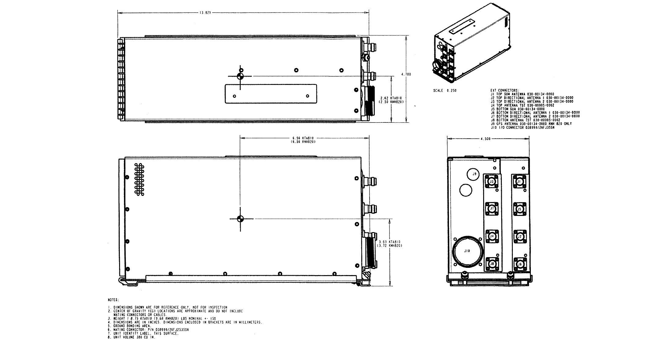
2.2.3.3 Installation Procedure
A. Slide the unit into the rack and secure it.
B. Attach the harness to the front mating connector of the unit.
C. Attach coax cables J1 thru J10 to the front of the unit.
FUNCTION COLOR LEGEND
Not Available Amber Terrain N/A or Terr N/A
Caution Amber Terrain
Warning Red Terrain
B
BB
BKMH 880/KTA 870
Rev 0, October/2000 10609I00.ZIPCDL Page 2-5
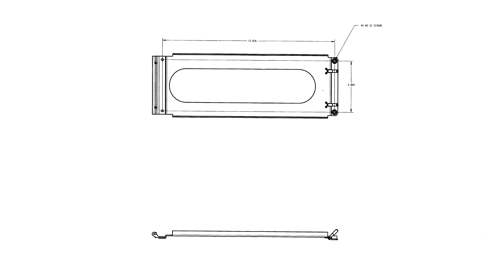
Figure 2-1 KMH 820/KTA 810 Installation Drawing
Dwg. No. 300-05639-0000 R-0 (Sheet 1 of 2)
PRELIMINARY - SUBJECT TO CHANGE WITHOUT NOTICE
B
BB
BKMH 880/KTA 870
Page 2-6 10609I00.ZIPCDL Rev 0, October/2000
THIS PAGE IS RESERVED
PRELIMINARY - SUBJECT TO CHANGE WITHOUT NOTICE
B
BB
BKMH 880/KTA 870
Rev 0, October/2000 10609I00.ZIPCDL Page 2-7
Figure 2-1 KMH 820/KTA 810 Installation Drawing
Dwg. No. 300-05639-0000 R0 (Sheet 2 of 2)
PRELIMINARY - SUBJECT TO CHANGE WITHOUT NOTICE
B
BB
BKMH 880/KTA 870
Page 2-8 10609I00.ZIPCDL Rev 0, October/2000
THIS PAGE IS RESERVED
PRELIMINARY - SUBJECT TO CHANGE WITHOUT NOTICE

PRELIMINARY - SUBJECT TO CHANGE WITHOUT NOTICE
B
BB
BKMH 880/KTA 870
Rev 0, October/2000 10609I00.ZIPCDL Page 2-9
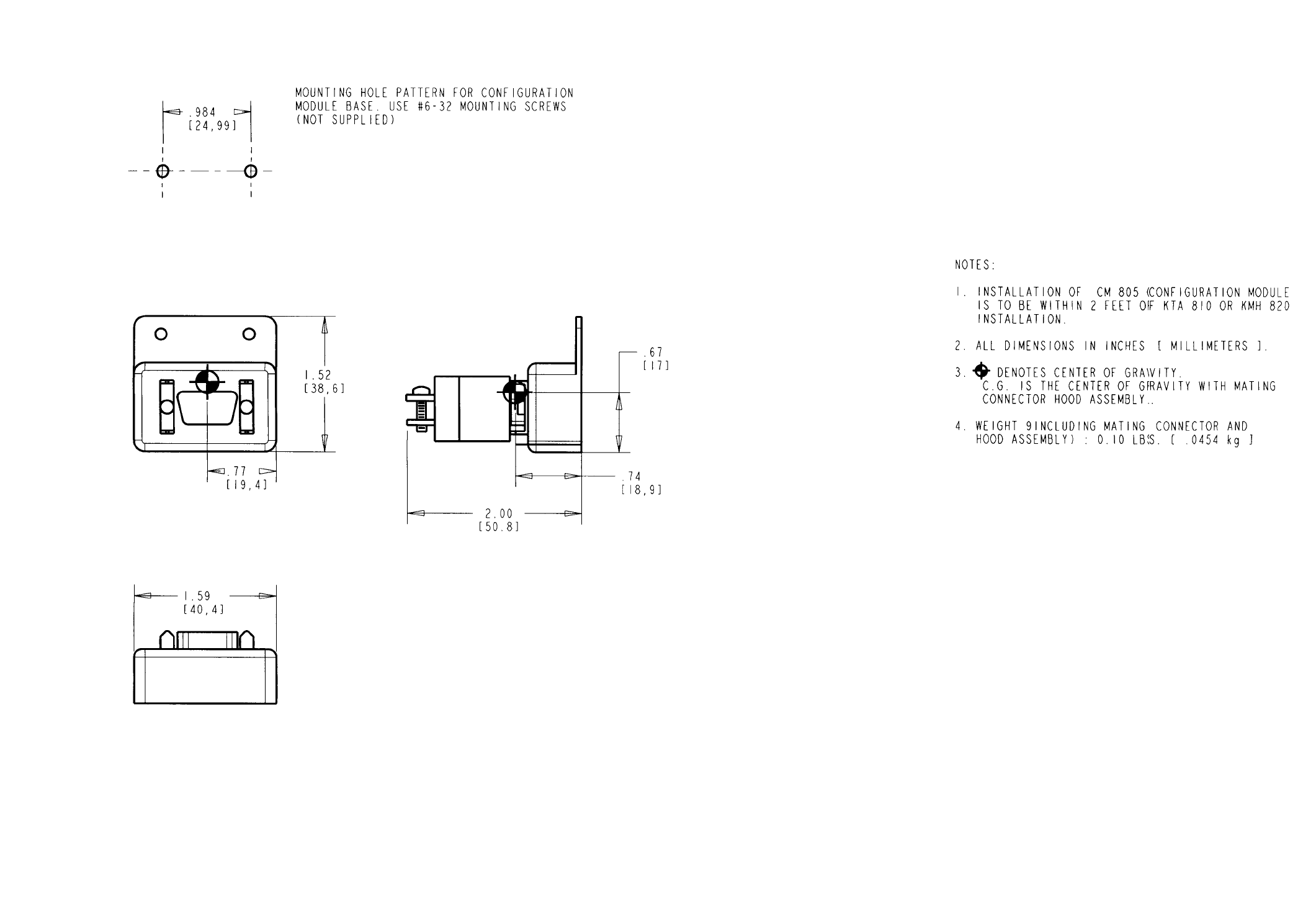
2.2.4 Configuration Module Installation
System configuration is defined via a Configuration Module which contains the aircraft
interface and functionality definitions specific to the installed aircraft.
2.2.4.1 Cooling Considerations
A. Make sure that the unit is installed in a location where the ambient tem-
peratures are -67°F to +158°F (-55°C to +70°C).
2.2.4.2 Installation Considerations
A. The Configuration Module must be mounted to the airframe within maxi-
mum cable/harness length of 2 feet. Make sure to leave adequate space
to mount the Configuration Module when installing the Processor Unit.
2.2.4.3 Installation Procedure
A. Install the Configuration Module into the airframe. Refer to figure 2- 2 .
B. Tighten the mounting screws to secure the Configuration Module.

PRELIMINARY - SUBJECT TO CHANGE WITHOUT NOTICE
B
BB
BKMH 880/KTA 870
Page 2-10 10609I00.ZIPCDL Rev 0, October/2000
THIS PAGE IS RESERVED
B
BB
BKMH 880/KTA 870
Rev 0, October/2000 10609I00.ZIPCDL Page 2-11
Figure 2-2 Configuration Module Installation Drawing
Dwg. No. 300-06161-0000 R-0
PRELIMINARY - SUBJECT TO CHANGE WITHOUT NOTICE
B
BB
BKMH 880/KTA 870
Page 2-12 10609I00.ZIPCDL Rev 0, October/2000
THIS PAGE IS RESERVED
PRELIMINARY - SUBJECT TO CHANGE WITHOUT NOTICE

PRELIMINARY - SUBJECT TO CHANGE WITHOUT NOTICE
B
BB
BKMH 880/KTA 870
Rev 0, October/2000 10609I00.ZIPCDL Page 2-13
2.2.5 DIRECTIONAL ANTENNA INSTALLATION
2.2.5.1 KA 815 Antenna Installation Considerations
A. Antenna Location
NOTE
The following antenna location procedure is provided for guidance pur-
poses and to outline a method of achieving certifiable system perfor-
mance.
The KMH 880/KTA 870 System uses a top-mounted directional antenna and
either a bottom-mounted directional or an L-band omni-directional antenna.
Refer to directional antenna outline drawings in Figure 2-3. Mounting the
directional antenna MUST include the appropriate doubler plate.The install-
ing agency is required to fabricate the doubler plate for the antenna installa-
tions.
NOTE
The L-band omni-directional has not been tested for the direct effects of lightning
and the installer (TC or STC applicant) must determine the suitability of the
antenna for the specific installation.
NOTE
KMH 880/KTA 870 Systems REQUIRE that the antenna installation
guidelines be followed. Adherence to these guidelines will assure that crit-
ical specifications are considered. Optimum bearing accuracy can be
achieved by following these directions.
Antenna locations should be chosen so that both antennas appear to be at
the same range and bearing from the intruder.
The centerline of the top and bottom-mounted TAS Antenna should be
located as close as possible to the aircraft centerline.
The top directional TAS Antenna should be the most forward antenna and as
far forward on the constant radius portion on the fuselage as possible.

PRELIMINARY - SUBJECT TO CHANGE WITHOUT NOTICE
B
BB
BKMH 880/KTA 870
Page 2-14 10609I00.ZIPCDL Rev 0, October/2000
Obstructions and ground plane discontinuities, such as door hatches, cowl-
ings and unriveted airframe skin overlaps must be 18 inches from the near-
est edge of the TAS Antenna. Other antennas, particularly high profile and L-
band transponder antennas, cannot be located in front of or within 30 inches
(edge to edge) of the top mounted TAS directional antenna. This will ensure
a minimum of 20 dB of isolation at 1090 MHz, while minimizing far-field path
distortion in the forward quadrants.
B. Mount the antenna on the aircraft skin which is horizontal during enroute
flight. Antenna baseplate must be level within + or - 5° in longitudinal and lat-
eral axes when the aircraft is in level flight. See Figure 2-4.
C. The antenna must be mounted on a nearly flat surface such that the antenna
contacts the bare metal skin all around the perimeter without gaps when nor-
mal mounting screw torque is applied.
NOTE
Aircraft with fixed landing gear must be equipped with a bottom mono-
pole antenna. Furthermore, the landing gear discrete must be strapped
to the retracted position. The bearing from a bottom directional is inval-
idated when landing gear is extended, so it would always be invalidated
on a fixed-gear aircraft. (Therefore, there would be no use for a directional
antenna.)
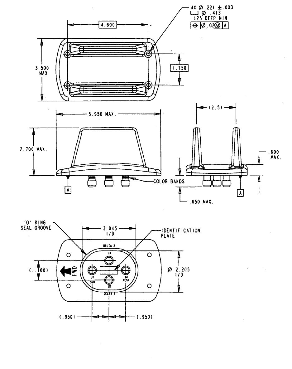
PRELIMINARY - SUBJECT TO CHANGE WITHOUT NOTICE
B
BB
BKMH 880/KTA 870
Rev 0, October/2000 10609I00.ZIPCDL Page 2-15
Figure 2-3 KA 815 Antenna Outline Drawing
PRELIMINARY - SUBJECT TO CHANGE WITHOUT NOTICE
B
BB
BKMH 880/KTA 870
Page 2-16 10609I00.ZIPCDL Rev 0, October/2000
THIS PAGE IS RESERVED
PRELIMINARY - SUBJECT TO CHANGE WITHOUT NOTICE
B
BB
BKMH 880/KTA 870
Rev 0, October/2000 10609I00.ZIPCDL Page 2-17
2.2.6 GPS ANTENNA INSTALLATION
2.2.6.1 KA 92 Antenna Installation Considerations (KMH 820 P/N 066-01175-
2101 only)
A. The KA 92 GPS Antenna should be mounted on top of the fuselage near the
cockpit and in the centerline of the aircraft. Avoid mounting the antenna near
any projections, and the tail of the aircraft, where shadows could occur. It is
recommended that there be a separation of at least 3 feet between the GPS
antenna and any VHF Comm, HF Comm, etc. on the aircraft. A minimum of 3
feet from any satcomm antenna should also be observed. Refer to Figure 2-
6.
B. Mount the GPS antenna on the aircraft skin which is horizontal during
enroute flight. Antenna baseplate must be level within + or - 5° in the longitu-
dinal and lateral axes when the aircraft is in level flight.
2.2.6.2 Installation Procedure
A. Make sure the antenna is well bonded to the aircraft skin.
B. Make sure the antenna is sealed to the aircraft to prevent corrosion from
forming between the skin of the aircraft and the antenna.
C. Install the optional GPS Antenna Splitter, if aircraft is already equipped with a
GPS antenna.
D. Make sure the antenna cable is connected to the antenna, splitter and unit
prior to system checkout.
E. Perform system checkout using instructions in Section 4.3.
PRELIMINARY - SUBJECT TO CHANGE WITHOUT NOTICE
B
BB
BKMH 880/KTA 870
Page 2-18 10609I00.ZIPCDL Rev 0, October/2000
THIS PAGE IS RESERVED
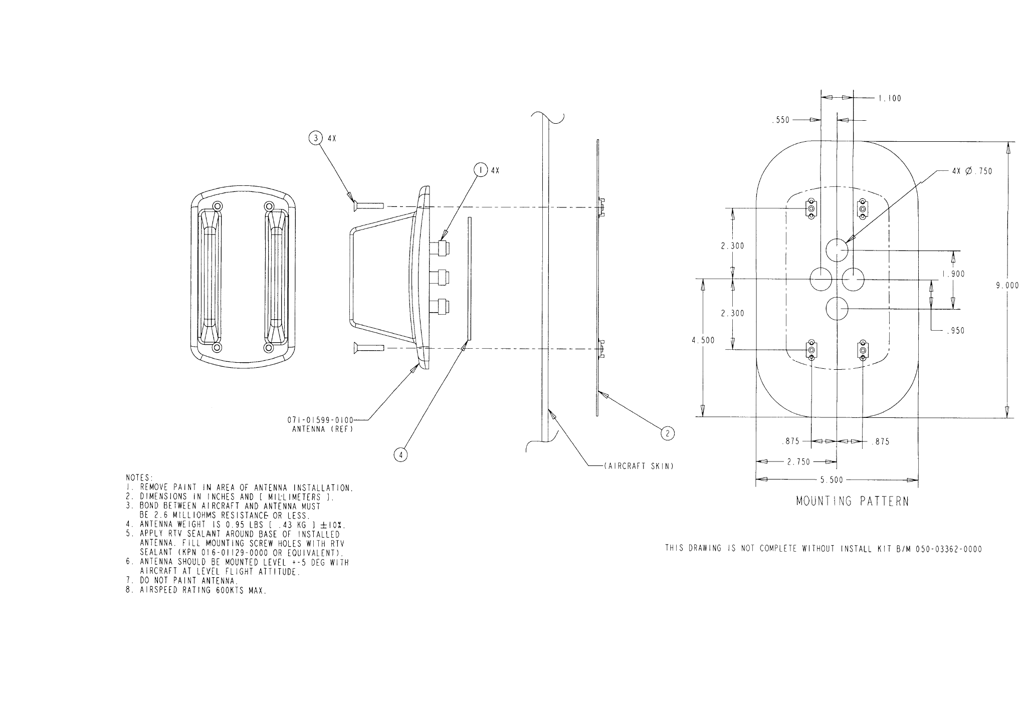
B
BB
BKMH 880/KTA 870
Rev 0, October/2000 10609I00.ZIPCDL Page 2-19
Figure 2-4 KA 815 Installation and Mounting Drawing
Dwg No. 155-06059-0000
PRELIMINARY - SUBJECT TO CHANGE WITHOUT NOTICE
B
BB
BKMH 880/KTA 870
Page 2-20 10609I00.ZIPCDL Rev 0, October/2000
THIS PAGE IS RESERVED
PRELIMINARY - SUBJECT TO CHANGE WITHOUT NOTICE
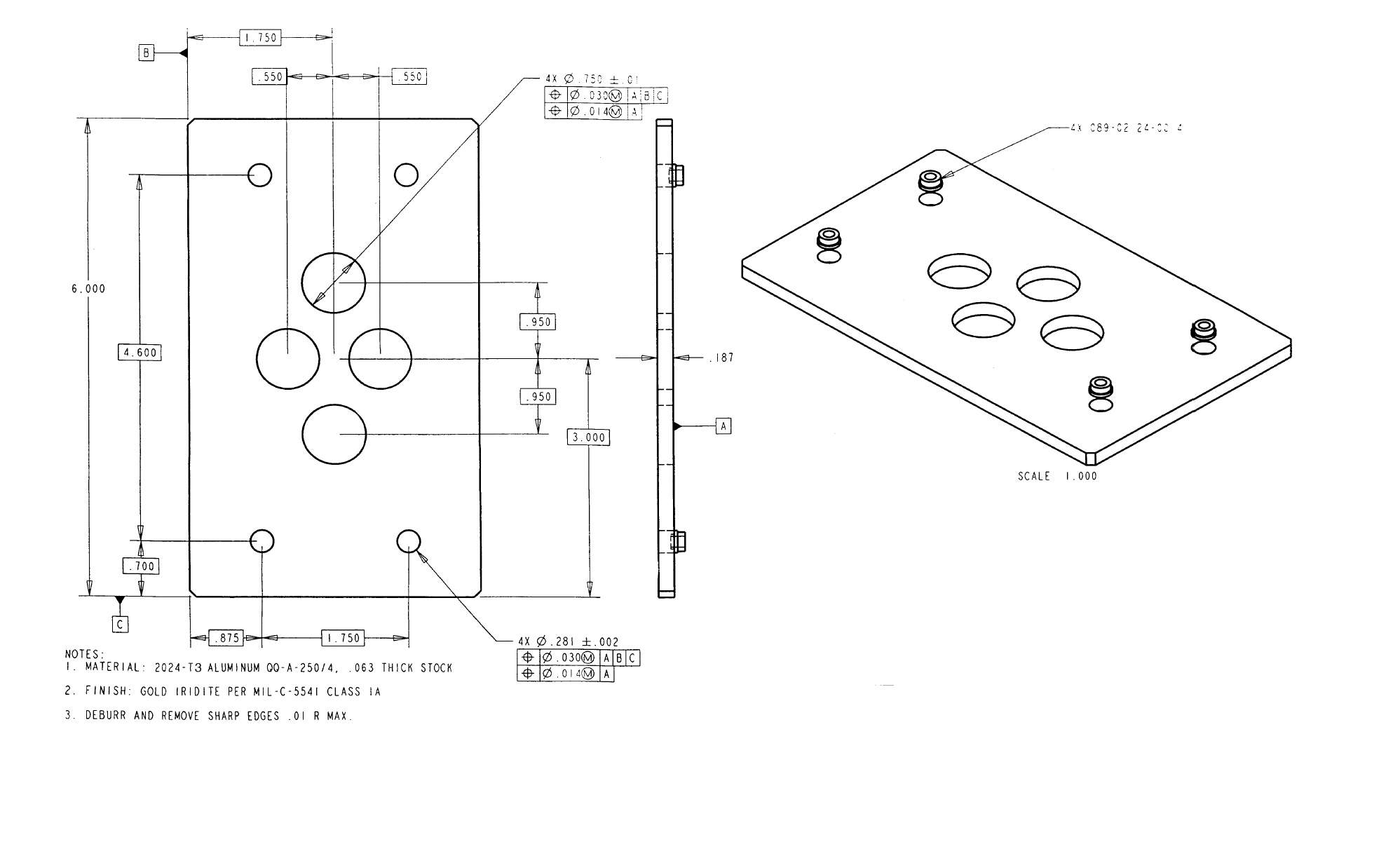
B
BB
BKMH 880/KTA 870
Rev 0, October/2000 10609I00.ZIPCDL Page 2-21
Figure 2-5 KA 815 Doubler Plate
PRELIMINARY - SUBJECT TO CHANGE WITHOUT NOTICE
B
BB
BKMH 880/KTA 870
Page 2-22 10609I00.ZIPCDL Rev 0, October/2000
THIS PAGE IS RESERVED
PRELIMINARY - SUBJECT TO CHANGE WITHOUT NOTICE
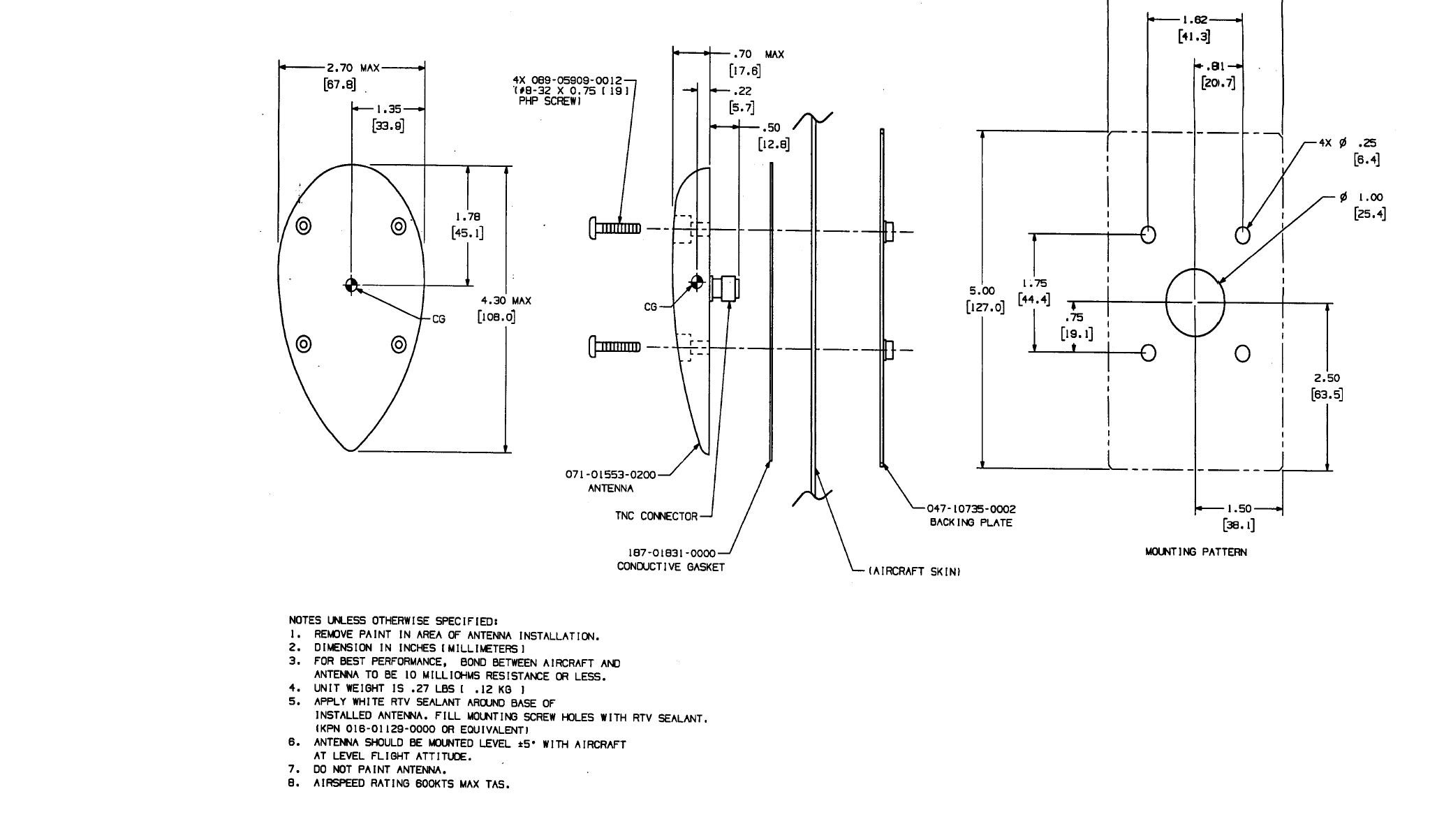
B
BB
BKMH 880/KTA 870
Rev 0, October/2000 10609I00.ZIPCDL Page 2-23
Figure 2-6 KA 92 Outline and Mounting Drawing
Dwg. No. 155-06019-0000 R-AA
PRELIMINARY - SUBJECT TO CHANGE WITHOUT NOTICE
B
BB
BKMH 880/KTA 870
Page 2-24 10609I00.ZIPCDL Rev 0, October/2000
THIS PAGE IS RESERVED
PRELIMINARY - SUBJECT TO CHANGE WITHOUT NOTICE
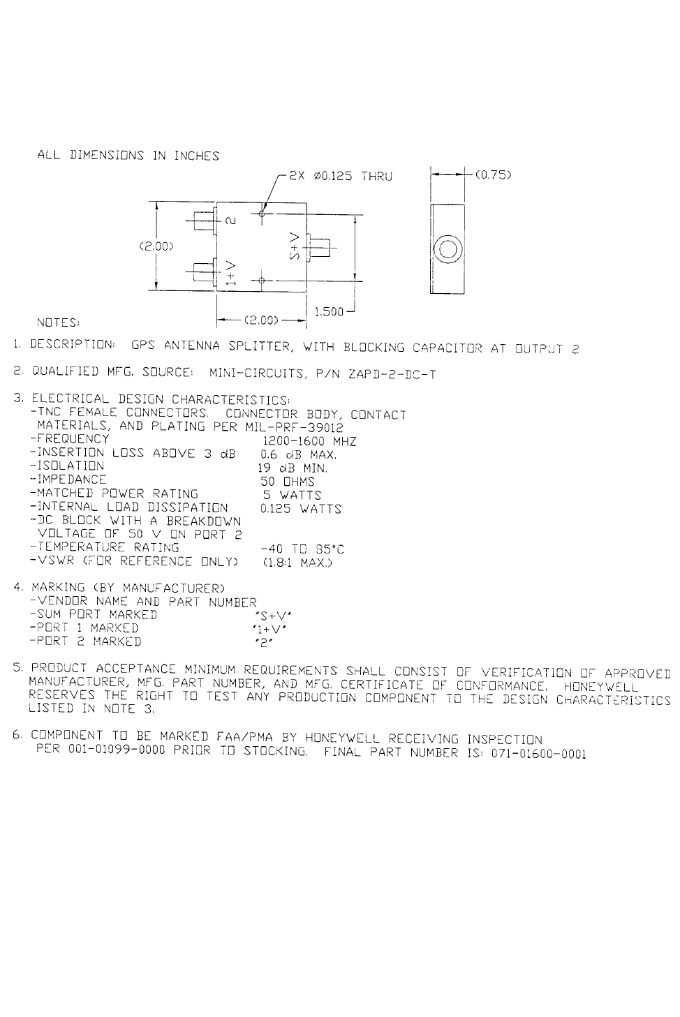
PRELIMINARY - SUBJECT TO CHANGE WITHOUT NOTICE
BKMH 880/KTA 870
Rev 0, October/2000 10609I00.ZIPCDL Page 2-25
Figure 2-7 GPS Antenna Splitter
Dwg. No. 071-01600-0001
PRELIMINARY - SUBJECT TO CHANGE WITHOUT NOTICE
BKMH 880/KTA 870
Page 2-26 10609I00.ZIPCDL Rev 0, October/2000
2.2.7 TAS Coaxial Cable Fabrication
The TAS cables must have an attenuation of 2.0 ± 1.0 dB within the frequency band of
1030-1090 MHZ. To ensure proper phase matching, each of the four cables of a set must
be of the same type. The lengths in each set of four must be within 2.0” of each other.
Color bands on the cable ends to match the antenna color bands is suggested as an aid
to hook up. Cables can be fabricated or purchased from a cable vendor.
NOTE
The nominal length of each set of four cables should be recorded for the
particular installation in the event a cable should require replacement. If
rework is required, a cable may be cut a maximum of 6”.
The following defines the characteristics of the 50 ohm coaxial cable types that can be
used with the KA 815 Antenna. Connectors are also defined. All lengths are defined as
end to end. Any in-line or bulkhead penetrations must be evaluated separately. It is rec-
ommended that the installer purchase prefabricated cable assemblies when using in-line
or bulkhead disconnects. Prefabricated cables can be purchased from Pic Wire & Cable
or ECS. These vendors have expertise in providing the aviation industry reliable cable
assemblies that meet the requirements for the various collision avoidance systems. It is
the installing agency’s responsibility to show airworthiness of the fabricated cable assem-
blies.
When determining cable type and length make the following assumptions.
A. Attenuation of each straight TNC male connector is 0.06 dB @ 1GHz
(using a 030-00134-0000 RF Connector)
B. Attenuation of each right angle TNC male connector is 0.07 dB @ 1 GHz
(using a 030-00134-0001 RF Connector)
C. Attenuation of each TNC female panel mount connector is 0.06 dB @
1 GHZ (using a 030-00101-0002 RF Connector)
D. Attenuation of M17/128-RG 400 Coaxial Cable is 0.13 dB/ft @ 1 GHz
Using the above information, a RG 400 cable with a right angle TNC (antenna end) and a
straight TNC (KMH/KTA end) must be no longer than 22 feet long as measured from end
to end. If longer length is required, then a lower loss cable with appropriate connectors
must be selected. Reference the diagram below.

PRELIMINARY - SUBJECT TO CHANGE WITHOUT NOTICE
BKMH 880/KTA 870
Rev 0, October/2000 10609I00.ZIPCDL Page 2-27
2.2.8 GPS Coaxial Cable Fabrication
The GPS Antenna Splitter allows the existing KA 91 or KA 92 GPS antenna to be interfaced to the
KMH 820 EGPWS.
The following criteria must be observed when using the antenna splitter:
1. The length of an M17/128-RG400 coaxial cable cannot exceed 18 feet.
2. The maximum allowable signal loss between the KA 91/92 antenna and the KLN
series GPS receiver cannot exceed 8.0 dB. Refer to the appropriate KLN series GPS
receiver Installation Manual for determination of loss.
3. The maximum allowable signal loss between the KA 91/92 antenna and the KMH 820
cannot exceed 8.0 dB. Refer to the following table to determine the loss between the
antenna and the KMH 820.
Table 2-1 Signal Loss
Part Number Description Signal Loss
per Item
Example
Quantity
Example
Signal Loss
Actual
Quantity
Actual
Signal Loss
071-01600-001 GPS Antenna Splitter 3.4 dB 1 ea 3.4 dB
M17/128-RG400 Coaxial Cable (18 ft max) 0.2dB/ft 10 ft 2.0 dB
030-00134-0000 Straight TNC Connector 0.1dB 2 ea 0.2 dB
030-00134-0001 Rt Angle YNC Connector 0.1dB 2 ea 0.2 dB
030-00101-0002 Panel Mount Plug 0.1dB 0 0
M39012/28-0504 Bulkhead TNC Connector 0.1dB 0 0
M39012/29-0504 Panel TNC Connector 0.1dB 0 0
TOTAL SIGNAL LOSS (8.0 dB max.) 5.8 dB
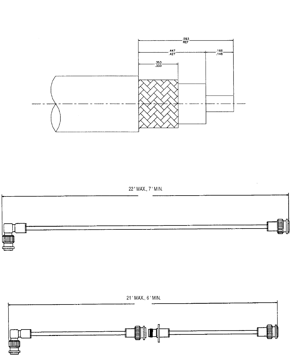
PRELIMINARY - SUBJECT TO CHANGE WITHOUT NOTICE
BKMH 880/KTA 870
Rev 0, October/2000 10609I00.ZIPCDL Page 2-28
Figure 2-8 Coax Cable Treatment
Figure 2-9 Standard RG-400 Coax Cable
Figure 2-10 Bulkhead/In-Line Connection RG-400 Coax Cable

PRELIMINARY - SUBJECT TO CHANGE WITHOUT NOTICE
BKMH 880/KTA 870
Rev 0, October/2000 10609I00.ZIPCDL Page 2-29
Figure 2-11 TNC Antenna Coax/Connector Assembly
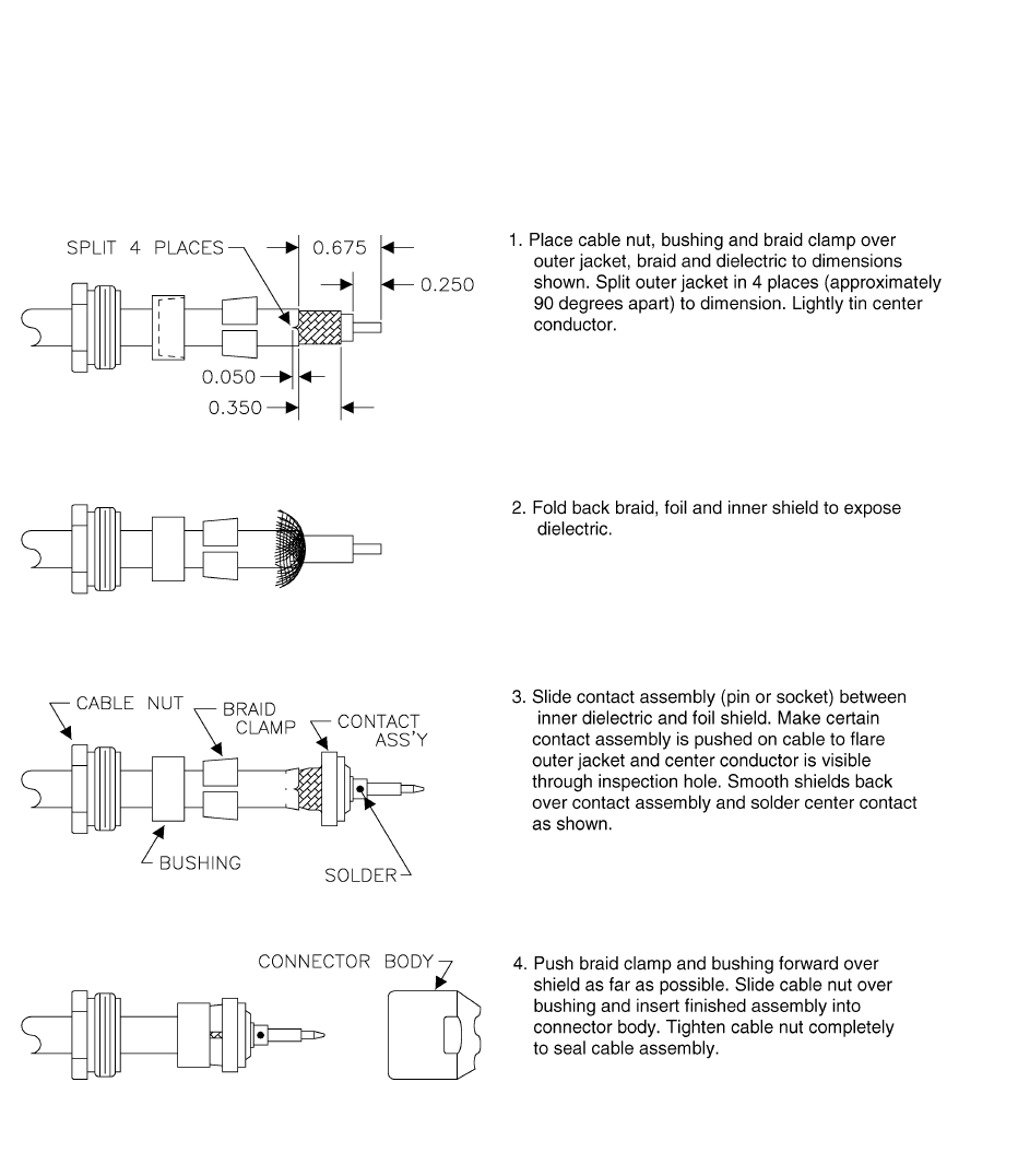
PRELIMINARY - SUBJECT TO CHANGE WITHOUT NOTICE
BKMH 880/KTA 870
Rev 0, October/2000 10609I00.ZIPCDL Page 2-30
Figure 2-12 TNC Antenna Coax/Connector Assembly
PRELIMINARY - SUBJECT TO CHANGE WITHOUT NOTICE
B
BB
BKMH 880/KTA 870
Rev 0, Octobert/2000 10609I00.ZIPCDL TOC 3-i
SECTION III
SYSTEM PLANNING
3.0 INTRODUCTION .............................................................................. 3-1
3.0.1 Applicable Part Numbers Subsection Description ............................ 3-1
3.0.2 Function Subsection Description ...................................................... 3-1
3.0.3 Requirements and Limitations Subsection Description. ................... 3-1
3.0.4 Electrical Characteristics Subsection Description. ............................ 3-1
3.0.5 Interface Subsection Description ...................................................... 3-1
3.1 GENERAL INTERCONNECT INFORMATION ................................. 3-5
3.1.1 Power Inputs ..................................................................................... 3-5
3.1.2 Air/Ground Discrete Input ................................................................. 3-5
3.1.3 Landing Gear Discrete Input ............................................................. 3-6
3.1.4 Above/Below/ Normal Input .............................................................. 3-6
3.1.5 Baro Altitude (ARINC 429) Input ....................................................... 3-7
3.1.6 Advisory Inhibit Input ........................................................................ 3-7
3.1.7 TAS Valid Output .............................................................................. 3-7
3.1.8 Visual Annunciate Traffic (Lamp Output) .......................................... 3-8
3.1.9 Synthesized Voice output ................................................................. 3-8
3.1.10 Air Temperature Input ....................................................................... 3-9
3.1.11 GPS Input ......................................................................................... 3-9
3.1.12 Factory Test Input ............................................................................. 3-10
3.1.12.1 TAS ATE Enable Input ................................................................... 3-10
3.1.12.2 TAS Built In Test Equipment (BITE) .............................................. 3-10
3.1.12.3 EGPWS Self Test Input ................................................................. 3-11
3.1.12.4 Display Select Input ....................................................................... 3-12
3.1.12.5 Terrain Awareness Inhibit Discrete ................................................ 3-12
3.1.13 Terrain Warning ................................................................................ 3-12
3.1.14 Terrain Caution.................................................................................. 3-12
3.1.15 Weather Select Output ..................................................................... 3-12
3.1.16 EGPWS Audio On Discrete .............................................................. 3-13
3.1.17 EGPWS Terrain Inop and Terrain Not Available Output.................... 3-13
LIST OF ILLUSTRATIONS
Figure 3-1 KMH 880/KTA 870 Interconnect Family ...................................... 3-3
Figure 3-2 KMH 820/KTA 810 Pinout Diagram ............................................. 3-15
Figure 3-3 KMH 820/KTA 810 System Interconnect Block Diagram ............. 3-29
Figure 3-4 KMH 820/KTA 810 Power Interface ............................................ 3-33
Figure 3-5 KMH 820/KTA 810 Discrete Interface ......................................... 3-35
Figure 3-6 KMH 820/KTA 810 Configuration Module Interconnect ............... 3-37
Figure 3-7 KMH 820/KTA 810 Attitude/Heading Interface............................. 3-39
Figure 3-8 KMH 820/KTA 810 Radar/Barometric Altitude Interface ............. 3-41
PRELIMINARY - SUBJECT TO CHANGE WITHOUT NOTICE
B
BB
BKMH 880/KTA 870
TOC 3-ii 10609I00.ZIPCDL Rev 0, October/2000
Figure 3-9 KMH 820/KTA 810 Antenna/Suppression Interface .................... 3-49
Figure 3-10 KMH 820/KTA 810 EFS 40/50 Interface .................................... 3-51
Figure 3-11 KMH 820/KTA 810 GS 362A Interface ....................................... 3-53
Figure 3-12 KMH 820/KTA 810 Honeywell GS 362A Interface ....................... 3-59
Figure 3-13 KMH 820/KTA 810 Collins GS 362A Interface ............................. 3-65
Figure 3-14 KMH 820/KTA 810 Honeywell Primus 1000 Interface.................. 3-69
Figure 3-15 KMH 820/KTA 810 Honeywell SPZ-805 Interface........................ 3-73
Figure 3-16 KMH 820/KTA 810 Diagnostic/Data Recorder Interface ............. 3-77
Figure 3-17 KMH 820/KTA 810 TAS ATE Interface ....................................... 3-79
Figure 3-18 KMH 820/KTA 810 CP 66B Interface........................................... 3-81
Figure 3-19 KMH 820/KTA 810 KFS 578A Interface....................................... 3-83
Figure 3-20 KMH 820/KTA 810 Display Interface............................................ 3-87
Figure 3-21 KMH 820/KTA 810 Processor Front Connector .......................... 3-95
Figure 3-22 KMH 820/KTA 810 Front Connector Cable.................................. 3-96
LIST OF TABLES
Table 3-1 KMH 820/KTA 810 Connector Pin Assignment ........................... 3-97
PRELIMINARY - SUBJECT TO CHANGE WITHOUT NOTICE
B
BB
BKMH 880/KTA 870
Rev 0, October/2000 10609I00.ZIPCDL Page 3-1
SECTION III
SYSTEM PLANNING
3.0 INTRODUCTION
You will find information relative to the KMH 880/KTA 870 system requirement options
available to the system planner and the electrical characteristics of the various interfaces
in Section III. You will also find pin function lists and interconnect diagrams in this section.
Section III contains interconnect family diagrams for the KMH 880/KTA 870 system.
Refer to figure 3-3 for the KMH 880/KTA 870 system diagram. There are several intercon-
nect drawings for popular equipment that interface with the KMH 880/KTA 870. The
installing agency should contact Honeywell International Inc. Product Support at (800)
257-0726 for information regarding the compatibility of equipment not listed in this man-
ual. Normal business hours are 8:00 A.M. to 5:00 P.M. CST, Monday through Friday.
3.0.1 Applicable Part Numbers Subsection Description
Information given in this section pertains only to the KMH 880/KTA 870 System
using part numbers. Refer to Section 1.4.1 for complete part number descriptions.
3.0.2 Function Subsection Description
Detailed information concerning the purpose and operation of the interface are
described in this section.
3.0.3 Requirements and Limitations Subsection Description.
Any operational requirements or limitations relating to the interface are described
in this section. Widely followed regulatory requirements may also be described
here. Regionally enforced requirements vary greatly and adherence to them
remains the responsibility of the installing agency.
3.0.4 Electrical Characteristics Subsection Description.
The electrical characteristics and format of the interface signals are described in
this section. Any flavor-related differences in signal format are also described
here. Overlined pin names generally indicate active low signals, although the
absence of an overline does not necessarily indicate an active high signal.
3.0.5 Interface Subsection Description
The harness techniques for shielding and shield termination described in this
manual are identical to those specified for the test harness used during HIRF and
Lightning testing. Adherence to the information in this manual is essential in
establishing an installation environment equivalent to the test environment used
during HIRF and Lightning testing.
PRELIMINARY - SUBJECT TO CHANGE WITHOUT NOTICE
B
BB
BKMH 880/KTA 870
Page 3-2 10609I00.ZIPCDL Rev 0, October/2000
Should grounding the shields, as shown in the interconnect diagrams, cause
unacceptable interference due to noise sources on the aircraft, double shielded
wire may be substituted for single shielded wire shown in this manual. The outer
shield must be grounded at both ends to comply with HIRF and Lightning require-
ments. The inner shield may then be grounded at a single end to protect against
the aircraft noise source. Normally the inner shield is grounded at the source end
of the signal carried by the wire. Planning to install double shielded wire for low
level signals known to have a history of interference may be easier than later add-
ing the double shielded wire into the aircraft harness.
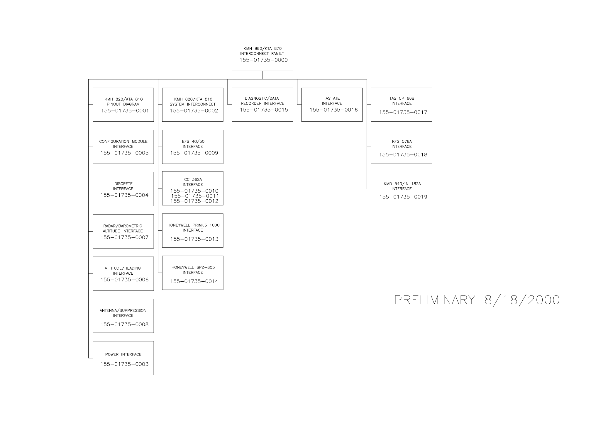
B KMH 880/KTA 870
Rev0, October/2000 10609I00.ZIPCDL Page 3-3
Figure 3-1 KMH 880/KTA 870 Interconnect Family
Dwg. No. 155-01735-0000 (08/18/2000)
PRELIMINARY - SUBJECT TO CHANGE WITHOUT NOTICE
B KMH 880/KTA 870
Rev0, October/2000 10609I00.ZIPCDL Page 3-4
THIS PAGE IS RESERVED
PRELIMINARY - SUBJECT TO CHANGE WITHOUT NOTICE

PRELIMINARY - SUBJECT TO CHANGE WITHOUT NOTICE
B
BB
BKMH 880/KTA 870
Rev 0, October/2000 10609I00.ZIPCDL Page 3-5
3.1 GENERAL INTERCONNECT INFORMATION
3.1.1 Power Inputs
The Processor is powered with +28 VDC and is protected by a circuit breaker
(5 Ampere) in the Aircraft distribution center.
A. 28 Volts Direct Current
J10 - 59 & 82 → Nominal: + 28 Vdc A/C Power In.
Range: + 22 Vdc to + 30 Vdc.
1.3 ± 0.2 Amps @ 28 VDC typical current
1.65 ± 0.2 Amps @28 VDC Max operating
3.3 Amps @ 18 VDC maximum current
Power: 46 ± 2.3 Watts
B. DC Return
J10 - 127 & 128
These pins connect to airframe ground with 22 gauge wire minimum.
NOTE
The KMH 820/KTA 810 will shut down when the power line dips below +15
VDC. The KMH 820/KTA 810 will resume normal operation (i.e. surveilling
targets) on power restoration (when the power line meets +18 VDC mini-
mum).
3.1.2 Air/Ground Discrete Input
The Air/Ground Discrete, if used, is wired to a logic source in the aircraft that
presents a standard “open” circuit while the aircraft is airborne and a standard
“ground” when the aircraft is on the ground. The Air/Ground Discrete is filtered
to allow takeoff and landings. The discrete will remain in the same state for 10
seconds before changing states.
AIRBORNE = >100Kohms , or +18.5 to +36 VDC.
ON GROUND = < 10 ohms, or 0 to +3.5 VDC.
J10-4 Air_Gnd*

PRELIMINARY - SUBJECT TO CHANGE WITHOUT NOTICE
B
BB
BKMH 880/KTA 870
Page 3-6 10609I00.ZIPCDL Rev 0, October/2000
NOTE
The normal mechanical failure mode will be the “airborne” condition
3.1.3 Landing Gear Discrete Input
The Landing Gear Discrete, if used, will present a standard “open” circuit when
the gear is retracted and a standard ground when the gear is extended.
RETRACTED = > 100Kohms to airframe DC GND or +18.5 to +36 VDC.
EXTENDED = <10 ohms to airframe DC GND or 0 to +3.5 VDC
J10-3 Landing_gear*.
NOTE
Aircraft with fixed landing gear must be equipped with a bottom monopole
antenna. Furthermore, the landing gear discrete must be strapped to the
retracted position.
NOTE
The normal mechanical failure mode is the “retracted” condition.
3.1.4 Above/Below/Normal Input
This input defines the Altitude Select for the display. Momentary (250 msec.
minimum) application of a “ground” at this input will cause a transistion
between the three states in a cyclical manner ; Normal- Below-Above. The
default mode is “Normal”.
J10-71 ABV_BEL_NORM*

PRELIMINARY - SUBJECT TO CHANGE WITHOUT NOTICE
B
BB
BKMH 880/KTA 870
Rev 0, October/2000 10609I00.ZIPCDL Page 3-7
3.1.5 Baro Altitude (ARINC 429) Input
Baro Altitude will be input to the TAS Processor via the Baro Altitude ARINC
429 low speed input bus. This bus may also be used as an ARINC 419 low
speed input bus. The ARINC 706 Air Data Computer will interface to the TAS
Processor using the ARINC 429 input ports and the ARINC 575 Air Data Com-
puter will interface to the TAS Processor using the ARINC 419 input ports.
3.1.6 Advisory Inhibit Input
The Advisory Inhibit into the TAS Processor will cause annunciations to be
inhibited when higher priority events occur (i.e., wind-shear alerts, terrain alert
warnings.)
NOTE
The TAS Computer Unit will inhibit certain functions which would tend to
distract the pilot when faced with a potentially hazardous condition such as
windshear or terrain alerts. These conditions are presumed to have a more
immediate possibility and higher probability of harm than the threat of a col-
lision. Thus, TAS functions such as aural announcements and aural alerts
are to be inhibited by placing the TAS Computer Unit in a mode which
would preclude its issuing the unwanted information.
If the Advisory Inhibit has been activated, no new voice or annunciator outputs
can be activated by the TAS computer unit during the deferment period. If
already activated, these outputs will be discontinued within 250 milliseconds. If
an advisory condition is present when the deferment is removed, it will be
annunciated.
ADVISORY INHIBIT = GROUND
NORMAL ADVISORY/ALERT = OPEN
J10-22 ADV_INHIBIT*
3.1.7 TAS Valid Output
This output is provided as a primary indicator of valid system operation. This
output is driven to the valid state during normal operation. The TAS Valid dis-
crete will go invalid during power up self tests and operator commanded self
tests.
VALID = GROUND ( < 10 ohms to ground)
INVALID = OPEN
J10-25 TAS_VALID*

PRELIMINARY - SUBJECT TO CHANGE WITHOUT NOTICE
B
BB
BKMH 880/KTA 870
Page 3-8 10609I00.ZIPCDL Rev 0, October/2000
3.1.8 Visual Annunciate Traffic (Lamp Output)
The “Visual Annuciator Traffic” output is activated whenever a traffic advisory is
issued. This output will remain in the activated state for the duration of the
advisory unless cancelled or inhibited.
ACTIVE = GROUND ( < 10 ohms to ground), VOLTAGE 0 to +3.5 VDC.
INACTIVE = OPEN
Current Capability = 200 milliamps., when activated.
Voltage Capability = +36 VDC, when not activated.
J10-24 VIS_ANNUN_TRAFFIC*
3.1.9 Synthesized Voice output
KMH 820/KTA 810 will supply low level audio signals of up to 100 milliwatts at
1000 Hz into a 600 ohm audio distribution system. The outputs are on pins
“PH_HI” and “PH_LO”.
J 10-20 = PH_HI
J 10-21 = PH_ LO
The power output will be adjustable based on the audio level inputs.
The TAS messages available for output are as follows:
1. “TAS System Test OK”
2. “TAS System Test Fail”
3. “Traffic, Traffic”
4. “Traffic”
NOTE
A 1 kHz tone is available for calibration adjustments only.

PRELIMINARY - SUBJECT TO CHANGE WITHOUT NOTICE
B
BB
BKMH 880/KTA 870
Rev 0, October/2000 10609I00.ZIPCDL Page 3-9
3.1.10 Air Temperature Input
Outside Air Temperature is an optional input. This can come from a number of
sources such as ARINC 429/575 Air Data or a dedicated AOT probe. EGPWS
is capable of interfacing directly to a standard 500 ohm temperature probe for
low temperature operations.
J10-109 OAT_H, J10-110 OAT_L, J10-111 OAT_Ref.
3.1.11 GPS Input
GPS information is furnished in ARINC 429 and RS-232 (NEMA or RNAV) for-
mats. The following Information is required from the GPS:
1. Latitude/Longitude
2. Ground Speed
3 . Tr u e Tr a ck A n g l e
4. GPS Altitude
5. Indication of the quality of the navigation solution. (VFOM and HFOM
prefered).
Optional information to be used, if available, are:
1. GPS Vertical Velocity
2. Number of satelites tracked
3. Results of RAIM
4. Altitude aiding flag
NOTE
An internal GPS xpress Card provides all the needed signals for proper
operation.

PRELIMINARY - SUBJECT TO CHANGE WITHOUT NOTICE
B
BB
BKMH 880/KTA 870
Page 3-10 10609I00.ZIPCDL Rev 0, October/2000
3.1.12 Factory Test Input
When active, the EGPWS will go into the Factory Test Mode. The TAS Proces-
sor and the Automatic Test Equipment will interface via RS-232 and the ATE
Test Pins.
J10-113 GSE_PRES# (Factory Test) (Factory Only)
3.1.12.1 TAS ATE Enable Input
The ATE Enable is used to enable the ATE lines for the Anechoic Chamber and
the RGS stations. The TAS Automated Test Equipment will fully test the TAS
system closing the loop around the TAS antenna system by emulating the
functions of an intruder aircraft.
3.1.12.2 TAS Built In Test Equipment (BITE)
BITE enables the TAS Processor to provide internal system performance mon-
itoring under normal bench conditions, under environmental extremes and dur-
ing normal operation. All BITE functions are an integral part of the normal
operational TAS system and do not interfere with normal TAS operations. The
TAS Processor BITE function is responsible for executing the test outlined
below (during cold start or functional test) to ensure that the TAS Processor
and inputs from interfacing components are functional.
1. Automatic System Performance Monitoring (SPM) and Functional Test
The TAS Processor SPM and functional test functions will test the TAS Pro-
cessor for correct operation (detection of internal faults) and test inputs
provided by external system components for correct operation (detection of
external faults). The SPM function and functional test are capable of
detecting and initiating the appropriate response to all faults that would
affect the ability of the TAS Processor to meet TAS system safety and per-
formance requirements.
System Performance Monitoring is performed on a continuous basis. The
tests outlined below are accomplished to ensure correct operation of the
TAS Processor and interfacing components during normal operation.
NOTE
The purpose of the TAS Processor automatic system performance
monitoring (SPM) and Self Test is to detect malfunctions that degrade
or preclude TAS protection.

PRELIMINARY - SUBJECT TO CHANGE WITHOUT NOTICE
B
BB
BKMH 880/KTA 870
Rev 0, October/2000 10609I00.ZIPCDL Page 3-11
2. Failure Processing
After each functional test or monitoring cycle is complete, the failures
detected are prioritized and logged in fault memory if the severity of the
fault allows. The fault memory will keep the three highest priority faults per
power cycle.
When a fault is detected that would cause the TAS Processor to declare
TAS inoperative or failed the following responses, regardless of failure cate-
gory will be initiated:
A. Set the ‘TAS Valid Output’ discrete to invalid.
B. Inhibit ATCRBS interrogations from TAS.
C. Deactivate the ‘normal’ TAS display functions.
D. Cancel any TA voice message.
If a fault is detected that would invoke one of the above responses, then
that response will be accomplished within one second of detecting the fault.
3. Failure Categories
A. Catastrophic
The severity of a catastrophic failure will preclude any software from exe-
cuting.
B. Fatal
The severity of a fatal failure will preclude any TAS surveillance software
from executing.
C. Critical
The severity of a critical failure will force the system to run in a failed
state.
D. System
This type of failure is used for inputs from system sources external to the
TAS Processor.
3.1.12.3 EGPWS Self Test Input
Level 1 cockpit self-test will annunciate “System OK” when the system is oper-
ating properly.
J10-121 GND_DISC_07 (Self Test)

PRELIMINARY - SUBJECT TO CHANGE WITHOUT NOTICE
B
BB
BKMH 880/KTA 870
Page 3-12 10609I00.ZIPCDL Rev 0, October/2000
3.1.12.4 Display Select Input
An input supplied by a momentarily actuated cockpit manual switch that tog-
gles between activating and de-activating the Terrain Awareness Display
(TAD).
J10-123 GND_DISC_12 (Disp. Sel.)
3.1.12.5 Terrain Awareness Inhibit Discrete
Terrain awareness will be provided via Terrain and Runway Databases. All run-
ways >2000 feet are provided. The nominal terrain database resolution around
the airport will be 15 arc-seconds where available. This resolution is not
needed for flat areas.
J10-126 GND_DISC_15 (Terrain Awareness Inhibit)
3.1.13 Terrain Warning
This is a means of displaying to the flight crew that there is a critical situation
involving terrain clearance and corrective action is required.
J10-116 TERRAIN WARNING
3.1.14 Terrain Caution
This is a means of displaying to the flight crew that there is a terrain clearance
situation developing that needs to be monitored.
J10-117 (TERRAIN CAUTION)
3.1.15 Weather Select Output
A discrete output for controlling the terrain display. It can be used either to con-
trol a picture bus switching relay or connected directly to a symbol generator.
J10-118 (WX/EGPWS DISPLAY SELECT)

PRELIMINARY - SUBJECT TO CHANGE WITHOUT NOTICE
B
BB
BKMH 880/KTA 870
Rev 0, October/2000 10609I00.ZIPCDL Page 3-13
3.1.16 EGPWS Audio On Discrete
The Audio On Discrete goes true whenever any voice message is being
annunciated. It will stay true until the voice is completed. This output can be
used to inhibit other audio systems (e.g., TAS) during EGPWS audio or used to
drive the audio key line input provided on some aircraft audio systems. This
discrete is internally wired to the TAS advisory inhibit and is available on:
J10-22 ADV_INHIBIT*
3.1.17 EGPWS, Terrain Inop and Terrain not available Output
The EGPWS produces one monitor output. This discrete reflects the EGPWS
Inop and Terrain Inop / Terrain Not Available functions. This discrete activates
with the loss of EGPWS power. The status of this discrete is also contained on
an ARINC 429 output word.
J10-120 (EGPWS Inop)

PRELIMINARY - SUBJECT TO CHANGE WITHOUT NOTICE
B
BB
BKMH 880/KTA 870
Rev 0, October/2000 10609I00.ZIPCDL Page 3-14
THIS PAGE IS RESERVED
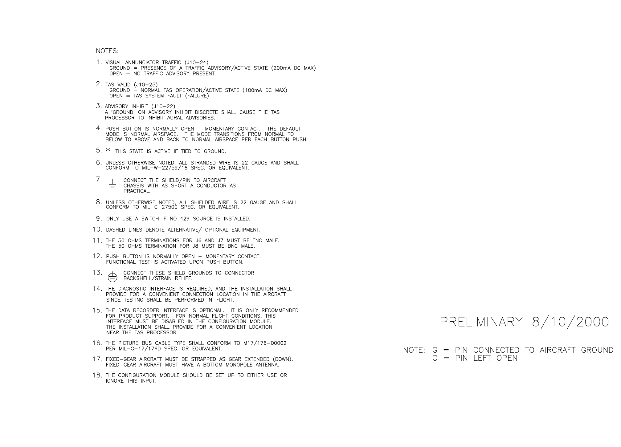
B
BB
BKMH 880/KTA 870
Rev 0, October/2000 10609I00.ZIPCDL Page 3-15
Figure 3-2 KMH 820/KTA 810 Pinout Diagram
Dwg. No. 155-01735-0001 (Sheet 1 of 7) (08/10/2000)
PRELIMINARY - SUBJECT TO CHANGE WITHOUT NOTICE
B
BB
BKMH 880/KTA 870
Page 3-16 10609I00.ZIPCDL Rev 0, October/2000
THIS PAGE IS RESERVED
PRELIMINARY - SUBJECT TO CHANGE WITHOUT NOTICE
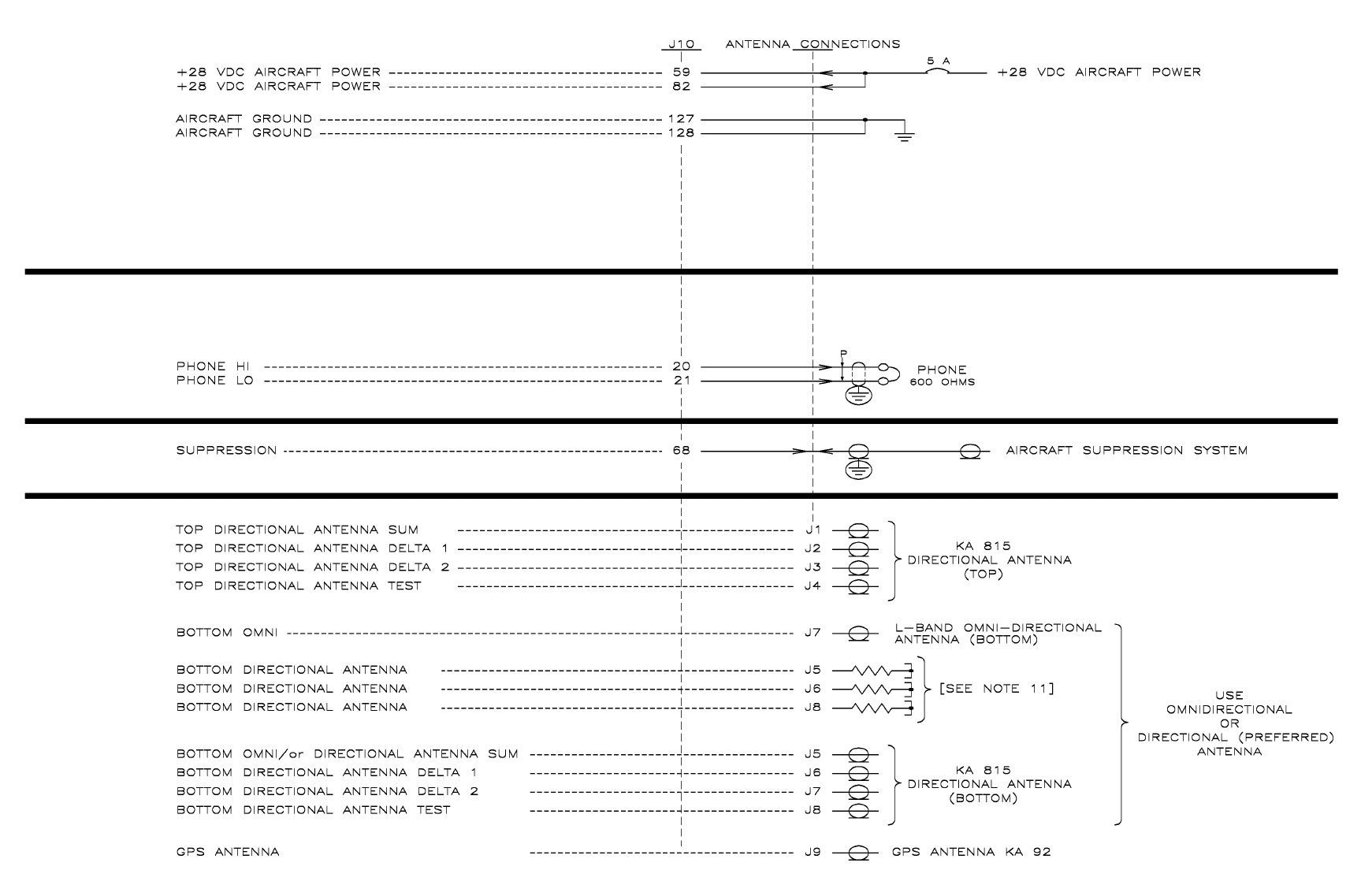
B
BB
BKMH 880/KTA 870
Rev 0, October/2000 10609I00.ZIPCDL Page 3-17
Figure 3-2 KMH 820/KTA 810 Pinout Diagram
Dwg. No. 155-01735-0001 (Sheet 2of 7) (08/10/2000)
PRELIMINARY - SUBJECT TO CHANGE WITHOUT NOTICE
B
BB
BKMH 880/KTA 870
Page 3-18 10609I00.ZIPCDL Rev 0, October/2000
THIS PAGE IS RESERVED
PRELIMINARY - SUBJECT TO CHANGE WITHOUT NOTICE
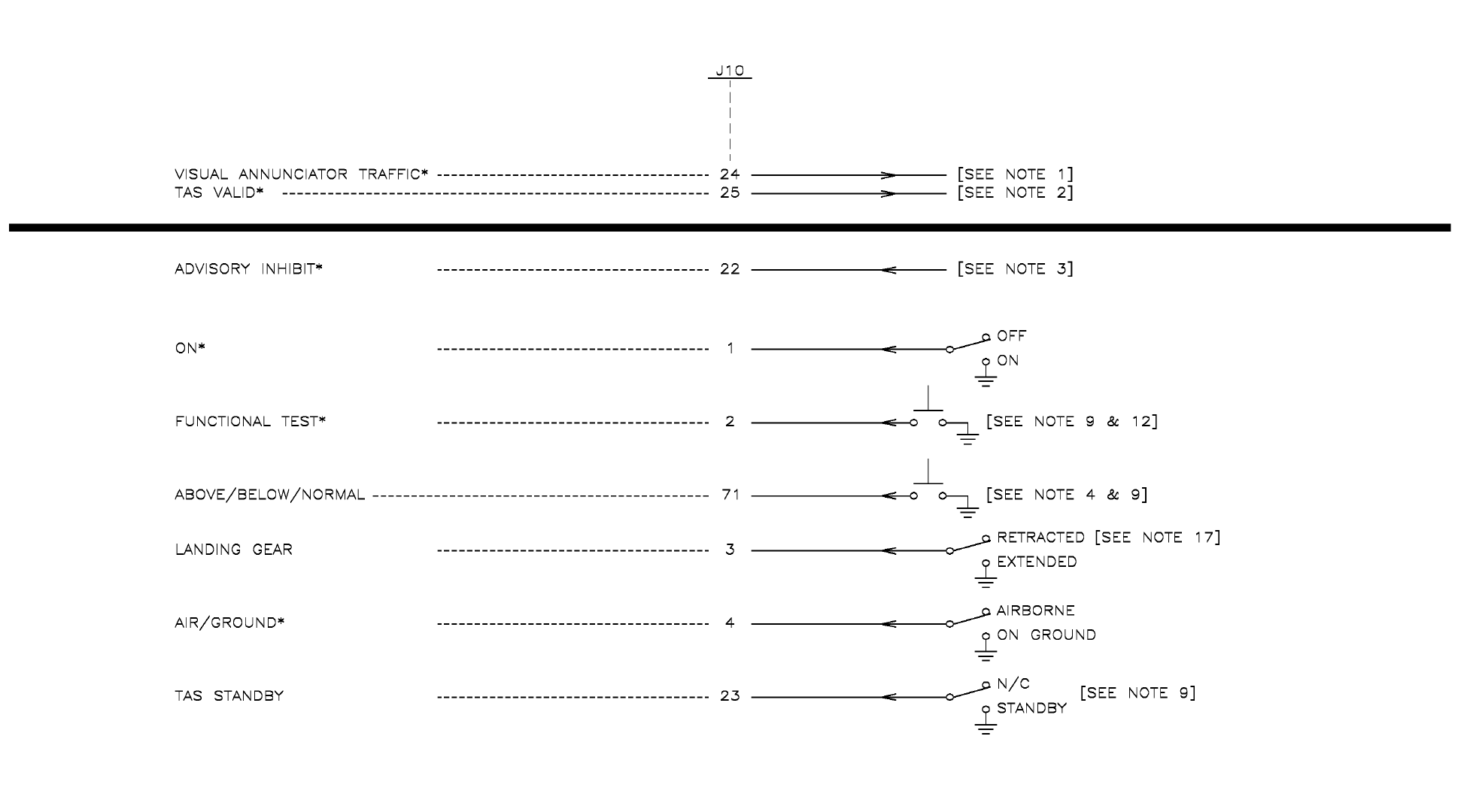
B
BB
BKMH 880/KTA 870
Rev 0, October/2000 10609I00.ZIPCDL Page 3-19
Figure 3-2 KMH 820/KTA 810 Pinout Diagram
Dwg. No. 155-01735-0001 (Sheet 3of 7) (07/11/2000)
PRELIMINARY - SUBJECT TO CHANGE WITHOUT NOTICE
B
BB
BKMH 880/KTA 870
Page 3-20 10609I00.ZIPCDL Rev 0, October/2000
THIS PAGE IS RESERVED
PRELIMINARY - SUBJECT TO CHANGE WITHOUT NOTICE
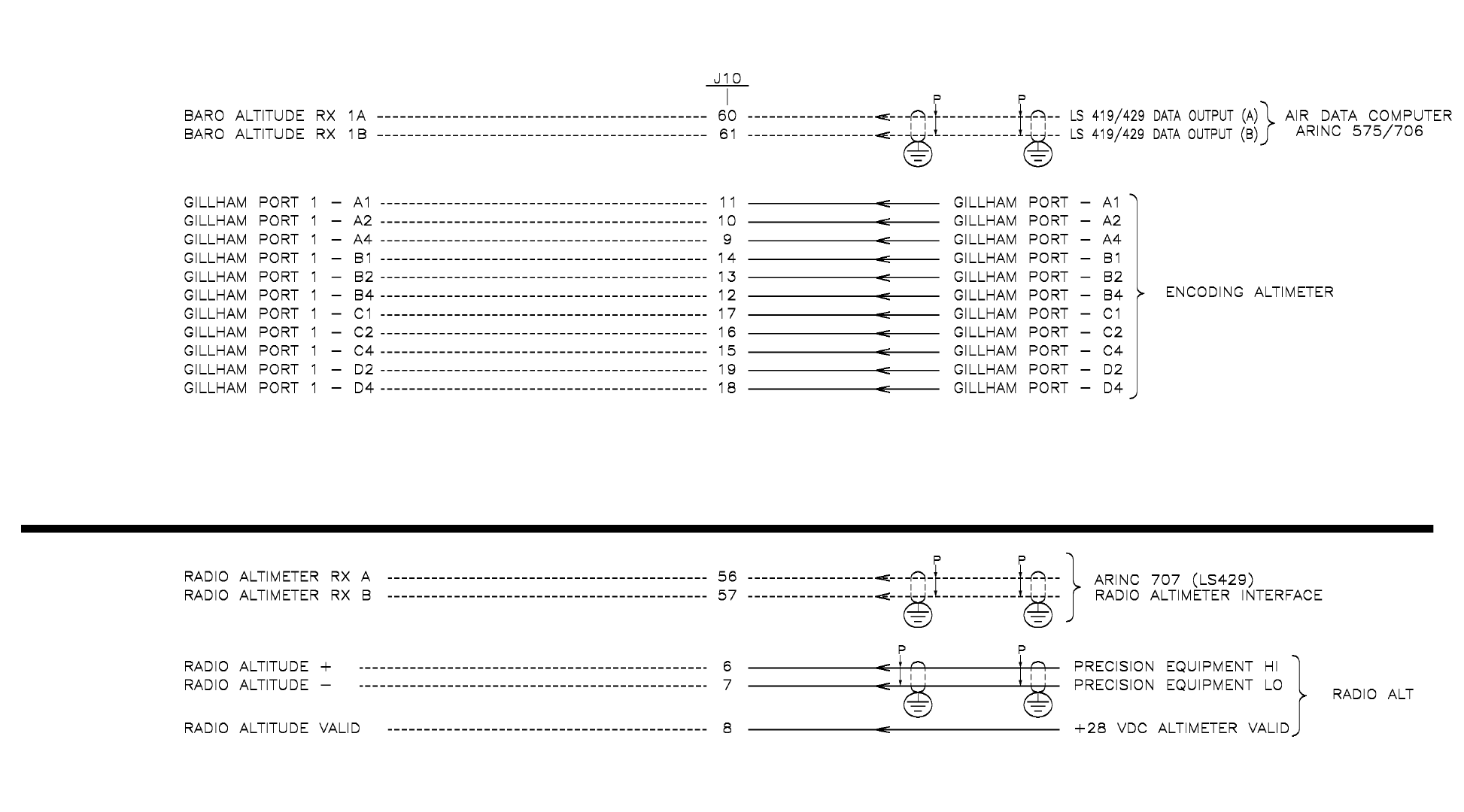
B
BB
BKMH 880/KTA 870
Rev 0, October/2000 10609I00.ZIPCDL Page 3-21
Figure 3-2 KMH 820/KTA 810 Pinout Diagram
Dwg. No. 155-01735-0001 (Sheet 4of 7) (08/10/2000)
PRELIMINARY - SUBJECT TO CHANGE WITHOUT NOTICE
B
BB
BKMH 880/KTA 870
Page 3-22 10609I00.ZIPCDL Rev 0, October/2000
THIS PAGE IS RESERVED
PRELIMINARY - SUBJECT TO CHANGE WITHOUT NOTICE
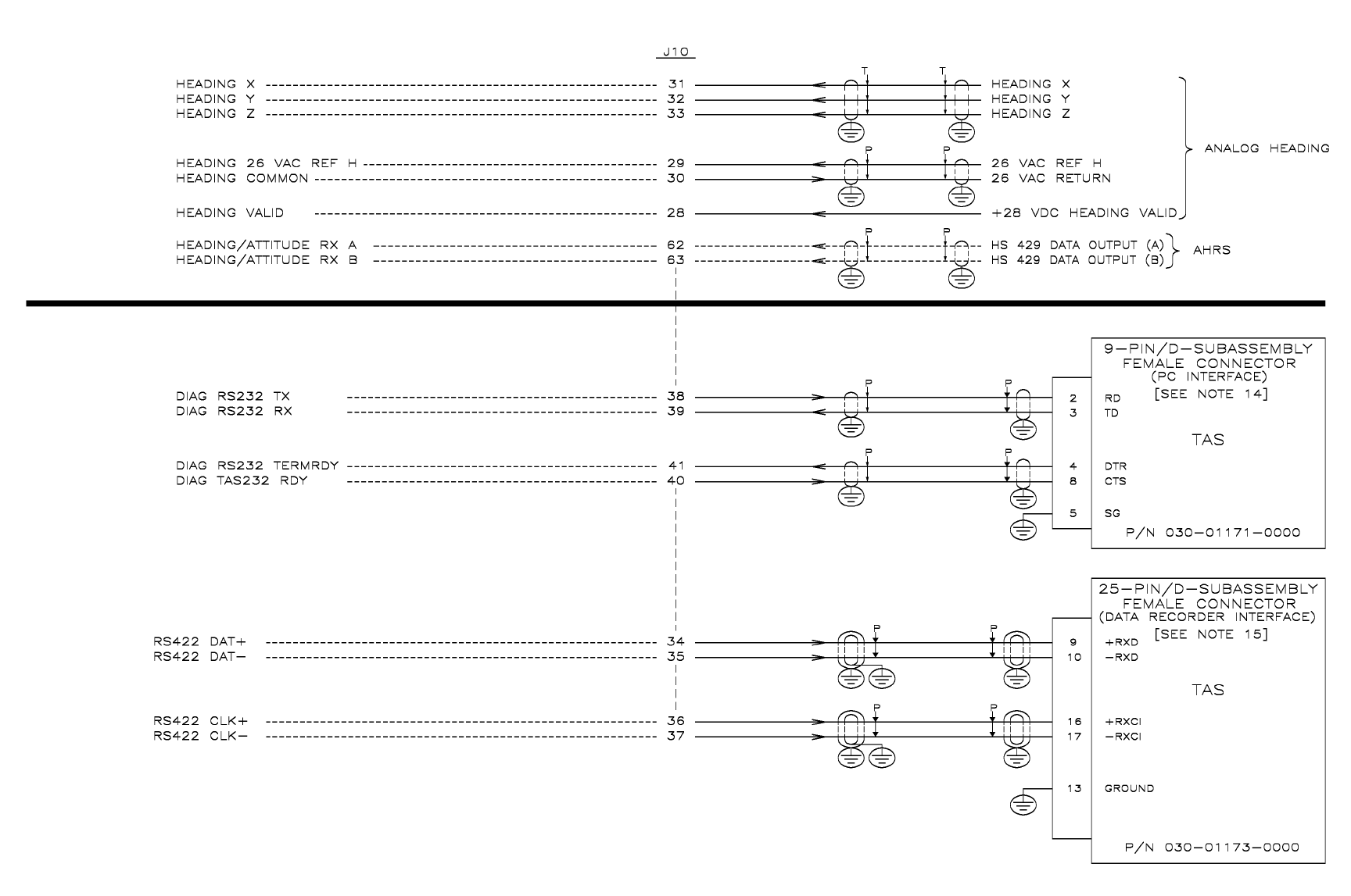
B
BB
BKMH 880/KTA 870
Rev 0, October/2000 10609I00.ZIPCDL Page 3-23
Figure 3-2 KMH 820/KTA 810 Pinout Diagram
Dwg. No. 155-01735-0001 (Sheet 5of 7) (08/10/2000)
PRELIMINARY - SUBJECT TO CHANGE WITHOUT NOTICE
B
BB
BKMH 880/KTA 870
Page 3-24 10609I00.ZIPCDL Rev 0, October/2000
THIS PAGE IS RESERVED
PRELIMINARY - SUBJECT TO CHANGE WITHOUT NOTICE
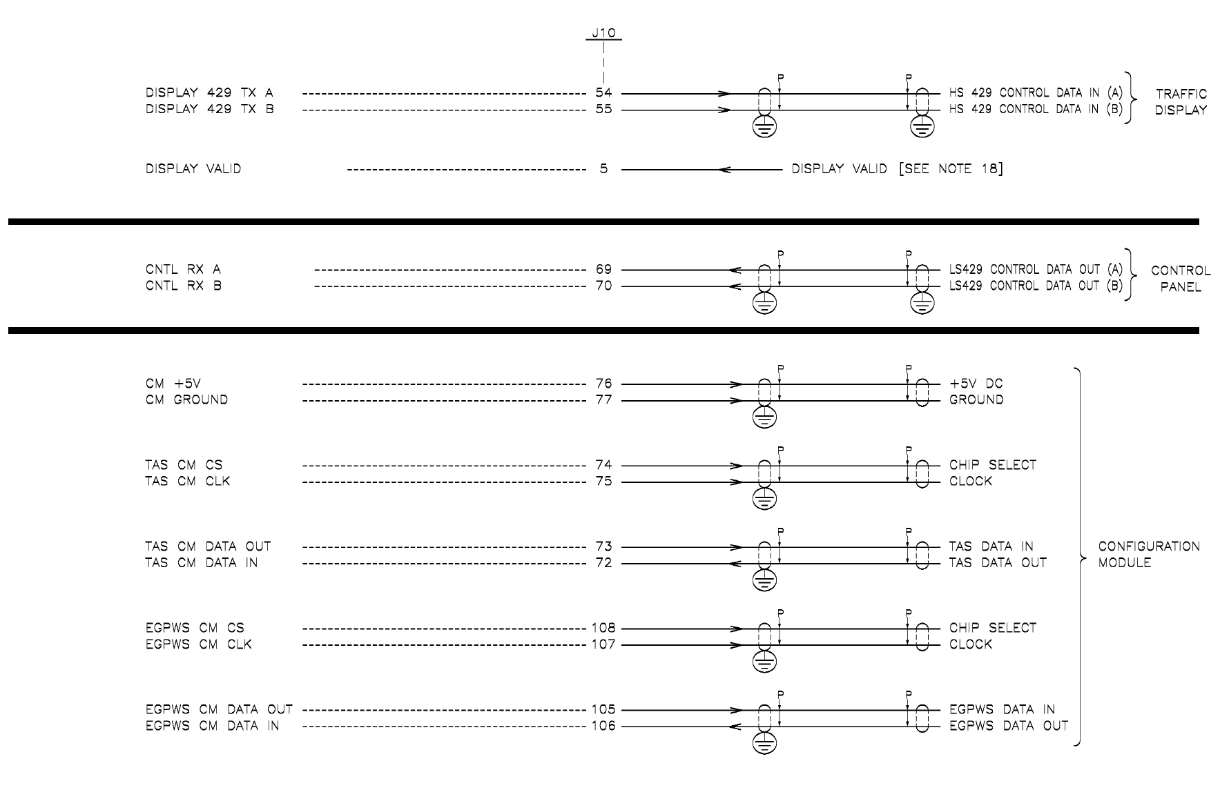
B
BB
BKMH 880/KTA 870
Rev 0, October/2000 10609I00.ZIPCDL Page 3-25
Figure 3-2 KMA 820/KTA 810 Pinout Diagram
Dwg. No. 155-01735-0001 (Sheet 6 of 7) (08/10/2000)
PRELIMINARY - SUBJECT TO CHANGE WITHOUT NOTICE
B
BB
BKMH 880/KTA 870
Page 3-26 10609I00.ZIPCDL Rev 0, October/2000
THIS PAGE IS RESERVED
PRELIMINARY - SUBJECT TO CHANGE WITHOUT NOTICE
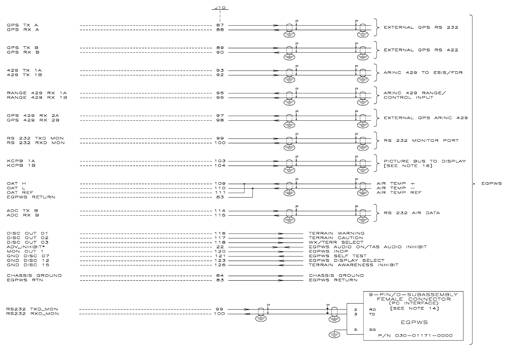
B
BB
BKMH 880/KTA 870
Rev 0, October/2000 10609I00.ZIPCDL Page 3-27
Figure 3-2 KMH 820/KTA 810 Pinout Diagram
Dwg. No. 155-01735-0001(Sheet 7 of 7) (08/11/2000)
PRELIMINARY - SUBJECT TO CHANGE WITHOUT NOTICE
B
BB
BKMH 880/KTA 870
Page 3-28 10609I00.ZIPCDL Rev 0, October/2000
THIS PAGE IS RESERVED
PRELIMINARY - SUBJECT TO CHANGE WITHOUT NOTICE
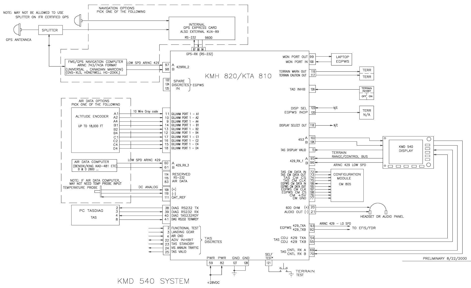
B
BB
BKMH 880/KTA 870
Rev 0, October/2000 10609I00.ZIPCDL Page 3-29
Figure 3-3 KMH 820/KTA 810 System Interconnect Block Diagram
Dwg. No. 155-01735-0002 (Sheet 1 of 2) (08/22/2000)
PRELIMINARY - SUBJECT TO CHANGE WITHOUT NOTICE
B
BB
BKMH 880/KTA 870
Page 3-30 10609I00.ZIPCDL Rev 0, October/2000
THIS PAGE IS RESERVED
PRELIMINARY - SUBJECT TO CHANGE WITHOUT NOTICE

B
BB
BKMH 880/KTA 870
Rev 0, October/2000 10609I00.ZIPCDL Page 3-31
Figure 3-3 KMH 820/KTA 810 System Interconnect Block Diagram
Dwg. No. 155-01735-0002 (Sheet 2 of 2) (08/22/2000)
PRELIMINARY - SUBJECT TO CHANGE WITHOUT NOTICE
B
BB
BKMH 880/KTA 870
Page 3-32 10609I00.ZIPCDL Rev 0, October/2000
THIS PAGE IS RESERVED
PRELIMINARY - SUBJECT TO CHANGE WITHOUT NOTICE
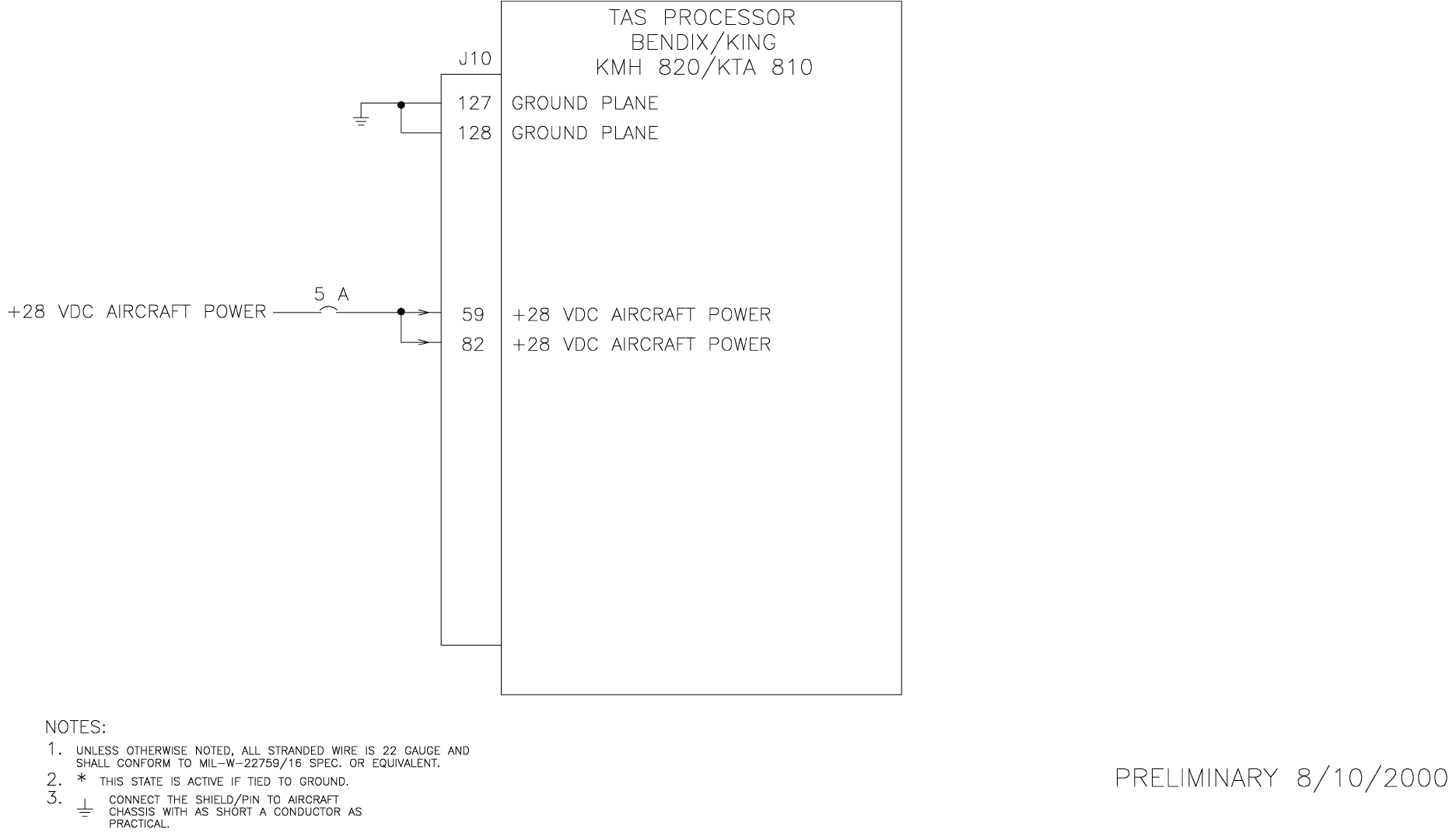
B
BB
BKMH 880/KTA 870
Rev 0, October/2000 10609I00.ZIPCDL Page 3-33
Figure 3-4 KMH 820/KTA 810 Power Interface
Dwg. No. 155-01735-0003
PRELIMINARY - SUBJECT TO CHANGE WITHOUT NOTICE
B
BB
BKMH 880/KTA 870
Page 3-34 10609I00.ZIPCDL Rev 0, October/2000
THIS PAGE IS RESERVED
PRELIMINARY - SUBJECT TO CHANGE WITHOUT NOTICE
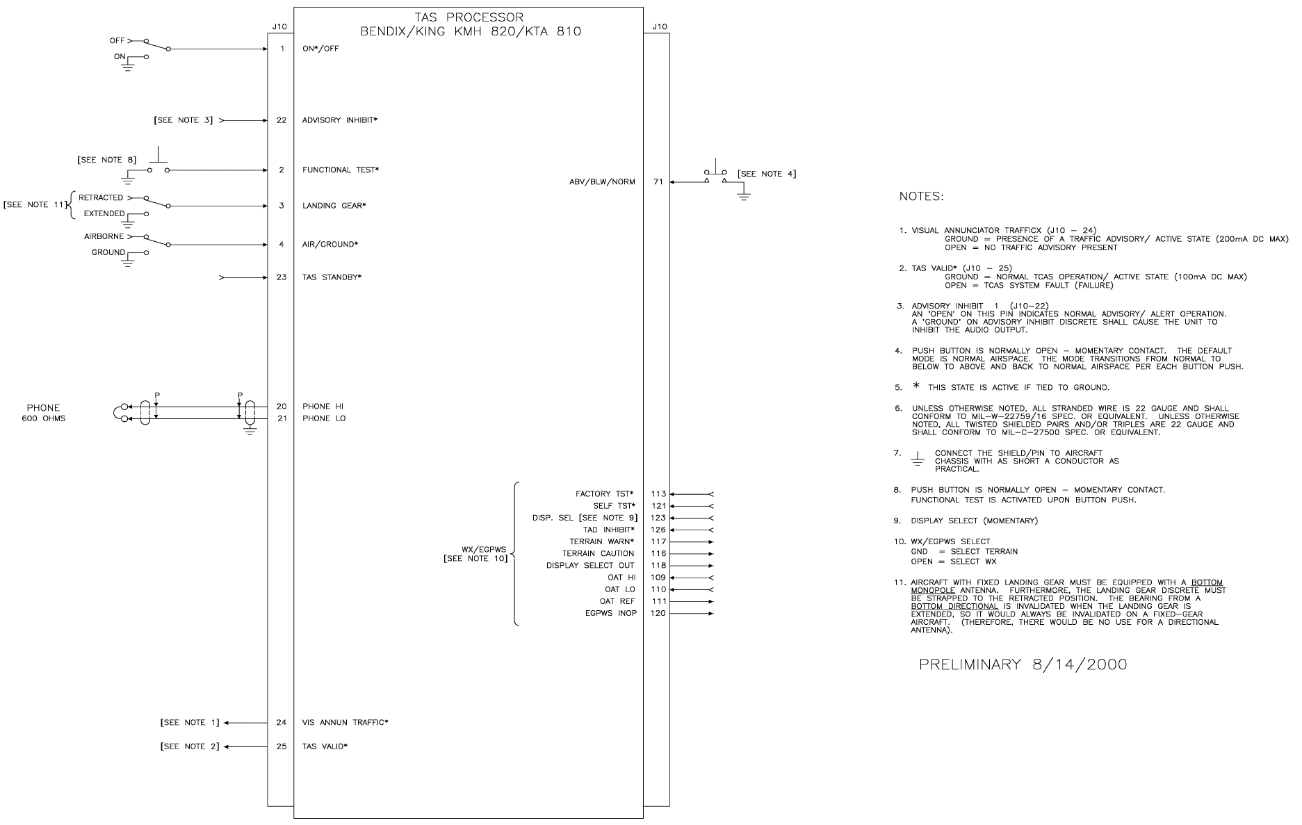
B
BB
BKMH 880/KTA 870
Rev 0, October/2000 10609I00.ZIPCDL Page 3-35
Figure 3-5 KMH 820/KTA 810 Discrete Interface
Dwg. No. 155-01735-0004 (08/14/2000)
PRELIMINARY - SUBJECT TO CHANGE WITHOUT NOTICE
B
BB
BKMH 880/KTA 870
Page 3-36 10609I00.ZIPCDL Rev 0, October/2000
THIS PAGE IS RESERVED
PRELIMINARY - SUBJECT TO CHANGE WITHOUT NOTICE
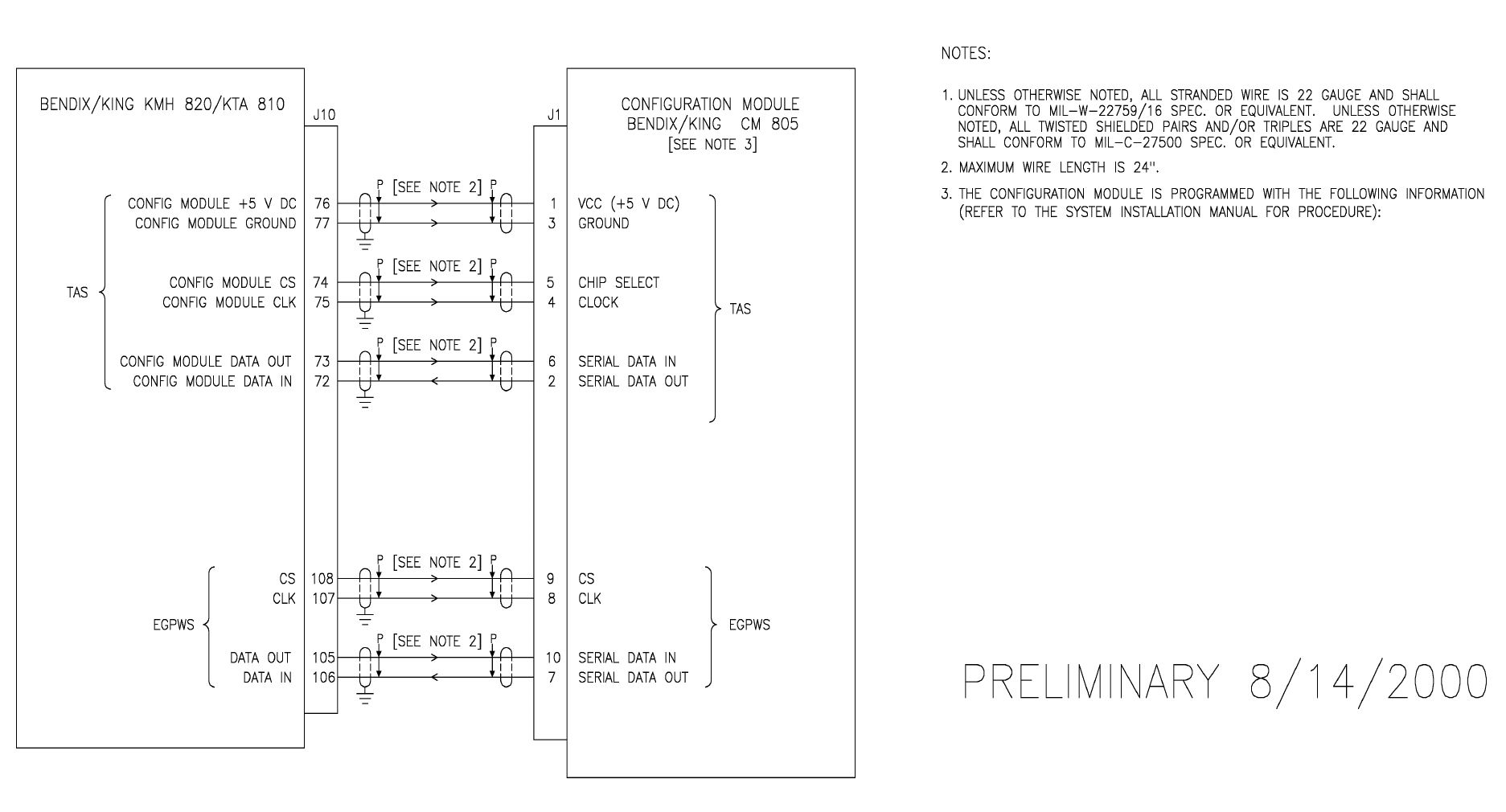
B
BB
BKMH 880/KTA 870
Rev 0, October/2000 10609I00.ZIPCDL Page 3-37
Figure 3-6 KMH 820/KTA 810 Configuration Module Interconnect
Dwg. No. 155-01735-0005 (08/14/2000)
PRELIMINARY - SUBJECT TO CHANGE WITHOUT NOTICE
B
BB
BKMH 880/KTA 870
Page 3-38 10609I00.ZIPCDL Rev 0, October/2000
THIS PAGE IS RESERVED
PRELIMINARY - SUBJECT TO CHANGE WITHOUT NOTICE
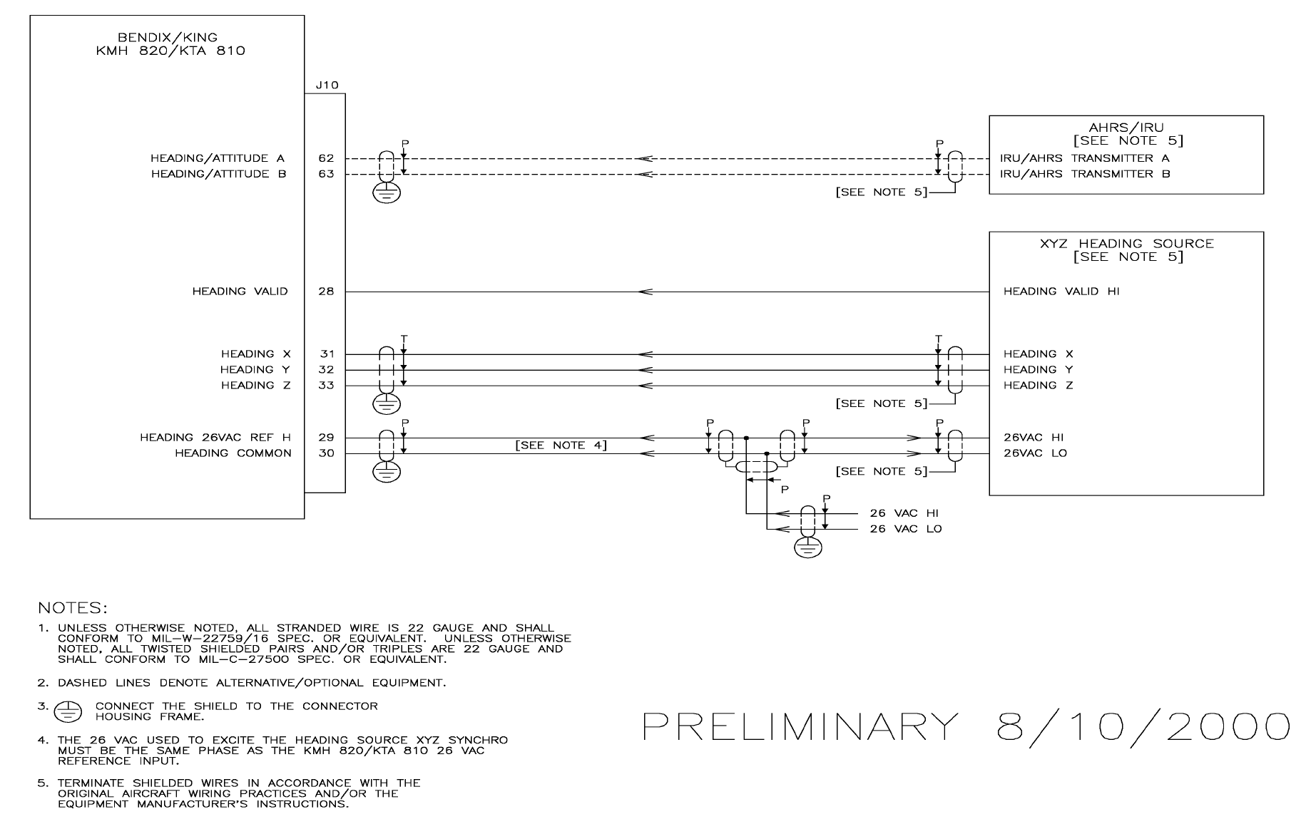
B
BB
BKMH 880/KTA 870
Rev 0, October/2000 10609I00.ZIPCDL Page 3-39
Figure 3-7 KMH 820/KTA 810 Attitude/Heading Interface
Dwg. No. 155-01735-0006 (08/10/2000)
PRELIMINARY - SUBJECT TO CHANGE WITHOUT NOTICE
B
BB
BKMH 880/KTA 870
Page 3-40 10609I00.ZIPCDL Rev 0, October/2000
THIS PAGE IS RESERVED
PRELIMINARY - SUBJECT TO CHANGE WITHOUT NOTICE

B
BB
BKMH 880/KTA 870
Rev 0, October/2000 10609I00.ZIPCDL Page 3-41
Figure 3-8 KMH 820/KTA 810 Radar/Barometric Altitude Interface
Dwg. No. 155-01735-0007 (Sheet 1 of 4) (08/10/2000)
PRELIMINARY - SUBJECT TO CHANGE WITHOUT NOTICE
B
BB
BKMH 880/KTA 870
Page 3-42 10609I00.ZIPCDL Rev 0, October/2000
THIS PAGE IS RESERVED
PRELIMINARY - SUBJECT TO CHANGE WITHOUT NOTICE
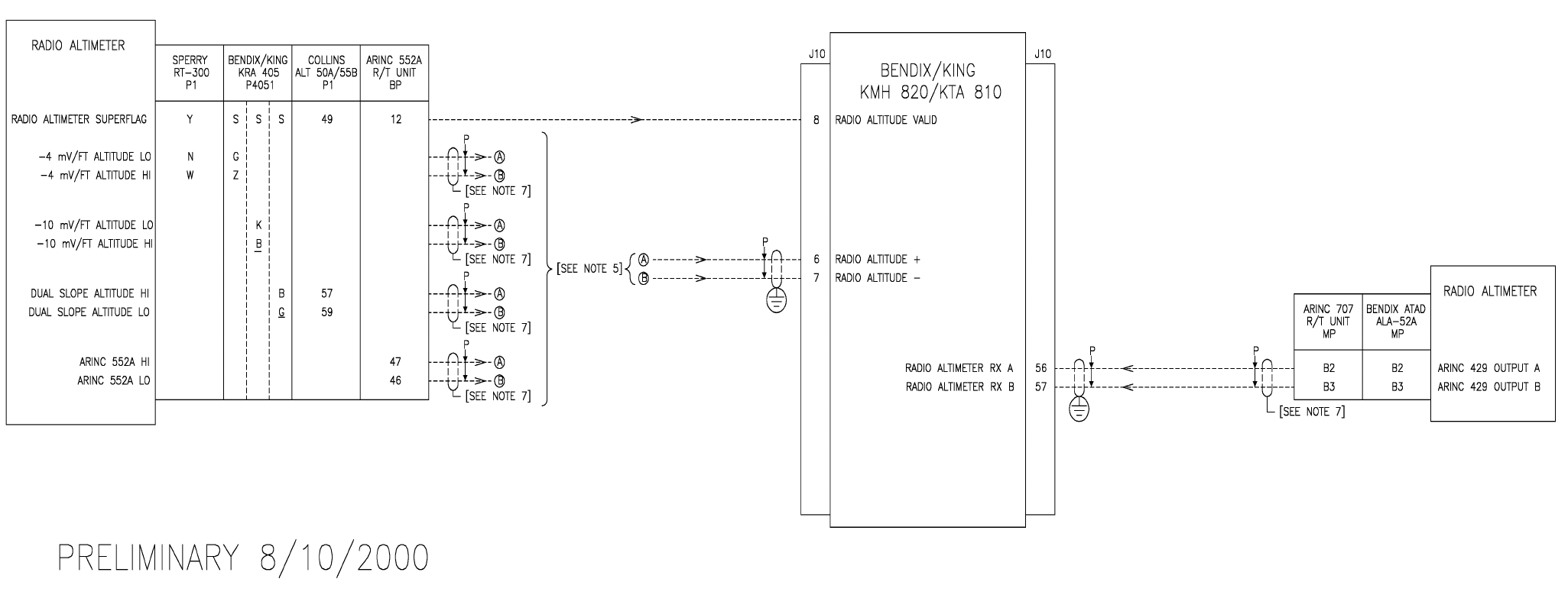
B
BB
BKMH 880/KTA 870
Rev 0, October/2000 10609I00.ZIPCDL Page 3-43
Figure 3-8 KMH 820/KTA 810 Radar/Barometric Altitude Interface
Dwg. No. 155-01735-0007 (Sheet 2 of 4) (08/10/2000)
PRELIMINARY - SUBJECT TO CHANGE WITHOUT NOTICE
B
BB
BKMH 880/KTA 870
Page 3-44 10609I00.ZIPCDL Rev 0, October/2000
THIS PAGE IS RESERVED
PRELIMINARY - SUBJECT TO CHANGE WITHOUT NOTICE
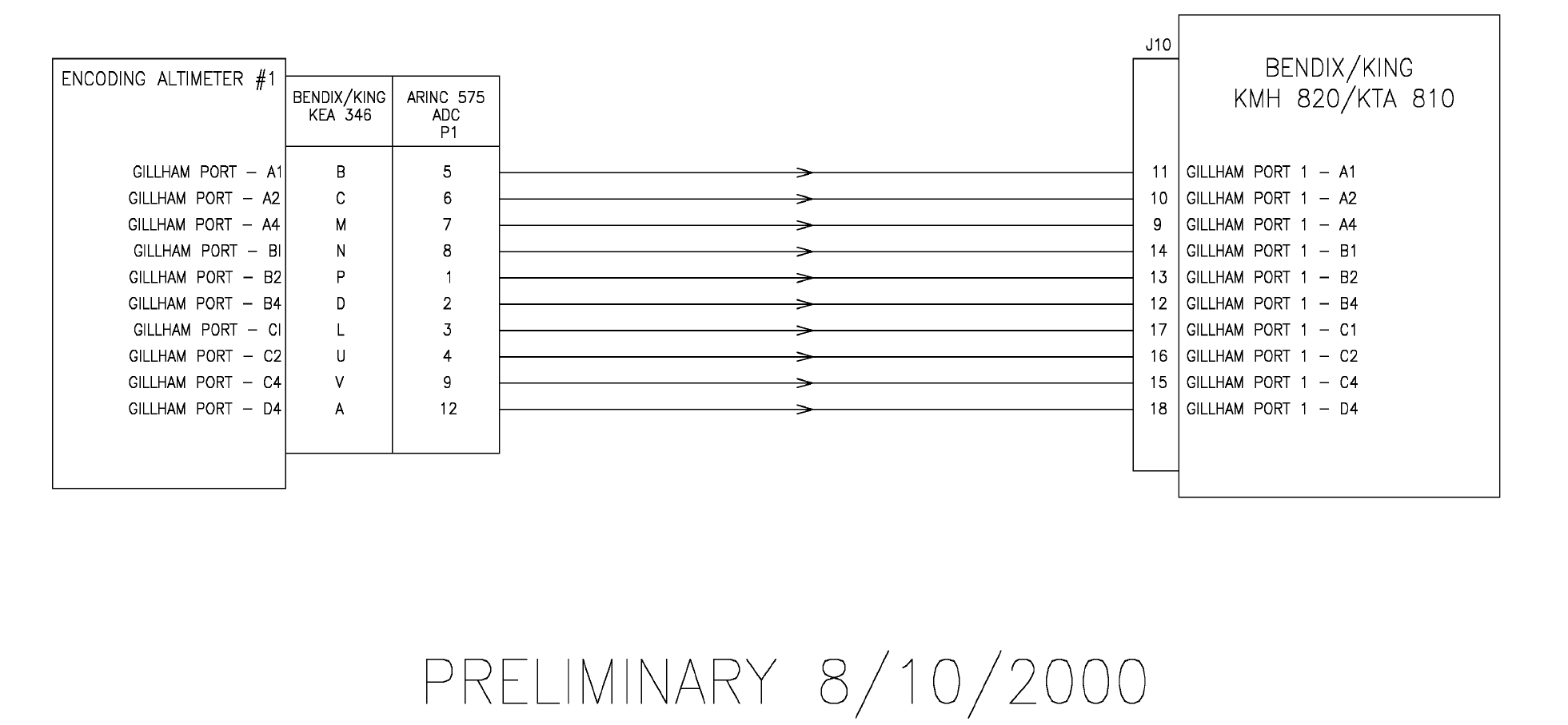
B
BB
BKMH 880/KTA 870
Rev 0, October/2000 10609I00.ZIPCDL Page 3-45
Figure 3-8 KMH 820/KTA 810 Radar/Barometric Altitude Interface
Dwg. No. 155-01735-0007 (Sheet 3 of 4) (08/10/2000)
PRELIMINARY - SUBJECT TO CHANGE WITHOUT NOTICE
B
BB
BKMH 880/KTA 870
Page 3-46 10609I00.ZIPCDL Rev 0, October/2000
THIS PAGE IS RESERVED
PRELIMINARY - SUBJECT TO CHANGE WITHOUT NOTICE
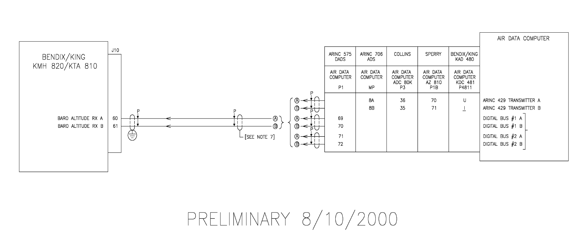
B
BB
BKMH 880/KTA 870
Rev 0, October/2000 10609I00.ZIPCDL Page 3-47
Figure 3-8 KMH 820/KTA 810 Radar/Barometric Altitude Interface
Dwg. No. 155-01735-0007 (Sheet 4 of 4) (08/10/2000)
PRELIMINARY - SUBJECT TO CHANGE WITHOUT NOTICE
B
BB
BKMH 880/KTA 870
Page 3-48 10609I00.ZIPCDL Rev 0, October/2000
THIS PAGE IS RESERVED
PRELIMINARY - SUBJECT TO CHANGE WITHOUT NOTICE
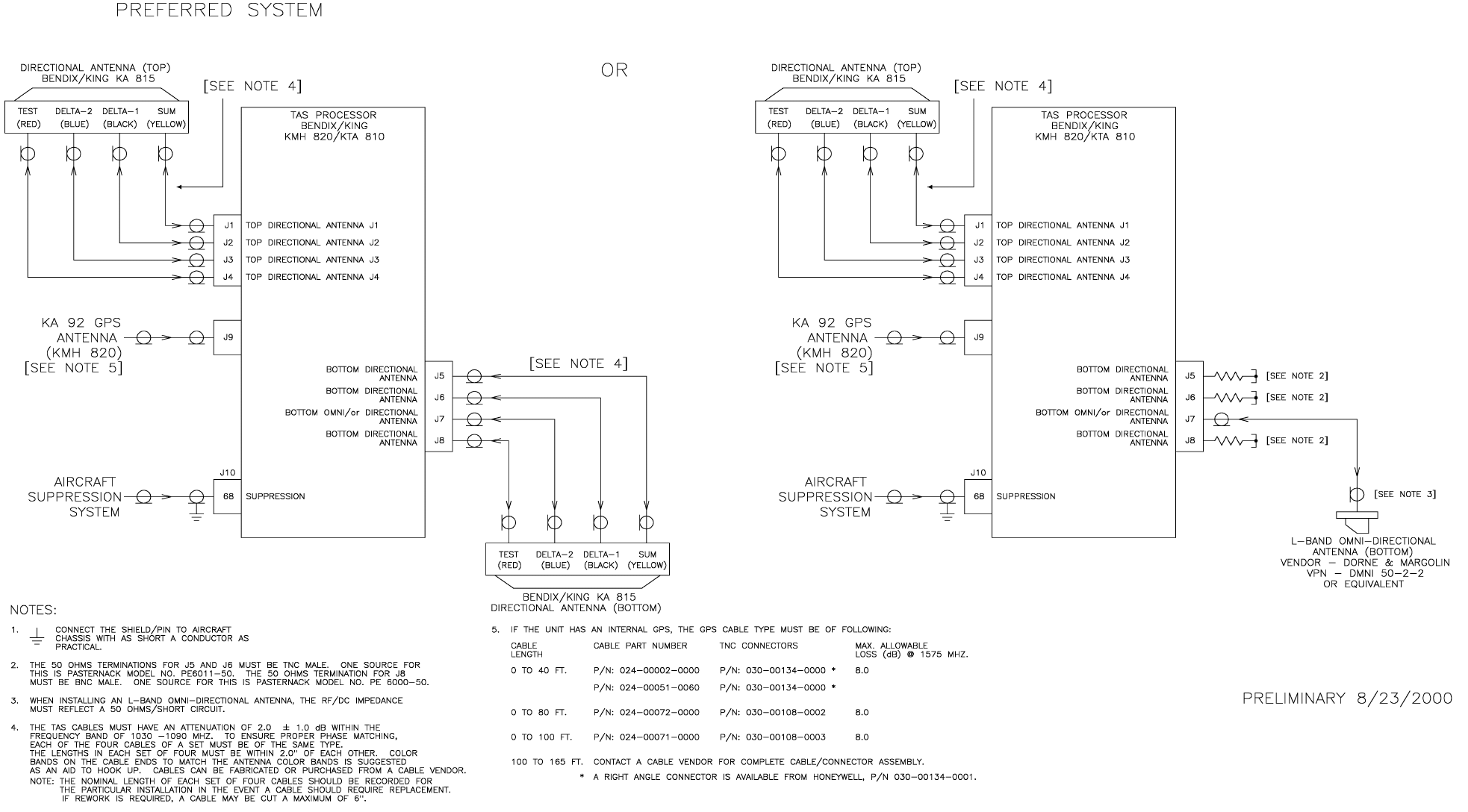
B
BB
BKMH 880/KTA 870
Rev 0, October/2000 10609I00.ZIPCDL Page 3-49
Figure 3-9 KMH 820/KTA 810 Antenna/Suppression Interface
Dwg. No. 155-01735-0008 (08/23/2000)
PRELIMINARY - SUBJECT TO CHANGE WITHOUT NOTICE
B
BB
BKMH 880/KTA 870
Page 3-50 10609I00.ZIPCDL Rev 0, October/2000
THIS PAGE IS RESERVED
PRELIMINARY - SUBJECT TO CHANGE WITHOUT NOTICE
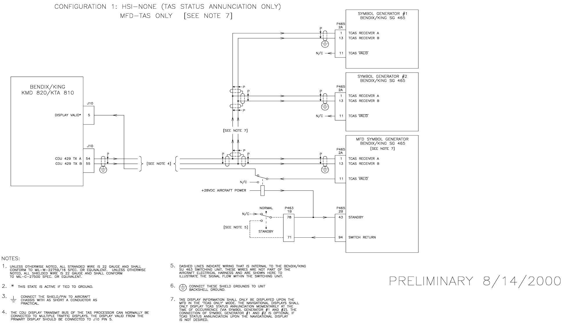
B
BB
BKMH 880/KTA 870
Rev 0, October/2000 10609I00.ZIPCDL Page 3-51
Figure 3-10 KMH 820/KTA 810 EFS 40/50 TAS Interface
Dwg. No. 155-01735-0009 (08/14/2000)
PRELIMINARY - SUBJECT TO CHANGE WITHOUT NOTICE
B
BB
BKMH 880/KTA 870
Page 3-52 10609I00.ZIPCDL Rev 0, October/2000
THIS PAGE IS RESERVED
PRELIMINARY - SUBJECT TO CHANGE WITHOUT NOTICE
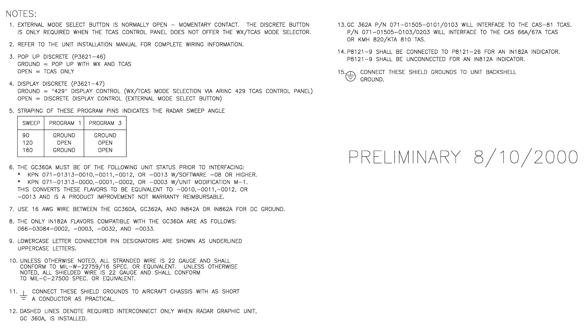
B
BB
BKMH 880/KTA 870
Rev 0, October/2000 10609I00.ZIPCDL Page 3-53
Figure 3-11 KMH 820/KTA 810 GC 362A Interface
Dwg. No. 155-01735-0010 (Sheet 1 of 3) (08/10/2000)
PRELIMINARY - SUBJECT TO CHANGE WITHOUT NOTICE
B
BB
BKMH 880/KTA 870
Page 3-54 10609I00.ZIPCDL Rev 0, October/2000
THIS PAGE IS RESERVED
PRELIMINARY - SUBJECT TO CHANGE WITHOUT NOTICE
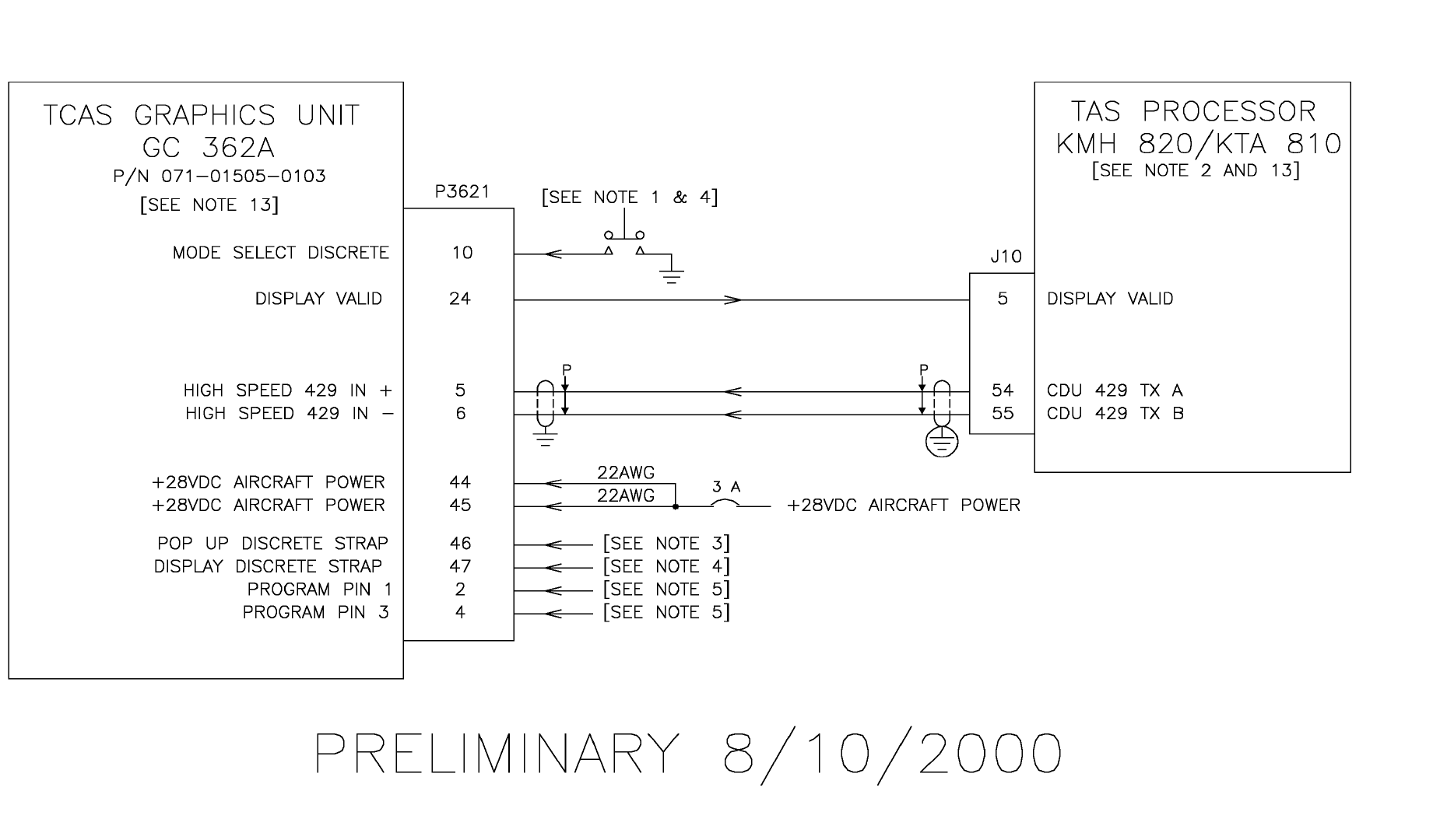
B
BB
BKMH 880/KTA 870
Rev 0, October/2000 10609I00.ZIPCDL Page 3-55
Figure 3-11 KMH 820/KTA 810 GC 362A Interface
Dwg. No. 155-01735-0010 (Sheet 2 of 3) (08/10/2000)
PRELIMINARY - SUBJECT TO CHANGE WITHOUT NOTICE
B
BB
BKMH 880/KTA 870
Page 3-56 10609I00.ZIPCDL Rev 0, October/2000
THIS PAGE IS RESERVED
PRELIMINARY - SUBJECT TO CHANGE WITHOUT NOTICE
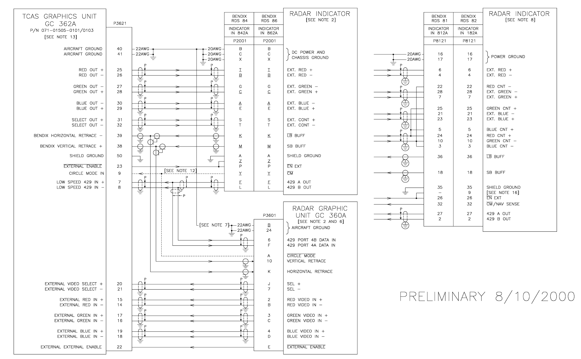
B
BB
BKMH 880/KTA 870
Rev 0, October/2000 10609I00.ZIPCDL Page 3-57
Figure 3-11 KMH 820/KTA 810 GC 362A Interface
Dwg. No. 155-01735-0010 (Sheet 3 of 3) (08/10/2000)
PRELIMINARY - SUBJECT TO CHANGE WITHOUT NOTICE
B
BB
BKMH 880/KTA 870
Page 3-58 10609I00.ZIPCDL Rev 0, October/2000
THIS PAGE IS RESERVED
PRELIMINARY - SUBJECT TO CHANGE WITHOUT NOTICE
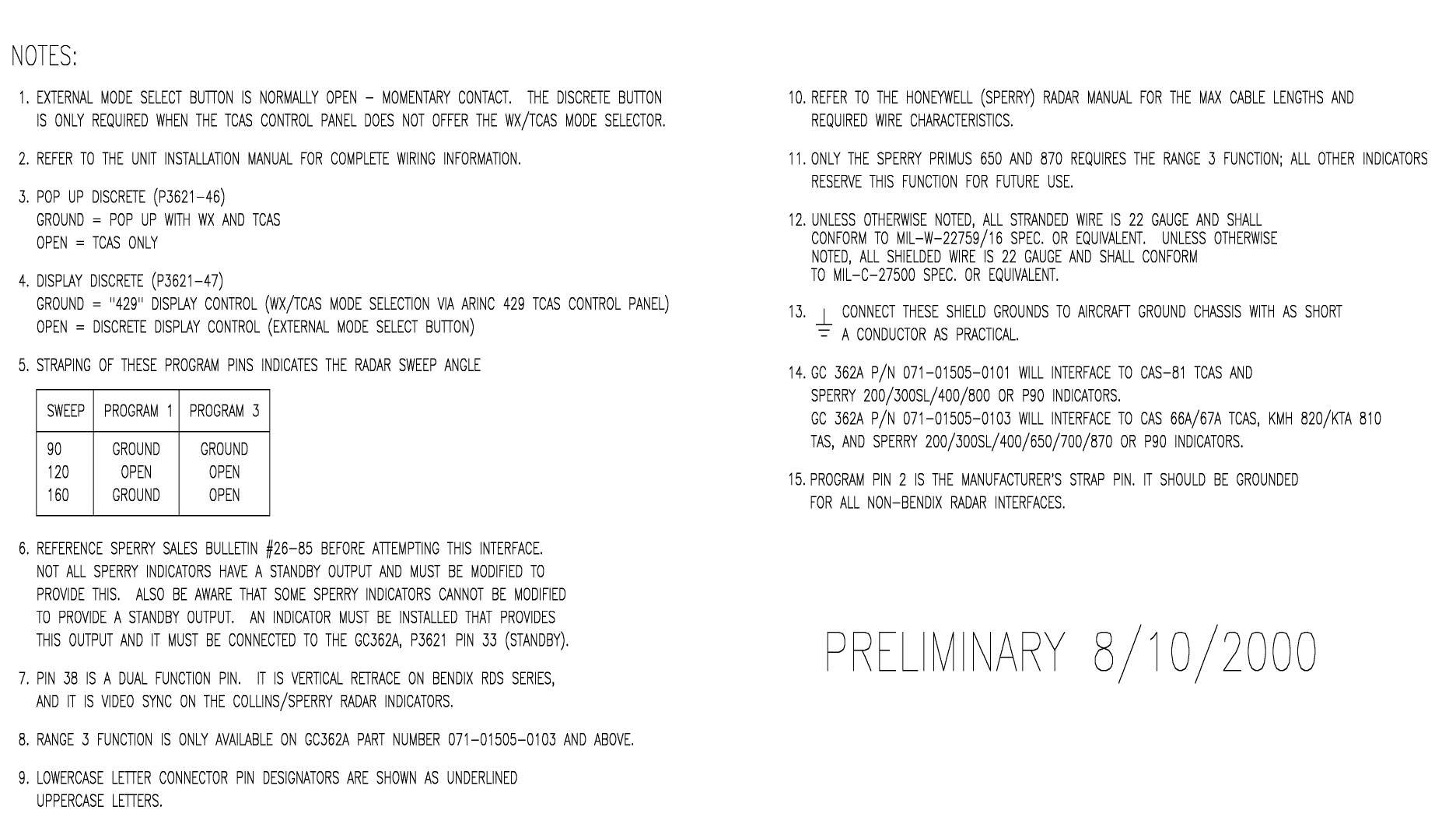
B
BB
BKMH 880/KTA 870
Rev 0, October/2000 10609I00.ZIPCDL Page 3-59
Figure 3-12 KMH 820/KTA 810 GC 362A Honeywell Interface
Dwg. No. 155-01735-0011 (Sheet 1 of 3) (08/10/2000)
PRELIMINARY - SUBJECT TO CHANGE WITHOUT NOTICE
B
BB
BKMH 880/KTA 870
Page 3-60 10609I00.ZIPCDL Rev 0, October/2000
THIS PAGE IS RESERVED
PRELIMINARY - SUBJECT TO CHANGE WITHOUT NOTICE
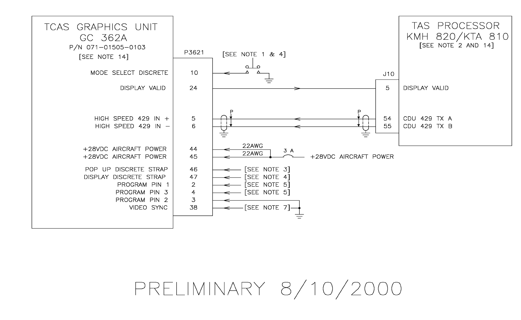
B
BB
BKMH 880/KTA 870
Rev 0, October/2000 10609I00.ZIPCDL Page 3-61
Figure 3-12 KMH 820/KTA 810 GC 362A Honeywell Interface
Dwg. No. 155-01735-0011 (Sheet 2 of 3) (08/10/2000)
PRELIMINARY - SUBJECT TO CHANGE WITHOUT NOTICE
B
BB
BKMH 880/KTA 870
Rev 0, October/2000 10609I00.ZIPCDL Page 3-62
THIS PAGE IS RESERVED
PRELIMINARY - SUBJECT TO CHANGE WITHOUT NOTICE
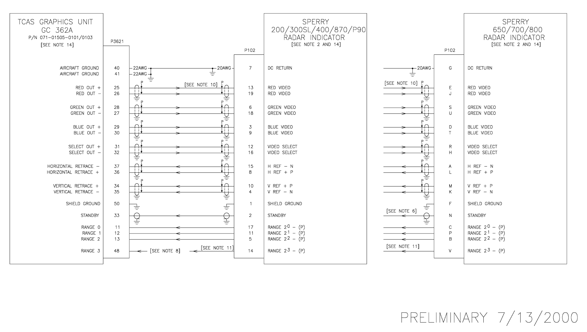
B
BB
BKMH 880/KTA 870
Rev 0, October/2000 10609I00.ZIPCDL Page 3-63
Figure 3-12 KMH 820/KTA 810 GC 362A Honeywell Interface
Dwg. No. 155-01735-0011 (Sheet 3 of 3) (07/13/2000)
PRELIMINARY - SUBJECT TO CHANGE WITHOUT NOTICE
B
BB
BKMH 880/KTA 870
Rev 0, October/2000 10609I00.ZIPCDL Page 3-64
THIS PAGE IS RESERVED
PRELIMINARY - SUBJECT TO CHANGE WITHOUT NOTICE
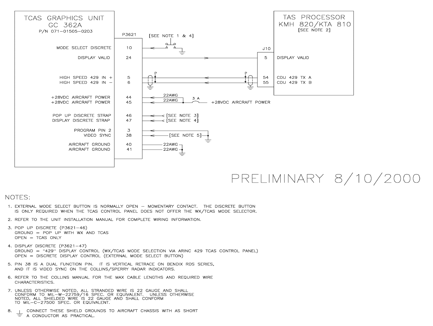
B
BB
BKMH 880/KTA 870
Rev 0, October/2000 10609I00.ZIPCDL Page 3-65
Figure 3-13 KMH 820/KTA 810 GC 362A Collins Interface
Dwg. No. 155-01735-0012 (Sheet 1 of 2) (08/10/2000)
PRELIMINARY - SUBJECT TO CHANGE WITHOUT NOTICE
B
BB
BKMH 880/KTA 870
Rev 0, October/2000 10609I00.ZIPCDL Page 3-66
THIS PAGE IS RESERVED
PRELIMINARY - SUBJECT TO CHANGE WITHOUT NOTICE
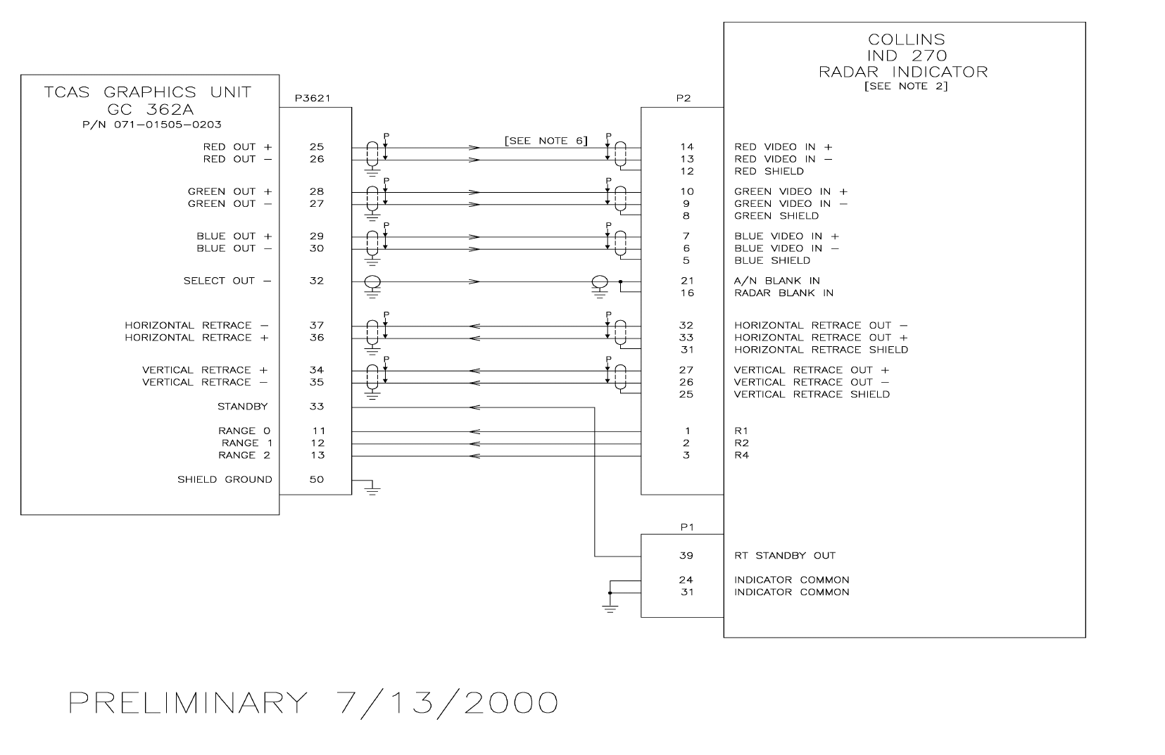
B
BB
BKMH 880/KTA 870
Rev 0, October/2000 10609I00.ZIPCDL Page 3-67
Figure 3-13 KMH 820/KTA 810 GC 362A Collins Interface
Dwg. No. 155-01735-0012 (Sheet 2 of 2) (07/13/2000)
PRELIMINARY - SUBJECT TO CHANGE WITHOUT NOTICE
B
BB
BKMH 880/KTA 870
Rev 0, October/2000 10609I00.ZIPCDL Page 3-68
THIS PAGE IS RESERVED
PRELIMINARY - SUBJECT TO CHANGE WITHOUT NOTICE
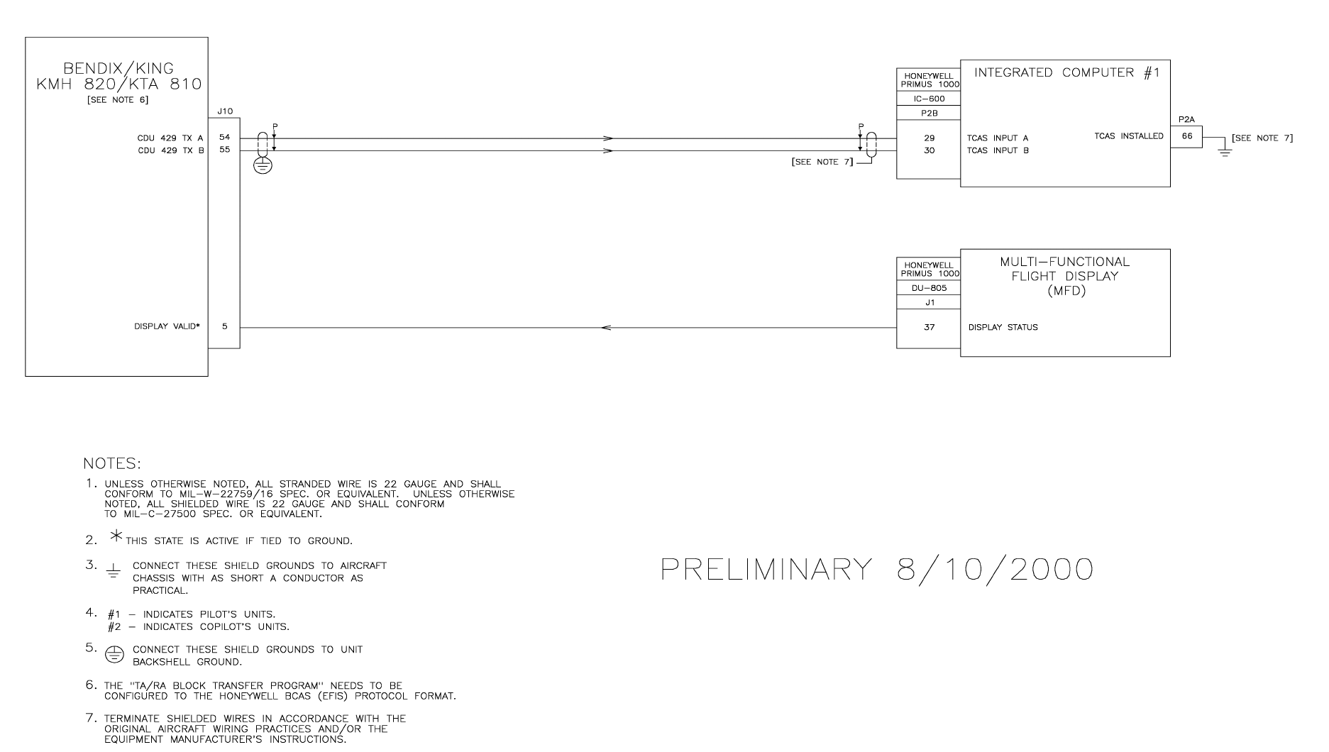
B
BB
BKMH 880/KTA 870
Rev 0, October/2000 10609I00.ZIPCDL Page 3-69
Figure 3-14 KMH 820/KTA 810 Honeywell Primus 1000 Interface
Dwg. No. 155-01735-0013 (Sheet 1 of 2) (08/10/2000)
PRELIMINARY - SUBJECT TO CHANGE WITHOUT NOTICE
B
BB
BKMH 880/KTA 870
Rev 0, October/2000 10609I00.ZIPCDL Page 3-70
THIS PAGE IS RESERVED
PRELIMINARY - SUBJECT TO CHANGE WITHOUT NOTICE
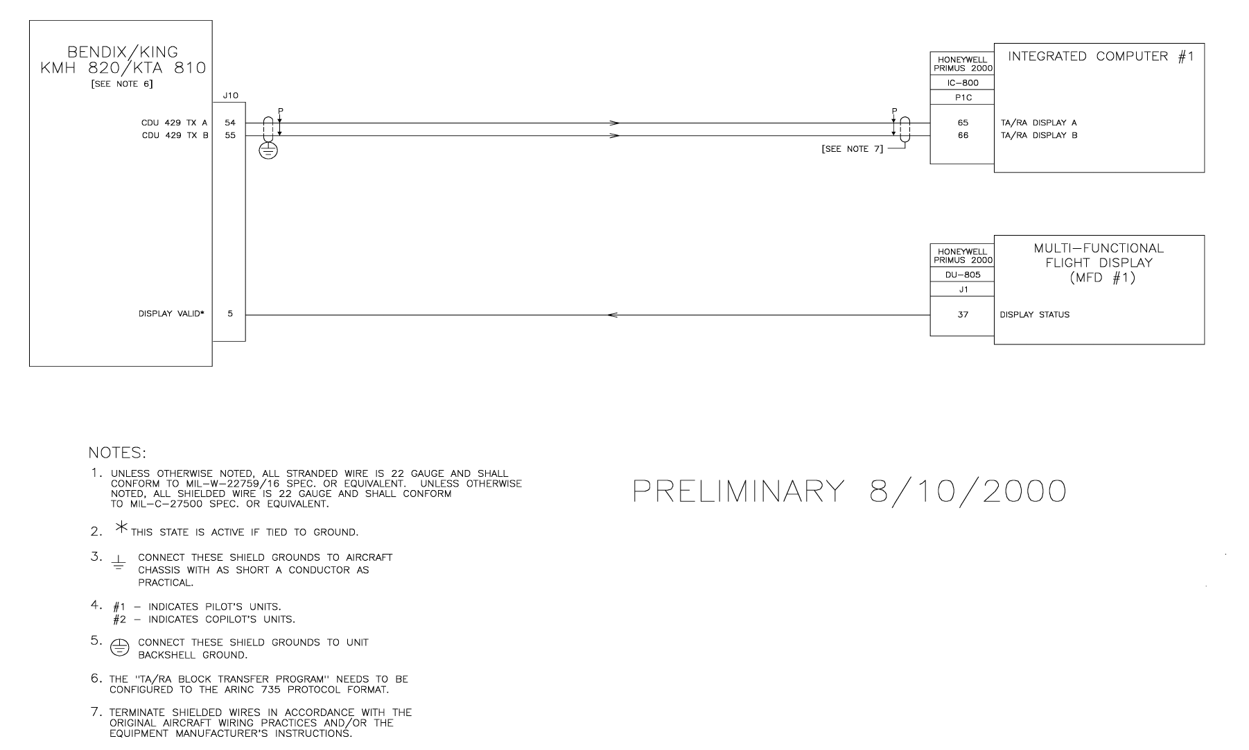
B
BB
BKMH 880/KTA 870
Rev 0, October/2000 10609I00.ZIPCDL Page 3-71
Figure 3-14 KMA 820/KTA 810 Honeywell Primus 1000 Interface
Dwg. No. 155-01735-0013 (Sheet 2 of 2) (08/10/2000)
PRELIMINARY - SUBJECT TO CHANGE WITHOUT NOTICE
B
BB
BKMH 880/KTA 870
Rev 0, October/2000 10609I00.ZIPCDL Page 3-72
THIS PAGE IS RESERVED
PRELIMINARY - SUBJECT TO CHANGE WITHOUT NOTICE
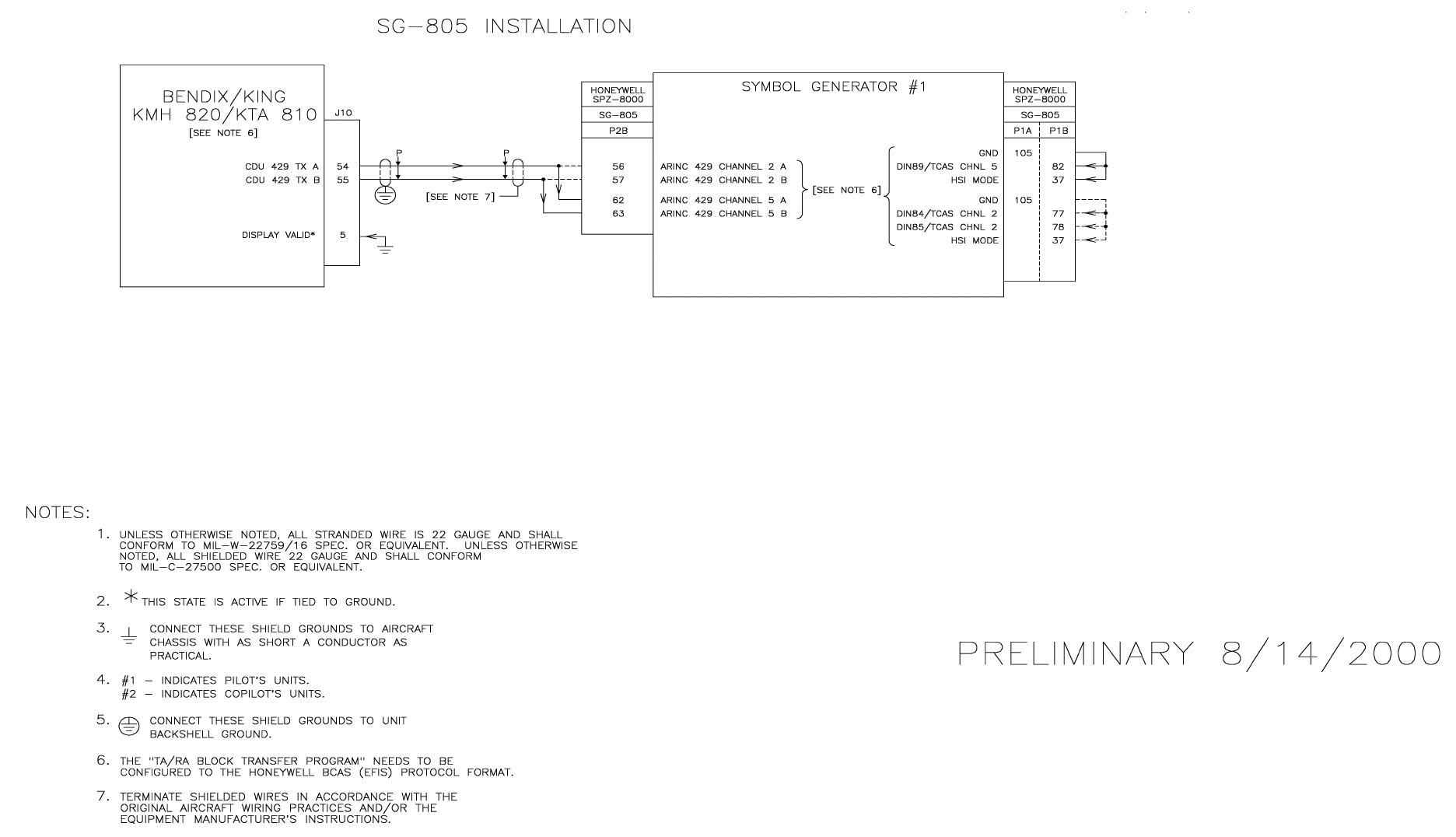
B
BB
BKMH 880/KTA 870
Rev 0, October/2000 10609I00.ZIPCDL Page 3-73
Figure 3-15 KMH 820/KTA 810 Honeywell SPZ-805 Interface
Dwg. No. 155-01735-0014 (Sheet 1 of 2) (08/14/2000)
PRELIMINARY - SUBJECT TO CHANGE WITHOUT NOTICE
B
BB
BKMH 880/KTA 870
Rev 0, October/2000 10609I00.ZIPCDL Page 3-74
THIS PAGE IS RESERVED
PRELIMINARY - SUBJECT TO CHANGE WITHOUT NOTICE
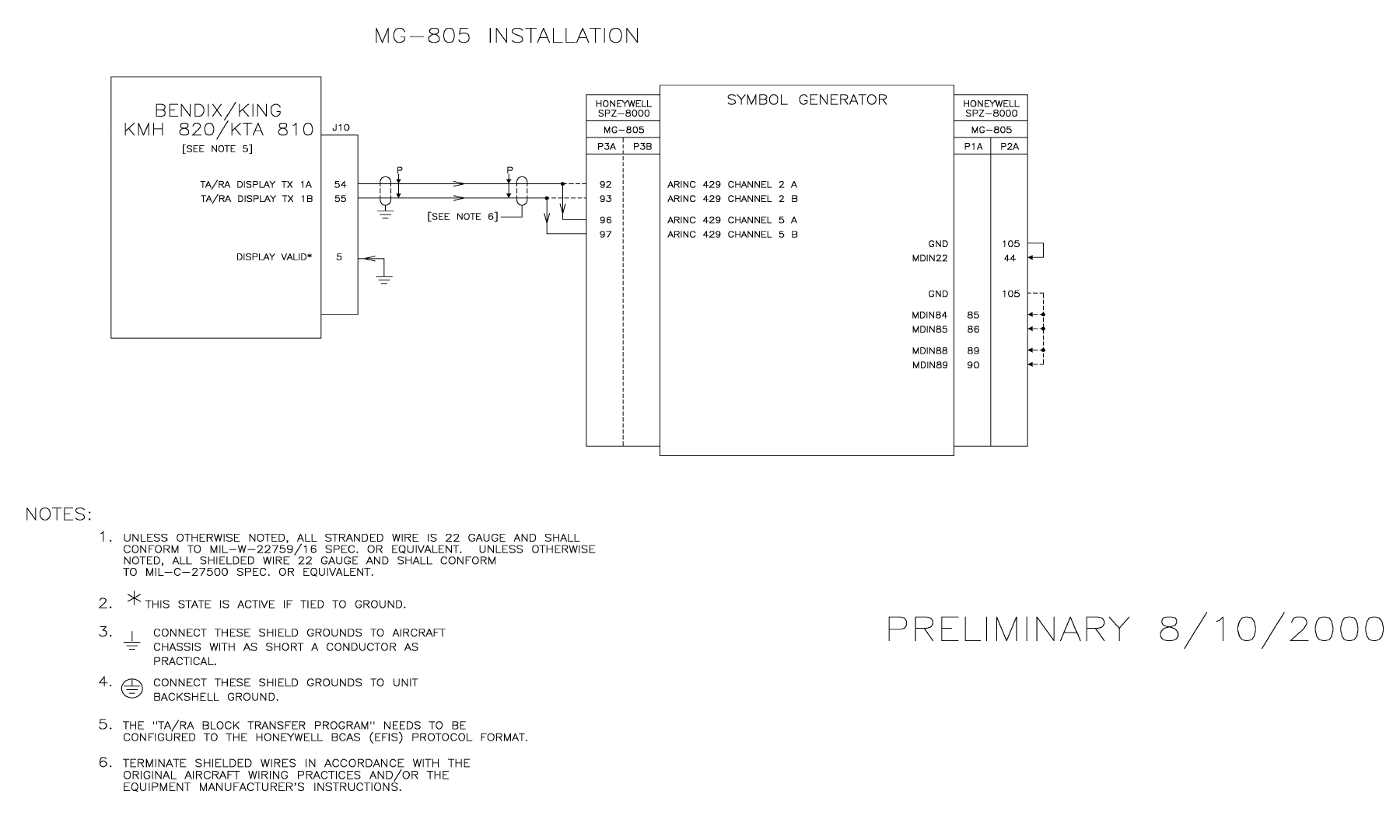
B
BB
BKMH 880/KTA 870
Rev 0, October/2000 10609I00.ZIPCDL Page 3-75
Figure 3-15 KMH 820/KTA 810 Honeywell SPZ-805 Interface
Dwg. No. 155-01735-0014 (Sheet 2 of 2) (08/10/2000)
PRELIMINARY - SUBJECT TO CHANGE WITHOUT NOTICE
B
BB
BKMH 880/KTA 870
Rev 0, October/2000 10609I00.ZIPCDL Page 3-76
THIS PAGE IS RESERVED
PRELIMINARY - SUBJECT TO CHANGE WITHOUT NOTICE
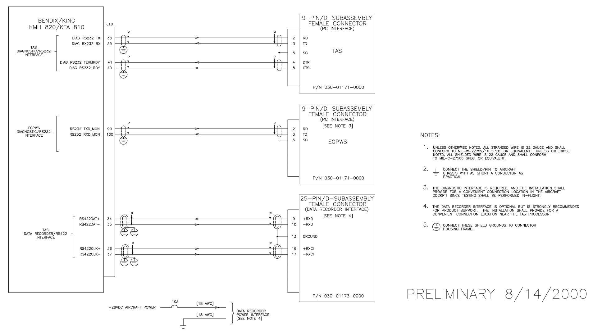
B
BB
BKMH 880/KTA 870
Rev 0, October/2000 10609I00.ZIPCDL Page 3-77
Figure 3-16 KMH 820/KTA 810 Diagnostic/Data Recorder Interface
Dwg. No. 155-01735-0015 (08/14/2000)
PRELIMINARY - SUBJECT TO CHANGE WITHOUT NOTICE
B
BB
BKMH 880/KTA 870
Rev 0, October/2000 10609I00.ZIPCDL Page 3-78
THIS PAGE IS RESERVED
PRELIMINARY - SUBJECT TO CHANGE WITHOUT NOTICE
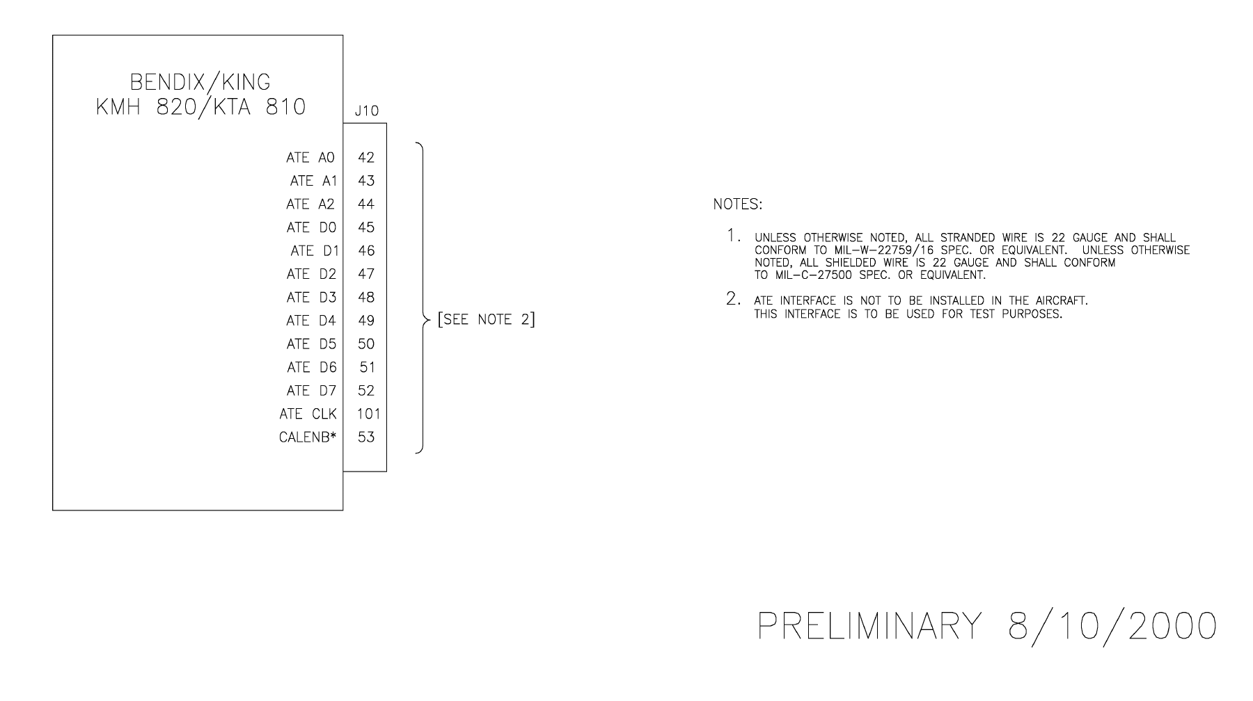
B
BB
BKMH 880/KTA 870
Rev 0, October/2000 10609I00.ZIPCDL Page 3-79
Figure 3-17 KMH 820/KTA 810 TAS ATE Interface
Dwg. No. 155-01735-0016
PRELIMINARY - SUBJECT TO CHANGE WITHOUT NOTICE
B
BB
BKMH 880/KTA 870
Rev 0, October/2000 10609I00.ZIPCDL Page 3-80
THIS PAGE IS RESERVED
PRELIMINARY - SUBJECT TO CHANGE WITHOUT NOTICE

B
BB
BKMH 880/KTA 870
Rev 0, October/2000 10609I00.ZIPCDL Page 3-81
Figure 3-18 KMH 820/KTA 810 CP 66B Interface
Dwg. No. 155-01735-0017 (08/11/2000)
PRELIMINARY - SUBJECT TO CHANGE WITHOUT NOTICE
B
BB
BKMH 880/KTA 870
Rev 0, October/2000 10609I00.ZIPCDL Page 3-82
THIS PAGE IS RESERVED
PRELIMINARY - SUBJECT TO CHANGE WITHOUT NOTICE
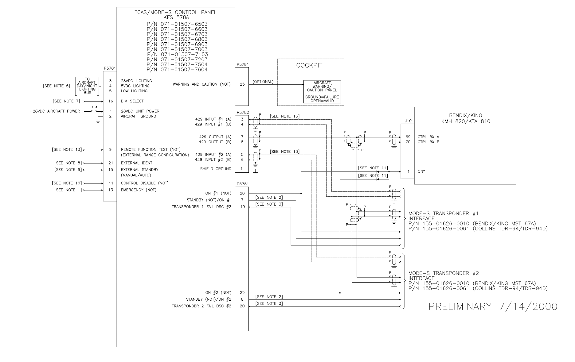
B
BB
BKMH 880/KTA 870
Rev 0, October/2000 10609I00.ZIPCDL Page 3-83
Figure 3-18 KMH 820/KTA 810 KFS 578A Interface
Dwg. No. 155-01735-0018 (Sheet 1 of 2) (07/14/2000)
PRELIMINARY - SUBJECT TO CHANGE WITHOUT NOTICE
B
BB
BKMH 880/KTA 870
Rev 0, October/2000 10609I00.ZIPCDL Page 3-84
THIS PAGE IS RESERVED
PRELIMINARY - SUBJECT TO CHANGE WITHOUT NOTICE

B
BB
BKMH 880/KTA 870
Rev 0, October/2000 10609I00.ZIPCDL Page 3-85
Figure 3-19 KMH 820/KTA 810 KFS 578A Interface
Dwg. No. 155-01735-0018 (Sheet 2 of 2)
PRELIMINARY - SUBJECT TO CHANGE WITHOUT NOTICE
B
BB
BKMH 880/KTA 870
Rev 0, October/2000 10609I00.ZIPCDL Page 3-86
THIS PAGE IS RESERVED
PRELIMINARY - SUBJECT TO CHANGE WITHOUT NOTICE
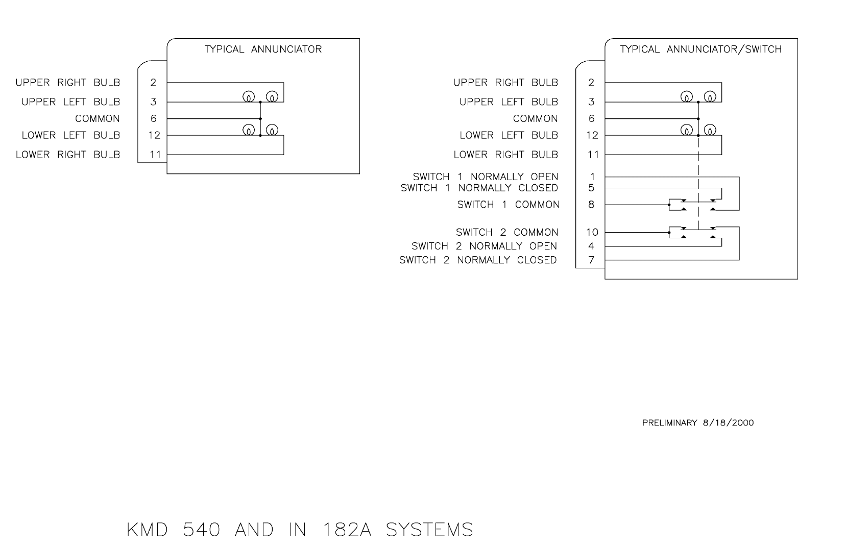
B
BB
BKMH 880/KTA 870
Rev 0, October/2000 10609I00.ZIPCDL Page 3-87
Figure 3-20 KMH 820/KTA 810 Display Interface
Dwg. No. 155-01735-0019 (Sheet 1 of 4) (08/18/2000)
PRELIMINARY - SUBJECT TO CHANGE WITHOUT NOTICE
B
BB
BKMH 880/KTA 870
Rev 0, October/2000 10609I00.ZIPCDL Page 3-88
THIS PAGE IS RESERVED
PRELIMINARY - SUBJECT TO CHANGE WITHOUT NOTICE
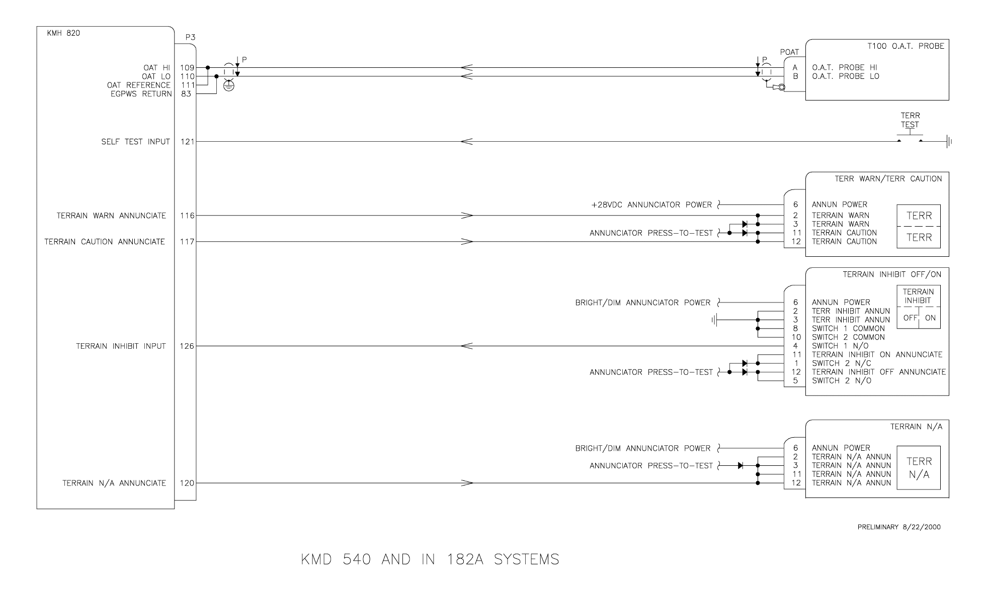
B
BB
BKMH 880/KTA 870
Rev 0, October/2000 10609I00.ZIPCDL Page 3-89
Figure 3-20 KMH 820/KTA 810 Display Interface
Dwg. No. 155-01735-0019 (Sheet 2 of 4) (08/22/2000)
PRELIMINARY - SUBJECT TO CHANGE WITHOUT NOTICE
B
BB
BKMH 880/KTA 870
Rev 0, October/2000 10609I00.ZIPCDL Page 3-90
THIS PAGE IS RESERVED
PRELIMINARY - SUBJECT TO CHANGE WITHOUT NOTICE
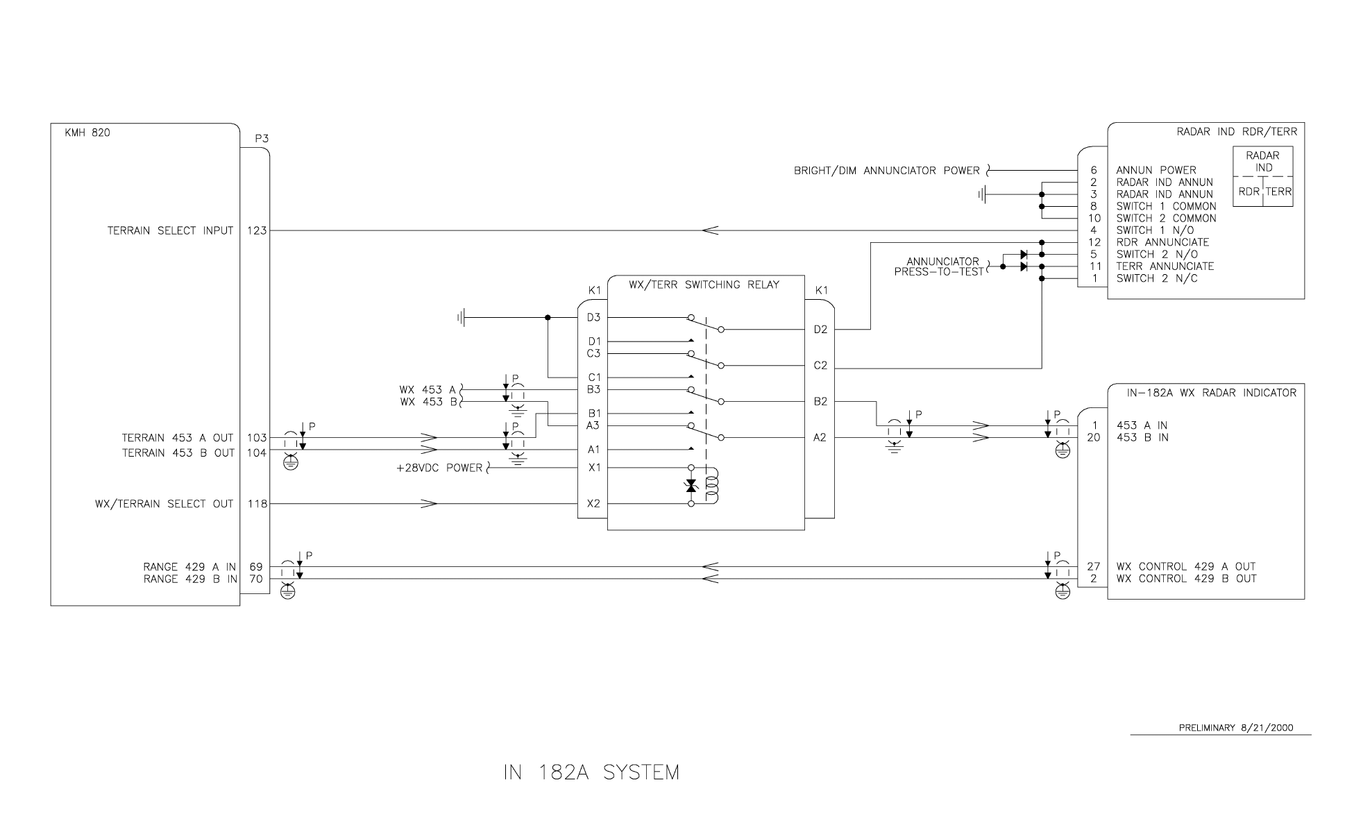
B
BB
BKMH 880/KTA 870
Rev 0, October/2000 10609I00.ZIPCDL Page 3-91
Figure 3-20 KMH 820/KTA 810 Display Interface
Dwg. No. 155-01735-0019 (Sheet 3 of 4) (08/21/2000)
PRELIMINARY - SUBJECT TO CHANGE WITHOUT NOTICE
B
BB
BKMH 880/KTA 870
Rev 0, October/2000 10609I00.ZIPCDL Page 3-92
THIS PAGE IS RESERVED
PRELIMINARY - SUBJECT TO CHANGE WITHOUT NOTICE
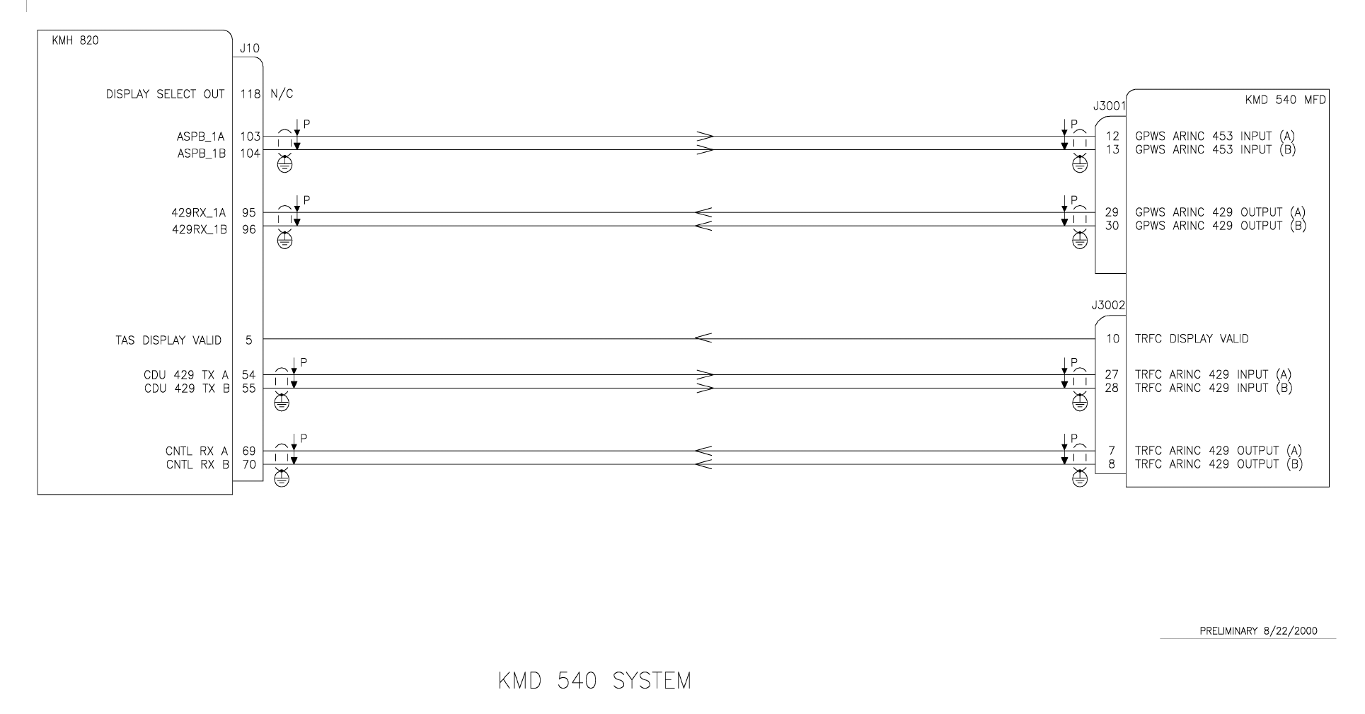
B
BB
BKMH 880/KTA 870
Rev 0, October/2000 10609I00.ZIPCDL Page 3-93
Figure 3-20 KMH 820/KTA 810 Display Interface
Dwg. No. 155-01735-0019 (Sheet 4 of 4) (08/22/2000)
PRELIMINARY - SUBJECT TO CHANGE WITHOUT NOTICE
B
BB
BKMH 880/KTA 870
Rev 0, October/2000 10609I00.ZIPCDL Page 3-94
THIS PAGE IS RESERVED
PRELIMINARY - SUBJECT TO CHANGE WITHOUT NOTICE

PRELIMINARY - SUBJECT TO CHANGE WITHOUT NOTICE
B
BB
B KMH 880/KTA 870
Rev 0, October/2000 10609I00.ZIPCDL Page 3-95
Figure 3-21 KMH 820/KTA 810 Processor Front Connector
35
71
72
81
58
82
46
83
84
85
70
68
69
86
77
75
1
2
3
5
6
7
32
42
24
47
34
45
44
57
67
66
78
22
56
33
62
65
54
31
43
13
14
23
4
12
19
40
52
64
50
63
37
74
59
60
15
51
8
26
38
25
36
48
49
61
73
18
55
20 76
39
41
30
21
16
9
11
10
27
17
28
29
53
80
79
87
95
96
92
93
94
97
90
98
89
88
91
106
105
104
103
102
101
100
99
98
116
115
114
113
112
111
110
109
108
107
127
126
125
124
123
122
121
120
119
118
117
128
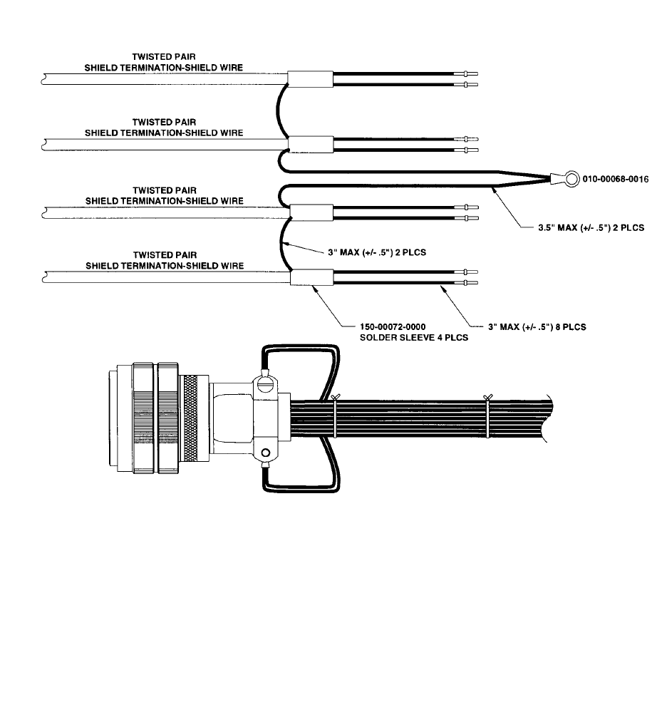
PRELIMINARY - SUBJECT TO CHANGE WITHOUT NOTICE
B
BB
B KMH 880/KTA 870
Page 3-96 10609I00.ZIPCDL Rev 0, October/2000
Figure 3-22 KMH 820/KTA 810 Front Connector Cable

PRELIMINARY - SUBJECT TO CHANGE WITHOUT NOTICE
B
BB
B KMH 880/KTA 870
Page 3-97 10609I00.ZIPCDL Rev 0, October/2000
Table 3-1 KMH 820/KTA 810 Connector Pin Assignment
I/O Pin Description Unit
N
otes
F
uture
U
se
(D
o
N
ot
Wi
re
)
I1ON* PS
POWER ON=GND
I 2 FUNCTIONAL_TEST TAS TEST=GND
I 3 LANDING_GEAR* TAS EXTENDED=GND
I 4 AIR_GND* TAS ON GND=GND
I 5 DISPLAY_VALID* TAS VALID=GND
I6
RADIO_ALT+ TAS ANALOG
I 7 RADIO_ALT- TAS ANALOG
I 8 RAD_ALT_VAL TAS ANALOG
I 9 GIL_ALT_A4 BOTH
I 10 GIL_ALT_A2 BOTH
I 11 GIL_ALT_A1 BOTH
I 12 GIL_ALT_B4 BOTH
I 13 GIL_ALT_B2 BOTH
I 14 GIL_ALT_B1 BOTH
I 15 GIL_ALT_C4 BOTH
I 16 GIL_ALT_C2 BOTH
I 17 GIL_ALT_C1 BOTH
I 18 GIL_ALT_D4 TAS
I 19 GIL_ALT_D2 TAS
O 20 PH_HI TAS HEADPHONE
O 21 PH_LO TAS HEADPHONE
I 22 ADV_INHIBIT* BOTH MUTE=GND
I 23 TAS_STANDBY* TAS STBY=GND
O 24 VIS_ANNUN_TRAFFIC* TAS TRAFFIC=GND ***
O 25 TAS_VALID* TAS VALID=GND ***
O 26 SPARE_DO1 TAS X
O 27 SPARE_DO2 TAS X
I 28 HEADING_VALID TAS
I 29 HEADING_H TAS
I 30 HEADING_C TAS
I 31 HEADING_X TAS
I 32 HEADING_Y TAS
I 33 HEADING_Z TAS
O 34 RS422_DATA+ TAS
O 35 RS422_DATA- TAS
O 36 RS422_CLK+ TAS
O 37 RS422_CLK- TAS
O 38 DIAG_RS232_TX TAS ***
I 39 DIAG_RS232_RX TAS
O 40 DIAG_RS232_RDY TAS ***
I 41 DIAG_RS232_TERMRDY TAS
O42ATE_A(0) TAS
O43ATE_A(1) TAS
O44ATE_A(2) TAS
O45ATE_D(0) TAS
O46ATE_D(1) TAS
O47ATE_D(2) TAS
O48ATE_D(3) TAS

PRELIMINARY - SUBJECT TO CHANGE WITHOUT NOTICE
B
BB
B KMH 880/KTA 870
Rev 0, October/2000 10609I00.ZIPCDL Page 3-98
Table 3-1 KMH 820/KTA 810 Connector Pin Assignment (Cont’)
I/O Pin Description Unit NOTES Future Use (Do Not Wire)
O49ATE_D(4) TAS
O50ATE_D(5) TAS
O51ATE_D(6) TAS
O52ATE_D(7) TAS
I 53 CALENB* TAS
O 54 CDU_429_TX_A BOTH ***
O 55 CDU_429_TX_B BOTH ***
I 56 RAD_ALTIM_RX_A TAS
I 57 RAD_ALTIM_RX_B TAS
58 n/c X
I 59 AIRCRAFT POWER PS
I 60 BARO_ALT_RX_A BOTH
I 61 BARO_ALT_RX_B BOTH
I 62 HDG_ATT_RX_A TAS
I 63 HDG_ATT_RX_B TAS
O 64 SPARE_RS232_TX TAS X
I 65 SPARE_RS232_RX TAS X
O 66 SPARE_RS232_RDY TAS X
I 67 SPARE_RS232_TERMRDY TAS X
I/O 68 SUPPRESSION TAS >18V=ACTIVE ***
I 69 CNTL_RX_A TAS
I 70 CNTL_RX_B TAS
I 71 ABV_BEL_NORM TAS Above/Below/Norm
I 72 CONFIG_MOD_DATA_IN TAS
O 73 CONFIG_MOD_DATA_OUT TAS
O 74 CONFIG_MOD_CHIP_SEL TAS
O75CM_CLOCK TAS
O76CM_+5V TAS ***
O 77 CM_GND BOTH
I 78 SPARE_RX_A TAS X
I 79 SPARE_RX_B TAS X
O 80 SPARE_TX_A TAS X
O 81 SPARE_TX_B TAS X
I 82 AIRCRAFT POWER PS
O 83 EGPWS RETURN EGPWS
O 84 CHASSIS GROUND
O 85 RS232TXD_GAMMA EGPWS X
I 86 RS232RXD_GAMMA EGPWS X
O 87 GPS_TXA EGPWS 232 OUT A / 422
I 88 GPS_RXA EGPWS 232 IN A / 422
O 89 GPS_TXB EGPWS 422
I 90 GPS_RXB EGPWS 422
O 91 ADC_TXA EGPWS X
O 92 429TX_1B BOTH JUMPER TO TAS
O 93 429TX_1A BOTH JUMPER TO TAS
I94ADC_RXA EGPWS X
I 95 429RX_1A EGPWS RANGE INPUT
I 96 429RX_1B EGPWS RANGE INPUT

PRELIMINARY - SUBJECT TO CHANGE WITHOUT NOTICE
B
BB
B KMH 880/KTA 870
Page 3-99 10609I00.ZIPCDL Rev 0, October/2000
Table 3-1 KMH 820/KTA 810 Connector Pin Assignment (Con’t)
I/O Pin Description Unit NOTES Future Use (Do Not Wire)
I 97 429RX_2A EGPWS GPS
I 98 429RX_2B EGPWS GPS
O 99 RS232TXD_MON EGPWS MONITOR PORT ***
I 100 RS232RXD_MON EGPWS MONITOR PORT
101 ATE_CLOCK TAS X
102 n/c X
O 103 ASPB_1A EGPWS PICT BUS
O 104 ASPB_1B EGPWS PICT BUS
O 105 SPIMOSI_CM_2 EGPWS CM DATA OUT ***
I 106 SPIMISO EGPWS CM DATA IN
O 107 SPICLK_CM_2 EGPWS CM CLK ***
O 108 SPISEL_CM#_2 EGPWS CM SEL ***
I109OAT_H EGPWS AIR TEMP +
I110OAT_L EGPWS AIR TEMP -
O111OAT_REF EGPWSAIR TEMP REF
112 n/c X
I 113 GSE_PRES# BOTH FACTORY TEST
O114ADC_TXB EGPWS
I 115 ADC_RXB EGPWS
O 116 DISC_OUT_01 EGPWS LAMP ALERT
O 117 DISC_OUT_02 EGPWS WARNING ALERT
O 118 DISC_OUT_03 EGPWS WX SELECT
I 119 SPARE_IN_2 TAS
O120MON_OUT_1 EGPWS EGPWS INOP
I 121 GND_DISC_07 EGPWS SELF TEST
I 122 GND_DISC_08 BOTH X
I 123 GND_DISC_12 EGPWS DISP SEL
I 124 GND_DISC_13 BOTH X
I 125 GND_DISC_14 BOTH
126 GND_DISC_15 EGPWS TERRAIN AWARE
I 127 AIRCRAFT GROUND PS
I 128 AIRCRAFT GROUND PS
Notes:
* indicates active ground
*** indicates that this line has a transorb located on the the interconnect board
PRELIMINARY - SUBJECT TO CHANGE WITHOUT NOTICE
B
BB
B KMH 880/KTA 870
Rev 0, October/2000 10609I00.ZIPCDL Page 3-100
THIS PAGE IS RESERVED
PRELIMINARY - SUBJECT TO CHANGE WITHOUT NOTICE
B
BB
BKMH 880/KTA 870
Rev 0, October/2000 10609I00.ZIPCDL TOC 4-i
SECTION IV
POST INSTALLATION CONFIGURATION AND CHECK OUT
4.0 INTRODUCTION .............................................................................. 4-1
4.1 LINE SELECT KEYS ........................................................................ 4-1
4.2 CONFIGURATION PROCEDURE .................................................... 4-1
4.2.1 Power On .......................................................................................... 4-1
4.2.2 Aircraft Configuration ........................................................................ 4-1
4.2.3 EGPWS Configuration Instructions.................................................... 4-2
4.2.3.1 Equipment needed............................................................................. 4-2
4.2.3.2 Configuration Module Programming.................................................. 4-2
4.2.3.3 Configuration String Format............................................................... 4-2
4.2.3.4 RS-232 Maintenance Port (Port SMC1) ............................................ 4-3
4.2.3.5 RS-232 Diagnostic Port ..................................................................... 4-4
4.2.3.6 Configuration Sequence of Events .................................................... 4-4
4.2.3.7 Configuration Types........................................................................... 4-4
4.2.3.8 Configuration Tables.......................................................................... 4-6
4.2.3.8.1 Category 1, Aircraft/Mode Type Select............................................ 4-6
4.2.3.8.2 Category 2, Air Data Input Select .................................................... 4-7
4.2.3.8.3 Category 3, Position Input Select .................................................... 4-7
4.2.3.8.4 Category 4, Terrain Display Select .................................................. 4-8
4.2.3.8.5 Category 5, Input/Output Discrete Type Select ............................... 4-9
4.2.3.8.6 Category 6, Audio Menu Select ....................................................... 4-10
4.2.3.8.7 Category 7, Audio Output Level....................................................... 4-10
4.2.3.8.8 Category 8, Altitude Monitor Options............................................... 4-11
4.2.3.8.9 Category 9, Terrain Display Alternate Pop Up Option ..................... 4-11
4.2.4 TAS Configuration Options................................................................ 4-12
4.2.4.1 TAS RS-232 Maintenance Port ......................................................... 4-15
4.2.4.2 TAS RS-422 Data Recorder .............................................................. 4-15
4.3 GROUND TEST PROCEDURES ...................................................... 4-15
4.3.1 Required Test Equipment.................................................................. 4-15
4.3.2 EGPWS Ground Test Procedures..................................................... 4-16
4.3.3 TAS Ground Test Procedures ........................................................... 4-18
LIST OF ILLUSTRATIONS
Figure 4-1 TAS Bearing Measurements............................................................ 4-34
PRELIMINARY - SUBJECT TO CHANGE WITHOUT NOTICE
B
BB
BKMH 880/KTA 870
Rev 0, October/2000 10609I00.ZIPCDL TOC 4-ii
LIST OF TABLES
Table 4-1 Configuration Identification .............................................................. 4-5
Table 4-2 Aircraft/Mode Type Select ............................................................... 4-6
Table 4-3 Air Data Input Select........................................................................ 4-7
Table 4-4 Position Input Select ........................................................................ 4-8
Table 4-5 Terrain Display Select...................................................................... 4-9
Table 4-6 Input/Output Discrete Type Select................................................... 4-9
Table 4-7 Audio Menu Select........................................................................... 4-10
Table 4-8 Audio Output Level .......................................................................... 4-11
Table 4-9 Altitude Monitor Options .................................................................. 4-11
Table 4-10 Terrain Display Alternate Pop Up Option......................................... 4-12

PRELIMINARY - SUBJECT TO CHANGE WITHOUT NOTICE
BKMH 880/KTA 870
Rev 0, October/2000 10609I00.ZIPCDL Page 4-1
SECTION IV
POST INSTALLATION CONFIGURATION AND CHECK OUT
4.0 INTRODUCTION
This Section describes the procedure for configuring and testing the KMH 880/KTA 870
System after it is installed in the aircraft.
4.1 POST CONFIGURATION TEST
This Post-Installation Test verifies the proper operation of the KMH 880/KTA 870 System.
These procedures are used after the units have been initially installed. Thereafter, these
procedures can be used as an operational check. These tests are performed on the
ground.
Many of the test can be performed indoors. The scenario tests should be done in an area
where the local traffic and signal multipaTH are not a factor. The bearing accuracy tests
should be conducted outside away from operating aircraft. 115 VAC, 60 Hz power may be
required for the test equipment.
CAUTION:
ADVISE THE LOCAL AIR TRAFFIC CONTROL BEFORE TESTING THE
TRANSPONDERS OR THE KMH 880/KTA 870 SYSTEM WITH A SYNTHETIC
ALTITUDE TO ACKNOWLEDGE POSSIBLE INTERACTION WITH OTHER
TAS/TCAS-EQUIPPED AIRCRAFT.
4.2 CONFIGURATION PROCEDURE
This section describes the configuration options available to be programmed into the
Configuration Module of the KMH 880/KTA 870 System.
4.2.1 Power On
Turn the KMH 880/KTA 870 System on.
4.2.2 Aircraft Configuration
Aircraft Configuration strapping is stored in the configuration module via a
personal computer executing TASDIAG software across theRS-232 port. Follow
instructions for configuration programming in the TASDIAG Diagnostic, Appen-
dix D of this manual.
PRELIMINARY - SUBJECT TO CHANGE WITHOUT NOTICE
BKMH 880/KTA 870
Page 4-2 10609I00.ZIPCDL Rev 0, October/2000
4.2.3 EGPWS Configuration Instructions
These instructions will detail the configuration check list, initial configuration
(new configuration module) and volume output levels for the EGPWS.
It describes how the EGPWS interfaces to specific aircraft configurations. It con-
tains an overview of the selection categories for the different aircraft sensor
interfaces. It defines how the category IDs are selected for the interface to air-
craft sensors and to select EGPWS performance options. It defines the specific
aircraft applications of the EGPWS.
4.2.3.1 Equipment Needed
A. EGPWS Installed and Operating
B. Interconnect Cable
C. IBM or Compatible PC
D. A Copy of Honeywell WINVIEWS
NOTE
WinViews is an Enhanced GPWS diagnostic communications program that runs
from Windows on a PC that is connected to the EGPWS. WinViews HELP, as
well as many other menu items are active even though the program is fully oper-
ational when communications are established with the EGPWS.
4.2.3.2 Configuration Module Programming
The Configuration Module Programming is completed via the RS-232 port. The
application code is capable of loading the Configuration Module with new data.
This programming is achieved by using the WinsViews software. In WinViews,
the EGPWS will accept valid commands. To prevent inadvertent access to the
Configuration Module’s EEPROM, the keyboard monitor is set up with a tiered
menu. The keyboard monitor command “CFG” is used to gain access to the
Configuration monitor.
The command to program the memory with the Configuration String is “CUW”.
This command takes a pre-configured String (defined below) containing the
new memory contents and a CRC (written by the EGPWS) and writes them to
the Configuration Module’s EEPROM.
4.2.3.3 Configuration String Format
The EGPWS requires a string of configuration information to be written to the
configuration module memory when requested from the keyboard monitor.

PRELIMINARY - SUBJECT TO CHANGE WITHOUT NOTICE
BKMH 880/KTA 870
Rev 0, October/2000 10609I00.ZIPCDL Page 4-3
Example String: = CUW 0/901000220/ (Space after cuw, category and each
number if there is no separator)
Where the first 0 reflects the string version, the next number is the number of
categories and the remaining numbers before the second separator reflect the
ID for each of the categories.
String breakdown Explanations:
CUW = The command to write
0 = String Version
/ = Separator
9 = the number of categories
0 = Category #1 ID = 0 (TSO-C151a Class B curve set)
1 = Category #2 ID = 1 (Altitude Encoder with 500 ohm
Temperature Probe)
0 = Category #3 ID = 0 (GPS, Internal GPS Express RS-232)
0 = Category #4 ID = 0 (Display select = ASPB)
0 = Category #5 ID = 0 (I/O Discrete Type Select = Basic, Lamp
format 2)
0 = Category #6 ID = 0 (Audio Menu Select = Basic)
2 = Category #7 ID = 2 (Audio Output Level = -12dB)
2 = Category #8 ID = 2 (Altitude Monitor Option Select = Disable)
0 = Category #9 ID = 0 (TA&D Alternate Pop Up = False)
/ = Separator
4.2.3.4 EGPWS RS-232 Maintenance Port (port: SMC1)
One port is provided which meets the characteristics specified in RS232C. This bus can
be used to access internal data from the EGPWS for aircraft testing. In addition to the
internal data, other items such as unit configuration and flight history can also be
accessed.
Baud Rate 19,200
Parity none
Data Bits 8
Stop Bits 1
Maximum Recommended Cable Length 15 meters
Pin Assignment (Signal Mnemonic)
RS-232TXD_MON J10-99
RS-232RXD_MON J10-100
PRELIMINARY - SUBJECT TO CHANGE WITHOUT NOTICE
BKMH 880/KTA 870
Page 4-4 10609I00.ZIPCDL Rev 0, October/2000
4.2.3.5 Configuration Sequence of Events (Application)
A. Turn the KMH 880 system power on.
B. Bring up the WINVIEWS program. Type Ctrl Z.
C. At the WINVIEWS prompt type “CFG”. Press the ENTER key.
D. Type in the pre-configured STRING using the command “CUW”. Press the
ENTER key.
E. After loading this string in the WINVIEWS, the cursor will flash waiting for
an answer “Y” or “N”.
F. Ty p e “Y”.
NOTE
At this point the EGPWS will reboot itself.
G. When, the system comes back up type Ctrl “Z” then type “PS” (Present
Status).
H. Check the Status information displayed. Confirm that your configuration
input write is accurate.
4.2.3.6 Configuration Types (Categories)
The selection of the basic interfaces to the EGPWS can be found in the following catego-
ries.
Aircraft/Mode Type Category 1
Air Data Type Category 2
Position Type Category 3
Terrain Display Type Category 4
I/O Discretes Types Category 5
Audio Menu Type Category 6
Audio Output Level Type Category 7
Altitude Monitor Options Type Category 8
Terrain Display Alternate Pop up Option Category 9
4.2.3.7 Configuration Identification Selection (ID)
The method to select the Configuration Identification (ID) for each Category Type on a
given aircraft installation is with the information in this document and the following table.

PRELIMINARY - SUBJECT TO CHANGE WITHOUT NOTICE
BKMH 880/KTA 870
Rev 0, October/2000 10609I00.ZIPCDL Page 4-5
This table provides the procedure to determine the Configuration ID selection required
for any given aircraft installation.
STEP
(CATEGORY)
SIGNAL
SELECTION INSTRUCTION IDENT.
NO.
1
Selects:
a) Aircraft Type
b) Mode Type
Using Table 4-2 and any sub-tables
contained within, locate the Air-
craft/Mode type.
Record the Ident (ID
No.) on the space
available on Ident
column of this table.
_____
ID #
2
Selects:
a) Air Data
Source
Using Table 4-3 and any sub-tables
contained within, locate the desired
Air Data signal type.
Record the Ident (ID
No.) on the space
available on Ident
column of this table
_____
ID #
3
Selects:
a) Position
Source
Using Table 4-4 and any sub-tables
contained within, locate the desired
Position Signal type.
Record the Ident (ID
No.) on the space
available on Ident
column of this table.
_____
ID #
4
Selects:
a) Display
Configuration
Using Table 4-5 and any sub-tables
contained within, locate the desired
Display indicator type/range bus
type.
Record the Ident (ID
No.) on the space
available on Ident
column of this table.
_____
ID #
5
Selects:
a) Input discrete
Functions
b) Output Discrete
Functions.
Using Table 4-6 and any sub-tables
contained within, locate the desired
I/O Discrete type.
Record the Ident (ID
No.) on the space
available on Ident
column of this table.
_____
ID #
6
Selects:
a) Audio Menu
Using Table 4-7 and any sub-tables
contained within, locate the desired
Audio Menu type
Record the Ident (ID
No.) on the space
available on Ident
column of this table.
_____
ID #
7
Selects:
a) Audio Output
Level
Using Table 4-8 and any sub-tables
contained within, locate the desired
Volume type
Record the Ident (ID
No.) on the space
available on Ident
column of this table.
_____
ID #

PRELIMINARY - SUBJECT TO CHANGE WITHOUT NOTICE
BKMH 880/KTA 870
Page 4-6 10609I00.ZIPCDL Rev 0, October/2000
Table 4-1 Configuration Identification
4.2.3.8 Configuration Tables
The Category columns define a category (or group) of functions or input devices that are
selected through ID Numbers. The Category Number identifies the subsection where the
details are defined. For example Air Data, Category 2, is identified in Table 4-3 and Posi-
tion Input Source, Category 3, is defined in Table 4-4.
4.2.3.8.1 Category 1, Aircraft/Mode Type Select
The following table provides identification of the basic mode types and associated
parameters.
In this category only the following parameters are to be defined:
• Basic mode alert and warning thresholds
Table 4-2 Aircraft / Mode Type Select
8
Selects:
a) Altitude Monitor
Display Disable
b) Altitude Monitor
Call out Disable
c) Altitude Monitor
Disable
Using Table 4-9 and any sub-tables
contained within, select the desired
True or False Condition for Altitude
Monitor Display Disable, Altitude
Monitor Callout Disable, and Alti-
tude Monitor Disable.
Record the Ident (ID
No.) on the space
available on Ident
column of this table. _____
ID #
9 Selects:
a) TA&D alternate
Pop Up
Using Table 4-10 and any sub-
tables contained within, select the
desired True or False condition for
TA&D Alternate Pop Up.
Record the Ident (ID
No.) on the space
available on Ident
column of this table.
_____
ID #
ID Aircraft/Mode Type Description Effectivity
App. Cfg.
0 0 TSO-C151a Class B curve set -001 -001
1 1 Non-TSO curve set #1 -001 -001
STEP
(CATEGORY)
SIGNAL
SELECTION INSTRUCTION IDENT.
NO.

PRELIMINARY - SUBJECT TO CHANGE WITHOUT NOTICE
BKMH 880/KTA 870
Rev 0, October/2000 10609I00.ZIPCDL Page 4-7
NOTE
When selecting ID 0; Category 6, (Audio Menu Select) must select ID #1 (Alter-
nate) in order to be in compliance with TSO-C151a.
4.2.3.8.2 Category 2, Air Data Input Select
The following table provides identification of the Air Data source type. In this category
only the following parameters are to be defined:
• Gillham/Gray coded altitude or uncorrected altitude in ARINC 429 format.
Temperature, Outside Air or Static Air in analog or ARINC 429 format.
Table 4-3 Air Data Input Select
4.2.3.8.3 Category 3, Position Input Select
The following table provides identification of the Position Source Signal. In this category,
only the following POSITION signals are to be defined:
• Altitude • Sensor Status
• Date • Track angle
• Ground Speed • Universal Time Correlation
• Horizontal Figure of Merit (HFOM) • Vertical Figure of Merit (VFOM)
• Horizontal Integrity Limit • Vertical Velocity
• Latitude Position • N/S Velocity
• Longitude Position • E/W Velocity
ID AIR DATA TYPE DESCRIPTION EFFECTIVITY
App. Cfg.
0 0 Altitude Encoder (9 wire Gillham/Gray coded altitude) -001 -001
1 1 Altitude Encoder (9 wire Gillham/Gray coded altitude)
with 500 ohm OAT Temperature Probe
-001 -001
2 2 Digital - ARINC 429
(Required Labels are 203 and 213)
-001 -001
3 3 Digital - ARINC 429 (with Corrected Altitude)
(Required Labels are 203,204,212,and 213)
-001 -001

PRELIMINARY - SUBJECT TO CHANGE WITHOUT NOTICE
BKMH 880/KTA 870
Page 4-8 10609I00.ZIPCDL Rev 0, October/2000
Table 4-4 Position Input Select
NOTE 1
The GPS Altitude Reference MSL or WGS-84 must be properly applied for the
appropriate GPS Position Type. At the time of release of this document, all GPS
sources except the Universal UNS-1 GPS are of the MSL type. The Universal
UNS-1 GPS (GPS-1000 engine in the UNS-1B+,-1C, -1D, -1k,and -1M) sources
are of WGS-84 type.
NOTE 2
This configuration is only applicable to Honeywell Qualification Test Lab. When
this configuration is enabled on a 066-01175-2101 (EGPWS with internal GPS)
a software internal GPS monitor is activated for testing.
4.2.3.8.4 Category 4, Terrain Display Select
The following table has an identification number (ID) associated with each Terrain Display
configuration. Each of the ID rows has a group number for the Display configuration, the
Input Control and the output 429 bus. The TA&D Pop Up Disable function is defined by a
Boolean. See Table 4-10.
ID POSITION
INPUT
TYPE
DESCRIPTION GPS ALTITUDE
REFERENCE
EFFECTIVITY
App. Cfg.
0 0 GPS, Internal GPS-PXPRESS RS-232 MSL -001 -001
1 1 GPS, External RS-232 (GPS-PXPRESS
format)
MSL -001 -001
2 2 GPS, ARINC 429 low speed, 743A format MSL -001 -001
3 3 GPS, ARINC 429 low speed, 743 format MSL -001 -001
4 4 GPS, ARINC 429 low speed, 743 format
(GPS Altitude referenced to WGS-84)
WGS-84 -001 -001

PRELIMINARY - SUBJECT TO CHANGE WITHOUT NOTICE
BKMH 880/KTA 870
Rev 0, October/2000 10609I00.ZIPCDL Page 4-9
In this category the following signals are configured by the ID number:
Table 4-5 Terrain Display Select
4.2.3.8.5 Category 5, Input/Output Discrete Type Select
The following table provides identification of the Input/Output Discrete Type.
Table 4-6 Input/Output Discrete Type Select
SIGNAL NAME SIGNAL TYPE DEFINED BY
Terrain Display Bus ASPB or ARINC Display configuration Group
Range Bus ARINC 429 Display Input Control Group
TA&D Alternate Pop Up Boolean Defined directly in Table 4-10
ID DISPLAY
CONFIG.
GROUP
DISPLAY INPUT
CONTROL GROUP
(NOTE 1)
OUTPUT
429 BUS
GROUP
APPLICATION NOTES EFFECTIVITY
App. Cfg.
0 0 0 0 ASPB -001 -001
1 None None 0 No Display -001 -001
2 1 1 0 Bendix
IN 182A, IN 812A
-001 -001
3 2 1 0 Bendix
IN 842A, IN 862A
-001 -001
4 3 2 0 Bendix RDR 4A/B PPI
(with blue waters modification)
-001 -001
ID Input/Output
Discrete Type
Description Effectivity
App. Cfg.
0 0 Basic input/output discretes (Lamp Format: Type 2) -001 -001

PRELIMINARY - SUBJECT TO CHANGE WITHOUT NOTICE
BKMH 880/KTA 870
Page 4-10 10609I00.ZIPCDL Rev 0, October/2000
NOTE
If a single cockpit lamp is desired for Terrain Cautions and Warnings, J10-116
and J10-117 can be diode or’ed together to drive one lamp.
4.2.3.8.6 Category 6, Audio Menu Select
The following table provides identification of the Voice Menu type.
Table 4-7 Audio Menu Select
NOTE
If Category 1 selected ID #0 (TSO-C151a Class B curve set) Category 6 ID #1
(Alternate) must be selected to be in compliance with the TSO.
4.2.3.8.7 Category 7, Audio Output Level
The following provides identification of the Audio Output Level type. Each entry in the ID
column corresponds to a particular nominal alert output level selection (max,-6dB, -12
dB, -18dB AND -24Db). The Nominal “Max” Output is 100 mW/rms for the 600 ohm out-
put. The output power level will be the nominal maximum output 100mW reduced by the
selected volume type.
ID AUDIO MENU TYPE DESCRIPTION EFFECTIVITY
App. Cfg.
0 0 Basic -001 -001
1 1 Alternate -001 -001

PRELIMINARY - SUBJECT TO CHANGE WITHOUT NOTICE
BKMH 880/KTA 870
Rev 0, October/2000 10609I00.ZIPCDL Page 4-11
Table 4-8 Audio Output level
4.2.3.8.8 Category 8, Altitude Monitor Options
The following table provides identification of the Altitude Monitor Options. Each entry in
the ID column corresponds to a particular combination of Altitude Monitor Display Dis-
able, Altitude Monitor Callout Disable and Altitude Monitor Disable.
NOTE: TRUE = Disable
Table 4-9 Altitude Monitor Options
4.2.3.8.9 Category 9, Terrain Display Alternate Pop Up Option
The following table provides identification of the Terrain Display Alternate Pop Up Option.
TA&D Alternate Pop Up = False allows automatic Pop Up On Caution or Warnings.
ID VOLUME TYPE EFFECTIVITY
App. Cfg.
0 Max (600 ohm ≈ 100mW) -001 -001
1 -6 dB -001 -001
2 -12dB -001 -001
3 -18dB -001 -001
4 -24dB -001 -001
255 -14db for ΚΜΗ 880/ΚΤΑ 870 configuration -001 -001
ID ALTITUDE MON-
ITOR DISABLE
ALTITUDE MONITOR CALLOUT
DISABLE
ALTITUDE MONITOR
DISPLAY DISABLE
EFFECTIVITY
App. Cfg.
0 False False False -001 -001
1 False False True -001 -001
2 False True False -001 -001
3 False True True -001 -001
4 True True True -001 -001

PRELIMINARY - SUBJECT TO CHANGE WITHOUT NOTICE
BKMH 880/KTA 870
Page 4-12 10609I00.ZIPCDL Rev 0, October/2000
TA&D Alternate Pop Up = True disables the automatic Pop Up feature.
Table 4-10 Terrain Display Alternate Pop Up Option
4.2.4 TAS Configuration Options
The TAS Processor will acquire the following hardware strap information from
the configuration module.
NOTE
Format is as follows: Configuration Option; Configuration Option Description.
A. Display Intruder Limit; 3 (Minimum) Display Intruder Limit 30 (Maximum),
incremented by 1.
The Display Intruder Limit Program is used to limit the number of intruders
displayed in the aircraft. The Display Intruder Limit will be configured to a
value between 3 (minimum FAA requirement) and 30 (max. intruder limit).
NOTE
The TAS Processor will transmit a maximum of 30 intruders to the traffic display.
B. Heading Type; Synchro Data or ARINC 429 Data
The Heading Type Program will indicate the type of heading source (either
ARINC 429 or Synchro) that interfaces to the TAS.
C. Attitude Type; Not Installed or ARINC 429 Data.
ARINC 429 magnetic heading (BCD or Binary), pitch angle and roll are
input to the TAS Processor via the Attitude/Magnetic Heading ARINC 429
high speed input bus.
ID TA&D ALTERNATE POP UP DISABLE EFFECTIVITY
0 False -001 -001
1 True -001 -001
PRELIMINARY - SUBJECT TO CHANGE WITHOUT NOTICE
BKMH 880/KTA 870
Rev 0, October/2000 10609I00.ZIPCDL Page 4-13
D. Radio Altimeter Type; Not Installed, ARINC 429, Bendix/King Analog,
Sperry Analog, Collins Analog or ARINC 552A.
The Radio Altimeter Source Port will input to the TAS Processor. The input
impedance into this port is 55 Kohms. The port has an associated Radio
Altitude Valid flag input to the TAS Processor.
Radio Altimeter Valid input will be 20 to 30 VDC during proper altimeter
operation (if present). Any failure of the altimeter causes the flag signal to
become an open circuit. The analog radio altimeter input (if present) will be
considered failed if the altitude is within a valid range (-20 to 2500 feet) and
the valid pin is in the invalid state.
The Radio Altimeter Type Program will indicate which type of radio altime-
ter input is used.
NOTE
Due to tolerances in the TAS Processor analog I/O hardware, the accuracy for
the 0 - 100 foot range may be ± 10 feet.
E. On Ground Display Mode; TAS in Standby Mode On-Ground or TAS in TA
Only Mode On-Ground.
The On Ground Display Mode will indicate to the processor whether the
system will go to Standby Mode when on the ground or that the system will
go to TA Mode (with aurals and voice inhibited due to altitude defined by
TAS logic) when the aircraft is on the ground.
F. Baro Altimeter Type; Gillham, ARINC 575, ARINC 706.
The Barometric Altimeter Type program will indicate the type of barometric
altimeter source [either Gillham/Gray Code, ARINC 575 (ARINC 419) or
ARINC 706 (ARINC 429)] that interfaces to the TAS Processor.
G. Controller Type; ARINC 735 Protocol, or Discrete Control.
The Controller Type will determine the type of control data, either the Con-
trol Panel to the TAS Processor via the CNTL HD RX (ARINC 429) input
bus or via Discrete Control switches.
H. Ground Headphone Volume; 1.25, 2.5, 5, 10, 20, 40, 80, 100 mw.
The on ground headphone level will be configurable to the above levels.
PRELIMINARY - SUBJECT TO CHANGE WITHOUT NOTICE
BKMH 880/KTA 870
Page 4-14 10609I00.ZIPCDL Rev 0, October/2000
I. Airborne Headphone Volume; 1.25, 2.5, 5, 10, 20, 40, 80, 100 mw.
The airborne headphone level will be configurable to the above levels.
J. Airborne Functional Test; Inhibited or Allowed.
When the Airborne Functional Test is inhibited, the TAS Processor will
inhibit Functional Test while in the air.
When the Airborne Functional Test is allowed, the TAS Processor will allow
Functional Test in the air.
K. ATE Output; Enabled or Disabled.
The ATE Output will be used to enable the ATE lines for the Anechoic
Chamber and the RGS stations.
L. Intruder File Protocol
ARINC 735a or Honeywell Business and Commuter Aviation Systems
(BCAS) protocol.
M. Display Valid Input Usage: Used or Ignored.
If “Used“ is selected, TAS will use the Display Valid Input for BITE pur-
poses. If “Ignored” is selected, TAS will ignore the Display Valid Input for
BITE purposes.
N. RS-422 Output Drivers: enabled or disabled
When the TAS processor is configured to have the Data Recorder RS-422
Drivers enabled, the RS-422 output bus shall be active. When the RS-422
Drivers are disabled the output bus shall be inactive. This should be set to
“disable” for aircraft installations.
PRELIMINARY - SUBJECT TO CHANGE WITHOUT NOTICE
BKMH 880/KTA 870
Rev 0, October/2000 10609I00.ZIPCDL Page 4-15
4.2.4.1 TAS RS-232 Maintenance Port
One port is provided which meets the characteristics specified in RS232C. This
bus can be used to access internal data from the TAS for aircraft testing. In addi-
tion to the internal data, other items such as unit configuration and flight history
can also be accessed.
Baud Rate 38,400
Parity none
Data Bits 8
Stop Bits 1
Maximum Recommended Cable Length 15 Meters
Pin Assignment (Signal Mnemonic)
DIAG_RS232_TX J10-38
DIAG_RS232_RX J10-39
DIAG_RS232_RDY J10-40
DIAG_RS232_TERMRDY J10-41
4.2.4.2 TAS RS-422 Data Recorder
One port is provided which meets the characteristics specified in EIA RS-422A.
This bus can be used as a data recording vehicle. It need not be wired unless
requested by Honeywell personnel.
Maximum Recommended Cable Length 15 Feet
Pin Assignment (Signal Mnemonic)
RS422_DATA+ J10-34
RS422_DATA- J10-35
RS422_CLK+ J10-36
RS422_CLK- J10-37
4.3 GROUND TEST PROCEDURES
4.3.1 Required Testing Equipment
• Personal Computer with Diagnostic Program (WinViews for the EGPWS
ground tests and TASDIAG for TAS ground tests. (See Appendix D).
• TCAS Ramp Test Set; TCAS 201, or equivalent.
• Transponder Ramp Test Set.
PRELIMINARY - SUBJECT TO CHANGE WITHOUT NOTICE
BKMH 880/KTA 870
Page 4-16 10609I00.ZIPCDL Rev 0, October/2000
• Pitot-Static Test Set.
• Radio Altimeter Test Set, or equivalent.
• Volt-Ohmmeter (DVM) (optional).
• 429 Bus reader (optional).
4.3.2 EGPWS Ground Test Procedures (066-01175-x101 only).
This Ground Test Procedure is designed to minimize potential equipment dam-
age and verify proper operation of the Honeywell EGPWS as installed in the air-
craft.
A. Review your aircraft installation drawings against the manufacturer’s data
sheets and verify that all necessary connections are included on your draw-
ings and that the pin numbers are in agreement.
B. With all units disconnected and aircraft power off, do a point to point wiring
check using an ohm meter to verify proper wiring interconnect.
C. With all units disconnected, apply aircraft DC power and verify that power is
supplied to the power input pins.
D. Remove power from the aircraft and connect all units.
E. Connect a PC to the RS-232 communications port of the EGPWS unit.
F. Power up the PC, start “WinViews” and select connect.
G. Power up the avionics in the aircraft. You should note the “Not Available”
light ON and you should see INITIALIZATION messages coming from the
EGPWS on your PC. When the messages quit (could be as long as 3 min-
utes for the first application of power) press Control ‘Z’ on your keyboard.
The PC display should show a ‘>’.
H. Type ‘PS’ and the ‘return’ key on your PC. You should receive several lines
of status messages from the EGPWS. One of the messages should be
‘Configuration Module not initialized’. Instructions for programming the con-
figuration module are contained in section 4.2.3.2 of this document. Go to
section 4.2.3.2 at this time and after configuration has been completed,
return to item I below.
I. With your PC communicating with the EGPWS, select ‘file’ at the top of the
WinViews screen. Select ‘Load Command File’ and then select the file
named Gagnddtst.cmd. (This file was supplied on your WinsViews Disk).
PRELIMINARY - SUBJECT TO CHANGE WITHOUT NOTICE
BKMH 880/KTA 870
Rev 0, October/2000 10609I00.ZIPCDL Page 4-17
J. Now press function key F6 on your keyboard.
K. Set the aircraft’s altimeter to 29.92 IN Hg and note the altitude displayed on
the altimeter. Now look at the PC screen and locate the item named Gill-
ham Alt ft. and verify that the altitude shown agrees with the aircraft altime-
ter, ± 100 feet. If it does not, troubleshoot the encoding altimeter / wiring.
L. Provide a source of GPS signals to the GPS antenna. This can be accom-
plished by using a GPS repeater inside a hanger, or by taking the aircraft
outside where it has a clear view of the sky.
M. Press function key F6 to return to the command mode of WinsViews. Type
in GPS followed by the ‘Return’ key to view the status of the GPS receiver.
Typing control ‘R’ on the keyboard will re-issue the last command sent and
allow you to continue to monitor GPS status. Once the GPS has acquired
satellites, the status message “Not Navigating” will change to “Navigation
with possible data collection”. The Not Available Lamp should turn off and if
a display is being used, a North UP terrain view should be shown on the
display.
N. Press the ‘Self Test’ switch and verify that the unit lights all lamps, produces
audio and the display, if installed, shows a test pattern. The EGPWS self
test function will identify any problems with the interfaces or with the
EGPWS computer. Troubleshoot any problem reported during the self test.
O. Connect a pitot-static test set to the aircraft static system. Operation of the
pitot-static test set should be performed only by persons trained in its use.
Additionally, if the aircraft static system was opened or modified to add an
encoder, the static system must be tested and approved by a licensed
mechanic or authorized repairman. Improper use of the pitot-static test set
can result in damage to altimeters, vertical speed indicators, etc.
P. Start with the pitot-static test set at current field elevation. Set the reference
altimeter in the test set for 29.92 IN. Hg.
Q. On the PC, select the Data display mode (F6). With the system receiving
GPS signals and no faults reported, you should now verify that the system
has correctly identified your closest airport. Look at the following items on
the PC display:
CrwyApt (the letter/number identifier of the closest airport Only
public airports with runways 2000 feet or longer)
CRwyDist nm The distance in nm to the reference point of the airport.
Verify that the displayed information agrees with your geographic location.
PRELIMINARY - SUBJECT TO CHANGE WITHOUT NOTICE
BKMH 880/KTA 870
Page 4-18 10609I00.ZIPCDL Rev 0, October/2000
R. Set the pitot-stat test set to -1000 feet, exercise caution to avoid excessive
pressure changes to the static system of the aircraft. Verify that the PC dis-
play shows the item named Gillham Alt ft. at -1000 feet ± 100 feet.
S. Set up the pitot-static test set to allow an ascent to 30,000 feet, or to the
maximum altitude of the lowest rated device attached to the static system.
If, for example, the aircraft uses a blind encoder rated to 25,000 feet; the
altitude to climb to would be 25,000 feet.
You must verify that all equipment connected to the static system can safely
be driven to your test altitude. If you go above 30,750 feet, the Gillham Alti-
tude displayed on your PC will start going backwards. This is normal
because the EGPWS does not use Gillham Code line D4. At altitudes
above 18,000 feet, the EGPWS uses GPS altitude for calculations.
T. Start an ascent at 3,000 feet per minute while monitoring the item named
Gillham Alt ft. At approximately a 2-second rate the displayed altitude
should increase by 100 feet. Make absolutely certain that the altitude
always increases; never goes backwards and never skips a 100 foot incre-
ment. You can record this test using the data collection feature of Win-
Views.
This will allow you to look through the data after the test using a text editor.
This test verifies that the barometric altitude source is working correctly and
that the wiring is correct. Troubleshoot anomalies discovered during this
test.
U. Return the static test set and aircraft static system to the local ambient
pressure.
V. If installed, press the Terrain Inhibit switch and verify that the item named
TerrDis switches between true and false on your PC’s display.
W. This completes the Ground Test of the EGPWS.
4.3.3 (TAS) Ground Test Procedure
Installation of the TAS System requires three stages of testing to ensure the proper oper-
ation of the TAS System components. Initially, before installation of the TAS processor
and display units, a system interwiring check is performed. This check verifies that the
aircraft and all TAS System interconnections are correct, before power is applied. After
the units are installed, a visual inspection of the equipment and connections is made.
The Post-installation test is used to apply power and functionally check out the system.
Successful completion of the post-installation test verifies the proper operation of the
KMH/KTA Traffic Advisory System.
PRELIMINARY - SUBJECT TO CHANGE WITHOUT NOTICE
BKMH 880/KTA 870
Rev 0, October/2000 10609I00.ZIPCDL Page 4-19
A. To check the aircraft system interconnections, perform the following:
Check that all cables and interwiring are installed according to the Interwir-
ing and Cable Fabrication instructions. (paragraph 2.2.7 and 2.2.8)
Check that the following functions are properly strapped to reflect the air-
craft system configuration. (paragraph 4.2.3.6)
•Aircraft/Mode Type
•Air Data Type
•Position Type
•Terrain Display type
•I/O Discretes Type
•Audio Menu Type
•Audio Output Level Type
•Altitude Monitor Options Type
•Terrain Display Alternate Pop UP Option
Using the interconnect diagrams (Figures 3-1 through Figure 3-23), check
wiring for proper destinations, opens and shorts.
Check RF Cable for electrical length matching, insertion loss and VSWR.
(See paragraph 2.2.7 and 2.2.8)
Check the transponder and DME interface.
NOTE
The only required interface between the KMH/KTA TAS and the transponder is
the suppression line. Some installations may use a common control for the tran-
sponder and the TAS. In these cases, the TAS control comes from the transpon-
der control unit.
B. In conjunction with the system installation, perform a visual inspection.
C. Perform the Pretest Setup to set the initial conditions to check the operation
and self-test features of the system. The following steps apply and check
the TAS System input power, configure the operational controls, and verify
that the system is ready for testing. It is assumed that the person perform-
ing these tests has a working knowledge of the KMH/KTA TAS System and
the Graphics Unit and is qualified to perform these tests on the aircraft.
Ensure that all aircraft systems are secure and safe. Confirm that 28Vdc
and 26Vac 400 Hz power sources are operational; i.e., check power bus
meter.
PRELIMINARY - SUBJECT TO CHANGE WITHOUT NOTICE
BKMH 880/KTA 870
Page 4-20 10609I00.ZIPCDL Rev 0, October/2000
Check that the aircraft 5Vac or Vdc or 28 Vdc panel background lighting
power source and dimmer control is operational by adjusting the cockpit
dimmer switch for proper cockpit panel background illumination.
Check that the Transponder, TAS, and Radar Systems are OFF. If applica-
ble, the selected encoding altitude source should be #1. If applicable, the
ADC (Air Data Computer) source should be set to normal.
Operate the appropriate aircraft circuit breakers to apply power to the TAS
Processor, Traffic Advisory displays and all other aircraft equipment con-
nected to the TAS Processor subsystem. Check that the circuit breakers
remain closed (pushed in).
Allow enough time for equipment warm-up. Equipment in the TAS system
require one minute for equipment warm-up. External sensors may require
more than one minute warm-up time.
On the TAS control panel, Place the SBY switch to SBY mode. Place the
ABOVE/NORM/BELOW switch so as to indicate “NORM”. Place the Range
so the 5 nautical mile (nmi) range has been selected. The following should
be visible on the traffic display screen:
• No “TAS” flag annunciation.
• “TAS STBY”.
• If installed, the TA/VSI vertical speed needle should indicate 0 fpm.
Check that the brightness of the traffic display can be controlled by the
appropriate control. Brightness of the traffic display may be controlled by
the aircraft dimmer switch or by the BRT control on the display unit.
On the TAS Control Unit, select the ON position. The following conditions
should exist:
• The traffic display should indicate “TA ” or “TA ONLY”.
• No faults or fail annunciations are present on the traffic display.
• Traffic may be displayed on the traffic display depending on the
TAS strapping configuration and whether traffic exists in the area.
• Non-threat Traffic, displayed as an open white diamond.
• Proximity Intruder Traffic, displayed as a filled white diamond.
• Traffic Advisory (TA) traffic, displayed as a yellow circle.
D. Perform the Self-test by initiating the TAS System Self-test on the TAS Con-
trol Panel. The following events should occur during the test period:
On the traffic display, a test pattern will be displayed that allows verification
of each type of intruder symbol that can be displayed. During the self-test,
PRELIMINARY - SUBJECT TO CHANGE WITHOUT NOTICE
BKMH 880/KTA 870
Rev 0, October/2000 10609I00.ZIPCDL Page 4-21
the word “TEST” is displayed on the display. The following symbols are dis-
played:
• Traffic Advisory (yellow circle) will appear at 9 o’clock, range of 2 miles,
200 feet below and climbing.
• Proximity traffic (solid white diamond) will appear at 1 o’clock, range 3.6
miles, 1000 feet below and descending.
• Non-threat traffic (open white diamond) will appear at 11 o’clock, range
of 3.6 miles, flying level 1000 feet above.
At the conclusion of a successful self-test, a synthesized voice announces,
“TAS System Test OK”. Should a failure be detected during self-test, the
audio message says, “TAS System Test Fail”.
E. Perform the Ground Test.
Ground tests are necessary to meet the requirements of DRAFT AC 20 ZZ.
While the tests are organized in a sequential fashion, they may be com-
pleted in a random order to accommodate other conditions. The person
performing these tests should be familiar with the TAS equipment, the air-
craft installation and the supporting test equipment.
NOTE
In the following test results space “_____”, enter “P” for Passed, “F” for Failed
and/or fill in the results or comments. If the section does not apply, write N/A.
1. Perform the TAS Power Checks
Verify aircraft power to TAS
Pull the 5 amp TAS Processor circuit breaker.
Verify that the “TA S ” flag appears on the traffic display.
Reset the circuit breaker. Verify that the flag clears.
Pass/Fail _____.
Pull the 1 amp TAS Control circuit breaker.
Verify that the “TA S ” flag appears on the traffic display.
Reset the circuit breaker. verify that the flag clears.
PRELIMINARY - SUBJECT TO CHANGE WITHOUT NOTICE
BKMH 880/KTA 870
Page 4-22 10609I00.ZIPCDL Rev 0, October/2000
Pass/Fail _____
NOTE
The following three steps should only be performed when the configuration mod-
ule is set to use the Display Valid input.
Pull the Traffic Display circuit breaker.
NOTE
The above circuit breaker should be for the unit providing a valid to the TAS Pro-
cessor at pin 5.
Verify that the appropriate flag appears INVALID.
Reset the circuit breaker. Verify that the flag clears.
Pass/Fail _____
Disable the 26Vac 400 Hz source used as a reference
for the Hg and Alt inputs.
Verify that the “TA S ” flag appears on the traffic display.
Reset the circuit breaker. Verify that the flag clears.
Pass/Fail _____
2. On the TAS Control Panel exercise all the TAS control functions
and observe for correct operation.
Test the ON/OFF and STB/ON functions as follows:
Set the PWR switch to the OFF condition. (If applicable)
Reset the PWR switch to the ON condition. (If applicable)
Set the SBY switch to the ON mode.
On the traffic display screen, check that “TA ” or “TA ONLY” annuncia-
tion is displayed.
PRELIMINARY - SUBJECT TO CHANGE WITHOUT NOTICE
BKMH 880/KTA 870
Rev 0, October/2000 10609I00.ZIPCDL Page 4-23
Pass/Fail _____
Test the ABOVE/NORMAL/BELOW function as follows:
On the TAS Control Panel, set the ABOVE/NORMAL/BELOW
to ABOVE. On the traffic display screen, “ABOVE” should be
annunciated. Traffic between 2700 feet below and 8700 feet
above can be displayed.
Select BELOW. The screen should annunciate “BELOW” in
place of the “ABOVE” annunciation. Traffic between 8700
feet below and 2700 feet above can be displayed.
Set the switch to NORMAL. The screen area that annunciated
“ABOVE” or “BELOW” should be blank. Traffic between
2700 feet above and 2700 feet below can be displayed.
Traffic Display _____
On the traffic display, check the TAS ranges to observe the range
annunciations and range rings.
NOTE
There are two configurations for the KMH 820/KTA 810, 3-5-10-15 and 5-10
-20-40. Not all ranges are available in every configuration.
NOTE
The 2 nm range ring is visible on all TAS RANGE selections less than 20 nm.
Set TAS RANGE switch to 3 nautical miles. The following
properly scaled range rings should be visible:
2 and 3 nautical mile range rings. ______
Set TAS RANGE switch to 5 nautical miles. The following
properly scaled range rings should be visible:
2 and 5 nautical mile range rings. ______
Set TAS RANGE switch to 10 nautical miles. The following
properly scaled range rings should be visible:
PRELIMINARY - SUBJECT TO CHANGE WITHOUT NOTICE
BKMH 880/KTA 870
Page 4-24 10609I00.ZIPCDL Rev 0, October/2000
2 and 10 nautical mile range rings. ______
Set TAS RANGE switch to 15 nautical miles. The following
properly scaled range rings should be visible:
2 and 15 nautical mile range rings. ______
Set TAS RANGE switch to 20 nautical miles. The following
properly scaled range rings should be visible:
5, 10, and 20 nautical mile range rings. ______
Set TAS RANGE switch to 40 nautical miles. The following
properly scaled range rings should be visible:
NOTE
On the traffic display unit, an outer ring represents maximum nautical (nm) dis-
play scaling as selected on the RANGE switch.
If applicable, test the FL (Flight Level) function as follows:
Press the FL switch.
Observe that the traffic display indicates “FL” in the upper left hand
corner. It will be FL --- (flagged) on most displays unless encoding
altitude source is higher than 18,000 feet.
Pass/Fail _____
If applicable (-0901 and -1001 versions of the CP 66B with a
Honeywell Multi-Functional Display), check that the display modes
can be selected properly via the MAN_AUTO discrete as follows:
Via the separate Man/Auto switch, ground MAN_ AUTO,
CP 66B J1 pin 23, and verify that when TCAS is not selected
on the Multi-Functional Display, it only displays TAS information when
a TA is in effect.
Via the separate Man/Auto switch, open MAN_AUTO, CP 66B
J1 pin 23, and verify that TAS information is displayed on the
Multi-Functional Display only when TAS has been selected on it
regardless of whether there is a TA in effect.
PRELIMINARY - SUBJECT TO CHANGE WITHOUT NOTICE
BKMH 880/KTA 870
Rev 0, October/2000 10609I00.ZIPCDL Page 4-25
Pass/Fail _____
3. If applicable, check that the traffic modes (T/WX) can be selected on
the color radar indicator as follows:
Set the T/WX switch to indicate “WX” (Weather Only).
Observe that the traffic display (radar indicator) annunciates
“TA AU TO ”, but unless TA traffic is present only the radar picture
is displayed.
Set the T/WX switch to “T/WX” (TAS and Weather).
Observe that the traffic display annunciates “TA ” or “TA O N LY ” and
shows both traffic and weather if the radar is ON.
Select “TCAS” (TAS ONLY) with the T/WX switch.
Observe that the traffic display annunciates “TA ” or “TA O N LY ” and
shows TAS traffic but no weather is displayed.
Pass/Fail ______
4. Confirm the Sensor Input to TAS by using a diagnostic computer
program. Additionally, the fault source can be viewed on the radar
indicator or by reading the LED fault code on the processor.
Verify the heading source interface to the TAS Processor. Confirm the
heading source and measure the inputs at the KMH/KTA Processor.
Refer to the drawings for the proper pin assignments.
The TAS and heading system should be operating normally for the
following test. Connect the Diagnostic Computer to the KMH/KTA
through the RS-232 port. Run the TASDIAG Input Data program and
observe the following on the Diagnostic Computer.
Monitor the heading source in the cockpit. Observe the Mag. Heading
readout on the computer. The computer readout should agree to
within a few degrees with the cockpit heading display. Record a
heading other than North (0.0°) _________.
The Heading Status on the computer should indicate VALID. The
heading type should indicate Synchro or ARINC 429.
Flag the heading source by pulling the circuit breaker.

PRELIMINARY - SUBJECT TO CHANGE WITHOUT NOTICE
BKMH 880/KTA 870
Page 4-26 10609I00.ZIPCDL Rev 0, October/2000
Verify that the Heading Status goes INVALID.
Verify that the “TA S ” flag appears on the traffic display.
Reset the circuit breaker. Verify that the TAS flag clears.
Pass/Fail ______
5. Verify that the encoding altitude is properly interfaced to the TAS
Processor. Confirm that the encoding altitude of the transponder and
TAS agree.
CAUTION
PRECAUTIONS MUST BE TAKEN TO INSURE THAT THE ALTITUDE TEST
OF THE TRANSPONDER DOES NOT INTERFERE WITH OTHER TCAS/TAS
EQUIPPED AIRCRAFT. SHIELDING THE TRANSPONDER AND TAS ANTEN-
NAS IS THE BEST WAY TO PREVENT INTERFERENCE WITH OTHER AIR-
CRAFT.
The TAS, transponder and encoding altitude source(s) should be
operating normally for the following test. Connect the Diagnostic
Computer to the KMH/KTA through the RS-232 port. Run the TAS-
DIAG Input Data program and observe the following on the Diagnostic
Computer.
Monitor the altitude source in the cockpit. Set the baro to 29.92”.
Observe the Enc. Altitude readout. The computer readout should
agree to within 50 feet of the cockpit altimeter.
The Enc. Alt. Status in the computer should indicate VALID.
Confirm the following Encoding Altitudes at the altimeter, Diagnostic
Computer and transponder:
Altitude at 2,000 feet, the computer screen indicates ______feet.
Transponder indicates ______ feet.
Altitude at 7,800 feet, the computer screen indicates ______ feet.
Transponder indicates ______ feet.
Altitude at 19,000 feet, the computer screen indicates ______ feet.
PRELIMINARY - SUBJECT TO CHANGE WITHOUT NOTICE
BKMH 880/KTA 870
Rev 0, October/2000 10609I00.ZIPCDL Page 4-27
Transponder indicates ______ feet.
Altitude at 31,800 feet, the computer screen indicates ______ feet.
Transponder indicates ______ feet.
NOTE
The above test step checks both logic states for all Gillham lines. Other tests
may be adequate for some installations.
Flag the encoding altitude source by pulling the circuit breaker.
Verify that the Enc. Alt. Status goes INVALID.
Verify that the ”TAS” flag appears on the traffic display.
Reset the circuit breaker. Verify that the “TA S ” flag clears.
Enc. Altitude Source #1 Pass/Fail ______.
If applicable, select the other encoding source and repeat the above
steps.
Enc. Altitude Source #2 Pass/Fail ______.
If applicable, verify the attitude interface to the TAS Processor. Confirm
the pitch and roll attitude source and measure the inputs at the
KMH/KTA Processor.
The TAS and attitude should be operating normally for the following
test. Connect the Diagnostic Computer to the KMH/KTA through the
RS-232 port. Run the TASDIAG Input Data program and observe the
following on the computer screen.
Monitor the attitude source in the cockpit. Observe the Pitch and Roll
attitude readouts. The computer screen readouts should agree to
within a few degrees of the cockpit heading display. Record a pitch and
roll attitude other than (0.0°) ______. Is it consistent with the aircraft’s
attitude?
The Pitch and Roll Status on the computer should indicate VALID.
Flag the attitude source by pulling the circuit breaker.
PRELIMINARY - SUBJECT TO CHANGE WITHOUT NOTICE
BKMH 880/KTA 870
Page 4-28 10609I00.ZIPCDL Rev 0, October/2000
Verify that the Pitch and Roll Status goes INVALID.
Verify that the “TAS” flag appears on the traffic display.
Reset the circuit breaker. Verify that the “TA S ” flag clears.
Pass/Fail ______.
6. If applicable, verify that the Radio Altimeter is properly interfaced to the
TAS Processor. Confirm the radio altitude configuration straps and
measure the input at the KMH/KTA Processor.
The TAS and radio altitude source(s) should be operating normally for
the following test. Connect the Diagnostic Computer to the TAS
through the RS-232 port. Run the TASDIAG Input Data program and
observe the following on the computer.
Monitor the radio altitude source in the cockpit. Observe the Radio
Altitude readout. The computer readout should agree with the cockpit
radio altimeter indicator. If the computer display is too erratic, measure
the voltage with an alternative test.
The Rad. Alt. Status on the computer should indicate VALID
Using the radio altimeter self-test, confirm the following:
With Radio Altitude source at 0 feet (on Ground), the computer
indicates ______feet.
When Radio altitude self-test (40-50’) is pressed, the computer
indicates ______ feet.
Do these readings agree with the cockpit display? Yes/No
An alternate method can be by using a Radio Altimeter tester.
Confirm the following:
When the Radio altitude is at 0 feet, the Diagnostic Computer indicates
______ feet.
When the Radio altitude is at 1,000 feet, the Diagnostic Computer
indicates ______ feet.
When the Radio altitude is at 2,000 feet, the Diagnostic Computer
indicates ______ feet.
PRELIMINARY - SUBJECT TO CHANGE WITHOUT NOTICE
BKMH 880/KTA 870
Rev 0, October/2000 10609I00.ZIPCDL Page 4-29
When the Radio altitude is at 2,500 feet, the Diagnostic Computer
indicates ______ feet.
Flag the Rad. Altitude source by pulling the circuit breaker.
Verify that the Rad. Alt. Status goes INVALID.
Verify that the “TAS” flag appears on the traffic display.
Reset the circuit breaker. Verify that the “TA S ” flag clears.
Rad. Altitude Source #1 Pass/Fail ______.
7. Check that the configuration
module and logic discretes are correct. Refer to supporting drawings
and documentation if necessary to confirm the following items.
The TAS and related aircraft system should be operating normally for
the following test. Connect the Diagnostic Computer to the KMH/KTA
through the RS-232 port. Run the TASDIAG Input Data program and
observe the following on the Diagnostic Computer.
Disable the WOW logic and check that the air/ground (J10-4) mode
changes from “ON-GROUND” (GND) to “AIRBORNE” (OPEN).
Pass/Fail ______.
Disable the landing gear logic and check that the gear position (J10-3)
changes from “EXTENDED (GND) to “RETRACTED (OPEN).
Pass/Fail ______.
If applicable, confirm that ADVISORY INHIBIT (J10-22) changes from
“INHIBITED” (GND) to NOT-INHIBITED (OPEN). when testing the
GPWS.
Top Antenna elements (J1-J4) indicate ______ ______ ______ _____.
The HEX value of the antenna elements should indicate between:
J1: BF H and CC H.
J2: D4 H and DF H.
J3: E5 H and ED H.
J4: 6C H and 93 H.
Bottom Antenna elements (J1-J4) indicate _____ _____ _____ _____.

PRELIMINARY - SUBJECT TO CHANGE WITHOUT NOTICE
BKMH 880/KTA 870
Page 4-30 10609I00.ZIPCDL Rev 0, October/2000
The HEX value of the bottom directional antenna elements should
indicate as described above. The value of the monopole antenna
elements (J2-J4) should indicate between 00 H and 93 H. antenna,
Do all items Pass/Fail ______?
8. Perform the Ramp test. This test requires the use of a TCAS Ramp
Tester. Specific instructions for operating the ramp tester are contained
in the applicable operator’s manual. Using the TCAS Ramp Tester
exercise the TAS with the various intruder aircraft scenarios. Monitor
the displays and aural messages to verify that system response is
correct.
Evaluate proper operation of the TAS system by observing traffic
advisories, proximity traffic and “other” traffic. Confirm that the voice
announcement is correct and occurs at the proper time. At this time it
will be necessary to have the appropriate systems operational.
WARNING
PRECAUTIONS MUST BE TAKEN TO INSURE THAT THIS TEST DOES NOT
INTERFERE WITH OTHER TCAS/TAS EQUIPPED AIRCRAFT.
Apply static pressure to the airplane using the pitot-static tester.
Increase the altitude to 20,000 feet.
NOTE
The TAS and Transponder controls should be in Standby until the test altitude is
set.
Apply a radio altitude signal to the aircraft using the radio altimeter test
set or equivalent. Increase the radio altitude to 2,000 feet or greater.
Disable the WOW logic and put the aircraft systems into the
“AIRBORNE” mode. For retractable gear aircraft, the landing gear logic
should remain in the “EXTENDED” or DOWN position.
Put the TAS and transponder control panels in the ON position. Select
#1 Transponder.
PRELIMINARY - SUBJECT TO CHANGE WITHOUT NOTICE
BKMH 880/KTA 870
Rev 0, October/2000 10609I00.ZIPCDL Page 4-31
Using TASDIAG, enable the “Ramp Tester Mode under the “File” drop
down menu.
NOTE
Once “Ramp Tester Mode” is entered, power must be cycled on the KMH/KTA
before any flight
Set up the TCAS Ramp Test Set.
Using the TCAS Ramp test set, create a scenario to simulate an
approaching Mode C transponder equipped aircraft beginning at 10
NM, at an altitude of 20,500 feet, at a closure rate of +450 KTS and an
altitude rate of 0 FPM. An alternate scenario may be required for some
test sets.
Initiate the intruder test on the TCAS Ramp Tester.
Verify that the intruder symbol corresponds to the scenario in bearing,
distance and relative altitude. Confirm that the audio announcement
agrees with the scenario.
The intruder symbol will begin as an open white diamond with relative
altitude tag of + 05. The bearing should be from the direction of the test
antenna. The intruder will become proximity traffic at 5 NM; The white
diamond will be filled. Finally, the intruder becomes a TA (traffic
advisory) and the symbol will change to a yellow circle.
“TRAFFIC, TRAFFIC” voice announcement should occur around 3.75
NM.
Traffic Display ______, Taffic Announcement ______.
While simulating a pressure altitude of more than 18,000 feet, MSL,
press the “FL” (Flight Level) switch on the TCAS Control Panel. Verify
the proper operation of the flight level mode on the traffic displays.
Traffic Display ______.
9. If installed, verify that the GPWS and Windshear warnings and TAS
voice alerts are compatible. Also verify that the GPWS and Windshear
warnings have been prioritized over the TAS voice alerts.
PRELIMINARY - SUBJECT TO CHANGE WITHOUT NOTICE
BKMH 880/KTA 870
Page 4-32 10609I00.ZIPCDL Rev 0, October/2000
Another test to check the Advisory Inhibit Inputs can be performed with
the Diagnostic Computer.
Initiate the TAS self-test.
As soon as the “TAS SYSTEM TEST OK” message begins, press
the GPWS Test switch or simulate a GPWS advisory. TAS audio is
interrupted.
Pass/Fail ______.
Initiate the TAS self-test.
As soon as the “TAS SYSTEM TEST OK” message begins, press
the Wind Shear test switch or simulate a Wind Shear advisory. Verify
the TAS audio is interrupted.
Pass/Fail ______.
10. TAS Bearing Accuracy is required for STC Approval.
Evaluate the performance of the directional antenna for 360° coverage
at 30° intervals.
NOTE
Whenever checking the TAS bearing accuracy, the test antenna must be within
line-of-sight of the directional antenna under test. The accuracy to the top direc-
tional antenna should be checked while the test antenna is 50 to 75 feet distant,
and the landing gear logic is “DOWN”. When measuring the accuracy of the bot-
tom antenna, the test antenna should not be within line-of sight of the top direc-
tional antenna. Either use the fuselage to block the top directional antenna and
position the test antenna 8 to 12 feet from the bottom antenna or shield the top
antenna with echosorb or equivalent. The landing gear logic must simulate
“RETRACTED” (UP) whenever checking the bearing accuracy to the bottom
antenna. TAs will appear as “No Bearing” targets when the gear position logic is
“EXTENDED” (DOWN) because the bottom antenna is in omni directional mode.
To insure proper antenna selection, the relative altitude difference between
the simulated intruder and own aircraft altitude should be + 6,000 feet (or
greater) when checking the top antenna. The test antenna should be ele-
vated slightly above the height of the top directional antenna.
PRELIMINARY - SUBJECT TO CHANGE WITHOUT NOTICE
BKMH 880/KTA 870
Rev 0, October/2000 10609I00.ZIPCDL Page 4-33
When checking the bottom antenna bearing accuracy, the relative altitude
difference between the simulated intruder and own aircraft altitude should
be -6,000 feet (or more). The test antenna should be below the mounting
plane of the bottom directional antenna.
Position the aircraft outside on a heading of north away from hangers and
other aircraft.
Static pressure to the aircraft using the static tester is not required unless
local conditions make it necessary.
Apply a radio altitude signal to the aircraft using the Radio Altimeter Test
Set or equivalent. Increase the radio altimeter to 1,000 feet or greater.
Disable the WOW logic to put the aircraft systems in the “AIRBORNE”
mode
Set up the TCAS Ramp Tester on headings listed in the following Figure.
On each heading in a CW direction initiate an intruder test scenario on the
TCAS Ramp Tester and measure the relative bearing to the intruder from
the traffic display.
Whenever testing the bottom directional antenna, set the landing gear logic
to “RETRACTED” (GEAR UP). Repeat the above steps for the bottom
antenna.
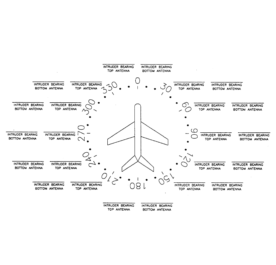
PRELIMINARY - SUBJECT TO CHANGE WITHOUT NOTICE
BKMH 880/KTA 870
Page 4-34 10609I00.ZIPCDL Rev 0, October/2000
Figure 4-1 TAS Bearing Measurements
NOTE
Bearing Error equals the heading to TCAS Ramp Tester less the relative bearing
of intruder. Relative bearing to the intruder should be a positive number mea-
sured clockwise from north on the traffic display unit.
PRELIMINARY - SUBJECT TO CHANGE WITHOUT NOTICE
BKMH 880/KTA 870
Rev 0, October/2000 10609I00.ZIPCDL Page 4-35
NOTE
The largest acceptable TAS bearing error is +/- 30° except between 135° and
225° (aft of the wings) where the error may be 45°.
11. Perform the Power and Frequency tests shown in the TAS Operator’s
Guide.
12. Perform Electromagnetic Interference (EMI) / Radio Frequency
Interference (RFI) required for STC. Determine if there is any mutual
interference with any other aircraft system.
Pass/Fail ______.
13. Determine that the system suppression is active.
14. Conduct a flight test of TAS (Required for STC) according to the
requirements of FAA Advisory Circular AC 20-ZZ, titled “Airworthiness
Approval and Operational Use of Active Traffic Advisory System
(TAS)”.
PRELIMINARY - SUBJECT TO CHANGE WITHOUT NOTICE
BKMH 880/KTA 870
Rev 0, October/2000 10609I00.ZIPCDL Page 4-36
THIS PAGE IS RESERVED
PRELIMINARY - SUBJECT TO CHANGE WITHOUT NOTICE
B
BB
BKMH 880/KTA 870
Rev 0, October/2000 10609I00.ZIPCDL TOC 5-i
SECTION V
CERTIFICATION
5.0 INTRODUCTION ................................................................................. 5-1
5.1 CERTIFICATION PROCEDURE ......................................................... 5-1
5.1.1 Equipment Compatibility ...................................................................... 5-1
5.1.2 Equipment Location ............................................................................. 5-1
5.1.3 Federal Communication Commission Rules ....................................... 5-2
5.1.4 TSO Category ..................................................................................... 5-2
5.1.5 FTZ Requirement ................................................................................ 5-2
5.1.6 FAA Requirements .............................................................................. 5-2
5.1.7 FAA Form 337 ..................................................................................... 5-3
5.1.8 Flight Manual Revision ........................................................................ 5-3
5.1.9 Pilot Briefing ........................................................................................ 5-3
PRELIMINARY - SUBJECT TO CHANGE WITHOUT NOTICE
B
BB
BKMH 880/KTA 870
Rev 0, October/2000 10609I00.ZIPCDL TOC 5-ii
THIS PAGE IS RESERVED
PRELIMINARY - SUBJECT TO CHANGE WITHOUT NOTICE
BKMH 880/KTA 870
Rev 0, October/2000 10609I00.ZIPCDL Page 5-1
SECTION V
CERTIFICATION
5.0 INTRODUCTION
This section outlines the procedures required to obtain IFR certification for the KMH 880/
KTA 870 System. Recommended flight test procedures are also included.
5.1 CERTIFICATION PROCEDURE
5.1.1 Equipment Compatibility
Careful consideration must be paid to the electrical characteristics of existing
equipment or possible additions that will be interfaced with the KMH 880/KTA
870 System, in order to ensure system compatibility. Section III of this manual
provides system planning guidelines, and defines the electrical characteristics
of the KMH 880/KTA 870 System. The installing agency should contact Honey-
well International Inc. Product Support at (800) 257-0726, for information
regarding the compatibility of equipment not listed in Section III. Normal busi-
ness hours are 8:00 AM to 5:00 PM Central Time, Monday through Friday.
The TAS system may operate in conjunction with, and in close proximity to, a
transponder. The functions of the system will not in any way degrade the per-
formance of the transponder beyond its specified limits.
All of the TAS requirements stated in this document will be met when the TAS
equipment is operating in conjunction with a compatible operating transponder,
except when the transponder is active. The active state of the transponder is
defined as the greater of the time interval between (a) the leading edge of the
first transmitted pulse of the transponder reply minus 10 microseconds and the
trailing edge of the last transmitted pulse of that reply plus 10 microseconds, or
(b) the time interval during which a mutual suppression occurs.
5.1.2 Equipment Location
The KMH 880/KTA 870 System and associated indicators, annunciators and
switches should be clearly visible and within easy reach of the pilot. Refer to
Section II of this manual for complete installation information.
PRELIMINARY - SUBJECT TO CHANGE WITHOUT NOTICE
BKMH 880/KTA 870
Page 5-2 10609I00.ZIPCDL Rev 0, October/2000
5.1.3 Federal Communication Commission Rules
The equipment will comply with all applicable rules of the Federal Communica-
tion Commission.
5.1.4 TSO Category
All aircraft, which are required by Federal Aviation Regulations to have a Ter-
rain Awareness and Warning System complying with TSO C151a Class B,
must be configured with the TSO curves. Additionally, the Alternate Audio
Menu must be selected to meet the alert/warning aural requirements of the
TSO.
5.1.5 FTZ Requirement
The KMH 880/KTA 870 system is compliant to FTZ document 17 TR 2010.
5.1.6 FAA Requirements
The installing agency should contact a local FAA Inspector (GADO, FSDO,
ACDO, MIDO, or ACO) who will determine whether the installation may be
approved by submitting FAA Form 337or whether a Supplemental Type Certifi-
cate (STC) will be required. If FAA Form 337 is determined to be sufficient, the
installing agency should determine the acceptability of the procedures defined
within this manual. If the FAA Inspector determines that an STC is required,
the installing agency will need to contact the nearest Aircraft Certification
Office (ACO) to obtain acceptable procedures.
The FAA Central Region Aircraft Certification Office, Wichita, Kansas, has on
file an approved report regarding the KMH 880/KTA 870 System. This report
contains the bench test data and DO-160D environmental test data required to
demonstrate the KMH 880/KTA 870 System’s compliance.
5.1.7 FAA Form 337
FAA Form 337 (if applicable) must be completed and submitted to the FAA. A
sample checklist is provided in the Certification Appendix of this manual.
PRELIMINARY - SUBJECT TO CHANGE WITHOUT NOTICE
BKMH 880/KTA 870
Rev 0, October/2000 10609I00.ZIPCDL Page 5-3
5.1.8 Flight Manual Revision
A Flight Manual Supplement is usually required for approval. A sample supple-
ment is provided in the Flight Manual Supplement Appendix of this manual.
The sample is to be used as a guide to acceptable content and format, and not
intended to apply to all installations. It is the responsibility of the installing
agency to prepare an appropriate Flight Manual Supplement, and obtain FAA
approval.
5.1.9 Pilot Briefing
The installing agency should carefully review the Flight Manual Supplement
and the KMH 880/KTA 870 System Operator’s Manual, P/N 006-18265-0000,
with the owner/operator of the aircraft.
PRELIMINARY - SUBJECT TO CHANGE WITHOUT NOTICE
BKMH 880/KTA 870
Page 5-4 10609I00.ZIPCDL Rev 0, October/2000
THIS PAGE IS RESERVED
PRELIMINARY - SUBJECT TO CHANGE WITHOUT NOTICE
B
BB
BKMH 880/KTA 870
Rev 0, October/2000 10609I00.ZIPCDL TOC 6-i
SECTION VI
OPERATION
6.0 INTRODUCTION..................................................................................... 6-1
PRELIMINARY - SUBJECT TO CHANGE WITHOUT NOTICE
B
BB
BKMH 880/KTA 870
Rev 0, October/2000 10609I00.ZIPCDL TOC 6-ii
THIS PAGE IS RESERVED
PRELIMINARY - SUBJECT TO CHANGE WITHOUT NOTICE
B
BB
BKMH 880/KTA 870
Rev 0, October/2000 10609I00.ZIPCDL Page 6-1
SECTION VI
OPERATION
6.0 INTRODUCTION
Refer to Section IV, of this manual, for the operating instructions for the post installation
checkout. Refer to the KMH 880/KTA 870 System Operator’s Manual P/N 006-18265-
0000, for complete operating instructions.
PRELIMINARY - SUBJECT TO CHANGE WITHOUT NOTICE
B
BB
BKMH 880/KTA 870
Page 6-2 10609I00.ZIPCDL Rev 0, October/2000
THIS PAGE IS RESERVED
PRELIMINARY - SUBJECT TO CHANGE WITHOUT NOTICE
B
BB
BKMH 880/KTA 870
Rev 0, October/2000 10609I00.ZIPCDL Page A-1
APPENDIX A
Antenna Surveillance Range
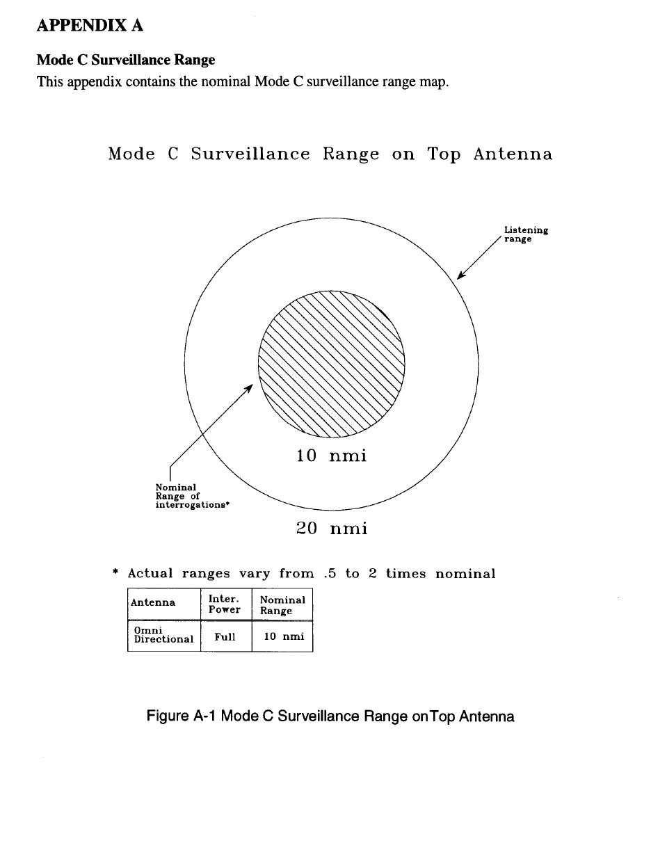
PRELIMINARY - SUBJECT TO CHANGE WITHOUT NOTICE
B
BB
BKMH 880/KTA 870
Page A-2 10609I00.ZIPCDL Rev 0, October/2000
PRELIMINARY - SUBJECT TO CHANGE WITHOUT NOTICE
B
BB
BKMH 880/KTA 870
Rev 0, October/2000 10609I00.ZIPCDL Page A-3
THIS PAGE IS RESERVED
PRELIMINARY - SUBJECT TO CHANGE WITHOUT NOTICE
B
BB
BKMH 880/KTA 870
Rev 0, October/2000 10609I00.ZIPCDL Page STC-1
APPENDIX B
STC Appendix
PRELIMINARY - SUBJECT TO CHANGE WITHOUT NOTICE
B
BB
BKMH 880/KTA 870
Page STC-2 10609I00.ZIPCDL Rev 0, October/2000
Information to be added, if required.
PRELIMINARY - SUBJECT TO CHANGE WITHOUT NOTICE
B
BB
BKMH 880/KTA 870
Rev 0, October/2000 10609I00.ZIPCDL Page CERT-1
APPENDIX C
CERTIFICATION APPENDIX
SAMPLE CERTIFICATION CHECKLIST
PRELIMINARY - SUBJECT TO CHANGE WITHOUT NOTICE
B
BB
BKMH 880/KTA 870
Page CERT-2 10609I00.ZIPCDL Rev 0, October/2000
THIS PAGE IS RESERVED
PRELIMINARY - SUBJECT TO CHANGE WITHOUT NOTICE
B
BB
BKMH 880/KTA 870
Rev 0, October/2000 10609I00.ZIPCDL Page CERT-3
SAMPLE CERTIFICATION CHECKLIST
AIRCRAFT MAKE: _______________________________
AIRCRAFT MODEL: _______________________________
AIRCRAFT SERIAL NUMBER: _______________________________
AIRCRAFT REGISTRATION NUMBER: _______________________________
DATE WORK COMPLETED: _______________________________
A. Installed the KMH 880/KTA 870 System in accordance with Unit Installation Manual
number 006-10609-000_, Revision ____, dated __________, and has been flight
tested in accordance with AC20-ZZ (draft), to verify proper operation and accuracy for
a follow-on IFR approval. Original IFR approval was accomplished by STC
____________, Master Drawing List number _________, specifications of TSO-C147
and TSO-C151a.
B. Ground and flight tests were conducted and determined that the KMH 880/KTA 870
System does not interfere with normal operation of other equipment installed in the
aircraft, and the KMH 880/KTA 870 System equipment is not a source of objection-
able electromagnetic interference. Proper operation and accuracy were verified, and
the unit functions properly and safely in accordance with the manufacturer’s specifica-
tions.
C. The unit was mounted in rack location for avionics provided by the manufacturer and
is sufficient to ensure the restraint of the equipment when subjected to emergency
landing loads.
D. Installed an FAA Approved Flight Manual Supplement in the aircraft manual and a
Operator’s Manual, part number 006-18265-0000, Revision _____, dated ________,
in the aircraft. Weight, balance and equipment list changes have been made in the
aircraft flight manual.
PRELIMINARY - SUBJECT TO CHANGE WITHOUT NOTICE
B
BB
BKMH 880/KTA 870
Page CERT-4 10609I00.ZIPCDL Rev 0, October/2000
THIS PAGE IS RESERVED
PRELIMINARY - SUBJECT TO CHANGE WITHOUT NOTICE
B
BB
BKMH 880/KTA 870
Rev 0, October/2000 10609I00.ZIPCDL D-1
APPENDIX D
DIAGNOSTIC APPENDIX
PRELIMINARY - SUBJECT TO CHANGE WITHOUT NOTICE
B
BB
BKMH 880/KTA 870
D-2 10609I00.ZIPCDL Rev 0, October/2000
THIS PAGE IS RESERVED

PRELIMINARY - SUBJECT TO CHANGE WITHOUT NOTICE
B
BB
BKMH 880/KTA 870
Rev 0, October/2000 10609I00.ZIPCDL D-3
DIAGNOSTIC APPENDICES
TASDIAG-TAS Processor Field Diagnotic Program User Instructions
WARNING: DO NOT USE THE “TASDIAG PROCESSOR FIELD DIAGNOSTIC
PROGRAM” WHILE AIRBORNE. THE PROGRAM IS USED ONLY WHILE THE AIR-
CRAFT IS ON THE GROUND. THE SYSTEM IS DEGRADED TO PERFORM MAINTE-
NANCE FUNCTIONS AND IS NOT AIRWORTHY WHILE RUNNING THE DIAGNOSTIC
SOFTWARE.
NOTE
The diagnostic tests are performed with KMH 880/KTA 870
installed in the aircraft.
PRELIMINARY - SUBJECT TO CHANGE WITHOUT NOTICE
B
BB
BKMH 880/KTA 870
D-4 10609I00.ZIPCDL Rev 0, October/2000
THIS PAGE IS RESERVED

PRELIMINARY - SUBJECT TO CHANGE WITHOUT NOTICE
B
BB
BKMH 880/KTA 870
D-5 10609I00.ZIPCDL Rev 0, October/2000
____________________________________________________________________
Honeywell International Inc. P/N 700-01055-0000
TAS Diag for Windows User Manual Revision-
Page 1 of 18
PRELIMINARY - SUBJECT TO CHANGE WITHOUT NOTICE
B
BB
BKMH 880/KTA 870
D-6 10609I00.ZIPCDL Rev 0, October/2000
THIS PAGE IS RESERVED
____________________________________________________________________
Honeywell International Inc. P/N 700-01055-0000
TAS Diag for Windows User Manual Revision-
Page 2 of 18
PRELIMINARY - SUBJECT TO CHANGE WITHOUT NOTICE
B
BB
BKMH 880/KTA 870
D-7 10609I00.ZIPCDL Rev 0, October/2000
Table of Contents
1. Introduction.........................................................................................................4
2. Computer Requirements ....................................................................................4
3. Installing the TAS Diag Program.........................................................................4
4. Starting TAS Diag ...............................................................................................5
4.1 TAS Diag. Demonstration Mode ................................................................6
5. Inspecting Current Processor I/O Data...............................................................6
5.1 Snapshot View...........................................................................................6
5.2 Continous View .........................................................................................7
6. Inspecting TAS Unit’s Internal Diagnostic and Log Data....................................7
7. Configuration Module Options ...........................................................................7
7.1 View Strap Data.........................................................................................7
7.2 Modify Strap Data......................................................................................8
7.3 Save to Text File ........................................................................................9
7.4 Save to Binary File ....................................................................................9
7.5 Copy from Binary File................................................................................9
7.6 Initialize Config Module .............................................................................10
8. Intruder Data ......................................................................................................10
8.1 Overwrite View ..........................................................................................12
8.2 Capture View .............................................................................................12
9. Viewing Cable Calibration Data..........................................................................12
10.Viewing Current System Status..........................................................................13
11.TAS S/W Info ......................................................................................................14
12 Ramp Tester Mode .............................................................................................14
13 Suggestions and Hints........................................................................................14
13.1 TAS Diag Doesn’t Communicate with TAS Unit .......................................14
____________________________________________________________________
Honeywell International Inc. P/N 700-01055-0000
TAS Diag for Windows User Manual Revision-
Page 3 of 18
PRELIMINARY - SUBJECT TO CHANGE WITHOUT NOTICE
B
BB
BKMH 880/KTA 870
Rev 0, October/2000 10609I00.ZIPCDL D-8
1. Introduction
The TAS Processor Field Diagnostics Program (TAS Diag) provides an interface to
the KMH 820/KTA 810 (TAS Processor Unit). The following information may be
retrieved from the TAS Unit via TAS Diag:
- I/O data (straps, attitude, altitude, etc.),
-TAS’s internal Diagnostic and Log File,
- Configuration module straps,
- Currently tracked intruder data (range, altitude, bearing, etc.),
- Cable calibration data,
- Current system status (fault LED reading and description).
TAS Diag for Windows has four different diagnostic windows:
•Main Diagnostic Window
•IO Continuous Window
•Intruder Data Window
•System Status Window
All data may be written to a user-specified file by clicking Save from the File menu.
The active (selected) window will be saved.
A TAS Diag demonstration mode, in which no RS-232 communications are present,
is available for familiarizing the user with the program. Select Demo Mode from the
File menu.
This document is an operations manual for TAS Diag, providing tips and techniques
enabling TAS Diag to be a useful tool in installation and/or troubleshooting KMH
820/KTA 810 TAS P{rocessors.
The following Part Numbers identify the TAS Diag program and documentation:
700-01055-0000 User Manual (this documentation)
731-30007-0000 CD-ROM containing TAS Diag for Windows and User Manual
____________________________________________________________________
Honeywell International Inc. P/N 700-01055-0000
TAS Diag for Windows User Manual Revision-
Page 4 of 18
PRELIMINARY - SUBJECT TO CHANGE WITHOUT NOTICE
B
BB
BKMH 880/KTA 870
D-9 10609I00.ZIPCDL Rev 0, October/2000
2. Computer Requirements
The TAS Diag program requires a personal computer with a CD_ROM running
Microsoft Windows 95, Windows 98, or Windows NT 4.0 or above WINDOWS
2000???. The user should be familiar with running Windows programs.
3. Installing the TAS Diag Program
1. Insert the TAS Diag CD into your CD-ROM drive.
2. Select the “Start” button then “Run”.
3. In the Command Line Box, type the letter of the drive that contains the TAS
Diag CD, acolon, a backslash, and the word setup. For example, Type:
d:\setup
4. Click the OK button.
5. Follow the instructions that appear on the screen.
If Setup prompts you to replace some of the system files with newer ver-
sions:
•Select OK, then Yes when prompted to restart Windows.
•After Windows restarts, repeat steps 1 through 5.
A Program Group called “TAS Diag” should have been created.
4. Starting TAS Diag
The TAS Diag program may be started at any time. If the TAS unit is currently pow-
ered on, TAS Diag will automatically establish communications. If the TAS unit is not
currently powered on, TAS Diag will continuously attempt to establish communica-
tions until communication is established or the Cancel button is pressed. Once com-
munications are established and the TAS unit has completed initialization, TAS Diag
will accept user input.
NOTE
If the TAS unit is powered on but communications are not being established, ensure
that the computer’s COM port is connected to the TAS unit’s RS-232 diagnostics
port. If the computer has more than one COM port, determine which one is con-
nected and check TAS Diag COM port properties
The TAS Diag program is started by selecting the “TAS Diag for Windows” icon in
the “Start-Programs-TAS Diag’ group.
____________________________________________________________________
Honeywell International Inc. P/N 700-01055-0000
TAS Diag for Windows User Manual Revision-
Page 5 of 18

PRELIMINARY - SUBJECT TO CHANGE WITHOUT NOTICE
B
BB
BKMH 880/KTA 870
Rev 0, October/2000 10609I00.ZIPCDL D-10
Once communications are established and the TAS unit has completed initialization,
theTAS Diag main screen appears (see Figure 1). The main window consists of a
menu bar and button bar at the top and TAS Processor specific information at the
bottom of the window. The processor specific information consists of the TAS Pro-
cessor serial number, software version, hardware version (if available), and the
Engineering software version.
Figure 1 Main Window
The menu and button bars contain the available options for the TAS Diag program.
WARNING
TAS Diag is not intended for use during flight.
____________________________________________________________________
Honeywell International Inc. P/N 700-01055-0000
TAS Diag for Windows User Manual Revision-
Page 6 of 18
PRELIMINARY - SUBJECT TO CHANGE WITHOUT NOTICE
B
BB
BKMH 880/KTA 870
D-11 10609I00.ZIPCDL Rev 0, October/2000
4.1 TAS Diag Demonstration Mode
The TAS Diag program contains a demonstration mode (in the file menu) which is
useful for familiarizing the user with available options. The demonstration mode
does not require an RS-232 connection to a TAS unit. Any option may be selected,
and a simulation TAS unit response will occur.
5. Inspecting Current Processor I/O Data
There are two options for inspecting the TAS unit’s I/O data: single snapshot or con-
tinuous ( see Figure 2).
Figure 2 I/O Data View Continuous Window
5.1 Snapshot View
On the I/O Data menu, click Snapshot View to request a snapshot ( one time) of
the I/O Data. The TAS unit sends the data to the “Main Diagnotic Window”.
____________________________________________________________________
Honeywell International Inc. P/N 700-01055-0000
TAS Diag for Windows User Manual Revision-
Page 7 of 18
PRELIMINARY - SUBJECT TO CHANGE WITHOUT NOTICE
B
BB
BKMH 880/KTA 870
Rev 0, October/2000 10609I00.ZIPCDL D-12
5.2 Continuous View
On the I/O Data Menu, click Continuous View to request continuous updates of
the I/O data. Continuous mode is the single snapshot repeated every one to two
seconds. The TAS unit sends the data to the “I/O Continuous Window”. A slight
screen flicker will be noticeable as each new screen of data is written. The red Stop
button on the button bar will be enabled as long as communications are on going
and the window is being updated. To stop the update, click the Stop button.
6. Inspecting TAS Unit’s Internal Diagnostic and Log Data
On the Diag Log Menu, click View Log to request the TAS unit’s Internal Diagnotic
and Log Data. The TAS unit sends the data to the “Main Diagnostic Window” ( see
Figure 3).
Figure 3 Diagnostic and Log Data Window
____________________________________________________________________
Honeywell International Inc. P/N 700-01055-0000
TAS Diag for Windows User Manual Revision-
Page 8 of 18
PRELIMINARY - SUBJECT TO CHANGE WITHOUT NOTICE
B
BB
BKMH 880/KTA 870
D-13 10609I00.ZIPCDL Rev 0, October/2000
NOTE
Failures for the current power cycle are not in the Diagnostic and Log Data, since
the Log is written at the end of each power cycle.
7. Configuration Module Options
The user will be offered options to view the strap data, modify the strap data, save to
a text file, save to a binary file, copy from a binary file, and initialize the configuration
module.
7.1 View Strap Data
This option allows the user to view the current strap settings in an easy to read lay-
out. The TAS unit sends the data to the “Main Diagnostic Window” ( see Figure 4).
Figure 4 View Strap Data Window
____________________________________________________________________
Honeywell International Inc. P/N 700-01055-0000
TAS Diag for Windows User Manual Revision-
Page 9 of 18
PRELIMINARY - SUBJECT TO CHANGE WITHOUT NOTICE
B
BB
BKMH 880/KTA 870
Rev 0, October/2000 10609I00.ZIPCDL D-14
7.2 Modify Strap Data
The strap data is read from the TAS unit and displayed in a dialog box ( see Figure
5). The dialog box has two pages, Strap Page 1 and Strap Page 2. Click on the top
of each page to view/modify the different straps. The user may modify any of the
straps by selecting the desired configuration. The selections are made using list
boxes and radio buttons. Click the down arrow on the list boxes and click the desired
configuration. For radio buttons, click the desired configuration button.
Once the user is satisfied with the strapping, click the OK button and the user will be
prompted as to whether or not to write the data to the configuration module. Click
the cancel button to exit without saving changes.
If the user opts to write the data to the configuration module, a message window will
appear informing the user that the data is being written, the TAS unit is resetting,
and the user should wait until the initialization is complete. When the TAS unit is ini-
tialized, a message will be displayed in the window. At this point the user may click
the OK button to continue.
Figure 5 Modify Straps Window
____________________________________________________________________
Honeywell International Inc. P/N 700-01055-0000
TAS Diag for Windows User Manual Revision-
Page 10 of 18
PRELIMINARY - SUBJECT TO CHANGE WITHOUT NOTICE
B
BB
BKMH 880/KTA 870
D-15 10609I00.ZIPCDL Rev 0, October/2000
7.3 Save to Text File
This option creates a specific file containing the configuation module’s strap and
bearing correction data. The file will have a header containing the TAS unit’s serial
number, the software version, the current PC date, and the current PC time. The file
will be an ASCII text file.
7.4 Save to Binary File
This option allows the user to save configuration module set-ups and recall them at
a later time, if needed ( see section ). The user will be prompted for a brief descrip-
tion to be attached to the binary file. File names of the format:
TASCFG.xxx,
where xxx is from 000 to 999 are created in the current PC directory.
7.5 Copy from Binary File
This option allows the user to program the configuration module with data previously
stored in a binary file ( see section ). When this option is selected, a window allow-
ing access to all binary file names in the current PC directory is displated ( see Fig-
ure 6 ). When a file is clicked, the description entered when it was saved is
displayed in the File Description Field. When a file is selected ( by clicking the open
button ), the user is prompted for the data to be written to the configuration module.
If the user opts to write the data to the configuration module, a message window will
appear informing the user that the data is being written, the TAS unit is resetting,
and the user should wait until the initialization is complete. When the TAS unit is ini-
tialized, a message will be displayed in the window for the user. At this point the
user may click the OK button to continue.
____________________________________________________________________
Honeywell International Inc. P/N 700-01055-0000
TAS Diag for Windows User Manual Revision-
Page 11 of 18
PRELIMINARY - SUBJECT TO CHANGE WITHOUT NOTICE
B
BB
BKMH 880/KTA 870
Rev 0, October/2000 10609I00.ZIPCDL D-16
Figure 6 Copy Binary File Window
7.6 Initialize Config Module
This option sets the configuration module’s strap data to default values. The user
must view both Strap Pages ( see Modify Strap Data ) to verify/modify the configura-
tion. The user may click the Cancel button at any time to end the initialization pro-
cess without actually writing to the configuration module.
When the Strap configuration is complete, click the OK button to save it to the con-
figuration module.
____________________________________________________________________
Honeywell International Inc. P/N 700-01055-0000
TAS Diag for Windows User Manual Revision-
Page 12 of 18
PRELIMINARY - SUBJECT TO CHANGE WITHOUT NOTICE
B
BB
BKMH 880/KTA 870
D-17 10609I00.ZIPCDL Rev 0, October/2000
8. Intruder Data
There are two options for viewing tracked intruder data ( currently under TAS sur-
veillance ). Overwrite View and Capture View ( see Figure 7).
Figure 7 Intruder Data Window
The following information is presented to the user:
TISI-- This is the number of interrogation update periods the TAS unit has
been through since power up.
survno-- This is the unique internal surveillance number assigned to an
intruder. This number remains assigned to an intruder the entire
time that it is under surveillance.
bear-- The bearing ( in degrees ) of the intruder relative to own aircraft.
0 degrees is at the 12 o’clock position, 90 degrees is at the 3 o’clock
position, 180 ( or - 180 ) degrees is at the 6 o’clock position, and - 90
is at the 9 o’clock position. A series of -----’s indicates that a bearing
could not be determined for the intruder.
____________________________________________________________________
Honeywell International Inc. P/N 700-01055-0000
TAS Diag for Windows User Manual Revision-
Page 13 of 18
PRELIMINARY - SUBJECT TO CHANGE WITHOUT NOTICE
B
BB
BKMH 880/KTA 870
Rev 0, October/2000 10609I00.ZIPCDL D-18
range-- The slant range from own aircraft to the intruder in nautical miles.
alt-- The intruder’s altitude in feet (MSL). A series of -----’s indicates that
the intruder is non-altitude reporting (NAR).
Ant-- This is an indication of the antenna on which the intruder is being
surveilled. A ‘T’ indicates the top antenna, while a ‘B’ indicates the
bottom antenna.
power-- The measure power of the last received from the intruder. A power
of 255 indicates no reply was received from the intruder. A power of
zero indicates that a power and/or bearing could not be computed
for the intruder during the current TISI.
8.1 Overwrite View
On the Intruder Data Menu, click Overwrite View. The user is prompted for the
maximum range in nautical miles-- this allows the user to limit the range at which
intruders are displayed.
When this option is selected, the intruder information is erased before each update
is sent to the screen. It is updated at approximately one TISI per second. To stop
the update, click the Stop button on the button bar.
8.2 Capture View
On the Intruder Data Menu, click Capture View. This option allows the user to cap-
ture specified number of TISI’s of data. The number of TISIs to be captured is
entered, then the maximum range is requested (see Overwrite). When the number
of TISIs have been captured, the updates are stopped. If the stop button on the but-
ton bar is clicked, the updates will also stop before completion of the specified num-
ber of TISIs.
____________________________________________________________________
Honeywell International Inc. P/N 700-01055-0000
TAS Diag for Windows User Manual Revision-
Page 14 of 18
PRELIMINARY - SUBJECT TO CHANGE WITHOUT NOTICE
B
BB
BKMH 880/KTA 870
D-19 10609I00.ZIPCDL Rev 0, October/2000
9. Viewing Cable Calibration Data
Cable calibrations are performed periodically by the TAS unit so that bearings may
be computed as accurately as possible. This option allows the user to view the
results of the most recent cable calibration and causes the cable calibrations to be
performed at an accelerated rate. Cable calibrations are normally spaced at two
minute intervals, but this option causes the spacing between the end of one cable
calibration and the start of the next to be 10 seconds. An internal TAS unit variable
that displays messages on retries and/or errors is enabled. A cable calibration
sequence for a dual directional system requires about 24 seconds to complete, so a
new cable calibration summary will be displayed every 34 seconds. To view the
cable calibration data, View Data on the Cable Cal Menu (see Figure 8).
Figure 8 Cable Calibration Data Window
____________________________________________________________________
Honeywell International Inc. P/N 700-01055-0000
TAS Diag for Windows User Manual Revision-
Page 15 of 18
PRELIMINARY - SUBJECT TO CHANGE WITHOUT NOTICE
B
BB
BKMH 880/KTA 870
Rev 0, October/2000 10609I00.ZIPCDL D-20
NOTE
The second cable calibration summary could take as long as 2 minutes and 34
seconds before being displayed, due to the nature of the multi-tasking environment
of the TAS unit and the method by which tasks are delayed.
10 Viewing Current System Status
This option allows the user to view the current TAS unit system status without hav-
ing to try to read the LEDs located on the side or front of the TAS unit (see Figure
9). This data may be viewed two different ways; Overwrite or Continuously. The sta-
tus is updated every second or two. The system’s status is indicated along with the
state of the LED indicator. When a fault occurs, a brief description is added to the
LED fault information. To stop the update, click the Stop button on the button bar.
In the Overwrite mode, the data is erased before each update. For the overwrite
mode, click Overwrite View on the Sys Status Menu. For continuously, click Con-
tinuous View on the Sys Status Menu.
Figure 9 System Status Window
____________________________________________________________________
Honeywell International Inc. P/N 700-01055-0000
TAS Diag for Windows User Manual Revision-
Page 16 of 18
PRELIMINARY - SUBJECT TO CHANGE WITHOUT NOTICE
B
BB
BKMH 880/KTA 870
D-21 10609I00.ZIPCDL Rev 0, October/2000
11. TAS S/W Info
This option allows the user to retrieve TAS unit specific software (see Figure 10).
Figure 10 TAS S/W Window
12. Ramp Tester Mode
This option turns on the P2 pulse of TAS ATCRBS interrogations so a IFR 401B
ramp tester can be used to reply to the TAS unit. To turn this option on or off, click
Ramp Tester Mode on the File Menu. When the option is on, a check mark
appears to the left of Ramp Tester Mode on the File Menu.
____________________________________________________________________
Honeywell International Inc. P/N 700-01055-0000
TAS Diag for Windows User Manual Revision-
Page 17 of 18
PRELIMINARY - SUBJECT TO CHANGE WITHOUT NOTICE
B
BB
BKMH 880/KTA 870
Rev 0, October/2000 10609I00.ZIPCDL D-22
13. Suggestions and Hints
Below is a list of some of the problems that have been encountered to date along
with possible solutions and/or work-arounds.
13.1 TAS Diag doesn’t Communicate with the TAS unit.
If TAS Diag can not establish communications with the TAS unit, the first thing to
check is the Comm port to which the RS-232 is connected. The RS-232 setting on
the File-Properties dialog box should not be changed. However, the Comm (serial)
port needs to be selected for the port connected to the TAS unit. Usually ‘Comm 1’
is the correct port. If you have several ports you may have to experiment by chang-
ing the Comm Port setting.
Some Laptops use Comm 1 for Modems and Infrared Sensors. If this is the case
and you have only one serial port, you will need to disable the device using the
Comm Port and enable it for external communications. This is usually done in the
“My Computer” properties or in the BIOS setting. You should call your computer
manufacturer if you can not free up the port.
____________________________________________________________________
Honeywell International Inc. P/N 700-01055-0000
TAS Diag for Windows User Manual Revision-
Page 18 of 18
PRELIMINARY - SUBJECT TO CHANGE WITHOUT NOTICE
B
BB
BKMH 880/KTA 870
Rev 0, October/2000 10609I00.ZIPCDL TSO-1
TSO APPENDIX
ENVIRONMENTAL QUALIFICATION FORM
PRELIMINARY - SUBJECT TO CHANGE WITHOUT NOTICE
B
BB
BKMH 880/KTA 870
TSO-2 10609I00.ZIPCDL Rev 0, October/2000
THIS PAGE IS RESERVED

PRELIMINARY - SUBJECT TO CHANGE WITHOUT NOTICE
B
BB
BKMH 880/KTA 870
Rev 0, October/2000 10609I00.ZIPCDL TSO-3
RTCA DO-160D
ENVIRONMENTAL QUALIFICATION FORM
NOMENCLATURE: KTA 810 Remote Mount Traffic Advisory Unit
KMH 820 Remote Mount Multi-Hazard Awareness Unit
CM 805 TAS / GPWS Configuration Module
PART NUMBER: 066-01152-0101 KTA 810
066-01175-0101 KMH 820 w/o GPS
066-01175-2101 KMH 820 w/ GPS
071-00112-0100 CM 805
050-03361-0000 Installation Kit
047-12545-0003 Mounting Tray
TSO NUMBER: C147 (Class A), C151a (Class B)
MANUFACTURER’S SPECIFICATION: MPS 004-02050-4000
MANUFACTURER: Honeywell International Inc.
ADDRESS: One Technology Center
23500 W. 105th Street
Olathe, KS 66061 USA
Temperature and Altitude 4.0 Category A2D2
Low Temperature 4.5.1 (Low Temp. -55°C)
High Temperature 4.5.2 &4.5.3 (High Temp. +70°C)
In-Flight Loss of Cooling 4.5.4 Category X (Not Tested)
Altitude 4.6.1 (Alt. tested to 51,500 feet)
Decompression 4.6.2 (Decomp., 8K to 51.5K < 15 sec.)
Overpressure 4.6.3 (Overpressure, 170 kPa)
Temperature Variation 5.0 Category B
Humidity 6.0 Category A
Shock (operational & crash safety) 7.0 Category B
Vibration 8.0 Category S (curves B & M)
(See Notes 1, 2, &3)
Explosion 9.0 Category X, (Not Tested)
Waterproofness 10.0 Category X (Not Tested)
Fluids Susceptibility 11.0 Category X (Not Tested)
Sand and Dust 12.0 Category X (Not Tested)
Fungus 13.0 Category X (Not Tested)
Salt Spray 14.0 Category X (Not Tested)
Magnetic Effect 15.0 Class A
CONDITIONS DO-160D SECTION DESCRIPTION OF CONDUCTED TESTS

PRELIMINARY - SUBJECT TO CHANGE WITHOUT NOTICE
B
BB
BKMH 880/KTA 870
TSO-4 10609I00.ZIPCDL Rev 0, October/2000
Power Input 16.0 Category BZ
Voltage Spike Conducted 17.0 Category A
Audio Frequency Conducted Susceptibility 18.0 Category BZ
Induced Signal Susceptibility 19.0 Category A
Radio Frequency Susceptibility 20.0 Category RRR (See Note 4)
Radio Frequency Emission 21.0 Category L
Lightning Induced Transient Susceptibility 22.0 Category A3E3 (See note 5)
Lightning Direct Effects 23.0 Category 1B
Icing 24.0 Category X (Not Tested)
ESD 25.0 Category A
Notes:
1. Vibration Critical Frequencies – The following critical frequencies are mechanical resonances of the unit under
test that have peak acceleration amplitudes greater than twice the input acceleration amplitude. Observed
changes in performance of the unit under test are to be determined (TBD).
2. Observed changes in the above resonant frequencies during the test are to be determined.
3. The unit shall comply with DO-160C, vibration category N and Y for helicopters.
4. RF susceptibility degradation information placed here if applicable.
5. The unit shall comply with A3E3 on all signal lines and A4E4 on the power leads.
Honeywell International Inc. P/N 004-02050-4800
Environmental Qualification Form Revision -
Vertical
(Top to Bottom)
Longitudinal
(Front to Back)
Lateral
(Side to Side)
TBD TBD TBD

PRELIMINARY - SUBJECT TO CHANGE WITHOUT NOTICE
B
BB
BKMH 880/KTA 870
Rev 0, October/2000 10609I00.ZIPCDL TSO-5
REVISION HISTORY
Revision PRN/CO # Description of Change Date
- PRN ______ Original Issue TBD
Honeywell International Inc. P/N 004-02050-4800
Environmental Qualification Form Revision -
PRELIMINARY - SUBJECT TO CHANGE WITHOUT NOTICE
B
BB
BKMH 880/KTA 870
TSO-6 10609I00.ZIPCDL Rev 0, October/2000
THIS PAGE IS RESERVED