Honeywell KX165A KX165A VHF Navigation / Communications Transceiver User Manual Installation Manual
Honeywell International Inc. KX165A VHF Navigation / Communications Transceiver Installation Manual
UserManual.wiki
>
Honeywell
>
KX165A User Manual
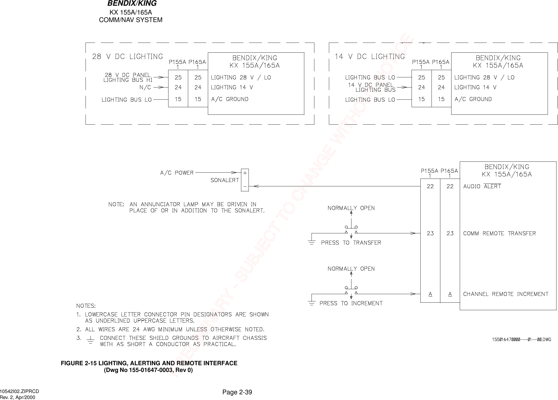
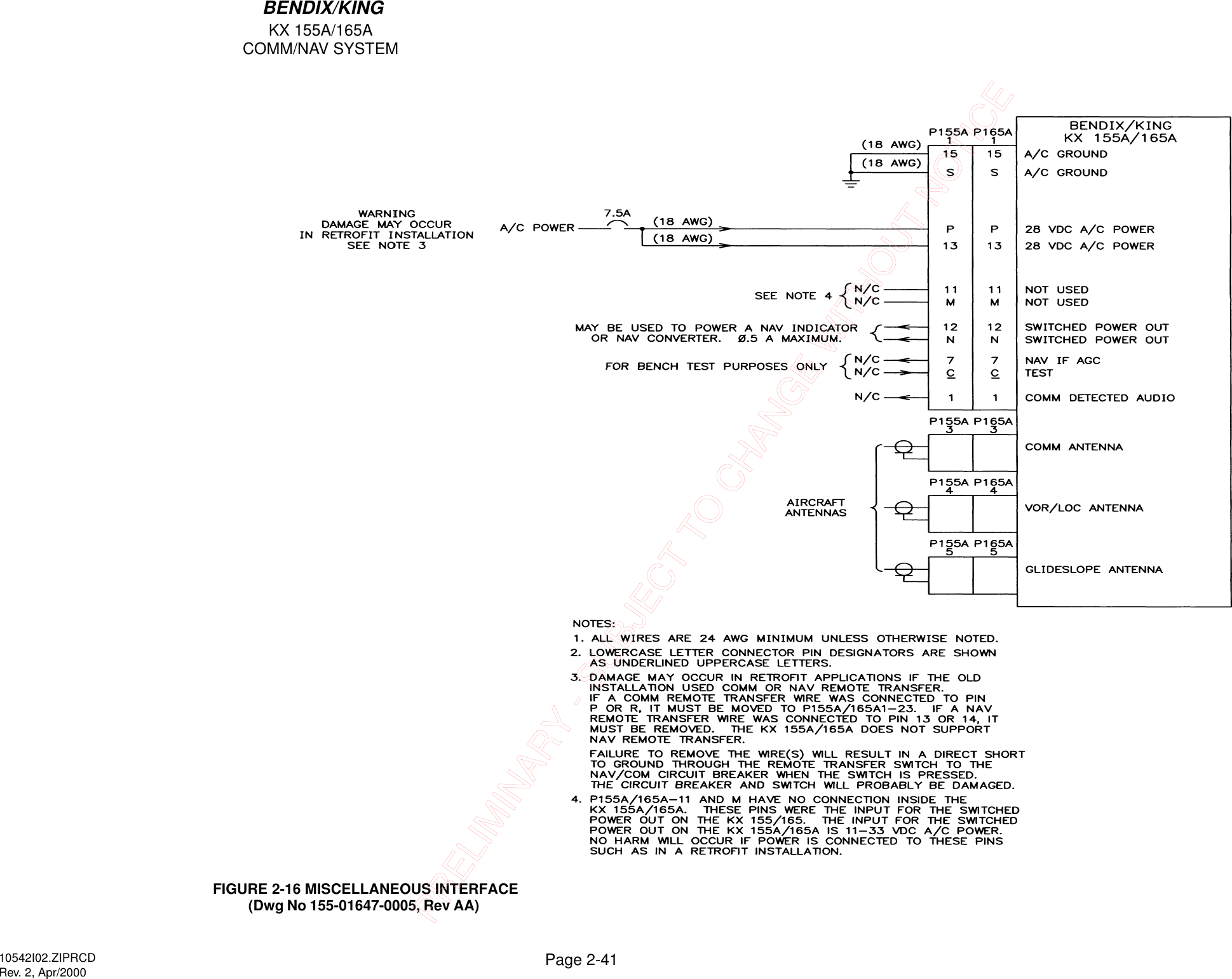
Installation Manual
Navigation menu
Upload a User Manual
Namespaces
Wiki Guide
HTML
PDF
Info
Views
User Manual
Discussion / Help
Navigation