Honeywell KX165A KX165A VHF Navigation / Communications Transceiver User Manual Installation Manual
Honeywell International Inc. KX165A VHF Navigation / Communications Transceiver Installation Manual
Installation Manual

INSTALLATION MANUAL
KX 155A/165A
COMM/NAV SYSTEM
MANUAL NUMBER 006-10542-0002
REVISION 2, APRIL 2000
PRELIMINARY - SUBJECT TO CHANGE WITHOUT NOTICE
WARNING
Prior to Export of this Document, review for export license requirement is needed.
COPYRIGHT NOTICE
©2000 Honeywell International Inc.
Reproduction of this publication or any portion thereof by any means without the express written
permission of Honeywell is prohibited. For further information contact the Manager, Technical
Publications, Honeywell, One Technology Center, 23500 West 105th Street Olathe KS 66061
Telephone: (913) 782-0400.
PRELIMINARY - SUBJECT TO CHANGE WITHOUT NOTICE
BENDIX/KING
KX 155A/165A
COMM/NAV SYSTEM
10542I02.ZIPRCD Page 1-1
Rev 2, Apr/2000
SECTION I
GENERAL INFORMATION
1.1 INTRODUCTION
This manual contains information relative to the physical, mechanical, and electrical characteris-
tics of the Bendix/King Silver Crown KX155A VHF COMM Transceiver/Navigation/VOR/LOC
Glideslope Receiver. Installation and operating procedures are also included.
Information relative to the maintenance, alignment, and procurement of replacement parts may be
found in the KX155A Maintenance/Overhaul Manual, P/N 006-15542-XXXX.
1.2 EQUIPMENT DESCRIPTION
The KX155A is a VHF NAV/COMM Transceiver which provides the following functions.
A. Two-way voice communication within the frequency range of 118.00 MHz to
136.975 MHz (760 Channels) in 25 kHz increments.
B. Reception of navigation signals within the frequency range of 108.00 MHz to
117.95 MHz in 50 kHz increments (200 channels).
C. Optional reception of glideslope signals within the frequency range of 329.15
MHz to 335.00 MHz in 150 kHz increments (40 channels).
D. High level speaker audio output plus limited audio intercom inputs and out-
puts.
E. Provides a count down timer.
The KX155A is a panel mounted unit. Connections to the unit are made through one 36 and one
50 pin Molex printed circuit board edge connector and three BNC coax connectors at the rear of
the unit.
Electrically, the KX155A consists of the following sections:
•COMM Transmitter
•COMM Receiver
•NAV Receiver
•Main Board
•Glideslope Receiver and Converter (Optional)
•Gas Discharge Display
•4 Ω Audio Amplifier
The KX155A is backward compatible with existing KX155 installations. See Section 2.3 Additional
Installation Notes for details.
PRELIMINARY - SUBJECT TO CHANGE WITHOUT NOTICE

BENDIX/KING
KX 155A/165A
COMM/NAV SYSTEM
Page 1-2 10542I02.ZIPRCD
Rev 2, Apr/2000
1.3 TECHNICAL CHARACTERISTICS
Table 1-1 KX155A/KX165A Technical Specifications
KX155A/KX165A GENERAL SPECIFICATIONS
ENVIRONMENTAL TSO COMPLI-
ANCE: RTCA DO-160C, Eurocae ED-14C Env Cat (see Appendix
E)
TEMPERATURE RANGE: -20°C to +55°C with short time operation at +70°C.
(Operational to -40°C)
ALTITUDE: -15,000 feet to 50,000 feet
WEIGHT:
KX 155A VERSIONS WEIGHT Mtg Rack
(nominal) w/hardware
069-01032-0101 4.2 lbs (1.9 kg) 1.1 lbs (0.5 kg)
069-01032-0201 3.7 lbs (1.7 kg) 1.1 lbs (0.5 kg)
VERSIONS WEIGHT Mtg Rack
(nominal) w/hardware
KX 165A 069-01033-0101 4.0 lbs (1.8 kg) 1.1 lbs (0.5 kg)
069-01033-0201 4.0 lbs (1.8 kg) 1.1 lbs (0.5 kg)
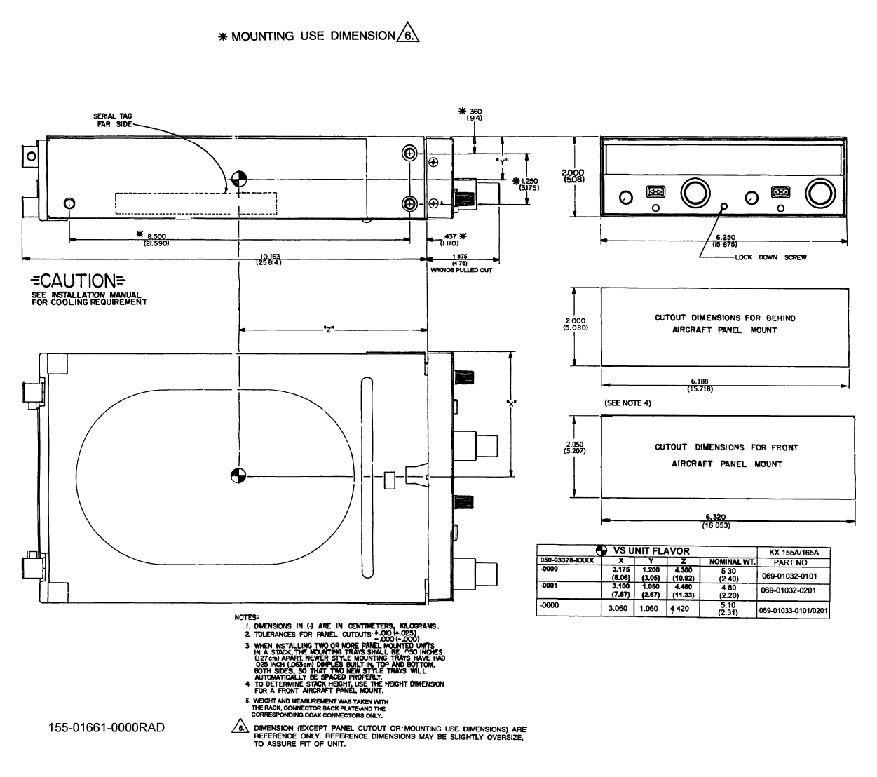
PHYSICAL DIMENSIONS
(NOMINAL) :
Width: 6.25 inches (15.875 cm)
Height: 2.00 inches (5.08 cm)
Depth: 10.16 inches (25.81 cm) to end of connector
MOUNTING: Panel mounted, no shock mounting required
POWER CONSUMPTION:
RECEIVE TRANSMIT
VERSIONS: TYP. PEAK
PRELIMINARY - SUBJECT TO CHANGE WITHOUT NOTICE

BENDIX/KING
KX 155A/165A
COMM/NAV SYSTEM
10542I02.ZIPRCD Page 1-3
Rev 2, Apr/2000
069-01032-0101 0.8 A 2.2 A 6.0 A (MAX)
069-01032-0201 0.8 A 2.2 A 6.0 A (MAX)
069-01033-0101 0.6 A 0.7 A 4.0 A (MAX)
069-01033-0201 0.6 A 0.7 A 4.0 A (MAX)
NOTE: Peak currents occur only when installation is configured for the 4Ω audio output & both
COMM and NAV volumes are adjusted to full.
Specifications are at 25°C unless otherwise specified.
COMM TRANSCEIVER
TSO COMPLIANCE:
Transmit: C37d (DO-186A, Class 4 - all flavors/
Class 4 & 6 069-01033-0201)
Receive: C38d (DO-186A, Class C & D - all flavors/
Class C, D, & E 069-01033-0201)
APPLICABLE DOCUMENTS: RTCA DO-186A, DO-160C,
*EUROCAE ED-23B, ED-14C
DUTY CYCLE: 10%, 4.5 minutes receive, 0.5 minutes transmit
FREQUENCY RANGE: 118.000 MHz to 136.975 MHz
COMM TRANSMITTER
POWER OUTPUT: 10 Watts minimum
10 Watts typical (KX 155A pre-Mod 5)
MODULATION: 70% minimum modulation capability with less than 15%
distortion. Audio leveling circuit used.
SIDETONE OUTPUT: Adjustable up to 100 mW ( 5.1 mW Mod 1 w/o Mod 6) into
500 Ω headphones
MICROPHONE: Standard carbon or dynamic mic containing transistorized
pre-amp. (Must provide 100 mVrms into 100 Ω load.)
PRELIMINARY - SUBJECT TO CHANGE WITHOUT NOTICE

BENDIX/KING
KX 155A/165A
COMM/NAV SYSTEM
Page 1-4 10542I02.ZIPRCD
Rev 2, Apr/2000
HARMONIC CONTENT: -56 dBc, minimum. Typically greater than -60 dBc
HIGH TEMPERATURE PROTEC-
TION: If the transmitter and modulator circuits become hot
enough to potentially damage any components in the
transceiver, a protection circuit will automatically reduce
the transmitter power consumption and output power.
TRANSMITTER TIME OUT: If MIC key is enabled for greater than 30 ( Nominal) sec-
onds, the transmitter will shut down. The transmitter is re-
set upon release of MIC key.
PRELIMINARY - SUBJECT TO CHANGE WITHOUT NOTICE

BENDIX/KING
KX 155A/165A
COMM/NAV SYSTEM
10542I02.ZIPRCD Page 1-5
Rev 2, Apr/2000
COMM RECEIVER
RECEIVER SENSITIVITY: -107 dBm (2µV hard) or less for 6 dB S + N/N with
1,000 Hz tone modulated 30 %.
RECEIVER SELECTIVITY:
Class C & D operating modes 6 dB bandwidth ±8.0 kHz, minimum
60 dB bandwidth ±22.0 kHz, maximum
Class E operating mode 6 dB bandwidth ±2.778 kHz, minimum
60 dB bandwidth ±7.37 kHz, maximum
RECEIVER AUDIO OUTPUT: 100 mW into 500 Ωs minimum.
AGC CHARACTERISTICS: From -93 dBm to -33 dBm audio output will not
vary more than 3 dB. Active from no signal to +3
dBm.
SQUELCH: Automatic squelch (internally adjustable carrier to
noise setting) with manual disable and carrier
squelch override. Both squelch adjustments are
externally accessible. The automatic squelch has
a typical factory setting of -106 dBm.
OUT OF BAND SPURIOUS RESPONSE,
INTERMODULATION AND
DESENSITIZATION
At least 60 dB down
NAV RECEIVER
TSO COMPLIANCE: C36e (DO-195, Class A) Localizer
C40c (DO-196) VOR
APPLICABLE DOCUMENTS: RTCA DO-195, RTCA DO-196, RTCA DO-160C
*EUROCAE ED-22B, & ED-46B, ED-14C
FREQUENCY RANGE: 108.00 MHz to 117.95 MHz in 50 kHz increments
OUT OF BAND SPURIOUS RESPONSES,
INTERMODULATION AND
DESENSITIZATION:
At least 60 dB down
Meets ICAO FM Immunity requirements consis-
tent with RTCA DO-195,196 and
*Eurocae ED-22B,46B
* Pre-Mod 5 units may not meet all applicable EUROCAE requirements.
PRELIMINARY - SUBJECT TO CHANGE WITHOUT NOTICE

BENDIX/KING
KX 155A/165A
COMM/NAV SYSTEM
Page 1-6 10542I02.ZIPRCD
Rev 2, Apr/2000
VOR COURSE ACCURACY: Two sigma limit 3° as specified in RTCA DO-196
when used with indicators per section 1.7.3 of this
installation manual.
Three sigma limit 2.7° as specified in *Eurocae
ED-22B when used with indicators per section
1.7.3 of this Installation manual.
AUDIO OUTPUT: With a 1 kHz tone 30% modulation at least 100
mW output into 500 Ω loads
IDENT/VOICE: With 100 mV input, 30% modulation at 1020 Hz,
the ident/voice tone ratio shall not be less than 15
dB.
LOC CENTERING ERROR: Two sigma limit ±9.9 µA as specified in RTCA DO-
195 and *Eurocae ED-46B when used with indica-
tors per section 1.7.2 of this installation manual.
GLIDESLOPE RECEIVER
TSO COMPLIANCE: C34e (DO-192)
APPLICABLE DOCUMENTS: RTCA DO-192, DO-160C
*EUROCAE ED-47B, ED-14C
CENTERING ACCURACY: Two sigma limit ±10µA as specified in RTCA DO-
192 and *Eurocae ED-47B when used with indica-
tors per section 1.7.1 of this Installation Manual.
DEFLECTION CHARACTERISTICS: A difference in depth of modulation of 0.091 ddm,
or 2 dB, shall produce a deflection of
78 ±3µA (typical). The deviation under opposite
polarity shall be 78 ±3 µA (typical).
FREQUENCY RANGE: 329.15 MHz to 335.00 MHz 40 channels (150 kHz
spacing).
SPURIOUS RESPONSE: All responses in the range from 90 kHz to 1500
MHz at least 60 dB below center frequency re-
sponse, excluding the range from 328.60 MHz to
335.40 MHz.
* Pre-Mod 5 units may not meet all applicable EUROCAE requirements.
PRELIMINARY - SUBJECT TO CHANGE WITHOUT NOTICE

BENDIX/KING
KX 155A/165A
COMM/NAV SYSTEM
10542I02.ZIPRCD Page 1-7
Rev 2, Apr/2000
1.4 UNITS AND ACCESSORIES SUPPLIED
1.4.1 KX 155A/KX 165A
The Bendix/King KX 155A/KX 165A Transceivers are available in the following configurations.
Table 1-2 KX 155A Configurations Available
VOR/LOC CONVERTER (KX 165A ONLY)
TSO COMPLIANCE: C40c (DO-196)
C36d (DO-195, Class A)
ACCURACY - VOR: Typical bearing error of less than 0.5° with preci-
sion track selector (2° max. error).
- LOC: Typical centering error of less than 3µA (7µA max
error).
COURSE WIDTH:
VOR: 10° ±1° externally adjustable
LOC: 90 µA ±5µA for ddm 0f 0.093 ddm of 4 dB
INPUT IMPEDANCE: 60 kΩ for 0.5 Vrms input (VOR mode)
LOADS: Five 1000Ω deviation loads, three 1000Ω flag
loads and three 200Ω from-to loads
AUDIO AMP (KX 155A ONLY)
4 Ω Output: 8 watts nominal
Inputs: Three 500 Ω Auxiliary Inputs
* Pre-Mod 5 units may not meet all applicable EUROCAE requirements.
Part Number 28V Glideslope Receiver
069-01032-0101 X X
069-01032-0201 X
PRELIMINARY - SUBJECT TO CHANGE WITHOUT NOTICE

BENDIX/KING
KX 155A/165A
COMM/NAV SYSTEM
Page 1-8 10542I02.ZIPRCD
Rev 2, Apr/2000
1.4.2 INSTALLATION KIT
Bendix/King KX 155A/KX 165A Installation Kit (P/N 050-03378-0000/0001), listed in Table 1-4
contains the following parts: 0000 for units with glideslope and 0001 for units without glideslope.
Table 1-3 KX 165A Configurations Available
Part Number 28V 8.33 kHz
069-01033-0101 X
069-01033-0201 X X
PRELIMINARY - SUBJECT TO CHANGE WITHOUT NOTICE

BENDIX/KING
KX 155A/165A
COMM/NAV SYSTEM
10542I02.ZIPRCD Page 1-9
Rev 2, Apr/2000
Table 1-4 Installation Kit (050-03378-XXXX)
1.5 ACCESSORIES REQUIRED BUT NOT SUPPLIED
A. Broad band 50 Ω vertically polarized Communications antenna with coaxial cable.
B. Headphones: 500 Ωs nominal impedance.
C. Microphone: Low impedance carbon or dynamic with transistorized pre-amp.
D. Broad band 50 Ω horizontally polarized Navigation antenna with coaxial cable.
E. Broad band 50 Ω horizontally polarized Glideslope antenna with coaxial cable or
low loss splitter used with the navigation antenna.
F. VOR, LOC, Glideslope Indicators. See section 1.7.6 for TSO’d systems.
G. In some installations it may be desirable to allow the Glideslope Receiver to oper-
ate using the aircraft’s navigation antenna. In other installations it may be desirable
to operate two NAV/LOC Receivers or two GS Receivers using a common anten-
na. Low-loss couplers are available to allow such operation.
An overall degradation in sensitivity will be realized due to the insertion loss of the
coupler. The installer must verify that acceptable sensitivity and proper system
Part Number Description 0000 0001
030-00101-0002 PANEL MOUNT PLUG 3 2
030-01094-0060 CONN 18 POS 1 1
030-01094-0088 CONN HOUSING (2 X 2.50 ) W
POLARIZING KEY
11
030-01107-0078 CONNECTOR TERM 78T 1 0
030-01107-0068 CONNECTOR TERM 68T 0 1
047-05959-0002 STRAIN RELIEF W/H 2 2
047-05960-0001 STRAIN RELIEF W/F 2 2
073-00431-0007 CONN MTG PLATE COMPLETE 1 1
089-02051-0024 NUT, SPEED, U, 6-32 4 4
089-02353-0001 NUT, CLIP, 6-32 6 6
089-05878-0005 SCR, PHP, 4-40 X 5/16 2 2
089-05878-0012 SCR, PHP, 4-40 X 3/4 4 4
089-05907-0006 SCR, PHP, 6-32 X 3/8 4 4
089-06012-0008 SCR, FHP, 6-32 X 1/2 6 6
090-00019-0007 RING, RTNR, .438 3 2
PRELIMINARY - SUBJECT TO CHANGE WITHOUT NOTICE

BENDIX/KING
KX 155A/165A
COMM/NAV SYSTEM
Page 1-10 10542I02.ZIPRCD
Rev 2, Apr/2000
performance is realized in a system that utilizes a coupler. A minimum of 20 dB of
GS receiver-to-receiver isolation is required in dual installations employing a KX
155A/KX 165A GS receiver. Examples of some common couplers are listed below.
Contact the coupler manufacturer for specifications for the couplers listed.
Table 1-5 Common Couplers
1.6 LICENSE REQUIREMENTS
The KX 155A/KX 165A NAV/COMM transceiver is to be utilized in an aircraft which already has a
station license, no additional radio station license is required.
If the transceiver is to be used as a ground station then a Ground Station Authorization is required.
Call the Federal Communications Commission (FCC) at 1-800-322-1117, or use the included FCC
Form 207, to order FCC Form 406, “Application for Ground Station Authorization in the Aviation
Services”.
You may also use the FCC’s FAX form service by calling 1-202-418-0177.
This equipment has been accepted by the FCC and entered into their list of Type Accepted Equip-
ment as AlliedSignal Avionics, Inc. Model KX 155A/KX 165A.
For more information call the FCC Hot line at 1-800-322-1117, press “2" for assistance with radio
service, then press “1" for ship and aircraft licensing information. To get information from the in-
ternet, visit the FCC web page at http://www.fcc.gov.
The KX 155A/KX 165A owner/operator accepts all responsibility for obtaining the proper licensing
before using the transmitter.
THE VHF TRANSMITTER IN THIS EQUIPMENT IS
GUARANTEED TO MEET FEDERAL COMMUNICATIONS
COMMISSION ACCEPTANCE OVER THE OPERATING
TEMPERATURE RANGE ONLY WHEN A BENDIX/KING
CRYSTAL IS USED IN THE STABILIZED MASTER OSCIL-
LATOR.
USE OF OTHER THAN A BENDIX/KING CRYSTAL IS
CONSIDERED AN UNAUTHORIZED MODIFICATION,
AND WILL VOID THE WARRANTY.
Coupler to allow one
antenna to operate: Dayton-Granger
(954) 463-3451 Dorne Margolin
(516) 585-4000
One Nav and one GS GSNC 20-05 H22-1
Two Navs DRC 20-04 or 14830 H21-1
Two Glideslopes DGSC 20-02 or 16009 H24-1
Two Navs and two GSs DOC 20-06 or 16010 H69-1
CAUTION
PRELIMINARY - SUBJECT TO CHANGE WITHOUT NOTICE

BENDIX/KING
KX 155A/165A
COMM/NAV SYSTEM
10542I02.ZIPRCD Page 1-11
Rev 2, Apr/2000
An Aircraft Radio Station License is no longer required for this equipment for domestic operation.
For international travel, forms (FCC Form 404, New Aircraft Station License, or FCC Form 405A,
Renewal of Aircraft Station License) can be obtained from your nearest FCC Field Office.
1.7 REQUIREMENTS FOR TSO’D VOR/ILS GLIDESLOPE SYSTEMS
The additional units used in conjunction with the KX 155A/KX 165A must meet the specifications
listed below to comprise a completely TSO’d navigation system.
1.7.1 KX 155A/KX 165A GLIDESLOPE INDICATOR REQUIREMENTS
A. The indicator shall meet all applicable requirements of TSO C34e.
B. Centering current to be 0 ±6.6 µA with a 95% probability under all environ-
mental conditions listed in RTCA Paper DO-192, Minimum Performance
Standards -- Airborne ILS Glideslope Receiving Equipment, Paragraph 2.1,
sub-paragraph B, Centering Accuracy.
C. The course deviation pointer shall visibly deflect at least ±5/8 inch along its
scale when the input current is changed from zero to ±150 µA.
D. Deflection linearity over the deflection range from zero to 150 µA shall be with-
in 10% of being proportional to the input current. Additionally, as the current
is increased beyond that producing full scale deflection to a value of ±685.7
µA, the indicator deflection shall not decrease.
E. When the input current is abruptly changed from any value from zero to ±150
µA, the pointer shall reach 67% of its ultimate deflection within 2 seconds and
pointer overshoot shall not exceed 5%.
F. The input impedance shall be 1 K Ωs ±5% for both the deviation indicator and
warning signal.
G. A warning signal input current of 150 µA or less shall produce a fully visible
warning flag. A warning signal input current of 260 µA or greater shall produce
a fully concealed warning flag.
1.7.2 KX 155A LOCALIZER CONVERTER AND INDICATOR REQUIREMENTS
A. The indicator shall meet all applicable requirements of C36e (RTCA DO-195
Class A) or C36d (RTCA DO-131 Class D).
B. Centering current to be 0 ±6.0 µA with a 95% probability under all environ-
mental conditions listed in RTCA Paper DO-195, Minimum Performance
Standards -- Airborne ILS Localizer Receiving Equipment, Paragraph 2.1,
sub-paragraph b, Centering Accuracy.
C. The course deviation pointer shall visibly deflect at least ±3/8 inch along its
scale when the input current is changed from zero to ±90 µA.
D. Deflection linearity over the deflection range from zero to ±90 µA shall be with-
in 10% of being proportional to the difference in depth of modulation of the 90
and 150 Hz signals, or the deflection shall be within 5% of standard deflection
(±90 µA) of being proportional to the difference in depth of modulation, which-
ever is greater. Additionally, as the difference in depth of modulation is in-
creased beyond that producing full scale deflection (±150 µA) to a value of 0.4
ddm, the course deviation pointer deflection shall not decrease.
PRELIMINARY - SUBJECT TO CHANGE WITHOUT NOTICE

BENDIX/KING
KX 155A/165A
COMM/NAV SYSTEM
Page 1-12 10542I02.ZIPRCD
Rev 2, Apr/2000
E. When the input current is abruptly changed from zero to ±150 µA, the pointer
shall reach 67% of its ultimate deflection within 2 seconds and pointer over-
shoot shall not exceed 5%.
F. The input impedance of the indicator for both the deviation indicator and warn-
ing signal shall be 1 KΩ ±5%.
G. A warning signal input current of 125 µA or less shall produce a fully visible
warning flag. A warning signal input current of 260 µA or greater shall pro-
duce a fully concealed warning flag.
1.7.3 KX 155A VOR CONVERTER AND INDICATOR REQUIREMENTS
A. The indicator shall meet all applicable requirements of TSO C40c.
B. The bearing error shall be less than 2.5° with a 95% probability under all en-
vironmental conditions listed in RTCA Paper DO-196, Minimum Performance
Standards -- Airborne VOR Receiving Equipment, Paragraph 2.1, sub-para-
graph 2.1.2, Bearing Accuracy.
NOTE
For older converters/indicators, the Bearing Error
shall be less than 2.7° with a 95% probability under
all environmental conditions listed in RTCA Paper
DO-114, MINIMUM PERFORMANCE STANDARDS
-- AIRBORNE VOR RECEIVING EQUIPMENT,
Paragraph 2.1, Sub-paragraph B, BEARING ACCU-
RACY.
C. The course deviation pointer shall visibly deflect at least ±1/2 inch (for DO-
196) or 3/8 inch (for DO-114) along its scale when the input current is
changed from zero to ±150 µA.
D. Deflection Linearity
The deflection shall be proportional to the change in phase between the two
components of the standard VOR test signal, within 20% of the deflection pro-
duced by a 10° (±150 µA) change in phase. This requirement shall be met at
all deflections produced when the phase difference is varied from plus 10° to
minus 10° of that producing an "on course" indication.
The pointer deflection shall not decrease as the phase difference is increased
from producing an "on course" indication to that producing an indication which
is equivalent to ±80° from "on course".
E. Deflection Response
When the difference in phase between the two components of an "on course"
standard VOR test signal is abruptly changed, the pointer shall reach 70% of
its ultimate position within 3 seconds and the pointer overshoot shall not ex-
ceed 20%.
F. The input impedance of the indicator for both the bearing error and warning
signal shall be 1 KΩ ±5%.
PRELIMINARY - SUBJECT TO CHANGE WITHOUT NOTICE

BENDIX/KING
KX 155A/165A
COMM/NAV SYSTEM
10542I02.ZIPRCD Page 1-13
Rev 2, Apr/2000
G. A warning signal input current of 125 µA or less shall produce a fully visible
warning flag. A warning signal input current of 266 µA or greater shall pro-
duce a fully concealed warning flag.
H. The input impedance of the TO/FROM indicator shall be 200 Ωs ±200 µA
sensitivity.
1.7.4 KX 165A VOR INDICATOR REQUIREMENTS
A. The indicator shall meet all applicable requirements of TSO C40c.
B. The bearing error shall be less than 1.9° with 95% probability under all environmen-
tal conditions listed in RTCA Paper DO-196, Minimum Performance Standards --
Airborne VOR Receiving Equipment, Paragraph 2.1, sub-paragraph 2.2.1, Bearing
Accuracy.
NOTE
For older indicators, the Bearing Error shall be less than
2.7° with a 95% probability under all environmental
conditions listed in RTCA Paper DO-114, MINIMUM
PERFORMANCE STANDARDS -- AIRBORNE VOR
RECEIVING EQUIPMENT, Paragraph 2.1, Sub-
paragraph B, BEARING ACCURACY.
C. The course deviation pointer shall visibly deflect at least ≈1/2 inch (for DO-196) 3/
8 inch (for DO-114) along its scale when the input current is changed from zero to
±150 µA.
D. Deflection Linearity
The deflection shall be proportional to the change in phase between the two com-
ponents of the standard VOR test signal, within 20% of the deflection produced by
a 10° (±150 µA) change in phase. This requirement shall be met at all deflections
produced when the phase difference is varied from plus 10° to minus 10° of that
producing an “on course” indication.
The pointer deflection shall not decrease as the phase difference is increased from
the producing an “on course” indication to that producing an indication which is
equivalent to ±80° from “on course”.
E. Deflection Response
When the difference in phase between the two components of an “on course” stan-
dard VOR test signal is abruptly changed, the pointer shall reach 70% of its ultimate
position within 3 seconds and the pointer overshoot shall not exceed 20%.
F. The input impedance of the indicator for both the bearing error and warning signal
shall be 1 KΩ ±5%.
G. A warning signal input current of 50 µA or less shall produce a fully visible warning
flag. A warning signal input current of 350 µA or greater shall produce a fully con-
cealed warning flag.
H. The input impedance of the TO/FROM indicator shall be 200 Ω ±200 µA sensitivity.
PRELIMINARY - SUBJECT TO CHANGE WITHOUT NOTICE

BENDIX/KING
KX 155A/165A
COMM/NAV SYSTEM
Page 1-14 10542I02.ZIPRCD
Rev 2, Apr/2000
1.7.5 KX 165A LOCALIZER INDICATOR REQUIREMENTS
A. The indicator shall meet all applicable requirements of C36e.
B. The localizer centering current to be 0 ±3.2 µA with a 95% probability under
all environmental conditions listed in RTCA DO-195, Minimum Performance
Standards -- Airborne ILS Localizer Receiving Equipment, Paragraph 2.2.1,
sub-paragraph B, Centering Accuracy.
C. The course deviation pointer shall visibly deflect at least ±3/8 inch along its
scale when the input current is changed from zero to ±90 µA.
D. Deflection linearity over the range from zero to ±90 µA shall be within 10% of
being proportional to the difference in depth of modulation of the 90 and 150
Hz signals, or the deflection shall be within 5% of standard deflection (±90 µA)
of being proportional to the difference in depth of modulation, whichever is
greater.
Additionally, as the difference in depth of modulation is increased beyond that
producing full scale deflection (±150 µA) to a value of 0.4 ddm, the course de-
viation pointer deflection shall not decrease.
E. When the input current is abruptly changed from zero to ±150 µA, the pointer
shall reach 67% of its ultimate deflection within 2 seconds and pointer over-
shoot shall not exceed 5%.
F. The input impedance of the indicator for both the deviation indicator and warn-
ing signal shall be 1 KΩ ±5%.
G. A warning signal input current of 50 µA or less shall produce a fully visible
warning flag. A warning signal input current of 350 µA or greater shall pro-
duce a fully concealed warning flag.
1.7.6 FULLY TSO’D SYSTEMS
The following systems when used in conjunction with the KX 155A will meet all TSO system re-
quirements.
1. KI 203
2. KI 204
3. KI 208/A
4. KI 209/A
5. KN 72, KI 206
6. KN 72, KI 525A
7. KN 72, KPI 552
8. KN 72, KPI 553
9. KN 72, KI 202
PRELIMINARY - SUBJECT TO CHANGE WITHOUT NOTICE

BENDIX/KING
KX 155A/165A
COMM/NAV SYSTEM
10542I02.ZIPRCD Page 2-1
Rev 2, Apr/2000
SECTION II
INSTALLATION
2.1 GENERAL
This section contains suggestions and factors to consider before installing the KX 155A/KX 165A.
Close adherence to these suggestions will assure a more satisfactory performance from the
equipment.
The conditions and tests required for TSO approval of this article are minimum performance stan-
dards. It is the responsibility of those desiring to install this article either on or within a specific
type or class of aircraft to determine that the aircraft installation conditions are within TSO stan-
dards. The article may be installed only if further evaluation by the applicant documents an ac-
ceptable installation and is approved by the Administrator.
2.2 UNPACKING AND INSPECTING EQUIPMENT
Exercise extreme care when unpacking the unit. Make a visual inspection of the unit for evidence
of damage incurred during shipment. If a claim for a damage is to be made, save the shipping
container to substantiate the claim. When all equipment is removed, place all packing materials
in the shipping container for use in unit storage or reshipment.
2.3 EQUIPMENT INSTALLATION
The KX 155A/KX 165A installation will conform to standards designated by the customer, install-
ing agency and existing conditions as to the unit location and type of installation. However, the
following suggestions should be considered before installing your KX 155A/KX 165A. The install-
ing agency will supply and fabricate all external cables. The connectors required are supplied by
AlliedSignal. Interconnect diagrams are Figures 2-12 through 2-16.
NOTE
Use good quality stranded wire with at least 600 volt insula-
tion that will not support a flame. If more than one Glides-
lope Receiver is to be operated from a single antenna, an
antenna coupler such as the DORNE and MARGOLIN INC.
(Model DMB H4-1) or equivalent should be used.
2.3.1 AVIONICS COOLING REQUIREMENTS FOR PANEL MOUNTED EQUIPMENT
The greatest single contributor to increased reliability of all modern day avionics is to limit the max-
imum operating temperature of the individual units. While modern day individual circuit designs
consume much less electrical energy, the watts per cubic inch dissipated within avionics units re-
mains much the same due to high density packaging techniques. Consequently, the importance
of providing avionics stack cooling is still with us.
Forced air cooling is required for the KX 155A/KX 165A. Forced air must be provided to the KX
155A/KX 165A through the air inlet port located on the back of the unit. Forced air must be sup-
plied by a source capable of delivering a minimum air flow of 3.5 CFM to the unit under the static
pressure conditions that will exist at the unit’s air inlet port (typically, not more than .032 psi relative
to ambient pressure). In order to maintain frequency stability per TSO specifications, the blower’s
inlet air temperature must not exceed 55° C. However, in order to provide optimum equipment
reliability, it is strongly recommended that inlet air temperature not exceed 35° C.
PRELIMINARY - SUBJECT TO CHANGE WITHOUT NOTICE

Page 2-2 10542I02.ZIPRCD
Rev 2, Apr/2000
BENDIX/KING
KX 155A/165A
COMM/NAV SYSTEM
Recommendations on stack cooling are contained in AlliedSignal Installation Bulletin #55. Failure
to provide stack cooling will certainly lead to increased avionics maintenance costs and may void
the AlliedSignal warranty.
2.3.2 MOUNTING RACK INSTALLATION
A. The KX 155A/KX 165A is mounted rigidly in the aircraft panel. Select a posi-
tion in the panel that is not too close to any high external heat source. Re-
member to allow adequate space for installation of cables and connectors.
Avoid sharp bends and placing the cables near aircraft control cables.
B. Refer to Figure 2-10 for the KX 155A/KX 165A mounting dimensions. Mark
and drill the mounting holes.
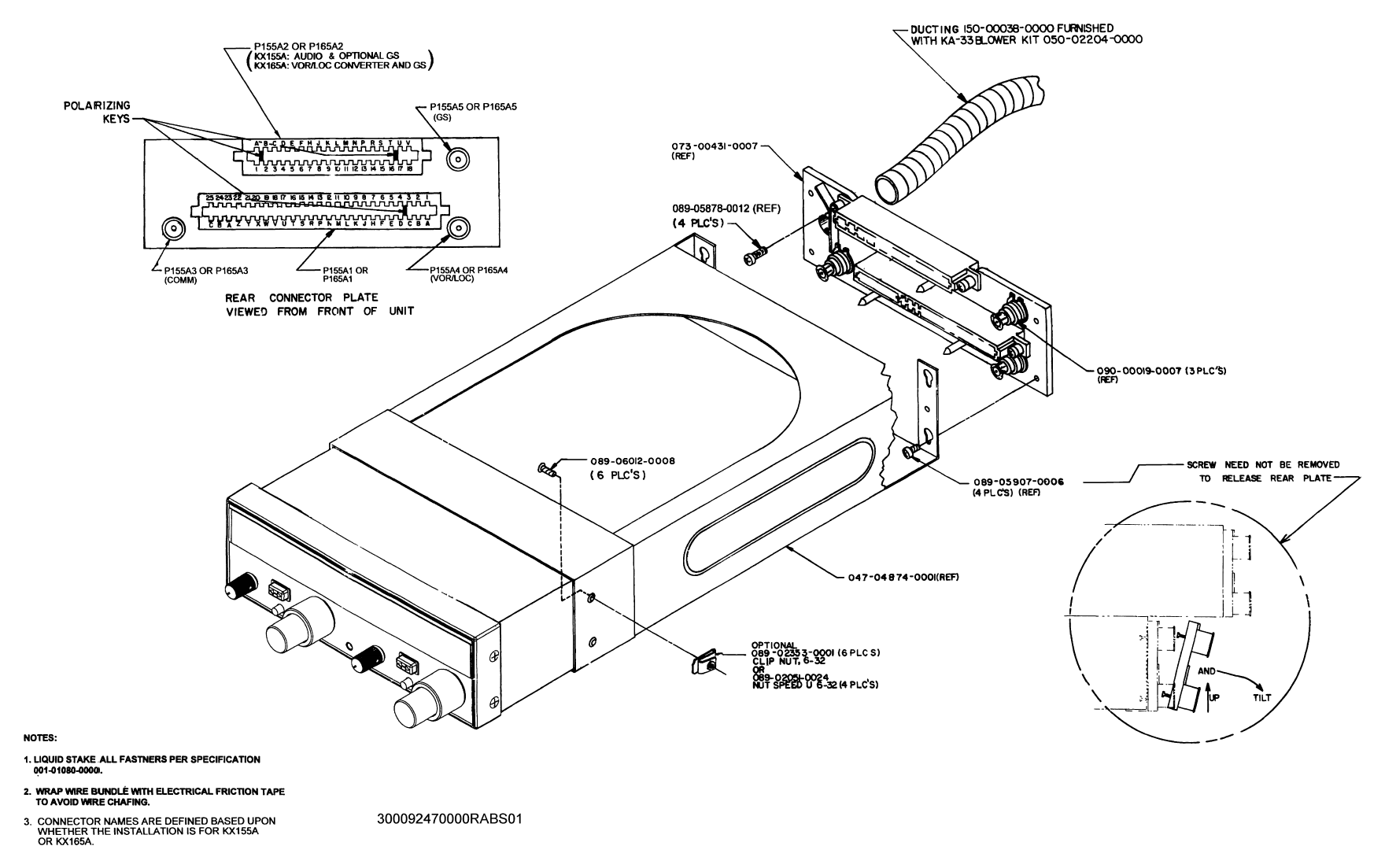
C. Secure the mounting rack to the instrument panel per Figure 2-11. The rear
mounting bosses should be attached to the aircraft by means of support
brackets.
2.3.3 ANTENNA INSTALLATION
A. Conventional 50 ohm horizontally polarized NAV Glideslope and vertically po-
larized COMM antennas are required with the KX 155A/KX 165A. Vertically
bent whip antennas are not recommended. Wideband COMM antennas pro-
vide efficient operation over the COMM band. Antennas should be installed
per manufacturer’s recommendations. Additional recommendations are as
follows:
1. COMM Antenna
a. Mount antenna on flat metal surface or install a ground plane at
least 18 inches square.
b. The antenna should be well removed from any projections and the
engine(s) and propeller.
2. Navigation Antennae (VOR/LOC & Glideslope)
a. The location should be well removed from other antennas, projec-
tions and engine(s). It should have a clear line of sight area if pos-
sible.
b. The antenna must be mounted symmetrically with the centerline of
the aircraft.
c. Avoid running other coaxial and wires near the NAV antenna cable.
B. The antenna connectors on the KX 155A/KX 165A are identified on the rear
die casting.
NOTE
With KX 155A/KX 165A viewed from the front, the NAV an-
tenna connector is on the right and the COMM antenna con-
nector is on the left. This means that the NAV Frequency
Selector and NAV Antenna are on the same side of the ra-
dio. The COMM Frequency Selector and COMM Antenna
Connector are also on the same side of the radio. The
Glideslope Antenna Connector is right above the NAV An-
tenna Connector.
PRELIMINARY - SUBJECT TO CHANGE WITHOUT NOTICE
BENDIX/KING
KX 155A/165A
COMM/NAV SYSTEM
10542I02.ZIPRCD Page 2-3
Rev 2, Apr/2000
2.3.4 CABLE HARNESS AND CONNECTOR ASSEMBLY
The KX 155A/KX 165A uses a special connector that mates directly with the printed circuit board
inside the unit. Assembly of the connector is as follows:
A. Contact Terminal Assembly using Molex Crimper (Figure 2-1 through 2-6)
1. Strip each wire 5/32" for contact terminal (Part Number 030-01107-
XXXX). (The last two digits of the contact terminal part number indicates
the number of terminals required).
2. Open the Molex hand crimper HT 1921 with the engraved side toward
the operator. Place the conductor tab section of a contact terminal on
Anvil B with the contact portion facing away from the operator. Close the
crimper slightly until the contact tabs touch the female jaw.
3. Insert the stripped conductor until the insulation is even with the side of
the crimper facing the operator. Crimp the conductor tabs by squeezing
the handles together until the jaws are fully closed or a sufficient crimp
is obtained.
4. Move the lead to Anvil A. Place the insulating tab section on Anvil A.
Crimp again until the jaws are fully closed or a sufficient crimp is ob-
tained.
B. Contact Insertion into Molex Connector Housing
1. After the contact terminals have been installed on the wiring harness, the
contact terminals can be inserted into the proper location in the connec-
tor housing (P/N 030-01094-00XX). The terminal cannot be inserted up-
side down. Be sure to push the terminal all the way in, until a click can
be felt or heard.
2. The self locking feature can be tested by gently pulling on the wire.
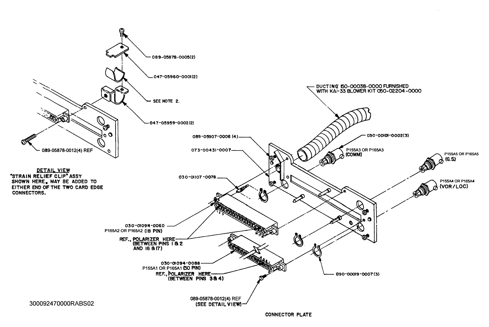
C. Location of Polarizing Key in Housing
1. Prior to insertion of connector into rear of unit, check polarizing key po-
sition between contacts 3 and 4 for P155A1/P165A2 & between contacts
A & B and T & V of P155A1/P165A2.
2. Refer to Figure 2-11 to check correct position of polarizing key.
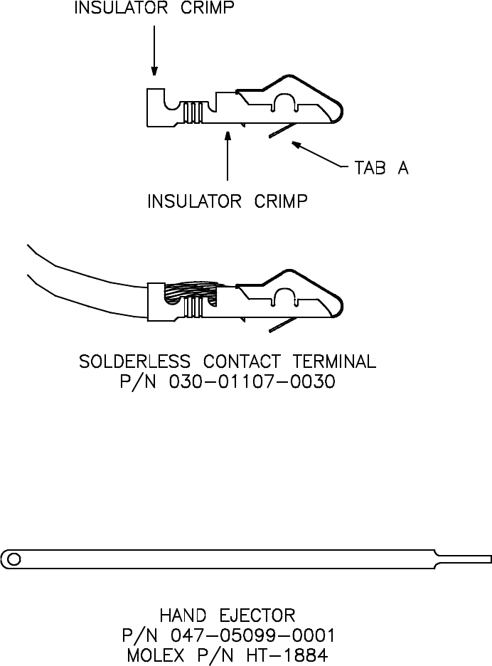
D. Extraction of Contact from Molex Connector
1. Slip the flat narrow blade of a Molex contact ejector tool, HT-1884 (P/N
005-02012-0011), under the contact on the mating side of the connector.
By turning the connector upside down one can see the blade slide into
the stop.
2. When the ejector is slid into place, the retaining tab of the contact is
raised, allowing the contact to be removed by pulling moderately on the
lead.
3. Neither the contact or position is damaged by removing a contact; how-
ever, the contact should be checked visually before reinstalling in con-
nector to be certain that retaining tab "A" extends as shown (see Figure
2-1).
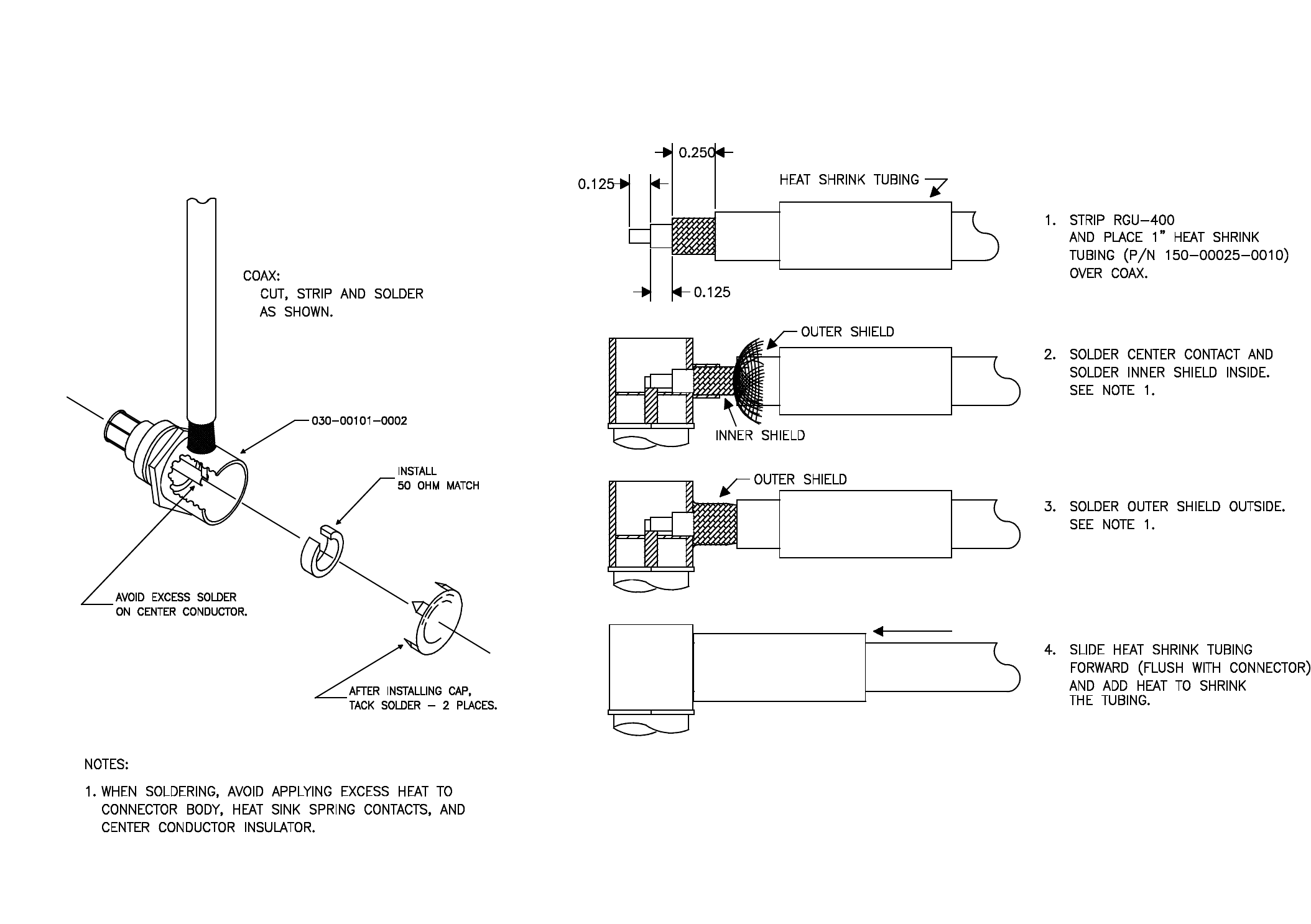
E. Coax Connector
Refer to Figure 2-9 for the details for mounting the right angle coaxial BNC
connector to the coax cable. Install the connector into the mounting rack.
PRELIMINARY - SUBJECT TO CHANGE WITHOUT NOTICE
Page 2-4 10542I02.ZIPRCD
Rev 2, Apr/2000
BENDIX/KING
KX 155A/165A
COMM/NAV SYSTEM
2.3.5 KX 155A/KX 165A INSTALLATION
SEE PARAGRAPH 2.3.1 FOR COOLING
REQUIREMENTS.
A. Looking at the top of the unit, make sure the front lobe of the holddown device is in
a vertical position.
B. Slide the unit into the mounting rack until the front lobe touches the mounting rack.
C. Insert a 3/32" Allen wrench through the hole in the front panel to engage the locking
screw. Turn clockwise until the rear lobe engages the mounting rack. Continue
turning until the unit is secure in the mounting rack. Do not overtighten.
D. For removal, turn the locking screw counterclockwise using a 3/32" Allen wrench
until the unit disengages from the mounting rack. Pull the unit out of the mounting
rack by pulling on the metal tabs located behind the front panel on each side of the
unit.
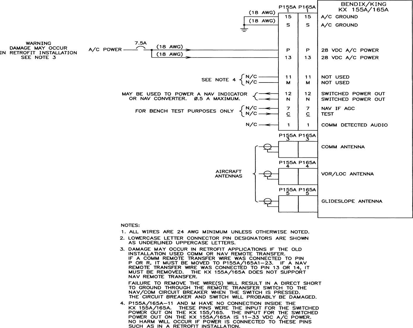
2.3.6 ELECTRICAL INSTALLATION NOTES
RETROFIT
Damage may occur in retrofit applications if the old
installation used COMM REMOTE TRANSFER or
NAV REMOTE TRANSFER. If a COMREMOTE
TRANSFER wire was connected to pin P or R, it
must be moved to P155A/165A1-23. If a NAV RE-
MOTE TRANSFER wire was connected to pin 13 or
14, it must be removed. The KX 155A/KX 165A
does not support NAV REMOTE TRANSFER. Fail-
ure to remove the wire(s) will result in a direct short
to ground through the remote transfer switch to the
NAV/COM circuit breaker when the switch is
pressed. The circuit breaker and switch will be
damaged.
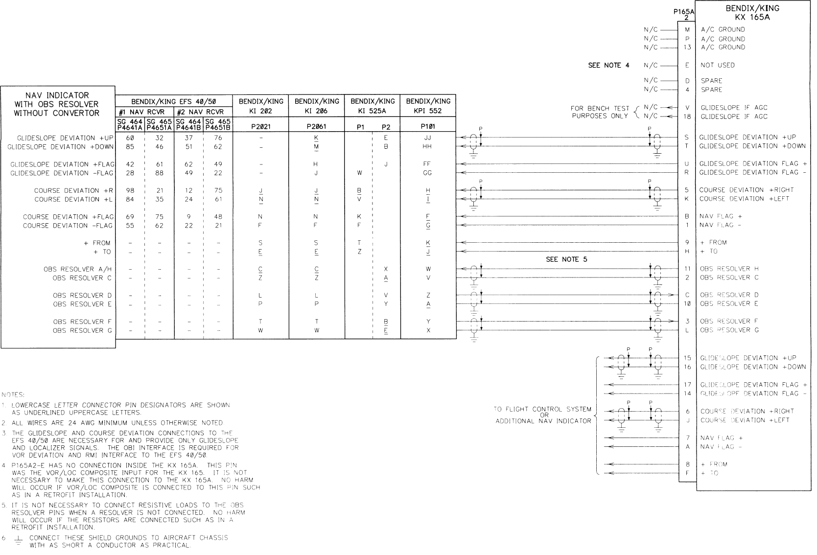
EFIS 40/50
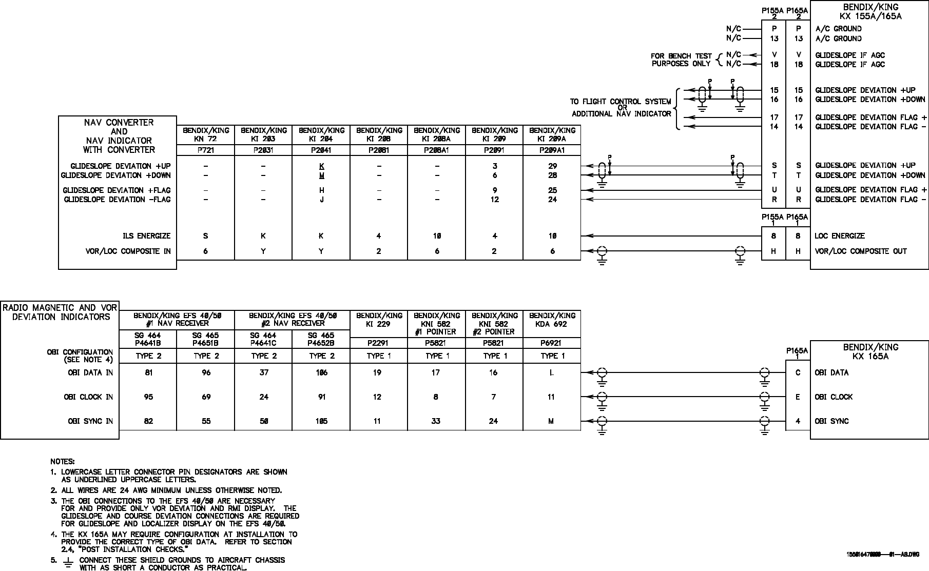
The KX 165A may be interfaced to the Bendix/King EFIS 40/50 by using the KX 165A’s OBI
CLOCK, OBI DATA, and OBI SYNC outputs for VOR bearing (RMI needle) and deviation, the
COURSE DEVIATION +RIGHT and +LEFT for localizer deviation, and the GLIDESLOPE DEVI-
ATION +UP and +DOWN for glideslope deviation. In order to use the KX 165A as a navigation
source, the EFIS 40/50 must be configured for KNS 81 as VOR/LOC 1 or 2. Additionally, the KX
165A must be configured for Type II OBI data (see paragraph 3.1.4).
CAUTION
CAUTION
PRELIMINARY - SUBJECT TO CHANGE WITHOUT NOTICE
BENDIX/KING
KX 155A/165A
COMM/NAV SYSTEM
10542I02.ZIPRCD Page 2-5
Rev 2, Apr/2000
TRANSMIT INTERLOCK
The KX 155A includes a TRANSMIT INTERLOCK (P155A1-J/165A2-J) input which should be
connected to the MIC KEY input(s) of the other COMM transceiver(s) in the aircraft. When this
input is grounded, the KX 155A desensitizes its receiver by approximately 13 dB, reducing the like-
lihood of its squelch breaking while another COMM in the aircraft is transmitting. It is highly rec-
ommended to use this feature on all COMMs in the aircraft which include such an interlock feature.
If TRANSMIT INTERLOCK is used in installations that employ a KX155A with a KMA26 (or other
audio panel that pulls the MIC KEY line above 11 Volts), isolation diodes will need to be installed
between P155A1, pin J and the MIC KEY line. Refer to Installation Bulletin 407 for details.
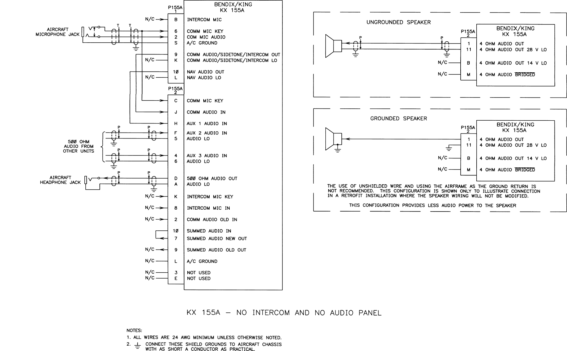
AUDIO AMPLIFIER
If the KX 155A is installed as a “slide-in” replacement for a KX 155. The KX 155A’s audio amplifier
functions will work just as the KX 155 did previously without rewiring any of the audio pins. Addi-
tionally, there are many new audio system features within the KX 155A which provide maximum
flexibility for use in a variety of audio/intercom configurations. The KX 155A provides audio am-
plification for its VHF communication transceiver for both headphones and the cockpit speaker.
In addition, up to three external sources of audio may be amplified and sent to the headphones
and speaker. With proper external switching, the KX 155A can provide the microphone bias volt-
age and amplification necessary for the implementation of a push-to-talk or a hot mic intercom.
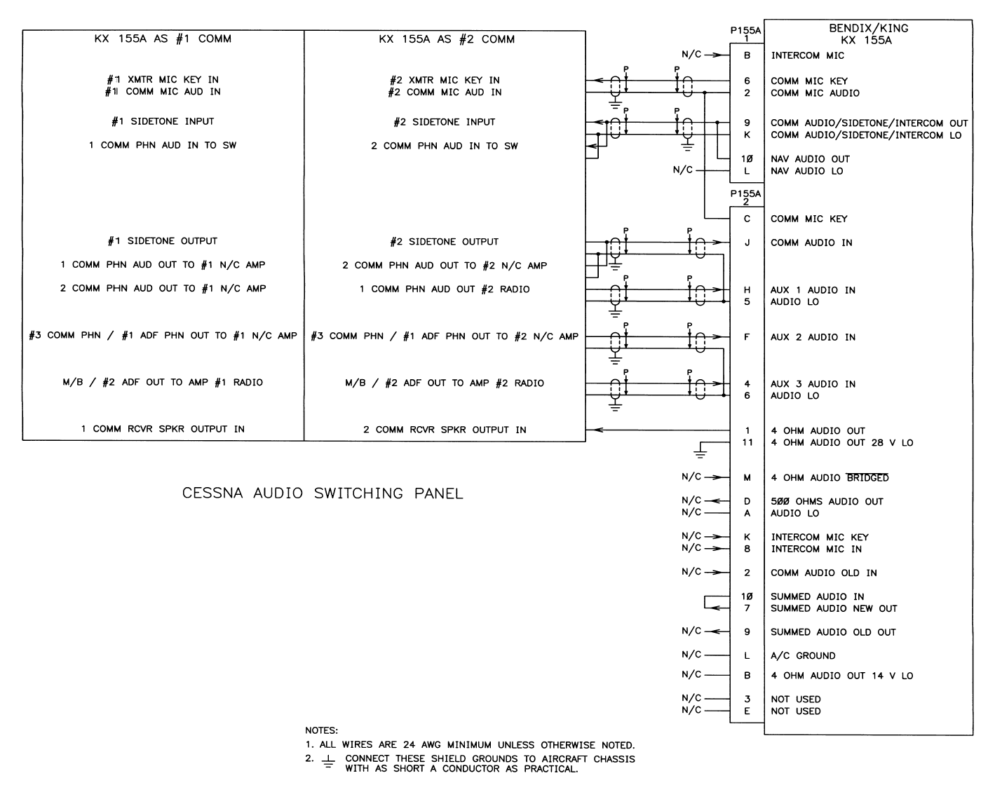
The KX 155A provides access to signals not commonly found on communication transceivers to
allow full-featured installation with audio switching panels and audio isolation/amplifier panels.
Three auxiliary audio inputs, AUX 1 AUDIO IN (P155A2-H), AUX 2 AUDIO IN (P155A2-F), and
AUX 3 AUDIO IN (P155A2-4) are typically used to amplify audio from VOR/LOC, Marker Beacon,
ADF, DME, Radio Altimeter Decision Height Alerters and other avionics audio sources. Any signal
capable of driving a 500Ω or lower impedance load that is adjustable to less than 7 volts is accept-
able. Each input has a low side pin, that is connected to ground inside the KX 155A.
Should you have more than three audio sources, it is sometimes possible to successfully connect
more than one source to a single pin. The sources will, in addition to driving the KX 155A input
load, be driving the other source outputs as loads. Normally, this does not damage the source
units but can cause lower signal levels resulting in less audio from these sources sharing that input
pin. After installation, verify that turning the power off on each of the sources does not stop the
audio from all the sources sharing the input.
COMM AUDIO IN (P155A2-J) and INTERCOM MIC IN (P155A2-8) are inputs to the same ampli-
fier used for the auxiliary audio inputs. The COMM AUDIO IN is reserved for the COMM AUDIO/
SIDETONE/INTERCOM OUT and has the same gain as the auxiliary audio inputs. The INTER-
COM MIC IN provides a MIC bias voltage output and should only be connected to aircraft micro-
phones. Connection to other devices may result in damage to both the KX 155A and the other
device.
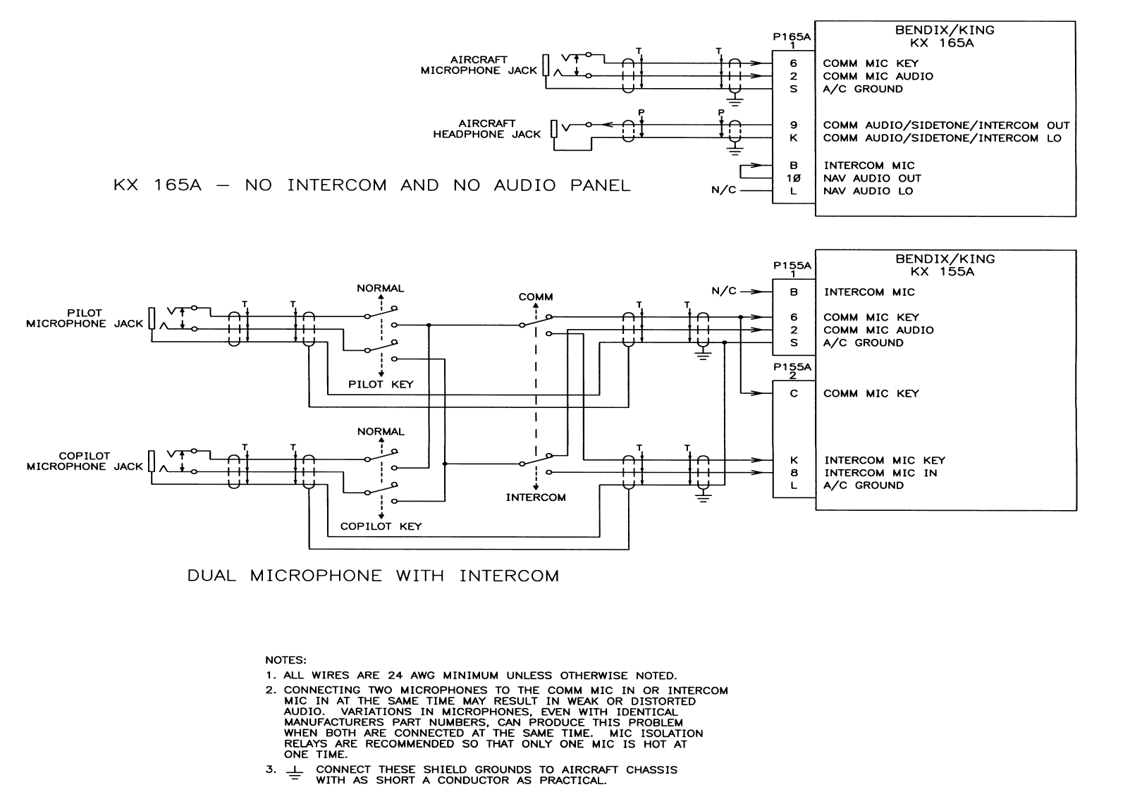
Connecting two microphones to the COMM MIC AUDIO or INTERCOM MIC IN at the same time
may result in weak or distorted audio. Variations in microphones, even with identical manufactur-
ers’ part numbers, can produce this problem when both are connected at the same time. Micro-
phone isolation relays are recommended so that only one microphone is connected at one time.
All five inputs described above are combined and amplified and output on the 500 OHMS AUDIO
OUT (P155A2-D) and SUMMED AUDIO (OLD or NEW) OUT (P155A2-9 or P155A2-7). Both pins
have identical signals but are at different voltage levels. The 500 OHMS AUDIO OUT will drive
headphones directly. The SUMMED AUDIO (OLD or NEW) OUT are provided so that they may
be input to the KX 155A’s internal 4Ω speaker amplifier. SUMMED AUDIO OLD OUT is utilized
in retrofits of KX 155 installations, and SUMMED AUDIO NEW OUT is utilized for new installa-
PRELIMINARY - SUBJECT TO CHANGE WITHOUT NOTICE

Page 2-6 10542I02.ZIPRCD
Rev 2, Apr/2000
BENDIX/KING
KX 155A/165A
COMM/NAV SYSTEM
tions. No signals, other than the five inputs, are output from the amplifier, thus allowing the install-
er complete flexibility.
SUMMED AUDIO IN (P155A2-10) is the input to the speaker amplifier. Only the signal applied to
this input will be output on the 4 OHM AUDIO OUT (P155A2-1) output. The output will drive
speakers of greater than 4Ω impedance, but since higher impedance speakers may expect higher
voltages, they may not be as loud as 4Ω speakers. The speaker amplifier is muted (output is dis-
abled) when the COMM transmitter is active (COMM MIC KEY input is low), and when the KX
155A intercom is keyed (INTERCOM MIC KEY input is low).
If the 4 OHM AUDIO OUT output is to be used, different wiring configurations are required, de-
pending on the KX 155A’s supply voltage, and whether or not the aircraft speaker is grounded on
its low side.
When a separate audio panel is used, neither the 500Ω nor 4Ω audio amplifiers in the KX 155A
are connected. The KX 155A audio amplifiers do not need external loads applied to either their
inputs or outputs when they are not used. NOTE: 500Ω audio output (P155A2 pins D & A) of 155-
01647-0002 sheet 2 are not TSO’d at time of publication.
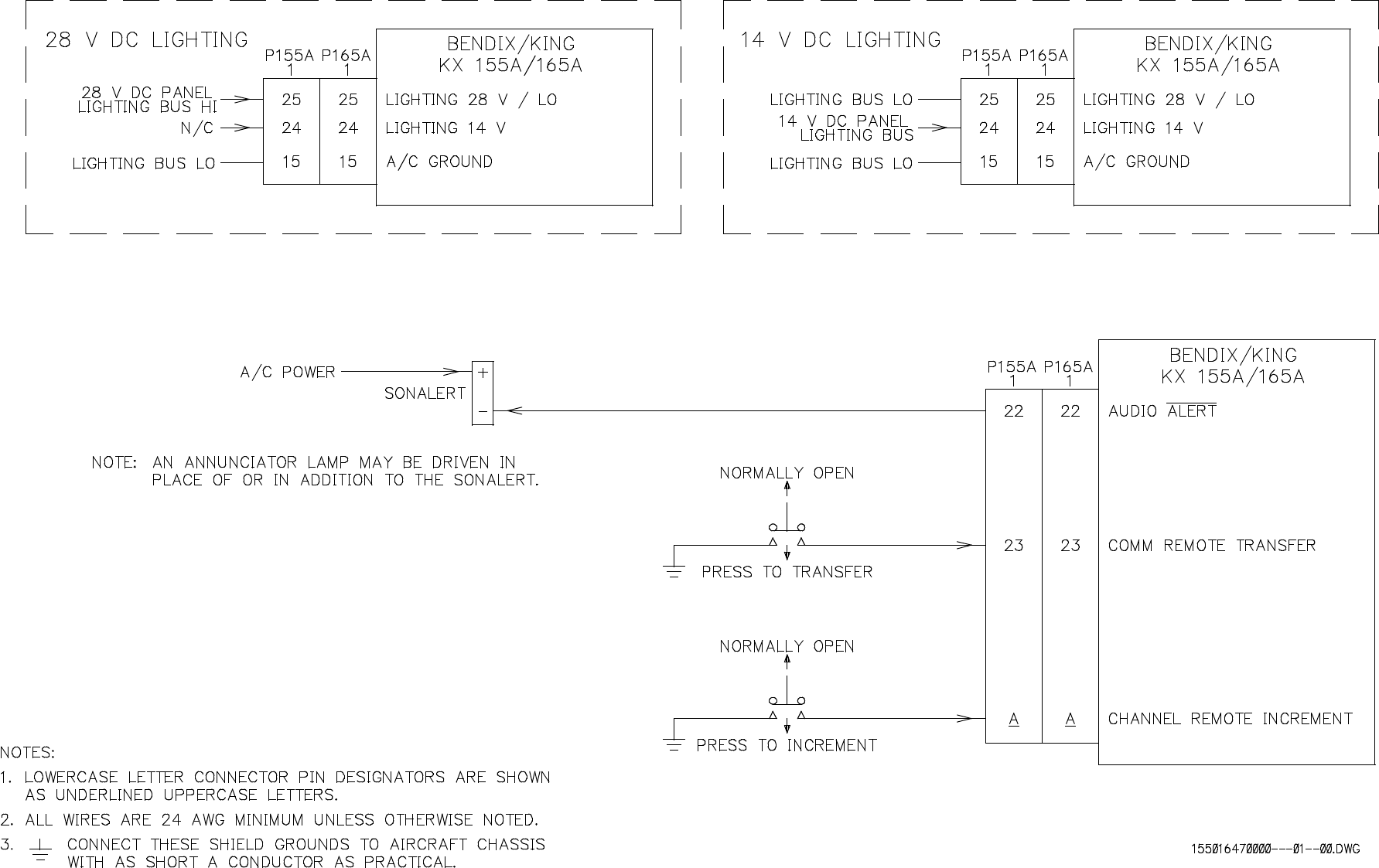
AUDIO ALERT
The AUDIO ALERT output may be connected to a Sonalert or equivalent audio alerter, or to a pan-
el-mounted annunciator lamp. At the time of this publication, the only function of AUDIO ALERT
is to activate when the KX 155A/KX 165A countdown timer expires.
2.4 POST INSTALLATION CHECK
An operation performance flight test is recommended after the installation is completed to insure
satisfactory performance of the equipment in its normal environment. Check all aircraft control
movements to be sure no electrical cables interfere with their operation.
To check the communications transceiver, maintain an altitude of at least 1500 feet and contact a
ground station facility at a range of at least fifty nautical miles. Contact a ground station close in.
Pull the volume control knob out to defeat the automatic squelch feature and listen for any unusual
electrical noise which would reduce the COMM receiver sensitivity by increasing the squelch
threshold. If possible, verify the communications capability on both the high and low end of the
VHF COMM band.
AS AN ADDED PRECAUTION BEFORE THE
FLIGHT, CHECK THE ANTENNA. VSWR
SHOULD BE CHECKED WITH AN IN-LINE TYPE
WATTMETER INSERTED IN THE COAXIAL
TRANSMISSION LINE BETWEEN THE TRANS-
CEIVER AND THE ANTENNA. ANY PROBLEM
WITH THE ANTENNA INSTALLATION WILL
MOST LIKELY BE SEEN AS A HIGH REFLECTED
POWER. A VSWR OF 3:1 WILL RESULT IN A
25% LOSS IN POWER.
NOTE
CAUTION
PRELIMINARY - SUBJECT TO CHANGE WITHOUT NOTICE
BENDIX/KING
KX 155A/165A
COMM/NAV SYSTEM
10542I02.ZIPRCD Page 2-7
Rev 2, Apr/2000
The brightness of the display can be set for the most
pleasing intensity during low light level conditions via
pilot configuration adjustment, see paragraph 3.1.3.
To check the VOR/ILS system, select a VOR frequency within a forty nautical mile range. Listen
to the VOR audio and insure that no electrical interference such as magneto noise is present.
Check the tone identifier filter operation. Fly inbound or outbound on a selected VOR radial and
check for proper LEFT-RIGHT and TO-FROM indications. Check the VOR accuracy.
To check the localizer and glideslope functions, select an appropriate ILS frequency and fly an
approach to the proper runway. Check for proper LEFT-RIGHT and UP-DOWN indications. The
glideslope function will not operate for units that do not have the glideslope receiver. Check sec-
tion 1 for unit part numbers that have glideslope receivers.
PRELIMINARY - SUBJECT TO CHANGE WITHOUT NOTICE
Page 2-8 10542I02.ZIPRCD
Rev 2, Apr/2000
BENDIX/KING
KX 155A/165A
COMM/NAV SYSTEM
NOTE
VOR Ground Station scalloping may be present.
FIGURE 2-1 MOLEX TERMINALS AND TOOLS
PRELIMINARY - SUBJECT TO CHANGE WITHOUT NOTICE

BENDIX/KING
KX 155A/165A
COMM/NAV SYSTEM
10542I02.ZIPRCD Page 2-9
Rev 2, Apr/2000
2.5 MOLEX TERMINAL INSTRUCTIONS
The Molex hand crimpers are available under P/N 071-06041-0000, or from Molex under P/N
6115.
Holding the hand crimpers as shown, release the crimper’s ratchet pawl and open by squeezing
tightly on the handles, and then releasing pressure.
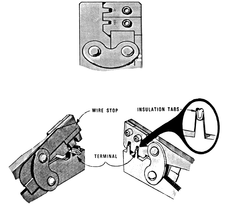
FIGURE 2-2 HAND CRIMPER
Close crimpers until ratchet begins to engage. Then insert the terminal into the jaws from the back
side. (See Figure 2-3 and 2-4) For 24 to 30 AWG wire, it will be necessary to start the crimp in
jaw A and then complete it in jaw B. The terminal is in the correct position when the insulation
tabs are flush with the outside face of the crimp jaws.
JAW TERMINAL WIRE SIZE INSULATION RANGE
A 030-01107-0030 18 TO 24 AWG .110 TO .055
B 030-01107-0030 24 TO 30AWG .055 TO .030
PRELIMINARY - SUBJECT TO CHANGE WITHOUT NOTICE
Page 2-10 10542I02.ZIPRCD
Rev 2, Apr/2000
BENDIX/KING
KX 155A/165A
COMM/NAV SYSTEM
FIGURE 2-3 CRIMP JAWS
FIGURE 2-4 TERMINAL INSERTION
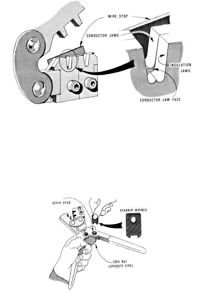
Once the terminal is in the correct position, close the jaws gently until the terminal is held loosely
in place. Push the wire stop down so that it rests snugly behind the contact portion of the terminal.
Strip the wire insulation back 1/8 inch and insert the wire through the insulation tabs into the con-
ductor tabs until the insulation hits the conductor jaw face or until the conductor touches the wire
stop. Squeeze the handles until the crimp jaws close and the ratchet releases. Straighten the
terminal if necessary, then release the plier grips and remove the crimped terminal.
PRELIMINARY - SUBJECT TO CHANGE WITHOUT NOTICE
BENDIX/KING
KX 155A/165A
COMM/NAV SYSTEM
10542I02.ZIPRCD Page 2-11
Rev 2, Apr/2000
FIGURE 2-5 HAND CRIMPER INSERTION
If too much or too little pressure is needed to release the crimper’s ratchet pawl at the end of the
crimp stroke, the ratchet can be easily adjusted. A spanner wrench provided with the tool can be
used to loosen the lock nut, and rotate the keyed stud clockwise for increased pressure and
counter clockwise for decreased pressure. Once the desired pressure has been set, the lock nut
must be tightened again. Newer models may have a screwdriver adjust-
ment.
FIGURE 2-6 CRIMPING PRESSURE ADJUSTMENT
PRELIMINARY - SUBJECT TO CHANGE WITHOUT NOTICE

Page 2-12 10542I02.ZIPRCD
Rev 2, Apr/2000
BENDIX/KING
KX 155A/165A
COMM/NAV SYSTEM
Figure 2-7 P155A1 & P165A1 CONNECTOR
* Reserved pins in P155A1
1 COM DETECTED AUDIO A RNAV MODE
2 COMM MIC AUDIO B INTERCOM MIC
3 DME CLOCK C OBI DATA *
4 OBI SYNC * D DME COMMON
5 DME DATA E OBI CLOCK *
6 COMM MIC KEY F RNAV/CHAN REQUEST
7 NAV IF AGC H VOR/LOC COMPOSITE OUT
8 LOC ENERGIZE J COMM IF AGC/ TRANSMIT INTERLOCK
9 COM AUD/SIDETONE/INTERCOM/OUT K COM AUDIO/SIDETONE/INTERCOM LO
10 NAV AUD OUT L NAV AUD LO
11 SPARE M SPARE
12 SWITCHED PWR OUT N SWITCHED PWR OUT
13 28 VDC A/C PWR P 28 VDC A/C PWR
14 RESERVED R RESERVED
15 A/C GROUND S A/C GROUND
16 SPARE T SPARE
17 SPARE U SPARE
18 SPARE V SPARE
19 RESERVED W RESERVED
20 RESERVED X RESERVED
21 A/C GROUND Y RS 232 OUT
22 AUDIO ALERT Z RS 232 IN
23 COM REMOTE TRANSFER A CHANNEL REMOTE INCREMENT
24 LIGHTING 14 VDC B RESERVED
25 LIGHTING 28 VDC/LO C TEST
PRELIMINARY - SUBJECT TO CHANGE WITHOUT NOTICE

BENDIX/KING
KX 155A/165A
COMM/NAV SYSTEM
10542I02.ZIPRCD Page 2-13
Rev 2, Apr/2000
Figure 2-8 P155A2
P155A2
A--------------- AUDIO LO
B--------------- 4 OHM AUDIO OUT 14V LO
C--------------- COMM MIC KEY
D--------------- 500 OHM AUDIO OUT
E--------------- RESERVED
F--------------- AUX 2 AUDIO IN
H--------------- AUX 1 AUDIO IN
J--------------- COM AUDIO IN
K--------------- INTERCOM MIC KEY
L--------------- A/C GROUND
M-------------- 4 OHM AUDIO BRIDGED
N--------------- SPARE
P--------------- GS GROUND
R--------------- GS -FLAG
S--------------- GS +UP
T--------------- GS +DN
U--------------- GS +FLAG
V--------------- GS IF AGC
1--------------- 4 OHM AUDIO OUT
2--------------- COMM AUD OLD IN
3--------------- RESERVED
4--------------- AUX 3 AUDIO IN
5--------------- AUDIO LO
6--------------- AUDIO LO
7--------------- SUMMED AUDIO NEW OUT
8--------------- INTERCOM MIC IN
9--------------- SUMMED AUDIO OLD OUT
10-------------- SUMMED AUDIO IN
11-------------- 4 OHM AUDIO OUT 28V LO
12-------------- SPARE
13-------------- GS GROUND
14-------------- GS -FLAG
15-------------- GS +UP
16-------------- GS +DN
17-------------- GS +FLAG
18-------------- GS IF AGC
PRELIMINARY - SUBJECT TO CHANGE WITHOUT NOTICE
Page 2-14 10542I02.ZIPRCD
Rev 2, Apr/2000
BENDIX/KING
KX 155A/165A
COMM/NAV SYSTEM
Figure 2-9 P165A2
P155A2
A--------------- NAV -FLAG
B--------------- NAV +FLAG
C--------------- OBS RESOLVER D
D--------------- SPARE
E--------------- RESERVED
F--------------- NAV +TO
H--------------- NAV +TO
J--------------- COURSE DEVIATION +LEFT
K--------------- COURSE DEVIATION +LEFT
L--------------- OBS RESOLVER G
M-------------- A/C GROUND
N--------------- SPARE
P--------------- A/C GROUND
R--------------- GS -FLAG
S--------------- GS +UP
T--------------- GS +DN
U--------------- GS +FLAG
V--------------- GS IF AGC
1--------------- NAV -FLAG
2--------------- OBS RESOLVER C
3--------------- OBS RESOLVER F
4--------------- SPARE
5--------------- COURSE DEVIATION +RIGHT
6--------------- COURSE DEVIATION +RIGHT
7--------------- NAV +FLAG
8--------------- NAV +FROM
9--------------- NAV +FROM
10-------------- OBS RESOLVER E
11-------------- OBS RESOLVER H
12-------------- SPARE
13-------------- GS GROUND
14-------------- GS -FLAG
15-------------- GS +UP
16-------------- GS +DN
17-------------- GS +FLAG
18-------------- GS IF AGC
PRELIMINARY - SUBJECT TO CHANGE WITHOUT NOTICE
KX 155A/165A
COMM/NAV SYSTEM
Page 2-15
BENDIX/KING
10542I02.ZIPRCD
Rev. 2, Apr/2000
FIGURE 2-9 ANTENNA CABLE ASSEMBLY
(P/N 030-00101-0002, R-9)
PRELIMINARY - SUBJECT TO CHANGE WITHOUT NOTICE
KX 155A/165A
COMM/NAV SYSTEM
Page 2-17
BENDIX/KING
10542I02.ZIPRCD
Rev. 2, Apr/2000
FIGURE 2-10 KX 155A/KX 165A OUTLINE AND MOUNTING DRAWING
(Dwg. No 155-01661-0000, Rev AC)
PRELIMINARY - SUBJECT TO CHANGE WITHOUT NOTICE
KX 155A/165A
COMM/NAV SYSTEM
Page 2-19
BENDIX/KING
10542I02.ZIPRCD
Rev. 2, Apr/2000
FIGURE 2-11 KX 155A/165A INSTALLATION ASSEMBLY DRAWING
(Dwg No 300-09247-0000, Rev AA)
(Sheet 1 of 2)
PRELIMINARY - SUBJECT TO CHANGE WITHOUT NOTICE
KX 155A/165A
COMM/NAV SYSTEM
Page 2-21
BENDIX/KING
10542I02.ZIPRCD
Rev. 2, Apr/2000
FIGURE 2-11 KX 155A/165A INSTALLATION ASSEMBLY DRAWING
(Dwg No 300-09247-0000, Rev AA)
(Sheet 2 of 2)
PRELIMINARY - SUBJECT TO CHANGE WITHOUT NOTICE
KX 155A/165A
COMM/NAV SYSTEM
Page 2-23
BENDIX/KING
10542I02.ZIPRCD
Rev. 2, Apr/2000
FIGURE 2-12 KX 155A/165A NAV INDICATOR INTERFACE
(Sheet 1 of 2) (Dwg No 155-01647-0000, Rev AB)
PRELIMINARY - SUBJECT TO CHANGE WITHOUT NOTICE
KX 155A/165A
COMM/NAV SYSTEM
Page 2-25
BENDIX/KING
10542I02.ZIPRCD
Rev. 2, Apr/2000
FIGURE 2-12 KX 155A/165A NAV INDICATOR INTERFACE
(Sheet 2 of 2) (Dwg No 155-01647-0000, Rev AB)
PRELIMINARY - SUBJECT TO CHANGE WITHOUT NOTICE
KX 155A/165A
COMM/NAV SYSTEM
Page 2-27
BENDIX/KING
10542I02.ZIPRCD
Rev. 2, Apr/2000
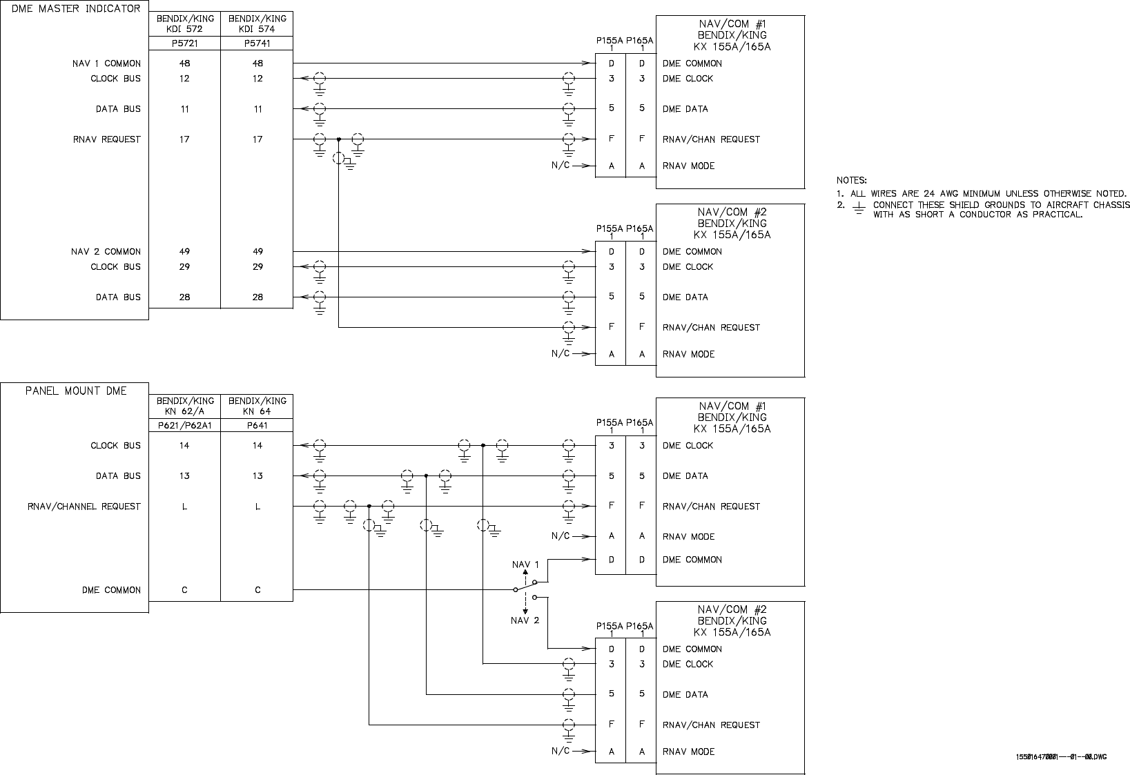
FIGURE 2-13 KX 155A/165A DME/RNAV INTERFACE
(Dwg No 155-01647-0001, Rev 0)
(Sheet 1 of 2)
PRELIMINARY - SUBJECT TO CHANGE WITHOUT NOTICE
KX 155A/165A
COMM/NAV SYSTEM
Page 2-29
BENDIX/KING
10542I02.ZIPRCD
Rev. 2, Apr/2000
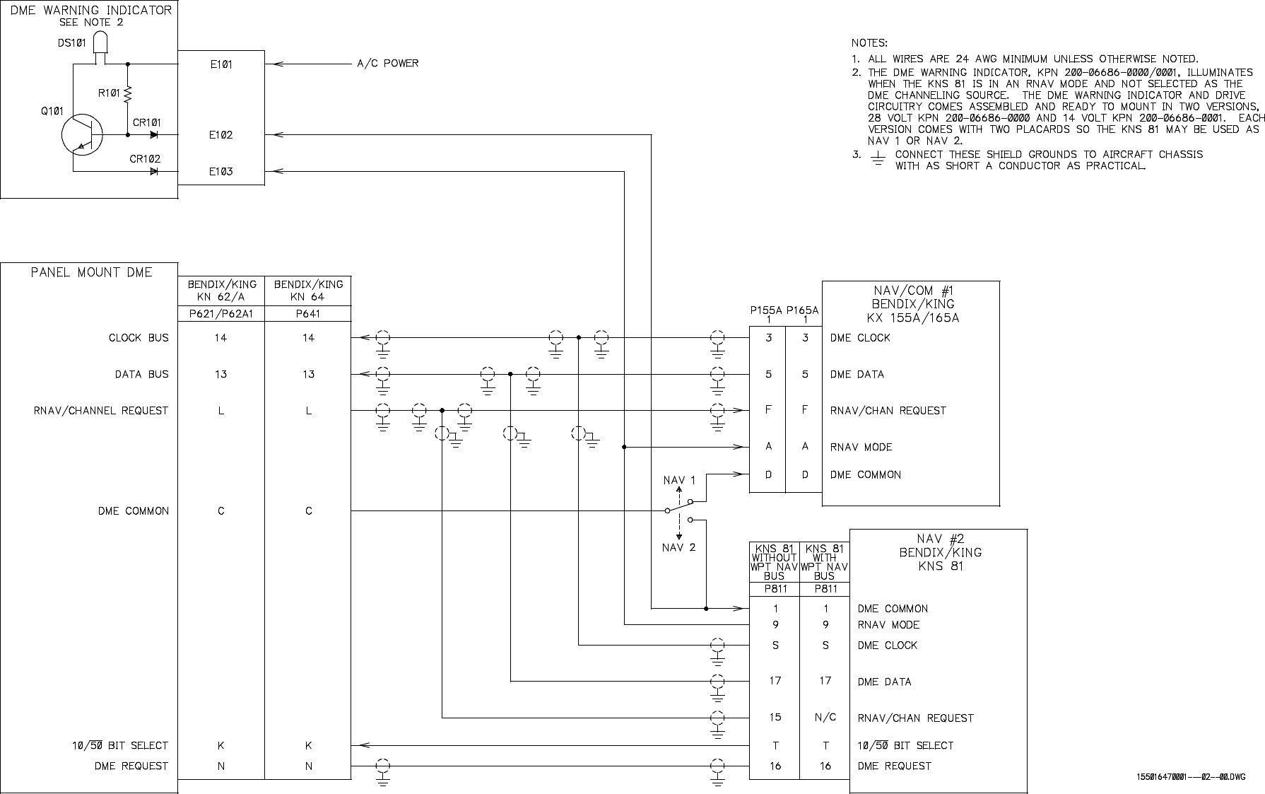
FIGURE 2-13 KX 155A/165A DME/RNAV INTERFACE
(Dwg No 155-01647-0001, Rev 0)
(Sheet 2 of 2)
PRELIMINARY - SUBJECT TO CHANGE WITHOUT NOTICE
KX 155A/165A
COMM/NAV SYSTEM
Page 2-31
BENDIX/KING
10542I02.ZIPRCD
Rev. 2, Apr/2000
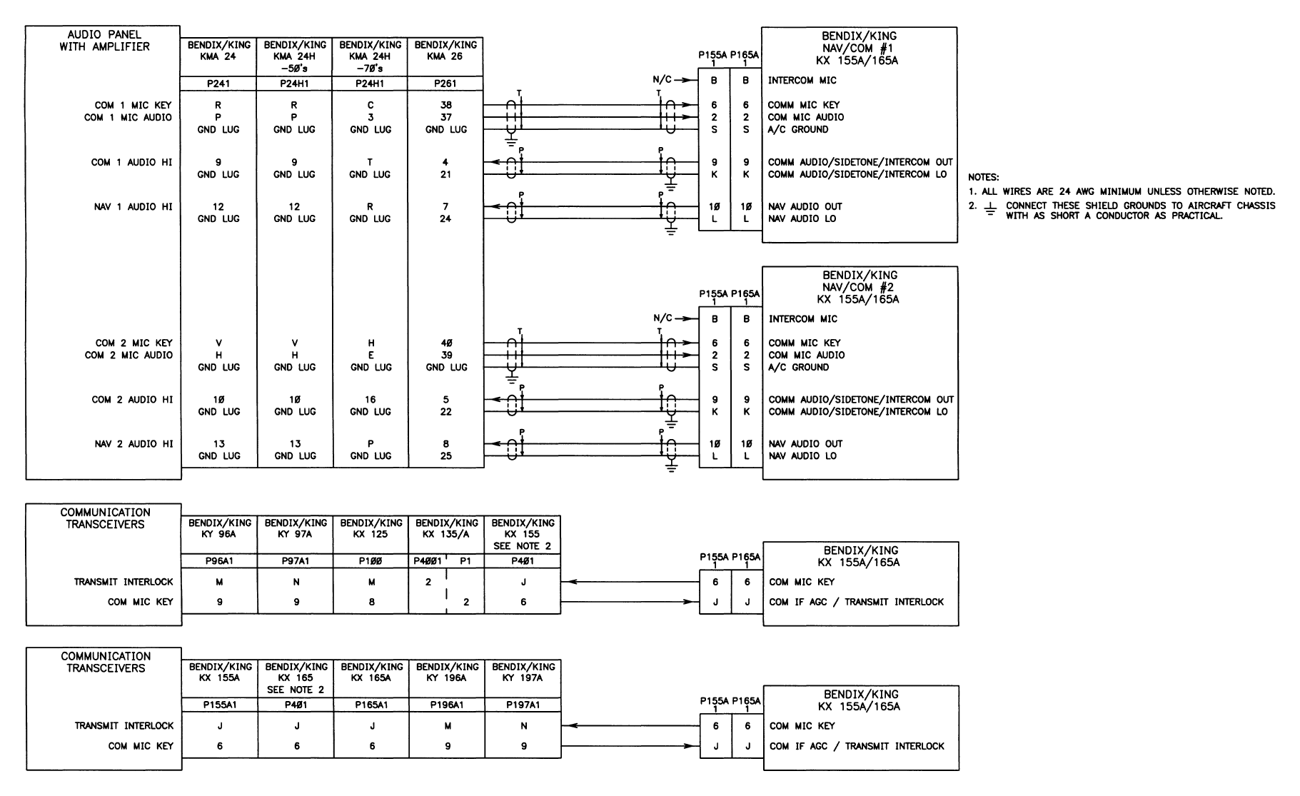
FIGURE 2-14 KX 155A/165A AUDIO INTERFACE
(Dwg No 155-01647-0002, Rev AB)
(Sheet 1 of 4)
PRELIMINARY - SUBJECT TO CHANGE WITHOUT NOTICE
KX 155A/165A
COMM/NAV SYSTEM
Page 2-33
BENDIX/KING
10542I02.ZIPRCD
Rev. 2, Apr/2000
FIGURE 2-14 KX155A/165A AUDIO INTERFACE
(Dwg No 155-01647-0002, Rev AB)
(Sheet 2 of 4)
PRELIMINARY - SUBJECT TO CHANGE WITHOUT NOTICE
KX 155A/165A
COMM/NAV SYSTEM
Page 2-35
BENDIX/KING
10542I02.ZIPRCD
Rev. 2, Apr/2000
FIGURE 2-14 KX 155A/165A AUDIO INTERFACE
(Dwg No 155-01647-0002, Rev AB)
(Sheet 3 of 4)
PRELIMINARY - SUBJECT TO CHANGE WITHOUT NOTICE
KX 155A/165A
COMM/NAV SYSTEM
Page 2-37
BENDIX/KING
10542I02.ZIPRCD
Rev. 2, Apr/2000
FIGURE 2-14 KX 155A/165A AUDIO INTERFACE
(Dwg No 155-01647-0002, Rev AB)
(Sheet 4 of 4)
PRELIMINARY - SUBJECT TO CHANGE WITHOUT NOTICE
KX 155A/165A
COMM/NAV SYSTEM
Page 2-39
BENDIX/KING
10542I02.ZIPRCD
Rev. 2, Apr/2000
FIGURE 2-15 LIGHTING, ALERTING AND REMOTE INTERFACE
(Dwg No 155-01647-0003, Rev 0)
pg
PRELIMINARY - SUBJECT TO CHANGE WITHOUT NOTICE
KX 155A/165A
COMM/NAV SYSTEM
Page 2-41
BENDIX/KING
10542I02.ZIPRCD
Rev. 2, Apr/2000
FIGURE 2-16 MISCELLANEOUS INTERFACE
(Dwg No 155-01647-0005, Rev AA)
PRELIMINARY - SUBJECT TO CHANGE WITHOUT NOTICE
BENDIX/KING
KX 155A/165A
COMM/NAV SYSTEM
10542I02.ZIPRCD Page 3-1
Rev 2, Apr/2000
SECTION III
OPERATION
3.1 GENERAL
All controls required to operate the KX 155A/165A are located on the unit front panel. (See Figure
3-1)
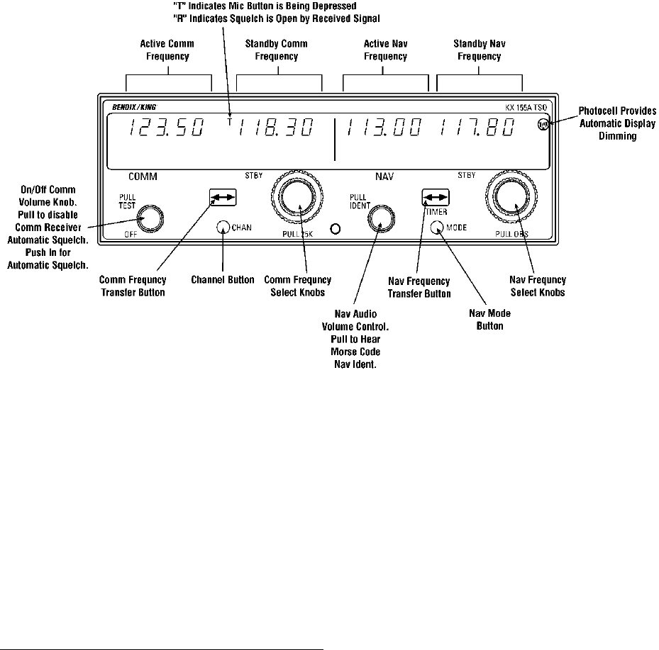
FIGURE 3-1 KX 155A/165A CONTROL FUNCTION
3.1.1 COMM TRANSCEIVER
Rotate the VOL knob clockwise from the OFF position. Pull the VOL knob out and adjust for de-
sired listening level. Push the VOL knob back in to actuate the automatic squelch.
The left portion of the digital display readout is allocated for COMM ACTIVE, and COMM STAND-
BY frequencies with a “T” between them to indicate TRANSMIT and an “R” to indicate RECEIVE
modes of operation.
Select the desired operating frequency in the standby display by rotating the Frequency Select
Knobs either clockwise or counter-clockwise. A clockwise rotation will increment the previous fre-
quency while a counterclockwise rotation will decrement the previous frequency.
Frequency Selection for 25 kHz radio versions:
This paragraph applies to KX 155A part numbers 069-01032-0101/0201 and KX 165A part num-
ber 069-01033-0101. The outer knob will change the MHz portion of the standby display. At one
PRELIMINARY - SUBJECT TO CHANGE WITHOUT NOTICE

Page 3-2 10542I02.ZIPRCD
Rev 2, Apr/2000
BENDIX/KING
KX 155A/165A
COMM/NAV SYSTEM
band-edge (118 or 136 MHz) the following 1 MHz change will wrap around to the other band-edge.
The inner knob will change the kHz portion of the standby display. It will change in steps of 50
kHz when the knob is pushed in, and 25 kHz when the knob is pulled out. The frequency wrap
around at the edge of the band is also utilized when incrementing or decrementing the kHz portion
of the standby display.
Frequency Selection for 8.33 kHz radio versions:
This paragraph applies to KX 165A part number 069-01033-0201. The outer knob will change the
MHz portion of the standby display. At one band-edge (118 or 136 MHz) the following 1 MHz
change will wrap around to the other band-edge. The inner knob will change the kHz portion of
the standby display. With the inner knob pushed in, the frequency will increment or decrement in
25 kHz steps as the inner knob is rotated clockwise or counterclockwise. The COMM receiver is
operating with conventional (25 kHz) selectivity when the inner knob is pushed in. When the inner
knob is pulled out the receiver becomes compatible with the new 8.33 kHz airspace. In this case
the displayed frequency doesn’t always correspond directly to the actual operating frequency. In
this case clockwise (counterclockwise) rotation of the inner knob increments (decrements) the dig-
its to the right of the decimal point in the following fashion.
Displayed Frequency Operating Frequency Receiver Selectivity
xxx.000 xxx.0000 MHz 25 kHz
xxx.005 xxx.0000 MHz 8.33 kHz
xxx.010 xxx.0083 MHz 8.33 kHz
xxx.015 xxx.0167 MHz 8.33 kHz
xxx.020 xxx.0250 MHz 25 kHz
xxx.030 xxx.0250 MHz 8.33 kHz
xxx.035 xxx.0333 MHz 8.33 kHz
xxx.040 xxx.0417 MHz 8.33 kHz
xxx.050 xxx.0500 MHz 25 kHz
xxx.055 xxx.0500 MHz 8.33 kHz
xxx.060 xxx.0583 MHz 8.33 kHz
xxx.065 xxx.0667 MHz 8.33 kHz
xxx.070 xxx.0750 MHz 25 kHz
xxx.080 xxx.0750 MHz 8.33 kHz
xxx.085 xxx.0833 MHz 8.33 kHz
xxx.090 xxx.0917 MHz 8.33 kHz
This pattern repeats for all the 100 kHz increments. (It should be noted that the pilot does not
need to know the operating frequency or selectivity associated with each displayed frequency.
Flying charts and/or ATC communications are designed to relate in terms of the displayed fre-
quency only.)
To tune the radio to the desired operating frequency, the desired frequency must be entered into
the standby display and then the transfer button must be pushed. This will trade the contents of
the active and standby displays. The operating frequency can also be entered by accessing the
ACTIVE ENTRY (direct tune) mode which is done by pushing and holding the COMM TRANSFER
button for 2 or more seconds. In the direct tune mode, only the active part of the display is visible.
The desired frequency can be directly entered into the display. Push the COMM TRANSFER but-
ton again to return to the active/standby display.
PRELIMINARY - SUBJECT TO CHANGE WITHOUT NOTICE
BENDIX/KING
KX 155A/165A
COMM/NAV SYSTEM
10542I02.ZIPRCD Page 3-3
Rev 2, Apr/2000
The transceiver is always tuned to the frequency appearing in the ACTIVE display. It is therefore
possible to have two different frequencies stored in the ACTIVE and STANDBY displays and to
change back and forth between them at the simple push of the transfer button.
During the transmit mode of operation, a “T” will appear between the ACTIVE and STANDBY dis-
plays. An “R” will appear between the ACTIVE and STANDBY displays if a detected signal is
strong enough to open the squelch, signifying that the transceiver is in the receive mode of oper-
ation.
A non-volatile memory stores the comm ACTIVE and STANDBY frequencies on power down.
When the unit is turned on again, the COMM ACTIVE and STANDBY windows will display the
same ACTIVE and STANDBY frequencies that were displayed before power down.
The KX 155A/165A also has provision to program 32 channels. Pressing the CHAN button for 2
or more seconds will cause the unit to enter the channel program mode. Upon entering the chan-
nel program mode,“PG” is displayed next to the channel number and the channel number will flash
indicating that it can be programmed. The desired channel can be selected by turning the comm
kHz knob. The channel frequency can be entered by pushing the COMM TRANSFER button
which will cause the standby frequency to flash. The comm frequency knobs are then used to en-
ter the desired frequency. If dashes (displayed when rotating the outer knob between 136 MHz
and 118 MHz) are entered instead of a frequency, the corresponding channel is skipped in chan-
nel selection mode. Additional channels may be programmed by pressing the COMM TRANS-
FER and using the same procedure. To exit the program mode and save the channel information,
momentarily push the CHAN button. This will cause the unit to return to the previous frequency
entry mode. The unit will also exit the channel program mode if there is no button or knob activity
for 20 seconds.
The channel selection mode can then be entered by momentarily pushing CHAN button. “CH” is
displayed next to the last used channel number. The comm frequency knobs can be used to se-
lect the desired channel. The unit will automatically default to the previous mode if no channel is
selected within 2 seconds after entering the channel selection mode.
The unit is placed in the transmit mode by depressing the MIC KEY button. The unit has a stuck
microphone alert feature. If the microphone is keyed continuously for greater than 33 seconds,
the transmitter stops transmitting and the active Comm frequency flashes to alert the pilot of the
stuck microphone condition.
3.1.2 NAV RECEIVER
The right portion of the display is allocated to NAV receiver information. The frequency channeling
is similar to the COMM when operating in the frequency mode (Figure 3-1). The NAV increment/
decrement knobs are located on the right hand side of the front panel. The outer knob operates
in 1 MHz steps and increments/decrements the STANDBY frequency display.
The inner knob operates in 50 kHz steps. The NAV receiver’s lower and upper frequency limits
are 108.00 MHz and 117.95 MHz. Exceeding the upper limit of frequency band will automatically
return to the lower limit and vice versa.
Depressing the NAV frequency transfer button for 2 seconds or more will cause the display to go
in to the ACTIVE ENTRY mode. Only the ACTIVE frequency will be displayed and it can be di-
rectly changed by using the NAV inc/dec knobs. The display will return to the ACTIVE/STANDBY
mode when the NAV frequency transfer button is pushed.
Depressing the mode button will cause the NAV display to go from the ACTIVE/STANDBY format
to the ACTIVE/CDI (Course Deviation Indicator) format as shown below in Figure 3-2. In the CDI
mode, the increment/decrement knob (pushed in) channels the ACTIVE frequency window and
depressing the frequency transfer button will cause the ACTIVE frequency to be placed in blind
storage and the STANDBY frequency (in blind storage) to be displayed in the ACTIVE window dis-
PRELIMINARY - SUBJECT TO CHANGE WITHOUT NOTICE

Page 3-4 10542I02.ZIPRCD
Rev 2, Apr/2000
BENDIX/KING
KX 155A/165A
COMM/NAV SYSTEM
play. When the ACTIVE window is tuned to a VOR frequency, the standby frequency area is re-
placed by a three digit OBS (Omni Bearing Selector) display. The desired OBS course can be
selected by pulling out the inner NAV frequency knob and turning it. This OBS display is indepen-
dent of any OBS course selected on an external CDI or HSI. An “OBS” in the middle of the NAV
display will flash while the inner NAV frequency knob is pulled out. The CDI is displayed on the
line below the frequency/OBS. When the ACTIVE window is tuned to a localizer frequency, the
standby frequency area is replaced by “LOC” Figure 3-3. Illustrations of the display are shown
below.
FIGURE 3-2 NAV DISPLAY; ACTIVE VOR FREQUENCY/CDI FORMAT
PRELIMINARY - SUBJECT TO CHANGE WITHOUT NOTICE
BENDIX/KING
KX 155A/165A
COMM/NAV SYSTEM
10542I02.ZIPRCD Page 3-5
Rev 2, Apr/2000
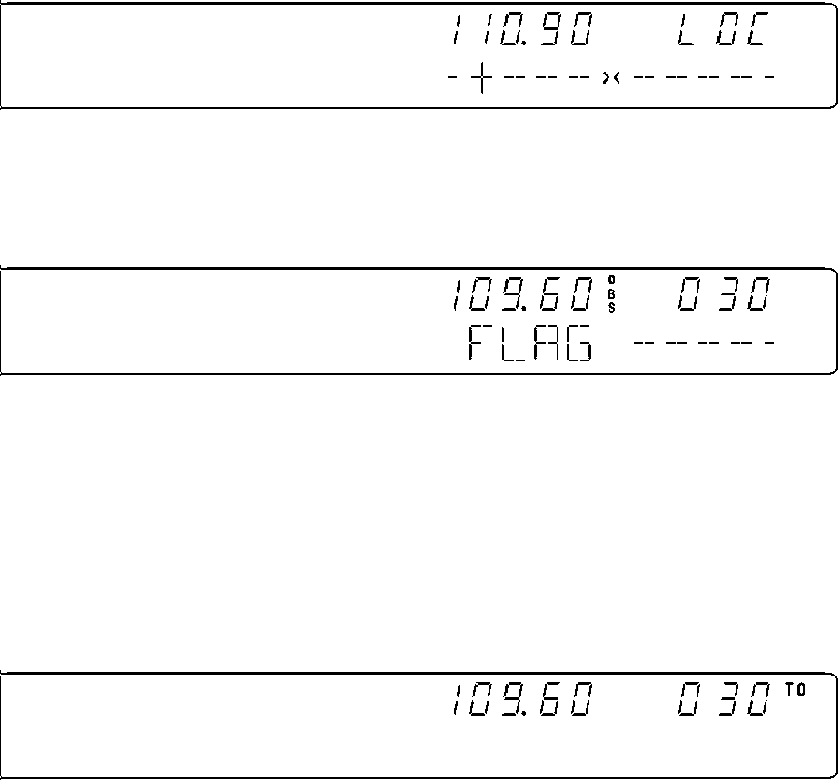
FIGURE 3-3 NAV DISPLAY; ACTIVE LOCALIZER FREQUENCY/CDI FORMAT
When the received signal is too weak to ensure accuracy the display will “flag”. See Figure 3-4.
FIGURE 3-4 VOR FLAG DISPLAY
Depressing the mode button will cause the NAV display to go from the ACTIVE/CDI format to the
ACTIVE/BEARING format. In the BEARING mode, the increment/decrement knob channels the
ACTIVE frequency window and depressing the frequency transfer button will cause the ACTIVE
frequency to be placed in blind storage and the STANDBY frequency (in blind storage) to be dis-
played in the ACTIVE window display. In bearing mode of operation, the right hand window of NAV
display shows the bearing TO the station. Figure 3-5 below illustrates the NAV side of the display
in this mode:
FIGURE 3-5 VOR MODE; BEARING TO FUNCTION
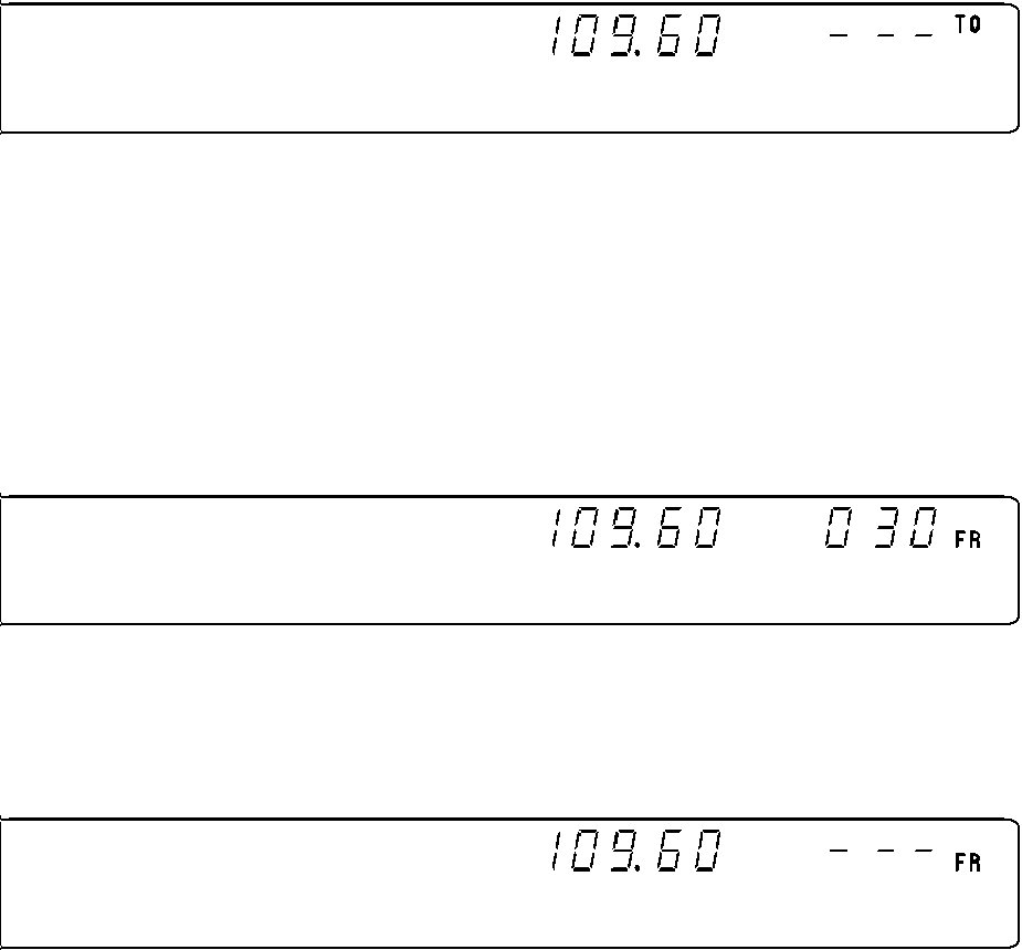
When a too weak or invalid VOR signal is received the display flags as shown in Figure 3-6.
PRELIMINARY - SUBJECT TO CHANGE WITHOUT NOTICE
Page 3-6 10542I02.ZIPRCD
Rev 2, Apr/2000
BENDIX/KING
KX 155A/165A
COMM/NAV SYSTEM
FIGURE 3-6 VOR MODE; ACTIVE/BEARING, FLAG DISPLAY
Another push of the mode button will cause the NAV display to go from the ACTIVE/BEARING
format to the ACTIVE/RADIAL format as shown in Figure 3-7. In the RADIAL mode, the incre-
ment/decrement knob channels the ACTIVE frequency window and depressing the frequency
transfer button will cause the ACTIVE frequency to be placed in blind storage and the STANDBY
frequency (in blind storage) to be displayed in the ACTIVE window display. In radial mode of op-
eration, the right hand window of NAV display shows the radial FROM the station. The picture
below illustrates the NAV side of the display in this mode:
FIGURE 3-7 VOR MODE; RADIAL FROM FUNCTION
When a too weak or invalid VOR signal is received the display flags as shown in Figure 3-8.
FIGURE 3-8 VOR MODE; ACTIVE/RADIAL, FLAG DISPLAY
PRELIMINARY - SUBJECT TO CHANGE WITHOUT NOTICE

BENDIX/KING
KX 155A/165A
COMM/NAV SYSTEM
10542I02.ZIPRCD Page 3-7
Rev 2, Apr/2000
Another push of the mode button will cause the unit to go into the TIMER mode. See Figure 3-9.
When the unit is turned on the elapsed timer begins counting upwards from zero. The timer can
be stopped and reset to zero by pushing the NAV frequency transfer button for 2 seconds or more
causing the ET on the display to flash. In this state the timer can be set as a countdown timer or
the elapsed timer can be restarted. The countdown timer is set by using the NAV inc/dec knobs
to set the desired time and then pushing the NAV frequency transfer button to start the timer. The
outer knob selects minutes, the inner knob in the “in “ position selects ten second intervals, and
the inner knob in the “out” position selects individual seconds. After the countdown timer reaches
zero, the counter will begin to count upwards indefinitely while flashing for the first 15 seconds. Or
the elapsed timer can also be reset to zero and started again after it has been stopped and reset
to zero by pushing the NAV frequency transfer button. The Audio Alert pin ( pin 22 of P155A1/
P165A1 ) goes low when the countdown timer goes to zero and drives an external alarm ( buyer
supplied ). The pin is capable of sinking 250 mA at a voltage of not more than 1 VDC.
FIGURE 3-9 TIMER MODE
The NAV ACTIVE and STANDBY frequencies are stored in the memory on power down and return
on power up.
When the smaller increment/decrement knob is pushed in, depressing the NAV TRANSFER but-
ton will interchange the ACTIVE and STANDBY frequencies. The NAV IDENT knob is active in
the pulled out position so that both voice and ident can be heard. When this knob is pushed in,
the ident tone is attenuated. The volume of voice/ident can be adjusted by turning this knob.
3.1.3 PILOT CONFIGURATION
This mode can be accessed by pressing and holding the Nav Mode Button for more than 2 sec-
onds and then pressing the Nav Frequency Transfer Button for an additional 2 seconds, while con-
tinuing to hold the Nav Mode Button. When the Pilot Config Mode is entered the unit will show the
“SWRV” mnemonic which is the unit software revision level. Adjustment pages can be accessed
by MODE button presses.
The pilot may adjust two parameters in the pilot configuration, the display minimum brightness and
sidetone volume level. See Table 3-1.
Minimum Brightness (BRIM) will have a range of 0 - 255. The dimmest is 0 and the brightest is
255. The brightness can be increased by rotating the inner and outer NAV Frequency Select
knobs clockwise. Rotate the knobs counterclockwise to decrease the brightness and clockwise to
increase the brightness. The inner knob will change the brightness in increments of 1 and the out-
er knob will change it in increments of 10.
PRELIMINARY - SUBJECT TO CHANGE WITHOUT NOTICE

Page 3-8 10542I02.ZIPRCD
Rev 2, Apr/2000
BENDIX/KING
KX 155A/165A
COMM/NAV SYSTEM
Sidetone volume level is adjusted when SIDE is displayed. Values from 0 - 255 may be selected
with 0 being least volume, 255 being the greatest.
Table 3-1 Pilot Configuration
Subsequent presses of the MODE button sequences through SWRV, BRIM, SIDE, and then back
to SWRV.
Momentarily pressing the Nav Transfer Button exits Pilot configuration mode. The Nav returns to
its pre-Pilot Config state with the new brightness and sidetone levels stored in non-volatile mem-
ory.
3.1.4 INSTALLATION MODE
The installation mode should only be used by a qualified avionics technician. Installation
configuration adjusts several unit parameters in order to conform the unit to a given installation.
The following adjustments will be accessible from the front panel in order to facilitate unit installa-
tion: Table 3-2 shows the page sequence.
Table 3-2 Installation Mode Pages
Adjustment Mnemonic Min Level Max Level
Software Revision Number SWRV -- --
Minimum Display Brightness BRIM 0 255
Sidetone Level SIDE 0 255
Adjustment Mnemonic Min Level Max Level Comment
Software Revision SWRV N/A N/A
Intercom INTC 0 255
Comm S/N Squelch SNSQ 0 255
Comm S/N Squelch (8.33) SNS8 0 255 KX 165A only
ComQuickTune CQTN 0 4
NavQuickTune NQTN 0 4
VOR/LOC Composite Level COMP 0 255
Photocell Offset PHOF -99 99
VOR D Bar Time Constant VBAR 1 10
LOC D Bar Time Constant LBAR 0.6 3
VOR/LOC Converter
Centering Offset
VLCO -64 64 KX 165A only
VOR/LOC Converter
Course Width VLCW 0 255 KX 165A only
Resolver Zero Point Z300 0 1 KX 165A only
PRELIMINARY - SUBJECT TO CHANGE WITHOUT NOTICE

BENDIX/KING
KX 155A/165A
COMM/NAV SYSTEM
10542I02.ZIPRCD Page 3-9
Rev 2, Apr/2000
The installation configuration mode will be accessed by the following sequence. The unit is turned
on while simultaneously pressing Communication Channel Button for 8 to 12 seconds. The button
shall be released within 8 to 12 seconds. Within 0.2 to 2 seconds following its release, the button
must be momentarily depressed. Following this sequence, the unit will automatically enter its in-
stallation mode. Within 0.5 seconds of reaching installation mode, the display will annunciate
“INST” in the 4 character alphanumeric position on the NAV side of the display; all other display
segments are off. A page can be accessed once in the installation configuration mode by pushing
the Comm Mode Button one or more times. Each button push will cause the display to advance
to the next page; the first page shall follow the last page.
3.1.4.1 Intercom Mic Gain adjustment (INTC)
Intercom Mic Gain adjustment (INTC) has a range of 0 to 255. The lowest volume is 0, and the
highest volume is 255.
3.1.4.2 Com S/N Squelch (SNSQ)
Com S/N Squelch (SNSQ) adjustment has a range of 0 to 255. In the range of settings from 0 to
63, it changes the Squelch setting approximately 1 dB/step. Lowering the setting causes the
squelch to open at higher R.F. power levels. Raising the setting causes the squelch to open at
lower R.F. power levels. Adjustments to SNSQ do not take affect until the radio’s power is cycled.
External OBS Resolver
300/0 Degree
R300 or
R000
Auto KX 165A only
External OBS Resolver
30/90 Degree
R030 or
R090
Auto KX 165A only
External OBS Resolver
120/180 Degree
R120 or
R180
Auto KX 165A only
External OBS Resolver
210/270 Degree
R210 or
R270
Auto KX 165A only
OBI Type I or II selection OBI 1 2 KX 165A only
Glide Slope Centering Offset GSCO -99 99
Glide Slope Course Width GSCW 0 255
Program Secure PSEC n/a n/a
Fault 01 FALT n/a n/a
Fault 02 FALT n/a n/a
Fault 03 FALT n/a n/a
Fault 04 FALT n/a n/a
Fault 05 FALT n/a n/a
Fault 06 FALT n/a n/a
Fault 07 FALT n/a n/a
Fault 08 FALT n/a n/a
Fault 09 FALT n/a n/a
Fault 10 FALT n/a n/a
PRELIMINARY - SUBJECT TO CHANGE WITHOUT NOTICE

Page 3-10 10542I02.ZIPRCD
Rev 2, Apr/2000
BENDIX/KING
KX 155A/165A
COMM/NAV SYSTEM
3.1.4.3 The SNS8 COMM S/N Squelch
The SNS8 COMM S/N Squelch setting behaves like the SNSQ setting but only applies to the 8.33
channel settings. Lowering the values for SNSQ and SNS8 will require a stronger signal to be
present before audio will be heard.
3.1.4.4 Comm Quick Tune (CQTN) and Nav Quick Tune (NQTN)
Comm Quick Tune (CQTN) and Nav Quick Tune (NQTN) are system numbers that will allow an
external device to update the standby frequencies for the Comm and Nav. The external device
must use the same system number as the number set here.
3.1.4.5 VOR/LOC Composite Level (COMP)
VOR/LOC Composite Level (COMP) has a range of 0 to 255. The Level is factory set, and should
not need adjustment. A setting of 0 produces a minimum VOR/LOC level, a setting of 255 pro-
duces a maximum level. The VOR/LOC Composite Level may be adjusted to interface with an
external converter/indicator. Increasing the Composite Level will increase an indicator’s needle
deflection. Decreasing the Composite Level will reduce an indicator’s needle deflection. Adjust-
ments to COMP do not take affect until the radio’s power is cycled. A description of this procedure
is included in the Maintenance Manual.
3.1.4.6 Photocell Offset (PHOF)
Photocell Offset (PHOF) has a range of -99 to 99. A setting of -99 increases the brightness of the
display, a setting of 99 decreases the brightness of the display.
3.1.4.7 VOR Deviation Bar Response Time (VBAR)
The following, Table 3-3 describes the correspondence between the front panel display and VOR
D bar response times. Response time is defined as time required to reach 67% of the final value.
Note: Any departure from the factory default value of VBAR should only be
made after careful consideration of its affect on the aircraft certification,
especially where a flight control system is involved.
PRELIMINARY - SUBJECT TO CHANGE WITHOUT NOTICE

BENDIX/KING
KX 155A/165A
COMM/NAV SYSTEM
10542I02.ZIPRCD Page 3-11
Rev 2, Apr/2000
Table 3-3 VOR Deviation Bar Response Time
3.1.4.8 Localizer Deviation Bar Time Constant (LBAR)
The following, Table 3-4 and Figure 3-11 describe the correspondence between the front panel
display and localizer D bar time constant. In this case, the “dot” shall be used to show the tenths
of seconds. Response time is defined as time required to reach 67% of the final value.
NOTE: Any departure from the factory default value of LBAR should only be
made after careful consideration of its affect on the aircraft certification,
expecially when a flight control system is involved.
3.1.4.9 VOR/LOC Converter Centering Offset (VLCO)
VOR/LOC Converter Centering Offset (VLCO) has a range of -64 to 64. A setting below 0 moves
the indicator’s needle to the left (increases the voltage?), a setting above 0 moves the indicator’s
needle to the right (decreases the voltage?). An external RF signal is not required to make this
adjustment. The radio automatically outputs a centering converter voltage that can be used when
adjusting to interface between the radio’s internal converter and an external indicator.
3.1.4.10 VOR/LOC Converter Course Width (VLCW)
VOR/LOC Converter Course Width (VLCW) has a range of 0 to 255. A setting of 0 will result in a
minumum amount of needle deflection to the left. A setting of 255 will result in a maximum amount
of needle deflection to the left. An external RF signel is not required to make this adjustment. The
radio automatically outputs a deflection converter voltage that can be used when adjusting the in-
terface between the radio’s internal converter and an external indicator.
3.1.4.11 Resolver Zero Point (Z300)
Resolver Zero Point (Z300) can have the value of 0 or 1. A setting of 1 indicates that the external
resolver is aligned at 300 degrees, and the next four pages will be labeled R300, R030, R120 and
R210. A setting of 0 indicates that the external resolver is aligned at 0 degrees and the next four
pages will be labeled R000, R090, R180 and R270. If this setting is incorrect the next four pages
External OBS Resolver Degree Settings will not successfully calibrate.
Front Panel
Value Time Con-
stant (sec)
11
22
33
44
55
66
77
88
99
10 10
PRELIMINARY - SUBJECT TO CHANGE WITHOUT NOTICE

Page 3-12 10542I02.ZIPRCD
Rev 2, Apr/2000
BENDIX/KING
KX 155A/165A
COMM/NAV SYSTEM
3.1.4.12 External OBS Resolver Degree Settings
(R300, R030, R120, R210; or R000, R090, R180, R270)
Supply a standard VOR signal to the NAV antenna port at 113.5 MHz. Bearing is not important.
This is necessary to generate a 30 Hz reference signal output by the internal converter. Adjust
the external resolver to the compass point indicated by the last three digits of the mnemonic, for
example on the “R030” page set the external resolver to 30 degrees. When adjusting the external
resolver it is best to go slightly past, and then back up to eliminate some of the mechanical back-
lash.
After External Resolver is set press the NAV Transfer Button. The display will flash while the re-
solver offset is being calibrated. When the display stops flashing, a number less than 99 should
appear. The number represents the alignment error in 0.1-degree units. Repeat for each of the
four compass points. The following figure 3-10 shows a 0.4-degree error after calibration at the
300-degree compass point.
Figure 3-10
If “99” is displayed the calibration was unsuccessfull. If any of the four compass pages are unsuc-
cessful, check for presence of a 3 Vp-p 30Hz (nominal) sine wave at Rotor C. If a 3 Vp-p 30 Hz
sine wave is present at Rotor C, variable amplitude 30Hz sine waves should be present at Stator
D and Stator F. Amplitude of these two signals should vary with resolver compass settings. If all
of these conditions are present and alignment shows “99”, the indicator or receiver may require
service.
3.1.4.13 OBI Type I or II Selection (OBI)
OBI Type I or II Selection (OBI) should be set for 1 for interfacing to a Type I OBI and set to 2 to
interface to a Type II OBI.
3.1.4.14 GS Converter Centering Offset (GSCO)
GS Converter Centering Offset (GSCO) has a range of -64 to 64. A setting below 0 raises the
indicator needle (increases the voltage), a setting above 0 lowers the indicator needle (decreases
the voltage). An external RF GS signal is not required to make this adjustment. The radio auto-
matically outputs a centering converter voltage that can be used when adjusting the interface be-
tween the radio’s internal GS converter and an external indicator. The GS Converter Centering
Offset should be adjusted so that the external indicator is set at zero (0 ddm, 0 µA).
113.5 4
R300
PRELIMINARY - SUBJECT TO CHANGE WITHOUT NOTICE
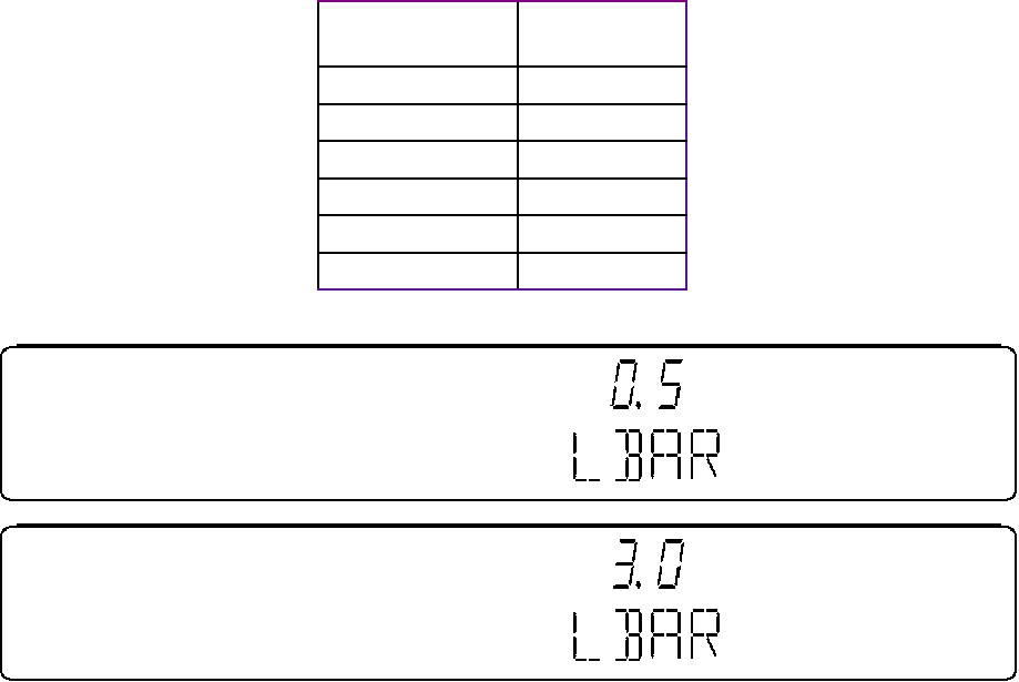
BENDIX/KING
KX 155A/165A
COMM/NAV SYSTEM
10542I02.ZIPRCD Page 3-13
Rev 2, Apr/2000
3.1.4.15 GS Converter Course Width (GSCW)
GS Converter Course Width (GSCW) has a range of 0 to 255. A setting of 0 will result in a mini-
mum indicator displayed half deflection. A setting of 255 will result in a maximum indicator dis-
played half deflection. An external RF GS signal is not required to make this adjustment. The
radio automatically outputs a half deflection converter voltage that can be used when adjusting the
interface between the radio’s internal GS converter and an external indicator. The GS Converter
Course Width should be adjusted so that the external indicator is set at half deflection (.091 ddm,
78 µA).
Table 3-4 Localizer Deviation Bar Time Constant
FIGURE 3-11 VOR DEVIATION BAR RESPONSE TIME
3.1.4.16 Program Secure
The program secure mode allows the installer to lock or unlock an already defined frequency to
a specific channel number, and will prohibit the operator from programming changes to the chan-
nel memories from the front of the unit during normal operation. All other functions shall remain
unchanged during normal operation. The lock state can be toggled rotating the Nav Inner or Outer
Frequency Selection Knobs. The Nav Mode Button is used to scroll the list of channels. If the
frequency is locked, the upper left segment of the nav display will display an “L”, otherwise a “U”
will be displayed as shown in Figure 3-12.
Front Panel
Value Time Con-
stant (sec)
0.5 0.6
1.0 1.0
1.5 1.5
2.0 2.0
2.5 2.5
3.0 3.0
PRELIMINARY - SUBJECT TO CHANGE WITHOUT NOTICE
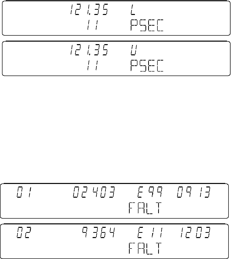
Page 3-14 10542I02.ZIPRCD
Rev 2, Apr/2000
BENDIX/KING
KX 155A/165A
COMM/NAV SYSTEM
FIGURE 3-12 FREQUENCY LOCK AND UNLOCK STATES
3.1.4.17 Fault Reporting
This section on fault reporting is here for reference only. The KX155A fault codes are primarily for
the benefit of AlliedSignal design engineering personnel. The meaning of each fault code is not
published here or in the KX155A Maintenance Manual since they contain no user or product ser-
vice benefit.
Faults that occur in the unit are recorded in non-volatile memory, and are part of the installation
mode. Only the last ten faults are recorded, and are shown one fault per page. Page (1) shows
the most recent fault. Page (2) shows the next most recent fault and so forth. If less than 10 faults
exist, then the fields for the time and fault code are blank. The fault type which is in the active
frequency area shows the type of fault that has occurred, and the fault code shows where in the
software the fault occurred. Figure 3-13 and Table 3-5 show the display while in fault reporting:
Figure 3-13 TYPICAL FAULT DISPLAY
PRELIMINARY - SUBJECT TO CHANGE WITHOUT NOTICE
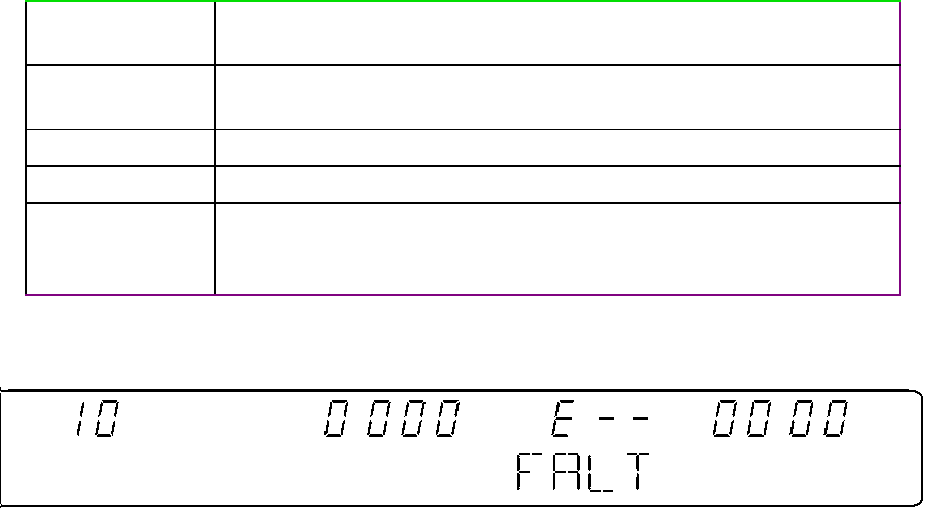
BENDIX/KING
KX 155A/165A
COMM/NAV SYSTEM
10542I02.ZIPRCD Page 3-15
Rev 2, Apr/2000
Table 3-5 Fault Display
If no faults exist, the following display is used for empty fault pages as shown in Figure 3-14.
Figure 3-14 FAULT DISPLAY, NO FAULT
The fault codes and times can be reset to zero (blank) by simultaneously depressing the comm
transfer and nav transfer buttons for 5 or more seconds.
3.2 KI 202/203/204, KI 206/208/209/208A/209A INDICATOR
CONTROLS AND FUNCTIONS
3.2.1 VOR OPERATION
Channel the NAV Receiver to the desired VOR and monitor the audio to positively identify the sta-
tion. To intercept a selected VOR radial, turn the OBS to set the desired radial under the lubber
line. The left-right needle will now deflect in the direction of the desired radial. Flying toward nee-
dle deflection will bring the aircraft to the desired radial.
To fly inbound toward the station, turn the OBS to center the left-right needle while the To-From
is indicating TO. Read the bearing under the lubber line and fly that magnetic course. When the
aircraft passes over the station, the To-From will momentarily disappear and then reappear as
FROM. This indicates the aircraft is outbound from the station.
3.2.2 LOC OPERATION
Localizer circuitry is energized when the NAV Receiver is channeled to an ILS frequency. The
VOR/LOC flag will be out of view when the signal is usable. Corrections for approach should be
made toward the needle, as in VOR, but due to increased sensitivity, corrections are smaller.
When flying inbound on a back course, deflection of the needle will be reversed.
Fault Page
Number:
Use the 2 most significant digits of the Comm active frequency dis-
play.
Fault Time: Use all digits of the comm standby frequency display with a maximum
of 199999 hours
FALT: Annunciates a fault; alphanumeric portion of the nav display.
Fault Type: Use 3 least significant digits of the nav active frequency display.
Fault Code The two most significant digits identify the module in which the error is
detected. The two least significant digits identify the error number for
the module error.
PRELIMINARY - SUBJECT TO CHANGE WITHOUT NOTICE
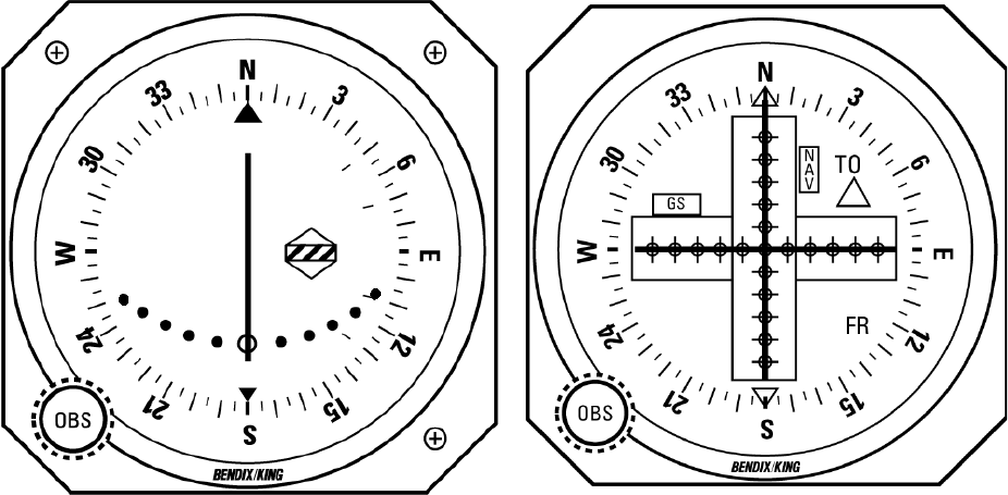
Page 3-16 10542I02.ZIPRCD
Rev 2, Apr/2000
BENDIX/KING
KX 155A/165A
COMM/NAV SYSTEM
3.2.3 GLIDESLOPE OPERATION
Glideslope operation is much the same as the Localizer just discussed. An Up deflection of the
needle indicates the aircraft is below desired glidepath. The pilot must fly toward the needle for
correction. A warning flag is provided to indicate usable signal conditions.
3.2.4 UNIT CONTROL FUNCTIONS
The following figure (Figure 3-15) displays the control functions for the KI 204/206/209. The KI
202/203/208 differs in not having a glideslope needle or flag. The KI 207 differs in not having an
OBS or Azimuth card.
FIGURE 3-15 KI 202/203/204/206/207/208/209/208A/209A TYPICAL INDICATOR MARKINGS
3.3 KI 525A INDICATOR CONTROLS AND FUNCTIONS
3.3.1 VOR/LOC AND GLIDESLOPE OPERATION
Set the navigation receiver to the desired VOR/LOC station and rotate the course select knob to
adjust the selected course pointer to the desired course radial. When a usable navigation signal
is received by the KI 525A the NAV warning flag will disappear from view.
For an ILS approach, tune the navigation receiver to the desired frequency.
The glideslope pointer will deflect into view after a 2 to 10 second delay if a usable glideslope sig-
nal is received. The glideslope pointer indicates the relative position of the glideslope path with
respect to the aircraft.
For LOC operation, tune the navigation receiver to the desired frequency and set the pointer to
the selected inbound localizer course. The position of the deviation bar with respect to the sym-
PRELIMINARY - SUBJECT TO CHANGE WITHOUT NOTICE
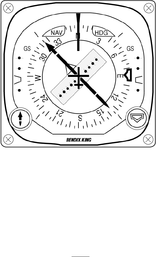
BENDIX/KING
KX 155A/165A
COMM/NAV SYSTEM
10542I02.ZIPRCD Page 3-17
Rev 2, Apr/2000
bolic aircraft indicates the relative position of the selected course. For backcourse operation, set
the course pointer to the inbound localizer front course. The deviation bar position relative to the
symbolic aircraft then represents the position of the backcourse with respect to the aircraft. Figure
3-16 displays the control functions for the KI 525.
FIGURE 3-16 KI 525A INDICATOR AND CONTROLS
3.4 KI 229 RMI OPERATION
The KNI 229 Radio Magnetic Indicator provides bearing information to both ADF and VOR sta-
tions by means of two pointers, each of which is read against the compass card. The servo drive
compass card displays heading information derived from ARINC type X, Y, Z, compass headings.
The double pointer is dedicated solely to a ADF DC SIN/COS source. The single pointer is as-
signed to VOR information.
NOTE
The single pointer can be switched between VOR
and ADF by means of an external switch as ex-
plained in the installation manual of the KNI 229.
3.5 OTHER INDICATORS
Refer to respective installation manuals for operation instructions of other indicators.
PRELIMINARY - SUBJECT TO CHANGE WITHOUT NOTICE
10542I02.ZIPRCD Page EN-72
Rev 2, Dec/1999
ENVIRONMENTAL QUALIFICATION APPENDIX
RTCA DO-160C
ENVIROMENTAL QUALIFICATION
FORMS
PRELIMINARY - SUBJECT TO CHANGE WITHOUT NOTICE
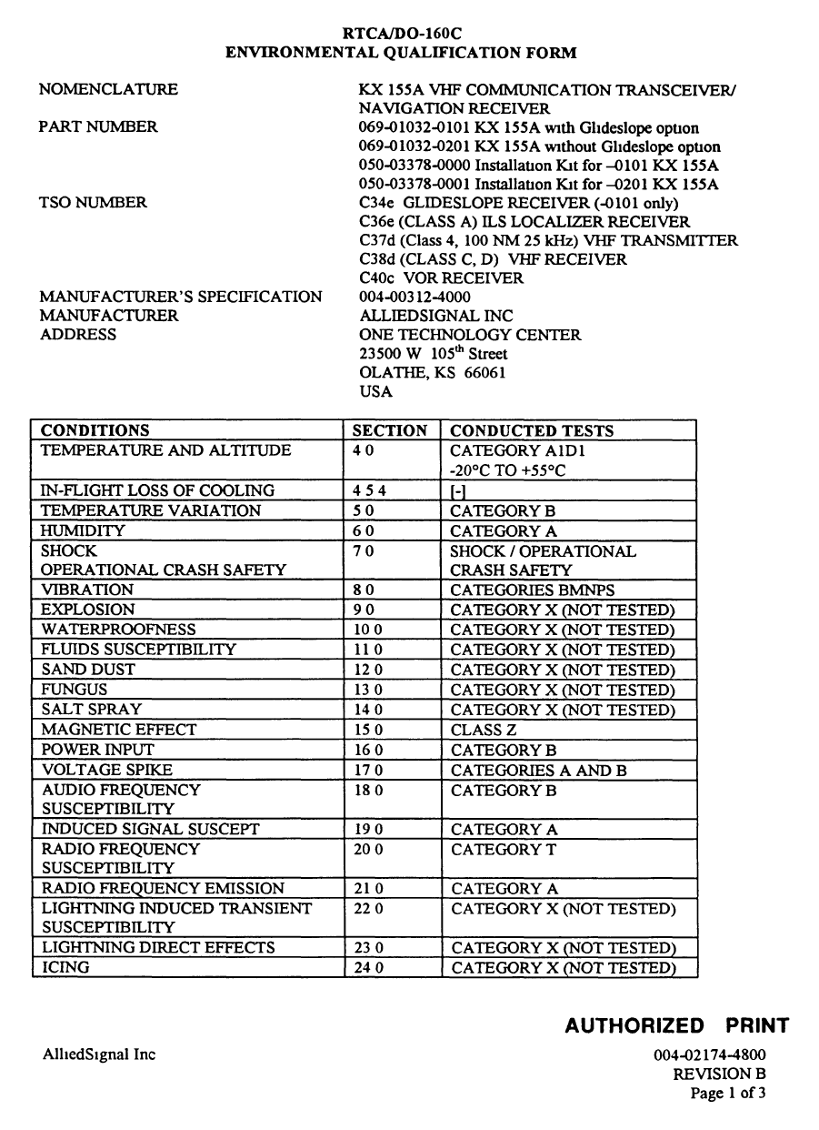
Page EN-73 10542I02.ZIPRCD
Rev 2, Apr/2000
BENDIX/KING
KX 155A/165A
COMM/NAV SYSTEM
PRELIMINARY - SUBJECT TO CHANGE WITHOUT NOTICE
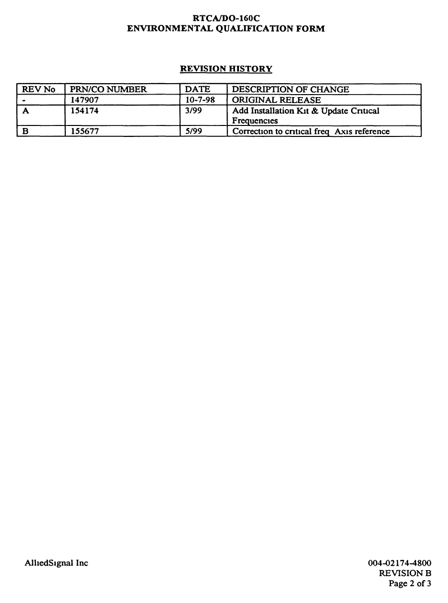
BENDIX/KING
KX 155A/165A
COMM/NAV SYSTEM
10542I02.ZIPRCD Page EN-74
Rev 2, Apr/2000
PRELIMINARY - SUBJECT TO CHANGE WITHOUT NOTICE
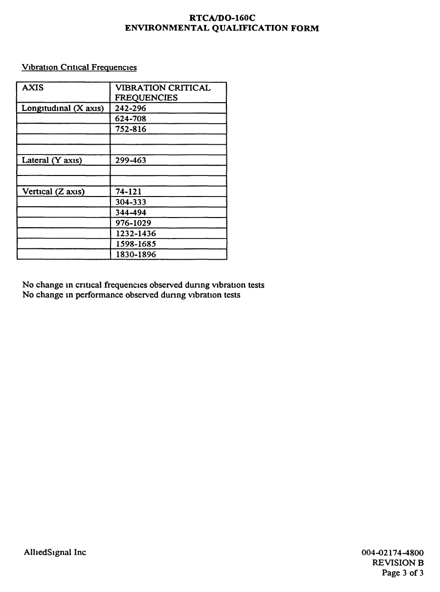
Page EN-75 10542I02.ZIPRCD
Rev 2, Apr/2000
BENDIX/KING
KX 155A/165A
COMM/NAV SYSTEM
PRELIMINARY - SUBJECT TO CHANGE WITHOUT NOTICE