Honeywell KXP2290 AVIATION SERVICES TRANSMITTER User Manual 2290im
Honeywell International Inc. AVIATION SERVICES TRANSMITTER 2290im
UserManual.wiki
>
Honeywell
>
KXP2290 User Manual
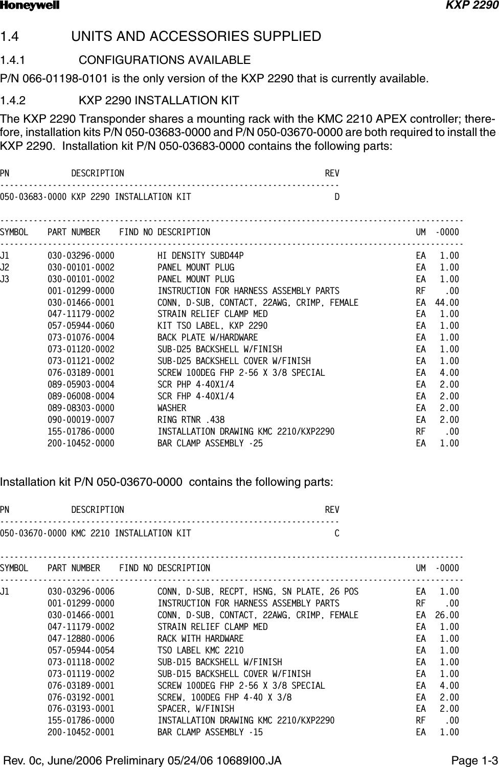
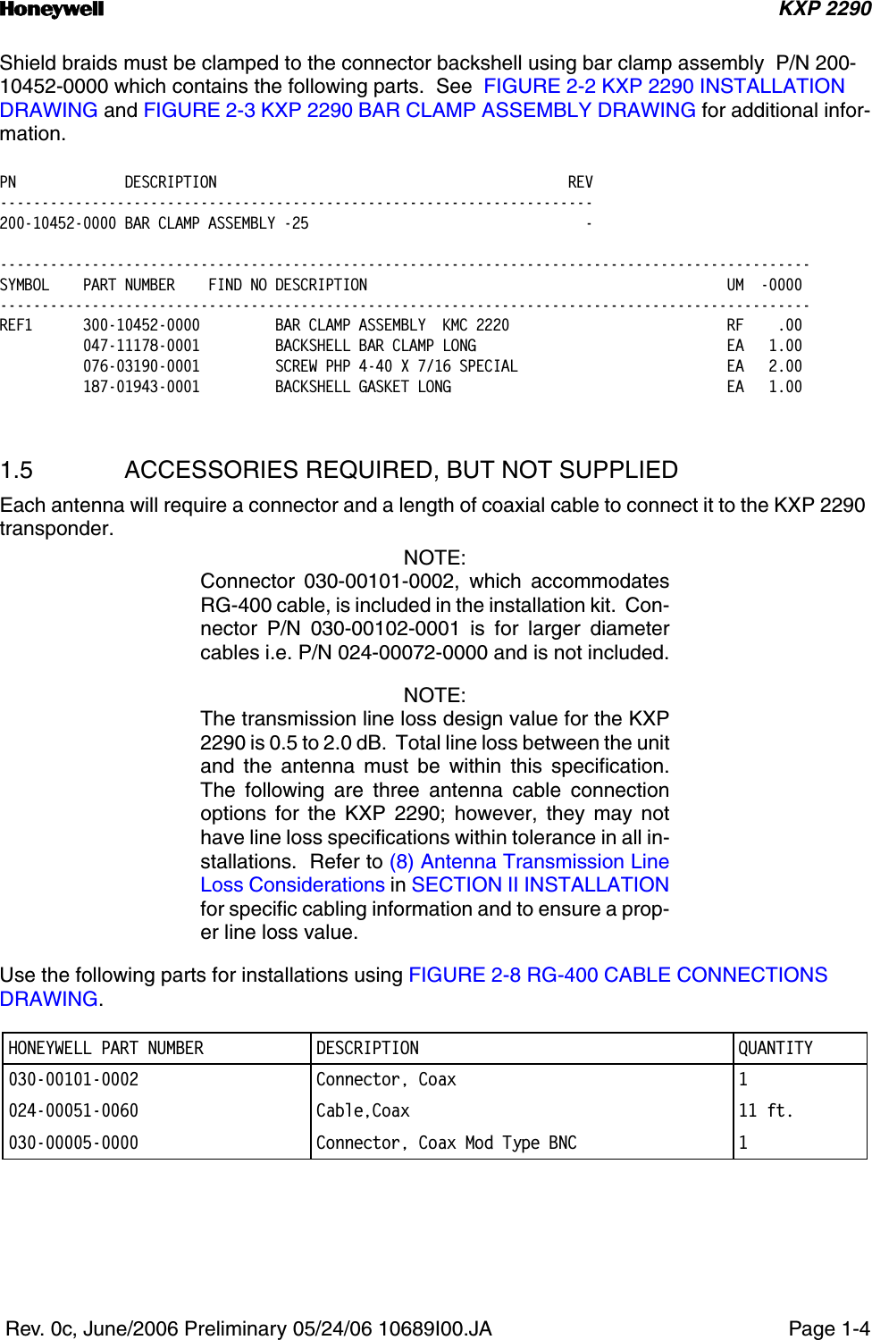
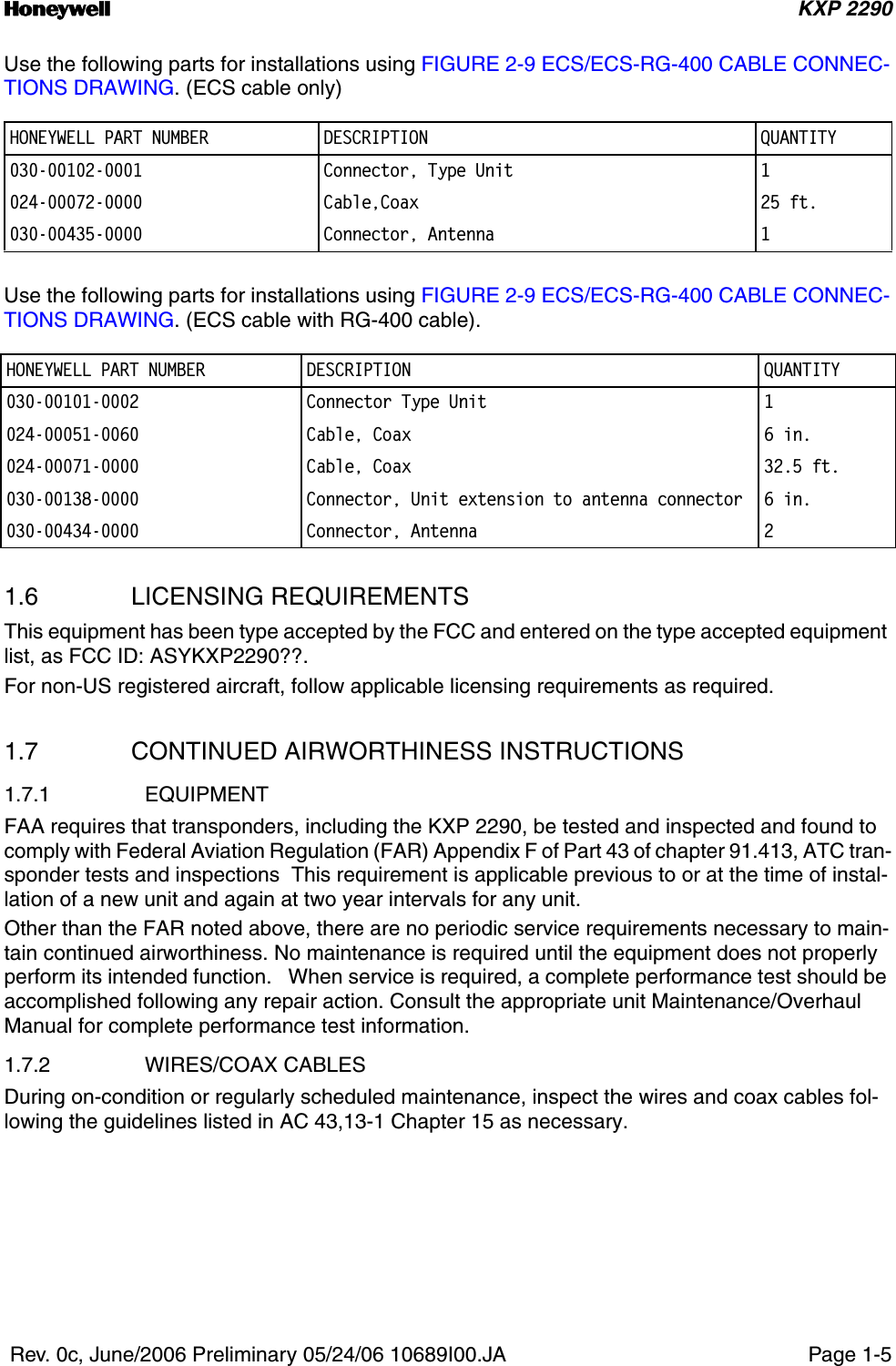
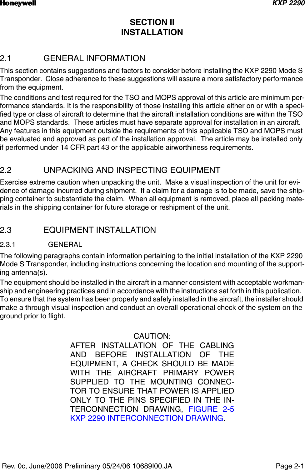
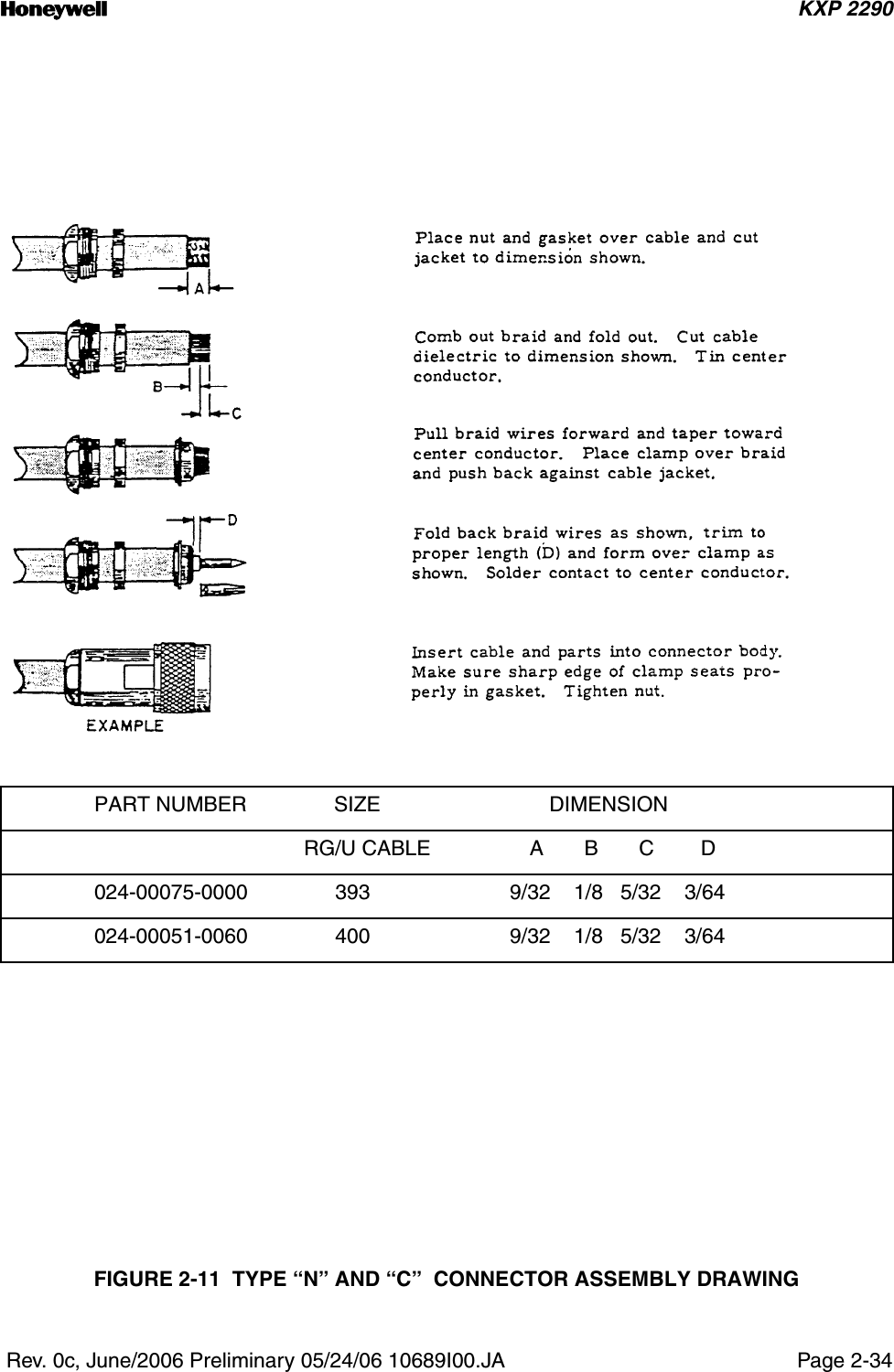
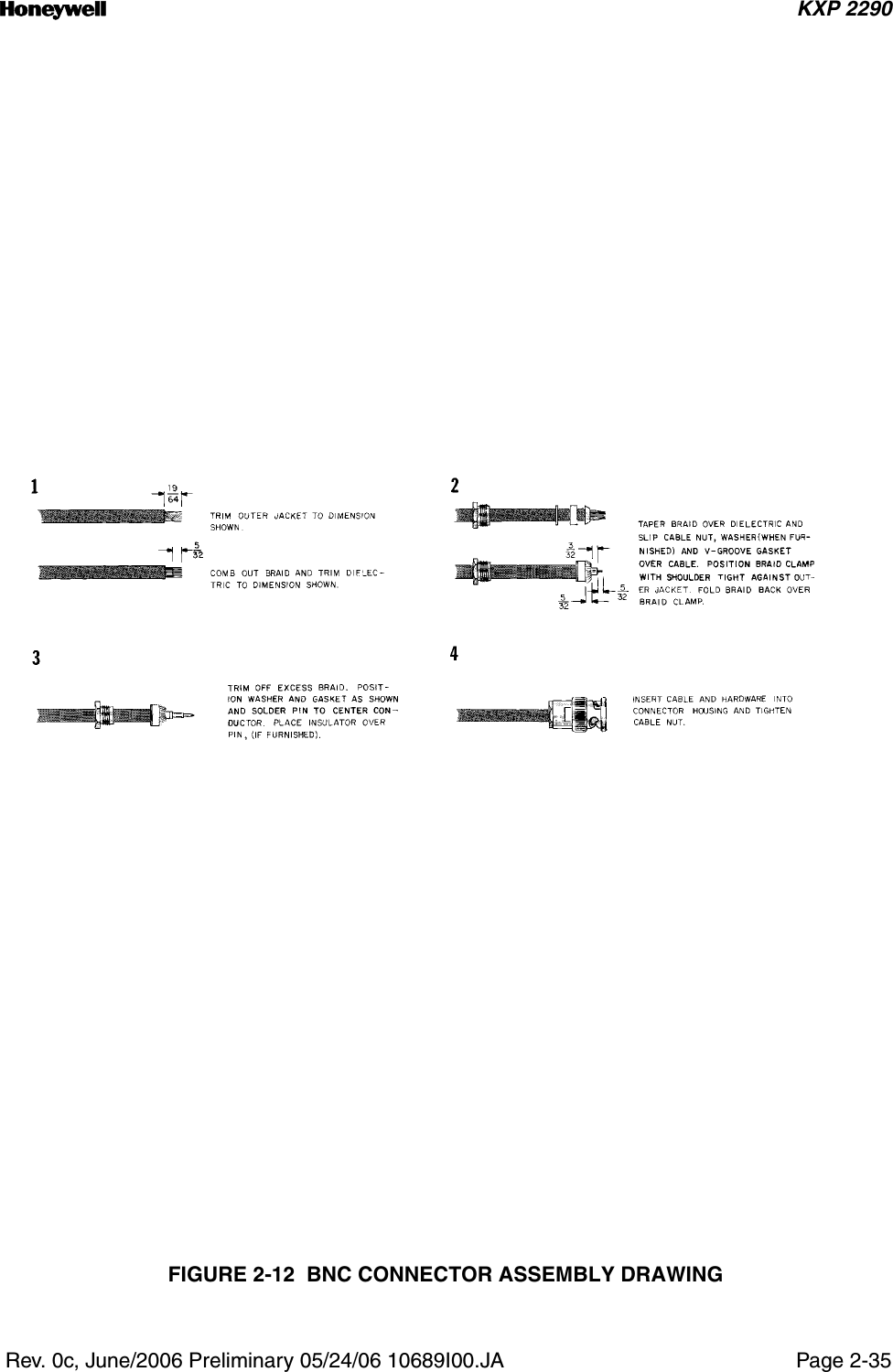
USERS MANUAL
Navigation menu
Upload a User Manual
Namespaces
Wiki Guide
HTML
PDF
Info
Views
User Manual
Discussion / Help
Navigation