Honeywell KXP2290 AVIATION SERVICES TRANSMITTER User Manual 2290im
Honeywell International Inc. AVIATION SERVICES TRANSMITTER 2290im
USERS MANUAL

INSTALLATION MANUAL
(Preliminary)
KXP 2290
MODE S
TRANSPONDER
MANUAL NUMBER 006-10689-0000
REVISION 0 JUNE, 2006
THIS PUBLICATION MAY BE CONTROLLED BY THE U.S. DEPARTMENT OF STATE INTER-
NATIONAL TRAFFIC IN ARMS REGULATIONS (ITAR) 22 CFR 120-130 OR THE U.S.
DEPARTMENT OF COMMERCE EXPORT ADMINISTRATION REGULATIONS (EAR), AND
MAY NOT BE EXPORTED OUT OF THE UNITED STATE OR BE PROVIDED TO FOREIGN
PERSONS (AS DEFINED BY THE ITAR) LOCATED WITHIN THE UNITED STATES, WITHOUT
THE APPROPRIATE PRIOR AUTHORIZATIONS FROM THE U.S. GOVERNMENT. DIVER-
SION CONTRARY TO U.S. EXPORT LAWS AND REGULATIONS IS PROHIBITED.
COPYRIGHT NOTICE
©2006 Honeywell International Inc.
REPRODUCTION OF THIS PUBLICATION OR ANY PORTION THEREOF BY ANY
MEANS WITHOUT THE EXPRESS WRITTEN PERMISSION OF HONEYWELL IS PRO-
HIBITED, EXCEPT TO THE EXTENT REQUIRED FOR INSTALLATION OR MAINTE-
NANCE OF THE RECIPIENT'S EQUIPMENT. FOR FURTHER INFORMATION
CONTACT THE MANAGER, TECHNICAL PUBLICATIONS, HONEYWELL, ONE TECH-
NOLOGY CENTER, 23500 WEST 105th STREET OLATHE KS 66061 TELEPHONE:
(913) 782-0400.

n KXP 2290
Rev. 0c, June/2006 Preliminary 05/24/06 10689I00.JA Page RH-1
REVISION HISTORY
KXP 2290
KXP 2290 Installation Manual
Part Number: 006-10689-XXXX
For each revision, add, delete, or replace as indicated.
Rev. 0c, June/2006 Preliminary 05/24/06
ITEM ACTION
New manual No previous manual revision exists.
n KXP 2290
Rev. 0c, June/2006 Preliminary 05/24/06 10689I00.JA Page RH-2
THIS PAGE IS RESERVED

n KXP 2290
Rev. 0c, June/2006 Preliminary 05/24/06 10689I00.JA Page TC-1
TABLE OF CONTENTS
ITEM PAGE
SECTION I
GENERAL INFORMATION
1.1 INTRODUCTION............................................................................................................ 1-1
1.2 EQUIPMENT DESCRIPTION ........................................................................................ 1-1
1.3 TECHNICAL CHARACTERISTICS ............................................................................... 1-2
1.3.1 KXP 2290 TECHNICAL CHARACTERISTICS............................................................... 1-2
1.3.2 ANTENNA ...................................................................................................................... 1-2
1.4 UNITS AND ACCESSORIES SUPPLIED ..................................................................... 1-3
1.4.1 CONFIGURATIONS AVAILABLE .................................................................................. 1-3
1.4.2 KXP 2290 INSTALLATION KIT...................................................................................... 1-3
1.5 ACCESSORIES REQUIRED, BUT NOT SUPPLIED .................................................... 1-4
1.6 LICENSING REQUIREMENTS...................................................................................... 1-5
1.7 CONTINUED AIRWORTHINESS INSTRUCTIONS ...................................................... 1-5
1.7.1 EQUIPMENT..................................................................................................................1-5
1.7.2 WIRES/COAX CABLES ................................................................................................. 1-5
SECTION II
INSTALLATION
2.1 GENERAL INFORMATION ........................................................................................... 2-1
2.2 UNPACKING AND INSPECTING EQUIPMENT ........................................................... 2-1
2.3 EQUIPMENT INSTALLATION ...................................................................................... 2-1
2.3.1 GENERAL ...................................................................................................................... 2-1
2.3.2 KXP 2290 INTERCONNECTION AND CABLE HARNESS FABRICATION .................. 2-2
2.3.3 EQUIPMENT LOCATION .............................................................................................. 2-4
2.3.4 KXP 2290 INSTALLATION ............................................................................................ 2-5
2.3.5 CRIMP TOOL INFORMATION....................................................................................... 2-7
2.4 POST-INSTALLATION CHECKS................................................................................ 2-37
2.4.1 TRANSPONDER SYSTEM CHECKOUT..................................................................... 2-37
SECTION III
OPERATION
3.1 GENERAL......................................................................................................................3-1
ENVIRONMENTAL QUALIFICATIONS APPENDIX
n KXP 2290
Rev. 0c, June/2006 Preliminary 05/24/06 10689I00.JA Page TC-2

n KXP 2290
Rev. 0c, June/2006 Preliminary 05/24/06 10689I00.JA Page TC-3
ITEM PAGE
FIGURE 2-1 MAIN CONNECTOR - JKXP2290-1............................................................. 2-9
FIGURE 2-2 KXP 2290 INSTALLATION DRAWING ...................................................... 2-11
FIGURE 2-3 KXP 2290 BAR CLAMP ASSEMBLY DRAWING....................................... 2-19
FIGURE 2-4 KA 61 INSTALLATION DRAWING............................................................. 2-21
FIGURE 2-5 KXP 2290 INTERCONNECTION DRAWING............................................. 2-25
FIGURE 2-6 KXP 2290 INTERCONNECTION DRAWING............................................. 2-27
FIGURE 2-7 RF CONNECTOR DRAWING .................................................................... 2-29
FIGURE 2-8 RG-400 CABLE CONNECTIONS DRAWING ............................................ 2-31
FIGURE 2-9 ECS/ECS-RG-400 CABLE CONNECTIONS DRAWING ........................... 2-32
FIGURE 2-10 CABLE CONNECTOR DRAWING ............................................................. 2-33
FIGURE 2-11 TYPE “N” AND “C” CONNECTOR ASSEMBLY DRAWING...................... 2-34
FIGURE 2-12 BNC CONNECTOR ASSEMBLY DRAWING............................................. 2-35
n KXP 2290
Rev. 0c, June/2006 Preliminary 05/24/06 10689I00.JA Page TC-4

n KXP 2290
Rev. 0c, June/2006 Preliminary 05/24/06 10689I00.JA Page TC-5
ITEM PAGE
TABLE 2-1 SIZE 22 HIGH DENSITY D-SUB CONTACT TOOLS .................................. 2-7
TABLE 2-2 JKXP2290-1 PIN FUNCTION LIST ............................................................. 2-9
TABLE 2-3 ANTENNA CONNECTORS AND DESCRIPTIONS ................................... 2-10
TABLE 2-4 INSPECTION/CHECK PROCEDURE........................................................ 2-37
n KXP 2290
Rev. 0c, June/2006 Preliminary 05/24/06 10689I00.JA Page TC-6
n KXP 2290
Rev. 0c, June/2006 Preliminary 05/24/06 10689I00.JA Page 1-1
SECTION I
GENERAL INFORMATION
1.1 INTRODUCTION
This manual contains information relative to the physical, mechanical, and electrical characteris-
tics of the Honeywell KXP 2290 Mode S Transponder. Installation and check out procedures are
also included. Information relative to the maintenance, alignment, and procurement of the re-
placement parts may be found in the KXP 2290 Maintenance/Overhaul Manual, P/N 006-15689-
XXXX. The only current KXP 2290 installation option is as a part of the APEX system. The KXP
2290 is blind-mounted and shares a mounting rack with the KMC 2210 APEX controller. For ad-
ditional information relating to the APEX system, refer to the APEX System Manual 006-10667-
XXXX.
1.2 EQUIPMENT DESCRIPTION
The KXP 2290 is a Mode S Transponder that is capable of non-diversity or diversity operation.
The KXP 2290 Mode S Transponder is designed to meet TSO-C112, ETSO-2C112a for a Class
2A ATCRBS/Mode Select Airborne Transponder System. It replies to ATCRBS Mode A and C,
Intermode, and Mode S interrogations.
Since the KXP 2290 is a Class 2A transponder, it can handle Comm A & Comm B Mode S data
link protocols. The KXP 2290 is compliant with TSO-C112 Class 2A and ETSO-2C112a require-
ments. The EUROCAE ED-73B transponder functionality is Level 2 (Surveillance and Comm A/
B) and the marking is level 2s. Additionally the ED-73B defined class is "CLASS 1". The KXP
2290 is also designed to meet the Enhanced Surveillance mandated in Europe.
The KXP 2290 has the ability to receive an 8-digit alphanumeric Flight ID code. The flight crew
enters the Flight ID information via the APEX control panel.
The KXP 2290 uses ARINC 735A TCAS interface protocol to interface with TCAS II. As a periph-
eral to the TCAS II processor, the transponder receives and replies to short and long Air-to-Air
surveillance and TCAS Coordination interrogations. Also, it receives and replies to Ground-to-Air
surveillance and Comm-A interrogations directed to TCAS.
Top and bottom antennas provide the diversity option that allow compatibility with TCAS. The di-
versity option allows selection of signal receptions from either the top or the bottom antenna based
on the characteristics of the received interrogation signals. This improves air-to-air surveillance
and communication. An Optional top-mounted omnidirectional antenna is required for diversity.
The KXP 2290 contains BITE (Built In Test Equipment) so the operational health of the unit is con-
stantly monitored. When a critical fault is detected, the unit will notify the APEX system. The unit
stores detected failures in non-volatile memory for later review. The unit also has a temperature
sensor and a timer so that faults can be time stamped and temperature data can be collected and
stored.

n KXP 2290
Rev. 0c, June/2006 Preliminary 05/24/06 10689I00.JA Page 1-2
1.3 TECHNICAL CHARACTERISTICS
1.3.1 KXP 2290 TECHNICAL CHARACTERISTICS
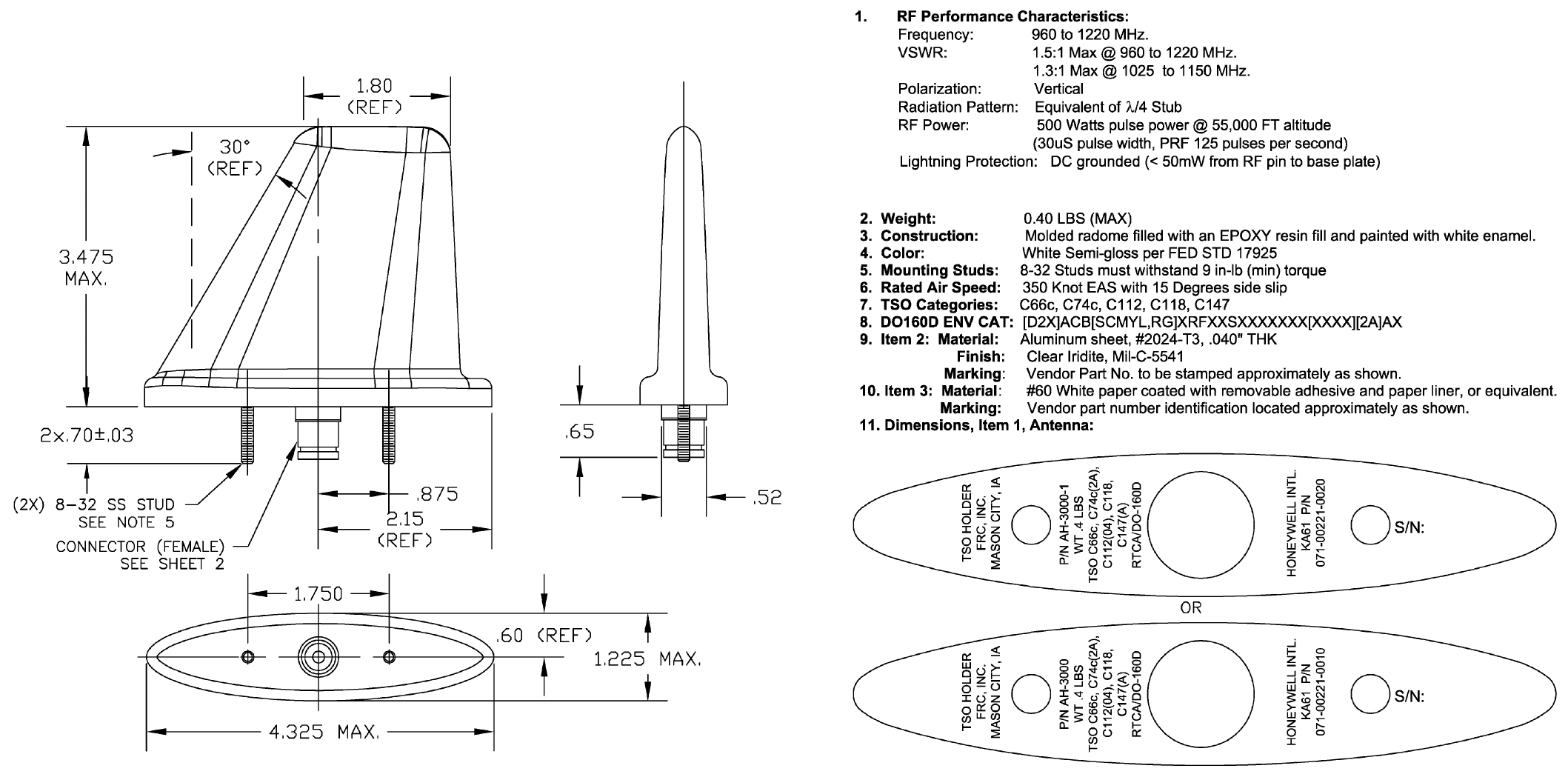
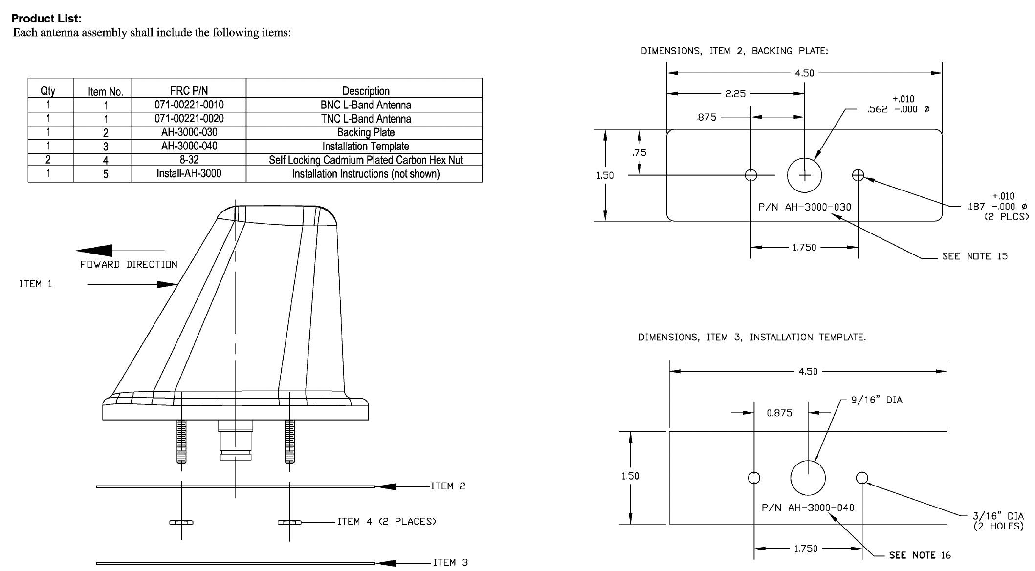
1.3.2 ANTENNA
The KXP 2290 will work with any conventional ATCRBS blade or quarter-wave monopole type an-
tenna provided it is certified to TSO-C112/ETSO-2C112a A representative type is the Honeywell
KA 61 antenna, P/N 071-00221-0010 (BNC) or 071-00221-0020 (TNC). Refer to FIGURE 2-4 KA
61 INSTALLATION DRAWING for KA 61 technical characteristics, installation, and certification
information.
NOTE:
Two antennas (top and bottom) are required for di-
versity operation.
TSO COMPLIANCE: TSO-C112, ETSO-2C112a
SOFTWARE CERTIFICATION
CATEGORY:
RTCA/DO-178B SOFTWARE LEVEL “B”
ENVIRONMENTAL
CATEGORIES:
SEE ENVIRONMENTAL QUALIFICATIONS APPENDIX
PHYSICAL DIMENSIONS: SEE FIGURE 2-2 KXP 2290 INSTALLATION DRAWING
WEIGHT: SEE FIGURE 2-2 KXP 2290 INSTALLATION DRAWING
MOUNTING: BLIND-MOUNT (SHARES RACK WITH KMC 2210)
TEMPERATURE: SEE ENVIRONMENTAL QUALIFICATIONS APPENDIX
ALTITUDE: SEE ENVIRONMENTAL QUALIFICATIONS APPENDIX
COOLING: NO FORCED-AIR COOLING REQUIRED.
POWER INPUT: 18-32 VOLTS, 30 WATTS
n KXP 2290
Rev. 0c, June/2006 Preliminary 05/24/06 10689I00.JA Page 1-3
1.4 UNITS AND ACCESSORIES SUPPLIED
1.4.1 CONFIGURATIONS AVAILABLE
P/N 066-01198-0101 is the only version of the KXP 2290 that is currently available.
1.4.2 KXP 2290 INSTALLATION KIT
The KXP 2290 Transponder shares a mounting rack with the KMC 2210 APEX controller; there-
fore, installation kits P/N 050-03683-0000 and P/N 050-03670-0000 are both required to install the
KXP 2290. Installation kit P/N 050-03683-0000 contains the following parts:
PN DESCRIPTION REV
-----------------------------------------------------------------------
050-03683-0000 KXP 2290 INSTALLATION KIT D
-------------------------------------------------------------------------------------------------
SYMBOL PART NUMBER FIND NO DESCRIPTION UM -0000
-------------------------------------------------------------------------------------------------
J1 030-03296-0000 HI DENSITY SUBD44P EA 1.00
J2 030-00101-0002 PANEL MOUNT PLUG EA 1.00
J3 030-00101-0002 PANEL MOUNT PLUG EA 1.00
001-01299-0000 INSTRUCTION FOR HARNESS ASSEMBLY PARTS RF .00
030-01466-0001 CONN, D-SUB, CONTACT, 22AWG, CRIMP, FEMALE EA 44.00
047-11179-0002 STRAIN RELIEF CLAMP MED EA 1.00
057-05944-0060 KIT TSO LABEL, KXP 2290 EA 1.00
073-01076-0004 BACK PLATE W/HARDWARE EA 1.00
073-01120-0002 SUB-D25 BACKSHELL W/FINISH EA 1.00
073-01121-0002 SUB-D25 BACKSHELL COVER W/FINISH EA 1.00
076-03189-0001 SCREW 100DEG FHP 2-56 X 3/8 SPECIAL EA 4.00
089-05903-0004 SCR PHP 4-40X1/4 EA 2.00
089-06008-0004 SCR FHP 4-40X1/4 EA 2.00
089-08303-0000 WASHER EA 2.00
090-00019-0007 RING RTNR .438 EA 2.00
155-01786-0000 INSTALLATION DRAWING KMC 2210/KXP2290 RF .00
200-10452-0000 BAR CLAMP ASSEMBLY -25 EA 1.00
Installation kit P/N 050-03670-0000 contains the following parts:
PN DESCRIPTION REV
-----------------------------------------------------------------------
050-03670-0000 KMC 2210 INSTALLATION KIT C
-------------------------------------------------------------------------------------------------
SYMBOL PART NUMBER FIND NO DESCRIPTION UM -0000
-------------------------------------------------------------------------------------------------
J1 030-03296-0006 CONN, D-SUB, RECPT, HSNG, SN PLATE, 26 POS EA 1.00
001-01299-0000 INSTRUCTION FOR HARNESS ASSEMBLY PARTS RF .00
030-01466-0001 CONN, D-SUB, CONTACT, 22AWG, CRIMP, FEMALE EA 26.00
047-11179-0002 STRAIN RELIEF CLAMP MED EA 1.00
047-12880-0006 RACK WITH HARDWARE EA 1.00
057-05944-0054 TSO LABEL KMC 2210 EA 1.00
073-01118-0002 SUB-D15 BACKSHELL W/FINISH EA 1.00
073-01119-0002 SUB-D15 BACKSHELL COVER W/FINISH EA 1.00
076-03189-0001 SCREW 100DEG FHP 2-56 X 3/8 SPECIAL EA 4.00
076-03192-0001 SCREW, 100DEG FHP 4-40 X 3/8 EA 2.00
076-03193-0001 SPACER, W/FINISH EA 2.00
155-01786-0000 INSTALLATION DRAWING KMC 2210/KXP2290 RF .00
200-10452-0001 BAR CLAMP ASSEMBLY -15 EA 1.00

n KXP 2290
Rev. 0c, June/2006 Preliminary 05/24/06 10689I00.JA Page 1-4
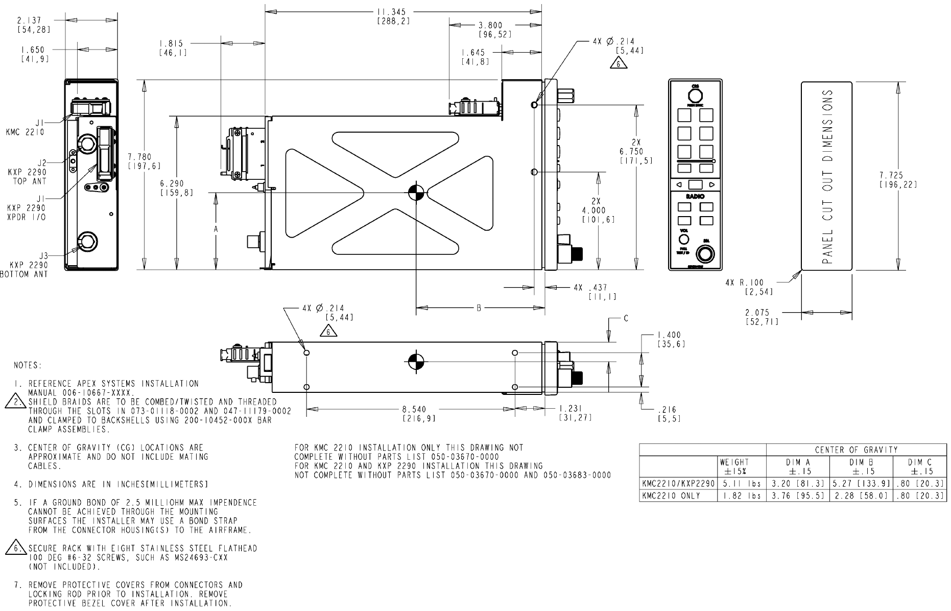
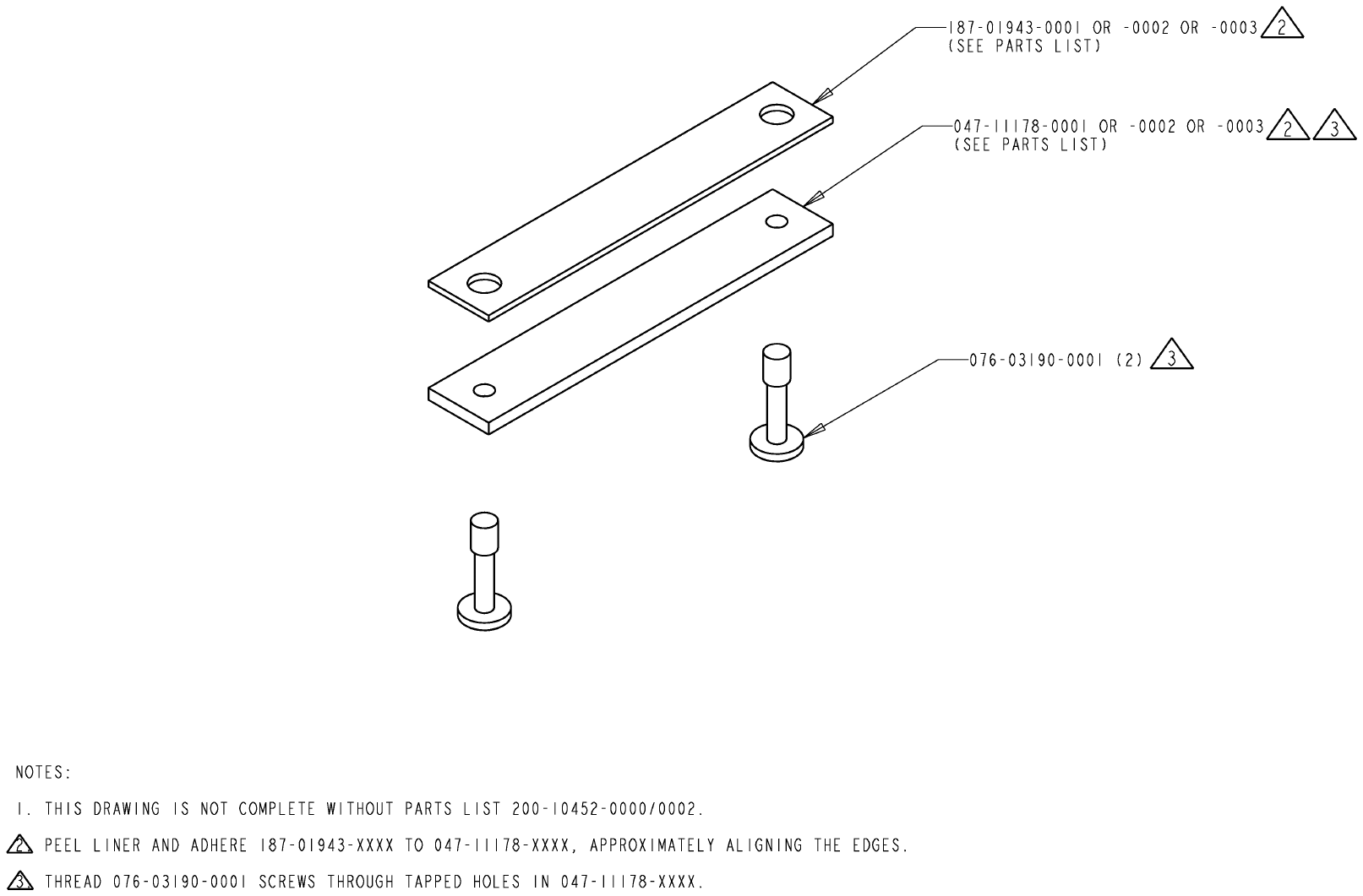
Shield braids must be clamped to the connector backshell using bar clamp assembly P/N 200-
10452-0000 which contains the following parts. See FIGURE 2-2 KXP 2290 INSTALLATION
DRAWING and FIGURE 2-3 KXP 2290 BAR CLAMP ASSEMBLY DRAWING for additional infor-
mation.
PN DESCRIPTION REV
-----------------------------------------------------------------------
200-10452-0000 BAR CLAMP ASSEMBLY -25 -
-------------------------------------------------------------------------------------------------
SYMBOL PART NUMBER FIND NO DESCRIPTION UM -0000
-------------------------------------------------------------------------------------------------
REF1 300-10452-0000 BAR CLAMP ASSEMBLY KMC 2220 RF .00
047-11178-0001 BACKSHELL BAR CLAMP LONG EA 1.00
076-03190-0001 SCREW PHP 4-40 X 7/16 SPECIAL EA 2.00
187-01943-0001 BACKSHELL GASKET LONG EA 1.00
1.5 ACCESSORIES REQUIRED, BUT NOT SUPPLIED
Each antenna will require a connector and a length of coaxial cable to connect it to the KXP 2290
transponder.
NOTE:
Connector 030-00101-0002, which accommodates
RG-400 cable, is included in the installation kit. Con-
nector P/N 030-00102-0001 is for larger diameter
cables i.e. P/N 024-00072-0000 and is not included.
NOTE:
The transmission line loss design value for the KXP
2290 is 0.5 to 2.0 dB. Total line loss between the unit
and the antenna must be within this specification.
The following are three antenna cable connection
options for the KXP 2290; however, they may not
have line loss specifications within tolerance in all in-
stallations. Refer to (8) Antenna Transmission Line
Loss Considerations in SECTION II INSTALLATION
for specific cabling information and to ensure a prop-
er line loss value.
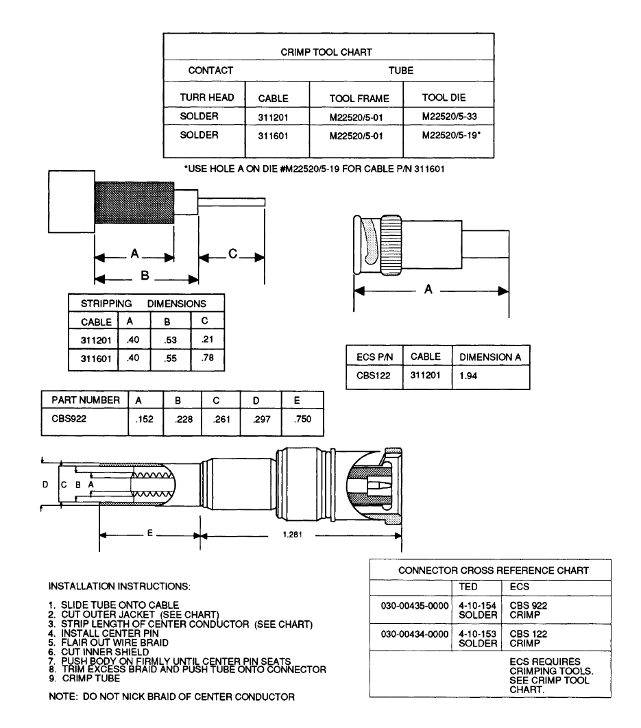
Use the following parts for installations using FIGURE 2-8 RG-400 CABLE CONNECTIONS
DRAWING.
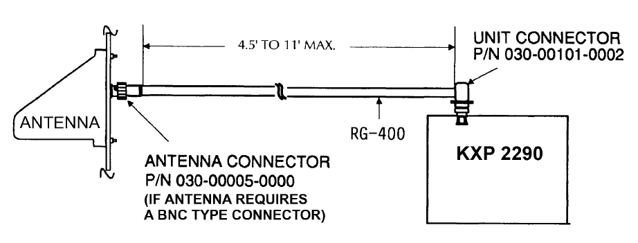
HONEYWELL PART NUMBER DESCRIPTION QUANTITY
030-00101-0002 Connector, Coax 1
024-00051-0060 Cable,Coax 11 ft.
030-00005-0000 Connector, Coax Mod Type BNC 1

n KXP 2290
Rev. 0c, June/2006 Preliminary 05/24/06 10689I00.JA Page 1-5
Use the following parts for installations using FIGURE 2-9 ECS/ECS-RG-400 CABLE CONNEC-
TIONS DRAWING. (ECS cable only)
Use the following parts for installations using FIGURE 2-9 ECS/ECS-RG-400 CABLE CONNEC-
TIONS DRAWING. (ECS cable with RG-400 cable).
1.6 LICENSING REQUIREMENTS
This equipment has been type accepted by the FCC and entered on the type accepted equipment
list, as FCC ID: ASYKXP2290??.
For non-US registered aircraft, follow applicable licensing requirements as required.
1.7 CONTINUED AIRWORTHINESS INSTRUCTIONS
1.7.1 EQUIPMENT
FAA requires that transponders, including the KXP 2290, be tested and inspected and found to
comply with Federal Aviation Regulation (FAR) Appendix F of Part 43 of chapter 91.413, ATC tran-
sponder tests and inspections This requirement is applicable previous to or at the time of instal-
lation of a new unit and again at two year intervals for any unit.
Other than the FAR noted above, there are no periodic service requirements necessary to main-
tain continued airworthiness. No maintenance is required until the equipment does not properly
perform its intended function. When service is required, a complete performance test should be
accomplished following any repair action. Consult the appropriate unit Maintenance/Overhaul
Manual for complete performance test information.
1.7.2 WIRES/COAX CABLES
During on-condition or regularly scheduled maintenance, inspect the wires and coax cables fol-
lowing the guidelines listed in AC 43,13-1 Chapter 15 as necessary.
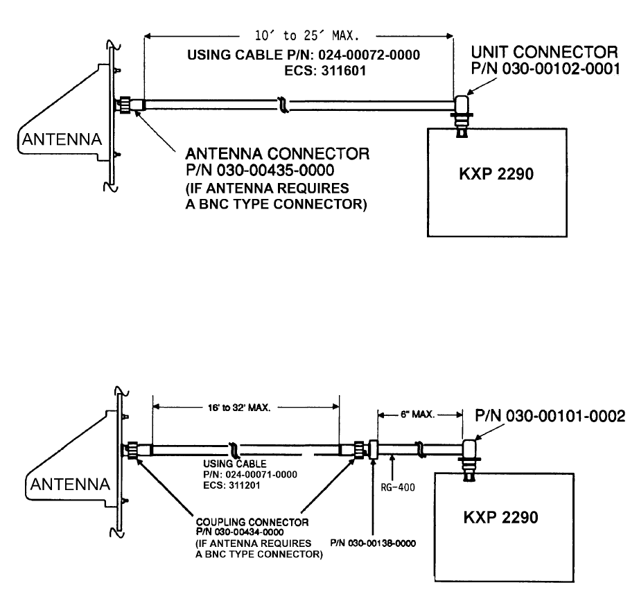
HONEYWELL PART NUMBER DESCRIPTION QUANTITY
030-00102-0001 Connector, Type Unit 1
024-00072-0000 Cable,Coax 25 ft.
030-00435-0000 Connector, Antenna 1
HONEYWELL PART NUMBER DESCRIPTION QUANTITY
030-00101-0002 Connector Type Unit 1
024-00051-0060 Cable, Coax 6 in.
024-00071-0000 Cable, Coax 32.5 ft.
030-00138-0000 Connector, Unit extension to antenna connector 6 in.
030-00434-0000 Connector, Antenna 2
n KXP 2290
Rev. 0c, June/2006 Preliminary 05/24/06 10689I00.JA Page 1-6
THIS PAGE IS RESERVED
n KXP 2290
Rev. 0c, June/2006 Preliminary 05/24/06 10689I00.JA Page 2-1
SECTION II
INSTALLATION
2.1 GENERAL INFORMATION
This section contains suggestions and factors to consider before installing the KXP 2290 Mode S
Transponder. Close adherence to these suggestions will assure a more satisfactory performance
from the equipment.
The conditions and test required for the TSO and MOPS approval of this article are minimum per-
formance standards. It is the responsibility of those installing this article either on or with a speci-
fied type or class of aircraft to determine that the aircraft installation conditions are within the TSO
and MOPS standards. These articles must have separate approval for installation in an aircraft.
Any features in this equipment outside the requirements of this applicable TSO and MOPS must
be evaluated and approved as part of the installation approval. The article may be installed only
if performed under 14 CFR part 43 or the applicable airworthiness requirements.
2.2 UNPACKING AND INSPECTING EQUIPMENT
Exercise extreme caution when unpacking the unit. Make a visual inspection of the unit for evi-
dence of damage incurred during shipment. If a claim for a damage is to be made, save the ship-
ping container to substantiate the claim. When all equipment is removed, place all packing mate-
rials in the shipping container for future storage or reshipment of the unit.
2.3 EQUIPMENT INSTALLATION
2.3.1 GENERAL
The following paragraphs contain information pertaining to the initial installation of the KXP 2290
Mode S Transponder, including instructions concerning the location and mounting of the support-
ing antenna(s).
The equipment should be installed in the aircraft in a manner consistent with acceptable workman-
ship and engineering practices and in accordance with the instructions set forth in this publication.
To ensure that the system has been properly and safely installed in the aircraft, the installer should
make a through visual inspection and conduct an overall operational check of the system on the
ground prior to flight.
CAUTION:
AFTER INSTALLATION OF THE CABLING
AND BEFORE INSTALLATION OF THE
EQUIPMENT, A CHECK SHOULD BE MADE
WITH THE AIRCRAFT PRIMARY POWER
SUPPLIED TO THE MOUNTING CONNEC-
TOR TO ENSURE THAT POWER IS APPLIED
ONLY TO THE PINS SPECIFIED IN THE IN-
TERCONNECTION DRAWING, FIGURE 2-5
KXP 2290 INTERCONNECTION DRAWING.
n KXP 2290
Rev. 0c, June/2006 Preliminary 05/24/06 10689I00.JA Page 2-2
The installation should be installed in accordance with standards established by the customer’s
installing agency and existing conditions as to unit location and type of installation. However, the
following suggestions should be considered before installing the system. Close adherence to
these suggestions will assure a more satisfactory performance from the equipment.
The installing agency will supply and fabricate all external cables. The connectors required are
supplied by Honeywell.
NOTE:
The TSO identifies the minimum performance stan-
dards, tests, and other conditions applicable for issu-
ance of design and production approval of the arti-
cle. The TSO applicant is responsible for document-
ing all limitations and conditions suitable for installa-
tion of the article. An applicant requesting approval
for installation of the article within a specific type or
class of product is responsible for determining envi-
ronmental and functional compatibility.
2.3.2 KXP 2290 INTERCONNECTION AND CABLE HARNESS FABRICATION
2.3.2.1 General
The KXP 2290 Mode S Transponder receives primary power from the aircraft power source. Pow-
er connections, voltage requirements, and circuit breaker requirements are shown on the inter-
connect diagrams (FIGURE 2-5 KXP 2290 INTERCONNECTION DRAWING).
The length of the wires to parallel pins should be approximately the same length, so that the best
distribution of current can be effected. Honeywell recommends that all wires, including spares as
shown on the interconnect diagram be included in the fabrication of the wiring harness. However;
if full wiring is not desired, the installer should ensure that the minimum wiring requirements for
the features and functions to be used have been incorporated.
When cables are installed in the aircraft, they must be supported firmly enough to prevent move-
ment and should be carefully protected against chaffing. Additional protection should also be pro-
vided in all locations where the cable may be subjected to abuse.
In wire bundles, the cabling should not be tied tightly together as this tends to increase the possi-
bility of noise pickup and similar interference. When routing cables through the aircraft the cables
should cross high level rf lines at right angles.
Prior to installing any equipment, make a continuity check of all wires and cables associated with
the system. Then apply power and check for proper voltages at system connectors, and then re-
move power before completing the installation.
Please note the following guidelines:
(1) The installing facility will supply and fabricate all external cables. The required con-
nectors are supplied as part of the installation kit (P/N 050-03451-0000).
(2) The KXP 2290 must be kept a minimum of three feet from the antenna(s). Addition-
ally, the antenna coax cable(s) should not be bundled with the other wiring harness-
es to the KXP 2290.
n KXP 2290
Rev. 0c, June/2006 Preliminary 05/24/06 10689I00.JA Page 2-3
(3) The length and routing of the external cables must be carefully planned before at-
tempting the actual installation. Avoid sharp bends or locating the cable near aircraft
control cables. The cables should be of a length to allow for a “maintenance loop”.
That is, the length should be adequate to access and extend the connectors aft of
the panel for future maintenance purposes. Excess cabling should be secured and
stowed by tie-wrapping until such maintenance is required.
(4) The cables should be supported firmly enough to prevent movement. They should
be carefully protected wherever one may chafe against another or against some oth-
er object. Extra protection should be provided in all locations where the cables may
be subject to abuse. Shields on shielded wires should be grounded as shown on
the system interconnection diagrams.
(5) Shields should be carried through any obstruction via a thru-bulkhead connector. If
shielding cannot be carried through by use of a bulkhead/connector pin, precautions
should be taken to ensure each segment of the shielded lead be grounded at only
one point. A ground connection of not more than two inches in length should be
used. The preceding discussion does not apply to coaxial and quadraxial cable.
(6) Avoid routing cabling near high noise and high power sources.
(7) Do not route the transponder antenna coax(s) near ADF sense or loop antenna ca-
bles.
(8) Antenna Transmission Line Loss Considerations
NOTE:
The total losses in the coaxial cable run and inter-
connects between the antenna(s) and the KXP 2290
transponder must not be less than 0.5 dB and must
not be more than 2.0 dB at 1030MHz.
NOTE:
The antenna cabling information noted in this sec-
tion, in particular by FIGURE 2-8 RG-400 CABLE
CONNECTIONS DRAWING, FIGURE 2-9 ECS/
ECS-RG-400 CABLE CONNECTIONS DRAWING,
FIGURE 2-10 CABLE CONNECTOR DRAWING,
FIGURE 2-11 TYPE “N” AND “C” CONNECTOR AS-
SEMBLY DRAWING, and FIGURE 2-12 BNC CON-
NECTOR ASSEMBLY DRAWING, is provided as
possible antenna connection solutions and is provid-
ed for reference only. While the options noted in the
figures will be applicable to many installations, ad-
herence to the following sub-sections will ensure that
the total cable/interconnection losses are within
specification.
n KXP 2290
Rev. 0c, June/2006 Preliminary 05/24/06 10689I00.JA Page 2-4
(a) Consult manufacturer’s coaxial cable data sheet specifications. Using the
length of the top and/or bottom antenna cables and the manufacturer speci-
fied dB loss per foot of cable type, select a particular type or types of cable
that meet the top and bottom cable loss limitations. In anticipation of aging
factors, it is advisable to select a cable type that has an insertion loss that
when combined with interconnect losses will equal a dB loss significantly low-
er than 2 dB.
(b) In diversity installations, it is conceivable that the type of cable selected to
meet the dB loss requirements of the top antenna cable will be different than
the type of cable selection required to meet the dB loss requirements of the
bottom antenna. For example: if the antenna run to one antenna is relatively
lengthy, and the antenna run to the other antenna is relatively short, the longer
run may require low loss antenna cable to meet the less than 2 dB antenna
cable/interconnect requirement while the short run may require a relatively
higher loss cable to exceed the 0.5 dB antenna cable/interconnect loss re-
quirement
NOTE:
For installations with diversity transponder antennas
(top and bottom) the cable lengths must be within 10
feet of each other.
(c) Consult manufacturer’s data sheets to determine the nanosecond delay per
foot (at 1030 MHz) for the type or types of cable selected.
2.3.2.2 Primary Power and Circuit Breaker Requirements and Wiring
The KXP 2290 transponder receives primary power from the aircraft power circuit breakers. The
KXP 2290 is designed to operate over the range of 18-32V dc. Power connections, wire sizes,
and circuit breaker requirements are shown on the interconnection diagrams FIGURE 2-5 KXP
2290 INTERCONNECTION DRAWING.
2.3.3 EQUIPMENT LOCATION
Care should be exercised to avoid mounting components near equipment operating with high
pulse current or high power outputs such as radar and satellite communications equipment. In
general, the equipment should be installed in a location convenient for operation, inspection, and
maintenance, and in an area consistent with the TSO environmental limits.
Refer to the mechanical installation drawing (FIGURE 2-2 KXP 2290 INSTALLATION DRAWING),
cable and connector assembly diagrams (FIGURE 2-7 RF CONNECTOR DRAWING, FIGURE 2-
8 RG-400 CABLE CONNECTIONS DRAWING, FIGURE 2-9 ECS/ECS-RG-400 CABLE CON-
NECTIONS DRAWING, FIGURE 2-10 CABLE CONNECTOR DRAWING, FIGURE 2-11 TYPE
“N” AND “C” CONNECTOR ASSEMBLY DRAWING, FIGURE 2-12 BNC CONNECTOR ASSEM-
BLY DRAWING), interconnection drawing(s) (FIGURE 2-5 KXP 2290 INTERCONNECTION
DRAWING), and connector pin assignments diagrams (FIGURE 2-1 MAIN CONNECTOR -
JKXP2290-1, TABLE 2-2 JKXP2290-1 PIN FUNCTION LIST) as required. Determine the mount-
ing location for system components following the guidelines below.
n KXP 2290
Rev. 0c, June/2006 Preliminary 05/24/06 10689I00.JA Page 2-5
2.3.3.1 Transponder And Mounting Tray Locations
The KXP 2290 Mode S Transponder shares a mounting tray with the Honeywell APEX KMC 2210
controller and is part of the APEX cockpit panel configuration.
Except for antenna cables the lengths of the cables from the KXP 2290 transponder mounting tray
connector to other system units are not critical because unit interfaces are designed with high im-
pedance inputs, low impedance outputs, and low noise susceptibility characteristics.
2.3.3.2 Antenna(s)
The antenna(s) should be well removed from other antenna projections, the engine(s), and pro-
peller(s). It should also be well removed from landing gear doors, access doors, or other openings
which will break the ground plane for the antenna(s). The surface directly beneath the antenna(s)
should be a flat plane over as large an area as possible.
A back-up plate for each antenna should be used for added strength on thin-skinned aircraft.
The antenna(s) need to be within 5 degrees of the centerline
To prevent rf interference, the antenna(s) must be physically mounted a minimum distance of
three feet from the KXP 2290 and the wiring harness.
The transponder antenna(s) should be mounted a minimum of 30 inches away from the TCAS or
DME antennas and four feet from the ADF sense antenna.
Where practical, plan the antenna location(s) to keep cable lengths as short as possible and avoid
sharp bends in the cable to minimize the VSWR.
Avoid running other cables or wires near the antenna cable(s).
On pressurized aircraft, the antenna(s) should be sealed using an approved sealant, such as RTV
No. 3145 (P/N 016-01082-0000) or equivalent, around the connector and mounting hardware.
The antenna mounting(s) should be sealed from the outside for moisture protection using RTV or
equivalent.
Mount the antenna(s) in as clean as environment as possible, away from exhaust gases and oils.
The antenna(s) should be kept clean. If left dirty (oil covered), the range of the transponder may
be affected.
For installations with diversity transponder antennas (top and bottom) the distance between the
top and bottom antennas on the horizontal plane of the aircraft fuselage must not exceed 25 feet
(7.62m).
2.3.4 KXP 2290 INSTALLATION
2.3.4.1 General
The mounting tray for the transponder/control unit should be mounted using the dimensions spec-
ified in the outline and mounting drawing, FIGURE 2-2 KXP 2290 INSTALLATION DRAWING.
KXP 2290 wiring should be per the system interconnect diagram, FIGURE 2-5 KXP 2290 INTER-
CONNECTION DRAWING.
2.3.4.2 Transponder
(1) Slide the transponder into the tray until the front lobe touches the mounting tray.
(2) Turn the Allen wrench clockwise until the rear lobe engages the mounting tray slot.
Continue turning the wrench clockwise until tight.
CAUTION:
DO NOT OVERTIGHTEN THE LOCKING FASTENER
n KXP 2290
Rev. 0c, June/2006 Preliminary 05/24/06 10689I00.JA Page 2-6
(3) For removal, turn the 3-32 inch Allen wrench counter-clockwise until the unit disen-
gages from the mounting tray slot. If all connectors are removed, the unit can be
pulled completely out of the rack.
For additional KXP 2290 installation information, refer to FIGURE 2-2 KXP 2290 INSTALLATION
DRAWING as required
2.3.4.3 Aircraft Address Programming Options
The Mode S aircraft address and maximum airspeed data must be programmed for use for the
KXP 2290. This information is received from the APEX system via the ARINC 429 bus.
NOTE:
THE AIRCRAFT MODE S ADDRESS MUST BE OB-
TAINED FROM FAA AND PROGRAMMED INTO
THE KXP 2290. FOR US REGISTERED AIR-
CRAFT, THE ICAO AIRCRAFT ADDRESS CODE
CAN BE FOUND ON THE AIRCRAFT REGISTRA-
TION.
AIRCRAFT MODE S ADDRESSES MAY BE OB-
TAINED BY CALLING THE FAA AIRMAN AND AIR-
CRAFT REGISTRY DIVISION AT (405)-954-3116.
IF THREE (3) OR MORE ADDRESSES ARE NEED-
ED, WRITE TO AIRCRAFT REGISTRATION
BRANCH, ANV-450, P.O. BOX 25082, OKLAHOMA
CITY, OK 73125.
2.3.4.4 Antenna
For KA 61 antenna installation information, refer to FIGURE 2-4 KA 61 INSTALLATION DRAW-
ING. For other L-band blade antenna outline drawings, installation procedures, and mounting di-
mensions, refer to the manufacturer’s instructions.

n KXP 2290
Rev. 0c, June/2006 Preliminary 05/24/06 10689I00.JA Page 2-7
2.3.5 CRIMP TOOL INFORMATION
The following is a listing of crimp tools and accessories for use with the KXP 2290.
* All source tools and positioners are to Mil-Spec Standard and are interchangeable.
** Positioner wire gauge (AWG) refers to barrel only.
*** SUPERCEDES MIL SPEC P/N M24308/18-1. ORDER FROM POSITRONICS, DANIELS, OR ASTRO
BY MIL SPEC P/N.
NOTE: Selections in parentheses denote optional ordering number from source.
Vendor Ordering Information:
Astro Tool Company
21615 SW TV Hwy, Beaverton, OR 97006
(503) 642-9853 * Fax: 503-591-7766 * Email: sales@astrotool.com
Daniels Manufacturing Company (DMC)
526 Thorpe Road, Orlando, FL 32824-8133 USA
Tel: 407-855-6161 * Fax: 407-855-6884 * Email: dmc@dmctools.com
Positronics Industries, Inc.
423 N. Campbell Ave P.O. Box 8247, Springfield, MO 65801
Tel: 800-641-4054 * Fax: 417-866-4115 * Email: info@connectpositronics.com
TABLE 2-1 SIZE 22 HIGH DENSITY D-SUB CONTACT TOOLS
SOURCE * CRIMP TOOL POSITIONER 22-30 AWG ** INSERTION/EXTRACTION TOOL
HONEYWELL 005-02012-0034 Not Available Not Available
MIL-SPEC M22520/2-01 M22520/2-06 M81969/1-04 ***
DANIELS MFG. AFM8 (M22520/2-01) K41 (M22520/2-06)
POSITRONICS 9507-0-0 9502-3 (K41)
ASTRO (BUCHANAN) 615717 (M22520/2-01) 615722 (M22520/2-06)
n KXP 2290
Rev. 0c, June/2006 Preliminary 05/24/06 10689I00.JA Page 2-8
THIS PAGE IS RESERVED

n KXP 2290
Rev. 0c, June/2006 Preliminary 05/24/06 10689I00.JA Page 2-9
FIGURE 2-1 MAIN CONNECTOR - JKXP2290-1
Front View
Pin # I/O Description Specification
1 I +28 Vdc Power In Aircraft Power +18 to +32 Vdc
2 I Ext Standby ~ Discrete input. GND (< 10 ohms-to-ground) on this
pin forces the unit to Standby. Resistance-to-
ground > 100K on this pin keeps the present mode.
3 I TCAS 429 RX - A TCAS II compatibility
4 I Spare 1 429 RX - A Reserved
5 I Spare 2 429 RX - A Reserved
6 I Spare 3 429 RX - A Reserved
7 I XPDR 1/2 Reserved
8 I Serial Data In Reserved
9 O Serial Clk Reserved
10 I Conc 429 RX - A Concentrated A429 input bus
11 I Spare 4 429 RX - A Reserved
12 I GPS 1 429 RX - A GPS ARINC 429 input
13 I GPS 2 429 RX - A GPS ARINC 429 input
14 O GP 2 429 TX - B Reserved
15 O GP 2 429 TX - A Reserved
16 I +28 Vdc Power Return Aircraft Ground
17 I +28 Vdc Power In Aircraft Power +18 to +32 Vdc
18 I TCAS 429 RX - B TCAS II compatibility
19 I Spare 1 429 RX - B Reserved
20 I Spare 2 429 RX - B Reserved
21 I Spare 3 429 RX - B Reserved
22 I RS232 Return Reserved
TABLE 2-2 JKXP2290-1 PIN FUNCTION LIST

n KXP 2290
Rev. 0c, June/2006 Preliminary 05/24/06 10689I00.JA Page 2-10
NOTE: Do not connect to pins marked “Reserved” as the functionality is for future application.
23 I Ext Ident Reserved
24 I Ext Air/Gnd Reserved
25 I Conc 429 RX - B Concentrated A429 input bus
26 I Spare 4 429 RX - B Reserved
27 I GPS 1 429 RX - B GPS ARINC 429 input
28 I GPS 2 429 RX - B GPS ARINC 429 input
29 O GP 1 429 TX - B General Purpose A429 output bus
30 O GP 1 429 TX - A General Purpose A429 output bus
31 I +28 Vdc Power Return Aircraft Ground
32 I GPS Mark 1 - A GPS Time Mark for precision ADS-B
33 I GPS Mark 1 - B GPS Time Mark for precision ADS-B
34 I GPS Mark 2 - A GPS Time Mark for precision ADS-B
35 O Serial Data Out Reserved
36 I GPS Mark 2 - B GPS Time Mark for precision ADS-B
37 I XPDR 1/2 Parity Reserved
38 O + 3.3 Vdc Reserved
39 O EXT EEPROM CS Reserved
40 I RS232 Diag - RX Diagnosis Input
41 O RS232 Diag - TX Diagnosis Output
42 I/O ARINC Supr I-O As an input: voltage >= 18 V and <= 70 V will
cause suppression. A steady state voltage >= 18
V will cause the suppression to cease.
As an output: this pin will go >= 18 V when the
transponder transmits. This line conforms to
ARINC 718A Attachment 6.
43 O TCAS 429 TX - A TCAS II compatibility
44 O TCAS 429 TX - B TCAS II compatibility
Connector Pin I/O Description
JKXP2290-2 J2 I/O RX/TX Port - Bottom Antenna (BNC)
JKXP2290-3 J3 I/O RX/TX Port - Top Antenna (BNC)
TABLE 2-3 ANTENNA CONNECTORS AND DESCRIPTIONS
Pin # I/O Description Specification
TABLE 2-2 JKXP2290-1 PIN FUNCTION LIST
n KXP 2290
Rev. 0c, June/2006 Preliminary 05/24/06 10689I00.JA Page 2-11
FIGURE 2-2 KXP 2290 INSTALLATION DRAWING
(Dwg. 155-01786-0000 Rev. B, Sheet 1 of 4)
n KXP 2290
Rev. 0c, June/2006 Preliminary 05/24/06 10689I00.JA Page 2-13
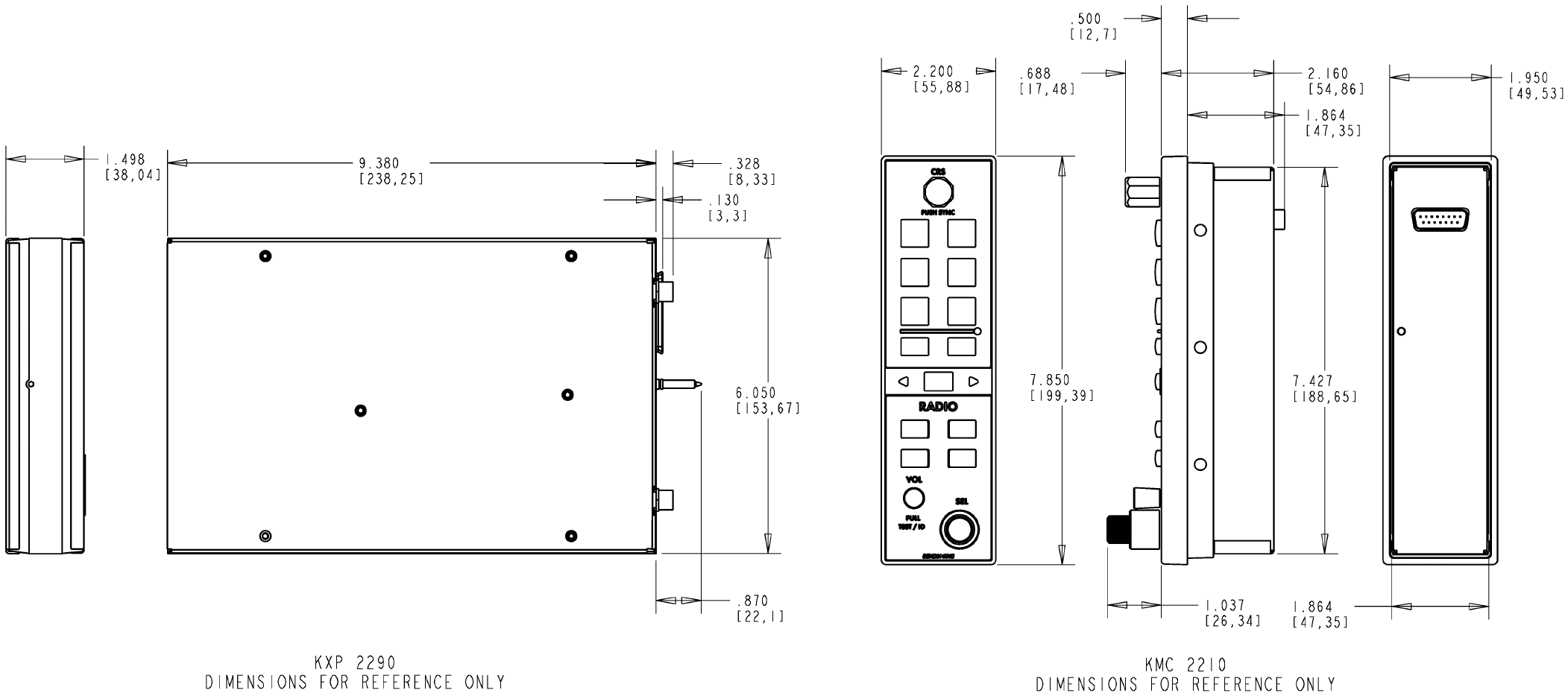
FIGURE 2-2 KXP 2290 INSTALLATION DRAWING
(Dwg. 155-01786-0000 Rev. B, Sheet 2 of 4)
n KXP 2290
Rev. 0c, June/2006 Preliminary 05/24/06 10689I00.JA Page 2-15
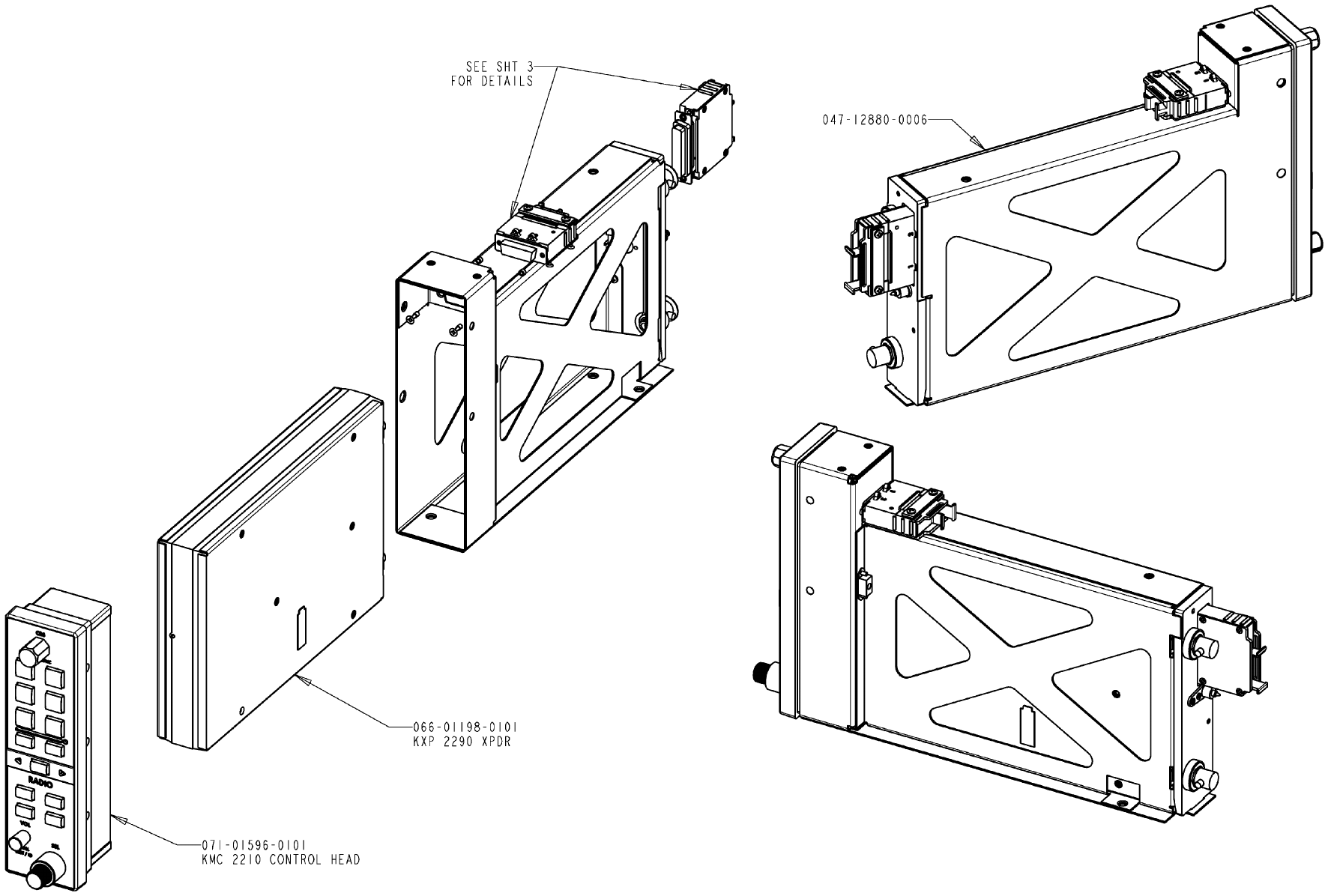
FIGURE 2-2 KXP 2290 INSTALLATION DRAWING
(Dwg. 155-01786-0000 Rev. B, Sheet 3 of 4)
n KXP 2290
Rev. 0c, June/2006 Preliminary 05/24/06 10689I00.JA Page 2-17
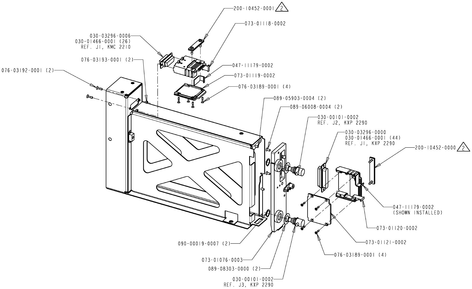
FIGURE 2-2 KXP 2290 INSTALLATION DRAWING
(Dwg. 155-01786-0000 Rev. B, Sheet 4 of 4)
n KXP 2290
Rev. 0c, June/2006 Preliminary 05/24/06 10689I00.JA Page 2-19
FIGURE 2-3 KXP 2290 BAR CLAMP ASSEMBLY DRAWING
(300-10452-0000, Rev. -)
n KXP 2290
Rev. 0c, June/2006 Preliminary 05/24/06 10689I00.JA Page 2-21
FIGURE 2-4 KA 61 INSTALLATION DRAWING
(Sheet 1 of 2)
n KXP 2290
Rev. 0c, June/2006 Preliminary 05/24/06 10689I00.JA Page 2-23
FIGURE 2-4 KA 61 INSTALLATION DRAWING
(Sheet 2 of 2)
n KXP 2290
Rev. 0c, June/2006 Preliminary 05/24/06 10689I00.JA Page 2-25
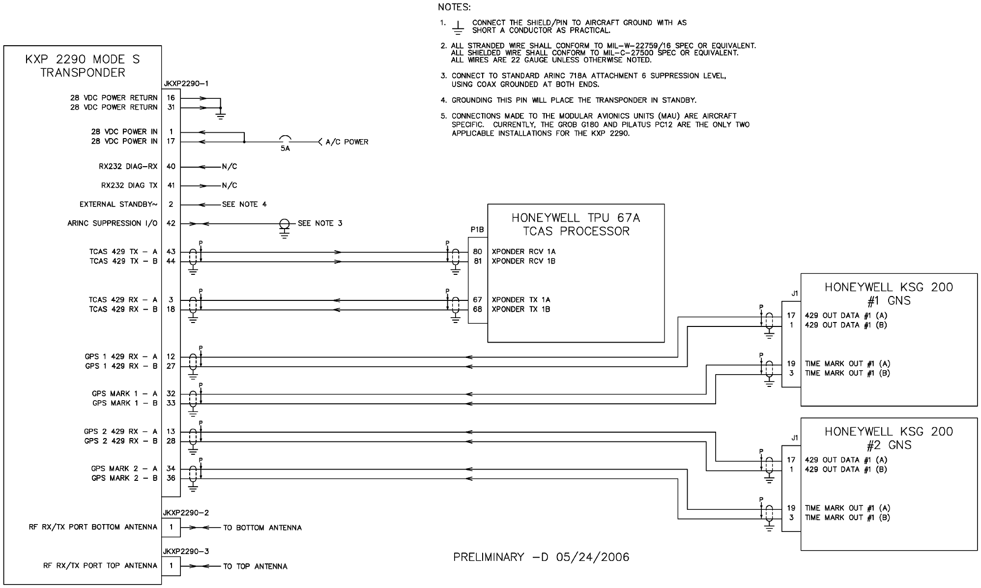
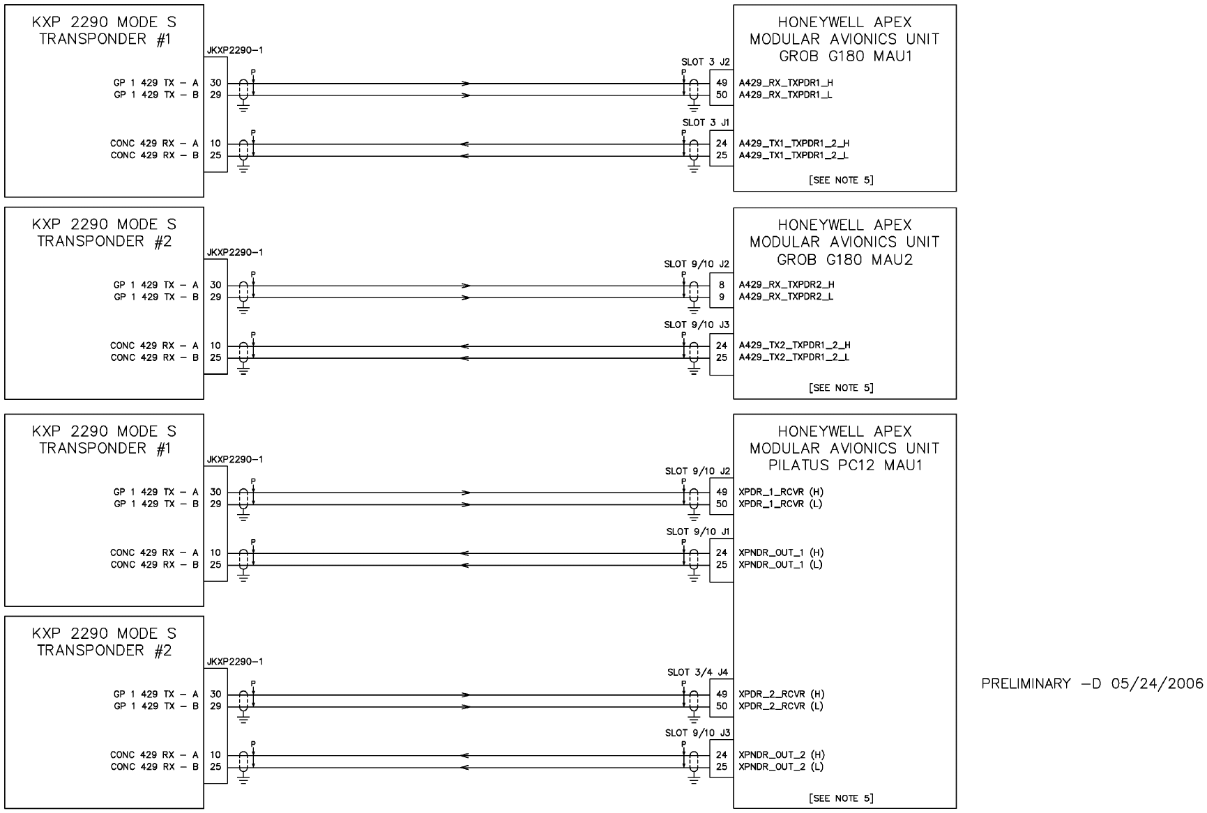
FIGURE 2-5 KXP 2290 INTERCONNECTION DRAWING
(Dwg. 155-0xxxx-000x Rev. -, Sheet 1 of 2)
n KXP 2290
Rev. 0c, June/2006 Preliminary 05/24/06 10689I00.JA Page 2-27
FIGURE 2-6 KXP 2290 INTERCONNECTION DRAWING
(Dwg. 155-0xxxx-000x Rev. -, Sheet 2 of 2)
n KXP 2290
Rev. 0c, June/2006 Preliminary 05/24/06 10689I00.JA Page 2-29
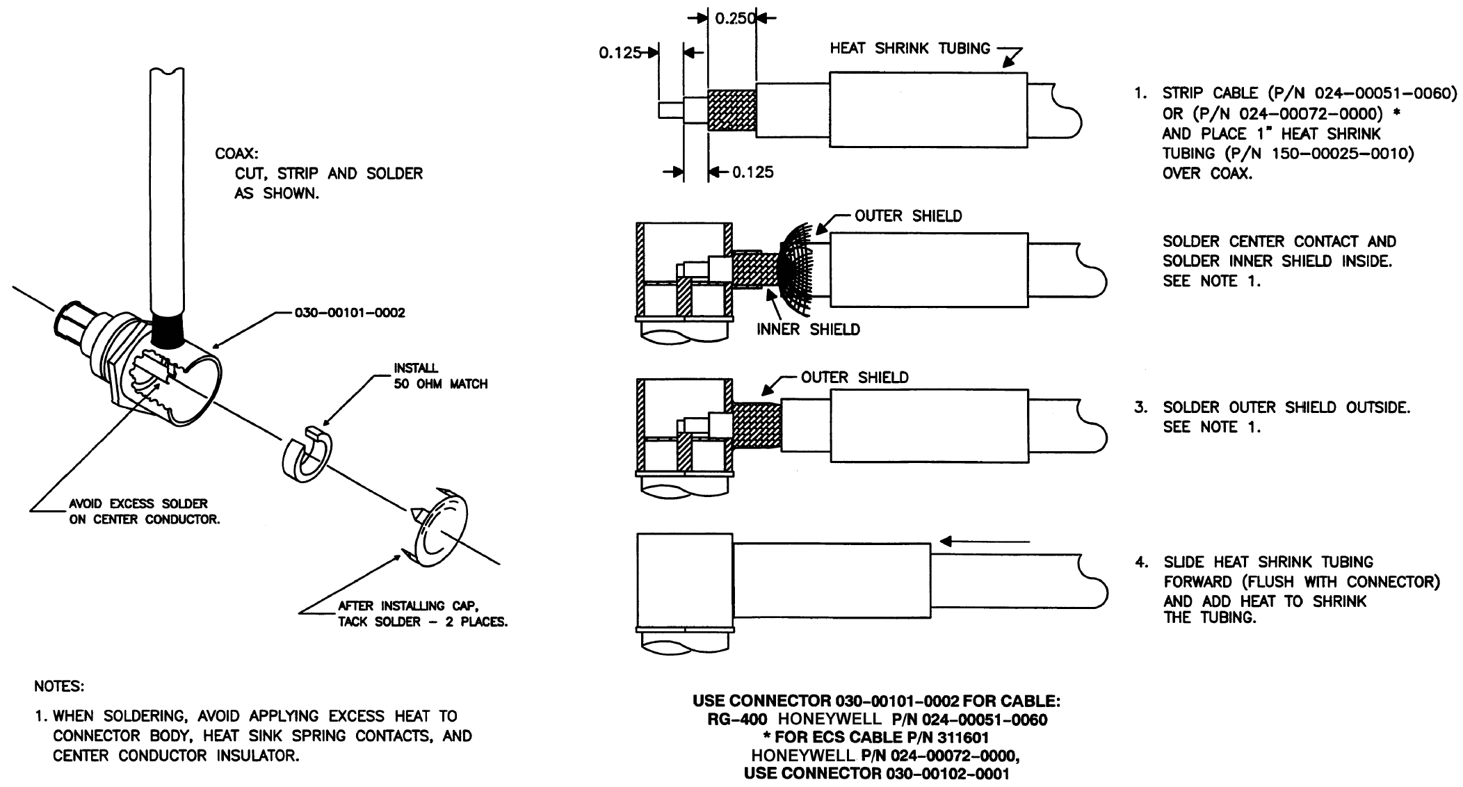
FIGURE 2-7 RF CONNECTOR DRAWING
n KXP 2290
Rev. 0c, June/2006 Preliminary 05/24/06 10689I00.JA Page 2-31
FIGURE 2-8 RG-400 CABLE CONNECTIONS DRAWING
(Option For Short Antenna Cable Lengths)
n KXP 2290
Rev. 0c, June/2006 Preliminary 05/24/06 10689I00.JA Page 2-32
FIGURE 2-9 ECS/ECS-RG-400 CABLE CONNECTIONS DRAWING
(Options For Longer Antenna Cable Lengths)
n KXP 2290
Rev. 0c, June/2006 Preliminary 05/24/06 10689I00.JA Page 2-33
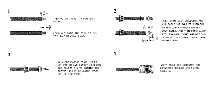
FIGURE 2-10 CABLE CONNECTOR DRAWING
n KXP 2290
Rev. 0c, June/2006 Preliminary 05/24/06 10689I00.JA Page 2-34
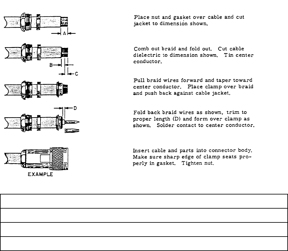
FIGURE 2-11 TYPE “N” AND “C” CONNECTOR ASSEMBLY DRAWING
PART NUMBER SIZE DIMENSION
RG/U CABLE A B C D
024-00075-0000 393 9/32 1/8 5/32 3/64
024-00051-0060 400 9/32 1/8 5/32 3/64
n KXP 2290
Rev. 0c, June/2006 Preliminary 05/24/06 10689I00.JA Page 2-35
FIGURE 2-12 BNC CONNECTOR ASSEMBLY DRAWING
n KXP 2290
Rev. 0c, June/2006 Preliminary 05/24/06 10689I00.JA Page 2-36
THIS PAGE IS RESERVED

n KXP 2290
Rev. 0c, June/2006 Preliminary 05/24/06 10689I00.JA Page 2-37
2.4 POST-INSTALLATION CHECKS
2.4.1 TRANSPONDER SYSTEM CHECKOUT
The post-installation test is used to apply power and functionally checkout the system. Successful
completion of the post-installation test verifies the proper operation of the KXP 2290 Mode S Tran-
sponder System.
TABLE 2-4 INSPECTION/CHECK PROCEDURE is a visual inspection/check procedure that
should be performed after system installation as part of a system checkout. A post-installation test
per paragraph 2.4.1.2 Post-Installation Checkout/Operation should be performed. In addition, the
procedure should be used as a periodic maintenance inspection check.
TABLE 2-4 INSPECTION/CHECK PROCEDURE
2.4.1.1 Inspection
Perform the following inspection on the overall system:
(1) Check that cables do not interfere with aircraft controls or other equipment.
(2) Check cabling for proper routing and check security of tie-down points. Inspect and
adjust cable runs to ensure that cables are not strained, kinked, or severely twisted
and are not exposed to rough or sharp surfaces.
2.4.1.2 Post-Installation Checkout/Operation
(1) General
Installation of the transponder system requires three stages of testing to ensure the
proper operation of the Mode S transponder. Initially, prior to the installation of the
transponder and antenna, a system interwiring check should be performed. This
check verifies that the aircraft and all transponder interconnections are correct, be-
fore power is applied. After the units are installed a visual inspection of the equip-
ment and connections is made. Finally, a post-Installation test is performed.
EQUIPMENT INSPECTION/CHECK PROCEDURE
KXP 2290 Mode S A. Inspect external surface for damage.
Transponder B. Check that the unit is securely installed and that retaining
mechanism is securely tightened.
C. Ensure that all connections in the mounting tray are properly
mounted and secure.
Antennas A. Inspect external surfaces for damage.
B. Check that antenna is properly mounted and mounting screws
are tight.
C. Ensure that antenna coaxial cable connectors are properly mated
and secure.
n KXP 2290
Rev. 0c, June/2006 Preliminary 05/24/06 10689I00.JA Page 2-38
(2) System Interwiring Check
To check the aircraft and transponder system interconnections proceed as follows:
(a) Check that all cables and interwiring are installed in accordance with the In-
terwiring and Cable Harness Fabrication instructions (paragraph 2.3.2 KXP
2290 INTERCONNECTION AND CABLE HARNESS FABRICATION).
(b) Using the interconnect diagram (see FIGURE 2-5 KXP 2290 INTERCON-
NECTION DRAWING), check wiring for proper destination, opens, and
shorts.
(c) Check rf cables for insertion loss and VSWR.
(3) Visual Inspection
In conjunction with system installation, perform the inspection/check procedure (TA-
BLE 2-4 INSPECTION/CHECK PROCEDURE).
(4) Post-Installation Test
Perform the ATC transponder tests and inspections noted in section 1.7.1 EQUIP-
MENT (per Federal Aviation Regulation Part 43).
n KXP 2290
Rev. 0c, June/2006 Preliminary 05/24/06 10689I00.JA Page 3-1
SECTION III
OPERATION
3.1 GENERAL
The only current operational function of the KXP 2290 is as a part of the Honeywell APEX system.
Consult the applicable APEX system operation handbook(s) as required.
n KXP 2290
Rev. 0c, June/2006 Preliminary 05/24/06 10689I00.JA Page 3-2
THIS PAGE IS RESERVED
n KXP 2290
Rev. 0c, June/2006 Preliminary 05/24/06 10689I00.JA Page TSO-1
ENVIRONMENTAL QUALIFICATIONS APPENDIX
ENVIRONMENTAL QUALIFICATION FORM(S)
n KXP 2290
Rev. 0c, June/2006 Preliminary 05/24/06 10689I00.JA Page TSO-2
THIS PAGE IS RESERVED
n KXP 2290
Rev. 0c, June/2006 Preliminary 05/24/06 10689I00.JA Page TSO-3
n KXP 2290
Rev. 0c, June/2006 Preliminary 05/24/06 10689I00.JA Page TSO-4
n KXP 2290
Rev. 0c, June/2006 Preliminary 05/24/06 10689I00.JA Page TSO-5
n KXP 2290
Rev. 0c, June/2006 Preliminary 05/24/06 10689I00.JA Page TSO-6
THIS PAGE IS RESERVED