Honeywell LXE-VM1 Wireless Vehicle Mount Terminal User Manual Thor User Guide
Honeywell International, Inc. Wireless Vehicle Mount Terminal Thor User Guide
Contents
- 1. User Manual
- 2. User Guide
User Manual
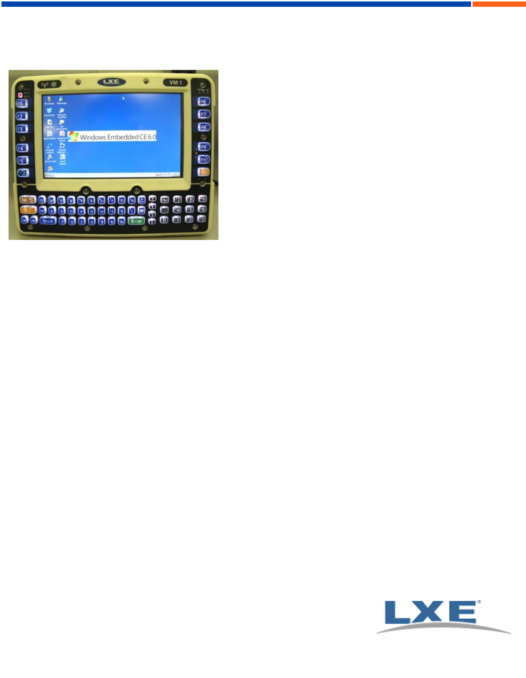
Thor CE User Guide
Microsoft® Windows® Embedded CE 6 Operating System
E-EQ-THORCEOGWW-A
2010 Copyright© by LXE®, Inc, An EMS Technologies Company. All Rights
Reserved.
For ENG/CERT Review - Not for Distribution or Publication - Draft 03

Notices
LXE Inc. reserves the right to make improvements or changes to published Thor information at any time without notice. While
reasonable efforts have been made in the preparation of this publication to assure its accuracy, LXE assumes no liability
resulting from any errors or omissions in this publication, or from the use of the information contained herein. Further, LXE
Incorporated, reserves the right to revise this publication and to make changes to it from time to time without any obligation to
notify any person or organization of such revision or changes.
Trademarks
Copyright © 2010 by LXE Inc., An EMS Technologies Company, 125 Technology Parkway, Norcross, GA 30092 U.S.A. (770)
447-4224
LXE® and Spire® are registered trademarks of LXE Inc.
Microsoft®, ActiveSync®, MSN, Outlook®, Windows®, Windows Mobile®, the Windows logo, and Windows Media are
either registered trademarks or trademarks of Microsoft Corporation in the United States and/or other countries.
Intel and Intel XScale are trademarks or registered trademarks of Intel Corporation or its subsidiaries in the United States and
other countries.
Summit Data Communications, Inc. Summit Data Communications, the Summit logo, and “The Pinnacle of Performance” are
trademarks of Summit Data Communications, Inc.
The Bluetooth® word mark and logos are owned by the Bluetooth SIG, Inc. and any use of such marks by LXE, Inc. is under
license.
PowerScan is a registered trademark of Datalogic Scanning, Inc., located in Eugene, OR.
Symbol® is a registered trademark of Symbol Technologies. MOTOROLA® and the Stylized M Logo are registered
trademarks of Motorola®, Inc.
Hand Held® is a registered trademark of Hand Held Products, Inc., located in Skaneateles Falls, NY.
When any part of this publication is in PDF format: “Acrobat ® Reader Copyright © 2010 Adobe Systems Incorporated. All
rights reserved. Adobe, the Adobe logo, Acrobat, and the Acrobat logo are trademarks of Adobe Systems Incorporated”
applies.
Other product names mentioned within this publication may be trademarks or registered trademarks of other companies.
For ENG/CERT Review - Not for Distribution or Publication - Draft 03

Table of Contents
Set Up A New Thor 1
Hardware Setup 1
Software Setup 1
Components 2
Front View 2
Back View 3
Access Panel 4
Thor Quick Mount 4
Using the Quick Mount 4
Removing Thor from Quick Mount 6
Tapping the Touchscreen with a Stylus 7
Backlights and Indicators 8
Set Power Scheme Timers 8
Battery Power Scheme 8
AC Power Scheme 8
Connecting Cables to the Thor 9
Connect Cable- USB Client 9
USB-C Cable Assembly 9
Connect Cable- USB Host 9
USB-H Cable Assembly 9
Connect Cable - Serial 10
Connecting Vehicle Power 11
Vehicle 9-60 VDC Power Connection 11
VX6 / VX7 Adapter Cable 12
Connecting an AC/DC Power Supply 12
Connecting the Headset Cable 13
Adjust Headset / Microphone and Secure Cable 14
Adjust Speaker Volume 14
Using the Keypad 14
Using the Control Panel 14
Set Date and Time Zone 15
Grab Time Utility 15
Autolaunch Time-Sync 15
Using the Input Panel / Virtual Keyboard 16
Touchscreen 17
Calibrating the Touchscreen 17
Adjusting the Display Backlight Timer 17
E-EQ-THORCEOGWW-A [ i ] Thor CE User Guide
For ENG/CERT Review - Not for Distribution or Publication - Draft 03

Table of Contents
Setup Terminal Emulation Parameters 17
Using the AppLock Switchpad 18
Using the Keypad 18
Using the Touchscreen 18
Reboot 19
Troubleshooting 19
Regulatory Notices and Safety Information 20
Class A Digital Device 20
RF Safety Notice 21
Lithium Battery Safety Statement 22
Vehicle Power Supply Connection Safety Statement 23
Revision History 23
Index 24
E-EQ-THORCEOGWW-A [ ii ] Thor CE User Guide
For ENG/CERT Review - Not for Distribution or Publication - Draft 03

Set Up A New Thor
Note: LXE recommends that installation or removal of accessories be performed on a clean, well-lit surface. When
necessary, protect the work surface, the Thor, and components from electrostatic discharge.
While the Thor is in a Hazardous Location DO NOT:
lConnect an external power source to the Thor.
lConnect a USB device or audio jack to the Thor.
Hardware Setup
1. Connect accessories to the Thor QuickMount.
2. Connect cables.
3. Connect power cable to the Thor Quick Mount.
4. Secure all cables to the Thor Quick Mount with the Strain Relief Cable Clamps.
5. Secure the Thor in the Quick Mount.
6. Press power switch on Quick Mount.
7. Press the Power key.
Software Setup
Prerequisite: Hardware setup is complete.
1. Calibrate Touch screen
2. Set Date and Time Zone
3. Set Power Schemes Timers
4. Adjust Speaker Volume
5. Pair Bluetooth devices
6. Setup Wireless client parameters
7. Setup terminal emulation parameters
8. Save changed settings to the registry
9. Setup the LXE AppLock parameters
10. Set the LXE DC Wedge parameters
E-EQ-THORCEOGWW-A [ 1 ] Thor CE User Guide
For ENG/CERT Review - Not for Distribution or Publication - Draft 03
Components
Components
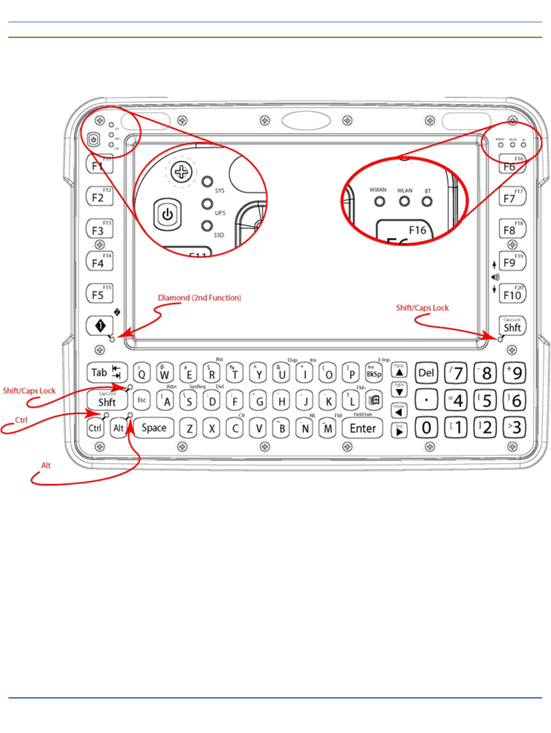
Front View
1. LEDs
2. Volume Control (2nd function)
3. Power Button
4. Speakers
5. Microphone?
6. Ambient light sensor?
E-EQ-THORCEOGWW-A [ 2 ] Thor CE User Guide
For ENG/CERT Review - Not for Distribution or Publication - Draft 03
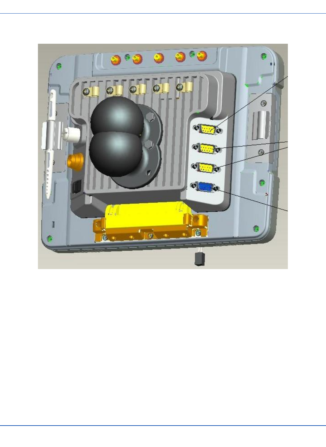
Back View
Back View
1. Antenna Connectors (on Thor)
2. SD card access (on Thor)
3. Quick release (on Thor)
4. Strain relief clamps (on Quick Mount)
5. Fuse (on Quick Mount)
6. Power connector (on Quick Mount)
7. COM1 (on Quick Mount)
8. COM2 (on Quick Mount)
9. USB (on Quick Mount)
10. CANbus/Audio (on Quick Mount)
E-EQ-THORCEOGWW-A [ 3 ] Thor CE User Guide
For ENG/CERT Review - Not for Distribution or Publication - Draft 03
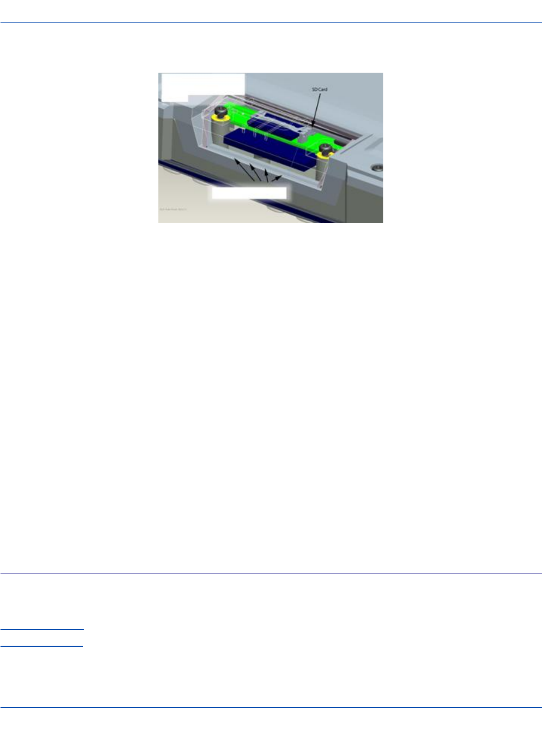
Access Panel
Access Panel
1. SD Memory Card Slot
2. Compact Flash Hard Drive
Thor Quick Mount
The Thor assembly consists of two parts, the Thor computer and the Quick Mount.
The Thor contains an internal UPSbattery that, once fully charged, powers the Thor for a minimum of 30 minutes when the unit
is not mounted in the Quick Mount.
The Quick Mount provides:
lA mount for the Thor computer. The Quick Mount attaches to a vehicle via a RAM mount.
lConditioned power for the Thor. The Quick Mount accepts 9-60 VDC power input.
lCOM1 and COM2 serial connections for a tethered scanner, printer, PC connection, etc.
lUSB host and client connections via an adapter cable.
lCANbus connection via an adapter cable.
lHeadset connection via an adapter cable. When a headset is not attached, the microphone and speakers on the Thor
are active.
lStrain relief cable mounts.
lMobility of the Thor, since the Quick Mount remains attached to the vehicle the Thor computer can easily be moved
from one vehicle equipped with a Quick Mount to another.
External antenna connectors may be present on the back of the Thor. The connectors may include:
l802.11 antenna connectors when the Thor is not equipped with internal antennas.
lExternal GPSantenna connector, when the Thor is equipped with GPS.
lExternal WWAN antenna connectors, when the Thor is equipped with WWAN.
Using the Quick Mount
Attach RAM mount to vehicle (see Cradle Guide).
Attachaccessories to Quick Mount.
Attach power cable.
Power on the Quick Mount.
E-EQ-THORCEOGWW-A [ 4 ] Thor CE User Guide
For ENG/CERT Review - Not for Distribution or Publication - Draft 03

Using the Quick Mount
Place Thor in the Quick Mount.
E-EQ-THORCEOGWW-A [ 5 ] Thor CE User Guide
For ENG/CERT Review - Not for Distribution or Publication - Draft 03

Removing Thor from Quick Mount
Removing Thor from Quick Mount
The Thor may be removed from the Quick Mount for limited periods of use or the transfer from vehicle to vehicle.
The UPSbattery inside the Thor powers a fully functional Thor for a minimum of 30 minutes.
To remove the Thor from the Quick Mount, pull the release latch downward on the back of the Thor.
E-EQ-THORCEOGWW-A [ 6 ] Thor CE User Guide
For ENG/CERT Review - Not for Distribution or Publication - Draft 03

Tapping the Touchscreen with a Stylus
Note: Always use the point of the stylus for tapping or
making strokes on the touchscreen.
Never use an actual pen, pencil, or sharp/abrasive
object to write on the touchscreen.
Hold the stylus as if it were a pen or pencil. Touch an element
on the screen with the tip of the stylus then remove the stylus
from the screen.
Firmly press the stylus into the stylus holder when the stylus
is not in use.
Using a stylus is similar to moving the mouse pointer then
left-clicking icons on a desktop computer screen.
Using the stylus to tap icons on the touchscreen is the basic
action that can:
lOpen applications
lChoose menu commands
lSelect options in dialog boxes or drop-down boxes
lDrag the slider in a scroll bar
lSelect text by dragging the stylus across the text
lPlace the cursor in a text box prior to typing in data
lPlace the cursor in a text box prior to retrieving data
using the scanner/imager or an input/output device
connected to the serial port.
A stylus replacement kit is available.
E-EQ-THORCEOGWW-A [ 7 ] Thor CE User Guide
For ENG/CERT Review - Not for Distribution or Publication - Draft 03
Backlights and Indicators
Set Power Scheme Timers
Start | Settings | Control Panel | Power | Schemes
Change the parameter values and tap OK to save the
changes.
Battery Power Scheme
Use this option to configure the Thor behavior when powered
by the UPS battery.
Switch state to User
Idle1
Default is After 3
seconds
Switch state to
System Idle2
Default is After 15
seconds
Switch state to
Suspend3
Default is After 5
minutes
AC Power Scheme
Use this option when the Thor will be running on external
power (e.g. connected to).
Switch state to User
Idle
Default is After 2
minutes
Switch state to
System Idle
Default is After 2
minutes
Switch state to
Suspend
Default is After 5
minutes
The timers are cumulative. The System Idle timer begins the
countdown after the User Idle timer has expired and the
Suspend timer begins the countdown after the System Idle
1An amount of time has passed, set by the User Idle timer,
and the device shuts down a minimum number of services
e.g. backlights. The System Idle timer and the Suspend timer
have not expired yet.
2An amount of time has passed, set by the System Idle
timer, and the device shuts down a few more services e.g.
display. The User Idle timer has expired and the Suspend
timer has not expired yet.
3Suspend mode is entered when (1) the unit is inactive for a
predetermined period of time, (2) the user taps the Power
key, or (3) Start | Suspend is chosen. Inactivity means that
internal devices that reset the power state are not active.
timer has expired. When the User Idle timer is set to “Never”,
the power scheme timers never place the Thor in User Idle,
System Idle or Suspend modes (even when the Thor is idle).
E-EQ-THORCEOGWW-A [ 8 ] Thor CE User Guide
For ENG/CERT Review - Not for Distribution or Publication - Draft 03
Connecting Cables to the Thor
Note: Do not connect or disconnect cables in a
Hazardous location.
Connect Cable- USB Client
Prerequisite : A commercially available standard USBcable
with a type A plug on one end and a type B plug on the other.
USB-C Cable Assembly
1. Seat the cable end connector (connector 1) firmly over
the on the Thor Quick Mount.
2. Tighten the thumbscrews in a clockwise direction. Do
not over tighten.
3. Connecter 2 on the cable provides a USB-Host con-
nection.
Connect Cable- USB Host
USB-H Cable Assembly
1. Seat the cable end connector (connector 1) firmly over
the on the Thor Quick Mount.
2. Tighten the thumbscrews in a clockwise direction. Do
not over tighten.
3. Connecter on the cable provides a USB-Host con-
nection.
E-EQ-THORCEOGWW-A [ 9 ] Thor CE User Guide
For ENG/CERT Review - Not for Distribution or Publication - Draft 03

Connect Cable - Serial
1. Seat the cable end connector firmly over the serial
COMport on the Thor Quick Mount.
2. Turn the thumbscrews in a clockwise direction. Do
not over tighten.
3. Connect the other cable end to the desired serial
device.
E-EQ-THORCEOGWW-A [ 10 ] Thor CE User Guide
For ENG/CERT Review - Not for Distribution or Publication - Draft 03
Connecting Vehicle Power
Complete vehicle cradle mounting and power instruction is
contained in the Thor Cradle Guide.
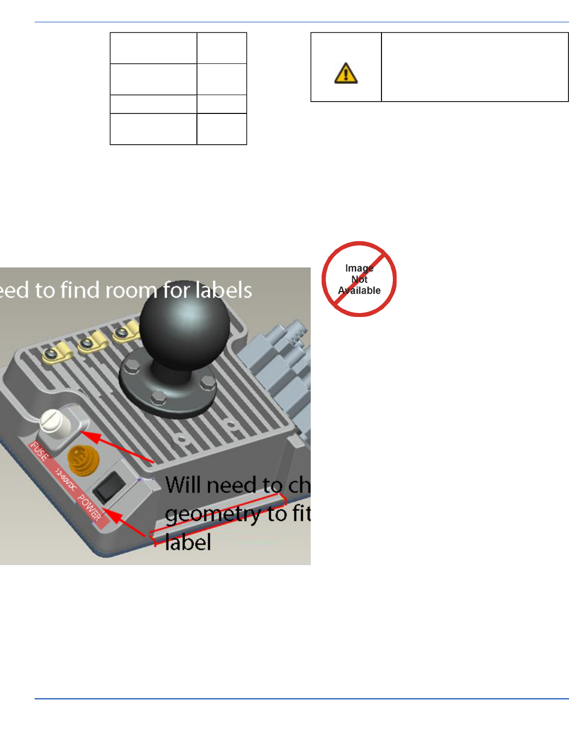
Vehicle 9-60 VDC Power Connection
Caution
For proper and safe installation, the input power
cable must be connected to a fused circuit on
the vehicle. This fused circuit requires a Amp
maximum time delay (slow blow) high
interrupting rating fuse. If the supply
connection is made directly to the battery, the
fuse should be installed in the positive lead
within 5 inches of the battery positive (+)
terminal. Note: For North America, a UL Listed
fuse is to be used.
Caution
For installation by trained service personnel
only.
Warning Risk of ignition or explosion. Explosive gas
mixture may be vented from battery. Work only
in well ventilated area. Avoid creating arcs and
sparks at battery terminals.
1. To Vehicle Battery
2. To Thor Quick Mount
3. White (DC+)??
4. Black (DC-)??
5. Green (GND)??
6. 9 – 60 VDC
1. Vehicle Electrical System
2. ?? Amp Slow Blow Fuse
3. DC +
4. DC -
5. Vehicle Chassis
6. White
7. Black
8. Green
Note: Correct electrical polarity is required for safe and
proper installation. Connecting the cable to the Thor
with the polarity reversed will cause the Thor fuse to be
blown. See the following figure titled “Vehicle
Connection Wiring Color Codes” for additional wire
color-coding specifics.
How To: Connect Vehicle 9-60VDC Connection
1. The Thor must be turned off and the power cable must
be UNPLUGGED from the Thor.
2. While observing the fuse requirements specified
above, connect the power cable as close as possible
to the actual battery terminals of the vehicle. When
available, always connect to un-switched terminals in
vehicle fuse panel, after providing proper fusing.
ATTENTION:For uninterrupted power, electrical
supply connections should not be made at any point
after the ignition switch of the vehicle.
3. Route the power cable the shortest way possible. The
cable is rated for a maximum temperature of 105°C
(221°F). When routing this cable it should be protected
from physical damage and from surfaces that might
exceed this temperature.
Do not expose the cable to chemicals or oil that may
cause the wiring insulation to deteriorate.
If the vehicle is equipped with a panel containing
Silicon Controller Rectifiers (SCR’s), avoid routing the
power cable in close proximity to these devices.
Always route the cable so that it does not interfere
with safe operation and maintenance of the vehicle.
Use proper electrical and mechanical fastening
means for terminating the cable. Properly sized
“crimp” type electrical terminals are an accepted
method of termination. Please select electrical
connectors sized for use with 18AWG (1mm2)
conductors.
Wiring color codes for LXE supplied DC input power
cabling:
E-EQ-THORCEOGWW-A [ 11 ] Thor CE User Guide
For ENG/CERT Review - Not for Distribution or Publication - Draft 03
Vehicle Supply Wire
Color
+9 - 60VDC (DC
+) White??
Return (DC -) Black??
Vehicle Chassis
GND Green??
4. Provide mechanical support for the cable by securing
it to the vehicle structure at approximately one foot
intervals, taking care not to over tighten and pinch con-
ductors or penetrate outer cable jacket.
5. Connect the adapter cable to the Thor Quick Mount.
6. Plug the vehicle cable into the adapter cable.
7. Flip the power switch on the back of the Quick Mount
to On.
VX6 / VX7 Adapter Cable
An adapter cable is available to attach the Thor to a vehicle
previously equipped with a VX6/VX7 DCpower cable. The
adapter cable has a connector to match with the VX6/VX7
power supply cable on one end and a connector to match to
the Thor on the other.
Caution Because the Thor supports 9-60 VDC
power input, verify input voltages before
using this adapter cable with an existing
VX6 or VX7 power connection
installation.
When this adapter cable is used, there is no provision for an
ignition switch input. Therefore the Auto On (with vehicle
ignition) is not available when using this cable.
Need to add How To when cable is ready??
Connecting an AC/DC Power Supply
Note: The LXE-approved AC Power Supply and
Adapter Cable are only intended for use in a 25ºC
(77ºF) maximum ambient temperature environment.
Placeholder for graphic when avail-
able??
In North America, this unit is intended for use with a UL
Listed ITE power supply with output rated 12 – 80 VDC,
minimum 15W75W. Outside North America, this unit is
intended for use with an IEC certified ITE power supply with
output rated 12 – 80 VDC, minimum 15W75W.
The external power supply may be connected to either a
120V, 60Hz supply or, outside North America, to a 230V,
50Hz supply, using the appropriate detachable cordset. In all
cases, connect to a properly grounded source of supply
provided with maximum 15 Amp overcurrent protection (10
Amp for 230V circuits).
1. Turn the Thor off.
2. Connect the detachable cordset provided by LXE (US
only, all others must provide their own cable) to the
external power supply (IEC 320 connector).
3. Plug cordset into appropriate, grounded, electrical
supply receptacle (AC mains).
4. Connect the DC Output Cable end to the power con-
nector on the Thor Quick Mount.
5. Turn the Thor on.
E-EQ-THORCEOGWW-A [ 12 ] Thor CE User Guide
For ENG/CERT Review - Not for Distribution or Publication - Draft 03
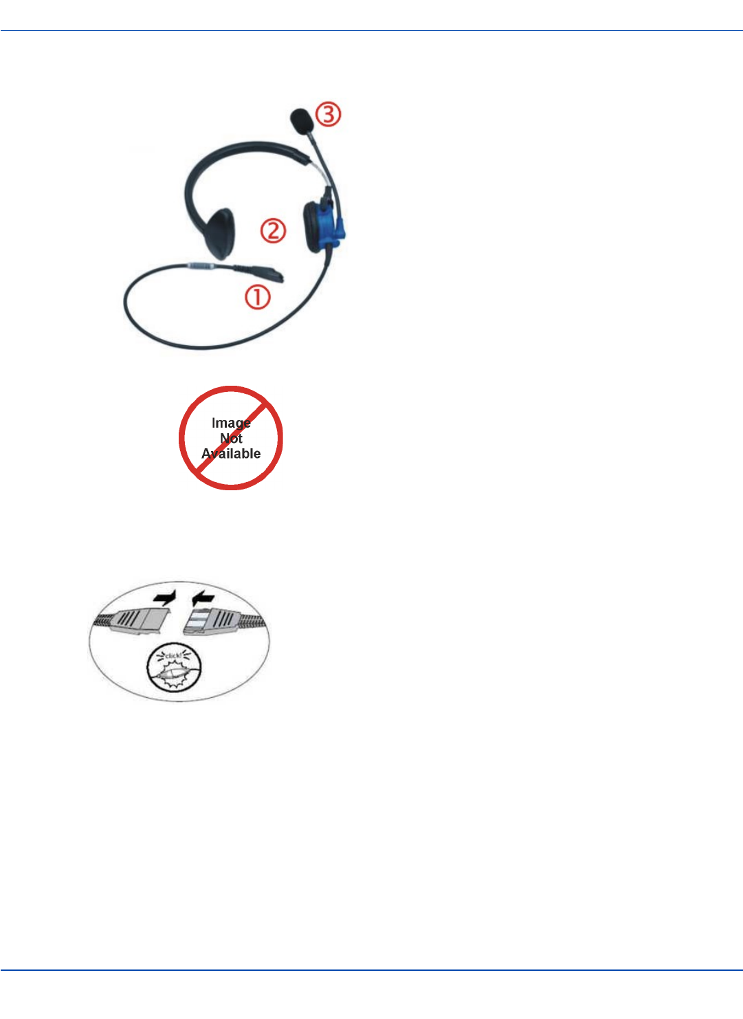
Connecting the Headset Cable
Headset
1. Connects to
end of audio
cable
2. Headphones
3. Microphone
Thor Audio Cable
Connect the Thor audio cable I/O connector to the
CANbus/Audio port on the Thor. The Thor internal
microphone and speaker are automatically disabled.
Slide the cable ends together until they click shut. Do not
twist or bend the connectors.
The Thor is ready for voice-enabled applications.
E-EQ-THORCEOGWW-A [ 13 ] Thor CE User Guide
For ENG/CERT Review - Not for Distribution or Publication - Draft 03
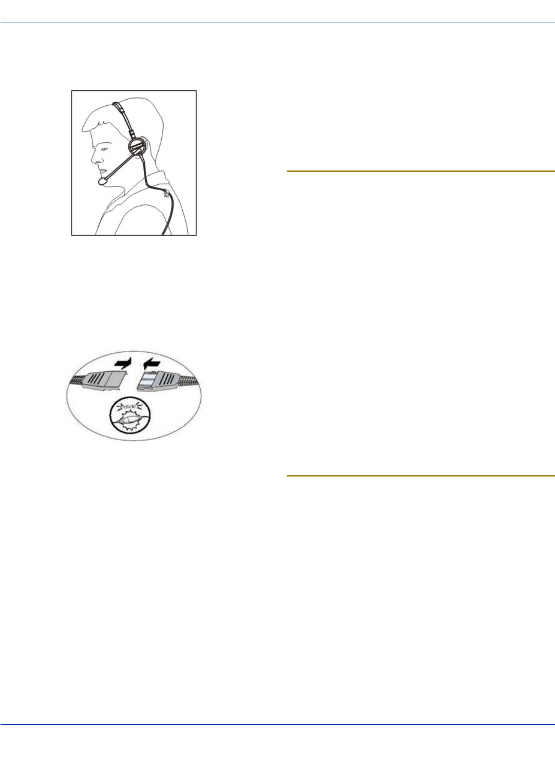
Adjust Headset / Microphone and
Secure Cable
The headset consists of an earpiece, a microphone, a
clothing clip and a cable. The headset attaches to the audio
cable end of the voice cable which attaches to the Thor.
Align the audio connector and the headset quick connect
cable end. Firmly push the cable ends together until they
click and lock in place.
Do not twist the microphone boom when adjusting the
microphone. The microphone should be adjusted to be about
two finger widths from your mouth.
Make sure the microphone is pointed at your mouth. Note the
small “Talk” label near the mouthpiece. Make sure the Talk
label is in front of your mouth. The microphone cable can be
routed over or under clothing.
Under Clothing
lLeave the cable exposed only at the top of the collar.
lBe sure to leave a small loop of cable to allow move-
ment of your head.
Over Clothing
lUse clothing clips to hold the cable close to your
body.
lTuck the cable under the belt, but leave a small loop
where it goes under the belt.
lDo not wear the cable on the front of your body. It may
get in your way or get caught on protruding objects.
Adjust Speaker Volume
The Thor has two speakers, located on the bottom of the unit.
Speaker volume can be adjusted to a comfortable level for
the listener by using the keypad or by changing parameters in
the Volume & Sounds control panel.
Using the Keypad
Note: Volume & Sounds (in Settings | Control Panel)
must be enabled before the following key sequences
can adjust the volume.
The volume is increased or decreased one step each time the
volume key sequence is pressed.
To adjust speaker volume, locate the 2nd key to the left of
the display. Press this key.
Adjust the speaker volume by pressing the:
Use the F9 key for volume Up and F10 key for volume Down.
Adjust volume until the speaker volume is satisfactory.
Press the Enter key to exit this mode.
The LED for the 2nd key blinks until the special editing mode
(set audio speaker volume) is complete.
Volume control using a keypad key press has six volume
settings that match those supported by the Volume and
Sounds Control panel. Volume does not “roll-over” from
minimum to maximum or from maximum to minimum.
Continuously holding down the up or down arrow keys does
not cause an automatic repeat of the up (or down) arrow key.
Using the Control Panel
Start | Settings | Control Panel | Volume & Sounds |
Volume
Change the volume setting and tap OK to save the change.
You can also select / deselect sounds for key clicks and
screen taps and whether each is loud or soft.
As the volume scrollbar is moved between Loud and Soft, the
Thor emits a tone each time the volume increases or
decreases in decibel range.
E-EQ-THORCEOGWW-A [ 14 ] Thor CE User Guide
For ENG/CERT Review - Not for Distribution or Publication - Draft 03

Set Date and Time Zone
Tap Start | Settings | Control Panel | Date/Time icon or
tap the Date/Time in the taskbar.
Set Date, Time, Time Zone, and assign a Daylight Savings
location on the Thor after a warm boot or anytime.
There is very little functional change from standard desktop
PC Date/Time Properties options. Adjust the settings and
tap the OK button or the Apply button to save changes to the
registry. Any changes take effect immediately.
Double-tapping the time displayed in the Taskbar causes the
Date/Time Properties screen to appear.
Grab Time Utility
The GrabTime utility can be configured to synchronize the
time with a local server during each reboot function.
Tap the Sync button to synchronize date and time with a
networked time server. By default, the Thor operating system
first searches for a time server on the local intranet. If not
found, it then searches the Internet for a time server. A
connection to the Internet is required for this option.
Autolaunch Time-Sync
Start | Settings | Control Panel | Thor Options |
Communication tab
By default, TimeSync does not automatically run on the Thor.
To enable TimeSync to run automatically on the Thor using
the GrabTime utility, check this checkbox.
Synchronize with a Local Time Server
By default, GrabTime synchronizes via an Internet
connection. To synchronize with a local time server:
1. Use ActiveSync to copy GrabTime.ini from the My
Device | Windows folder on the Thor to the host PC.
2. Edit the copy of GrabTime.ini on the host PC. Add the
local time server’s domain name to the beginning of
the list of servers. You can optionally delete the
remainder of the list.
3. Copy the modified GrabTime.ini file to the My Device |
System folder on the Thor. The System/GrabTime.ini
file takes precedence over the Windows/GrabTime.ini
file. System/Grabtime.ini also persists after a cold-
boot; Windows/Grabtime.ini does not persist.
E-EQ-THORCEOGWW-A [ 15 ] Thor CE User Guide
For ENG/CERT Review - Not for Distribution or Publication - Draft 03

Using the Input Panel / Virtual Keyboard
The virtual keyboard is always available when needed e.g.
text entry.
Place the cursor in the text entry field and, using the stylus:
lTap the Shift key to type one capital letter.
lTap the CAPS key to type all capital letters.
lTap the áü key to access symbols.
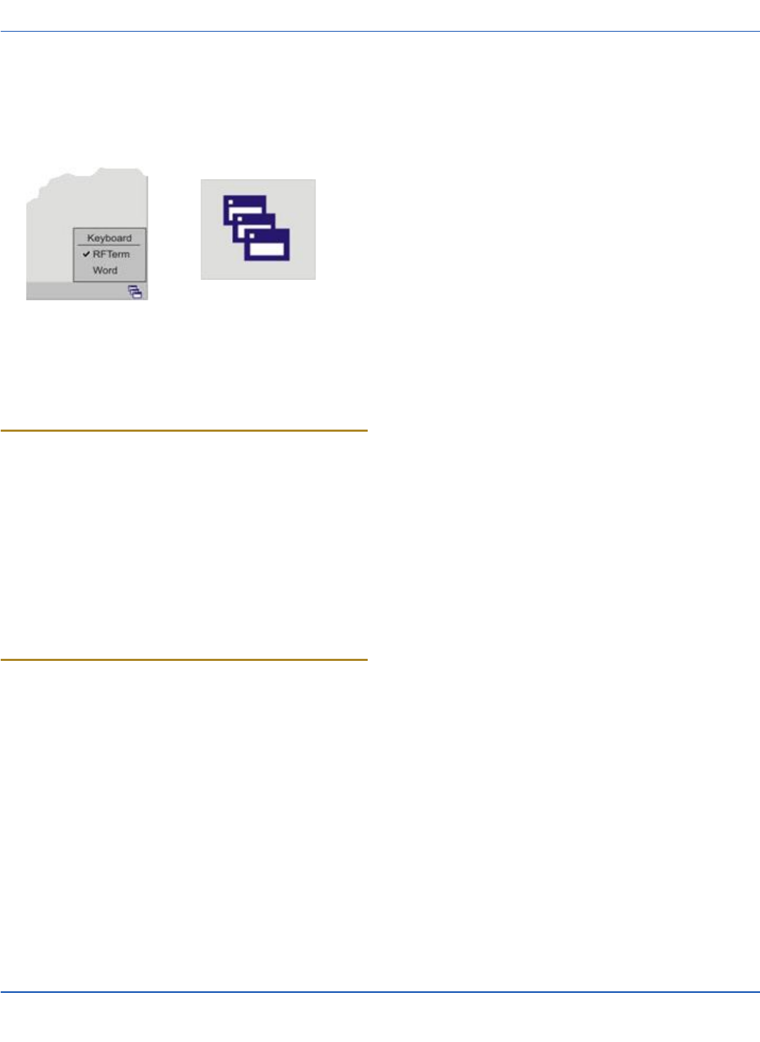
Some applications do not automatically display the Input
Panel. In this case, do the following to use the Input Panel:
Input Panel icon in the taskbar
Keyboard icon in the taskbar
lTap the Input Panel or Keyboard icon in the taskbar.
lSelect Keyboard from the menu.
lMove the cursor into the text entry field when you
want to enter data using the Input Panel.
When finished entering data, tap the icon in the Taskbar
again.Select Hide Input Panel.
E-EQ-THORCEOGWW-A [ 16 ] Thor CE User Guide
For ENG/CERT Review - Not for Distribution or Publication - Draft 03

Touchscreen
Calibrating the Touchscreen
If the touchscreen is not responding properly to stylus taps,
you may need to recalibrate the touchscreen.
Recalibration involves tapping the center of a target. If you
miss the center, keep the stylus on the screen, slide it over
the target's center, and then lift the stylus.
Follow the instructions on the screen and press the Enter key
to save the new calibration settings or press Esc to cancel or
quit.
Adjusting the Display Backlight Timer
The backlight settings use the LXE set of default timeouts
and are synchronized to the User Idle setting in the Schemes
tab in the Power control panel.
When the backlight timer expires, the display backlight is
dimmed, not turned off. When both checkboxes are
unchecked, the backlight never turns off (or dims).
Default values are 3 seconds for Battery, 2 minutes for
External and both the check boxes are enabled.
Setup Terminal Emulation Parameters
Before you make a host connection, you will, at a minimum,
need to know:
lthe alias name or IP address (Host Address) and
lthe port number (Telnet Port) of the host system to
properly set up your host session.
1. Make sure the mobile client network settings are con-
figured and functional. If you are connecting over wire-
less LAN (802.11x), make sure your mobile client is
communicating with the Access Point.
2. From Start | Program, run LXE RFTerm or tap the
RFTerm icon on the desktop.
3. Select Session | Configure from the application
menu and select the "host type" that you require. This
will depend on the type of host system that you are
going to connect to; i.e. 3270 mainframe, AS/400
5250 server or VT host.
4. Enter the "Host Address" of the host system that you
wish to connect to. This may either be a DNS name
or an IP address of the host system.
5. Update the telnet port number, if your host appli-
cation is configured to listen on a specific port. If not,
just use the default telnet port.
6. Select OK.
7. Select Session | Connect from the application menu
or tap the "Connect" button on the Tool Bar. Upon a
successful connection, you should see the host appli-
cation screen displayed.
To change options such as Display, Colors, Cursor,
Barcode, etc., please refer to these sections in the RFTerm
Reference Guide for complete descriptions of these and
other features.
E-EQ-THORCEOGWW-A [ 17 ] Thor CE User Guide
For ENG/CERT Review - Not for Distribution or Publication - Draft 03
Using the AppLock Switchpad
Note: The touchscreen must be enabled. Select Start |
Settings | Control Panel | Options | Misc. tab to
verify touchscreen status.
Switchpad Menu Switchpad Icon in Taskbar
A checkmark indicates applications currently active or
available for Launching by the Thor user. When Keyboard, on
the Switchpad Menu, is selected, the default input method
(Input Panel, Transcriber, or custom input method) is
activated.
Using the Keypad
One switch key sequence (or hotkey) is defined by the
Administrator for the end-user to use when switching
between locked applications. This is known as the
Activation key.
When the switch key sequence is pressed on the keypad,
the next application in the AppLock configuration is moved to
the foreground and the previous application moves to the
background. The previous application continues to run in the
background. Thor key presses affect the application in focus
only.
Using the Touchscreen
The figure shown above is an example and is shown only to
aid in describing how the user can switch between
applications using a stylus.
When the user taps the Switchpad icon with the stylus, a
menu pops up listing the applications available to the user.
The user can tap an application name in the popup menu and
the selected application is brought to the foreground. The
previous application continues to run in the background.
Stylus taps affect the application in focus only. When the
user needs to use the Input Panel, they tap the Keyboard
option. Input Panel taps affect the application in focus only.
E-EQ-THORCEOGWW-A [ 18 ] Thor CE User Guide
For ENG/CERT Review - Not for Distribution or Publication - Draft 03

Reboot
When the Windows CE desktop is displayed or an
application begins, the power up (or reboot) sequence is
complete.
Troubleshooting
Thor seems to lockup as soon
as it is rebooted.
There may be slight
delays while the wireless
client connects to the
network, authorization
for voice-enabled
applications complete,
and Bluetooth
relationships establish or
re-establish.
When an application
begins, the Thor is ready
for use.
E-EQ-THORCEOGWW-A [ 19 ] Thor CE User Guide
For ENG/CERT Review - Not for Distribution or Publication - Draft 03
Regulatory Notices and Safety Information
Class A Digital Device
NOTICE
This device complies with FCC Rules, part 15. Operation is
subject to the following two conditions:
1. This device may not cause harmful interference, and
2. This device must accept any interference received,
including interference that may cause undesired oper-
ation.
NOTE: This equipment has been tested and found to comply
with the limits for a Class A digital device, pursuant to Part
15 of the FCC Rules. These limits are designed to provide
reasonable protection against harmful interference when the
equipment is operated in a commercial environment. This
equipment generates, uses, and can radiate radio frequency
energy and, if not installed and used in accordance with the
instruction manual, may cause harmful interference to radio
communications. Operation of this equipment in a residential
area is likely to cause harmful interference in which case the
user will be required to correct the interference at his own
expense.
NOTICE
Changes or modifications made to this equipment not
expressly approved by LXE, Inc., may void the FCC
authorization to operate this equipment.
Industry Canada
This Class A digital apparatus meets all requirements of the
Canadian Interference Causing Equipment Regulations.
Operation is subject to the following two conditions: (1) this
device may not cause harmful interference, and (2) this
device must accept any interference received, including
interference that may cause undesired operation. Cet
appareil numérique de la classe A respecte toutes les
exigences du Règlement sur le matériel brouilleur du
Canada. Le présent appareil numérique n'émet pas de bruits
radioélectriques dépassant les limites applicables aux
appareils numériques de Classe A prescrites dans le
Réglement sur le brouillage radioélectrique édits par le
ministère des Communications du Canada.
EMC Directive Requirements:
This is a Class A product. In a domestic environment this
product may cause radio interference in which case the user
may be required to take adequate measures.
Lithium Ion Battery
When disposing of the main battery, the following
precautions should be observed: The battery should be
disposed of properly. The battery should not be
disassembled or crushed. The battery should not be heated
above 212°F (100°C) or incinerated.
Waste Electrical and Electronic Equipment (WEEE)
Important:
This symbol is placed on the product to remind
users to dispose of Waste Electrical and
Electronic Equipment (WEEE) appropriately, per
Directive 2002-96-EC. In most areas, this
product can be recycled, reclaimed and re-used
when properly discarded. Do not discard labeled
units with trash. For information about proper
disposal, Contact your LXE representative, or
visit www lxe com.
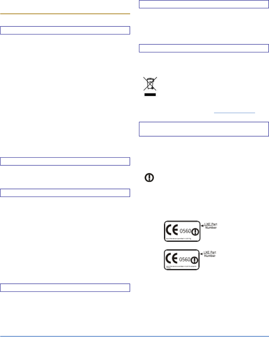
R&TTE Directive Requirements (Applies only to equipment
operated within the EU/EFTA)
Information to User
A label on the exterior of the device should
resemble one of the labels shown below (the label
contains the LXE part number of the installed radio
card). The labels shown below and affixed to the
device, identify where the device may be used and
where its use is restricted. Use of a device is
prohibited in countries not listed below or
otherwise identified by the label. (May or may not
include the 0560 Notified Body Number.
Substitute 4 digit Notified Body Number may also
be applied.)
E-EQ-THORCEOGWW-A [ 20 ] Thor CE User Guide
For ENG/CERT Review - Not for Distribution or Publication - Draft 03

Regulatory Notices and Safety Information
RF Safety Notice
This device is intended to transmit RF energy. For
protection against RF exposure to humans and in
accordance with FCC rules and Industry Canada
rules, this transmitter should be installed such that
a minimum separation distance of at least 20 cm
(7.8 in.) is maintained between the antenna and the
general population. This device is not to be co-
located with other transmitters.
E-EQ-THORCEOGWW-A [ 21 ] Thor CE User Guide
For ENG/CERT Review - Not for Distribution or Publication - Draft 03
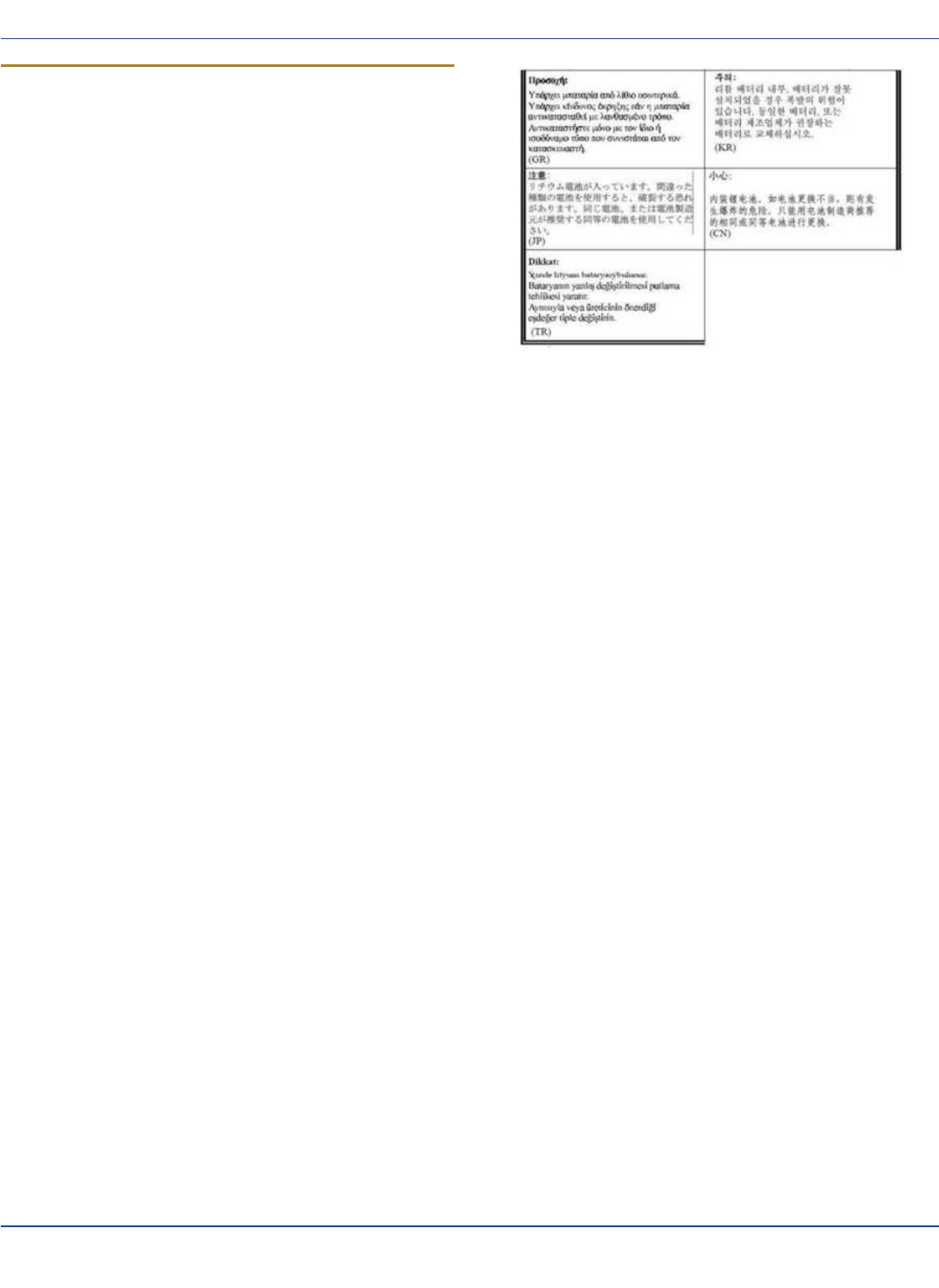
Lithium Battery Safety Statement
Caution: Lithium battery inside. Danger of explosion if battery
is incorrectly replaced. Replace only with same or equivalent
type recommended by battery manufacturer. (US)
Attention: Contient une pile de lithium. Risque d’explosion
dans le cas où la pile ne serait pas correctement remplacée.
Remplacer uniquement avec une pile semblable ou
equivalente au type de pile recommandé par le fabricant.
(FR)
Forsigtig: Indeholder lithiumbattterier. Risiko for eksplosion,
hvis batteriet udskiftes forkert. Må kun udskiftes med
samme eller tilsvarende type, som anbefalet af fabikanten.
(DK)
Varoitus: Tämä tuote käyttää laservaloa. Skannerissa on
jokin seuraavista tarroista. Lue Huomio-kohta. (FI)
Vorsicht: Enthält Lithium-Batterie. Bei unsachgemäßem
Ersatz besteht Explosionsgefahr. Nur durch gleichen oder
vom Hersteller empfohlenen Typ ersetzen. (DE)
Attenzione: Batteria al litio. Pericolo di esplosione qualora la
batteria venga sostituita in maniera scorretta. Sostituire solo
con lo stesso tipo o equivalente consigliato per il fabbricante.
(IT)
Atenção: Contém pilha de lítio. Há perigo de explosão no
caso de uma substituição incorreta. Substitua somente pelo
mesmo tipo, ou equivalente, recomendado pelo fabricante.
(PT) Varning: Innehåller litiumbatteri. Fara för explosion om
batteriet är felaktigt placerat eller av fel typ. Använd endast
samma eller motsvarande typ batterier rekommenderade av
tillverkaren. (SE)
Advarsel: Innmontert Lithium batteri. Eksplosjonsfare ved feil
montering av batteri. Benytt kun batteri anbefalt av
produsent. (NO)
Cuidado: Pila de litio adentro. Peligro de explosión si la pila
se reemplaza incorrectamente. Reemplace solamente con el
mismo tipo o equivalente recomendado por el fabricante.
(ES)
Oppassen: Bevat Lithium-batterij. Incorrrecte plaatsing van
batterij kan leiden tot explosiegevaar. Alleen vervangen door
hetzelfde of door fabrikant aanbevolen gelijkwaardig type.
(NL)
Legend: Danish – DK; English – US; Finnish – FI; French- -
FR; German – DE; Greek – GR; Italian – IT; Norwegian –
NO; Portuguese – PT; Spanish – ES; Swedish – SE; Turkish
– TR.
E-EQ-THORCEOGWW-A [ 22 ] Thor CE User Guide
For ENG/CERT Review - Not for Distribution or Publication - Draft 03
Vehicle Power Supply Connection Safety
Statement
Vehicle Power Supply Connection: If the supply connection
is made directly to the battery, a 10A slow-blow fuse should
be installed in the positive lead within 5 inches (12.7 cm.) of
the battery positive (+) terminal. (US)
Raccordement de l’alimentation du véhicule Si l’alimentation
est raccordée directement à la batterie, un fusible à action
retardée de 10A doit être installé sur le câble positif à moins
de 12,7 cm de la borne positive (+) de la batterie. (FR)
EL forsyning af køretøjet. Er forsyningsforbindelsen direkte
tilknyttet til batteriet og og tilsluttet til den positive part
indenfor 12,7 cm (+ delen). vil der være en langsom tændelse
af 10 ampere. (DK)
Kytkentä ajoneuvon virtalähteeseen Jos virtaa otetaan
suoraan akusta, 10 ampeerin hidas sulake on asennettava
positiiviseen johtoon enintään 12 cm:n etäisyydelle akun
positiivisesta (+) navasta. (FI)
Anschluss an Fahrzeugbatterie Bei direktem Anschluss an
die Fahrzeugbatterie sollte eine träge 10A-Sicherung in die
positive Leitung zwischengeschaltet werden, und zwar nicht
weiter als ca. 13 cm von der positiven (+) Batterieklemme
entfernt. (DE)
Σύνδεση Τροφοδοτικού Ισχύος Οχήματος Αν η σύνδεση του
τροφοδοτικού γίνει κατευθείαν στη μπαταρία, μια ασφάλεια
βραδείας τήξης των 10A θα πρέπει να τοποθετηθεί στο
θετικό καλώδιο εντός 5 ιντσών (12,7 εκ.) του θετικού (+)
ακροδέκτη της μπαταρίας. (GR)
Collegamento dell’alimentazione del veicolo Se il
collegamento dell’alimentazione viene stabilito direttamente
con la batteria, è necessario installare un fusibile ad azione
lenta da 10A nel conduttore positivo a meno di 5 in. (12,7
cm) dal terminale positivo (+) della batteria. (IT)
Tilkople strømforsyningen til kjøretøyet Hvis
strømforsyningen koples direkte til batteriet, skal det
installeres en 10A treg sikring i den positive ledningen innen
12,7 cm fra plusspolen (+) på batteriet. (NO)
Ligação do fornecimento de corrente do veículo Se a ligação
de fornecimento de corrente for ligada directamente à bateria,
deve instalar-se um fusível de 10A no terminal positivo, a
12,7 cm. do terminal positivo (+) da bateria. (PT)
Conexión de suministro eléctrico para el vehículo Si el
suministro eléctrico se proporciona directamente a la batería,
se debe instalar un fusible de retardo de 10A en el conductor
positivo, como máximo a 12,7 cm (5 pulgadas) del terminal
positivo (+). (ES)
Fordonets strömförsörjningskoppling Om strömkopplingen
görs direkt till batteriet, måste en 10A-säkring installeras i
den positivt laddade ledningen inom 12.7 cm från batteriets
pluspol (+). (SE)
Taşıt Güç Kaynağı Bağlantısı Kaynak bağlantısı doğrudan
aküye yapılırsa, pozitif bağlantı kablosu üzerinde akünün
pozitif (+) kutbuna 12.7 cm mesafede 10A’lık yavaş atan bir
sigorta monte edilmelidir. (TR)
Legend: Danish – DK; English – US; Finnish – FI; French- -
FR; German – DE; Greek – GR; Italian – IT; Norwegian –
NO; Portuguese – PT; Spanish – ES; Swedish – SE; Turkish
– TR.
Revision History
Revision / Date Location / Change
/ Jan 2010 Components / Added
Component pages.
E-EQ-THORCEOGWW-A [ 23 ] Thor CE User Guide
For ENG/CERT Review - Not for Distribution or Publication - Draft 03

Index
A
AC Power Scheme 8
Adjust Headset / Microphone and Secure Cable 14
Adjust Speaker Volume 14
AppLock Switchpad 18
Autolaunch Time-Sync 15
B
Battery Power Scheme 8
C
Calibrate 17
Class A Digital Device 20
Connect Cable- USB Client 9
Connect Cable- USB Host 9
Connect Cable - Seria 10
Connecting Cables 9
Connecting the Headset Cable 13
Connecting Vehicle Power 11
Cumulative mode timers 8
D
Date, Time, TimeZone 15
Daylight Savings location 15
G
Grab Time Utility 15
H
Hardware Setup 1
Headset
Adjusting the microphone 14
Mouthpiece Talk label 14
quick connect
cable
14
Hide input panel 16
Hide online keyboard 16
I
Input panel 16
P
Power key 1
R
Recalibrate 17
Revision History 23
RF Safety Notice 21
S
Safety Statement
Vehicle Power Supply 23
Set Date and Time Zone 15
Set Power Scheme Timers 8
Set Up A New Device 1
Setup Terminal Emulation Parameters 17
SIP soft input panel 16
Software Setup 1
Stylus
how to use 7
Switchpad 18
Synchronize with a Local Time Server 15
T
Touchscreen
and the stylus 7
Troubleshooting 19
U
Using the AppLock Switchpad 18
V
Vehicle Power Connection Cable 11
E-EQ-THORCEOGWW-A [ 24 ] Thor CE User Guide
For ENG/CERT Review - Not for Distribution or Publication - Draft 03