Honeywell LXE-VM1 Wireless Vehicle Mount Terminal User Manual Draft CE
Honeywell International, Inc. Wireless Vehicle Mount Terminal Draft CE
Contents
- 1. User Manual
- 2. User Guide
User Guide
User’s Manual
CV41C
With Microsoft® Windows® Embedded CE Operating System

1
1
Using the Vehicle Mount Computer
This chapter introduces the CV41C Vehicle Mount Computer
with Windows® CE operating system. Use this chapter to learn
about the basic features and available accessories.

Chapter 1 — Using the Vehicle Mount Computer
2 CV41C Vehicle Mount Computer User Guide
About the CV41C Vehicle Mount Computer
The rugged CV41C Vehicle Mount Computer is designed for real-time
data collection applications in warehousing, distribution,
work-in-process, time and attendance, and stationary applications.
The CV41C is highly configured and runs on the Microsoft Windows
CE operating system. Additionally, the CV41C supports the use of
terminal emulation applications, browser-based applications, or
custom applications.
Overview of the CV41C Features
The CV41C includes these standard features:
•8” color display with a resolution of 800 x 480.
•Two USB ports, two COM ports, a CANBUS port, an Ethernet port,
a headphone jack, and a microphone jack
•1 GB of RAM expandable to 2 GB of RAM
•Customer-accessible SD slot for memory cards up to 32 GB
•802.11a/b/g, Bluetooth®, GPS, and WWAN radios
•Intel Atom 1.6 GHz processor
The CV41C Vehicle Mount Computer has an IEEE 802.11a/b/g
radio installed and Wi-Fi® certified for interoperability with
other 802.11a/b/g wireless LAN devices.
Chapter 1 — Using the Vehicle Mount Computer
CV41C Vehicle Mount Computer User Guide 3
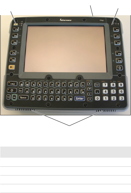
CV41C Front View
Callout Description
1Power button
2Speakers
3 Ambient light sensor
4Microphone
1
2
3
4
Chapter 1 — Using the Vehicle Mount Computer
4 CV41C Vehicle Mount Computer User Guide
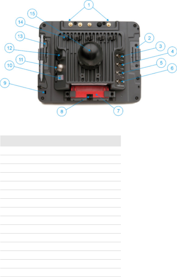
CV41C Back View with Quick Mount Smart Dock
Callout Description
1 Antenna connectors
2 SIM card access panel
3 COM 1
4COM 2
5 USB connector
6 CAN/audio connector
7 Quick release handle
8 Provision for padlock
9 Provision for laptop security cable
10 Power switch
11 Power connector
12 Fuse
13 SD card access panel
14 Strain relief clamp
15 RAM ball
Chapter 1 — Using the Vehicle Mount Computer
CV41C Vehicle Mount Computer User Guide 5
About the LEDs
The LEDs on the CV41C tell the state of the computer. Use this section
to learn about the connection and system LEDs.
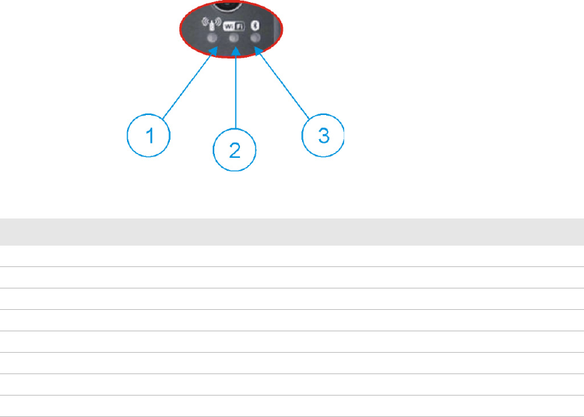
Connection LEDs
Connection LED Status Descriptions
Callout LED State Description
1 WWAN Solid green The CV41C is connected to WWAN.
Off The CV41C is not connected to WWAN.
2 Wi-Fi Solid amber The CV41C is connected to Wi-Fi.
Off The CV41C is not connected to Wi-Fi.
3 Bluetooth Blinking slowly Bluetooth is paired but not connected to a device.
Blinking medium Bluetooth is paired and connected to a device.
Blinking fast Bluetooth is discovering a device.
Off Bluetooth hardware has been turned off.
Chapter 1 — Using the Vehicle Mount Computer
6 CV41C Vehicle Mount Computer User Guide
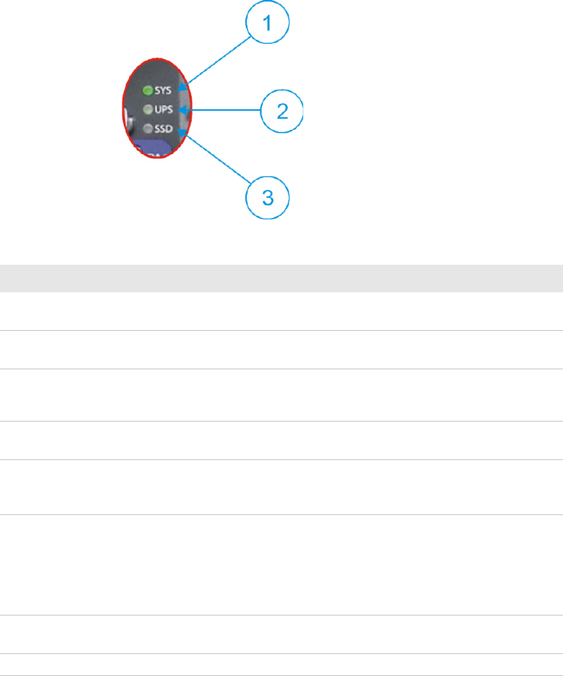
System LEDs
Connection LED Status Descriptions
Callout LED State Description
1 System Solid green The CV41C is on, or the CV41C is on but the
backlight or display may be off.
Blinking green
every 4.5 seconds
The CV41C is in suspend mode, or external power
is not present.
Blinking green
every 1.5 seconds
The CPU temperature is less than -20°C (-4°F), the
heater is warming the CPU for 30 seconds, or the
CV41C needs to be moved to a warmer environment.
Off The CV41C is off, external power is not present,
or it is in suspend mode.
2 UPS Solid green (External power present) The UPS battery is charging.
(External power not present) The CV41C is off or the
UPS battery is not present.
Solid amber (External power present) There is no UPS battery
present, the CV41C is out of charging temperature
range, a charge timeout has occurred, or there is a
charging fault.
(External not present) UPS battery is supplying power
and is discharging.
Off The UPS battery is fully charged, or it is not
charging.
3 SSD Flashing green Read or write activity is occurring.

Chapter 1 — Using the Vehicle Mount Computer
CV41C Vehicle Mount Computer User Guide 7
CV41C Accessories
The CV41C does not ship with any accessories. All accessories are sold
and ordered separately. For help, contact your local Intermec sales
representative.
CV41C Accessories
Mounting the CV41C
To properly mount the CV41C to a desktop or vehicle, you must
purchase the smart dock and one of the following mounting kits:
•RAM Mounting Kit
Off There is no read or write activity.
Callout LED State Description
Accessory Description
Quick Mount Smart Dock The smart dock provides a mount for the
CV41C, and supplies conditioned power to the
CV41C. For more information, see the CV41C
Mounting Kit Reference Guide.
RAM Mounting Kit Use this mounting kit to attach the CV41C to
a variety of surfaces, including a vehicle or to
your desktop. For more information, see the
CV41C Mounting Kit Reference Guide.
U-Bracket Mounting Kit Use this mounting kit to attach the CV41C to
a vehicle such as a forklift. For more
information, see the CV41C Mounting Kit
Reference Guide.
10-60 VDC Power
Connection Kit
Use this kit to supply 10-60 VDC power to the
CV41C.
72-144 VDC Power
Connection Kit
Use this kit to supply 72-144 VDC power to the
CV41C.
AC Power Supply Use the AC power supply to power to the
CV41C. The power supply can be connected to
a 120V or to a 230 V supply. If you are outside
of the United States, you must supply your
own power cord.
Chapter 1 — Using the Vehicle Mount Computer
8 CV41C Vehicle Mount Computer User Guide
•U-Bracket Mounting Kit
For more information on installing the smart dock and mounting kits,
see the CV41C Mounting Kit Reference Guide.
Connecting the CV41C to Power
For the CV41C to operate, you must attach it to the smart dock and
provide power to the CV41C through a DC/DC power supply or an
AC/DC power supply.
There are three power options for the CV41C. You must order one of
these power options separately:
•10-60 VDC Power Connection Kit
•72-144 VDC Power Connection Kit
•AC Power Supply
For more information on installing the DC power options, see the
CV41C Vehicle Mounting Kit Reference Guide.
Once you have connected the smart dock to power and attached the
CV41C to the smart dock, press the Power switch on the back of the
smart dock to supply power to the CV41C.
About the Internal UPS Battery
The CV41C contains an internal UPS battery that is automatically
charged when the CV41C is placed in a powered smart dock. The UPS
battery can power the CV41C for a minimum of 30 minutes at -20°C
(-4°F) or higher. The UPS battery allows you to continue using the
CV41C when not mounted in a dock or when the vehicle battery is
being changed.
If the UPS battery becomes critically low on power, the CV41C
performs a controlled shutdown. You can recharge it by placing the
CV41C back into the smart dock. You can fully charge a discharged
UPS battery in approximately 4 hours.
Maximizing the Internal UPS Battery Usage
You can maximize the internal UPS battery usage by changing the
battery power scheme.
Chapter 1 — Using the Vehicle Mount Computer
CV41C Vehicle Mount Computer User Guide 9
To set the battery power scheme:
1Tap Start > Settings > Control Panel. The Control Panel Screen
appears.
2Tap Power. The Power Properties screen appears.
3Tap the Schemes tab.
4In the Power Scheme drop-down menu, select Battery Power.
5Adjust the User Idle, System Idle, and Suspend times by selecting
the desired times in the drop-down menus.
6Tap OK when you are finished to save your changes and exit the
Power Properties screen.
About the Backup Battery
The CV41C has a permanent Lithium-Ion battery installed to
maintain the time, date, and CMOS setup information for a minimum
of 90 days. The Lithium-Ion battery is not user-replaceable and should
last five years before it needs replacement.
The backup battery must only be changed by authorized service
personnel. For more information, contact your local Intermec service
representative.
Installing an SD Card
You can use an SD card to increase file storage and install software.
The computer supports an optional 32 GB maximum capacity SD
card.
To install an SD card on the CV41C:
1Remove the CV41C from the smart dock.
2Press the Power button to place the CV41C in Suspend mode.
3Using a small Phillips screwdriver, remove the two screws that
secure the SD card access panel.
Chapter 1 — Using the Vehicle Mount Computer
10 CV41C Vehicle Mount Computer User Guide
4Insert the SD card into the SD card slot.
5Reattach the SD Card Access Panel and torque the screws to 4-5
in/lbs.
6Attach the CV41C back into the smart dock.
7Press the Power button to resume the CV41C from Suspend mode.
About the Phone
The CV41C supports UMTS cellular technology. The phone features
include a speaker and a microphone. You can also use a Bluetooth
headset or hands-free kit.
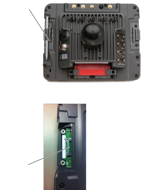
SD card
access panel
SD card slot
Chapter 1 — Using the Vehicle Mount Computer
CV41C Vehicle Mount Computer User Guide 11
Activating the UMTS Phone
You can use a SIM card to activate the UMTS phone on your computer.
You can purchase the SIM card from your network provider.
To install the SIM card and activate the UMTS radio:
1Remove the CV41C from the smart dock.
2Press the Power button to place the CV41C in Suspend mode.
3Using a small Phillips screwdriver, remove the SIM Card Access
Panel.
4Insert a SIM card into the SIM Card Slot.
5Reattach the SIM Card Access Panel and torque the screws to 4-5
in/lbs.
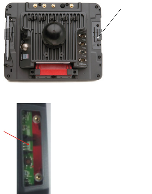
SIM card
access panel
Chapter 1 — Using the Vehicle Mount Computer
12 CV41C Vehicle Mount Computer User Guide
6Attach the CV41C back into the smart dock.
7Press the Power button to resume the CV41C from Suspend mode.
Adjusting the Volume
You can change the CV41C volume, for sounds you hear when you tap
the screen or scan bar codes with a scanner, to adjust to your needs and
the environment.
To adjust the volume:
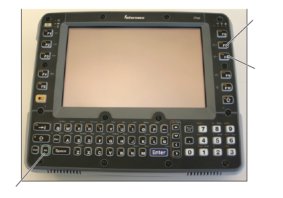
1On the keypad, tap the ALT key to enable the secondary keys.
2Tap F9 to increase volume or F10 to decrease the volume.
3Repeat Steps 1 and 2 to increase or decrease volume.
About the Touch Screen
8” color touch screen display with a resolution of 800 x 640 pixels. The
display also comes with a heater to reduce condensation on the
external surface of the display when moving between sub-freezing
temperatures and normal temperatures.
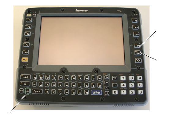
ALT key
F9 key
F10 key
Chapter 1 — Using the Vehicle Mount Computer
CV41C Vehicle Mount Computer User Guide 13
If you are going to use the CV41C in extreme cold conditions for an
extended period of time, you should turn on the power at room
temperature for at least 15 minutes prior to using it. This process of
“warming up” helps preserve the lighting on the display.
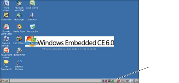
The default screen appears on the display when you turn on the
CV41C. This screen appears unless you are running ITE. If you have
installed ITE, it launches after the initial booting process.
Windows CE Default Screen on the CV41C
Enabling the Defroster
If your CV41C contains an optional defroster, you can use it to help
reduce condensation on an external surface when you are moving
between sub-freezing and normal temperatures.
To enable the defroster:
1Tap Start > Settings > Control Panel. The Control Panel screen
appears.
2Double-tap Peripherals. The Peripherals screen appears.
3Verify that a defroster is installed. If it is installed, enable it by
selecting Enabled.
4Set the Defroster trip point in degrees Celsius. When the
temperature reaches the defroster trip point, the defroster
automatically turns on.
5Tap OK to save and exit the Peripherals screen.
Windows CE
tasbar

Chapter 1 — Using the Vehicle Mount Computer
14 CV41C Vehicle Mount Computer User Guide
Navigating the Touch Screen
Use a stylus or your fingers to navigate the touch screen on the CV41C.
Touch Screen Navigation
Adjusting the Screen Brightness
By default, the CV41C has a built-in ambient light sensor that adjusts
the screen brightness automatically depending on the current lighting
conditions. You can adjust the brightness of the screen manually if you
do not want to use this feature.
To adjust the screen brightness manually:
1On the keypad, tap the ALT key to enable the secondary keys.
Action Description
Tap Touch the screen once with the stylus or finger to select
options, open or close applications, or launch menus.
Double tap Double tap the screen with the stylus or your finger to
launch applications.
Drag Hold the stylus or your finger on the screen and drag
across the screen to select text and images.
Tap and hold Tap and hold the stylus or your finger on an item to see a
menu of actions available for that item. On the pop-up
menu that appears, tap the action you want to perform.
Chapter 1 — Using the Vehicle Mount Computer
CV41C Vehicle Mount Computer User Guide 15
2Tap F7 to increase brightness or F8 to decrease the brightness.
3Repeat Steps 1 and 2 to increase or decrease volume.
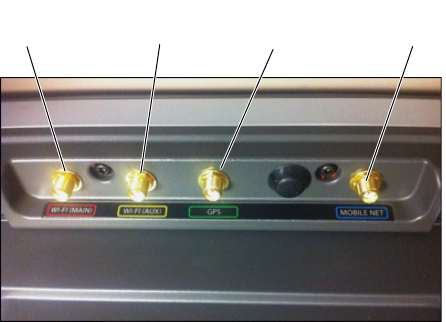
Installing an External Antenna
You can purchase an a WI-FI or GPS antenna to mount on a wall,
forklift, or other flat surface using either screws or small patches of
adhesive-backed hook and loop fastener material.
Since system performance and antenna polarization are
site-dependent, a permanent mounting location may require some
experimentation. In most fixed installations, you should mount the
antenna initially in a vertically-polarized position, with the cable from
the antenna parallel to the floor and ceiling. For information on
purchasing an antenna, contact your local Intermec sales
representative.
To connect an external antenna:
1Secure the antenna to one of the antenna plugs on the CV41C.
ALT key
F7 key
F8 key
Chapter 1 — Using the Vehicle Mount Computer
16 CV41C Vehicle Mount Computer User Guide
2Using your own hardware, secure the external antenna to a wall,
forklift, or other flat surface.
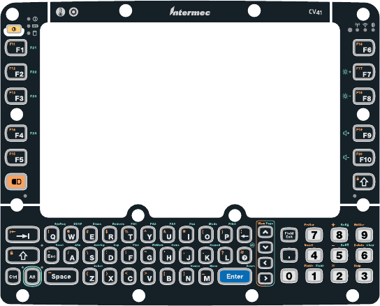
About the Keypad
The CV41C comes with one standard keypad overlay. The computer
has a keypad backlight for low light conditions. By default, the keypad
is enabled. You can disable the keypad backlight to conserve power.
GPS antenna
plug
Wi-Fi (aux)
antenna plug
Wi-Fi
antenna plug
WWAN
plug
Chapter 1 — Using the Vehicle Mount Computer
CV41C Vehicle Mount Computer User Guide 17
CV41C Keypad Overlay
Enabling or Disabling the Keypad Backlight
You can enable or disable the keypad backlight to conserve power.
To enable or disable the keypad backlight:
1Tap Start > Control Panel. The Control Panel screen appears.
2Double-tap Power. The Power menu appears.
3Select the Schemes tab.
4Select the check box to enable the keypad backlight. Clear the check
box to disable the backlight.
5Tap OK to save your changes and exit the Options screen.
Setting the Keypad Backlight Timer
The keypad backlight and the display backlight share the same timer.
When the display is on, the keypad backlight is also on. Use this section
to learn how to set the keypad backlight timer.
To set the keypad backlight timer:
1Tap Start > Control Panel. The Control Panel screen appears.
Chapter 1 — Using the Vehicle Mount Computer
18 CV41C Vehicle Mount Computer User Guide
2Double-tap Power. The Power Properties screen appears.
3Adjust the User Idle, System Idle, and Suspend times by selecting
the desired times in the drop-down menus.
4Tap OK when you are finished to save your changes and exit the
Power Properties screen.
Entering Characters on the Keypad
You need to use the orange modifier key and the ALT key to access all
characters and functions on the keypad.
To type a character:
•Press a key for that character.
To type a character or access a function on the overlay:
•Press the Orange or ALT key and then press the key for the
character or function.
To type an uppercase letter:
•Press the Up Arrow on the keypad and then press the key to type
an uppercase character.
Rebooting the Computer
If you are experiencing problems with the CV41C, you can perform a
warm boot or restart.
Warm Booting the CV41C
When you perform a warm boot, the CV41C reboots without erasing
any registry data, configuration settings, data in RAM storage, and cab
files that were installed. Networking sessions are lost, and any data in
applications that were running may be lost if they were not saved.
To perform a warm boot:
1Tap Start > Settings > Control Panel. The Control Panel screen
appears.
2Double-tap Registry. The Registry screen appears.
3Tap Warm Boot to warm boot the CV41C.

Chapter 1 — Using the Vehicle Mount Computer
CV41C Vehicle Mount Computer User Guide 19
Restarting the CV41C
When you perform a restart, the CV41C reboots without erasing any
registry data and configuration settings. The data in RAM storage is
lost, networking sessions are lost, cab files are reloaded, and any data
in applications that were running may be lost if they were not saved
reloaded.
To perform a restart:
1Tap Start > Settings > Control Panel. The Control Panel screen
appears.
2Double-tap Registry. The Registry screen appears.
3Tap Restart to restart the CV41C.
Physical and Environmental Specifications
Physical Dimensions
Environmental Specifications
Dimensions 26.8 x 21.4 x 1.7 cm (10.6 x 8.4 x 6.6 in)
Weight 2.1 kg (5.6 lbs)
Standard Operating temperature Non-condensing: -20°C to 50°C (-4°F to 122°F)
Extreme operating temperature Condensing: -30°C to 50°C (-22°F to 122°F)
Storage temperature Non-condensing: -30°C to 60°C (-22°F to 148°F)
Relative humidity Up to 90% non- condensing at 40°C (104°F) with extended
temperatures up to 100%
Water and dust IP66
ESD 15 kV
Vibration MIL-STD-810F, composite wheeled vehicles
Crash SAE-J 1455

Chapter 1 — Using the Vehicle Mount Computer
20 CV41C Vehicle Mount Computer User Guide
Power and Electrical Specifications
Operating System
Microsoft Windows CE 6.0
Hardware
Touch Screen Specifications
8” color WVGA display with a resolution of 800 x 480 pixels, with
optional heated display.
Standard Communications
•802.11a/b/g
•Bluetooth
•USB
•Serial
Wireless LAN
Input power DC input voltage: 10-60 VDC
Input current: 4.6 Amps
Input fuse: 10 A time delay
External power supply AC adapter: 120-240 VAC to 12 VDC
Backup battery (CMOS) Internal lithium-ion battery
Processor Intel Atom CPU at 1.6 GHz
Memory 1 GB expandable to 2 GB SDRAM
Removable storage Compact Flash or Secure Digital
Data rates Supports all 802.11a/b/g data rates.
Security WPA, WPA2, 802.1x (EAP-TLS, TTLS, LEAP, PEAP,
EAP-FAST), WEP

Regulatory Notices and Safety Information
CV41C Vehicle Mount Computer User Guide
21
Regulatory Notices and Safety Information
Waste Electrical and Electronic Equipment (WEEE)
Important:
This symbol is placed on the product to remind users to dispose of Waste Electrical and Electronic
Equipment (WEEE) appropriately, per Directive 2002-96-EC. In most areas, this product can be
recycled, reclaimed and re-used when properly discarded. Do not discard labeled units with trash.
For information about proper disposal, contact your supplier.
Class B Digital Device
NOTICE
This device complies with Part 15 of the FCC Rules. Operation is subject to the following two conditions:
1. This device may not cause harmful interference, and
2. This device must accept any interference received, including interference that may cause undesired
operation.
NOTE: This equipment has been tested and found to comply with the limits for a Class B digital device,
pursuant to Part 15 of the FCC Rules. These limits are designed to provide reasonable protection against
harmful interference in a residential installation. This equipment generates, uses and can radiate radio
frequency energy and, if not installed and used in accordance with the instructions, may cause harmful
interference to radio communications. However, there is no guarantee that interference will not occur in a
particular installation. If this equipment does cause harmful interference to radio or television reception,
which can be determined by turning the equipment off and on, the user is encouraged to try to correct the
interference by one or more of the following measures:
Reorient or relocate the receiving antenna.
Increase the separation between the equipment and the receiver.
Connect the equipment into an outlet on a circuit different from that to which the receiver is
connected.
Consult the dealer or an experienced radio/TV technician for help.
NOTICE
Changes or modifications made to this equipment not expressly approved by Intermec may void the FCC
authorization to operate this equipment.
EMC Directive Requirements
This is a Class B product. In a domestic environment this product may cause radio interference in which
case the user may be required to take adequate measures.
Canada, Industry Canada (IC) Notices
This Class B digital apparatus complies with Canadian RSS-GEN issue 3:2010 and RSS-210 issue 8:2010.
Operation is subject to the following two conditions: (1) this device may not cause interference, and (2)
this device must accept any interference, including interference that may cause undesired operation of the
device.
Radio Frequency (RF) Exposure Information
The radiated output power of the CV41C is below the Industry Canada (IC) radio frequency exposure
limits. The CV41C should be used in such a manner such that the potential for human contact during
normal operation is minimized.
Regulatory Notices and Safety Information
22 CV41C Vehicle Mount Computer User Guide
This device has been certified for use in Canada. Status of the listing in the Industry Canada’s REL (Radio
Equipment List) can be found at the following web address:
http://www.ic.gc.ca/app/sitt/reltel/srch/nwRdSrch.do?lang=eng
Additional Canadian information on RF exposure also can be found at the following web address:
http://www.ic.gc.ca/eic/site/smt-gst.nsf/eng/sf08792.html
Canada, avis d'Industry Canada (IC)
Cet appareil numérique de classe B est conforme aux normes canadiennes RSS-GEN numéro 3:2010 et
RSS-210 numéro 8:2010.
Son fonctionnement est soumis aux deux conditions suivantes : (1) cet appareil ne doit pas causer
d'interférence et (2) cet appareil doit accepter toute interférence, notamment les interférences qui
peuvent affecter son fonctionnement.
Informations concernant l'exposition aux fréquences radio (RF)
La puissance de sortie émise par de le CV41C est inférieure à la limite d'exposition aux fréquences radio
d'Industry Canada (IC). Utilisez le CV41C de façon à minimiser les contacts humains lors du
fonctionnement normal.
Ce périphérique est homologué pour l'utilisation au Canada. Pour consulter l'entrée correspondant à
l’appareil dans la liste d'équipement radio (REL - Radio Equipment List) d'Industry Canada rendez-vous
sur: http://www.ic.gc.ca/app/sitt/reltel/srch/nwRdSrch.do?lang=eng
Pour des informations supplémentaires concernant l'exposition aux RF au Canada rendez-vous sur :
http://www.ic.gc.ca/eic/site/smt-gst.nsf/eng/sf08792.html
ANATEL (Brazil)
Este equipamento opera em caráter secundário, isto é, não tem direito a proteção contra interferência
prejudicial, mesmo de estações do mesmo tipo, e não causar interferência a sistema operando em caráter
primário.
Li-Ion Battery
When disposing of the CV41C main battery, the following precautions should be observed: The battery
should be disposed of properly. The battery should not be disassembled or crushed. The battery should
not be heated above 212°F (100°C) or incinerated.
R&TTE Directive Requirements (Applies only to equipment operated within the EU/EFTA)
Information to User
A label on the exterior of the device should resemble one of the labels shown below (the label contains
the part number of the installed radio card). The labels shown below and affixed to the device, identify
where the device may be used and where its use is restricted. Use of a device is prohibited in
countries not listed below or otherwise identified by the label. (May or may not include the 0560
Notified Body Number. Substitute 4 digit Notified Body Number may also be applied.)
RF Safety Notice
This device is intended to transmit RF energy. For protection against RF exposure to humans and in
accordance with FCC rules and Industry Canada rules, this transmitter should be installed such that a
minimum separation distance of at least 20 cm (7.8 in.) is maintained between the antenna and the
general population. This device can only be co-located with FCC ID:TWG-SDCMSD30G.