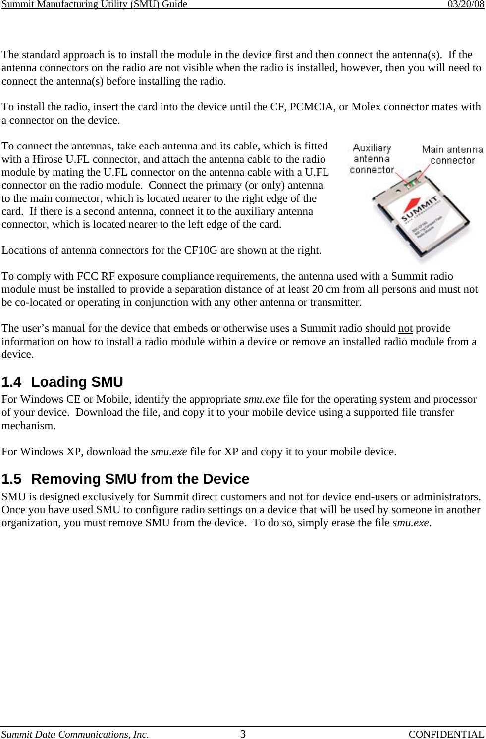
Honeywell LXE4831P 802.11 abg wireless module User Manual Manual

Honeywell International, Inc. 802.11 abg wireless module Manual

Manual

Summit Manufacturing Utility (SMU) Guide    03/20/08 Summit Data Communications, Inc.  i CONFIDENTIAL                  Summit Data Communications, Inc. Summit Manufacturing Utility (SMU) Guide  Software Version 2.01 for Windows CE and Windows Mobile
Summit Manufacturing Utility (SMU) Guide    03/20/08 Summit Data Communications, Inc.  ii CONFIDENTIAL Table of Contents 1.0 SUMMIT PRODUCTS AND SUMMIT SOFTWARE ...............................................................................1 1.1 SUMMIT SOFTWARE ......................................................................................................................................1 1.2 INSTALLING SUMMIT SOFTWARE ..................................................................................................................2 1.3 INSTALLING THE RADIO ................................................................................................................................2 1.4 LOADING SMU .............................................................................................................................................3 1.5 REMOVING SMU FROM THE DEVICE.............................................................................................................3 2.0 THE SUMMIT MANUFACTURING UTILITY.........................................................................................4 2.1 USING SMU..................................................................................................................................................4 2.2 SMU-CONFIGURABLE SETTINGS ..................................................................................................................4 2.2.1 Unit Setting: Administrative Override.....................................................................................................4 2.2.2 Unit Setting: Import/Export.....................................................................................................................4 2.2.3 Regulatory Domain..................................................................................................................................5 2.2.4 Bluetooth Coexistence..............................................................................................................................6 2.2.5 BG Max Antenna Adjust and A Max Antenna Adjust...............................................................................6 APPENDIX: FCC INFORMATION .........................................................................................................................8
Summit Manufacturing Utility (SMU) Guide    03/20/08 Summit Data Communications, Inc.  1 CONFIDENTIAL 1.0  Summit Products and Summit Software Thank you for choosing one of the following radio modules or cards from Summit Data Communications, Inc.: •  SDC-CF10G 802.11g compact flash radio module with antenna connectors •  SDC-PC10G  802.11g PCMCIA radio module with antenna connectors •  SDC-MCF10G  802.11g miniature compact flash radio module with antenna connectors •  SDC-CF20G  802.11g compact flash radio card with integrated antennas •  SDC-PC20G  802.11g PCMCIA radio card with integrated antennas •  SDC-CF10AG  802.11a/g compact flash radio module with antenna connectors •  SDC-PC10AG  802.11a/g PCMCIA radio module with antenna connectors  For an overview of Summit products, go to http://www.summitdatacom.com/products.htm.  Each Summit G radio enables a computing device to communicate to a computing network using the IEEE 802.11g and IEEE 802.11b protocols.  The hardware components and software for all Summit G radios are the same.  A 20G version is a 10G version with integrated antennas. A PCMCIA version is a CF version in a specially designed CF-to-PCMCIA carrier. The miniature CF version is essentially the CF version with a different layout and a different (Molex) connector.  Each Summit AG radio enables a computing device to communicate to a computing network using the IEEE 802.11a, 802.11g, and IEEE 802.11b protocols.  The hardware components and software for all Summit AG radios are the same. 1.1 Summit Software The software that Summit provides for its radios consists of the following components: •  A device driver for the operating system running on the computing device that houses the radio •  An integrated IEEE 802.1X supplicant •  SCU as well as other utilities that use a software developer’s kit (SDK) to interact with the driver •  A service that displays in the Windows System Tray an icon that provides a visual status for the Summit radio and enables the user to launch SCU by tapping the icon  Summit supports its software on the following operating systems: •  Windows CE 4.2, Windows Mobile 2003 or Pocket PC 2003 •  Windows CE 5.0, Windows Mobile 5.0, Windows Mobile 6.0 •  Windows XP Professional and Windows XP Embedded  SCU is designed for end users and administrators of mobile devices that use a Summit radio module.  SCU provides a GUI for access to all of its functions.  Access to these functions also is available through an API that is provided to every Summit customer.  A Summit customer can use the API to manage the radio from another utility, such as one that the customer provides with its mobile devices.  Using SCU, an administrator can configure radio and security settings in a configuration profile, or config.  For a list of config settings, see the Summit User’s Guide.  An administrator also can use SCU to define a set of global settings, which apply to all configs and to SCU.  For a list of global settings that can be configured using SCU, see the Summit User’s Guide.  The Summit Manufacturing Utility (SMU) allows for the configuration of certain radio settings that cannot be configured through SCU.  Summit offers SMU only to its direct customers:
Summit Manufacturing Utility (SMU) Guide    03/20/08 Summit Data Communications, Inc.  2 CONFIDENTIAL •  Device manufacturers that embed Summit radios in their devices or offer Summit radios as device options •  Value-added distributors that must configure Summit radios for resellers and end-customers  This guide is for SMU V2.01 running on Windows CE or Windows Mobile.  To use SMU in a computing device, you first must perform the following steps: •  Install Summit software on a mobile computing device that runs a supported operating system •  Install the Summit radio on the device •  Load SMU on the device  It is recommended that you complete the steps in the order shown above. If you insert the radio in your device before you install the software, then the operating system will flag the radio as unknown and display the “Found New Hardware Wizard” screen, and you must select “Cancel” to cancel the Hardware Wizard.  Once you have finished using SMU, you must remove SMU from the device.  SMU is for the exclusive use of those Summit customers to which Summit makes SMU available.  Those customers are not permitted to redistribute SMU to anyone. 1.2  Installing Summit Software Summit software is in a .cab file, which is the software equivalent of a “file cabinet”.  A Summit .cab file contains all software components, including the device driver and the Summit Client Utility (SCU).  To install the Summit software, perform these tasks: •  Download the appropriate .cab file for the operating system and processor of your device.  You can obtain your device’s operating system and processor from the system information under Windows Control Panel (Tap Start, then Settings, and then System or Control Panel) -  Pocket PC or Mobile: Select a .cab file with a name that begins with “mobile”. -  CE .NET: Do a search on your device’s processor to determine if it is an ARM v4i processor or an ARM v4 processor.  If it is an ARM v4i processor, select a .cab file with a name that begins with “sdc_armv4i”.  If it is an ARM v4 processor, select a .cab file with a name that begins with “sdc_armv4”. •  Copy the file to your device using a supported file transfer mechanism. Common methods of moving the file include: -  Place the file on a supported Compact Flash or SD memory card and use that card for copying the file to the device. -  Use a program such as FTP or Microsoft ActiveSync. •  On the device, use the resident File Explorer program to locate the .cab file. •  Run the .cab file by single-clicking the file or by right-clicking and selecting “run”. •  If asked to replace any existing files on the device, answer “Yes to all”. 1.3  Installing the Radio Once you have installed the Summit software, you must install the Summit radio card or module.  To install a 20G Series radio card, you simply insert the card in an external card slot. To install a 10G Series or 10AG Series radio module, you must complete two types of connections: •  Module to device: Mate a connector on the end of the module to a connector on the device •  Antenna(s) to module: Use an antenna cable that mates with the antenna on one end and with the radio module’s U.FL connector on the other end
Summit Manufacturing Utility (SMU) Guide    03/20/08 Summit Data Communications, Inc.  3 CONFIDENTIAL  The standard approach is to install the module in the device first and then connect the antenna(s).  If the antenna connectors on the radio are not visible when the radio is installed, however, then you will need to connect the antenna(s) before installing the radio.  To install the radio, insert the card into the device until the CF, PCMCIA, or Molex connector mates with a connector on the device.  To connect the antennas, take each antenna and its cable, which is fitted with a Hirose U.FL connector, and attach the antenna cable to the radio module by mating the U.FL connector on the antenna cable with a U.FL connector on the radio module.  Connect the primary (or only) antenna to the main connector, which is located nearer to the right edge of the card.  If there is a second antenna, connect it to the auxiliary antenna connector, which is located nearer to the left edge of the card.  Locations of antenna connectors for the CF10G are shown at the right. To comply with FCC RF exposure compliance requirements, the antenna used with a Summit radio module must be installed to provide a separation distance of at least 20 cm from all persons and must not be co-located or operating in conjunction with any other antenna or transmitter.  The user’s manual for the device that embeds or otherwise uses a Summit radio should not provide information on how to install a radio module within a device or remove an installed radio module from a device. 1.4 Loading SMU For Windows CE or Mobile, identify the appropriate smu.exe file for the operating system and processor of your device.  Download the file, and copy it to your mobile device using a supported file transfer mechanism.  For Windows XP, download the smu.exe file for XP and copy it to your mobile device. 1.5  Removing SMU from the Device  SMU is designed exclusively for Summit direct customers and not for device end-users or administrators.  Once you have used SMU to configure radio settings on a device that will be used by someone in another organization, you must remove SMU from the device.  To do so, simply erase the file smu.exe.
Summit Manufacturing Utility (SMU) Guide    03/20/08 Summit Data Communications, Inc.  4 CONFIDENTIAL 2.0  The Summit Manufacturing Utility 2.1 Using SMU To run SMU, use File Explorer or Windows Explorer to locate the smu.exe file, and tap the file to execute it.  SMU will display a graphical user interface (GUI) like the one shown at the right.  The values displayed on the SMU window may not reflect what is programmed on the radio or on the device.  Use the selection boxes, radio buttons, and input fields to select the desired card and unit settings, and then tap the Commit Changes button.  Once you tap Commit, SMU uses the Summit application programming interface (in the Summit software developer’s kit, or SDK) and programmatically does the following: •  Gathers the specified settings •  Calls SetGlobalSettings •  Calls updateSROM  It takes about 30 seconds from when you tap the button to when the settings are stored. 2.2 SMU-Configurable Settings There are two types of global settings that can be configured only through SMU: •  Unit Settings: Stored in the registry of the unit on which SMU is run. •  Card Settings: Stored in the SROM on the radio module, or card.  If you move the card from one device to another, the card will retain these settings, provided that the device is running a version of the driver as current as the version with which SMU was used. 2.2.1  Unit Setting: Administrative Override When the administrative override setting is On, then the Admin Login button is removed from the SCU Main window, and SCU considers the user in Admin mode. 2.2.2  Unit Setting: Import/Export When the import/export setting is On, then a user logged into SCU as an administrator will see an Import/Export button on the SCU Main window, as shown on the next page.  By tapping that button, the user will view a dialog box on which he or she can: •  Export global settings, all standard SCU profiles, and the special ThirdPartyConfig profile from the SCU area of a device’s registry to a file that can be transferred to another device •  Import global settings, all standard SCU profiles, and the special ThirdPartyConfig profile from a file (created using the Export facility) to the SCU area of a device’s registry so that SCU can use it -  If “Add to existing” is selected, then the imported information will be merged with information that was in the registry previously -  If “Replace” is selected, then the imported information will overwrite the information that was in the registry previously
Summit Manufacturing Utility (SMU) Guide    03/20/08 Summit Data Communications, Inc.  5 CONFIDENTIAL  SCU Main window with Import/Export button  Import/Export dialog box 2.2.3 Regulatory Domain A Summit radio’s regulatory domain determines the radio’s maximum transmit power and the frequency channels available to the radio.  Summit radios are certified for operation in three regulatory domains: •  FCC, which is governed by the Federal Communications Commission, the regulatory agency and standards body for the Americas and parts of Asia •  ETSI, which is governed by the European Telecommunications Standards Institute, the standards body applicable to most of Europe, Africa, the Middle East and parts of Asia •  TELEC, which is governed by the Telecom Engineering Center, the standards body for Japan  A Summit radio can be programmed for any one of these three domains.  Alternatively, a Summit radio can be programmed for a Worldwide domain, which enables the radio to be used in any domain.  “Worldwide” value is the default value for the setting.  An 802.11g radio, which supports both 802.11b and 802.11g, operates in the 2.4 GHz frequency spectrum, where up to 14 channels, numbered 1 to 14, are defined.  Adjacent channels overlap.  In fact, there must be five channels of separation to avoid overlap and co-channel interference.  As an example, channels 1, 6, and 11 are non-overlapping.  An 802.11a/g radio operates in both the 2.4 GHz spectrum for 802.11b and 802.11g and the 5 GHz spectrum for 802.11a. The 5 GHz frequency spectrum is grouped into sets of channels, or bands: •  UNII-1: 36, 40, 44, 48 •  UNII-2: 52, 56, 60, 64 •  Intermediate: 100, 104, 108, 112, 116, 120, 124, 128, 132, 136, 140 •  UNII-3: 149, 153, 157, 161  None of the channels in the 5 GHz bands overlap.  Dynamic Frequency Selection, or DFS, is required for the UNII-2 and Intermediate bands.  With V2.01 of Summit software, a Summit AG radio programmed for the FCC regulatory domain does not support DFS or the bands that require DFS.
Summit Manufacturing Utility (SMU) Guide    03/20/08 Summit Data Communications, Inc.  6 CONFIDENTIAL The table below shows the channels and the nominal maximum transmit power values that are supported in each regulatory domain with V2.01: 2.4 GHz  5 GHz (AG radio only) Domain  Channels Tx (.11b) Channels Tx FCC  1-11  18 dBm   UNII-1 and UNII-3  14 dBm ETSI  1-13  18 dBm   UNII-1, UNII-2, and Intermediate  14 dBm TELEC  1-14  17 dBm   UNII-1 and UNII-2, plus additional channels: 34, 38, 42, 46  14 dBm WorldWide: no 802.11d  1-11  17 dBm  UNII-1  14 dBm WorldWide: 802.11d  All  18 dBm  All  14 dBm  V2.01 of Summit software supports a performance-optimized version of IEEE 802.11d, the ratified standard for the operation of a wireless LAN client radio in multiple regulatory domains.  This 802.11d support ensures that a Summit radio that is programmed for the WorldWide regulatory domain can adjust its 2.4 GHz and 5 GHz channel sets and maximum transmit power settings to match those for the country specified in the Country information element transmitted in an access point’s (AP’s) association response.  To take advantage of 802.11d support in Summit software and ensure optimal performance, an organization that uses devices with Summit radios must make sure that every AP on the wireless LAN supports 802.11d, specifies the correct Country information element, and broadcasts its SSIDs.  The device manufacturer or other organization that uses the Summit Manufacturing Utility to program Summit radios must ensure that every Summit radio is programmed for a regulatory domain of WorldWide.  A radio that is programmed for a regulatory domain of FCC, ETSI, or TELEC will ignore the Country information elements from APs.  A Summit radio uses 802.11d only when it tries to associate on an SSID for the first time.  During the initial association process, if the AP provides a Country information element, then the radio configures its channel set and maximum transmit power for that country.  The radio assumes that all APs with the same SSID have the same 802.11d country code; as a result, the radio effectively ignores the country code when roaming from one AP to another.  The radio will continue to use the channel set and maximum transmit power for a country until the radio disconnects from the WLAN (with that SSID). 2.2.4 Bluetooth Coexistence When Bluetooth coexistence is on, pins 39 and 45 of the radio are used for two-wire Bluetooth coexistence handshaking.  When Bluetooth coexistence is off, the handshaking lines are not used.  The default value is “Off”. 2.2.5  BG Max Antenna Adjust and A Max Antenna Adjust  The last two card settings provides for an adjustment to the radio’s transmit power to accommodate a 2.4 GHz (802.11b/g) antenna, a 5 GHz (802.11a) antenna, or a dual-band antenna with a gain greater than 0 dBm.  The values for each of these settings, “BG Max antenna adjust” and “A Max antenna adjust”, is the degree of antenna attenuation expressed as a percentage of dBm, not milliwatts (mW), with the percentage based on a TELEC 50 mW test.  On the next page is a table of popular dBm values and their corresponding mW values.  Here is an example: In ETSI, to ensure that the maximum 802.11b transmit power is 50 mW, use 94%: 94% x 18 dBm = 16.92 dBm = 50 mW  The default value is “100%”.
Summit Manufacturing Utility (SMU) Guide    03/20/08 Summit Data Communications, Inc.  7 CONFIDENTIAL dBm  mW   dBm  mW   dBm  mW 20 100  15 31.6  10 10 19  79.4   14  25.1   8  6.3 18 63.1  13  20   6  4 17  50.1   12  15.8   3  2 16  39.8   11  12.6   0  1  Beginning with V1.03.23 of Summit software, the transmit power (Tx Power) value on the SCU Status window accounts for the transmit power adjustment set in SMU.  As a result, the displayed value is the true transmit power of the Summit radio.  In previous releases, the Status window displayed the transmit power without the adjustment, because SCU assumed that the antenna provided a gain that compensated for the adjustment.  With previous releases, therefore, the displayed value was an estimate of EIRP and not a true radio transmit power value.
Summit Manufacturing Utility (SMU) Guide    03/20/08 Summit Data Communications, Inc.  8 CONFIDENTIAL Appendix: FCC Information Note: All declarations and instructions for the SDC-CF10G apply to other Summit 802.11g radio modules and cards.  Summit declares that SDC-CF10G (FCC ID: TWG-SDCCF10G) is limited in CH1~CH11 for 2.4 GHz by specified firmware controlled in U.S.A.   This device is intended for host device manufacturers and integrators only under the following conditions:  1)  The antenna must be installed such that 20 cm is maintained between the antenna and users, and  2)  The transmitter module may not be co-located with any other transmitter or antenna.   As long as the two conditions above are met, further transmitter test will not be required. However, the OEM integrator is still responsible for testing its end-product for any additional compliance requirements required with this module installed (for example, digital device emissions, PC peripheral requirements, etc.).   IMPORTANT NOTE: In the event that the two conditions above cannot be met (for example certain device configurations or co-location with another transmitter), then the FCC authorization is no longer considered valid and the FCC ID cannot be used on the final product. In these circumstances, the OEM integrator will be responsible for re-evaluating the end product (including the transmitter) and obtaining a separate FCC authorization.   •  End Product Labeling  This transmitter module is authorized only for use in device where the antenna may be installed such that 20 cm may be maintained between the antenna and users, for example, mobile data terminals (MDTs) and vehicle-mounted devices (VMDs). The final end product must be labeled in a visible area with the following: “Contains TX FCC ID: TWG-SDCCF10G”.   •  Manual Information That Must be Included  The OEM integrator must not provide information to the end user regarding how to install or remove this RF module in the users manual of the end product which integrate this module.   The users manual for OEM integrators must include the following information in a prominent location: “IMPORTANT NOTE: To comply with FCC RF exposure compliance requirements, the antenna used for this transmitter must be installed to provide a separation distance of at least 20 cm from all persons and must not be co-located or operating in conjunction with any other antenna or transmitter.”  Federal Communication Commission Interference Statement  This equipment has been tested and found to comply with the limits for a Class B digital device, pursuant to Part 15 of the FCC Rules. These limits are designed to provide reasonable protection against harmful interference in a residential installation. This equipment generates, uses and can radiate radio frequency energy and, if not installed and used in accordance with the instructions, may cause harmful interference to radio communications. However, there is no guarantee that interference will not occur in a particular installation. If this equipment does cause harmful interference to radio or television reception, which can be determined by turning the equipment off and on, the user is encouraged to try to correct the interference by one of the following measures:  1.  Reorient or relocate the receiving antenna  2.  Increase the separation between the equipment and receiver
Summit Manufacturing Utility (SMU) Guide    03/20/08 Summit Data Communications, Inc.  9 CONFIDENTIAL 3.  Connect the equipment into an outlet on a circuit different from that to which the receiver is connected 4.  Consult the dealer or an experienced radio/TV technician for help   FCC Caution: Any changes or modifications not expressly approved by the party responsible for compliance could void the user's authority to operate this equipment.  This device complies with Part 15 of the FCC Rules. Operation is subject to the following two conditions: (1) This device may not cause harmful interference, and (2) this device must accept any interference received, including interference that may cause undesired operation.  IMPORTANT NOTE:  FCC Radiation Exposure Statement:  This equipment complies with FCC radiation exposure limits set forth for an uncontrolled environment. This equipment should be installed and operated with minimum distance 20cm between the radiator & your body.  This transmitter must not be co-located or operating in conjunction with any other antenna or transmitter.   Industry Canada  To prevent radio interference to the licensed service, this device is intended to be operated indoors and away from windows to provide maximum shielding. Equipment (or its transmit antenna) that is installed outdoors is subject to licensing.  This device has been designed to operate with the antennas listed below, and having a maximum gain of 5.1 dB. Antennas not included in this list or having a gain greater than 5.1 dB are strictly prohibited for use with this device. The required antenna impedance is 50 ohms.  Manufacturer: Laird Centurion  Model Name: NanoBlade Antenna Type: PCB Omnidirectional Gain at 2.40 GHz : 3.8 dBi Gain at 5.25 GHz: 5.1 dBi  Gain at 5.80 GHz: 4.5 dBi   Manufacturer: Volex Part Number: VLX-51004-A Antenna Type: Dipole Gain at 2.40 GHz : 2.3 dBi Gain at 5 GHz: 1.9 dBi   Manufacturer: Larson Part Number: R380.500.314 Antenna Type: Dipole Gain at 2.40 GHz : 1.6 dBi Gain at 5 GHz:  5 dBi

Navigation menu