Honeywell LXE6730M WIRELESS LAN ACCESS POINT User Manual ap1200 3b
Honeywell International, Inc. WIRELESS LAN ACCESS POINT ap1200 3b
UserManual.wiki
>
Honeywell
>
LXE6730M User Manual
>
MANUAL
Contents
1.
MANUAL
2.
INSTALLATION INSTRUCTIONS
MANUAL
Navigation menu
Upload a User Manual
Namespaces
Wiki Guide
HTML
PDF
Info
Views
User Manual
Discussion / Help
Navigation

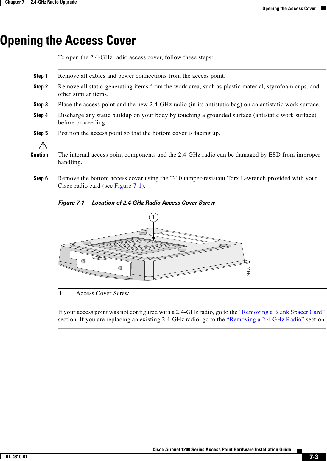
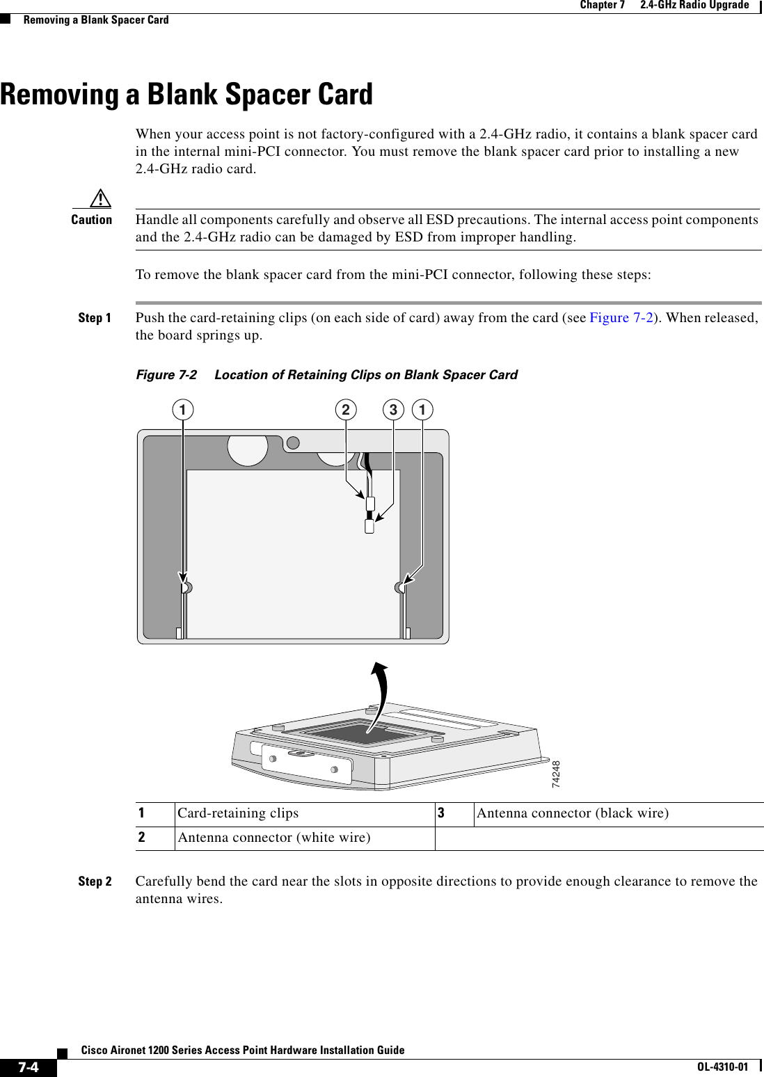
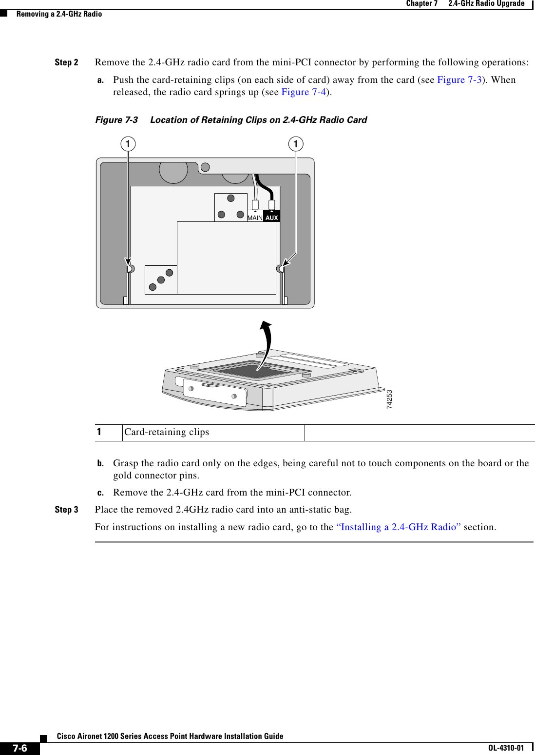
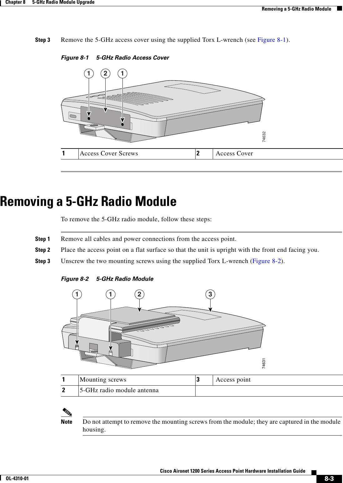
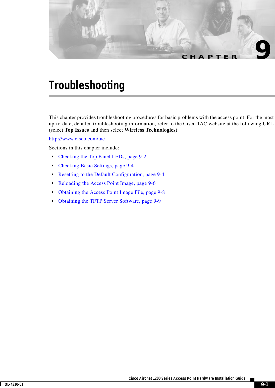
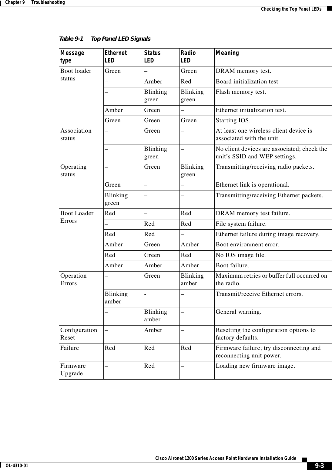
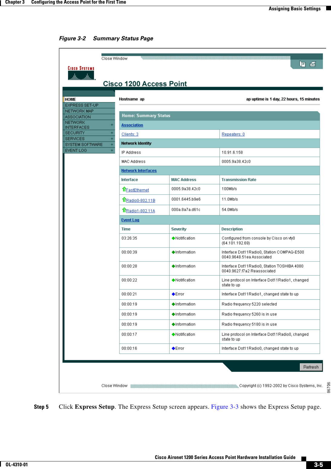
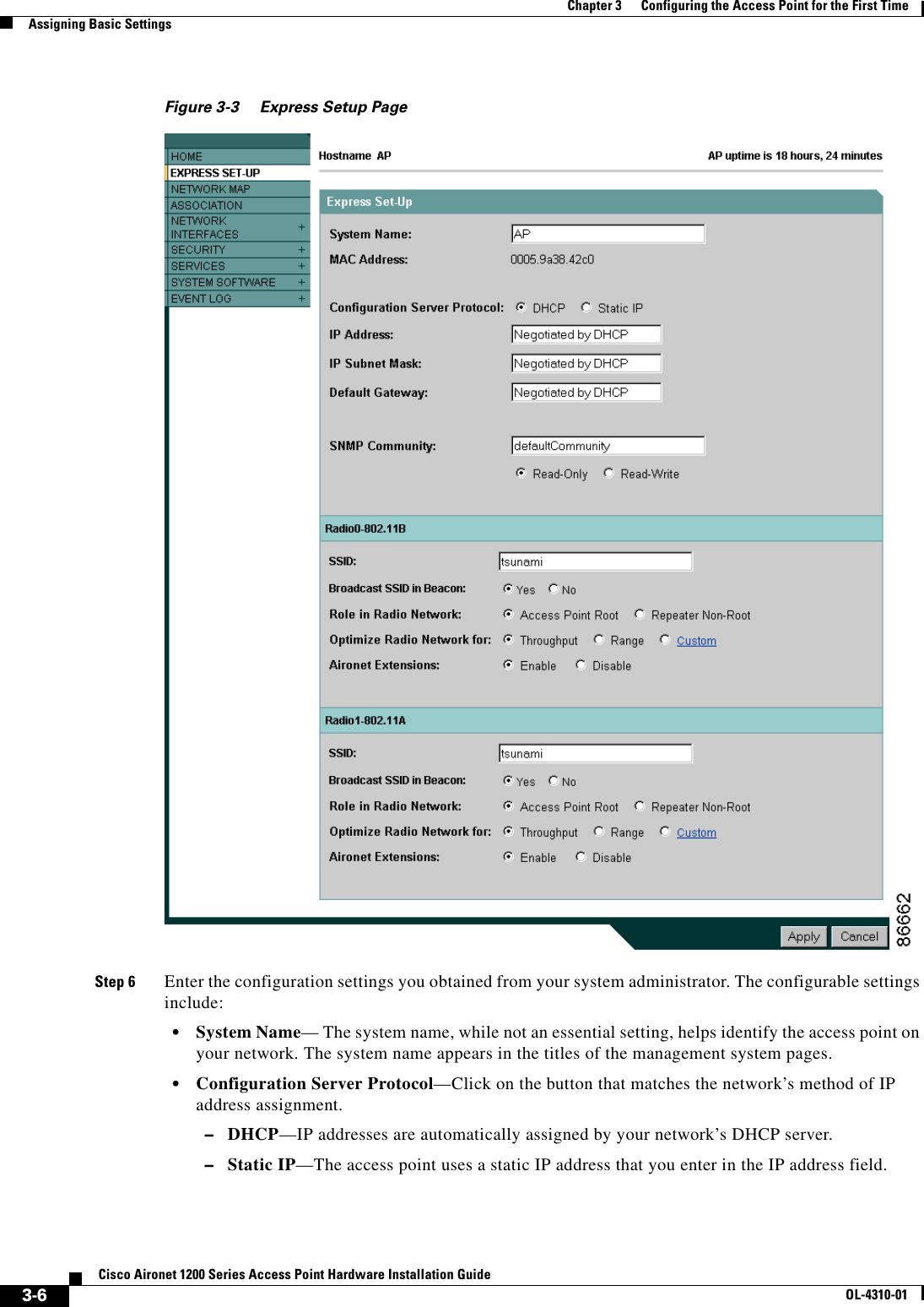
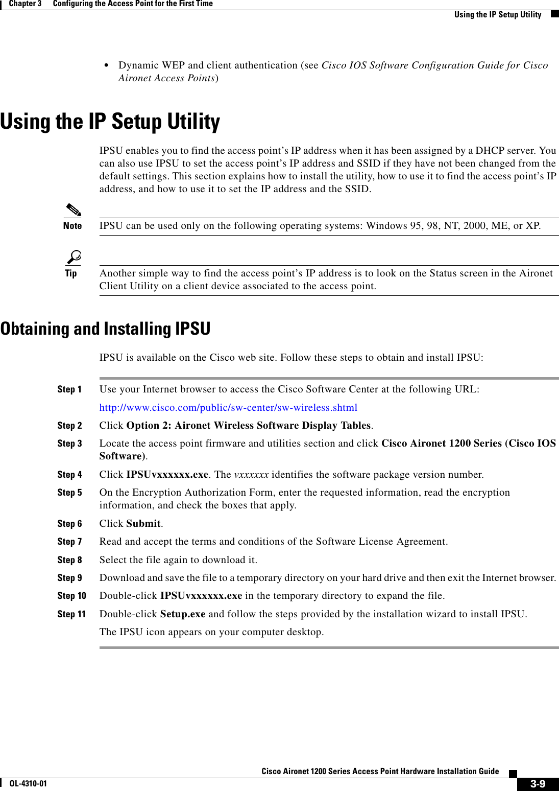
![xCisco Aironet 1200 Series Access Point Hardware Installation GuideOL-4310-01PrefaceConventionsChapter 5, “Using the Command-Line Interface,” describes how to use the command-line interface (CLI) to configure the access point.Chapter 6, “Mounting Instructions,” describes how to mount the access point on a desktop, wall, or ceiling.Chapter 7, “2.4-GHz Radio Upgrade,” provides instructions for upgrading the access point 2.4-GHz radio.Chapter 8, “5-GHz Radio Module Upgrade,” provides instructions for upgrading the access point 5-GHz radio.Chapter 9, “Troubleshooting,” provides troubleshooting procedures for basic problems with the access point.Appendix A, “Translated Safety Warnings,” provides translations of the safety warnings that appear in this publication.Appendix B, “Declarations of Conformity and Regulatory Information,” provides declarations of conformity and regulatory information for the access point.Appendix C, “Access Point Specifications,” lists technical specifications for the access point.Appendix D, “Channels and Antenna Settings,” lists the access point radio channels and the maximum power levels supported by the world’s regulatory domains.Appendix E, “Console Cable Pinouts,” identifies the pinouts for the serial console cable that connects to the access point’s serial console port. ConventionsThis publication uses these conventions to convey instructions and information:Command descriptions use these conventions:•Commands and keywords are in boldface text.•Arguments for which you supply values are in italic.•Square brackets ([ ]) mean optional elements.•Braces ({ }) group required choices, and vertical bars ( | ) separate the alternative elements.•Braces and vertical bars within square brackets ([{ | }]) mean a required choice within an optional element.Interactive examples use these conventions:•Terminal sessions and system displays are in screen font.•Information you enter is in boldface screen font.•Nonprinting characters, such as passwords or tabs, are in angle brackets (< >).Notes, cautions, and timesavers use these conventions and symbols:Tip Means the following will help you solve a problem. The tips information might not be troubleshooting or even an action, but could be useful information.](https://usermanual.wiki/Honeywell/LXE6730M.MANUAL/User-Guide-359888-Page-10.png)
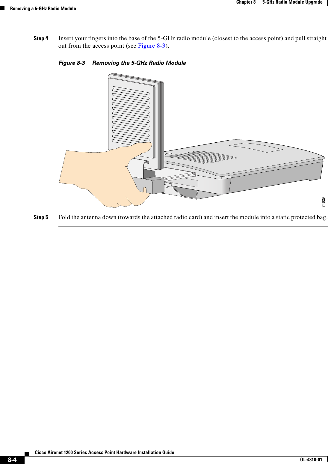
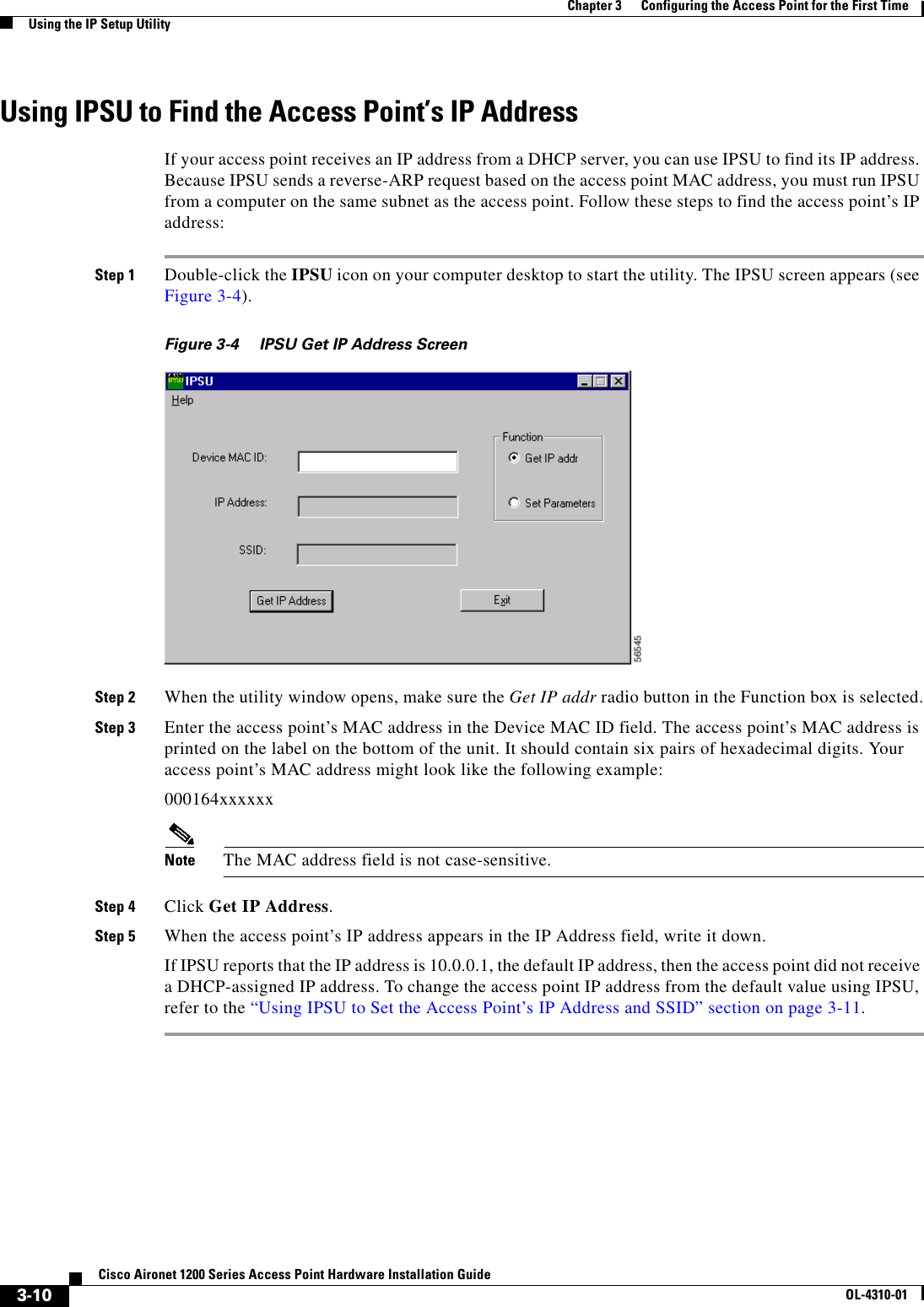
![xiiCisco Aironet 1200 Series Access Point Hardware Installation GuideOL-4310-01PrefaceRelated PublicationsRelated PublicationsThese documents provide complete information about the access point:•Release Notes for 1200 Series Access Points •Cisco Aironet 1200 Series Access Point Command Reference •Cisco IOS Software Configuration Guide for Cisco Aironet Access PointsClick this link to browse to the Cisco Aironet documentation home page:http://www.cisco.com/univercd/cc/td/doc/product/wireless/index.htmTo browse to the 1200 series access point documentation, select Aironet 1200 Series Wireless LAN Products > Cisco Aironet 1200 Series Access Points.Obtaining DocumentationCisco provides several ways to obtain documentation, technical assistance, and other technical resources. These sections explain how to obtain technical information from Cisco Systems.Cisco.comYou can access the most current Cisco documentation on the World Wide Web at this URL:http://www.cisco.com/univercd/home/home.htmAdvarselDette varselsymbolet betyr fare. Du befinner deg i en situasjon som kan føre til personskade. Før du utfører arbeid på utstyr, må du være oppmerksom på de faremomentene som elektriske kretser innebærer, samt gjøre deg kjent med vanlig praksis når det gjelder å unngå ulykker. (Hvis du vil se oversettelser av de advarslene som finnes i denne publikasjonen, kan du se i vedlegget "Translated Safety Warnings" [Oversatte sikkerhetsadvarsler].)AvisoEste símbolo de aviso indica perigo. Encontra-se numa situação que lhe poderá causar danos fisicos. Antes de começar a trabalhar com qualquer equipamento, familiarize-se com os perigos relacionados com circuitos eléctricos, e com quaisquer práticas comuns que possam prevenir possíveis acidentes. (Para ver as traduções dos avisos que constam desta publicação, consulte o apêndice “Translated Safety Warnings” - “Traduções dos Avisos de Segurança”).¡Advertencia!Este símbolo de aviso significa peligro. Existe riesgo para su integridad física. Antes de manipular cualquier equipo, considerar los riesgos que entraña la corriente eléctrica y familiarizarse con los procedimientos estándar de prevención de accidentes. (Para ver traducciones de las advertencias que aparecen en esta publicación, consultar el apéndice titulado “Translated Safety Warnings.”)Varning!Denna varningssymbol signalerar fara. Du befinner dig i en situation som kan leda till personskada. Innan du utför arbete på någon utrustning måste du vara medveten om farorna med elkretsar och känna till vanligt förfarande för att förebygga skador. (Se förklaringar av de varningar som förekommer i denna publikation i appendix "Translated Safety Warnings" [Översatta säkerhetsvarningar].)](https://usermanual.wiki/Honeywell/LXE6730M.MANUAL/User-Guide-359888-Page-12.png)
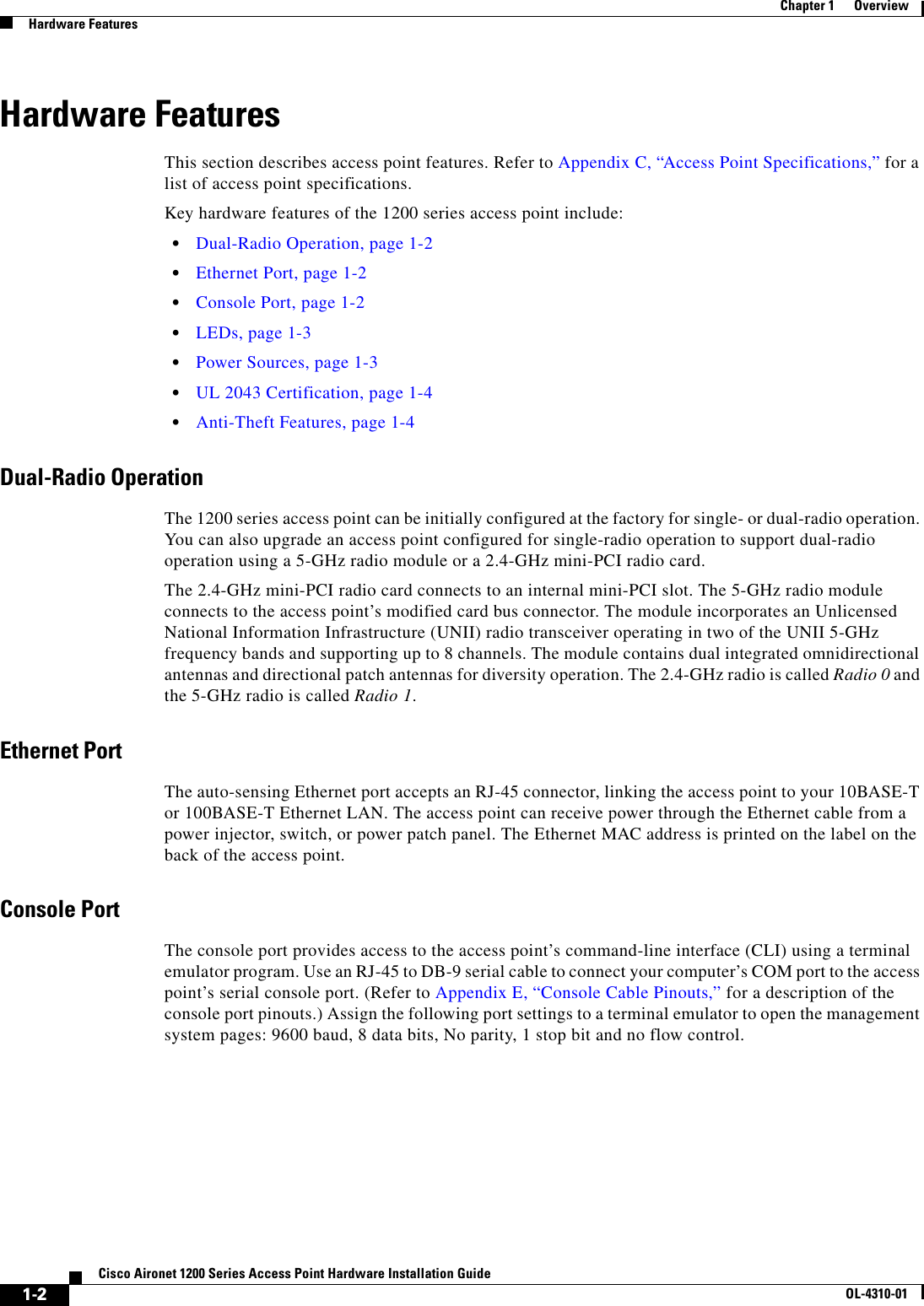

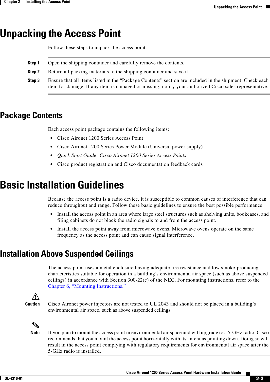
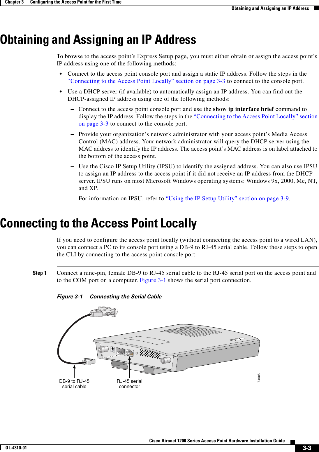
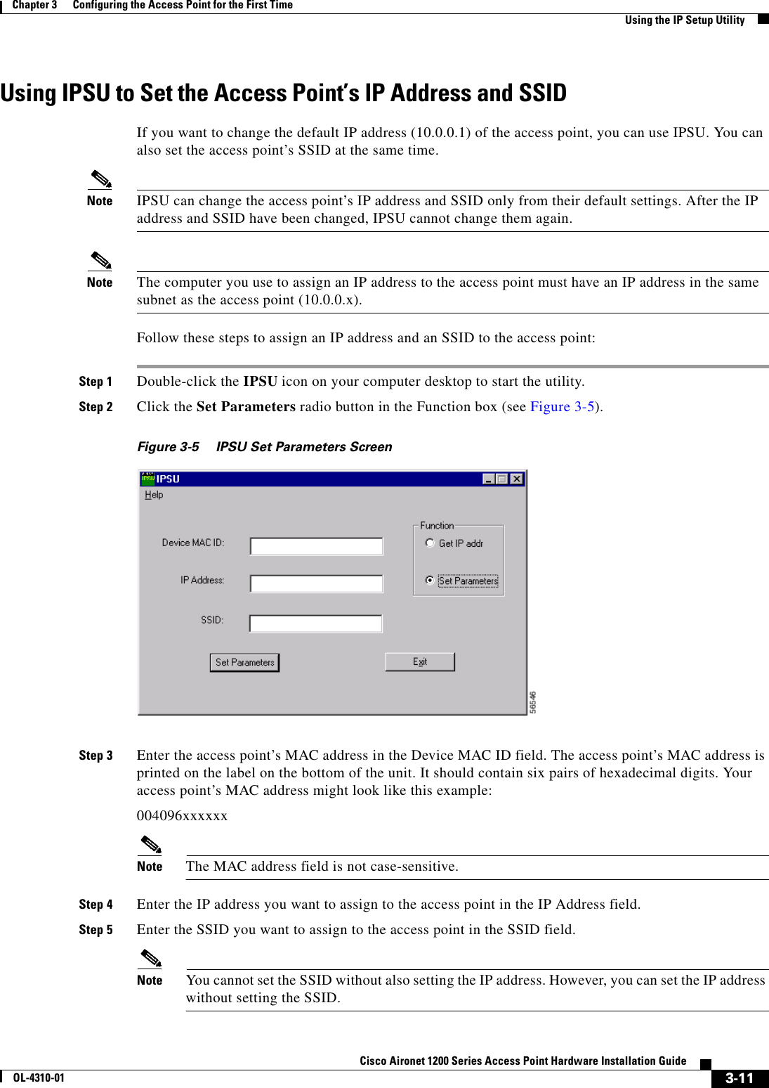
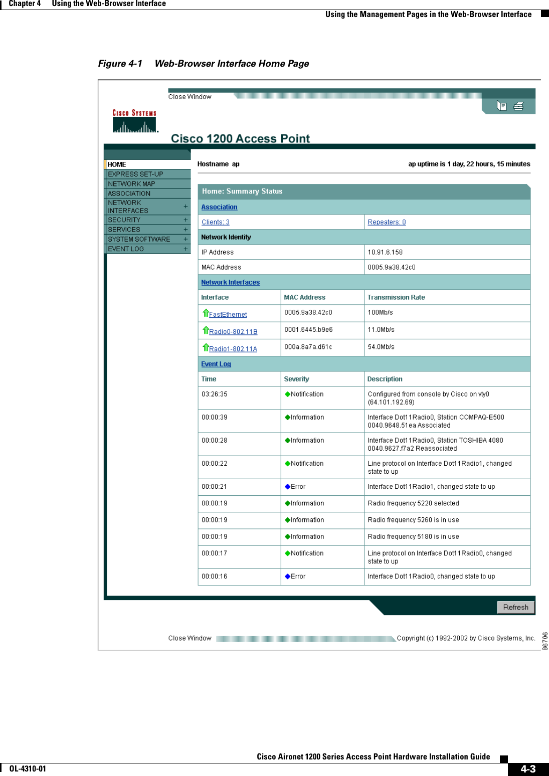
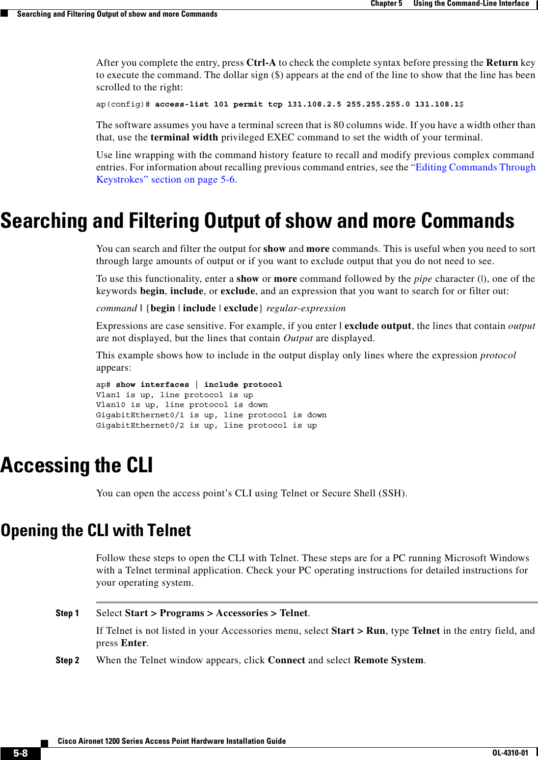
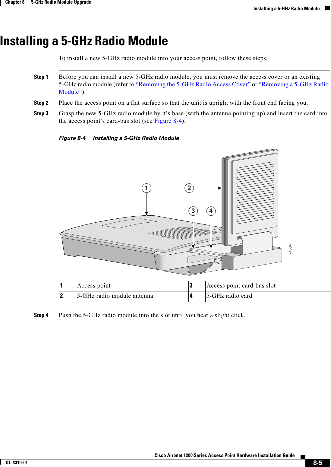
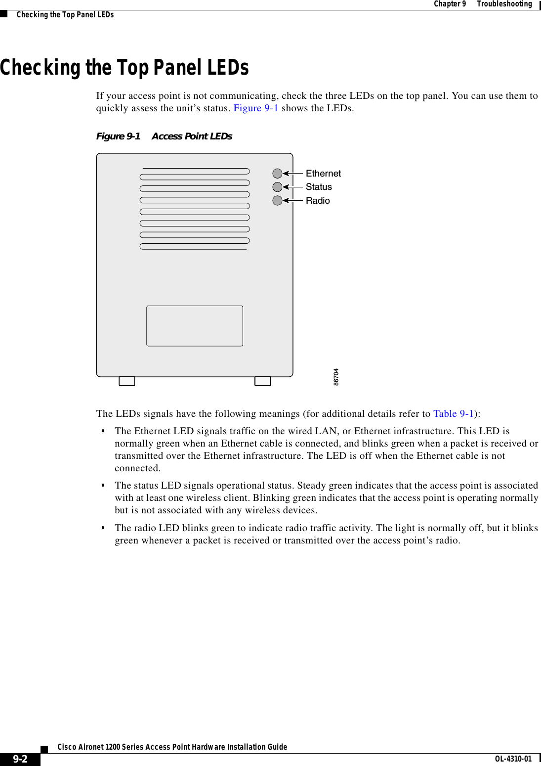
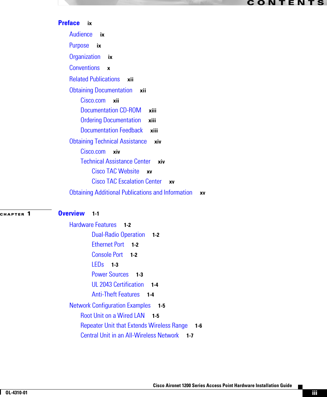
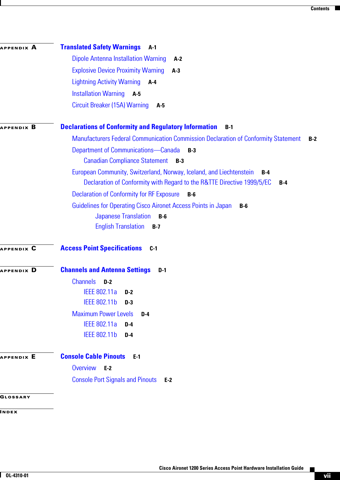
![5-4Cisco Aironet 1200 Series Access Point Hardware Installation GuideOL-4310-01Chapter 5 Using the Command-Line InterfaceUnderstanding CLI MessagesConfiguration commands can also have a default form. The default form of a command returns the command setting to its default. Most commands are disabled by default, so the default form is the same as the no form. However, some commands are enabled by default and have variables set to certain default values. In these cases, the default command enables the command and sets variables to their default values.Understanding CLI MessagesTable 5-3 lists some error messages that you might encounter while using the CLI to configure your access point.Using Command HistoryThe IOS provides a history or record of commands that you have entered. This feature is particularly useful for recalling long or complex commands or entries, including access lists. You can customize the command history feature to suit your needs as described in these sections:•Changing the Command History Buffer Size, page 5-4•Recalling Commands, page 5-5•Disabling the Command History Feature, page 5-5Changing the Command History Buffer SizeBy default, the access point records ten command lines in its history buffer. Beginning in privileged EXEC mode, enter this command to change the number of command lines that the access point records during the current terminal session: ap# terminal history [size number-of-lines]Table 5-3 Common CLI Error MessagesError Message Meaning How to Get Help% Ambiguous command: "show con"You did not enter enough characters for your access point to recognize the command.Re-enter the command followed by a question mark (?) with a space between the command and the question mark.The possible keywords that you can enter with the command are displayed.% Incomplete command. You did not enter all the keywords or values required by this command. Re-enter the command followed by a question mark (?) with a space between the command and the question mark.The possible keywords that you can enter with the command are displayed.% Invalid input detected at ‘^’ marker. You entered the command incorrectly. The caret (^) marks the point of the error.Enter a question mark (?) to display all the commands that are available in this command mode.The possible keywords that you can enter with the command are displayed.](https://usermanual.wiki/Honeywell/LXE6730M.MANUAL/User-Guide-359888-Page-54.png)
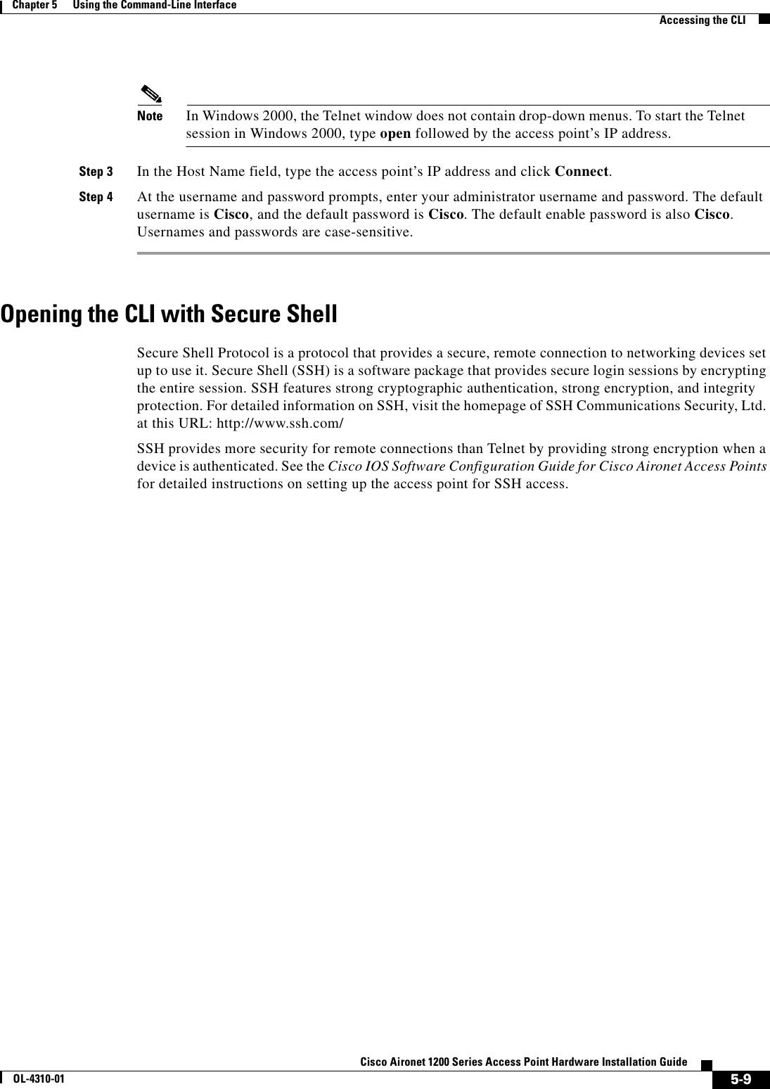
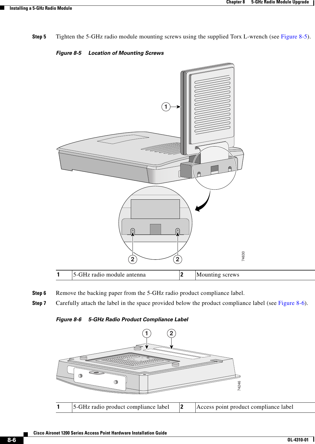
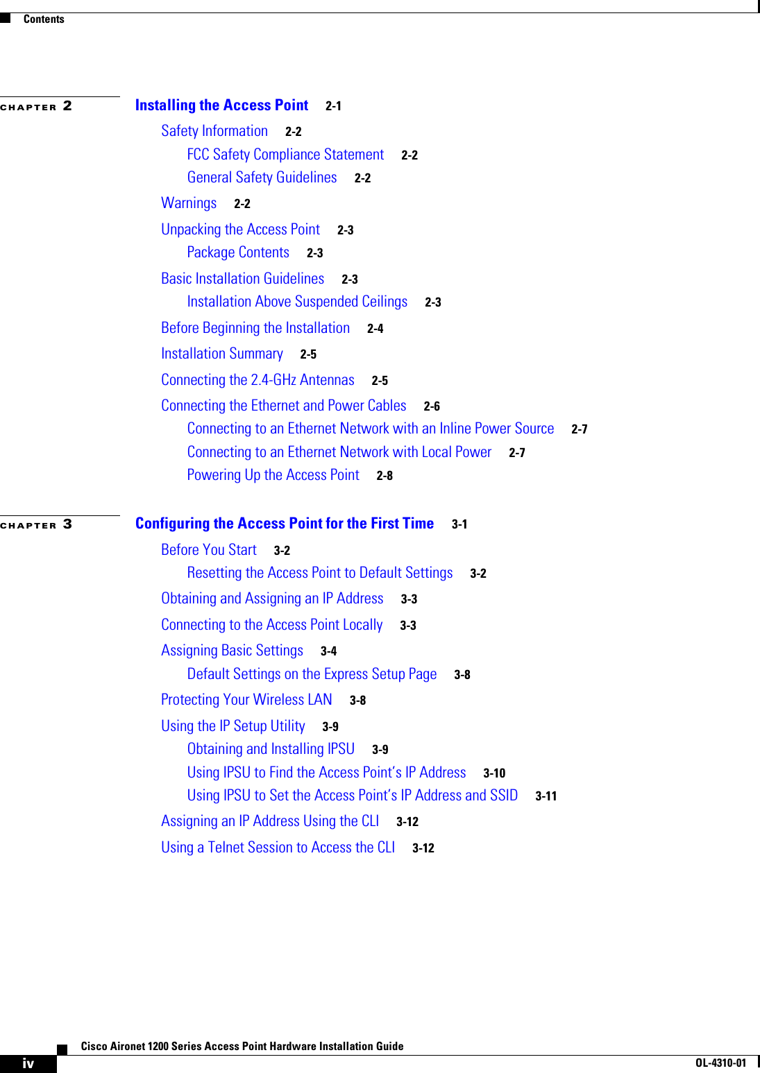
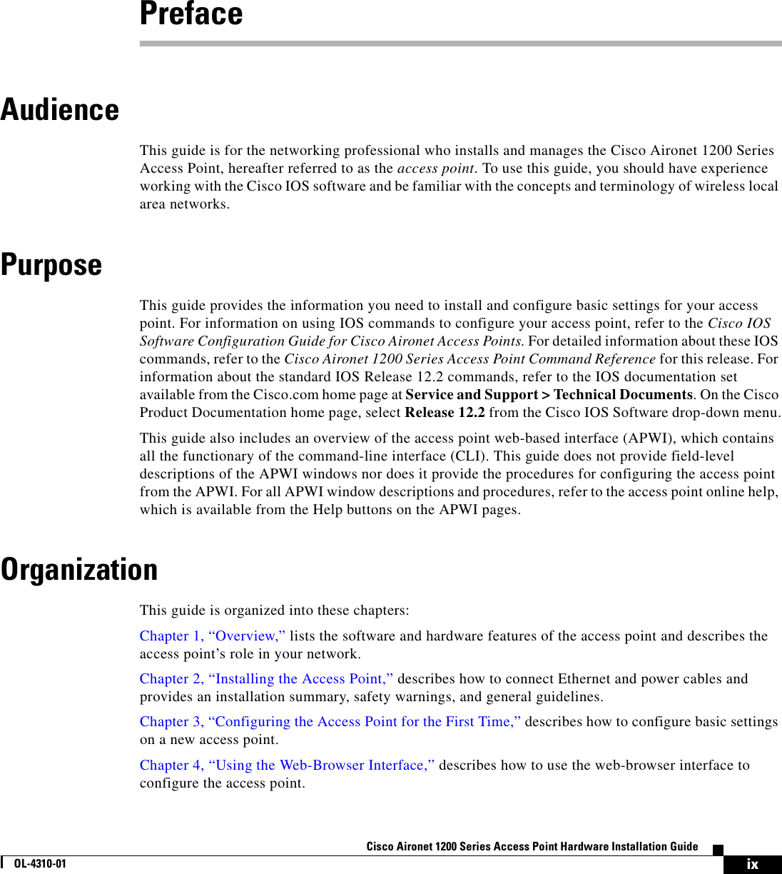
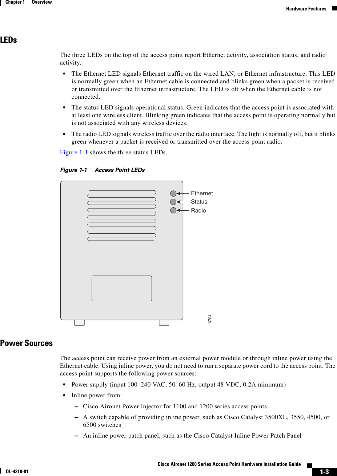
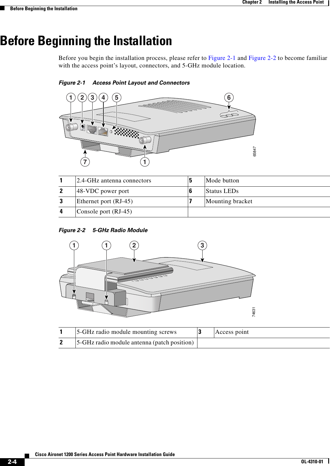
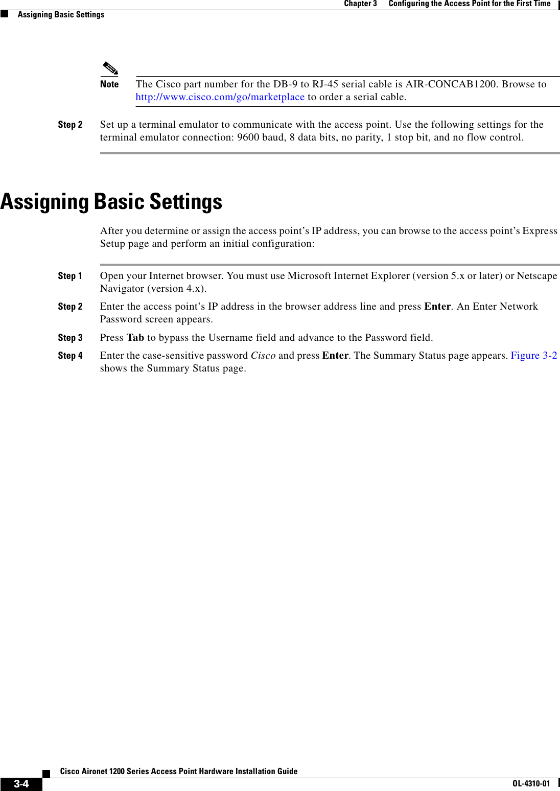
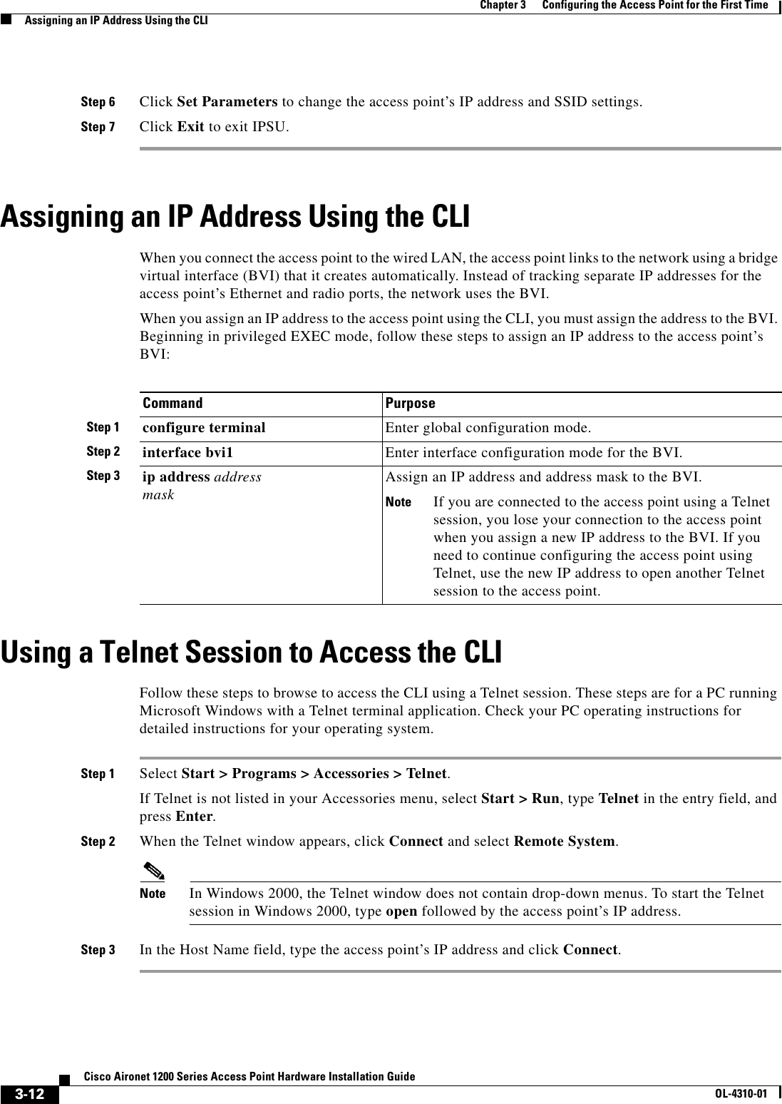
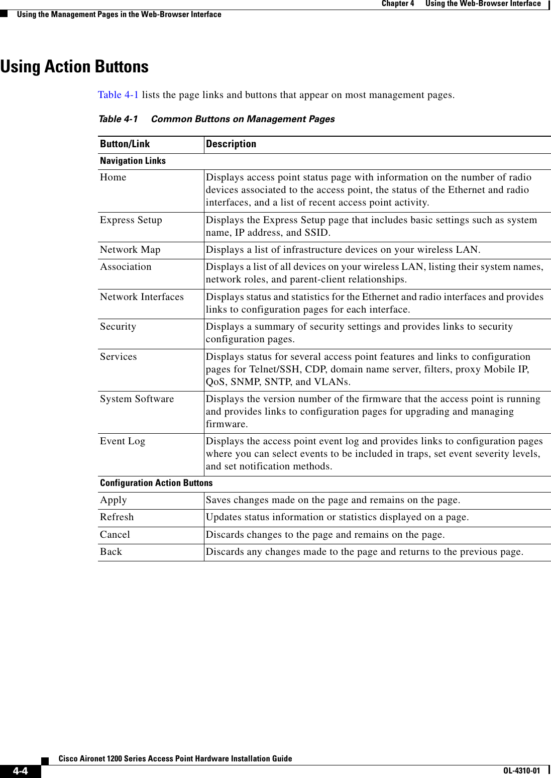
![5-5Cisco Aironet 1200 Series Access Point Hardware Installation GuideOL-4310-01Chapter 5 Using the Command-Line InterfaceUsing Editing FeaturesThe range is from 0 to 256.Beginning in line configuration mode, enter this command to configure the number of command lines the access point records for all sessions on a particular line:ap(config-line)# history [size number-of-lines]The range is from 0 to 256.Recalling CommandsTo recall commands from the history buffer, perform one of the actions listed in Table 5-4:Disabling the Command History FeatureThe command history feature is automatically enabled. To disable the feature during the current terminal session, enter the terminal no history privileged EXEC command. To disable command history for the line, enter the no history line configuration command.Using Editing FeaturesThis section describes the editing features that can help you manipulate the command line. It contains these sections:•Enabling and Disabling Editing Features, page 5-6•Editing Commands Through Keystrokes, page 5-6•Editing Command Lines that Wrap, page 5-7Table 5-4 Recalling CommandsAction11. The arrow keys function only on ANSI-compatible terminals such as VT100s.ResultPress Ctrl-P or the up arrow key. Recall commands in the history buffer, beginning with the most recent command. Repeat the key sequence to recall successively older commands.Press Ctrl-N or the down arrow key. Return to more recent commands in the history buffer after recalling commands with Ctrl-P or the up arrow key. Repeat the key sequence to recall successively more recent commands. show history While in privileged EXEC mode, list the last several commands that you just entered. The number of commands that are displayed is determined by the setting of the terminal history global configuration command and history line configuration command.](https://usermanual.wiki/Honeywell/LXE6730M.MANUAL/User-Guide-359888-Page-55.png)