Honeywell LXE6730M WIRELESS LAN ACCESS POINT User Manual Change Notice Form

Honeywell International, Inc. WIRELESS LAN ACCESS POINT Change Notice Form

Contents

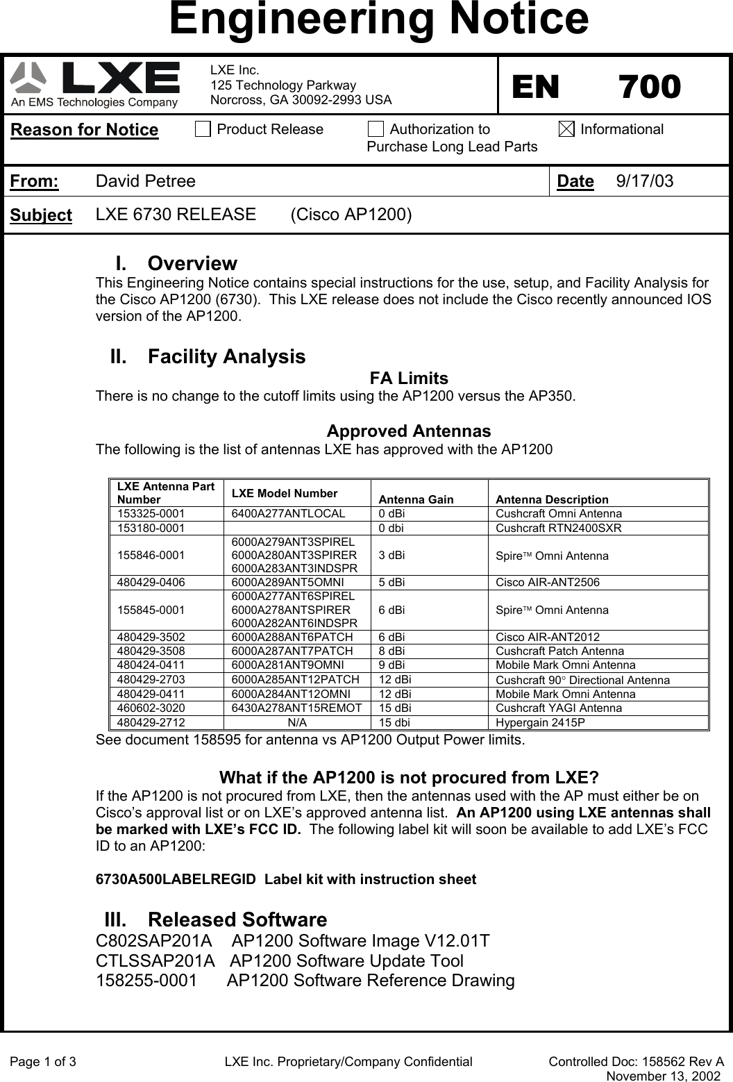
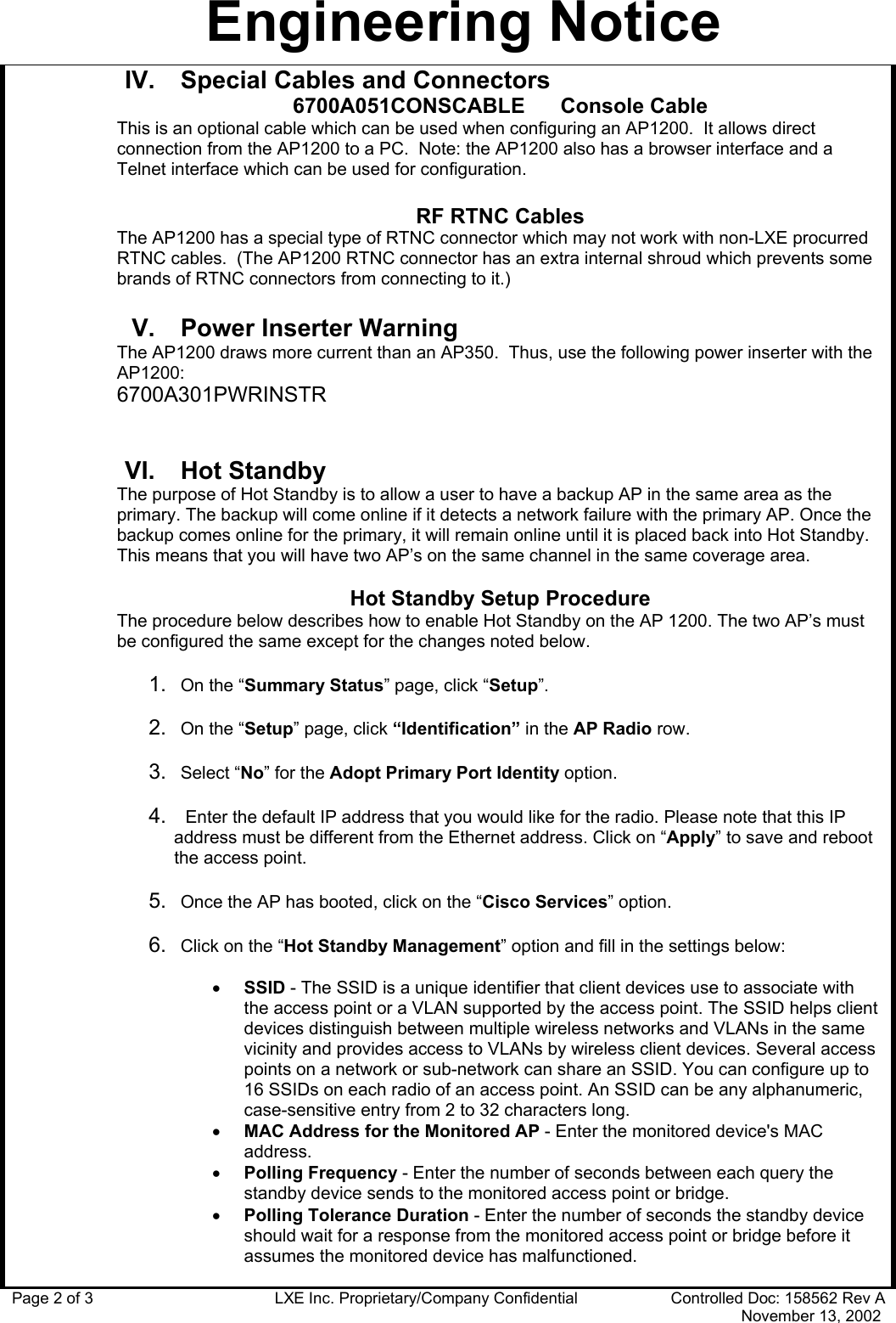
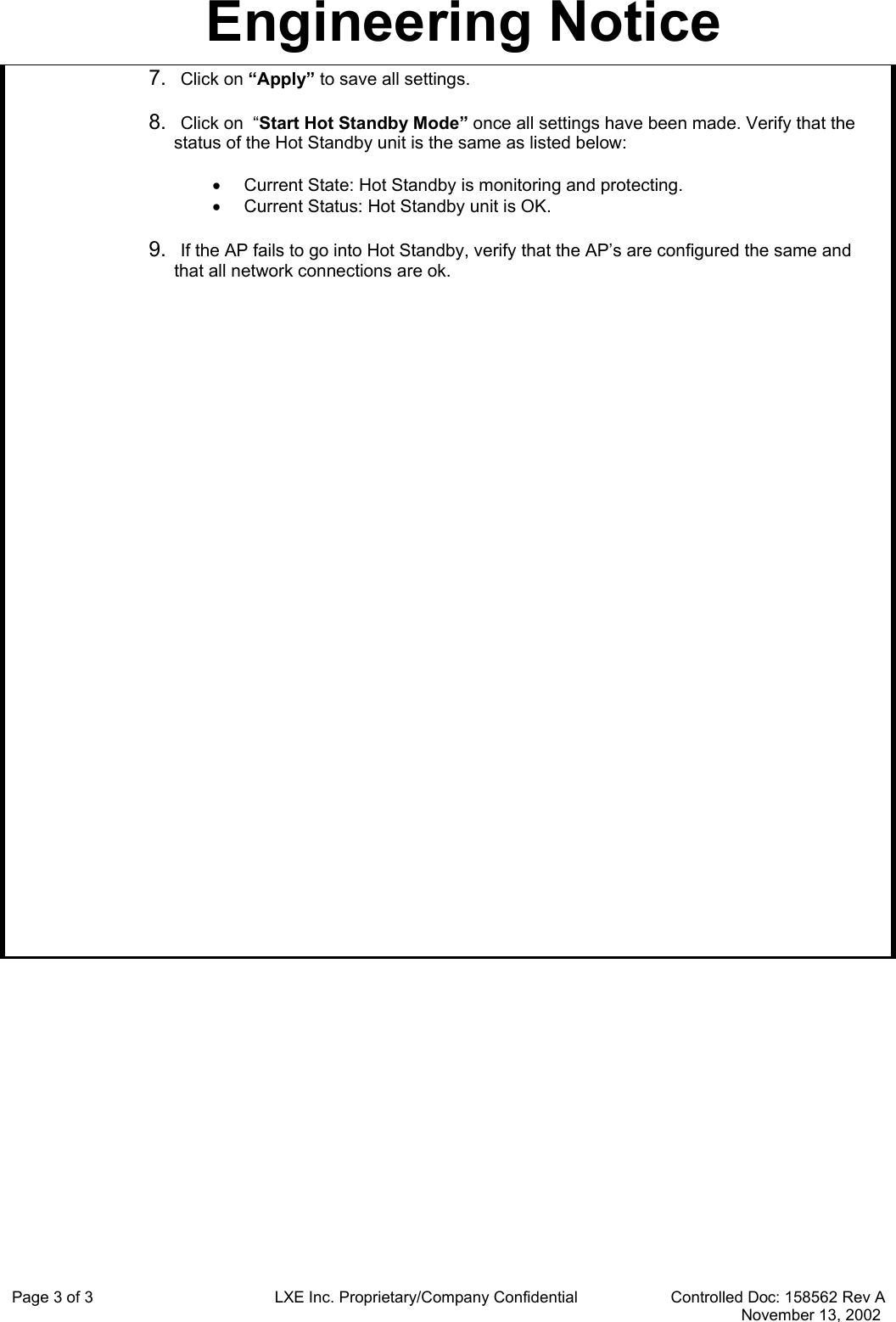
INSTALLATION INSTRUCTIONS

Engineering Notice  LXE Inc. 125 Technology Parkway Norcross, GA 30092-2993 USA  EN 700 Reason for Notice  Product Release   Authorization to Purchase Long Lead Parts  Informational From:  David Petree  Date 9/17/03 Subject LXE 6730 RELEASE       (Cisco AP1200)   I. Overview This Engineering Notice contains special instructions for the use, setup, and Facility Analysis for the Cisco AP1200 (6730).  This LXE release does not include the Cisco recently announced IOS version of the AP1200.  II. Facility Analysis FA Limits There is no change to the cutoff limits using the AP1200 versus the AP350.  Approved Antennas The following is the list of antennas LXE has approved with the AP1200  LXE Antenna Part Number LXE Model Number   Antenna Gain  Antenna Description 153325-0001  6400A277ANTLOCAL  0 dBi  Cushcraft Omni Antenna 153180-0001    0 dbi  Cushcraft RTN2400SXR 155846-0001 6000A279ANT3SPIREL 6000A280ANT3SPIRER 6000A283ANT3INDSPR 3 dBi  Spire Omni Antenna 480429-0406  6000A289ANT5OMNI  5 dBi  Cisco AIR-ANT2506 155845-0001 6000A277ANT6SPIREL 6000A278ANTSPIRER 6000A282ANT6INDSPR 6 dBi  Spire Omni Antenna 480429-3502  6000A288ANT6PATCH  6 dBi  Cisco AIR-ANT2012 480429-3508  6000A287ANT7PATCH  8 dBi  Cushcraft Patch Antenna 480424-0411  6000A281ANT9OMNI  9 dBi  Mobile Mark Omni Antenna 480429-2703 6000A285ANT12PATCH 12 dBi  Cushcraft 90° Directional Antenna 480429-0411  6000A284ANT12OMNI  12 dBi  Mobile Mark Omni Antenna 460602-3020  6430A278ANT15REMOT  15 dBi  Cushcraft YAGI Antenna 480429-2712  N/A  15 dbi  Hypergain 2415P See document 158595 for antenna vs AP1200 Output Power limits.  What if the AP1200 is not procured from LXE? If the AP1200 is not procured from LXE, then the antennas used with the AP must either be on Cisco’s approval list or on LXE’s approved antenna list.  An AP1200 using LXE antennas shall be marked with LXE’s FCC ID.  The following label kit will soon be available to add LXE’s FCC ID to an AP1200:  6730A500LABELREGID  Label kit with instruction sheet  III. Released Software C802SAP201A    AP1200 Software Image V12.01T CTLSSAP201A   AP1200 Software Update Tool 158255-0001      AP1200 Software Reference Drawing   Page 1 of 3                                         LXE Inc. Proprietary/Company Confidential                     Controlled Doc: 158562 Rev A                                                                                                                                                                      November 13, 2002
Engineering Notice Page 2 of 3                                         LXE Inc. Proprietary/Company Confidential                     Controlled Doc: 158562 Rev A                                                                                                                                                                      November 13, 2002 IV.  Special Cables and Connectors 6700A051CONSCABLE      Console Cable This is an optional cable which can be used when configuring an AP1200.  It allows direct connection from the AP1200 to a PC.  Note: the AP1200 also has a browser interface and a Telnet interface which can be used for configuration.    RF RTNC Cables The AP1200 has a special type of RTNC connector which may not work with non-LXE procurred RTNC cables.  (The AP1200 RTNC connector has an extra internal shroud which prevents some brands of RTNC connectors from connecting to it.)  V.  Power Inserter Warning The AP1200 draws more current than an AP350.  Thus, use the following power inserter with the AP1200: 6700A301PWRINSTR   VI. Hot Standby The purpose of Hot Standby is to allow a user to have a backup AP in the same area as the primary. The backup will come online if it detects a network failure with the primary AP. Once the backup comes online for the primary, it will remain online until it is placed back into Hot Standby. This means that you will have two AP’s on the same channel in the same coverage area.  Hot Standby Setup Procedure The procedure below describes how to enable Hot Standby on the AP 1200. The two AP’s must be configured the same except for the changes noted below.  1.  On the “Summary Status” page, click “Setup”.  2.  On the “Setup” page, click “Identification” in the AP Radio row.  3.  Select “No” for the Adopt Primary Port Identity option.  4.   Enter the default IP address that you would like for the radio. Please note that this IP address must be different from the Ethernet address. Click on “Apply” to save and reboot the access point.  5.  Once the AP has booted, click on the “Cisco Services” option.  6.  Click on the “Hot Standby Management” option and fill in the settings below:  •  SSID - The SSID is a unique identifier that client devices use to associate with the access point or a VLAN supported by the access point. The SSID helps client devices distinguish between multiple wireless networks and VLANs in the same vicinity and provides access to VLANs by wireless client devices. Several access points on a network or sub-network can share an SSID. You can configure up to 16 SSIDs on each radio of an access point. An SSID can be any alphanumeric, case-sensitive entry from 2 to 32 characters long. •  MAC Address for the Monitored AP - Enter the monitored device's MAC address. •  Polling Frequency - Enter the number of seconds between each query the standby device sends to the monitored access point or bridge.  •  Polling Tolerance Duration - Enter the number of seconds the standby device should wait for a response from the monitored access point or bridge before it assumes the monitored device has malfunctioned.
Engineering Notice Page 3 of 3                                         LXE Inc. Proprietary/Company Confidential                     Controlled Doc: 158562 Rev A                                                                                                                                                                      November 13, 2002 7.  Click on “Apply” to save all settings.  8.  Click on  “Start Hot Standby Mode” once all settings have been made. Verify that the status of the Hot Standby unit is the same as listed below:  •  Current State: Hot Standby is monitoring and protecting. •  Current Status: Hot Standby unit is OK.  9.  If the AP fails to go into Hot Standby, verify that the AP’s are configured the same and that all network connections are ok.

Navigation menu