Honeywell LXERFID3 802.11 b/g radio User Manual RX2 User s Guide
Honeywell International, Inc. 802.11 b/g radio RX2 User s Guide
UserManual.wiki
>
Honeywell
>
LXERFID3 User Manual
>
User Manual
Contents
1.
User Manual
2.
User Manual 2
3.
User Manual 1
User Manual
Navigation menu
Upload a User Manual
Namespaces
Wiki Guide
HTML
PDF
Info
Views
User Manual
Discussion / Help
Navigation
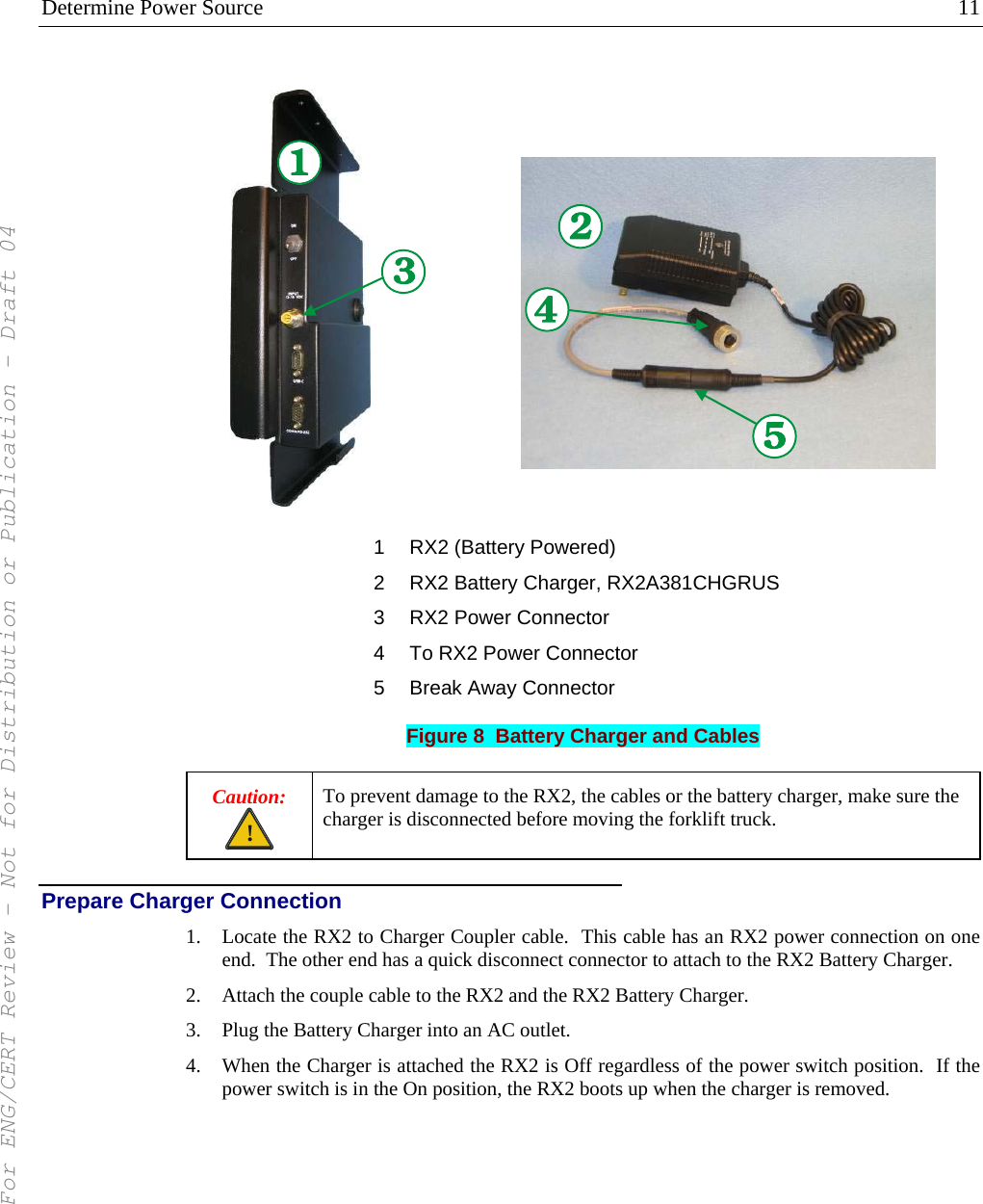
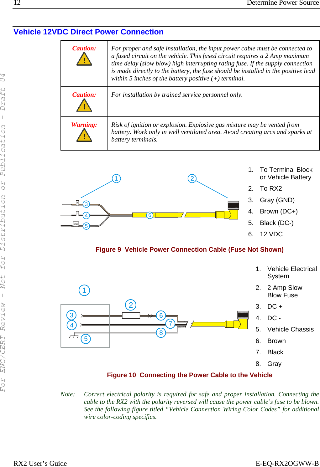
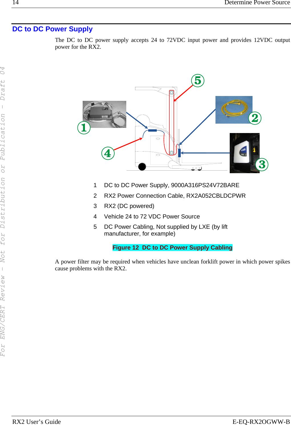
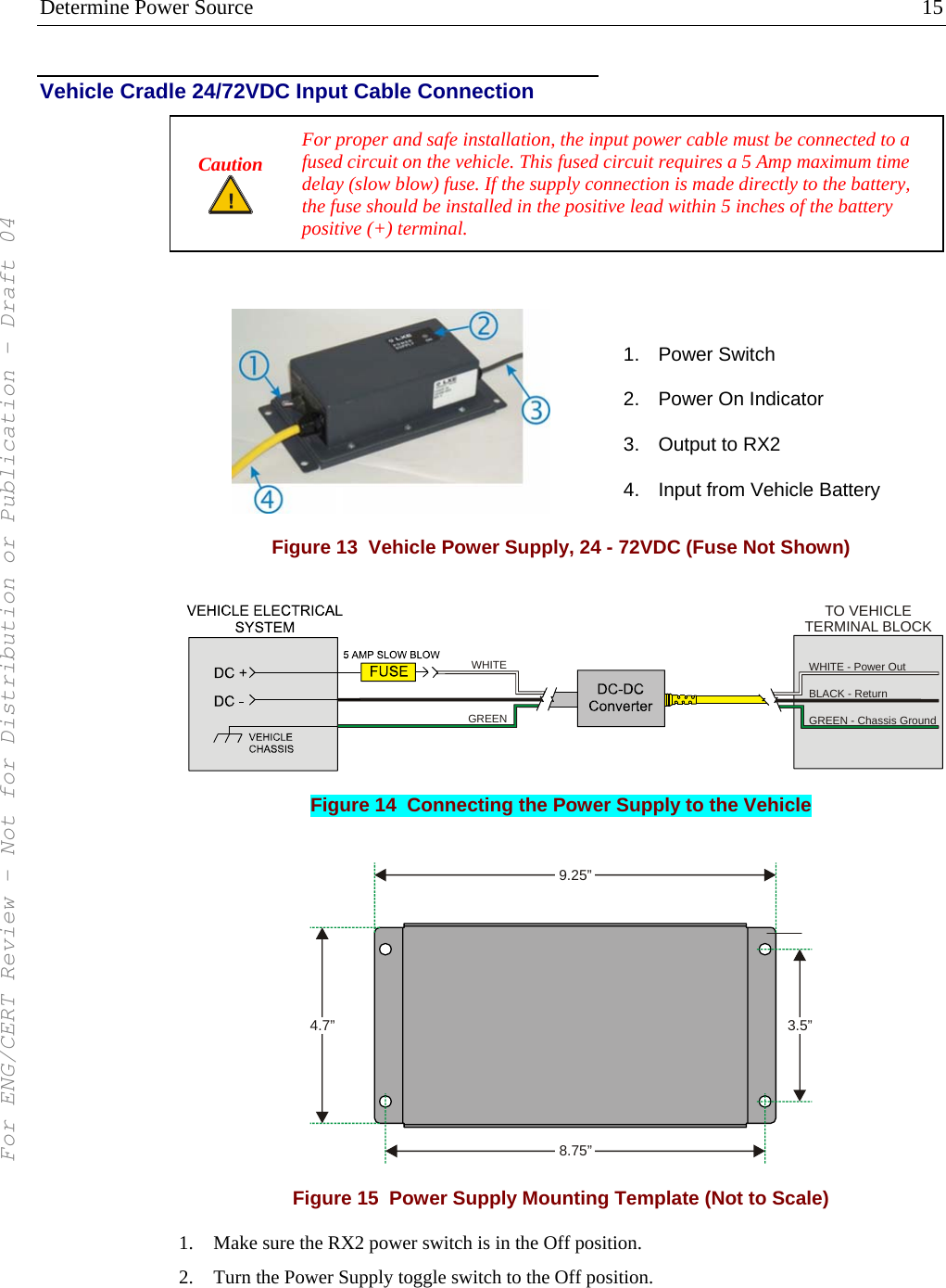
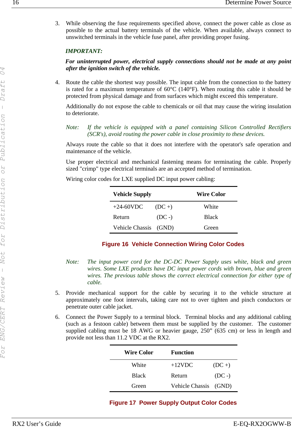
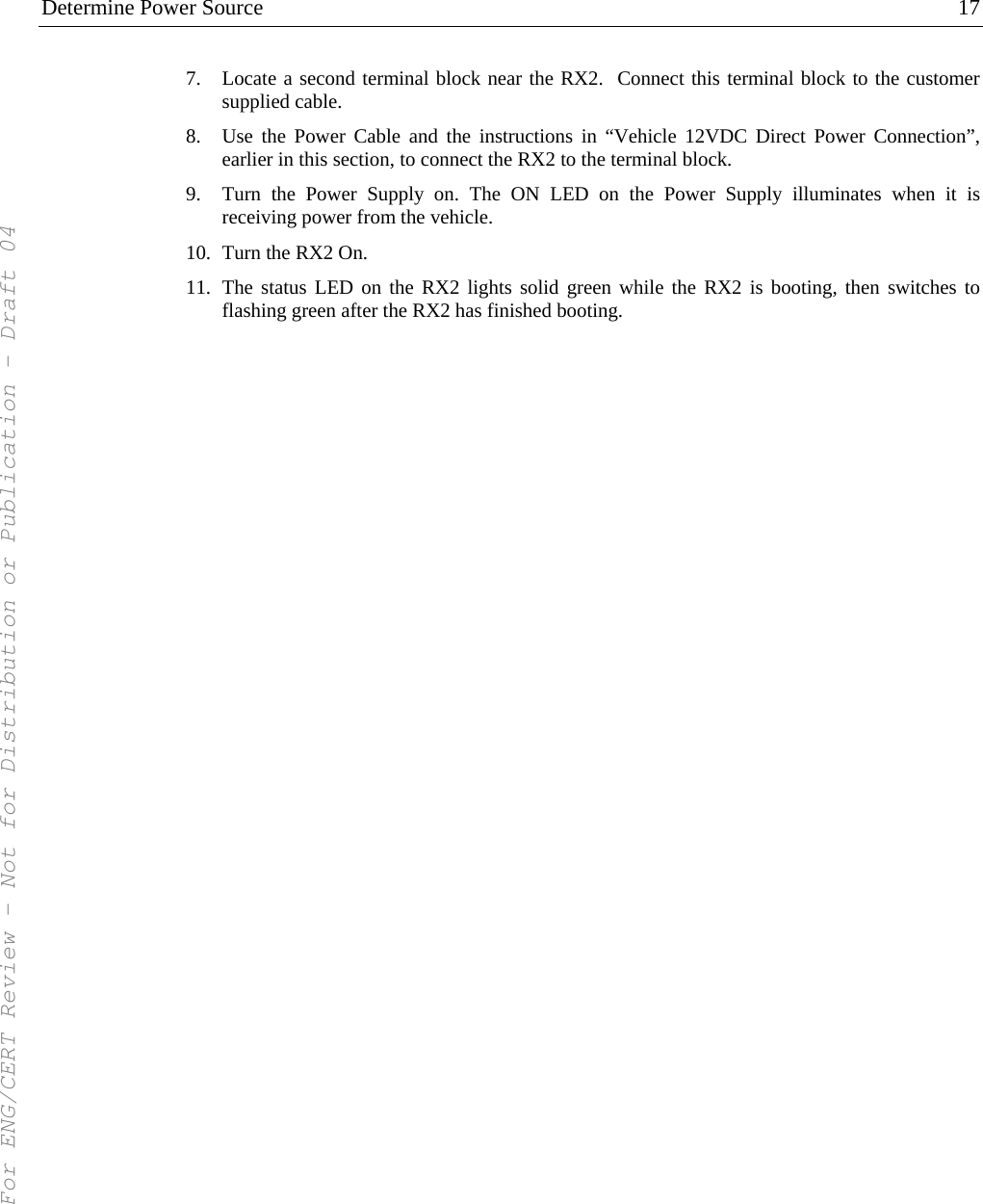
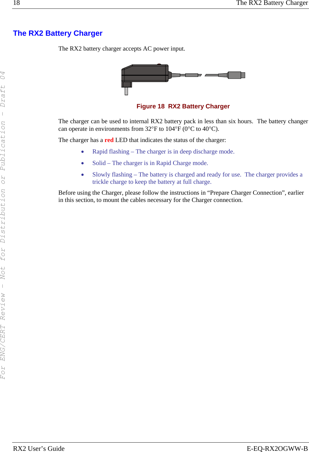
![24 Approvals RX2 User’s Guide E-EQ-RX2OGWW-B Approvals Product EMI / EMC Standards RX2 FCC Part 15 Subpart B, Class A Industry Canada Class A Transceiver: Transceiver RF Standards Notes FCC Part 15, Subpart C FCC Part 2 Unlicensed Operation IC-RSS 210 Requires License for Outdoor Use 6726 (LXE Model No.) [Cisco] IC-RSS 102 4830 (LXE Model No.) LXE 2.4GHz CF with Type II PCMCIA Adapter Card FCC Part 15, Subpart C IC-RSS 210 IC-RSS 102 Unlicensed Operation Requires License for Outdoor Use RFID Reader (Sirit) FCC Part 15, Subpart C IC-RSS 210 IC RSS 102 Unlicensed Operation Requires License for Outdoor Use Important: This symbol is placed on the product to remind users to dispose of Waste Electrical and Electronic Equipment (WEEE) appropriately, per Directive 2002-96-EC. In most areas, this product can be recycled, reclaimed and re-used when properly discarded. Do not discard labeled units with trash. For information about proper disposal, contact LXE through your local sales representative, or visit www lxe com. ! Vehicle Power Supply Connection Safety Statement ! Vehicle Power Supply Connection: If the supply connection is made directly to the battery, a 2A slow-blow fuse should be installed in the positive lead within 5 inches (12.7 cm.) of the battery positive (+) terminal. (US) Legend: English – US Updated 02/10/2004 For ENG/CERT Review - Not for Distribution or Publication - Draft 04](https://usermanual.wiki/Honeywell/LXERFID3.User-Manual/User-Guide-793575-Page-30.png)