Honeywell MCR5532C Contactless Smart Card Reader User Manual
Honeywell (China) Co., LTD Contactless Smart Card Reader Users Manual
UserManual.wiki
>
Honeywell
>
MCR5532C User Manual
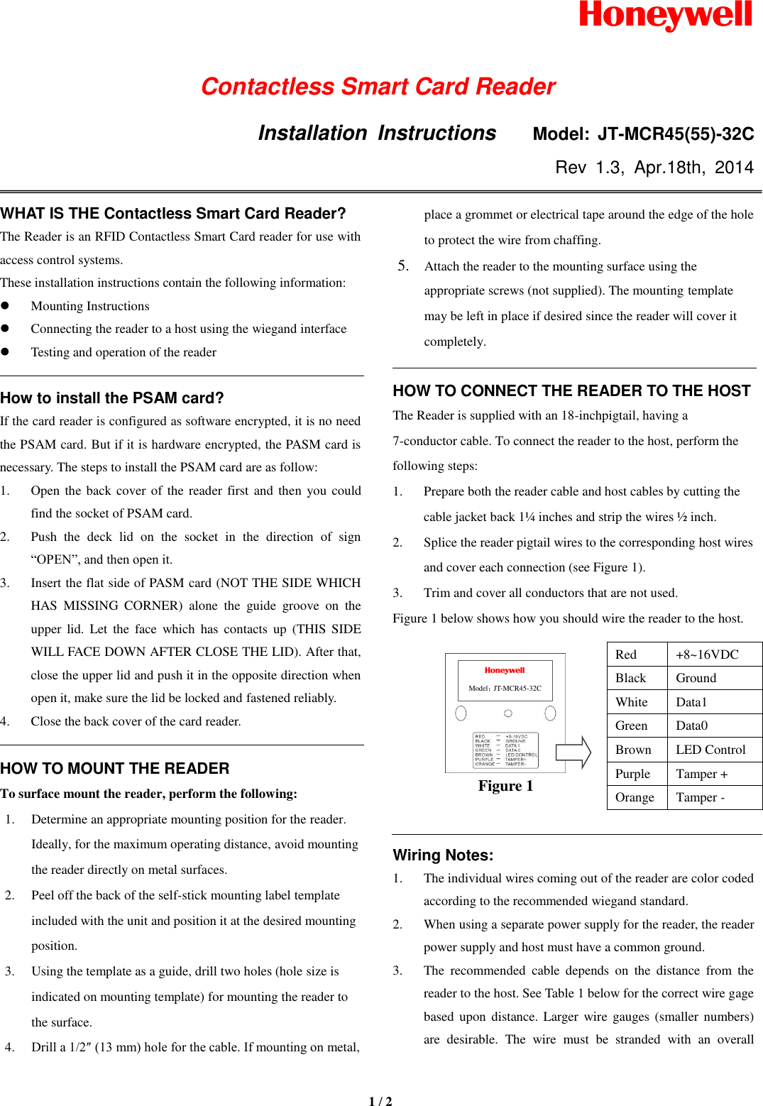
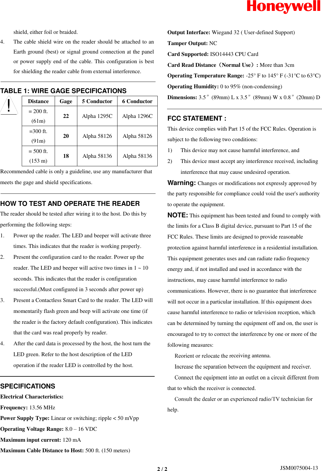
Users Manual
Navigation menu
Upload a User Manual
Namespaces
Wiki Guide
HTML
PDF
Info
Views
User Manual
Discussion / Help
Navigation