Honeywell MCR5532C Contactless Smart Card Reader User Manual
Honeywell (China) Co., LTD Contactless Smart Card Reader Users Manual
Users Manual
Honeywell
1 / 2
Contactless Smart Card Reader
Installation Instructions Model: JT-MCR45(55)-32C
Rev 1.3, Apr.18th, 2014
WHAT IS THE Contactless Smart Card Reader?
The Reader is an RFID Contactless Smart Card reader for use with
access control systems.
These installation instructions contain the following information:
Mounting Instructions
Connecting the reader to a host using the wiegand interface
Testing and operation of the reader
How to install the PSAM card?
If the card reader is configured as software encrypted, it is no need
the PSAM card. But if it is hardware encrypted, the PASM card is
necessary. The steps to install the PSAM card are as follow:
1. Open the back cover of the reader first and then you could
find the socket of PSAM card.
2. Push the deck lid on the socket in the direction of sign
“OPEN”, and then open it.
3. Insert the flat side of PASM card (NOT THE SIDE WHICH
HAS MISSING CORNER) alone the guide groove on the
upper lid. Let the face which has contacts up (THIS SIDE
WILL FACE DOWN AFTER CLOSE THE LID). After that,
close the upper lid and push it in the opposite direction when
open it, make sure the lid be locked and fastened reliably.
4. Close the back cover of the card reader.
HOW TO MOUNT THE READER
To surface mount the reader, perform the following:
1. Determine an appropriate mounting position for the reader.
Ideally, for the maximum operating distance, avoid mounting
the reader directly on metal surfaces.
2. Peel off the back of the self-stick mounting label template
included with the unit and position it at the desired mounting
position.
3. Using the template as a guide, drill two holes (hole size is
indicated on mounting template) for mounting the reader to
the surface.
4. Drill a 1/2″ (13 mm) hole for the cable. If mounting on metal,
place a grommet or electrical tape around the edge of the hole
to protect the wire from chaffing.
5. Attach the reader to the mounting surface using the
appropriate screws (not supplied). The mounting template
may be left in place if desired since the reader will cover it
completely.
HOW TO CONNECT THE READER TO THE HOST
The Reader is supplied with an 18-inchpigtail, having a
7-conductor cable. To connect the reader to the host, perform the
following steps:
1. Prepare both the reader cable and host cables by cutting the
cable jacket back 1¼ inches and strip the wires ½ inch.
2. Splice the reader pigtail wires to the corresponding host wires
and cover each connection (see Figure 1).
3. Trim and cover all conductors that are not used.
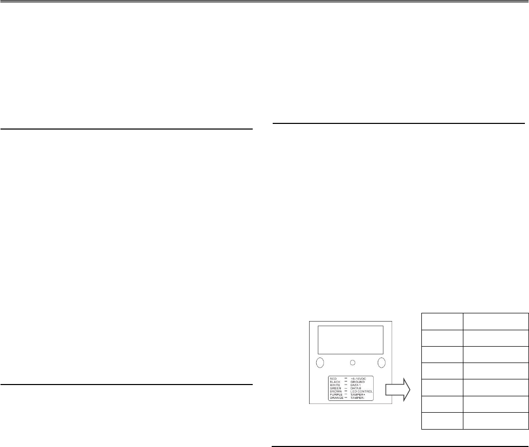
Figure 1 below shows how you should wire the reader to the host.
Figure 1
Wiring Notes:
1. The individual wires coming out of the reader are color coded
according to the recommended wiegand standard.
2. When using a separate power supply for the reader, the reader
power supply and host must have a common ground.
3. The recommended cable depends on the distance from the
reader to the host. See Table 1 below for the correct wire gage
based upon distance. Larger wire gauges (smaller numbers)
are desirable. The wire must be stranded with an overall
Red +8~16VDC
Black Ground
White Data1
Green Data0
Brown LED Control
Purple Tamper +
Orange Tamper -
Honeywell
Model:JT-MCR45-32C
Honeywell
2 / 2
!
shield, either foil or braided.
4. The cable shield wire on the reader should be attached to an
Earth ground (best) or signal ground connection at the panel
or power supply end of the cable. This configuration is best
for shielding the reader cable from external interference.
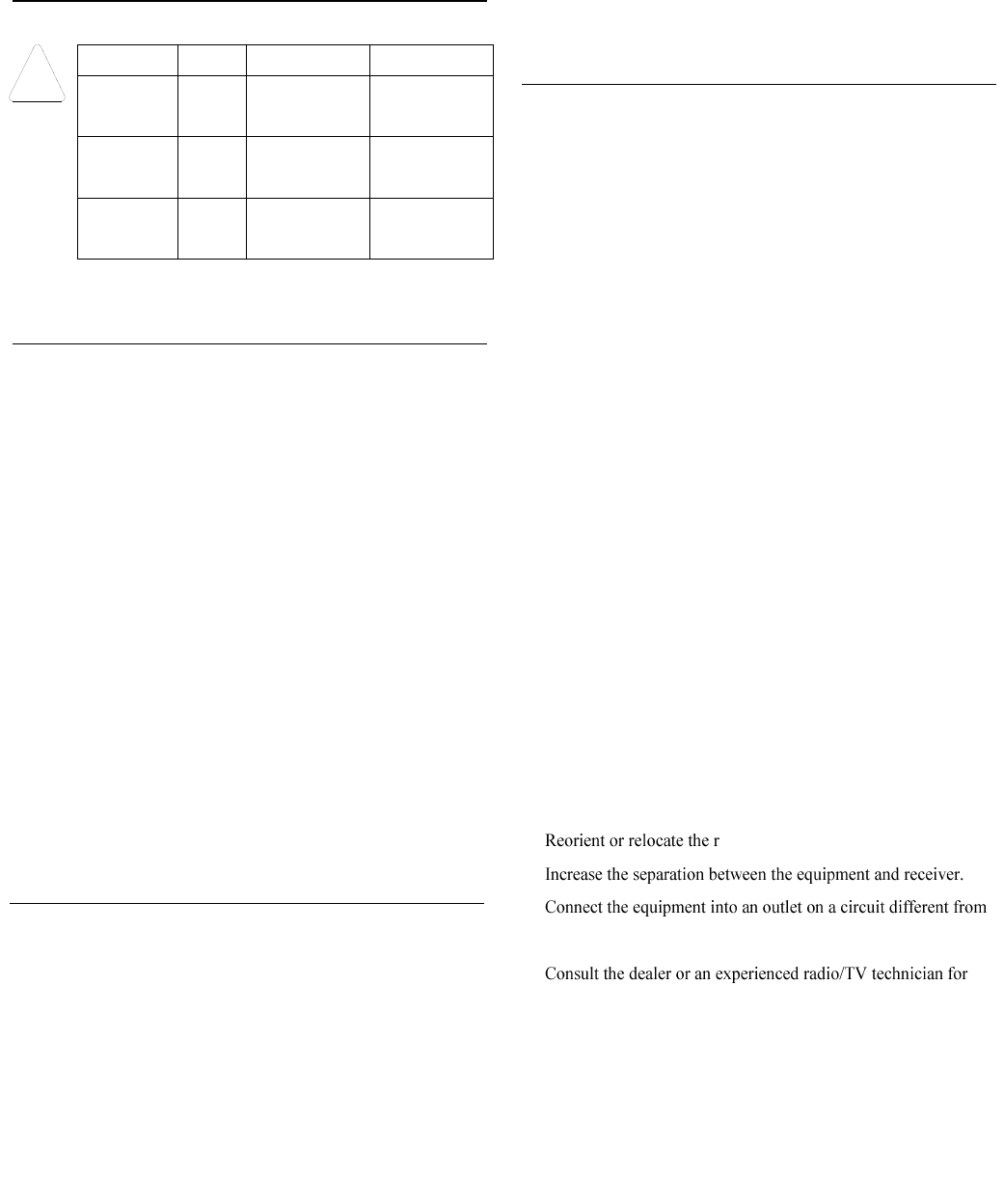
TABLE 1: WIRE GAGE SPECIFICATIONS
Distance
Gage
5 Conductor
6 Conductor
= 200 ft.
(61m)
22
Alpha 1295C
Alpha 1296C
=300 ft.
(91m)
20
Alpha 58126
Alpha 58126
= 500 ft.
(153 m)
18
Alpha 58136
Alpha 58136
Recommended cable is only a guideline, use any manufacturer that
meets the gage and shield specifications.
HOW TO TEST AND OPERATE THE READER
The reader should be tested after wiring it to the host. Do this by
performing the following steps:
1. Power up the reader. The LED and beeper will activate three
times. This indicates that the reader is working properly.
2. Present the configuration card to the reader. Power up the
reader. The LED and beeper will active two times in 1 ~ 10
seconds. This indicates that the reader is configuration
successful.(Must configured in 3 seconds after power up)
3. Present a Contactless Smart Card to the reader. The LED will
momentarily flash green and beep will activate one time (if
the reader is the factory default configuration). This indicates
that the card was read properly by reader.
4. After the card data is processed by the host, the host turn the
LED green. Refer to the host description of the LED
operation if the reader LED is controlled by the host.
SPECIFICATIONS
Electrical Characteristics:
Frequency: 13.56 MHz
Power Supply Type: Linear or switching; ripple < 50 mVpp
Operating Voltage Range: 8.0 – 16 VDC
Maximum input current: 120 mA
Maximum Cable Distance to Host: 500 ft. (150 meters)
Output Interface: Wiegand 32 ( User-defined Support)
Tamper Output: NC
Card Supported: ISO14443 CPU Card
Card Read Distance(Normal Use): More than 3cm
Operating Temperature Range: -25° F to 145° F (-31°C to 63°C)
Operating Humidity: 0 to 95% (non-condensing)
Dimensions: 3.5″(89mm) L x 3.5″(89mm) W x 0.8″(20mm) D
FCC STATEMENT :
This device complies with Part 15 of the FCC Rules. Operation is
subject to the following two conditions:
1) This device may not cause harmful interference, and
2) This device must accept any interference received, including
interference that may cause undesired operation.
Warning: Changes or modifications not expressly approved by
the party responsible for compliance could void the user's authority
to operate the equipment.
NOTE: This equipment has been tested and found to comply with
the limits for a Class B digital device, pursuant to Part 15 of the
FCC Rules. These limits are designed to provide reasonable
protection against harmful interference in a residential installation.
This equipment generates uses and can radiate radio frequency
energy and, if not installed and used in accordance with the
instructions, may cause harmful interference to radio
communications. However, there is no guarantee that interference
will not occur in a particular installation. If this equipment does
cause harmful interference to radio or television reception, which
can be determined by turning the equipment off and on, the user is
encouraged to try to correct the interference by one or more of the
following measures:
eceiving antenna.
that to which the receiver is connected.
help.
JSM0075004-13