Honeywell MKXXII Installation Manual MK II EGPWS For Rotorwing Aircraft User To The 9007811f 9995 4f22 9775 C9ea39d8fc10
User Manual: Honeywell MKXXII to the manual
Open the PDF directly: View PDF ![]() .
.
Page Count: 254 [warning: Documents this large are best viewed by clicking the View PDF Link!]

CAGE CODE: 97896 SCALE: NONE SIZE: A DWG NO: 060-4314-225 REV:C SHEET 1 OF 254
Airlines & Cvionics Products
Honeywell International, Inc.
15001 N.E. 36 th Street
Redmond, WA 98052
MK XXII
Enhanced Ground Proximity
Warning System
for
Rotorwing
Aircraft
Installation Manual
060-4314-225 Rev C
Part Numbers:
965-1590-006
965-1590-008
965-1590-010
965-1590-011
Release Date: 12/14/00

Honeywell
MK XXII EGPWS Installation Manual
CAGE CODE: 97896 SCALE: NONE SIZE: A DWG NO: 060-4314-225 REV: C SHEET 2
This document is an unpublished work. Copyright 2000 Honeywell, International, Inc. All
rights reserved.
This document and all information and expression contained herein are the property of Honeywell International
Inc., and is provided to the recipient in confidence on a “need to know” basis. Your use of this document is strictly
limited to a legitimate business purpose requiring the information contained therein. Your use of this document
constitutes acceptance of these terms.

Honeywell
MK XXII EGPWS Installation Manual
CAGE CODE: 97896 SCALE: NONE SIZE: A DWG NO: 060-4314-225 REV: C SHEET 3
Typed names constitute approval signatures. Actual signatures are on file at Honeywell in
Redmond, WA.
DRAWN Dennis Martin 12/8/00
CHECK Sara Stark 12/8/00
ENGR Dennis Martin 12/8/00
MFG
QA
APVD Dennis Martin 12/8/00
APVD
REVISIONS
SH REV DESCRIPTION DATE APPROVED
ALL A Added Software –008 Revisions.
Reason: 01 Severity: 10
8/9/01
8/9/01
S. Wright
D. Martin
ALL B Added Software –010 Revisions.
Reason: 01 Severity: 10
3/22/02
3/22/02
D. Martin
R Gilliland
ALL C Added Software –011 Revisions.
Reason: 01 Severity: 10
6/07/02
6/7/02
D Martin
T Curtis

Honeywell
MK XXII EGPWS Installation Manual
CAGE CODE: 97896 SCALE: NONE SIZE: A DWG NO: 060-4314-225 REV: C SHEET 4

Honeywell
MK VI MK VIII EGPWS Installation Design Guide
Proprietary notice on title page applies
CAGE CODE: 97896 SCALE: NONE SIZE: A DWG NO: 060-4314-225 REV: C SHEET 5
TABLE OF CONTENTS
SECTION I – GENERAL INFORMATION............................................................................................ 16
1.1 INTRODUCTION.................................................................................................................................... 16
1.2 APPLICABILITY.................................................................................................................................... 16
1.3 HOW TOUSE THIS DOCUMENT ........................................................................................................... 16
1.4 REFERENCE DOCUMENTS .................................................................................................................... 17
1.5 DESCRIPTION OF EQUIPMENT............................................................................................................... 18
1.5.1 MK XXII EGPWS Computer........................................................................................................ 19
1.5.2 MK XXII EGPWS Configuration Module .................................................................................... 19
1.5.3 GPS Antenna................................................................................................................................ 19
1.5.4 OAT Sensor.................................................................................................................................. 19
1.5.5 Smart Cable (PCMCIA Interface)................................................................................................ 20
1.6 TECHNICAL CHARACTERISTICS ........................................................................................................... 21
1.7 UNITS SUPPLIED .................................................................................................................................. 22
1.7.1 MK XXII EGPWS......................................................................................................................... 22
note 1: -0XX defines the Application software version......................................................................... 22
1.7.2 Configuration Module.................................................................................................................. 22
1.7.3 Smart Cable (PCMCIA Interface)................................................................................................ 22
1.8 INSTALLATION AND ACCESSORIES KITS .............................................................................................. 24
1.8.1 MK XXII EGPWS Installation Kits.............................................................................................. 24
1.8.2 RS-232 Cable............................................................................................................................... 24
1.8.3 Smart Cable ................................................................................................................................. 24
1.8.4 Terrain Database Cards.............................................................................................................. 25
1.8.5 Flight History Card ..................................................................................................................... 25
1.9 ACCESSORIES REQUIRED BUT NOT SUPPLIED....................................................................................... 25
1.9.1 ARINC 453 Terrain Display wiring............................................................................................. 25
1.9.2 GPS Antenna & cable.................................................................................................................. 26
1.9.3 Circuit Breaker............................................................................................................................ 26
1.9.4 Annunciators & Switch/Annunciators.......................................................................................... 26
1.9.4.1 GPWS Warning (red) P/TEST; switch/annunciator assembly............................................................... 26
1.9.4.2 GPWS Caution (amber) G/S CANCLD switch/annunciator assembly.................................................. 27
1.9.4.3 LOW ALT / ON switch/annunciator assembly...................................................................................... 27
1.9.4.4 TERR INHIB / ON switch/annunciator assembly ................................................................................. 27
1.9.4.5 AUDIO INHIBIT / ON switch/annunciator assembly........................................................................... 27
1.9.4.6 GPWS INOP / TERR INOP annunciator assemblies............................................................................. 27
1.9.4.7 TERR DISPLAY / ON switch/annunciator assemblies .........................................................................27
1.10 COCKPIT SPEAKER (OPTIONAL)......................................................................................................... 27
1.11 TOOLS REQUIRED .............................................................................................................................. 28
1.11.1 Crimping Tool - P1, P2, P3 ...................................................................................................... 28
1.11.2 Contact Positioner - P1, P2, P3................................................................................................ 28

Honeywell
MK VI MK VIII EGPWS Installation Design Guide
Proprietary notice on title page applies
CAGE CODE: 97896 SCALE: NONE SIZE: A DWG NO: 060-4314-225 REV: C SHEET 6
1.11.3 Insertion/Removal Tool - P1, P2, P3........................................................................................ 28
1.11.4 Spare Contacts - P1, P2, P3 ...................................................................................................... 28
1.12 LICENSE REQUIREMENTS................................................................................................................... 28
SECTION II - INSTALLATION .............................................................................................................................. 33
2.1 INTRODUCTION.................................................................................................................................................... 33
2.2 UNPACKING AND INSPECTING THE EQUIPMENT ................................................................................................... 33
2.3 EQUIPMENT INSTALLATION ................................................................................................................................. 33
2.3.1 General........................................................................................................................................................ 33
2.3.2 MK XXII Computer Location....................................................................................................................... 34
2.3.3 MK XXII Computer Installation................................................................................................................... 34
2.3.4 Configuration Module Location .................................................................................................................. 35
2.3.5 Configuration Module Installation .............................................................................................................. 35
2.3.6 GPS Antenna location.................................................................................................................................. 44
2.3.7 GPS Antenna Installation ............................................................................................................................ 44
2.3.8 OAT Sensor Location................................................................................................................................... 44
2.3.9 OAT Sensor Installation............................................................................................................................... 44
2.3.10 Cockpit Annunciators / Switches................................................................................................................ 44
2.3.10.1 Description ............................................................................................................................................................ 45
2.3.10.2 Location................................................................................................................................................................. 46
2.3.10.3 Inhibit Switch Functions and Selection ................................................................................................................. 48
2.3.10.3.1 Terrain Inhibit ................................................................................................................................................ 48
2.3.10.3.2 Audio Inhibit (Timed) .................................................................................................................................... 48
2.3.10.3.3 Audio Inhibit (Not Described Above)............................................................................................................ 48
2.3.10.3.4 Low Altitude Mode........................................................................................................................................ 48
SECTION III – SYSTEM PLANNING.................................................................................................................................57
3.1 INTRODUCTION.................................................................................................................................... 57
3.2 SYSTEM WIRING/ ELECTRICAL INTERFACES........................................................................................ 57
3.2.1 Primary Power Input ................................................................................................................................................57
3.2.2 Chassis Ground ........................................................................................................................................................57
3.2.3 GPS Antenna.............................................................................................................................................................58
3.2.4 Analog and Digital Inputs.........................................................................................................................................58
3.2.5 Discrete Inputs..........................................................................................................................................................58
3.2.6 Serial Outputs...........................................................................................................................................................58
3.2.7 Audio Output.............................................................................................................................................................59
3.2.8 Discrete Outputs.......................................................................................................................................................59
3.2.9 Configuration Module...............................................................................................................................................59
3.3 CONFIGURABLE INTERFACES............................................................................................................... 60
3.3.1 Category 1 - Aircraft / Mode Type Select .................................................................................................................60
3.3.1.1 Aircraft / Mode Type............................................................................................................................. 60
3.3.1.2 Instructions ............................................................................................................................................ 60
3.3.1.3 Generic Helicopter with and without Torque......................................................................................... 60

Honeywell
MK VI MK VIII EGPWS Installation Design Guide
Proprietary notice on title page applies
CAGE CODE: 97896 SCALE: NONE SIZE: A DWG NO: 060-4314-225 REV: C SHEET 7
3.3.2 Category 2 – Air Data Input Select....................................................................................... ....................................61
3.3.2.1 Instructions ........................................................................................................... ................................. 61
3.3.2.2 Examples ............................................................................................................... ................................ 62
3.3.2.3 Analog altitude and 500 ohm OAT ........................................................................................ ........... 62
3.3.2.4 Digital – ARINC 429 (Cat. 2 ID 5, 1, 6) ........................................................................................... 63
3.3.2.5 Digital –ARINC 575 (Cat. 2 ID 2) .................................................................................................... 64
3.3.2.6 Shadin 2000 (Cat. 2 ID 10) ............................................................................................................... 65
3.3.2.7 Digital – ARINC 429 Dual IOC Buses (Cat. 2. ID 255) ................................................................... 66
3.3.3 Category 3 – Position Input Select ...........................................................................................................................67
3.3.3.1 Instructions ............................................................................................................................................ 67
3.3.3.2 ARINC 743 Format ............................................................................................................................... 67
3.3.3.Examples .................................................................................................................................................. 68
3.3.3.1 ARINC 429 BUS (Cat. 3 ID 0,1,4,5)................................................................................................. 68
3.3.3.2 RS-232 Transmit-Receive, 9600 baud (Cat. 3 ID 3) ......................................................................... 68
3.3.3.3 Dual ARINC 429 BUS (Cat. 3 ID 255)............................................................................................. 69
3.3.4 Category 4 – Altitude Callouts .................................................................................................................................70
3.3.4.1 Instructions ............................................................................................................................................ 70
3.3.5 Category 5 – Audio Menu Select ..............................................................................................................................71
3.3.5.1 Instructions ............................................................................................................................................ 71
3.3.6 Category 6 – Terrain Display Select ........................................................................................................................72
3.3.6.1 Instructions ............................................................................................................................................ 72
3.3.6.2 TAD Selection....................................................................................................................................... 72
3.3.6.3 Terrain Display Configuration Group.................................................................................................... 73
3.3.6.4 Display Input Control Group................................................................................................................. 75
3.3.6.5 Output 429 Bus Group........................................................................................................................... 75
3.3.6.6 Example................................................................................................................................................. 75
3.3.7 Category 7 – Options Select Group #1 .....................................................................................................................81
3.3.7.1 Instructions ............................................................................................................................................ 81
3.3.7.2 Steep Approach (Not Available in the Mk XXII).................................................................................. 81
3.3.7.3 TA&D Alternate Pop-up........................................................................................................................ 81
3.3.7.4 Peaks Mode ........................................................................................................................................... 82
3.3.7.5 Obstacle Awareness............................................................................................................................... 82
3.3.7.6 Bank Angle Callout Enabling................................................................................................................ 82
3.3.7.8 WOW Reversal...................................................................................................................................... 83
3.3.7.9 GPS Altitude Reference......................................................................................................................... 83
3.3.8 Category 8 – Radio Altitude Input Select..................................................................................................................84
3.3.8.1 Instructions ............................................................................................................................................ 84
3.3.8.2 Example................................................................................................................................................. 84
3.3.8.3 Digital Radio Altitude Interface ........................................................................................................ 84
3.3.8.4 Analog Radio Altitude Interface........................................................................................................ 85
3.3.9 Category 9 – Navigation Inputs Select .....................................................................................................................86
3.3.9.1 Instructions ............................................................................................................................................ 86
3.3.9.2 Example................................................................................................................................................. 87

Honeywell
MK VI MK VIII EGPWS Installation Design Guide
Proprietary notice on title page applies
CAGE CODE: 97896 SCALE: NONE SIZE: A DWG NO: 060-4314-225 REV: C SHEET 8
3.3.9.3 Analog Glideslope Interface (cat. 9 ID 0,1,5) ................................................................................... 87
3.3.9.4 Digital Glideslope/Localizer Interface .............................................................................................. 88
3.3.9.5 Dual Glideslope Receiver.................................................................................................................. 88
3.3.10 Category 10 – Attitude Input Select........................................................................................................................89
3.3.10.1 Attitude Signals ...................................................................................................... ............................. 89
3.3.10.2 Instructions.......................................................................................................................................... 89
3.3.10.3 Example............................................................................................................... ................................ 90
3.3.10.4 Analog Roll Angle (Synchro)........................................................................................... ............... 90
3.3.10.5 Digital ARINC 429 High Speed.......................................................................................... ............ 91
3.3.11 Category 11 – Heading Input Select.......................................................................................................................92
3.3.11.1 Instructions.......................................................................................................................................... 92
3.3.11.2 Magnetic Heading................................................................................................................................ 92
3.3.11.3 Example............................................................................................................................................... 93
3.3.11.3.1 Analog Heading (Synchro) (CAT. 11 ID 0) ................................................................................. 93
3.3.11.3.2 Digital ARINC 429 High Speed................................................................................................... 94
3.3.12 Category 12 – Windshear Input Select ...................................................................................................................95
3.3.12.1 Instruction............................................................................................................................................ 95
3.3.13 Category 13 – Input / Output Discrete Type Select ................................................................................................96
3.3.13.1 Instruction............................................................................................................................................ 96
3.3.13.2 Input/Output Discretes......................................................................................................................... 96
3.3.13.3 Audio Inhibit Discrete..................................................................................................................... 97
3.3.13.4 Landing Gear Discrete..................................................................................................................... 97
3.3.13.5 Weight ON Wheels (WOW) Discrete ............................................................................................. 97
3.3.13.6 Glideslope Cancel Discrete ............................................................................................................. 98
3.3.13.7 Mode 6 Low Volume Discrete ........................................................................................................ 98
3.3.13.8 Autopilot Engaged Discrete ............................................................................................................ 98
3.3.13.9 Terrain Awareness Inhibit............................................................................................................... 99
3.3.13.10 Self Test Discrete .......................................................................................................................... 99
3.3.13.11 Glideslope Inhibit Discrete............................................................................................................ 99
3.3.13.12 Timed Audio Inhibit Discrete...................................................................................................... 100
3.3.13.13 Low Altitude Mode Select Discrete ............................................................................................ 100
3.3.13.14 Output Discretes.......................................................................................................................... 100
3.3.13.15 Lamp Format............................................................................................................................... 100
3.3.13.16 GPWS INOP Discrete ................................................................................................................. 101
3.3.13.17 TAD INOP Discrete.................................................................................................................... 101
3.3.13.18 GPWS Warning Discrete............................................................................................................. 101
3.3.13.19 GPWS Alert Discrete .................................................................................................................. 101
3.3.13.20 Glideslope Cancel Discrete ......................................................................................................... 101
3.3.13.21 TCAS Inhibit Discrete................................................................................................................. 101
3.3.13.22 Terrain Display Select #1 & #2 Discrete..................................................................................... 102
3.3.13.23 Timed Audio Inhibit Discrete...................................................................................................... 102
3.3.13.24 Low Altitude Mode Discrete....................................................................................................... 102
3.3.14 Category 14 – Audio Output Level .......................................................................................................................104

Honeywell
MK VI MK VIII EGPWS Installation Design Guide
Proprietary notice on title page applies
CAGE CODE: 97896 SCALE: NONE SIZE: A DWG NO: 060-4314-225 REV: C SHEET 9
3.3.14.1 Instructions.......................................................................................................... .............................. 104
3.3.15 Category 15, Autorotation Threshold ..................................................................................... ..............................105
3.3.15.1 Instruction........................................................................................................... ............................... 105
SECTION IV – CONFIGURATION MODULE PROGRAMMING AND REGIONAL TERRAIN
DATABASE LOADING........................................................................................................................................................109
4.1 INTRODUCTION.................................................................................................................................. 109
4.2 HARNESS CHECKOUT AND POWER CHECK ........................................................................................ 109
4.3 UNIT INSTALLATION.......................................................................................................................... 109
4.4 EGPWC INITIALIZATION AND CONFIGURATION ............................................................................... 109
4.4.1 RS-232 Communication with the MK XXII EGPWS.................................................................. 109
4.4.2 EGPWC Front Panel Test Connector........................................................................................ 110
4.4.3 WinVIEWS ................................................................................................................................. 110
4.4.4 WinVIEWS Operation................................................................................................................ 111
4.5 CONFIGURATION MODULE PROGRAMMING ....................................................................................... 111
4.5.1 CUW and CMR Commands....................................................................................................... 113
4.5.2 Configuration Module Reprogramming..................................................................................... 114
4.6 REGIONAL TERRAIN DATABASE LOADING ........................................................................................ 115
4.6.1 Effectivity................................................................................................................................... 115
4.6.2 Description ................................................................................................................................ 115
4.6.3 Approval .................................................................................................................................... 115
4.6.4 Material – Cost and Availability................................................................................................ 116
4.6.5 Accomplishment Instructions..................................................................................................... 117
4.6.6 Verification of the Terrain Database Version............................................................................ 118
SECTION V – CERTIFICATION 124
5.1 INTRODUCTION ................................................................................................................................. 124
5.2 CERTIFICATION PROCEDURE ............................................................................................................. 124
5.2.2 Equipment Location ...............................................................................................................................................124
5.2.3 FAA Requirements .................................................................................................................................................124
5.2.4 Ground Test ...........................................................................................................................................................124
5.2.5 Flight Manual Revision .........................................................................................................................................124
5.2.6 Flight Test ..............................................................................................................................................................125
5.2.7 Pilots Guide ...........................................................................................................................................................125
5.2.8 Failure Modes, Effects, and Safety Analysis ..........................................................................................................125
5.2.9 Existing STC’s .......................................................................................................................................................125
APPENDIX A.........................................................................................................................................................................127
CUSTOMER WORKSHEET...............................................................................................................................................127
APPENDIX B.........................................................................................................................................................................139
SAMPLE WIRING DIAGRAMS.........................................................................................................................................139

Honeywell
MK VI MK VIII EGPWS Installation Design Guide
Proprietary notice on title page applies
CAGE CODE: 97896 SCALE: NONE SIZE: A DWG NO: 060-4314-225 REV: C SHEET 10
APPENDIX C.........................................................................................................................................................................143
WINVIEWS OPERATION INSTRUCTIONS ...................................................................................................................143
APPENDIX D............................................................................................................................................ 149
VENDOR DRAWINGS............................................................................................................................ 149
D 1-0 VENDOR CONTACT INFORMATION................................................................................................. 151
D1-1 EDMO................................................................................................................................. 153
D1-2 EMTEQ............................................................................................................................... 154
GPS - RF Cable Sets......................................................................................................................... 154
TABLE 2 ............................................................................................................................................. 156
Table 2.A.1 Connectors (for TFLX cable series) - GPS ................................................................... 156
TABLE 2 (continued).......................................................................................................................... 157
Table 2.B.1 Connectors (for PFLX cable series) – GPS.................................................................... 157
TOOL FRAME AND DIE PART NUMBERS....................................................................................... 158
INSTALLATION CONSIDERATIONS:........................................................................................................... 159
D1-3 Aerospace Optics ................................................................................................................ 160
AEROSPACE OPTICS INC.................................................................................................................... 160
LED LIGHTING ...................................................................................................................................... 160
INTRODUCTION .................................................................................................................................................................166
E 1 PART NUMBER..........................................................................................................................................................166
E 2 PURPOSE...................................................................................................................................................................166
E 3 SYSTEM OVERVIEW..................................................................................................................................................166
E 4 ELECTRICAL INTERFACE..................................................................................................................................167
E 4.1 Introduction .....................................................................................................................................................167
E 4.2 Signal Interfaces ..............................................................................................................................................167
E 4.2.1 Grounds ...........................................................................................................................................................167
E 4.2.2 Primary Power Input .......................................................................................................................................167
E 4.2.3 DC Analog Inputs ............................................................................................................................................168
E 4.2.7 AC Analog Inputs.............................................................................................................................................170
E 4.2.9 ARINC 429/575 Digital Serial Bus Inputs .......................................................................................................172
E 4.2.9.1 RS-232 / RS-422 Digital Serial Bus Inputs ..................................................................................................173
E 4.2.10 Discrete Inputs.............................................................................................................................................174
E 4.2.11 Configuration Module Interface ..................................................................................................................175
E 4.2.12 GPS Antenna Input ......................................................................................................................................175
E 4.2.13 OAT Voltage Reference Output....................................................................................................................176
E 4.2.14 Lamp Driver Outputs ...................................................................................................................................176
E 4.2.16 Audio Outputs ..............................................................................................................................................176
E 4.2.17 ARINC Digital Serial Output Busses ...........................................................................................................177

Honeywell
MK VI MK VIII EGPWS Installation Design Guide
Proprietary notice on title page applies
CAGE CODE: 97896 SCALE: NONE SIZE: A DWG NO: 060-4314-225 REV: C SHEET 11
E 4.2.17.1 ARINC 429 Output Bus................................................................................................. ...........................177
E 4.2.17.2 ARINC 453 Output Bus................................................................................................. ...........................178
E 4.2.18 FRONT PANEL TEST INTERFACE........................................................................................................................178
E 4.2.18.1 RS-232 MAINTENANCE PORT (SERIAL PORT 4).............................................................................................178
E 4.2.18.2 PCMCIA / SmartCable Port ....................................................................................................................179
E 4.2.18.3 GSE Present Discrete Input .....................................................................................................................179
E 4.2.19 FRONT PANEL STATUS INDICATORS .................................................................................................................179
E 5 AIRCRAFT APPLICATION DATA .......................................................................................................................180
E 5.1 CONFIGURATION TYPES........................................................................................................................................180
E 5.2 CONFIGURATION SELECTION ................................................................................................................................180
E 5.3 Configuration Selection Tables........................................................................................................................182
E 5.3.1 Category 1, Aircraft / Mode Type Select..........................................................................................................183
E 5.3.2 Category 2, Air Data Input Select....................................................................................................................189
E 5.3.3 Category 3, Position Input Select ...................................................................................................................195
E 5.3.4 Category 4, Altitude Callouts ..........................................................................................................................199
E 5.3.5 Category 5, Audio Menu Select........................................................................................................................201
E 5.3.6 Category 6, Terrain Display Select..................................................................................................................202
E 5.3.7 Category 7, Options 1 Select ...........................................................................................................................231
E 5.3.8 Category 8, Radio Altitude Input Select...........................................................................................................233
E 5.3.9 Category 9, Navigation Input Select................................................................................................................236
E 5.3.10 Category 10, Attitude Input Select ...............................................................................................................238
E 5.3.11 Category 11, Heading Input Select..............................................................................................................240
E 5.3.12 Category 12, Windshear Input Select...........................................................................................................241
E 5.3.13 Category 13, Input / Output Discrete Type Select .......................................................................................242
E 5.3.14 Category 14, Audio Output Level ................................................................................................................245
E 5.3.15 Category 15, Autorotation Threshold ..........................................................................................................246
E 6 CONNECTOR INTERFACE...................................................................................................................................247
E 6.1 PINOUT FOR FRONT CONNECTORS SORTED BY PIN NUMBER .................................................................................247
E 7 DEFINITIONS ........................................................................................................................................................252

Honeywell
MK XXII EGPWS Installation Manual
CAGE CODE: 97896 SCALE: NONE SIZE: A DWG NO: 060-4314-225 REV: C SHEET 12
SECTION I
GENERAL INFORMATION

Honeywell
MK XXII EGPWS Installation Manual
CAGE CODE: 97896 SCALE: NONE SIZE: A DWG NO: 060-4314-225 REV: C SHEET 13

Honeywell
MK XXII EGPWS Installation Manual
CAGE CODE: 97896 SCALE: NONE SIZE: A DWG NO: 060-4314-225 REV: C SHEET 14
SECTION I – GENERAL INFORMATION
SECTION I – GENERAL INFORMATION............................................................................................ 16
1.1 INTRODUCTION.................................................................................................................................... 16
1.2 APPLICABILITY.................................................................................................................................... 16
1.3 HOW TOUSE THIS DOCUMENT ........................................................................................................... 16
1.4 REFERENCE DOCUMENTS .................................................................................................................... 17
1.5 DESCRIPTION OF EQUIPMENT............................................................................................................... 18
1.5.1 MK XXII EGPWS Computer........................................................................................................ 19
1.5.2 MK XXII EGPWS Configuration Module .................................................................................... 19
1.5.3 GPS Antenna................................................................................................................................ 19
1.5.4 OAT Sensor.................................................................................................................................. 19
1.5.5 Smart Cable (PCMCIA Interface)................................................................................................ 20
1.6 TECHNICAL CHARACTERISTICS ........................................................................................................... 21
1.7 UNITS SUPPLIED .................................................................................................................................. 22
1.7.1 MK XXII EGPWS......................................................................................................................... 22
note 1: -0XX defines the Application software version......................................................................... 22
1.7.2 Configuration Module.................................................................................................................. 22
1.7.3 Smart Cable (PCMCIA Interface)................................................................................................ 22
1.8 INSTALLATION AND ACCESSORIES KITS .............................................................................................. 24
1.8.1 MK XXII EGPWS Installation Kits.............................................................................................. 24
1.8.2 RS-232 Cable............................................................................................................................... 24
1.8.3 Smart Cable ................................................................................................................................. 24
1.8.4 Terrain Database Cards.............................................................................................................. 25
1.8.5 Flight History Card ..................................................................................................................... 25
1.9 ACCESSORIES REQUIRED BUT NOT SUPPLIED....................................................................................... 25
1.9.1 ARINC 453 Terrain Display wiring............................................................................................. 25
1.9.2 GPS Antenna & cable.................................................................................................................. 26
1.9.3 Circuit Breaker............................................................................................................................ 26
1.9.4 Annunciators & Switch/Annunciators.......................................................................................... 26
1.9.4.1 GPWS Warning (red) P/TEST; switch/annunciator assembly............................................................... 26
1.9.4.2 GPWS Caution (amber) G/S CANCLD switch/annunciator assembly.................................................. 27
1.9.4.3 LOW ALT / ON switch/annunciator assembly...................................................................................... 27
1.9.4.4 TERR INHIB / ON switch/annunciator assembly ................................................................................. 27
1.9.4.5 AUDIO INHIBIT / ON switch/annunciator assembly........................................................................... 27
1.9.4.6 GPWS INOP / TERR INOP annunciator assemblies............................................................................. 27
1.9.4.7 TERR DISPLAY / ON switch/annunciator assemblies .........................................................................27
1.10 COCKPIT SPEAKER (OPTIONAL)......................................................................................................... 27
1.11 TOOLS REQUIRED .............................................................................................................................. 28
1.11.1 Crimping Tool - P1, P2, P3 ...................................................................................................... 28
1.11.2 Contact Positioner - P1, P2, P3................................................................................................ 28
1.11.3 Insertion/Removal Tool - P1, P2, P3........................................................................................ 28
1.11.4 Spare Contacts - P1, P2, P3 ...................................................................................................... 28

Honeywell
MK XXII EGPWS Installation Manual
CAGE CODE: 97896 SCALE: NONE SIZE: A DWG NO: 060-4314-225 REV: C SHEET 15
1.12 LICENSE REQUIREMENTS................................................................................................................... 28

Honeywell
MK XXII EGPWS Installation Manual
CAGE CODE: 97896 SCALE: NONE SIZE: A DWG NO: 060-4314-225 REV: C SHEET 16
SECTION I – GENERAL INFORMATION
1.1 Introduction
The Honeywell MK XXII Enhanced Ground Proximity Warning System (MK XXII EGPWS)
provides alerts and warnings to prevent controlled flight into terrain (CFIT).
This Installation Manual must be used in conjunction with the Interface Description
Document (Appendix E) for the MK XXII Enhanced Ground Proximity Warning System (MK
XXII EGPWS) to select features and design the installation for this system.
It is assumed that the user of this document is familiar with avionics installation practices
and helicopter systems associated with the installation and operation of the MK XXII
EGPWS. It also assumes access to pertinent aircraft wiring diagrams, modification
records and manuals.
The information contained herein, together with general procedures outlined in FAA AC.43.13
must be followed carefully to assure a safe, electrically sound, certifiable and operational
installation.
The contents of this document are for information and reference only and must not be
construed as formal FAA approved work authorization.
1.2 Applicability
This manual is applicable only to MK XXII EGPWS computers with the following part number:
MK XXII 965-1590-0XX
Part numbers 965-1590-0XX include an internal GPS card.
1.3 How To Use This Document
Section 1 provides a system overview.
Section 2 provides mechanical installation and location information.
Section 3 provides information and instructions for selecting required features of the EGPWS.
Section 4 provides Configuration Module programming instructions.
Section 5 provides certification requirements.
Appendix A Customer Worksheet.
Appendix B Sample Wiring Diagrams.
Appendix C provides WinViews operation instructions.
Appendix D Vendor drawings.
Appendix E Interface Description Document

Honeywell
MK XXII EGPWS Installation Manual
CAGE CODE: 97896 SCALE: NONE SIZE: A DWG NO: 060-4314-225 REV: C SHEET 17
1.4 Reference Documents
Following is a list of Honeywell reference documents:
965-1590-601 Product Specification for the MK XXII Enhanced Ground Proximity
Warning System (EGPWS)
993-1176-401 Interface Control Document (ICD) for the MK VI/VIII/XXII Enhanced
Ground Proximity Warning System
965-1590-206 Outline, MK XXII EGPWC
060-4326-000 EGPWS Terrain Database Airport Coverage List
060-4314-009 Generic RWFM Supplement For EGPWS
060-4314-200 Mk XXII Helicopter-Enhanced GPWS Pilot’s Guide
060-4314-006 General Flight Test Procedure
060-4167-167 Installation Ground Test Procedure for the Mk XXII EGPWS for
Rotary Wing Aircraft
060-4314-002 Failures Modes, Effects, and Safety Analysis
060-4314-011 Line Maintenance Manual
Honeywell
MK XXII EGPWS Installation Manual
CAGE CODE: 97896 SCALE: NONE SIZE: A DWG NO: 060-4314-225 REV: C SHEET 18
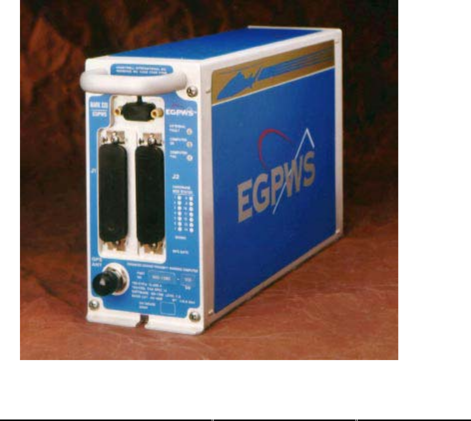
1.5 Description of Equipment
The MK XXII EGPWS is a rack mount ground proximity warning (GPWS) and terrain display
(TAWS) computer. Some of the system features include:
♦ Basic Helicopter Ground Proximity Warning Modes 1-5
♦ Mode 6 Altitude, Bank Angle, and Tail Strike Callouts
♦ Terrain and Obstacle Awareness alert and display
♦ Terrain map with runways
♦ Internal GPS card
♦ Front loading updateable database
♦ External Configuration Module
♦ Internal heater blanket for operation outside of the heated area of the aircraft
Fig 1.0 MK XXII EGPWC

Honeywell
MK XXII EGPWS Installation Manual
CAGE CODE: 97896 SCALE: NONE SIZE: A DWG NO: 060-4314-225 REV: C SHEET 19
1.5.1 MK XXII EGPWS Computer
The MK XXII EGPWS computer is available under P/N 965-1590-0XX with internal GPS. The MK
XXII EGPWS computer is intended for Helicopters and provides a mixture of analog and digital
interfaces. The type of supported displays is limited and includes some EFIS displays. The terrain
database included with the MK XXII EGPWS computer are North America, South America,
Europe, Eastern Europe, Africa, Asia, Pacific, South Pacific, and Middle East regions and are
comprises of terrain data (6 arc second where available), all known airports, many heliports and
man-made obstacles (North America only).
1.5.2 MK XXII EGPWS Configuration Module
The MK XXII EGPWS Configuration Module is available under P/N 700-1710-001 (Included in
Installation Kits, see section 1.8). The MK XXII EGPWS uses a Configuration Module installed in
the aircraft wiring to store aircraft/EGPWS interface configuration.Specifically, the module comes
prewired and replaces part of the backshell of the (P2) connector that plugs into the front of the
MK XXII computer. The Configuration Module is read by the EGPWS only during power up. The
configuration is copied into Non Volatile Memory (NVM) of the EGPWS. The Configuration
Module is programmable via an RS-232 interface with the EGPWS. The contents of the
Configuration Module can also be read back via the same RS-232 interface.
1.5.3 GPS Antenna
EGPWS installations using the internal GPS require an active GPS antenna and cabling. The
GPS antenna should meet the following qualifications:
Frequency: 1575.42 MHz
Impedance: 50 ohms
Gain: 33dB max, 26.5 dB preferred
Power: 5 VDC
Qualification: TSO C129 or C129a or C144
The following GPS antennas are found to be compatible with the EGPWS internal GPS card.
Other GPS antennas may be found compatible, contact EGPWS engineering for assistance. It is
the responsibility of the OEM or owner/operator (and ultimately the regulatory authorities) to
assess the antenna acceptance criteria relative to ARINC, MIL, or other specifications.
King KA 91 P/N 071-01545-0200 TSO-C129
King KA 92 P/N 071-01553-0200 TSO-C129
Sensor Systems P/N S67-1575-52 TSO-C129, ARINC 743A
Sensor Systems P/N S67-1575-133 TSO-C129a, ARINC 743A
1.5.4 OAT Sensor
The OAT sensor is available from Computer Instruments Corp. (CIC) P/N 05257. The EGPWS
uses a separate OAT sensor (Outside Air Temperature) to measure outside air temperature on

Honeywell
MK XXII EGPWS Installation Manual
CAGE CODE: 97896 SCALE: NONE SIZE: A DWG NO: 060-4314-225 REV: C SHEET 20
aircraft that do not have another compatible source of outside air temperature. Outside Air
Temperature is used by the EGPWS along with pressure altitude in computing Geometric
Altitude. If Outside Air Temperature is not available, Geometric Altitude is computed using
pressure altitude with a corresponding reduction in accuracy.
Geometric Altitude is computed by the EGPWS to reduce or eliminate errors potentially induced
in corrected barometric altitude by temperature extremes, non-standard altitude conditions, and
altimeter miss-sets. Geometric Altitude also allows continuous EGPWS operation in QFE
environments without crew intervention.
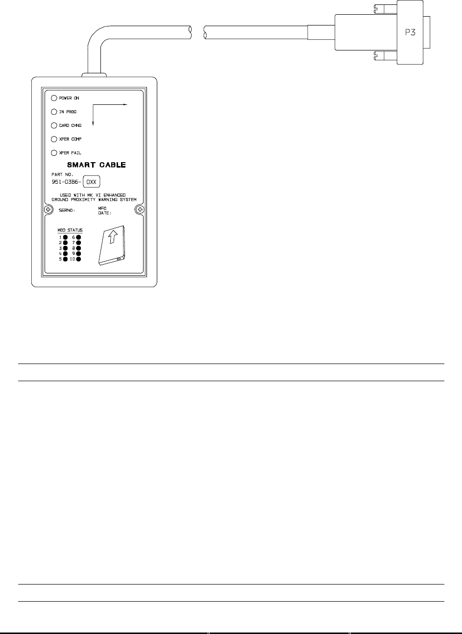
1.5.5 Smart Cable (PCMCIA Interface)
The EGPWS Smart Cable (part number 951-0386-001) is a removable PCMCIA card interface.
The Smart Card is compatible with any Honeywell supplied EGPWS PCMCIA style cards. The
purpose of the Smart Cable in the EGPWS system is for upload of software and databases and
also for download of EGPWS Flight History. The Smart Card loading operation will closely
emulate that of an ARINC 615 Data Loader.
Honeywell
MK XXII EGPWS Installation Manual
CAGE CODE: 97896 SCALE: NONE SIZE: A DWG NO: 060-4314-225 REV: C SHEET 21
FIGURE 1-1 MK XXII EGPWS SMART CABLE
1.6 Technical Characteristics
MK XXII EGPWS
TSO Compliance: TSO-C92c, TSO-C151a, class A
Physical size (HxWxD): 6.20” x 3.04” x 10.30”
Weight: 3.9 pounds maximum
Mounting: Standard 3 inch King Radio rack
Temperature (operational): -55°C to +70°C (F2)
Altitude range: 55,000 feet (F2)
Cooling: No cooling necessary
Shock: No shock mounting required
Power Consumption (28 VDC): 3 Amps
9 watts – no warning
+7 watts – with warning over 8 ohm speaker
+3 watts – with GPS card
+49 watts – with heater blanket on
Configuration Module
TSO Compliance: same as MK XXII EGPWS

Honeywell
MK XXII EGPWS Installation Manual
CAGE CODE: 97896 SCALE: NONE SIZE: A DWG NO: 060-4314-225 REV: C SHEET 22
Physical size: 2.68” x 1.51” x 0.32” (fits Positronic connector backshell)
Weight: <1 pound with connector and backshell
Mounting: Mounts to Positronic connector backshell
Temperature (operational): same as MK XXII EGPWS
Altitude range: same as MK XXII EGPWS
Cooling: No cooling necessary
Shock: No shock mounting required
Power Consumption (5 VDC): from MK XXII EGPWS
GPS Antenna Sensor
See Manufacturer’s specifications Appendix D.
OAT Sensor
See Manufacturer’s specifications Appendix D.
1.7 Units Supplied
1.7.1 MK XXII EGPWS
The MK XXII EGPWS The part number for the units is as follows:
965-1590-0XX with Internal GPS card
note 1: -0XX defines the Application software version
1.7.2 Configuration Module
The MK XXII EGPWS Configuration Module is available in one version. When ordering the
Configuration Module, order part number 700-1710-001.
1.7.3 Smart Cable (PCMCIA Interface)
The MK XXII EGPWS Smart Cable is available in one version. The Smart Cable is used for Line
Maintenance, only one Smart Cable is required for an installation house or operator. When
ordering the Smart Cable, order part number 951-0386-001.

Honeywell
MK XXII EGPWS Installation Manual
CAGE CODE: 97896 SCALE: NONE SIZE: A DWG NO: 060-4314-225 REV: C SHEET 23

Honeywell
MK XXII EGPWS Installation Manual
CAGE CODE: 97896 SCALE: NONE SIZE: A DWG NO: 060-4314-225 REV: C SHEET 24
1.8 Installation and Accessories Kits
NOTE: Not all installation kits are immediately available, contact Honeywell Order
Administration (425-885-8719) for availability.
1.8.1 MK XXII EGPWS Installation Kits
(A) New EGPWS installation with OAT and Internal GPS
The MK XXII EGPWS Installation Kit #1, P/N 755-7013-001, contains the following parts:
Vendor Name Vendor P/N Description QTY UM Honeywell P/N
Positronic Ind. DD78F1OJVLC-15 P1 connector 1 EA 440-1158-009
Positronic Ind. RD50F1OJVLC-15 P2 connector 1 EA 440-1233-001
Amphenol 79075 GPS Antenna connector 1 EA 440-1239-001
Honeywell 700-1710-001 Configuration Module 1 EA 700-1710-001
Bendix/King 071-04003-0002 Computer Mounting Tray 1 EA 405-0383-001
CIC 05257 OAT Sensor 1 EA 107-1049-001
CIC 05257-TOMK OAT mounting Kit 1 EA 107-1049-002
CIC 05257-TPIK OAT Connector Kit 1 EA 107-1049-003
(B) New EGPWS installation with Internal GPS
The MK XXII EGPWS Installation Kit #5, P/N 755-7013-005, contains the following parts:
Vendor Name Vendor P/N Description QTY UM Honeywell P/N
Positronic Ind. DD78F1OJVLC-15 P1 connector 1 EA 440-1158-009
Positronic Ind. RD50F1OJVLC-15 P2 connector 1 EA 440-1233-001
Amphenol 79075 GPS Antenna connector 1 EA 440-1239-001
Honeywell 700-1710-001 Configuration Module 1 EA 700-1710-001
Bendix/King 071-04003-0002 Computer Mounting Tray 1 EA 405-0383-001
1.8.2 RS-232 Cable
The MK XXII EGPWS RS-232 Cable can be ordered using the following part numbers:
NOTE: The RS-232 Cable can be built by the Installer/Operator per the description in Section 4.4.2
Vendor Name Vendor P/N Description QTY UM Honeywell P/N
Honeywell 704-2617-001 RS-232 Cable 1 EA 704-2617-001
1.8.3 Smart Cable
The MK XXII EGPWS Smart Cable can be ordered using the following part numbers:
Vendor Name Vendor P/N Description QTY UM Honeywell P/N
Honeywell 951-0386-001 Smart Cable 1 EA 951-0386-001

Honeywell
MK XXII EGPWS Installation Manual
CAGE CODE: 97896 SCALE: NONE SIZE: A DWG NO: 060-4314-225 REV: C SHEET 25
1.8.4 Terrain Database Cards
The MK XII EGPWS Terrain Database Cards can be ordered using the following part numbers:
Vendor Name Vendor P/N Description QTY UM Honeywell P/N
Honeywell 424NAM North America 1 EA 718-1447-xxx
Honeywell 424SAM South America 1 EA 718-1448-xxx
Honeywell 424EUR Europe 1 EA 718-1449-xxx
Honeywell 424EEU Eastern Europe 1 EA 718-1450-xxx
Honeywell 424AFR Africa 1 EA 718-1451-xxx
Honeywell 424PAC Pacific 1 EA 718-1452-xxx
Honeywell 424ASI Asia 1 EA 718-1453-xxx
Honeywell 424SPA South Pacific 1 EA 718-1457-xxx
Honeywell 424MES Middle East 1 EA 718-1458-xxx
Honeywell 402-6075-xxx Label, TDB Front Panel 1 EA 402-6075-xxx
1.8.5 Flight History Card
The Flight History Card is a PCMCIA card that has been loaded with a down load instruction file
to allow the down loading of flight history data from an EGPWS. Flight History files contain status
information, fault history and flight data from 20 seconds prior to 10 seconds after a EGPWS
caution or warning event. The card is used to aid in troubleshooting systems faults and or
nuisance warnings.
The MK XXII EGPWS Flight History Card can be ordered using the following part numbers:
Vendor Name Vendor P/N Description QTY UM Honeywell P/N
Honeywell * Flight History Download 1 EA *
* For flight history download cards call Honeywell GPWS Hotline 1 800 813-2099
1.9 Accessories Required but not Supplied
1.9.1 ARINC 453 Terrain Display wiring
The Terrain display wiring (ARINC 453) must meet the display manufacturer’s specifications
including termination method. ARINC 453 buss wiring must meet the following requirements:
• Cable length must be less than 300 feet (91.4 meters).
• Wire to wire capacitance must not exceed 50 pF/foot.
• Shielded twisted pair with not less than one twist per inch.
• Impedance of 78 ohms ±10% at 1 MHz.
Vendor Name Vendor P/N Description QTY UM Honeywell P/N
Pic Wire&Cable D620224 ARINC 453 cable A/R EA
Pic Wire&Cable D5102QX Hi Temp Quadraxial A/R EA
Pic Wire&Cable D771553 MIL-STD 1553 Data Bus A/R EA
ECS 4122021 ARINC 453 cable A/R EA

Honeywell
MK XXII EGPWS Installation Manual
CAGE CODE: 97896 SCALE: NONE SIZE: A DWG NO: 060-4314-225 REV: C SHEET 26
Vendor Name Vendor P/N Description QTY UM Honeywell P/N
Emteq D 07002-100 ARINC 453 Cable A/R EA
M17/176-00002 Military Specification A/R EA
1.9.2 GPS Antenna & cable
The GPS Antenna & cable can be ordered from their manufacturers using the following part
numbers:
Vendor Name Vendor P/N Description QTY UM Honeywell P/N
Bendix/King 071-01545-0200 KA 91 GPS Antenna 1 EA
Bendix/King 071-01553-0200 KA 92 GPS Antenna 1 EA 300-1147-001
Comant CI 405-2 KA 92 GPS Antenna 1 EA 300-1147-001
Bendix/King 050-03318-0000 Antenna Installation Kit OPT EA 405-0432-001
Sensor Systems S67-1575-38 S67 GPS Antenna 1 EA
Sensor Systems S67-1575-52 S67 GPS Antenna 1 EA
Sensor Systems S67-1575-133 S67 GPS Antenna 1 EA
Thermax M17/128-RG400 Coax Cable, RG400 A/R EA
Coax Cable, RG-142 A/R EA
Amp 225554-6 TNC Angle Plug, Male 1 EA 440-1239-001
Amphenol 79075 TNC Angle Plug, Male 1 EA 440-1239-001
1.9.3 Circuit Breaker
The Circuit Breaker needs to be a 3 Amp delayed action circuit breaker.
Vendor Name Vendor P/N Description QTY UM Honeywell P/N
Klixon (T.I.) 7277-2-3 3 Amp Circuit Breaker,
EGPWS power +28
1EA
Klixon (T.I.) 7277-2-1 1 Amp Circuit Breaker,
lamp power +28
1EA
1.9.4 Annunciators & Switch/Annunciators
The devices shown below are switch/annunciators and are representative of those used in some
installations. The installer/customer is cautioned to verify regulatory approval of the annunciation
devices installed. See Appendix D for Vendors.
1.9.4.1 GPWS Warning (red) P/TES T; switch/annunciator assembly
The ‘GPWS’ annunciator provides visual indication of an EGPWS alert. The GPWS warning (red)
annunciator also has a switch that is used to manually initiate EGPWS Self Test.

Honeywell
MK XXII EGPWS Installation Manual
CAGE CODE: 97896 SCALE: NONE SIZE: A DWG NO: 060-4314-225 REV: C SHEET 27
1.9.4.2 GPWS Caution (amber) G/S CANCLD switch/annunciator assembly.
The ‘GPWS caution annunciator provides visual indication of an EGPWS alert. The EGPWS
caution (amber) annunciator also has a switch that is used to manually inhibit EGPWS Mode 5
glideslope alerts. The bottom half of the annunciator provides visual indication that the mode 5
glideslope alerts have been canceled.
1.9.4.3 LOW ALT / ON switch/annu nciator assembly
The LOW ALT / ON switch/annunciator provides for manual selection of low altitude mode and
visual indication that the Mk XXII EGPWS is in low altitude mode.
1.9.4.4 TERR INHIB / ON switch/annunciator assembly
The ‘TERR INHIBIT’ switch/annunciator provides for manual selection of terrain inhibit mode and
visual indication that the EGPWS Terrain functions have been inhibited.
1.9.4.5 AUDIO INHIBIT / ON switch /annunciator assembly
The ‘AUDIO INHIBIT’ switch/annunciator provides for manual selection of audio inhibit mode and
visual indication that the EGPWS mode 6 functions have been inhibited.
1.9.4.6 GPWS INOP / TERR INOP a nnunciator assemblies
The ‘GPWS INOP’ annunciator provides visual indication that the EGPWS GPWS modes have a
disabled function.
The ‘TERR INOP’ annunciator provides visual indication that the EGPWS Terrain modes have a
disabled function.
1.9.4.7 TERR DISPLAY / ON switch /annunciator assemblies
The ‘TERR DISPLAY’ switch/annunciator provides for manual selection of the terrain display and
visual indication that the EGPWS Terrain Display has been selected for the associated display.
1.10 Cockpit Speaker (Optional)
The MK XXII EGPWS can interface to an 8 ohm audio speaker for cockpit annunciation of aural
alerts.
Vendor Name Vendor P/N Description QTY UM Honeywell P/N
Quam 30A05Z8 Audio Speaker 1 EA
Utah SP-3A Audio Speaker 1 EA
CTS 4AC3 Audio Speaker 1 EA 300-0218-002

Honeywell
MK XXII EGPWS Installation Manual
CAGE CODE: 97896 SCALE: NONE SIZE: A DWG NO: 060-4314-225 REV: C SHEET 28
1.11 Tools Required
1.11.1 Crimping Tool - P1, P2, P3
Description UM QTY Vendor Name & Part Number
Hand Crimping Tool EA 1 Positronic Ind. 9507
Hand Crimping Tool EA 1 Daniels AFM8
Hand Crimping Tool EA 1 Military M22520/2-1
1.11.2 Contact Positioner - P1, P2, P3
Description UM QTY Vendor Name & Part Number
Contact Positioner, Socket P1 EA 1 Positronic Ind. 9502-3
Contact Positioner, Socket P1 EA 1 Daniels K41 (for 22 to 28 AWG)
Contact Positioner, Socket P1 EA 1 Military M22520/2-06
Contact Positioner, Socket P2 EA 1 Positronic Ind. 9502-5
Contact Positioner, Socket P2 EA 1 Daniels K13-1 (20-24 AWG)
Contact Positioner, Socket P2 EA 1 Military M22520/2-08
Contact Positioner, Pin P3 EA 1 Positronics 9502-4
Contact Positioner, Pin P3 EA 1 Daniles K42 (22-28 AWG)
Contact Positioner, Pin P3 EA 1 Military M22520/2-09
1.11.3 Insertion/Removal Tool - P1, P2, P3
Description UM QTY Vendor Name & Part Number
Removal Tool P1, P3 EA 1 Daniels DRK 95-22M
Removal Tool P1, P3 EA 1 Military M81969/8-02
Removal Tool P2 EA 1 Daniels DRK145
Insertion Tool P1, P3 EA 1 Daniels DAK 95-22M
Insertion Tool P1, P3 EA 1 Military M81969/8-01
Insertion Tool P2 EA 1 Daniels DAK145
Insertion/Removal Tool P1, P3 EA 1 Military M81969/1-04
Insertion/Removal Tool P2 EA 1 Military M81969/1-02
1.11.4 Spare Contacts - P1, P2, P3
Description Mil Spec Part Number
Contacts (P1) socket M39029/57-354 22-28 GA Wire
Contacts (P2) socket M39029/63-368 20-24 GA Wire
Contacts (P3) Pin M39029/58-360 22-28 GA Wire
1.12 License Requirements
There are no Radio license requirements for the MK XXII EGPWS.

Honeywell
MK XXII EGPWS Installation Manual
CAGE CODE: 97896 SCALE: NONE SIZE: A DWG NO: 060-4314-225 REV: C SHEET 29

Honeywell
MK XXII EGPWS Installation Manual
CAGE CODE: 97896 SCALE: NONE SIZE: A DWG NO: 060-4314-225 REV: C SHEET 30
SECTION II
INSTALLATION

Honeywell
MK XXII EGPWS Installation Manual
CAGE CODE: 97896 SCALE: NONE SIZE: A DWG NO: 060-4314-225 REV: C SHEET 31

Honeywell
MK XXII EGPWS Installation Manual
CAGE CODE: 97896 SCALE: NONE SIZE: A DWG NO: 060-4314-225 REV: C SHEET 32
SECTION II – INSTALLATION
SECTION II - INSTALLATION .............................................................................................................................. 33
2.1 INTRODUCTION.................................................................................................................................................... 33
2.2 UNPACKING AND INSPECTING THE EQUIPMENT ................................................................................................... 33
2.3 EQUIPMENT INSTALLATION ................................................................................................................................. 33
2.3.1 General........................................................................................................................................................ 33
2.3.2 MK XXII Computer Location....................................................................................................................... 34
2.3.3 MK XXII Computer Installation................................................................................................................... 34
2.3.4 Configuration Module Location .................................................................................................................. 35
2.3.5 Configuration Module Installation .............................................................................................................. 35
2.3.6 GPS Antenna location.................................................................................................................................. 44
2.3.7 GPS Antenna Installation ............................................................................................................................ 44
2.3.8 OAT Sensor Location................................................................................................................................... 44
2.3.9 OAT Sensor Installation............................................................................................................................... 44
2.3.10 Cockpit Annunciators / Switches................................................................................................................ 44
2.3.10.1 Description............................................................................................................................................................ 45
2.3.10.2 Location ................................................................................................................................................................ 46
2.3.10.3 Inhibit Switch Functions and Selection................................................................................................................. 48
2.3.10.3.1 Terrain Inhibit................................................................................................................................................ 48
2.3.10.3.2 Audio Inhibit (Timed).................................................................................................................................... 48
2.3.10.3.3 Audio Inhibit (Not Described Above)............................................................................................................ 48
2.3.10.3.4 Low Altitude Mode........................................................................................................................................ 48

Honeywell
MK XXII EGPWS Installation Manual
CAGE CODE: 97896 SCALE: NONE SIZE: A DWG NO: 060-4314-225 REV: C SHEET 33
SECTION II - INSTALLATION
2.1 Introduction
This section contains suggestions and factors to consider before installing the Enhanced Ground Proximity
Warning System. Close adherence to these suggestions will assure satisfactory performance from the
equipment.
NOTE
The conditions and tests performed on this article are minimum performance
standards. It is the responsibility of those desiring to install this article either on or
within a specific type or class of aircraft to determine that the aircraft installation
conditions are within these performance standards. The article may be installed only if
further evaluation by the applicant documents an acceptable installation and is
approved by the Administrator.
2.2 Unpacking and Inspecting the Equipment
Exercise extreme caution when unpacking equipment. Perform a visual inspection of the unit for evidence
of damage incurred during shipment. If a damage claim must be filed then save the shipping container and
all packing materials to substantiate your claim. The claim should be filed as soon as possible. The
shipping container and all packing materials should be retained in the event that storage or reshipment of
the equipment is necessary.
2.3 Equipment Installation
2.3.1 General
The following paragraphs contain information pertaining to the installation of the MK XXII EGPWS,
including instructions concerning the location and mounting of the equipment. The equipment should be
installed in the aircraft in a manner consistent with acceptable workmanship and engineering practices,
and in accordance with the instructions set forth in this publication. To ensure the system has been
properly and safely installed in the aircraft, the installer should make a thorough visual inspection and
conduct an overall operational check of the system, on the ground, prior to flight.
CAUTION
AFTER INSTALLATION OF THE CABLING AND BEFORE INSTALLATION OF THE
EQUIPMENT, A CHECK SHOULD BE MADE WITH THE AIRCRAFT PRIMARY POWER
SUPPLIED TO THE MOUNTING CONNECTOR, TO ENSURE THAT POWER IS
APPLIED ONLY TO THE PINS SPECIFIED IN THE INTERWIRING DIAGRAMS IN
SECTION III.

Honeywell
MK XXII EGPWS Installation Manual
CAGE CODE: 97896 SCALE: NONE SIZE: A DWG NO: 060-4314-225 REV: C SHEET 34
2.3.2 MK XXII Computer Location
Care should be exercised to avoid mounting components near equipment operating with high pulse current
or high power outputs such as radar and satellite communications equipment. In general, the equipment
should be installed in a location convenient for operation, inspection, and maintenance, and in an area free
from excessive vibration, heat, and noise generating sources.
The MK XXII EGPWS has an internal heater blanket therefore they can be mounted outside the heated
area of the aircraft. The computers have been qualified for operation up to 50,000 feet and -55°C using the
heater blanket.
All mechanical installation drawings, connector assembly diagrams, interwiring diagrams, and connector
pin assignment tables referenced in this section are located at the end of Section II, of the manual.
Determine the mounting location for the system components following the guidelines below.
The length of cables from the EGPWS connectors to other system units is not generally critical because
unit interfaces are designed with high impedance inputs, low impedance outputs, and low noise
susceptibility characteristics. The exception is the wires from the EGPWS Configuration Module, which
was designed to be a part of the EGPWS connector backshell because of the requirement for short lead
length.
To allow for inspection or repair of the wiring of the connector assembly itself, sufficient lead length should
be left so that EGPWS may be moved several inches. A bend should be made in the harness to allow
water droplets that might form on the harness due to condensation, to drip off at the bend and not collect in
the connector.
Prior to installing any equipment, make a continuity check of all wires and cables associated with the
system. Then apply power and check for proper voltages at system connectors, and then remove power
before completing the installation.
2.3.3 MK XXII Computer Installation
The MK XXII EGPWS installation will conform to standards designated by the customer, installing agency,
and existing conditions as to the unit location and type of installation. However, the following suggestions
will assure a more satisfactory performance from the equipment.
A. Plan a location on the aircraft so that the EGPWS is accessible for front panel maintenance controls.
Check to be sure that there is adequate space in the front of the computer for connectors and cabling.
B. Refer to Figure 2-2 and 2-3 for outline dimensions of the computer and mounting tray.
C. Mount the EGPWS mounting tray in the aircraft radio rack or other location using the four screw
mounting holes. Match drill the mounting holes using the Mounting Tray as a template.
D. Ensure that the mounting tray is electrically bonded (less than 10 milli-ohm to aircraft ground).

Honeywell
MK XXII EGPWS Installation Manual
CAGE CODE: 97896 SCALE: NONE SIZE: A DWG NO: 060-4314-225 REV: C SHEET 35
E. Slide the EGPWS unit in the mounting tray, and secure it using the Hold Down latch.
F. (After Continuity and Power check) Attach the cable harness to the front panel connectors and lock
connectors using the slide lock of the P1 & P2 connectors. The EGPWS should be wired according to
the interconnect diagrams in Section III, of this manual.
2.3.4 Configuration Module Location
The aircraft configuration is programmed into the EGPWS Configuration Module installed in the aircraft
wiring. The Configuration Module is identified as Honeywell part number 700-1710-001. The Configuration
Module is installed as one side of the P2 (50 pin) mating connector backshell and contains electrically
reprogrammable memory for configuration storage. The Configuration Module when installed is wired
directly to the appropriate pins in the P2 connector.
2.3.5 Configuration Module Installation
The purpose of this procedure is to give an assembly sequence for assembly of the Configuration Module
with the P2 connector and backshell.
A. The P2 connector, Honeywell part number 440-1233-001, vendor part number RD50F1OJVLC-15,
when ordered comes with 50 contacts and a plastic backshell (hood).
B. The Configuration Module will replace the Backshell Plate. The Backshell Plate can be discarded.
C. Wire the Configuration Module to the P2 connector using contacts provided with the connector. Wire
per the following wire list:
Wire Color P2 pin #
Violet P2-17
Blue P2-16
Orange P2-33
Wire Color P2 pin #
Black P2-50
White P2-49
Red P2-32

Honeywell
MK XXII EGPWS Installation Manual
CAGE CODE: 97896 SCALE: NONE SIZE: A DWG NO: 060-4314-225 REV: C SHEET 36
D. Position Slide Lock and Spring Clip onto connector.
E. Install Backshell Housing onto connector. The Ground wire (used for ESD discharge) is terminated
with shielded pigtails inside the backshell to the P2 connector.
F. Organize and dress wire exiting from the backshell, route Configuration Module wires in a coil. Install
Cable Clamp, do not tighten Cable Clamp screws.
G. Secure the Configuration Module to the connector using screws provided. Tighten Cable Clamp
screws as required.
CONFIGURATION MODULE ASSEMBLY
REQUIRED: Two items as follows:
ITEM 1.0 Connector (P2) Positronic Ind. RD50F10JVLC-15 *
ITEM 2.0 Configuration Module Honeywell 700-1710-001
* This item may be available from Honeywell under Part No. (440-1233-001)
ITEM 1 DESCRIPTION:
Connector P2 (Positronic Ind. PN RD50F10JVLC-15) is a packaged kit consisting of the following parts:
1.1 Connector, 50 socket D-Sub Qty - 1
1.2 Contacts, size 20 crimp Qty - 50
1.3 Backshell housing Qty - 1
1.4 Backshell plate Qty - 1
1.5 Screws, Phillips CSK Qty - 2
1.6 Spring Clip Qty - 1
1.7 Slide Lock Qty - 1
1.8 Screws, Slotted Qty - 2
1.9 Cable Clamp Qty - 1
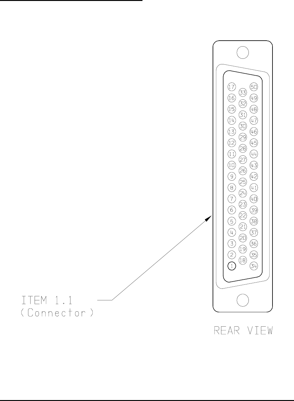
Honeywell
MK XXII EGPWS Installation Manual
CAGE CODE: 97896 SCALE: NONE SIZE: A DWG NO: 060-4314-225 REV: C SHEET 37
INSTALLATION ASSEMBLY SEQUENCE
STEP 1 Install all MK XXII system aircraft wiring to this connector using items 1.2 (Crimp Contacts)
and item 1.1 (Connector). See figure 2-1.1 below.
FIGURE 2-1.1 MK XXII EGPWS CONFIGURATION MODULE

Honeywell
MK XXII EGPWS Installation Manual
CAGE CODE: 97896 SCALE: NONE SIZE: A DWG NO: 060-4314-225 REV: C SHEET 38
STEP 2 Wire item 2.0 (Configuration Module). This part will replace item 1.4 (Backshell plate).
Install the pre-crimped colored wires into item 1.1 (Connector) as shown in figure 2-1.2
below.
FIGURE 2-1.2 MK XXII EGPWS CONFIGURATION MODULE

Honeywell
MK XXII EGPWS Installation Manual
CAGE CODE: 97896 SCALE: NONE SIZE: A DWG NO: 060-4314-225 REV: C SHEET 39
STEP 3 Position item 1.7 (Slide lock) onto wired connector as shown in figure 2-1.3 below:
FIGURE 2-1.3 MK XXII EGPWS CONFIGURATION MODULE
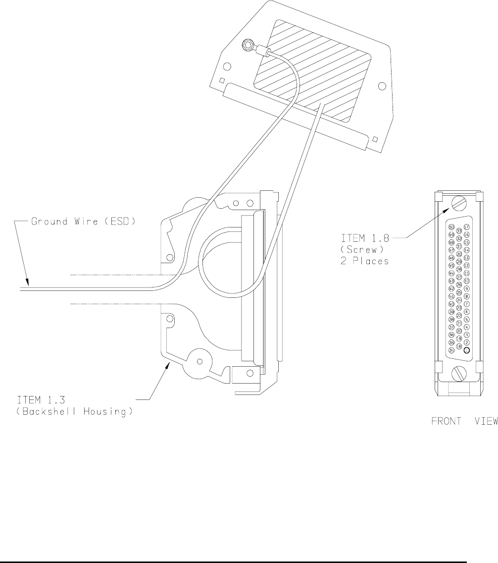
Honeywell
MK XXII EGPWS Installation Manual
CAGE CODE: 97896 SCALE: NONE SIZE: A DWG NO: 060-4314-225 REV: C SHEET 40
STEP 4 Install item 1.3 (Backshell Housing) onto connector using item 1.8 (Screws) as shown in
figure 2-1.4 below:
Ground Wire (used for electrostatic discharge {ESD} protection) is terminated with
shielded pigtails of wires at this connector.
FIGURE 2-1.4 MK XXII EGPWS CONFIGURATION MODULE

Honeywell
MK XXII EGPWS Installation Manual
CAGE CODE: 97896 SCALE: NONE SIZE: A DWG NO: 060-4314-225 REV: C SHEET 41
STEP 5 Install item 1.6 (Spring Clip) as shown figure 2-1.5 below:
FIGURE 2-1.5 MK XXII EGPWS CONFIGURATION MODULE

Honeywell
MK XXII EGPWS Installation Manual
CAGE CODE: 97896 SCALE: NONE SIZE: A DWG NO: 060-4314-225 REV: C SHEET 42
STEP 6 Organize and dress wiring exiting from backshell. Route Configuration Module wires
exiting from connector, then coil as shown in figure 2-1.6 below. Install item 1.9 (Cable
Clamp) as shown. Do not tighten screws yet.
FIGURE 2-1.6 MK XXII EGPWS CONFIGURATION MODULE

Honeywell
MK XXII EGPWS Installation Manual
CAGE CODE: 97896 SCALE: NONE SIZE: A DWG NO: 060-4314-225 REV: C SHEET 43
STEP 7 Secure Configuration Module to connector assembly using item 1.5 (Screws) as shown in
figure 2-1.7 below. Tighten Cable Clamp screws as required.
FIGURE 2-1.7 MK XXII EGPWS CONFIGURATION MODULE

Honeywell
MK XXII EGPWS Installation Manual
CAGE CODE: 97896 SCALE: NONE SIZE: A DWG NO: 060-4314-225 REV: C SHEET 44
2.3.6 GPS Antenna location
The antenna must be mounted on top of the fuselage. Avoid mounting the antenna near any projections
such as the rotor mast, or engine exhaust, where shadows could occur or high heat could damage the
antenna. It is recommended that there be a separation of at least 3 feet between the GPS antenna and
any VHF Comm antenna on the aircraft. The antenna baseplate must be level within ± 5° in both axis
when the aircraft is level (level is defined as the aircraft attitude required when weighing the aircraft for
weight and balance). If the antenna is tilted more than 5° or is mounted close to other objects that shadow
it, loss of some of the satellites will occur and system performance may be degraded. See manufacturer’s
drawing in Appendix D for specifications of antenna, antenna cables, and connector information.
2.3.7 GPS Antenna Installation
Refer to manufacturer’s procedures or applicable STC documentation.
2.3.8 OAT Sensor Location
The OAT sensor (CIC 05257) should be mounted on the underside (belly) of the aircraft or other
convenient location meeting the following conditions. Avoid mounting the sensor where it can be affected
by direct sunlight, or exhaust gases from engines or heaters. The probe tip should extend beyond the
aircraft boundary layer into the turbulent airflow. See manufacturer’s drawing in Appendix D for
specifications.
2.3.9 OAT Sensor Installation
Refer to manufacturer’s procedures or applicable STC documentation.
2.3.10 Cockpit Annunciators / Switches
This section provides information for selecting, locating and mounting of the MK XXII EGPWS Lighted
annunciators / switches. NOTE: The nomenclature given for each lamp is an example only. Other
manufacturers use nomenclature that is also acceptable. Refer to Honeywell Product Specification 965-
1590-601 for additional information and for electrical loads specification

Honeywell
MK XXII EGPWS Installation Manual
CAGE CODE: 97896 SCALE: NONE SIZE: A DWG NO: 060-4314-225 REV: C SHEET 45
2.3.10.1 Description
EGPWS warning GPWS P/TEST
This assembly is illuminated with Red background and black or white letters. For dark cockpits black
background and Red letters. The EGPWS warning annunciator is not normally dimmable. For Lamp
Format 1 (I/O Discrete Type 128) the lamp is activated during any Mode 1 through Mode 4, and Terrain
/Obstacle Awareness alerts and warnings. For Lamp Format 2 (I/O Discrete Type 129) the lamp is
activated during Mode 1 and Mode 2 Pull Up, and Terrain /Obstacle Awareness warnings. This assembly
also includes a momentary switch that will activate EGPWS Self Test.
EGPWS caution GPWS G/S CANCLD
This assembly is illuminated with Amber background and black or white letters, for dark cockpits black
background and Amber letters. The EGPWS alert annunciator is not normally dimmable. For Lamp Format
1 (I/O Discrete Type 128) the lamp is activated during any Mode 5 alert. For Lamp Format 2 (I/O Discrete
Type 129) the lamp is activated during any Mode 1 through Mode 4, and Terrain /Obstacle Awareness
alerts. This assembly also includes a momentary switch that will activate glideslope cancel.
LOW ALTITUDE LOW ALT ON
This assembly is illuminated with black background and white, green, or blue letters. This assembly also
includes a momentary switch that will activate / de-activate (cancel) EGPWS low altitude mode.
TERRAIN INHIBIT TERR INHIB ON
This assembly is illuminated with black background and white, blue, or green letters. This assembly also
includes a alternate action switch that will activate ./ de-activate (cancel) Terrain inhibit mode. (Optional
see section 2.3.10.3)
AUDIO INHIBIT AUDIO INHIB ON
This assembly is illuminated with black background and white, blue, or green letters This assembly also
includes a momentary switch that will activate ./ de-activate (cancel) Audio inhibit mode. (Optional see
section 2.3.10.3)
GPWS system validity GPWS INOP TERR INOP
This assembly is illuminated with black background and amber letters activated during any detected partial
or total failure of the GPWS modes 1-5. And TA&D
TERRAIN select TERR DISPLAY ON
This assembly is illuminated with white background and activated after the flight crew has initiated the
manual selection of the EGPWS terrain display for the associated cockpit display. This assembly also
includes a momentary switch that will activate EGPWS Terrain display feature.

Honeywell
MK XXII EGPWS Installation Manual
CAGE CODE: 97896 SCALE: NONE SIZE: A DWG NO: 060-4314-225 REV: C SHEET 46
2.3.10.2 Location
Cockpit layout, size and operator’s preference will determine if only one set of lights is used (i.e., mounted
in the center), or if dual sets of lights are used (one set on each side), or a combination thereof is desired.
For a typical example of cockpit light locations refer to Figure 2-7. For panel cutouts and assembly options
see the manufacturer’s specifications in Appendix D. The following are recommended locations:
GPWS warning (red) & GPWS alert (amber)
These lights should be located together and in the flight crew’s “primary field of view”. This would include
either the instrument panel or the edge of the glareshield.
LOW ALTITUDE
This light should be located in the flight crew’s “field of view” and within reach of both crewmembers. This
light/switch may be located in an assembly with the GPWS red and GPWS amber lights and/or other
EGPWS annunciators.
TERR INHIBIT ON (Optional see section 2.3.10.3)
This light should be located in the flight crew’s “field of view” and within reach of both crewmembers. This
light/switch may be located in an assembly with the TERR DISPLAY light(s) and/or other EGPWS
annunciators.
AUDIO INHIBIT ON (Optional see section 2.3.10.3)
This light should be located in the flight crew’s “field of view” and within reach of both crewmembers. This
light/switch may be located in an assembly with the TERR DISPLAY light(s) and/or other EGPWS
annunciators.
TERR DISPLAY ON
This light should be located near the associated cockpit display, in the flight crew’s “field of view” and
within reach of one or both crewmembers. This light/switch may be located in an assembly with the TERR
INHIBIT light(s) and/or other EGPWS annunciators.
GPWS INOP
This light should be located within crewmember’s “field of view” or with other system INOP lights of similar
importance. It is recommended that this light not be located in the flight crew’s “primary field of view”. The
reason being that in the event of a GPWS system failure at the beginning of a flight, this light will remain
“ON” until the problem is fixed.
TERR INOP
This light should be located within at least one crewmember’s “field of view” or with other system INOP
lights of similar importance. Note: Annunciators are available with split legend GPWS INOP / TERR INOP
in one assembly. It is recommended that this light not be located in the flight crew’s “primary field of view”.
The reason being that in the event of a GPWS system failure at the beginning of a flight, this light will
remain “ON” until the problem is fixed.
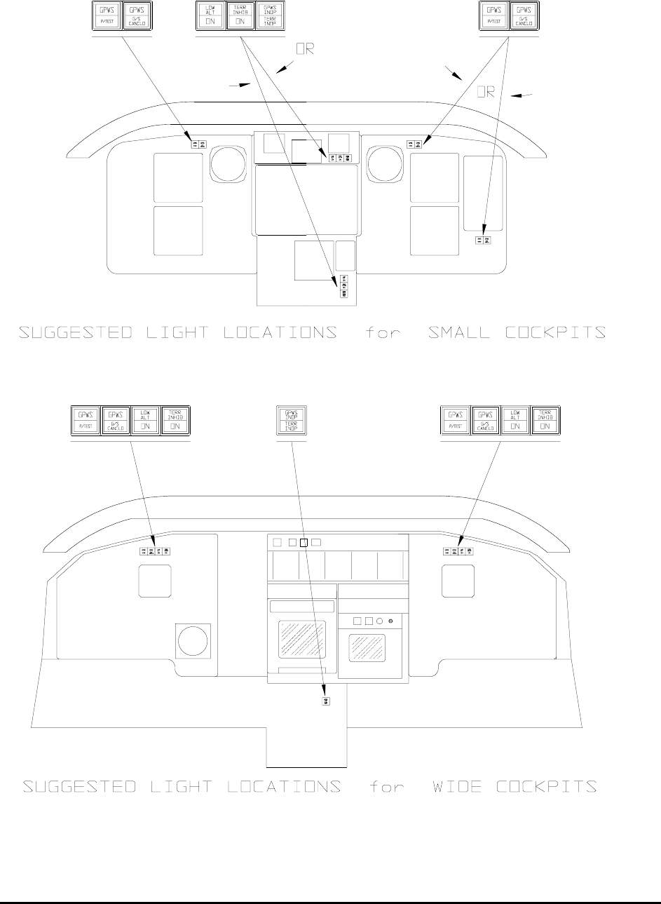
Honeywell
MK XXII EGPWS Installation Manual
CAGE CODE: 97896 SCALE: NONE SIZE: A DWG NO: 060-4314-225 REV: C SHEET 47
FIGURE 2-1.8 MK XXII EGPWS Annunciators/Switches Location

Honeywell
MK XXII EGPWS Installation Manual
CAGE CODE: 97896 SCALE: NONE SIZE: A DWG NO: 060-4314-225 REV: C SHEET 48
2.3.10.3 Inhibit Switch Functions and Selection
The Terrain Inhibit and Audio Inhibit functions are optional but it is recommended that one be used to
inhibit the system during certain operations. The operator should evaluate the two options together with
the Low Altitude Mode function and select the one that best fits his operational requirements. The Low
Altitude Mode is also described below for reference.
2.3.10.3.1 Terrain Inhibit
The Terrain Inhibit will inhibit Terrain and Obstacle audio alerts and warnings. It will not deselect the
Terrain Display. The switch is a toggle action, which must be pressed to turn ON and re-pressed to turn
OFF. The switch lighting must be activated thru the switch contacts. This Inhibit is recommended for
corporate transport operations.
2.3.10.3.2 Audio Inhibit (Timed)
The Timed Audio Inhibit will inhibit all audio output for a period of 5 minutes. It will not affect visual alert
and warning outputs and will not deselect the terrain display. The switch is momentary and the lamp is
illuminated by an output from the EGPWS. This inhibit is recommended for EMS and SAR operations.
2.3.10.3.3 Audio Inhibit (Not Described Above)
The Audio Inhibit will inhibit all audio output as long as it is active. It will not affect visual alert and warning
outputs and will not deselect the terrain display. The switch is a toggle action, which must be pressed to
turn ON and re-pressed to turn OFF. The switch lighting must be activated thru the switch contacts. This
Inhibit is NOT RECOMMENTED.
2.3.10.3.4 Low Altitude Mode
To allow for helicopter operations that require low altitude flight a Low Altitude function is enabled with a
switch. This function is designed for flight at low altitude in VFR conditions. When this function is engaged
Mode 2 and Mode 4 warning boundaries are significantly reduced and Terrain Advisory look ahead
distances are reduced. . Low Altitude operation is defined as operation below 500 feet AGL. There are
other circumstances where the use of the Low Altitude Mode is appropriate. Those include operation in a
high-density metropolitan environment with high rise buildings, operation below 1250 feet AGL when the
GPS is not operational or is providing poor accuracy.

Honeywell
MK XXII EGPWS Installation Manual
CAGE CODE: 97896 SCALE: NONE SIZE: A DWG NO: 060-4314-225 REV: C SHEET 49
FIGURE 2-2 MK XXII EGPWS OUTLINE
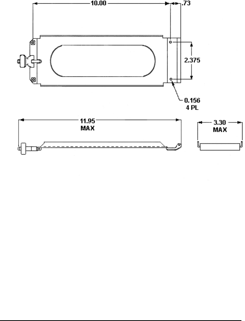
Honeywell
MK XXII EGPWS Installation Manual
CAGE CODE: 97896 SCALE: NONE SIZE: A DWG NO: 060-4314-225 REV: C SHEET 50
FIGURE 2-3 MK XXII EGPWS MOUNTING TRAY
Honeywell P/N
405-0383-001

Honeywell
MK XXII EGPWS Installation Manual
CAGE CODE: 97896 SCALE: NONE SIZE: A DWG NO: 060-4314-225 REV: C SHEET 51

Honeywell
MK XXII EGPWS Installation Manual
CAGE CODE: 97896 SCALE: NONE SIZE: A DWG NO: 060-4314-225 REV: C SHEET 52
SECTION III
SYSTEM PLANNING

Honeywell
MK XXII EGPWS Installation Manual
CAGE CODE: 97896 SCALE: NONE SIZE: A DWG NO: 060-4314-225 REV: C SHEET 53

Honeywell
MK XXII EGPWS Installation Manual
CAGE CODE: 97896 SCALE: NONE SIZE: A DWG NO: 060-4314-225 REV: C SHEET 54
SECTION III – SYSTEM PLANNING
SECTION III – SYSTEM PLANNING..................................................................57
3.1 INTRODUCTION.................................................................................................................................... 57
3.2 SYSTEM WIRING/ ELECTRICAL INTERFACES........................................................................................ 57
3.2.1 Primary Power Input ................................................................................................................... 57
3.2.2 Chassis Ground ........................................................................................................................... 57
3.2.3 GPS Antenna................................................................................................................................ 58
3.2.4 Analog and Digital Inputs............................................................................................................ 58
3.2.5 Discrete Inputs............................................................................................................................. 58
3.2.6 Serial Outputs.............................................................................................................................. 58
3.2.7 Audio Output................................................................................................................................ 59
3.2.8 Discrete Outputs.......................................................................................................................... 59
3.2.9 Configuration Module ................................................................................................................. 59
3.3 CONFIGURABLE INTERFACES............................................................................................................... 60
3.3.1 Category 1 - Aircraft / Mode Type Select .................................................................................... 60
3.3.1.1 Aircraft / Mode Type............................................................................................................................. 60
3.3.1.2 Instructions ............................................................................................................................................ 60
3.3.1.3 Generic Helicopter with and without Torque......................................................................................... 60
3.3.2 Category 2 – Air Data Input Select.............................................................................................. 61
3.3.2.1 Instructions ............................................................................................................................................ 61
3.3.2.2 Examples ............................................................................................................................................... 62
3.3.2.3 Analog altitude and 500 ohm OAT ................................................................................................... 62
3.3.2.4 Digital – ARINC 429 (Cat. 2 ID 5, 1, 6) ........................................................................................... 63
3.3.2.5 Digital –ARINC 575 (Cat. 2 ID 2) .................................................................................................... 64
3.3.2.6 Shadin 2000 (Cat. 2 ID 10) ............................................................................................................... 65
3.3.2.7 Digital – ARINC 429 Dual IOC Buses (Cat. 2. ID 255) ................................................................... 66
3.3.3 Category 3 – Position Input Select .............................................................................................. 67
3.3.3.1 Instructions ............................................................................................................................................ 67
3.3.3.2 ARINC 743 Format ............................................................................................................................... 67
3.3.3.Examples .................................................................................................................................................. 68
3.3.3.1 ARINC 429 BUS (Cat. 3 ID 0,1,4,5)................................................................................................. 68
3.3.3.2 RS-232 Transmit-Receive, 9600 baud (Cat. 3 ID 3) ......................................................................... 68
3.3.3.3 Dual ARINC 429 BUS (Cat. 3 ID 255)............................................................................................. 69
3.3.4 Category 4 – Altitude Callouts .................................................................................................... 70
3.3.4.1 Instructions ............................................................................................................................................ 70
3.3.5 Category 5 – Audio Menu Select ................................................................................................. 71
3.3.5.1 Instructions ............................................................................................................................................ 71
3.3.6 Category 6 – Terrain Display Select ........................................................................................... 72
3.3.6.1 Instructions ............................................................................................................................................ 72
3.3.6.2 TAD Selection....................................................................................................................................... 72

Honeywell
MK XXII EGPWS Installation Manual
CAGE CODE: 97896 SCALE: NONE SIZE: A DWG NO: 060-4314-225 REV: C SHEET 55
3.3.6.3 Terrain Display Configuration Group.................................................................................................... 73
3.3.6.4 Display Input Control Group................................................................................................................. 75
3.3.6.5 Output 429 Bus Group........................................................................................................................... 75
3.3.6.6 Example................................................................................................................................................. 75
3.3.7 Category 7 – Options Select Group #1........................................................................................ 81
3.3.7.1 Instructions ............................................................................................................................................ 81
3.3.7.2 Steep Approach (Not Available in the Mk XXII).................................................................................. 81
3.3.7.3 TA&D Alternate Pop-up........................................................................................................................ 81
3.3.7.4 Peaks Mode ........................................................................................................................................... 82
3.3.7.5 Obstacle Awareness............................................................................................................................... 82
3.3.7.6 Bank Angle Callout Enabling................................................................................................................ 82
3.3.7.8 WOW Reversal...................................................................................................................................... 83
3.3.7.9 GPS Altitude Reference......................................................................................................................... 83
3.3.8 Category 8 – Radio Altitude Input Select .................................................................................... 84
3.3.8.1 Instructions ............................................................................................................................................ 84
3.3.8.2 Example................................................................................................................................................. 84
3.3.8.3 Digital Radio Altitude Interface ........................................................................................................ 84
3.3.8.4 Analog Radio Altitude Interface........................................................................................................ 85
3.3.9 Category 9 – Navigation Inputs Select ........................................................................................ 86
3.3.9.1 Instructions ............................................................................................................................................ 86
3.3.9.2 Example................................................................................................................................................. 87
3.3.9.3 Analog Glideslope Interface (cat. 9 ID 0,1,5) ................................................................................... 87
3.3.9.4 Digital Glideslope/Localizer Interface .............................................................................................. 88
3.3.9.5 Dual Glideslope Receiver.................................................................................................................. 88
3.3.10 Category 10 – Attitude Input Select........................................................................................... 89
3.3.10.1 Attitude Signals ................................................................................................................................... 89
3.3.10.2 Instructions.......................................................................................................................................... 89
3.3.10.3 Example............................................................................................................................................... 90
3.3.10.4 Analog Roll Angle (Synchro).......................................................................................................... 90
3.3.10.5 Digital ARINC 429 High Speed...................................................................................................... 91
3.3.11 Category 11 – Heading Input Select.......................................................................................... 92
3.3.11.1 Instructions.......................................................................................................................................... 92
3.3.11.2 Magnetic Heading................................................................................................................................ 92
3.3.11.3 Example............................................................................................................................................... 93
3.3.11.3.1 Analog Heading (Synchro) (CAT. 11 ID 0) ................................................................................. 93
3.3.11.3.2 Digital ARINC 429 High Speed................................................................................................... 94
3.3.12 Category 12 – Windshear Input Select ...................................................................................... 95
3.3.12.1 Instruction............................................................................................................................................ 95
3.3.13 Category 13 – Input / Output Discrete Type Select ................................................................... 96
3.3.13.1 Instruction............................................................................................................................................ 96
3.3.13.2 Input/Output Discretes......................................................................................................................... 96
3.3.13.3 Audio Inhibit Discrete..................................................................................................................... 97
3.3.13.4 Landing Gear Discrete..................................................................................................................... 97

Honeywell
MK XXII EGPWS Installation Manual
CAGE CODE: 97896 SCALE: NONE SIZE: A DWG NO: 060-4314-225 REV: C SHEET 56
3.3.13.5 Weight ON Wheels (WOW) Discrete ............................................................................................. 97
3.3.13.6 Glideslope Cancel Discrete ............................................................................................................. 98
3.3.13.7 Mode 6 Low Volume Discrete ........................................................................................................ 98
3.3.13.8 Autopilot Engaged Discrete ............................................................................................................ 98
3.3.13.9 Terrain Awareness Inhibit............................................................................................................... 99
3.3.13.10 Self Test Discrete .......................................................................................................................... 99
3.3.13.11 Glideslope Inhibit Discrete............................................................................................................ 99
3.3.13.12 Timed Audio Inhibit Discrete...................................................................................................... 100
3.3.13.13 Low Altitude Mode Select Discrete ............................................................................................ 100
3.3.13.14 Output Discretes.......................................................................................................................... 100
3.3.13.15 Lamp Format............................................................................................................................... 100
3.3.13.16 GPWS INOP Discrete ................................................................................................................. 101
3.3.13.17 TAD INOP Discrete.................................................................................................................... 101
3.3.13.18 GPWS Warning Discrete............................................................................................................. 101
3.3.13.19 GPWS Alert Discrete .................................................................................................................. 101
3.3.13.20 Glideslope Cancel Discrete ......................................................................................................... 101
3.3.13.21 TCAS Inhibit Discrete................................................................................................................. 101
3.3.13.22 Terrain Display Select #1 & #2 Discrete..................................................................................... 102
3.3.13.23 Timed Audio Inhibit Discrete...................................................................................................... 102
3.3.13.24 Low Altitude Mode Discrete....................................................................................................... 102
3.3.14 Category 14 – Audio Output Level .......................................................................................... 104
3.3.14.1 Instructions........................................................................................................................................ 104
3.3.15 Category 15, Autorotation Threshold...................................................................................... 105
3.3.15.1 Instruction.......................................................................................................................................... 105
Honeywell
MK XXII EGPWS Installation Manual
CAGE CODE: 97896 SCALE: NONE SIZE: A DWG NO: 060-4314-225 REV: C SHEET 57
SECTION III – SYSTEM PLANNING
3.1 Introduction
This section provides information for selecting features and wiring the electrical interfaces of the
MK XXII EGPWS. Sample wiring diagrams for the most commonly used MK XXII EGPWS
configurations are provided in Appendix B. Appendix E Section E 3 groups features (functions)
into sets called Categories. This document follows the Category structure of the Appendix E . It
provides descriptions of the features and instructions for selecting features and for determining
the correct wiring.
1. Make a copy of Appendix E Table E 3. Use this table along with Appendix A Fig A-1.1, A1.2,
and A1.3 to record feature selection and determine the wiring interface.
3.2 System Wiring/ Electrical Interfaces
System wiring is broken down into the following main components:
- Electrical Interfaces (power and ground)
- GPS Antenna
- Analog and Digital Inputs
- Discrete Inputs
- Serial Outputs
- Audio Outputs
- Discrete Outputs
- Configuration Module
Many of these inputs and outputs will be defined as the Categories are selected for Configuration
Module programming. Appendix E Table E 4 shows the typical usage for each pin, on the Left
(J1), Right (J2) and Upper (J3) connectors.
3.2.1 Primary Power Input
The MK XXII EGPWC requires a primary power input (28 VDC input power) and ground. The
Primary power should be connected as follows.
Pin Signal
J1-40, J1-60 +28 VDC Input
J1-41, J1-61 +28 VDC Return
Recommended EGPWC Power Control Device: 3 Amp Delayed Action Circuit Breaker
3.2.2 Chassis Ground
Chassis ground provides a redundant metal connection and should not be used as a normal
current carrying conductor. Chassis ground should be connected as follows:
Pin Signal
J1-42, J1-53 GND

Honeywell
MK XXII EGPWS Installation Manual
CAGE CODE: 97896 SCALE: NONE SIZE: A DWG NO: 060-4314-225 REV: C SHEET 58
3.2.3 GPS Antenna
A GPS antenna connector is available on the front of the MK XXII EGPWS 965-1590-0XX.
3.2.4 Analog and Digital Inputs
The analog and digital inputs to the MK XXII EGPWS are defined as the Categories are selected.
Instructions for documenting these interfaces are provided with the Category selection
instructions. Section 3.3 contains detailed category configuration information.
3.2.5 Discrete Inputs
Additional information for some discretes is provided within the Category in which they are used.
See section 3.3.13.
3.2.6 Serial Outputs
The EGPWC provides for ARINC 453 and ARINC 429 serial outputs.
Terrain display data is output on two ARINC 453 channels when the Terrain Awareness display
function is enabled.
Two ARINC 429 low speed output buses provided by the EGPWC. The ARINC 429 output data
includes:
1. Internal data (data output for test purposes only such as internal logic booleans, Geometric
Altitude, and Terrain Clearance information).
2. Alert/Warning status (Voice and Lamp activity can be provided to display systems and flight
recorders).
3. Internal mode status.
4. Terrain display messages for TAD cockpit integration.
Note: During EGPWS Self Test, the SSM of each output label is set to the Functional Test status
code.
For category configuration information see section 3.3.6.

Honeywell
MK XXII EGPWS Installation Manual
CAGE CODE: 97896 SCALE: NONE SIZE: A DWG NO: 060-4314-225 REV: C SHEET 59
3.2.7 Audio Output
The audio outputs consist of both an 8-ohm amplifier and a transformer isolated 600-ohm output.
Audio output messages are provided as specified in the selected Audio Menu (Category 5) when
inputs are valid and the audio inhibit discretes are not active.
When audio inhibit is enabled, the output discrete(s) associated with suppressed
message(s) are active.
3.2.8 Discrete Outputs
The MK XXII EGPWS provides for up to twelve 0.5 amp (1 amp maximum) Ground/Open discrete
outputs. The discrete outputs are defined in Appendix E
Category 13.
The discrete outputs are optional if the ARINC 429 output data is used for driving the
alert/warning lamps via a symbol generator. Except for fully integrated cockpits, most Aircraft
Types do not use the ARINC 429 output data for lamp control. (This data is typically sent to the
Flight Data Recorder.)
All outputs to lamps are driven by solid state switches to ground. These outputs can also be used
as discrete drivers for other devices (e.g. terrain display switching). See section 3.3.13.
3.2.9 Configuration Module
The EGPWS aircraft configuration is programmed into a configuration module installed in the
aircraft wiring. This Configuration Module is identified as Honeywell part number 700-1710-001.
The configuration module is installed as part of the P2 mating connector backshell and contains
electrically reprogrammable memory for configuration storage. By this method the aircraft
configuration is stored in the configuration module on the aircraft and each newly installed
EGPWS computer does not require operator assisted programming before or during installation.
The aircraft configuration in the Configuration Module can be changed at any time by use of the
WinViews software, as explained in Section 4.

Honeywell
MK XXII EGPWS Installation Manual
CAGE CODE: 97896 SCALE: NONE SIZE: A DWG NO: 060-4314-225 REV: C SHEET 60
3.3 Configurable Interfaces
The following subsections define configurable interfaces for the EGPWS. Typical interface
connection information and diagrams are provided. Use this in conjunction with Appendix E
which has detailed interface configuration information.
3.3.1 Category 1 - Aircraft / Mode Type Select
Category 1 specifies the general aircraft type, warning mode definitions, , fixed or retractable
gear, and engine torque interface.
Note: Category 15 will set the engine torque value used for autorotation mode.
3.3.1.1 Aircraft / Mode Type
The Aircraft Type identifies the aircraft as “Manufacture and Model”. The aircraft category defines
configurable data that control performance. The configurable values are not user defined or
controlled.
Appendix E Table E 3.1.1
lists the combinations of Aircraft/Mode Types and identifies the first MK
XXII EGPWS version in which the option was available (see the Effectivity entry), and describes
the options available with each Aircraft/Model type (see Description column).
3.3.1.2 Instructions
1. Using Appendix E Tables E 3, under Step/category 1 select Aircraft type. Using Table E 3.1.1
select ID number for your aircraft type and record that number on Table E 3 under Ident No.
This number will be used for programming the configuration module.
2. Using Appendix E Table E 3.1.1 under Aircraft/Model Type Table use table E 3.1.1-x to
determine the torque wiring interconnects and record it on Appendix A Fig A1-2.
Note. Aircraft types 129, 130 and 138 with software version –010 and earlier are configured for
the raw low level DC torque input. This interface will not work. With software version –011 these
types are configured to use an external Buffer Amplifier provideing a gain of 30.23. For these
applications it is recommended that either the No Torque configuration or the Shadin Converter
configuration, described below, be used.
3.3.1.3 Generic Helicopter with and without Torque
For any airframe not listed in Appendix E table E 3.1.1 contact Honeywell GPWS hot line 1
800 813-2099.
Generic helicopter types are provided for aircraft with torque interfacing problems. Category 1 ID
type 146, 147, 148, and 149, allow interface to airframes without torque input,. These types do

Honeywell
MK XXII EGPWS Installation Manual
CAGE CODE: 97896 SCALE: NONE SIZE: A DWG NO: 060-4314-225 REV: C SHEET 61
not detect autorotation and thus do not provide the autorotation altitude callouts or advanced gear
warnings. Mode 1 is inhibited in these types. The generic types are segregated into retractable
and fixed gear configurations and tail strike warning profiles. Contact the Honeywell GPWS hot
line 1 800 813-2099 for help in selecting the correct generic type.
Category 1 ID types 150, 151, 152 and 153 are provided for applications where low level DC
torque signals are externally amplified and scaled to a common 0.040 VDC per %.
Category 1 ID types 154, 155, 156 and 157 are provided for applications where low level DC
torque is scaled and converted to ARINC 429 using the Shadin DC Torque to 429 Converter, Part
Number 933755-00. This is particularly applicable to S-76-A/A+/A++ /C, and Bell 407 aircraft.
Contact the Honeywell GPWS hot line 1 800 813-2099 for help in selecting the correct generic
type.
3.3.2 Category 2 – Air Data Input Select
Category 2 defines the Air Data interface. The Air Data input currently defines 5 analog and 6
digital air data types.
3.3.2.1 Instructions
1. Using Appendix E Table E 3, under Step/category 2 select Air Data Source. Using table E
3.1.2 and 3.1.2-x select the ID number for your air data source and record that number on
Table E 3 under Ident No. for step 2. This number will be used during programming of the
configuration module.
2. Using Appendix E Tables E 3.1.2-x, where x is the Air Data Type number, define the
electrical interfaces required to support your Air Data Type. Using Table E 3.1.2-x determine
the wiring interconnects and record it on Appendix A Fig A1-2.

Honeywell
MK XXII EGPWS Installation Manual
CAGE CODE: 97896 SCALE: NONE SIZE: A DWG NO: 060-4314-225 REV: C SHEET 62
3.3.2.2 Examples
3.3.2.3 Analog altitude and 500 ohm OAT
62
43
9
25
63
44
53
J1
Altitude Out
Signal Common
BIT Out
Analog Air Data ComputerEGPWS MK XXII
(+)
(-)
Uncorrected
Barometric
Altitude
Baro Altitude Valid +28V
(+)
(-)
Temp. Input
Chassis Ground
+5V Excitation
500 ohm
Temperature
Probe
Analog-ADC.vsd
Cat 2 Uncorrected Baro Altitude
Vendor Model ID Altitude Out Common BIT Out
CIC 04077 0 J1-F J1-G J1-E
Collins ADS-65 3 J1-12 J1-13 J1-5
CIC 02702 4 J1-A J1-B J1-E
Honeywell AZ-241 11/12 J1-63 J1-11 J1-12
Honeywell AZ-242 11/12 J1A-40 J1A-11 J1A-12
Honeywell AZ-648 11/12 J1-J J1-G J1-U
Honeywell AZ-800 11/12 J1A-78 J1A-10 J1A-34
Honeywell AZ-810 11/12 J1A-78 J1A-10 J1A-34
NOTE: The connector pin numbers given in the Table above are to the best knowledge of Honeywell EGPWS
engineering. Please contact the manufacturer’s customer service to confirm your installation.
NOTE: Honeywell AZ-810 should only be used as an analog source if it does not have a digital interface.
NOTE: The CIC 02702 scaling was changed in –008 software. The analog barometric altitude conversion to barometric
altitude rate noise problem was fixed in –008 software.

Honeywell
MK XXII EGPWS Installation Manual
CAGE CODE: 97896 SCALE: NONE SIZE: A DWG NO: 060-4314-225 REV: C SHEET 63
3.3.2.4 Digital – ARINC 429 (Cat. 2 ID 5, 1, 6)
Air Data Type 1 (AZ-800 or equivalent) is a low speed, digital ARINC 429 signal having the air
data labels 203, 206, 212, and 213.
Air Data Type 5 (AZ-800 or equivalent) is a low speed, digital ARINC 429 signal having the air
data labels 203, 204, 206, 212, and 213.
Air Data Type 6 (AZ-800 or equivalent) is a low speed, digital ARINC 429 signal having the air
data labels 203, 206, and 213.
39
38
A
B
J2 ARINC 429 Air Data
ARINC 429 Bus - Hi
ARINC 429 Bus - Lo
EGPWS MK XXII
A
B
ARINC 429 Low Speed
Air Data Bus
Digital-ADC.vsd
Cat 2 Bus 1 Bus 2
Vendor Model ID A B A B
Sperry AZ-8XX 5* J1B-26 J1B-27 J1B-70 J1B-71
CIC 04471 5* J1-12 J1-13
CIC 02702 mod 6 * J2-J J2-K
KDC 281 * P2811-5 P2811-6
KDC 481 * P4811-U P4811- i
B&D 90004 5* J1-27 J1-9
B&D 2600 * 6 8
B&D 2601 * 14 13
B&D 2800 * P201-11 P201-28
Collins ADC 85/86 5* P2-9 P2-10 P2-29 P2-30
Shadin ADC-2000
(s/w mod 71.73.01) 5* J1-40 J1-22
NOTE: The connector pin numbers given in the Table above are to the best knowledge of Honeywell EGPWS
engineering. Please contact the manufacturer’s customer service to confirm your installation.
* Category 2, ID 5, 1 or 6 depending on availability of labels 204 and 212.

Honeywell
MK XXII EGPWS Installation Manual
CAGE CODE: 97896 SCALE: NONE SIZE: A DWG NO: 060-4314-225 REV: C SHEET 64
3.3.2.5 Digital –ARINC 575 (Cat. 2 ID 2)
Air Data Type 2 (ADC-80 or equivalent) is a low speed, digital ARINC 575 signal having the air
data labels 203, 206, 212, and 213.
39
38
A
B
J2 ARINC 575 Air Data
ARINC 575 Bus - Hi
ARINC 575 Bus - Lo
EGPWS MK XXII
A
B
ARINC 575
Air Data Bus
ARINC575-ADC.vsd
Cat 2 Bus 1 Bus 2
Vendor Model ID A B A B
Collins ADC-80( )
Collins ADC-82A
2 P3-35 P3-36
B&D 90004 2 J1-27 J1-9
NOTE: The connector pin numbers given in the Table above are to the best knowledge of Honeywell EGPWS
engineering. Please contact the manufacturer’s customer service to confirm your installation.
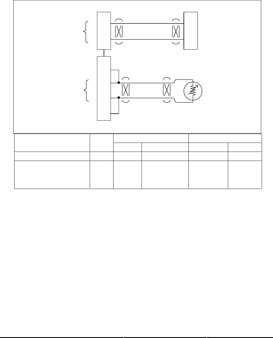
Honeywell
MK XXII EGPWS Installation Manual
CAGE CODE: 97896 SCALE: NONE SIZE: A DWG NO: 060-4314-225 REV: C SHEET 65
3.3.2.6 Shadin 2000 (Cat. 2 ID 10)
Air Data Type 10 (Shadin 2000 or equivalent) is a low speed, digital ARINC 429 signal having the
air data labels 203, 204, 206, and 212. Total Air Temperature is from a dedicated (EGPWS) 500-
ohm probe using +5 volt excitation from the MK XXII EGPWC.
39
38
A
B
J2 ARINC 429 Air Data
ARINC 429 Bus - Hi
ARINC 429 Bus - Lo
EGPWS MK XXII
A
B
ARINC 429 Low Speed
Air Data Bus
(+)
(-)
Temp. Input
Chassis Ground
+5V Excitation
500 ohm
Temperature
Probe
25
63
44
53
J1
Shadin2000.vsd
Cat 2 Bus 1 Bus 2
Vendor PN ID A B A B
962830-1,2,3 10 J2-7 J2-8
962830A-1,2,3
962830A-X-S-4
962830A-X-S-5
962830A-1-S-7(B212/412)
10 J1-40 J1-22
NOTE: The connector pin numbers given in the Table above are to the best knowledge of Honeywell EGPWS
engineering. Please contact the manufacturer’s customer service to confirm your installation.

Honeywell
MK XXII EGPWS Installation Manual
CAGE CODE: 97896 SCALE: NONE SIZE: A DWG NO: 060-4314-225 REV: C SHEET 66
3.3.2.7 Digital – ARINC 429 Dual IOC Buses (Cat. 2. ID 255)
Air Data Type 255 (IOC bus or equivalent) is a dual, high speed, digital ARINC 429 signal having
the air data labels 203, 204, 206, 210, 212, and 213.
39
38
A
B
J2 IOC Buses
IOC Bus 1
EGPWS MK VI / MK VIII
A
B
ARINC 429
High Speed
41
40
A
B
IOC Bus 2
A
B
ARINC 429
High Speed
ARINC429-IOC.vsd
Cat 2 IOC Bus 1 IOC Bus 2
Vendor Model ID A B A B
BD 100 IAPS
L-IOC (L-GP-5)
R-IOC (R-GP-5)
255 A4P1-1 A4P1-2
A4P101-1 A4P101-2
NOTE: The connector pin numbers given in the Table above are to the best knowledge of Honeywell EGPWS
engineering. Please contact the manufacturer’s customer service to confirm your installation.

Honeywell
MK XXII EGPWS Installation Manual
CAGE CODE: 97896 SCALE: NONE SIZE: A DWG NO: 060-4314-225 REV: C SHEET 67
3.3.3 Category 3 – Position Input Select
Category 3 defines the Global Position System bus type and interface. GPS Input selection is
available in the following formats: ARINC 429 low speed and ARINC 429 high speed in either
ARINC 743 or 743A format, RS-232, and Internal GPS card.
CAUTION
Not all GPS receivers calculate Horizontal Figure of Merit (HFOM) and Vertical Figure of Merit
(VFOM) correctly and thus are unacceptable sources of position. The following GPS systems are
know to have FOM computational errors:
Universal GPS-1000
3.3.3.1 Instructions
1. Using Appendix E Tables E 3, Under Step/category 3 select Position Input Source. Using
table E 3.1.3 and E 3.1.3-x select ID number for your position input source and record that
number on Table E 3 under Ident No. for step 3. This number will be used during
programming of the configuration module.
2. Appendix E Tables E 3.1.3-x, where x is the position input type number, define the electrical
interfaces required to support the position input type. Using Tables E 3.1.3-x determine the
wiring interconnects and record it on Appendix A Fig A1-3.
Note: See Category 7 to select GPS Altitude Reference (mean sea level or WGS-84)
for ARINC 429 label 076.
3.3.3.2 ARINC 743 Format
This option provides the ability to specify the GPS input data format as ARINC 743 instead of the
ARINC 743A data format. For ARINC 743A the VFOM is in feet and the HFOM is in nautical miles
(nm). For ARINC 743 both VFOM and HFOM are in meters.
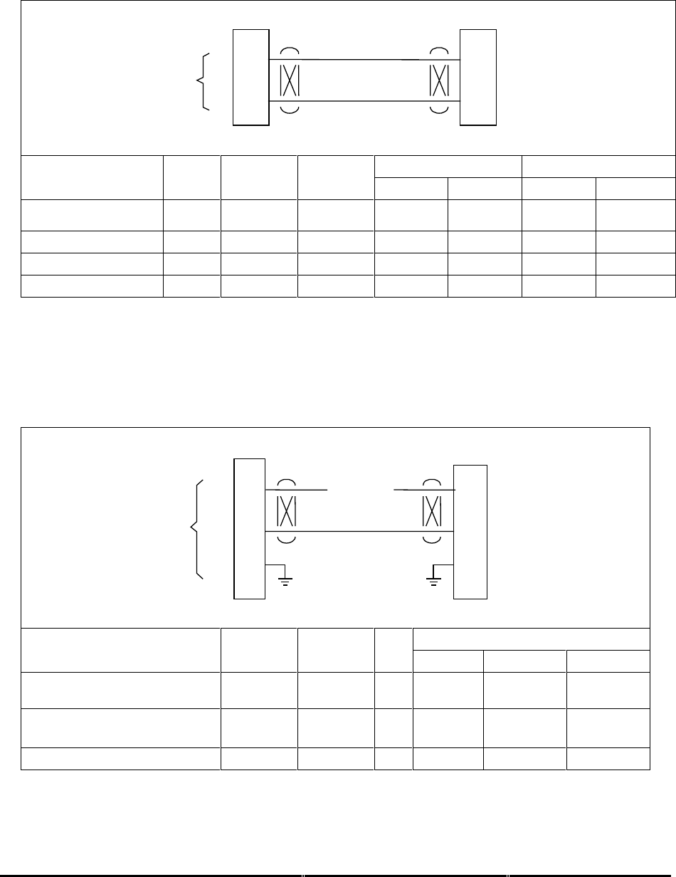
Honeywell
MK XXII EGPWS Installation Manual
CAGE CODE: 97896 SCALE: NONE SIZE: A DWG NO: 060-4314-225 REV: C SHEET 68
3.3.3.Examples
3.3.3.1 ARINC 429 BUS (Cat. 3 ID 0,1,4,5)
25
8
A
B
J2 ARINC 429 GPS
ARINC 429 Bus - Hi
ARINC 429 Bus - Lo
EGPWS MK XXII
A
B
ARINC 429
GPS Bus
ARINC429-GPS.vsd
429 GPS Alt ARINC Bus 1 Bus 2
Vendor Model Speed Ref. 743/743A A B A B
GNS-XLS (17960-0203-)
or (17960-0102-) SM06 Low MSL 743A J101-N5 * J101-N6 *
GNS-XL (18355-) SM06 Low MSL 743A J101-N5 J101-N6
HG2021GBXX H/L** MSL 743 J1-38 J1-39 J1-24 J1-25
HG2021GDXX H/L** MSL 743A J1-38 J1-39 J1-24 J1-25
NOTE: The connector pin numbers given in the Table above are to the best knowledge of Honeywell EGPWS
engineering. Please contact the manufacturer’s customer service to confirm your installation.
* GNS-XLS ARINC 429 bus also contains Range label
** Pin 21 open = high speed; Pin 21 GND = Low speed
3.3.3.2 RS-232 Transmit-Receive, 9600 baud (Cat. 3 ID 3)
45
29
J2 RS-232 GPS
RX – Receive In
TX – Transmit Out
EGPWS MK XXII
TX
RX
RS – 232
GPS Bus
28CM GND
NC
RS232-GPS.vsd
GPS Alt ARINC RS-232
Vendor Model Ref. 743/743A RX TX GND
GARMIN GNS430
Software Version 2.21 MSL N/A P4001-56 Chassis
KLN 900
066-04034-0104 or 066-04034-0204
MSL N/A P9002-13 Chassis
KLN 94 MSL N/A P941-6 Chassis
NOTE: The connector pin numbers given in the Table above are to the best knowledge of Honeywell EGPWS
engineering. Please contact the manufacturer’s customer service to confirm your installation.
The KLN 90B is not compatible with EGPWS.
The GNS 430 software mod is also applicable to the GPS 400 and GNC 420 units.
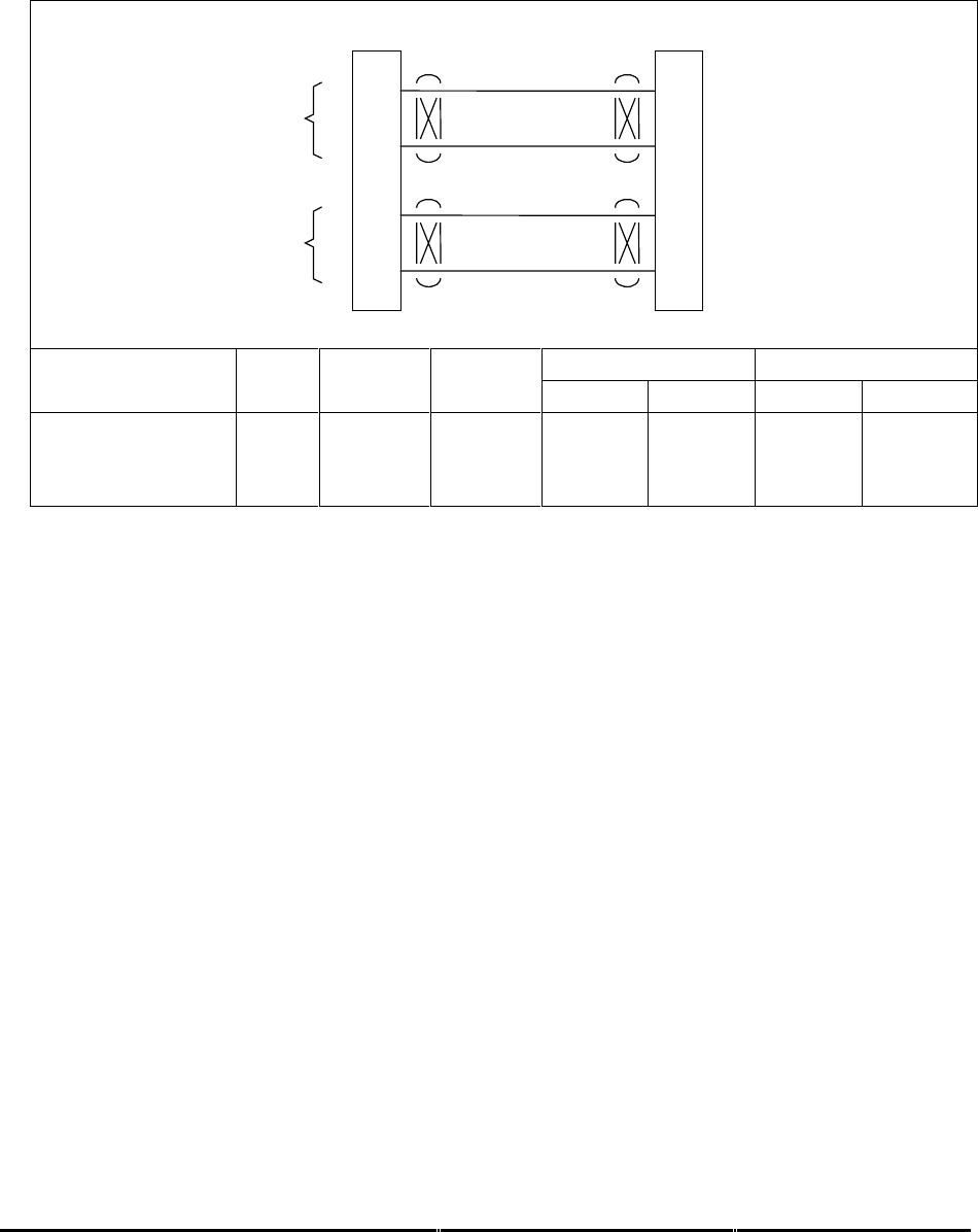
Honeywell
MK XXII EGPWS Installation Manual
CAGE CODE: 97896 SCALE: NONE SIZE: A DWG NO: 060-4314-225 REV: C SHEET 69
3.3.3.3 Dual ARINC 429 BUS (Cat. 3 ID 255)
NOTE: If GPS #2 is not installed in the aircraft, then GPS bus #1 must be connected in parallel to
both EGPWS GPS input ports.
25
8
A
B
J2 ARINC 429 GPS
ARINC 429 Bus 1
Lo
EGPWS MK XXII
A
B
ARINC 429
GPS Bus
23
6
A
B
A
B
ARINC 429
GPS Bus
Hi
ARINC 429 Bus 2
Lo
Hi
ARINC429-DualGPS.vsd
429 GPS Alt ARINC Bus 1 Bus 2
Aircraft Model Speed Ref. 743/743A A B A B
BD 100
GPS-1 (L-GPS-2)
GPS-2 (R-GPS-2)
High
High
MSL
MSL
743A
743A
A25BP1-6A A25BP1-6B
A24BP1-6A A24BP1-6B
NOTE: The connector pin numbers given in the Table above are to the best knowledge of Honeywell EGPWS
engineering. Please contact the manufacturer’s customer service to confirm your installation.

Honeywell
MK XXII EGPWS Installation Manual
CAGE CODE: 97896 SCALE: NONE SIZE: A DWG NO: 060-4314-225 REV: C SHEET 70
3.3.4 Category 4 – Altitude Callouts
Category 4 defines the Altitude Callout menu choices and Smart ‘500’ Callout selection along with
Autorotation callout enablement.
Appendix E Table E 3.1.4
defines the Altitude Callout Menu options and identifies the first MK
XXII EGPWS version in which the option was available (see the Effectivity entry).
The Altitude callout menus have selected combinations of “Minimums-Minimums”, Smart “500”,
“200”, “100”, “50”, “40”, “30”, “20”, and “10”. Autorotation mode, and no altitude callouts may also
be selected. Recommended selections are ID 133, 135 or 136.
NOTE: For applications that use Category 1 (Aircraft Type) ID 146, 147, 148 or 149, where
autorotation will not be detected, it is strongly recommended that a callout menu be selected that
provides, as a minimum, 200 and 100 feet such as ID 132 or 136.
The Altitude Callout menu provides altitude annunciation for descent below predefined altitudes
(example: “One Hundred” is annunciated when descending through 100 feet radio altitude).
A Smart “500” foot callout is available that will issue a “500” callout when the aircraft is 500’ AGL.
This callout is active only during non-precision approaches or when the Glideslope or Localizer
deviation is greater than 2 dots.
“Minimums-Minimums” callout can be selected or deselected from these combinations by
connecting or not connecting the Decision Height (DH) discrete (J1-33) of Category 8.
3.3.4.1 Instructions
1. Using
Appendix E Table E 3.1.4
, select the preferred Altitude Callout Menu Type (ID)
that matches the feature preferences and version (part number) being installed. Using
table E 3.1.4 select ID number for your Altitude callouts and record that number on Table
E 3 under Ident No. for step 4. This number will be used during programming of the
configuration module.
2. If the “Minimums-Minimums” callout will be used, use the electrical interfaces (pin-outs)
for Radio Altitude Input Select Type (Category 8) shown in Appendix E
Table E 3.1.8-x
to
generate the installation wiring diagrams.

Honeywell
MK XXII EGPWS Installation Manual
CAGE CODE: 97896 SCALE: NONE SIZE: A DWG NO: 060-4314-225 REV: C SHEET 71
3.3.5 Category 5 – Audio Menu Select
Category 5 defines one Audio Menu options for Helicopters (ID 128).
3.3.5.1 Instructions
1. Using Appendix E Tables E 3, Under Step/category 5 select Audio Menu. Using table E 3.1.5,
select ID number for your audio menu and record that number on Table E 3 under Ident No.
This number will be used for programming the configuration module.
2. Audio Menu has no bearing on Aircraft wiring interface

Honeywell
MK XXII EGPWS Installation Manual
CAGE CODE: 97896 SCALE: NONE SIZE: A DWG NO: 060-4314-225 REV: C SHEET 72
3.3.6 Category 6 – Terrain Display Select
Category 6 defines the Terrain Display options available.
Appendix E
Table E 3.1.6
defines the Terrain Display Select options (
Display Configuration
Group Tables, Display Input Control Group Tables
and
Output 429 Bus Group Tables)
and
identifies the first MK XXII EGPWS version in which the option was available (see the Effectivity
entry).
Note: TA&D mode
enabling/disabling
is controlled by Category 6. Chose ID 2 for aircraft without
TA&D.
3.3.6.1 Instructions
1.
Using Appendix E
Tables E3.1.6 and E 3.1.6-x
select the Terrain Display Select Type (ID)
that matches the aircraft configuration, feature preferences and version (part number) being
installed. Record the ID number for the Terrain Display Select Type from Appendix E
Table E
3
under the Ident No. heading for Step (Category) 6
.
2. Using the I D number
Table E 3.1.6
as “x”, go to the Table E 3.1.6-x
.
The electrical interfaces
(pin-outs) for the Display are shown in the
Display Configuration Group, Display Input
Control Group, and Output 429 Bus Group, Table
E 3.1.6-x are used to generate the
installation wiring diagrams. Determine the wiring interconnects and record it on Appendix A
Fig A1-1.
Figure 3.8-1 is an example of single tube Wx/Terrain display wiring connections.
3.3.6.2 TAD Selection
The Terrain Awareness & Display feature consists of a Terrain Awareness Alerting feature and a
Terrain Awareness Display feature. The Terrain Awareness Alerting feature continuously
computes terrain clearance envelopes ahead of the aircraft and issues alerts if the boundaries of
these envelopes conflict with terrain elevation data in the terrain database. The Terrain
Awareness Display feature displays the terrain data relative to aircraft altitude.
A “False” entry in Appendix E
Table E 3.1.6
for “TAD Disable” indicates that TA&D is ENABLED
(the “Disable” is disabled).

Honeywell
MK XXII EGPWS Installation Manual
CAGE CODE: 97896 SCALE: NONE SIZE: A DWG NO: 060-4314-225 REV: C SHEET 73
3.3.6.3 Terrain Display Configuration Group
This option provides the ability to specify the type of Terrain Display compatible with the aircraft
configuration. A definition of each of the entries in the Display Configuration Group tables is
provided in the table below.
Function Value Reference section
Display Type
Display manufacturer, model, etc.
Sweep Type
The type of sweep used for terrain data (fan, standard, etc.)
Auto Pop Up Category 7, Options Select Group #1
TA&D Alternate Pop Up: False TA&D Alternate Pop Up: True
The TA&D Alternate Pop Up is set to
False or True in Category 7. If False,
Pop Up behavior for the terrain
display is described here.
The TA&D Alternate Pop Up is set to
False or True in Category 7. If True,
Pop Up behavior for the terrain
display is described here.
Peaks Mode Category 7, Options Select Group #1
See Note 1 Peaks Enable: False Peaks Enable: True
Peaks Enable is set to False or True
in Category 7. The effect of setting it
to False is described here.
Peaks Enable is set to False or True
in Category 7. The effect of setting it
to True is described here.
Manual select
Describes if/when terrain display(s) can be manually selected
Manual deselect
Describes if/when terrain display(s) can be manually deselected
Auto Range
Defines if the display data is automatically scaled and, if so, the scale used
(such as 10 nautical miles)
Moving Marker
Indicates whether or not a moving marker is provided
Overlay Page
Describes where “TERR” and Peaks Elevations overlays will be located on the
display screen.
Display Priority
Indicates the priority for displaying terrain data. For example:
Standard (PWS Warn, Terrain Warn, PWS Caution, Terrain Caution)
Searchlights
Display bus type
Defines the display bus type ‘KC Picture Bus’ (ASPB), ‘Honeywell Picture Bus’
or ‘ARINC 453’.
CHANNEL
TX453-1 CONNECT TO:
A = J1-58
B = J1-59
Indicates the correct connection for these pins
CHANNEL
TX453-2 CONNECT TO:
A = J1-56
B = J1-57
Indicates the correct connection for these pins
Notes: 1 Peaks Mode “(Not Available)” or “(Elevations via overlay)” shown here. Peaks mode “Not Available” means
that this display type cannot display Peaks Mode.
Table 0-1 Definition of Display Configuration Group Tables (Appendix E Section 5.3.6)

Honeywell
MK XXII EGPWS Installation Manual
CAGE CODE: 97896 SCALE: NONE SIZE: A DWG NO: 060-4314-225 REV: C SHEET 74
WX System R/T
J2-37
J2-36
J1-58
J1-59
J1-51
J1-32
A
B
A
BARINC 453 TERRAIN BUS #1
ARINC 429 RANGE BUS
J1-54 Terrain Display Select #1 Discrete Output
Terrain Pop-Up Discrete Output
Display Select
Discrete #1 Input
DSD #1 Gnd
Gnd
Range #1
Gnd
TERR
ON
Momentary
28 VDC
DISPLAY RELAY
429 IN 453 OUT
453 #1
J1-56
J1-57
A
B
453 #2
J2-41
J2-40
A
B
Range #2
J1-31DSD #2 Gnd
Wx/TERR
Display
System
453 WX /
TERR BUS
A
B
A
B
TERRAIN
POP-UP
TERRAIN
SELECTED
429 Range
Output Bus
BRT/
DIM/
TEST
FIGURE 3.3.6-1 Single Tube Wx/Terrain Display
* Display relay specifications:
- 4PDT - Continuous Duty Cycle
- Pickup Voltage: 13.5 Vdc Max. - Dropout Voltage: 7.5 - 2.0 Vdc
- Coil Resistance: nominal 500 Ohms (~100mA @ 28 Vdc)
- Coil Rating: 26.0 Vdc (nominal) 34 Vdc (max.)
- Contact V drop: < 125mV @ rated load
- Contact current rating: 2 Amps resistive @ 28 Vdc

Honeywell
MK XXII EGPWS Installation Manual
CAGE CODE: 97896 SCALE: NONE SIZE: A DWG NO: 060-4314-225 REV: C SHEET 75
3.3.6.4 Display Input Control Group
This input bus is connected to the display (or display controller) and transmits Range settings,
Display Mode, and Display status to the MK XXII EGPWC.
3.3.6.5 Output 429 Bus Group
This output bus is commonly connected to EFIS and/or EICAS displays and Flight Recorders and
transmits MK XXII EGPWC alert, fault, and mode status to other systems.
3.3.6.6 Example
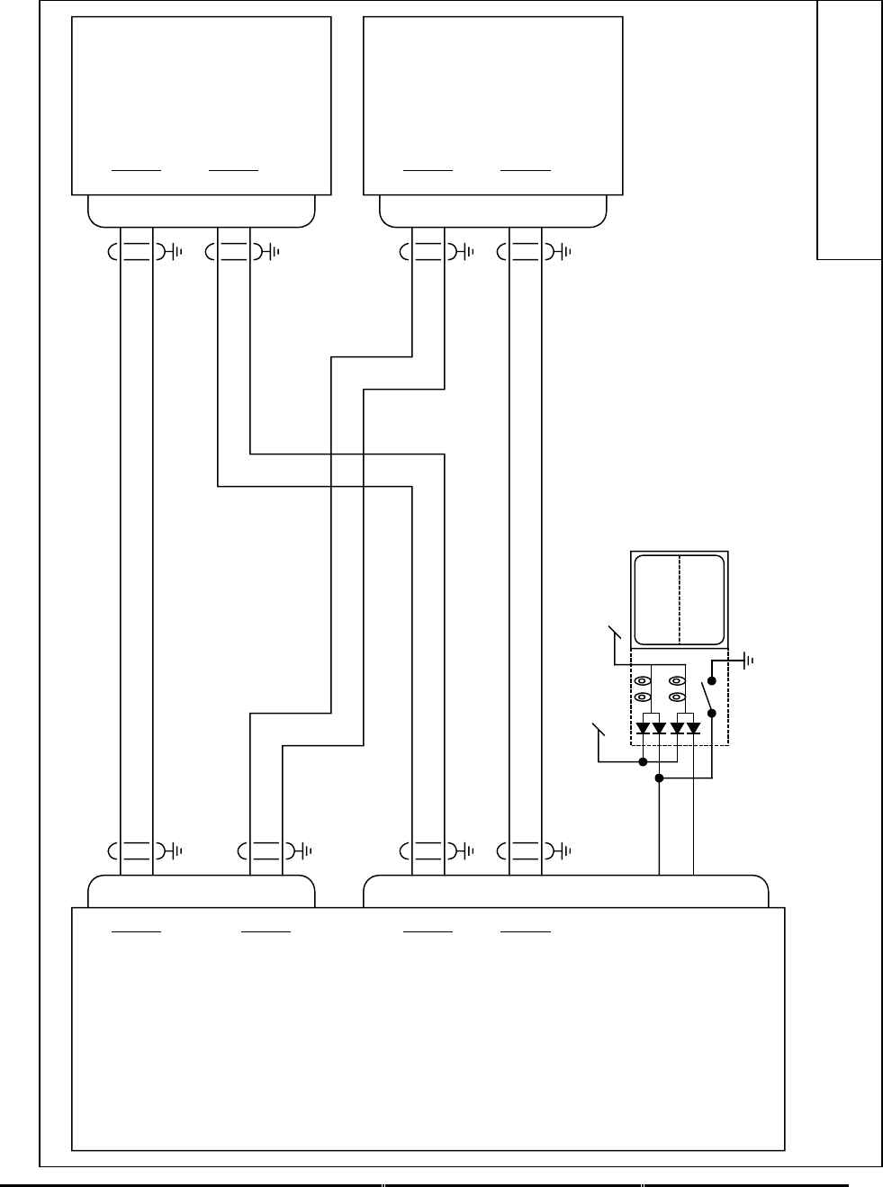
Honeywell
MK XXII EGPWS Installation Manual
CAGE CODE: 97896 SCALE: NONE SIZE: A DWG NO: 060-4314-225 REV: C SHEET 76
Honeywell Grimes
TRA-45A
J2
J1
J1
J1
28
13
1
3
28
13
1
3
37
36
41
40
58
59
56
57
TERR
INHIB
TERR
INOP
Lamp Test 28V Lamp Dimming Bus
Alternate Action
12
55
EGPWS TRA-45A
TRA-45A
A
B
ARINC 429 Range #1 In
A
B
ARINC 429 Range #2 In
A
B
KCPB Video #1 Out
A
B
KCPB Video #2 Out
Terrain Inhibit (in)
Terrain INOP (out)
MK XXII 965-1590-006 or later
A
B
A
B
A
B
A
B
Range out
KCPB Video in
Range out
KCPB Video in
80-5145-X-2
Note:
For interface and operation of the Honeywell Grimes TRA-45A see
Honeywell TRA-45A Equipment Installation Manual P/N 34-40-01
80-5145-X-2
TRA45.vsd

Honeywell
MK XXII EGPWS Installation Manual
CAGE CODE: 97896 SCALE: NONE SIZE: A DWG NO: 060-4314-225 REV: C SHEET 77
Honeywell GNS-XLS
J2
J1
J101
J101
N5
N6
Q4
Q6
N5
N6
Q4
Q6
37
36
25
8
41
40
58
59
56
57
TERR
INHIB
TERR
INOP
Lamp Test 28V Lamp Dimming Bus
Alternate Action
12
55
EGPWS GNS-XLS
GNS-XLS
A
B
ARINC 429 Range #1 In
A
B
ARINC 429 GPS In
A
B
ARINC 429 Range #2 In
A
B
KCPB Video #1 Out
A
B
KCPB Video #2 Out
Terrain Inhibit (in)
Terrain INOP (out)
MK XXII 965-1590-006 or later.
A
B
A
B
A
B
A
B
Range & GPS out
KCPB Video in
Range out
KCPB Video in
17960-0203-XXXX
17960-0203-XXXX
Note:
GNS-XLS will not perform auto pop-up during Alert.
For interface and operation of the GNS-XLS see Honeywell
GNS-XLS System Installation Manual 006-10528-0000
GNS-XLS.vsd

Honeywell
MK XXII EGPWS Installation Manual
CAGE CODE: 97896 SCALE: NONE SIZE: A DWG NO: 060-4314-225 REV: C SHEET 78
AVIDYNE FSD
J2
J1
J5
J5
17
35
4
22
17
35
4
22
37
36
41
40
58
59
56
57
TERR
INHIB
TERR
INOP
Lamp Test 28V Lamp Dimming Bus
Alternate Action
12
55
EGPWS AVIDYNE FSD
AVIDYNE FSD
A
B
ARINC 429 Range #1 In
A
B
ARINC 429 Range #2 In
A
B
KCPB Video #1 Out
A
B
KCPB Video #2 Out
Terrain Inhibit (in)
Terrain INOP (out)
MK XXII 965-1590-006 or later.
A
B
A
B
A
B
A
B
Range out
KCPB Video in
Range out
KCPB Video in
D98-00001-5X
Note:
For interface and operation of the Avidyne FSD
see Avidyne FSD Installation Manual P/N 600-0067
D98-00001-5X
Avidyne.vsd
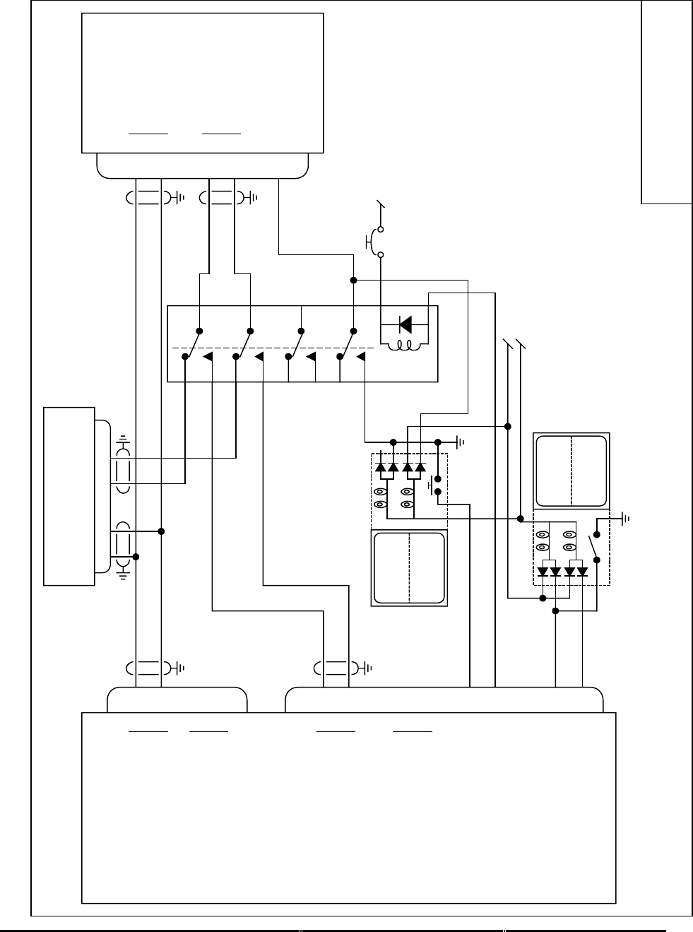
Honeywell
MK XXII EGPWS Installation Manual
CAGE CODE: 97896 SCALE: NONE SIZE: A DWG NO: 060-4314-225 REV: C SHEET 79
Integrated
Primus 440/660/880
J2
J1
F
G
M
L
37
36
41
40
58
59
56
57
TERR
INHIB
TERR
INOP
Lamp Test
28V Lamp Dimming Bus
Alternate Action
12
55
EGPWS
Honeywell
Radar Indicator
A
B
RS-422 Serial Range #1 In
A
B
Range #2 In
A
B
ARINC 453 Video #1 Out
A
B
ARINC 453 Video #2 Out
Terrain Inhibit (in)
Terrain INOP (out)
MK XXII 965-1590-006 or later.
P
N
P
N
SCI Bus
WXPD Bus
Note:
For interface and operation of the Honeywell Weather Radar Indicator
WI-440, 660, 880 see Honeywell Service Bulletin 7007700-34-15
WI-440, 660, 880
7007700-X1X
IntP880.vsd
NC
NC
Honeywell WRX R/T
WU-440, 660, 880
71 72 3 4
TERR
ON
momentary
32
54
Terrain Display Select (in)
Terrain Display Select (out)
28V EGPWS PWR Bus
XEGPWS Selected
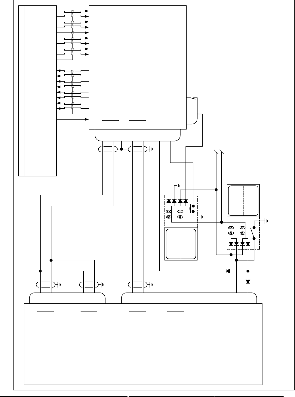
Honeywell
MK XXII EGPWS Installation Manual
CAGE CODE: 97896 SCALE: NONE SIZE: A DWG NO: 060-4314-225 REV: C SHEET 80
AVTECH DSU
Primus WXR UDI
J2
J1
J1
8
9
47
48
37
36
41
40
58
59
56
57
TERR
INHIB
TERR
INOP
Lamp Test
28V Lamp Dimming Bus
Alternate Action
12
55
EGPWS
AVTECH DSU
A
B
ARINC 429 Range #1 In
A
B
ARINC 429 Range #2 In
A
B
KCPB Video #1 Out
A
B
KCPB Video #2 Out
Terrain Inhibit (in)
Terrain INOP (out)
MK XXII 965-1590-006 or later.
A
B
A
B
Range out
KCPB Video in
Note:
For interface and operation of the Avtech 6001 DSU see Avtech
DSU Installation and Operation Procedure P/N 6001-1680
P/N 6001-1
PrimusUDI.vsd
PRIMUS SERIES
90, 100, 200, 300,
300SL, 400, 500, AVQ30
450, 650 w/o Lightning,
800
440, 650 w/ Lightning,
660, 670, 700, 880 21913 618 931612 10 4815 11
17 14
5
7
21913 618 931612 10 4815 11
17
NC
5
7
1
N JESUTDHR MKLA PCVBGF
49
open
7
2
TERR
ON
momentary 32
Display Invalid
Terrain Select
Terrain Status
J2

Honeywell
MK XXII EGPWS Installation Manual
CAGE CODE: 97896 SCALE: NONE SIZE: A DWG NO: 060-4314-225 REV: C SHEET 81
3.3.7 Category 7 – Options Select Group #1
Category 7 enables/disables the following Options: Steep Approach (not available in MkXXII),
TA&D Alternate Pop Up, Peaks Mode, Obstacle Awareness, Bank Angle, WOW Reversal, and
GPS Altitude Reference.
Appendix E
Table E 3.1.7
defines the Options Select group and identifies the first MK XXII
EGPWS version in which the option was available (see the Effectivity entry).
Note: Disabling peaks mode is not an option in the Mk XXII
3.3.7.1 Instructions
1. Review the sections below for information on Steep Approach, TA&D Pop Up, Peaks Mode,
Obstacle Awareness, Bank Angle, WOW Reversal, and GPS Altitude Reference
2.
Using Appendix E
Tables E 3.1.7
, select the preferred Category 7 (Options Select Group #1)
ID that matches the aircraft configuration, features preferences and version (part number)
being installed. Record the ID number for the Options Select Group #1 from Appendix E
Table E 3
under the Ident No. heading for Step (Category) 7
.
This number will be used for
programming the configuration module
3.3.7.2 Steep Approach (Not Available in the Mk XXII)
This feature is not applicable to MK XXII.
3.3.7.3 TA&D Alternate Pop-up
The Display Configuration Group Type (Category 6) defines default and alternate definitions for
EGPWS alert “Pop-up” behavior, when no terrain displays are active or when a combination of
terrain and non-terrain displays are active. (Some Display Configuration Group Types do not
support an Alternate Pop-up definition.)
Category 7 enables/disables Alternate Pop Up.
Pop-Up and
Alternate Pop-Up
Defines whether EGPWC visual alerts will “pop-up” on displays not
currently displaying terrain data. The entries are:
False Selected terrain-compatible displays will switch to display
surrounding terrain data. (Some displays will only Pop Up
when display is in the proper mode.)
True EGPWS alerts will not pop-up in terrain-compatible
displays.

Honeywell
MK XXII EGPWS Installation Manual
CAGE CODE: 97896 SCALE: NONE SIZE: A DWG NO: 060-4314-225 REV: C SHEET 82
For Helicopters TA&D Alternate Pop Up should always be set to False.
3.3.7.4 Peaks Mode
Peaks mode is an alternate means of displaying terrain data. The standard terrain display mode
displays terrain relative to the aircraft altitude that is within the aircraft envelope (the terrain is
above or not more than 2000 feet below the aircraft). The terrain display is typically blank during
the cruise portion of a flight. Peaks mode provides increased situational awareness by providing
the same information as the standard display mode as well as displaying terrain outside of the
aircraft envelope and the highest and lowest elevations of terrain displayed. Peaks mode
displays terrain based on the absolute terrain elevations.
Disabling peaks mode is not an option in the Mk XXII. Peaks Mode is always selected.
3.3.7.5 Obstacle Awareness
The Obstacle Awareness feature adds a database of (man-made) obstacles that are greater than
100 feet taller than the surrounding terrain to the Terrain Awareness Alerting calculations. (The
Terrain Awareness Alerting feature continuously computes terrain clearance envelopes ahead of
the aircraft and issues alerts if the boundaries of these envelopes conflict with terrain elevation
data in the terrain database.) Obstacle data is currently available for North America and parts of
the Caribbean. Not all obstacles will be contained in the database.
Category 7 enables Obstacle Awareness if TA&D is not disabled in Category 6.
Note: TAD must be enabled if Obstacle Awareness is enabled.
Honeywell strongly recommends the selection of Obstacle Awarness.
3.3.7.6 Bank Angle Callout Enabling
The Bank Angle feature provides protection for over banking during maneuvering on approach or
climb-out and while at altitude.. The Bank Angle callout can be enabled or disabled as
appropriate for this installation.

Honeywell
MK XXII EGPWS Installation Manual
CAGE CODE: 97896 SCALE: NONE SIZE: A DWG NO: 060-4314-225 REV: C SHEET 83
3.3.7.8 WOW Reversal
The WOW discrete input is defined in Category 13. The Category 7 control is used to reverse the
defined logic to match aircraft wiring, if necessary.
+28 VDC WOW discrete active position:
WOW Reversal
WOW Discrete (Category 13) Not Selected Selected
WOW Discrete = +28V WOW Not WOW
WOW Discrete = Open Not WOW WOW
Ground seeking WOW discrete active position:
WOW Reversal
WOW Discrete (Category 13) Not Selected Selected
WOW Discrete = GND WOW Not WOW
WOW Discrete = Open Not WOW WOW
3.3.7.9 GPS Altitude Reference
The GPS Altitude (label 076, Category 3) may be referenced to mean sea level (MSL) or WGS-
84. Determine which reference the GPS position uses and set the GPS Altitude Reference
accordingly in this Category. If using the internal GPS card select MSL.

Honeywell
MK XXII EGPWS Installation Manual
CAGE CODE: 97896 SCALE: NONE SIZE: A DWG NO: 060-4314-225 REV: C SHEET 84
3.3.8 Category 8 – Radio Altitude Input Select
Category 8 defines the Radio Altitude and Decision Height interface.
3.3.8.1 Instructions
1. Using Appendix E Tables E 3, under Step/category 8 select Radio Altitude Type. Using table
E 3.1.8 and E 3.1.8-x select ID number for your Radio Altimeter and record that number on
Table E 3 under Ident No. for step 8. This number will be used during programming of the
configuration module.
2. Appendix E Tables E 3.1.8-x, where x is the Radio Altimeter Type number, define the
electrical interfaces required to support each Radio Altimeter. Using Table E 3.1.8-x
determine the wiring interconnects and record it on Appendix A Fig A1-1.
3. The Decision Height discrete (J1-33, Category 8) indicates to the MK XXII EGPWC whether
the aircraft is above or below the selected Decision Height. This discrete is typically
connected to the Decision Height output on the Radio Altimeter indicator. If the ‘Minimums-
Minimums’ callout is not wanted the Decision Height discrete should be left open. Using
Table E 3.1.8-x determine the wiring interconnects for Decision Height and record it on
Appendix A Fig A1-1.
3.3.8.2 Example
3.3.8.3 Digital Radio Altitude Interface
21
4
J2 Radio Altimeter R/T
A
B
EGPWS MK XXII
A
B
ARINC 429
Radio Altitude ARINC 429
DH Discrete (Gnd) 33
Radio Altimeter Indicator
DH
J1
Vendor Model Indicator R/T
R/T Indicator SCALE DH A B
Collins RAC-870 ALI-55 ARINC 429 P1-V P1-2 P1-3
Honeywell ALA-52A ARINC 429 MP-B2 MP-B3
Honeywell KRA 405B KNI-415/416 ARINC 429 M B C
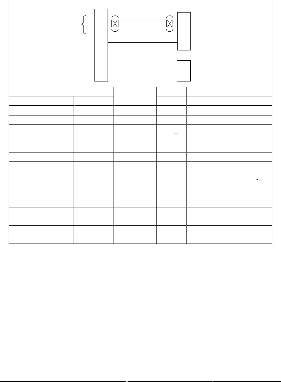
Honeywell
MK XXII EGPWS Installation Manual
CAGE CODE: 97896 SCALE: NONE SIZE: A DWG NO: 060-4314-225 REV: C SHEET 85
3.3.8.4 Analog Radio Altitude Interface
64
45
29
J1 Radio Altimeter R/T
+
-
EGPWS MK XXII
(+)
(-)
Analog Radio Altitude ARINC 552, ALT 55,
RT-200/300
Radio Altitude Valid +28V Valid
DH Discrete (Gnd) 33
Radio Altimeter Indicator
DH
Vendor Model Indicator R/T
R/T Indicator SCALE DH + - Valid
Collins ALT 55 (3) ALI-55 ALT55 P1-V P1-57 P1-59 P1-49
Collins ALT 50 -20 to 2100 ft P1-57 P1-59 P1-49
Honeywell HG7502 JG1072( ) ARINC 552 P1-e P4-47 P4-46 P4-27
Honeywell RT-300 (1) RA-315 ARINC 552 P1-F P1-X P1-N P1-Y
Honeywell RT-200 (2) RA-215 -.4mV/ft P1-F P1-N P1-W P1-Y
Honeywell KRA-405 KNI-415/416 ALT55 M P1-B P1-g S
Honeywell KRA 405B KNI-415/416 ALT55 M E X j
KRA 405B (2)
066-01153-0101
-4mV/ft G Z j
KRA 405B
066-01153-0202
ARINC 552A Z G j
Honeywell ALA-51A INA-51( ) ARINC 552 P2-e P1B-
47
P1B-46 P1B-27
Collins 860F-1 339H-1/-2 ARINC 552 P1-e P1B-
47
P1B-46 P1B-27
NOTE 1: The following RT-300 part numbers meet ARINC 552 for the Auxiliary Output: 7001840 -
902, -906, -912, -916, -917, -918, -922, -926, -928, -932, -936, -937, and -938. Some RT-
200’s are also compatible, consult your Honeywell representative.
NOTE 2: This is the precision output from the R/T. Note the + and – signals are swapped to convert
the –4mV to +4mV.
NOTE 3: The ALT-55 provides compromised EGPWS performance due to the average altitude
tracking algorithm employed.

Honeywell
MK XXII EGPWS Installation Manual
CAGE CODE: 97896 SCALE: NONE SIZE: A DWG NO: 060-4314-225 REV: C SHEET 86
3.3.9 Category 9 – Navigation Inputs Select
Category 9 selects the Glideslope and Localizer Deviation interfaces and Glideslope Validity and
ILS Tuned discretes.
Appendix E Table E 3.1.9
defines the Category 9 Navigation Inputs Select options (called
Navigation Inputs Select Types) and identifies the first MK XXII EGPWS version in which the
option was available (see the Effectivity entry).
3.3.9.1 Instructions
1. Using
Appendix E Tables E 3, E 3.1.9 and E 3.1.9-x
as described above, select the
Navigation Input Select Type that matches the aircraft configuration, feature preferences, and
version (part number) being installed.
2. Record the ID number for the Navigation Inputs Select Type from
Appendix E Table E 3
under the Ident No. heading for Step (Category) 9
.
This number will be used during
programming of the configuration module.
3. Using the Navigation Inputs Select number from
Appendix E Table E 3.1.9
as “x”, go to
Appendix E Table E 3.1.9-x. .
The electrical interfaces (pin-outs) for the Navigation Inputs
Select Type are shown in
Appendix E Table E 3.1.9-x
and are used to determine the wiring
interconnects and record it on Appendix A Fig A1-1.
Navigation Inputs Select (Glideslope & Localizer Inputs)
Glideslope Deviation is basic (required) and is available in analog and digital formats. Localizer
Deviation is an enhancement (not required) and is available in digital format only.
Glideslope Validity
Glideslope Validity (+28V Super Flag) is required for Navigation Inputs Select 0 at pin J1-11.
Glideslope Validity (Low Level) is required for Navigation Inputs Select 1 at pins J1-30 (+) and J1-10 (-).
Digital 429 Glideslope interfaces (Navigation Inputs 2 & 3) do not require Glideslope Validity input.
ILS Tuned Discrete Input #1 (+28V) and #2 (GND)
The ILS Tuned Discrete indicates that an Instrument Landing System frequency has been
selected on the Captain’s (or selected) ILS. The ILS Tuned Discretes #1 (+28V) and #2 (GND)
are optional to each other. These discretes are used with the analog Glideslope inputs. When an
ILS is tuned, the MK XXII EGPWS checks the Glideslope Validity discretes and monitors the
Glideslope inputs.

Honeywell
MK XXII EGPWS Installation Manual
CAGE CODE: 97896 SCALE: NONE SIZE: A DWG NO: 060-4314-225 REV: C SHEET 87
3.3.9.2 Example
3.3.9.3 Analog Glideslope Interface (cat. 9 ID 0,1,5)
J2 ILS Receiver
EGPWS MK XXII
GS Valid +28 11
+
-
Low Level
GS Valid
+28
GND
ILS Tuned
+
-
GS Deviation 65
46
30
10
39
20
Super Flag +28V
+
-
Delayed ILS Mode
ILS Energize
GS Flag
(Low Level)
+Up
+Dn GS Deviation
Valid ILS Tuned Deviation
Vendor Model SuperFlag
+28V
Low Level
Flag
+28V GND GS
+up/+dn
Honeywell
KNR 630
J1003-27 J1003-21
J1003-22
J1002-18 J1003-8
J1003-9
Honeywell
KNR 634
P6342-50 P6342-34
P6342-18
P6341-17 P6342-36
P6342-35
Honeywell
KGM-691
P692-S
P692-T
P692-a P692-B
P692-C
Honeywell
KNR 600A
P601-e
P601-q
P601-k P601-r
P601-s
Collins
51RV-1
TP-22
TP-21
BP-18 TP-8
TP-9
Collins
VIR-30, -31, -32
P1-17 J1-9
J1-13
P2-40 P1-5
P1-1
Honeywell
VNS 41A
P1001-60 J1001-56 J1001-90
J1001-23
Honeywell
RNA-34A
TP-27 TP-21 BP-18 TP-8
TP-9
Honeywell
KN 53
P2-13
P2-R
P2-12 P2-P
P2-14
Honeywell
RNZ 850
P1-A74 P1-B64 P1-B79
P1-B75

Honeywell
MK XXII EGPWS Installation Manual
CAGE CODE: 97896 SCALE: NONE SIZE: A DWG NO: 060-4314-225 REV: C SHEET 88
3.3.9.4 Digital Glideslope/Localizer Interface
22
5
J2
ILS Bus
A
B
EGPWS MK VI / MK VIII
A
B
ARINC 429 ILS
ARINC 429
Low Speed
Vendor Model ARINC 429 Bus 1 ARINC 429 Bus 2
ABAB
Honeywell KNR 634A P6342-41 P6342-42 P6342-44 P6342-45
Honeywell VNS 41A P1001-62 P1001-103
Honeywell RNA-34A P1024-24 P1024-28 P1024-21 P1024-25
Honeywell KN 40A(B) P401 (403) –41 P401 (403) –42 P401 (403)-44 P401 (403)-45
Collins VIR-432 P1-35 P1-36 P1-22 P1-23
3.3.9.5 Dual Glideslope Receiver
An example of dual Glideslope receivers are shown on Fig A1-1 Appendix A

Honeywell
MK XXII EGPWS Installation Manual
CAGE CODE: 97896 SCALE: NONE SIZE: A DWG NO: 060-4314-225 REV: C SHEET 89
3.3.10 Category 10 – Attitude Input Select
Category 10 defines the Roll and Pitch Attitude interface.
3.3.10.1 Attitude Signals
Roll Angle is used for Bank Angle callout, Pseudo Altitude Algorithm and Terrain Awareness
display.
Pitch Angle is used for the Tail Strike alert.
NOTE: For MD900 series aircraft where no Tail Strike alert is applicable, Pitch is not required, so
a roll only configuration may be selected.
Appendix E Table E 3.1.10
defines the Attitude Input Select type and identifies the first MK XXII
EGPWS version in which the option was available (see the Effectivity entry).
3.3.10.2 Instructions
1. Using
Appendix E Tables E 3 and Table E 3.1.10
,select the Attitude Input Select type that
matches the aircraft configuration, feature preferences, and version (part number) being
installed.
2.
Record the ID number for the Attitude Input Select from
Appendix E Table E 3.1.10
under the
Ident No. heading for Step (Category) 10 on Table E 3
.
This number will be used for
programming the configuration module
3. Using the Attitude Input Select ID number from
Appendix E Table E 3.1.10
as “x”, go to
Appendix E Table E 3.1.10-x.
The electrical interfaces (pin-outs) for the Attitude Input Select
Type are used to determine the wiring interconnects and record it on Appendix A Fig A1-3.

Honeywell
MK XXII EGPWS Installation Manual
CAGE CODE: 97896 SCALE: NONE SIZE: A DWG NO: 060-4314-225 REV: C SHEET 90
3.3.10.3 Example
3.3.10.4 Analog Roll Angle (Synchro)
5
7
6
1
21
2
J1 Vertical Gyro
X
Y
EGPWS MK XXII
Roll Angle
Z
X
Y
Roll Synchro
Z
X
Y
Pitch Synchro
Z
X
Y
Z
Pitch Angle
Vendor Model Attitude Pitch Synchro Roll Synchro
V/G Valid +28 XYZXYZ
Aeronetics RVG 801 P1-U P1-A P1-B P1-C P1-D P1-E P1-F
Collins AHC-85( ) P1-13 P2-50 P2-51 P2-52 P2-42 P2-43 P2-44
Collins 332D-11 N A B C D E F
Honeywell HG1075 J1B-C9 J1B-C10 J1B-C11 J1B-D9 J1B-D10 J1B-D11
Jet VG-208 P1-U P1-A P1-B P1-C P1-D P1-E P1-F
King KVG-350 HH X Y Z P Q R
Litef LTR-81 MP-A11 MP-B1 MP-B2 MP-B3 MP-B4 MP-B5 MP-B6
Litef LCR-92& 93 Note 2 J3-11 J3-40 J3-26 J3-16 J3-39 J3-25
Sperry VG-14A Note 3 X Y Z P Q R
Sperry VG-311 P1-45 P1-5 P1-4 P1-6 P1-7 P1-8 P1-9
Note 1: The connector pin numbers given in the table above are to the best knowledge of Honeywell
EGPWS engineering. Please contact the manufacturer’s customer service to confirm your
installation.
Note 2: See LCR installation manual.
Note 3: See airframe drawing.
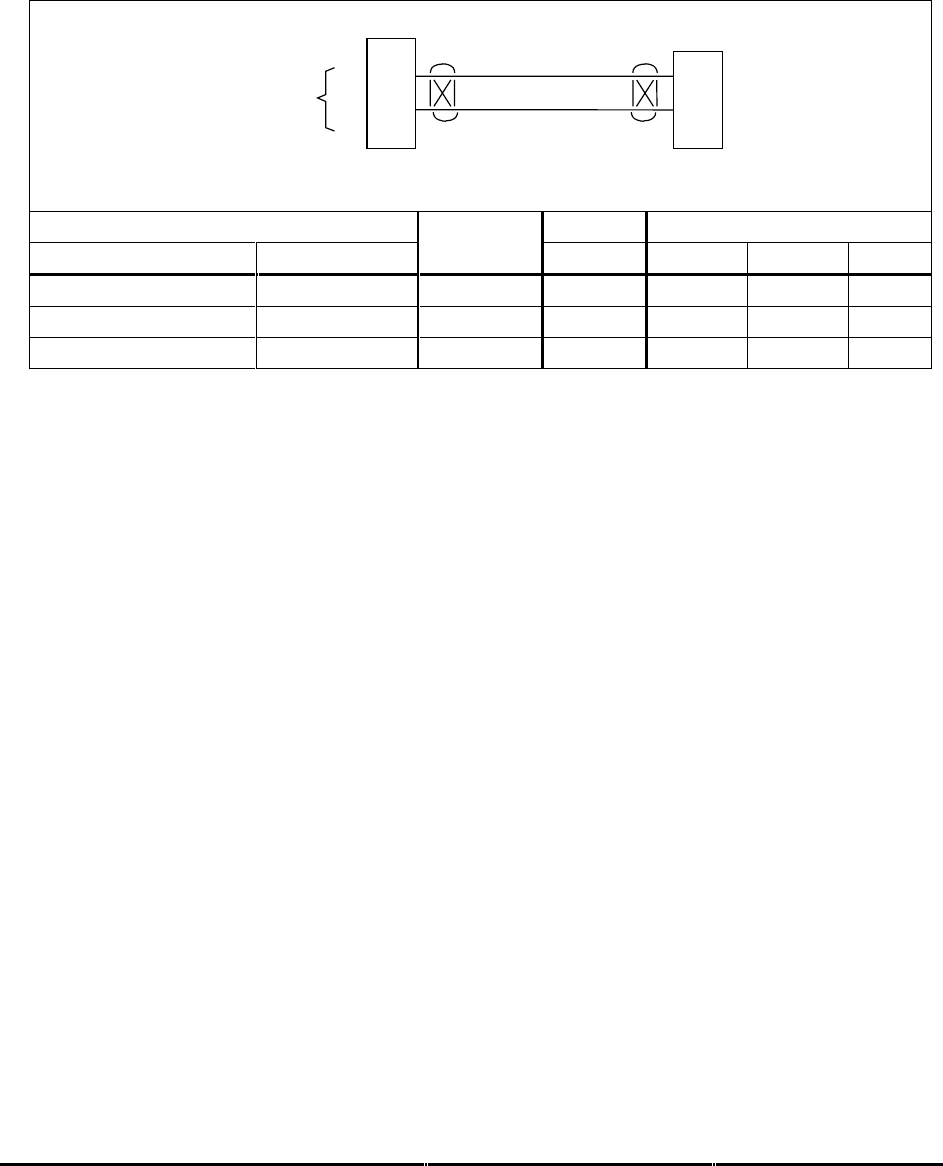
Honeywell
MK XXII EGPWS Installation Manual
CAGE CODE: 97896 SCALE: NONE SIZE: A DWG NO: 060-4314-225 REV: C SHEET 91
3.3.10.5 Digital ARINC 429 High Speed
Attitude Input ID 128 (Litef LCR 92S or equivalent) is a high speed, digital ARINC 429 signal
having roll pitch angle, and roll pitch rate labels 325, 324, 327, and 326.
23
6
J2 AHRS
A
B
EGPWS MK XXII
A
B
AHRS 429
HS Roll Pitch
Angle
Vendor Model 429 High Speed
AHRS A B
Litef LCR 92S P2-23 P2-6

Honeywell
MK XXII EGPWS Installation Manual
CAGE CODE: 97896 SCALE: NONE SIZE: A DWG NO: 060-4314-225 REV: C SHEET 92
3.3.11 Category 11 – Heading Input Select
Category 11 defines the Magnetic Heading interface.
Appendix E Table E 3.1.11
defines the Heading Input Select types and identifies the first MK XXII
EGPWS version in which the option was available (see the Effectivity entry).
3.3.11.1 Instructions
1. Using
Appendix E Tables E 3, E 3.1.11 and E 3.1.11-x
, select Heading Input type that
matches the aircraft configuration, feature preferences, and version (part number) being
installed.
2. Record the ID number for the Heading Input Select from
Appendix E Table E 3.1.11
under the Ident No. heading for Step (Category) 11 on Table E 3. This number will be
used for programming the configuration module.
3. Using the Heading Input Select number from
Appendix E Table E 3.1.11
as “x”, go to
Appendix E Table E 3.1.11-x.
The electrical interfaces (pin-outs) for the Heading Input
Select Type are shown in
Appendix E Table E 3.1.11-x
are used to determine the wiring
interconnects and record it on Appendix A Fig A1-3.
3.3.11.2 Magnetic Heading
Magnetic Heading is used for Terrain Awareness alert and display and for Envelope Modulation.
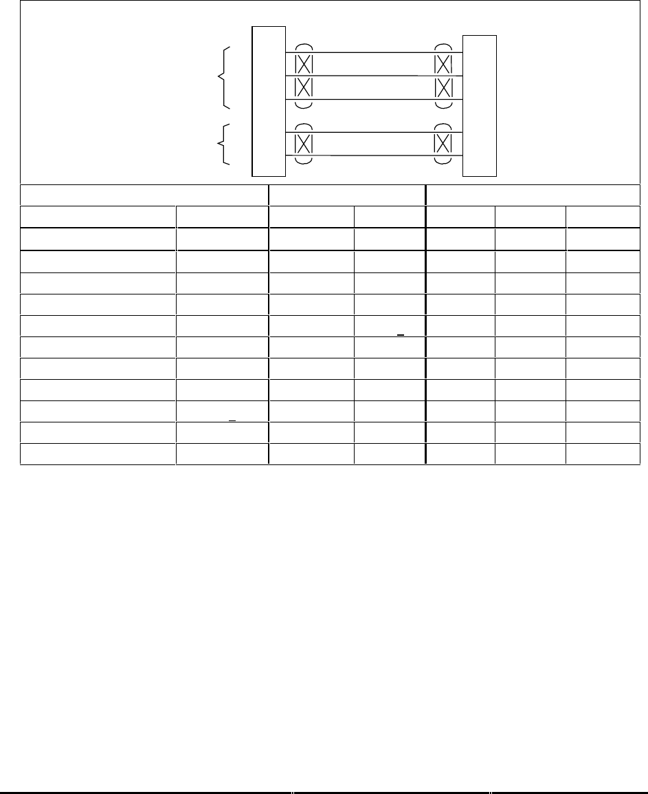
Honeywell
MK XXII EGPWS Installation Manual
CAGE CODE: 97896 SCALE: NONE SIZE: A DWG NO: 060-4314-225 REV: C SHEET 93
3.3.11.3 Example
3.3.11.3.1 Analog Heading (Synchro) (CAT. 11 ID 0)
22
23
3
J1 Directional Gyro
X
Y
EGPWS MK XXII
X
Y
Heading Synchro Heading
ZZ
H
C
4
24
26 VAC Reference H
CHeading Ref
Vendor Model Heading Reference Heading Synchro
V/G H C X Y Z
Aeronetics Model 9100 P1-28 P1-6 P1-7 P1-8 P1-9 P1-10
Collins AHC-85( ) P2-57 P2-57 P2-34 P2-35 P2-36
Collins DGS-65 P1-50 P1-6 P1-3 P1-25 P1-40 P1-24
Honeywell HG 1075 J1B-G2 J1B-F13 J1B-G13 J1B-E10 J1B-E11 J1B-E12
Honeywell KSG 105 P1-V P1-P P1-d P1-Z P1-W P1-T
Jet DN-104 P2-31 P2-9 P2-10 P2-1 P2-2 P2-3
Litef LTR-81 MP-E15 MP-B12 MP-B13 MP-B9 MP-B10 MP-B11
Litef LCR 92/LCR-93 Note 2 J3-05 J3-20 J3-13 J3-42 J3-28
Sperry C-14A P1-e P1-H P1-J P1-L P1-M P1-K
Sperry C-14D P1-DD P1-X P1-Y P1-AA P1-BB P1-Z
Sperry DG-234 P2-F P1-L P1-K P1-J
Note 1: The connector pin numbers given in the table above are to the best knowledge of Honeywell
EGPWS engineering. Please contact the manufacturer’s customer service to confirm your
installation.
Note 2: See LCR installation manual.
Note 3: See airframe drawing.

Honeywell
MK XXII EGPWS Installation Manual
CAGE CODE: 97896 SCALE: NONE SIZE: A DWG NO: 060-4314-225 REV: C SHEET 94
3.3.11.3.2 Digital ARINC 429 High Speed
Heading Input ID (Litef LCR 92S or equivalent) is a high speed, digital ARINC 429 signal having
roll angle, pitch angle, roll rate, pitch rate, and heading labels 320, 325, 324, 327, and 326.
23
6
J2 AHRS
A
B
EGPWS MK XXII
A
B
AHRS 429
HS Heading
Vendor Model 429 High Speed
AHRS A B
Litef LCR 92S

Honeywell
MK XXII EGPWS Installation Manual
CAGE CODE: 97896 SCALE: NONE SIZE: A DWG NO: 060-4314-225 REV: C SHEET 95
3.3.12 Category 12 – Windshear Input Select
Category 12 defines the Windshear interface.
Windshear is not applicable to MK XXII.
3.3.12.1 Instruction
Select ID 0 for all helicopter configurations.

Honeywell
MK XXII EGPWS Installation Manual
CAGE CODE: 97896 SCALE: NONE SIZE: A DWG NO: 060-4314-225 REV: C SHEET 96
3.3.13 Category 13 – Input / Output Discrete Type Select
Category 13 defines the input and output discretes not defined as part of any of the other
Categories.
Appendix E Table E 3.1.13
defines the Input/Output discretes options and identifies the first MK
XXII EGPWS version in which the option was available (see the Effectivity entry).
3.3.13.1 Instruction
1. Using
Appendix E Tables E 3, E 3.1.13, and E 3.1.13-x
, select the Input/Output Discrete
Type number that matches the aircraft configuration, feature preferences and version (part
number) being installed.
Note: Helicopter I/O Discrete options are Types 128 or 129. The difference is the Output Lamp
format described below in section 3.3.13.3.1.
2. Record the ID number for the Input/Output Discrete Select number from
Appendix E Table
5.3.13
under the Ident No. heading for Step (Category) 13 in
Appendix E Table E 3.
This
number will be used for programming the configuration module.
3. Using the Input/Output Discrete Type number from
Appendix E Table E 3.1.13
as “x”, the
ICD
Table E 3.1.13-x.
is used to determine the wiring interconnects, record it on Appendix A Fig
A1-1, A1-2, and A1-3.
Note: When there are two discrete pin choices for the same pin function in
Appendix E Table E
3.1.13-x
, use only the one that matches the aircraft wiring (use only the +28V and 0V or the
Ground and Open definitions).
3.3.13.2 Input/Output Discretes
Additional information for the discretes is provided below.

Honeywell
MK XXII EGPWS Installation Manual
CAGE CODE: 97896 SCALE: NONE SIZE: A DWG NO: 060-4314-225 REV: C SHEET 97
3.3.13.3 Audio Inhibit Discrete
The Audio Inhibit discrete is an optional input to maintain audio and visual prioritization. When
activated, this discrete inhibits all audio (Ground Proximity and Terrain Awareness). Activation of
the Audio Inhibit input for more than 60 seconds will result in the “All Modes Inhibit” fault.
The Audio Inhibit discrete input can be connected to any or all of the following (as applicable to
the aircraft configuration):
- a separately labeled guarded cockpit switch
For some existing GPWS installations, this discrete may have been tied to the analog Radio
Altimeter Receiver-Transmitter Self-Test output. This connection is no longer required but may
be left intact for this installation.
Discrete Position / Status Connector Pin
Audio Inhibit +28 Inhibit = +28V
Not Inhibit = Gnd/Open
J1-36
Honeywell does not recommend the use of this input for Helicopters.
3.3.13.4 Landing Gear Discrete
Landing Gear discrete is supplied by the Gear (or Gear handle) switch. The active position (+28V
or GND) indicates “Gear Down” and should be connected to a contact that will indicate Gear
Down when the Gear are lowered.
Discrete Position / Status Connector Pin
Landing Gear +28 Down = +28V
Not Down = Gnd/Open
J1-35
Landing Gear Gnd Down = Gnd
Not Down = +28V /Open
J1-16
For fixed gear or skid equipped aircraft this input is not required.
3.3.13.5 Weight ON Wheels (WOW) Discrete
The Weight on Wheels (WOW) discrete is supplied by the WOW system in the aircraft.
Connection can be made to the actual OLEO switch or relay logic later in the aircraft wiring.
For aircraft without WOW indication such as those with fixed gear or skids, this input discrete is
not required.
Discrete Position / Status Connector Pin
WOW +28 On Ground = +28V
In Air = Gnd/Open
J1-37
WOW Gnd On Ground = Gnd
In Air = +28V /Open
J1-18

Honeywell
MK XXII EGPWS Installation Manual
CAGE CODE: 97896 SCALE: NONE SIZE: A DWG NO: 060-4314-225 REV: C SHEET 98
NOTE: The logic sense of the WOW discrete can be reversed by selecting the WOW eversal
option in Category 7, see section 3.3.7.
3.3.13.6 Glideslope Cancel Discrete
The Glideslope Cancel discrete provides the crew with the capability to manually cancel Mode 5
for an approach. This is automatically reset when the aircraft descends below 30 feet or ascends
above 2000 feet or by selecting a non-ILS frequency.
This discrete is typically supplied by a momentary action cockpit Glideslope mode manual inhibit
switch, typically part of the Glideslope Lamp assembly (Below GS).
Discrete Position / Status Connector Pin
Glideslope Cancel Cancel = Gnd
Normal = Open
J1-15
3.3.13.7 Mode 6 Low Volume Discrete
The Mode 6 Low Volume discrete permanently or temporarily modifies the volume of the Mode 6
altitude and bank angle callouts. This discrete operates independent of the Category 14 options.
The Mode 6 Low Volume discrete is used to reduce the Mode 6 volume by 6dB from the volume
level select in Category 14.
This discrete is typically connected to ground to lower the volume an additional 6dB. In some
installations, it is connected to the windshield wiper control to decrease the Mode 6 Volume level
under normal conditions and automatically increase Mode 6 volume 6dB when the cabin noise
increases due to the windshield wipers being on.
Discrete Position / Status Connector Pin
Mode 6 Low Volume Low Volume = Gnd
Not Low Volume = Open
J1-13
3.3.13.8 Autopilot Engaged Discrete
For helicopters this discrete is currently not used.
Discrete Position / Status Connector Pin
Autopilot Engaged Engaged = +28V
Not Engaged = Open
J1-8

Honeywell
MK XXII EGPWS Installation Manual
CAGE CODE: 97896 SCALE: NONE SIZE: A DWG NO: 060-4314-225 REV: C SHEET 99
3.3.13.9 Terrain Awareness Inhibit
The Terrain Awareness inhibit discrete, inhibits the Terrain Awareness modes in the MK XXII
EGPWS.
This discrete is typically connected to an “alternate action switch” in the cockpit. The
recommended label for this switch is “Terrain Override” although labeling for this switch should be
consistent with existing cockpit nomenclature.
“Terrain Inhibited” will be annunciated during cockpit Self-Test if these functions are inhibited.
Discrete Position / Status Connector Pin
TA Inhibit Inhibit = Gnd
Not Inhibit = Open
J1-12
3.3.13.10 Self Test Discrete
The cockpit Self Test discrete is provided to manually initiate test of the EGPWC, EGPWS aircraft
interface, and to annunciate system configuration and status information. This discrete is typically
supplied by a momentary action cockpit ‘push to test’ switch, typically part of the GPWS WARN
Lamp assembly.
This discrete must be momentarily connected to ground to activate the Self Test. Activation of
this discrete continuously for more than 60 seconds will result in the ‘Self Test Invalid’ fault which
will cause a GPWS INOP indication.
Discrete Position / Status Connector Pin
Self Test Self Test = Gnd
Normal = Open
J1-34
3.3.13.11 Glideslope Inhibit Discrete
The Glideslope Inhibit Discrete, also known as the Backcourse Inhibit, provides an inhibit to the
Glideslope alert when on a backcourse approach.
The Glideslope Inhibit is usually connected to the Flight Director or FMS backcourse discrete
output.
Discrete Position / Status Connector Pin
Glideslope Inhibit +28 Inhibit = +28V
Not Inhibit = Gnd/Open
J1-38
Glideslope Inhibit Gnd Inhibit = Gnd
Not Inhibit = +28V /Open
J1-19

Honeywell
MK XXII EGPWS Installation Manual
CAGE CODE: 97896 SCALE: NONE SIZE: A DWG NO: 060-4314-225 REV: C SHEET 100
3.3.13.12 Timed Audio Inhibit Discrete
The Timed Audio Inhibit will cause the inhibiting of all audio messages for a period of 5 minutes
or until reset. The discrete input is connected to a momentary lighted switch. When pressed the
condition is latched in memory and will be reset after 5 minutes have elapsed or pressing the
switch again or when landing. The switch lighting, indicating the Audio is Inhibited is driven by a
discrete output described below.
Discrete Position / Status Connector Pin
Timed Audio Inhibit Momentary Toggle = Gnd
Normal = Open
J1-17
NOTE: Either the Timed Audio Inhibit or the Terrain Inhibit should be used depending on the
aircraft operations. See discussion is section 1.
3.3.13.13 Low Altitude Mode Select Discrete
The Low Altitude Mode select is a required input and is used for cruise operation below 500 feet
AGL and for operation in high density metropolitan environments such as tall buildings. When
selected, the Low Altitude Mode inhibits Excessive Terrain Closure (Mode 2) warnings, retards
the Terrain Clearance warnings (Mode 4), and reduces the Terrain look ahead distances and
width. When selected, Low Altitude Mode may be de-selected by pressing the switch again.
The Low Altitude select switch is a lighted momentary switch where the selected condition lighting
is driven by an output discrete described below.
3.3.13.14 Output Discretes
The discrete outputs are defined in
Appendix E Section 7.4
. The MK XXII EGPWS supports two
kinds of Ground/Open discrete outputs used to indicate various conditions. Monitor outputs are
used to indicate failure conditions for the EGPW system. Monitor outputs default to an active
state when there is a failure or if power is removed from the EGPWS (no connection if the
EGPWC is removed from the rack). The Discrete Out Lamp driver outputs are used to indicate
alert modes (GPWS WARN, BELOW GS, etc.) or mode control status (Terrain Display Select,
etc.) of the EGPWS.
Short-term current limit protection is provided on all drivers for output shorting conditions. Ground
going output discretes may be connected together to produce a ‘wired OR’ function for the active
low state of the outputs. If output discretes are ‘wire OR’d’ then diodes must be installed for
isolation.
3.3.13.15 Lamp Format
The Lamp Format Type (configuration) is a function of the discrete output pin functions and
defines the operation of the red and amber GPWS cockpit lamps.

Honeywell
MK XXII EGPWS Installation Manual
CAGE CODE: 97896 SCALE: NONE SIZE: A DWG NO: 060-4314-225 REV: C SHEET 101
For Lamp Format Type 1, the amber “Below G/S” lamp is driven by the GPWS Alert (Glideslope
only) discrete and the red “GPWS” lamp is driven by the remaining alerts and warnings.
For Lamp Format Type 2, the red “EGPWS” lamp is driven by the GPWS Warning (Pull Up,
Warning Terrain, and Warning Obstacle only) discrete and the amber “EGPWS” lamp is driven by
the remaining alerts and warnings.
3.3.13.16 GPWS INOP Discrete
The GPWS INOP discrete (J1-72) indicates GPWS modes are inoperative. This feature activates
a ‘GPWS INOP” lamp located in the cockpit within sight of the pilots.
3.3.13.17 TAD INOP Discrete
The TAD INOP discrete (J1-55) indicates, Terrain Awareness (TA), and Terrain Display are ‘Not
Available’. This feature activates a ‘TERRAIN INOP” lamp located in the cockpit within sight of the
pilots.
3.3.13.18 GPWS Warning Discrete
(Lamp Format Type 1 definition)
GPWS Warning discrete (J1-78) will activate during any Mode 1 through Mode 4 alert or warning,
Terrain Awareness caution/warning, and Obstacle Awareness caution/warning. This feature
activates a ‘GPWS” lamp located in the cockpit within sight of each pilot. Note that Mode 6 does
not activate any lamp outputs, only voices.
3.3.13.19 GPWS Alert Discrete
(Lamp Format Type 1 definition)
GPWS Alert discrete (J1-77) will activate during Mode 5 Glideslope cautions only. This feature
activates a ‘BELOW GS” red lamp located in the cockpit within sight of each pilot.
3.3.13.20 Glideslope Cancel Discrete
-Optional- Glideslope Cancel discrete (J1-76) will activate when the Glideslope Cancel discrete
(momentary) has been pressed any time below 2000 feet Radio Altitude if the ILS is tuned. This
feature activates a ‘G/S CAN” amber lamp located in the cockpit within sight of the pilots.
3.3.13.21 TCAS Inhibit Discrete
-Optional- TCAS Inhibit discrete (J1-69) will activate during any EGPWS voice annunciation. This
output is used to inhibit TCAS from talking during EGPWS annunciation. This feature does not
have a lamp associated with it.

Honeywell
MK XXII EGPWS Installation Manual
CAGE CODE: 97896 SCALE: NONE SIZE: A DWG NO: 060-4314-225 REV: C SHEET 102
3.3.13.22 Terrain Display Select #1 & #2 Discrete
Terrain Display Select #1 & #2 discrete (J1-54 & J1-49) will activate after the related pilot has
initiated manual selection of the Terrain Display Select (momentary) discrete #1 or #2 (J1-32 &
J1-31, Category 6). This feature activates a ‘TERR” white lamp located in the cockpit within sight
of each pilot. The lamp serves to remind the flight crew that this function is active. The select
switches (J1-32 & J1-31) and the indicator lamps (J1-54 & J1-49) are commonly combined in
switch-lamp assemblies mounted near the displays being selected.
3.3.13.23 Timed Audio Inhibit Discrete
The Timed Audio Inhibit discrete (J1-52) will activate after a Timed Audio Inhibit switch
(momentary) is pressed in the cockpit. The discrete will stay active until the Timed Audio Inhibit
latch resets after 5 minutes or the switch is pressed again or the aircraft lands. The discrete is
used to light the ON status portion of the Timed Audio Inhibit lighted switch assembly.
3.3.13.24 Low Altitude Mode Discrete
The Low Altitude Mode discrete (J1-73) will activate after a Low Alt switch (momentary) is
pressed in the cockpit. The discrete is used to light the ON status portion of the Low Altitude
lighted switch assembly. The discrete will stay active as long as the Low Altitude Mode is
selected. The Low Altitude Mode may be de-selected by pressing the Low Alt switch again.
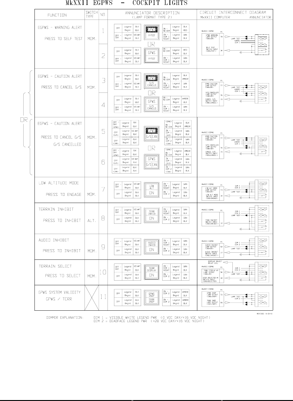
Honeywell
MK XXII EGPWS Installation Manual
CAGE CODE: 97896 SCALE: NONE SIZE: A DWG NO: 060-4314-225 REV: C SHEET 103
Table 0-1 MKXXII EGPWS – Example Cockpit Lights

Honeywell
MK XXII EGPWS Installation Manual
CAGE CODE: 97896 SCALE: NONE SIZE: A DWG NO: 060-4314-225 REV: C SHEET 104
3.3.14 Category 14 – Audio Output Level
Category 14 controls the Audio Output level for alert menu callouts (cautions and warnings).
Refer to Category 13 for information on the Mode 6 Low Volume discrete.
Appendix E Table E 3.1.14
defines the Audio Output Level options and identifies the first MK
VI/VIII EGPWS version in which the option was available (see the Effectivity entry).
3.3.14.1 Instructions
1. Using
Appendix E Tables E 3 and E 3.1.14
as described above, select the Audio Output
Level ID number that matches the feature preferences and version (part number) being
installed.
2. Record the ID number for the Audio Output Level from
Appendix E Table E 3.1.14
under the
Ident No. heading for Step (Category) 14 in
Appendix E Table E 3.
The Nominal Volume Select is equivalent to MK XXII MAX volume level. The –6dB through –24
dB are successively lower volume from Nominal. The Nominal output is 4 watts rms into an 8-
ohm load and 100 milli-watts rms into a 600-ohm load. The audio output level for Mode 6 alerts
can be reduced an additional 6 dB by activating the Mode 6 Low Volume discrete of Category 13.
High level audio
600 ohm
Audio
Panel
Low level audio
J1-70
HJ1-71
L
J1-75H J1-74L
8 ohm
FIGURE 3.16-1 Audio Interface
Note: Because most helicopters use a full muff headset, cockpit speakers are not applicable.

Honeywell
MK XXII EGPWS Installation Manual
CAGE CODE: 97896 SCALE: NONE SIZE: A DWG NO: 060-4314-225 REV: C SHEET 105
3.3.15 Category 15, Autorotation Threshold
Category 15 controls the Autorotation Threshold level used for Autorotation detection. Actual
thresholds are determined during first of type flight. The thresholds are found in Table 3.1.15-1-1
below.
Appendix E Table E 3.1.15
defines the Autorotation threshold options.
3.3.15.1 Instruction
1. Using Table 3.1.15-1-1 below and
Appendix E Tables E 3 and E 3.1.15
as described
above, select the Autorotation threshold torque ID number that was determined during
flight test.
2. Record the ID number for the Autorotation threshold torque Level from Table 3.1.15-1 or
Table 3.1.15-1 below under the Ident No. heading for Step (Category) 15 in
Appendix E
Table E 3.

Honeywell
MK XXII EGPWS Installation Manual
CAGE CODE: 97896 SCALE: NONE SIZE: A DWG NO: 060-4314-225 REV: C SHEET 106
AUTOROTATION THRESHOLD
Aircraft Type ID Aircraft Model Threshold % Threshold ID
128 S-76 B/C+ 7.5 15
129 S-76C/A++ 7.5 15
130 S-76A/A+ 7.5 15
131 Bell 212 6 12
131 Bell 412 6 12
132 EC-155B 7.5 15
133 MD900 7.5 15
133 MD902 7.5 15
134
135
136 AS 365N3 7.5 15
137
138
139
140
141 Bell 412, DC Torque 6 12
142
143
144
145
Table 3.1.15-1: Autorotation Thereshold

Honeywell
MK XXII EGPWS Installation Manual
CAGE CODE:
97896 SCALE: NONE SIZE: A DWG NO: 060-4314-225 REV: C SHEET
107
SECTION IV
CONFIGURATION MODULE PROGRAMMING
AND
REGIONAL TERRAIN DATABASE LOADING

Honeywell
MK XXII EGPWS Installation Manual
CAGE CODE:
97896 SCALE: NONE SIZE: A DWG NO: 060-4314-225 REV: C SHEET
108
SECTION IV – CONFIGURATION MODULE PROGRAMMING AND
REGIONAL TERRAIN DATABASE LOADING
SECTION IV – CONFIGURATION MODULE PROGRAMMING AND REGIONAL TERRAIN
DATABASE LOADING .................................................................................................................109
4.1 INTRODUCTION.................................................................................................................................. 109
4.2 HARNESS CHECKOUT AND POWER CHECK ........................................................................................ 109
4.3 UNIT INSTALLATION.......................................................................................................................... 109
4.4 EGPWC INITIALIZATION AND CONFIGURATION ............................................................................... 109
4.4.1 RS-232 Communication with the MK XXII EGPWS.................................................................. 109
4.4.2 EGPWC Front Panel Test Connector........................................................................................ 110
4.4.3 WinVIEWS ................................................................................................................................. 110
4.4.4 WinVIEWS Operation................................................................................................................ 111
4.5 CONFIGURATION MODULE PROGRAMMING ....................................................................................... 111
4.5.1 CUW and CMR Commands....................................................................................................... 113
4.5.2 Configuration Module Reprogramming..................................................................................... 114
4.6 REGIONAL TERRAIN DATABASE LOADING ........................................................................................ 115
4.6.1 Effectivity................................................................................................................................... 115
4.6.2 Description ................................................................................................................................ 115
4.6.3 Approval .................................................................................................................................... 115
4.6.4 Material – Cost and Availability................................................................................................ 116
4.6.5 Accomplishment Instructions..................................................................................................... 117
4.6.6 Verification of the Terrain Database Version............................................................................ 118

Honeywell
MK XXII EGPWS Installation Manual
CAGE CODE:
97896 SCALE: NONE SIZE: A DWG NO: 060-4314-225 REV: C SHEET
109
SECTION IV – CONFIGURATION MODULE PROGRAMMING AND
REGIONAL TERRAIN DATABASE LOADING
4.1 Introduction
The following procedures outline the steps necessary to accomplish a complete configuration of
the MK XXII EGPWS. This section must be accomplished in the order presented to minimize
errors in configuring and operating the system(s). If problems are encountered in performing
these procedures, the installer may refer to aircraft wiring diagrams for harness troubleshooting or
the aircraft maintenance manual to isolate faulty equipment. All discrepancies should be resolved
before proceeding. This section will also load the Regional Terrain Database in MK XXII EGPWS
that will be operating outside of the North American region.
4.2 Harness Checkout and Power Check
Prior to installing any equipment, it is important to verify that all interfaces have been made and
that power and ground at each unit connector is correct, using the wiring diagrams for the
installation. Any discrepancies in the wiring must be resolved before proceeding.
The wire harness should also be checked for proper clearance near any control cables and other
potential areas that may cause binding and/or chafing.
4.3 Unit Installation
After the harness check has been completed and any discrepancies have been resolved, the
units should be installed into their respective racks, and all connections to the wiring harness
should be made (connectors attached). Verify that all of the units are secure in their respective
racks, panels, etc., and all harness connections are secure. Refer to aircraft installation drawings
for the unit locations and mounting information.
4.4 EGPWC Initialization and Configuration
The first time a MK XXII EGPWS is turned on in a new installation, the Configuration Module in
the EGPWS harness must be programmed to the specific interface configuration for the aircraft.
This programming is done via RS-232 cable connection between the EGPWC and a PC running
the Honeywell WinViews software. This interface capability is provided to facilitate diagnostic and
configuration functions with the EGPWC during post installation checkout. Refer to Appendix C
for instructions related to using the WinViews software.
4.4.1 RS-232 Communication with the MK XXII EGPWS
The MK XXII EGPWS computer contains software that allows monitoring of its internal

Honeywell
MK XXII EGPWS Installation Manual
CAGE CODE:
97896 SCALE: NONE SIZE: A DWG NO: 060-4314-225 REV: C SHEET
110
parameters, for testing purposes, without altering its operation. The monitoring of these
parameter values enables the operator to quickly determine if the EGPWC is using the correct
signal and scaling. The communication link utilizes the RS-232 communication protocol
configured as follows:
19200 Baud, No Parity, 8 Bits, and 1 Stop Bit
4.4.2 EGPWC Front Panel Test Connector
The RS-232 interface with the EGPWC is accomplished via a test connector provided on the
EGPWC front panel (J3). This provides access for a PC test monitor and portable data loading
capabilities. The mating connector for the EGPWC test plug (P3) is a male, 15 pin, double density
D-subminiature type (or equivalent).
The connection between the PC serial port connector (with standard DB9) and the EGPWC RS-
232 interface is defined as follows:
RS-232 Receive RS-232 Transmit RS-232 Ground
EGPWS Front Connector (J3) Pin 3 Pin 4 Pin 1
Standard (PC)* DB9 Connector Pin 3 Pin 2 Pin 5
*NOTE: Some PC Comm Ports have Pins 2 & 3 reversed from what is described above.
Connector, AMP 205161-1
Socket Contact, AMP 205090-1, QTY 3
PCOM
Connector, AMP 748364-1
Pin Contact, 204370-2, QTY 4
Backshell, AMP 745854-5
Jackscrew, AMP 747784-3
Grommet Set, AMP 747746-1
P3
4.4.3 WinVIEWS
(Windows Virtual Interface to the Enhanced Warning System)
WinVIEWS is a software tool developed by Honeywell to communicate with the EGPWS.
WinVIEWS provides a detailed status of the software configuration and input signals, which
enables quick identification of system configuration, and is utilized for programming the system
Configuration Module.
3
2
5
3
4
1
12
Length as required (5’ to 50’)

Honeywell
MK XXII EGPWS Installation Manual
CAGE CODE:
97896 SCALE: NONE SIZE: A DWG NO: 060-4314-225 REV: C SHEET
111
To obtain a copy of the WinVIEWS software, contact:
Honeywell
Aerospace Electronic Systems
PO Box 97001
Redmond, WA 98073-9701 USA
Attn: Order Administration M/S 33
Phone: (425) 885-8719
FAX: (425) 885-8988
or Honeywell
Aerospace Electronic Systems
PO Box 97001
Redmond, WA 98073-9701 USA
Attn: EGPWS Applications Engineering
Phone: (425) 885-3711
FAX: (425) 885-2994
GPWS Hotline: (800) 813-2099
WinVIEWS can be sent via e-mail when an e-mail address is provided or downloaded from the
web (www.egpws.com)
4.4.4 WinVIEWS Operation
1. Connect the PC to the EGPWC using the RS-232 cable as described in section 4.4.2.
2. On the PC, start Windows 3.1, or higher.
3. Start the WinVIEWS.EXE program.
4. Use F6 to select the Terminal Mode. Various commands are available in this mode. Type
“HELP” or “?” for a list of the commands available.
4.5 Configuration Module Programming
The EGPWC reads the aircraft configuration from the Configuration Module, which is installed in
the EGPWC connector. The Configuration Module must have the aircraft specific configuration ID
string written to it before the EGPWS is operational. The ID string is defined by 15 separate
categories listed in Appendix E Table 5.2, Category ID Selection Procedure.
For programming the Configuration Module, the following procedure is used:
1. Verify EGPWC interface to P2 connector (including Configuration Module) and RS-232
interface to PC.
2. Power EGPWC and PC and start WinVIEWS.
3. With WinVIEWS active in the Terminal Mode, configuration sub-mode commands are
available for programming purpose. Type “CFG” at the Terminal Mode prompt (>). At this
point, the CFG> prompt is displayed and the program and EGPWC are ready for entering the
program command and data string. Type “HELP” or “?” to display a list of the Terminal Mode
commands and their description. “CUW” is the preface command for entering the ID string.
4. Using the Category ID’s as chosen from the Appendix E (refer to completed Table 5.2),
create a command string with the following structure:
CUW 0/15 # # # # # # # # # # # # # # #/

Honeywell
MK XXII EGPWS Installation Manual
CAGE CODE:
97896 SCALE: NONE SIZE: A DWG NO: 060-4314-225 REV: C SHEET
112
-CUW<space>0 is the command and version number. CUW writes the category ID’s defined
by version 0 definition (0 is the only version currently available) to the Configuration Module
via the EGPWC without a CRC (checksum) value attached (this is generated by the EGPWC
when the data is transmitted).
-/15 indicates the beginning of the data string (/) with 15 being the number of categories to
follow.
-<space><Cat 1 ID#><space><Cat 2 ID #>…<Cat 14 ID#>/ each Cat ID# is the chosen ID
for the category from the Appendix E Table 5.2. The ending slash (/) indicates the end of the
data string.
Note: If 15 ID’s do not follow “/15”, the error message “
Invalid Parameter. Not enough
ID’s. Configuration update failed, please try again.
” will be given. The value
entered for each category must be an available ID for the associated category or a
similar error message will be given. If the number of categories provided is less than
15 (e.g., “/8 # … #/” with eight ID’s defined), then the remaining categories (9 through
15) will be set to 0.
After completing the data string as defined above, pressing ENTER the cursor will flash waiting
for an answer “Y” or “N”. Pressing the Y (or y) key confirms the data and sends the data to the
EGPWC to write to the Configuration Module.
Note: Using Kermit or a similar terminal emulator pressing ENTER results in a question:
“
Confirm this data reflects configuration to be programmed (Y/N)
”. Pressing the Y
(or y) key confirms the data and sends the data to the EGPWC to write to the
Configuration Module.
Following the writing to the Configuration Module the EGPWC is automatically rebooted in order
for the new configuration to take affect.
Note: If when the ENTER key is pressed the question response is not given (cursor just moves
to the next line), pressing any character key should provide the proper response.
Pressing the N key results in the message “
Command aborted – No configuration
module change has been made
”. If necessary, revise the data to correct or change as
necessary and continue as above. The backspace key can be used to make corrections.
5. Following the successful writing to the Configuration Module (no error messages) and
EGPWC reboot, pressing Control Z (Ctrl-Z) restarts the WinVIEWS Terminal Mode
communication.
6. There are a couple ways to now confirm the Configuration Module programming with the
following being the preferred. As above, type “CFG” to restart the Configuration sub-mode. At
the CFG> prompt, type “CMR<Enter>”. Each category and its associated ID is read from the

Honeywell
MK XXII EGPWS Installation Manual
CAGE CODE:
97896 SCALE: NONE SIZE: A DWG NO: 060-4314-225 REV: C SHEET
113
Configuration Module and listed on the PC screen. Alternately, when not in the Configuration
sub-mode, the command “PS<Enter>” (Present Status) will display EGPWC and
configuration data.
7. Configuration Module programming is complete. If the “CFG >” prompt is still present type
“Exit<Enter>” to exit the Configuration sub-mode.
4.5.1 CUW and CMR Commands
An example CUW command/data string, its definition, and the corresponding CWR list is provided
below.
CUW command/data string:
CFG > CUW 0/15 128 3 2 134 128 3 29 1 0 2 0 0 129 0 15/
Above configuration defined:
Category 1 Aircraft/Mode Type: 128
Category 2 Air Data Type: 3
Category 3 Position Type: 2
Category 4 Altitude Callouts Menu: 134 (All Callouts)
Category 5 Audio Menu: 128 (Basic menu)
Category 6 Display Type: 3
Category 7 Options Select Group #1: 29
(TA&D Alternate pop-up False)
(Peaks Mode True)
(Obstacle Awareness True)
(Bank Angle True)
(Weight on Wheels Reversal)
(GPS Altitude Ref. MSL)
Category 8 Radio Altitude Type: 1
Category 9 Navigation Type: 0
Category 10 Attitude Type: 2
Category 11 Heading Type: 0
Category 12 Windshear select Type: 0
Category 13 Discrete I/O Type: 129
Category 14 Audio Output Level Type: 0
Category 15 Autorotation Threshold 15
CWR list: (based on the above configuration)
CFG > CMR<Enter>
CONFIGURATION MODULE:
Format Version: 0
Category 1 ID: 128
Category 2 ID: 3
Category 3 ID: 2
Category 4 ID: 134
Category 5 ID: 128
Category 6 ID: 3

Honeywell
MK XXII EGPWS Installation Manual
CAGE CODE:
97896 SCALE: NONE SIZE: A DWG NO: 060-4314-225 REV: C SHEET
114
Category 7 ID: 29
Category 8 ID: 1
Category 9 ID: 0
Category 10 ID: 2
Category 11 ID: 0
Category 12 ID: 0
Category 13 ID: 129
Category 14 ID: 0
Category 15 ID: 15
CRC: 527518533
4.5.2 Configuration Module Reprogramming
Reprogramming the EGPWS Configuration Module is accomplished similar to the programming
process above. Prior to reprogramming, the desired new configuration should be determined
based on the MK XXII Installation Manual (Appendix E), document number 060-4314-225.
For reprogramming the Configuration Module, the following procedure is used:
1. Verify EGPWC interface to P2 connector (including Configuration Module) and RS-232
interface to PC.
2. Power EGPWC and PC and start WinVIEWS.
3. With WinVIEWS active in the Terminal Mode, start the Configuration sub-mode by typing
“CFG” at the prompt (>). At this point, either all the ID’s can be rewritten using the CUW
command as before, or individual categories can be changed as follows:
4. At the
CFG >
prompt use the CAT command with the following structure:
-CAT<space><category #><space><ID#><space><T or F><Enter>
- <category #> is the Appendix E Category to change (example 7)
- <ID #> is the new ID to change to (example 92)
- <T or F> is True or False for rebooting the EGPWC. Use “T” if only one category is to be
changed and the EGPWC will reboot following <Enter>. Use “F” if another individual ID is to
be changed by another CAT operation.
Example: CFG > CAT 7 92 T<Enter>
5. After inputting the desired change information, pressing <Enter> will transmit the data to the
EGPWC to write to the Configuration Module. If a reboot is commanded (T), then the
EGPWC will reboot at the completion of the write process. If a reboot is not commanded (F),
then a message “Writing to configuration module … Category 7 ID updated
successfully.” is given and the CFG > prompt is again displayed. At this point the
Configuration Module has been changed, but the change will not be effective until the
EGPWC is rebooted. Additional changes can be made with the final change set to command
the EGPWC to reboot (or cycle EGPWC power to reboot).
6. Verification of the changes made is the same as before. As above, type “CFG” to restart the
Configuration sub-mode. At the CFG > prompt, type “CMR<Enter>”. Each category and its

Honeywell
MK XXII EGPWS Installation Manual
CAGE CODE:
97896 SCALE: NONE SIZE: A DWG NO: 060-4314-225 REV: C SHEET
115
associated ID is read from the Configuration Module and listed on the PC display. Alternately,
when not in the Configuration sub-mode, the command “PS<Enter>” (Present Status) will
display the EGPWC and Configuration Module data.
7. Configuration Module reprogramming is complete.
4.6 Regional Terrain Database Loading
4.6.1 Effectivity
The MK XXII EGPWS (965-1590-0XX) are shipped from the factory with the North American
Regional Terrain Database installed. Aircraft operating outside of the North American region will
have to load one of the other eight Regional Terrain Databases before beginning the ground test.
Use (operation) of a MK XXII EGPWS outside of the loaded Regional Terrain Database will result
in the Terrain Awareness function being unavailable.
4.6.2 Description
This modification consists of loading the PCMCIA card into the EGPWS either In The Aircraft or
On The Bench. An optional verification procedure is provided.
4.6.3 Approval
This procedure contains no modification information that revises the approved configuration and
therefore does not require FAA or other regulatory agency approval.

Honeywell
MK XXII EGPWS Installation Manual
CAGE CODE:
97896 SCALE: NONE SIZE: A DWG NO: 060-4314-225 REV: C SHEET
116
4.6.4 Material – Cost and Availability
The Regional Terrain Database PCMCIA card is available at no charge to Operators that will be
operating outside of the North America region. Order part from:
Honeywell
Airlines & Avionics Products
Order Administration M/S 33
PO Box 97001
Redmond, WA 98073-9701
Phone: 425-885-8719
Fax: 425-885-8988
Honeywell Aerospace
Toulouse Office
Centreda, Avenue Didier Daurat
31700 Blagnac, France
Phone: (33) 5-6171-0079
Fax: (33) 5-6130-0497
Vendor Name Vendor P/N Description QTY UM Honeywell P/N
Honeywell 424NAM North America 1 EA 718-1447-XXX
Honeywell 424 SAM South America 1 EA 718-1448-XXX
Honeywell 424EUR Europe 1 EA 718-1449-XXX
Honeywell 424EEU Eastern Europe 1 EA 718-1450-XXX
Honeywell 424AFR Africa 1 EA 718-1451-XXX
Honeywell 424PAC Pacific 1 EA 718-1452-XXX
Honeywell 424SPA South Pacific 1 EA 718-1457-XXX
Honeywell 424MES Middle East 1 EA 718-1458-XXX

Honeywell
MK XXII EGPWS Installation Manual
CAGE CODE:
97896 SCALE: NONE SIZE: A DWG NO: 060-4314-225 REV: C SHEET
117
4.6.5 Accomplishment Instructions
Load the PCMCIA card data as described in paragraphs 4.6.5 A. or 4.6.5 B. below. Loading time
will be approximately 70 minutes.
A. Loading the PCMCIA Card Data with the Computer mounted in the Aircraft.
(1) Connect the Smart Cable (Honeywell PN 951-0386-001) to the EGPWC J3
connector.
(2) Ensure that the 28 VDC circuit breaker to the EGPWC is ON and that the
COMPUTER OK LED on the EGPWC front panel is on.
(3) Insert the PCMCIA card into the Smart Cable PCMCIA card slot.
NOTE: Precautionary notes on the PCMCIA card, regarding insertion and/or removal
while power is applied, should be ignored since the EGPWC automatically
handles the application and removal of PCMCIA card power.
(4) While the loading is in progress, the IN PROG LED on the Smart Card remains ON
and the COMPUTER OK LED on the EGPWC is OFF.
(5) When loading is complete the XFER COMP LED on the Smart Card turns ON.
(6) Remove the PCMCIA card from the Smart Card slot.
(7) After approximately 15 seconds the COMPUTER OK LED comes ON to indicate that
the contents of the PCMCIA card were successfully transferred.
(8) Remove the Smart Card connector from the EGPWC front panel J3 connector.
(9) To perform the verification of the Terrain Database version, go to paragraph 4.6.6
below.
B. Loading the PCMCIA Card Data with the Computer removed from aircraft
(1) Locate a 28 VDC Power Supply with a minimum supply current of 2 amps.
(2) With the Power Supply turned OFF, connect the Power Supply to the J1 connector of
the EGPWC as follows:
J1 connector Pin Pin Nomenclature
J1-40, J1-60 28 VDC (+)
J1-41, J1-61 28 VDC (-)
J1-42, J1-53 Chassis GND

Honeywell
MK XXII EGPWS Installation Manual
CAGE CODE:
97896 SCALE: NONE SIZE: A DWG NO: 060-4314-225 REV: C SHEET
118
(3) Connect the Smart Cable (Honeywell PN 951-0386-001) to the EGPWC J3
connector.
(4) Turn the Power Supply ON and verify the COMPUTER OK LED on front of the
EGPWC panel is on.
(5) Insert the PCMCIA card into the Smart Cable PCMCIA card slot.
NOTE: Precautionary notes on the PCMCIA card, regarding insertion and/or removal
while power is applied, should be ignored since the EGPWC automatically
handles the application and removal of PCMCIA card power.
(6) While the loading is in progress, the IN PROG LED on the Smart Card remains ON
and the COMPUTER OK LED on the EGPWC remains OFF.
(7) When loading is complete the XFER COMP LED on the Smart Card turns ON.
(8) Remove the PCMCIA card from the Smart Card slot.
(9) After approximately 15 seconds the COMPUTER OK LED comes ON to indicate that
the contents of the PCMCIA card were successfully transferred.
(10) Remove the Smart Card connector from the EGPWC front panel J3 connector.
(11) To perform the verification of the Terrain Database version, go to paragraph 4.6.6
below.
4.6.6 Verification of the Terrain Database Version
Since the EGPWC software verifies the PCMCIA card loading process, this verification is to
assure the operator/installer that the correct Regional Terrain Database version is installed.
Terrain Database version verification is accomplished with the EGPWS Self Test (ST) function.
The ST function may be initiated from the aircraft cockpit with the GPWS Test Switch. NOTE:
Initiation of the cockpit ST function may vary from one aircraft to another. For example, the ST
function may be initiated by pressing the GPWS (PULL-UP) light assembly, or by activating a
separate ST switch.
The EGPWS ST function has 6 levels that describe the current condition and configuration of the
EGPWS, the fault and warning history, and the condition of the various inputs. To help navigate
through the various levels, there are 2 cancel functions: SHORT CANCEL (press and hold the ST
button for more than 0.5 seconds, but less than 2 seconds) and LONG CANCEL (press and hold
the ST button for more than 2 seconds, but less than 8 seconds). The Short Cancel and Long
Cancel functions operate differently, depending upon the ST level. To initiate a ST sequence, or

Honeywell
MK XXII EGPWS Installation Manual
CAGE CODE:
97896 SCALE: NONE SIZE: A DWG NO: 060-4314-225 REV: C SHEET
119
to continue from level-to-level, the ST button must also be ‘pressed and held’ for more than 0.5
seconds, but less than 2 seconds, which is identical to the Short Cancel function.
Therefore, for simplicity, the phrase “Press ST Button” in the verification procedure means to
press and hold the ST button for more than 0.5 seconds, but less than 2 seconds. The procedure
guides the operator directly to ST Level 3, “System Configuration”, skipping most of ST Level 1
and Level 2.
To verify the Regional Terrain Database that was just loaded into the EGPWC, perform these
steps:
NOTE: ‘On the Bench’, this test requires an audio speaker and a self test button.
(1) Ensure the EGPWC power is ON
(2) Press ST button to initiate ST Level 1.
(3) After ST Level 1 message starts, Press ST button to cancel Level 1 and start Level 2.
(4) After ST Level 2 message, “Current Faults”, is heard, Press ST button to cancel Level 2.
(5) When the message, “Press to Continue”, is heard, Press ST button to start ST Level 3.
(6) Verify the Terrain Database version annunciated in the following sequence:
a) “
SYSTEM CONFIGURATION
”
b) “
PART NUMBER 965-1590-XXX
”
c) “
MOD STATUS XX
”
d) “
SERIAL NUMBER XXXX
”
e) “
APPLICATION SOFTWARE VERSION XXXXX
”
f) “
TERRAIN DATABASE VERSION XXXX
”
The following example of Terrain Database Version annunciation: “424NAM” (for
NORTH AMERICA), “424EUR” (for EUROPE), or “424PAC” (for PACIFIC). Other
versions will follow the same pattern.
(7) Other messages that follow the Terrain Database Version can be ignored. When ST
Level 3 finishes, the message “Press to Continue” is heard. If the ST button is not
pressed again the ST sequence terminates.
NOTE: If power was connected to the EGPWC per steps B1 through B4, perform shut-down per
steps (7) and (8) following.
(8) Turn Power Supply OFF.
(9) Disconnect Power leads from the EGPWC.
END OF TEST

Honeywell
MK XXII EGPWS Installation Manual
CAGE CODE:
97896 SCALE: NONE SIZE: A DWG NO: 060-4314-225 REV: C SHEET
120

Honeywell
MK XXII EGPWS Installation Manual
CAGE CODE: 97896 SCALE: NONE SIZE: A DWG NO: 060-4314-225 REV: C SHEET 121
SECTION V
CERTIFICATION

Honeywell
MK XXII EGPWS Installation Manual
CAGE CODE: 97896 SCALE: NONE SIZE: A DWG NO: 060-4314-225 REV: C SHEET 122

Honeywell
MK XXII EGPWS Installation Manual
CAGE CODE: 97896 SCALE: NONE SIZE: A DWG NO: 060-4314-225 REV: C SHEET 123
SECTION V – CERTIFICATION 124
5.1 INTRODUCTION ................................................................................................................................. 124
5.2 CERTIFICATION PROCEDURE ............................................................................................................. 124
5.2.2 Equipment Location .................................................................................................................. 124
5.2.3 FAA Requirements .................................................................................................................... 124
5.2.4 Ground Test .............................................................................................................................. 124
5.2.5 Flight Manual Revision ............................................................................................................ 124
5.2.6 Flight Test ................................................................................................................................. 125
5.2.7 Pilots Guide .............................................................................................................................. 125
5.2.8 Failure Modes, Effects, and Safety Analysis ............................................................................. 125
5.2.9 Existing STC’s .......................................................................................................................... 125

Honeywell
MK XXII EGPWS Installation Manual
CAGE CODE: 97896 SCALE: NONE SIZE: A DWG NO: 060-4314-225 REV: C SHEET 124
SECTION V – CERTIFICATION
5.1 Introduction
This section outlines the procedures required to obtain FAA approval for the MK XXII EGPWS
installation.
5.2 Certification Procedure
5.2.1.1 Equipment Compatibility
Careful consideration must be paid to the electrical characteristics of existing equipment or
possible additions that will be interfaced to the MK XXII EGPWS, in order to ensure system
compatibility. Section III of this manual provides system-planning guidelines, and defines the
electrical characteristics of the EGPWS. The installing agency should contact Honeywell
Product Support (800-813-2099), for information regarding the compatibility of equipment
not listed in Section III or interface into any airframe not listed in Appendix E Table E 3.1.1.
Normal business hours are 8:00 AM to 5:00 PM Pacific Time, Monday through Friday.
5.2.2 Equipment Location
The EGPWS and associated indicators, annunciators, and switches should be clearly visible and
within easy reach of the pilot(s). Refer to Section II of this manual for complete installation
information.
5.2.3 FAA Requirements
The installing agency should contact a local FAA Inspector who will determine whether the
installation may be approved by Supplemental Type Certificate (STC) or by submitting FAA Form
337 with an applicable STC package.
5.2.4 Ground Test
Honeywell has developed a generic Installation Ground Test Procedure for the MK XXII EGPWS,
drawing number 060-4167-167.
5.2.5 Flight Manual Revision
Honeywell has developed a generic Rotorwing Flight Manual Supplement for the MK XXII
EGPWS, drawing number 060-4314-009.

Honeywell
MK XXII EGPWS Installation Manual
CAGE CODE: 97896 SCALE: NONE SIZE: A DWG NO: 060-4314-225 REV: C SHEET 125
5.2.6 Flight Test
Honeywell has developed a generic Flight Test procedure for the MK XXII EGPWS, drawing
number 060-4314-006. The Flight Test procedure was developed for first of type installations, for
these installations all sections of the Flight Test procedure shall be performed.
For follow on installations of the same aircraft type and interface, the flight test is not required.
When updating an STC to the current part number it is only necessary to flight test significant new
features. The notice of change is available in Honeywell Service Bulletins.
5.2.7 Pilots Guide
Honeywell has developed a Pilot’s Guide for the MK XXII EGPWS, drawing number 060-4314-
200 that provides a description of the modes and the controls of the EGPWS.
5.2.8 Failure Modes, Effects, and Safety Analysis
Honeywell has developed a Failure Modes, Effects, and Safety Analysis document for the MK
XXII EGPWS, drawing number 060-4314-002 that provides an analysis of the failure modes of
the EGPWS.
5.2.9 Existing STC’s
For more information and a list of existing STC’s see the EGPWS web site www.egpws.com

Honeywell
MK XXII EGPWS Installation Manual
CAGE CODE: 97896 SCALE: NONE SIZE: A DWG NO: 060-4314-225 REV: C SHEET 126

Honeywell
MK XXII EGPWS Installation Manual
CAGE CODE: 97896 SCALE: NONE SIZE: A DWG NO: 060-4314-225 REV: C SHEET 127
APPENDIX A
CUSTOMER WORKSHEET

Honeywell
MK XXII EGPWS Installation Manual
CAGE CODE: 97896 SCALE: NONE SIZE: A DWG NO: 060-4314-225 REV: C SHEET 127

MK XXII EGPWS
ENHANCED GROUND PROXIMITY WARNING SYSTEM
CAGE CODE: 97896 SCALE: NONE SIZE: A DWG NO: 060-4314-225 REV: C SHEET 128
The purpose for this work sheet is to obtain the necessary aircraft data for determining the specific interface configuration for the MK XXII Enhanced Ground
Proximity Warning System (EGPWS). For defined MK XXII EGPWS interface data, refer to Honeywell document No. 060-4314-225,
Installation Manual for the
MK XXII
For product description information, refer to Honeywell document No. 965-1590-601,
Product Specification for the MK XXII Enhanced Ground
Proximity Warning System
. Contact Honeywell EGPWS Applications Engineering for assistance.
Aircraft Operator:
Contact: Phone:
Installer:
Contact: Phone:
Aircraft Type (be specific):
Model S/N N #
Engine Type (model number):
COCKPIT DISPLAYS:
Please provide the following information for intended EGPWS display purposes (include any new displays planned):
SYSTEM QTY MANUFACTURER MODEL NO. PART NO. SOFTWARE NO.
EFIS Symbol Generator
EFIS Display
EFIS Display Control Panel
Multifunction Display (MFD)
Weather Radar Indicator
Weather Radar R/T
Weather Radar Controller
Other (specify)
Notes:

MK XXII EGPWS
ENHANCED GROUND PROXIMITY WARNING SYSTEM
CAGE CODE: 97896 SCALE: NONE SIZE: A DWG NO: 060-4314-225 REV: C SHEET 129
AIRCRAFT SYSTEMS INFORMATION: Please provide the manufacturer, model number, part number, software part number, quantity per aircraft, and
output data information for:
SYSTEM MFGR. MODEL NO. PART NO. S/W PART NO. QTY
OUTPUT DATA FORMAT – NOTES
(ARINC 429, 547, 552, 575, DC, synchro, potentiometer,
discrete, etc. Identify available ARINC 429 labels)
Air Data
Computers
GPS *
Radio
Altimeters
ILS
Receivers
AHRS / IRU
/ INU
VG
DG
Engine
Torque
* GPS Altitude Reference: WGS-84 MSL Use “N/A” if Not Applicable

MK XXII EGPWS
ENHANCED GROUND PROXIMITY WARNING SYSTEM
CAGE CODE: 97896 SCALE: NONE SIZE: A DWG NO: 060-4314-225 REV: C SHEET 130
DISCRETE INPUTS:
Please check applicable boxes for both up and down positions.
PARAMETER GND OPEN +28 VDC
DH >°>°
WOW <°<°
Landing Gear Down
Landing Gear Up
Notes: ________________________________________________________________________________________________________________________
________________________________________________________________________________________________________________________
______________________________________________________________________________________________________________________________
Listed below are typical parameters from each system, which are required to implement the EGPWS functions. Note that this list is a
typical example. Actual source systems may vary depending on aircraft configuration and selected options.
SYSTEM PARAMETERS
RADIO ALTIMETER radio altitude, decision height
ADC barometric altitude, corrected baro altitude, baro rate, computed airspeed, static air temperature or total air
temperature
IRS / AHRS magnetic heading, vertical velocity, pitch, roll
ILS / NAV receiver glideslope deviation / flag , localizer deviation / flag
FMS / GPS altitude, latitude, longitude, ground speed, true track, true heading, mag variation, Nav mode, horizontal figure of
merit, horizontal integrity limit, vertical figure of merit
Engine 1 and 2 or FADEC Torque
Display Range
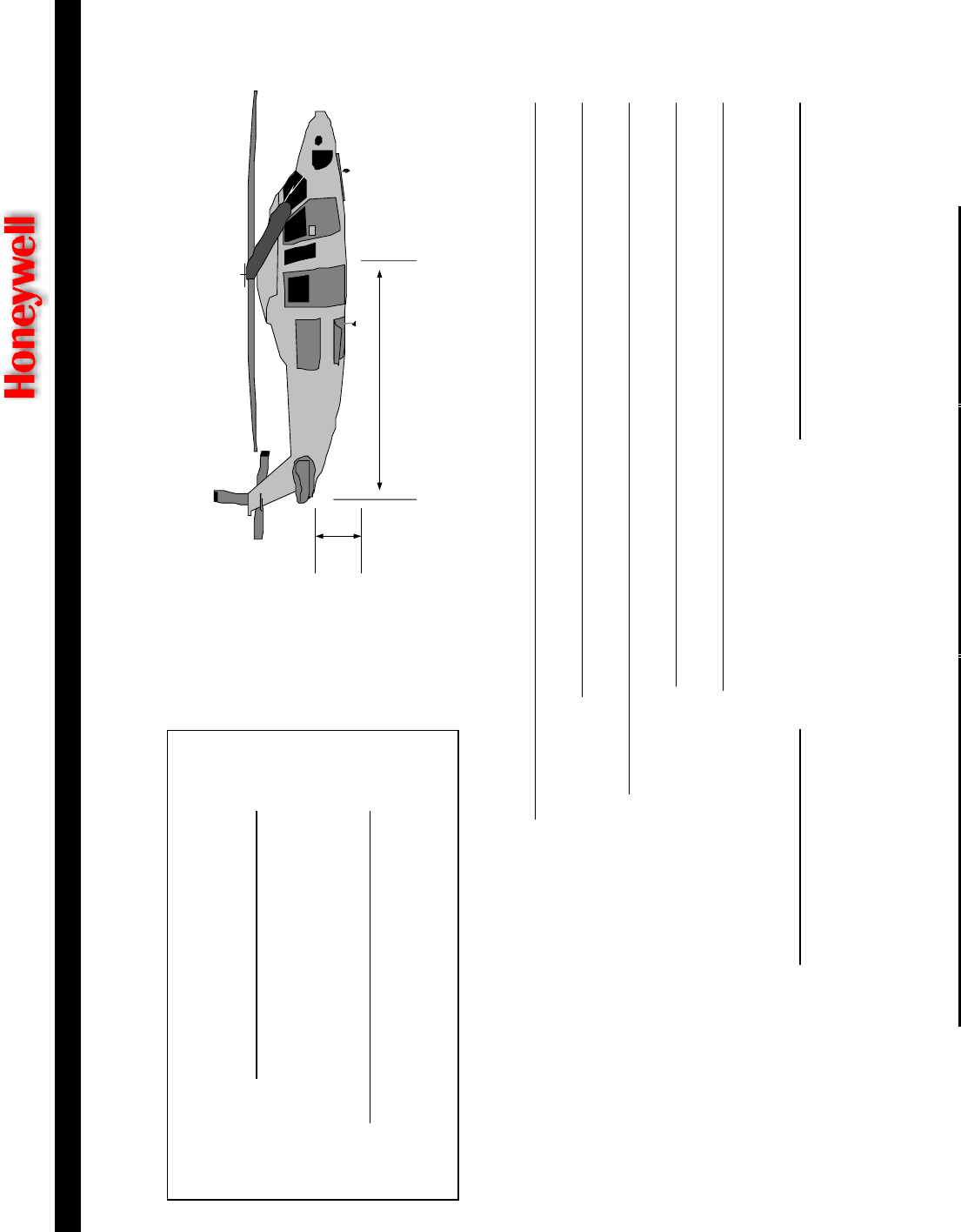
MK XXII EGPWS
ENHANCED GROUND PROXIMITY WARNING SYSTEM
CAGE CODE: 97896 SCALE: NONE SIZE: A DWG NO: 060-4314-225 REV: C SHEET 131
GENERIC MODEL INFORMATION
Aircraft Tail Geometry:
Height of Nominal CG above ground
Distance from CG to Tail (Lowest point of tail or skid)
Distance from CG to center of Tail Rotor
Distance from lowest point of tail or tail-skid to ground
Distance from tail rotor blade (lowest point) to ground
Rotational Frequencies:
Main Rotor RPM No. Of Blades (Main Rotor)
Height
of Tail
Tip of Tail to CG
Manufacturer:
Model:
(be specific)

MK XXII EGPWS
ENHANCED GROUND PROXIMITY WARNING SYSTEM
CAGE CODE: 97896 SCALE: NONE SIZE: A DWG NO: 060-4314-225 REV: C SHEET 132
SYSTEM Number of Engines DATA FORMAT
(ARINC 429, RS 422, RS
232, synchro, DC, AC
Signal Scale Factor
In % Torque
NOTES
Engine
Torque

CAGE CODE: 97896 SCALE: NONE SIZE: A DWG NO: 060-4314-225 REV: C SHEET 133

CAGE CODE: 97896 SCALE: NONE SIZE: A DWG NO: 060-4314-225 REV: C SHEET 134
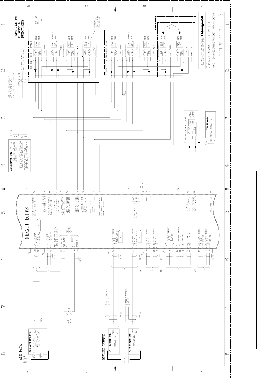
CAGE CODE: 97896 SCALE: NONE SIZE: A DWG NO: 060-4314-225 REV: C SHEET 135
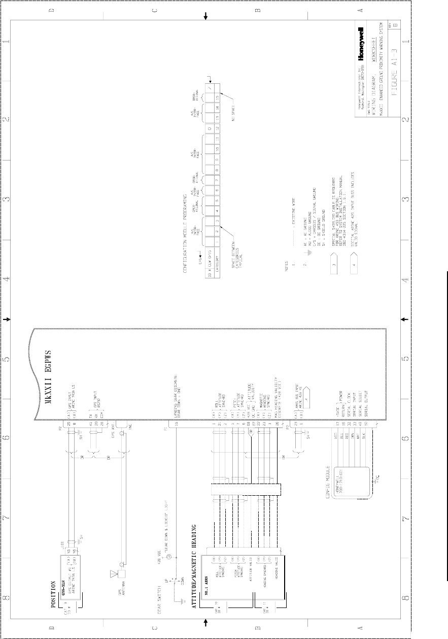
CAGE CODE: 97896 SCALE: NONE SIZE: A DWG NO: 060-4314-225 REV: C SHEET 136

CAGE CODE: 97896 SCALE: NONE SIZE: A DWG NO: 060-4314-225 REV: C SHEET 137

Honeywell
MK XXII EGPWS Installation Manual
CAGE CODE: 97896 SCALE: NONE SIZE: A DWG NO: 060-4314-225 REV: C SHEET 139
APPENDIX B
SAMPLE WIRING DIAGRAMS

Honeywell
MK XXII EGPWS Installation Manual
CAGE CODE: 97896 SCALE: NONE SIZE: A DWG NO: 060-4314-225 REV:C SHEET 140

Honeywell
MK XXII EGPWS Installation Manual
CAGE CODE: 97896 SCALE: NONE SIZE: A DWG NO: 060-4314-225 REV:C SHEET 141

Honeywell
MK XXII EGPWS Installation Manual
CAGE CODE: 97896 SCALE: NONE SIZE: A DWG NO: 060-4314-225 REV:C SHEET 142

Honeywell
MK XXII EGPWS Installation Manual
CAGE CODE: 97896 SCALE: NONE SIZE: A DWG NO: 060-4314-225 REV: C SHEET 143
APPENDIX C
WinViews OPERATION INSTRUCTIONS

Honeywell
MK XXII EGPWS Installation Manual
CAGE CODE: 97896 SCALE: NONE SIZE: A DWG NO: 060-4314-225 REV: C SHEET 144

Honeywell
MK XXII Installation Manual
CAGE CODE: 97896 SCALE: NONE SIZE: A DWG NO: 060-4314-225 REV: C SHEET 145
APPENDIX C – WinViews Operation Instructions
RS-232 COMMUNICATION WITH THE EGPWS
The EGPWS contains software that allows monitoring of its internal parameters, for testing
purposes, without altering its operation. The monitoring of these parameter values enables the
operator to quickly determine if the correct signal and scaling is being used by the EGPWS
computer. The communication link utilizes the RS-232 Communication Protocol configured as
follows:
19200 Baud, No Parity, 8 bits, and 1 stop bit.
The RS-232 interface with the EGPWS is accomplished via the J3 test connector on the front of
the EGPWS. The connection between a PC (with a standard DB9 serial port connector) and the
EGPWS RS-232 interface is defined as follows: (Please note that the EGPWS will activate its RS-
232 port only when it receives the command CONTROL Z after power is applied to the EGPWS.
The CONTROL Z command is automatically sent by WinVIEWS)
RS-232 Receive RS-232 Transmit RS-232 Ground
EGPWS Front Connector Pin 3 Pin 4 Pin 1
Standard DB9 Connector (for a PC)* Pin 3 Pin 2 Pin 5
*NOTE:Some PC Comm Ports have Pins 2 & 3 reversed from what is described above.
The mating connector for the EGPWS J3 test connector is a male (pins) 15 pin double density D-
subminiature type, Positronics Industries (kit) part number ODD15M1OYOZ or the following
individual parts:
Nomenclature (AMP) Amp Part Number Military Part Number
Connector Shell (HDP-22 Crimp Snap In Contact) 748364-1 reference MIL-C-24308
Size 22 DM Crimp Snap In Contacts Pin 0.030 204370-2 M39029/58-360
Backshell (Shielded Cable Clamp Assembly) 745854-5
Jackscrews, 2 required (4-40 Male Jackscrew Kit) 747784-8
Grommet Sets 747746-1
The following tools will work with Positronics, Amp, and Mil Spec Connectors:
Insertion / Extraction Tool 91067-1 M81969/1-04
Hand Crimp Tool M22520/2-01
Positioner M22520/2-09

Honeywell
MK XXII Installation Manual
CAGE CODE: 97896 SCALE: NONE SIZE: A DWG NO: 060-4314-225 REV: C SHEET 146
WinVIEWS OPERATION:
Windows Virtual Interface to the Enhanced Warning System
WinVIEWS software is a tool developed by Honeywell to monitor or view values within the EGPWS.
The WinVIEWS software provides a monitor function that does not alter the operation of the EGPWS.
The monitoring of values assists in the installation testing of the EGPWS by allowing the operator to
quickly determine if the correct signal and scaling is being used by the EGPWS. Additionally,
WinVIEWS provides a detailed status of the software configuration and input signals which enables
quick identification of system anomalies.
WinVIEWS software can be ordered as Honeywell part number 998-2846-500. A User’s Guide to
WinVIEWS is available as Honeywell document number 998-2846-600. The software consists of the
WinVIEWS executable file, a help file, and sample command files.
The command file is a simple text file that should include each CVT Item used in this test procedure.
A sample command file for this test procedure is found on the following page. The file must be a
‘Text Only’ type of file, such as those created in the Microsoft Windows Note Pad program. It should
have a filename extension of .CMD. Once this file is loaded, WinVIEWS can automatically display
the current value of each parameter listed in the file.
Normal Operation for Ground Testing the EGPWS:
STEP 1 - Connect the PC to the EGPWS via the RS-232 cable as defined above.
STEP 2 - On the PC, start Windows 3.1, or higher.
STEP 3 - Start the WinVIEWS program.
STEP 4 - Under the File Menu select the “Load Command File” option and load the appropriate
Command File.
STEP 5 - Use F6 to select Data Display Mode. Each CVT Item listed in the Command File will
be continuously updated at a rate of greater than once per second. The values
shown for the CVT Items listed will be the test values.

Honeywell
MK XXII Installation Manual
CAGE CODE: 97896 SCALE: NONE SIZE: A DWG NO: 060-4314-225 REV: C SHEET 147
Command File: MK XXII_GTP.CMD
The format for the WinVIEWS command file is:
1. ASCII Text Only; no spaces
2. A CVT Item as specified in the test procedure
3. Each CVT Item Name is followed by a <return> or <enter>
RawRA1 VF
ARA1Val V
DHDsc V
RawBAlt1 VF
RawBaroRt1 VF
RawCAS1 VF
RawSAT1 VF
ILSTuned1 V
GnILSTuned1 V
RawAACGS1 VF
AGS1Val V
GPSLatude1 VF
GPSLngude1 VF
RawGLat1 VF
RawGLng1 VF
RawGAlt1 VF
RawVFOM1 VF
RawHFOM1 VF
RawGGSpd1 VF
RawHil1 VF
RawGTTk1 VF
RawRoll1 VF
RawPitch1 VF
AnAtt1Val V
RawAACMHD VF
AACMHDVal V
WOWDsc V
LandGrDsc V
GSCan V
AudInhDsc V
M6LwVolDsc V
GSInh V
GSlnhDsc V
TAWxRng1 VF
TAWxRng2 VF
TerrDis V
AnaTerrDis V
RawTorque1 VF
RawTorque2 VF
TacticalSel V
TAInop C
TAInop1 C
TAInop2 C
EngTorque1 VF
EngTorque2 VF
DispRngOut1 V
DispRngOut2 V

Honeywell
MK XXII Installation Manual
CAGE CODE: 97896 SCALE: NONE SIZE: A DWG NO: 060-4314-225 REV: C SHEET 148

Honeywell
MK XXII EGPWS Installation Manual
CAGE CODE: 97896 SCALE: NONE SIZE: A DWG NO: 060-4314-225 REV: C SHEET 149
APPENDIX D
VENDOR DRAWINGS

Honeywell
MK XXII EGPWS Installation Manual
CAGE CODE: 97896 SCALE: NONE SIZE: A DWG NO: 060-4314-225 REV: C SHEET 150

Honeywell
MK XXII EGPWS Installation Manual
CAGE CODE: 97896 SCALE: NONE SIZE: A DWG NO: 060-4314-225 REV: C SHEET 151
D 1-0 Vendor Contact Information
The vendor contact information provided below is current at the time of publication of this
document.
AMP 2800 Fulling Mill Road
MS 038-035
Middletown, PA 17507
800 806-0480
Barry Controls Burbank, CA
818 843-1000
Brighton, MA
616 787-1555
United Kingdom:
Surrey, England
44 (0932) 22-4122
Germany:
Raunheim, Germany
49 (6142) 43077/8/9
EDMO 5505 E. Rutter Ave.
Spokane, WA 99212
www.edmo.com
1 800 235-3300
Electronic Cable Specialists
and Electrical Conservation
Systems, Inc.
5300 W Franklin Drive
Franklin, WI 53132-8642
414 421-5300
EMTEQ, Inc. S84 W18693 Enterprise Drive
Muskego, WI 53150
(888) 679-6170
(262) 679-6170
(262) 679-6175 Fax
e-mail: smatar@emteq.com
Hollingsead International Sante Fe Springs, CA
213 921-3436
IDD Aerospace Redmond, WA
425 885-4353
ITT Cannon Santa Ana, CA
714 557-4700

Honeywell
MK XXII EGPWS Installation Manual
CAGE CODE: 97896 SCALE: NONE SIZE: A DWG NO: 060-4314-225 REV: C SHEET 152
Korry Electronics 901 Dexter Avenue North Seattle,
WA
Attention: Airline Sales
206 281-1300
800 257- 8921
For orders and AOG requirements, contact:
Sonya Cordova
206 281-3567
email: scordova@korry.com
fax: 206 281-3576
SITA: SEAKEXD
For engineering inquiries, contact:
Bob Jacques
Airline Business Manager
206 281-3584
email: bjacques@korry.com
fax: 206 273-4128
Tom Howard
Airline Business Manager
206 281-1458
email: thoward@korry.com
fax: 206 273-4128
Master Specialties Co. Costa Mesa, CA
714 642-2427
Optima Wire 1120 Harpeth Industrial Ct.
Franklin, TN 37064
615 599-3770
Cathy Harper
cathy.h@mindspring.com
PIC Wire & Cable Supply N63 W22619 Main Street
P.O. Box 330
Sussex, WI 53089-0330
414 246-0500
Fax: 414 246-0450
Sensor Systems, Inc. 8929 Fullbright Avenue
Chatsworth, CA 91311
818 341-5366
Fax: 818 341-9059
StacoSwitch 1139 Baker Street
Costa Mesa, CA 92626-4191
www.stacoswitch.com
714-549-3041
Fax: 714-549-0930
Dan Sugg
dsugg@stacoswitch.com
Also contact EDMO – Avionics
Distributor for StacoSwitch
West Coast Specialties P.O. Box 5010
Preston, WA 98050
425 222-3118
Fax: 425-222-3119
Contact:
Bruce Maxwell, (Rep)
206-232-2871
Fax: 206-232-3174

Honeywell
MK XXII EGPWS Installation Manual
CAGE CODE: 97896 SCALE: NONE SIZE: A DWG NO: 060-4314-225 REV: C SHEET 153
D1-1 EDMO
EDMO Distributors (800)235-3300 – “One Stop Shopping” for the following EGPWS
and TAWS support products:
* MD41-12XX/13XX TAWS ACU’s from Mid-Continent Instruments
* 90-44802-1 PMA’d TAWS ACU from West Coast Specialties
* Eaton and StacoSwitch EGPWS split switch & annunciator kits
* Shadin XYZ compass to RS-232/422 Converters
* Shadin low cost Airdata computers
* Solid State Altitude Encoders (most models)
* GAE-1575 GPS Repeater for hangar testing
* Installation Supplies

Honeywell
MK XXII EGPWS Installation Manual
CAGE CODE: 97896 SCALE: NONE SIZE: A DWG NO: 060-4314-225 REV: C SHEET 154
D1-2 EMTEQ
EMTEQ, Inc. supports all EGPWS/TAWS systems manufactured by Honeywell, Inc. by offering
products to help complete your installation. The installation provisions are fully compliant with
ARINC specifications and standards.
We have a full understanding of the system requirements for coaxial components, wire
harnesses, Switchpanels and mounting accessories.
♦ Fully certified and tested RF cable sets for GPS
♦ Bulk coax cable (cut to length) and the necessary coax connectors to complete the
installation on your own
♦ Avionics Trays
♦ Switchpanel and mounting hardware
♦ ARINC Rack Connectors, Circular Connectors, etc
♦ Wire harnesses
GPS - RF Cable Sets
EMTEQ performs the critical electrical testing for GPS cables using a Hewlett Packard 8753D
Vector Network Analyzer. The state of the art equipment stores all profiles at the exact time the
cables were tested. Comprehensive reports are supplied on all cable assemblies manufactured.
Individual assemblies can be matched electrically to an original set of cables when necessary due
to the assignment of unique serial numbers on all cable units.
EMTEQ offers a unique option in the marketplace with a choice in two families of RF cable types
to meet your specifications and budget. We offer Teflon ® (TFLX series) and PE (PFLX series)
cables as shown in Table 1 (Table 1.A. Teflon ®; Table 1.B. Polyethylene (PE)) . Both types are
Skydrol resistant, meet or exceed MIL-C-17, and meet or exceed FAA Flammability requirements.
The characteristics of each option give you the choice that fits your requirements. Pricing will
differ between the two options, so please call us to discuss your particular project requirements.
This phone call may give you the competitive edge required to win your bid. We have this
outcome in mind when we offered options to our customers.
For each option, EMTEQ offers connectors to meet the system requirements. Connectors for
PFLX and TFLX cable types are listed in Table 2.

Honeywell
MK XXII EGPWS Installation Manual
CAGE CODE: 97896 SCALE: NONE SIZE: A DWG NO: 060-4314-225 REV: C SHEET 155
TABLE 1
Table 1.A. (Teflon ® Jacketed RF Coax) (High Temp)
Cable Type Loss @ 1600 Mhz O.D. Bend Radius
P/N Per 100 ft (inches) Minimum
TFLX130-100 21.60 dB 0.130 “ ½”
TFLX165-100 17.00 dB 0.161” 1 ¾”
TFLX205-100 13.90 dB 0.195 “ 1 ¾”
TFLX295-100 7.60 dB 0.205 “ 3.0 “
TFLX480-100 4.75 dB 0.480 “ 2.40 “
Table 1.B. (PE – Polyethylene Jacketed RF Coax) (85 C temp)
Cable Type Loss @ 1600 Mhz O.D. Bend Radius
P/N Per 100 ft (inches) Minimum
PFLX195-500 14.00 dB 0.195 “ ½”
PFLX240-500 11.00dB 0.242 “ ¾”
PFLX340-500 7.59 dB 0.340 “ 1”
PFLX500-500 4.27 dB 0.500 “ 1 ¼”

Honeywell
MK XXII EGPWS Installation Manual
CAGE CODE: 97896 SCALE: NONE SIZE: A DWG NO: 060-4314-225 REV: C SHEET 156
TABLE 2
Table 2.A.1 Connectors (for TFLX cable series) - GPS
GPS
Connector
Type
Application Description TFLX130-100 TFLX165-100 TFLX205-100
TNC male Antenna Straight TMS130-1 TMS165-1 TMS205-1
TNC male Antenna Right Angle TMR130-1 TMR165-1 TMR205-1
TNC female Disconnects Bulkhead Straight TFS130- 2 TFS165-2 TFS205-2
C male Antenna Straight CMS130-1 CMS165-1 CMS205-1
C male Antenna Right Angle CMR130-1 CMR165-1 CMR205-1
GPS
Connector
Type
Application Description TFLX295-100 TFLX480-100
TNC male Antenna Straight TMS295-1 TMS488-1
TNC male Antenna Right Angle TMR295-1 TMR488-1
TNC female Disconnects Bulkhead Straight TFS295-2 TFS488-2
C male Antenna Straight CMS295-1 CMS488-1
C male Antenna Right Angle CMR295-1 CMR488-1

Honeywell
MK XXII EGPWS Installation Manual
CAGE CODE: 97896 SCALE: NONE SIZE: A DWG NO: 060-4314-225 REV: C SHEET 157
TABLE 2 (continued)
Table 2.B.1 Connectors (for PFLX cable series) – GPS
GPS
Connector
Type
Application Description PFLX195-500 PFLX240-500 PFLX340-500
TNC male Antenna Straight TMS195-1 TMS240-1 TMS340-1
TNC male Antenna Right Angle TMR195-1 TMR240-1 TMR340-1
TNC female Disconnects Bulkhead Straight TFS195-2 TFS240-2 TFS340-2
C male Antenna Straight CMS195-1 CMS240-1 CMS340-1
C male Antenna Right Angle CMR195-1 CMR240-1 CMR340-1
GPS
Connector
Type
Application Description PFLX500-500
TNC male Antenna Straight TMS500-1
TNC male Antenna Right Angle TMR500-1
TNC female Disconnects Bulkhead Straight TFS500-2
C male Antenna Straight N/A

Honeywell
MK XXII EGPWS Installation Manual
CAGE CODE: 97896 SCALE: NONE SIZE: A DWG NO: 060-4314-225 REV: C SHEET 158
Tool Frame and Die Part Numbers
Mil-Spec P/N Daniels
Cable Type for Hex Die P/N for Hex Die Tool Frame Die Hex
PFLX195 M22520/5-19 Y142 M22520/5-01 (HX4) B Hex
PFLX200 M22520/5-19 Y142 M22520/5-01 (HX4) B Hex
PFLX240 M22520/5-43 Y141 M22520/5-01 (HX4) A Hex
PFLX340 M22520/5-35 Y137 M22520/5-01 (HX4) A Hex
PFLX500 M22520/5-21 Y149 M22520/5-01 (HX4) A Hex
TFLX130 M22520/5-43 Y141 M22520/5-01 (HX4) A (ARINC) / B Hex
TFLX165 M22520/5-19 Y142 M22520/5-01 (HX4) B Hex
TFLX205 M22520/5-43 Y141 M22520/5-01 (HX4) A Hex
TFLX295 M22520/5-35 Y137 M22520/5-01 (HX4) A Hex
TFLX488 M22520/5-27 Y151 M22520/5-01 (HX4) A Hex

Honeywell
MK XXII EGPWS Installation Manual
CAGE CODE: 97896 SCALE: NONE SIZE: A DWG NO: 060-4314-225 REV: C SHEET 159
Installation Considerations:
Meeting the specifications when faced with a long cable run could be challenging at some times.
Solutions typically are found when combining a Low Loss Cable (large OD) for the majority of the
run with a “pig tail” at the box or antenna sides. The “pig tail” cable will have a small OD, and will
be very flexible to make the installation in difficult areas easier. Please use the Tables above for
additional information. You can also call EMTEQ’s knowledgeable staff at the below numbers to
help in the configuration and meet your requirements.
EMTEQ, Inc.
S84 W18693 Enterprise Drive
Muskego, WI 53150
(888) 679-6170 Toll Free
(262) 679-6170
Fax: (262) 679-6175
e-mail: smatar@emteq.com

Honeywell
MK XXII EGPWS Installation Manual
CAGE CODE: 97896 SCALE: NONE SIZE: A DWG NO: 060-4314-225 REV: C SHEET 160
D1-3 Aerospace Optics
Aerospace Optics Inc.
Aerospace Optics Inc. is pleased to support the Honeywell EGPWS/TAWS team
with our line of Vivisun LED lighted switches and indicators. We would welcome
the opportunity to assist with your installation and address your Honeywell
EGPWS/TAWS lighting requirements.
LED Lighting
The Honeywell EGPWS/TAWS systems offer state-of-the-art performance.
Accordingly, several recent innovations in LED cockpit lighting have emerged
which truly complement the performance of the Honeywell Systems.
Traditionally, lighted cockpit switches have used incandescent lamps which are
known for the excessive face cap temperatures they generate. The lamps are
also subject to high failure rates which degrades sunlight readability and creates
reliability concerns. LED lighting resolves each of these limitations as they
consume less than half the power of typical incandescent lamps and offer life-of-
the-aircraft reliability. However, the use of LED lighting also has a number of
additional challenges, which can quickly dilute their utility.
When using LED lighting in the past, sunlight readability and viewing angles were
limited and uniform dimming required special pulse width modulation.
Additionally, unprotected LEDs were susceptible to damage from transients and
voltage spikes from severe electrical environments as defined in RTCA/DO-
160D. However, today, with the evolution of LED technology and innovative
design techniques, it is possible to take advantage of the efficiencies afforded by
LEDs while continuing to meet the lighting and environmental requirements of
aircraft design.
The Vivisun LED resolves each of these challenges including DO-160D
compliance and standard voltage controlled dimming. LEDs are the lighting
source for the future and the ideal compliment to the Honeywell EGPWS/TAWS
Systems.

Honeywell
MK XXII EGPWS Installation Manual
CAGE CODE: 97896 SCALE: NONE SIZE: A DWG NO: 060-4314-225 REV: C SHEET 161
Please feel free to contact the Aerospace Optics Technical Sales Team for
assistance in addressing the use of LED lighted switches and indicators.
Aerospace Optics Inc.
3201 Sandy Lane
Fort Worth TX, 76016
1-(888)VIVISUN- (848-4786) Toll Free
Fax (817) 654-3405
www.vivisun.com
e-mail : switches@vivisun.com

Honeywell
MK XXII EGPWS Installation Manual
CAGE CODE: 97896 SCALE: NONE SIZE: A DWG NO: 060-4314-225 REV: C SHEET 162
D1-4 StacoSwitch
StacoSwitch
As a supplier of high reliability switches and indicators for avionics since 1958,
StacoSwitch is proud to be integrated with many Honeywell products and
divisions. Through our relationship with EDMO Distributors in Spokane, WA, we
supply AV17 kits that include all the switches, annunciators, and crimp pins
needed to complete the installation of your Honeywell EGPWS (TAWS) system.
These kits meet all lighting and color requirements in the shortest and lightest
switch and indicator units available on the market. EDMO stocks these kits and
can even generate customized legend and color combinations with extremely
fast delivery, usually within a couple days.
StacoSwitch can also provide solutions to most switch needs that may arise,
such as LED lighting, Night Vision (NVIS) compatibility, EMI/RFI shielding,
watertight seals, Digital Dimming Modules that can dim both incandescent and
LED lights with consistency, pushbutton guards, and customized-legend switch
and indicator assemblies that can be packaged into impressive matrix mounts.
Please check out our full line of products at www.stacoswitch.com. It includes all
the detailed information to help answer any questions you may have during an
installation and also a link to EDMO.
Contact Information:
Dan Sugg – Vice President of Sales
dsugg@stacoswitch.com
StacoSwitch
1139 Baker Street
Costa Mesa, CA 92626
Phone: (714) 549-3041
Fax: (714) 549-0930
www.stacoswitch.com

Honeywell
MK XXII EGPWS Installation Manual
CAGE CODE: 97896 SCALE: NONE SIZE: A DWG NO: 060-4314-225 REV: C SHEET 163
APPENDIX E
INTERFACE DESCRIPTION DOCUMENT

Honeywell
MK XXII EGPWS Installation Manual
CAGE CODE: 97896 SCALE: NONE SIZE: A DWG NO: 060-4314-225 REV: C SHEET 164

Honeywell
MK XXII EGPWS Installation Manual
CAGE CODE: 97896 SCALE: NONE SIZE: A DWG NO: 060-4314-225 REV: C SHEET 165
INTRODUCTION ...................................................................................................................................................................166
E 1 Part Number.............................................................................................................................................................166
E 2 Purpose.....................................................................................................................................................................166
E 3 System Overview.....................................................................................................................................................166
E 4 ELECTRICAL INTERFACE ..................................................................................................................................167
E 4.1 Introduction......................................................................................................................................................167
E 4.2 Signal Interfaces...............................................................................................................................................167
E 4.2.1 Grounds............................................................................................................................................................167
E 4.2.2 Primary Power Input ........................................................................................................................................167
E 4.2.3 DC Analog Inputs ............................................................................................................................................168
E 4.2.7 AC Analog Inputs ............................................................................................................................................170
E 4.2.9 ARINC 429/575 Digital Serial Bus Inputs.......................................................................................................172
E 4.2.9.1 RS-232 / RS-422 Digital Serial Bus Inputs..................................................................................................173
E 4.2.10 Discrete Inputs .............................................................................................................................................174
E 4.2.11 Configuration Module Interface...................................................................................................................175
E 4.2.12 GPS Antenna Input.......................................................................................................................................175
E 4.2.13 OAT Voltage Reference Output...................................................................................................................176
E 4.2.14 Lamp Driver Outputs ...................................................................................................................................176
E 4.2.16 Audio Outputs..............................................................................................................................................176
E 4.2.17 ARINC Digital Serial Output Busses...........................................................................................................177
E 4.2.17.1 ARINC 429 Output Bus...........................................................................................................................177
E 4.2.17.2 ARINC 453 Output Bus...........................................................................................................................178
E 4.2.18 Front Panel Test Interface ................................................................................................................................178
E 4.2.18.1 RS-232 Maintenance Port (serial port 4)......................................................................................................178
E 4.2.18.2 PCMCIA / SmartCable Port.....................................................................................................................179
E 4.2.18.3 GSE Present Discrete Input......................................................................................................................179
E 4.2.19 Front Panel Status Indicators............................................................................................................................179
E 5 AIRCRAFT APPLICATION DATA...........................................................................................................................180
E 5.1 Configuration Types.............................................................................................................................................180
E 5.2 Configuration Selection .......................................................................................................................................180
E 5.3 Configuration Selection Tables........................................................................................................................182
E 5.3.1 Category 1, Aircraft / Mode Type Select .........................................................................................................183
E 5.3.2 Category 2, Air Data Input Select ....................................................................................................................189
E 5.3.3 Category 3, Position Input Select....................................................................................................................195
E 5.3.4 Category 4, Altitude Callouts...........................................................................................................................199
E 5.3.5 Category 5, Audio Menu Select .......................................................................................................................201
E 5.3.6 Category 6, Terrain Display Select ..................................................................................................................202
E 5.3.7 Category 7, Options 1 Select............................................................................................................................231
E 5.3.8 Category 8, Radio Altitude Input Select...........................................................................................................233
E 5.3.9 Category 9, Navigation Input Select ................................................................................................................236
E 5.3.10 Category 10, Attitude Input Select...............................................................................................................238
E 5.3.11 Category 11, Heading Input Select...............................................................................................................240
E 5.3.12 Category 12, Windshear Input Select...........................................................................................................241
E 5.3.13 Category 13, Input / Output Discrete Type Select........................................................................................242
E 5.3.14 Category 14, Audio Output Level ................................................................................................................245
E 5.3.15 Category 15, Autorotation Threshold...........................................................................................................246
E 6 CONNECTOR INTERFACE ......................................................................................................................................247
E 6.1 Pinout for Front Connectors sorted by pin number..............................................................................................247
E 7 DEFINITIONS.........................................................................................................................................................252

Honeywell
MK XXII EGPWS Installation Manual
CAGE CODE: 97896 SCALE: NONE SIZE: A DWG NO: 060-4314-225 REV: C SHEET 166
INTRODUCTION
E 1 PART NUMBER
This document is the Interface Description for the MKXXII Helicopter Enhanced Ground Proximity Warning System
(EGPWS) part number 965-1590-0XX.
The MK XXII EGPWC 10 digit part number will identify the configuration of the EGPWC as follows:
•965-1590-XXX (example 965-1590-010)
•XXX = Application Software (including Configuration Software)
The Terrain Database (including the Envelope Modulation Database) Version is not identified in the 10-digit part number but
with a separate identifier on the nameplate.
All modification changes not affecting form, fit or function will be identified via “mod dots”.
The digits identifying the Application software will match the respective version number of the Application software.
E 2 PURPOSE
This Appendix describes all of the system external interfaces for the MK XXII Enhanced Ground Proximity Warning System
(EGPWS).
E 3 SYSTEM OVERVIEW
For more information please refer to the EGPWS Product Specification document 965-1590-601.

Honeywell
MK XXII EGPWS Installation Manual
CAGE CODE: 97896 SCALE: NONE SIZE: A DWG NO: 060-4314-225 REV: C SHEET 167
E 4 ELECTRICAL INTERFACE
E 4.1 INTRODUCTION
The MK XXII EGPWS provides electrical interfaces for aircraft systems and to support maintenance functions. The
interfaces are made via the front panel aircraft interface connectors, front panel maintenance/test port and front panel LED’s.
A TNC coaxial connector is located on the front panel for internal GPS receivers in the 965-1590-0XX MK XXII EGPWC.
The following sections describe the types of electrical interfaces provided in the EGPWC. See Section E 5 for the specific
interface configuration capabilities of the MK XXII EGPWS.
E 4.2 SIGNAL INTERFACES
This section identifies and describes the number and characteristics of each interface type provided in the front aircraft
interface connectors. The aircraft interface connectors are defined as P1 (78 pins) and P2 (50 pins). Section E 6 identifies the
connector pin assignments. The signal mnemonic for each signal in Section E 6 is included in the following sections. All
synchro inputs are brought in as three or five wire devices. No two wire absolute AC signals are available. All analog inputs
provide broken wire detection on all input signal legs. Unless otherwise stated, the “Maximum reverse fault current” is
defined as the current resulting from an internal component failure, with the input signal at zero volts.
E 4.2.1 GROUNDS
CHASSIS GROUND
Used for redundant metal connection. This pin is internally connected to DC Ground (see section 0).
Pin Assignment (Signal Mnemonic): J1-42, J1-53 (GND)
DC GROUND
For discrete inputs and lamp driver outputs. These pins are also internally connected to Chassis Ground (see section 0).
Pin Assignment (Signal Mnemonic):
(same as +28 VDC Return) J1-41, J1-61 (PWR_L)
NOTE: All analog signals are differential input.
E 4.2.2 PRIMARY POWER INPUT
Nominal Input 28 VDC
Normal Voltage Range 22.0 to 30.3 VDC
Normal Surge Voltage Range 15 – 40VDC (30 msec)
Abnormal Voltage Range 20.5 to 32.2 VDC
Abnormal Surge Voltage Range 37.8 VDC (1sec); 46.3 VDC (100 msec)
Normal Frequency Range not applicable
Frequency Transients not applicable
Power Requirements 9 Watts - No Warnings
+7 Watts with warning voice over 8 Ω speaker
+3 Watts with Internal GPS (includes antenna power)1
+49 Watts (typical) with heater blanket on2
Recommended Power Control Device 3 Amp delayed action circuit breaker.
Pin Assignment (Signal Mnemonic):
+28 VDC Input
+28 VDC Return J1-40, J1-60
J1-41, J1-61 (PWR_H3)
(PWR_L3)
1Based on the Honeywell GPS Pxpress card specification and applies to 965-1590-0XX only.
2The heater blanket turns on at temperatures ≤ -23° C and turns off at temperatures ≥ -20° C.

Honeywell
MK XXII EGPWS Installation Manual
CAGE CODE: 97896 SCALE: NONE SIZE: A DWG NO: 060-4314-225 REV: C SHEET 168
3Note that this is not a floating input. +28 VDC must be applied to both PWR_H and +28 VDC Return to both
PWR_L inputs.
E 4.2.3 DC ANALOG INPUTS
Unless otherwise specified, Input Signal accuracy is1% linearity +0.1% full scale offset.
E 4.2.3.1 RADIO ALTITUDE
Quantity 1
Input Impedance, each leg > 83 KΩ
Maximum Reverse Fault Current < 200 µamps
Signal Range 0 to 2500 feet
Input Voltage Range (VRA)37.7V ≥ VRA ≥ -2.5V
Conversion Range (Vc)29.7V ≥ Vc≥ -0.4V
Input Filter 0.1 Second Low Pass, ± 10%
Broken Wire Detect Input will be biased to less than -50 feet
Pin Assignment (Signal Mnemonic):
Signal (+)
Return (-) J1-64
J1-45 (RALT_H)
(RALT_L)
E 4.2.3.2 LOW LEVEL GLIDESLOPE
Quantity 1
Input Impedance, each leg > 2.5 MΩ
Reverse Fault Current < 6.2 µamps
Signal Range ±12 Dots
Input Voltage Range ±0.9VDC
Input Filter 0.1 Second Low Pass, ± 10%
Input Type Differential
Common Mode Voltage Range (VCM)11V ≥ VCM ≥ -2V
Broken Wire Detect Input will be biased less than -15 dots
Pin Assignment (Signal Mnemonic):
+Up, Below Beam, Fly Up
+Down, Above Beam, Fly Down J1-65
J1-46 (GSDEV_H)
(GSDEV_L)
E 4.2.3.3 LOCALIZER DEVIATION OR LOW LEVEL GLIDESLOPE VALIDITY
This input can be configured as either a low level glideslope valid, or as a localizer deviation input. Installations that only
have the low level validity signal for glideslope can not activate the analog localizer input. See section 5.3.9 for more
information.
Quantity 1
Input Impedance, each leg > 2.5 MΩ
Reverse Fault Current < 6.2 µA
Input Filter 0.1 Second Low Pass, ± 10%
Input Type Differential
Common Mode Voltage Range (VCM)11V ≥ VCM ≥ -2V
Pin Assignment (Signal Mnemonic):
+
- J1-30
J1-10 (GS_VAL_H)
(GS_VAL_L)

Honeywell
MK XXII EGPWS Installation Manual
CAGE CODE: 97896 SCALE: NONE SIZE: A DWG NO: 060-4314-225 REV: C SHEET 169
When used as a validity input:
Active Voltage Range (Logic True) +160 to +840 mVDC
Inactive Voltage Range (Logic False) 0 to 50 mVDC
Broken Wire Detect Input will be biased less than –1 VDC
When used as a localizer input:
Signal Range ±12 Dots
Input Voltage Range ±0.9VDC
Broken Wire Detect Input will be biased less than -15 dots
E 4.2.4 BAROMETRIC ALTITUDE
Quantity 1
Input Impedance, each leg > 83 KΩ
Reverse Fault Current < 200 µamps
Input Voltage Range -0.18VDC to +15VDC
Input Filter 0.1 Second Low Pass, ± 10%
Input Type Differential
Broken Wire Detect Input will be biased less than -3000 feet
Pin Assignment (Signal Mnemonic):
Signal (+)
Return (-) J1-62
J1-43 (ALT_H)
(ALT_L)
E 4.2.5 OUTSIDE AIR TEMPERATURE
Quantity 1
Input Impedance, each leg > 100 KΩ
Reverse Fault Current < 200 µamps
Input Voltage Range +0.3 VDC to +0.6VDC
Input Filter 0.1 Second Low Pass, ± 10%
Input Type Differential
Broken Wire Detect Input will be biased less than -80° C
Pin Assignment (Signal Mnemonic):
Signal (+)
Return (-) J1-63
J1-44 (OAT_H)
(OAT_L)
NOTE: For temperature probe voltage reference see section 0.
E 4.2.6 CONFIGURATION DEFINED DC INPUTS
Quantity 2
Input Impedance, each leg > 83 KΩ
Reverse Fault Current < 200 µamps
Input Voltage Range ±5 VDC
Input Filter 0.1 Second Low Pass, ± 10%
Input Type Differential
Broken Wire Detect Input will be biased less than –6 VDC
Pin Assignment (Signal Mnemonic):
#1 Signal (+)
#1 Return (-)
#2 Signal (+)
#2 Return (-)
J1-26
J1-27
J1-66
J1-47
(TORQUE_1H)
(TORQUE _1L)
(TORQUE _2H)
(TORQUE _2L)

Honeywell
MK XXII EGPWS Installation Manual
CAGE CODE: 97896 SCALE: NONE SIZE: A DWG NO: 060-4314-225 REV: C SHEET 170
E 4.2.7 AC ANALOG INPUTS
Unless otherwise specified, Input Signal accuracy is1% linearity +0.1% full scale offset
E 4.2.7.1 SYNCHRO ROLL ATTITUDE
Quantity 1
Input Impedance: X leg > 140 KΩ
Input Impedance: Y leg > 140 KΩ
Input Impedance: Z leg > 140 KΩ
Maximum Reverse Fault Current < 200 µamps
Input Voltage Range ±11.8 VACRMS ± 20% (leg to leg)
Synchro Angle Range ±80 deg
Reference Voltages Not Required
Accuracy 2.5% linearity + 0.1% full scale offset
Pin Assignment (Signal Mnemonic):
X leg
Y leg
Z leg
J1-1
J1-21
J1-2
(SYN_1X)
(SYN_1Y)
(SYN_1Z)
E 4.2.7.2 SYNCHRO MAGNETIC HEADING
Quantity 1
Input Impedance: X leg > 140 KΩ
Input Impedance: Y leg > 140 KΩ
Input Impedance: Z leg > 140 KΩ
Maximum Reverse Fault Current < 200 µamps
Input Voltage Range ±11.8 VACRMS ± 20% (leg to leg)
Reference Voltages ±26 VACRMS ± 20% (see 4.2.4.4)
Accuracy 2.5% linearity + 0.1% full scale offset
Pin Assignment (Signal Mnemonic):
X leg
Y leg
Z leg
J1-22
J1-23
J1-3
(SYN_2X)
(SYN_2Y)
(SYN_2Z)

Honeywell
MK XXII EGPWS Installation Manual
CAGE CODE: 97896 SCALE: NONE SIZE: A DWG NO: 060-4314-225 REV: C SHEET 171
E 4.2.7.3 CONFIGURATION DEFINED SYNCHRO INPUTS
Quantity 3
Input Impedance: X leg > 140 KΩ
Input Impedance: Y leg > 140 KΩ
Input Impedance: Z leg > 140 KΩ
Maximum Reverse Fault Current < 200 µamps
Input Voltage Range ±11.8 VACRMS ± 20% (leg to leg)
Reference Voltages ±26 VACRMS ± 20%
Accuracy 2.5% linearity + 0.1% full scale offset
Pin Assignment (Signal Mnemonic):
#1 X leg
#1 Y leg
#1 Z leg
#2 X leg
#2 Y leg
#2 Z leg
#3 X leg
#3 Y leg
#3 Z leg
J1-5
J1-7
J1-6
J2-1
J2-2
J2-18
J2-19
J2-20
J2-3
(SYN_3X)
(SYN_3Y)
(SYN_3Z)
(SYN_4X)
(SYN_4Y)
(SYN_4Z)
(SYN_5X)
(SYN_5Y)
(SYN_5Z)
E 4.2.8 SIGNAL TIMING REFERENCE INPUTS
These inputs accept 400 Hz AC signals, and detect the “zero crossings” of these signals. These zero crossings are used to
time the conversion and input of AC signals. Absolute voltage level of these signals is not measured, but it must be within
the range specified below. Voltage below the specified minimum value may result in intermittent or “jittery” zero cross
detection.
Timing reference signals are required for input of most AC devices (not required for roll). These references can be brought
into the appropriate timing reference input, or the system can be configured to derive a reference from the signal. Timing
reference signals are specified for synchro inputs requiring a range greater than ± 80 degrees. Inputs requiring less (i.e., Roll
Attitude) are configured to derive a reference from the synchro input signal and do not require a separate reference voltage
input.
Quantity 2
Input Impedance > 140KΩ each line to signal ground
Maximum Reverse Fault Current < 120 µamps
A/C Input Signal Frequency Range 400 Hz, ±10%
Maximum Input Voltage Swing (differential) 50V between input legs
Maximum Input Voltage Swing (ref. to Gnd) 50V from any leg to signal ground
Input Hardware Filtering None
Minimum Input Voltage ± 0.5 VAC
Pin Assignment (Signal Mnemonic):
26VAC Reference #1 H
26VAC Reference #1 C
26VAC Reference #2 H
26VAC Reference #2 C
J1-4
J1-24
J2-34
J2-35
(26REF_1H)
(26REF_1L)
(26REF_2H)
(26REF_2L)

Honeywell
MK XXII EGPWS Installation Manual
CAGE CODE: 97896 SCALE: NONE SIZE: A DWG NO: 060-4314-225 REV: C SHEET 172
E 4.2.9 ARINC 429/575 DIGITAL SERIAL BUS INPUTS
Quantity 8
Format DITS, ARINC 429/575 Low or high speed 1
Low Speed Data Rate 12.0 KBPS to 14.5 KBPS
High Speed Data Rate 100 KBPS ± 1%
Direction of Information Flow Type ‘A’ broadcast for ARINC 429/575
Word/Frame Structure Type ‘B’ 32 bit words consisting of 8 bits label and 24
bits data/status
Data definition Refer to Section 6 of this document
Pin Assignment (Signal Mnemonic):
Receive #1 A leg
Receive #1 B leg
Receive #2 A leg
Receive #2 B leg
Receive #3 A leg
Receive #3 B leg
Receive #4 A leg
Receive #4 B leg
Receive #5 A leg
Receive #5 B leg
Receive #6 A leg
Receive #6 B leg
Receive #7 A leg
Receive #7 B leg
Receive #8 A leg
Receive #8 B leg
J2-37
J2-36
J2-39
J2-38
J2-41
J2-40
J2-25
J2-8
J2-21
J2-4
J2-22
J2-5
J2-23
J2-6
J2-24
J2-7
(429/422RX_1A)
(429/422RX_1B)
(429RX_2A)
(429RX_2B)
(429RX_3A)
(429RX_3B)
(429RX_4A)
(429RX_4B)
(429RX_5A)
(429RX_5B)
(429RX_6A)
(429RX_6B)
(429RX_7A)
(429RX_7B)
(429RX_8A)
(429RX_8B)
SSM/SDI Definition: Refer to Section 6 of this document
1 The bus speed is defined in the configuration selection, see Section 5 for details.

Honeywell
MK XXII EGPWS Installation Manual
CAGE CODE: 97896 SCALE: NONE SIZE: A DWG NO: 060-4314-225 REV: C SHEET 173
E 4.2.9.1 RS-232 / RS-422 DIGITAL SERIAL BUS INPUTS
Two full duplex RS-232 / RS-422 buses and a third RS-422 receiver are provided at the aircraft interface connectors. The
RS-422 transceivers are electrically multiplexed with the RS-232 transceivers, and are selected through the configuration
process. The third RS-422 receiver is electrically multiplexed with the ARINC 429 channel 1 receiver. The maintenance
RS-232 bus is described in section 0. The specific characteristics (data rate, parity, data bits, stop bits) is defined in the
configuration selection, see Section 5 and 6 for details. RS-422 cable termination will not be required for typical
applications, see TIA/EIA-422-B Annex A.
The RS-232 bus meets the characteristics specified in RS232C and supports the following characteristics:
Data Rate 1200, 2400, 4800, 9600, 19200 or 38400 bits/Sec
Parity None, Odd or Even
Data bits 7 or 8
Stop bits 1 or 2
Maximum Recommended Cable Length 15 meters
Data definition Refer to Section 6 of this document
The RS-422 bus meets the characteristics of TIA/EIA-422-B and supports the following characteristics:
Data Rate 1200, 2400, 4800, 9600, 12000, 19200 or 38400 bits/Sec
Maximum Transceivers on Bus 20
Receiver Input Impedance 12 KΩ
Word/Frame Structure Refer to Section 6 of this document
Data definition Refer to Section 6 of this document
E 4.2.9.2 GPS RS-232 DIGITAL SERIAL BUS (SERIAL PORT 3)
One port is provided for use with external or internal RS-232 GPS interfaces. This port is common with the GPS RS-422 port
described in Section 0 and can only function as a RS-232 interface or a RS-422 interface but not both.
Pin Assignment (Signal Mnemonic):
Transmit
Receive
Common
J2-45
J2-29
J2-28
(GPS_TXA)
(GPS_RXA)
(GND)
NOTE: If an internal GPS configuration is used (965-1186-0XX, 965-1216-0XX or 965-1590-0XX) then the receive
input will be non-functional.
E 4.2.9.3 GPS RS-422 DIGITAL SERIAL BUS (SERIAL PORT 3)
One port is provided for use with external GPS interfaces. This port is common with the GPS RS-232 port described in
Section 0 and can only function as a RS-232 interface or a RS-422 interface but not both.
Pin Assignment (Signal Mnemonic):
Transmit A leg
Transmit B leg
Receive A leg
Receive B leg
J2-45
J2-46
J2-29
J2-12
(GPS_TXA)
(GPS_TXB)
(GPS_RXA)
(GPS_RXB)
NOTE: If an internal GPS configuration is used (965-1186-0XX, 965-1216-0XX or 965-1590-0XX) then the receive
input will be non-functional.

Honeywell
MK XXII EGPWS Installation Manual
CAGE CODE: 97896 SCALE: NONE SIZE: A DWG NO: 060-4314-225 REV: C SHEET 174
E 4.2.9.4 AIR DATA RS-232 DIGITAL SERIAL BUS (SERIAL PORT 2)
One port is provided for use with Air Data computer or Static Pressure Sensor interfaces. This port is common with the Air
Data RS-422 port described in Section 0 and can only function as a RS-232 interface or a RS-422 interface but not both.
Pin Assignment (Signal Mnemonic):
Transmit
Receive
Common
J2-27
J2-11
J2-28
(ADC_TXA)
(ADC_RXA)
(GND)
E 4.2.9.5 AIR DATA RS-422 DIGITAL SERIAL BUS (SERIAL PORT 2)
One port is provided for use with Air Data computer or Static Pressure Sensor interfaces. This port is common with the Air
Data RS-232 port described in Section 0 and can only function as a RS-232 interface or a RS-422 interface but not both.
Pin Assignment (Signal Mnemonic):
Transmit A leg
Transmit B leg
Receive A leg
Receive B leg
J2-27
J2-44
J2-11
J2-10
(ADC_TXA)
(ADC_TXB)
(ADC_RXA)
(ADC_RXB)
E 4.2.9.6 SCI RANGE RS-422 DIGITAL SERIAL BUS (SERIAL PORT 1)
One port is provided for use with the SCI range bus interfaces. This port is common with the ARINC 429 channel 1 port
described in Section 0 and can only function as a RS-422 interface or an ARINC 429 interface but not both.
Pin Assignment (Signal Mnemonic):
Recieve A leg
Recieve B leg J2-37
J2-36 (429/422RX_1A)
(429/422RX_1B)
E 4.2.10 DISCRETE INPUTS
Discrete signals are intended for remote switching through the aircraft, and are therefore subject to being connected to other
signals, and are also subject to transient voltage conditions. For these reasons, the following rules apply to each input, unless
otherwise stated.
Each input is capable of withstanding voltage transients of ± 600VDC for 10 µs, without damage. The +28 VDC discretes
are internally biased via a pull down resistor, and are externally pulled up to +28VDC when active. The characteristics of
each +28 VDC discrete input are as follows:
+28 VDC Discrete Characteristics
Quantity 13
Active Voltage Range (Logic True) > +17 VDC
Inactive Voltage Range (Logic False) < +4.4 VDC
Diode Isolation None
Input Impedance > 95 KΩ
Maximum Fault Current < 60 µA
Pin Assignment (Signal Mnemonic): See specific discrete in Category 13 (28V_DISC_xx)

Honeywell
MK XXII EGPWS Installation Manual
CAGE CODE: 97896 SCALE: NONE SIZE: A DWG NO: 060-4314-225 REV: C SHEET 175
The Ground discretes are internally biased via a pull up resistor, and are externally pulled down to ground when active. The
characteristics of each Ground discrete input are as follows:
Ground Discrete Characteristics
Quantity 15
Active Voltage Range (Logic True) < +3 VDC
Inactive Voltage Range (Logic False) > 100 KΩ (to ground) or > +3.5 VDC
Diode Isolation Each input is diode isolated to prevent current sinking
Input Impedance > 10 KΩ
Maximum Fault Current < 100 µA (at +28 VDC input)
Pin Assignment (Signal Mnemonic): See specific discrete in Category 13 (GND_DISC_xx)
E 4.2.11 CONFIGURATION MODULE INTERFACE
System configuration is defined via a Configuration Module, which resides in the MKIV/VI/VIII/XXII EGPWS aircraft
wiring harness backshell. The EGPWS Configuration Module contains the aircraft interface and functionality definitions
specific to the installed aircraft. Refer to Section 5 for interface and functional definitions by category.
Electrical Characteristics Refer to the EGPWS Configuration Module specification
Data definition Refer to the EGPWS Configuration Module specification
Pin Assignment (Signal Mnemonic):
Clock
Master Data Out
Master Data In
Configuration Module Select
Configuration Module +5VDC
Configuration Module +5VDC Return
J2-32 (RED)
J2-50 (BLK)
J2-33 (ORN)
J2-49 (WHT)
J2-17 (VIO)
J2-16 (BLU)
(SPICLK)
(SPIMOSI)
(SPIMISO)
(SPISEL_CM#)
(SC_PWR)
(GND)
Output to Config Module Logic Low (nominal) Logic High (nominal)
EMK4/6/8/22 EMK4/6/8/22
Clock Out 0 V 5 V
Master Data Out 0 V 5 V
Config Module Select 0 V 5 V
INTERFACE OF EGPWS OUTPUTS TO CONFIGURATION MODULE
E 4.2.12 GPS ANTENNA INPUT
A GPS input connector is available on the front of the MK VI EGPWS (965-1186-0XX only), MK VIII EGPWS (965-1216-
0XX only), MK XXII EGPWS (965-1590-0XX only), and MK IV EGPWS (965-1686-0XX only).
Quantity 1
Cable Length/Allowed Signal Loss Not more than 8 dB, at 1575.42 MHz, for cable and
connector loss from antenna to unit.
Connector Type TNC
Low Level DC on RF Output +5 VDC ±5%, 50 mAmps maximum, Shield Ground.
Pin Assignment (Signal Mnemonic): GPS ANT (COAX)

Honeywell
MK XXII EGPWS Installation Manual
CAGE CODE: 97896 SCALE: NONE SIZE: A DWG NO: 060-4314-225 REV: C SHEET 176
E 4.2.13 OAT VOLTAGE REFERENCE OUTPUT
This output is an accurate voltage source for 500 Ω resistive temperature sensors.
Quantity 1
Output Voltage 5.000 VDC ±10 mVDC (no load)
Nominal Load 500 Ω
Pin Assignment (Signal Mnemonic): J1-25 (OAT_REF)
NOTE: This output has a source impedance of 4.42 KΩ, 0.1%.
E 4.2.14 LAMP DRIVER OUTPUTS
The MK IV, VI, VIII and XXII EGPWS supports two kinds of Ground/Open discrete outputs used to signal various discrete
conditions. Monitor outputs are used to signal failure conditions for the MK IV, VI, VIII and XXII EGPWS. Monitor
outputs default to an active state when there is a failure or if power is removed from the MK IV, VI, VIII and XXII EGPWS.
The other Lamp Driver outputs are used to signal the alert or mode control status of the MK IV, VI, VIII and XXII EGPWS.
Short-term current limit protection is provided on all drivers for output shorting conditions. Ground going output discretes
may be connected together to produce a “wired OR” function for the active low state of the signals. If output discretes are
“wired or’ed” then diodes must be installed for isolation.
E 4.2.14.1 MONITOR OUTPUT CHARACTERISTICS
Quantity 3
Type of Output: Switch Closure to Ground
Max. Open Circuit Voltage: 30 VDC
Current Limit 1 Amp
Potential Across “Closed” Switch: 2.5 VDC Max
Pin Assignment (Signal Mnemonic): See specific output in Category 13 (MON_OUT_xx)
NOTE: Intended to operate with +28VDC lamp sources and will not operate with +5VDC lamp sources.
E 4.2.15 DISCRETE OUTPUT CHARACTERISTICS
Quantity 9
Type of Output: Switch Closure to Ground
Max. Open Circuit Voltage: 30 VDC
Current Limit 500 mAmp (typical)
Potential Across “Closed” Switch: 1 VDC Max
Pin Assignment (Signal Mnemonic): See specific output in Category 13 (DISC_OUT_xx)
E 4.2.16 AUDIO OUTPUTS
There are two audio outputs provided – one 8-ohm output and one 600-ohm output. There are several possible volume levels
available with the MKIV/VI/VIII/XXII EGPWS as shown below, with maximum output being 4W (8Ω) or 100mW (600Ω).
The actual audio level output by the EGPWS is dependent on several items:
•Selection of nominal alert audio volume level (max, -6, -12, -18 or -24 dB) via Category 14. (Section 5.3.14)

Honeywell
MK XXII EGPWS Installation Manual
CAGE CODE: 97896 SCALE: NONE SIZE: A DWG NO: 060-4314-225 REV: C SHEET 177
•If a ‘soft’ Glideslope alert is being issued (given 6 dB below nominal alert volume level).
•If a Self Test is in progress, alerts are given 6 dB below nominal alert volume level.
•Selection of Mode 6 Low Volume Discrete (lowers callout volume by 6 dB - See Section 5.3.13).
E 4.2.16.1 HIGH LEVEL (SPEAKER) AUDIO OUTPUT
The 8-ohm output is capable of driving a speaker directly but can also be used to drive other devices with equal or higher
impedance.
Quantity 1
Maximum Power Output 4 Watts Nominal
Nominal Output Impedance 8Ω
Load Impedance 8Ω or greater
Number of Available Power Output Levels 5 1
Pin Assignment (Signal Mnemonic):
Signal (+)
Return (-) J1-70
J1-71 (AUD_HL_H)
(AUD_HL_L)
E 4.2.16.2 LOW LEVEL (INTERPHONE) AUDIO OUTPUT
The 600-ohm output is capable of driving one 600-ohm load at the specified level (or at a reduced level). This output is
primarily designed for headphones and interphone systems.
Quantity 1
Nominal Output Impedance 600Ω±
10%
Maximum Single Channel Power Output 100 mW Nominal ()
Available Power Output Levels 5 1
Pin Assignment (Signal Mnemonic):
Signal (+)
Return (-) J1-75
J1-74 (AUD_LL_H)
(AUD_LL_L)
E 4.2.17 ARINC DIGITAL SERIAL OUTPUT BUSSES
E 4.2.17.1 ARINC 429 OUTPUT BUS
The ARINC 429 output buses are defined in the terrain display select Section 5.3.6.3, output 429 bus group.
Quantity 2
Format DITS, ARINC 429
Low Speed Data Rate 12.0 KBPS to 14.5 KBPS
High Speed Data Rate 100 KBPS ± 1%
Direction of Information Flow Type ‘A’ broadcast for ARINC 429
Word/Frame Structure Type ‘B’ 32 bit words consisting of 8 bits label and 24
bits data/status
Data definition Refer to Section 7
Pin Assignment (Signal Mnemonic):
Bus #1 (A leg)
Bus #1 (B leg)
Bus #2 (A leg)
Bus #2 (B leg)
J2-43
J2-42
J2-26
J2-9
(429TX_1A)
(429TX_1B)
(429TX_2A)
(429TX_2B)
2
2 Five Selectable levels excluding the Mode 6 Audio Reduction function.

Honeywell
MK XXII EGPWS Installation Manual
CAGE CODE: 97896 SCALE: NONE SIZE: A DWG NO: 060-4314-225 REV: C SHEET 178
E 4.2.17.2 ARINC 453 OUTPUT BUS
Quantity 2
Format 1600 bit Manchester BI-phase per ARINC 708A
Data Rate 1 Mb per second
Word/Frame Structure Refer to Section 7.2
Data definition Refer to Section 7.2
Pin Assignment (Signal Mnemonic):
Bus #1 (A leg)
Bus #1 (B leg)
Bus #2 (A leg)
Bus #2 (B leg)
J1-58
J1-59
J1-56
J1-57
(KCPB_1A)
(KCPB_1B)
(KCPB_2A)
(KCPB_2B)
E 4.2.18 FRONT PANEL TEST INTERFACE
The MK IV, VI, VIII and XXII EGPWS provides a 15 pin (double density, D-Sub) test connector on the front panel, which
provides interfaces for various test and maintenance functions. This connector provides the following interfaces.
E 4.2.18.1 RS-232 MAINTENANCE PORT (SERIAL PORT 4)
One port is provided which meets the characteristics specified in RS232C. This bus can be used to read internal data from
the MK IV, VI, VIII and XXII EGPWS for both bench, and aircraft testing or transmitting configuration data for selected
EGPWS interfaces and options.
Baud Rate 19,200
Parity None
Data bits 8
Stop bits 1
Maximum Recommended Cable Length 15 meters
Pin Assignment (Signal Mnemonic):
Transmit
Receive
Common
J3-4
J3-3
J3-1
(RS232TXD_MON)
(RS232RXD_MON)
(GND)

Honeywell
MK XXII EGPWS Installation Manual
CAGE CODE: 97896 SCALE: NONE SIZE: A DWG NO: 060-4314-225 REV: C SHEET 179
E 4.2.18.2 PCMCIA / SMARTCABLE PORT
One port is provided which meets the Motorola SPI characteristics. The PCMCIA / SmartCable interface allows for both the
uploading, and downloading of internal MK IV, VI, VIII and XXII EGPWS information. Using this interface system,
software and databases can be updated. Control of the upload/download process is accomplished by insertion of the
PCMCIA card / SmartCable to the MK IV, VI, VIII and XXII EGPWS front panel test connector. LEDs are provided on the
SmartCable for PCMCIA interface operation. The PCMCIA / SmartCable is not intended as an on-line/in-flight storage
medium and must be removed after completion of the upload/download operation.
Electrical Characteristics Refer to the Motorola SPI specification
Data definition Refer to the Motorola SPI specification
Maximum Recommended Cable Length 2 meters
Pin Assignment (Signal Mnemonic):
Clock
Master Data Out
Master Data In
SmartCable Select
SmartCable +5VDC
SmartCable +5VDC Return
PCMCIA Card Present
SmartCable Ground
J3-7
J3-9
J3-8
J3-10
J3-6
J3-1
J3-2
J3-12, -13, -14
(SPICLK)
(SPIMOSI)
(SPIMISO)
(SPISEL_SC#)
(SC_PWR)
(GND)
(CARD_PRES#)
(GND)
NOTE: SmartCable +5VDC Return is common with RS-232 Maintenance Port common.
E 4.2.18.3 GSE PRESENT DISCRETE INPUT
A discrete input for test and Ground Support Equipment is provided. Grounding this pin indicates to the EGPWS that test or
Ground Support Equipment is connected to the system.
Active Threshold Voltage (Logic True) < 0.8 VDC
Inactive Threshold Voltage (Logic False) > 2.0 VDC
Input Impedance > 20 KΩ
Maximum Fault Current < 500 µAmps
Pin Assignment (Signal Mnemonic): J3-11 (GSE_PRES#)
E 4.2.19 FRONT PANEL STATUS INDICATORS
The MK XXII EGPWC front panel provides three LEDs for indicating system and LRU status. A yellow LED labeled
“EXTERNAL FAULT” is activated when a signal fault external to the MK XXII EGPWS is detected. A green LED labeled
“COMPUTER OK” is activated when the MK XXII EGPWS itself is okay. A red LED labeled “COMPUTER FAIL” is
activated when the MK XXII EGPWS has detected an internal computer fault.
Refer to Product Specifications 965-1590-601 for a detailed discussion of status indications, recommended maintenance
actions, Self-Test activation and response.

Honeywell
MK XXII EGPWS Installation Manual
CAGE CODE: 97896 SCALE: NONE SIZE: A DWG NO: 060-4314-225 REV: C SHEET 180
E 5 AIRCRAFT APPLICATION DATA
This section describes the MK XXII EGPWS interfaces for aircraft applications. Section E 5.1 is a listing of the selection
categories defining the various aircraft sensor interfaces and EGPWS functional options. Section E 5.2 describes how the
Category ID’s are selected and programmed for the interface to aircraft sensors and EGPWS functional options. Section E
5.3 and its sub-sections define the specific aircraft interfaces available for the MK XXII EGPWS.
E 5.1 CONFIGURATION TYPES
The selection of the basic interfaces to the MK XXII EGPWS can be found in the following categories:
Category 1 Aircraft / Mode Type Select
Category 2 Air Data Input Select
Category 3 Position Input Select
Category 4 Altitude Callous
Category 5 Audio Menu Select
Category 6 Terrain Display Select
Category 7 Options 1 Select
Category 8 Radio Altitude Input Select
Category 9 Navigation Input Select
Category 10 Attitude Input Select
Category 11 Heading Input Select
Category 12 Windshear Input Select
Category 13 I / O Discretes Select
Category 14 Audio Output Level
Category 15 Autorotation Threshold
E 5.2 CONFIGURATION SELECTION
Each category provides information relative to aircraft interfaces or EGPWS functional options required or used for EGPWS
operation. Each category must be defined for the specific aircraft application according to the available aircraft sensors or
equipment and the intended EGPWS function. The choices provided are available in each category identified by an “ID”
number. The ID number is selected for each category and is used to load the selected configuration in a configuration
module installed in the aircraft wiring (physically part of one of the EGPWC mating connectors). For example, selecting
Category 2, ID 1 defines the Air Data Input as ARINC 429 per Table E 3.1.2-1 in Category 2. With this ID programmed into
the configuration module the EGPWC will look for and use the interface defined for this ID. Table E 3 can be used to record
the selected ID for each category for later reference when programming the configuration module. This programming is
accomplished using a programming software tool available from Honeywell or generating a data text string and transferring
this data (in either case) via the EGPWC RS-232C to the configuration module. Once programmed, the configuration is
available and read by any installed EGPWC on power up.

Honeywell
MK XXII EGPWS Installation Manual
CAGE CODE: 97896 SCALE: NONE SIZE: A DWG NO: 060-4314-225 REV: C SHEET 181
TABLE E 3 CATEGORY ID SELECTION PROCEDURE
Step
(Category) Signal
Selection Instruction Ident No.
1
Selects:
a) Aircraft
Type
b) Mode Type
Using Table 5.3.1, and any sub-tables
contained within, locate the Aircraft / Mode
Type.
Record the Ident (ID No.) on the space
available on Ident column of this table. _______
ID #
2
Selects:
a) Air Data
Source
Using Table 5.3.2, and any sub-tables
contained within, locate the desired Air
Data signal type.
Record the Ident (ID No.) on the space
available on Ident column of this table. _______
ID #
3
Selects:
a) Position
Source
Using Table 5.3.3, and any sub-tables
contained within, locate the desired Position
signal type.
Record the Ident (ID No.) on the space
available on Ident column of this table. _______
ID #
4
Selects:
a) Altitude
Callouts
Menu
Using Table 5.3.4 and any sub-tables
contained within, locate the desired Altitude
Call-Out Menu.
Record the Ident (ID No.) on the space
available on Ident column of this table. _______
ID #
5Selects:
a) Audio Menu
Using Table 5.3.5 and any sub-tables
contained within, locate the desired Audio
Menu type.
Record the Ident (ID No.) on the space
available on Ident column of this table. _______
ID #
6
Selects:
a) Display
Config.
Using Table 5.3.6 and any sub-tables
contained within, locate the desired Display
indicator type / range bus type.
Record the Ident (ID No.) on the space
available on Ident column of this table. _______
ID #
7
Selects:
a) Steep
Approach
Enabled
b) TA&D
Alternate
Pop Up
c) Peaks Mode
Enable
d) Obstacle
Awareness
Enable
e) Bank Angle
Enable
f) Weight on
Wheels
Reversal
g) GPS
Altitude
Reference
Using Table 5.3.7 and any sub-tables
contained within, select the desired True or
False condition for TA&D Alternate Pop
Up, Obstacle Awareness Enable, Peaks
Mode Enable, Bank Angle Enable, WOW
Reversal Select, Steep Approach Enabled
functions and GPS Altitude Reference type.
Record the Ident (ID No.) on the space
available on Ident column of this table.
_______
ID #
8
Selects:
a) Radio
Altitude
Source
Using Table 5.3.8, and any sub-tables
contained within, locate the desired Radio
Altitude signal type.
Record the Ident (ID No.) on the space
available on Ident column of this table. _______
ID #

Honeywell
MK XXII EGPWS Installation Manual
CAGE CODE: 97896 SCALE: NONE SIZE: A DWG NO: 060-4314-225 REV: C SHEET 182
Step
(Category) Signal
Selection Instruction Ident No.
9
Selects:
a) Glideslope
and/or
Localizer
Source
Using Table 5.3.9, and any sub-tables
contained within, locate the desired
Navigation signal type.
Record the Ident (ID No.) on the space
available on Ident column of this table. _______
ID #
10
Selects:
a) Attitude
Source
Using Table 5.3.10, and any sub-tables
contained within, locate the desired Attitude
signal type.
Record the Ident (ID No.) on the space
available on Ident column of this table. _______
ID #
11
Selects:
a) Magnetic
Heading
Source
Using Table 5.3.11, and any sub-tables
contained within, locate the desired
Magnetic Heading signal type.
Record the Ident (ID No.) on the space
available on Ident column of this table. _______
ID #
12 Selects: Using Table 5.3.12, no Windshear is
available for helicopter applications. Please
select ID 0.
Record the Ident (ID No.) on the space
available on Ident column of this table. _______
ID #
13
Selects:
a) Input
Discrete
Functions
b) Output
Discrete
Functions
Using Table 5.3.13, and any sub-tables
contained within, locate the desired I / O
Discrete type.
Record the Ident (ID No.) on the space
available on Ident column of this table.
_______
ID #
14
Selects:
a) Audio
Output Level
Using Table 5.3.14, and any sub-tables
contained within, locate the desired Volume
type.
Record the Ident (ID No.) on the space
available on Ident column of this table. _______
ID #
15
Selects:
a) Autorotation
Threshold
Using Table 5.3.15, locate the desired
Autorotation Threshold. This Category is
used on helicopters only.
Record the Ident (ID No.) on the space
available on Ident column of this table. _______
ID #
LIMITATIONS: The described use of the configuration module provides for maximum flexibility in selection of input
sensors and output behavior. Every attempt has been made to avoid conflicts arising between categories and to reflect the
known configurations of aircraft. However in the case of input sensors it should not be construed that all combinations are
valid configurations. There may be configurations not supported by the EGPWS software configuration building process
(which will cause the EGPWS to fail in an obvious manner). In general you can not have redundancy through the mixing of
analog and digital sources, however redundant digital signals on different buses are permissable. As it is not practical to
verify all possible sensor combinations, verification of particular sensor combinations is part of the installation certification
process. If you intend to implement a sensor configuration not currently identified in Section E 3, please contact Honeywell
or an authorized dealer/installer.
E 5.3 CONFIGURATION SELECTION TABLES
Configuration selection is defined by category (or group of functions or inputs). The Category number identifies the
subsection where the details are defined. For example Air Data, Category 2, is defined in Section E 5.3.2, and Position Input
Source, Category 3, is defined in Section E 5.3.3.
0

Honeywell
MK XXII EGPWS Installation Manual
CAGE CODE: 97896 SCALE: NONE SIZE: A DWG NO: 060-4314-225 REV: C SHEET 183
E 5.3.1 CATEGORY 1, AIRCRAFT / MODE TYPE SELECT
Category 1 defines the Aircraft Type. This determines the warning modes algorthm configuration, gear type and Torque
Interface characteristics.
The following table provides ID values for each of the basic helicopter type descriptions. For purposes of selecting an ID,
use the “Description” provided in Table E 3.1.1 appropriate to the desired variables as given above. Refer to the identified
Table E .3.1.1-X for the Engine Torque input requirements.

Honeywell
MK XXII EGPWS Installation Manual
CAGE CODE: 97896 SCALE: NONE SIZE: A DWG NO: 060-4314-225 REV: C SHEET 184
TABLE E 3.1.1: HELICOPTER TYPE ID AND TORQUE INPUTS FOR EGPWS MK XXII
ID Torque
Type DESCRIPTION Effectivity
Table (E
3.1.1-x) App. Cfg.
128 0 Helo, S-76B/C+, Retractable Gear -003 -003
129 1 Helo, S-76C/A++, Retractable Gear -003 -003
130 2 Helo, S-76A/A+, Retractable Gear -003 -003
131 3 Helo, Bell 212/412 Fixed Gear -006 -006
132 4 Helo, EC-155B, Retractable Gear -006 -006
133 5 Helo, MD 900, Fixed Gear -006 -006
134 6 Helo, Super Puma, Retractable Gear -008 -008
135 7 Helo, AS365 Dauphin N1, N2, Retractable Gear -008 -008
136 8 Helo, AS365 Dauphin N3, Retractable Gear -008 -008
137 9 Helo, Bell 430, Retractable Gear -008 -008
138 10 Helo, Bell 407, Fixed Gear -008 -008
139 5 Helo, Agusta 109E Power, Retractable Gear -008 -008
Reserved
141 11 Bell 212/412, Fixed gear DC torque -010 -010
142 9 Bell 430, Fixed gear -010 -010
Reserved
Reserved
145 12 Coast Guard HH-65, Dauphin N2 -010 -010
146 13 Generic Helo, No Torque, Retractable Gear, Tail
Strike Type 1 -011 -011
147 13 Generic Helo, No Torque, Retractable Gear, Tail
Strike Type 2 -011 -011
148 13 Generic Helo, No Torque, Fixed Gear, Tail Strike
Type 1 -011 -011
149 13 Generic Helo, No Torque, Fixed Gear, Tail Strike
Type 2 -011 -011
150 14 Generic Helo, Common DC Torque, Retractable
Gear, Tail Strike Type 1. -011 -011
151 14 Generic Helo, Common DC Torque, Retractable
Gear, Tail Strike Type 2. -011 -011
152 14 Generic Helo, Common DC Torque, Fixed Gear, Tail
Strike Type 1. -011 -011
153 14 Generic Helo, Common DC Torque, Fixed Gear, Tail
Strike Type 2. -011 -011
154 15 Generic Helo, Shadin 429 Torque, Retractable Gear,
Tail Strike Type 1. -011 -011
155 15 Generic Helo, Shadin 429 Torque, Retractable Gear,
Tail Strike Type 2. -011 -011
156 15 Generic Helo, Shadin 429 Torque, Fixed Gear, Tail
Strike Type 1. -011 -011
157 15 Generic Helo, Shadin 429 Torque, Fixed Gear, Tail
Strike Type 2. -011 -011
Note:
For any airframe not listed in table E 3.1.1 and help selecting application ID contact Honeywell GPWS hot line 1 800 813-
2099.
Category 1 ID type 146, 147, 148 and 149 allow interface to airframes without torque input, these installation will not
provide autorotation detection and have Mode 1 inhibited. See section 3.3.1 for additional commentary and instructions.

Honeywell
MK XXII EGPWS Installation Manual
CAGE CODE: 97896 SCALE: NONE SIZE: A DWG NO: 060-4314-225 REV: C SHEET 185
E 5.3.1.2 ENGINE TORQUE DATA SELECTION
WHEN A SINGLE ENGINE HELICOPTER IS ADDED TO THIS SECTION, IT NEEDS TO BE TREATED AS IF THERE WERE TWO
ENGINES VIA AIRCRAFT WIRING. THE SRD REQURIEMENTS ARE ALL WRITTEN FOR TWO ENGINES, BUT SINGLE ENGINES
WERE ACCOUNTED FOR AS LONG AS THIS METHOD IS USED.
TABLE E 3.1.1-0
TORQUE DATA SELECT 0 (S-76B/C+)
CHANNEL
RX429-8 CONNECT TO:
Eng #1 (low speed) Fault Designation: ENGINE 1 BUS
Bus Type: Basic
A = J2-24
B = J2-07 Data
Torque Label
243 Sig. Bits
15 Range
799% Signal Type
Basic Resolution
0.1 Rate (ms)
200
CHANNEL
RX429-5
(Note 1)
CONNECT TO:
Eng #2 (low speed) Fault Designation: ENGINE 2 BUS
Bus Type: Basic
A = J2-21
B = J2-04 Data
Torque Label
243 Sig. Bits
15 Range
799% Signal Type
Basic Resolution
0.1 Rate (ms)
200
Note 1: Digital Radar Altitude (type 2) can not be used with this configuration.
TABLE E 3.1.1-1
TORQUE DATA SELECT 1 (S-76C/A++)
SIGNAL CONNECTION SUMMARY DATA
Engine Torque #1 (+) = J1-26
(-) = J1-27 Format: DC
Input Type: Basic
Fault Designation: ENGINE TORQUE 1
Engine Torque #2 (+) = J1-66
(-) = J1-47 Format: DC
Input Type: Basic
Fault Designation: ENGINE TORQUE 2
TABLE E 3.1.1-2
TORQUE DATA SELECT 2 (S-76A/A+)
SIGNAL CONNECTION SUMMARY DATA
Engine Torque #1 (+) = J1-26
(-) = J1-27 Format: DC
Input Type: Basic
Fault Designation: ENGINE TORQUE 1
Validity: none
Engine Torque #2 (+) = J1-66
(-) = J1-47 Format: DC
Input Type: Basic
Fault Designation: ENGINE TORQUE 2
Validity: none
TABLE E 3.1.1-3
TORQUE DATA SELECT 3 (BELL 212/412)
SIGNAL CONNECTION SUMMARY DATA
Engine Torque #1 (X) = J2-1
(Y) = J2-2
(Z) = J2-18
Reference
(H) = J2-34
(C) = J2-35
Format: 5 Wire Synchro
Input Type: Basic
Fault Designation: ENGINE TORQUE 1
Validity: none
Engine Torque #2 (X) = J2-19
(Y) = J2-20
(Z) = J2-3
Reference
(H) = J2-34
(C) = J2-35
Format: 5 Wire Synchro
Input Type: Basic
Fault Designation: ENGINE TORQUE 2
Validity: none
Honeywell
MK XXII EGPWS Installation Manual
CAGE CODE: 97896 SCALE: NONE SIZE: A DWG NO: 060-4314-225 REV: C SHEET 186
TABLE E 3.1.1-4
TORQUE DATA SELECT 4 (EC-155B, AS-365N3)
CHANNEL
RX429-8 CONNECT TO:
Eng #1 (high speed) Fault Designation: ENGINE 1 BUS
Bus Type: Basic
A = J2-24
B = J2-07 Data
Torque Label
053 Sig. Bits
15 Range
0 to 180% Signal Type
Basic Resolution
0. 0078125 Rate (ms)
20
CHANNEL
RX429-5
(Note 1)
CONNECT TO:
Eng #2 (high speed) Fault Designation: ENGINE 2 BUS
Bus Type: Basic
A = J2-21
B = J2-04 Data
Torque Label
053 Sig. Bits
15 Range
0 to 180% Signal Type
Basic Resolution
0. 0078125 Rate (ms)
20
Note 1: Digital Radar Altitude (type 2) can not be used with this configuration.
TABLE E 3.1.1-5
TORQUE DATA SELECT 5 (MD900/902, AGUSTA 109E)
CHANNEL
429_422RX_1
Note 1
CONNECT TO:
Eng #1 Fault Designation: ENGINE 1 BUS
Bus Type: (RS-422 – 9600 baud)
A = J2-36
B = J2-37 Data
Torque
Torque Valid
Word
5
13
Sig. Bits
15
16
Range
256%
N/A
Signal Type
Basic
Basic
Resolution
0.0078125
N/A
Rate (ms)
250
250
CHANNEL
RX422-2
Note 1
CONNECT TO:
Eng #2 Fault Designation: ENGINE 2 BUS
Bus Type: (RS-422 – 9600 baud)
A = J2-10
B = J2-11 Data
Torque
Torque Valid
Word
5
13
Sig. Bits
15
16
Range
256%
N/A
Signal Type
Basic
Basic
Resolution
0.0078125
N/A
Rate (ms)
250
250
Note 1: This type is only compatible with display type 242 that uses RX429-8 for range control.
TABLE E 3.1.1-6
TORQUE DATA SELECT 6 (SUPER PUMA)
SIGNAL CONNECTION SUMMARY DATA
Engine Torque #1 (+) = J1-26
(-) = J1-27 Format: DC
Input Type: Basic
Fault Designation: ENGINE TORQUE 1
Validity: none
Engine Torque #2 (+) = J1-66
(-) = J1-47 Format: DC
Input Type: Basic
Fault Designation: ENGINE TORQUE 2
Validity: none
TABLE E 3.1.1-7
TORQUE DATA SELECT 7 (AS365 DAUPHIN N1 & N2)
SIGNAL CONNECTION SUMMARY DATA
Engine Torque #1 (+) = J1-26
(-) = J1-27 Format: DC
Input Type: Basic
Fault Designation: ENGINE TORQUE 1
Validity: none
Engine Torque #2 (+) = J1-66
(-) = J1-47 Format: DC
Input Type: Basic
Fault Designation: ENGINE TORQUE 2
Validity: none

Honeywell
MK XXII EGPWS Installation Manual
CAGE CODE: 97896 SCALE: NONE SIZE: A DWG NO: 060-4314-225 REV: C SHEET 187
TABLE E 3.1.1-8
TORQUE DATA SELECT 8 (AS365 DAUPHIN N3)
CHANNEL
RX429-8 CONNECT TO:
Eng #1 (low speed) Fault Designation: ENGINE 1 BUS
Bus Type: Basic
A = J2-24
B = J2-07 Data
Torque Label
211 Sig. Bits
15 Range
799% Signal Type
Basic Resolution
0.1 Rate (ms)
100
CHANNEL
RX429-5
(Note 1)
CONNECT TO:
Eng #2 (low speed) Fault Designation: ENGINE 2 BUS
Bus Type: Basic
A = J2-21
B = J2-04 Data
Torque Label
211 Sig. Bits
15 Range
799% Signal Type
Basic Resolution
0.1 Rate (ms)
100
Note 1: Digital Radar Altitude (type 2) can not be used with this configuration.
TABLE E 3.1.1-9
TORQUE DATA SELECT 9 (BELL 430)
CHANNEL
RX429-8 CONNECT TO:
Eng #1 (low speed) Fault Designation: ENGINE 1 BUS
Bus Type: Basic
A = J2-24
B = J2-07 Data
Torque Label
050 Sig. Bits
15 Range
0 to +126 Signal Type
Basic Resolution
0.1 Rate (ms)
100
CHANNEL
RX429-5
(Note 1)
CONNECT TO:
Eng #2 (low speed) Fault Designation: ENGINE 2 BUS
Bus Type: Basic
A = J2-21
B = J2-04 Data
Torque Label
050 Sig. Bits
15 Range
0 to +126 Signal Type
Basic Resolution
0.1 Rate (ms)
100
Note 1: Digital Radar Altitude (type 2) can not be used with this configuration.
TABLE E 3.1.1-10
TORQUE DATA SELECT 10 (BELL 407)
SIGNAL CONNECTION SUMMARY DATA
Engine Torque #1 (+) = J1-26
(-) = J1-27 Format: DC
Input Type: Basic
Fault Designation: ENGINE TORQUE 1
Validity: none
Engine Torque #2 (+) = J1-66
(-) = J1-47 Format: DC
Input Type: Basic
Fault Designation: ENGINE TORQUE 2
Validity: none
TABLE E 3.1.1-11
TORQUE DATA SELECT 11 (BELL 212/412)
SIGNAL CONNECTION SUMMARY DATA
Engine Torque #1 (+) = J1-26
(-) = J1-27 Format: DC
Input Type: Basic
Fault Designation: ENGINE TORQUE 1
Validity: none
Engine Torque #2 (+) = J1-66
(-) = J1-47 Format: DC
Input Type: Basic
Fault Designation: ENGINE TORQUE 2
Validity: none

Honeywell
MK XXII EGPWS Installation Manual
CAGE CODE: 97896 SCALE: NONE SIZE: A DWG NO: 060-4314-225 REV: C SHEET 188
TABLE E 3.1.1-12
TORQUE DATA SELECT 14 (COAST GUARD HH-65)
SIGNAL CONNECTION SUMMARY DATA
Engine Torque #1 (+) = J1-26
(-) = J1-27 Format: DC
Input Type: Basic
Fault Designation: ENGINE TORQUE 1
Validity: none
Engine Torque #2 (+) = J1-66
(-) = J1-47 Format: DC
Input Type: Basic
Fault Designation: ENGINE TORQUE 2
Validity: none
TABLE E3.1.1-13
: TORQUE DATA SELECT 15 (GENERIC FIXED TORQUE 20%)
SIGNAL CONNECTION SUMMARY DATA
Engine Torque #1 No Connection Format: Fixed Internal
Input Type: Basic
Fault Designation:
Engine Torque #2 No Connection Format: Fixed Internal
Input Type: Basic
Fault Designation:
TABLE E3.1.1-14
TORQUE DATA SELECT 16 (COMMON DC TORQUE)
SIGNAL CONNECTION SUMMARY DATA
Engine Torque #1 (+) = J1-26
(-) = J1-27 Format: DC
Input Type: Basic
Fault Designation: ENGINE TORQUE 1
Engine Torque #2 (+) = J1-66
(-) = J1-47 Format: DC
Input Type: Basic
Fault Designation: ENGINE TORQUE 2
TABLE E3.1.1-15
TORQUE DATA SELECT 17 (GENERIC SHADIN DC TO 429 CONVERTER)
CHANNEL
RX429-8 CONNECT TO:
Eng #1 (high speed) Fault Designation: ENGINE 1 BUS
Bus Type: Basic
A = J2-24
B = J2-07 Data
Torque 1
Torque 2
Label
053
054
Sig. Bits
15
15
Range
0 to 180%
0 to 180%
Signal Type
Basic
Basic
Resolution
0. 0078125
0. 0078125
Rate (ms)
50
50
Note 1: The actual number of significant bits is 16 but 15 bits will support the data range. This is adjusted to make the input
processing work with the actual MSB = to bit 29.

Honeywell
MK XXII EGPWS Installation Manual
CAGE CODE: 97896 SCALE: NONE SIZE: A DWG NO: 060-4314-225 REV: C SHEET 189
E 5.3.2 CATEGORY 2, AIR DATA INPUT SELECT
The following table provides identification of the Air Data source type. The entry in the Air Data Type corresponds to a
table that provides detailed information on the configuration. For example, the details for Air Data Type #2 are found in
Table E 3.1.2. In this category, only the following signals are defined:
•Uncorrected Barometric Altitude in analog and/or RS-422 or ARINC 429 format, and associated validity.
•Temperature (Outside Air or Static Air) in analog or ARINC 429 format.
•Corrected Barometric Altitude in ARINC 429 format.
•Barometric Rate in ARINC 429 format.
•Computed Airspeed in ARINC 429 format.
TABLE E 3.1.2: AIR DATA INPUT SELECT FOR EGPWS MKXXII
ID Air Data Type Description Effectivity
(Table E 3.1.2-x) App. Cfg.
00
Analog - altitude and 500Ω OAT (i.e., CIC
04077)
-001 -001
1 1 Digital – ARINC 429 (i.e., Bendix KDC 281) -001 -001
2 2 Digital – ARINC 575 (i.e., Collins ADC-80,
81, 82) -001 -001
33
Analog - altitude and 500Ω OAT (i.e., Collins
ADS-65)
-001 -001
44
Analog - altitude and 500Ω OAT (i.e., CIC
02702)
-001 -001
5 5 Digital – ARINC 429 with Corrected Altitude
label 204
(i.e., Bendix KDC 481T)
-001 -001
6 6 Digital – ARINC 429 without Baro Rate label
212
(i.e., Honeywell AZ-810)
-001 -001
10 10 Digital – ARINC 429 and 500Ω OAT (i.e.
Shadin 2000)
-003 -003
11 11 Analog – altitude and 500Ω OAT (i.e.,
Honeywell AZ-241 or AZ-800 with additional
OAT). (Note 1)
-004 -004
12 12 Analog – altitude and internal constant for
OAT (i.e., Honeywell AZ-800 or AZ-241).
(Note 1)
-006 -006
Note 1: The AZ-800 provides an OAT signal with reference provided by the ADC. This is not compatible with the EGPWS
interface. The AZ-241 provides no OAT interface. The customer may either add an additional OAT probe (ID 11) or use the
internal constant (ID 12). ID 11 is to be recommended in operations in temperature extremes.
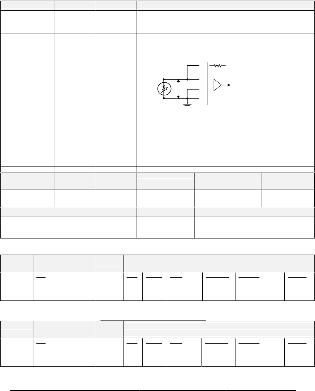
Honeywell
MK XXII EGPWS Installation Manual
CAGE CODE: 97896 SCALE: NONE SIZE: A DWG NO: 060-4314-225 REV: C SHEET 190
TABLE E 3.1.2-0: AIR DATA INPUT SELECT #0
SIGNAL CONNECTION SUMMARY DATA
Uncorrected Barometric
Altitude (+) = J1-62
(-) = J1-43 Format: DC with Validity Flag
Input Type: Basic
Fault Designation: BAROMETRIC ALTITUDE FAULT
Validity: Barometric Alt Valid (+28V)
Outside Air Temp
Total Air Temperature
Probe element
Excitation:
Temp Input
(probe element):
Ground
5 V = J1-25
(+) = J1-63
(-) = J1-44
GND = J1-53
Format: DC
Input Type: Basic
Fault Designation: STATIC AIR TEMPERATURE FAULT
OAT PROBE
ELEMENT
25
J1 (5 V Ref)
63
44
Temp In
4.42 K Ohms
53
Voat
Chassis Gnd
-
+
Note: Nominal 500 Ω Temperature Probe only.
Resistance @ 0°C: 500Ω±
0.6Ω
Connection example:
CIC Temperature Sensor, P/N 05257 (2 wire). Connect positive lead
to both J1-25 and J1-63. Connect negative lead to both J1-44 and J1-
53 (Chassis Ground).
Other probes may have three contacts.
Computed Airspeed No Connection N/A Substitute Ground Speed for Airspeed (airspeed is not available with this air data input)
PIN FUNCTION CONNECTION PIN TYPE CHANNEL
DESIGNATION
REFERENCE Polarity/Configuration References
Barometric Altitude
Validity Discrete
(+28V)
J1-9 Input 28V_DISC_08 >+17V = Valid
< +4.4V = Invalid 6.6.19
4.2.7
Configuration Data Type Summary Data
Derive Baro Altitude Rate Analog Baro Altitude Rate is derived using
Uncorrected Barometric Altitude. Baro Rate
is not available with this air data source.
TABLE E 3.1.2-1: AIR DATA INPUT SELECT #1
CHANNEL
429RX_2
CONNECT TO:
ADC #1 (Low Speed)
Format: ARINC 429
Fault Designation: AIR DATA BUS
Bus Type: Basic
A = J2-39
B = J2-38 Data
Uncorrected. Baro. Alt
Computed Airspeed
Barometric Rate
Static Air Temperature
Label
203
206
212
213
Sig. Bits
17
14
11
11
Range
±131,072 FT
±1024 KTS
±32768 FPM
512 Degrees
Signal Type
Basic
Basic
Basic
Basic
Resolution
1.0
0.0625
16.0
0.25
Rate (ms)
31.3-62.5
62.5-125
31.3-62.5
250-500
TABLE E 3.1.2-2: AIR DATA INPUT SELECT #2
CHANNEL
429RX_2
CONNECT TO:
ADC #1 (Low Speed)
Format: ARINC 575
Fault Designation: AIR DATA BUS
Bus Type: Basic
A = J2-39
B = J2-38 Data
Uncorrected. Baro. Alt
Computed Airspeed
Barometric Rate
Static Air Temperature
Label
203
206
212
213
Sig. Bits
17
13
11
10
Range
±131,072 FT
±1024 KTS
±20480 FPM
±512 Degrees
Signal Type
Basic
Basic
Basic
Basic
Resolution
1.0
0.125
10.0
0.5
Rate (ms)
31.3-62.5
62.5-125
31.3-62.5
250-500
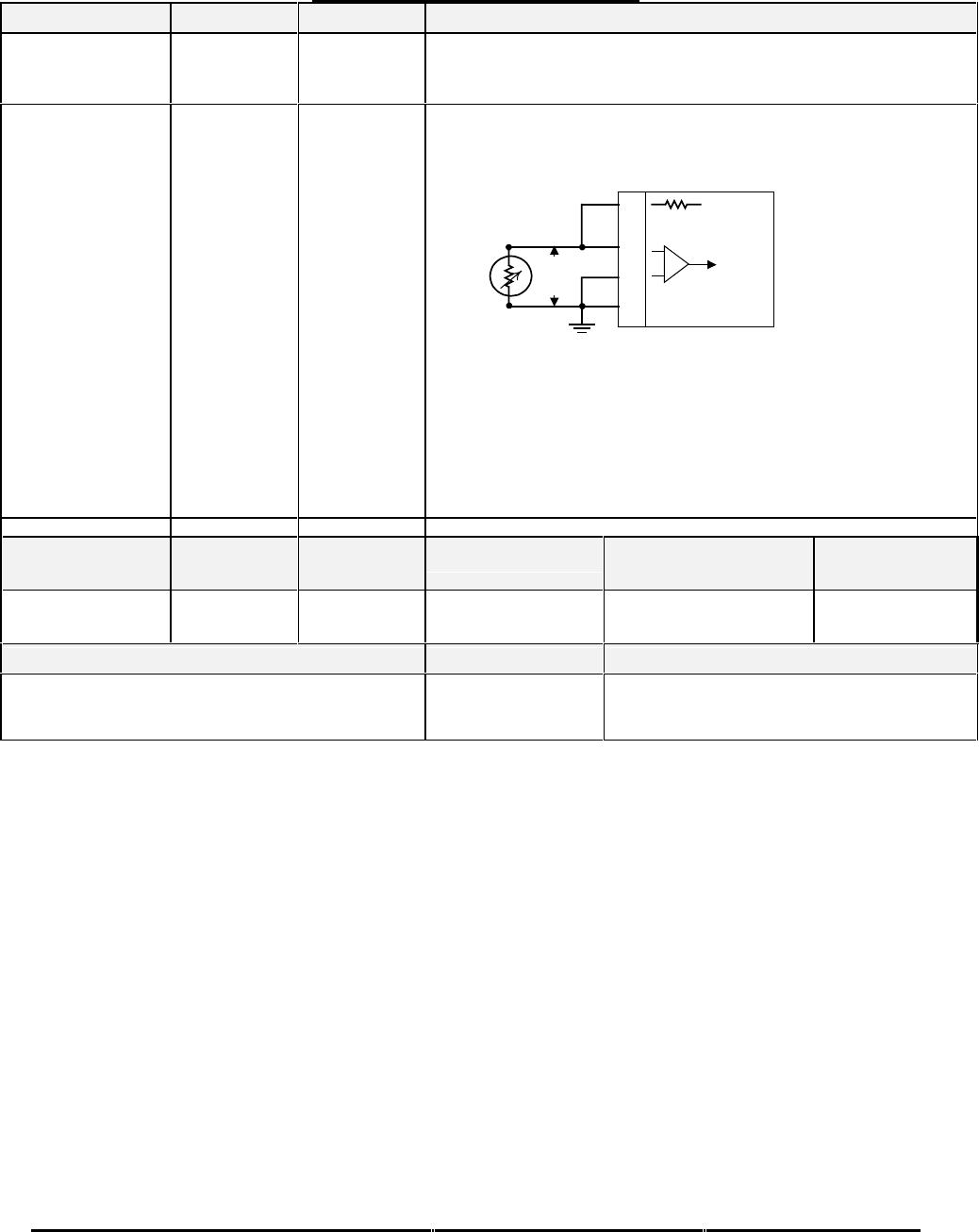
Honeywell
MK XXII EGPWS Installation Manual
CAGE CODE: 97896 SCALE: NONE SIZE: A DWG NO: 060-4314-225 REV: C SHEET 191
TABLE E 3.1.2-3: AIR DATA INPUT SELECT #3
SIGNAL CONNECTION SUMMARY DATA
Uncorrected Barometric
Altitude (+) = J1-62
(-) = J1-43 Format: DC with Validity Flag
Input Type: Basic
Fault Designation: BAROMETRIC ALTITUDE FAULT
Validity: Barometric Alt Valid (+28V)
Outside Air Temp
Total Air Temperature
Probe element
Excitation:
Temp Input
(probe element):
Ground
5 V = J1-25
(+) = J1-63
(-) = J1-44
GND = J1-53
Format: DC
Input Type: Basic
Fault Designation: STATIC AIR TEMPERATURE FAULT
OAT PROBE
ELEMENT
25
J1 (5 V Ref)
63
44
Temp In
4.42 K Ohms
53
Voat
Chassis Gnd
-
+
Note: Nominal 500 Ω Temperature Probe only.
Resistance @ 0°C: 500Ω±
0.6Ω
Connection example:
CIC Temperature Sensor, P/N 05257 (2 wire). Connect positive lead
to both J1-25 and J1-63. Connect negative lead to both J1-44 and J1-
53 (Chassis Ground).
Other probes may have three contacts.
Computed Airspeed No Connection N/A Substitute Ground Speed for Airspeed (airspeed is not available with this air data input)
PIN FUNCTION CONNECTION PIN TYPE CHANNEL
DESIGNATION
REFERENCE Polarity/Configuration References
Barometric Altitude
Validity Discrete
(+28V)
J1-9 Input 28V_DISC_08 >+17V = Valid
< +4.4V = Invalid 6.6.19
4.2.7
Configuration Data Type Summary Data
Derive Baro Altitude Rate Analog Baro Altitude Rate is derived using
Uncorrected Barometric Altitude. Baro Rate
is not available with this air data source.
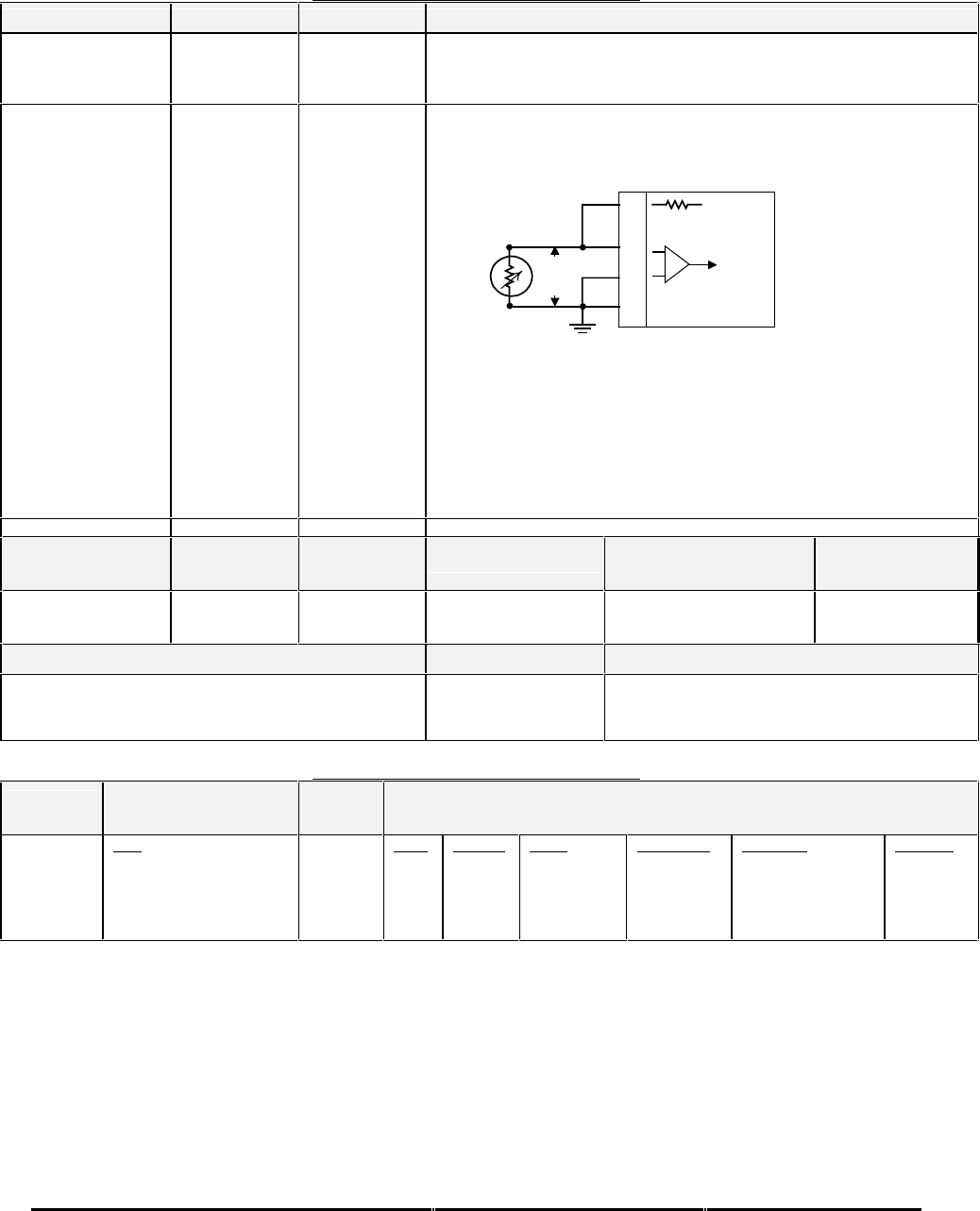
Honeywell
MK XXII EGPWS Installation Manual
CAGE CODE: 97896 SCALE: NONE SIZE: A DWG NO: 060-4314-225 REV: C SHEET 192
TABLE E 3.1.2-4: AIR DATA INPUT SELECT #4
SIGNAL CONNECTION SUMMARY DATA
Uncorrected Barometric
Altitude (+) = J1-62
(-) = J1-43 Format: DC with Validity Flag
Input Type: Basic
Fault Designation: BAROMETRIC ALTITUDE FAULT
Validity: Barometric Alt Valid (+28V)
Outside Air Temp
Total Air Temperature
Probe element
Excitation:
Temp Input
(probe element):
Ground
5 V = J1-25
(+) = J1-63
(-) = J1-44
GND = J1-53
Format: DC
Input Type: Basic
Fault Designation: STATIC AIR TEMPERATURE FAULT
OAT PROBE
ELEMENT
25
J1 (5 V Ref)
63
44
Temp In
4.42 K Ohms
53
Voat
Chassis Gnd
-
+
Note: Nominal 500 Ω Temperature Probe only.
Resistance @ 0°C: 500Ω±
0.6Ω
Connection example:
CIC Temperature Sensor, P/N 05257 (2 wire). Connect positive lead
to both J1-25 and J1-63. Connect negative lead to both J1-44 and J1-
53 (Chassis Ground).
Other probes may have three contacts.
Computed Airspeed No Connection N/A Substitute Ground Speed for Airspeed (airspeed is not available with this air data input)
PIN FUNCTION CONNECTION PIN TYPE CHANNEL
DESIGNATION
REFERENCE Polarity/Configuration References
Barometric Altitude
Validity Discrete
(+28V)
J1-9 Input 28V_DISC_08 >+17V = Valid
< +4.4V = Invalid 6.6.19
4.2.7
Configuration Data Type Summary Data
Derive Baro Altitude Rate Analog Baro Altitude Rate is derived using
Uncorrected Barometric Altitude. Baro Rate
is not available with this air data source.
TABLE E 3.1.2-5: AIR DATA INPUT SELECT #5
CHANNEL
429RX_2
CONNECT TO:
ADC #1 (Low Speed)
Format: ARINC 429
Fault Designation: AIR DATA BUS
Bus Type: Basic
A = J2-39
B = J2-38 Data
Uncorrected. Baro. Alt
Corrected Baro. Alt
Computed Airspeed
Barometric Rate
Static Air Temperature
Label
203
204
206
212
213
Sig. Bits
17
17
14
11
11
Range
±131,072 FT
±131,072 FT
±1024 KTS
±32678 FPM
±512 Degrees
Signal Type
Basic
Basic
Basic
Basic
Basic
Resolution
1.0
1.0
0.0625
16.0
0.25
Rate (ms)
31.3-62.5
31.3-62.5
62.5-125
31.3-62.5
250-500
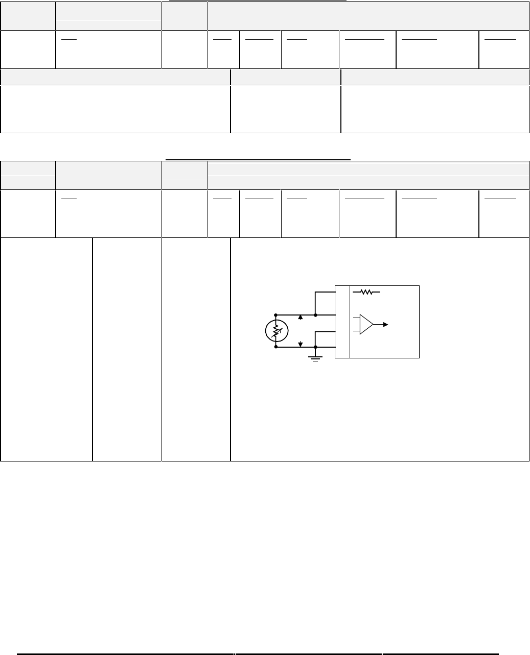
Honeywell
MK XXII EGPWS Installation Manual
CAGE CODE: 97896 SCALE: NONE SIZE: A DWG NO: 060-4314-225 REV: C SHEET 193
TABLE E 3.1.2-6: AIR DATA INPUT SELECT #6
CHANNEL
429RX_2
CONNECT TO:
ADC #1 (Low Speed)
Format: ARINC 429
Fault Designation: AIR DATA BUS
Bus Type: Basic
A = J2-39
B = J2-38 Data
Uncorrected. Baro. Alt
Computed Airspeed
Static Air Temperature
Label
203
206
213
Sig. Bits
17
14
11
Range
±131,072 FT
±1024 KTS
±512 Degrees
Signal Type
Basic
Basic
Basic
Resolution
1.0
0.0625
0.25
Rate (ms)
31.3-62.5
62.5-125
250-500
Configuration Data Type Summary Data
Derive Baro Altitude Rate Digital Baro Altitude Rate is derived using
Uncorrected Barometric Altitude. Baro
Rate is not available with this air data
source.
TABLE E 3.1.2-10: AIR DATA INPUT SELECT #10
CHANNEL
429RX_2
CONNECT TO:
ADC #1 (Low Speed)
Format: ARINC 429
Fault Designation: AIR DATA BUS
Bus Type: Basic
A = J2-39
B = J2-38 Data
Uncorrected. Baro. Alt
Corrected Baro. Alt
Computed Airspeed
Barometric Rate
Label
203
204
206
212
Sig. Bits
17
17
14
11
Range
±131,072 FT
±131,072 FT
±1024 KTS
±32678 FPM
Signal Type
Basic
Basic
Basic
Basic
Resolution
1.0
1.0
0.0625
16.0
Rate (ms)
31.3-62.5
31.3-62.5
62.5-125
31.3-62.5
Outside Air Temp
Total Air Temperature
Probe element
Excitation:
Temp Input
(probe element):
Ground
5 V = J1-25
(+) = J1-63
(-) = J1-44
GND = J1-53
Format: DC
Input Type: Basic
Fault Designation: STATIC AIR TEMPERATURE FAULT
OAT PROBE
ELEMENT
25
J1 (5 V Ref)
63
44
Temp In
4.42 K Ohms
53
Voat
Chassis Gnd
-
+
Note: Nominal 500 Ω Temperature Probe only.
Resistance @ 0°C: 500Ω±
0.6Ω
Connection example:
CIC Temperature Sensor, P/N 05257 (2 wire). Connect positive lead
to both J1-25 and J1-63. Connect negative lead to both J1-44 and J1-
53 (Chassis Ground).
Other probes may have three contacts.
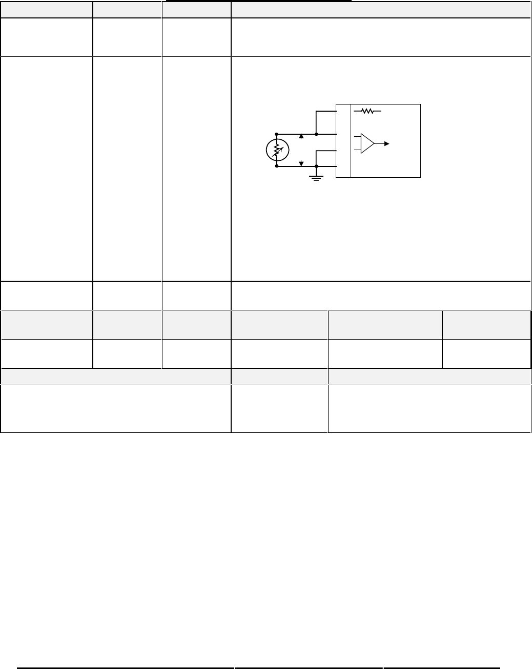
Honeywell
MK XXII EGPWS Installation Manual
CAGE CODE: 97896 SCALE: NONE SIZE: A DWG NO: 060-4314-225 REV: C SHEET 194
TABLE E 3.1.2-11: AIR DATA INPUT SELECT #11
SIGNAL CONNECTION SUMMARY DATA
Uncorrected Barometric
Altitude (+) = J1-62
(-) = J1-43 Format: DC with Validity Flag
Input Type: Basic
Fault Designation: BAROMETRIC ALTITUDE FAULT
Validity: Barometric Alt Valid (+28V)
Outside Air Temp
Total Air Temperature
Probe element
Excitation:
Temp Input
(probe element):
Ground
5 V = J1-25
(+) = J1-63
(-) = J1-44
GND = J1-53
Format: DC
Input Type: Basic
Fault Designation: STATIC AIR TEMPERATURE FAULT
OAT PROBE
ELEMENT
25
J1 (5 V Ref)
63
44
Temp In
4.42 K Ohms
53
Voat
Chassis Gnd
-
+
Note: Nominal 500 Ω Temperature Probe only.
Resistance @ 0°C: 500Ω±
0.6Ω
Connection example:
CIC Temperature Sensor, P/N 05257 (2 wire). Connect positive lead
to both J1-25 and J1-63. Connect negative lead to both J1-44 and J1-
53 (Chassis Ground).
Other probes may have three contacts.
Computed Airspeed No Connection N/A Substitute Ground Speed for Airspeed (airspeed is not available with this air data
input).
PIN FUNCTION CONNECTION PIN TYPE CHANNEL
DESIGNATION
REFERENCE Polarity/Configuration References
Barometric Altitude
Validity Discrete
(+28V)
J1-9 Input 28V_DISC_08 >+17V = Valid
< +4.4V = Invalid 6.6.19
4.2.7
Configuration Data Type Summary Data
Derive Baro Altitude Rate Analog Baro Altitude Rate is derived using
Uncorrected Barometric Altitude. Although
the AZ-241 provides Baro rate, the EGPWS
does not have an analog connection available.
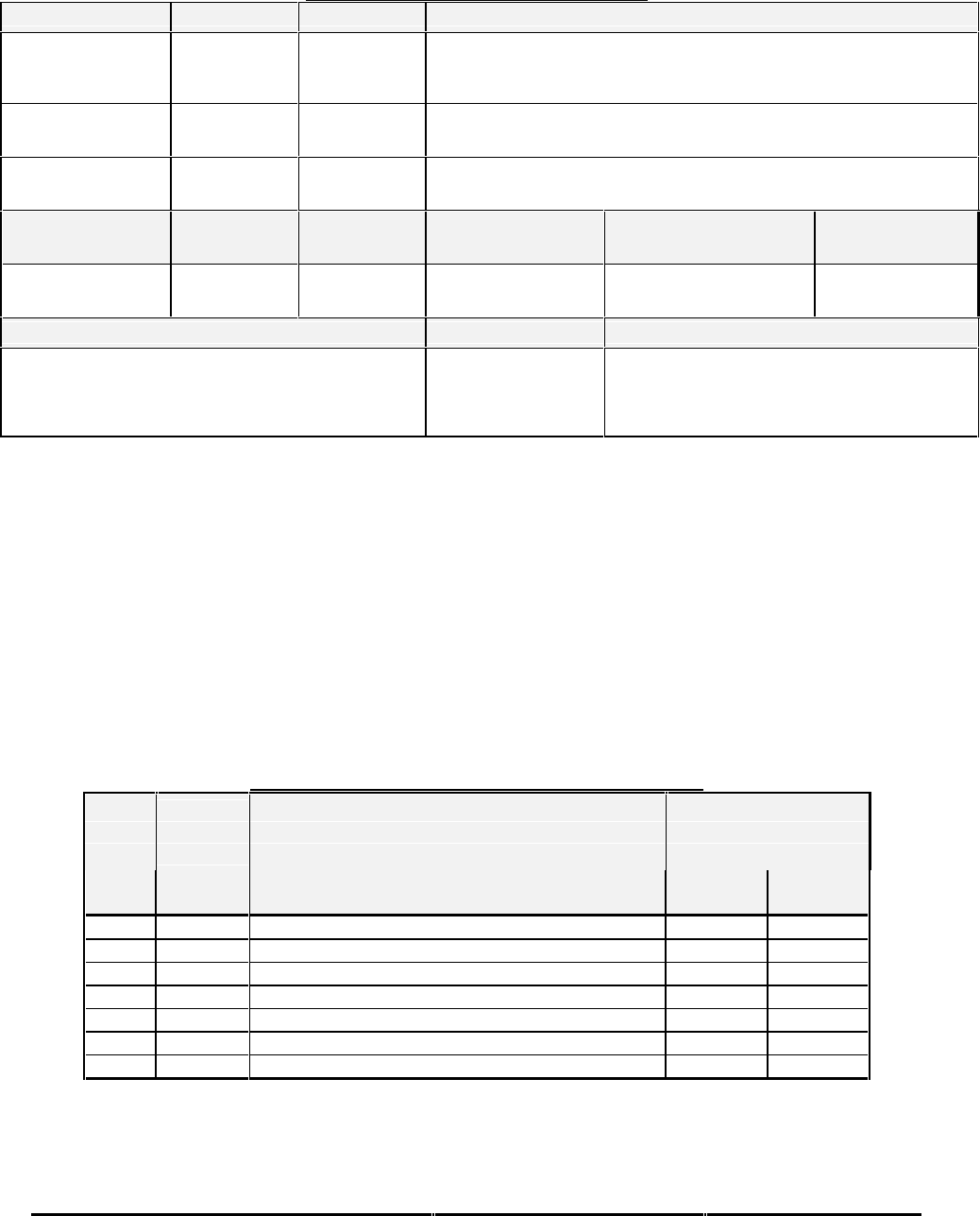
Honeywell
MK XXII EGPWS Installation Manual
CAGE CODE: 97896 SCALE: NONE SIZE: A DWG NO: 060-4314-225 REV: C SHEET 195
TABLE E 3.1.2-12: AIR DATA INPUT SELECT #12
SIGNAL CONNECTION SUMMARY DATA
Uncorrected Barometric
Altitude (+) = J1-62
(-) = J1-43 Format: DC with Validity Flag
Input Type: Basic
Fault Designation: BAROMETRIC ALTITUDE FAULT
Validity: Barometric Alt Valid (+28V)
Outside Air Temp No Connection Format: Internal Constant 250C and Valid.
Input Type: Basic
Fault Designation: Static Air Temperature.
Computed Airspeed No Connection N/A Substitute Ground Speed for Airspeed (airspeed is not available with this air data
input).
PIN FUNCTION CONNECTION PIN TYPE CHANNEL
DESIGNATION
REFERENCE Polarity/Configuration References
Barometric Altitude
Validity Discrete
(+28V)
J1-9 Input 28V_DISC_08 >+17V = Valid
< +4.4V = Invalid 6.6.19
4.2.7
Configuration Data Type Summary Data
Derive Baro Altitude Rate Analog Baro Altitude Rate is derived using
Uncorrected Barometric Altitude. Although
the AZ-800 provides Baro rate, the EGPWS
does not have an analog connection available.
E 5.3.3 CATEGORY 3, POSITION INPUT SELECT
The following table provides identification of the Position source signal. Each entry in the Position Input Type column has a
corresponding table that provides detailed information on the configuration. For example, the details for Position Input Type
#0 are found in Table E 3.1.3-0.
In this category, only the following Position signals are defined:
•Altitude
•Date
•Ground Speed
•Horizontal Figure of Merit (HFOM)
•Horizontal. Integrity Limit
•Latitude Position
•Longitude Position
•Sensor Status
•True Track Angle
•Universal Time Correlation
•Vertical Figure of Merit (VFOM)
TABLE E 3.1.3: POSITION INPUT SELECT FOR EGPWS MKXXII
ID Position
Input
Type Description Effectivity
(TableE
3.1.3-x) App. Cfg.
0 0 GPS, ARINC 429 low speed, 743A format -001 -001
1 1 GPS, ARINC 429 low speed, 743 format -001 -001
2 2 GPS, Internal (RS-232 GPS-PXPRESS format) -001 -001
3 3 GPS, External (RS-232 GPS-PXPRESS format) -001 -001
4 4 GPS, ARINC 429 high speed, 743A format -001 -001
5 5 GPS, ARINC 429 high speed, 743 format -001 -001
255 6 Dual GPS, ARINC 429 high speed, 743 format -003 -003
Note 1: The GPS Altitude Reference in Category 7, Options 1 Select must be properly applied for the appropriate GPS
Position type. At the time of release of this document, all GPS sources except the Universal GPS1000 based systems are of

Honeywell
MK XXII EGPWS Installation Manual
CAGE CODE: 97896 SCALE: NONE SIZE: A DWG NO: 060-4314-225 REV: C SHEET 196
MSL type. The Universal GPS1000 based GPS sources are of WGS-84 type. If the internal GPS source (ID=2) is defined,
the GPS altitude reference in Category 7 must be MSL.
Note 2: Universal GPS 1000 does not calculate VFOM and HFOM correctly which makes it an unacceptble position source
for helicopters.
TABLE E 3.1.3-0: POSITION INPUT TYPE 0 (LOW SPEED ARINC 743A GPS)
CHANNEL
429RX_4
CONNECT TO:
GPS (Low Speed)
per ARINC 743A-2
Fault Designation: GPS BUS
Bus Type: Basic
A = J2-25
B = J2-8 Data
Latitude - Normal
Longitude - Normal
GPS Hor. Int. Limit
Altitude
VFOM
HFOM
Ground Speed
True Track Angle
Sensor Status
**UTC
**Date
**This label is not required.
Data used if present
Label
110
111
130
076
136
247
112
103
273
125
260
Sig. Bits
20
20
17
20
18
18
15
15
19
19
19
Range
±180 Degrees
±180 Degrees
16 nm
±131,072 FT
32768 ft
16 nm
±4096 Knots
±180 Degrees
Discrete Wd
Discrete Wd
Discrete Wd
Signal Type
Basic
Basic
Basic
Basic
Basic
Basic
Basic
Basic
Basic
Basic
Basic
Resolution
0.00017166137695
0.00017166137695
0.00012207
0.125
0.125
0.000061035
0.125
0.0054931640625
n/a
0.1 min
1 day
*Rate (ms)
1000
1000
1000
1000
1000
1000
1000
1000
1000
1000
1000
*Slowest acceptable update rate in milliseconds.
TABLE E 3.1.3-1: POSITION INPUT TYPE 1 (LOW SPEED ARINC 743 GPS)
CHANNEL
429RX_4
CONNECT TO:
GPS (Low Speed)
per ARINC 743
Fault Designation: GPS BUS
Bus Type: Basic
A = J2-25
B = J2-8 Data
Latitude - Normal
Longitude - Normal
GPS Hor. Int. Limit
Altitude
VFOM
HFOM
Ground Speed
True Track Angle
Sensor Status
**UTC
**Date
**This label is not required.
Data used if present
Label
110
111
130
076
136
247
112
103
273
125
260
Sig. Bits
20
20
17
20
15
15
15
15
19
19
19
Range
±180 Degrees
±180 Degrees
16 nm
±131,072 FT
1024 meters
1024 meters
±4096 Knots
±180 Degrees
Discrete Wd
Discrete Wd
Discrete Wd
Signal Type
Basic
Basic
Basic
Basic
Basic
Basic
Basic
Basic
Basic
Basic
Basic
Resolution
0.00017166137695
0.00017166137695
0.00012207
0.125
0.03125
0.03125
0.125
0.0054931640625
n/a
0.1 min
1 day
*Rate (ms)
1000
1000
1000
1000
1000
1000
1000
1000
1000
1000
1000
*Slowest acceptable update rate in milliseconds.
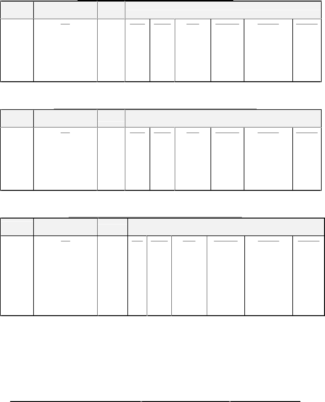
Honeywell
MK XXII EGPWS Installation Manual
CAGE CODE: 97896 SCALE: NONE SIZE: A DWG NO: 060-4314-225 REV: C SHEET 197
TABLE E 3.1.3-2: POSITION INPUT TYPE 2 (INTERNAL RS-232 GPS)
CHANNEL
GPS_RXA
GPS_TXA
Internal GPS
[XPGPS_Int] = 1
(9600 baud)
Fault Designation: INTERNAL GPS
Bus Type: Basic
Internal Data
Latitude
Longitude
HP Error
Altitude
VP Error
Ground Speed
True Track Angle
GPS State
Integrity State
Error Status
ID/byte
15/1-4
15/5-8
15/9-12
16/1-4
16/5-8
17/1-4
17/5-8
1C/0
1C/1
1C/6-7
Sig. Bits
32
32
32
32
32
32
32
8
8
8
Range
±180 Degrees
±180 Degrees
meters
meters
meters
meters/sec
360 Degrees
Discrete Wd
Discrete Wd
Discrete Wd
Signal Type
Basic
Basic
Basic
Basic
Basic
Basic
Basic
Basic
Basic
Basic
Resolution
real single-precision
real single-precision
real single-precision
real single-precision
real single-precision
real single-precision
real single-precision
n/a
n/a
n/a
*Rate (ms)
1000
1000
1000
1000
1000
1000
1000
1000
1000
1000
* Slowest acceptable update rate in milliseconds.
Note: "MSL" reference must be selected when an internal GPS is utilized. Refer to Table 5.3.7
TABLE E 3.1.3-3: POSITION INPUT TYPE 3 (EXTERNAL RS232 GPS, PXPRESS FORMAT)
CHANNEL
GPS_RXA
GPS_TXA
Internal GPS
[XPGPS_Int] = 0
(9600 baud)
Fault Designation: GPS BUS
Bus Type: Basic
External
J2-28 (cm)
J2-45 (Tx)
J2-29 (Rx)
Data
Latitude
Longitude
HP Error
Altitude
VP Error
Ground Speed
True Track Angle
GPS State
Integrity State
Error Status
ID/byte
15/1-4
15/5-8
15/9-12
16/1-4
16/5-8
17/1-4
17/5-8
1C/0
1C/1
1C/6-7
Sig. Bits
32
32
32
32
32
32
32
8
8
8
Range
±180 Degrees
±180 Degrees
meters
meters
meters
meters/sec
360 Degrees
Discrete Wd
Discrete Wd
Discrete Wd
Signal Type
Basic
Basic
Basic
Basic
Basic
Basic
Basic
Basic
Basic
Basic
Resolution
real single-precision
real single-precision
real single-precision
real single-precision
real single-precision
real single-precision
real single-precision
n/a
n/a
n/a
*Rate (ms)
1000
1000
1000
1000
1000
1000
1000
1000
1000
1000
* Slowest acceptable update rate in milliseconds.
TABLE E 3.1.3-4: POSITION INPUT TYPE 4 (HIGH SPEED ARINC 743A GPS)
CHANNEL
429RX_4
CONNECT TO:
GPS (High Speed)
per ARINC 743A-2
Fault Designation: GPS BUS
Bus Type: Basic
A = J2-25
B = J2-8 Data
Latitude - Normal
Longitude - Normal
GPS Hor. Int. Limit
Altitude
VFOM
HFOM
Ground Speed
True Track Angle
Sensor Status
**UTC
**Date
**This label is not required.
Data used if present
Label
110
111
130
076
136
247
112
103
273
125
260
Sig. Bits
20
20
17
20
18
18
15
15
19
19
19
Range
±180 Degrees
±180 Degrees
16 nm
±131,072 FT
32768 ft
16 nm
±4096 Knots
±180 Degrees
Discrete Wd
Discrete Wd
Discrete Wd
Signal Type
Basic
Basic
Basic
Basic
Basic
Basic
Basic
Basic
Basic
Basic
Basic
Resolution
0.00017166137695
0.00017166137695
0.00012207
0.125
0.125
0.000061035
0.125
0.0054931640625
n/a
0.1 min
1 day
*Rate (ms)
1000
1000
1000
1000
1000
1000
1000
1000
1000
1000
1000
*Slowest acceptable update rate in milliseconds.
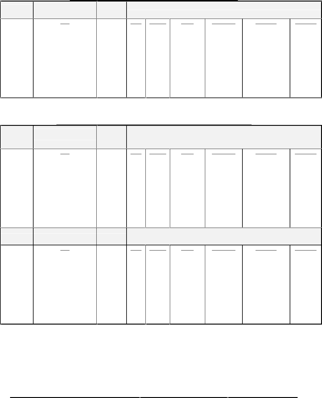
Honeywell
MK XXII EGPWS Installation Manual
CAGE CODE: 97896 SCALE: NONE SIZE: A DWG NO: 060-4314-225 REV: C SHEET 198
TABLE E 3.1.3-5: POSITION INPUT TYPE 5 (HIGH SPEED ARINC 743 GPS)
CHANNEL
429RX_4
CONNECT TO:
GPS (High Speed)
per ARINC 743
Fault Designation: GPS BUS
Bus Type: Basic
A = J2-25
B = J2-8 Data
Latitude - Normal
Longitude - Normal
GPS Hor. Int. Limit
Altitude
VFOM
HFOM
Ground Speed
True Track Angle
Sensor Status
**UTC
**Date
**This label is not required.
Data used if present
Label
110
111
130
076
136
247
112
103
273
125
260
Sig. Bits
20
20
17
20
15
15
15
15
19
19
19
Range
±180 Degrees
±180 Degrees
16 nm
±131,072 FT
1024 meters
1024 meters
±4096 Knots
±180 Degrees
Discrete Wd
Discrete Wd
Discrete Wd
Signal Type
Basic
Basic
Basic
Basic
Basic
Basic
Basic
Basic
Basic
Basic
Basic
Resolution
0.00017166137695
0.00017166137695
0.00012207
0.125
0.03125
0.03125
0.125
0.0054931640625
n/a
0.1 min
1 day
*Rate (ms)
1000
1000
1000
1000
1000
1000
1000
1000
1000
1000
1000
*Slowest acceptable update rate in milliseconds.
TABLE E3.1.3-255: POSITION INPUT TYPE 255 (DUAL HIGH SPEED ARINC 743A GPS)
CHANNEL
429RX_4
CONNECT TO:
GPS #1 (High Speed)
per ARINC 743A-2
Fault Designation: GPS BUS 1
Bus Type: Basic
A = J2-25
B = J2-8 Data
Latitude - Normal
Longitude - Normal
GPS Hor. Int. Limit
Altitude
VFOM
HFOM
Ground Speed
True Track Angle
Sensor Status
**UTC
**Date
**This label is not required.
Data used if present
Label
110
111
130
076
136
247
112
103
273
125
260
Sig. Bits
20
20
17
20
18
18
15
15
19
19
19
Range
±180 Degrees
±180 Degrees
16 nm
±131,072 FT
32768 ft
16 nm
±4096 Knots
±180 Degrees
Discrete Wd
Discrete Wd
Discrete Wd
Signal Type
Basic
Basic
Basic
Basic
Basic
Basic
Basic
Basic
Basic
Basic
Basic
Resolution
0.00017166137695
0.00017166137695
0.00012207
0.125
0.125
0.000061035
0.125
0.0054931640625
n/a
0.1 min
1 day
*Rate (ms)
1000
1000
1000
1000
1000
1000
1000
1000
1000
1000
1000
CHANNEL
429RX_7 CONNECT TO:
GPS #2 (High Speed)
per ARINC 743A-2
Fault Designation: GPS BUS 2
Bus Type: Basic
A = J2-23
B = J2-6 Data
Latitude - Normal
Longitude - Normal
GPS Hor. Int. Limit
Altitude
VFOM
HFOM
Ground Speed
True Track Angle
Sensor Status
**UTC
**Date
**This label is not required.
Data used if present
Label
110
111
130
076
136
247
112
103
273
125
260
Sig. Bits
20
20
17
20
18
18
15
15
19
19
19
Range
±180 Degrees
±180 Degrees
16 nm
±131,072 FT
32768 ft
16 nm
±4096 Knots
±180 Degrees
Discrete Wd
Discrete Wd
Discrete Wd
Signal Type
Basic
Basic
Basic
Basic
Basic
Basic
Basic
Basic
Basic
Basic
Basic
Resolution
0.00017166137695
0.00017166137695
0.00012207
0.125
0.125
0.000061035
0.125
0.0054931640625
n/a
0.1 min
1 day
*Rate (ms)
1000
1000
1000
1000
1000
1000
1000
1000
1000
1000
1000
*Slowest acceptable update rate in milliseconds.
Note: This configuration may not be selected if an AHRS configuration is required for Attitude and Heading information
(refer to Category 10 type 1 and Category 11 type 1), due to the conflict with Channel 429RX-7.

Honeywell
MK XXII EGPWS Installation Manual
CAGE CODE: 97896 SCALE: NONE SIZE: A DWG NO: 060-4314-225 REV: C SHEET 199
E 5.3.4 CATEGORY 4, ALTITUDE CALLOUTS
The following table provides identification of the Altitude Callouts Menu. Each entry in the ID column corresponds to a
particular menu selection.
The Altitude Callouts menu consists of standard callout options and Autorotation Mode reversion callout options. ID’s 0
through 127 consist of standard callouts while ID’s 128 through 255 include standard callouts and reversion to a set of
Autorotation callouts. Selecting ID 0 – 8 will result in the callouts listed being enunciated whether the aircraft is in
autorotation or not. Selecting ID 128 – 137 will result in the identified standard callouts if the aircraft is not in autorotation
and the autorotation callouts listed if the aircraft is in autorotation. The Autorotation Mode is defined by logic within the
EGPWC for helicopter types identified in Category 1.
Smart Callout activation (TRUE) is reflected by a “500” callout being spoken at the end of the selected callout menu
sequence in the Long Level 1 Self-Test. In addition, the Callout menu ID number and the “Smart Callout Selected”
configuration message, will both be given during level 3 Self-Test and in the RS232 Present Status display.
TABLE E 3.1.4: ALTITUDE CALLOUTS FOR EGPWS MKXXII
ID MENU Autorotation3
Callout Enable Smart Callout
Selected Effectivity
App. Cfg.
0MINIMUMS-MINIMUMS,
“Smart 500”, 200, 100, 50, 40, 30, 20 ,10 False True -001 -001
1MINIMUMS-MINIMUMS,
“Smart 500”, 200 False True -001 -001
2MINIMUMS-MINIMUMS,
“Smart 500”, 100, 50, 40, 30, 20,10 False True -001 -001
3 MINIMUMS-MINIMUMS, “Smart 500” False True -001 -001
4MINIMUMS-MINIMUMS,
200, 100, 50, 40, 30, 20 ,10 False False -001 -001
5 MINIMUMS-MINIMUMS, 200 False False -001 -001
6MINIMUMS-MINIMUMS,
100, 50, 40, 30, 20 ,10 False False -001 -001
8 MINIMUMS-MINIMUMS False False -001 -001
128 MINIMUMS-MINIMUMS,
“Smart 500”, 200, 100, 50, 40, 30, 20 ,10 True True4-003 -003
129 MINIMUMS-MINIMUMS,
“Smart 500”, 200 True True4-003 -003
130 MINIMUMS-MINIMUMS,
“Smart 500”, 100, 50, 40, 30, 20 ,10 True True4-003 -003
131 MINIMUMS-MINIMUMS, “Smart 500” True True4-003 -003
132 MINIMUMS-MINIMUMS,
200, 100, 50, 40, 30, 20 ,10 True False -003 -003
133 MINIMUMS-MINIMUMS, 200 True False -003 -003
134 MINIMUMS-MINIMUMS,
100, 50, 40, 30, 20 ,10 True False -003 -003
135 MINIMUMS-MINIMUMS,
100 True False -006 -006
136 MINIMUMS-MINIMUMS, 200, 100 True False -006 -006
137 MINIMUMS-MINIMUMS True False -006 -006
3 The AUTOROTATION callouts consists of: 200, 100 during Autorotation, if Autorotation Callout Enabled is True.
4 The Smart Callout function will not be given if in autorotation.

Honeywell
MK XXII EGPWS Installation Manual
CAGE CODE: 97896 SCALE: NONE SIZE: A DWG NO: 060-4314-225 REV: C SHEET 200
Note: Selecting an Altitude Callout ID without a minimums callout can be accomplished by leaving the Decision Height
input discrete open or connected to +28VDC.

Honeywell
MK XXII EGPWS Installation Manual
CAGE CODE: 97896 SCALE: NONE SIZE: A DWG NO: 060-4314-225 REV: C SHEET 201
E 5.3.5 CATEGORY 5, AUDIO MENU SELECT
The following table provides identification of the Voice Menu type. Each entry in the Voice Menu column has a
corresponding table that provides detailed information on the configuration. For example, the details for Voice Menu # are
found in Table E 3.1.5-128.
TABLE E 3.1.5: AUDIO MENU TYPE
ID Audio Menu Type Description Effectivity
(Table E 3.1.5.-x) App
.Cfg.
128 128 Basic Helicopter Menu -006 -006
TABLE E 3.1.5-128: AUDIO MENU TYPE 128 (BASIC HELICOPTER)
ALERT/WARNING CONDITION AUDIO MENU NOTES
MODE 1 PULL UP PULL UP 1
MODE 2 PULL UP PREFACE TERRAIN TERRAIN 1, 2
MODE 2 PULL UP PULL UP 1
TERRAIN AWARENESS PREFACE WARNING! TERRAIN 1, 2
TERRAIN AWARENESS WARNING WARNING! TERRAIN 1, 3
OBSTACLE AWARENESS PREFACE WARNING! OBSTACLE 1, 2
OBSTACLE AWARENESS WARNING WARNING! OBSTACLE 1, 3
MODE 2 TERRAIN TERRAIN
MODE 6 MINIMUMS SELECTED CALLOUTS (See 5.3.4)
MODE 6 ALTITUDE ALTITUDE ALTITUDE (See 5.3.4)
TERRAIN AWARENESS CAUTION CAUTION TERRAIN (PAUSE) CAUTION TERRAIN 4
OBSTACLE AWARENESS CAUTION CAUTION OBSTACLE (PAUSE) CAUTION OBSTACLE 4
MODE 4 TOO LOW TERRAIN TOO LOW TERRAIN
TCF TOO LOW TERRAIN TOO LOW TERRAIN
MODE 6 ALTITUDE CALLOUTS SELECTED CALLOUTS (See 5.3.4)
MODE 4 TOO LOW GEAR TOO LOW GEAR
MODE 1 SINKRATE SINKRATE
Note: The basic warning is “SINKRATE (PAUSE) SINKRATE”.
However, if the Mode 1 Pullup curve is violated only a single “Sinkrate”
may occur prior to the pull up voice.
5
MODE 3 DON’T SINK DON’T SINK (PAUSE) DON’T SINK
MODE 5 GLIDESLOPE GLIDESLOPE
MODE 6 APPROACHING DH SELECTED CALLOUTS (See 5.3.4)
MODE 6 BANK ANGLE BANK ANGLE (PAUSE) BANK ANGLE,
BANK ANGLE BANK ANGLE (AlliedSignal Algorithm at low
altitudes)
MODE 6 TAIL STRIKE TAIL TOO LOW
TA&D INVALID ALERT BE ALERT TERRAIN INOP
Note 1: These are the only voices that can interrupt.
Note 2: The preface voices will always be given prior to the warning voice.
Note 3: Voice message is continuous.
Note 4: Voice message will repeat every 10 seconds.
Note 5: Long Self-Test will only issue a single 'Sinkrate".

Honeywell
MK XXII EGPWS Installation Manual
CAGE CODE: 97896 SCALE: NONE SIZE: A DWG NO: 060-4314-225 REV: C SHEET 202
E 5.3.6 CATEGORY 6, TERRAIN DISPLAY SELECT
Section Overview
The following table (5.3.6) has an identification number (ID) associated with each Terrain Display configuration. Each of the
ID rows has a group number for the Display Configuration, the Input Control. The TA&D Pop Up Disable function is
defined by a Boolean. The ID groups will completely identify a particular Terrain Display Interface.
In this category the following signals are configured by the ID number:
Signal Name Signal Type Defined By
Terrain Display Bus: KCPB* or ARINC Display Configuration Group
Range Bus: ARINC 429 or RS-422 Display Input Control Group
TA&D Alternate Pop Up Boolean Defined directly in Table
*KCPB is also known as AlliedSignal Picture Bus (ASPB)
TABLE E 3.1.6: TERRAIN DISPLAY SELECT FOR EGPWS MKXXII
ID
E 3.1.6-x-
x
TAD
and
TCF Disable Application Notes Type
Effectivity
0 False KC Picture Bus (KCPB) (Note 1) -006
1False
No Display
TAD And TCF Enabled -006
2 True TA&D / TCF Disabled -006
3 False Collins ProLine II (4x4) (Note 3) -006
4 False Bendix PPI-4A/4B (Note 2)-006
5 False Collins ProLine II (5x6) (Note 3) -006
6 False Collins ProLine II (5x4,5x5) (Note 3) -006
Reserved
Reserved
9 False Non-Integrated EFIS 40/50 (Honeywell/Bendix) -006
10 False Integrated EFIS 40/50 (Honeywell/Bendix) -006
12 False Collins WXI-701/711, without Auto Range -006
13 False Integrated Honeywell P880/660/440
(WXPD w/ SCI range) -006
14 False Bendix PPI-4A/4B without Auto Range (Note 2)-006
15 False Integrated Honeywell P880/660/440
(WXPD w/ SCI range and aircraft symbol on overlay) -006
16 False Bendix, IN182A, IN812A, (RDR 2000) -010
17 False Bendix, IN842A, IN862A, (RDR 2100) -010
18 False KC Picture Bus (KCPB) w/o presentation of Terrain
Awareness Corrected Altitude (Note 1, Note 7) -010
235 False Collins ProLine 4 (Non-Intergrated) -011
236 False Collins ProLine 4 (Intergrated) -011
242 False KC Picture Bus (KCPB) (Note 1, Note 6) -006
246 False Non-Integrated EFIS 10 (Bendix/Honeywell) -006
250 False Honeywell EDZ705 (5x5), EDZ756 (5x6) with DC-811
range push button control -006
255 False Honeywell SPZ8000 (w/SCI range) (Note 4)-006
Note 1: For a description of the KCPB features implemented in a particular software release, see Appendix B: KCPB Phased
Implementation in the EGPWS Interface Methodology document 060-4303-000.
Note 2: This configuration is applicable to RDR-4B with a mod that makes it capable of displaying blue.
Note 3: Refer to Rockwell Collins Service Information Letter, EFIS 84/85/86 SIL 2-99 Dated March 16/99 or later revision,

Honeywell
MK XXII EGPWS Installation Manual
CAGE CODE: 97896 SCALE: NONE SIZE: A DWG NO: 060-4314-225 REV: C SHEET 203
for information describing the requirements to interface an EGPWS to the Collins Pro Line II system equipped with EFIS
84/85/86 Displays and WXR-350/840/700 or TWR-850 Weather Radar systems.
Note 4: This interface only supports the SG-810 and SG-811 SPZ-8000. This display is defined for the –001 & -003 releases
but can cause periodic resets of the EGPWS due to an internal SCI range problem. The –001 & -003 release should not be
used for this display.
Note 5: Peaks Enable is always true regardless of the selection from Category 7 Table 5.3.7.
Note 6: This configuration is applicable to the Aircraft Type 133 (MD900/902) only. It is the only display configuration
supported for that Aircraft Type.
Note-7 With this configuration the EGPWC shall not overlay Terrain Awareness Corrected Altitude.
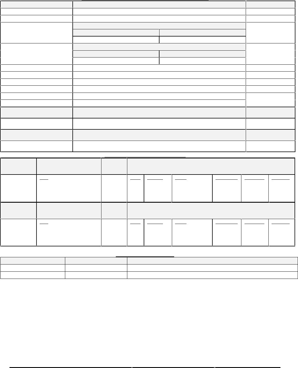
Honeywell
MK XXII EGPWS Installation Manual
CAGE CODE: 97896 SCALE: NONE SIZE: A DWG NO: 060-4314-225 REV: C SHEET 204
Table E 3.1.6-0 KC Picture Bus
DISPLAY CONFIGURATION GROUP 0 (KC PICTURE BUS2)
Function Value
Display Type KC Picture Bus (KCPB)
Sweep Type Curtain (Vertical or Horizontal scan)
Category 7, Options Select Group #1
TA&D Alternate Pop Up: False TA&D Alternate Pop Up: True
Auto Pop Up
Pop Up On Caution or Warning Never Pop Up
Category 7, Options Select Group #1
Peaks Enable: False Peaks Enable: True
Peaks Mode
(Elevations via overlay)
Peaks Off Peaks On
Manual select None (Display Control Selection)
Manual deselect None (Display Control Selection)
Auto Range Controlled by display response (if selected a 10 nm range will be used)
Moving Marker None
Overlay Page Controlled by display
Display bus type KCPB
DISPLAY BUS #1
453TX_1 CONNECT TO:
A = J1-58
B = J1-59 Terrain Display data
DISPLAY BUS #2
453TX_2 CONNECT TO:
A = J1-56
B = J1-57 Terrain Display data
DISPLAY INPUT CONTROL GROUP 0
CHANNEL
429_422RX_1 CONNECT TO:
KCPB-IND 429 out (range)
Bus 1 (Low Speed)
Fault Designation: KCPB BUS 1
Bus Type: Basic
A = J2-37
B = J2-36 Data
*Range
Query/Continuous Response
DSU Status Data (DSU only)
*Key Press/Display Mode
Label
271
011
350
012
Sig. Bits
11
Discrete
Discrete
Discrete
Range
0.5-1023.5NM
N/A
N/A
N/A
Signal Type
Basic
Basic
Basic
Basic
Resolution
0.5
N/A
N/A
N/A
Rate (ms)
250
1000
1000
250
CHANNEL
429RX_3 CONNECT TO:
KCPB-IND 429 out (range)
Bus 2 (Low Speed)
Fault Designation: KCPB BUS 2
Bus Type: Basic
A = J2-41
B = J2-40 Data
*Range
Query/Continuous Response
DSU Status Data (DSU only)
*Key Press/Display Mode
Label
271
011
350
012
Sig. Bits
11
Discrete
Discrete
Discrete
Range
0.5-1023.5NM
N/A
N/A
N/A
Signal Type
Basic
Basic
Basic
Basic
Resolution
0.5
N/A
N/A
N/A
Rate (ms)
250
1000
1000
250
OUTPUT 429 BUS GROUP 0
Channel Pins Comments
429TX_1 (Low Speed) A = J2-43 B = J2-42 Transmits (Section 7) Label sets: 7.1.1.x, 7.1.2.x, 7.1.3.x and 7.1.4.x
429TX_2 A = J2-26 B = J2-9 No Connection (No Data Output)
Integration notes:
•KCPB is also known as ASPB (AlliedSignal Picture Bus).
•Label 012 is optional. The current fault and fault history message “RANGE” for label 271 (Range) is not shown if
Range Keys are requested on label 012 (Key Press/Display Mode).
•When interfacing to a single display controller configuration the bus must be connected to both EGPWS input channels.
This prevents the EGPWS from reporting an external bus fault on the second channel.

Honeywell
MK XXII EGPWS Installation Manual
CAGE CODE: 97896 SCALE: NONE SIZE: A DWG NO: 060-4314-225 REV: C SHEET 205
Table Table E 3.1.6-1 No Display – TAD and TCF Enabled
OUTPUT 429 BUS GROUP 0
Channel Pins Comments
429TX_1 (Low Speed) A = J2-43 B = J2-42 Transmits (Section 7) Label sets: 7.1.1.x, 7.1.2.x, 7.1.3.x and 7.1.4.x
429TX_2 A = J2-26 B = J2-9 No Connection (No Data Output)
Table Table E 3.1.6-2 TA&D / TCF Disabled
OUTPUT 429 BUS GROUP 0
Channel Pins Comments
429TX_1 (Low Speed) A = J2-43 B = J2-42 Transmits (Section 7) Label sets: 7.1.1.x, 7.1.2.x, 7.1.3.x and 7.1.4.x
429TX_2 A = J2-26 B = J2-9 No Connection (No Data Output)
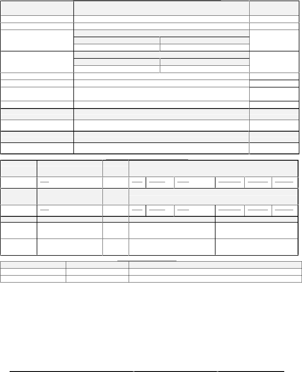
Honeywell
MK XXII EGPWS Installation Manual
CAGE CODE: 97896 SCALE: NONE SIZE: A DWG NO: 060-4314-225 REV: C SHEET 206
Table Table E 3.1.6-3 Collins ProLine II (4x4)
DISPLAY CONFIGURATION GROUP 6 (COLLINS PRO-LINE II, 4X4)
Function Value
Display Type Collins Pro-Line II (4x4) Display
Sweep Type Standard with +/-60 degree limit
Category 7, Options Select Group #1
TA&D Alternate Pop Up: False TA&D Alternate Pop Up: True
Auto Pop Up
Pop Up On Caution or Warning Never Pop Up
Category 7, Options Select Group #1
Peaks Enabled: False Peaks Enabled: True
Peaks Mode
(Elevations via overlay)
Peaks Off Peaks On
Auto Range No
Moving Marker No
Overlay Page Yes; “TERR” located on the left side of display.
Peaks Elevations located on the upper left side of Terrain image.
Display bus type Standard ARINC 453
DISPLAY BUS #1
453TX_1 CONNECT TO:
A = J1-58
B = J1-59 Terrain Display data to switching relay/Symbol Generator
DISPLAY BUS #2
453TX_2 CONNECT TO:
A = J1-56
B = J1-57 Terrain Display data to switching relay/Symbol Generator
DISPLAY INPUT CONTROL GROUP 1
CHANNEL
429_422RX_1 CONNECT TO:
WX-IND 429 out (range)
Bus 1 (Low Speed)
Fault Designation: DISPLAY BUS 1
Bus Type: Basic
A = J2-37
B = J2-36 Data
Range (Display Word 2) Label
271 Sig. Bits
Discrete Range
5-320NM Signal Type
Basic Resolution
N/A Rate (ms)
100
CHANNEL
429RX_3 CONNECT TO:
WX-IND 429 out (range)
Bus 2 (Low Speed)
Fault Designation: DISPLAY BUS 2
Bus Type: Basic
A = J2-41
B = J2-40 Data
Range (Display Word 2) Label
271 Sig. Bits
Discrete Range
5-320NM Signal Type
Basic Resolution
N/A Rate (ms)
100
CONN PIN # REFERENCE NAME PIN FUNCTION Polarity/Configuration
J1-32 GND_DISC_12 Display Select Discrete #1 Type 1 (Momentary)
Gnd = Display Select Toggle
<not> Gnd = Normal
J1-31 GND_DISC_13 Display Select Discrete #2 Type 1 (Momentary)
Gnd = Display Select Toggle
<not> Gnd = Normal
OUTPUT 429 BUS GROUP 0
Channel Pins Comments
429TX_1 (Low Speed) A = J2-43 B = J2-42 Transmits (Section 7) Label sets: 7.1.1.x, 7.1.2.x, 7.1.3.x and 7.1.4.x
429TX_2 A = J2-26 B = J2-9 No Connection (No Data Output)
Integration note:
When interfacing to a single display controller configuration the bus must be connected to both EGPWS input channels. This
prevents the EGPWS from reporting an external bus fault on the second channel.
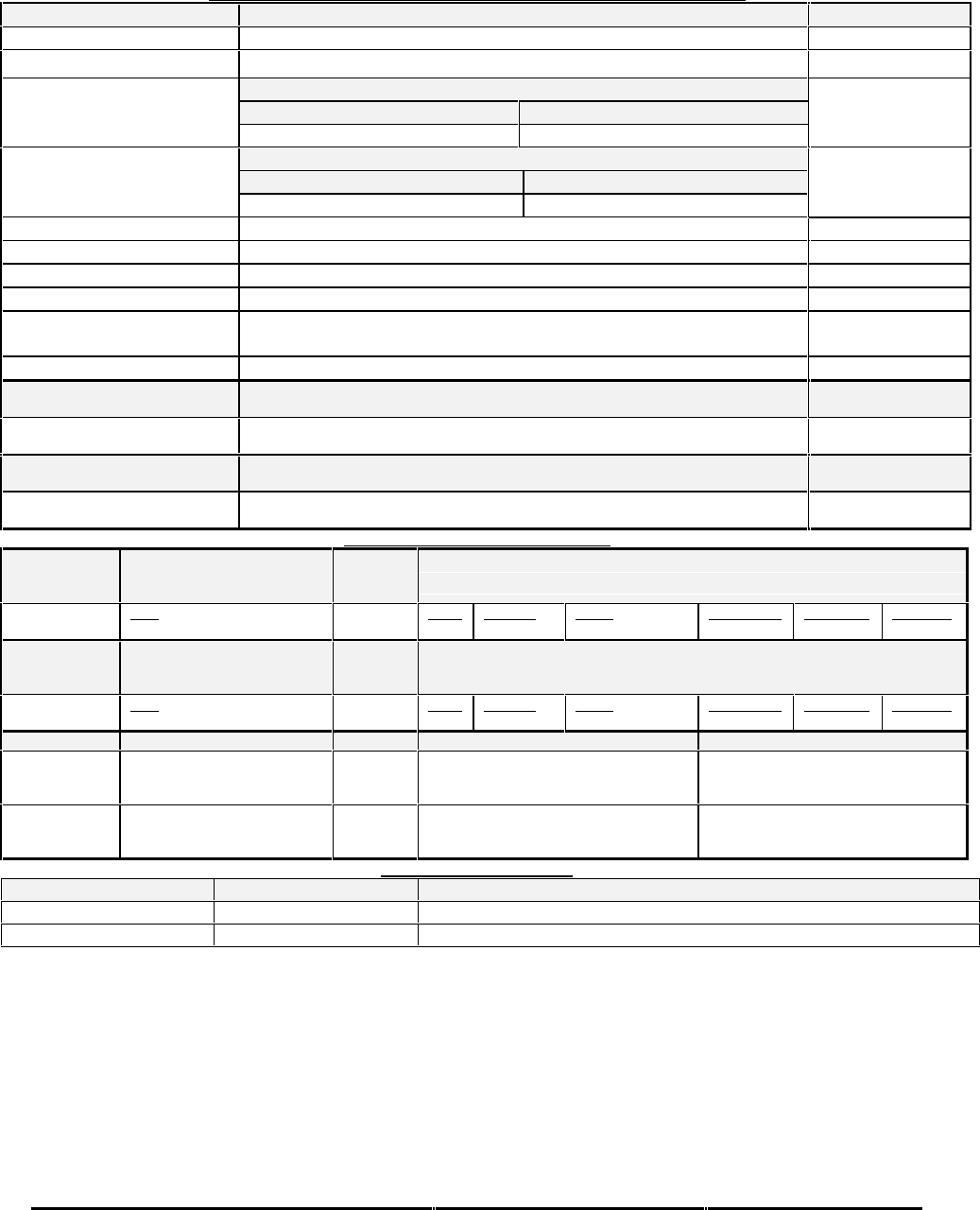
Honeywell
MK XXII EGPWS Installation Manual
CAGE CODE: 97896 SCALE: NONE SIZE: A DWG NO: 060-4314-225 REV: C SHEET 207
Table Table E 3.1.6-4 Bendix PPI-4A/4B
DISPLAY CONFIGURATION GROUP 1 (BENDIX RDR 4A/B PPI WITH MOD )
Function Value
Display Type Bendix PPI-4A/4B (MAP-MODE)
Sweep Type Standard
Category 7, Options Select Group #1
TA&D Alternate Pop Up: False TA&D Alternate Pop Up: True
Auto Pop Up
Pop Up On Caution or Warning Never Pop Up
Category 7, Options Select Group #1
Peaks Enable: False Peaks Enable: True
Peaks Mode
(Elevations via overlay)
Peaks Off Peaks On
Manual select Anytime
Manual deselect Anytime
Auto Range Yes 10NM
Moving Marker No
Overlay Page Without Peaks: “TERR” located in the lower right corner.
With Peaks: Peaks numbers located in the lower right corner.
Display bus type Standard ARINC 453
DISPLAY BUS #1
453TX_1 CONNECT TO:
A = J1-58
B = J1-59 Terrain Display data to switching relay/Symbol Generator
DISPLAY BUS #2
453TX_2 CONNECT TO:
A = J1-56
B = J1-57 Terrain Display data to switching relay/Symbol Generator
DISPLAY INPUT CONTROL GROUP 1
CHANNEL
429_422RX_1 CONNECT TO:
WX-IND 429 out (range)
Bus 1 (Low Speed)
Fault Designation: DISPLAY BUS 1
Bus Type: Basic
A = J2-37
B = J2-36 Data
Range (Display Word 2) Label
271 Sig. Bits
Discrete Range
5-320NM Signal Type
Basic Resolution
N/A Rate (ms)
100
CHANNEL
429RX_3 CONNECT TO:
WX-IND 429 out (range)
Bus 2 (Low Speed)
Fault Designation: DISPLAY BUS 2
Bus Type: Basic
A = J2-41
B = J2-40 Data
Range (Display Word 2) Label
271 Sig. Bits
Discrete Range
5-320NM Signal Type
Basic Resolution
N/A Rate (ms)
100
CONN PIN # REFERENCE NAME PIN FUNCTION Polarity/Configuration
J1-32 GND_DISC_12 Display Select Discrete #1 Type 1 (Momentary)
Gnd = Display Select Toggle
<not> Gnd = Normal
J1-31 GND_DISC_13 Display Select Discrete #2 Type 1 (Momentary)
Gnd = Display Select Toggle
<not> Gnd = Normal
OUTPUT 429 BUS GROUP 0
Channel Pins Comments
429TX_1 (Low Speed) A = J2-43 B = J2-42 Transmits (Section 7) Label sets: 7.1.1.x, 7.1.2.x, 7.1.3.x and 7.1.4.x
429TX_2 A = J2-26 B = J2-9 No Connection (No Data Output)
Integration note:
When interfacing to a single display controller configuration the bus must be connected to both EGPWS input channels. This
prevents the EGPWS from reporting an external bus fault on the second channel.

Honeywell
MK XXII EGPWS Installation Manual
CAGE CODE: 97896 SCALE: NONE SIZE: A DWG NO: 060-4314-225 REV: C SHEET 208
Table E 3.1.6-5 Collins ProLine II (5x6)
DISPLAY CONFIGURATION GROUP 2 (COLLINS PROLINE II, 5X6)
Function Value
Display Type Collins ProLine II (5x6)
Sweep Type Standard with +/-60 degree limit
Category 7, Options Select Group #1
TA&D Alternate Pop Up: False TA&D Alternate Pop Up: True
Auto Pop Up
Pop Up On Caution or Warning Never Pop Up
Category 7, Options Select Group #1
Peaks Enabled: False Peaks Enabled: True
Peaks Mode
(Available as of -003)
Peaks Off Peaks On
Manual select Anytime
Manual deselect Anytime
Auto Range No
Moving Marker No
Overlay Page Yes; “TERR” is located on the right side of display.
“TERR” and Peaks Elevations located on upper left side of Terrain
image as of –003.
Display bus type Standard ARINC 453
DISPLAY BUS #1
453TX_1 CONNECT TO:
A = J1-58
B = J1-59 Terrain Display data to switching relay/Symbol Generator
DISPLAY BUS #2
453TX_2 CONNECT TO:
A = J1-56
B = J1-57 Terrain Display data to switching relay/Symbol Generator
DISPLAY INPUT CONTROL GROUP 1
CHANNEL
429_422RX_1 CONNECT TO:
WX-IND 429 out (range)
Bus 1 (Low Speed)
Fault Designation: DISPLAY BUS 1
Bus Type: Basic
A = J2-37
B = J2-36 Data
Range (Display Word 2) Label
271 Sig. Bits
Discrete Range
5-320NM Signal Type
Basic Resolution
N/A Rate (ms)
100
CHANNEL
429RX_3 CONNECT TO:
WX-IND 429 out (range)
Bus 2 (Low Speed)
Fault Designation: DISPLAY BUS 2
Bus Type: Basic
A = J2-41
B = J2-40 Data
Range (Display Word 2) Label
271 Sig. Bits
Discrete Range
5-320NM Signal Type
Basic Resolution
N/A Rate (ms)
100
CONN PIN # REFERENCE NAME PIN FUNCTION Polarity/Configuration
J1-32 GND_DISC_12 Display Select Discrete #1 Type 1 (Momentary)
Gnd = Display Select Toggle
<not> Gnd = Normal
J1-31 GND_DISC_13 Display Select Discrete #2 Type 1 (Momentary)
Gnd = Display Select Toggle
<not> Gnd = Normal
OUTPUT 429 BUS GROUP 0
Channel Pins Comments
429TX_1 (Low Speed) A = J2-43 B = J2-42 Transmits (Section 7) Label sets: 7.1.1.x, 7.1.2.x, 7.1.3.x and 7.1.4.x
429TX_2 A = J2-26 B = J2-9 No Connection (No Data Output)
Integration note:
When interfacing to a single display controller configuration the bus must be connected to both EGPWS input channels. This
prevents the EGPWS from reporting an external bus fault on the second channel.
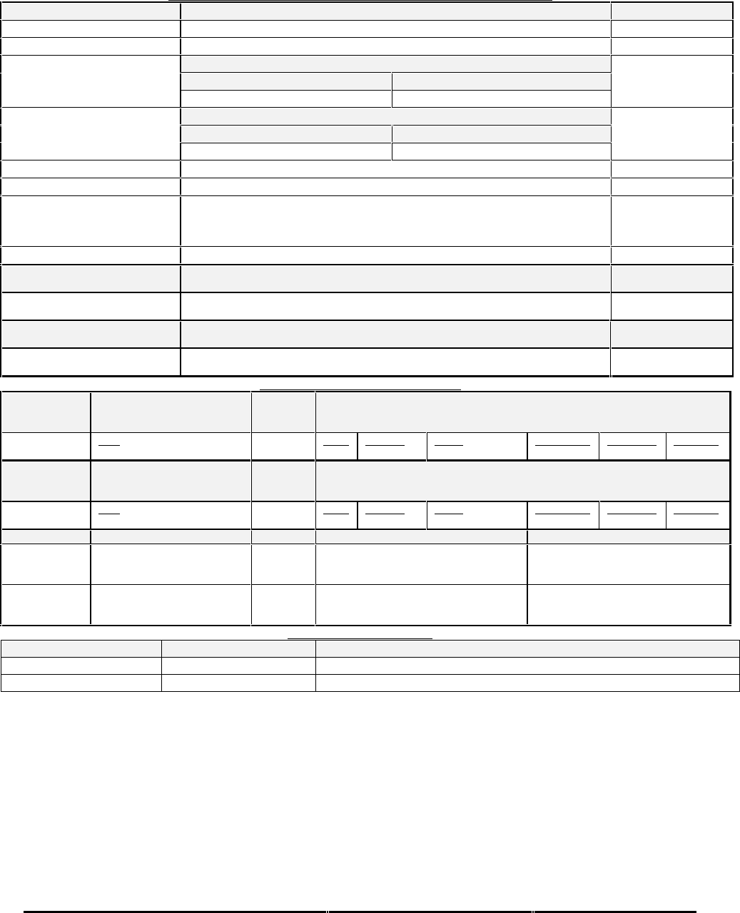
Honeywell
MK XXII EGPWS Installation Manual
CAGE CODE: 97896 SCALE: NONE SIZE: A DWG NO: 060-4314-225 REV: C SHEET 209
Table E 3.1.6-6 Collins ProLine II (5x4,5x5)
DISPLAY CONFIGURATION GROUP 3 (COLLINS PROLINE II, 5X4, 5X5)
Function Value
Display Type Collins ProLine II (5x4, 5x5) Display
Sweep Type Standard with +/-60 degree limit
Category 7, Options Select Group #1
TA&D Alternate Pop Up: False TA&D Alternate Pop Up: True
Auto Pop Up
Pop Up On Caution or Warning Never Pop Up
Category 7, Options Select Group #1
Peaks Enabled: False Peaks Enabled: True
Peaks Mode
(Available as of –003)
Peaks Off Peaks On
Auto Range No
Moving Marker No
Overlay Page Yes; “TERR” is located on the right side of display.
“TERR” or Peaks Elevations located on upper left side of Terrain image
as of -003.
Display bus type Standard ARINC 453
DISPLAY BUS #1
453TX_1 CONNECT TO:
A = J1-58
B = J1-59 Terrain Display data to switching relay/Symbol Generator
DISPLAY BUS #2
453TX_2 CONNECT TO:
A = J1-56
B = J1-57 Terrain Display data to switching relay/Symbol Generator
DISPLAY INPUT CONTROL GROUP 1
CHANNEL
429_422RX_1 CONNECT TO:
WX-IND 429 out (range)
Bus 1 (Low Speed)
Fault Designation: DISPLAY BUS 1
Bus Type: Basic
A = J2-37
B = J2-36 Data
Range (Display Word 2) Label
271 Sig. Bits
Discrete Range
5-320NM Signal Type
Basic Resolution
N/A Rate (ms)
100
CHANNEL
429RX_3 CONNECT TO:
WX-IND 429 out (range)
Bus 2 (Low Speed)
Fault Designation: DISPLAY BUS 2
Bus Type: Basic
A = J2-41
B = J2-40 Data
Range (Display Word 2) Label
271 Sig. Bits
Discrete Range
5-320NM Signal Type
Basic Resolution
N/A Rate (ms)
100
CONN PIN # REFERENCE NAME PIN FUNCTION Polarity/Configuration
J1-32 GND_DISC_12 Display Select Discrete #1 Type 1 (Momentary)
Gnd = Display Select Toggle
<not> Gnd = Normal
J1-31 GND_DISC_13 Display Select Discrete #2 Type 1 (Momentary)
Gnd = Display Select Toggle
<not> Gnd = Normal
OUTPUT 429 BUS GROUP 0
Channel Pins Comments
429TX_1 (Low Speed) A = J2-43 B = J2-42 Transmits (Section 7) Label sets: 7.1.1.x, 7.1.2.x, 7.1.3.x and 7.1.4.x
429TX_2 A = J2-26 B = J2-9 No Connection (No Data Output)
Integration note:
When interfacing to a single display controller configuration the bus must be connected to both EGPWS input channels. This
prevents the EGPWS from reporting an external bus fault on the second channel.
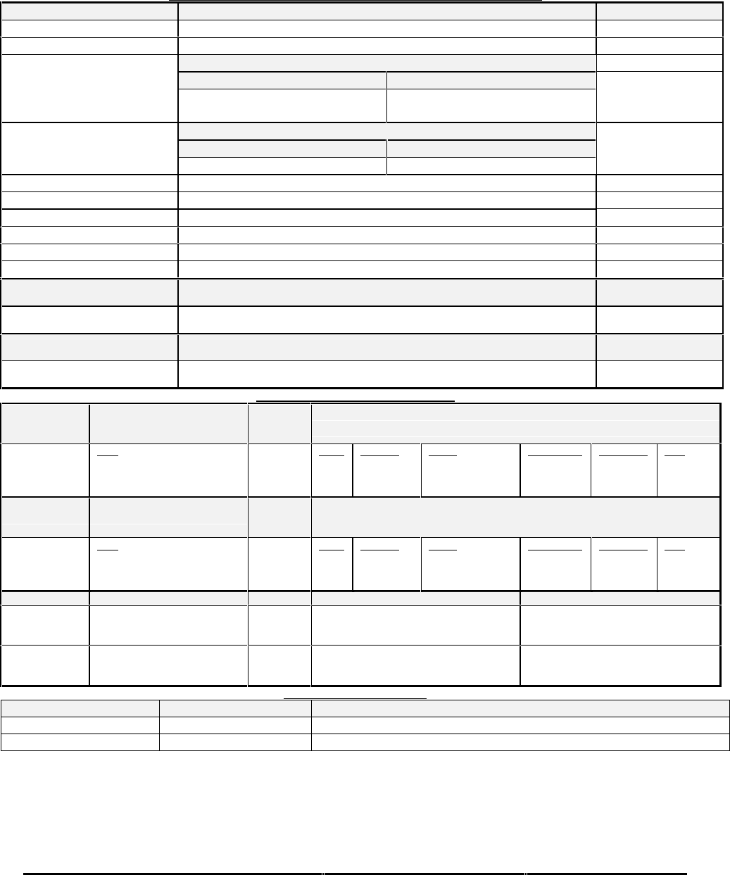
Honeywell
MK XXII EGPWS Installation Manual
CAGE CODE: 97896 SCALE: NONE SIZE: A DWG NO: 060-4314-225 REV: C SHEET 210
Table E 3.1.6-9 Non-Integrated EFIS 40/50 (Honeywell/Bendix)
DISPLAY CONFIGURATION GROUP 7 (NON-INTEGRATED EFIS 40/50)
Function Value
Display Type Bendix Non-Integrated EFIS 40/50
Sweep Type Sweep range +/- 60 degrees
Category 7, Options Select Group #1
TA&D Alternate Pop Up: False TA&D Alternate Pop Up: True
Auto Pop Up
Pop Up when display is in the
proper mode. Never Pop Up
Category 7, Options Select Group #1
Peaks Enabled: False Peaks Enabled: True
Peaks Mode (Peaks
Elevations are in Terrain
Image, replacing “TERR”) Peaks Off Peaks On
Manual select Anytime WXR is on and display is in proper Mode
Manual deselect Anytime
Auto Range No
Moving Marker No
Overlay Page Yes; “TERR” at upper right corner of display.
Display bus type Standard ARINC 453
DISPLAY BUS #1
453TX_1 CONNECT TO:
A = J1-58
B = J1-59 Terrain Display data to switching relay/Symbol Generator
DISPLAY BUS #2
453TX_2 CONNECT TO:
A = J1-56
B = J1-57 Terrain Display data to switching relay/Symbol Generator
DISPLAY INPUT CONTROL GROUP 2
CHANNEL
429_422RX_1 CONNECT TO:
WX-IND 429 out (range)
Bus 1 (Low Speed)
Fault Designation: DISPLAY BUS 1
Bus Type: Basic
A = J2-37
B = J2-36 Data
Mode (Display Word 1)
Range (Display Word 2)
Discrete Word (VP)
Label
270
271
273
Sig. Bits
Discrete
Discrete
Discrete
Range
Mode, Tilt, Gain
5-320NM
VP Mode, Bit 11
Signal Type
Basic
Basic
Basic
Resolution
N/A
N/A
N/A
Rate
100 ms
100 ms
100 ms
CHANNEL
429RX_3 CONNECT TO:
WX-IND 429 out (range)
Bus 2 (Low Speed)
Fault Designation: DISPLAY BUS 2
Bus Type: Basic
A = J2-41
B = J2-40 Data
Mode (Display Word 1)
Range (Display Word 2)
Discrete Word (VP)
Label
270
271
273
Sig. Bits
Discrete
Discrete
Discrete
Range
Mode, Tilt, Gain
5-320NM
VP Mode, Bit 11
Signal Type
Basic
Basic
Basic
Resolution
N/A
N/A
N/A
Rate
100 ms
100 ms
100 ms
CONN PIN # REFERENCE NAME PIN FUNCTION Polarity/Configuration
J1-32 GND_DISC_12 Display Select Discrete #1 Type 1 (Momentary)
Gnd = Display Select Toggle
<not> Gnd = Normal
J1-31 GND_DISC_13 Display Select Discrete #2 Type 1 (Momentary)
Gnd = Display Select Toggle
<not> Gnd = Normal
OUTPUT 429 BUS GROUP 0
Channel Pins Comments
429TX_1 (Low Speed) A = J2-43 B = J2-42 Transmits (Section 7) Label sets: 7.1.1.x, 7.1.2.x, 7.1.3.x and 7.1.4.x
429TX_2 A = J2-26 B = J2-9 No Connection (No Data Output)
Integration note:
When interfacing to a single display controller configuration the bus must be connected to both EGPWS input channels. This
prevents the EGPWS from reporting an external bus fault on the second channel.

Honeywell
MK XXII EGPWS Installation Manual
CAGE CODE: 97896 SCALE: NONE SIZE: A DWG NO: 060-4314-225 REV: C SHEET 211
Table E 3.1.6-10 Integrated EFIS 40/50 (Honeywell/Bendix)
DISPLAY CONFIGURATION GROUP 8 (INTEGRATED EFIS 40/50)
Function Value
Display Type Bendix Integrated EFIS 40/50
Sweep Type Sweep range +/- 90 degrees
Category 7, Options Select Group #1
TA&D Alternate Pop Up: False TA&D Alternate Pop Up: True
Auto Pop Up
Pop Up on Terrain Caution or
Warning. Never Pop Up
Peaks Always Enabled
Peaks Mode
The EFIS display supplies the Peak Elevations as stroked characters.
The EFIS can be configured to place the Elevations on the bottom left
or right side of the display.
Manual select Anytime
Manual deselect Anytime
Auto Range Yes, to 10 nm on Terrain Caution or Warning.
Moving Marker No
Overlay Page No, the display supplies a “TERR” mode annunciation.
Display bus type Standard ARINC 453
DISPLAY BUS #1
453TX_1 CONNECT TO:
A = J1-58 B = J1-59 Terrain Display data to switching relay/Symbol Generator
DISPLAY BUS #2
453TX_2 CONNECT TO:
A = J1-56 B = J1-57 Terrain Display data to switching relay/Symbol Generator
DISPLAY INPUT CONTROL GROUP 2
CHANNEL
429_422RX_1 CONNECT TO:
WX-IND 429 out (range)
Bus 1 (Low Speed)
Fault Designation: DISPLAY BUS 1
Bus Type: Basic
A = J2-37
B = J2-36 Data
Mode (Display Word 1)
Range (Display Word 2)
Discrete Word (VP)
Label
270
271
273
Sig. Bits
Discrete
Discrete
Discrete
Range
Mode, Tilt, Gain
5-320NM
VP Mode, Bit 11
Signal Type
Basic
Basic
Basic
Resolution
N/A
N/A
N/A
Rate
100 ms
100 ms
100 ms
CHANNEL
429RX_3 CONNECT TO:
WX-IND 429 out (range)
Bus 2 (Low Speed)
Fault Designation: DISPLAY BUS 2
Bus Type: Basic
A = J2-41
B = J2-40 Data
Mode (Display Word 1)
Range (Display Word 2)
Discrete Word (VP)
Label
270
271
273
Sig. Bits
Discrete
Discrete
Discrete
Range
Mode, Tilt, Gain
5-320NM
VP Mode, Bit 11
Signal Type
Basic
Basic
Basic
Resolution
N/A
N/A
N/A
Rate
100 ms
100 ms
100 ms
CONN PIN # REFERENCE NAME PIN FUNCTION Polarity/Configuration
J1-32 GND_DISC_12 Display Select Discrete #1 Type 1 (Momentary)
Gnd = Display Select Toggle
<not> Gnd = Normal
J1-31 GND_DISC_13 Display Select Discrete #2 Type 1 (Momentary)
Gnd = Display Select Toggle
<not> Gnd = Normal
OUTPUT 429 BUS GROUP 0
Channel Pins Comments
429TX_1 (Low Speed) A = J2-43 B = J2-42 Transmits (Section 7) Label sets: 7.1.1.x, 7.1.2.x, 7.1.3.x and 7.1.4.x
429TX_2 A = J2-26 B = J2-9 No Connection (No Data Output)
Integration note:
•Peaks Elevations are transmitted digitally to the display via Label 025 on the ARINC453 bus; they are then display as
stroked charters on the bottom left or right of the display (depending on EFIS strapping).
•To Pop Up for a Terrain Caution or Warning it is necessary for the EFIS to receive two discrete signals from the EGPWS
(one to indicate that Terrain is selected and one to indicate that selection was due to an alert). The EFIS needs to
distinguish between manual selection and alert conditions so it will know when it should autorange. Both EFIS and
EGPWS start to autorange on a Caution or Warning to minimize any latency problem displaying status during an alert.

Honeywell
MK XXII EGPWS Installation Manual
CAGE CODE: 97896 SCALE: NONE SIZE: A DWG NO: 060-4314-225 REV: C SHEET 212
•When interfacing to a single display controller configuration the bus must be connected to both EGPWS input channels.
This prevents the EGPWS from reporting an external bus fault on the second channel.
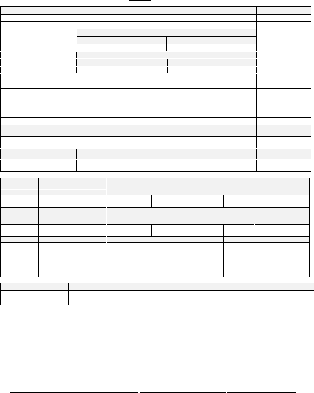
Honeywell
MK XXII EGPWS Installation Manual
CAGE CODE: 97896 SCALE: NONE SIZE: A DWG NO: 060-4314-225 REV: C SHEET 213
Table E 3.1.6-12 Collins WXI-701/711, without Auto Range
DISPLAY CONFIGURATION GROUP 10 (COLLINS WXI 701/711 PPI, WITHOUT AUTO RANGE)
Function Value
Display Type Collins WXI-701/711 PPI
Sweep Type Fan
Category 7, Options Select Group #1
TA&D Alternate Pop Up: False TA&D Alternate Pop Up: True
Auto Pop Up
Pop Up On Caution or Warning Never Pop Up
Category 7, Options Select Group #1
Peaks Enable: False Peaks Enable: True
Peaks Mode
Peaks Off Peaks On
Manual select Anytime
Manual deselect Anytime
Auto Range No
Moving Marker No
Overlay Page Without Peaks: “TERR” located at the bottom left of display.
With Peaks: Peaks numbers lower left.
Display bus type Standard ARINC 453
DISPLAY BUS #1
453TX_1 CONNECT TO:
A = J1-58
B = J1-59 Terrain Display data to switching relay/Symbol Generator
DISPLAY BUS #2
453TX_2 CONNECT TO:
A = J1-56
B = J1-57 Terrain Display data to switching relay/Symbol Generator
DISPLAY INPUT CONTROL GROUP 1
CHANNEL
429_422RX_1 CONNECT TO:
WX-IND 429 out (range)
Bus 1 (Low Speed)
Fault Designation: DISPLAY BUS 1
Bus Type: Basic
A = J2-37
B = J2-36 Data
Range (Display Word 2) Label
271 Sig. Bits
Discrete Range
5-320NM Signal Type
Basic Resolution
N/A Rate (ms)
100
CHANNEL
429RX_3 CONNECT TO:
WX-IND 429 out (range)
Bus 2 (Low Speed)
Fault Designation: DISPLAY BUS 2
Bus Type: Basic
A = J2-41
B = J2-40 Data
Range (Display Word 2) Label
271 Sig. Bits
Discrete Range
5-320NM Signal Type
Basic Resolution
N/A Rate (ms)
100
CONN PIN # REFERENCE NAME PIN FUNCTION Polarity/Configuration
J1-32 GND_DISC_12 Display Select Discrete #1 Type 1 (Momentary)
Gnd = Display Select Toggle
<not> Gnd = Normal
J1-31 GND_DISC_13 Display Select Discrete #2 Type 1 (Momentary)
Gnd = Display Select Toggle
<not> Gnd = Normal
OUTPUT 429 BUS GROUP 0
Channel Pins Comments
429TX_1 (Low Speed) A = J2-43 B = J2-42 Transmits (Section 7) Label sets: 7.1.1.x, 7.1.2.x, 7.1.3.x and 7.1.4.x
429TX_2 A = J2-26 B = J2-9 No Connection (No Data Output)
Integration note:
•Left/Right shift keys on the display are not to be used when displaying terrain.
•When interfacing to a single display controller configuration the bus must be connected to both EGPWS input channels.
This prevents the EGPWS from reporting an external bus fault on the second channel.
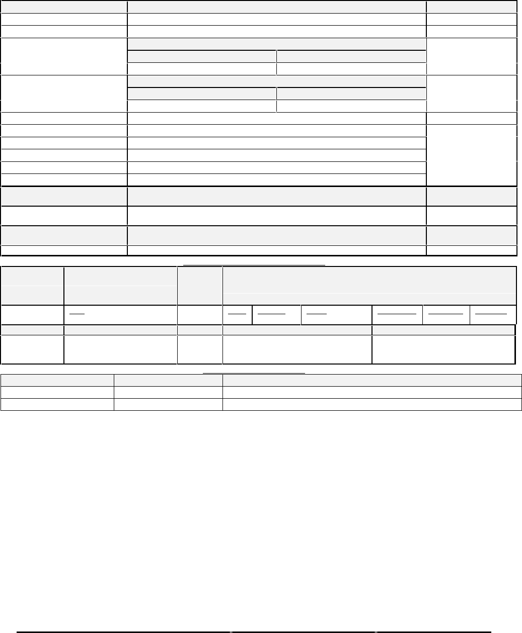
Honeywell
MK XXII EGPWS Installation Manual
CAGE CODE: 97896 SCALE: NONE SIZE: A DWG NO: 060-4314-225 REV: C SHEET 214
Table E 3.1.6-13 Integrated Honeywell P880/660/440 (WXPD w/ SCI range)
Display Configuration Group 11 (Honeywell Integrated P880/660/440).
Function Value
Display Type Honeywell Integrated P880/660/440 radar displays
Sweep Type Honeywell
Auto Pop Up Category 7, Options Select Group #1
TA&D Alternate Pop Up: False TA&D Alternate Pop Up: True
Pop Up On Caution or Warning Never Pop Up
Peaks Mode Category 7, Options Select Group #1
Peaks Enable: False Peaks Enable: True
Peaks Off Peaks On
Manual select Anytime
Manual deselect Anytime
Auto Range No
Moving Marker Yes (across bottom of display)
Overlay Page Yes, for Peaks Elevations only
Display bus type Honeywell picture bus
TERRAIN DISPLAY BUS #1
453TX_1 CONNECT TO:
A = J1-58
B = J1-59 Terrain Display data to switching relay/Symbol Generator #1
TERRAIN DISPLAY BUS #2
453TX_2 CONNECT TO: Not supported for this display type
DISPLAY INPUT CONTROL GROUP 3
CHANNEL
429_422RX_1 CONNECT TO:
SCI Bus 1
(RS-422 - 12K baud) 1.1.1.1.1.1 Fault Designation: DISPLAY BUS 1
Bus Type: Basic
A = J2-36
B = J2-37 Data
Range (Mode/Range Word) Label
80 Sig. Bits
4 Discrete Range
2000NM Signal Type
Basic Resolution
N/A Rate (ms)
100
CONN PIN # REFERENCE NAME PIN FUNCTION Polarity/Configuration
J1-32 GND_DISC_12 Display Select Discrete #1 Type 1 (Momentary)
Gnd = Display Select Toggle
<not> Gnd = Normal
OUTPUT 429 BUS GROUP 0
Channel Pins Comments
429TX_1 (Low Speed) A = J2-43 B = J2-42 Transmits (Section 7) Label sets: 7.1.1.x, 7.1.2.x, 7.1.3.x and 7.1.4.x
429TX_2 A = J2-26 B = J2-9 No Connection (No Data Output)
Integration note:

Honeywell
MK XXII EGPWS Installation Manual
CAGE CODE: 97896 SCALE: NONE SIZE: A DWG NO: 060-4314-225 REV: C SHEET 215
Table E 3.1.6-14 Bendix PPI-4A/4B without Auto Range
DISPLAY CONFIGURATION GROUP 12 (BENDIX RDR 4A/B PPI WITHOUT AUTORANGE, WITH MOD )
Function Value
Display Type Bendix PPI-4A/4B (MAP-MODE)
Sweep Type Standard
Category 7, Options Select Group #1
TA&D Alternate Pop Up: False TA&D Alternate Pop Up: True
Auto Pop Up
Pop Up On Caution or Warning Never Pop Up
Category 7, Options Select Group #1
Peaks Enable: False Peaks Enable: True
Peaks Mode
(Elevations via overlay)
Peaks Off Peaks On
Manual select Anytime
Manual deselect Anytime
Auto Range No
Moving Marker No
Overlay Page Without Peaks: “TERR” located in the lower right corner.
With Peaks: Peaks numbers located in the lower right corner.
Display bus type Standard ARINC 453
TERRAIN DISPLAY BUS #1
453TX_1 CONNECT TO:
A = J1-58
B = J1-59 Terrain Display data to switching relay/Symbol Generator
TERRAIN DISPLAY BUS #2
453TX_2 CONNECT TO:
A = J1-56
B = J1-57 Terrain Display data to switching relay/Symbol Generator
DISPLAY INPUT CONTROL GROUP 1
CHANNEL
429_422RX_1 CONNECT TO:
WX-IND 429 out (range)
Bus 1 (Low Speed)
Fault Designation: DISPLAY BUS 1
Bus Type: Basic
A = J2-37
B = J2-36 Data
Range (Display Word 2) Label
271 Sig. Bits
Discrete Range
5-320NM Signal Type
Basic Resolution
N/A Rate (ms)
100
CHANNEL
429RX_3 CONNECT TO:
WX-IND 429 out (range)
Bus 2 (Low Speed)
Fault Designation: DISPLAY BUS 2
Bus Type: Basic
A = J2-41
B = J2-40 Data
Range (Display Word 2) Label
271 Sig. Bits
Discrete Range
5-320NM Signal Type
Basic Resolution
N/A Rate (ms)
100
CONN PIN # REFERENCE NAME PIN FUNCTION Polarity/Configuration
J1-32 GND_DISC_12 Display Select Discrete #1 Type 1 (Momentary)
Gnd = Display Select Toggle
<not> Gnd = Normal
J1-31 GND_DISC_13 Display Select Discrete #2 Type 1 (Momentary)
Gnd = Display Select Toggle
<not> Gnd = Normal
OUTPUT 429 BUS GROUP 0
Channel Pins Comments
429TX_1 (Low Speed) A = J2-43 B = J2-42 Transmits (Section 7) Label sets: 7.1.1.x, 7.1.2.x, 7.1.3.x and 7.1.4.x
429TX_2 A = J2-26 B = J2-9 No Connection (No Data Output)
Integration note:
•When interfacing to a single display controller configuration the bus must be connected to both EGPWS input channels.
This prevents the EGPWS from reporting an external bus fault on the second channel.
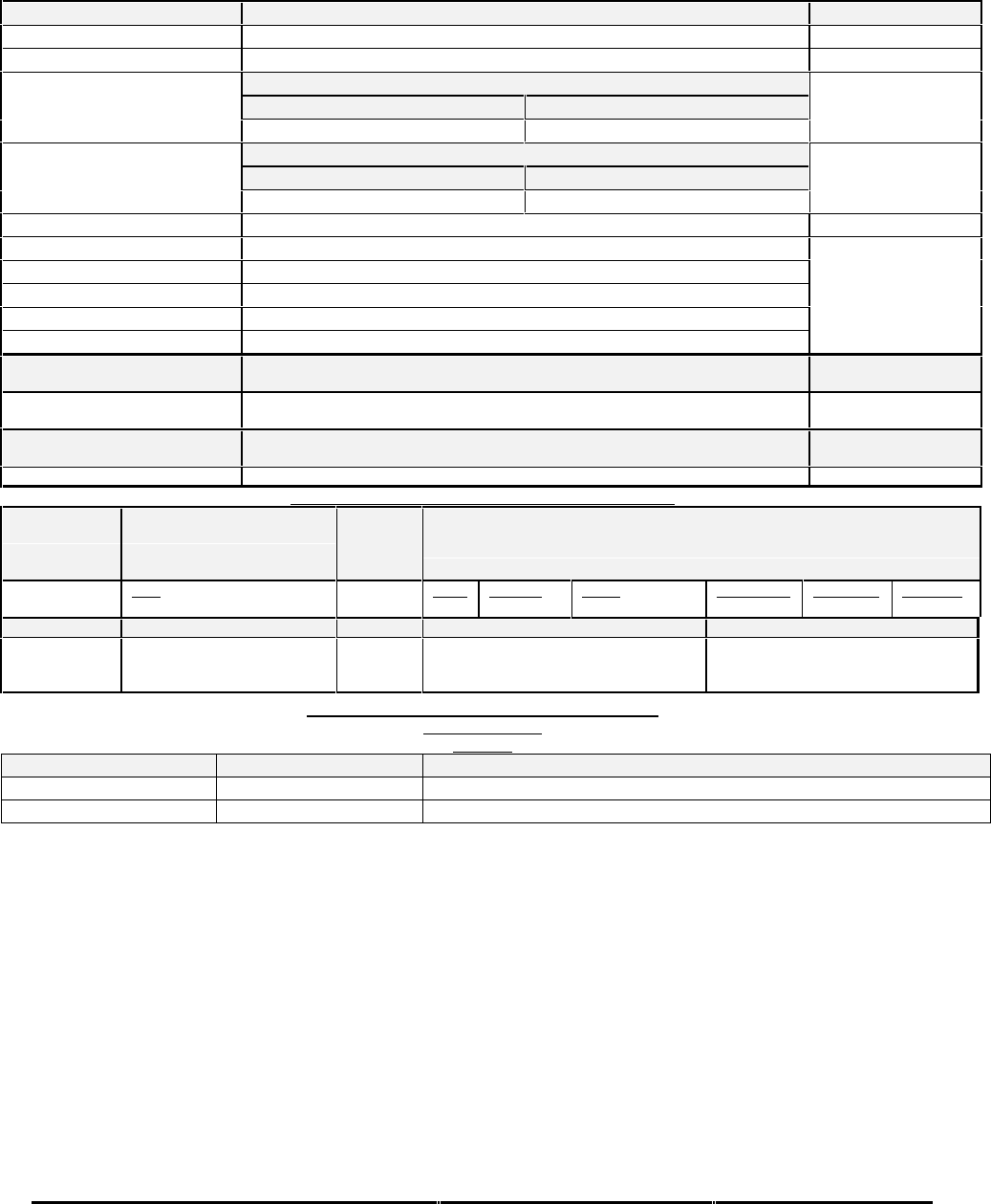
Honeywell
MK XXII EGPWS Installation Manual
CAGE CODE: 97896 SCALE: NONE SIZE: A DWG NO: 060-4314-225 REV: C SHEET 216
Table E 3.1.6-15 Integrated Honeywell P880/660/440
(Honeywell Integrated P880/660/440 with A/C symbol)
Function Value
Display Type Honeywell Integrated P880/660/440 radar displays with A/C symbol
Sweep Type Honeywell
Auto Pop Up Category 7, Options Select Group #1
TA&D Alternate Pop Up: False TA&D Alternate Pop Up: True
Pop Up On Caution or Warning Never Pop Up
Peaks Mode Category 7, Options Select Group #1
Peaks Enable: False Peaks Enable: True
Peaks Off Peaks On
Manual select Anytime
Manual deselect Anytime
Auto Range No
Moving Marker Yes (across bottom of display)
Overlay Page Yes, for Peaks Elevations only
Display bus type Honeywell picture bus
TERRAIN DISPLAY BUS #1
453TX_1 CONNECT TO:
A = J1-58
B = J1-59 Terrain Display data to switching relay/Symbol Generator #1
TERRAIN DISPLAY BUS #2
453TX_2 CONNECT TO: Not supported for this display type
TABLE 5.3.6.2-3 DISPLAY INPUT CONTROL GROUP 3
CHANNEL
429_422RX_1 CONNECT TO:
SCI Bus 1
(RS-422 - 12K baud) 1.1.1.1.1.2 Fault Designation: DISPLAY BUS 1
Bus Type: Basic
A = J2-36
B = J2-37 Data
Range (Mode/Range Word) Label
80 Sig. Bits
4 Discrete Range
2000NM Signal Type
Basic Resolution
N/A Rate (ms)
100
CONN PIN # REFERENCE NAME PIN FUNCTION Polarity/Configuration
J1-32 GND_DISC_12 Display Select Discrete #1 Type 1 (Momentary)
Gnd = Display Select Toggle
<not> Gnd = Normal
TABLE 5.3.6.3-0 OUTPUT 429 BUS GROUP 0
TRACEABILITY
5.3.6.3-0:
Channel Pins Comments
429TX_1 (Low Speed) A = J2-43 B = J2-42 Transmits (Section 7) Label sets: 7.1.1.x, 7.1.2.x, 7.1.3.x and 7.1.4.x
429TX_2 A = J2-26 B = J2-9 No Connection (No Data Output)
Integration Notes:
This display type overlays an inverted T aircraft symbol

Honeywell
MK XXII EGPWS Installation Manual
CAGE CODE: 97896 SCALE: NONE SIZE: A DWG NO: 060-4314-225 REV: C SHEET 217
Table E 3.1.6-16 Bendix IN182A/IN812A Radar display (RDR 2000)
Function Value Reference section
Display Type Bendix IN182A/IN812A color Radar Display (RDR-2000 radar
system)
Sweep Type Sweep range +/- 50 degrees
Category 7, Options Select Group #1
TA&D Alternate Pop Up: False TA&D Alternate Pop Up: True
Auto Pop Up
Pop Up when the display is in the
proper mode. Never Pop Up
Category 7, Options Select Group #1
Peaks Enabled: False Peaks Enabled: True
Peaks Mode
(Available -003)
Peaks Off Peaks On
Manual select Anytime WXR is on and display is in proper Mode
Manual deselect Anytime
Auto Range No
Moving Marker No
Overlay Page Yes; “TERR” centered at top of display.
“TERR” or Peaks Elevation located on upper right side of Terrain
image as of –003.
Display bus type Standard ARINC 453
TERRAIN DISPLAY BUS #1
453TX_1 CONNECT TO:
A = J1-58
B = J1-59 Terrain Display data to switching relay/Symbol Generator
TERRAIN DISPLAY BUS #2
453TX_2 CONNECT TO:
A = J1-56
B = J1-57 Terrain Display data to switching relay/Symbol Generator
Note :
•This config group is similar to config group 4 except warning inhibited message not seen on the overlay
Display Input Control Group 2
CHANNEL
429_422RX_1 CONNECT TO:
WX-IND 429 out (range)
Bus 1 (Low Speed)
Fault Designation: DISPLAY BUS 1
Bus Type: Basic
A = J2-37
B = J2-36 Data
Mode (Display Word 1)
Range (Display Word 2)
Discrete Word (VP)
Reference
6.2.25
6.2.18
6.2.26
Label
270
271
273
Sig. Bits
Discrete
Discrete
Discrete
Range
Mode, Tilt, Gain
5-320NM
VP Mode, Bit 11
Signal Type
Basic
Basic
Basic
Resolution
N/A
N/A
N/A
Rate
100 ms
100 ms
100 ms
CHANNEL
429RX_3 CONNECT TO:
WX-IND 429 out (range)
Bus 2 (Low Speed)
Fault Designation: DISPLAY BUS 2
Bus Type: Basic
A = J2-41
B = J2-40 Data
Mode (Display Word 1)
Range (Display Word 2)
Discrete Word (VP)
Reference
6.2.25
6.2.18
6.2.26
Label
270
271
273
Sig. Bits
Discrete
Discrete
Discrete
Range
Mode, Tilt, Gain
5-320NM
VP Mode, Bit 11
Signal Type
Basic
Basic
Basic
Resolution
N/A
N/A
N/A
Rate
100 ms
100 ms
100 ms
CONN PIN # REFERENCE NAME PIN FUNCTION Polarity/Configuration
J1-32 GND_DISC_12 Reference
4.2.7
6.6.18
Display Select Discrete #1 Type 1 (Momentary)
Gnd = Display Select Toggle
<not> Gnd = Normal
J1-31 GND_DISC_13 Reference
4.2.7
6.6.19
Display Select Discrete #2 Type 1 (Momentary)
Gnd = Display Select Toggle
<not> Gnd = Normal
* When interfacing to a single display controller configuration the bus must be connected to both EGPWS input channels.
This prevents the EGPWS from reporting an external bus fault on the second channel.

Honeywell
MK XXII EGPWS Installation Manual
CAGE CODE: 97896 SCALE: NONE SIZE: A DWG NO: 060-4314-225 REV: C SHEET 218
Output 429 Bus Group 0
Channel Pins Comments
429TX_1 (Low Speed) A = J2-43
B = J2-42 Transmits (Section 7) Label sets: 7.1.1.x, 7.1.2.x, 7.1.3.x, 7.1.4.x, and
7.1.6.x1
429TX_2 A = J2-26
B = J2-9 No Connection (No Data Output)

Honeywell
MK XXII EGPWS Installation Manual
CAGE CODE: 97896 SCALE: NONE SIZE: A DWG NO: 060-4314-225 REV: C SHEET 219
Table E 3.1.6-17 Bendix IN842A/IN862A Radar display (RDR 2100)
Function Value Reference section
Display Type Bendix IN842A/IN862A color Radar Display (RDR-2100 radar
system)
Sweep Type Sweep range +/- 60 degrees
Category 7, Options Select Group #1
TA&D Alternate Pop Up: False TA&D Alternate Pop Up: True
Auto Pop Up
Pop Up when display is in the
proper mode. Never Pop Up
Category 7, Options Select Group #1
Peaks Enabled: False Peaks Enabled: True
Peaks Mode
(Available -003)
Peaks Off Peaks On
Manual select Anytime WXR is on and display is in proper Mode
Manual deselect Anytime
Auto Range No
Moving Marker No
Overlay Page Yes; “TERR” centered at top of display.
“TERR” or Peaks Elevation located on upper right side of Terrain
image as of –003.
Display bus type Standard ARINC 453
TERRAIN DISPLAY BUS #1
453TX_1 CONNECT TO:
A = J1-58
B = J1-59 Terrain Display data to switching relay/Symbol Generator
TERRAIN DISPLAY BUS #2
453TX_2 CONNECT TO:
A = J1-56
B = J1-57 Terrain Display data to switching relay/Symbol Generator
Note :
•This config group is similar to config group 5 except warning inhibited message not seen on the overlay

Honeywell
MK XXII EGPWS Installation Manual
CAGE CODE: 97896 SCALE: NONE SIZE: A DWG NO: 060-4314-225 REV: C SHEET 220
Display Input Control Group 2
CHANNEL
429_422RX_1 CONNECT TO:
WX-IND 429 out (range)
Bus 1 (Low Speed)
Fault Designation: DISPLAY BUS 1
Bus Type: Basic
A = J2-37
B = J2-36 Data
Mode (Display Word 1)
Range (Display Word 2)
Discrete Word (VP)
Reference
6.2.25
6.2.18
6.2.26
Label
270
271
273
Sig. Bits
Discrete
Discrete
Discrete
Range
Mode, Tilt, Gain
5-320NM
VP Mode, Bit 11
Signal Type
Basic
Basic
Basic
Resolution
N/A
N/A
N/A
Rate
100 ms
100 ms
100 ms
CHANNEL
429RX_3 CONNECT TO:
WX-IND 429 out (range)
Bus 2 (Low Speed)
Fault Designation: DISPLAY BUS 2
Bus Type: Basic
A = J2-41
B = J2-40 Data
Mode (Display Word 1)
Range (Display Word 2)
Discrete Word (VP)
Reference
6.2.25
6.2.18
6.2.26
Label
270
271
273
Sig. Bits
Discrete
Discrete
Discrete
Range
Mode, Tilt, Gain
5-320NM
VP Mode, Bit 11
Signal Type
Basic
Basic
Basic
Resolution
N/A
N/A
N/A
Rate
100 ms
100 ms
100 ms
CONN PIN # REFERENCE NAME PIN FUNCTION Polarity/Configuration
J1-32 GND_DISC_12 Reference
4.2.7
6.6.18
Display Select Discrete #1 Type 1 (Momentary)
Gnd = Display Select Toggle
<not> Gnd = Normal
J1-31 GND_DISC_13 Reference
4.2.7
6.6.19
Display Select Discrete #2 Type 1 (Momentary)
Gnd = Display Select Toggle
<not> Gnd = Normal
* When interfacing to a single display controller configuration the bus must be connected to both EGPWS input channels.
This prevents the EGPWS from reporting an external bus fault on the second channel.
Output 429 Bus Group 0
Channel Pins Comments
429TX_1 (Low Speed) A = J2-43
B = J2-42 Transmits (Section 7) Label sets: 7.1.1.x, 7.1.2.x, 7.1.3.x, 7.1.4.x, and
7.1.6.x1
429TX_2 A = J2-26
B = J2-9 No Connection (No Data Output)

Honeywell
MK XXII EGPWS Installation Manual
CAGE CODE: 97896 SCALE: NONE SIZE: A DWG NO: 060-4314-225 REV: C SHEET 221
Table E 3.1.6-18 KC Picture Bus w/o p resen ta tio n of T e rra in A w aren ess C orrected
Altitu d e
Function Value Reference section
Display Type KC Picture Bus (KCPB)
Sweep Type Curtain (Vertical or Horizontal scan)
Category 7, Options Select Group #1
TA&D Alternate Pop Up: False TA&D Alternate Pop Up: True
Auto Pop Up
Pop Up On Caution or Warning Never Pop Up
Category 7, Options Select Group #1
Peaks Enable: False Peaks Enable: True
Peaks Mode
(Elevations via overlay)
Peaks Off Peaks On
Manual select None (Display Control Selection)
Manual deselect None (Display Control Selection)
Auto Range Controlled by display response (if selected a 10 nm range will be used)
Moving Marker None
Overlay Page Controlled by display
Display bus type KCPB
TERRAIN DISPLAY BUS #1
453TX_1 CONNECT TO:
A = J1-58
B = J1-59 Terrain Display data
TERRAIN DISPLAY BUS #2
453TX_2 CONNECT TO:
A = J1-56
B = J1-57 Terrain Display data
Integration Notes:
•KCPB is also known as ASPB (AlliedSignal Picture Bus).
•This Display Group is configured by the Display using response labels on its ARINC 429 data bus.
Display Input Control Group 0
CHANNEL
429_422RX_1 CONNECT TO:
KCPB-IND 429 out (range)
Bus 1 (Low Speed)
Fault Designation: KCPB BUS 1
Bus Type: Basic
A = J2-37
B = J2-36 Data
*Range
Query/Continuous Response
DSU Status Data (DSU only)
*Key Press/Display Mode
Reference
6.2.35
6.2.23
6.2.36
6.2.24
Label
271
011
350
012
Sig. Bits
11
Discrete
Discrete
Discrete
Range
0.5-1023.5NM
N/A
N/A
N/A
Signal Type
Basic
Basic
Basic
Basic
Resolution
0.5
N/A
N/A
N/A
Rate (ms)
250
1000
1000
250
CHANNEL
429RX_3 CONNECT TO:
KCPB-IND 429 out (range)
Bus 2 (Low Speed)
Fault Designation: KCPB BUS 2
Bus Type: Basic
A = J2-41
B = J2-40 Data
*Range
Query/Continuous Response
DSU Status Data (DSU only)
*Key Press/Display Mode
Reference
6.2.35
6.2.23
6.2.36
6.2.24
Label
271
011
350
012
Sig. Bits
11
Discrete
Discrete
Discrete
Range
0.5-1023.5NM
N/A
N/A
N/A
Signal Type
Basic
Basic
Basic
Basic
Resolution
0.5
N/A
N/A
N/A
Rate (ms)
250
1000
1000
250
* Label 012 is optional. The current fault and fault history message “RANGE” for label 271 (Range) is not shown if
Range Keys are requested on label 012 (Key Press/Display Mode).
* When interfacing to a single display controller configuration the bus must be connected to both EGPWS input channels.
This prevents the EGPWS from reporting an external bus fault on the second channel.

Honeywell
MK XXII EGPWS Installation Manual
CAGE CODE: 97896 SCALE: NONE SIZE: A DWG NO: 060-4314-225 REV: C SHEET 222
Output 429 Bus Group 0
Channel Pins Comments
429TX_1 (Low Speed) A = J2-43
B = J2-42 Transmits (Section 7) Label sets: 7.1.1.x, 7.1.2.x, 7.1.3.x, 7.1.4.x, and
7.1.6.x1
429TX_2 A = J2-26
B = J2-9 No Connection (No Data Output)
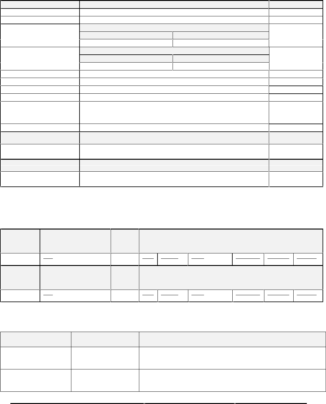
Honeywell
MK XXII EGPWS Installation Manual
CAGE CODE: 97896 SCALE: NONE SIZE: A DWG NO: 060-4314-225 REV: C SHEET 223
Table E 3.1.6-235 Display Configuration (Collins ProLine II, 5x6, and ProLine 4)
Function Value Reference section
Display Type Collins ProLine II (5x6)
Sweep Type Standard with +/-60 degree limit
Category 7, Options Select Group #1
TA&D Alternate Pop Up: False TA&D Alternate Pop Up: True
Auto Pop Up
Pop Up On Caution or Warning Never Pop Up
Category 7, Options Select Group #1
Peaks Enabled: False Peaks Enabled: True
Peaks Mode
(Available as of -003)
Peaks Off Peaks On
Manual select Anytime
Manual deselect Anytime
Auto Range No
Moving Marker No
Overlay Page Yes; “TERR” is located on the right side of display.
“TERR” or Peaks Elevations located on upper left side of Terrain image
as of -003.
Display bus type Standard ARINC 453
TERRAIN DISPLAY BUS #1
453TX_1 CONNECT TO:
A = J1-58
B = J1-59 Terrain Display data to switching relay/Symbol Generator
TERRAIN DISPLAY BUS #2
453TX_2 CONNECT TO:
A = J1-56
B = J1-57 Terrain Display data to switching relay/Symbol Generator
Integration Notes:
1. Peaks Elevation numbers have been re-positioned to improve their presentation/visibility as of –010 release.
Display Input Control Group
CHANNEL
429_422RX_1 CONNECT TO:
IOC #1 Bus (High Speed)
Format: ARINC429 Fault Designation: IOC BUS 1
Bus Type: Basic
A = J2-37
B = J2-36 Data
Range (Mode/Range Word) Label
155 Sig. Bits
Discrete Range
5-640NM Signal Type
Basic Resolution
N/A Rate (ms)
50
CHANNEL
429RX_3 CONNECT TO:
IOC #2 Bus (High Speed)
Format: ARINC429 Fault Designation: IOC BUS 2
BUS TYPE: BASIC
A = J2-41
B = J2-40 Data
Range (Mode/Range Word) Label
155 Sig. Bits
Discrete Range
5-640NM Signal Type
Basic Resolution
N/A Rate (ms)
50
* When interfacing to a single display controller configuration the bus must be connected to both EGPWS input channels.
This prevents the EGPWS from reporting an external bus fault on the second channel.
Output 429 Bus Group
Channel Pins Comments
429TX_1 (Low Speed) A = J2-43
B = J2-42 Transmits
429TX_2 A = J2-26
B = J2-9 No Connection (No Data Output)
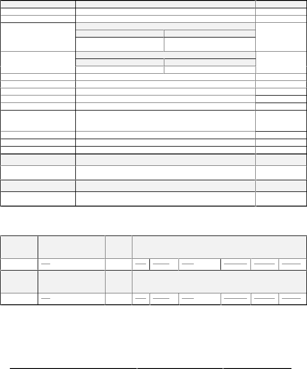
Honeywell
MK XXII EGPWS Installation Manual
CAGE CODE: 97896 SCALE: NONE SIZE: A DWG NO: 060-4314-225 REV: C SHEET 224
Table E3.1.6-236 Display Configuration (Collins ProLine IV, 5x6)
Function Value
Display Type Collins ProLine IV (5x6)
Sweep Type Standard with +/-60 degree limit
Category 7, Options Select Group #1
TA&D Alternate Pop Up: False TA&D Alternate Pop Up: True
Auto Pop Up
No Effect
Pop Up Controlled by Display No Effect
Pop Up Controlled by Display
Category 7, Options Select Group #1
Peaks Enabled: False Peaks Enabled: True
Peaks Mode
(Available as of -011)
Peaks Off Peaks On
Pop Down Never Automatically pop down
Manual select Anytime
Manual deselect Anytime
Auto Range No
Moving Marker No
Overlay Page Yes; “TERR” is located on the right side of display.
“TERR” and Peaks Elevations located on upper left side of Terrain
image as of -011.
Display Priority Standard
Display bus type Standard ARINC 708
Terrain Mode Annunciation Standard
TERRAIN DISPLAY BUS #1
453TX_1 CONNECT TO:
A = J1-58
B = J1-59 Terrain Display data to switching relay/Symbol Generator
TERRAIN DISPLAY BUS #2
453TX_2 CONNECT TO:
A = J1-56
B = J1-57 Terrain Display data to switching relay/Symbol Generator
Display Input Control
CHANNEL
429_422RX_1 CONNECT TO:
IOC #1 Bus (High Speed)
Format: ARINC429 Fault Designation: IOC BUS 1
Bus Type: Basic
A = J2-37
B = J2-36 Data
Range (Mode/Range Word) Label
155 Sig. Bits
Discrete Range
5-640NM Signal Type
Basic Resolution
N/A Rate (ms)
50
CHANNEL
429RX_3 CONNECT TO:
IOC #2 Bus (High Speed)
Format: ARINC429 Fault Designation: IOC BUS 2
BUS TYPE: BASIC
A = J2-41
B = J2-40 Data
Range (Mode/Range Word) Label
155 Sig. Bits
Discrete Range
5-640NM Signal Type
Basic Resolution
N/A Rate (ms)
50
* When interfacing to a single display controller configuration the bus must be connected to both EGPWS input channels.
This prevents the EGPWS from reporting an external bus fault on the second channel.

Honeywell
MK XXII EGPWS Installation Manual
CAGE CODE: 97896 SCALE: NONE SIZE: A DWG NO: 060-4314-225 REV: C SHEET 225
Output 429 Bus Group
Channel Pins Comments
429TX_1 (Low Speed) A = J2-43
B = J2-42 Transmits (Section 7) Label sets: 7.1.1.x, 7.1.2.x, 7.1.3.x, 7.1.4.x, and
7.1.6.x1
429TX_2 A = J2-26
B = J2-9 No Connection (No Data Output)
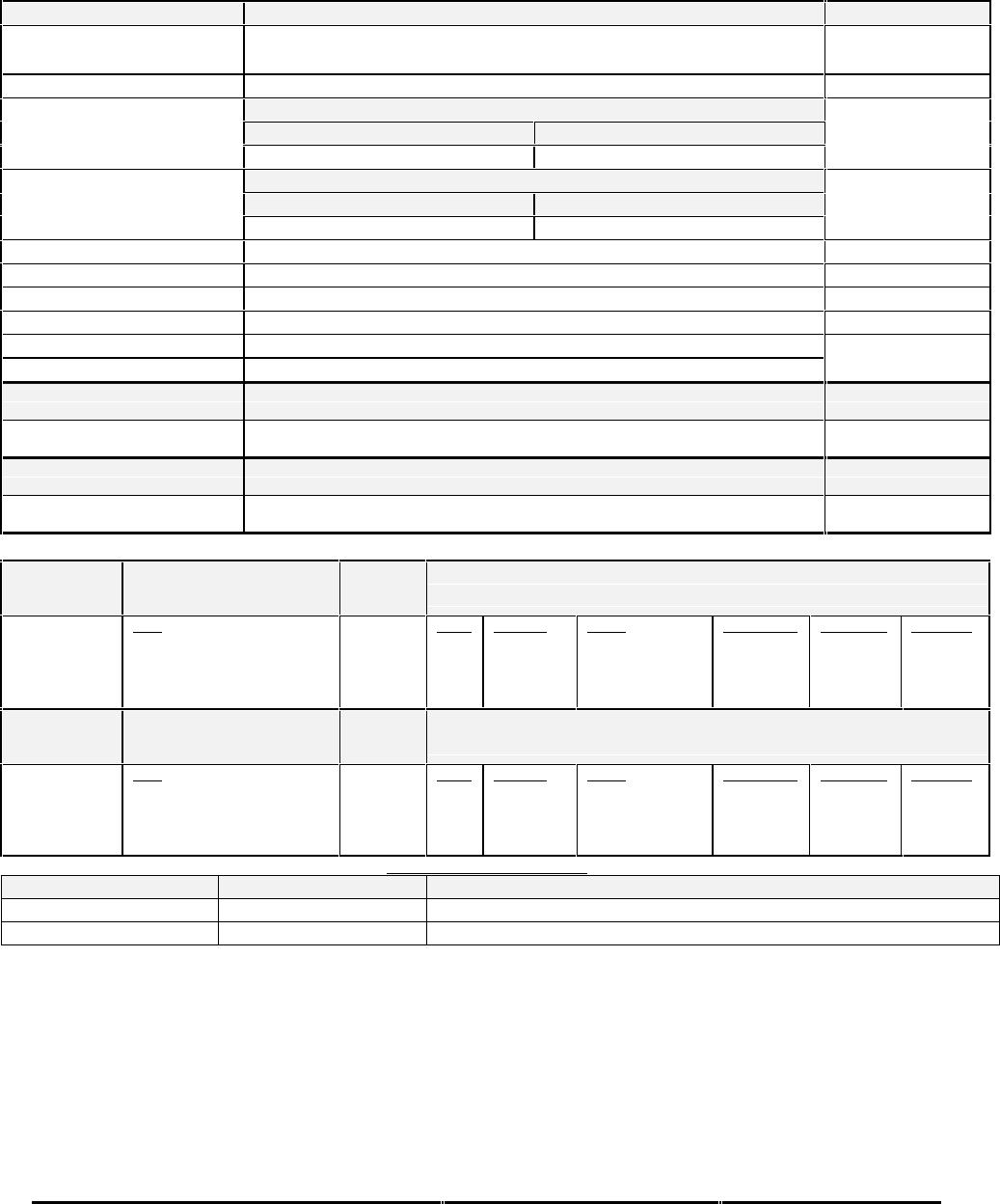
Honeywell
MK XXII EGPWS Installation Manual
CAGE CODE: 97896 SCALE: NONE SIZE: A DWG NO: 060-4314-225 REV: C SHEET 226
Table E 3.1.6-242 KC Picture Bus
Display Configuration Group 0 (KC Picture Bus1)
Function Value
Display Type KC Picture Bus (KCPB)
Sweep Type Curtain (Vertical or Horizontal scan)
Category 7, Options Select Group #1
TA&D Alternate Pop Up: False TA&D Alternate Pop Up: True
Auto Pop Up
Pop Up On Caution or Warning Never Pop Up
Category 7, Options Select Group #1
Peaks Enable: False Peaks Enable: True
Peaks Mode
(Elevations via overlay)
Peaks Off Peaks On
Manual select None (Display Control Selection)
Manual deselect None (Display Control Selection)
Auto Range Controlled by display response (if selected a 10 nm range will be used)
Moving Marker None
Overlay Page Controlled by display
Display bus type KCPB
TERRAIN DISPLAY BUS #1
453TX_1 CONNECT TO:
A = J1-58
B = J1-59 Terrain Display data
TERRAIN DISPLAY BUS #2
453TX_2 CONNECT TO:
A = J1-56
B = J1-57 Terrain Display data
Display Input Control Group 245
CHANNEL
429RX_8 CONNECT TO:
KCPB-IND 429 out (range)
Bus 1 (Low Speed)
Fault Designation: KCPB BUS 1
Bus Type: Basic
A = J2-24
B = J2-07 Data
*Range
Query/Continuous Response
DSU Status Data (DSU only)
*Key Press/Display Mode
Label
271
011
350
012
Sig. Bits
11
Discrete
Discrete
Discrete
Range
0.5-1023.5NM
N/A
N/A
N/A
Signal Type
Basic
Basic
Basic
Basic
Resolution
0.5
N/A
N/A
N/A
Rate (ms)
250
1000
1000
250
CHANNEL
429RX_3 CONNECT TO:
KCPB-IND 429 out (range)
Bus 2 (Low Speed)
Fault Designation: KCPB BUS 2
Bus Type: Basic
A = J2-41
B = J2-40 Data
*Range
Query/Continuous Response
DSU Status Data (DSU only)
*Key Press/Display Mode
Label
271
011
350
012
Sig. Bits
11
Discrete
Discrete
Discrete
Range
0.5-1023.5NM
N/A
N/A
N/A
Signal Type
Basic
Basic
Basic
Basic
Resolution
0.5
N/A
N/A
N/A
Rate (ms)
250
1000
1000
250
OUTPUT 429 BUS GROUP 0
Channel Pins Comments
429TX_1 (Low Speed) A = J2-43 B = J2-42 Transmits (Section 7) Label sets: 7.1.1.x, 7.1.2.x, 7.1.3.x and 7.1.4.x
429TX_2 A = J2-26 B = J2-9 No Connection (No Data Output)
Integration Notes:
•KCPB is also known as ASPB (AlliedSignal Picture Bus).
•This Display Group is configured by the Display using response labels on its ARINC 429 data bus.
•Label 012 is optional. The current fault and fault history message “RANGE” for label 271 (Range) is not shown if
Range Keys are requested on label 012 (Key Press/Display Mode).
•When interfacing to a single display controller configuration the bus must be connected to both EGPWS input channels.
This prevents the EGPWS from reporting an external bus fault on the second channel.
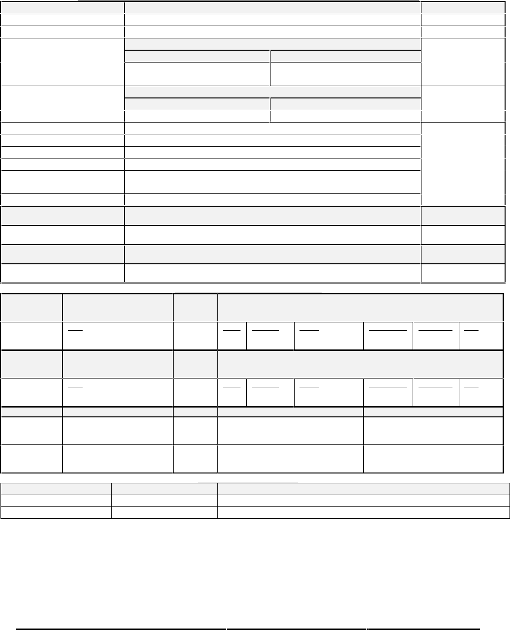
Honeywell
MK XXII EGPWS Installation Manual
CAGE CODE: 97896 SCALE: NONE SIZE: A DWG NO: 060-4314-225 REV: C SHEET 227
Table E 3.1.6-246 Non-Integrated EFIS 10 (Bendix/Honeywell)
DISPLAY CONFIGURATION GROUP 246 (BENDIX EFIS 10 DISPLAY, EFS86 RADAR SYSTEM)
Function Value
Display Type Bendix EFIS 10
Sweep Type Normal, Sweep range +/- 90 degrees
Auto Pop Up Category 7, Options Select Group #1
TA&D Alternate Pop Up: False TA&D Alternate Pop Up: True
Pop Up On Terrain Caution or
Warning.1Never Pop Up
Peaks Mode Category 7, Options Select Group #1
Peaks Enable: False Peaks Enable: True
Peaks Off Peaks On
Manual select Anytime1
Manual deselect Anytime1
Auto Range No
Moving Marker No
Overlay Page Yes; Without Peaks: “TERR” is located at the bottom left of the display.
With Peaks: Peaks numbers are located at the lower left of the display.
Display bus type Standard ARINC 708/453
TERRAIN DISPLAY BUS #1
453TX_1 CONNECT TO:
A = J1-58
B = J1-59 Terrain Display data to switching relay/Symbol Generator #1
TERRAIN DISPLAY BUS #2
453TX_2 CONNECT TO:
A = J1-56
B = J1-57 Terrain Display data to switching relay/Symbol Generator #2
DISPLAY INPUT CONTROL GROUP 246
CHANNEL
429_422RX_1 CONNECT TO:
WX-IND 429 out (range)
Bus 1 (Low Speed)
Fault Designation: DISPLAY BUS 1
Bus Type: Basic
A = J2-37
B = J2-36 Data
Mode (Display Word 1)
Range (Display Word 2)
Label
270
271
Sig. Bits
Discrete
Discrete
Range
Mode, Tilt, Gain
5-320NM
Signal Type
Basic
Basic
Resolution
N/A
N/A
Rate
100 ms
100 ms
CHANNEL
429RX_3 CONNECT TO:
WX-IND 429 out (range)
Bus 2 (Low Speed)
Fault Designation: DISPLAY BUS 2
Bus Type: Basic
A = J2-41
B = J2-40 Data
Mode (Display Word 1)
Range (Display Word 2)
Label
270
271
Sig. Bits
Discrete
Discrete
Range
Mode, Tilt, Gain
5-320NM
Signal Type
Basic
Basic
Resolution
N/A
N/A
Rate
100 ms
100 ms
CONN PIN # REFERENCE NAME PIN FUNCTION Polarity/Configuration
J1-32 GND_DISC_12 Display Select Discrete #1 Type 1 (Momentary)
Gnd = Display Select Toggle
<not> Gnd = Normal
J1-31 GND_DISC_13 Display Select Discrete #2 Type 1 (Momentary)
Gnd = Display Select Toggle
<not> Gnd = Normal
OUTPUT 429 BUS GROUP 0
Channel Pins Comments
429TX_1 (Low Speed) A = J2-43 B = J2-42 Transmits (Section 7) Label sets: 7.1.1.x, 7.1.2.x, 7.1.3.x and 7.1.4.x
429TX_2 A = J2-26 B = J2-9 No Connection (No Data Output)
Integration note:
•Either weather or a weather test pattern must be displayed before Terrain can be viewed. The white weather
annunciation “WX” will still be present when terrain is displayed.
•When interfacing to a single display controller configuration the bus must be connected to both EGPWS input channels.
This prevents the EGPWS from reporting an external bus fault on the second channel.
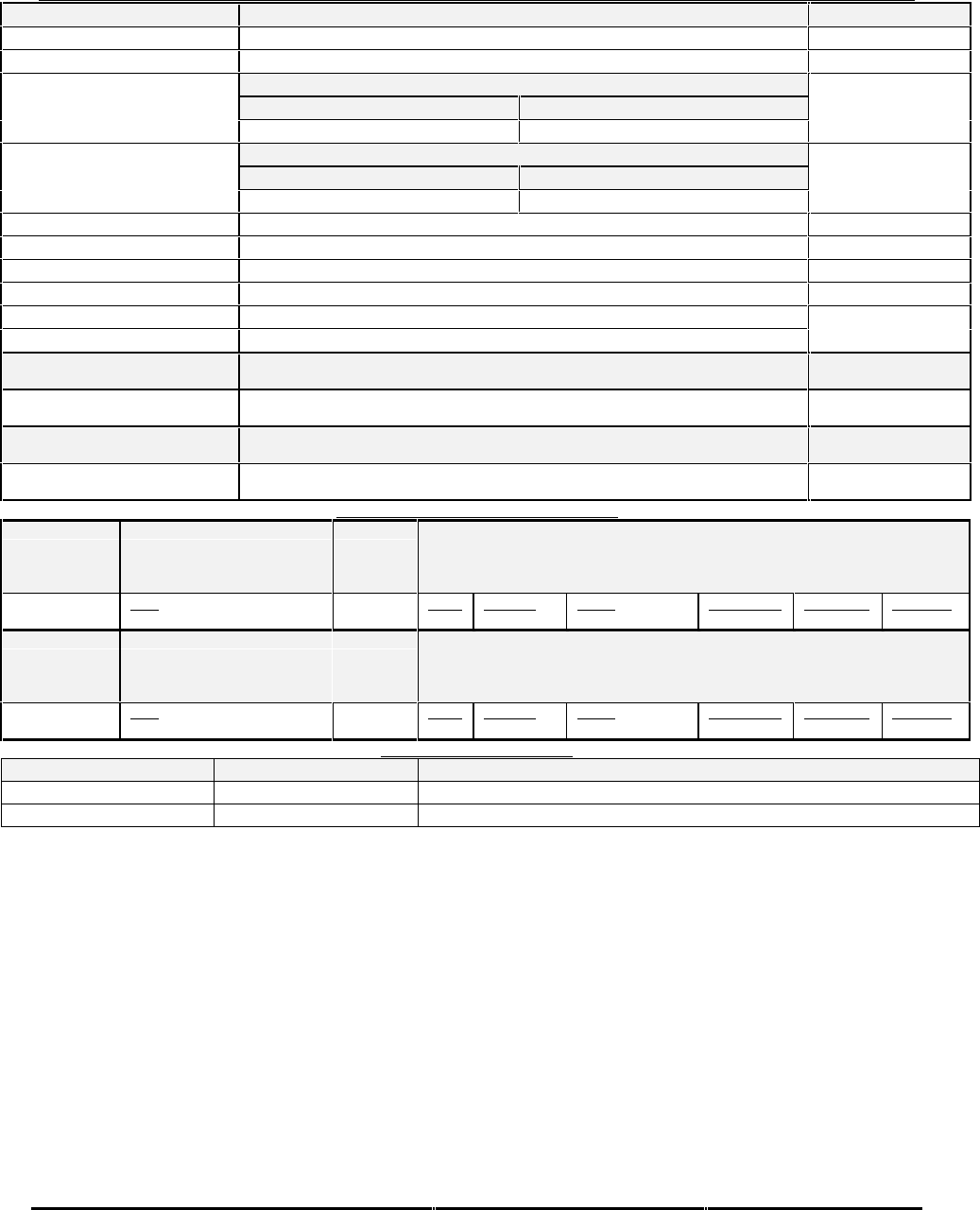
Honeywell
MK XXII EGPWS Installation Manual
CAGE CODE: 97896 SCALE: NONE SIZE: A DWG NO: 060-4314-225 REV: C SHEET 228
Table E 3.1.6-250 Honeywell EDZ705 (5x5), EDZ756 (5x6) with DC-811 range push button control
DISPLAY CONFIGURATION GROUP 250 HONEYWELL SPZ8000, EDZ705 (5X5), EDZ756 (5X6), EDZ605, EDZ805, AND EDZ806)
Function Value
Display Type Honeywell (SPZ8000 new style - every fourth display line is blanked)
Sweep Type Honeywell
Auto Pop Up Category 7, Options Select Group #1
TA&D Alternate Pop Up: False TA&D Alternate Pop Up: True
Pop Up On Caution or Warning Never Pop Up
Peaks Mode Category 7, Options Select Group #1
Peaks Enable: False Peaks Enable: True
Peaks Off Peaks On
Manual select Controlled by display system
Manual deselect Controlled by display system
Auto Range Yes (10NM)
Moving Marker Yes (Honeywell type)
Overlay Page Yes for Peaks Elevations only.
Display bus type Honeywell picture bus
TERRAIN DISPLAY BUS #1
453TX_1 CONNECT TO:
A = J1-58
B = J1-59 Terrain Display data to switching relay/Symbol Generator #1 and MFD left channel
TERRAIN DISPLAY BUS #2
453TX_2 CONNECT TO:
A = J1-56
B = J1-57 Terrain Display data to switching relay/Symbol Generator #2 and MFD right channel
DISPLAY INPUT CONTROL GROUP 251
CHANNEL
429_422RX_1 CONNECT TO:
DC811 #1 1.1.1.1.1.3 Fault Designation: DISPLAY BUS 1
Bus Type: (RS-422 – 7.8125K baud)
A = J2-36
B = J2-37 Data
Range (Up/Down) Label
N/A Sig. Bits Range Signal Type
Basic Resolution
N/A Rate (ms)
100
CHANNEL
422RX_2 CONNECT TO:
DC811 #2 1.1.1.1.1.4 Fault Designation: DISPLAY BUS 2
BUS TYPE: (RS-422 – 7.8125K BAUD)
A = J2-10
B = J2-11 Data
Range (Up/Down) Label
N/A Sig. Bits Range Signal Type
Basic Resolution
N/A Rate (ms)
100
OUTPUT 429 BUS GROUP 0
Channel Pins Comments
429TX_1 (Low Speed) A = J2-43 B = J2-42 Transmits (Section 7) Label sets: 7.1.1.x, 7.1.2.x, 7.1.3.x and 7.1.4.x
429TX_2 A = J2-26 B = J2-9 No Connection (No Data Output)
Integration Notes:
•The EGPWS ARINC 429 Output Bus must be connected to the display.
•This display uses the following ARINC 429 labels from the EGPWS for annunciation:
The Terrain display will annunciate:
“TERR" in green or cyan (depending on the program) when the Terrain is selected and valid.
“TERR” in amber if Terrain is selected and any of the following conditions are TRUE:
•The EGPWS ARINC 429 output bus is missing or labels 050 and 051 are absent or unreadable for 2 seconds.
•EGPWS ARINC label 051 bit 13 = 0 (“Terrain Display Valid” bit FALSE)
•EGPWS ARINC label 050 bit 17 = 1 (“Terrain Inhibit” bit TRUE)
Note - Per customer request for EDZ705 and EDZ756, the display does not go blank when Terrain is Inhibited,
nor is an amber TERR presented. This change is part of the EFIS system
•EGPWS ARINC labels are valid, but range in label 050 disagrees with range via SCI bus label 80 (Label 050 bits
11-14 contain the left display range and bits 15-18 contain the right).
The display will be blanked when the amber “TERR” is present.
The Terrain display will Pop Up to Terrain mode as follows:
•If all the conditions indicated by for the amber “TERR” above are FALSE.

Honeywell
MK XXII EGPWS Installation Manual
CAGE CODE: 97896 SCALE: NONE SIZE: A DWG NO: 060-4314-225 REV: C SHEET 229
•If the display is in normal MFD mode (not HSI backup, or SG backup) AND if Label 051 bit 11 transitions from 0
to 1 (rising edge), AND Checklist is not selected on the MFD, and TCAS Auto Pop Up is not occurring.
•The display will change to Map mode.
•The display will energize the Terrain selection relays.
•The display will annunciate “TERR”.
•The display will change to the range indicated by the EGPWS ARINC 429 Label 050.
•When interfacing to a single display controller configuration the bus must be connected to both EGPWS input channels.
This prevents the EGPWS from reporting an external bus fault on the second channel.
•Note that the Channel 429_422RX_1 polarity is shown reversed from ARINC 429 application.
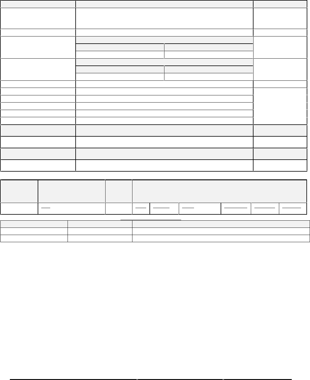
Honeywell
MK XXII EGPWS Installation Manual
CAGE CODE: 97896 SCALE: NONE SIZE: A DWG NO: 060-4314-225 REV: C SHEET 230
Table E 3.1.6-255 Honeywell SPZ8000 (w/ SCI range)
Display Configuration Group 255 (Honeywell SPZ8000 older style)
Function Value
Display Type Honeywell (5x6) (SPZ8000) older style; does not blank every fourth
weather radar display line. This interface supports SG-810 and SG-
811 SPZ8000 systems only.
Sweep Type Honeywell
Auto Pop Up Category 7, Options Select Group #1
TA&D Alternate Pop Up: False TA&D Alternate Pop Up: True
Pop Up On Caution or Warning Never Pop Up
Peaks Mode Category 7, Options Select Group #1
(Elevations via overlay) Peaks Enable: False Peaks Enable: True
Peaks Off Peaks On
Manual select Controlled by SPZ8000 display system
Manual deselect Controlled by SPZ8000 display system
Auto Range Yes (10 NM)
Moving Marker Yes (Honeywell type)
Overlay Page Yes, for Peaks Elevations (located on lower right side)
Display bus type Honeywell picture bus
TERRAIN DISPLAY BUS #1
453TX_1 CONNECT TO:
A = J1-58
B = J1-59 Terrain Display data to switching relay/Symbol Generator #1
TERRAIN DISPLAY BUS #2
453TX_2 CONNECT TO:
A = J1-56
B = J1-57 Terrain Display data to switching relay/Symbol Generator #2
(NOTE: Range setting always follows Display Bus #1).
Display Input Control Group 255
CHANNEL
429_422RX_1 CONNECT TO:
SCI Bus 1
(RS-422 - 12K baud) Fault Designation: DISPLAY BUS 1
Bus Type: Basic
A = J2-36
B = J2-37 Data
Range (Mode/Range Word) Label
80 Sig. Bits
4 Discrete Range
2000NM Signal Type
Basic Resolution
N/A Rate (ms)
100
OUTPUT 429 BUS GROUP 0
Channel Pins Comments
429TX_1 (Low Speed) A = J2-43 B = J2-42 Transmits (Section 7) Label sets: 7.1.1.x, 7.1.2.x, 7.1.3.x and 7.1.4.x
429TX_2 A = J2-26 B = J2-9 No Connection (No Data Output)
Integration Notes:
•The EGPWS ARINC 429 Output Bus must be connected to the SPZ8000 display.
•This display type may also be used for an integrated P880/660/440 display, but requires Auto Pop Up to be disabled and
relay selection to be controlled directly from an alternate action switch (for new installations of P880/660/440 use ID
13).

Honeywell
MK XXII EGPWS Installation Manual
CAGE CODE: 97896 SCALE: NONE SIZE: A DWG NO: 060-4314-225 REV: C SHEET 231
E 5.3.7 CATEGORY 7, OPTIONS 1 SELECT
The following table provides identification of the Options Select Group #1. Each entry in the ID column corresponds to a
particular combination of TA&D Alternate Pop Up, Obstacle Awareness Enabled, Peaks Mode Enabled, Bank Angle Enable,
Steep Approach Enabled, Flap / WOW Reversal and GPS Altitude Reference selection. Refer to section 7.5 for configuration
messages that will be present for each option selected.
Note: Peaks Mode Enable is always True regardless of the option selected.
TABLE E 317: OPTIONS SELECT GROUP #1
ID TA&D
Alternate
Pop Up
Peaks
Mode
Enabled5
Obstacle
Awareness
Enabled
Bank Angle
Enable Weight On
Wheels
Reversal
GPS
Altitude
Reference6
Effectivity
App
.Cfg.
0 False False False False False WGS-84 -001 -001
1 False False False False False MSL -001 -001
2 False False False False True WGS-84 -001 -001
3 False False False False True MSL -001 -001
4 False False False True False WGS-84 -001 -001
5 False False False True False MSL -001 -001
6 False False False True True WGS-84 -001 -001
7 False False False True True MSL -001 -001
8 False False True False False WGS-84 -001 -001
9 False False True False False MSL -001 -001
10 False False True False True WGS-84 -001 -001
11 False False True False True MSL -001 -001
12 False False True True False WGS-84 -001 -001
13 False False True True False MSL -001 -001
14 False False True True True WGS-84 -001 -001
15 False False True True True MSL -001 -001
16 False True False False False WGS-84 -001 -001
17 False True False False False MSL -001 -001
18 False True False False True WGS-84 -001 -001
19 False True False False True MSL -001 -001
20 False True False True False WGS-84 -001 -001
21 False True False True False MSL -001 -001
22 False True False True True WGS-84 -001 -001
23 False True False True True MSL -001 -001
24 False True True False False WGS-84 -001 -001
25 False True True False False MSL -001 -001
26 False True True False True WGS-84 -001 -001
27 False True True False True MSL -001 -001
28 False True True True False WGS-84 -001 -001
29 False True True True False MSL -001 -001
30 False True True True True WGS-84 -001 -001
31 False True True True True MSL -001 -001
32 True False False False False WGS-84 -001 -001
33 True False False False False MSL -001 -001
5 Enables PEAKS mode display if display supports
6 "MSL" reference must be selected when an internal GPS is utilized.

Honeywell
MK XXII EGPWS Installation Manual
CAGE CODE: 97896 SCALE: NONE SIZE: A DWG NO: 060-4314-225 REV: C SHEET 232
ID TA&D
Alternate
Pop Up
Peaks
Mode
Enabled5
Obstacle
Awareness
Enabled
Bank Angle
Enable Weight On
Wheels
Reversal
GPS
Altitude
Reference6
Effectivity
App
.Cfg.
34 True False False False True WGS-84 -001 -001
35 True False False False True MSL -001 -001
36 True False False True False WGS-84 -001 -001
37 True False False True False MSL -001 -001
38 True False False True True WGS-84 -001 -001
39 True False False True True MSL -001 -001
40 True False True False False WGS-84 -001 -001
41 True False True False False MSL -001 -001
42 True False True False True WGS-84 -001 -001
43 True False True False True MSL -001 -001
44 True False True True False WGS-84 -001 -001
45 True False True True False MSL -001 -001
46 True False True True True WGS-84 -001 -001
47 True False True True True MSL -001 -001
48 True True False False False WGS-84 -001 -001
49 True True False False False MSL -001 -001
50 True True False False True WGS-84 -001 -001
51 True True False False True MSL -001 -001
52 True True False True False WGS-84 -001 -001
53 True True False True False MSL -001 -001
54 True True False True True WGS-84 -001 -001
55 True True False True True MSL -001 -001
56 True True True False False WGS-84 -001 -001
57 True True True False False MSL -001 -001
58 True True True False True WGS-84 -001 -001
59 True True True False True MSL -001 -001
60 True True True True False WGS-84 -001 -001
61 True True True True False MSL -001 -001
62 True True True True True WGS-84 -001 -001
63 True True True True True MSL -001 -001
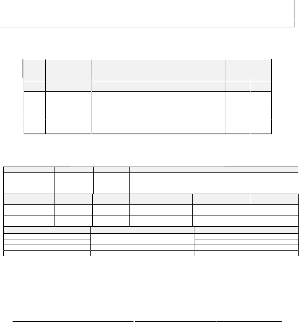
Honeywell
MK XXII EGPWS Installation Manual
CAGE CODE: 97896 SCALE: NONE SIZE: A DWG NO: 060-4314-225 REV: C SHEET 233
E 5.3.8 CATEGORY 8, RADIO ALTITUDE INPUT SELECT
The following table provides identification of the Radio Altitude type. The entry in the Radio Altitude Type corresponds to a
table that provides detailed information on the configuration. For example, the details for Radio Altitude Type #1 are found
in Table 0-1. ARINC 552, ALT 55 and digital ARINC 429 compatible Radio Altimeters are supported. ALT 50 Radio
Altimeters are not supported due to the maximum 2000-foot operation
CAUTION:
ALT 55 radio altimeters use an avarage altitude tracking technique that does not track the nearest terrain. This can
produce errors up to 200 to 300 feet in high bank turns and mountainous terrain. This characteristic may degrade
EGPWS performance for Modes 1 thru 6.
In this category, only the following signals are defined:
•Radio Altitude source selection, input scaling, and associated validities.
TABLE E 3.1.8: RADIO ALTITUDE INPUT SELECT FOR EGPWS MKXXII
ID Radio Altitude
Type Description Effectivity
(Table E 3.1.8-
x) App. Cfg.
0 0 Analog Radio Altitude (ARINC 552) -001 -001
1 1 Analog (ALT 55) -001 -001
2 2 Digital Radio Altitude (ARINC 429) (Note 2) -001 -001
3 3 Analog Radio Altitude (RT-200/300) -001 -001
4 4 Analog (KRA 405) -003 -003
5 5 Analog (Alt 50) -010 -010
Note 2: Digital Radio Altimeters can not be used on two engine Helicopters with Digital Torque.
TABLE E 3.1.8-0: RADIO ALTITUDE INPUT SELECT TYPE 0 (ARINC 552)
SIGNAL CONNECTION SUMMARY DATA
Radio Altimeter #1 (+) = J1-64
(-) = J1-45 Format: ARINC 552 with Validity Flag
Input Type: Basic
Fault Designation: RADIO ALTIMETER FAULT
Validity: Radio Altitude Valid Discrete #1 (+28V)
PIN FUNCTION CONNECTION PIN TYPE CHANNEL DESIGNATION
REFERENCE Polarity/Configuration
Radio Altitude Validity
Discrete #1 (+28V) J1-29 Input 28V_DISC_07 >+17V = Valid
<+4.4V = Invalid
DH Discrete (Gnd) J1-33 Input GND_DISC_11 Gnd = Below DH
<not> Gnd = Above DH
CONFIGURATION DATA Description Value
Out of Track Maximum 2800
Out of Track Minimum
Pseudo altitude is only allowed to operate within
these limits. -20
Pseudo Altitude Type Selects parameters for pseudo altitude engage logic 3
Field Enable Type Selects pseudo altitude field elevation 2
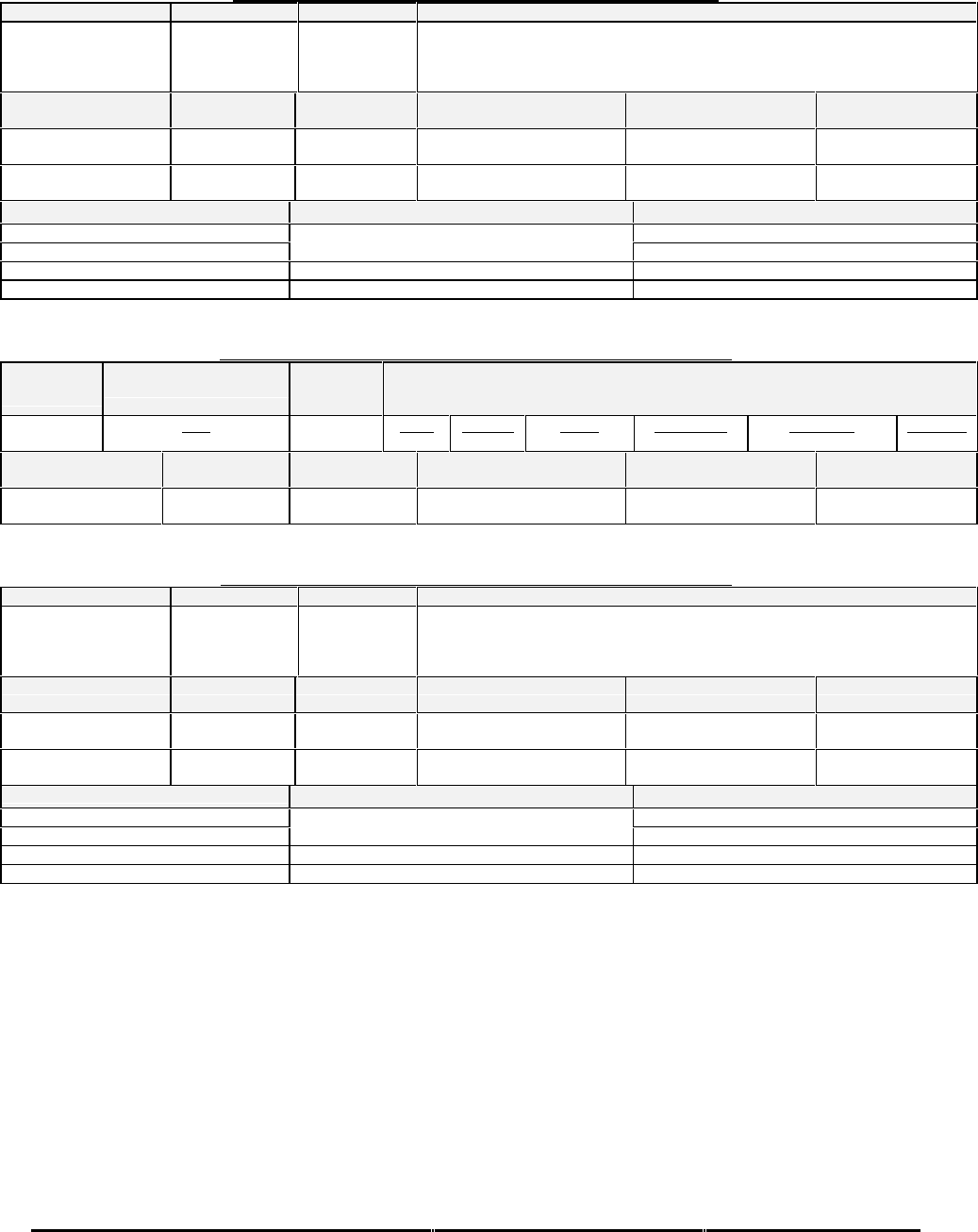
Honeywell
MK XXII EGPWS Installation Manual
CAGE CODE: 97896 SCALE: NONE SIZE: A DWG NO: 060-4314-225 REV: C SHEET 234
TABLE E 3.1.8-1: RADIO ALTITUDE INPUT SELECT TYPE 1 (ALT 55)
SIGNAL CONNECTION SUMMARY DATA
Radio Altimeter #1 (+) = J1-64
(-) = J1-45 Format: Alt 55 with Validity Flag
Input Type: Basic
Fault Designation: RADIO ALTIMETER FAULT
Validity: Radio Altitude Valid Discrete #1 (+28V)
PIN FUNCTION CONNECTION PIN TYPE CHANNEL DESIGNATION
REFERENCE Polarity/Configuration
Radio Altitude Validity
Discrete #1 (+28V) J1-29 Input 28V_DISC_07 >+17V = Valid
<+4.4V = Invalid
DH Discrete (Gnd) J1-33 Input GND_DISC_11 Gnd = Below DH
<not> Gnd = Above DH
CONFIGURATION DATA Description Value
Out of Track Maximum 2800
Out of Track Minimum
Pseudo altitude is only allowed to operate within
these limits. -20
Pseudo Altitude Type Selects parameters for pseudo altitude engage logic 4
Field Enable Type Selects pseudo altitude field elevation 2
TABLE E 3.1.8-2: RADIO ALTITUDE INPUT SELECT TYPE 2 (ARINC 429)
CHANNEL
429RX_5
CONNECT TO:
Left ( #1) LRRA
(Low Speed)
Fault Designation: RADIO ALTIMETER BUS
Bus Type: Basic
A = J2-21
B = J2-4 Data
Radio Altitude Label
164 Sig. Bits
16 Range
±8192 FT Signal Type
Basic Resolution
0.125 Rate (ms)
25-50
PIN FUNCTION CONNECTION PIN TYPE CHANNEL DESIGNATION
REFERENCE Polarity/Configuration
DH Discrete (Gnd) J1-33 Input GND_DISC_11 Gnd = Below DH
<not> Gnd = Above DH
TABLE E 3.1.8-3: RADIO ALTITUDE INPUT SELECT TYPE 3 (RT-200/300)
SIGNAL CONNECTION SUMMARY DATA
Radio Altimeter #1 (+) = J1-64
(-) = J1-45 Format: DC with Validity Flag (RT-200/300)
Input Type: Basic
Fault Designation: RADIO ALTIMETER FAULT
Validity: Radio Altitude Valid Discrete #1 (+28V)
PIN FUNCTION CONNECTION PIN TYPE CHANNEL DESIGNATION
REFERENCE Polarity/Configuration
Radio Altitude Validity
Discrete #1 (+28V) J1-29 Input 28V_DISC_07 >+17V = Valid
<+4.4V = Invalid
DH Discrete (Gnd) J1-33 Input GND_DISC_11 Gnd = Below DH
<not> Gnd = Above DH
CONFIGURATION DATA Description Value
Out of Track Maximum 2800
Out of Track Minimum
Pseudo altitude is only allowed to operate within
these limits. -20
Pseudo Altitude Type Selects parameters for pseudo altitude engage logic 3
Field Enable Type Selects pseudo altitude field elevation 2

Honeywell
MK XXII EGPWS Installation Manual
CAGE CODE: 97896 SCALE: NONE SIZE: A DWG NO: 060-4314-225 REV: C SHEET 235
TABLE E 3.1.8-4: RADIO ALTITUDE INPUT SELECT TYPE 4 (KRA 405)
SIGNAL CONNECTION SUMMARY DATA
Radio Altimeter #1 (+) = J1-64
(-) = J1-45 Format: Alt 55 with Validity Flag
Input Type: Basic
Fault Designation: RADIO ALTIMETER FAULT
Validity: Radio Altitude Valid Discrete #1 (+28V)
PIN FUNCTION CONNECTION PIN TYPE CHANNEL DESIGNATION
REFERENCE Polarity/Configuration
Radio Altitude Validity
Discrete #1 (+28V) J1-29 Input 28V_DISC_07 >+17V = Valid
<+4.4V = Invalid
DH Discrete (Gnd) J1-33 Input GND_DISC_11 Gnd = Below DH
<not> Gnd = Above DH
CONFIGURATION DATA Description Value
Out of Track Maximum 2800
Out of Track Minimum
Pseudo altitude is only allowed to operate within
these limits. -20
Pseudo Altitude Type Selects parameters for pseudo altitude engage logic 3
Field Enable Type Selects pseudo altitude field elevation 2
Table E 3.1.8-5: Radio Altitude Input Select Type 5 (ALT 50)
SIGNAL CONNECTION REFERENCE SUMMARY DATA
Radio Altimeter #1 (+) = J1-64
(-) = J1-45 Format: Alt 50 with Validity Flag
Input Type: Basic
Fault Designation: RADIO ALTIMETER FAULT
Validity: Radio Altitude Valid Discrete #1 (+28V)
PIN FUNCTION CONNECTION PIN TYPE CHANNEL DESIGNATION
REFERENCE Polarity/Configuration
Radio Altitude Validity
Discrete #1 (+28V) J1-29 Input 28V_DISC_07 >+17V = Valid
<+4.4V = Invalid
DH Discrete (Gnd) J1-33 Input GND_DISC_11 Gnd = Below DH
<not> Gnd = Above DH
CONFIGURATION DATA Description Value
Out of Track Maximum 2100
Out of Track Minimum
Pseudo altitude is only allowed to operate within
these limits. -20
Pseudo Altitude Type Selects parameters for pseudo altitude engage logic 4
Field Enable Type Selects pseudo altitude field elevation 2

Honeywell
MK XXII EGPWS Installation Manual
CAGE CODE: 97896 SCALE: NONE SIZE: A DWG NO: 060-4314-225 REV: C SHEET 236
E 5.3.9 CATEGORY 9, NAVIGATION INPUT SELECT
The following table provides identification of the Navigation type. The entry in the Navigation Type corresponds to a table
that provides detailed information on the configuration. For example, the details for Navigation Type #1 are found in Table
0-1. In this category, only the following signals are defined:
•Glideslope source selection.
•Localizer source selection. (optional for digital only)
TABLE E 3.1.9: NAVIGATION INPUT SELECT FOR EGPWS MKXXII
I
DNavigation
Inputs Select Description Effectivity
(Table E 3.1.9-
x) App. Cfg.
0 0 Analog Glideslope (ARINC 547) with +28V
Validity Flag -001 -001
1 1 Analog Glideslope (ARINC 547) with Low Level
Validity -001 -001
2 2 Digital Glideslope (ARINC 429) -001 -001
3 3 Digital Glideslope and Localizer (ARINC 429) -001 -001
4 4 Digital KN40 Glideslope and Localizer (ARINC
429) -003 -003
5 5 Analog Glideslope/Localizer (ARINC 547) with
+28V Validity Flags -008 -008
TABLE E 3.1.9-0: NAVIGATION INPUTS SELECT 0
SIGNAL CONNECTION SUMMARY DATA
Glideslope Deviation (+) = J1-65
(-) = J1-46
Format: ARINC 547 with Validity Flag & ILS Select
Input Type: Basic
Fault Designation: GLIDESLOPE FAULT
Validity: Glideslope Validity Discrete #1 (+28V)
PIN FUNCTION CONNECTION PIN TYPE CHANNEL DESIGNATION
REFERENCE Polarity/Configuration
Glideslope Validity
Discrete #1 J1-11 Input 28V_DISC_06 >+17V = Valid
< +4.4V = Not Valid
+28V ILS Tuned
Discrete #1 J1-39 Input 28V_DISC_01 >+17V = ILS Tuned
< +4.4V = ILS Not Tuned
GND ILS Tuned
Discrete #1 J1-20 Input GND_DISC_01 Gnd = ILS Tuned
<not> Gnd = ILS Not Tuned
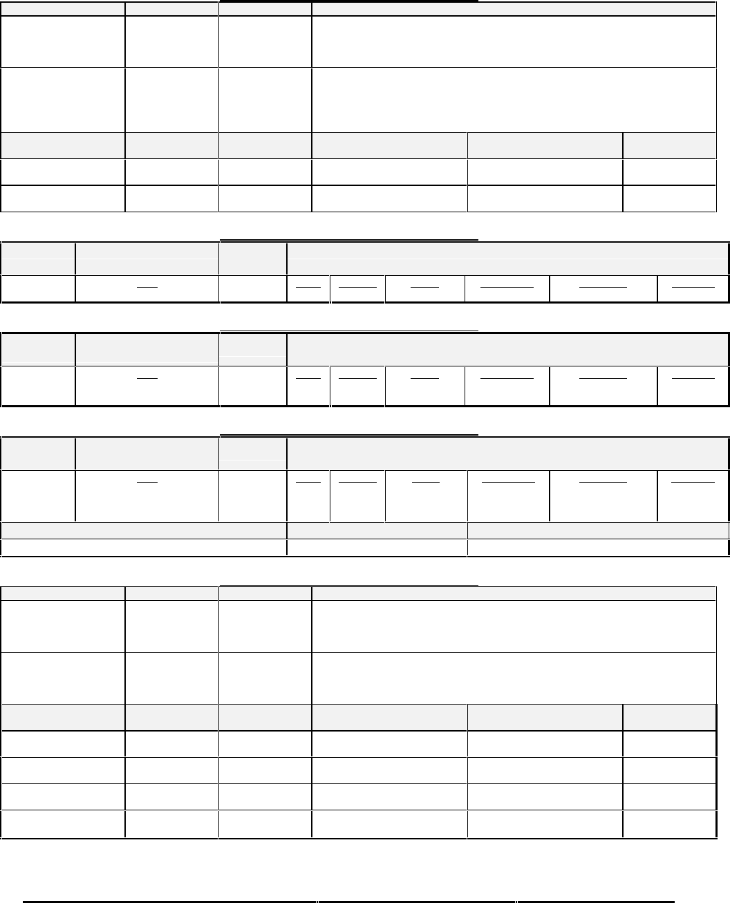
Honeywell
MK XXII EGPWS Installation Manual
CAGE CODE: 97896 SCALE: NONE SIZE: A DWG NO: 060-4314-225 REV: C SHEET 237
TABLE E 3.1.9-1: NAVIGATION INPUTS SELECT 1
SIGNAL CONNECTION SUMMARY DATA
Glideslope Deviation (+) = J1-65
(-) = J1-46
Format: ARINC 547 with Low Level Validity & ILS Select
Input Type: Basic
Fault Designation: GLIDESLOPE FAULT
Validity: Low Level Glideslope Deviation Validity
Low Level Glideslope
Deviation Validity (+) = J1-30
(-) = J1-10
Format: DC
Input Type: Basic
Fault Designation: GLIDESLOPE LOW LEVEL VALIDITY FAULT
> 0.145V = Valid (typical active range is 0.16V to 0.84V)
<= 0.145V = Invalid
PIN FUNCTION CONNECTION PIN TYPE CHANNEL DESIGNATION
REFERENCE Polarity/Configuration
+28V ILS Tuned
Discrete #1 J1-39 Input 28V_DISC_01 >+17V = ILS Tuned
< +4.4V = ILS Not Tuned
GND ILS Tuned
Discrete #1 J1-20 Input GND_DISC_01 Gnd = ILS Tuned
<not> Gnd = ILS Not Tuned
TABLE E 3.1.9-2: NAVIGATION INPUTS SELECT 2
CHANNEL
429RX_6 CONNECT TO:
ILS #1 (Low Speed) Fault Designation: ILS BUS
Bus Type: Basic
A = J2-22
B = J2-5 Data
Glideslope Label
174 Sig. Bits
12 Range
±0.8 DDM Signal Type
Basic Resolution
0.0001953125 Rate (ms)
33.3-66.6
TABLE E 3.1.9-3: NAVIGATION INPUTS SELECT 3
CHANNEL
429RX_6 CONNECT TO:
ILS #1 (Low Speed) Fault Designation: ILS BUS
Bus Type: Basic
A = J2-22
B = J2-5 Data
Glideslope
Localizer
Label
174
173
Sig. Bits
12
12
Range
±0.8 DDM
±0.4 DDM
Signal Type
Basic
Basic
Resolution
0.0001953125
0.00009765625
Rate (ms)
33.3-66.6
33.3-66.6
TABLE E 3.1.9-4: NAVIGATION INPUTS SELECT 4
CHANNEL
429RX_6 CONNECT TO:
ILS #1 (Low Speed) Fault Designation: ILS BUS
Bus Type: Basic
A = J2-22
B = J2-5 Data
Glideslope
Localizer
ILS Select (VOR/ILS Freq)
Label
174
173
034
Sig. Bits
12
12
Discrete
Range
±0.8 DDM
±0.4 DDM
n/a
Signal Type
Basic
Basic
Basic
Resolution
0.0001953125
0.00009765625
Bit 14 = ILS
Rate (ms)
33.3-66.6
33.3-66.6
167-333
Configuration Data Type Reference Section
KN40 Nav Source True SRD 5.9.2.1.R61, 5.9.3.R41
TABLE E 3.1.9-5: NAVIGATION INPUTS SELECT 5
SIGNAL CONNECTION SUMMARY DATA
Glideslope Deviation (+) = J1-65
(-) = J1-46 Format: ARINC 547 with Validity Super Flag & ILS Select
Input Type: Basic
Fault Designation: GLIDESLOPE FAULT
Validity: Glideslope Validity Discrete #1 (+28V)
Localizer Deviation (+) = J1-30
(-) = J1-10 Format: ARINC 547 with Validity Flag & ILS Select
Input Type: Basic
Fault Designation: LOCALIZER FAULT
Validity: Localizer Validity Discrete #1 (+28V)
PIN FUNCTION CONNECTION PIN TYPE CHANNEL DESIGNATION
REFERENCE Polarity/Configuration
Localizer Validity
Discrete #1 J1-48 Input 28V_DISC_11 >+17V = Valid
< +4.4V = Not Valid
Glideslope Validity
Discrete #1 J1-11 Input 28V_DISC_06 >+17V = Valid
< +4.4V = Not Valid
+28V ILS Tuned
Discrete #1 J1-39 Input 28V_DISC_01 >+17V = ILS Tuned
< +4.4V = ILS Not Tuned
GND ILS Tuned
Discrete #1 J1-20 Input GND_DISC_01 Gnd = ILS Tuned
<not> Gnd = ILS Not Tuned
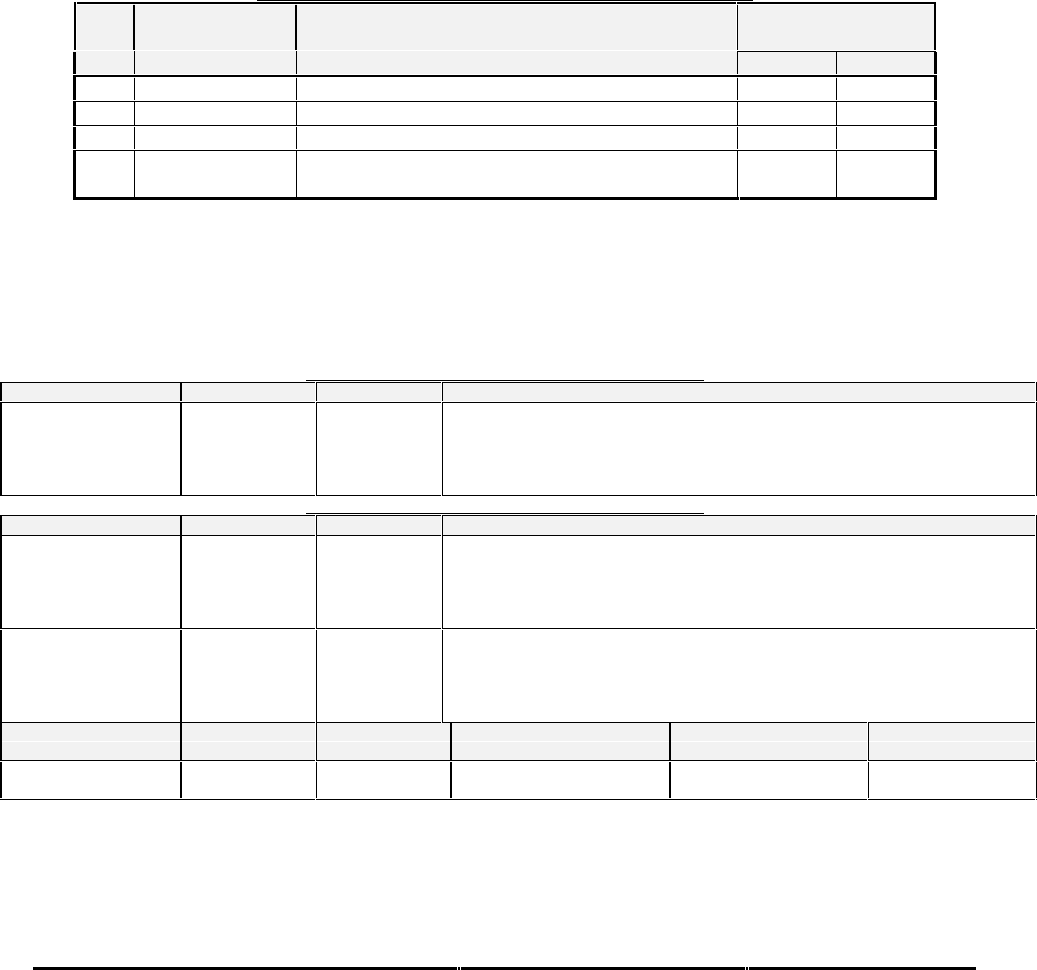
Honeywell
MK XXII EGPWS Installation Manual
CAGE CODE: 97896 SCALE: NONE SIZE: A DWG NO: 060-4314-225 REV: C SHEET 238
E 5.3.10 CATEGORY 10, ATTITUDE INPUT SELECT
The following table provides identification of the Roll Attitude Angle type. The entry in the Attitude Input Select
corresponds to a table that provides detailed information on the configuration. For example, the details for Attitude Input
Select #1 are found in 0-1.
In this category, only the following signals are defined:
•Roll Attitude
•Pitch Attitude
•
•
TABLE E 3.1.10: ATTITUDE INPUT SELECT FOR EGPWS MK XXII
ID Attitude Input
Select Description Effectivity
(Table 0-x) App. Cfg.
0 0 Analog Roll (3-Wire Synchro) without validity -001 -001
2 2 Analog Pitch and Roll (3-Wire Synchro) -003 -003
4 4 Analog Roll(3-Wire Synchro) with validity (Note 1) -003 -003
128 128 Digital Pitch, Roll, Pitch Rate and Roll Rate (High
Speed ARINC 429) (Note 3) -006 -006
Note 1: ID 4 may not be used with Category 13 (I/O Discrete Type) ID’s 2, or 3. This is due to a conflict with the validity
discrete. ID 0 may be used instead with the Validity discrete left unconnected. Also, ID 4 are intended to be used with
helicopter types that do not have the tail strike functionality (currently the MD-900 only).
Note 2: ID 128 may only be used in conjunction with Category 11 (Magnetic Heading) ID 2.
TABLE E 3.1.10-0: ATTITUDE INPUT SELECT TYPE 0
SIGNAL CONNECTION SUMMARY DATA
Roll Attitude (X) = J1-1
(Y) = J1-21
(Z) = J1-2
Format: 3 Wire Synchro
Input Type: Basic
Fault Designation: ROLL FAULT
Validity: None
Reference: None
TABLE E 3.1.10-2: ATTITUDE INPUT SELECT TYPE 2
SIGNAL CONNECTION SUMMARY DATA
Roll Attitude (X) = J1-1
(Y) = J1-21
(Z) = J1-2
Format: 3 Wire Synchro with Validity Flag
Input Type: Basic
Fault Designation: ROLL FAULT
Validity: Attitude Validity Discrete #1
Reference: None
Pitch Attitude (X) = J1-5
(Y) = J1-7
(Z) = J1-6
Format: 3 Wire Synchro with Validity Flag
Input Type: Basic
Fault Designation: PITCH FAULT
Validity: Attitude Validity Discrete #1
Reference: None
PIN FUNCTION CONNECTION PIN TYPE CHANNEL DESIGNATION
REFERENCE Polarity/Configuration References
Attitude Validity
Discrete #1 J1-68 Input 28V_DISC_12 >+17V = Valid
<+4.4V = Invalid 6.6.24
4.2.7

Honeywell
MK XXII EGPWS Installation Manual
CAGE CODE: 97896 SCALE: NONE SIZE: A DWG NO: 060-4314-225 REV: C SHEET 239
TABLE E 3.1.10-4: ATTITUDE INPUT SELECT TYPE 4
SIGNAL CONNECTION SUMMARY DATA
Roll Attitude (X) = J1-1
(Y) = J1-21
(Z) = J1-2
Format: 3 Wire Synchro with Validity Flag
Input Type: Basic
Fault Designation: ROLL FAULT
Validity: Attitude Validity Discrete #1
Reference: None
PIN FUNCTION CONNECTION PIN TYPE CHANNEL DESIGNATION
REFERENCE Polarity/Configuration Summary Data
Attitude Validity
Discrete #1 J1-68 Input 28V_DISC_12 >+17V = Valid
<+4.4V = Invalid 6.6.24
4.2.7
TABLE E 3.1.10-128: ATTITUDE INPUT SELECT TYPE 128
CHANNEL
429RX_7
CONNECT TO:
AHRS
(High Speed)
Fault Designation: AHRS BUS
Bus Type: Basic
A = J2-23
B = J2-6 Data
Roll Angle
Pitch Angle
Body Roll Rate
Body Pitch Rate
Label
325
324
327
326
Sig. Bits
14
14
13
13
Range
±180 degrees
±180 degrees
±128 deg/sec
±128 deg/sec
Signal Type
Basic
Basic
Basic
Basic
Resolution
0.010986328125
0.010986328125
0.01562500
0.01562500
Rate (ms)
10-20
10-20
10-20
10-20
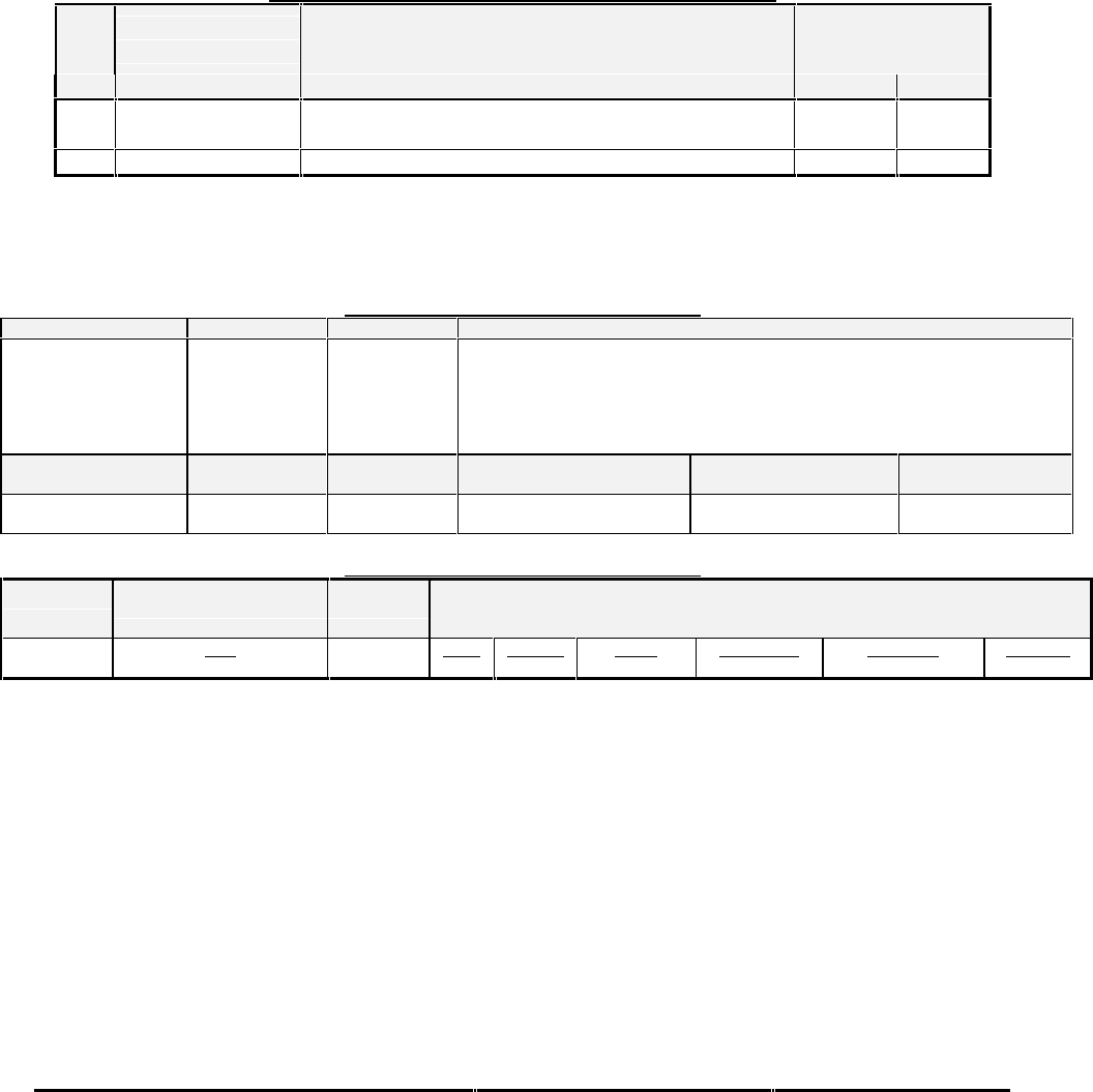
Honeywell
MK XXII EGPWS Installation Manual
CAGE CODE: 97896 SCALE: NONE SIZE: A DWG NO: 060-4314-225 REV: C SHEET 240
E 5.3.11 CATEGORY 11, HEADING INPUT SELECT
The following table provides identification of the Heading type. The entry in the Heading Input Select corresponds to a table
that provides detailed information on the configuration. For example, the details for Magnetic Heading Input Select #1 are
found in 0-1.
In this category, only the following signals are defined:
•Magnetic Heading TABLE E 3.1.11: HEADING INPUT SELECT FOR EGPWS MK XXII
ID Heading Input
Select Description Effectivity
(Table E 3.1.11-x) App. Cfg.
00
Analog Magnetic Heading (3-Wire Synchro with
reference and validity discrete) -001 -001
2 2 High Speed ARINC 429 (Note 1) -006 -006
Note 1: ID 2 is intended to be used in conjunction with Category 10 (Attitude) ID 128.
TABLE E 3.1.11-0: HEADING INPUT SELECT 0
SIGNAL CONNECTION SUMMARY DATA
Magnetic Heading
(X) = J1-22
(Y) = J1-23
(Z) = J1-3
Reference
(H) = J1-4
(C) = J1-24
Format: 5 Wire Synchro with Validity Flag
Input Type: Basic
Fault Designation: MAGNETIC HEADING FAULT
Validity: Magnetic Heading Validity Discrete (+28V)
Reference: Nominal 26 VAC
PIN FUNCTION CONNECTION PIN TYPE CHANNEL DESIGNATION
REFERENCE Polarity/Configuration
Magnetic Heading
Validity Discrete J1-28 Input 28V_DISC_10 >+17V = Valid
< +4.4V = Invalid
TABLE E 3.1.11-2: HEADING INPUT SELECT 2
CHANNEL
429RX_7
CONNECT TO:
AHRS
(High Speed)
Fault Designation: AHRS BUS
Bus Type: Basic
A = J2-23
B = J2-6 Data
Magnetic Heading Label
320 Sig. Bits
15 Range
±180 degrees Signal Type
Basic Resolution
0.0054931640625 Rate (ms)
10-50

Honeywell
MK XXII EGPWS Installation Manual
CAGE CODE: 97896 SCALE: NONE SIZE: A DWG NO: 060-4314-225 REV: C SHEET 241
E 5.3.12 CATEGORY 12, WINDSHEAR INPUT SELECT
The Windshear warning is not applicable to Helicopters.
The following table provides the definition of Windshear Input Select ID 0, which is used for helicopter installations.
TABLE E 3.1.12: WINDSHEAR INPUT SELECT
EffectivityID Description Windshear INOP Disable Windshear Caution
Voice Disable App. Cfg.
0 No Windshear TRUE TRUE -003 -003

Honeywell
MK XXII EGPWS Installation Manual
CAGE CODE: 97896 SCALE: NONE SIZE: A DWG NO: 060-4314-225 REV: C SHEET 242
E 5.3.13 CATEGORY 13, INPUT / OUTPUT DISCRETE TYPE SELECT
The following table provides identification of the Input/Output Discrete Type. Each entry in the Input/Output Discrete Type
column has a corresponding table that provides detailed information on the configuration. For example, the details for
Input/Output Discrete Type #128 are found in Table E 3.1.13-128.
TABLE E 3.1.13: INPUT/OUTPUT DISCRETE TYPE SELECT FOR EGPWS MK XXII
ID
Input/Output
Discrete Type
(Table E 3.1.13-
x)
Description Effectivity
App. Cfg.
128 128 Helicopter Input / output discrete definitions (Lamp
Format 1) -003 -003
129 129 Helicopter Input / output discrete definitions (Lamp
Format 2) -003 -003

Honeywell
MK XXII EGPWS Installation Manual
CAGE CODE: 97896 SCALE: NONE SIZE: A DWG NO: 060-4314-225 REV: C SHEET 243
TABLE E 3.1.13-128: INPUT/OUTPUT DISCRETE TYPE 128
CONN PIN # CHANNEL
DESIGNATION
REFERENCE
PIN TYPE PIN FUNCTION Polarity/Configuration
J1-38 28V_DISC_02 Input +28V Glideslope Inhibit Discrete >+17V = Inhibit
<+4.4V = Not Inhibit
J1-19 GND_DISC_02 Input GND Glideslope Inhibit Discrete Gnd = Inhibit
<not> Gnd = Not Inhibit
J1-37 28V_DISC_03 Input +28V WOW Discrete >+17V = WOW
<+4.4V = Not WOW
J1-18 GND_DISC_03 Input GND WOW Discrete Gnd = WOW
<not> Gnd = Not WOW
J1-36 28V_DISC_04 Input +28V Audio Inhibit Discrete >+17V = Inhibit
<+4.4V = Not Inhibit
J1-17 GND_DISC_04 Input Timed Audio Inhibit Discrete Gnd = Audio Inhibit Toggle
<not> Gnd = Audio Inhibit
Not Toggle
J1-35 28V_DISC_05 Input +28V Landing Gear Discrete >+17V = Gear Down
<+4.4V = Gear Up
J1-16 GND_DISC_05 Input GND Landing Gear Discrete Gnd = Gear Down
<not> Gnd = Gear Up
J1-15 GND_DISC_06 Input Glideslope Cancel Discrete (Note 1) Gnd = Cancel Toggle
<not> Gnd = Normal
J1-14 GND_DISC_07 Input Low Altitude Mode Select (Tactical) (Note 1) Gnd = Low Altitude Mode
Select
<not> Gnd = Normal
J1-13 GND_DISC_08 Input Mode 6 Low Volume Discrete Gnd = Low Volume
<not> Gnd = Normal
J1-8 28V_DISC_09 Input Autopilot Engaged Discrete #1 >+17V = Engaged
<+4.4V = Not Engaged
J1-12 GND_DISC_09 Input Terrain Awareness Inhibit Discrete (Note 2) Gnd = Inhibit
<not> Gnd = Not Inhibit
J1-34 GND_DISC_10 Input Self-Test Discrete (Note 1) Gnd = Self-Test Toggle
<not> Gnd = Normal
J1-72 MON_OUT_1 Output GPWS INOP Discrete
J1-55 MON_OUT_2 Output TAD INOP Discrete
Terrain Not Available
J1-78 DISC_OUT_1 Output GPWS Warning Discrete
Terrain Awareness Caution or Warning
Obstacle Awareness Caution or Warning
J1-77 DISC_OUT_2 Output GPWS Alert Discrete (Glideslope Only)
J1-76 DISC_OUT_3 Output Glideslope Cancel Discrete
J1-73 DISC_OUT_4 Output Low Altitude Mode Discrete (Tactical)
J1-69 DISC_OUT_5 Output TCAS Inhibit discrete
J1-54 DISC_OUT_6 Output Terrain Display Select #1 Discrete
J1-51 DISC_OUT_8 Output Terrain Awareness Caution or Warning
Obstacle Awareness Caution or Warning Gnd = Terrain Pop Up
J1-49 DISC_OUT_9 Output Terrain Display Select #2 Discrete
J1-52 DISC_OUT_7 Output Timed Audio Inhibit Gnd = Audio Inhibit
J1-48 28V_DISC_11 Input Not Defined in this ID (Note 3).
J1-67 GND_DISC_14 Input Not Defined in this ID (Note 3).
J2-15 28V_DISC_13 Input Not Defined in this ID (Note 3).
J2-31 GND_DISC_15 Input Not Defined in this ID (Note 3).
J1-50 MON_OUT_3 Output Not Defined in this ID (Note 3).
Configuration Data Possible States State
Lamp Format Type 1,Type 2 Type 1
Flashing Lamps True, False False
Note 1: Provided by Momentary cockpit switch (non-latching)
Note 2: Provided by Alternate cockpit switch (Latching) with guard if inhibiting
Note 3: This discrete may be used in another category.

Honeywell
MK XXII EGPWS Installation Manual
CAGE CODE: 97896 SCALE: NONE SIZE: A DWG NO: 060-4314-225 REV: C SHEET 244
TABLE E 3.1.13-129: INPUT/OUTPUT DISCRETE TYPE 129
CONN PIN # CHANNEL
DESIGNATION
REFERENCE
PIN TYPE PIN FUNCTION Polarity/Configuration
J1-38 28V_DISC_02 Input +28V Glideslope Inhibit Discrete >+17V = Inhibit
<+4.4V = Not Inhibit
J1-19 GND_DISC_02 Input GND Glideslope Inhibit Discrete Gnd = Inhibit
<not> Gnd = Not Inhibit
J1-37 28V_DISC_03 Input +28V WOW Discrete >+17V = WOW
<+4.4V = Not WOW
J1-18 GND_DISC_03 Input GND WOW Discrete Gnd = WOW
<not> Gnd = Not WOW
J1-36 28V_DISC_04 Input +28V Audio Inhibit Discrete >+17V = Inhibit
<+4.4V = Not Inhibit
J1-17 GND_DISC_04 Input Timed Audio Inhibit Discrete Gnd = Audio Inhibit Toggle
<not> Gnd = Audio Inhibit
Not Toggle
J1-35 28V_DISC_05 Input +28V Landing Gear Discrete >+17V = Gear Down
<+4.4V = Gear Up
J1-16 GND_DISC_05 Input GND Landing Gear Discrete Gnd = Gear Down
<not> Gnd = Gear Up
J1-15 GND_DISC_06 Input Glideslope Cancel Discrete (Note 1) Gnd = Cancel Toggle
<not> Gnd = Normal
J1-14 GND_DISC_07 Input Low Altitude Mode Select (Tactical) (Note 1) Gnd = Low Altitude Mode
Select
<not> Gnd = Normal
J1-13 GND_DISC_08 Input Mode 6 Low Volume Discrete Gnd = Low Volume
<not> Gnd = Normal
J1-8 28V_DISC_09 Input Autopilot Engaged Discrete #1 >+17V = Engaged
<+4.4V = Not Engaged
J1-12 GND_DISC_09 Input Terrain Awareness Inhibit Discrete (Note 2) Gnd = Inhibit
<not> Gnd = Not Inhibit
J1-34 GND_DISC_10 Input Self-Test Discrete (Note 1) Gnd = Self-Test Toggle
<not> Gnd = Normal
J1-72 MON_OUT_1 Output GPWS INOP Discrete
J1-55 MON_OUT_2 Output TAD INOP Discrete
Terrain Not Available
J1-78 DISC_OUT_1 Output GPWS Warning Discrete
Terrain Awareness Warning
Obstacle Awareness Warning
J1-77 DISC_OUT_2 Output GPWS Alert Discrete
Terrain Awareness Caution
Obstacle Awareness Caution
J1-76 DISC_OUT_3 Output Glideslope Cancel Discrete
J1-73 DISC_OUT_4 Output Low Altitude Mode Discrete (Tactical)
J1-69 DISC_OUT_5 Output TCAS Inhibit discrete
J1-54 DISC_OUT_6 Output Terrain Display Select #1 Discrete
J1-51 DISC_OUT_8 Output Terrain Awareness Caution or Warning
Obstacle Awareness Caution or Warning Gnd = Terrain Pop Up
J1-49 DISC_OUT_9 Output Terrain Display Select #2 Discrete
J1-52 DISC_OUT_7 Output Timed Audio Inhibit Gnd = Audio Inhibit
J1-48 28V_DISC_11 Input Not Defined in this ID (Note 3).
J1-67 GND_DISC_14 Input Not Defined in this ID (Note 3).
J2-15 28V_DISC_13 Input Not Defined in this ID (Note 3).
J2-31 GND_DISC_15 Input Not Defined in this ID (Note 3).
J1-50 MON_OUT_3 Output Not Defined in this ID (Note 3).
Configuration Data Possible States State
Lamp Format Type 1,Type 2 Type 2
Flashing Lamps True, False False
Note 1: Provided by Momentary cockpit switch (non-latching)
Note 2: Provided by Alternate cockpit switch (Latching) with guard if inhibiting
Note 3: This discrete may be used in another category.

Honeywell
MK XXII EGPWS Installation Manual
CAGE CODE: 97896 SCALE: NONE SIZE: A DWG NO: 060-4314-225 REV: C SHEET 245
E 5.3.14 CATEGORY 14, AUDIO OUTPUT LEVEL
The following table provides identification of the Audio Output Level Select. Each entry in the ID column corresponds to a
particular nominal alert output level selection (Max, -6 dB, -12 dB, -18dB and –24dB). The nominal output is 4 Wrms for the
8-ohm output and 100 mWrms for the 600-ohm output. The Audio Output Level can be additionally reduced by 6dB with the
Mode 6 Low Volume discrete (see Category 13). The output power level will be the nominal maximum output (4W or
100mW) reduced by the volume selection from Table 5.3.14 and the Mode 6 Low Volume discrete.
TABLE E 3.1.14: AUDIO OUTPUT LEVEL
ID Volume Select Effectivity
App Cfg.
0 Nominal -001 -001
1 -6 dB -001 -001
2 -12 dB -001 -001
3 -18 dB -001 -001
4 -24 dB -001 -001

Honeywell
MK XXII EGPWS Installation Manual
CAGE CODE: 97896 SCALE: NONE SIZE: A DWG NO: 060-4314-225 REV: C SHEET 246
E 5.3.15 CATEGORY 15, AUTOROTATION THRESHOLD
The following table provides identification of the Autorotation Threshold. Each entry in the ID column corresponds to an
engine torque threshold for autorotation. Each helicopter type has a unique engine torque percentage during autorotation
based on the aerodynamic qualities of the aircraft. This value is not typically published or well known, thus it has been
included as a configuration item in Table 10.3.15. Since a typical Autorotation Threshold value is between 5% and 10%, the
values have been chosen from 0% to 15% in increments of 0.5%.
TABLE E 3.1.15: AUTOROTATION THRESHOLD FOR EGPWS MK XXII
1.1.1.
1
Autorotation
Threshold
Effectivity
% of Torque App. Cfg.
0 N/A EM22 -006 EM22 -006
1 0.5 % EM22 -006 EM22 -006
2 1.0 % EM22 -006 EM22 -006
3 1.5 % EM22 -006 EM22 -006
4 2.0 % EM22 -006 EM22 -006
5 2.5 % EM22 -006 EM22 -006
6 3.0 % EM22 -006 EM22 -006
7 3.5 % EM22 -006 EM22 -006
8 4.0 % EM22 -006 EM22 -006
9 4.5 % EM22 -006 EM22 -006
10 5.0 % EM22 -006 EM22 -006
11 5.5 % EM22 -006 EM22 -006
12 6.0 % EM22 -006 EM22 -006
13 6.5 % EM22 -006 EM22 -006
14 7.0 % EM22 -006 EM22 -006
15 7.5 % EM22 -006 EM22 -006
16 8.0 % EM22 -006 EM22 -006
17 8.5 % EM22 -006 EM22 -006
18 9.0 % EM22 -006 EM22 -006
19 9.5 % EM22 -006 EM22 -006
20 10.0 % EM22 -006 EM22 -006
21 10.5 % EM22 -006 EM22 -006
22 11.0 % EM22 -006 EM22 -006
23 11.5 % EM22 -006 EM22 -006
24 12.0 % EM22 -006 EM22 -006
25 12.5 % EM22 -006 EM22 -006
26 13.0 % EM22 -006 EM22 -006
27 13.5 % EM22 -006 EM22 -006
28 14.0 % EM22 -006 EM22 -006
29 14.5 % EM22 -006 EM22 -006
30 15.0 % EM22 -006 EM22 -006

Honeywell
MK XXII EGPWS Installation Manual
CAGE CODE: 97896 SCALE: NONE SIZE: A DWG NO: 060-4314-225 REV: C SHEET 247
E 6 CONNECTOR INTERFACE
E 6.1 PINOUT FOR FRONT CONNECTORS SORTED BY PIN NUMBER
TABLE E 4: PIN ASSIGNMENT FOR FRONT CONNECTORS SORTED BY PIN NUMBER
Connector -
Pin
Channel
Designation
Reference Signal Usage Summary*
J1-01 SYN_1X Roll Attitude Synchro (X leg)
J1-02 SYN_1Z Roll Attitude Synchro (Z leg)
J1-03 SYN_2Z Magnetic Heading Synchro (Z leg)
J1-04 26REF_1H 26VAC Reference #1 (H)
J1-05 SYN_3X Spare Synchro (X leg)
J1-06 SYN_3Z Spare Synchro (Z leg)
J1-07 SYN_3Y Spare Synchro (Y leg)
J1-08 28V_DISC_09 Autopilot Engaged Discrete (+28VDC)
J1-09 28V_DISC_08 Barometric Altitude Validity Discrete (+28VDC)
J1-10 GS_VAL_L Glideslope Deviation Low Level Validity (-)
J1-11 28V_DISC_06 Glideslope Validity Discrete (+28VDC)
J1-12 GND_DISC_09 Terrain Awareness and TCF Inhibit Discrete (Ground)
J1-13 GND_DISC_08 Mode 6 Low Volume Discrete (Ground)
J1-14 GND_DISC_07 Reserved
J1-15 GND_DISC_06 Glideslope Cancel Discrete (Ground)
J1-16 GND_DISC_05 Landing Gear Discrete (Ground)
J1-17 GND_DISC_04 Audio Inhibit Discrete (Ground) or Timed Audio Inhibit Discrete
J1-18 GND_DISC_03 Reserved
J1-19 GND_DISC_02 Glideslope Inhibit Discrete (Ground)
J1-20 GND_DISC_01 ILS Tuned Discrete (Ground)
J1-21 SYN_1Y Roll Attitude Synchro (Y leg)
J1-22 SYN_2X Magnetic Heading Synchro (X leg)
J1-23 SYN_2Y Magnetic Heading Synchro (Y leg)
J1-24 26REF_1L 26VAC Reference #1 (L)
J1-25 OAT_REF Air Temperature Reference (+5VDC)
J1-26 TORQUE_1H Engine Torque #1 (+)
J1-27 TORQUE_1L Engine Torque #1 (-)
J1-28 28V_DISC_10 Magnetic Heading Validity Discrete (+28VDC)
J1-29 28V_DISC_07 Radio Altitude Validity Discrete (+28VDC)
J1-30 GS_VAL_H Glideslope Deviation Low Level Validity (+)
J1-31 GND_DISC_13 Display Selected Discrete #2 (Ground)
J1-32 GND_DISC_12 Display Selected Discrete #1 (Ground)
J1-33 GND_DISC_11 DH Discrete (Ground)
J1-34 GND_DISC_10 Self Test Discrete (Ground)
J1-35 28V_DISC_05 Landing Gear Discrete (+28VDC)
J1-36 28V_DISC_04 Audio Inhibit Discrete (+28VDC)
J1-37 28V_DISC_03 Reserved
J1-38 28V_DISC_02 Glideslope Inhibit Discrete (+28VDC)
J1-39 28V_DISC_01 ILS 1 Tuned Discrete (+28VDC)
J1-40 PWR_H Power Input: 28 VDC (+)
J1-41 PWR_L Power Input: 28 VDC (return)
J1-42 GND Chassis Ground
J1-43 ALT_L Barometric Altitude (-)
J1-44 OAT_L Air Temperature (-)
J1-45 RALT_L Radio Altitude: ARINC 552 or ALT 55 (-)
J1-46 GSDEV_L Glideslope Deviation - Low Level (+ down)
J1-47 TORQUE_2L Engine Torque #2 (-)
J1-48 28V_DISC_11 Spare +28VDC Discrete
J1-49 DISC_OUT_9 Terrain Select Relay Output #2
J1-50 MON_OUT_3 Reserved
J1-51 DISC_OUT_8 Spare Lamp Output

Honeywell
MK XXII EGPWS Installation Manual
CAGE CODE: 97896 SCALE: NONE SIZE: A DWG NO: 060-4314-225 REV: C SHEET 248
Connector -
Pin
Channel
Designation
Reference Signal Usage Summary*
J1-52 DISC_OUT_7 Spare Output/ Timed Audio Inhibit /Windshear Warning
Output**
J1-53 GND Temperature Probe GND
J1-54 DISC_OUT_6 Terrain Select Relay Output #1
J1-55 MON_OUT_2 TAD / TCF INOP Output (monitor)
J1-56 453TX_2A Terrain Display Output Data #2 (A leg)
J1-57 453TX_2B Terrain Display Output Data #2 (B leg)
J1-58 453TX_1A Terrain Display Output Data #1 (A leg)
J1-59 453TX_1B Terrain Display Output Data #1 (B leg)
J1-60 PWR_H Power Input: 28 VDC (+)
J1-61 PWR_L Power Input: 28 VDC (return)
J1-62 ALT_H Barometric Altitude (+)
J1-63 OAT_H Air Temperature (+)
J1-64 RALT_H Radio Altitude: ARINC 552 or ALT 55 (+)
J1-65 GSDEV_H Glideslope Deviation - Low Level (+ up)
J1-66 TORQUE_2H Engine Torque #2 (+)
J1-67 GND_DISC_14 GPWS Inhibit (GND) Discrete or Attitude Validity Discrete
J1-68 28V_DISC_12 Spare +28VDC Discrete
J1-69 DISC_OUT_5 Audio On (GND) Output or TCAS Inhibit Discrete (GND)
Output
J1-70 AUD_HL_H High Level Audio Output - 8Ω (+)
J1-71 AUD_HL_L High Level Audio Output - 8Ω (-)
J1-72 MON_OUT_1 GPWS INOP Output (monitor)
J1-73 DISC_OUT_4 Reserved
J1-74 AUD_LL_L Low Level Audio Output – 600Ω (-)
J1-75 AUD_LL_H Low Level Audio Output - 600Ω (+)
J1-76 DISC_OUT_3 Glideslope Cancel Output
J1-77 DISC_OUT_2 Glideslope Alert Output
J1-78 DISC_OUT_1 GPWS Warning Output
J2-01 SYN_4X Configurable Synchro #1 (X leg)
J2-02 SYN_4Y Configurable Synchro #1 (Y leg)
J2-03 SYN_5Z Configurable Synchro #2 (Z leg)
J2-04 429RX_5B Radio Altitude ARINC 429 Input (B leg)
J2-05 429RX_6B ILS ARINC 429 Input (B leg)
J2-06 429RX_7B Magnetic Heading/Roll ARINC 429 Input (B leg)
J2-07 429RX_8B Spare ARINC 429 Input (B leg)
J2-08 429RX_4B GPS ARINC 429 Input (B leg)
J2-09 429TX_2B EGPWS ARINC 429 Output #2 (B leg)
J2-10 422_232RX_2B Alt Display Display #2 or ADC RS-232 / 422 Input (B leg)
J2-11 422_232RX_2A Alt Display Range #2 or ADC RS-232 / 422 Input (A leg)
J2-12 GPS_RXB GPS RS-232 / 422 Input (B leg)
J2-13
J2-14 GND ADC RS-232 Common
J2-15 28V_DISC_13 Spare Discrete Input
J2-16 GND Configuration Module Power Return (Ground)
J2-17 SC_PWR Configuration Module Power (+5VDC)
J2-18 SYN_4Z Configurable Synchro #1 (Z leg)
J2-19 SYN_5X Configurable Synchro #2 (X leg)
J2-20 SYN_5Y Configurable Synchro #2 (Y leg)
J2-21 429RX_5A Radio Altitude ARINC 429 Input (A leg)
J2-22 429RX_6A ILS ARINC 429 Input (A leg)
J2-23 429RX_7A Magnetic Heading/Roll ARINC 429 Input (A leg)
J2-24 429RX_8A Spare ARINC 429 Input (A leg)
J2-25 429RX_4A GPS ARINC 429 Input (A leg)

Honeywell
MK XXII EGPWS Installation Manual
CAGE CODE: 97896 SCALE: NONE SIZE: A DWG NO: 060-4314-225 REV: C SHEET 249
Connector -
Pin
Channel
Designation
Reference Signal Usage Summary*
J2-26 429TX_2A EGPWS ARINC 429 Output #2 (A leg)
J2-27 422_232TX_2A ADC RS-232 / 422 Output (A leg)
J2-28 GND GPS / ADC RS-232 / 422 Common
J2-29 GPS_RXA GPS RS-232 / 422 Input (A leg)
J2-30
J2-31 GND_DISC_15 Spare Discrete Input
J2-32 SPICLK Configuration Module Serial Clock
J2-33 SPIMISO Configuration Module Serial Input
J2-34 26REF_2H 26VAC Reference #2 (H)
J2-35 26REF_2L 26VAC Reference #2 (L)
J2-36 429_422RX_1 Display Range #1
ARINC 429 (B leg)
RS-422 Input (A leg)
J2-37 429_422RX_1 Display Range #1
ARINC 429 (A leg)
RS-422 Input (B leg)
J2-38 429RX_2B Air Data ARINC 429 Input (B leg)
J2-39 429RX_2A Air Data ARINC 429 Input (A leg)
J2-40 429RX_3B Display Range #2 ARINC 429 Input (B leg)
J2-41 429RX_3A Display Range #2 ARINC 429 Input (A leg)
J2-42 429TX_1B EGPWS ARINC 429 Output #1 (B leg)
J2-43 429TX_1A EGPWS ARINC 429 Output #1 (A leg)
J2-44 422_232TX_2B ADC RS-232 / 422 Output (B leg)
J2-45 GPS_TXA GPS RS-232 / 422 Output (A leg)
J2-46 GPS_TXB GPS RS-232 / 422 Output (B leg)
J2-47
J2-48
J2-49 SPISEL_CM# Configuration Module Serial Select
J2-50 SPIMOSI Configuration Module Serial Output
J3-01 GND SmartCable Power Return (Ground)
J3-02 CARD_PRES# PCMCIA Card Present
J3-03 RS232RXD_MON EGPWS Monitor Port (RS232 Receive)
J3-04 RS232TXD_MON EGPWS Monitor Port (RS232 Transmit)
J3-05 Reserved
J3-06 SC_PWR SmartCable Power (+5VDC)
J3-07 SPICLK SmartCable Serial Clock
J3-08 SPIMISO SmartCable Serial Input
J3-09 SPIMOSI SmartCable Serial Output
J3-10 SPISEL_SC# SmartCable Serial Select
J3-11 GSE_PRES# GSE Present
J3-12 GND Ground
J3-13 GND Ground
J3-14 GND Ground
J3-15 Reserved
GPS ANT COAX GPS COAX connection
*Refer to Category 13 where multiple uses are possible.
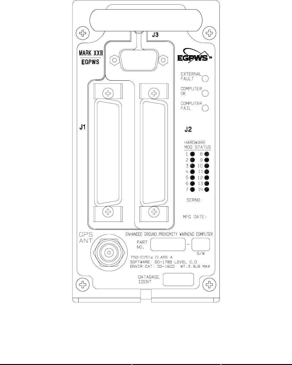
Honeywell
MK XXII EGPWS Installation Manual
CAGE CODE: 97896 SCALE: NONE SIZE: A DWG NO: 060-4314-225 REV: C SHEET 250
Figure E 4, Front Panel Connector Orientation - J1, J2, J3, GPS ANT
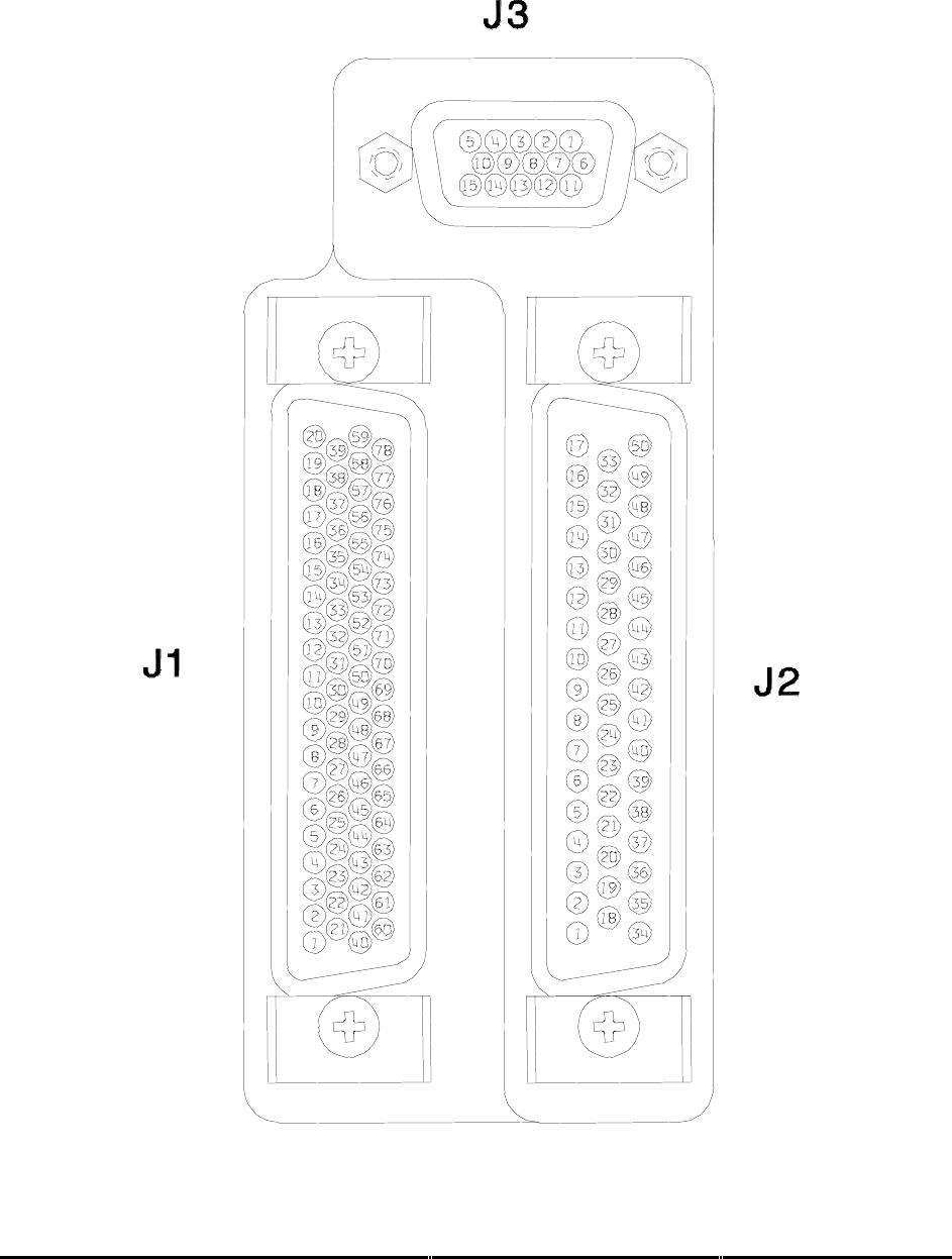
Honeywell
MK XXII EGPWS Installation Manual
CAGE CODE: 97896 SCALE: NONE SIZE: A DWG NO: 060-4314-225 REV: C SHEET 251
Figure E 4.1, Connector Pin References - J1, J2, J3

Honeywell
MK XXII EGPWS Installation Manual
CAGE CODE: 97896 SCALE: NONE SIZE: A DWG NO: 060-4314-225 REV: C SHEET 252
E 7 DEFINITIONS
The following acronyms are provided for use with this document:
Acronym Interpretation
AAAS Alternate Audio Alert Select
ADC Air Data Com
p
uter
ADS Air Data S
y
ste
m
AGL Above Ground Level
AHRS Attitude Headin
g
Reference S
y
stem
AIC Analo
g
In
p
ut Controller
AIMS Air
p
lane Information Mana
g
ement S
y
ste
m
AOA An
g
le of Attac
k
ASA AlliedSi
g
nal Aeros
p
ace
ASL Above Sea Level
ATP Acce
p
tance Test Procedure
BCD Binar
y
Coded Decimal
BIST Built in Self Test
BIT Built In Test
BITE Built In Test E
q
ui
p
ment
BNR Binar
y
BOSS Batch Oriented Simulation S
y
stem
C/O Callouts
CAA Civil Aviation Authorit
y
CAIMS Central Aircraft Information/Maintenance S
y
ste
m
CFDS Centralized Fault Dis
p
la
y
S
y
ste
m
CFIT Controlled Fli
g
ht Into Terrain
CFM Cubic Feet
p
er Minute
CISRD CFDS Interface S
y
stem Re
q
uirements Document
CMC Central Maintenance Com
p
uter
COTS Commercial Off the Shelf
CP Control Panel
CRS Course
CW Clockwise
DAA Di
g
ital/Analo
g
Ada
p
ter
DADC Di
g
ital Air Data Com
p
uter
DAU Data Ac
q
uisition Unit
DC Di
g
ital Command
DDM Difference in De
p
th of Modulation
DEVN Deviation
DH Decision Hei
g
ht
DITS Di
g
ital Information Transfer S
y
ste
m
DME Distance Measurin
g
E
q
ui
p
ment
DO Discrete Out
p
ut
DSP Di
g
ital Si
g
nal Processor
DSU Dis
p
la
y
Switchin
g
Unit
DSWC Di
g
ital Stall Warnin
g
Com
p
uter
EEPROM Electricall
y
Erasable Pro
g
rammable Read Onl
y
Memor
y
EFCP EFIS Control Panel
EFIS Electronic Fli
g
ht Instrument S
y
ste
m
EGPWC Enhanced Ground Proximit
y
Warnin
g
Com
p
uter
EGPWD Enhanced Ground Proximit
y
Warnin
g
Dis
p
la
y
EGPWS Enhanced Ground Proximit
y
Warnin
g
S
y
ste
m
EICAS En
g
ine Indication and Crew Alert S
y
ste
m
EMI Electroma
g
netic Interference
ENB Enabled
EPROM Erasable Pro
g
rammable Read Onl
y
Memor
y

Honeywell
MK XXII EGPWS Installation Manual
CAGE CODE: 97896 SCALE: NONE SIZE: A DWG NO: 060-4314-225 REV: C SHEET 253
Acronym Interpretation
F/T Functional Test
F/W Fail/Warnin
g
F/W Fail/Warnin
g
FAA Federal Aviation Administration
FCC Fli
g
ht Control Com
p
uter
FDR Fli
g
ht Data Recorder
FIAS Fli
g
ht Ins
p
ection Aircraft S
y
ste
m
FMC Fli
g
ht Mana
g
ement Com
p
uter
FMS Fli
g
ht Mana
g
ement S
y
stem
FPM Feet
p
er Minute
FSEU Fla
p
s/Slats Electronic Unit
FWC Fault Warnin
g
Com
p
uter
G/S Glideslo
p
e
GMT Greenwich Mean Time
GPS Global Position S
y
ste
m
GPW Ground Proximit
y
Warnin
g
GPWS Ground Proximit
y
Warnin
g
S
y
ste
m
GT Greater Than
H/W Hardware
HDG Headin
g
HDOP Horizontal Dilution of Position
HSID Hardware/Software Interface Document
I/O In
p
ut/Out
p
ut
IAC Inte
g
rated Avionics Com
p
uter
ICD Interface Control Document
ILS Instrument Landin
g
S
y
stem
INOP Ino
p
erative
IOC In
p
ut/Out
p
ut Concentrator
IRS Inertial Reference S
y
ste
m
ISO International Standards Or
g
anization
IVS Inertial Vertical S
p
eed
KT Knots
KTS Knots
LED Li
g
ht Emittin
g
Diode
LRRA Low Ran
g
e Radio Altimeter
LRU Line Re
p
laceable Unit
LSB Least Si
g
nificant Bit
LT Less Than
MCP Mode Control Panel
MDA Minimum Barometric Altitude
MFD Multi-Functional Dis
p
la
y
MKII Mark Two Warnin
g
Com
p
uter
MKV Mark Five Warnin
g
Com
p
uter
MKVI Mark Six Warnin
g
Com
p
uter
MKVII Mark Seven Warnin
g
Com
p
uter
MKVIII Mark Ei
g
ht Warnin
g
Com
p
uter
MKXXII Mark Twent
y
Two Warnin
g
Com
p
uter
MLS Microwave Landin
g
S
y
ste
m
MMU Memor
y
Mana
g
ement Unit
MSB Most Si
g
nificant Bit
N/A Not A
pp
licable
NCD No Com
p
uted Data
ND Navi
g
ation Dis
p
la
y
NVM Non Volatile Memor
y
OMS Onboard Maintenance S
y
ste
m
P/N Part Number
PAR Parit
y

Honeywell
MK XXII EGPWS Installation Manual
CAGE CODE: 97896 SCALE: NONE SIZE: A DWG NO: 060-4314-225 REV: C SHEET 254
Acronym Interpretation
PC Personal Com
p
uter
PCMCIA Personal Com
p
uter Memor
y
Card Industr
y
Association
PFD Primar
y
Fli
g
ht Dis
p
la
y
PMAT Portable Maintanence Access Terminal
PP Pro
g
ram Pin
PVM Processor/Voice/Memor
y
PWS Predictive Windshear S
y
stem
QFE Corrected Baro Alt relative to field elevation
QNH Corrected Baro Alt relative to sea level
RA Radio Altitude
RAM Random Access Memor
y
RDOP Radar Dis
p
la
y
Out
p
ut Processin
g
ROM Read Onl
y
Memor
y
RTCA Re
q
uirements and Technical Conce
p
ts for Aviation
RTS Read
y
to Transmit Si
g
nal
RWY Runwa
y
S/T Self Test
S/W Software
SDI Source/Destination Identifier
SDRD Software Desi
g
n Re
q
uirements Document
SIG Si
g
nificant
SPC Stall Protection Com
p
uter
SRD S
y
stem Re
q
uirements Document
SSM Si
g
n Status Matrix
ST Self Test
SWC Stall Warnin
g
Com
p
uter
TA&D Terrain Awareness & Dis
p
la
y
TACAN Tactical Air Navi
g
ation
TAD Terrain Awareness Dis
p
la
y
TBD To Be Determined
TCAS Traffic Collision Avoidance S
y
ste
m
TCF Terrain Clearance Floor
TERPS United States’ Standards for Terminal Instrument Procedures
TK Trac
k
TLB Translation Lookaside Buffer
TSO Technical Standin
g
Order
TTL Tuned To Localizer
UART Universal As
y
nchronous Receiver Transmitter
USM Unsi
g
ned Ma
g
nitude
UTC Universal Time Correlation
UUT Unit Under Test
VDC Volts, DC
VDOP Vertical Dilution of Precision
VHF Ver
y
Hi
g
h Fre
q
uenc
y
VLSI Ver
y
Lar
g
e Scale Inte
g
rated Circuit
VOR VHF Omni-directional Ran
g
e
W/S Windshear
WC Warnin
g
Com
p
uter
WX Weather
