Honeywell MLPN5500 Data Collector User Manual Optimus Users Guide v1 0
Honeywell International Inc. Data Collector Optimus Users Guide v1 0
UserManual.wiki
>
Honeywell
>
MLPN5500 User Manual
User Manual
Navigation menu
Upload a User Manual
Namespaces
Wiki Guide
HTML
PDF
Info
Views
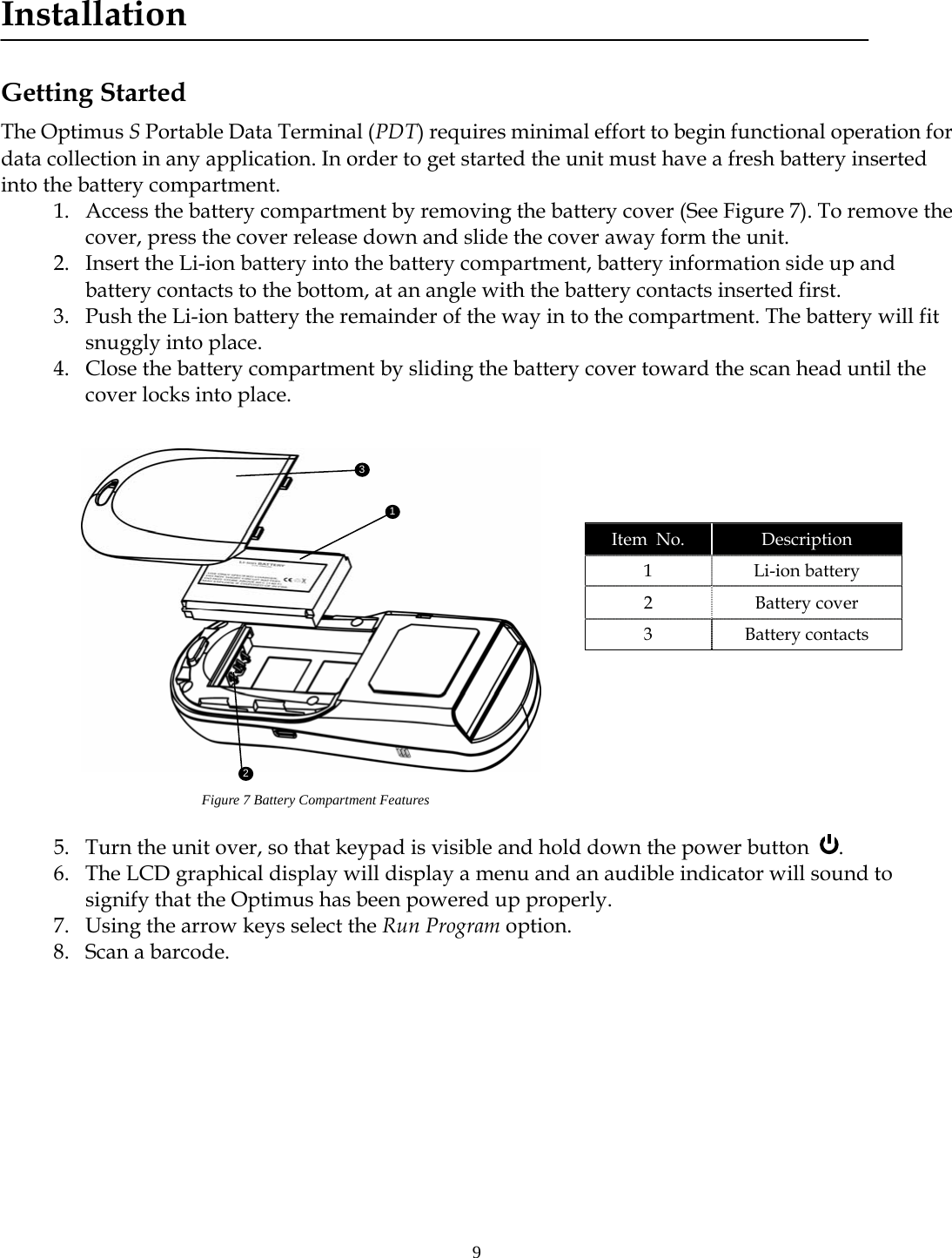
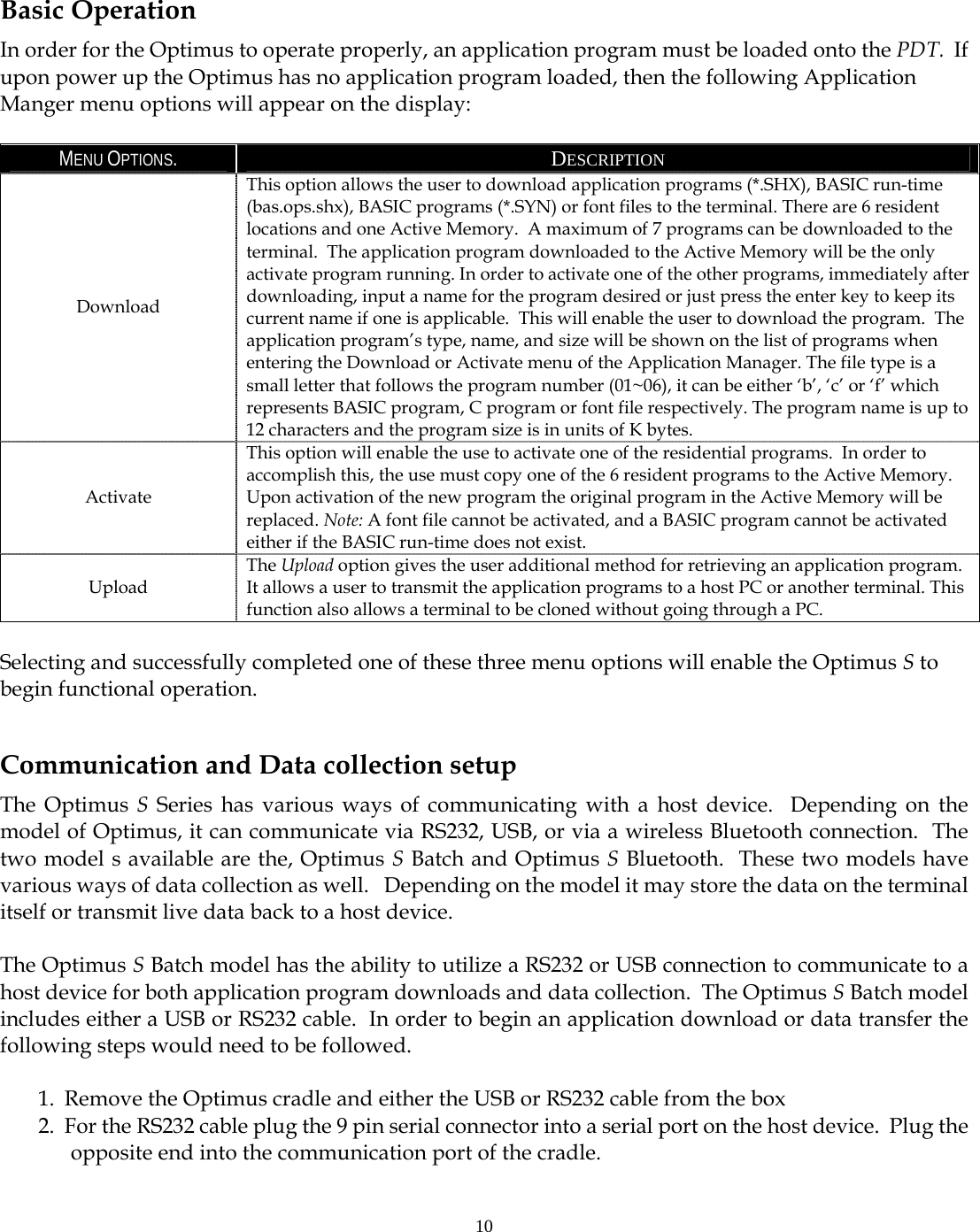
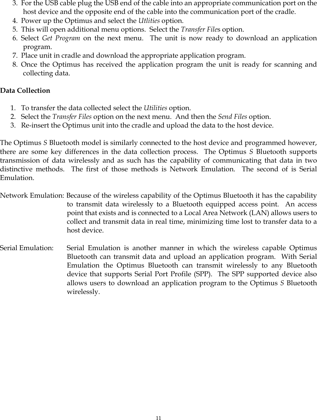
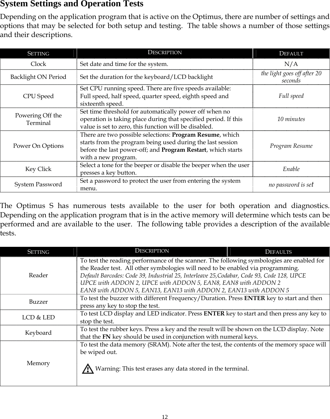
User Manual
Discussion / Help
Navigation