Honeywell MLPN5500 Data Collector User Manual Optimus Users Guide v1 0
Honeywell International Inc. Data Collector Optimus Users Guide v1 0
User Manual
i
Metrologic Instruments, Inc.
SP5500 Optimus S Series
Users’s Guide
ii
Copyright
© 2005 by Metrologic Instruments, Inc. All rights reserved. No part of this work may be
reproduced, transmitted, or stored in any form or by any means without prior written consent,
except by reviewer, who may quote brief passages in a review, or provided for in the Copyright
Act of 1976.
Products and brand names mentioned in this document are trademarks of their respective
companies.

iii
Table of Contents
Cover Page. ............................................................................................................................................................ i
Introduction .......................................................................................................................................................... 4
Product Overview........................................................................................................................................ 4
Scanner and Accessories ............................................................................................................................. 5
General Features and Characteristics................................................................................................................ 6
Multifunctional Keypad.............................................................................................................................. 7
The LCD Screen............................................................................................................................................ 8
The Lithium-Ion Battery ............................................................................................................................. 8
Installation............................................................................................................................................................. 9
Getting Started.............................................................................................................................................. 9
Basic Operation*......................................................................................................................................... 10
Communication and Data collection setup* .......................................................................................... 10
System Settings and Operation Tests...................................................................................................... 12
Application.................................................................................................................................................. 13
Specification........................................................................................................................................................ 15
OPTIMUS S SERIES......................................................................................................................................... 15
OPERATIONAL .............................................................................................................................................. 15
OPTIMUS S SERIES......................................................................................................................................... 16
MECHANICAL ............................................................................................................................................... 16
ELECTRICAL .................................................................................................................................................. 16
ENVIRONMENTAL......................................................................................................................................... 16
Contact Information and Office Locations..................................................................................................... 17
Safety Notices ..................................................................................................................................................... 18

4
Introduction
Product Overview
The SP5500 Optimus S Portable Data Terminals are robust and versatile data terminals designed to
provide exceptional performance, while enduring the demands of everyday use. The lithium-ion
rechargeable battery provides the Optimus with more than 100 hours of operation. It is supported by
a resourceful set of development tools. That includes a Windows-based application generator, “C”
compiler, and “Basic” compiler. The Optimus S has a fully integrated laser for scanning all barcode
symbologies, completely enclosed by the protective ergonomic housing. That built-in functionality of
the Optimus makes it an excellent choice for numerous applications. However, when combined with
the optional Bluetooth module it is the ideal solution for real time applications such as inventory
control, shop floor management, warehousing operations, and distribution operations.
Key Product Features
• 2 Mb RAM capable of storing over 100,000 records
• Easy to use Application Generator and download software
• Auto-backlit LCD display
• Audible and visual indications
• Built-in laser bar code scan engine capable of scanning all 1D barcode symbologies.
• Powered by rechargeable Lithium-ion battery
• Upload/download data via RS232 interfaces
• Programmable Charging and Communication cradle
• Integrated laser scanner
• Decodes all 1D barcode symbologies

5
Scanner and Accessories
METROLOGIC PART NUMBERS. PART DESCRIPTION
SP5501-6 OptimusS laser batch unit with 1MB RAM
SP5502-6 OptimusS laser batch unit with 2MB RAM
SP5535-6 OptimusS laser Bluetooth unit
MI5500-614 OptimusS Charging/Communication cradle
6
General Features and Characteristics
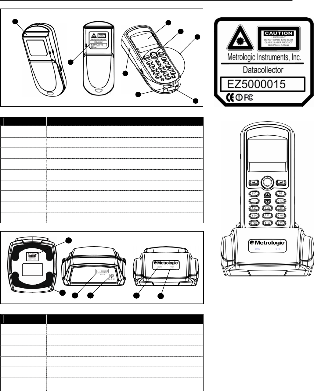
Figure 1. Scanner Features
ITEM NO. DESCRIPTION
1 Red Output Window (Laser Aperture)
2 Safety and Product label (Figure 3)
3 Speaker for audible indicators
4 LCD display
5 Multi-functional Keypad
6 Charging and communication contacts
7 IrDA Communication port
8 Battery Compartment release
9 Scan Button
Figure .2.Cradle Features
ITEM NO. DESCRIPTION
1 Safety and Product label
2 RS232 communication port
3 Power Adapter port
4 LED power indicator
5 LED Transmission indicator
6 Rubber footpads
1
2 3 45
F
1
2
4
5
3
7
8
9
Fi
g
ure 3 Product Label
Fi
g
ure 4
O
p
timus and Cradle
7
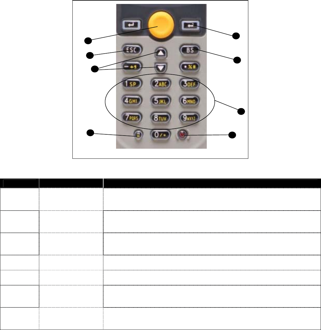
Multifunctional Keypad
Figure 5.Cradle Features
ITEM NO. KEY NAME DESCRIPTION
1 POWER
Power On/Off.
To prevent a faulty push, it needs about 1.5 sec of continuous pressing to turn
On/Off the power.
2 ALPHANUMERIC
Alphanumeric
These 10 keys can be used for either alpha characters or numerical input. (See
Item 8 for further description of key operation)
3 ENTER
Enter.
There are two enter keys on the side of the scan key. Normally the enter keys are
used for command execution or input confirmation.
4 SCAN Scan a barcode.
Pressing this button will trigger the scanner to read a barcode.
5 ESC Escape.
This key is used to stop and exit current operation.
6 BS
Back Space.
This key can be used to toggle back one space or if pressed down longer than one
second, a clear code will be sent.
7 ARROW
Arrow.
The two arrow keys located below the Scan key are used to toggle up and down
between menu selections.
5
6
7
8
4
3
2
1
8
ITEM NO. KEY NAME DESCRIPTION
ALPHA()
The toggle key for Alphabet / Numeral input.
When the system is in alpha-mode, a small icon will be shown in the lower right
corner of the display. For the 24-key keyboard, each numeric key can be used to
generate one of the three capital letters located on that number key. For example,
numeral 2 can be used to produce A, B, or C. Pressing the same key twice within
one second, will produce the letter B. Pressing the same key without halting
longer than one second, will allow the user to toggle through the three letters.
When the key has been depressed for longer than one second or another key has
been pressed, the unit will send the real key code to the application program.
8
FUNCTION(FN)
The function key.
This key cannot be activated alone, it must be pressed with one of the numeric
keys at the same time. For example, FN + 1 generates function #1, FN + 2
generates function #2, etc (up to 9 functions). Also, this key can be combined
with the UP/DOWN arrow keys to adjust the contrast of the LCD. And when this
key is combined with the ENTER key, it will turn ON/OFF the backlight.
The LCD Screen
The LCD screen of the Optimus S Portable Data Terminal displays program settings, operational
parameters, data collected, and much more. The display is a graphical LCD with the following
characteristics:
y Display area of 64 pixels x 100 pixels
y Resolution:
y Maximum of 8 lines x 20 characters
y Minimum of 4 lines x 15 characters
y Displays alpha-characters, numbers, and symbols
y Automated back light
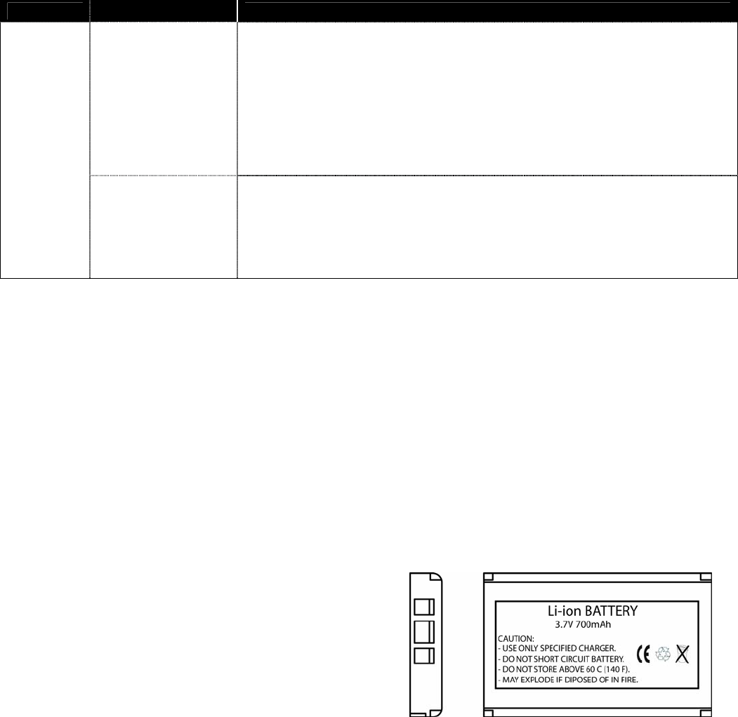
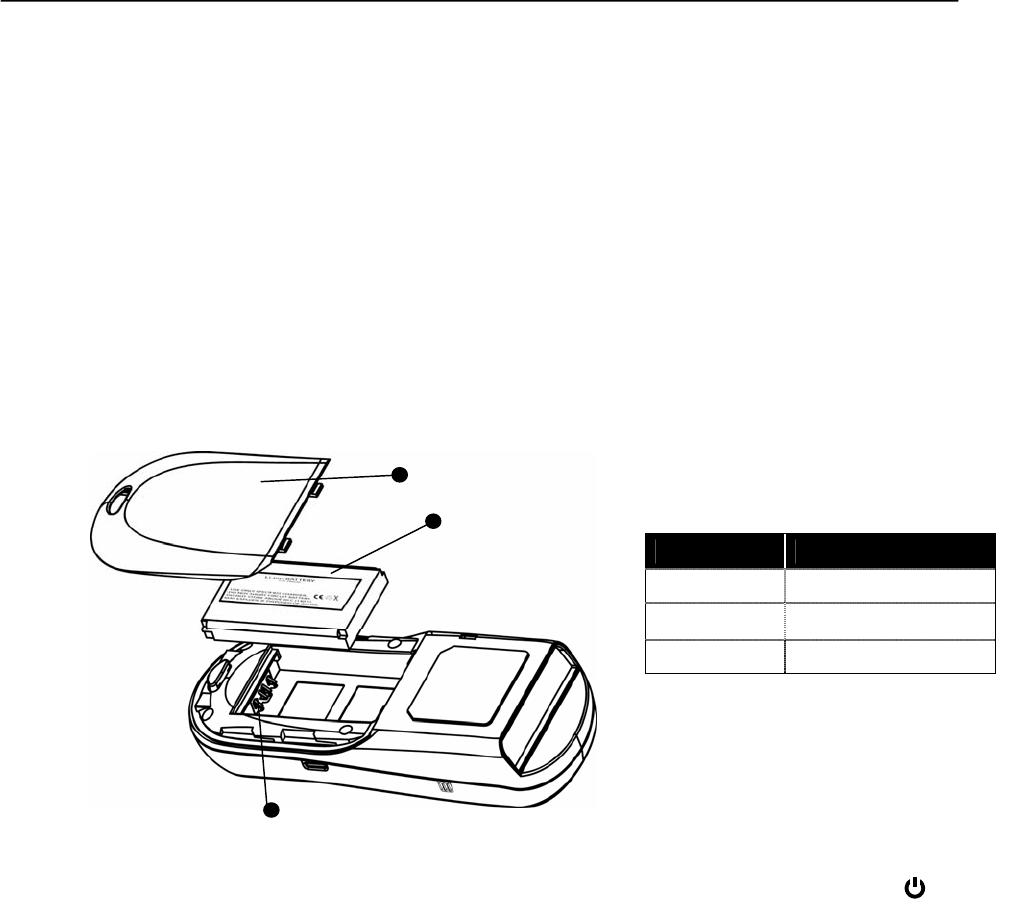
The Lithium-Ion Battery
The Optimus S Portable Data Terminal includes a
lithium-ion rechargeable battery pack. The battery is
inserted (See Getting Started for battery installation)
into the battery compartment of the Optimus and
recharges with Optimus in the cradle and in charging
mode.
Fi
g
ure 6 Lithium-Ion Batter
y
9
Installation
Getting Started
The Optimus S Portable Data Terminal (PDT) requires minimal effort to begin functional operation for
data collection in any application. In order to get started the unit must have a fresh battery inserted
into the battery compartment.
1. Access the battery compartment by removing the battery cover (See Figure 7). To remove the
cover, press the cover release down and slide the cover away form the unit.
2. Insert the Li-ion battery into the battery compartment, battery information side up and
battery contacts to the bottom, at an angle with the battery contacts inserted first.
3. Push the Li-ion battery the remainder of the way in to the compartment. The battery will fit
snuggly into place.
4. Close the battery compartment by sliding the battery cover toward the scan head until the
cover locks into place.
Figure 7 Battery Compartment Features
5. Turn the unit over, so that keypad is visible and hold down the power button .
6. The LCD graphical display will display a menu and an audible indicator will sound to
signify that the Optimus has been powered up properly.
7. Using the arrow keys select the Run Program option.
8. Scan a barcode.
1
2
3
Item No. Description
1 Li-ion battery
2 Battery cover
3 Battery contacts

10
Basic Operation
In order for the Optimus to operate properly, an application program must be loaded onto the PDT. If
upon power up the Optimus has no application program loaded, then the following Application
Manger menu options will appear on the display:
MENU OPTIONS. DESCRIPTION
Download
This option allows the user to download application programs (*.SHX), BASIC run-time
(bas.ops.shx), BASIC programs (*.SYN) or font files to the terminal. There are 6 resident
locations and one Active Memory. A maximum of 7 programs can be downloaded to the
terminal. The application program downloaded to the Active Memory will be the only
activate program running. In order to activate one of the other programs, immediately after
downloading, input a name for the program desired or just press the enter key to keep its
current name if one is applicable. This will enable the user to download the program. The
application program’s type, name, and size will be shown on the list of programs when
entering the Download or Activate menu of the Application Manager. The file type is a
small letter that follows the program number (01~06), it can be either ‘b’, ‘c’ or ‘f’ which
represents BASIC program, C program or font file respectively. The program name is up to
12 characters and the program size is in units of K bytes.
Activate
This option will enable the use to activate one of the residential programs. In order to
accomplish this, the use must copy one of the 6 resident programs to the Active Memory.
Upon activation of the new program the original program in the Active Memory will be
replaced. Note: A font file cannot be activated, and a BASIC program cannot be activated
either if the BASIC run-time does not exist.
Upload
The Upload option gives the user additional method for retrieving an application program.
It allows a user to transmit the application programs to a host PC or another terminal. This
function also allows a terminal to be cloned without going through a PC.
Selecting and successfully completed one of these three menu options will enable the Optimus S to
begin functional operation.
Communication and Data collection setup
The Optimus S Series has various ways of communicating with a host device. Depending on the
model of Optimus, it can communicate via RS232, USB, or via a wireless Bluetooth connection. The
two model s available are the, Optimus S Batch and Optimus S Bluetooth. These two models have
various ways of data collection as well. Depending on the model it may store the data on the terminal
itself or transmit live data back to a host device.
The Optimus S Batch model has the ability to utilize a RS232 or USB connection to communicate to a
host device for both application program downloads and data collection. The Optimus S Batch model
includes either a USB or RS232 cable. In order to begin an application download or data transfer the
following steps would need to be followed.
1. Remove the Optimus cradle and either the USB or RS232 cable from the box
2. For the RS232 cable plug the 9 pin serial connector into a serial port on the host device. Plug the
opposite end into the communication port of the cradle.
11
3. For the USB cable plug the USB end of the cable into an appropriate communication port on the
host device and the opposite end of the cable into the communication port of the cradle.
4. Power up the Optimus and select the Utlities option.
5. This will open additional menu options. Select the Transfer Files option.
6. Select Get Program on the next menu. The unit is now ready to download an application
program.
7. Place unit in cradle and download the appropriate application program.
8. Once the Optimus has received the application program the unit is ready for scanning and
collecting data.
Data Collection
1. To transfer the data collected select the Utilities option.
2. Select the Transfer Files option on the next menu. And then the Send Files option.
3. Re-insert the Optimus unit into the cradle and upload the data to the host device.
The Optimus S Bluetooth model is similarly connected to the host device and programmed however,
there are some key differences in the data collection process. The Optimus S Bluetooth supports
transmission of data wirelessly and as such has the capability of communicating that data in two
distinctive methods. The first of those methods is Network Emulation. The second of is Serial
Emulation.
Network Emulation: Because of the wireless capability of the Optimus Bluetooth it has the capability
to transmit data wirelessly to a Bluetooth equipped access point. An access
point that exists and is connected to a Local Area Network (LAN) allows users to
collect and transmit data in real time, minimizing time lost to transfer data to a
host device.
Serial Emulation: Serial Emulation is another manner in which the wireless capable Optimus
Bluetooth can transmit data and upload an application program. With Serial
Emulation the Optimus Bluetooth can transmit wirelessly to any Bluetooth
device that supports Serial Port Profile (SPP). The SPP supported device also
allows users to download an application program to the Optimus S Bluetooth
wirelessly.

12
System Settings and Operation Tests
Depending on the application program that is active on the Optimus, there are number of settings and
options that may be selected for both setup and testing. The table shows a number of those settings
and their descriptions.
SETTING DESCRIPTION DEFAULT
Clock Set date and time for the system. N/A
Backlight ON Period Set the duration for the keyboard/LCD backlight the light goes off after 20
seconds
CPU Speed
Set CPU running speed. There are five speeds available:
Full speed, half speed, quarter speed, eighth speed and
sixteenth speed.
Full speed
Powering Off the
Terminal
Set time threshold for automatically power off when no
operation is taking place during that specified period. If this
value is set to zero, this function will be disabled.
10 minutes
Power On Options
There are two possible selections: Program Resume, which
starts from the program being used during the last session
before the last power-off; and Program Restart, which starts
with a new program.
Program Resume
Key Click Select a tone for the beeper or disable the beeper when the user
presses a key button. Enable
System Password Set a password to protect the user from entering the system
menu. no password is set
The Optimus S has numerous tests available to the user for both operation and diagnostics.
Depending on the application program that is in the active memory will determine which tests can be
performed and are available to the user. The following table provides a description of the available
tests.
SETTING DESCRIPTION DEFAULTS
Reader
To test the reading performance of the scanner. The following symbologies are enabled for
the Reader test. All other symbologies will need to be enabled via programming.
Default Barcodes: Code 39, Industrial 25, Interleave 25,Codabar, Code 93, Code 128, UPCE
UPCE with ADDON 2, UPCE with ADDON 5, EAN8, EAN8 with ADDON 2
EAN8 with ADDON 5, EAN13, EAN13 with ADDON 2, EAN13 with ADDON 5
Buzzer To test the buzzer with different Frequency/Duration. Press ENTER key to start and then
press any key to stop the test.
LCD & LED To test LCD display and LED indicator. Press ENTER key to start and then press any key to
stop the test.
Keyboard To test the rubber keys. Press a key and the result will be shown on the LCD display. Note
that the FN key should be used in conjunction with numeral keys.
Memory
To test the data memory (SRAM). Note after the test, the contents of the memory space will
be wiped out.
Warning: This test erases any data stored in the terminal.
13
Application
The Application module runs on top of the System module. The Optimus S Series Portable Data
Terminals are preloaded with the Application Generator’s run-time program and the following menu
will be shown upon powering the unit up:
Batch model (SP5501, SP5502):
1. Run Program
2. Utilities
Bluetooth models (SP5535)
1. Take data
2. Utilities
Utilizing the arrow keys select the menu option and execute it by pressing the ENTER key. For certain
models of the Optimus S Series the Data Optimizer program may need to be used in order to handle
the in-coming and out-going data to and from a host device. For detailed information, please refer to
“Optimizer User’s Guide” and “Data Optimizer User’s Guide”.
Note: If the Application Generator is used to create the application program, it will be necessary to download it to
the terminal.
Programming the terminal
There are three software tools available for developing application programs for the terminal.
• The Optimizer
• The “BASIC” Compiler
• The “C” Compiler
For detailed information, please contact Metrologic Instruments, Inc..
Programming the communication cradle
The communication cradle of the Optimus S Portable Data Terminal supports serial IR interface only.
If a customized PC application has been developed for communication with the terminal via the cradle,
it will be necessary to first configure the cradle through programming. There is a DLL available for
this purpose.
For more information, please contact Metrologic Instruments, Inc..

14
Troubleshooting
SYMPTOM DESCRIPTION
Make sure the battery is loaded.
Charge the battery and check the charging status. If no charging information shown on
the display, reload the battery and check if the battery is properly installed then try
again.
Does not power up after
pressing POWER key.
Call for service if problem persists.
Check if the cable is plugged tightly Cannot transmit data or
programs via the terminal’s
communication port. Check if host communication parameters (COM port, baud rate, data bits, parity, and
stop bit) match with the Terminal's.
Turn off the power then enter the system menu. From the system menu, select the Test
and then its sub-item KBD. Perform the key-in test.
Keypad does not work
properly
Call for service if problem persists.
Check if the barcodes used are enabled
Check if battery-low indicator is shown on the LCD display. If yes, charge the battery
Scanner does not scan
Call for service if problem persists.
Open the battery cap and re-load the battery.
Enter system menu. Check if the terminal can have a correct response by performing
tests.
Abnormal responses
Call for service if problem persists.

15
Specification
OPTIMUS S SERIES
OPERATIONAL
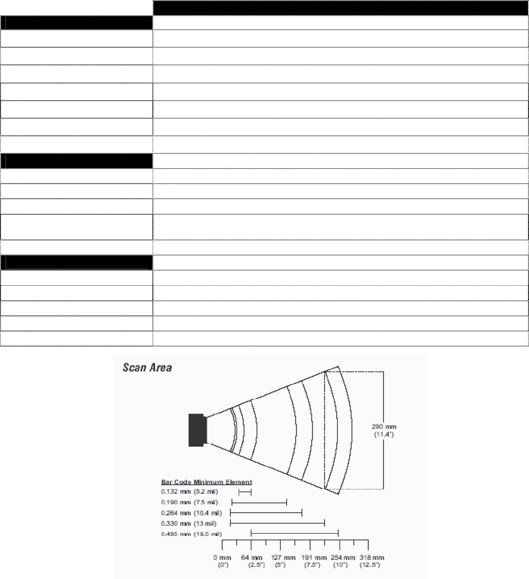
Light Source: Visible Laser Diode (VLD) @ 650 nm
Normal Depth of Field: 20 mm - 202 mm
(.75"- 8.75")
0.33 mm (13 mil)
bar code
Width of Scan Field: 290mm (11.4”) @ 222 mm (8.75”)
Single-Line
Scan Speed: 100 scan lines per second
No. of Scan Lines: 1
Min Bar Width: 0.127 mm (5.0 mil)
Decode Capability: All standard 1-D bar codes including RSS-14,
RSS-Expanded, and RSS-14 Limited
System Interfaces: RS232, USB, and Bluetooth
Print Contrast: 35% minimum reflectance difference
No. Characters Read: Up to 80 data characters
Maximum number will vary based on symbology and density.
Beeper Operation: 7 tones or no beep
CPU: 16-bit CMOS, low power consumption
Program Memory: 1 MB Flash ROM
1 MB SRAM (Bluetooth)
Data Memory: 2 MB SRAM (Batch)
Display: LCD 100 x 64 pixels, back-lit
Display Resolution: 8 lines x 20 Characters (max), 4 Lines x 15 characters (min)
Bluetooth Versions: 1.1
Bluetooth Profiles: Bluetooth Network Encapsulation Profile(BNEP), Serial Port Profile (SPP)
Communication (Unit): IrDA, CradleIR or Bluetooth
Communication (Cradle): RS232 or USB
Application Development: Windows-based Optmizer; optional C & BASIC compilers
16
OPTIMUS S SERIES
MECHANICAL
Width (Unit): 55 mm (2.2")
Depth (Unit): 28 mm (1.1")
Height (Unit): 137 mm (5.4")
Weight (Unit): 4.9 oz (140 g) – including battery
Width (Cradle): 92 mm (3.6")
Depth (Cradle): 110 mm (4.3")
Height (Cradle): 58 mm (2.3")
ELECTRICAL
Battery Operation: Li-ion
Battery Backup: 3.7V, 700mA hours, rechargeable lithium battery
Operation: Over 36 hours
Laser Class 1: IEC 60825-1:1993+A1:1997+A2:2001
EN 60825-1:1994+A11:1996+A2:2001
EMC: FCC, Class B
ENVIRONMENTAL
Operating Temperature: 0°C to 55°C (32°F to 131°F)
Storage Temperature: -70°C to 60°C (-4°F to 140°F)
Humidity: 5% to 95% relative humidity, non-condensing
Contaminants: Sealed to resist airborne particulate contaminants
Shock Resistance: 1.2 m (4’) drop onto concrete
Fi
g
ure
8 Scan
A
reas
17
Contact Information and Office Locations
CORPORATE HEADQUARTERS
NORTH AMERICA EUROPEAN, MIDDLE EAST & AFRICAN
HEADQUARTERS
USA, New Jersey Germany, Munich
Metrologic Instruments, Inc. Metrologic Instruments GmbH
Tel: 1-800-ID-METRO Fax: 856-228-6673 Tel: 49-89-89019-0 Fax: 49-89-89019-200
Email: info@metrologic.com Email: info@europe.metrologic.com
SOUTH AMERICA AND CENTRAL AMERICA Germany, Austria and Switzerland
Brazil São Paulo Tel: 49-89-89019-0 Fax: 49-89-89019-200
Metrologic do Brasil Ltda. Email: info@de.metrologic.com
Tel: 55-11-5182-8226 Fax: 55-11-5182-8315
Email: info@br.metrologic.com Eastern Europe and Middle East
Tel: 49-89-89019-222 Fax: 49-89-89019-173
Outside Brazil São Paulo
Metrologic South America Italy, Bologna
Tel: 55-11-5182-7273 Fax: 55-11-5182-7198 Metrologic Instruments Italia srl
Email: info@sa.metrologic.com Tel: +39 0 51 6511978 Fax: +39 0 51 6521337
Email: info@it.metrologic.com
ASIAN HEADQUARTERS
Asia, Singapore France, Paris
Metrologic Asia (Pte) Ltd Metrologic Eria France SA
Tel: (65) 6842-7155 Fax: (65) 6842-7166 Tel: +33 (0) 1 48.63.78.78
Email: info@sg.metrologic.com Fax: +33 (0) 1 48.63.24.94
Email: info@fr.metrologic.com
China
MTLG Auto ID Instruments (Shanghai) Co.,
Ltd Spain, Madrid
Tel: 86-2158692780 Fax: 86-21-58692782 Metrologic Eria Ibérica, SL
Email: info@cn.metrologic.com Tel: +34 913 272 400 Fax: +34 913 273 829
Email: info@es.metrologic.com
Metro (Suzhou) Sales Office
Tel: 86-512-67622550 Fax: 86-512-67622560 Metrologic European Repair Center (MERC)
Email: info@cn.metrologic.com Metrologic Eria Ibérica, SL
Tel: +34 913 751 249 Fax: +34 913 270 437
Guangzhou Sales Office
Tel: 86-20-38823476 Fax: 86-20-38823477 United Kingdom, Basingstoke
Email: info@cn.metrologic.com Metrologic Instruments UK Limited
Tel: +44 (0) 1256 365900
Beijing Sales Office Fax: +44 (0) 1256 365955
Tel/Fax: 86 10 82253472 Email: info@uk.metrologic.com
Email: info@cn.metrologic.com
Russia, Moscow
Japan, Tokyo Metrologic Russia
Metrologic Japan Co., Ltd. Tel: +7 095 730 7424 Fax: +7 095 730 7425
Tel: 81-03-3839-8511 Fax: 81-03-3839-8519 Email: info@ru.metrologic.com
Email: info@jp.metrologic.com
Poland, Warsaw
India, Bangalore Metrologic Instruments Poland Sp.z o.o
Metrologic India Tel: +48 (22) 545 04 30
Tel: +91 80 51256718 Fax: +91 80 51256719 Fax: +48 (22) 545 04 31
Email: info@in.metrologic.com Email: info@pl.metrologic.com
18
Safety Notices
This equipment has been tested and found to comply with the limits for a Class B digital device,
pursuant to Part 15 of the FCC Rules. These limits are designed to provide reasonable protection
against harmful interference in a residential installation. This equipment generates, uses and can
radiate radio frequency energy and, if not installed and used in accordance with the instructions, may
cause harmful interference to radio communications. However, there is no guarantee that interference
will not occur in a particular installation. If this equipment does cause harmful interference to radio or
television reception, which can be determined by turning the equipment off and on, the user is
encouraged to try to correct the interference by one of the following measures:
- Reorient or relocate the receiving antenna.
- Increase the separation between the equipment and receiver.
- Connect the equipment into an outlet on a circuit different from that
to which the receiver is connected.
- Consult the dealer or an experienced radio/TV technician for help.
This device complies with Part 15 of the FCC Rules. Operation is subject to the following two
conditions: (1) This device may not cause harmful interference, and (2) this device must accept any
interference received, including interference that may cause undesired operation.
Any changes or modifications not expressly approved by the party responsible for compliance could
void the user's authority to operate this equipment.
The equipment complies with FCC RF radiation exposure limits set forth for an uncontrolled
environment. The internal / external antennas used for this transmitter must not be co-located or
operating in conjunction with any other antenna or transmitter within the host device.
Canada (Industry Canada) :
"Operation is subject to the following two conditions: (1) this device may not cause interference,
and (2) this device must accept any interference, including interference that may cause undesired
operation of the device."