Honeywell MX2702B Bluetooth Bar Code Scanner Base Station User Manual 5620 UG Rev a
Honeywell International Inc Bluetooth Bar Code Scanner Base Station 5620 UG Rev a
UserManual.wiki
>
Honeywell
>
MX2702B User Manual
User Manual
Navigation menu
Upload a User Manual
Namespaces
Wiki Guide
HTML
PDF
Info
Views
User Manual
Discussion / Help
Navigation


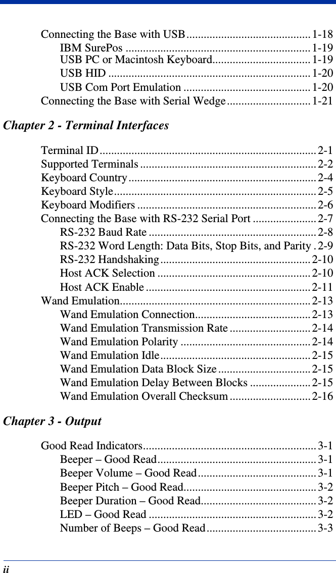
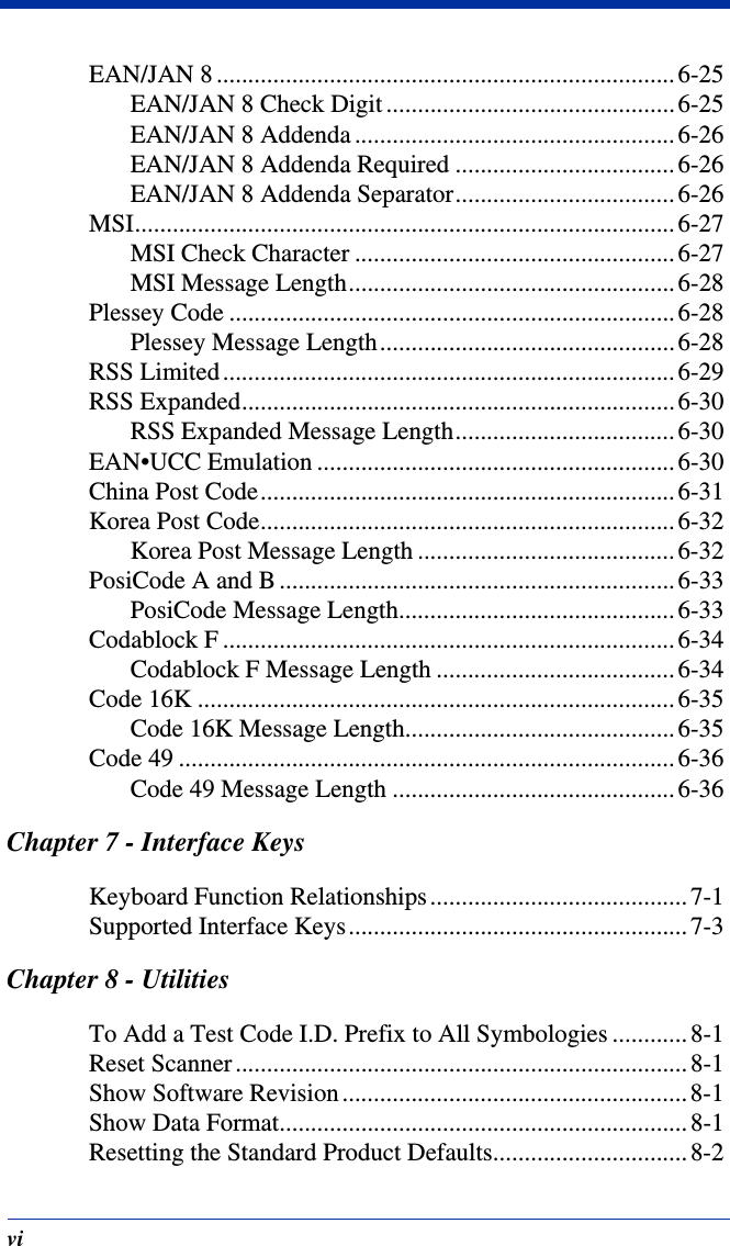


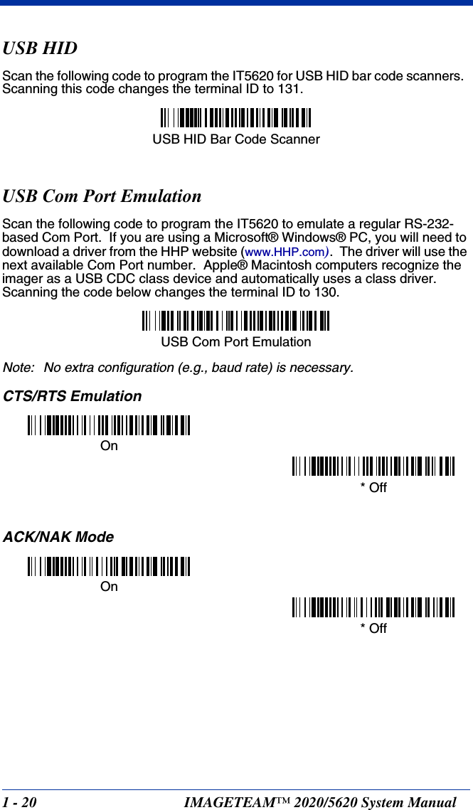
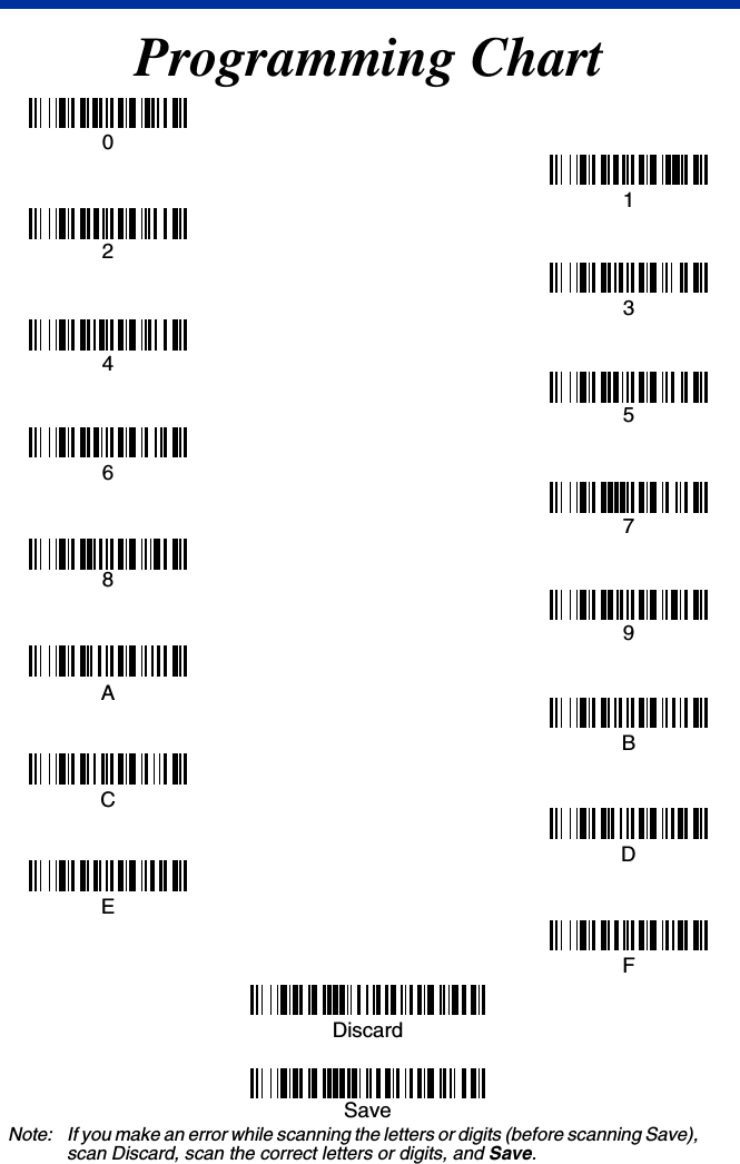
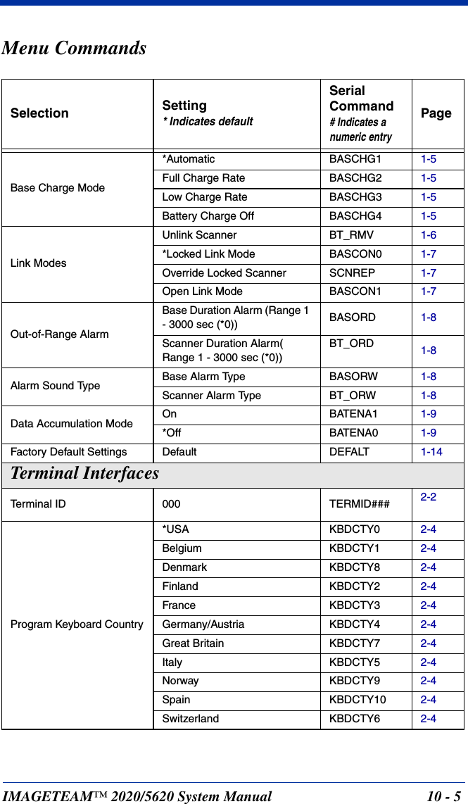
![2 - 4 IMAGETEAM™ 2020/5620 System ManualKeyboard CountryScan the appropriate country code below to program the keyboard for your country. As a general rule, the following characters are supported, but need special care for countries other than the United States:@ | $ # { } [ ] = / ‘ \ < > ~ * United States Denmark France Germany/AustriaGreat BritainItalyNorway SpainSwitzerlandBelgiumFinland](https://usermanual.wiki/Honeywell/MX2702B/User-Guide-486300-Page-42.png)

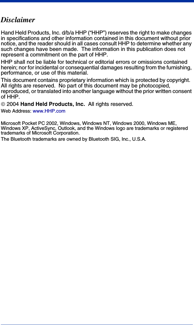
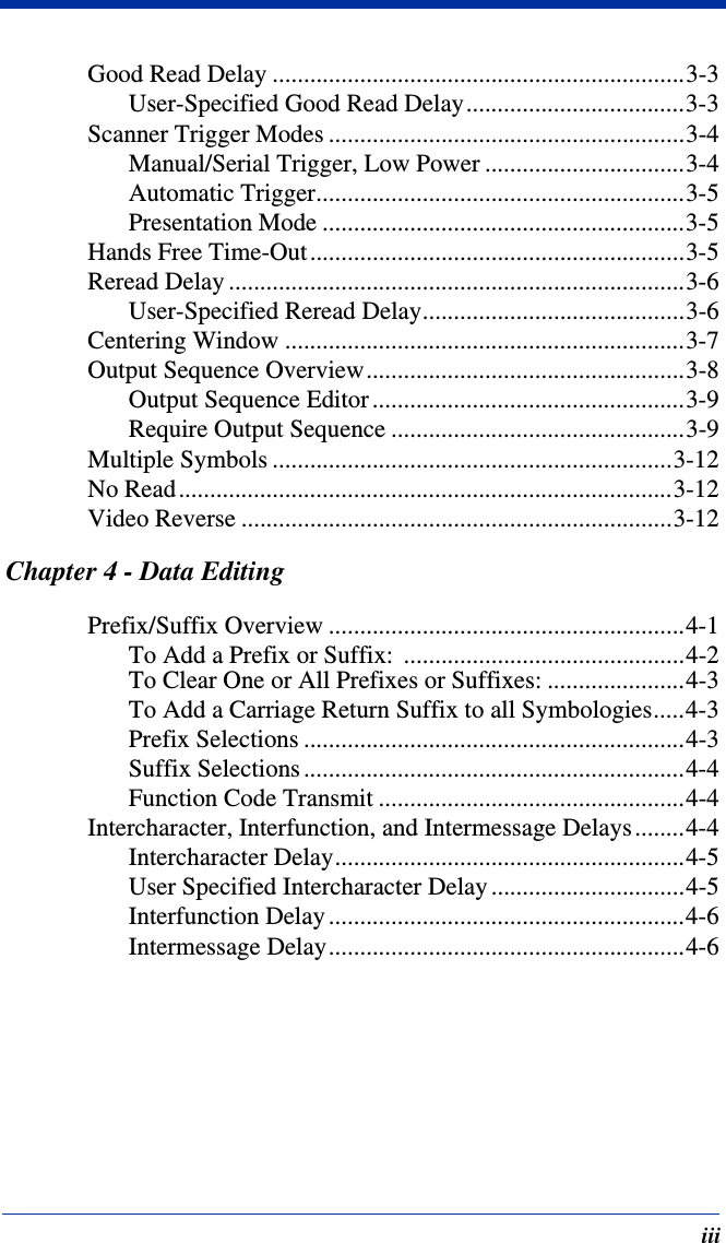
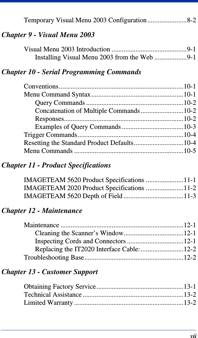
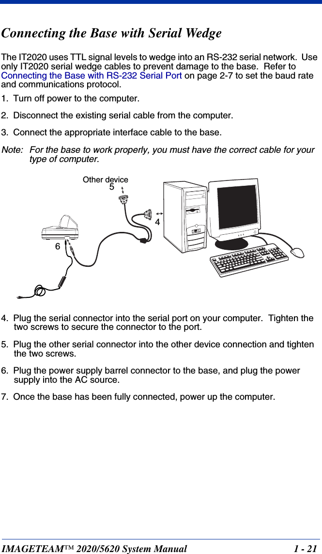
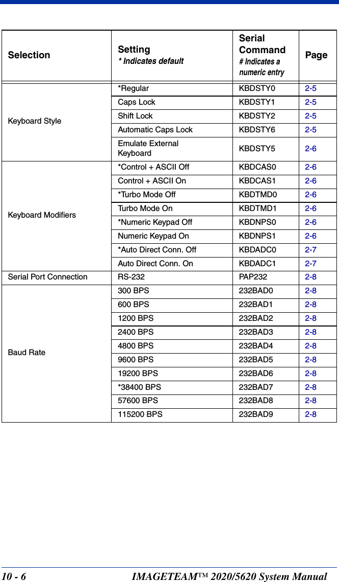
![6 - 8 IMAGETEAM™ 2020/5620 System ManualFull ASCIIIf Full ASCII Code 39 decoding is enabled, certain character pairs within the bar code symbol will be interpreted as a single character. For example: $V will be decoded as the ASCII character SYN, and /C will be decoded as the ASCII character #. Default = On.Character pairs /M and /N decode as a minus sign and period respectively.Character pairs /P through /Y decode as 0 through 9.NUL %U DLE $PSP SPACE00@%VPP‘%Wp+PSOH $A DC1 $Q !/A 11AAQQa+Aq+QSTX $B DC2 $R “/B 22BBRRb+Br+RETX $C DC3 $S #/C 33CCSSc+Cs+SEOT $D DC4 $T $/D 44DDTTd+Dt+TENQ $E NAK $U %/E 55EEUUe+Eu+UACK $F SYN $V &/F 66FFVVf+Fv+VBEL $G ETB $W ‘/G77GGWWg+Gw+WBS $H CAN $X (/H 88HHXXh+Hx+XHT $I EM $Y )/I 99IIYYi+Iy+YLF $J SUB $Z */J :/ZJJZZj+Jz+ZVT $K ESC %A +/K ;%FKK[%Kk+K{%PFF $L FS %B ,/L <%GLL\%Ll+L|%QCR $M GS %C -- =%HMM]%Mm+M}%RSO $N RS %D .. >%INN^%Nn+N~%SSI $O US %E //O?%JOO_%Oo+ODEL %TFull ASCII Off* Full ASCII On](https://usermanual.wiki/Honeywell/MX2702B/User-Guide-486300-Page-86.png)
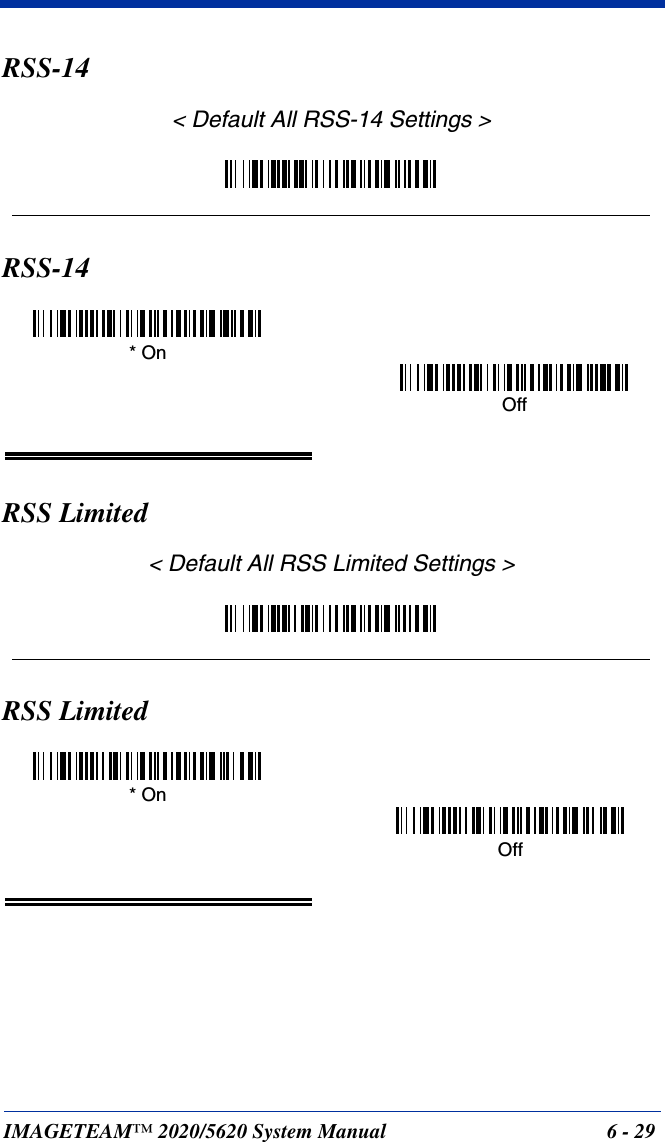
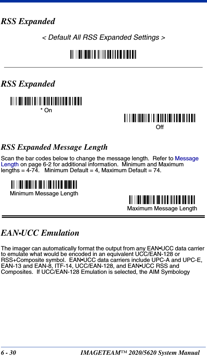
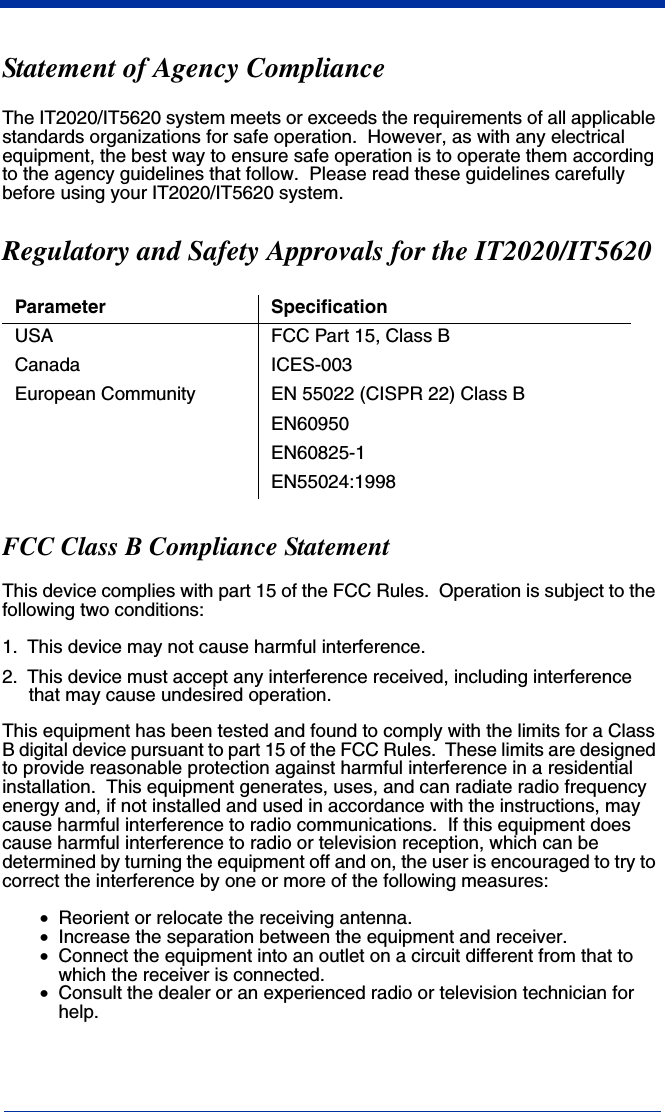
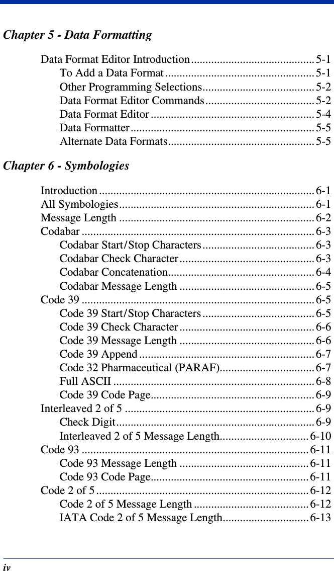
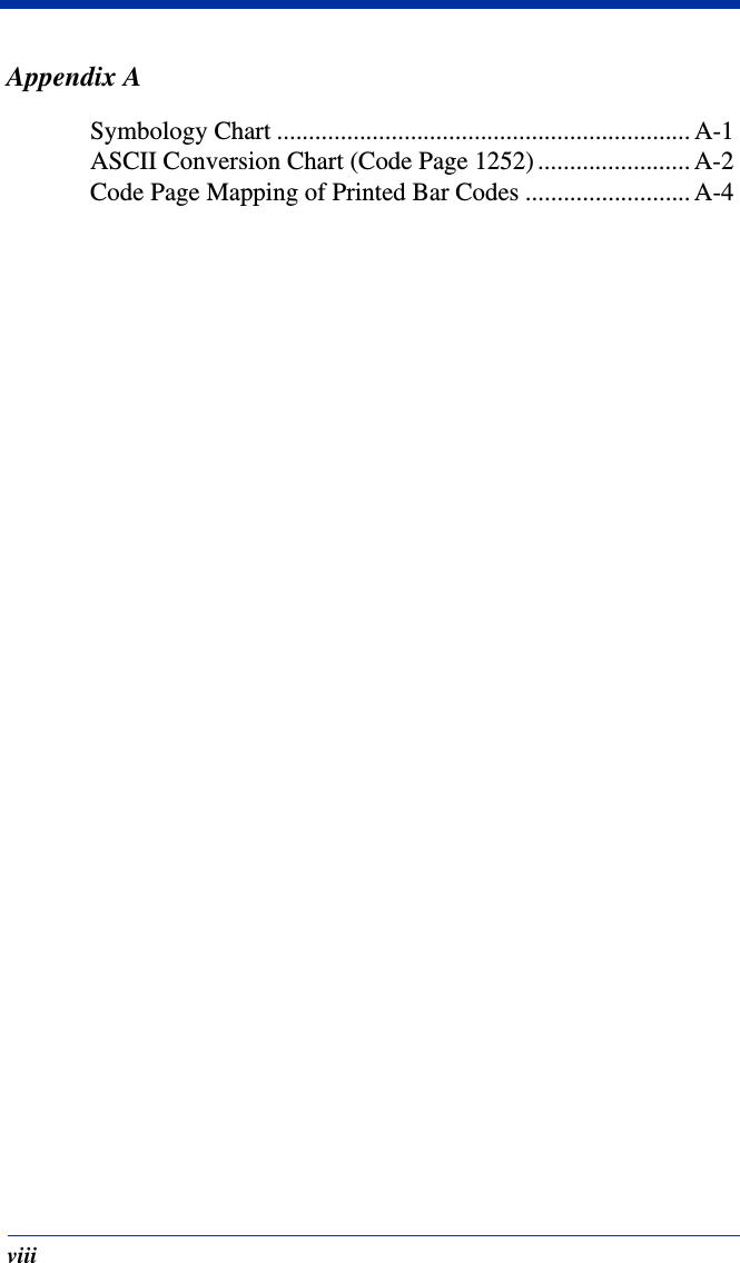
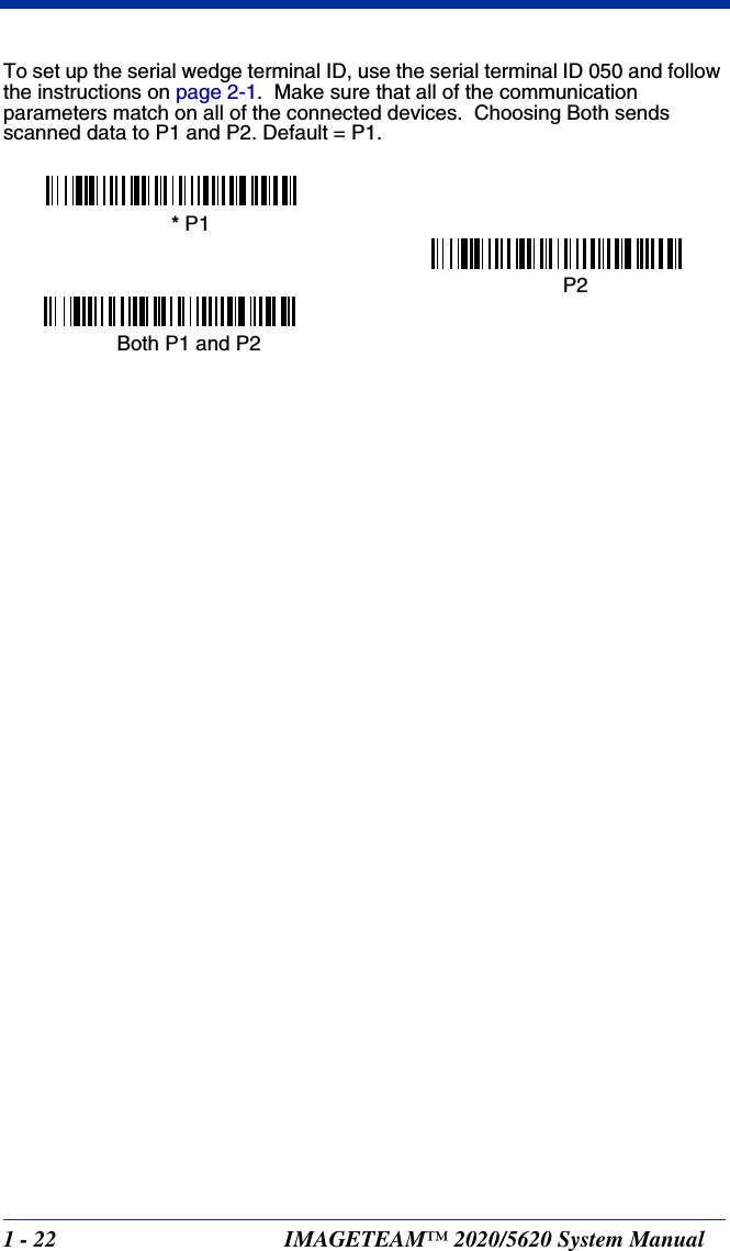
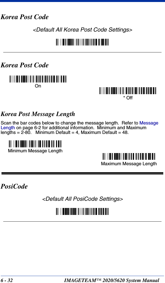
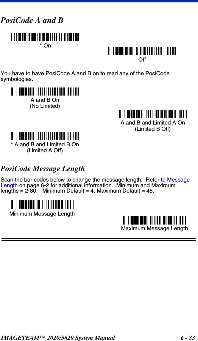
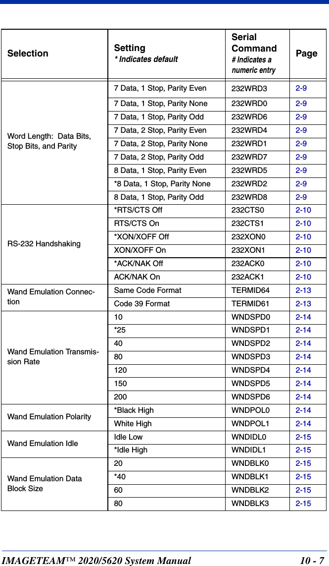
![IMAGETEAM™ 2020/5620 System Manual 6 - 31Identifier will be reported as “]C1”. If RSS Emulation is selected, the AIM Symbology Identifier will be reported as “]e0.” Any application that accepts EAN•UCC data can be simplified since it only needs to recognize one data carrier type. Default = EAN•UCC Emulation Off.China Post Code<Default All China Post Code Settings>China Post CodeChina Post Message LengthScan the bar codes below to change the message length. Refer to Message Length on page 6-2 for additional information. Minimum and Maximumlengths = 2-80. Minimum Default = 4, Maximum Default = 80.RSS Emulation128 Emulation* EAN•UCC Emulation OffOn* OffMinimum Message LengthMaximum Message Length](https://usermanual.wiki/Honeywell/MX2702B/User-Guide-486300-Page-109.png)
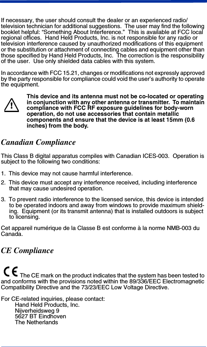
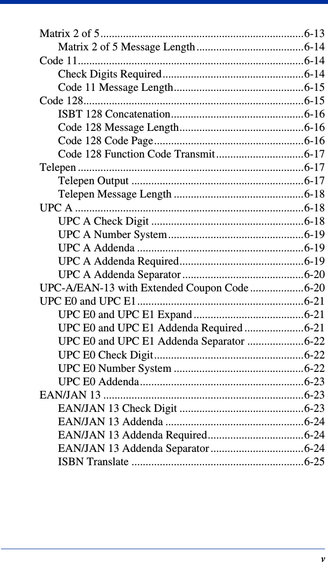
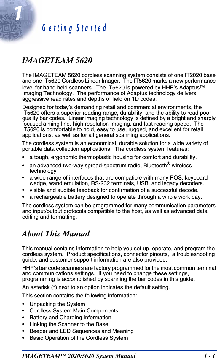
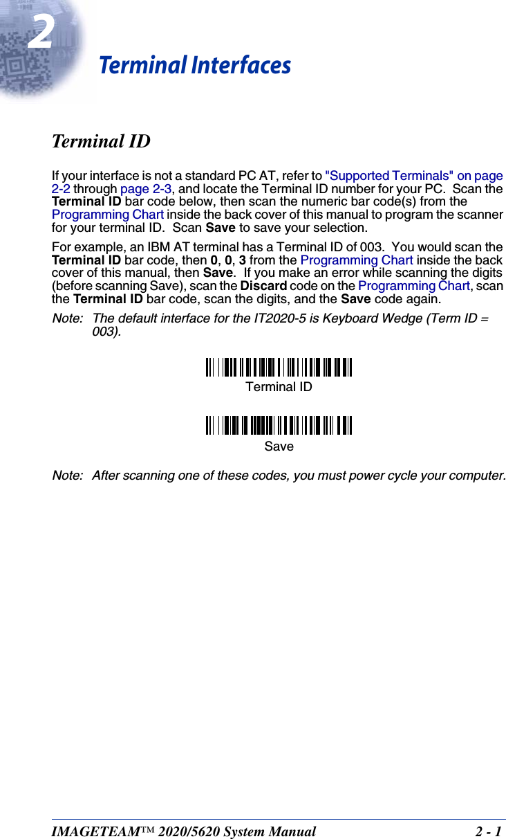
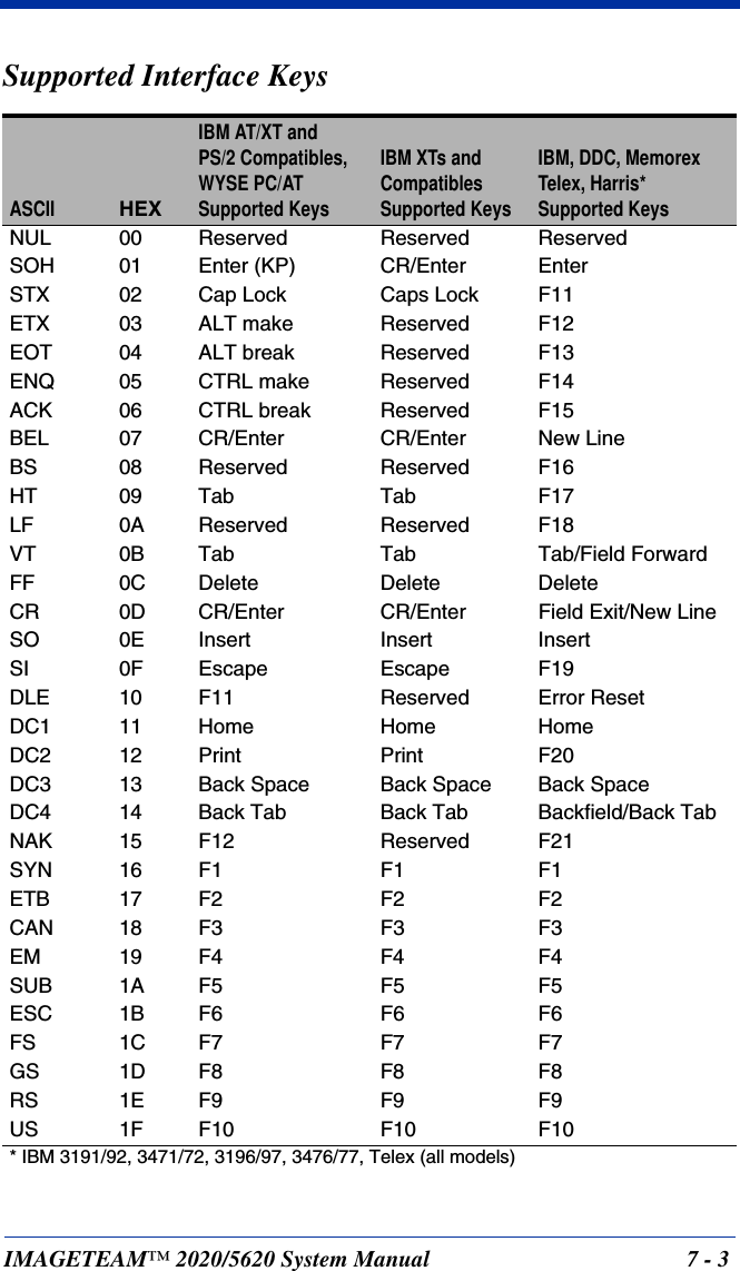
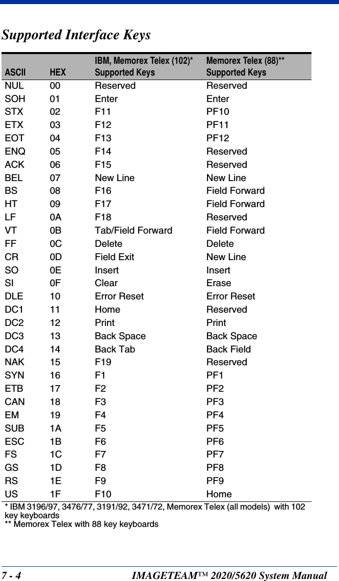
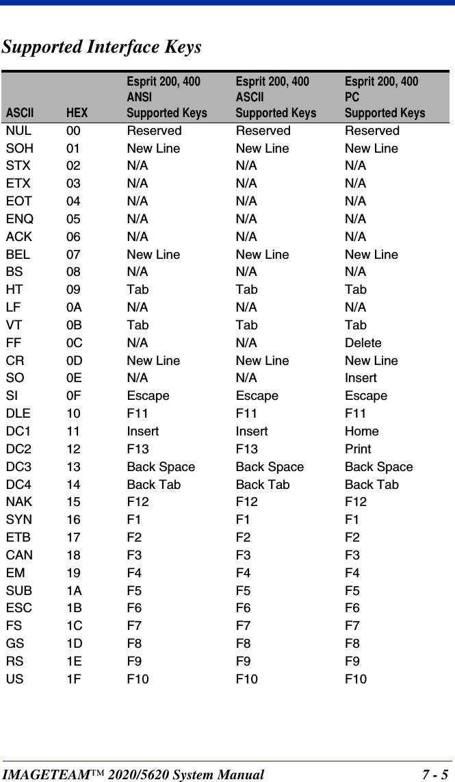
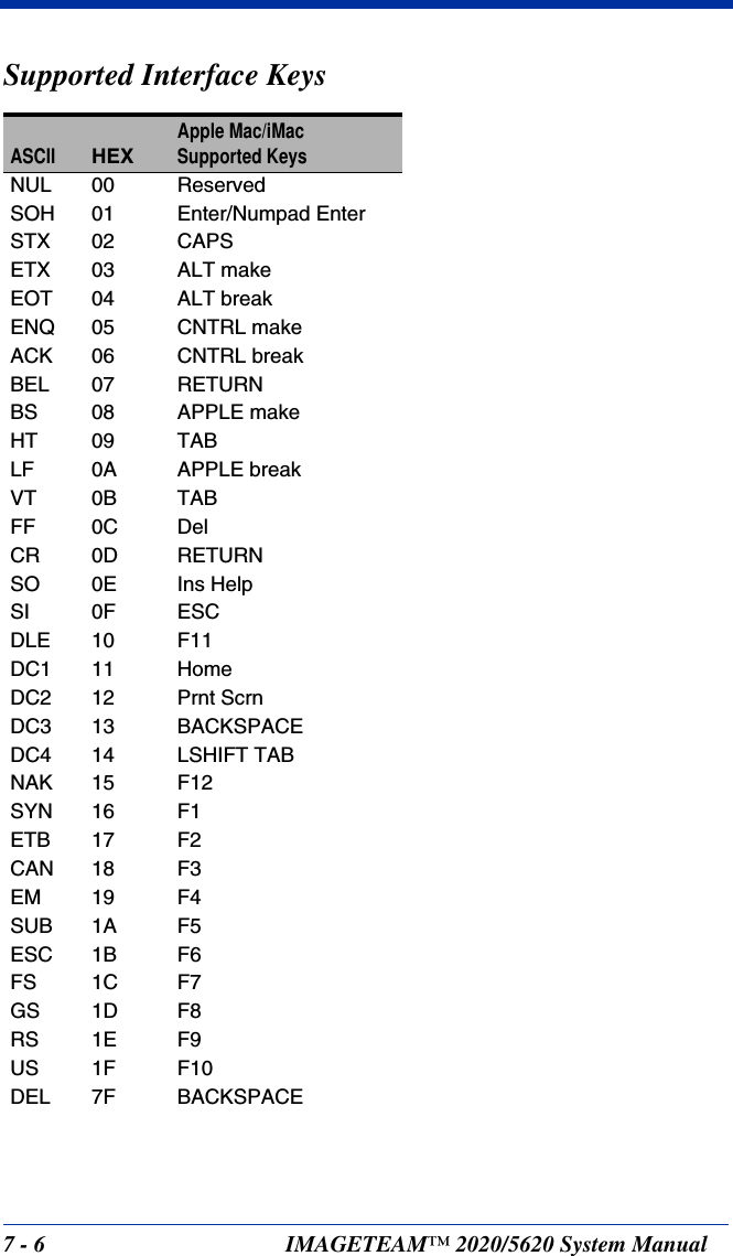
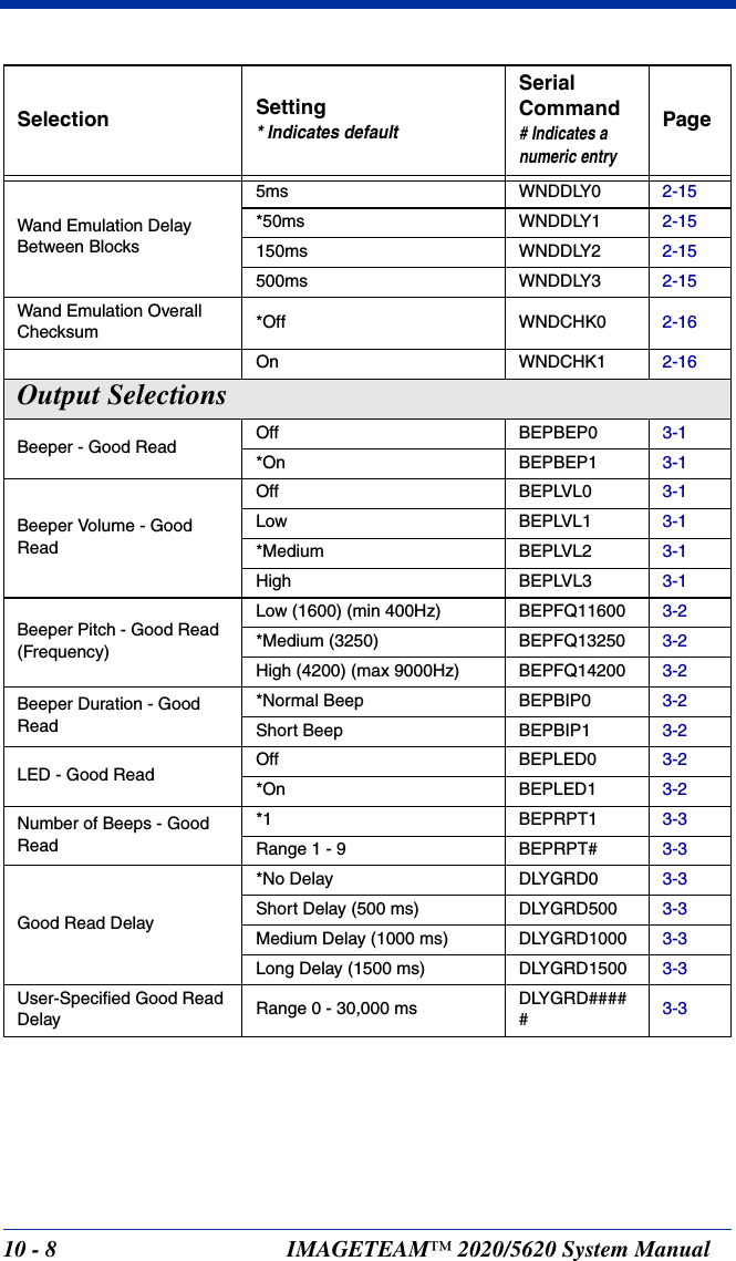
![IMAGETEAM™ 2020/5620 System Manual 7 - 17Interface KeysKeyboard Function RelationshipsThe following Keyboard Function Code, Hex/ASCII Value, and Full ASCII “CTRL”+ relationships apply to all terminals that can be used with the scanner. Refer to page 2-6 enable Control + ASCII mode.Function Code HEX/ASCII Value Full ASCII “CTRL” +NUL 00 2SOH 01 ASTX 02 BETX 03 CEOT 04 DENQ 05 EACK 06 FBEL 07 GBS 08 HHT 09 ILF 0A JVT 0B KFF 0C LCR 0D MSO 0E NSI 0F ODLE 10 PDC1 11 QDC2 12 RDC3 13 SDC4 14 TNAK 15 USYN 16 VETB 17 WCAN 18 XEM 19 YSUB 1A ZESC 1B [FS 1C \GS 1D ]RS 1E 6US 1F -](https://usermanual.wiki/Honeywell/MX2702B/User-Guide-486300-Page-115.png)
![7 - 2 IMAGETEAM™ 2020/5620 System ManualThe last five characters in the Full ASCII “CTRL”+ column ( [ \ ] 6 - ), apply to US only. The following chart indicates the equivalents of these five characters for different countries.Country CodesUnited States [ \ ] 6 -Belgium [ < ] 6 -Scandinavia 8 < 9 6 -France ^ 8 $ 6 =Germany à + 6 -Italy \ + 6 -Switzerland <. . 6 -United Kingdom [ ¢ ] 6 -Denmark 8 \ 9 6 -Norway 8 \ 9 6 -Spain [ \ ] 6 -](https://usermanual.wiki/Honeywell/MX2702B/User-Guide-486300-Page-116.png)
![IMAGETEAM™ 2020/5620 System Manual 10 - 110Serial Programming CommandsThe serial programming commands can be used in place of the programming bar codes. Both the serial commands and the programming bar codes will program the IT2020-5. For complete descriptions and examples of each serial programming command, refer to the corresponding programming bar code in this manual.The device must be set to an RS-232 interface (see page 1-15). The following commands can be sent via a PC com port using terminal emulation software.ConventionsThe following conventions are used for menu and query command descriptions:parameterA label representing the actual value you should send as part of a command.[option] An optional part of a command.{Data} Alternatives in a command.bold Names of menus, menu commands, buttons, dialog boxes, and windows that appear on the screen.Menu Command SyntaxMenu commands have the following syntax (spaces have been used for clarity only):Prefix [:Name:] Tag SubTag {Data} [, SubTag {Data}] [; Tag SubTag {Data}] […] StoragePrefix Three ASCII characters: SYN M CR (ASCII 22,77,13).:NAME: To send information to the scanner (with the base connected to host): SYN M CR :NAME: Tag A 3 character case-insensitive field that identifies the desired menu command group. For example, all RS-232 configuration settings are identified with a Tag of 232.SubTag A 3 character case-insensitive field that identifies the desired menu command within the tag group. For example, the SubTag for the RS-232 baud rate is BAD.Data The new value for a menu setting, identified by the Tag and Sub-Tag.](https://usermanual.wiki/Honeywell/MX2702B/User-Guide-486300-Page-125.png)
![IMAGETEAM™ 2020/5620 System Manual 10 - 3ACK Indicates a good command which has been processed.ENQ Indicates an invalid Tag or SubTag command. NAK Indicates the command was good, but the Data field entry was out of the allowable range for this Tag and SubTag combination, e.g., an entry for a minimum message length of 100 when the field will only accept 2 characters.When responding, the device echoes back the command sequence with the status character inserted directly before each of the punctuation marks (the period, exclamation point, comma, or semicolon) in the command.Examples of Query CommandsIn the following examples, a bracketed notation [ ] depicts a non-displayable response.Example #1:What is the range of possible values for Codabar Coding Enable?Enter: cbrena*.Response: CBRENA0-1[ACK]This response indicates that Codabar Coding Enable (CBRENA) has a range of values from 0 to 1 (off and on). Example #2: What is the default value for Codabar Coding Enable?Enter: cbrena^.Response: CBRENA1[ACK]This response indicates that the default setting for Codabar Coding Enable (CBRENA) is 1, or on. Example #3: What is the device’s current setting for Codabar Coding Enable?Enter: cbrena?.Response: CBRENA1[ACK]This response indicates that the device’s Codabar Coding Enable (CBRENA) is set to 1, or on.](https://usermanual.wiki/Honeywell/MX2702B/User-Guide-486300-Page-127.png)
![10 - 4 IMAGETEAM™ 2020/5620 System ManualExample #4: What are the device’s settings for all Codabar selections?Enter: cbr?.Response: CBRENA1[ACK],SSX0[ACK],CK20[ACK],CCT1[ACK],MIN2[ACK],MAX60[ACK],DFT[ACK].This response indicates that the device’s Codabar Coding Enable (CBRENA) is set to 1, or on; the Start/Stop Character (SSX) is set to 0, or Don’t Transmit; the Check Character (CK2) is set to 0, or Not Required;concatenation (CCT) is set to 1, or Enabled; the Minimum Message Length (MIN) is set to 2 characters; the Maximum Message Length (MAX) is set to 60 characters; and the Default setting (DFT) has no value. Trigger CommandsYou can activate and deactivate the scanner with serial trigger commands. First, the scanner must be put in Manual/Serial Trigger Mode either by scanning the Manual/Serial Trigger Mode bar code (page 3-4), or by sending the Manual/Serial Menu Command (page 10-9). Once the scanner is in serial trigger mode, the trigger is activated and deactivated by sending the following commands:Activate:SYN T CRDeactivate:SYN U CRThe scanner scans until a bar code has been read, until the deactivate com-mand is sent, or until the serial time-out has been reached (see Read Time-Out (Serial Trigger Mode) on page 3-4 for a description, and the serial command on page 10-9).Resetting the Standard Product DefaultsIf you aren’t sure what programming options are in your scanner, or you’ve changed some options and want the factory settings restored, scan the Standard Product Default Settings bar code below.The chart on the following pages lists the factory default settings for each of the menu commands (indicated by an asterisk (*) on the programming pages).Standard Product Default Settings](https://usermanual.wiki/Honeywell/MX2702B/User-Guide-486300-Page-128.png)


![IMAGETEAM™ 2020/5620 System Manual A - 1Appendix ASymbology ChartNote: “m” represents the AIM modifier character. Refer to International Technical Specification, Symbology Identifiers, for AIM modifier character details.Note: Prefix/Suffix entries for specific symbologies override the universal (All Symbologies, 99) entry. Refer to Data Editingbeginning on page 4-1 and Data Formattingbeginning on page 5-1 for information about using Code ID and AIM ID.Symbology CodeIDAIMIDHexID Symbology CodeIDAIMIDHexIDChina Post Q]X051IATA 2 of 5 f]Rm66Codabar a]Fm61 Interleaved 2 of 5 e]lm65Codablock F q]Om71 Korea Post ?]X03FCode 2 of 5 f]Rm66 Matrix 2 of 5 m]X06DCode 11 h]Hm68 MSI g]Mm67Code 16K o ]Km6F No Read 9CCode 39 b]Am62 Plessey Code n]P06ECode 32 Pharma-ceutical (PARAF)<]X03CPosiCode W]pm57Code 49l]Tm6C Reduced Space Symbology (RSS-14, RSS Limited, RSS Expanded)y]em79Code 93 i]Gm69 Telepen t]Bm74Code 128 j]Cm6A Trioptic Code =]X03DUCC/EAN-128 I]C149UPC-A c]E063EAN/JAN-8 D ]E4 44 UPC-A with Extended Coupon Codec]E363EAN/JAN-13 d]E064 UPC-E E]E045EAN-13 with Extended Coupon Coded]E364All Symbologies 99](https://usermanual.wiki/Honeywell/MX2702B/User-Guide-486300-Page-159.png)
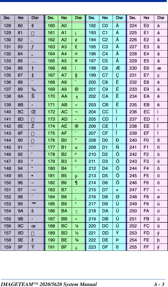
![A - 2 IMAGETEAM™ 2020/5620 System ManualASCII Conversion Chart (Code Page 1252)Dec Hex Char Dec Hex Char Dec Hex Char Dec Hex Char000 NUL 32 20 64 40 @96 60 ‘101 SOH 33 21 !65 41 A97 61 a202 STX 34 22 “66 42 B98 62 b303 ETX 35 23 #67 43 C99 63 c404 EOT 36 24 $68 44 D100 64 d505 ENQ 37 25 %69 45 E101 65 e606 ACK 38 26 &70 46 F102 66 f707 BEL 39 27 ‘71 47 G103 67 g808 BS 40 28 (72 48 H104 68 h909 HT 41 29 )73 49 l105 69 i10 0A LF 42 2A *74 4A J106 6A j11 0B VT 43 2B +75 4B K107 6B k12 0C FF 44 2C ,76 4C L108 6C l13 0D CR 45 2D -77 4D M109 6D m14 0E SO 46 2E .78 4E N110 6E n15 0F SI 47 2F /79 4F O111 6F o16 10 DLE 48 30 080 50 P112 70 p17 11 DC1 49 31 181 51 Q113 71 q18 12 DC2 50 32 282 52 R114 72 r19 13 DC3 51 33 383 53 S115 73 s20 14 DC4 52 34 484 54 T116 74 t21 15 NAK 53 35 585 55 U117 75 u22 16 SYN 54 36 686 56 V118 76 v23 17 ETB 55 37 787 57 W119 77 w24 18 CAN 56 38 888 58 X120 78 x25 19 EM 57 39 989 59 Y121 79 y26 1A SUB 58 3A :90 5A Z122 7A z27 1B ESC 59 3B ;91 5B [123 7B {28 1C FS 60 3C <92 5C \124 7C |29 1D GS 61 3D =93 5D ]125 7D }30 1E RS 62 3E >94 5E ^126 7E ~31 1F US 63 3F ?95 5F _127 7F](https://usermanual.wiki/Honeywell/MX2702B/User-Guide-486300-Page-160.png)