Honeywell MX2702B Bluetooth Bar Code Scanner Base Station User Manual 5620 UG Rev a
Honeywell International Inc Bluetooth Bar Code Scanner Base Station 5620 UG Rev a
User Manual
™
IMAGETEAM™ 2020/5620
Retail Cordless System
System Manual
Draft 13 10/13/04

Disclaimer
Hand Held Products, Inc. d/b/a HHP (“HHP”) reserves the right to make changes
in specifications and other information contained in this document without prior
notice, and the reader should in all cases consult HHP to determine whether any
such changes have been made. The information in this publication does not
represent a commitment on the part of HHP.
HHP shall not be liable for technical or editorial errors or omissions contained
herein; nor for incidental or consequential damages resulting from the furnishing,
performance, or use of this material.
This document contains proprietary information which is protected by copyright.
All rights are reserved. No part of this document may be photocopied,
reproduced, or translated into another language without the prior written consent
of HHP.
© 2004 Hand Held Products, Inc. All rights reserved.
Web Address: www.HHP.com
Microsoft Pocket PC 2002, Windows, Windows NT, Windows 2000, Windows ME,
Windows XP, ActiveSync, Outlook, and the Windows logo are trademarks or registered
trademarks of Microsoft Corporation.
The Bluetooth trademarks are owned by Bluetooth SIG, Inc., U.S.A.

Statement of Agency Compliance
The IT2020/IT5620 system meets or exceeds the requirements of all applicable
standards organizations for safe operation. However, as with any electrical
equipment, the best way to ensure safe operation is to operate them according
to the agency guidelines that follow. Please read these guidelines carefully
before using your IT2020/IT5620 system.
Regulatory and Safety Approvals for the IT2020/IT5620
FCC Class B Compliance Statement
This device complies with part 15 of the FCC Rules. Operation is subject to the
following two conditions:
1. This device may not cause harmful interference.
2. This device must accept any interference received, including interference
that may cause undesired operation.
This equipment has been tested and found to comply with the limits for a Class
B digital device pursuant to part 15 of the FCC Rules. These limits are designed
to provide reasonable protection against harmful interference in a residential
installation. This equipment generates, uses, and can radiate radio frequency
energy and, if not installed and used in accordance with the instructions, may
cause harmful interference to radio communications. If this equipment does
cause harmful interference to radio or television reception, which can be
determined by turning the equipment off and on, the user is encouraged to try to
correct the interference by one or more of the following measures:
•Reorient or relocate the receiving antenna.
•Increase the separation between the equipment and receiver.
•Connect the equipment into an outlet on a circuit different from that to
which the receiver is connected.
•Consult the dealer or an experienced radio or television technician for
help.
Parameter Specification
USA FCC Part 15, Class B
Canada ICES-003
European Community EN 55022 (CISPR 22) Class B
EN60950
EN60825-1
EN55024:1998

If necessary, the user should consult the dealer or an experienced radio/
television technician for additional suggestions. The user may find the following
booklet helpful: “Something About Interference.” This is available at FCC local
regional offices. Hand Held Products, Inc. is not responsible for any radio or
television interference caused by unauthorized modifications of this equipment
or the substitution or attachment of connecting cables and equipment other than
those specified by Hand Held Products, Inc. The correction is the responsibility
of the user. Use only shielded data cables with this system.
In accordance with FCC 15.21, changes or modifications not expressly approved
by the party responsible for compliance could void the user’s authority to operate
the equipment.
This device and its antenna must not be co-located or operating
in conjunction with any other antenna or transmitter. To maintain
compliance with FCC RF exposure guidelines for body-worn
operation, do not use accessories that contain metallic
components and ensure that the device is at least 15mm (0.6
inches) from the body.
Canadian Compliance
This Class B digital apparatus compiles with Canadian ICES-003. Operation is
subject to the following two conditions:
1. This device may not cause harmful interference.
2. This device must accept any interference received, including interference
that may cause undesired operation.
3. To prevent radio interference to the licensed service, this device is intended
to be operated indoors and away from windows to provide maximum shield-
ing. Equipment (or its transmit antenna) that is installed outdoors is subject
to licensing.
Cet appareil numérique de la Classe B est conforme à la norme NMB-003 du
Canada.
CE Compliance
The CE mark on the product indicates that the system has been tested to
and conforms with the provisions noted within the 89/336/EEC Electromagnetic
Compatibility Directive and the 73/23/EEC Low Voltage Directive.
For CE-related inquiries, please contact:
Hand Held Products, Inc.
Nijverheidsweg 9
5627 BT Eindhoven
The Netherlands
!
HHP shall not be liable for use of our product with equipment (i.e., power
supplies, personal computers, etc.) that is not CE marked and does not comply
with the Low Voltage Directive.
Regulatory Approvals for Bluetooth Radio Devices
RF devices are designed to comply with the most current applicable standards
on safe levels of RF energy developed by the Institute of Electrical and
Electronics Engineers (IEEE) and the American National Standards Institute
(ANSI) and have been recommended for adoption by the Federal
Communications Commission (FCC).
Bluetooth Radio Device R&TTE Compliance Statement
The IT2020 and IT5620 are in conformity with all essential requirements of the
R&TTE Directive (1999/5/EC). This equipment has been assessed to the
following standards:
This product is marked with in accordance with the Class II product
requirements specified in the R&TTE Directive, 1999/5/EC.
The equipment is intended for use throughout the European Community.
Bluetooth Qualified Product
Bluetooth Identifier:
Parameter Specification
RF Approvals
U.S.A. FCC Part 15.247
Canada RSS 210
Parameter Specification
R&TTE EN 300 328-2:2000
EN 301 489-1 (2002-08)
EN 301 489-17 (2002-08)
EN 60950:2000
EN 50361:2001

UL and cUL Statement
UL listed UL1950 and CSA 22.2 No.950. cUL listed UL1950 and CSA 22.2 No
950.
TÜV Statement
TÜV or GS marked to EN60950 and EN60825-1.
C-Tick Statement
Conforms to AS/NZS 3548. C-Tick number: N10410.
Mexico
Patents
Please refer to the IT5620 packaging for patent information.
Solids and Water Protection
The IT5620 has a rating of IP41, immunity of foreign particles and dripping water.
Certified
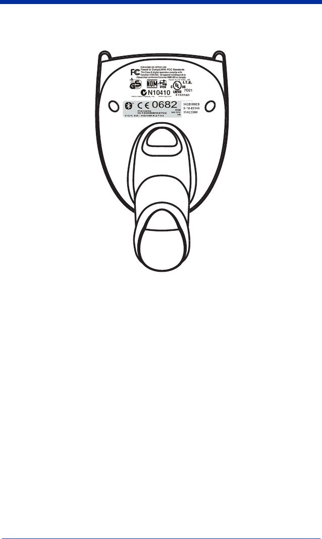
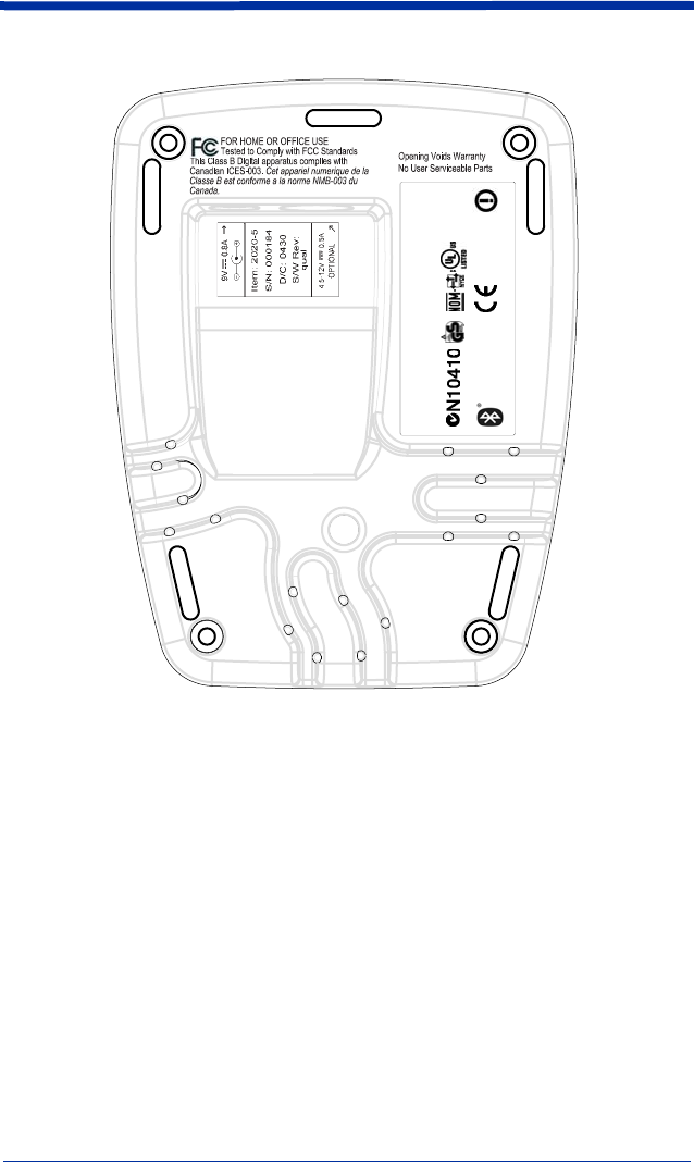
Required Safety Labels
IT5620
'
'
FCC ID: HD5MX2702B
Canada IC1693BMX2702B
Hand Held Products, Inc.
Skaneateles Falls, NY 13153
www.hhp.com
"Made in China"
E153740
US and Foreign Patents Pending
0682
I.T.E.
ACCESSORY
7D21
IT2020

i
Chapter 1 - Getting Started
IMAGETEAM 5620............................................................. 1-1
About This Manual ............................................................... 1-1
Unpacking the System .......................................................... 1-2
Models .................................................................................. 1-2
Cordless System: Main Components.................................... 1-3
About the Battery.................................................................. 1-3
Proper Disposal of the Battery ....................................... 1-4
Base Charge Mode................................................................ 1-5
Linking Scanner to Base....................................................... 1-6
Unlinking the Scanner.................................................... 1-6
Link Modes........................................................................... 1-6
Locked Link Mode......................................................... 1-7
Open Link Mode ............................................................ 1-7
Out-of-Range Alarm............................................................. 1-8
Duration.......................................................................... 1-8
Alarm Sound Type ......................................................... 1-8
Data Accumulation Mode..................................................... 1-9
Beeper and LED Sequences and Meaning............................ 1-9
IT5620 LED Sequences and Meaning ........................... 1-9
IT2020 LED Sequences and Meaning ........................... 1-9
Basic Operation of the Cordless System ............................ 1-10
System Conditions ....................................................... 1-11
Communication Between the Cordless System and the Host
1-11
Connecting the Base When Powered by Host
(Keyboard Wedge) ........................................................... 1-12
Reading Techniques............................................................ 1-13
Resetting the Standard Product Defaults ............................ 1-14
Plug and Play ...................................................................... 1-14
Keyboard Wedge Connection............................................. 1-14
Laptop Direct Connect ................................................. 1-15
RS-232.......................................................................... 1-15
Wand Emulation Plug & Play ...................................... 1-15
IBM 4683 Ports 5B, 9B, and 17 Interface .......................... 1-17
Table of Contents

ii
Connecting the Base with USB........................................... 1-18
IBM SurePos ................................................................ 1-19
USB PC or Macintosh Keyboard.................................. 1-19
USB HID ...................................................................... 1-20
USB Com Port Emulation ............................................ 1-20
Connecting the Base with Serial Wedge............................. 1-21
Chapter 2 - Terminal Interfaces
Terminal ID........................................................................... 2-1
Supported Terminals ............................................................. 2-2
Keyboard Country................................................................. 2-4
Keyboard Style...................................................................... 2-5
Keyboard Modifiers .............................................................. 2-6
Connecting the Base with RS-232 Serial Port ...................... 2-7
RS-232 Baud Rate .......................................................... 2-8
RS-232 Word Length: Data Bits, Stop Bits, and Parity . 2-9
RS-232 Handshaking.................................................... 2-10
Host ACK Selection ..................................................... 2-10
Host ACK Enable ......................................................... 2-11
Wand Emulation.................................................................. 2-13
Wand Emulation Connection........................................ 2-13
Wand Emulation Transmission Rate ............................ 2-14
Wand Emulation Polarity ............................................. 2-14
Wand Emulation Idle.................................................... 2-15
Wand Emulation Data Block Size ................................ 2-15
Wand Emulation Delay Between Blocks ..................... 2-15
Wand Emulation Overall Checksum ............................ 2-16
Chapter 3 - Output
Good Read Indicators............................................................ 3-1
Beeper – Good Read....................................................... 3-1
Beeper Volume – Good Read......................................... 3-1
Beeper Pitch – Good Read.............................................. 3-2
Beeper Duration – Good Read........................................ 3-2
LED – Good Read .......................................................... 3-2
Number of Beeps – Good Read...................................... 3-3

iii
Good Read Delay ..................................................................3-3
User-Specified Good Read Delay...................................3-3
Scanner Trigger Modes .........................................................3-4
Manual/Serial Trigger, Low Power ................................3-4
Automatic Trigger...........................................................3-5
Presentation Mode ..........................................................3-5
Hands Free Time-Out............................................................3-5
Reread Delay .........................................................................3-6
User-Specified Reread Delay..........................................3-6
Centering Window ................................................................3-7
Output Sequence Overview...................................................3-8
Output Sequence Editor ..................................................3-9
Require Output Sequence ...............................................3-9
Multiple Symbols ................................................................3-12
No Read...............................................................................3-12
Video Reverse .....................................................................3-12
Chapter 4 - Data Editing
Prefix/Suffix Overview .........................................................4-1
To Add a Prefix or Suffix: .............................................4-2
To Clear One or All Prefixes or Suffixes: ......................4-3
To Add a Carriage Return Suffix to all Symbologies.....4-3
Prefix Selections .............................................................4-3
Suffix Selections .............................................................4-4
Function Code Transmit .................................................4-4
Intercharacter, Interfunction, and Intermessage Delays........4-4
Intercharacter Delay........................................................4-5
User Specified Intercharacter Delay ...............................4-5
Interfunction Delay .........................................................4-6
Intermessage Delay.........................................................4-6

iv
Chapter 5 - Data Formatting
Data Format Editor Introduction........................................... 5-1
To Add a Data Format .................................................... 5-1
Other Programming Selections....................................... 5-2
Data Format Editor Commands...................................... 5-2
Data Format Editor ......................................................... 5-4
Data Formatter................................................................ 5-5
Alternate Data Formats................................................... 5-5
Chapter 6 - Symbologies
Introduction ........................................................................... 6-1
All Symbologies.................................................................... 6-1
Message Length .................................................................... 6-2
Codabar ................................................................................. 6-3
Codabar Start/Stop Characters....................................... 6-3
Codabar Check Character............................................... 6-3
Codabar Concatenation................................................... 6-4
Codabar Message Length ............................................... 6-5
Code 39 ................................................................................. 6-5
Code 39 Start/Stop Characters ....................................... 6-5
Code 39 Check Character ............................................... 6-6
Code 39 Message Length ...............................................6-6
Code 39 Append ............................................................. 6-7
Code 32 Pharmaceutical (PARAF)................................. 6-7
Full ASCII ...................................................................... 6-8
Code 39 Code Page......................................................... 6-9
Interleaved 2 of 5 ..................................................................6-9
Check Digit..................................................................... 6-9
Interleaved 2 of 5 Message Length............................... 6-10
Code 93 ............................................................................... 6-11
Code 93 Message Length .............................................6-11
Code 93 Code Page....................................................... 6-11
Code 2 of 5 .......................................................................... 6-12
Code 2 of 5 Message Length ........................................ 6-12
IATA Code 2 of 5 Message Length.............................. 6-13

v
Matrix 2 of 5........................................................................6-13
Matrix 2 of 5 Message Length......................................6-14
Code 11................................................................................6-14
Check Digits Required..................................................6-14
Code 11 Message Length..............................................6-15
Code 128..............................................................................6-15
ISBT 128 Concatenation...............................................6-16
Code 128 Message Length............................................6-16
Code 128 Code Page.....................................................6-16
Code 128 Function Code Transmit...............................6-17
Telepen ................................................................................6-17
Telepen Output .............................................................6-17
Telepen Message Length ..............................................6-18
UPC A .................................................................................6-18
UPC A Check Digit ......................................................6-18
UPC A Number System................................................6-19
UPC A Addenda ...........................................................6-19
UPC A Addenda Required............................................6-19
UPC A Addenda Separator ...........................................6-20
UPC-A/EAN-13 with Extended Coupon Code ...................6-20
UPC E0 and UPC E1...........................................................6-21
UPC E0 and UPC E1 Expand .......................................6-21
UPC E0 and UPC E1 Addenda Required .....................6-21
UPC E0 and UPC E1 Addenda Separator ....................6-22
UPC E0 Check Digit.....................................................6-22
UPC E0 Number System ..............................................6-22
UPC E0 Addenda..........................................................6-23
EAN/JAN 13 .......................................................................6-23
EAN/JAN 13 Check Digit ............................................6-23
EAN/JAN 13 Addenda .................................................6-24
EAN/JAN 13 Addenda Required..................................6-24
EAN/JAN 13 Addenda Separator .................................6-24
ISBN Translate .............................................................6-25

vi
EAN/JAN 8 ......................................................................... 6-25
EAN/JAN 8 Check Digit .............................................. 6-25
EAN/JAN 8 Addenda ................................................... 6-26
EAN/JAN 8 Addenda Required ................................... 6-26
EAN/JAN 8 Addenda Separator................................... 6-26
MSI...................................................................................... 6-27
MSI Check Character ................................................... 6-27
MSI Message Length.................................................... 6-28
Plessey Code ....................................................................... 6-28
Plessey Message Length............................................... 6-28
RSS Limited ........................................................................ 6-29
RSS Expanded..................................................................... 6-30
RSS Expanded Message Length................................... 6-30
EAN•UCC Emulation ......................................................... 6-30
China Post Code.................................................................. 6-31
Korea Post Code.................................................................. 6-32
Korea Post Message Length ......................................... 6-32
PosiCode A and B ............................................................... 6-33
PosiCode Message Length............................................ 6-33
Codablock F ........................................................................ 6-34
Codablock F Message Length ...................................... 6-34
Code 16K ............................................................................ 6-35
Code 16K Message Length........................................... 6-35
Code 49 ............................................................................... 6-36
Code 49 Message Length .............................................6-36
Chapter 7 - Interface Keys
Keyboard Function Relationships ......................................... 7-1
Supported Interface Keys...................................................... 7-3
Chapter 8 - Utilities
To Add a Test Code I.D. Prefix to All Symbologies ............ 8-1
Reset Scanner ........................................................................ 8-1
Show Software Revision ....................................................... 8-1
Show Data Format................................................................. 8-1
Resetting the Standard Product Defaults............................... 8-2

vii
Temporary Visual Menu 2003 Configuration .......................8-2
Chapter 9 - Visual Menu 2003
Visual Menu 2003 Introduction ............................................9-1
Installing Visual Menu 2003 from the Web ...................9-1
Chapter 10 - Serial Programming Commands
Conventions.........................................................................10-1
Menu Command Syntax......................................................10-1
Query Commands .........................................................10-2
Concatenation of Multiple Commands .........................10-2
Responses......................................................................10-2
Examples of Query Commands ....................................10-3
Trigger Commands..............................................................10-4
Resetting the Standard Product Defaults.............................10-4
Menu Commands ................................................................10-5
Chapter 11 - Product Specifications
IMAGETEAM 5620 Product Specifications ......................11-1
IMAGETEAM 2020 Product Specifications ......................11-2
IMAGETEAM 5620 Depth of Field ...................................11-3
Chapter 12 - Maintenance
Maintenance ........................................................................12-1
Cleaning the Scanner’s Window...................................12-1
Inspecting Cords and Connectors .................................12-1
Replacing the IT2020 Interface Cable:.........................12-2
Troubleshooting Base..........................................................12-2
Chapter 13 - Customer Support
Obtaining Factory Service...................................................13-1
Technical Assistance ...........................................................13-2
Limited Warranty ................................................................13-2


IMAGETEAM™ 2020/5620 System Manual 1 - 1
1
G e ttin g S ta rte d
IMAGETEAM 5620
The IMAGETEAM 5620 cordless scanning system consists of one IT2020 base
and one IT5620 Cordless Linear Imager. The IT5620 marks a new performance
level for hand held scanners. The IT5620 is powered by HHP’s AdaptusTM
Imaging Technology. The performance of Adaptus technology delivers
aggressive read rates and depths of field on 1D codes.
Designed for today’s demanding retail and commercial environments, the
IT5620 offers a superior reading range, durability, and the ability to read poor
quality bar codes. Linear imaging technology is defined by a bright and sharply
focused aiming line, high resolution imaging, and fast reading speed. The
IT5620 is comfortable to hold, easy to use, rugged, and excellent for retail
applications, as well as for all general scanning applications.
The cordless system is an economical, durable solution for a wide variety of
portable data collection applications. The cordless system features:
• a tough, ergonomic thermoplastic housing for comfort and durability.
• an advanced two-way spread-spectrum radio, Bluetooth® wireless
technology
• a wide range of interfaces that are compatible with many POS, keyboard
wedge, wand emulation, RS-232 terminals, USB, and legacy decoders.
• visible and audible feedback for confirmation of a successful decode.
• a rechargeable battery designed to operate through a whole work day.
The cordless system can be programmed for many communication parameters
and input/output protocols compatible to the host, as well as advanced data
editing and formatting.
About This Manual
This manual contains information to help you set up, operate, and program the
cordless system. Product specifications, connector pinouts, a troubleshooting
guide, and customer support information are also provided.
HHP’s bar code scanners are factory programmed for the most common terminal
and communications settings. If you need to change these settings,
programming is accomplished by scanning the bar codes in this guide.
An asterisk (*) next to an option indicates the default setting.
This section contains the following information:
• Unpacking the System
• Cordless System Main Components
• Battery and Charging Information
• Linking the Scanner to the Base
• Beeper and LED Sequences and Meaning
• Basic Operation of the Cordless System

1 - 2 IMAGETEAM™ 2020/5620 System Manual
• Communication Between the Cordless System and the Host
• Connection of the Base to an Interface
Unpacking the System
After you open the shipping carton containing the product, take the following
steps:
• Check to make sure everything you ordered is present.
• Save the shipping container for later storage or shipping.
• Check for damage during shipment. Report damage immediately to the
carrier who delivered the carton.
Models
Models Description
2020-5 Base: Keyboard wedge, TTL level 232, TTL level 232
serial wedge, IBM 4683, wand emulation, USB keyboard,
USB HID, USB retail (IBM SurePOS)
2020-CB Base with charger only (no host interfaces)
5620SR0C0 Cordless Linear Scanner
IMAGETEAM™ 2020/5620 System Manual 1 - 3
Cordless System: Main Components
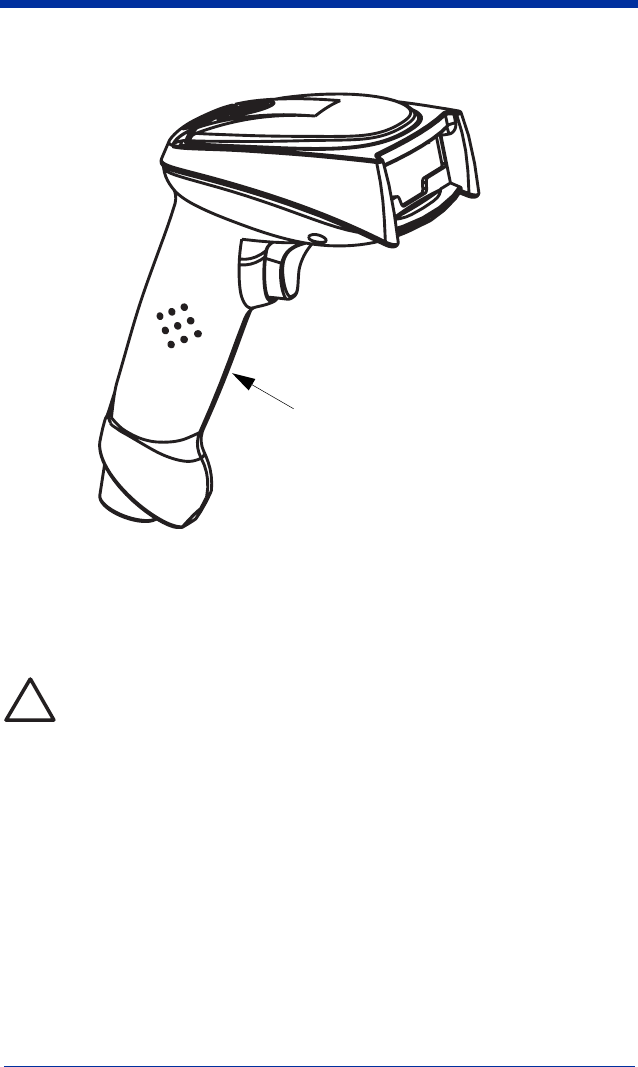
About the Battery
Use only the Li-ion battery packs provided by HHP. The use of any
battery pack not sold by HHP will void your warranty and may result in
damage to your unit.
Power is supplied to the cordless scanner by a rechargeable battery that is
integrated in the scanner handle. Each scanner is shipped with a battery.
(See
Product Specifications
beginning on page 11-1
.)
Charging Information
The battery is designed to charge while the scanner is positioned in the cordless
base unit. Refer to "IT2020 LED Sequences and Meaning" on page 1-9 for an
interpretation of the Charge Status indicators.
• Place the scanner in the base that is connected to an appropriate power
supply.
Battery Contained in Handle
!

1 - 4 IMAGETEAM™ 2020/5620 System Manual
Battery Recommendations
• Batteries are shipped approximately 30% to 60% charged and should be fully
charged for maximum charge capacity.
• The battery is a lithium ion cell and can be used without a full charge, as well
as can be charged without fully discharging, without impacting the battery life.
There is no need to perform any charge/discharge conditioning on this cell
type battery.
• Do not disassemble the battery. There are no user-serviceable parts in the
battery.
• Keep the base connected to power when the host is not in use.
• Replace a defective battery immediately since it could damage the IT5620.
• Don’t short-circuit a battery or throw it into a fire. It can explode and cause
severe personal injury.
• Although your battery can be recharged many times, it will eventually be
depleted. Replace it after the battery is unable to hold an adequate charge.
• If you are not sure if the battery or charger is working properly, send it to HHP
or an authorized HHP service center for inspection.
Proper Disposal of the Battery
When the battery has reached the end of its useful life, the
battery should be disposed of by a qualified recycler or
hazardous materials handler. Do not incinerate the battery or
dispose of the battery with general waste materials. You may
send batteries to HHP (postage paid). The shipper is
responsible for complying with all federal, state, and local laws
and regulations related to the packing, labeling, manifesting,
and shipping of spent batteries. Contact the Product Service
Department (see page 11-1) for recycling or disposal information. Since you
may find that your cost of returning the batteries significant, it may be more cost
effective to locate a local recycle/disposal company.
IMAGETEAM™ 2020/5620 System Manual 1 - 5
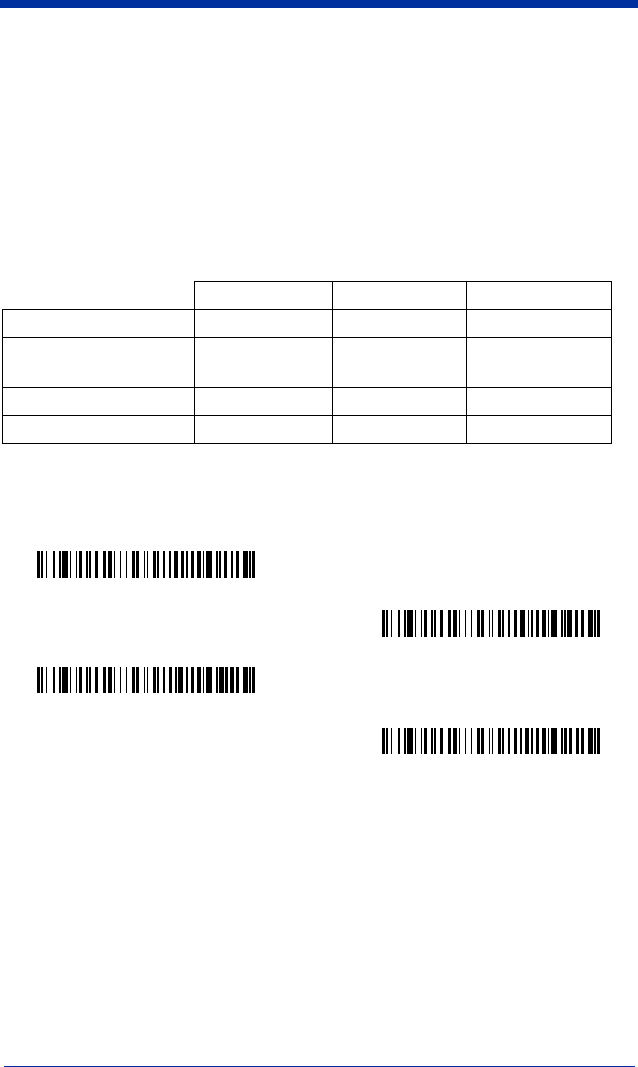
Base Charge Mode
In order for the battery to be charged, there must be enough voltage for the
circuitry to work. There are three conditions during which power can be supplied
to the base:
Condition 1: 9VDC power supply connected to the barrel connector
Condition 2: 12VDC host power source only
Condition 3: 5VDC host power source only
The chart below describes each selection by condition.
Using a slow charge rate draws less current (power) from the input power source
when the battery is mostly discharged.
Scan the appropriate bar code for your application.
Default = Automatic
.
Condition 1 Condition 2 Condition 3
Automatic Fast Charge Slow Charge No Charge
Full Charge Rate Fast Charge Fast Charge No Charge
Low Charge Rate Slow Charge Slow Charge No Charge
Battery Charge Off No Charge No Charge No Charge
* Automatic
Low Charge Rate
Full Charge Rate
Battery Charge Off
1 - 6 IMAGETEAM™ 2020/5620 System Manual
Linking Scanner to Base
When newly shipped or defaulted to factory settings, the base and scanner are
not linked. Once the scanner is placed into the base, the software automatically
links the scanner and the base. If the scanner and base have previously been
linked, you do not receive any feedback. If this is the first time that the scanner
and base are linked, both devices emit a short chirp when their radios link.
1. Provide power to the base.
2. Place the IT5620 into the base. The scanner and base link.
3. To determine if your cordless system is set up correctly, scan one of the
sample bar codes in the back of this manual. If the scanner provides a
single good read beep and the green LED lights, the scanner has
successfully linked to the base. If you receive a triple error beep and the red
LED lights, the scanner has not linked to the base.
Unlinking the Scanner
If the base has a scanner linked to it, that scanner must be unlinked before a new
scanner can be linked. Once the previous scanner is unlinked, it will no longer
communicate with the base. To unlink a scanner from the base, scan the Unlink
Scanner bar code below.
Link Modes
There are two link modes to accommodate different applications: Locked Link
Mode and Open Link Mode. Scan the appropriate bar codes included in the
Open Link and Locked Link Mode explanations that follow to switch from one
mode to another.
Default = Locked Link Mode
.
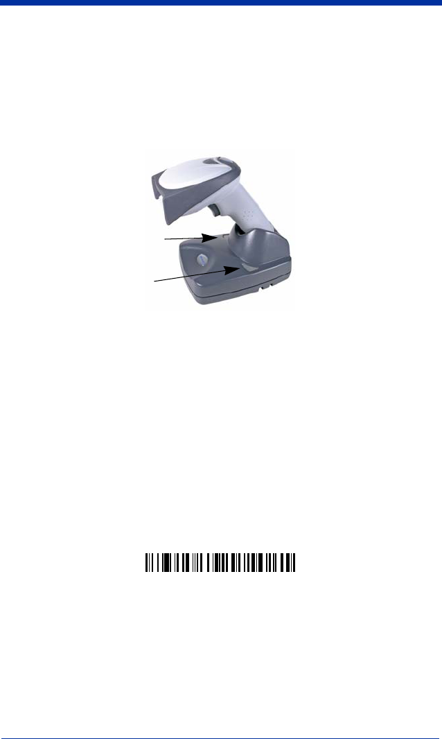
IT5620 Imager
IT2020 Cordless Base
Green LED
Red LED
Unlink Scanner

IMAGETEAM™ 2020/5620 System Manual 1 - 7
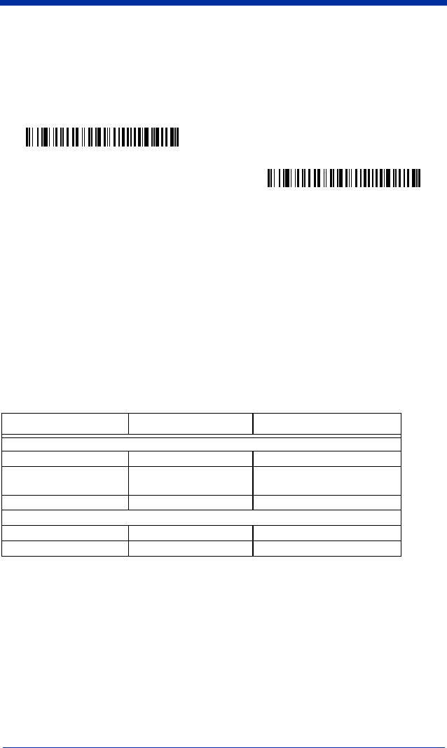
Locked Link Mode
If you link a scanner to a base using the Locked Link Mode, this blocks other
scanners from being linked if they are inadvertently placed into the base. If you
do place a different scanner into the base, it will charge the scanner, but the
scanner will not be linked.
To use a different scanner, you need to remove the original scanner by scanning
the Unlink Scanner bar code. (See "Unlinking the Scanner" on page 1-6.)
If you need to replace a broken or lost scanner that is linked to a base, scan the
Override Locked Scanner bar code below and place that scanner in the base.
The locked link will be overridden; the broken or lost scanner’s link with the base
will be removed, and the new scanner will be linked.
Open Link Mode
When newly shipped or defaulted to factory settings, the base and scanner are
not linked. By placing a scanner into the base, they establish a link. Placing a
different scanner into the base establishes a new link and the old scanner is
unlinked. Each time a scanner is placed into the base, it becomes the linked
scanner; the old scanner is unlinked.
* Locked Link Mode
Override Locked Scanner
Open Link Mode

1 - 8 IMAGETEAM™ 2020/5620 System Manual
Out-of-Range Alarm
Duration
If your scanner is out range of the base, an alarm sounds from both your base
and scanner if they are programmed to emit an alarm. To activate the alarm
options for the scanner or the base and to set the alarm duration, scan the
appropriate bar code below and then set the time-out duration (from 0-3000
seconds) by scanning digits on the Programming Chart inside the back cover,
then scanning Save.
Default = 0 sec (no alarm).
Note: If you are out of range when you scan a bar code, you will receive an error
beep even if you do not have the alarm set. You receive the error beep
since the data could not be communicated to the base or the host.
Alarm Sound Type
If you have set the out-of-range alarm enabled, you may change the alarm type
for the scanner or base by scanning the appropriate bar code below and then
scanning a digit (0-7) bar code and the Save bar code on the Programming Chart
inside the back cover of this manual.
Default = 0.
Set the sound type to fit your
application.
Base Duration Alarm
Scanner Duration Alarm
Base Alarm Type
Scanner Alarm Type
IMAGETEAM™ 2020/5620 System Manual 1 - 9
Data Accumulation Mode
Scan the bar codes below to turn data accumulation (batch) mode on and off. If
data accumulation mode is on, bar code data is stored when the scanner is out
of range of the base and transmitted once the scanner is back in range.
Beeper and LED Sequences and Meaning
The IT5620 contains LEDs on the top of the unit to indicate its power up,
communication, and battery status. Simply stated, red LED = error; green
LED = success of any type. The unit’s audible indicators have meaning as well:
3 beeps = error; 2 beeps = menu change; 1 beep = all other successes.
The table below lists the indication and cause of the LED illumination and beeps
for the IT5620.
IT5620 LED Sequences and Meaning
IT2020 LED Sequences and Meaning
The base contains a red LED that indicates the status of the unit and verifies its
communication with the host system and a green LED that indicates scanner
battery charge condition.
LED Indication Beeper Indication Cause
Normal Operation
Red Flash None Battery low
Green Flash 1 beep Successful communication
or linking
Red, blinking 3 beeps Failed communication
Menu Operation
Green Flash 2 beeps Successful menu change
Red, blinking 3 beeps Unsuccessful menu change
Data Accumulation Mode On
* Data Accumulation Mode Off
1 - 10 IMAGETEAM™ 2020/5620 System Manual
The tables below list the indication and cause of the LED illumination and beeps
for the IT2020.
Note: Charging only occurs with external power applied to the IT2020 or 12 volt
Host power.
Basic Operation of the Cordless System
Cordless Base
The cordless base provides the link between the cordless scanner and the host
system. The base contains an interface assembly and an RF communication
module. The RF communication module performs the data exchange between
the cordless scanner and the interface assembly. The control assembly
coordinates the central interface activities including: transmitting/receiving
commands and data to/from the host system, performing software activities
(parameter menuing, visual indicator support, power-on diagnostics), and data
translation required for the host system.
The base also is the scanner battery charger with the external 9VDC power
source applied. Once you place the scanner into base, the base green LED
responds according to the Charge Status Indicator table above.
The base can be powered by the Host (parasitic power mode). If the base is in
parasitic power mode without the 9VDC power source, the base will still function,
but will not charge the battery.
RF (Radio Frequency) Module Operation
The cordless system uses a state-of-the-art two-way Bluetooth radio to transmit
and receive data between the scanner and the base. Designed for point-to-point
and multipoint-to-single point applications, the radio operates using a license
free ISM band, which sends relatively small data packets at a fast data rate over
System Condition System Status Indicator (Red LED)
Power On/System Idle LED is on
Power On/Diagnostic Error Blink LED for long duration, pulsing indefinitely
Receiving Data
Blink LED for short duration in multiple pulses. Occurs
while transferring data to/from the RF module or the Host
port.
Charge Condition Charge Status Indicator (Green LED)
Scanner inserted into base Three flashes
>80% charged On continuously
30% to 80% charged Slow flash, 1 second on, 1 second off
<30% charged Fast flash, 300 mSec on, 300 mSec off

IMAGETEAM™ 2020/5620 System Manual 1 - 11
a radio signal with randomly changing frequencies, makes the cordless system
highly responsive to a wide variety of data collection applications and resistant to
noisy RF environments. Bluetooth Class 2 power level provides range of 33 feet
(10m) depending on the environment.
Cordless Scanner
The cordless scanner enables fast and accurate bar code scanning using a non-
contact linear imager.
The scanner is comprised of a linear imager, a decode/control assembly, and an
RF communication module. The scan engine performs the bar code image
illumination and sensing. The decode/control assembly coordinates the central
communication activities including: capturing and decoding the bar code image
data, performing software activities (parameter menuing, visual indicator
support, low battery indication), and data translation required for the host system.
The RF communication module performs the data exchange between the
scanner and the base.
System Conditions
The components of the cordless system interact in specific ways as you
associate a scanner to a base, as you move a scanner out of range, bring a
scanner back in range, or swap scanners between two cordless systems. The
following information explains the cordless system operating conditions.
Linking Process
Once a scanner is placed into the base, the scanner’s battery charge status is
checked, and software automatically detects the scanner and links it to the base
if another scanner is not already linked.
Scanner is Out of Range
The cordless scanner is in communication with its base, even when it is not
transmitting bar code data. Whenever the scanner can’t communicate with the
base for a few seconds, it is out of range. If the scanner is out of range and you
scan a bar code, the scanner issues a triple beep and your scanner and base
sounds an alarm if your scanner is programmed to emit an alarm.
Scanner is Moved Back Into Range
The scanner re-links if the scanner or the base have been reset or out of range.
If the scanner re-links, you will hear a single chirp when the re-linking process
(uploading of the parameter table) is complete.
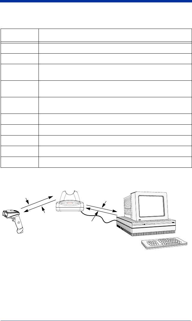
Communication Between the Cordless System and the Host
The cordless scanner provides immediate feedback in the form of a “good read”
indication (a green LED on the scanner and an audible beep) after a bar code is
scanned correctly and the base has acknowledged receiving the data. This is
possible since the cordless system provides two-way communication between
the scanner and the base.
1 - 12 IMAGETEAM™ 2020/5620 System Manual
When data is scanned, the data is sent to the host system via the base unit.
Confirmation from the host system or the base indicates that the data sent was
received by the host. The cordless scanner recognizes data acknowledgement
(ACK) from the base unit. If it cannot be determined that the data has been
properly sent to the base, the scanner issues an error indication. You must then
check to see if the scanned data was received by the host system.
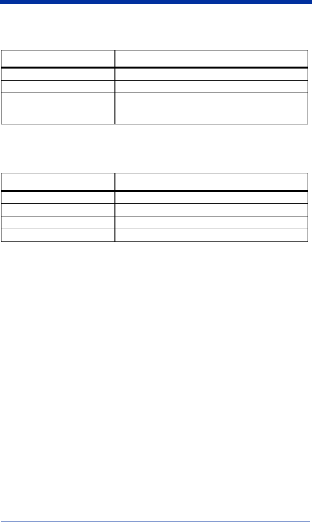
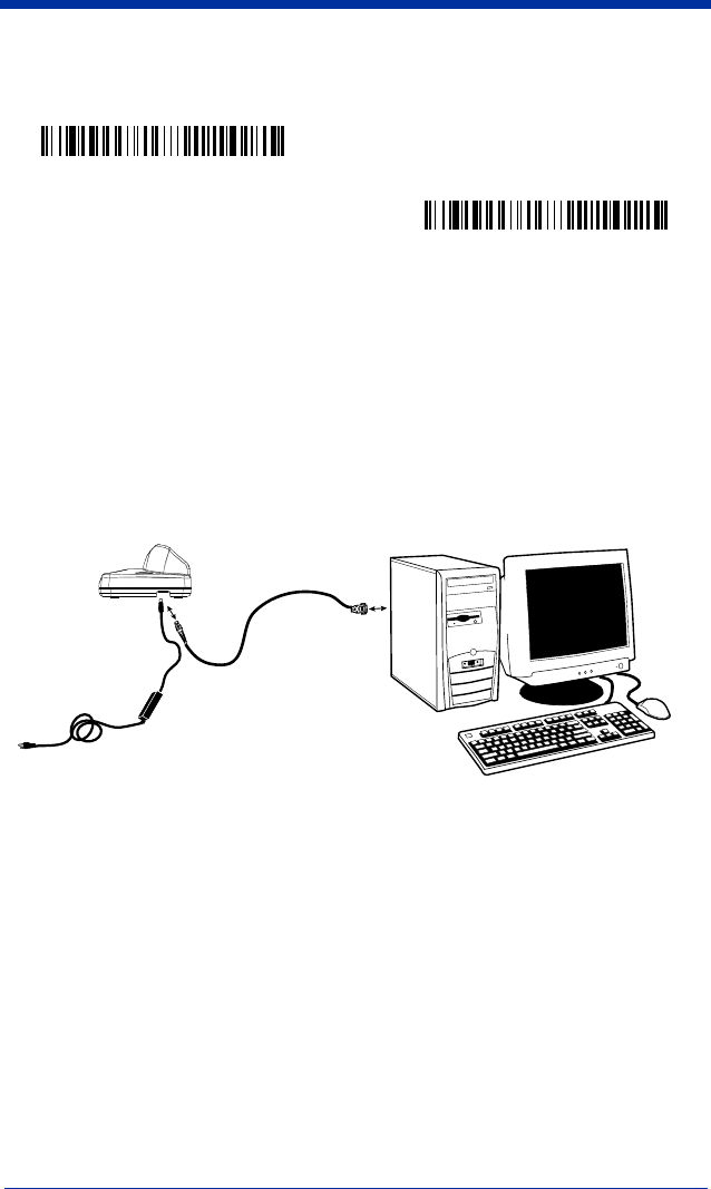
Connecting the Base When Powered by Host
(Keyboard Wedge)
A base can be connected between the keyboard and PC as a “keyboard wedge,”
plugged into the serial port, or connected to a portable data terminal in wand
emulation or non decoded output mode. The following is an example of a
keyboard wedge connection:
1. Turn off power to the terminal/computer.
2. Disconnect the keyboard cable
from the back of the terminal/
computer.
3) Base sends
data to host
1) Good Read
2) ACK from base
Disconnect
IMAGETEAM™ 2020/5620 System Manual 1 - 13
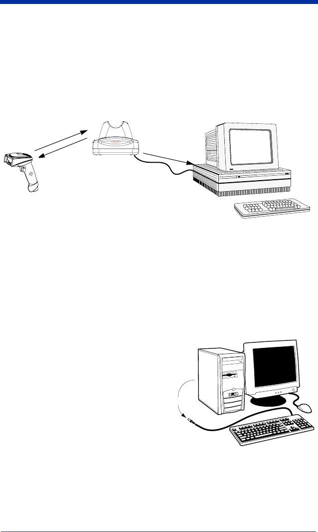
3. Connect the
appropriate
interface cable
to the base and
to the terminal/
computer and
keyboard.
4. Turn the
terminal/
computer power
back on.
5. Program the
base for the
keyboard wedge interface. See "Keyboard Wedge Connection" on page 1-
14.)
6. Verify the base operation by scanning a bar code from the Sample Symbols
in the back of this manual.
Note: Without using the 9-volt external, power supply, the base only uses
enough power from the host to operate the interface. The scanner’s
battery is not charged when in this mode. Using the 9-volt, external power
supply allows the scanner’s battery to be charged, and no power is drawn
from the host.
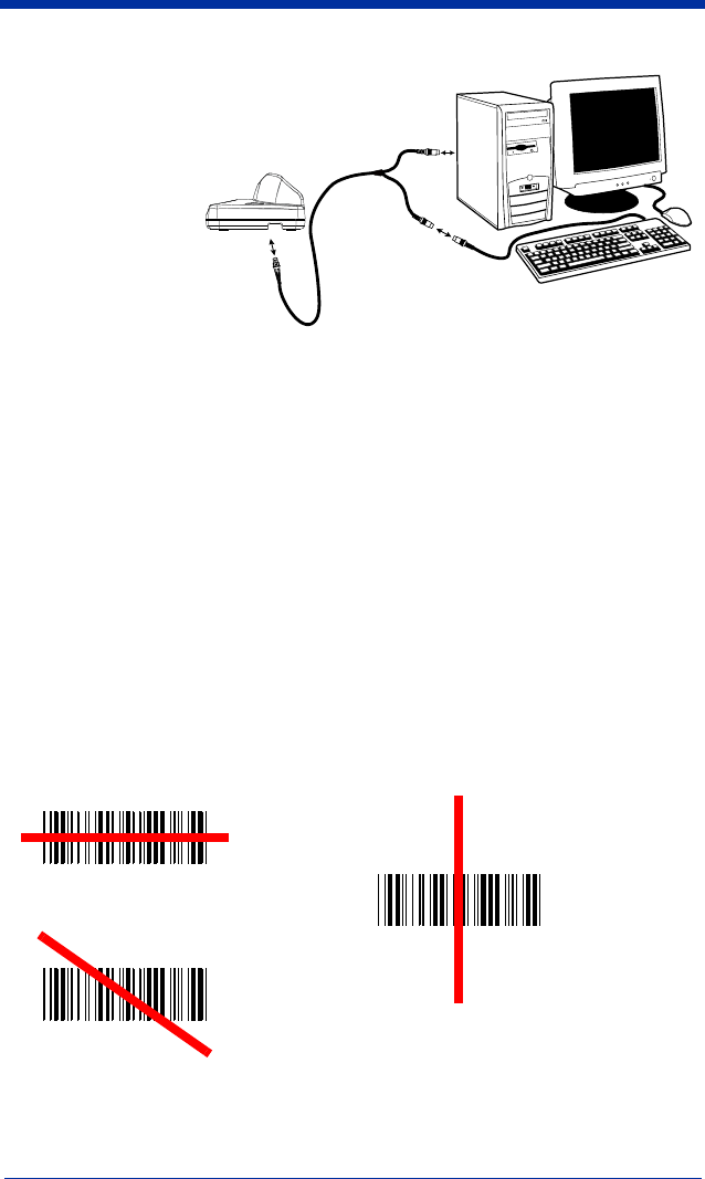
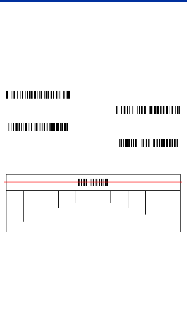
Reading Techniques
The scanner has a view finder that projects a bright red aiming beam that
corresponds to its horizontal field of view. The aiming line should be centered
horizontally over the bar code; it will not read if the aiming line is in any other
direction.
12
3
Good Read
Bad Read
Bad Read

1 - 14 IMAGETEAM™ 2020/5620 System Manual
The best focus point for reading most code densities is about 5 inches (12.7 cm)
from the unit. To read single or multiple symbols (on a page or on an object),
hold the imager at an appropriate distance from the target, pull the trigger, and
center the aiming line on the symbol.
Resetting the Standard Product Defaults
If you aren’t sure what programming options are in your scanner, or you’ve
changed some options and want the factory settings restored, scan the
Standard Product Default Settings
bar code below.
The Menu Commands starting on page 10-5 lists the factory default settings for
each of the commands (indicated by an asterisk (*) on the programming pages).
Note: Scanning this bar code also causes both the scanner and the base to
perform a reset and become unlinked. Refer to "Linking Scanner to
Base" on page 1-6 for additional information.
Plug and Play
Plug and Play bar codes provide instant scanner set up for commonly used
interfaces.
Note: After you scan one of the codes, power cycle the host terminal to have the
interface in effect.
Keyboard Wedge Connection
If you want your scanner programmed for an IBM PC AT and compatibles
keyboard wedge interface with a USA keyboard, scan the bar code below.
Standard Product Default Settings

IMAGETEAM™ 2020/5620 System Manual 1 - 15
Note: The following bar code also programs a carriage return (CR) suffix.
Laptop Direct Connect
For most laptops, scanning the Laptop Direct Connect bar code allows
operation of the scanner in parallel with the integral keyboard. The following
Laptop Direct Connect bar code selects terminal ID 03, programs a carriage
return (CR) suffix and turns on Emulate External Keyboard (page 2-5).
RS-232
The RS-232 Interface bar code is used when connecting to the serial port of a
PC or terminal. The following RS-232 Interface bar code also programs a
carriage return (CR) and a line feed (LF) suffix, baud rate, and data format as
indicated below. It also changes the trigger mode to manual.
Wand Emulation Plug & Play
In Wand Emulation mode, the imager decodes the bar code then sends data in
the same format as a wand imager. The Code 39 Format converts all
symbologies to Code 39.
The Same Code Format transmits UPC, EAN, Code 128 and Interleaved 2 of 5
without any changes, but converts all other symbologies to Code 39.
Option Setting
Baud Rate 38400 bps
Data Format 8 data bits, no parity bit, 1 stop bit
IBM PC AT and Compatibles
with CR suffix
Laptop Direct Connect
with CR suffix
RS-232 Interface

1 - 16 IMAGETEAM™ 2020/5620 System Manual
The
Wand Emulation Plug & Play Code 39 Format
bar code below sets the
terminal ID to 61. The
Wand Emulation Plug & Play Same Code Format
bar
code sets the terminal ID to 64. These Plug & Play bar codes also set the
Transmission Rate to 25 inches per second, Output Polarity to black high, and
Idle State to high. (If you want to change the terminal ID
only
, without changing
any other imager settings, please refer to Terminal ID on page 2-1.)
Wand Emulation Same Code
Wand Emulation (Code 39 Format)

IMAGETEAM™ 2020/5620 System Manual 1 - 17
IBM 4683 Ports 5B, 9B, and 17 Interface
Scan one of the following “Plug and Play” codes to program the IT5620 for IBM
4683 Port 5B, 9B, or 17.
Note: After scanning one of these codes, you must power cycle the cash
register.
Each bar code above also programs the following suffixes for each symbology:
* Suffixes programmed for Code 128 with IBM 4683 Port 5B, IBM 4683 Port 9B HHBCR-1,
and IBM 4683 Port 17 Interfaces
**Suffixes programmed for Code 128 with IBM 4683 Port 9 HHBCR-2 Interface
Symbology Suffix
EAN 8 0C
EAN 13 16
UPC A 0D
UPC E 0A
Code 39 00 0A 0B
Interleaved 2 of 5 00 0D 0B
Code 128 * 00 0A 0B
Code 128 ** 00 18 0B
IBM 4683 Port 5B Interface
IBM 4683 Port 9B HHBCR-1 Interface
IBM 4683 Port 17 Interface
IBM 4683 Port 9B HHBCR-2 Interface

1 - 18 IMAGETEAM™ 2020/5620 System Manual
Connecting the Base with USB
A base can be connected to the USB port of a computer.
1. Connect the appropriate interface cable to the base and to the computer.
2. Program the base for the USB interface. (See "Connecting the Base with
USB" on page 1-18.)
3. Verify the base operation by scanning a bar code from the Sample Symbols
in the back of this manual.
For additional USB programming and technical information, refer to HHP’s “USB
Application Note,” available at www.HHP.com.
Note: Without using the 9-volt external, power supply, the base only uses
enough power from the host to operate the interface. The scanner’s
battery is not charged when in this mode. Using the 9-volt, external power
supply allows the scanner’s battery to be charged, and no power is drawn
from the host.

IMAGETEAM™ 2020/5620 System Manual 1 - 19
IBM SurePos
Scan one of the following “Plug and Play” codes to program the IT5620 for IBM
SurePos (USB Hand Held scanner) or IBM SurePos (USB Tabletop scanner).
Note: After scanning one of these codes, you must power cycle the cash
register.
Each bar code above also programs the following suffixes for each symbology:
USB PC or Macintosh Keyboard
Scan one of the following codes to program the IT5620 for USB PC Keyboard or
USB Macintosh Keyboard. Scanning these codes adds a CR and LF, along with
selecting the terminal ID (USB PC Keyboard - 124, USB Macintosh Keyboard -
125).
Symbology Suffix
EAN 8 0C
EAN 13 16
UPC A 0D
UPC E 0A
Code 39 00 0A 0B
Interleaved 2 of 5 00 0D 0B
Code 128 00 18 0B
IBM SurePos (USB Hand
Held Scanner) Interface
IBM SurePos (USB Tabletop
Scanner) Interface
USB Keyboard (PC)
USB Keyboard (Mac)

1 - 20 IMAGETEAM™ 2020/5620 System Manual
USB HID
Scan the following code to program the IT5620 for USB HID bar code scanners.
Scanning this code changes the terminal ID to 131.
USB Com Port Emulation
Scan the following code to program the IT5620 to emulate a regular RS-232-
based Com Port. If you are using a Microsoft® Windows® PC, you will need to
download a driver from the HHP website (www.HHP.com). The driver will use the
next available Com Port number. Apple® Macintosh computers recognize the
imager as a USB CDC class device and automatically uses a class driver.
Scanning the code below changes the terminal ID to 130.
Note: No extra configuration (e.g., baud rate) is necessary.
CTS/RTS Emulation
ACK/NAK Mode
USB HID Bar Code Scanner
USB Com Port Emulation
On
* Off
On
* Off
IMAGETEAM™ 2020/5620 System Manual 1 - 21
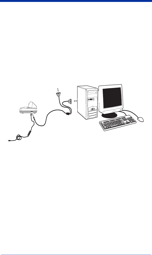
Connecting the Base with Serial Wedge
The IT2020 uses TTL signal levels to wedge into an RS-232 serial network. Use
only IT2020 serial wedge cables to prevent damage to the base. Refer to
Connecting the Base with RS-232 Serial Port on page 2-7 to set the baud rate
and communications protocol.
1. Turn off power to the computer.
2. Disconnect the existing serial cable from the computer.
3. Connect the appropriate interface cable to the base.
Note: For the base to work properly, you must have the correct cable for your
type of computer.
4. Plug the serial connector into the serial port on your computer. Tighten the
two screws to secure the connector to the port.
5. Plug the other serial connector into the other device connection and tighten
the two screws.
6. Plug the power supply barrel connector to the base, and plug the power
supply into the AC source.
7. Once the base has been fully connected, power up the computer.
6
4
5
Other device

1 - 22 IMAGETEAM™ 2020/5620 System Manual
To set up the serial wedge terminal ID, use the serial terminal ID 050 and follow
the instructions on page 2-1. Make sure that all of the communication
parameters match on all of the connected devices. Choosing Both sends
scanned data to P1 and P2. Default = P1.
* P1
P2
Both P1 and P2

IMAGETEAM™ 2020/5620 System Manual 2 - 1
2
Terminal Interfaces
Terminal ID
If your interface is not a standard PC AT, refer to "Supported Terminals" on page
2-2 through page 2-3, and locate the Terminal ID number for your PC. Scan the
Terminal ID bar code below, then scan the numeric bar code(s) from the
Programming Chart inside the back cover of this manual to program the scanner
for your terminal ID. Scan Save to save your selection.
For example, an IBM AT terminal has a Terminal ID of 003. You would scan the
Terminal ID bar code, then 0, 0, 3 from the Programming Chart inside the back
cover of this manual, then Save. If you make an error while scanning the digits
(before scanning Save), scan the Discard code on the Programming Chart, scan
the Terminal ID bar code, scan the digits, and the Save code again.
Note: The default interface for the IT2020-5 is Keyboard Wedge (Term ID =
003).
Note: After scanning one of these codes, you must power cycle your computer.
Terminal ID
Save

2 - 2 IMAGETEAM™ 2020/5620 System Manual
Supported Terminals
Terminal Model(s) Terminal ID
DEC VT510, 520, 525 (PC style) 005
DEC VT510, 520, 525 (DEC style
LK411) 104
Esprit 200, 400 005
Heath Zenith PC, AT 003*
HP Vectra 003
IBM XT 001
IBM PS/2 25, 30, 77DX2 002
IBM AT, PS/2 30–286, 50, 55SX, 60,
70, 70–061, 70–121, 80 003*
IBM 102 key 3151, 3161, 3162, 3163, 3191,
3192, 3194, 3196, 3197, 3471,
3472, 3476, 3477
006
IBM 122 key 3191, 3192, 3471, 3472 007
IBM 122 key 3196, 3197, 3476, 3477, 3486,
3482, 3488 008
IBM 122 key 3180 024
IBM 122 key 3180 data entry keyboard 114
IBM DOS/V 106 key PC & Workstation 102
IBM SurePOS USB Hand Held Scanner 128
IBM SurePOS USB Tabletop Scanner 129
IBM Thinkpad 360 CSE, 340, 750 097
IBM Thinkpad 106
IBM Thinkpad 365, 755CV 003*
I/O 122 key 2676D, 2677C, 2677D 008
ITT 9271 007
Lee Data IIS 007
NEC 98XX Series 103
Olivetti M19, M200 001
Olivetti M240, M250, M290, M380,
P500 003*
RS-232 TTL 000
Serial Wedge 050
Silicon Graphics Indy, Indigoll 005
Telex 88 key 078, 078A, 79, 80, 191, 196,
1191,1192, 1471, 1472, 1476,
1477, 1483
025
Telex 88 key Data Entry Keyboard 112
Telex 102 key 078, 078A, 79, 80, 191, 196,
1191,1192, 1471, 1472, 1476,
1477, 1483
045

IMAGETEAM™ 2020/5620 System Manual 2 - 3
* Default for IT2020-5.
Telex 122 key 078, 078A, 79, 80, 191, 196,
1191,1192, 1471, 1472, 1476,
1477, 1482, 1483
046
USB PC Keyboard 124
USB Mac Keyboard 125
USB Com Port 130
USB HIDPOS 131
Wand Emulation (Code
39 Format) 061
Wand Emulation (Same
Code Format) 064
Supported Terminals (Continued)
Terminal Model(s) Terminal ID

2 - 4 IMAGETEAM™ 2020/5620 System Manual
Keyboard Country
Scan the appropriate country code below to program the keyboard for your
country. As a general rule, the following characters are supported, but need
special care for countries other than the United States:
@ | $ # { } [ ] = / ‘ \ < > ~
* United States
Denmark
France
Germany/Austria
Great Britain
Italy
Norway
Spain
Switzerland
Belgium
Finland

IMAGETEAM™ 2020/5620 System Manual 2 - 5
Please refer to HHP’s website (www.HHP.com) for complete keyboard country
support information and applicable interfaces. If you need to program a
keyboard for a country other than one listed above, scan the Program Keyboard
Country bar code below, then scan the numeric bar code(s) for the appropriate
country from the inside back cover, then the Save bar code.
Keyboard Style
This programs keyboard styles, such as Caps Lock and Shift Lock.
Default =
Regular.
Regular
is used when you normally have the Caps Lock key off.
Caps Lock
is used when you normally have the Caps Lock key on.
Shift Lock
is used when you normally have the Shift Lock key on (not common
to U.S. keyboards).
Automatic Caps Lock
is used if you change the Caps Lock key on and off. The
software tracks and reflects if you have Caps Lock on or off (AT and PS/2 only).
This selection can only be used with systems that have an LED which notes the
Caps Lock status.
Autocaps via NumLock
bar code should be scanned in countries (e.g.,
Germany, France) where the Caps Lock key cannot be used to toggle Caps
Lock. The NumLock option works similarly to the regular Auotcaps, but uses the
NumLock key to retrieve the current state of the Caps Lock.
Program Keyboard Country
* Regular
Caps Lock
Shift Lock
Automatic Caps Lock
Autocaps via NumLock

2 - 6 IMAGETEAM™ 2020/5620 System Manual
Emulate External Keyboard
should be scanned if you do not have an external
keyboard (IBM AT or equivalent).
Note: After scanning the Emulate External Keyboard bar code, you must power
cycle your computer.
Keyboard Modifiers
This modifies special keyboard features, such as CTRL+ ASCII codes and Turbo
Mode.
Control + ASCII Mode On:
The scanner sends key combinations for ASCII
control characters for values 00-1F. Refer to Keyboard Function
Relationships, page 7-1 for CTRL+ ASCII Values.
Default = Off
Turbo Mode:
The scanner sends characters to a terminal faster. If the terminal
drops characters, do not use Turbo Mode.
Default = Off
Numeric Keypad Mode:
Sends numeric characters as if entered from a
numeric keypad.
Default = Off
Emulate External Keyboard
Control + ASCII Mode On
* Control + ASCII Mode Off
Turbo Mode On
* Turbo Mode Off
Numeric Keypad Mode On
* Numeric Keypad Mode Off
IMAGETEAM™ 2020/5620 System Manual 2 - 7
Automatic Direct Connect Mode:
This selection can be used if you have an
IBM AT style terminal and the system is dropping characters.
Default = Off
Connecting the Base with RS-232 Serial Port
1. Turn off power to the terminal/computer.
2. Connect the appropriate interface cable to the base.
Note: For the base to work properly, you must have the correct cable for your
type of terminal/computer.
3. Plug the serial connector into the serial port on your computer. Tighten the
two screws to secure the connector to the port.
4. Plug the power supply barrel connector to the base, and plug the power
supply into the AC source.
5. Once the base has been fully connected, power up the computer.
Automatic Direct
Connect Mode On
* Automatic Direct Connect
Mode Off
5
4
3
2

2 - 8 IMAGETEAM™ 2020/5620 System Manual
All communication parameters between the scanner and terminal must match for
correct data transfer through the serial port using RS-232 protocol. Scanning the
RS-232 interface bar code, programs the scanner for an RS-232 interface at
38,400 baud, parity–none, 8 data bits, 1 stop bit, and adds a suffix of a CR LF.
RS-232 Baud Rate
Baud Rate sends the data from the scanner to the terminal at the specified rate.
The host terminal must be set for the same baud rate as the scanner.
Default = 38,400
.
RS-232 Interface
300
2400
600
1200
4800
* 38400
9600
19200
115,200
57,600

IMAGETEAM™ 2020/5620 System Manual 2 - 9
RS-232 Word Length: Data Bits, Stop Bits, and Parity
Data Bits
sets the word length at 7 or 8 bits of data per character. If an
application requires only ASCII Hex characters 0 through 7F decimal (text, digits,
and punctuation), select 7 data bits. For applications which require use of the full
ASCII set, select 8 data bits per character.
Default = 8.
Stop Bits
sets the stop bits at 1 or 2.
Default = 1.
Parity
provides a means of checking character bit patterns for validity.
Default = None.
7 Data, 1 Stop, Parity Even
7 Data, 1 Stop, Parity None
7 Data, 1 Stop, Parity Odd
7 Data, 2 Stop, Parity Odd
7 Data, 2 Stop, Parity Even
7 Data, 2 Stop Parity None
* 8 Data, 1 Stop, Parity None
8 Data, 1 Stop, Parity Even
8 Data, 1 Stop, Parity Odd

2 - 10 IMAGETEAM™ 2020/5620 System Manual
RS-232 Handshaking
RS-232 Handshaking allows control of data transmission from the Imager using
software commands from the host device. When this feature is turned
Off
, no
data flow control is used. When Data Flow Control is turned
On
, the host device
suspends transmission by sending the XOFF character (DC3, hex 13) to the
Imager. To resume transmission, the host sends the XON character (DC1, hex
11). Data transmission continues where it left off when XOFF was sent.
Default
= RTS/CTS, XON/XOFF and ACK/NAK Off
Host ACK Selection
Some applications require that the host terminal (or server) approve or reject
incoming bar code data and notify the operator of these actions. These
applications require that the host maintain control over the response indicators
emitted from the source scanner. Turning the Host ACK selection on, configures
the cordless system scanners to respond to commands from the host system.
The following criteria must be met for the Host ACK to work correctly:
• The cordless system must be configured for “Host Port RS-232” (Terminal ID
= 050)
• RTS/CTS is defaulted off. You must enable it if the host system requires it.
• Host ACK must be enabled (page 2-11).
• System performance degrades when using Host ACK at rates lower than
9600.
• The host terminal software must be capable of interpreting the bar code data,
make decisions based on the data content, and send out appropriate escape
commands to the source scanner.
Escape commands are addressed to the source scanner via “Application Work
Groups.” Once a command is sent, all scanners in a group respond to that
command. Because of this situation, it is recommended that each scanner is
assigned to its own group.
RTS/CTS On
* XON/OFF Off
* RTS/CTS Off
XON/XOFF On
ACK/NAK On
* ACK/NAK Off

IMAGETEAM™ 2020/5620 System Manual 2 - 11
The commands to which the scanner responds are listed on page 2-12. The
<ESC> is a 1B in hex. A typical command string is y <ESC> x, where “y” is the
application work group number, “<ESC> x” is the escape command, and the
comma is the terminator.
Up to twenty commands may be strung together to create custom response
sequences. An example of a command is listed below.
0<ESC>4<ESC>5<ESC>6,
The above example will make a scanner in application work group zero beep low,
medium, high.
Once Host ACK is enabled, the system works as follows:
• The scanner reads a code and sends data to the base/host system. No
audible or visual indication is emitted until you receive an escape command.
The scanner read illumination goes out upon a successful read.
• Scanner is suspended until 1) a valid escape string is received from the host
system (via the base) or 2) the scanner “times out.”
• Once condition 1 or 2 above has been met, the scanner is ready to scan
again, and the process repeats.
Time out is indicated by three rapid beeps at the same pitch. A time out occurs
if the source scanner does not receive a valid escape command in 10 seconds.
If a time out occurs, the operator should check the host system to understand
why a response to the scanner was not received.
Host ACK Enable
Host ACK On
* Host ACK Off
2 - 12 IMAGETEAM™ 2020/5620 System Manual
IT2020-5 Host Escape Commands
Command Action
<ESC> a Indicate as if successful menu change made
<ESC> b Indicate as if unsuccessful menu change made
<ESC> 1 Illuminate green LED for 135 milliseconds (followed by at least 70 mSecs.
dark time when multiple blinks)
<ESC> 2 Illuminate green LED for two seconds (followed by at least 500 mSecs.
dark time when multiple blinks)
<ESC> 3 Illuminate green LED for five seconds (followed by at least 500 mSecs.
dark time when multiple blinks)
<ESC> 4 One beep at low volume
<ESC> 5 One beep at medium volume
<ESC> 6 One beep at high volume
<ESC> 7 Indicate as successful decode and communication to host.
<ESC> 8 Indicate as unsuccessful decode and communication to host.
1) Good Read
3) ACK: Host to Base
4) ACK: Base to Scanner
2) Base sends
data to host

IMAGETEAM™ 2020/5620 System Manual 2 - 13
Wand Emulation
Wand Emulation Connection
The Wand Emulation Connection bar codes should be used if you want to
change the terminal ID
only
, without changing any other imager settings. We
recommend using Wand Emulation Plug & Play bar codes to program your
imager to emulate a wand reader. The Wand Emulation Plug & Play bar codes
change other parameters, in addition to changing the terminal ID. Please refer
to Wand Emulation Plug & Play on page 1-15 for further information.
In Wand Emulation mode, the imager decodes the bar code then sends data in
the same format as a wand imager. The Code 39 Format converts all
symbologies to Code 39.
The Same Code Format transmits UPC, EAN, Code 128 and Interleaved 2 of 5
without any changes, but converts all other symbologies to Code 39. 2D
symbologies are converted to Code 128.
The
Code 39 Format
bar code below sets the terminal ID to 61, and the
Same
Code Format
bar code sets the terminal ID to 64.
Code 39 Format
Same Code Format

2 - 14 IMAGETEAM™ 2020/5620 System Manual
Wand Emulation Transmission Rate
The transmission rate is limited by the terminal’s ability to receive data without
dropping characters.
Default = 25 inches/second.
Wand Emulation Polarity
The Polarity can be sent as standard with black bars high, or reversed with white
bars high.
Default = Black High.
10
80
* 25
40
120
150
200
* Black High
White High

IMAGETEAM™ 2020/5620 System Manual 2 - 15
Wand Emulation Idle
The idle describes the state of the scanner when no data is being transmitted.
When in Wand Emulation mode, you must set the scanner’s idle state to match
the idle state for the device to which the scanner is connected.
Default = Idle
High
.
Wand Emulation Data Block Size
This transmits the data in smaller blocks to prevent buffer overflow.
Default = 40.
Wand Emulation Delay Between Blocks
This sets the delay time between data blocks.
Default = 50ms.
* Idle High
Idle Low
20
80
* 40
60
5ms
500ms
* 50ms
150ms

2 - 16 IMAGETEAM™ 2020/5620 System Manual
Wand Emulation Overall Checksum
When this option is turned on, a computed check character is added at the end
of the entire message. The check character is the character which when
Exclusive-OR’d with every preceding character of the message yields a result of
0x00 (00H).
Default = Off.
On
* Off

IMAGETEAM™ 2020/5620 System Manual 3 - 1
3
Output
Scanner Functions
Good Read Indicators
Beeper – Good Read
The beeper may be programmed On or Off in response to a good read. Turning
this option off, only turns off the beeper response to a good read indication. All
error and menu beeps are still audible.
Default = On.
Beeper Volume – Good Read
The beeper volume codes modify the volume of the beep the scanner emits on
a good read.
Default = Medium.
* On
Off
High
* Medium
Off
Low

3 - 2 IMAGETEAM™ 2020/5620 System Manual
Beeper Pitch – Good Read
The beeper pitch codes modify the pitch (frequency) of the beep the scanner
emits on a good read.
Default = Medium.
Beeper Duration – Good Read
The beeper duration codes modify the length of the beep the scanner emits on a
good read.
Default = Normal.
LED – Good Read
The LED indicator can be programmed On or Off in response to a good read.
Default = On.
Low (1600 Hz)
* Medium (3250 Hz)
High (4200 Hz)
* Normal Beep
Short Beep
* On
Off

IMAGETEAM™ 2020/5620 System Manual 3 - 3
Number of Beeps – Good Read
The number of beeps of a good read can be programmed from 1 - 9. The same
number of beeps will be applied to the beeper and LED in response to a good
read. For example, if you program this option to have five beeps, there will be
five beeps and five LED flashes in response to a good read. The beeps and LED
flashes are in sync with one another. To change the number of beeps, scan the
bar code below and then scan a digit (1-9) bar code and the Save bar code on
the Programming Chart inside the back cover of this manual.
Default = One.
Good Read Delay
This sets the minimum amount of time before the scanner can read another bar
code.
Default = 0 ms (No Delay.
)
User-Specified Good Read Delay
If you want to set your own length for the good read delay, scan the bar code
below, then set the delay (from 0-30,000 milliseconds) by scanning digits from
the inside back cover, then scanning
Save
.
Number of Pulses
* No Delay
Short Delay (500 ms)
Medium Delay (1000 ms)
Long Delay (1500 ms)
User-Specified Good Read Delay

3 - 4 IMAGETEAM™ 2020/5620 System Manual
Scanner Trigger Modes
Manual/Serial Trigger, Low Power
You can activate the scanner either by pressing the trigger, or using a serial
trigger command (see Trigger Commands on page 11-4). When in manual
trigger mode, the scanner scans until a bar code is read, or until the trigger is
released.
When in serial mode, the scanner scans until a bar code has been read or until
the deactivate command is sent. In serial mode, the scanner can also be set to
turn itself off after a specified time has elapsed (see Read Time-Out (Serial
Trigger Mode), which follows).
Read Time-Out (Serial Trigger Mode)
Use this selection to set a time-out (in milliseconds) of the scanner’s trigger when
using serial commands to trigger the scanner. Once the scanner has timed out,
you can activate the scanner either by pressing the trigger or using a serial
trigger command. After scanning the Read Time-Out bar code, set the time-out
duration (from 0-300,000 milliseconds) by scanning digits on the Programming
Chart inside the back cover, then scanning Save.
Default = 0 ms (no time-out).
Scanner Power Time-Out Timer
Note: The Scanner Power Time-out Timer option only applies to Manual/Serial
Trigger.
When there is no activity within a specified time period, the scanner enters low
power mode. Scan the Scanner Power Time-Out bar code to change the time-
out duration (in seconds). Then scan the digit value of the duration (from 1-
10,800 seconds) and the Save bar codes on the Programming Chart inside the
back cover of this manual.
Default = 3600 seconds (1 hour).
* Manual/Serial Trigger
Read Time-Out

IMAGETEAM™ 2020/5620 System Manual 3 - 5
If there are no trigger pulls during the “scanner power time-out timer” interval, the
scanner goes in power down mode. Whenever the trigger is enabled, the
“scanner power time-out timer” is reset. If the scanner is placed in the IT2020-5
cradle and the battery is in the process of being charged, the scanner will not go
into power down mode.
Note: When the scanner is in power down mode, pull trigger to power the unit
back up. There will be a set of power up beeps and a delay of up to a few
seconds for the radio to join. The scanner will then be ready to use.
Automatic Trigger
The scanner scans continuously at full power with illumination fully on.
Presentation Mode
The LEDs are off until a bar code is presented to the scanner. Then the LEDs
turn on automatically to read the code. Presentation Mode uses ambient light to
detect the bar codes. If the light level in the room is not high enough,
Presentation Mode will not work properly.
Hands Free Time-Out
The Automatic Trigger and Presentation Modes are referred to as “hands free”
modes. If the imager’s trigger is pulled when using a hands free mode, the
imager changes to manual trigger mode. You can set the time the imager should
remain in manual trigger mode by setting the Hands Free Time-Out. Once the
time-out value is reached, (if there have been no further trigger pulls) the imager
reverts to the original hands free mode.
Scan the
Hands Free Time-Out
bar code, then scan the time-out duration (from
0-300,000 milliseconds) from the inside back cover, and
Save
.
Default = 5,000
ms.
Scanner Power Time-Out
Automatic Trigger
Presentation Mode
Hands Free Time-Out

3 - 6 IMAGETEAM™ 2020/5620 System Manual
Reread Delay
This sets the time period before the scanner can read the
same
bar code a
second time. Setting a reread delay protects against accidental rereads of the
same bar code. Longer delays are effective in minimizing accidental rereads at
POS (point of sale). Use shorter delays in applications where repetitive bar code
scanning is required.
Default = Medium.
Reread Delay only works when in automatic trigger mode (see page 3-5).
User-Specified Reread Delay
If you want to set your own length for the reread delay, scan the bar code below,
then set the delay (from 0-30,000 milliseconds) by scanning digits from the inside
back cover, then scanning
Save
.
Short (500 ms)
* Medium (750 ms)
Long (1000 ms)
Extra Long (2000 ms)
User-Specified Reread Delay
IMAGETEAM™ 2020/5620 System Manual 3 - 7
Centering Window
Use the centering feature to narrow the scanner’s field of view so the scanner
reads only the bar code you want. When centering is turned on, the scanner only
reads codes that intersect or are contained within the centering window you set
up. At least part of a bar code must be within the window to be decoded or output
by the scanner.
To change the left or right edge of the centering window, scan Centering On, then
scan one of the following bar codes. Then scan the percent you want to shift the
centering window using digits on the inside back cover of this manual. Scan
Save. Default Centering = 40% for Left, 60% for Right.
The figure below illustrates the percentage range from 1 to 100%.
Left of Centering Window
Right of Centering Window
* Centering Off
Centering On
20%
30%
90%
80%
40% 60% 70%
10%
0% 100%

3 - 8 IMAGETEAM™ 2020/5620 System Manual
Example: If you have two bar codes next to one another and the centering
window is set to 40% left edge and 60% right edge, only the bar
code that intersects that window will be decoded.
Output Sequence Overview
Require Output Sequence
When turned off, the bar code data will be output to the host as the scanner
decodes it. When turned on, all output data must conform to an edited sequence
or the scanner will not transmit the output data to the host device.
Note: This selection is unavailable when the Multiple Symbols Selection is
turned on.
Output Sequence Editor
This programming selection allows you to program the scanner to output data
(when scanning more than one symbol) in whatever order your application
requires, regardless of the order in which the bar codes are scanned. Reading
the
Default Sequence
symbol programs the scanner to the Universal values,
shown below. These are the defaults. Be certain you want to delete or clear all
formats before you read the
Default Sequence
symbol.
Note: To make Output Sequence Editor selections, you’ll need to know the code
I.D., code length, and character match(es) your application requires. Use
the Alphanumeric symbols (inside back cover) to read these options.
To Add an Output Sequence
1. Scan the
Enter Sequence
symbol (see Multiple Symbols, page 3-12).
2. Code I.D.
On the Symbology Chart on page A-1, find the symbology to which you want
to apply the output sequence format. Locate the Hex value for that symbol-
ogy and scan the 2 digit hex value from the Programming Chart inside the
back cover of this manual.
20%
30%
90%
80%
40% 60% 70%
10%
0% 100%
Decoded bar code

IMAGETEAM™ 2020/5620 System Manual 3 - 9
3. Length
Specify what length (up to 9999 characters) of data output will be acceptable
for this symbology. Scan the four digit data length from the Programming
Chart inside the back cover of this manual. (Note: 50 characters is entered
as 0050. 9999 is a universal number, indicating all lengths.) When calculat-
ing the length, you must count any programmed prefixes, suffixes, or format-
ted characters as part of the length (unless using 9999).
4. Character Match Sequences
On the ASCII Conversion Chart (Code Page 1252), page A-2, find the Hex
value that represents the character(s) you want to match. Use the Program-
ming Chart inside the back cover of this manual to read the alphanumeric
combination that represents the ASCII characters. (99 is the Universal num-
ber, indicating all characters.)
5. End Output Sequence Editor
Scan
F F
to enter an Output Sequence for an additional symbology, or
Save
to save your entries.
Other Programming Selections
•
Discard
This exits without saving any Output Sequence changes.
Output Sequence Editor
Require Output Sequence
When an output sequence is
Required
, all output data must conform to an edited
sequence or the scanner will not transmit the output data to the host device.
When it’s
On/Not Required
, the scanner will attempt to get the output data to
conform to an edited sequence, but if it cannot, the scanner transmits all output
data to the host device as is.
Enter Sequence
Default Sequence

3 - 10 IMAGETEAM™ 2020/5620 System Manual
When the output sequence is
Off
, the bar code data is output to the host as the
scanner decodes it.
Note: This selection is unavailable when the Multiple Symbols Selection is
turned on.
Output Sequence Example
In this example, you are scanning Code 93, Code 128, and Code 39 bar codes,
but you want the scanner to output Code 39 1st, Code 128 2nd, and Code 93
3rd, as shown below.
Note: Code 93 must be enabled to use this example.
You would set up the sequence editor with the following command line:
SEQBLK62999941FF6A999942FF69999943FF
The breakdown of the command line is shown below:
SEQBLKsequence editor start command
Required
On/Not Required
* Off
A - Code 39
B - Code 128
C - Code 93

IMAGETEAM™ 2020/5620 System Manual 3 - 11
62 code identifier for Code 39
9999 code length that must match for Code 39, 9999 = all lengths
41 start character match for Code 39, 41h = “A”
FF termination string for first code
6A code identifier for Code 128
9999 code length that must match for Code 128, 9999 = all lengths
42 start character match for Code 128, 42h = “B”
FF termination string for second code
69 code identifier for Code 93
9999 code length that must match for Code 93, 9999 = all lengths
43 start character match for Code 93, 43h = “C”
FF termination string for third code
To program the previous example using specific lengths, you would have to
count any programmed prefixes, suffixes, or formatted characters as part of the
length. If you use the example on page 3-10, but assume a <CR> suffix and
specific code lengths, you would use the following command line:
SEQBLK62001241FF6A001342FF69001243FF
The breakdown of the command line is shown below:
SEQBLK sequence editor start command
62 code identifier for Code 39
0012 A - Code 39 sample length (11) plus CR suffix (1) = 12
41 start character match for Code 39, 41h = “A”
FF termination string for first code
6A code identifier for Code 128
0013 B - Code 128 sample length (12) plus CR suffix (1) = 13
42 start character match for Code 128, 42h = “B”
FF termination string for second code
69 code identifier for Code 93
0012 C - Code 93 sample length (11) plus CR suffix (1) = 12
43 start character match for Code 93, 43h = “C”
FF termination string for third code

3 - 12 IMAGETEAM™ 2020/5620 System Manual
Multiple Symbols
When this programming selection is turned
On
, it allows you to read multiple
symbols with a single pull of the scanner’s trigger. If you press and hold the
trigger, aiming the scanner at a series of symbols, it reads unique symbols once,
beeping (if turned on) for each read. The scanner attempts to find and decode
new symbols as long as the trigger is pulled. When this programming selection
is turned
Off
, the scanner will only read the symbol closest to the aiming beam.
No Read
With No Read turned
On
, the scanner sends an “NR” to the host if you pull and
release the trigger without reading a code (e.g., bad bar code). If No Read is
turned
Off
, the “NR” will not be sent to the host.
If you want a different notation than “NR,” for example, “Error,” or “Bad Code,”
you can edit the output message using the Data Formatter (page 5-5). The hex
code for the No Read symbol is 9C.
Video Reverse
Video Reverse is used to allow the scanner to read bar codes that are inverted.
The “Off” bar code below is an example of this type of bar code.
Note: If additional menuing is required, Video Reverse must be disabled to read
the menu bar codes and then re-enabled after menuing is completed.
On
* Off
On
* Off
On
* Off
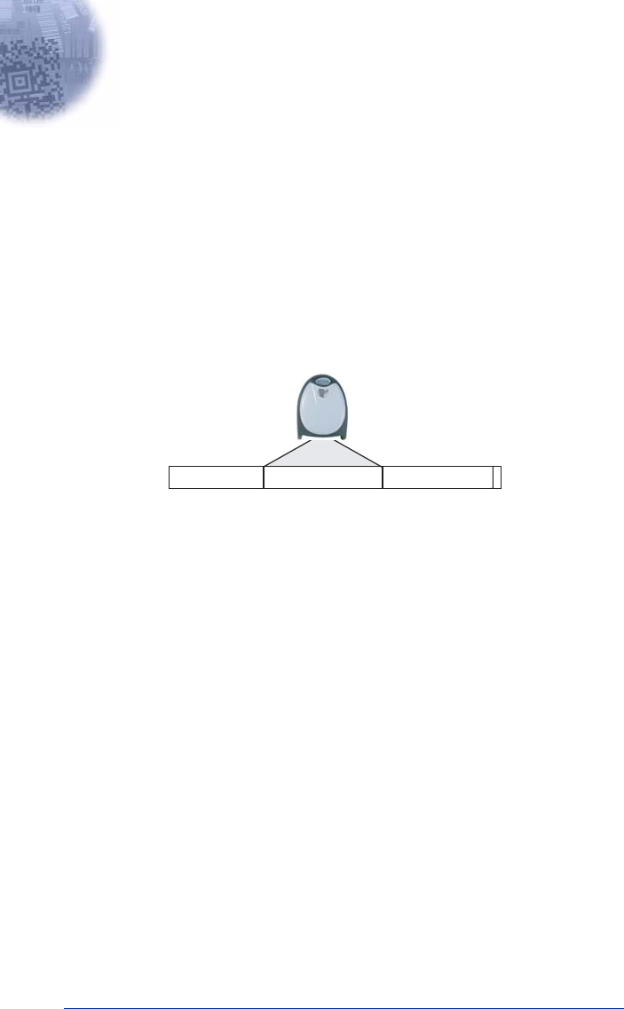
IMAGETEAM™ 2020/5620 System Manual 4 - 1
4
Data Editing
Prefix/Suffix Overview
When a bar code is scanned, additional information is sent to the host computer
along with the bar code data. This group of bar code data and additional,
user-defined data is called a “message string.” The selections in this section are
used to build the user-defined data into the message string.
Prefix and Suffix characters are data characters that can be sent before and after
scanned data. You can specify if they should be sent with all symbologies, or
only with specific symbologies. The following illustration shows the breakdown
of a message string:
Points to Keep In Mind
• It is not necessary to build a message string. The selections in this chapter
are only used if you wish to alter the default settings.
Default prefix = None.
Default suffix = None
.
• A prefix or suffix may be added or cleared from one symbology or all
symbologies.
• You can add any prefix or suffix from the ASCII Conversion Chart (Code Page
1252) on page A-2, plus Code I.D. and AIM I.D.
• You can string together several entries for several symbologies at one time.
• Enter prefixes and suffixes in the order in which you want them to appear on
the output.
• When setting up for specific symbologies (as opposed to all symbologies), the
specific symbology ID value counts as an added prefix or suffix character.
Prefix Scanned DataSuffix
1-11
alpha numeric
characters
variable length1-11
alpha numeric
characters

4 - 2 IMAGETEAM™ 2020/5620 System Manual
To Add a Prefix or Suffix:
Step 1. Scan the Add Prefix or Add Suffix symbol (page 4-3).
Step 2. Determine the 2 digit Hex value from the Symbology Chart (included in
the Appendix A) for the symbology to which you want to apply the prefix
or suffix. For example, for Code 128, Code ID is “j” and Hex ID is “6A”.
Step 3. Scan the 2 hex digits from the Programming Chart inside the back
cover of this manual or scan 9, 9 for all symbologies.
Step 4. Determine the hex value from the ASCII Conversion Chart (Code Page
1252) on page A-2, for the prefix or suffix you wish to enter.
Step 5. Scan the 2 digit hex value from the Programming Chart inside the back
cover of this manual.
Step 6. Repeat Steps 4 and 5 for every prefix or suffix character.
Step 7. To add the Code I.D., scan 5, C, 8, 0.
To add AIM I.D., scan 5, C, 8, 1.
To add a backslash (\), scan 5, C, 5, C.
Note: To add a backslash (\) as in Step 7, you must scan 5C twice – once to
create the leading backslash and then to create the backslash itself.
Step 8. Scan Save to exit and save, or scan Discard to exit without saving.
Repeat Steps 1-6 to add a prefix or suffix for another symbology.
Example: Add a Suffix to a specific symbology
To send a CR (carriage return)Suffix for UPC only:
Step 1. Scan Add Suffix.
Step 2. Determine the 2 digit hex value from the Symbology Chart (included in
the Appendix A) for UPC.
Step 3. Scan 6, 3 from the Programming Chart inside the back cover of this
manual.
Step 4. Determine the hex value from the ASCII Conversion Chart (Code Page
1252) on page A-2, for the CR (carriage return).
Step 5. Scan 0, D from the Programming Chart inside the back cover of this
manual.
Step 6. Scan Save, or scan Discard to exit without saving.

IMAGETEAM™ 2020/5620 System Manual 4 - 3
To Clear One or All Prefixes or Suffixes:
You can clear a single prefix or suffix, or clear all prefixes/suffixes for a
symbology. When you Clear One Prefix (Suffix), the specific character you
select is deleted from the symbology you want. When you Clear All Prefixes
(Suffixes), all the prefixes or suffixes for a symbology are deleted.
Step 1. Scan the Clear One Prefix or Clear One Suffix symbol.
Step 2. Determine the 2 digit Hex value from the Symbology Chart (included in
the Appendix A) for the symbology from which you want to clear the pre-
fix or suffix.
Step 3. Scan the 2 digit hex value from the Programming Chart inside the back
cover of this manual or scan 9, 9 for all symbologies.
Your change is automatically saved.
To Add a Carriage Return Suffix to all Symbologies
Scan the following bar code if you wish to add a carriage return suffix to all
symbologies at once. This action first clears all current suffixes, then programs
a carriage return suffix for all symbologies.
Prefix Selections
Add CR Suffix
All Symbologies
Add Prefix
Clear One Prefix
Clear All Prefixes

4 - 4 IMAGETEAM™ 2020/5620 System Manual
Suffix Selections
Function Code Transmit
When this selection is enabled and function codes are contained within the
scanned data, the scanner transmits the function code to the terminal. Charts of
these function codes are provided in Supported Interface Keys starting on
page 7-3. When the scanner is in keyboard wedge mode, the scan code is
converted to a key code before it is transmitted.
Default = Enable.
Intercharacter, Interfunction, and Intermessage Delays
Some terminals drop information (characters) if data comes through too quickly.
Intercharacter, interfunction, and intermessage delays slow the transmission of
data, increasing data integrity.
Each delay is composed of a 5 millisecond step. You can program up to 99 steps
(of 5 ms each) for a range of 0-495 ms.
Add Suffix
Clear One Suffix
Clear All Suffixes
* Enable
Disable

IMAGETEAM™ 2020/5620 System Manual 4 - 5
Intercharacter Delay
An intercharacter delay of up to 495 milliseconds may be placed between the
transmission of each character of scanned data. Scan the Intercharacter Delay
bar code below, then scan the number of milliseconds and the SAVE bar code
using the Programming Chart inside the back cover of this manual.
To remove this delay, scan the Intercharacter Delay bar code, then set the
number of steps to 0. Scan the SAVE bar code using the Programming Chart
inside the back cover of this manual.
Note: Intercharacter delays are not supported in USB serial emulation.
User Specified Intercharacter Delay
An intercharacter delay of up to 495 milliseconds may be placed after the
transmission of a particular character of scanned data. Scan the Delay Length
bar code below, then scan the number of milliseconds and the SAVE bar code
using the Programming Chart inside the back cover of this manual.
Next, scan the Character to Trigger Delay bar code, then the 2-digit hex value
for the ASCII character that will trigger the delay ASCII Conversion Chart (Code
Page 1252) on page A-2.
To remove this delay, scan the Delay Length bar code, and set the number of
steps to 0. Scan the SAVE bar code using the Programming Chart inside the
back cover of this manual.
12345
Intercharacter Delay
Prefix Scanned Data Suffix
Intercharacter Delay
Delay Length
Character to Trigger Delay
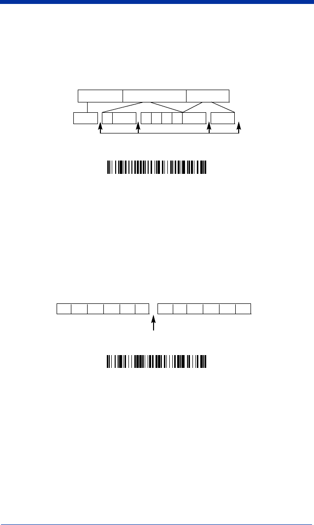
4 - 6 IMAGETEAM™ 2020/5620 System Manual
Interfunction Delay
An interfunction delay of up to 495 milliseconds may be placed between the
transmission of each segment of the message string. Scan the Interfunction
Delay bar code below, then scan the number of milliseconds and the SAVE bar
code using the Programming Chart inside the back cover of this manual.
To remove this delay, scan the Interfunction Delay bar code, then set the
number of steps to 0. Scan the SAVE bar code using the Programming Chart
inside the back cover of this manual.
Intermessage Delay
An intermessage delay of up to 495 milliseconds may be placed between each
scan transmission. Scan the Intermessage Delay bar code below, then scan
the number of milliseconds and the SAVE bar code using the Programming
Chart inside the back cover of this manual.
To remove this delay, scan the Intermessage Delay bar code, then set the
number of steps to 0. Scan the SAVE bar code using the Programming Chart
inside the back cover of this manual.
Interfunction Delays
Prefix Scanned Data Suffix
12345STX HT CR LF
Interfunction Delay
2nd Scan Transmission1st Scan Transmission
Intermessage Delay
Intermessage Delay

IMAGETEAM™ 2020/5620 System Manual 5 - 1
5
Data Formatting
Data Format Editor Introduction
You may use the Data Format Editor to change the scanner’s output. For
example, you can use the Data Format Editor to insert characters at certain
points in bar code data as it is scanned. The selections in the following pages
are used only if you wish to alter the output.
Default Data Format setting = None.
Normally, when you scan a bar code, it gets outputted automatically; however
when you do a format, you must use a “send” command (see Send Commands
on page 5-2) within the format program to output data.
Multiple formats may be programmed into the scanner. They are stacked in the
order in which they are entered. However, the following list presents the order
in which formats are applied:
1. Specific Term ID, Actual Code ID, Actual Length
2. Specific Term ID, Actual Code ID, Universal Length
3. Specific Term ID, Universal Code ID, Actual Length
4. Specific Term ID, Universal Code ID, Universal Length
5. Universal Term ID, Actual Code ID, Actual Length
6. Universal Term ID, Actual Code ID, Universal Length
7. Universal Term ID, Universal Code ID, Actual Length
8. Universal Term ID, Universal Code ID, Universal Length
If you have changed data format settings, and wish to clear all formats and return
to the factory defaults, scan the Default Data Format code on page 5-4.
To Add a Data Format
Step 1. Scan the Enter Data Format symbol (page 5-4).
Step 2. Primary/Alternate Format
Determine if this will be your primary data format, or one of 3 alternate
formats. (Alternate formats allow you “single shot” capability to scan
one bar code using a different data format. After the one bar code has
been read, the scanner reverts to the primary data format. See page 5-
5.) If you are programming the primary format, scan 0 using the Pro-
gramming Chart inside the back cover of this manual. If you are pro-
gramming an alternate format, scan 1, 2, or 3, depending on the
alternate format you are programming.
Step 3. Terminal Type
Refer to the Supported Terminals Chart (page 2-2) and locate the Ter-
minal ID number for your PC. Scan three numeric bar codes on the
inside back cover to program the scanner for your terminal ID (you must
enter 3 digits). For example, scan 0 0 3 for an AT wedge.

5 - 2 IMAGETEAM™ 2020/5620 System Manual
Note: The wildcard for all terminal types is 099.
Step 4. Code I.D.
In the Appendix A, find the symbology to which you want to apply the
data format. Locate the Hex value for that symbology and scan the 2
digit hex value from the Programming Chart inside the back cover of
this manual.
Step 5. Length
Specify what length (up to 9999 characters) of data will be acceptable
for this symbology. Scan the four digit data length from the Program-
ming Chart inside the back cover of this manual. (Note: 50 characters is
entered as 0050. 9999 is a universal number, indicating all lengths.)
Step 6. Editor Commands
Refer to the Format Editor Commands Chart (page 5-2). Scan the sym-
bols that represent the command you want to enter. 94 alphanumeric
characters may be entered for each symbology data format.
Step 7. Scan Save from the Programming Chart inside the back cover of this
manual to save your entries.
Other Programming Selections
•Clear One Data Format
This deletes one data format for one symbology. If you are clearing the
primary format, scan 0 from the Programming Chart inside the back cover of
this manual. If you are clearing an alternate format, scan 1, 2, or 3, depending
on the alternate format you are clearing. Scan the Terminal Type (refer to the
Supported Terminals Chart on page 2-2), Code I.D. (refer to the Symbology
Chart on page A-1), and the bar code data length for the specific data format
that you want to delete. All other formats remain unaffected.
•Save from the Programming Chart inside the back cover of this manual
This exits, saving any Data Format changes.
•Discard from the Programming Chart inside the back cover of this manual
This exits without saving any Data Format changes.
Data Format Editor Commands
Send Commands
F1 Send all characters followed by “xx” key or function code, starting from cur-
rent cursor position.
Syntax = F1xx
(xx stands for the hex value for an
ASCII code, see ASCII Conversion Chart (Code Page 1252) on page A-2.)
F2 Send “nn” characters followed by “xx” key or function code, starting from
current cursor position.
Syntax = F2nnxx
(nn stands for the numeric value
(00-99) for the number of characters and xx stands for the hex value for an
ASCII code. See ASCII Conversion Chart (Code Page 1252) on page A-2.)
F3 Send up to but not including “ss” character (Search and Send) starting from
current cursor position, leaving cursor pointing to “ss” character followed by
“xx” key or function code.
Syntax = F3ssxx
(ss and xx both stand for the

IMAGETEAM™ 2020/5620 System Manual 5 - 3
hex values for ASCII codes, see ASCII Conversion Chart (Code Page
1252) on page A-2.)
F4 Send “xx” character “nn” times (Insert) leaving cursor in current cursor posi-
tion.
Syntax = F4xxnn
(xx stands for the hex value for an ASCII code, see
ASCII Conversion Chart (Code Page 1252) on page A-2, and nn is the
numeric value (00-99) for the number of times it should be sent.)
E9 Send all but the last “nn” characters, starting from the current cursor posi-
tion.
Syntax = E9nn
(nn is the numeric value (00-99) for the number of
characters that will not be sent at the end of the message.)
Move Commands
F5 Move the cursor ahead “nn” characters from current cursor position.
Syntax = F5nn
(nn stands for the numeric value (00-99) for the number of
characters the cursor should be moved ahead.)
F6 Move the cursor back “nn” characters from current cursor position.
Syntax = F6nn
(nn stands for the numeric value (00-99) for the number of
characters the cursor should be moved back.)
F7 Move the cursor to the beginning of the data string.
Syntax = F7.
EA Move the cursor to the end of the data string.
Syntax = EA
Search Commands
F8 Search ahead for “xx” character from current cursor position, leaving cursor
pointing to “xx” character.
Syntax = F8xx
(xx stands for the hex value for
an ASCII code, see ASCII Conversion Chart (Code Page 1252) on page A-
2.)
F9 Search back for “xx” character from current cursor position, leaving cursor
pointing to “xx” character.
Syntax = F9xx
(xx stands for the hex value for
an ASCII code, see ASCII Conversion Chart (Code Page 1252) on page A-
2.)
E6 Search ahead for the first non “xx” character from the current cursor posi-
tion, leaving cursor pointing to non “xx” character.
Syntax = E6xx
(xx
stands for the hex value for an ASCII code, see ASCII Conversion Chart
(Code Page 1252) on page A-2.
E7 Search back for the first non “xx” character from the current cursor position,
leaving cursor pointing to non “xx” character.
Syntax = E7xx
(xx stands for
the hex value for an ASCII code, see ASCII Conversion Chart (Code Page
1252) on page A-2.)
Miscellaneous Commands
FB Suppress all occurrences of up to 15 different characters, starting at the cur-
rent cursor position, as the cursor is advanced by other commands. When
the FC command is encountered, the suppress function is terminated. The
cursor is not moved by the FB command. Syntax = FBnnxxyy . .zz where
nn is a count of the number of suppressed characters in the list and xxyy ..
zz is the list of characters to be suppressed. (xx stands for the hex value for
an ASCII code, see ASCII Conversion Chart (Code Page 1252) on page A-
2.)
FC Disables suppress filter and clear all suppressed characters.
Syntax = FC.

5 - 4 IMAGETEAM™ 2020/5620 System Manual
E4 Replaces up to 15 characters in the data string with user specified charac-
ters. Replacement continues until the E5 command is encountered.
Syn-
tax = E4nnxx1xx2yy1yy2...zz1zz2
where nn is the total count of both
characters to be replaced plus replacement characters; xx1 defines charac-
ters to be replaced and xx2 defines replacement characters, continuing
through zz1 and zz2.
E5 Terminates character replacement.
Syntax = E5.
FE Compare character in current cursor position to the character “xx.” If char-
acters are equal, increment cursor. If characters are not equal, no format
match.
Syntax = FExx
(xx stands for the hex value for an ASCII code, see
ASCII Conversion Chart (Code Page 1252) on page A-2.)
EC Check to make sure there is an ASCII number at the current cursor position.
If character is not numeric, format is aborted.
Syntax = EC
.
ED Check to make sure there is a non-numeric ASCII character at the current
cursor position. If character is numeric, format is aborted.
Syntax = ED
.
Data Format Editor
Enter Data Format
* Default Data Format
Clear One Data Format
Save
Discard
Clear All Data Formats

IMAGETEAM™ 2020/5620 System Manual 5 - 5
Data Formatter
When Data Formatter is turned off, the bar code data is output to the host as read
(including prefixes and suffixes). Choose one of the following options.
Default =
Data Formatter On.
When Data Formatter is required, all input data must conform to an edited format
or the scanner does not transmit the input data to the host device.
Alternate Data Formats
Alternate formats allow you “single shot” capability to scan one bar code using a
different data format than your primary format. When data formats are
programmed (see page 5-1), you must input whether you are programming the
primary format, or an alternate format numbered 1, 2, or 3.
An alternate format is initiated by scanning one of the 3 alternate format bar
codes below. The scanner will scan the next bar code, formatting the data with
the selected alternate format, then revert immediately to the primary format.
Data Formatter Off
* Data Formatter On,
but Not Required
Data Format On, Format Required
Alternate Data Format 1
Alternate Data Format 2
Alternate Data Format 3


IMAGETEAM™ 2020/5620 System Manual 6 - 1
6
Symbologies
Introduction
This programming section contains the following menu selections. Refer to
Chapter 10 for settings and defaults.
All Symbologies
If you want to decode all the symbologies allowable for your scanner, scan the
All Symbologies On
code. If on the other hand, you want to decode only a
particular symbology, scan All Symbologies Off followed by the On symbol for
that particular symbology.
• All Symbologies • IATA Code 2 of 5
• China Post • Interleaved 2 of 5
• Codabar • Korea Post
• Codablock F • Matrix 2 of 5
• Code 2 of 5 • Coupon Code
• Code 11 • MSI
• Code 16K • Plessey Code
• Code 39 • PosiCode
• Code 32 Pharmaceutical (PARAF) • RSS-14
• Code 49 • Telepen
• Code 93 • Trioptic
• Code 128 • UPC-A
• EAN/JAN • UPC-E
All Symbologies On
All Symbologies Off

6 - 2 IMAGETEAM™ 2020/5620 System Manual
Message Length
You are able to set the valid reading length of some of the bar code symbologies.
If the data length of the scanned bar code doesn’t match the valid reading length,
the scanner will issue an error beep. You may wish to set the same value for
minimum and maximum length to force the scanner to read fixed length bar code
data. This helps reduce the chances of a misread.
EXAMPLE: Decode only those bar codes with a count of 9-20 characters.
Min. length = 09 Max. length = 20
EXAMPLE: Decode only those bar codes with a count of 15 characters.
Min. length = 15 Max. length = 15
For a value other than the minimum and maximum message length defaults,
scan the bar codes included in the explanation of the symbology, then scan the
digit value of the message length and Save bar codes on the Programming Chart
inside the back cover of this manual. The minimum and maximum lengths and
the defaults are included with the respective symbologies.

IMAGETEAM™ 2020/5620 System Manual 6 - 3
Codabar
<Default All Codabar Settings>
Codabar
Codabar Start/Stop Characters
Start/Stop characters identify the leading and trailing ends of the bar code. You
may either transmit, or not transmit Start/Stop characters.
Default = Don’t Transmit
.
Codabar Check Character
Codabar check characters are created using different “modulos.” You can
program the scanner to read only Codabar bar codes with Modulo 16 check
characters.
Default = No Check Character.
No Check Character
indicates that the scanner reads and transmits bar code
data with or without a check character.
When Check Character is set to
Validate and Transmit
, the scanner will only
read Codabar bar codes printed with a check character, and will transmit this
character at the end of the scanned data.
* On
Off
Transmit
* Don’t Transmit

6 - 4 IMAGETEAM™ 2020/5620 System Manual
When Check Character is set to
Validate, but Don’t Transmit
, the unit will only
read Codabar bar codes printed
with
a check character, but will not transmit the
check character with the scanned data.
Codabar Concatenation
Codabar supports symbol concatenation. When you enable concatenation, the
scanner looks for a Codabar symbol having a “D” start character, adjacent to a
symbol having a “D” stop character. In this case the two messages are
concatenated into one with the “D” characters omitted.
Default = On.
Select Require to prevent the scanner from decoding a single “D” Codabar
symbol without its companion. This selection has no effect on Codabar symbols
without Stop/Start D characters.
* No Check Character
Validate Modulo 16 and Transmit
Validate Modulo 16, but
Don’t Transmit
A12D D34A
Codabar
Character Stop Start StopStart
* On
Off
Require
IMAGETEAM™ 2020/5620 System Manual 6 - 5
Codabar Message Length
Scan the bar codes below to change the message length. Refer to Message
Length on page 6-2 for additional information. Minimum and Maximum
lengths = 2-60. Minimum Default = 4, Maximum Default = 60.
Code 39
< Default All Code 39 Settings >
Code 39
Code 39 Start/Stop Characters
Start/Stop characters identify the leading and trailing ends of the bar code. You
may either transmit, or not transmit Start/Stop characters.
Default =
Don’t
Transmit.
Minimum Message Length
Maximum Message Length
* On
Off
Transmit
* Don’t Transmit

6 - 6 IMAGETEAM™ 2020/5620 System Manual
Code 39, continued
Code 39 Check Character
No Check Character indicates that the scanner reads and transmits bar code
data with or without a check character.
When Check Character is set to Validate, but Don’t Transmit, the unit only
reads Code 39 bar codes printed with a check character, but will not transmit the
check character with the scanned data.
When Check Character is set to Validate and Transmit, the scanner only reads
Code 39 bar codes printed with a check character, and will transmit this character
at the end of the scanned data.
Default = No Check Character.
Code 39 Message Length
Scan the bar codes below to change the message length. Refer to Message
Length on page 6-2 for additional information. Minimum and Maximum
lengths = 0-48. Minimum Default = 0, Maximum Default = 48.
Validate, but Don’t Transmit
* No Check Character
Validate and Transmit
Minimum Message Length
Maximum Message Length

IMAGETEAM™ 2020/5620 System Manual 6 - 7
Code 39, continued
Code 39 Append
This function allows the scanner to append the data from several Code 39 bar
codes together before transmitting them to the host computer. When this
function is enabled, the scanner stores those Code 39 bar codes that start with
a space (excluding the start and stop symbols), and does not immediately
transmit the data. The scanner stores the data in the order in which the bar
codes are read, deleting the first space from each. The scanner transmits the
appended data when it reads a Code 39 bar code that starts with a character
other than a space.
Default = Off.
Code 32 Pharmaceutical (PARAF)
Code 32 Pharmaceutical is a form of the Code 39 symbology used by Italian
pharmacies. This symbology is also known as PARAF.
Note: Trioptic Code must be turned off to scan Code 32 Pharmaceutical codes.
* Off
On
* Off
On
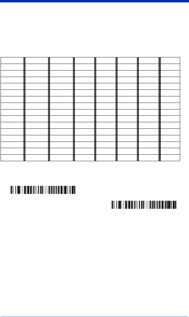
6 - 8 IMAGETEAM™ 2020/5620 System Manual
Full ASCII
If Full ASCII Code 39 decoding is enabled, certain character pairs within the bar
code symbol will be interpreted as a single character. For example: $V will be
decoded as the ASCII character SYN, and /C will be decoded as the ASCII
character #.
Default = On
.
Character pairs /M and /N decode as a minus sign and period respectively.
Character pairs /P through /Y decode as 0 through 9.
NUL %U DLE $P
SP SPACE
00@%VPP‘%Wp+P
SOH $A DC1 $Q !/A 11AAQQa+Aq+Q
STX $B DC2 $R “/B 22BBRRb+Br+R
ETX $C DC3 $S #/C 33CCSSc+Cs+S
EOT $D DC4 $T $/D 44DDTTd+Dt+T
ENQ $E NAK $U %/E 55EEUUe+Eu+U
ACK $F SYN $V &/F 66FFVVf+Fv+V
BEL $G ETB $W ‘/G77GGWWg+Gw+W
BS $H CAN $X (/H 88HHXXh+Hx+X
HT $I EM $Y )/I 99IIYYi+Iy+Y
LF $J SUB $Z */J :/ZJJZZj+Jz+Z
VT $K ESC %A +/K ;%FKK[%Kk+K{%P
FF $L FS %B ,/L <%GLL\%Ll+L|%Q
CR $M GS %C -- =%HMM]%Mm+M}%R
SO $N RS %D .. >%INN^%Nn+N~%S
SI $O US %E //O?%JOO_%Oo+ODEL %T
Full ASCII Off
* Full ASCII On

IMAGETEAM™ 2020/5620 System Manual 6 - 9
Code 39 Code Page
Code pages define the mapping of character codes to characters. If the data
received does not display with the proper characters, it may be because the bar
code being scanned was created using a code page that is different from the one
the host program is expecting. If this is the case, scan the bar code below, select
the code page with which the bar codes were created from the chart, Code Page
Mapping of Printed Bar Codes on page A-4, and scan the value and the SAVE
bar code from the Programming Chart inside the back cover of this manual. The
data characters should then appear properly.
Interleaved 2 of 5
< Default All Interleaved 2 of 5 Settings >
Interleaved 2 of 5
Check Digit
No Check Digit indicates that the scanner reads and transmits bar code data
with or without a check digit.
Code 39 Code Page
* On
Off

6 - 10 IMAGETEAM™ 2020/5620 System Manual
When Check Digit is set to Validate, but Don’t Transmit, the unit only reads
Interleaved 2 of 5 bar codes printed with a check digit, but will not transmit the
check digit with the scanned data.
When Check Digit is set to Validate and Transmit, the scanner only reads
Interleaved 2 of 5 bar codes printed with a check digit, and will transmit this digit
at the end of the scanned data.
Default = No Check Digit.
Interleaved 2 of 5 Message Length
Scan the bar codes below to change the message length. Refer to Message
Length on page 6-2 for additional information. Minimum and Maximum
lengths = 2-80. Minimum Default = 4, Maximum Default = 80.
Validate, but Don’t Transmit
* No Check Digit
Validate and Transmit
Minimum Message Length
Maximum Message Length

IMAGETEAM™ 2020/5620 System Manual 6 - 11
Code 93
< Default All Code 93 Settings >
Code 93
Code 93 Message Length
Scan the bar codes below to change the message length. Refer to Message
Length on page 6-2 for additional information. Minimum and Maximum
lengths = 0-80. Minimum Default = 0, Maximum Default = 80.
Code 93 Code Page
Code pages define the mapping of character codes to characters. If the data
received does not display with the proper characters, it may be because the bar
code being scanned was created using a code page that is different from the one
the host program is expecting. If this is the case, scan the bar code below, select
the code page with which the bar codes were created from the chart, Code Page
Mapping of Printed Bar Codes on page A-4, and scan the value and the SAVE
bar code from the Programming Chart inside the back cover of this manual. The
data characters should then appear properly.
* On
Off
Minimum Message Length
Maximum Message Length
Code 93 Code Page

6 - 12 IMAGETEAM™ 2020/5620 System Manual
Code 2 of 5
<Default All Code 2 of 5 Settings>
Code 2 of 5
Code 2 of 5 Message Length
Scan the bar codes below to change the message length. Refer to Message
Length on page 6-2 for additional information. Minimum and Maximum
lengths = 1-48. Minimum Default = 4, Maximum Default = 48.
IATA Code 2 of 5
<Default All Code IATA 2 of 5 Settings>
On
* Off
Minimum Message Length
Maximum Message Length
IMAGETEAM™ 2020/5620 System Manual 6 - 13
IATA Code 2 of 5, continued
IATA Code 2 of 5 Message Length
Scan the bar codes below to change the message length. Refer to Message
Length on page 6-2 for additional information. Minimum and Maximum
lengths = 1-48. Minimum Default = 4, Maximum Default = 48.
Matrix 2 of 5
<Default All Matrix 2 of 5 Settings>
Matrix 2 of 5
On
* Off
Minimum Message Length
Maximum Message Length
On
* Off
6 - 14 IMAGETEAM™ 2020/5620 System Manual
Matrix 2 of 5 Message Length
Scan the bar codes below to change the message length. Refer to Message
Length on page 6-2 for additional information. Minimum and Maximum
lengths = 1-80. Minimum Default = 4, Maximum Default = 80.
Code 11
<Default All Code 11 Settings>
Code 11
Check Digits Required
This option sets whether 1 or 2 check digits are required with Code 11 bar codes.
Default = Two Check Digits.
Minimum Message Length
Maximum Message Length
On
* Off
One Check Digit
* Two Check Digits

IMAGETEAM™ 2020/5620 System Manual 6 - 15
Code 11, continued
Code 11 Message Length
Scan the bar codes below to change the message length. Refer to Message
Length on page 6-2 for additional information. Minimum and Maximum
lengths = 1-80. Minimum Default = 4, Maximum Default = 80.
Code 128
<Default All Code 128 Settings>
Code 128
Minimum Message Length
Maximum Message Length
* On
Off

6 - 16 IMAGETEAM™ 2020/5620 System Manual
Code 128, continued
ISBT 128 Concatenation
In 1994 the International Society of Blood Transfusion (ISBT) ratified a standard
for communicating critical blood information in a uniform manner. The use of
ISBT formats requires a paid license. The ISBT 128 Application Specification
describes 1) the critical data elements for labeling blood products, 2) the current
recommendation to use Code 128 due to its high degree of security and its
space-efficient design, 3) a variation of Code 128 that supports concatenation of
neighboring symbols, and 4) the standard layout for bar codes on a blood product
label. Use the bar codes below to turn concatenation on or off.
Default =Off.
Code 128 Message Length
Scan the bar codes below to change the message length. Refer to Message
Length on page 6-2 for additional information. Minimum and Maximum
lengths = 0-80. Minimum Default = 0, Maximum Default = 80.
Code 128 Code Page
Code pages define the mapping of character codes to characters. If the data
received does not display with the proper characters, it may be because the bar
code being scanned was created using a code page that is different from the one
the host program is expecting. If this is the case, scan the bar code below, select
the code page with which the bar codes were created from the chart, Code Page
Mapping of Printed Bar Codes on page A-4, and scan the value and the SAVE
bar code from the Programming Chart inside the back cover of this manual. The
data characters should then appear properly.
* Off
On
Minimum Message Length
Maximum Message Length
Code 128 Code Page
IMAGETEAM™ 2020/5620 System Manual 6 - 17
Code 128 Function Code Transmit
By default, Code 128 function codes are not transmitted with Code 128 bar code
data. However, if you wish to transmit Code 128 function codes with the bar code
data, scan the Function Codes On bar code, below.
Telepen
<Default All Telepen Settings>
Telepen
Telepen Output
Using AIM Telepen Output, the scanner reads symbols with start/stop pattern 1
and decodes them as standard full ASCII (start/stop pattern 1). When Original
Telepen Output is selected, the scanner reads symbols with start/stop pattern 1
and decodes them as compressed numeric with optional full ASCII (start/stop
pattern 2).
Default = AIM Telepen Output.
* Function Codes Off
Function Codes On
On
* Off
Original Telepen Output
* AIM Telepen Output
6 - 18 IMAGETEAM™ 2020/5620 System Manual
Telepen Message Length
Scan the bar codes below to change the message length. Refer to Message
Length on page 6-2 for additional information. Minimum and Maximum
lengths = 1-60. Minimum Default = 1, Maximum Default = 60.
UPC A
<Default All UPC A Settings>
UPC A
UPC A Check Digit
This selection allows you to specify whether the check digit should be transmitted
at the end of the scanned data or not. Default = On.
Minimum Message Length
Maximum Message Length
* On
Off
* On
Off

IMAGETEAM™ 2020/5620 System Manual 6 - 19
UPC A Number System
The numeric system digit of a U.P.C. symbol is normally transmitted at the
beginning of the scanned data, but the unit can be programmed so it will not
transmit it.
Default = On.
UPC A Addenda
This selection adds 2 or 5 digits to the end of all scanned UPC A data.
Default = Off for both 2 Digit and 5 Digit Addenda.
UPC A Addenda Required
When Addenda Required is set to on, the scanner will only read UPC A bar
codes that have addenda.
Default = Not Required.
Off
* On
* 5 Digit Addenda Off
5 Digit Addenda On
* 2 Digit Addenda Off
2 Digit Addenda On
* Not Required
Required

6 - 20 IMAGETEAM™ 2020/5620 System Manual
UPC A Addenda Separator
When this feature is on, there is a space between the data from the bar code and
the data from the addenda. When turned off, there is no space.
Default = On.
UPC-A/EAN-13 with Extended Coupon Code
Use the following codes to enable or disable UPC-A and EAN-13 with Extended
Coupon Code.
Default = On.
UPC E
<Default All UPC E Settings>
Off
* On
* On
Off

IMAGETEAM™ 2020/5620 System Manual 6 - 21
UPC E0 and UPC E1
Most U.P.C. bar codes lead with the 0 number system. For these codes, use the
UPC E0 selection. If you need to read codes that lead with the 1 number system,
use the UPC E1 selection.
Default = On (UPC E0) and Off (UPC E1).
UPC E0 and UPC E1 Expand
UPC E Expand expands the UPC E code to the 12 digit, UPC A format.
Default = Off.
UPC E0 and UPC E1 Addenda Required
When Addenda Required is set to on, the scanner will only read UPC E bar
codes that have addenda.
Default = Not Required.
* UPC E0 On
UPC E0 Off
* UPC E1 On
UPC E1 Off
* Off
On
* Not Required
Required
6 - 22 IMAGETEAM™ 2020/5620 System Manual
UPC E0 and UPC E1 Addenda Separator
When this feature is on, there is a space between the data from the bar code and
the data from the addenda. When turned off, there is no space.
Default = On.
UPC E0 Check Digit
Check Digit specifies whether the check digit should be transmitted at the end of
the scanned data or not.
Default = On.
UPC E0 Number System
The numeric system digit of a U.P.C. symbol is normally transmitted at the
beginning of the scanned data, but the unit can be programmed so it will not
transmit it.
Default = On.
Off
* On
Off
* On
Off
* On

IMAGETEAM™ 2020/5620 System Manual 6 - 23
UPC E0 Addenda
This selection adds 2 or 5 digits to the end of all scanned UPC E data.
Default = Off for both 2 Digit and 5 Digit Addenda.
EAN/JAN 13
<Default All EAN/JAN Settings>
EAN/JAN 13
EAN/JAN 13 Check Digit
This selection allows you to specify whether the check digit should be transmitted
at the end of the scanned data or not.
Default = On.
* 5 Digit Addenda Off
5 Digit Addenda On
* 2 Digit Addenda Off
2 Digit Addenda On
* On
Off
Off
* On

6 - 24 IMAGETEAM™ 2020/5620 System Manual
EAN/JAN 13 Addenda
This selection adds 2 or 5 digits to the end of all scanned EAN/JAN 13 data.
Default = Off for both 2 Digit and 5 Digit Addenda.
EAN/JAN 13 Addenda Required
When Addenda Required is set to on, the scanner will only read EAN/JAN 13 bar
codes that have addenda.
Default = Not Required.
EAN/JAN 13 Addenda Separator
When this feature is on, there is a space between the data from the bar code and
the data from the addenda. When turned off, there is no space.
Default = On.
Note: If you want to enable or disable EAN13 with Extended Coupon Code,
refer to UPC-A/EAN-13 with Extended Coupon Code on page 6-20.
* 5 Digit Addenda Off
5 Digit Addenda On
* 2 Digit Addenda Off
2 Digit Addenda On
* Not Required
Required
Off
* On
IMAGETEAM™ 2020/5620 System Manual 6 - 25
ISBN Translate
This selection causes EAN-13 Bookland symbols to be translated into their
equivalent ISBN number format.
Default = Off.
EAN/JAN 8
<Default All EAN/JAN 8 Settings>
EAN/JAN 8
EAN/JAN 8 Check Digit
This selection allows you to specify whether the check digit should be transmitted
at the end of the scanned data or not.
Default = On.
* Off
On
* On
Off
Off
* On

6 - 26 IMAGETEAM™ 2020/5620 System Manual
EAN/JAN 8 Addenda
This selection adds 2 or 5 digits to the end of all scanned EAN/JAN 8 data.
Default = Off for both 2 Digit and 5 Digit Addenda.
EAN/JAN 8 Addenda Required
When Addenda Required is set to on, the scanner will only read EAN/JAN 8 bar
codes that have addenda.
Default = Not Required.
EAN/JAN 8 Addenda Separator
When this feature is on, there is a space between the data from the bar code and
the data from the addenda. When turned off, there is no space.
Default = On.
* 5 Digit Addenda Off
5 Digit Addenda On
* 2 Digit Addenda Off
2 Digit Addenda On
* Not Required
Required
Off
* On

IMAGETEAM™ 2020/5620 System Manual 6 - 27
MSI
<Default All MSI Settings>
MSI
MSI Check Character
Different types of check characters are used with MSI bar codes. You can
program the scanner to read MSI bar codes with Type 10 check characters.
Default = Validate Type 10, but Don’t Transmit.
When Check Character is set to
Validate and Transmit
, the scanner will only
read MSI bar codes printed with the specified type check character, and will
transmit this character at the end of the scanned data.
When Check Character is set to
Validate, but Don’t Transmit
, the unit will only
read MSI bar codes printed with the specified type check character, but will not
transmit the check character with the scanned data.
On
* Off
Validate Type 10 and Transmit
* Validate Type 10, but Don’t
Transmit
6 - 28 IMAGETEAM™ 2020/5620 System Manual
MSI Message Length
Scan the bar codes below to change the message length. Refer to Message
Length on page 6-2 for additional information. Minimum and Maximum
lengths = 4-48. Minimum Default = 4, Maximum Default = 48.
Plessey Code
<Default All Plessey Code Settings>
Plessey Code
Plessey Message Length
Scan the bar codes below to change the message length. Refer to Message
Length on page 6-2 for additional information. Minimum and Maximum
lengths = 4-48. Minimum Default = 4, Maximum Default = 48.
Minimum Message Length
Maximum Message Length
On
* Off
Minimum Message Length
Maximum Message Length

6 - 30 IMAGETEAM™ 2020/5620 System Manual
RSS Expanded
< Default All RSS Expanded Settings >
RSS Expanded
RSS Expanded Message Length
Scan the bar codes below to change the message length. Refer to Message
Length on page 6-2 for additional information. Minimum and Maximum
lengths = 4-74. Minimum Default = 4, Maximum Default = 74.
EAN•UCC Emulation
The imager can automatically format the output from any EAN•UCC data carrier
to emulate what would be encoded in an equivalent UCC/EAN-128 or
RSS+Composite symbol. EAN•UCC data carriers include UPC-A and UPC-E,
EAN-13 and EAN-8, ITF-14, UCC/EAN-128, and EAN•UCC RSS and
Composites. If UCC/EAN-128 Emulation is selected, the AIM Symbology
* On
Off
Minimum Message Length
Maximum Message Length
IMAGETEAM™ 2020/5620 System Manual 6 - 31
Identifier will be reported as “]C1”. If RSS Emulation is selected, the AIM
Symbology Identifier will be reported as “]e0.” Any application that accepts
EAN•UCC data can be simplified since it only needs to recognize one data carrier
type.
Default = EAN•UCC Emulation Off
.
China Post Code
<Default All China Post Code Settings>
China Post Code
China Post Message Length
Scan the bar codes below to change the message length. Refer to Message
Length on page 6-2 for additional information. Minimum and Maximum
lengths = 2-80. Minimum Default = 4, Maximum Default = 80.
RSS Emulation
128 Emulation
* EAN•UCC Emulation Off
On
* Off
Minimum Message Length
Maximum Message Length

6 - 32 IMAGETEAM™ 2020/5620 System Manual
Korea Post Code
<Default All Korea Post Code Settings>
Korea Post Code
Korea Post Message Length
Scan the bar codes below to change the message length. Refer to Message
Length on page 6-2 for additional information. Minimum and Maximum
lengths = 2-80. Minimum Default = 4, Maximum Default = 48.
PosiCode
<Default All PosiCode Settings>
On
* Off
Minimum Message Length
Maximum Message Length

IMAGETEAM™ 2020/5620 System Manual 6 - 33
PosiCode A and B
You have to have PosiCode A and B on to read any of the PosiCode
symbologies.
PosiCode Message Length
Scan the bar codes below to change the message length. Refer to Message
Length on page 6-2 for additional information. Minimum and Maximum
lengths = 2-80. Minimum Default = 4, Maximum Default = 48.
* On
Off
A and B On
(No Limited)
A and B and Limited A On
(Limited B Off)
* A and B and Limited B On
(Limited A Off)
Minimum Message Length
Maximum Message Length

6 - 34 IMAGETEAM™ 2020/5620 System Manual
Trioptic Code
Trioptic Code is used for labeling magnetic storage media.
Note: If you are going to scan Code 32 Pharmaceutical codes, Trioptic Code
must be off.
Codablock F
<Default All Codablock F Settings>
Codablock F
Codablock F Message Length
Scan the bar codes below to change the message length. Refer to Message
Length on page 6-2 for additional information. Minimum and Maximum
lengths = 1-2048. Minimum Default = 1, Maximum Default = 2048.
On
* Off
On
* Off
Minimum Message Length
Maximum Message Length

IMAGETEAM™ 2020/5620 System Manual 6 - 35
Code 16K
<Default All Code 16K Settings>
Code 16K
Code 16K Message Length
Scan the bar codes below to change the message length. Refer to Message
Length on page 6-2 for additional information. Minimum and Maximum
lengths = 0-160. Minimum Default = 1, Maximum Default = 160.
Code 49
<Default All Code 49 Settings>
On
* Off
Minimum Message Length
Maximum Message Length

6 - 36 IMAGETEAM™ 2020/5620 System Manual
Code 49
Code 49 Message Length
Scan the bar codes below to change the message length. Refer to Message
Length on page 6-2 for additional information. Minimum and Maximum
lengths = 1-81. Minimum Default = 1, Maximum Default = 81.
* On
Off
Minimum Message Length
Maximum Message Length

IMAGETEAM™ 2020/5620 System Manual 7 - 1
7
Interface Keys
Keyboard Function Relationships
The following Keyboard Function Code, Hex/ASCII Value, and Full ASCII
“CTRL”+ relationships apply to all terminals that can be used with the scanner.
Refer to page 2-6 enable Control + ASCII mode.
Function Code HEX/ASCII Value Full ASCII “CTRL” +
NUL 00 2
SOH 01 A
STX 02 B
ETX 03 C
EOT 04 D
ENQ 05 E
ACK 06 F
BEL 07 G
BS 08 H
HT 09 I
LF 0A J
VT 0B K
FF 0C L
CR 0D M
SO 0E N
SI 0F O
DLE 10 P
DC1 11 Q
DC2 12 R
DC3 13 S
DC4 14 T
NAK 15 U
SYN 16 V
ETB 17 W
CAN 18 X
EM 19 Y
SUB 1A Z
ESC 1B [
FS 1C \
GS 1D ]
RS 1E 6
US 1F -

7 - 2 IMAGETEAM™ 2020/5620 System Manual
The last five characters in the Full ASCII “CTRL”+ column ( [ \ ] 6 - ), apply to US
only. The following chart indicates the equivalents of these five characters for
different countries.
Country Codes
United States [ \ ] 6 -
Belgium [ < ] 6 -
Scandinavia 8 < 9 6 -
France ^ 8 $ 6 =
Germany à + 6 -
Italy \ + 6 -
Switzerland <. . 6 -
United Kingdom [ ¢ ] 6 -
Denmark 8 \ 9 6 -
Norway 8 \ 9 6 -
Spain [ \ ] 6 -

IMAGETEAM™ 2020/5620 System Manual 7 - 3
Supported Interface Keys
ASCII HEX
IBM AT/XT and
PS/2 Compatibles,
WYSE PC/AT
Supported Keys
IBM XTs and
Compatibles
Supported Keys
IBM, DDC, Memorex
Telex, Harris*
Supported Keys
NUL 00 Reserved Reserved Reserved
SOH 01 Enter (KP) CR/Enter Enter
STX 02 Cap Lock Caps Lock F11
ETX 03 ALT make Reserved F12
EOT 04 ALT break Reserved F13
ENQ 05 CTRL make Reserved F14
ACK 06 CTRL break Reserved F15
BEL 07 CR/Enter CR/Enter New Line
BS 08 Reserved Reserved F16
HT 09 Tab Tab F17
LF 0A Reserved Reserved F18
VT 0B Tab Tab Tab/Field Forward
FF 0C Delete Delete Delete
CR 0D CR/Enter CR/Enter Field Exit/New Line
SO 0E Insert Insert Insert
SI 0F Escape Escape F19
DLE 10 F11 Reserved Error Reset
DC1 11 Home Home Home
DC2 12 Print Print F20
DC3 13 Back Space Back Space Back Space
DC4 14 Back Tab Back Tab Backfield/Back Tab
NAK 15 F12 Reserved F21
SYN 16 F1 F1 F1
ETB 17 F2 F2 F2
CAN 18 F3 F3 F3
EM 19 F4 F4 F4
SUB 1A F5 F5 F5
ESC 1B F6 F6 F6
FS 1C F7 F7 F7
GS 1D F8 F8 F8
RS 1E F9 F9 F9
US 1F F10 F10 F10
* IBM 3191/92, 3471/72, 3196/97, 3476/77, Telex (all models)

7 - 4 IMAGETEAM™ 2020/5620 System Manual
Supported Interface Keys
ASCII HEX IBM, Memorex Telex (102)*
Supported Keys Memorex Telex (88)**
Supported Keys
NUL 00 Reserved Reserved
SOH 01 Enter Enter
STX 02 F11 PF10
ETX 03 F12 PF11
EOT 04 F13 PF12
ENQ 05 F14 Reserved
ACK 06 F15 Reserved
BEL 07 New Line New Line
BS 08 F16 Field Forward
HT 09 F17 Field Forward
LF 0A F18 Reserved
VT 0B Tab/Field Forward Field Forward
FF 0C Delete Delete
CR 0D Field Exit New Line
SO 0E Insert Insert
SI 0F Clear Erase
DLE 10 Error Reset Error Reset
DC1 11 Home Reserved
DC2 12 Print Print
DC3 13 Back Space Back Space
DC4 14 Back Tab Back Field
NAK 15 F19 Reserved
SYN 16 F1 PF1
ETB 17 F2 PF2
CAN 18 F3 PF3
EM 19 F4 PF4
SUB 1A F5 PF5
ESC 1B F6 PF6
FS 1C F7 PF7
GS 1D F8 PF8
RS 1E F9 PF9
US 1F F10 Home
* IBM 3196/97, 3476/77, 3191/92, 3471/72, Memorex Telex (all models) with 102
key keyboards
** Memorex Telex with 88 key keyboards

IMAGETEAM™ 2020/5620 System Manual 7 - 5
Supported Interface Keys
ASCII HEX
Esprit 200, 400
ANSI
Supported Keys
Esprit 200, 400
ASCII
Supported Keys
Esprit 200, 400
PC
Supported Keys
NUL 00 Reserved Reserved Reserved
SOH 01 New Line New Line New Line
STX 02 N/A N/A N/A
ETX 03 N/A N/A N/A
EOT 04 N/A N/A N/A
ENQ 05 N/A N/A N/A
ACK 06 N/A N/A N/A
BEL 07 New Line New Line New Line
BS 08 N/A N/A N/A
HT 09 Tab Tab Tab
LF 0A N/A N/A N/A
VT 0B Tab Tab Tab
FF 0C N/A N/A Delete
CR 0D New Line New Line New Line
SO 0E N/A N/A Insert
SI 0F Escape Escape Escape
DLE 10 F11 F11 F11
DC1 11 Insert Insert Home
DC2 12 F13 F13 Print
DC3 13 Back Space Back Space Back Space
DC4 14 Back Tab Back Tab Back Tab
NAK 15 F12 F12 F12
SYN 16 F1 F1 F1
ETB 17 F2 F2 F2
CAN 18 F3 F3 F3
EM 19 F4 F4 F4
SUB 1A F5 F5 F5
ESC 1B F6 F6 F6
FS 1C F7 F7 F7
GS 1D F8 F8 F8
RS 1E F9 F9 F9
US 1F F10 F10 F10

7 - 6 IMAGETEAM™ 2020/5620 System Manual
Supported Interface Keys
ASCII HEX
Apple Mac/iMac
Supported Keys
NUL 00 Reserved
SOH 01 Enter/Numpad Enter
STX 02 CAPS
ETX 03 ALT make
EOT 04 ALT break
ENQ 05 CNTRL make
ACK 06 CNTRL break
BEL 07 RETURN
BS 08 APPLE make
HT 09 TAB
LF 0A APPLE break
VT 0B TAB
FF 0C Del
CR 0D RETURN
SO 0E Ins Help
SI 0F ESC
DLE 10 F11
DC1 11 Home
DC2 12 Prnt Scrn
DC3 13 BACKSPACE
DC4 14 LSHIFT TAB
NAK 15 F12
SYN 16 F1
ETB 17 F2
CAN 18 F3
EM 19 F4
SUB 1A F5
ESC 1B F6
FS 1C F7
GS 1D F8
RS 1E F9
US 1F F10
DEL 7F BACKSPACE

IMAGETEAM™ 2020/5620 System Manual 8 - 1
8
Utilities
To Add a Test Code I.D. Prefix to All Symbologies
This selection allows you to turn on transmission of a Code I.D. before the
decoded symbology. (See the Symbology Chart, included in the Appendix
A, page A-1) for the single character code that identifies each symbology.) This
action first clears all current prefixes, then programs a Code I.D. prefix for all
symbologies. This is a temporary setting that will be removed when the unit is
reset. For instructions on how to reset your scanner, refer to Reset Scanner
(page 8-1).
Reset Scanner
Scanning the following bar code clears temporary settings in the scanner and
returns scanner to normal operation. Scanning this bar code also causes the
scanner to re-link the radio.
Show Software Revision
Scan the bar code below to output the current software revision, unit serial
number, and other product information for both the scanner and base.
Show Data Format
Scan the bar code below to show current data format settings.
Add Code I.D. Prefix to
All Symbologies (Temporary)
Reset Scanner
Show Revision
Data Format Settings

8 - 2 IMAGETEAM™ 2020/5620 System Manual
Resetting the Standard Product Defaults
If you aren’t sure what programming options are in your scanner, or you’ve
changed some options and want the standard product default settings restored,
scan the
Standard Product Default Settings
bar code below.
The Menu Commands starting on page 10-5 lists the standard product default
settings for each of the commands (indicated by an asterisk (*) on the
programming pages).
Temporary Visual Menu 2003 Configuration
For quick download communication configuration, scan the Visual Menu 2003
bar code to temporarily configure the scanner for Visual Menu 2003 settings.
Refer to Visual Menu 2003 on page 10-1 for additional information about Visual
Menu 2003. After using Visual Menu, scan the Reset Scanner bar code on page
8-1.
Note: If you have a unit capable of keyboard wedge mode, scan the bar code
below and the unit will communicate in RS-232 mode, allowing it to work
with Visual Menu 2003. To convert the scanner back to keyboard wedge
communication, cycle the power.
Note: If you download new software into a unit, the user-programmed
parameters are retained. If you need to discard user-programmed
settings, scan the Standard Product Default Settings bar code (see
Standard Product Default Settings on page 8-2).
Standard Product Default Settings
Visual Menu 2003

IMAGETEAM™ 2020/5620 User’s Guide 9 - 1
9
Visual Menu 2003
Visual Menu 2003 Introduction
Visual Menu 2003 provides the ability to configure a scanning device by
connecting the scanner to the com port of a PC. Visual Menu 2003 allows you
to download upgrades to a scanner’s firmware, change programmed
parameters, and create and print programming bar codes. Using Visual Menu
2003, you can even set up the configuration for a scanner which is not attached
to your PC. This enables one expert user to establish the configuration settings
for all the devices your company uses, then save these configuration files for
others. A configuration file can be e-mailed or, if you prefer, an expert user can
create a bar code (or series of bar codes) that contains all the customized
programming parameters, and mail or fax the bar code(s) to any location. Users
in other locations can scan the bar code(s) to load in the customized parameters.
To communicate with a scanner, Visual Menu 2003 requires that the PC have at
least one available serial communication port and an RS-232 cable to connect
the port to the device. A power supply, which plugs into the cable, is also
required.
Note: IT5620/IT2020 works only with Visual Menu 2003 version 4.2 or later.
Visual Menu 2003 Operations
The Visual Menu 2003 program performs the following operations:
• Displays all configuration data, and saves the information to a file on your
PC.
• Configures the device to meet your specific requirements. Visual Menu
2003 has all the programming parameters which are available via
programming bar codes in this User’s Guide.
• Creates and prints a clone bar code which contains the program and
configuration data from one device. This bar code can then be used to
program additional devices with the same parameters.
• Selects a device from a list, then performs offline or online file
configuration for that device.
Installing Visual Menu 2003 from the Web
1. Access the HHP web site at www.hhp.com.
2. Click in the Quick Search text box and enter Visual Menu 2003.
3. Click on Search Now.
4. Click on the entry for Visual Menu 2003.

9 - 2 IMAGETEAM™ 2020/5620 User’s Guide
5. When prompted, select Save File, and save the files to the
c:\windows\temp directory.
6. Once you have finished downloading the file, exit the web site.
7. Using Explorer, go to the c:\windows\temp file.
8. Double click on the Visual Menu 2003.exe file. Follow the screen prompts
to install the Visual Menu 2003 program.
9. To start Visual Menu 2003, from the Start Menu click on Programs, Visual
Menu 2003, Visual Menu 2003.
Note: If you wish, you can create a shortcut to the Visual Menu 2003 executable
on your desktop.

IMAGETEAM™ 2020/5620 System Manual 10 - 1
10
Serial Programming Commands
The serial programming commands can be used in place of the programming bar
codes. Both the serial commands and the programming bar codes will program
the IT2020-5. For complete descriptions and examples of each serial
programming command, refer to the corresponding programming bar code in
this manual.
The device must be set to an RS-232 interface (see page 1-15). The following
commands can be sent via a PC com port using terminal emulation software.
Conventions
The following conventions are used for menu and query command descriptions:
parameter
A label representing the actual value you should send as part of a
command.
[
option
] An optional part of a command.
{Data} Alternatives in a command.
bold Names of menus, menu commands, buttons, dialog boxes, and
windows that appear on the screen.
Menu Command Syntax
Menu commands have the following syntax (spaces have been used for clarity
only):
Prefix [:Name:] Tag SubTag {Data} [, SubTag {Data}] [; Tag SubTag {Data}] […]
Storage
Prefix Three ASCII characters: SYN M CR (ASCII 22,77,13).
:NAME: To send information to the scanner (with the base connected to
host): SYN M CR :NAME:
Tag A 3 character case-insensitive field that identifies the desired menu
command group. For example, all RS-232 configuration settings
are identified with a Tag of 232.
SubTag A 3 character case-insensitive field that identifies the desired menu
command within the tag group. For example, the SubTag for the
RS-232 baud rate is BAD.
Data The new value for a menu setting, identified by the Tag and Sub-
Tag.

10 - 2 IMAGETEAM™ 2020/5620 System Manual
Storage A single character that specifies the storage table to which the
command is applied. An exclamation point (!) performs the com-
mand’s operation on the device’s volatile menu configuration table.
A period (.) performs the command’s operation on the device’s
non-volatile menu configuration table. Use the non-volatile table
only for semi-permanent changes you want saved through a power
cycle.
Query Commands
Several special characters can be used to query the device about its settings.
^What is the default value for the setting(s).
?What is the device’s current value for the setting(s).
*What is the range of possible values for the setting(s). (The de-
vice’s response uses a dash (-) to indicate a continuous range of
values. A pipe (|) separates items in a list of non-continuous val-
ues.)
Tag Field Usage
When a query is used in place of a Tag field, the query applies to the
entire
set
of commands available for the particular storage table indicated by the Storage
field of the command. In this case, the SubTag and Data fields should not be
used because they are ignored by the device.
SubTag Field Usage
When a query is used in place of a SubTag field, the query applies only to the
subset of commands available that match the Tag field. In this case, the Data
field should not be used because it is ignored by the device.
Data Field Usage
When a query is used in place of the Data field, the query applies only to the
specific command identified by the Tag and SubTag fields.
Concatenation of Multiple Commands
Multiple commands can be issued within one Prefix/Storage sequence. Only the
Tag, SubTag, and Data fields must be repeated for each command in the
sequence. If additional commands are to be applied to the same Tag, then the
new command sequence is separated with a comma (,) and only the SubTag and
Data fields of the additional command are issued. If the additional command
requires a different Tag field, the command is separated from previous
commands by a semicolon (;).
Responses
The device responds to serial commands with one of three responses:

IMAGETEAM™ 2020/5620 System Manual 10 - 3
ACK Indicates a good command which has been processed.
ENQ Indicates an invalid Tag or SubTag command.
NAK Indicates the command was good, but the Data field entry was out of the
allowable range for this Tag and SubTag combination, e.g., an entry for a
minimum message length of 100 when the field will only accept 2
characters.
When responding, the device echoes back the command sequence with the
status character inserted directly before each of the punctuation marks (the
period, exclamation point, comma, or semicolon) in the command.
Examples of Query Commands
In the following examples, a bracketed notation [ ] depicts a non-displayable
response.
Example #1:What is the range of possible values for Codabar Coding Enable?
Enter: cbrena*.
Response: CBRENA0-1[ACK]
This response indicates that Codabar Coding Enable (CBRENA) has a range of
values from 0 to 1 (off and on).
Example #2: What is the default value for Codabar Coding Enable?
Enter: cbrena^.
Response: CBRENA1[ACK]
This response indicates that the default setting for Codabar Coding Enable
(CBRENA) is 1, or on.
Example #3: What is the device’s current setting for Codabar Coding Enable?
Enter: cbrena?.
Response: CBRENA1[ACK]
This response indicates that the device’s Codabar Coding Enable (CBRENA) is
set to 1, or on.

10 - 4 IMAGETEAM™ 2020/5620 System Manual
Example #4: What are the device’s settings for all Codabar selections?
Enter: cbr?.
Response: CBRENA1[ACK],
SSX0[ACK],
CK20[ACK],
CCT1[ACK],
MIN2[ACK],
MAX60[ACK],
DFT[ACK].
This response indicates that the device’s Codabar Coding Enable (CBRENA) is
set to 1, or on;
the Start/Stop Character (SSX) is set to 0, or Don’t Transmit;
the Check Character (CK2) is set to 0, or Not Required;
concatenation (CCT) is set to 1, or Enabled;
the Minimum Message Length (MIN) is set to 2 characters;
the Maximum Message Length (MAX) is set to 60 characters;
and the Default setting (DFT) has no value.
Trigger Commands
You can activate and deactivate the scanner with serial trigger commands.
First, the scanner must be put in Manual/Serial Trigger Mode either by scanning
the Manual/Serial Trigger Mode bar code (page 3-4), or by sending the Manual/
Serial Menu Command (page 10-9). Once the scanner is in serial trigger mode,
the trigger is activated and deactivated by sending the following commands:
Activate:SYN T CR
Deactivate:SYN U CR
The scanner scans until a bar code has been read, until the deactivate com-
mand is sent, or until the serial time-out has been reached (see Read Time-Out
(Serial Trigger Mode) on page 3-4 for a description, and the serial command on
page 10-9).
Resetting the Standard Product Defaults
If you aren’t sure what programming options are in your scanner, or you’ve
changed some options and want the factory settings restored, scan the
Standard Product Default Settings
bar code below.
The chart on the following pages lists the factory default settings for each of the
menu commands (indicated by an asterisk (*) on the programming pages).
Standard Product Default Settings

IMAGETEAM™ 2020/5620 System Manual 10 - 5
Menu Commands
Selection Setting
* Indicates default
Serial
Command
# Indicates a
numeric entry
Page
Base Charge Mode
*Automatic BASCHG1 1-5
Full Charge Rate BASCHG2 1-5
Low Charge Rate BASCHG3 1-5
Battery Charge Off BASCHG4 1-5
Link Modes
Unlink Scanner BT_RMV 1-6
*Locked Link Mode BASCON0 1-7
Override Locked Scanner SCNREP 1-7
Open Link Mode BASCON1 1-7
Out-of-Range Alarm
Base Duration Alarm (Range 1
- 3000 sec (*0)) BASORD 1-8
Scanner Duration Alarm(
Range 1 - 3000 sec (*0))
BT_ORD 1-8
Alarm Sound Type Base Alarm Type BASORW 1-8
Scanner Alarm Type BT_ORW 1-8
Data Accumulation Mode On BATENA1 1-9
*Off BATENA0 1-9
Factory Default Settings Default DEFALT 1-14
Terminal Interfaces
Terminal ID 000 TERMID### 2-2
Program Keyboard Country
*USA KBDCTY0 2-4
Belgium KBDCTY1 2-4
Denmark KBDCTY8 2-4
Finland KBDCTY2 2-4
France KBDCTY3 2-4
Germany/Austria KBDCTY4 2-4
Great Britain KBDCTY7 2-4
Italy KBDCTY5 2-4
Norway KBDCTY9 2-4
Spain KBDCTY10 2-4
Switzerland KBDCTY6 2-4

10 - 6 IMAGETEAM™ 2020/5620 System Manual
Keyboard Style
*Regular KBDSTY0 2-5
Caps Lock KBDSTY1 2-5
Shift Lock KBDSTY2 2-5
Automatic Caps Lock KBDSTY6 2-5
Emulate External
Keyboard KBDSTY5 2-6
Keyboard Modifiers
*Control + ASCII Off KBDCAS0 2-6
Control + ASCII On KBDCAS1 2-6
*Turbo Mode Off KBDTMD0 2-6
Turbo Mode On KBDTMD1 2-6
*Numeric Keypad Off KBDNPS0 2-6
Numeric Keypad On KBDNPS1 2-6
*Auto Direct Conn. Off KBDADC0 2-7
Auto Direct Conn. On KBDADC1 2-7
Serial Port Connection RS-232 PAP232 2-8
Baud Rate
300 BPS 232BAD0 2-8
600 BPS 232BAD1 2-8
1200 BPS 232BAD2 2-8
2400 BPS 232BAD3 2-8
4800 BPS 232BAD4 2-8
9600 BPS 232BAD5 2-8
19200 BPS 232BAD6 2-8
*38400 BPS 232BAD7 2-8
57600 BPS 232BAD8 2-8
115200 BPS 232BAD9 2-8
Selection Setting
* Indicates default
Serial
Command
# Indicates a
numeric entry
Page

IMAGETEAM™ 2020/5620 System Manual 10 - 7
Word Length: Data Bits,
Stop Bits, and Parity
7 Data, 1 Stop, Parity Even 232WRD3 2-9
7 Data, 1 Stop, Parity None 232WRD0 2-9
7 Data, 1 Stop, Parity Odd 232WRD6 2-9
7 Data, 2 Stop, Parity Even 232WRD4 2-9
7 Data, 2 Stop, Parity None 232WRD1 2-9
7 Data, 2 Stop, Parity Odd 232WRD7 2-9
8 Data, 1 Stop, Parity Even 232WRD5 2-9
*8 Data, 1 Stop, Parity None 232WRD2 2-9
8 Data, 1 Stop, Parity Odd 232WRD8 2-9
RS-232 Handshaking
*RTS/CTS Off 232CTS0 2-10
RTS/CTS On 232CTS1 2-10
*XON/XOFF Off 232XON0 2-10
XON/XOFF On 232XON1 2-10
*ACK/NAK Off 232ACK0 2-10
ACK/NAK On 232ACK1 2-10
Wand Emulation Connec-
tion
Same Code Format TERMID64 2-13
Code 39 Format TERMID61 2-13
Wand Emulation Transmis-
sion Rate
10 WNDSPD0 2-14
*25 WNDSPD1 2-14
40 WNDSPD2 2-14
80 WNDSPD3 2-14
120 WNDSPD4 2-14
150 WNDSPD5 2-14
200 WNDSPD6 2-14
Wand Emulation Polarity *Black High WNDPOL0 2-14
White High WNDPOL1 2-14
Wand Emulation Idle Idle Low WNDIDL0 2-15
*Idle High WNDIDL1 2-15
Wand Emulation Data
Block Size
20 WNDBLK0 2-15
*40 WNDBLK1 2-15
60 WNDBLK2 2-15
80 WNDBLK3 2-15
Selection Setting
* Indicates default
Serial
Command
# Indicates a
numeric entry
Page

10 - 8 IMAGETEAM™ 2020/5620 System Manual
Wand Emulation Delay
Between Blocks
5ms WNDDLY0 2-15
*50ms WNDDLY1 2-15
150ms WNDDLY2 2-15
500ms WNDDLY3 2-15
Wand Emulation Overall
Checksum *Off WNDCHK0 2-16
On WNDCHK1 2-16
Output Selections
Beeper - Good Read Off BEPBEP0 3-1
*On BEPBEP1 3-1
Beeper Volume - Good
Read
Off BEPLVL0 3-1
Low BEPLVL1 3-1
*Medium BEPLVL2 3-1
High BEPLVL3 3-1
Beeper Pitch - Good Read
(Frequency)
Low (1600) (min 400Hz) BEPFQ11600 3-2
*Medium (3250) BEPFQ13250 3-2
High (4200) (max 9000Hz) BEPFQ14200 3-2
Beeper Duration - Good
Read
*Normal Beep BEPBIP0 3-2
Short Beep BEPBIP1 3-2
LED - Good Read Off BEPLED0 3-2
*On BEPLED1 3-2
Number of Beeps - Good
Read
*1 BEPRPT1 3-3
Range 1 - 9 BEPRPT# 3-3
Good Read Delay
*No Delay DLYGRD0 3-3
Short Delay (500 ms) DLYGRD500 3-3
Medium Delay (1000 ms) DLYGRD1000 3-3
Long Delay (1500 ms) DLYGRD1500 3-3
User-Specified Good Read
Delay Range 0 - 30,000 ms DLYGRD####
#3-3
Selection Setting
* Indicates default
Serial
Command
# Indicates a
numeric entry
Page

IMAGETEAM™ 2020/5620 System Manual 10 - 9
Trigger Mode
*Manual Trigger TRGMOD0 3-4
Read Time-Out (0 - 300,000
ms) *0 TRGSTO#### 3-4
Scanner Power Time-Out
Timer (1 - 10,800 seconds)
*3600
BT_LPT##### 3-5
Automatic Trigger TRGMOD1 3-5
Presentation Mode TRGMOD3 3-5
Hands Free Time-Out (0-
300,000 seconds) *5000
TRGPTO####
## 3-5
Reread Delay
Short (500 ms) DLYRRD500 3-6
*Medium (750 ms) DLYRRD750 3-6
Long (1000 ms) DLYRRD1000 3-6
Extra Long (2000 ms) DLYRRD3000 3-6
User-Specified Reread
Delay Range 0 - 30,000 ms DLYRRD####
#3-6
Centering
Centering On DECWIN1 3-7
*Centering Off DECWIN0 3-7
Left of Centering Window *40 DECLFT### 3-7
Right of Centering Window *60 DECRGT### 3-7
Output Sequence Editor Enter Sequence SEQBLK 3-9
Default Sequence SEQDFT 3-9
Require Output Sequence
Required SEQ_EN2 3-10
On/Not Required SEQ_EN1 3-10
*Off SEQ_EN0 3-10
Multiple Symbols On SHOTGN1 3-12
*Off SHOTGN0 3-12
No Read On SHWNRD1 3-12
*Off SHWNRD0 3-12
Video Reverse On VIDREV1 3-12
*Off VIDREV0 3-12
Prefix/Suffix Selections
Add CR Suffix to All Symbologies VSUFCR 4-3
Selection Setting
* Indicates default
Serial
Command
# Indicates a
numeric entry
Page
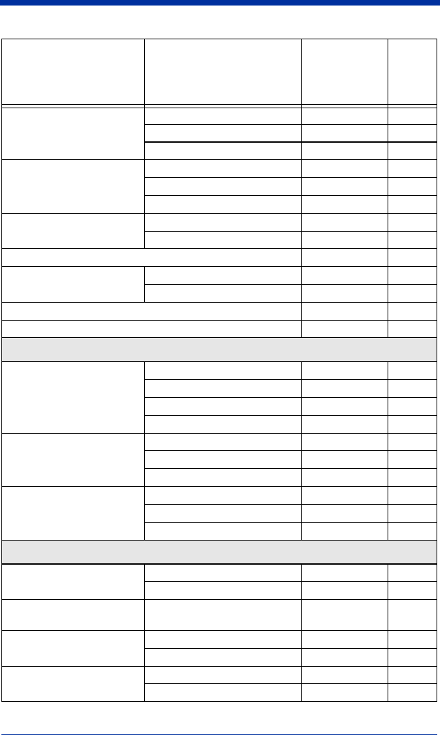
10 - 10 IMAGETEAM™ 2020/5620 System Manual
Prefix
Add Prefix PREBK2## 4-3
Clear One Prefix PRECL2 4-3
Clear All Prefixes PRECA2 4-3
Suffix
Add Suffix SUFBK2## 4-4
Clear One Suffix SUFCL2 4-4
Clear All Suffixes SUFCA2 4-4
Function Code Transmit *Enable RMVFNC0 4-4
Disable RMVFNC1 4-4
Intercharacter Delay DLYCHR## 4-5
User Specified Intercharac-
ter Delay
Delay Length DLYCRX## 4-5
Character to Trigger Delay DLY_XX### 4-5
Interfunction Delay DLYFNC## 4-6
Intermessage Delay DLYMSG## 4-6
Data Formatter Selections
Data Format Editor
*Default Data Format (None) DFMDF3 5-4
Enter Data Format DFMBK3## 5-4
Clear One Data Format DFMCL3 5-4
Clear All Data Formats DFMCA3 5-4
Data Formatter
Off DFM_EN0 5-5
*On, but Not Required DFM_EN1 5-5
On, Required DFM_EN2 5-5
Alternate Data Formats
1VSAF_15-5
2VSAF_25-5
3VSAF_35-5
Symbologies
All Symbologies All Symbologies Off ALLENA0 6-1
All Symbologies On ALLENA1 6-1
Codabar Default All Codabar
Settings CBRDFT 6-3
Codabar Off CBRENA0 6-3
*On CBRENA1 6-3
Codabar Start/Stop Char. *Don’t Transmit CBRSSX0 6-3
Transmit CBRSSX1 6-3
Selection Setting
* Indicates default
Serial
Command
# Indicates a
numeric entry
Page

IMAGETEAM™ 2020/5620 System Manual 10 - 11
Codabar Check Char.
*No Check Char. CBRCK20 6-4
Validate, But Don’t Transmit CBRCK21 6-4
Validate, and Transmit CBRCK22 6-4
Codabar Concatenation
Off CBRCCT0 6-4
*On CBRCCT1 6-4
Require CBRCCT2 6-4
Codabar Message Length Minimum (2 - 60) *4 CBRMIN## 6-5
Maximum (2 - 60) *60 CBRMAX## 6-5
Code 39 Default All Code 39
Settings C39DFT 6-5
Code 39 Off C39ENA0 6-5
*On C39ENA1 6-5
Code 39 Start/Stop Char. *Don’t Transmit C39SSX0 6-5
Transmit C39SSX1 6-5
Code 39 Check Char.
*No Check Char. C39CK20 6-6
Validate, But Don’t
Transmit C39CK21 6-6
Validate,
and Transmit C39CK22 6-6
Code 39 Message Length Minimum (0 - 48) *0 C39MIN## 6-6
Maximum (0 - 48) *48 C39MAX## 6-6
Code 39 Append *Off C39APP0 6-7
On C39APP1 6-7
Code 32 Pharmaceutical
(PARAF)
*Off C39B320 6-7
On C39B321 6-7
Code 39 Full ASCII Off C39ASC0 6-8
*On C39ASC1 6-8
Interleaved 2 of 5 Default All Interleaved
2 of 5 Settings I25DFT 6-9
Interleaved 2 of 5 Off I25ENA0 6-9
*On I25ENA1 6-9
Interleaved 2 of 5 Check
Digit
*No Check Char. I25CK20 6-10
Validate, But Don’t
Transmit I25CK21 6-10
Validate, and Transmit I25CK22 6-10
Selection Setting
* Indicates default
Serial
Command
# Indicates a
numeric entry
Page

10 - 12 IMAGETEAM™ 2020/5620 System Manual
Interleaved 2 of 5 Message
Length
Minimum (2 - 80) *4 I25MIN## 6-10
Maximum (2 - 80) *80 I25MAX## 6-10
Code 93 Default All Code 93
Settings C93DFT 6-11
Code 93 Off C93ENA0 6-11
*On C93ENA1 6-11
Code 93 Message Length Minimum (0 - 80) *0 C93MIN## 6-11
Maximum (0 - 80) *80 C93MAX## 6-11
Code 2 of 5 Default All Code 2 of 5
Settings R25DFT 6-12
Code 2 of 5 *Off R25ENA0 6-12
On R25ENA1 6-12
Code 2 of 5 Message
Length
Minimum (1 - 48) *4 R25MIN## 6-12
Maximum (1 - 48) *48 R25MAX## 6-12
IATA Code 2 of 5 Default All IATA Code 2 of 5
Settings A25DFT 6-13
IATA Code 2 of 5 *Off A25ENA0 6-13
On A25ENA1 6-13
IATA Code 2 of 5 Message
Length
Minimum (1 - 48) *4 A25MIN## 6-13
Maximum (1 - 48) *48 A25MAX## 6-13
Matrix 2 of 5 Default All Matrix 2 of 5
Settings X25DFT 6-13
Matrix 2 of 5 *Off X25ENA0 6-13
On X25ENA1 6-13
Matrix 2 of 5 Message
Length
Minimum (1 - 80) *4 X25MIN## 6-14
Maximum (1 - 80) *80 X25MAX## 6-14
Code 11 Default All Code 11
Settings C11DFT 6-14
Code 11 *Off C11ENA0 6-14
On C11ENA1 6-14
Code 11 Check Digits
Required
1 Check Digit C11CK20 6-14
*2 Check Digits C11CK21 6-14
Code 11 Message Length Minimum (1 - 80) *4 C11MIN## 6-15
Maximum (1 - 80) *80 C11MAX## 6-15
Selection Setting
* Indicates default
Serial
Command
# Indicates a
numeric entry
Page

IMAGETEAM™ 2020/5620 System Manual 10 - 13
Code 128 Default All Code 128
Settings 128DFT 6-15
Code 128 Off 128ENA0 6-16
*On 128ENA1 6-15
ISBT Concatenation On ISBENA1 6-16
*Off ISBENA0 6-16
Code 128 Message Length Minimum (0 - 80) *0 128MIN## 6-16
Maximum (0 - 80) *80 128MAX## 6-16
Code 128 Code Page Code 128 Code Page 128DCP 6-16
Code 128 Function Code
Transmit
*Off 128FNX0 6-17
On 128FNX1 6-17
ISBT Concatenation *Off ISBENA0 6-16
On ISBENA1 6-16
Telepen Default All Telepen
Settings TELDFT 6-17
Telepen *Off TELENA0 6-17
On TELENA1 6-17
Telepen Output *AIM Telepen Output TELOLD0 6-17
Original Telepen Output TELOLD1 6-17
Telepen Message Length Minimum (1 - 60) *1 TELMIN## 6-18
Maximum (1 - 60) *60 TELMAX## 6-18
UPC A Default All
UPC A Settings UPADFT 6-18
UPC A Off UPAENA0 6-18
*On UPAENA1 6-18
UPC A Check Digit Off UPACKX0 6-18
*On UPACKX1 6-18
UPC A Number System Off UPANSX0 6-19
*On UPANSX1 6-19
UPC A 2 Digit Addenda *Off UPAAD20 6-19
On UPAAD21 6-19
UPC A 5 Digit Addenda *Off UPAAD50 6-19
On UPAAD51 6-19
Selection Setting
* Indicates default
Serial
Command
# Indicates a
numeric entry
Page

10 - 14 IMAGETEAM™ 2020/5620 System Manual
UPC A Addenda Required *Not Required UPAARQ0 6-19
Required UPAARQ1 6-19
UPC A Addenda
Separator
Off UPAADS0 6-20
*On UPAADS1 6-20
UPC E Default All UPC E
Settings UPEDFT 6-21
UPC E0 Off UPEEN00 6-21
*On UPEEN01 6-21
UPC E1 Off UPEEN10 6-21
*On UPEEN11 6-21
UPC E Expand *Off UPEEXP0 6-21
On UPEEXP1 6-21
UPC E Check Digit Off UPECKX0 6-22
*On UPECKX1 6-22
UPC E Number System Off UPENSX0 6-22
*On UPENSX1 6-22
UPC E 2 Digit Addenda *Off UPEAD20 6-23
On UPEAD21 6-23
UPC E 5 Digit Addenda *Off UPEAD50 6-23
On UPEAD51 6-23
UPC E Addenda Required *Not Required UPEARQ0 6-21
Required UPEARQ1 6-21
UPC E Addenda
Separator
Off UPEADS0 6-22
*On UPEADS1 6-22
EAN/JAN 13 Default All EAN/
JAN 13 Settings E13DFT 6-23
EAN/JAN 13 Off E13ENA0 6-23
*On E13ENA1 6-23
EAN/JAN 13 Check Digit Off E13CKX0 6-23
*On E13CKX1 6-23
EAN/JAN 13 2 Digit
Addenda
*Off E13AD20 6-24
On E13AD21 6-24
EAN/JAN 13 5 Digit
Addenda
*Off E13AD50 6-24
On E13AD51 6-24
Selection Setting
* Indicates default
Serial
Command
# Indicates a
numeric entry
Page

IMAGETEAM™ 2020/5620 System Manual 10 - 15
EAN/JAN 13 Addenda
Required
*Not Required E13ARQ0 6-24
Required E13ARQ1 6-24
EAN/JAN 13 Addenda
Separator
Off E13ADS0 6-24
*On E13ADS1 6-24
ISBN Translate *Off E13ISB0 6-25
On E13ISB1 6-25
EAN/JAN 8 Default All EAN/
JAN 8 Settings EA8DFT 6-25
EAN/JAN 8 Off EA8ENA0 6-25
*On EA8ENA1 6-25
EAN/JAN 8 Check Digit Off EA8CKX0 6-25
*On EA8CKX1 6-25
EAN/JAN 8 2 Digit
Addenda
*Off EA8AD20 6-26
On EA8AD21 6-26
EAN/JAN 8 5 Digit
Addenda
*Off EA8AD50 6-26
On EA8AD51 6-26
EAN/JAN 8 Addenda
Required
*Not Required EA8ARQ0 6-26
Required EA8ARQ1 6-26
EAN/JAN 8 Addenda
Separator
Off EA8ADS0 6-26
*On EA8ADS1 6-26
Coupon Code Off CPNENA0 6-26
*On CPNENA1 6-20
MSI Default All MSI Settings MSIDFT 6-27
MSI *Off MSIENA0 6-27
On MSIENA1 6-27
MSI Check Character
*Validate Type 10, but Don’t
Transmit MSICHK0 6-27
Validate Type 10 and
Transmit MSICHK1 6-27
MSI Message Length Minimum (4 - 48) *4 MSIMIN## 6-28
Maximum (4 - 48) *48 MSIMAX## 6-28
Plessey Code Default All Plessey Settings PLSDFT 6-28
Plessey Code *Off PLSENA0 6-28
On PLSENA1 6-28
Selection Setting
* Indicates default
Serial
Command
# Indicates a
numeric entry
Page

10 - 16 IMAGETEAM™ 2020/5620 System Manual
Plessey Message Length Minimum (4 - 48) *4 PLSMIN## 6-28
Maximum (4 - 48) *48 PLSMAX## 6-28
RSS-14 Default All
RSS-14 Settings RSSDFT 6-29
RSS-14 Off RSSENA0 6-29
*On RSSENA1 6-29
RSS Limited Default All RSS-14
Limited Settings RSLDFT 6-29
RSS Limited Off RSLENA0 6-29
*On RSLENA1 6-29
RSS Expanded Default All RSS-14
Expanded Settings RSEDFT 6-30
RSS Expanded Off RSEENA0 6-30
*On RSEENA1 6-30
RSS Expanded Msg.
Length
Minimum (4 - 74) *4 RSEMIN## 6-30
Maximum (4 - 74) *74 RSEMAX## 6-30
EAN•UCC Emulation
RSS Emulation EANEMU2 6-31
128 Emulation EANEMU1 6-31
*EAN•UCC Emulation Off EANEMU0 6-31
China Post Code Default All China Post Code
Settings CPCDFT 6-31
China Post Code *Off CPCENA0 6-31
On CPCENA1 6-31
China Post Code Msg.
Length
Minimum (2 - 80) *4 CPCMIN## 6-31
Maximum (2 - 80) *80 CPCMAX## 6-31
Korea Post Code Default All Korea Post Code
Settings KPCDFT 6-32
Korea Post Code *Off KPCENA0 6-32
On KPCENA1 6-32
Korea Post Code Msg.
Length
Minimum (2 - 80) *4 KPCMIN## 6-32
Maximum (2 - 80) *48 KPCMAX## 6-32
PosiCode Default All PosiCode Settings POSDFT 6-32
Selection Setting
* Indicates default
Serial
Command
# Indicates a
numeric entry
Page

IMAGETEAM™ 2020/5620 System Manual 10 - 17
PosiCode
Off POSENA0 6-33
*On POSENA1 6-33
A and B On POSLIM0 6-33
A and B and Limited A On POSLIM1 6-33
*A and B and Limited B On POSLIM2 6-33
PosiCode Msg. Length Minimum (2 - 80) *4 POSMIN## 6-33
Maximum (2 - 80) *48 POSMAX## 6-33
Trioptic Code *Off TRIENA0 6-34
On TRIENA1 6-34
Codablock F Default All Codablock F Set-
tings CBFDFT 6-34
Codablock F *Off CBFENA0 6-34
On CBFENA1 6-34
Codablock F Msg. Length Minimum (1 - 2048) *1 CBFMIN#### 6-34
Maximum (1 - 2048) *2048 CBFMAX#### 6-34
Code 16K Default All Code 16K Settings 16KDFT 6-35
Code 16K *Off 16KENA0 6-35
On 16KENA1 6-35
Code 16K Minimum (0 - 160) *1 16KMIN### 6-35
Maximum (0 - 160) *160 16KMAX### 6-35
Code 49 Default All Code 49 Settings C49DFT 6-35
Code 49 Off C49ENA0 6-36
*On C49ENA1 6-36
Code 49 Minimum (1 - 81) *1 C49MIN## 6-36
Maximum (1 - 81) *81 C49MAX## 6-36
Selection Setting
* Indicates default
Serial
Command
# Indicates a
numeric entry
Page


IMAGETEAM™ 2020/5620 System Manual 11 - 1
11
Product Specifications
IMAGETEAM 5620 Product Specifications
Parameter Specification
Dimensions (Typical):
Height 6.2 inches (15.7 cm)
Length 5.3 inches (13.5 cm)
Width 3.2 inches (8.1 cm)
Weight (with battery) 9.2 ounces (260 g)
Light Source 630 nM visible red LED
Scan Rate 270 scans per second in most usages
Skew Angle ±65 degrees
Pitch Angle ±65 degrees
Horizontal Velocity 2 inches (5 cm) per second
Scan Contrast 20% minimum
Battery:
Lithium Ion 3.6 Volt
1600 mAHr minimum
Battery Capacity: Standby Heavy Usage (1 scan per second)
20 hours 12 hours
Storage: 5% loss per month
Temperature Ranges:
Operating 32° F to +122° F (0° C to +50° C)
Battery Charge 32° F to +113° F (0° C to +45° C)
Storage -40° F to +140° F (-40° C to +60° C)
Humidity Up to 95% non-condensing
Mechanical Drop Operational after 50 drops from 6 feet
(1.8 m) to concrete
Vibration Withstands 5G peak from 22 to 300 Hz
ESD Sensitivity 15 kV to any external surface
Sealant Rating IP41

11 - 2 IMAGETEAM™ 2020/5620 System Manual
IMAGETEAM 2020 Product Specifications
Parameter Specification
Dimensions (Typical):
Height 3.1 inches (7.9 cm)
Length 5.6 inches (14.2 cm)
Width 4.3 inches (10.9 cm)
Weight 8.8 ounces (250 g)
Voltage:
DC Barrel 8.5 to 9.5 volts
Host Port 4.5-14 volts
Current Draw: Base Only Base/Scanner w/ max charging
5 Volt Host 150 400mA
9 Volt DC Barrel 100 750mA
12 volt Host 100 150mA
Charge Rate
32° F to +113° F (0° C to +45° C)
9 Volt DC Barrel (external
power)
Maximum 4 hours full charge for fully discharged
battery
Temperature Ranges:
Operating 32° F to +122° F (0° C to +50° C)
Storage -40° F to +140° F (-40° C to +60° C)
Humidity Up to 95% non-condensing
Mechanical Drop Operational after 50 drops from 4 feet
(1.2 m) to concrete
Vibration Withstands 5G peak from 22 to 300 Hz
ESD Sensitivity 15 kV to any external surface
Sealant Rating IP41

IMAGETEAM™ 2020/5620 System Manual 11 - 3
IMAGETEAM 5620 Depth of Field
Minimum Bar
Width
Maximum Near
Field
Minimum Far Field
(no ambient lighting)
13 mil 100% UPC 1 in (2.5 cm) 24 in (61 cm)
7.5 mil Code 39 4 in (10 cm) 14 in (36 cm)
10 mil Code 39 2 in (5 cm) 18 in (46 cm)
13 mil Code 39 1 in (2.5 cm) 24 in (61 cm)
15 mil Code 39 1 in (2.5 cm) 28 in (71 cm)
20 mil Code 39 1 in (2.5 cm) 36 in (91 cm)
55 mil Code 39 2.5 in (7 cm) 44 in (112 cm)

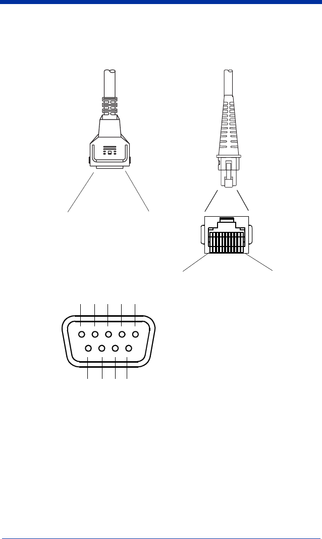
IMAGETEAM™ 2020/5620 System Manual 11 - 5
Standard Cable Pinouts
Wand Emulation
10 Pin Modular Plug
connects to the base
1
2Cord shield
3 Prog 1 (Tied to supply power for primary cable)
4 Supply ground
5
6 Bar code data output
7 Supply power input (Refer to tables on page 11-2.)
8
9
10
Bar code data output
Supply power input
9 Pin Type D Female
connects to your terminal
Supply ground
Cord shield
1
2
3
4
5
6
7
8
9

11 - 6 IMAGETEAM™ 2020/5620 System Manual
Standard Cable Pinouts
Serial Output
10 Pin RJ41 Modular Plug
connects to the base
1
2 Cord shield
3 Prog 1 (Tied to supply power for primary cable)
4 Supply ground
5 Receive data - Serial data to scanner
6 Transmit data - Serial data from scanner
7 Supply power input (Refer to tables on page 11-2.)
8 Request to send data
9 Clear to send data
10
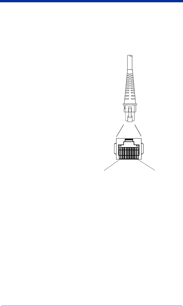


IMAGETEAM™ 2020/5620 System Manual 12 - 1
12
Maintenance
Maintenance
Repairs and/or upgrades are not to be performed on this product. These
services are to be performed only by an authorized service center. See
"Customer Support" on page 15-1 for further information.
Cleaning the Scanner’s Window
Reading performance may degrade if the scanner’s window is not clean. If the
window is visibly dirty, or if the scanner isn’t operating well, clean the window with
a soft cloth or lens tissue dampened with water (or a mild detergent-water
solution or alcohol). If a detergent solution is used, rinse with a clean lens tissue
dampened with water only.
The scanner’s housing may also be cleaned the same way.
Inspecting Cords and Connectors
Inspect the base’s interface cable and connector for wear or other signs of
damage. A badly worn cable or damaged connector may interfere with scanner
operation. Contact your HHP distributor for information about cable
replacement. Cable replacement instructions are on page 12-2.
!Caution:
Do not submerge the imager in water. The scanner’s
housing is not watertight.
Do not use abrasive wipes or tissues on the imager’s
window – abrasive wipes may scratch the window. Never
use solvents (e.g., alcohol or acetone) on the housing or
window – solvents may damage the finish or the window.
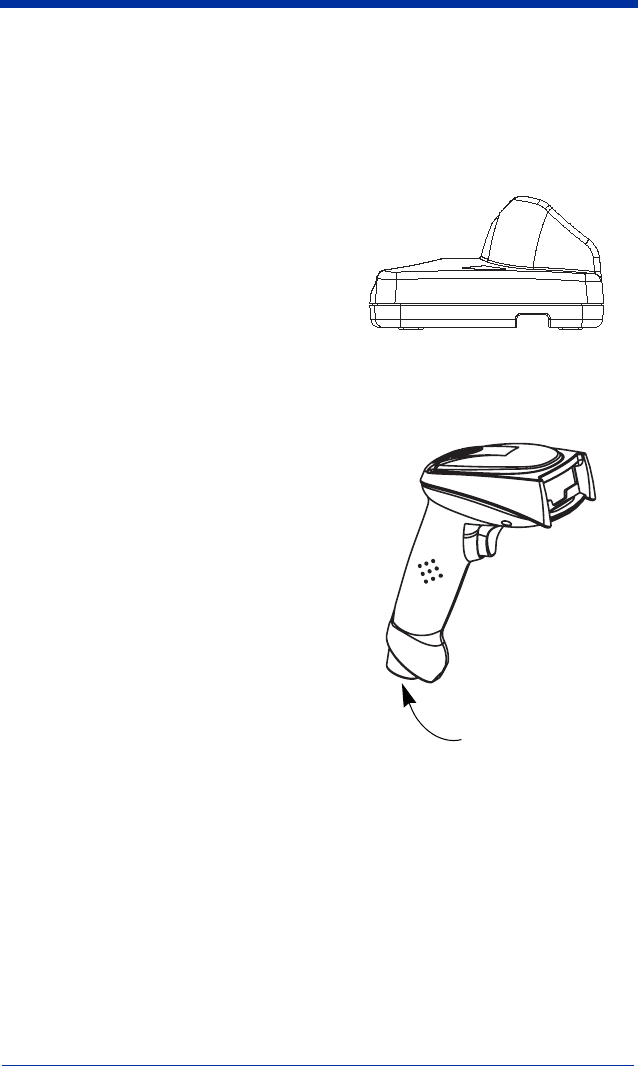
12 - 2 IMAGETEAM™ 2020/5620 System Manual
Replacing the IT2020 Interface Cable:
1. Turn the power to the host system
OFF.
2. Disconnect the base’s cable from the
terminal or computer.
3. Turn the base upside down.
4. Pull the connector out while
maintaining pressure on the connector
release clip.
5. Replace with the new cable.
Insert the connector into the opening
and press firmly. The connector is
keyed to go in only one way, and will
click into place.
Changing the IT5620
Battery:
1. Remove the screw on the end
cap.
2. Remove the battery from the
handle.
3. Insert battery.
4. Replace end cap and screw.
Troubleshooting Base
The base automatically performs
self-tests whenever you turn it on.
If your scanner is not functioning properly, review the following Troubleshooting
Guide to try to isolate the problem.
Is the power on? Is the LED on?
If the LED isn’t illuminated, check that:
• The cable is connected properly.
• The host system power is on (if external power isn’t used).
Troubleshooting Scanner
Is the scanner having trouble reading your symbols?
End Cap

IMAGETEAM™ 2020/5620 System Manual 12 - 3
If the scanner isn’t reading symbols well, check that the symbols:
• Aren’t smeared, rough, scratched, or exhibiting voids.
• Aren’t coated with frost or water droplets on the surface.
• Are enabled in the base to which the scanner connects.
Is the bar code displayed but not entered into the application?
The bar code is displayed on the host device correctly, but you still have to press
a key to enter it (the Enter/Return key or the Tab key, for example).
You need to program a suffix. Programming a suffix enables the scanner to
output the bar code data plus the key you need (such as “CR”) to enter the data
into your application. Refer to Prefix/Suffix Overview on page 4-1 for further
information.
Does the scanner read the bar code incorrectly?
If the scanner reads a bar code, but the data is not displayed correctly on the host
screen:
• The base may not be programmed for the appropriate terminal interface.
For example, you scan “12345” and the host displays “@es%.”
Reprogram the base with the correct Plug and Play or Terminal selection bar
code. See Chapter 1 and Chapter 2.
• The base may not be programmed to output your bar code data properly.
For example, you scan “12345” and the host displays “A12345B.”
Reprogram the base with the proper symbology selections. See Chapter 6.
The scanner won’t read your bar code at all.
1. Scan the sample bar codes in the back of this manual. If the scanner reads
the sample bar codes, check that your bar code is readable.
Verify that your bar code symbology is enabled (see Chapter 6).
2. If the scanner still can’t read the sample bar codes, scan All Symbologies on
page 6-1.
If you aren’t sure what programming options have been set in the base, or if you
want the factory default settings restored, scan Resetting the Standard Product
Defaults on page 10-4.
Troubleshooting the Cordless System
• Is the base powered?
• Does the scanner illuminate?
• Are the radios set up? within range?


IMAGETEAM™ 2020/5620 System Manual 13 - 1
13
Customer Support
Obtaining Factory Service
HHP provides service for all its products through service centers throughout the
world. To obtain warranty or non-warranty service, return the unit to HHP
(postage paid) with a copy of the dated purchase record attached. Contact the
appropriate location below to obtain a Return Material Authorization number
(RMA #) before returning the product.
North America
HHP Corporate Offices
Telephone: (800) 782-4263, Option 3
Fax: (704) 566-9904
E-mail: ProductService@HHP.com
Latin America
HHP Latin America
Telephone: (941) 263-7600
Fax: (941) 263-9689
Brazil
HHP Brazil
Telephone: +55 (21) 2494-7060
Fax: +55 (21) 2494-5033
E-mail: suporte@HHP.com.br
Europe, Middle East, and Africa
HHP Europe
Telephone:+ 31 (0) 40 29 01 633
Fax: + 31 (0) 40 2901631
E-mail: EuroService@HHP.com
Asia Pacific
HHP Asia/Pacific
Telephone: +852-2511-3050
Fax: +852-251-13557
E-mail: chuie@HHP.com
Japan
HHP Japan
Telephone: +81-3-5770-6312
Fax: +81-3-5770-6313
E-mail: kobayashit@HHP.com

13 - 2 IMAGETEAM™ 2020/5620 System Manual
Technical Assistance
If you need assistance installing or troubleshooting your scanner, please call
your Distributor or the nearest HHP technical support office:
North America/Canada:
Telephone: (800) 782-4263, Option 4 (8 a.m. to 6 p.m. EST)
Fax number: (315) 685-4960
E-mail: support@HHP.com
Europe, Middle East, and Africa:
Telephone-
European Ofc: Int+31 (0) 40 29 01 600
U.K. Ofc: Int+44 1925 240055
E-mail: euro_support@
HHP
.com
Asia:
Telephone: Int+852-2511-3050
or
2511-3132
E-mail: asia_support@
HHP
.com
Latin America:
Telephone: (239) 263-7600
E-mail: la_support@
HHP
.com
Limited Warranty
Hand Held Products, Inc., d/b/a HHP ("Hand Held Products, Inc., d/b/a HHP
("HHP") warrants its products to be free from defects in materials and
workmanship and to conform to HHP’s published specifications applicable to the
products purchased at the time of shipment. This warranty does not cover any
HHP product which is (i) improperly installed or used; (ii) damaged by accident
or negligence, including failure to follow the proper maintenance, service, and
cleaning schedule; or (iii) damaged as a result of (A) modification or alteration by
the purchaser or other party, (B) excessive voltage or current supplied to or
drawn from the interface connections, (C) static electricity or electro-static
discharge, (D) operation under conditions beyond the specified operating
parameters, or (E) repair or service of the product by anyone other than HHP or
its authorized representatives.
This warranty shall extend from the time of shipment for the duration published
by HHP for the product at the time of purchase ("Warranty Period"). Any
defective product must be returned (at purchaser’s expense) during the Warranty
Period to HHP’s factory or authorized service center for inspection. No product
will be accepted by HHP without a Return Materials Authorization, which may be
obtained by contacting HHP. In the event that the product is returned to HHP or
its authorized service center within the Warranty Period and HHP determines to
its satisfaction that the product is defective due to defects in materials or
workmanship, HHP, at its sole option, will either repair or replace the product
without charge, except for return shipping to HHP.

IMAGETEAM™ 2020/5620 System Manual 13 - 3
EXCEPT AS MAY BE OTHERWISE PROVIDED BY APPLICABLE LAW, THE
FOREGOING WARRANTY IS IN LIEU OF ALL OTHER COVENANTS OR
WARRANTIES, EITHER EXPRESSED OR IMPLIED, ORAL OR WRITTEN,
INCLUDING, WITHOUT LIMITATION, ANY IMPLIED WARRANTIES OF
MERCHANTABILITY OR FITNESS FOR A PARTICULAR PURPOSE.
HHP’S RESPONSIBILITY AND PURCHASER’S EXCLUSIVE REMEDY
UNDER THIS WARRANTY IS LIMITED TO THE REPAIR OR REPLACEMENT
OF THE DEFECTIVE PRODUCT. IN NO EVENT SHALL HHP BE LIABLE FOR
INDIRECT, INCIDENTAL, OR CONSEQUENTIAL DAMAGES, AND, IN NO
EVENT, SHALL ANY LIABILITY OF HHP ARISING IN CONNECTION WITH
ANY PRODUCT SOLD HEREUNDER (WHETHER SUCH LIABILITY ARISES
FROM A CLAIM BASED ON CONTRACT, WARRANTY, TORT, OR
OTHERWISE) EXCEED THE ACTUAL AMOUNT PAID TO HHP FOR THE
PRODUCT. THESE LIMITATIONS ON LIABILITY SHALL REMAIN IN FULL
FORCE AND EFFECT EVEN WHEN HHP MAY HAVE BEEN ADVISED OF THE
POSSIBILITY OF SUCH INJURIES, LOSSES, OR DAMAGES. SOME
STATES, PROVINCES, OR COUNTRIES DO NOT ALLOW THE EXCLUSION
OR LIMITATIONS OF INCIDENTAL OR CONSEQUENTIAL DAMAGES, SO
THE ABOVE LIMITATION OR EXCLUSION MAY NOT APPLY TO YOU.
All provisions of this Limited Warranty are separate and severable, which means
that if any provision is held invalid and unenforceable, such determination shall
not affect the validity of enforceability of the other provisions hereof. Use of any
peripherals not manufactured/sold by HHP voids the warranty. This includes but
is not limited to: cables, power supplies, cradles, and docking stations. Hand
Held Products, Inc. extends these warranties only to the first end-users of the
products. These warranties are nontransferable.
The limited duration of the warranty for the IT2020 and IT5620 is for three (3)
years. The limited duration of the warranty for the scanner battery is for one (1)
year.


IMAGETEAM™ 2020/5620 System Manual A - 1
Appendix A
Symbology Chart
Note: “m” represents the AIM modifier character. Refer to International
Technical Specification, Symbology Identifiers, for AIM modifier character
details.
Note: Prefix/Suffix entries for specific symbologies override the universal (All
Symbologies, 99) entry.
Refer to
Data Editing
beginning on page 4-1 and
Data Formatting
beginning on
page 5-1 for information about using Code ID and AIM ID.
Symbology Code
ID
AIM
ID
Hex
ID Symbology Code
ID
AIM
ID
Hex
ID
China Post Q]X051
IATA 2 of 5 f]R
m
66
Codabar a]F
m
61 Interleaved 2 of 5 e]l
m
65
Codablock F q]O
m
71 Korea Post ?]X03F
Code 2 of 5 f]R
m
66 Matrix 2 of 5 m]X06D
Code 11 h]H
m
68 MSI g]M
m
67
Code 16K o ]K
m
6F No Read 9C
Code 39 b]A
m
62 Plessey Code n]P06E
Code 32 Pharma-
ceutical (PARAF)
<]X03C
PosiCode W]p
m
57
Code 49
l]T
m
6C Reduced Space
Symbology (RSS-
14, RSS Limited,
RSS Expanded)
y]e
m
79
Code 93 i]G
m
69 Telepen t]B
m
74
Code 128 j]C
m
6A Trioptic Code =]X03D
UCC/EAN-128 I]C149
UPC-A c]E
0
63
EAN/JAN-8 D ]E4 44 UPC-A with
Extended Coupon
Code
c]E363
EAN/JAN-13 d]E
0
64 UPC-E E]E
0
45
EAN-13 with
Extended
Coupon Code
d]E364
All Symbologies 99

A - 2 IMAGETEAM™ 2020/5620 System Manual
ASCII Conversion Chart (Code Page 1252)
Dec Hex Char Dec Hex Char Dec Hex Char Dec Hex Char
000 NUL 32 20 64 40 @96 60 ‘
101 SOH 33 21 !65 41 A97 61 a
202 STX 34 22 “66 42 B98 62 b
303 ETX 35 23 #67 43 C99 63 c
404 EOT 36 24 $68 44 D100 64 d
505 ENQ 37 25 %69 45 E101 65 e
606 ACK 38 26 &70 46 F102 66 f
707 BEL 39 27 ‘71 47 G103 67 g
808 BS 40 28 (72 48 H104 68 h
909 HT 41 29 )73 49 l105 69 i
10 0A LF 42 2A *74 4A J106 6A j
11 0B VT 43 2B +75 4B K107 6B k
12 0C FF 44 2C ,76 4C L108 6C l
13 0D CR 45 2D -77 4D M109 6D m
14 0E SO 46 2E .78 4E N110 6E n
15 0F SI 47 2F /79 4F O111 6F o
16 10 DLE 48 30 080 50 P112 70 p
17 11 DC1 49 31 181 51 Q113 71 q
18 12 DC2 50 32 282 52 R114 72 r
19 13 DC3 51 33 383 53 S115 73 s
20 14 DC4 52 34 484 54 T116 74 t
21 15 NAK 53 35 585 55 U117 75 u
22 16 SYN 54 36 686 56 V118 76 v
23 17 ETB 55 37 787 57 W119 77 w
24 18 CAN 56 38 888 58 X120 78 x
25 19 EM 57 39 989 59 Y121 79 y
26 1A SUB 58 3A :90 5A Z122 7A z
27 1B ESC 59 3B ;91 5B [123 7B {
28 1C FS 60 3C <92 5C \124 7C |
29 1D GS 61 3D =93 5D ]125 7D }
30 1E RS 62 3E >94 5E ^126 7E ~
31 1F US 63 3F ?95 5F _127 7F

IMAGETEAM™ 2020/5620 System Manual A - 3
Dec. Hex Char Dec. Hex Char Dec. Hex Char Dec. Hex Char
128 80 €
€160 A0 192 C0 À224 E0 à
129 81 161 A1 ¡193 C1 Á225 E1 á
130 82 ‚162 A2 ¢194 C2 Â226 E2 â
131 83 ƒ163 A3 £195 C3 Ã227 E3 ã
132 84 „164 A4 ¤196 C4 Ä228 E4 ä
133 85 …165 A5 ¥197 C5 Å229 E5 å
134 86 †166 A6 ¦198 C6 Æ230 E6 æ
135 87 ‡167 A7 §199 C7 Ç231 E7 ç
136 88 ˆ168 A8 ¨200 C8 È232 E8 è
137 89 ‰169 A9 ©201 C9 É233 E9 é
138 8A Š170 AA 202 CA Ê234 EA ê
139 8B ‹171 AB «203 CB Ë235 EB ë
140 8C Œ172 AC ¬204 CC Ì236 EC ì
141 8D 173 AD -205 CD Í237 ED í
142 8E Ž174 AE ®206 CE Î238 EE î
143 8F 175 AF ¯207 CF Ï239 EF ï
144 90 176 B0 °208 D0 Ð240 F0 ð
145 91 ‘177 B1 ±209 D1 Ñ241 F1 ñ
146 92 ’178 B2 ²210 D2 Ò242 F2 ò
147 93 “179 B3 ³211 D3 Ó243 F3 ó
148 94 ”180 B4 ´212 D4 Ô244 F4 ô
149 95 •181 B5 µ213 D5 Õ245 F5 õ
150 96 –182 B6 ¶214 D6 Ö246 F6 ö
151 97 —183 B7 ·215 D7 ×247 F7 ÷
152 98 ˜184 B8 ¸216 D8 Ø248 F8 ø
153 99 ™185 B9 ¹217 D9 Ù249 F9 ù
154 9A š186 BA 218 DA Ú250 FA ú
155 9B ›187 BB »219 DB Û251 FB û
156 9C œ188 BC ¼220 DC Ü252 FC ü
157 9D 189 BD ½221 DD Ý253 FD ý
158 9E ž190 BE ¾222 DE Þ254 FE þ
159 9F Ÿ191 BF ¿223 DF ß255 FF ÿ
ª

A - 4 IMAGETEAM™ 2020/5620 System Manual
Code Page Mapping of Printed Bar Codes
Code pages define the mapping of character codes to characters. If the data
received does not display with the proper characters, it may be because the bar
code being scanned was created using a code page that is different from the one
the host program is expecting. If this is the case, select the code page with which
the bar codes were created. The data characters should then appear properly.
Note: The Code Page option is available for Code 39, Code 93, and Code 128.
Code Page Standard Description
1CP ISO646
2 (Default) ISO 2022 Automatic National Replacement
Characters
3CP Binary
82 ISO 2022 11 Swe Swedish Replacement Characters
83 ISO 2022 69 Fra French/Belgium Replacement Charac-
ters
81 ISO 2022 25 Fra French/Belgium Replacement Charac-
ters
84 ISO 2022 11 Ger German Replacement Characters
85 ISO 2022 11 Ita Italian Replacement Characters
86 ISO 2022 11 Swi Swiss Replacement Characters
87 ISO 2022 11 UK British Replacement Characters
88 ISO 2022 11 Dan Danish Replacement Characters
89 ISO 2022 11 Nor Norwegian Replacement Characters
90 ISO 2022 11 Spa Spanish Replacement Characters


Sample Symbols
UPC A
0 123456 7890 Interleaved 2 of 5
Code 128
EAN 13
1234567890
Code 128
9 780330 290951
654
EAN 8
3210 5
456123 80
UPC-E

Sample Symbols
Code 93
123456-9$ Code 2 of 5
123456
Matrix 2 of 5
6543210 RSS-14
(01)00123456789012
Code 39
Codabar
BC321
A13579B


Programming Chart
A
C
Save
B
Discard
F
E
D
Note: If you make an error while scanning the letters or digits (before scanning Save),
scan Discard, scan the correct letters or digits, and Save.
0
2
6
1
7
5
4
3
8
9

5620-SM Rev (13-a)