Honeywell MXTY3 Barcode Scanner with BT User Manual 4820 UG
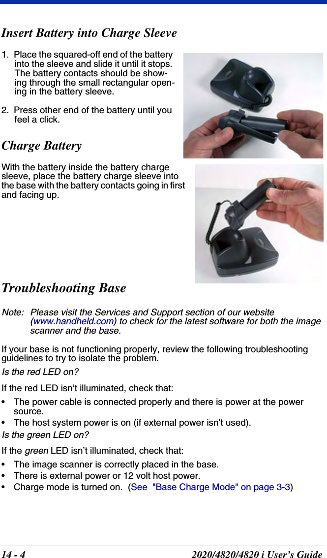
Honeywell International Inc Barcode Scanner with BT 4820 UG
UserManual.wiki
>
Honeywell
>
MXTY3 User Manual
>
User Manual 4820
Contents
1.
User Manual 3820
2.
User Manual 4820
User Manual 4820
Navigation menu
Upload a User Manual
Namespaces
Wiki Guide
HTML
PDF
Info
Views
User Manual
Discussion / Help
Navigation
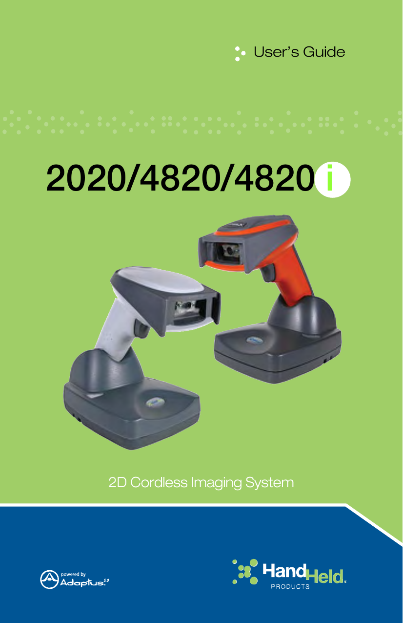

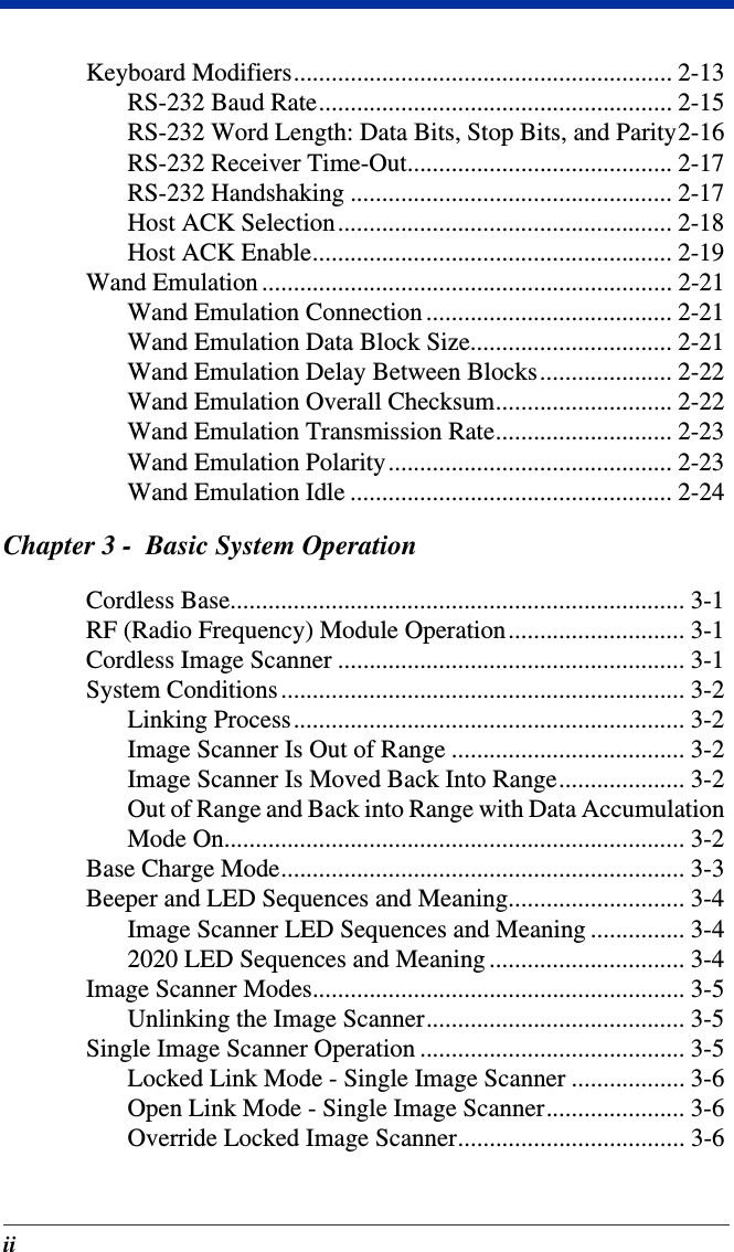
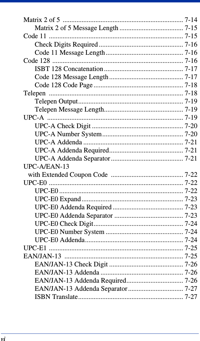

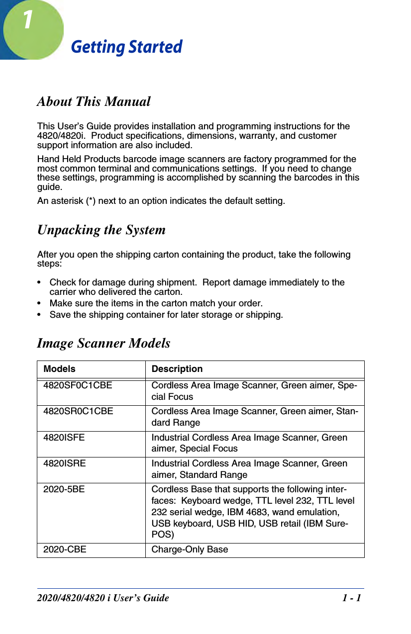
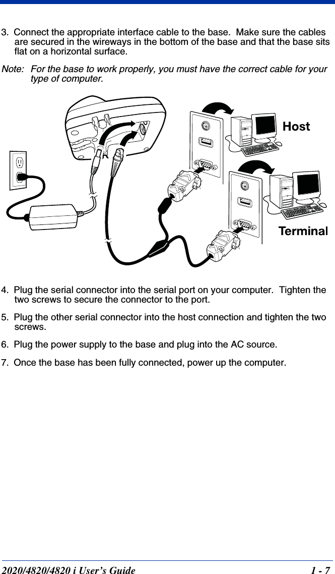
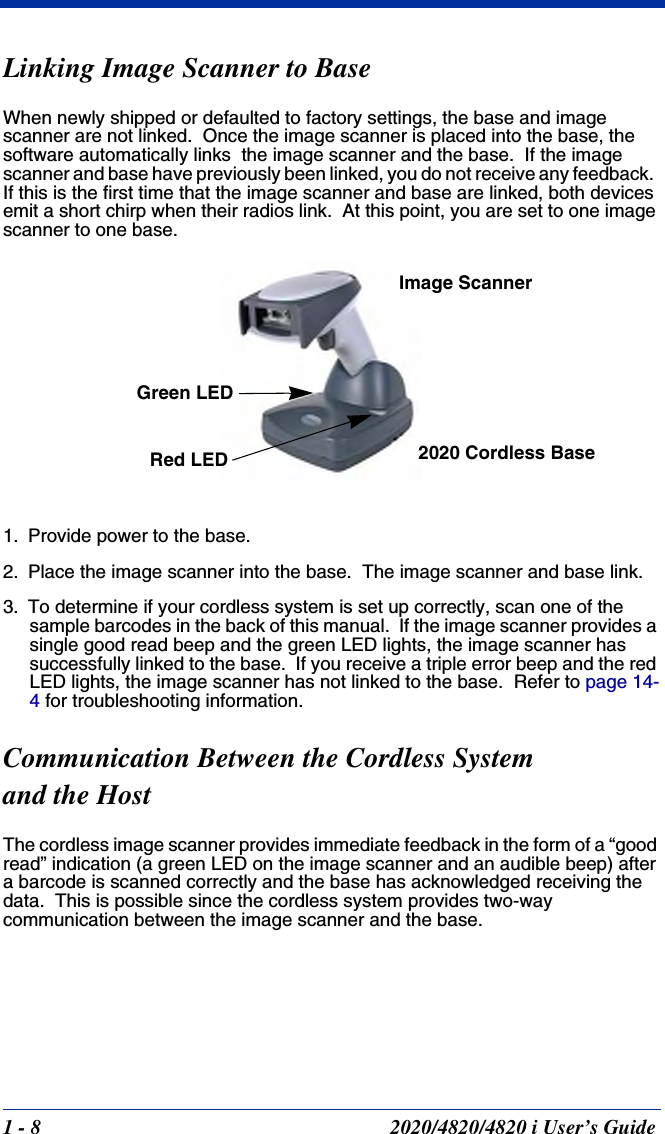
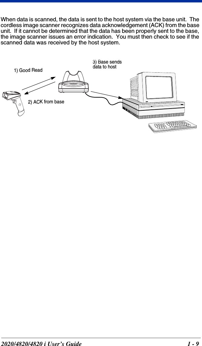
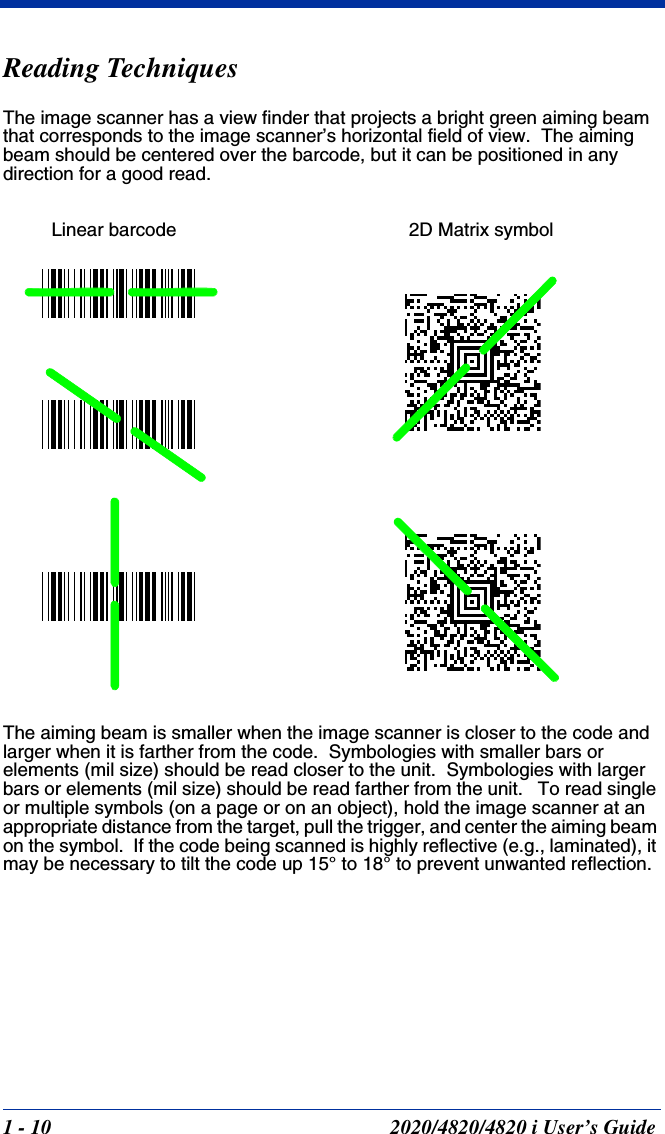
![2 - 10 2020/4820/4820 i User’s GuideKeyboard CountryScan the appropriate country code below to program the keyboard for your country. As a general rule, the following characters are supported, but need special care for countries other than the United States:@ | $ # { } [ ] = / ‘ \ < > ~ * United States BrazilCzech RepublicDenmarkFinland (Sweden)FranceGermany/AustriaGreeceHungaryBelgiumCanada (French)Israel (Hebrew)](https://usermanual.wiki/Honeywell/MXTY3.User-Manual-4820/User-Guide-887198-Page-40.png)


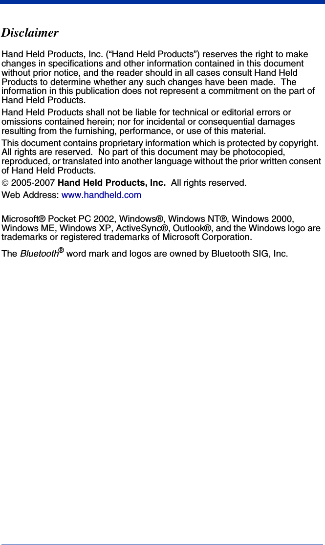
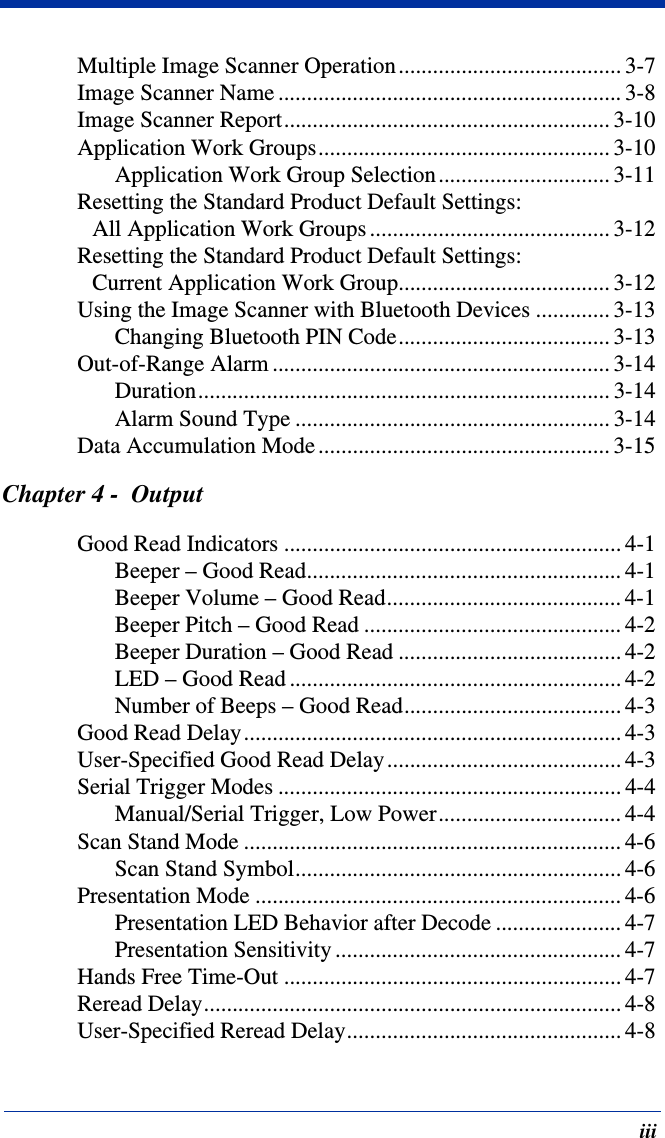
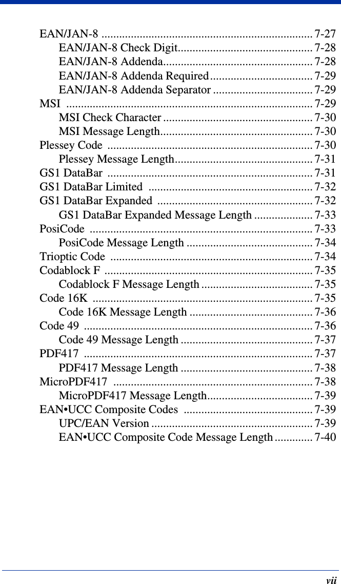
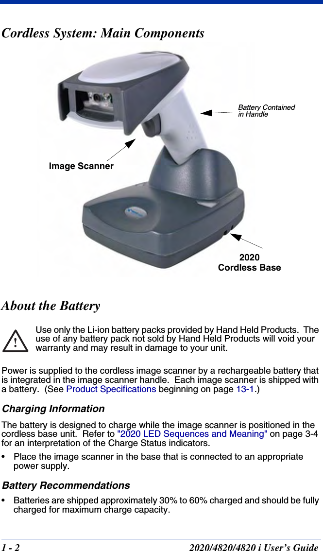
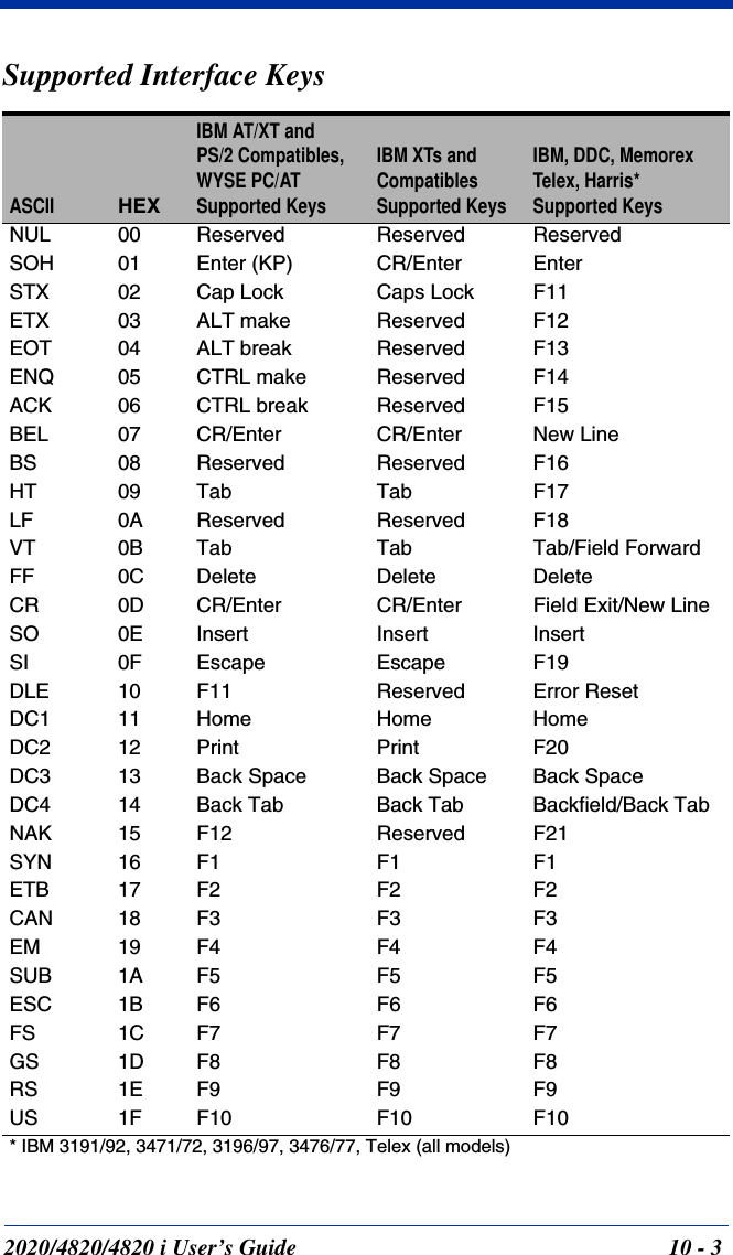
![2020/4820/4820 i User’s Guide 10 - 110Interface KeysKeyboard Function RelationshipsThe following Keyboard Function Code, Hex/ASCII Value, and Full ASCII “CTRL”+ relationships apply to all terminals that can be used with the image scanner. Refer to page 2-13 enable Control + ASCII mode.Function Code HEX/ASCII Value Full ASCII “CTRL” +NUL 00 @SOH 01 ASTX 02 BETX 03 CEOT 04 DENQ 05 EACK 06 FBEL 07 GBS 08 HHT 09 ILF 0A JVT 0B KFF 0C LCR 0D MSO 0E NSI 0F ODLE 10 PDC1 11 QDC2 12 RDC3 13 SDC4 14 TNAK 15 USYN 16 VETB 17 WCAN 18 XEM 19 YSUB 1A ZESC 1B [FS 1C \GS 1D ]RS 1E ^US 1F _](https://usermanual.wiki/Honeywell/MXTY3.User-Manual-4820/User-Guide-887198-Page-130.png)
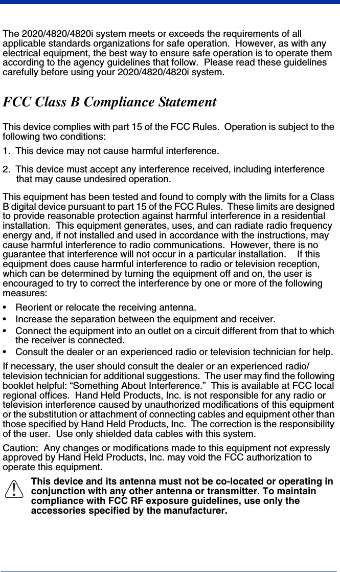
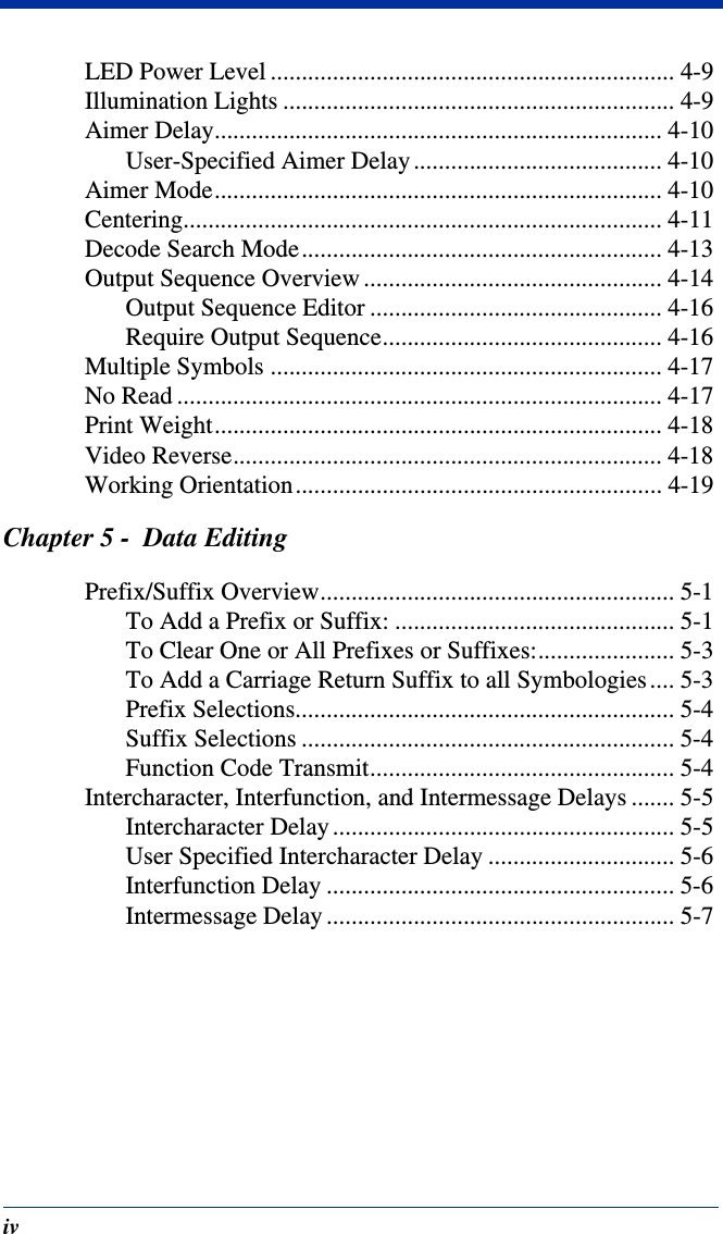
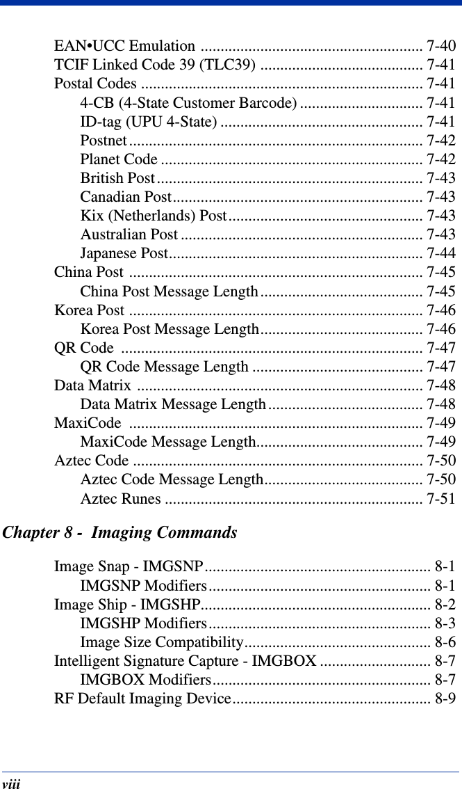
![10 - 2 2020/4820/4820 i User’s GuideThe last five characters in the Full ASCII “CTRL”+ column ( [ \ ] 6 - ), apply to US only. The following chart indicates the equivalents of these five characters for different countries.Country CodesUnited States [ \ ] 6 -Belgium [ < ] 6 -Scandinavia 8 < 9 6 -France ^ 8 $ 6 =Germany à + 6 -Italy \ + 6 -Switzerland <. . 6 -United Kingdom [ ¢ ] 6 -Denmark 8 \ 9 6 -Norway 8 \ 9 6 -Spain [ \ ] 6 -](https://usermanual.wiki/Honeywell/MXTY3.User-Manual-4820/User-Guide-887198-Page-131.png)
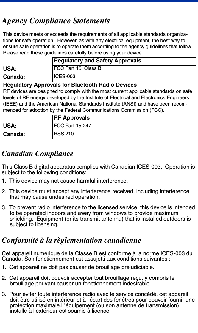
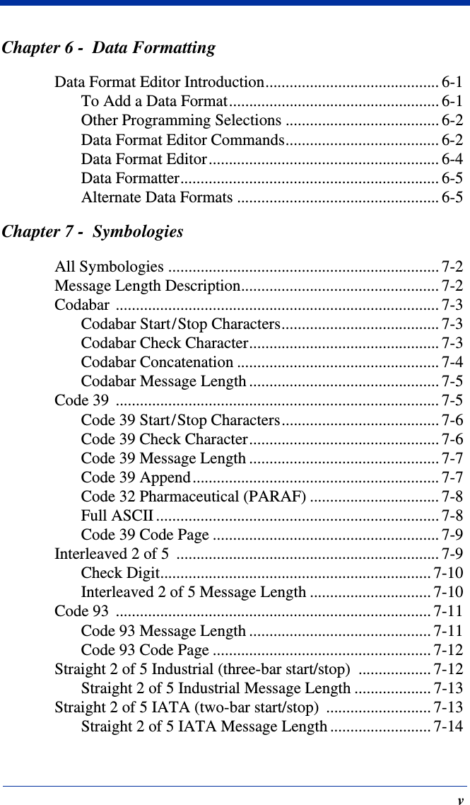
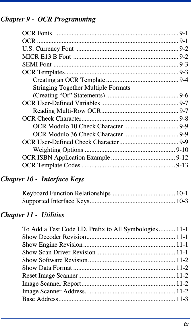
![2020/4820/4820 i User’s Guide 11 - 111UtilitiesTo Add a Test Code I.D. Prefix to All SymbologiesThis selection allows you to turn on transmission of a Code I.D. before the decoded symbology. (See the Symbology Chart, beginning on page A-1) for the single character code that identifies each symbology.) This action first clears all current prefixes, then programs a Code I.D. prefix for all symbologies. This is a temporary setting that will be removed when the unit is power cycled.Show Decoder RevisionScan the barcode below to output the decoder revision.Show Engine RevisionScan the barcode below to output the engine revision. It will return the engine type, revision number, and status character [ACK]. For example, an image scanner with a 5100 engine, version 26 would return:ENGREVType: 1 Revision: 26[ACK]Show Scan Driver RevisionScan the barcode below to output the scan driver revision. The scan driver controls image capture.Add Code I.D. Prefix toAll Symbologies (Temporary)Show Decoder RevisionShow Engine RevisionShow Scan Driver Revision](https://usermanual.wiki/Honeywell/MXTY3.User-Manual-4820/User-Guide-887198-Page-136.png)
![2020/4820/4820 i User’s Guide 12 - 112Serial Programming CommandsThe serial programming commands can be used in place of the programming barcodes. Both the serial commands and the programming barcodes will program the image scanner. For complete descriptions and examples of each serial programming command, refer to the corresponding programming barcode in this manual.The device must be set to an RS-232 interface (see page 2-2). The following commands can be sent via a PC COM port using terminal emulation software.ConventionsThe following conventions are used for menu and query command descriptions:parameterA label representing the actual value you should send as part of a command.[option] An optional part of a command.{Data} Alternatives in a command.bold Names of menus, menu commands, buttons, dialog boxes, and windows that appear on the screen.Menu Command SyntaxMenu commands have the following syntax (spaces have been used for clarity only):Prefix [:Name:] Tag SubTag {Data} [, SubTag {Data}] [; Tag SubTag {Data}] […] StoragePrefix Three ASCII characters: SYN M CR (ASCII 22,77,13).:Name: To send information to the image scanner (with the base connect-ed to host), use :4820: or :4820i: The default factory setting for a 4820 image scanner is 4820, and 4820i for a 4820i image scanner. This setting is changed by using the BT_NAM command, which ac-cepts alphanumeric values. If the name is not known, a wildcard (*) can be used :*:.Note: Since the base stores all work group settings and transfers to them to image scanner once they are linked, changes are typically done to the base and not to the image scanner.Tag A 3 character case-insensitive field that identifies the desired menu command group. For example, all RS-232 configuration settings are identified with a Tag of 232.SubTag A 3 character case-insensitive field that identifies the desired menu command within the tag group. For example, the SubTag for the RS-232 baud rate is BAD.Data The new value for a menu setting, identified by the Tag and Sub-Tag.](https://usermanual.wiki/Honeywell/MXTY3.User-Manual-4820/User-Guide-887198-Page-142.png)
![2020/4820/4820 i User’s Guide 12 - 3ResponsesThe device responds to serial commands with one of three responses:ACK Indicates a good command which has been processed.ENQ Indicates an invalid Tag or SubTag command. NAK Indicates the command was good, but the Data field entry was out of the allowable range for this Tag and SubTag combination, e.g., an entry for a minimum message length of 100 when the field will only accept 2 characters.When responding, the device echoes back the command sequence with the status character inserted directly before each of the punctuation marks (the period, exclamation point, comma, or semicolon) in the command.Examples of Query CommandsIn the following examples, a bracketed notation [ ] depicts a non-displayable response.Example #1:What is the range of possible values for Codabar Coding Enable?Enter: cbrena*.Response: CBRENA0-1[ACK]This response indicates that Codabar Coding Enable (CBRENA) has a range of values from 0 to 1 (off and on). Example #2: What is the default value for Codabar Coding Enable?Enter: cbrena^.Response: CBRENA1[ACK]This response indicates that the default setting for Codabar Coding Enable (CBRENA) is 1, or on. Example #3: What is the device’s current setting for Codabar Coding Enable?Enter: cbrena?.Response: CBRENA1[ACK]This response indicates that the device’s Codabar Coding Enable (CBRENA) is set to 1, or on.](https://usermanual.wiki/Honeywell/MXTY3.User-Manual-4820/User-Guide-887198-Page-144.png)
![12 - 4 2020/4820/4820 i User’s GuideExample #4: What are the device’s settings for all Codabar selections?Enter: cbr?.Response: CBRENA1[ACK],SSX0[ACK],CK20[ACK],CCT1[ACK],MIN2[ACK],MAX60[ACK],DFT[ACK].This response indicates that the device’s Codabar Coding Enable (CBRENA) is set to 1, or on; the Start/Stop Character (SSX) is set to 0, or Don’t Transmit; the Check Character (CK2) is set to 0, or Not Required;concatenation (CCT) is set to 1, or Enabled; the Minimum Message Length (MIN) is set to 2 characters; the Maximum Message Length (MAX) is set to 60 characters; and the Default setting (DFT) has no value. Trigger CommandsYou can activate and deactivate the image scanner with serial trigger com-mands. First, the image scanner must be put in Manual/Serial Trigger Mode either by scanning the Manual/Serial Trigger Mode barcode (page 4-4), or by sending the Manual/Serial Menu Command (page 12-9). Once the image scan-ner is in serial trigger mode, the trigger is activated and deactivated by sending the following commands:Activate: SYN T CRDeactivate: SYN U CRThe image scanner scans until a barcode has been read, until the deactivate command is sent, or until the serial time-out has been reached (see "Read Time-Out (Serial Trigger Mode)" on page 4-4 for a description, and the serial command on page 12-9).](https://usermanual.wiki/Honeywell/MXTY3.User-Manual-4820/User-Guide-887198-Page-145.png)

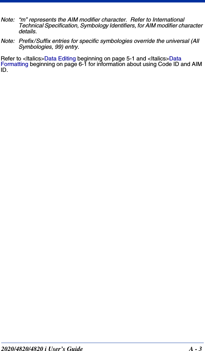
![2020/4820/4820 i User’s Guide A - 1AReference ChartsSymbology ChartSymbology AIMIDPossible AIM ID Modifiers (m)Hand Held Products Code ID (hex)All Symbologies (0x99)4-CB (4-State Customer Barcode) ]X0 M (0x4D)Australian Post ]X0 A (0x41)Aztec Code ]zm0-9, A-C z (0x7A)British Post ]X0 B (0x42)Canadian Post ]X0 C (0x43)China Post ]X0 Q (0x51)Codabar ]Fm0-1 a (0x61)Codablock F ]Om0, 1, 4, 5, 6 q (0x71)Code 11 ]H3 h (0x68)Code 128 ]Cm0, 1, 2, 4 j (0x6A)Code 16K ]Km0, 1, 2, 4 o (0x6F)Code 32 Pharmaceutical (PARAF)]X0 < (0x3C)Code 39 ]Am0, 1, 3, 4, 5, 7 b (0x62)Code 49 ]Tm0, 1, 2, 4 l (0x6CCode 93 and 93i ]Gm0-9, A-Z, a-m i (0x69Data Matrix ]dm0-6 w (0x77)EAN-13 ]E0 d (0x64)EAN-8 ]E4 D (0x44)EAN•UCC Composite ]em0-3 y (0x79)EAN-13 with Extended Coupon Code ]E3 d (0x64)ID-tag (UPU 4-State) ]X0 N (0x4E)Interleaved 2 of 5 ]lm0, 1, 3 e (0x65)Japanese Post ]X0 J (0x4A)KIX (Netherlands) Post ]X0 K (0x4B)Korea Post ]X0 ? (0x3F)](https://usermanual.wiki/Honeywell/MXTY3.User-Manual-4820/User-Guide-887198-Page-164.png)
![A - 2 2020/4820/4820 i User’s Guide* Only available by special order.Matrix 2 of 5 ]X0 m (0x6D)MaxiCode ]Um0-3 x (0x78)MicroPDF417 ]Lm3-5 R (0x52)MSI ]Mm0 g (0x67)No Read (0x9C)OCR-A ]o1 O (0x4F)OCR-B ]o2 O (0x4F)OCR MICR E-13B ]ZE O (0x4F)OCR US Money Font ]o3 O (0x4F)SEMI Font ]o3 O (0x4F)PDF417 ]Lm0-2 r (0x72)Planet Code ]X0 L (0x4C)Plessey Code ]P0 n (0x6E)PosiCode ]pm0, 1, 2 W (0x57)Postnet ]X0 P (0x50)QR/Micro QR Code ]Qm0-6 s (0x73)Reduced Space Symbology (GS1 DataBar, GS1 DataBar Limited, GS1 DataBar Expanded)]em0 y (0x79)Straight 2 of 5 IATA (two-bar start/stop) ]Rm0, 1, 3 f (0x66)Straight 2 of 5 Industrial (three-bar start/stop) ]S0 0, 1, 3 f (0x66)TCIF Linked Code 39 (TLC39) ]L2 T (0x54)Telepen ]Bm0, 1, 2, 4 t (0x74)Trioptic Code ]X0 = (0x3D)UCC/EAN-128 ]C1 I (0x49)UPC-A ]E0 c (0x63)UPC-A with Extended Coupon Code ]E3 c (0x63)UPC-E ]E0 E (0x45)VeriCode* ]X0 v (0x76)Symbology AIMIDPossible AIM ID Modifiers (m)Hand Held Products Code ID (hex)](https://usermanual.wiki/Honeywell/MXTY3.User-Manual-4820/User-Guide-887198-Page-165.png)
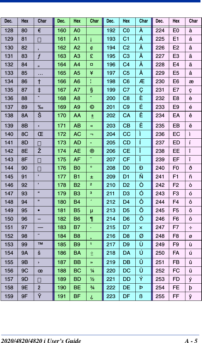
![A - 4 2020/4820/4820 i User’s GuideASCII Conversion Chart (Code Page 1252)Note: This table applies to U.S. style keyboards. Certain characters may differ depending on your Country Code/PC regional settings.Dec Hex Char Dec Hex Char Dec Hex Char Dec Hex Char000 NUL 32 20 64 40 @96 60 ‘101 SOH 33 21 !65 41 A97 61 a202 STX 34 22 “66 42 B98 62 b303 ETX 35 23 #67 43 C99 63 c404 EOT 36 24 $68 44 D100 64 d505 ENQ 37 25 %69 45 E101 65 e606 ACK 38 26 &70 46 F102 66 f707 BEL 39 27 ‘71 47 G103 67 g808 BS 40 28 (72 48 H104 68 h909 HT 41 29 )73 49 l105 69 i10 0A LF 42 2A *74 4A J106 6A j11 0B VT 43 2B +75 4B K107 6B k12 0C FF 44 2C ,76 4C L108 6C l13 0D CR 45 2D -77 4D M109 6D m14 0E SO 46 2E .78 4E N110 6E n15 0F SI 47 2F /79 4F O111 6F o16 10 DLE 48 30 080 50 P112 70 p17 11 DC1 49 31 181 51 Q113 71 q18 12 DC2 50 32 282 52 R114 72 r19 13 DC3 51 33 383 53 S115 73 s20 14 DC4 52 34 484 54 T116 74 t21 15 NAK 53 35 585 55 U117 75 u22 16 SYN 54 36 686 56 V118 76 v23 17 ETB 55 37 787 57 W119 77 w24 18 CAN 56 38 888 58 X120 78 x25 19 EM 57 39 989 59 Y121 79 y26 1A SUB 58 3A :90 5A Z122 7A z27 1B ESC 59 3B ;91 5B [123 7B {28 1C FS 60 3C <92 5C \124 7C |29 1D GS 61 3D =93 5D ]125 7D }30 1E RS 62 3E >94 5E ^126 7E ~31 1F US 63 3F ?95 5F _127 7F](https://usermanual.wiki/Honeywell/MXTY3.User-Manual-4820/User-Guide-887198-Page-167.png)