Honeywell RTA-44DM2 RTA-44D VHF Data Radio User Manual 1144 1Rev5 1144 1r5frontmatter
Honeywell International Inc. RTA-44D VHF Data Radio 1144 1Rev5 1144 1r5frontmatter
UserManual.wiki
>
Honeywell
>
RTA-44DM2 User Manual
>
Users Manual
Contents
1.
Users Manual
2.
Addendum to Users Manual
Users Manual
Navigation menu
Upload a User Manual
Namespaces
Wiki Guide
HTML
PDF
Info
Views
User Manual
Discussion / Help
Navigation
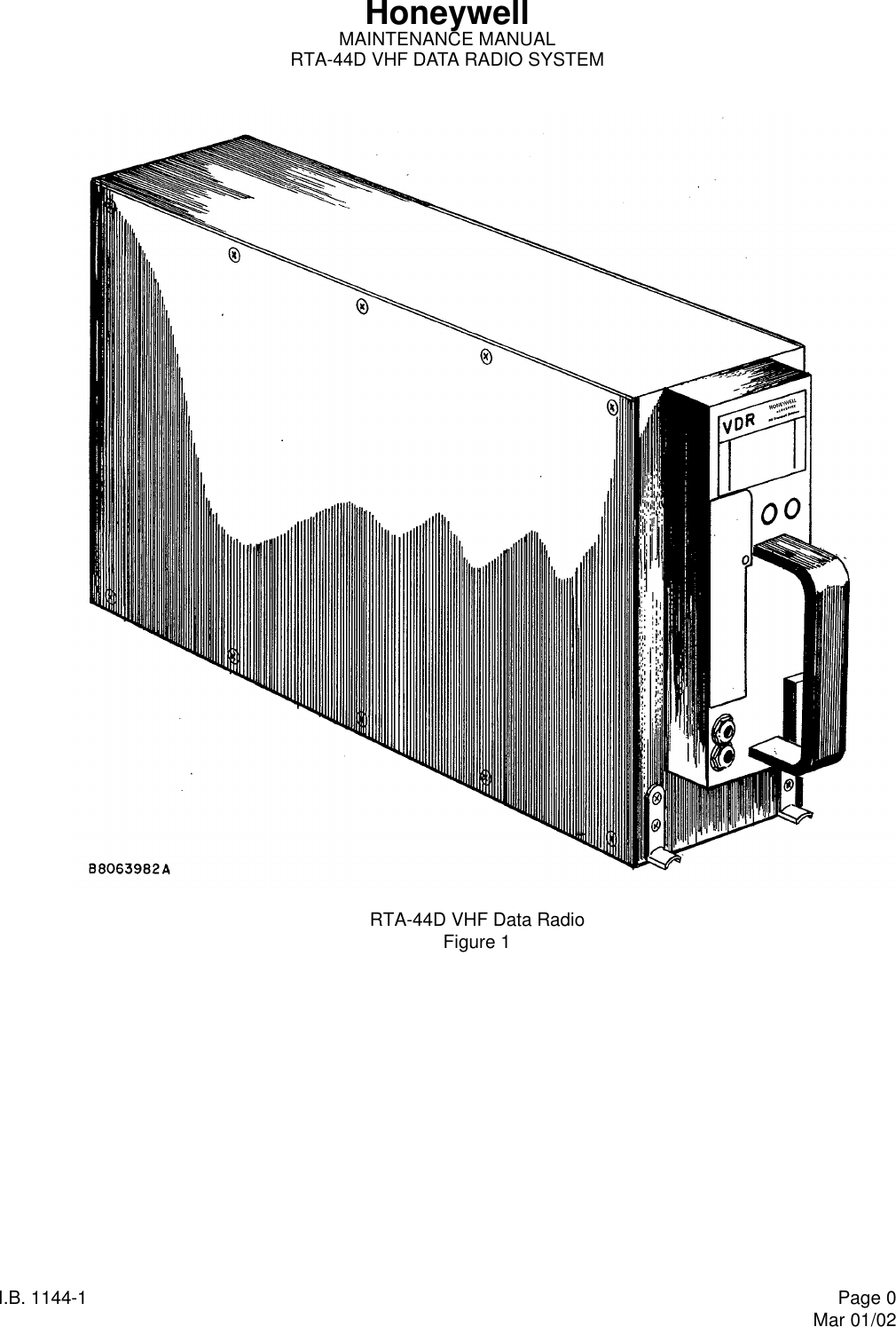
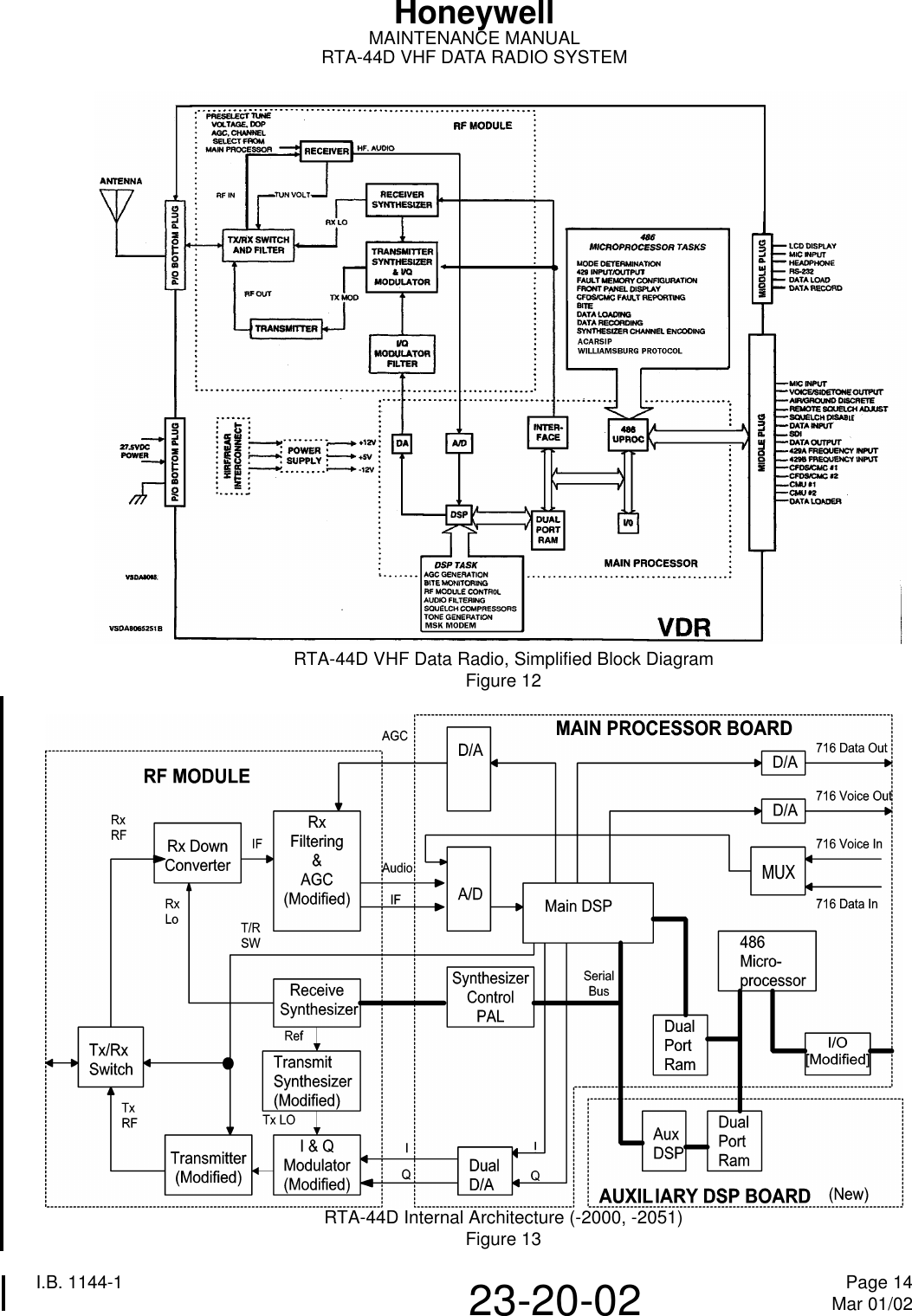
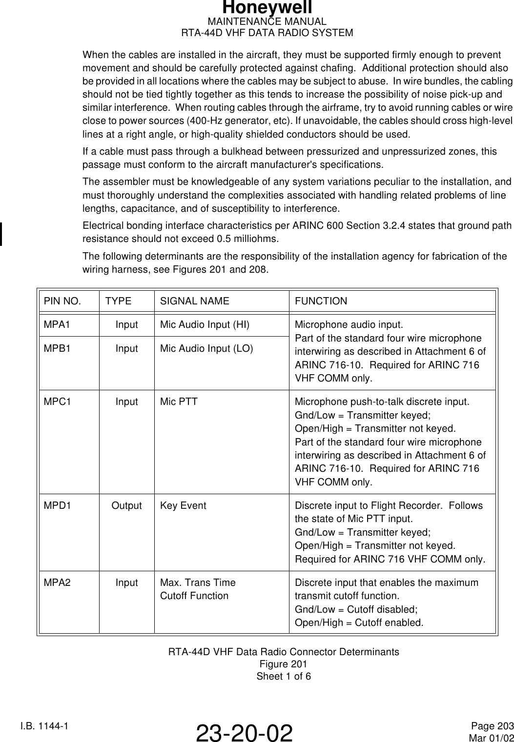
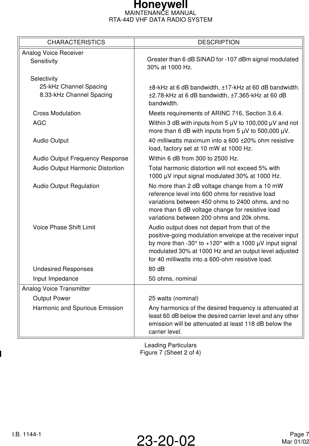
![I.B. 1144-1 Page 6Mar 01/0223-20-02HoneywellMAINTENANCE MANUALRTA-44D VHF DATA RADIO SYSTEM3. System Leading ParticularsA. Unit SpecificationsFigure 7 lists the leading particulars for the RTA-44D VHF Data Radio System.Leading ParticularsFigure 7 (Sheet 1 of 4)CHARACTERISTICS DESCRIPTIONGeneral - Overall VDRForm Factor 3MCU (ARINC600)Dimensions Refer to outline drawing, Figure 207.Weight 9.6 LBS., (4,4Kg) MaximumGeneral - Overall VDRPower Requirements 27.5 Vdc nominal (+10%, -20%)1.0A - Receive (-0101, -0110, -0202, -0303 and -0505)1.5A - Receive (-2000 and -2051)7.0A - Transmit (All Units)TemperatureOperatingStorage-55°C to +70°C (-67°F to +158°F) (-0101, -0110, -0202, -0303 and -0505)-15°C to +70°C (5°F to 158°F) (-2000 and -2051)-65°C to +85°C (-85°F to +185°F) (All Units)Cooling ARINC600Humidity Zero to 95%Altitude To 15,240 meters (50,000feet)Warm-up period None; stable operation after power application.Frequency Control ARINC, 429 Mark, 33 (Serial Digital)Frequency Range 118.000MHz to 136.975MHzChannel Spacing 25-kHz and 8.33-kHzFrequency Stability ±0.0005%Duty Cycle Continuous operation from -55°C to +70°C with ARINC 600 cooling.Certification-0101, -0110, -0202, -0303 and -0505 Units-2000, -2051 UnitsTSO C37d Class3 and 5 and C38d ClassC and E;DO-160C Categories/A2D2/ZCA/MNB/XXXXXXAAAZZUZ/XXE2/XXDO-186a, DO-178B, DO-207 AND EUROCAEED-23BTSO C37d Class3 and 5 and C38d ClassC and E;DO-160D Categories[(A2)(D2)Z]BAB[RB1]XXXXXXZAAZCRRL[A2C2]XXADO-186a, DO-178B, DO-207 AND EUROCAEED-23BGeneral - Analog Voice/Data Channel Changing Time Transmit to Receive RecoveryLess than 50milliseconds to stabilize on a new channel frequency.Less than 50 milliseconds after transmission to provide 90% of its output at an input level of 10 µV modulated 30% at 1000Hz.](https://usermanual.wiki/Honeywell/RTA-44DM2.Users-Manual/User-Guide-258270-Page-19.png)
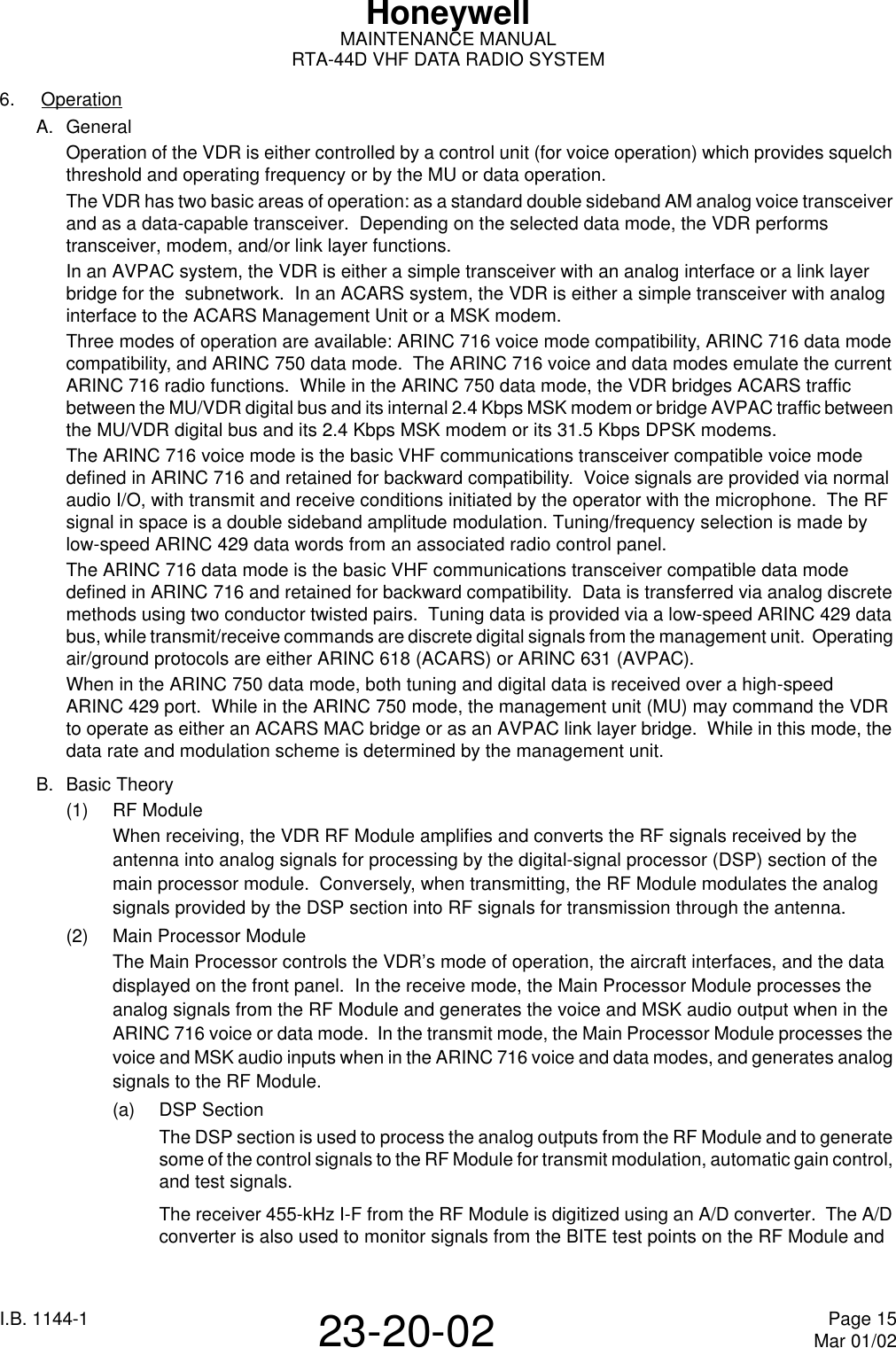
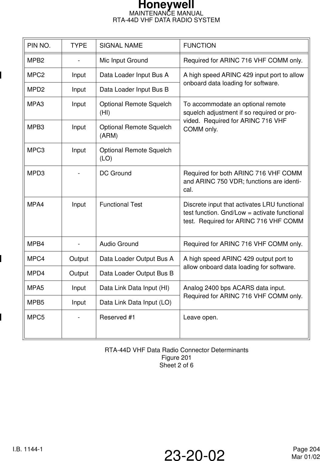
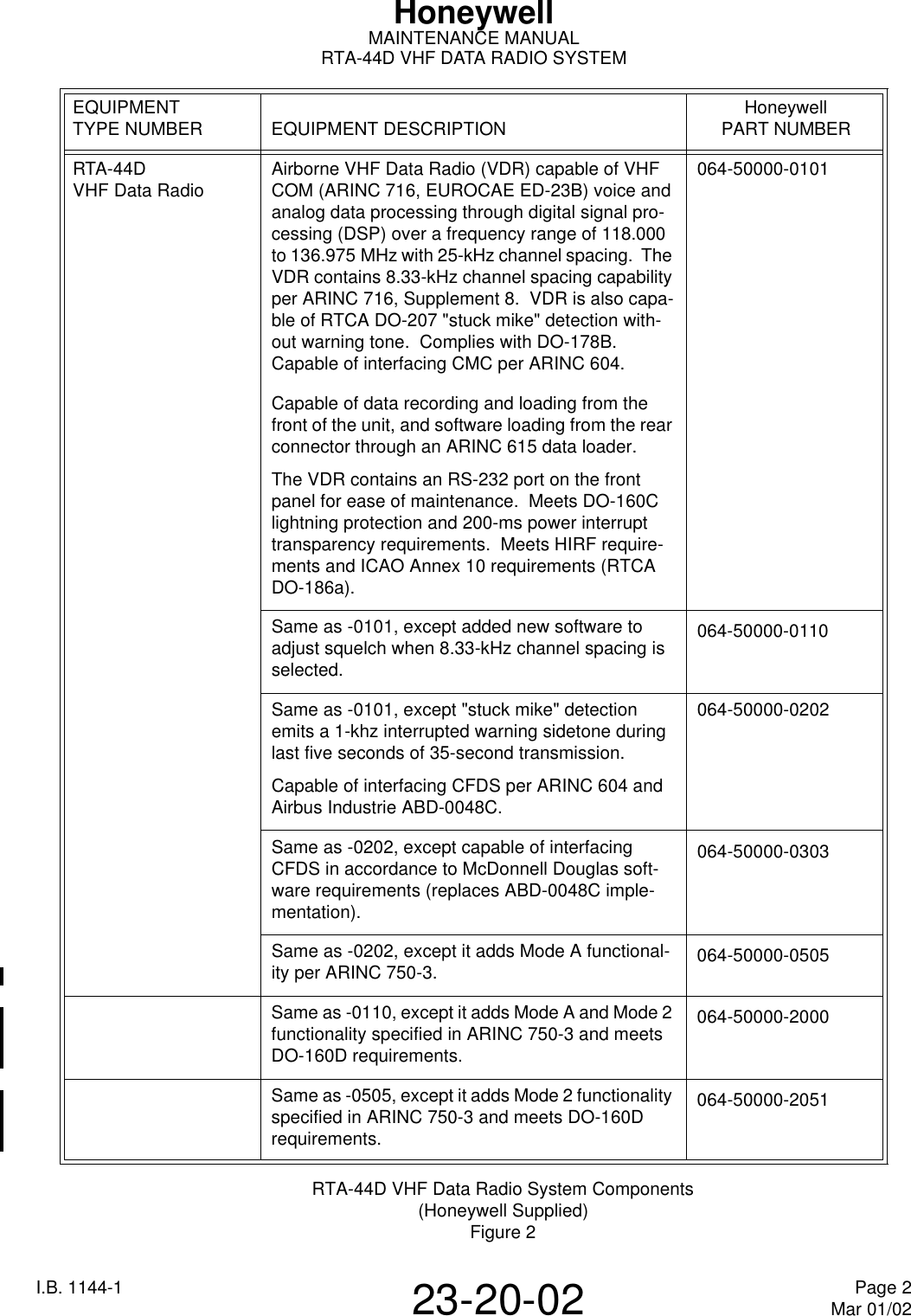
![I.B. 1144-1 Page 9Mar 01/0223-20-02HoneywellMAINTENANCE MANUALRTA-44D VHF DATA RADIO SYSTEMB. Environmental CertificationThe RTA-44D VHF Data Radio meets the environmental conditions of the Radio Technical Commission for Aeronautics (RTCA) document number DO-160C (DO-160D for -2000 and -2051), "Environmental Conditions and Test Procedures for Airline Electronic/Electronical Equipment and Instruments". The environmental certification categories of the VDR, P/N 064-50000-0101, -0110, -0202, -0303 and -0505, are: /A2D2/ZCA/MNB/XXXXXXAAAZZUZ/XXE2/XX.The environmental certification categories of the VDR, P/N 064-50000-2000 and -2051 are: [(A2)(D2)Z]BAB[RB1]XXXXXXZAAZCRRL[A2C2]XXA. Environmental Certification Categories of RTA-44DFigure 8TEST CATEGORY FOR UNITS P/N 064-50000-0101, -0110, -0202, -0303, -0505 -2000, -2051Temperature and Altitude A2D2 A2D2In-Flight Loss of Cooling Z ZTemperature Variation CBHumidity A AOperational Shocks and Crash Safety Meets Specification BVibration MNB RB1Explosion Proofness X XWaterproofness X XFluids and Susceptibility X XSand and Dust X XFungus Resistance X XSalt Spray X XMagnetic Effect AZPower Input A AVoltage Spike A AAudio Frequency Conducted Susceptibility - Power Inputs Z ZInduced Signal Susceptibility ZCRadio Frequency Susceptibility (Radiated and Conducted) U RREmission of Radio Frequency Energy ZLLightning Induced Transient Susceptibility XXE2 A2C2Lightning Direct Effects X XIcing X XElectrostatic Discharge A](https://usermanual.wiki/Honeywell/RTA-44DM2.Users-Manual/User-Guide-258270-Page-25.png)