Honeywell RTA-44DM2 RTA-44D VHF Data Radio User Manual 1144 1Rev5 1144 1r5frontmatter
Honeywell International Inc. RTA-44D VHF Data Radio 1144 1Rev5 1144 1r5frontmatter
Contents
- 1. Users Manual
- 2. Addendum to Users Manual
Users Manual

Honeywell
MAINTENANCE MANUAL
RTA-44D VHF DATA RADIO SYSTEM
I.B. 1144-1 23-20-02
TO: Holders of RTA-44D VHF Data Radio System Maintenance Manual, I.B. 1144-1.
REVISION NO. 5
to
MAINTENANCE MANUAL, I.B. 1144-1
Covering
Date of Original Publication Sep/93
Date of Revision No. 1 Jul/95
Date of Revision No. 2 Nov/95
Date of Revision No. 3 Sep/97
Date of Revision No. 4 Feb 01/00
Date of Revision No. 5 Mar 01/02
INSTRUCTIONS:
1. This revision is a completely revised reissue of I.B. 1144-1, which contains the information printed in the
original manual and all subsequent revisions. The manual was extensively revised to reflect the latest
manufacturing configurations and up-to-date information.
2. Discard the original issue and all previous issues of this publication, and replace with Revision Number 5,
dated Mar 01/02.
3. A bar in the left-hand column indicates where changes were made in this latest revision.
4. Revision stripes are applied where data has changed.
5. Discard this information page after completion.
Honeywell
I.B. 1144-1 T-1
Sep/93
Rev 5: Mar 01/0223-20-02
System
Maintenance Manual
RTA-44D
VHF Data Radio System
Honeywell
CAGE Code 97896

Honeywell
PN-1
No Date
23-20-02
NOTE
IF ANY UNUSUAL OR SPECIAL SERVICE PROBLEMS ARISE,
CONTACT HONEYWELL AIRLINES AND AVIONICS PRODUCTS
CUSTOMER SUPPORT DEPARTMENT.
PROPRIETARY NOTICE
This document contains proprietary information
and such information may not be disclosed to
others for any purpose, nor used for manufac-
turing purposes without written permission from
Honeywell International, Inc.

Honeywell
MAINTENANCE MANUAL
RTA-44D VHF DATA RADIO SYSTEM
I.B. 1144-1 RH-1
Mar 01/02
23-20-02
REVISION NO. 5
Mar 01/02
REVISION HIGHLIGHTS
Pages that have been revised are listed below, together with the highlights of the revision.
- - - - - - - - - - - - - - - - - - - - - - - - - - - - - - - - - - - - - - - - - - - - - - - - - - - - -
PAGE NUMBER DESCRIPTION OF CHANGE
T-1 Updated Title Page format to current standards.
RH-1/RH-2 Updated Revision Highlights pages for Revision No. 5.
LEP-1/LEP-2 Updated "List of Effective Pages" for this revision.
1Added reference to Mode 2 functionality of VDR.
2Added -2000 and -2051 units to RTA-44D VHF Data Radio System
Components table, Figure 2.
3Added reference to -2000 and -2051 units in Related Publications table,
Figure 4.
4Added reference to VDR Mode 2 functionality and made corrections to
Configurations Available table, Figure 5.
5Added Mode 2 VDR functionality to RTA-44D VHF Data Radio Features table,
Figure 6.
6Added VDR Mode 2 units to Leading Particulars listing, Figure 7.
7Changed number of pages in Figure 7.
8Changed number of pages in Figure 7.
8.1 Added 750 Digital Mode to Leading Particulars table, Figure 7.
8.2 Added ARINC 429 Input Labels table, Figure 7.1
8.3/8.4 Added ARINC 429 Output Labels table, Figure 7.2
9Added -2000 and -2051 units to Environmental Certification table, Figure 8.
10 Restructured Paragraph 4 to preserve logical order. Figure 11 moved to
Figure 10.
11 Restructured Paragraph 4 to preserve logical order. Figure 10 moved to
Figure 10.1.
12 Restructured Paragraph 4 to preserve logical order. Figure 13 moved to
Figure 11. Added VDR Mode 2 to primary modes of operation listing.
13 Added Auxiliary Processor Module to System Component Description.
14 Added VDR Mode 2 Units (-2000 and -2051) Internal Architecture Diagram,
Figure 13. (This replaced old Figure 13, which moved to become 11.)
16 Added reference to Production Test Mode (PTM) Tool Quantum Line Tester to
I/O Section discussion. Added Basic Theory of Operation of Auxiliary
Processor Module paragraph.
17/18 Adjusted formatting to accommodate added Theory of Operation of Auxiliary
Processor Module paragraph.
Honeywell
MAINTENANCE MANUAL
RTA-44D VHF DATA RADIO SYSTEM
I.B. 1144-1 RH-2
Mar 01/02
23-20-02
101 Added VDR Mode 2 Units, (-2000 and -2051) "Normal Screen" diagram to
Figure 101. Corrected screen nomenclature for consistency.
102 Updated LCD Control Flow by adding CMU PORT STATUS page to Figure
101.1
103 Corrected screen nomenclature for consistency.
106 Corrected screen nomenclature for consistency.
107 Added explanation of numeric/alpha notation to display screens.
109 Moved text from page 110 to page 109 to accommodate Figures 114.1 and
114.2.
110 Added new Failure pages from VDR Mode 2 units (-2000 and -2051), as
Figures 114.1 and 114.2. Corrected screen nomenclature for consistency.
111 Added "Tuning Port Status Page" Screen for VDR Mode 2 units (-2000 and
-2051) as Figure 116.1.
112 Added Valid Data Examples of "Tuning Port Status Page" Screen (-2000 and
-2051) as Figure 116.2.
113 Added "Discrete Input Status Page 4" Screen for VDR Mode 2 units (-2000
and -2051) as Figure 119.1.
114 Eliminated Figure 122.
115 Updated discussion of Previous Flight Legs Failure data. Corrected screen
nomenclature for consistency.
116 Corrected "Previous Flight Legs Failures Data Page" Screen, Figure 125.
202 Added mention of maximum cable loss specification.
203 Added mention of ARINC specification for ground path resistance.
204 Updated Radio Connector Determinants Table, Figure 201, Sheet 3.
205 Updated Radio Connector Determinants Table, Figure 201, Sheet 4
206 Updated Radio Connector Determinants Table, Figure 201, Sheet 5
207 Updated Radio Connector Determinants Table, Figure 201, Sheet 6
209 Added Software On Board Loadable Instructions.
210 Added Software On Board Loadable Instructions.
211 Added Software On Board Loadable Instructions
212 Added Software On Board Loadable Instructions
213 Added Software On Board Loadable Instructions
214 Added "Normal Mode" Screen for VDR Mod 2 units (-2000 and -2051), Figure
203.1.
215 Text moved from previous revision to accommodate new data on previous
pages and correction to "Test Complete, Failures" Screen, Figure 206 .
216 Text moved from previous revision to accommodate new data on previous
pages .
217/218 Text moved from previous revision to accommodate new data on previous
pages and Figure 207 updated.
219/220 Text moved from previous revision to accommodate new data on previous
pages and Figure 208 updated.
Honeywell
MAINTENANCE MANUAL
RTA-44D VHF DATA RADIO SYSTEM
I.B. 1144-1 RR-1
No Date
23-20-02
RECORD OF REVISIONS
REV.
NO. REVISION
DATE DATE
INSERTED BY REV.
NO. REVISION
DATE DATE
INSERTED BY
Complete through
Revision No. 5

Honeywell
MAINTENANCE MANUAL
RTA-44D VHF DATA RADIO SYSTEM
I.B. 1144-1 RR-2
No Date
23-20-02
RECORD OF REVISIONS
REV.
NO. REVISION
DATE DATE
INSERTED BY REV.
NO. REVISION
DATE DATE
INSERTED BY

Honeywell
MAINTENANCE MANUAL
RTA-44D VHF DATA RADIO SYSTEM
I.B. 1144-1 RTR-1
Mar 01/02
23-20-02
RECORD OF TEMPORARY REVISIONS
T.R.
NO. DATE
DATE
INSERTED
BY DATE
REMOVED
BY
Complete Through
Temporary Revision 23-5

Honeywell
MAINTENANCE MANUAL
RTA-44D VHF DATA RADIO SYSTEM
I.B. 1144-1 RTR-2
Mar 01/02
23-20-02
RECORD OF TEMPORARY REVISIONS
T.R.
NO. DATE DATE
INSERTED BY DATE
REMOVED BY

Honeywell
MAINTENANCE MANUAL
RTA-44D VHF DATA RADIO SYSTEM
LIST OF EFFECTIVE PAGES
I.B. 1144-1 LEP-1/LEP-2
Mar 01/02
23-20-02
Title Page *T-1 Mar 01/02
Proprietary PN-1 No Date
Notice
Revision *RH-1 Mar 01/02
Highlights *RH-2 Mar 01/02
Record of RR-1 No Date
Revisions RR-2 No Date
Record of RTR-1 Mar 01/02
Temporary RTR-2 Mar 01/02
Revisions
List of *LEP-1 Mar 01/02
Effective LEP-2 Blank
Pages
Table of TC-1 Mar 01/02
Contents TC-2 Blank
Introduction INTRO-1 Mar 01/02
Description 0 Mar 01/02
and Operation 1 Mar 01/02
*2 Mar 01/02
*3 Mar 01/02
*4 Mar 01/02
*5 Mar 01/02
*6 Mar 01/02
*7 Mar 01/02
*8 Mar 01/02
*8.1 Mar 01/02
*8.2 Mar 01/02
*8.3 Mar 01/02
*8.4 Blank
*9 Mar 01/02
*10 Mar 01/02
*11 Mar 01/02
*12 Mar 01/02
*13 Mar 01/02
*14 Mar 01/02
15 Mar 01/02
*16 Mar 01/02
*17 Mar 01/02
18 Blank
Fault Isolation *101 Mar 01/02
*102 Mar 01/02
*103 Mar 01/02
104 Mar 01/02
105 Mar 01/02
*106 Mar 01/02
*107 Mar 01/02
108 Mar 01/02
*109 Mar 01/02
*110 Mar 01/02
*111 Mar 01/02
*112 Mar 01/02
*113 Mar 01/02
*114 Mar 01/02
*115 Mar 01/02
*116 Mar 01/02
Maintenance 201 Mar 01/02
Practices *202 Mar 01/02
*203 Mar 01/02
*204 Mar 01/02
*205 Mar 01/02
*206 Mar 01/02
*207 Mar 01/02
208 Mar 01/02
*209 Mar 01/02
*210 Mar 01/02
*211 Mar 01/02
*212 Mar 01/02
*213 Mar 01/02
*214 Mar 01/02
*215 Mar 01/02
*216 Mar 01/02
F*217 Mar 01/02
F 218 Blank
F*219 Mar 01/02
F*220 Blank
SUBJECT PAGE DATE SUBJECT PAGE DATE

Honeywell
MAINTENANCE MANUAL
RTA-44D VHF DATA RADIO SYSTEM
I.B. 1144-1 TC-1/TC-2
Mar 01/02
23-20-02
TABLE OF CONTENTS
Paragraph/Title Page
DESCRIPTION AND OPERATION - - - - - - - - - - - - - - - - - - - - - - - - - - - - - - - 1
FAULT ISOLATION - - - - - - - - - - - - - - - - - - - - - - - - - - - - - - - 101
MAINTENANCE PRACTICES - - - - - - - - - - - - - - - - - - - - - - - - - - - - - - - 201
Honeywell
MAINTENANCE MANUAL
RTA-44D VHF DATA RADIO SYSTEM
I.B. 1144-1 INTRO-1
Mar 01/02
23-20-02
INTRODUCTION
This manual, I.B. 1144-1 (23-20-02), contains
information covering description and operation,
installation, and flight-line checkout procedures for the
Honeywell International, Airlines and Avionics Products
RTA-44D VHF Data Radio System
Honeywell
MAINTENANCE MANUAL
RTA-44D VHF DATA RADIO SYSTEM
I.B. 1144-1 Page 0
Mar 01/02
RTA-44D VHF Data Radio
Figure 1

Honeywell
MAINTENANCE MANUAL
RTA-44D VHF DATA RADIO SYSTEM
I.B. 1144-1 Page 1
Mar 01/02
23-20-02
DESCRIPTION AND OPERATION
1. General
This section contains descriptive information covering the RTA-44D VHF Data Radio (VDR) System and
lists other components required for system operation. The RTA-44D VHF Data Radio (VDR) is illustrated
in Figure1.
A. Purpose of Equipment
The RTA-44D VHF Radio (VDR) System is an airborne VHF Communications Transceiver designed to
provide voice and data communication between on-board aircraft systems, to other aircraft systems,
and to ground-based systems.
The VDR is designed to Aeronautical Radio Incorporated (ARINC) 716 Airborne VHF Communications
Transceiver and ARINC 750 Airborne VHF Data Radio Specifications, Radio Technical Commission for
Aeronautics (RTCA) documents number DO-186a Minimum Operational Performance Standards
(MOPS) for Airborne Radio Communications Equipment Operating within the Radio Frequency Range
117.975-137.000Megahertz and number DO-207 MOPS for Devices that Prevent Blocked Channels
Used in Two-Way Radio Communications Due to Unintentional Transmissions, and European
Organization for Civil Aviation Equipment (EUROCAE) ED-23B Minimum Performance Specification for
Airborne VHF Communications Equipment Operating in the Frequency Range 117.975 - 137.000 MHz.
The VDR is fully interchangeable with the earlier ARINC716 RTA-44A VHF Communications
Transceiver for backward compatibility.
In an Aircraft Communications Addressing and Reporting System (ACARS), the VDR is a simple
transceiver with an analog interface to the ACARS Management Unit (MU) or a MSK modem.
In Mode 2, the VDR contains a D8PSK modem and a digital high speed ARINC 429 link to the
MU/CMU/ATSU per Mode 2 functionality in ARINC 750-3.
The VDR system requires an antenna for its RF inputs and outputs, a control head or radio management
panel, an audio input source and output sink for its analog voice functions, and an ACARS MU, CMU
or ATSU for its digital control and data functions. The VDR system may also be connected to a Central
Maintenance Computer (CMC) or Central Fault Display System (CFDS) to transfer maintenance data.
Depending upon the selected mode, the VDR operates with the following equipment:
•an ARINC 597, 724, or 724B ACARS MU,
•an ARINC 604 and Airbus Industrie ABD-0048C Centralized Fault Display Interface Unit
(CFDIU),
•an ARINC 716 voice audio input source and output sink,
•an ARINC 716 voice frequency control source,
•an ARINC 758 CMU or ATSU.
•an antenna.
B. Equipment Part Numbers
Components of the RTA-44D VHF Data Radio System supplied by Honeywell are listed in Figure2. The
figure lists the currently available components of the system, along with part numbers and equipment
type numbers.

I.B. 1144-1 Page 2
Mar 01/02
23-20-02
Honeywell
MAINTENANCE MANUAL
RTA-44D VHF DATA RADIO SYSTEM
RTA-44D VHF Data Radio System Components
(Honeywell Supplied)
Figure 2
EQUIPMENT
TYPE NUMBER EQUIPMENT DESCRIPTION Honeywell
PART NUMBER
RTA-44D
VHF Data Radio Airborne VHF Data Radio (VDR) capable of VHF
COM (ARINC 716, EUROCAE ED-23B) voice and
analog data processing through digital signal pro-
cessing (DSP) over a frequency range of 118.000
to 136.975MHz with 25-kHz channel spacing. The
VDR contains 8.33-kHz channel spacing capability
per ARINC716, Supplement 8. VDR is also capa-
ble of RTCA DO-207 "stuck mike" detection with-
out warning tone. Complies with DO-178B.
Capable of interfacing CMC per ARINC 604.
064-50000-0101
Capable of data recording and loading from the
front of the unit, and software loading from the rear
connector through an ARINC 615 data loader.
The VDR contains an RS-232 port on the front
panel for ease of maintenance. Meets DO-160C
lightning protection and 200-ms power interrupt
transparency requirements. Meets HIRF require-
ments and ICAO Annex 10 requirements (RTCA
DO-186a).
Same as -0101, except added new software to
adjust squelch when 8.33-kHz channel spacing is
selected.
064-50000-0110
Same as -0101, except "stuck mike" detection
emits a 1-khz interrupted warning sidetone during
last five seconds of 35-second transmission.
Capable of interfacing CFDS per ARINC 604 and
Airbus Industrie ABD-0048C.
064-50000-0202
Same as -0202, except capable of interfacing
CFDS in accordance to McDonnell Douglas soft-
ware requirements (replaces ABD-0048C imple-
mentation).
064-50000-0303
Same as -0202, except it adds Mode A functional-
ity per ARINC 750-3.064-50000-0505
Same as -0110, except it adds Mode A and Mode 2
functionality specified in ARINC 750-3 and meets
DO-160D requirements.
064-50000-2000
Same as -0505, except it adds Mode 2 functionality
specified in ARINC 750-3 and meets DO-160D
requirements.
064-50000-2051

Honeywell
MAINTENANCE MANUAL
RTA-44D VHF DATA RADIO SYSTEM
I.B. 1144-1 Page 3
Mar 01/02
23-20-02
C. Equipment Required but Not Supplied
Figure 3 lists equipment required for the RTA-44D VHF Data Radio System, but not supplied by
Honeywell.
Equipment Required but Not Supplied
Figure 3
D. Related Publications
Figure 4 lists the publications covering the RTA-44D VHF Data Radio and test procedure supporting the
system.
Related Publications
Figure 4
EQUIPMENT DESCRIPTION
Power Source DC power supply of 27.5 volts.
Receive - 1 ampere, Transmit - 7 amperes (at stated input voltage.)
Audio Distribution System Audio system with an input impedance of 200 to 10,000 ohms.
Control Panel Provides remote control of frequency selection for 25-kHz or 8.33-kHz
channel spacing system operation (serial digital, ARINC 429-7 and
ARINC 716, Supplement 8), power on/off, volume, and squelch in con-
formance to ARINC 716.
MU/CMU/ATSU Provides control and data source/sink when operating in the 750 data
mode.
3 MCU Unit Mount Provides a means of mounting RTA-44D VHF Data Radio in the aircraft.
VHF Antenna Capable of receiving and transmitting VHF signals over a frequency range
of 118.000 through 136.975 MHz.
Microphone 150-ohm impedance microphone (either carbon or transistor) operating
from approximately 16-volt power supply.
Cables and Connectors Necessary connectors and cables as shown in RTA-44D VHF Data Radio
System Interwiring Diagram, Figure 208.
PUBLICATION
HoneywelI
IDENTIFICATION
NUMBER
ATA
IDENTIFICATION
NUMBER
RTA-44D VHF Data Radio
Part Numbers 064-50000-0101, -0110 and -2000
Component Maintenance Manual
I.B. 1144A-2 23-20-36
RTA-44D VHF Data Radio
Part Numbers 064-50000-0202, -0303, -0505 and -2051
Component Maintenance Manual
I.B. 1144A-3 23-20-38
I.B. 1144-1 Page 4
Mar 01/02
23-20-02
Honeywell
MAINTENANCE MANUAL
RTA-44D VHF DATA RADIO SYSTEM
2. Configurations Available
Figure 5 lists the available configurations of the RTA-44D VHF Data Radio and the features contained in
each configuration. Figure6 contains a brief description of each feature.
1 = Airbus CFDS interface software.
2 = McDonnell Douglas CFDS interface software.
3 = All -0202 hardware capable. 02/02 software required for squelch adjustment for 8.3-kHz channel spacing.
4 =On Board Loadable Dependent.
RTA-44D VHF Data Radio, Configurations Available
Figure 5
RTA-44D VHF Data Radio Features
Figure 6
Sheet 1 of 2
Honeywell
PART
NUMBER
064-50000
FEATURES
BASIC
UNIT FAULT
MEMORY
STUCK
MIKE
ALARM
COMPATIBILITY Mode
AMode
2
ACARS
INTERFACE 8.33-kHz
CHANNEL
SPACING
BOEING
CMC
CFDS
-0101 X X X X X
-0110 X X X X X
-0202 X X X X X1X3
-0303 X X X X X2X
-0505 X X X X X1X X
-2000 X X X X X4X4X X X
-2051 X X X X X1X X X
FEATURE DESCRIPTION
Basic Unit Airborne solid-state VDR is capable of receiving and transmitting ARINC
716 voice and ARINC 716 data over a frequency range of 118.000 to
136.975MHz with 25-kHz channel spacing. Channel spacing capability
of 8.33-kHz per ARINC716, Supplement10 is available as well as RTCA
DO-207 "stuckmike" detection. Complies with DO-178B software
requirements and enhanced BITE requirements of Airbus, Boeing, and
McDonnell Douglas.

Honeywell
MAINTENANCE MANUAL
RTA-44D VHF DATA RADIO SYSTEM
I.B. 1144-1 Page 5
Mar 01/02
23-20-02
RTA-44D VHF Data Radio Features
Figure 6 (Sheet 2 of 2)
FEATURE DESCRIPTION
Basic Unit (Continued)
Fault Memory
Stuck Microphone Alarm
ACARS Compatible
CMC Interface
CFDS Interface
Capable of data recording and loading from the front of the VDR, and
software loading from the rear connector through an ARINC615 data
loader. Contains an RS-232 port on the front panel for ease of
maintenance. Meets RTCA DO-160C lightning protection and 200ms
power interrupt transparency requirements. Meets HIRF requirements
and ICAO Annex10 requirements (RTCA DO-186a). Front panel LCD
displays unit's characteristics (part number, serial number), BITE
status with fault location help pages, line maintenance values with help
pages, and software data loading help screens.
A nonvolatile, single-chip fault memory that allows the recording of
faults associated with a particular flight leg. Sixty-four flight legs are
available with each flight leg made up of a flight-leg information header
containing a fault record section for recording ten airborne faults and
three ground faults. When all flight legs have been used, the oldest
flight leg shall be reused.
After the VDR detects that the microphone is in the transmit (keyed)
position for a time duration longer than 30seconds, a 1kHz
interrupted tone (½second on, ½second off) is emitted for five
seconds via the audio/sidetone output. After a total of 35seconds, the
VDR turns off the transmitter and the 1kHz interrupted sidetone. To
reactivate the transmitter, the microphone push-to-talk button must be
released and then rekeyed.
The VDR ensures proper processing of the ACARS messages.
The VDR interfaces fault memory and BITE data between the VDR
and line maintenance Centralized Maintenance Computer (CMC) for
the purpose of extracting maintenance information and initiating tests.
Designed to conform with ARINC 429 interfaces and ARINC 604
requirements.
The VDR interfaces fault memory and BITE data between the VDR
and line maintenance Centralized Fault Display Interface Unit (CFDIU)
for the purpose of extracting maintenance information and initiating
tests. Designed to conform with ARINC 429 interfaces, ARINC 604
and Airbus Industrie ABD-0048C or McDonnell Douglas software
requirements.
8.33-kHz Channel
Spacing Capability The VDR is capable of 8.33-kHz channel spacing to meet the
European narrow-band (8.33-kHz) VHF voice communications
systems. The narrow-band mode of operation is limited to voice
communications.
Mode A The Mode A VDR contains an ACARS MSK modem and a digital high
speed ARINC 429 link to the MU/CMU/ATSU per the Mode A
functionality specified in ARINC 750-3.
Mode 2 The Mode 2 VDR contains a D8PSK modem and a digital high speed
ARINC 429 link to the MU/CMU/ATSU per Mode 2 functionality in
ARINC 750-3. The Mode 2 VDR meets DO-160D requirements.

I.B. 1144-1 Page 6
Mar 01/0223-20-02
Honeywell
MAINTENANCE MANUAL
RTA-44D VHF DATA RADIO SYSTEM
3. System Leading Particulars
A. Unit Specifications
Figure 7 lists the leading particulars for the RTA-44D VHF Data Radio System.
Leading Particulars
Figure 7 (Sheet 1 of 4)
CHARACTERISTICS DESCRIPTION
General - Overall VDR
Form Factor 3MCU (ARINC600)
Dimensions Refer to outline drawing, Figure 207.
Weight 9.6 LBS., (4,4Kg) Maximum
General - Overall VDR
Power Requirements 27.5 Vdc nominal (+10%, -20%)
1.0A - Receive (-0101, -0110, -0202, -0303 and -0505)
1.5A - Receive (-2000 and -2051)
7.0A - Transmit (All Units)
Temperature
Operating
Storage
-55°C to +70°C (-67°F to +158°F) (-0101, -0110, -0202, -0303 and -0505)
-15°C to +70°C (5°F to 158°F) (-2000 and -2051)
-65°C to +85°C (-85°F to +185°F) (All Units)
Cooling ARINC600
Humidity Zero to 95%
Altitude To 15,240 meters (50,000feet)
Warm-up period None; stable operation after power application.
Frequency Control ARINC, 429 Mark, 33 (Serial Digital)
Frequency Range 118.000MHz to 136.975MHz
Channel Spacing 25-kHz and 8.33-kHz
Frequency Stability ±0.0005%
Duty Cycle Continuous operation from -55°C to +70°C with ARINC 600 cooling.
Certification
-0101, -0110, -0202, -0303 and
-0505 Units
-2000, -2051 Units
TSO C37d Class3 and 5 and C38d ClassC and E;
DO-160C Categories
/A2D2/ZCA/MNB/XXXXXXAAAZZUZ/XXE2/XX
DO-186a, DO-178B, DO-207 AND EUROCAEED-23B
TSO C37d Class3 and 5 and C38d ClassC and E;
DO-160D Categories
[(A2)(D2)Z]BAB[RB1]XXXXXXZAAZCRRL[A2C2]XXA
DO-186a, DO-178B, DO-207 AND EUROCAEED-23B
General - Analog Voice/Data
Channel Changing Time
Transmit to Receive Recovery
Less than 50milliseconds to stabilize on a new channel frequency.
Less than 50 milliseconds after transmission to provide 90% of its output
at an input level of 10 µV modulated 30% at 1000Hz.

Honeywell
MAINTENANCE MANUAL
RTA-44D VHF DATA RADIO SYSTEM
I.B. 1144-1 Page 7
Mar 01/02
23-20-02
Leading Particulars
Figure 7 (Sheet 2 of 4)
CHARACTERISTICS DESCRIPTION
Analog Voice Receiver
Sensitivity Greater than 6dB SINAD for -107dBm signal modulated
30% at 1000Hz.
Selectivity
25-kHz Channel Spacing
8.33-kHz Channel Spacing ±8-kHz at 6dB bandwidth, ±17-kHz at 60dB bandwidth.
±2.78-kHz at 6 dB bandwidth, ±7.365-kHz at 60 dB
bandwidth.
Cross Modulation Meets requirements of ARINC716, Section3.6.4.
AGC Within 3dB with inputs from 5µV to 100,000 µV and not
more than 6dB with inputs from 5µV to 500,000 µV.
Audio Output 40milliwatts maximum into a 600±20% ohm resistive
load, factory set at 10mW at 1000 Hz.
Audio Output Frequency Response Within 6dB from 300 to 2500Hz.
Audio Output Harmonic Distortion Total harmonic distortion will not exceed 5% with
1000µV input signal modulated 30% at 1000Hz.
Audio Output Regulation No more than 2dB voltage change from a 10mW
reference level into 600ohms for resistive load
variations between 450ohms to 2400ohms, and no
more than 6dB voltage change for resistive load
variations between 200ohms and 20k ohms.
Voice Phase Shift Limit Audio output does not depart from that of the
positive-going modulation envelope at the receiver input
by more than -30° to +120° with a 1000µV input signal
modulated 30% at 1000Hz and an output level adjusted
for 40milliwatts into a 600-ohm resistive load.
Undesired Responses 80 dB
Input Impedance 50 ohms, nominal
Analog Voice Transmitter
Output Power 25 watts (nominal)
Harmonic and Spurious Emission Any harmonics of the desired frequency is attenuated at
least 60dB below the desired carrier level and any other
emission will be attenuated at least 118dB below the
carrier level.

I.B. 1144-1 Page 8
Mar 01/02
23-20-02
Honeywell
MAINTENANCE MANUAL
RTA-44D VHF DATA RADIO SYSTEM
Leading Particulars
Figure 7 (Sheet 3 of 4)
CHARACTERISTICS DESCRIPTION
Analog Voice Transmitter (Con’t)
Transmitter Modulation Frequency
Response
Flat within 6dB from 300Hz to 2500Hz.
Audio Distortion 6% maximum for 30% modulation and 10%maximum
for 90% modulation with a 0.5volt input and a
modulating frequency from 300Hz to 2500Hz.
Modulation Level 90% modulation minimum for an input level of 0.25volts
rms at 1000Hz.
Analog Data Receiver
Gain SELCAL/Output 0.6volts rms minimum with a 2µV signal modulated
30% at 1000Hz into a 600-ohm load.
Frequency Response SELCAL
Output
±2.5dB from 312Hz to 1200Hz (post detection
response with respect to 1000Hz is ±4.5dB from
300Hz to 6600Hz).
Distortion SELCAL Output 4.5% maximum with an input signal of 1000µV
modulated 30% at 1000Hz and a level adjusted to
provide 0.5 volts into a 600-ohm load.
AGC Attack Time SELCAL Output Reaches 90% of its steady-state value within
30milliseconds maximum after the step application of an
RF carrier of 1000µV modulated 30% at 1000Hz.
AGC Decay Time SELCAL Output Reaches 90% of its steady-state value within
45milliseconds maximum after the receiver input of
1000µV modulated 30% at 1000Hz is step reduced to
10µV.
Analog Data Transmitter
Modulation Level Data Input 70% modulation minimum for a frequency of 1000Hz at
a -10dBm level.
Frequency Response Data Input Flat within 5.5dB from 600Hz to 6600Hz.
Distortion Data Input 9.5% maximum distortion at modulation level up to 90%
over frequency range of 600Hz to 6600Hz.

Honeywell
MAINTENANCE MANUAL
RTA-44D VHF DATA RADIO SYSTEM
I.B. 1144-1 Page 8.1
Mar 01/02
23-20-02
Leading Particulars
Figure 7 (Sheet 4 of 4)
CHARACTERISTICS DESCRIPTION
Digital Data Receiver (750 Mode)
Sensitivity <0.01 message error rate @ -104 dBm (Mode A)
<10-3 Uncorrected BER @ -98 dBm (Mode 2)
Dynamic Range Min. -7 dBm.
Adjacent Channel Rejection
+/-25-kHz
+/-50-kHz
+/-100-kHz and beyond
+44 dBc
+50 dBc
+60 dBc
Interference Rejection
Out-of-Band
Co-Channel
Per ARINC 750-3, para 4.3.4.3
-20 dBc Interferer
Channel Sensing Modulated Signal Sensed (Mode A)
Carrier Sensed (Mode 2)
Digital Data Transmitter (750 Mode)
Output Power 25W nominal (Mode A)
17.5 +/- 2W (Mode 2)
Modulation Type and Data Rate 2400 bps Amplitude Modulated Minimum Shift
Keying, AM-MSK (Mode A)
31,500 bps Differential 8-Phase Shift Keying, D8PSK
(Mode 2).
Duty Cycle 20% as defined in ARINC 750-3 para. 4.2.2
Transmitter Emissions (Mode)
Adjacent Channel
+/- 25kHz (25kHz BW)
+/- 25kHz (16kHz BW)
+/- 50kHz (25kHz BW)
+/- 100kHz (25kHz BW)
Wideband Noise
+2 dBm
-18 dBm
-28 dBm
-38 dBm
Decreases 5 dB/octave from +/-100-kHz to -53 dBm max
emission in 25-kHz BW (118-136.975 MHz)
Phase/Amplitude Balance (Mode 2)
Spurious Radiation
Tuning Time
Transmitter Ramp-up
8% Error Vector Magnitude
Per ARINC 750-3 para. 4.2.8.6
100 ms
2 ms for Pre-key (Mode A)
reaches 90% at least 3 symbols prior to
Preamble (Mode 2)
Data Clock Stability 0.005%
Honeywell
MAINTENANCE MANUAL
RTA-44D VHF DATA RADIO SYSTEM
I.B. 1144-1 Page 8.2
Mar 01/02
23-20-02
VDR ARINC 429 Input Labels
Figure 7.1
429 INPUT LABEL RATE DESCRIPTION
Tuning Bus A and B (Low Speed)
030
047
276
200 ms
200 ms
500 ms
Tuning Frequency 25-kHz
Tuning Frequency 8.33-kHz
Voice/Data Indication
CMU Input Bus 1 and 2 (High Speed)
(-0505, -2000, -2051)
270 1 second CMU Status Word
250, 251, 252, 253 (When Own Aircraft
SDI is 0, 1, 2, or 3 respectively
Whenever Data
available
CMU Solo words and BOP files
Data Loader Input Bus (High Speed)
251 Follows ARINC
615 protocol
ARINC 615 Data loader
CMC Data Input Bus 1 and 2 (Low Speed)
040
041
042
125
126
1551
1561
1571
227
233
234
235
236
237
260
2612
301
302
303
304
NOTES:
1 For Airbus Only (-0202, -0505, -2051)
2 For McDonnell Douglas Only (-0303)
1 second (+.5)
1 second (+.5)
1 second (+.5)
1 second (+.5)
1 second (+.5)
1 second (+.5)
1 second (+.5)
1 second (+.5)
1 second (+.5)
1 second (+.5)
1 second (+.5)
1 second (+.5)
1 second (+.5)
1 second (+.5)
1 second (+.5)
1 second (+.5)
1 second (+.5)
1 second (+.5)
1 second (+.5)
1 second (+.5)
City Pair 1
City Pair 2
City Pair 3
UTC
Flight Phase
Aircraft Configuration 1
Aircraft Configuration 2
Aircraft Configuration 3
Command Word
Flight Number 1
Flight Number 2
Flight Number 3
Flight Number 4
Flight Number 5
Date
Flight Number
Aircraft ID 1
Aircraft ID 2
Aircraft ID 3
Aircraft ID 4
Honeywell
MAINTENANCE MANUAL
RTA-44D VHF DATA RADIO SYSTEM
I.B. 1144-1 Page 8.3/8.4
Mar 01/02
VDR ARINC 429 Output Labels
Figure 7.2
429 OUTPUT LABEL RATE DESCRIPTION
CMU Output Bus (High Speed)
(-0505, -2000, -2051)
270 1 second VDR Status Word
172 1 second System Address Label
377 1 second Equipment Identifier
304 Whenever data to send to
CMU VDR Solo words and BOP Files
Data Loader Output Bus (High Speed)
226 Follows ARINC 615
protocol
ARINC 615 Data Loader
CMC Output Bus (Low Speed)
350 750 ms Fault Summary Word
354 50 ms to 250 ms LRU Identification (P/N and S/N)
356 50 ms to 250 ms
3 ms and 3 seconds max.
ISO 5 Fault Message
Normal Mode
Interactive Mode
377 1 second maximum ARINC 429 Equipment Identification
I.B. 1144-1 Page 9
Mar 01/02
23-20-02
Honeywell
MAINTENANCE MANUAL
RTA-44D VHF DATA RADIO SYSTEM
B. Environmental Certification
The RTA-44D VHF Data Radio meets the environmental conditions of the Radio
Technical Commission for Aeronautics (RTCA) document number DO-160C
(DO-160D for -2000 and -2051), "Environmental Conditions and Test Procedures for
Airline Electronic/Electronical Equipment and Instruments". The environmental
certification categories of the VDR, P/N 064-50000-0101, -0110, -0202, -0303 and
-0505, are: /A2D2/ZCA/MNB/XXXXXXAAAZZUZ/XXE2/XX.
The environmental certification categories of the VDR, P/N 064-50000-2000 and
-2051 are: [(A2)(D2)Z]BAB[RB1]XXXXXXZAAZCRRL[A2C2]XXA.
Environmental Certification Categories of RTA-44D
Figure 8
TEST CATEGORY FOR UNITS P/N
064-50000
-0101, -0110, -0202,
-0303, -0505 -2000, -2051
Temperature and Altitude A2D2 A2D2
In-Flight Loss of Cooling Z Z
Temperature Variation CB
Humidity A A
Operational Shocks and Crash Safety Meets Specification B
Vibration MNB RB1
Explosion Proofness X X
Waterproofness X X
Fluids and Susceptibility X X
Sand and Dust X X
Fungus Resistance X X
Salt Spray X X
Magnetic Effect AZ
Power Input A A
Voltage Spike A A
Audio Frequency Conducted Susceptibility - Power Inputs Z Z
Induced Signal Susceptibility ZC
Radio Frequency Susceptibility (Radiated and Conducted) U RR
Emission of Radio Frequency Energy ZL
Lightning Induced Transient Susceptibility XXE2 A2C2
Lightning Direct Effects X X
Icing X X
Electrostatic Discharge A
Honeywell
MAINTENANCE MANUAL
RTA-44D VHF DATA RADIO SYSTEM
I.B. 1144-1 Page 10
Mar 01/02
23-20-02
4. System Description
Figure 9 Deleted by Revision 3
A. VDR System
The VDR system consists of an antenna for its rf inputs and outputs, a control head or radio
management panel (RMP) (refer to Figure 10) and an audio input source and output sink for its analog
voice functions. The VDR system may also be connected to a Central Maintenance Computer (CMC)
or Centralized Fault Display System (CFDS) to transfer maintenance data.
VHF Communications for Voice Operation
Figure 10
There are four primary modes of operation in the VDR system:
•ARINC 716 voice compatibility mode, 25-kHz or 8.33-kHz channel spacing,
•ARINC 716 data compatibility mode.
•ARINC 750 Mode A
•ARINC 750 Mode 2
I.B. 1144-1 Page 11
Mar 01/02
23-20-02
Honeywell
MAINTENANCE MANUAL
RTA-44D VHF DATA RADIO SYSTEM
The ARINC 716 voice and data modes emulate the current ARINC 716 radio functions found in the previous
RTA-44A VHF Transceiver System.
B. ARINC 716 Data Mode
In ACARS, the VDR system is a simple transceiver with an analog interface to the ACARS Management
Unit (MU) (refer to Figure 10.1).
ACARS Audio Interface
Figure 10.1
Honeywell
MAINTENANCE MANUAL
RTA-44D VHF DATA RADIO SYSTEM
I.B. 1144-1 Page 12
Mar 01/02
23-20-02
C. ARINC 750 Modes A and 2
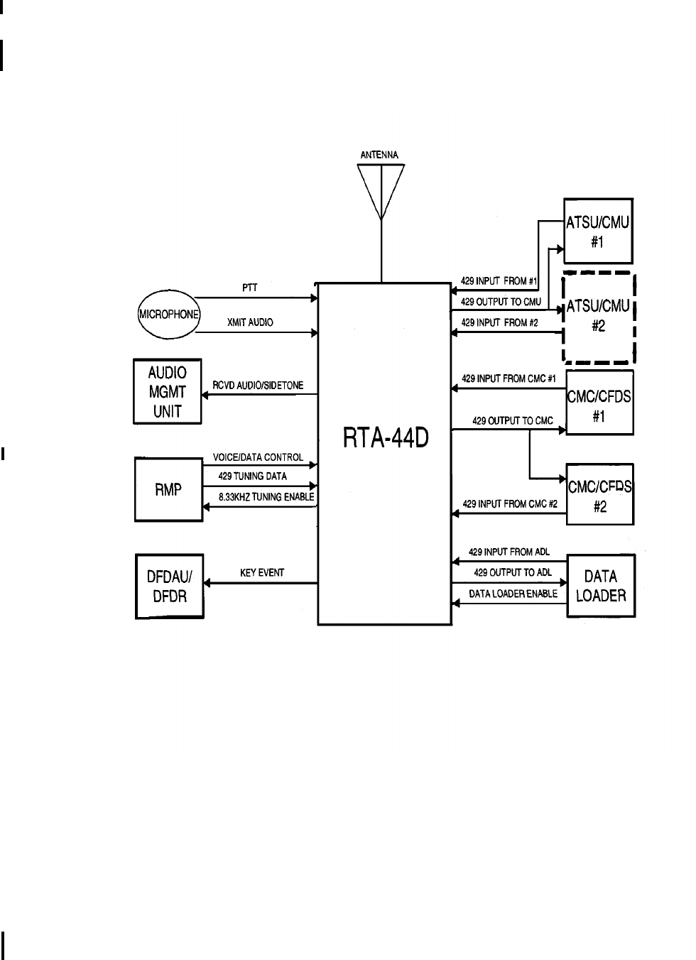
Figure 11 illustrates the same interfaces when the radio is operating in ARINC 750 Mode with a
compatible CMU, ACARS MU, or ATSU. This wiring configuration would be used for Mode A and Mode
2 operation. The Mode A and Mode 2 VDR can be installed in an ARINC 716 configuration, if Mode A
and Mode 2 operation is not required.
RTA-44D External Interfaces (ARINC 750 Mode)
Figure 11

I.B. 1144-1 Page 13
Mar 01/02
23-20-02
Honeywell
MAINTENANCE MANUAL
RTA-44D VHF DATA RADIO SYSTEM
5. System Component Description
A. RTA-44D VHF Data Radio
The VDR is a VHF transmitter-receiver that provides modulation for double-sideband amplitude
modulation for analog voice/data operation in the 25-kHz or 8.33-kHz spaced channels from
118.000MHz to 136.975MHz. Frequency selection is provided through a serial-digital format in
accordance with ARINC Specification 429.
The VDR is completely solid state and is housed in an ARINC 3-MCU case per ARINC
Specification600. A handle is located on the front panel of the VDR to facilitate installation, removal,
and transport of the VDR.
The VDR uses a low insertion force, size one shell ARINC600 rear panel connector with two inserts.
The middle insert is used for aircraft interconnections and the bottom insert is used for input power and
coaxial antenna connectors. The keying pins are set to index pin code "04".
Forced air cooling, in accordance with ARINC specification 600, is required for cooling the VDR.
For maintenance purposes, a microphone jack and headphone jack are provided on the front panel of
the VDR. A front panel display provides an interface to an operator via a liquid crystal display (LCD)
that is visible from the front of the VDR to display messages in simple language in one of four modes:
normal operation, BITE display, maintenance, and software loading.
Software loading and data recording of data to/from the CPU is via the front panel Personal Computer
Memory Card International Association (PCMCIA) slot. Intel Series 1 Flash Cards with capabilities
ranging from 1 up to 64 megabytes are supported.
Two pushbutton switches allow operator interface with the VDR LCD.
In normal operation, the front panel LCD displays the unit's characteristics: unit identification, part
number, and serial number. The BITE display mode is activated after manual self-test has been
exercised either from the front panel test pushbutton or remotely. In the BITE mode, BITE status is
reported and in the event of a detected failure, additional help screens are provided to locate the
detected failure to a module. BITE help pages are provided. In the maintenance mode, a set of
maintenance words are displayed and decoded showing the names of data fields and the value of the
data. Maintenance help pages are provided. For loading software, a series of screens direct the
operator during the data loading process. Software version and loading status are provided during the
update process.
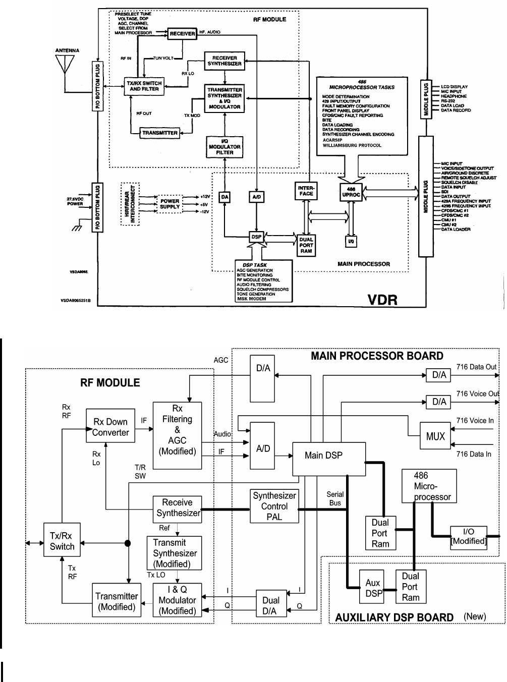
The VDR is partitioned into six subassemblies: RF Module, Main Processor Module, HIRF/Interconnect
Module, Power Supply Assembly, Display Assembly, and Flash Card Memory Module (refer to
Figure12). An Auxiliary Processor Module was added for ARINC 750 Mode 2 (-2000, -2051) operation
(refer to Figure 13).
B. Other Components in the System
Other VDR system components are not supplied by Honeywell AIrlines and Avionics Products.
Information on these units must be obtained from their respective manufacturers.
Honeywell
MAINTENANCE MANUAL
RTA-44D VHF DATA RADIO SYSTEM
I.B. 1144-1 Page 14
Mar 01/02
23-20-02
RTA-44D VHF Data Radio, Simplified Block Diagram
Figure 12
RTA-44D Internal Architecture (-2000, -2051)
Figure 13

I.B. 1144-1 Page 15
Mar 01/02
23-20-02
Honeywell
MAINTENANCE MANUAL
RTA-44D VHF DATA RADIO SYSTEM
6. Operation
A. General
Operation of the VDR is either controlled by a control unit (for voice operation) which provides squelch
threshold and operating frequency or by the MU or data operation.
The VDR has two basic areas of operation: as a standard double sideband AM analog voice transceiver
and as a data-capable transceiver. Depending on the selected data mode, the VDR performs
transceiver, modem, and/or link layer functions.
In an AVPAC system, the VDR is either a simple transceiver with an analog interface or a link layer
bridge for the subnetwork. In an ACARS system, the VDR is either a simple transceiver with analog
interface to the ACARS Management Unit or a MSK modem.
Three modes of operation are available: ARINC716 voice mode compatibility, ARINC716 data mode
compatibility, and ARINC750 data mode. The ARINC 716 voice and data modes emulate the current
ARINC716 radio functions. While in the ARINC750 data mode, the VDR bridges ACARS traffic
between the MU/VDR digital bus and its internal 2.4 Kbps MSK modem or bridge AVPAC traffic between
the MU/VDR digital bus and its 2.4 Kbps MSK modem or its 31.5Kbps DPSK modems.
The ARINC716 voice mode is the basic VHF communications transceiver compatible voice mode
defined in ARINC716 and retained for backward compatibility. Voice signals are provided via normal
audio I/O, with transmit and receive conditions initiated by the operator with the microphone. The RF
signal in space is a double sideband amplitude modulation. Tuning/frequency selection is made by
low-speed ARINC429 data words from an associated radio control panel.
The ARINC716 data mode is the basic VHF communications transceiver compatible data mode
defined in ARINC716 and retained for backward compatibility. Data is transferred via analog discrete
methods using two conductor twisted pairs. Tuning data is provided via a low-speed ARINC429 data
bus, while transmit/receive commands are discrete digital signals from the management unit. Operating
air/ground protocols are either ARINC618 (ACARS) or ARINC631 (AVPAC).
When in the ARINC750 data mode, both tuning and digital data is received over a high-speed
ARINC429 port. While in the ARINC750 mode, the management unit (MU) may command the VDR
to operate as either an ACARS MAC bridge or as an AVPAC link layer bridge. While in this mode, the
data rate and modulation scheme is determined by the management unit.
B. Basic Theory
(1) RF Module
When receiving, the VDR RF Module amplifies and converts the RF signals received by the
antenna into analog signals for processing by the digital-signal processor (DSP) section of the
main processor module. Conversely, when transmitting, the RF Module modulates the analog
signals provided by the DSP section into RF signals for transmission through the antenna.
(2) Main Processor Module
The Main Processor controls the VDR’s mode of operation, the aircraft interfaces, and the data
displayed on the front panel. In the receive mode, the Main Processor Module processes the
analog signals from the RF Module and generates the voice and MSK audio output when in the
ARINC 716 voice or data mode. In the transmit mode, the Main Processor Module processes the
voice and MSK audio inputs when in the ARINC 716 voice and data modes, and generates analog
signals to the RF Module.
(a) DSP Section
The DSP section is used to process the analog outputs from the RF Module and to generate
some of the control signals to the RF Module for transmit modulation, automatic gain control,
and test signals.
The receiver 455-kHz I-F from the RF Module is digitized using an A/D converter. The A/D
converter is also used to monitor signals from the BITE test points on the RF Module and

Honeywell
MAINTENANCE MANUAL
RTA-44D VHF DATA RADIO SYSTEM
I.B. 1144-1 Page 16
Mar 01/02
23-20-02
the power supply voltages. The digitized data from the A/D converter is stored in a FIFO
which is accessed by the DSP.
A D/A converter routes the DSP generated AGC and test control signals to the RF Module.
A second D/A converter provides the audio outputs which are amplified to provide up to
40milliwatts into a load ranging from 200ohms to 600ohms.
Data is exchanged with the CPU section through a dual-port RAM (random access memory)
providing maximum throughput of both processors.
(b) CPU Section
The CPU section is used to process the data from the DSP section, to provide information
to the front panel display, and to provide the data and control signals to the I/O section.
The microprocessor in the CPU section controls all major functions to the VDR.
Programmable logic devices serve as the microprocessor controller and provide the
interfaces to the memory devices (boot routine, program, fault, and data), the data
recorder/data loader flash card, and the front panel display driver.
Data is exchanged with the DSP section through a dual-port RAM.
(c) I/O Section
The I/O section provides the interfaces with other aircraft systems including the ACARS
Management Unit (MU), Central Maintenance Computer (CMC), Data Loader, control
panels, and displays.
ARINC 429 inputs from the tuning control panels, data loader, and CMC are processed by
the ARINC 429 LSIs. These LSIs also provide the ARINC 429 data loader, and CMC
outputs. External buffers are used to satisfy the ARINC429 characteristics for the
transmitters.
All discrete inputs and outputs external to the VDR are processed by discrete components
and digital latches.
The I/O section also contains an RS-232C test interface. This test interface is also used to
update serial number, part number and memory configuration, as applicable, utilizing the
stand alone version of the Production Test Mode (PTM) Tool or PTM utility in the RTS
software when the Main Processor Module is replaced.
(3) Auxiliary Processor Module
The Auxiliary Module’s DSP communicates with the Main Processor’s TMS320C31 via a single,
bi-directional, on-chip serial port. 84-kHz sampled RF receiver data are transferred serially from
the Main Processor’s DSP to the Auxiliary Processor’s DSP to be processed. The Auxiliary
Module’s higher performance TMS320VC33 DSP is then used to perform decimation, frequency
correction, symbol synchronization, equalization, time tracking, D8PSK symbol decoding,
descrambling, de-interleaving, RS block error correction, flag and bit removal, transmission
header decoding, preamble detection, frequency error estimation and symbol timing estimation.
(4) Power Supply Module
The 27.5 volts dc aircraft power is converted by the Power Supply Module into the dc operating
voltages required by the various modules within the VDR. A self-contained, high efficiency
switching power supply is used to minimize power dissipation.
(5) HIRF/Rear Interconnect
To prevent High Intensity Radiation Fields (HIRF) or lightning from affecting operation by entering
via rear connector cables, a HIRF compartment is formed in the rear of the VDR. The signal and
power cables are filtered by using discrete and distributed filter elements and limiting devices on

Honeywell
MAINTENANCE MANUAL
RTA-44D VHF DATA RADIO SYSTEM
I.B. 1144-1 Page 17/18
Mar 01/02
23-20-02
the Rear Interconnect Module located inside this HIRF compartment. The filtered lines are then
fed to the appropriate points in the VDR.
The VDR is packaged in an aluminum casting. This seamless main frame ensures HIRF cannot
enter the unit through structural seams. The slots formed by the removable side covers are
sealed against HIRF with protective gaskets and metal covers.
(6) Front Panel Display Assembly
The Front Panel Display Module is mounted behind the front panel and provides an interface to
an operator via a low-power liquid crystal display (LCD) that is visible from the front of the VDR.
In addition to the LCD, the module contains "Light Pipe" backlighting, temperature compensation
circuitry, and a PC board containing an associated LCD driver, two pushbutton switches, and a
D-sub, nine-pin, RS-232 serial type connector.
The LCD is a bit-mapped display capable of displaying alphanumeric and graphical symbols.
Simple messages written in plain language minimize the potential for misunderstanding or
incorrect interpretation. The LCD displays the following:
•Part Number/Software Identification,
•Status,
•Results of Level 1 BITE Tests,
•Maintenance Help Pages,
•Shop Maintenance Data,
•Flight Fault Memory Contents,
•Software Loading Status
(7) Memory Card Interface Module
The Memory Card Interface Module is used to load software program data into the CPU or record
software program data from the CPU. The Memory Card Interface Module supports Series 2
FLASH cards via the front panel Personal Computer Memory Card International Association
(PCMCIA) slot. Cards with the capabilities ranging from 1 up to 64 megabytes are supported. The
FLASH card is inserted through the front panel. In one mode, data stored on the flash card
memory module is used to update program or data memory in the VDR. In another mode, the
flash card memory module functions as a data recorder.
I.B. 1144-1 Page 101
Mar 01/02
23-20-02
Honeywell
MAINTENANCE MANUAL
RTA-44D VHF DATA RADIO SYSTEM
FAULT ISOLATION
1. General
Fault isolation is the process of isolating the source of a system failure to an LRU (line replaceable unit) or
to the aircraft wiring.
Fault isolation in the RTA-44D VHF Data Radio System includes a continuity check of the interwiring, and
the assurance that proper installation techniques and procedures have been followed.
A functional self test of the LRU may be initiated by pressing the "test" key pushbutton switch as designated
on the front panel LCD (Figure 101). Although the "Normal Mode" Screen indicates that this is actuated
from the right key, the left key has the same function if pressed while the VDR LCD is in its Normal Mode.
Typical "Normal Mode" Screen (-0101, -0110, -0202, -0303 and -0505)
NOTE: "Wrong AC Type" appears only if discretes are not correct at MP-C11 and MP-A14 - see
Figure 208 . Typical "Normal Mode" Screen (-2000 and -2051)
Figure 101
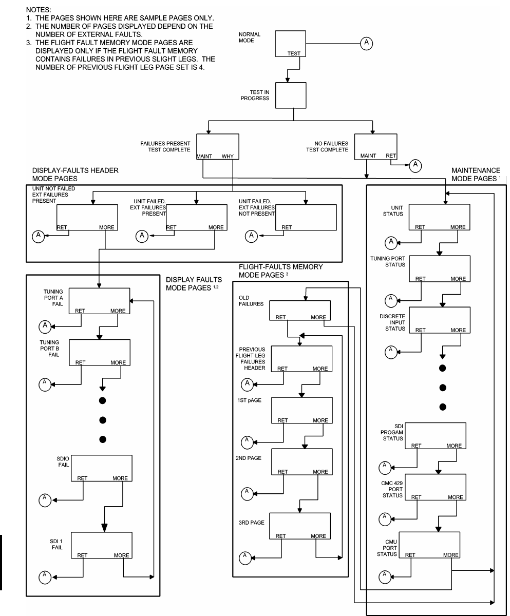
Figure 101.1 illustrates the control flow of the LCD screens (except for the data loading and data recording
screens).
A complete functional test of the system can be performed as described in paragraph 7.B. in "Maintenance
Practices" Section 200 of this manual.
VHF
DATARADIO
P/N:064-
50000-0101
S/W:01/0 1
PUSHTO
↓TEST↓
VD R
PN:064-50000-
2000
SW:998-2858
501
WRONGACTYPE
PUSHTO
↓TEST↓
11
Honeywell
MAINTENANCE MANUAL
RTA-44D VHF DATA RADIO SYSTEM
I.B. 1144-1 Page 102
Mar 01/02
23-20-02
LCD Control Flow
Figure 101.1

I.B. 1144-1 Page 103
Mar 01/02
23-20-02
Honeywell
MAINTENANCE MANUAL
RTA-44D VHF DATA RADIO SYSTEM
2. Self-Test Mode
The Self-Test Mode starts by displaying the "Test in Progress" Screen (Figure 102) one second after
pressing the "test" key. This is displayed for four seconds with a moving thermometer along the bottom of
the LCD indicating the progress of the test from one to five seconds.
"Test in Progress" Screen
Figure 102
The "Normal Mode" Screen (Figure 101) is displayed for the first second of the test sequence.
Once complete, the "Test Complete, No Failures" Screen is displayed (Figure 103), or the "Test Complete,
Failures" Screen is displayed (Figure 104). Both screens contain two key selections each: "MAINT" and
"RETURN" or "MAINT" and "WHY?", respectively.
•"MAINT" -For both screens, "MAINT" is located on the left key. This allows the initiation
of the extended maintenance pages of the system for troubleshooting. Refer
to paragraph 4.
•"RETURN" -In the "Test Complete, No Failures" Screen, the "RETURN" key to the right
returns the system to its "Normal Mode" Screen (Figure101).
•"WHY?" -In the "Test Complete, Failures" Screen, the "WHY?" key to the right puts the
system into the Display-Failures Mode where individual system failures are
displayed one per page. Refer to paragraph 3.
While in the Self-Test Mode, not pressing either key for five minutes causes the system to return to the
"Normal Mode" Screen (Figure101).
VHF
DATARADIO
TESTIN
PROGRESS
0 5 0 1 0 0
XXXXXXXXXXX

Honeywell
MAINTENANCE MANUAL
RTA-44D VHF DATA RADIO SYSTEM
I.B. 1144-1 Page 104
Mar 01/02
23-20-02
"Test Complete, No Failures" Screen
Figure 103
"Test Complete, Failures" Screen
Figure 104
VHF
DATARADIO
TESTCOMPLETE
NOFAILURE S
MAINTRETURN
VHF
DATARADIO
TESTCOMPLETE
FAILURES-
↓
MAINTWHY?

I.B. 1144-1 Page 105
Mar 01/02
23-20-02
Honeywell
MAINTENANCE MANUAL
RTA-44D VHF DATA RADIO SYSTEM
3. Display-Failures Mode
One of three failure possibilities exist: the VDR is okay, but there are external failures (Figure 105), the VDR
failed and there are external failures (Figure 106), and the VDR failed, but there are no external failures
(Figure 107).
"VHF Data Radio OK, External Failures Present" Screen
Figure 105
"VHF Data Radio Failed, External Failures Present" Screen
Figure 106
VHF
DATARADIO
-OK-
-------------
EXTERNAL
FAILURES-
PRESENT↓
RETURN MORE
VHF
DATARADIO
FAILED
-------------
EXTERNAL
FAILURES-
PRESENT↓
RETURN MORE

Honeywell
MAINTENANCE MANUAL
RTA-44D VHF DATA RADIO SYSTEM
I.B. 1144-1 Page 106
Mar 01/02
23-20-02
"VHF Data Radio Failed, External Failures Not Present" Screen
Figure 107
All "Display-Failures Mode" Screens have the "MORE" selection on the right key. The only exception is
when there is only one failure page. This only happens when the VDR itself has failed and no other external
failure exists (Figure 107).
•"MORE" -Pressing this key cycles through all of the failures present. When on the last
page, the "MORE" key causes a return to the first displayed failure page
(Figure105 or 106).
All "Display-Failures Mode" Screens have the "RETURN" selection on the left key.
•"RETURN" -Pressing this key causes the system to return to the "Normal Mode" Screen
(Figure 101).
While in the Display-Failures Mode, not pressing either key for five minutes causes the system to return to
the "Normal Mode" Screen (Figure 101).
VHF
DATARADIO
FAILED
RETURN

I.B. 1144-1 Page 107
Mar 01/02
23-20-02
Honeywell
MAINTENANCE MANUAL
RTA-44D VHF DATA RADIO SYSTEM
NOTE: Designation of pin names can be shown with numeric/alpha position in either format ANN or
NNA, e.g. MP-11A is equivalent to MP-A11.
"Tuning Port A Failure" Screen
Figure 108
"Tuning Port B Failure" Screen
Figure 109
TUNINGPORT A
IS SELECTED
TUNINGPORTA
MISSINGINPUT
P#MP-11A/11B
RETURN MORE
CMCPORT# 1
MISSINGINPUT
P#MP-6A/6B
RETURN MORE

Honeywell
MAINTENANCE MANUAL
RTA-44D VHF DATA RADIO SYSTEM
I.B. 1144-1 Page 108
Mar 01/02
23-20-02
Figure 110 deleted by Revision No. 4
"SDI 0 Program Pin Failure" Screen
Figure 111
SDI0
PROGRAMPIN
SHORTEDTO
GROUND
P#MP-9A
RETURN MORE

I.B. 1144-1 Page 109
Mar 01/02
23-20-02
Honeywell
MAINTENANCE MANUAL
RTA-44D VHF DATA RADIO SYSTEM
"SDI 1 Program pin Failure" Screen
Figure 112
"CMC Port #1 Failure" Screen
Figure 113
"CMC Port#2 Failure" Screen
Figure 114
SDI1
PROGRAMPIN
SHORTEDTO
GROUND
P#MP-9B
RETURN MORE
CMCPORT# 1
MISSINGINPUT
P#MP-6A/6B
RETURN MORE
CMCPORT# 2
MISSINGINPUT
P#MP-6C/6D
RETURN MORE

Honeywell
MAINTENANCE MANUAL
RTA-44D VHF DATA RADIO SYSTEM
I.B. 1144-1 Page 110
Mar 01/02
23-20-02
"CMU/ATSU Failure Page" Screen (-2000 and -2051)
Figure 114.1
"LGCIU Failure Page" Screen (-2000 and -2051)
Figure 114.2
4. Maintenance Mode
The Maintenance Mode is entered from either one of the two "Test Complete" Screens (Figures 103 or 104).
The Maintenance Mode allows troubleshooting of all components of the VDR system, both internal and
external.
All pages have the "MORE" selection on the right key.
•"MORE" -Pressing this key cycles through all of the maintenance pages. When on the
last page, the "MORE" key causes a return to the first displayed
maintenance screen.
All pages have the "RETURN" selection on the left key.
•"RETURN" -Pressing this key causes the system to return to the "Normal Mode" Screen
(Figure 101).
There is no timeout in the Maintenance Mode when the aircraft is on the ground. But while in the air, not
pressing a key for five minutes causes the system to return to the "Normal Mode" Screen (Figure 101).
Figures 115 through 122 show typical Maintenance Mode Pages that may be encountered.
CMU/ATSU PORT
MISSINGINPUT
P#MP-12A/12B
OR
P#MP-12C/12D
RETURN MORE
LGCIU-A/G
MISMATCH
P#MP-14B AN D
CMC LABEL 227
RETURN MORE

I.B. 1144-1 Page 111
Mar 01/02
23-20-02
Honeywell
MAINTENANCE MANUAL
RTA-44D VHF DATA RADIO SYSTEM
NOTE: The "Status" field displays "FAILED" if either an external or an internal failure is detected.
"VDR Unit Status (OK, Failed)" Screen
Figure 115
"Tuning Port Status (NORM, FAIL, TEST, NCD, NODAT)" Screen
Figure 116
"Tuning Port Status Page" Screen (-2000 and -2051)
Figure 116.1
VHF
DATARADIO
STATUS:OK
FAULT CODE:X X
RETURN MORE
TUNINGPORTX
SELECTED
PORTX S TATUS
NORM131.550
RETURN MORE
TUNING/STATUS
STATE:SSTATE
FREQ:FRE.QUE
PORT:X STATS
CMU: CMUS
M2CH:CHSTAT
VSWR:SWR:1
RETURN MORE
Honeywell
MAINTENANCE MANUAL
RTA-44D VHF DATA RADIO SYSTEM
I.B. 1144-1 Page 112
Mar 01/02
23-20-02
NOTE: See ARINC 750 specification for data definitions.
Valid Data Field Examples of "Tuning Port Status Page " Screen (-2000 and -2051)
Figure 116.2
"Discrete Input Status Page 1 (OPEN, GRND)" Screen
Figure 117
"Discrete Input Status Page 2 (OPEN, GRND)" Screen
Figure 118
VARIABLE FIELD VALID DATA
SSTATE BERTM (S0) 716VP (S3)716DB (S6)750DSA (S7-A)
716VN (S1 716DP (S4)750DN (S7-N)750DR2 (S7-R2)
716DM (S2) 716VB (S5)750DRA (S7-RA)750DS2 (S7-2)
FRE.QUE Operating Frequency (e.g. 131.550)
XA, B
STATS NORM, TEST, NCD, NODAT
CMUS NULL, CMU1, CMU2
CHSTAT N/A, TX. RXBUSY, RXIDLE
DISCRETE S 1
PUSHT T :OPEN
P#MP-1C
DATA KEY:GRND
P#MP-7D
VCE/DATA:OPEN
P#MP-7C
RETURN MORE
DISCRETE S 2
AIR/GRND:OPEN
P#MP-14B
SQLCH DS:OPEN
P#MP-13C
FREQ O FF:OPEN
P#MP-8C
RETURN MORE

I.B. 1144-1 Page 113
Mar 01/02
23-20-02
Honeywell
MAINTENANCE MANUAL
RTA-44D VHF DATA RADIO SYSTEM
"Discrete Input Status Page 3 (OPEN, GRND)" Screen
Figure 119
"Discrete Input Status Page 4 (OPEN, GRND)" Screen (-2000 and -2051)
Figure 119.1
"SDI Program Pin Status Page (OPEN, COMM)" Screen
Figure 120
DISCRETE S 3
TXCTOFF:GRND
P#MP-2A
FCT T EST:OPEN
P#MP-4A
DLD R ENB:OPEN
P#MP-8B
RETURN MORE
DISCRETES 4
BER TEST:GRND
P#MP-9D
M0M1:OPENGRND
P#MP14A MP11C
ANT MON: OPEN
P3MP-8A
RETURN MORE
SDIPRO G PINS
SDI0:OPEN
P#MP-9A
SDI1:COM M
P#MP-9B
COMM:P#MP-9C
RETURN MORE

Honeywell
MAINTENANCE MANUAL
RTA-44D VHF DATA RADIO SYSTEM
I.B. 1144-1 Page 114
Mar 01/02
23-20-02
"CMC Port Status (ACTIVE, INACTIVE)" Screen
Figure 121
Figure 122 is eliminated by Revision 5 of this Maintenance Manual.
CMC#X
SELECTED
CMC1:ACTIV E
P#MP-6A/6B
CMC2:INACTIV E
P#MP-6C/6D
RETURN MORE

I.B. 1144-1 Page 115
Mar 01/02
23-20-02
Honeywell
MAINTENANCE MANUAL
RTA-44D VHF DATA RADIO SYSTEM
5. Flight Fault Memory Mode
When the Flight-Fault Memory contains failures from previous flight legs, an "Old Failures" Screen (Figure
123) is presented as the last page of the Maintenance Mode Screens. This page allows the viewing of
previous flight leg failures, one flight leg at a time by pressing the "YES" key. Pressing the "MORE" key from
this page bypasses this function and returns the system back to the first page of the maintenance data.
Once in the Flight-Fault Memory Mode, flight legs are displayed from the most recent, backwards. The VDR
stores up to 10 "in air" failures and up to 3 "on ground" failures per flight leg, there will be up to four pages
displayed on the LCD. There are over 120 different fault codes that can be stored for each of the 13 failures.
These are described in the Component Maintenance Manuals (CMM) I.B. 1144A-2 (23-20-36) and
I.B.1144A-3 (23-20-38), in the "Testing and Troubleshooting" Section.
The first page of each flight leg contains the date, flight number, aircraft number, and departure/destination
stations, as shown in the "Previous Flight Legs Failures First Page" Screen (Figure 124). The second page
displays failures 1-5, the third page displays failures 6-10 and the fourth page displays failures 11-13, as
shown in the "Previous Flight Legs Data Page" Screens (Figure 125).
All flight fault memory pages have the "MORE" selection on the right key.
•"MORE" -Pressing the key cycles through all of the Flight-Fault Memory pages. When
on the last page, the "MORE" key causes a return to the first page.
All flight fault memory pages have the "RETURN" selection on the left key.
•"RETURN" -Pressing this key causes the system to return to Normal Mode Screen
(Figure 101).
There is no timeout in this mode when the aircraft is on the ground. But, while in the air, not pressing a key
for five minutes causes the system to return to the "Normal Mode" Screen (Figure 101)
.
"Old Failures Page" Screen
"Previous Flight Legs Failures First Page" Screen
Figure 123
FAILURE S HAVE
BEEN R ECORDED
FORPREVIOUS
FLIGHTLEGS
_YES TOVIEW
_MORETOSKIP
YES MORE
Honeywell
MAINTENANCE MANUAL
RTA-44D VHF DATA RADIO SYSTEM
I.B. 1144-1 Page 116
Mar 01/02
23-20-02
"Previous Flight Legs Failures First Page" Screen
Figure 124
NOTE: "FC" is fault code, "UTC" is time, "R" is repetition count, "P" is phase, "O" is origin.
"Previous Flight Legs Failures Data Page" Screen
(Three Screens per Flight Leg)
Figure 125
All "Display-Failures Mode" Screens have the "RETURN" selection on the left key.
•"RETURN" -Pressing this key causes the system to return to the "Normal Mode" Screen
(Figure 101).
While in the Display-Failures Mode, not pressing either key for five minutes causes the system to return to
the "Normal Mode" Screen (Figure101).
FLIGHTLEG:X X
DATE:MMMD D
DEPT:X X X X
DEST:X X X X
F#:XXXXXXXXXX
A/C:XXXXXXX
RETURN MORE
FLIGHTLEG:X X
FC U TC R PO
00 0000 000
00 0000 000
00 0000 000
00 0000 000
00 0000 000
RETURN MORE

I.B. 1144-1 Page 201
Mar 01/02
23-20-02
Honeywell
MAINTENANCE MANUAL
RTA-44D VHF DATA RADIO SYSTEM
MAINTENANCE PRACTICES
1. General
This section of the manual provides service personnel with installation and maintenance information for the
RTA-44D VHF Data Radio (VDR) System. Installation instructions are supported by mechanical outline
drawings and a electrical interconnection diagram. These drawings, located at the back of this section,
should be reviewed by the installer, and requirements peculiar to the airframe should be established before
starting the installation.
2. Inspection After Unpacking
CAUTION: THIS EQUIPMENT CONTAINS ELECTROSTATIC DISCHARGE SENSITIVE (ESDS)
DEVICES. EQUIPMENT, MODULES, AND ESDS DEVICES MUST BE HANDLED WITH
APPROPRIATE PRECAUTIONS.
Visually inspect the RTA-44D VHF Data Radio System and all associated equipments for possible damage
which may have occurred during shipment. Inspect for dents, deep abrasions, chipped paint, etc. If any
equipment is damaged, notify the transportation carrier immediately.
A Honeywell Airlines and Avionics Products test and inspection record and quality report tag is included with
each shipped unit. This ensures the customer that the necessary production tests and inspection
operations have been performed on that particular unit.
One copy of the report tag is affixed to each unit by the first assembly inspector. As the unit proceeds
through production and stock to the shipping area, the appropriate blocks on the test and inspection record
of the tag are stamped. This tag accompanies the unit when it is shipped to the customer. Customers are
requested to complete the Honeywell Airlines and Avionics Products quality report portion of the tag and
return it to the Honeywell Airlines and Avionics Products Quality Assurance Department. This portion of the
tag provides Honeywell Airlines and Avionics Products with the necessary information required to evaluate
shipping methods as well as test and inspection effectiveness.
Completed cards are accumulated to provide information for a periodic analysis.
3. Preinstallation Testing
The components in the RTA-44D VHF Data Radio System have been adjusted and tested prior to shipment.
Therefore, preinstallation testing is not required. However, if preinstallation testing of the units is desired,
refer to the customer acceptance criteria given in the Component Maintenance Manual for the appropriate
unit in the system. Refer to Figure 4 in the "Description and Operation" Section of this manual for a list of
related Component Maintenance Manuals.
4. Equipment Changes and Marking
Honeywell Airlines and Avionics Products uses a standardized marking system to identify equipment and
their subassemblies which have had changes incorporated. Refer to the front of the appropriate Component
Maintenance Manual for a list of Service Bulletins affecting the unit.
5. Interchangeability
The RTA-44D VHF Data Radio System will operate in any installation that complies with ARINC
Characteristic 750; it will also operate as a RTA-44A VHF Transceiver System replacement in any
installation that complies with ARINC 716. Refer to System Interwiring Diagram, Figure 208, for particulars.

Honeywell
MAINTENANCE MANUAL
RTA-44D VHF DATA RADIO SYSTEM
I.B. 1144-1 Page 202
Mar 01/02
23-20-02
6. Installation
A. General
The RTA-44D VHF Data Radio System should be installed in the aircraft in a manner consistent with
acceptable workmanship and engineering practices, and in accordance with the instructions set forth in
this publication. To ensure that the system has been properly and safely installed in the aircraft, the
installer should make a thorough visual inspection and conduct an overall operational and functional
check of the system on the ground prior to flight.
CAUTION: AFTER INSTALLATION OF THE CABLING AND BEFORE INSTALLATION OF THE
EQUIPMENT, A CHECK SHOULD BE MADE WITH AIRCRAFT PRIMARY POWER
BEING SUPPLIED TO THE MOUNT CONNECTORS TO ENSURE THAT POWER IS
APPLIED ONLY TO THE PINS SPECIFIED IN INTERWIRING DIAGRAM FIGURE 208.
B. Location of Equipment
Location of the RTA-44D VHF Data Radio System in the aircraft is not critical, as long as the
environment is compatible with the equipment design. Refer to the Leading Particulars, Figure 7, in the
"Description and Operation" section of this manual. Forced air cooling is required for cooling the
RTA-44D VHF Data Radio in accordance with ARINC Characteristic 600. The associated cooling
equipment must be mounted in accordance with the manufacturer's instructions.
Antenna mounting should be in accordance with the manufacturer's instructions for the antenna being
used. The coaxial cable connecting the antenna to the mount should be as short and direct as possible
and any required bends should be gradual. When two or more RTA-44D VHF Data Radios are installed
in an aircraft, it is necessary to provide adequate space isolation between antennas of each system to
ensure that the use of one transceiver does not interfere with reception from another system. A
minimum of 35 dB of space isolation should be provided, and any steps which can be taken to provide
further isolation should be considered. Maximum cable loss should be < 3dB.
Control unit location and mounting can be determined by mutual agreement between the user and
airframe manufacturer.
C. Interwiring and Cable Fabrication
(1) General
Figure 208 is the complete aircraft interwiring diagram for a single RTA-44D VHF Data Radio
System and associated components. This diagram requires thorough study before the installer
begins installation of the aircraft wiring.
When two or more systems are being installed in the aircraft, the interconnecting wiring shown in
Figure 208, as well as all other installation instructions must be duplicated.
Cabling must be fabricated by the installer in accordance with Figure 208. Wires connected to
parallel pins should be approximately the same length, so that the best distribution of current can
be effected. Honeywell Airlines and Avionics Products recommends that all wires, including
spares, shown on interwiring diagram Figure 208 be included in the fabricated harness. However,
if full ARINC wiring is not desired, the installer should ensure that the minimum wiring
requirements for the features and functions to be used are incorporated.
NOTE: To allow for inspection or repair of the connector, or the wiring to the connector, sufficient
lead length should be left so that the rear connector assembly can be pulled forward
several inches when the mounting hardware for the rear connector assembly is removed.
A bend should be made in the harness near the connector to allow water droplets, that
might form on the harness from condensation, to drip off at the bend and not collect at
the connector.

I.B. 1144-1 Page 203
Mar 01/0223-20-02
Honeywell
MAINTENANCE MANUAL
RTA-44D VHF DATA RADIO SYSTEM
When the cables are installed in the aircraft, they must be supported firmly enough to prevent
movement and should be carefully protected against chafing. Additional protection should also
be provided in all locations where the cables may be subject to abuse. In wire bundles, the cabling
should not be tied tightly together as this tends to increase the possibility of noise pick-up and
similar interference. When routing cables through the airframe, try to avoid running cables or wire
close to power sources (400-Hz generator, etc). If unavoidable, the cables should cross high-level
lines at a right angle, or high-quality shielded conductors should be used.
If a cable must pass through a bulkhead between pressurized and unpressurized zones, this
passage must conform to the aircraft manufacturer's specifications.
The assembler must be knowledgeable of any system variations peculiar to the installation, and
must thoroughly understand the complexities associated with handling related problems of line
lengths, capacitance, and of susceptibility to interference.
Electrical bonding interface characteristics per ARINC 600 Section 3.2.4 states that ground path
resistance should not exceed 0.5 milliohms.
The following determinants are the responsibility of the installation agency for fabrication of the
wiring harness, see Figures201 and 208.
RTA-44D VHF Data Radio Connector Determinants
Figure 201
Sheet 1 of 6
PIN NO. TYPE SIGNAL NAME FUNCTION
MPA1 Input Mic Audio Input (HI) Microphone audio input.
Part of the standard four wire microphone
interwiring as described in Attachment 6 of
ARINC716-10. Required for ARINC716
VHF COMM only.
MPB1 Input Mic Audio Input (LO)
MPC1 Input Mic PTT Microphone push-to-talk discrete input.
Gnd/Low=Transmitter keyed;
Open/High=Transmitter not keyed.
Part of the standard four wire microphone
interwiring as described in Attachment 6 of
ARINC716-10. Required for ARINC716
VHF COMM only.
MPD1 Output Key Event Discrete input to Flight Recorder. Follows
the state of Mic PTT input.
Gnd/Low=Transmitter keyed;
Open/High=Transmitter not keyed.
Required for ARINC716 VHF COMM only.
MPA2 Input Max. Trans Time
Cutoff Function
Discrete input that enables the maximum
transmit cutoff function.
Gnd/Low=Cutoff disabled;
Open/High=Cutoff enabled.

Honeywell
MAINTENANCE MANUAL
RTA-44D VHF DATA RADIO SYSTEM
I.B. 1144-1 Page 204
Mar 01/02
23-20-02
RTA-44D VHF Data Radio Connector Determinants
Figure 201
Sheet 2 of 6
PIN NO. TYPE SIGNAL NAME FUNCTION
MPB2 -Mic Input Ground Required for ARINC716 VHF COMM only.
MPC2 Input Data Loader Input Bus A A high speed ARINC 429 input port to allow
onboard data loading for software.
MPD2 Input Data Loader Input Bus B
MPA3 Input Optional Remote Squelch
(HI)
To accommodate an optional remote
squelch adjustment if so required or pro-
vided. Required for ARINC716 VHF
COMM only.
MPB3 Input Optional Remote Squelch
(ARM)
MPC3 Input Optional Remote Squelch
(LO)
MPD3 -DC Ground Required for both ARINC716 VHF COMM
and ARINC750 VDR; functions are identi-
cal.
MPA4 Input Functional Test Discrete input that activates LRU functional
test function. Gnd/Low=activate functional
test. Required for ARINC716 VHF COMM
MPB4 -Audio Ground Required for ARINC716 VHF COMM only.
MPC4 Output Data Loader Output Bus A A high speed ARINC 429 output port to
allow onboard data loading for software.
MPD4 Output Data Loader Output Bus B
MPA5 Input Data Link Data Input (HI) Analog 2400bps ACARS data input.
Required for ARINC716 VHF COMM only.
MPB5 Input Data Link Data Input (LO)
MPC5 -Reserved #1 Leave open.

I.B. 1144-1 Page 205
Mar 01/02
23-20-02
Honeywell
MAINTENANCE MANUAL
RTA-44D VHF DATA RADIO SYSTEM
RTA-44D VHF Data Radio Connector Determinants
Figure 201
Sheet 3 of 6
PIN NO. TYPE SIGNAL NAME FUNCTION
MPD5 Output 8.33-kHz Programming Discrete output that indicates to control
panel the VDR is capable of 8.33-kHz or
25- kHz operation. This output is internally
grounded.
MPA6 Input Data from OMS/CFDS #1
Input Port (A)
One of two low speed ARINC 429 data
input ports provided for dual OMS/CFDS's.
Required for both ARINC716 VHF COMM
and ARINC750 VDR; functions are identi-
cal.
MPB6 Input Data from OMS/CFDS #1
Input Port (B)
MPC6 Input Data from OMS/CFDS #2
Input Port (A)
One of two low speed ARINC 429 data
input ports provided for dual OMS/CFDS's.
Required for ARINC750 VDR only.
MPD6 Input Data from OMS/CFDS #2
Input Port (B)
MPA7 Input Freq/Funct Select Data I/P
Port B (A)
One of two low speed ARINC 429 input
ports to provide frequency tuning data.
Required for ARINC716 VHF COMM only.
MPB7 Input Freq/Funct Select Data I/P
Port B (B)
MPC7 Input Voice/Data Select Discrete input that enables either the PTT
key line (MPC1) or the Data key line
(MPD7).
Gnd/Low=Data Key line enabled;
Open/High=PTT enabled. Required for
ARINC716 VHF COMM only.
MPD7 Input Data Key Line Discrete input that keys the transmitter.
Gnd/Low=Transmitter keyed;
Open/High=Transmitter not keyed.
Required for ARINC716 VHF COMM only.
MPA8 -Spare
MPB8 Input Data Loader Enable Input Discrete input to allow onboard data loading
of software. Required for ARINC750 VDR
only.
Honeywell
MAINTENANCE MANUAL
RTA-44D VHF DATA RADIO SYSTEM
I.B. 1144-1 Page 206
Mar 01/02
23-20-02
RTA-44D VHF Data Radio Connector Determinants
Figure 201
Sheet 4 of 6
PIN NO. TYPE SIGNAL NAME FUNCTION
MPC8 Input Freq Offset Enable Discrete input that enables the offsetting of
the transmit frequency by a board-strap
programmable value.
Gnd/Low=Frequency offset enabled;
Open/High=Frequency offset disabled.
Required for ARINC716 VHF COMM only.
MPD8 -Data Key Line Return Required for ARINC716 VHF COMM only.
MPA9 Input SDI Bit 0 Prog A discrete input pair prewired at the rear
connector to identify the specific VHF radio
location in the aircraft. Required for both
ARINC716 VHF COMM and ARINC750
VDR; functions are identical.
MPB9 Input SDI Bit 1 Prog
MPC9 -SDI Prog Pin Common Ground for the SDI code inputs. Required
for ARINC716 VHF COMM only.
MPD9 Output AGC OUT AGC output signal for test purposes.
MPA10 -Spare
MPB10 -Spare
MPC10 Output Data to CMU #1, CMU#2
Output Port(A)
A high speed ARINC 429 output port to
CMU/MU/ATSU’s #1 and #2. Required for
ARINC750 VDR only.
MPD10 Output Data to CMU #1, CMU#2
Output Port(B)
MPA11 Input Freq/Funct Select Data I/P
Port A (A)
One of two low speed ARINC 429 input
ports to provide frequency tuning data.
Required for ARINC716 VHF COMM only.
MPB11 Input Freq/Funct Select Data I/P
Port A (B)
MPC11 Input Maintenance System ID 1 Identifies CFDS type along with MPA14
(See Figure 208).
MPD11 Input Freq Port Select Discrete input used to select either Fre-
quency/Function Select Data I/P Port A or
B. Gnd/Low=Select Port A,
Open/High=Select Port B. Required for
both ARINC716 VHF COMM and
ARINC750 VDR; functions are identical.

I.B. 1144-1 Page 207
Mar 01/02
23-20-02
Honeywell
MAINTENANCE MANUAL
RTA-44D VHF DATA RADIO SYSTEM
RTA-44D VHF Data Radio Connector Determinants
Figure 201
Sheet 5 of 6
PIN NO. TYPE SIGNAL NAME FUNCTION
MPA12 Input CMU #1 Input Bus A A high speed ARINC 429 input port from
CMU/MU/ATSU #1. Used to receive com-
mands/status/data in Williamsburg files,
and periodic and aperiodic ARINC 429
words. Required for ARINC750 VDR only.
MPB12 Input CMU #1 Input Bus B
MPC12 Input CMU #2 Input Bus A A high speed ARINC 429 input port from
CMU/MU/ATSU #2. Used to receive com-
mands/status/data in Williamsburg files,
and periodic and aperiodic ARINC 429
words. Required for ARINC750 VDR only.
MPD12 Input CMU #2 Input Bus B
MPA13 Output SELCAL Audio and Data
Link Output (HI)
An analog output to provide 2400bps MSK
data to the ACARS MU. May also be used
for SELCAL provisions. Required for
ARINC716 VHF COMM only.
MPB13 Output SELCAL Audio and Data
Link Output (LO)
MPC13 Input Squelch Disable A discrete input to provide squelch override
or disable capability. Required for
ARINC716 VHF COMM only.
MPD13 -Squelch Disable Return
MPA14 Input Maintenance System ID 0 Identifies CFDS type along with MPC11
(See Figure 208).
MPB14 Input Air/Ground Discrete A discrete input to indicate if the aircraft is
in the air or on the ground.
Gnd/Low=Airborne, Open/High=On
Ground. Required for both ARINC716 VHF
COMM and ARINC750 VDR; functions are
identical.
MPC14 Output Data to OMS/CFDS Output
Port A
A low speed ARINC 429 output port to one
or two OMS/CFDS's. Required for both
ARINC716 VHF COMM and ARINC750
VDR; Functions are identical.
MPD14 Output Data to OMS/CFDS Output
Port B
MPA15 Output Audio/Sidetone Output (HI) An analog output for receiver audio during
receive mode and sidetone audio during
voice transmit modes. Required for
ARINC716 VHF COMM only.
MPB15 Output Audio/Sidetone Output
(LO)

Honeywell
MAINTENANCE MANUAL
RTA-44D VHF DATA RADIO SYSTEM
I.B. 1144-1 Page 208
Mar 01/02
23-20-02
RTA-44D VHF Data Radio Connector Determinants
Figure 201
Sheet 6 of 6
(2) Reserved and Spare Wires
If the installer does not wish to connect all wires, he may select wires reserved for optional
functions which his system does not contain and delete these wires. He should also decide which
future spare wires to include in the installation. Reserved and spare wires are identified in Figure
201 and in interwiring diagram Figure208.
D. Installation of System
The RTA-44D VHF Data Radio is secured in the airframe with 3-MCU unit mounts. The mounts are
designed to be removed without rewiring the connectors. Follow the equipment manufacturer's
installation instructions to install the mount into the airframe.
To wire the mounts into the system, first remove the mount connector cover and connector plate
assembly. Then crimp or solder (as applicable) the interconnecting wiring to the appropriate connector
pins. Finally, return the connector plate assembly and cover to their original positions.
The RTA-44D VHF Data Radio (VDR) is installed in the mount as follows.
(1) Slide the VDR into the mount until the guide pins are aligned and the electrical connectors are
firmly engaged.
(2) Secure the front of the VDR to the mount by tightening the two knurled screw clamps (located on
the front of the mount) until they are firmly seated over hold-down hooks located on the front of
the unit.
(3) Safety-wire the two screw clamps.
PIN NO. TYPE SIGNAL NAME FUNCTION
MPC15 Input Muting An optional two wire discrete output to pro-
vide a switch closure internal to the VHF
COMM for external system muting applica-
tions during transmit modes.
Open=Muting Off, Gnd=Muting On.
Required for ARINC716 VHF COMM only.
MPD15 -Muting Return
BP1 Input/
Output
Antenna RF Input Required for both ARINC716 VHF COMM
and ARINC750 VDR; functions are identi-
cal.
BP2 Input DC Power Input +27.5VDC Required for both ARINC716 VHF COMM
and ARINC750 VDR; functions are identi-
cal.
BP3 -Spare
BP4 -DC Power GND Required for both ARINC716 VHF COMM
and ARINC750 VDR; functions are identi-
cal.
BP5 -Spare

I.B. 1144-1 Page 209
Mar 01/02
23-20-02
Honeywell
MAINTENANCE MANUAL
RTA-44D VHF DATA RADIO SYSTEM
7. Inspection and System Check Procedures
NOTE: Inspection and check procedures for the RTA-44D VHF Data Radio System includes
checkout of all interfacing units that may affect performance of the VDR.
A. Inspection
Figure202 is a visual inspection check procedure and should be performed after system installation,
prior to system checkout. In addition, the procedure should be used as a periodic inspection check.
Inspection/Check Procedures
Figure 202
B. System Checkout
(1) General
After installation of the RTA-44D VHF Data Radio System, and inspection of the equipment per
previous Figure 202, perform a continuity and visual check of the system interwiring per paragraph
7.B.(2). A post-installation test per paragraph 7.B.(3) should then be performed.
(2) System Interwiring Check
Visually check the system interwiring for abnormalities, such as cables rubbing unprotected metal
edges or tightly stretched cables. Check continuity of all interwiring. In particular, check the
following:
(a) Check that the VDR is properly installed and the hold-down screw clamps are tight.
(b) Check wiring harness connectors for security and connection to the VDR.
(c) Check that antenna transmission line connectors are securely fastened.
(d) Check that cables do not interfere with aircraft controls or other equipment.
(3) Software On Board Loadable Instructions
The VDR Mode 2 is capable of on board software loadability. The following describes this
process:
(a) Loosen Phillips head screw on cover, left of handle, to expose the front panel PCMCIA slot.
When the main program card is inserted into this slot, the front panel LCD will display either
the "Program Prompt" Screen (Figure 202.1) or the "Invalid Card" Screen (Figure 202.2).
EQUIPMENT INSPECTION/CHECK PROCEDURE
3 MCU Unit Mount As defined by manufacturer's instructions.
RTA-44D VHF
Data Radio
(1) Check that unit is fully inserted in mount and that the knurled screw
clamps which secure the unit in the mount are tight and safety wired.
(2) Inspect the case for deformation, dents, corrosion, and damage to finish;
ensure that ventilation holes in the unit are not clogged.
ARINC 716/750
Control Panel
As defined by manufacturer's instructions.
ARINC 716/750
VHF Antenna
As defined by manufacturer's instructions.

Honeywell
MAINTENANCE MANUAL
RTA-44D VHF DATA RADIO SYSTEM
I.B. 1144-1 Page 210
Mar 01/02
23-20-02
"Program Prompt" Screen
Figure 202.1
"Invalid Card" Screen
Figure 202.2
(b) When the "Start" key of the "Program Prompt" Screen (Figure 202.1) is pressed, program
loading starts and the front panel LCD displays the "Programming in Progress" Screen,
(Figure 202.3).
(c) The "S....S" field in the third row of the display is a string that shows the module presently
loading. After loading of the individual modules ends, the "S...S" field momentarily shows
the software part number.
(d) The moving thermometer-type display near the bottom half of the display indicates the
percent completion of the program load.
PRE S S S TART
TO
LOADPRO G RAM
|
↓START↓
INVALID CAR D
TURN POWER
OFF
REMOVE CAR D
I.B. 1144-1 Page 211
Mar 01/02
23-20-02
Honeywell
MAINTENANCE MANUAL
RTA-44D VHF DATA RADIO SYSTEM
"Programming in Progress" Screen
Figure 202.3
(e) When the program loading is complete, the front panel LCD displays either the "Load
Complete" Screen (Figure 202.4) if the program loading was successful, or the "Load
Failed" Screen (Figure 202.5) if the program loading failed.
"Load Complete" Screen
Figure 202.4
LOADING
SSSSSSSSSSSSS
0 5 0 1 0 0
XXXXXXXXXX
%COMPLETE
PROGRAMLOAD
OK
REMOVE CAR D

Honeywell
MAINTENANCE MANUAL
RTA-44D VHF DATA RADIO SYSTEM
I.B. 1144-1 Page 212
Mar 01/02
23-20-02
"Load Failed" Screen
Figure 202.5
(f) If the program was successfully loaded, the front panel LCD displays the "Verifying
Program" Screen (Figure 202.6) when the program card is removed. The verification
consists of checking the cyclic redundancy check (CRC) of the loaded program.
"Verifying Program" Screen
Figure 202.6
(g) When the program verification is completed, the front panel LCD displays either the "Normal
Mode" Screen (Figure 203.1) if the verification succeeded, or the "Invalid Load" Screen
(Figure 202.7) if the verification failed.
PROGRAMLOAD
FAILED
REMOVE CAR D
VERIFYING
PROGRAM

I.B. 1144-1 Page 213
Mar 01/02
23-20-02
Honeywell
MAINTENANCE MANUAL
RTA-44D VHF DATA RADIO SYSTEM
"Invalid Load" Screen
Figure 202.7
(4) Post-Installation Check
(a) Test Equipment Required
None required.
(b) System Test
A functional self test of the RTA-44D VHF Data Radio System may be initiated by pressing
the "test" key pushbutton switch as designated on the front panel LCD (Figures 203 and
203.1). Although the "Normal Mode" Screen indicates that this is actuated from the right
key, the left key has the same function if pressed while the VDR LCD is in its normal mode.
"Normal Mode" Screen (-0101, -0110, -0202, -0303 and -0505)
Figure 203
INVALIDLOAD
TURN POWER
OF F
VHF
DATARADIO
P/N:064-
50000-0101
S/W:01/0 1
PUSHTO
↓TEST↓

Honeywell
MAINTENANCE MANUAL
RTA-44D VHF DATA RADIO SYSTEM
I.B. 1144-1 Page 214
Mar 01/02
23-20-02
"Normal Mode" Screen (-2000 and -2051)
Figure 203.1
The Self-Test Mode starts by displaying the "Test in Progress" Screen (Figure 204) one
second after pressing the "test" key. This is displayed for four seconds with a moving
thermometer along the bottom of the LCD indicating the progress of the test from one to five
seconds
"Test in Progress" Screen
Figure 204
The "Normal Mode" Screen (Figures 203 and 203.1) is displayed for the first second of the
test sequence. Once complete, the "Test Complete, No Failures" Screen is displayed
(Figure 205), or the "Test Complete, Failures" Screen is displayed (Figure 206). Both
screens contain two key selections each: "MAINT" and "RETURN" or "MAINT" and "WHY?",
respectively.
•"MAINT" -For both screens, "MAINT" is located on the left key. This allows the
initiation of the extended maintenance pages of the system for
troubleshooting. Refer to Paragraph4 of "Fault Isolation" Section 100 of
this manual.
•"RETURN" -In the "Test Complete, No Failures" Screen, the "RETURN" key to the
right returns the system to its "Normal Mode" Screen (Figures203 and
203.1).
VD R
PN:064-50000-
2000
SW:998-2858-
501
PUSHTO
↓TEST↓
VHF
DATARADIO
TESTIN
PROGRESS
0 5 0 1 0 0
XXXXXXXXXXX

I.B. 1144-1 Page 215
Mar 01/02
23-20-02
Honeywell
MAINTENANCE MANUAL
RTA-44D VHF DATA RADIO SYSTEM
•"WHY?" -In the "Test Complete, Failures" Screen, the "WHY?" key to the right puts
the system into the Display-Failures Mode where individual system
failures are displayed one per page. Refer to Paragraph 3 of "Fault
Isolation" Section 100 of this manual.
While in the Self-Test Mode, not pressing either key for five minutes causes the system to
return to the "Normal Mode" Screen (Figures 203 and 203.1)
.
"Test Complete, No Failures" Screen
Figure 205
"Test Complete, Failures" Screen
Figure 206
C. Flight Tests
(1) Preflight Test
(a) General
The following test procedure gives instructions for a preflight test which ensures that the
RTA-44D VHF Data Radio System is functioning in an acceptable manner prior to takeoff.
(b) Test Procedures
1Establish the initial control settings listed below.
VHF
DATARADIO
TESTCOMPLETE
NOFAILURE S
MAINTRETURN
VHF
DATARADIO
TESTCOMPLETE
FAILURES-
↓
MAINTWHY?
CONTROL PANEL
Power
Frequency Selector
Volume Control
POSITION
On
Tune to any local VHF frequency (local
control tower or ground control frequency)
Midrange

Honeywell
MAINTENANCE MANUAL
RTA-44D VHF DATA RADIO SYSTEM
I.B. 1144-1 Page 216
Mar 01/02
23-20-02
2Using the system's headphone (or speaker) and microphone, check operation of the
RTA-44D VHF Data Radio System.
3Key the microphone and speak into it; speech should be audible. Request a radio check,
and release the push-to-talk button.
4Listen through the headphones (or speaker) and press the SQ/TEST pushbutton. A
squelch break should be audible.
5As soon as possible, a local flight check should be made to verify system operation for
both local and distant stations.
(2) In-Flight Confidence Test
Upon completion of the post-installation and preflight checks, a local flight may be made to verify
system operation for both local and distant stations. Repeat the test procedure found in
paragraph 7.C.(1)(b).
8. Removal and Replacement
A. Removal
(1) Loosen the two knurled screw clamps (located on the front of mount) that secure the VDR to the
mount.
(2) Gently pull the VDR forward until it is disconnected from the rear connector and guide pins.
B. Replacement
(1) Slide the VDR onto the tray of the mount and then gently push the VDR until the guide pins are
aligned and the connectors make a firm connection.
(2) Tighten the two knurled screw clamps located on the front of the mount until they are firmly seated
over the hold-down hooks located on the front of the VDR.
(3) Safety wire the two knurled screw clamps.
9. Maintenance Procedures
A. Adjustments and Alignments
There are no adjustments or alignments required for the RTA-44D VHF Data Radio System. All
alignment and adjustment procedures are accomplished during bench maintenance. The technician
should remove the unit from the aircraft and reference should be made to the related maintenance
manual when unit performance indicates an adjustment or an alignment is required.
B. System Protection
The system should be protected by a 10-ampere circuit breaker located at the circuit breaker panel in
the aircraft.
C. Lubrication Practices
There are no requirements for lubrication of any RTA-44D VHF Data Radio System components.
D. Cleaning
When deemed necessary, depending upon the environment to which the equipment is exposed and the
intensity of use, periodic cleaning should be performed. Any dust on the RTA-44D VHF Data Radio
System LRU's should be wiped off with a lint-free cloth.
NOTE: Any cleaning of equipment interiors should be limited to that required when performing overhaul
(bench-type) work.
Honeywell
MAINTENANCE MANUAL
RTA-44D VHF DATA RADIO SYSTEM
I.B. 1144-1 Page 217/218
Mar 01/02
23-20-02
RTA-44D VHF Data Radio Dimensional Outline Drawing
Figure 207
I.B. 1144-1 Page 219/220
Mar 01/02
23-20-02
Honeywell
MAINTENANCE MANUAL
RTA-44D VHF DATA RADIO SYSTEM
RTA-44D VHF Data Radio System Interwiring Diagram
Figure 208