Honeywell RTA-50D VHFAIRBORNE VOICE / DATA TRANSCEIVER User Manual User s Manual
Honeywell International Inc. VHFAIRBORNE VOICE / DATA TRANSCEIVER User s Manual
UserManual.wiki
>
Honeywell
>
RTA 50D User Manual
User's Manual
Navigation menu
Upload a User Manual
Namespaces
Wiki Guide
HTML
PDF
Info
Views
User Manual
Discussion / Help
Navigation


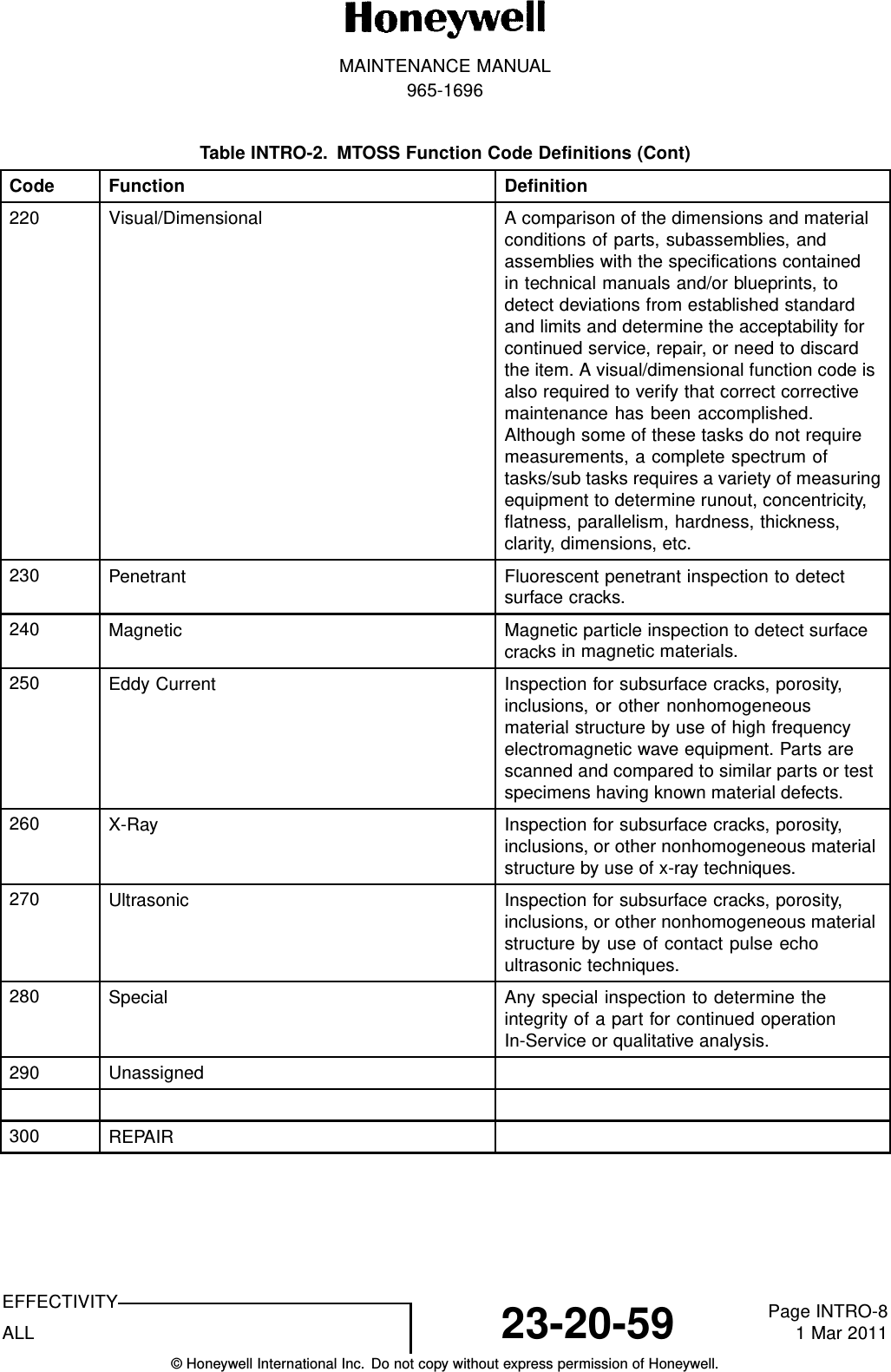
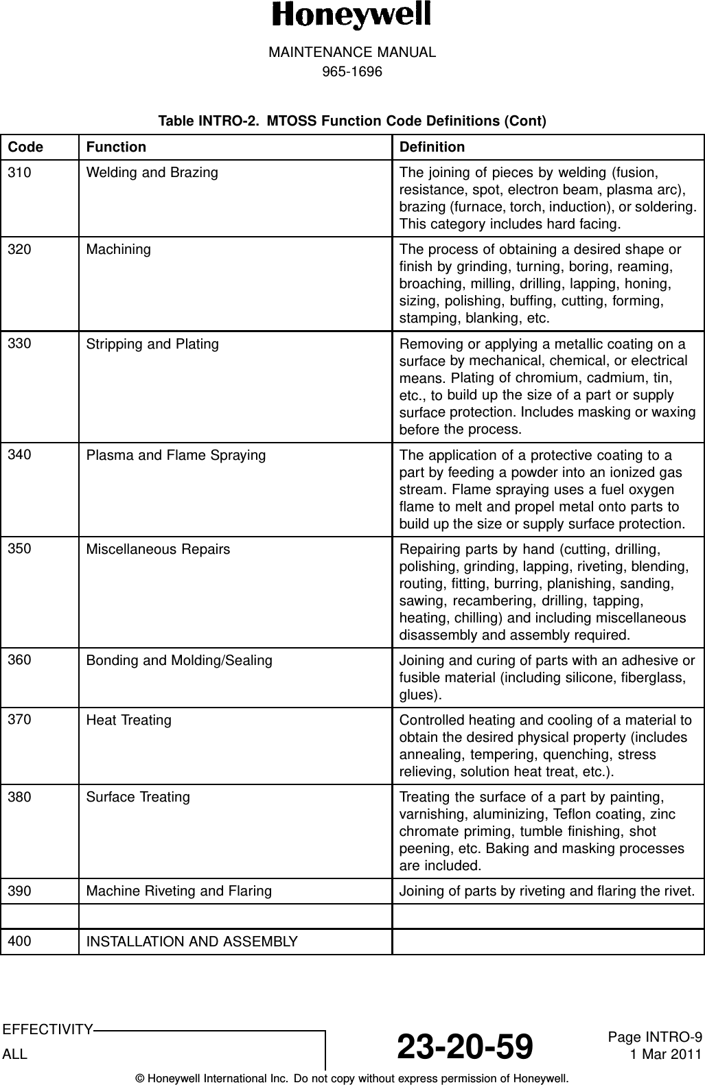
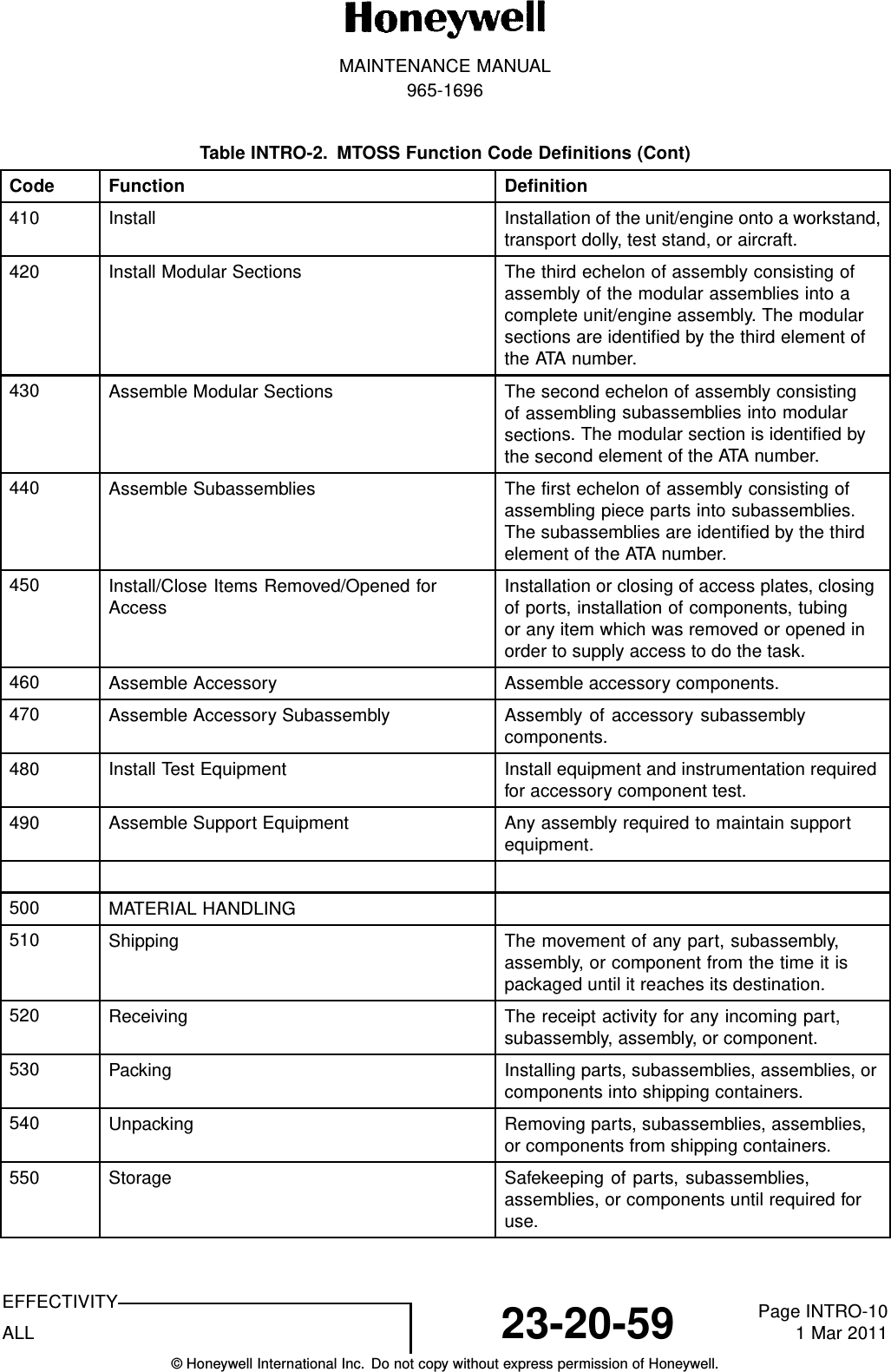
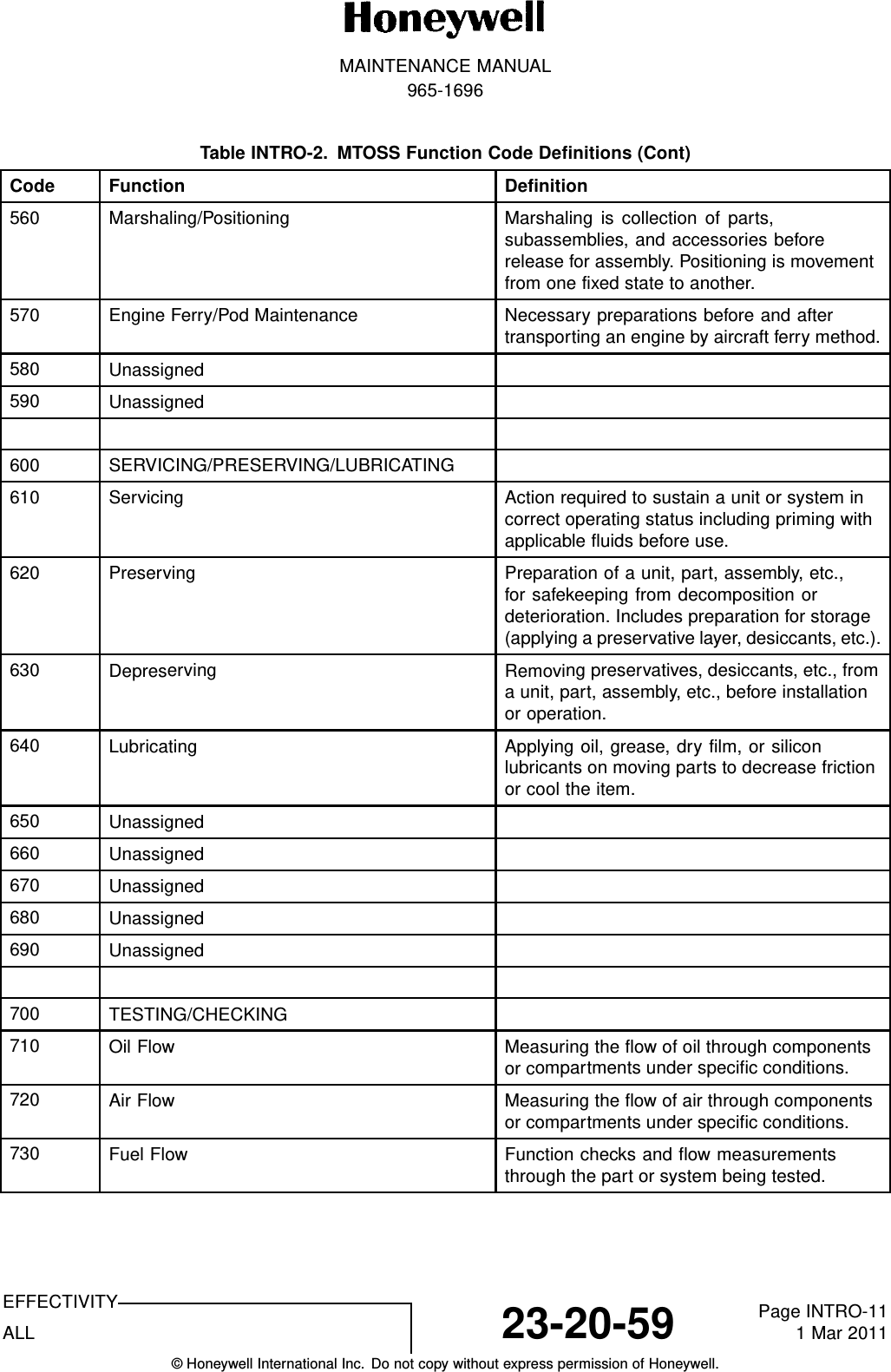
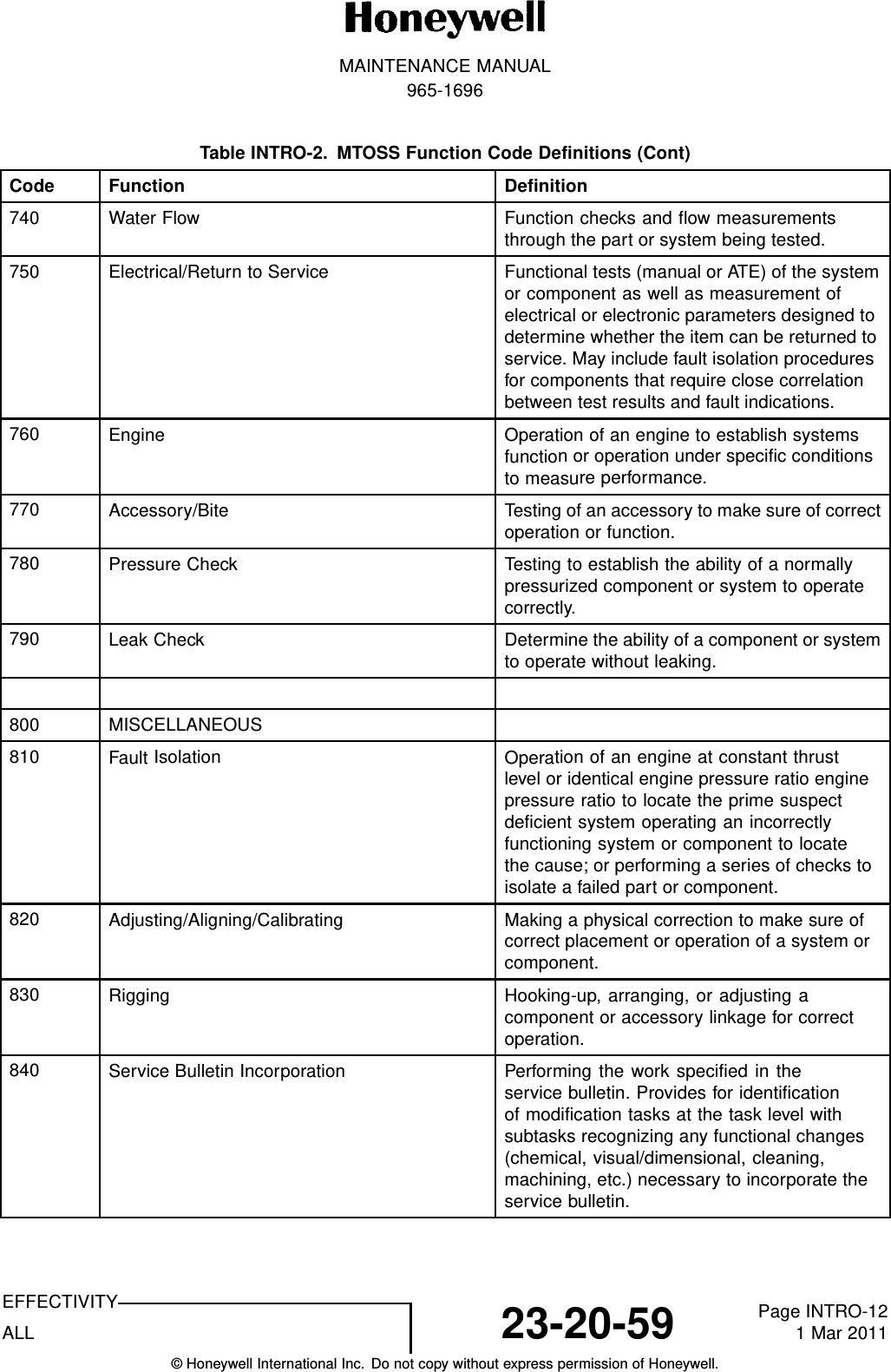
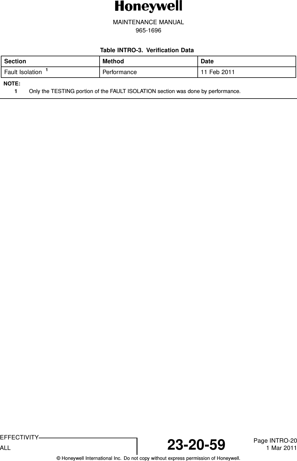
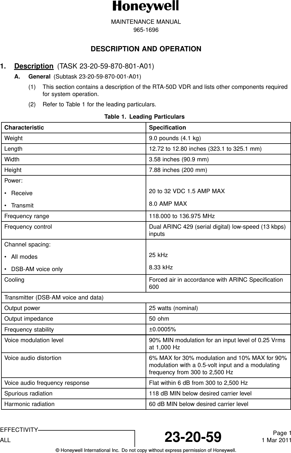
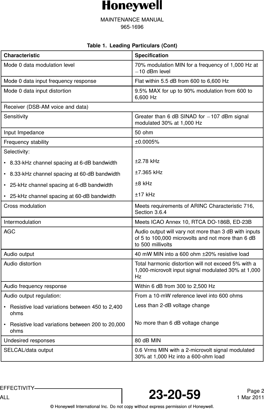
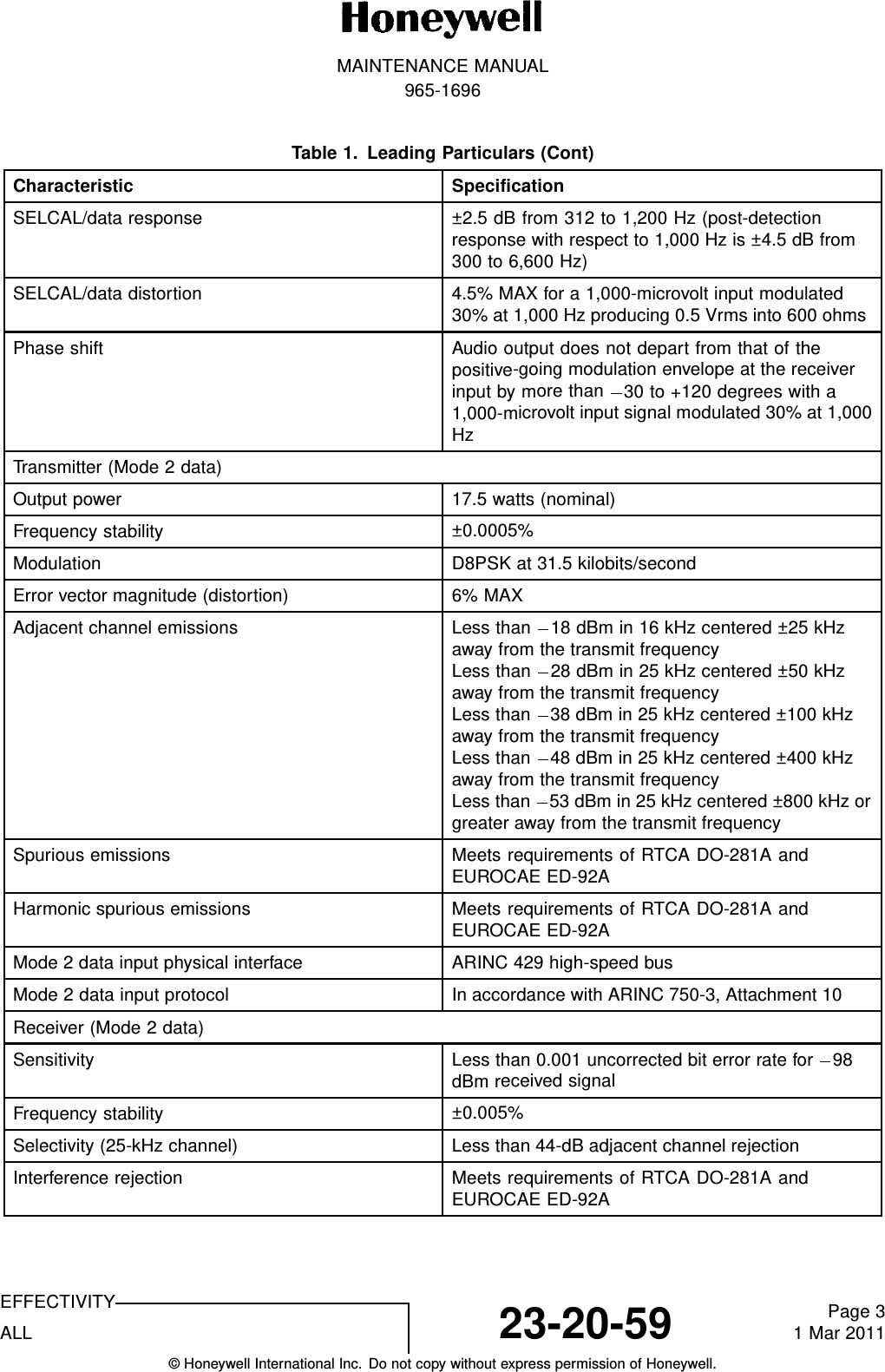
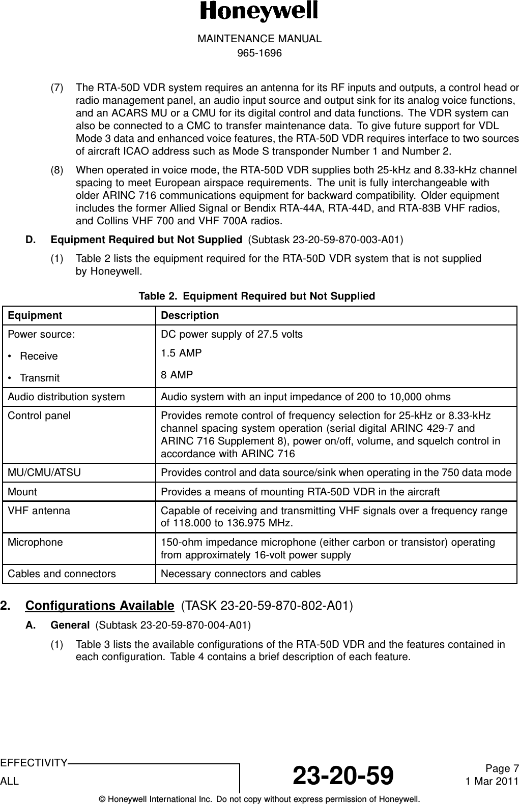
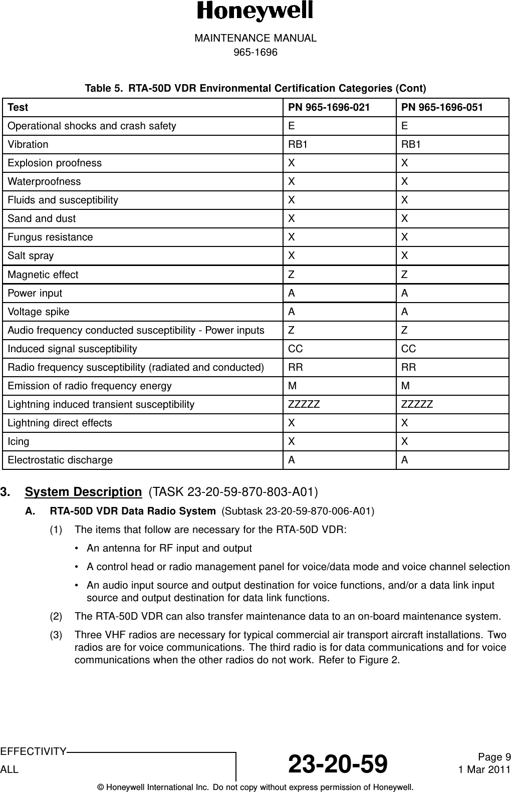
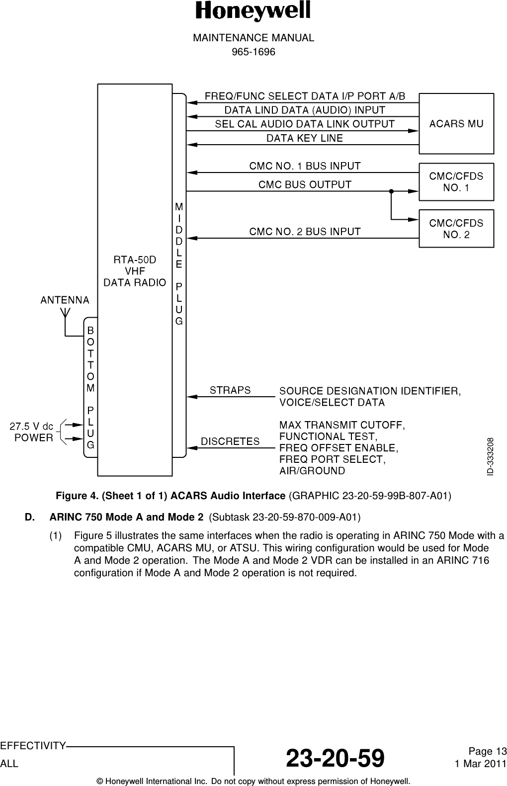
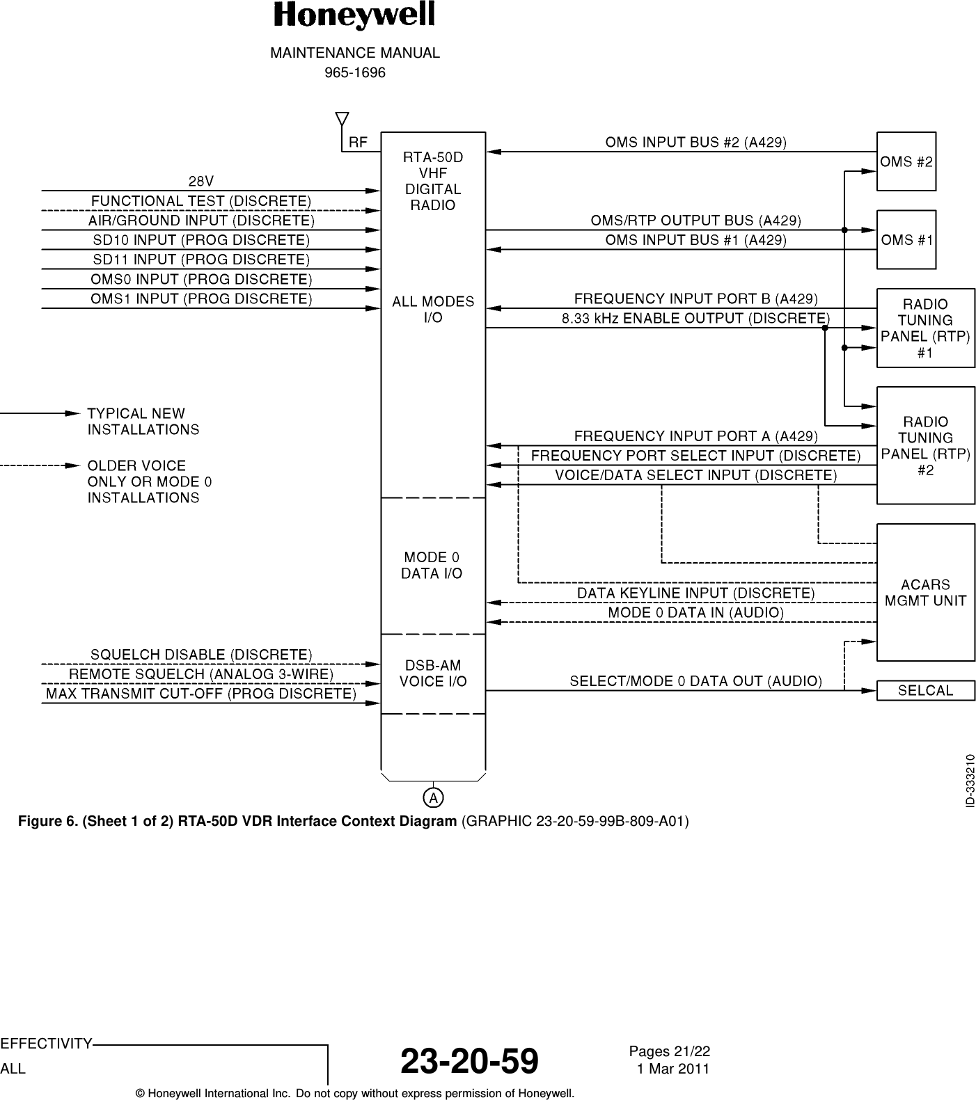
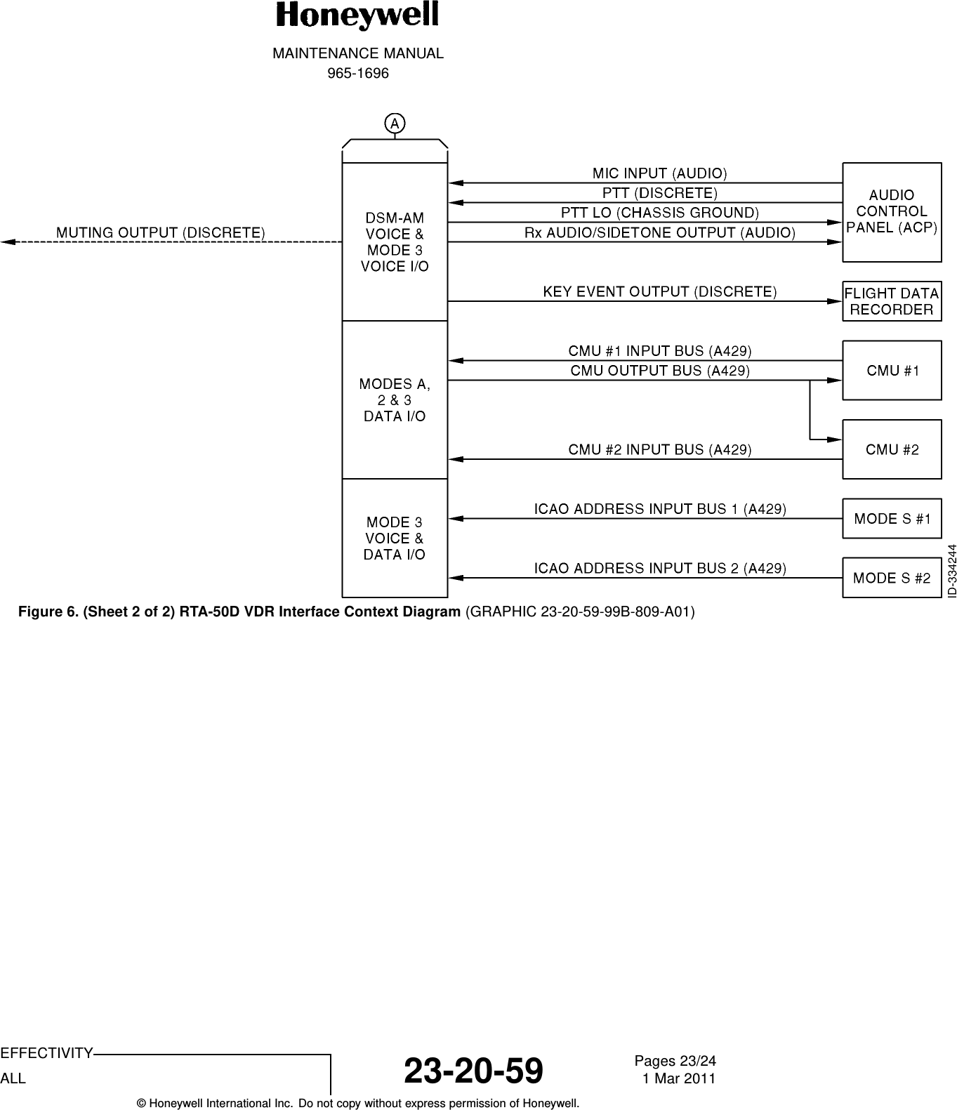
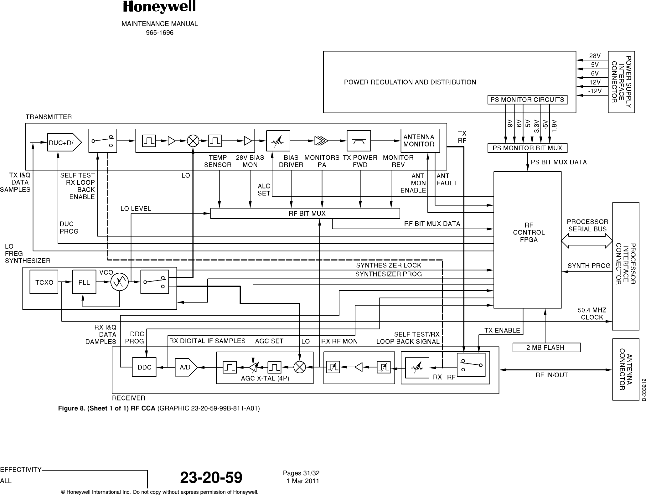
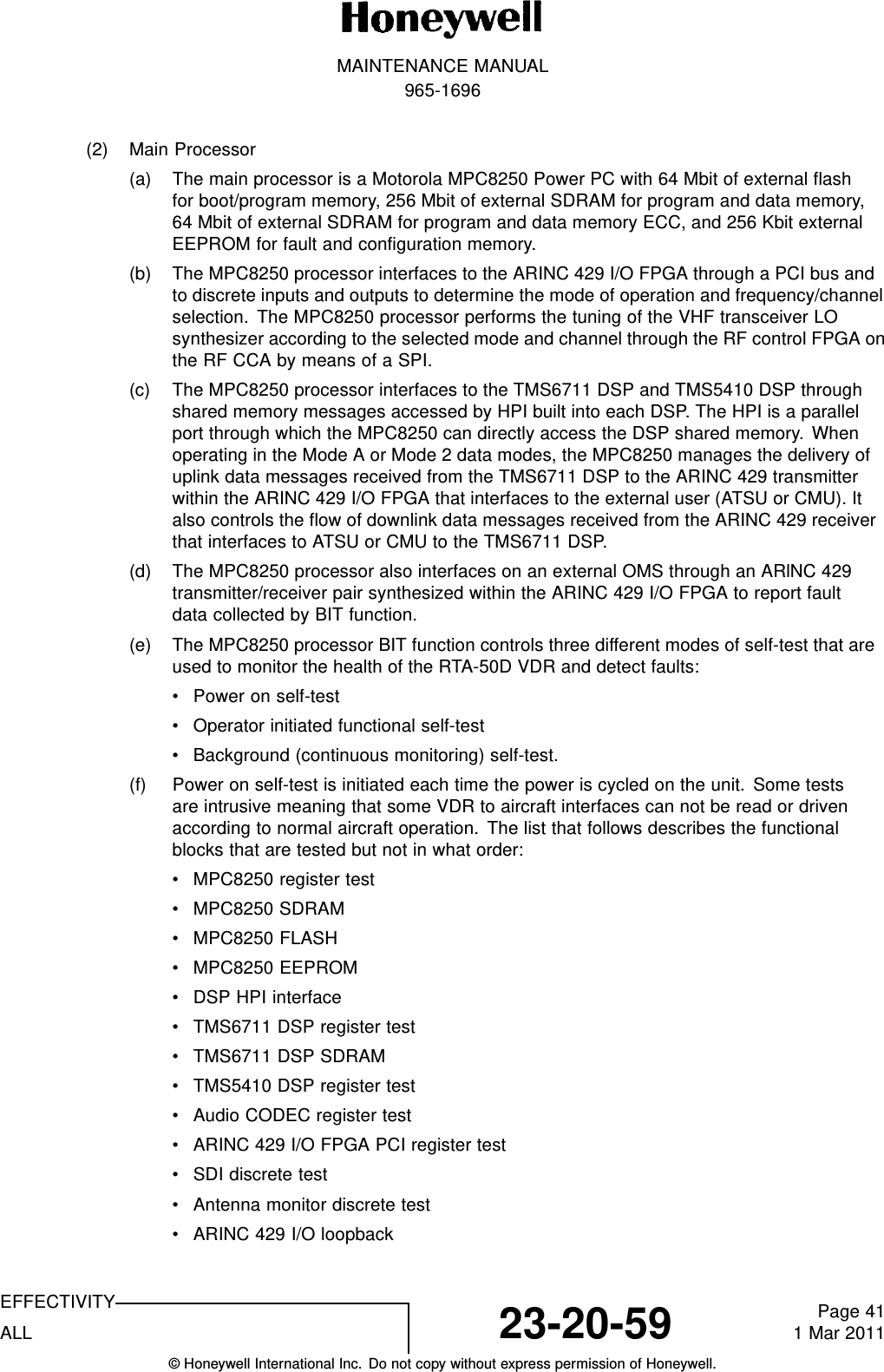
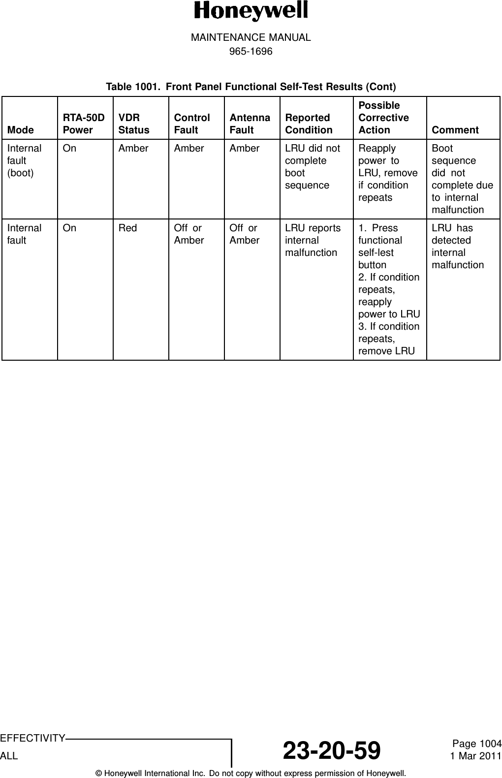
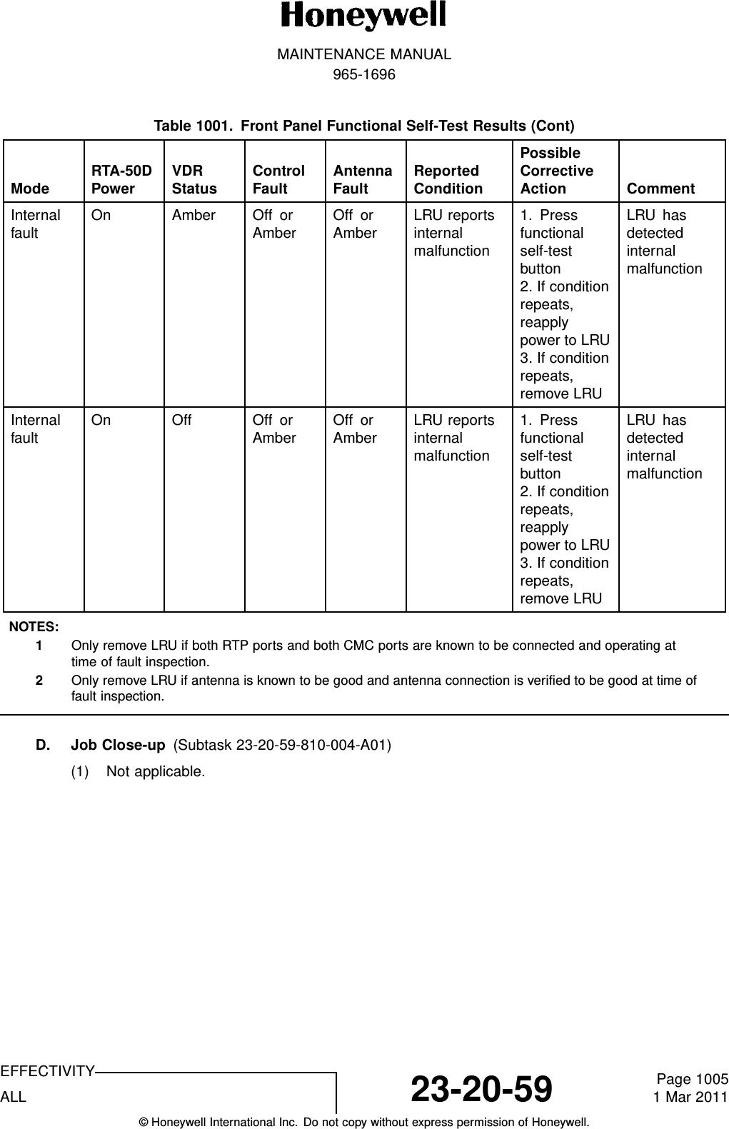
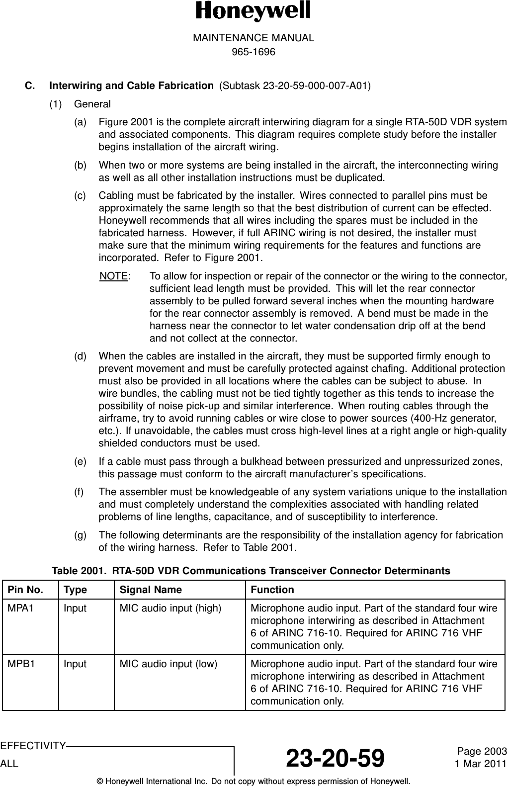
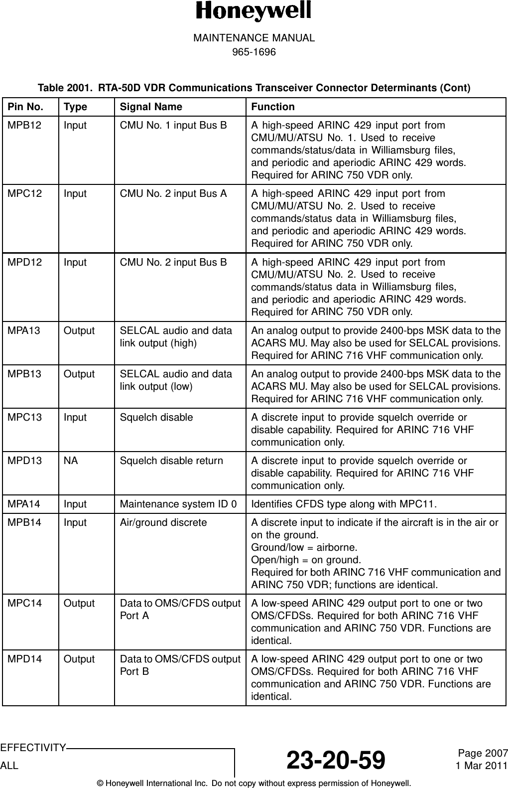
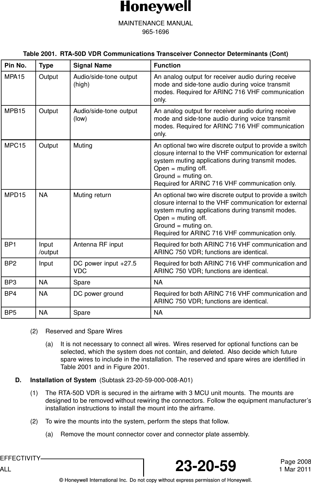
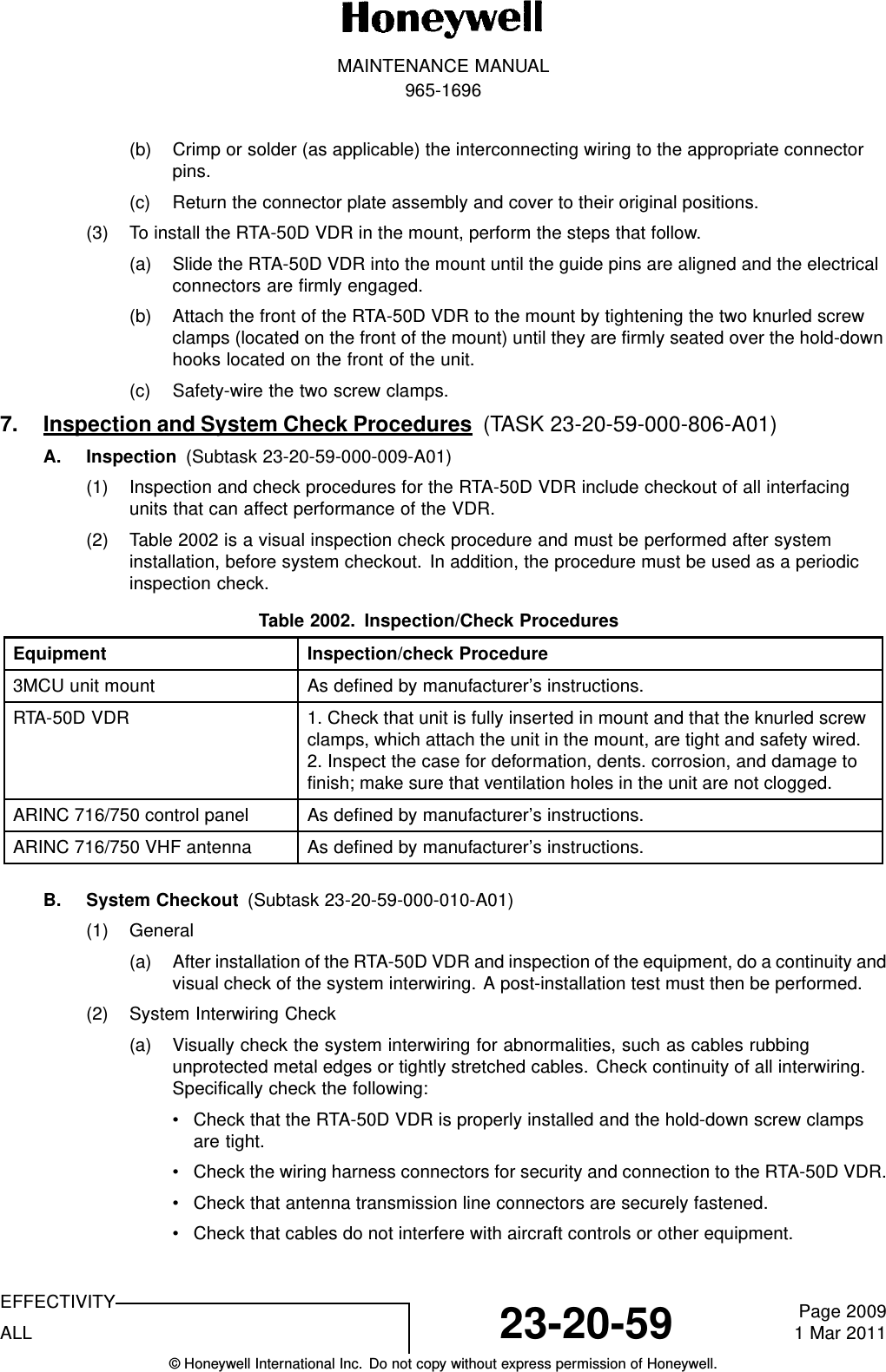
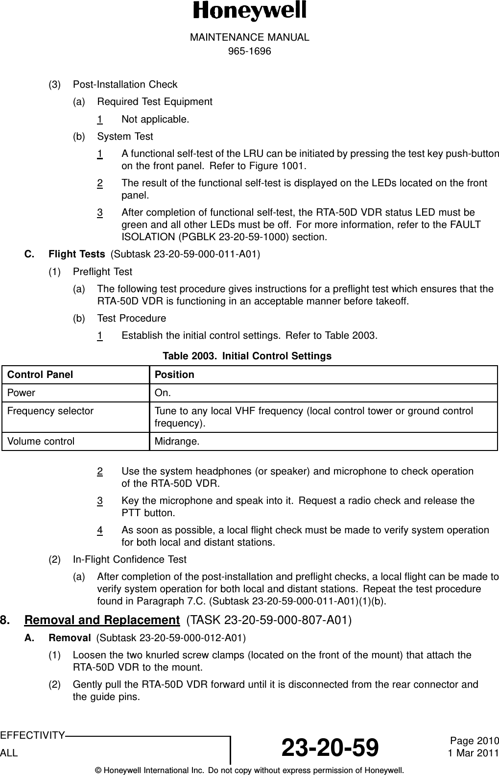
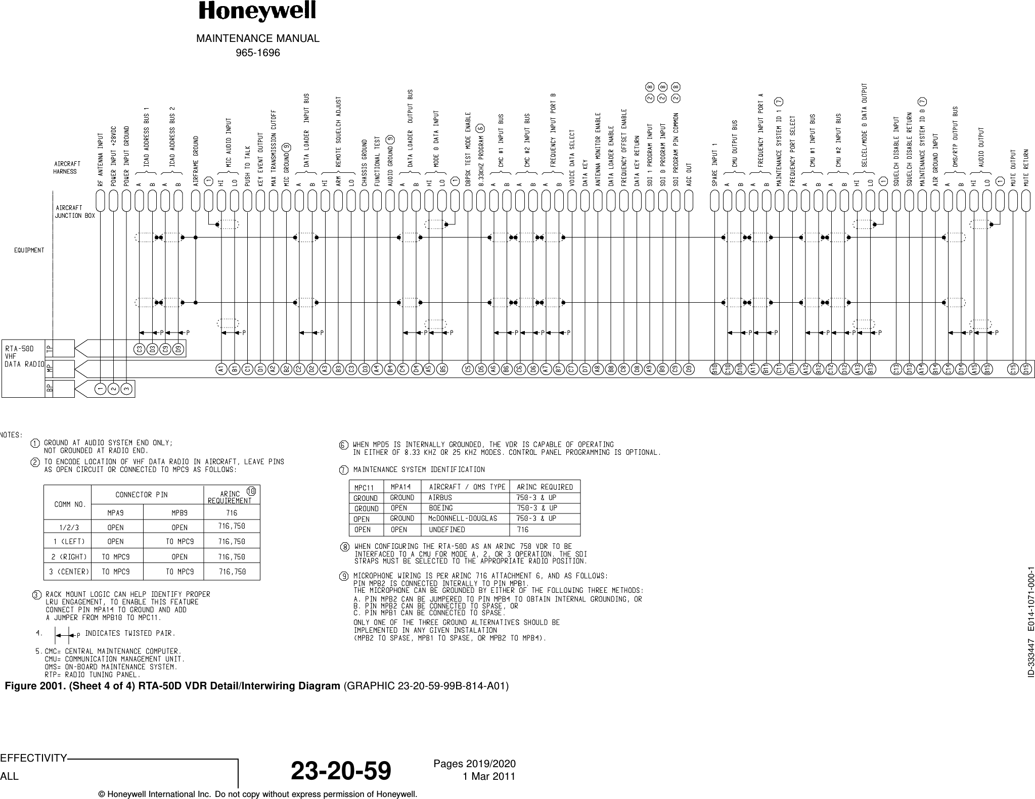
![MAINTENANCE MANUAL965-1696Table 3. RTA-50D VDR Configurations AvailablePN8.33-kHzChannelSpacing ACARS Mode A Mode 2AirbusCFDS/CMC BoeingCMC965-1696-021X X X X X965-1696-051 X X X X XTable 4. RTA-50D VDR FeaturesDescription118.000 to 136.975 MHz operation8.33-kHz and 25-kHz channel spacingICAO Annex 10 FM immunityACARS MSK (Mode A) data link functionVDL Mode 2 (D8PSK) data link functionGrowth function to VDL Mode 3 digital voice and data transmissionGrowth function to single-channel VDL Mode 4 data for data link communications applications onlyDual ARINC 429 tuning interfacesCMC/CFDS maintenance system interface200-ms power interrupt transparencyDO-160E environmental test compliantHIRF protectionLightning protection (Level 3)35-second stuck mike protection and protection disable circuitryRS-232 PC maintenance portB. Environmental Certification (Subtask 23-20-59-870-005-A01)(1) The RTA-50D VDR communications transceiver meets the environmental conditionsof the RTCA DO-160E, Environmental Conditions and Test Procedures forAirline Electronic/Electronical Equipment and Instruments. The environmentalcertification categories of the RTA-50D VDR, PN 965-1696-021 and -051, are[(A2)(D2)Z]BAE[RB1]XXXXXXZAAZ[CC][RR]M[ZZZZZ]XXA. Refer to Table 5.Table 5. RTA-50D VDR Environmental Certification CategoriesTest PN 965-1696-021 PN 965-1696-051Temperature and altitude A2D2 A2D2In-flight loss of cooling Z (18 hours) Z (18 hours)Temperature variation B BHumidity A AEFFECTIVITYALL 23-20-59 Page 81 Mar 2011© Honeywell International Inc. Do not copy without express permission of Honeywell.](https://usermanual.wiki/Honeywell/RTA-50D/User-Guide-1467620-Page-48.png)