Honeywell RTA-50D VHFAIRBORNE VOICE / DATA TRANSCEIVER User Manual User s Manual
Honeywell International Inc. VHFAIRBORNE VOICE / DATA TRANSCEIVER User s Manual
User's Manual

Honeywell International Inc.
15001 N.E. 36 Street
Redmond, Washington 98052-5317
U.S.A.
CAGE: 97896
Telephone: (800) 601-3099 (Toll Free U.S.A./Canada)
Telephone: (602) 365-3099 (International Direct)
Telephone: 00-800-601-30999 (EMEA Toll Free)
Telephone: 420-234-625-500 (EMEA Direct)
Web site: www.myaerospace.com
Maintenance Manual
RTA-50D VHF Data Radio System
Part Number CAGE
965-1696-021 97896
965-1696-051 97896
Legal Notice
Export Control
This document contains technical data and is subject to U.S. export regulations. These commodities, technology, or
software were exported from the United States in accordance with the export administration regulations. Diversion contrary
to U.S. law is prohibited.
ECCN: 7E994, NLR Eligible.
23-20-59
Page T-1
Publication Number D201010000047, Revision 0 Initial 1 Mar 2011
©Honeywell International Inc. Do not copy without express permission of Honeywell.

MAINTENANCE MANUAL
965-1696
Proprietary Information Honeywell - Confidential
THIS COPYRIGHTED WORK AND ALL INFORMATION ARE THE PROPERTY OF HONEYWELL
INTERNATIONAL INC., CONTAIN TRADE SECRETS AND MAY NOT, IN WHOLE OR IN PART, BE USED,
DUPLICATED, OR DISCLOSED FOR ANY PURPOSE WITHOUT PRIOR WRITTEN PERMISSION OF
HONEYWELL INTERNATIONAL INC. ALL RIGHTS RESERVED.
Honeywell Materials License Agreement
The documents and information contained herein ("the Materials") are the proprietary data of Honeywell
International Inc. and Honeywell Intellectual Properties Inc. (collectively "Honeywell"). These Materials
are provided for the exclusive use of Honeywell Service Centers; Honeywell-authorized repair facilities;
operators of Honeywell aerospace products subject to an applicable product support agreement, their
wholly owned-subsidiaries or a formally designated third party service provider; and direct recipients of
Materials from Honeywell’s Aerospace Technical Publication Distribution. The terms and conditions of
this License Agreement govern your use of these Materials, except to the extent that any terms and
conditions of another applicable agreement with Honeywell regarding the operation, maintenance, or
repair of Honeywell aerospace products conflict with the terms and conditions of this License Agreement,
in which case the terms and conditions of the other agreement will govern. However, this License
Agreement will govern in the event of a conflict between its terms and conditions and those of a purchase
order or acknowledgement.
1. License Grant - If you are a party to an applicable product support agreement, a Honeywell Service
Center agreement, or an authorized repair facility agreement, Honeywell hereby grants you a limited,
non-exclusive license to use these Materials to operate, maintain, or repair Honeywell aerospace products
only in accordance with that agreement.
If you are a direct recipient of these Materials from Honeywell’s Aerospace Technical Publication
Distribution and are not a party to an agreement related to the operation, maintenance or repair of
Honeywell aerospace products, Honeywell hereby grants you a limited, non-exclusive license to use
these Materials to maintain or repair the subject Honeywell aerospace products only at the facility to
which these Materials have been shipped ("the Licensed Facility"). Transfer of the Materials to another
facility owned by you is permitted only if the original Licensed Facility retains no copies of the Materials
and you provide prior written notice to Honeywell.
2. Rights In Materials - Honeywell retains all rights in these Materials and in any copies thereof that are not
expressly granted to you, including all rights in patents, copyrights, trademarks, and trade secrets. No
license to use any Honeywell trademarks or patents is granted under this License Agreement.
3. Confidentiality - You acknowledge that these Materials contain information that is confidential and
proprietary to Honeywell. You agree to take all reasonable efforts to maintain the confidentiality of these
Materials.
4. Assignment And Transfer - This License Agreement may be assigned to a formally designated service
designee or transferred to a subsequent owner or operator of an aircraft containing the subject Honeywell
aerospace products. However, the recipient of any such assignment or transfer must assume all of
your obligations under this License Agreement. No assignment or transfer shall relieve any party of
any obligation that such party then has hereunder.
5. Copies of Materials - Unless you have the express written permission of Honeywell, you may not
make or permit making of copies of the Materials. Notwithstanding the foregoing, you may make copies
of only portions of the Material for your internal use. You agree to return the Materials and any copies
thereof to Honeywell upon the request of Honeywell.
23-20-59 Page T-2
1 Mar 2011
© Honeywell International Inc. Do not copy without express permission of Honeywell.

MAINTENANCE MANUAL
965-1696
6. Term - This License Agreement is effective until terminated as set forth herein. This License Agreement
will terminate immediately, without notice from Honeywell, if you fail to comply with any provision of this
License Agreement or will terminate simultaneously with the termination or expiration of your applicable
product support agreement, authorized repair facility agreement, or your formal designation as a third party
service provider. Upon termination of this License Agreement, you will return these Materials to Honeywell
without retaining any copies and will have one of your authorized officers certify that all Materials have
been returned with no copies retained.
7. Remedies - Honeywell reserves the right to pursue all available remedies and damages resulting from
a breach of this License Agreement.
8. Limitation of Liability - Honeywell does not make any representation regarding the use or sufficiency of
the Materials. THERE ARE NO OTHER WARRANTIES, WHETHER WRITTEN OR ORAL, EXPRESS,
IMPLIED OR STATUTORY, INCLUDING, BUT NOT LIMITED TO, (i) WARRANTIES ARISING FROM
COURSE OF PERFORMANCE, DEALING, USAGE, OR TRADE, WHICH ARE HEREBY EXPRESSLY
DISCLAIMED, OR (ii) WARRANTIES AGAINST INFRINGEMENT OF INTELLECTUAL PROPERTY
RIGHTS OF THIRD PARTIES, EVEN IF HONEYWELL HAS BEEN ADVISED OF ANY SUCH
INFRINGEMENT. IN NO EVENT WILL HONEYWELL BE LIABLE FOR ANY INCIDENTAL DAMAGES,
CONSEQUENTIAL DAMAGES, SPECIAL DAMAGES, INDIRECT DAMAGES, LOSS OF PROFITS, LOSS
OF REVENUES, OR LOSS OF USE, EVEN IF INFORMED OF THE POSSIBILITY OF SUCH DAMAGES.
TO THE EXTENT PERMITTED BY APPLICABLE LAW, THESE LIMITATIONS AND EXCLUSIONS WILL
APPLY REGARDLESS OF WHETHER LIABILITY ARISES FROM BREACH OF CONTRACT, WARRANTY,
TORT (INCLUDING BUT NOT LIMITED TO NEGLIGENCE), BY OPERATION OF LAW, OR OTHERWISE.
9. Controlling Law - This License shall be governed and construed in accordance with the laws of the
State of New York without regard to the conflicts of laws provisions thereof. This license sets forth the
entire agreement between you and Honeywell and may only be modified by a writing duly executed by
the duly authorized representatives of the parties.
Safety Advisory
WARNING: BEFORE THE MATERIALS CALLED OUT IN THIS PUBLICATION ARE USED, KNOW THE
HANDLING, STORAGE AND DISPOSAL PRECAUTIONS RECOMMENDED BY THE MANUFACTURER
OR SUPPLIER. FAILURE TO OBEY THE MANUFACTURERS’ OR SUPPLIERS’ RECOMMENDATIONS
CAN RESULT IN PERSONAL INJURY OR DISEASE.
This publication describes physical and chemical processes which can make it necessary to use chemicals,
solvents, paints, and other commercially available materials. The user of this publication must get the
Material Safety Data Sheets (OSHA Form 174 or equivalent) from the manufacturers or suppliers of the
materials to be used. The user must know the manufacturer/supplier data and obey the procedures,
recommendations, warnings and cautions set forth for the safe use, handling, storage, and disposal
of the materials.
Warranty/Liability Advisory
WARNING: HONEYWELL ASSUMES NO RESPONSIBILITY FOR ANY HONEYWELL EQUIPMENT
WHICH IS NOT MAINTAINED AND/OR REPAIRED IN ACCORDANCE WITH HONEYWELL’S
PUBLISHED INSTRUCTIONS AND/OR HONEYWELL’S FAA/SFAR 36 REPAIR AUTHORIZATION.
NEITHER DOES HONEYWELL ASSUME RESPONSIBILITY FOR SPECIAL TOOLS AND TEST
EQUIPMENT FABRICATED BY COMPANIES OTHER THAN HONEYWELL.
WARNING: INCORRECTLY REPAIRED COMPONENTS CAN AFFECT AIRWORTHINESS OR
DECREASE THE LIFE OF THE COMPONENTS. INCORRECTLY FABRICATED SPECIAL TOOLING
OR TEST EQUIPMENT CAN RESULT IN DAMAGE TO THE PRODUCT COMPONENTS OR GIVE
UNSATISFACTORY RESULTS.
23-20-59 Page T-3
1 Mar 2011
© Honeywell International Inc. Do not copy without express permission of Honeywell.

MAINTENANCE MANUAL
965-1696
Copyright - Notice
Copyright 2011 Honeywell International Inc. All rights reserved.
Honeywell is a registered trademark of Honeywell International Inc.
All other marks are owned by their respective companies.
THIS IS THE CMM FOSI - DATE: 20101217
23-20-59 Page T-4
1 Mar 2011
© Honeywell International Inc. Do not copy without express permission of Honeywell.

MAINTENANCE MANUAL
965-1696
TRANSMITTAL INFORMATION
THIS IS AN INITIAL RELEASE OF RTA-50D VHF DATA RADIO SYSTEM MM ATA NO. 23-20-59 AND IS
ISSUED FOR USE IN SUPPORT OF THE FOLLOWING:
Table TI-1. Applicable Components
Component PN Nomenclature
965-1696-021RTA-50D VHF Data Radio System
965-1696-051 RTA-50D VHF Data Radio System
Revision History
Table TI-2 shows the revision history of this MM.
Table TI-2. Revision History
Revision Number Revision Date
01 Mar 2011
EFFECTIVITY
ALL 23-20-59 Page TI-1
1 Mar 2011
© Honeywell International Inc. Do not copy without express permission of Honeywell.

MAINTENANCE MANUAL
965-1696
Blank Page
EFFECTIVITY
ALL 23-20-59 Page TI-2
1 Mar 2011
© Honeywell International Inc. Do not copy without express permission of Honeywell.
MAINTENANCE MANUAL
965-1696
RECORD OF REVISIONS
For each revision, write the revision number, revision date, date put in the manual, and your initials in the
applicable column.
NOTE: Refer to the Revision History in the TRANSMITTAL INFORMATION section for revision data.
EFFECTIVITY
ALL 23-20-59 Page RR-1
1 Mar 2011
© Honeywell International Inc. Do not copy without express permission of Honeywell.

MAINTENANCE MANUAL
965-1696
Blank Page
EFFECTIVITY
ALL 23-20-59 Page RR-2
1 Mar 2011
© Honeywell International Inc. Do not copy without express permission of Honeywell.

MAINTENANCE MANUAL
965-1696
RECORD OF TEMPORARY REVISIONS
Instructions on each page of a temporary revision tell you where to put the pages in your manual. Remove
the temporary revision pages only when discard instructions are given. For each temporary revision, put the
applicable data in the record columns on this page.
Definition of Status column: TR can be active, cancelled, or incorporated. If TR is incorporated, list the revision
number. For example, enter: INC Rev 7. If TR is replaced by another TR, then put “Cancelled”. For example:
Cancelled by TR NN-NN. “Active” is entered by the holder of manual.
Date Date
Temporary Put Removed
Revision Page Issue in from
Number Status Number Date Manual By Manual By
EFFECTIVITY
ALL 23-20-59 Page RTR-1
1 Mar 2011
© Honeywell International Inc. Do not copy without express permission of Honeywell.

MAINTENANCE MANUAL
965-1696
Blank Page
EFFECTIVITY
ALL 23-20-59 Page RTR-2
1 Mar 2011
© Honeywell International Inc. Do not copy without express permission of Honeywell.

MAINTENANCE MANUAL
965-1696
SERVICE BULLETIN LIST
Service Bulletin / Date Put in
Revision Number Title Modification Manual
EFFECTIVITY
ALL 23-20-59 Page SBL-1
1 Mar 2011
© Honeywell International Inc. Do not copy without express permission of Honeywell.

MAINTENANCE MANUAL
965-1696
Blank Page
EFFECTIVITY
ALL 23-20-59 Page SBL-2
1 Mar 2011
© Honeywell International Inc. Do not copy without express permission of Honeywell.

MAINTENANCE MANUAL
965-1696
LIST OF EFFECTIVE PAGES
Subheading and Page Date Subheading and Page Date
Title
T-1 1 Mar 2011
T-2 1 Mar 2011
T-3 1 Mar 2011
T-4 1 Mar 2011
Transmittal Information
TI-1 1 Mar 2011
TI-2 1 Mar 2011
Record of Revisions
RR-1 1 Mar 2011
RR-2 1 Mar 2011
Record of Temporary Revisions
RTR-1 1 Mar 2011
RTR-2 1 Mar 2011
Service Bulletin List
SBL-1 1 Mar 2011
SBL-2 1 Mar 2011
List of Effective Pages
LEP-1 1 Mar 2011
LEP-2 1 Mar 2011
Table of Contents
TC-1 1 Mar 2011
TC-2 1 Mar 2011
TC-3 1 Mar 2011
TC-4 1 Mar 2011
TC-5 1 Mar 2011
TC-6 1 Mar 2011
Introduction
INTRO-1 1 Mar 2011
INTRO-2 1 Mar 2011
INTRO-3 1 Mar 2011
INTRO-4 1 Mar 2011
INTRO-5 1 Mar 2011
INTRO-6 1 Mar 2011
INTRO-7 1 Mar 2011
INTRO-8 1 Mar 2011
INTRO-9 1 Mar 2011
INTRO-10 1 Mar 2011
INTRO-11 1 Mar 2011
INTRO-12 1 Mar 2011
INTRO-13 1 Mar 2011
INTRO-14 1 Mar 2011
INTRO-15 1 Mar 2011
INTRO-16 1 Mar 2011
INTRO-17 1 Mar 2011
INTRO-18 1 Mar 2011
INTRO-19 1 Mar 2011
INTRO-20 1 Mar 2011
Description and Operation
11Mar2011
21Mar2011
31Mar2011
41Mar2011
51Mar2011
61Mar2011
71Mar2011
81Mar2011
91Mar2011
10 1 Mar 2011
11 1 Mar 2011
12 1 Mar 2011
13 1 Mar 2011
14 1 Mar 2011
15 1 Mar 2011
16 1 Mar 2011
17 1 Mar 2011
18 1 Mar 2011
19 1 Mar 2011
20 1 Mar 2011
F 21/22 1 Mar 2011
F 23/24 1 Mar 2011
25 1 Mar 2011
26 1 Mar 2011
F 27/28 1 Mar 2011
* indicates pages changed or added data
F indicates a right foldout
LF indicates a left foldout
EFFECTIVITY
ALL 23-20-59 Page LEP-1
1 Mar 2011
© Honeywell International Inc. Do not copy without express permission of Honeywell.

MAINTENANCE MANUAL
965-1696
LIST OF EFFECTIVE PAGES (Cont)
Subheading and Page Date Subheading and Page Date
29 1 Mar 2011
30 1 Mar 2011
F 31/32 1 Mar 2011
33 1 Mar 2011
34 1 Mar 2011
35 1 Mar 2011
36 1 Mar 2011
37 1 Mar 2011
38 1 Mar 2011
F 39/40 1 Mar 2011
41 1 Mar 2011
42 1 Mar 2011
43 1 Mar 2011
44 1 Mar 2011
45 1 Mar 2011
46 1 Mar 2011
Fault Isolation
1001 1 Mar 2011
1002 1 Mar 2011
1003 1 Mar 2011
1004 1 Mar 2011
1005 1 Mar 2011
1006 1 Mar 2011
Maintenance Practices
2001 1 Mar 2011
2002 1 Mar 2011
2003 1 Mar 2011
2004 1 Mar 2011
2005 1 Mar 2011
2006 1 Mar 2011
2007 1 Mar 2011
2008 1 Mar 2011
2009 1 Mar 2011
2010 1 Mar 2011
2011 1 Mar 2011
2012 1 Mar 2011
F 2013/2014 1 Mar 2011
F 2015/2016 1 Mar 2011
F 2017/2018 1 Mar 2011
F 2019/2020 1 Mar 2011
* indicates pages changed or added data
F indicates a right foldout
LF indicates a left foldout
EFFECTIVITY
ALL 23-20-59 Page LEP-2
1 Mar 2011
© Honeywell International Inc. Do not copy without express permission of Honeywell.

MAINTENANCE MANUAL
965-1696
TABLE OF CONTENTS
LIST OF SECTIONS
Title Page
INTRODUCTION
1. How to Use This Manual (TASK 23-20-59-99F-801-A01)................................ INTRO-1
A. General (Subtask 23-20-59-99F-001-A01) .......................................... INTRO-1
B. Observance of Manual Instructions (Subtask 23-20-59-99F-002-A01) .......... INTRO-1
C. Symbols (Subtask 23-20-59-99F-003-A01) ......................................... INTRO-1
D. Units of Measure (Subtask 23-20-59-99F-004-A01) ............................... INTRO-4
E. Page Number Block Explanation (Subtask 23-20-59-99F-005-A01) ............. INTRO-4
F. Application of Maintenance Task Oriented Support System
(MTOSS) (Subtask 23-20-59-99F-006-A01) ........................................ INTRO-4
G. Standard Practices Manual (Subtask 23-20-59-99F-007-A01) ................... INTRO-14
H. Electrostatic Discharge (Subtask 23-20-59-99F-008-A01) ........................ INTRO-14
2. Customer Support (TASK 23-20-59-99F-802-A01) ....................................... INTRO-14
A. Honeywell Aerospace Online Technical Publications Web
Site (Subtask 23-20-59-99F-009-A01)............................................... INTRO-14
B. Global Customer Care Center (Subtask 23-20-59-99F-010-A01) ................ INTRO-14
3. References (TASK 23-20-59-99F-803-A01) ............................................... INTRO-14
A. Honeywell/Vendor Publications (Subtask 23-20-59-99F-011-A01) ............... INTRO-14
B. Other Publications (Subtask 23-20-59-99F-012-A01).............................. INTRO-15
4. Acronyms and Abbreviations (TASK 23-20-59-99F-804-A01) ........................... INTRO-15
A. General (Subtask 23-20-59-99F-013-A01) .......................................... INTRO-15
5. Process Verification (TASK 23-20-59-99F-805-A01) ..................................... INTRO-19
A. Verification Data (Subtask 23-20-59-99F-014-A01) ................................ INTRO-19
DESCRIPTION AND OPERATION
1. Description (TASK 23-20-59-870-801-A01) ............................................... 1
A. General (Subtask 23-20-59-870-001-A01) .......................................... 1
B. Job Setup Data (Subtask 23-20-59-99C-001-A01) ................................. 5
C. Purpose of Equipment (Subtask 23-20-59-870-002-A01) ......................... 6
D. Equipment Required but Not Supplied (Subtask 23-20-59-870-003-A01) ....... 7
2. Configurations Available (TASK 23-20-59-870-802-A01) ................................ 7
A. General (Subtask 23-20-59-870-004-A01) .......................................... 7
B. Environmental Certification (Subtask 23-20-59-870-005-A01) .................... 8
3. System Description (TASK 23-20-59-870-803-A01) ...................................... 9
EFFECTIVITY
ALL 23-20-59 Page TC-1
1 Mar 2011
© Honeywell International Inc. Do not copy without express permission of Honeywell.

MAINTENANCE MANUAL
965-1696
TABLE OF CONTENTS (Cont)
LIST OF SECTIONS (Cont)
Title Page
A. RTA-50D VDR Data Radio System (Subtask 23-20-59-870-006-A01) ........... 9
B. Description of Equipment (Subtask 23-20-59-870-007-A01) ...................... 10
C. ARINC 716 Data Mode (Subtask 23-20-59-870-008-A01) ........................ 12
D. ARINC 750 Mode A and Mode 2 (Subtask 23-20-59-870-009-A01) ............. 13
4. System Component Description (TASK 23-20-59-870-804-A01) ....................... 14
A. RTA-50D VDR (Subtask 23-20-59-870-010-A01) .................................. 14
B. Other Components in the System (Subtask 23-20-59-870-011-A01) ............ 15
5. Operation (TASK 23-20-59-870-805-A01) ................................................. 15
A. Voice Mode (Subtask 23-20-59-870-012-A01) ..................................... 15
B. Mode 0 Data (Subtask 23-20-59-870-013-A01) .................................... 15
C. Mode A Data (Subtask 23-20-59-870-014-A01) .................................... 16
D. VDL Mode 2 (Subtask 23-20-59-870-015-A01)..................................... 16
E. VDL Mode 3 (Subtask 23-20-59-870-016-A01)..................................... 17
F. VDL Mode 4 (Subtask 23-20-59-870-017-A01)..................................... 18
6. Theory of Operation (TASK 23-20-59-870-806-A01) ..................................... 19
A. VDR Overview (Subtask 23-20-59-870-018-A01) .................................. 19
B. RTA-50D VDR System Architecture (Subtask 23-20-59-870-019-A01) .......... 25
C. RF CCA (Subtask 23-20-59-870-020-A01) ......................................... 29
D. Digital Processor CCA (Subtask 23-20-59-870-021-A01) ......................... 37
E. Front Panel I/O Board (Subtask 23-20-59-870-022-A01) .......................... 45
F. Power Supply (Subtask 23-20-59-870-023-A01) ................................... 45
G. Rear Interconnect (Subtask 23-20-59-870-024-A01) .............................. 45
FAULT ISOLATION
1. Planning Data (TASK 23-20-59-99C-801-A01) ........................................... 1001
A. Reason for the Job (Subtask 23-20-59-99C-002-A01)............................. 1001
B. Job Setup Data (Subtask 23-20-59-99C-003-A01) ................................. 1001
2. Procedure (TASK 23-20-59-810-801-A01) ................................................ 1001
A. Job Setup (Subtask 23-20-59-810-001-A01) ....................................... 1001
B. Functional Self-Test (Subtask 23-20-59-810-002-A01) ............................ 1001
C. RTA-50D VDR Test Results (Subtask 23-20-59-810-003-A01) ................... 1002
D. Job Close-up (Subtask 23-20-59-810-004-A01) .................................... 1005
EFFECTIVITY
ALL 23-20-59 Page TC-2
1 Mar 2011
© Honeywell International Inc. Do not copy without express permission of Honeywell.

MAINTENANCE MANUAL
965-1696
TABLE OF CONTENTS (Cont)
LIST OF SECTIONS (Cont)
Title Page
MAINTENANCE PRACTICES
1. Planning Data (TASK 23-20-59-99C-802-A01) ........................................... 2001
A. Reason for the Job (Subtask 23-20-59-99C-004-A01)............................. 2001
B. Job Setup Data (Subtask 23-20-59-99C-005-A01) ................................. 2001
2. Inspection After Unpacking (TASK 23-20-59-000-801-A01) ............................. 2001
A. General (Subtask 23-20-59-000-001-A01) .......................................... 2001
3. Preinstallation Testing (TASK 23-20-59-000-802-A01) ................................... 2001
A. Overview (Subtask 23-20-59-000-002-A01) ........................................ 2001
4. Equipment Changes and Marking (TASK 23-20-59-000-803-A01) ..................... 2002
A. Overview (Subtask 23-20-59-000-003-A01) ........................................ 2002
5. Interchangeability (TASK 23-20-59-000-804-A01) ........................................ 2002
A. Overview (Subtask 23-20-59-000-004-A01) ........................................ 2002
6. Installation (TASK 23-20-59-000-805-A01) ................................................ 2002
A. General (Subtask 23-20-59-000-005-A01) .......................................... 2002
B. Location of Equipment (Subtask 23-20-59-000-006-A01) ......................... 2002
C. Interwiring and Cable Fabrication (Subtask 23-20-59-000-007-A01) ............ 2003
D. Installation of System (Subtask 23-20-59-000-008-A01) .......................... 2008
7. Inspection and System Check Procedures (TASK 23-20-59-000-806-A01) ........... 2009
A. Inspection (Subtask 23-20-59-000-009-A01) ....................................... 2009
B. System Checkout (Subtask 23-20-59-000-010-A01)............................... 2009
C. Flight Tests (Subtask 23-20-59-000-011-A01) ...................................... 2010
8. Removal and Replacement (TASK 23-20-59-000-807-A01)............................. 2010
A. Removal (Subtask 23-20-59-000-012-A01) ......................................... 2010
B. Replacement (Subtask 23-20-59-000-013-A01) .................................... 2011
9. Maintenance Procedures (TASK 23-20-59-000-808-A01) ............................... 2011
A. Adjustments and Alignments (Subtask 23-20-59-000-014-A01) .................. 2011
B. System Protection (Subtask 23-20-59-000-015-A01) .............................. 2011
C. Lubrication Practices (Subtask 23-20-59-000-016-A01) ........................... 2011
D. Cleaning (Subtask 23-20-59-000-017-A01) ......................................... 2011
10. Diagrams (TASK 23-20-59-000-809-A01) ................................................. 2011
A. RTA-50D VDR Diagrams (Subtask 23-20-59-000-018-A01) ...................... 2011
EFFECTIVITY
ALL 23-20-59 Page TC-3
1 Mar 2011
© Honeywell International Inc. Do not copy without express permission of Honeywell.

MAINTENANCE MANUAL
965-1696
Blank Page
EFFECTIVITY
ALL 23-20-59 Page TC-4
1 Mar 2011
© Honeywell International Inc. Do not copy without express permission of Honeywell.

MAINTENANCE MANUAL
965-1696
TABLE OF CONTENTS (Cont)
LIST OF FIGURES
Figure Description Page
INTRO-1 Geometric Tolerance Symbols (GRAPHIC 23-20-59-99B-801-A01) ................ INTRO-2
INTRO-2 Symbols (GRAPHIC 23-20-59-99B-802-A01) ......................................... INTRO-4
INTRO-3 MTOSS Code Positions (GRAPHIC 23-20-59-99B-803-A01) ....................... INTRO-5
1 Typical RTA-50D VDR (GRAPHIC 23-20-59-99B-804-A01) ......................... 5
2 VHF Communications for Voice Operation (GRAPHIC 23-20-59-99B-805-A01) .. 10
3 Module and Assembly Locations (GRAPHIC 23-20-59-99B-806-A01) ............. 11
4 ACARS Audio Interface (GRAPHIC 23-20-59-99B-807-A01)........................ 13
5 RTA-50D VDR External Interfaces (ARINC 750 Mode) (GRAPHIC 23-20-59-
99B-808-A01).............................................................................. 14
6 RTA-50D VDR Interface Context Diagram (GRAPHIC 23-20-59-99B-809-A01) .. 21
7 RTA-50D VDR Internal Architecture (GRAPHIC 23-20-59-99B-810-A01) .......... 27
8 RF CCA (GRAPHIC 23-20-59-99B-811-A01) ......................................... 31
9 Digital Processor CCA Block Diagram (GRAPHIC 23-20-59-99B-812-A01) ....... 39
1001 RTA-50D VDR Front Panel Functional Self-Test Interface (GRAPHIC 23-20-59-
99B-813-A01).............................................................................. 1002
2001 RTA-50D VDR Detail/Interwiring Diagram (GRAPHIC 23-20-59-99B-814-A01) ... 2013
EFFECTIVITY
ALL 23-20-59 Page TC-5
1 Mar 2011
© Honeywell International Inc. Do not copy without express permission of Honeywell.

MAINTENANCE MANUAL
965-1696
TABLE OF CONTENTS (Cont)
LIST OF TABLES
Table Description Page
INTRO-1 Page Number Blocks ..................................................................... INTRO-4
INTRO-2 MTOSS Function Code Definitions ...................................................... INTRO-5
INTRO-3 Verification Data ........................................................................... INTRO-20
1 Leading Particulars ....................................................................... 1
2 Equipment Required but Not Supplied .................................................. 7
3 RTA-50D VDR Configurations Available ................................................ 8
4 RTA-50D VDR Features .................................................................. 8
5 RTA-50D VDR Environmental Certification Categories ............................... 8
6 Module and Assembly Designations .................................................... 10
7 Modes of Operation ....................................................................... 12
1001 Front Panel Functional Self-Test Results ............................................... 1002
2001 RTA-50D VDR Communications Transceiver Connector Determinants ............. 2003
2002 Inspection/Check Procedures............................................................ 2009
2003 Initial Control Settings .................................................................... 2010
EFFECTIVITY
ALL 23-20-59 Page TC-6
1 Mar 2011
© Honeywell International Inc. Do not copy without express permission of Honeywell.

MAINTENANCE MANUAL
965-1696
INTRODUCTION
1. How to Use This Manual (TASK 23-20-59-99F-801-A01)
A. General (Subtask 23-20-59-99F-001-A01)
(1) This publication gives maintenance instructions for the equipment shown on the Title page.
(2) Standard maintenance procedures that technicians must know are not given in this manual.
(3) This publication is written in agreement with the ATA Specification.
(4) Warnings, cautions, and notes in this manual give the data that follows:
• A WARNING gives a condition or tells personnel what part of an operation or maintenance
procedure, which if not obeyed, can cause injury or death
• A CAUTION gives a condition or tells personnel what part of an operation or maintenance
procedure, which if not obeyed, can cause damage to the equipment
• A NOTE gives data, not commands. The NOTE helps personnel when they do the related
instruction.
(5) Warnings and cautions go before the applicable paragraph or step. Notes follow the applicable
paragraph or step.
B. Observance of Manual Instructions (Subtask 23-20-59-99F-002-A01)
(1) The procedures used must be consistent with standard shop practices and be carefully
examined to make sure that all safety, efficiency, and operation procedures of the unit are
obeyed.
(2) All personnel who operate equipment and do maintenance specified in this manual must know
and obey the safety precautions.
C. Symbols (Subtask 23-20-59-99F-003-A01)
(1) The symbols and special characters are in agreement with IEEE Publication 260 and IEC
Publication 27. Special characters in text are spelled out.
(2) The signal mnemonics, unit control designators, and test designators are shown in capital
letters.
(3) The signal names followed by an “*” show an active low signal.
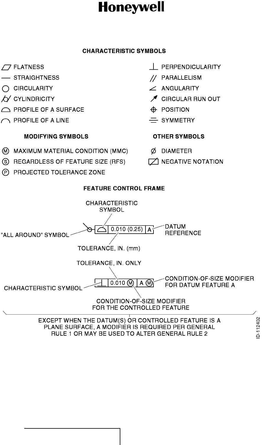
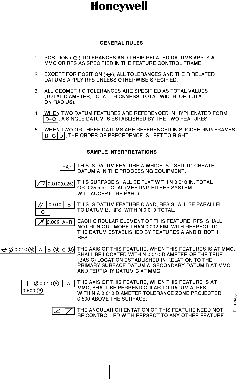
(4) Some figures in this manual incorporate standard geometric characteristic symbols. Refer to
Figure INTRO-1 for the geometric characteristic symbols.
EFFECTIVITY
ALL 23-20-59 Page INTRO-1
1 Mar 2011
© Honeywell International Inc. Do not copy without express permission of Honeywell.
MAINTENANCE MANUAL
965-1696
Figure INTRO-1. (Sheet 1 of 2) Geometric Tolerance Symbols (GRAPHIC 23-20-59-99B-801-A01)
EFFECTIVITY
ALL 23-20-59 Page INTRO-2
1 Mar 2011
© Honeywell International Inc. Do not copy without express permission of Honeywell.
MAINTENANCE MANUAL
965-1696
Figure INTRO-1. (Sheet 2 of 2) Geometric Tolerance Symbols (GRAPHIC 23-20-59-99B-801-A01)
EFFECTIVITY
ALL 23-20-59 Page INTRO-3
1 Mar 2011
© Honeywell International Inc. Do not copy without express permission of Honeywell.
MAINTENANCE MANUAL
965-1696
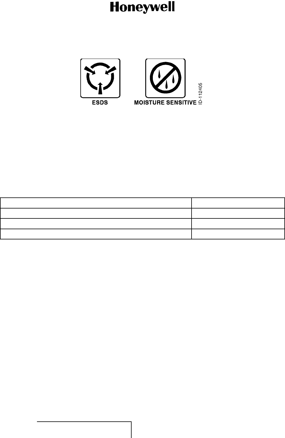
(5) The symbols in Figure INTRO-2 show ESDS and moisture sensitive devices.
Figure INTRO-2. (Sheet 1 of 1) Symbols (GRAPHIC 23-20-59-99B-802-A01)
D. Units of Measure (Subtask 23-20-59-99F-004-A01)
(1) Measurements, weights, temperatures, dimensions, and other values are expressed in the
USMS followed by the appropriate SI metric units in parentheses. Some standard tools or
parts such as drills, taps, bolts, nuts, etc., do not have an equivalent.
E. Page Number Block Explanation (Subtask 23-20-59-99F-005-A01)
(1) The data in this manual is divided into sections. A standard page number block system is
used. Page number blocks are shown in Table INTRO-1.
TableINTRO-1. PageNumberBlocks
Section Page Number Block
Description and Operation 1thru999
Fault Isolation 1001 thru 1999
Maintenance Practices 2001 thru 2999
F. Application of Maintenance Task Oriented Support System (MTOSS) (Subtask 23-20-59-
99F-006-A01)
(1) In accordance with the ATA Specification 2200, this publication uses a Maintenance Task
Numbering System which make the maintenance procedures in this manual compatible with
an automated shop environment.
(2) The system uses standard and unique number combinations to identify maintenance tasks
and subtasks.
(3) The MTOSS structure is the logical approach to organizing maintenance tasks and subtasks.
The MTOSS numbering system includes the ATA Chapter-Section-Subject number as well as a
function code and unique identifiers. The purpose of incorporating the MTOSS numbering
system is to give a means for the automated sorting, retrieval, and management of digitized
data.
(4) Section and Subsection Numbering System
(a) All procedures in this publication have TASK and SUBTASK numbers at key data retrieval
points. The numbers give the following:
• Identification of the hardware (parts or parts) primary to the TASK
• Identification of the maintenance function applied to the part or parts
• A unique identifier for a set of instructions (known as TASK or SUBTASK)
EFFECTIVITY
ALL 23-20-59 Page INTRO-4
1 Mar 2011
© Honeywell International Inc. Do not copy without express permission of Honeywell.
MAINTENANCE MANUAL
965-1696
• Identification of alternate methods and configuration differences that change the
procedure applied to the TASK
• Identification of airline changes to a TASK or SUBTASK.
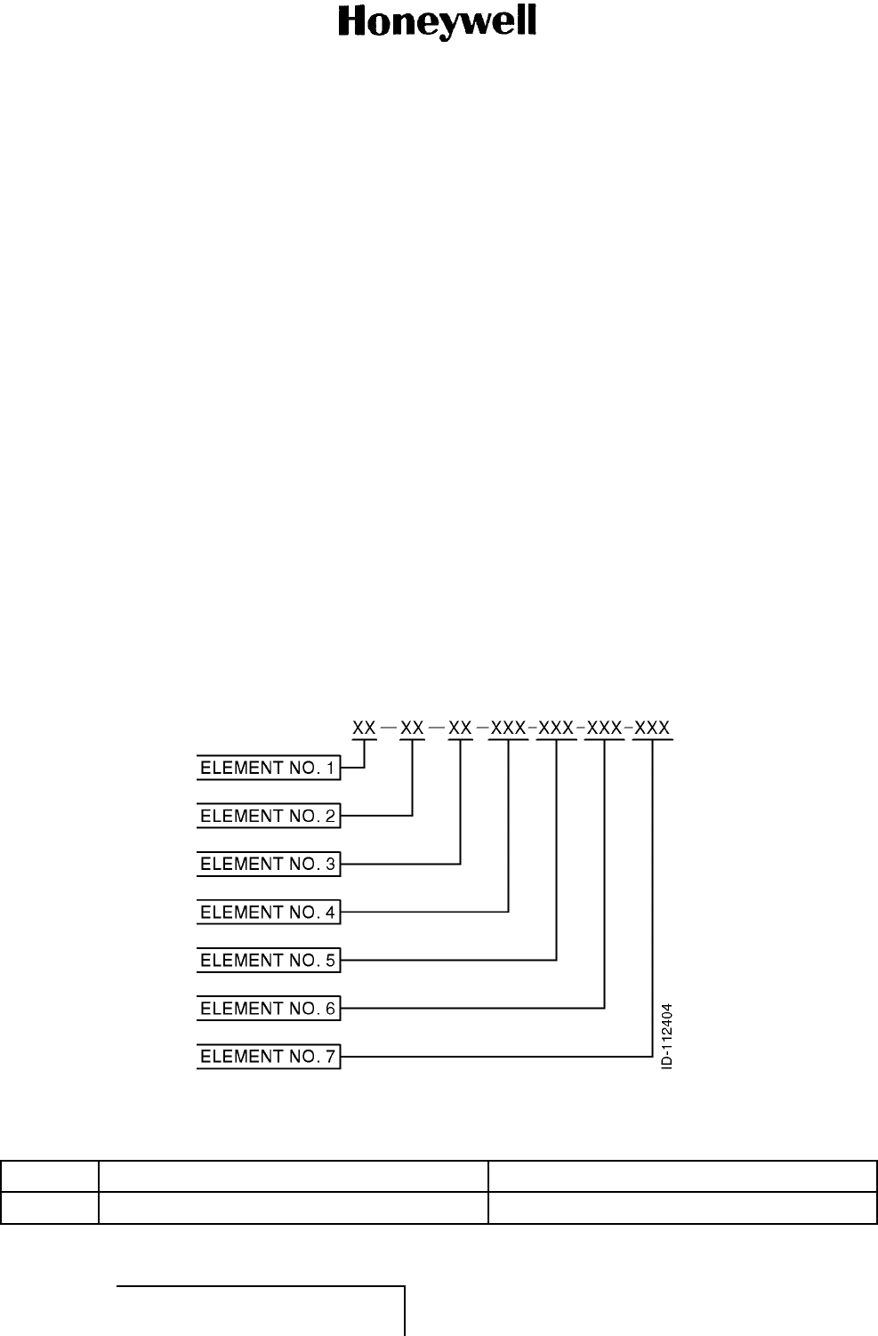
(5) Components of Task and Subtask Number
(a) The numbering system is an expansion of the ATA three-element numbering system. The
number has seven elements. The first five elements are necessary for each TASK or
SUBTASK. The sixth and seventh elements are applied only when necessary. Refer to
Figure INTRO-3.
(b) Elements 1, 2, and 3 identify the ATA Chapter-Section-Subject number of the page block.
(c) Element 4 defines the maintenance function being performed. This element is a three
position element. The third position is zero filled when further definition is not required. If
required, the manufacturer will use the numbers 1 thru 9 or letters A thru Z, excluding the
letters I and O. Refer to Table INTRO-2.
(d) Element 5 provides a unique identification for each TASK or SUBTASK number which is
similarly numbered through the first four elements as follows:
• TASKS are numbered from 801 thru 999
• SUBTASKS are numbered from 001 thru 800.
(e) Element 6 is a three position alphanumeric element used for identification of differences
in configurations, methods or techniques, variations of standard practice applications, etc.
(f) Element 7 provides coding of those tasks or subtasks that have been changed by the
customer (e.g., those tasks or subtasks accomplished by an outside repair source).
Figure INTRO-3. (Sheet 1 of 1) MTOSS Code Positions (GRAPHIC 23-20-59-99B-803-A01)
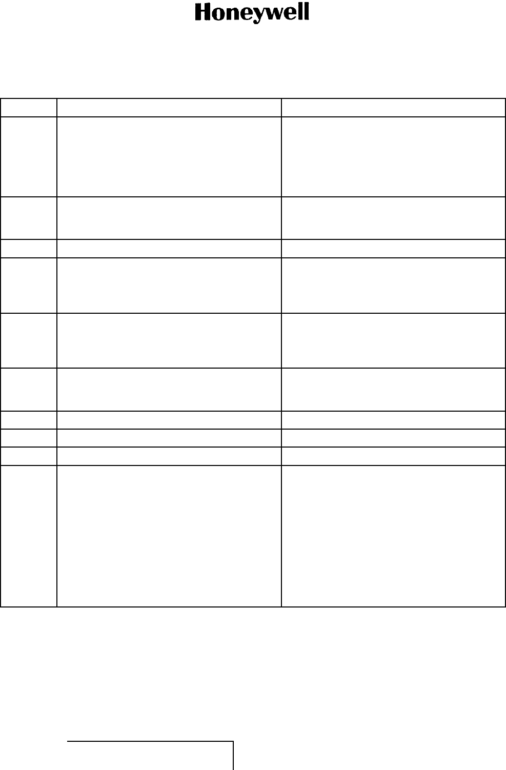
Table INTRO-2. MTOSS Function Code Definitions
Code Function Definition
000 REMOVAL AND DISASSEMBLY
EFFECTIVITY
ALL 23-20-59 Page INTRO-5
1 Mar 2011
© Honeywell International Inc. Do not copy without express permission of Honeywell.

MAINTENANCE MANUAL
965-1696
Table INTRO-2. MTOSS Function Code Definitions (Cont)
Code Function Definition
010 Removal Removal of the engine/component from a
workstand, transport dolly, test stand, etc., or
aircraft.
020 Remove Modular Sections This is the first echelon of disassembly which
has sectionalization of the unit/engine into
primary modular sections. Modular sections
are identified by the third element of the ATA
number when removed from the unit/engine.
030 Disassemble Modular Sections This is the second echelon of disassembly
which has disassembly of the modular sections
into subassemblies after removal from the
unit/engine. Modular section designations
appear in the second element of the ATA
number for this echelon of disassembly.
040 Disassemble Subassemblies This is the third echelon of engine disassembly
which has disassembly of subassemblies
to the piece part level. The subassemblies
are identified by the third element of the ATA
number.
050 Remove Accessory/Power Plant Components This has removing individual accessory/power
plant components from either installed or
uninstalled engines.
060 Disassemble Accessory This involves disassembly of accessories
/components into subassemblies.
070 Disassemble Accessory Subassembly This involves disassembly of accessories
/components subassemblies into piece parts.
080 Remove Test Equipment This has removing equipment and
instrumentation after accessory/component
test.
090 Disassemble Support Equipment This has disassembly of support equipment
required to maintain said support equipment.
100 CLEANING
110 Chemical Removal of surface deposits from a part by
use of a chemical cleaning agent. After being
dissolved, the deposit is washed or rinsed away
after a soaking period. Also includes chemical
power flushing.
120 Abrasive Removal of surface deposits from a part by wet
or dry particle impingement.
EFFECTIVITY
ALL 23-20-59 Page INTRO-6
1 Mar 2011
© Honeywell International Inc. Do not copy without express permission of Honeywell.
MAINTENANCE MANUAL
965-1696
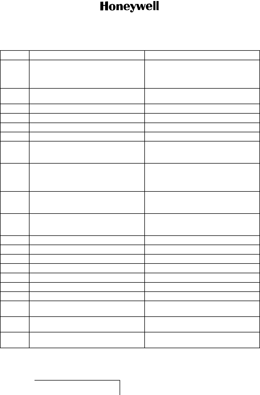
Table INTRO-2. MTOSS Function Code Definitions (Cont)
Code Function Definition
130 Ultrasonic Removal of surface deposits and entrapped
material by use of high frequency sound waves
to produce cavitation at the surface of the
part. Cleaning is performed in a liquid bath
that transmits the sound energy and keeps the
removed material in suspension.
140 Mechanical Removal of surface deposits from a part by use
of a brush, felt bob, sandpaper, or other hand
or mechanical action.
150 Unassigned
160 Miscellaneous Removal of deposits from parts with
compressed air, miscellaneous hand cleaning,
and various combinations of cleaning
procedures.
170 Foam/Water Wash Removal of post emulsified fluorescent
penetrant through an agitated water wash,
automatic spray rinse, or an aqueous remover
aeratedtoproduceafoam.
180 Testing of Solutions Test used to assist in identifying certain
materials by electro-mechanically determining
the presence or absence of known constituents.
190 Unassigned
200 INSPECTION
210 Check A thorough visual examination of components,
accessories, subsystems, and piece parts
to detect structural failure, deterioration
or damage and to determine the need for
corrective action. For example: exterior
surfaces, electronic circuit cards, gears, control
systems, linkages, accessories, components,
tubing, wiring and connections, safety wiring,
fasteners, clamps, etc., are inspected to
verify correct condition and acceptability for
continued service.
EFFECTIVITY
ALL 23-20-59 Page INTRO-7
1 Mar 2011
© Honeywell International Inc. Do not copy without express permission of Honeywell.

MAINTENANCE MANUAL
965-1696
Table INTRO-2. MTOSS Function Code Definitions (Cont)
Code Function Definition
220 Visual/Dimensional A comparison of the dimensions and material
conditions of parts, subassemblies, and
assemblies with the specifications contained
in technical manuals and/or blueprints, to
detect deviations from established standard
and limits and determine the acceptability for
continued service, repair, or need to discard
the item. A visual/dimensional function code is
also required to verify that correct corrective
maintenance has been accomplished.
Although some of these tasks do not require
measurements, a complete spectrum of
tasks/sub tasks requires a variety of measuring
equipment to determine runout, concentricity,
flatness, parallelism, hardness, thickness,
clarity, dimensions, etc.
230 Penetrant Fluorescent penetrant inspection to detect
surface cracks.
240 Magnetic Magnetic particle inspection to detect surface
cracks in magnetic materials.
250 Eddy Current Inspection for subsurface cracks, porosity,
inclusions, or other nonhomogeneous
material structure by use of high frequency
electromagnetic wave equipment. Parts are
scanned and compared to similar parts or test
specimens having known material defects.
260 X-Ray Inspection for subsurface cracks, porosity,
inclusions, or other nonhomogeneous material
structure by use of x-ray techniques.
270 Ultrasonic Inspection for subsurface cracks, porosity,
inclusions, or other nonhomogeneous material
structure by use of contact pulse echo
ultrasonic techniques.
280 Special Any special inspection to determine the
integrity of a part for continued operation
In-Service or qualitative analysis.
290 Unassigned
300 REPAIR
EFFECTIVITY
ALL 23-20-59 Page INTRO-8
1 Mar 2011
© Honeywell International Inc. Do not copy without express permission of Honeywell.

MAINTENANCE MANUAL
965-1696
Table INTRO-2. MTOSS Function Code Definitions (Cont)
Code Function Definition
310 Welding and Brazing The joining of pieces by welding (fusion,
resistance, spot, electron beam, plasma arc),
brazing (furnace, torch, induction), or soldering.
This category includes hard facing.
320 Machining The process of obtaining a desired shape or
finish by grinding, turning, boring, reaming,
broaching, milling, drilling, lapping, honing,
sizing, polishing, buffing, cutting, forming,
stamping, blanking, etc.
330 Stripping and Plating Removing or applying a metallic coating on a
surface by mechanical, chemical, or electrical
means. Plating of chromium, cadmium, tin,
etc., to build up the size of a part or supply
surface protection. Includes masking or waxing
before the process.
340 Plasma and Flame Spraying The application of a protective coating to a
part by feeding a powder into an ionized gas
stream. Flame spraying uses a fuel oxygen
flame to melt and propel metal onto parts to
build up the size or supply surface protection.
350 Miscellaneous Repairs Repairing parts by hand (cutting, drilling,
polishing, grinding, lapping, riveting, blending,
routing, fitting, burring, planishing, sanding,
sawing, recambering, drilling, tapping,
heating, chilling) and including miscellaneous
disassembly and assembly required.
360 Bonding and Molding/Sealing Joining and curing of parts with an adhesive or
fusible material (including silicone, fiberglass,
glues).
370 Heat Treating Controlled heating and cooling of a material to
obtain the desired physical property (includes
annealing, tempering, quenching, stress
relieving, solution heat treat, etc.).
380 Surface Treating Treating the surface of a part by painting,
varnishing, aluminizing, Teflon coating, zinc
chromate priming, tumble finishing, shot
peening, etc. Baking and masking processes
are included.
390 Machine Riveting and Flaring Joining of parts by riveting and flaring the rivet.
400 INSTALLATION AND ASSEMBLY
EFFECTIVITY
ALL 23-20-59 Page INTRO-9
1 Mar 2011
© Honeywell International Inc. Do not copy without express permission of Honeywell.

MAINTENANCE MANUAL
965-1696
Table INTRO-2. MTOSS Function Code Definitions (Cont)
Code Function Definition
410 Install Installation of the unit/engine onto a workstand,
transport dolly, test stand, or aircraft.
420 Install Modular Sections The third echelon of assembly consisting of
assembly of the modular assemblies into a
complete unit/engine assembly. The modular
sections are identified by the third element of
the ATA number.
430 Assemble Modular Sections The second echelon of assembly consisting
of assembling subassemblies into modular
sections. The modular section is identified by
the second element of the ATA number.
440 Assemble Subassemblies The first echelon of assembly consisting of
assembling piece parts into subassemblies.
The subassemblies are identified by the third
element of the ATA number.
450 Install/Close Items Removed/Opened for
Access Installation or closing of access plates, closing
of ports, installation of components, tubing
or any item which was removed or opened in
order to supply access to do the task.
460 Assemble Accessory Assemble accessory components.
470 Assemble Accessory Subassembly Assembly of accessory subassembly
components.
480 Install Test Equipment Install equipment and instrumentation required
for accessory component test.
490 Assemble Support Equipment Any assembly required to maintain support
equipment.
500 MATERIAL HANDLING
510 Shipping The movement of any part, subassembly,
assembly, or component from the time it is
packaged until it reaches its destination.
520 Receiving The receipt activity for any incoming part,
subassembly, assembly, or component.
530 Packing Installing parts, subassemblies, assemblies, or
components into shipping containers.
540 Unpacking Removing parts, subassemblies, assemblies,
or components from shipping containers.
550 Storage Safekeeping of parts, subassemblies,
assemblies, or components until required for
use.
EFFECTIVITY
ALL 23-20-59 Page INTRO-10
1 Mar 2011
© Honeywell International Inc. Do not copy without express permission of Honeywell.
MAINTENANCE MANUAL
965-1696
Table INTRO-2. MTOSS Function Code Definitions (Cont)
Code Function Definition
560 Marshaling/Positioning Marshaling is collection of parts,
subassemblies, and accessories before
release for assembly. Positioning is movement
from one fixed state to another.
570 Engine Ferry/Pod Maintenance Necessary preparations before and after
transporting an engine by aircraft ferry method.
580 Unassigned
590 Unassigned
600 SERVICING/PRESERVING/LUBRICATING
610 Servicing Action required to sustain a unit or system in
correct operating status including priming with
applicable fluids before use.
620 Preserving Preparation of a unit, part, assembly, etc.,
for safekeeping from decomposition or
deterioration. Includes preparation for storage
(applying a preservative layer, desiccants, etc.).
630 Depreserving Removing preservatives, desiccants, etc., from
a unit, part, assembly, etc., before installation
or operation.
640 Lubricating Applying oil, grease, dry film, or silicon
lubricants on moving parts to decrease friction
or cool the item.
650 Unassigned
660 Unassigned
670 Unassigned
680 Unassigned
690 Unassigned
700 TESTING/CHECKING
710 Oil Flow Measuring the flow of oil through components
or compartments under specific conditions.
720 Air Flow Measuring the flow of air through components
or compartments under specific conditions.
730 Fuel Flow Function checks and flow measurements
through the part or system being tested.
EFFECTIVITY
ALL 23-20-59 Page INTRO-11
1 Mar 2011
© Honeywell International Inc. Do not copy without express permission of Honeywell.

MAINTENANCE MANUAL
965-1696
Table INTRO-2. MTOSS Function Code Definitions (Cont)
Code Function Definition
740 Water Flow Function checks and flow measurements
through the part or system being tested.
750 Electrical/Return to Service Functional tests (manual or ATE) of the system
or component as well as measurement of
electrical or electronic parameters designed to
determine whether the item can be returned to
service. May include fault isolation procedures
for components that require close correlation
between test results and fault indications.
760 Engine Operation of an engine to establish systems
function or operation under specific conditions
to measure performance.
770 Accessory/Bite Testing of an accessory to make sure of correct
operation or function.
780 Pressure Check Testing to establish the ability of a normally
pressurized component or system to operate
correctly.
790 Leak Check Determine the ability of a component or system
to operate without leaking.
800 MISCELLANEOUS
810 Fault Isolation Operation of an engine at constant thrust
level or identical engine pressure ratio engine
pressure ratio to locate the prime suspect
deficient system operating an incorrectly
functioning system or component to locate
the cause; or performing a series of checks to
isolate a failed part or component.
820 Adjusting/Aligning/Calibrating Makingaphysicalcorrectiontomakesureof
correct placement or operation of a system or
component.
830 Rigging Hooking-up, arranging, or adjusting a
component or accessory linkage for correct
operation.
840 Service Bulletin Incorporation Performing the work specified in the
service bulletin. Provides for identification
of modification tasks at the task level with
subtasks recognizing any functional changes
(chemical, visual/dimensional, cleaning,
machining, etc.) necessary to incorporate the
service bulletin.
EFFECTIVITY
ALL 23-20-59 Page INTRO-12
1 Mar 2011
© Honeywell International Inc. Do not copy without express permission of Honeywell.

MAINTENANCE MANUAL
965-1696
Table INTRO-2. MTOSS Function Code Definitions (Cont)
Code Function Definition
850 Part Number Change/Re-identification Change of part number, application of part
number by transfer, engrave repair number, etc.
860 Unassigned
870 Description and Operation Electrical and mechanical description of the
unit or component. Includes leading particulars,
descriptions, limitations, specifications, and
theory of operation.
880 Approved Vendor Processes Includes processes that can be proprietary and
controlled by a particular manufacturer, or by
nonproprietary and approved for application by
conforming vendors.
890 Airline Maintenance Program (Customer Use)
900 Unassigned
910 Special Equipment Maintenance Identification of tasks to maintain special
support equipment.
920 Standard Equipment Maintenance Identification of tasks to maintain standard
support equipment.
930 Tool Fabrication Includes fabricating any tool for which
procedures to use are included in the manual.
940 Special Tools, Equip, and Consumables Listing Listing of all special tools, standard equipment,
special equipment, and consumables required
to do maintenance on the unit or component.
94A Consumables
94B Special Tools/Non Std Tools
94C Fixtures/Test Equipment
94D Standard Tools
950 Illustrated Parts List (Detailed Parts List) Section of IPL/IPC that contains parts
description and identification in top-down break
down sequence.
960 Illustrated Parts List (Equipment Designation
Index) Section of IPL/IPC that contains equipment
designators cross-referenced to detailed parts
list.
970 Illustrated Parts List (Numerical Index) Section of IPL/IPC that contains an
alphanumeric listing of all parts in the unit
cross-referenced to the detailed parts list.
980 Illustrated Parts List (Alternate Vendor Index) Optional section of IPL/IPC that contains an
alphanumeric listing of all parts in the unit that
have more than one vendor source.
EFFECTIVITY
ALL 23-20-59 Page INTRO-13
1 Mar 2011
© Honeywell International Inc. Do not copy without express permission of Honeywell.
MAINTENANCE MANUAL
965-1696
Table INTRO-2. MTOSS Function Code Definitions (Cont)
Code Function Definition
990 Illustrations, Tables, Front Matter, Etc.
99A Tables
99B Illustrations
99C Front Matter Pageblock (TASK Level MTOSS)
Front Matter Task (Collection of Subtask
MTOSS)
99D Access
99E References
99F General/Introduction
G. Standard Practices Manual (Subtask 23-20-59-99F-007-A01)
(1) Standard cleaning, check, repair, and assembly procedures applicable to multiple models can
be found in a standard practices manual. Refer to Paragraph 3 (TASK 23-20-59-99F-803-A01).
H. Electrostatic Discharge (Subtask 23-20-59-99F-008-A01)
(1) Touch the items susceptible to electrostatic discharge in accordance with MIL-HDBK-263.
Refer to MIL-STD-1686 for definition of the standards and conditions.
2. Customer Support (TASK 23-20-59-99F-802-A01)
A. Honeywell Aerospace Online Technical Publications Web Site (Subtask 23-20-59-99F-009-A01)
(1) Go to the Honeywell Online Technical Publications Web site at (www.myaerospace.com).
• To download or see publications online
• To order a publication
• To tell Honeywell of a possible data error in a publication.
B. Global Customer Care Center (Subtask 23-20-59-99F-010-A01)
(1) If you do not have access to the Honeywell Technical Publications Web site, or if you need to
speak to personnel about non-Technical Publication matters, the Honeywell Aerospace Global
Customer Care Center gives 24/7 customer service to Air Transport & Regional, Business &
General Aviation, and Defense & Space customers around the globe.
• Telephone: 800-601-3099 (Toll Free U.S.A./Canada)
• Telephone: 602-365-3099 (International)
• Telephone: 00-800-601-30999 (EMEA Toll Free)
• Telephone: 420-234-625-500 (EMEA Direct).
3. References (TASK 23-20-59-99F-803-A01)
A. Honeywell/Vendor Publications (Subtask 23-20-59-99F-011-A01)
(1) Related Honeywell publications in this manual are shown in the list that follows:
EFFECTIVITY
ALL 23-20-59 Page INTRO-14
1 Mar 2011
© Honeywell International Inc. Do not copy without express permission of Honeywell.

MAINTENANCE MANUAL
965-1696
• ATA No. 23-20-56 (Pub. No. 012-0797-001), CMM, RTA-50D VHF Data Radio
• Pub. No. A09-1100-004, Standard Repair Procedures for Honeywell Avionics Equipment
Instruction Manual.
B. Other Publications (Subtask 23-20-59-99F-012-A01)
(1) These publications are standard references. Check for latest version of publication.
• The United States GPO Style Manual 2000 (available at http://www.gpoaccess.gov
/stylemanual/browse.html)
• IEEE Std 260, Standard Letter Symbols for Units of Measurement (available from the
American National Standards Institute, New York, NY)
• ASME Y14.38, Abbreviations for Use on Drawings and in Text (available from the American
National Standards Institute, New York, NY)
• ANSI/IEEE Std 91, Graphic Symbols for Logic Functions (available from the American
National Standards Institute, New York, NY)
• H4/H8 CAGE Codes (available at http://www.dlis.dla.mil/cage_welcome.asp)
• IEEE 315/ANSI Y32.2, Graphic Symbols for Electrical and Electronics Diagrams (available
from the American National Standards Institute, New York, NY)
• MIL-HDBK-263, Electrostatic Discharge Control Handbook for Protection of Electrical and
Electronic Parts, Assemblies and Equipment (Excluding Electrically Initiated Explosive
Devices) (Metric) (available from any military standards database)
• MIL-STD-1686, Electrostatic Discharge Control Program for Protection of Electrical and
Electronic Parts, Assemblies and Equipment (Excluding Electrically Initiated Explosive
Devices) (Metric) (available from any military standards database).
4. Acronyms and Abbreviations (TASK 23-20-59-99F-804-A01)
A. General (Subtask 23-20-59-99F-013-A01)
(1) The abbreviations are used in agreement with ASME Y14.38.
(2) Acronyms and non-standard abbreviations used in this publication are as follows.
List of Acronyms and Abbreviations
Term Full Term
A/D analog-to-digital
ACARS airborne communications addressing and reporting system
ACR aircraft communications router
ADC analog-to-digital converter
ADS-B automatic dependent surveillance broadcast
AGC automatic gain control
ALC automatic level control
AM amplitude modulation
AMM aircraft maintenance manual
AMP ampere
ANSI American National Standards Institute
EFFECTIVITY
ALL 23-20-59 Page INTRO-15
1 Mar 2011
© Honeywell International Inc. Do not copy without express permission of Honeywell.

MAINTENANCE MANUAL
965-1696
List of Acronyms and Abbreviations (Cont)
Term Full Term
AOA airborne communications addressing and reporting system over
aviation very-high frequency link control
AOC airline operational communications
ARINC Aeronautical Radio, Incorporated
ASCII American Standard Code for Information Interchange
ASME American Society of Mechanical Engineers
ATA Air Transport Association
ATC air traffic control
ATE automated test equipment
ATN aeronautical telecommunication network
ATR Air Transport Radio
ATSU air traffic services unit
BIT built-in test
BITE built-in test equipment
BOP bit oriented protocol
CCA circuit card assembly
CFDS central fault display system
CMC central maintenance computer
CMM component maintenance manual
CMU communications management unit
CODEC coder-decoder
CPDLC controller pilot data link communication
CSMA carrier sense multiple access
D/A digital-to-analog
DC direct current
DDC digital down converter
DSB-AM double side band-amplitude modulation
DSP digital signal processor
DUC digital up converter
ECC error correction control
ECCN export control classification number
EEPROM electronically erasable programmable read only memory
EMEA Europe, the Middle East, and Africa
ESDS electrostatic discharge sensitive
EFFECTIVITY
ALL 23-20-59 Page INTRO-16
1 Mar 2011
© Honeywell International Inc. Do not copy without express permission of Honeywell.

MAINTENANCE MANUAL
965-1696
List of Acronyms and Abbreviations (Cont)
Term Full Term
EUROCAE Equipment and European Organization for Civil Aviation Equipment
FANS future air navigation system
FM frequency module
FPGA field-programmable gate array
GPO Government Printing Office
GPS global positioning system
HIRF high-intensity radiated field
HPI host port interface
Hz hertz
I/O input/output
ICAO International Civil Aviation Organization
ID identification
IEC International Electrotechnical Commission
IEEE Institute of Electrical and Electronics Engineers
IF intermediate frequency
IPC illustrated parts catalog
IPL illustrated parts list
Kbit kilobit
Kbps kilobyte per second
LED light-emitting diode
LNA low noise amplifier
LO local oscillator
LRU line-replaceable unit
MAX maximum
MCBSP multichannel buffered serial port
MCU micro-controller unit
MHz megahertz
MIC microphone
MIN minimum
MM maintenance manual
MOPS minimum operational performance standard
MSK minimum shift keying
MTOSS maintenance task oriented support system
MU management unit
EFFECTIVITY
ALL 23-20-59 Page INTRO-17
1 Mar 2011
© Honeywell International Inc. Do not copy without express permission of Honeywell.

MAINTENANCE MANUAL
965-1696
List of Acronyms and Abbreviations (Cont)
Term Full Term
MUX multiplexor
Mbit megabit
NA not applicable
NLR no license required
No. number
OEM original equipment manufacturer
OMS on-board maintenance system
PA power amplifier
PC personal computer
PCI peripheral component interconnect
PLL phase-locked loop
PN part number
POA plain old airborne communications addressing and reporting system
PPM parts per million
PS power supply
PTT push-to-talk
Pub. publication
RAM random access memory
RF radio frequency
RTCA Radio Technical Commission for Aeronautics
RTP radio tuning panel
Rx receive
SAW surface acoustical wave
SDI source/destination identifier
SDRAM synchronous dynamic random access memory
SELCAL selective calling
SEU single event upset
SI International System of Units
SINAD signal noise and distortion
SNR signal-to-noise ratio
SPI serial peripheral interface
STDMA self-organizing time division multiple access
TCXO temperature-controlled crystal oscillator
TDMA time division multiple access
EFFECTIVITY
ALL 23-20-59 Page INTRO-18
1 Mar 2011
© Honeywell International Inc. Do not copy without express permission of Honeywell.

MAINTENANCE MANUAL
965-1696
List of Acronyms and Abbreviations (Cont)
Term Full Term
TR temporary revision
Tx transmit
USMS United States Measurement System
UTC universal time coordinated
VCO voltage-controlled oscillator
VDC volt, direct current
VDL very-high frequency data link
VDR very-high frequency data radio
VHF very-high frequency
VSWR voltage standing wave ratio
Vrms volt, root mean square
bps bytes per second
dB decibel
dBm decibel (referenced to one milliwatt)
kHz kilohertz
kbps kilobyte per second
kg kilogram
mW milliwatt
mm millimeter
ms millisecond
5. Process Verification (TASK 23-20-59-99F-805-A01)
A. Verification Data (Subtask 23-20-59-99F-014-A01)
(1) Honeywell does a verification of these technical instructions by performance or by simulation
of the necessary procedures. Performance shows that the procedures were checked by the
use of the manual. Simulation shows that the applicable personnel looked at the procedure
in the manual and that the procedure is technically correct. The dates of verification for
this manual are given in Table INTRO-3.
EFFECTIVITY
ALL 23-20-59 Page INTRO-19
1 Mar 2011
© Honeywell International Inc. Do not copy without express permission of Honeywell.

MAINTENANCE MANUAL
965-1696
Table INTRO-3. Verification Data
Section Method Date
Fault Isolation 1Performance 11 Feb 2011
NOTE:
1Only the TESTING portion of the FAULT ISOLATION section was done by performance.
EFFECTIVITY
ALL 23-20-59 Page INTRO-20
1 Mar 2011
© Honeywell International Inc. Do not copy without express permission of Honeywell.

MAINTENANCE MANUAL
965-1696
DESCRIPTION AND OPERATION
1. Description (TASK 23-20-59-870-801-A01)
A. General (Subtask 23-20-59-870-001-A01)
(1) This section contains a description of the RTA-50D VDR and lists other components required
for system operation.
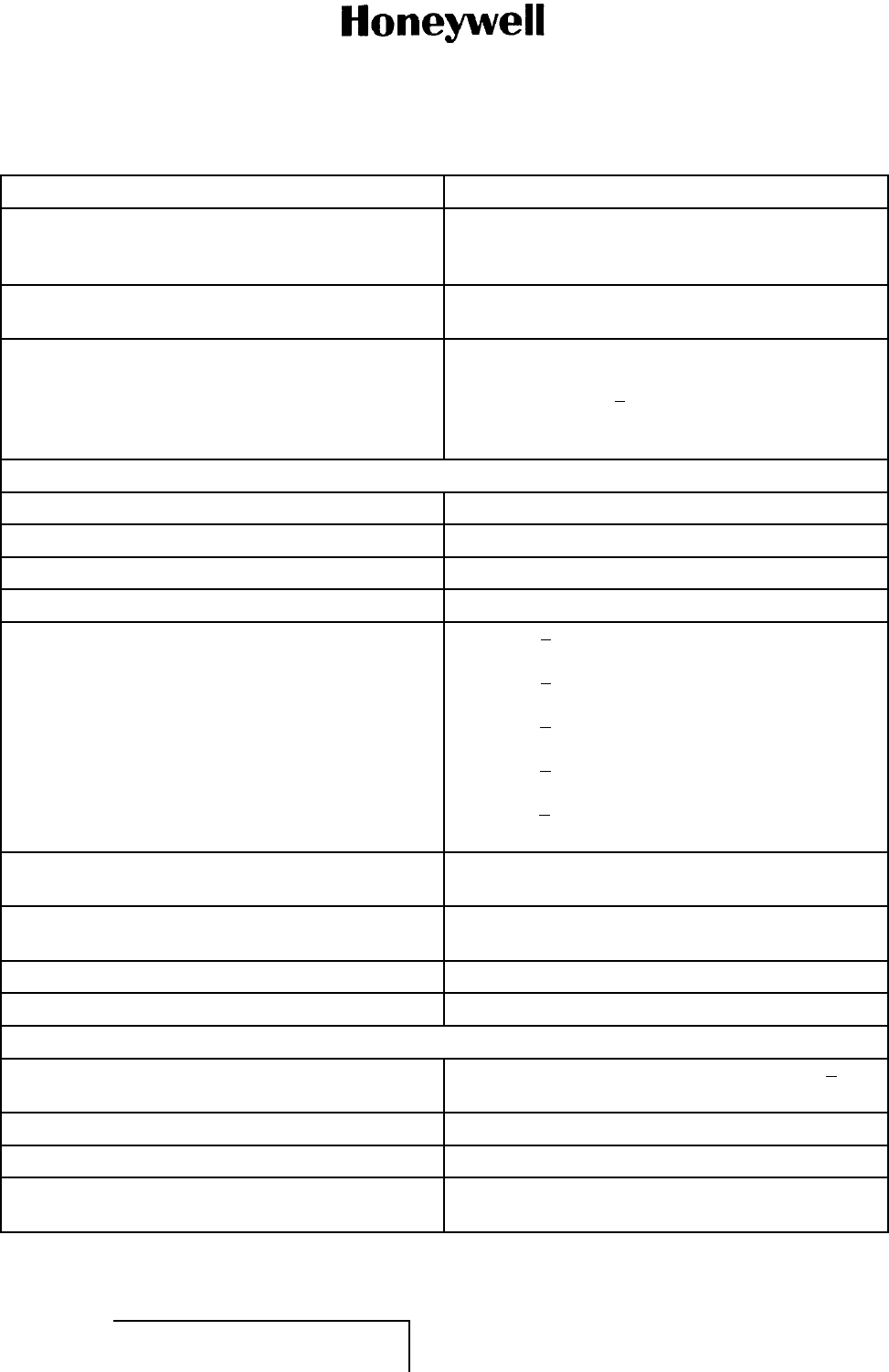
(2) Refer to Table 1 for the leading particulars.
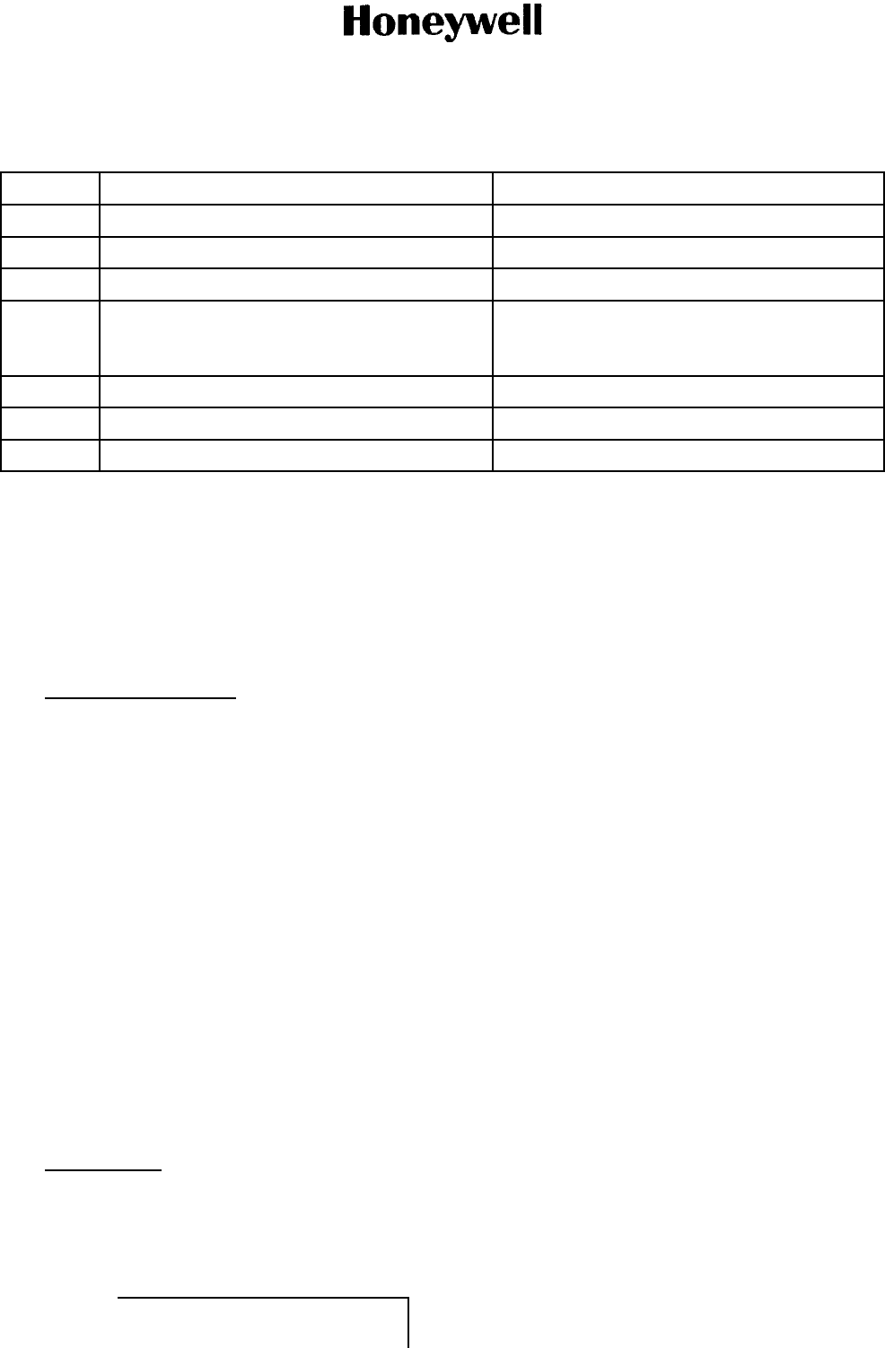
Table 1. Leading Particulars
Characteristic Specification
Weight 9.0 pounds (4.1 kg)
Length 12.72 to 12.80 inches (323.1 to 325.1 mm)
Width 3.58 inches (90.9 mm)
Height 7.88 inches (200 mm)
Power:
• Receive 20 to 32 VDC 1.5 AMP MAX
• Transmit 8.0 AMP MAX
Frequency range 118.000 to 136.975 MHz
Frequency control Dual ARINC 429 (serial digital) low-speed (13 kbps)
inputs
Channel spacing:
•Allmodes 25 kHz
• DSB-AM voice only 8.33 kHz
Cooling Forced air in accordance with ARINC Specification
600
Transmitter (DSB-AM voice and data)
Output power 25 watts (nominal)
Output impedance 50 ohm
Frequency stability ±0.0005%
Voice modulation level 90% MIN modulation for an input level of 0.25 Vrms
at 1,000 Hz
Voice audio distortion 6% MAX for 30% modulation and 10% MAX for 90%
modulation with a 0.5-volt input and a modulating
frequency from 300 to 2,500 Hz
Voice audio frequency response Flat within 6 dB from 300 to 2,500 Hz
Spurious radiation 118 dB MIN below desired carrier level
Harmonic radiation 60 dB MIN below desired carrier level
EFFECTIVITY
ALL 23-20-59 Page 1
1 Mar 2011
© Honeywell International Inc. Do not copy without express permission of Honeywell.

MAINTENANCE MANUAL
965-1696
Table 1. Leading Particulars (Cont)
Characteristic Specification
Mode 0 data modulation level 70% modulation MIN for a frequency of 1,000 Hz at
10 dBm level
Mode 0 data input frequency response Flat within 5.5 dB from 600 to 6,600 Hz
Mode 0 data input distortion 9.5% MAX for up to 90% modulation from 600 to
6,600 Hz
Receiver (DSB-AM voice and data)
Sensitivity Greater than 6 dB SINAD for 107 dBm signal
modulated 30% at 1,000 Hz
Input Impedance 50 ohm
Frequency stability ±0.0005%
Selectivity:
• 8.33-kHz channel spacing at 6-dB bandwidth ±2.78 kHz
• 8.33-kHz channel spacing at 60-dB bandwidth ±7.365 kHz
• 25-kHz channel spacing at 6-dB bandwidth ±8 kHz
• 25-kHz channel spacing at 60-dB bandwidth ±17 kHz
Cross modulation Meets requirements of ARINC Characteristic 716,
Section 3.6.4
Intermodulation Meets ICAO Annex 10, RTCA DO-186B, ED-23B
AGC Audio output will vary not more than 3 dB with inputs
of 5 to 100,000 microvolts and not more than 6 dB
to 500 millivolts
Audio output 40 mW MIN into a 600 ohm ±20% resistive load
Audio distortion Total harmonic distortion will not exceed 5% with a
1,000-microvolt input signal modulated 30% at 1,000
Hz
Audio frequency response Within6dBfrom300to2,500Hz
Audio output regulation: From a 10-mW reference level into 600 ohms
• Resistive load variations between 450 to 2,400
ohms
Less than 2-dB voltage change
•Re
sistive load variations between 200 to 20,000
ohms
No more than 6 dB voltage change
Undesired responses 80 dB MIN
SELCAL/data output 0.6 Vrms MIN with a 2-microvolt signal modulated
30% at 1,000 Hz into a 600-ohm load
EFFECTIVITY
ALL 23-20-59 Page 2
1 Mar 2011
© Honeywell International Inc. Do not copy without express permission of Honeywell.
MAINTENANCE MANUAL
965-1696
Table 1. Leading Particulars (Cont)
Characteristic Specification
SELCAL/data response ±2.5 dB from 312 to 1,200 Hz (post-detection
response with respect to 1,000 Hz is ±4.5 dB from
300to6,600Hz)
SELCAL/data distortion 4.5% MAX for a 1,000-microvolt input modulated
30% at 1,000 Hz producing 0.5 Vrms into 600 ohms
Phase shift Audio output does not depart from that of the
positive-going modulation envelope at the receiver
input by more than 30 to +120 degrees with a
1,000-microvolt input signal modulated 30% at 1,000
Hz
Transmitter (Mode 2 data)
Output power 17.5 watts (nominal)
Frequency stability ±0.0005%
Modulation D8PSK at 31.5 kilobits/second
Error vector magnitude (distortion) 6% MAX
Adjacent channel emissions Less than 18 dBm in 16 kHz centered ±25 kHz
away from the transmit frequency
Less than 28 dBm in 25 kHz centered ±50 kHz
away from the transmit frequency
Less than 38 dBm in 25 kHz centered ±100 kHz
away from the transmit frequency
Less than 48 dBm in 25 kHz centered ±400 kHz
away from the transmit frequency
Less than 53 dBm in 25 kHz centered ±800 kHz or
greater away from the transmit frequency
Spurious emissions Meets requirements of RTCA DO-281A and
EUROCAE ED-92A
Harmonic spurious emissions Meets requirements of RTCA DO-281A and
EUROCAE ED-92A
Mode 2 data input physical interface ARINC 429 high-speed bus
Mode 2 data input protocol In accordance with ARINC 750-3, Attachment 10
Receiver (Mode 2 data)
Sensitivity Less than 0.001 uncorrected bit error rate for 98
dBm received signal
Frequency stability ±0.005%
Selectivity (25-kHz channel) Less than 44-dB adjacent channel rejection
Interference rejection Meets requirements of RTCA DO-281A and
EUROCAE ED-92A
EFFECTIVITY
ALL 23-20-59 Page 3
1 Mar 2011
© Honeywell International Inc. Do not copy without express permission of Honeywell.

MAINTENANCE MANUAL
965-1696
Table 1. Leading Particulars (Cont)
Characteristic Specification
Intermodulation performance Meets requirements of RTCA DO-281A and
EUROCAE ED-92A
Mode 2 data output physical interface ARINC 429 high-speed bus
Mode 2 data output protocol In accordance with ARINC 750-3, Attachment 10
Tuning time 100 ms MAX
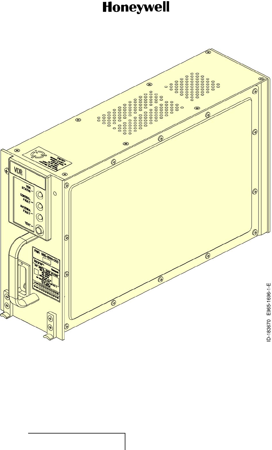
(3) Refer to Figure 1 for a typical RTA-50D VDR.
EFFECTIVITY
ALL 23-20-59 Page 4
1 Mar 2011
© Honeywell International Inc. Do not copy without express permission of Honeywell.
MAINTENANCE MANUAL
965-1696
Figure 1. (Sheet 1 of 1) Typical RTA-50D VDR (GRAPHIC 23-20-59-99B-804-A01)
B. Job Setup Data (Subtask 23-20-59-99C-001-A01)
(1) The list that follows identifies Honeywell publications that are related to this section:
• Not applicable.
EFFECTIVITY
ALL 23-20-59 Page 5
1 Mar 2011
© Honeywell International Inc. Do not copy without express permission of Honeywell.

MAINTENANCE MANUAL
965-1696
C. Purpose of Equipment (Subtask 23-20-59-870-002-A01)
(1) The RTA-50D VDR system is an airborne VHF communications transceiver that provides voice
and data communication between on-board aircraft systems, other aircraft systems, and
ground-based systems. It can operate in analog DSB-AM analog voice mode, VHF ACARS
data modes (Mode A and Mode 0), and VDL Mode 2 data mode. It also provides future support
for VDL Mode 3 digital voice and data modes.
(2) The RTA-50D VDR agrees with the standards and specifications for VHF radios that operate in
the 118 to 137-MHz band as follows:
• ARINC 716-11 airborne VHF communications transceiver
• ARINC 750-4 airborne VHF data radio
• EUROCAE ED-23B minimum performance specification for airborne VHF communications
equipment operating in the frequency range 117,975 to 137,000 MHz
• EUROCAE ED-92A MOPS for airborne VDL Mode 2 transceiver operating in the frequency
range 118-136.975 MHz
• RTCA DO-186B MOPS for airborne radio communications equipment operating within the
radio frequency range 117.975 to 137.000 MHz
• RTCA DO-207 MOPS for devices that prevent blocked channels used in two-way radio
communications due to unintentional transmissions
• RTCA DO-281A MOPS for aircraft VDL Mode 2 transceiver physical, link and network layer.
(3) The RTA-50D VDR operates as a voice transceiver that agrees with the voice mode defined
in ARINC Characteristic 716 when operated as a 716 voice radio. Microphone audio and
PTT audio are inputs and side-tone audio is output. The RF signal is double sideband AM.
Frequency and channel bandwidth selection is made through a low-speed ARINC 429 bus
input interface to an RTP.
(4) The RTA-50D VDR operates as a transceiver when used as a 716 data radio. In this mode, it
agrees with the external data modem interface defined in ARINC Characteristic 716. The data
modem audio input, data key-line input, and data modem audio output interface to an ACARS
MU. The ACARS data modem audio input and output are 2,400-bps MSK modulated signals.
The RF signal is a double sideband AM-MSK signal. Channel frequency selection is made
through a second low-speed ARINC 429 bus input interface to the ACARS MU.
(5) The data modem audio output can be wired to a SELCAL decoder when the radio is not wired
to support 716 data mode operation. In ARINC 750 Data Mode A, the RTA-50D VDR provides
2,400-bps MSK modem functionality within the radio with ARINC 429 digital data input/output
interfaces to a CMU as defined in ARINC Characteristic 750. The command and data transfer
protocol between the VDR and CMU uses the ARINC 429 Williamsburg BOP Version 1 or
Version 3. The RF signal is a double sideband AM-MSK signal. Channel frequency selection is
made through the ARINC 429 interface to the CMU.
(6) When operated in Mode 2, the VDR supplies Mode 2 functionality defined in ARINC
Characteristic 750 and a 31,500-bps D8PSK modem functional internal to the radio. The Mode
2 radio uses ARINC 429 digital data input/output interfaces to a CMU as specified in ARINC
Characteristic 750. The command and data transfer protocol between the VDR and CMU uses
the ARINC 429 Williamsburg BOP Version 3. The RF signal is a D8PSK-modulated RF carrier.
Channel frequency selection is made through the ARINC 429 interface to the CMU.
EFFECTIVITY
ALL 23-20-59 Page 6
1 Mar 2011
© Honeywell International Inc. Do not copy without express permission of Honeywell.
MAINTENANCE MANUAL
965-1696
(7) The RTA-50D VDR system requires an antenna for its RF inputs and outputs, a control head or
radio management panel, an audio input source and output sink for its analog voice functions,
and an ACARS MU or a CMU for its digital control and data functions. The VDR system can
also be connected to a CMC to transfer maintenance data. To give future support for VDL
Mode 3 data and enhanced voice features, the RTA-50D VDR requires interface to two sources
of aircraft ICAO address such as Mode S transponder Number 1 and Number 2.
(8) When operated in voice mode, the RTA-50D VDR supplies both 25-kHz and 8.33-kHz channel
spacing to meet European airspace requirements. The unit is fully interchangeable with
older ARINC 716 communications equipment for backward compatibility. Older equipment
includes the former Allied Signal or Bendix RTA-44A, RTA-44D, and RTA-83B VHF radios,
and Collins VHF 700 and VHF 700A radios.
D. Equipment Required but Not Supplied (Subtask 23-20-59-870-003-A01)
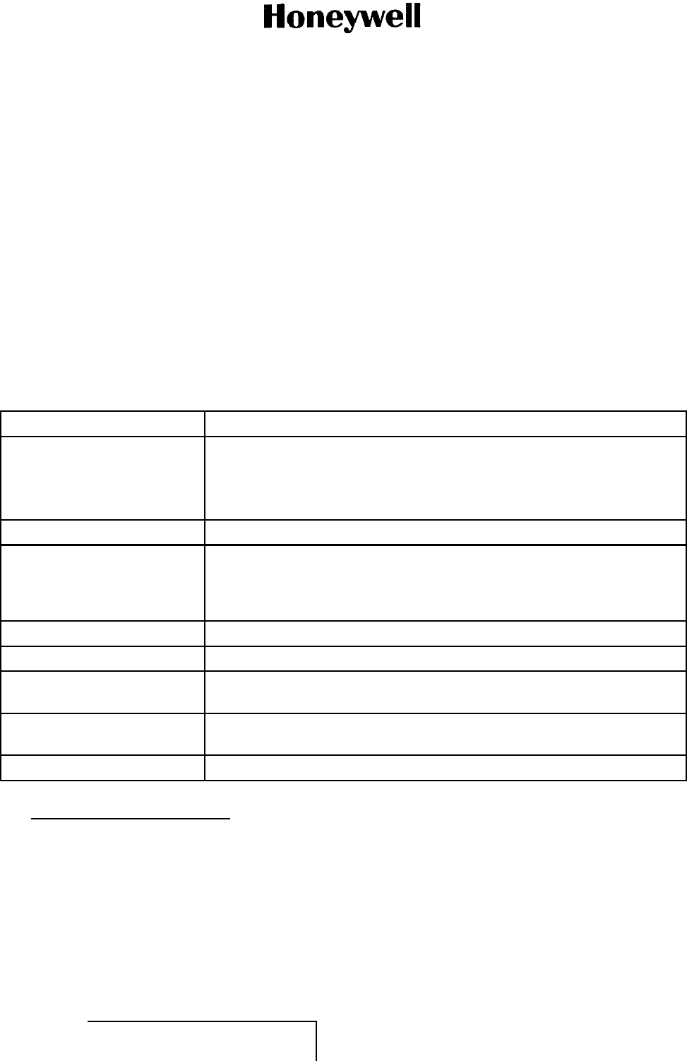
(1) Table 2 lists the equipment required for the RTA-50D VDR system that is not supplied
by Honeywell.
Table 2. Equipment Required but Not Supplied
Equipment Description
Power source: DC power supply of 27.5 volts
• Receive 1.5 AMP
• Transmit 8AMP
Audio distribution system Audio system with an input impedance of 200 to 10,000 ohms
Control panel Provides remote control of frequency selection for 25-kHz or 8.33-kHz
channel spacing system operation (serial digital ARINC 429-7 and
ARINC 716 Supplement 8), power on/off, volume, and squelch control in
accordance with ARINC 716
MU/CMU/ATSU Provides control and data source/sink when operating in the 750 data mode
Mount Provides a means of mounting RTA-50D VDR in the aircraft
VHF antenna Capable of receiving and transmitting VHF signals over a frequency range
of 118.000 to 136.975 MHz.
Microphone 150-ohm impedance microphone (either carbon or transistor) operating
from approximately 16-volt power supply
Cables and connectors Necessary connectors and cables
2. Configurations Available (TASK 23-20-59-870-802-A01)
A. General (Subtask 23-20-59-870-004-A01)
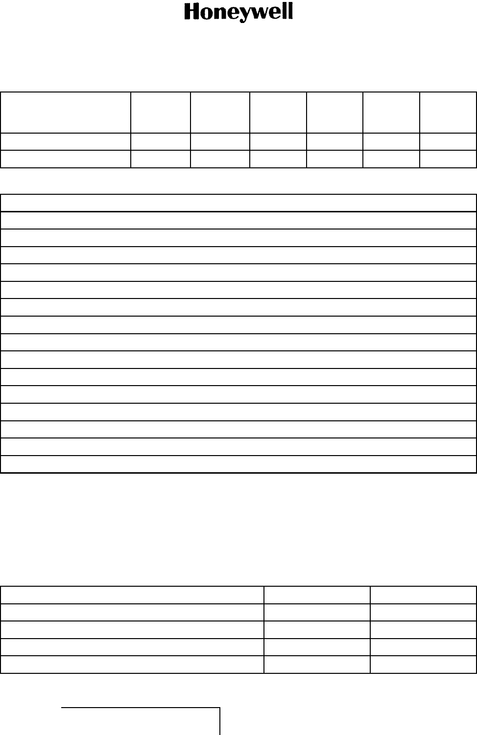
(1) Table 3 lists the available configurations of the RTA-50D VDR and the features contained in
each configuration. Table 4 contains a brief description of each feature.
EFFECTIVITY
ALL 23-20-59 Page 7
1 Mar 2011
© Honeywell International Inc. Do not copy without express permission of Honeywell.
MAINTENANCE MANUAL
965-1696
Table 3. RTA-50D VDR Configurations Available
PN
8.33-kHz
Channel
Spacing ACARS Mode A Mode 2
Airbus
CFDS
/CMC Boeing
CMC
965-1696-021X X X X X
965-1696-051 X X X X X
Table 4. RTA-50D VDR Features
Description
118.000 to 136.975 MHz operation
8.33-kHz and 25-kHz channel spacing
ICAO Annex 10 FM immunity
ACARS MSK (Mode A) data link function
VDL Mode 2 (D8PSK) data link function
Growth function to VDL Mode 3 digital voice and data transmission
Growth function to single-channel VDL Mode 4 data for data link communications applications only
Dual ARINC 429 tuning interfaces
CMC/CFDS maintenance system interface
200-ms power interrupt transparency
DO-160E environmental test compliant
HIRF protection
Lightning protection (Level 3)
35-second stuck mike protection and protection disable circuitry
RS-232 PC maintenance port
B. Environmental Certification (Subtask 23-20-59-870-005-A01)
(1) The RTA-50D VDR communications transceiver meets the environmental conditions
of the RTCA DO-160E, Environmental Conditions and Test Procedures for
Airline Electronic/Electronical Equipment and Instruments. The environmental
certification categories of the RTA-50D VDR, PN 965-1696-021 and -051, are
[(A2)(D2)Z]BAE[RB1]XXXXXXZAAZ[CC][RR]M[ZZZZZ]XXA. Refer to Table 5.
Table 5. RTA-50D VDR Environmental Certification Categories
Test PN 965-1696-021 PN 965-1696-051
Temperature and altitude A2D2 A2D2
In-flight loss of cooling Z (18 hours) Z (18 hours)
Temperature variation B B
Humidity A A
EFFECTIVITY
ALL 23-20-59 Page 8
1 Mar 2011
© Honeywell International Inc. Do not copy without express permission of Honeywell.
MAINTENANCE MANUAL
965-1696
Table 5. RTA-50D VDR Environmental Certification Categories (Cont)
Test PN 965-1696-021 PN 965-1696-051
Operational shocks and crash safety E E
Vibration RB1 RB1
Explosion proofness X X
Waterproofness X X
Fluids and susceptibility X X
Sand and dust X X
Fungus resistance X X
Salt spray X X
Magnetic effect Z Z
Power input A A
Voltage spike A A
Audio frequency conducted susceptibility - Power inputs Z Z
Induced signal susceptibility CC CC
Radio frequency susceptibility (radiated and conducted) RR RR
Emission of radio frequency energy M M
Lightning induced transient susceptibility ZZZZZ ZZZZZ
Lightning direct effects X X
Icing X X
Electrostatic discharge A A
3. System Description (TASK 23-20-59-870-803-A01)
A. RTA-50D VDR Data Radio System (Subtask 23-20-59-870-006-A01)
(1) The items that follow are necessary for the RTA-50D VDR:
• An antenna for RF input and output
• A control head or radio management panel for voice/data mode and voice channel selection
• An audio input source and output destination for voice functions, and/or a data link input
source and output destination for data link functions.
(2) The RTA-50D VDR can also transfer maintenance data to an on-board maintenance system.
(3) Three VHF radios are necessary for typical commercial air transport aircraft installations. Two
radios are for voice communications. The third radio is for data communications and for voice
communications when the other radios do not work. Refer to Figure 2.
EFFECTIVITY
ALL 23-20-59 Page 9
1 Mar 2011
© Honeywell International Inc. Do not copy without express permission of Honeywell.
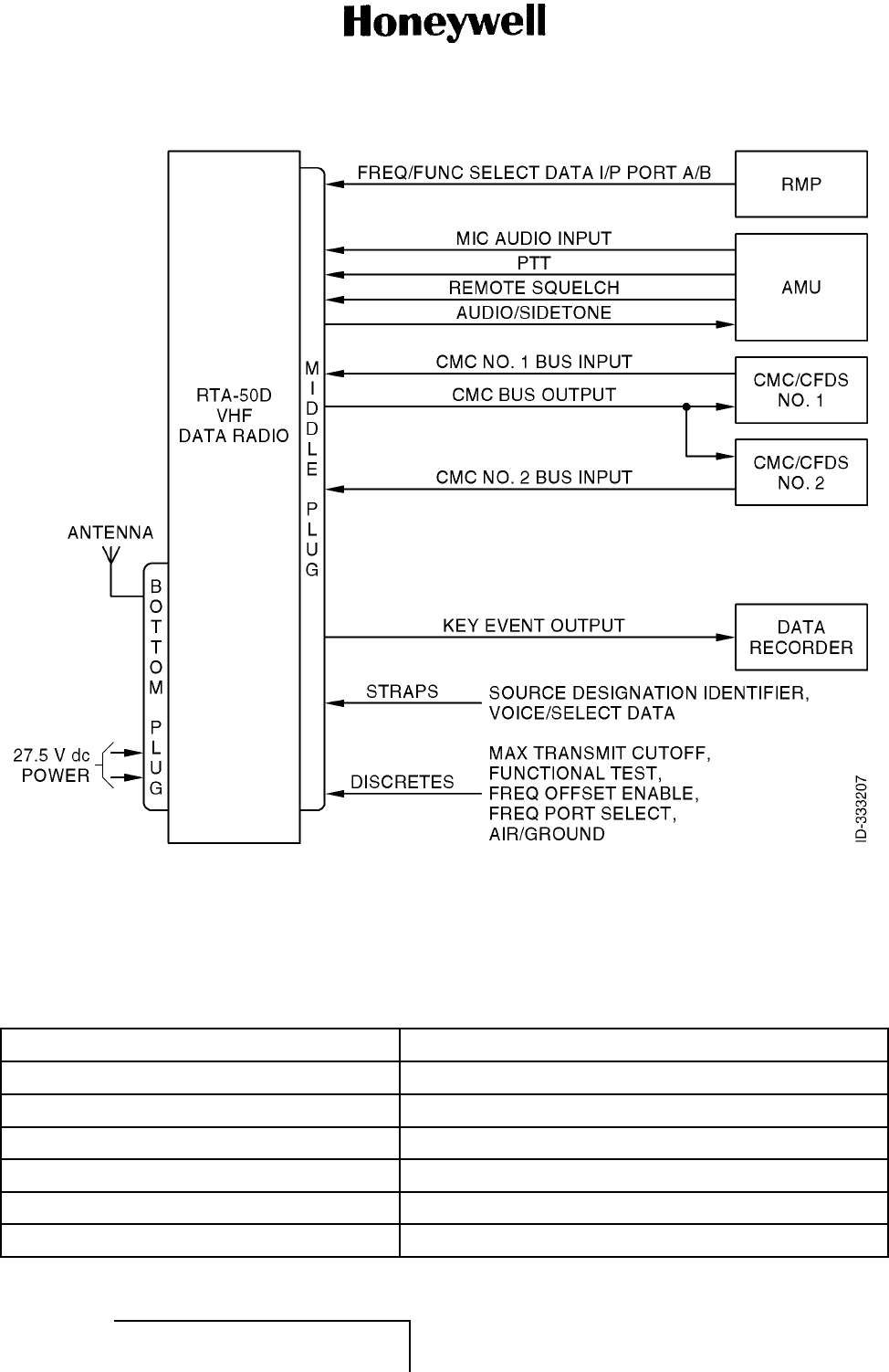
MAINTENANCE MANUAL
965-1696
Figure 2. (Sheet 1 of 1) VHF Communications for Voice Operation (GRAPHIC 23-20-59-99B-805-A01)
B. Description of Equipment (Subtask 23-20-59-870-007-A01)
(1) Refer to Table 6 for a list of all modules and assemblies in the unit. Refer to Figure 3 for the
location of the modules and assemblies.
Table 6. Module and Assembly Designations
PN Module/Assembly
700-1768-002 Rear interconnect assembly
700-1782-001 Main processor assembly
700-1854-001 Front panel assembly
710-0361-001 Power supply assembly
722-4444-006 RF transceiver module
722-4445-006 Main processor module
EFFECTIVITY
ALL 23-20-59 Page 10
1 Mar 2011
© Honeywell International Inc. Do not copy without express permission of Honeywell.
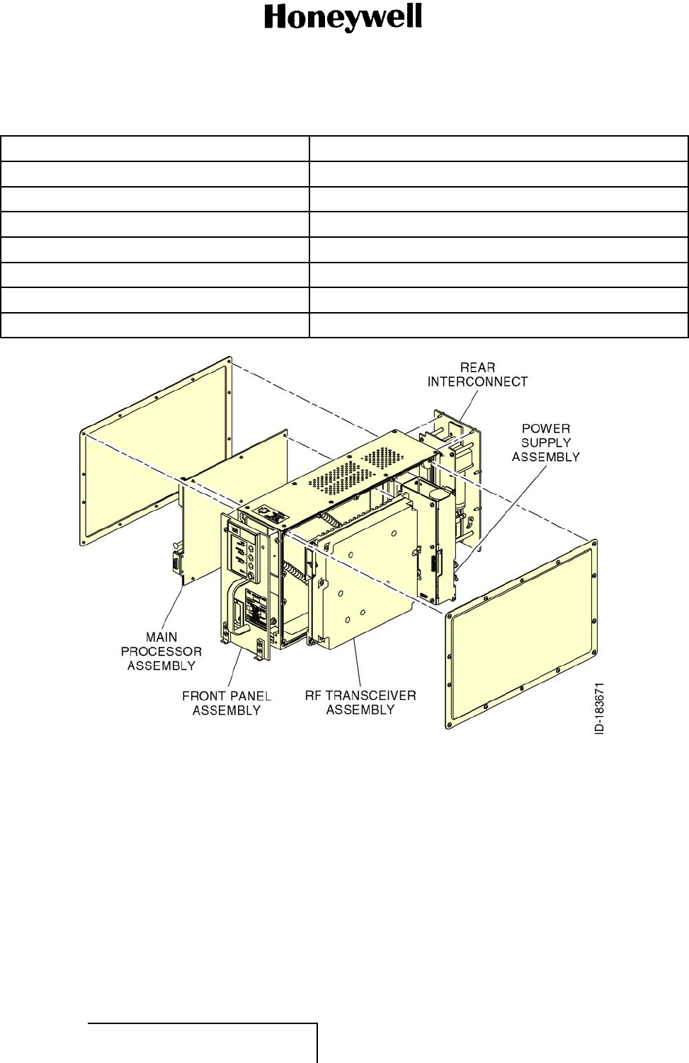
MAINTENANCE MANUAL
965-1696
Table 6. Module and Assembly Designations (Cont)
PN Module/Assembly
722-4446-002 Front panel module
722-4576-003 DC to DC converter
722-4577-005 Power supply output module
722-4600-004 Rear interconnect module
722-4767-001 Power supply input module
727-0008-001 RF transceiver assembly
965-1696-051 Final assembly
Figure 3. (Sheet 1 of 1) Module and Assembly Locations (GRAPHIC 23-20-59-99B-806-A01)
(2) Electrical Description
(a) The RTA-50D VDR provides high-speed data link communications as well as voice and
data modes. The RTA-50D VDR can provide for future Mode 3 operation which requires
digital voice and data transmission at the same time, or Mode 4 data link only.
(b) When in voice mode, the RTA-50D VDR provides both 25-kHz and 8.33-kHz channel
spacing to meet European airspace requirements. The unit can be interchanged
with older ARINC 716 communications equipment such as the former AlliedSignal or
Bendix RTA-44A, RTA-44D, and RTA-83B VHF radios, and Collins VHF 700 and VHF
700A radios.
EFFECTIVITY
ALL 23-20-59 Page 11
1 Mar 2011
© Honeywell International Inc. Do not copy without express permission of Honeywell.
MAINTENANCE MANUAL
965-1696
(c) To provide high-speed data link communications, the RTA-50D VDR also operates in
VDL Modes A and 2, and can provide future VDL Mode 3 digital voice and data, and
single-channel VDL Mode 4 data services.
(d) Refer to Table 7 for the modes of operation supported by the RTA-50D VDR.
Table 7. Modes of Operation
Mode Modulation
Scheme Channel
Spacing Access
Scheme Data Rate
(bits/sec) User Traffic
Type Interface
Voice DSB-AM 25/8.33 kHz PTT NA Voice audio Analog audio
Mode 0 data DSB-AM
MSK 25 kHz CSMA 2,400 ACARS
(POA) Analog audio
Mode A data DSB-AM
MSK 25 kHz CSMA 2,400 ACARS
(POA) A429
Mode 2 data D8PSK 25 kHz CSMA 31,500 Simultaneous
ACARS and
ATN data
A429
Mode3voic
e
and data 1D8PSK 25 kHz TDMA 31,500 Simultaneous
ACARS and
ATN data
Analog audio
and A429
Mode4data
12 GFSK 25 kHz TDMA 19,200 ATN data A429
NOTES:
1Requires software upgrade.
2May also require hardware modifications.
C. ARINC 716 Data Mode (Subtask 23-20-59-870-008-A01)
(1) In ACARS, the VDR system is a simple transceiver with an analog interface to the ACARS MU.
RefertoFigure4.
EFFECTIVITY
ALL 23-20-59 Page 12
1 Mar 2011
© Honeywell International Inc. Do not copy without express permission of Honeywell.
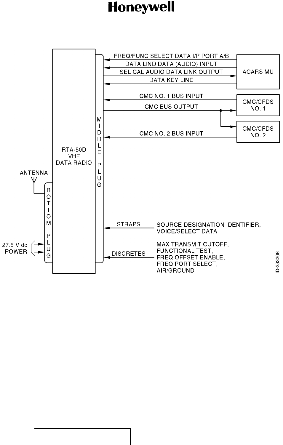
MAINTENANCE MANUAL
965-1696
Figure 4. (Sheet 1 of 1) ACARS Audio Interface (GRAPHIC 23-20-59-99B-807-A01)
D. ARINC750ModeAandMode2 (Subtask 23-20-59-870-009-A01)
(1) Figure 5 illustrates the same interfaces when the radio is operating in ARINC 750 Mode with a
compatible CMU, ACARS MU, or ATSU. This wiring configuration would be used for Mode
A and Mode 2 operation. The Mode A and Mode 2 VDR can be installed in an ARINC 716
configuration if Mode A and Mode 2 operation is not required.
EFFECTIVITY
ALL 23-20-59 Page 13
1 Mar 2011
© Honeywell International Inc. Do not copy without express permission of Honeywell.
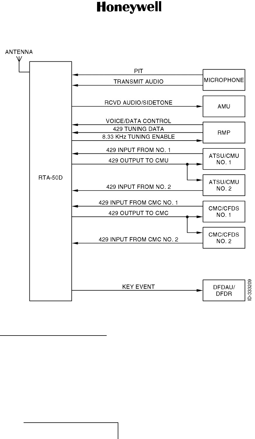
MAINTENANCE MANUAL
965-1696
Figure 5. (Sheet 1 of 1) RTA-50D VDR External Interfaces (ARINC 750 Mode) (GRAPHIC 23-20-59-
99B-808-A01)
4. System Component Description (TASK 23-20-59-870-804-A01)
A. RTA-50D VDR (Subtask 23-20-59-870-010-A01)
(1) The VDR is a VHF transmitter-receiver that provides modulation for double-sideband amplitude
modulation for analog voice/data operation in the 25-kHz or 8.33-kHz spaced channels of the
118.000 to 136.975 MHz. Frequency is provided through a serial-digital format in accordance
with ARINC Specification 429.
(2) The VDR is completely solid-state and is housed in a 3MCU case in accordance with ARINC
Characteristic 600. A handle is located on the front panel of the VDR to facilitate installation,
removal, and transport of the VDR.
EFFECTIVITY
ALL 23-20-59 Page 14
1 Mar 2011
© Honeywell International Inc. Do not copy without express permission of Honeywell.

MAINTENANCE MANUAL
965-1696
(3) The VDR uses a low insertion force, Size 1 shell ARINC 600 rear panel connector with two
inserts. The middle insert is used for aircraft interconnections and the bottom insert is used for
input power and coaxial antenna connectors. The keying pins are set to index pin code 04.
(4) Forced air cooling, in accordance with ARINC Specification 600, is required for cooling the
VDR.
(5) Three front panel LEDs provides visual indication of real-time BITE status as follows:
• Internal fault status monitoring
• External controller status
• External antenna status.
(6) One front panel push-button switch allows activation of manual self-test.
(7) The VDR is partitioned into five subassemblies as follows:
• Front panel module
• Main processor module
• Power supply module
• Rear interconnect module
• RF module.
B. Other Components in the System (Subtask 23-20-59-870-011-A01)
(1) Other VDR system components are not supplied by Honeywell. Information on these units
must be obtained from their respective manufacturers.
5. Operation (TASK 23-20-59-870-805-A01)
A. Voice Mode (Subtask 23-20-59-870-012-A01)
(1) In voice mode, the RTA-50D VDR supports simplex PTT communications in any of the
760 channels with 25-kHz spacing or 2,280 channels with 8.33-kHz spacing in the 118
to 136.975-MHz range.
(2) DSB-AM is used for voice communications where the voice audio from the microphone
modulates the VHF carrier frequency. The spectrum required for this type of modulation is less
than 7 kHz. When operating in a 25-kHz channel, the excess bandwidth of the channel is used
as a guard band to reduce emissions into adjacent channels.
(3) Voice channel selection is controlled from the flight deck by a radio tuning panel. In installations
where a radio can be used in either voice or data mode, voice and data can be set from the
flight deck by the radio tuning panel.
B. Mode 0 Data (Subtask 23-20-59-870-013-A01)
(1) Mode 0 and Mode A support data link communications that use protocols now called POA.
POA uses ASCII character-oriented message formats and protocols to ensure end-to-end
error-free delivery of messages. The difference between these two modes is the interface to
the source and destination of the POA messages.
(2) Mode 0 connects to a legacy ARINC 724 or 724B ACARS MU or CMU through an analog
audio interface. Data is transmitted between the MU/CMU and VDR units at a rate of 2,400 bits
each second by MSK modulated audio signals. The MSK audio modem is in the MU or CMU.
The MSK audio signal produced by the modem is a 1,200 or 2,400-Hz tone that indicates if the
polarity of the transmitted data bit is the same as the previous bit or is different.
EFFECTIVITY
ALL 23-20-59 Page 15
1 Mar 2011
© Honeywell International Inc. Do not copy without express permission of Honeywell.

MAINTENANCE MANUAL
965-1696
(3) The 1,200 or 2,400-Hz tones sent by the MU or CMU modulate the amplitude of the VHF
carrier generated by the VDR. This modulated signal is a DSB-AM signal whose amplitude is
modulated at 2,400 bps. The MU/CMU controls the access to the channel and initiates the
transmission of a message by a data key line discrete input to the VDR. The MU/CMU also
controls the data link channel selection through one of the low-speed (13 Kbps) ARINC 429
tuning inputs. Mode 0 operation is backward compatible with legacy ARINC 716 radios.
C. Mode A Data (Subtask 23-20-59-870-014-A01)
(1) Mode A allows the RTA-50D VDR to exchange downlink and uplink POA data messages with
an Airbus ATSU or an ARINC 758 CMU through a transmit/receive pair of 100 Kbps ARINC
429 digital interfaces instead of the analog audio interfaces used by Mode 0.
(2) The downlink message data bits transferred to the VDR modulate the RF carrier at a rate of
2,400 bps using the same DSB-AM MSK modulation scheme used in Mode 0. The difference
is that the MSK modem functionality resides in the RTA-50D VDR.
(3) The VDR also controls when to access the channel to transmit data. The channel access
protocol is the same CSMA employed by the MU/CMU in Mode 0 operation. The data link
channel selection is still controlled by the ATSU/CMU, but channel selection messages are
exchanged through the same high-speed ARINC 429 interface used to exchange POA
messages which simplifies wiring.
D. VDL Mode 2 (Subtask 23-20-59-870-015-A01)
(1) The newest VHF data link communication mode is VDL Mode 2. VDL Mode 2 is the term
used to describe a suite of air/ground protocols that increases the data rate of the air/ground
link to 31,500 bps.
(2) VDL Mode 2 allows the transition from character-oriented ACARS protocols for end-to-end
delivery of messages to one that uses bit-oriented ATN protocols using the same VHF ground
and aircraft radios. The RTA-50D VDR Mode 2 capability supports the transmission and
reception of standard ACARS messages such as those generated by FANS A and FANS 1
applications using a protocol referred to as AOA.
(3) The RTA-50D VDR Mode 2 capability also supports the transmission and reception of
bit-oriented ATN application messages such as CPDLC. The delivery of FANS A over AOA
and CPDLC over ATN/VDL Mode 2 is supported concurrently. The set of VDL Mode 2
protocols consist of the physical layer protocol, channel access protocol, data link service and
management protocol, and Mode 2 network access protocol. The physical layer protocol
includes the modulation, data rate, and forward error correction techniques used to transmit
data over the air/ground link.
(4) The channel access protocol is the method that allows multiple aircraft to communicate
with the ground stations on the same frequency. The data link service and management
protocol includes procedures to establish, maintain and hand-off an air/ground link, and ensure
error-free delivery of messages. The network access protocol is the interface between users
and the Mode 2 air/ground link service providers. As in Mode A, only the physical layer and
channel access protocols are performed by the RTA-50D VDR while the data link service and
management, and the network access protocols are performed by the CMU.
(5) The VDL Mode 2 physical layer protocol employs a bit transmission rate of 31,500 bps over
the air/ground link on a single 25-kHz channel. The increased utilization of the 25-kHz
channel is achieved by use of a bandwidth modulation scheme known as D8PSK. A D8PSK
transmitter transmits a carrier whose phase is modulated by the data. The phase can be 0, 45,
90, 135, 180, 225, 270, or 315 degrees. The rate at which the carrier phase is changed is
the modulation rate.
EFFECTIVITY
ALL 23-20-59 Page 16
1 Mar 2011
© Honeywell International Inc. Do not copy without express permission of Honeywell.

MAINTENANCE MANUAL
965-1696
(6) The phase difference or D8PSK symbol between successive phase changes can be equal
to 0, 45, 90, 135, 180, 225, 270, or 315 degrees. Since there are eight possible phase
differences, each phase change (D8PSK symbol) represents three bits of information: 000,
001, 011, 010, 110, 111, 101, or 100.
(7) For example, if the phase changes at a 10.5-kHz rate, the bit transmission rate is equal to 31.5
Kbps. The VDL Mode 2 D8PSK modulator uses the bits in the message, three at a time, to
select the carrier phase change at a rate of 10,500 D8PSK symbols each second. A 10.5-kHz
D8PSK phase modulation rate corresponds to a D8PSK bit transmission rate of 31.5 Kbps.
(8) The VDL Mode 2 channel access protocol is CSMA modified to let all terminals to have
equal chances to access the channel when multiple terminals have data to transmit. The
ability to optimize the CSMA protocol is included in the VDL Mode 2 channel access protocol
specification.
(9) As in Mode A, the Mode 2 data link channel selection is controlled by the ATSU/CMU through
the same high-speed ARINC 429 interface used to exchange downlink and uplink AOA or
ATN messages. The ATSU/CMU also dynamically controls the switching between Mode
A and Mode 2 operation subject to available coverage. Since the VDL Mode 2 data rate
and modulation scheme differ from those used in Mode A, separate VHF frequencies and
ground-based VHF equipment must be used to give POA and AOA/ATN service coverage. As a
result, the availability of high-speed AOA service depends on the availability of ground stations.
E. VDL Mode 3 (Subtask 23-20-59-870-016-A01)
(1) VDL Mode 2 is a data link protocol that has been optimized for efficient delivery of as much
data traffic as possible within a 25-kHz channel assignment and with radio transmitters limited
to 15 watts output power. It requires dedicated 25-kHz channel assignments. However, there
is also a need to increase the number of VHF channels available in the 118 to 137-MHz
band. To provide for additional voice and data channels, the FAA is developing a VHF digital
transmission mode known as VDL Mode 3.
(2) The RTA-50D VDR has been designed to support VDL Mode 3 voice and data operation
through a software upgrade. Although VDL Mode 3 functionality is not available in the current
FAA ground stations, a prototype software upgrade to the RTA-50D VDR has proven the
functionality with FAA VDL Mode 3 test ground stations.
(3) VDL Mode 3 takes a 25-kHz frequency assignment and breaks it up into 120-ms frames with
four time slots of 30-ms duration each. Each time slot is a different channel. Each channel
(frequency and time slot) can be assigned for use by a different ATC sector. The selection of
which VDL Mode 3 frequency and time slot to use is initially performed by the Pilot using a
radio control panel in the same way 25-kHz or 8.33-kHz channel selection is now performed.
Frequency division into time slots (channels) and the assigned use of the channels (slots) to
differentsectorsiscalledTDMA.Theslotscanbeusedtotransmitpacketsofdigitizedvoiceor
data sized to fit in the appropriate time slot.
(4) VDL Mode 3 uses TDMA to allow access to multiple voice and data users on the same 25-kHz
frequency assignment. VDL Mode 3 ground stations can be configured to support different
combinations of voice and data services.
(5) VDL Mode 3 ground stations can be configured so that each of the four time slots is assigned
to voice traffic only (4V configuration). Slot use can be assigned to a different sector. When an
aircraft enters a sector that has been assigned a particular frequency and time slot (channel),
the Pilot can select the appropriate channel on the radio control panel.
EFFECTIVITY
ALL 23-20-59 Page 17
1 Mar 2011
© Honeywell International Inc. Do not copy without express permission of Honeywell.

MAINTENANCE MANUAL
965-1696
(6) The aircraft radio would then tune to the frequency associated with the channel and would
look for an uplink from the sectors ground station to synchronize its receive time slot clocks
with those of the ground station. VDL Mode 3 ground stations transmit management burst
uplinks in their allocated time slots to allow aircraft to synchronize their clocks. If the aircraft
does not receive any uplink transmissions from the ground station, it cannot synchronize its
clock and communication with the ground is not possible.
(7) When the aircraft is synchronized with the ground station, voice communications between the
aircraft and the ground station on the selected time slot can proceed. When operating in VDL
Mode 3, voice communications is initiated with a “listen before PTT” procedure. When the VDL
3 radio uses a selected time slot, all digital voice traffic received on the selected time slot is
sent to the radio speaker. Voice traffic received on any other time slot is discarded.
(8) VDL Mode 3 ground stations can be also be configured so that two time slots are used for
voice traffic and two used for data traffic (2V/2D configuration). Each sector is assigned a voice
and a data channel pair. When the airborne radio is tuned to a sector’s voice channel, it also
automatically tunes to the sectors data channel. If the ground station supports data services
in addition to basic voice services as indicated in its management bursts, the radio sends a
net entry request message to the ground station on the selected time slot to gain access to
the data services. When the VDL Mode 3 ground station receives a net entry request, a net
response message is sent to the aircraft to configure access.
(9) The net entry request message includes the 24-bit ICAO identifier assigned to the aircraft. To
support the enhanced features, VDL Mode 3 radios require access to a source of ICAO ID
such as the Mode S transponder.
(10) Downlink data transmission on the data channel is sent on slots reserved by the ground station
for exclusive use by the aircraft. Reservation request messages can be sent by the aircraft
using either slotted aloha random access protocol or in response to polling from the ground
station. The maximum number of contiguous slots requested is 15.
(11) The 2V/2D configurations require the airborne VDR to process voice audio and data link
traffic simultaneously. For example, while the VDR outputs received voice audio or digitizes
and compresses transmit voice audio, it must also process and deliver received uplink data
messages or accept and transmit downlink data messages. As a result, the processing load is
significantly higher than that required for operation in a voice-only or data-only mode.
(12) Like VDL Mode 2, VDL Mode 3 uses D8PSK modulation at a bit transmission rate of 31,500
bps to deliver digitized and compressed speech as well as data messages. Note that VDL
Mode 3 requires that the modulation rate have an accuracy of ±5 PPM, where VDL Mode 2
requires a modulation rate accuracy of ±50 PPM. As a result, VDL Mode 3 requires transmitter
clocks that are 10 times more accurate than VDL Mode 2. The greater accuracy is needed to
provide aircraft at the edges of the coverage area to maintain time slot synchronization with the
VDL Mode 3 ground station. This synchronization ensures that transmissions from aircraft at
the edge of the coverage area do not interfere with transmissions in adjacent time slots.
(13) VDL Mode 3 operation requires radio management panels to have the capability to select the
VDL 3 channel as well as to support unique enhanced voice services.
F. VDL Mode 4 (Subtask 23-20-59-870-017-A01)
(1) VDL Mode 2 provides data link throughput and VDL Mode 3 provides communications capacity
enhancements and simultaneous voice and data communications. VDL Mode 4 provides both
broadcast surveillance applications and air/ground data link communications. The surveillance
application supported by VDL Mode 4 allows aircraft to periodically broadcast their position and
monitor and display the position of other similarly equipped aircraft.
EFFECTIVITY
ALL 23-20-59 Page 18
1 Mar 2011
© Honeywell International Inc. Do not copy without express permission of Honeywell.

MAINTENANCE MANUAL
965-1696
(2) VDL Mode 4 subdivides each 25-kHz channel into periodic slots of 13.33-ms duration to
allow short periodic transmissions from many aircraft. VDL Mode 3 requires each aircraft to
synchronize its TDMA slot timing to that of a ground station. VDL Mode 4 stations synchronize
their TDMA slot timing to UTC derived from a source such as GPS.
(3) VDL Mode 4 uses a slot reservation protocol that allows VDL Mode 4 stations to access the
network and assure that ADS-B transmission will not be interfered with, without the need for
coordination through a ground station. The access protocol used by VDL Mode 4 is STDMA.
(4) VDL Mode 2 and VDL Mode 3 operate in simplex mode; that is, they operate in either
transmit or receive mode on the same frequency. ADS-B operation over VDL Mode 4,
requires concurrent transmission and reception on two different frequencies. Use of VDL
Mode 4 for both ADS-B surveillance and applications and for data link applications requires
concurrent transmission and reception on three different frequencies. If VDL Mode 4 is used
only for data link communications, transmission and reception on only one frequency at a
time is required. As a result the required applications determine the type of radio required
to support VDL Mode 4.
6. Theory of Operation (TASK 23-20-59-870-806-A01)
A. VDR Overview (Subtask 23-20-59-870-018-A01)
(1) The RTA-50D VDR is an airborne VHF radio whose function is to provide aircraft with
line-of-sight air/ground ATC voice and AOC data communications capability in the 118 to
136.975-MHz VHF frequency band. The RTA-50D VDR is capable of operating in DSB-AM
analog voice mode, VHF ACARS data modes (Mode A and Mode 0), and VDL Mode 2 data
mode.
(2) A typical aircraft installation consists of two VDRs dedicated for ATC voice communications
and one VDR for data link communications and back up voice communications. Each VDR
interfaces to its own dedicated VHF blade antenna so that simultaneous operation of all
threeVDRsispossible.
(3) Figure 6 shows the interfaces between the RTA-50D VDR and other avionics equipment.
NOTE: Figure 6 also shows the inputs and outputs that are processed in each of the
modes of operation. Interfaces that apply to typical new aircraft installations are
shown as solid lines. Interfaces that apply to legacy retrofit DSB-AM voice-only
installations that do not require VDL Mode A or VDL Mode 2 functionality are
shown as dashed lines.
EFFECTIVITY
ALL 23-20-59 Page 19
1 Mar 2011
© Honeywell International Inc. Do not copy without express permission of Honeywell.

MAINTENANCE MANUAL
965-1696
Blank Page
EFFECTIVITY
ALL 23-20-59 Page 20
1 Mar 2011
© Honeywell International Inc. Do not copy without express permission of Honeywell.
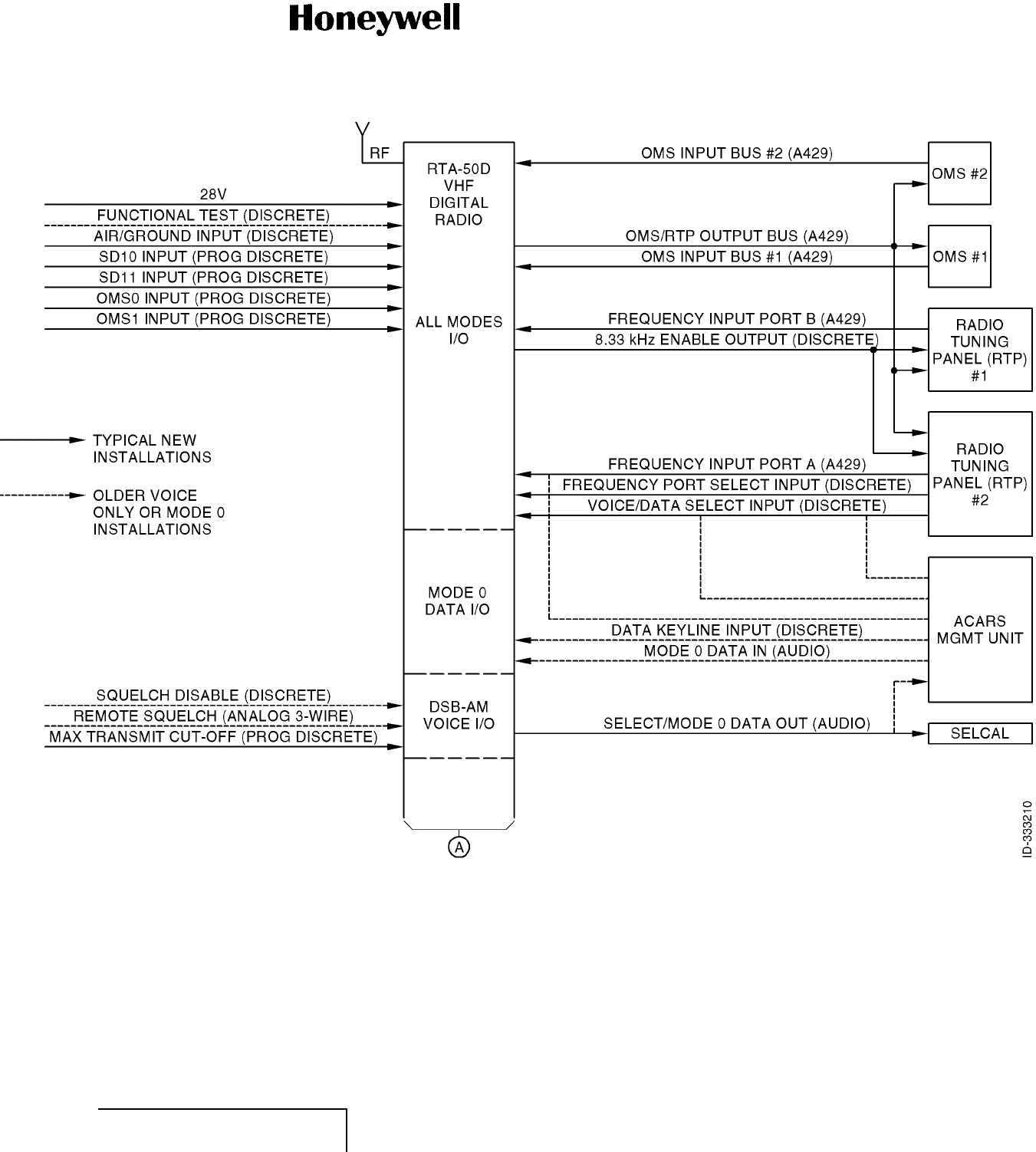
MAINTENANCE MANUAL
965-1696
Figure 6. (Sheet 1 of 2) RTA-50D VDR Interface Context Diagram (GRAPHIC 23-20-59-99B-809-A01)
EFFECTIVITY
ALL 23-20-59 Pages 21/22
1 Mar 2011
© Honeywell International Inc. Do not copy without express permission of Honeywell.
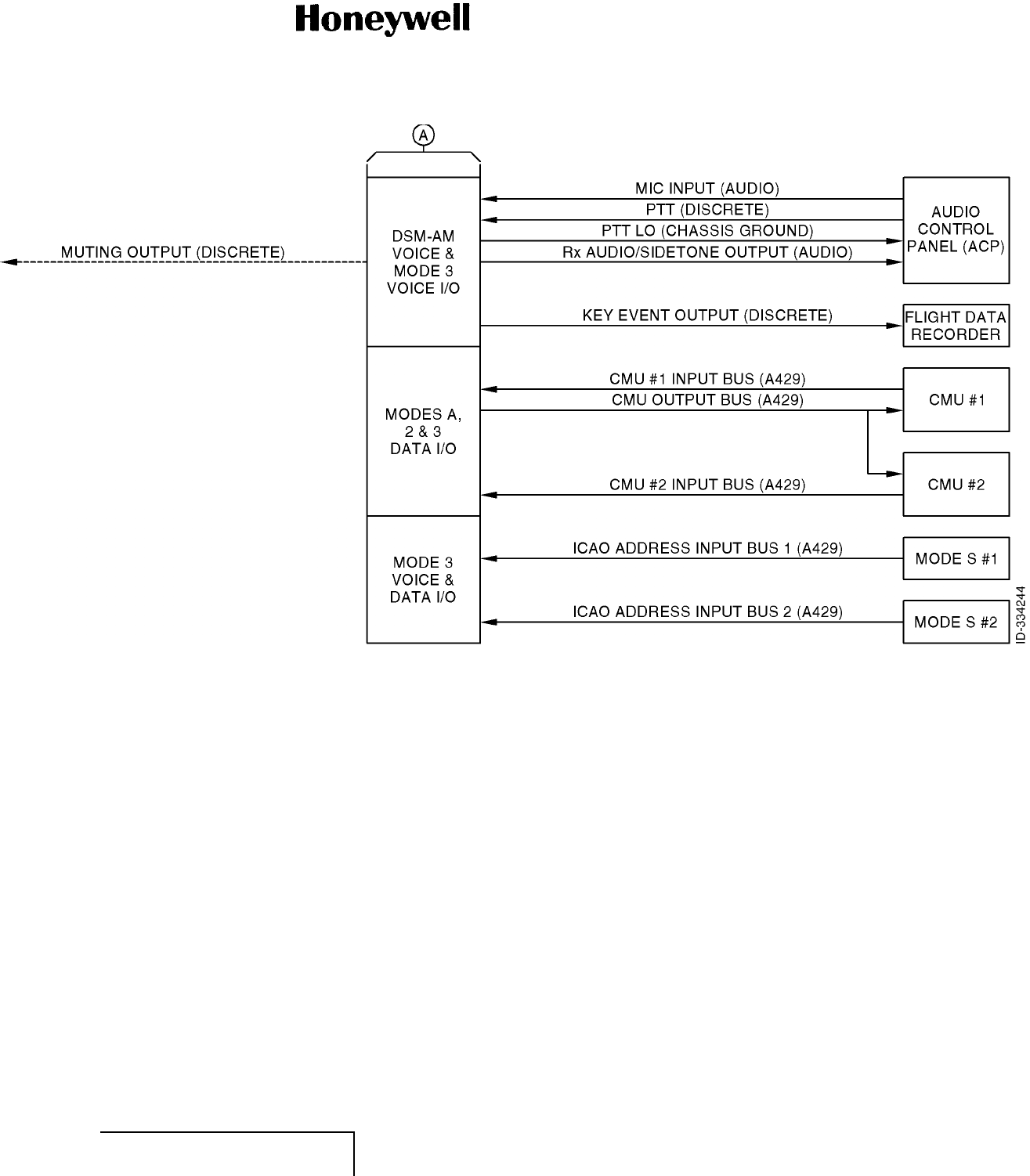
MAINTENANCE MANUAL
965-1696
Figure 6. (Sheet 2 of 2) RTA-50D VDR Interface Context Diagram (GRAPHIC 23-20-59-99B-809-A01)
EFFECTIVITY
ALL 23-20-59 Pages 23/24
1 Mar 2011
© Honeywell International Inc. Do not copy without express permission of Honeywell.

MAINTENANCE MANUAL
965-1696
(4) Voice Communications Installations
(a) Each VHF radio is controlled through one or two RTPs. The RTA-50D VDR provides
ARINC 429 interfaces to two RTPs. A discrete input labeled "frequency port select input"
is used to determine which of the two RTP inputs controls the operation of the VDR.
The contents of the ARINC 429 words received from the RTP are used by the VDR to
determine the voice channel (frequency) selected, as well as the type of voice channel:
• DSB-AM voice with 8.33-kHz channel spacing
• DSB-AM voice with 25-kHz channel spacing.
(b) An analog audio input and output pair provide the interfaces to the microphone and
speakers. A discrete input labeled PTT provides the means to switch between
transmit and receive operation. When the VDR is operating in transmit mode (PTT is
grounded), the transmitted audio is output to the Rx audio/side-tone output port. The
Rx audio/side-tone output is muted during transmit operation if an internal VDR failure
prevents the radio from transmitting RF.
(c) The RTA-50D VDR provides ARINC 429 interfaces to the OMS. Two different OMS
interface protocols are supported as follows:
• Airbus CMC/CFDS protocol
• Boeing CMC protocol.
(d) However, only one of the OMS interface protocols is supported at a time, depending on
the software version loaded (VDR part number).
(5) Data Link Communications Installations
(a) Data link capable installations can support data communications only or they can be
wired to support both data and voice communications. When supporting voice and data
communications, one or two RTPs provide the means to select the mode of operation
(voice or data) and the means to select the voice channel. The mode of operation is
determined from the contents of the ARINC 429 words received from the RTP or from a
discrete input labeled "voice/data select input" depending on the aircraft installation.
(b) The RTA-50D VDR provides ARINC 429 data link interfaces to a CMU, ATSU, or ACR
which is the source of the transmitted data messages and the destination of the received
data messages. A second CMU, ATSU, or ACR may be operated in standby mode if the
aircraft installation supports ATC data link communications.
(c) When the selected mode of operation is a data only mode (Mode 0, Mode A, or Mode 2),
the particular data-only mode is determined from the presence or absence of ARINC 429
data on the ARINC 429 data link interfaces to the two CMUs/ATSUs/ACRs.
B. RTA-50D VDR System Architecture (Subtask 23-20-59-870-019-A01)
(1) A high-level block diagram of the internal architecture of the RTA-50D VDR is shown in Figure
7. The RTA-50D VDR consists of five subassemblies as follows:
• Digital processor CCA
• Front panel CCA
• Power supply module
• Rear interconnect module
•RFCCA.
EFFECTIVITY
ALL 23-20-59 Page 25
1 Mar 2011
© Honeywell International Inc. Do not copy without express permission of Honeywell.

MAINTENANCE MANUAL
965-1696
(2) The RTA-50D VDR is packaged in a 3MCU standard form factor. A low insertion force, Size
1 shell ARINC 600 connector with three inserts provides the means to interface to other
onboard avionics as well as the antenna and aircraft power. The top plug and middle plug
inserts are used for system interconnects. The bottom plug insert is used for input power
and coaxial antenna connections.
EFFECTIVITY
ALL 23-20-59 Page 26
1 Mar 2011
© Honeywell International Inc. Do not copy without express permission of Honeywell.
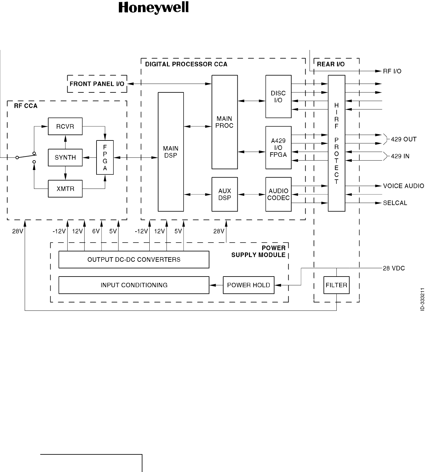
MAINTENANCE MANUAL
965-1696
Figure 7. (Sheet 1 of 1) RTA-50D VDR Internal Architecture (GRAPHIC 23-20-59-99B-810-A01)
EFFECTIVITY
ALL 23-20-59 Pages 27/28
1 Mar 2011
© Honeywell International Inc. Do not copy without express permission of Honeywell.

MAINTENANCE MANUAL
965-1696
C. RF CCA (Subtask 23-20-59-870-020-A01)
(1) General
(a) The RF CCA performs the basic VHF receive and transmit functions of the VDR in all
voice and data modes of operation. The RF CCA circuitry is comprised of five processing
sections:
• Receiver section
• Transmitter section
• LO frequency synthesizer section
•RFcontrol
• BIT monitoring circuits.
(b) A block diagram of the RF CCA is shown in Figure 8.
EFFECTIVITY
ALL 23-20-59 Page 29
1 Mar 2011
© Honeywell International Inc. Do not copy without express permission of Honeywell.

MAINTENANCE MANUAL
965-1696
Blank Page
EFFECTIVITY
ALL 23-20-59 Page 30
1 Mar 2011
© Honeywell International Inc. Do not copy without express permission of Honeywell.
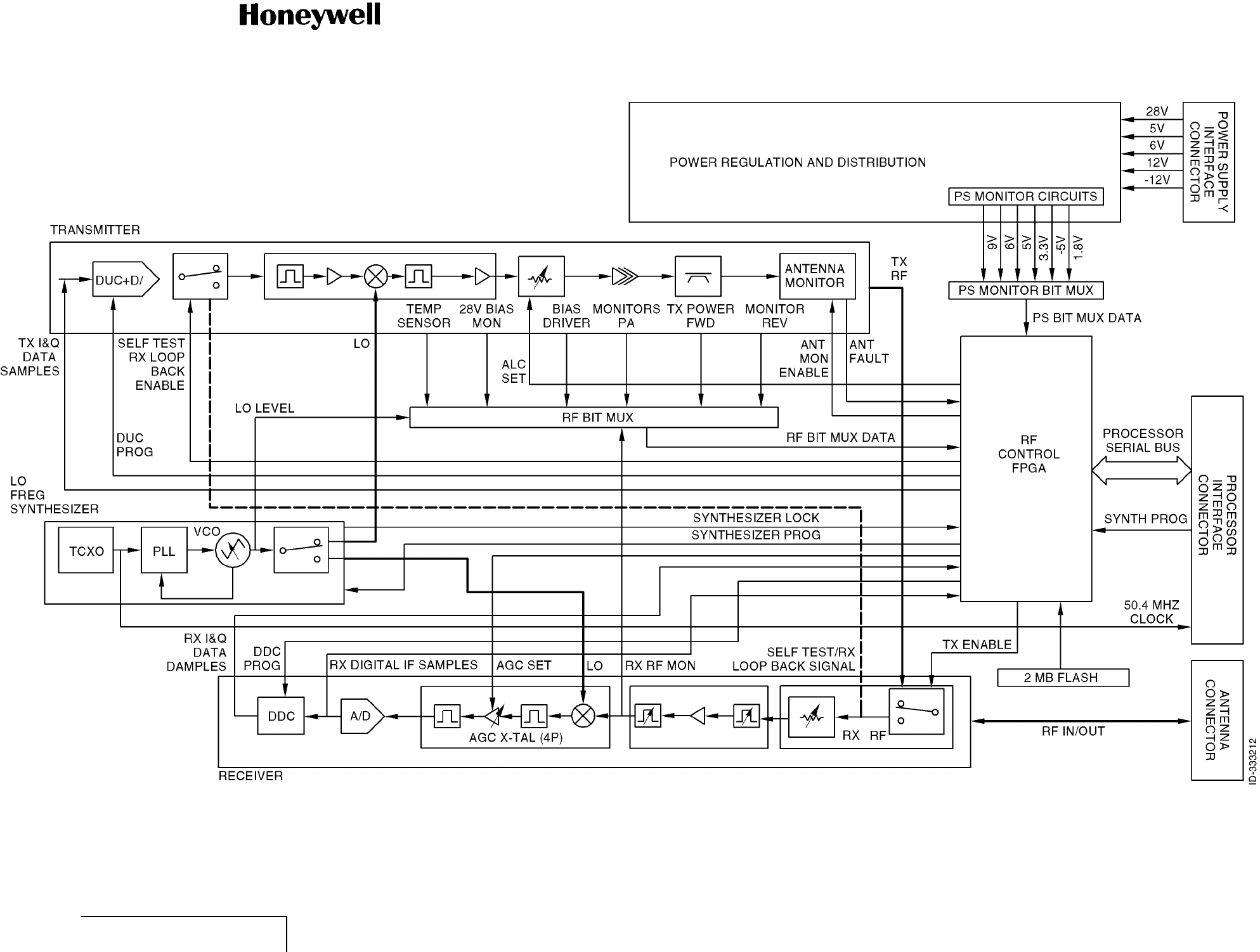
MAINTENANCE MANUAL
965-1696
Figure 8. (Sheet 1 of 1) RF CCA (GRAPHIC 23-20-59-99B-811-A01)
EFFECTIVITY
ALL 23-20-59 Pages 31/32
1 Mar 2011
© Honeywell International Inc. Do not copy without express permission of Honeywell.

MAINTENANCE MANUAL
965-1696
(2) Receiver
(a) The receiver section of the RF CCA employs a heterodyne architecture to convert
a received RF signal in the 118 to 136.975-MHz range to baseband quadrature digital
samples.
(b) A preselector filter followed by an LNA and another preselector filter first limit the RF
bandwidth to about less than 2 MHz centered about the selected operating frequency.
The preselectors center frequency is voltage controlled. The voltage level is selected
by the RF control FPGA from a table of settings prestored in an EEPROM whenever a
new operating frequency is selected. A pin-diode variable attenuator preceding the first
preselector provides the means to attenuate the received RF signal when the output
of the second preselector exceeds the level at which the RF-to-IF conversion mixer
becomes nonlinear.
(c) The RF-to-IF conversion is accomplished by mixing the received RF signal with a LO
signal in the 139.825 to 158.800-MHz range to produce an IF signal at 21.825 MHz. A
four-pole crystal filter with nominal 25-kHz bandwidth which follows the mixer provides
enough rejection of undesired signals occupying channels adjacent to the selected
frequency to prevent aliasing and/or desensitization in the A/D conversion process.
(d) The IF signal is then digitized at 50.4 mega-samples each second by an ADC and
digitally down converted to baseband in-phase and quadrature digital sample streams
using a programmable DDC integrated circuit. The DDC also performs the 25 or
8.33-kHz channel selectivity filtering to reject adjacent channel signals. The DDC channel
selectivity is preprogrammed and the desired channel bandwidth is selected by the RF
control FPGA whenever a new channel is selected. The filtered in-phase and quadrature
digital sample streams are decimated by the DDC and sent to the digital processor CCA
at an 84-kHz rate through a serial bus interface provided by the RF control FPGA.
(e) The input signal level at the ADC is held constant by means of an AGC amplifier circuit.
The AGC control signal is generated by a DSP in the digital processor CCA and passed
on to the RF CCA through the serial bus connection to the RF control FPGA.
(3) Transmitter
(a) The transmitter section of the RF CCA also utilizes a heterodyne architecture for
conversion of in-phase and quadrature digital samples to a RF signal in the 118 to
136.975-MHz band.
(b) Baseband in-phase and quadrature digital sample streams generated by the digital
processor CCA are sent to the RF CCA at a 252-kHz rate in serial format through the
serial bus connection to the RF control FPGA. A preprogrammed DUC up samples and
interpolates the in-phase and quadrature digital sample streams to a 50.4-MHz sample
rate and up converts them to an analog IF signal at 21.825 MHz.
(c) A four-pole crystal filter with nominal 25-kHz bandwidth is used to reject the harmonics
and spurious of the D/A conversion process. This IF signal is amplified and up converted
to the selected VHF channel by mixing it with the same 139.825 to 158.800-MHz LO used
by the receiver. A SAW filter with 20-MHz bandwidth (centered on the 118 to 137-MHz
band), followed by a post selector filter with about a 4-MHz bandwidth (centered about
the selected operating frequency) are then used to reject LO leakage and harmonic
products of the mixer. The post selectors center frequency is voltage controlled. The
voltage level is selected by the RF control FPGA from a table of settings prestored in an
EEPROM whenever a new operating frequency is selected.
EFFECTIVITY
ALL 23-20-59 Page 33
1 Mar 2011
© Honeywell International Inc. Do not copy without express permission of Honeywell.

MAINTENANCE MANUAL
965-1696
(d) The filtered RF signal is then amplified to produce a 25-watt average RF output signal
when operating in DSB-AM voice or ACARS Mode A data mode, or a 17.5-watt average
RF output signal when operating in VDL Mode 2 data mode. An ALC signal generated
by the RF control FPGA is used to set the transmitter output power at the desired level
for the operating mode during the ramp-up transition from receive to transmit. When
operating in DSB-AM voice or data mode, the ALC signal is also used to maintain the
output signal level at the desired level throughout the transmission.
(e) A 20-dB coupler at the output of the transmitter is used to obtain low-power forward and
reverse voltage replicas of the transmitted RF signal. The forward and reverse voltages
are envelope detected and digitized for downstream processing by the RF control FPGA
and DSPs on the digital processor CCA. The forward voltage signal is used by the FPGA
to derive the ALC control signal and by the DSPs to derive transmit audio side tone when
operating in DSB-AM voice mode. The forward and reverse voltages are used by the
DSP to monitor the antenna VSWR during transmit operation in all modes.
(f) An antenna DC ground monitoring circuit is also used at the antenna port to detect
antenna faults on aircraft installations that use DC grounded antennas (pin programming
selectable).
(4) LO Frequency Synthesizer
(a) The LO frequency synthesizer section of the RF CCA generates the 139.825 to
158.800-MHz LO signal that is used by the transmitter and receiver chains. The LO
frequency synthesizer is comprised of a reference oscillator, a PLL frequency synthesizer
integrated circuit, and VCO.
(b) The reference oscillator is a TCXO that generates a 50.4-MHz reference clock signal
that is used to generate the LO frequency as well as the clocks for the ADC, DDC,
DUC, and for the digital processor circuitry.
(c) The PLL and VCO generate the selected LO frequency from the reference frequency
provided by the TCXO. The LO frequency selection (tuning) is controlled by the digital
processor CCA and the synthesizer programming data is passed to the LO frequency
synthesizer through the RF control FPGA. The LO frequency synthesizer provides an
indication (synthesizer lock) to the RF control FPGA when it has tuned to the selected
frequency.
(5) RF Control
(a) The RF control functions are implemented in a Xilinx Spartan lIe FPGA with 300,000
gates. The RF control FPGA is responsible for managing the flow of transmit and receive
digital data samples, and command and control data by interfaces to the devices that
follow:
• TMS320C6711 DSP bi-directional serial communications port (MCBSP) interface
• MPC8250 processor SPI
• Transmitter DUC interface
• Receiver DDC interface
• Receiver high-speed A/D converter (ADC) interface
• Frequency synthesizer interface
• RF BIT MUX A/D converter interface
• Voltage monitoring BIT MUX A/D converter interface
EFFECTIVITY
ALL 23-20-59 Page 34
1 Mar 2011
© Honeywell International Inc. Do not copy without express permission of Honeywell.

MAINTENANCE MANUAL
965-1696
• Digital potentiometer interface
• Serial EEPROM interface
• Transmitter ALC
• External discrete I/O interface.
(b) The RF control FPGA receives 24-bit command data consisting of alternating 14-bit I and
Q transmit data samples, 6-bit control words, and 4-bit command code sent from the
TMS6711 DSP on the downstream MCBSP serial bus at a 504-kHz rate. The RF control
FPGA writes the 14-bit I or Q data to the DUC if transmit mode is enabled (appropriate bit
in control word is set), and decodes the 6-bit control words to control various transceiver
components on the RF CCA. The transceiver functions controlled are as follows:
• Enabling of Tx function
• Antenna Tx/Rx switching
• LO Tx/Rx switching
•Driver/PA
Tx bias enabling
• Forced termination of Tx data flow.
(c) The TMS6711 DSP also uses the downstream 24-bit command data to command the
RF control FPGA to program and configure the DUC and DDC during power up and
after mode changes.
(d) The RF control FPGA sends 192-bit data frames to the TMS6711 DSP on a second
(upstream) MCBSP serial bus at an 84-kHz rate. The 192-bit frame contains:
• The 32-bit I and Q receive data from DDC channel 0 for data demodulation
• The 32-bit I and Q receive data from DDC channel I for adjacent channel interference
detection
• The 32-bit ADC output values for AGC
• The 32-bit frame ID/BIT data values for frame synchronization and fault/event detection.
(e) The BIT data content of the last 32 bits of each frame rotates on an 8-frame cycle. The
17-bit data consists of an 8-bit field that alternates between data samples of:
• Driver bias monitor
• PA bias monitor
• Temperature sense
• An Rx RF monitor
• A 28-volt monitor
• Rx LO level monitor
• Requested data ID or requested data
• An 8-bit field that alternates between samples of forward power and reverse power
• A 1-bit field that alternates between antenna DC monitor, synthesizer lock, FPGA SEU
flag, FPGA watchdog, and DUC overflow flag status.
(f) The transmission of each frame is periodic and synchronized to the receiver DDC frame
synchronization signal. An automatic upstream mode also exists to send data when the
DDC is not operating.
EFFECTIVITY
ALL 23-20-59 Page 35
1 Mar 2011
© Honeywell International Inc. Do not copy without express permission of Honeywell.

MAINTENANCE MANUAL
965-1696
(g) In transmit mode, the RF control FPGA uses the RF BIT MUX forward power samples
to derive an automatic level control signal to adjust the PA gain using the digital
potentiometer interface.
(h) Other functions performed by the RF control FPGA include:
• MPC8250 processor and TMS6711 DSP write access to the LO frequency synthesizer
device to select the LO frequency
• TMS6711 DSP read/write access to the serial EEPROM through commands
• TMS6711 DSP write access to the serial pot interface to update 1 of 16 available
digital potentiometers
• TMS6711 DSP write access to various FPGA mode and discrete output registers
• TMS6711 DSP read access to RF control FPGA revision and discrete input bits.
(6) BIT Monitoring
(a) The RF CCA incorporates BIT circuitry to detect failures both during normal operation as
well as during power on self-test and operator-initiated self-test.
(b) The Tx/Rx BIT signals continuously monitored (RF BIT MUX) during normal transmit
and receive operation include:
• Transmit forward power measured at the antenna port during transmit operation
• Reflected power measured at the antenna port during transmit operation
• Primary 28-volt input to the RTA-50D VDR
• DC bias voltages of the driver and final PA devices
• Temperature of the RF CCA
• Received signal level at down converter mixer
• LO output level.
(c) The distributed voltage regulators continuously monitored (PS monitor BIT MUX) include:
• 9-volt regulator output
• 6-volt regulator output
• 5-volt regulator output
• 3.3-volt regulator output
• -5-volt regulator output
• 1.8-volt regulator output.
(d) Other signals continuously monitored are the synthesizer lock detector output.
(e) During power on self-test, the RF CCA performs an antenna continuity test to detect the
presence or absence of an antenna connection and a receiver functionality test under the
control of the digital processor CCA. The receiver functionality test consists of looping
back a test RF signal generated by the DUC that is injected into the receiver chain and
measuring the SNR of the received signal. Refer to Figure 8.
(f) When self-test is initiated by the operator, the RF CCA performs the antenna continuity
test and receiver functionality test as well as a transmitter/antenna test. The
transmitter/antenna test consists of the transmission of a test signal at 118 MHz and
the measurement of the forward transmitted and reflected powers at the antenna port.
EFFECTIVITY
ALL 23-20-59 Page 36
1 Mar 2011
© Honeywell International Inc. Do not copy without express permission of Honeywell.

MAINTENANCE MANUAL
965-1696
Reporting of the measurements to the digital processor CCA for computation of the
VSWR then takes place.
D. Digital Processor CCA (Subtask 23-20-59-870-021-A01)
(1) General
(a) The digital processor CCA comprises nine processing sections:
• MPC8250 main processor
• TMS320C6711 digital signal processor (main DSP)
• TMS320VC5410A digital signal processor (auxiliary DSP)
• Audio I/O circuitry
• ARINC 429 I/O circuitry
• Discrete I/O circuitry
• Clock generation circuitry
• Monitoring circuitry
• Manufacturing and engineering support I/O circuitry.
(b) A block diagram of the digital processor CCA is shown in Figure 9.
EFFECTIVITY
ALL 23-20-59 Page 37
1 Mar 2011
© Honeywell International Inc. Do not copy without express permission of Honeywell.

MAINTENANCE MANUAL
965-1696
Blank Page
EFFECTIVITY
ALL 23-20-59 Page 38
1 Mar 2011
© Honeywell International Inc. Do not copy without express permission of Honeywell.
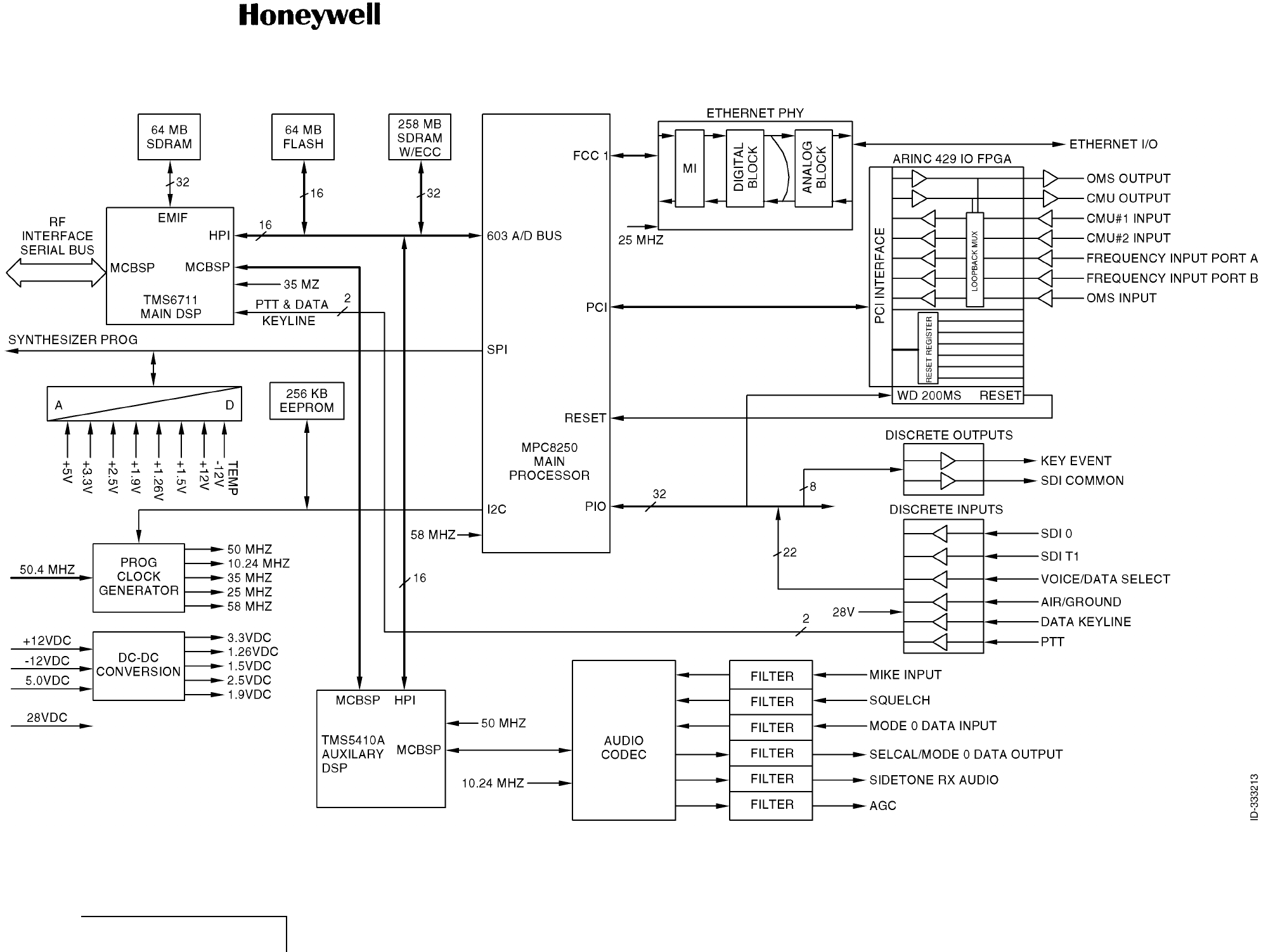
MAINTENANCE MANUAL
965-1696
Figure 9. (Sheet 1 of 1) Digital Processor CCA Block Diagram (GRAPHIC 23-20-59-99B-812-A01)
EFFECTIVITY
ALL 23-20-59 Pages 39/40
1 Mar 2011
© Honeywell International Inc. Do not copy without express permission of Honeywell.

MAINTENANCE MANUAL
965-1696
(2) Main Processor
(a) The main processor is a Motorola MPC8250 Power PC with 64 Mbit of external flash
for boot/program memory, 256 Mbit of external SDRAM for program and data memory,
64 Mbit of external SDRAM for program and data memory ECC, and 256 Kbit external
EEPROM for fault and configuration memory.
(b) The MPC8250 processor interfaces to the ARINC 429 I/O FPGA through a PCI bus and
to discrete inputs and outputs to determine the mode of operation and frequency/channel
selection. The MPC8250 processor performs the tuning of the VHF transceiver LO
synthesizer according to the selected mode and channel through the RF control FPGA on
the RF CCA by means of a SPI.
(c) The MPC8250 processor interfaces to the TMS6711 DSP and TMS5410 DSP through
shared memory messages accessed by HPI built into each DSP. The HPI is a parallel
port through which the MPC8250 can directly access the DSP shared memory. When
operating in the Mode A or Mode 2 data modes, the MPC8250 manages the delivery of
uplink data messages received from the TMS6711 DSP to the ARINC 429 transmitter
within the ARINC 429 I/O FPGA that interfaces to the external user (ATSU or CMU). It
also controls the flow of downlink data messages received from the ARINC 429 receiver
that interfaces to ATSU or CMU to the TMS6711 DSP.
(d) The MPC8250 processor also interfaces on an external OMS through an ARlNC 429
transmitter/receiver pair synthesized within the ARINC 429 I/O FPGA to report fault
data collected by BIT function.
(e) The MPC8250 processor BIT function controls three different modes of self-test that are
used to monitor the health of the RTA-50D VDR and detect faults:
• Power on self-test
• Operator initiated functional self-test
• Background (continuous monitoring) self-test.
(f) Power on self-test is initiated each time the power is cycled on the unit. Some tests
are intrusive meaning that some VDR to aircraft interfaces can not be read or driven
according to normal aircraft operation. The list that follows describes the functional
blocks that are tested but not in what order:
• MPC8250 register test
• MPC8250 SDRAM
• MPC8250 FLASH
• MPC8250 EEPROM
• DSP HPI interface
• TMS6711 DSP register test
• TMS6711 DSP SDRAM
• TMS5410 DSP register test
• Audio CODEC register test
• ARINC 429 I/O FPGA PCI register test
•SDIdiscretetest
• Antenna monitor discrete test
• ARINC 429 I/O loopback
EFFECTIVITY
ALL 23-20-59 Page 41
1 Mar 2011
© Honeywell International Inc. Do not copy without express permission of Honeywell.

MAINTENANCE MANUAL
965-1696
• Ethernet loopback
• RF control FPGA interface test
• Voltage monitor.
(g) Operator-initiated functional self-test can be initiated by pressing the front panel switch,
grounding the functional test discrete or OMS command. The set of tests executed are
the same as in the power on self-test plus additional transmitter and receiver loop back
tests that check the functionality of the transmitter, antenna, interface, and receiver. This
mode is useful in diagnosing problems only seen after the RTA-50D VDR has been
running for some time.
(h) Background self-tests are run continuously in the RTA-50D VDR as long as power is
applied. These tests only exercise circuitry in a way that is nonintrusive to system
operation. The background self-tests listed as follows are a subset of the functional
self-tests but, where possible, use the same test software routines:
• MPC8250 SDRAM
• MPC8250 FLASH
• MPC8250 EEPROM
• DSP HPI interface
• TMS6711 DSP SDRAM
• Ethernet loopback
• RF control FPGA interface test
• Voltage monitor.
(3) Main DSP
(a) The main DSP is a Texas Instruments TMS320C6711 DSP with 64 Mbit of external
SDRAM for program and data memory.
(b) The TMS6711 DSP interfaces to the RF control FPGA through a MCBSP serial bus
and to the TMS5410 DSP through a second MCBSP serial bus. The TMS6711 DSP
interfaces to the MPC8250 through shared memory accessed by its HPI interface. The
shared memory is configured as 64 message buffers of 4,096 bytes for each transfer
direction as well as a 592-byte control/status buffer. The TMS6711 DSP program is
loaded into its internal RAM and external SDRAM by the MPC8250 on power up.
(c) The TMS6711 DSP processes digital data provided by the RF control FPGA to generate
the receiver AGC loop control voltage in all voice and data receive modes of operation.
(d) When operating in voice mode, the TMS6711 DSP monitors the PTT input to determine
when to switch between receive and transmit operation, and controls the switching of the
TMS5410 DSP between transmit and receive operation.
(e) When operating in voice transmit mode, the TMS6711 DSP performs the real-time
DSB-AM of digitized voice samples received from the TMS5410 DSP and delivers
252-kilo sample each second streams of I and Q digital modulation samples to the
RF CCA for RF carrier modulation and downlink transmission. Simultaneously while
transmitting the modulation samples, the TMS6711 DSP delivers the forward power
samples received from the RF CCA to the TMS5410 for side-tone output.
(f) When operating in voice receive mode, the TMS6711 DSP performs envelope detection
of the 84-kilo sample each second I and Q digital data streams received from the RF CCA
and delivers the demodulated samples to the TMS5410 DSP.
EFFECTIVITY
ALL 23-20-59 Page 42
1 Mar 2011
© Honeywell International Inc. Do not copy without express permission of Honeywell.

MAINTENANCE MANUAL
965-1696
(g) When operating in Mode A or Mode 2 data mode, the TMS6711 DSP monitors the
receiver AGC control loop voltage to determine when the channel is idle and available
for transmit operation. When the channel is idle and a data message is queued for
transmission, the TMS6711 DSP switches to data transmit operation; otherwise it
operates in data receive mode. When operating in data transmit mode, the TMS6711
DSP performs the encoding of data messages received from the MPC8250 and
generates a 252-kilo sample each second. Streams of I and Q digital samples of the
modulation waveform correspond to the data mode selected by the user. When operating
in data receive mode, the TMS6711 DSP performs message detection, decoding, error
detection, and address screening, and delivers the error-free decoded messages with
matching address to the MPC8250 for up-stream delivery.
(4) Auxiliary DSP
(a) The auxiliary DSP is a Texas Instruments TMS320VC5410 DSP with no external memory.
(b) The TMS5410 DSP interfaces to the TMS6711 DSP through McBSP serial bus and to the
audio input/output CODEC through a second McBSP serial bus. The TMS5410 DSP
interfaces to the MPC8250 through shared memory accessed by its HPI interface. The
shared memory is configured as 8 message buffers of 176 bytes for data transfer to the
MPS8250, 12 message buffers of 176 bytes for data transfer from the MPC8250, and a
16-byte control/status buffer. The TMS5410 DSP program is loaded into its internal RAM
bytheMPC8250onpowerup.
(c) When operating in transmit mode, the TMS5410 DSP performs digital filtering of the
digitized audio input samples provided by the audio CODEC at 42-kilo samples each
second and sends the filtered transmit audio samples to the TMS6711 DSP for DSB-AM
modulation and up-sampling. The demodulated transmit audio which is simultaneously
received from the TMS6711 DSP is sent to the side-tone output of the audio CODEC.
(d) When operating in receive mode the TMS5410 DSP performs the audio bandpass filtering
and squelch control processing functions and sends the 42-kilo sample each second
stream of digital audio samples to the receive/side-tone output of the audio CODEC.
(5) Audio I/O Circuitry
(a) The audio I/O circuitry is comprised of an Analog Devices ADI836AS audio CODEC
integrated circuit that supports A/D and D/A conversion of up to four channels, and audio
input/output conditioning (low-pass filters) for each audio signal.
(b) Three CODEC A/D channels are used to support the following audio inputs:
• Microphone audio input for use on installations that support DSB-AM voice
• Modem audio input for use on installations that support Mode 0 data
• Remote squelch control input for use on installations that support remote squelch
control of DSB-AM voice audio.
(c) Three CODEC D/A channels are used to support the following audio outputs:
• Received audio/side-tone output to the speaker for use on installations that support
DSB-AM voice
• SELCAL audio output for use on installations that support DSB-AM voice or Mode 0
data link modem audio output for use on Mode 0 data installations
• Analog AGC control voltage to support DSB-AM MOPS compliance testing.
EFFECTIVITY
ALL 23-20-59 Page 43
1 Mar 2011
© Honeywell International Inc. Do not copy without express permission of Honeywell.

MAINTENANCE MANUAL
965-1696
(6) ARINC 429 I/O Circuitry
(a) The ARINC 429 I/O transmitter encoding and receiver decoding logic is implemented
in an Actel ProASIC Plus flash FPGA with 600,000 gates. Digital logic-to-CMOS level
translation circuits are provided externally for each transmitter and receiver.
(b) The ARINC429 I/O FPGA interfaces to the MPC8250 through a PCI bus interface. The
ARINC 429 I/O FPGA supports 4 ARINC 429 transmitters and 11 ARINC 429 receivers
with automatic speed detection.
(c) The ARINC 429 transmitters are used to do the following functions:
• Data link output high-speed transmitter
• OMS output low-speed transmitter
• Two spare transmitters.
(d) The ARINC 429 receivers are used to do the following functions:
• Two frequency select tuning input receivers
• Two data link input receivers
• Two OMS input receivers
• Five spare receivers.
(7) Clock Generator
(a) The clocks for the various processors are generated by a Cypress Semiconductor
programmable clock generator integrated circuit. The clock generator derives the
following clocks from a 50.4-MHz clock input from RF CCA:
• 58-MHz clock provided to the MPC8250
• 50-MHz clock provided to the TMS5410 DSP
• 35-MHz clock provided to the TMS6711 DSP
• 25-MHz clock provided to the Ethernet transceiver
• 10.24-MHz clock provided to the audio CODEC.
(8) Monitoring Circuitry
(a) The monitoring circuitry consists of voltage level monitoring circuits and a processor
watchdog circuit. The digital processor regulator voltage levels monitored are as follows:
•+12volts
•12 volts
•+5volts
•+3.3volts
•+2.5volts
•+1.9volts
•+1.5volts
• +1.26 volts.
(b) The ARINC 429 I/O FPGA provides a supervisory watchdog function used to monitor
the MPC8250 main processor. If the MPC8250 fails to monitor the watchdog register at
10-ms intervals, the MPC8250 is reset by the ARINC 429 I/O FPGA.
EFFECTIVITY
ALL 23-20-59 Page 44
1 Mar 2011
© Honeywell International Inc. Do not copy without express permission of Honeywell.

MAINTENANCE MANUAL
965-1696
(9) Manufacturing and Engineering Support I/O Circuitry
(a) The manufacturing and engineering support I/O circuitry consists of:
• Ethernet interface used for data loading and troubleshooting
• RS232 port used for test equipment support.
E. Front Panel I/O Board (Subtask 23-20-59-870-022-A01)
(1) The front panel I/O board performs the conditioning of the signals that drive three LED lights
and monitors a push-button switch on the front panel of the RTA-50D VDR to initiate LRU
self-test. No self-test is available for this subassembly.
F. Power Supply (Subtask 23-20-59-870-023-A01)
(1) The power supply subassembly is a self-contained high-efficiency power supply that converts
the 28-VDC power into the DC operating voltages required by each subassembly. The power
supply circuitry is grouped into three sections:
• Power hold circuitry
• Input voltage conditioning circuitry
• DC-to-DC voltage conversion and output voltage conditioning.
(2) The power supply is capable of holding power up during power input interrupts lasting
up to 200 ms. Each of the power supply output voltages are monitored on either the RF
subassembly or the processor subassembly.
G. Rear Interconnect (Subtask 23-20-59-870-024-A01)
(1) The rear interconnect subassembly consists of the ARINC 600 connector that provides the
means to interface the power supply module, the processor CCA, and the RF CCA to the
aircraft wiring, and HIRF and lightning protection circuitry for each input/output. The RF
and power supply inputs are in the bottom plug. Discrete, ARINC 429, and analog audio
inputs/outputs are in the middle plug and the top plug.
(2) There is no active circuitry on this assembly and thus it has a low failure rate. No self-test is
available for the rear interconnect.
EFFECTIVITY
ALL 23-20-59 Page 45
1 Mar 2011
© Honeywell International Inc. Do not copy without express permission of Honeywell.

MAINTENANCE MANUAL
965-1696
Blank Page
EFFECTIVITY
ALL 23-20-59 Page 46
1 Mar 2011
© Honeywell International Inc. Do not copy without express permission of Honeywell.

MAINTENANCE MANUAL
965-1696
FAULT ISOLATION
1. Planning Data (TASK 23-20-59-99C-801-A01)
A. Reason for the Job (Subtask 23-20-59-99C-002-A01)
(1) Use the procedures in this section to isolate faults.
(2) Fault isolation is the process of isolating the source of a system failure to an LRU or to the
aircraft wiring.
(3) It is recommended that a system test of the RTA-50D VDR be done in accordance with the
instructions provided in the aircraft manufacturer’s AMM to confirm the reported fault condition.
(4) Access to the equipment bay is necessary to view the RTA-50D VDR front panel maintenance
status information and/or to initiate a self-test of the RTA-50D VDR equipment.
(5) Fault isolation in the RTA-50D VDR includes a continuity check of the interwiring and the
assurance that correct installation techniques and procedures have been followed.
B. Job Setup Data (Subtask 23-20-59-99C-003-A01)
(1) The list that follows identifies Honeywell publications that are related to this section:
• Not applicable.
2. Procedure (TASK 23-20-59-810-801-A01)
A. Job Setup (Subtask 23-20-59-810-001-A01)
CAUTION: USE INDUSTRY APPROVED ELECTROSTATIC DISCHARGE SENSITIVE
PRECAUTIONS. THE RTA-50D VERY-HIGH FREQUENCY DATA RADIO CONTAINS
ELECTROSTATIC DISCHARGE SENSITIVE ITEMS.
CAUTION: DO NOT DROP OR HIT THE RTA-50D VERY-HIGH FREQUENCY DATA RADIO
DURING THESE PROCEDURES. THE RTA-50D VERY-HIGH FREQUENCY DATA
RADIO CONTAINS AN ASSEMBLY THAT CAN BE DAMAGED FROM INCORRECT
USE.
(1) Obey the precautions.
B. Functional Self-Test (Subtask 23-20-59-810-002-A01)
(1) A functional self-test of the RTA-50D VDR can be initiated by pressing the test key push-button
on the front panel.
(2) Results of the functional self-test are displayed on the LEDs located on the front panel. Refer
to Figure 1001.
EFFECTIVITY
ALL 23-20-59 Page 1001
1 Mar 2011
© Honeywell International Inc. Do not copy without express permission of Honeywell.
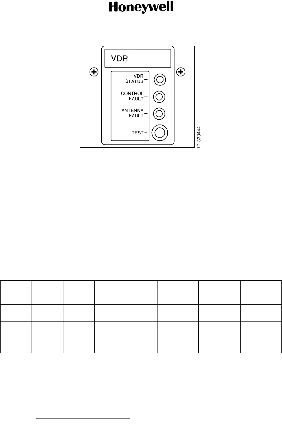
MAINTENANCE MANUAL
965-1696
Figure 1001. (Sheet 1 of 1) RTA-50D VDR Front Panel Functional Self-Test Interface
(GRAPHIC 23-20-59-99B-813-A01)
C. RTA-50D VDR Test Results (Subtask 23-20-59-810-003-A01)
(1) Apply power to the RTA-50D VDR in accordance with the aircraft manufacturer’s AMM and
confirm that the circuit breaker associated with the RTA-50D VDR equipment is closed.
(2) Locate the RTA-50D VDR in the equipment bay and observe the status of the LEDs according
to the information provided in Table 1001.
(3) In the event that a failure condition is indicated, do a self-test on the RTA-50D VDR as follows.
(a) While power is applied to the RTA-50D VDR, momentarily depress the TEST push
button on the front panel.
(b) Observe the LEDs according to the information provided in Table 1001.
(c) In the event that a failure condition is indicated, note the indication and do the corrective
action associated with the indicated fault condition.
Table 1001. Front Panel Functional Self-Test Results
Mode RTA-50D
Power VDR
Status Control
Fault Antenna
Fault Reported
Condition
Possible
Corrective
Action Comment
Power off Off Off Off Off LRU powered
off None LRU power
not applied
Normal
operation On Green Off Off Normal
operation None LRU
operational,
no errors
detected
EFFECTIVITY
ALL 23-20-59 Page 1002
1 Mar 2011
© Honeywell International Inc. Do not copy without express permission of Honeywell.

MAINTENANCE MANUAL
965-1696
Table 1001. Front Panel Functional Self-Test Results (Cont)
Mode RTA-50D
Power VDR
Status Control
Fault Antenna
Fault Reported
Condition
Possible
Corrective
Action Comment
General
fault On Off Off Off 1. Breaker
malfunction
2. LRU
malfunction
1. Check
aircraft
breaker to
LRU
2. Reapply
power to
LRU, remove
if condition
repeats
1. Power
not reaching
LRU due
to breaker
problem or
2. LRU
has internal
malfunction
External
fault
(control)
On Green Amber Off 1. RTP
and/or CMC
controller not
present
2. Internal
malfunction
of RTP/CMC
interface
1. Check
aircraft RTP
and CMC
controllers
and/or
connections
2. Press
functional
self-test
button,
remove if
condition
repeats
1. RTP
and/or CMC
controller is
not present or
2. LRU
has internal
malfunction
of RTP/CMC
interface 1
External
fault
(antenna)
On Green Off Amber 1. Antenna is
not present.
2. Internal
malfunction
of antenna
interface.
1. Check
aircraft
antenna,
and antenna
connection
2. Press
functional
self-test
button,
remove if
condition
repeats
1. Antenna
or antenna
connection is
not present or
2. LRU
has internal
malfunction
of antenna
interface 2
External
fault
(control
/antenna)
On Green Amber Amber Refer to
external
(control) fault
and external
(antenna)
fault
Refer to
External
(control) fault
and external
(antenna)
fault
Refer to
external
(control) fault
and external
(antenna)
fault
EFFECTIVITY
ALL 23-20-59 Page 1003
1 Mar 2011
© Honeywell International Inc. Do not copy without express permission of Honeywell.
MAINTENANCE MANUAL
965-1696
Table 1001. Front Panel Functional Self-Test Results (Cont)
Mode RTA-50D
Power VDR
Status Control
Fault Antenna
Fault Reported
Condition
Possible
Corrective
Action Comment
Internal
fault
(boot)
On Amber Amber Amber LRU did not
complete
boot
sequence
Reapply
power to
LRU, remove
if condition
repeats
Boot
sequence
did not
complete due
to internal
malfunction
Internal
fault On Red Off or
Amber Off or
Amber LRU reports
internal
malfunction
1. Press
functional
self-lest
button
2. If condition
repeats,
reapply
power to LRU
3. If condition
repeats,
remove LRU
LRU has
detected
internal
malfunction
EFFECTIVITY
ALL 23-20-59 Page 1004
1 Mar 2011
© Honeywell International Inc. Do not copy without express permission of Honeywell.
MAINTENANCE MANUAL
965-1696
Table 1001. Front Panel Functional Self-Test Results (Cont)
Mode RTA-50D
Power VDR
Status Control
Fault Antenna
Fault Reported
Condition
Possible
Corrective
Action Comment
Internal
fault On Amber Off or
Amber Off or
Amber LRU reports
internal
malfunction
1. Press
functional
self-test
button
2. If condition
repeats,
reapply
power to LRU
3. If condition
repeats,
remove LRU
LRU has
detected
internal
malfunction
Internal
fault On Off Off or
Amber Off or
Amber LRU reports
internal
malfunction
1. Press
functional
self-test
button
2. If condition
repeats,
reapply
power to LRU
3. If condition
repeats,
remove LRU
LRU has
detected
internal
malfunction
NOTES:
1Only remove LRU if both RTP ports and both CMC ports are known to be connected and operating at
time of fault inspection.
2Only remove LRU if antenna is known to be good and antenna connection is verified to be good at time of
fault inspection.
D. Job Close-up (Subtask 23-20-59-810-004-A01)
(1) Not applicable.
EFFECTIVITY
ALL 23-20-59 Page 1005
1 Mar 2011
© Honeywell International Inc. Do not copy without express permission of Honeywell.

MAINTENANCE MANUAL
965-1696
Blank Page
EFFECTIVITY
ALL 23-20-59 Page 1006
1 Mar 2011
© Honeywell International Inc. Do not copy without express permission of Honeywell.

MAINTENANCE MANUAL
965-1696
MAINTENANCE PRACTICES
1. Planning Data (TASK 23-20-59-99C-802-A01)
A. Reason for the Job (Subtask 23-20-59-99C-004-A01)
(1) This section gives service personnel installation and maintenance information for the RTA-50D
VDR. Installation instructions are supported by mechanical outline drawings and an electrical
interconnection diagram. These drawings must be reviewed by the installer and requirements
unique to the airframe must be established before starting the installation.
(2) Use these diagrams as an aid to fault isolate the RTA-50D VDR.
B. Job Setup Data (Subtask 23-20-59-99C-005-A01)
(1) The list that follows identifies Honeywell publications that are related to this section:
• Not applicable.
2. Inspection After Unpacking (TASK 23-20-59-000-801-A01)
A. General (Subtask 23-20-59-000-001-A01)
CAUTION: THIS EQUIPMENT CONTAINS ELECTROSTATIC DISCHARGE SENSITIVE (ESDS)
DEVICES. EQUIPMENT, MODULES, AND ESDS DEVICES MUST BE HANDLED
WITH APPROPRIATE PRECAUTIONS.
(1) Visually inspect the RTA-50D VDR and all associated equipment for possible damage which
can have occurred during shipment. Inspect for dents, deep abrasions, chipped paint, etc. If
any equipment is damaged, notify the transportation carrier immediately.
(2) The Honeywell test, inspection record, and quality report tag is included with each shipped
unit. This informs the customer that the necessary production tests and inspection operations
have been performed on that particular unit.
(3) One copy of the report tag is affixed to each unit by the first assembly inspector. As the unit
proceeds through production and stock to the shipping area, the appropriate blocks on the
test and inspection record of the tag are stamped. This tag accompanies the unit when it is
shipped to the customer. Customers are requested to complete the Honeywell Airlines and
Avionics Products quality report portion of the tag and return it to the Honeywell Airlines and
Avionics Products Quality Assurance Department. This portion of the tag provides Honeywell
with the necessary information required to evaluate shipping methods as well as test and
inspection effectiveness.
(4) Completed cards are accumulated to give information for a periodic analysis.
3. Preinstallation Testing (TASK 23-20-59-000-802-A01)
A. Overview (Subtask 23-20-59-000-002-A01)
(1) The components in the RTA-50D VDR have been adjusted and tested before shipment.
Preinstallation testing is not required. However if preinstallation testing of the RTA-50D VDR is
desired, refer to the customer acceptance criteria given in the CMM for the appropriate unit in
the system. Refer to Paragraph 3.A. (Subtask 23-20-59-99F-011-A01) in the INTRODUCTION
(PGBLK 23-20-59-0) section for a list of related CMMs.
EFFECTIVITY
ALL 23-20-59 Page 2001
1 Mar 2011
© Honeywell International Inc. Do not copy without express permission of Honeywell.

MAINTENANCE MANUAL
965-1696
4. Equipment Changes and Marking (TASK 23-20-59-000-803-A01)
A. Overview (Subtask 23-20-59-000-003-A01)
(1) Honeywell uses a standardized marking system to identify equipment and their subassemblies
which have had changes incorporated. Refer to the front of the appropriate CMM for a list of
service bulletins affecting the unit.
5. Interchangeability (TASK 23-20-59-000-804-A01)
A. Overview (Subtask 23-20-59-000-004-A01)
(1) The RTA-50D VDR will operate in any installation that complies with ARINC Characteristic
566A. Refer to Figure 2001.
NOTE: Contact the OEM for certification status.
6. Installation (TASK 23-20-59-000-805-A01)
A. General (Subtask 23-20-59-000-005-A01)
CAUTION: AFTER INSTALLATION OF THE CABLING AND BEFORE INSTALLATION OF THE
EQUIPMENT, A CHECK MUST BE MADE WITH AIRCRAFT PRIMARY POWER
SUPPLIED TO THE MOUNT CONNECTORS TO MAKE SURE THAT POWER IS
APPLIED ONLY TO THE PINS SPECIFIED IN INTERWIRING DIAGRAM. REFER TO
FIGURE 2001.
(1) The RTA-50D VDR must be installed in the aircraft in a manner consistent with acceptable
workmanship and engineering practices, and in accordance with the instructions in this
manual. To make sure that the system has been properly and safely installed in the aircraft,
the installer must make a thorough visual inspection and conduct an overall operational and
functional check of the system on the ground before flight.
B. Location of Equipment (Subtask 23-20-59-000-006-A01)
(1) Location of the RTA-50D VDR in the aircraft is not critical as long as the environment is
compatible with the equipment sign. Refer to Table 1 in the DESCRIPTION AND OPERATION
(PGBLK 23-20-59-1) section. Forced air cooling is required for cooling the RTA-50D VDR
communications transceiver in accordance with ARINC Characteristic 404A. The associated
cooling equipment must be mounted in accordance with the manufacturer’s instructions.
(2) The RTA-50D VDR can use the existing MTA-43A mount or any other equivalent mounting
tray that is compatible for securing a unit meeting the 1/2 ATR short form factor according to
ARINC Characteristic 404.
(3) Antenna mounting must be in accordance with the manufacturer’s instructions for the antenna
being used. The coaxial cable connecting the antenna to the mount must be as short and
direct as possible and any required bends must be gradual. When two or more RTA-50D VDR
systems are installed in an aircraft, it is necessary to give adequate space isolation between
the antennas of each system to make sure that the use of one unit does not interfere with
reception from another system. A minimum of 35 dB of space isolation must be provided and
any steps which can be taken to give further isolation must be considered.
(4) Control unit location and mounting can be determined by mutual agreement between the
user and airframe manufacturer.
EFFECTIVITY
ALL 23-20-59 Page 2002
1 Mar 2011
© Honeywell International Inc. Do not copy without express permission of Honeywell.

MAINTENANCE MANUAL
965-1696
C. Interwiring and Cable Fabrication (Subtask 23-20-59-000-007-A01)
(1) General
(a) Figure 2001 is the complete aircraft interwiring diagram for a single RTA-50D VDR system
and associated components. This diagram requires complete study before the installer
begins installation of the aircraft wiring.
(b) When two or more systems are being installed in the aircraft, the interconnecting wiring
as well as all other installation instructions must be duplicated.
(c) Cabling must be fabricated by the installer. Wires connected to parallel pins must be
approximately the same length so that the best distribution of current can be effected.
Honeywell recommends that all wires including the spares must be included in the
fabricated harness. However, if full ARINC wiring is not desired, the installer must
make sure that the minimum wiring requirements for the features and functions are
incorporated. Refer to Figure 2001.
NOTE: To allow for inspection or repair of the connector or the wiring to the connector,
sufficient lead length must be provided. This will let the rear connector
assembly to be pulled forward several inches when the mounting hardware
for the rear connector assembly is removed. A bend must be made in the
harness near the connector to let water condensation drip off at the bend
and not collect at the connector.
(d) When the cables are installed in the aircraft, they must be supported firmly enough to
prevent movement and must be carefully protected against chafing. Additional protection
must also be provided in all locations where the cables can be subject to abuse. In
wire bundles, the cabling must not be tied tightly together as this tends to increase the
possibility of noise pick-up and similar interference. When routing cables through the
airframe, try to avoid running cables or wire close to power sources (400-Hz generator,
etc.). If unavoidable, the cables must cross high-level lines at a right angle or high-quality
shielded conductors must be used.
(e) If a cable must pass through a bulkhead between pressurized and unpressurized zones,
this passage must conform to the aircraft manufacturer’s specifications.
(f) The assembler must be knowledgeable of any system variations unique to the installation
and must completely understand the complexities associated with handling related
problems of line lengths, capacitance, and of susceptibility to interference.
(g) The following determinants are the responsibility of the installation agency for fabrication
of the wiring harness. Refer to Table 2001.
Table 2001. RTA-50D VDR Communications Transceiver Connector Determinants
Pin No. Type Signal Name Function
MPA1 Input MIC audio input (high) Microphone audio input. Part of the standard four wire
microphone interwiring as described in Attachment
6 of ARINC 716-10. Required for ARINC 716 VHF
communication only.
MPB1 Input MIC audio input (low) Microphone audio input. Part of the standard four wire
microphone interwiring as described in Attachment
6 of ARINC 716-10. Required for ARINC 716 VHF
communication only.
EFFECTIVITY
ALL 23-20-59 Page 2003
1 Mar 2011
© Honeywell International Inc. Do not copy without express permission of Honeywell.

MAINTENANCE MANUAL
965-1696
Table 2001. RTA-50D VDR Communications Transceiver Connector Determinants (Cont)
Pin No. Type Signal Name Function
MPC1 Input MIC PTT Microphone PTT discrete input.
Ground/low = transmitter keyed.
Open/high = transmitter not keyed.
Part of the standard four-wire MIC interwiring as
described in Attachment 6 of ARINC 716·10. Required
for ARINC 716 VHF communication only.
MPD1 Output Key event Discrete input to flight recorder. Follows the state of
MIC PTT input.
Ground/low = transmitter keyed
Open/high = transmitter not keyed
Required for ARINC 716 VHF communication only.
MPA2 Input MAX transmit time cutoff
function Discrete input that enables the MAX transmit cutoff
function.
Ground/Low = cutoff disabled
Open/High = cutoff enabled
MPB2 NA MIC input ground Required for ARINC 716 VHF communication only.
MPC2 Input Data loader input Bus A A high-speed ARINC 429 input port to allow on-board
data loading for software.
MPD2 Input Data loader input Bus B Ahigh-sp
eed ARINC 429 input port to allow on-board
data loading for software.
MPA3 Input Optional remote squelch
(high) To accommodate an optional remote squelch
adjustment if so required or provided. Required for
ARINC 716 VHF communication only.
MPB3 Input Optional remote squelch
(arm) To accommodate an optional remote squelch
adjustment if so required or provided. Required for
ARINC 716 VHF communication only.
MPC3 Input Optional remote squelch
(low) To accommodate an optional remote squelch
adjustment if so required or provided. Required for
ARINC 716 VHF communication only.
MPD3 NA DC ground Required for both ARINC 716 VHF communication and
ARINC 750 VDR; functions are identical.
MPA4 Input Functional test Discrete input that activates LRU functional test
function. ground/low = activate functional test.
Required for ARINC 716 VHF communication.
MPB4 NA Audio ground Required for ARINC 716 VHF communication only.
MPC4 Output Data loader output Bus A A high-speed ARINC 429 output port to allow on-board
data loading for software.
MPD4 Output Data loader output Bus B A high-speed ARINC 429 output port to allow on-board
data loading for software.
EFFECTIVITY
ALL 23-20-59 Page 2004
1 Mar 2011
© Honeywell International Inc. Do not copy without express permission of Honeywell.

MAINTENANCE MANUAL
965-1696
Table 2001. RTA-50D VDR Communications Transceiver Connector Determinants (Cont)
Pin No. Type Signal Name Function
MPA5 Input Data link data input (high) Analog 2,400-bps ACARS data input. Required for
ARINC 716 VHF communication only.
MPB5 Input Data link data input (low) Analog 2,400-bps ACARS data input. Required for
ARINC 716 VHF communication only.
MPC5 NA Reserved No. 1 Leave open.
MPD5 Output 8.33 kHz programming Discrete output that indicates to control panel the VDR
is capable of 8.33 or 25-kHz operation. This output is
internally grounded.
MPA6 Input Data from OMS/CFDS No.
1 Input Port (A) One of two low-speed ARINC 429 data input ports
provided for dual OMS/CFDSs. Required for both
ARINC 716 VHF communication and ARINC 750 VDR;
functions are identical.
MPB6 Input Data from OMS/CFDS No.
1 Input Port (B) One of two low-speed ARINC 429 data input ports
provided for dual OMS/CFDSs. Required for both
ARINC 716 VHF communication and ARINC 750 VDR;
functions are identical.
MPC6 Input Data from OMS/CFDS No.
2 Input Port (A) One of two low-speed ARINC 429 data input ports
provided for dual OMS/CFDSs. Required for ARINC
750 VDR only.
MPD6 Input Data from OMS/CFDS No.
2 Input Port (B) One of two low-speed ARINC 429 data input ports
provided for dual OMS/CFDSs. Required for ARINC
750 VDR only.
MPA7 InputFrequency/function select
data l/P Port B (A) One of two low-speed ARINC 429 input ports to
provide frequency tuning data. Required for ARINC
716 VHF communication only.
MPB7 Input Frequency/function select
data l/P Port B (B) One of two low-speed ARINC 429 input ports to
provide frequency tuning data. Required for ARINC
716 VHF communication only.
MPC7 Input Voice/data select Discrete input that enables either the PTT key line
(MPC1) or the Data key line (MPD7).
Ground/low = data Key line enabled
Open/High = PTT enabled.
Required for ARINC 716 VHF communication only.
MPD7Input Data key line Discrete input that keys the transmitter.
Ground/low = transmitter keyed.
Open/high = transmitter not keyed.
Required for ARINC 716 VHF communication only.
MPA8 Input Antenna monitor enable
input Discrete input that allows antenna monitor function
at power-up.
Ground/low = monitor enabled.
Open/high = monitor disabled.
EFFECTIVITY
ALL 23-20-59 Page 2005
1 Mar 2011
© Honeywell International Inc. Do not copy without express permission of Honeywell.
MAINTENANCE MANUAL
965-1696
Table 2001. RTA-50D VDR Communications Transceiver Connector Determinants (Cont)
Pin No. Type Signal Name Function
MPB8 Input Data loader enable input Discrete input to allow on-board data loading of
software. Required for ARINC 750 VDR only.
MPC8 Input Frequency offset enable Not implemented.
MPD8 NA Data key line return Required for ARINC 716 VHF communication only.
MPA9 Input SDI Bit 0 program A discrete input pair pre-wired at the rear connector to
identify the specific VHF radio location in the aircraft.
Required for both ARINC 716 VHF communication and
ARINC 750 VDR; functions are identical.
MPB9 Input SDI Bit 1 program A discrete input pair pre-wired at the rear connector to
identify the specific VHF radio location in the aircraft.
Required for both ARINC 716 VHF communication and
ARINC 750 VDR; functions are identical.
MPC9 NA SPI program pin common Ground for the SDI code inputs. Required for ARINC
716 VHF communication only.
MPD9 Output AGC out AGC output signal for test purposes.
MPA10 NA Spare NA
MPB10 NA Spare NA
MPC10 Output Data to CMU No. 1, CMU
No. 2 output Port (A) A high-speed ARINC 429 output port to CMU/MU/ATSU
No. 1 and No. 2. Required for ARINC 750 VDR only.
MPD10 Output Data to CMU No. 1, CMU
No. 2 output Port (B) A high-speed ARINC 429 output port to CMU/MU/ATSU
No. 1 and No. 2. Required for ARINC 750 VDR only.
MPA11 Input Frequency/function select
data I/P Port A (A) One of two low-speed ARINC 429 input ports to
provide frequency tuning data. Required for ARINC
716 VHF communication only.
MPB11 Input Frequency/function select
data I/P Port A (B) One of two low-speed ARINC 429 input ports to
provide frequency tuning data. Required for ARINC
716 VHF communication only.
MPC11 Input Maintenance system ID 1 Identifies CFDS type along with MPA14.
MPD11 Input Frequency port select Discrete input used to select either frequency/function
select data l/P Port A or B.
Ground/low = Select Port A.
Open/high = Select Port B.
Required for both ARINC 716 VHF communication and
ARINC 750 VDR; functions are identical.
MPA12 Input CMU No. 1 input Bus A A high-speed ARINC 429 input port from
CMU/MU/ATSU No. 1. Used to receive
commands/status/data in Williamsburg files,
and periodic and aperiodic ARINC 429 words.
Required for ARINC 750 VDR only.
EFFECTIVITY
ALL 23-20-59 Page 2006
1 Mar 2011
© Honeywell International Inc. Do not copy without express permission of Honeywell.

MAINTENANCE MANUAL
965-1696
Table 2001. RTA-50D VDR Communications Transceiver Connector Determinants (Cont)
Pin No. Type Signal Name Function
MPB12 Input CMU No. 1 input Bus B A high-speed ARINC 429 input port from
CMU/MU/ATSU No. 1. Used to receive
commands/status/data in Williamsburg files,
and periodic and aperiodic ARINC 429 words.
Required for ARINC 750 VDR only.
MPC12 Input CMU No. 2 input Bus A A high-speed ARINC 429 input port from
CMU/MU/ATSU No. 2. Used to receive
commands/status data in Williamsburg files,
and periodic and aperiodic ARINC 429 words.
Required for ARINC 750 VDR only.
MPD12 Input CMU No. 2 input Bus B A high-speed ARINC 429 input port from
CMU/MU/ATSUNo.2.Usedtoreceive
commands/status data in Williamsburg files,
and periodic and aperiodic ARINC 429 words.
Required for ARINC 750 VDR only.
MPA13 Output SELCAL audio and data
link output (high) An analog output to provide 2400-bps MSK data to the
ACARSMU.MayalsobeusedforSELCALprovisions.
Required for ARINC 716 VHF communication only.
MPB13 Output SELCAL audio and data
link output (low) An analog output to provide 2400-bps MSK data to the
ACARSMU.MayalsobeusedforSELCALprovisions.
Required for ARINC 716 VHF communication only.
MPC13 Input Squelch disable Adisc
rete input to provide squelch override or
disable capability. Required for ARINC 716 VHF
communication only.
MPD13 NA Squelch disable return A discrete input to provide squelch override or
disable capability. Required for ARINC 716 VHF
communication only.
MPA14 Input Maintenance system ID 0 Identifies CFDS type along with MPC11.
MPB14 Input Air/ground discrete Adi
screte input to indicate if the aircraft is in the air or
on the ground.
Ground/low = airborne.
Open/high = on ground.
Required for both ARINC 716 VHF communication and
ARINC 750 VDR; functions are identical.
MPC14 Output Data to OMS/CFDS output
Port A A low-speed ARINC 429 output port to one or two
OMS/CFDSs. Required for both ARINC 716 VHF
communication and ARINC 750 VDR. Functions are
identical.
MPD14 Output Data to OMS/CFDS output
Port B A low-speed ARINC 429 output port to one or two
OMS/CFDSs. Required for both ARINC 716 VHF
communication and ARINC 750 VDR. Functions are
identical.
EFFECTIVITY
ALL 23-20-59 Page 2007
1 Mar 2011
© Honeywell International Inc. Do not copy without express permission of Honeywell.

MAINTENANCE MANUAL
965-1696
Table 2001. RTA-50D VDR Communications Transceiver Connector Determinants (Cont)
Pin No. Type Signal Name Function
MPA15 Output Audio/side-tone output
(high) An analog output for receiver audio during receive
mode and side-tone audio during voice transmit
modes. Required for ARINC 716 VHF communication
only.
MPB15 Output Audio/side-tone output
(low) An analog output for receiver audio during receive
mode and side-tone audio during voice transmit
modes. Required for ARINC 716 VHF communication
only.
MPC15 Output Muting An optional two wire discrete output to provide a switch
closure internal to the VHF communication for external
system muting applications during transmit modes.
Open = muting off.
Ground = muting on.
Required for ARINC 716 VHF communication only.
MPD15 NA Muting return An optional two wire discrete output to provide a switch
closure internal to the VHF communication for external
system muting applications during transmit modes.
Open = muting off.
Ground = muting on.
Required for ARINC 716 VHF communication only.
BP1 Input
/output Antenna RF input Required for both ARINC 716 VHF communication and
ARINC 750 VDR; functions are identical.
BP2 Input DC power input +27.5
VDC Required for both ARINC 716 VHF communication and
ARINC 750 VDR; functions are identical.
BP3 NA Spare NA
BP4 NA DC power ground Required for both ARINC 716 VHF communication and
ARINC 750 VDR; functions are identical.
BP5 NA Spare NA
(2) Reserved and Spare Wires
(a) It is not necessary to connect all wires. Wires reserved for optional functions can be
selected, which the system does not contain, and deleted. Also decide which future
spare wires to include in the installation. The reserved and spare wires are identified in
Table 2001 and in Figure 2001.
D. Installation of System (Subtask 23-20-59-000-008-A01)
(1) The RTA-50D VDR is secured in the airframe with 3 MCU unit mounts. The mounts are
designed to be removed without rewiring the connectors. Follow the equipment manufacturer’s
installation instructions to install the mount into the airframe.
(2) To wire the mounts into the system, perform the steps that follow.
(a) Remove the mount connector cover and connector plate assembly.
EFFECTIVITY
ALL 23-20-59 Page 2008
1 Mar 2011
© Honeywell International Inc. Do not copy without express permission of Honeywell.
MAINTENANCE MANUAL
965-1696
(b) Crimp or solder (as applicable) the interconnecting wiring to the appropriate connector
pins.
(c) Return the connector plate assembly and cover to their original positions.
(3) To install the RTA-50D VDR in the mount, perform the steps that follow.
(a) Slide the RTA-50D VDR into the mount until the guide pins are aligned and the electrical
connectors are firmly engaged.
(b) Attach the front of the RTA-50D VDR to the mount by tightening the two knurled screw
clamps (located on the front of the mount) until they are firmly seated over the hold-down
hooks located on the front of the unit.
(c) Safety-wire the two screw clamps.
7. Inspection and System Check Procedures (TASK 23-20-59-000-806-A01)
A. Inspection (Subtask 23-20-59-000-009-A01)
(1) Inspection and check procedures for the RTA-50D VDR include checkout of all interfacing
units that can affect performance of the VDR.
(2) Table 2002 is a visual inspection check procedure and must be performed after system
installation, before system checkout. In addition, the procedure must be used as a periodic
inspection check.
Table 2002. Inspection/Check Procedures
Equipment Inspection/check Procedure
3MCU unit mount As defined by manufacturer’s instructions.
RTA-50D VDR 1. Check that unit is fully inserted in mount and that the knurled screw
clamps, which attach the unit in the mount, are tight and safety wired.
2. Inspect the case for deformation, dents. corrosion, and damage to
finish; make sure that ventilation holes in the unit are not clogged.
ARINC 716/750 control panel As defined by manufacturer’s instructions.
ARINC 716/750 VHF antenna As defined by manufacturer’s instructions.
B. System Checkout (Subtask 23-20-59-000-010-A01)
(1) General
(a) After installation of the RTA-50D VDR and inspection of the equipment, do a continuity and
visual check of the system interwiring. A post-installation test must then be performed.
(2) System Interwiring Check
(a) Visually check the system interwiring for abnormalities, such as cables rubbing
unprotected metal edges or tightly stretched cables. Check continuity of all interwiring.
Specifically check the following:
• Check that the RTA-50D VDR is properly installed and the hold-down screw clamps
are tight.
• Check the wiring harness connectors for security and connection to the RTA-50D VDR.
• Check that antenna transmission line connectors are securely fastened.
• Check that cables do not interfere with aircraft controls or other equipment.
EFFECTIVITY
ALL 23-20-59 Page 2009
1 Mar 2011
© Honeywell International Inc. Do not copy without express permission of Honeywell.
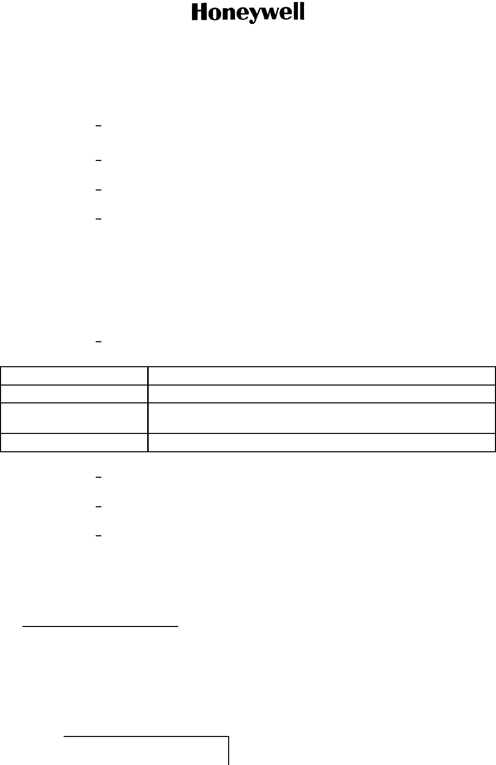
MAINTENANCE MANUAL
965-1696
(3) Post-Installation Check
(a) Required Test Equipment
1Not applicable.
(b) System Test
1A functional self-test of the LRU can be initiated by pressing the test key push-button
on the front panel. Refer to Figure 1001.
2The result of the functional self-test is displayed on the LEDs located on the front
panel.
3After completion of functional self-test, the RTA-50D VDR status LED must be
green and all other LEDs must be off. For more information, refer to the FAULT
ISOLATION (PGBLK 23-20-59-1000) section.
C. Flight Tests (Subtask 23-20-59-000-011-A01)
(1) Preflight Test
(a) The following test procedure gives instructions for a preflight test which ensures that the
RTA-50D VDR is functioning in an acceptable manner before takeoff.
(b) Test Procedure
1Establish the initial control settings. Refer to Table 2003.
Table 2003. Initial Control Settings
Control Panel Position
Power On.
Frequency selector Tune to any local VHF frequency (local control tower or ground control
frequency).
Volume control Midrange.
2Use the system headphones (or speaker) and microphone to check operation
of the RTA-50D VDR.
3Key the microphone and speak into it. Request a radio check and release the
PTT button.
4As soon as possible, a local flight check must be made to verify system operation
for both local and distant stations.
(2) In-Flight Confidence Test
(a) After completion of the post-installation and preflight checks, a local flight can be made to
verify system operation for both local and distant stations. Repeat the test procedure
found in Paragraph 7.C. (Subtask 23-20-59-000-011-A01)(1)(b).
8. Removal and Replacement (TASK 23-20-59-000-807-A01)
A. Removal (Subtask 23-20-59-000-012-A01)
(1) Loosen the two knurled screw clamps (located on the front of the mount) that attach the
RTA-50D VDR to the mount.
(2) Gently pull the RTA-50D VDR forward until it is disconnected from the rear connector and
the guide pins.
EFFECTIVITY
ALL 23-20-59 Page 2010
1 Mar 2011
© Honeywell International Inc. Do not copy without express permission of Honeywell.

MAINTENANCE MANUAL
965-1696
B. Replacement (Subtask 23-20-59-000-013-A01)
(1) Slide the RTA-50D VDR onto the tray of the mount and then gently push the RTA-50D VDR
until the guide pins are aligned and the connectors make a firm connection.
(2) Tighten the two knurled screw clamps located on the front of the mount until they are firmly
seated over the hold-down hooks located on the front of the RTA-50D VDR.
(3) Safety wire the two knurled screw clamps.
9. Maintenance Procedures (TASK 23-20-59-000-808-A01)
A. Adjustments and Alignments (Subtask 23-20-59-000-014-A01)
(1) There are no adjustments or alignments required for the RTA-50D VDR. All alignment and
adjustment procedures are accomplished during bench maintenance. The technician must
remove the unit from the aircraft and reference must be made to the related maintenance
manual when unit performance indicates an adjustment or an alignment is required.
B. System Protection (Subtask 23-20-59-000-015-A01)
(1) The system must be protected by a 10-AMP circuit breaker located at the circuit breaker
panel in the aircraft.
C. Lubrication Practices (Subtask 23-20-59-000-016-A01)
(1) There are no requirements for lubrication of any RTA-50D VDR components.
D. Cleaning (Subtask 23-20-59-000-017-A01)
(1) When deemed necessary, depending on the environment to which the equipment is exposed
and the intensity of use, periodic cleaning can be performed. Any dust on the RTA-50D
VDR must be wiped off with a lint-free cloth.
NOTE: Any cleaning of equipment interiors must be limited to that required when
performing overhaul (bench-type) work.
10. Diagrams (TASK 23-20-59-000-809-A01)
A. RTA-50D VDR Diagrams (Subtask 23-20-59-000-018-A01)
(1) Diagrams for the RTA-50D VDR are listed in Figure 2001.
EFFECTIVITY
ALL 23-20-59 Page 2011
1 Mar 2011
© Honeywell International Inc. Do not copy without express permission of Honeywell.

MAINTENANCE MANUAL
965-1696
Blank Page
EFFECTIVITY
ALL 23-20-59 Page 2012
1 Mar 2011
© Honeywell International Inc. Do not copy without express permission of Honeywell.
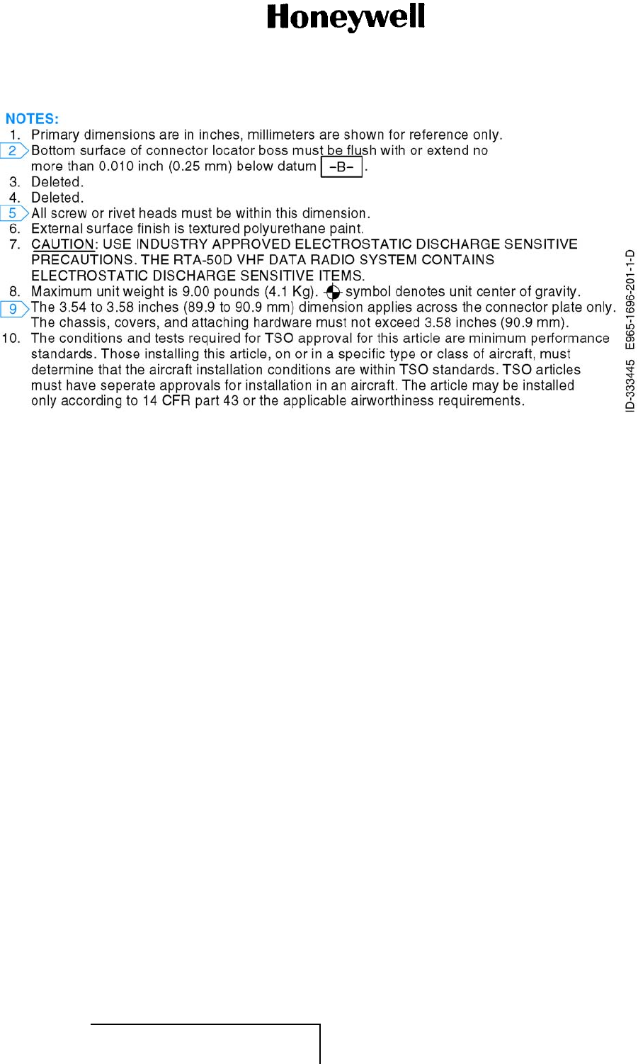
MAINTENANCE MANUAL
965-1696
Figure 2001. (Sheet 1 of 4) RTA-50D VDR Detail/Interwiring Diagram (GRAPHIC 23-20-59-99B-814-A01)
EFFECTIVITY
ALL 23-20-59 Pages 2013/2014
1 Mar 2011
© Honeywell International Inc. Do not copy without express permission of Honeywell.
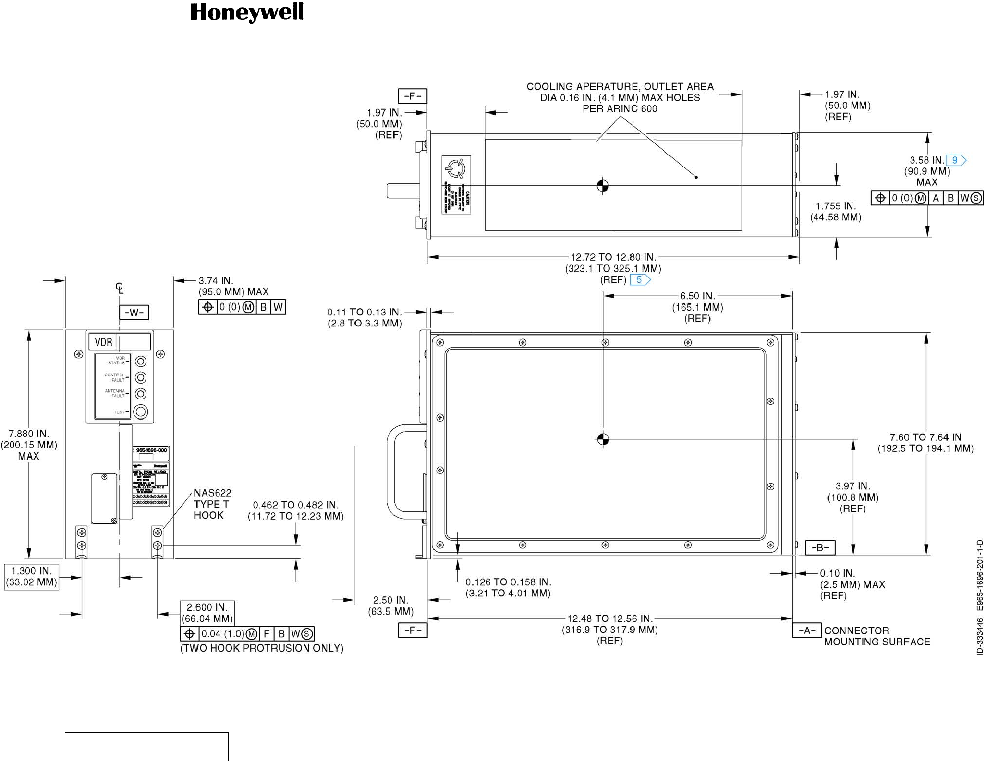
MAINTENANCE MANUAL
965-1696
Figure 2001. (Sheet 2 of 4) RTA-50D VDR Detail/Interwiring Diagram (GRAPHIC 23-20-59-99B-814-A01)
EFFECTIVITY
ALL 23-20-59 Pages 2015/2016
1 Mar 2011
© Honeywell International Inc. Do not copy without express permission of Honeywell.

MAINTENANCE MANUAL
965-1696
Figure 2001. (Sheet 3 of 4) RTA-50D VDR Detail/Interwiring Diagram (GRAPHIC 23-20-59-99B-814-A01)
EFFECTIVITY
ALL 23-20-59 Pages 2017/2018
1 Mar 2011
© Honeywell International Inc. Do not copy without express permission of Honeywell.
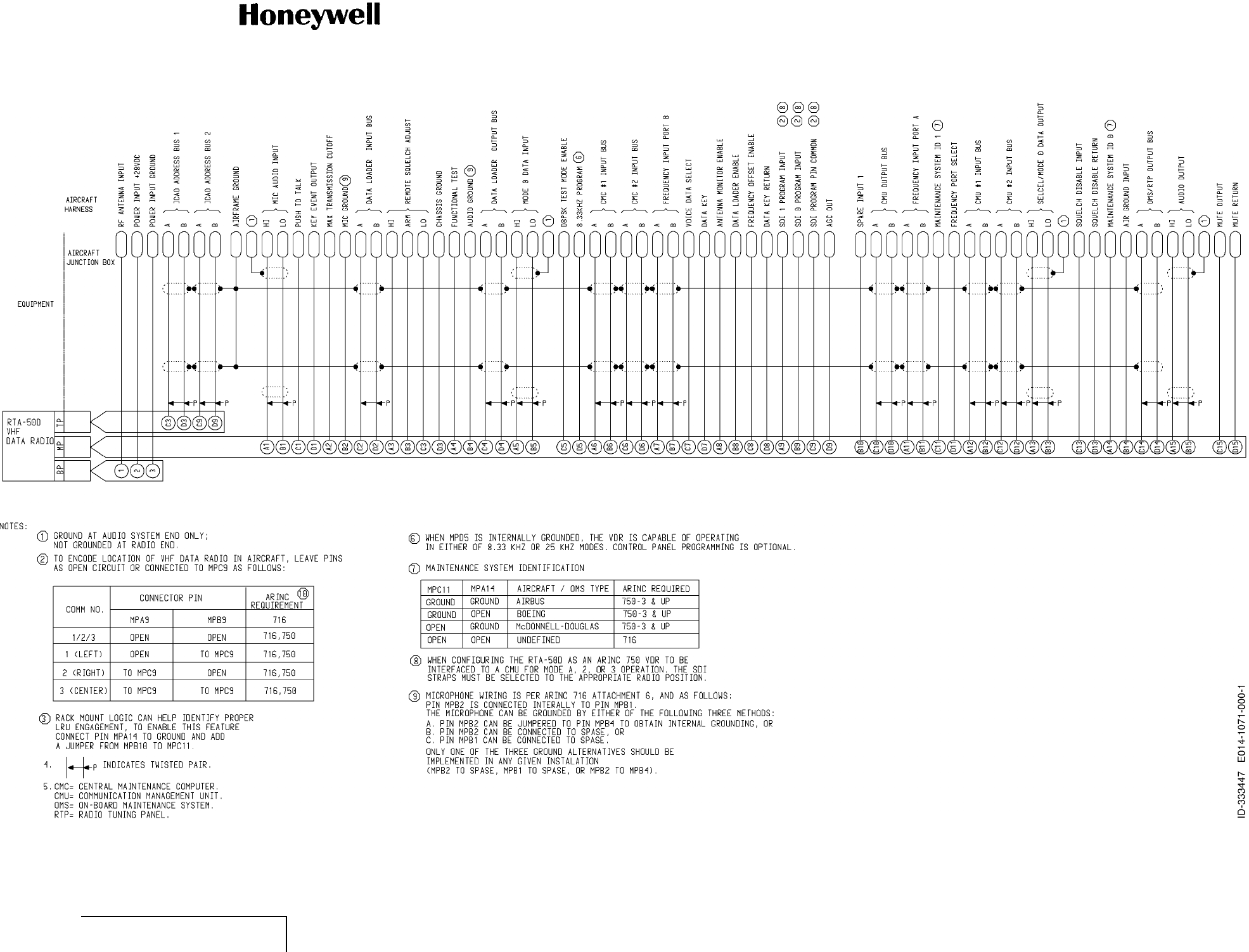
MAINTENANCE MANUAL
965-1696
Figure 2001. (Sheet 4 of 4) RTA-50D VDR Detail/Interwiring Diagram (GRAPHIC 23-20-59-99B-814-A01)
EFFECTIVITY
ALL 23-20-59 Pages 2019/2020
1 Mar 2011
© Honeywell International Inc. Do not copy without express permission of Honeywell.