Honeywell SCS-1000 Mini-M Satelite Communication System User Manual Substitute ation
Honeywell International Inc. Mini-M Satelite Communication System Substitute ation
UserManual.wiki
>
Honeywell
>
SCS 1000 User Manual
User Manual Substitute Documentation
Navigation menu
Upload a User Manual
Namespaces
Wiki Guide
HTML
PDF
Info
Views
User Manual
Discussion / Help
Navigation


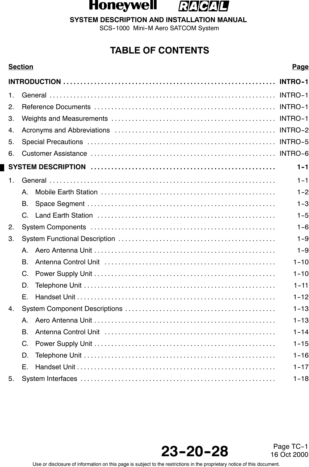

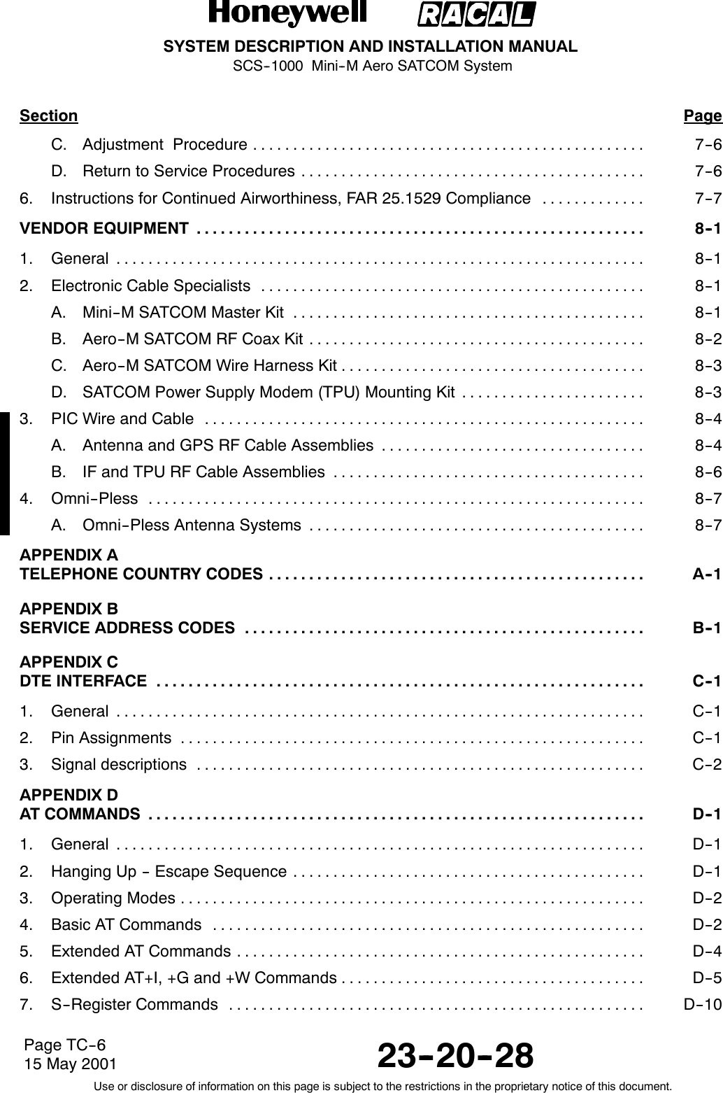

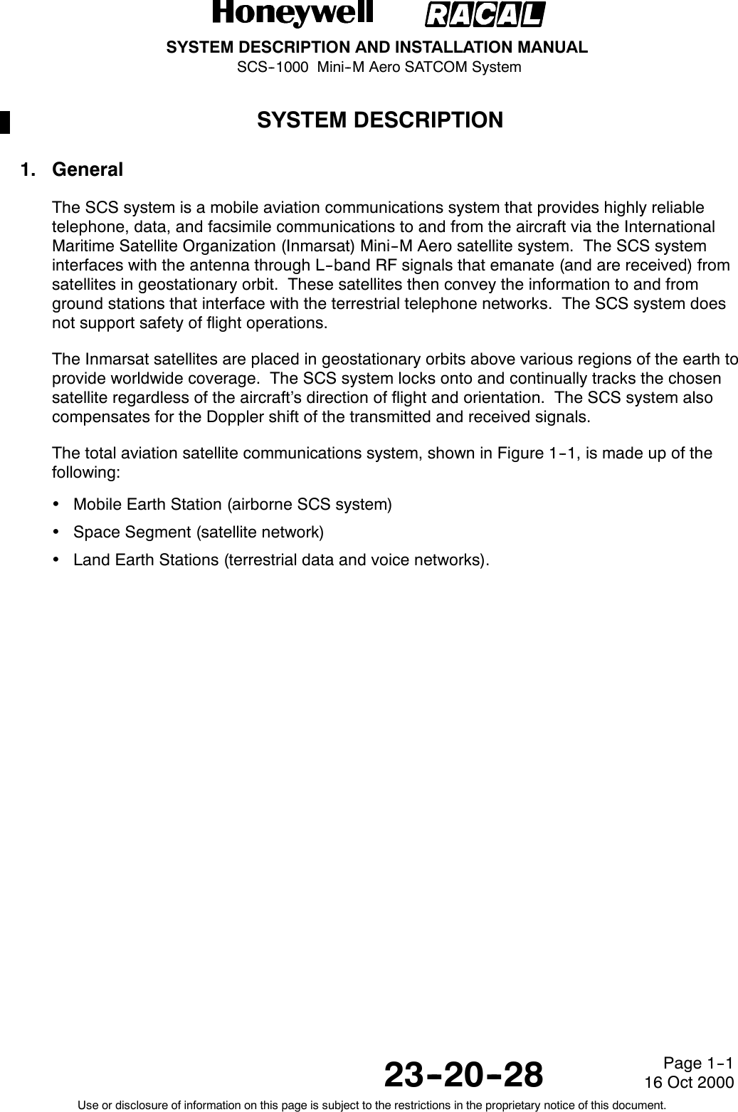

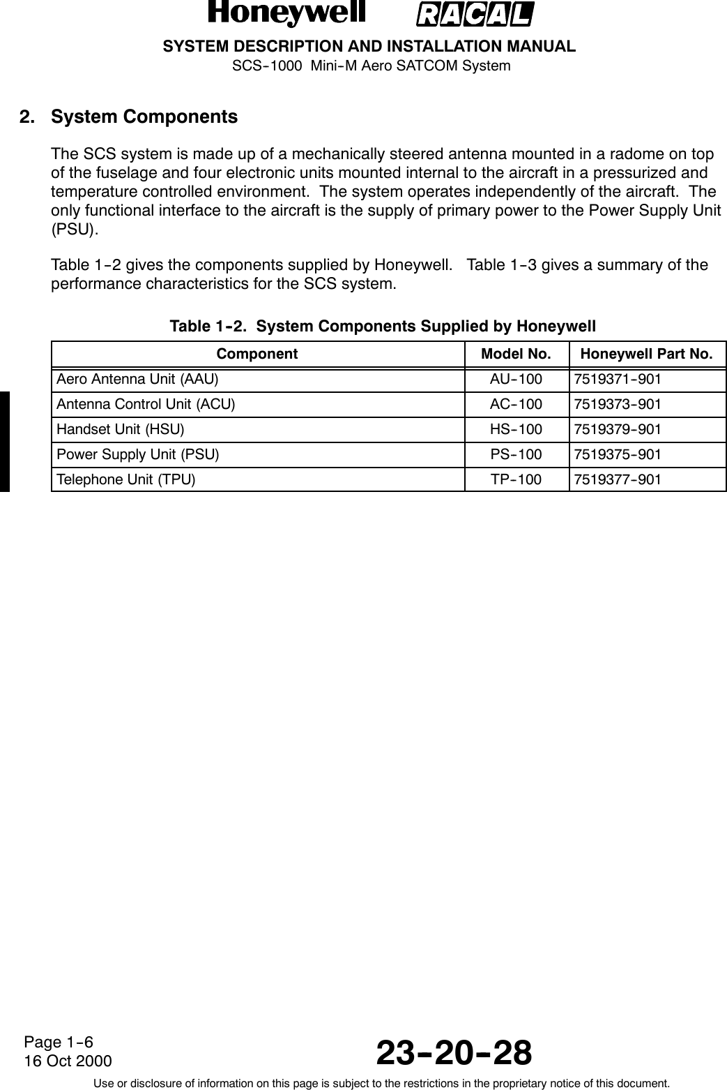
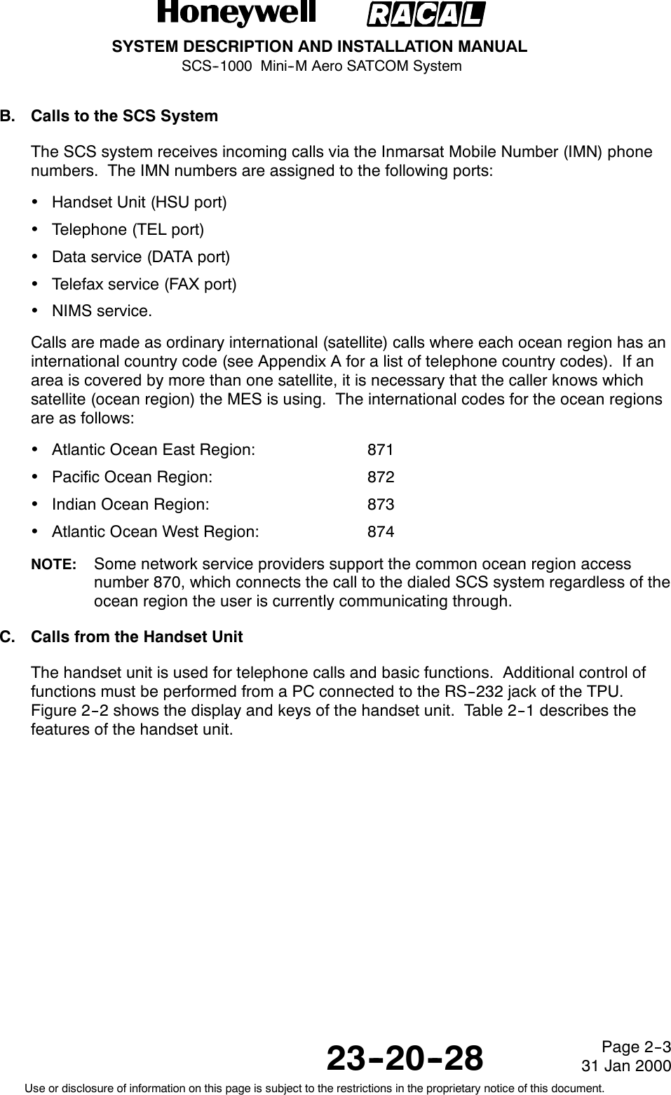
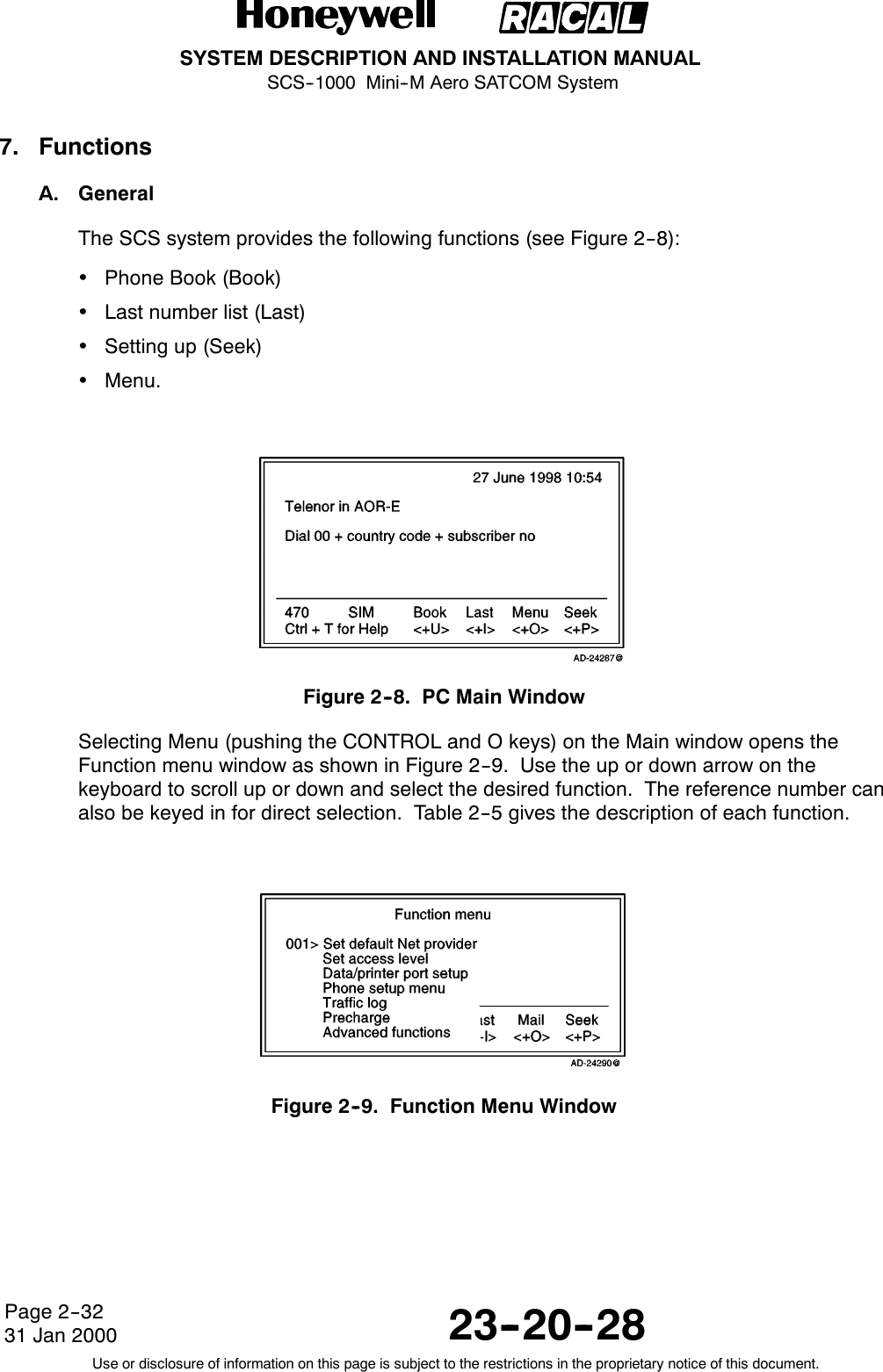
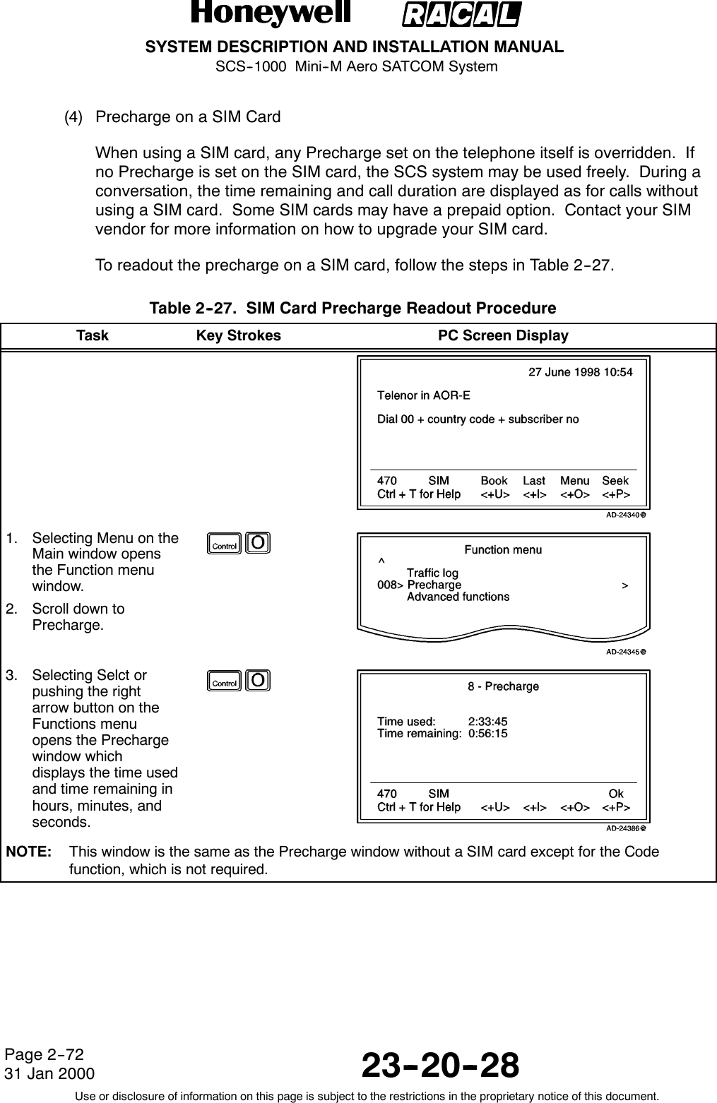
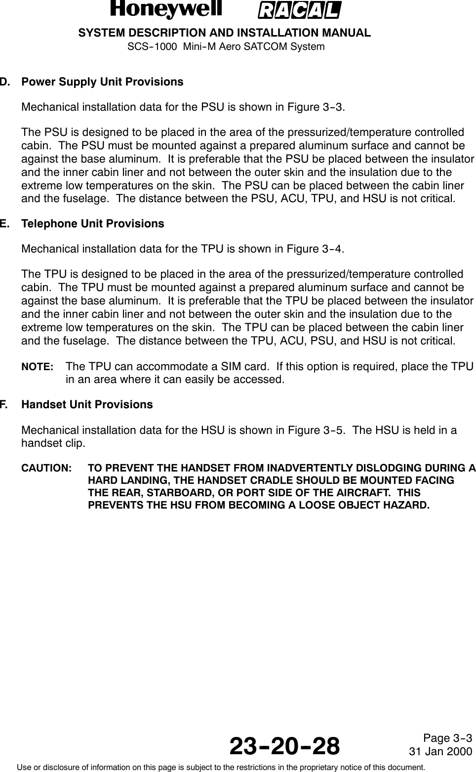
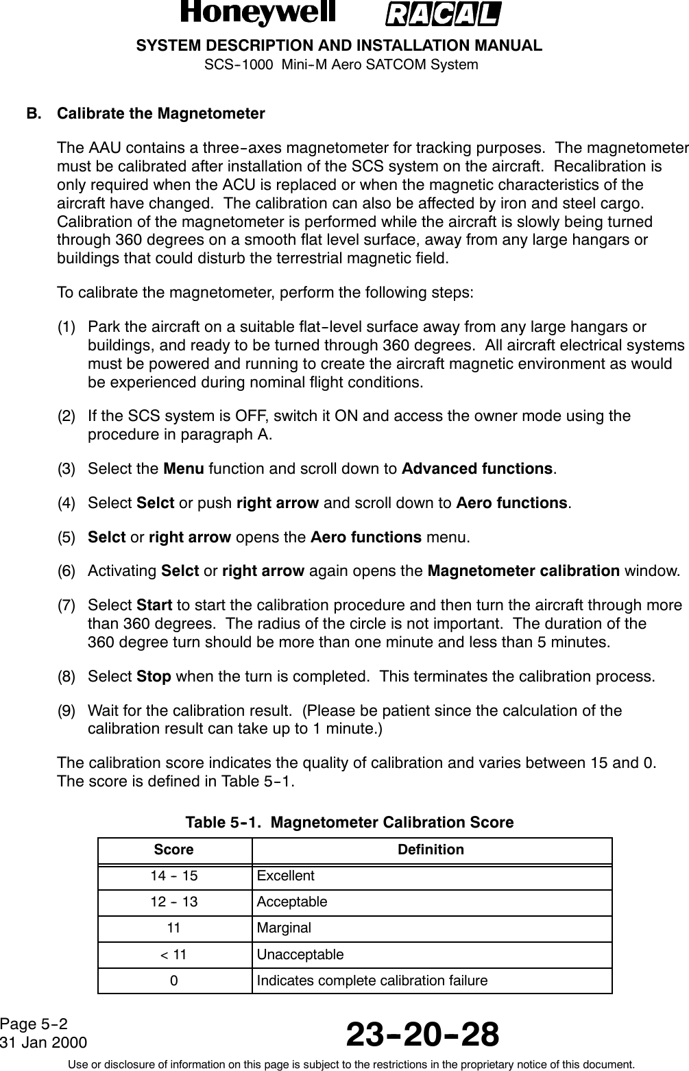
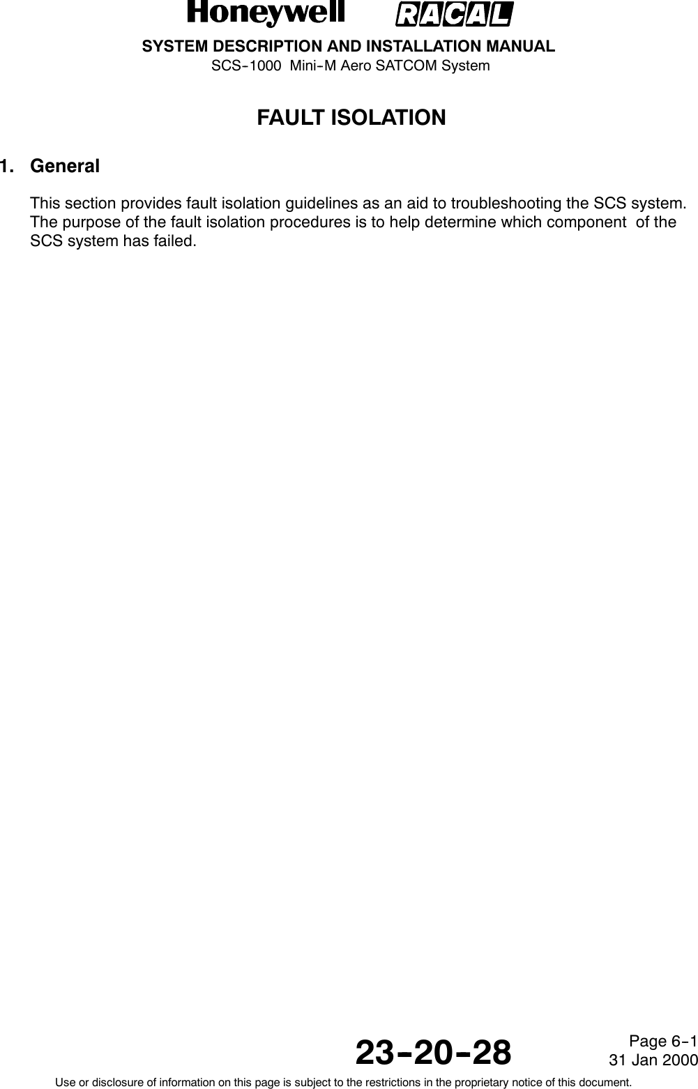
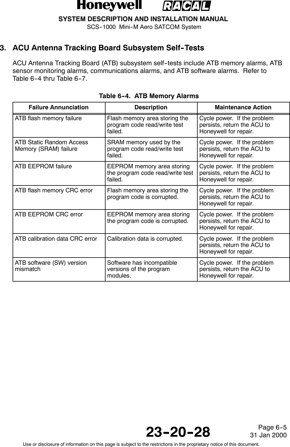
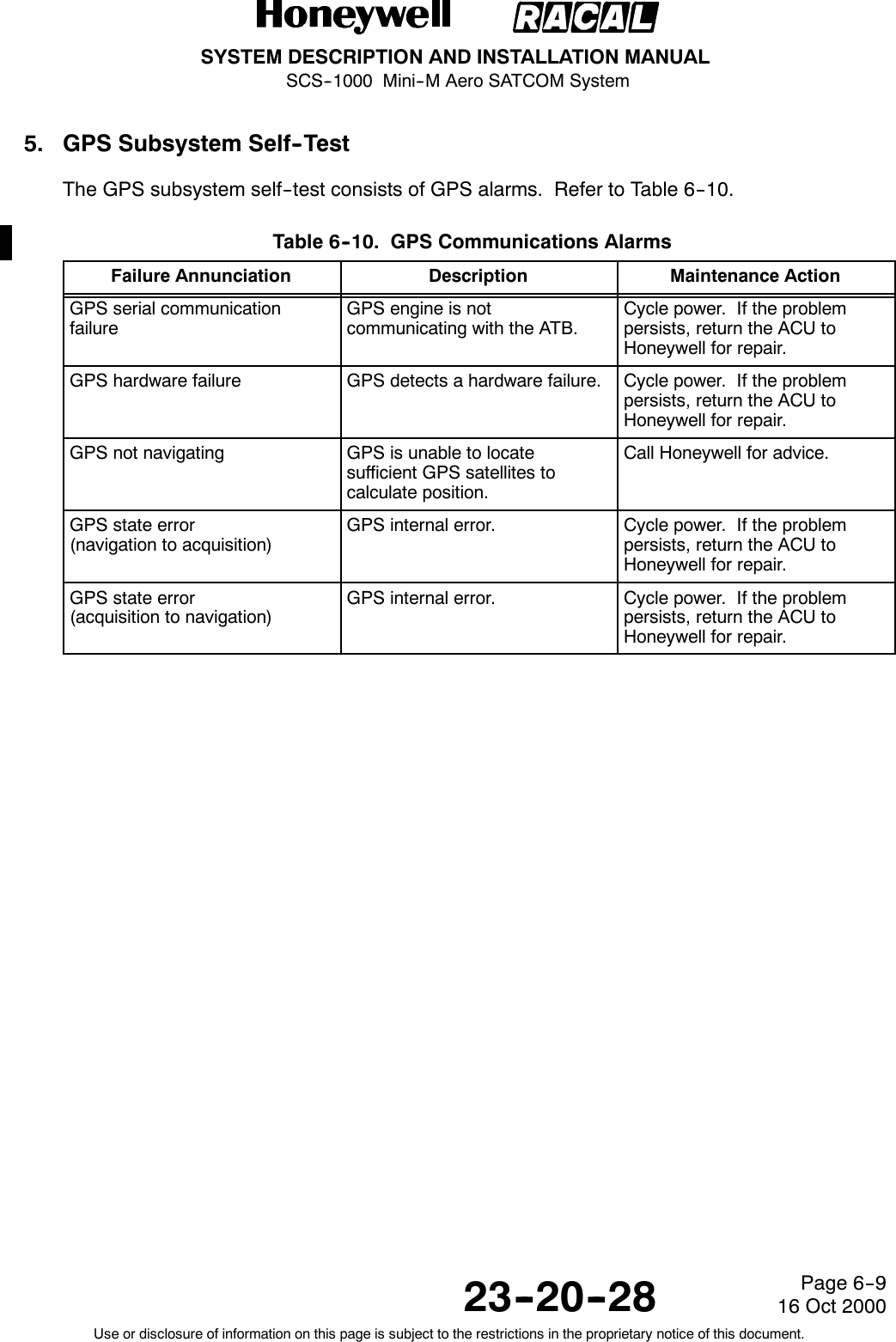
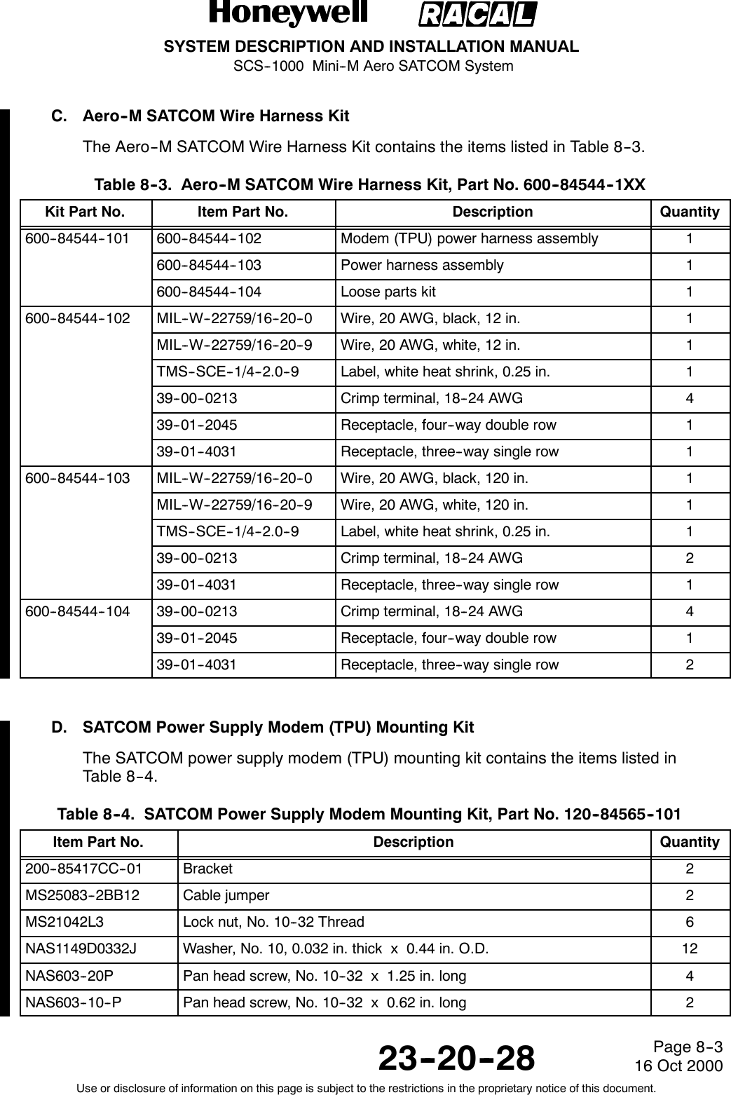
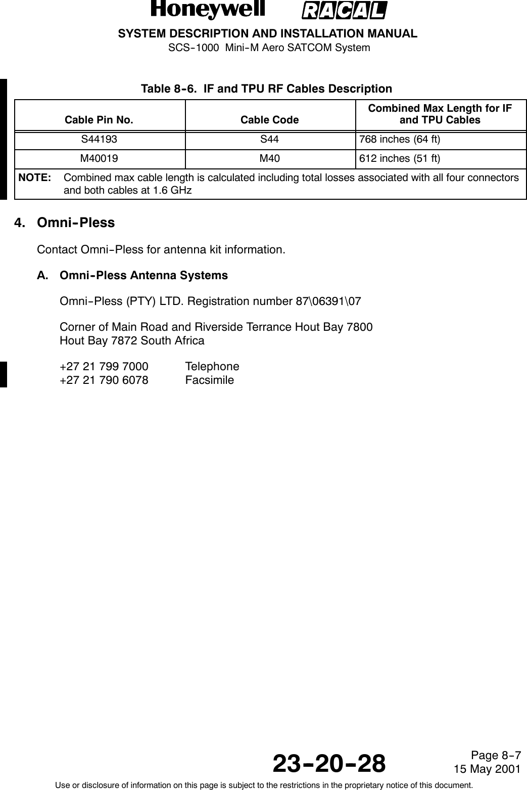
![SYSTEM DESCRIPTION AND INSTALLATION MANUALSCS--1000 Mini--M Aero SATCOM System23--20--28Use or disclosure of information on this page is subject to the restrictions in the proprietary notice of this document.Page 1--816 Oct 2000Table 1--4. DO--160D Environmental CategoriesDescriptionCategory for AeroAntenna Unit (AAU)Category for All OtherUnitsTemperature and Altitude [E1X] [(A1)(A4)X]Temperature Variation A BHumidity C AShock E EVibration [(RCC1)(SLM)] [(RCC1)(SLM)]Explosion Proofness X XWaterproofness S XFluids Susceptibility F XSand and Dust D XFungus Resistance F XSalt Spray S XMagnetic Effect A APower Input B BVoltage Spike B BAudio Frequency Susceptibility B BInduced Signal Susceptibility A ARF Susceptibility [VVX] [VVX]Emission of RF Energy H MLightning Direct Effects [2A] XIcing A XElectrostatic Discharge A A](https://usermanual.wiki/Honeywell/SCS-1000/User-Guide-188961-Page-40.png)


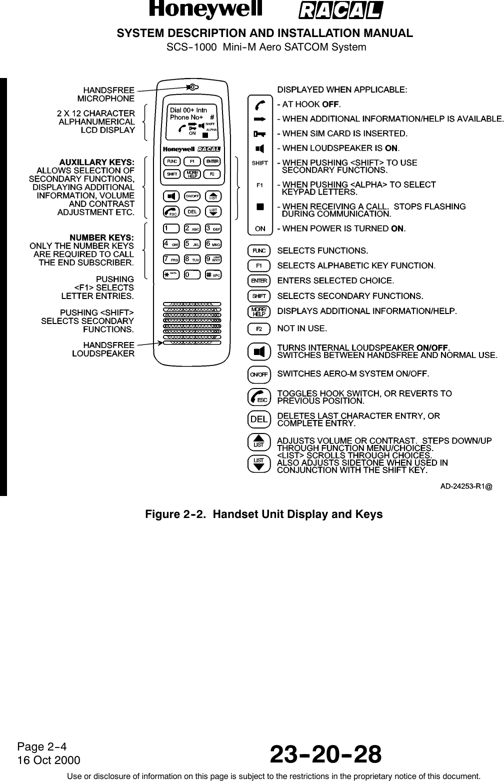

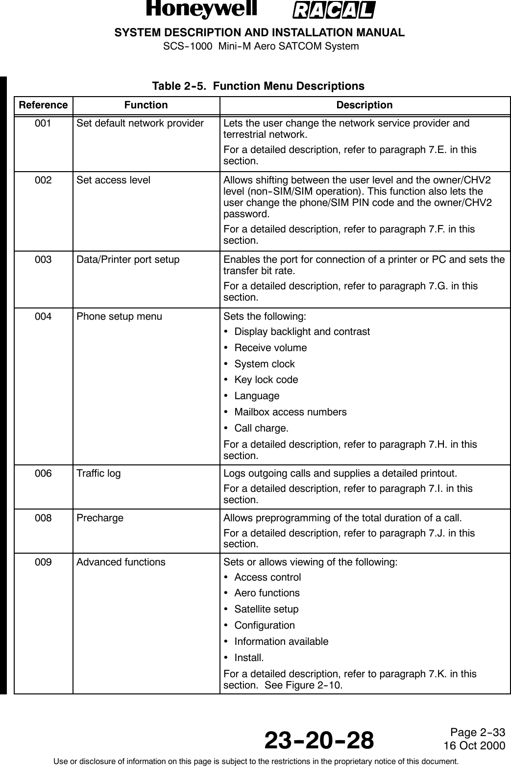
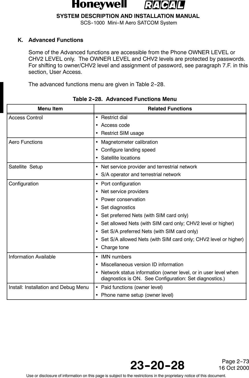

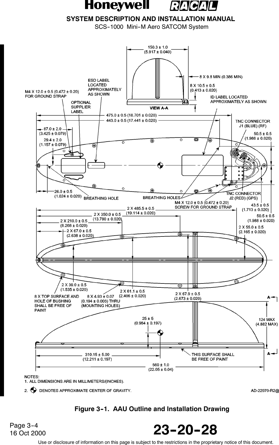
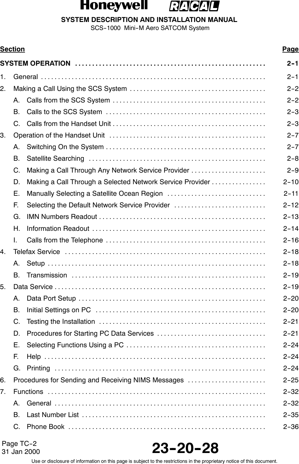
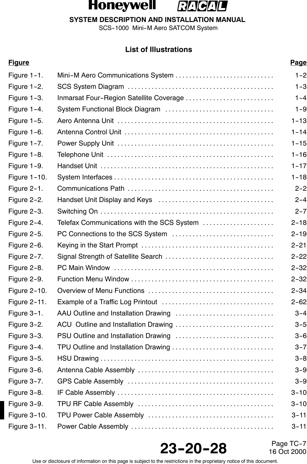
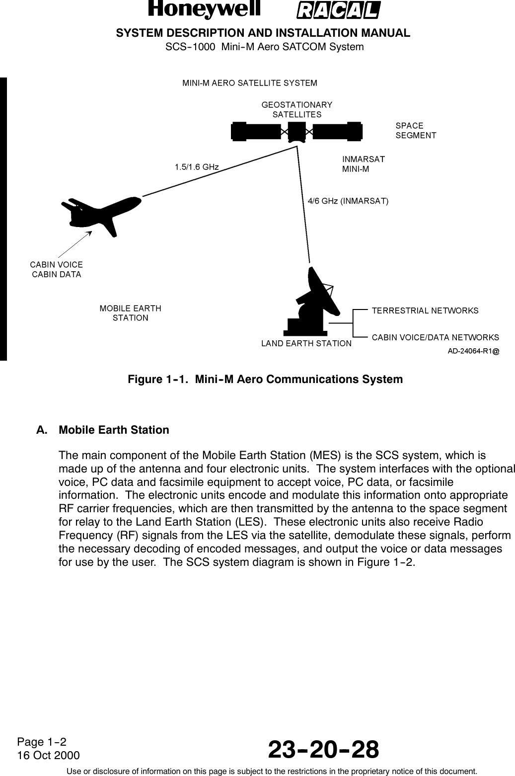
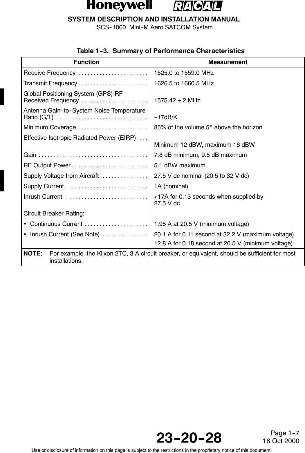
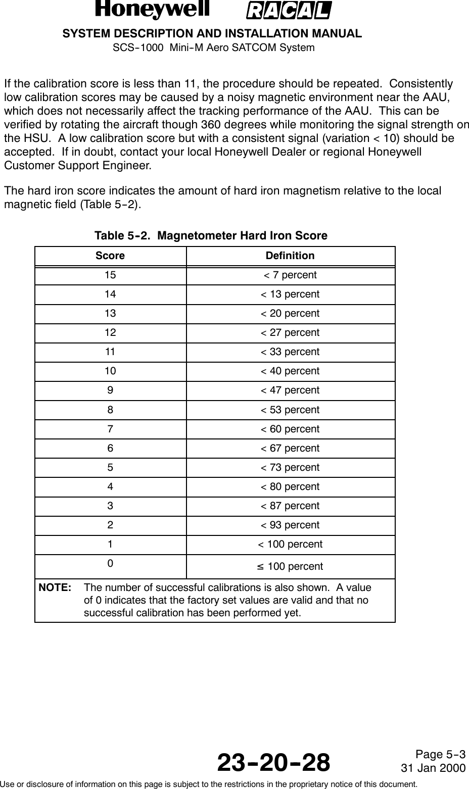
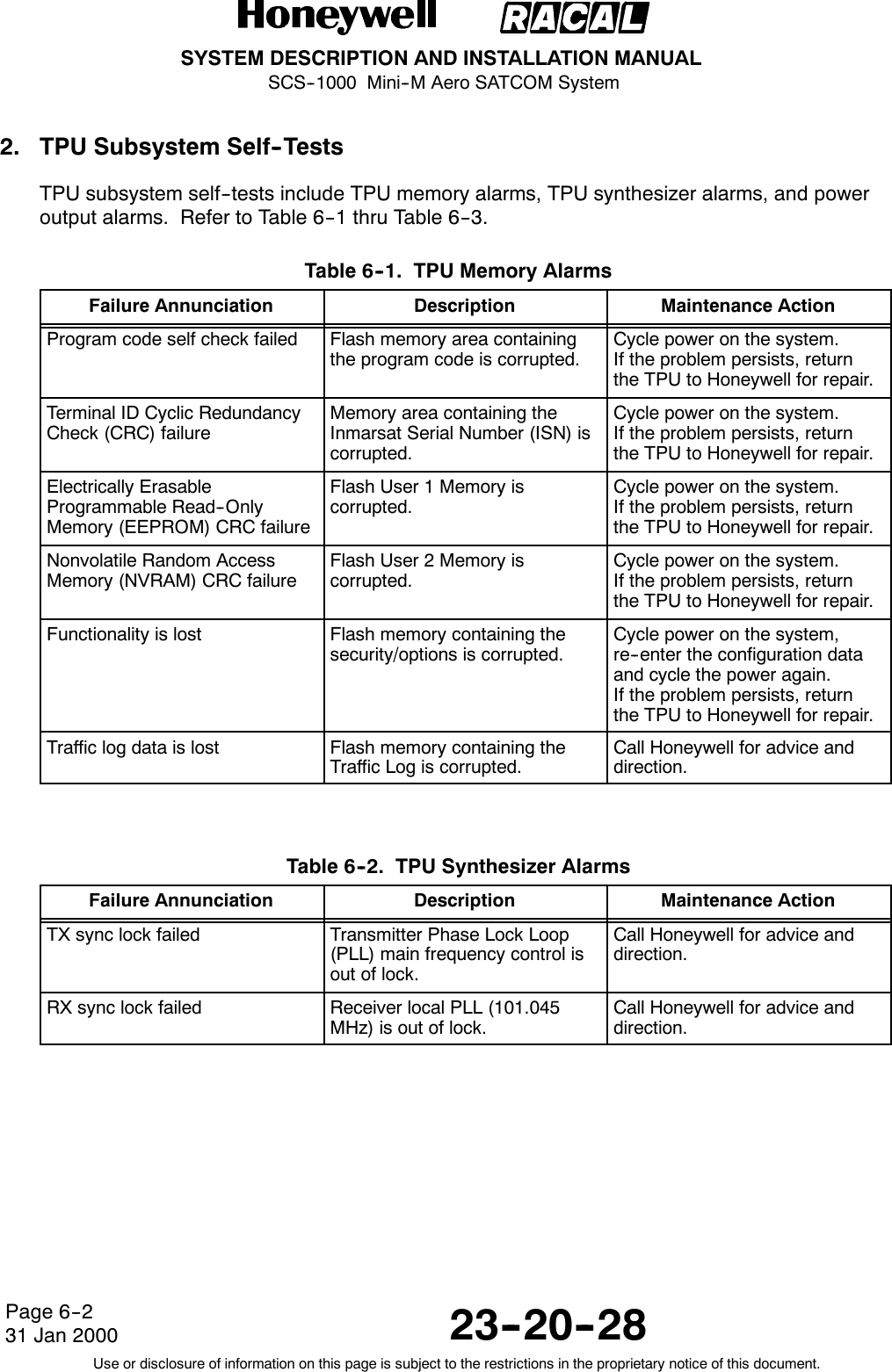
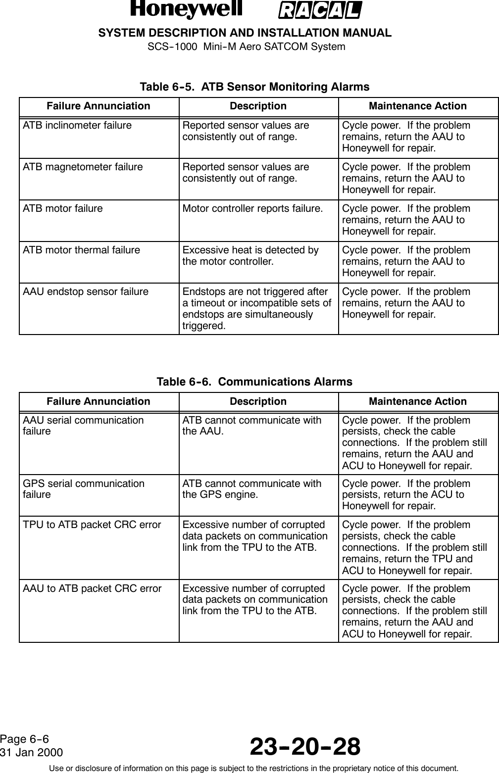
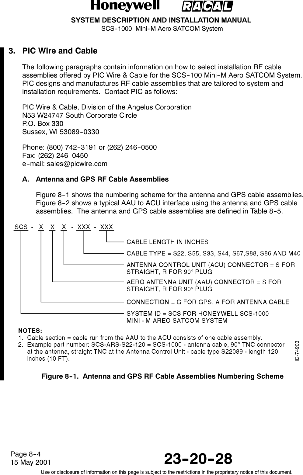
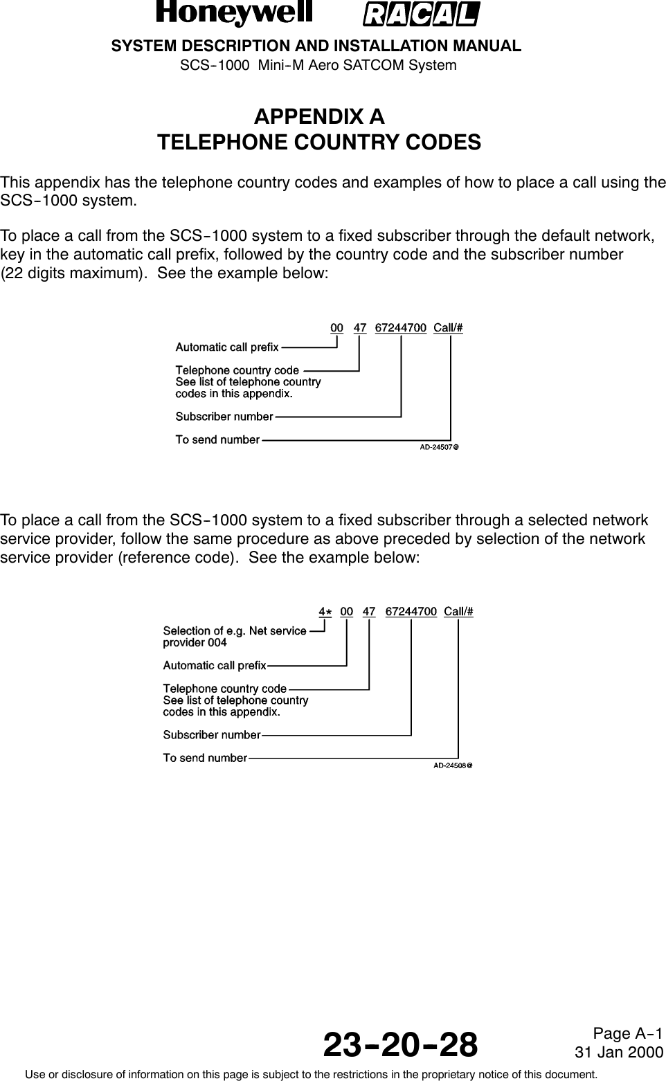
![SYSTEM DESCRIPTION AND INSTALLATION MANUALSCS--1000 Mini--M Aero SATCOM System23--20--28Use or disclosure of information on this page is subject to the restrictions in the proprietary notice of this document.Page 3--1216 Oct 20004. Mechanical Installation InstructionsA. AAU Installation(1) Positioning the AAUBecause the AAU communicates with satellites, the AAU must be positioned on thetop of the fuselage. Try to position the AAU near the middle of the cabin area orslightly to the rear. Many factors influence the performance of the system. Factorsthat influence the final position are as follows:Tail Plane RF BlockageThe tail plane and ventral strake block a small amount of the RF beam. For smallaircraft (less than 12,500 lb [5700 kg]), place the AAU at least 10 ft. (3 m) forwardof the base of the tail plane.Other AntennasTransmissions from the AAU may affect other RF systems. The GPS antenna ismost likely to be affected. Mount the AAU at least 1.65 ft (0.5 m) from the GPSantenna. For GPS antennas with poor filtering or high gain, mount the AAU atleast 5 ft (1.5 m) away. Mount the AAU at least 15 inches (381 mm) from the ADFantenna.Magnetic EnvironmentThe AAU contains magnetometers that can be affected by ferrous materials,magnets, or large currents in cables located nearby. Do not place the AAUdirectly above speakers.Fuselage StructureThe AAU is designed to be positioned above the pressurized area, but otherlocations are acceptable. It can be positioned on either side the the center line ofthe fuselage, but keep the offset to a minimum. Use the template to determine thebest position so that the required holes do not interfere with structure components.Distance from FrontPosition the AAU as far from the front of the cabin as possible to reduce drag,wind noise, lightning strikes, and damage from airborne objects.Engines and APU InletsPosition the AAU out of the engine zone of influence and APU inlets.](https://usermanual.wiki/Honeywell/SCS-1000/User-Guide-188961-Page-172.png)

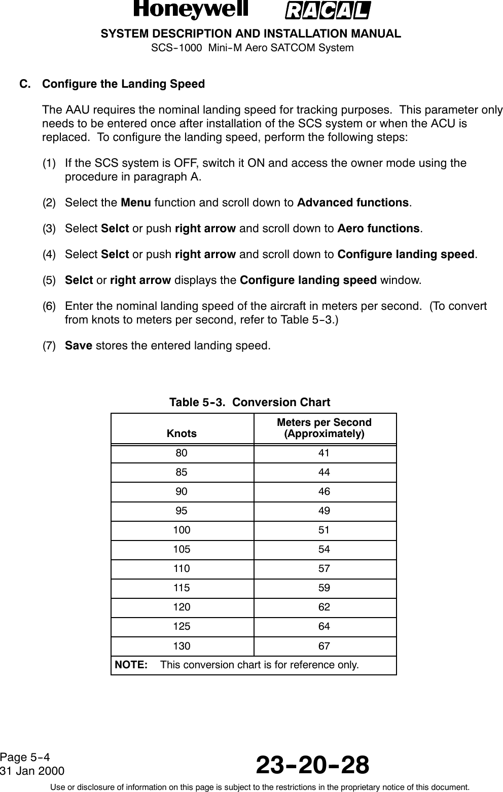

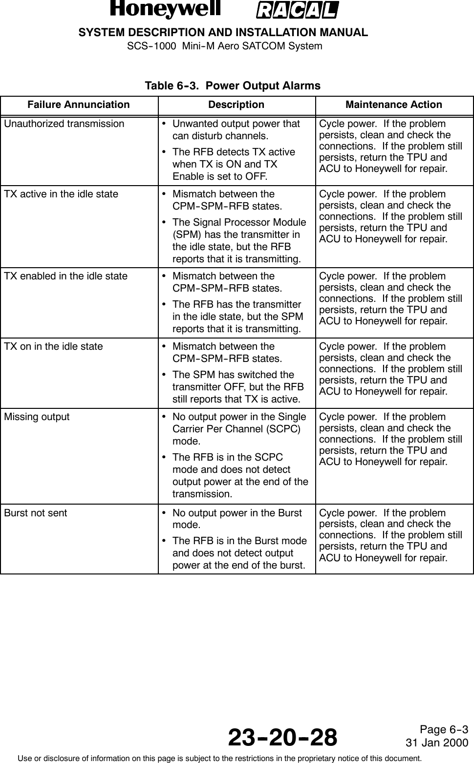
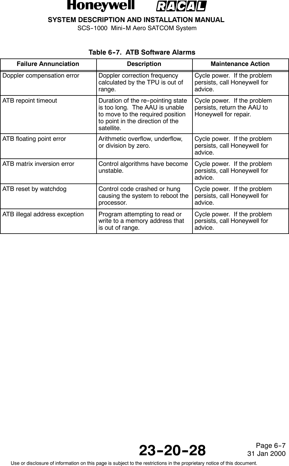

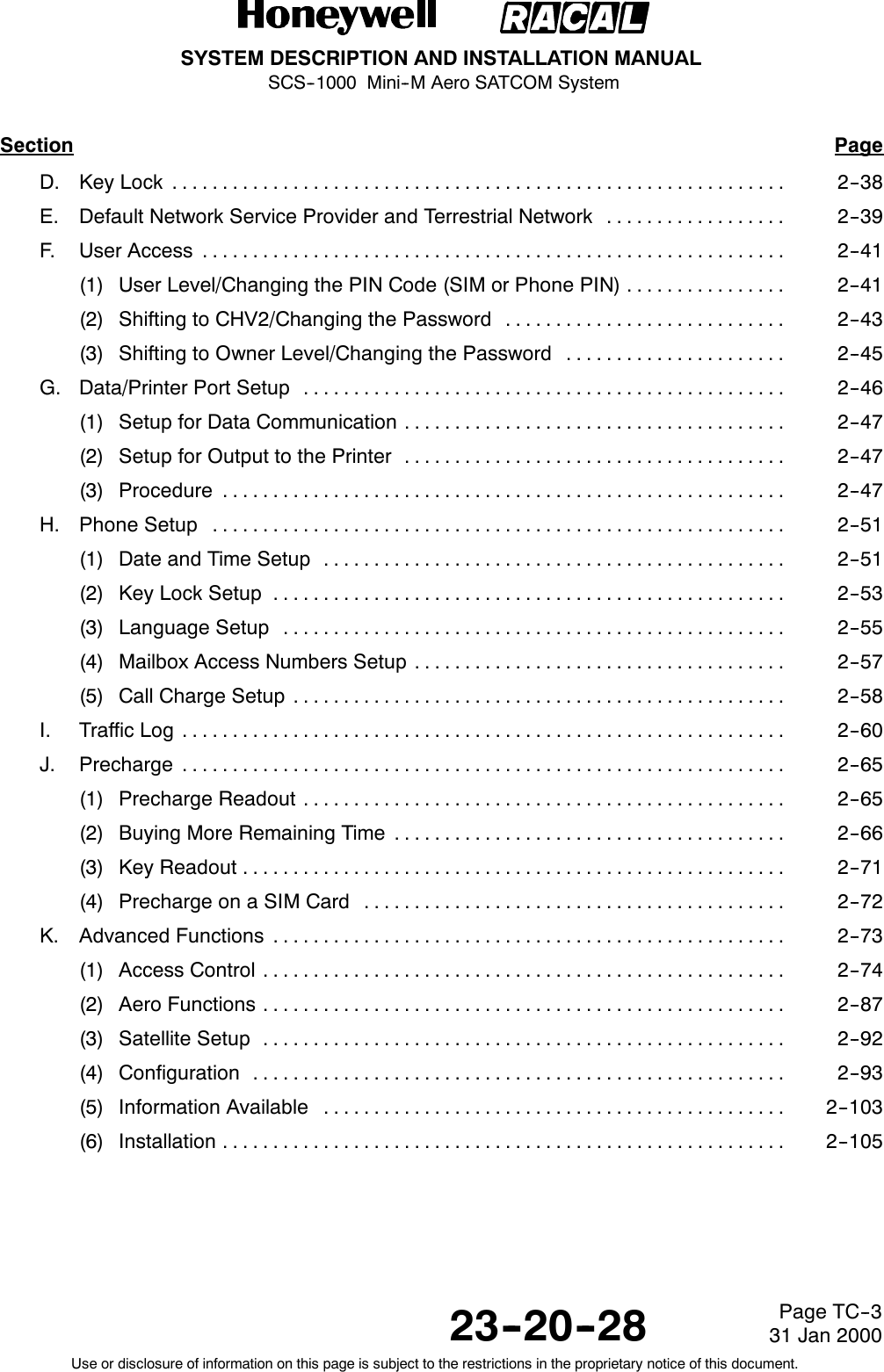
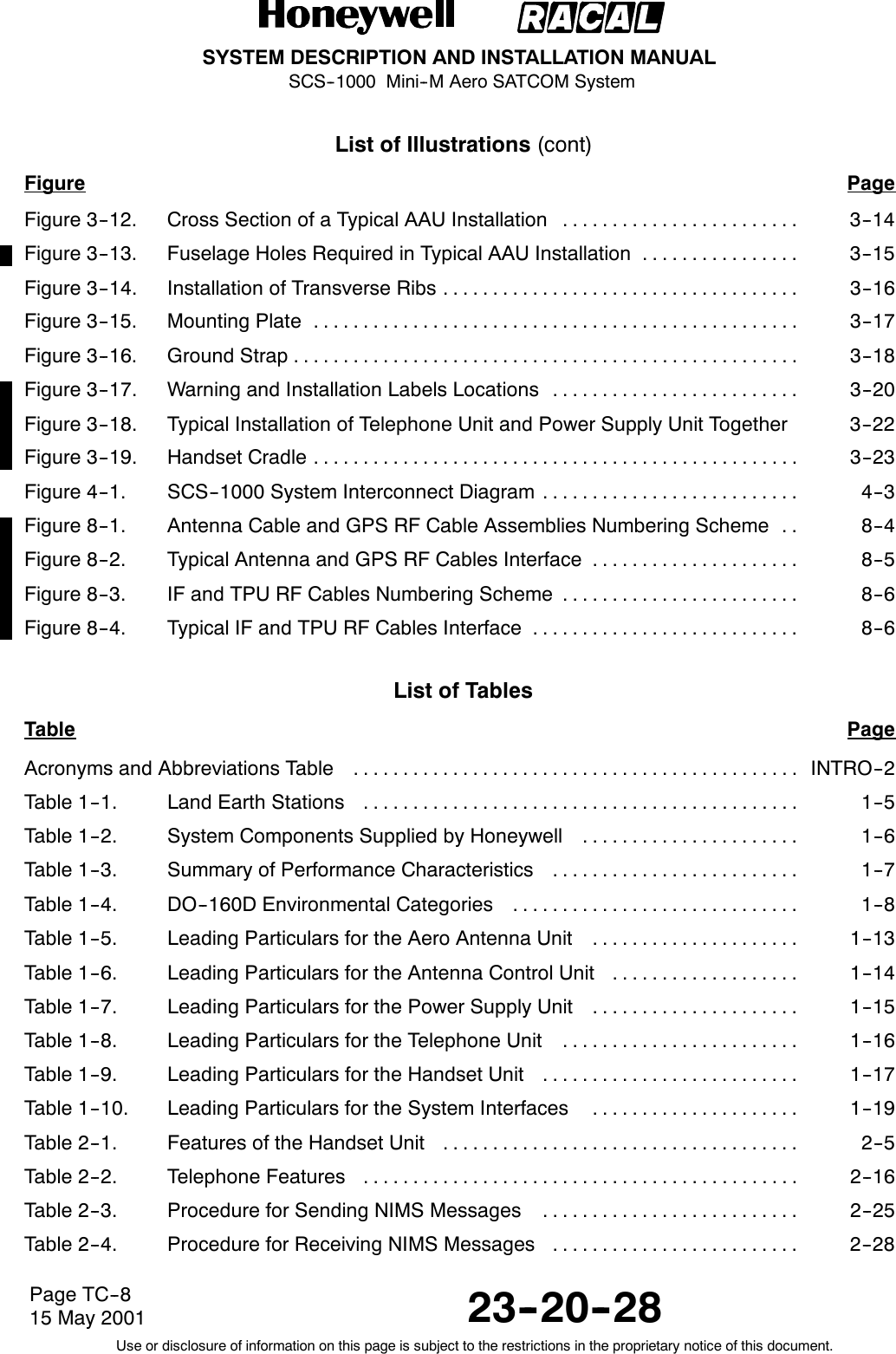
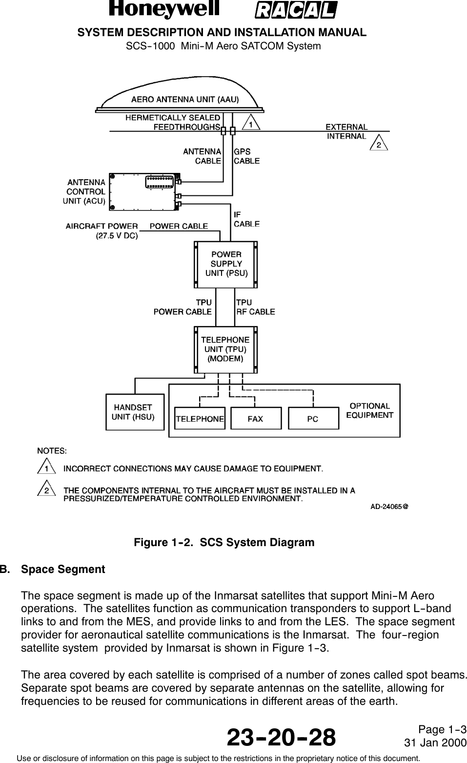
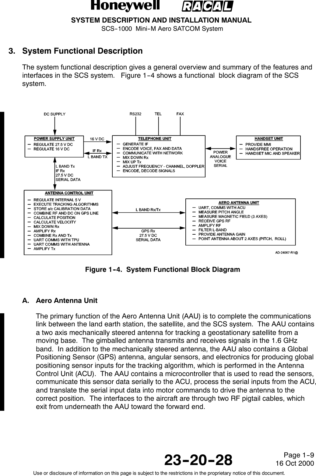
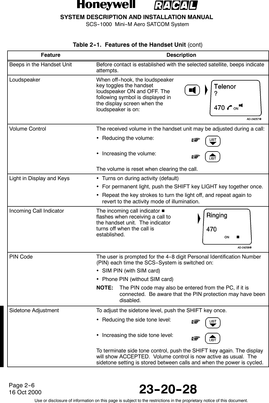
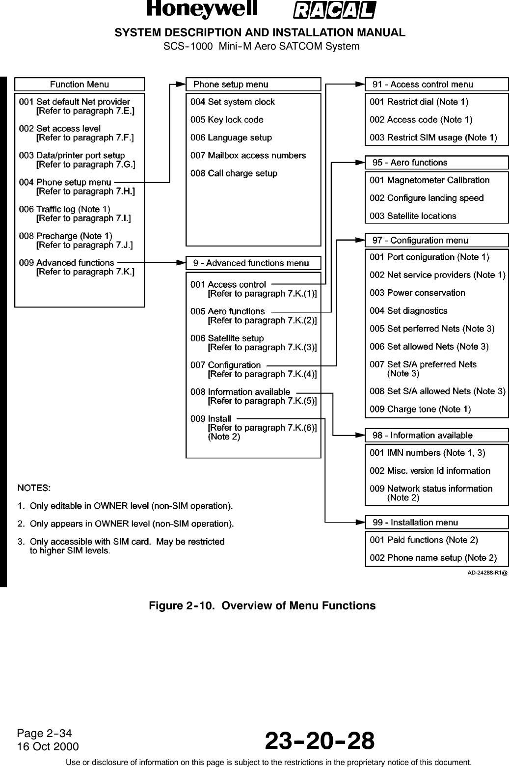
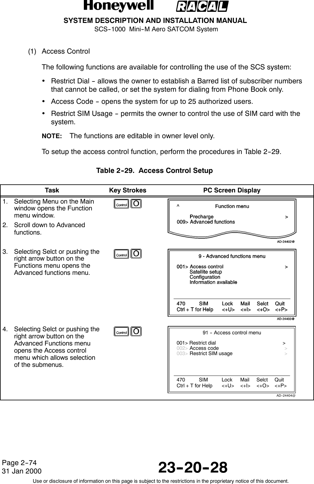
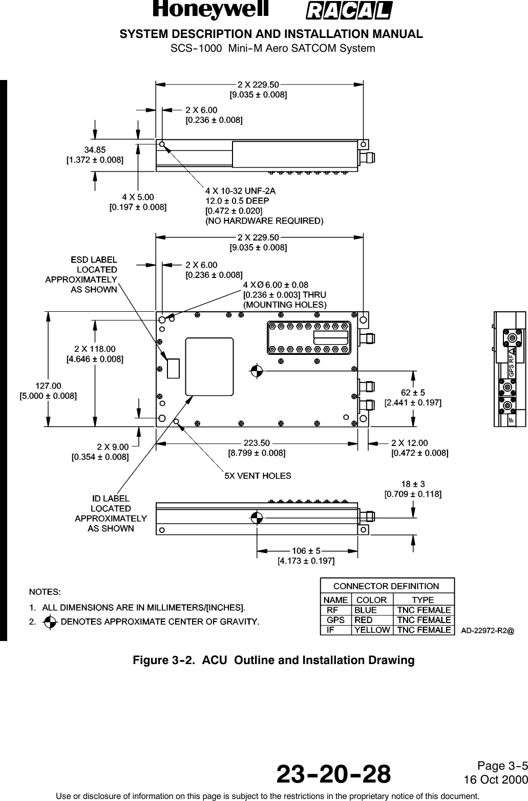
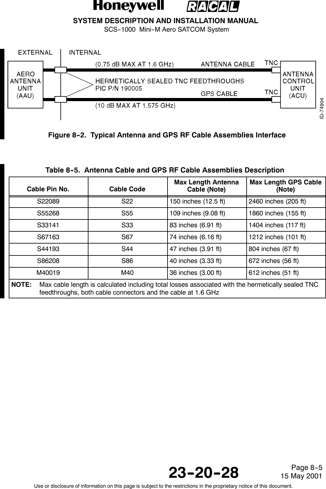
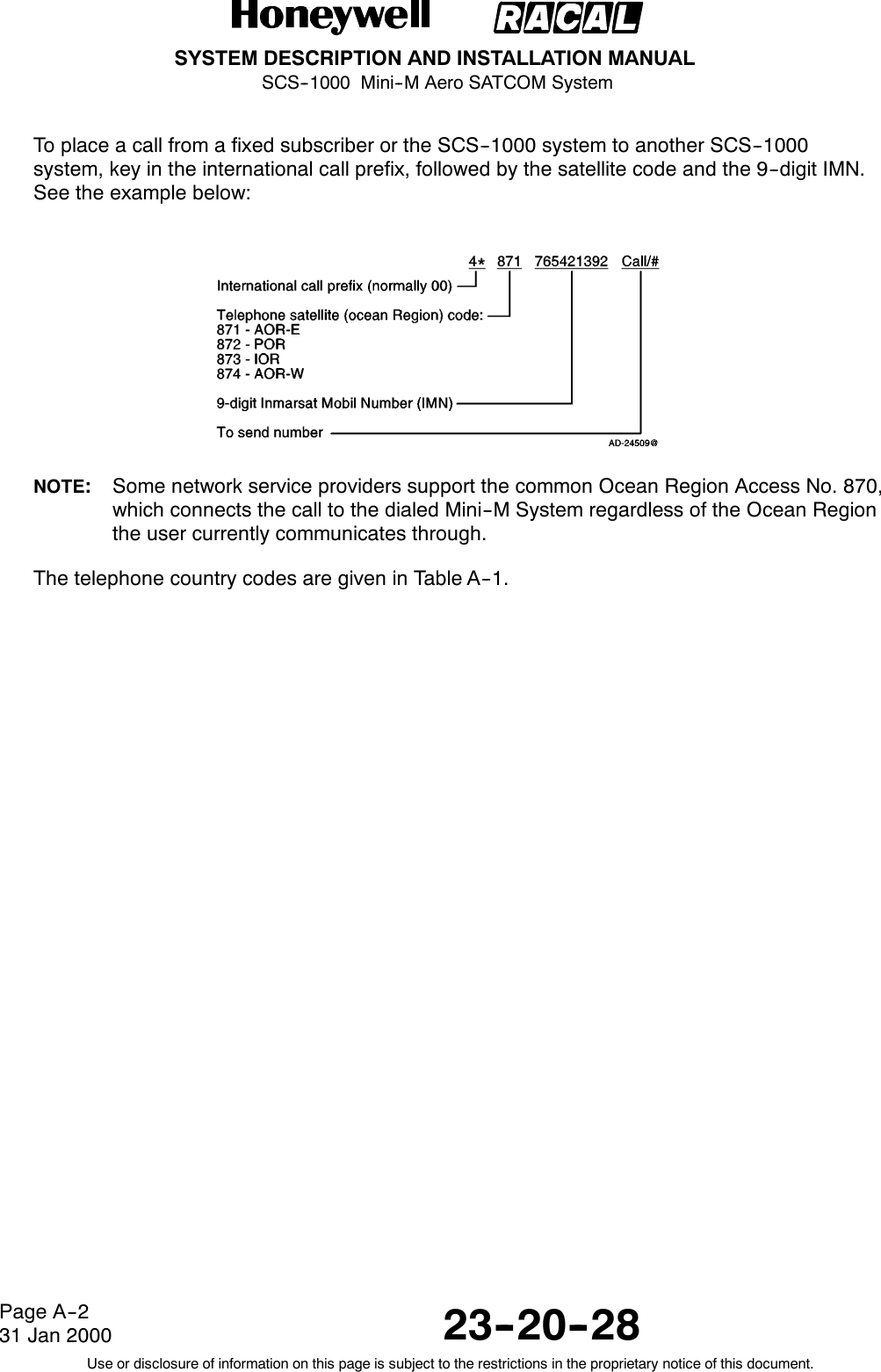
![SYSTEM DESCRIPTION AND INSTALLATION MANUALSCS--1000 Mini--M Aero SATCOM System23--20--28Use or disclosure of information on this page is subject to the restrictions in the proprietary notice of this document.Page 7--316 Oct 2000(e) Connect AAU RF cables to TNC feedthrough connectors. Ensure that they arealigned so that they will fit in the hollow provided in the base plate. Wire theconnectors together with safety wire.(f) Align the AAU with the mounting holes. Secure the AAU with eight mountingscrews. The torque for the mounting screws is 44 lb--inch.CAUTION: DO NOT EXCEED THE TORQUE LIMITS OF THE MOUNTINGSCREWS.(g) Apply a sealant to the mounting screw heads to prevent water seepage.B. Reinstallation Inspection ProcedureInspect and repair in accordance with Table 7-- 1.Table 7-- 1. AAU Reinstallation InspectionInspection Repair ActionMeasure the resistance from the base plate of theAAU to the fuselage. The resistance must beless than 5 milliohms.Remove the AAU. Clean and check all groundingareas. Replace the AAU.Measure resistance from the tab end (not thescrew) of each lightning diverter strip to thefuselage. The resistance must be less than5 milliohms.Remove the screws at the tab ends. Clean off allsigns of corrosion on the top and bottom of thetab and the screw. Care must be taken not tostress the junction between the tab and the stripthat is bonded to the radome. Tighten andrecheck.Check that the AAU is securely fastened to thefuselage.Tighten any loose screws.Check for any cracking of the fuselage over thearea covered by the doubler plate.Repair the cracks in accordance with acceptedprocedures.Check that the lightning diverter strips are secureon the radome.Reattach the diverter strip ends with epoxyadhesive if they are loose (up to 0.47 in. [12mm]).Carefully, lift the loose ends and clean withalcohol. Abrade the painted surface of theradome and underside of the strip with No. 220sandpaper or finer. Apply adhesive to bothsurfaces and press the parts together. Wipeaway any excess adhesive. Tape the strips downuntil the epoxy has cured.If the loose part of the diverter strip is greater than0.47 in. (12 mm), replace the radome or return tothe supplier for repair.Check the radome for cracks. Replace the radome.Check the radome for excessive erosion. Replace the radome.](https://usermanual.wiki/Honeywell/SCS-1000/User-Guide-188961-Page-210.png)


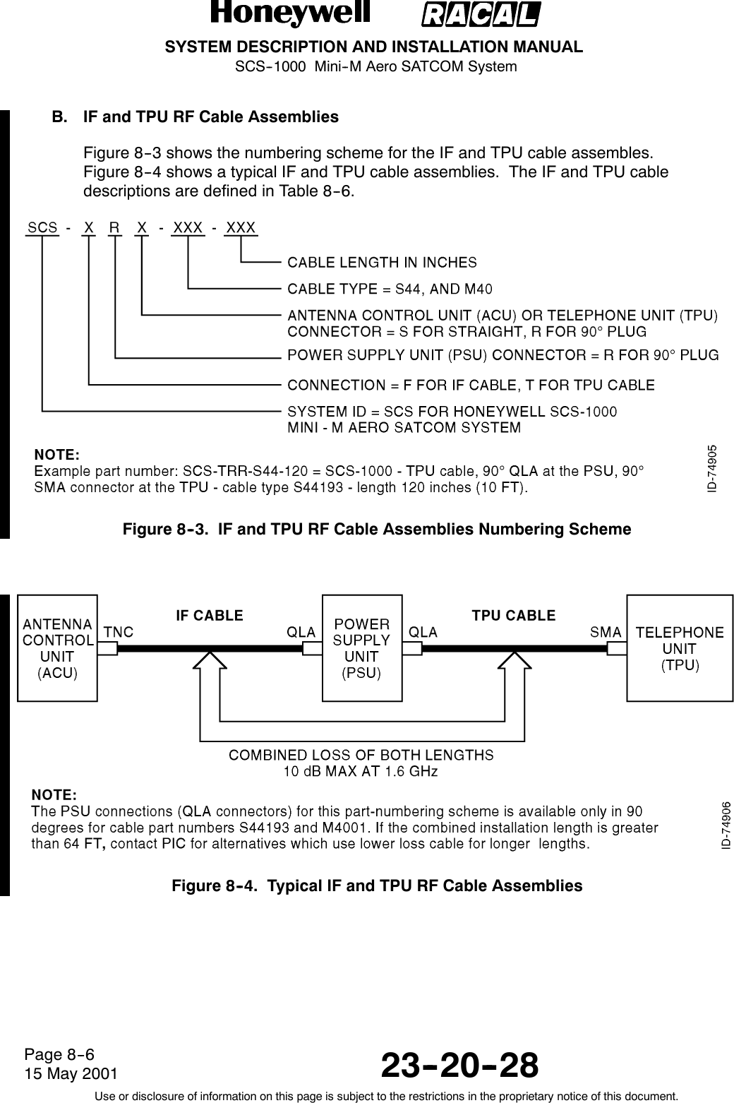

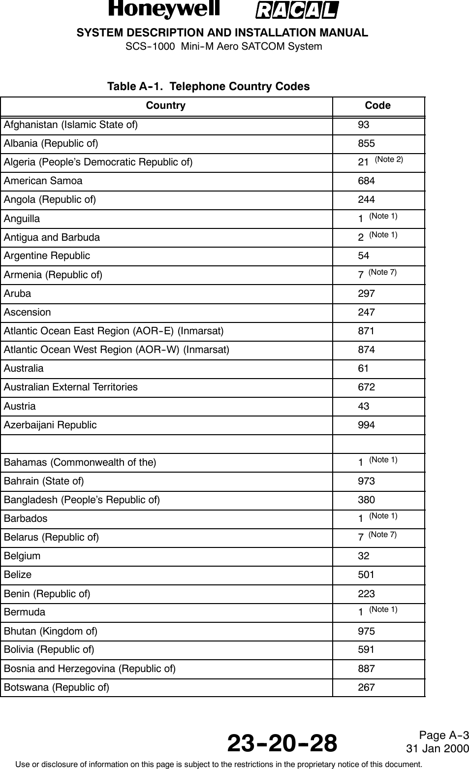


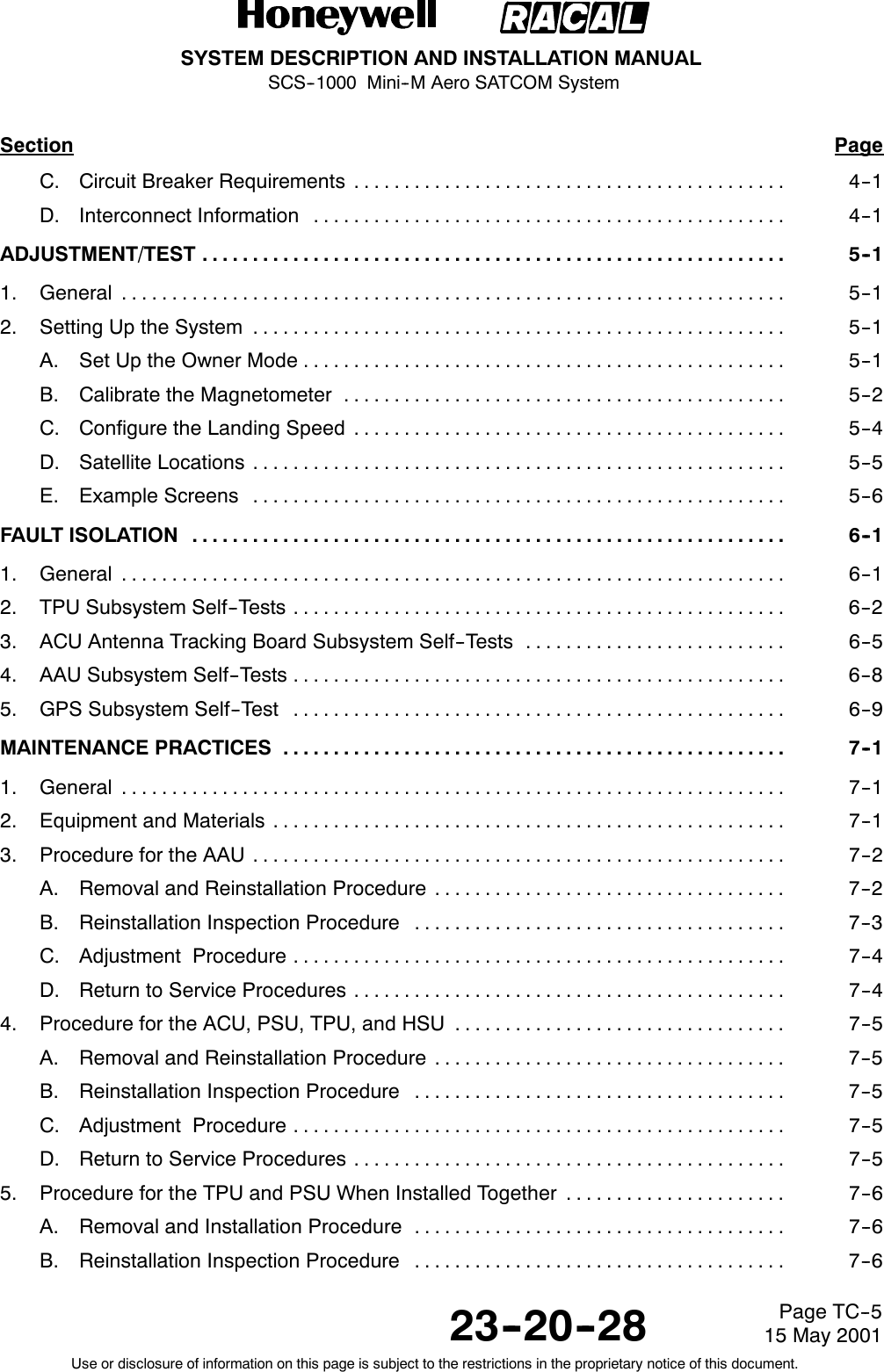
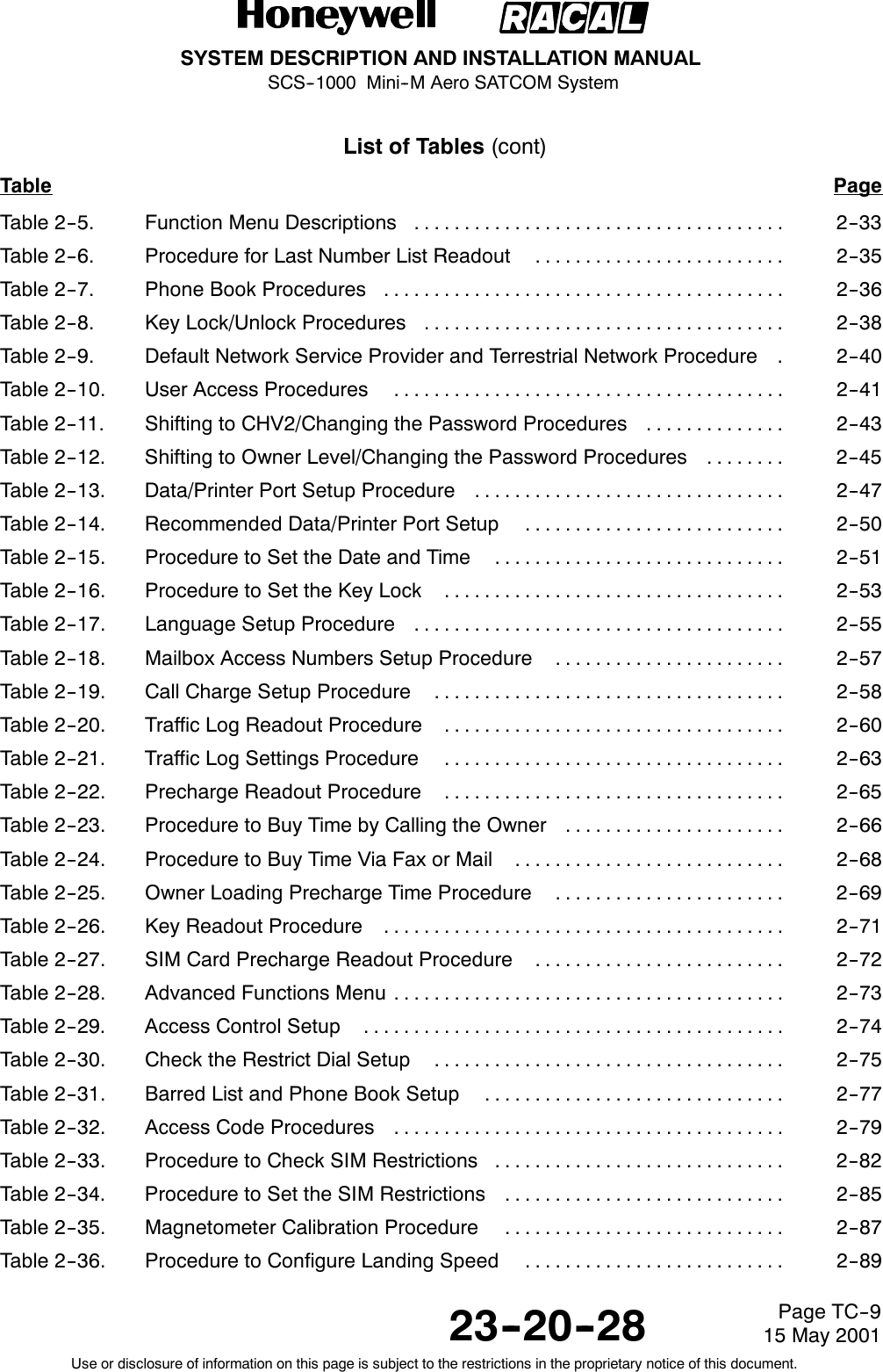
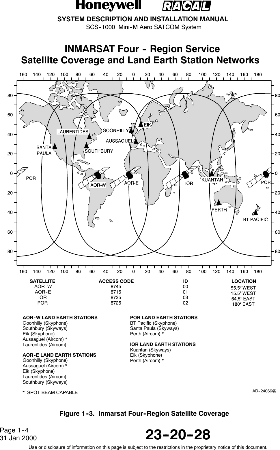
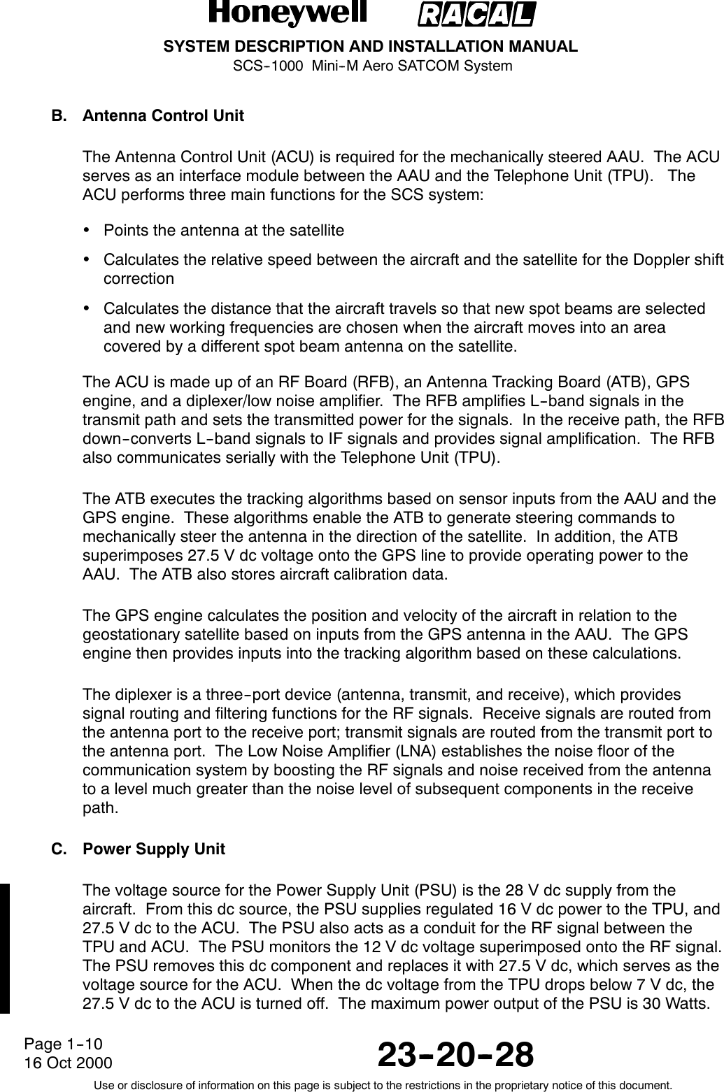
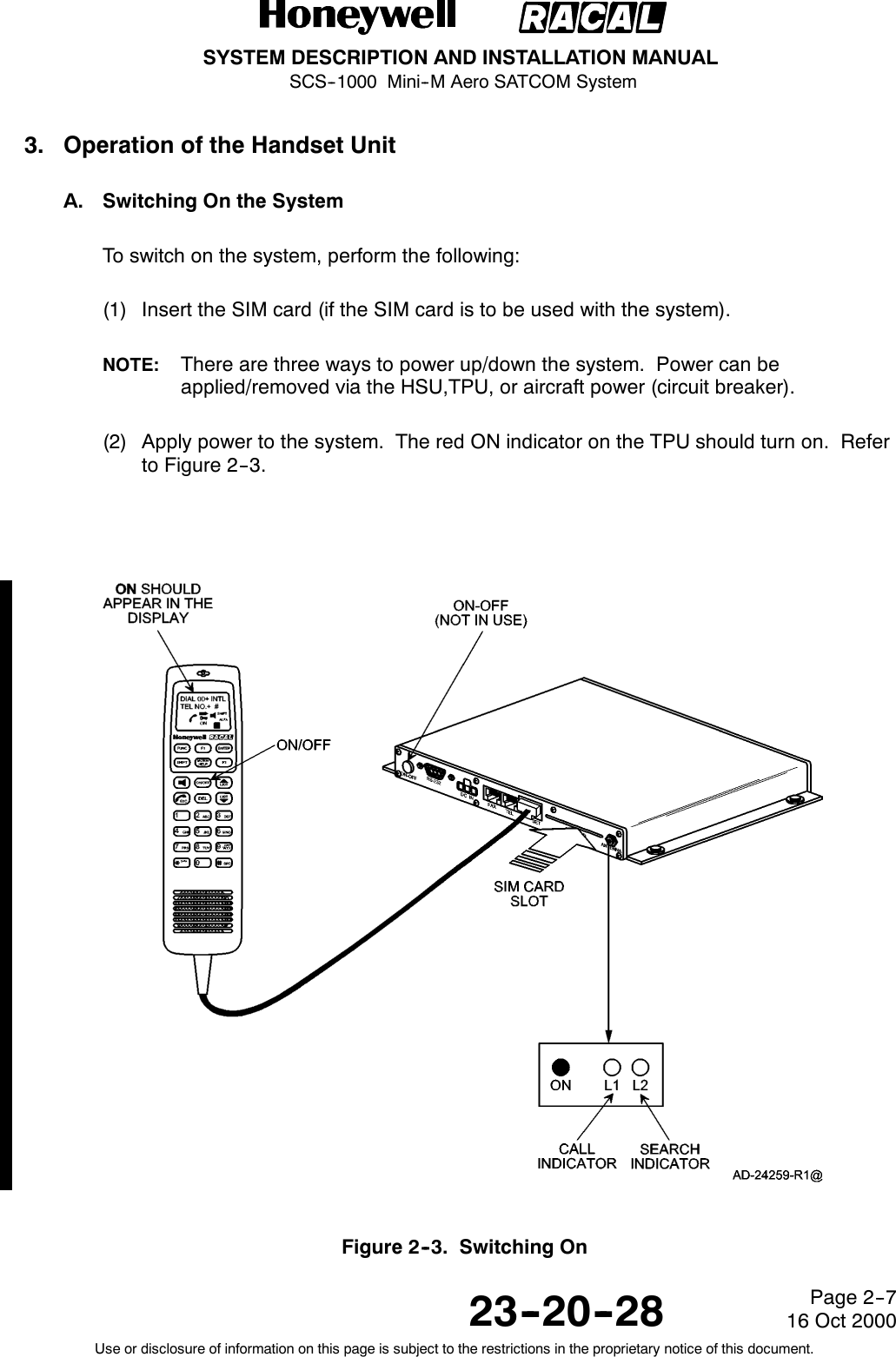
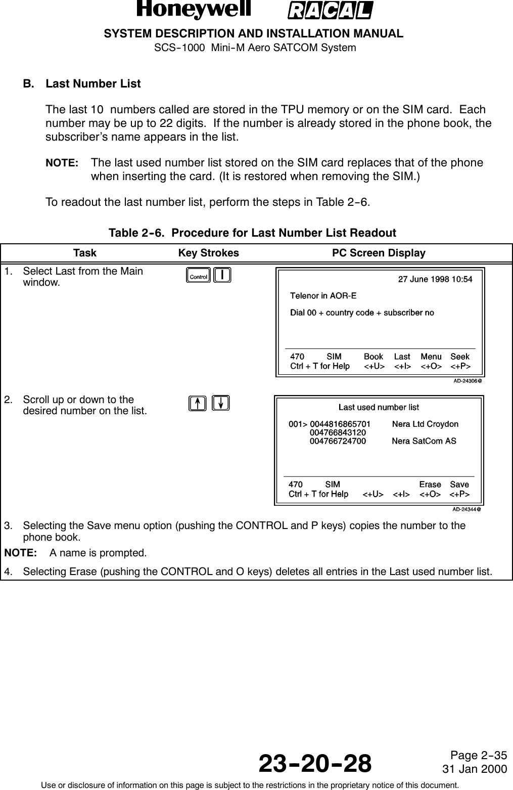
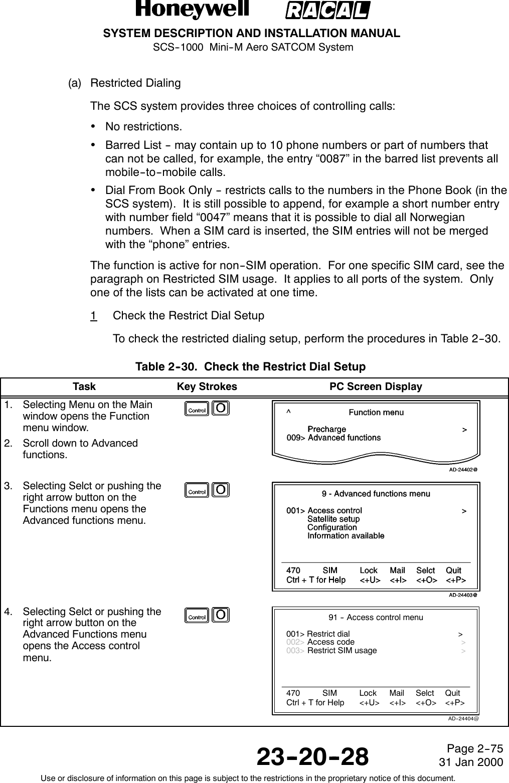
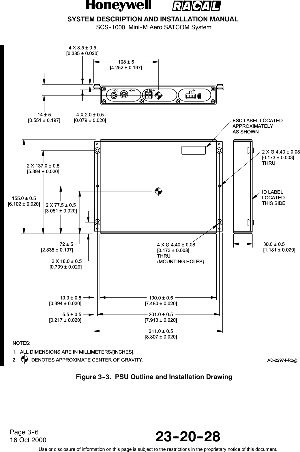
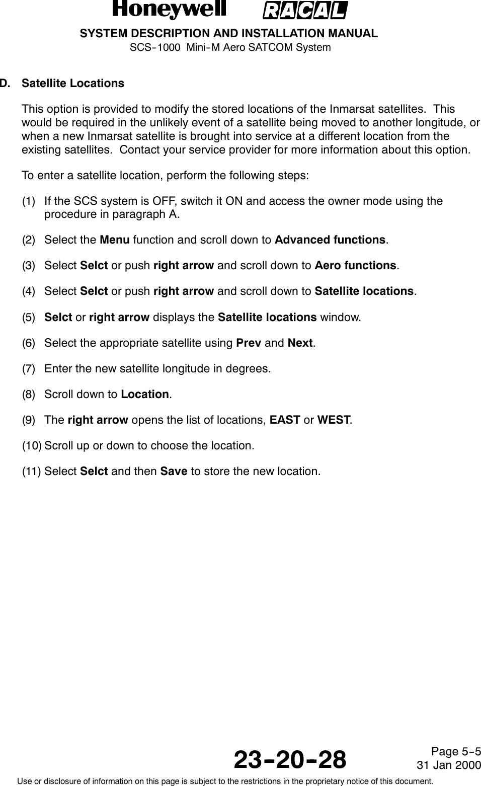
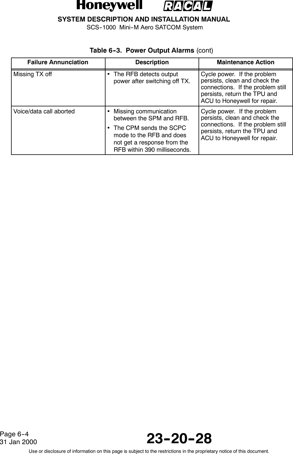
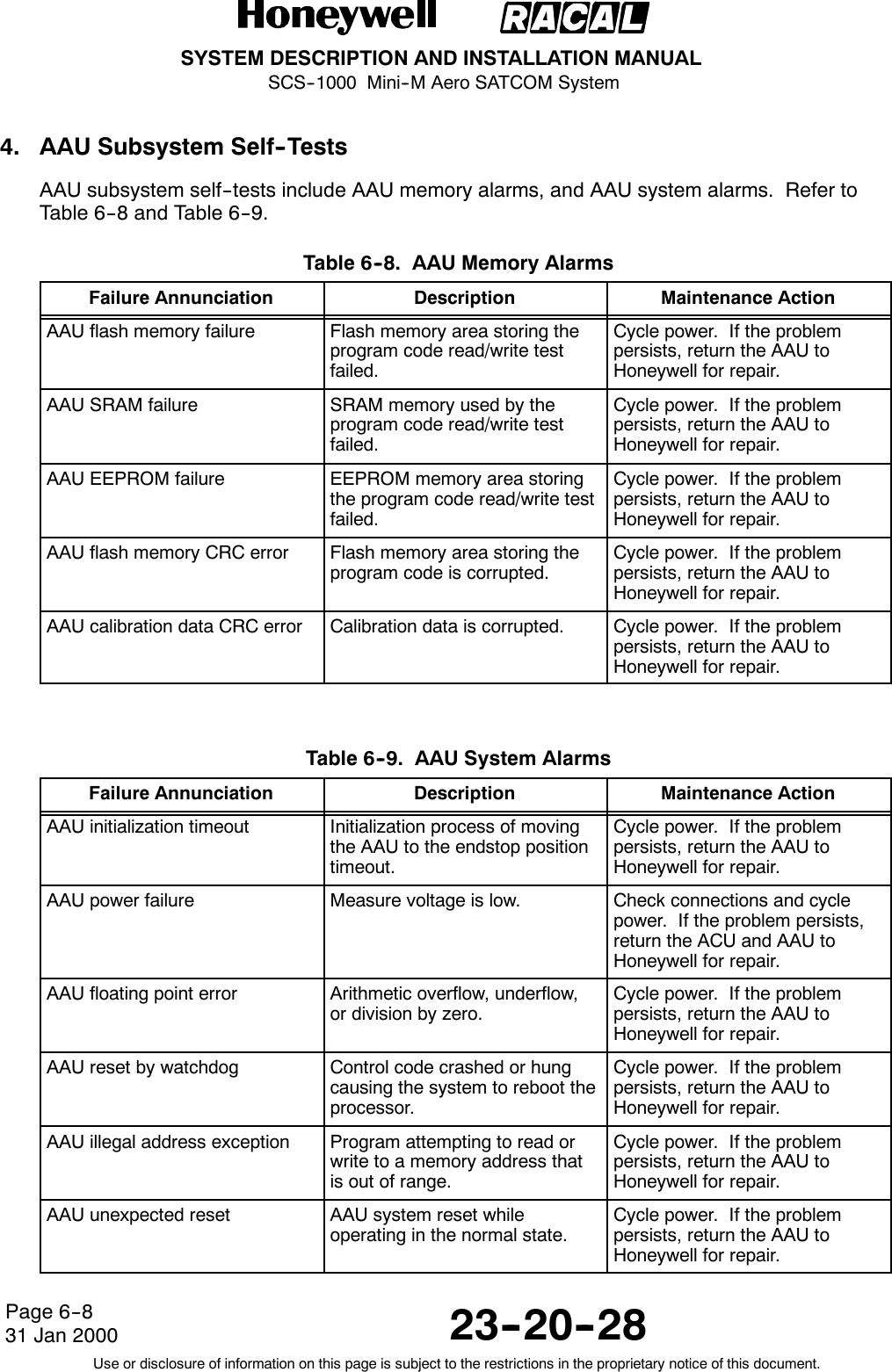
![SYSTEM DESCRIPTION AND INSTALLATION MANUALSCS--1000 Mini--M Aero SATCOM System23--20--28Use or disclosure of information on this page is subject to the restrictions in the proprietary notice of this document.Page D--231 Jan 20003. Operating ModesThe SCS system ASD function may operate in three modes given in Table D--1.Table D--1. ASD Function Modes of OperationMode DescriptionCommand Mode The SCS system ASD responds to AT commands. No remotecommunication occurs.Online Command Mode A data call is taking place and an escape sequence has beeninitiated, after which the SCS system ASD responds to ATcommands during the call.Online Data Mode Once the SCS system ASD is connected, anything arriving fromthe PC is interpreted as data and sent to the remote end and viceversa.4. Basic AT CommandsTable D--2 gives the basic AT commands and their descriptions.NOTE:AT commands may be entered in either upper or lower case (not mixed).Table D--2. Basic AT CommandsCommand (Note 1) DescriptionATA Instructs the SCS system ASD to connect the line and start theanswer sequence of the incoming call. Used when not configuredfor auto answer.ATD004767244700 Instructs the SCS system ASD to dial the number 00 47 67 24 4700 via the default network service provider.ATD4*004767244700 Instructs the SCS system ASD to dial the number 00 47 67 24 4700 via the selected network service provider, for example, Telenor(Norwegian Telecom, code No. 4).ATD2311 Dials the telephone number stored under short number 11.ATE [n] Turns the local echo of the keyboard commands OFF or ON.ATE0 Turns the local echo OFF.ATE1 (Note 2) Turns the local echo ON.ATH Hook control. Sets the SCS system ASD ON--hook when in theOnline Data Mode. Disconnects the line and terminates the call.ATO Returns to the Online Data Mode when in Online Command Modeduring a data call.ATQ [n] Sets responses sent by the SCS system ASD.ATQ0 (Note 2) The SCS system ASD returns responses like OK or ERROR.](https://usermanual.wiki/Honeywell/SCS-1000/User-Guide-188961-Page-241.png)
![SYSTEM DESCRIPTION AND INSTALLATION MANUALSCS--1000 Mini--M Aero SATCOM System23--20--28Use or disclosure of information on this page is subject to the restrictions in the proprietary notice of this document.Page D--331 Jan 2000Table D--2. Basic AT Commands (cont)Command (Note 1) DescriptionATQ1 The SCS system ASD does not return responses.ATS Sets and displays S register values. See the paragraph onS--register commands.ATV [n] Sets the SCS system ASD response format to words or numbers.ATV0 Selects numeric response.ATV1 (Note 2) Selects verbal response.ATX [n] Selects the CONNECT result code format (dial tone detection --busy detection).ATX0 Selects the basic message set: OK, CONNECT, RING, NOCARRIER, and ERROR.ATX1 Selects the basic message set extended with CONNECTxxxx--yyyy.ATX2 Selects the basic message set extended with NO DIALTONE.ATX3 Selects the basic message set extended with BUSY.ATX4 (Note 2) Selects the basic message set extended with all of the above.ATZ Resets the SCS system ASD configuration to the last savedcommand. Also clears the call if used when in the OnlineCommand Mode.A/ Repeats the last command. Re--executes the last AT commandstring issued to the SCS system ASD, including redialing atelephone number.NOTES:1. Push the RETURN (or ENTER) key after typing each command, except the command A/.2. This is the default setting.](https://usermanual.wiki/Honeywell/SCS-1000/User-Guide-188961-Page-242.png)
![SYSTEM DESCRIPTION AND INSTALLATION MANUALSCS--1000 Mini--M Aero SATCOM System23--20--28Use or disclosure of information on this page is subject to the restrictions in the proprietary notice of this document.Page D--431 Jan 20005. Extended AT CommandsTable D--3 gives the extended AT commands and their descriptions.Table D--3. Extended AT CommandsCommand (Note 1) DescriptionAT&C [n] Determines the Data Carrier Detect (DCD) behavior.AT&C0 Sets DCD always ON.AT&C1 (Note 2) Sets DCD, only when connected.AT&D [n] Selects the Data Terminal Ready (DTR) behavior.AT&D0 The SCS system ASD ignores DTR.AT&D1 The SCS system ASD enters the Online Command Mode whenDTR goes inactive.AT&D2 (Note 2) The SCS system ASD clears the call when DTR goes inactive.AT&F Resets the SCS system ASD to the factory default. The factorydefault is not saved like it is with the AT&W command, so ATZrevokes to last saved values.AT&S [n] Selects the Data Set Ready (DSR) behavior.AT&S0 (Note 2) Sets DSR permanently ON.AT&S1 Sets DSR ON when the satellite link is established.AT&V Displays the stored configuration profile.AT&W Saves the active configuration profile. (May be recalled using theATZ command.)NOTES:1. Push the RETURN (or ENTER) key after typing each command.2. This is the default setting.](https://usermanual.wiki/Honeywell/SCS-1000/User-Guide-188961-Page-243.png)
![SYSTEM DESCRIPTION AND INSTALLATION MANUALSCS--1000 Mini--M Aero SATCOM System23--20--28Use or disclosure of information on this page is subject to the restrictions in the proprietary notice of this document.Page D--531 Jan 20006. Extended AT+I, +G and +W CommandsThe extended AT+I, AT+G and AT+W commands are non--standard features, some of whichare designed specially for the Inmarsat Mini--M system. Table D--4 gives the extended AT+I,AT+G and AT+W commands and their descriptions.Table D--4. Extended AT+I, +G, and +W CommandsCommand (Note 1) DescriptionAT+GCAP Displays capabilities supported by SCS system terminals.AT+GMI Displays manufacturer identification.AT+GMM Displays equipment identification.AT+GMR Displays software revision.AT+ICF = [n<format>],[m<parity>]Specifies the local serial port start--stop (asynchronous) characterframing between the PC and the SCS system. The formatreference number nis defined as follows:1=8databits,2stopbits3 = 8 data bits, 1 stop bit (default setting)4=7databits,2stopbits5 = 7 data bits, 1 parity bit, 1 stop bit.The parity reference number mis defined as follows:0 = odd1 = even2 = mark3 = space (default setting).EXAMPLE:AT+ICF=3,3 Specifies a data format of 8 data bits, 1 stop bit,and space parity.AT+ICF ? Displays current settings.AT+ICF =? Displays available settings.](https://usermanual.wiki/Honeywell/SCS-1000/User-Guide-188961-Page-244.png)
![SYSTEM DESCRIPTION AND INSTALLATION MANUALSCS--1000 Mini--M Aero SATCOM System23--20--28Use or disclosure of information on this page is subject to the restrictions in the proprietary notice of this document.Page D--631 Jan 2000Table D--4. Extended AT+I, +G, and +W Commands (cont)Command (Note 1) DescriptionAT + I F C = [ n < W P -- t o -- P C > ][,m<PC--to--WP>];Specifies the local flow control between the PC and the SCSsystem. The system--to--PC reference number nis defined asfollows:0 = no flow control1 = XON/XOFF (software flow control stripped of controlcharacters)2 = RTS (hardware flow control) [default setting]3 = XON/XOFF (software flow control with pass--through ofcontrol characters).The PC--to--system reference number mis defined as follows:0 = no flow control1 = XON/XOFF (software flow control)2 = CTS (hardware flow control) [default setting].AT+IFC ? Displays current settings.AT+IFC =? Displays available settings.AT+IPR = [r(PC--to--WP rate)] Specifies the data rate at which PC -- system interface acceptscommands. Selectable data rates rare defined as follows:1200 bps2400 bps4800 bps9600 bps19200 bps38400 bps.EXAMPLE:AT+IPR=9600 Specifies a data rate of 9600 bps between the PCand the SCS system TPU.AT+IPR ? Displays current settings.AT+IPR =? Displays available settings.AT+W Indicates which PCCA standard the SCS system ASD complieswith.AT+WKSIZE = [n] Sets the maximum ARQ window size for subsequent data callsusing the ARQ mode. The ARQ window determines the size of thebuffer that keeps in memory the data not yet acknowledged by theother end. A valid setting for nis between 1 and 63. The defaultnumber for nis 15.AT+WKSIZE? Displays current settings.AT+WKSIZE=? Displays available settings.](https://usermanual.wiki/Honeywell/SCS-1000/User-Guide-188961-Page-245.png)
![SYSTEM DESCRIPTION AND INSTALLATION MANUALSCS--1000 Mini--M Aero SATCOM System23--20--28Use or disclosure of information on this page is subject to the restrictions in the proprietary notice of this document.Page D--731 Jan 2000Table D--4. Extended AT+I, +G, and +W Commands (cont)Command (Note 1) DescriptionAT+WINMARSAT Lists the Inmarsat specific functions supported by the SCS systemASD.AT+WLES = [n] Selects the Net service provider for the next outgoing call. Theparameter nnn specifies the Net service provider Access Code.Three digits must be keyed in. If omitted, the default Net serviceprovider set from the SCS system is selected. A valid setting for nis between 0 and 255. The default number for nnn is 000.AT+WNERAHSHAKE = [n] Selects the handshake setup. The number nis defined as follows:0 = Routes handshake transitions from the PC directly tothe Net service provider. Minimizes transmissiondelays when handshake is seldom used. This is thedefault setting.1 = Fills the SCS system buffer before handshaking with theNet service provider.AT+WRATE = [<sat_rate>][,<ter_rate>]Sets the wanted satellite data rate, and the terrestrial data rateused for outgoing data calls. The sat_rate is the requested datarate to use over satellite channel, for the SCS system topermanently set to, for example, 2400 bps. The ter_rate is thedata rate to use on the terrestrial modem. Valid rates are asfollows:1200 bps2400 bps4800 bps9600 bps (default setting)14400 bps.EXAMPLE:AT+WRATE=2400,2400 Sets both the satellite rate andthe terrestrial modem rate to2400 bps.AT+WRATE? Displays the selected rates.AT+WRATE =? Displays the available rates.](https://usermanual.wiki/Honeywell/SCS-1000/User-Guide-188961-Page-246.png)
![SYSTEM DESCRIPTION AND INSTALLATION MANUALSCS--1000 Mini--M Aero SATCOM System23--20--28Use or disclosure of information on this page is subject to the restrictions in the proprietary notice of this document.Page D--831 Jan 2000Table D--4. Extended AT+I, +G, and +W Commands (cont)Command (Note 1) DescriptionAT+WRTL = [<low>] [,<high>] Sets the lower and upper threshold level in bytes of the buffer usedin the Net service provider--to--system direction (SCS systemreceive buffer).The low parameter specifies the lower threshold at which point theSCS system ASD should issue an Receiver Ready (RR) packetsignalling that it is ready to receive data from Net service provider.Valid values are between 0 and 511. The default value is 120.The high parameter specifies the upper threshold at which pointthe SCS system ASD should issue an Receiver Not Ready (RNR)packet signalling that it is not ready to receive any more data fromNet service provider. Valid values are between 1 and 512. Thedefault value is 240.NOTE: The high value must be larger than the low value.When the high value is omitted, it becomes thelow value + 120.AT+WRTL? Displays the selected threshold levels.AT+WRTL =? Displays the available threshold levels.AT+WS45 = [n] Sets the requested satellite and terrestrial error correction schemefor data calls. The parameter reference number nis defined inTable D--5.NOTE: The default setting for nis 1.AT+WS45? Displays the current setting.AT+WS45 =? Displays the available setting.AT+WS46? Shows that the Inmarsat Mini--M ASD standard is to be used fordata communication. This is fixed and may not be changed.AT+WTNID = [<nnn>] Sets the terrestrial network for the next outgoing data call. Theparameter nnn specifies the terrestrial network ID. If omitted, it isset to 000, which means that the terrestrial network is unspecified.The range of this parameter is between 0 and 255.AT+WTNID? Displays the selected Terrestrial Network Identification Digit(TNID).AT+WTNID =? Displays the available TNIDs.](https://usermanual.wiki/Honeywell/SCS-1000/User-Guide-188961-Page-247.png)
![SYSTEM DESCRIPTION AND INSTALLATION MANUALSCS--1000 Mini--M Aero SATCOM System23--20--28Use or disclosure of information on this page is subject to the restrictions in the proprietary notice of this document.Page D--931 Jan 2000Table D--4. Extended AT+I, +G, and +W Commands (cont)Command (Note 1) DescriptionAT+WTTL = [<low>] [,<high>] Sets the lower and upper threshold level in bytes of the buffer usedin the WORLDPHONE--to--Net service provider direction (SCSsystem transmit buffer).The low parameter specifies the lower threshold at which point theSCS system ASD should issue an XON, or raise the Clear to Send(CTS) line signaling that it is ready to receive data from the PC.Valid values are between 0 and 511. The default value is 120.The high parameter specifies the upper threshold at which pointthe SCS system ASD should issue an an XOFF, or lower the CTSline signalling that it is not ready to receive data from the PC. Validvalues are between 1 and 512. The default value is 240.NOTE: The high value must be larger than the low value.When the high value is omitted, it becomes thelow value + 120.AT+WTTL? Displays the selected threshold levels.AT+WTTL =? Displays the available threshold levels.AT+WXR = [n] Determines the format of a CONNECT response from the SCSsystem ASD. The format reference number nis defined asfollows:0 = CONNECT <(See Note 3)>+WXSR:<satellite rate>,<ARQ I NARQ>+WXTR:<terrestrial rate>,<ARQ I NARQ>+WXKR:<ARQ window size>CONNECT <PC--WP rate>2 = CONNECT <(See Note 3)>,<ARQ I NARQ> [defaultsetting]3 = XON/XOFF (software flow control with pass--through ofcontrol characters).AT+WXR? Displays the selected format.AT+WXR =? Displays the available formats.NOTES:1. Push the RETURN (or ENTER) key after typing each command.2. This is the default setting.3. This value is the lowest value of the PC--WP rate, satellite rate and terrestrial rate.Table D--5. Parameter Reference Number n for AT+WS45 CommandnSatellite ErrorCorrectionTerrestrial ErrorCorrection End--To--End0non--ARQ non--V.42 NARQ1ARQ V.42 ARQ](https://usermanual.wiki/Honeywell/SCS-1000/User-Guide-188961-Page-248.png)
![SYSTEM DESCRIPTION AND INSTALLATION MANUALSCS--1000 Mini--M Aero SATCOM System23--20--28Use or disclosure of information on this page is subject to the restrictions in the proprietary notice of this document.Page D--1031 Jan 2000Table D--5. Parameter Reference Number n for AT+WS45 Command (cont)n E n d -- T o -- E n dTerrestrial ErrorCorrectionSatellite ErrorCorrection200 non--ARQ V.42 NARQ201 ARQ non--V.42 NARQ7. S--Register CommandsS--registers are special memory locations in the SCS system System for storing specificconfiguration and operating parameters. The S--register commands are given in Table D--6.Table D--6. S--Register CommandsCommand (Note 1) DescriptionATS0 = [n] Specifies automatic answer at the nth ring. The parameter nisdefined as follows:0= OFF1 thru 255 = ON.ATS0 = <n> Sets the value of the register.ATS0 ? Displays the current value of the register.ATS0 =0 (Note 2) Turns automatic answer OFF.ATS0 =1 Answers after one ring.NOTE: The SCS system ASD will terminate incoming calls after95 sec.ATS2 = [n] Stores the ASCII decimal code for the escape character.Authorized codes are between 0 and 255.NOTE: n = 128 disables the escape sequence.ATS2 = <n> Sets the value of the register.ATS2 ? Displays the current value of the register.ATS2 =43 (Note 2) Sets the ESCAPE code to 43 (+ key).ATS3 = [n] Stores the ASCII decimal code for the carriage return character(RETURN or ENTER key). Authorized codes are between0 and 127.ATS3 = <n> Sets the value of the register.ATS3 ? Displays the current value of the register.ATS3 =13 (Note 2) Sets the CARRIAGE RETURN code to 13 (RETURN or ENTERkey).ATS4 = [n] Stores the ASCII decimal code for the line feed character.Authorized codes are between 0 and 127.](https://usermanual.wiki/Honeywell/SCS-1000/User-Guide-188961-Page-249.png)
![SYSTEM DESCRIPTION AND INSTALLATION MANUALSCS--1000 Mini--M Aero SATCOM System23--20--28Use or disclosure of information on this page is subject to the restrictions in the proprietary notice of this document.Page D--1131 Jan 2000Table D--6. S--Register Commands (cont)Command (Note 1) DescriptionATS4 = <n> Sets the value of the register.ATS4 ? Displays the current value of the register.ATS4 =10 (Note 2) Sets the the LINE FEED code to 10.ATS5 = [n] Stores the ASCII decimal code for the editing character.Authorized codes are between 0 and 127.ATS5 = <n> Sets the value of the register.ATS5 ? Displays the current value of the register.ATS5 =8 (Note 2) Sets the the BACK SPACE code to 8.ATS25 = [n] Sets a delay before examining DTR (108/2) after dialing and whenonline with a system--to--Net call. The value of nranges from 0 to255 in hundredths of a second.ATS25 = <n> Sets the delay value.ATS25 ? Displays the current delay value.ATS25=5(Note2) Sets the delay to 5(corresponding to 50 milliseconds).NOTES:1. Push the RETURN (or ENTER) key after typing each command.2. This is the default setting.](https://usermanual.wiki/Honeywell/SCS-1000/User-Guide-188961-Page-250.png)
