Honeywell SCS-1000 Mini-M Satelite Communication System User Manual Substitute ation
Honeywell International Inc. Mini-M Satelite Communication System Substitute ation
User Manual Substitute Documentation

Honeywell
Aerospace Electronic Systems
CES--Phoenix
P.O. Box 21111
Phoenix, Arizona 85036-1111
U.S.A.
Highlights (23--20--28)
Page1of2
15 May 2001
Copyright 2001 Honeywell
All Rights Reserved
TO HOLDERS OF SYSTEM DESCRIPTION AND INSTALLATION MANUAL,
PUB. NO. A15--5111--002,
SCS--1000 MINI--M AERO SATCOM SYSTEM
REVISION NO. 2 DATED 15 MAY 2001
HIGHLIGHTS
Pages that are added and revised are identified below together with the highlights of this revision.
Revision bars show where changes are made in the manual.
Remove the out--of--date pages and put the added and revised pages into your copy of this manual.
Page Descriptions of Change
T--1, T--2,
LEP--1 thru LEP 4,
TC--4thruTC--10
Revised to show where changes are made in the manual.
RR--1 Revised to add entry for revision 2.
3--13 thru 3--24 Updated information in this section. Added warranty conditions information and
warning and installation labels location diagram.
8--4 thru 8--8 Updated information in this section. Added PIC Wire and Cable information.
Updated telephone and facsimile numbers for Omni--Pless.

SYSTEM DESCRIPTION AND INSTALLATION MANUAL
SCS--1000 Mini--M Aero SATCOM System
23--20--28
Use or disclosure of information on this page is subject to the restrictions in the proprietary notice of this document.
Page 2
15 May 2001
Blank Page

Honeywell
Aerospace Electronic Systems
CES--Phoenix
P.O. Box 21111
Phoenix, Arizona 85036-1111
U.S.A.
REVISED 15 MAY 2001
31 JANUARY 2000
23--20--28
TITLE PAGE T-1
PRINTED IN U.S.A. PUB. NO. A15--5111--002
SCS--1000
Mini--M Aero SATCOM System
System Description and
Installation Manual

SYSTEM DESCRIPTION AND INSTALLATION MANUAL
SCS--1000 Mini--M Aero SATCOM System
23--20--28
Use or disclosure of information on this page is subject to the restrictions in the proprietary notice of this document.
Page 2
31 Jan 2000
PROPRIETARY NOTICE
This document and the information disclosed herein are proprietary data of Honeywell. Neither this
document nor the information contained herein shall be used, reproduced, or disclosed to others
without the written authorization of Honeywell, except to the extent required for installation or
maintenance of the recipient’s equipment.
NOTICE -- FREEDOM OF INFORMATION ACT (5 USC 552) AND DISCLOSURE OF
CONFIDENTIAL INFORMATION GENERALLY (18 USC 1905)
This document is being furnished in confidence by Honeywell. The information disclosed herein
falls within exemption (b) (4) of 5 USC 552 and the prohibitions of 18 USC 1905.
S2001
Honeywell is a U.S. registered trademark of Honeywell. All other marks are owned by their respective companies.

SYSTEM DESCRIPTION AND INSTALLATION MANUAL
SCS--1000 Mini--M Aero SATCOM System
23--20--28
Use or disclosure of information on this page is subject to the restrictions in the proprietary notice of this document.
Page RR--1
16 Oct 2000
RECORD OF REVISIONS
For each revision, put the revised pages in your manual and discard the superseded pages. Write
the revision number and date, date put in manual, and the incorporator’s initials in the applicable
columns on the Record of Revisions. The initial H shows Honeywell is the incorporator.
Revision
Number Revision Date Date Put in Manual By
116 Oct 2000 16 Oct 2000 H
215 May 2001 15 May 2001 H

SYSTEM DESCRIPTION AND INSTALLATION MANUAL
SCS--1000 Mini--M Aero SATCOM System
23--20--28
Use or disclosure of information on this page is subject to the restrictions in the proprietary notice of this document.
Page RR--2
31 Jan 2000
Blank Page

SYSTEM DESCRIPTION AND INSTALLATION MANUAL
SCS--1000 Mini--M Aero SATCOM System
23--20--28
Use or disclosure of information on this page is subject to the restrictions in the proprietary notice of this document.
Page RTR--1
16 Oct 2000
RECORD OF TEMPORARY REVISIONS
Read the location instructions on each temporary revision page to know where to put the pages in
your manual. Remove temporary revision pages only when discard instructions are given. For
each temporary revision, give the correct data in the applicable columns.
Temporary
Revision No.
Temporary
Revision Date
Date Put
in Manual By *
Date Removed
from Manual By *
* The initial H in this column shows Honeywell has done the task.

SYSTEM DESCRIPTION AND INSTALLATION MANUAL
SCS--1000 Mini--M Aero SATCOM System
23--20--28
Use or disclosure of information on this page is subject to the restrictions in the proprietary notice of this document.
Page RTR--2
31 Jan 2000
Blank Page

SYSTEM DESCRIPTION AND INSTALLATION MANUAL
SCS--1000 Mini--M Aero SATCOM System
23--20--28
Use or disclosure of information on this page is subject to the restrictions in the proprietary notice of this document.
Page SBL--1
31 Jan 2000
SERVICE BULLETIN LIST
Service Bulletin
Identified
Mod
Date Included
in this Manual Description

SYSTEM DESCRIPTION AND INSTALLATION MANUAL
SCS--1000 Mini--M Aero SATCOM System
23--20--28
Use or disclosure of information on this page is subject to the restrictions in the proprietary notice of this document.
Page SBL--2
31 Jan 2000
Blank Page

SYSTEM DESCRIPTION AND INSTALLATION MANUAL
SCS--1000 Mini--M Aero SATCOM System
23--20--28
Use or disclosure of information on this page is subject to the restrictions in the proprietary notice of this document.
Page LEP--1
15 May 2001
LIST OF EFFECTIVE PAGES
Original 0 . . 31 Jan 2000
Revision 1 . . 16 Oct 2000
Revision 2 . . 15 May 2001
Subheading and Page RevisionSubheading and Page Revision Subheading and Page Revision
Title
T--1 H2
T--2 H2
Record of Revisions
RR--1 1
RR--2 0
Record of Temporary Revisions
RTR--1 1
RTR--2 0
Service Bulletin List
SBL--1 0
SBL--2 0
List of Effective Pages
LEP--1 H2
LEP--2 1
LEP--3 H2
LEP--4 H2
Table of Contents
TC--1 1
TC--2 0
TC--3 0
TC--4 H2
TC--5 H2
TC--6 H2
TC--7 1
TC--8 H2
TC--9 H2
TC--10 H2
TC--11 1
TC--12 1
Introduction
INTRO--1 0
INTRO--2 1
INTRO--3 0
INTRO--4 1
INTRO--5 0
INTRO--6 1
System Description
1--1 1
1--2 1
1--3 0
1--4 0
1--5 0
1--6 1
1--7 1
1--8 1
1--9 1
1--10 1
1--11 0
1--12 0
1--13 1
1--14 1
1--15 1
1--16 1
1--17 1
1--18 1
1--19 1
1--20 1
1--21 0
1--22 0
Hindicates changed, added, or deleted page.
F indicates right foldout page with blank back.

SYSTEM DESCRIPTION AND INSTALLATION MANUAL
SCS--1000 Mini--M Aero SATCOM System
23--20--28
Use or disclosure of information on this page is subject to the restrictions in the proprietary notice of this document.
Page LEP--2
16 Oct 2000
System Operation
2--1 0
2--2 0
2--3 0
2--4 1
2--5 0
2--6 1
2--7 1
2--8 0
2--9 0
2--10 1
2--11 0
2--12 0
2--13 0
2--14 0
2--15 0
2--16 0
2--17 0
2--18 0
2--19 0
2--20 1
2--21 0
2--22 1
2--23 0
2--24 0
2--25 0
2--26 0
2--27 0
2--28 0
2--29 0
2--30 0
2--31 0
2--32 0
2--33 1
2--34 1
2--35 0
2--36 0
2--37 0
2--38 0
2--39 0
2--40 0
2--41 0
2--42 0
2--43 0
2--44 0
2--45 0
2--46 0
2--47 0
2--48 0
2--49 0
2--50 0
2--51 0
2--52 0
2--53 0
2--54 0
2--55 0
2--56 0
2--57 0
2--58 0
2--59 0
2--60 0
2--61 0
2--62 0
2--63 0
2--64 0
2--65 0
2--66 0
2--67 0
2--68 0
2--69 0
2--70 0
2--71 0
2--72 0
2--73 1
2--74 0
2--75 0
2--76 0
2--77 0
2--78 0
2--79 0
2--80 0
2--81 0
2--82 0
2--83 0
2--84 0
Subheading and Page RevisionSubheading and Page Revision Subheading and Page Revision

SYSTEM DESCRIPTION AND INSTALLATION MANUAL
SCS--1000 Mini--M Aero SATCOM System
23--20--28
Use or disclosure of information on this page is subject to the restrictions in the proprietary notice of this document.
Page LEP--3
15 May 2001
2--85 0
2--86 0
2--87 1
2--88 1
2--89 1
2--90 0
2--91 0
2--92 0
2--93 1
2--94 0
2--95 0
2--96 0
2--97 0
2--98 0
2--99 0
2--100 0
2--101 0
2--102 0
2--103 0
2--104 0
2--105 0
2--106 0
Mechanical Installation
3--1 0
3--2 0
3--3 0
3--4 1
3--5 1
3--6 1
3--7 1
3--8 1
3--9 1
3--10 1
3--11 1
3--12 1
3--13 H2
3--14 0
3--15 H2
3--16 1
3--17 1
3--18 H2
3--19 H2
3--20 H2
3--21 H2
3--22 H2
3--23 H2
3--24 H2
Electrical Installation
4--1 1
4--2 0
F4--3/4--4 0
Adjustment/Test
5--1 0
5--2 0
5--3 0
5--4 0
5--5 0
5--6 0
5--7 0
5--8 0
5--9 0
5--10 0
Fault Isolation
6--1 0
6--2 0
6--3 0
6--4 0
6--5 0
6--6 0
6--7 0
6--8 0
6--9 1
6--10 0
Maintenance Practices
7--1 1
7--2 0
7--3 1
7--4 1
7--5 0
7--6 0
7--7 0
7--8 0
Subheading and Page RevisionSubheading and Page Revision Subheading and Page Revision

SYSTEM DESCRIPTION AND INSTALLATION MANUAL
SCS--1000 Mini--M Aero SATCOM System
23--20--28
Use or disclosure of information on this page is subject to the restrictions in the proprietary notice of this document.
Page LEP--4
15 May 2001
Vendor Equipment
8--1 1
8--2 1
8--3 1
8--4 H2
8--5 H2
8--6 H2
8--7 H2
8--8 H2
Appendix A -- Telephone Country Codes
A--1 0
A--2 0
A--3 0
A--4 0
A--5 0
A--6 0
A--7 0
A--8 0
A--9 0
A--10 0
A--11 0
A--12 0
Appendix B -- Service Address Codes
B--1 0
B--2 0
Appendix C -- DTE Interface
C--1 0
C--2 0
Appendix D -- AT Commands
D--1 0
D--2 0
D--3 0
D--4 0
D--5 0
D--6 0
D--7 0
D--8 0
D--9 0
D--10 0
D--11 0
D--12 0
Subheading and Page RevisionSubheading and Page Revision Subheading and Page Revision

SYSTEM DESCRIPTION AND INSTALLATION MANUAL
SCS--1000 Mini--M Aero SATCOM System
23--20--28
Use or disclosure of information on this page is subject to the restrictions in the proprietary notice of this document.
Page TC--1
16 Oct 2000
TABLE OF CONTENTS
Section Page
INTRODUCTION INTRO--1..............................................................
1. General INTRO--1..................................................................
2. Reference Documents INTRO--1.....................................................
3. Weights and Measurements INTRO--1................................................
4. Acronyms and Abbreviations INTRO--2...............................................
5. Special Precautions INTRO--5.......................................................
6. Customer Assistance INTRO--6......................................................
SYSTEM DESCRIPTION 1--1
......................................................
1. General 1--1..................................................................
A. Mobile Earth Station 1--2...................................................
B. Space Segment 1--3.......................................................
C. Land Earth Station 1--5....................................................
2. System Components 1--6......................................................
3. System Functional Description 1--9..............................................
A. Aero Antenna Unit 1--9.....................................................
B. Antenna Control Unit 1--10..................................................
C. Power Supply Unit 1--10.....................................................
D. Telephone Unit 1--11........................................................
E. Handset Unit 1--12..........................................................
4. System Component Descriptions 1--13............................................
A. Aero Antenna Unit 1--13.....................................................
B. Antenna Control Unit 1--14..................................................
C. Power Supply Unit 1--15.....................................................
D. Telephone Unit 1--16........................................................
E. Handset Unit 1--17..........................................................
5. System Interfaces 1--18.........................................................

SYSTEM DESCRIPTION AND INSTALLATION MANUAL
SCS--1000 Mini--M Aero SATCOM System
23--20--28
Use or disclosure of information on this page is subject to the restrictions in the proprietary notice of this document.
Page TC--2
31 Jan 2000
Section Page
SYSTEM OPERATION 2--1........................................................
1. General 2--1..................................................................
2. Making a Call Using the SCS System 2--2........................................
A. Calls from the SCS System 2--2.............................................
B. Calls to the SCS System 2--3...............................................
C. Calls from the Handset Unit 2--3.............................................
3. Operation of the Handset Unit 2--7..............................................
A. Switching On the System 2--7...............................................
B. Satellite Searching 2--8....................................................
C. Making a Call Through Any Network Service Provider 2--9......................
D. Making a Call Through a Selected Network Service Provider 2--10................
E. Manually Selecting a Satellite Ocean Region 2--11.............................
F. Selecting the Default Network Service Provider 2--12...........................
G. IMN Numbers Readout 2--13.................................................
H. Information Readout 2--14...................................................
I. Calls from the Telephone 2--16...............................................
4. Telefax Service 2--18...........................................................
A. Setup 2--18................................................................
B. Transmission 2--19.........................................................
5. Data Service 2--19..............................................................
A. Data Port Setup 2--20.......................................................
B. Initial Settings on PC 2--20..................................................
C. Testing the Installation 2--21.................................................
D. Procedures for Starting PC Data Services 2--21................................
E. Selecting Functions Using a PC 2--24.........................................
F. Help 2--24.................................................................
G. Printing 2--24..............................................................
6. Procedures for Sending and Receiving NIMS Messages 2--25.......................
7. Functions 2--32................................................................
A. General 2--32..............................................................
B. Last Number List 2--35......................................................
C. Phone Book 2--36..........................................................

SYSTEM DESCRIPTION AND INSTALLATION MANUAL
SCS--1000 Mini--M Aero SATCOM System
23--20--28
Use or disclosure of information on this page is subject to the restrictions in the proprietary notice of this document.
Page TC--3
31 Jan 2000
Section Page
D. Key Lock 2--38.............................................................
E. Default Network Service Provider and Terrestrial Network 2--39..................
F. User Access 2--41..........................................................
(1) User Level/Changing the PIN Code (SIM or Phone PIN) 2--41................
(2) Shifting to CHV2/Changing the Password 2--43............................
(3) Shifting to Owner Level/Changing the Password 2--45......................
G. Data/Printer Port Setup 2--46................................................
(1) Setup for Data Communication 2--47......................................
(2) Setup for Output to the Printer 2--47......................................
(3) Procedure 2--47........................................................
H. Phone Setup 2--51.........................................................
(1) Date and Time Setup 2--51..............................................
(2) Key Lock Setup 2--53...................................................
(3) Language Setup 2--55..................................................
(4) Mailbox Access Numbers Setup 2--57.....................................
(5) Call Charge Setup 2--58.................................................
I. Traffic Log 2--60............................................................
J. Precharge 2--65............................................................
(1) Precharge Readout 2--65................................................
(2) Buying More Remaining Time 2--66.......................................
(3) Key Readout 2--71......................................................
(4) Precharge on a SIM Card 2--72..........................................
K. Advanced Functions 2--73...................................................
(1) Access Control 2--74....................................................
(2) Aero Functions 2--87....................................................
(3) Satellite Setup 2--92....................................................
(4) Configuration 2--93.....................................................
(5) Information Available 2--103..............................................
(6) Installation 2--105........................................................

SYSTEM DESCRIPTION AND INSTALLATION MANUAL
SCS--1000 Mini--M Aero SATCOM System
23--20--28
Use or disclosure of information on this page is subject to the restrictions in the proprietary notice of this document.
Page TC--4
15 May 2001
Section Page
MECHANICAL INSTALLATION 3--1.................................................
1. General 3--1..................................................................
2. Equipment and Materials 3--1...................................................
3. Mechanical Installation Provisions 3--2...........................................
A. Circuit Breaker Provisions 3--2..............................................
B. Aero Antenna Unit Provisions 3--2...........................................
C. Antenna Control Unit Provisions 3--2.........................................
D. Power Supply Unit Provisions 3--3...........................................
E. Telephone Unit Provisions 3--3..............................................
F. Handset Unit Provisions 3--3................................................
G. Cable Provisions 3--9......................................................
(1) Antenna Cable Assembly 3--9...........................................
(2) GPS Cable Assembly 3--9..............................................
(3) IF Cable Assembly 3--10................................................
(4) TPU RF Cable Assembly 3--10...........................................
(5) TPU Power Cable Assembly 3--11........................................
(6) Power Cable Assembly 3--11............................................
4. Mechanical Installation Instructions 3--12..........................................
A. AAU Installation 3--12.......................................................
(1) Positioning the AAU 3--12...............................................
(2) Warranty Conditions 3--13
...............................................
(3) Installing the AAU 3--13
.................................................
B. ACU Installation 3--21
.......................................................
C. PSU Installation 3--21
.......................................................
D. TPU Installation 3--21
.......................................................
E. HSU Installation 3--23
.......................................................
ELECTRICAL INSTALLATION 4--1.................................................
1. General 4--1..................................................................
2. Equipment and Materials 4--1...................................................
3. Electrical Installation 4--1.......................................................
A. Power Requirements 4--1..................................................
B. Ground Requirements 4--1.................................................

SYSTEM DESCRIPTION AND INSTALLATION MANUAL
SCS--1000 Mini--M Aero SATCOM System
23--20--28
Use or disclosure of information on this page is subject to the restrictions in the proprietary notice of this document.
Page TC--5
15 May 2001
Section Page
C. Circuit Breaker Requirements 4--1...........................................
D. Interconnect Information 4--1...............................................
ADJUSTMENT/TEST 5--1..........................................................
1. General 5--1..................................................................
2. Setting Up the System 5--1.....................................................
A. Set Up the Owner Mode 5--1................................................
B. Calibrate the Magnetometer 5--2............................................
C. Configure the Landing Speed 5--4...........................................
D. Satellite Locations 5--5.....................................................
E. Example Screens 5--6.....................................................
FAULT ISOLATION 6--1...........................................................
1. General 6--1..................................................................
2. TPU Subsystem Self--Tests 6--2.................................................
3. ACU Antenna Tracking Board Subsystem Self--Tests 6--5..........................
4. AAU Subsystem Self--Tests 6--8.................................................
5. GPS Subsystem Self--Test 6--9.................................................
MAINTENANCE PRACTICES 7--1..................................................
1. General 7--1..................................................................
2. Equipment and Materials 7--1...................................................
3. Procedure for the AAU 7--2.....................................................
A. Removal and Reinstallation Procedure 7--2...................................
B. Reinstallation Inspection Procedure 7--3.....................................
C. Adjustment Procedure 7--4.................................................
D. Return to Service Procedures 7--4...........................................
4. Procedure for the ACU, PSU, TPU, and HSU 7--5.................................
A. Removal and Reinstallation Procedure 7--5...................................
B. Reinstallation Inspection Procedure 7--5.....................................
C. Adjustment Procedure 7--5.................................................
D. Return to Service Procedures 7--5...........................................
5. Procedure for the TPU and PSU When Installed Together 7--6......................
A. Removal and Installation Procedure 7--6.....................................
B. Reinstallation Inspection Procedure 7--6.....................................

SYSTEM DESCRIPTION AND INSTALLATION MANUAL
SCS--1000 Mini--M Aero SATCOM System
23--20--28
Use or disclosure of information on this page is subject to the restrictions in the proprietary notice of this document.
Page TC--6
15 May 2001
Section Page
C. Adjustment Procedure 7--6.................................................
D. Return to Service Procedures 7--6...........................................
6. Instructions for Continued Airworthiness, FAR 25.1529 Compliance 7--7.............
VENDOR EQUIPMENT 8--1........................................................
1. General 8--1..................................................................
2. Electronic Cable Specialists 8--1................................................
A. Mini--MSATCOMMasterKit 8--1............................................
B. Aero--M SATCOM RF Coax Kit 8--2..........................................
C. Aero--M SATCOM Wire Harness Kit 8--3......................................
D. SATCOM Power Supply Modem (TPU) Mounting Kit 8--3.......................
3. PIC Wire and Cable 8--4
.......................................................
A. Antenna and GPS RF Cable Assemblies 8--4
.................................
B. IF and TPU RF Cable Assemblies 8--6
.......................................
4. Omni--Pless 8--7
..............................................................
A. Omni--Pless Antenna Systems 8--7
..........................................
APPENDIX A
TELEPHONE COUNTRY CODES A--1...............................................
APPENDIX B
SERVICE ADDRESS CODES B--1..................................................
APPENDIX C
DTE INTERFACE C--1.............................................................
1. General C--1..................................................................
2. Pin Assignments C--1..........................................................
3. Signal descriptions C--2........................................................
APPENDIX D
AT COMMANDS D--1..............................................................
1. General D--1..................................................................
2. Hanging Up -- Escape Sequence D--1............................................
3. Operating Modes D--2..........................................................
4. Basic AT Commands D--2......................................................
5. Extended AT Commands D--4...................................................
6. Extended AT+I, +G and +W Commands D--5......................................
7. S--Register Commands D--10....................................................

SYSTEM DESCRIPTION AND INSTALLATION MANUAL
SCS--1000 Mini--M Aero SATCOM System
23--20--28
Use or disclosure of information on this page is subject to the restrictions in the proprietary notice of this document.
Page TC--7
16 Oct 2000
List of Illustrations
Figure Page
Figure 1--1. Mini--M Aero Communications System 1--2.............................
Figure 1--2. SCS System Diagram 1--3...........................................
Figure 1--3. Inmarsat Four--Region Satellite Coverage 1--4..........................
Figure 1--4. System Functional Block Diagram 1--9................................
Figure 1--5. Aero Antenna Unit 1--13..............................................
Figure 1--6. Antenna Control Unit 1--14............................................
Figure 1--7. Power Supply Unit 1--15..............................................
Figure 1--8. Telephone Unit 1--16.................................................
Figure 1--9. Handset Unit 1--17...................................................
Figure 1--10. System Interfaces 1--18...............................................
Figure 2--1. Communications Path 2--2...........................................
Figure 2--2. Handset Unit Display and Keys 2--4..................................
Figure 2--3. Switching On 2--7...................................................
Figure 2--4. Telefax Communications with the SCS System 2--18.....................
Figure 2--5. PC Connections to the SCS System 2--19..............................
Figure 2--6. Keying in the Start Prompt 2--21.......................................
Figure 2--7. Signal Strength of Satellite Search 2--22................................
Figure 2--8. PC Main Window 2--32...............................................
Figure 2--9. Function Menu Window 2--32..........................................
Figure 2--10. Overview of Menu Functions 2--34.....................................
Figure 2--11. Example of a Traffic Log Printout 2--62.................................
Figure 3--1. AAU Outline and Installation Drawing 3--4.............................
Figure 3--2. ACU Outline and Installation Drawing 3--5.............................
Figure 3--3. PSU Outline and Installation Drawing 3--6.............................
Figure 3--4. TPU Outline and Installation Drawing 3--7..............................
Figure 3--5. HSU Drawing 3--8...................................................
Figure 3--6. Antenna Cable Assembly 3--9........................................
Figure 3--7. GPS Cable Assembly 3--9...........................................
Figure 3--8. IF Cable Assembly 3--10..............................................
Figure 3--9. TPU RF Cable Assembly 3--10
........................................
Figure 3--10. TPU Power Cable Assembly 3--11
.....................................
Figure 3--11. Power Cable Assembly 3--11..........................................

SYSTEM DESCRIPTION AND INSTALLATION MANUAL
SCS--1000 Mini--M Aero SATCOM System
23--20--28
Use or disclosure of information on this page is subject to the restrictions in the proprietary notice of this document.
Page TC--8
15 May 2001
List of Illustrations (cont)
Figure Page
Figure 3--12. Cross Section of a Typical AAU Installation 3--14........................
Figure 3--13. Fuselage Holes Required in Typical AAU Installation 3--15
................
Figure 3--14. Installation of Transverse Ribs 3--16....................................
Figure 3--15. Mounting Plate 3--17.................................................
Figure 3--16. Ground Strap 3--18...................................................
Figure 3--17. Warning and Installation Labels Locations 3--20
.........................
Figure 3--18. Typical Installation of Telephone Unit and Power Supply Unit Together 3--22
Figure 3--19. Handset Cradle 3--23.................................................
Figure 4--1. SCS--1000 System Interconnect Diagram 4--3..........................
Figure 8--1. Antenna Cable and GPS RF Cable Assemblies Numbering Scheme 8--4
..
Figure 8--2. Typical Antenna and GPS RF Cables Interface 8--5
.....................
Figure 8--3. IF and TPU RF Cables Numbering Scheme 8--6
........................
Figure 8--4. Typical IF and TPU RF Cables Interface 8--6
...........................
List of Tables
Table Page
Acronyms and Abbreviations Table INTRO--2.............................................
Table 1--1. Land Earth Stations 1--5............................................
Table 1--2. System Components Supplied by Honeywell 1--6......................
Table 1--3. Summary of Performance Characteristics 1--7.........................
Table 1--4. DO--160D Environmental Categories 1--8.............................
Table 1--5. Leading Particulars for the Aero Antenna Unit 1--13.....................
Table 1--6. Leading Particulars for the Antenna Control Unit 1--14...................
Table 1--7. Leading Particulars for the Power Supply Unit 1--15.....................
Table 1--8. Leading Particulars for the Telephone Unit 1--16........................
Table 1--9. Leading Particulars for the Handset Unit 1--17..........................
Table 1--10. Leading Particulars for the System Interfaces 1--19.....................
Table 2--1. Features of the Handset Unit 2--5....................................
Table 2--2. Telephone Features 2--16............................................
Table 2--3. Procedure for Sending NIMS Messages 2--25..........................
Table 2--4. Procedure for Receiving NIMS Messages 2--28.........................

SYSTEM DESCRIPTION AND INSTALLATION MANUAL
SCS--1000 Mini--M Aero SATCOM System
23--20--28
Use or disclosure of information on this page is subject to the restrictions in the proprietary notice of this document.
Page TC--9
15 May 2001
List of Tables (cont)
Table Page
Table 2--5. Function Menu Descriptions 2--33.....................................
Table 2--6. Procedure for Last Number List Readout 2--35.........................
Table 2--7. Phone Book Procedures 2--36........................................
Table 2--8. Key Lock/Unlock Procedures 2--38....................................
Table 2--9. Default Network Service Provider and Terrestrial Network Procedure 2--40.
Table 2--10. User Access Procedures 2--41.......................................
Table 2--11. Shifting to CHV2/Changing the Password Procedures 2--43..............
Table 2--12. Shifting to Owner Level/Changing the Password Procedures 2--45........
Table 2--13. Data/Printer Port Setup Procedure 2--47...............................
Table 2--14. Recommended Data/Printer Port Setup 2--50..........................
Table 2--15. Procedure to Set the Date and Time 2--51.............................
Table 2--16. Procedure to Set the Key Lock 2--53..................................
Table 2--17. Language Setup Procedure 2--55.....................................
Table 2--18. Mailbox Access Numbers Setup Procedure 2--57.......................
Table 2--19. Call Charge Setup Procedure 2--58...................................
Table 2--20. Traffic Log Readout Procedure 2--60..................................
Table 2--21. Traffic Log Settings Procedure 2--63..................................
Table 2--22. Precharge Readout Procedure 2--65..................................
Table 2--23. Procedure to Buy Time by Calling the Owner 2--66......................
Table 2--24. Procedure to Buy Time Via Fax or Mail 2--68...........................
Table 2--25. Owner Loading Precharge Time Procedure 2--69.......................
Table 2--26. Key Readout Procedure 2--71........................................
Table 2--27. SIM Card Precharge Readout Procedure 2--72.........................
Table 2--28. Advanced Functions Menu 2--73.......................................
Table 2--29. Access Control Setup 2--74..........................................
Table 2--30. Check the Restrict Dial Setup 2--75...................................
Table 2--31. Barred List and Phone Book Setup 2--77..............................
Table 2--32. Access Code Procedures 2--79.......................................
Table 2--33. Procedure to Check SIM Restrictions 2--82.............................
Table 2--34. Procedure to Set the SIM Restrictions 2--85............................
Table 2--35. Magnetometer Calibration Procedure 2--87............................
Table 2--36. Procedure to Configure Landing Speed 2--89..........................

SYSTEM DESCRIPTION AND INSTALLATION MANUAL
SCS--1000 Mini--M Aero SATCOM System
23--20--28
Use or disclosure of information on this page is subject to the restrictions in the proprietary notice of this document.
Page TC--10
15 May 2001
List of Tables (cont)
Table Page
Table 2--37. Satellite Locations Procedure 2--90...................................
Table 2--38. Satellite Setup Procedure 2--92.......................................
Table 2--39. Port Configuration Procedure 2--94...................................
Table 2--40. Secure Voice Option Setup Procedure 2--95...........................
Table 2--41. Network Service Providers Setup Procedure 2--97......................
Table 2--42. Procedure to Set the Diagnostics 2--98................................
Table 2--43. Procedure to Store Net Service Providers/Operators 2--99...............
Table 2--44. Procedure to Set the Charge Tone 2--102...............................
Table 2--45. Procedure to View Information 2--104..................................
Table 2--46. Paid Functions Setup Procedure 2--105................................
Table 2--47. Phone Name Setup Procedure 2--106..................................
Table 5--1. Magnetometer Calibration Score 5--2.................................
Table 5--2. Magnetometer Hard Iron Score 5--3..................................
Table 5--3. Conversion Chart 5--4..............................................
Table 6--1. TPU Memory Alarms 6--2...........................................
Table 6--2. TPU Synthesizer Alarms 6--2........................................
Table 6--3. Power Output Alarms 6--3..........................................
Table 6--4. ATB Memory Alarms 6--5...........................................
Table 6--5. ATB Sensor Monitoring Alarms 6--6..................................
Table 6--6. Communications Alarms 6--6........................................
Table 6--7. ATB Software Alarms 6--7..........................................
Table 6--8. AAU Memory Alarms 6--8...........................................
Table 6--9. AAU System Alarms 6--8...........................................
Table 6--10. GPS Communications Alarms 6--9...................................
Table 7-- 1. AAU Reinstallation Inspection 7--3...................................
Table 7-- 2. ACU, PSU, TPU, and HSU Reinstallation Inspection 7--5...............
Table 8--1. Mini--M SATCOM Master Kit, Part No. 120--84552--1XX 8--1............
Table 8--2. Mini--M SATCOM RF Coax Kit, Part No. 500--84475--XX 8--2............
Table 8--3. Aero--M SATCOM Wire Harness Kit, Part No. 600--84544--1XX 8--3......
Table 8--4. SATCOM Power Supply Modem Mounting Kit,
Part No. 120--84565--101 8--3.......................................
Table 8--5. Antenna Cable and GPS RF Cable Assemblies Description 8--5
..........
Table 8--6. IF and TPU RF Cables Description 8--7
................................

SYSTEM DESCRIPTION AND INSTALLATION MANUAL
SCS--1000 Mini--M Aero SATCOM System
23--20--28
Use or disclosure of information on this page is subject to the restrictions in the proprietary notice of this document.
Page TC--11
16 Oct 2000
List of Tables (cont)
Table Page
Table A--1. Telephone Country Codes A--3......................................
Table B--1. Service Address Codes B--1........................................
Table C--1. RS--232 Jack to DTE Interface Pin Assignments C--1...................
Table C--2. DTE Interface Signal Descriptions C--2...............................
Table D--1. ASD Function Modes of Operation D--2...............................
Table D--2. Basic AT Commands D--2...........................................
Table D--3. Extended AT Commands D--4.......................................
Table D--4. Extended AT+I, +G, and +W Commands D--5.........................
Table D--5. Parameter Reference Number n for AT+WS45 Command D--9..........
Table D--6. S--Register Commands D--10.........................................

SYSTEM DESCRIPTION AND INSTALLATION MANUAL
SCS--1000 Mini--M Aero SATCOM System
23--20--28
Use or disclosure of information on this page is subject to the restrictions in the proprietary notice of this document.
Page TC--12
16 Oct 2000
Blank Page

SYSTEM DESCRIPTION AND INSTALLATION MANUAL
SCS--1000 Mini--M Aero SATCOM System
23--20--28
Use or disclosure of information on this page is subject to the restrictions in the proprietary notice of this document.
Page INTRO--1
31 Jan 2000
INTRODUCTION
1. General
This manual provides general system maintenance instructions and theory of operation for the
SCS--1000 Mini--M Aero Satellite Communications (SATCOM) System. It also provides
interface information and interconnect diagrams to permit a general understanding of the
overall system.
The purpose of this manual is to help you install, operate, maintain, and troubleshoot the SCS
system in the aircraft. Common system maintenance procedures are not presented in this
manual. The best established shop and flight line practices should be used.
2. Reference Documents
Publications on subsystems installed as part of the SCS system are identified in the list that
follows:
Document Title
Honeywell
Publication Number
Handling, Storage, and Shipping Procedures Instruction Manual for
Honeywell Avionics Equipment
A09--1100--01
3. Weights and Measurements
Weights and measurements in this manual use both U.S. and S.I. (metric) values.

SYSTEM DESCRIPTION AND INSTALLATION MANUAL
SCS--1000 Mini--M Aero SATCOM System
23--20--28
Use or disclosure of information on this page is subject to the restrictions in the proprietary notice of this document.
Page INTRO--2
16 Oct 2000
4. Acronyms and Abbreviations
The letter symbols for abbreviations are the same as shown in ANSI/IEEE Std 260 and ASME
Y1.1, except as identified in the acronyms and abbreviations table.
Acronyms and Abbreviations Table
Term Definition
AAU Aero Antenna Unit
ACU Antenna Control Unit
ASD Asynchronous Data
AT Attention
ATB Antenna Tracking Board
CHV2 Card Holder Verification Level 2
CPM Control Processor Module
CRC Cyclic Redundancy Check
CTS Clear to Send
ECS Electronic Cable Specialist
DCD Data Carrier Detect
DSR Data Set Ready
DTE Data Terminal Equipment
DTMF Dual Tone Multi--Frequency
DTR Data Terminal Ready
EEPROM Electrically Erasable Programmable Read--Only Memory
EIRP Effective Isotropic Radiated Power
ESDS Electrostatic Discharge Sensitive
FAA Federal Aviation Administration
G/T Antenna Gain--to--System Noise Temperature Ratio
GMT Greenwich Mean Time
GPS Global Positioning System
HSU Handset Unit

SYSTEM DESCRIPTION AND INSTALLATION MANUAL
SCS--1000 Mini--M Aero SATCOM System
23--20--28
Use or disclosure of information on this page is subject to the restrictions in the proprietary notice of this document.
Page INTRO--3
31 Jan 2000
Acronyms and Abbreviations Table (cont)
Term Definition
I/O Input/Output
IMN Inmarsat Mobile Number
Inmarsat International Maritime Satellite Organization
IPC Illustrated Parts Catalog
ISN Inmarsat Serial Number
ISP Internet Service Provider
LES Land Earth Station
LNA Low Noise Amplifier
LRU Line Replaceable Unit
MES Mobile Earth Station
MMI Man Machine Interface
NCS Network Coordination Station
NIMS Nera Internet Message Service
NVRAM Nonvolatile Random Access Memory
OEM Original Equipment Manufacturer
PC Personal Computer
PIN Personal Identification Number
PLL Phase Lock Loop
PSTN Public Switched Telephone Network
PSU Power Supply Unit
RF Radio Frequency
RFB RF Board
RNR Receiver Not Ready
RR Receiver Ready
RTS Request to Send
RX Receive
S/A Stand Alone
SATCOM Satellite Communications
SCPC Single Carrier Per Channel
SIM Subscriber Identity Module
SPM Signal Processor Module
SRAM Static Random Access Memory
SW Software

SYSTEM DESCRIPTION AND INSTALLATION MANUAL
SCS--1000 Mini--M Aero SATCOM System
23--20--28
Use or disclosure of information on this page is subject to the restrictions in the proprietary notice of this document.
Page INTRO--4
16 Oct 2000
Acronyms and Abbreviations Table (cont)
Term Definition
TNID Terrestrial Network Identification Digit
TPU Telephone Unit
TX Transmit
UTC Coordinated Universal Time
VSWR Voltage Standing Wave Ratio

SYSTEM DESCRIPTION AND INSTALLATION MANUAL
SCS--1000 Mini--M Aero SATCOM System
23--20--28
Use or disclosure of information on this page is subject to the restrictions in the proprietary notice of this document.
Page INTRO--5
31 Jan 2000
5. Special Precautions
Warnings, cautions, and notes in this manual give the data that follows:
A WARNING is an operation or maintenance procedure or condition, which, if not obeyed,
can cause injury or death
A CAUTION is an operation or maintenance procedure or condition, which, if not obeyed,
can cause damage to the equipment
A NOTE gives data to make the work easier or gives directions to go to a procedure.
All personnel who operate and do maintenance on the applicable test equipment, must know
and obey the safety precautions. The warnings and cautions that follow apply to all parts of
this manual.
WARNING: HIGH VOLTAGES MAY BE PRESENT ON SYSTEM INTERCONNECT CABLES.
MAKE SURE THAT SYSTEM POWER IS OFF BEFORE YOU DISCONNECT LINE
REPLACEABLE UNIT (LRU) MATING CONNECTORS
WARNING: TO AVOID POTENTIALLY DANGEROUS EXPOSURE TO RADIO FREQUENCY
ENERGY OF MORE THAN 5 MW/CM@
@@
@WITHIN A FEW FEET OF THE ANTENNA, DO
NOT OPERATE THE SCS SYSTEM WHEN ANY PERSONNEL ARE WITHIN 3 FEET
(0.9 M) OF THE ANTENNA FOR PERIODS OF LONGER THAN 3 MINUTES PER
HOUR.
CAUTION: THE SYSTEM CONTAINS ITEMS THAT ARE ELECTROSTATIC DISCHARGE
SENSITIVE (ESDS). IF YOU DO NOT OBEY THE NECESSARY CONTROLS, A
FAILURE OR UNSATISFACTORY OPERATION OF THE UNIT CAN OCCUR FROM
ELECTROSTATIC DISCHARGE. USE APPROVED INDUSTRY PRECAUTIONS TO
KEEP THE RISK OF DAMAGE TO A MINIMUM WHEN YOU TOUCH, REMOVE, OR
INSERT PARTS OR ASSEMBLIES.

SYSTEM DESCRIPTION AND INSTALLATION MANUAL
SCS--1000 Mini--M Aero SATCOM System
23--20--28
Use or disclosure of information on this page is subject to the restrictions in the proprietary notice of this document.
Page INTRO--6
16 Oct 2000
6. Customer Assistance
For assistance with installation, operation, or maintenance of the Mini--M Aero SATCOM
System contact your local Honeywell Dealer or regional Honeywell Customer Support
Engineer. Additional assistance can be obtained from:
Honeywell
Business, Regional and General Aviation (BRGA)
Customer Support Engineering
5353 W. Bell Road
Glendale, AZ 85308--9000
U.S.A.
TEL: (602) 436--4400
FAX: (602) 436--4100

SYSTEM DESCRIPTION AND INSTALLATION MANUAL
SCS--1000 Mini--M Aero SATCOM System
23--20--28
Use or disclosure of information on this page is subject to the restrictions in the proprietary notice of this document.
Page 1--1
16 Oct 2000
SYSTEM DESCRIPTION
1. General
The SCS system is a mobile aviation communications system that provides highly reliable
telephone, data, and facsimile communications to and from the aircraft via the International
Maritime Satellite Organization (Inmarsat) Mini--M Aero satellite system. The SCS system
interfaces with the antenna through L--band RF signals that emanate (and are received) from
satellites in geostationary orbit. These satellites then convey the information to and from
ground stations that interface with the terrestrial telephone networks. The SCS system does
not support safety of flight operations.
The Inmarsat satellites are placed in geostationary orbits above various regions of the earth to
provide worldwide coverage. The SCS system locks onto and continually tracks the chosen
satellite regardless of the aircraft’s direction of flight and orientation. The SCS system also
compensates for the Doppler shift of the transmitted and received signals.
The total aviation satellite communications system, shown in Figure 1--1, is made up of the
following:
Mobile Earth Station (airborne SCS system)
Space Segment (satellite network)
Land Earth Stations (terrestrial data and voice networks).

SYSTEM DESCRIPTION AND INSTALLATION MANUAL
SCS--1000 Mini--M Aero SATCOM System
23--20--28
Use or disclosure of information on this page is subject to the restrictions in the proprietary notice of this document.
Page 1--2
16 Oct 2000
Figure 1--1. Mini--M Aero Communications System
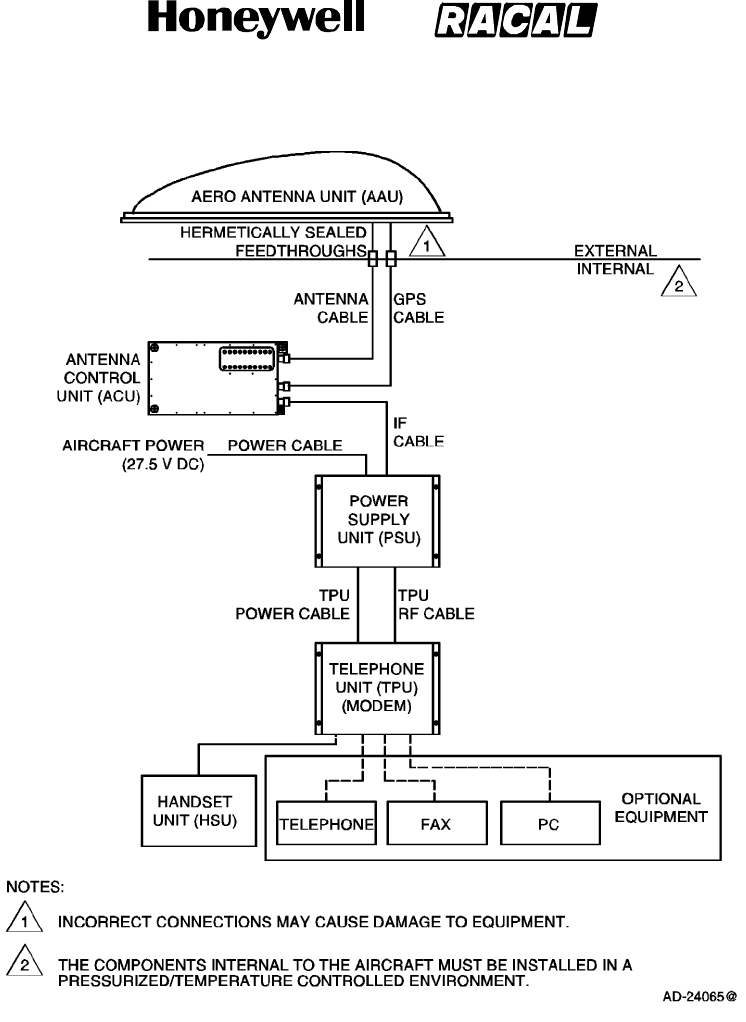
A. Mobile Earth Station
The main component of the Mobile Earth Station (MES) is the SCS system, which is
made up of the antenna and four electronic units. The system interfaces with the optional
voice, PC data and facsimile equipment to accept voice, PC data, or facsimile
information. The electronic units encode and modulate this information onto appropriate
RF carrier frequencies, which are then transmitted by the antenna to the space segment
for relay to the Land Earth Station (LES). These electronic units also receive Radio
Frequency (RF) signals from the LES via the satellite, demodulate these signals, perform
the necessary decoding of encoded messages, and output the voice or data messages
for use by the user. The SCS system diagram is shown in Figure 1--2.
SYSTEM DESCRIPTION AND INSTALLATION MANUAL
SCS--1000 Mini--M Aero SATCOM System
23--20--28
Use or disclosure of information on this page is subject to the restrictions in the proprietary notice of this document.
Page 1--3
31 Jan 2000
Figure 1--2. SCS System Diagram
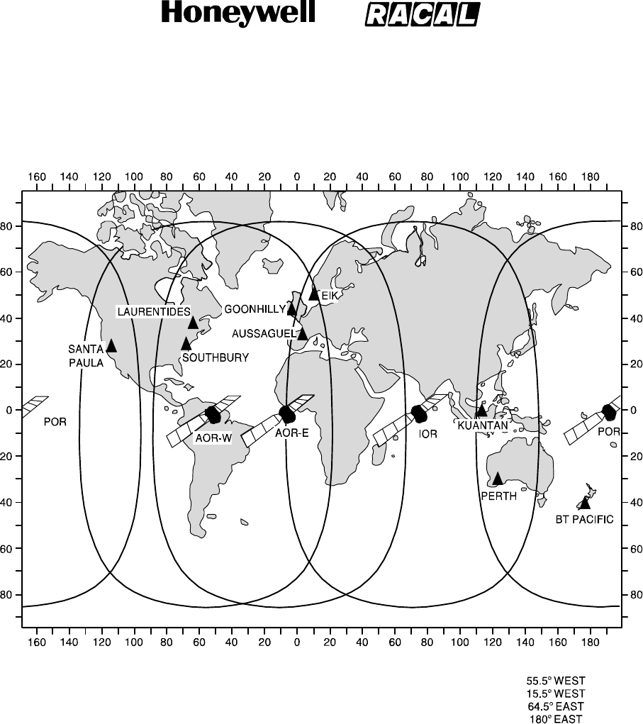
B. Space Segment
The space segment is made up of the Inmarsat satellites that support Mini--M Aero
operations. The satellites function as communication transponders to support L--band
links to and from the MES, and provide links to and from the LES. The space segment
provider for aeronautical satellite communications is the Inmarsat. The four--region
satellite system provided by Inmarsat is shown in Figure 1--3.
The area covered by each satellite is comprised of a number of zones called spot beams.
Separate spot beams are covered by separate antennas on the satellite, allowing for
frequencies to be reused for communications in different areas of the earth.
SYSTEM DESCRIPTION AND INSTALLATION MANUAL
SCS--1000 Mini--M Aero SATCOM System
23--20--28
Use or disclosure of information on this page is subject to the restrictions in the proprietary notice of this document.
Page 1--4
31 Jan 2000
INMARSAT Four -- Region Service
Satellite Coverage and Land Earth Station Networks
AD--24066@
AOR--W LAND EARTH STATIONS
Goonhilly (Skyphone)
Southbury (Skyways)
Eik (Skyphone)
Aussaguel (Aircom) *
Laurentides (Aircom)
AOR--E LAND EARTH STATIONS
Goonhilly (Skyphone)
Aussaguel (Aircom) *
Eik (Skyphone)
Laurentides (Aircom)
Southbury (Skyways)
POR LAND EARTH STATIONS
BT Pacific (Skyphone)
Santa Paula (Skyways)
Perth (Aircom) *
IOR LAND EARTH STATIONS
Kuantan (Skyways)
Eik (Skyphone)
Perth (Aircom) *
SATELLITE
AOR--W
AOR--E
IOR
POR
ACCESS CODE
8745
8715
8735
8725
ID
00
01
03
02
LOCATION
* SPOT BEAM CAPABLE
Figure 1--3. Inmarsat Four--Region Satellite Coverage

SYSTEM DESCRIPTION AND INSTALLATION MANUAL
SCS--1000 Mini--M Aero SATCOM System
23--20--28
Use or disclosure of information on this page is subject to the restrictions in the proprietary notice of this document.
Page 1--5
31 Jan 2000
C. Land Earth Station
Mini--M Aero communications, via Inmarsat satellites, are transmitted to and from the
terrestrial phone and data networks through the LES. Each LES provides the user with a
diverse routing of national and international voice and data communications via
submarine cable, satellite, and microwave links to all destinations. Automatic traffic
management systems ensure efficient routing of communications by using optimum links
into Public Switched Telephone Networks (PSTN) and avoiding multiple satellite
connections whenever possible.
The Land Earth Stations (LES) are located strategically around the world to provide
redundancy and diversity in the terrestrial extension of communications. Some problems
may be encountered when the aircraft flies in polar regions with a latitude greater than
75 degrees. The present worldwide complement of LES including location, operator, and
coverage region are summarized in Table 1--1.
Table 1--1. Land Earth Stations
Country Location Operator Coverage Region
Australia Laurentides Australian Telstra Atlantic Ocean West
Canada Laurentides Canadian Stratos Atlantic Ocean West
France Aussaguel France Telecom Atlantic Ocean West
Norway Eik Norwegian Telenor Atlantic Ocean West
United Kingdom Goonhilly British Telecom Atlantic Ocean West
USA Southbury COMSAT Atlantic Ocean West
Australia Laurentides Australian Telstra Atlantic Ocean East
Canada Laurentides Canadian Stratos Atlantic Ocean East
France Aussaguel France Telecom Atlantic Ocean East
Norway Eik Norwegian Telenor Atlantic Ocean East
United Kingdom Goonhilly British Telecom Atlantic Ocean East
USA Southbury COMSAT Atlantic Ocean East
Canada Perth Canadian Stratos Indian Ocean
France Aussaguel France Telecom Indian Ocean
Malaysia Kuantan COMSAT Indian Ocean
Norway Eik Norwegian Telenor Indian Ocean
Australia Perth Australian Telstra Pacific Ocean
Canada Perth Canadian Stratos Pacific Ocean
France Perth France Telecom Pacific Ocean
New Zealand BT Pacific British Telecom Pacific Ocean
New Zealand BT Pacific Norwegian Telenor Pacific Ocean
USA Santa Paula COMSAT Pacific Ocean

SYSTEM DESCRIPTION AND INSTALLATION MANUAL
SCS--1000 Mini--M Aero SATCOM System
23--20--28
Use or disclosure of information on this page is subject to the restrictions in the proprietary notice of this document.
Page 1--6
16 Oct 2000
2. System Components
The SCS system is made up of a mechanically steered antenna mounted in a radome on top
of the fuselage and four electronic units mounted internal to the aircraft in a pressurized and
temperature controlled environment. The system operates independently of the aircraft. The
only functional interface to the aircraft is the supply of primary power to the Power Supply Unit
(PSU).
Table 1--2 gives the components supplied by Honeywell. Table 1--3 gives a summary of the
performance characteristics for the SCS system.
Table 1--2. System Components Supplied by Honeywell
Component Model No. Honeywell Part No.
Aero Antenna Unit (AAU) AU--100 7519371--901
Antenna Control Unit (ACU) AC--100 7519373--901
Handset Unit (HSU) HS--100 7519379--901
Power Supply Unit (PSU) PS--100 7519375--901
Telephone Unit (TPU) TP--100 7519377--901

SYSTEM DESCRIPTION AND INSTALLATION MANUAL
SCS--1000 Mini--M Aero SATCOM System
23--20--28
Use or disclosure of information on this page is subject to the restrictions in the proprietary notice of this document.
Page 1--7
16 Oct 2000
Table 1--3. Summary of Performance Characteristics
Function Measurement
Receive Frequency ....................... 1525.0 to 1559.0 MHz
Transmit Frequency ...................... 1626.5 to 1660.5 MHz
Global Positioning System (GPS) RF
Received Frequency ...................... 1575.42 2MHz
Antenna Gain--to--System Noise Temperature
Ratio(G/T) .............................. --17dB/K
MinimumCoverage ....................... 85% of the volume 5_above the horizon
Effective Isotropic Radiated Power (EIRP) . . .
Minimum 12 dBW, maximum 16 dBW
Gain .................................... 7.8 dB minimum, 9.5 dB maximum
RFOutputPower......................... 5.1 dBW maximum
Supply Voltage from Aircraft ............... 27.5 V dc nominal (20.5 to 32 V dc)
Supply Current ........................... 1A (nominal)
InrushCurrent ........................... <17A for 0.13 seconds when supplied by
27.5 V dc
Circuit Breaker Rating:
Continuous Current ..................... 1.95 A at 20.5 V (minimum voltage)
InrushCurrent(SeeNote) ............... 20.1 A for 0.11 second at 32.2 V (maximum voltage)
12.8 A for 0.18 second at 20.5 V (minimum voltage)
NOTE: For example, the Klixon 2TC, 3 A circuit breaker, or equivalent, should be sufficient for most
installations.

SYSTEM DESCRIPTION AND INSTALLATION MANUAL
SCS--1000 Mini--M Aero SATCOM System
23--20--28
Use or disclosure of information on this page is subject to the restrictions in the proprietary notice of this document.
Page 1--8
16 Oct 2000
Table 1--4. DO--160D Environmental Categories
Description
Category for Aero
Antenna Unit (AAU)
Category for All Other
Units
Temperature and Altitude [E1X] [(A1)(A4)X]
Temperature Variation A B
Humidity C A
Shock E E
Vibration [(RCC1)(SLM)] [(RCC1)(SLM)]
Explosion Proofness X X
Waterproofness S X
Fluids Susceptibility F X
Sand and Dust D X
Fungus Resistance F X
Salt Spray S X
Magnetic Effect A A
Power Input B B
Voltage Spike B B
Audio Frequency Susceptibility B B
Induced Signal Susceptibility A A
RF Susceptibility [VVX] [VVX]
Emission of RF Energy H M
Lightning Direct Effects [2A] X
Icing A X
Electrostatic Discharge A A
SYSTEM DESCRIPTION AND INSTALLATION MANUAL
SCS--1000 Mini--M Aero SATCOM System
23--20--28
Use or disclosure of information on this page is subject to the restrictions in the proprietary notice of this document.
Page 1--9
16 Oct 2000
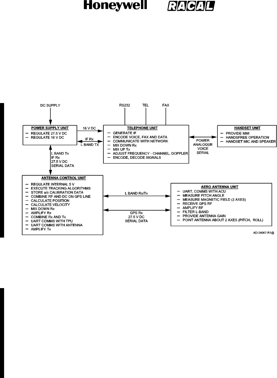
3. System Functional Description
The system functional description gives a general overview and summary of the features and
interfaces in the SCS system. Figure 1--4 shows a functional block diagram of the SCS
system.
Figure 1--4. System Functional Block Diagram
A. Aero Antenna Unit
The primary function of the Aero Antenna Unit (AAU) is to complete the communications
link between the land earth station, the satellite, and the SCS system. The AAU contains
a two axis mechanically steered antenna for tracking a geostationary satellite from a
moving base. The gimballed antenna transmits and receives signals in the 1.6 GHz
band. In addition to the mechanically steered antenna, the AAU also contains a Global
Positioning Sensor (GPS) antenna, angular sensors, and electronics for producing global
positioning sensor inputs for the tracking algorithm, which is performed in the Antenna
Control Unit (ACU). The AAU contains a microcontroller that is used to read the sensors,
communicate this sensor data serially to the ACU, process the serial inputs from the ACU,
and translate the serial input data into motor commands to drive the antenna to the
correct position. The interfaces to the aircraft are through two RF pigtail cables, which
exit from underneath the AAU toward the forward end.

SYSTEM DESCRIPTION AND INSTALLATION MANUAL
SCS--1000 Mini--M Aero SATCOM System
23--20--28
Use or disclosure of information on this page is subject to the restrictions in the proprietary notice of this document.
Page 1--10
16 Oct 2000
B. Antenna Control Unit
The Antenna Control Unit (ACU) is required for the mechanically steered AAU. The ACU
serves as an interface module between the AAU and the Telephone Unit (TPU). The
ACU performs three main functions for the SCS system:
Points the antenna at the satellite
Calculates the relative speed between the aircraft and the satellite for the Doppler shift
correction
Calculates the distance that the aircraft travels so that new spot beams are selected
and new working frequencies are chosen when the aircraft moves into an area
covered by a different spot beam antenna on the satellite.
The ACU is made up of an RF Board (RFB), an Antenna Tracking Board (ATB), GPS
engine, and a diplexer/low noise amplifier. The RFB amplifies L--band signals in the
transmit path and sets the transmitted power for the signals. In the receive path, the RFB
down--converts L--band signals to IF signals and provides signal amplification. The RFB
also communicates serially with the Telephone Unit (TPU).
The ATB executes the tracking algorithms based on sensor inputs from the AAU and the
GPS engine. These algorithms enable the ATB to generate steering commands to
mechanically steer the antenna in the direction of the satellite. In addition, the ATB
superimposes 27.5 V dc voltage onto the GPS line to provide operating power to the
AAU. The ATB also stores aircraft calibration data.
The GPS engine calculates the position and velocity of the aircraft in relation to the
geostationary satellite based on inputs from the GPS antenna in the AAU. The GPS
engine then provides inputs into the tracking algorithm based on these calculations.
The diplexer is a three--port device (antenna, transmit, and receive), which provides
signal routing and filtering functions for the RF signals. Receive signals are routed from
the antenna port to the receive port; transmit signals are routed from the transmit port to
the antenna port. The Low Noise Amplifier (LNA) establishes the noise floor of the
communication system by boosting the RF signals and noise received from the antenna
to a level much greater than the noise level of subsequent components in the receive
path.
C. Power Supply Unit
The voltage source for the Power Supply Unit (PSU) is the 28 V dc supply from the
aircraft. From this dc source, the PSU supplies regulated 16 V dc power to the TPU, and
27.5 V dc to the ACU. The PSU also acts as a conduit for the RF signal between the
TPU and ACU. The PSU monitors the 12 V dc voltage superimposed onto the RF signal.
The PSU removes this dc component and replaces it with 27.5 V dc, which serves as the
voltage source for the ACU. When the dc voltage from the TPU drops below 7 V dc, the
27.5 V dc to the ACU is turned off. The maximum power output of the PSU is 30 Watts.

SYSTEM DESCRIPTION AND INSTALLATION MANUAL
SCS--1000 Mini--M Aero SATCOM System
23--20--28
Use or disclosure of information on this page is subject to the restrictions in the proprietary notice of this document.
Page 1--11
31 Jan 2000
D. Telephone Unit
The TPU interfaces with the handset unit and the optional accessory equipment
(telephone, PC, fax machine) through serial Input/Output (I/O) ports. The function of the
TPU is to modulate and demodulate signals being received and transmitted by these
communication devices. The TPU is responsible for handling the communication
protocol, frequency adjustment resulting from Doppler shift and channel changes, the
encoding and decoding of signals, and generating IF signals for processing. In the
transmit path, analog voice, fax, or PC data signals from the communication devices are
modulated and encoded by the TPU, converted to an IF signal, and then up--converted to
an RF signal for transmission. In the receive path, IF signals from the ACU are
demodulated and decoded into analog voice, fax, or PC data signals for the
communication devices.
The TPU can interface with an ordinary Dual Tone Multi--Frequency (DTMF) telephone for
basic voice communications. The fax port allows the TPU to interface with a telefax
machine to support Group 3 fax transmissions at a rate of 2.4 kilobits per second (kbps).
The telefax machine is assigned a separate incoming call number.
A personal computer can be connected to the TPU through an RS--232 port for individual
setup and operation of all functions of the SCS system. The computer also allows the
use of the built--in data transmission service without the aid of a modem or data card.
The TPU provides access to Asynchronous Data (ASD) services through its built--in
modem capability. The ASD system provides 2.4 kbps data transmissions between an
SCS system and the fixed international network. The data transmission service is
assigned a separate call number. The data transmission service can be used with
standard dial--up connection software to connect the Internet and e--mail services of most
Internet Service Providers (ISP).
The TPU also contains a card slot for a Subscriber Identity Module (SIM) card. The SIM
card carries subscription information from the Inmarsat service provider or network
service provider on an integrated circuit. The SCS system used with the SIM card
assumes the identity of the card. Each SIM card contains its own set of numbers on
which the user can be contacted regardless of the SCS system being used. All outgoing
calls are billed to the owner of the SIM card.

SYSTEM DESCRIPTION AND INSTALLATION MANUAL
SCS--1000 Mini--M Aero SATCOM System
23--20--28
Use or disclosure of information on this page is subject to the restrictions in the proprietary notice of this document.
Page 1--12
31 Jan 2000
E. Handset Unit
The Handset Unit (HSU) is the primary communication device for the SCS system and is
used for telephone calls and basic functions. A 12--character, alphanumeric display
screen allows the system to display messages requesting information from the user such
as a Personal Identification Number (PIN) and to display the status of the system. The
user can also use the display screen to access all functions that the system supports.
The HSU has a keypad that allows the user to enter PINs and dial telephone numbers,
select functions, and turn off and on the speaker phone function. An ON/OFF key on the
keypad allows the user to switch the system on and off. A handset microphone and
loudspeaker allows handsfree operation for the user. In addition to normal voice
communications, the HSU provides the following options:
PIN Protection
Access to the phone book entries
Manual selection of the satellite ocean region
Selection of the default network service provider.
SYSTEM DESCRIPTION AND INSTALLATION MANUAL
SCS--1000 Mini--M Aero SATCOM System
23--20--28
Use or disclosure of information on this page is subject to the restrictions in the proprietary notice of this document.
Page 1--13
16 Oct 2000
4. System Component Descriptions
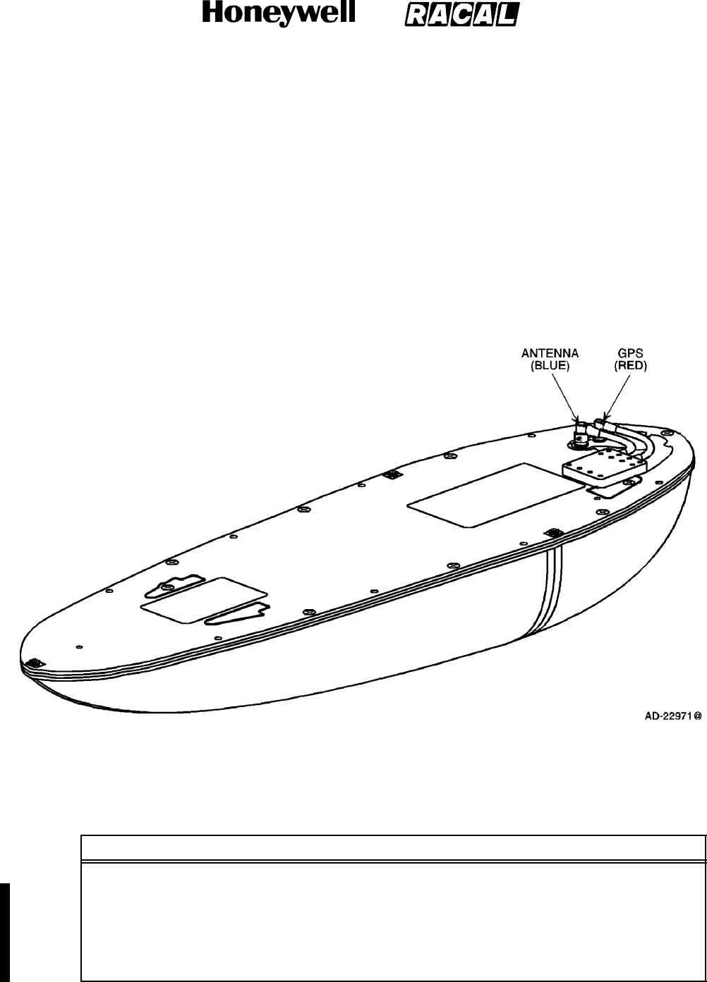
A. Aero Antenna Unit
The AAU contains a mechanically steered antenna for transmitting and receiving RF
signals to and from a geostationary satellite. The AAU is mounted in a radome on top of
the fuselage. See Figure 1--5 for a graphic view of the AAU. Refer to Table 1--5 for the
AAU leading particulars.
Figure 1--5. Aero Antenna Unit
Table 1--5. Leading Particulars for the Aero Antenna Unit
Item Specification
Dimensions (maximum):
Height ....................................... 4.88 in. (124 mm)
Width ........................................ 5.96 in. (151.3 mm)
Length ....................................... 22.09 in. (561 mm)
Weight (maximum) .............................. 5.30 lb (2.4 kg)
SYSTEM DESCRIPTION AND INSTALLATION MANUAL
SCS--1000 Mini--M Aero SATCOM System
23--20--28
Use or disclosure of information on this page is subject to the restrictions in the proprietary notice of this document.
Page 1--14
16 Oct 2000
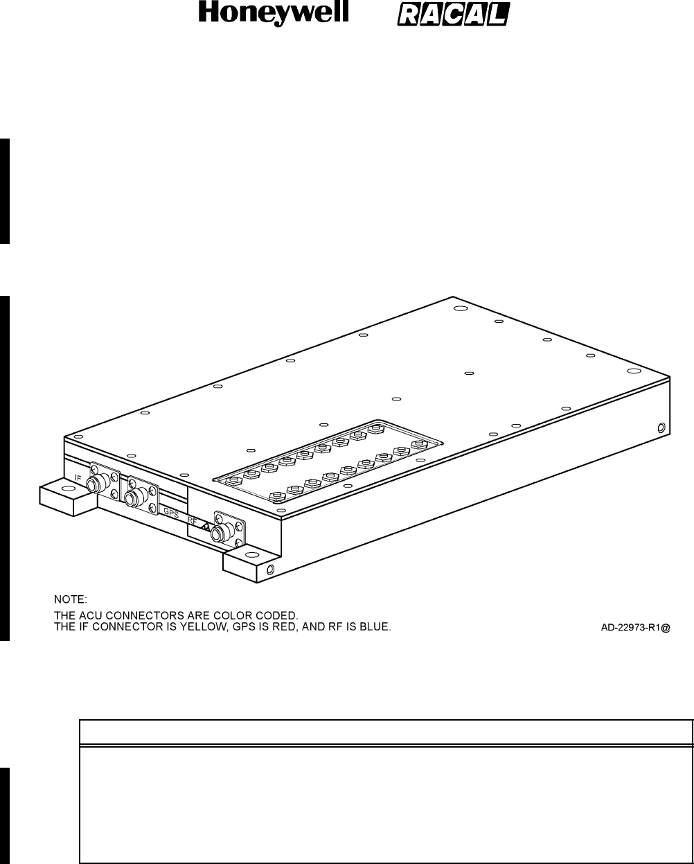
B. Antenna Control Unit
The ACU serves as an interface between the AAU and the TPU. The ACU is mounted in
the pressurized/temperature controlled cabin as close as possible to the AAU within the
limitations imposed by the allowable RF cable loss (less than or equal to 0.75 dB at 1.6
GHz) and the RF cable selection. Generally this is limited to less than 3m (10 ft) with the
best available cables. See Figure 1--6 for a graphic view of the ACU. Refer to Table 1--6
for the ACU leading particulars.
Figure 1--6. Antenna Control Unit
Table 1--6. Leading Particulars for the Antenna Control Unit
Item Specification
Dimensions (maximum):
Height ....................................... 1.38 in. (35 mm)
Width ........................................ 5.01 in. (127.2 mm)
Length ....................................... 9.29 in. (236 mm)
Weight (maximum) .............................. 3.2 lb (1.45 kg)
SYSTEM DESCRIPTION AND INSTALLATION MANUAL
SCS--1000 Mini--M Aero SATCOM System
23--20--28
Use or disclosure of information on this page is subject to the restrictions in the proprietary notice of this document.
Page 1--15
16 Oct 2000
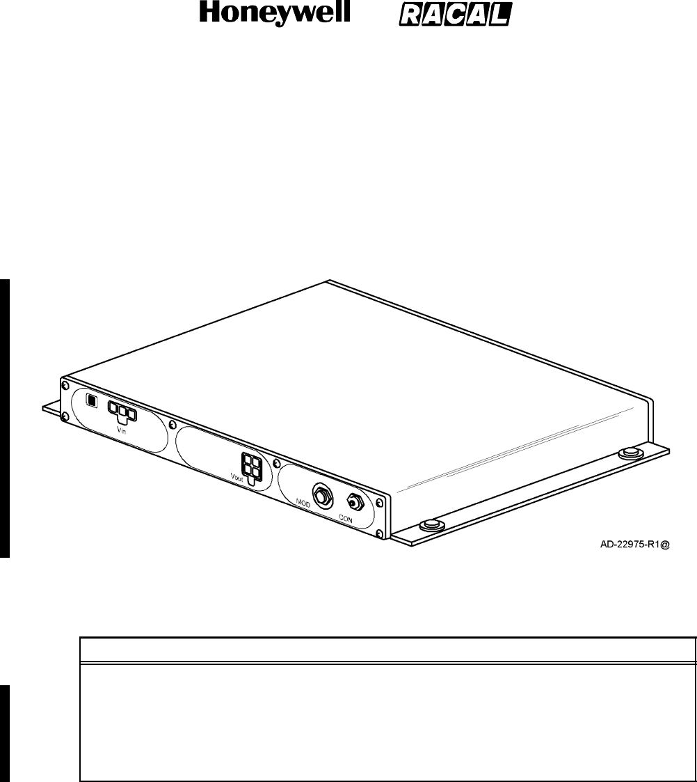
C. Power Supply Unit
The PSU provides the operating power for the system. The PSU and TPU may be
mounted together in the pressurized/temperature controlled cabin. The maximum
distance between the PSU and the ACU is defined by the cable requirements and the
cable selection. See Figure 1--7 for a graphic view of the PSU. Refer to Table 1--7 for the
PSU leading particulars.
Figure 1--7. Power Supply Unit
Table 1--7. Leading Particulars for the Power Supply Unit
Item Specification
Dimensions (maximum):
Height ....................................... 1.20 in. (30.5 mm)
Width ........................................ 8.33 in. (211.5 mm)
Length ....................................... 6.12 in. (155.5 mm)
Weight (maximum) .............................. 2.4 lb (1.09 kg)
SYSTEM DESCRIPTION AND INSTALLATION MANUAL
SCS--1000 Mini--M Aero SATCOM System
23--20--28
Use or disclosure of information on this page is subject to the restrictions in the proprietary notice of this document.
Page 1--16
16 Oct 2000
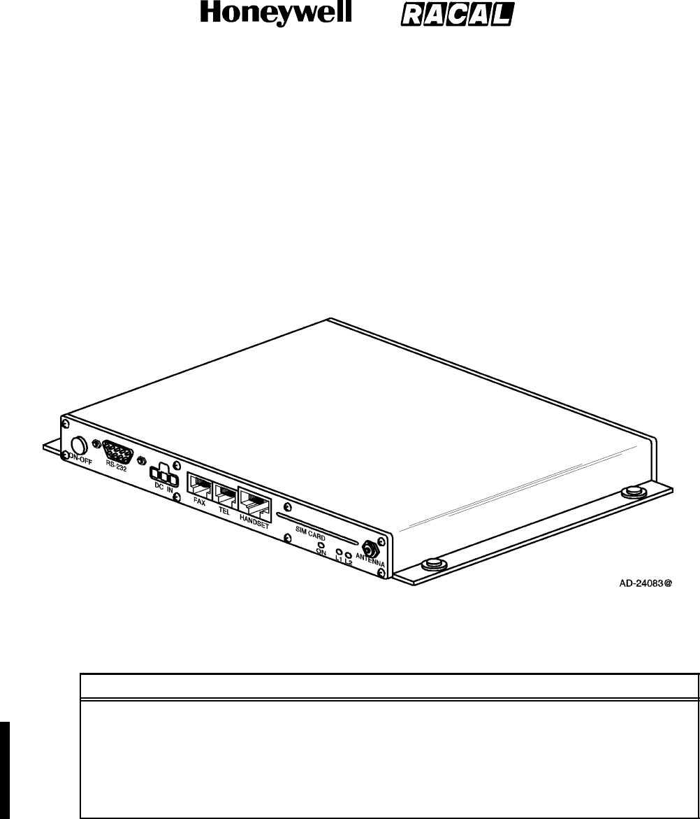
D. Telephone Unit
The TPU serves as the interface between various user devices, such as the HSU, PC,
telephone, and fax machine, and the network. The HSU interface is through a RJ45 jack.
The interface with the PC is through a standard RS--232 port, while the telephone and fax
machine use a standard RJ11 jack. The TPU and PSU may be mounted together in the
pressurized/temperature controlled cabin. The maximum distance between the TPU and
the PSU is defined by the cable requirements and the cable selection. See Figure 1--8 for
a graphic view of the TPU. Refer to Table 1--8 for the TPU leading particulars.
Figure 1--8. Telephone Unit
Table 1--8. Leading Particulars for the Telephone Unit
Item Specification
Dimensions (maximum):
Height ....................................... 1.20 in. (30.5 mm)
Width ........................................ 8.33 in. (211.5 mm)
Length ....................................... 6.12 in. (155.5 mm)
Weight (maximum) .............................. 2.2lb(1.0kg)
SYSTEM DESCRIPTION AND INSTALLATION MANUAL
SCS--1000 Mini--M Aero SATCOM System
23--20--28
Use or disclosure of information on this page is subject to the restrictions in the proprietary notice of this document.
Page 1--17
16 Oct 2000
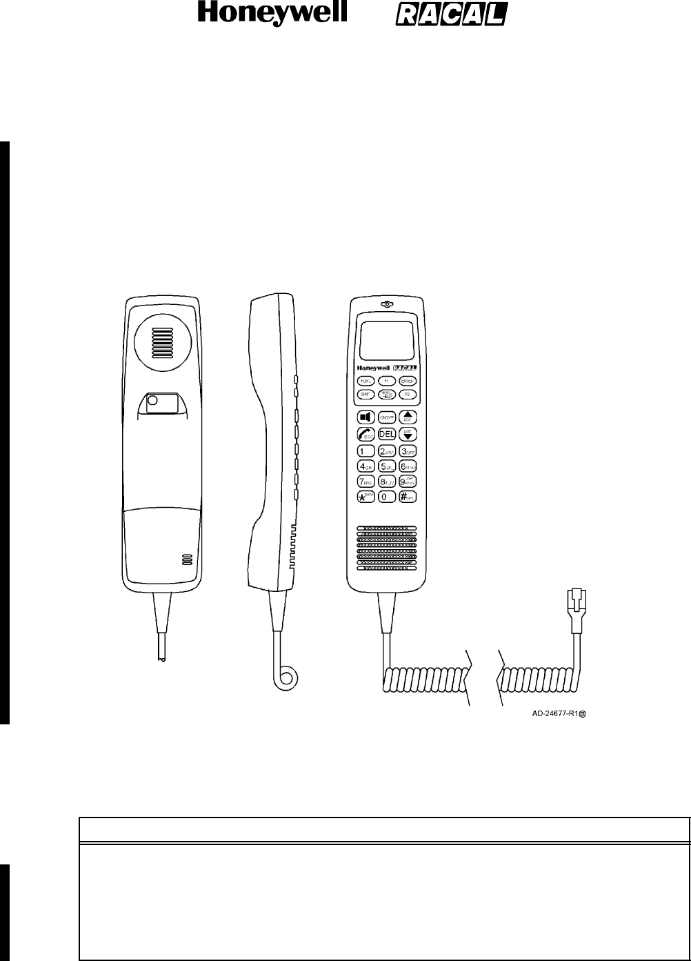
E. Handset Unit
The HSU interfaces with the TPU to supply a telephone handset and a display screen for
the user. The handset connects to the TPU through an RJ45 jack and comes with a
coiled cord, extendable to a maximum of 1.8 meters (5.9 feet). A coiled cord extension
up to 15 feet is acceptable. This restricts where the HSU and TPU can be mounted in the
pressurized/temperature controlled cabin. Also, the HSU must be mounted so it cannot
be removed from its cradle in the forward direction. See Figure 1--9 for a graphic view of
the HSU. Refer to Table 1--9 for the HSU leading particulars.
Figure 1--9. Handset Unit
Table 1--9. Leading Particulars for the Handset Unit
Item Specification
Dimensions (maximum):
Height ....................................... 1.46 in. (37 mm)
Width ........................................ 2.13 in. (54 mm)
Length ....................................... 7.87 in. (200 mm)
Weight (maximum) .............................. 0.85 lb (0.39 kg)
SYSTEM DESCRIPTION AND INSTALLATION MANUAL
SCS--1000 Mini--M Aero SATCOM System
23--20--28
Use or disclosure of information on this page is subject to the restrictions in the proprietary notice of this document.
Page 1--18
16 Oct 2000
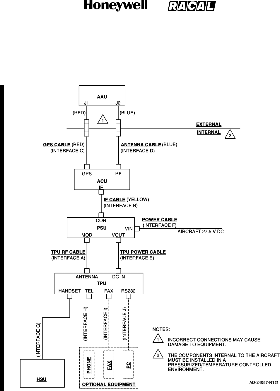
5. System Interfaces
The system interfaces and cables are shown in Figure 1--10. Refer to Table 1--10 for the
system interfaces leading particulars.
Figure 1--10. System Interfaces

SYSTEM DESCRIPTION AND INSTALLATION MANUAL
SCS--1000 Mini--M Aero SATCOM System
23--20--28
Use or disclosure of information on this page is subject to the restrictions in the proprietary notice of this document.
Page 1--19
16 Oct 2000
Table 1--10. Leading Particulars for the System Interfaces
Item Specification
Interface A (TPU RF Cable)
Mechanical Interface:
TPU ......................................... QLA Jack (Antenna)
Power Supply ................................. SMA Jack (TPU)
Electrical Interface:
Loss ......................................... 2 dB at 1.6 GHz
VSWR ....................................... < 1.4:1
Impedance ................................... 50 ohm
DC Signal .................................... 27.5 0.5 V dc, 30 W max
TX Signal .................................... 1626.5 to 1660.5 MHz
RX Signal .................................... 101.5 MHz carrier
Interface B (IF Cable)
Mechanical Interface:
ACU......................................... TNC Jack (IF)
Power Supply ................................. QLA Jack (CON)
ColorCoding ................................. Yellow
Electrical Interface:
Loss ......................................... 8 dB at 1.6 GHz
VSWR ....................................... < 1.4:1
Impedance ................................... 50 ohm
DC Signal .................................... 27.5 0.5 V dc, 30 W max
TX Signal .................................... 1626.5 to 1660.5 MHz
RX Signal .................................... 101.5 MHz carrier
Interface C (GPS Cable)
Mechanical Interface:
ACU......................................... TNC Jack (GPS)
Antenna ..................................... TNC Jack (J2)
ColorCoding ................................. Red

SYSTEM DESCRIPTION AND INSTALLATION MANUAL
SCS--1000 Mini--M Aero SATCOM System
23--20--28
Use or disclosure of information on this page is subject to the restrictions in the proprietary notice of this document.
Page 1--20
16 Oct 2000
Table 1--10. Leading Particulars for the System Interfaces (cont)
Item Specification
Electrical Interface:
Loss ......................................... 10 dB at 1575.42 MHz
VSWR ....................................... < 1.4:1
Impedance ................................... 50 ohm
DC Signal .................................... 27.5 0.5 V dc, 15 W max
RX Signal .................................... 1575.42 MHz carrier (GPS)
Interface D (Antenna Cable)
Mechanical Interface:
ACU......................................... TNC Jack (RF)
Antenna ..................................... TNC (J1)
ColorCoding ................................. Blue
Electrical Interface:
Loss ......................................... 0.75 dB at 1.6 GHz
VSWR ....................................... < 1.4:1
Impedance ................................... 50 ohm
TX Signal .................................... 1626.5 to 1660.5 MHz
RX Signal .................................... 1525 to 1559 MHz
Interface E (TPU Power Cable)
Mechanical Interface:
TPU ......................................... Molex Mini--Fit Jrt: 5569**A2* 3 circuits
single row. Mates with Molex Mini--Fit
Jrttype 5557, P/N 39--01--4030 or
39--01--4031 on cable (DC in).
Power Supply ................................. Molex Mini--Fit Jr: 5569**A2* 4 circuits
2*2 dual row. Mates with Molex Mini--Fit
Jrttype 5557, P/N 39--01--2040 or
39--01--2045 on cable (Vout).
Electrical Interface:
Voltage ...................................... 27.5 V dc nominal
Current ...................................... <1A
Resistance ................................... < 0.5 ohm

SYSTEM DESCRIPTION AND INSTALLATION MANUAL
SCS--1000 Mini--M Aero SATCOM System
23--20--28
Use or disclosure of information on this page is subject to the restrictions in the proprietary notice of this document.
Page 1--21
31 Jan 2000
Table 1--10. Leading Particulars for the System Interfaces (cont)
Item Specification
Interface F (Power Cable)
Mechanical Interface:
TPU ......................................... Molex Mini--Fit Jr: 5569**A2* 3 circuits
single row. Mates with Molex Mini--Fit
Jrttype 5557, P/N 39--01--4030 or
39--01--4031 on cable (Vin).
Electrical Interface:
Input Voltage ................................. 27.5 V dc nominal
Power ....................................... 30W maximum
Interface G (RJ45 Jack for Handset)
Connector .................................... 8--pin RJ45 jack on TPU
Interface H (RJ11 Jack for Telephone and Fax)
Speech Level ................................. +2.5 dBm
ReceiveLevel ................................ -- 9 d B m
DialTone..................................... 425 Hz, --19dBm
DTMF(Dialing) ............................... --20 dBm
Minimum ..................................... 30 V dc
LineVoltage .................................. 35 Vrms, 25 HZ (maximum of two
telephones/faxes)
Ringing Signal (Hook off) ....................... >20mA
Signaling(Hookon) ........................... <9mA
Interface J (RS232 Jack for PC)
Connector .................................... 9--pin D--type sub miniature female
connector
DataProtocol ................................. Hayes AT compatible
BitRate ...................................... 1.2 to 38.4 kbps
Parity ........................................ No parity (AT programmable: odd, even,
mark, or space)
DataBits ..................................... 8 bits (AT programmable: 7 or 8 bits)
StopBits ..................................... 1 bit (AT programmable: 1 or 2 bits)
FlowControl .................................. RTS/CTS (AT programmable: ON,
XON/XOFF or RTS/CTS)

SYSTEM DESCRIPTION AND INSTALLATION MANUAL
SCS--1000 Mini--M Aero SATCOM System
23--20--28
Use or disclosure of information on this page is subject to the restrictions in the proprietary notice of this document.
Page 1--22
31 Jan 2000
Blank Page

SYSTEM DESCRIPTION AND INSTALLATION MANUAL
SCS--1000 Mini--M Aero SATCOM System
23--20--28
Use or disclosure of information on this page is subject to the restrictions in the proprietary notice of this document.
Page 2--1
31 Jan 2000
SYSTEM OPERATION
1. General
The SCS system provides direct telephony, telefax, Nera Internet Message Service (NIMS),
and data connection to international public networks via the Inmarsat satellite system. For
basic operation, the system requires the following:
Aero Antenna Unit (AAU)
Antenna Control Unit (ACU)
Power Supply Unit (PSU)
Telephone Unit (TPU)
Handset Unit (HSU).
For additional functionality, the following equipment may be added:
Personal Computer (PC) for control and settings
Telefax machine
Telephone.
The network service provider issues the user license and Inmarsat Mobile Numbers (IMN).
The service provider is also responsible for the billing of calls. The services supported by the
system are as follows:
Telephone calls -- basic telephony services
Telefax -- CCITT Group 3 facsimile services, 2.4 bps
Data communication -- Hayes compatible 2.4 bps data service
Mail service -- NIMS.
Figure 2--1 shows the communication path for calls to and from the SCS system.
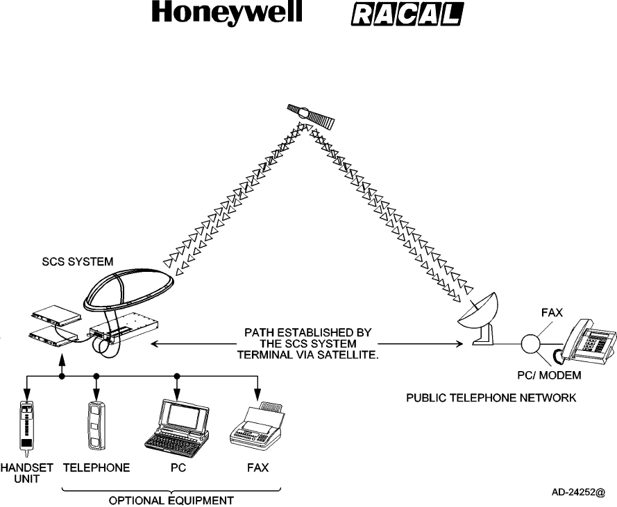
SYSTEM DESCRIPTION AND INSTALLATION MANUAL
SCS--1000 Mini--M Aero SATCOM System
23--20--28
Use or disclosure of information on this page is subject to the restrictions in the proprietary notice of this document.
Page 2--2
31 Jan 2000
Figure 2--1. Communications Path
2. Making a Call Using the SCS System
A. Calls from the SCS System
To make an outgoing call, you use a standard international telephone number with the
00 prefix. The MES automatically includes information to identify the system and the
particular port that originates the call. The SCS system has four ports configured for:
Handset Unit Calls
Telephone Calls
Telefax Service
Data Service (personal computer).
The LES uses the port identifying information (OI) for billing purposes. The system
transmits the dialling information on a channel specially assigned by the Network
Coordination Station (NCS) to the LES, which also has been instructed to tune to the
same channel. The LES routes the call over the public telecommunications networks to
the intended destination. When the called party responds, the call proceeds.

SYSTEM DESCRIPTION AND INSTALLATION MANUAL
SCS--1000 Mini--M Aero SATCOM System
23--20--28
Use or disclosure of information on this page is subject to the restrictions in the proprietary notice of this document.
Page 2--3
31 Jan 2000
B. Calls to the SCS System
The SCS system receives incoming calls via the Inmarsat Mobile Number (IMN) phone
numbers. The IMN numbers are assigned to the following ports:
Handset Unit (HSU port)
Telephone (TEL port)
Data service (DATA port)
Telefax service (FAX port)
NIMS service.
Calls are made as ordinary international (satellite) calls where each ocean region has an
international country code (see Appendix A for a list of telephone country codes). If an
area is covered by more than one satellite, it is necessary that the caller knows which
satellite (ocean region) the MES is using. The international codes for the ocean regions
are as follows:
Atlantic Ocean East Region: 871
Pacific Ocean Region: 872
Indian Ocean Region: 873
Atlantic Ocean West Region: 874
NOTE: Some network service providers support the common ocean region access
number 870, which connects the call to the dialed SCS system regardless of the
ocean region the user is currently communicating through.
C. Calls from the Handset Unit
The handset unit is used for telephone calls and basic functions. Additional control of
functions must be performed from a PC connected to the RS--232 jack of the TPU.
Figure 2--2 shows the display and keys of the handset unit. Table 2--1 describes the
features of the handset unit.
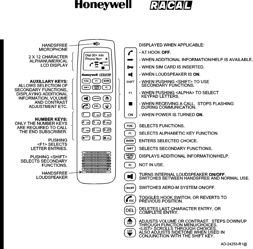
SYSTEM DESCRIPTION AND INSTALLATION MANUAL
SCS--1000 Mini--M Aero SATCOM System
23--20--28
Use or disclosure of information on this page is subject to the restrictions in the proprietary notice of this document.
Page 2--4
16 Oct 2000
Figure 2--2. Handset Unit Display and Keys
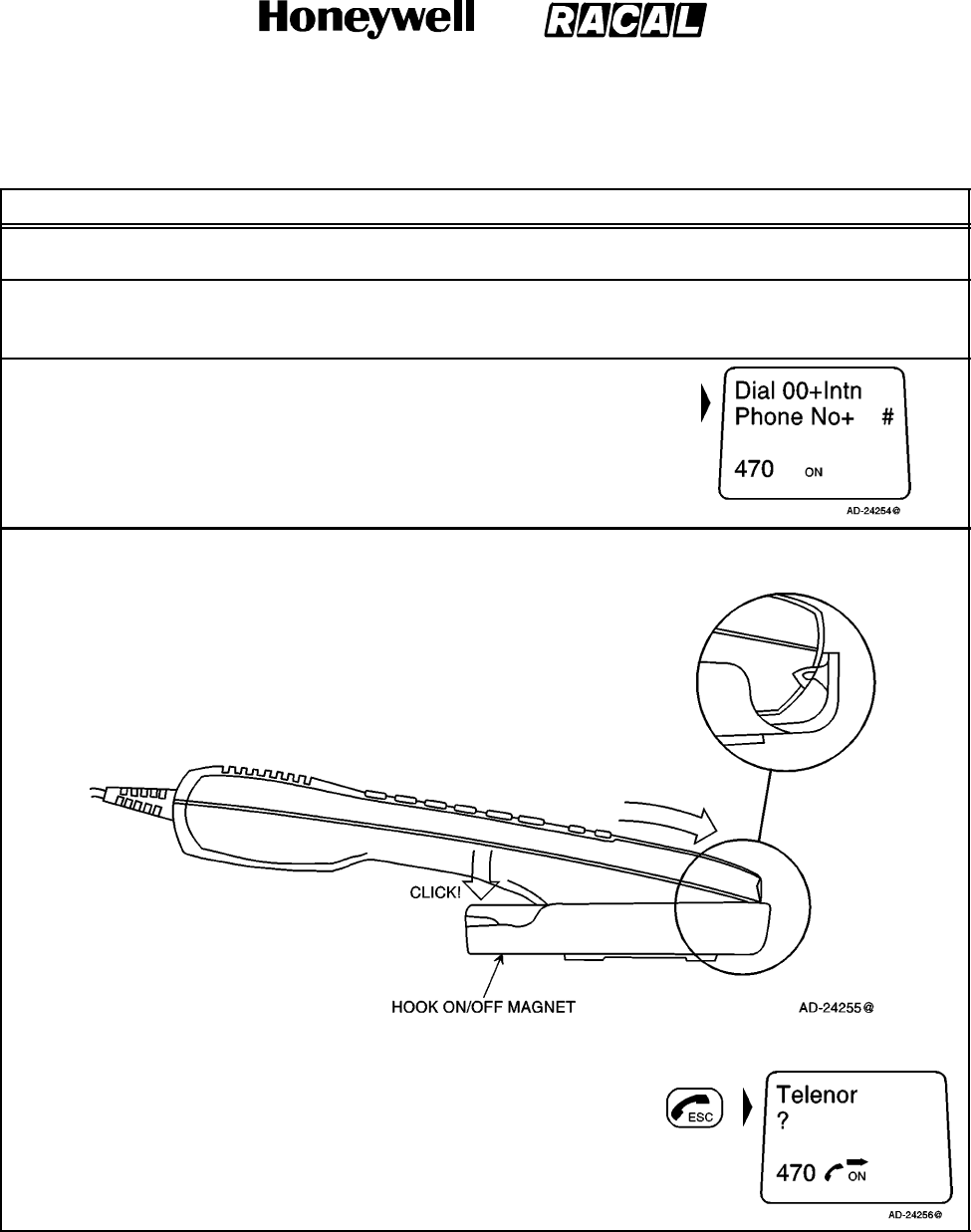
SYSTEM DESCRIPTION AND INSTALLATION MANUAL
SCS--1000 Mini--M Aero SATCOM System
23--20--28
Use or disclosure of information on this page is subject to the restrictions in the proprietary notice of this document.
Page 2--5
31 Jan 2000
Table 2--1. Features of the Handset Unit
Feature Description
Auxiliary Keys The auxiliary keys allow selection of secondary functions, displaying
additional information, and volume and contrast adjustment.
Number Keys Only the number keys are required to call the end subscriber. Pushing
the F1 key selects the letter entries. Pushing the SHIFT key selects
the secondary functions.
IDLE Mode The following message appears in
the in the display screen when in
IDLE mode:
HOOK ON/OFF The handset unit is secured in a desk-- or wall--mounted bracket.
A magnet toggles the internal hook switch:
The switch can also be toggled
with the combined HOOK
ON/OFF and ESCAPE key:
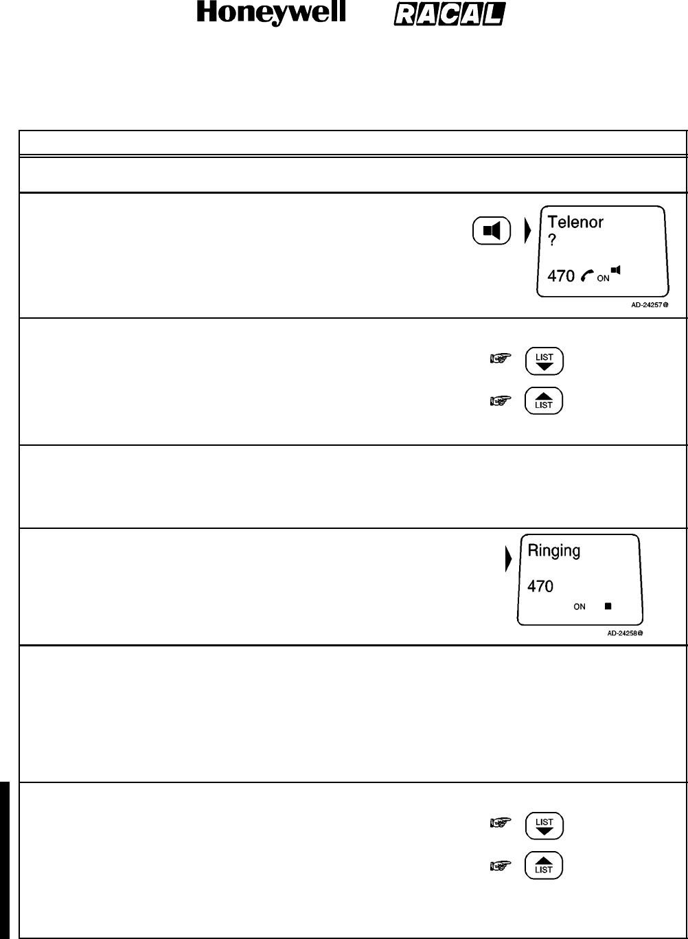
SYSTEM DESCRIPTION AND INSTALLATION MANUAL
SCS--1000 Mini--M Aero SATCOM System
23--20--28
Use or disclosure of information on this page is subject to the restrictions in the proprietary notice of this document.
Page 2--6
16 Oct 2000
Table 2--1. Features of the Handset Unit (cont)
Feature Description
Beeps in the Handset Unit Before contact is established with the selected satellite, beeps indicate
attempts.
Loudspeaker When off--hook, the loudspeaker
key toggles the handset
loudspeaker ON and OFF. The
following symbol is displayed in
the display screen when the
loudspeaker is on:
Volume Control The received volume in the handset unit may be adjusted during a call:
Reducing the volume:
Increasing the volume:
The volume is reset when clearing the call.
Light in Display and Keys Turns on during activity (default)
For permanent light, push the SHIFT key LIGHT key together once.
Repeat the key strokes to turn the light off, and repeat again to
revert to the activity mode of illumination.
Incoming Call Indicator The incoming call indicator H
flashes when receiving a call to
the handset unit. The indicator
turns off when the call is
established.
PIN Code The user is prompted for the 4--8 digit Personal Identification Number
(PIN) each time the SCS--System is switched on:
SIM PIN (with SIM card)
Phone PIN (without SIM card)
NOTE: The PIN code may also be entered from the PC, if it is
connected. Be aware that the PIN protection may have been
disabled.
Sidetone Adjustment To adjust the sidetone level, push the SHIFT key once.
j
Reducing the side tone level:
Increasing the side tone level:
To terminate side tone control, push the SHIFT key again. The display
will show ACCEPTED. Volume control is now active as usual. The
sidetone setting is stored between calls and when the power is cycled.
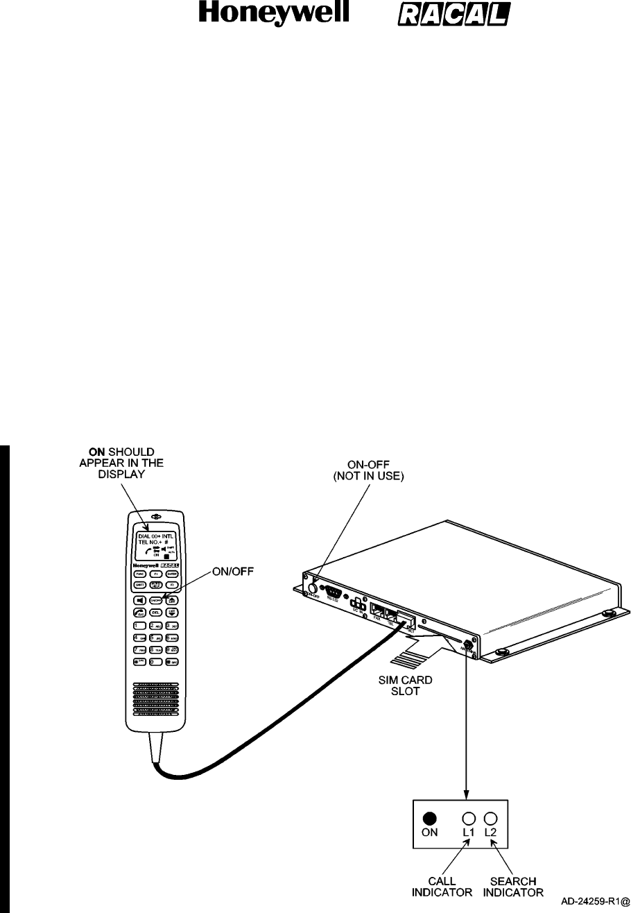
SYSTEM DESCRIPTION AND INSTALLATION MANUAL
SCS--1000 Mini--M Aero SATCOM System
23--20--28
Use or disclosure of information on this page is subject to the restrictions in the proprietary notice of this document.
Page 2--7
16 Oct 2000
3. Operation of the Handset Unit
A. Switching On the System
To switch on the system, perform the following:
(1) Insert the SIM card (if the SIM card is to be used with the system).
NOTE: There are three ways to power up/down the system. Power can be
applied/removed via the HSU,TPU, or aircraft power (circuit breaker).
(2) Apply power to the system. The red ON indicator on the TPU should turn on. Refer
to Figure 2--3.
Figure 2--3. Switching On
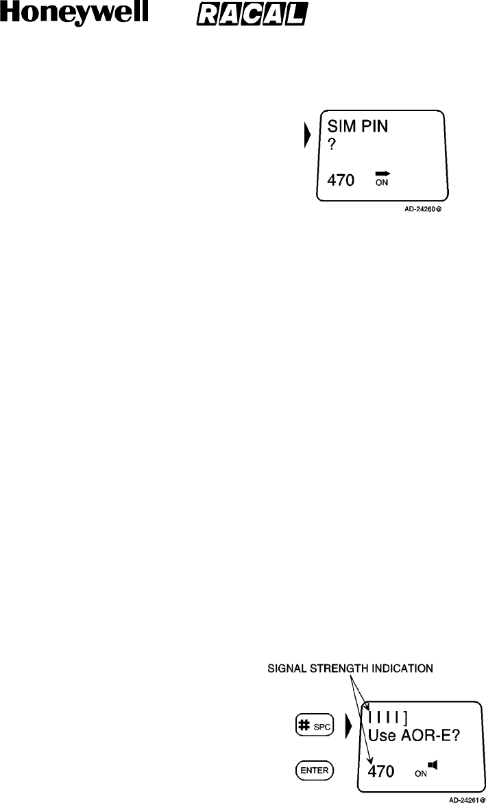
SYSTEM DESCRIPTION AND INSTALLATION MANUAL
SCS--1000 Mini--M Aero SATCOM System
23--20--28
Use or disclosure of information on this page is subject to the restrictions in the proprietary notice of this document.
Page 2--8
31 Jan 2000
(3) Enter the SIM PIN code, followed by the pound (#)
key. If no SIM card is inserted, the Phone PIN
must be entered.
B. Satellite Searching
To search for a satellite, perform the following:
(1) Push the loudspeaker key to turn on the loudspeaker.
(2) Push the LIST up arrow and LIST down arrow keys to adjust the volume of the
loudspeaker.
(3) During the satellite search, beep tones are heard in the HSU (green indicator L2 on
the TPU) flashes in step with the tones:
HHHHHHHHSlow intermittent tones when searching
for any satellite.
HHHHHHHHHHHHHHHHH Rapid intermittent tones when searching
for a specific satellite (faster when
searching for a single satellite).
(4) When receiving a satellite signal, a short tone is sounded. If it is an Inmarsat
satellite, a continuous tone is sounded with varying frequency. When closing in on a
satellite, the tone should increase in frequency.
NOTE: Searching all satellites is the normal mode of operation.
(5) Push the pound (#) key or the ENTER key to
accept the satellite selection, e.g., AOR--E.
or
NOTES:
1. Push the ESC key once to restart the satellite search, or twice to choose
another region. Refer to paragraph 3.E. for a description on how to
manually select a Satellite Ocean Region.
2. With no user intervention, the SCS system automatically searches and logs
on to an appropriate ground earth station via a satellite.
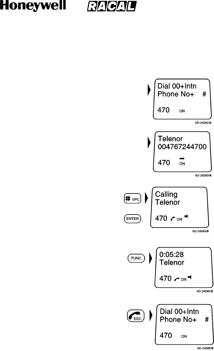
SYSTEM DESCRIPTION AND INSTALLATION MANUAL
SCS--1000 Mini--M Aero SATCOM System
23--20--28
Use or disclosure of information on this page is subject to the restrictions in the proprietary notice of this document.
Page 2--9
31 Jan 2000
C. Making a Call Through Any Network Service Provider
To make a call through any network service provider, perform the following:
(1) Key in the international call prefix 00, followed by
the country code and subscriber code (maximum
of 22 digits):
NOTE: For an explanation of call numbers and a
list of the telephone country codes, see
Appendix A.
(2) Initiate the call by pushing the pound (#) key or the
ENTER key. Slow beeps are heard during the call
setup. The ringing tone is heard until the call is
answered. The call indicator L1 on the TPU turns
on.
or
NOTE: Pushing the FUNC key displays the
duration of the call as it proceeds
(hours:minutes:seconds).
(3) Clear the call when finished by pushing the
ESCAPE key:

SYSTEM DESCRIPTION AND INSTALLATION MANUAL
SCS--1000 Mini--M Aero SATCOM System
23--20--28
Use or disclosure of information on this page is subject to the restrictions in the proprietary notice of this document.
Page 2--10
16 Oct 2000
D. Making a Call Through a Selected Network Service Provider
To make a call through a selected network service provider, perform the following:
(1) Push the No. 2 key then the star (*) key to enter
the network service provider reference code.
then
(2) Repeat all of the steps in paragraph C., Making a Call Through Any Network
Service Provider.
NOTE: Availability of this function depends on the service provider.
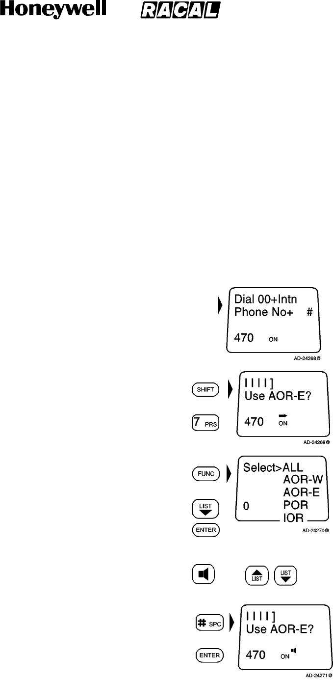
SYSTEM DESCRIPTION AND INSTALLATION MANUAL
SCS--1000 Mini--M Aero SATCOM System
23--20--28
Use or disclosure of information on this page is subject to the restrictions in the proprietary notice of this document.
Page 2--11
31 Jan 2000
E. Manually Selecting a Satellite Ocean Region
Some geographic locations allow contact with more than one Ocean Region satellite. It is
recommended that the user choose an Ocean Region providing good signal quality and
cost--effective communication. Use the satellite coverage map in Figure 1--3 to select the
Ocean Region at your location:
AOR--W Atlantic Ocean Region West: (1)
AOR--E Atlantic Ocean Region East: (2)
POR Pacific Ocean Region: (3)
IOR Indian Ocean Region: (4)
To select a satellite ocean region, starting from idle, perform the following:
NOTE: The following message appears in the display
when in the idle mode:
(1) Push the SHIFT key then the No. 7 key to enter
the Ocean region selection.
NOTE: This mode can also be entered by
pushing the ESC key twice during the
satellite search function.
then
(2) Push the FUNC key to enter the Satellite Region
list. Use the LIST--down and ENTER keys to scroll
down to the desired region. then
NOTE: Turn on the loudspeaker to hear the
search tone and adjust the volume.
Pushing the ESC key stops the search.
then
(3) Push the pound (#) key or ENTER key to accept
the satellite selection, e.g., AOR--E.
or
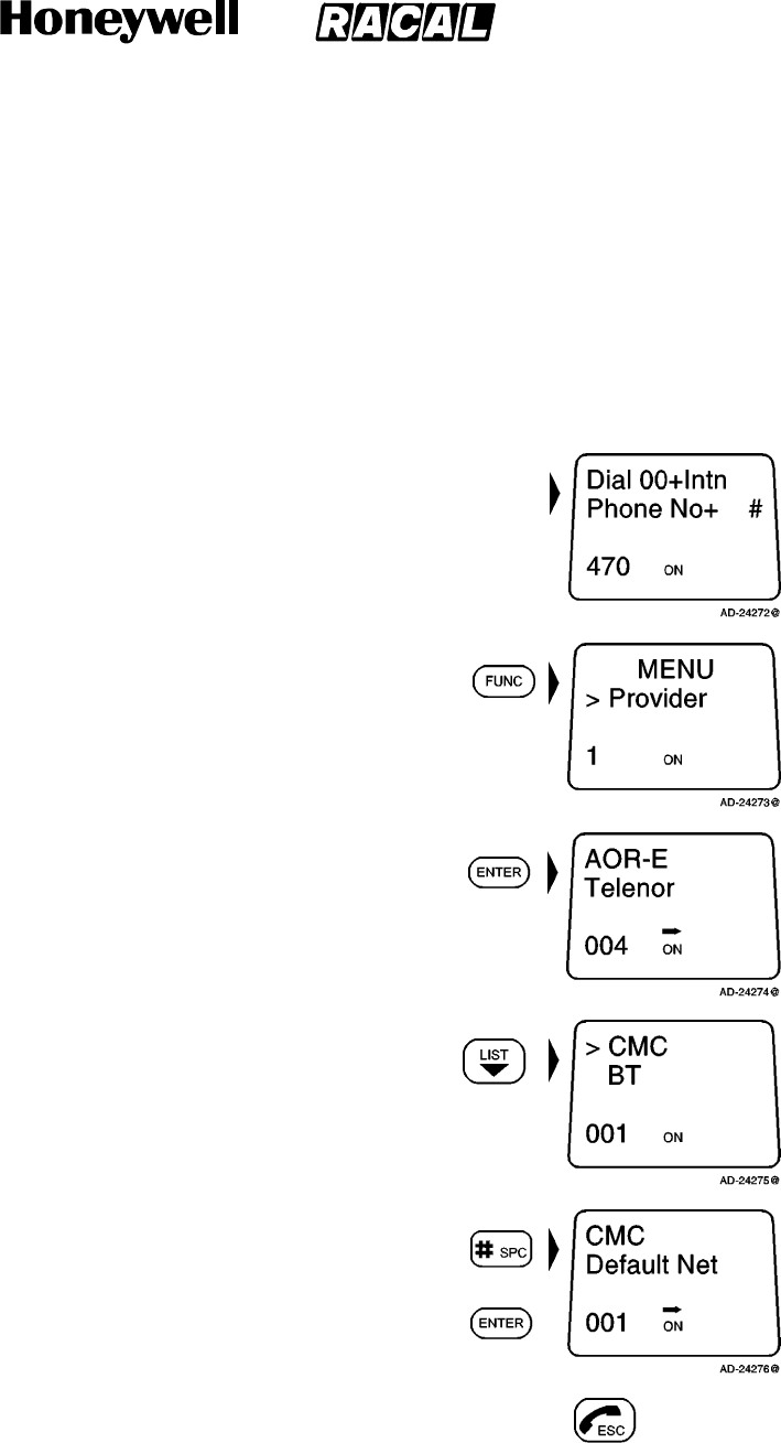
SYSTEM DESCRIPTION AND INSTALLATION MANUAL
SCS--1000 Mini--M Aero SATCOM System
23--20--28
Use or disclosure of information on this page is subject to the restrictions in the proprietary notice of this document.
Page 2--12
31 Jan 2000
F. Selecting the Default Network Service Provider
The default Inmarsat Network Service Provider (ISP) for a satellite (Ocean Region) is
automatically used if the user does not select another service provider when making a
call. When using a SIM card, the selection of an ISP is restricted to one of the allowed
network service providers. When the restricted network function is enabled, and with
some SIM cards, the selection of default network service provider is not possible.
To select the default network service provider, perform the following:
NOTE: The following message appears in the display
when in the idle mode:
(1) Push the FUNC key to open the function MENU:
(2) Push the ENTER key to display the current default
network:
(3) Use the LIST down key to scroll down through the
list to the desired network service provider:
(4) Push the pound (#) key or the ENTER key to store
the selected network service provider as the
default: or
(5) Push the ESC key twice to revert to the idle mode. 2X
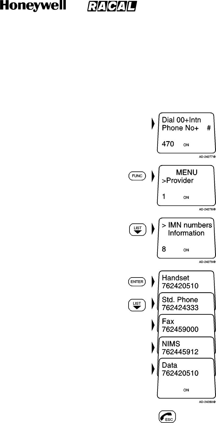
SYSTEM DESCRIPTION AND INSTALLATION MANUAL
SCS--1000 Mini--M Aero SATCOM System
23--20--28
Use or disclosure of information on this page is subject to the restrictions in the proprietary notice of this document.
Page 2--13
31 Jan 2000
G. IMN Numbers Readout
This function lists the IMN numbers assigned to the Mini--M Aero SATCOM System.
Editing of the numbers on the telephone or SIM card can only be performed from the PC
when connected.
To readout the IMN numbers, perform the following:
NOTE: The following message appears in the display
when in the idle mode:
(1) Push the FUNC key to open the function MENU:
(2) Use the LIST down key to scroll down to the IMN
numbers:
(3) Push the ENTER key to enter the list, and then
use the LIST down key to display the assigned
IMN numbers: then
(4) Push the ESC key twice to revert to the idle mode. 2X
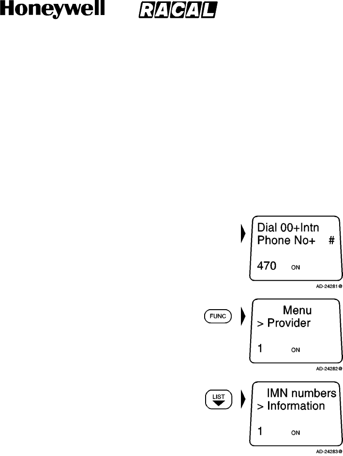
SYSTEM DESCRIPTION AND INSTALLATION MANUAL
SCS--1000 Mini--M Aero SATCOM System
23--20--28
Use or disclosure of information on this page is subject to the restrictions in the proprietary notice of this document.
Page 2--14
31 Jan 2000
H. Information Readout
The following information is provided:
TPU version number
Forward ID number that identifies the user’s particular Mini--M Aero System and SIM
card,ifinstalled
System version numbers of the internal software programs.
To readout the information, perform the following:
NOTE: The following message appears in the display
when in the idle mode:
(1) Push the FUNC key to open the function MENU:
(2) Use the LIST down key to scroll down to the
information:
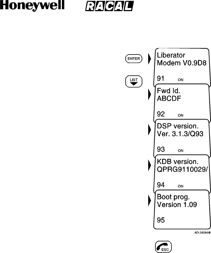
SYSTEM DESCRIPTION AND INSTALLATION MANUAL
SCS--1000 Mini--M Aero SATCOM System
23--20--28
Use or disclosure of information on this page is subject to the restrictions in the proprietary notice of this document.
Page 2--15
31 Jan 2000
(3) Push the ENTER key to access the list, and then
use the LIST down key to display the information
available: then
(4) Push the ESC key twice to revert to the idle mode. 2X
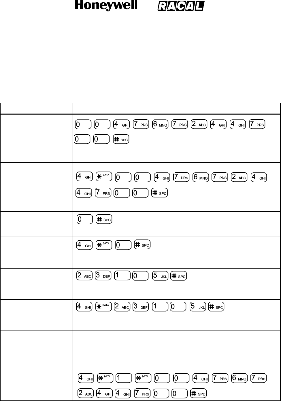
SYSTEM DESCRIPTION AND INSTALLATION MANUAL
SCS--1000 Mini--M Aero SATCOM System
23--20--28
Use or disclosure of information on this page is subject to the restrictions in the proprietary notice of this document.
Page 2--16
31 Jan 2000
I. Calls from the Telephone
A telephone connected to the RJ--11 jack in the TPU can be used to make calls. (Refer
to Table 1--10 for specifications.) Additional control of functions must be done from the
HSU or a PC connected to the RS--232 port of the TPU. Table 2--2 gives the telephone
features.
Table 2--2. Telephone Features
Function Description
Call through Default
Network Service Provider
routes the call through the default network service provider for the satellite
(Ocean Region) that the user is using.
Call through Selected
Network Service Provider
routes the call through the network service provider Telenor (4) in Norway.
Last Number Redialing
retransmits the last number.
Last Number Redialing
through the Selected
t
h
r
o
u
g
h
t
h
e
S
e
l
e
c
t
e
d
Network Service Provider retransmits the last number through the selected network service provider
(Telenor = 4).
Short Number Dialing
(Pre
f
ix 23)
(
P
r
e
f
i
x
2
3
)
fetches and sends the telephone number stored on the SIM card under the
number 105.
Short Number Dialing
(Pre
f
ix 23) throu
g
hthe
(
P
r
e
f
i
x
2
3
)
t
h
r
o
u
g
h
t
h
e
Selected Network Service
Provider fetches and sends the telephone number stored under the number 105 through
the selected network service provider (Telenor = 4).
Call through Selected
Network Service Provider
and Terrestrial Network
Dialing through a terrestrial network is only possible using a selected network
service provider. The number may be in the range of 0 to 127.
Example of a call through the selected network service provider, e.g., Telenor,
and terrestrial network 1:
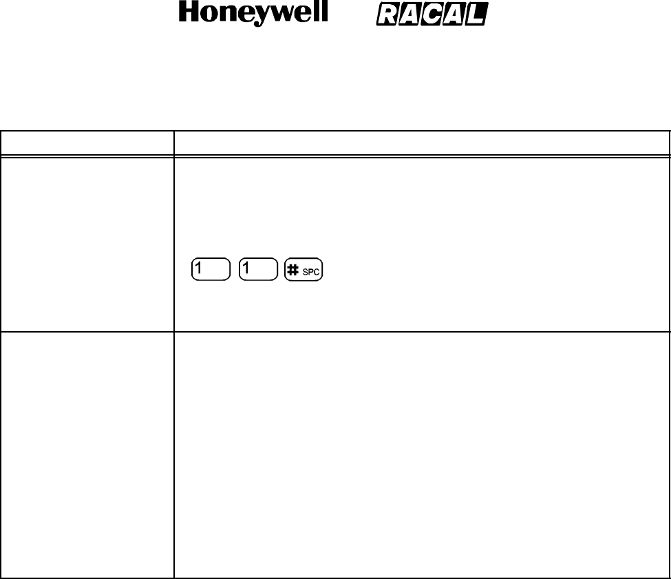
SYSTEM DESCRIPTION AND INSTALLATION MANUAL
SCS--1000 Mini--M Aero SATCOM System
23--20--28
Use or disclosure of information on this page is subject to the restrictions in the proprietary notice of this document.
Page 2--17
31 Jan 2000
Table 2--2. Telephone Features (cont)
Function Description
Service Calls Special information services are accessible with a 2--digit service address
code. See Appendix B for a list of service address codes.
The following is an example of obtaining assistance from the international
operator. Dial:
NOTE: Not all network service providers offer every service listed.
Call the SCS--1000 To call the SCS--1000, dial the international prefix followed by the 87X IMN
number, for example from the U.S., 011 871 762420510. The Xin 87X
depends on which satellite the SCS--1000 is currently using:
1--AOR--E(Atlantic Ocean Region East)
2--POR(Pacific Ocean Region)
3 -- IOR (Indian Ocean region)
4--AOR--W(Atlantic Ocean Region West)
NOTE: Some network service providers support the common Ocean Region
access number 870, which connects the call to the dialed SCS--1000
regardless of the Ocean Region the user currently communicates
through.
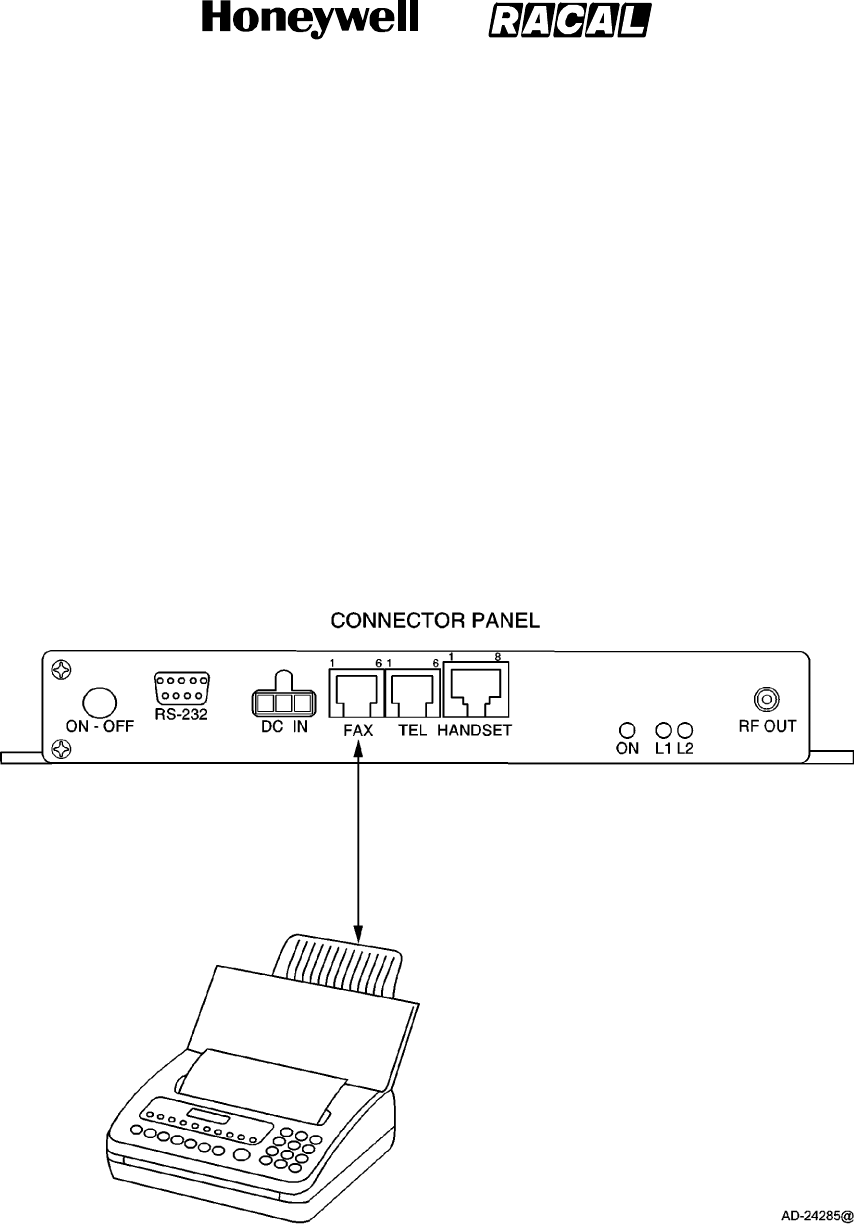
SYSTEM DESCRIPTION AND INSTALLATION MANUAL
SCS--1000 Mini--M Aero SATCOM System
23--20--28
Use or disclosure of information on this page is subject to the restrictions in the proprietary notice of this document.
Page 2--18
31 Jan 2000
4. Telefax Service
The TPU provides access to a telefax service at a transmission rate of 2.4 kpbs. The TPU is
fully compatible with the world’s leading telefax machines and telefax software standards.
NOTE:Transmission may not be possible through some of the telefax machines available on
the market. Check with the network service provider before purchasing a telefax
machine for use with the SCS system.
A. Setup
Connect the telefax machine to the FAX port on the TPU connector panel as shown in
Figure 2--4. (Refer to the telefax machine owner’s manual to set the default transmission
rate to 2.4 kpbs.) Verify that the FAX port is configured for telefax service. Refer to the
advanced functions port configuration paragraph 7.K.(4)(a) in this section for information
on how to configure the FAX port for telefax service. Paragraph 3. of this section
describes the operation of the HSU.
Figure 2--4. Telefax Communications with the SCS System
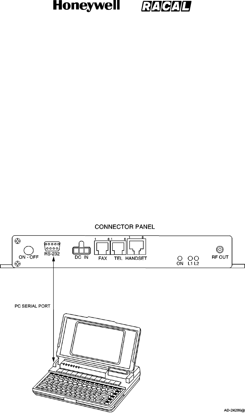
SYSTEM DESCRIPTION AND INSTALLATION MANUAL
SCS--1000 Mini--M Aero SATCOM System
23--20--28
Use or disclosure of information on this page is subject to the restrictions in the proprietary notice of this document.
Page 2--19
31 Jan 2000
B. Transmission
Telefax calls made by the SCS system are telefax only. Any telephone handset
connected to the telefax machine is for dialing purposes only. To send a facsimile, use
the same dialing sequences as when making a call, either through the default network
service provider or a selected network service provider. Enter the pound (#) key as the
last digit before starting the transmission.
Telefax transmissions normally take 1.5 minutes per standard text page using standard
resolution. Using superfine or halftone resolution doubles the transmission time. To save
time, avoid using a separate cover page. If a call failure should occur while sending a
multi--page document, re--send only the failed pages.
5. Data Service
Access to all system functions is obtained by connecting a PC to the RS--232 port on the TPU
connector panel as shown in Figure 2--5. With a VT100 compatible terminal emulator, such as
Windows 95 -- HyperTerminal, the menu is displayed on the PC screen. The TPU also
provides access to asynchronous data services through its built--in modem capability. The
transmission rate over the satellite is 2.4 kpbs, and any standard PC with a serial port can be
used.
Figure 2--5. PC Connections to the SCS System

SYSTEM DESCRIPTION AND INSTALLATION MANUAL
SCS--1000 Mini--M Aero SATCOM System
23--20--28
Use or disclosure of information on this page is subject to the restrictions in the proprietary notice of this document.
Page 2--20
16 Oct 2000
A. Data Port Setup
The DATA port on the TPU may be set to operate with a PC, or with a printer. To operate
with a PC, the initial settings of the DATA port must be as follows:
Speed, normally 38,400 bps
8 data bits
No parity
1stopbit.
B. Initial Settings on PC
Use a PC terminal emulator program, such as HyperTerminal, to make the following initial
settings:
(1) Start the HyperTerminal
(2) Enter a name for the terminal, for example: TPU_test
(3) In the phone number window, select Direct to COM1 (or the COM port the TPU is
connected to)
(4) In the COM1 Properties window, set as follows:
Bits per second: 38,400 bps
Data bits: 8
Parity: None
Stop bits: 1
Flow control: None.
(5) In the File menu, select Properties then click Settings and select Terminal.
(6) Select ANSI in the Emulation list box.
(7) In the view menu, click Fonts. Select Terminal in the fonts list. Set the size to 11
points.
(8) Click on Ok.
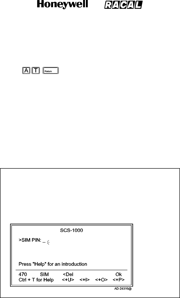
SYSTEM DESCRIPTION AND INSTALLATION MANUAL
SCS--1000 Mini--M Aero SATCOM System
23--20--28
Use or disclosure of information on this page is subject to the restrictions in the proprietary notice of this document.
Page 2--21
31 Jan 2000
C. Testing the Installation
Enter a command on the PC keyboard to verify that an OK is displayed on the PC screen.
An example command is shown below:
If there is no response, check that the baud rate setting is the same for both the PC and
the TPU.
D. Procedures for Starting PC Data Services
Perform the following procedures for starting the data service from the PC:
(1) Turn on the TPU. See paragraph 3.A. for procedures to turn on the system.
(2) Open the terminal emulator on the PC and connect. Key in the start prompt
at+wneradte. Refer to Figure 2--6.
NOTE: When using the terminal emulator, the data/printer port Data Terminal
Equipment (DTE) is busy and is not capable of receiving a data call.
at+wneradte
Terminal MMI started in mode: MMI (multilingual)
CTRL--f to switch font
CTRL--xtoreturntoATcommandmode.
Press space to continue
Figure 2--6. Keying in the Start Prompt
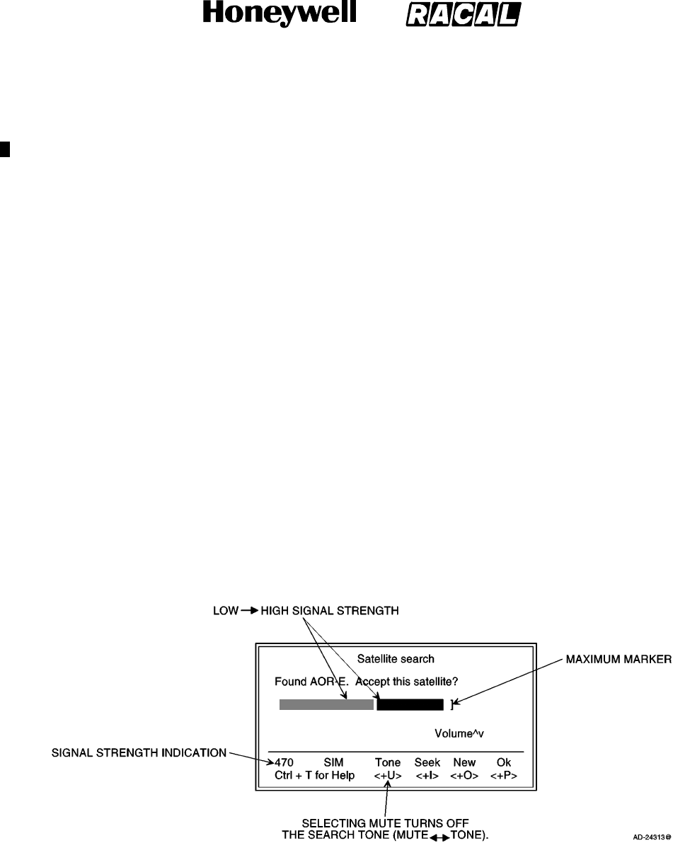
SYSTEM DESCRIPTION AND INSTALLATION MANUAL
SCS--1000 Mini--M Aero SATCOM System
23--20--28
Use or disclosure of information on this page is subject to the restrictions in the proprietary notice of this document.
Page 2--22
16 Oct 2000
NOTE: The user is prompted for the 4--8 digit PIN each time the system is switched on.
(3) Enter the SIM PIN code and push the CONTROL key and P key.
NOTE: If no SIM card is installed, the user is prompted to enter the Phone PIN.
(4) During the satellite search, beep tones are heard in the handset as follows:
HHHHHHHHSlow intermittent tones when searching
for any satellite.
HHHHHHHHHHHHHHHHH Rapid intermittent tones when searching
for a specific satellite (faster when
searching for a single satellite).
(5) When receiving a satellite signal, a short tone is sounded. If it is an Inmarsat
satellite, a continuous tone is sounded with varying frequency provided the tone is
on. When closing in on a satellite, the tone should increase in frequency.
(6) A signal strength bar appears on the PC display screen. The longer the signal bar or
higher the signal strength indicator value, the better the signal quality. The bar
becomes dashed when the signal strength value reaches 400. The maximum marker
indicates the highest signal strength achieved during the current satellite search.
Refer to Figure 2--7.
NOTE: The VOLUME indicator appears when the Tone is ON.
Figure 2--7. Signal Strength of Satellite Search
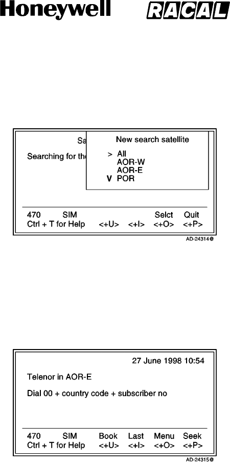
SYSTEM DESCRIPTION AND INSTALLATION MANUAL
SCS--1000 Mini--M Aero SATCOM System
23--20--28
Use or disclosure of information on this page is subject to the restrictions in the proprietary notice of this document.
Page 2--23
31 Jan 2000
(7) Selecting the SEEK function starts the satellite search again. The NEW function
allows the selection of a specific satellite. Scroll down to the desired satellite and
select. An example is given below:
NOTE: Searching for a new satellite should be done under special circumstances
only. Searching for any satellite is the normal (default) mode of operation.
(8) Selecting OK initializes the system.
(9) The equipment is ready for use when the main window appears as shown below:
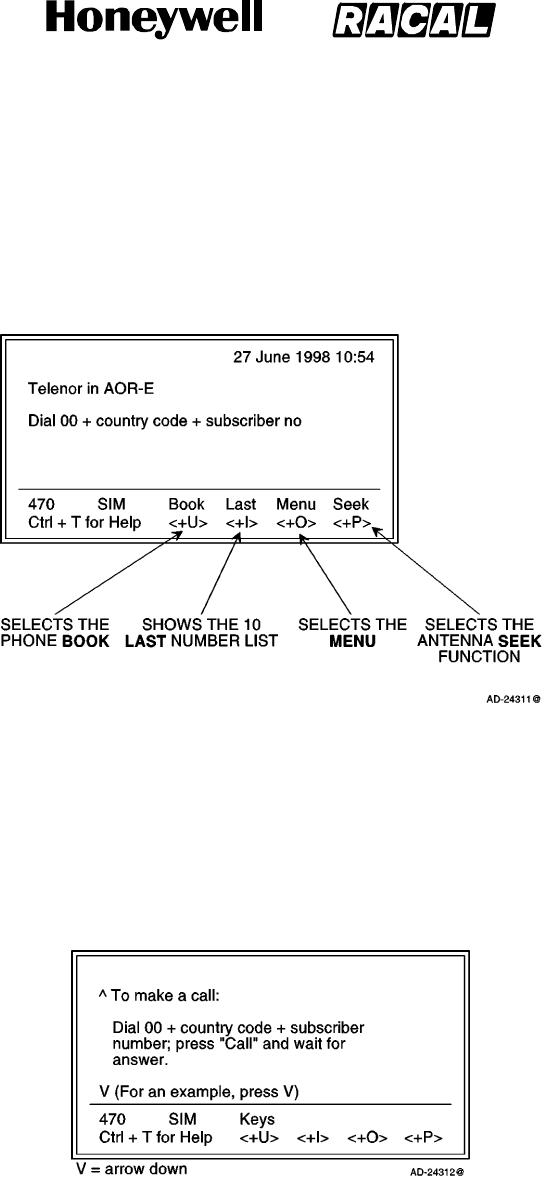
SYSTEM DESCRIPTION AND INSTALLATION MANUAL
SCS--1000 Mini--M Aero SATCOM System
23--20--28
Use or disclosure of information on this page is subject to the restrictions in the proprietary notice of this document.
Page 2--24
31 Jan 2000
E. Selecting Functions Using a PC
The display screen shows the function currently assigned to each soft key:
<U, I, O, or P>. The function is selected by pushing the CONTROL key and the
U, I, O, or P key simultaneously. The example below shows the function that can be
selected when starting the system:
NOTE: The function selected by pushing the keys varies with the opened window. Refer to
paragraph 7. in this section for an overview of the functions provided by the SCS system.
F. Help
Pushing the CONTROL key and T key selects the HELP function whenever it is needed
by the user. See the example below:
Pushing the CONTROL key and U key selects the KEYS function for a direct explanation
of the various tasks performed by the four soft keys.
G. Printing
When printing, such as a NIMS message or traffic log, the display screen switches to the
text mode. The system must be restarted to revert to the data mode.
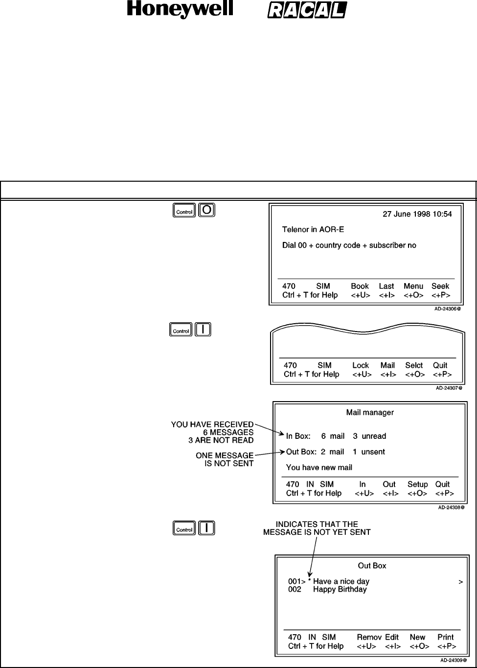
SYSTEM DESCRIPTION AND INSTALLATION MANUAL
SCS--1000 Mini--M Aero SATCOM System
23--20--28
Use or disclosure of information on this page is subject to the restrictions in the proprietary notice of this document.
Page 2--25
31 Jan 2000
6. Procedures for Sending and Receiving NIMS Messages
Sending and receiving NIMS messages is only possible through network service providers
that support the NIMS service. The procedures for sending NIMS messages through the PC
are provided in Table 2--3. The procedures for receiving NIMS message through the PC are
provided in Table 2--4.
Table 2--3. Procedure for Sending NIMS Messages
Task Key Strokes PC Screen Display
1. Select Menu.
2. Select Mail to open the Mail
manager window.
Example:
3. Selecting the Out menu option
on the Mail manager window
opens the Out Box screen.
Use the DOWN key to scroll
down to the desired message.
a. Selecting the Remov
menu option (pushing the
CONTROL and U keys)
on the Out Box window
erases the selected
message.
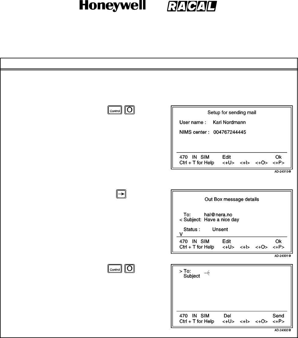
SYSTEM DESCRIPTION AND INSTALLATION MANUAL
SCS--1000 Mini--M Aero SATCOM System
23--20--28
Use or disclosure of information on this page is subject to the restrictions in the proprietary notice of this document.
Page 2--26
31 Jan 2000
Table 2--3. Procedure for Sending NIMS Messages (cont)
Task PC Screen DisplayKey Strokes
b. Selecting the Print menu option (pushing the CONTROL and P keys) on the Out Box window
outputs the message to the display screen.
NOTE: The Print menu option appears only if a printer is enabled. Refer to paragraph 7.G. in this
section.
c. Selecting the Setup menu
option on the Out Box
window opens the Setup
for sending mail window.
NOTE: Selecting Ok (pushing the
CONTROL and P keys) returns the
user to the mail manager window.
d. Pushing the right arrow
key on the Out Box
window opens the Out
Box message details
window.
e. Selecting the New menu
option on the Out Box
window opens a window
for a new message.
NOTE: Selecting Del
(pushing the
CONTROL and U
keys) deletes the
message without
sending it.
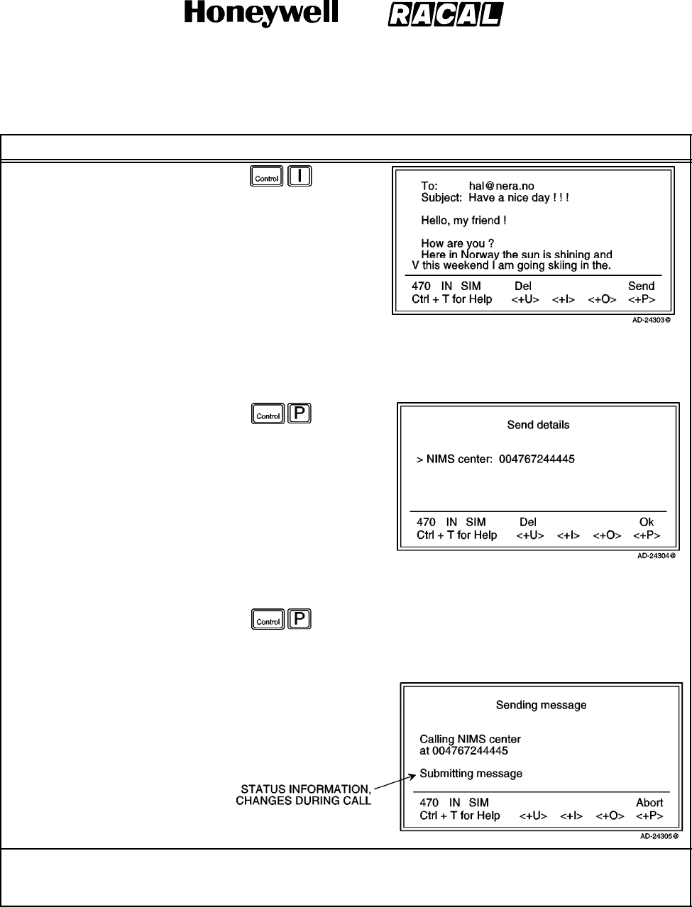
SYSTEM DESCRIPTION AND INSTALLATION MANUAL
SCS--1000 Mini--M Aero SATCOM System
23--20--28
Use or disclosure of information on this page is subject to the restrictions in the proprietary notice of this document.
Page 2--27
31 Jan 2000
Table 2--3. Procedure for Sending NIMS Messages (cont)
Task PC Screen DisplayKey Strokes
f. Selecting the Edit menu
option on the Out Box
window allows the user to
edit a message. Use the
DOWN key to scroll down
to the desired line.
NOTE: Selecting Edit (pushing the
CONTROL and U keys) on the Out
Box message details window also
opens the Edit window.
NOTE: Pushing the ESC key on the Edit
window opens a window that gives
the choice of sending the mail later.
g. Selecting the Send menu
option on the Edit window
shows the send details of
the mail message.
NOTE: Selecting Send (pushing the
CONTROL and P keys) on the New
message window also opens the
Send details window.
NOTE: Selecting Del (pushing the
CONTROL and U keys) deletes the
message without sending it.
h. Selecting Ok on the Send
details window opens a
window showing that the
message is being sent.
NOTE: The Abort menu
option (pushing the
CONTROL and P
keys) stops NIMS
after confirmation.
NOTE: The IMN number of the NIMS service must have been entered into the SCS System to allow
communication. Refer to the advanced functions information available paragraph
7.K.(5) in this section.
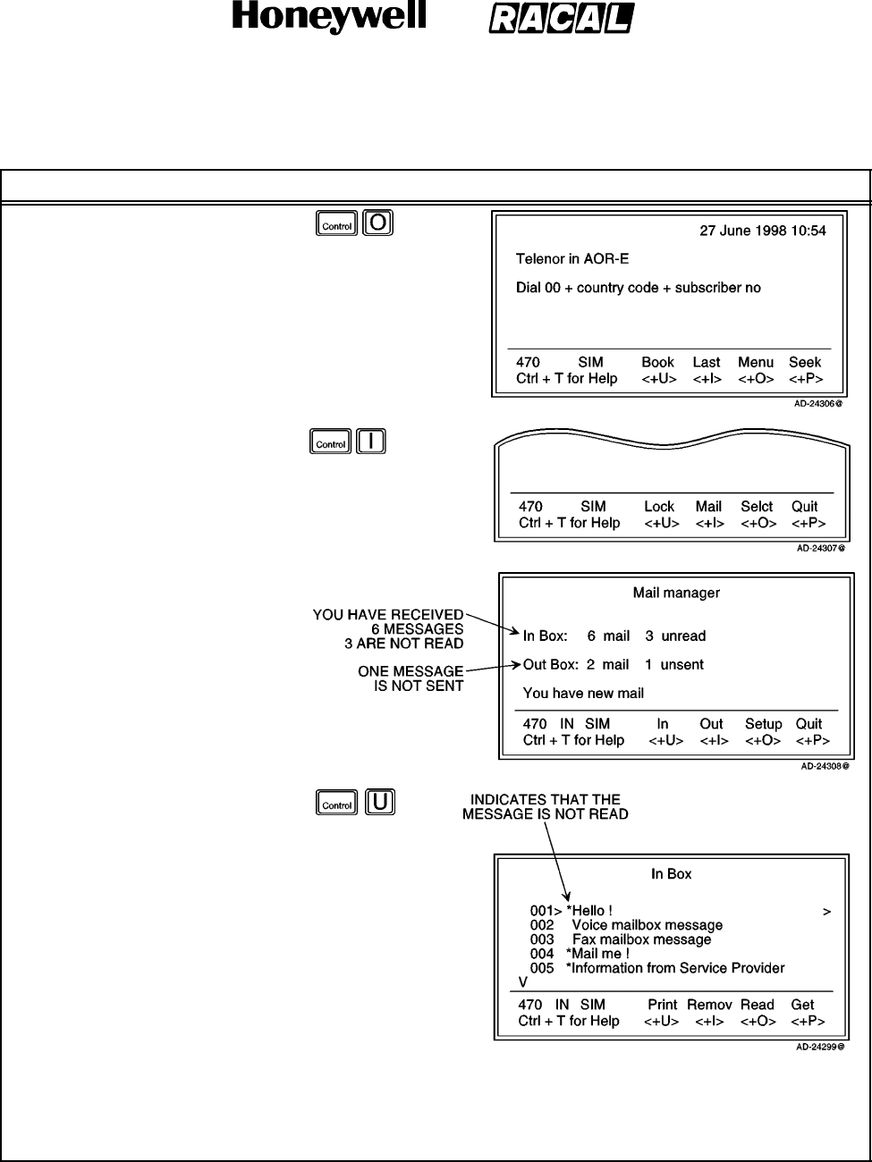
SYSTEM DESCRIPTION AND INSTALLATION MANUAL
SCS--1000 Mini--M Aero SATCOM System
23--20--28
Use or disclosure of information on this page is subject to the restrictions in the proprietary notice of this document.
Page 2--28
31 Jan 2000
Table 2--4. Procedure for Receiving NIMS Messages
Task Key Strokes PC Screen Display
1. Select Menu.
2. Select Mail to open the Mail
manager window.
Example:
3. Selecting the In menu option
on the Mail manager window
opens the In Box screen. Use
the DOWN key to scroll down
to the desired message.
a. Selecting the Remov
menu option (pushing the
CONTROL and I keys) on
the In Box window erases
the selected message.
b. Selecting the Print menu option (pushing the CONTROL and U keys) on the In Box window outputs
the message to the display screen.
NOTE: The Print menu option appears only if a printer is enabled. Refer to paragraph 7.G. in this
section.
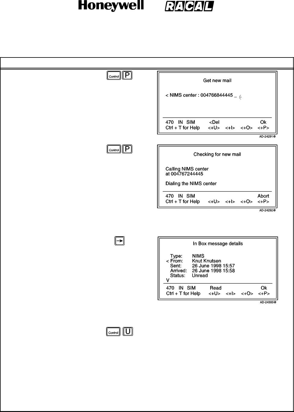
SYSTEM DESCRIPTION AND INSTALLATION MANUAL
SCS--1000 Mini--M Aero SATCOM System
23--20--28
Use or disclosure of information on this page is subject to the restrictions in the proprietary notice of this document.
Page 2--29
31 Jan 2000
Table 2--4. Procedure for Receiving NIMS Messages (cont)
Task PC Screen DisplayKey Strokes
c. Selecting Get on the In
Box window calls the
NIMS server to read out
stored NIMS messages.
(1) Selecting Ok opens a
window showing that
the NIMS server is
checking for new mail.
(2) Modify the server
number if required by
selecting Del (pushing
the CONTROL and U
keys).
NOTE: Selecting Abort (pushing the CONTROL and P keys) stops the request to the NIMS
server.
d. Pushing the right arrow
key on the In Box window
opens the In Box
message details window.
(1) Selecting Ok (pushing the CONTROL and P keys) on the In Box message details window
returns the user to the In Box window.
(2) Selecting Read on the
In Box message
details window or
selecting Read
(pushing the
CONTROL and O
keys) on the In Box
window allows the
user to read the
desired message.
NOTE: See the following
examples.
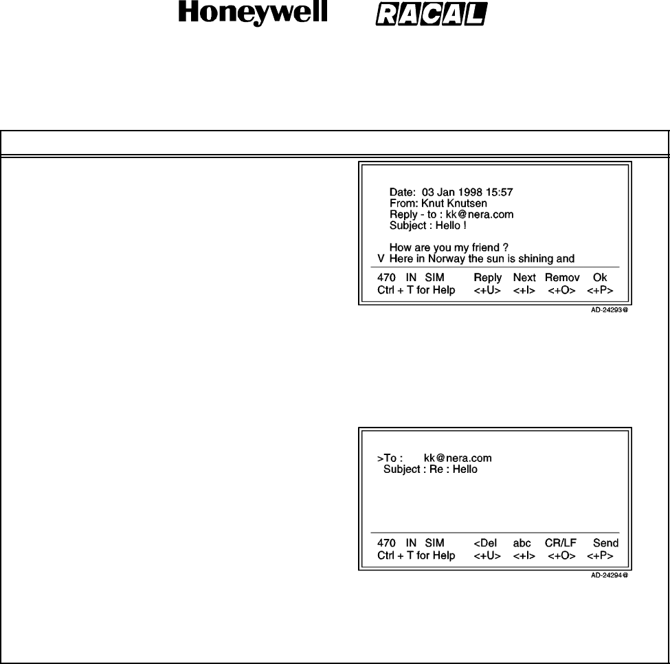
SYSTEM DESCRIPTION AND INSTALLATION MANUAL
SCS--1000 Mini--M Aero SATCOM System
23--20--28
Use or disclosure of information on this page is subject to the restrictions in the proprietary notice of this document.
Page 2--30
31 Jan 2000
Table 2--4. Procedure for Receiving NIMS Messages (cont)
Task PC Screen DisplayKey Strokes
Example 1:
(Hello ! message from the In Box)
NOTES:
1. Selecting the Next menu option (pushing the CONTROL and I keys) displays the next
message.
2. Selecting the Remov menu option (pushing the CONTROL and O keys) erases the message.
3. Selecting Ok (pushing the CONTROL and P keys) returns the user to the In Box window.
4. Selecting Reply (pushing the
CONTROL and U keys) opens the
following window that allows the user
to send a reply message:
(1) Selecting Del (pushing the CONTROL and U keys)
on this window deletes the reply message.
(2) Selecting Send (pushing the CONTROL and P
keys) on this window sends the reply message.
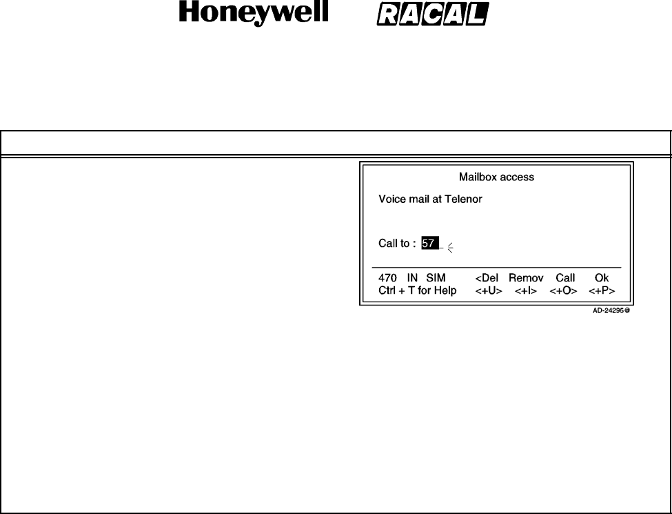
SYSTEM DESCRIPTION AND INSTALLATION MANUAL
SCS--1000 Mini--M Aero SATCOM System
23--20--28
Use or disclosure of information on this page is subject to the restrictions in the proprietary notice of this document.
Page 2--31
31 Jan 2000
Table 2--4. Procedure for Receiving NIMS Messages (cont)
Task PC Screen DisplayKey Strokes
Example 2:
(Voice mailbox message from In Box)
NOTES:
1. Selecting the Del menu option (pushing the CONTROL and U keys) on the Mailbox
access window deletes the message.
2. Selecting the Remov menu option (pushing the CONTROL and I keys) on the Mailbox
access window erases the alert message.
3. Selecting the Call menu option (pushing the CONTROL and O keys) on the Mailbox
access window dials the mailbox to read out the voice message.
4. Selecting Ok (pushing the CONTROL and P keys) on the Mailbox access window returns
the user to the In Box window.
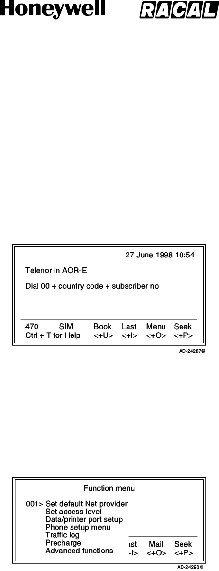
SYSTEM DESCRIPTION AND INSTALLATION MANUAL
SCS--1000 Mini--M Aero SATCOM System
23--20--28
Use or disclosure of information on this page is subject to the restrictions in the proprietary notice of this document.
Page 2--32
31 Jan 2000
7. Functions
A. General
The SCS system provides the following functions (see Figure 2--8):
Phone Book (Book)
Last number list (Last)
Setting up (Seek)
Menu.
Figure 2--8. PC Main Window
Selecting Menu (pushing the CONTROL and O keys) on the Main window opens the
Function menu window as shown in Figure 2--9. Use the up or down arrow on the
keyboard to scroll up or down and select the desired function. The reference number can
also be keyed in for direct selection. Table 2--5 gives the description of each function.
Figure 2--9. Function Menu Window

SYSTEM DESCRIPTION AND INSTALLATION MANUAL
SCS--1000 Mini--M Aero SATCOM System
23--20--28
Use or disclosure of information on this page is subject to the restrictions in the proprietary notice of this document.
Page 2--33
16 Oct 2000
Table 2--5. Function Menu Descriptions
Reference Function Description
001 Set default network provider Lets the user change the network service provider and
terrestrial network.
For a detailed description, refer to paragraph 7.E. in this
section.
002 Set access level Allows shifting between the user level and the owner/CHV2
level (non--SIM/SIM operation). This function also lets the
user change the phone/SIM PIN code and the owner/CHV2
password.
For a detailed description, refer to paragraph 7.F. in this
section.
003 Data/Printer port setup Enables the port for connection of a printer or PC and sets the
transfer bit rate.
For a detailed description, refer to paragraph 7.G. in this
section.
004 Phone setup menu Sets the following:
Display backlight and contrast
Receive volume
System clock
Key lock code
Language
Mailbox access numbers
Call charge.
For a detailed description, refer to paragraph 7.H. in this
section.
006 Traffic log Logs outgoing calls and supplies a detailed printout.
For a detailed description, refer to paragraph 7.I. in this
section.
008 Precharge Allows preprogramming of the total duration of a call.
For a detailed description, refer to paragraph 7.J. in this
section.
009 Advanced functions Sets or allows viewing of the following:
Access control
Aero functions
Satellite setup
Configuration
Information available
Install.
For a detailed description, refer to paragraph 7.K. in this
section. See Figure 2--10.
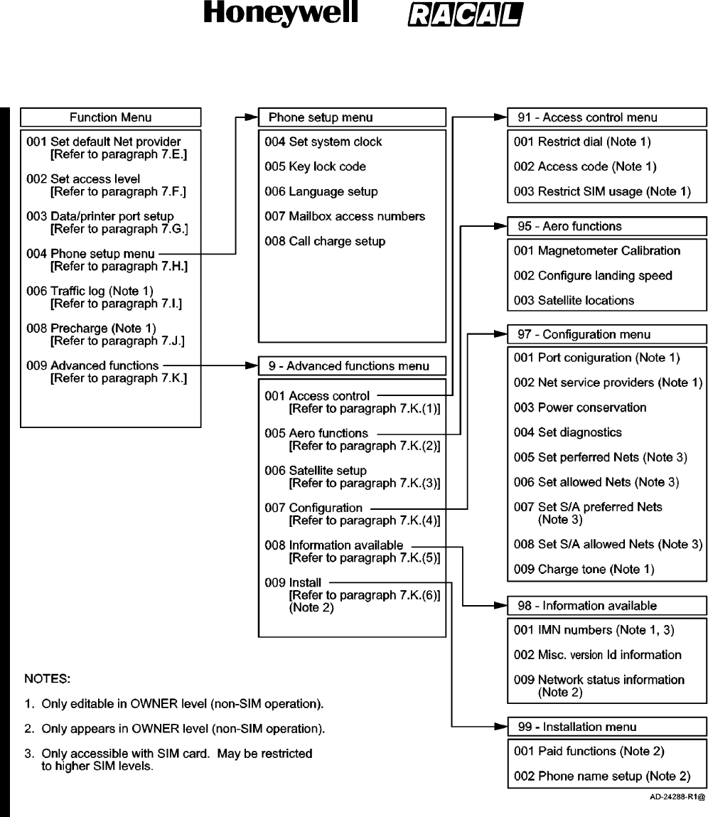
SYSTEM DESCRIPTION AND INSTALLATION MANUAL
SCS--1000 Mini--M Aero SATCOM System
23--20--28
Use or disclosure of information on this page is subject to the restrictions in the proprietary notice of this document.
Page 2--34
16 Oct 2000
Figure 2--10. Overview of Menu Functions
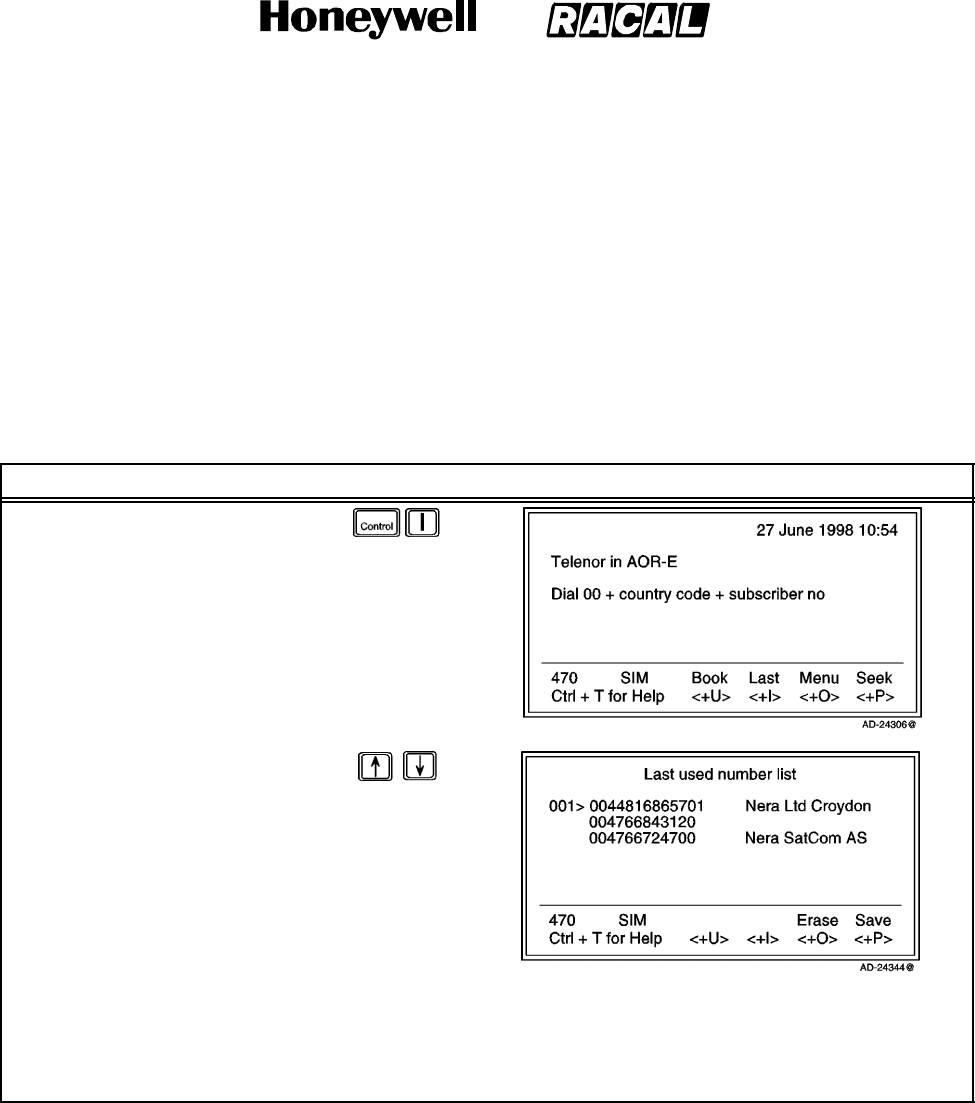
SYSTEM DESCRIPTION AND INSTALLATION MANUAL
SCS--1000 Mini--M Aero SATCOM System
23--20--28
Use or disclosure of information on this page is subject to the restrictions in the proprietary notice of this document.
Page 2--35
31 Jan 2000
B. Last Number List
The last 10 numbers called are stored in the TPU memory or on the SIM card. Each
number may be up to 22 digits. If the number is already stored in the phone book, the
subscriber’s name appears in the list.
NOTE: The last used number list stored on the SIM card replaces that of the phone
when inserting the card. (It is restored when removing the SIM.)
To readout the last number list, perform the steps in Table 2--6.
Table 2--6. Procedure for Last Number List Readout
Task Key Strokes PC Screen Display
1. Select Last from the Main
window.
2. Scroll up or down to the
desired number on the list.
3. Selecting the Save menu option (pushing the CONTROL and P keys) copies the number to the
phone book.
NOTE: A name is prompted.
4. Selecting Erase (pushing the CONTROL and O keys) deletes all entries in the Last used number list.
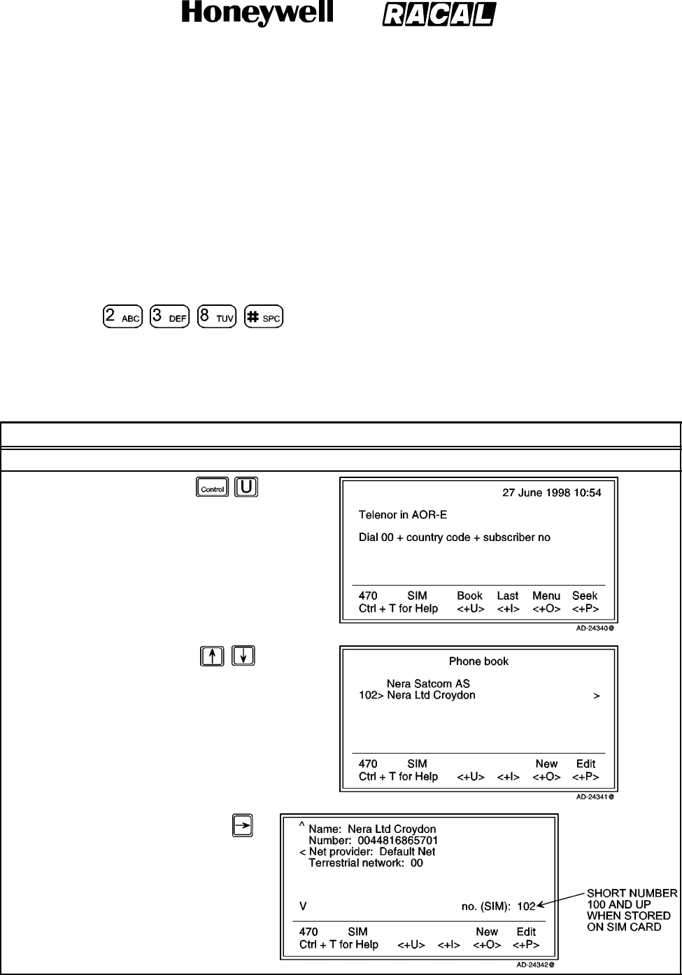
SYSTEM DESCRIPTION AND INSTALLATION MANUAL
SCS--1000 Mini--M Aero SATCOM System
23--20--28
Use or disclosure of information on this page is subject to the restrictions in the proprietary notice of this document.
Page 2--36
31 Jan 2000
C. Phone Book
The following may be stored for abbreviated dialing from the Handset Unit or telephone:
99 entries (No. 1 to 99) with names of up to 29 characters in the TPU.
Up to 100 entries (No.100 and up) with names of up to 10 characters on the SIM card
(varies with type).
NOTE: The list is sorted by name. The SIM card entries and phone entries merge when
the card is inserted.
The following is an example of short number dialing:
fetches and sends the telephone number stored in
the phone book under the short number 8.
To make a phone book entry, edit an entry, or copying an entry, perform the procedures in
Table 2--7.
Table 2--7. Phone Book Procedures
Task Key Strokes PC Screen Display
To make a phone book entry, perform the following:
1. Select Book on the
Main window.
2. Scroll up or down to
the desired name on
the list or search for
the first letter(s) of the
subscriber name.
3. Pushing the right
arrow button display
all of the data.
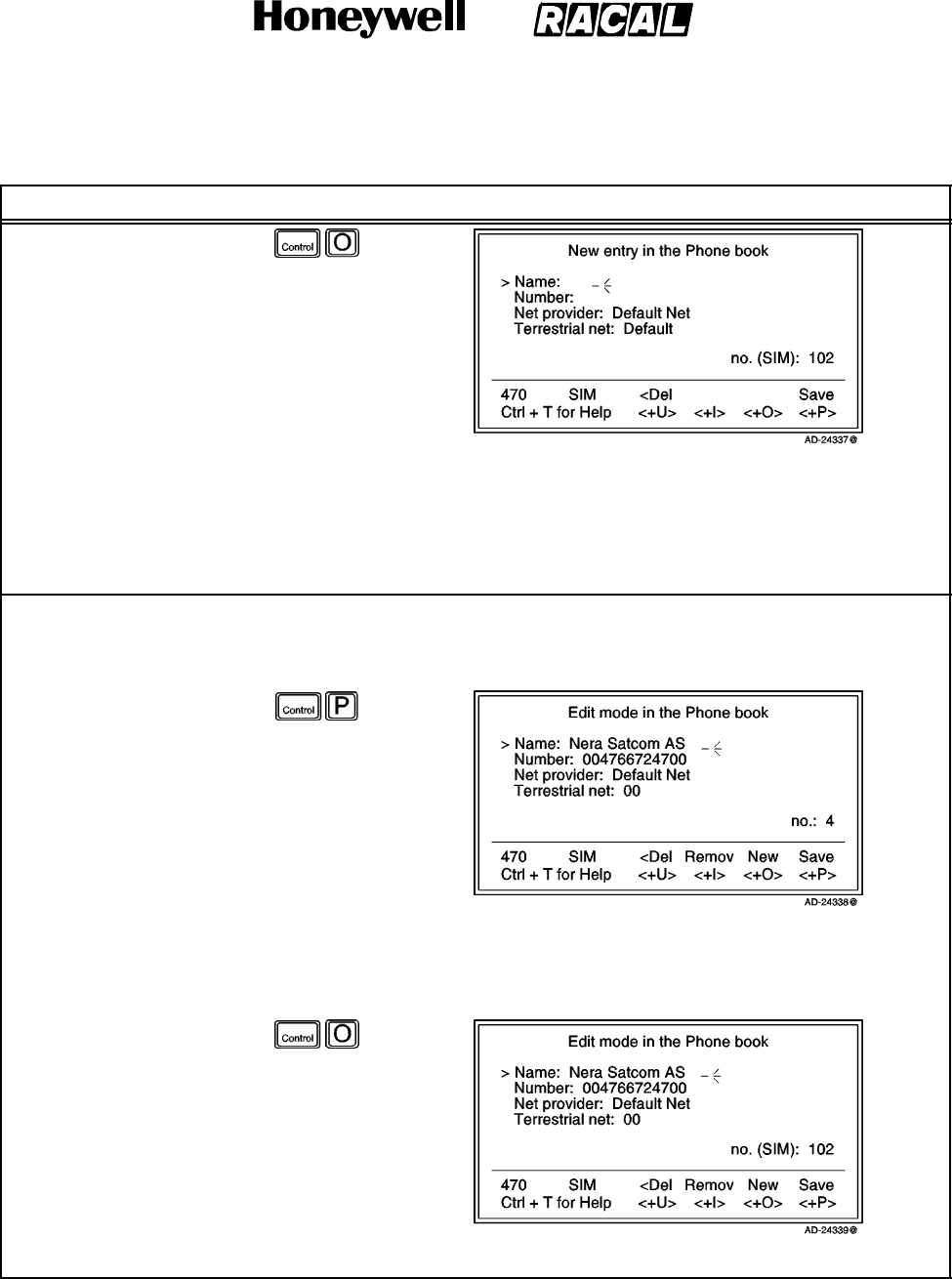
SYSTEM DESCRIPTION AND INSTALLATION MANUAL
SCS--1000 Mini--M Aero SATCOM System
23--20--28
Use or disclosure of information on this page is subject to the restrictions in the proprietary notice of this document.
Page 2--37
31 Jan 2000
Table 2--7. Phone Book Procedures (cont)
Task PC Screen DisplayKey Strokes
4. Pushing New on the
Phone book window
opens the New entry
in the Phone book
window.
a. Selecting Save
(pushing the
CONTROL and P
keys) saves the
entry.
b. Selecting Del
(pushing the
CONTROL and U
keys) deletes the
digit to the left of
the cursor.
To edit a phone book entry or copy an entry, perform the following:
1. Perform steps 1 thru 3
above.
2. Pushing Edit on the
Phone book window
opens the Edit mode
in the Phone book
window.
a. Selecting Save (pushing the CONTROL and P keys) saves the entry.
b. Selecting Remov (pushing the CONTROL and I keys) deletes the entry.
c. Selecting Del (pushing the CONTROL and U keys) deletes the digit to the left of the cursor.
d. Selecting New on
the Edit mode in
the Phone book
window copies the
entry (from a
non--SIM phone
book to a SIM
book, for
example)
NOTE: The entry is assigned the first free short number on the SIM card.
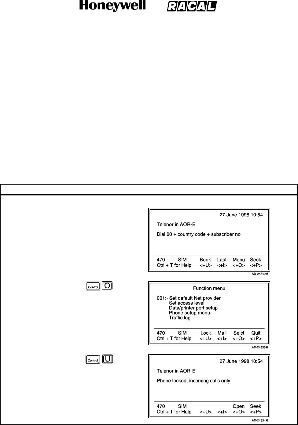
SYSTEM DESCRIPTION AND INSTALLATION MANUAL
SCS--1000 Mini--M Aero SATCOM System
23--20--28
Use or disclosure of information on this page is subject to the restrictions in the proprietary notice of this document.
Page 2--38
31 Jan 2000
D. Key Lock
The key lock function prevents unauthorized use when the system is on, but still allows
reception of incoming calls. When the lock is set no dial tone is produced, and the PC AT
commands are unavailable. Entering a login password (Phone PIN / SIM PIN) still
unlocks the phone.
NOTE: If Phone PIN / SIM PIN is disabled, turning power off and then on will not unlock
the phone.
This function is only accessible when the system is restricted for use with a specific SIM
card, or with no SIM card. Refer to the advanced functions access control paragraph
7.K.(1) in this section.
To initiate the key lock and enter or change the unlock code, refer to the key lock setup
paragraph 7.H.(2) in this section.
To set the lock or unlock, perform the procedures in Table 2--8.
Table 2--8. Key Lock/Unlock Procedures
Task Key Strokes PC Screen Display
To lock, perform the following:
1. Selecting Menu on the
Main window opens
the Function menu
window.
2. Select Lock on the
Function menu
window.
NOTE: A warning is
displayed in the
Main window.
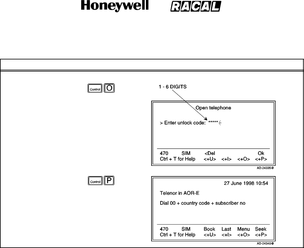
SYSTEM DESCRIPTION AND INSTALLATION MANUAL
SCS--1000 Mini--M Aero SATCOM System
23--20--28
Use or disclosure of information on this page is subject to the restrictions in the proprietary notice of this document.
Page 2--39
31 Jan 2000
Table 2--8. Key Lock/Unlock Procedures (cont)
Task PC Screen DisplayKey Strokes
To unlock, perform the following:
1. Selecting Open on the
Main window with the
key lock enabled
allows the user to
enter the unlock code.
2. Selecting Ok on the
Open telephone
window opens the
Main window.
E. Default Network Service Provider and Terrestrial Network
The default ISP for a satellite (Ocean Region) is automatically used if the user does not
select another one when making a call. To set the default network service provider,
perform the steps in Table 2--9.
NOTES:
1. When using SIM card, selection of an ISP is restricted to one of the allowed
network service providers.
2. When the Restricted network function is enabled, and with some SIM cards,
selection of the default network service provider is not possible. In this case, the
entry ”001 Set default Net provider” will not appear in the Function menu window.
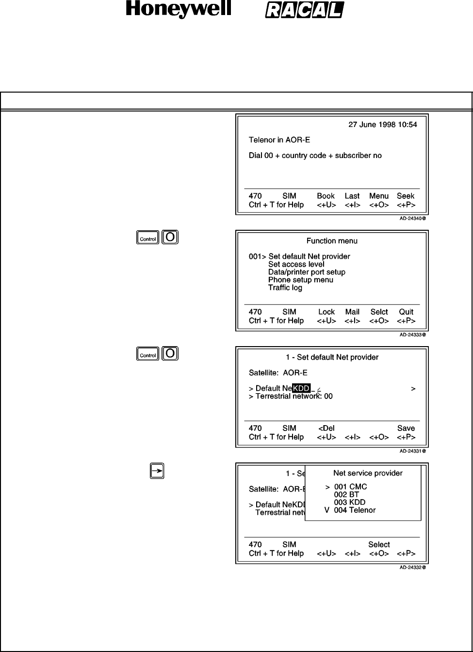
SYSTEM DESCRIPTION AND INSTALLATION MANUAL
SCS--1000 Mini--M Aero SATCOM System
23--20--28
Use or disclosure of information on this page is subject to the restrictions in the proprietary notice of this document.
Page 2--40
31 Jan 2000
Table 2--9. Default Network Service Provider and Terrestrial Network Procedure
Task Key Strokes PC Screen Display
1. Selecting Menu on the
Main window opens
the Function menu
window.
2. Selecting Selct or
pushing the right
arrow button opens
the Set default Net
provider window.
3. Key in the network
service provider code,
or push the right
arrow button to
display a list of the
available networks.
4. Scroll up or down to select the desired network.
5. Selecting Selct (pushing the CONTROL and O keys) enters the chosen network.
6. Repeat steps 3 thru 5 for entering the terrestrial network code.
7. Selecting Save (pushing the CONTROL and P keys) on the Set default Net provider window stores the
selected network service provider and terrestrial network as the default.
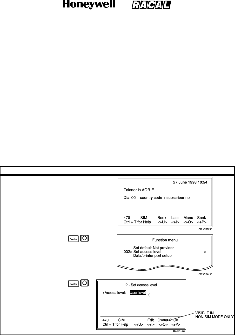
SYSTEM DESCRIPTION AND INSTALLATION MANUAL
SCS--1000 Mini--M Aero SATCOM System
23--20--28
Use or disclosure of information on this page is subject to the restrictions in the proprietary notice of this document.
Page 2--41
31 Jan 2000
F. User Access
The Mini--M Aero SATCOM System user program is accessible from two levels:
USER LEVEL -- accessed by Phone PIN or SIM PIN.
NOTE: If the Phone PIN is accidentally lost, it is possible to reset the user’s password to
the default password by logging in as the owner: “Phone PIN: the star button (*)
plus the owner’s password”. (Resetting is not possible on the SIM card.)
CHV2 LEVEL / OWNER LEVEL -- accessed by CHV2 or owner--level passwords. With
a SIM card inserted, the password allows access to CHV2 level SIM functions.
Without a SIM card the password allows access to owner level phone resident
functions.
WARNING: TO PREVENT MISUSE, THE DEFAULT PASSWORD MUST BE CHANGED
BEFORE PUTTING THE SCS SYSTEM IN OPERATION.
(1) User Level/Changing the PIN Code (SIM or Phone PIN)
To change the SIM PIN or Phone PIN at the user level, perform the procedures in
Table 2--10.
Table 2--10. User Access Procedures
Task Key Strokes PC Screen Display
1. Selecting Menu on the
Main window opens
the Function menu
window.
2. Scroll down to Set
access level.
3. Selecting Selct or
pushing the right
arrow button on the
Functions menu
opens the Set access
level window.
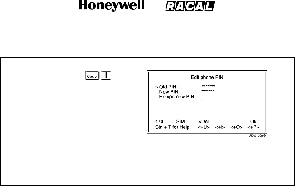
SYSTEM DESCRIPTION AND INSTALLATION MANUAL
SCS--1000 Mini--M Aero SATCOM System
23--20--28
Use or disclosure of information on this page is subject to the restrictions in the proprietary notice of this document.
Page 2--42
31 Jan 2000
Table 2--10. User Access Procedures (cont)
Task PC Screen DisplayKey Strokes
4. Selecting Edit on the
Set access level
window opens the Edit
phone PIN window.
5. Key in the following:
Current PIN code
New PIN code
Retype the new PIN
code to confirm.
6. Select Ok (pushing the CONTROL and P keys) following each entry, and to store the new PIN code.
NOTES:
1. Selecting Ok without entering any numbers for New PIN and Retype new PIN disables the SIM
PIN/Phone PIN.
2. The “Old” PIN code must be entered to reactivate the SIM PIN/Phone PIN.
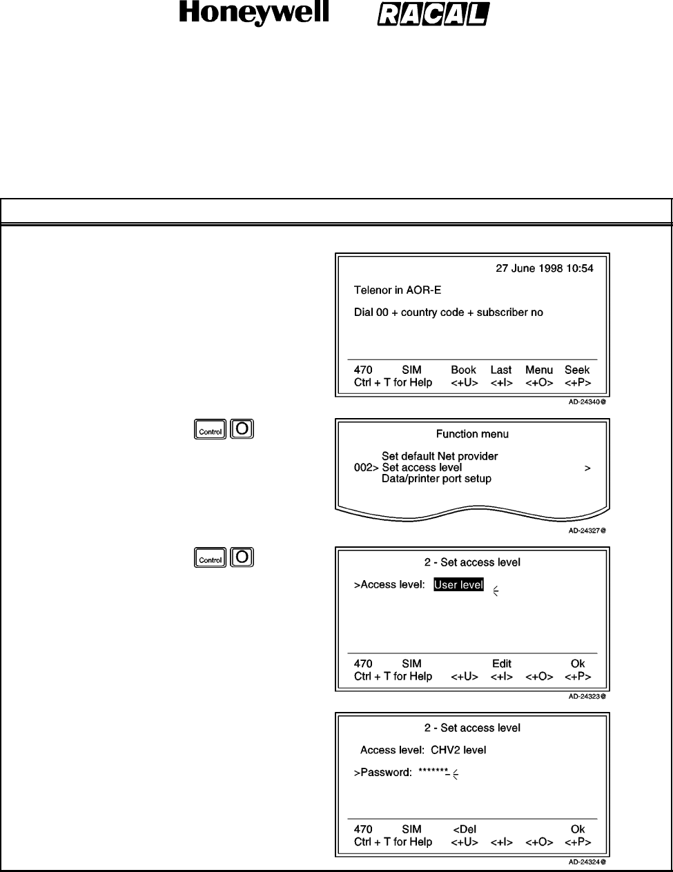
SYSTEM DESCRIPTION AND INSTALLATION MANUAL
SCS--1000 Mini--M Aero SATCOM System
23--20--28
Use or disclosure of information on this page is subject to the restrictions in the proprietary notice of this document.
Page 2--43
31 Jan 2000
(2) Shifting to CHV2/Changing the Password
To shift to CHV2 and change the password, perform the procedures in Table 2--11.
Table 2--11. Shifting to CHV2/Changing the Password Procedures
Task Key Strokes PC Screen Display
To shift to CHV2, perform the following:
1. Selecting Menu on the
Main window opens
the Function menu
window.
2. Scroll down to Set
access level.
3. Selecting Selct or
pushing the right
arrow button on the
Functions menu
opens the Set access
level window.
4. Key in 2002 to open
the window for
entering the
password.
5. Key in the password.
6. Selecting Ok (pushing
the CONTROL and P
keys) activates the
CHV2 level.
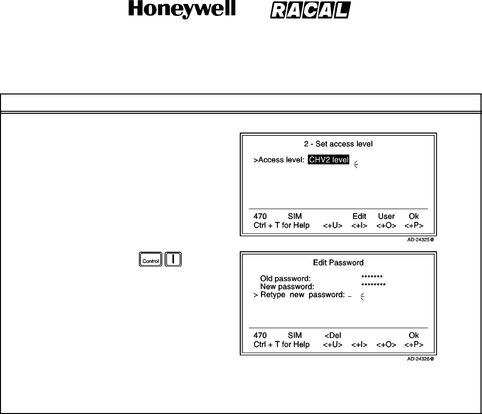
SYSTEM DESCRIPTION AND INSTALLATION MANUAL
SCS--1000 Mini--M Aero SATCOM System
23--20--28
Use or disclosure of information on this page is subject to the restrictions in the proprietary notice of this document.
Page 2--44
31 Jan 2000
Table 2--11. Shifting to CHV2/Changing the Password Procedures (cont)
Task PC Screen DisplayKey Strokes
To change the password, perform the following:
1. Open the Set access
level window again.
2. Selecting Edit on the
Set access level
window opens the Edit
password window.
3. Key in the following:
Current password
New password
Retype the new
password to
confirm.
4. Select Ok (pushing the CONTROL and P keys) following each entry, and to store the new password.
NOTE: To revert to the User level, reselect the Set access level function and select User.
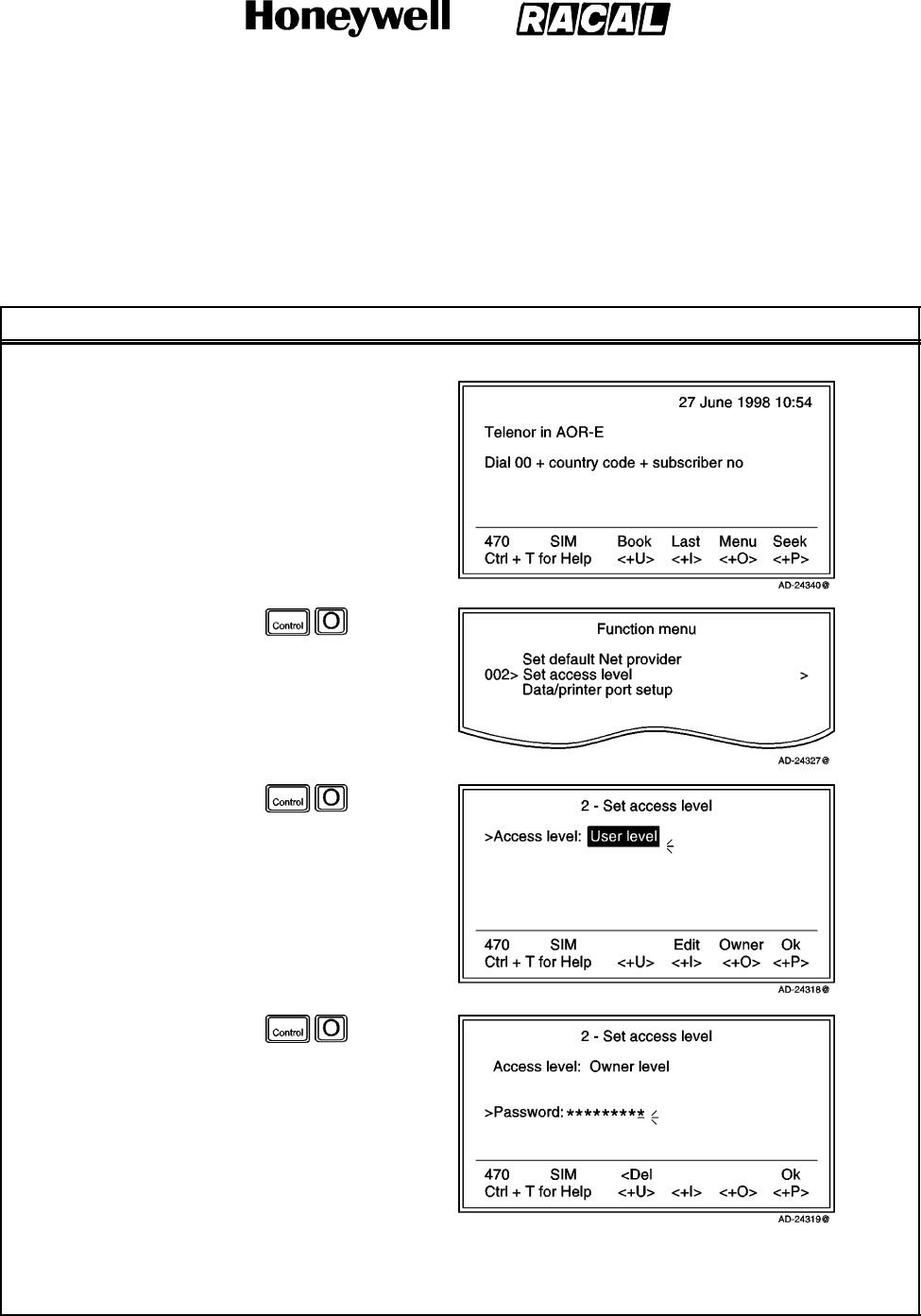
SYSTEM DESCRIPTION AND INSTALLATION MANUAL
SCS--1000 Mini--M Aero SATCOM System
23--20--28
Use or disclosure of information on this page is subject to the restrictions in the proprietary notice of this document.
Page 2--45
31 Jan 2000
(3) Shifting to Owner Level/Changing the Password
To shift to the owner level and change the password, perform the procedures in
Table 2--12.
Table 2--12. Shifting to Owner Level/Changing the Password Procedures
Task Key Strokes PC Screen Display
To shift to the owner level, perform the following:
1. Selecting Menu on the
Main window opens
the Function menu
window.
2. Scroll down to Set
access level.
3. Selecting Selct or
pushing the right
arrow button on the
Functions menu
opens the Set access
level window.
4. Selecting Owner on
the Set access level
window opens the
window for entering
the password.
NOTE: The default
password is
1234567890.
5. Key in the password.
6. Selecting Ok (pushing
the CONTROL and P
keys) activates the
Owner level.
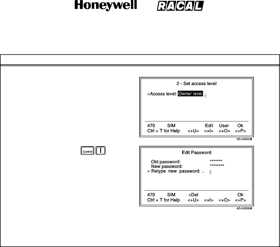
SYSTEM DESCRIPTION AND INSTALLATION MANUAL
SCS--1000 Mini--M Aero SATCOM System
23--20--28
Use or disclosure of information on this page is subject to the restrictions in the proprietary notice of this document.
Page 2--46
31 Jan 2000
Table 2--12. Shifting to Owner Level/Changing the Password Procedures (cont)
Task PC Screen DisplayKey Strokes
To change the password, perform the following:
1. Open the Set access
level window again.
2. Selecting Edit on the
Set access level
window opens the Edit
password window.
3. Key in the following:
Current password
New password
(10to12digits)
Retype the new
password to
confirm.
4. Select Ok (pushing the CONTROL and P keys) following each entry, and to store the new password.
NOTE: To revert to the User level, reselect the Set access level function and select User.
G. Data/Printer Port Setup
The DATA port may be set to operate with a PC or, for example, to output a Traffic log
directly to a printer.
NOTE: The bit rate setting applies for both the PC and printer transfer.
When printing the Traffic log to the PC, for example, the screen enters the text mode. To
revert to the data mode, the system must be restarted.
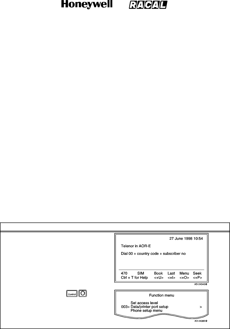
SYSTEM DESCRIPTION AND INSTALLATION MANUAL
SCS--1000 Mini--M Aero SATCOM System
23--20--28
Use or disclosure of information on this page is subject to the restrictions in the proprietary notice of this document.
Page 2--47
31 Jan 2000
(1) Setup for Data Communication
Setup for data communication as follows:
Speed as selected using the procedure in Table 2--13, normally 9600 bps
(See Note 1.)
No parity (See Note 2.)
8databits (SeeNote2.)
1stopbit (SeeNote2.).
NOTES:
1. The bit rate set between the PC and the SAT--2000 must be higher than the
nominal 2400 bps SAT--2000--to--satellite bit rate to ensure maximum speed
transfer.
2. These parameters can only be changed using AT commands. Refer to
Appendix D.
(2) Setup for Output to the Printer
A printer must have serial interface, and is set as follows:
Speed as selected using the procedure in Table 2--13, for example, the bit rate
specified for the printer to be connected
No parity
8 data bits
1stopbit.
(3) Procedure
To setup the data/printer port, follow the steps in Table 2--13.
Table 2--13. Data/Printer Port Setup Procedure
Task Key Strokes PC Screen Display
1. Selecting Menu on the
Main window opens
the Function menu
window.
2. Scroll down to
Data/printer port
setup.
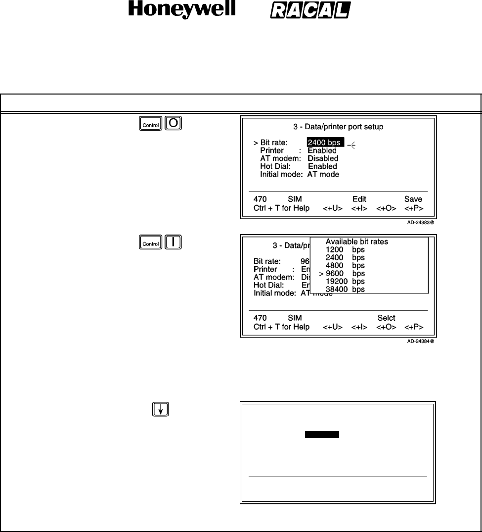
SYSTEM DESCRIPTION AND INSTALLATION MANUAL
SCS--1000 Mini--M Aero SATCOM System
23--20--28
Use or disclosure of information on this page is subject to the restrictions in the proprietary notice of this document.
Page 2--48
31 Jan 2000
Table 2--13. Data/Printer Port Setup Procedure (cont)
Task PC Screen DisplayKey Strokes
3. Selecting Selct or
pushing the right
arrow button on the
Functions menu
opens the Data/printer
port setup window.
NOTE: The Bit rate is
the first item in
the list.
4. Selecting Edit on the
Data/printer port setup
window opens the list
of bit rates.
5. Scroll up or down to
the required
data/printer bit rate.
NOTE: It is recommended to use 9600 bps for data communication.
6. Selecting Selct (pushing the CONTROL and O keys) enters the chosen rate.
NOTE: For output to the printer, select the bit rate according to the printer specifications.
7. Scroll down to Printer
and Enable/Disable
the DATA port for
printing, as required.
8. Scroll down to AT
modem and
Enable/Disable the
DATA port for AT
modem, as required.
3 -- Data/printer port setup
470
Ctrl + T for Help
SIM
<+U> <+I> <+O> <+P>
Bit rate: 9600 bps
> Printer : Enabled >
>AT modem: Enabled >
Hot Dial: Disabled
Initial mode: AT modem
AD--24385@
Disab SaveEnab
NOTE: Refer to Table 2--14 for the recommended data/printer port setup.
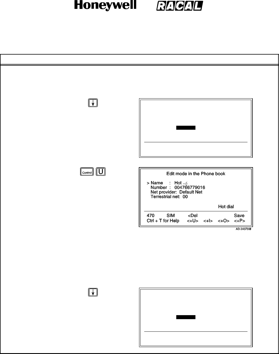
SYSTEM DESCRIPTION AND INSTALLATION MANUAL
SCS--1000 Mini--M Aero SATCOM System
23--20--28
Use or disclosure of information on this page is subject to the restrictions in the proprietary notice of this document.
Page 2--49
31 Jan 2000
Table 2--13. Data/Printer Port Setup Procedure (cont)
Task PC Screen DisplayKey Strokes
Hot Dial:
When enabled, this function monitors the Data Terminal Ready (DTR) pin on the DATA port. If the
DTR--pin is pulled high by equipment connected to the DATA port, a data call is automatically
initiated to a pre--programmed number. The number is automatically stored under short number 99.
9. Scroll down to Hot
Dial. 3 -- Data/printer port setup
470
Ctrl + T for Help
SIM
<+U>
Setup
<+I>
Enab
<+O>
Disab
<+P>
Save
Bit rate: 9600 bps
Printer : Enabled
AT modem: Disabled
> Hot Dial: Enabled >
>Initial mode: AT mode >
AD--24378@
10. Selecting Setup on
the Data/printer port
setup window open
the Edit mode in the
Phone book window.
a. Enter the name, for example, Hot.
b. Fill in the required number.
c. Change the provider and network, if needed.
Initial mode:
The mode is set to AT modem as the default mode. When selecting any of the MMI (Man Machine
Interface) settings, the PC screen automatically displays the system menu.
11. Scroll down to Initial
mode on the
Data/printer port
setup.
3 -- Data/printer port setup
470
Ctrl + T for Help
SIM
<+U>
Setup
<+I>
Enab
<+O>
Disab
<+P>
Save
Bit rate: 9600 bps
Printer : Enabled
AT modem: Disabled
> Hot Dial: Enabled >
>Initial mode: AT mode >
AD--24378@
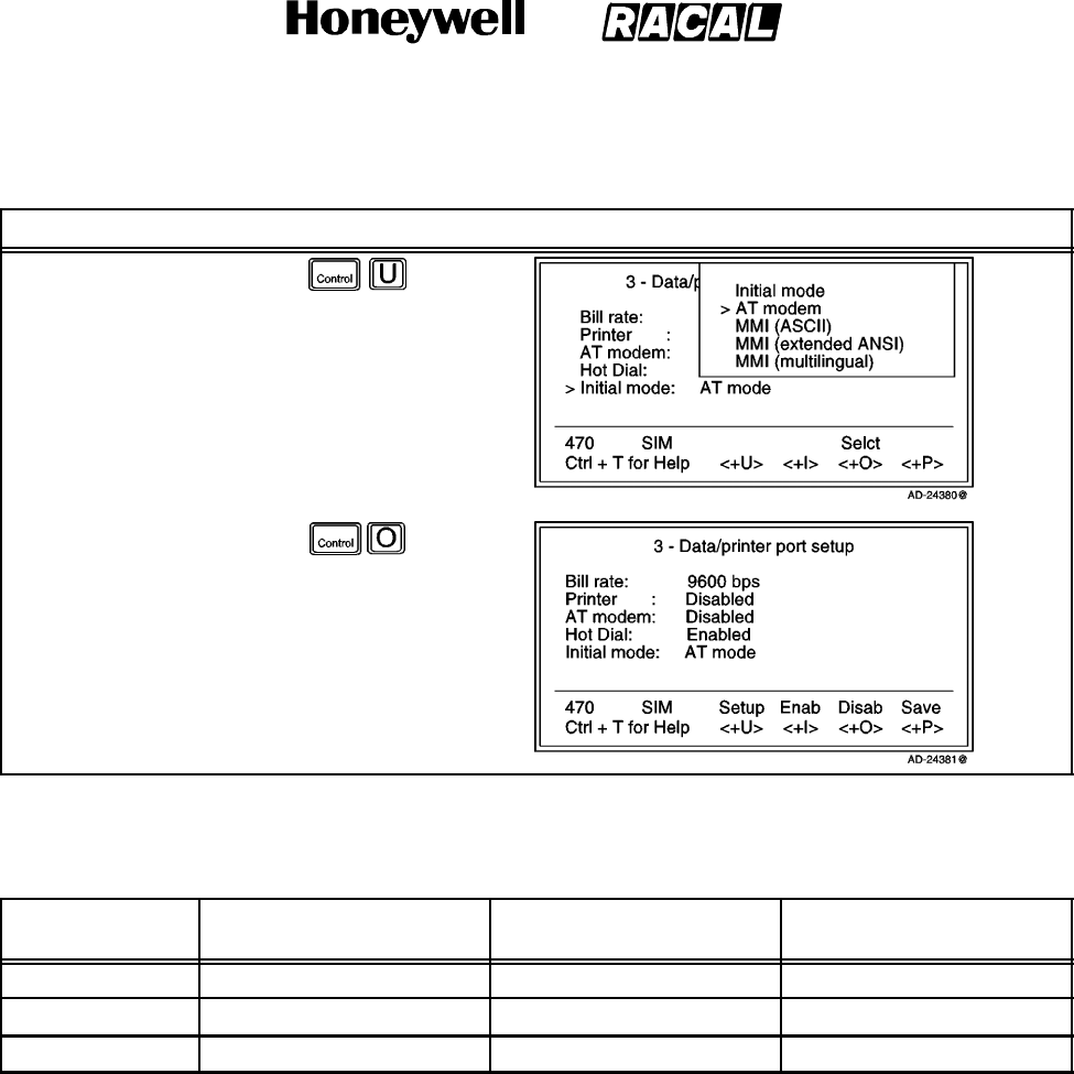
SYSTEM DESCRIPTION AND INSTALLATION MANUAL
SCS--1000 Mini--M Aero SATCOM System
23--20--28
Use or disclosure of information on this page is subject to the restrictions in the proprietary notice of this document.
Page 2--50
31 Jan 2000
Table 2--13. Data/Printer Port Setup Procedure (cont)
Task PC Screen DisplayKey Strokes
12. Selecting Setup on
the Data/printer port
setup window opens
the list on Initial mode
options.
13. Selecting Selct enters
the chosen mode.
14. Selecting Save
(pushing the
CONTROL and P
keys) stores the
settings.
Table 2--14. Recommended Data/Printer Port Setup
Mode Output to Printer Data Communication (AT)
Data Communication
(DTR dialing)
Printer Enabled Disabled Disabled
AT Modem Disabled Enabled Disabled
Hot Dial Disabled Disabled Enabled
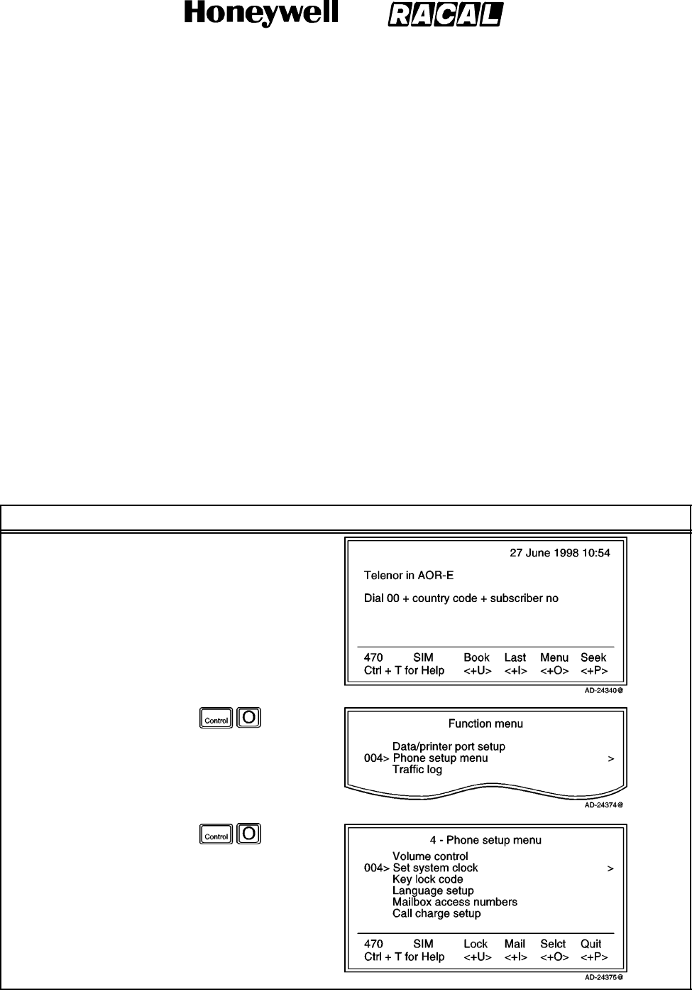
SYSTEM DESCRIPTION AND INSTALLATION MANUAL
SCS--1000 Mini--M Aero SATCOM System
23--20--28
Use or disclosure of information on this page is subject to the restrictions in the proprietary notice of this document.
Page 2--51
31 Jan 2000
H. Phone Setup
This function sets the following:
Date and time
Key lock (which prevents unauthorized use)
Language
Mailbox access numbers
Call charge.
(1) Date and Time Setup
The date and time is set to Coordinated Universal Time (UTC) Greenwich Mean Time
(GMT) at the factory. It is recommended to leave this setting if correct. To set the
date and time, perform the steps in Table 2--15.
WARNING: THE SYSTEM IS AUTOMATICALLY RESTARTED WHEN ACCEPTING NEW
TIME SETTINGS. ALL CALLS WILL BE DISCONNECTED.
Table 2--15. Procedure to Set the Date and Time
Task Key Strokes PC Screen Display
1. Selecting Menu on the
Main window opens
the Function menu
window.
2. Scroll down to Phone
setup menu.
3. Selecting Selct or
pushing the right
arrow button on the
Functions menu
opens the Phone
setup menu window.
4. Scroll down to Set
system clock.
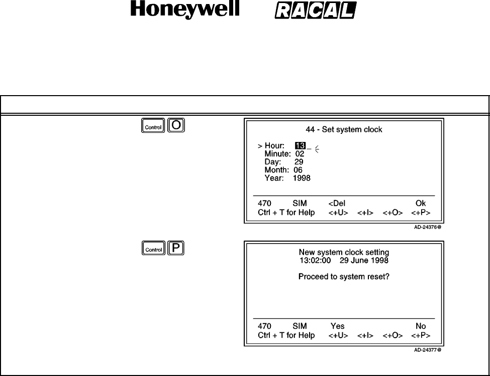
SYSTEM DESCRIPTION AND INSTALLATION MANUAL
SCS--1000 Mini--M Aero SATCOM System
23--20--28
Use or disclosure of information on this page is subject to the restrictions in the proprietary notice of this document.
Page 2--52
31 Jan 2000
Table 2--15. Procedure to Set the Date and Time (cont)
Task PC Screen DisplayKey Strokes
5. Selecting Selct or
pushing the right
arrow button on the
Phone setup menu
opens the Set system
clock window.
6. Scroll down to change
each entry, if needed.
7. Select Ok on the Set
system clock window
when the entries are
completed.
8. Selecting Yes
(pushing the
CONTROL and U
keys) confirms that
the settings are
correct.
NOTE: The system is now restarted.
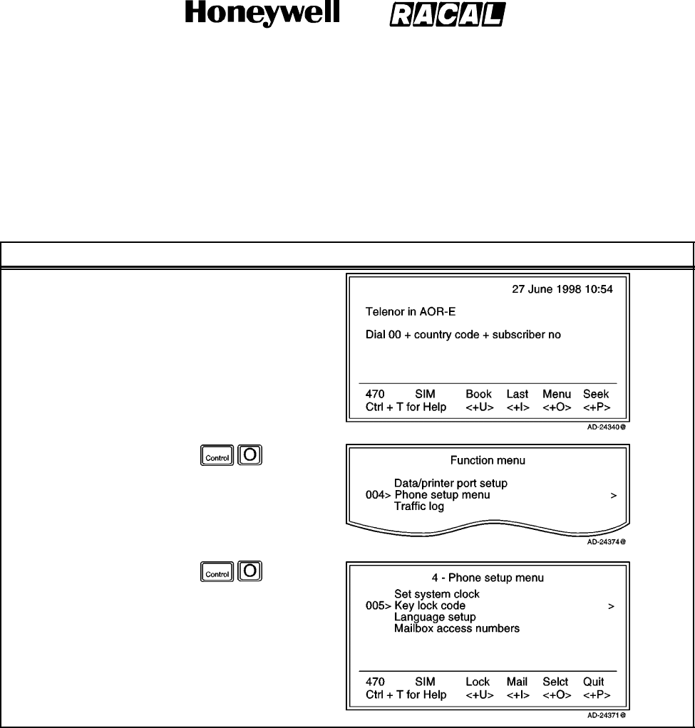
SYSTEM DESCRIPTION AND INSTALLATION MANUAL
SCS--1000 Mini--M Aero SATCOM System
23--20--28
Use or disclosure of information on this page is subject to the restrictions in the proprietary notice of this document.
Page 2--53
31 Jan 2000
(2) Key Lock Setup
The SCS--1000 system must be set for use with a specific SIM, or with no SIM. Refer
to the advanced functions access control paragraph 7.K.(1) in this section. To set the
key lock, perform the steps in Table 2--16.
Table 2--16. Procedure to Set the Key Lock
Task Key Strokes PC Screen Display
1. Selecting Menu on the
Main window opens
the Function menu
window.
2. Scroll down to Phone
setup menu.
3. Selecting Selct or
pushing the right
arrow button on the
Functions menu
opens the Phone
setup menu window.
4. Scroll down to Key
lock code.
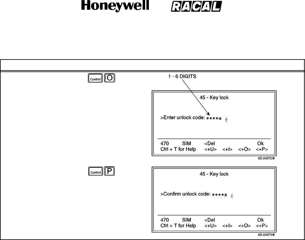
SYSTEM DESCRIPTION AND INSTALLATION MANUAL
SCS--1000 Mini--M Aero SATCOM System
23--20--28
Use or disclosure of information on this page is subject to the restrictions in the proprietary notice of this document.
Page 2--54
31 Jan 2000
Table 2--16. Procedure to Set the Key Lock (cont)
Task PC Screen DisplayKey Strokes
5. Selecting Selct or
pushing the right
arrow button on the
Phone setup menu
opens the Key lock
window.
6. Enter the unlock code
(1 to 6 digits).
7. Select Ok.
8. Repeat the unlock
code to confirm it.
9. Select Ok (pushing
the CONTROL and P
keys) again.
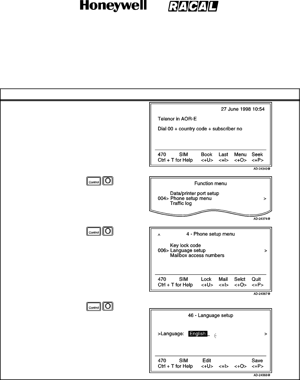
SYSTEM DESCRIPTION AND INSTALLATION MANUAL
SCS--1000 Mini--M Aero SATCOM System
23--20--28
Use or disclosure of information on this page is subject to the restrictions in the proprietary notice of this document.
Page 2--55
31 Jan 2000
(3) Language Setup
The display language may be changed as described in Table 2--17.
Table 2--17. Language Setup Procedure
Task Key Strokes PC Screen Display
1. Selecting Menu on the
Main window opens
the Function menu
window.
2. Scroll down to Phone
setup menu.
3. Selecting Selct or
pushing the right
arrow button on the
Functions menu
opens the Phone
setup menu window.
4. Scroll down to
Language setup.
5. Selecting Selct or
pushing the right
arrow button on the
Phone setup menu
opens the Language
setup window.
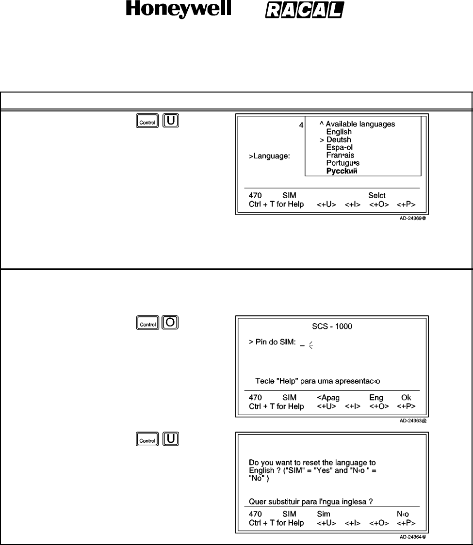
SYSTEM DESCRIPTION AND INSTALLATION MANUAL
SCS--1000 Mini--M Aero SATCOM System
23--20--28
Use or disclosure of information on this page is subject to the restrictions in the proprietary notice of this document.
Page 2--56
31 Jan 2000
Table 2--17. Language Setup Procedure (cont)
Task PC Screen DisplayKey Strokes
6. Selecting Edit on the
Language setup
window opens the list
of available
languages.
7. Scroll up or down to
the desired language.
8. Selecting Selct (pushing the CONTROL and O keys) reads out the selected language in the setup
window.
9. Selecting Save (pushing the CONTROL and P keys) changes the display text to the selected language.
Language reset:
When starting the system with the display language set to Portuguese, for example, the Eng
function key supplies an easy way to restore the default English display language.
1. Select Eng.
2. Select Sim (Yes) to
reset the language to
English.
3. Select No (pushing
the CONTROL and P
keys) to keep the
current display
language.
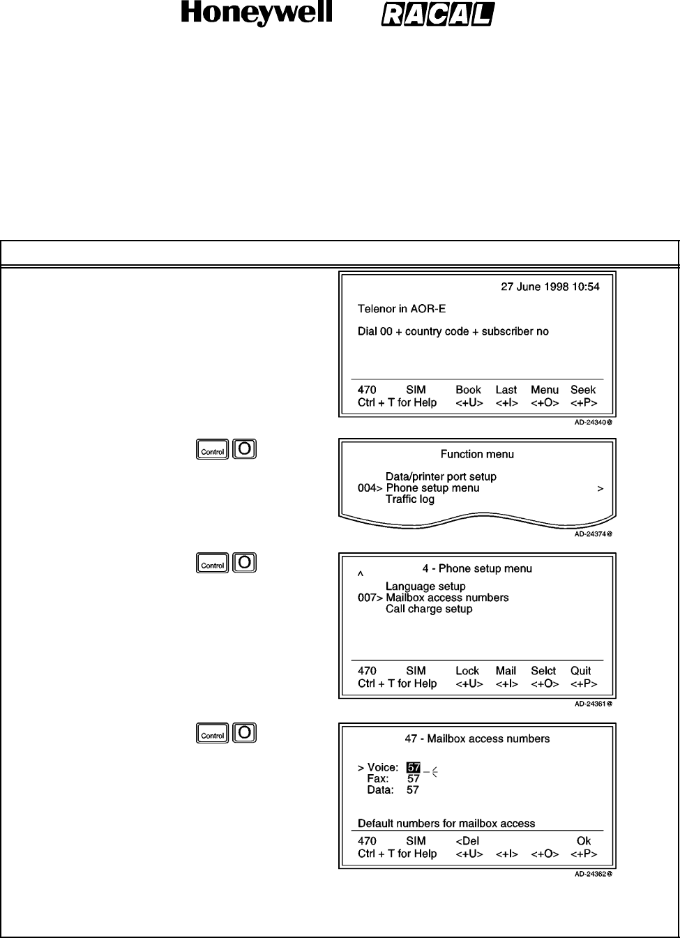
SYSTEM DESCRIPTION AND INSTALLATION MANUAL
SCS--1000 Mini--M Aero SATCOM System
23--20--28
Use or disclosure of information on this page is subject to the restrictions in the proprietary notice of this document.
Page 2--57
31 Jan 2000
(4) Mailbox Access Numbers Setup
When receiving a mail alert (voice, fax, or data), the user must call the server mailbox
to retrieve the message. To call the mailbox, normally the default number 57 can be
used. The mailbox dial--up number may be changed as described in Table 2--18.
Table 2--18. Mailbox Access Numbers Setup Procedure
Task Key Strokes PC Screen Display
1. Selecting Menu on the
Main window opens
the Function menu
window.
2. Scroll down to Phone
setup menu.
3. Selecting Selct or
pushing the right
arrow button on the
Functions menu
opens the Phone
setup menu window.
4. Scroll down to Mailbox
access numbers.
5. Selecting Selct or
pushing the right
arrow button on the
Phone setup menu
opens the Mailbox
access numbers
window.
6. Key in the new
numbers.
7. Select Ok (pushing
the CONTROL and P
keys) to store the new
mailbox number(s).
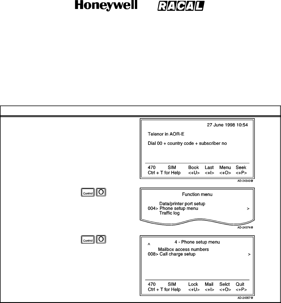
SYSTEM DESCRIPTION AND INSTALLATION MANUAL
SCS--1000 Mini--M Aero SATCOM System
23--20--28
Use or disclosure of information on this page is subject to the restrictions in the proprietary notice of this document.
Page 2--58
31 Jan 2000
(5) Call Charge Setup
With the Call charge function enabled, the cost of the call is displayed during the call
and for 10 seconds after the call is terminated. Later the charge can be fetched
using the Traffic log function. The price per unit and minimum charge time is set as
described in Table 2--19.
Table 2--19. Call Charge Setup Procedure
Task Key Strokes PC Screen Display
1. Selecting Menu on the
Main window opens
the Function menu
window.
2. Scroll down to Phone
setup menu.
3. Selecting Selct or
pushing the right
arrow button on the
Functions menu
opens the Phone
setup menu window.
4. Scroll down to Call
charge setup.
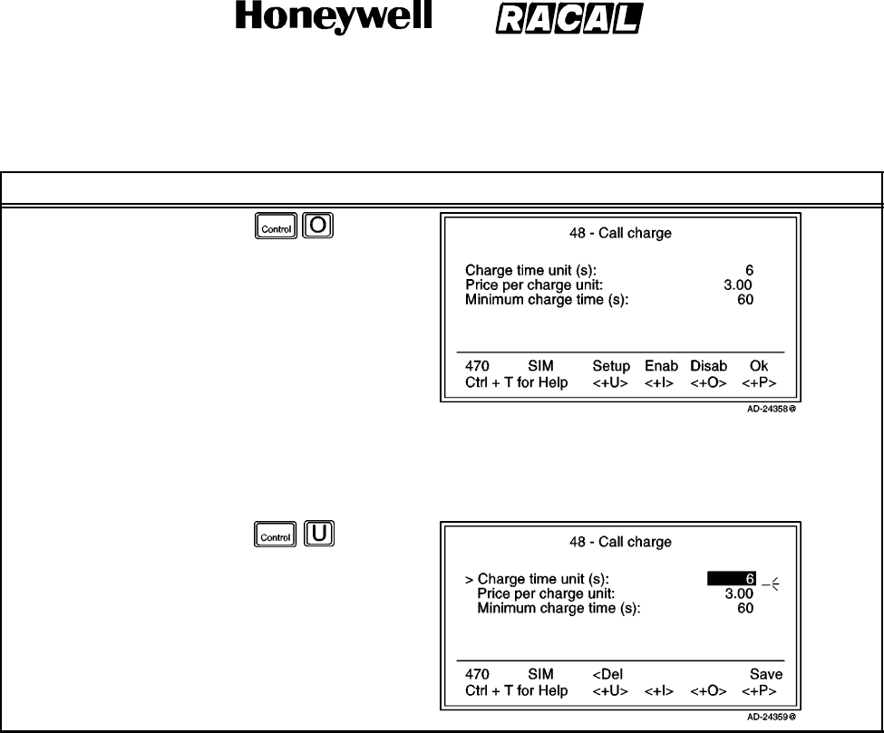
SYSTEM DESCRIPTION AND INSTALLATION MANUAL
SCS--1000 Mini--M Aero SATCOM System
23--20--28
Use or disclosure of information on this page is subject to the restrictions in the proprietary notice of this document.
Page 2--59
31 Jan 2000
Table 2--19. Call Charge Setup Procedure (cont)
Task PC Screen DisplayKey Strokes
5. Selecting Selct or
pushing the right
arrow button on the
Phone setup menu
opens the Call charge
window.
a. Selecting Enab (pushing the CONTROL and I keys) activates the values.
b. Selecting Disab (pushing the CONTROL and O keys) disables the Call charge indication.
c. Selecting Ok (pushing the CONTROL and P keys) activates the Call charge indication.
d. Selecting Setup
on the Call charge
window allows the
user to modify the
entries.
e. Selecting Save
stores the new
values.
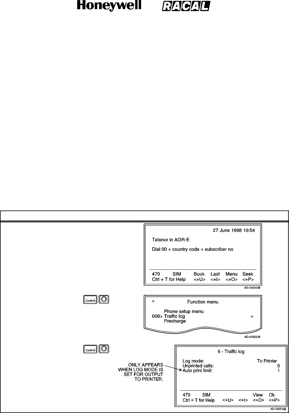
SYSTEM DESCRIPTION AND INSTALLATION MANUAL
SCS--1000 Mini--M Aero SATCOM System
23--20--28
Use or disclosure of information on this page is subject to the restrictions in the proprietary notice of this document.
Page 2--60
31 Jan 2000
I. Traffic Log
This function logs all outgoing calls both with and without the SIM card inserted. Every
call is logged with the following:
Subscriber number, start time, and duration
Service (voice, fax, data, NIMS)
Network provider and satellite
User name (if access code is enabled) / SIM card FWD.
The system owner may set the log output mode as follows:
Off (stops logging)
Cleared (stops logging and clears the log)
For automatic printout after 1 or 10 calls (auto print limit)
For display on the screen
Logging of incoming calls.
For traffic log readout, perform the steps in Table 2--20. An example of a traffic log
printout is shown in Figure 2--11. Table 2--21 gives the traffic log settings procedure,
which is accessible at the owner level only.
Table 2--20. Traffic Log Readout Procedure
Task Key Strokes PC Screen Display
1. Selecting Menu on the
Main window opens
the Function menu
window.
2. Scroll down to Traffic
log.
3. Selecting Selct or
pushing the right
arrow button on the
Functions menu
opens the Traffic log
window.
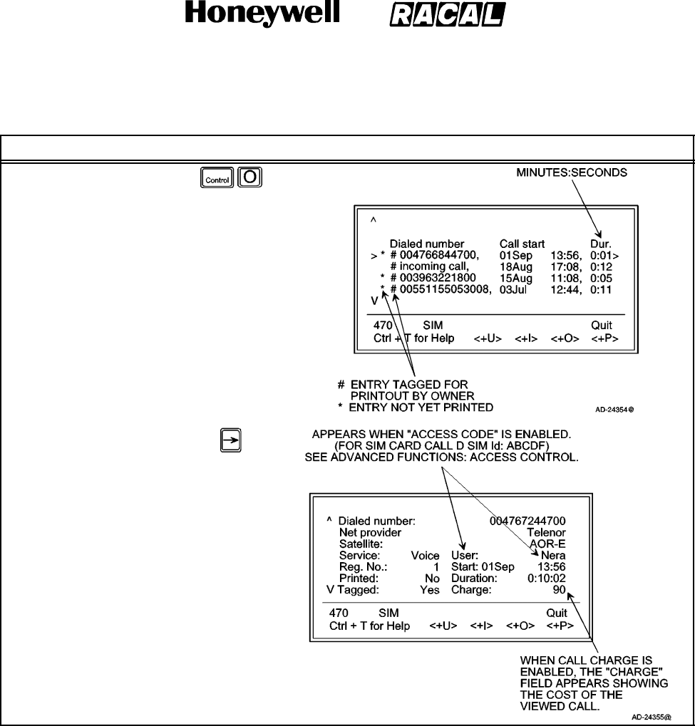
SYSTEM DESCRIPTION AND INSTALLATION MANUAL
SCS--1000 Mini--M Aero SATCOM System
23--20--28
Use or disclosure of information on this page is subject to the restrictions in the proprietary notice of this document.
Page 2--61
31 Jan 2000
Table 2--20. Traffic Log Readout Procedure (cont)
Task PC Screen DisplayKey Strokes
4. Selecting View on the
Traffic log window
displays the list of
calls.
5. Scroll up or down to
the desired call.
6. Pushing the right
arrow button shows
the detailed call data.
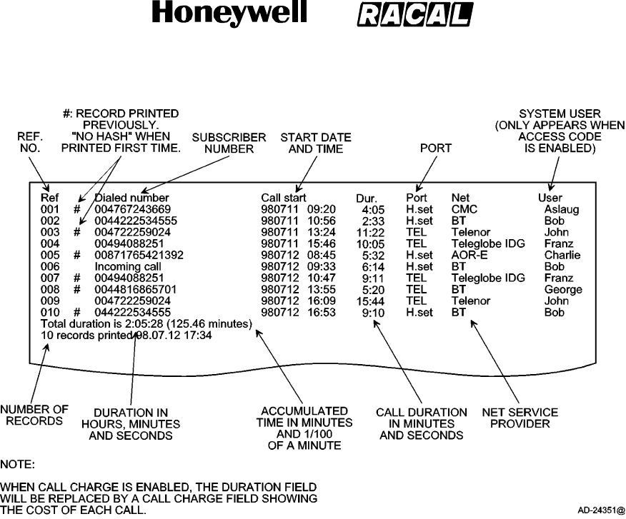
SYSTEM DESCRIPTION AND INSTALLATION MANUAL
SCS--1000 Mini--M Aero SATCOM System
23--20--28
Use or disclosure of information on this page is subject to the restrictions in the proprietary notice of this document.
Page 2--62
31 Jan 2000
Figure 2--11. Example of a Traffic Log Printout
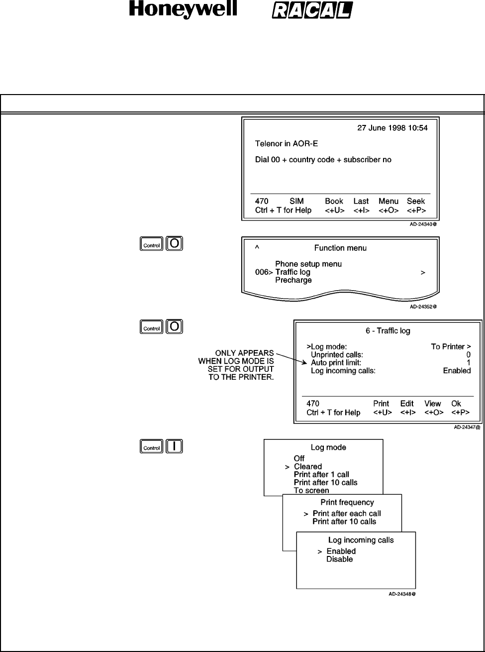
SYSTEM DESCRIPTION AND INSTALLATION MANUAL
SCS--1000 Mini--M Aero SATCOM System
23--20--28
Use or disclosure of information on this page is subject to the restrictions in the proprietary notice of this document.
Page 2--63
31 Jan 2000
Table 2--21. Traffic Log Settings Procedure
Task Key Strokes PC Screen Display
1. Selecting Menu on the
Main window opens
the Function menu
window.
2. Scroll down to Traffic
log.
3. Selecting Selct or
pushing the right
arrow button on the
Functions menu
opens the Traffic log
window.
3. Selecting Edit or
pushing the right
arrow button on the
Traffic log window
allows the user to edit
the settings for Log
mode, Print
frequency, and Log
incoming calls.
a. Scroll up or down
and then Selct the
desired output
Log mode.
b. Scroll up or down and then Selct the desired Print frequency.
NOTE: The Auto print limit can be easily toggled between 1 and 10.
c. Scroll up or down and then Selct to enable or disable the logging of incoming calls.
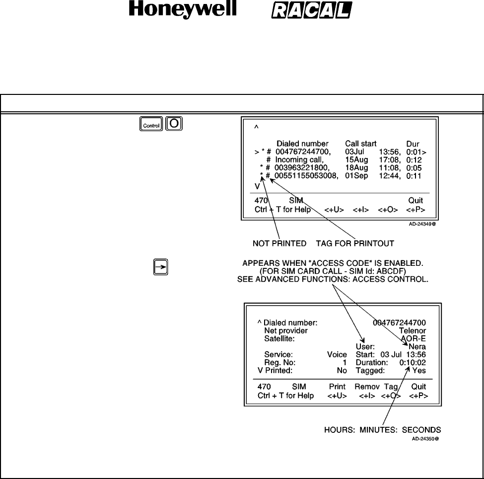
SYSTEM DESCRIPTION AND INSTALLATION MANUAL
SCS--1000 Mini--M Aero SATCOM System
23--20--28
Use or disclosure of information on this page is subject to the restrictions in the proprietary notice of this document.
Page 2--64
31 Jan 2000
Table 2--21. Traffic Log Settings Procedure (cont)
Task PC Screen DisplayKey Strokes
4. Selecting View on the
Traffic log window
displays the list of
calls.
5. Scroll up or down to
the desired call.
6. Pushing the right
arrow button shows
the details of the call.
a. Selecting Tag
(pushing the
CONTROL and O
keys) tags the
entry. Repeat to
untag it.
b. Selecting Print
(pushing the
CONTROL and U
keys) outputs the
selected entry to
the printer without
header and footer.
c. Selecting Remov (pushing the CONTROL and I keys) erases the entry from the log.
d. Selecting Quit (pushing the CONTROL and P keys) reverts back to the Main window.
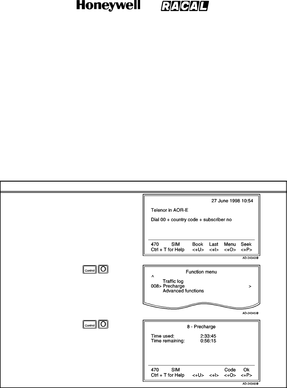
SYSTEM DESCRIPTION AND INSTALLATION MANUAL
SCS--1000 Mini--M Aero SATCOM System
23--20--28
Use or disclosure of information on this page is subject to the restrictions in the proprietary notice of this document.
Page 2--65
31 Jan 2000
J. Precharge
NOTE: For use with a SIM card, refer to paragraph 7.J.(4) in this section.
The SCS--1000 system can be preprogrammed with a total call duration limit of up to
44640 minutes (744 hours). The owner stores a special telephone number under short
number 00. This allows the user to call the owner to buy more time even when the time
limit has been exceeded. During a call the remaining time is displayed next to the call
duration in hours and minutes (seconds for the last minute).
NOTE: For users, the Precharge function only appears in the menu when enabled, for
example when bought time is loaded.
(1) Precharge Readout
To readout the precharge, follow the steps in Table 2--22.
Table 2--22. Precharge Readout Procedure
Task Key Strokes PC Screen Display
1. Selecting Menu on the
Main window opens
the Function menu
window.
2. Scroll down to
Precharge.
3. Selecting Selct or
pushing the right
arrow button on the
Functions menu
opens the Precharge
window which
displays the time used
and time remaining in
hours, minutes, and
seconds.
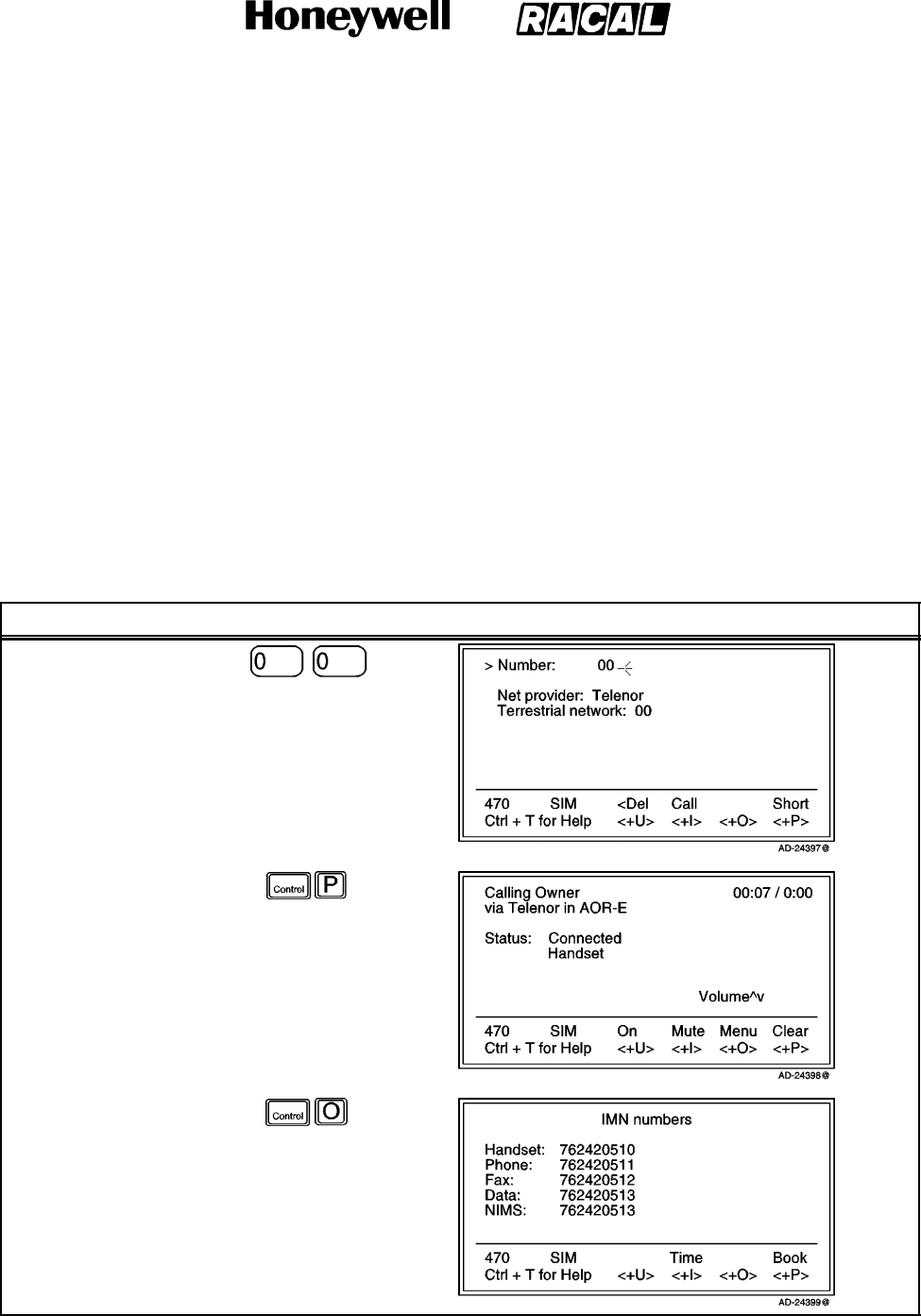
SYSTEM DESCRIPTION AND INSTALLATION MANUAL
SCS--1000 Mini--M Aero SATCOM System
23--20--28
Use or disclosure of information on this page is subject to the restrictions in the proprietary notice of this document.
Page 2--66
31 Jan 2000
(2) Buying More Remaining Time
There are three ways to load precharge time:
Call the owner via short number 00 and get the buy code during the conversation.
(Calling short number 00 can be done even if exceeding the remaining time limit
and does not influence the limit value.)
Fax or mail the Forward ID and Index to the owner who generates the buy code
and returns this by fax, mail, etc.
The owner loads the new Precharge limit into the SCS--1000 system.
(a) Buying Time by Calling the Owner
To buy time by calling the owner, follow the steps in Table 2--23.
Table 2--23. Procedure to Buy Time by Calling the Owner
Task Key Strokes PC Screen Display
1. Dial 00.
2. Select Short.
3. Selecting Menu
displays the IMN
numbers.
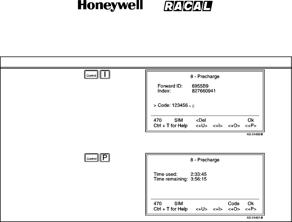
SYSTEM DESCRIPTION AND INSTALLATION MANUAL
SCS--1000 Mini--M Aero SATCOM System
23--20--28
Use or disclosure of information on this page is subject to the restrictions in the proprietary notice of this document.
Page 2--67
31 Jan 2000
Table 2--23. Procedure to Buy Time by Calling the Owner (cont)
Task PC Screen DisplayKey Strokes
4. Selecting Time opens
the Precharge window
which displays the
Forward ID, Index,
and user code entry
field.
5. Read the Forward ID,
Index, and the new
call duration you want
to buy to the owner.
6. Key in the code that the owner reads back to you. The code contains the time information.
7. Selecting Ok loads
the new remaining
time limit.
8. Select Ok (pushing
the CONTROL and P
keys) again and then
push ESC to return to
the conversation
window.
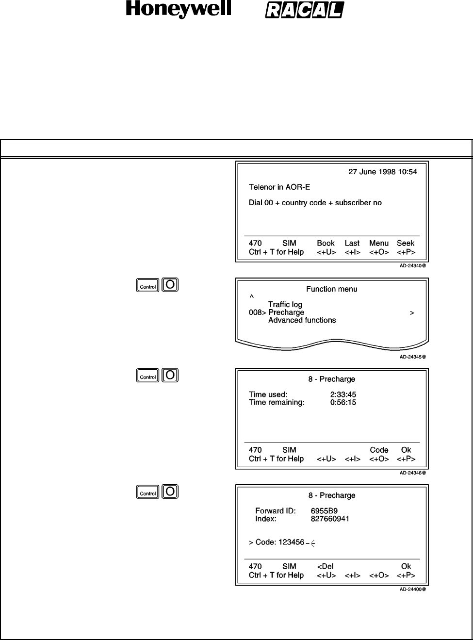
SYSTEM DESCRIPTION AND INSTALLATION MANUAL
SCS--1000 Mini--M Aero SATCOM System
23--20--28
Use or disclosure of information on this page is subject to the restrictions in the proprietary notice of this document.
Page 2--68
31 Jan 2000
(b) Buying Time Via Fax or Mail
To buy time via fax or mail, follow the steps in Table 2--24.
Table 2--24. Procedure to Buy Time Via Fax or Mail
Task Key Strokes PC Screen Display
1. Selecting Menu on the
Main window opens
the Function menu
window.
2. Scroll down to
Precharge.
3. Selecting Selct or
pushing the right
arrow button on the
Functions menu
opens the Precharge
window.
4. Selecting Code opens
the Precharge window
which displays the
Forward ID, Index,
and user code entry
field.
5. Fax or mail the
Forward ID, Index,
and the new call
duration you want to
buy to the owner.
6. Key in the code that is faxed or mailed back to you. The code contains the time information.
7. Selecting Ok loads the new remaining time limit.

SYSTEM DESCRIPTION AND INSTALLATION MANUAL
SCS--1000 Mini--M Aero SATCOM System
23--20--28
Use or disclosure of information on this page is subject to the restrictions in the proprietary notice of this document.
Page 2--69
31 Jan 2000
(c) Buying Time by Owner Loading Precharge Time
For the owner to load precharge time, perform the steps in Table 2--25.
NOTE: The SCS system must be set to the Owner level.
Table 2--25. Owner Loading Precharge Time Procedure
Task Key Strokes PC Screen Display
1. Selecting Menu on the
Main window opens
the Function menu
window.
2. Scroll down to
Precharge.
3. Selecting Selct or
pushing the right
arrow button on the
Functions menu
opens the Precharge
window.
a. Selecting Buy
allows the keying
in of a new time
limit.
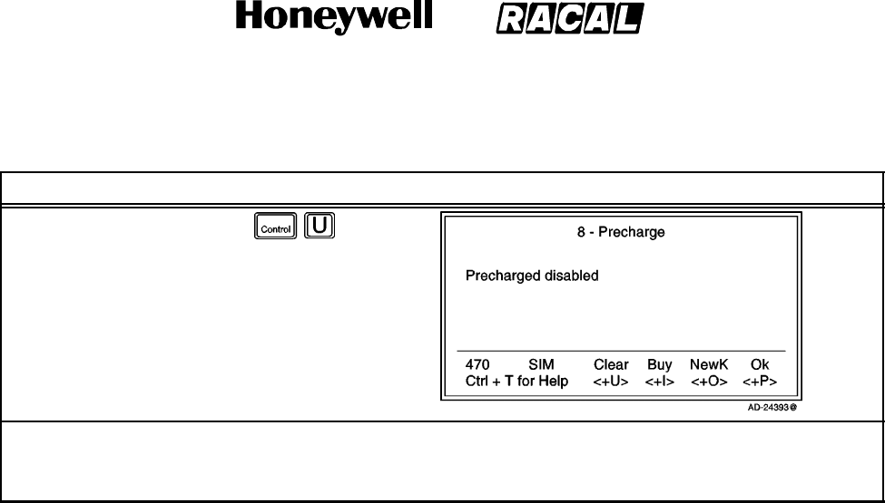
SYSTEM DESCRIPTION AND INSTALLATION MANUAL
SCS--1000 Mini--M Aero SATCOM System
23--20--28
Use or disclosure of information on this page is subject to the restrictions in the proprietary notice of this document.
Page 2--70
31 Jan 2000
Table 2--25. Owner Loading Precharge Time Procedure (cont)
Task PC Screen DisplayKey Strokes
b. Selecting Clear
disables the
Precharge
function.
NOTE: The Precharge
menu is now no
longer visible
from the user
level.
NOTES:
1. Precharge is enabled when buying minutes.
2. Remember to revert to the user level when done.
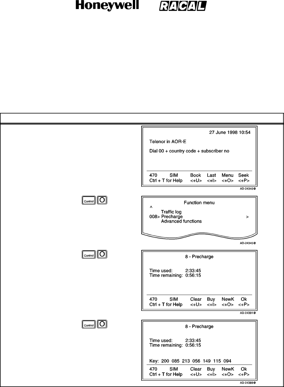
SYSTEM DESCRIPTION AND INSTALLATION MANUAL
SCS--1000 Mini--M Aero SATCOM System
23--20--28
Use or disclosure of information on this page is subject to the restrictions in the proprietary notice of this document.
Page 2--71
31 Jan 2000
(3) Key Readout
Using the Precharge Administrator program (QPRG 9110039) to generate a buyer’s
Precharge code requires both the owner’s password and a key that is generated by
the SCS system. Perform the steps in Table 2--26 for the key readout.
NOTE: The SCS system must be set to the Owner level.
Table 2--26. Key Readout Procedure
Task Key Strokes PC Screen Display
1. Selecting Menu on the
Main window opens
the Function menu
window.
2. Scroll down to
Precharge.
3. Selecting Selct or
pushing the right
arrow button on the
Functions menu
opens the Precharge
window.
4. A new key is
generated every time
the NewK key is
selected.
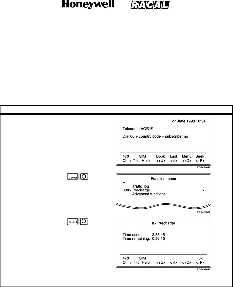
SYSTEM DESCRIPTION AND INSTALLATION MANUAL
SCS--1000 Mini--M Aero SATCOM System
23--20--28
Use or disclosure of information on this page is subject to the restrictions in the proprietary notice of this document.
Page 2--72
31 Jan 2000
(4) Precharge on a SIM Card
When using a SIM card, any Precharge set on the telephone itself is overridden. If
no Precharge is set on the SIM card, the SCS system may be used freely. During a
conversation, the time remaining and call duration are displayed as for calls without
using a SIM card. Some SIM cards may have a prepaid option. Contact your SIM
vendor for more information on how to upgrade your SIM card.
To readout the precharge on a SIM card, follow the steps in Table 2--27.
Table 2--27. SIM Card Precharge Readout Procedure
Task Key Strokes PC Screen Display
1. Selecting Menu on the
Main window opens
the Function menu
window.
2. Scroll down to
Precharge.
3. Selecting Selct or
pushing the right
arrow button on the
Functions menu
opens the Precharge
window which
displays the time used
and time remaining in
hours, minutes, and
seconds.
NOTE: This window is the same as the Precharge window without a SIM card except for the Code
function, which is not required.

SYSTEM DESCRIPTION AND INSTALLATION MANUAL
SCS--1000 Mini--M Aero SATCOM System
23--20--28
Use or disclosure of information on this page is subject to the restrictions in the proprietary notice of this document.
Page 2--73
16 Oct 2000
K. Advanced Functions
Some of the Advanced functions are accessible from the Phone OWNER LEVEL or
CHV2 LEVEL only. The OWNER LEVEL and CHV2 levels are protected by passwords.
For shifting to owner/CHV2 level and assignment of password, see paragraph 7.F. in this
section, User Access.
The advanced functions menu are given in Table 2--28.
Table 2--28. Advanced Functions Menu
Menu Item Related Functions
Access ControlRestrict dial
Access code
Restrict SIM usage
Aero Functions Magnetometer calibration
Configure landing speed
Satellite locations
Satellite Setup Net service provider and terrestrial network
S/A operator and terrestrial network
Configuration Port configuration
Net service providers
Power conservation
Set diagnostics
Set preferred Nets (with SIM card only)
Set allowed Nets (with SIM card only; CHV2 level or higher)
Set S/A preferred Nets (with SIM card only)
Set S/A allowed Nets (with SIM card only; CHV2 level or higher)
Charge tone
Information Available IMN numbers
Miscellaneous version ID information
Network status information (owner level, or in user level when
diagnostics is ON. See Configuration: Set diagnostics.)
Install: Installation and Debug Menu Paid functions (owner level)
Phone name setup (owner level)
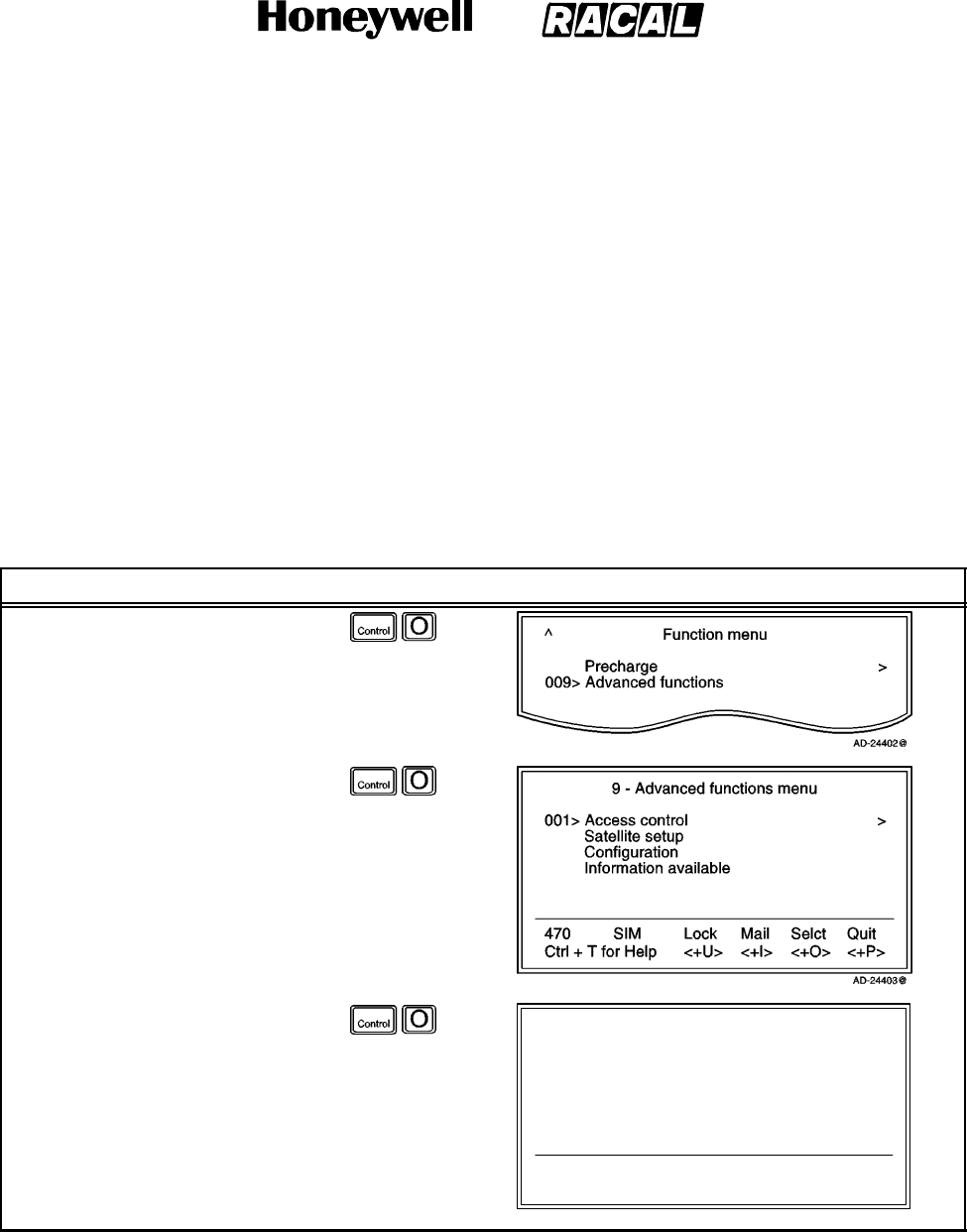
SYSTEM DESCRIPTION AND INSTALLATION MANUAL
SCS--1000 Mini--M Aero SATCOM System
23--20--28
Use or disclosure of information on this page is subject to the restrictions in the proprietary notice of this document.
Page 2--74
31 Jan 2000
(1) Access Control
The following functions are available for controlling the use of the SCS system:
Restrict Dial -- allows the owner to establish a Barred list of subscriber numbers
that cannot be called, or set the system for dialing from Phone Book only.
Access Code -- opens the system for up to 25 authorized users.
Restrict SIM Usage -- permits the owner to control the use of SIM card with the
system.
NOTE: The functions are editable in owner level only.
To setup the access control function, perform the procedures in Table 2--29.
Table 2--29. Access Control Setup
Task Key Strokes PC Screen Display
1. Selecting Menu on the Main
window opens the Function
menu window.
2. Scroll down to Advanced
functions.
3. Selecting Selct or pushing the
right arrow button on the
Functions menu opens the
Advanced functions menu.
4. Selecting Selct or pushing the
right arrow button on the
Advanced Functions menu
opens the Access control
menu which allows selection
of the submenus.
91 -- Access control menu
470
Ctrl + T for Help
SIM
<+U>
Lock
<+I>
Mail
<+O>
Selct
<+P>
Quit
001> Restrict dial >
002> Access code >
003> Restrict SIM usage >
AD--24404@
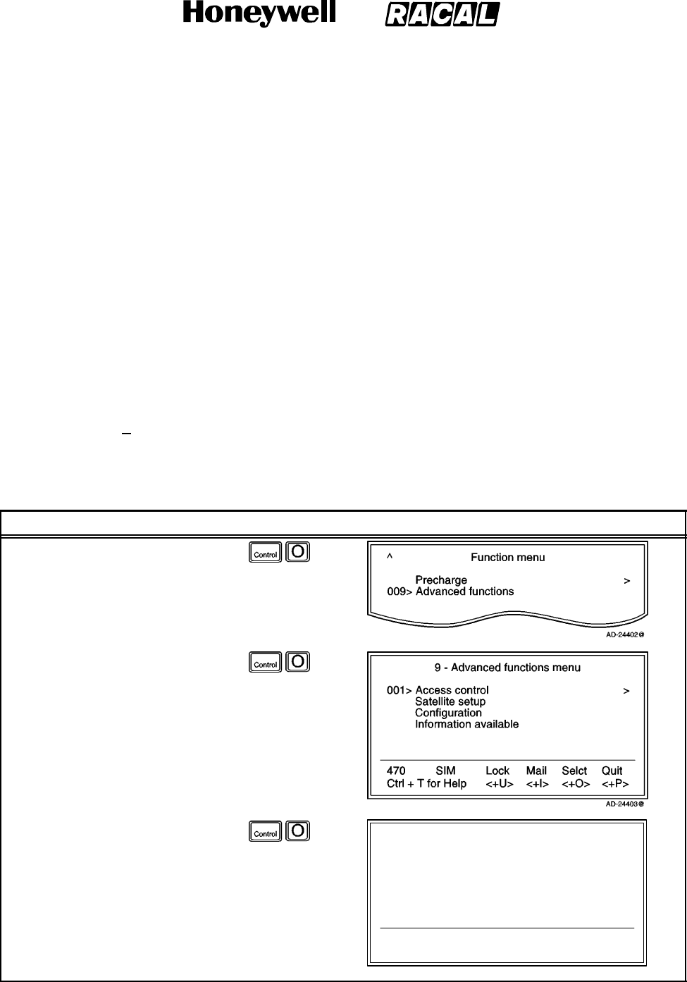
SYSTEM DESCRIPTION AND INSTALLATION MANUAL
SCS--1000 Mini--M Aero SATCOM System
23--20--28
Use or disclosure of information on this page is subject to the restrictions in the proprietary notice of this document.
Page 2--75
31 Jan 2000
(a) Restricted Dialing
The SCS system provides three choices of controlling calls:
No restrictions.
Barred List -- may contain up to 10 phone numbers or part of numbers that
can not be called, for example, the entry “0087” in the barred list prevents all
mobile--to--mobile calls.
Dial From Book Only -- restricts calls to the numbers in the Phone Book (in the
SCS system). It is still possible to append, for example a short number entry
with number field “0047” means that it is possible to dial all Norwegian
numbers. When a SIM card is inserted, the SIM entries will not be merged
with the “phone” entries.
The function is active for non--SIM operation. For one specific SIM card, see the
paragraph on Restricted SIM usage. It applies to all ports of the system. Only
one of the lists can be activated at one time.
1Check the Restrict Dial Setup
To check the restricted dialing setup, perform the procedures in Table 2--30.
Table 2--30. Check the Restrict Dial Setup
Task Key Strokes PC Screen Display
1. Selecting Menu on the Main
window opens the Function
menu window.
2. Scroll down to Advanced
functions.
3. Selecting Selct or pushing the
right arrow button on the
Functions menu opens the
Advanced functions menu.
4. Selecting Selct or pushing the
right arrow button on the
Advanced Functions menu
opens the Access control
menu.
91 -- Access control menu
470
Ctrl + T for Help
SIM
<+U>
Lock
<+I>
Mail
<+O>
Selct
<+P>
Quit
001> Restrict dial >
002> Access code >
003> Restrict SIM usage >
AD--24404@
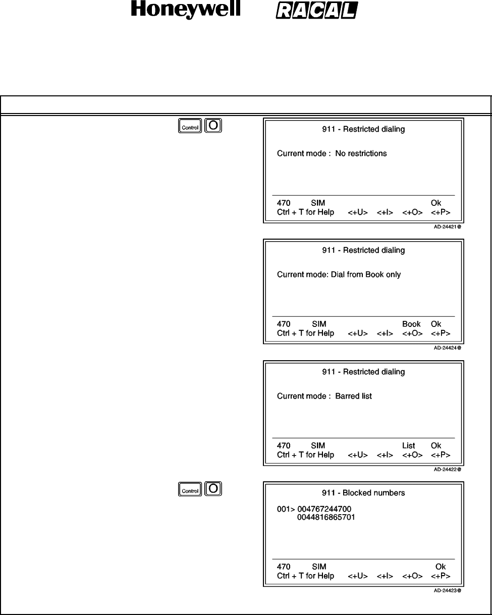
SYSTEM DESCRIPTION AND INSTALLATION MANUAL
SCS--1000 Mini--M Aero SATCOM System
23--20--28
Use or disclosure of information on this page is subject to the restrictions in the proprietary notice of this document.
Page 2--76
31 Jan 2000
Table 2--30. Check the Restrict Dial Setup (cont)
Task PC Screen DisplayKey Strokes
5. Select Selct or push the right
arrow button on the Access
control menu to open the
Restricted dialing window,
which shows the active list:
No restrictions
Dial from Book only
NOTE: Book (pushing the
CONTROL and O
keys) is similar to
Phone Book.
Barred list.
6. Selecting List on the
Restricted dialing window
opens the Blocked numbers
window.
NOTE: The list to be active is selected by the owner.
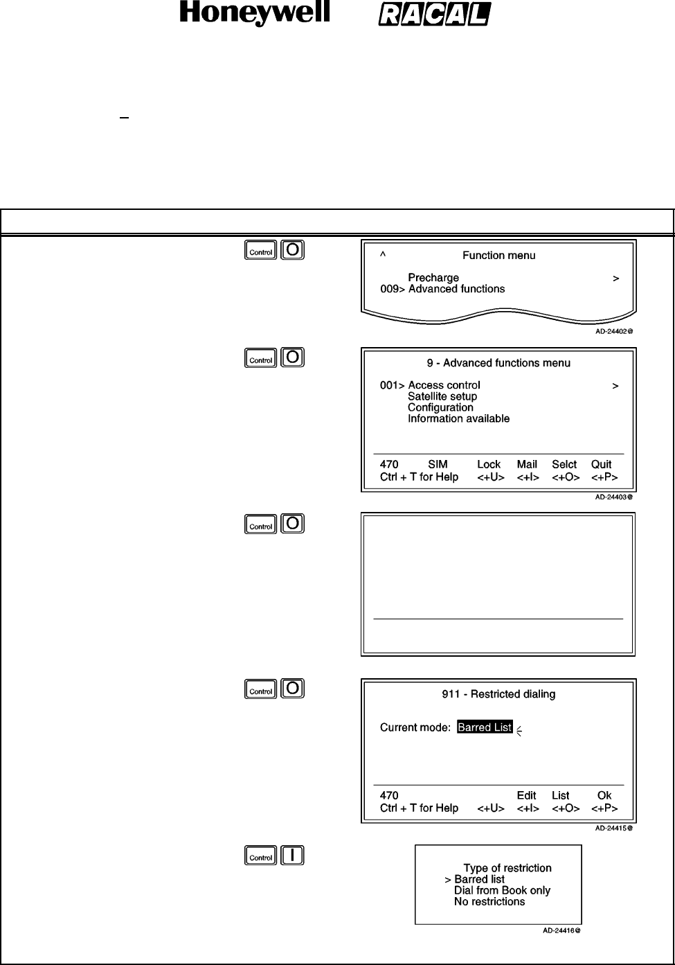
SYSTEM DESCRIPTION AND INSTALLATION MANUAL
SCS--1000 Mini--M Aero SATCOM System
23--20--28
Use or disclosure of information on this page is subject to the restrictions in the proprietary notice of this document.
Page 2--77
31 Jan 2000
2Restricted Dialing Setup (Owner Level Only)
To set up the Barred list and phone book, perform the procedures in
Table 2--31.
Table 2--31. Barred List and Phone Book Setup
Task Key Strokes PC Screen Display
1. Selecting Menu on the Main
window opens the Function
menu window.
2. Scroll down to Advanced
functions.
3. Selecting Selct or pushing the
right arrow button on the
Functions menu opens the
Advanced functions menu.
4. Selecting Selct or pushing the
right arrow button on the
Advanced Functions menu
opens the Access control
menu.
91 -- Access control menu
470
Ctrl + T for Help
SIM
<+U>
Lock
<+I>
Mail
<+O>
Selct
<+P>
Quit
001> Restrict dial >
002> Access code >
003> Restrict SIM usage >
AD--24404@
5. Select Selct or push the right
arrow button on the Access
control menu to open the
Restricted dialing window, that
shows which list is currently
active.
6. Selecting Edit on the
Restricted dialing window
allows selection of the
restriction mode.
7. Scroll up or down to select.
NOTE: Selecting Selct enters the chosen mode.
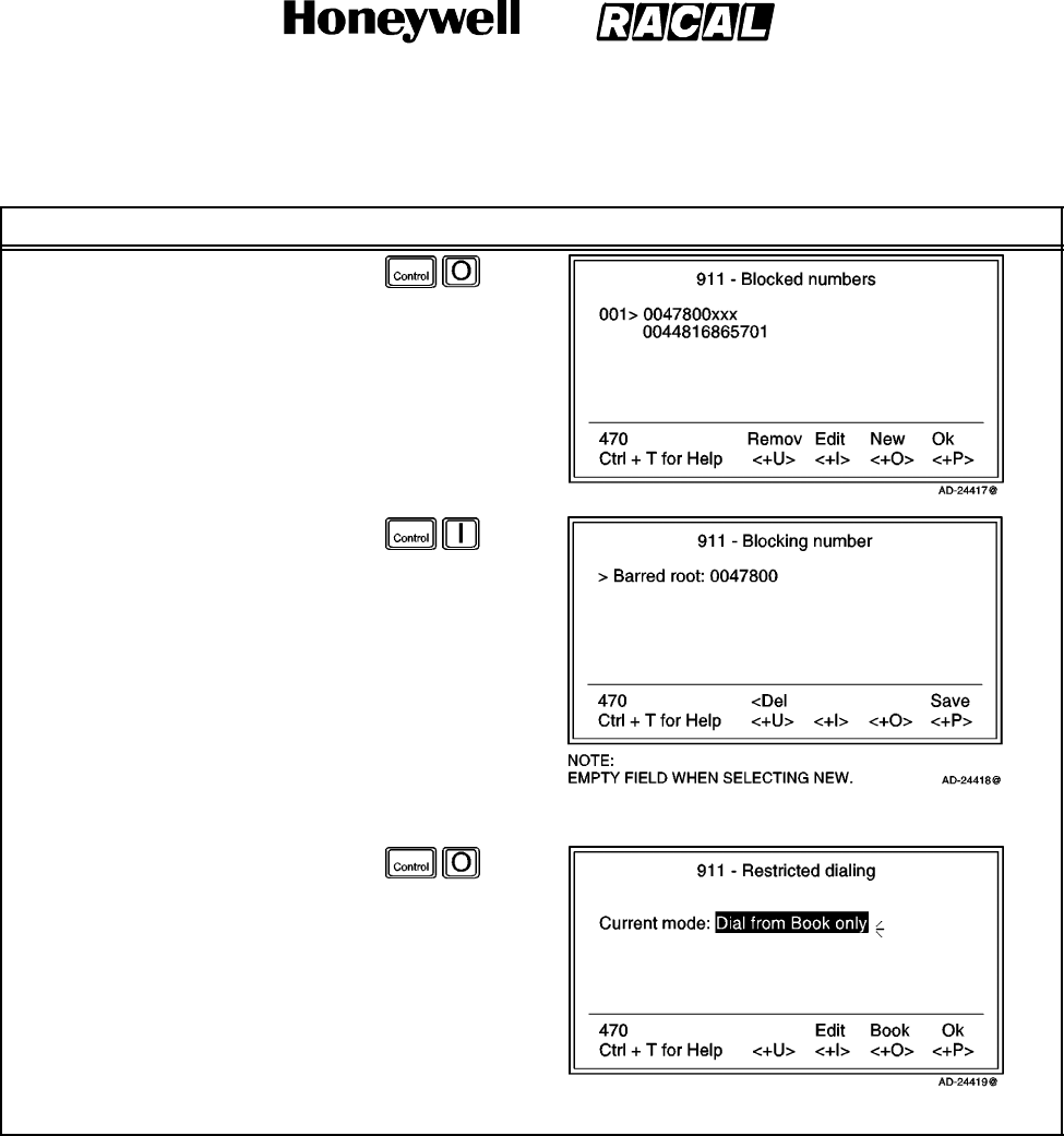
SYSTEM DESCRIPTION AND INSTALLATION MANUAL
SCS--1000 Mini--M Aero SATCOM System
23--20--28
Use or disclosure of information on this page is subject to the restrictions in the proprietary notice of this document.
Page 2--78
31 Jan 2000
Table 2--31. Barred List and Phone Book Setup (cont)
Task PC Screen DisplayKey Strokes
8. Selecting List on the
Restricted dialing window
opens the Blocked numbers
window.
9. Scroll up or down to select.
a. Remov (pushing the
CONTROL and U keys)
deletes the number.
b. Selecting Edit on the
Blocked numbers window
allows modification of the
barred number.
NOTES:
1. The Barred root
field is empty when
selecting New to
add a phone
number to the list.
2. Selecting Save (pushing the CONTROL and P keys) stores the changes.
10. When the restriction mode
“Dial from Book only” is active,
selecting Book allows the
entering of short numbers.
NOTE: Remember to revert to the User level.
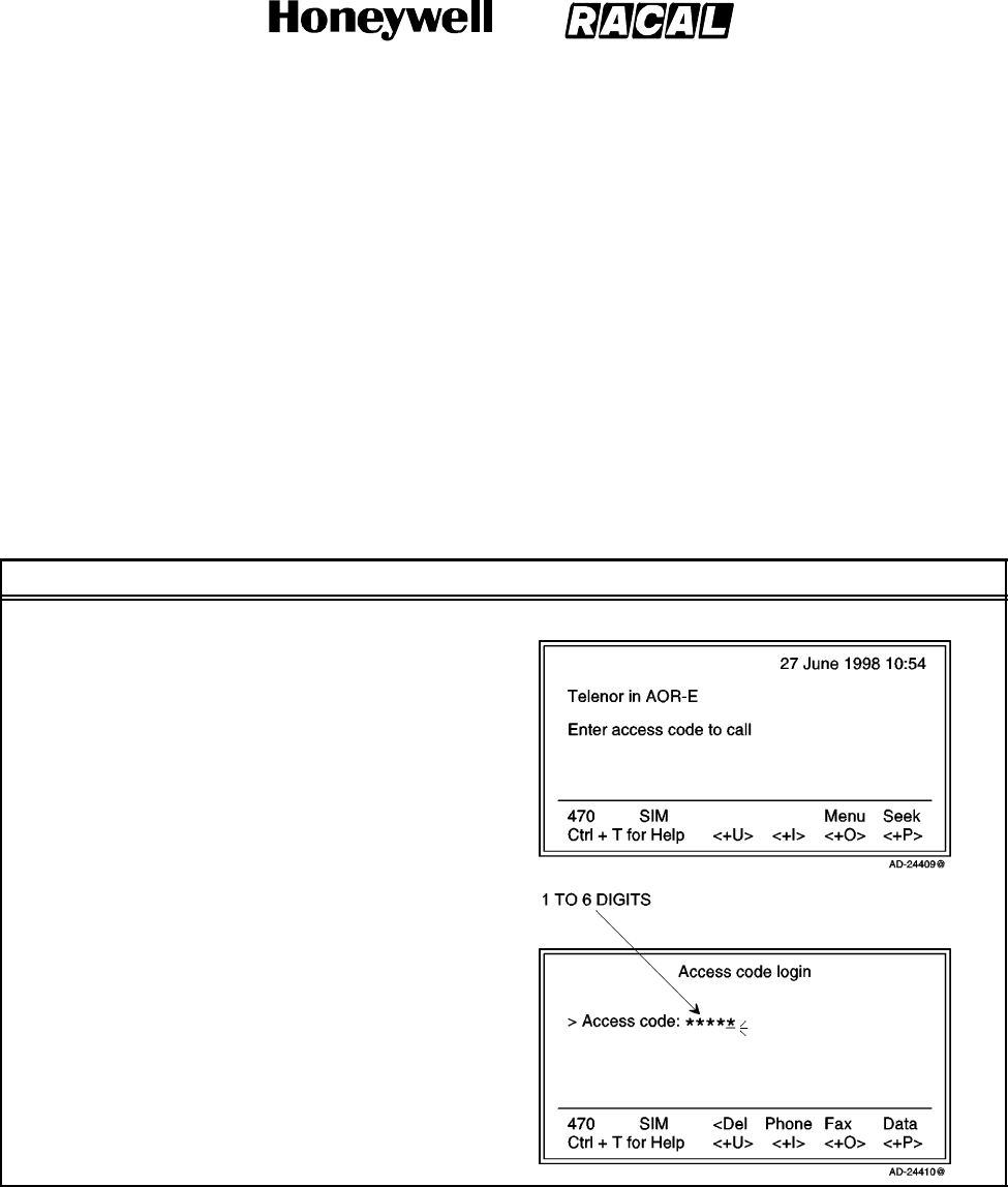
SYSTEM DESCRIPTION AND INSTALLATION MANUAL
SCS--1000 Mini--M Aero SATCOM System
23--20--28
Use or disclosure of information on this page is subject to the restrictions in the proprietary notice of this document.
Page 2--79
31 Jan 2000
(b) Access Code
When the access code function has been enabled, the user is prompted for a
1 to 8 digit personal code when making a call. The code opens the system for
one call. Up to 25 authorized users can be allocated access codes. The
function is active for non--SIM use and for one specific SIM card, see the
paragraph on Restricted SIM usage in this section. It applies to all ports of the
SCS system.
NOTE: The access code can only be entered from owner level.
To make a call, check the setup, or setup the access code, perform the
procedures in Table 2--32.
Table 2--32. Access Code Procedures
Task Key Strokes PC Screen Display
MakingaCall:
1. At hook--off or when
attempting to dial a phone
number from the main
window, the Access code
login window opens,
prompting the user to enter
the access code.
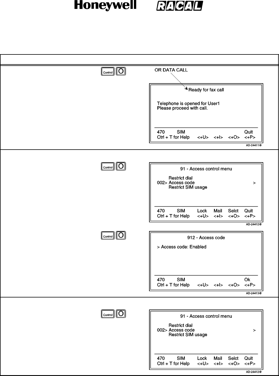
SYSTEM DESCRIPTION AND INSTALLATION MANUAL
SCS--1000 Mini--M Aero SATCOM System
23--20--28
Use or disclosure of information on this page is subject to the restrictions in the proprietary notice of this document.
Page 2--80
31 Jan 2000
Table 2--32. Access Code Procedures (cont)
Task PC Screen DisplayKey Strokes
2. Selecting Fax or Data
(pushing the CONTROL and
P keys) on the Access code
login window shows which
users are allowed to make a
telefax or data call.
NOTE: Selecting Phone on the
Access code login
window opens a window
for entering the phone
number.
Checking the Setup:
1. Selecting Selct or pressing the
right arrow via the Advanced
functions window opens the
Access control menu.
2. Scroll down to Access code.
3. Selecting Selct or the right
arrow again opens the Access
code window, which indicates
whether the Access code
function is Enabled or
Disabled.
Access Code Setup:
1. Selecting Selct or pressing the
right arrow via the Advanced
functions window opens the
Access control menu.
2. Scroll down to Access code.
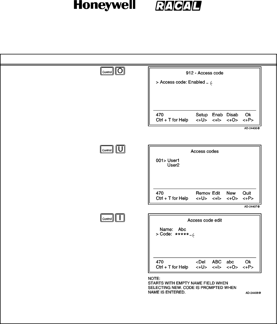
SYSTEM DESCRIPTION AND INSTALLATION MANUAL
SCS--1000 Mini--M Aero SATCOM System
23--20--28
Use or disclosure of information on this page is subject to the restrictions in the proprietary notice of this document.
Page 2--81
31 Jan 2000
Table 2--32. Access Code Procedures (cont)
Task PC Screen DisplayKey Strokes
3. Selecting Selct or the right
arrow again opens the Access
code window.
a. Enab (pushing the
CONTROL and I keys)
enables the access code
function.
b. Disab (pushing the
CONTROL and O keys)
disables the access code
function.
c. Selecting Setup displays
the list of authorized
users.
NOTE: Scroll down to
the desired user.
4. Select Edit on the Access
codes window to modify the
code, or select New (pushing
the CONTROL and O keys) to
addausertothelist.
a. Del (pushing the
CONTROL and U keys)
modifies the entries.
b. Select ABC (pushing the
CONTROL and I keys) or
abc (pushing the
CONTROL and O keys) to
enter uppercase or
lowercase letters, as
required.
c. Ok (pushing the CONTROL and P keys) stores the modified user name.
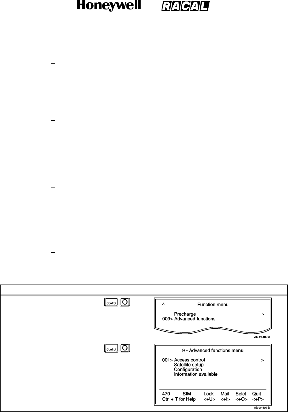
SYSTEM DESCRIPTION AND INSTALLATION MANUAL
SCS--1000 Mini--M Aero SATCOM System
23--20--28
Use or disclosure of information on this page is subject to the restrictions in the proprietary notice of this document.
Page 2--82
31 Jan 2000
(c) Restricted SIM Usage
1Allowed SIM
The Mini--M Aero System can be set to operate from:
One specific SIM card (Any other SIM users will be rejected.)
No SIM card (All SIM users will be rejected.)
Any SIM card.
2Restricted SIM
The restrictions “Restrict dial” and “Access code” can be set to be active for:
One specific SIM card (in addition to non--SIM usage)
No SIM card (only active for non--SIM usage).
NOTE: The setting can only be made from owner level. Refer to paragraph
7.K.(1)(c)6.
3When Restricted to SIM Provider
The service provider can lock the Mini--M Aero System to a specific type of
card, e.g. a “MOBIQ” SIM card. The restrictions will then be:
Any “MOBIQ” SIM card
One specific “MOBIQ” card
No SIM card at all.
4Check SIM Restrictions
To check SIM restrictions, perform the procedure in Table 2--33.
Table 2--33. Procedure to Check SIM Restrictions
Task Key Strokes PC Screen Display
1. Selecting Menu on the Main
window opens the Function
menu window.
2. Scroll down to Advanced
functions.
3. Selecting Selct or pushing the
right arrow button on the
Functions menu opens the
Advanced functions menu.
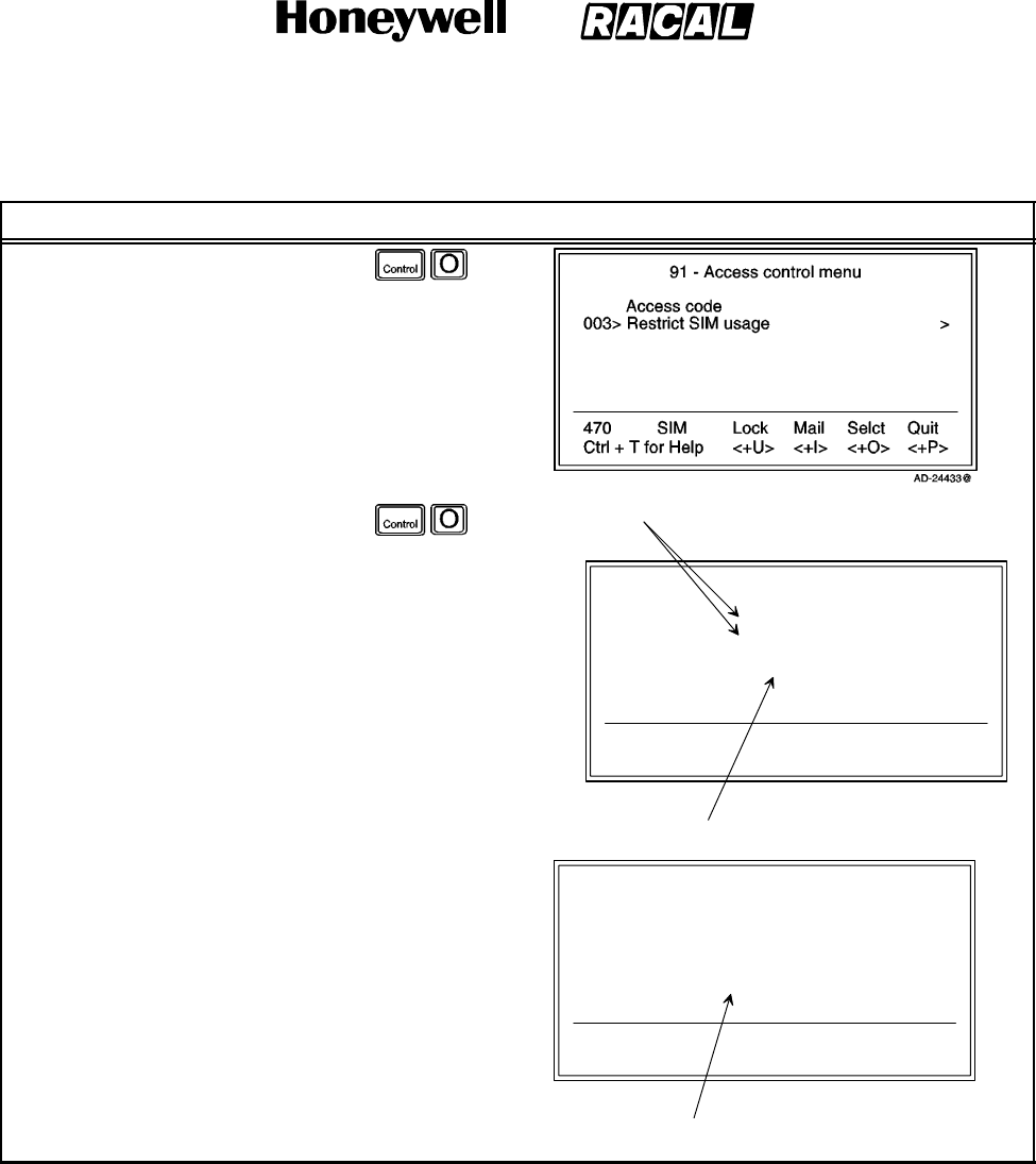
SYSTEM DESCRIPTION AND INSTALLATION MANUAL
SCS--1000 Mini--M Aero SATCOM System
23--20--28
Use or disclosure of information on this page is subject to the restrictions in the proprietary notice of this document.
Page 2--83
31 Jan 2000
Table 2--33. Procedure to Check SIM Restrictions (cont)
Task PC Screen DisplayKey Strokes
4. Selecting Selct or pushing the
right arrow button on the
Advanced Functions menu
opens the Access control
menu.
5. Scroll down to Restrict SIM
usage.
6. Select Selct or push the right
arrow button on the Access
control menu to open the SIM
restrictions window. 913 -- SIM restrictions
470
Ctrl + T for Help
SIM
<+U> <+I> <+O> <+P>
Ok
Allowed SIM:
Restricted SIM:
SIM provider Id:
AD--24434@
Any
No restrictions
8012
APPEARS IF CARD IS LOCKED BY SIM PROVIDER
ALTERNATIVES: SEE ALTERNATIVE RESTRICTIONS
913 -- SIM restrictions
470
Ctrl + T for Help
SIM
<+U> <+I> <+O> <+P>
Ok
Allowed SIM:
Card number:
Restricted SIM:
Card number:
SIM provider Id:
AD--24435@
Locked to one
89013000513658144571
Locked to one
89013000513658144571
8012
APPEARS IF CARD IS
LOCKED BY SIM PROVIDER

SYSTEM DESCRIPTION AND INSTALLATION MANUAL
SCS--1000 Mini--M Aero SATCOM System
23--20--28
Use or disclosure of information on this page is subject to the restrictions in the proprietary notice of this document.
Page 2--84
31 Jan 2000
5Alternative Restrictions
When Allowed SIM is set to:
Any -- no restrictions apply.
No SIM -- SIM cards are not accepted.
Locked to one -- one specific card is allowed.
When Restricted SIM is set to:
No restrictions -- Access code and Restricted dial only apply for non--SIM
operation.
Locked to one -- Access code and Restricted dial apply for non--SIM
operation and operation with the specified SIM card.
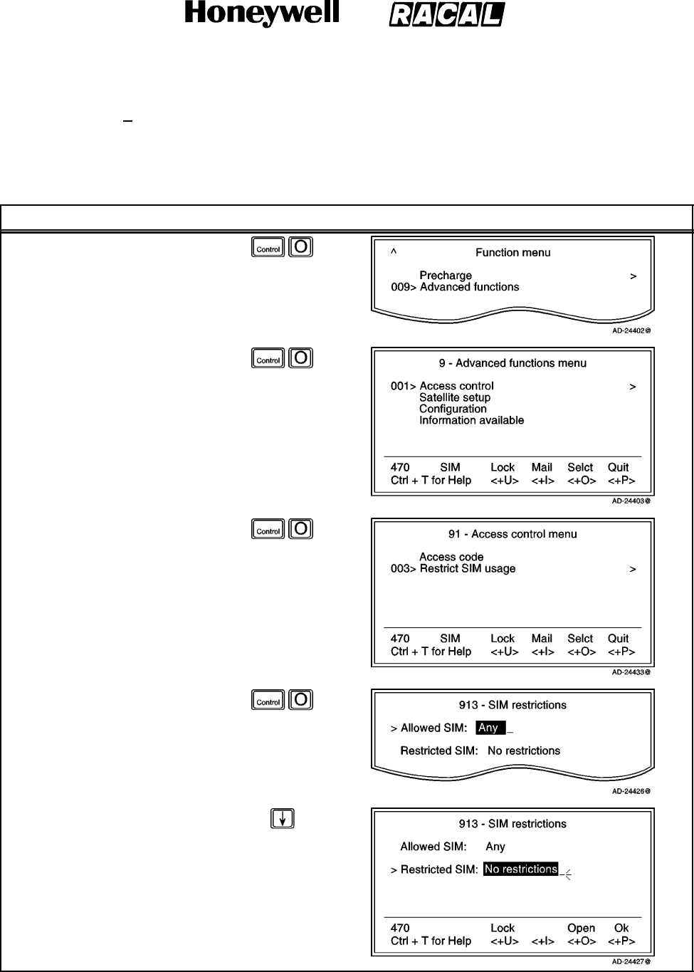
SYSTEM DESCRIPTION AND INSTALLATION MANUAL
SCS--1000 Mini--M Aero SATCOM System
23--20--28
Use or disclosure of information on this page is subject to the restrictions in the proprietary notice of this document.
Page 2--85
31 Jan 2000
6Set the SIM Restrictions (Owner Level Only)
To set the SIM restrictions, perform the procedures in Table 2--34.
Table 2--34. Procedure to Set the SIM Restrictions
Task Key Strokes PC Screen Display
1. Selecting Menu on the Main
window opens the Function
menu window.
2. Scroll down to Advanced
functions.
3. Selecting Selct or pushing the
right arrow button on the
Functions menu opens the
Advanced functions menu.
4. Selecting Selct or pushing the
right arrow button on the
Advanced Functions menu
opens the Access control
menu.
5. Scroll down to Restrict SIM
usage.
6. Select Selct or push the right
arrow button on the Access
control menu to open the SIM
restrictions window.
7. Scroll down to Restricted SIM.
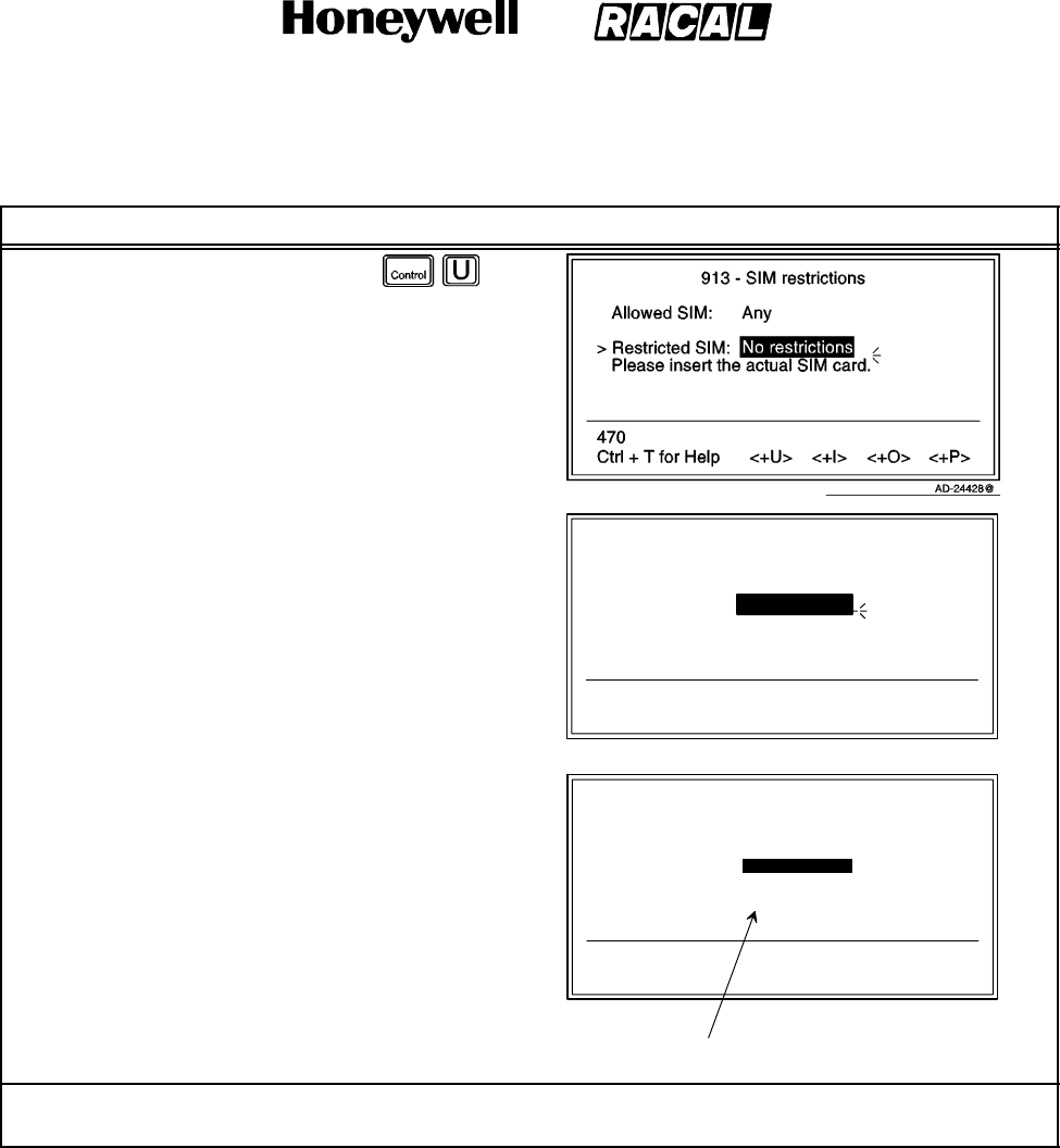
SYSTEM DESCRIPTION AND INSTALLATION MANUAL
SCS--1000 Mini--M Aero SATCOM System
23--20--28
Use or disclosure of information on this page is subject to the restrictions in the proprietary notice of this document.
Page 2--86
31 Jan 2000
Table 2--34. Procedure to Set the SIM Restrictions (cont)
Task PC Screen DisplayKey Strokes
8. Select Lock and insert the
actual SIM card.
NOTE: The system can now be
operated with that
specific card only.
913 -- SIM restrictions
470
Ctrl + T for Help <+U> <+I> <+O> <+P>
Allowed SIM: Any
> Restricted SIM: Locked to one
Card number: 8980120000166470336
Please retract the SIM card.
AD--24429@
NOTE: When retracting the SIM
card, the ID of the SIM
provider is displayed.
9. Selecting Ok (pushing the
CONTROL and P keys) stores
the settings.
913 -- SIM restrictions
470
Ctrl + T for Help <+U> <+I> <+O> <+P>
Allowed SIM:
> Restricted SIM:
Card number:
SIM provider Id:
AD--24430@
Any
Locked to one
8980120000166470336
8012
Lock Open Ok
APPEARS IF CARD IS
LOCKED BY SIM PROVIDER
NOTE: To set the Allowed SIM, follow the same procedures as above with the marker remaining on
Allowed SIM instead of Restricted SIM.
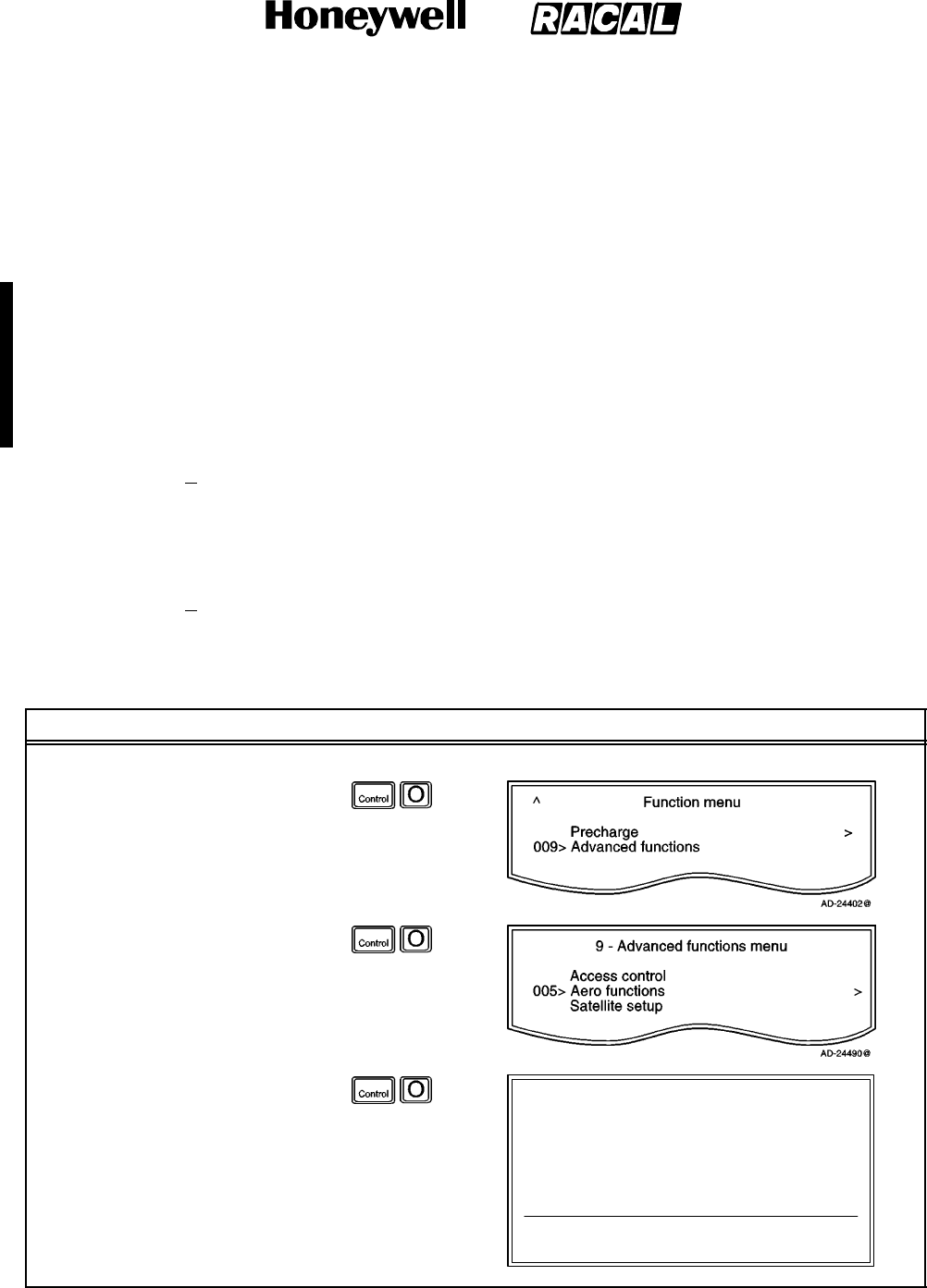
SYSTEM DESCRIPTION AND INSTALLATION MANUAL
SCS--1000 Mini--M Aero SATCOM System
23--20--28
Use or disclosure of information on this page is subject to the restrictions in the proprietary notice of this document.
Page 2--87
16 Oct 2000
(2) Aero Functions
Allows re--calibration of the magnetometer, setting of the aircraft landing speed, and
location of the satellites to be used.
(a) Calibrating the Magnetrometer
The antenna unit contains a three--axes magnetometer for tracking purposes,
which must be calibrated after installation of the system in the aircraft.
Recalibration is required when the Antenna Control Unit (ACU) is replaced or
when the magnetic characteristics of the aircraft have changed. Calibration is
performed while the aircraft is being turned slowly through 360 degrees on a
smooth flat level surface, away from any large hangers or buildings that could
disturb the terrestrial magnetic field.
1Preparation
Park the aircraft on the selected site. Note that all aircraft systems must be
powered and running, to create the aircraft magnetic environment that would
be experienced in flight.
2Magnetometer Calibration (Owner level only)
To calibrate the magnetometer, perform the procedures in Table 2--35.
Table 2--35. Magnetometer Calibration Procedure
Task Key Strokes PC Screen Display
1. Wait until the SCS system has completed initializing after power up.
2. Selecting Menu on the Main
window opens the Function
menu window.
3. Scroll down to Advanced
functions.
4. Selecting Selct or pushing the
right arrow button on the
Functions menu opens the
Advanced functions menu.
5. Scroll down to Aero functions.
6. Selecting Selct or pushing the
right arrow button on the
Advanced Functions menu
opens the Aero functions
menu.
95 -- Aero functions
Ctrl + T for Help <+U>
Lock
<+I>
Mail
<+O>
Selct
<+P>
Quit
001> Magnetometer calibration >
002> Configure landing speed >
003> Satellite locations >
AD--24491@
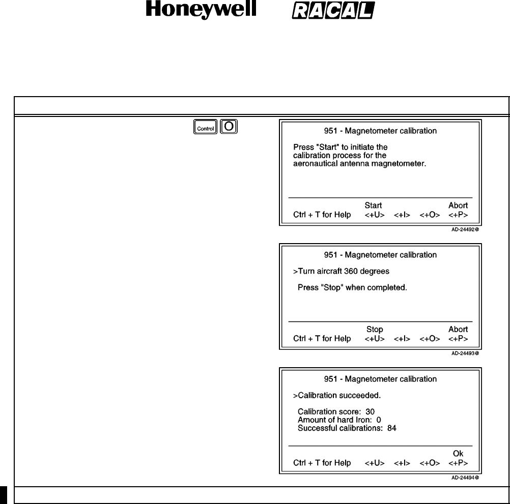
SYSTEM DESCRIPTION AND INSTALLATION MANUAL
SCS--1000 Mini--M Aero SATCOM System
23--20--28
Use or disclosure of information on this page is subject to the restrictions in the proprietary notice of this document.
Page 2--88
16 Oct 2000
Table 2--35. Magnetometer Calibration Procedure (cont)
Task PC Screen DisplayKey Strokes
7. Select Selct or push the right
arrow button on the Aero
functions menu to open the
Magnetometer calibration
window.
8. Select Start (pushing the
CONTROL and U keys) to
start the calibration procedure.
9. Turn the aircraft through 360
degrees.
NOTE: The duration of the 360
degree turn should be
more than one minute
and less that 5 minutes.
10. Select Stop (pushing the
CONTROL and U keys) when
the turn is completed. This
will terminate the calibration
process.
NOTE: Refer to the ADJUSTMENT/TEST section for interpretation of the calibration scores.
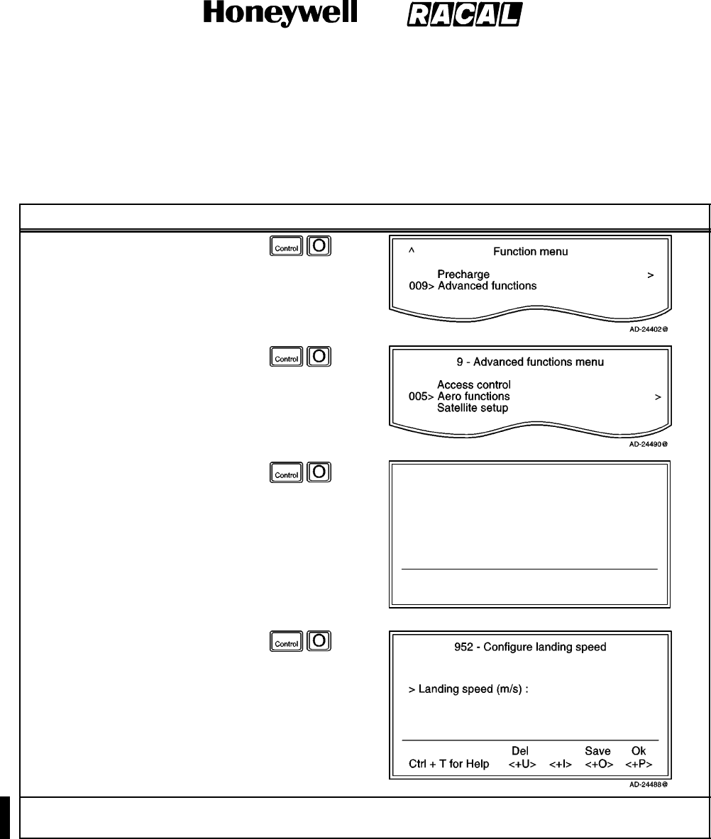
SYSTEM DESCRIPTION AND INSTALLATION MANUAL
SCS--1000 Mini--M Aero SATCOM System
23--20--28
Use or disclosure of information on this page is subject to the restrictions in the proprietary notice of this document.
Page 2--89
16 Oct 2000
(b) Configure Landing Speed (Owner Level Only)
To configure the landing speed, perform the procedures in Table 2--36.
Table 2--36. Procedure to Configure Landing Speed
Task Key Strokes PC Screen Display
1. Selecting Menu on the Main
window opens the Function
menu window.
2. Scroll down to Advanced
functions.
3. Selecting Selct or pushing the
right arrow button on the
Functions menu opens the
Advanced functions menu.
4. Scroll down to Aero functions.
5. Selecting Selct or pushing the
right arrow button on the
Advanced Functions menu
opens the Aero functions
menu.
6. Scroll down to Configure
landing speed.
95 -- Aero functions
Ctrl + T for Help <+U>
Lock
<+I>
Mail
<+O>
Selct
<+P>
Quit
001> Magnetometer calibration >
002> Configure landing speed >
003> Satellite locations >
AD--24487@
7. Select Selct or push the right
arrow button on the Aero
functions menu to open the
Configure landing speed
window.
8. Enter the nominal landing
speed in meter per second.
9. Save (pushing the CONTROL
and O keys) saves the entry.
NOTE: Refer to the ADJUSTMENT/TEST section for additional information about configuring landing
speed.
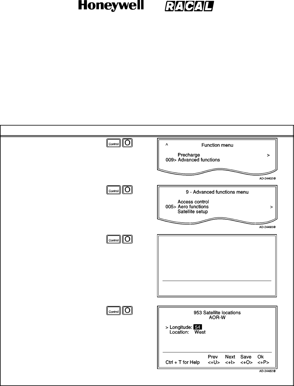
SYSTEM DESCRIPTION AND INSTALLATION MANUAL
SCS--1000 Mini--M Aero SATCOM System
23--20--28
Use or disclosure of information on this page is subject to the restrictions in the proprietary notice of this document.
Page 2--90
31 Jan 2000
(c) Satellite Locations (Owner Level Only)
This option is provided to modify the stored locations of the INMARSAT satellites.
This would be required in the (unlikely) event of a satellite being moved to
another longitude, or when a new INMARSAT satellite is brought into service at a
different location to the existing satellites.
To modify the stored satellite locations, perform the procedures in Table 2--37.
Table 2--37. Satellite Locations Procedure
Task Key Strokes PC Screen Display
1. Selecting Menu on the Main
window opens the Function
menu window.
2. Scroll down to Advanced
functions.
3. Selecting Selct or pushing the
right arrow button on the
Functions menu opens the
Advanced functions menu.
4. Scroll down to Aero functions.
5. Selecting Selct or pushing the
right arrow button on the
Advanced Functions menu
opens the Aero functions
menu.
6. Scroll down to Satellite
locations.
95 -- Aero functions
Ctrl + T for Help <+U>
Lock
<+I>
Mail
<+O>
Selct
<+P>
Quit
001> Magnetometer calibration
002> Configure landing speed
003> Satellite locations
AD--24481@
>
>
>
7. Select Selct or push the right
arrow button on the Aero
functions menu to open the
Satellite locations window.
8. Select the appropriate satellite
using Prev (pushing the
CONTROL and U keys) and
Next (pushing the CONTROL
and I keys).
9. Enter the satellite longitude in
degrees.
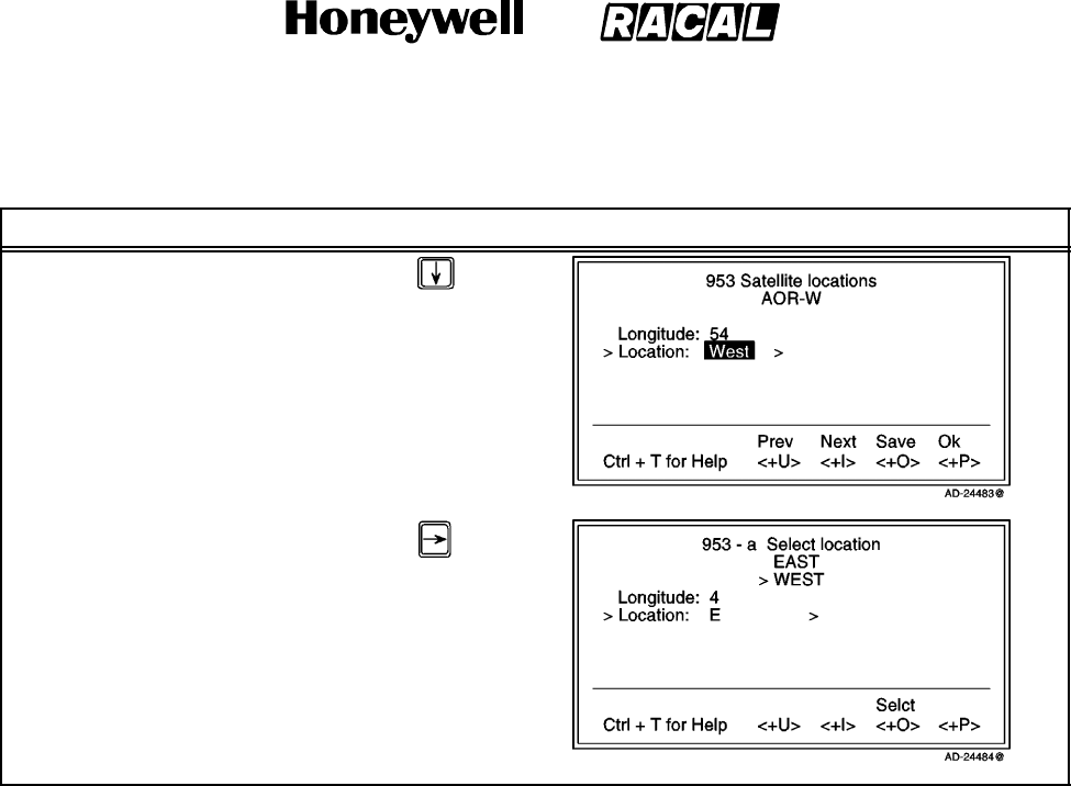
SYSTEM DESCRIPTION AND INSTALLATION MANUAL
SCS--1000 Mini--M Aero SATCOM System
23--20--28
Use or disclosure of information on this page is subject to the restrictions in the proprietary notice of this document.
Page 2--91
31 Jan 2000
Table 2--37. Satellite Locations Procedure (cont)
Task PC Screen DisplayKey Strokes
10. Scroll down to Location.
11. Pushing the right arrow button
opens the list of locations,
East or West.
12. Scroll up or down to choose
the location.
13. Select Selct (pushing the
CONTROL and O keys) and
then Save (pushing the
CONTROL and O keys) to
store the new location.
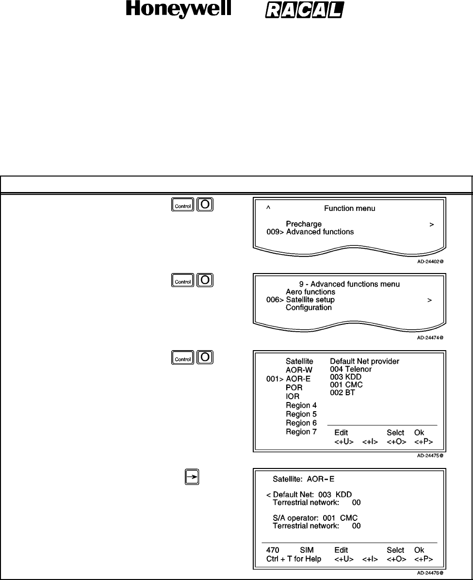
SYSTEM DESCRIPTION AND INSTALLATION MANUAL
SCS--1000 Mini--M Aero SATCOM System
23--20--28
Use or disclosure of information on this page is subject to the restrictions in the proprietary notice of this document.
Page 2--92
31 Jan 2000
(3) Satellite Setup
This function allows preprogramming of the default network service provider, Stand
Alone (S/A) operator, and terrestrial network for each satellite region (Ocean Region).
To set up the satellite, perform the procedures in Table 2--38.
Table 2--38. Satellite Setup Procedure
Task Key Strokes PC Screen Display
1. Selecting Menu on the Main
window opens the Function
menu window.
2. Scroll down to Advanced
functions.
3. Selecting Selct or pushing the
right arrow button on the
Functions menu opens the
Advanced functions menu.
4. Scroll down to Satellite setup.
5. Selecting Selct or pushing the
right arrow button on the
Advanced Functions menu
opens the list of satellites and
default network service
providers.
6. Scroll up or down to the
desired satellite.
NOTE: Pushing the right arrow
button displays the
selected satellite
information. Scroll down
to the desired satellite.
7. Selecting Selct (pushing the
CONTROL and O keys)
initiates a search for the
specified satellite.
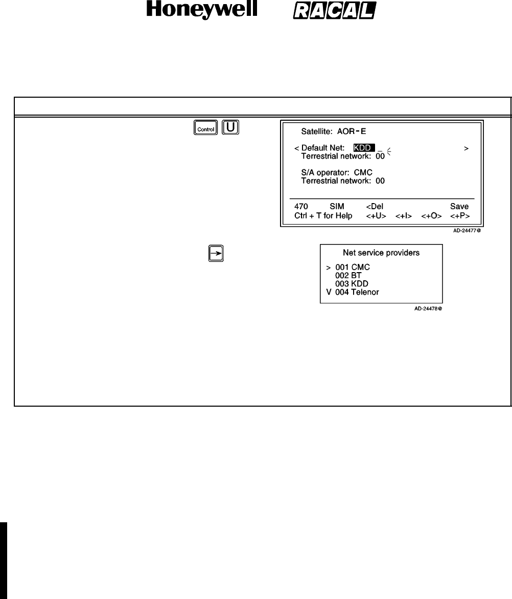
SYSTEM DESCRIPTION AND INSTALLATION MANUAL
SCS--1000 Mini--M Aero SATCOM System
23--20--28
Use or disclosure of information on this page is subject to the restrictions in the proprietary notice of this document.
Page 2--93
16 Oct 2000
Table 2--38. Satellite Setup Procedure (cont)
Task PC Screen DisplayKey Strokes
8. Selecting Edit opens the
setting window for the
selected satellite.
9. Scroll up or down to the
desired satellite.
10. Pushing the right arrow button
opens the list of available
network service providers.
11. Scroll up or down to the
desired network service
provider.
12. Selecting Selct (pushing the CONTROL and O keys) enters the new default network service provider.
13. Repeat step 10, scroll down to Terrestrial network, and key in the code.
14. Selecting Save (pushing the CONTROL and P keys) stores the selected network service provider and
terrestrial network as the default for that particular satellite.
NOTE: To set up the Stand Alone (S/A) operator and terrestrial network, repeat steps 10 thru 14 with the
marker on S/A operator and Terrestrial network.
(4) Configuration
(a) Port Configuration
Displays current configuration. Reconfiguration can be made in the Owner
level only (non--SIM operation).
With Broadcast On, incoming calls initiate ringing on all ports configured for
voice communication.
With Broadcast Off, only the dialed port rings.
The secure voice function allows selected port(s) to be used with an
encrypted telephone. Refer to paragraph 7.K.(4)(b) in this section.
To set the port configuration, perform the procedures in Table 2--39.
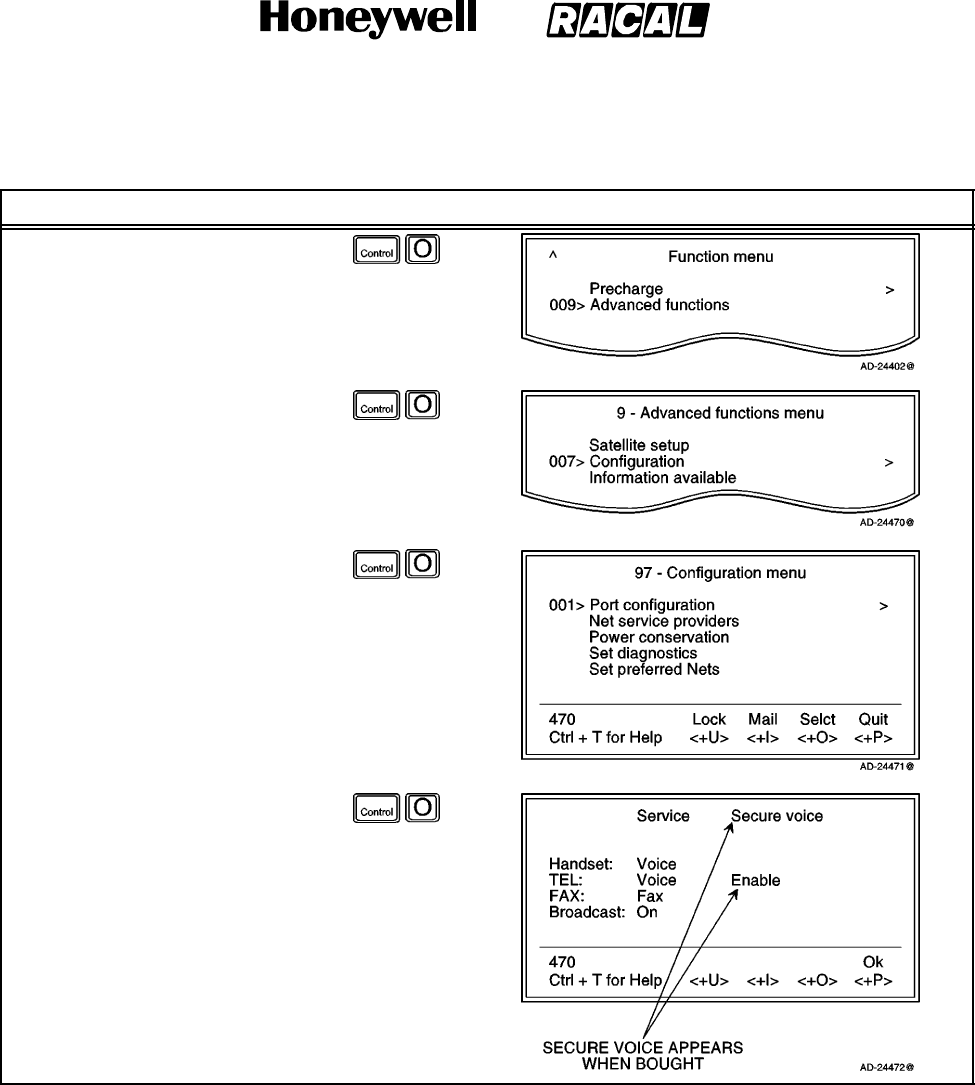
SYSTEM DESCRIPTION AND INSTALLATION MANUAL
SCS--1000 Mini--M Aero SATCOM System
23--20--28
Use or disclosure of information on this page is subject to the restrictions in the proprietary notice of this document.
Page 2--94
31 Jan 2000
Table 2--39. Port Configuration Procedure
Task Key Strokes PC Screen Display
1. Selecting Menu on the Main
window opens the Function
menu window.
2. Scroll down to Advanced
functions.
3. Selecting Selct or pushing the
right arrow button on the
Functions menu opens the
Advanced functions menu.
4. Scroll down to Configuration.
5. Selecting Selct or pushing the
right arrow button on the
Advanced Functions menu
opens the Configuration
menu.
6. Selecting Selct or pushing the
right arrow button on the
Configuration menu opens the
Port configuration window,
which shows the present
service of the ports, and the
incoming call response.
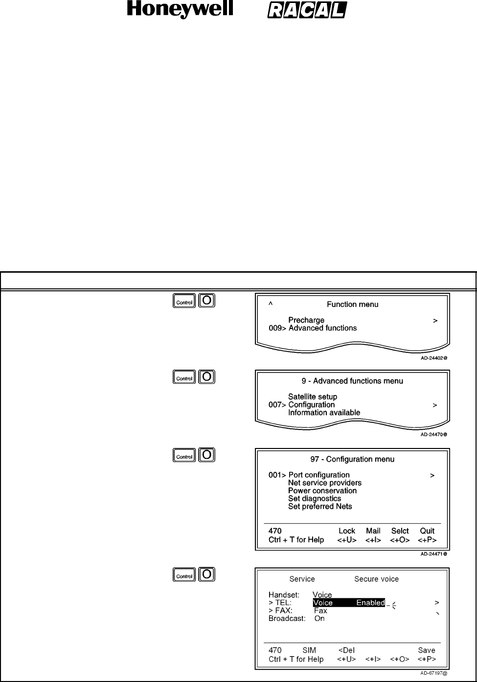
SYSTEM DESCRIPTION AND INSTALLATION MANUAL
SCS--1000 Mini--M Aero SATCOM System
23--20--28
Use or disclosure of information on this page is subject to the restrictions in the proprietary notice of this document.
Page 2--95
31 Jan 2000
(b) Secure Voice Option
The SCS system can be programmed to allow the operation of encrypted speech
through the telephone (TEL) port and FAX port when configured for voice
service.
NOTES:
1. The STU IIB/III is enabled as the default on ports configured for voice
service.
2. Verify that your service provider supports secure voice operation.
To set up the secure voice option, perform the procedures in Table 2--40.
Table 2--40. Secure Voice Option Setup Procedure
Task Key Strokes PC Screen Display
1. Selecting Menu on the Main
window opens the Function
menu window.
2. Scroll down to Advanced
functions.
3. Selecting Selct or pushing the
right arrow button on the
Functions menu opens the
Advanced functions menu.
4. Scroll down to Configuration.
5. Selecting Selct or pushing the
right arrow button on the
Advanced Functions menu
opens the Configuration
menu.
6. Selecting Selct or pushing the
right arrow button on the
Configuration menu displays
which ports are enabled or
disabled for use with secure
voice.
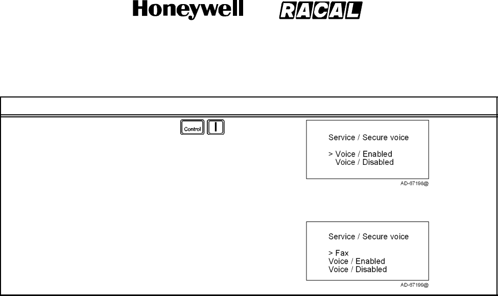
SYSTEM DESCRIPTION AND INSTALLATION MANUAL
SCS--1000 Mini--M Aero SATCOM System
23--20--28
Use or disclosure of information on this page is subject to the restrictions in the proprietary notice of this document.
Page 2--96
31 Jan 2000
Table 2--40. Secure Voice Option Setup Procedure (cont)
Task PC Screen DisplayKey Strokes
7. Selecting Edit or pushing the
right arrow button again allows
the user to enable or disable
secure voice.
8. Scroll up or down and then
select Selct (push the
CONTROL and O keys) to
choose the desired mode.
NOTE: To set up the FAX port
for secure voice
operation, repeat the
steps above with the
marker on FAX instead
of TEL.
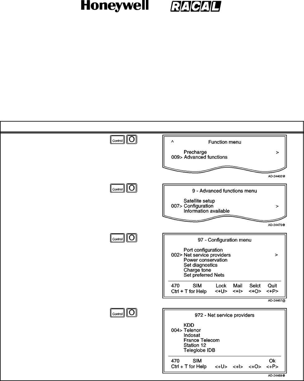
SYSTEM DESCRIPTION AND INSTALLATION MANUAL
SCS--1000 Mini--M Aero SATCOM System
23--20--28
Use or disclosure of information on this page is subject to the restrictions in the proprietary notice of this document.
Page 2--97
31 Jan 2000
(c) Net Service Providers
Each network service provider has a station code. The Net service provider
window displays a list which matches the codes to the station owners. Names
can be edited in the Owner level (non--SIM operation).
To set the network service providers, perform the procedures in Table 2--41.
Table 2--41. Network Service Providers Setup Procedure
Task Key Strokes PC Screen Display
1. Selecting Menu on the Main
window opens the Function
menu window.
2. Scroll down to Advanced
functions.
3. Selecting Selct or pushing the
right arrow button on the
Functions menu opens the
Advanced functions menu.
4. Scroll down to Configuration.
5. Selecting Selct or pushing the
right arrow button on the
Advanced Functions menu
opens the Configuration
menu.
6. Scroll down to Net service
providers.
7. Selecting Selct or pushing the
right arrow button on the
Configuration menu opens the
list of Net service providers.
8. Scroll up or down to the
desired service provider.
9. Selecting Ok (pushing the
CONTROL and P keys) stores
the chosen service provider.
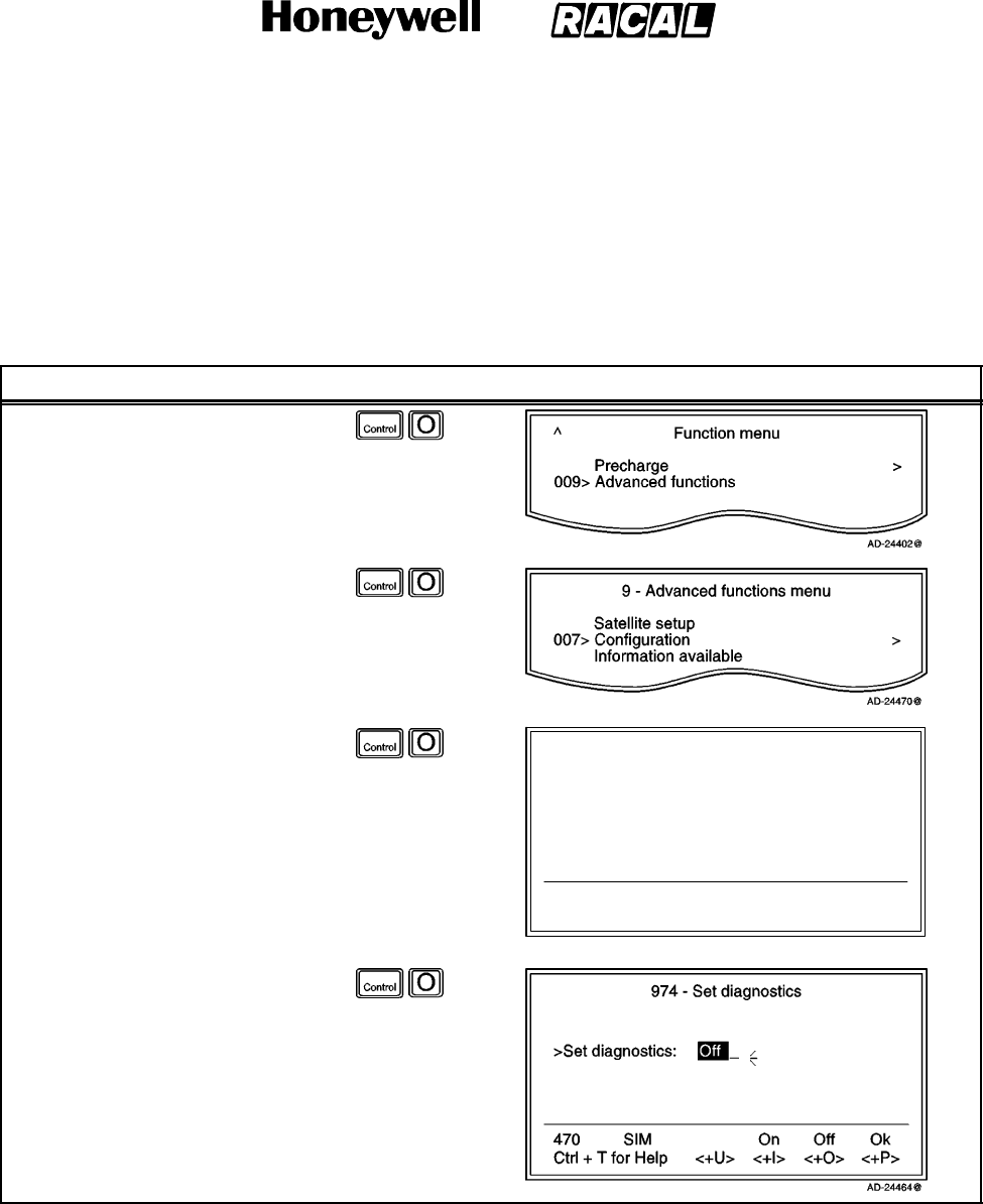
SYSTEM DESCRIPTION AND INSTALLATION MANUAL
SCS--1000 Mini--M Aero SATCOM System
23--20--28
Use or disclosure of information on this page is subject to the restrictions in the proprietary notice of this document.
Page 2--98
31 Jan 2000
(d) Set Diagnostics
NOTE: This mode is not necessary for normal telephone use.
Additional system information is displayed when diagnostics is turned On. To set
the diagnostics, perform the procedure in Table 2--42.
Table 2--42. Procedure to Set the Diagnostics
Task Key Strokes PC Screen Display
1. Selecting Menu on the Main
window opens the Function
menu window.
2. Scroll down to Advanced
functions.
3. Selecting Selct or pushing the
right arrow button on the
Functions menu opens the
Advanced functions menu.
4. Scroll down to Configuration.
5. Selecting Selct or pushing the
right arrow button on the
Advanced Functions menu
opens the Configuration
menu.
6. Scroll down to Set
diagnostics.
97 -- Configuration menu
470
Ctrl + T for Help
SIM
<+U>
Lock
<+I>
Mail
<+O>
Selct
<+P>
Quit
Net service providers
Power conservation >
004> Set diagnostics >
Charge tone
Set preferred Nets
Set S/A preferred Nets
AD--24463@
7. Selecting Selct or pushing the
right arrow button on the
Configuration menu opens the
Set diagnostics window.
8. Select On or Off by choosing
On (pushing the CONTROL
and I keys) or Off (pushing the
CONTROL and O keys) and
then Ok (pushing the
CONTROL and P keys).
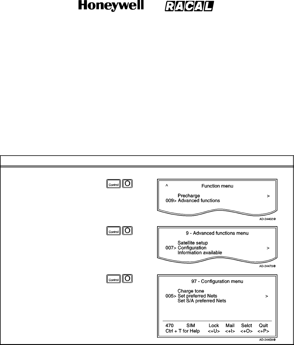
SYSTEM DESCRIPTION AND INSTALLATION MANUAL
SCS--1000 Mini--M Aero SATCOM System
23--20--28
Use or disclosure of information on this page is subject to the restrictions in the proprietary notice of this document.
Page 2--99
31 Jan 2000
(e) Storing of Preferred/Allowed Net Service Provider and Stand Alone Operator on
the SIM Card
These functions allow you to store the preferred/allowed network service provider
and preferred/allowed Stand Alone operator for each satellite region on a SIM
card.
NOTE: The access level required to operate this functions depend on the SIM
card supplier.
To store the provider and operator information, perform the procedures in
Table 2--43.
Table 2--43. Procedure to Store Net Service Providers/Operators
Task Key Strokes PC Screen Display
Preferred Net Service Provider:
1. Selecting Menu on the Main
window opens the Function
menu window.
2. Scroll down to Advanced
functions.
3. Selecting Selct or pushing the
right arrow button on the
Functions menu opens the
Advanced functions menu.
4. Scroll down to Configuration.
5. Selecting Selct or pushing the
right arrow button on the
Advanced Functions menu
opens the Configuration
menu.
6. Scroll down to Set preferred
Nets.
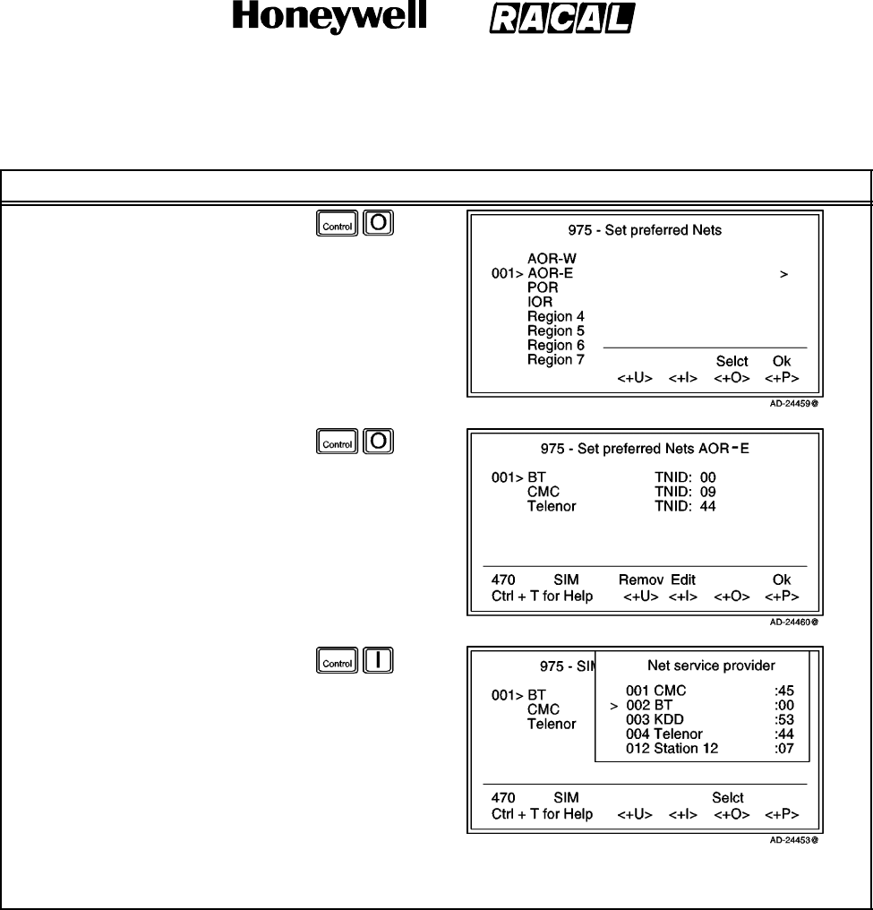
SYSTEM DESCRIPTION AND INSTALLATION MANUAL
SCS--1000 Mini--M Aero SATCOM System
23--20--28
Use or disclosure of information on this page is subject to the restrictions in the proprietary notice of this document.
Page 2--100
31 Jan 2000
Table 2--43. Procedure to Store Net Service Providers/Operators (cont)
Task PC Screen DisplayKey Strokes
7. Selecting Selct or pushing the
right arrow button on the
Configuration menu opens the
Set preferred Nets window.
8. Scroll up or down to the
desired satellite.
9. Selecting Selct or pushing the
right arrow button on the Set
preferred Nets window show
the current Net and Terrestrial
Network Identification Digits
(TNID).
10. Remov (pushing the
CONTROL and U keys)
deletes the Net entry.
11. Selecting Edit on the Set
preferred Nets window opens
the list of available Nets.
NOTE: If the SIM card is not
restricted, selecting Edit
opens the satellite
preferred list. See If the
SIM Card is Not
Restricted below.
12. Scroll up or down to the desired Net.
13. Selct (pushing the CONTROL and O keys) enters the new default network service provider.
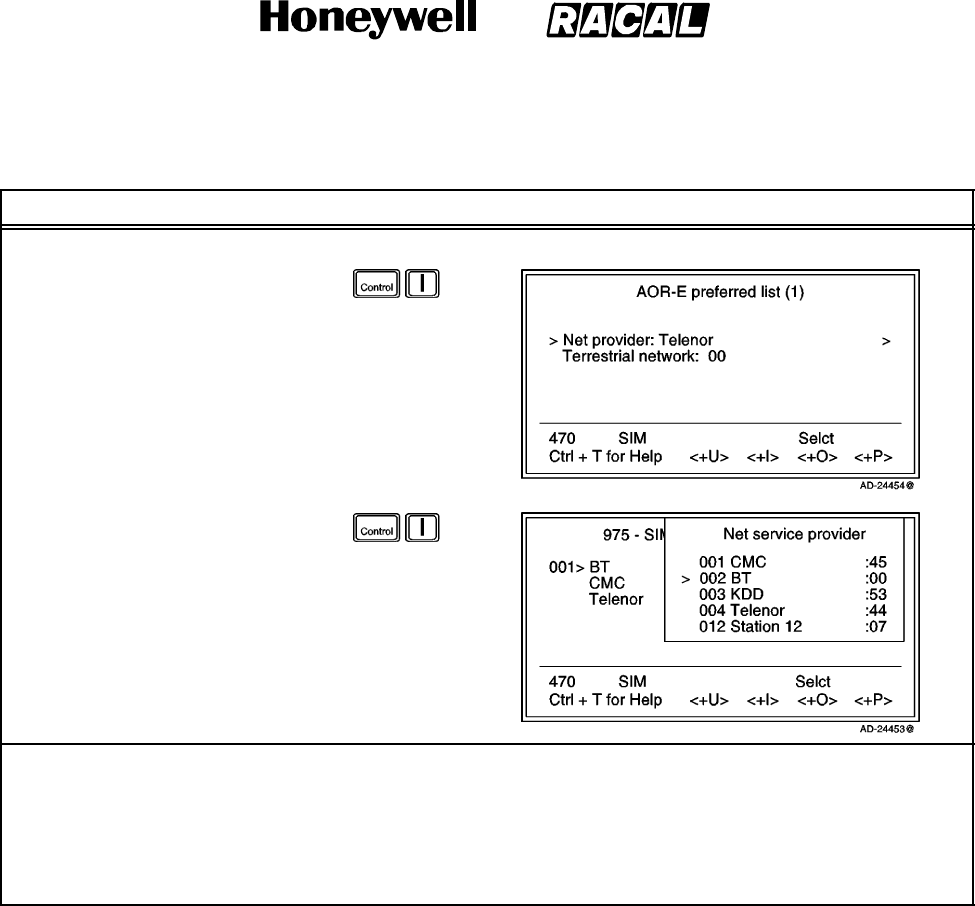
SYSTEM DESCRIPTION AND INSTALLATION MANUAL
SCS--1000 Mini--M Aero SATCOM System
23--20--28
Use or disclosure of information on this page is subject to the restrictions in the proprietary notice of this document.
Page 2--101
31 Jan 2000
Table 2--43. Procedure to Store Net Service Providers/Operators (cont)
Task PC Screen DisplayKey Strokes
If the SIM Card is Not Restricted:
1. Selecting Edit on the Set
preferred Nets window opens
the satellite preferred list
window.
2. Selecting Edit on the Set
preferred Nets window opens
the list of available Nets.
3. Scroll up or down to the
desired Net.
4. Selct (pushing the CONTROL
and O keys) enters the new
default network service
provider.
NOTES:
1. To set the S/A preferred Nets (Stand Alone Operator), repeat the steps for Preferred Net Service
Provider, except place the marker on Set S/A preferred Nets.
2. To set the allowed Nets or set the S/A allowed Nets, repeat the steps for Preferred Net Service
Provider, except place the marker on Set allowed Nets or Set S/A allowed Nets. This function is
restricted to the CHV2 level or higher, depending on the network service provider.
(f) Charge Tone
When the charge tone function is enabled, a single frequency tone or DTMF is
transmitted once the call has been established. The tone informs an external
debiting system, for example, a pay phone (connected to the TEL port) that
charging can start.
NOTE: Settings can only be made in the owner level.
To set the charge tone, perform the procedure in Table 2--44.
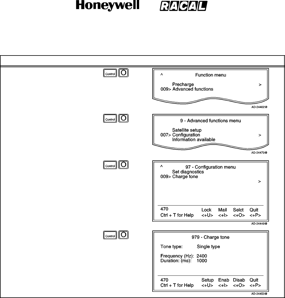
SYSTEM DESCRIPTION AND INSTALLATION MANUAL
SCS--1000 Mini--M Aero SATCOM System
23--20--28
Use or disclosure of information on this page is subject to the restrictions in the proprietary notice of this document.
Page 2--102
31 Jan 2000
Table 2--44. Procedure to Set the Charge Tone
Task Key Strokes PC Screen Display
1. Selecting Menu on the Main
window opens the Function
menu window.
2. Scroll down to Advanced
functions.
3. Selecting Selct or pushing the
right arrow button on the
Functions menu opens the
Advanced functions menu.
4. Scroll down to Configuration.
5. Selecting Selct or pushing the
right arrow button on the
Advanced Functions menu
opens the Configuration
menu.
6. Scroll down to Charge Tone.
7. Selecting Selct or pushing the
right arrow button on the
Configuration menu opens the
Charge tone window.
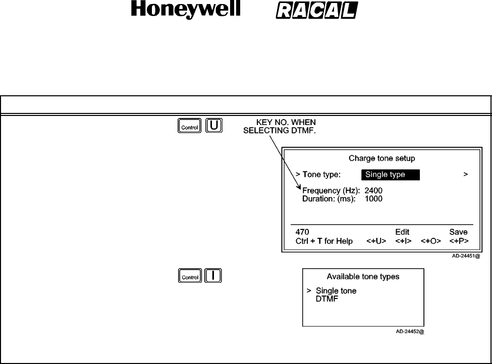
SYSTEM DESCRIPTION AND INSTALLATION MANUAL
SCS--1000 Mini--M Aero SATCOM System
23--20--28
Use or disclosure of information on this page is subject to the restrictions in the proprietary notice of this document.
Page 2--103
31 Jan 2000
Table 2--44. Procedure to Set the Charge Tone (cont)
Task PC Screen DisplayKey Strokes
8. Selecting Setup opens the
Charge tone setup window,
which allow the user to set the
required single frequency tone
or DTMF, and its duration in
milliseconds.
NOTE: Valid settings are as
follows:
Frequency: 400 to 3400 Hz
Duration: 10 to 5000 ms
DTMF key: 0 to 15
9. Selecting Edit or pushing the
right arrow button opens the
Available tone types window.
10. Scroll up or down to choose
Single tone or DTMF and then
select Selct (push the
CONTROL and O keys) to
enter the chose settings.
(5) Information Available
The following information is provided:
The IMN numbers assigned to the SCS system. The access level must be set to
Owner for editing of the numbers on the telephone or CHV2 for editing of the
numbers on the SIM card.
Forward ID number which identifies your particular system and SIM card if
installed.
System version numbers of the internal software programs.
Network status information (only appears when Set diagnostics is On, or the
access level is set to Owner).
To view the information, perform the procedure in Table 2--45.
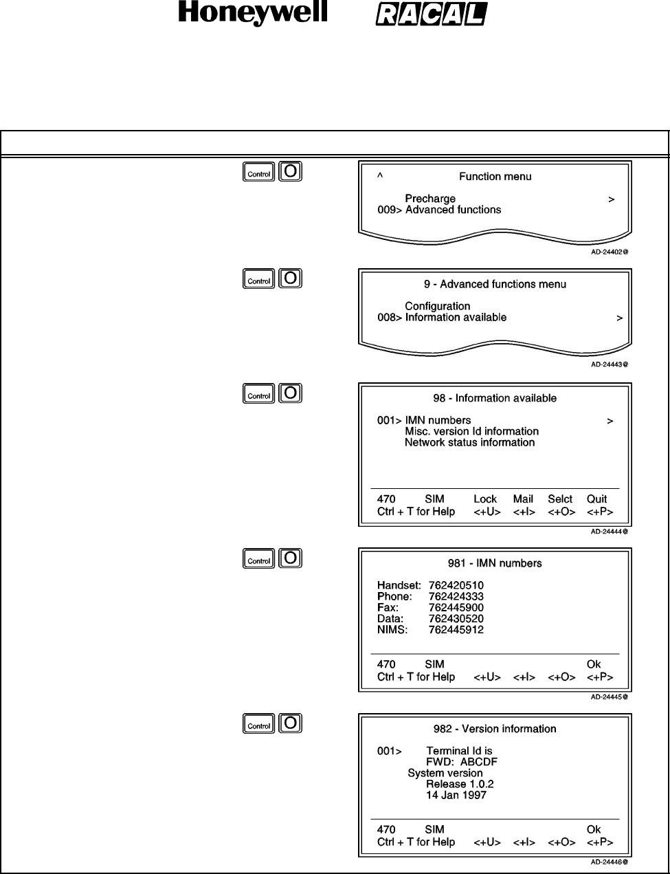
SYSTEM DESCRIPTION AND INSTALLATION MANUAL
SCS--1000 Mini--M Aero SATCOM System
23--20--28
Use or disclosure of information on this page is subject to the restrictions in the proprietary notice of this document.
Page 2--104
31 Jan 2000
Table 2--45. Procedure to View Information
Task Key Strokes PC Screen Display
1. Selecting Menu on the Main
window opens the Function
menu window.
2. Scroll down to Advanced
functions.
3. Selecting Selct or pushing the
right arrow button on the
Functions menu opens the
Advanced functions menu.
4. Scroll down to Information
available.
5. Selecting Selct or pushing the
right arrow button on the
Advanced Functions menu
opens the Information
available window.
6. Selecting Selct or pushing the
right arrow button again opens
the Information available
window.
NOTE: To view the
Miscellaneous version
ID information, select
Selct or push the right
arrow button on the
Information available
window with the marker
on Misc. version Id
information.
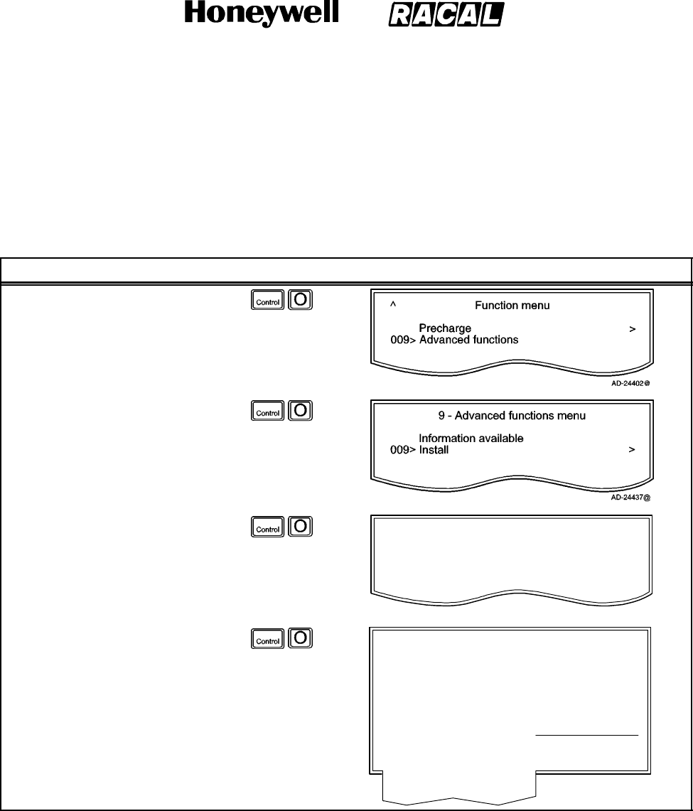
SYSTEM DESCRIPTION AND INSTALLATION MANUAL
SCS--1000 Mini--M Aero SATCOM System
23--20--28
Use or disclosure of information on this page is subject to the restrictions in the proprietary notice of this document.
Page 2--105
31 Jan 2000
(6) Installation
(a) Paid Functions
This function appears only in the Owner level (non--SIM operation). To set up
the paid functions, perform the procedure in Table 2--46.
Table 2--46. Paid Functions Setup Procedure
Task Key Strokes PC Screen Display
1. Selecting Menu on the Main
window opens the Function
menu window.
2. Scroll down to Advanced
functions.
3. Selecting Selct or pushing the
right arrow button on the
Functions menu opens the
Advanced functions menu.
4. Scroll down to Install.
5. Selecting Selct or pushing the
right arrow button on the
Advanced Functions menu
opens the Installation menu.
99 -- Installation menu
001> Paid functions
002> Phone name setup
AD--24438@
>
>
6. Selecting Selct or pushing the
right arrow button again opens
the Paid functions list.
NOTE: The list only shows the
purchased functions.
991 -- Paid functions
<+I>
Last
<+O>
New
<+P>
Ok
001> Charge tone
002> Traffic log
003> Precharge
004> Restricted Net provider
005> Restricted dial
006> Secure voice
007> Access code
008> Data
009> Advanced service level
010> Fax
011> NIMS
012> Aero functions
AD--24439@

SYSTEM DESCRIPTION AND INSTALLATION MANUAL
SCS--1000 Mini--M Aero SATCOM System
23--20--28
Use or disclosure of information on this page is subject to the restrictions in the proprietary notice of this document.
Page 2--106
31 Jan 2000
(b) Phone Name Setup
This function appears only in the Owner level (non--SIM operation). To set up
the phone name, perform the procedure in Table 2--47.
Table 2--47. Phone Name Setup Procedure
Task Key Strokes PC Screen Display
1. Selecting Menu on the Main
window opens the Function
menu window.
2. Scroll down to Advanced
functions.
3. Selecting Selct or pushing the
right arrow button on the
Functions menu opens the
Advanced functions menu.
4. Scroll down to Install.
5. Selecting Selct or pushing the
right arrow button on the
Advanced Functions menu
opens the Installation menu.
99 -- Installation menu
001> Paid functions
002> Phone name setup
AD--24438--1@
>
>
6. Selecting Selct or pushing the
right arrow button on the
Installation menu opens the
Phone name setup window.
a. Del (pushing the
CONTROL and U keys)
modifies the entries.
b. ABC (pushing the
CONTROL and I keys)
enters uppercase letters,
as required.
c. abc (pushing the CONTROL and O keys) enters lowercase letters, as required.
d. Save (pushing the CONTROL and P keys) stores the modified phone name.

SYSTEM DESCRIPTION AND INSTALLATION MANUAL
SCS--1000 Mini--M Aero SATCOM System
23--20--28
Use or disclosure of information on this page is subject to the restrictions in the proprietary notice of this document.
Page 3--1
31 Jan 2000
MECHANICAL INSTALLATION
1. General
This section contains information on how and where to mount each component of an SCS
system installation. For new installations, plan installation in two stages. First, determine
location of the LRUs in the aircraft. Next, determine the length of RF and electrical
interconnections for selected locations.
2. Equipment and Materials
Contact the aircraft Original Equipment Manufacturer (OEM) for a list of materials necessary
to install the SCS system.

SYSTEM DESCRIPTION AND INSTALLATION MANUAL
SCS--1000 Mini--M Aero SATCOM System
23--20--28
Use or disclosure of information on this page is subject to the restrictions in the proprietary notice of this document.
Page 3--2
31 Jan 2000
3. Mechanical Installation Provisions
A. Circuit Breaker Provisions
The SCS system must be protected by a circuit breaker and switch. The rating of the
circuit breaker depends on the breaker slowness, due to the surge that occurs at switch
on. The circuit breaker requirements are as follows:
Continuous Current: 1.95 A at 20.5 V (minimum voltage)
In--rush Current: 20.1 A for 0.11 second at 32.2 V
(maximum voltage)
less than 17A for 0.13 seconds when supplied
by 27.5 V dc
12.8 A for 0.18 second at 20.5 V
(minimum voltage).
For example, the Klixon 2TC, 3 A circuit breaker, or equivalent, should be sufficient in
most installations.
B. Aero Antenna Unit Provisions
Mechanical installation data for the AAU is shown in Figure 3--1.
The AAU is attached to the fuselage with eight screws. Structural modifications must be
made to the aircraft to accommodate the extra loads and adapt the flat underside of the
AAU to the curvature of the fuselage. An installation kit is available to simplify this task.
Refer to Section 8, Vendor Equipment.
C. Antenna Control Unit Provisions
Mechanical installation data for the ACU is shown in Figure 3--2.
The ACU is designed to be placed in the area of the pressurized/temperature controlled
cabin. It is preferable that the ACU be placed between the insulator and the inner cabin
liner and not between the outer skin and the insulation, due to the extreme low
temperatures on the skin. The ACU can be placed between the cabin liner and the
fuselage. To minimize cable attenuation, place the ACU as close to the antenna as
possible. The ACU needs to be grounded to aircraft common.
NOTE: Make sure that the ACU is not placed against dissimilar metals.

SYSTEM DESCRIPTION AND INSTALLATION MANUAL
SCS--1000 Mini--M Aero SATCOM System
23--20--28
Use or disclosure of information on this page is subject to the restrictions in the proprietary notice of this document.
Page 3--3
31 Jan 2000
D. Power Supply Unit Provisions
Mechanical installation data for the PSU is shown in Figure 3--3.
The PSU is designed to be placed in the area of the pressurized/temperature controlled
cabin. The PSU must be mounted against a prepared aluminum surface and cannot be
against the base aluminum. It is preferable that the PSU be placed between the insulator
and the inner cabin liner and not between the outer skin and the insulation due to the
extreme low temperatures on the skin. The PSU can be placed between the cabin liner
and the fuselage. The distance between the PSU, ACU, TPU, and HSU is not critical.
E. Telephone Unit Provisions
Mechanical installation data for the TPU is shown in Figure 3--4.
The TPU is designed to be placed in the area of the pressurized/temperature controlled
cabin. The TPU must be mounted against a prepared aluminum surface and cannot be
against the base aluminum. It is preferable that the TPU be placed between the insulator
and the inner cabin liner and not between the outer skin and the insulation due to the
extreme low temperatures on the skin. The TPU can be placed between the cabin liner
and the fuselage. The distance between the TPU, ACU, PSU, and HSU is not critical.
NOTE: The TPU can accommodate a SIM card. If this option is required, place the TPU
in an area where it can easily be accessed.
F. Handset Unit Provisions
Mechanical installation data for the HSU is shown in Figure 3--5. The HSU is held in a
handset clip.
CAUTION: TO PREVENT THE HANDSET FROM INADVERTENTLY DISLODGING DURING A
HARD LANDING, THE HANDSET CRADLE SHOULD BE MOUNTED FACING
THE REAR, STARBOARD, OR PORT SIDE OF THE AIRCRAFT. THIS
PREVENTS THE HSU FROM BECOMING A LOOSE OBJECT HAZARD.

SYSTEM DESCRIPTION AND INSTALLATION MANUAL
SCS--1000 Mini--M Aero SATCOM System
23--20--28
Use or disclosure of information on this page is subject to the restrictions in the proprietary notice of this document.
Page 3--4
16 Oct 2000
Figure 3--1. AAU Outline and Installation Drawing
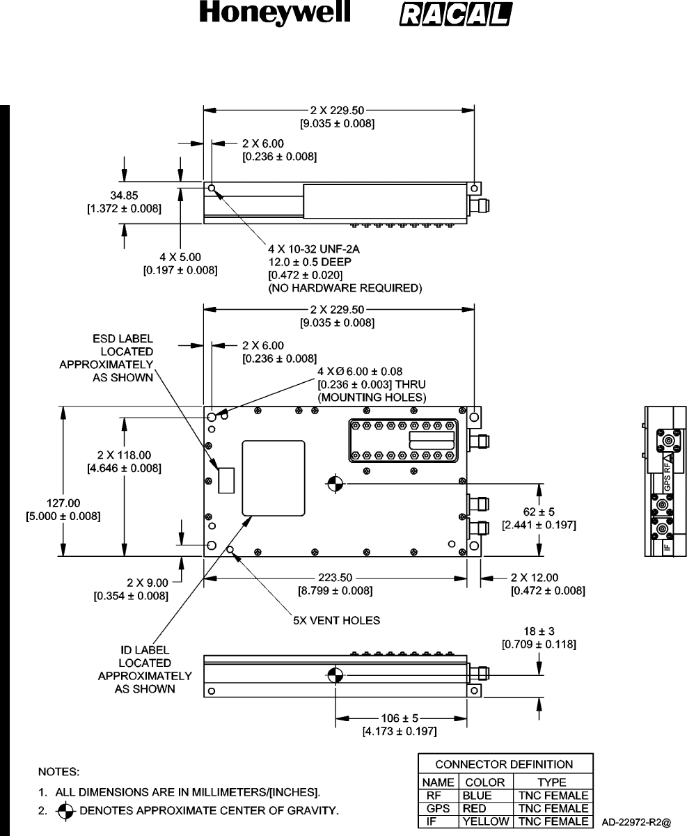
SYSTEM DESCRIPTION AND INSTALLATION MANUAL
SCS--1000 Mini--M Aero SATCOM System
23--20--28
Use or disclosure of information on this page is subject to the restrictions in the proprietary notice of this document.
Page 3--5
16 Oct 2000
Figure 3--2. ACU Outline and Installation Drawing
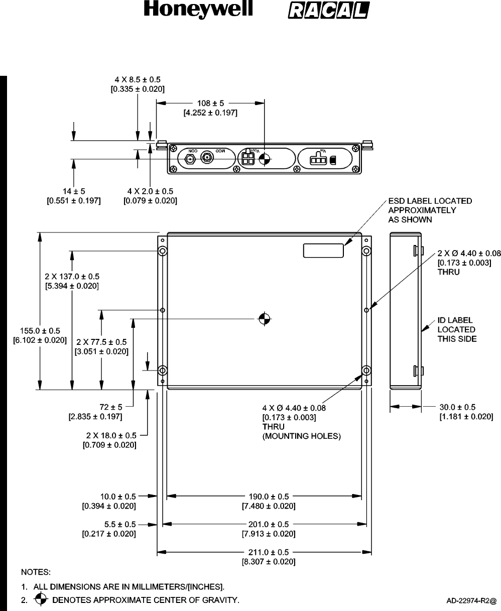
SYSTEM DESCRIPTION AND INSTALLATION MANUAL
SCS--1000 Mini--M Aero SATCOM System
23--20--28
Use or disclosure of information on this page is subject to the restrictions in the proprietary notice of this document.
Page 3--6
16 Oct 2000
Figure 3--3. PSU Outline and Installation Drawing
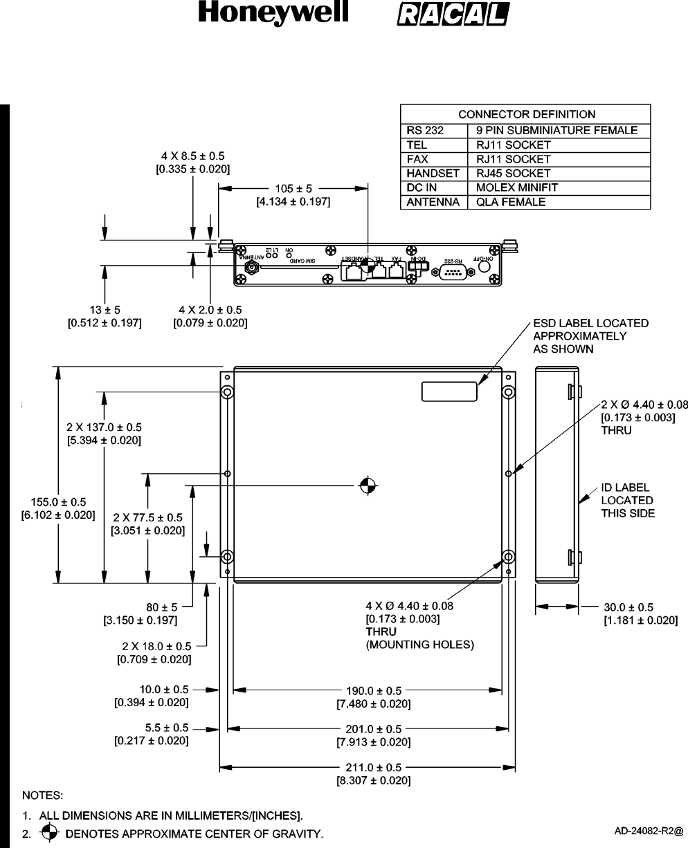
SYSTEM DESCRIPTION AND INSTALLATION MANUAL
SCS--1000 Mini--M Aero SATCOM System
23--20--28
Use or disclosure of information on this page is subject to the restrictions in the proprietary notice of this document.
Page 3--7
16 Oct 2000
Figure 3--4. TPU Outline and Installation Drawing
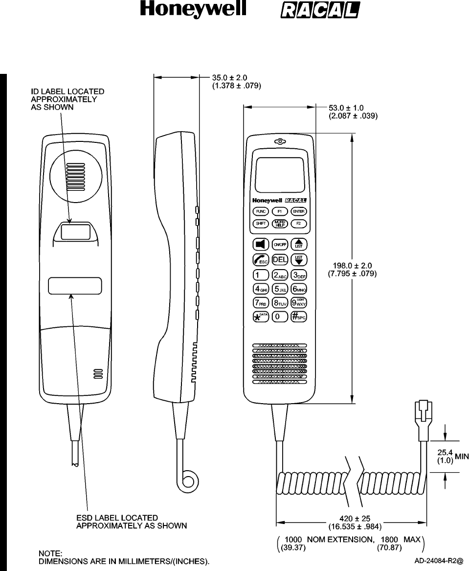
SYSTEM DESCRIPTION AND INSTALLATION MANUAL
SCS--1000 Mini--M Aero SATCOM System
23--20--28
Use or disclosure of information on this page is subject to the restrictions in the proprietary notice of this document.
Page 3--8
16 Oct 2000
Figure 3--5. HSU Drawing
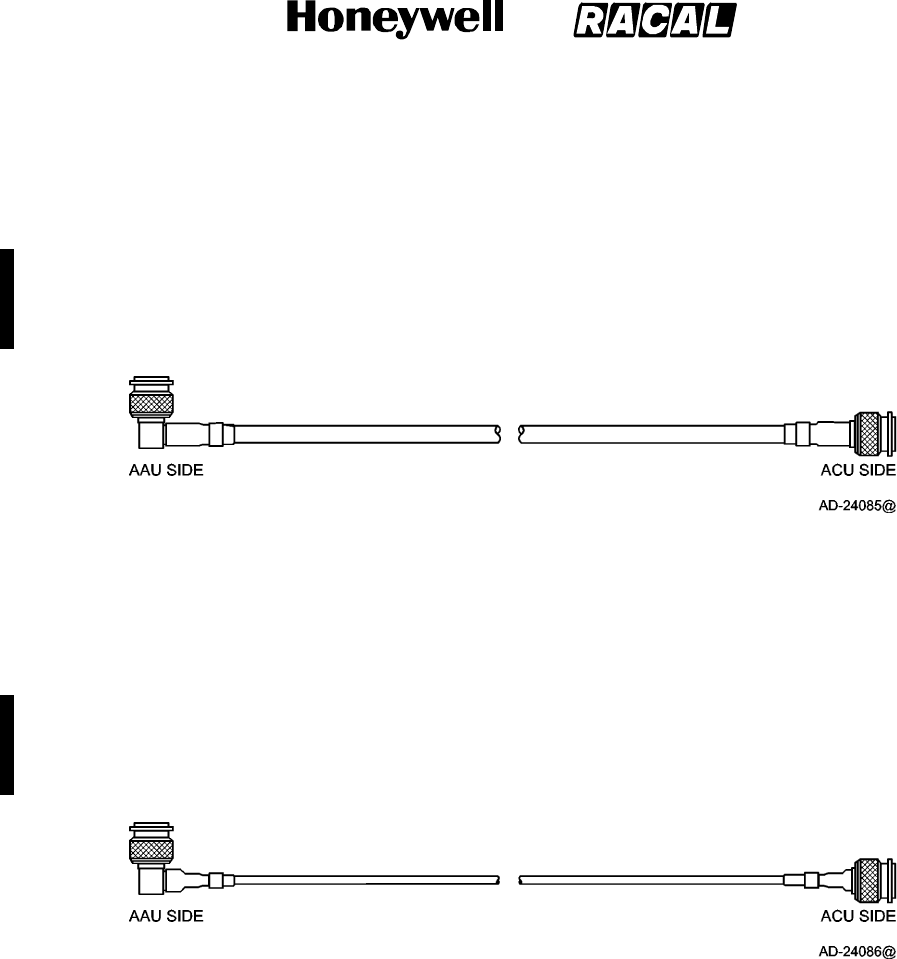
SYSTEM DESCRIPTION AND INSTALLATION MANUAL
SCS--1000 Mini--M Aero SATCOM System
23--20--28
Use or disclosure of information on this page is subject to the restrictions in the proprietary notice of this document.
Page 3--9
16 Oct 2000
G. Cable Provisions
(1) Antenna Cable Assembly
The cable length is installation and cable loss dependent. It is made up of one TNC
50 Ohm right--angle connector, one TNC 50 Ohm straight connector, and
double--shielded 50 Ohm coaxial cable. The cable loss must be equal to or less than
0.75 dB. Figure 3--6 shows the antenna cable assembly.
Figure 3--6. Antenna Cable Assembly
(2) GPS Cable Assembly
The cable length is installation dependent. It is made up of one TNC 50 Ohm
right--angle connector, one TNC 50 Ohm straight connector, and double shielded 50
Ohm coaxial cable. The cable loss must not exceed 10 dB. Figure 3--7 shows the
GPS cable assembly.
Figure 3--7. GPS Cable Assembly
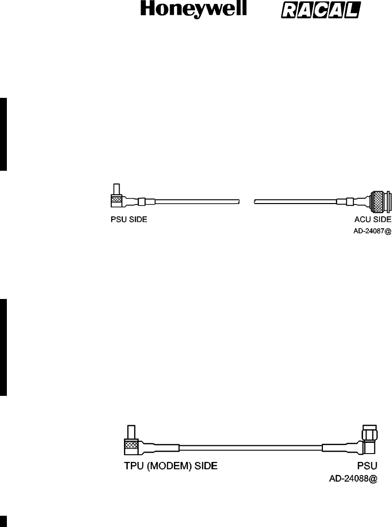
SYSTEM DESCRIPTION AND INSTALLATION MANUAL
SCS--1000 Mini--M Aero SATCOM System
23--20--28
Use or disclosure of information on this page is subject to the restrictions in the proprietary notice of this document.
Page 3--10
16 Oct 2000
(3) IF Cable Assembly
The cable length is installation dependent. It is made up of one QLA 50 Ohm
right--angle connector, one TNC 50 Ohm straight connector, and double shielded 50
Ohm coaxial cable. The cable loss must not exceed 8 dB. Figure 3--8 shows the IF
cable assembly.
NOTE: The cable loss sum of the IF and TPU RF cables must not exceed 10 dB.
Figure 3--8. IF Cable Assembly
(4) TPU RF Cable Assembly
The cable length is installation dependent. It is made up of one QLA 50 Ohm
right--angle connector, one SMA 50 Ohm right--angle connector, and double shielded
50 Ohm coaxial cable. The cable must not exceed 2 dB. Figure 3--9 shows the TPU
RF cable assembly.
NOTE: The cable loss sum of the IF and TPU RF cables must not exceed 10 dB.
Figure 3--9. TPU RF Cable Assembly
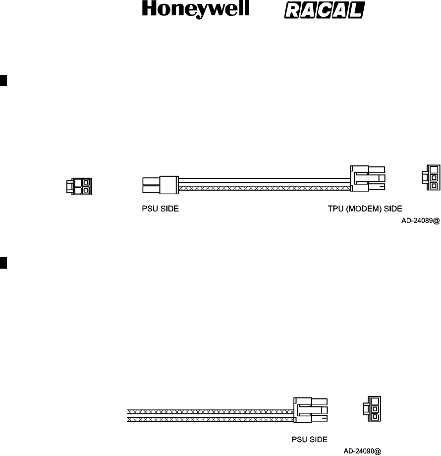
SYSTEM DESCRIPTION AND INSTALLATION MANUAL
SCS--1000 Mini--M Aero SATCOM System
23--20--28
Use or disclosure of information on this page is subject to the restrictions in the proprietary notice of this document.
Page 3--11
16 Oct 2000
(5) TPU Power Cable Assembly
The cable length is installation dependent. There is no recommended maximum
length as long as the cable performance requirements are met, which is a resistance
of less than 0.5 ohms. Figure 3--10 shows the TPU power cable assembly.
Figure 3--10. TPU Power Cable Assembly
(6) Power Cable Assembly
The cable length is installation dependent. There is no recommended maximum
length as long as the cable performance requirements are met, which is a resistance
of less than 0.5 ohms. Figure 3--11 shows the power cable assembly.
Figure 3--11. Power Cable Assembly

SYSTEM DESCRIPTION AND INSTALLATION MANUAL
SCS--1000 Mini--M Aero SATCOM System
23--20--28
Use or disclosure of information on this page is subject to the restrictions in the proprietary notice of this document.
Page 3--12
16 Oct 2000
4. Mechanical Installation Instructions
A. AAU Installation
(1) Positioning the AAU
Because the AAU communicates with satellites, the AAU must be positioned on the
top of the fuselage. Try to position the AAU near the middle of the cabin area or
slightly to the rear. Many factors influence the performance of the system. Factors
that influence the final position are as follows:
Tail Plane RF Blockage
The tail plane and ventral strake block a small amount of the RF beam. For small
aircraft (less than 12,500 lb [5700 kg]), place the AAU at least 10 ft. (3 m) forward
of the base of the tail plane.
Other Antennas
Transmissions from the AAU may affect other RF systems. The GPS antenna is
most likely to be affected. Mount the AAU at least 1.65 ft (0.5 m) from the GPS
antenna. For GPS antennas with poor filtering or high gain, mount the AAU at
least 5 ft (1.5 m) away. Mount the AAU at least 15 inches (381 mm) from the ADF
antenna.
Magnetic Environment
The AAU contains magnetometers that can be affected by ferrous materials,
magnets, or large currents in cables located nearby. Do not place the AAU
directly above speakers.
Fuselage Structure
The AAU is designed to be positioned above the pressurized area, but other
locations are acceptable. It can be positioned on either side the the center line of
the fuselage, but keep the offset to a minimum. Use the template to determine the
best position so that the required holes do not interfere with structure components.
Distance from Front
Position the AAU as far from the front of the cabin as possible to reduce drag,
wind noise, lightning strikes, and damage from airborne objects.
Engines and APU Inlets
Position the AAU out of the engine zone of influence and APU inlets.

SYSTEM DESCRIPTION AND INSTALLATION MANUAL
SCS--1000 Mini--M Aero SATCOM System
23--20--28
Use or disclosure of information on this page is subject to the restrictions in the proprietary notice of this document.
Page 3--13
15 May 2001
(2) Warranty Conditions
CAUTION: THE WARRANTY FOR THE ANTENNA (AAU) IS VALID ONLY IF THE
WARRANTY CONDITIONS ARE MET.
The warranty conditions for the AAU are as follows:
Adapter plate design is approved. Adapter plates produced by the vendors listed
in the VENDOR EQUIPMENT section have been approved.
Drainage slots in the adapter plate must remain uncovered after installation.
Breathing holes must be covered/left open according to the instructions in
paragraph 4.A.(3)(b).
The two grounding lug holes must be blocked by a grounding strap mounting
screw.
(3) Installing the AAU
WARNING: TO AVOID POTENTIALLY DANGEROUS EXPOSURE TO RADIO
FREQUENCY ENERGY OF MORE THAN 5 MW/CM@
@@
@WITHIN A FEW FEET
OF THE ANTENNA, DO NOT OPERATE THE SCS SYSTEM WHEN ANY
PERSONNEL ARE WITHIN 3 FEET (0.9 M) OF THE ANTENNA FOR
PERIODS OF LONGER THAN 3 MINUTES PER HOUR.
CAUTION: TO PREVENT RECALIBRATION OF THE AAU, USE DEMAGNETIZED
HARDWARE AND TOOLS.
Figure 3--12 shows a cross section of a typical AAU installation. Figure 3--13 shows
the holes required on the fuselage in a typical AAU installation. Perform the
following:
(a) Determine the best position for the AAU.
(b) Determine which breathing holes need to be sealed. The AAU has three
breathing/drainage holes in its base, as indicated in Figure 3--1, to accommodate
different orientations left and right of centerline. If all of the breathing holes are
left open, water can potentially enter the AAU directly or air can potentially flow
continually through the AAU, giving rise to excessive condensation inside the
AAU. Two of the three holes must be blocked off. The two holes which must be
blocked off are the rear breathing hole and the highest of the two forward holes.
This will allow gravity to drain any collected water when on the ground. For the
case where the AAU is mounted horizontally level and neither forward breathing
hole is higher than the other, then either one of the two forward holes can be
blocked.
CAUTION: FAILURE TO COVER THE TWO BREATHING HOLES DESCRIBED
ABOVE WILL RESULT IN WATER ENTERING THE ANTENNA.
EXCESSIVE INGRESS OF WATER INTO AAU WILL RESULT IN
DAMAGE TO INTERNAL ELECTRONICS.
(c) Apply sealing compound to the doubler plate. Install the doubler plate in the
selected position.
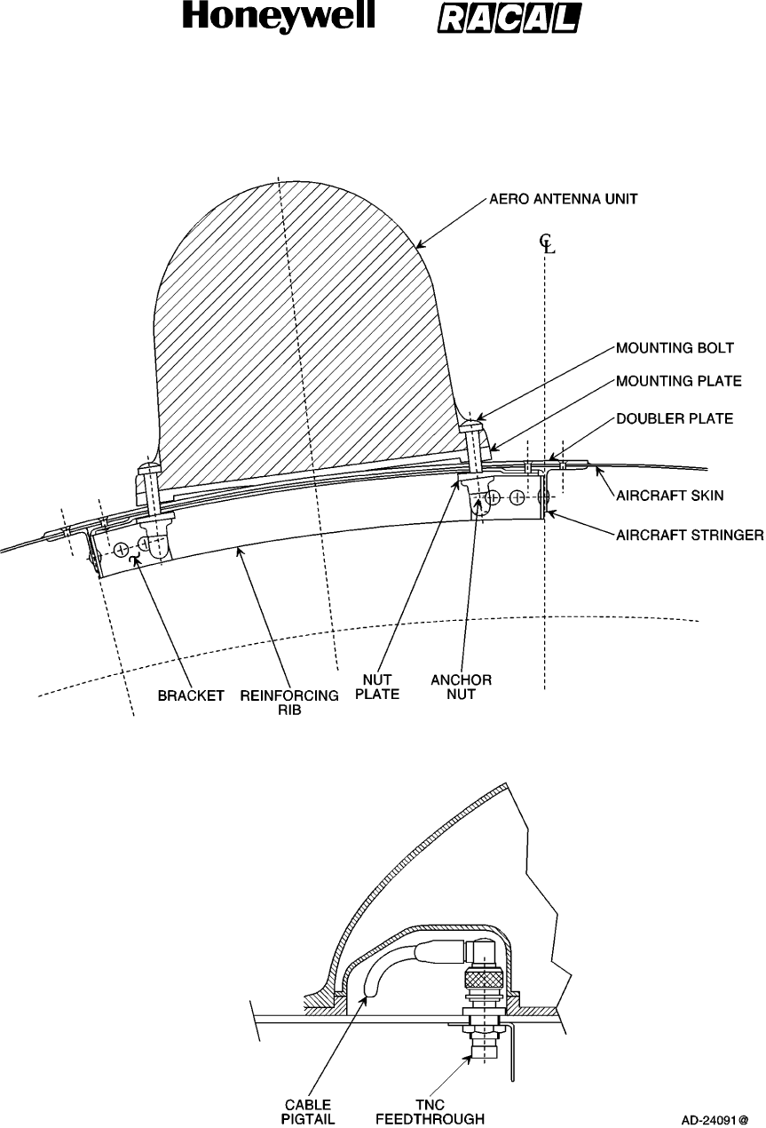
SYSTEM DESCRIPTION AND INSTALLATION MANUAL
SCS--1000 Mini--M Aero SATCOM System
23--20--28
Use or disclosure of information on this page is subject to the restrictions in the proprietary notice of this document.
Page 3--14
31 Jan 2000
Figure 3--12. Cross Section of a Typical AAU Installation
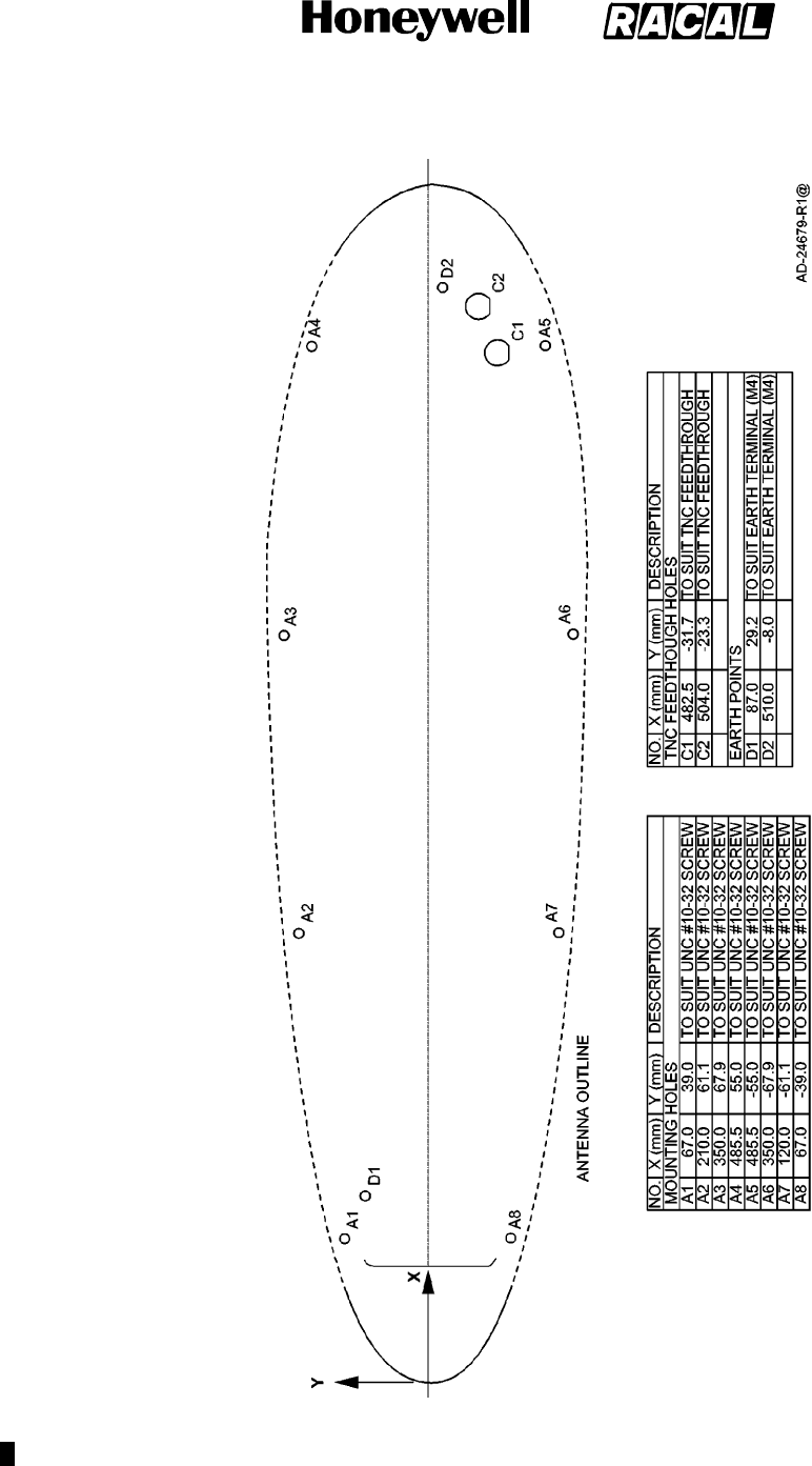
SYSTEM DESCRIPTION AND INSTALLATION MANUAL
SCS--1000 Mini--M Aero SATCOM System
23--20--28
Use or disclosure of information on this page is subject to the restrictions in the proprietary notice of this document.
Page 3--15
15 May 2001
Figure 3--13. Fuselage Holes Required in Typical AAU Installation
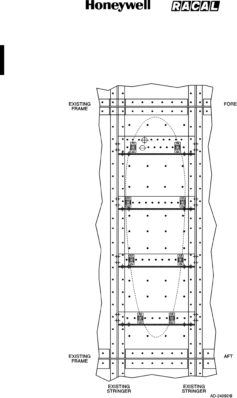
SYSTEM DESCRIPTION AND INSTALLATION MANUAL
SCS--1000 Mini--M Aero SATCOM System
23--20--28
Use or disclosure of information on this page is subject to the restrictions in the proprietary notice of this document.
Page 3--16
16 Oct 2000
(d) Apply sealing compound to the transverse ribs. Install four transverse ribs to
correspond with the mounting holes. The foremost rib must be wide enough to
accommodate the connector feedthrough holes. Figure 3--14 shows a typical
installation of the transverse ribs.
Figure 3--14. Installation of Transverse Ribs
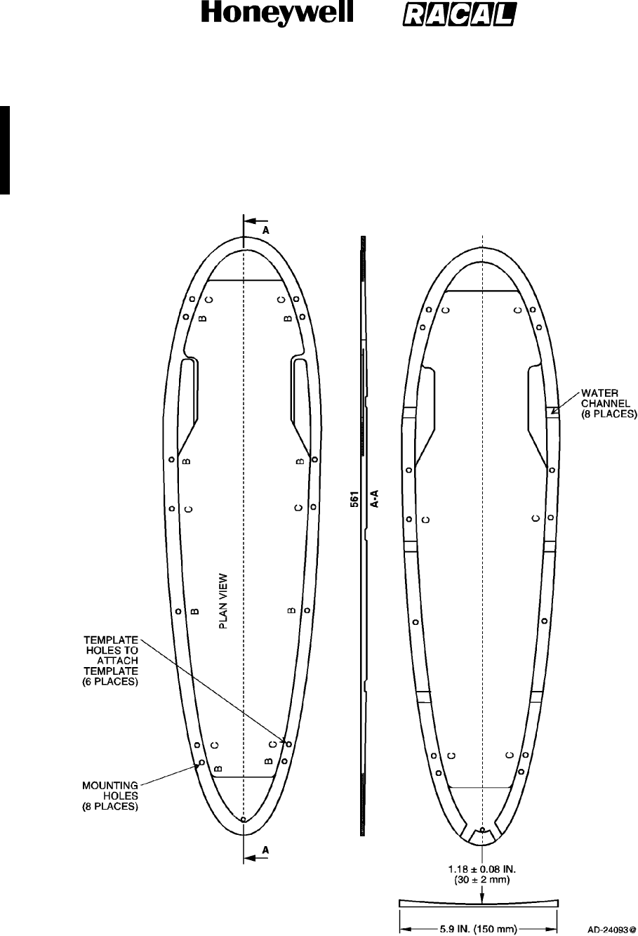
SYSTEM DESCRIPTION AND INSTALLATION MANUAL
SCS--1000 Mini--M Aero SATCOM System
23--20--28
Use or disclosure of information on this page is subject to the restrictions in the proprietary notice of this document.
Page 3--17
16 Oct 2000
(e) Position the mounting plate and template on the fuselage. Using the marks
supplied on the template, align the mounting plate to the fore--aft axis of the
fuselage. Drill eight 0.138 in. (3.5 mm) starting holes for the mounting holes
shown in Figure 3--15. The final drilled mounting holes must be 0.189 in. (4.8
mm) minimum and 0.197 in. (5.0 mm) recommended.
Figure 3--15. Mounting Plate
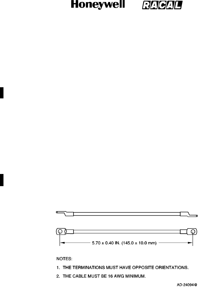
SYSTEM DESCRIPTION AND INSTALLATION MANUAL
SCS--1000 Mini--M Aero SATCOM System
23--20--28
Use or disclosure of information on this page is subject to the restrictions in the proprietary notice of this document.
Page 3--18
15 May 2001
(f) Install eight nut plates and anchor nuts on the transverse ribs. Figure 3--14
shows the position of the nut plates and anchor nuts.
(g) Apply a sealing compound to the curved surface of the mounting plate.
Assemble the mounting plate to the fuselage using eight mounting bolts. Make
sure the water channels of the mounting plate are free of sealing compound.
Allow the sealing compound to cure.
CAUTION: COVERING THE ADAPTER PLATE WATER CHANNELS CAN ALLOW
WATER TO GET INTO THE AAU.
(h) Remove the template from the mounting plate. Six threaded holes are left by the
removal of the template. Fill them with a sealant to prevent water accumulation.
Figure 3--13 shows the position of the template holes.
(i) Drill two TNC feedthrough holes. Figure 3--14 shows the position of the holes.
Install two TNC feedthrough connectors with the O--ring to the outside of the
fuselage and the nut on the inside. Safety wire the two nuts together. Color
code the connectors with heat shrinkable tubing on both the inside and outside.
Use red tubing for the GPS feedthrough and blue tubing for the antenna
feedthrough. Figure 3--13 shows the feed though connectors.
NOTE: The O--ring can be on either side with sealant applied to the opposite
side.
(j) Attach two ground straps to the fuselage. Align each strap to face forward.
Figure 3--16 shows a ground strap.
Figure 3--16. Ground Strap

SYSTEM DESCRIPTION AND INSTALLATION MANUAL
SCS--1000 Mini--M Aero SATCOM System
23--20--28
Use or disclosure of information on this page is subject to the restrictions in the proprietary notice of this document.
Page 3--19
15 May 2001
(k) Place the adapter plate over the mounting holes.
(l) Apply seals to the two breathing holes that were selected in paragraph
4.A.(3)(b).
NOTE: The adapter plates come in two different configurations: one with three
rubber seals for covering the breathing holes installed on the adapter
plate and the other with the rubber seals for the breathing holes not
installed. If the seals are already installed on the adapter plate, the
rubber seal to cover the breathing hole that needs to be open should be
removed. (Refer to paragraph 4.A.(3)(b)). If the seals are not installed,
the two rubber seals needed to cover the breathing holes identified in
paragraph 4.A.(3)(b) should be installed in the proper location on the
adapter plate to make sure the holes are covered.
(m) Remove the following warning and installation labels. Figure 3--17 shows the
locations of these labels.
warranty void label
magnetic sensitive device label
sealant protection label.
NOTE: The paint warning decal cannot be removed and should be left alone.
(n) Place the AAU over the mounting holes and tilt up. Attach the ground straps to
the AAU base plate.
CAUTION: FAILURE TO INSTALL GROUNDING STRAPS CAN RESULT IN POOR
PERFORMANCE OR WATER GETTING INTO THE AAU THROUGH THE
GROUNDING STRAP HOLE.
(o) Connect AAU RF cables to TNC feedthrough connectors. Ensure that they are
aligned so that they will fit in the hollow provided in the base plate. Safety wire
the connectors together.
(p) Align the AAU with the mounting holes. Secure the AAU with eight screws.
Torque the screws to a value of 44 lb--inch to make sure that the AAU is firmly
seated on the fuselage. Apply a sealant to the mounting screw heads to prevent
water seepage.
CAUTION: DO NOT SEAL THE AAU/ADAPTER PLATE INTERFACE WITH
SEALANT.
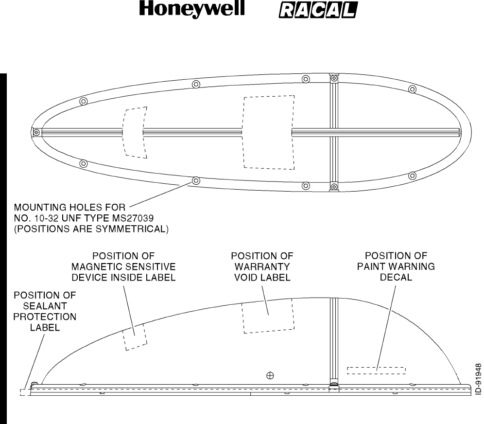
SYSTEM DESCRIPTION AND INSTALLATION MANUAL
SCS--1000 Mini--M Aero SATCOM System
23--20--28
Use or disclosure of information on this page is subject to the restrictions in the proprietary notice of this document.
Page 3--20
15 May 2001
Figure 3--17. Warning and Installation Labels Locations

SYSTEM DESCRIPTION AND INSTALLATION MANUAL
SCS--1000 Mini--M Aero SATCOM System
23--20--28
Use or disclosure of information on this page is subject to the restrictions in the proprietary notice of this document.
Page 3--21
15 May 2001
B. ACU Installation
Place the ACU in the area of the pressurized/temperature controlled cabin. It is
preferable that the ACU be placed between the insulator and the inner cabin liner and not
between the outer skin and the insulation, due to the extreme low temperatures on the
skin. The ACU can be placed between the cabin liner and the fuselage. To minimize
cable attenuation, place the ACU as close to the antenna as possible. Maximum cable
attenuation is 0.75 dB at 1.6 GHz.
NOTE: Make sure the ACU is not placed against dissimilar metals. A prepared
aluminum surface using Alodine or equivalent is acceptable.
C. PSU Installation
Place the PSU in the area of the pressurized/temperature controlled cabin. The PSU
must be mounted against a prepared aluminum surface and cannot be against the base
aluminum. Prepare the aluminum surface using Alodine or equivalent, per Honeywell
Manufacturing Specification M690278--2 (MIL--C--5541, Class 3). It is preferable that the
PSU be placed between the insulator and the inner cabin liner and not between the outer
skin and the insulation due to the extreme low temperatures on the skin. The PSU can
be placed between the cabin liner and the fuselage. The distance between the PSU and
the ACU, TPU, and HSU is not critical. Maximum cable attenuation is 10 dB at 1.6 GHz.
The TPU and PSU may be installed together using a installer or user supplied bracket.
Figure 3--18 shows a typical installation of the PSU and TPU together.
D. TPU Installation
Place the TPU in the area of the pressurized/temperature controlled cabin. The TPU
must be mounted against a prepared aluminum surface and cannot be against the base
aluminum. Prepare the aluminum surface using Alodine or equivalent, per Honeywell
Manufacturing Specification M690278--2 (MIL--C--5541, Class 3). It is preferable that the
TPU be placed between the insulator and the inner cabin liner and not between the outer
skin and the insulation, due to the extreme low temperatures on the skin. The TPU can
be placed between the cabin liner and the fuselage. The distance between the TPU and
the ACU, PSU, and HSU is not critical. Maximum cable attenuation is 10 dB at 1.6 GHz.
The TPU and PSU may be installed together using a installer or user supplied bracket.
Figure 3--18 shows a typical installation of the PSU and TPU together.
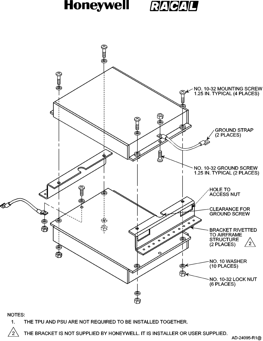
SYSTEM DESCRIPTION AND INSTALLATION MANUAL
SCS--1000 Mini--M Aero SATCOM System
23--20--28
Use or disclosure of information on this page is subject to the restrictions in the proprietary notice of this document.
Page 3--22
15 May 2001
Figure 3--18. Typical Installation of Telephone Unit and Power Supply Unit Together
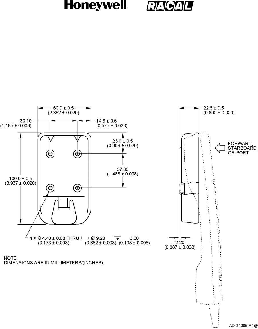
SYSTEM DESCRIPTION AND INSTALLATION MANUAL
SCS--1000 Mini--M Aero SATCOM System
23--20--28
Use or disclosure of information on this page is subject to the restrictions in the proprietary notice of this document.
Page 3--23
15 May 2001
E. HSU Installation
The HSU is held in a handset clip. Figure 3--19 shows the handset cradle.
CAUTION: TO PREVENT THE HANDSET FROM INADVERTENTLY DISLODGING DURING A
HARD LANDING, THE HANDSET CRADLE SHOULD BE MOUNTED FACING
THE REAR, STARBOARD, OR PORT SIDE OF THE AIRCRAFT. THIS
PREVENTS THE HSU FROM BECOMING A LOOSE OBJECT HAZARD.
Figure 3--19. Handset Cradle

SYSTEM DESCRIPTION AND INSTALLATION MANUAL
SCS--1000 Mini--M Aero SATCOM System
23--20--28
Use or disclosure of information on this page is subject to the restrictions in the proprietary notice of this document.
Page 3--24
15 May 2001
Blank Page

SYSTEM DESCRIPTION AND INSTALLATION MANUAL
SCS--1000 Mini--M Aero SATCOM System
23--20--28
Use or disclosure of information on this page is subject to the restrictions in the proprietary notice of this document.
Page 4--1
16 Oct 2000
ELECTRICAL INSTALLATION
1. General
This section provides electrical installation information, power and ground requirements, and
an interconnect diagram for the SCS--1000 system.
2. Equipment and Materials
None.
3. Electrical Installation
A. Power Requirements
The aircraft dc power supply must be 27.5 V dc (nominal). The normal minimum and
maximum allowable voltages are 20.5 and 32.2 V dc respectively.
B. Ground Requirements
Proper grounding is a key factor in ensuring proper system operation under normal
conditions. The AAU is grounded to the fuselage using two ground straps. For proper
grounding, the mating surfaces must be free of all paint and other non--conductive
elements and are burnished to ensure a good bond. Make sure that the impedance
between the AAU and the fuselage is less than 5.0 milliohm. The ACU must be grounded
to the aircraft common.
C. Circuit Breaker Requirements
Refer to Section 3, Mechanical Installation.
D. Interconnect Information
The information necessary to provide the electrical interconnects is shown in Figure 4--1.

SYSTEM DESCRIPTION AND INSTALLATION MANUAL
SCS--1000 Mini--M Aero SATCOM System
23--20--28
Use or disclosure of information on this page is subject to the restrictions in the proprietary notice of this document.
Page 4--2
31 Jan 2000
Blank Page
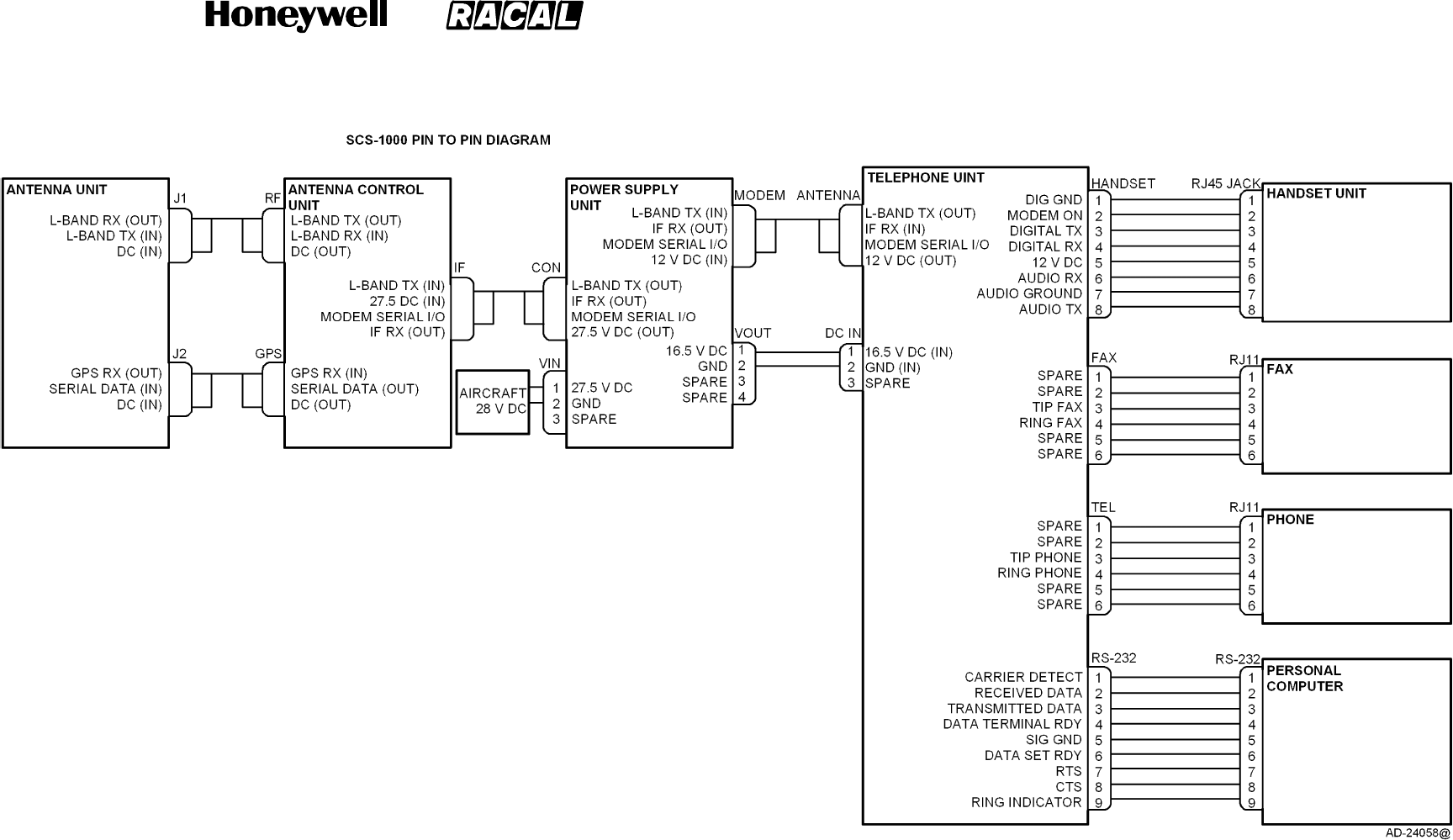
SYSTEM DESCRIPTION AND INSTALLATION MANUAL
SCS--1000 Mini--M Aero SATCOM System
23--20--28
Use or disclosure of information on this page is subject to the restrictions in the proprietary notice of this document.
Page 4--3/(4--4 blank)
31 Jan 2000
Figure 4--1. SCS--1000 System Interconnect Diagram

SYSTEM DESCRIPTION AND INSTALLATION MANUAL
SCS--1000 Mini--M Aero SATCOM System
23--20--28
Use or disclosure of information on this page is subject to the restrictions in the proprietary notice of this document.
Page 5--1
31 Jan 2000
ADJUSTMENT/TEST
1. General
This section contains instructions on how to set up the SCS system after it has been installed
in an aircraft.
2. Setting Up the System
The following procedures must be performed while the system is connected to an external PC
in order to access all of the internal functions. The PC must be set as a VT100 emulator.
Refer to PC set up procedures in OPERATION section of this manual.
A. Set Up the Owner Mode
The SCS system must be in the owner mode before the Aero functions menu is
accessible. To set up the owner mode, perform the following steps:
(1) Remove the SIM card.
NOTE: The SIM card must be removed before the system is switched on to be able
to enter the owner mode.
(2) Switch the system ON and wait until it has completed initialization. (INITIALIZING is
displayed on the HSU during initialization and disappears when the initialization is
complete.)
(3) Select the Menu function and scroll down to Set access level.
(4) Push Selct to open the Select access level window.
(5) Push Owner to open the window for entering the owner password.
(6) Key in the password and push ENTER. If the owner mode password has not yet
been set, then the default password is 1234567890.
(7) Push OK to activate the owner mode. (If the access level window is opened again,
Owner level is displayed if the above procedure has been successful.)
(8) Aero functions should now be accessible from the Advanced functions menu.

SYSTEM DESCRIPTION AND INSTALLATION MANUAL
SCS--1000 Mini--M Aero SATCOM System
23--20--28
Use or disclosure of information on this page is subject to the restrictions in the proprietary notice of this document.
Page 5--2
31 Jan 2000
B. Calibrate the Magnetometer
The AAU contains a three--axes magnetometer for tracking purposes. The magnetometer
must be calibrated after installation of the SCS system on the aircraft. Recalibration is
only required when the ACU is replaced or when the magnetic characteristics of the
aircraft have changed. The calibration can also be affected by iron and steel cargo.
Calibration of the magnetometer is performed while the aircraft is slowly being turned
through 360 degrees on a smooth flat level surface, away from any large hangars or
buildings that could disturb the terrestrial magnetic field.
To calibrate the magnetometer, perform the following steps:
(1) Park the aircraft on a suitable flat--level surface away from any large hangars or
buildings, and ready to be turned through 360 degrees. All aircraft electrical systems
must be powered and running to create the aircraft magnetic environment as would
be experienced during nominal flight conditions.
(2) If the SCS system is OFF, switch it ON and access the owner mode using the
procedure in paragraph A.
(3) Select the Menu function and scroll down to Advanced functions.
(4) Select Selct or push right arrow and scroll down to Aero functions.
(5) Selct or right arrow opens the Aero functions menu.
(6) Activating Selct or right arrow again opens the Magnetometer calibration window.
(7) Select Start to start the calibration procedure and then turn the aircraft through more
than 360 degrees. The radius of the circle is not important. The duration of the
360 degree turn should be more than one minute and less than 5 minutes.
(8) Select Stop when the turn is completed. This terminates the calibration process.
(9) Wait for the calibration result. (Please be patient since the calculation of the
calibrationresultcantakeupto1minute.)
The calibration score indicates the quality of calibration and varies between 15 and 0.
The score is defined in Table 5--1.
Table 5--1. Magnetometer Calibration Score
Score Definition
14 -- 15 Excellent
12 -- 13 Acceptable
11 Marginal
<11 Unacceptable
0Indicates complete calibration failure

SYSTEM DESCRIPTION AND INSTALLATION MANUAL
SCS--1000 Mini--M Aero SATCOM System
23--20--28
Use or disclosure of information on this page is subject to the restrictions in the proprietary notice of this document.
Page 5--3
31 Jan 2000
If the calibration score is less than 11, the procedure should be repeated. Consistently
low calibration scores may be caused by a noisy magnetic environment near the AAU,
which does not necessarily affect the tracking performance of the AAU. This can be
verified by rotating the aircraft though 360 degrees while monitoring the signal strength on
the HSU. A low calibration score but with a consistent signal (variation < 10) should be
accepted. If in doubt, contact your local Honeywell Dealer or regional Honeywell
Customer Support Engineer.
The hard iron score indicates the amount of hard iron magnetism relative to the local
magnetic field (Table 5--2).
Table 5--2. Magnetometer Hard Iron Score
Score Definition
15 < 7 percent
14 < 13 percent
13 < 20 percent
12 < 27 percent
11 < 33 percent
10 < 40 percent
9< 47 percent
8< 53 percent
7< 60 percent
6< 67 percent
5< 73 percent
4< 80 percent
3< 87 percent
2< 93 percent
1< 100 percent
0100 percent
NOTE: The number of successful calibrations is also shown. A value
of 0 indicates that the factory set values are valid and that no
successful calibration has been performed yet.

SYSTEM DESCRIPTION AND INSTALLATION MANUAL
SCS--1000 Mini--M Aero SATCOM System
23--20--28
Use or disclosure of information on this page is subject to the restrictions in the proprietary notice of this document.
Page 5--4
31 Jan 2000
C. Configure the Landing Speed
The AAU requires the nominal landing speed for tracking purposes. This parameter only
needs to be entered once after installation of the SCS system or when the ACU is
replaced. To configure the landing speed, perform the following steps:
(1) If the SCS system is OFF, switch it ON and access the owner mode using the
procedure in paragraph A.
(2) Select the Menu function and scroll down to Advanced functions.
(3) Select Selct or push right arrow and scroll down to Aero functions.
(4) Select Selct or push right arrow and scroll down to Configure landing speed.
(5) Selct or right arrow displays the Configure landing speed window.
(6) Enter the nominal landing speed of the aircraft in meters per second. (To convert
from knots to meters per second, refer to Table 5--3.)
(7) Save stores the entered landing speed.
Table 5--3. Conversion Chart
Knots
Meters per Second
(Approximately)
80 41
85 44
90 46
95 49
100 51
105 54
110 57
115 59
120 62
125 64
130 67
NOTE: This conversion chart is for reference only.

SYSTEM DESCRIPTION AND INSTALLATION MANUAL
SCS--1000 Mini--M Aero SATCOM System
23--20--28
Use or disclosure of information on this page is subject to the restrictions in the proprietary notice of this document.
Page 5--5
31 Jan 2000
D. Satellite Locations
This option is provided to modify the stored locations of the Inmarsat satellites. This
would be required in the unlikely event of a satellite being moved to another longitude, or
when a new Inmarsat satellite is brought into service at a different location from the
existing satellites. Contact your service provider for more information about this option.
To enter a satellite location, perform the following steps:
(1) If the SCS system is OFF, switch it ON and access the owner mode using the
procedure in paragraph A.
(2) Select the Menu function and scroll down to Advanced functions.
(3) Select Selct or push right arrow and scroll down to Aero functions.
(4) Select Selct or push right arrow and scroll down to Satellite locations.
(5) Selct or right arrow displays the Satellite locations window.
(6) Select the appropriate satellite using Prev and Next.
(7) Enter the new satellite longitude in degrees.
(8) Scroll down to Location.
(9) The right arrow opens the list of locations, EAST or WEST.
(10) Scroll up or down to choose the location.
(11) Select Selct and then Save to store the new location.

SYSTEM DESCRIPTION AND INSTALLATION MANUAL
SCS--1000 Mini--M Aero SATCOM System
23--20--28
Use or disclosure of information on this page is subject to the restrictions in the proprietary notice of this document.
Page 5--6
31 Jan 2000
E. Example Screens
The following figures are examples of the screens that the user sees on the PC when
setting up the system.
Ctrl+T for Help <+U> <+I> <+O> <+P>
9 - Advanced functions menu
Access control
Aero functions
Satellite setup
Configuration
Information available
002>
Lock Mail Selct Quit
>
Ctrl+T for Help <+U> <+I> <+O> <+P>
95 - Aero functions
Magnetometer calibration
Configure landing speed
Satellite locations
001>
Lock Mail Selct Quit
>

SYSTEM DESCRIPTION AND INSTALLATION MANUAL
SCS--1000 Mini--M Aero SATCOM System
23--20--28
Use or disclosure of information on this page is subject to the restrictions in the proprietary notice of this document.
Page 5--7
31 Jan 2000
Ctrl+T for Help <+U> <+I> <+O> <+P>
951 - Magnetometer calibration
Press “Start” to initiate the
calibration process for the
aeronautical antenna magnetometer.
Start Abort
Ctrl+T for Help <+U> <+I> <+O> <+P>
951 - Magnetometer calibration
Turn aircraft 360 degrees.
Press “Stop” when completed.
Stop Abort
Ctrl+T for Help <+U> <+I> <+O> <+P>
951 - Magnetometer calibration
Calibration succeeded.
Calibration score: 15
Amount of hard iron: 15
Ok
Successful calibrations: 1

SYSTEM DESCRIPTION AND INSTALLATION MANUAL
SCS--1000 Mini--M Aero SATCOM System
23--20--28
Use or disclosure of information on this page is subject to the restrictions in the proprietary notice of this document.
Page 5--8
31 Jan 2000
Ctrl+T for Help <+U> <+I> <+O> <+P>
95 - Aero functions
Magnetometer calibration
Configure landing speed
Satellite locations
002>
Lock Mail Selct Quit
>
Ctrl+T for Help <+U> <+I> <+O> <+P>
952 - Configure landing speed
Landing speed (m/s):
Del Send Ok
>
Ctrl+T for Help <+U> <+I> <+O> <+P>
95 - Aero functions
Magnetometer calibration
Configure landing speed
Satellite locations003>
Lock Mail Selct Quit
>

SYSTEM DESCRIPTION AND INSTALLATION MANUAL
SCS--1000 Mini--M Aero SATCOM System
23--20--28
Use or disclosure of information on this page is subject to the restrictions in the proprietary notice of this document.
Page 5--9
31 Jan 2000
Ctrl+T for Help <+U> <+I> <+O> <+P>
953 - Satellite locations
Location: WEST
Prev Next Save Ok
>
AOR-W
Longitude: 54
Ctrl+T for Help <+U> <+I> <+O> <+P>
953 - Satellite locations
Prev Next Save Ok
>
AOR-W
Longitude: 54
Location: WEST >
Ctrl+T for Help <+U> <+I> <+O> <+P>
953 - Select location
Selct
WEST
Longitude: 4 54
Location: E
EAST
>
>>

SYSTEM DESCRIPTION AND INSTALLATION MANUAL
SCS--1000 Mini--M Aero SATCOM System
23--20--28
Use or disclosure of information on this page is subject to the restrictions in the proprietary notice of this document.
Page 5--10
31 Jan 2000
Blank Page

SYSTEM DESCRIPTION AND INSTALLATION MANUAL
SCS--1000 Mini--M Aero SATCOM System
23--20--28
Use or disclosure of information on this page is subject to the restrictions in the proprietary notice of this document.
Page 6--1
31 Jan 2000
FAULT ISOLATION
1. General
This section provides fault isolation guidelines as an aid to troubleshooting the SCS system.
The purpose of the fault isolation procedures is to help determine which component of the
SCS system has failed.

SYSTEM DESCRIPTION AND INSTALLATION MANUAL
SCS--1000 Mini--M Aero SATCOM System
23--20--28
Use or disclosure of information on this page is subject to the restrictions in the proprietary notice of this document.
Page 6--2
31 Jan 2000
2. TPU Subsystem Self--Tests
TPU subsystem self--tests include TPU memory alarms, TPU synthesizer alarms, and power
output alarms. Refer to Table 6--1 thru Table 6--3.
Table 6--1. TPU Memory Alarms
Failure Annunciation Description Maintenance Action
Program code self check failed Flash memory area containing
the program code is corrupted.
Cycle power on the system.
If the problem persists, return
the TPU to Honeywell for repair.
Terminal ID Cyclic Redundancy
Check (CRC) failure
Memory area containing the
Inmarsat Serial Number (ISN) is
corrupted.
Cycle power on the system.
If the problem persists, return
the TPU to Honeywell for repair.
Electrically Erasable
Programmable Read--Only
Memory (EEPROM) CRC failure
Flash User 1 Memory is
corrupted.
Cycle power on the system.
If the problem persists, return
the TPU to Honeywell for repair.
Nonvolatile Random Access
Memory (NVRAM) CRC failure
Flash User 2 Memory is
corrupted.
Cycle power on the system.
If the problem persists, return
the TPU to Honeywell for repair.
Functionality is lost Flash memory containing the
security/options is corrupted.
Cycle power on the system,
re--enter the configuration data
and cycle the power again.
If the problem persists, return
the TPU to Honeywell for repair.
Traffic log data is lost Flash memory containing the
Traffic Log is corrupted.
Call Honeywell for advice and
direction.
Table 6--2. TPU Synthesizer Alarms
Failure Annunciation Description Maintenance Action
TXsynclockfailed Transmitter Phase Lock Loop
(PLL) main frequency control is
out of lock.
Call Honeywell for advice and
direction.
RX sync lock failed Receiver local PLL (101.045
MHz) is out of lock.
Call Honeywell for advice and
direction.

SYSTEM DESCRIPTION AND INSTALLATION MANUAL
SCS--1000 Mini--M Aero SATCOM System
23--20--28
Use or disclosure of information on this page is subject to the restrictions in the proprietary notice of this document.
Page 6--3
31 Jan 2000
Table 6--3. Power Output Alarms
Failure Annunciation Description Maintenance Action
Unauthorized transmission Unwanted output power that
can disturb channels.
The RFB detects TX active
when TX is ON and TX
Enable is set to OFF.
Cycle power. If the problem
persists, clean and check the
connections. If the problem still
persists, return the TPU and
ACU to Honeywell for repair.
TX active in the idle state Mismatch between the
CPM--SPM--RFB states.
The Signal Processor Module
(SPM) has the transmitter in
the idle state, but the RFB
reports that it is transmitting.
Cycle power. If the problem
persists, clean and check the
connections. If the problem still
persists, return the TPU and
ACU to Honeywell for repair.
TX enabled in the idle state Mismatch between the
CPM--SPM--RFB states.
The RFB has the transmitter
in the idle state, but the SPM
reports that it is transmitting.
Cycle power. If the problem
persists, clean and check the
connections. If the problem still
persists, return the TPU and
ACU to Honeywell for repair.
TX on in the idle state Mismatch between the
CPM--SPM--RFB states.
The SPM has switched the
transmitter OFF, but the RFB
still reports that TX is active.
Cycle power. If the problem
persists, clean and check the
connections. If the problem still
persists, return the TPU and
ACU to Honeywell for repair.
Missing output No output power in the Single
Carrier Per Channel (SCPC)
mode.
The RFB is in the SCPC
mode and does not detect
output power at the end of the
transmission.
Cycle power. If the problem
persists, clean and check the
connections. If the problem still
persists, return the TPU and
ACU to Honeywell for repair.
Burst not sent No output power in the Burst
mode.
The RFB is in the Burst mode
and does not detect output
power at the end of the burst.
Cycle power. If the problem
persists, clean and check the
connections. If the problem still
persists, return the TPU and
ACU to Honeywell for repair.

SYSTEM DESCRIPTION AND INSTALLATION MANUAL
SCS--1000 Mini--M Aero SATCOM System
23--20--28
Use or disclosure of information on this page is subject to the restrictions in the proprietary notice of this document.
Page 6--4
31 Jan 2000
Table 6--3. Power Output Alarms (cont)
Failure Annunciation Maintenance ActionDescription
Missing TX off The RFB detects output
power after switching off TX.
Cycle power. If the problem
persists, clean and check the
connections. If the problem still
persists, return the TPU and
ACU to Honeywell for repair.
Voice/data call aborted Missing communication
between the SPM and RFB.
The CPM sends the SCPC
mode to the RFB and does
not get a response from the
RFB within 390 milliseconds.
Cycle power. If the problem
persists, clean and check the
connections. If the problem still
persists, return the TPU and
ACU to Honeywell for repair.

SYSTEM DESCRIPTION AND INSTALLATION MANUAL
SCS--1000 Mini--M Aero SATCOM System
23--20--28
Use or disclosure of information on this page is subject to the restrictions in the proprietary notice of this document.
Page 6--5
31 Jan 2000
3. ACU Antenna Tracking Board Subsystem Self--Tests
ACU Antenna Tracking Board (ATB) subsystem self--tests include ATB memory alarms, ATB
sensor monitoring alarms, communications alarms, and ATB software alarms. Refer to
Table 6--4 thru Table 6--7.
Table 6--4. ATB Memory Alarms
Failure Annunciation Description Maintenance Action
ATB flash memory failure Flash memory area storing the
program code read/write test
failed.
Cycle power. If the problem
persists, return the ACU to
Honeywell for repair.
ATB Static Random Access
Memory (SRAM) failure
SRAM memory used by the
program code read/write test
failed.
Cycle power. If the problem
persists, return the ACU to
Honeywell for repair.
ATB EEPROM failure EEPROM memory area storing
the program code read/write test
failed.
Cycle power. If the problem
persists, return the ACU to
Honeywell for repair.
ATB flash memory CRC error Flash memory area storing the
program code is corrupted.
Cycle power. If the problem
persists, return the ACU to
Honeywell for repair.
ATB EEPROM CRC error EEPROM memory area storing
the program code is corrupted.
Cycle power. If the problem
persists, return the ACU to
Honeywell for repair.
ATB calibration data CRC error Calibration data is corrupted. Cycle power. If the problem
persists, return the ACU to
Honeywell for repair.
ATB software (SW) version
mismatch
Software has incompatible
versions of the program
modules.
Cycle power. If the problem
persists, return the ACU to
Honeywell for repair.

SYSTEM DESCRIPTION AND INSTALLATION MANUAL
SCS--1000 Mini--M Aero SATCOM System
23--20--28
Use or disclosure of information on this page is subject to the restrictions in the proprietary notice of this document.
Page 6--6
31 Jan 2000
Table 6--5. ATB Sensor Monitoring Alarms
Failure Annunciation Description Maintenance Action
ATB inclinometer failure Reported sensor values are
consistently out of range.
Cycle power. If the problem
remains, return the AAU to
Honeywell for repair.
ATB magnetometer failure Reported sensor values are
consistently out of range.
Cycle power. If the problem
remains, return the AAU to
Honeywell for repair.
ATB motor failure Motor controller reports failure. Cycle power. If the problem
remains, return the AAU to
Honeywell for repair.
ATB motor thermal failure Excessive heat is detected by
the motor controller.
Cycle power. If the problem
remains, return the AAU to
Honeywell for repair.
AAU endstop sensor failure Endstops are not triggered after
a timeout or incompatible sets of
endstops are simultaneously
triggered.
Cycle power. If the problem
remains, return the AAU to
Honeywell for repair.
Table 6--6. Communications Alarms
Failure Annunciation Description Maintenance Action
AAU serial communication
failure
ATB cannot communicate with
the AAU.
Cycle power. If the problem
persists, check the cable
connections. If the problem still
remains, return the AAU and
ACU to Honeywell for repair.
GPS serial communication
failure
ATB cannot communicate with
the GPS engine.
Cycle power. If the problem
persists, return the ACU to
Honeywell for repair.
TPU to ATB packet CRC error Excessive number of corrupted
data packets on communication
link from the TPU to the ATB.
Cycle power. If the problem
persists, check the cable
connections. If the problem still
remains, return the TPU and
ACU to Honeywell for repair.
AAU to ATB packet CRC error Excessive number of corrupted
data packets on communication
link from the TPU to the ATB.
Cycle power. If the problem
persists, check the cable
connections. If the problem still
remains, return the AAU and
ACU to Honeywell for repair.

SYSTEM DESCRIPTION AND INSTALLATION MANUAL
SCS--1000 Mini--M Aero SATCOM System
23--20--28
Use or disclosure of information on this page is subject to the restrictions in the proprietary notice of this document.
Page 6--7
31 Jan 2000
Table 6--7. ATB Software Alarms
Failure Annunciation Description Maintenance Action
Doppler compensation error Doppler correction frequency
calculated by the TPU is out of
range.
Cycle power. If the problem
persists, call Honeywell for
advice.
ATB repoint timeout Duration of the re--pointing state
is too long. The AAU is unable
to move to the required position
to point in the direction of the
satellite.
Cycle power. If the problem
persists, return the AAU to
Honeywell for repair.
ATB floating point error Arithmetic overflow, underflow,
or division by zero.
Cycle power. If the problem
persists, call Honeywell for
advice.
ATB matrix inversion error Control algorithms have become
unstable.
Cycle power. If the problem
persists, call Honeywell for
advice.
ATB reset by watchdog Control code crashed or hung
causing the system to reboot the
processor.
Cycle power. If the problem
persists, call Honeywell for
advice.
ATB illegal address exception Program attempting to read or
write to a memory address that
is out of range.
Cycle power. If the problem
persists, call Honeywell for
advice.

SYSTEM DESCRIPTION AND INSTALLATION MANUAL
SCS--1000 Mini--M Aero SATCOM System
23--20--28
Use or disclosure of information on this page is subject to the restrictions in the proprietary notice of this document.
Page 6--8
31 Jan 2000
4. AAU Subsystem Self--Tests
AAU subsystem self--tests include AAU memory alarms, and AAU system alarms. Refer to
Table 6--8 and Table 6--9.
Table 6--8. AAU Memory Alarms
Failure Annunciation Description Maintenance Action
AAU flash memory failure Flash memory area storing the
program code read/write test
failed.
Cycle power. If the problem
persists, return the AAU to
Honeywell for repair.
AAU SRAM failure SRAM memory used by the
program code read/write test
failed.
Cycle power. If the problem
persists, return the AAU to
Honeywell for repair.
AAU EEPROM failure EEPROM memory area storing
the program code read/write test
failed.
Cycle power. If the problem
persists, return the AAU to
Honeywell for repair.
AAU flash memory CRC error Flash memory area storing the
program code is corrupted.
Cycle power. If the problem
persists, return the AAU to
Honeywell for repair.
AAU calibration data CRC error Calibration data is corrupted. Cycle power. If the problem
persists, return the AAU to
Honeywell for repair.
Table 6--9. AAU System Alarms
Failure Annunciation Description Maintenance Action
AAU initialization timeout Initialization process of moving
the AAU to the endstop position
timeout.
Cycle power. If the problem
persists, return the AAU to
Honeywell for repair.
AAU power failure Measure voltage is low. Check connections and cycle
power. If the problem persists,
return the ACU and AAU to
Honeywell for repair.
AAU floating point error Arithmetic overflow, underflow,
or division by zero.
Cycle power. If the problem
persists, return the AAU to
Honeywell for repair.
AAU reset by watchdog Control code crashed or hung
causing the system to reboot the
processor.
Cycle power. If the problem
persists, return the AAU to
Honeywell for repair.
AAU illegal address exception Program attempting to read or
write to a memory address that
is out of range.
Cycle power. If the problem
persists, return the AAU to
Honeywell for repair.
AAU unexpected reset AAU system reset while
operating in the normal state.
Cycle power. If the problem
persists, return the AAU to
Honeywell for repair.

SYSTEM DESCRIPTION AND INSTALLATION MANUAL
SCS--1000 Mini--M Aero SATCOM System
23--20--28
Use or disclosure of information on this page is subject to the restrictions in the proprietary notice of this document.
Page 6--9
16 Oct 2000
5. GPS Subsystem Self--Test
The GPS subsystem self--test consists of GPS alarms. Refer to Table 6--10.
Table 6--10. GPS Communications Alarms
Failure Annunciation Description Maintenance Action
GPS serial communication
failure
GPS engine is not
communicating with the ATB.
Cycle power. If the problem
persists, return the ACU to
Honeywell for repair.
GPS hardware failure GPS detects a hardware failure. Cycle power. If the problem
persists, return the ACU to
Honeywell for repair.
GPS not navigating GPS is unable to locate
sufficient GPS satellites to
calculate position.
Call Honeywell for advice.
GPS state error
(navigation to acquisition)
GPS internal error. Cycle power. If the problem
persists, return the ACU to
Honeywell for repair.
GPS state error
(acquisition to navigation)
GPS internal error. Cycle power. If the problem
persists, return the ACU to
Honeywell for repair.

SYSTEM DESCRIPTION AND INSTALLATION MANUAL
SCS--1000 Mini--M Aero SATCOM System
23--20--28
Use or disclosure of information on this page is subject to the restrictions in the proprietary notice of this document.
Page 6--10
31 Jan 2000
Blank Page

SYSTEM DESCRIPTION AND INSTALLATION MANUAL
SCS--1000 Mini--M Aero SATCOM System
23--20--28
Use or disclosure of information on this page is subject to the restrictions in the proprietary notice of this document.
Page 7--1
16 Oct 2000
MAINTENANCE PRACTICES
1. General
This section provides instructions for removing, reinstalling, and adjusting each LRU of the
SCS--1000 Mini--M Aero SATCOM System that has been previously installed by the aircraft
manufacturer or completion center. Adjustment information is called out as required.
WARNING: TO AVOID POTENTIALLY DANGEROUS EXPOSURE TO RADIO FREQUENCY
ENERGY OF MORE THAN 5 MW/CM@
@@
@WITHIN A FEW FEET OF THE ANTENNA, DO
NOT OPERATE THE SCS SYSTEM WHEN ANY PERSONNEL ARE WITHIN 3 FEET
(0.9 M) OF THE ANTENNA FOR PERIODS OF LONGER THAN 3 MINUTES PER
HOUR.
CAUTION: SHOULD ANY INSTALLATION CRITICAL CASES ARISE WITH THE
REINSTALLATION OF ANY UNIT, YOU MUST COMPLY 100 PERCENT WITH THE
INSTRUCTION.
CAUTION: TO PREVENT DAMAGE TO EQUIPMENT, TURN AIRCRAFT POWER OFF WHEN
REMOVING OR INSTALLING LRUS.
2. Equipment and Materials
Contact the aircraft OEM for a list of materials necessary to install the SCS system.
No additional special equipment or materials other than those commonly used in the shop are
required to install the units in existing trays and clamps, and to adjust the system.

SYSTEM DESCRIPTION AND INSTALLATION MANUAL
SCS--1000 Mini--M Aero SATCOM System
23--20--28
Use or disclosure of information on this page is subject to the restrictions in the proprietary notice of this document.
Page 7--2
31 Jan 2000
3. Procedure for the AAU
A. Removal and Reinstallation Procedure
CAUTION: TO PREVENT RECALIBRATION OF THE AAU, USE DEMAGNETIZED TOOLS
AND HARDWARE.
(1) Remove the AAU.
CAUTION: TO PREVENT DAMAGE TO THE TNC CONNECTORS, COVER THEM WITH
SEALED, SCREW ON END CAPS AND WIRE TOGETHER WITH SAFETY
WIRE IF THE AIRCRAFT IS TO BE FLOWN WITHOUT THE AAU.
(a) Pull the appropriate circuit breakers.
NOTE: To prevent damage to the AAU, do not apply pressure to or pry on
plastic housings.
(b) Remove eight mounting screws.
(c) After removing and saving the hardware, cut the bond line of any
installer--applied sealant between the AAU and the mounting area.
(d) Carefully pull the AAU away from the mounting area far enough to disconnect
the cable connectors.
(e) Disconnect the AAU RF cables from the TNC feed through connectors.
(f) Remove the ground straps from the AAU.
(2) Reinstall the AAU.
(a) Clean the airframe at the AAU mounting area to remove any foreign material.
(b) Apply a weather sealant around the periphery of the AAU base to prevent
seepage of water and condensation and to preclude corrosion. If a sealant or
aerodynamic smoother is used around the periphery of the AAU base, apply it
after the AAU has been torqued down. Use a non--adhering sealant to allow
removal of the AAU at a later time, if necessary. Chromatic tape is
recommended.
CAUTION: CONTACT THE AIRCRAFT ORIGINAL EQUIPMENT MANUFACTURER
(OEM) TO VERIFY THE PROPER WEATHER SEALANT NEEDED TO
PREVENT WATER SEEPAGE.
(c) To prevent water seepage on top mounted AAUs, it may be necessary to apply a
sealant to the mounting screw heads.
(d) Place the AAU over the mounting holes and tilt up. Attach the ground straps to
the AAU base plate.

SYSTEM DESCRIPTION AND INSTALLATION MANUAL
SCS--1000 Mini--M Aero SATCOM System
23--20--28
Use or disclosure of information on this page is subject to the restrictions in the proprietary notice of this document.
Page 7--3
16 Oct 2000
(e) Connect AAU RF cables to TNC feedthrough connectors. Ensure that they are
aligned so that they will fit in the hollow provided in the base plate. Wire the
connectors together with safety wire.
(f) Align the AAU with the mounting holes. Secure the AAU with eight mounting
screws. The torque for the mounting screws is 44 lb--inch.
CAUTION: DO NOT EXCEED THE TORQUE LIMITS OF THE MOUNTING
SCREWS.
(g) Apply a sealant to the mounting screw heads to prevent water seepage.
B. Reinstallation Inspection Procedure
Inspect and repair in accordance with Table 7-- 1.
Table 7-- 1. AAU Reinstallation Inspection
Inspection Repair Action
Measure the resistance from the base plate of the
AAU to the fuselage. The resistance must be
less than 5 milliohms.
Remove the AAU. Clean and check all grounding
areas. Replace the AAU.
Measure resistance from the tab end (not the
screw) of each lightning diverter strip to the
fuselage. The resistance must be less than
5 milliohms.
Remove the screws at the tab ends. Clean off all
signs of corrosion on the top and bottom of the
tab and the screw. Care must be taken not to
stress the junction between the tab and the strip
that is bonded to the radome. Tighten and
recheck.
Check that the AAU is securely fastened to the
fuselage.
Tighten any loose screws.
Check for any cracking of the fuselage over the
area covered by the doubler plate.
Repair the cracks in accordance with accepted
procedures.
Check that the lightning diverter strips are secure
on the radome.
Reattach the diverter strip ends with epoxy
adhesive if they are loose (up to 0.47 in. [12mm]).
Carefully, lift the loose ends and clean with
alcohol. Abrade the painted surface of the
radome and underside of the strip with No. 220
sandpaper or finer. Apply adhesive to both
surfaces and press the parts together. Wipe
away any excess adhesive. Tape the strips down
until the epoxy has cured.
If the loose part of the diverter strip is greater than
0.47 in. (12 mm), replace the radome or return to
the supplier for repair.
Check the radome for cracks. Replace the radome.
Check the radome for excessive erosion. Replace the radome.

SYSTEM DESCRIPTION AND INSTALLATION MANUAL
SCS--1000 Mini--M Aero SATCOM System
23--20--28
Use or disclosure of information on this page is subject to the restrictions in the proprietary notice of this document.
Page 7--4
16 Oct 2000
C. Adjustment Procedure
The magnetometer must be recalibrated after the AAU has been installed. Refer to
procedures in ADJUSTMENT/TEST section of this manual.
D. Return to Service Procedures
Refer to procedures in ADJUSTMENT/TEST section of this manual.

SYSTEM DESCRIPTION AND INSTALLATION MANUAL
SCS--1000 Mini--M Aero SATCOM System
23--20--28
Use or disclosure of information on this page is subject to the restrictions in the proprietary notice of this document.
Page 7--5
31 Jan 2000
4. Procedure for the ACU, PSU, TPU, and HSU
A. Removal and Reinstallation Procedure
(1) Removal.
(a) Remove all cables as applicable. Separate the units from the mounting
brackets.
(b) Remove nuts, washers, screws, and ground straps from each unit as applicable.
(2) Reinstallation.
(a) Secure a ground strap to each unit with one screw, washer, and nut as
applicable.
(b) Secure each unit to the mounting brackets with screws, washers and nuts as
applicable.
(c) Secure the cables to each unit as applicable.
B. Reinstallation Inspection Procedure
Inspect and repair in accordance with Table 7-- 2.
Table 7-- 2. ACU, PSU, TPU, and HSU Reinstallation Inspection
Inspection Repair Action
Measure the resistance from the base plate of
each unit to the fuselage. The resistance must be
less than 0.25 Ohms.
Remove the unit. Clean and check all
grounding areas. Replace the unit.
Check that each unit is securely fastened to the
fuselage.
Tighten any loose screws.
Check for any cracking of the mounting structure. Repair the cracks in accordance with
accepted procedures.
Check that all interconnecting cables are secure
and the connectors properly tightened.
Secure the cables and tighten the
connectors.
C. Adjustment Procedure
After replacement of the ACU, reinitialization is required and the magnetometer must be
calibrated. Refer to procedures in ADJUSTMENT/TEST section of this manual.
After replacement of the TPU, the new TPU must be registered with the service provider.
Reprogramming may be required unless a SIM card is used. Refer to procedures in
ADJUSTMENT/TEST section of this manual.
D. Return to Service Procedures
Refer to procedures in ADJUSTMENT/TEST section of this manual.

SYSTEM DESCRIPTION AND INSTALLATION MANUAL
SCS--1000 Mini--M Aero SATCOM System
23--20--28
Use or disclosure of information on this page is subject to the restrictions in the proprietary notice of this document.
Page 7--6
31 Jan 2000
5. Procedure for the TPU and PSU When Installed Together
A. Removal and Installation Procedure
Figure 3--18 shows a typical installation of the TPU and PSU together.
(1) Remove the TPU and PSU.
(a) Remove all cables from the TPU and PSU. Separate the units from the
mounting brackets.
(b) Remove four nuts, washers, and screws.
(c) Remove one nut, washer, screw, and ground strap from each unit.
(2) Install the TPU and PSU.
(a) Secure a ground strap to each unit with one screw, washer, and nut.
(b) Secure the TPU and PSU to the mounting brackets with four screws, washers
and nuts.
(c) Secure all cables to the TPU and PSU.
B. Reinstallation Inspection Procedure
Inspect and repair in accordance with Table 7-- 2.
C. Adjustment Procedure
After replacement of the TPU, the new TPU must be registered with the service provider.
Reprogramming may be required unless a SIM card is used. Refer to procedures in
ADJUSTMENT/TEST section of this manual.
D. Return to Service Procedures
Refer to procedures in ADJUSTMENT/TEST section of this manual.

SYSTEM DESCRIPTION AND INSTALLATION MANUAL
SCS--1000 Mini--M Aero SATCOM System
23--20--28
Use or disclosure of information on this page is subject to the restrictions in the proprietary notice of this document.
Page 7--7
31 Jan 2000
6. Instructions for Continued Airworthiness, FAR 25.1529 Compliance
Maintenance requirements and instructions for Continued Airworthiness of the Mini--M Aero
SATCOM System components are contained in the paragraphs that follow:
Installation of the Mini--M Aero SATCOM System on an aircraft by Supplemental Type
Certificate obligates the aircraft operator to include the maintenance information provided by
this manual in the operator’s Aircraft Maintenance Manual and the operator’s Aircraft
Scheduled Maintenance Program.
A. This manual contains Maintenance information for the Mini--M Aero SATCOM System
(system description, removal, installation, testing, etc.).
B. Put Line Replaceable Unit (LRU) part numbers and other necessary part numbers
contained in this manual into the aircraft operator’s appropriate aircraft Illustrated Parts
Catalog (IPC).
C. Aircraft wiring diagrams applicable to the operator’s Mini--M Aero SATCOM System
installation need to be incorporated into the operator’s aircraft Wiring Diagram Manual.
D. The Mini--M Aero SATCOM System System components require no periodic maintenance
action. Component failure(s) are self--annunciating. Refer to Section 6 for fault isolation
procedures and refer to Section 7 for component removal and replacement instructions.
E. The Mini--M Aero SATCOM System components can be repaired only at a factory
authorized repair center or an appropriately rated Federal Aviation Administration (FAA)
Part 145 repair station.
F. Once repaired, reinstall the Mini--M Aero SATCOM System component in the aircraft in
accordance with the design data used for the initial installation. Perform a return to
service test of the Mini--M Aero SATCOM System using the procedures specified in
Section 6. When the RTS test is successful, note this maintenance action in accordance
with FAA approved procedures.
G. Scheduled Maintenance Program tasks to be added to the aircraft operator’s appropriate
aircraft maintenance program are as follows:
(1) Recommended Periodic Scheduled Servicing Tasks: None Required.
(2) Recommended Periodic Equipment Inspections: None Required.
NOTE: The (applicable LRUs) used with this system have test and inspections that
are required by FAR 91.413 to be completed every 24 calender months.
(3) Recommended Periodic Equipment Installation Inspections, including primary
structure elements (antenna installation): Interval specified by
approved installation design
data using the inspection
method specified.

SYSTEM DESCRIPTION AND INSTALLATION MANUAL
SCS--1000 Mini--M Aero SATCOM System
23--20--28
Use or disclosure of information on this page is subject to the restrictions in the proprietary notice of this document.
Page 7--8
31 Jan 2000
Blank Page

SYSTEM DESCRIPTION AND INSTALLATION MANUAL
SCS--1000 Mini--M Aero SATCOM System
23--20--28
Use or disclosure of information on this page is subject to the restrictions in the proprietary notice of this document.
Page 8--1
16 Oct 2000
VENDOR EQUIPMENT
1. General
This section contains information on vendor--manufactured equipment that can be installed on
an aircraft configured for the SCS--1000 Mini--M Aero SATCOM System. Installation of this
equipment is dependent on the specific requirements of the operator. Therefore, information
in this section is supplied as a courtesy to the SCS--1000 equipment operators.
2. Electronic Cable Specialists
The following paragraphs contain information on how to select installation provisions offered
by Electronic Cable Specialists (ECS) for the SCS--1000 Mini--M Aero SATCOM System. ECS
designs and manufactures the installation provisions described in the following paragraphs
and can provide either individual components or complete installation kits. ECS offers several
options for each kit to accommodate the variety of requirements specific to each aircraft
installation. The address for Electronic Cable Specialists is as follows:
Electronic Cable
5300 W. Franklin Drive
Franklin, WI 53132
U.S.A.
Telephone: (414) 421--5300
FAX: (414) 421--5301
A. Mini--M SATCOM Master Kit
The Mini--M SATCOM Master Kit contains the items given in Table 8--1.
Table 8--1. Mini--M SATCOM Master Kit, Part No. 120--84552--1XX
KitPartNo. Item Part No. Description Quantity
120--84552--101 500--84475--101 Aero--MSATCOMRFcoaxkit 1
600--84544--101 Aero--M SATCOM wire harness 1
BTF101 TNC bulkhead adapter 2
120--84565--101 SATCOM power supply modem (TPU)
mounting kit
1
120--84552--102 500--84475--102 Aero--MSATCOMRFcoaxkit 1
600--84544--101 Aero--M SATCOM wire harness 1
BTF101 TNC bulkhead adapter 2
120--84565--101 SATCOM power supply modem (TPU)
mounting kit
1
SYSTEM DESCRIPTION AND INSTALLATION MANUAL
SCS--1000 Mini--M Aero SATCOM System
23--20--28
Use or disclosure of information on this page is subject to the restrictions in the proprietary notice of this document.
Page 8--2
16 Oct 2000
Table 8--1. Mini--M SATCOM Master Kit, Part No. 120--84552--1XX (cont)
KitPartNo. QuantityDescriptionItem Part No.
120--84552--103 500--84475--103 Aero--MSATCOMRFcoaxkit 1
600--84544--101 Aero--M SATCOM wire harness 1
BTF101 TNC bulkhead adapter 2
120--84565--101 SATCOM power supply modem (TPU)
mounting kit
1
B. Aero--M SATCOM RF Coax Kit
The Aero--M SATCOM RF Coax Kit contains the items given in Table 8--2.
Table 8--2. Mini--M SATCOM RF Coax Kit, Part No. 500--84475--XX
KitPartNo. Item Part No. Description
Length
(in.)
Length
(mm) Quantity
500--84475--101 500--84475--01 GPS cable 40.0 1016.0 1
500--84475--02 Antenna cable 40.0 1016.0 1
500--84475--03 IF cable 240.0 6096.0 1
500--84475--04 TPU RF cable 12.0 304.8 1
500--84475--102 500--84475--03 IF cable 240.0 6096.0 1
500--84475--04 TPU RF cable 12.0 304.8 1
500--84475--05 GPS cable 80.0 2032.0 1
500--84475--06 Antenna cable 80.0 2032.0 1
500--84475--103 500--84475--03 IF cable 240.0 6096.0 1
500--84475--04 TPU RF cable 12.0 304.8 1
500--84475--07 GPS cable 150.0 3810.0 1
500--84475--08 Antenna cable 150.0 3810.0 1

SYSTEM DESCRIPTION AND INSTALLATION MANUAL
SCS--1000 Mini--M Aero SATCOM System
23--20--28
Use or disclosure of information on this page is subject to the restrictions in the proprietary notice of this document.
Page 8--3
16 Oct 2000
C. Aero--M SATCOM Wire Harness Kit
The Aero--M SATCOM Wire Harness Kit contains the items listed in Table 8--3.
Table 8--3. Aero--M SATCOM Wire Harness Kit, Part No. 600--84544--1XX
KitPartNo. Item Part No. Description Quantity
600--84544--101 600--84544--102 Modem (TPU) power harness assembly 1
600--84544--103 Power harness assembly 1
600--84544--104 Loose parts kit 1
600--84544--102 MIL--W--22759/16--20--0 Wire, 20 AWG, black, 12 in. 1
MIL--W--22759/16--20--9 Wire,20AWG,white,12in. 1
TMS--SCE--1/4--2.0--9 Label, white heat shrink, 0.25 in. 1
39--00--0213 Crimp terminal, 18--24 AWG 4
39--01--2045 Receptacle, four--way double row 1
39--01--4031 Receptacle, three--way single row 1
600--84544--103 MIL--W--22759/16--20--0 Wire, 20 AWG, black, 120 in. 1
MIL--W--22759/16--20--9 Wire,20AWG,white,120in. 1
TMS--SCE--1/4--2.0--9 Label, white heat shrink, 0.25 in. 1
39--00--0213 Crimp terminal, 18--24 AWG 2
39--01--4031 Receptacle, three--way single row 1
600--84544--104 39--00--0213 Crimp terminal, 18--24 AWG 4
39--01--2045 Receptacle, four--way double row 1
39--01--4031 Receptacle, three--way single row 2
D. SATCOM Power Supply Modem (TPU) Mounting Kit
The SATCOM power supply modem (TPU) mounting kit contains the items listed in
Table 8--4.
Table 8--4. SATCOM Power Supply Modem Mounting Kit, Part No. 120--84565--101
Item Part No. Description Quantity
200--85417CC--01 Bracket 2
MS25083--2BB12 Cable jumper 2
MS21042L3 Lock nut, No. 10--32 Thread 6
NAS1149D0332J Washer, No. 10, 0.032 in. thick x 0.44 in. O.D. 12
NAS603--20P Pan head screw, No. 10--32 x 1.25 in. long 4
NAS603--10--P Pan head screw, No. 10--32 x 0.62 in. long 2
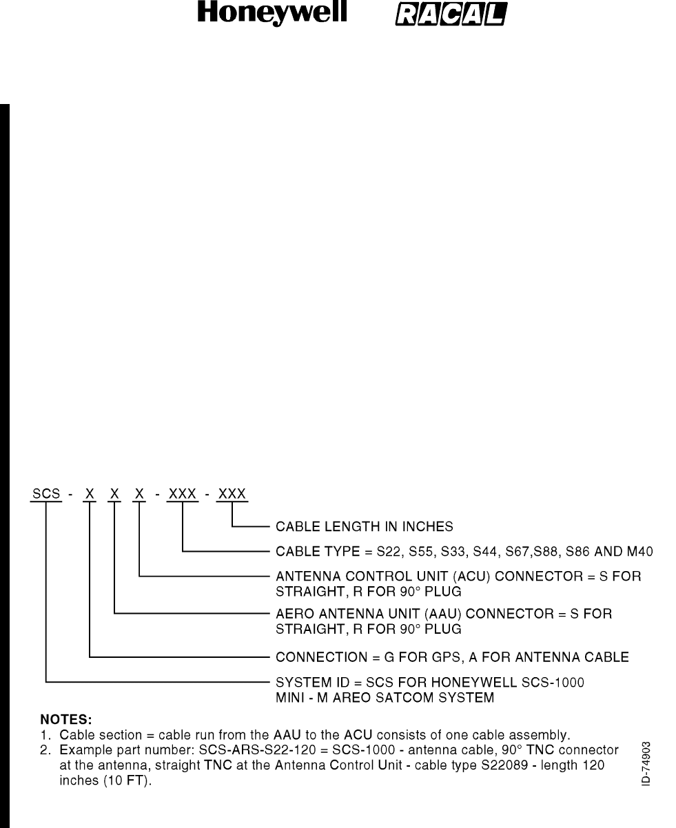
SYSTEM DESCRIPTION AND INSTALLATION MANUAL
SCS--1000 Mini--M Aero SATCOM System
23--20--28
Use or disclosure of information on this page is subject to the restrictions in the proprietary notice of this document.
Page 8--4
15 May 2001
3. PIC Wire and Cable
The following paragraphs contain information on how to select installation RF cable
assemblies offered by PIC Wire & Cable for the SCS--100 Mini--M Aero SATCOM System.
PIC designs and manufactures RF cable assemblies that are tailored to system and
installation requirements. Contact PIC as follows:
PIC Wire & Cable, Division of the Angelus Corporation
N53 W24747 South Corporate Circle
P.O. Box 330
Sussex, WI 53089--0330
Phone: (800) 742--3191 or (262) 246--0500
Fax: (262) 246--0450
e--mail: sales@picwire.com
A. Antenna and GPS RF Cable Assemblies
Figure 8--1 shows the numbering scheme for the antenna and GPS cable assemblies.
Figure 8--2 shows a typical AAU to ACU interface using the antenna and GPS cable
assemblies. The antenna and GPS cable assemblies are defined in Table 8--5.
Figure 8--1. Antenna and GPS RF Cable Assemblies Numbering Scheme
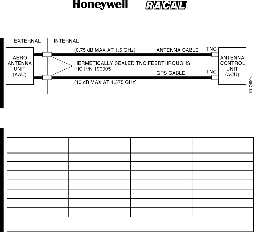
SYSTEM DESCRIPTION AND INSTALLATION MANUAL
SCS--1000 Mini--M Aero SATCOM System
23--20--28
Use or disclosure of information on this page is subject to the restrictions in the proprietary notice of this document.
Page 8--5
15 May 2001
Figure 8--2. Typical Antenna and GPS RF Cable Assemblies Interface
Table 8--5. Antenna Cable and GPS RF Cable Assemblies Description
Cable Pin No. Cable Code
Max Length Antenna
Cable (Note)
Max Length GPS Cable
(Note)
S22089 S22 150 inches (12.5 ft) 2460 inches (205 ft)
S55268 S55 109 inches (9.08 ft) 1860 inches (155 ft)
S33141 S33 83 inches (6.91 ft) 1404 inches (117 ft)
S67163 S67 74 inches (6.16 ft) 1212 inches (101 ft)
S44193 S44 47 inches (3.91 ft) 804 inches (67 ft)
S86208 S86 40 inches (3.33 ft) 672 inches (56 ft)
M40019 M40 36 inches (3.00 ft) 612 inches (51 ft)
NOTE: Max cable length is calculated including total losses associated with the hermetically sealed TNC
feedthroughs, both cable connectors and the cable at 1.6 GHz
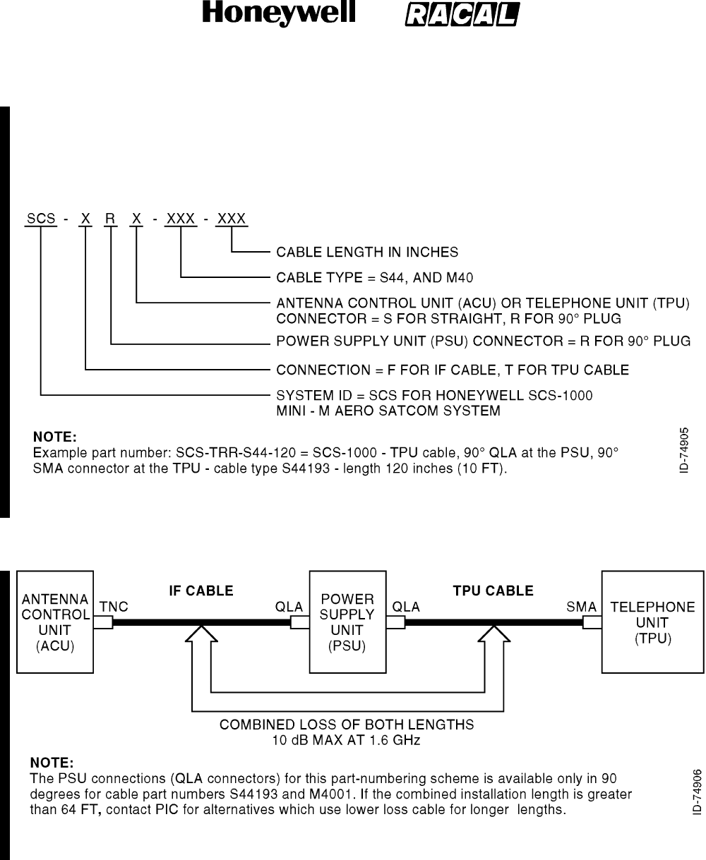
SYSTEM DESCRIPTION AND INSTALLATION MANUAL
SCS--1000 Mini--M Aero SATCOM System
23--20--28
Use or disclosure of information on this page is subject to the restrictions in the proprietary notice of this document.
Page 8--6
15 May 2001
B. IF and TPU RF Cable Assemblies
Figure 8--3 shows the numbering scheme for the IF and TPU cable assembles.
Figure 8--4 shows a typical IF and TPU cable assemblies. The IF and TPU cable
descriptions are defined in Table 8--6.
Figure 8--3. IF and TPU RF Cable Assemblies Numbering Scheme
Figure 8--4. Typical IF and TPU RF Cable Assemblies

SYSTEM DESCRIPTION AND INSTALLATION MANUAL
SCS--1000 Mini--M Aero SATCOM System
23--20--28
Use or disclosure of information on this page is subject to the restrictions in the proprietary notice of this document.
Page 8--7
15 May 2001
Table 8--6. IF and TPU RF Cables Description
Cable Pin No. Cable Code
Combined Max Length for IF
and TPU Cables
S44193 S44 768 inches (64 ft)
M40019 M40 612 inches (51 ft)
NOTE: Combined max cable length is calculated including total losses associated with all four connectors
and both cables at 1.6 GHz
4. Omni--Pless
Contact Omni--Pless for antenna kit information.
A. Omni--Pless Antenna Systems
Omni--Pless (PTY) LTD. Registration number 87\06391\07
Corner of Main Road and Riverside Terrance Hout Bay 7800
Hout Bay 7872 South Africa
+27 21 799 7000 Telephone
+27 21 790 6078 Facsimile

SYSTEM DESCRIPTION AND INSTALLATION MANUAL
SCS--1000 Mini--M Aero SATCOM System
23--20--28
Use or disclosure of information on this page is subject to the restrictions in the proprietary notice of this document.
Page 8--8
15 May 2001
Blank Page
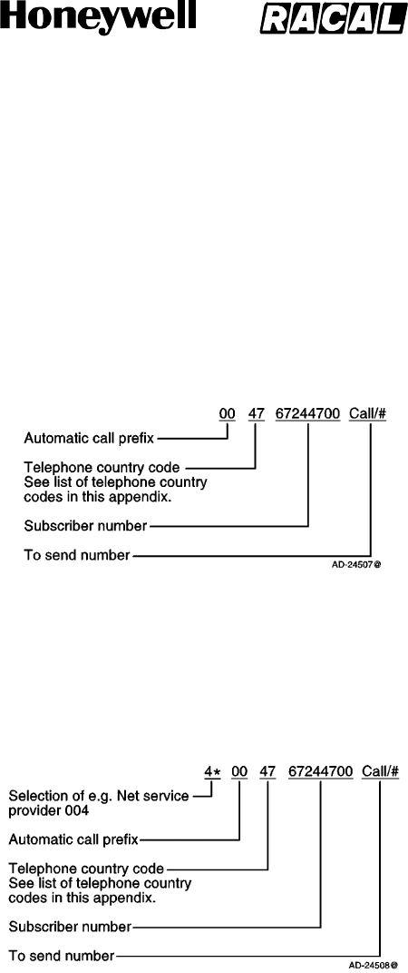
SYSTEM DESCRIPTION AND INSTALLATION MANUAL
SCS--1000 Mini--M Aero SATCOM System
23--20--28
Use or disclosure of information on this page is subject to the restrictions in the proprietary notice of this document.
Page A--1
31 Jan 2000
APPENDIX A
TELEPHONE COUNTRY CODES
This appendix has the telephone country codes and examples of how to place a call using the
SCS--1000 system.
To place a call from the SCS--1000 system to a fixed subscriber through the default network,
key in the automatic call prefix, followed by the country code and the subscriber number
(22 digits maximum). See the example below:
To place a call from the SCS--1000 system to a fixed subscriber through a selected network
service provider, follow the same procedure as above preceded by selection of the network
service provider (reference code). See the example below:
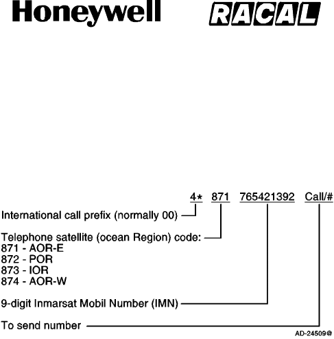
SYSTEM DESCRIPTION AND INSTALLATION MANUAL
SCS--1000 Mini--M Aero SATCOM System
23--20--28
Use or disclosure of information on this page is subject to the restrictions in the proprietary notice of this document.
Page A--2
31 Jan 2000
To place a call from a fixed subscriber or the SCS--1000 system to another SCS--1000
system, key in the international call prefix, followed by the satellite code and the 9--digit IMN.
See the example below:
NOTE:Some network service providers support the common Ocean Region Access No. 870,
which connects the call to the dialed Mini--M System regardless of the Ocean Region
the user currently communicates through.
The telephone country codes are given in Table A--1.

SYSTEM DESCRIPTION AND INSTALLATION MANUAL
SCS--1000 Mini--M Aero SATCOM System
23--20--28
Use or disclosure of information on this page is subject to the restrictions in the proprietary notice of this document.
Page A--3
31 Jan 2000
Table A--1. Telephone Country Codes
Country Code
Afghanistan (Islamic State of) 93
Albania (Republic of) 855
Algeria (People’s Democratic Republic of) 21 (Note 2)
American Samoa 684
Angola (Republic of) 244
Anguilla 1(Note 1)
Antigua and Barbuda 2(Note 1)
Argentine Republic 54
Armenia (Republic of) 7(Note 7)
Aruba 297
Ascension 247
Atlantic Ocean East Region (AOR--E) (Inmarsat) 871
Atlantic Ocean West Region (AOR--W) (Inmarsat) 874
Australia 61
Australian External Territories 672
Austria 43
Azerbaijani Republic 994
Bahamas (Commonwealth of the) 1(Note 1)
Bahrain (State of) 973
Bangladesh (People’s Republic of) 380
Barbados 1(Note 1)
Belarus (Republic of) 7(Note 7)
Belgium 32
Belize 501
Benin (Republic of) 223
Bermuda 1(Note 1)
Bhutan (Kingdom of) 975
Bolivia (Republic of) 591
Bosnia and Herzegovina (Republic of) 887
Botswana (Republic of) 267

SYSTEM DESCRIPTION AND INSTALLATION MANUAL
SCS--1000 Mini--M Aero SATCOM System
23--20--28
Use or disclosure of information on this page is subject to the restrictions in the proprietary notice of this document.
Page A--4
31 Jan 2000
Table A--1. Telephone Country Codes (cont)
Country Code
Brazil (Federative Republic of) 55
British Virgin Islands 1(Note 1)
Brunei Darussalam 673
Bulgaria (Republic of) 859
Burkina Faso 226
Burundi (Republic of) 257
Cambodia 355
Cameroon (Republic of) 237
Canada 1(Note 1)
Cape Verde (Republic of) 238
Cayman Islands 1(Note 1)
Central African Republic 236
Chad (Republic of) 235
Chile 56
China (People’s Republic of) 86 (Note 8)
Colombia (Republic of) 57
Comoros (Islamic Federal Republic of the) 269
Congo (Republic of the) 242
Cook Islands 682
Costa Rica 506
Croatia (Republic of) 385
Cuba 53
Cyprus (Republic of) 357
Czech Republic 42 (Note 6)
Democratic People’s Republic of Korea 850
Denmark 45
Diego Garda 246
Djibouti (Republic of) 253
Dominican Republic 1(Note 1)

SYSTEM DESCRIPTION AND INSTALLATION MANUAL
SCS--1000 Mini--M Aero SATCOM System
23--20--28
Use or disclosure of information on this page is subject to the restrictions in the proprietary notice of this document.
Page A--5
31 Jan 2000
Table A--1. Telephone Country Codes (cont)
Country Code
Ecuador 593
Egypt (Arab Republic of) 20
El Salvador (Republic of) 503
Equatorial Guinea (Republic of) 240
Eritrea 291
Estonia (Republic of) 372
Ethiopia 251
Falkland Islands (Malvinas) 500
Faroe Islands (Denmark) 298
Fiji (Republic of) 679
Finland 358
France 33 (Note 6)
French Poiynesia 68
Gabonese Republic 241
Gambia (Republic of the) 220
Georgia (Republic of) 7(Note 7)
Germany (Federal Republic of) 49
Ghana 233
Gibraltar 350
Greece 30
Greenland (Denmark) 299
Grenada 1(Note 1)
Guadeloupe (French Department of) 590
Guam 671
Guatemala (Republic of) 502
Guiana (French Department of) 594
Guinea (Republic of) 224
Guinea--Bissau (Republic of) 245
Guyana 592

SYSTEM DESCRIPTION AND INSTALLATION MANUAL
SCS--1000 Mini--M Aero SATCOM System
23--20--28
Use or disclosure of information on this page is subject to the restrictions in the proprietary notice of this document.
Page A--6
31 Jan 2000
Table A--1. Telephone Country Codes (cont)
Country Code
Haiti (Republic of) 509
Honduras (Republic of) 504
Hongkong 852
Hungary (Republic of) 36
Iceland 354
India (Republic of) 91
Indian Ocean Region (IOR)(Inmarsat) 873
Indonesia (Republic of) 62
Iran (Islamic Republic of) 98
Iraq (Republic of) 964
Ireland 353
Israel (State of) 972
Italy 39
Ivory Cost (Republic of) 225
Jamaica 1(Note 1)
Japan 81
Jordan (Hashemite Kingdom of) 962
Kazakhstan (Republic of) 7(Note 7)
Kenya (Republic of) 254
Kiribati Republic of) 686
Kuwait (State of) 965
Kyrgyzstan (Republic of) 7(Note 7)
Lao People’s Democratic Republic 856
Latvia (Republic of) 371
Lebanon 961
Lesotho (Kingdom of) 266
Liberia (Republic of) 231

SYSTEM DESCRIPTION AND INSTALLATION MANUAL
SCS--1000 Mini--M Aero SATCOM System
23--20--28
Use or disclosure of information on this page is subject to the restrictions in the proprietary notice of this document.
Page A--7
31 Jan 2000
Table A--1. Telephone Country Codes (cont)
Country Code
Libya (Socialist People’s Ubyan Arab Jamahiriya) 21 (Note 3)
Liechtenstein (Principality of) 41 (Note 6)
Lithuania (Republic of) 370
Luxembourg 352
Macau 853
Macedonia (the former Yugoslav Republic of) 389
Madagascar (Republic of) 261
Malawi 265
Malaysia 60
Maldives (Republic of) 960
Mali (Republic of) 223
Malta 356
Marshall Islands (Republic of the) 692
Martinique (French Department of) 596
Mauritania (Islamic Republic of) 222
Mauritius (Republic of) 230
Mexico 52
Micronesia (Federated States of) 691
Moldova (Republic of) 373
Monaco (See also code 377) 33 (Note 6)
Mongolia 976
Montserrat 1(Note 1)
Morocco (Kingdom of) 21 (Note 4)
Mozambique (Republic of) 258
Myanmar (Union of) 95
Namibia (Republic of) 264
Nauru (Republic of) 674
Nepal 977
Netherlands Antilles 599

SYSTEM DESCRIPTION AND INSTALLATION MANUAL
SCS--1000 Mini--M Aero SATCOM System
23--20--28
Use or disclosure of information on this page is subject to the restrictions in the proprietary notice of this document.
Page A--8
31 Jan 2000
Table A--1. Telephone Country Codes (cont)
Country Code
Netherlands (Kingdom of the) 31
New Caledonia 687
New Zealand 64
Nicaragua 505
Niger (Republic of the) 227
Nigeria (Federal Republic of) 234
Niue 683
Northern Mariana Islands (Commonwealth of the) 670
Norway 47
Oman (Sultanate of) 968
Pacific Ocean Region (POR)(Inmarsat) 872
Pakistan (Islamic Republic of) 92
Palau (Republic of) 680
Panama (Republic of) 507
Papua New Guinea 675
Paraguay (Republic of) 595
Peru 51
Philippines (Republic of the) 63
Poland (Republic of) 48
Portugal 351
Qatar (State of) 974
Reunion (French Department of) 262
Romania 40
Russian Federation 7(Note 7)
Rwandese Republic 250

SYSTEM DESCRIPTION AND INSTALLATION MANUAL
SCS--1000 Mini--M Aero SATCOM System
23--20--28
Use or disclosure of information on this page is subject to the restrictions in the proprietary notice of this document.
Page A--9
31 Jan 2000
Table A--1. Telephone Country Codes (cont)
Country Code
Saint Vincent and the Grenadines 1(Note 7)
Saint Luda 1(Note 1)
Saint Kitts and Nevis 1(Note 1)
Saint Helena 290
Saint Pierre and Miquelon (French Department of) 508
San Marino (Republic of) 378
Sao Tome and Principe (Democratic Repulic of) 239
Saudi Arabia (Kingdom of) 966
Senegal (Republic of) 221
Seychelles (Republic of) 248
Sierra Leone 232
Singapore (Republic of) 65
Slovak Republic 42 (Note 6)
Slovenia (Republic of) 386
Solomon Islands 677
Somali Democratic Republic 252
South Africa (Republic of) 27
Spain 34
Sri Lanka (Democratic Socialist Republic of) 94
Sudan (Republic of the) 249
Suriname (Republic of) 597
Swaziland (Kingdom of) 268
Sweden 46
Switzerland (Confederation of) 41 (Note 6)
Syrian Arab Republic 963
Tajikistan (Republic of) 7(Note 7)
Tanzania (United Republic of) 255
Thailand 66
Togolese Republic 228
Tokelau 690

SYSTEM DESCRIPTION AND INSTALLATION MANUAL
SCS--1000 Mini--M Aero SATCOM System
23--20--28
Use or disclosure of information on this page is subject to the restrictions in the proprietary notice of this document.
Page A--10
31 Jan 2000
Table A--1. Telephone Country Codes (cont)
Country Code
Tonga (Kingdom of) 676
Trinidad and Tobago (Code actually used: +1) 296
Tunisia 21 (Note 5)
Turkey 90
Turkmenistan 7(Note 7)
Turks arid Caicos Islands 1(Note 1)
Tuvalu 688
Uganda (Republic of) 256
Ukraine 7(Note 7)
United Arab Emirates 971 (Note 9)
United States of America, + Puerto Rico, Virgin Islands 1(Note 1)
United Kingdom of Great Britain and Northern Ireland 44
Uruguay (Eastern Republic of) 598
Uzbekistan (Republic of) 7(Note 7)
Vanuatu (Republic of) 678
Vatican City State 379
Venezuela (Republic of) 58
Viet Nam (Socialist Republic of) 84
Wallis and Futuna 681
Western Samoa (Independent State of) 685
Yemen (Republic of) 967
Yugoslavia (Federal Republic of) 381

SYSTEM DESCRIPTION AND INSTALLATION MANUAL
SCS--1000 Mini--M Aero SATCOM System
23--20--28
Use or disclosure of information on this page is subject to the restrictions in the proprietary notice of this document.
Page A--11
31 Jan 2000
Table A--1. Telephone Country Codes (cont)
Country Code
Zaire (Republic of) 243
Zambia (Republic of) 260
Zanzibar (Tanzania) 259
Zimbabwe (Republic of) 263
NOTES:
1. Integrated numbering area.
2. Integrated numbering area with subdivisions: 213, 214 and 215 for Algeria.
3. Integrated numbering area with subdivisions: 218 and 219 for Libya.
4. Integrated numbering area with subdivisions: 210, 211, 212 (212 in service) for
Morocco.
5. Integrated numbering area with subdivisions: 216, 217 for Tunisia.
6. Integrated numbering plan.
7. Will form part of numbering zone 7.
8. Code 866 has been allocated to the province of Taiwan.
9. United Arab Emirates (U.A.E.) includes: Abu Dhabi, AJmna, Dubai, Fujeirah,
Ras Al, Khaimah, Sharjah, Umm al Oaiwain.

SYSTEM DESCRIPTION AND INSTALLATION MANUAL
SCS--1000 Mini--M Aero SATCOM System
23--20--28
Use or disclosure of information on this page is subject to the restrictions in the proprietary notice of this document.
Page A--12
31 Jan 2000
Blank Page

SYSTEM DESCRIPTION AND INSTALLATION MANUAL
SCS--1000 Mini--M Aero SATCOM System
23--20--28
Use or disclosure of information on this page is subject to the restrictions in the proprietary notice of this document.
Page B--1
31 Jan 2000
APPENDIX B
SERVICE ADDRESS CODES
Table B--1. Service Address Codes
Abbreviateddialing ..................................................... 23
Accesstomaritimepacketassembly/disassembly .......................... 20
Administrationspecializeduse ........................................... 6(X)
Automatic ............................................................. 00
Automaticlinetest ...................................................... 91
Collectcall ............................................................ 35
Creditcardcall ......................................................... 36
Commissioningtests.................................................... 92
Databases ............................................................. 70
Faxmail ............................................................... 26
International outgoing operator ........................................... 11
International information service .......................................... 12
Mailretrieval ........................................................... 57
Maritimeassistance .................................................... 39
Maritime enquiries ...................................................... 31
Medicaladvice ......................................................... 32
Medicalassistance ..................................................... 38
Meteorological reports .................................................. 41
Navigational hazards and warnings ....................................... 42
National operator ....................................................... 13
National information service .............................................. 14
Person--to--personcall .................................................. 34

SYSTEM DESCRIPTION AND INSTALLATION MANUAL
SCS--1000 Mini--M Aero SATCOM System
23--20--28
Use or disclosure of information on this page is subject to the restrictions in the proprietary notice of this document.
Page B--2
31 Jan 2000
Table B--1. Service Address Codes (cont)
Ship position reports .................................................... 43
Technicalassistance(onnetwork) ........................................ 33
Telephone call booking .................................................. 17
Timeandduration ...................................................... 37
Time announcement .................................................... 50

SYSTEM DESCRIPTION AND INSTALLATION MANUAL
SCS--1000 Mini--M Aero SATCOM System
23--20--28
Use or disclosure of information on this page is subject to the restrictions in the proprietary notice of this document.
Page C--1
31 Jan 2000
APPENDIX C
DTE INTERFACE
1. General
This appendix describes how Data Terminal Equipment (DTE) interfaces with the SCS--1000
system.
2. Pin Assignments
The TPU RS--232 jack pin assignments for interface with DTE is given in Table C--1.
Table C--1. RS--232 Jack to DTE Interface Pin Assignments
Pin Signal
CCITT
Circuit
Signal
Source Description
1CD 109 DCE Carrier detect
2RXD 104 DTE Received data
3TXD 103 DCE Transmitted data
4DTR 108 DTE Data terminal ready
5GND 102 Signal ground
6DSR 107 DCE Data set ready
7RTS 105 DTE Request To Send
8CTS 106 DCE Clear To Send
9RI 125 DCE Ring indicator
NOTES:
1. Signal source DTE means the signal goes from the PC to the SCS system.
2. Signal source DCE means the signal goes from the SCS system to the PC.

SYSTEM DESCRIPTION AND INSTALLATION MANUAL
SCS--1000 Mini--M Aero SATCOM System
23--20--28
Use or disclosure of information on this page is subject to the restrictions in the proprietary notice of this document.
Page C--2
31 Jan 2000
3. Signal descriptions
Table C--2 describes the DTE interface signals.
Table C--2. DTE Interface Signal Descriptions
CCITT
Circuit Signal Name Description
102 Signal Ground Digital ground, return line.
103 Send Data Data transmitted from the DTE to the DCE.
104 Receive Data Data received from the DCE to the DTE.
105 Request To Send OFF requests DCE to suspend transmission to DTE.
ON requests DCE to resume transmission to DTE.
106 Clear to Send OFF indicates that the DCE cannot accept data from
the DTE.
ON indicates that the DCE is prepared to accept data
from the DTE.
107 Data Set Ready Signal from the SCS system. ON indicates that a
data call setup is in progress.
108 Data Terminal Ready Signal from the PC. This signal is used in the Hotline
mode. When going from OFF to ON, this signal
indicates that the PC wants to make a data call. The
PC clears the call by setting the signal from ON to
OFF.
109 Receive Signal Indicator Signal from SCS system. ON indicates that
connection is established and received data will be
delivered on circuit 104, Received Data.
125 Ring Indicator Signal from SCS system. This signal is used in the
Auto answer OFF mode. ON indicates that an
incoming call is in progress. The signal goes OFF
when the call is answered by the PC (turning circuit
108 Data
Terminal Ready ON).
NOTES:
1. DTE means the signal goes from the PC to the SCS system.
2. DCE means the signal goes from the SCS system to the PC.

SYSTEM DESCRIPTION AND INSTALLATION MANUAL
SCS--1000 Mini--M Aero SATCOM System
23--20--28
Use or disclosure of information on this page is subject to the restrictions in the proprietary notice of this document.
Page D--1
31 Jan 2000
APPENDIX D
AT COMMANDS
1. General
The Attention (AT) command set allows the user to configure the SCS system Asynchronous
Data (ASD) transmission function directly from your PC keyboard. The AT characters are a
prefix to the commands that the user issues to the SCS system ASD service.
NOTE:Most communication applications do not require knowledge of AT commands.
Every time AT is typed, the user is essentially asking for the SCS system ASD’s ATtention.
For instance, if the user wants to answer an incoming data call, type ATA and then push the
RETURN (or ENTER) key to answer.
NOTE:When a value associated with a command is not entered, it is assumed to be zero,
for example, typing AT&D equals AT&D0.
2. Hanging Up -- Escape Sequence
Once the the SCS system ASD is online to another system, the only command it recognizes is
an escape code that contains three typed pluses (+), which forces the SCS system ASD back
to the command mode.
The following should be done, when issuing the escape command:
Wait 1 second after sending the last item of data.
Type +++ with less than 1 second between the characters.
Wait 1 second, and then an OK response should appear.
NOTE:Do not type the AT prefix or push the RETURN (or ENTER) key. The guard time
of 1 second before and after the code prevents the SCS system ASD from
misinterpreting the occurrence of +++ in the transmitted data stream.
In response to +++, the SCS system ASD returns to the command mode.
If necessary, the character used in the escape code or the duration of the guard time can be
changed by altering Register S2 or S12, see the paragraph on S--register commands.
To hang up or return to the online mode, perform the following:
To hang up, type ATH and then push the RETURN (or ENTER)key.
To return to the online mode, type ATO and then push the RETURN (or ENTER)key.

SYSTEM DESCRIPTION AND INSTALLATION MANUAL
SCS--1000 Mini--M Aero SATCOM System
23--20--28
Use or disclosure of information on this page is subject to the restrictions in the proprietary notice of this document.
Page D--2
31 Jan 2000
3. Operating Modes
The SCS system ASD function may operate in three modes given in Table D--1.
Table D--1. ASD Function Modes of Operation
Mode Description
Command Mode The SCS system ASD responds to AT commands. No remote
communication occurs.
Online Command Mode A data call is taking place and an escape sequence has been
initiated, after which the SCS system ASD responds to AT
commands during the call.
Online Data Mode Once the SCS system ASD is connected, anything arriving from
the PC is interpreted as data and sent to the remote end and vice
versa.
4. Basic AT Commands
Table D--2 gives the basic AT commands and their descriptions.
NOTE:AT commands may be entered in either upper or lower case (not mixed).
Table D--2. Basic AT Commands
Command (Note 1) Description
ATA Instructs the SCS system ASD to connect the line and start the
answer sequence of the incoming call. Used when not configured
for auto answer.
ATD004767244700 Instructs the SCS system ASD to dial the number 00 47 67 24 47
00 via the default network service provider.
ATD4*004767244700 Instructs the SCS system ASD to dial the number 00 47 67 24 47
00 via the selected network service provider, for example, Telenor
(Norwegian Telecom, code No. 4).
ATD2311 Dials the telephone number stored under short number 11.
ATE [n] Turns the local echo of the keyboard commands OFF or ON.
ATE0 Turns the local echo OFF.
ATE1 (Note 2) Turns the local echo ON.
ATH Hook control. Sets the SCS system ASD ON--hook when in the
Online Data Mode. Disconnects the line and terminates the call.
ATO Returns to the Online Data Mode when in Online Command Mode
during a data call.
ATQ [n] Sets responses sent by the SCS system ASD.
ATQ0 (Note 2) The SCS system ASD returns responses like OK or ERROR.

SYSTEM DESCRIPTION AND INSTALLATION MANUAL
SCS--1000 Mini--M Aero SATCOM System
23--20--28
Use or disclosure of information on this page is subject to the restrictions in the proprietary notice of this document.
Page D--3
31 Jan 2000
Table D--2. Basic AT Commands (cont)
Command (Note 1) Description
ATQ1 The SCS system ASD does not return responses.
ATS Sets and displays S register values. See the paragraph on
S--register commands.
ATV [n] Sets the SCS system ASD response format to words or numbers.
ATV0 Selects numeric response.
ATV1 (Note 2) Selects verbal response.
ATX [n] Selects the CONNECT result code format (dial tone detection --
busy detection).
ATX0 Selects the basic message set: OK, CONNECT, RING, NO
CARRIER, and ERROR.
ATX1 Selects the basic message set extended with CONNECT
xxxx--yyyy.
ATX2 Selects the basic message set extended with NO DIALTONE.
ATX3 Selects the basic message set extended with BUSY.
ATX4 (Note 2) Selects the basic message set extended with all of the above.
ATZ Resets the SCS system ASD configuration to the last saved
command. Also clears the call if used when in the Online
Command Mode.
A/ Repeats the last command. Re--executes the last AT command
string issued to the SCS system ASD, including redialing a
telephone number.
NOTES:
1. Push the RETURN (or ENTER) key after typing each command, except the command A/.
2. This is the default setting.

SYSTEM DESCRIPTION AND INSTALLATION MANUAL
SCS--1000 Mini--M Aero SATCOM System
23--20--28
Use or disclosure of information on this page is subject to the restrictions in the proprietary notice of this document.
Page D--4
31 Jan 2000
5. Extended AT Commands
Table D--3 gives the extended AT commands and their descriptions.
Table D--3. Extended AT Commands
Command (Note 1) Description
AT&C [n] Determines the Data Carrier Detect (DCD) behavior.
AT&C0 Sets DCD always ON.
AT&C1 (Note 2) Sets DCD, only when connected.
AT&D [n] Selects the Data Terminal Ready (DTR) behavior.
AT&D0 The SCS system ASD ignores DTR.
AT&D1 The SCS system ASD enters the Online Command Mode when
DTR goes inactive.
AT&D2 (Note 2) The SCS system ASD clears the call when DTR goes inactive.
AT&F Resets the SCS system ASD to the factory default. The factory
default is not saved like it is with the AT&W command, so ATZ
revokes to last saved values.
AT&S [n] Selects the Data Set Ready (DSR) behavior.
AT&S0 (Note 2) Sets DSR permanently ON.
AT&S1 Sets DSR ON when the satellite link is established.
AT&V Displays the stored configuration profile.
AT&W Saves the active configuration profile. (May be recalled using the
ATZ command.)
NOTES:
1. Push the RETURN (or ENTER) key after typing each command.
2. This is the default setting.

SYSTEM DESCRIPTION AND INSTALLATION MANUAL
SCS--1000 Mini--M Aero SATCOM System
23--20--28
Use or disclosure of information on this page is subject to the restrictions in the proprietary notice of this document.
Page D--5
31 Jan 2000
6. Extended AT+I, +G and +W Commands
The extended AT+I, AT+G and AT+W commands are non--standard features, some of which
are designed specially for the Inmarsat Mini--M system. Table D--4 gives the extended AT+I,
AT+G and AT+W commands and their descriptions.
Table D--4. Extended AT+I, +G, and +W Commands
Command (Note 1) Description
AT+GCAP Displays capabilities supported by SCS system terminals.
AT+GMI Displays manufacturer identification.
AT+GMM Displays equipment identification.
AT+GMR Displays software revision.
AT+ICF = [n<format>],
[m<parity>]
Specifies the local serial port start--stop (asynchronous) character
framing between the PC and the SCS system. The format
reference number nis defined as follows:
1=8databits,2stopbits
3 = 8 data bits, 1 stop bit (default setting)
4=7databits,2stopbits
5 = 7 data bits, 1 parity bit, 1 stop bit.
The parity reference number mis defined as follows:
0 = odd
1 = even
2 = mark
3 = space (default setting).
EXAMPLE:
AT+ICF=3,3 Specifies a data format of 8 data bits, 1 stop bit,
and space parity.
AT+ICF ? Displays current settings.
AT+ICF =? Displays available settings.

SYSTEM DESCRIPTION AND INSTALLATION MANUAL
SCS--1000 Mini--M Aero SATCOM System
23--20--28
Use or disclosure of information on this page is subject to the restrictions in the proprietary notice of this document.
Page D--6
31 Jan 2000
Table D--4. Extended AT+I, +G, and +W Commands (cont)
Command (Note 1) Description
AT + I F C = [ n < W P -- t o -- P C > ]
[,m<PC--to--WP>];
Specifies the local flow control between the PC and the SCS
system. The system--to--PC reference number nis defined as
follows:
0 = no flow control
1 = XON/XOFF (software flow control stripped of control
characters)
2 = RTS (hardware flow control) [default setting]
3 = XON/XOFF (software flow control with pass--through of
control characters).
The PC--to--system reference number mis defined as follows:
0 = no flow control
1 = XON/XOFF (software flow control)
2 = CTS (hardware flow control) [default setting].
AT+IFC ? Displays current settings.
AT+IFC =? Displays available settings.
AT+IPR = [r(PC--to--WP rate)] Specifies the data rate at which PC -- system interface accepts
commands. Selectable data rates rare defined as follows:
1200 bps
2400 bps
4800 bps
9600 bps
19200 bps
38400 bps.
EXAMPLE:
AT+IPR=9600 Specifies a data rate of 9600 bps between the PC
and the SCS system TPU.
AT+IPR ? Displays current settings.
AT+IPR =? Displays available settings.
AT+W Indicates which PCCA standard the SCS system ASD complies
with.
AT+WKSIZE = [n] Sets the maximum ARQ window size for subsequent data calls
using the ARQ mode. The ARQ window determines the size of the
buffer that keeps in memory the data not yet acknowledged by the
other end. A valid setting for nis between 1 and 63. The default
number for nis 15.
AT+WKSIZE? Displays current settings.
AT+WKSIZE=? Displays available settings.

SYSTEM DESCRIPTION AND INSTALLATION MANUAL
SCS--1000 Mini--M Aero SATCOM System
23--20--28
Use or disclosure of information on this page is subject to the restrictions in the proprietary notice of this document.
Page D--7
31 Jan 2000
Table D--4. Extended AT+I, +G, and +W Commands (cont)
Command (Note 1) Description
AT+WINMARSAT Lists the Inmarsat specific functions supported by the SCS system
ASD.
AT+WLES = [n] Selects the Net service provider for the next outgoing call. The
parameter nnn specifies the Net service provider Access Code.
Three digits must be keyed in. If omitted, the default Net service
provider set from the SCS system is selected. A valid setting for n
is between 0 and 255. The default number for nnn is 000.
AT+WNERAHSHAKE = [n] Selects the handshake setup. The number nis defined as follows:
0 = Routes handshake transitions from the PC directly to
the Net service provider. Minimizes transmission
delays when handshake is seldom used. This is the
default setting.
1 = Fills the SCS system buffer before handshaking with the
Net service provider.
AT+WRATE = [<sat_rate>]
[,<ter_rate>]
Sets the wanted satellite data rate, and the terrestrial data rate
used for outgoing data calls. The sat_rate is the requested data
rate to use over satellite channel, for the SCS system to
permanently set to, for example, 2400 bps. The ter_rate is the
data rate to use on the terrestrial modem. Valid rates are as
follows:
1200 bps
2400 bps
4800 bps
9600 bps (default setting)
14400 bps.
EXAMPLE:
AT+WRATE=2400,2400 Sets both the satellite rate and
the terrestrial modem rate to
2400 bps.
AT+WRATE? Displays the selected rates.
AT+WRATE =? Displays the available rates.

SYSTEM DESCRIPTION AND INSTALLATION MANUAL
SCS--1000 Mini--M Aero SATCOM System
23--20--28
Use or disclosure of information on this page is subject to the restrictions in the proprietary notice of this document.
Page D--8
31 Jan 2000
Table D--4. Extended AT+I, +G, and +W Commands (cont)
Command (Note 1) Description
AT+WRTL = [<low>] [,<high>] Sets the lower and upper threshold level in bytes of the buffer used
in the Net service provider--to--system direction (SCS system
receive buffer).
The low parameter specifies the lower threshold at which point the
SCS system ASD should issue an Receiver Ready (RR) packet
signalling that it is ready to receive data from Net service provider.
Valid values are between 0 and 511. The default value is 120.
The high parameter specifies the upper threshold at which point
the SCS system ASD should issue an Receiver Not Ready (RNR)
packet signalling that it is not ready to receive any more data from
Net service provider. Valid values are between 1 and 512. The
default value is 240.
NOTE: The high value must be larger than the low value.
When the high value is omitted, it becomes the
low value + 120.
AT+WRTL? Displays the selected threshold levels.
AT+WRTL =? Displays the available threshold levels.
AT+WS45 = [n] Sets the requested satellite and terrestrial error correction scheme
for data calls. The parameter reference number nis defined in
Table D--5.
NOTE: The default setting for nis 1.
AT+WS45? Displays the current setting.
AT+WS45 =? Displays the available setting.
AT+WS46? Shows that the Inmarsat Mini--M ASD standard is to be used for
data communication. This is fixed and may not be changed.
AT+WTNID = [<nnn>] Sets the terrestrial network for the next outgoing data call. The
parameter nnn specifies the terrestrial network ID. If omitted, it is
set to 000, which means that the terrestrial network is unspecified.
The range of this parameter is between 0 and 255.
AT+WTNID? Displays the selected Terrestrial Network Identification Digit
(TNID).
AT+WTNID =? Displays the available TNIDs.

SYSTEM DESCRIPTION AND INSTALLATION MANUAL
SCS--1000 Mini--M Aero SATCOM System
23--20--28
Use or disclosure of information on this page is subject to the restrictions in the proprietary notice of this document.
Page D--9
31 Jan 2000
Table D--4. Extended AT+I, +G, and +W Commands (cont)
Command (Note 1) Description
AT+WTTL = [<low>] [,<high>] Sets the lower and upper threshold level in bytes of the buffer used
in the WORLDPHONE--to--Net service provider direction (SCS
system transmit buffer).
The low parameter specifies the lower threshold at which point the
SCS system ASD should issue an XON, or raise the Clear to Send
(CTS) line signaling that it is ready to receive data from the PC.
Valid values are between 0 and 511. The default value is 120.
The high parameter specifies the upper threshold at which point
the SCS system ASD should issue an an XOFF, or lower the CTS
line signalling that it is not ready to receive data from the PC. Valid
values are between 1 and 512. The default value is 240.
NOTE: The high value must be larger than the low value.
When the high value is omitted, it becomes the
low value + 120.
AT+WTTL? Displays the selected threshold levels.
AT+WTTL =? Displays the available threshold levels.
AT+WXR = [n] Determines the format of a CONNECT response from the SCS
system ASD. The format reference number nis defined as
follows:
0 = CONNECT <(See Note 3)>
+WXSR:<satellite rate>,<ARQ I NARQ>
+WXTR:<terrestrial rate>,<ARQ I NARQ>
+WXKR:<ARQ window size>
CONNECT <PC--WP rate>
2 = CONNECT <(See Note 3)>,<ARQ I NARQ> [default
setting]
3 = XON/XOFF (software flow control with pass--through of
control characters).
AT+WXR? Displays the selected format.
AT+WXR =? Displays the available formats.
NOTES:
1. Push the RETURN (or ENTER) key after typing each command.
2. This is the default setting.
3. This value is the lowest value of the PC--WP rate, satellite rate and terrestrial rate.
Table D--5. Parameter Reference Number n for AT+WS45 Command
n
Satellite Error
Correction
Terrestrial Error
Correction End--To--End
0non--ARQ non--V.42 NARQ
1ARQ V.42 ARQ

SYSTEM DESCRIPTION AND INSTALLATION MANUAL
SCS--1000 Mini--M Aero SATCOM System
23--20--28
Use or disclosure of information on this page is subject to the restrictions in the proprietary notice of this document.
Page D--10
31 Jan 2000
Table D--5. Parameter Reference Number n for AT+WS45 Command (cont)
n E n d -- T o -- E n d
Terrestrial Error
Correction
Satellite Error
Correction
200 non--ARQ V.42 NARQ
201 ARQ non--V.42 NARQ
7. S--Register Commands
S--registers are special memory locations in the SCS system System for storing specific
configuration and operating parameters. The S--register commands are given in Table D--6.
Table D--6. S--Register Commands
Command (Note 1) Description
ATS0 = [n] Specifies automatic answer at the nth ring. The parameter nis
defined as follows:
0= OFF
1 thru 255 = ON.
ATS0 = <n> Sets the value of the register.
ATS0 ? Displays the current value of the register.
ATS0 =0 (Note 2) Turns automatic answer OFF.
ATS0 =1 Answers after one ring.
NOTE: The SCS system ASD will terminate incoming calls after
95 sec.
ATS2 = [n] Stores the ASCII decimal code for the escape character.
Authorized codes are between 0 and 255.
NOTE: n = 128 disables the escape sequence.
ATS2 = <n> Sets the value of the register.
ATS2 ? Displays the current value of the register.
ATS2 =43 (Note 2) Sets the ESCAPE code to 43 (+ key).
ATS3 = [n] Stores the ASCII decimal code for the carriage return character
(RETURN or ENTER key). Authorized codes are between
0 and 127.
ATS3 = <n> Sets the value of the register.
ATS3 ? Displays the current value of the register.
ATS3 =13 (Note 2) Sets the CARRIAGE RETURN code to 13 (RETURN or ENTER
key).
ATS4 = [n] Stores the ASCII decimal code for the line feed character.
Authorized codes are between 0 and 127.

SYSTEM DESCRIPTION AND INSTALLATION MANUAL
SCS--1000 Mini--M Aero SATCOM System
23--20--28
Use or disclosure of information on this page is subject to the restrictions in the proprietary notice of this document.
Page D--11
31 Jan 2000
Table D--6. S--Register Commands (cont)
Command (Note 1) Description
ATS4 = <n> Sets the value of the register.
ATS4 ? Displays the current value of the register.
ATS4 =10 (Note 2) Sets the the LINE FEED code to 10.
ATS5 = [n] Stores the ASCII decimal code for the editing character.
Authorized codes are between 0 and 127.
ATS5 = <n> Sets the value of the register.
ATS5 ? Displays the current value of the register.
ATS5 =8 (Note 2) Sets the the BACK SPACE code to 8.
ATS25 = [n] Sets a delay before examining DTR (108/2) after dialing and when
online with a system--to--Net call. The value of nranges from 0 to
255 in hundredths of a second.
ATS25 = <n> Sets the delay value.
ATS25 ? Displays the current delay value.
ATS25=5(Note2) Sets the delay to 5(corresponding to 50 milliseconds).
NOTES:
1. Push the RETURN (or ENTER) key after typing each command.
2. This is the default setting.

SYSTEM DESCRIPTION AND INSTALLATION MANUAL
SCS--1000 Mini--M Aero SATCOM System
23--20--28
Use or disclosure of information on this page is subject to the restrictions in the proprietary notice of this document.
Page D--12
31 Jan 2000
Blank Page