Honeywell SD-700A Satcom Transceiver User Manual
Honeywell International Inc. Satcom Transceiver
UserManual.wiki
>
Honeywell
>
SD 700A User Manual
User Manual
Navigation menu
Upload a User Manual
Namespaces
Wiki Guide
HTML
PDF
Info
Views
User Manual
Discussion / Help
Navigation
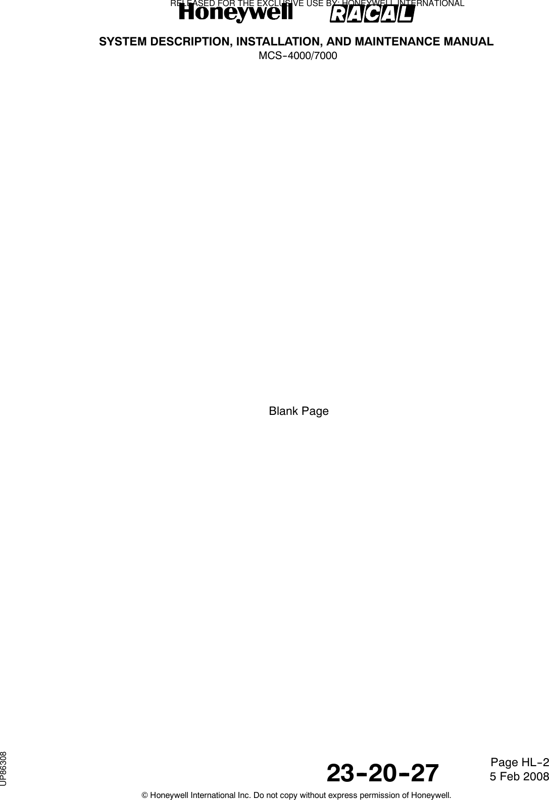


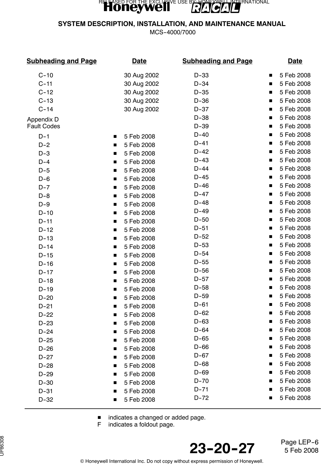
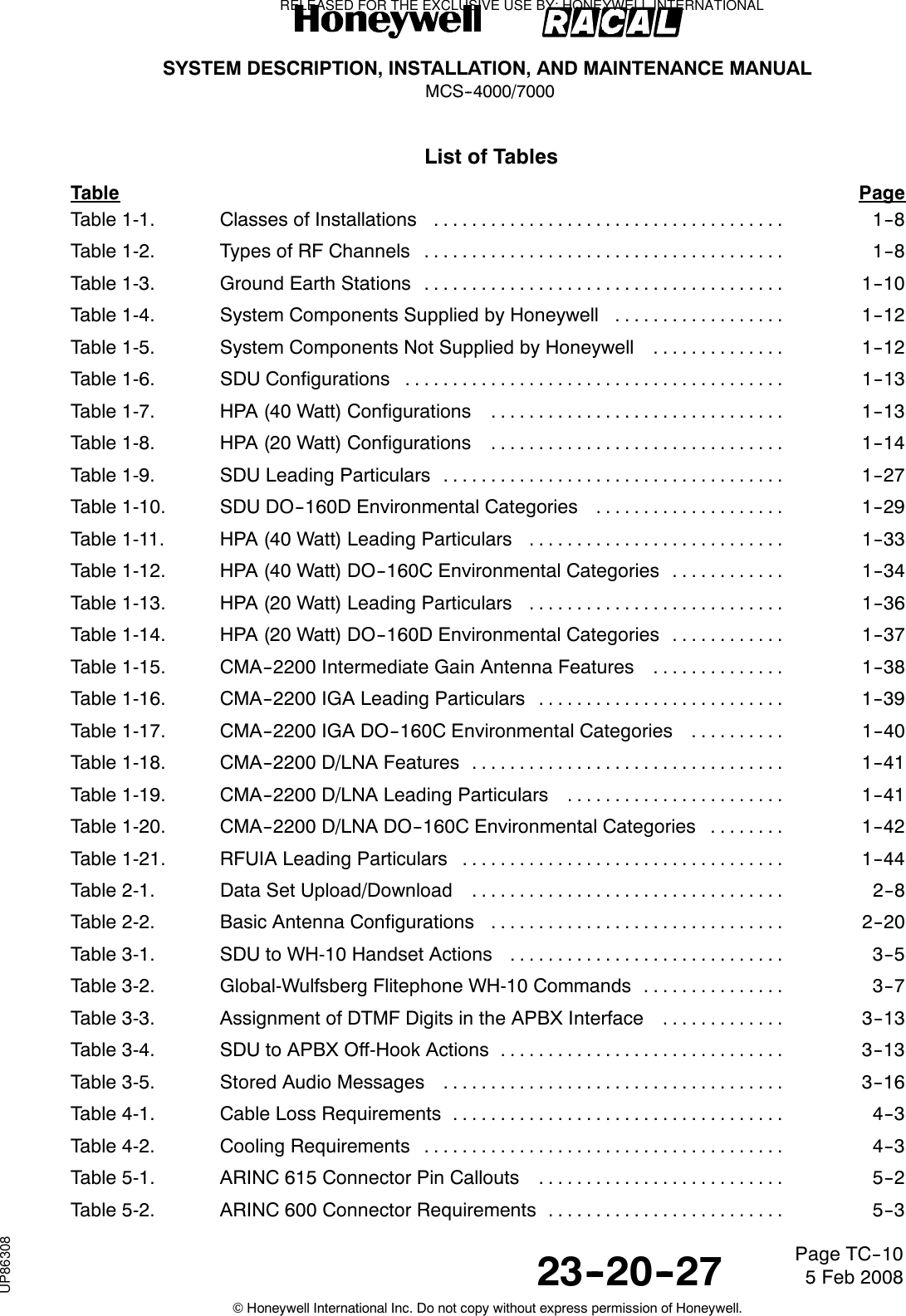
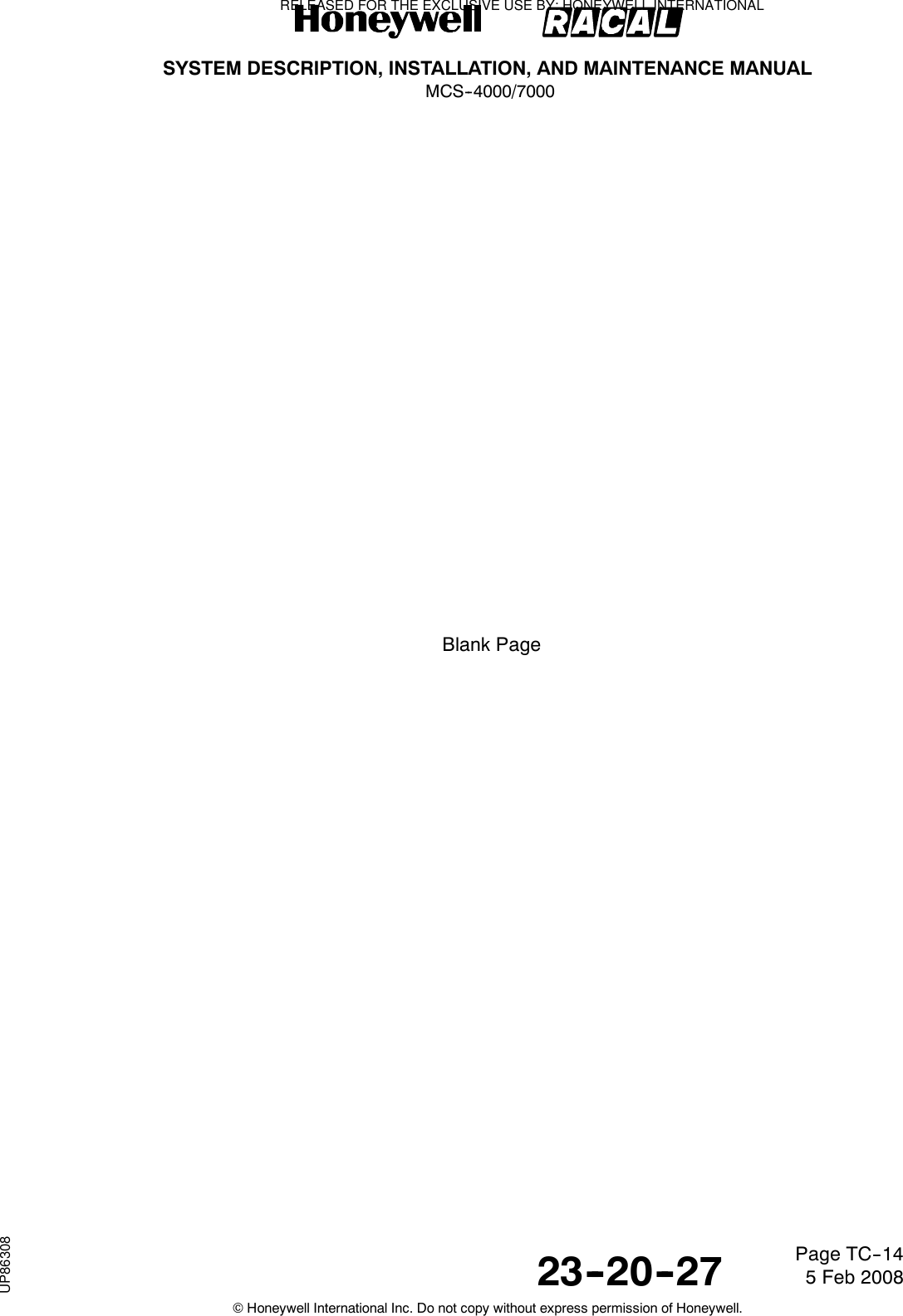

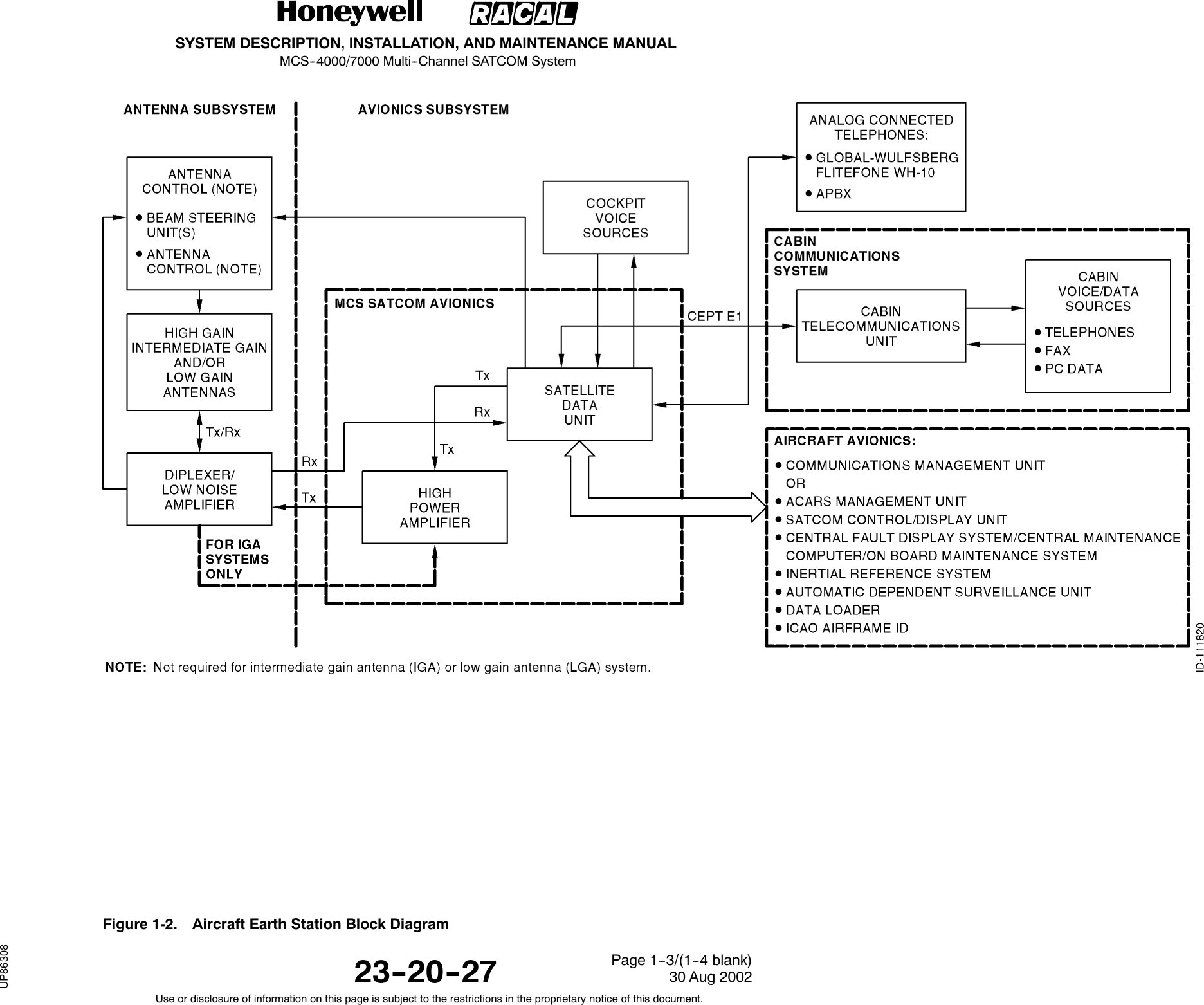
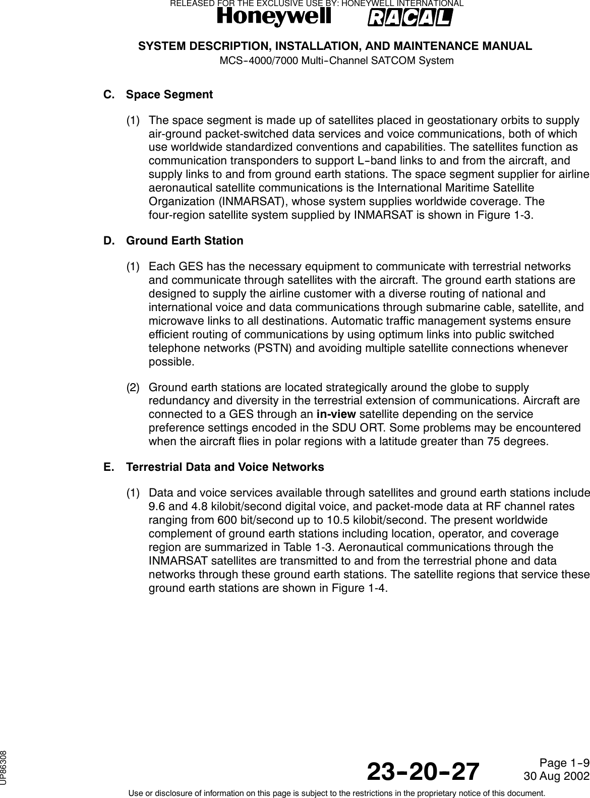
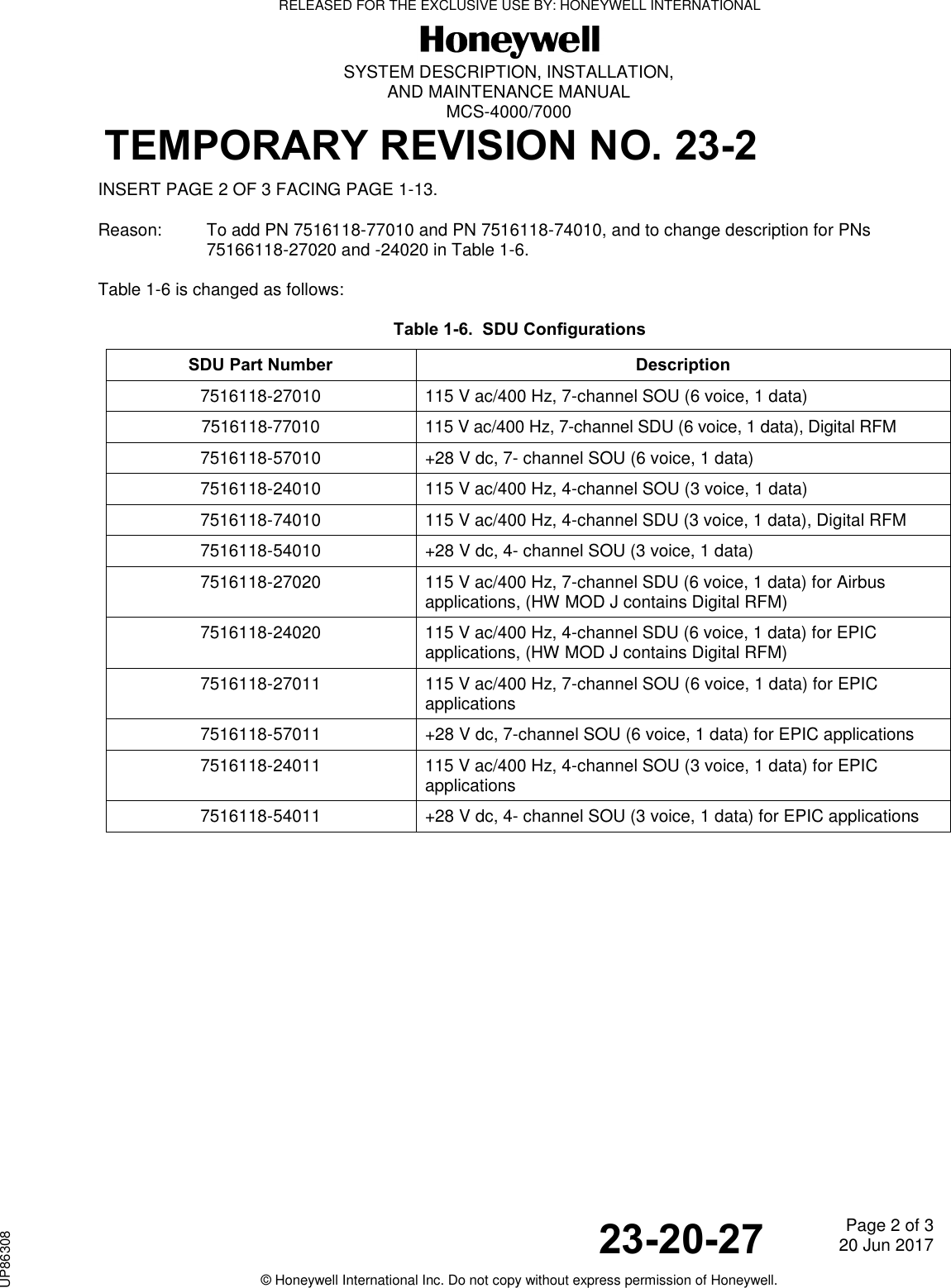
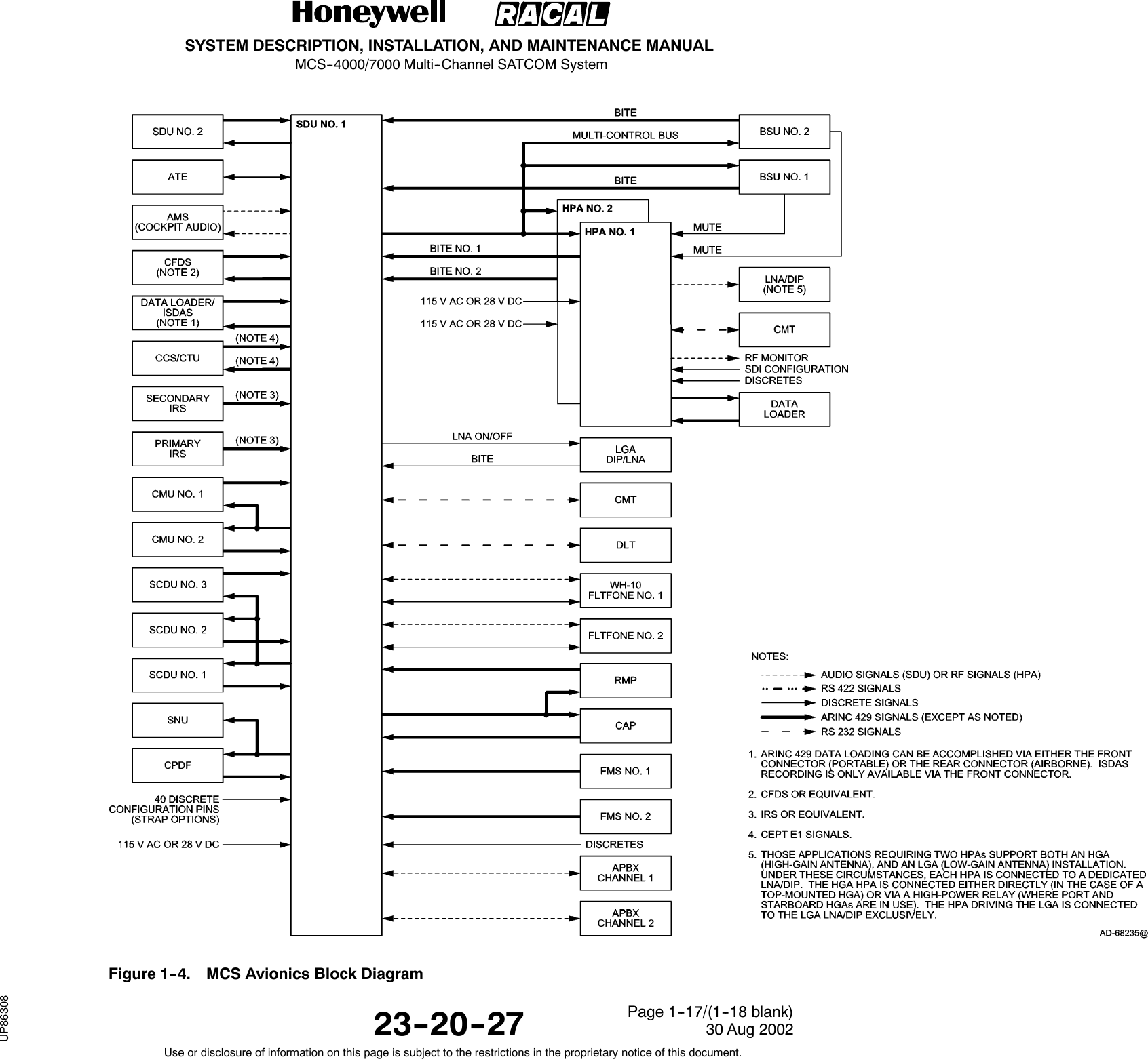
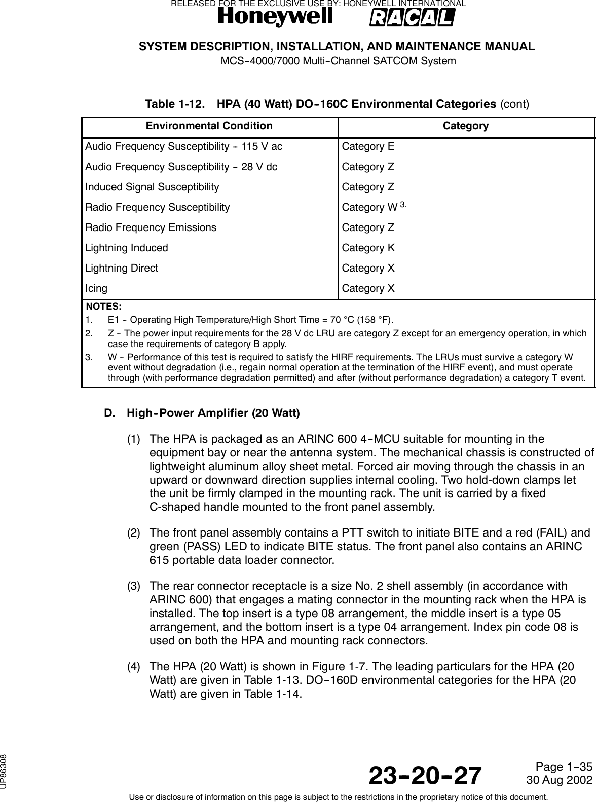
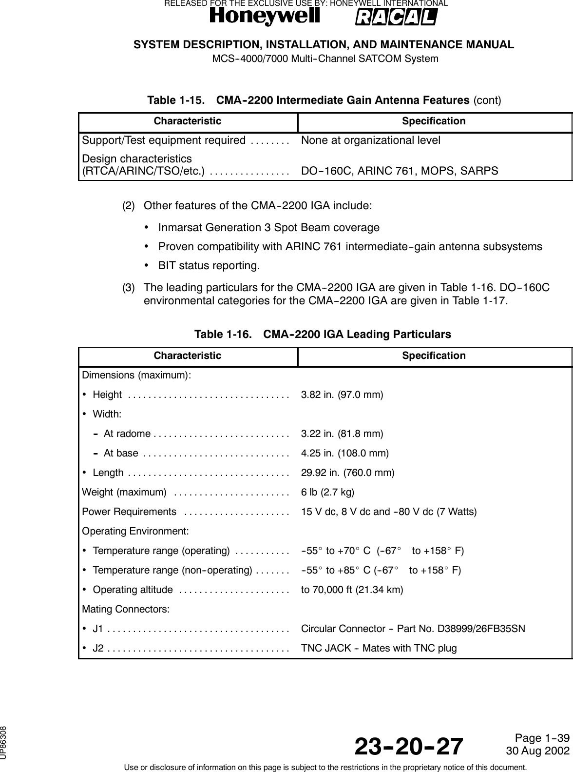
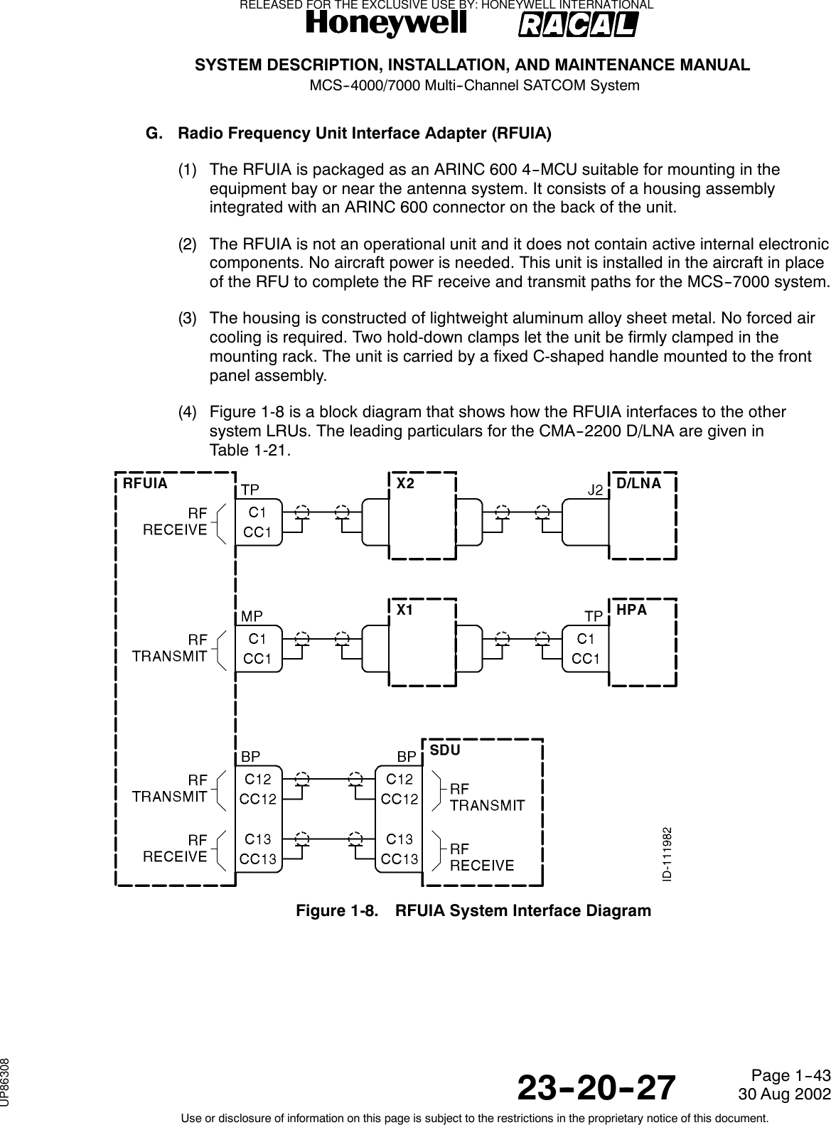
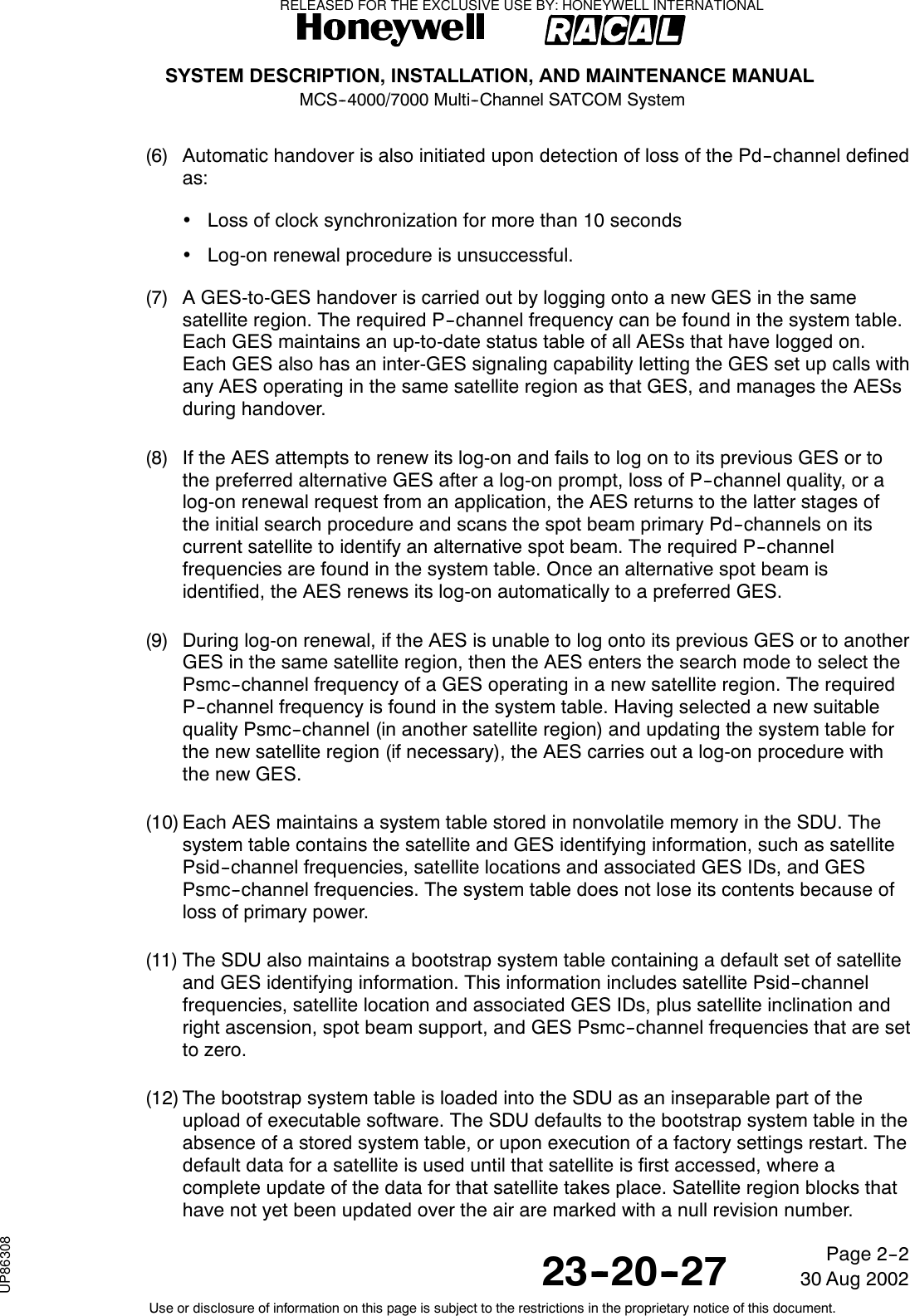
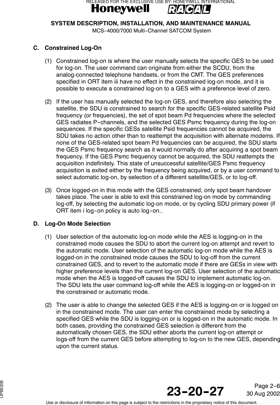
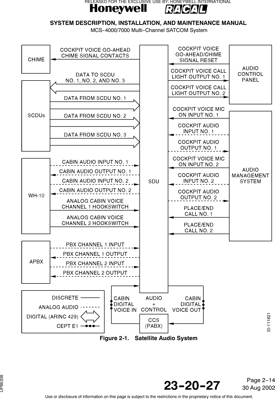
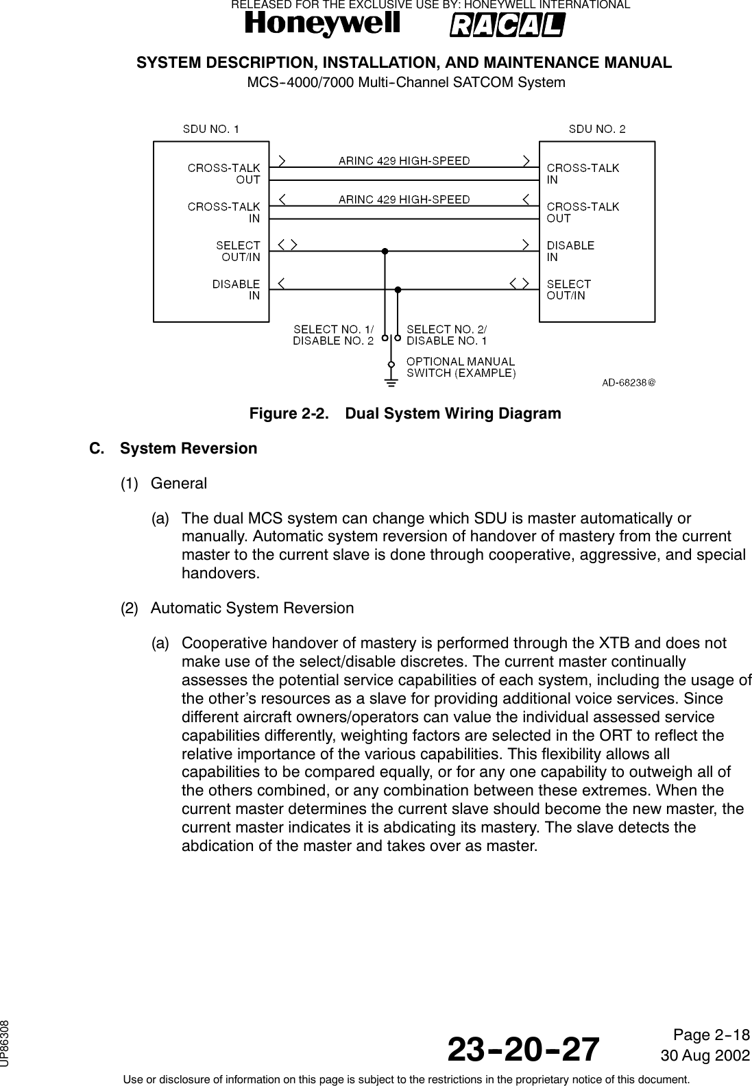
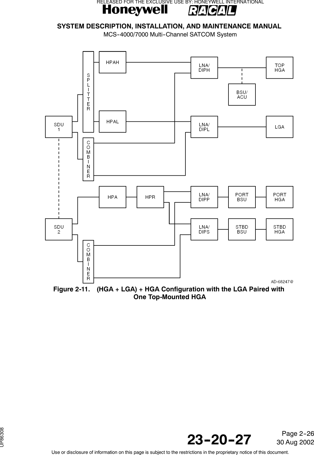
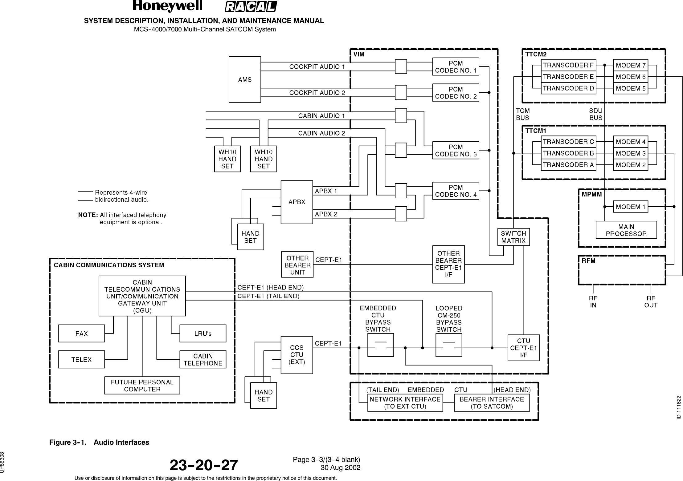
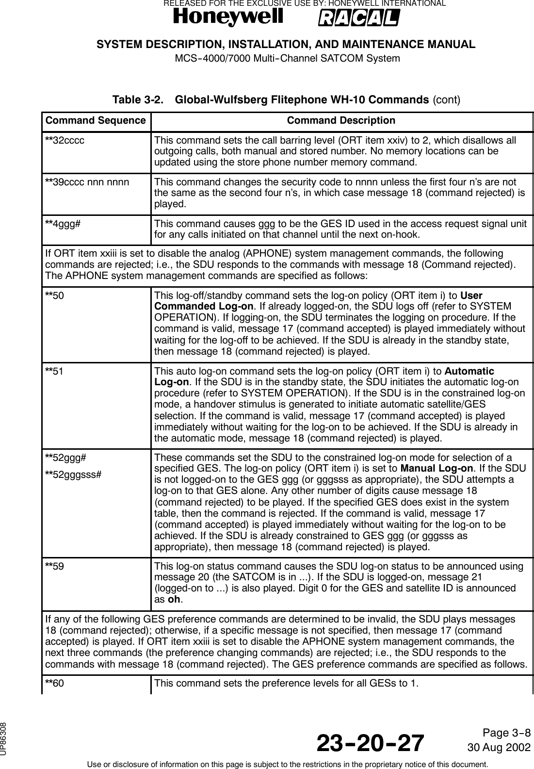
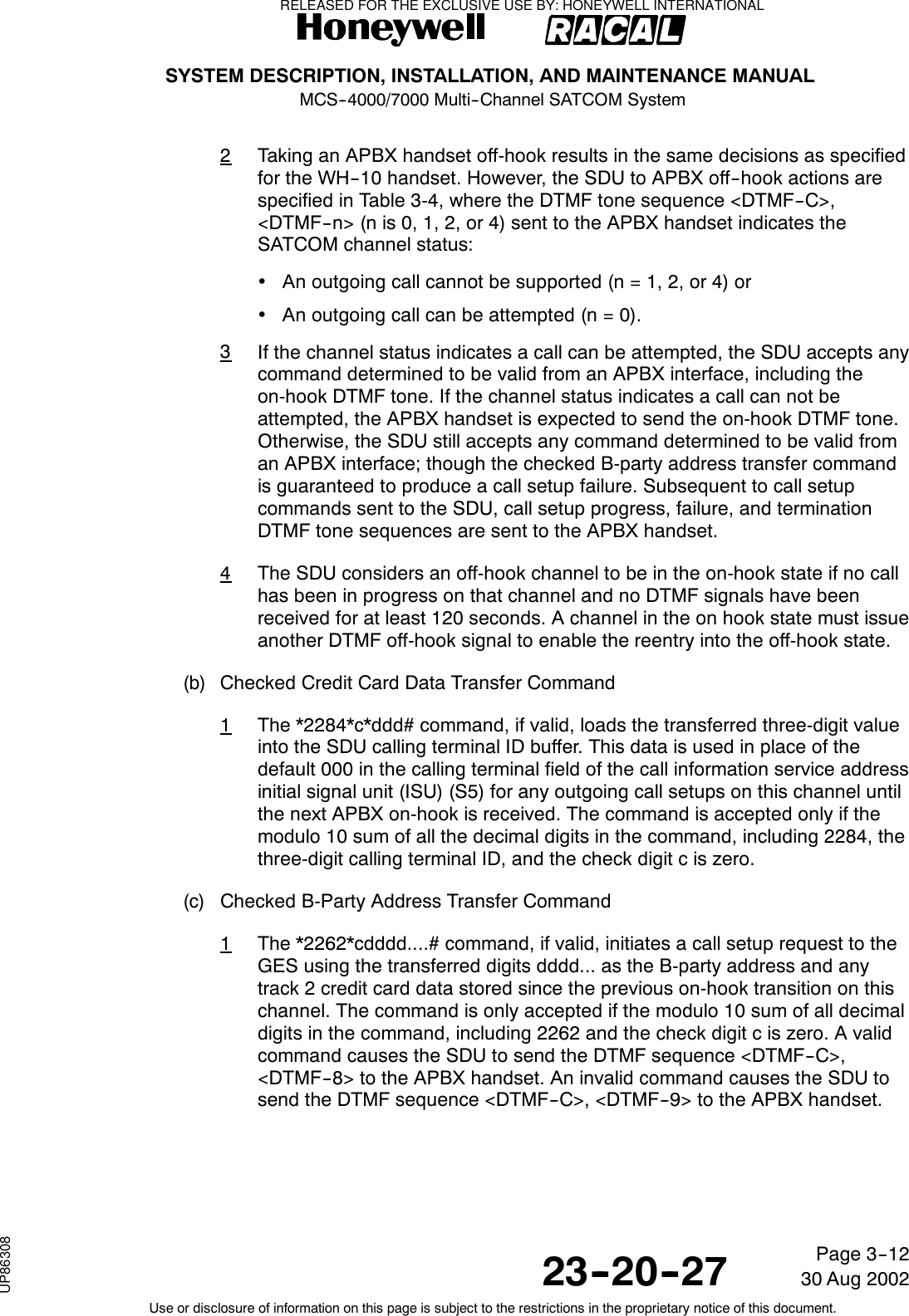
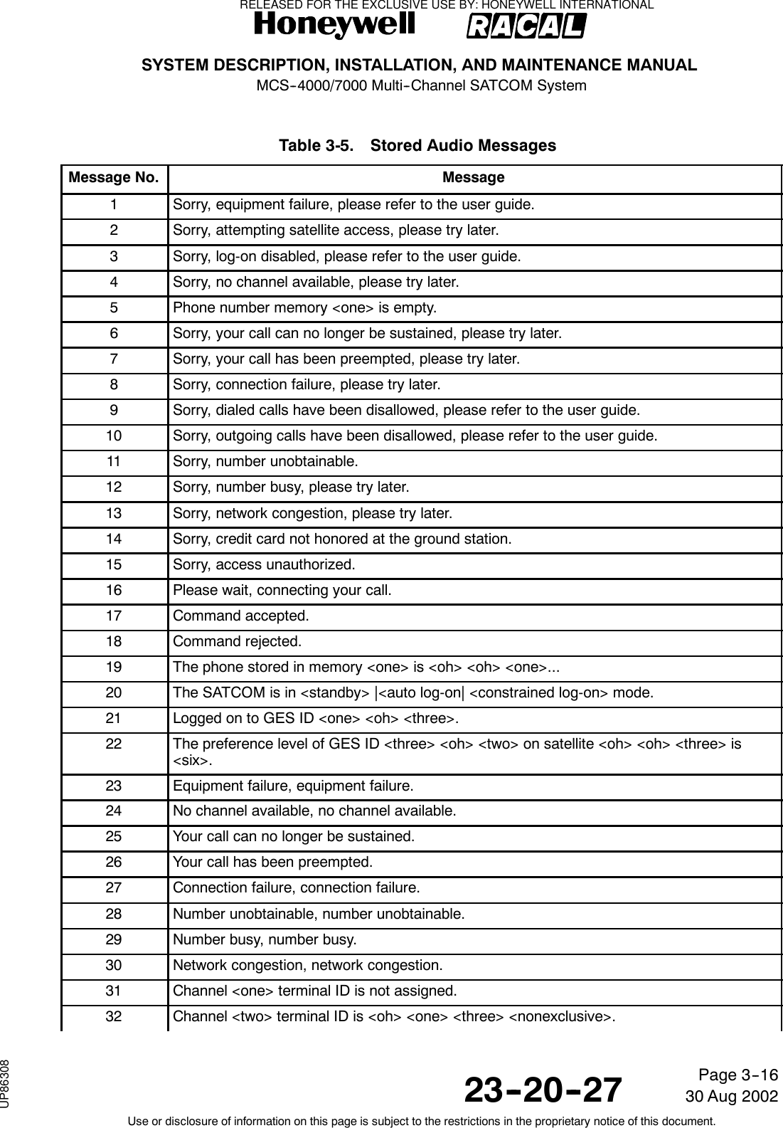
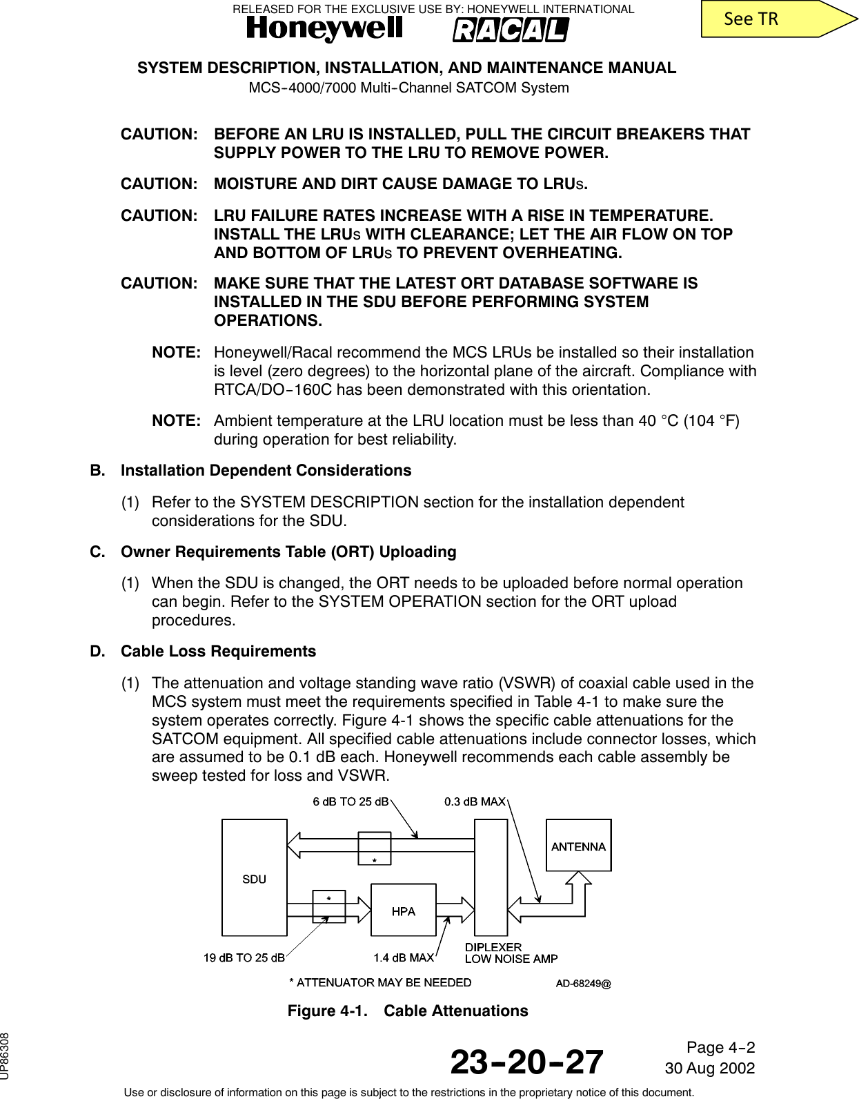
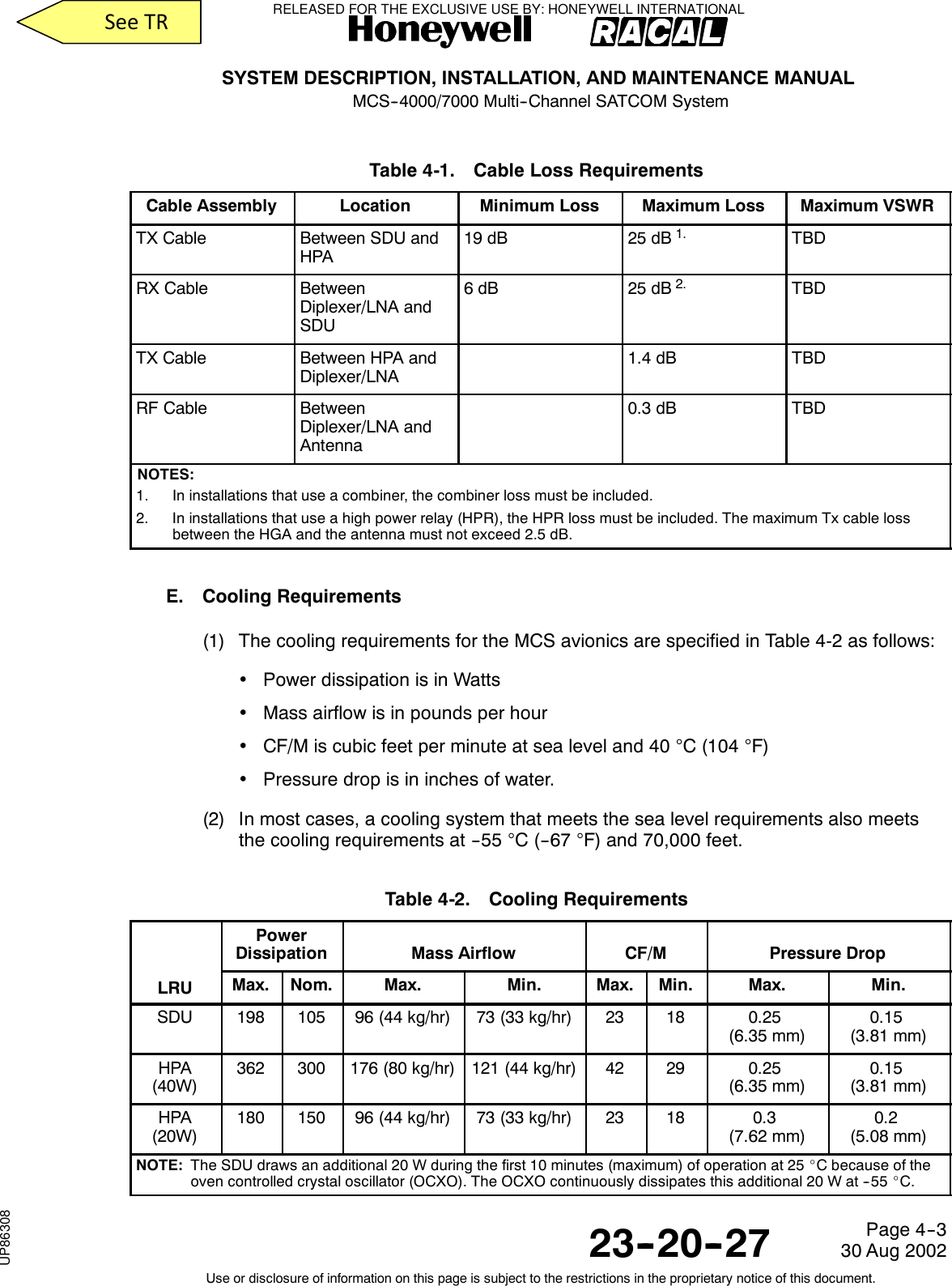
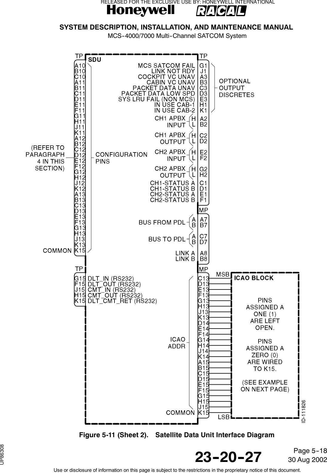
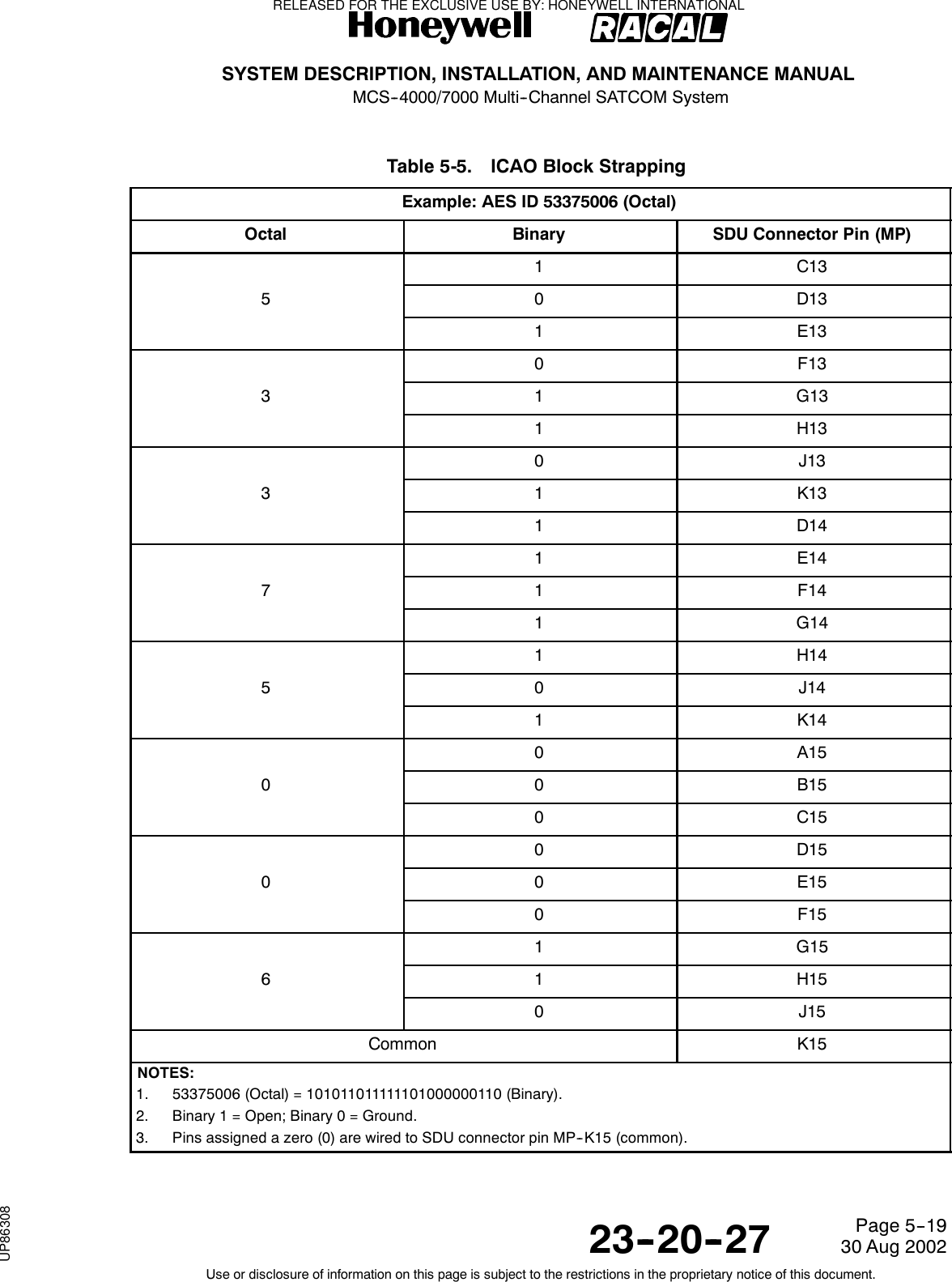
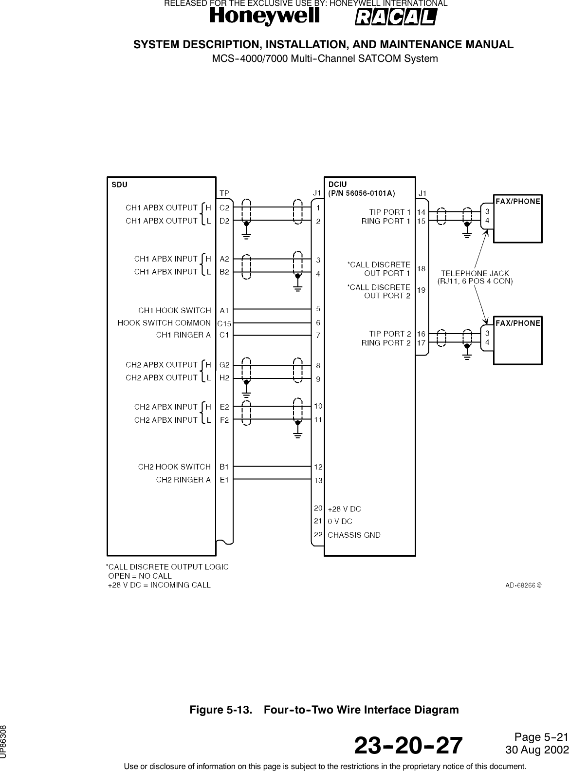
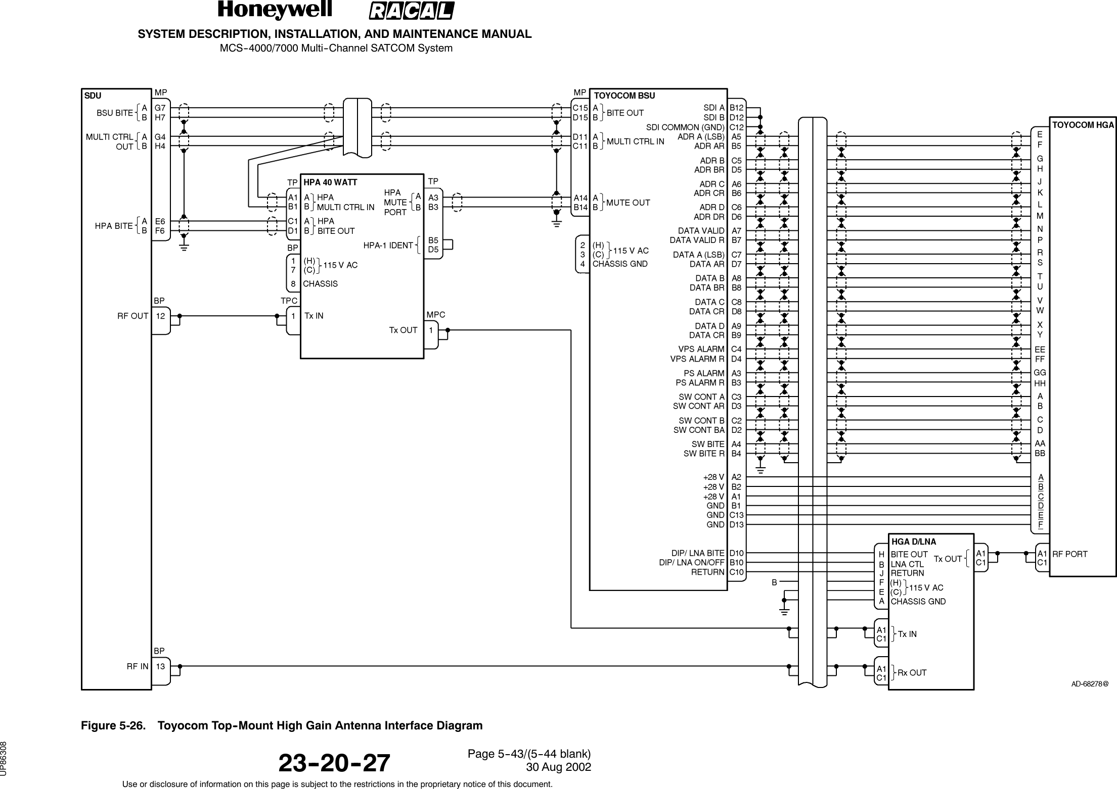
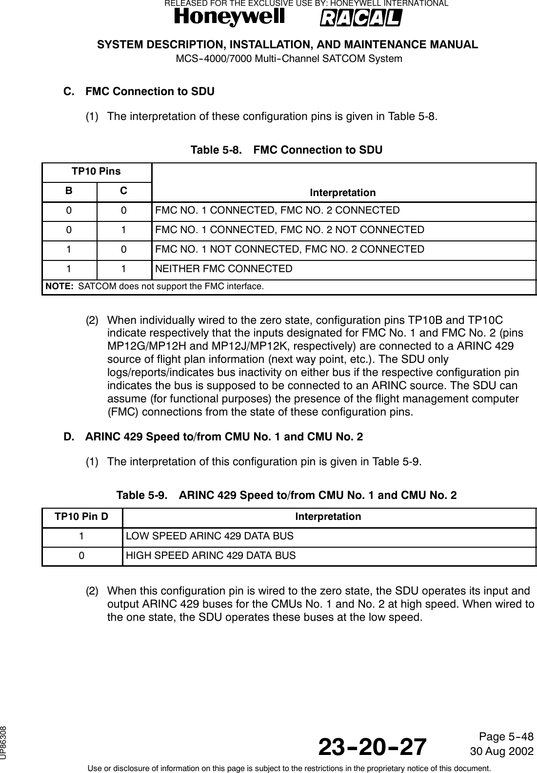
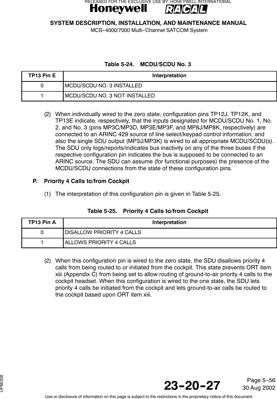
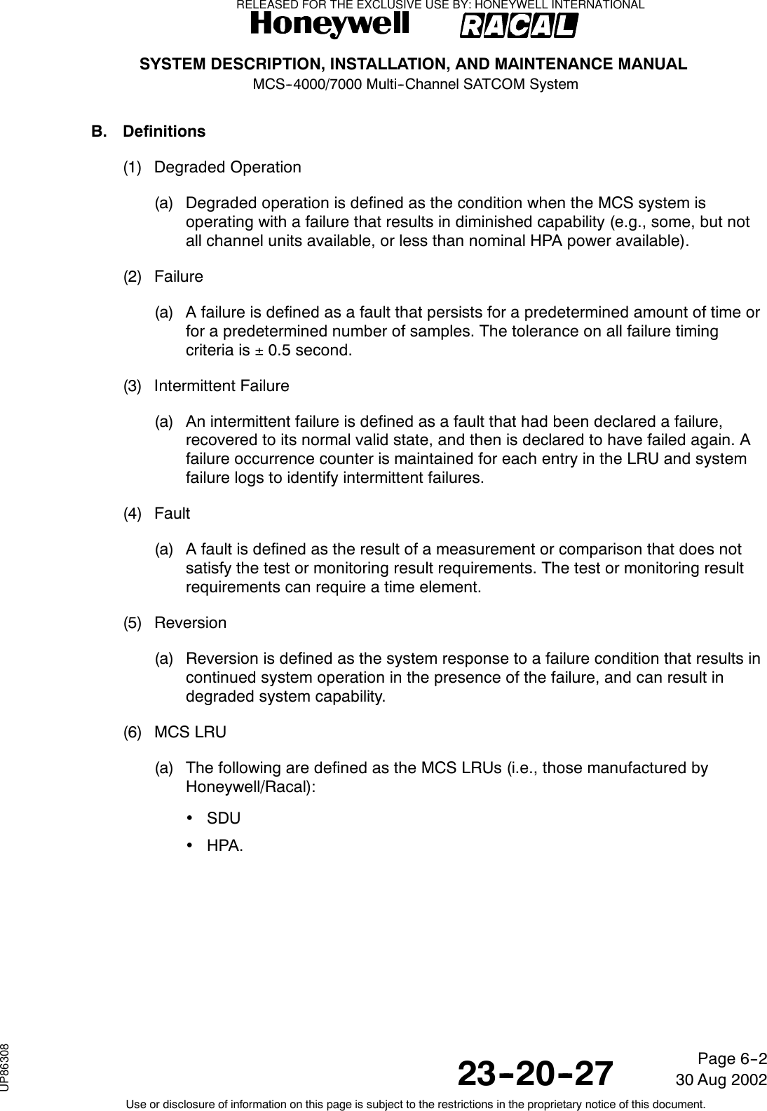
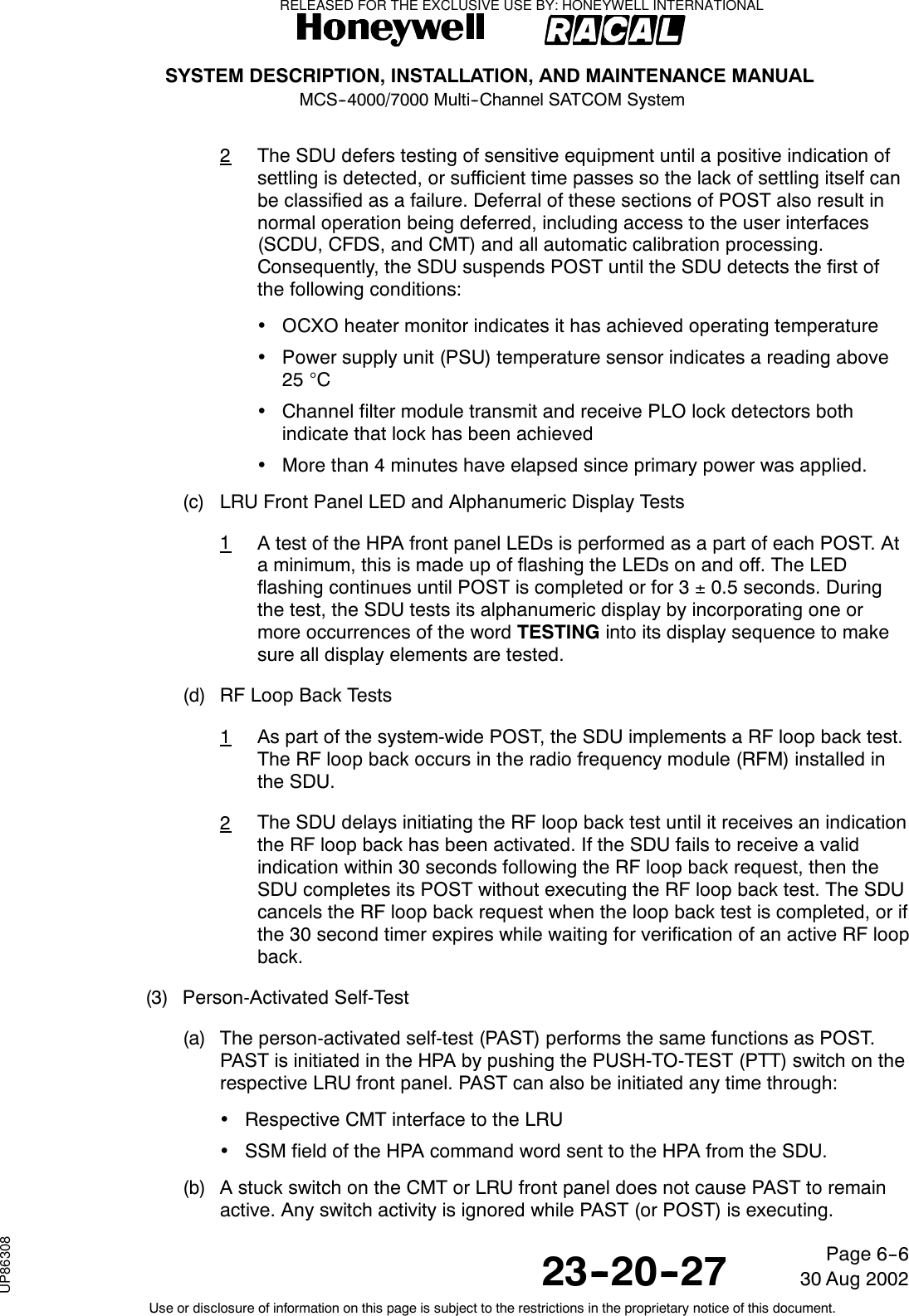
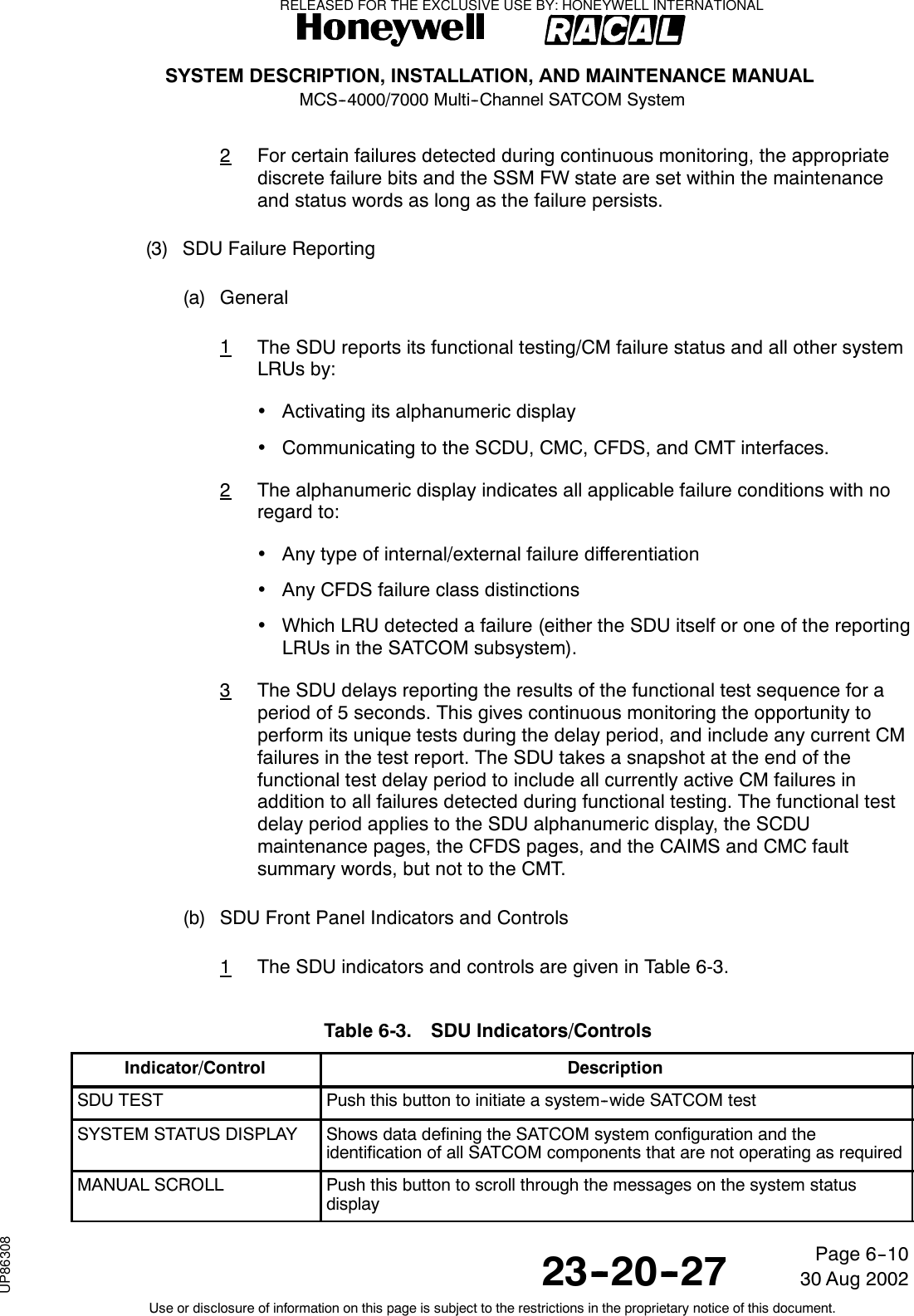
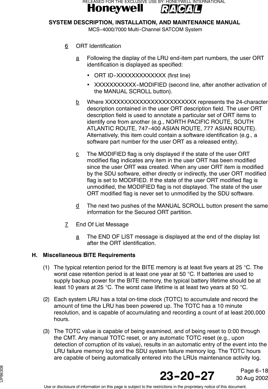
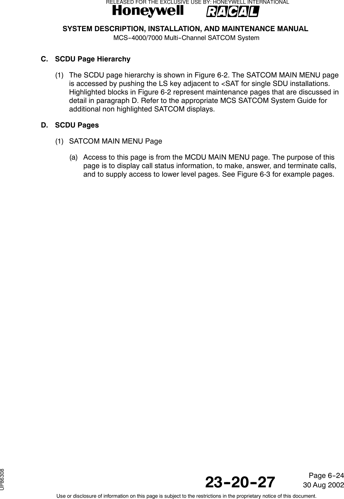
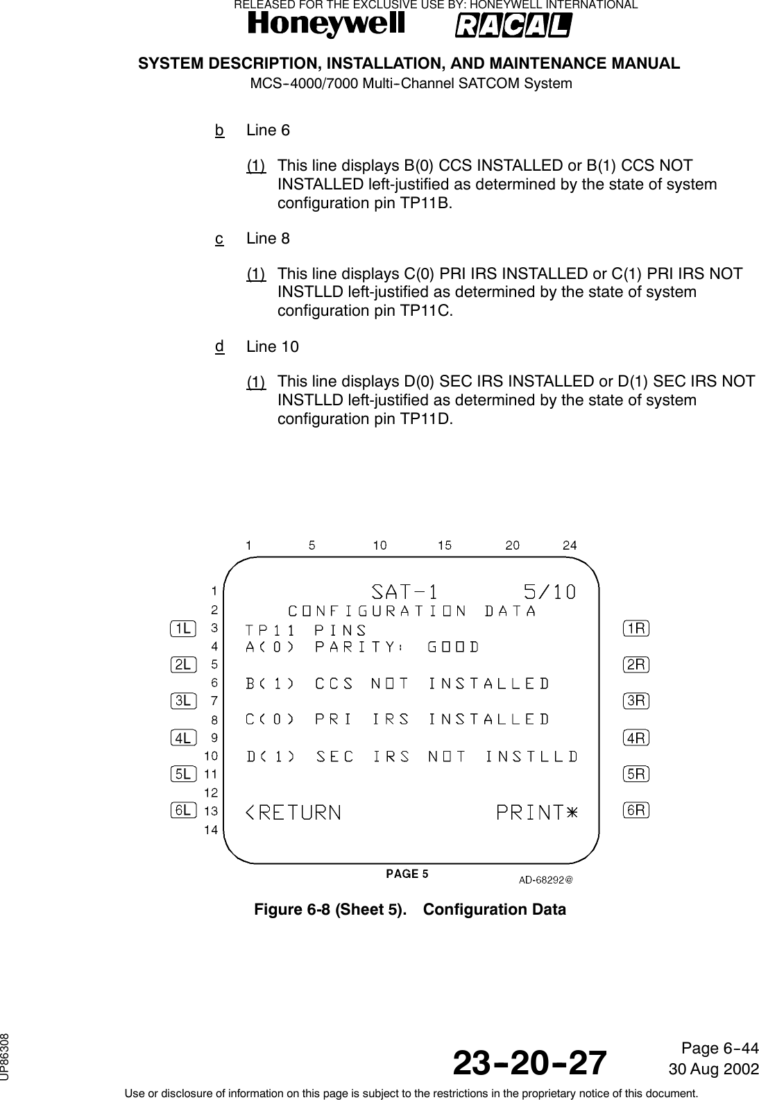
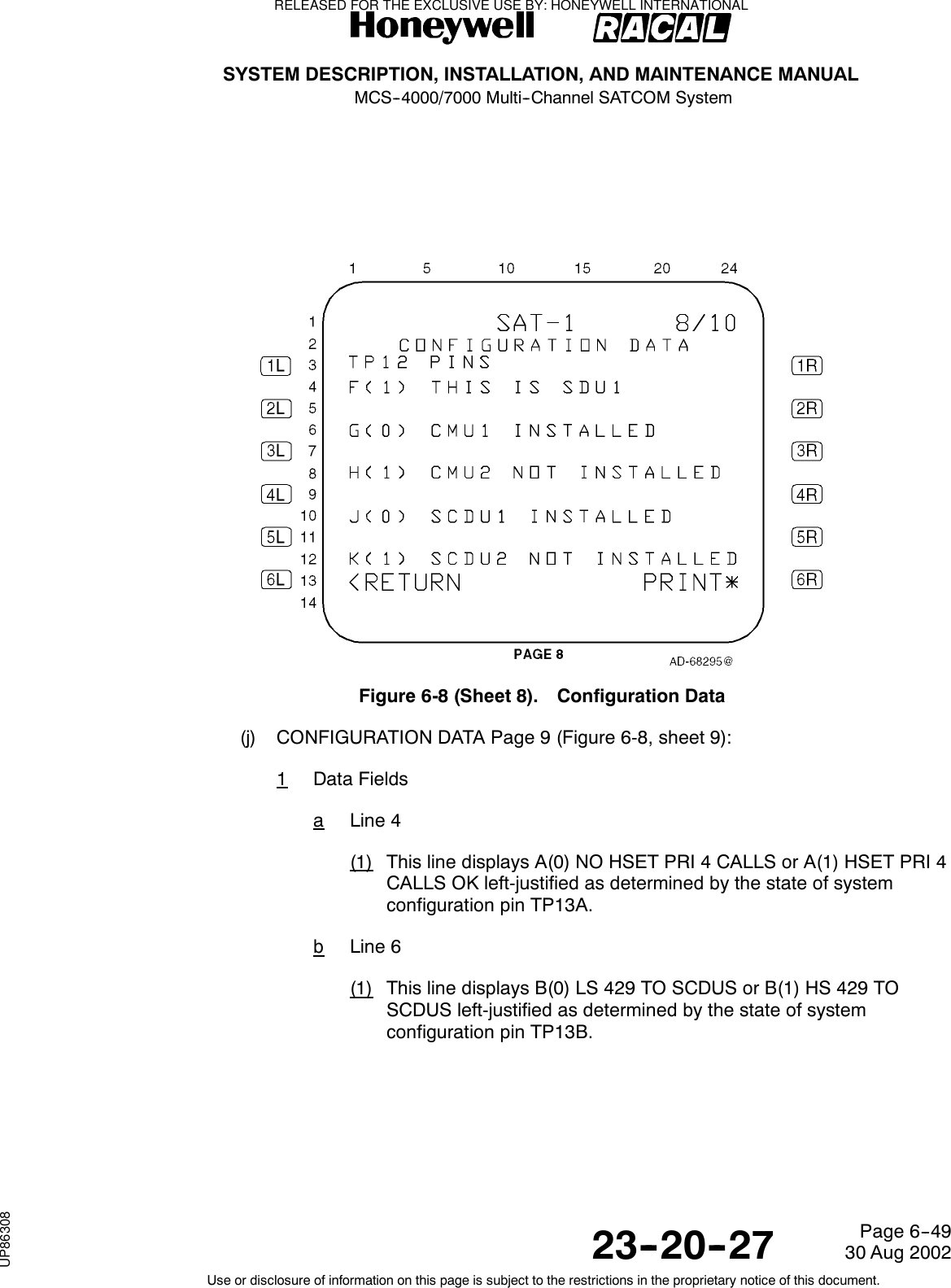
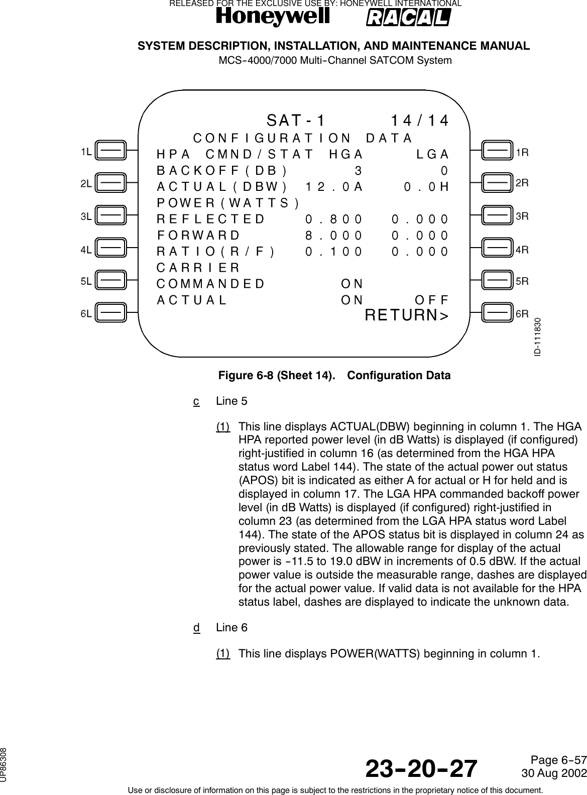
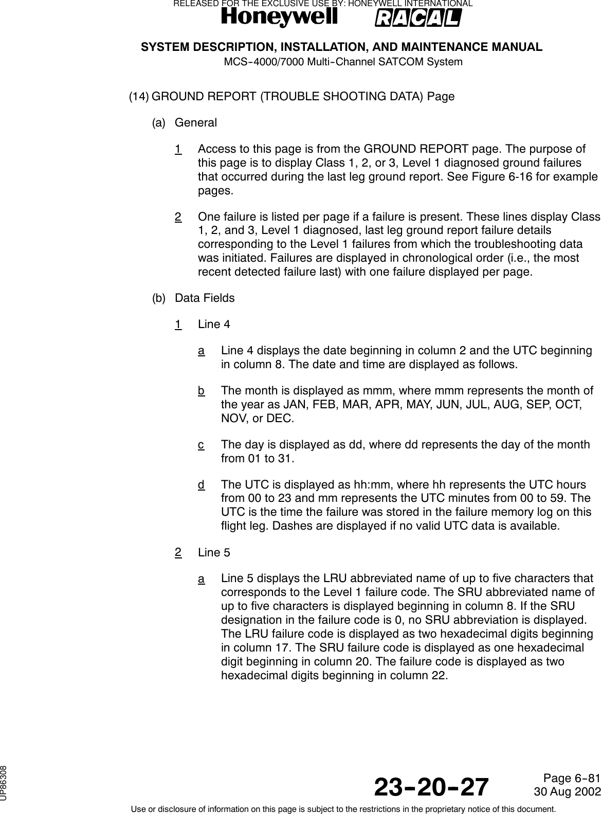
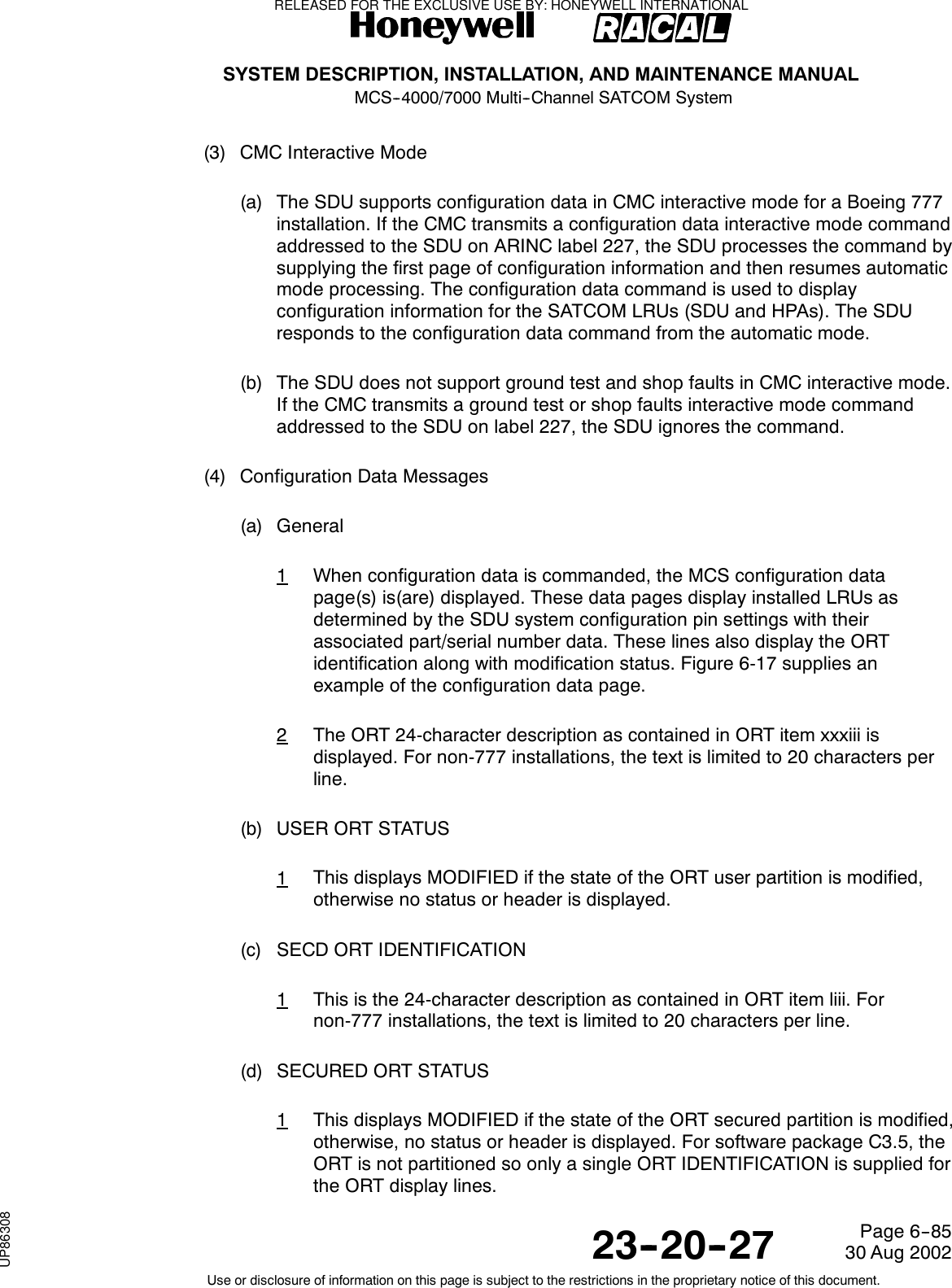
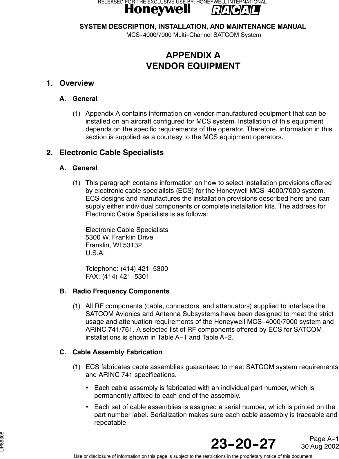
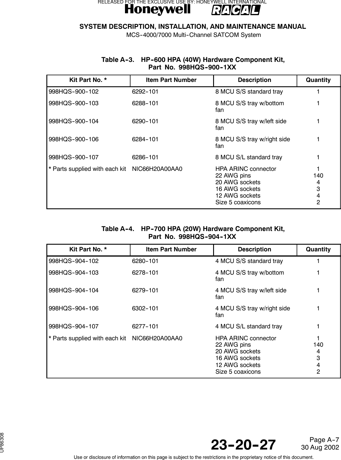
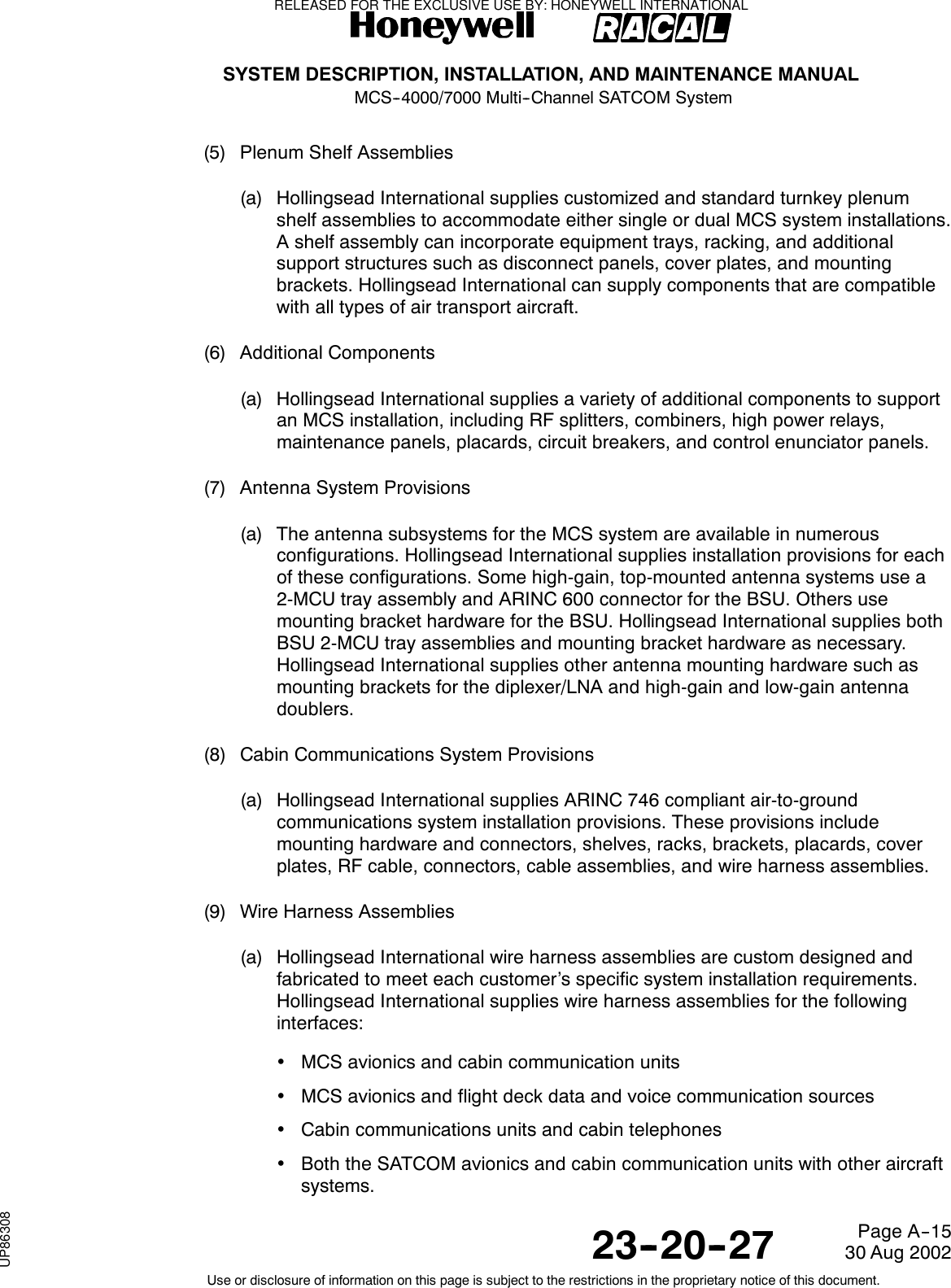
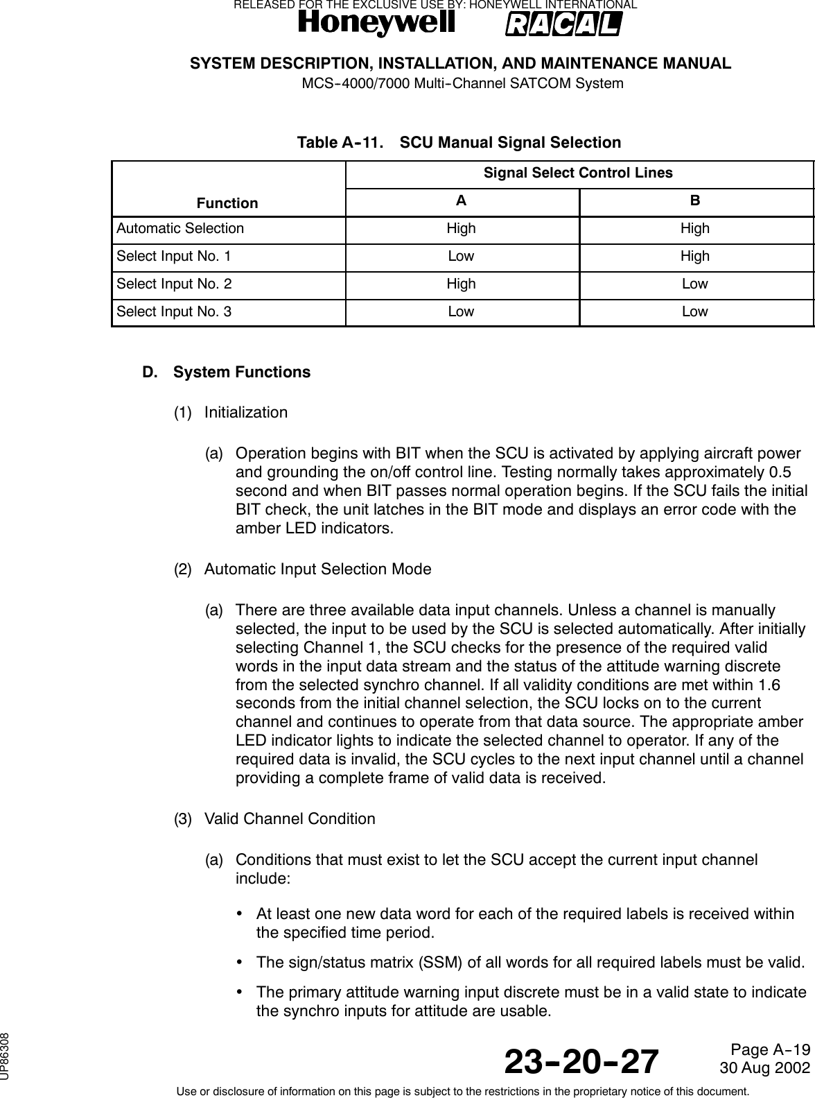
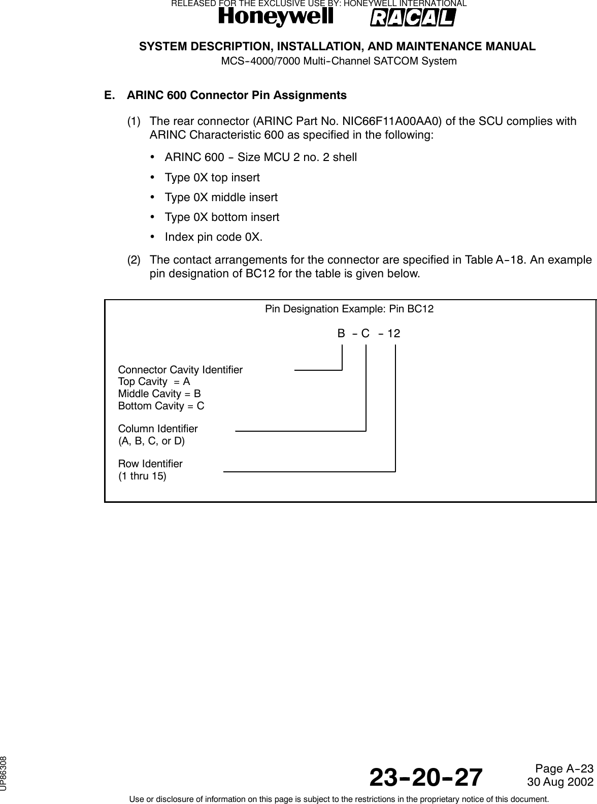
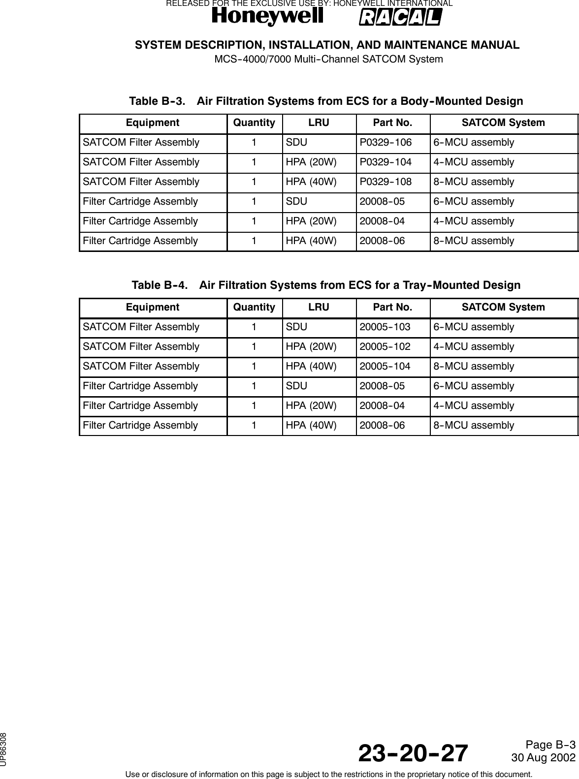
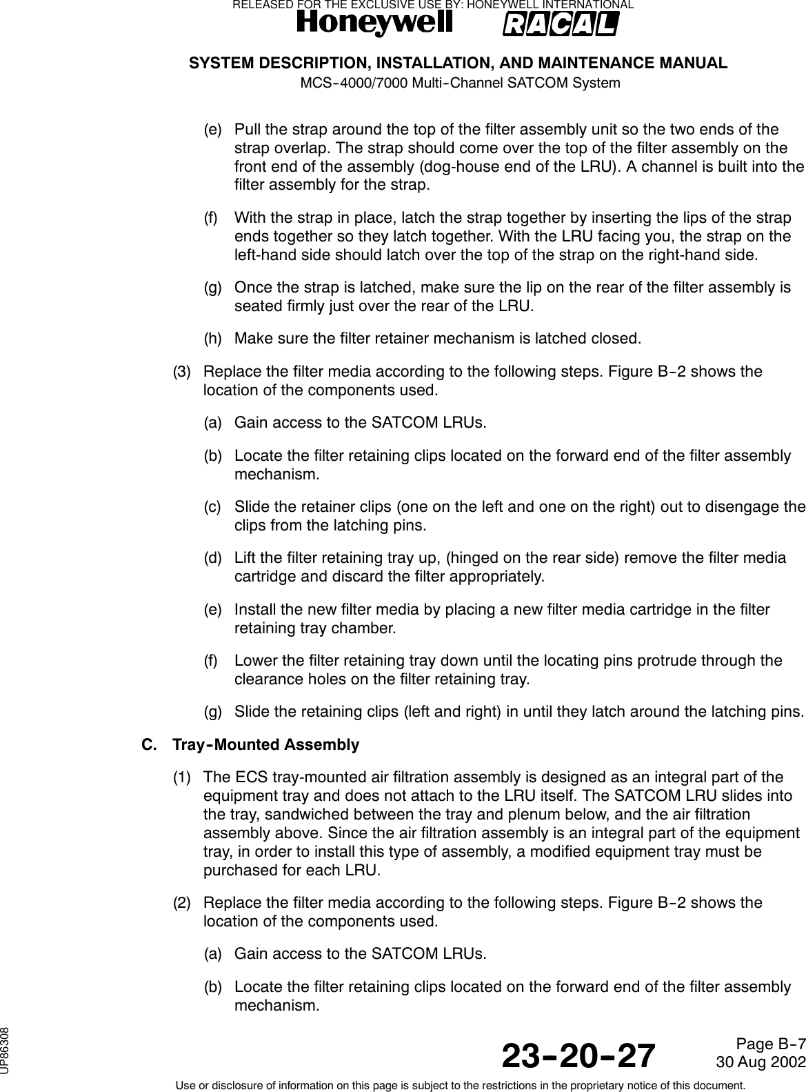
![SYSTEM DESCRIPTION, INSTALLATION, AND MAINTENANCE MANUALMCS--4000/7000 Multi--Channel SATCOM System23--20--2730 Aug 2002Use or disclosure of information on this page is subject to the restrictions in the proprietary notice of this document.Page 1--7(e) Analog Connected Telephones1The SDU has provisions to support up to two simultaneous analog audiochannels. Each analog channel supports two interface types:Global-Wulfsberg Flitephone WH--10 and the analog private branchexchange (APBX). The WH--10 is a stand-alone handset with a 12-buttonkeypad. The APBX has analog trunk lines and in-line dual tonemultifrequency (DTMF) signaling.(f) Cockpit Voice Sources1The SDU supports headset interfaces for cockpit use only. These interfacesincorporate off-hook/on-hook signaling and dialing through the combinationof a control and display unit (either [SATCOM control and display unit] SCDUor MCDU), and push-to-talk (PTT) or similar switches. When the PTT switchis pushed, a microphone audio signal is sent to the selected voice channeland a discrete signal is sent to the SDU. An audible chime and call lampsannounce call connections.(g) Aircraft Avionics1Standard interfaces between the MCS avionics and the other aircraftavionics include the following:•Communications management unit (CMU), or the management unit (MU)of the Aircraft Communications Addressing and Reporting System(ACARS), where installed.•SATCOM control and display unit (SCDU), where installed, to supply aninterface to the MCS system for system log-on, GES selection, cockpitvoice call setup, data loading, and to access the SATCOM maintenancepages including fault messages.•Central fault display system (CFDS), central maintenance computer(CMC), or on--board maintenance system (OMS), where installed, for faultreporting.•The inertial reference system (IRS), where installed, to supply the SDUwith navigation coordinates for positioning the antenna platform.•Channels are also supplied for voice and data communication with ATCto support departure clearances by datalink, as well as ADS for non radarposition reporting in oceanic regions.•There is an ARINC 615 Airborne or portable data loader (ADL or PDL) foruploading operational software and the owner requirements table (ORT).Connections are made through front and back panel connectors on theMCS avionics LRUs.•The 24-bit ICAO address identifies the aircraft in which the SDU isinstalled. Address pins identified to take on the binary one state must beleft open. Address pins identified to take on the binary zero state must bewired to address common on the airframe side of the connector. ARINC429 interface options for the ICAO address are also supplied.RELEASED FOR THE EXCLUSIVE USE BY: HONEYWELL INTERNATIONALUP86308](https://usermanual.wiki/Honeywell/SD-700A/User-Guide-3476924-Page-52.png)
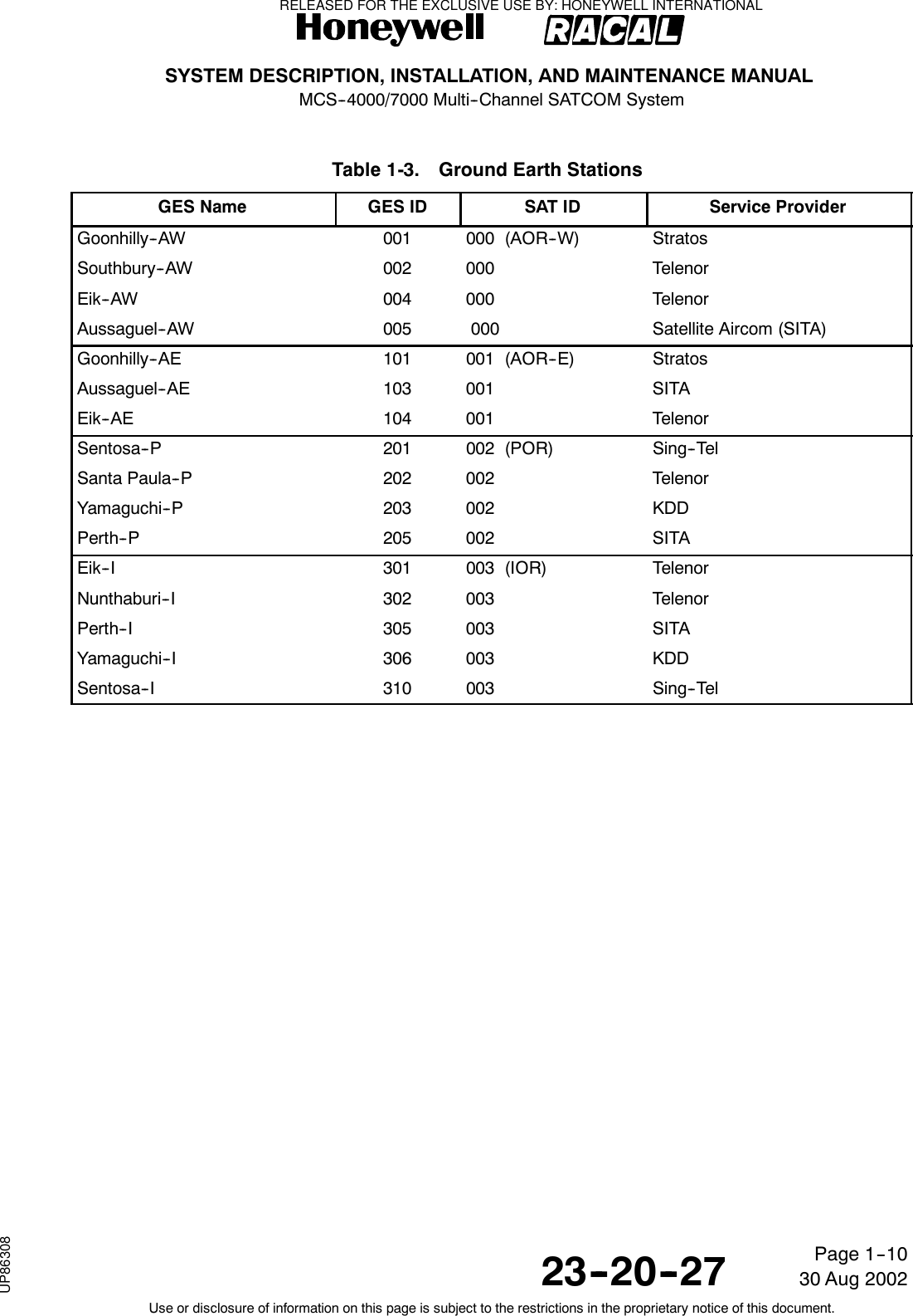
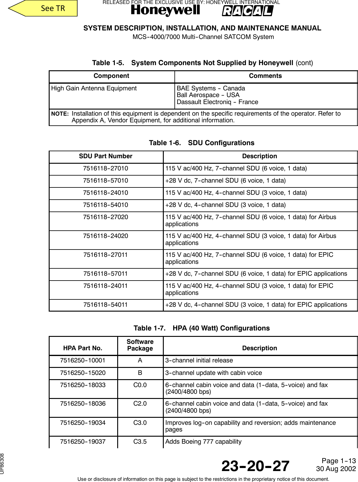

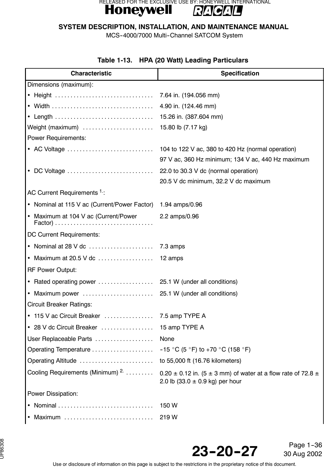
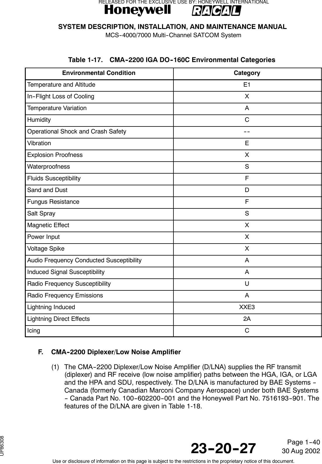
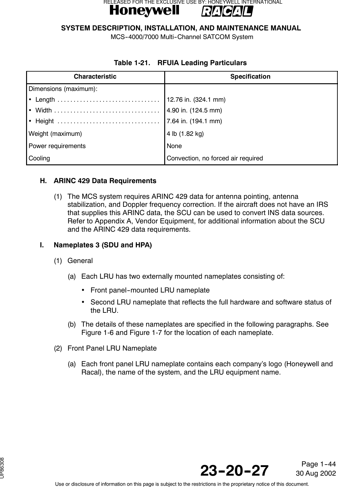
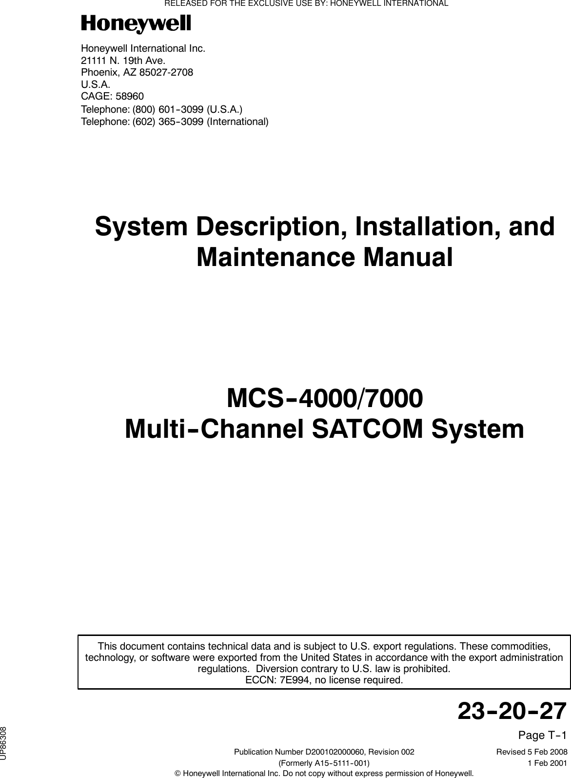
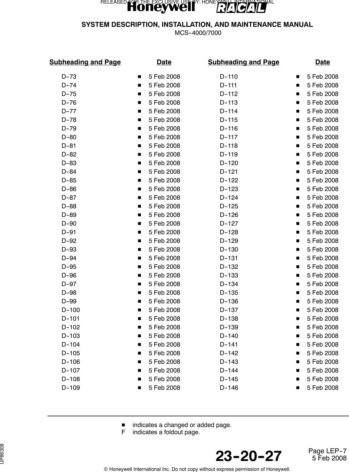
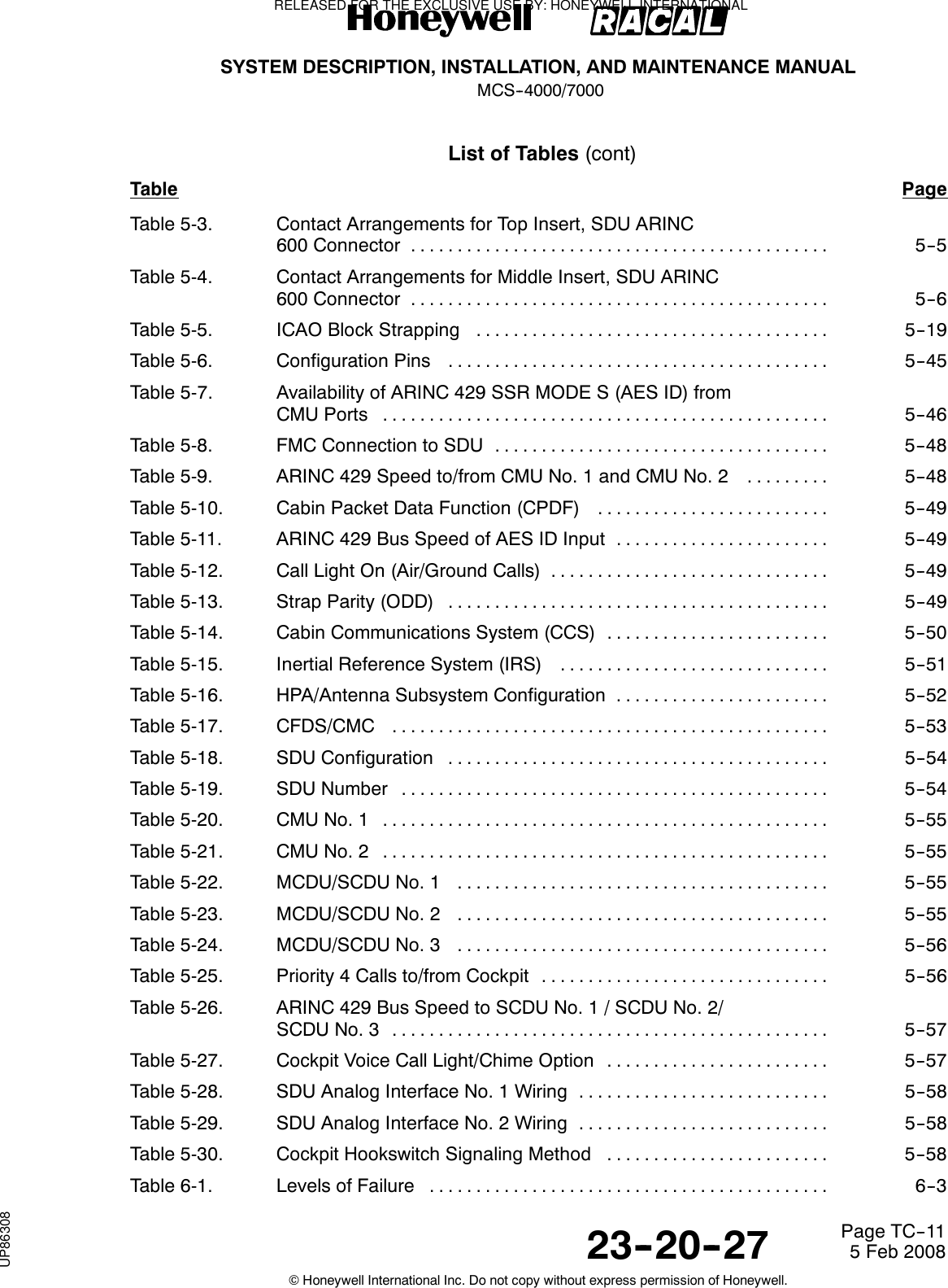
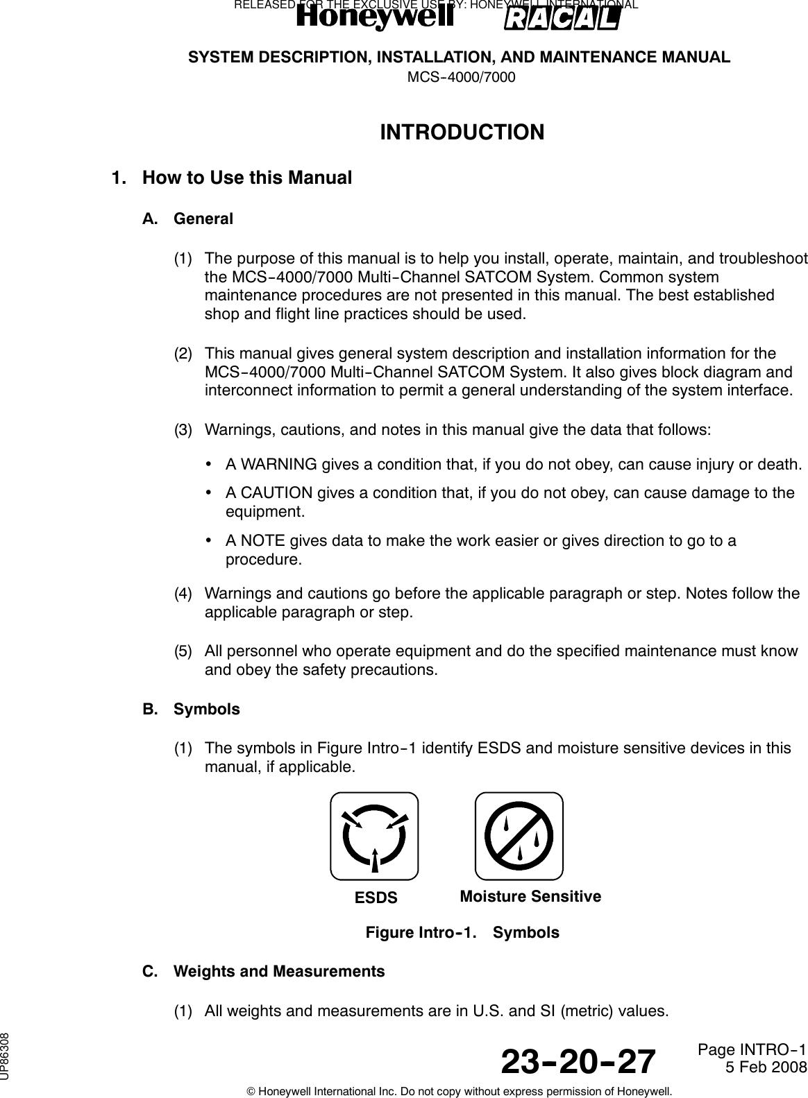
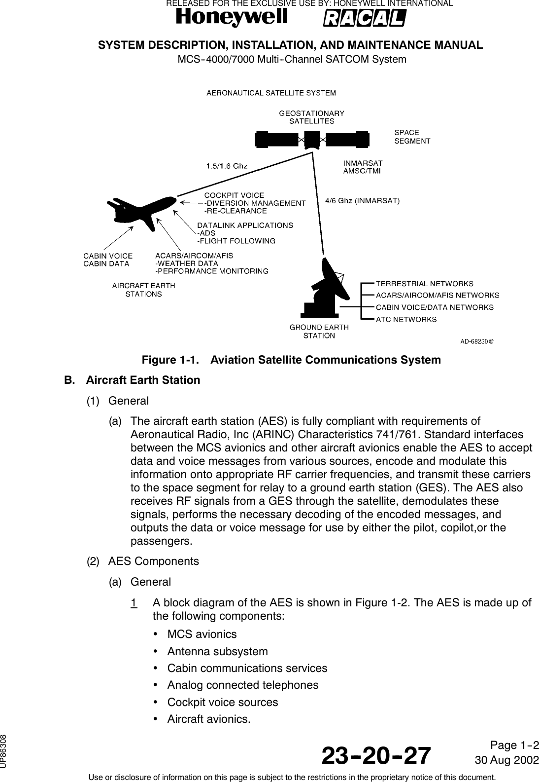
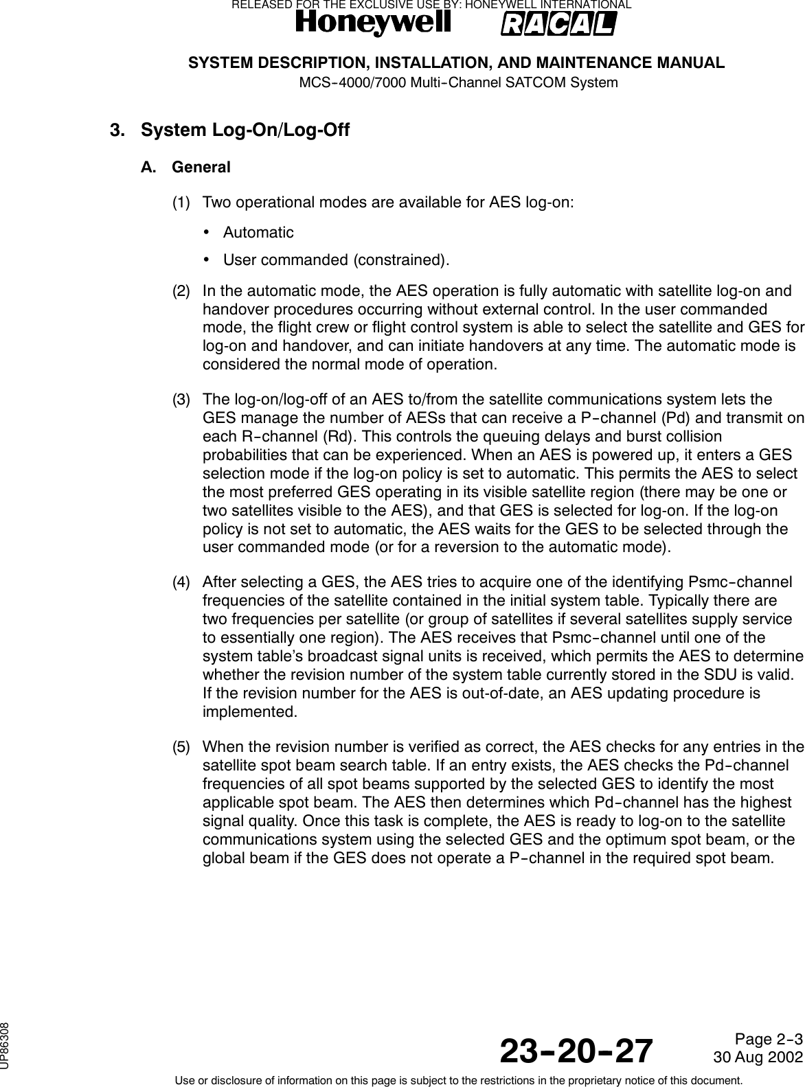
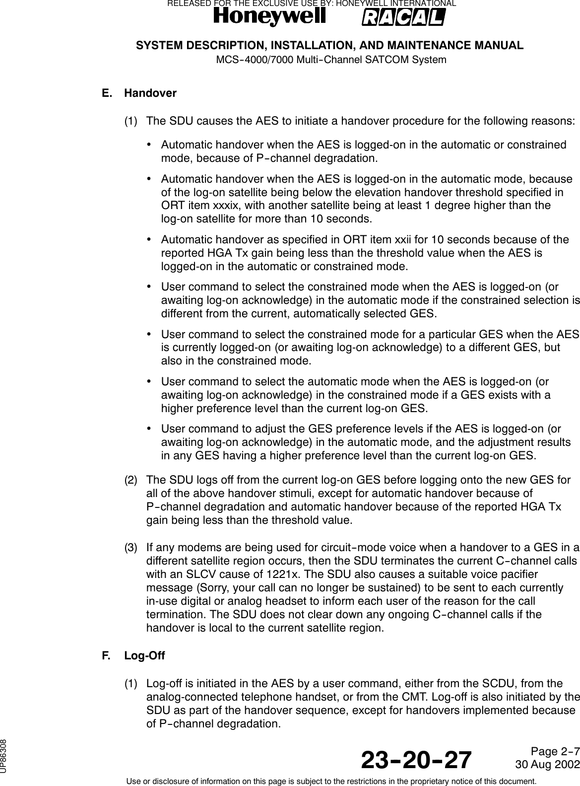
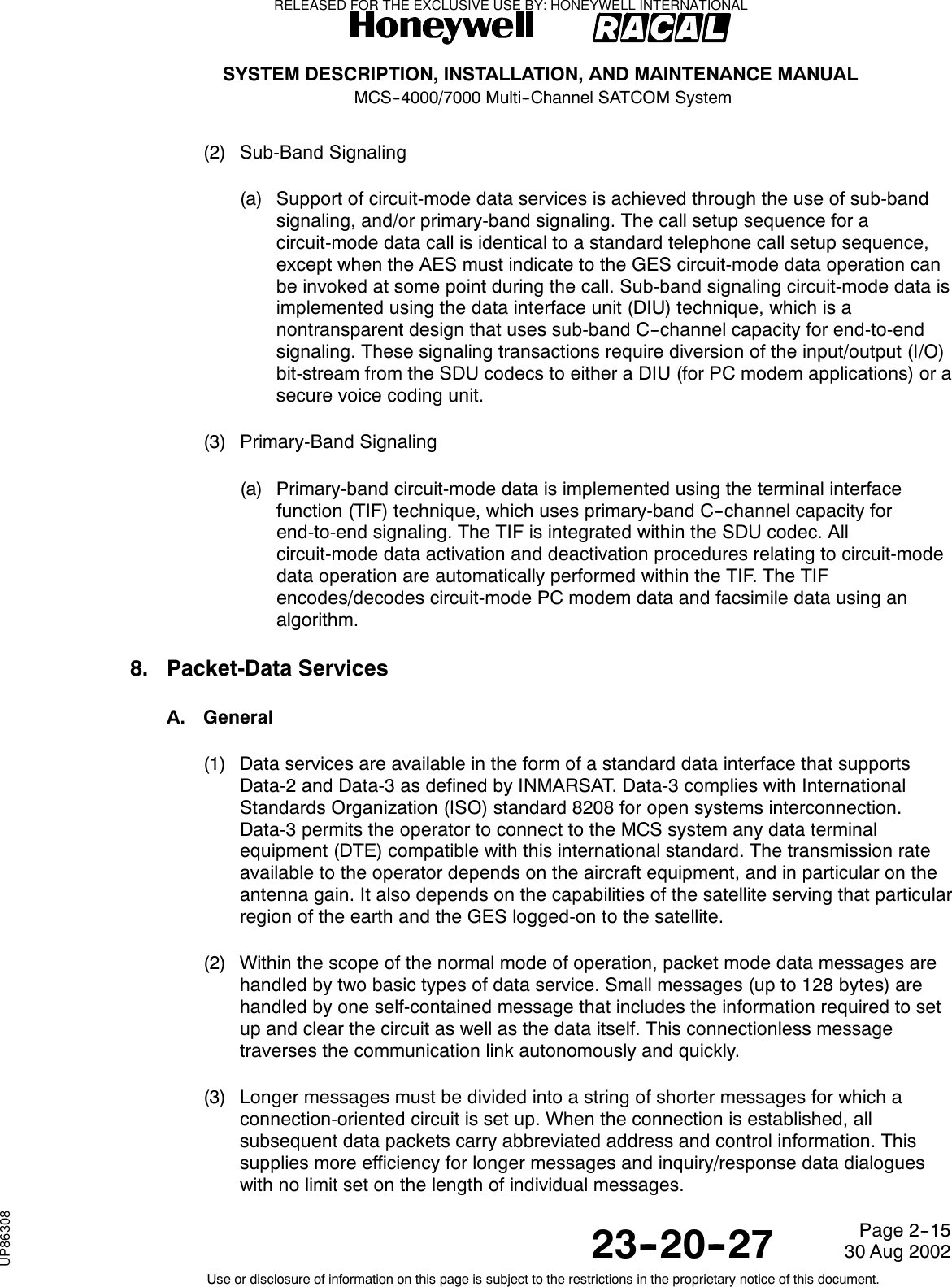
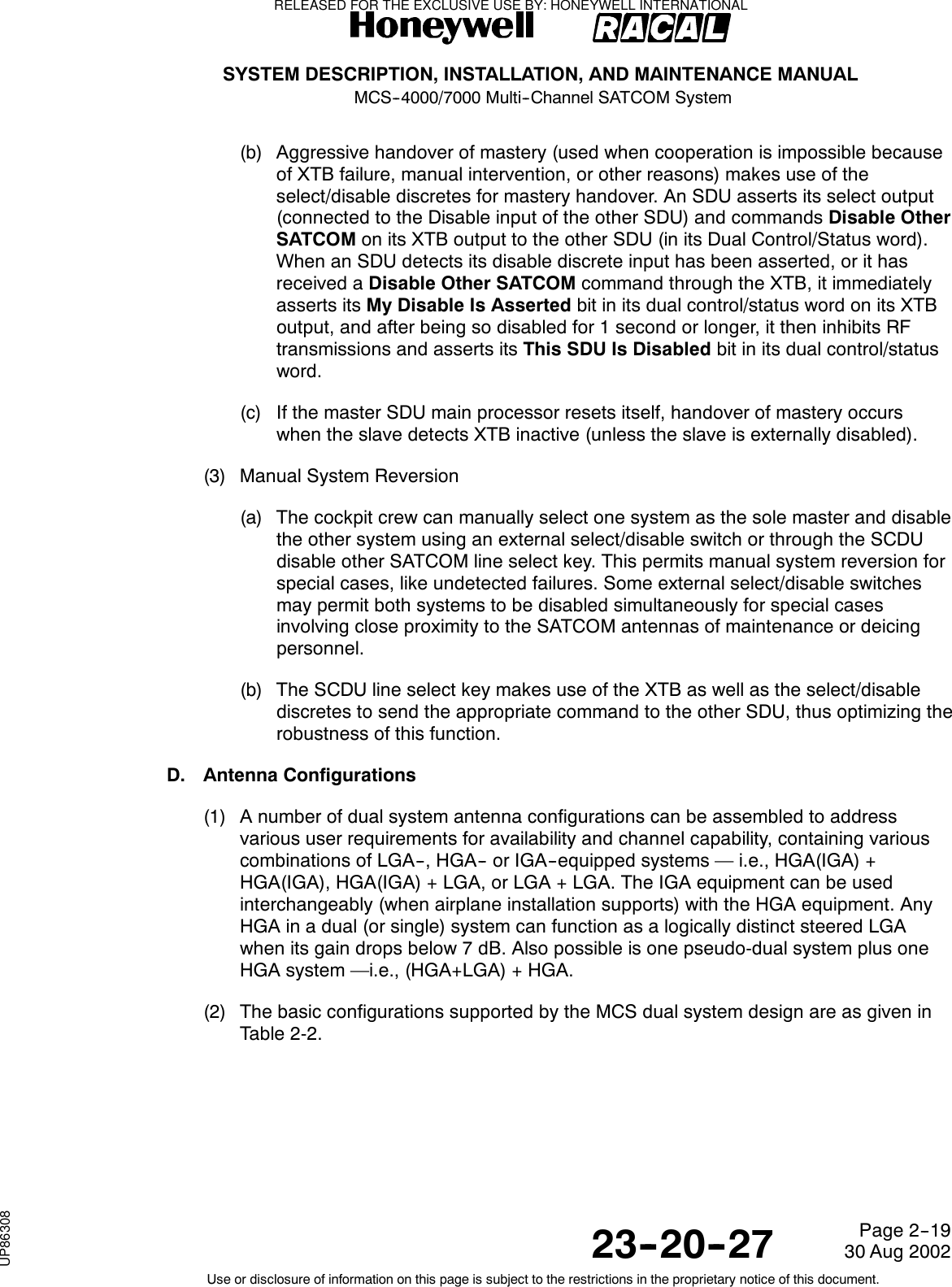
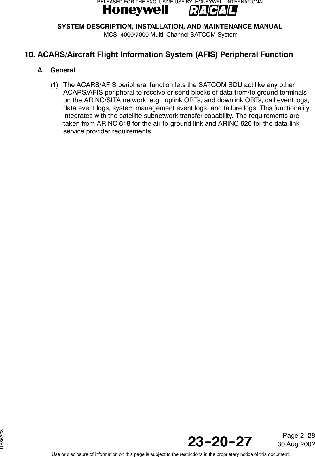
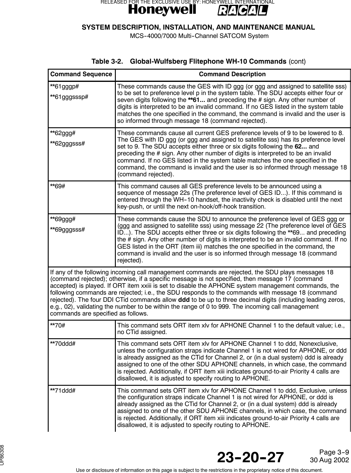
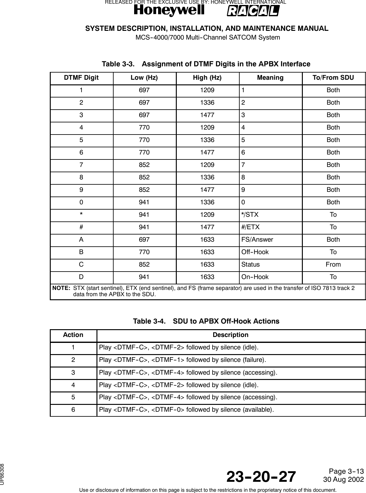
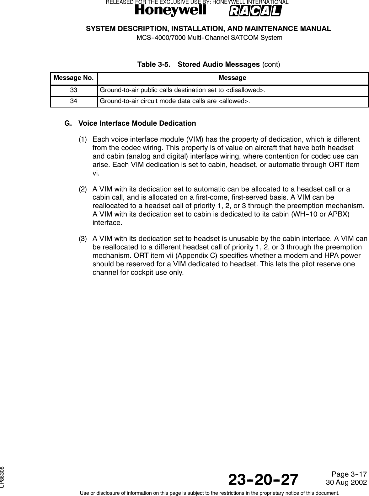
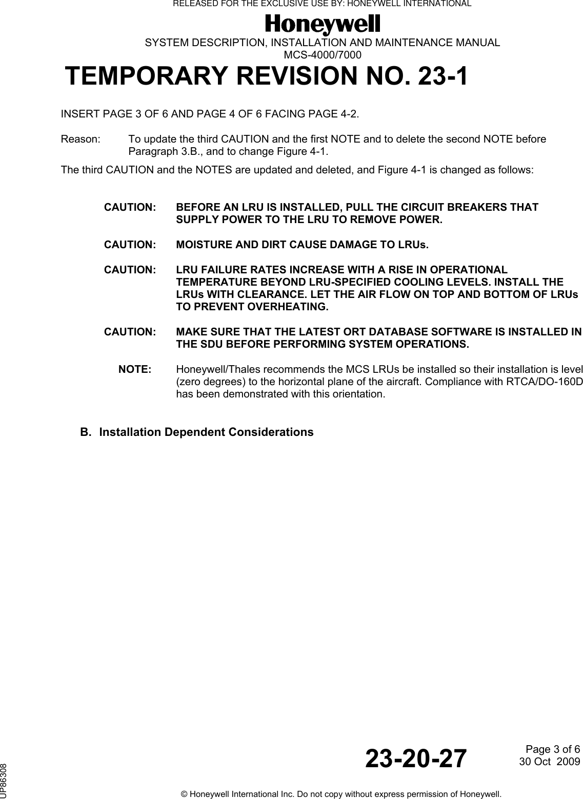
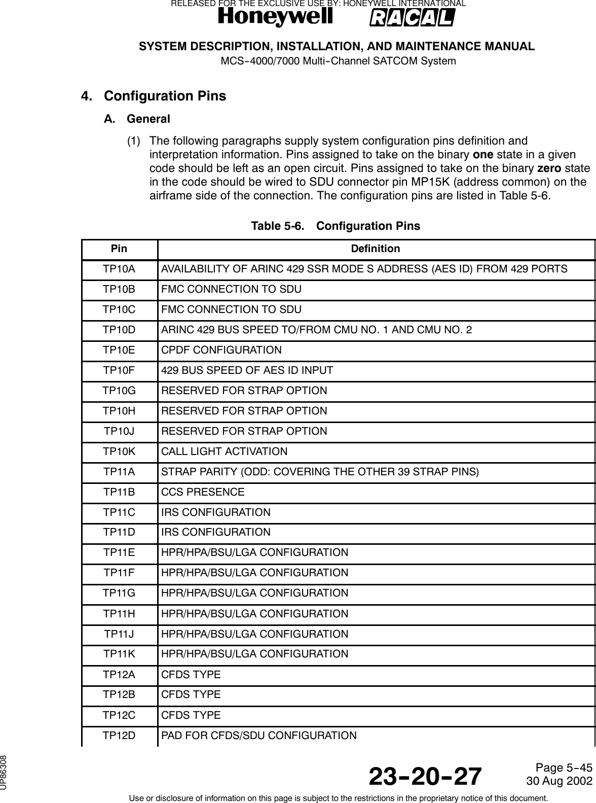
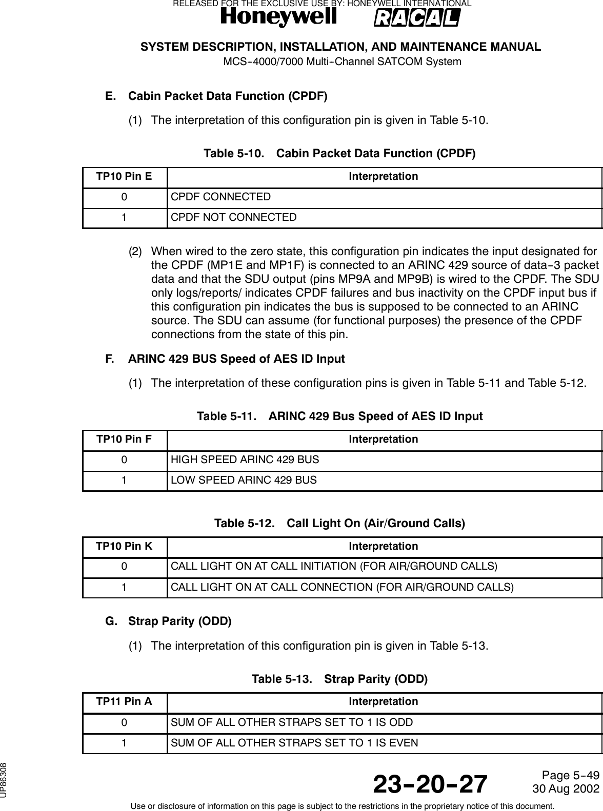
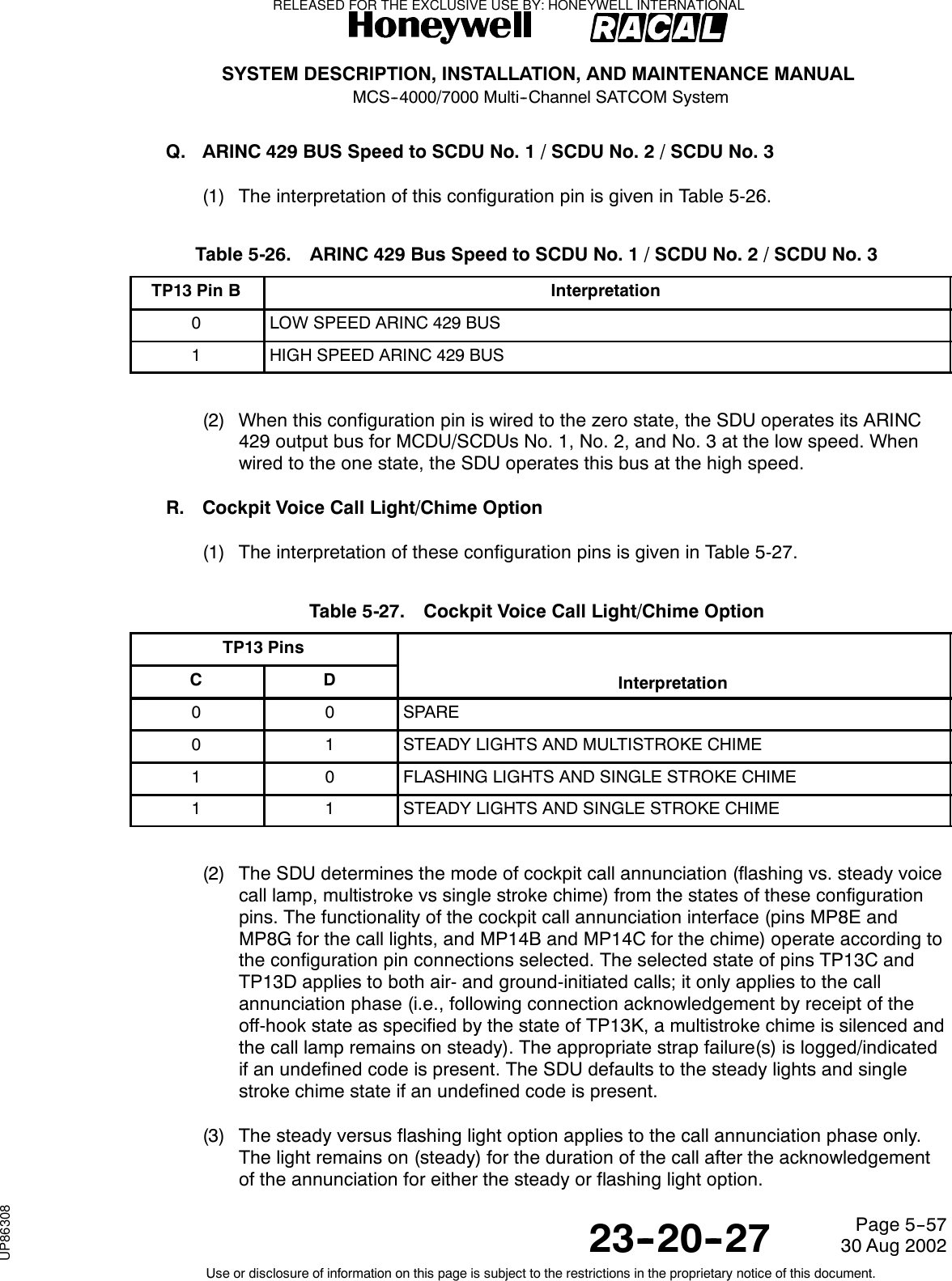
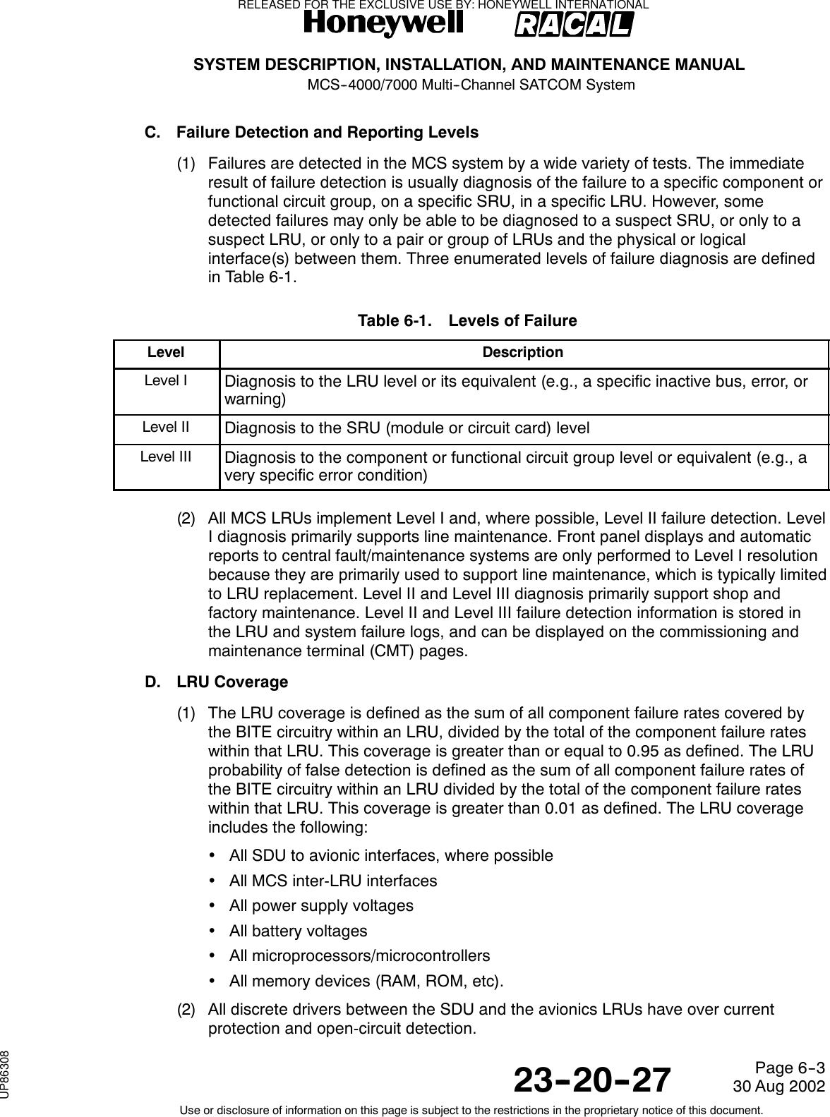
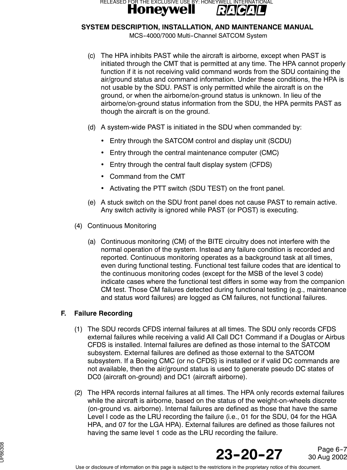
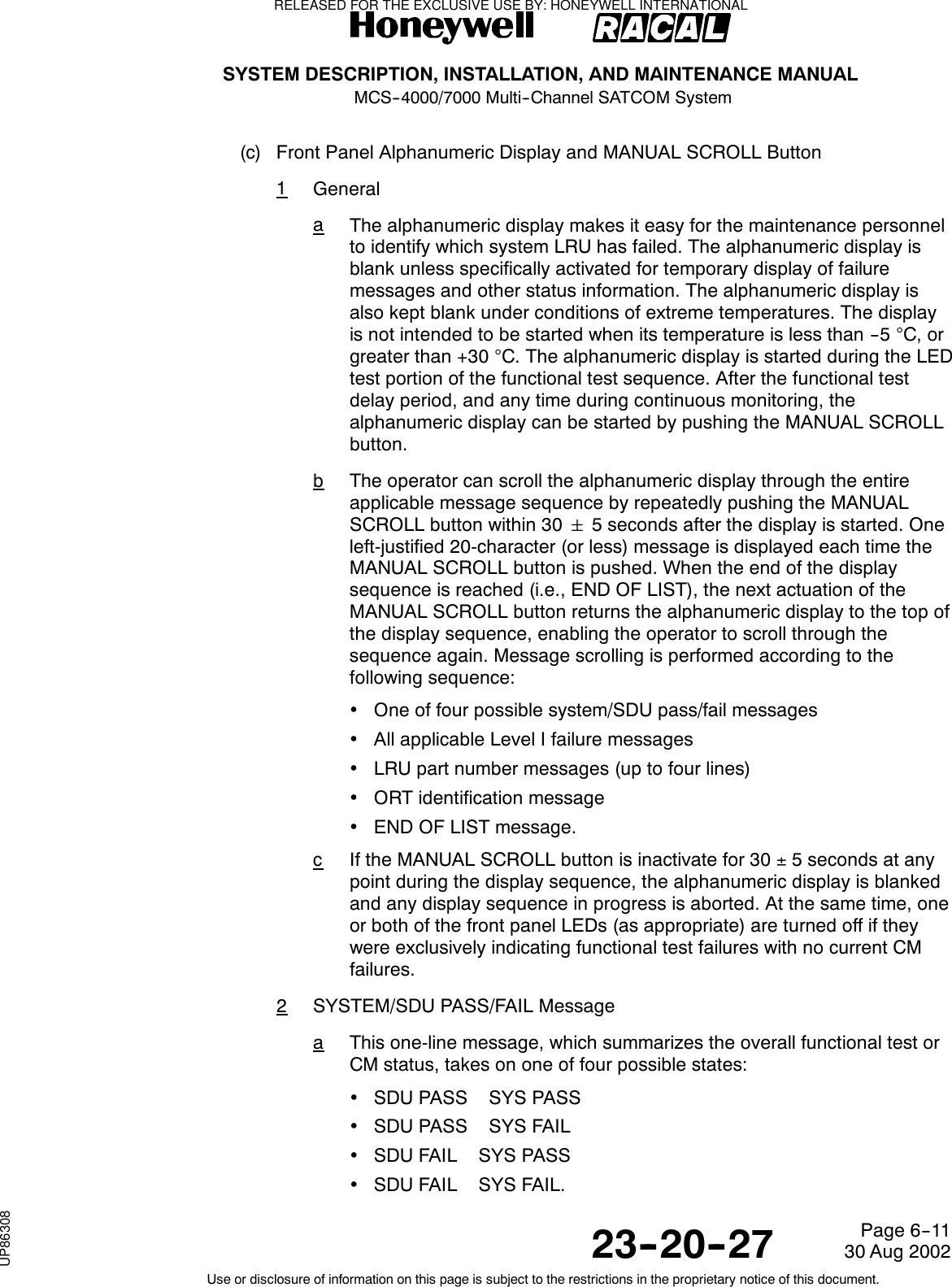
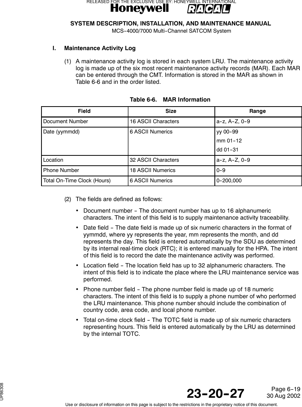
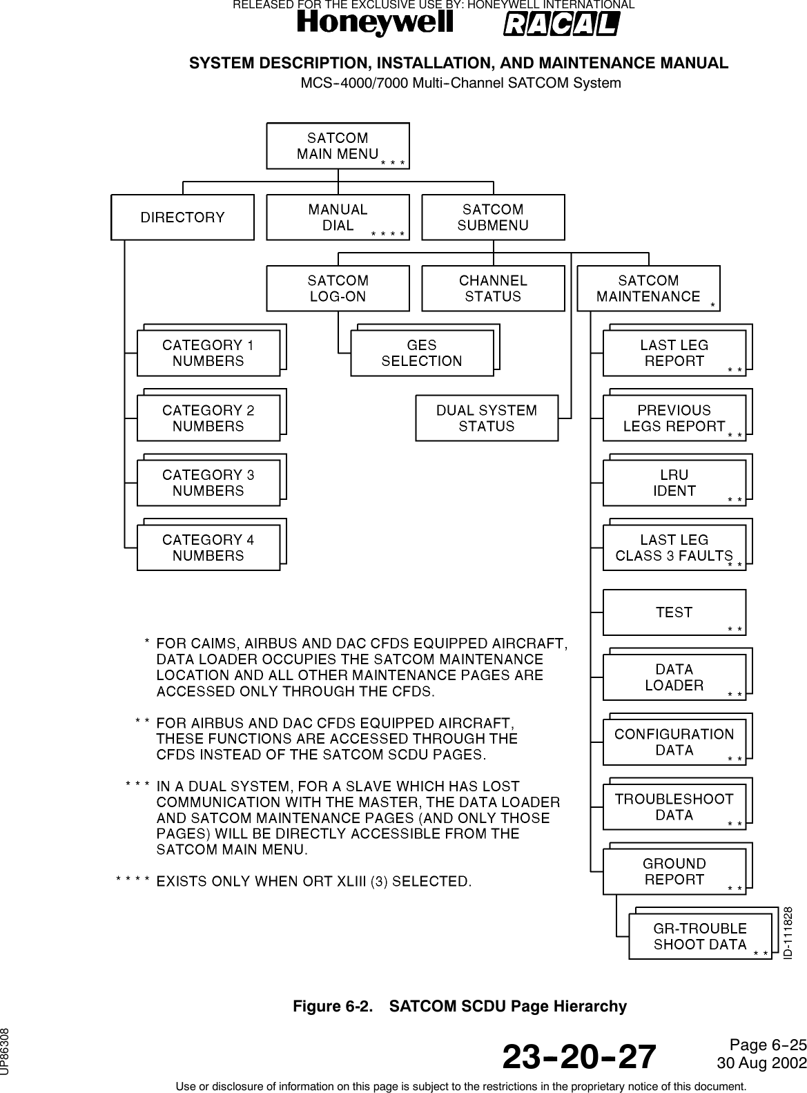
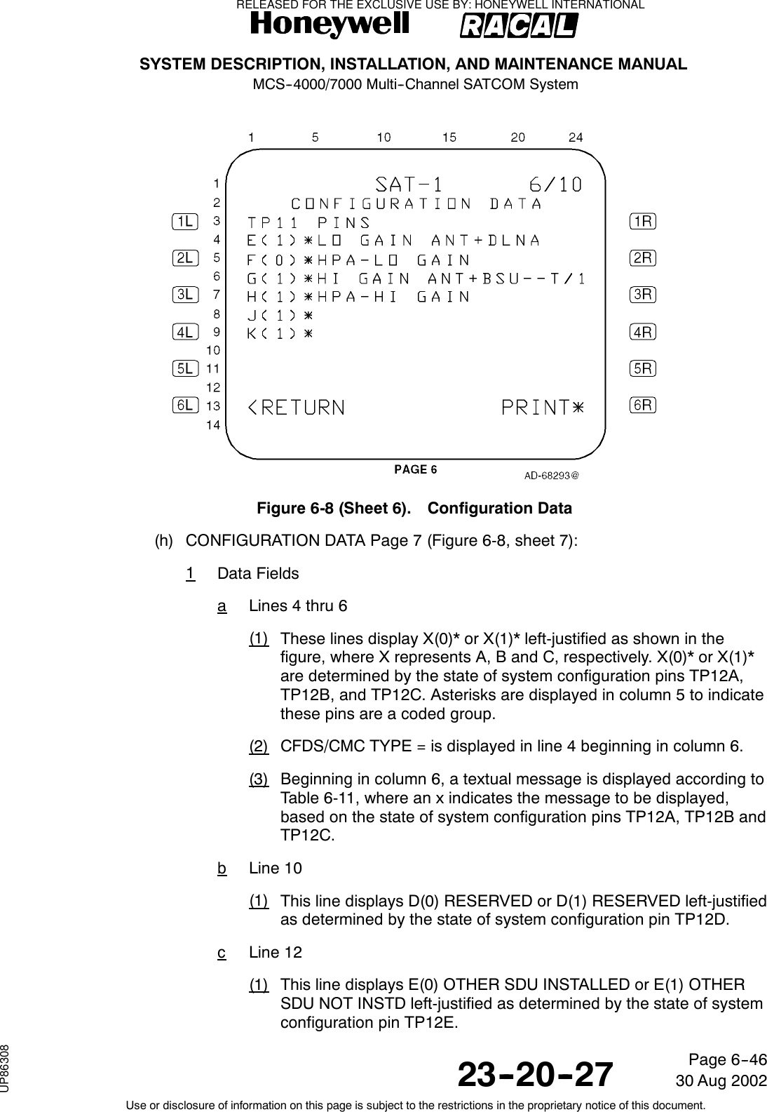
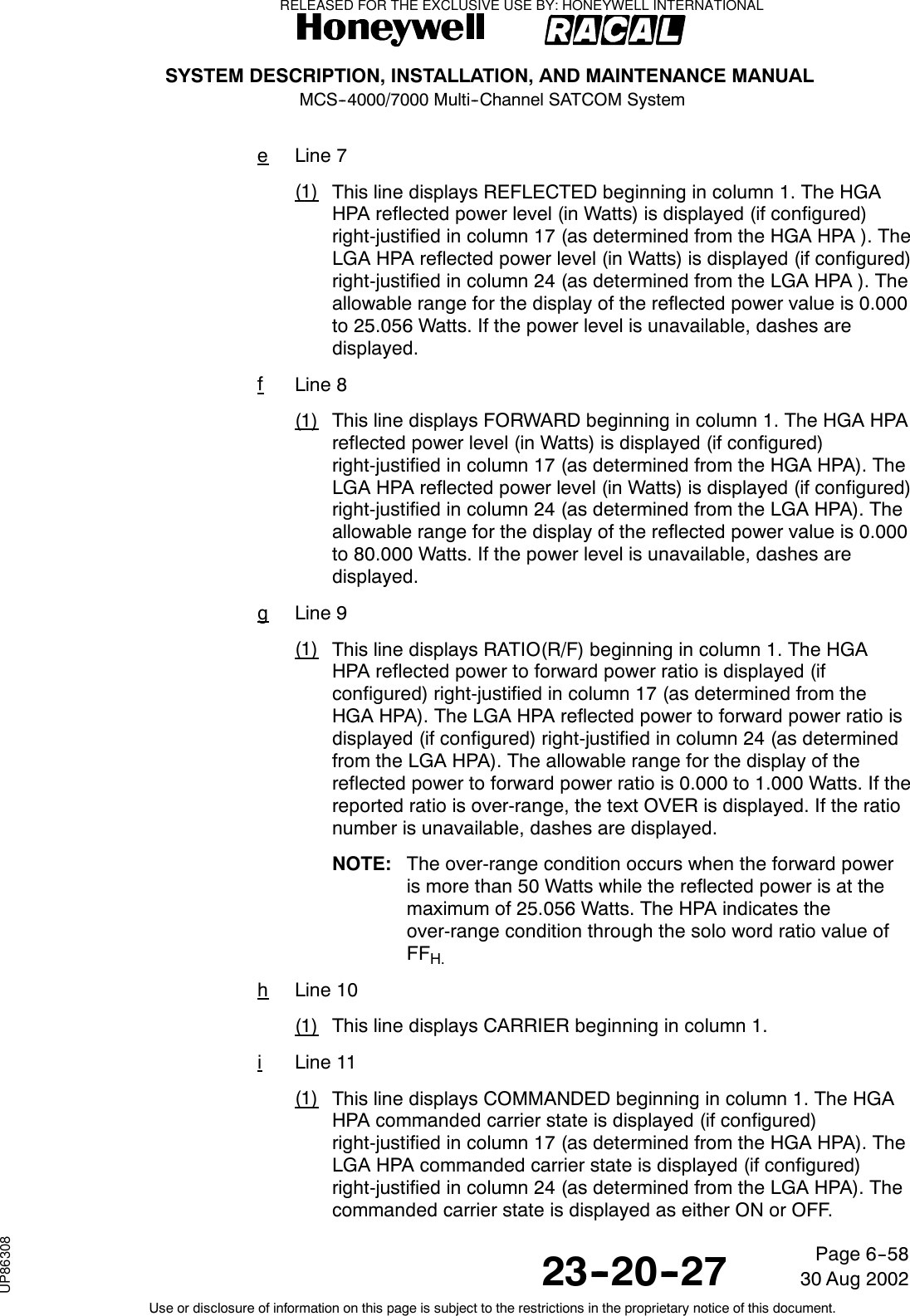
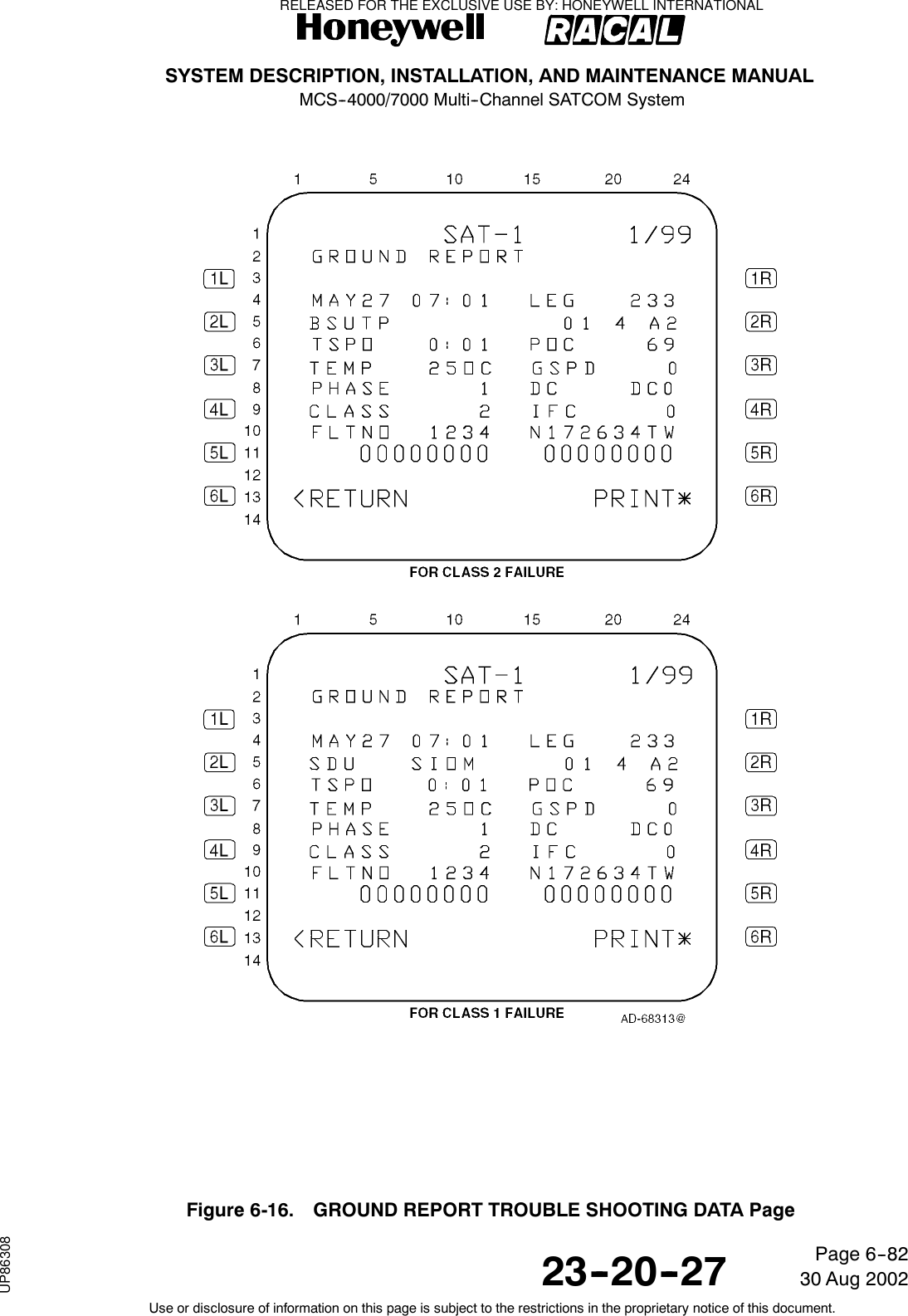
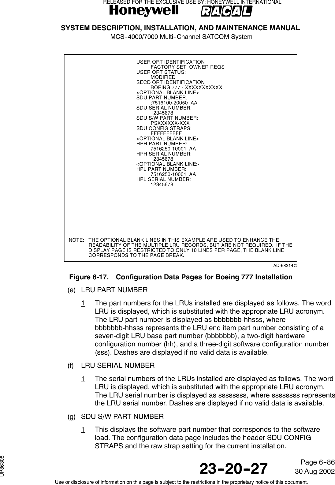
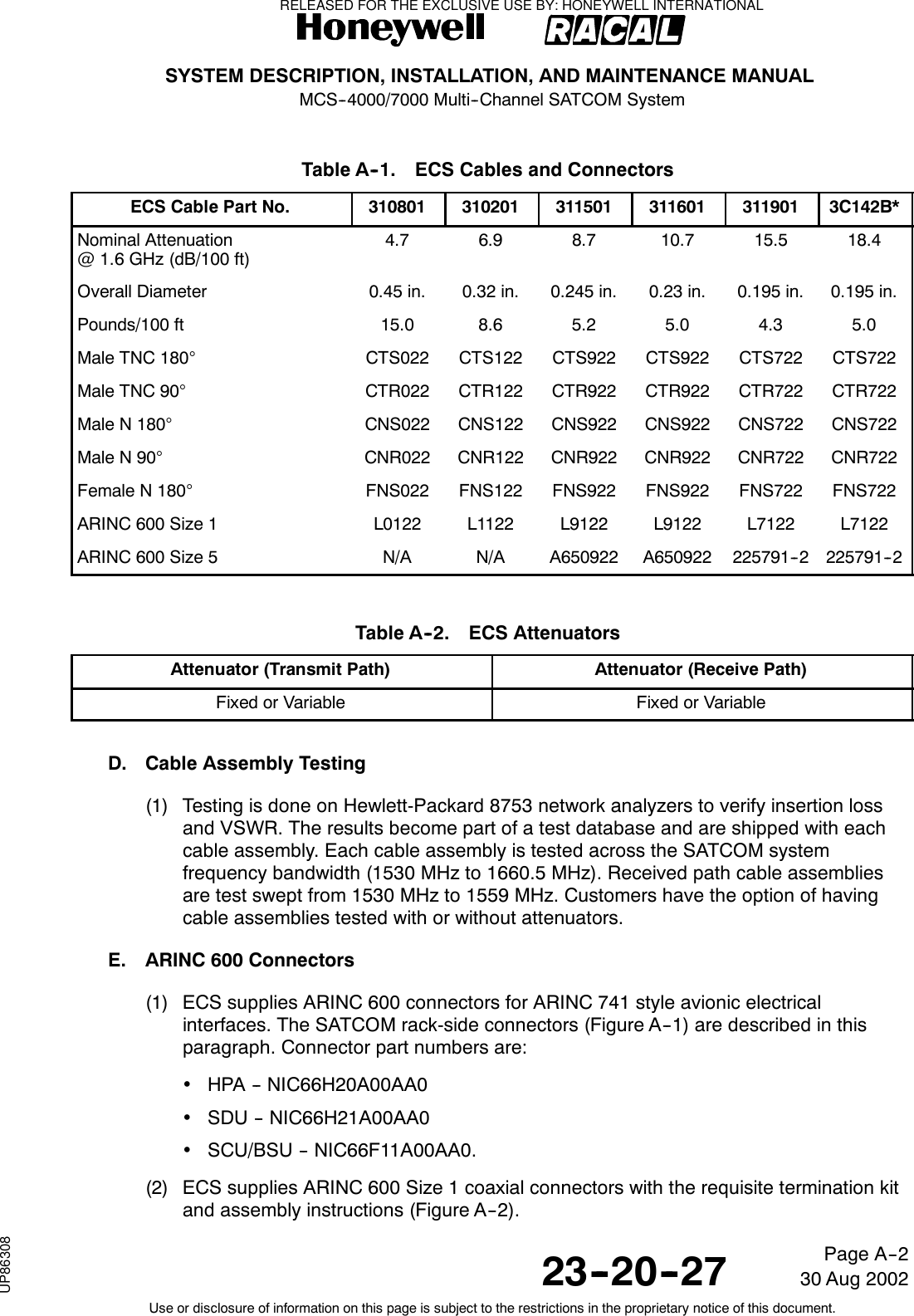
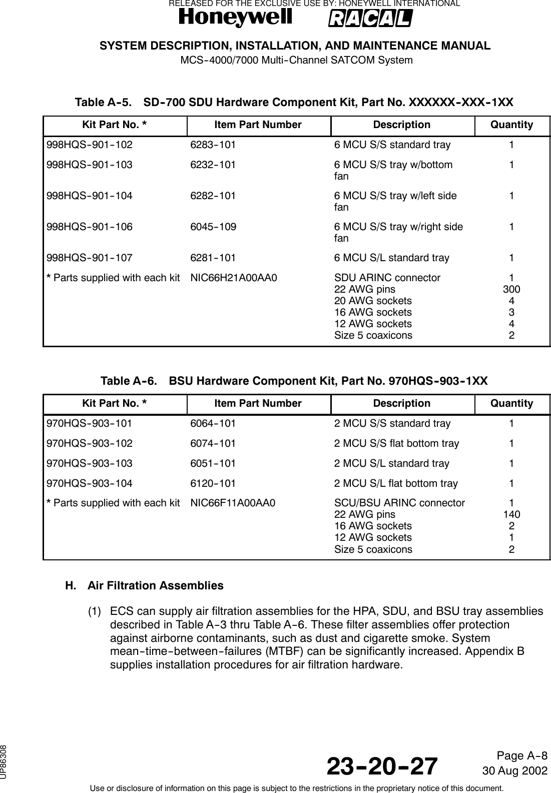
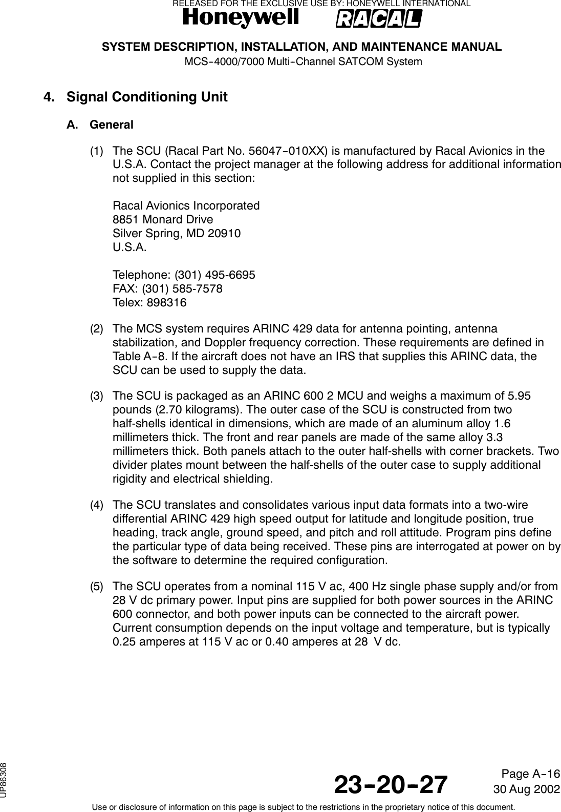
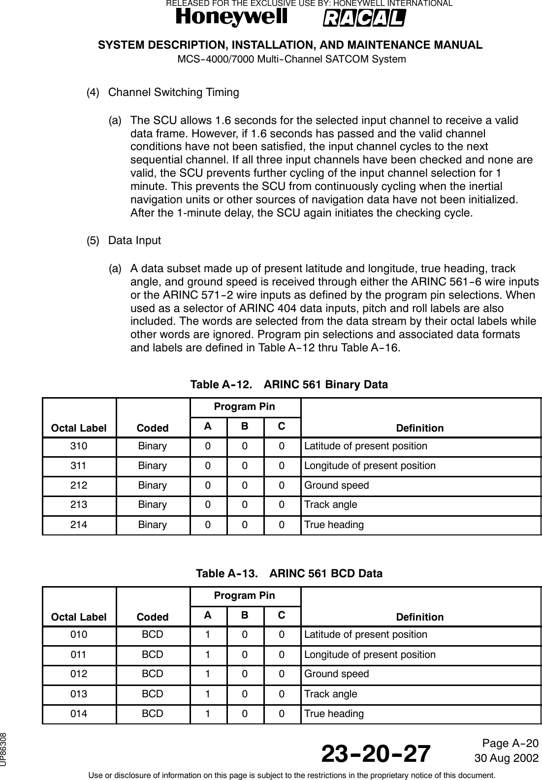
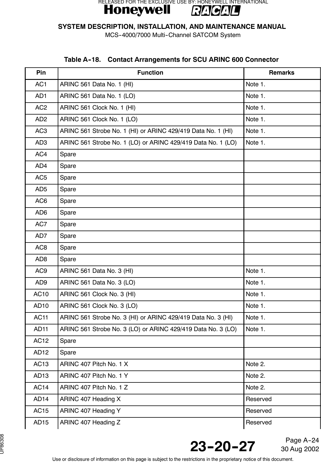
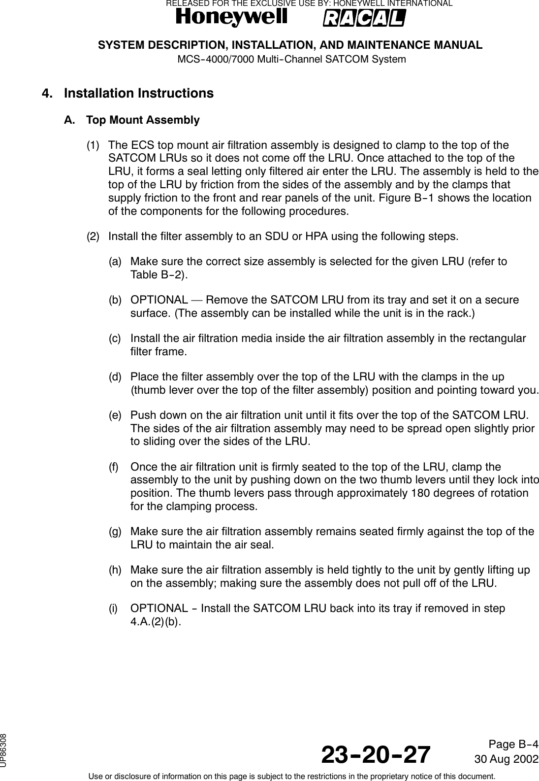
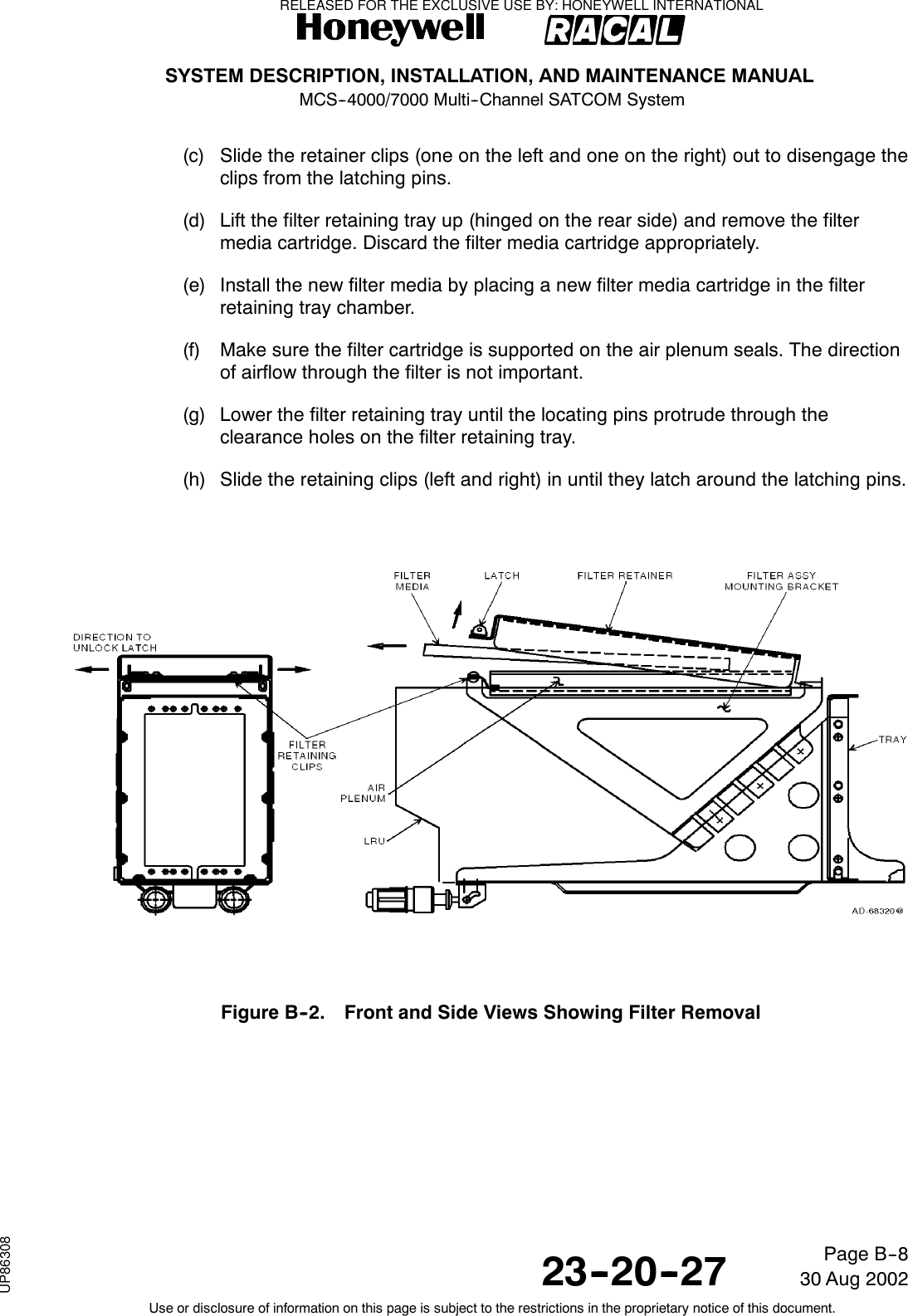
![SYSTEM DESCRIPTION, INSTALLATION, AND MAINTENANCE MANUALMCS--4000/7000 Multi--Channel SATCOM System23--20--2730 Aug 2002Use or disclosure of information on this page is subject to the restrictions in the proprietary notice of this document.Page 1--46(f) The software modification level consists of a maximum of two upper--casealphabetic characters ranging from A (or “--”) to ZZ, with letters I, O, Q, and Xexcluded. Usage of this nameplate characteristic reflects the implementation ofminor software changes.(g) The DO--178A or DO--178B software levels applicable to the MCS LRUs is thelevel an LRU was certified. This nameplate is capable of being removed andreplaced when a software change is significant enough to require the three--digitsoftware configuration number be incremented, or a hardware change issignificant enough to require that the two--digit hardware configuration numberbe incremented.J. Software and Hardware Compatibility (SDU and HPA)(1) Provisions for a set of discrete wire jumpers (straps) are included in each MCS LRUto ensure hardware and software compatibility. The code setting for these straps ismanually changed each time a hardware revision is made that is not compatible withall previously released versions of software. The status of these straps is testedevery time an LRU undergoes a cold start (power--on self--test [POST], orperson--activated self--test [PAST] ), and every time a software load is attempted froman ARINC 615 portable data loader.(2) The LRU header records in the ARINC 615 data loader software upload file and inthe operational software itself, contain a list of hardware/software compatibility strapcodes with which the software is compatible. This list of codes is compared with thewired hardware/software compatibility strap code in the LRU; if any of the codes inthe software upload file match the hardware/software compatibility strap code in theLRU, then the software upload process is allowed (otherwise it is inhibited). Similarly,if any of the codes in the software itself match the strap code in the LRU, normal LRUoperation is allowed (otherwise it remains in an inert state).RELEASED FOR THE EXCLUSIVE USE BY: HONEYWELL INTERNATIONALUP86308](https://usermanual.wiki/Honeywell/SD-700A/User-Guide-3476924-Page-90.png)
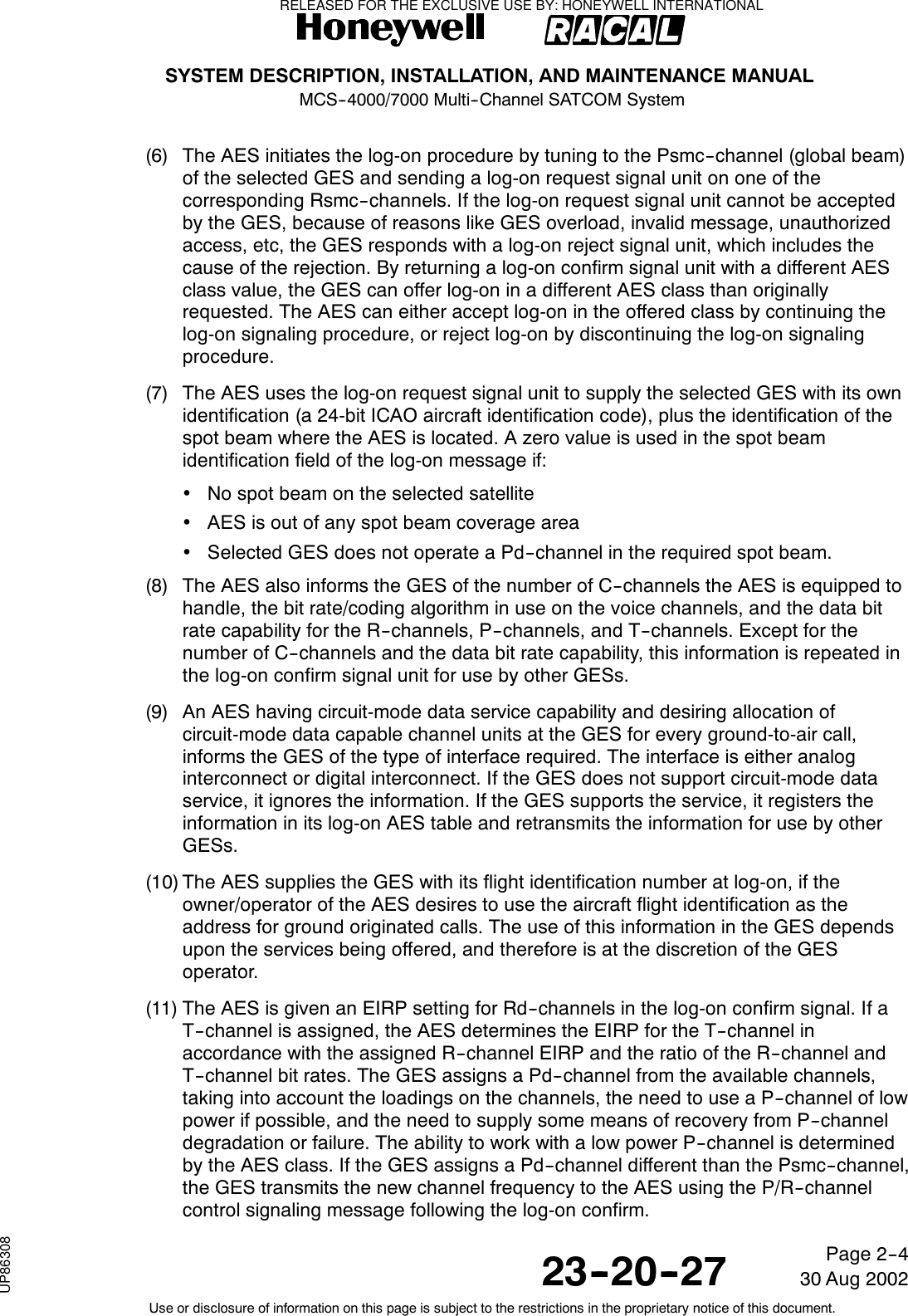
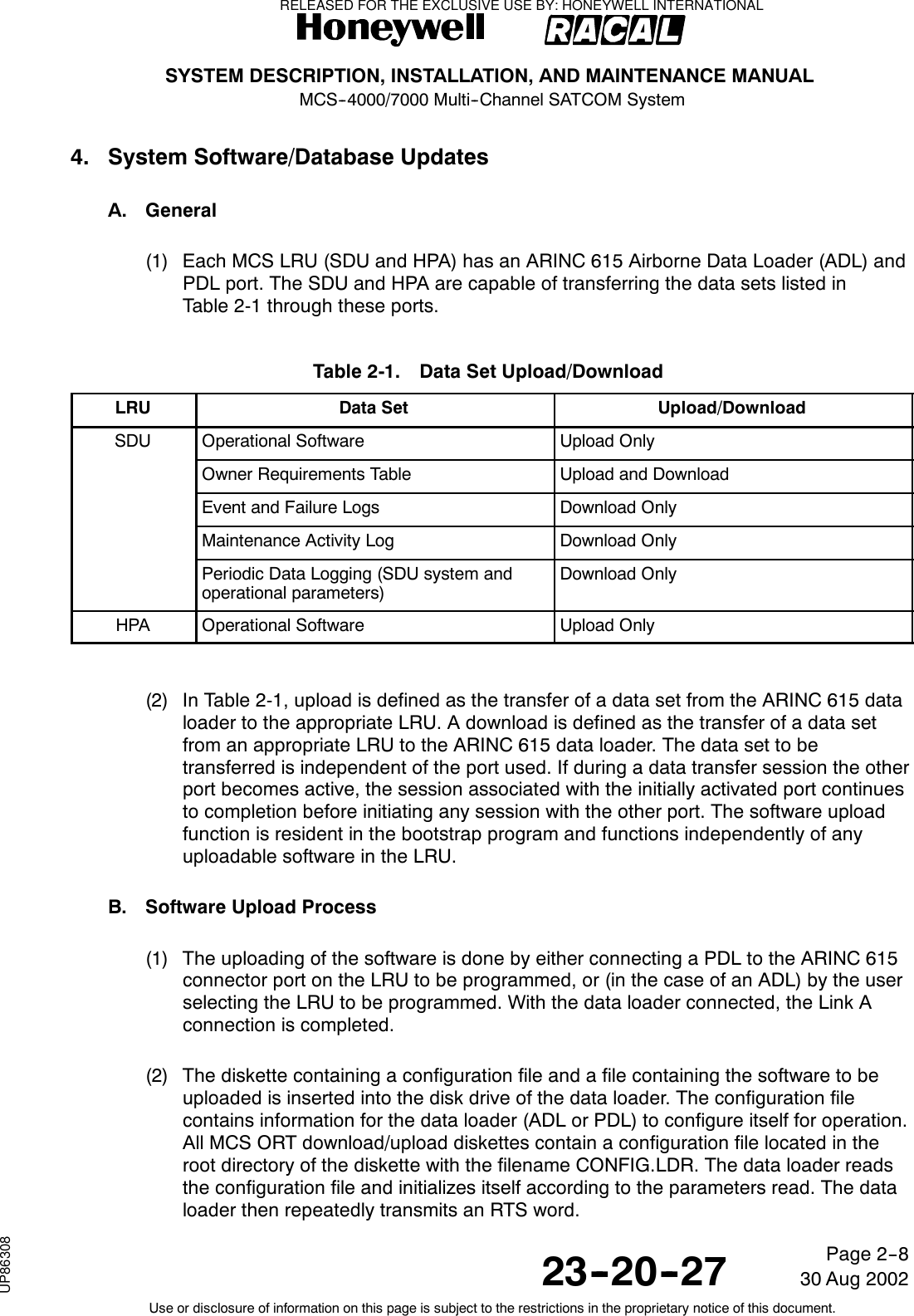
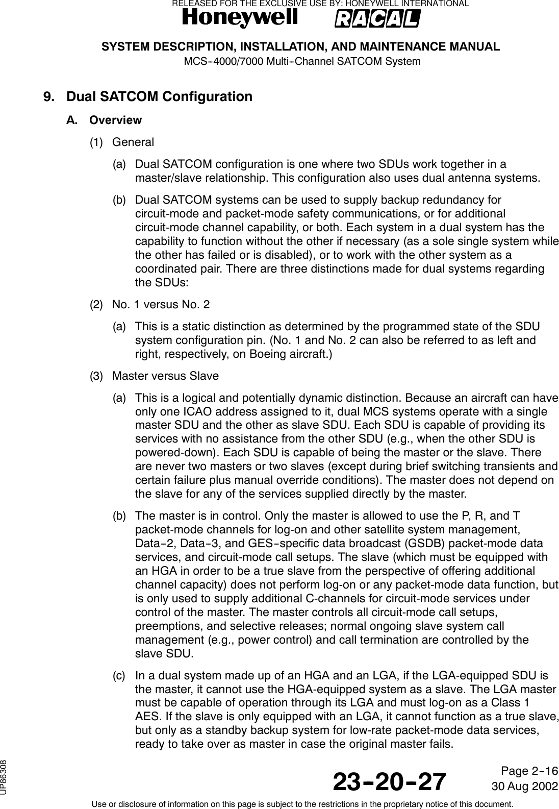
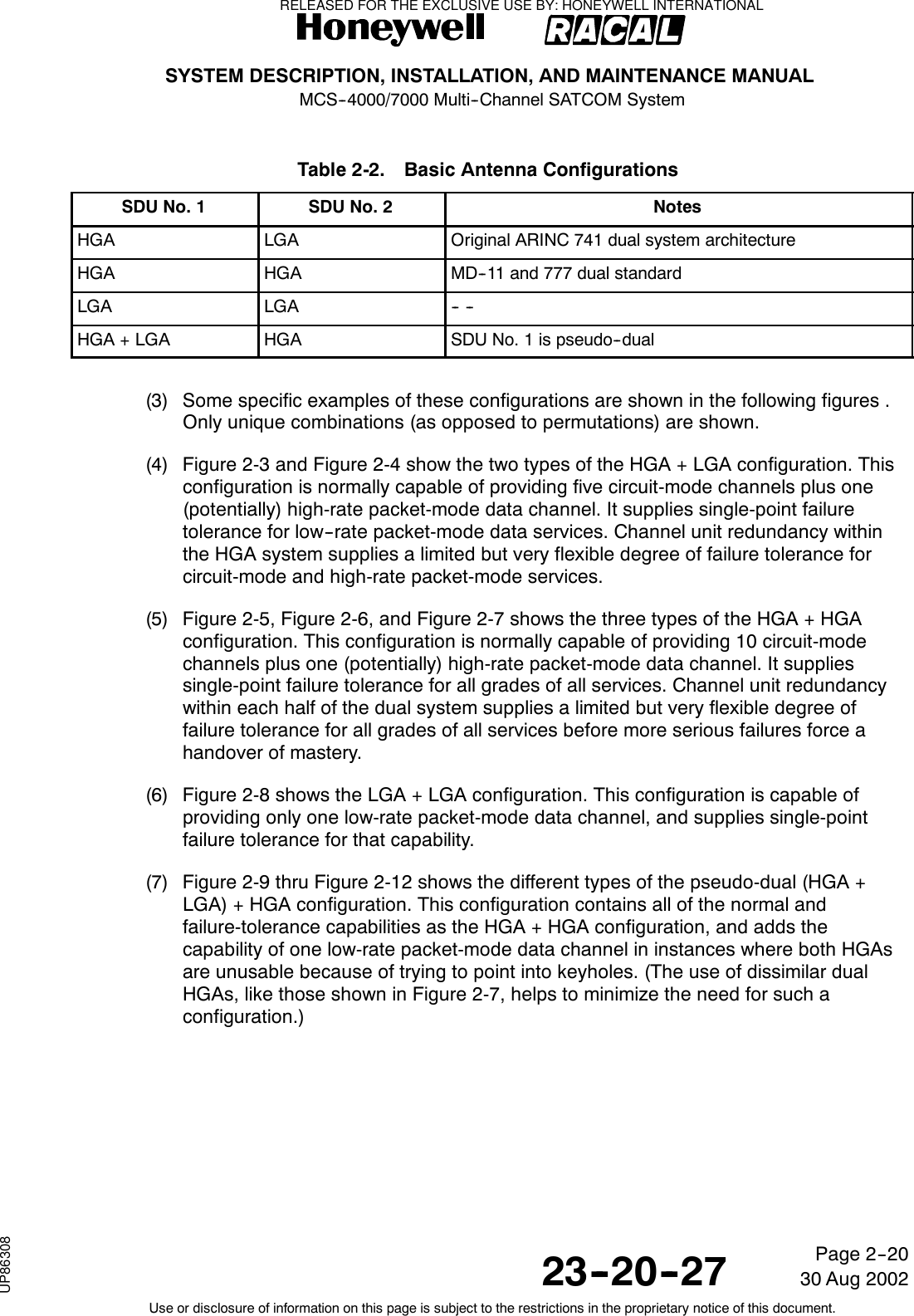
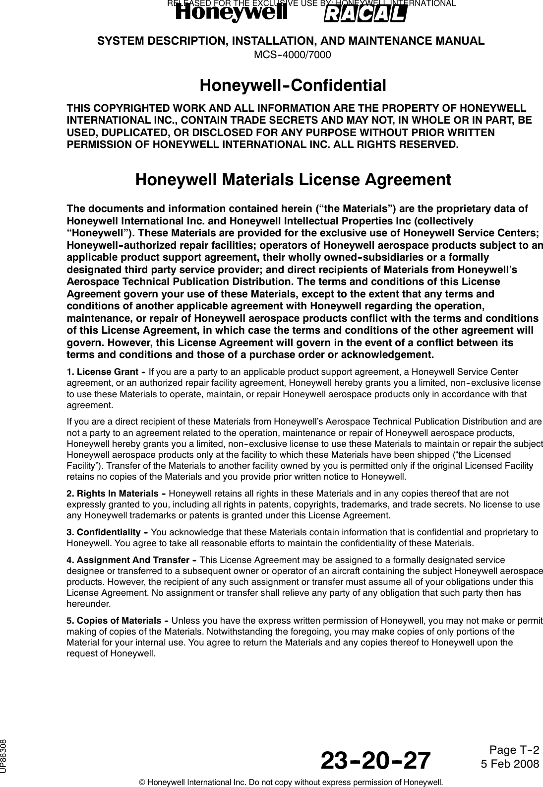
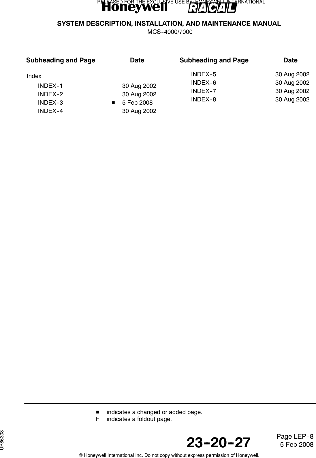
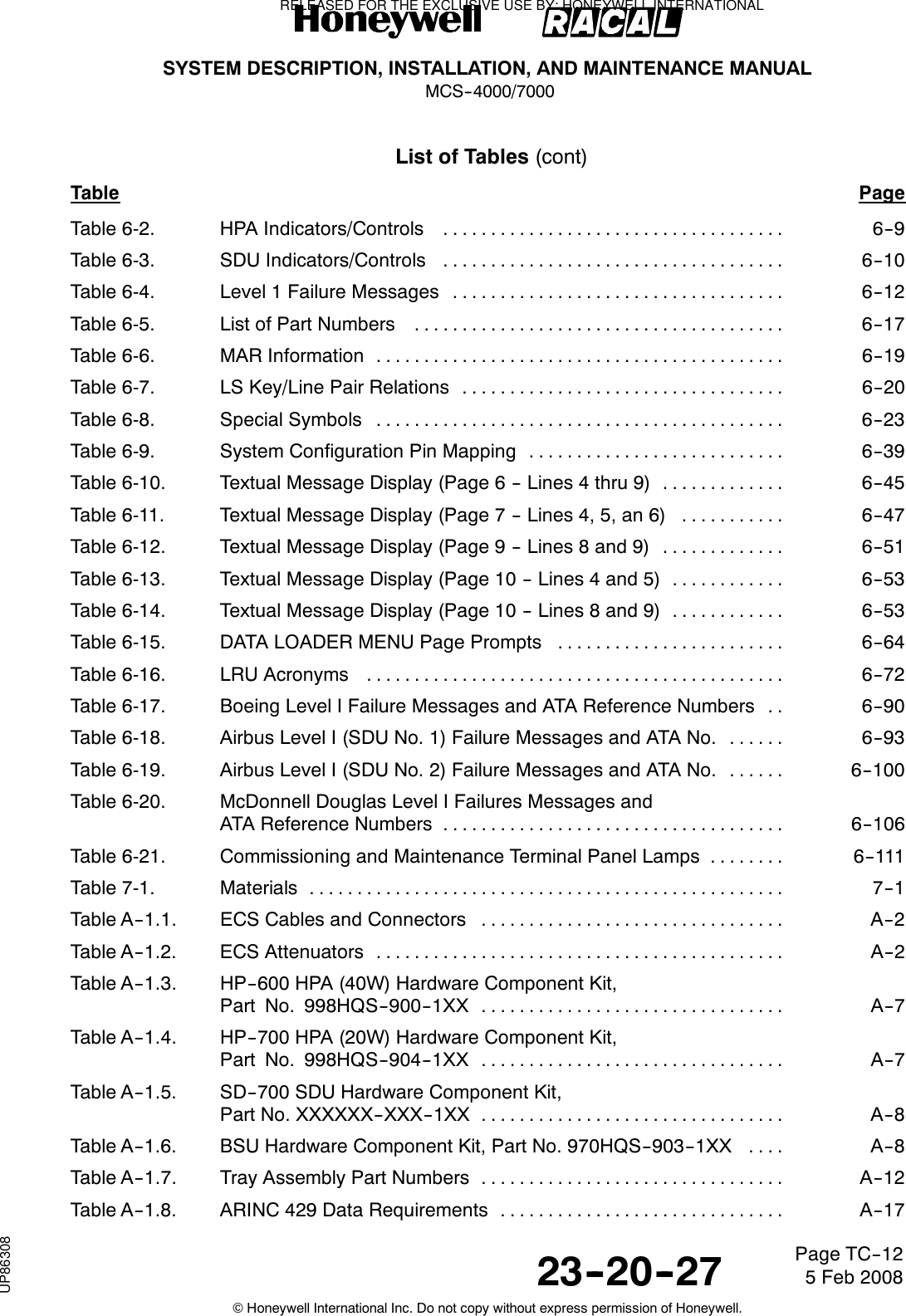
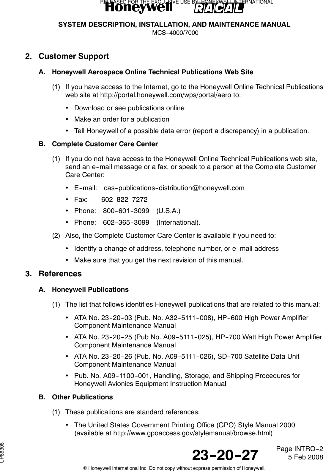
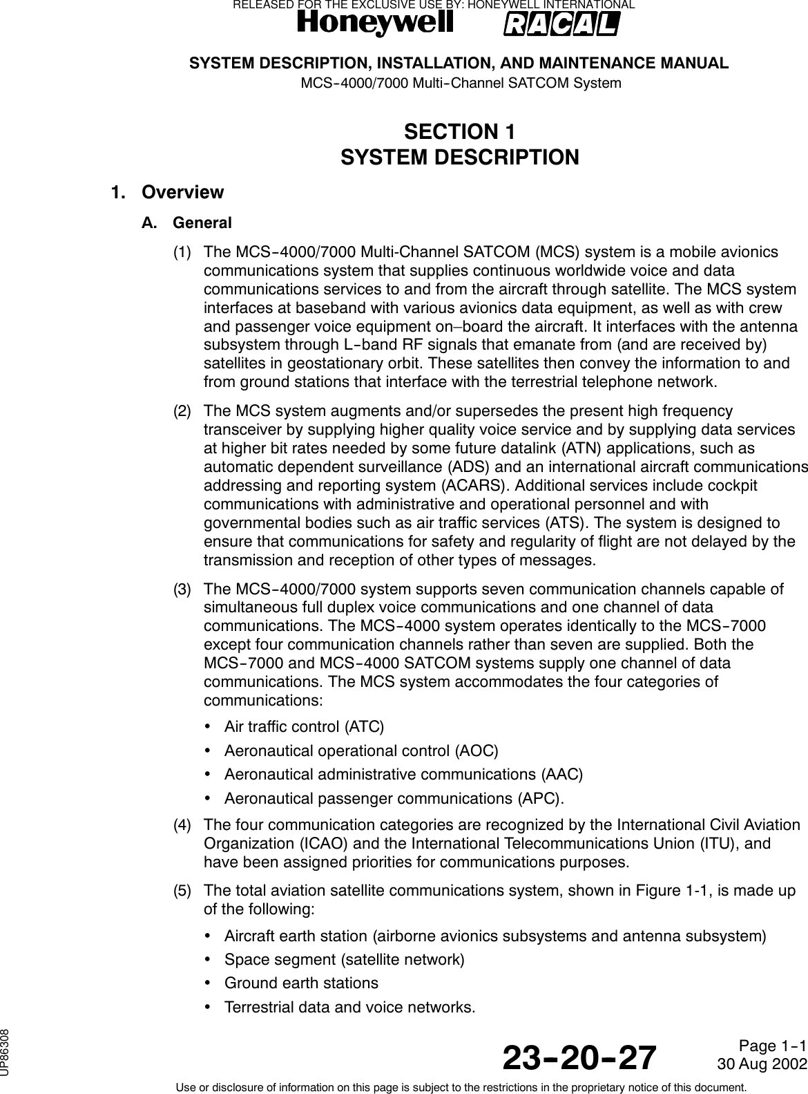
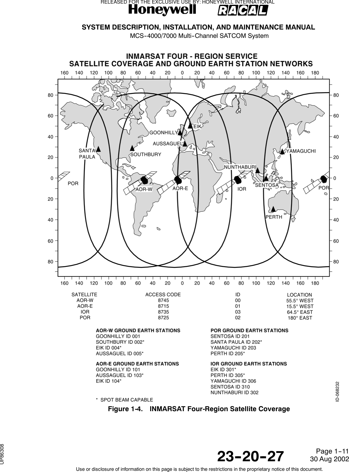
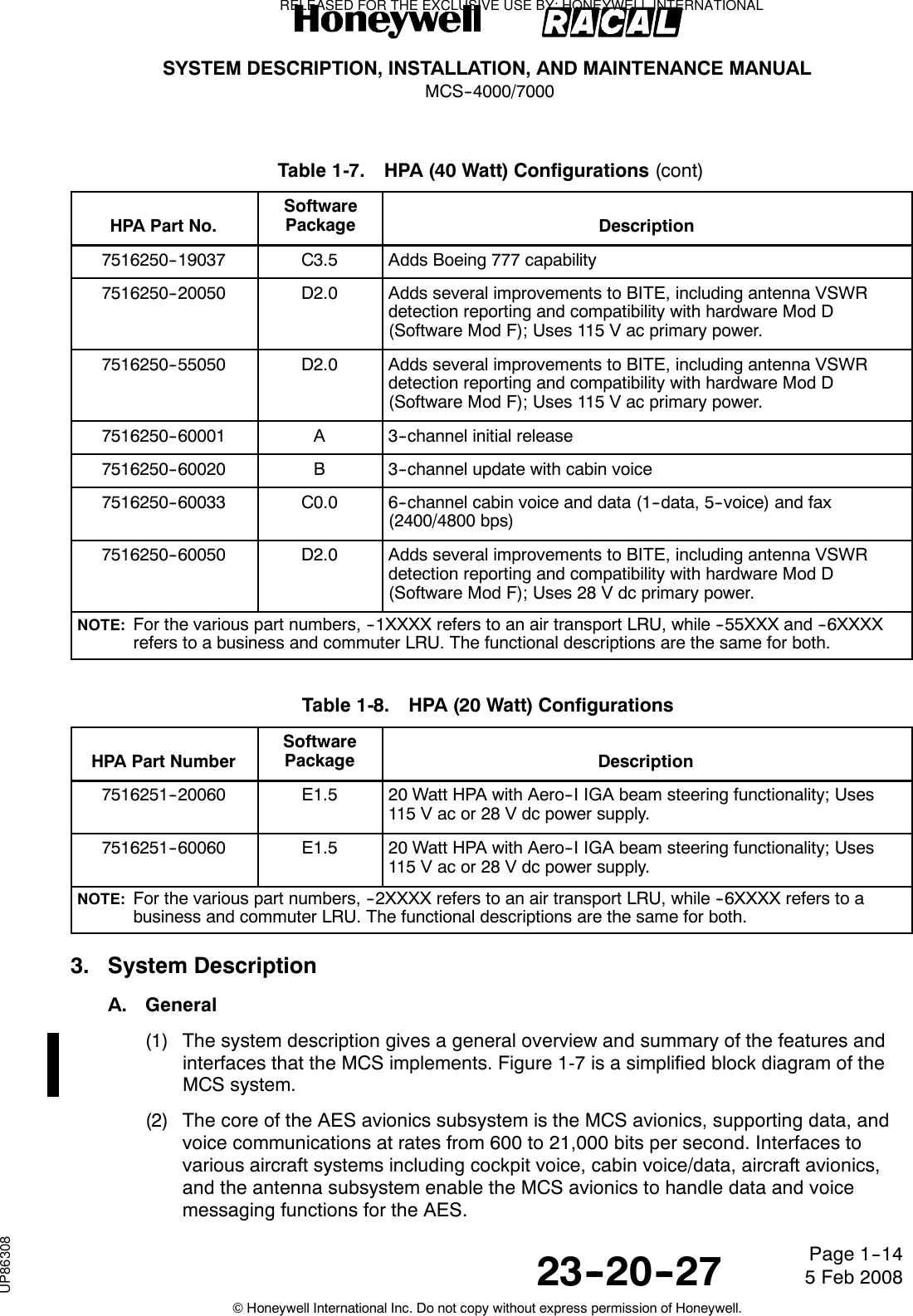
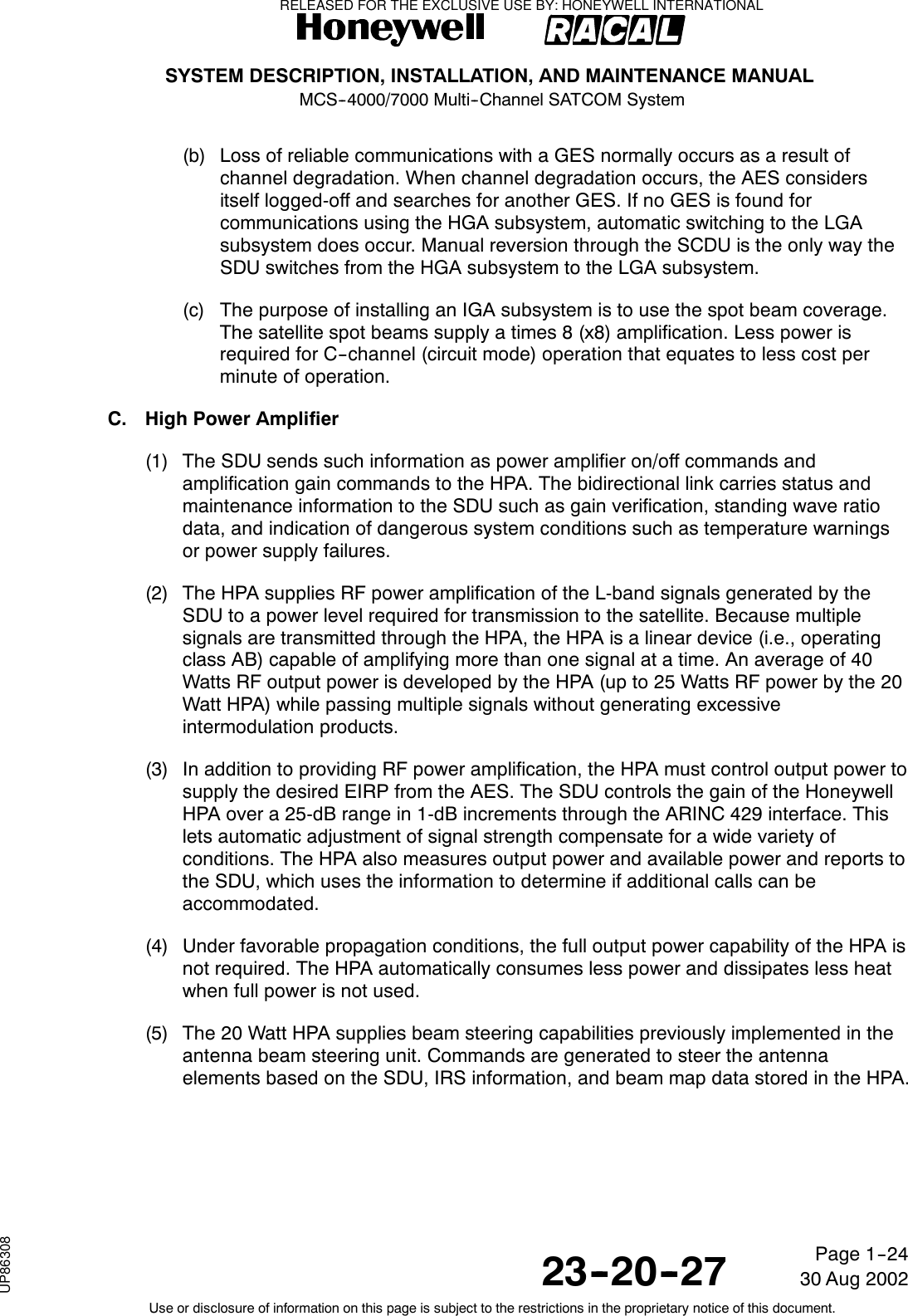
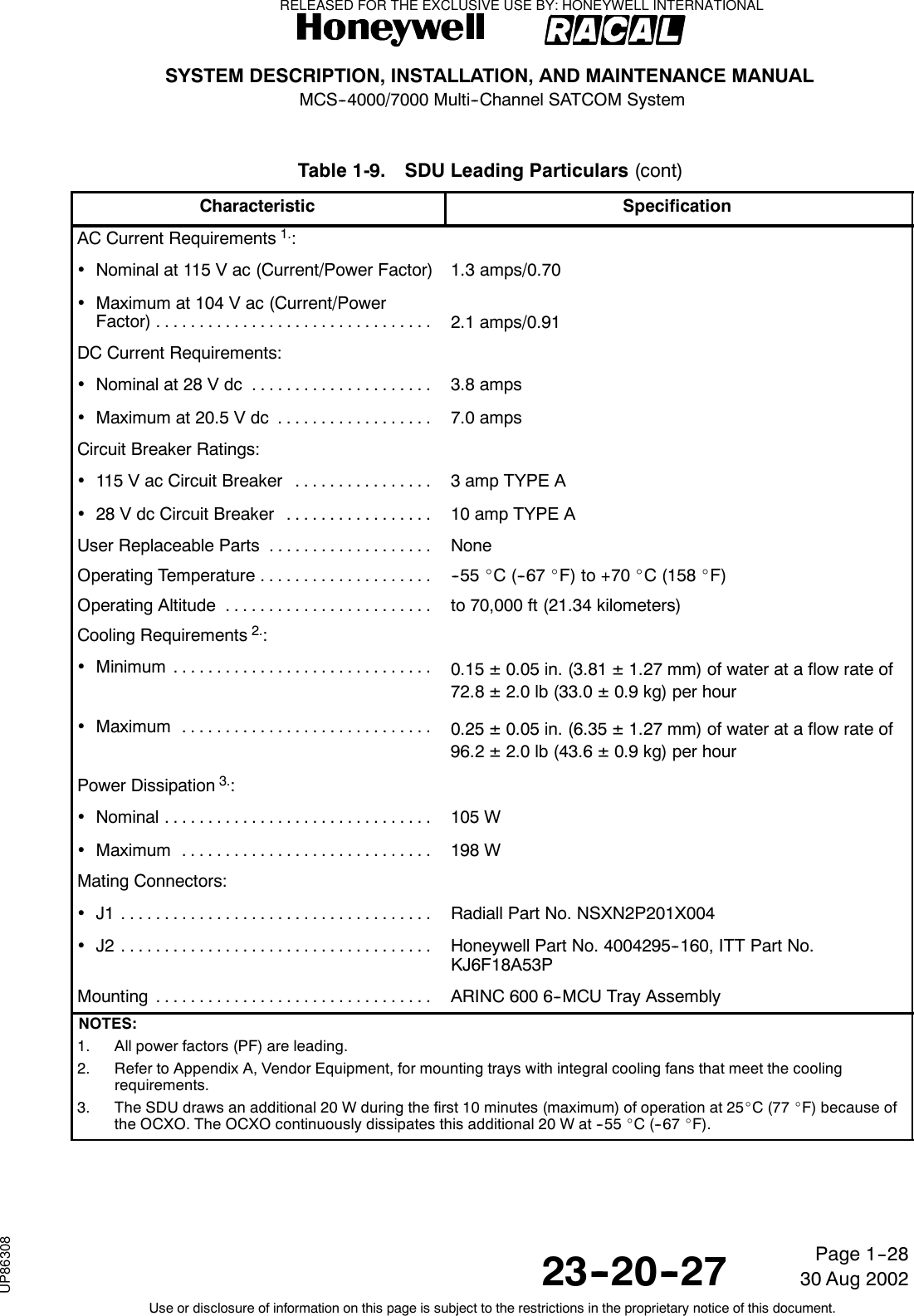
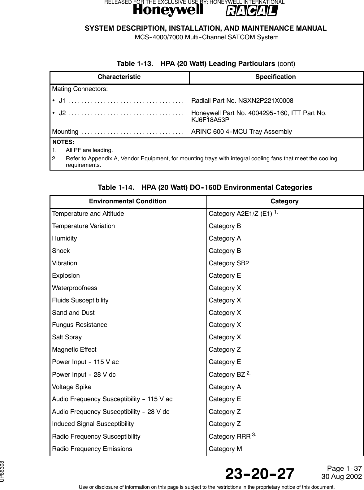
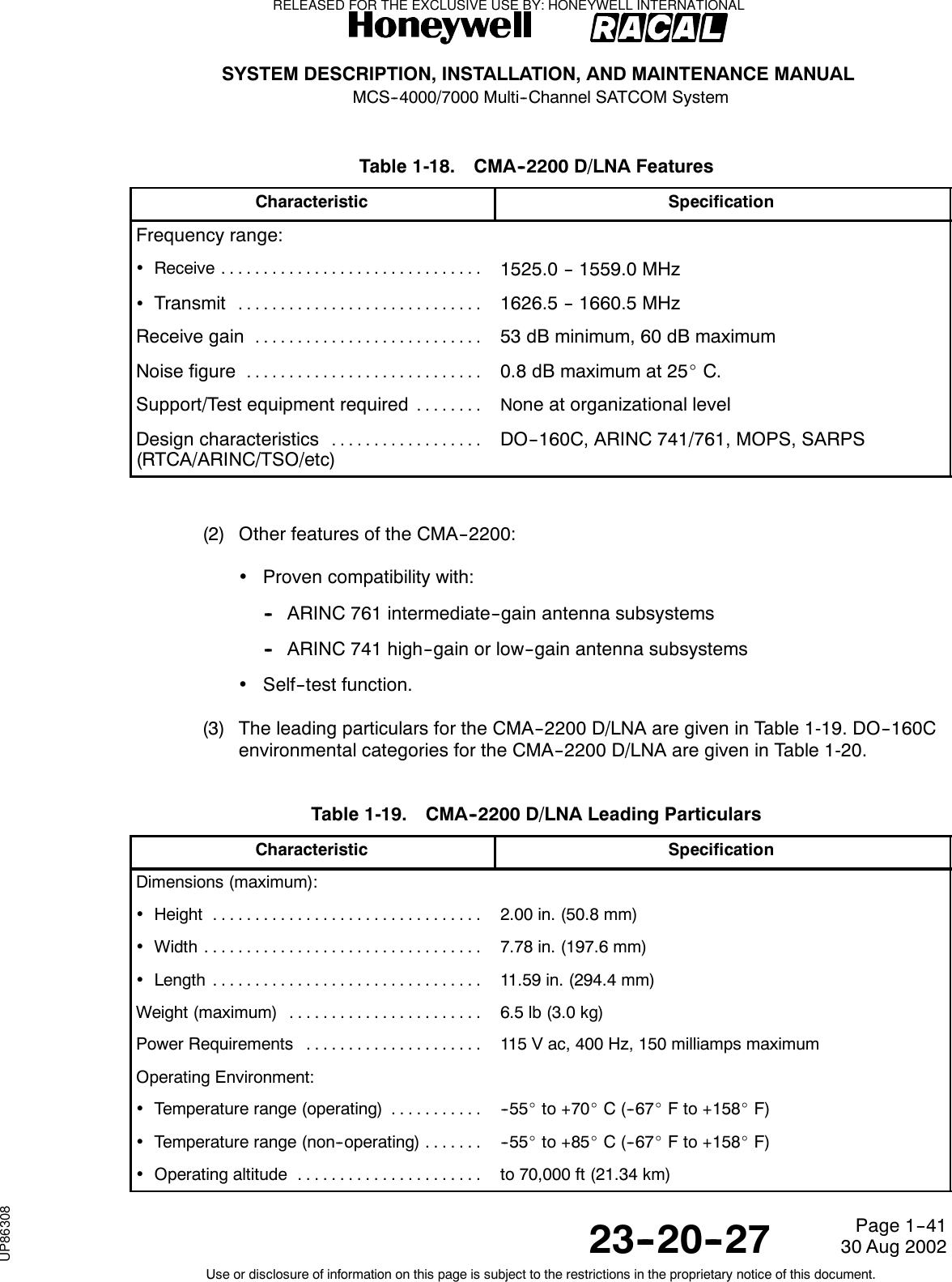
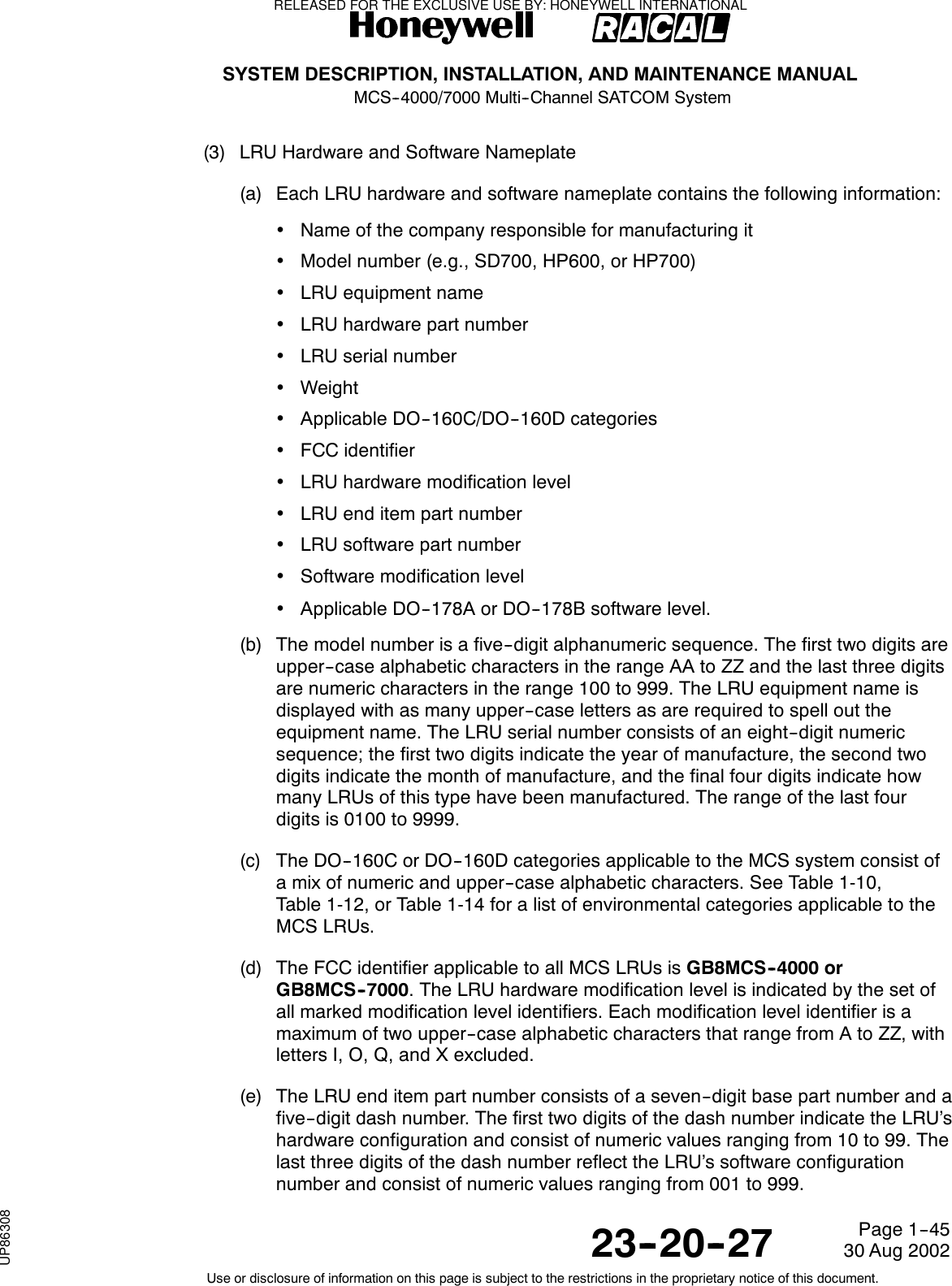
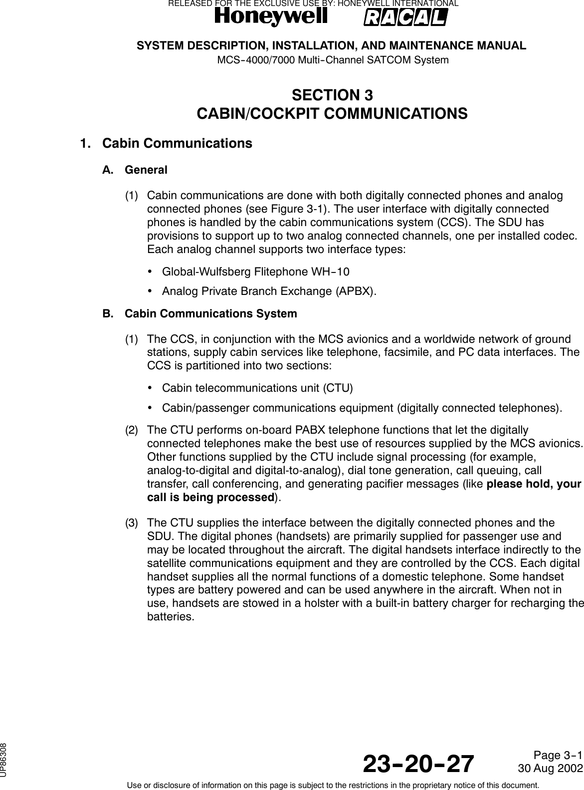
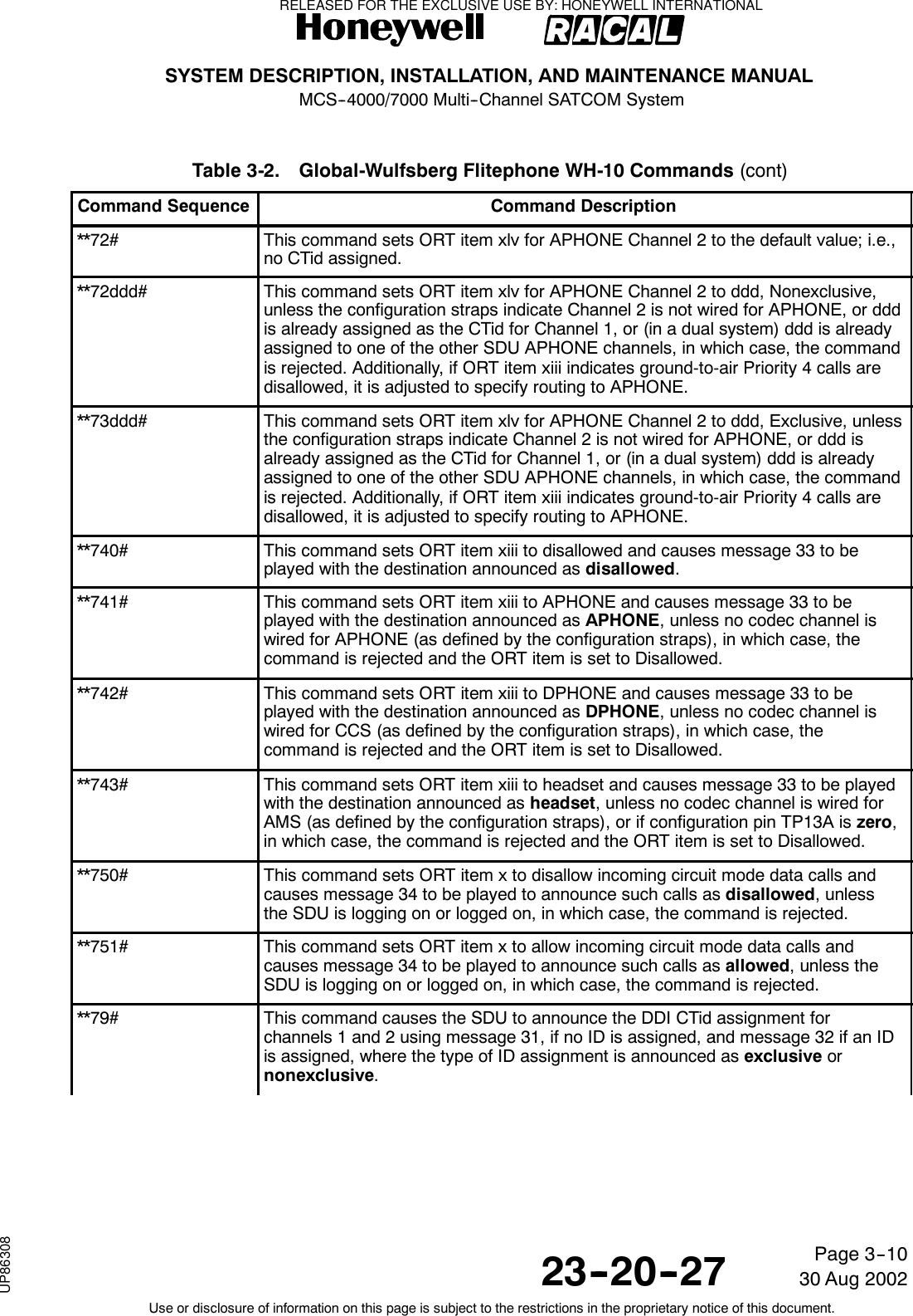
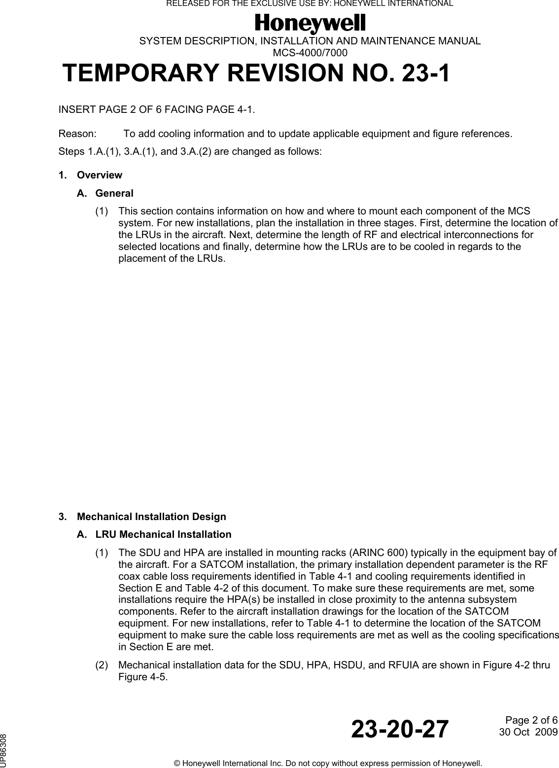
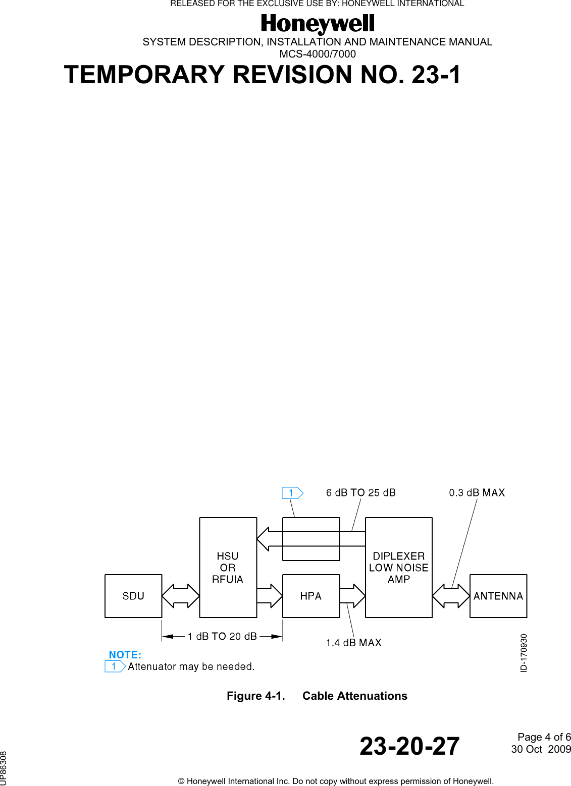
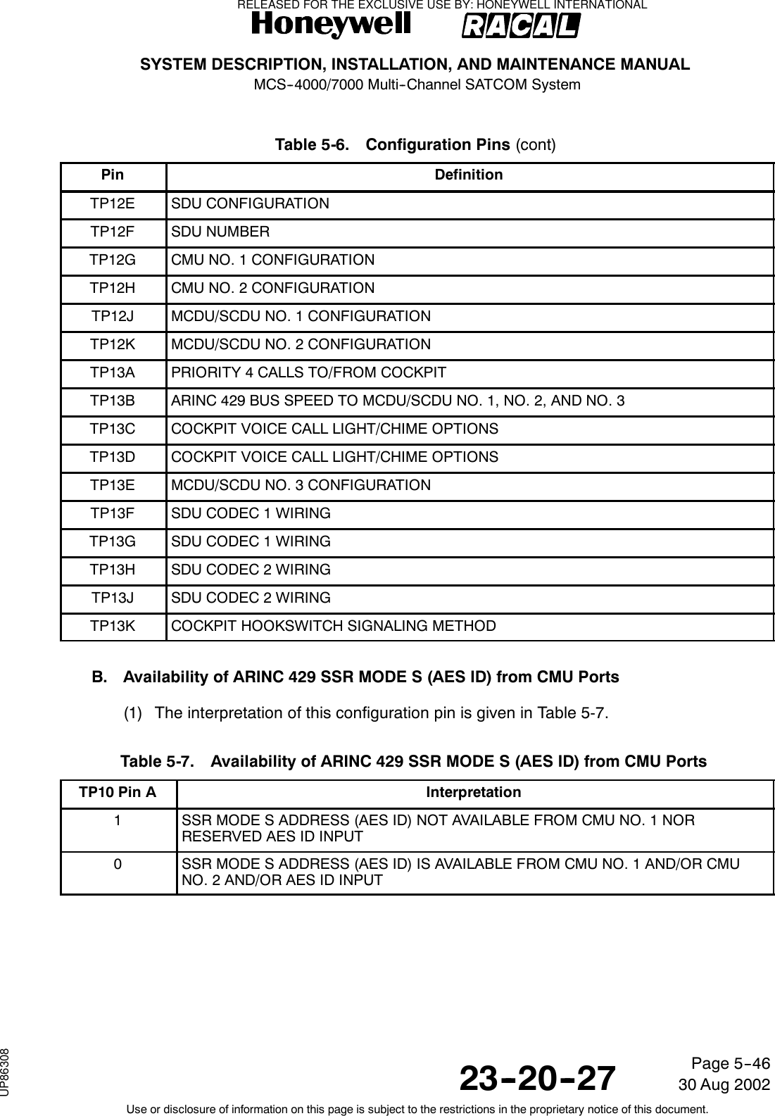
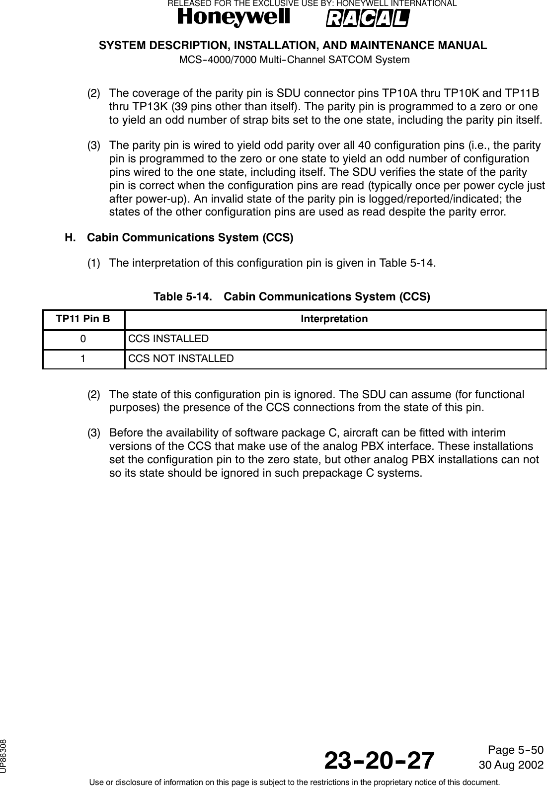
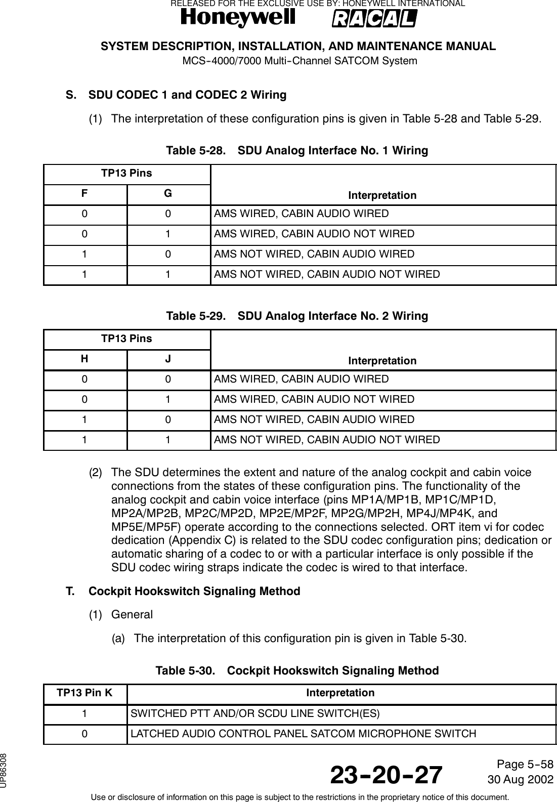
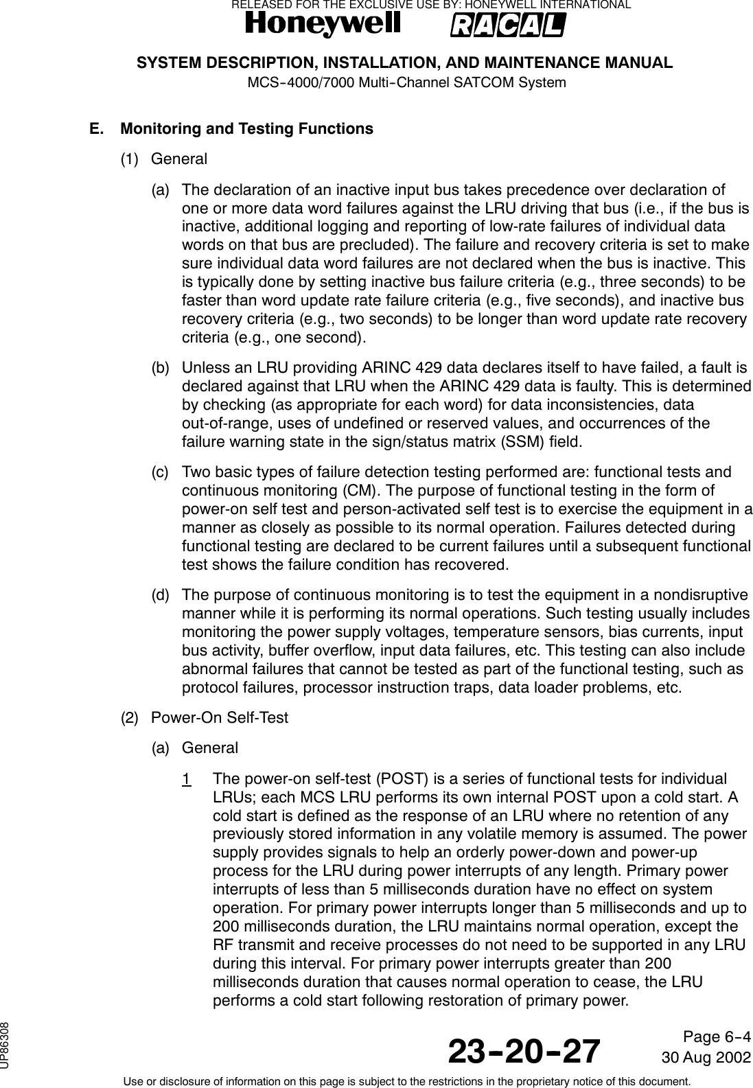
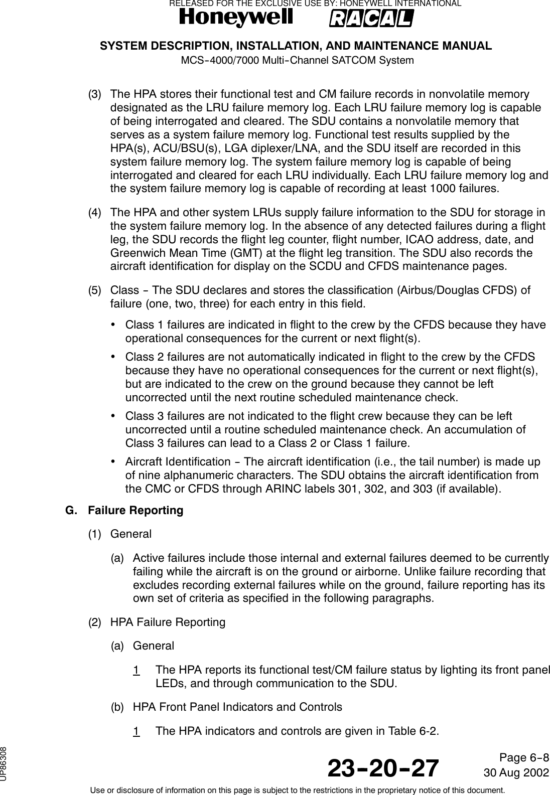
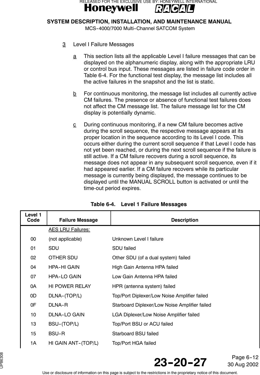
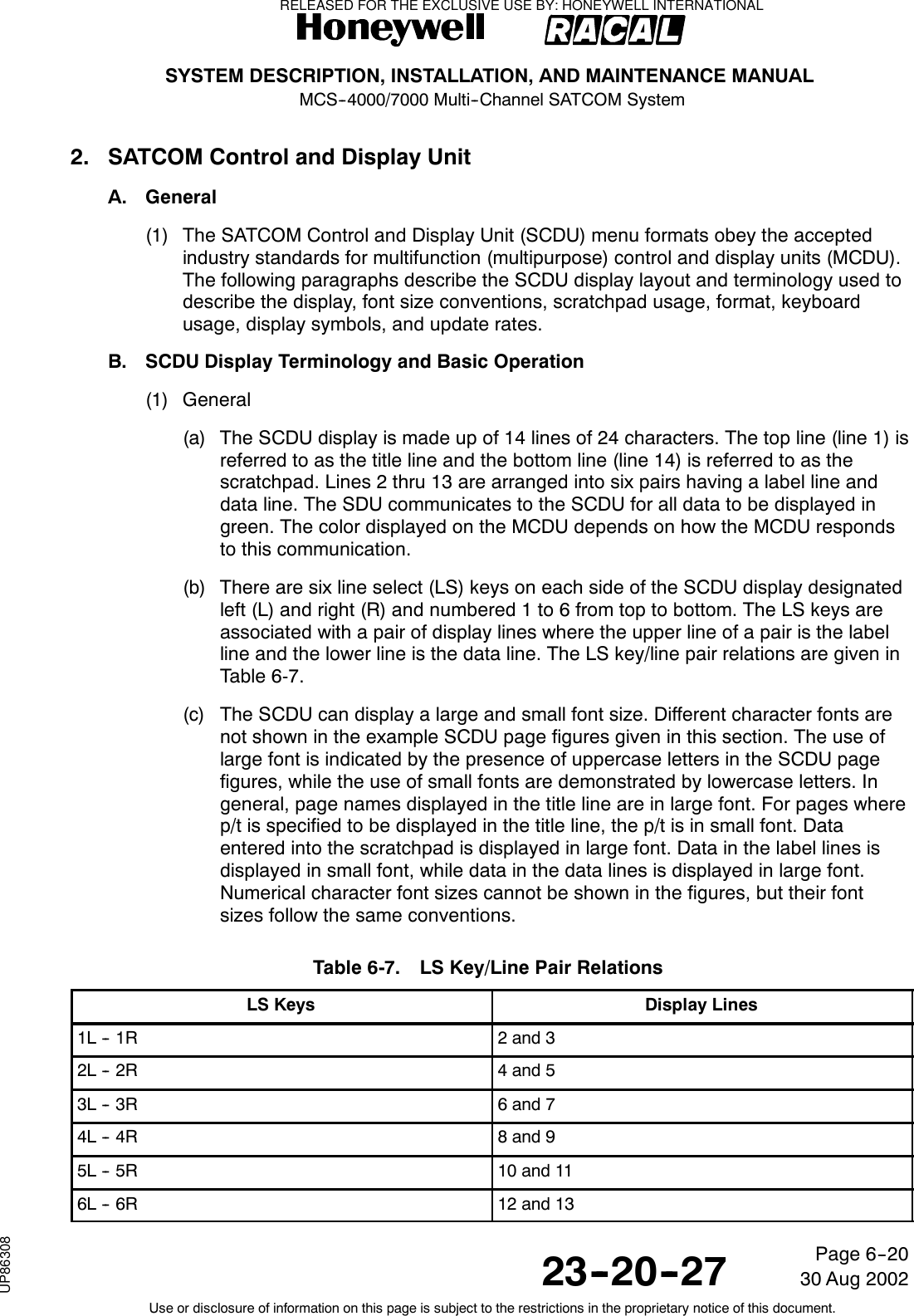
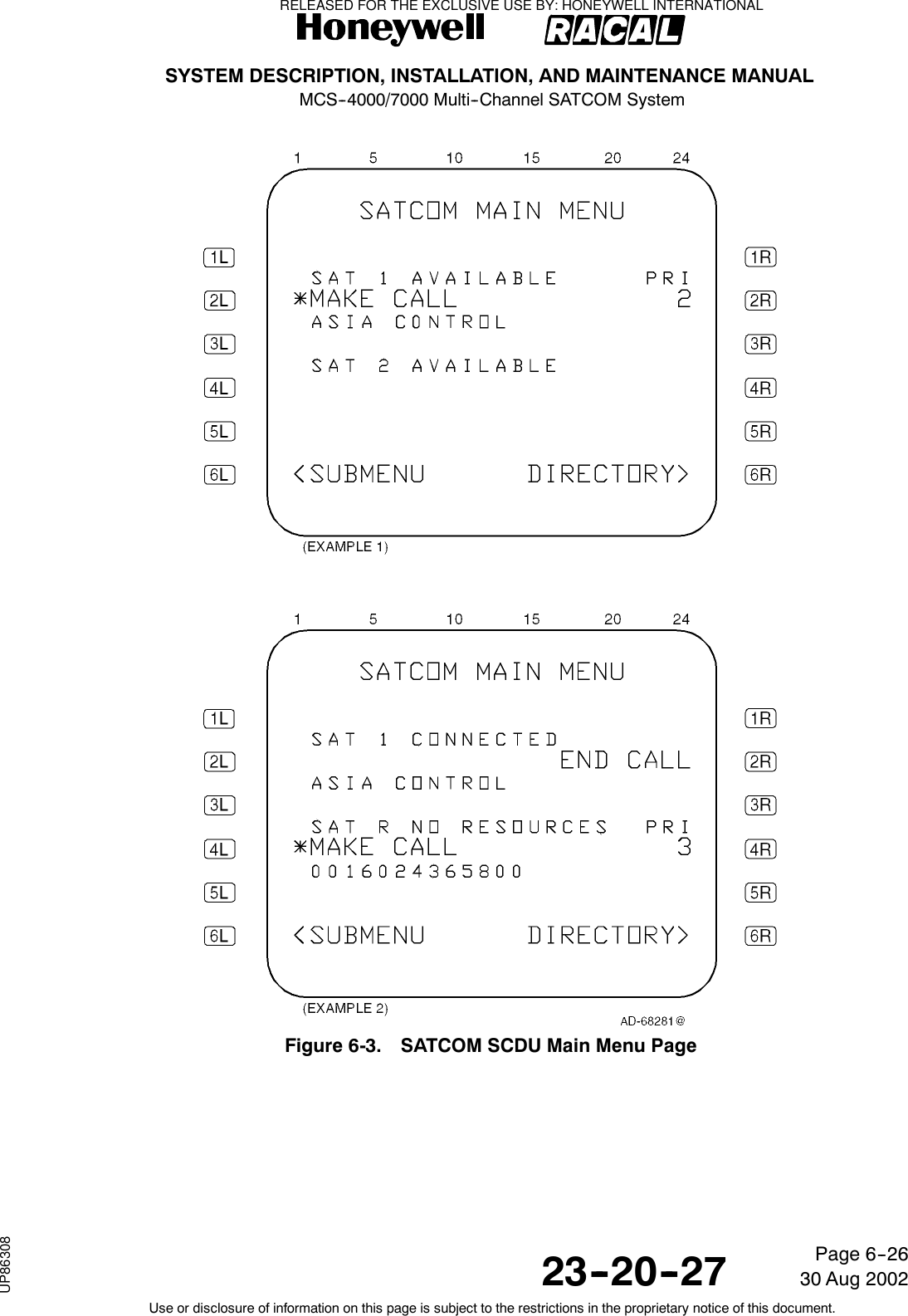
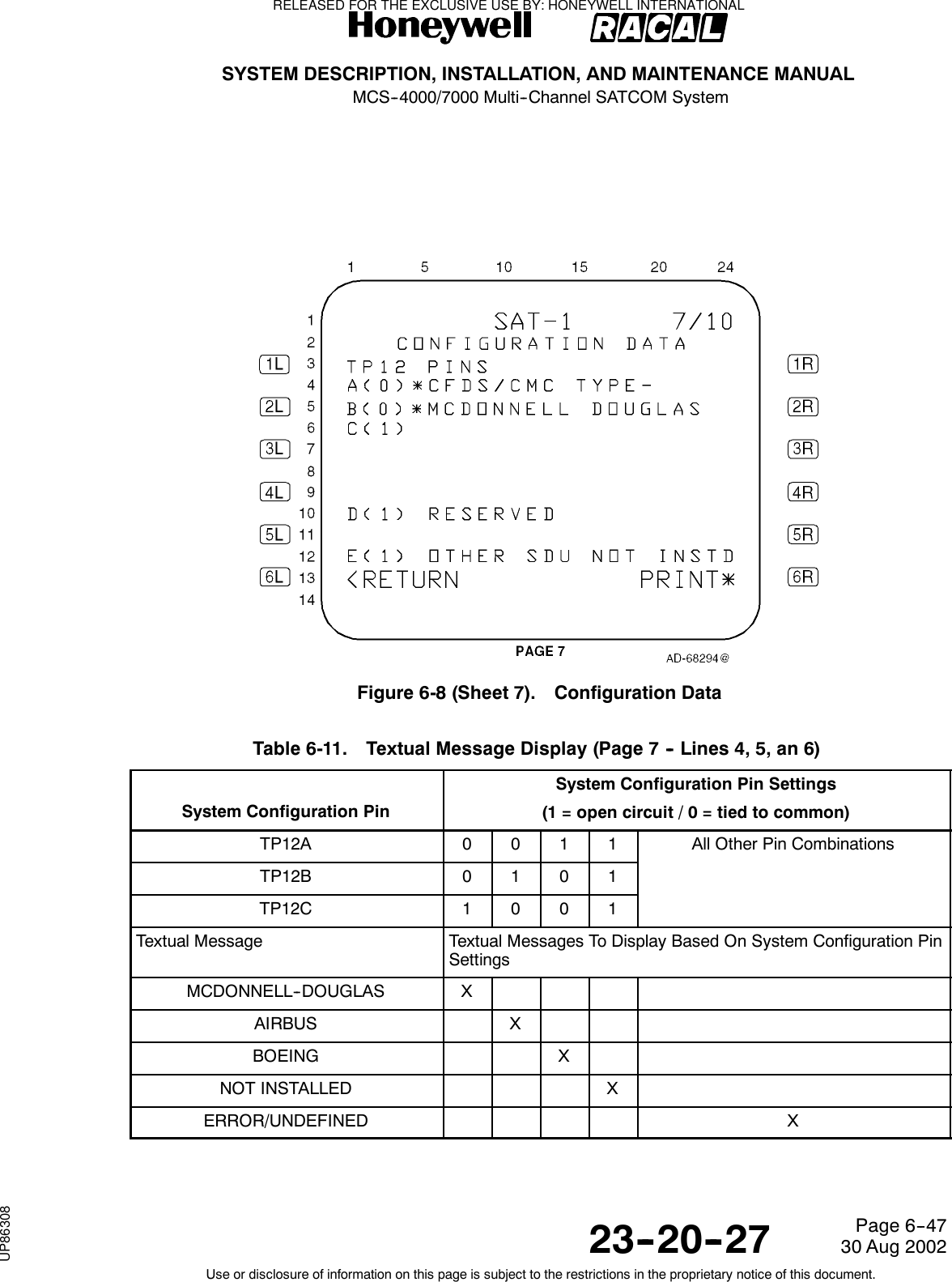
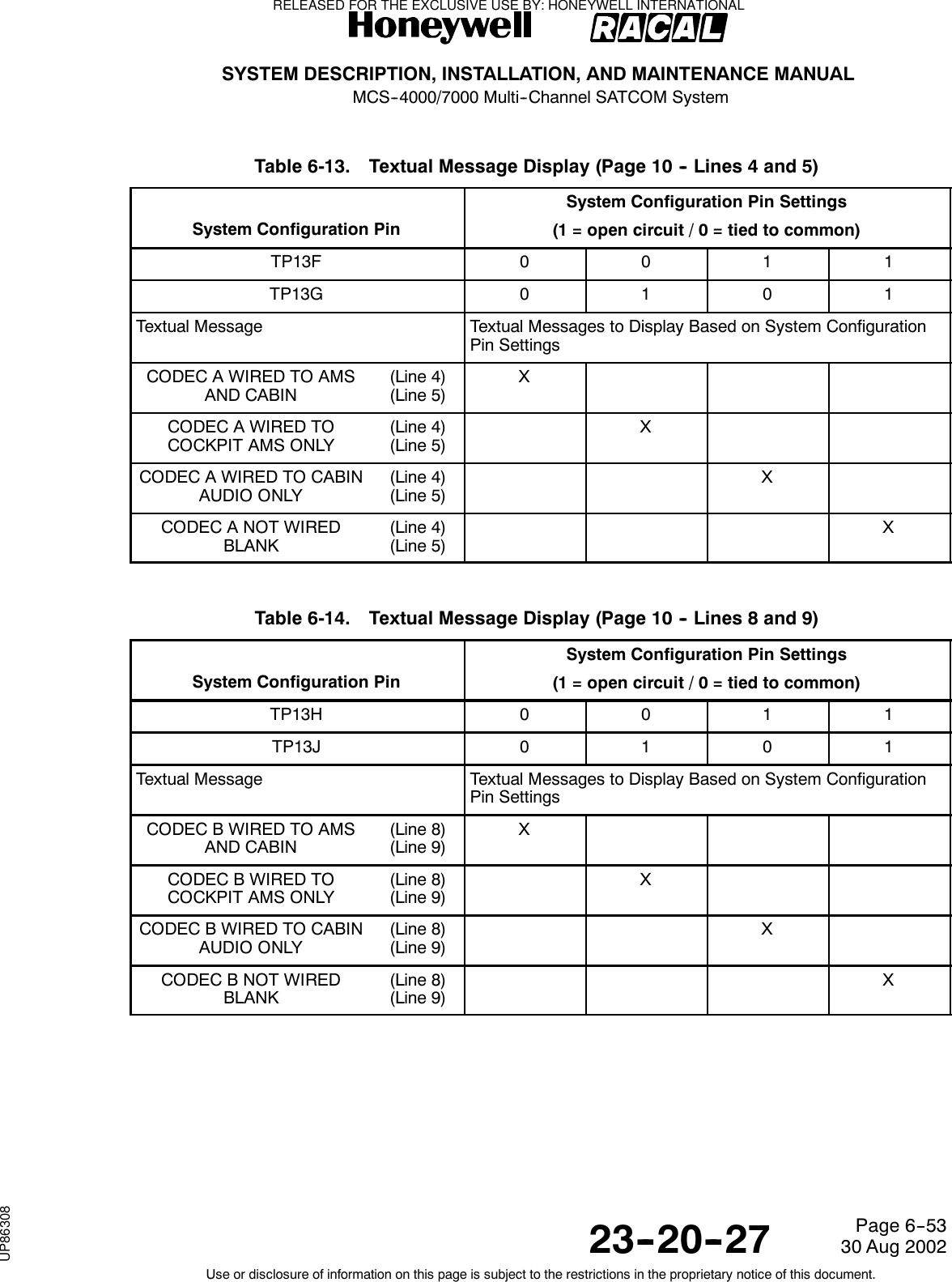
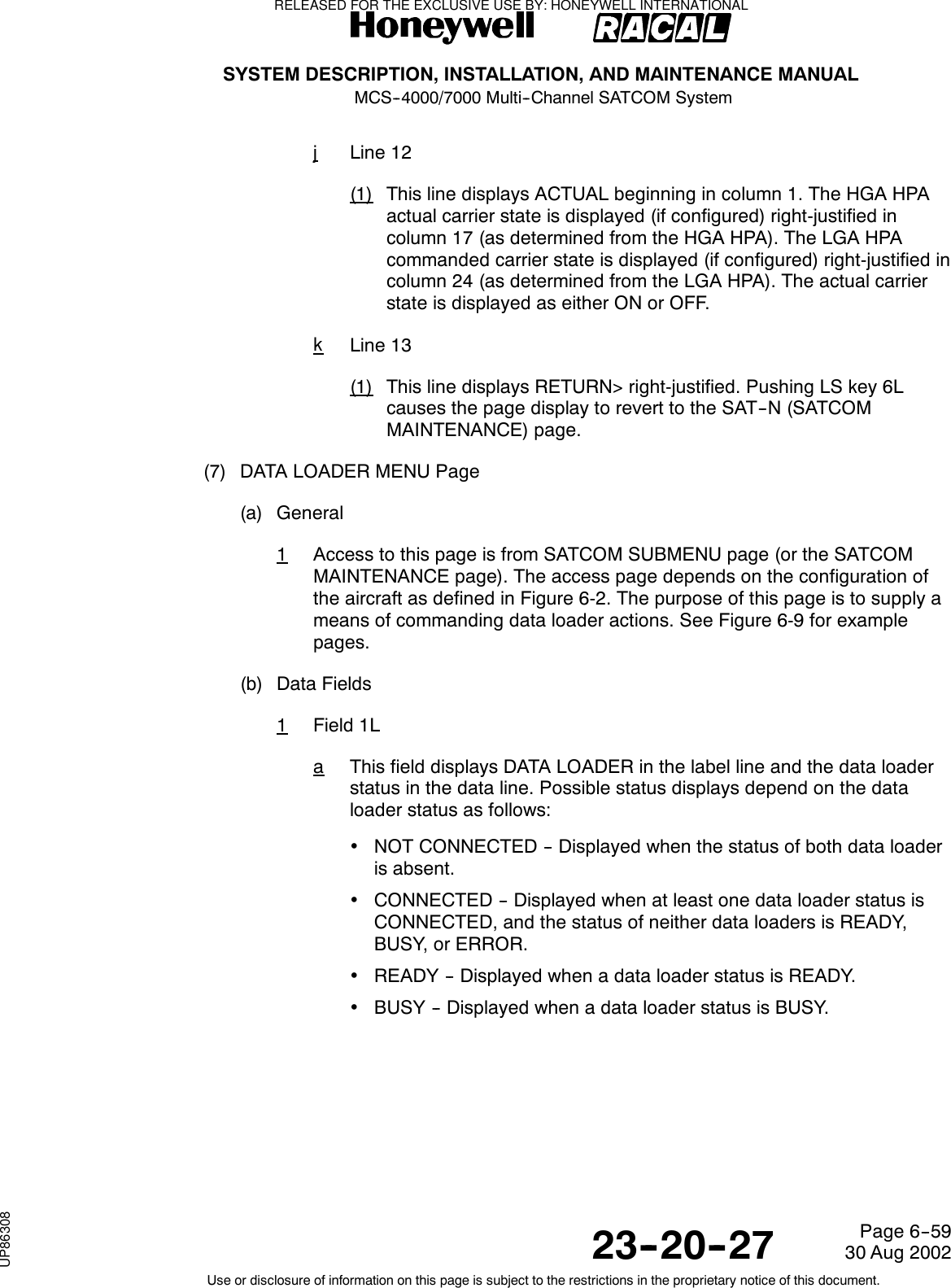
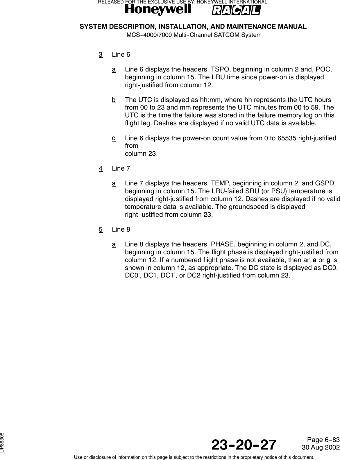
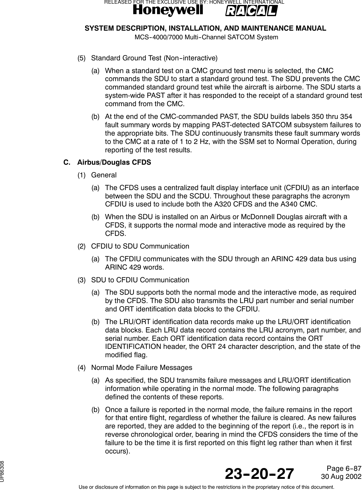
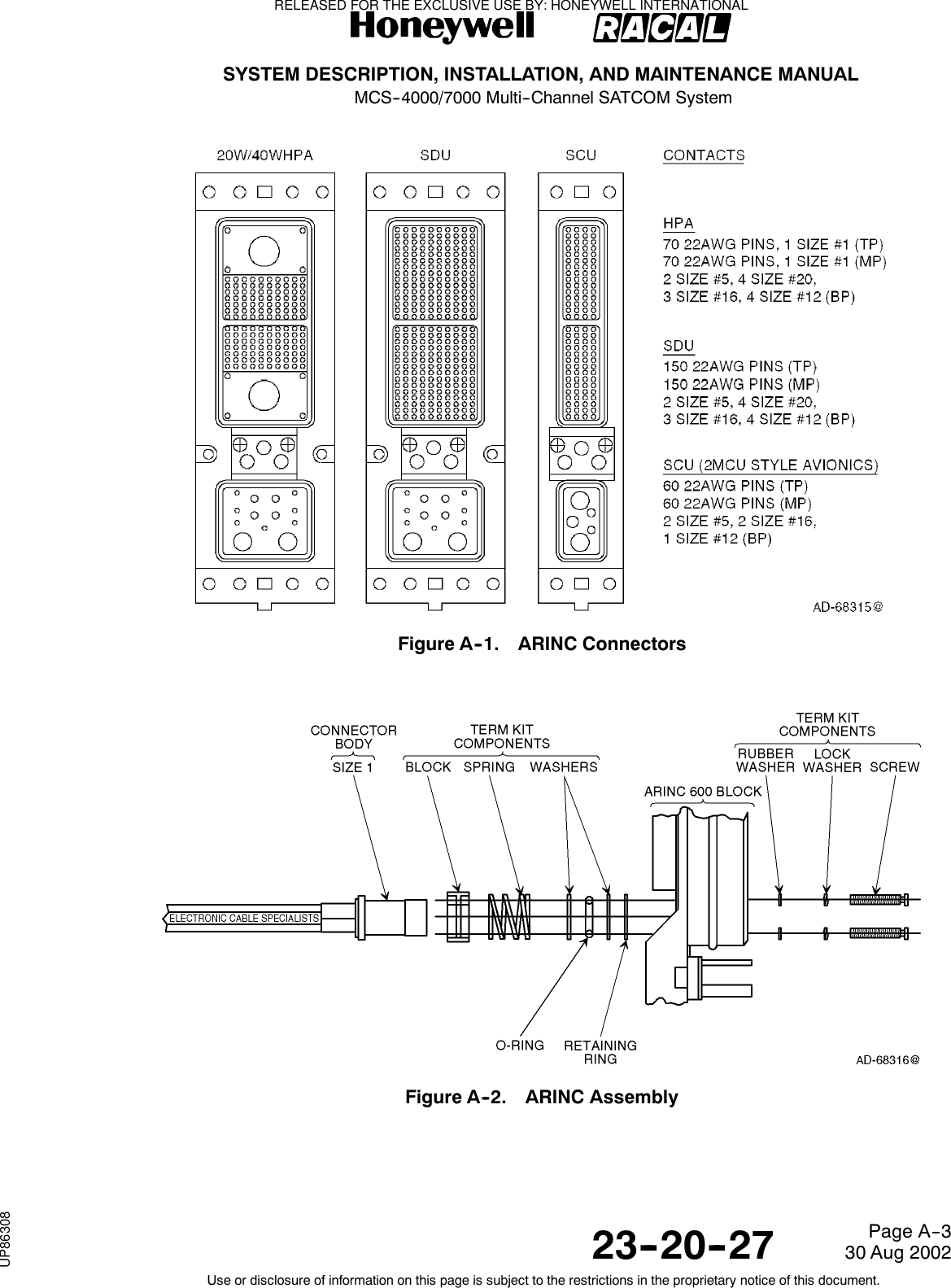
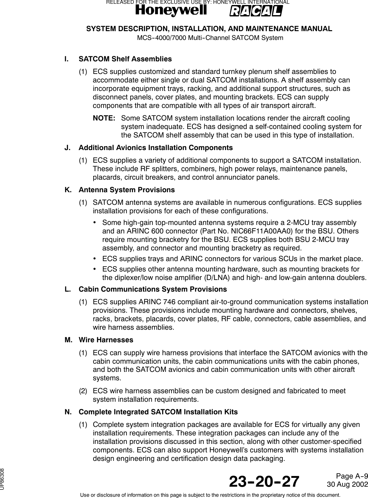
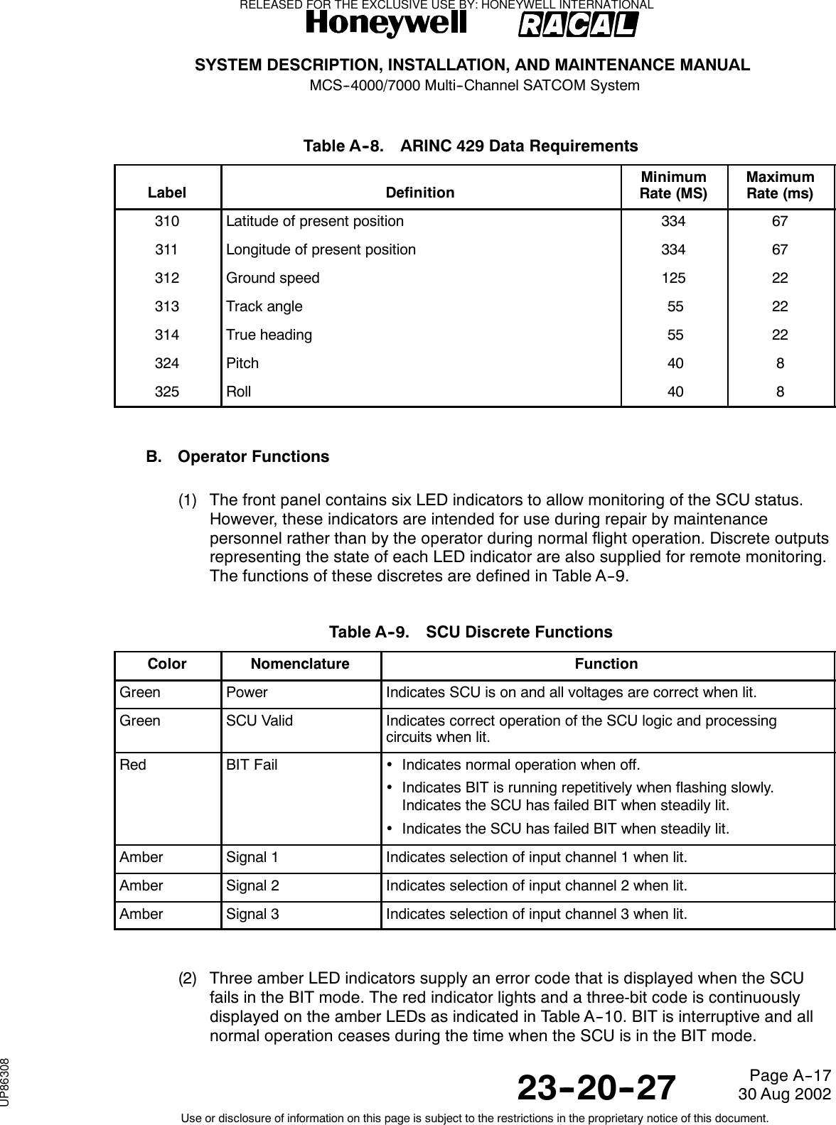
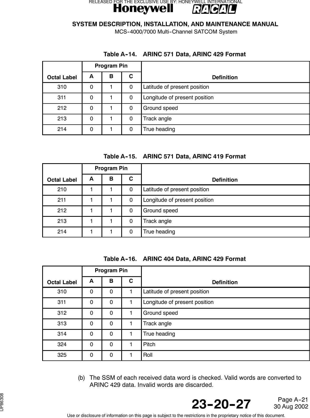
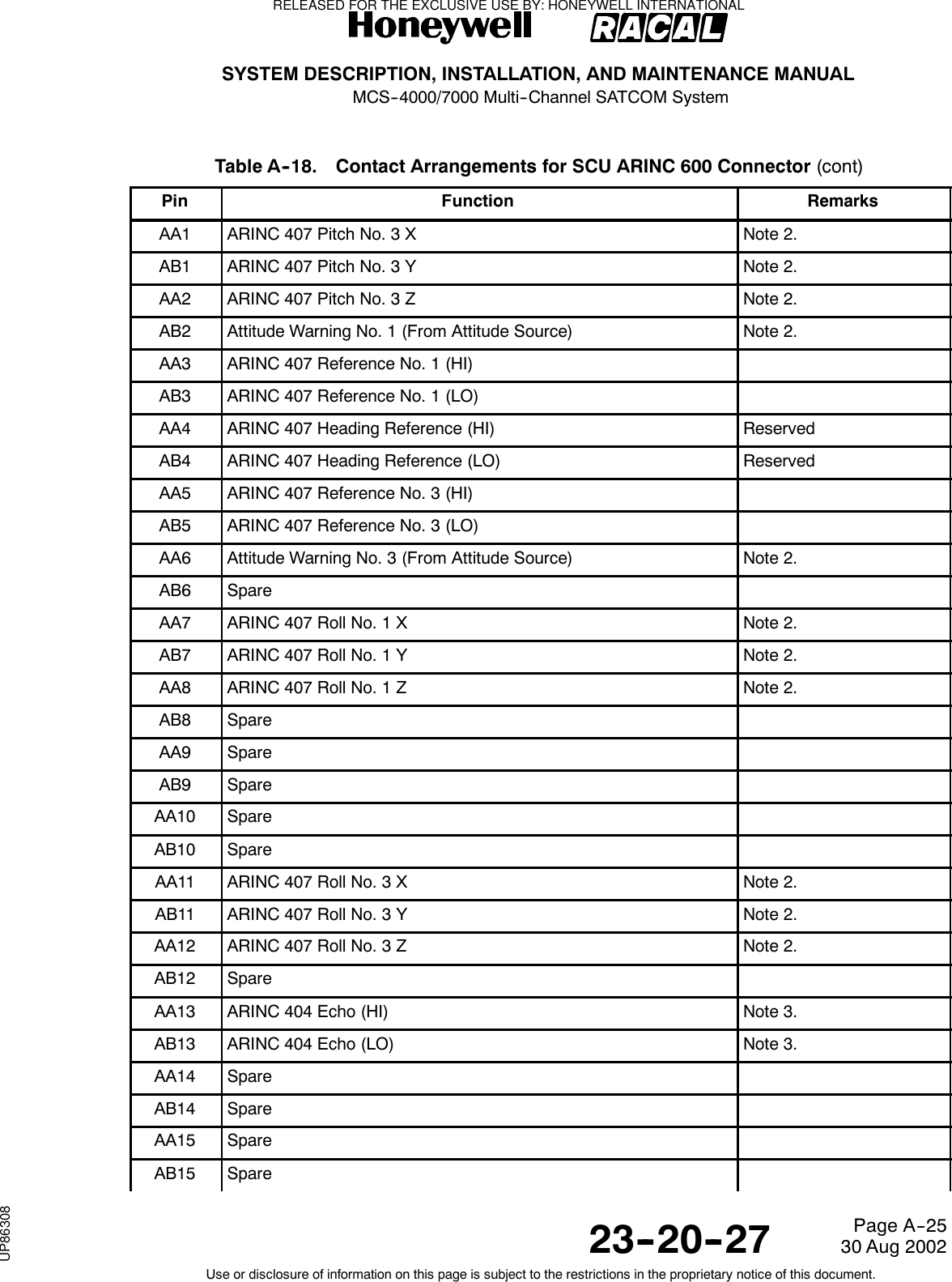
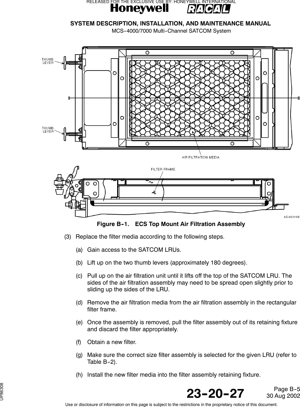
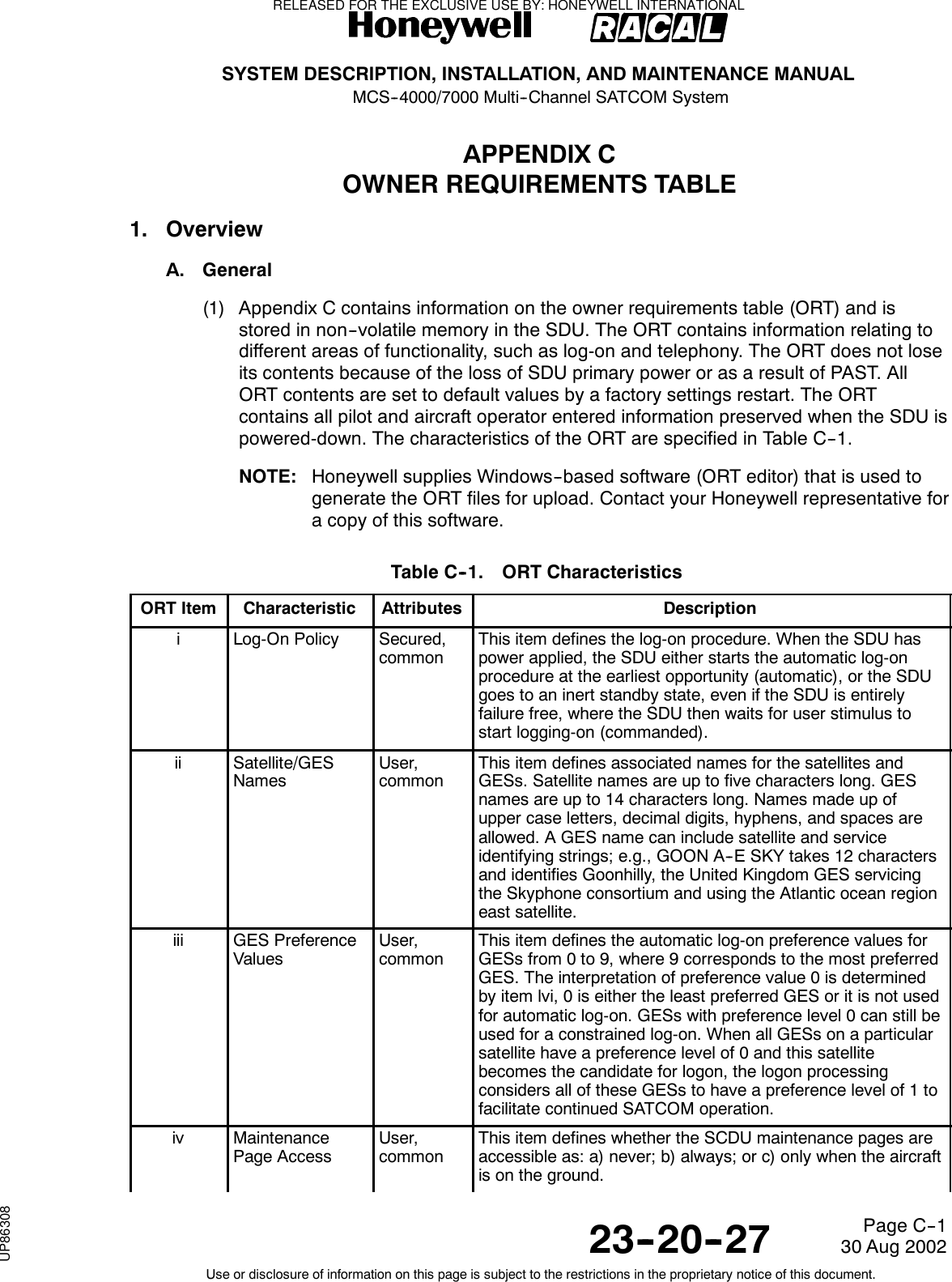
![SYSTEM DESCRIPTION, INSTALLATION, AND MAINTENANCE MANUALMCS--4000/7000 Multi--Channel SATCOM System23--20--2730 Aug 2002Use or disclosure of information on this page is subject to the restrictions in the proprietary notice of this document.Page 2--27Figure 2-12. (HGA + LGA) + HGA Configuration with Two Top-Mounted HGAsE. Cockpit Voice Configurations and Functionality(1) System configuration pins TP13F and TP13J specify the physical wiring for thecodecs of each SDU to the possible interfaces -- a codec/channel can only beavailable to the cockpit if the wiring strap is set to Cockpit or Both (and not if thewiring is to Cabin or Neither).(2) An additional issue with dual systems is how to map the potentially available fourphysical SDU cockpit voice channels with the one or two (maximum) usable logicalcockpit channels controllable through the audio control panels (ACPs) and theSCDUs (i.e., as seen by the audio management system [AMS] user). Twoconfigurations are defined, which are identified by ORT item xlviii (Cockpit ChannelInterface Type for Dual): (1) interfacing each ACP/SCDU logical channel to onephysical channel on one SDU only (fixed),and(2)interfacinganACP/SCDUlogicalchannel to one physical channel on each of the two SDUs (shared). Note theinterfacing referred to is conceptual and not necessarily physical -- i.e., for shared,the physical wiring can be literally paralleled, or it can be simple point-to-point, withsome form of signal splitting/combining or paralleling being performed within the AMSitself. The system configuration straps for codec wiring let the SDU determine thephysical channels which are candidate channels for each logical channel.RELEASED FOR THE EXCLUSIVE USE BY: HONEYWELL INTERNATIONALUP86308](https://usermanual.wiki/Honeywell/SD-700A/User-Guide-3476924-Page-117.png)
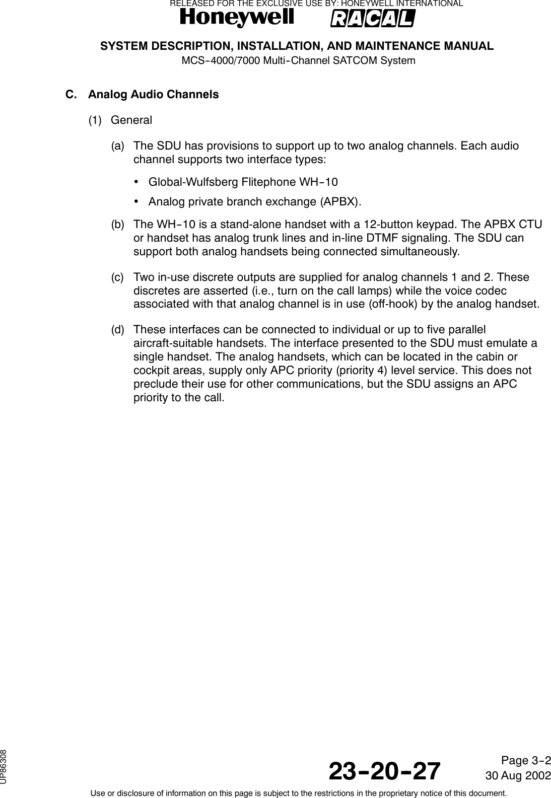
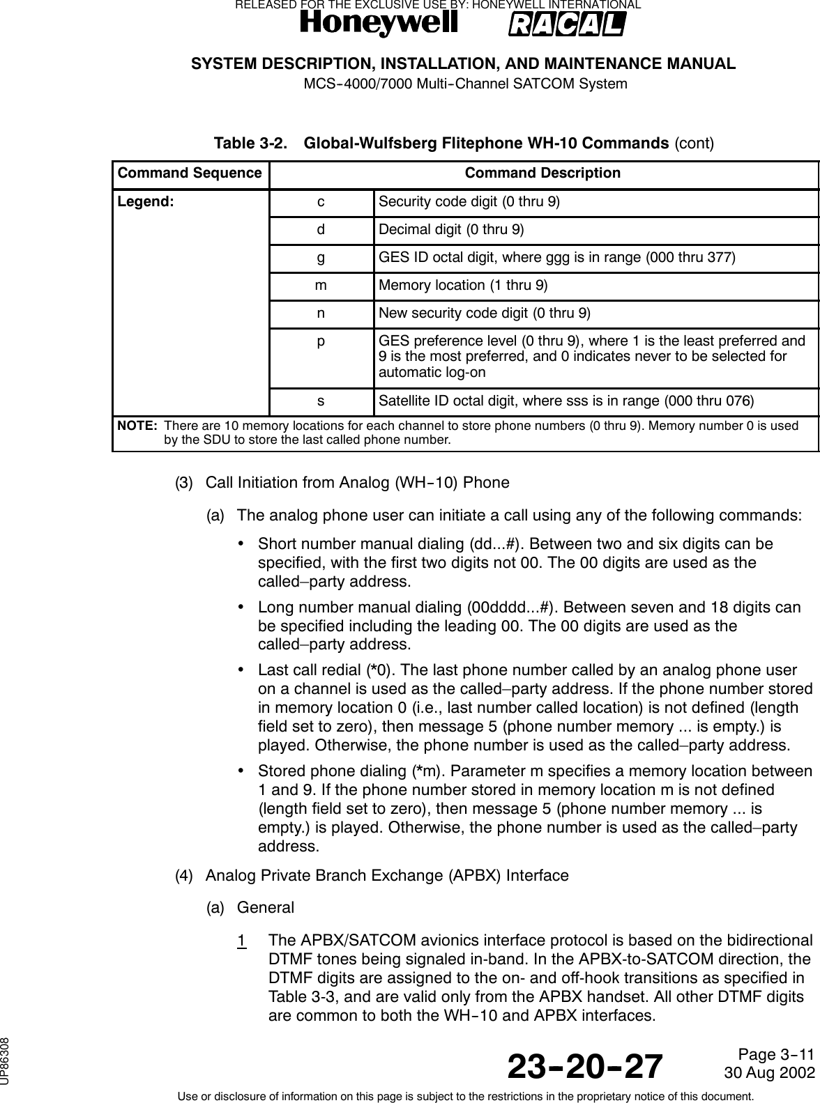
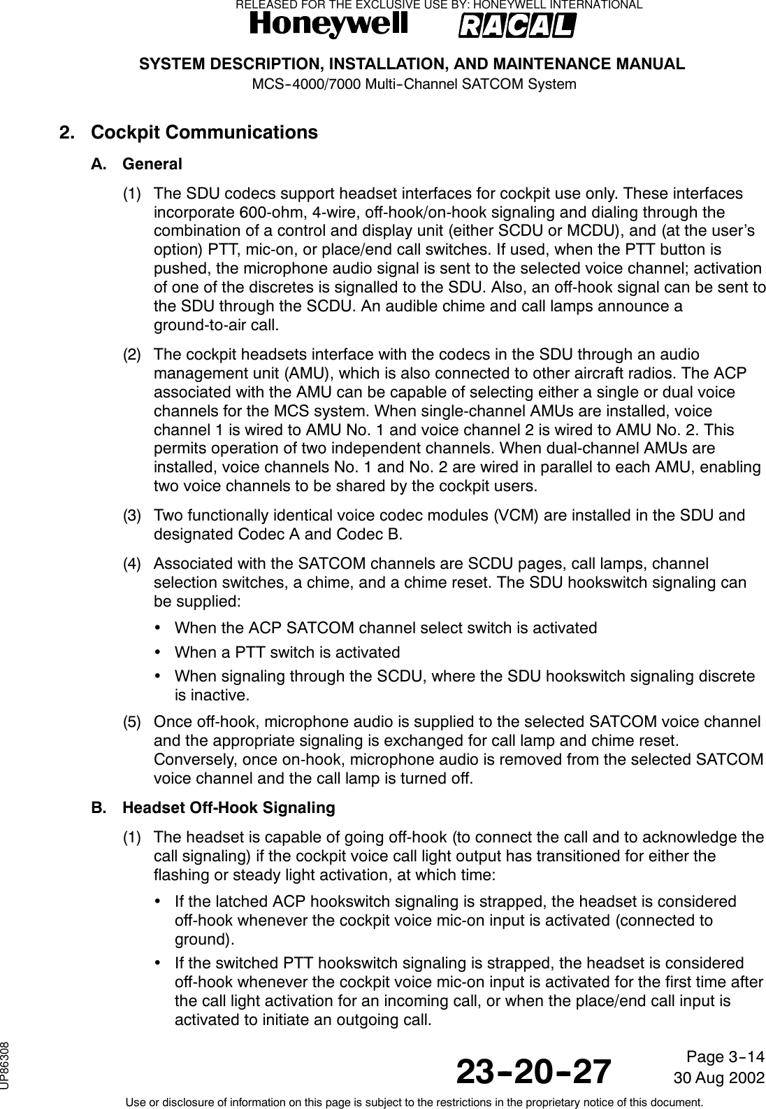
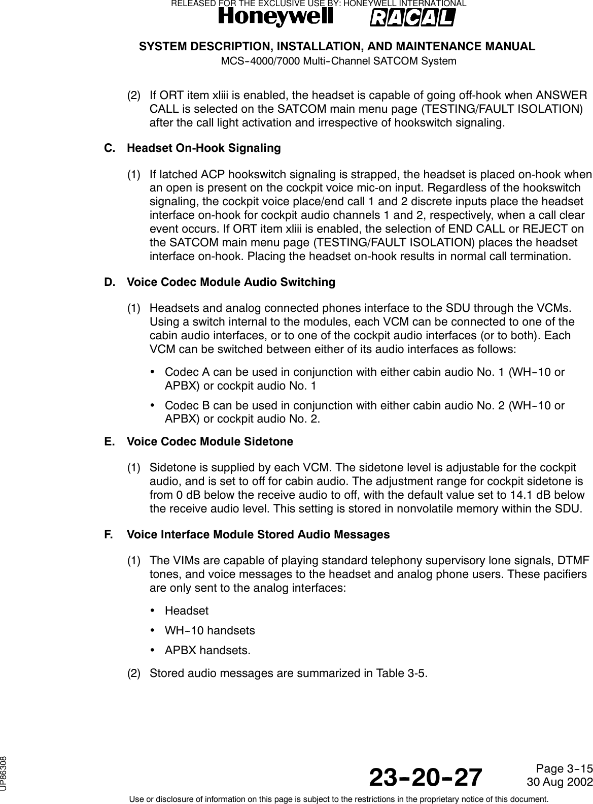

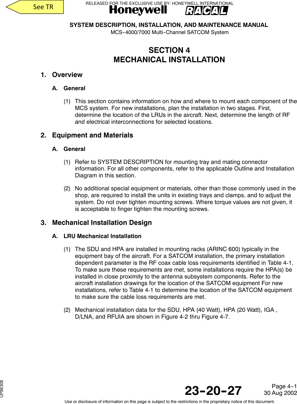
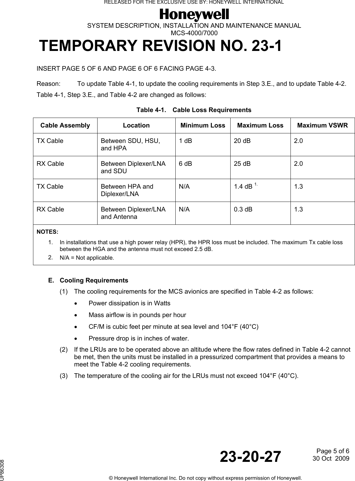

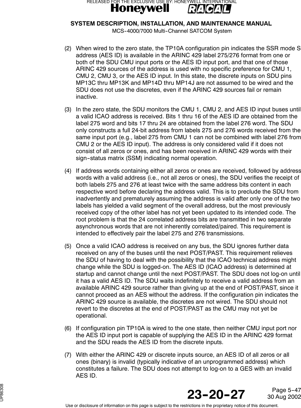
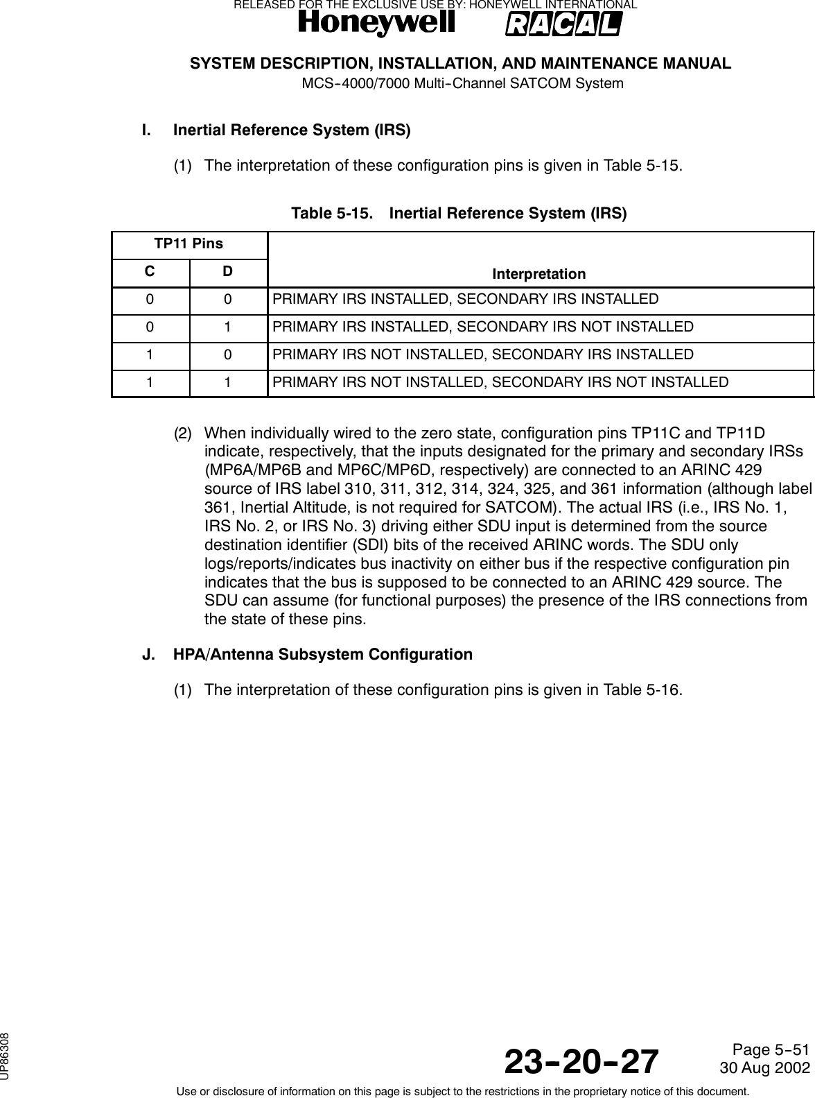
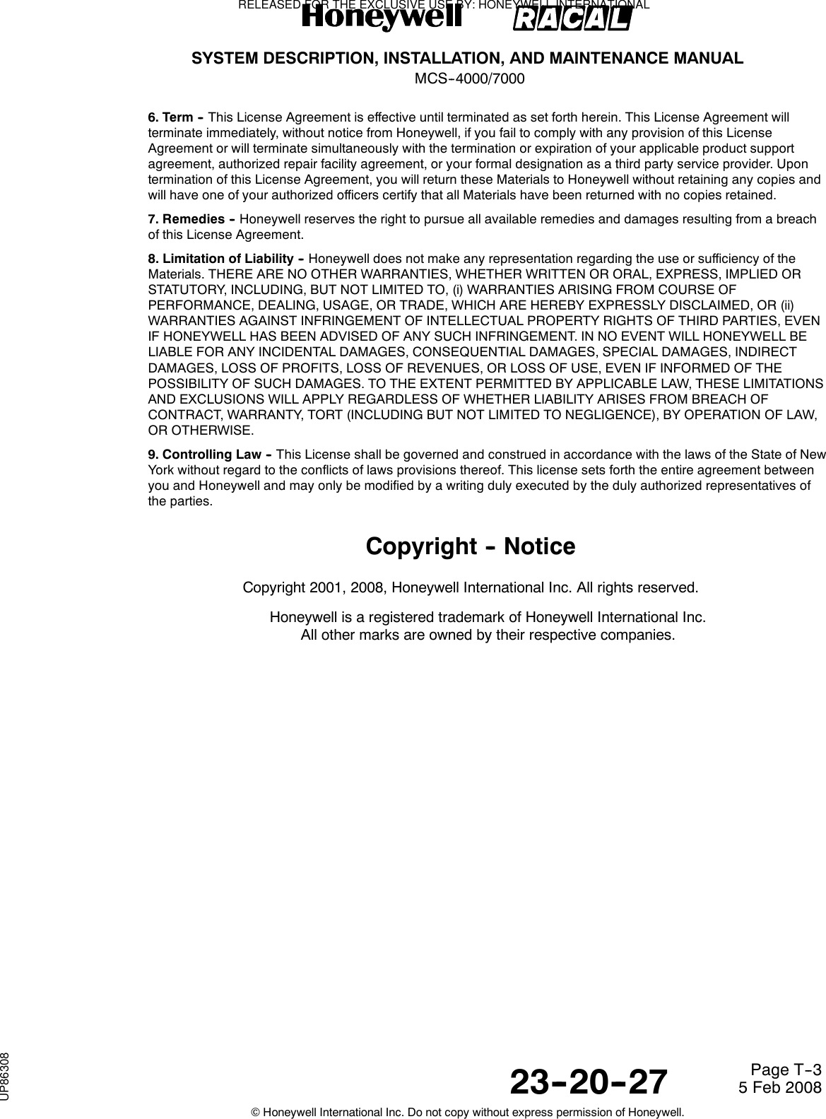
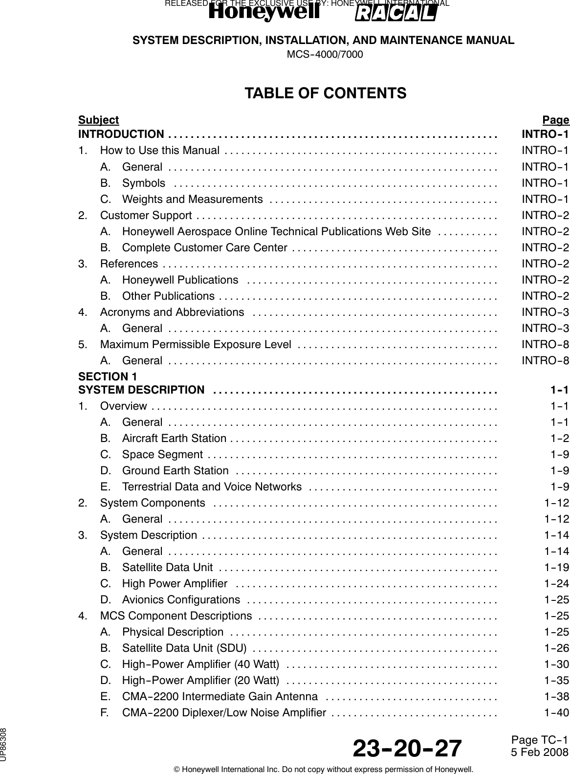
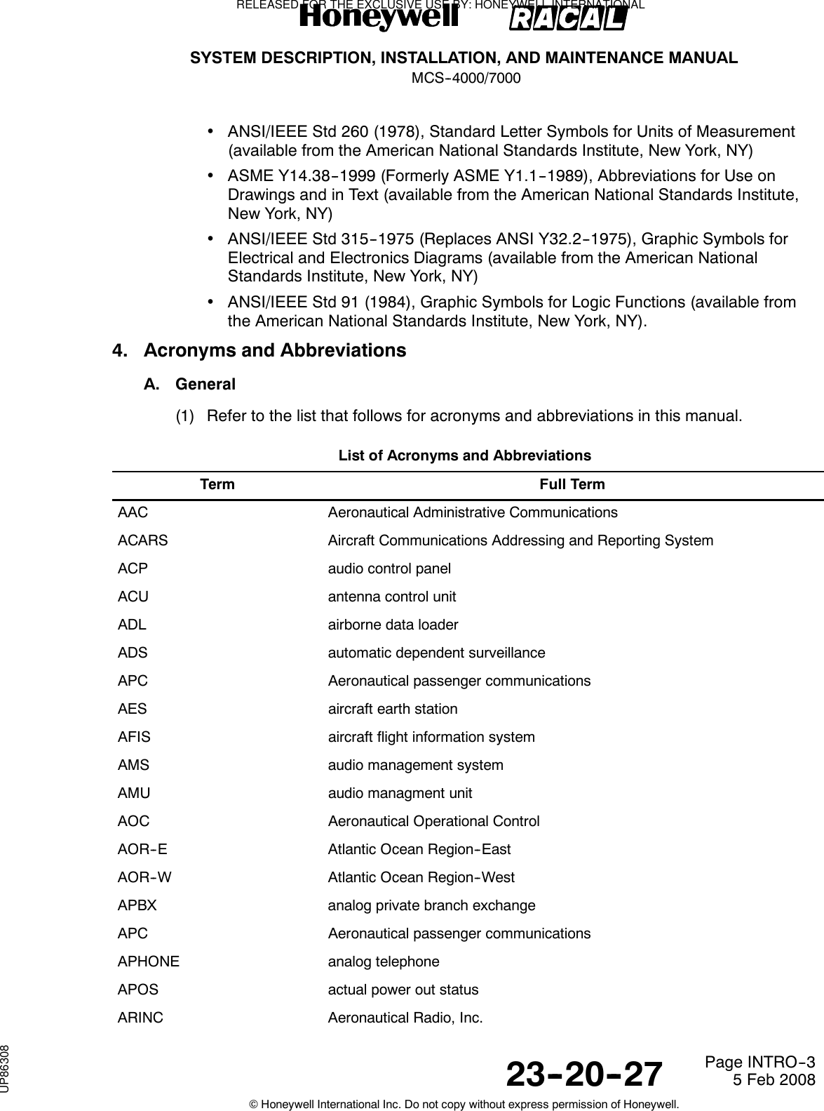
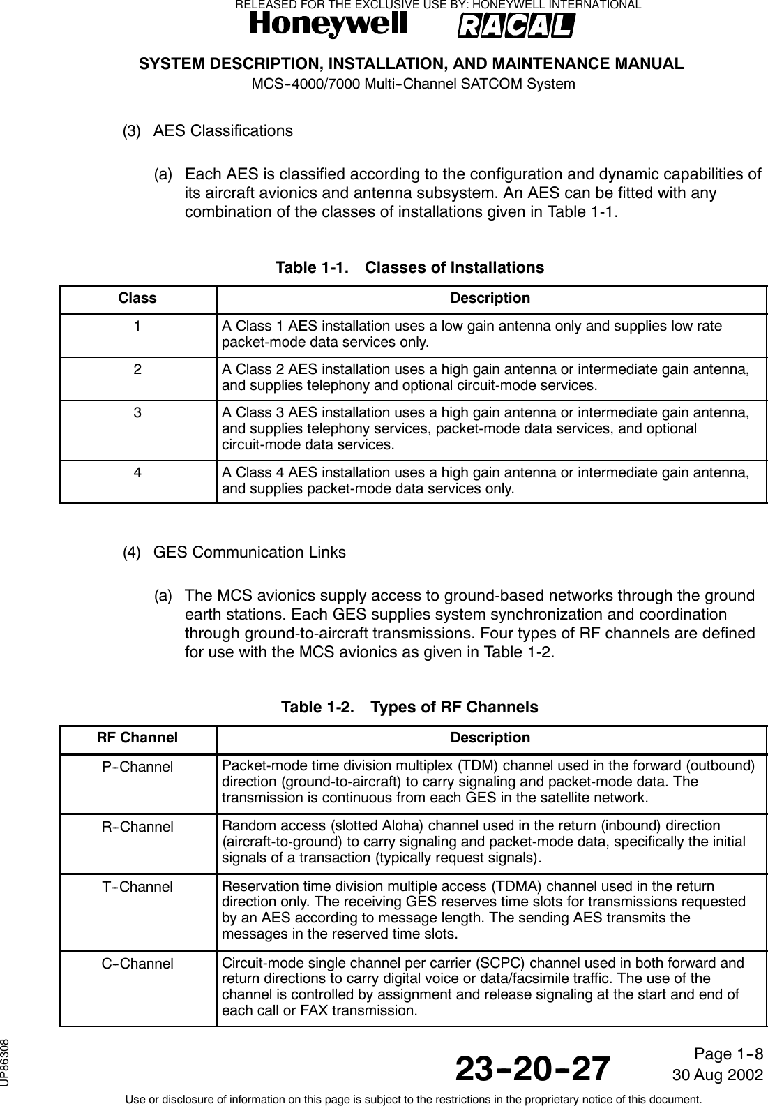
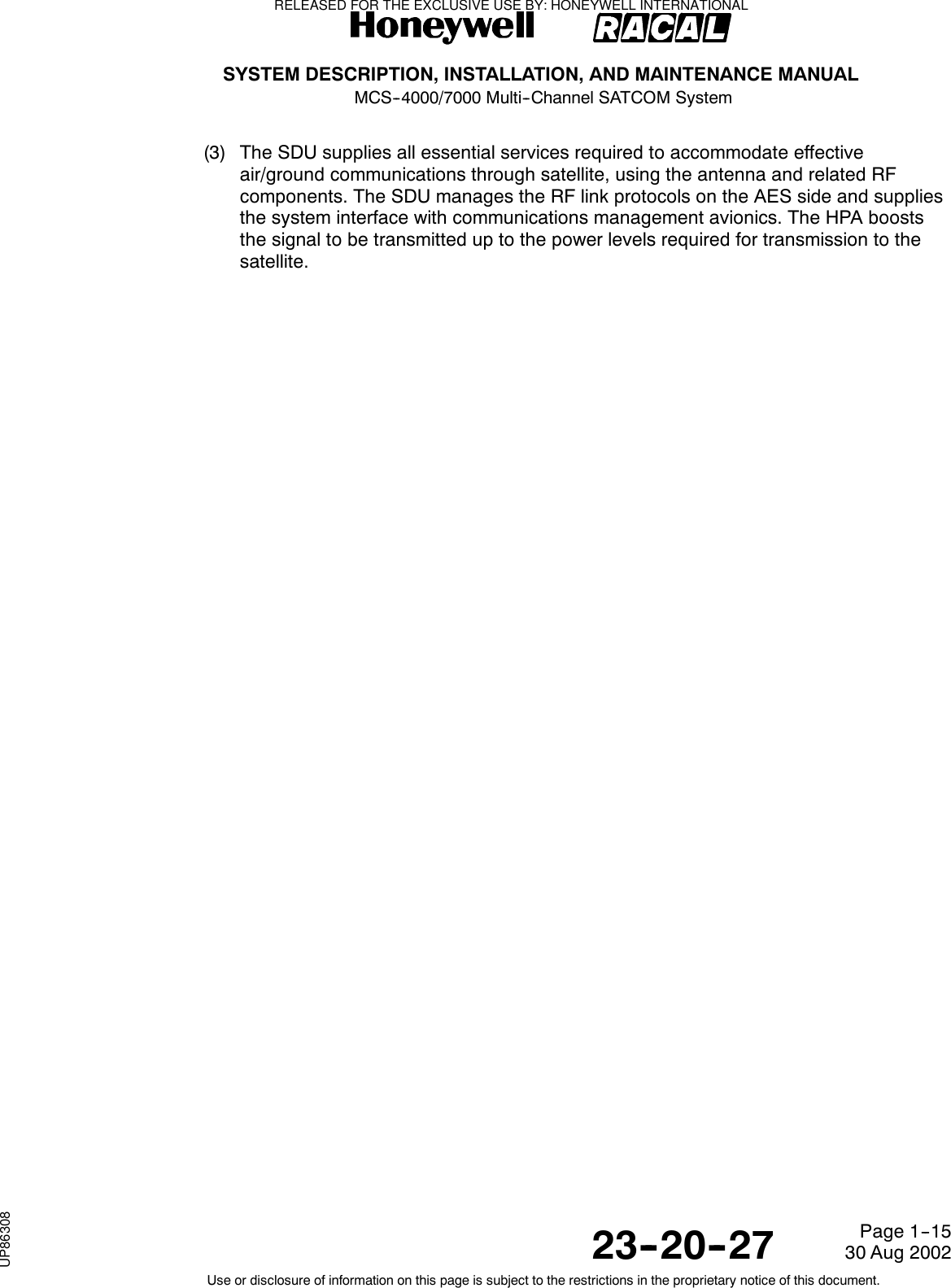
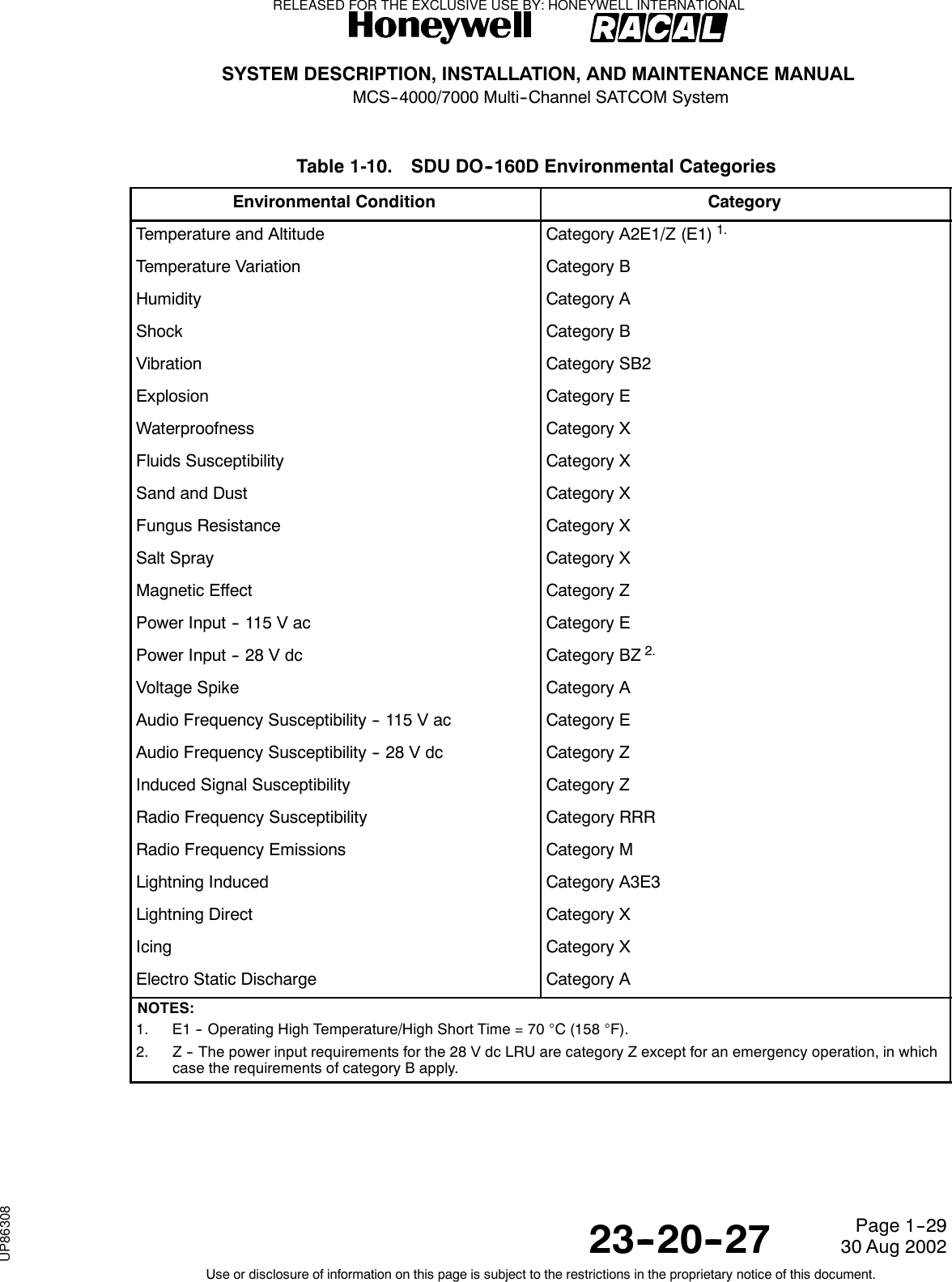
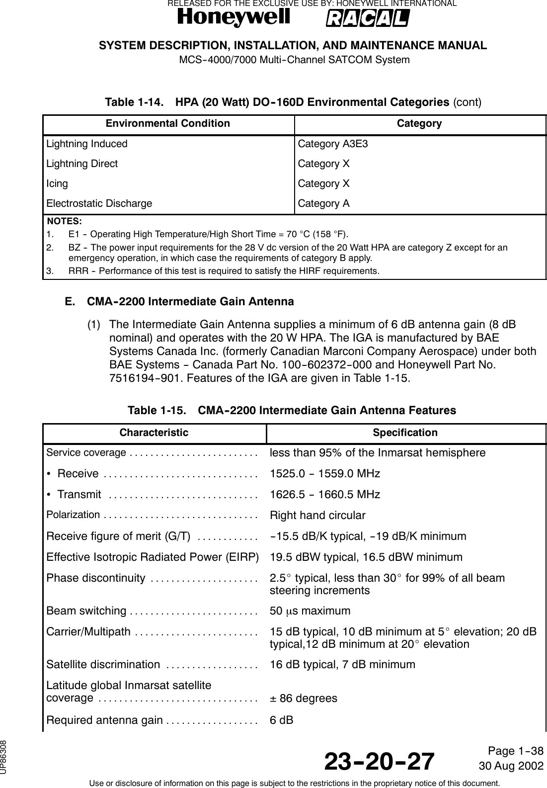
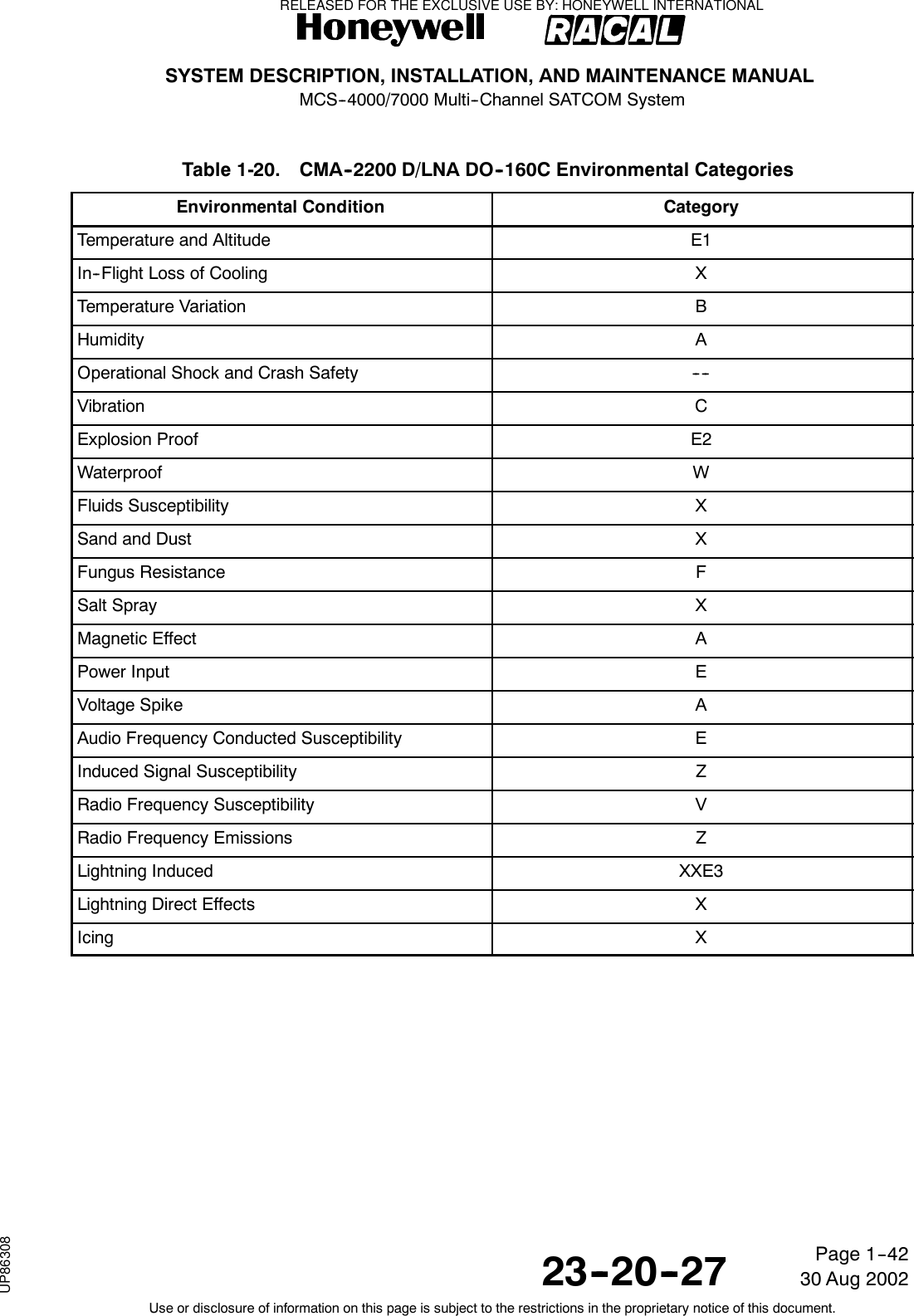
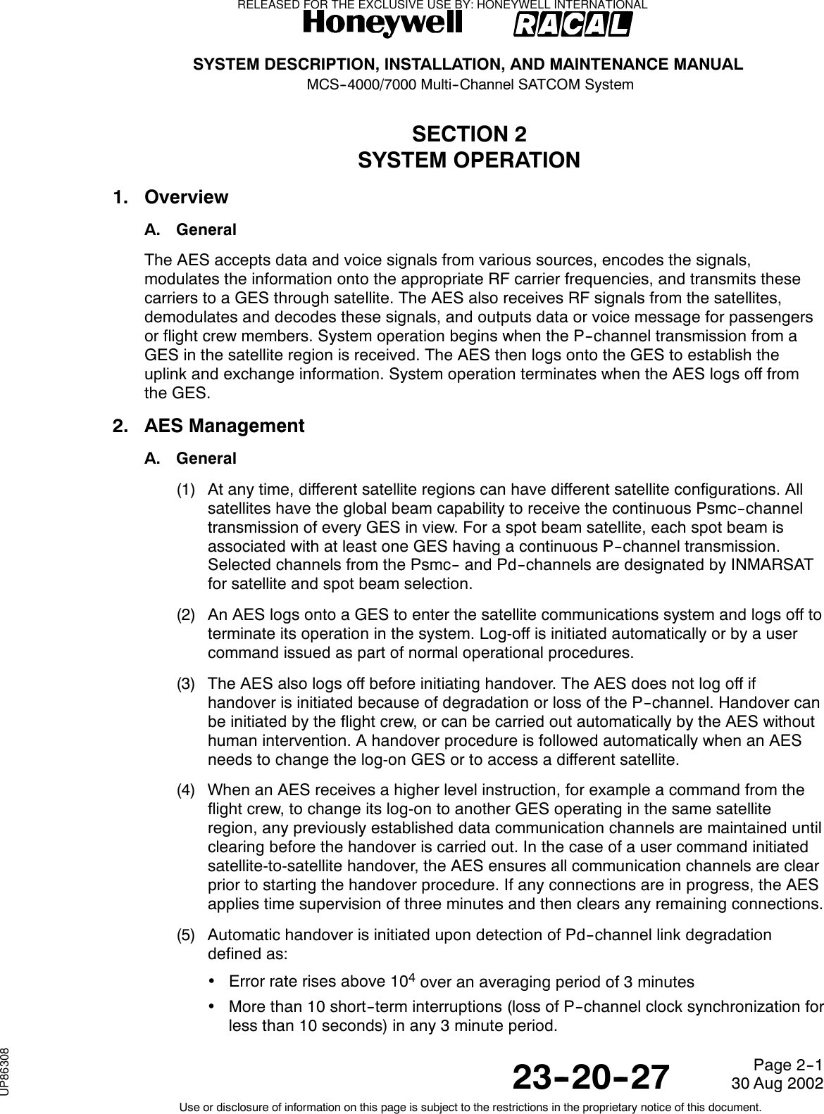
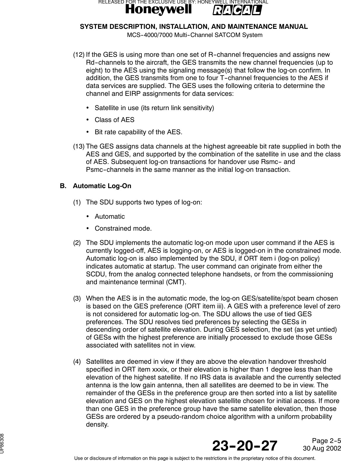
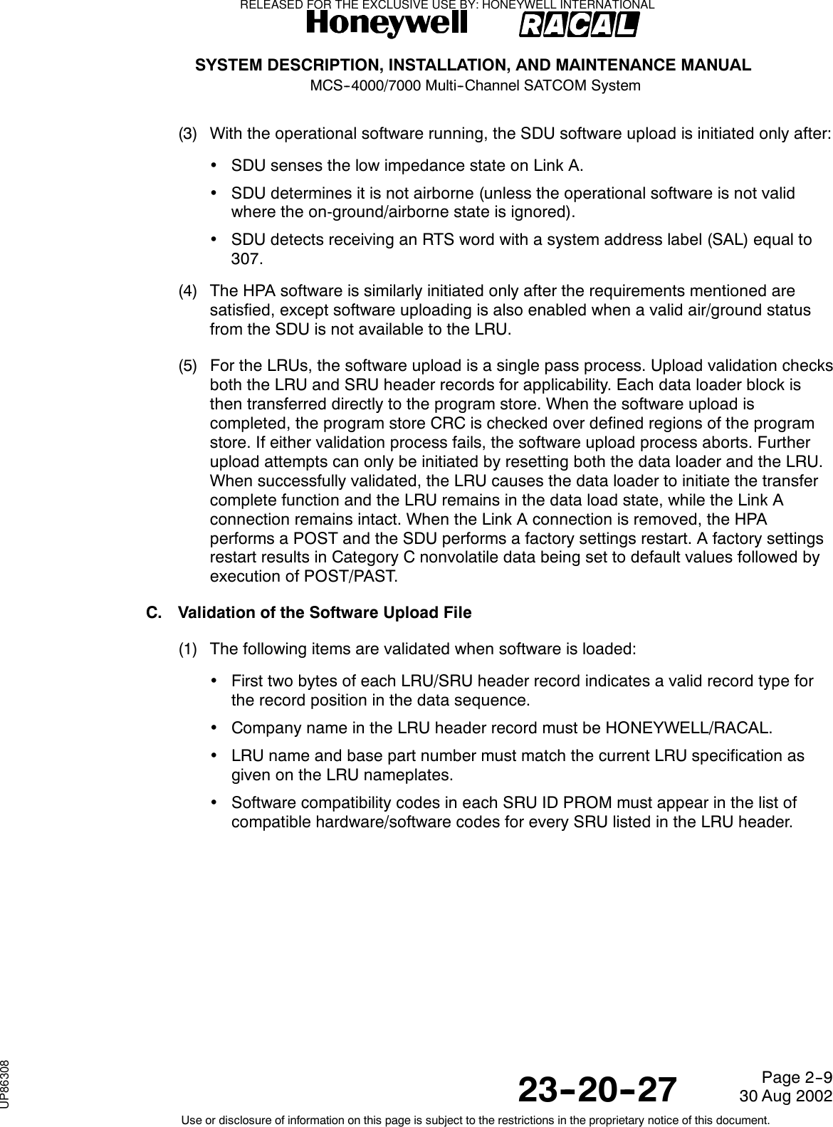
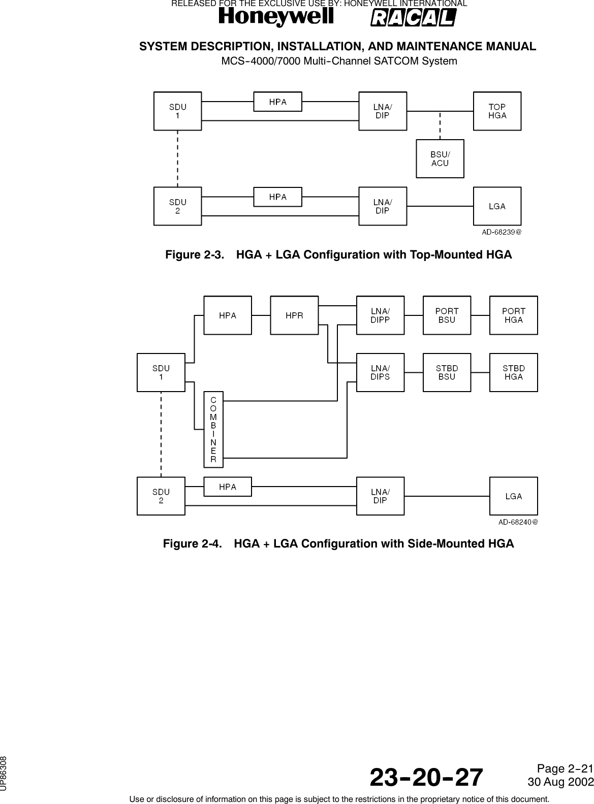
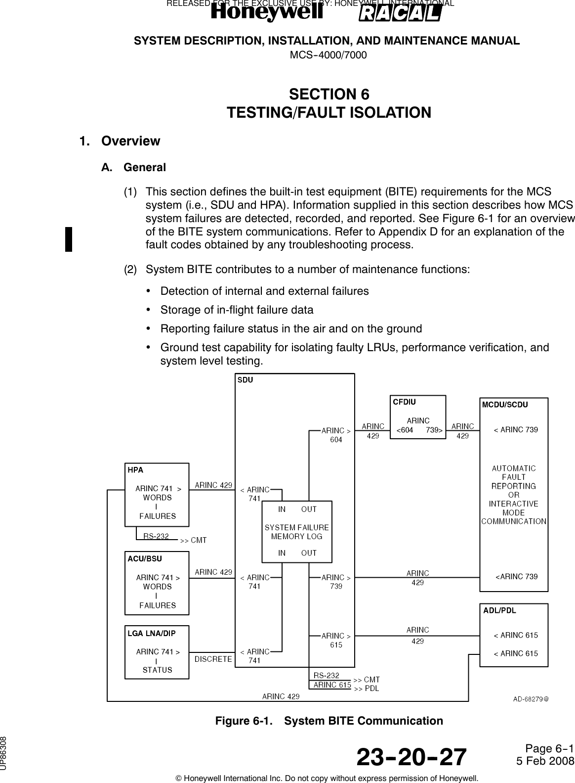
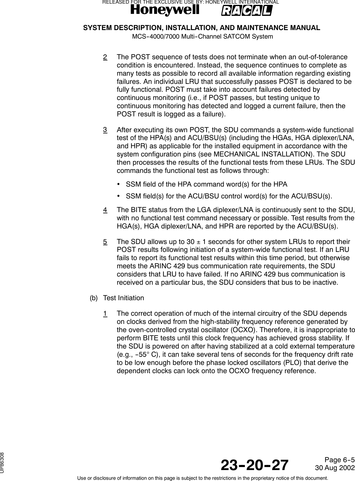
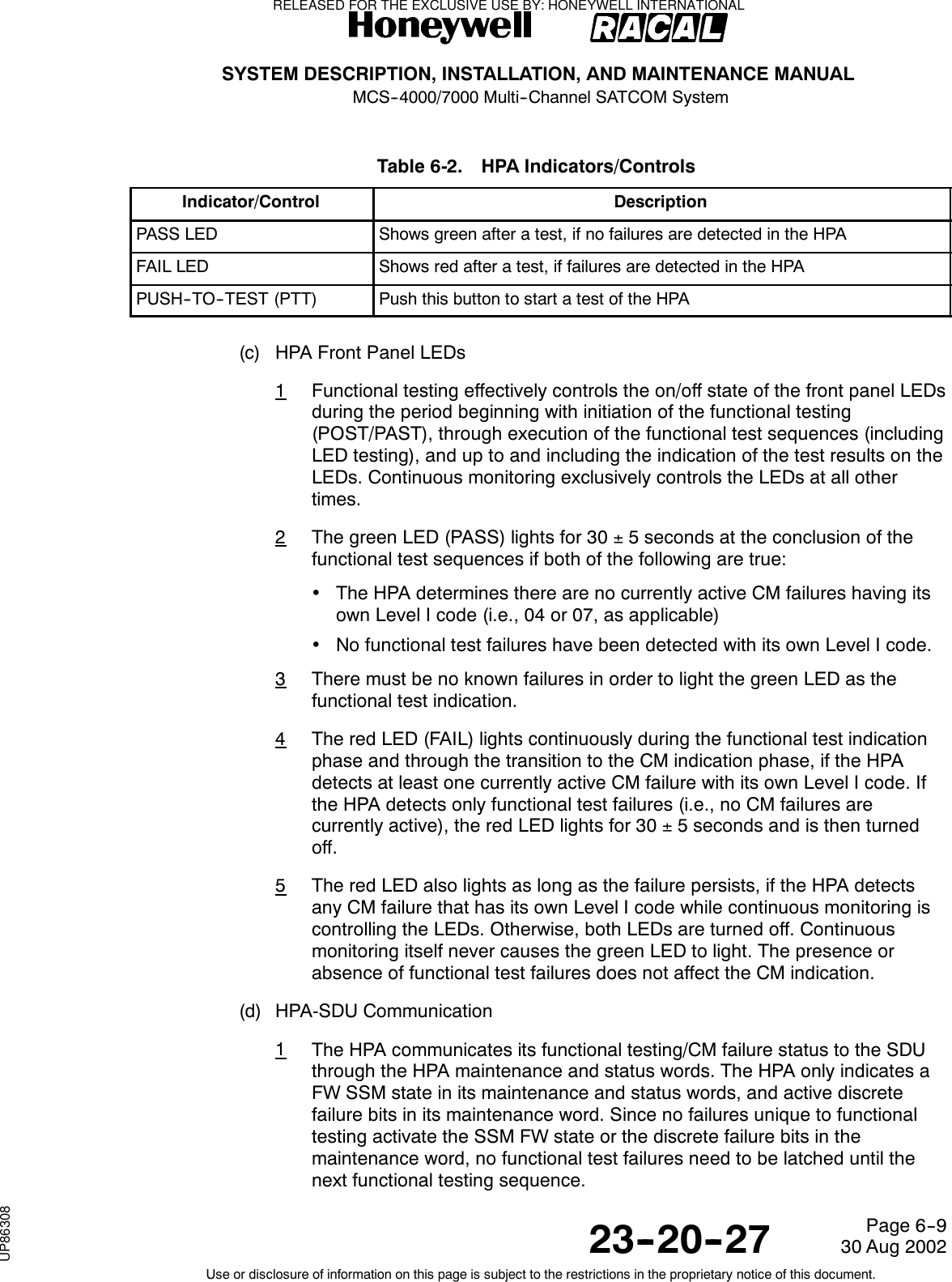
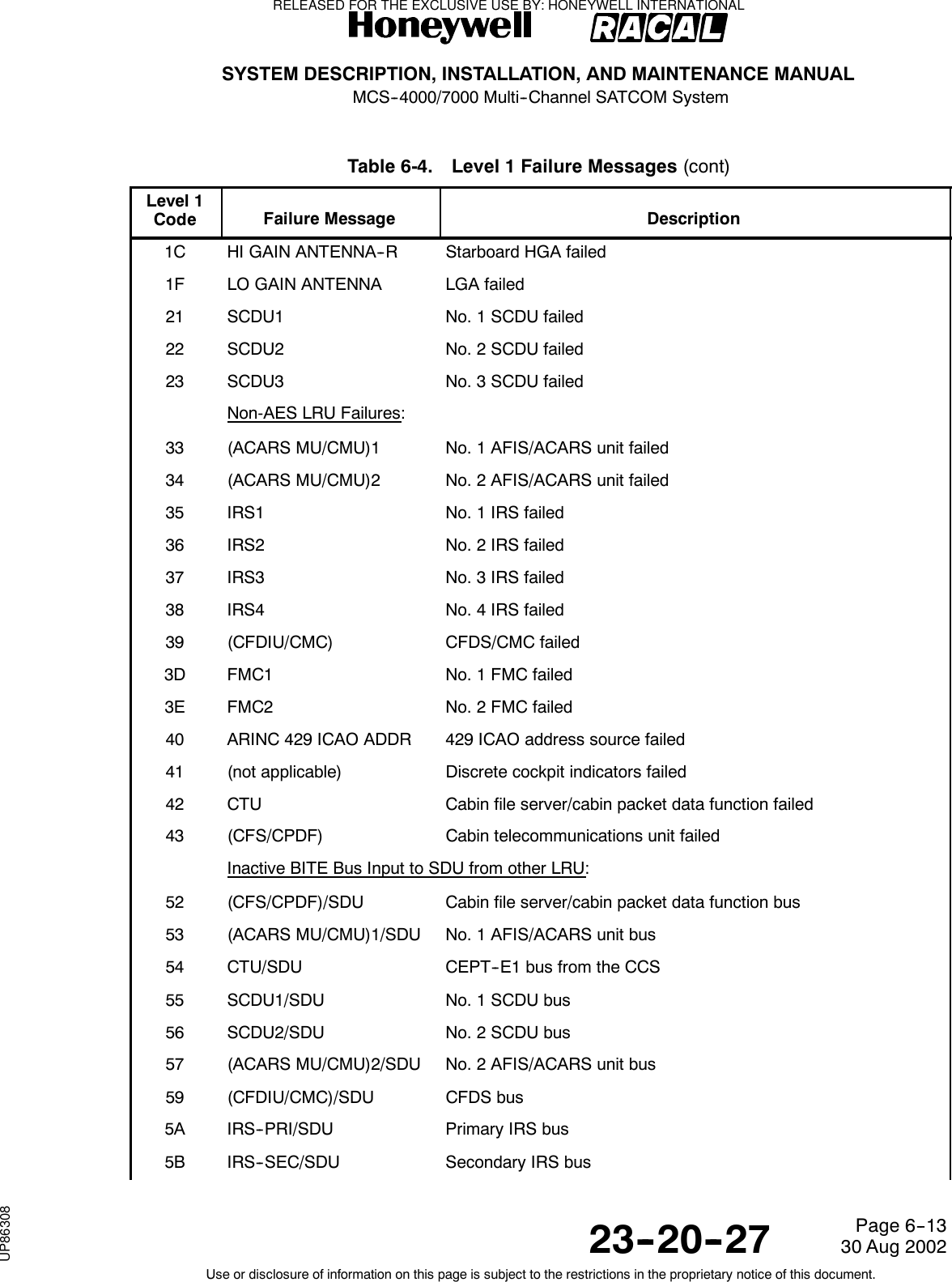
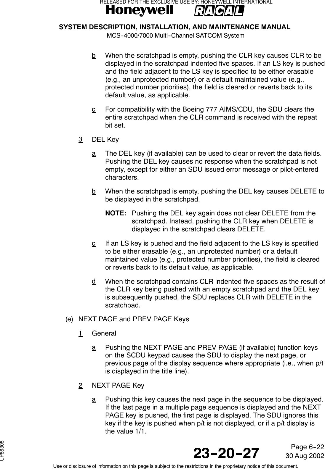
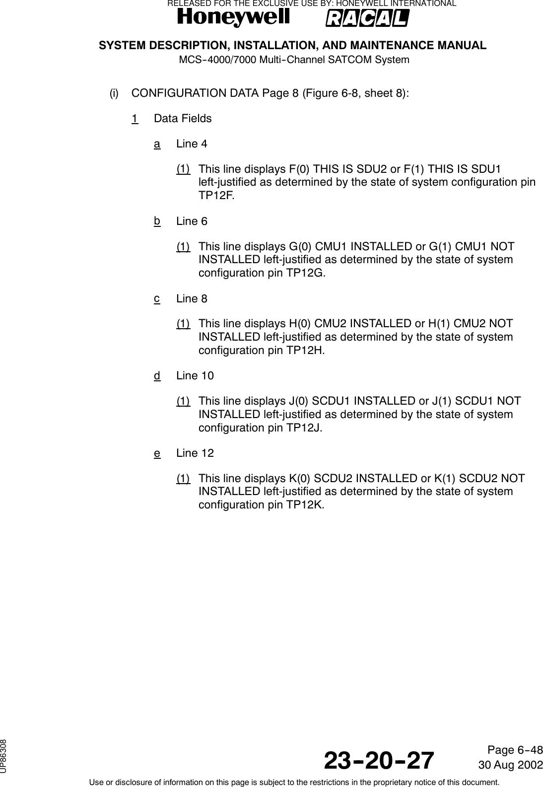
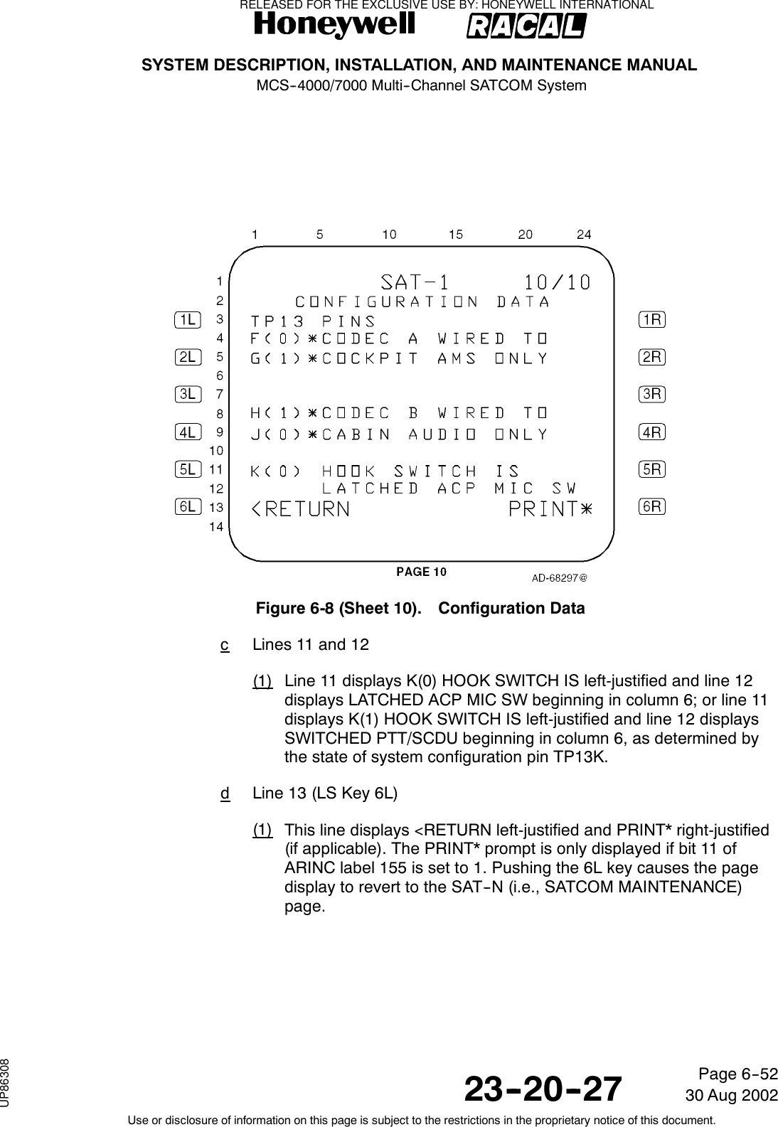
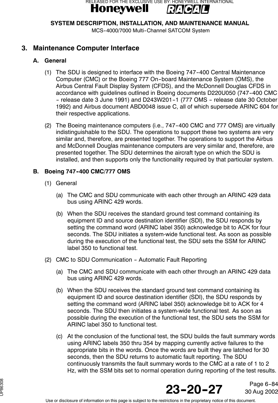
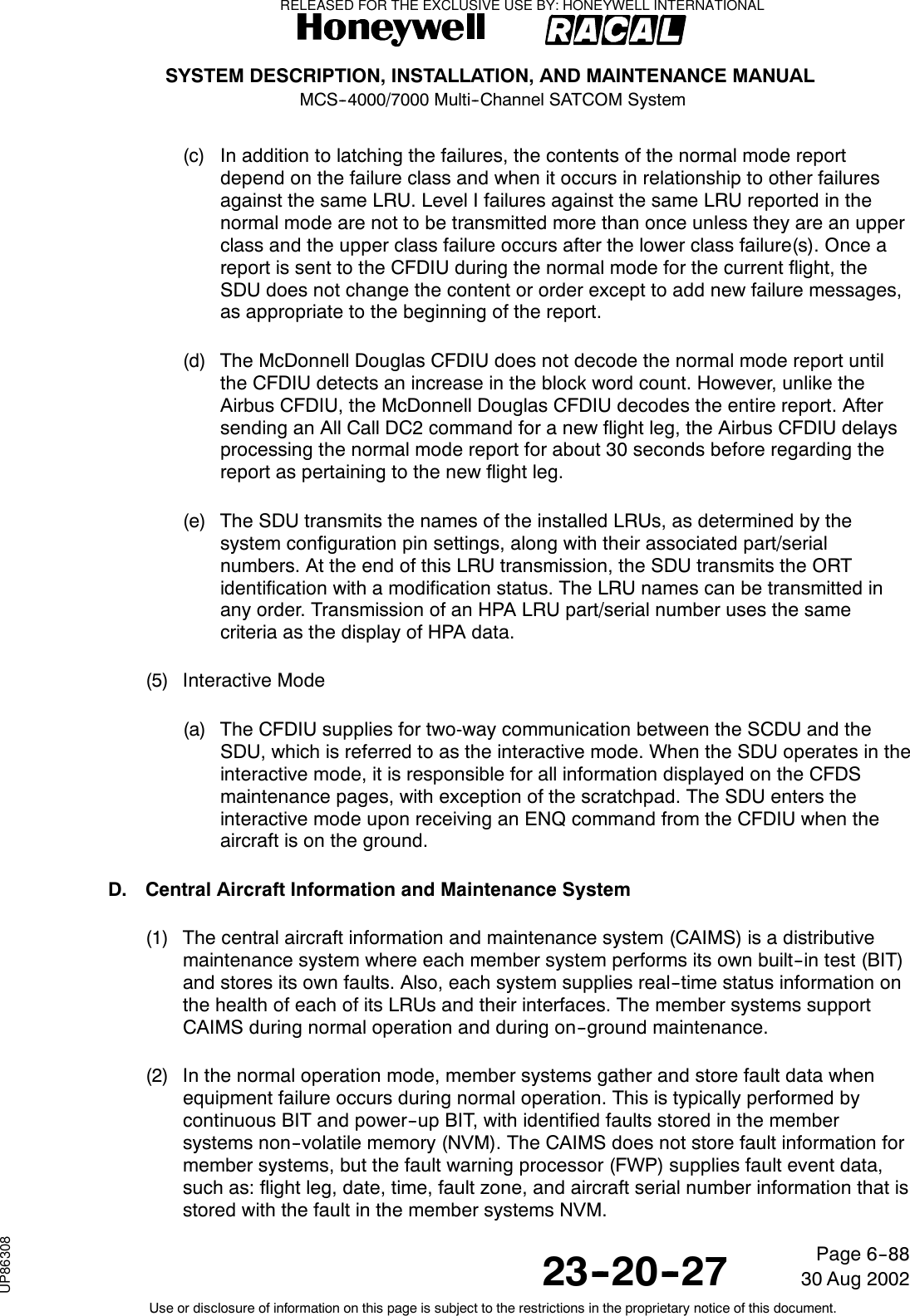
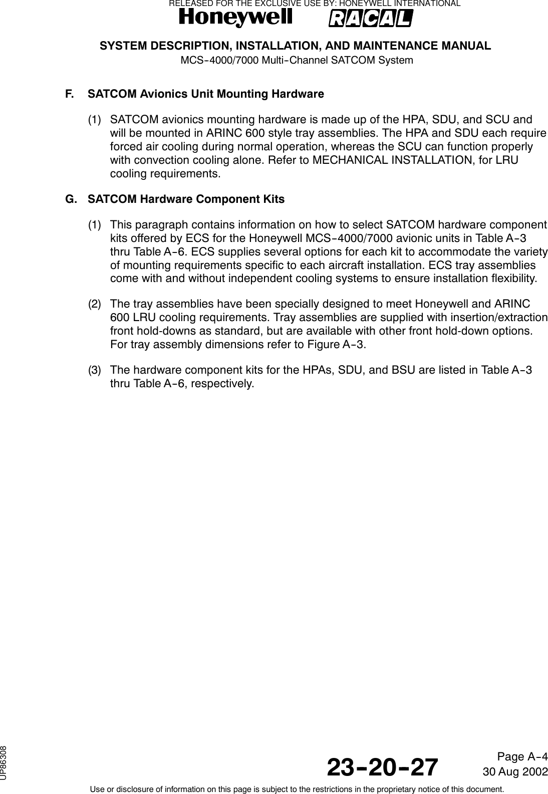
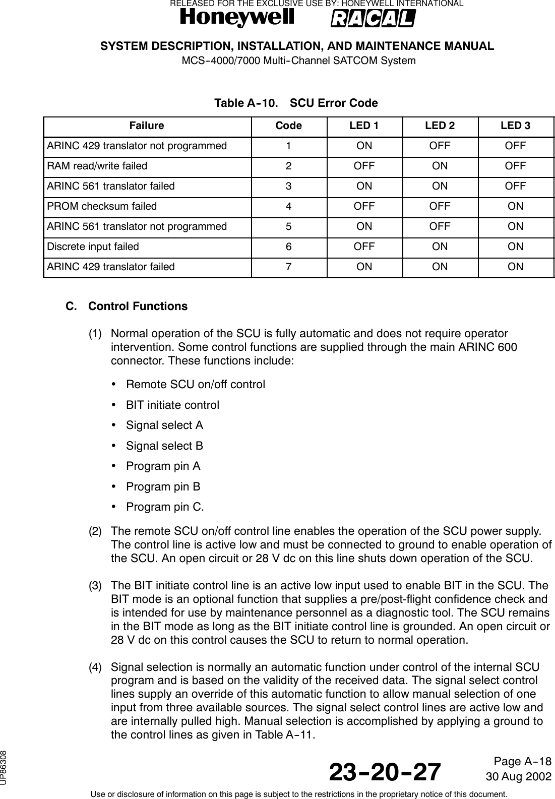
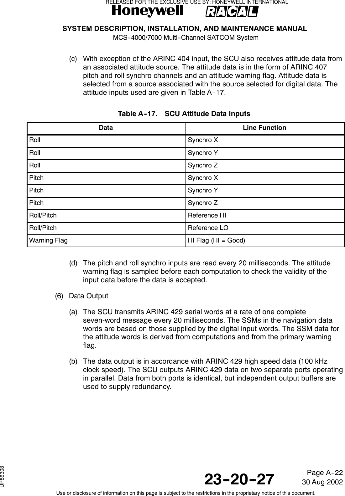
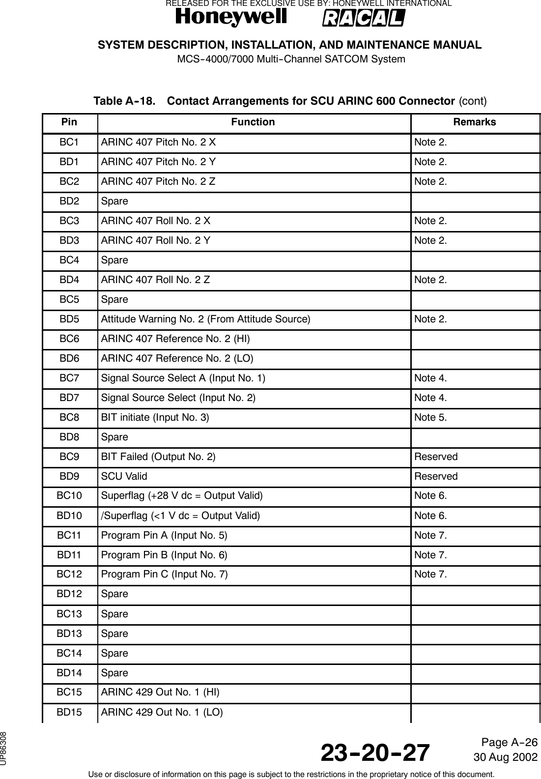
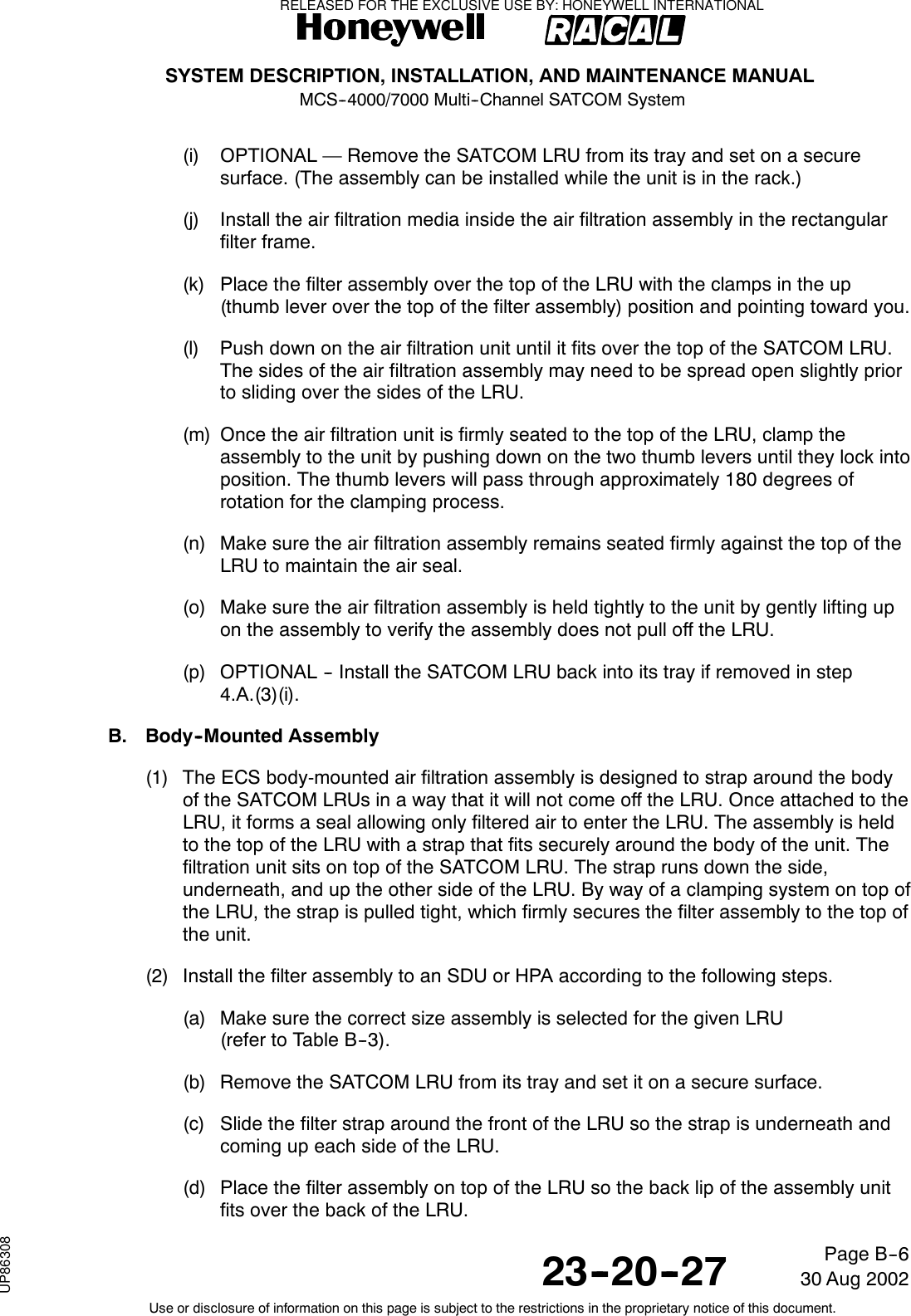
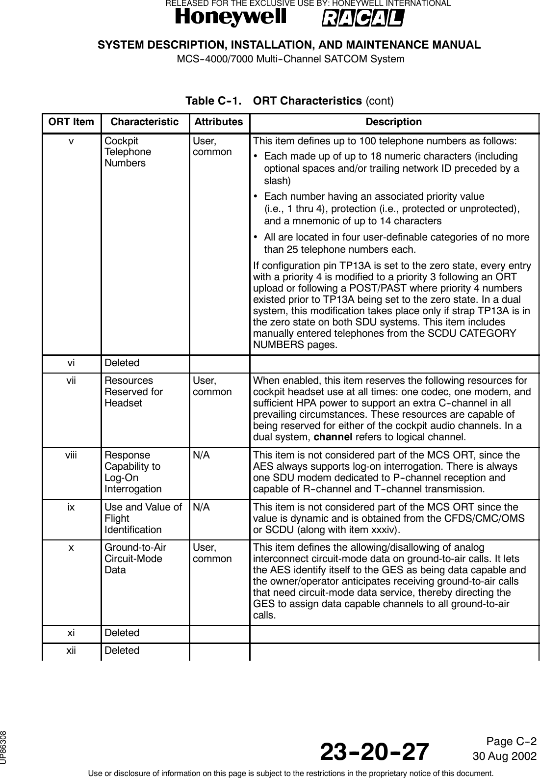
![SYSTEM DESCRIPTION, INSTALLATION, AND MAINTENANCE MANUALMCS--4000/7000 Multi--Channel SATCOM System23--20--2730 Aug 2002Use or disclosure of information on this page is subject to the restrictions in the proprietary notice of this document.Page 5--59(b) This configuration pin specifies the functionality of the SDU Cockpit VoiceMic-On Input No. 1 (and No. 2) discrete inputs (referred to as the mic-oninputs). When TP13K is wired to the one state, the SDU utilizes the switchedPTT and/or SCDU line switch(es) (referred to as switched PTT) method forcockpit hookswitch signaling on the mic-on inputs. When TP13K is wired to thezero state, the SDU utilizes the latched audio control panel SATCOMmicrophone switch (referred to as the latched ACP) method. These twomethods are described below.(2) Switched PTT Method(a) With the switched PTT method, the SDU assumes the mic-on inputs are wired toconventional microphone momentary push-to-talk switches (i.e., they aredynamically active [on/off] throughout the duration of the call). The SDUassumes the air- or ground-initiated call annunciation to have beenacknowledged (i.e., the call to in the off-hook state) when the appropriate mic-oninput is activated (connected to ground) for the first time after the callannunciation for a particular channel. Successive activations of that mic-on inputfor the duration of that call have no effect on the status of that call until the callhas been cleared.(b) With the switched PTT method, the off-hook state is also entered followingactivation of the Answer Call line select switch on the SCDU. The on-hook stateis entered following activation of the End Call lineselectswitchontheSCDUthat results in call clearing.(c) This method also allows usage of the place/end call discrete input andassociated switch to initiate calls to preselected numbers, as well as to terminateexisting calls.(3) Latched ACP Method(a) With the latched ACP method, the SDU assumes the mic-on inputs are wired toSATCOM microphone select switches on the ACP that are latched on(connected to ground) for the entire duration of a call. The SDU considers theair- or ground-initiated call annunciation to have been acknowledged (i.e., thecall to be in the off-hook state) when the appropriate mic-on input is active(connected to ground) for a particular channel. The call is cleared and thechannel is considered to be in the on-hook state when the mic-on input is in theopen-circuit state.(b) With the latched ACP method, all hookswitch signaling for answering andterminating all air- and ground-initiated calls is handled by the mic-on inputs; theSCDU Answer Call and End Call options are blanked (the SCDU is onlynecessary for specifying the called-party number and initiating the call processfor air-to-ground calls).(c) This method also allows usage of the mic--on discrete input and switch to initiatecalls to preselected numbers.RELEASED FOR THE EXCLUSIVE USE BY: HONEYWELL INTERNATIONALUP86308](https://usermanual.wiki/Honeywell/SD-700A/User-Guide-3476924-Page-206.png)

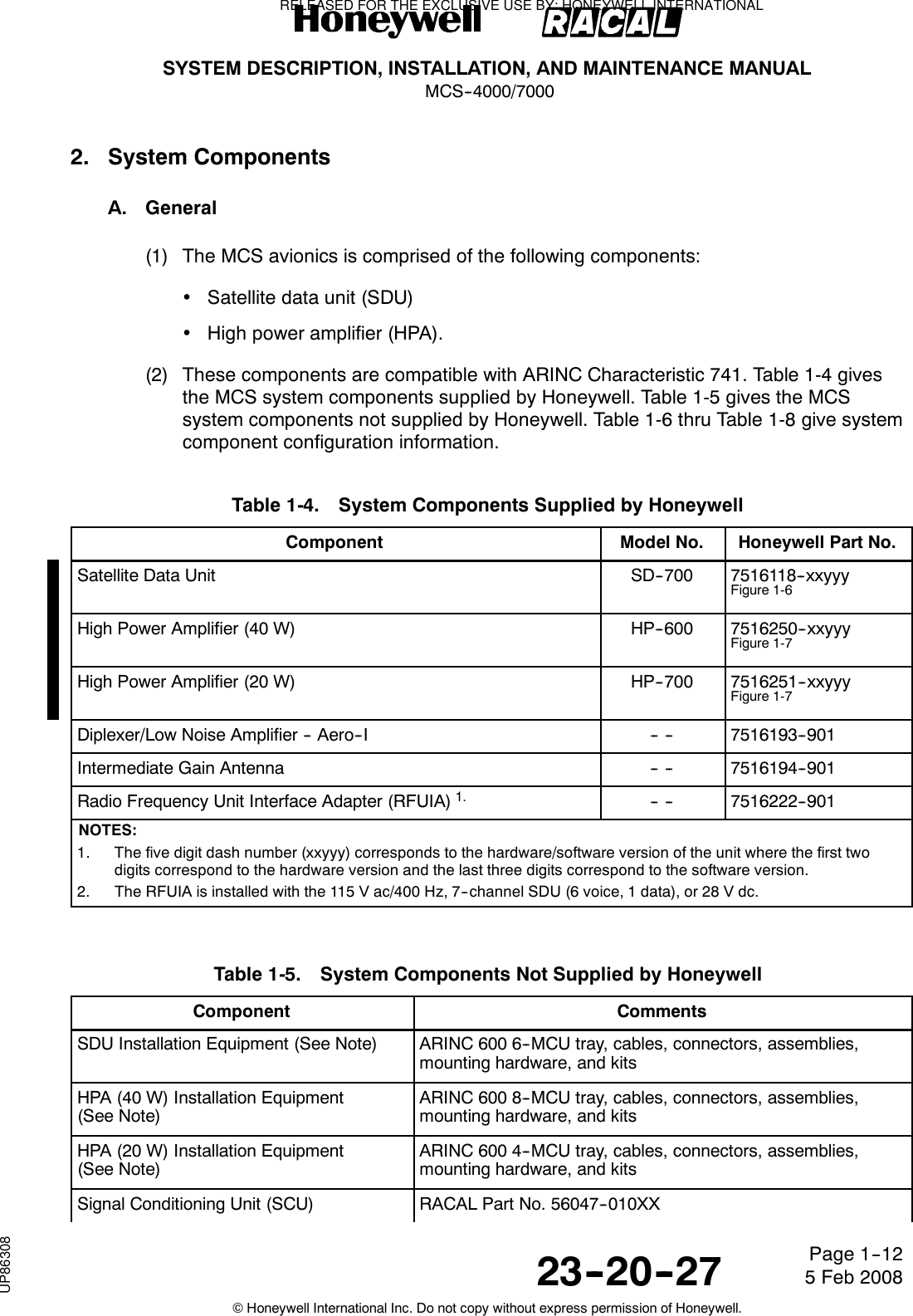
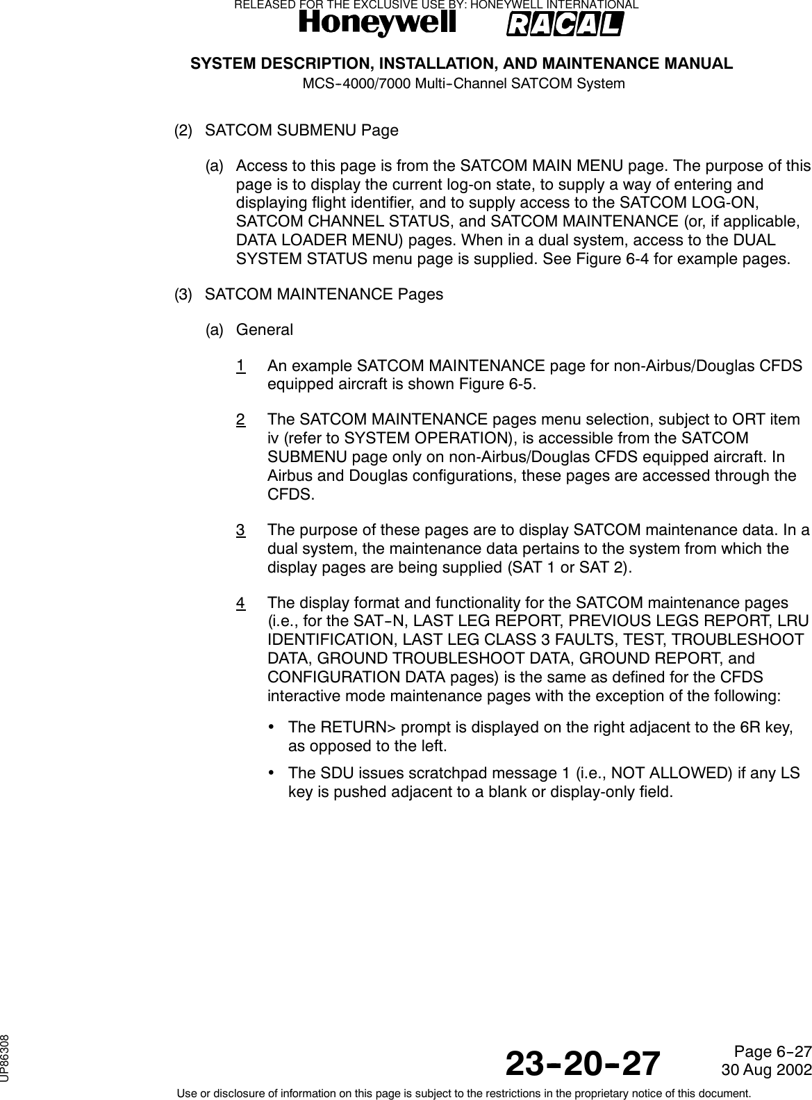
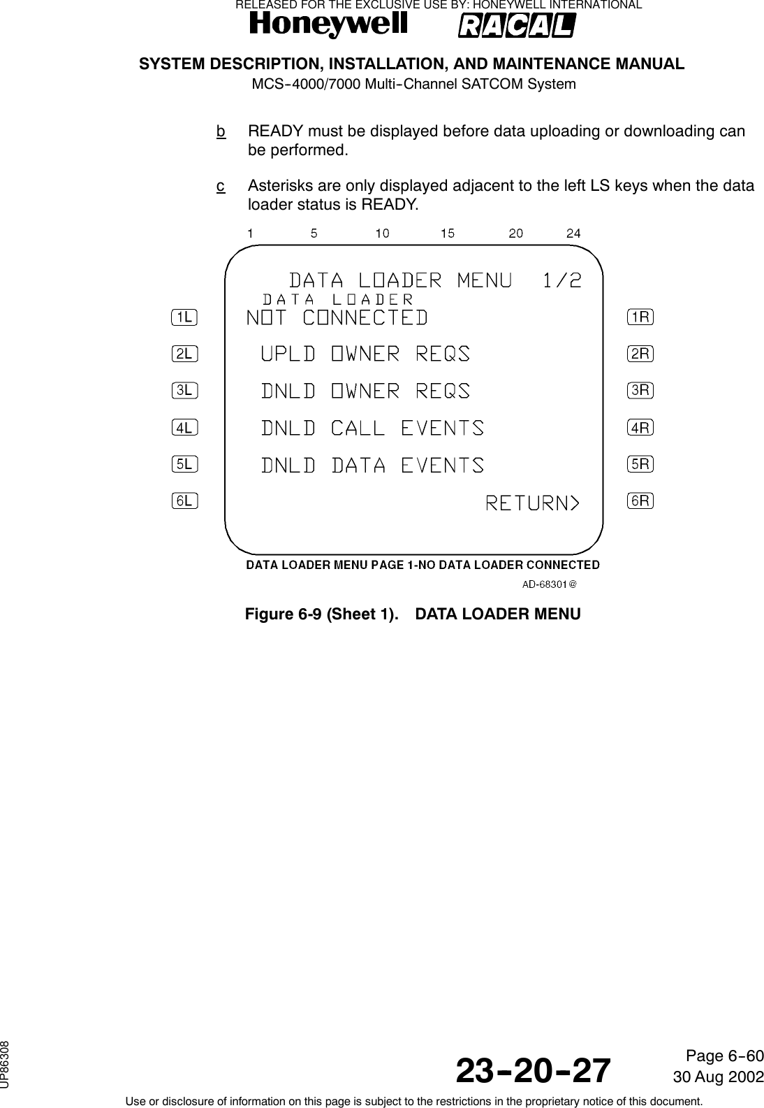
![SYSTEM DESCRIPTION, INSTALLATION, AND MAINTENANCE MANUALMCS--4000/7000 Multi--Channel SATCOM System23--20--2730 Aug 2002Use or disclosure of information on this page is subject to the restrictions in the proprietary notice of this document.Page 6--21(d) Labels on the left side of the SCDU display are displayed beginning in column 2of the label line. Data on the left side is left-justified in the data line. Labels anddata on the right side of the SCDU display is right-justified. This is the caseunless specified otherwise.(2) Scratchpad(a) General1The scratchpad is used for data entry and displaying SDU generatedmessages. Pushing an alphanumeric key on the keypad (0 through 9, Athrough Z, +/-- [plus or minus], / [slash, space]) enters that character into thescratchpad. The scratchpad is not used for fixed format display purposes.The mechanism used for data entry is described below.(b) Data Entry1When the user types the appropriate characters using the SCDU keypad,the characters are echoed on the scratchpad. After data entry, the user mustpush the appropriate LS key adjacent to the data field where the data is tobe displayed. The SDU then checks the data for format and acceptability(out-of-range, entry not permitted into the field, etc). If the data is incorrect,the SDU leaves the previous data in the field and displays the appropriateerror message in the scratchpad. If any LS key is pushed adjacent to ablank or nonselectable field, the scratchpad message 1 (i.e., NOTALLOWED) is issued. If the entry was rejected because an incorrect LS keywas pushed, the entry is accepted if the correct LS key is subsequentlypushed.(c) Scratchpad Message1If the SDU determines a data entry does not conform to format oracceptability requirements after an entry is attempted, the SDU issues ascratchpad message prompting the user for the correct data. The user canclear a scratchpad message by using the clear (CLR) key, or by enteringdata into the scratchpad over the message.(d) CLR and DEL Keys1GeneralaThe CLR and delete (DEL) keys are used to clear the scratchpad andalter the data fields. Generally, for MCDUs that have only a CLR key(e.g., Airbus and Douglas) the scratchpad is cleared and the data fieldsare altered by using this key. For MCDUs that have both CLR and DELkeys (e.g., Boeing), the scratchpad is cleared using the CLR key, whilethedatafieldsarealteredusingtheDELkey.2CLR KeyaPushing the CLR key clears the scratchpad message. When thescratchpad contains user-entered characters, momentary actuation ofthe CLR key clears the last entered character, while continual actuationof the CLR key clears the entire contents of the scratchpad.RELEASED FOR THE EXCLUSIVE USE BY: HONEYWELL INTERNATIONALUP86308](https://usermanual.wiki/Honeywell/SD-700A/User-Guide-3476924-Page-228.png)
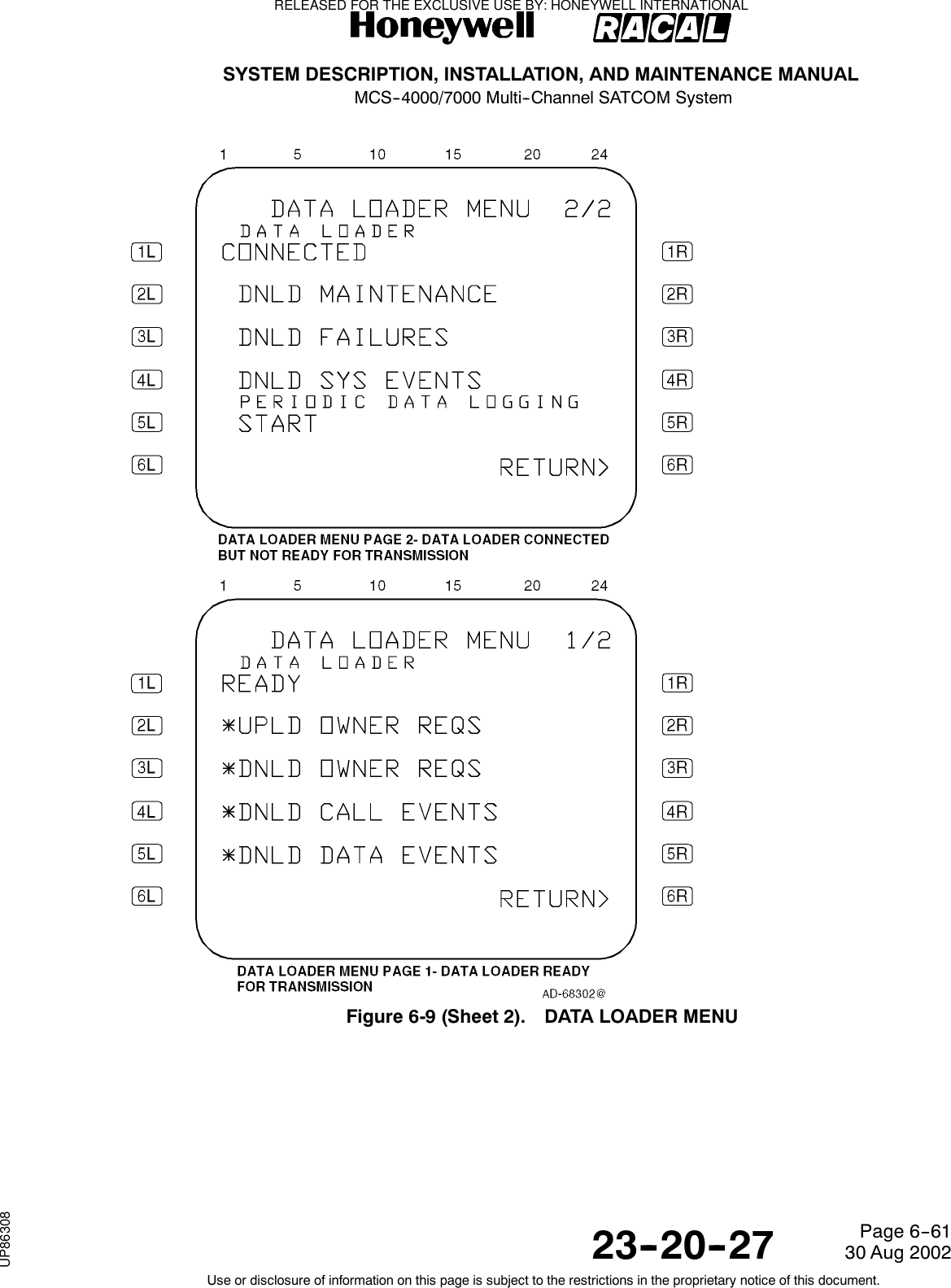
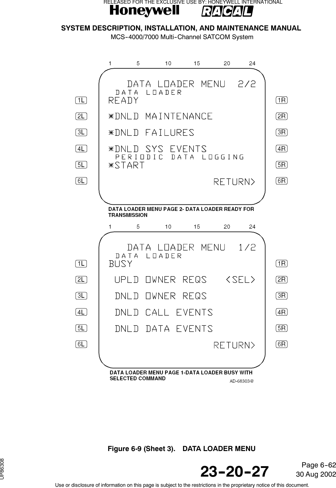
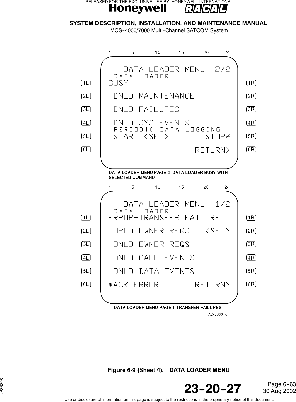
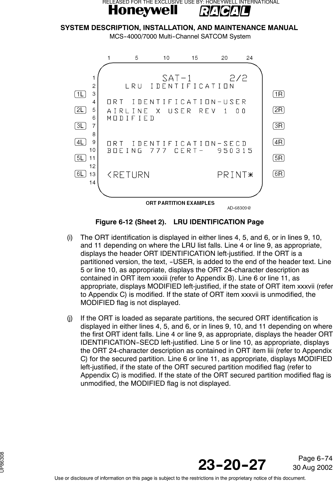
Empty brackets prompt the user for data entry into the field. However, dataentry is not mandatory. Brackets surrounding data indicate the data isunprotected and can be modified or deleted. Not all fields modifiable aresurrounded by brackets. When brackets are used to enclose existing data,as opposed to prompting entry of data into an empty field, they areintended as an indication the data is unprotected (i.e., an unprotectedphone number). Conversely, protected phone numbers do not havebrackets, indicating the phone number cannot be modified or deleted.<,>(Carets)A caret adjacent to an LS key indicates if the key is pushed the displaychanges to a new page. The new page is either the one indicated next tothe caret or, in case of RETURN>, the higher level page.<SEL>Indicates the data in the field is currently selected (e.g., the selected GESor antenna).(g) Updates1Dynamically generated display fields, whose contents have changed, areupdated by the SDU both periodically (at a rate of at least 1 Hz), and uponcompletion of an LS key action that could have caused the display or thedisplay field to change. With multiple SCDU configurations, the SDU onlymaintains one version of each page for display. The SDU responds to LSkey actuations from all SCDUs in a serial fashion and updates the displaypage(s). Each SCDU scratchpad and the channel selection fields areindependent from all others, allowing each user to perform independentactions.RELEASED FOR THE EXCLUSIVE USE BY: HONEYWELL INTERNATIONALUP86308](https://usermanual.wiki/Honeywell/SD-700A/User-Guide-3476924-Page-230.png)

![SYSTEM DESCRIPTION, INSTALLATION, AND MAINTENANCE MANUALMCS--4000/7000 Multi--Channel SATCOM System23--20--2730 Aug 2002Use or disclosure of information on this page is subject to the restrictions in the proprietary notice of this document.Page 6--90Table 6-17. Boeing Level I Failure Messages and ATA Reference NumbersFailureCode SCDU Accessed Maintenance Pages ATA NumberCMCMessage ID01 SDU 232500 2320502 OTHER SDU INCOMPATIBILITY 232500 2320503 RESERVED04 HPA--HI GAINHPA--HI GAIN[IGA][HGA] 232500 2320707 HPA--LO GAIN 232500 232090A HI POWER RELAY 232500 232180D LNA/DIP--(TOP/PORT) 232500 232100F LNA/DIP--STBD 232500 2321110 LNA/DIP--LO GAIN 232500 2321213 BSU--(TOP/PORT) 232500 2321315 BSU--STBD 232500 232141A IN GAIN ANTENNA--TOPHI GAIN ANTENNA--(TOP/PORT)[IGA][HGA] 232500 232151C HI GAIN ANTENNA--STBD 232500 232161F LO GAIN ANTENNA 232500 2322521 MCDU1 34610022 MCDU2 34610023 MCDU3 34610033 (ACARS MU/CMU)1 232700 2321934 (ACARS MU/CMU)2 232700 2321935 IRS--PRI 342100 3422236 IRS--SEC 342100 3422437 RESERVED38 RESERVED39 CMC 454500 232013D FMC1 3461003E FMC2 34610040 ARINC 429 ICAO ADDRESS None 23251RELEASED FOR THE EXCLUSIVE USE BY: HONEYWELL INTERNATIONALUP86308](https://usermanual.wiki/Honeywell/SD-700A/User-Guide-3476924-Page-297.png)
![SYSTEM DESCRIPTION, INSTALLATION, AND MAINTENANCE MANUALMCS--4000/7000 Multi--Channel SATCOM System23--20--2730 Aug 2002Use or disclosure of information on this page is subject to the restrictions in the proprietary notice of this document.Page 6--91Table 6-17. Boeing Level I Failure Messages and ATA Reference Numbers (cont)FailureCodeCMCMessage IDATA NumberSCDU Accessed Maintenance Pages42 CTU 231900 2323543 (CFS/CPDF) 23320052 (CFS/CPDF)/SDU 23320053 (ACARS MU/CMU)1/SDU 232700 2321954 CTU/SDU 231900 2323555 MCDU1/SDU 34610056 MCDU2/SDU 34610057 (ACARS MU/CMU)2/SDU 232700 2323559 CMC/SDU 454500 232015A IRS--PRI/SDU 342100 232225B IRS--SEC/SDU 342100 232245C HPA--IN GAIN/SDUHPA--HI GAIN/SDU[IGA][HGA] 232500 232265F HPA--LO GAIN/SDU 232500 2322562 BSU--(TOP/PORT)/SDU 232500 2321364 BSU--STBD/SDU 232500 2321466 MCDU3/SDU 34610067 RESERVED68 RESERVED6A RESERVED6C RESERVED6D RESERVED6E RESERVED6F RESERVED71 OTHER SDU/THIS SDU 23250073 FMC1/SDU 34610074 FMC2/SDU 34610080 RESERVED82 RESERVEDRELEASED FOR THE EXCLUSIVE USE BY: HONEYWELL INTERNATIONALUP86308](https://usermanual.wiki/Honeywell/SD-700A/User-Guide-3476924-Page-298.png)
![SYSTEM DESCRIPTION, INSTALLATION, AND MAINTENANCE MANUALMCS--4000/7000 Multi--Channel SATCOM System23--20--2730 Aug 2002Use or disclosure of information on this page is subject to the restrictions in the proprietary notice of this document.Page 6--92Table 6-17. Boeing Level I Failure Messages and ATA Reference Numbers (cont)FailureCodeCMCMessage IDATA NumberSCDU Accessed Maintenance Pages88 RESERVED90 SDU M--CTRL/HPA--IN GAINSDU M--CTRL/HPA--HI GAIN[IGA][HGA] 232500 2324696 SDU M--CTRL/HPA--LO GAIN 232500 2324898 SDU M--CTRL/BSU--(TOP/PORT) 232500 232499A BSU--STBD XTALK/BSU--PORT 232500 232529C SDU M--CTRL/BSU--STBD 232500 232509D BSU--PORT XTALK/BSU--STBD 232500 23253C0 WRG:CONFIG PIN PROG/SDU 232500 23236C1 SDU WOW MISCOMPARE N/AC2 SDU/OTHER SDU SELECT--DISABLE DISCRETE 232500C3 WRG:ICAO ADDRESS PIN PROG/SDU 232500 23251C4 TX PATH VSWR--IN GAINTX PATH VSWR--HI GAIN[IGA][HGA] 232500 23257C5 WRG:CONFIG PIN PROG/SDU OWNER REQS 232500C6 TX PATH VSWR--LO GAIN 232500 23216C7 HPA--HI GAIN/OVER TEMPERATUREHPA--HI GAIN/OVER TEMPERATURE[IGA][HGA] 232500 23247C8 BAD DATA FROM GROUND EARTH STATION NoneC9 HPA--LO GAIN/OVER TEMPERATURE 232500 23254CA SDU/LNA/DIP--LO GAIN 232500 23237CB WRG:SDI PIN PROG/HPA--IN GAINWRG:SDI PIN PROG/HPA--HI GAIN[IGA][HGA] 232500CC WRG:SDI PIN PROG/HPA--HI GAIN 232500CD SDU (POC/TOTC) DATA RESET NoneCE RESERVEDCF HPA--IN GAIN (POC/TOTC) DATA RESETHPA--HI GAIN (POC/TOTC)DATA RESET[IGA][HGA] NoneD0 HPA--LO GAIN (POC/TOTC) DATA RESET NoneRELEASED FOR THE EXCLUSIVE USE BY: HONEYWELL INTERNATIONALUP86308](https://usermanual.wiki/Honeywell/SD-700A/User-Guide-3476924-Page-299.png)
![SYSTEM DESCRIPTION, INSTALLATION, AND MAINTENANCE MANUALMCS--4000/7000 Multi--Channel SATCOM System23--20--2730 Aug 2002Use or disclosure of information on this page is subject to the restrictions in the proprietary notice of this document.Page 6--93Table 6-17. Boeing Level I Failure Messages and ATA Reference Numbers (cont)FailureCodeCMCMessage IDATA NumberSCDU Accessed Maintenance PagesD1 WRG:SDI PIN PROG/HPA--IN GAINWRG:SDI PIN PROG/HPA--HI GAIN[IGA][HGA] 232500D2 WRG:SDI PIN PROG/HPA--LO GAIN 232500D3 WRG:SDI PIN PROG/BSU--(TOP/PORT) 232500D4 WRG:SDI PIN PROG/BSU--STBD 232500D5 SDU COAX/HPA--IN GAINSDU COAX/HPA--HI GAIN[IGA][HGA] 232500 23237D6 SDU COAX/HPA--LO GAIN 232500 23237D7 RESERVEDD8 LNA/DIP/ (SDU)--(TOP/PORT) 232500 23236D9 LNA/DIP/ (SDU)--STBD 232500 23236DA LNA/DIP/ (SDU)--LO GAIN 232500 23236DB LO GAIN SUBSYSTEM 232500DC NO ACTIVE ACARS MU/CMU 232700DD SDU OWNER REQS -- SECURED NoneDE SDU OWNER REQS -- USER NoneDF IN GAIN SUBSYSTEMHI GAIN SUBSYSTEM[IGA][HGA] 232500E0 RESERVEDFE POWER SUPPLY INTERRUPT NoneTable 6-18. Airbus Level I (SDU No. 1) Failure Messages and ATA No.FailureCode SDU/SDU No. 1 -- CFDS Normal and Interactive Modes ATA Number01 SDU1(105RV1)SDU1(5RV1)[IGA][HGA]23283423283402 SDU2(105RV2)SDU2(5RV2) INCOMPATIBILITY[IGA][HGA]23283423283403 RESERVEDRELEASED FOR THE EXCLUSIVE USE BY: HONEYWELL INTERNATIONALUP86308](https://usermanual.wiki/Honeywell/SD-700A/User-Guide-3476924-Page-300.png)
![SYSTEM DESCRIPTION, INSTALLATION, AND MAINTENANCE MANUALMCS--4000/7000 Multi--Channel SATCOM System23--20--2730 Aug 2002Use or disclosure of information on this page is subject to the restrictions in the proprietary notice of this document.Page 6--94Table 6-18. Airbus Level I (SDU No. 1) Failure Messages and ATA No. (cont)FailureCode ATA NumberSDU/SDU No. 1 -- CFDS Normal and Interactive Modes04 HPA1(107RV1)HPA--HIGAIN(7RV1)[IGA][HGA]23283523283107 HPA--LO GAIN(9RV) 2328350A HI POWER RELAY(21RV) 2328420D DLNA1(119RV1)DLNA--TOP(19RV1)DLNA--L(20RV1)[IGA][Top Mount][Conformal]2328372328382328370F DLNA--R(20RV2) [Conformal] 23283710 DLNA--LO GAIN(14RV) 23283613 BSU(8RV1)BSU--L(15RV1)[Top Mount][Conformal]23284623284415 BSU--R(15RV2) [Conformal] 2328441A ANTENNA1(116RV1)HI GAIN ANTENNA--TOP(16RV1)HI GAIN ANTENNA--L(17RV)[IGA][Top Mount][Conformal]2328132328132328121C HI GAIN ANTENNA--R(18RV) [Conformal] 2328121F LO GAIN ANTENNA(13RV) 23281121 MCDU1(2CA1) 22821222 MCDU2(2CA2) 22821223 MCDU3(2CA3) 22821233 ATSU1(1TX1) [A320/A330/A340 ATSU] 462100ACARS MU(1RB) [A320 ACARS] 232434ACARS MU1(1RB1) [A330/A340 ACARS] 23243434 ATSU2 (1TX2) [A320/1A330/A340 ATSU] 462100ACARS MU2 [A320 ACARS] N/AACARS MU2(1RB2) [A330/A340 ACARS] 23243435 ADIRU1(1FP1) 34123436 ADIRU2(1FP2) 34123437 RESERVED N/A38 RESERVED N/ARELEASED FOR THE EXCLUSIVE USE BY: HONEYWELL INTERNATIONALUP86308](https://usermanual.wiki/Honeywell/SD-700A/User-Guide-3476924-Page-301.png)
![SYSTEM DESCRIPTION, INSTALLATION, AND MAINTENANCE MANUALMCS--4000/7000 Multi--Channel SATCOM System23--20--2730 Aug 2002Use or disclosure of information on this page is subject to the restrictions in the proprietary notice of this document.Page 6--95Table 6-18. Airbus Level I (SDU No. 1) Failure Messages and ATA No. (cont)FailureCode ATA NumberSDU/SDU No. 1 -- CFDS Normal and Interactive Modes39 CFDIU(1TW)CMC1(1TM1)[A320][A320/A340]3132344513343D FMGC1(1CA1)FMGEC1(1CA1)[A320][A330/A340]2283342283343E FMGC2(1CA2)FMGEC2(1CA2)[A320][A330/A340]22833422833440 ARINC 429 ICAO N/A42 CTU(303RD)CTU(3RY)[A320][A330/A340]23353423923443 CPDF N/A52 CPDF/SDU1 N/A53 ATSU1 (1TX1)/SDU1(105RV1) [IGA A320/A330/A340 ATSU] 462100ATSU1 (1TX1)/SDU1(5RV1) [HGA A320/A330/A340 ATSU] 462100ACARS MU (1RB)/SDU1(105RV1) [IGA A320 ACARS] 232434ACARS MU1 (1RB1)/SDU1(105RV1) [IGA A330/A340 ACARS] 232434ACARS MU (1RB)/SDU1(5RV1) [HGA A320 ACARS] 232434ACARS MU1 (1RB1)/SDU1(5RV1) [HGA A330/A340 ACARS] 23243454 CTU (303RD)/SDU1(105RV1) [IGA A320] 233534CTU (3RY)/SDU1(105RV1) [IGA A330/A340] 239234CTU (303RD)/SDU1(5RV1) [HGA A320] 233534CTU (3RY)/SDU1(5RV1) [HGA A330/A340] 23923455 MCDU1(2CA1)/SDU1(105RV1)MCDU1(2CA1)/SDU1(5RV1)[IGA][HGA]22821222821256 MCDU2(2CA2)/SDU1(105RV1)MCDU2(2CA2)/SDU1(5RV1)[IGA][HGA]228212228212RELEASED FOR THE EXCLUSIVE USE BY: HONEYWELL INTERNATIONALUP86308](https://usermanual.wiki/Honeywell/SD-700A/User-Guide-3476924-Page-302.png)
![SYSTEM DESCRIPTION, INSTALLATION, AND MAINTENANCE MANUALMCS--4000/7000 Multi--Channel SATCOM System23--20--2730 Aug 2002Use or disclosure of information on this page is subject to the restrictions in the proprietary notice of this document.Page 6--96Table 6-18. Airbus Level I (SDU No. 1) Failure Messages and ATA No. (cont)FailureCode ATA NumberSDU/SDU No. 1 -- CFDS Normal and Interactive Modes57 ATSU2 (1TX2)/SDU1(105RV1) [IGA A320/A330/A340 ATSU] 462100ATSU2 (1TX2)/SDU1(5RV1) [HGA A320/A330/A340 ATSU] 462100ACARS MU2/SDU1(105RV1) [IGA A320 ACARS] 232434ACARS MU2 (1RB2)/SDU1(105RV1) [IGA A330/A340 ACARS] 232434ACARS MU2/SDU1(5RV1) [HGA A320 ACARS] 232434ACARS MU2 (1RB2)/SDU1(5RV1) [HGA A330/A340 ACARS] 23243459 CFDIU(1TW)/SDU1(105RV1) [IGA A320] 313243CMC1(1TM1)/SDU1(105RV1) [IGA A330/A340] 451334CFDIU(1TW)/SDU1(5RV1) [HGA A320] 313243CMC1(1TM1)/SDU1(5RV1) [HGA A330/A340] 4513345A ADIRU1(1FP1)/SDU1(105RV1)ADIRU1(1FP1)/SDU1(5RV1)[IGA][HGA]3412343412345B ADIRU2(1FP2)/SDU1(105RV1)ADIRU2(1FP2)/SDU1(5RV1)[IGA][HGA]3412343412345C HPA1 (107RV1)/SDU1(105RV1)HPA--HI GAIN(7RV1)/SDU1(5RV1)[IGA][HGA]2328352328315F HPA--LO GAIN(9RV)/SDU1(5RV1) 23283562 BSU(8RV1)/SDU1(5RV1)BSU--L(15RV1)/SDU1(5RV1)[Top Mount][Conformal]23284623284464 BSU--R(15RV2)/SDU1(5RV1) [Conformal] 23284466 MCDU3(2CA3)/SDU1(105RV1)MCDU3(2CA3)/SDU1(5RV1)[IGA][HGA]22821222821267 RESERVED68 RESERVED6A RESERVED6C RESERVED6D RESERVED6E RESERVED6F RESERVEDRELEASED FOR THE EXCLUSIVE USE BY: HONEYWELL INTERNATIONALUP86308](https://usermanual.wiki/Honeywell/SD-700A/User-Guide-3476924-Page-303.png)
![SYSTEM DESCRIPTION, INSTALLATION, AND MAINTENANCE MANUALMCS--4000/7000 Multi--Channel SATCOM System23--20--2730 Aug 2002Use or disclosure of information on this page is subject to the restrictions in the proprietary notice of this document.Page 6--97Table 6-18. Airbus Level I (SDU No. 1) Failure Messages and ATA No. (cont)FailureCode ATA NumberSDU/SDU No. 1 -- CFDS Normal and Interactive Modes71SDU2(105RV2)/SDU1(105RV1)SDU2(5RV2)/SDU1(5RV1)[IGA][HGA]23283423283473 FMGC1(1CA1)/SDU1(105RV1) [IGA A320] 228334FMGEC1(1CA1)/SDU1(105RV1) [IGA A330/A340] 228334FMGC1(1CA1)/SDU1(5RV1) [HGA A320] 228334FMGEC1(1CA1)/SDU1(5RV1) [HGA A330/A340] 22833474 FMGC2(1CA2)/SDU1(105RV1) [IGA A320] 228334FMGEC2(1CA2)/SDU1(105RV1) [IGA A330/A340] 228334FMGC2(1CA2)/SDU1(5RV1) [HGA A320] 228334FMGEC2(1CA2)/SDU1(5RV1) [HGA A330/A340] 22833480 RESERVED82 RESERVED88 RESERVED90 SDU1(105RV1) BUS M--CTRL/HPA1(107RV1) [IGA] 232834SDU1(5RV1) BUS M--CTRL/HPA--HIGAIN(7RV1)[HGA]23283496 SDU1(5RV1) BUS M--CTRL/HPA--LO GAIN(9RV) 23283498 SDU1(5RV1) BUS M--CTRL/BSU(8RV1)SDU1(5RV1) BUS M--CTRL/BSU--L(15RV1)[Top Mount][Conformal]2328342328349A BSU--R XTALK/BSU--L [Conformal] N/A9C SDU1(5RV1) BUS M--CTRL/BSU--R(15RV2) [Conformal] 2328349D BSU--L XTALK/BSU--R [Conformal] N/AC0 WRG:CONFIG PIN PROG/SDU1(105RV1) [IGA] 232834C0 WRG:CONFIG PIN PROG/SDU1(5RV1) [HGA] 232834C1 LGCIU1(5GA1)/LGCIU2(5GA2)/SDU1(105RV1) [IGA] 323171LGCIU1(5GA1)/LGCIU2(5GA2)/SDU1(5RV1) [HGA] 323171C2 SDU1(105RV1) SEL--DISABLEDISCRETE/SDU2(105RV2)[IGA] 232834SDU1(5RV1) SEL--DISABLEDISCRETE/SDU2(5RV2)[HGA] 232834RELEASED FOR THE EXCLUSIVE USE BY: HONEYWELL INTERNATIONALUP86308](https://usermanual.wiki/Honeywell/SD-700A/User-Guide-3476924-Page-304.png)
![SYSTEM DESCRIPTION, INSTALLATION, AND MAINTENANCE MANUALMCS--4000/7000 Multi--Channel SATCOM System23--20--2730 Aug 2002Use or disclosure of information on this page is subject to the restrictions in the proprietary notice of this document.Page 6--98Table 6-18. Airbus Level I (SDU No. 1) Failure Messages and ATA No. (cont)FailureCode ATA NumberSDU/SDU No. 1 -- CFDS Normal and Interactive ModesC3 WRG:ICAO ADDRESS PINPROG/SDU1(105RV1)[IGA] 232834WRG:ICAO ADDRESS PINPROG/SDU1(5RV1)[HGA] 232834C4 HPA1 (107RV1)/VSWR [IGA] 232835HPA--HI GAIN(7RV1)/VSWR [HGA] 232831C5 WRG:CONFIG PIN PROG/SDU1(105RV1)OWNER REQS DB[IGA] 232834WRG:CONFIG PIN PROG/SDU1(5RV1)OWNER REQS DB[HGA] 232834C6 HPA--LO GAIN(9RV)/VSWR 232835C7 HPA(107RV1)/OVER TEMPERATURE [IGA] 232835HPA--HI GAIN(7RV1)/OVER TEMPERATURE [HGA] 232831C8 SDU1(105RV1)/BAD DATA FROM GROUNDSTATION[IGA] 232834SDU1(5RV1)/BAD DATA FROM GROUNDEARTH STATION[HGA] 232834C9 HPA--LO GAIN(9RV)/OVER TEMPERATURE 232835CA SDU1(5RV1)/DLNA--LO GAIN(14RV) 232834CB WRG:SDI PIN PROG/HPA1(107RV1) [IGA] 232835WRG:SDI PIN PROG/HPA--HI GAIN(7RV1) [HGA] 232831CC WRG:SDI PIN PROG/HPA--LO GAIN(9RV) 232835CD DATA:SDU1 POC/TOTC RESET N/ACE RESERVEDCF DATA:HPA1 POC/TOTC RESET [IGA] N/ADATA:HPA--HI GAIN POC/TOTC RESET [HGA] N/AD0 DATA:HPA--LO GAIN POC/TOTC RESET N/AD1 WRG:SDI PIN PROG/HPA1 (107RV1) [IGA] 232835WRG:SDI PIN PROG/HPA--HI GAIN(7RV1) [HGA] 232831D2 WRG:SDI PIN PROG/HPA--LO GAIN(9RV) 232835D3 WRG:SDI PIN PROG/BSU(8RV1)WRG:SDI PIN PROG/BSU--L(15RV1)[Top Mount][Conformal]232846232844RELEASED FOR THE EXCLUSIVE USE BY: HONEYWELL INTERNATIONALUP86308](https://usermanual.wiki/Honeywell/SD-700A/User-Guide-3476924-Page-305.png)
![SYSTEM DESCRIPTION, INSTALLATION, AND MAINTENANCE MANUALMCS--4000/7000 Multi--Channel SATCOM System23--20--2730 Aug 2002Use or disclosure of information on this page is subject to the restrictions in the proprietary notice of this document.Page 6--99Table 6-18. Airbus Level I (SDU No. 1) Failure Messages and ATA No. (cont)FailureCode ATA NumberSDU/SDU No. 1 -- CFDS Normal and Interactive ModesD4 WRG:SDI PIN PROG/BSU--R(15RV2) [Conformal] 232844D5 SDU1(105RV1) COAX/HPA1(107RV1) [IGA] 232833SDU1(5RV1) COAX/HPA--HI GAIN (7RV1) [HGA] 232833D6 SDU1 (5RV1) COAX/HPA--LO GAIN (9RV) 232833D7 RESERVEDD8 DLNA1(119RV1)/SDU1(105RV1)DLNA--TOP(19RV1)/SDU1(5RV1)DLNA--L(20RV1)/SDU1(5RV1)[IGA][Top Mount][Conformal]232838232838232837D9 DLNA--R(20RV2)/SDU1(5RV1) [Conformal] 232837DA DLNA--LO GAIN(14RV)/SDU1(5RV1) 232836DB DLNA--LO GAIN(14RV)/LO GAIN ANTENNA(13RV) 232836DC ATSU1(1TX1)/NO ACTIVE ATSU [A320/A330/A340 ATSU] 462100ACARS MU(1RB)/NO ACTIVE MU [A320 ACARS] 232434ACARS MU(1RB1/2)/NO ACTIVE MU [A330/A340 ACARS] 232434DD SDU1(105RV1) OWNER REQS DB SECUREDPARTITION[IGA] N/ASDU1(5RV1) OWNER REQS DB SECUREDPARTITION[HGA] N/ADE SDU1(105RV1) OWNER REQS DS USERPARTITION[IGA] N/ASDU1(5RV1) OWNER REQS DB USERPARTITION[HGA] N/ADF DLNA--T(19RV1)/BSU(8RV1)/HI GAINANT--TOP(16RV)[Top Mount] 232838HI PWR RELAY(21RV)/BSU--L(15RV1)/BSU--R(15RV2)[Conformal] 232842E0 RESERVEDFE POWER SUPPLY INTERRUPT 240000RELEASED FOR THE EXCLUSIVE USE BY: HONEYWELL INTERNATIONALUP86308](https://usermanual.wiki/Honeywell/SD-700A/User-Guide-3476924-Page-306.png)
![SYSTEM DESCRIPTION, INSTALLATION, AND MAINTENANCE MANUALMCS--4000/7000 Multi--Channel SATCOM System23--20--2730 Aug 2002Use or disclosure of information on this page is subject to the restrictions in the proprietary notice of this document.Page 6--100Table 6-19. Airbus Level I (SDU No. 2) Failure Messages and ATA No.FailureCode SDU/SDU No. 2 -- CFDS Normal and Interactive Modes ATA Number01 SDU2(105RV2)SDU2(5RV2)[IGA][HGA]23283423283402 SDU1(105RV1) INCOMPATIBILITYSDU1(5RV1) INCOMPATIBILITY[IGA][HGA]23283423283403 RESERVED04 HPA2(107RV2)HPA--HI GAIN(7RV1)[IGA][HGA]23283523283107 HPA--LO GAIN(9RV) 2328350A HI POWER RELAY(21RV) 2328420D DLNA2 (119RV2)DLNA--TOP(19RV1)DLNA--L(20RV1)[IGA][Top Mount][Conformal]2328372328382328370F DLNA--R(20RV2) [Conformal] 23283710 DLNA--LO GAIN(14RV) 23283613 BSU(8RV1)BSU--L(15RV1)[Top Mount][Conformal]23284623284415 BSU--R(15RV2) [Conformal] 2328441A ANTENNA2(116RV2)HI GAIN ANTENNA--TOP(16RV1)HI GAIN ANTENNA--L(17RV)[IGA][Top Mount][Conformal]2328132328132328121C HI GAIN ANTENNA--R(18RV) [Conformal] 2328121F LO GAIN ANTENNA(13RV) 23281121 MCDU1(2CA1) 22821222 MCDU2(2CA2) 22821223 MCDU3(2CA3) 22821233 ATSU1(1TX1) [A320/A330/A340 ATSU] 462100ACARS MU(1RB) [A320 ACARS] 232434ACARS MU1(1RB1) [A330/A340 ACARS] 232434RELEASED FOR THE EXCLUSIVE USE BY: HONEYWELL INTERNATIONALUP86308](https://usermanual.wiki/Honeywell/SD-700A/User-Guide-3476924-Page-307.png)
![SYSTEM DESCRIPTION, INSTALLATION, AND MAINTENANCE MANUALMCS--4000/7000 Multi--Channel SATCOM System23--20--2730 Aug 2002Use or disclosure of information on this page is subject to the restrictions in the proprietary notice of this document.Page 6--101Table 6-19. Airbus Level I (SDU No. 2) Failure Messages and ATA No. (cont)FailureCode ATA NumberSDU/SDU No. 2 -- CFDS Normal and Interactive Modes34 ATSU2 (1TX2) [A320/A330/A340 ATSU] 462100ACARS MU2 [A320 ACARS] 232434ACARS MU2(1RB2) [A320/A340 ACARS] 23243435 ADIRU1(1FP1) 34123436 ADIRU2(1FP2) 34123437 RESERVED N/A38 RESERVED N/A39 CFDIU(1TW)CMC1(1TM1)[A320][A330/A340]3132344513343D FMGC1(1CA1)FMGEC1(1CA1)[A320][A330/A340]2283342283343E FMGC2(1CA2)FMGEC2(1CA2)[A320][A330/A340]22833422833440 ARINC 429 ICAO N/A42 CTU(303RD)CTU(3RY)[A320][A330/A340]23353423923443 CPDF N/A52 CPDF/SDU1 N/A53 ATSU1 (1TX1)/SDU2(105RV2) [IGA A320/A330/A340 ATSU] 462100ATSU1 (1TX1)/SDU2(5RV2) [HGA A320/A330/A340 ATSU] 462100ACARS MU(1RB)/SDU2(105RV2) [IGA A320 ACARS] 232434ACARS MU1(1RB1)/SDU2(105RV2) [IGA A330/A340 ACARS] 232434ACARS MU(1RB)/SDU2(5RV2) [HGA A320 ACARS] 232434ACARS MU1(1RB1)/SDU2(5RV2) [HGA A330/A340 ACARS] 23243454 CTU(303RD)/SDU2(105RV2) [IGA A320] 233534CTU(3RY)/SDU2(105RV2) [IGA A330/A340] 239234CTU(303RD)/SDU2(5RV2) [HGA A320] 233534CTU(3RY)/SDU2(5RV2) [HGA A330/A340] 23923455 MCDU1(2CA1)/SDU2(105RV2)MCDU1(2CA1)/SDU2(5RV2)[IGA][HGA]228212228212RELEASED FOR THE EXCLUSIVE USE BY: HONEYWELL INTERNATIONALUP86308](https://usermanual.wiki/Honeywell/SD-700A/User-Guide-3476924-Page-308.png)
![SYSTEM DESCRIPTION, INSTALLATION, AND MAINTENANCE MANUALMCS--4000/7000 Multi--Channel SATCOM System23--20--2730 Aug 2002Use or disclosure of information on this page is subject to the restrictions in the proprietary notice of this document.Page 6--102Table 6-19. Airbus Level I (SDU No. 2) Failure Messages and ATA No. (cont)FailureCode ATA NumberSDU/SDU No. 2 -- CFDS Normal and Interactive Modes56 MCDU2(2CA2)/SDU2(105RV2)MCDU2(2CA2)/SDU2(5RV2)[IGA][HGA]22821222821257 ATSU2 (1TX2)/SDU2(105RV2) [IGA A320/A330/A340 ATSU] 462100ATSU2 (1TX2)/SDU2(5RV2) [HGA A320/A330/A340 ATSU] 462100ACARS MU2/SDU2(105RV2) [IGA A320 ACARS] 232434ACARS MU2 (1RB2)/SDU2(105RV2) [IGA A330/A340 ACARS] 232434ACARS MU2/SDU2(5RV2) [HGA A320 ACARS] 232434ACARS MU2(1RB2)/SDU2(5RV2) [HGA A330/A340 ACARS] 23243459 CFDIU(1TW)/SDU2(105RV2) [IGA A320] 313234CMC1(1TM1)/SDU2(105RV2) [IGA A330/A340] 451334CFDIU(1TW)/SDU2(5RV2) [HGA A320] 313234CMC1(1TM1)/SDU2(5RV2) [HGA A330/A340] 4513345A ADIRU1(1FP1)/SDU2(105RV2) [IGA] 341234ADIRU1(1FP1)/SDU2(5RV2) [HGA] 3412345B ADIRU2(1FP2)/SDU2(105RV2) [IGA] 341234ADIRU2(1FP2)/SDU2(5RV2) [HGA] 3412345C HPA2(107RV2)/SDU2(105RV2) [IGA] 232835HPA--HI GAIN(7RV1)/SDU2(5RV2) [HGA] 2328315F HPA--LO GAIN(9RV)/SDU2(5RV2) 23283562 BSU(8RV1)/SDU2(5RV2)BSU--L(15RV1)/SDU2(5RV2)[Top Mount][Conformal]23284623284464 BSU--R(15RV2)/SDU2(5RV2) [Conformal] 23284466 MCDU3(2CA3)/SDU2(105RV2)MCDU3(2CA3)/SDU2(5RV2)[IGA][HGA]22821222821267 RESERVED68 RESERVED6A RESERVED6C RESERVED6D RESERVEDRELEASED FOR THE EXCLUSIVE USE BY: HONEYWELL INTERNATIONALUP86308](https://usermanual.wiki/Honeywell/SD-700A/User-Guide-3476924-Page-309.png)
![SYSTEM DESCRIPTION, INSTALLATION, AND MAINTENANCE MANUALMCS--4000/7000 Multi--Channel SATCOM System23--20--2730 Aug 2002Use or disclosure of information on this page is subject to the restrictions in the proprietary notice of this document.Page 6--103Table 6-19. Airbus Level I (SDU No. 2) Failure Messages and ATA No. (cont)FailureCode ATA NumberSDU/SDU No. 2 -- CFDS Normal and Interactive Modes6E RESERVED6F RESERVED71 SDU1(105RV1)/SDU2(105RV2)SDU1(5RV1)/SDU2(5RV2)[IGA][HGA]23283423283473 FMGC1(1CA1)/SDU2(105RV2) [IGA A320] 228334FMGEC1(1CA1)/SDU2(105RV2) [IGA A330/A340] 228334FMGC1(1CA1)/SDU2(5RV2) [HGA A320] 228334FMGEC1(1CA1)/SDU2(5RV2) [HGA A330/A340] 22833474 FMGC2(1CA2)/SDU2(105RV2) [IGA A320] 228334FMGEC2(1CA2)/SDU2(105RV2) [IGA A330/A340] 228334FMGC2(1CA2)/SDU2(5RV2) [HGA A320] 228334FMGEC2(1CA2)/SDU2(5RV2) [HGA A330/A340] 22833480 RESERVED82 RESERVED88 RESERVED90 SDU2(105RV2) BUS M--CTRL/HPA2(107RV2) [IGA] 232834SDU2(5RV2) BUS M--CTRL/HPA--HIGAIN(7RV1)[HGA] 23283496 SDU2(5RV2) BUS M--CTRL/HPA--LO GAIN(9RV) 23283498 SDU2(5RV2) BUS M--CTRL/BSU(8RV1) [Top Mount] 232834SDU2(5RV2) BUS M--CTRL/BSU--L(15RV1) [Conformal] 2328349A BSU--R XTALK/BSU--L [Conformal] N/A9C SDU2(5RV2) BUS M--CTRL/BSU--R(15RV2) [Conformal] 2328349D NBSU--L XTALK/BSU--R [Conformal] N/AC0 WRG:CONFIG PIN PROG/SDU2(105RV2)WRG:CONFIG PIN PROG/SDU2(5RV2)[IGA][HGA]232834232834C1 LGCIU1(5GA1)/LGCIU2(5GA2)/SDU2(105RV2) [IGA] 323171LGCIU1(5GA1)/LGCIU2(5GA2)/SDU2(5RV2) [HGA] 323171RELEASED FOR THE EXCLUSIVE USE BY: HONEYWELL INTERNATIONALUP86308](https://usermanual.wiki/Honeywell/SD-700A/User-Guide-3476924-Page-310.png)
![SYSTEM DESCRIPTION, INSTALLATION, AND MAINTENANCE MANUALMCS--4000/7000 Multi--Channel SATCOM System23--20--2730 Aug 2002Use or disclosure of information on this page is subject to the restrictions in the proprietary notice of this document.Page 6--104Table 6-19. Airbus Level I (SDU No. 2) Failure Messages and ATA No. (cont)FailureCode ATA NumberSDU/SDU No. 2 -- CFDS Normal and Interactive ModesC2 SDU2(105RV2) SEL--DISABLEDISCRETE/SDU1(105RV1)[IGA] 232834SDU2(5RV2) SELECT--DISABLEDISCRETE/SDU1(5RV1)[HGA] 232834C3 WRG:ICAO ADDRESS PIN PROG/SDU2(105RV2)[IGA] 232834WRG:ICAO ADDRESS PIN PROG/SDU2(5RV2)[HGA] 232834C4 HPA2(107RV2)/VSWR [IGA] 232835HPA--HI GAIN(7RV1)/VSWR [HGA] 232831C5 WRG:CONFIG PIN PROG/SDU2(105RV2)OWNER REQS DB[IGA] 232834WRG:CONFIG PIN PROG/SDU2(5RV2)OWNER REQS DB[HGA] 232834C6 LPA--LO GAIN(9RV)/VSWR 232835C7 HPA--HI GAIN(107RV2)/OVERTEMPERATURE[IGA] 232835HPA--HI GAIN(7RV1)/OVER TEMPERATURE [HGA] 232831C8 SDU2(105RV2)/BAD DATA FROM GROUNDSTATION[IGA] 232834SDU2(5RV2)/BAD DATA FROM GROUNDEARTH STATION[HGA] 232834C9 HPA--LO GAIN(9RV)/OVER TEMPERATURE 232835CA SDU2(5RV2)/DLNA--LO GAIN(14RV) 232834CB WRG:SDI PIN PROG/HPA2(107RV1) [IGA] 232835WRG:SDI PIN PROG/HPA--HI GAIN(7RV1) [HGA] 232831CC WRG:SDI PIN PROG/HPA--LO GAIN(9RV) 232835CD DATA:SDU1 POC/TOTC RESET N/ACE RESERVEDCF DATA:HPA2 POC/TOTC RESET [IGA] N/ADATA:HPA--HI GAIN POC/TOTC RESET [HGA] N/AD0 DATA:HPA--LO GAIN POC/TOTC RESET N/ARELEASED FOR THE EXCLUSIVE USE BY: HONEYWELL INTERNATIONALUP86308](https://usermanual.wiki/Honeywell/SD-700A/User-Guide-3476924-Page-311.png)
![SYSTEM DESCRIPTION, INSTALLATION, AND MAINTENANCE MANUALMCS--4000/7000 Multi--Channel SATCOM System23--20--2730 Aug 2002Use or disclosure of information on this page is subject to the restrictions in the proprietary notice of this document.Page 6--105Table 6-19. Airbus Level I (SDU No. 2) Failure Messages and ATA No. (cont)FailureCode ATA NumberSDU/SDU No. 2 -- CFDS Normal and Interactive ModesD1 WRG:SDI PIN PROG/HPA2(107RV2) [IGA] 232835WRG:SDI PIN PROG/HPA--HI GAIN(7RV1) [HGA] 232831D2 WRG:SDI PIN PROG/HPA--LO GAIN(9RV) 232835D3 WRG:SDI PIN PROG/BSU(8RV1)WRG:SDI PIN PROG/BSU--L(15RV1)[Top Mount][Conformal]232846232844D4 WRG:SDI PIN PROG/BSU--R(15RV2) [Conformal] 232844D5 SDU2(105RV2) COAX/HPA2(107RV2) [IGA] 232833SDU2(105RV2) COAX/HPA--HI GAIN(7RV1) [HGA] 232833D6 SDU2(105RV2) COAX/HPA--LO GAIN(9RV) 232833D7 RESERVEDD8 DLNA2(119RV2)/SDU2(105RV2) [IGA Top Mount] 232838DLNA--TOP(19RV1)/SDU2(5RV2) [HGA Top Mount] 232838DLNA--L(20RV1)/SDU2(5RV2) [Conformal] 232837D9 DLNA--R(20RV2)/SDU2(5RV2) [Conformal] 232837DA DLNA--LO GAIN(14RV)/SDU2(5RV2) 232836DB DLNA--LO GAIN(14RV)/LO GAIN ANTENNA(13RV) 232836DC ATSU1 (1TX1)/ NO ACTIVE ATSU [A320/A330/A340 ATSU] 462100ACARS MU(1RB)/ NO ACTIVE MU [A320 ACARS] 232434ACARS MU(1RB1/2) NO ACTIVE MU [A330/A340 ACARS] 232434DD SDU2 (105RV2) OWNER REQS DB SECUREDPORTITION[IGA] N/ASDU2 (5RV2) OWNER REQS DB SECUREDPORTITION[HGA] N/ADE SDU2 (105RV2) OWNER REQS DB USERPORTITION[IGA] N/ASDU2 (5RV2) OWNER REQS DB USERPORTITION[HGA] N/ADF DLNA--T(19RV1)/BSU(8RV1)/HI GAINANT--TOP(16RV)[Top Mount] 232838HI PWR RELAY(21RV)/BSU--L(15RV1)/BSU--R(15RV2)[Conformal] 232842RELEASED FOR THE EXCLUSIVE USE BY: HONEYWELL INTERNATIONALUP86308](https://usermanual.wiki/Honeywell/SD-700A/User-Guide-3476924-Page-312.png)
![SYSTEM DESCRIPTION, INSTALLATION, AND MAINTENANCE MANUALMCS--4000/7000 Multi--Channel SATCOM System23--20--2730 Aug 2002Use or disclosure of information on this page is subject to the restrictions in the proprietary notice of this document.Page 6--106Table 6-19. Airbus Level I (SDU No. 2) Failure Messages and ATA No. (cont)FailureCode ATA NumberSDU/SDU No. 2 -- CFDS Normal and Interactive ModesE0 RESERVEDFE POWER SUPPLY INTERRUPT 240000Table 6-20. McDonnell Douglas Level I Failures Messages andATA Reference NumbersFailureCode CFDS Normal and Interactive Modes ATA Number01 SDU 23261002 OTHER SDU INCOMPATIBILITY 23261103 RESERVED04 HPA--IN GAIN [IGA] 232600HPA--HI GAIN [HGA] 23261307 HPA--LO GAIN 2326140A HI POWER RELAY 2326150D DLNA--(TOP/L) 2326160F DLNA--R 23261810 DLNA--LO GAIN 23261913 BSU--(TOP/L) 23261B15 BSU--R 23261C1A IN GAIN ANTENNA--TOP [IGA] 232600HI GAIN ANTENNA--(TOP/L) [HGA] 23261D1C HI GAIN ANTENNA--R 23261F1F LO GAIN ANTENNA 23262021 MCDU1 23263522 MCDU2 23263623 MCDU3 23263733 (ACARS MU/CMU) 23243C34 (ACARS MU/CMU)2 N/A35 (IRS/ADIRU)--PRI 23263E36 (IRS/ADIRU)--SEC 23263FRELEASED FOR THE EXCLUSIVE USE BY: HONEYWELL INTERNATIONALUP86308](https://usermanual.wiki/Honeywell/SD-700A/User-Guide-3476924-Page-313.png)
![SYSTEM DESCRIPTION, INSTALLATION, AND MAINTENANCE MANUALMCS--4000/7000 Multi--Channel SATCOM System23--20--2730 Aug 2002Use or disclosure of information on this page is subject to the restrictions in the proprietary notice of this document.Page 6--107Table 6-20. McDonnell Douglas Level I Failures Messages andATA Reference Numbers (cont)FailureCode ATA NumberCFDS Normal and Interactive Modes37 RESERVED38 RESERVED39 CFDIU 4545003D (FMC/VIA)1 2326423E (FMC/VIA)2 23264340 ARINC 429 ICAO ADDRESS N/A42 CTU 23264443 (CFS/CPDF) TBD52 (CFS/CPDF)/SDU TBD53 (ACARS MU/CMU)/SDU 23263C54 CTU/SDU 23264455 MCDU1/SDU 23263556 MCDU2/SDU 23263657 (ACARS MU/CMU)2/SDU N/A59 CFDIU/SDU 2326415A (IRS/ADIRU)--PRI/SDU 23263E5B (IRS/ADIRU)--SEC/SDU 23263F5C HPA--IN GAIN/SDU [IGA] 232600HPA--HI GAIN/SDU [HGA] 2326005F HPA--LO GAIN/SDU 23262362 BSU--(TOP/L)/SDU 23262664 BSU--R/SDU 23262766 MCDU3/SDU 23263767 RESERVED68 RESERVED6A RESERVED6C RESERVED6D RESERVEDRELEASED FOR THE EXCLUSIVE USE BY: HONEYWELL INTERNATIONALUP86308](https://usermanual.wiki/Honeywell/SD-700A/User-Guide-3476924-Page-314.png)
![SYSTEM DESCRIPTION, INSTALLATION, AND MAINTENANCE MANUALMCS--4000/7000 Multi--Channel SATCOM System23--20--2730 Aug 2002Use or disclosure of information on this page is subject to the restrictions in the proprietary notice of this document.Page 6--108Table 6-20. McDonnell Douglas Level I Failures Messages andATA Reference Numbers (cont)FailureCode ATA NumberCFDS Normal and Interactive Modes6E RESERVED6F RESERVED71 OTHER SDU/THIS SDU 23260073 (FMC/VIA)1/SDU 23264274 (FMC/VIA)2/SDU 23264380 RESERVED82 RESERVED88 RESERVED90 SDU M--CTRL/HPA--IN GAINSDU M--CTRL/HPA--HI GAIN[IGA][HGA]23260023260096 SDU M--CTRL/HPA--LO GAIN 23262D98 SDU M--CTRL/BSU--(TOP/L) 2326009A BSU--R XTALK/BSU--L 2326009C SDU M--CTRL/BSU--R 2326309D BSU--L XTALK/BSU--R 232600C0 WRG:CONFIG PIN PROG/SDU 232600C1 SDU WOW MISCOMPARE N/AC2 SDU/OTHER SDU SELECT--DISABLE DISCRETE 232600C3 WRG:ICAO ADDRESS PIN PROG/SDU 232631C4 TX PATH VSWR--IN GAINTX PATH VSWR--HI GAIN[IGA][HGA]232600232600C5 WRG:CONFIG PIN PROG/SDU OWNER REQS 232600C6 TX PATH VSWR--LO GAIN 232600C7 HPA--IN GAIN/OVER TEMPERATUREHPA--HI GAIN/OVER TEMPERATURE[IGA][HGA]23260023262CC8 BAD DATA FROM GROUND EARTH STATION NoneC9 HPA--LO GAIN/OVER TEMPERATURE 232634CA SDU/DLNA--LO GAIN 232619RELEASED FOR THE EXCLUSIVE USE BY: HONEYWELL INTERNATIONALUP86308](https://usermanual.wiki/Honeywell/SD-700A/User-Guide-3476924-Page-315.png)
![SYSTEM DESCRIPTION, INSTALLATION, AND MAINTENANCE MANUALMCS--4000/7000 Multi--Channel SATCOM System23--20--2730 Aug 2002Use or disclosure of information on this page is subject to the restrictions in the proprietary notice of this document.Page 6--109Table 6-20. McDonnell Douglas Level I Failures Messages andATA Reference Numbers (cont)FailureCode ATA NumberCFDS Normal and Interactive ModesCB WRG:SDI PIN PROG/HPA--IN GAINWRG:SDI PIN PROG/HPA--HI GAIN[IGA][HGA]232600232600CC WRG:SDI PIN PROG/HPA--LO GAIN 232600CD SDU (POC/TOTC) DATA RESET NoneCE RESERVEDCF HPA--IN GAIN (POC/TOTC) DATA RESETHPA--HI GAIN (POC/TOTC) DATA RESET[IGA][HGA]NoneNoneD0 HPA--LO GAIN (POC/TOTC) NoneD1 WRG:SDI PIN PROG/HPA--IN GAINWRG:SDI PIN PROG/HPA--HI GAIN[IGA][HGA]232600232600D2 WRG:SDI PIN PROG/HPA--LO GAIN 232600D3 WRG:SDI PIN PROG/BSU--(TOP/L) 232600D4 WRG:SDI PIN PROG/BSU--R 232600D5 SDU COAX/HPA--IN GAINSDU COAX/HPA--HI GAIN[IGA][HGA]232600232600D6 SDU COAX/HPA--LO GAIN 232600D7 RESERVEDD8 DLNA/(SDU)--(TOP/L) 232600D9 DLNA/(SDU)--R 232600DA DLNA/(SDU)--LO GAIN 232600DB LO GAIN SUBSYSTEM 232600DC NO ACTIVE ACARS MU/CMU 232400DD SDU OWNER REQS -- SECURED NoneDE SDU OWNER REQS -- USER NoneDF IN GAIN SUBSYSTEMHI GAIN SUBSYSTEM[IGA][HGA]232600232600E0 RESERVEDFE POWER SUPPLY INTERRUPT NoneRELEASED FOR THE EXCLUSIVE USE BY: HONEYWELL INTERNATIONALUP86308](https://usermanual.wiki/Honeywell/SD-700A/User-Guide-3476924-Page-316.png)


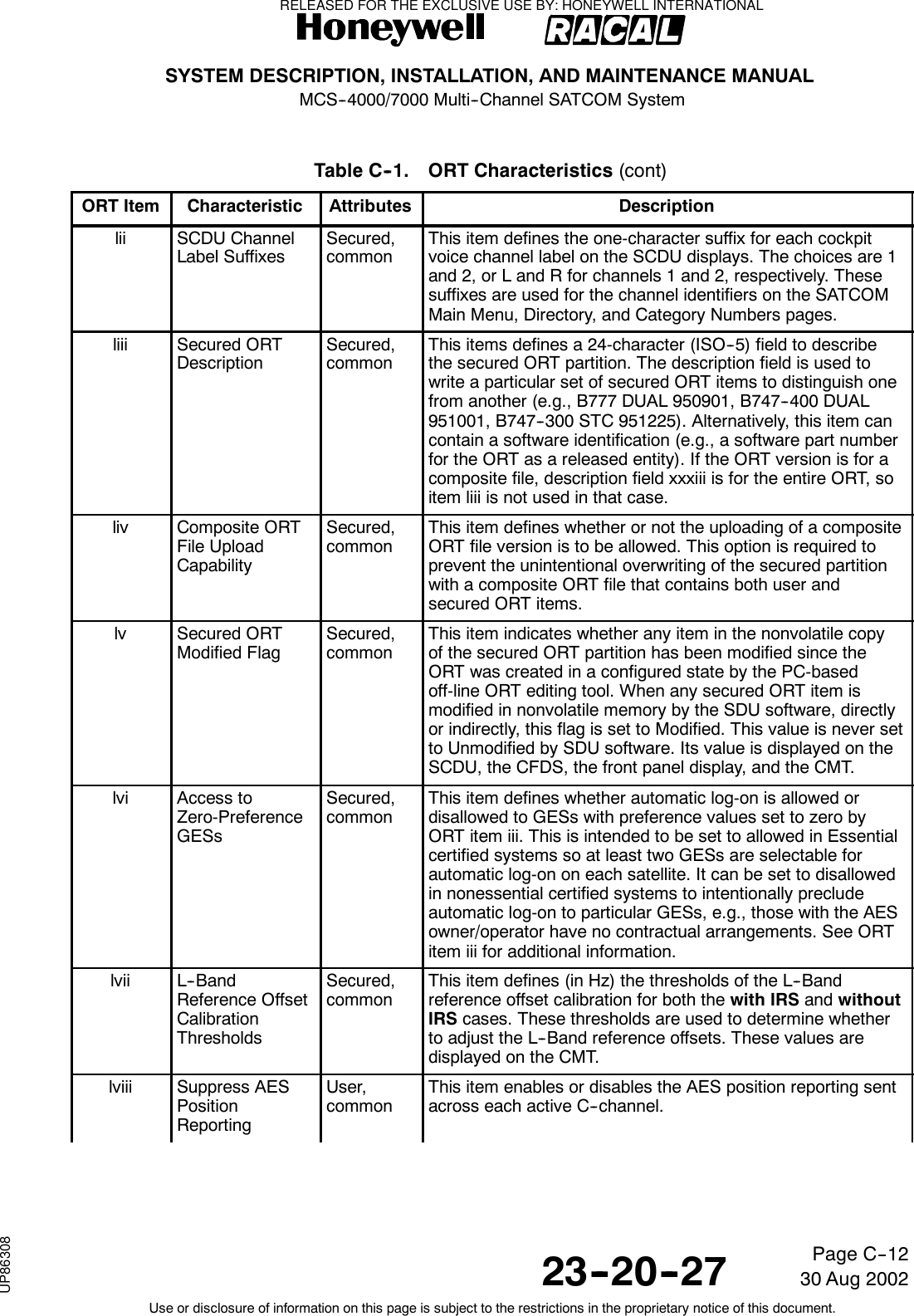
![SYSTEM DESCRIPTION, INSTALLATION, AND MAINTENANCE MANUALMCS--4000/7000 Multi--Channel SATCOM System23--20--2730 Aug 2002Use or disclosure of information on this page is subject to the restrictions in the proprietary notice of this document.Page C--11Table C--1. ORT Characteristics (cont)ORT Item DescriptionAttributesCharacteristicil MasteryHandoverAlgorithmWeightingUser,commonThis item stores the relative weighting factors for each of thesix functional capability items that form the criteria fordetermining which system should automatically become themaster in a dual system. Each of the six weighting factors is anon-negative integer ranging from 0 to 99. Higher factorsindicate more important criteria; however, only the relativevalues of the factors is significant. Zero is used to indicate acapability factor not installed, not used, or is a don’t care. Thefunctional capability items are as follows:•CoV -- Cockpit voice (for any number of channels).•CaV -- Cabin circuit-mode voice/fax/data(any number of channels, any cabin interface).•CoL -- Cockpit packet-mode data(through [C]MU) at low-rate only.•CoH -- Cockpit packet-mode data(through [C]MU) at (potentially) high-rate.•CaL -- Cabin packet-mode data(through CPDF or CTU) at low rate only.•CaH -- Cabin packet-mode data (through CPDF or CTU) at(potentially) high-rate.CoL and CoH are mutually exclusive, as are CaL andCaH — i.e., regardless of the weighting factors assigned, nomore than one of the cockpit data (or cabin data) capabilitiescanbetrueatatime.The primary practical use of this ORT item is for determiningwhich SDU in a dual system should be the master when thechoice is down to one system which only has voice capabilityvs one which only has data capability, or one with only cockpitservices capabilities vs one with only cabin servicescapabilities.lDisable/ReenableOther SATCOMSCDU PromptsSecured,commonThis item determines if the disable other SATCOM andre--enable other SATCOM toggling SCDU prompts arepresented or suppressed. The SCDU prompts are usuallysuppressed if the optional external manual switch (thatcontrols the dual system select and disable discretes) issupplied so there is only one means of performing anyfunction at a time and the possibility of inadvertently disablingboth systems is avoided.li SCDU SATCOMSubsystemPromptsSecured,duplicatedThis item defines up to six ISO--5 characters used for theSCDU main menu SATCOM subsystem selection LSKprompts. The owner/operator is able to select any ISO--5characters and any length up to six characters. Examplecharacter strings would be SAT L and SAT R, or <SDU--1 and<SDU--2.RELEASED FOR THE EXCLUSIVE USE BY: HONEYWELL INTERNATIONALUP86308](https://usermanual.wiki/Honeywell/SD-700A/User-Guide-3476924-Page-372.png)
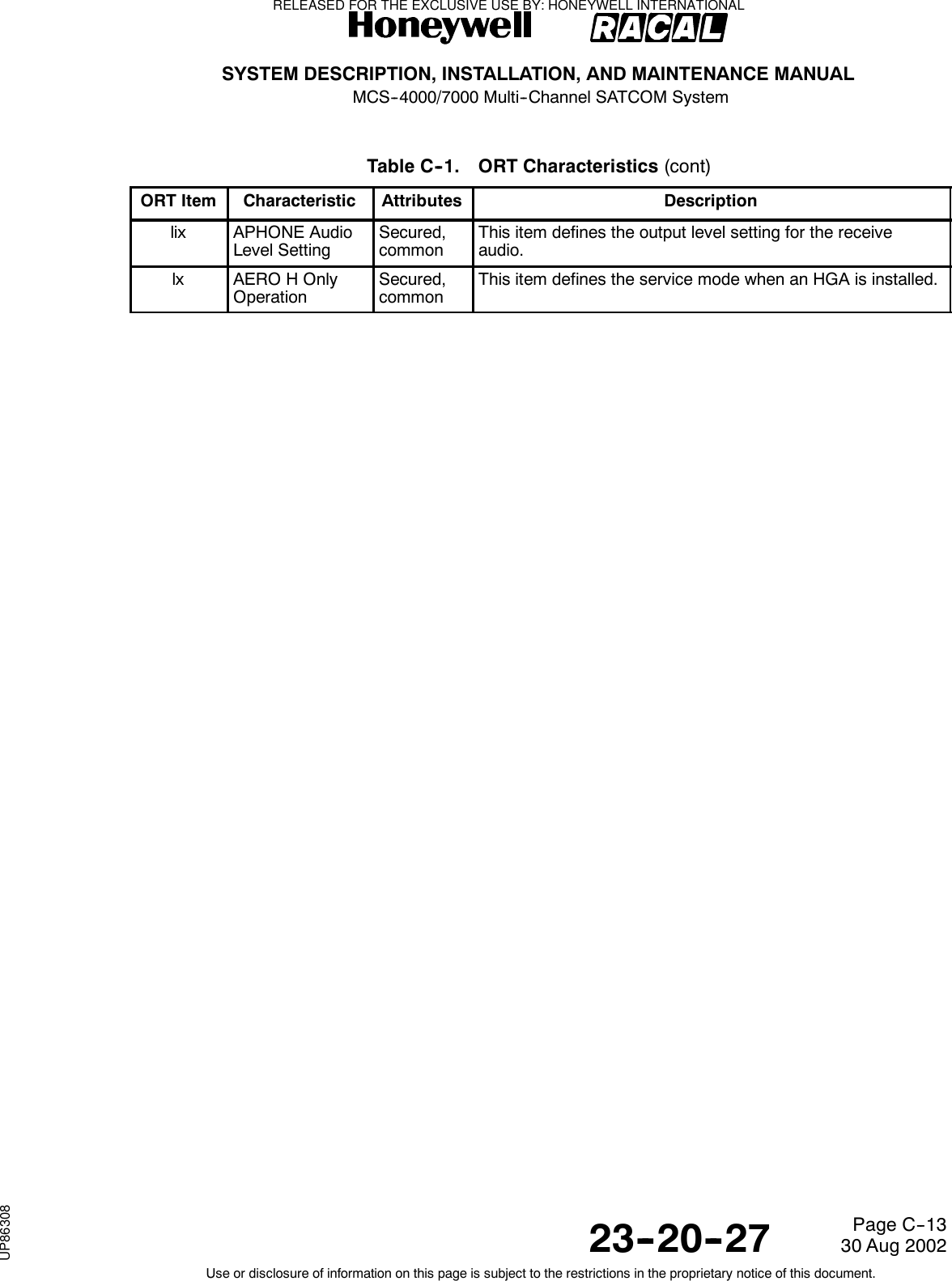

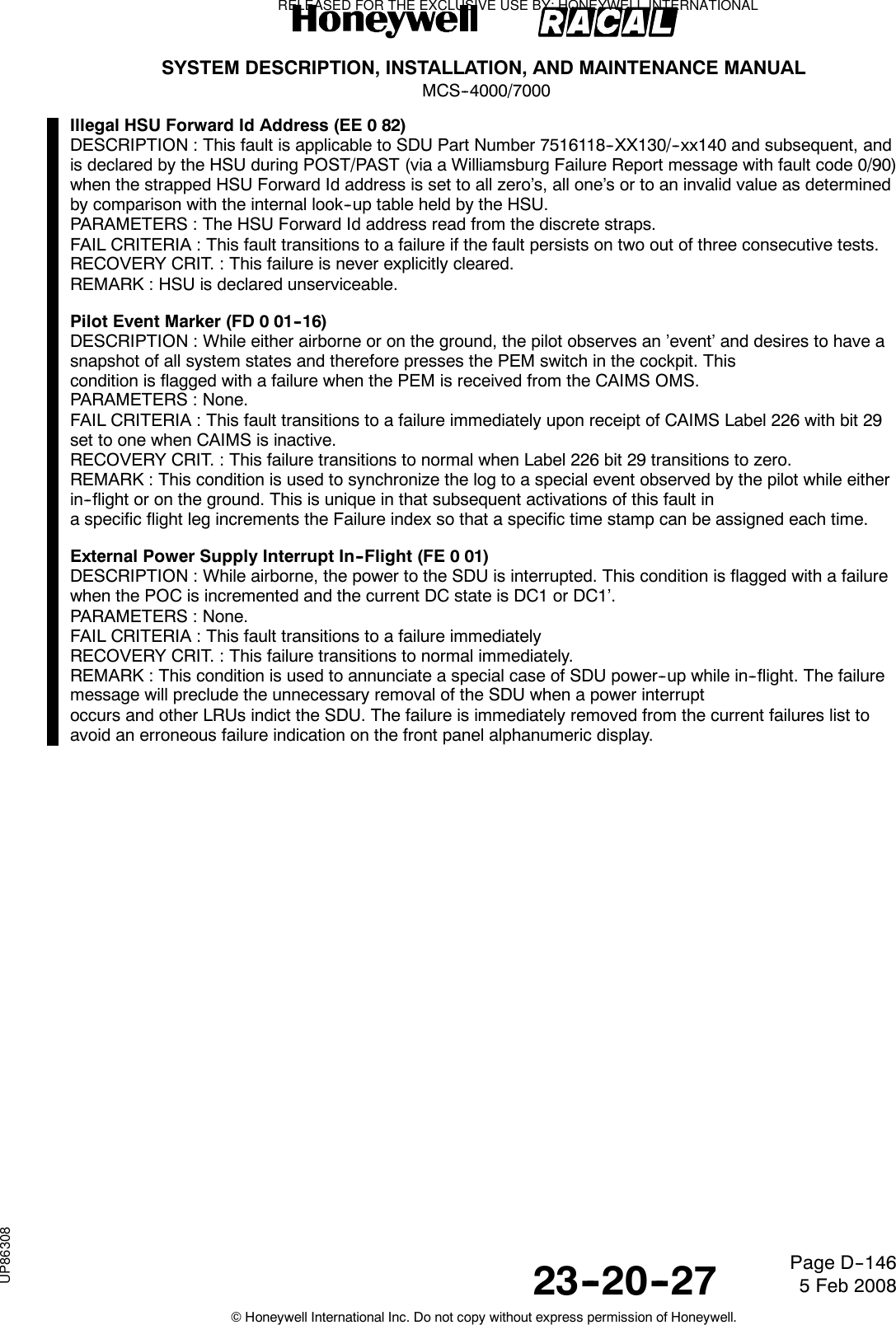
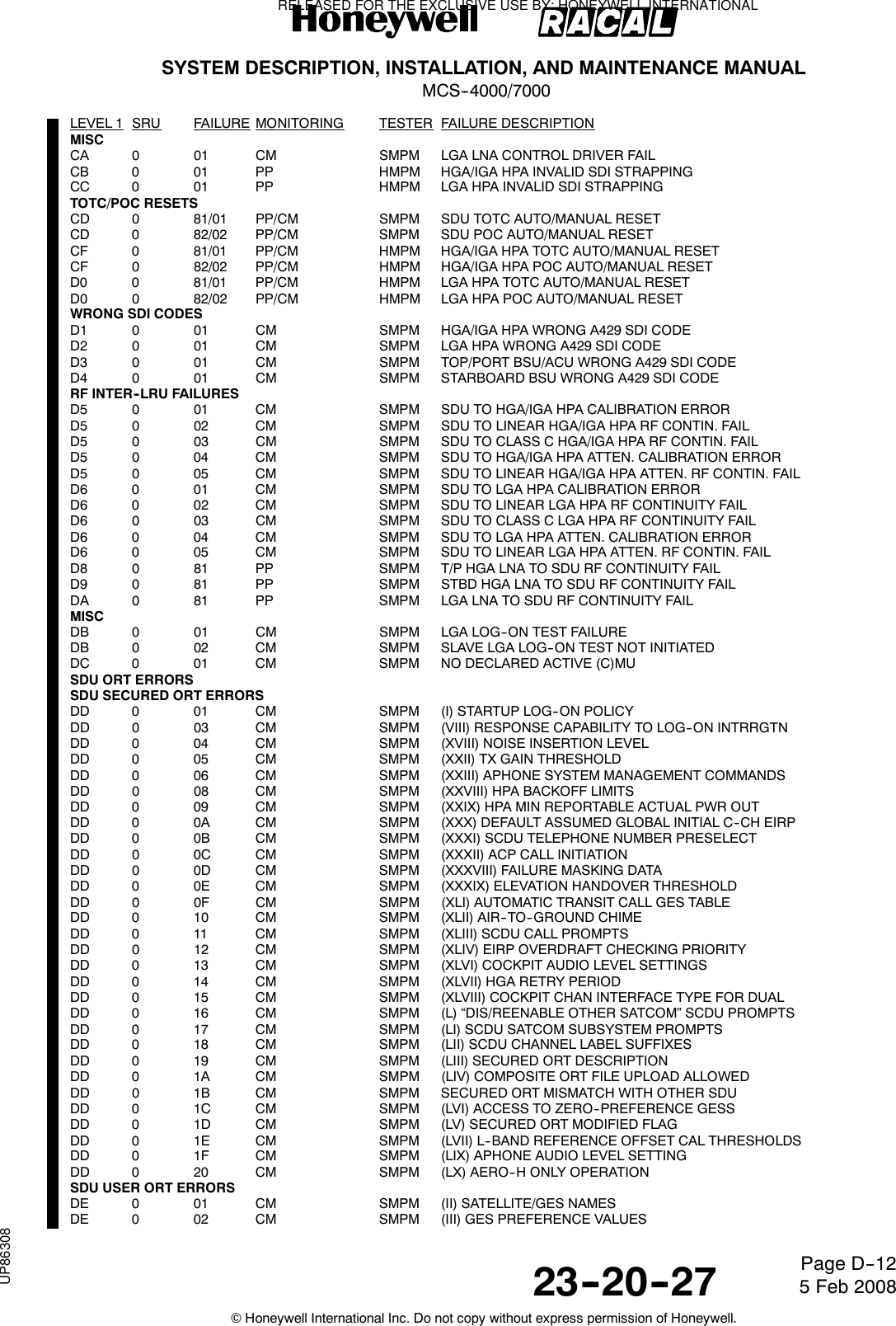
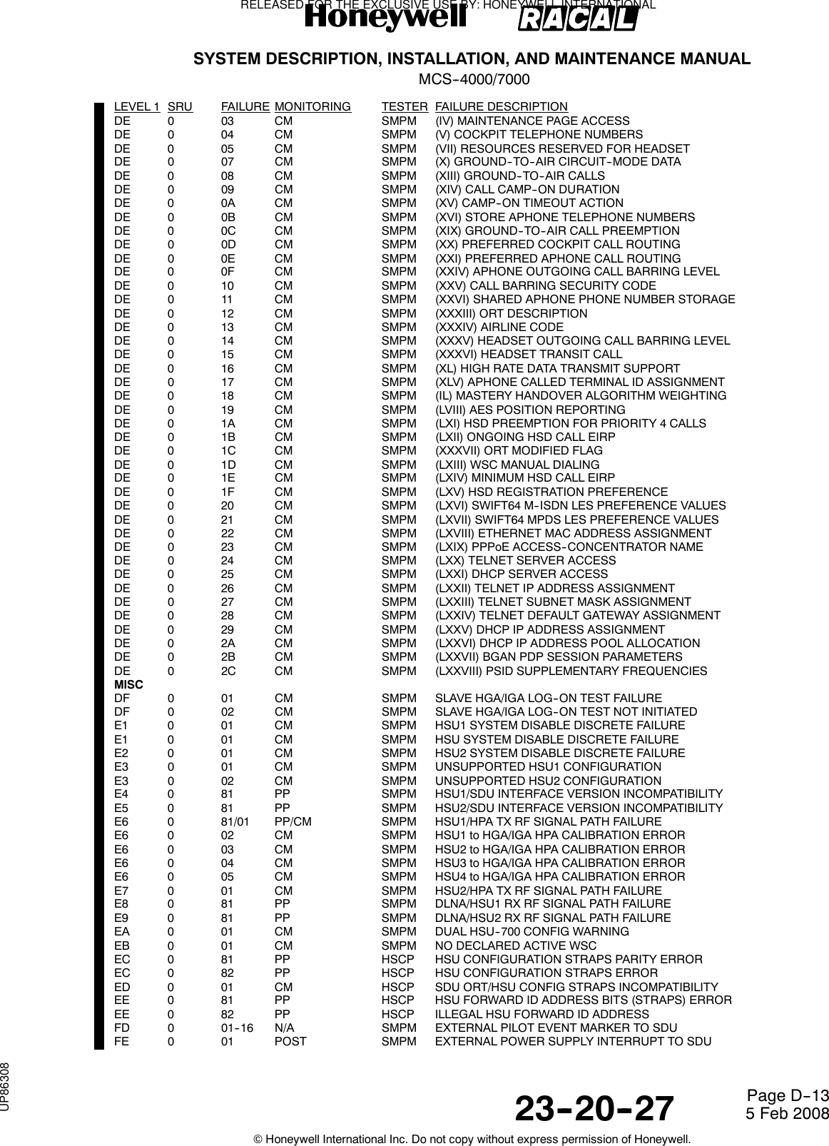
![SYSTEM DESCRIPTION, INSTALLATION, AND MAINTENANCE MANUALMCS--4000/700023--20--27 5 Feb 2008©Honeywell International Inc. Do not copy without express permission of Honeywell.Page D--1APPENDIX DFAULT CODESLEVEL 1 SRU FAILURE MONITORING TESTER FAILURE DESCRIPTIONFailure OverviewSDUUNKNOWN SDU SRU01 0 02 CM HMPM HPA CMD WORD (143) UPDATE RATE FAIL01 0 03 CM HMPM HPA CMD WORD (143) DATA FAIL01 0 07 CM SMPM HSU1--SDU W’BURG DATA TX FAIL01 0 08 CM SMPM HSU1--SDU W’BURG SOLO WORD ACK FAIL01 0 0B CM SMPM HSU2--SDU W’BURG DATA TX FAIL01 0 0C CM SMPM HSU2--SDU W’BURG SOLO WORD ACK FAIL01 0 10 CM SMPM HGA HPA COMMAND WORD (NCD)01 0 12 CM SMPM LGA HPA COMMAND WORD (NCD)01 0 96 PP SMPM INCOMPLETE ID PROM RESPONSESSMPM: SDU MAIN PROCESSOR MODULE01 1 81 PP SMPM SDU H/W--S/W COMPATIBILITY FAIL01 1 82 PP SMPM BATTERY VOLTAGE LOW01 1 83 PP SMPM WATCHDOG TIMEOUT FAIL01 1 84 PP SMPM MICRO BOOT ROM FAIL01 1 85/05 PP/CM SMPM EEPROM FAIL01 1 86/06 PP/CM SMPM FLASH FAIL01 1 87/07 PP/CM SMPM SRAM FAIL]01 1 88/08 PP/CM SMPM REAL TIME CLOCK FAIL01 1 89 PP SMPM QUART FAIL01 1 0A CM SMPM SOFTWARE ERROR (SYSFAIL)01 1 0B CM SMPM FLASH--PSRAM MISCOMPARE01 1 0C CM SMPM FLASH--PSRAM MISCOMPARE EXTENSION01 1 0D CM SMPM FLASH--PSRAM MISCOMPARE EXTENSIONCODA: SDU VOICE CODEC MODULE A01 2 81/01 PP/CM CODA <CODEC--A> PROGRAM MEMORY CRC FAIL01 2 87/07 PP/CM CODA <CODEC--A> TIMING GENERATOR FAIL01 2 88 PP CODA <CODEC--A> DUAL PORT RAM FAIL CODEC SIDE01 2 8A/0A PP/CM CODA <CODEC--A> PROGRAM MEMORY W/R FAIL01 2 8B PP CODA <CODEC--A> DSP INTERNAL MEMORY W/R FAIL01 2 8C/0C PP/CM CODA <CODEC--A> DSP COMPREHENSIVE FAIL01 2 0D CM SMPM <CODEC--A> HEALTH COUNT UPDATE01 2 8E PP SMPM <CODEC--A> DUAL PORT RAM FAIL SMPM SIDE01 2 90 PP SMPM <CODEC--A> BUS ERROR01 2 91 PP SMPM <CODEC--A> SELF TEST MISOPERATION01 2 12 CM SMPM <CODEC--A> COMMUNICATION PROBLEM01 2 94 PP SMPM <CODEC--A> ST BUS AUDIO LOOPBACK FAIL01 2 95 PP SMPM <CODEC--A> SW DOWNLOAD FAILCODB: SDU VOICE CODEC MODULE B01 3 Same entries as for CODA above except substitute CODB for CODA, SRU code 3 for code 2, [CODEC_B] for [CODEC_A] and<CODEC--B> for <CODEC--A>.Fault codes for codecs C--F have Level 2 (SRU) codes E--H. They are listed in the appropriate section of this table for those SRU codes.SIOM: SDU INPUT/OUTPUT MODULE (EXCLUSIVE TO SIOM)01 4 81 PP SMPM A429 XMTR LOOP--BACK TO OTHER SDU FAIL01 4 82 PP SMPM A429 XMTR LOOP--BACK TO CFDS FAIL01 4 83 PP SMPM A429 XMTR LOOP--BACK TO ADL FAIL01 4 84 PP SMPM A429 XMTR LOOP--BACK TO PDL FAIL01 4 85 PP SMPM A429 XMTR LOOP--BACK TO (C)MUs FAIL01 4 86 PP SMPM A429 XMTR LOOP--BACK TO SCDUs FAIL01 4 87 PP SMPM A429 XMTR LOOP--BACK TO MULTI--CNTRL FAIL01 4 89 PP SMPM A429 XMTR LOOP--BACK TO RMP/CAP FAIL01 4 8A PP SMPM A429 XMTR LOOP--BACK TO SNU/CPDF FAIL01 4 8B PP SMPM A429 XMTR LOOP--BACK TO HSU1 FAIL01 4 8C PP SMPM A429 XMTR LOOP--BACK TO HSU2 FAIL01 4 8D PP SMPM A429 XMTR LOOP--BACK SPARE01 4 8E PP SMPM A429 XMTR LOOP--BACK SPARE01 4 8F PP SMPM A429 XMTR LOOP--BACK SPARE01 4 90 PP SMPM A429 XMTR LOOP--BACK SPARE01 4 AB PP SMPM SIOM BUS ERROR01 4 2C CM SMPM A429 TX TO OTHER SDU BUFFER FULL01 4 2D CM SMPM A429 TX TO CFDS BUFFER FULL01 4 2E CM SMPM A429 TX TO ADL BUFFER FULL01 4 2F CM SMPM A429 TX TO PDL BUFFER FULLRELEASED FOR THE EXCLUSIVE USE BY: HONEYWELL INTERNATIONALUP86308](https://usermanual.wiki/Honeywell/SD-700A/User-Guide-3476924-Page-376.png)
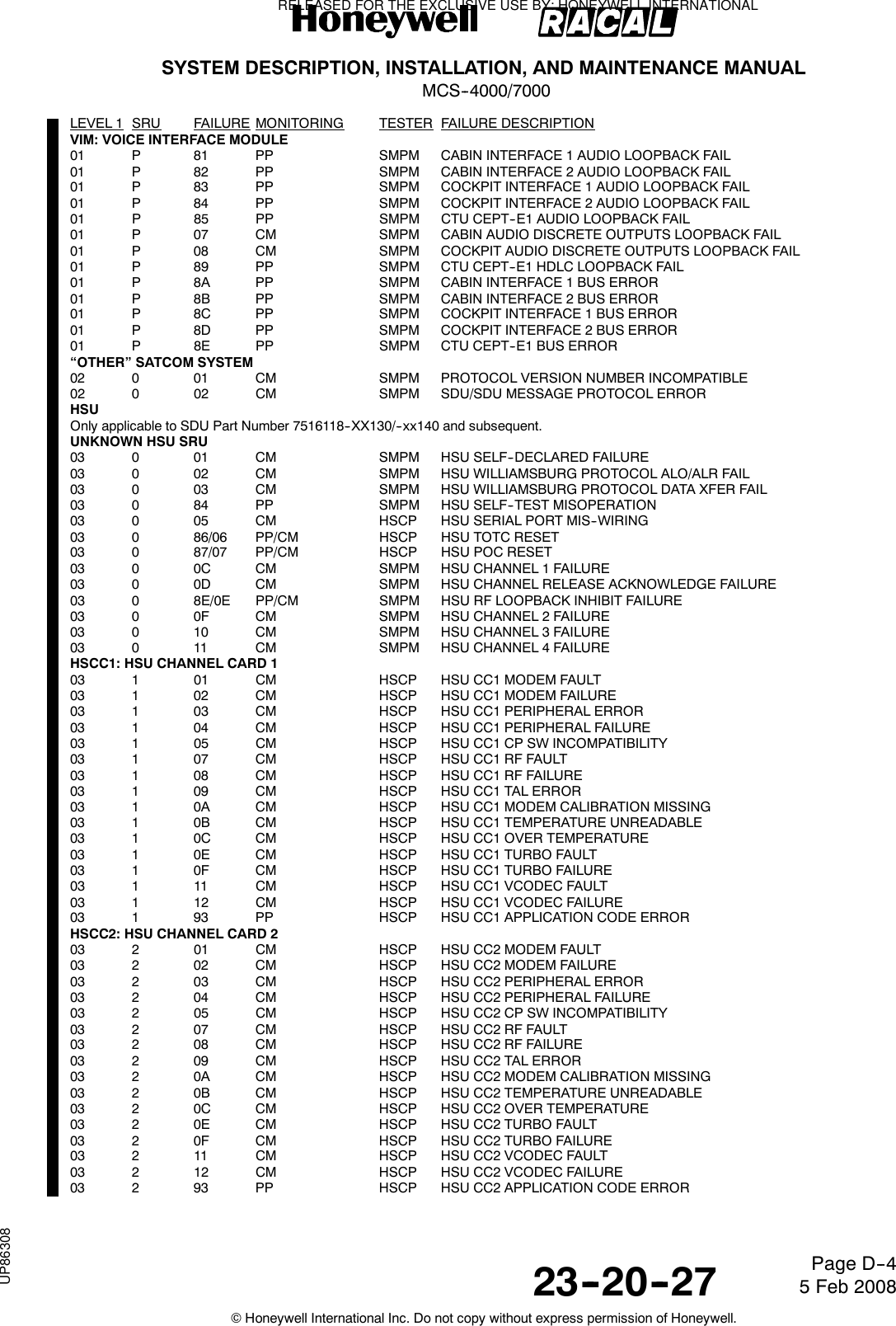
![SYSTEM DESCRIPTION, INSTALLATION, AND MAINTENANCE MANUALMCS--4000/700023--20--27 5 Feb 2008©Honeywell International Inc. Do not copy without express permission of Honeywell.Page D--2LEVEL 1 SRU FAILURE MONITORING TESTER FAILURE DESCRIPTION01 4 30 CM SMPM A429 TX TO (C)MUs BUFFER FULL01 4 31 CM SMPM A429 TX TO SCDUs BUFFER FULL01 4 32 CM SMPM A429 TX TO MULTI--CTRL BUFFER FULL01 4 34 CM SMPM A429 TX TO RMP/CAP BUFFER FULL01 4 35 CM SMPM A429 TX TO SNU/CPDF BUFFER FULL01 4 36 CM SMPM A429 TX TO HSU1 BUFFER FULL01 4 37 CM SMPM A429 TX TO HSU2 BUFFER FULL01 4 38 CM SMPM A429 TX BUFFER FULL SPARE01 4 39 CM SMPM A429 TX BUFFER FULL SPARE01 4 3A CM SMPM A429 TX BUFFER FULL SPARE01 4 3B CM SMPM A429 TX BUFFER FULL SPARE01 4 BC PP SMPM SIOM INTERRUPT FAIL01 4 3D CM SMPM IRS ASIC MATCHING PROBLEMSMDM1: SDU MODEM MODULE #101 5 81 PP SMDM1 <MODEM--1> PROCESSOR FAIL01 5 84/04 PP/CM SMDM1 <MODEM--1> PROGRAM CRC FAIL01 5 0A CM SMDM1 <MODEM--1>MODEM TO RFM INTERFACE FAIL01 5 8B PP SMDM1 <MODEM--1> TIMER/INTERRUPT FAIL01 5 8E PP SMDM1 <MODEM--1> EXTERNAL MEMORY FAIL01 5 91 PP SMDM1 <MODEM--1> MODEM DPR FAIL01 5 95 PP SMPM <MODEM--1> SMPM SIDE DPR FAIL01 5 16 CM SMPM <MODEM--1> SW DOWNLOAD FAIL01 5 17 CM SMPM <MODEM--1> HEALTH COUNT UPDATE FAIL01 5 99 PP SMPM <MODEM--1> BUS ERROR01 5 9A PP SMPM <MODEM--1> SELF TEST MISOPERATION01 5 1B CM SMDM1 <MODEM--1> SOFTWARE FAIL01 5 1C CM SMPM <MODEM--1> COMMUNICATIONS PROBLEM01 5 9E PP SMPM <MODEM--1> RFM SSI LOOPBACK FAILSMDM2: SDU MODEM MODULE #201 6 Same entries as for SMDM1 above except substitute SMDM2 for SMDM1, SRU code 6 for code 5, [MODEM_2] for [MODEM_1] and<MODEM--2> for <MODEM--1>.SMDM3: SDU MODEM MODULE #301 7 Same entries as for SMDM1 above except substitute SMDM3 for SMDM1, SRU code 7 for code 5, [MODEM_3] for [MODEM_1] and<MODEM--3> for <MODEM--1>.Fault codes for modems 4--7 have Level 2 (SRU) codes J, L, M and N. They are listed in this table in the appropriate section for those SRUcodes.SRFM: SDU RADIO FREQUENCY MODULE01 8 8E/0E PP/CM SMPM RF SYNTH CHAN1 LOCK DETECT FAIL01 8 90/10 PP/CM SMPM RF SYNTH CHAN2 LOCK DETECT FAIL01 8 92/12 PP/CM SMPM RF SYNTH CHAN3 LOCK DETECT FAIL01 8 96/16 PP/CM SMPM RF SYNTH CHAN4 LOCK DETECT FAIL01 8 97/17 PP/CM SMPM RF SYNTH CHAN5 LOCK DETECT FAIL01 8 98/18 PP/CM SMPM RF SYNTH CHAN6 LOCK DETECT FAIL01 8 99/19 PP/CM SMPM RF SYNTH CHAN7 LOCK DETECT FAIL01 8 9A/1A PP/CM SMPM RF SYNTH CHAN8 LOCK DETECT FAIL01 8 9B/1B PP/CM SMPM RF SYNTH TX BLOCK PLO LOCK DETECT FAIL01 8 9C/1C PP/CM SMPM RF SYNTH RX BLOCK PLO LOCK DETECT FAIL01 8 9D/1D PP/CM SMPM RF SYNTH RX CHAN PLO LOCK DETECT FAIL01 8 9E/1E PP/CM SMPM RF SYNTH TX DOPPLER PLO LOCK DETECT FAIL01 8 A0 PP SMPM RFM CHAN 1 L--BAND LOOP--BACK (TX) FAIL01 8 A1 PP SMPM RFM CHAN 1 L--BAND LOOP--BACK (RX) FAIL01 8 A2 PP SMPM RFM CHAN 2 L--BAND LOOP--BACK (TX) FAIL01 8 A3 PP SMPM RFM CHAN 2 L--BAND LOOP--BACK (RX) FAIL01 8 A4 PP SMPM RFM CHAN 3 L--BAND LOOP--BACK (TX) FAIL01 8 A5 PP SMPM RFM CHAN 3 L--BAND LOOP--BACK (RX) FAIL01 8 A6 PP SMPM RFM CHAN 4 L--BAND LOOP--BACK (TX) FAIL01 8 A7 PP SMPM RFM CHAN 4 L--BAND LOOP--BACK (RX) FAIL01 8 A8 PP SMPM RFM CHAN 5 L--BAND LOOP--BACK (TX) FAIL01 8 A9 PP SMPM RFM CHAN 5 L--BAND LOOP--BACK (RX) FAIL01 8 AA PP SMPM RFM CHAN 6 L--BAND LOOP--BACK (TX) FAIL01 8 AB PP SMPM RFM CHAN 6 L--BAND LOOP--BACK (RX) FAIL01 8 AC PP SMPM RFM CHAN 7 L--BAND LOOP--BACK (TX) FAIL01 8 AD PP SMPM RFM CHAN 7 L--BAND LOOP--BACK (RX) FAIL01 8 AE PP SMPM RFM CHAN 8 L--BAND LOOP--BACK (TX) FAIL01 8 AF PP SMPM RFM CHAN 8 L--BAND LOOP--BACK (RX) FAIL01 8 30 CM SMPM RFM CHAN 1 TX CALIBRATION ERROR01 8 31 CM SMPM RFM CHAN 2 TX CALIBRATION ERROR01 8 32 CM SMPM RFM CHAN 3 TX CALIBRATION ERRORRELEASED FOR THE EXCLUSIVE USE BY: HONEYWELL INTERNATIONALUP86308](https://usermanual.wiki/Honeywell/SD-700A/User-Guide-3476924-Page-377.png)
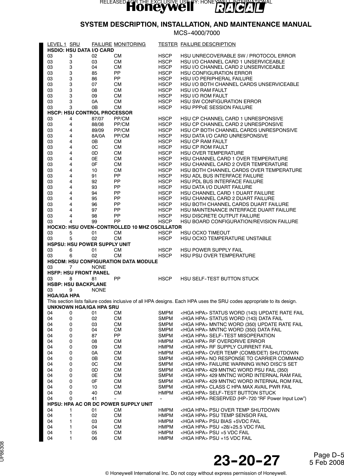
![SYSTEM DESCRIPTION, INSTALLATION, AND MAINTENANCE MANUALMCS--4000/700023--20--27 5 Feb 2008©Honeywell International Inc. Do not copy without express permission of Honeywell.Page D--3LEVEL 1 SRU FAILURE MONITORING TESTER FAILURE DESCRIPTION01 8 33 CM SMPM RFM CHAN 4 TX CALIBRATION ERROR01 8 34 CM SMPM RFM CHAN 5 TX CALIBRATION ERROR01 8 35 CM SMPM RFM CHAN 6 TX CALIBRATION ERROR01 8 36 CM SMPM RFM CHAN 7 TX CALIBRATION ERROR01 8 37 CM SMPM RFM CHAN 8 TX CALIBRATION ERROR01 8 38 CM SMPM RFM CHAN 1 RX CALIBRATION ERROR01 8 39 CM SMPM RFM CHAN 2 RX CALIBRATION ERROR01 8 3A CM SMPM RFM CHAN 3 RX CALIBRATION ERROR01 8 3B CM SMPM RFM CHAN 4 RX CALIBRATION ERROR01 8 3C CM SMPM RFM CHAN 5 RX CALIBRATION ERROR01 8 3D CM SMPM RFM CHAN 6 RX CALIBRATION ERROR01 8 3E CM SMPM RFM CHAN 7 RX CALIBRATION ERROR01 8 3F CM SMPM RFM CHAN 8 RX CALIBRATION ERROR01 8 C0/40 PP/CM SMPM RFM CHAN 1 AGC TELLBACK FAIL01 8 C1/41 PP/CM SMPM RFM CHAN 2 AGC TELLBACK FAIL01 8 C2/42 PP/CM SMPM RFM CHAN 3 AGC TELLBACK FAIL01 8 C3/43 PP/CM SMPM RFM CHAN 4 AGC TELLBACK FAIL01 8 C4/44 PP/CM SMPM RFM CHAN 5 AGC TELLBACK FAIL01 8 C5/45 PP/CM SMPM RFM CHAN 6 AGC TELLBACK FAIL01 8 C6/46 PP/CM SMPM RFM CHAN 7 AGC TELLBACK FAIL01 8 C7/47 PP/CM SMPM RFM CHAN 8 AGC TELLBACK FAIL01 8 C8/48 PP/CM SMPM RFM BLOCK AGC TELLBACK FAIL01 8 C9 PP SMPM I/Q CALIBRATION FAIL01 8 D0 PP SMPM RFM CHAN 1 AGC CALIBRATION ERROR01 8 D1 PP SMPM RFM CHAN 2 AGC CALIBRATION ERROR01 8 D2 PP SMPM RFM CHAN 3 AGC CALIBRATION ERROR01 8 D3 PP SMPM RFM CHAN 4 AGC CALIBRATION ERROR01 8 D4 PP SMPM RFM CHAN 5 AGC CALIBRATION ERROR01 8 D5 PP SMPM RFM CHAN 6 AGC CALIBRATION ERROR01 8 D6 PP SMPM RFM CHAN 7 AGC CALIBRATION ERROR01 8 D7 PP SMPM RFM CHAN 8 AGC CALIBRATION ERROR01 8 D8 PP SMPM RFM BLOCK AGC CALIBRATION ERROROCXO: SDU OVEN CONTROLLED CRYSTAL OSCILLATOR01 A 01 CM SMPM OVEN READY FAILSMB: SDU MOTHER BOARD01 B NONESPSU: SDU AC OR DC POWER SUPPLY UNIT01 C 01 CM SMPM PSU TEMP LIMITS FAIL01 C 03 CM SMPM PSU SECONDARY VOLTAGE FAILSFPDM: SDU FRONT PANEL DISPLAY MODULE01 D 01 CM SMPM TEST (PAST) SWITCH STUCK01 D 02 CM SMPM MANUAL SCROLL SWITCH STUCKCODC: SDU VOICE CODEC MODULE C01 E Same entries as for CODA (01 2 xx) above except substitute CODC for CODA, SRU code E for code 2, [CODEC_C] for [CODEC_A]and <CODEC--C> for <CODEC--A>.CODD: SDU VOICE CODEC MODULE D01 F Same entries as for CODA (01 2 xx) above except substitute CODD for CODA, SRU code F for code 2, [CODEC_D] for [CODEC_A]and <CODEC--D> for <CODEC--A>.CODE: SDU VOICE CODEC MODULE E01 G Same entries as for CODA (01 2 xx) above except substitute CODE for CODA, SRU code G for code 2, [CODEC_E] for [CODEC_A]and <CODEC--E> for <CODEC--A>.CODF: SDU VOICE CODEC MODULE F01 H Same entries as for CODA (01 2 xx) above except substitute CODF for CODA, SRU code H for code 2, [CODEC_F] for [CODEC_A]and <CODEC--F> for <CODEC--A>.01 I Not used.SMDM4: SDU MODEM MODULE #401 J Same entries as for SMDM1 (01 5 xx) above except substitute SMDM4 for SMDM1, SRU code J for code 5, [MODEM_4] for[MODEM_1] and <MODEM--4> for <MODEM--1>.01 K Not used.SMDM5: SDU MODEM MODULE #501 L Same entries as for SMDM1 (01 5 xx) above except substitute SMDM5 for SMDM1, SRU code L for code 5, [MODEM_5] for[MODEM_1] and <MODEM--5> for <MODEM--1>.SMDM6: SDU MODEM MODULE #601 M Same entries as for SMDM1 (01 5 xx) above except substitute SMDM6 for SMDM1, SRU code M for code 5, [MODEM_6] for[MODEM_1] and <MODEM--6> for <MODEM--1>.SMDM7: SDU MODEM MODULE #701 N Same entries as for SMDM1 (01 5 xx) above except substitute SMDM7 for SMDM1, SRU code N for code 5, [MODEM_7] for[MODEM_1] and <MODEM--7> for <MODEM--1>.RELEASED FOR THE EXCLUSIVE USE BY: HONEYWELL INTERNATIONALUP86308](https://usermanual.wiki/Honeywell/SD-700A/User-Guide-3476924-Page-378.png)
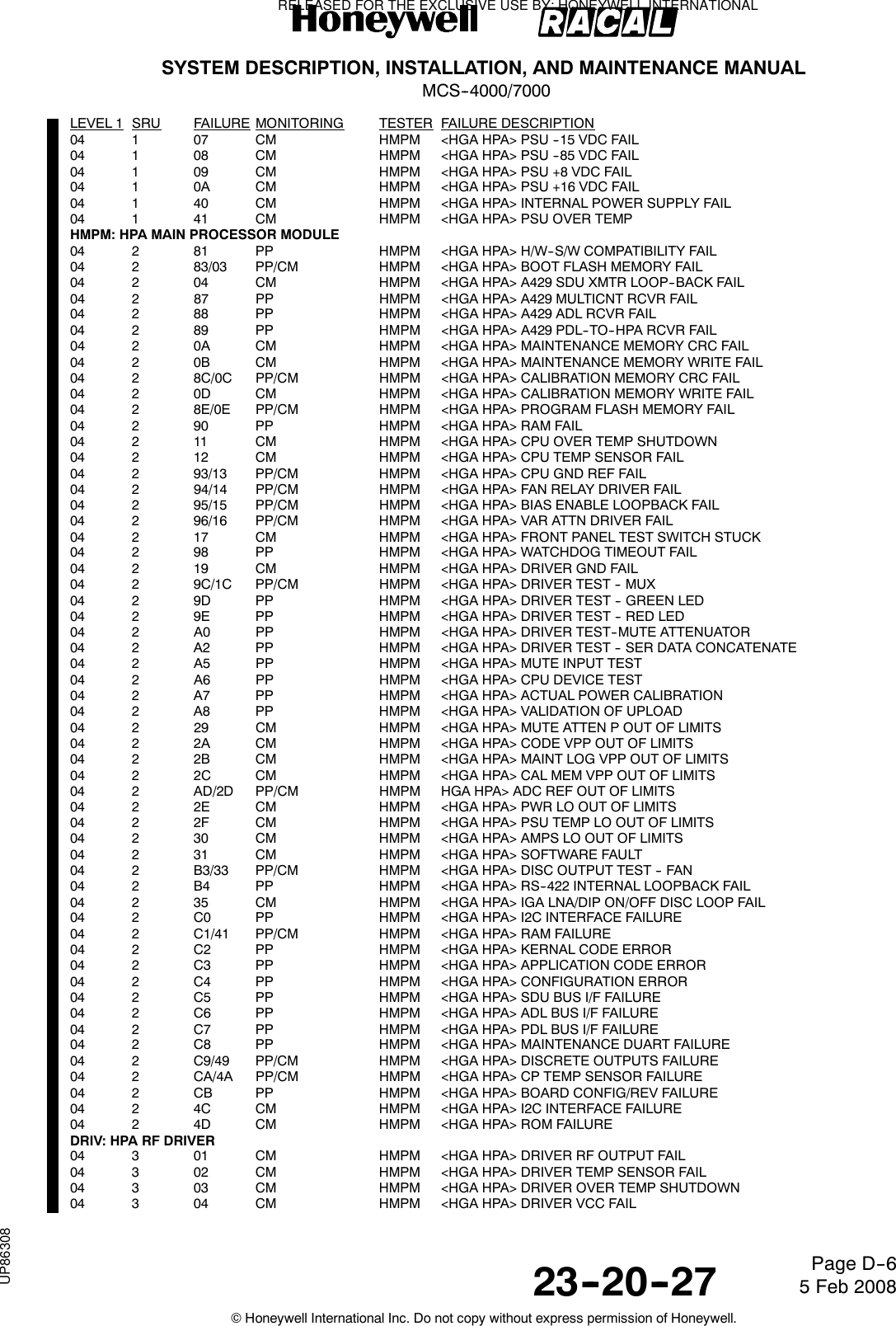
![SYSTEM DESCRIPTION, INSTALLATION, AND MAINTENANCE MANUALMCS--4000/700023--20--27 5 Feb 2008©Honeywell International Inc. Do not copy without express permission of Honeywell.Page D--7LEVEL 1 SRU FAILURE MONITORING TESTER FAILURE DESCRIPTIONPWR1: HPA RF POWER AMPLIFIER (1)04 5 01 CM HMPM <HGA HPA> <AMP 1> RF BALANCE FAIL04 5 02 CM HMPM <HGAHPA><AMP1>VCCFAILPWR2: HPA RF POWER AMPLIFIER (2)04 6 Same as for PWR1 except sub. SRU code 6 for 5 and <AMP--2> for <AMP--1>.PWR3: HPA RF POWER AMPLIFIER (3)04 7 Same as for PWR1 except sub. SRU code 7 for 5 and <AMP--3> for <AMP--1>.C/DET: HPA RF POWER COMBINER/DETECTOR04 8 01 CM HMPM <HGA HPA> FORWARD OUTPUT POWER DET 1 FAIL04 8 02 CM HMPM <HGA HPA> FORWARD OUTPUT POWER DET 2 FAIL04 8 03 CM HMPM <HGA HPA> FORWARD OUTPUT PWR COMPARE FAIL04 8 04 CM HMPM <HGA HPA> REFLECTED OUTPUT PWR DET FAIL04 8 05 CM HMPM <HGA HPA> COMBINER TEMP SENSOR FAILFPAMP: HPA RF FINAL POWER AMPLIFIER04 9 01 CM HMPM <HGA HPA> FINAL AMP 1 RF BALANCE FAIL04 9 02 CM HMPM <HGA HPA> FINAL AMP 1 VCC FAIL04 9 04 CM HMPM <HGA HPA> FINAL AMP 2 RF BALANCE FAIL04 9 05 CM HMPM <HGA HPA> FINAL AMP 2 VCC FAIL04 9 C0/40 PP/CM HMPM <HGA HPA> PA UNRESPONSIVE04 9 42 CM HMPM <HGA HPA> OVER CURRENT FAILURE04 9 43 CM HMPM <HGA HPA> DRIVER AMPLIFIER DC VOLTAGE FAILURE04 9 44 CM HMPM <HGA HPA> DRIVER AMPLIFIER CURRENT FAILURE04 9 45 CM HMPM <HGA HPA> 12 VDC FAILURE04 9 46 CM HMPM <HGA HPA> PA MUTE FAILURE04 9 47 CM HMPM <HGAHPA>PAOVERTEMP04 9 48 CM HMPM <HGAHPA>PASTATUSFAILURE04 9 49 CM HMPM <HGA HPA> PA TEMP SENSOR FAILUREHMB: HPA MOTHER BOARD04 A 40 CM HMPM <HGA HPA> BP TEMP SENSOR FAILURERFAM: 20W HPA RF AMPLIFIER MODULE04 B 01 CM HMPM <HGA HPA> OVER TEMP SHUTDOWN04 B 02 CM HMPM <HGA HPA> RFAM VCC FAIL04 B 03 CM HMPM <HGA HPA> AMP 1 VCC FAIL04 B 04 CM HMPM <HGA HPA> FORWARD OUTPUT POWER DET 1 FAIL04 B 05 CM HMPM <HGA HPA> FORWARD OUTPUT POWER DET 2 FAIL04 B 06 CM HMPM <HGA HPA> REFLECTED OUTPUT PWR DET FAIL04 B 07 CM HMPM <HGA HPA> TEMP SENSOR FAIL04 B 08 CM HMPM <HGA HPA> FORWARD OUTPUT POWER FAIL04 B 09 CM HMPM <HGA HPA> AMP 2 RF BALANCE FAIL04 B 0A CM HMPM <HGA HPA> AMP 2 VCC FAILLGA HPA07 Same entries as for HGA/IGA HPA above except substitute LRU code 7 for code 4, <LGA HPA> for <HGA HPA>, and [LGA_SUBSYS]for [HGA_SUBSYS]. For the cases of conditional HGA subsystem indictments ([cond_HGA_SUBSYS]), the equivalent LGA HPA failuresshall UNconditionally indict [LGA_SUBSYS].HSU #1Only applicable prior to SDU Part Number 7516118--XX130/--xx140.UNKNOWN <HSU1> SRU08 0 01 CM SMPM <HSU1> SELF--DECLARED FAILURE08 0 02 CM SMPM <HSU1> WILLIAMSBURG PROTOCOL ALO/ALR FAIL08 0 03 CM SMPM <HSU1> WILLIAMSBURG PROTOCOL DATA XFER FAIL08 0 84 PP SMPM <HSU1> SELF--TEST MISOPERATION08 0 05 CM SMPM <HSU1> CHANNEL RELEASE ACKNOWLEDGE FAILURE08 0 86/06 PP/CM SMPM <HSU1> RF LOOPBACK INHIBIT FAILUREHSCPU: <HSU1> CPU08 1 FA PP HSCPU <HSU1> ACCESS LEVEL DEVELOPMENT08 1 FB PP HSCPU <HSU1> ACCESS LEVEL PRODUCTION08 1 FC PP HSCPU <HSU1> ACCESS LEVEL PRODUCTION FAST STARTUP08 1 FD PP HSCPU <HSU1> SW VERSIONS INCONSISTENCY08 1 7F CM HSCPU <HSU1> ENVIRONMENT TEMP AT POWER--UP FAIL08 1 91 PP HSCPU <HSU1> TEMP SENSOR FAILUREFDSMP: <HSU1> FRAME DSP (AND INTERFACES)08 2 95 PP HSCPU <HSU1> FRAME DSP/CPU INTERFACE FAILUREVSDPM: <HSU1> VFC DSP (AND INTERFACES)08 3 98 PP HSCPU <HSU1> VFC DSP/CPU INTERFACE FAILURETFPGA: <HSU1> TURBO FPGA08 4 86 PP HSCPU <HSU1> TURBO FPGA FAILISDNT: <HSU1> ISDN TRANSCEIVER08 5 87 PP HSCPU <HSU1> ISDN TRANSCEIVER FAILURERELEASED FOR THE EXCLUSIVE USE BY: HONEYWELL INTERNATIONALUP86308](https://usermanual.wiki/Honeywell/SD-700A/User-Guide-3476924-Page-382.png)
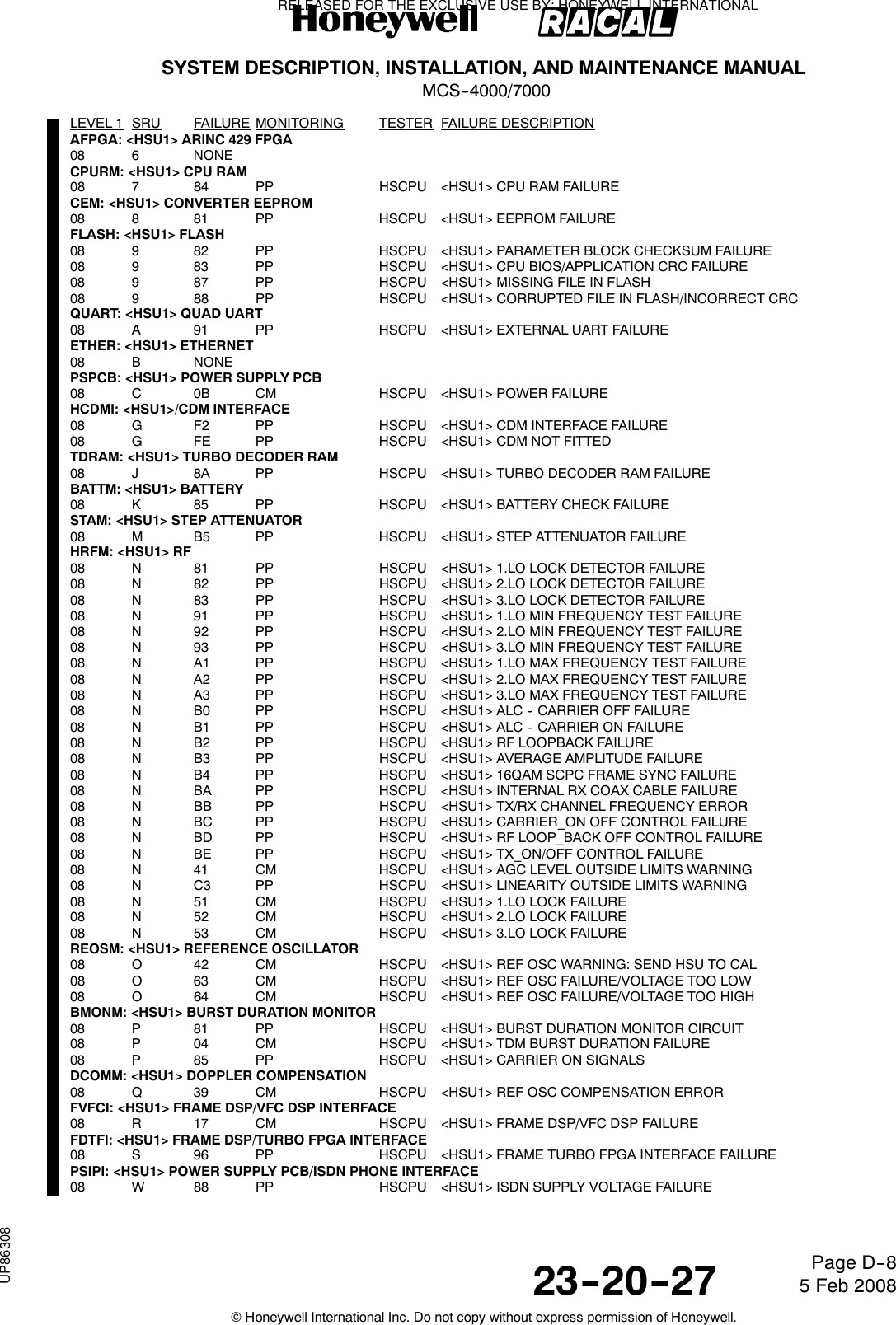
![SYSTEM DESCRIPTION, INSTALLATION, AND MAINTENANCE MANUALMCS--4000/700023--20--27 5 Feb 2008©Honeywell International Inc. Do not copy without express permission of Honeywell.Page D--9LEVEL 1 SRU FAILURE MONITORING TESTER FAILURE DESCRIPTIONCDM: <HSU1> CONFIGURATION DATA MODULE08 X F1 PP HSCPU <HSU1> INVALID SERIAL NUMBER08 X F3 PP HSCPU <HSU1> CDM ESSENTIAL DATA FAILURE08 X F4 PP HSCPU <HSU1> CDM DATA ACCESS ERROR08 X F5 PP HSCPU <HSU1> CDM MISSING WRITE PROTECTION08 X F6 PP HSCPU <HSU1> CDM INCORRECT VERSIONITPSI: <HSU1> ISDN TRANSCEIVER/POWER SUPPLY PCB INTERFACE08 Z 89 PP HSCPU <HSU1> ISDN RX VOLTAGEHSU #209 Same entries as for HSU #1 above except substitute LRU code 09 for code 08, <HSU2> for <HSU1>, and [HSU2] for [HSU1]. Onlyapplicable prior to SDU Part Number 7516118--XX130/--xx140.HIGH POWER RELAYUNKNOWN HPR SRU0A 0 01 CM SMPM (PORT) MNTNC WORD HPR FAIL0A 0 02 CM SMPM (STBD) MNTNC WORD HPR FAILTOP/PORT LNA/DIPLEXERUNKNOWN TOP/PORT LNA/DIPLEXER SRU0D 0 01 CM SMPM <T/P LNA/DIP> MNTNC WORD FAILSTARBOARD LNA/DIPLEXER0F Same entries as for TOP/PORT LNA/Diplexer above except substitute STBD BSU for T/P BSU, LRU code 0F for code 0D and <STBDLNA/DIP> for <T/P LNA/DIP>.LGA LNA/DIPLEXERUNKNOWN LGA LNA/DIPLEXER SRU10 0 01 CM SMPM LGA LNA/DIP FAILTOP/PORT BSU OR ACUUNKNOWN TOP/PORT BSU OR ACU SRU13 0 01 CM SMPM <T/P B/A> MNTNC WORD (350) UPDATE RATE FAIL13 0 02 CM SMPM <T/P B/A> MNTNC WORD (350) DATA FAIL13 0 03 CM SMPM <T/P B/A> STATUS WORD (144) UPDATE RATE FAIL13 0 04 CM SMPM <T/P B/A> STATUS WORD (144) DATA FAIL13 0 05 CM SMPM <T/P B/A> MNTNC WORD RAM FAIL13 0 06 CM SMPM <T/P B/A> MNTNC WORD ROM FAIL13 0 07 CM SMPM <T/P B/A> MNTNC WORD PSU FAIL13 0 08 CM SMPM <T/P B/A> MNTNC WORD PARAMETER FAIL13 0 09 CM SMPM <T/P B/A> MNTNC WORD TEMP FAIL13 0 8A PP SMPM <T/P B/A> SELF--TEST MISOPERATIONSTARBOARD BSU15 Same entries as for TOP/PORT BSU or ACU above except substitute LRU code 15 for code 13 and <STBD BSU> for <T/P B/A>.TOP/PORT HGA/IGAUNKNOWN TOP/PORT HGA/IGA SRU1A 0 01 CM SMPM <T/P HGA/IGA> MNTNC WORD FAIL1A 0 02 CM HMPM IGA FAILURE1A 0 03 CM HMPM IGA RS--422 INPUT BUS LINK FAULT1A 0 04 CM HMPM IGA HPA RS--422 INPUT BUS ERROR/INACTIVESTARBOARD HGA1C Same entries as for TOP/PORT HGA above except substitute LRU code 1C for code 1A, <STBD BSU> for <T/P B/A>, and <STBDHGA> for <T/P HGA>.LGAUNKNOWN LGA SRUSCDU/WSC #1UNKNOWN SCDU/WSC #1 SRU21 0 01 CM SMPM <SCDU--1> PROTOCOL ERROR21 0 02 CM SMPM <WSC--1> STATUS (270) BAD SSM21 0 03 CM SMPM <WSC--1> MASTER PROTOCOL ERROR21 0 04 CM SMPM <WSC--1> DATA TRANSMISSION FAILURE21 0 07 CM SMPM <WSC--1> MASTER TEST LOOP FAILURESCDU/WSC #222 Same entries as for SCDU/WSC #1 above except substitute LRU code 22 for code 21, <WSC--2> for <WSC--1>, and <SCDU--2> for<SCDU--1>.SCDU/WSC #323 Same entries as for SCDU/WSC #1 above except substitute LRU code 23 for code 21, <WSC--3> for <WSC--1>, and <SCDU--3> for<SCDU--1>.(C)MU #1UNKNOWN (C)MU #1 SRU33 0 02 CM SMPM <(C)MU--1> STATUS (270) BAD SSM33 0 03 CM SMPM <(C)MU--1> MASTER PROTOCOL ERROR33 0 04 CM SMPM <(C)MU--1> DATA TRANSMISSION FAILURE33 0 05 CM SMPM <(C)MU--1> SLAVE PROTOCOL ERROR33 0 06 CM SMPM <(C)MU--1> SELF--DECLARED FAILURERELEASED FOR THE EXCLUSIVE USE BY: HONEYWELL INTERNATIONALUP86308](https://usermanual.wiki/Honeywell/SD-700A/User-Guide-3476924-Page-384.png)
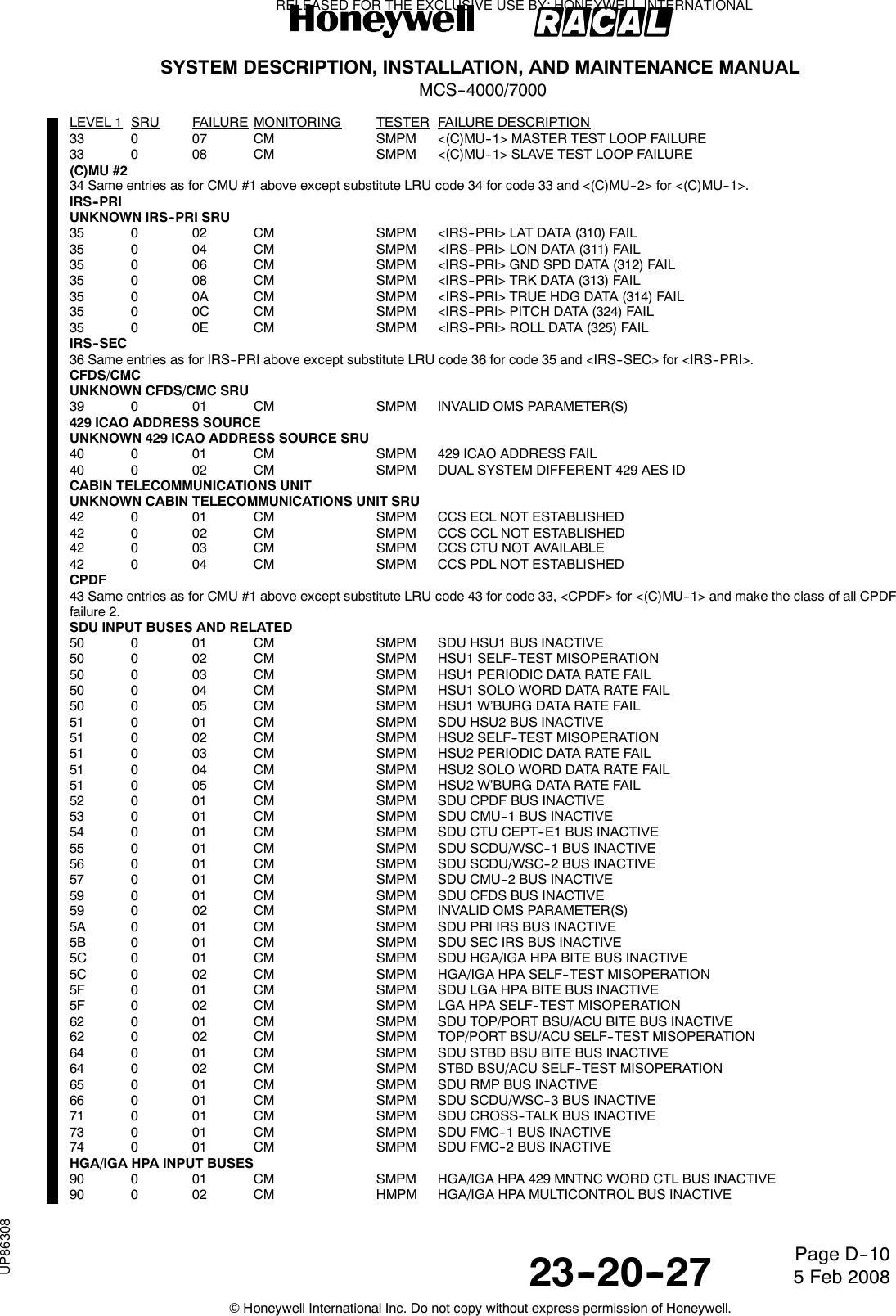
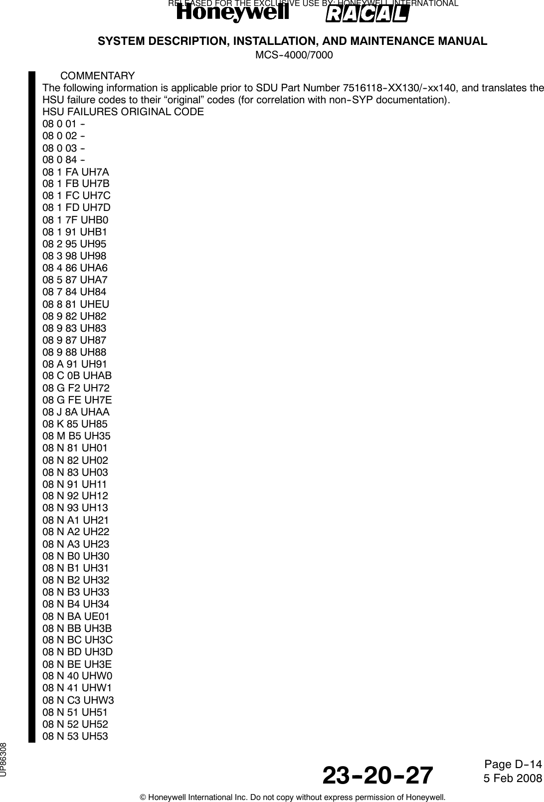
![SYSTEM DESCRIPTION, INSTALLATION, AND MAINTENANCE MANUALMCS--4000/700023--20--27 5 Feb 2008©Honeywell International Inc. Do not copy without express permission of Honeywell.Page D--1508 O 42 UHW208 O 63 UH6308 O 64 UH6408 P 81 UHA108 P 04 UHA408 P 85 UHA508 Q 39 UH3908 R 17 UH9708 S 96 UH9608 W 88 UHA808 X F1 UH7108 X F3 UH7308 X F4 UH7408 X F5 UH7508 X F6 UH7608 Z 89 UHA99E002UH779E003UH789E004UH79COMMENTARYThe following information is applicable to SDU Part Number 7516118--XX130/--xx140 and subsequent, andtranslates the remapped HSU failure codes back to their “original” codes (as reported by the HSU viaWilliamsburg messages).HSU FAILURES ORIGINAL CODEA6001001A7001002A8001003A9001004EC08108CEC082982ED00100FEE081981EE082090NOTES:1. This note not used for MCS7000.2. Not implemented.3. To preclude the possibility of ongoing failure indications in case the “OK” flag block transfer (which clears afailure when it is no longer currently active) is not received for any reason, failure codes 04/07 1 40, 04/07 241/4D, 90/96 0 02, C4/C6 0 02 are implemented only in the HPA (i.e., they are ignored by the SDU and arenot copied into the system failure log) since they are redundant to failures raised by the SDU in response tocertain HPA Maintenance Word DISCRETES bits being set.4. This note not applicable for MCS7000.5. This failure is declared “Internal,” even though it is believed to be caused by the GES, in order to permit itto be logged if it occurs while the aircraft is on the ground (since the defined response is to reset the SDU,whereupon the failure is lost while on the ground due to external failure logging being inhibited at that time).6. Failure CB 0 01 is used by either the SDU in the system failure log (”HGA HPA INVALID ...”) or genericallyby either HPA in its LRU failure log (”HPA INVALID ...”), hence the bracketed “[HGA]” in the failure descriptionentry (because the “HGA” part only applies to the SDU usage). Failure CC 0 01 is used exclusively by theSDU, hence “LGA” is not bracketed. Contrary to the usual convention, the CM failure code 01 is used (ratherthan the POST/PAST code 81) even though the failures are only detected during POST/PAST.7. This note not applicable to MCS7000.8. This note not applicable to MCS7000.9. If the 40W HGA (or LGA) HPA’s hardware/software compatibility strap setting is 00h (indicating thepresence of the original 40W HPA hardware configuration), then regardless of the software package residentin the HPA, failure codes 04 (or 07)/4/xx (for the splitter SRU [A4]), 04 (or 07)/6/xx (for the power amplifier #2SRU [A6]), and 04 (or 07)/7/xx (for the power amplifier #3 SRU [A7]) is reported to the SDU as well as storedRELEASED FOR THE EXCLUSIVE USE BY: HONEYWELL INTERNATIONALUP86308](https://usermanual.wiki/Honeywell/SD-700A/User-Guide-3476924-Page-390.png)
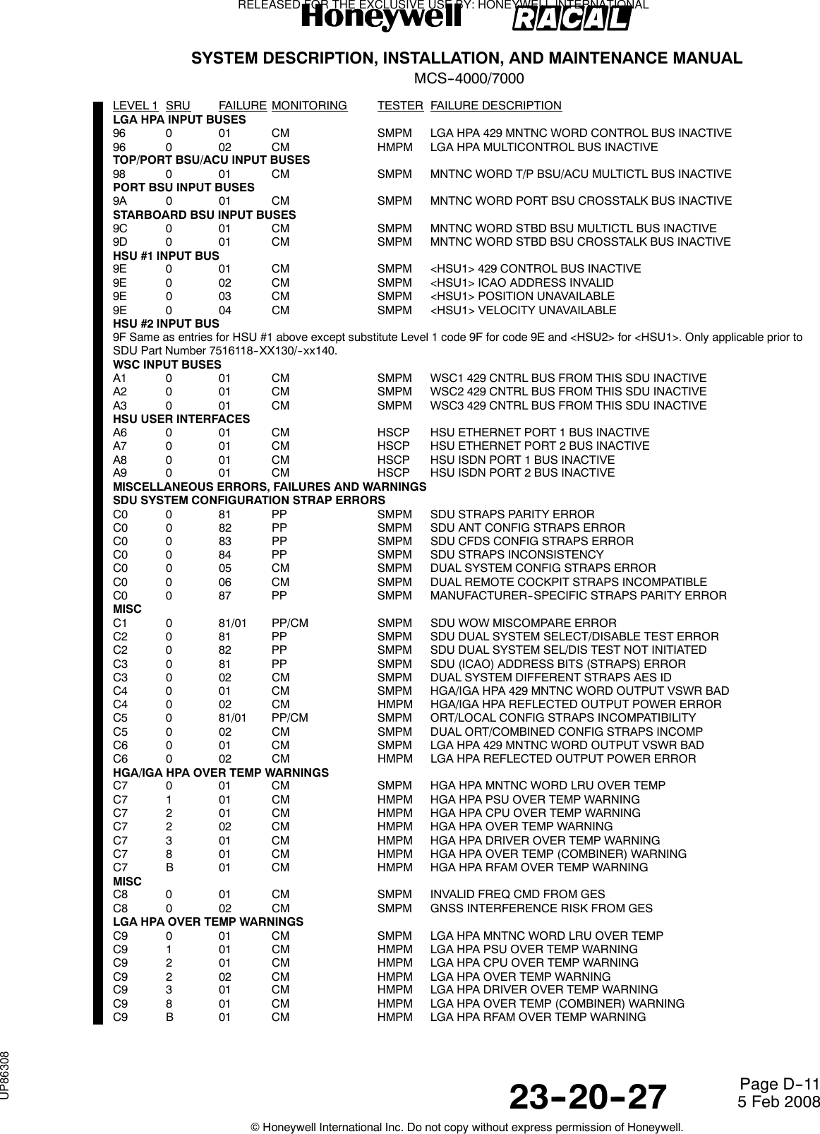
![SYSTEM DESCRIPTION, INSTALLATION, AND MAINTENANCE MANUALMCS--4000/700023--20--27 5 Feb 2008©Honeywell International Inc. Do not copy without express permission of Honeywell.Page D--16in the HPA when the respective failures occur. If the HPA’s HW/SW compatibility strap setting is 02h orbeyond (indicating the inclusion of Hardware Mod D, in which the functions of the former A4, A6, and A7SRUs, as well as the combiner portion of the former A8 SRU, are integrated into a single new final poweramplifier SRU [A9]), and if the resident HPA software package is any one prior to D2.0, then the HPA shalltransmit 04 (or 07)/7/xx (the code for SRU A7 [power amplifier #3]) to the SDU whenever 04 (or 07)/9/xx (thecode for SRU A9 [final power amplifier]) is recorded in the HPA’s internal failure log; under these conditions,the other codes (for A4 and A6) are never transmitted to the SDU.10. Failure codes 04 (or 07)/9/xx is reported to the SDU as well as stored in the HPA when the HPA’s residentsoftware package is D2.0 or beyond and the HPA has a hardware/software compatibility strap setting of 02hor beyond.11. All other HPA block--transfer failures that are redundant to those covered by the HPA Maintenance Wordare not implemented in the SDU (per Note 3 above). The overtemp warnings and shutdowns covered by thisnote, however, (04/07 0 0A/42, 04/07 1 01/41, 04/07 2 11, 04/07 3 03, 04/07 9 47, 04/07 B 01, C7/C91/2/3/8/B 01, C7/C9 2 02), which do map to HPA Maintenance Word bit #13 (which is covered by failureC7/C9 0 01), are nonetheless still implemented by the SDU.12. Code 35 is designated IRS--PRI, code 36 is designated IRS--SEC.13. This note not applicable to MCS7000.14. This is a pseudo--failure.15. This failure is only generated by the Honeywell 20W HPA.16. This failure is only generated by the Honeywell 40W HPA.17. The PSU +25.5 VDC failure is only applicable to the Honeywell 20W HPA and the +28 VDC failure is onlyapplicable to the Honeywell 40W HPA.18. Not used.19. These BSU Maintenance Word--related failures can also be raised due to Solo Word #8 transmitted froma Honeywell 20W HPA that is steering an IGA.20. This fault, if it does not transition to a failure, will cause the modem software to be reloaded.21. This note not applicable to MCS7000.22. This note not applicable to MCS7000.23. This note not applicable to MCS7000.24. This note not applicable to MCS7000.25. This failure is only applicable to Modems 2 and 5.26. Code not used in MCS7000, reserved due to use in MCS 3000/6000.27. The indicted functional resource is conditional ---- [hga_subsys] if another antenna subsystem is installed(including the case of a dual system), and NONE if the HGA is the only antenna subsystem installed.28. These failures shall not apply to aircraft strapped for “Airbus” CFDS type.29. These failures shall only apply to aircraft strapped for “Airbus” CFDS type.30. Resource indictment prior to package 2.0 is (unconditional) [hga_subsys].31. HSU failures reported by the HSU via Williamsburg message type code 4Dx do not directly indict the[hsu1] or [hsu2] functional resources (hence the “NONE” entries in this table for these failures). HSUfunctional resource indictment for these failures is handled indirectly, as necessary, via the SSM = FailureWarning state of the HSU’s label 270 status word, as follows:Within the HSU, errors (failures) are classified as either fatal, essential or non--essential, depending on theiroperational impact. (”Fatal” means that one or more HSD services are unavailable and that the HSU is notallowed to continue to operate in normal mode, else it may be harmful to itself or other LRUs; “essential”means that one or more services are unavailable, but the HSU can run in normal mode without any risk ofharm to itself or other LRUs; “non--essential” means that there is no definite service unavailability, but thatthere is some kind of service degradation, and that the HSU can run in normal mode without any risk of harmto itself or other LRUs). The HSU sets its label 270 status word SSM to Failure Warning [and also asserts itsHSU Failure discrete output, and also sets its Category field to 1 (indicting) in its code 4Dx failure messages]for all current fatal errors. Depending on the HSU user data interface configuration as specified by the HSU’sCDM programming (MPDS {Ethernet or 232}, or M--ISDN, or both), the HSU may set its label 270 statusword SSM to Failure Warning for current essential errors (it will if all configured user data interfaces {one orthe other or both sets} are rendered unavailable by the essential error(s)). [The HSU also sets the HSUFailure discrete output if its label 270 status word SSM is set to Failure Warning, and sets its Category field to1 (indicting) in its code 4Dx failure messages, for all current essential errors.] The HSU does not set its labelRELEASED FOR THE EXCLUSIVE USE BY: HONEYWELL INTERNATIONALUP86308](https://usermanual.wiki/Honeywell/SD-700A/User-Guide-3476924-Page-391.png)
![SYSTEM DESCRIPTION, INSTALLATION, AND MAINTENANCE MANUALMCS--4000/700023--20--27 5 Feb 2008©Honeywell International Inc. Do not copy without express permission of Honeywell.Page D--17270 status word SSM to Failure Warning [nor does it set its HSU Failure discrete output, nor does it set itsCategory field to 1 (indicting) in its code 4Dx failure messages] for any current non--essential errors.When the SDU receives HSU label 270 status words with the SSM = Failure Warning, the SDU raises theHSU Self--Declared Failure (08/0/01 or 09/0/01), and indicts the respective HSU functional resource ([hsu1]or [hsu2]).Through this indirect process, the SDU thus indicts the HSU functional resources as required for the HSU’sself--reported failures.In this table, an asterisk following the note “31” entry indicates the failures which may (depending on theHSU’s user data interface configuration) or definitely do result in HSU functional resource indictment via thisindirect process.32. These failures is not implemented in software packages 3.0 and subsequent. These failure codes is notused for any other purpose in packages 3.0 and subsequent in order to maintain compatibility with theirpre--package 3.0 usage.33. Although no functional resource is indicted for this condition, there is grave operational impact34. These failures are applicable prior to SDU Part Number 7516118--XX130/--xx140.35. These failures are applicable to SDU Part Number 7516118--XX130/--xx140 and subsequent.36. HSU failures reported by the HSU (via Williamsburg message type code 6Dx) shall never directly indictthe [hsu] functional resource. If an HSU failure requires indictment, the SSM field will be set to FailureWarning in the label 270 status word sent from the HSU (see Commentary below for details). The SDU shallthen raise the HSU Self--Declared Failure (03/0/01), and indict the HSU functional resource. Failures whichcan cause HSU functional resource indictment via this indirect process are indicated in the table by anasterisk * next to “36” in the NOTES column.The HS--720 (supported from SDU Part Number 7516118--XX130/--xx140) provides Channel Failureinformation in the label 270 status word, in addition to the SSM Failure Warning indication. When an HSUfailure results in the loss of one or more individual HSD channels, the HSU will set the associated ChannelFailure bit(s) in the status word. The SDU shall then raise the appropriate non--indicting HSU ChannelFailure(s) (03/0/0C, 03/0/OF, 03/0/10, 03/0/11), as specified in COMMENTARYFor failures with major operational impact, the HSU will set the Category field to 1 (indicting) in thecorresponding Williamsburg failure message, will set SSM to Failure Warning in the label 270 status word,and will assert the HSU Failure discrete output. For failures with no/limited operational impact, the HSU willset the Category field to 0 (non--indicting) in the corresponding Williamsburg failure message, but will not setthe SSM to Failure Warning in the label 270 status word, and will not assert the HSU Failure discrete output.37. This failure is only generated by the Honeywell 60W HPA.38. The HP--720 60W HPA has several failures that do not map to the DISCRETES bits in the HPAMaintenance word but which do cause SSM=FW in Maintenance and the Status words. When the HP--720raises such failures, the SDU will raise this failure (04 0 0C), resulting in both failures appearing in the failurelogs.39. HP--720 failure codes 04/07 2 C0/C1/C2/C3/C4/C will never be transferred to the SDU via the HPA blocktransfer for various reasons, which are detailed in the Remarks block for the respective failure.40. Prior to SDU Part Number 7516118--XX130/--xx140, these failures shall indict the [hsu1] functionalresource, whereas for SDU Part Number 7516118--XX130/--xx140 and subsequent, these failures shall indictthe [hsu] functional resource.41. The POST/PAST failure is applicable to SDU Part Number 7516118--XX130/--xx140 and subsequent only.42. These failures are not currently implemented in the HS--720.43. Prior to SDU Part Number 7516118--XX130/--xx140, these failures shall indict the [hsu1] functionalresource, whereas for SDU Part Number 7516118--XX130/--xx140 and subsequent, these failures is nonindicting.44. This failure code (04 0 41) is used by the HP--720 to indicate when the RF power at the HPA input is lessthan --32 dBm. In addition to transferring this failure with the label 171 manufacturer--specific status word, theHP--720 also sets DISCRETES bit 14 in the label 350 maintenance word. Since the SDU completely ignoresthis failure code and the state of bit 14, this failure code is not defined, but is reserved so that it not be usedfor anything else.RELEASED FOR THE EXCLUSIVE USE BY: HONEYWELL INTERNATIONALUP86308](https://usermanual.wiki/Honeywell/SD-700A/User-Guide-3476924-Page-392.png)
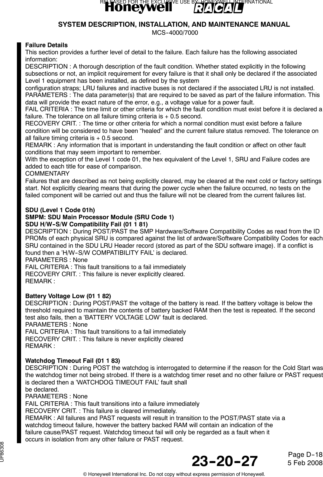
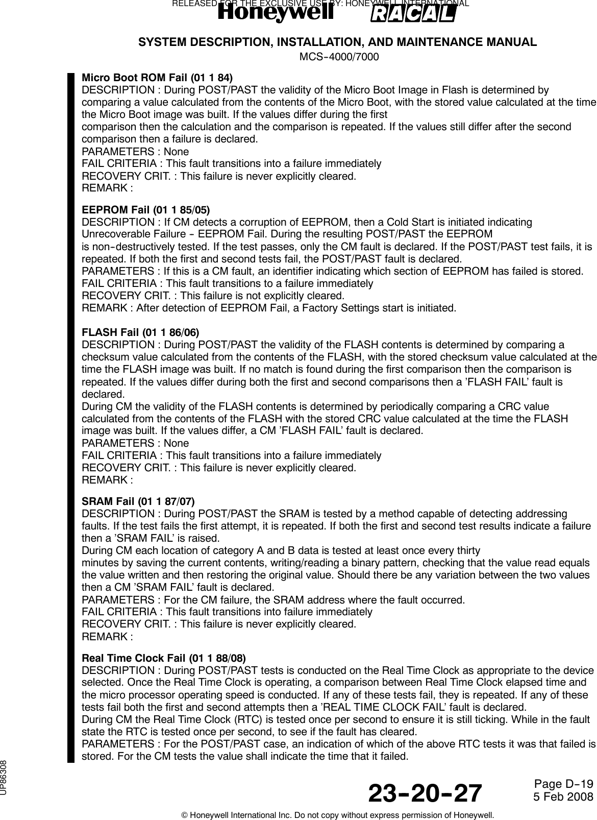
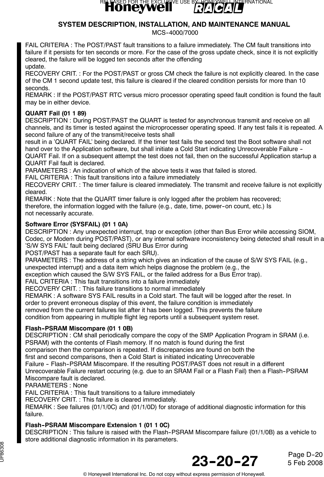
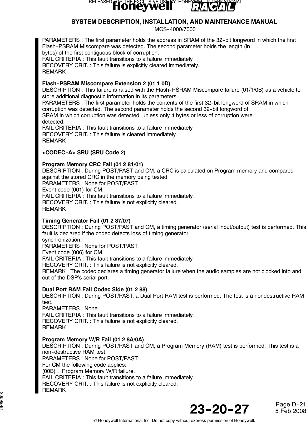
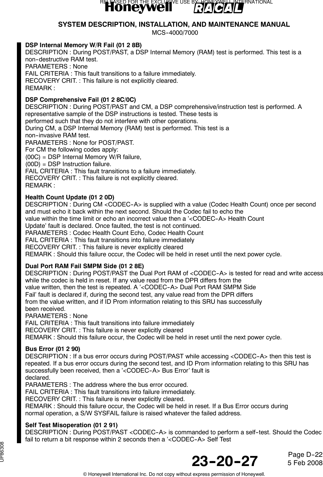
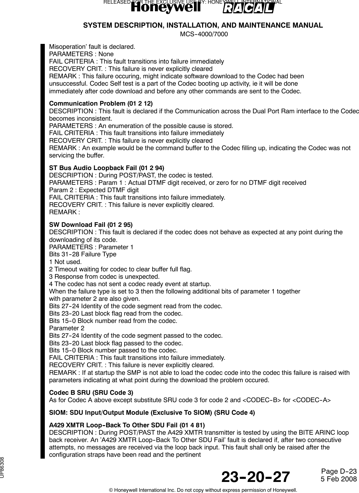
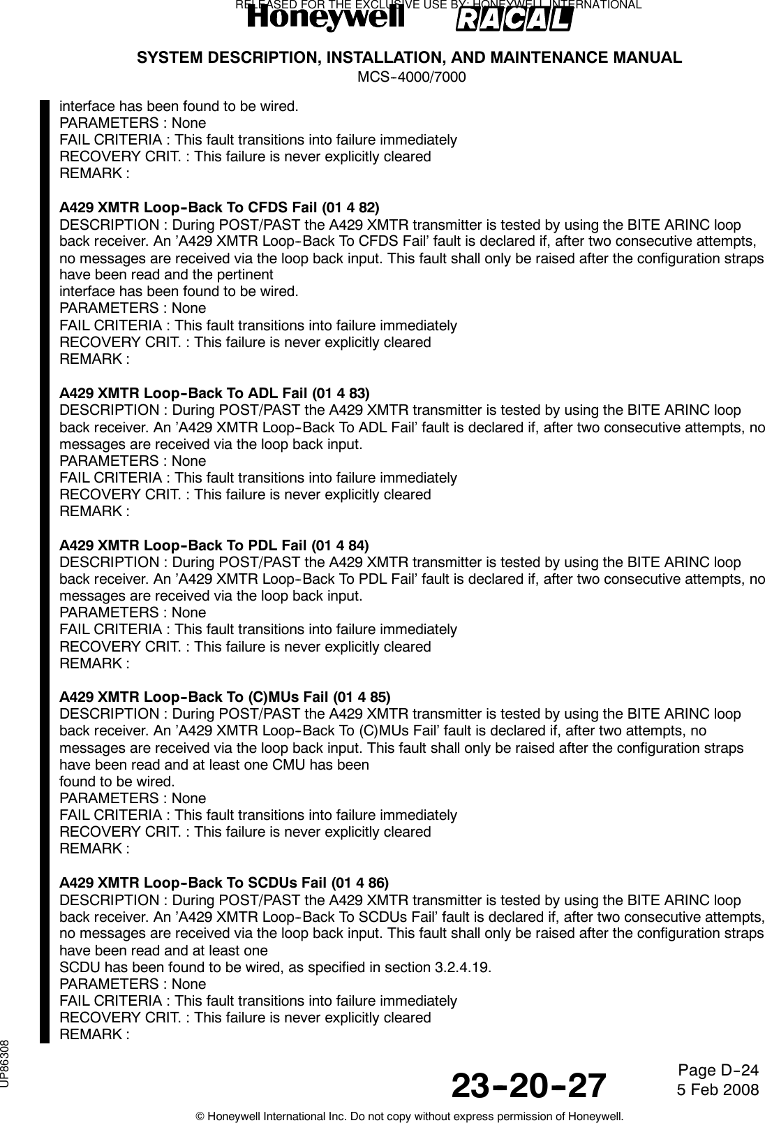
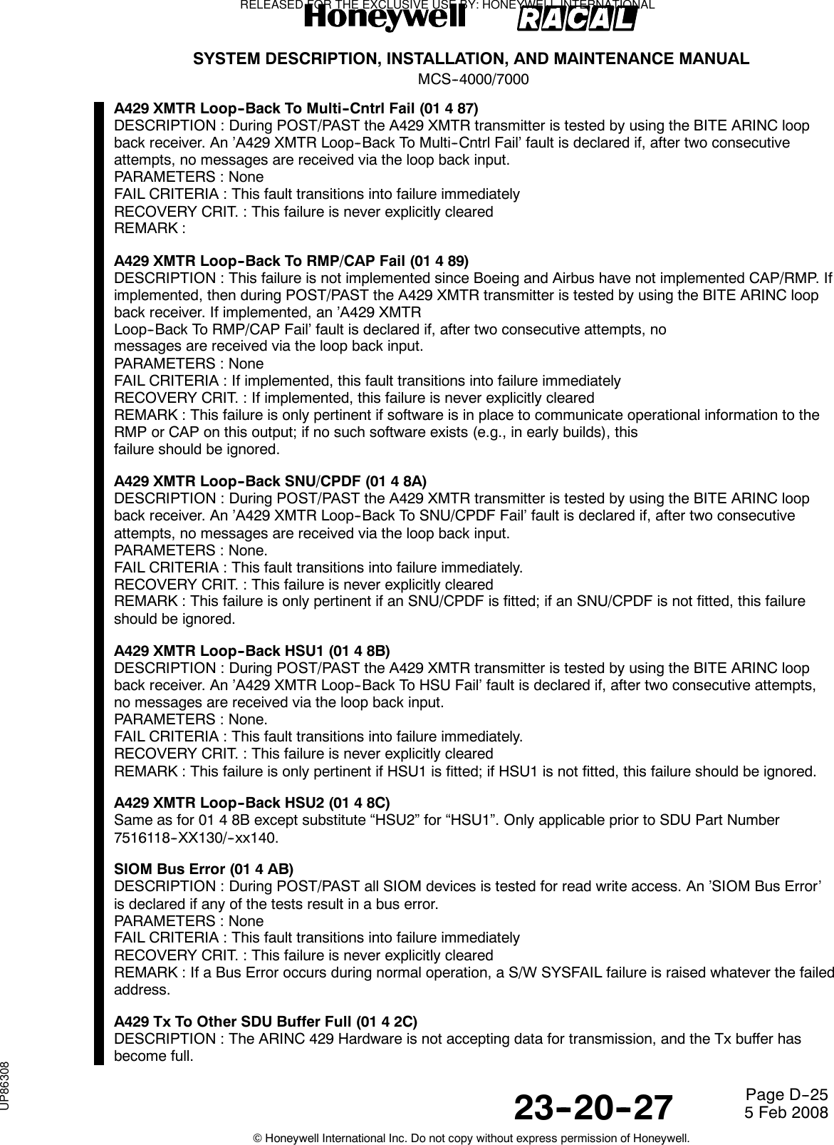
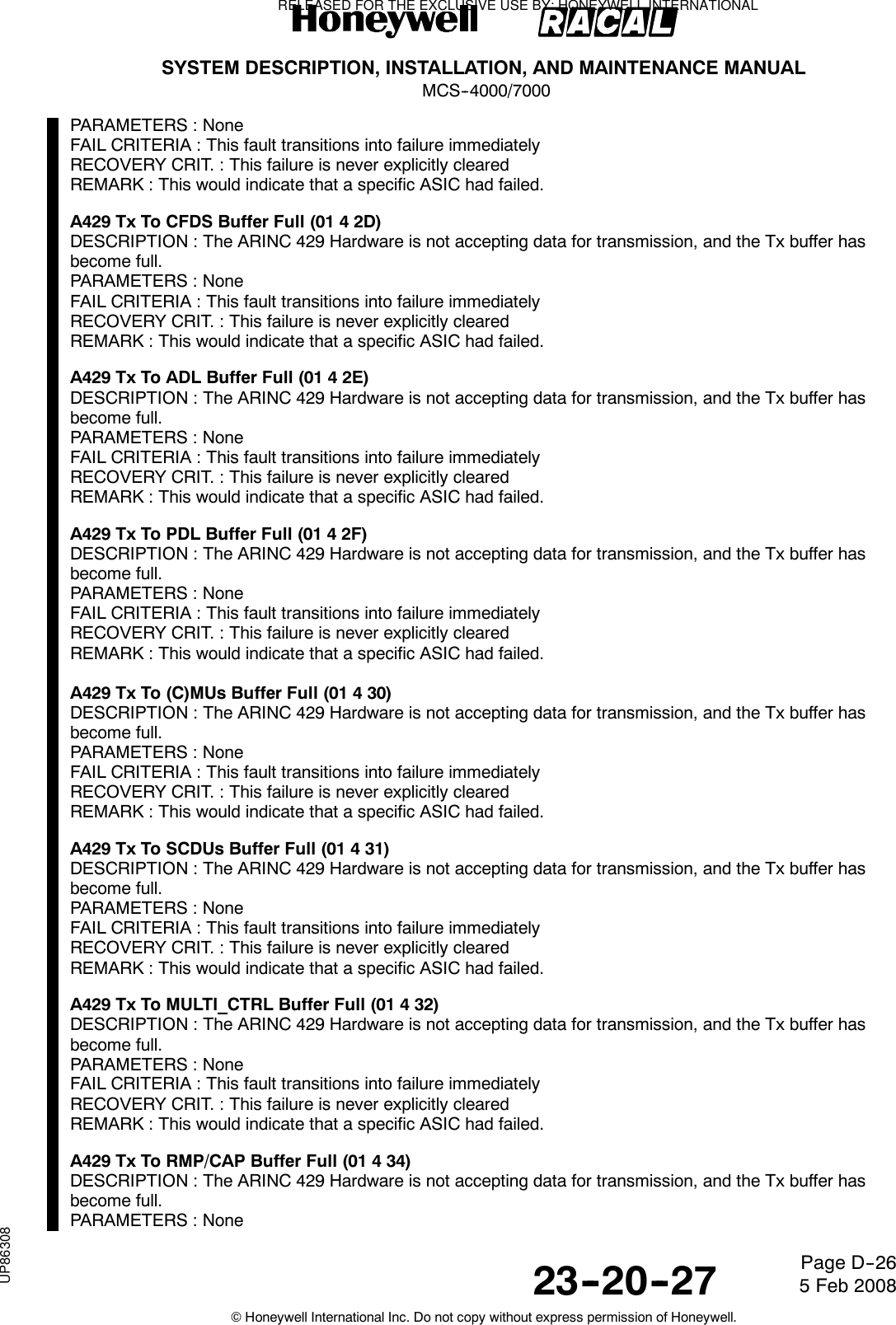
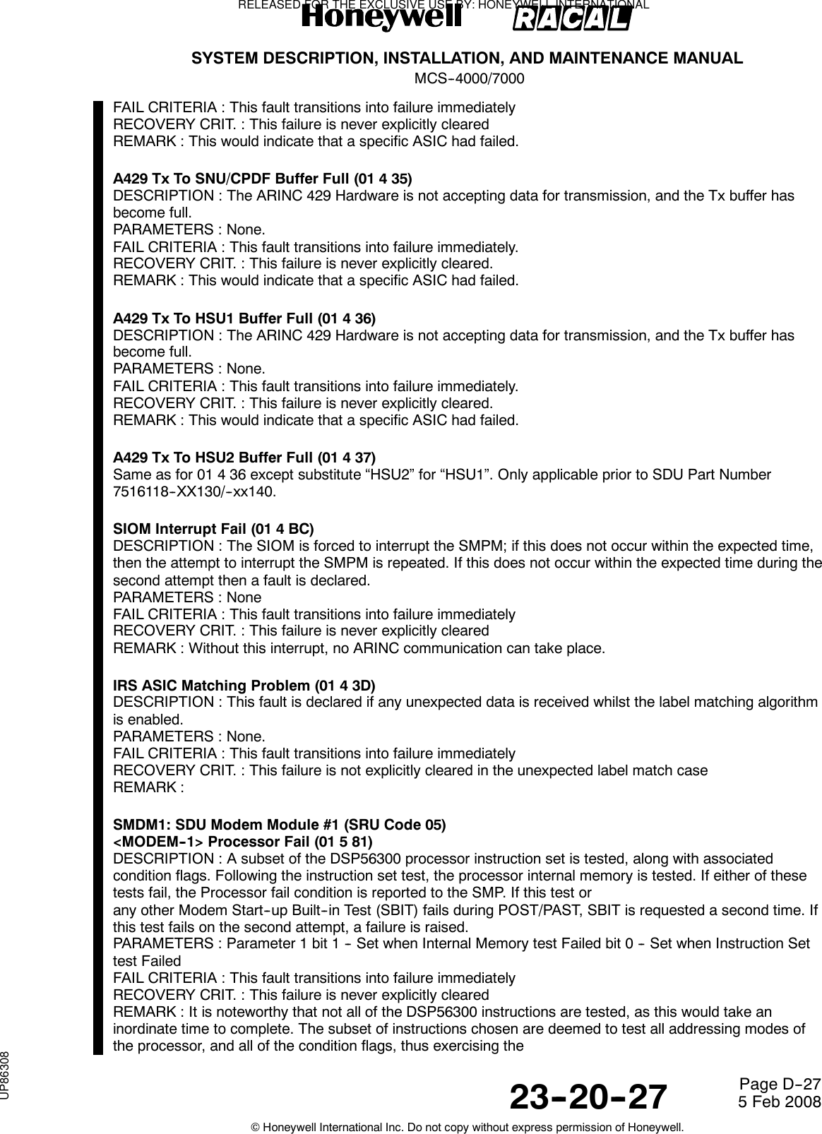
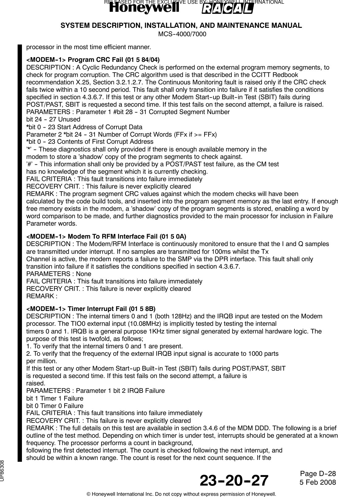
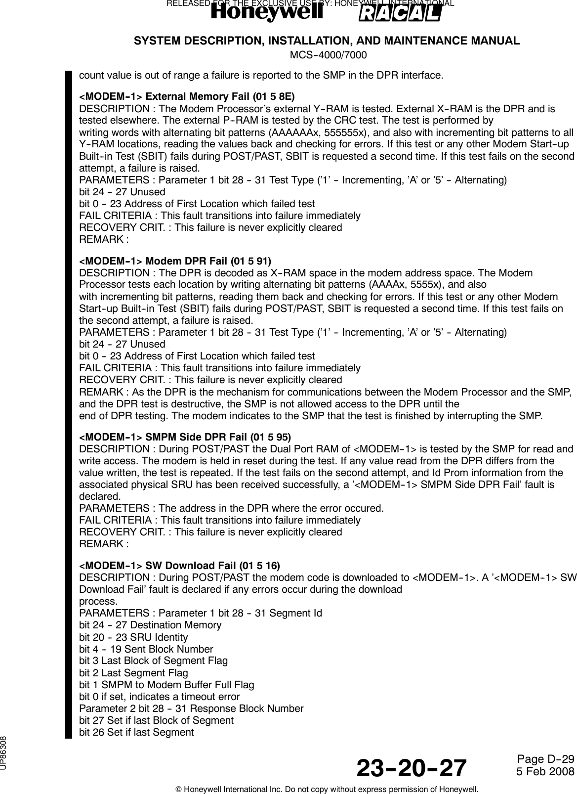
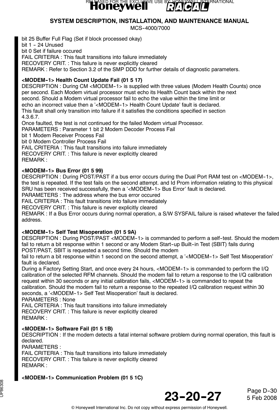
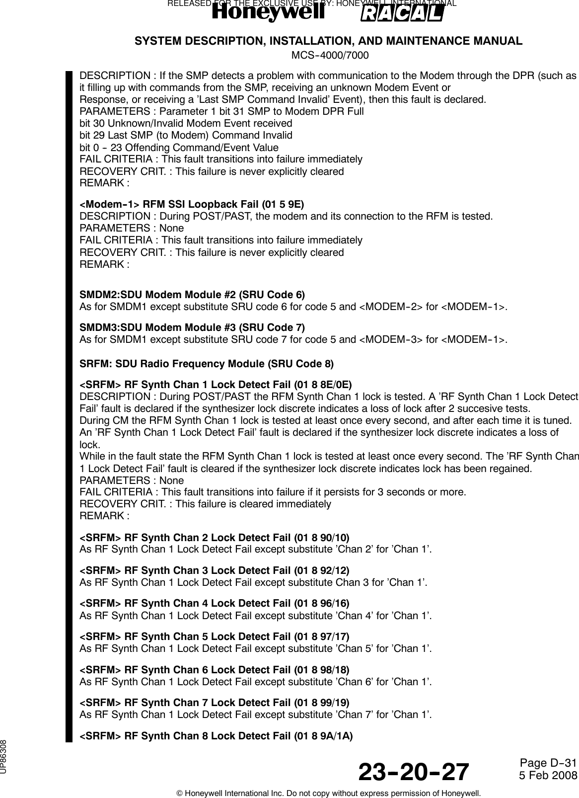
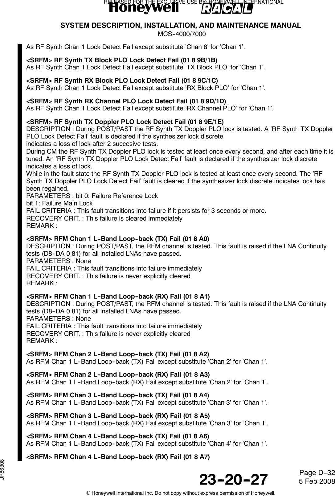
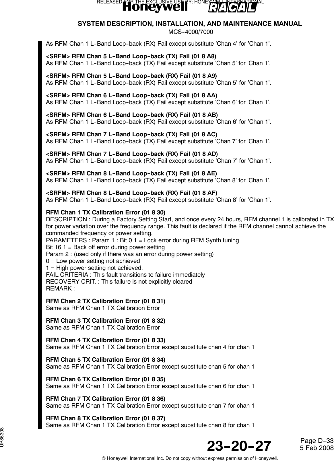
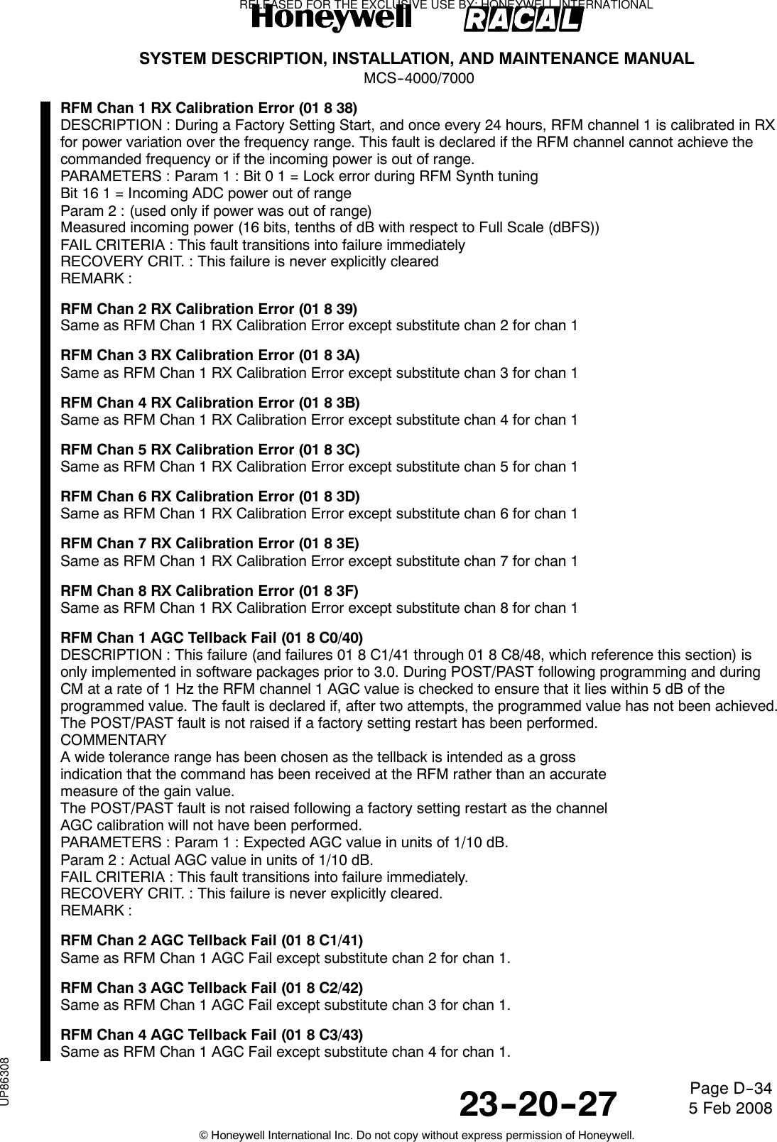
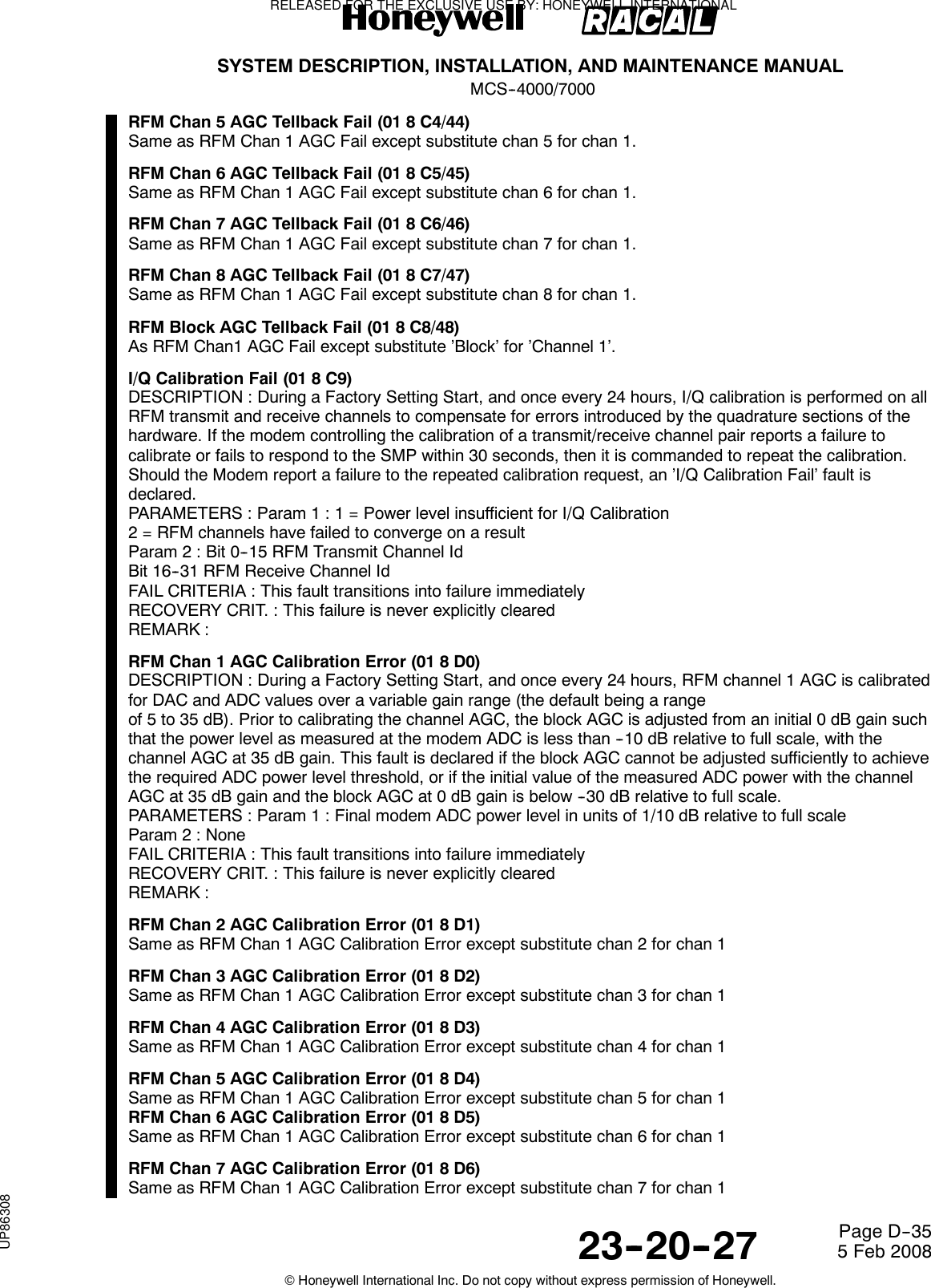
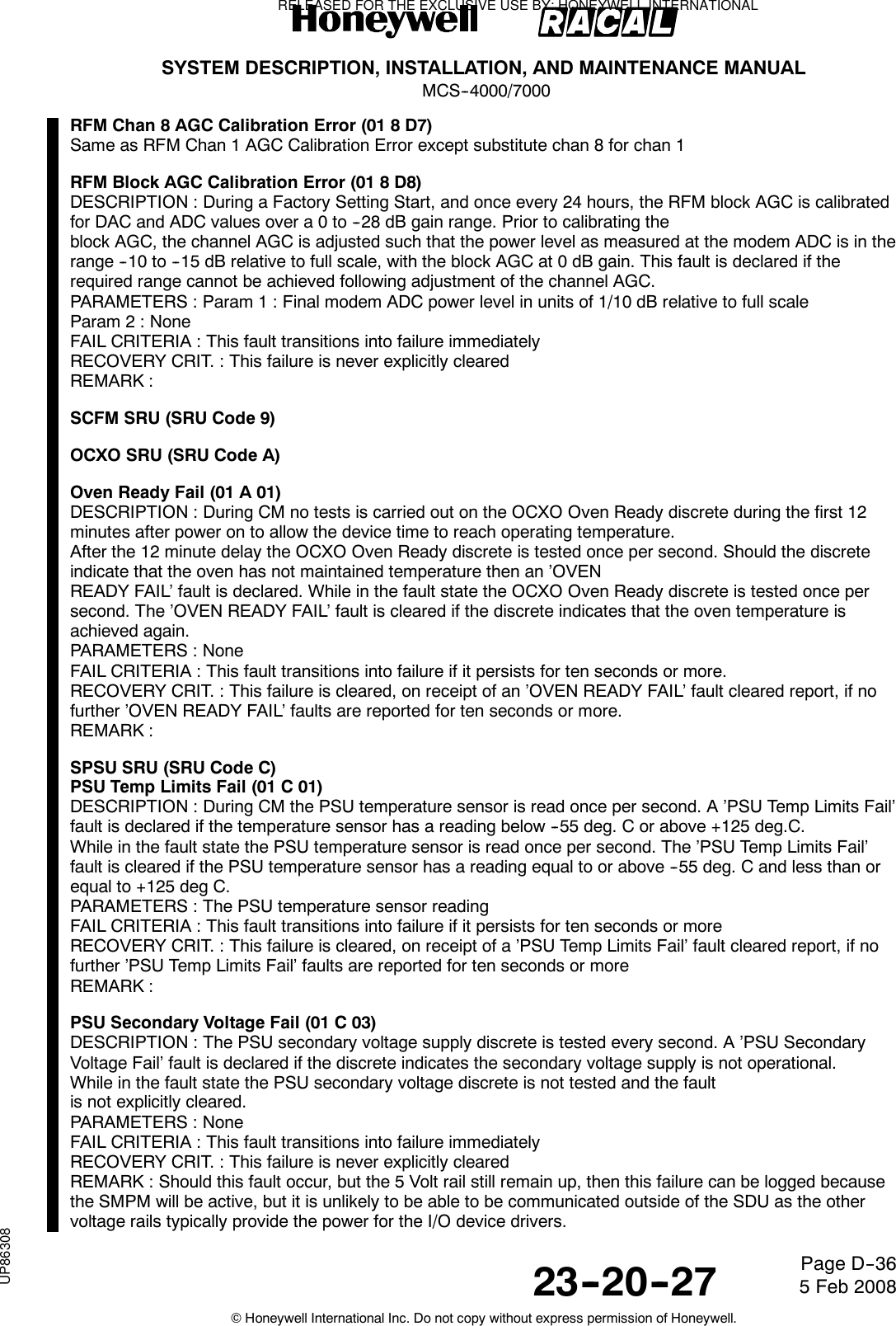
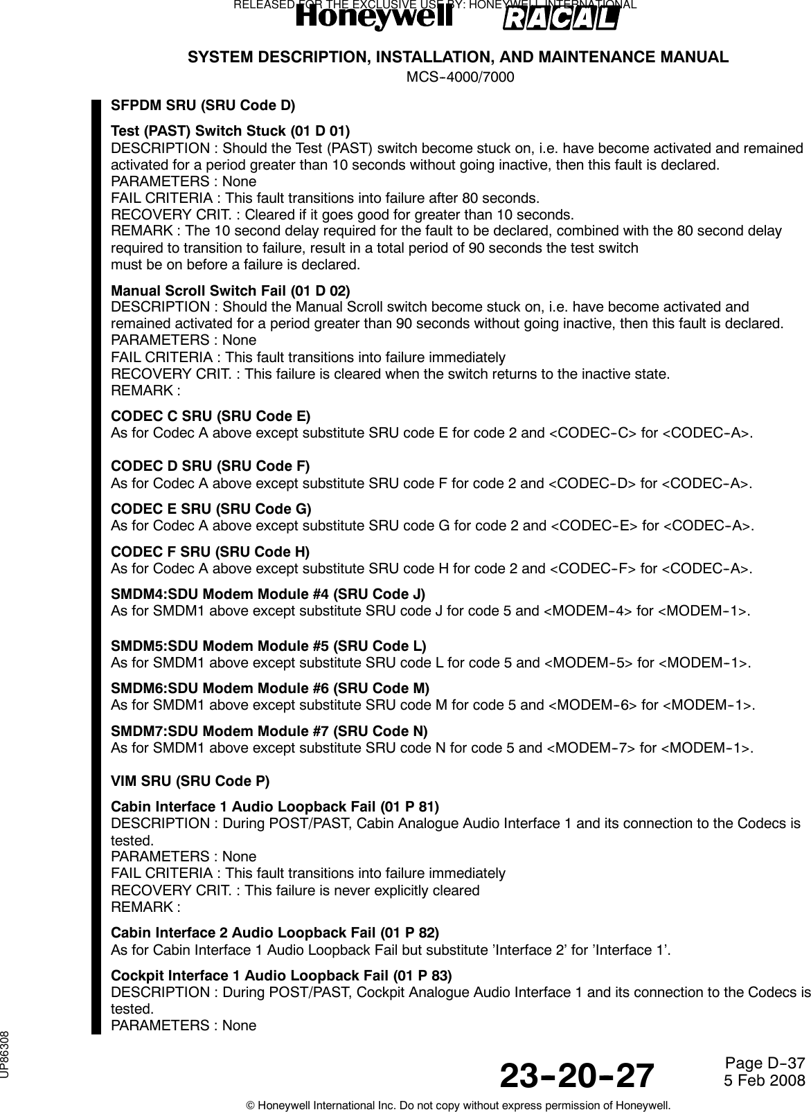
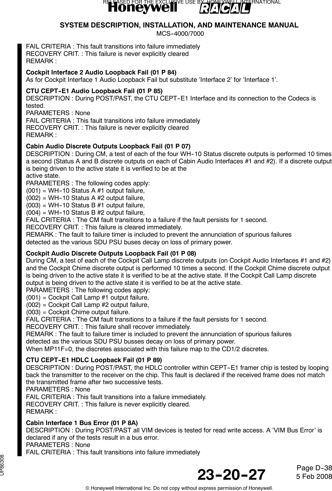
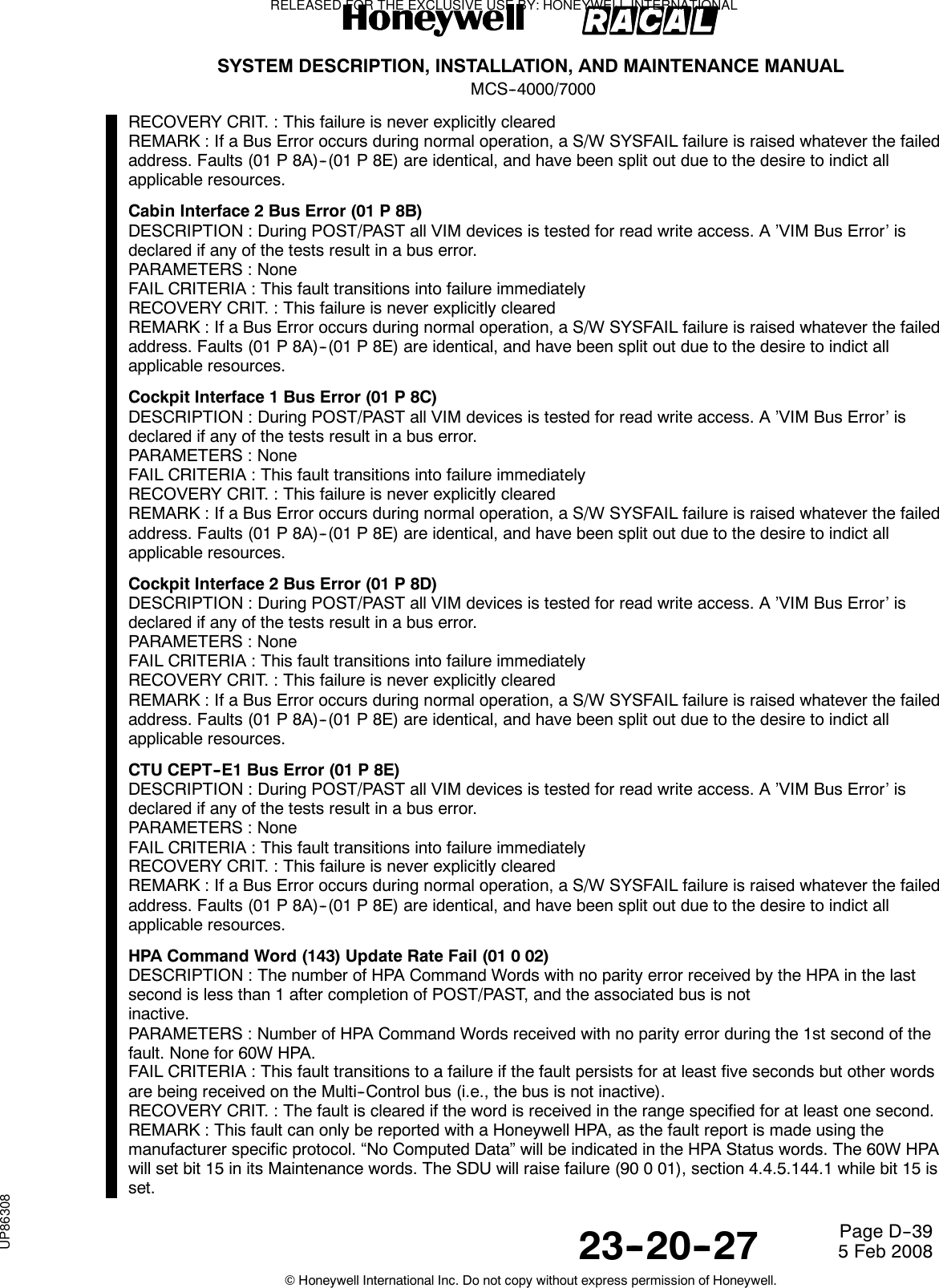
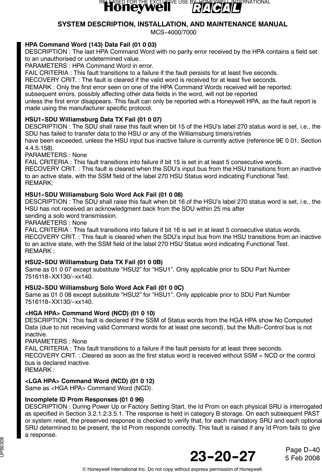
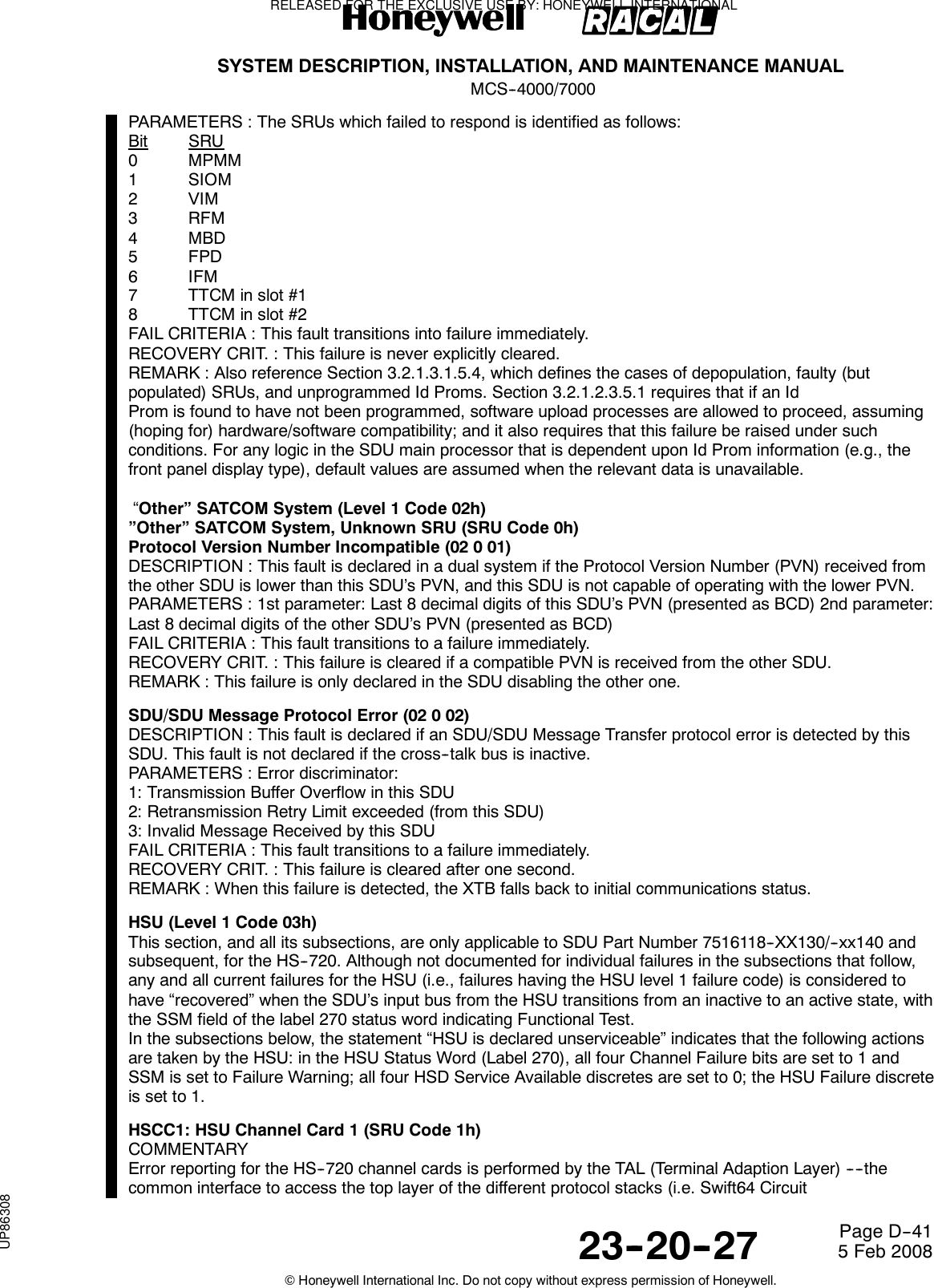
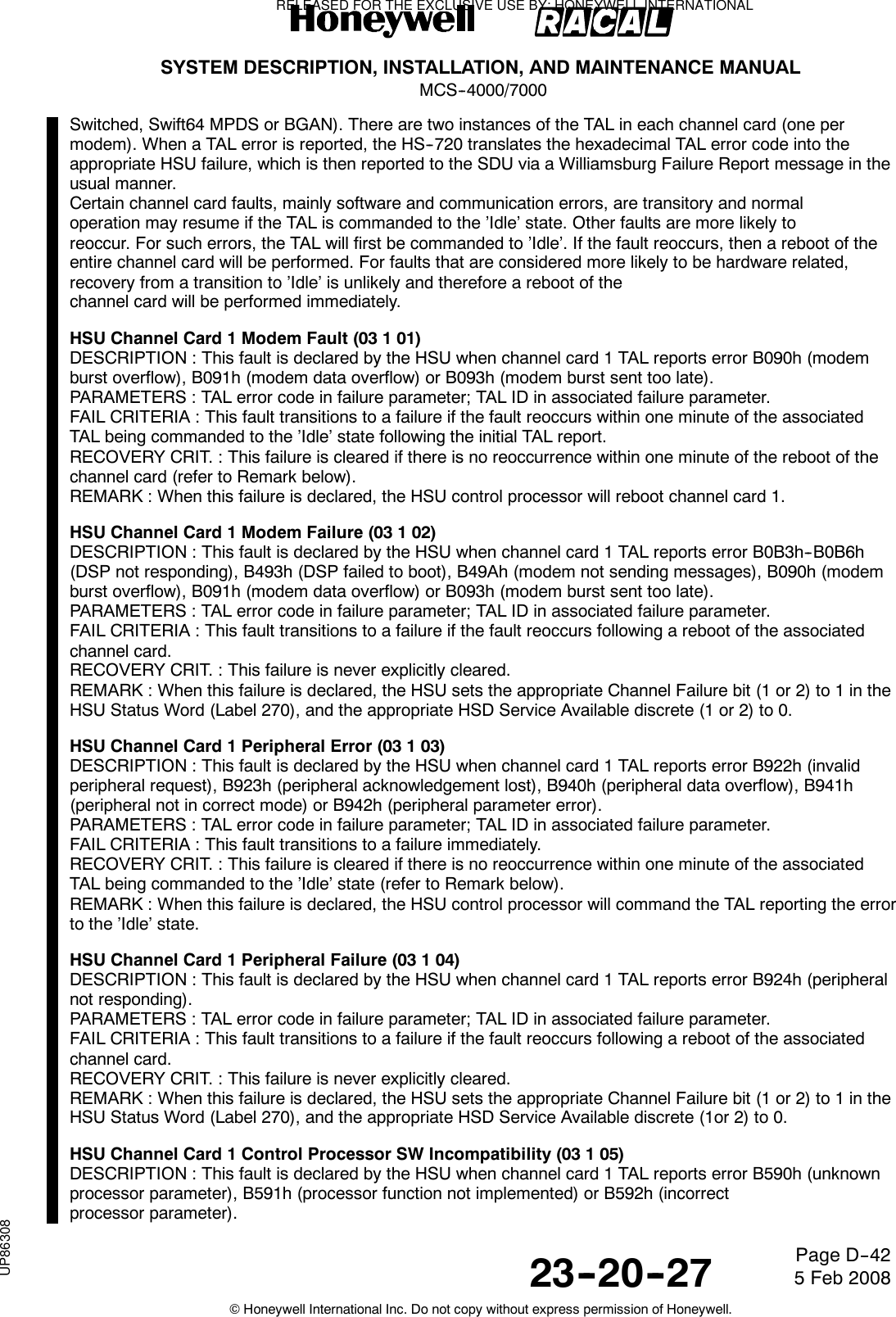
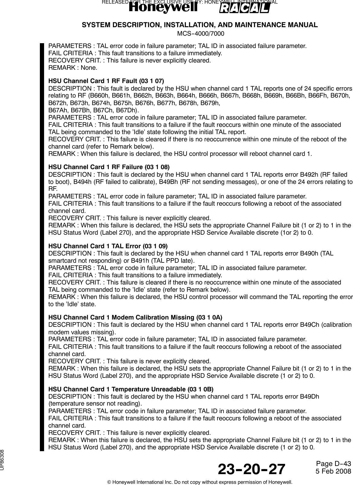
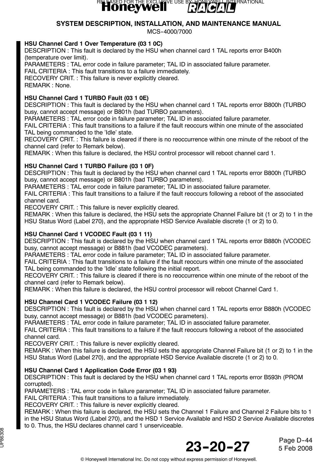
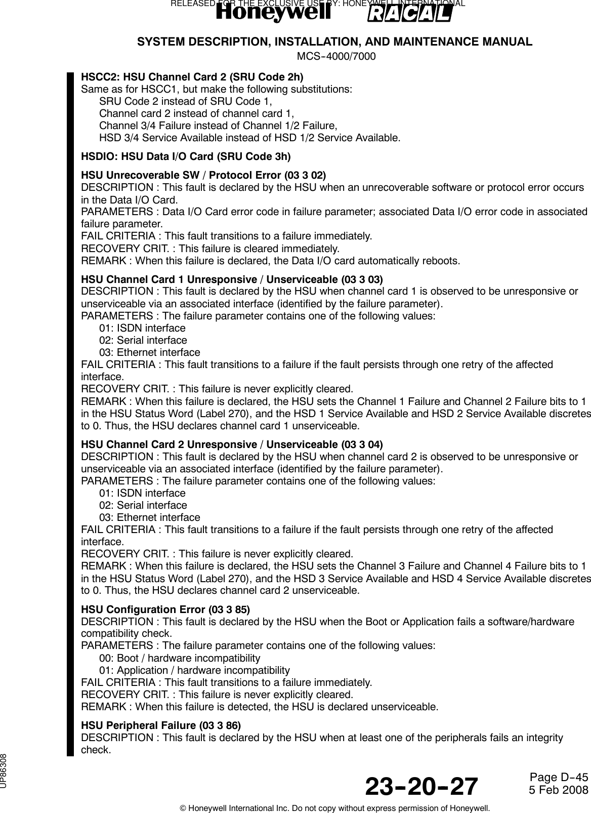
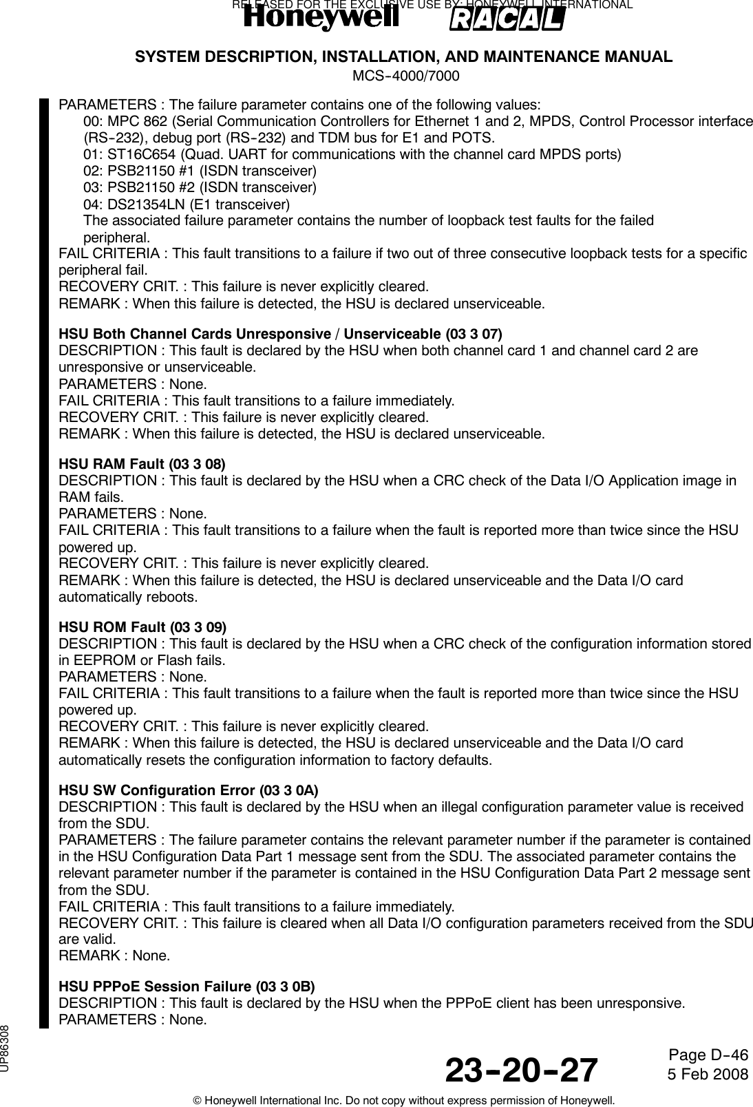
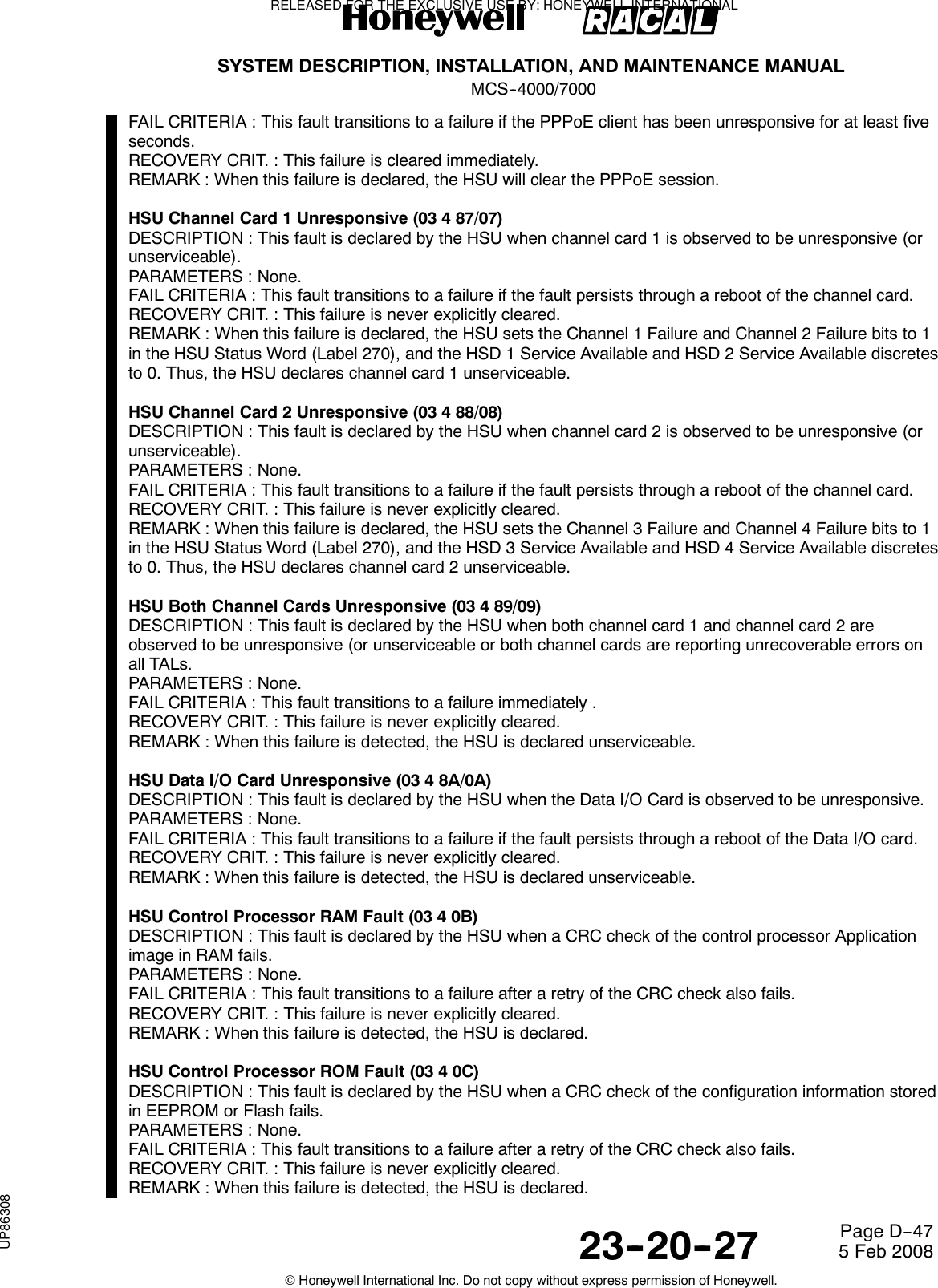
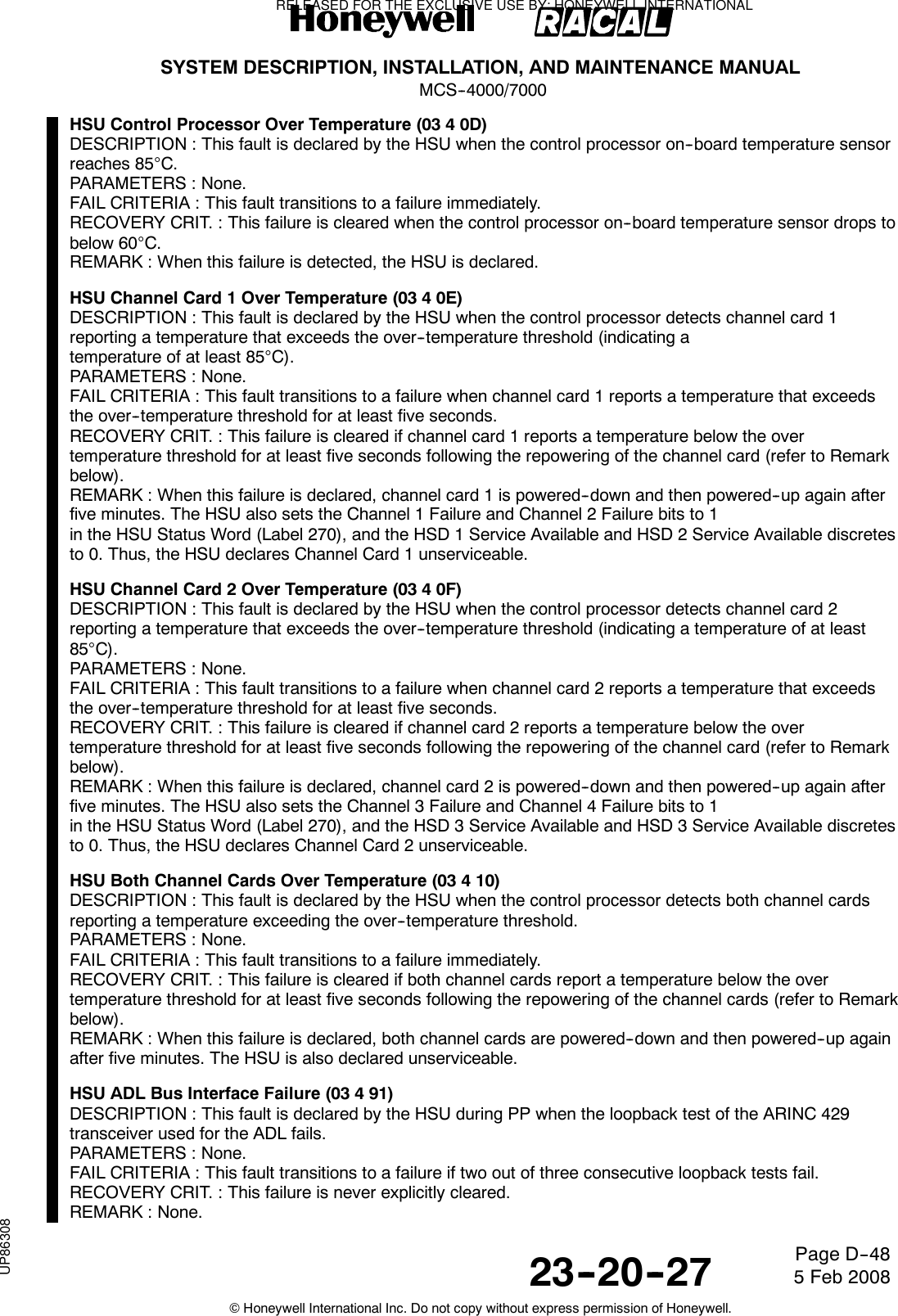
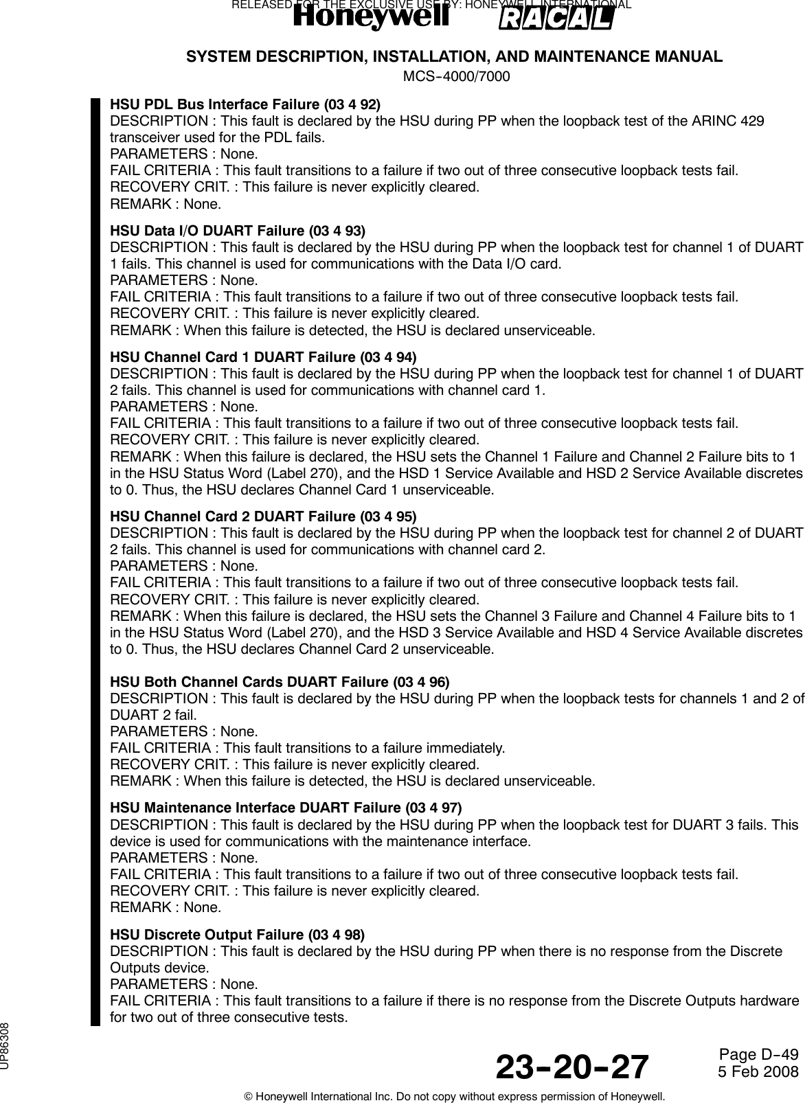
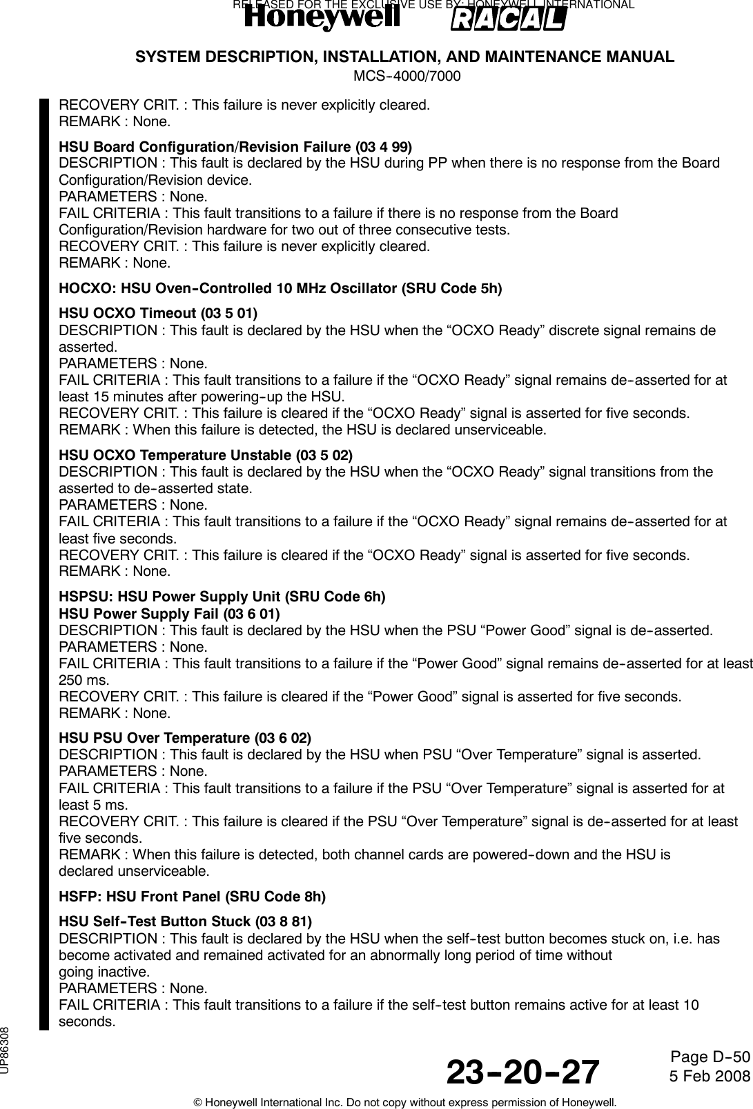
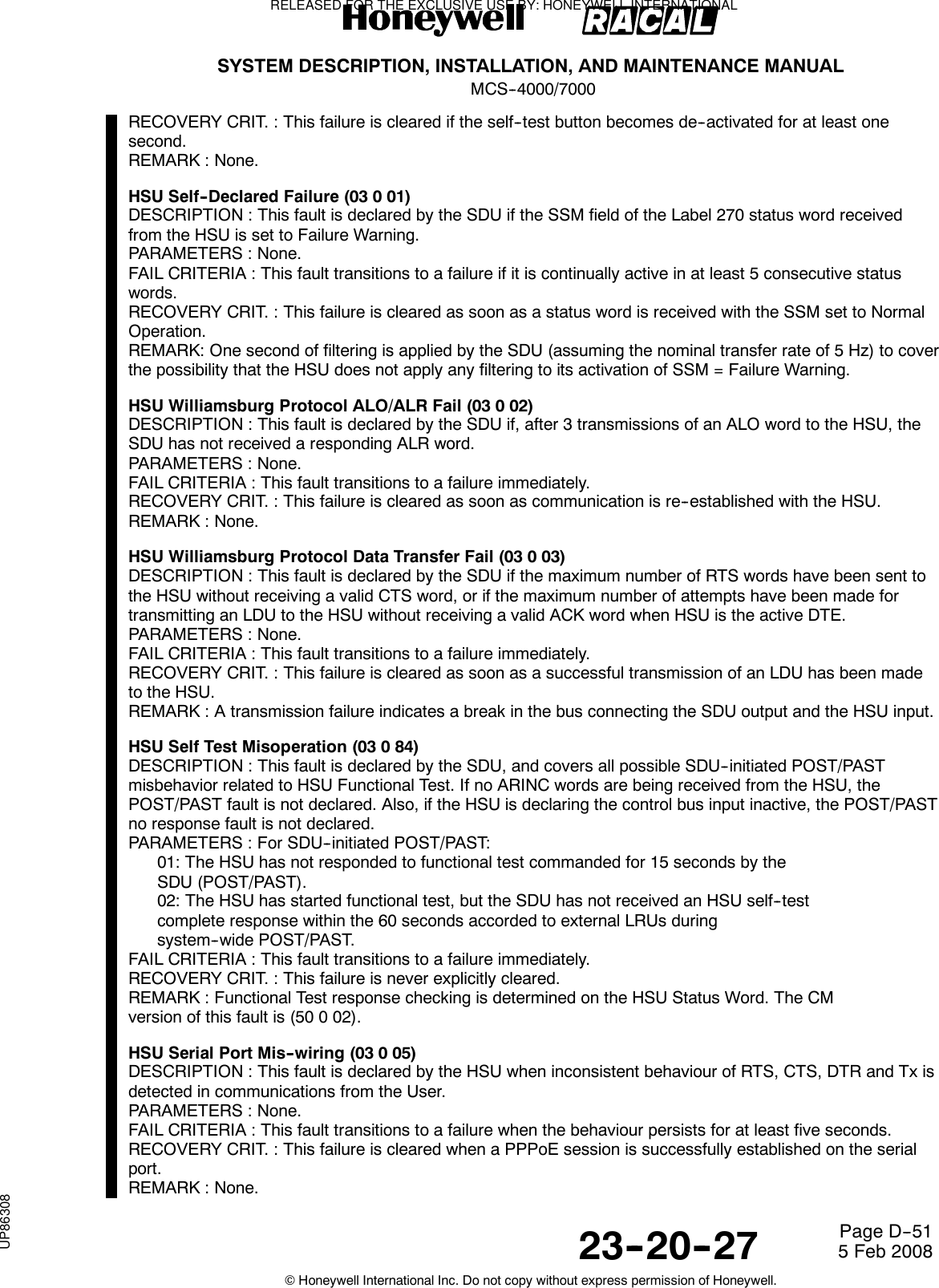
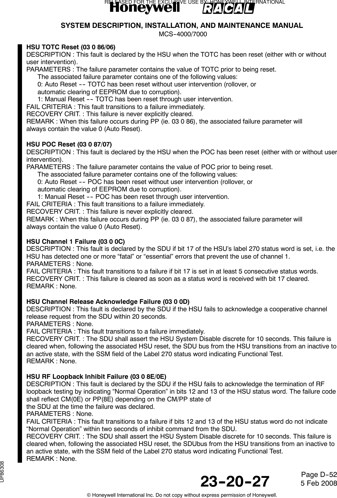
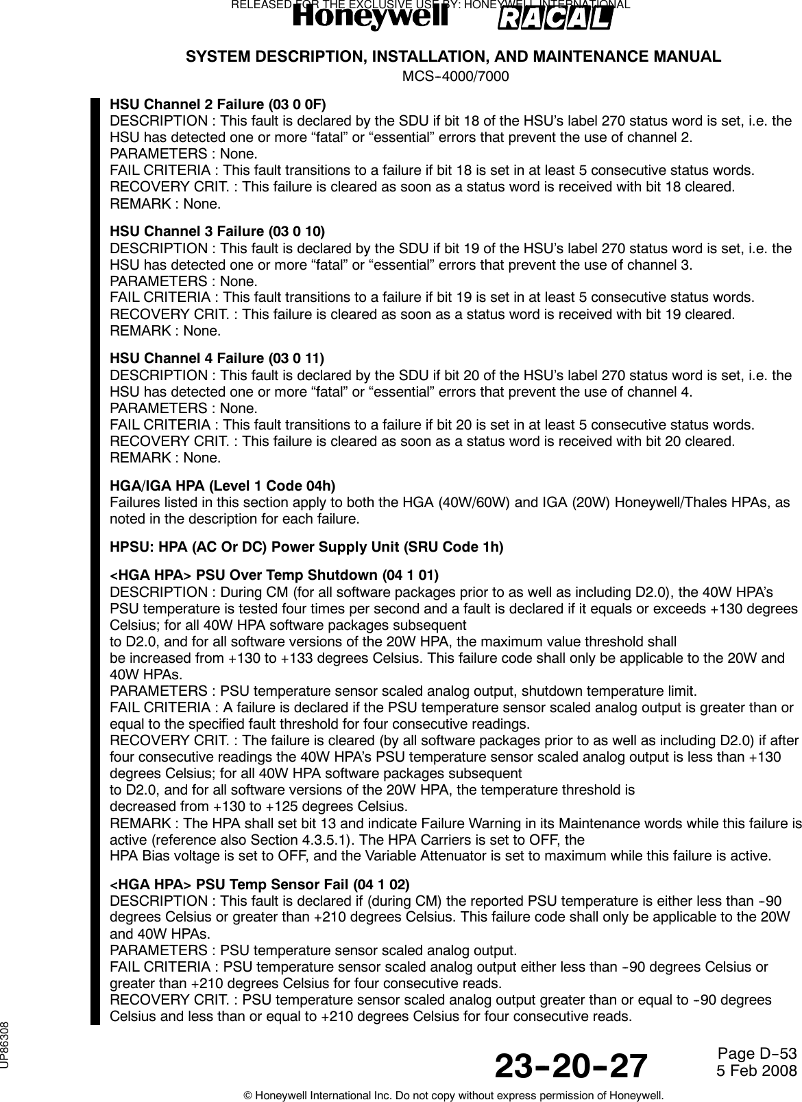
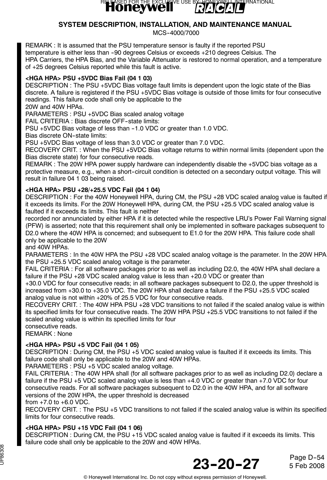
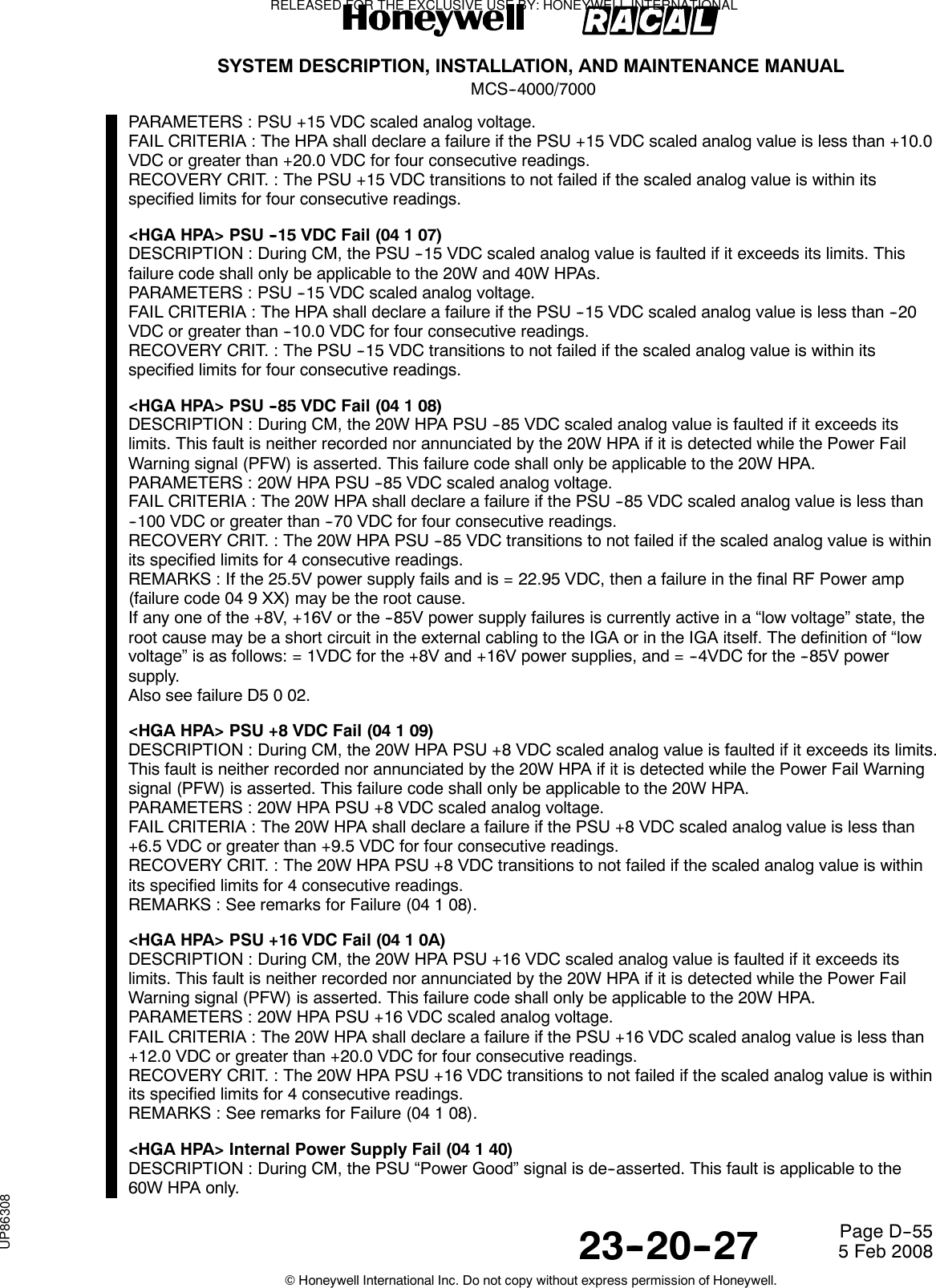
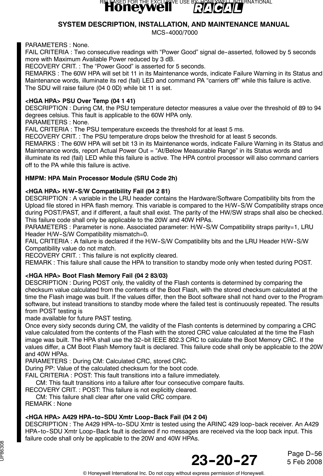
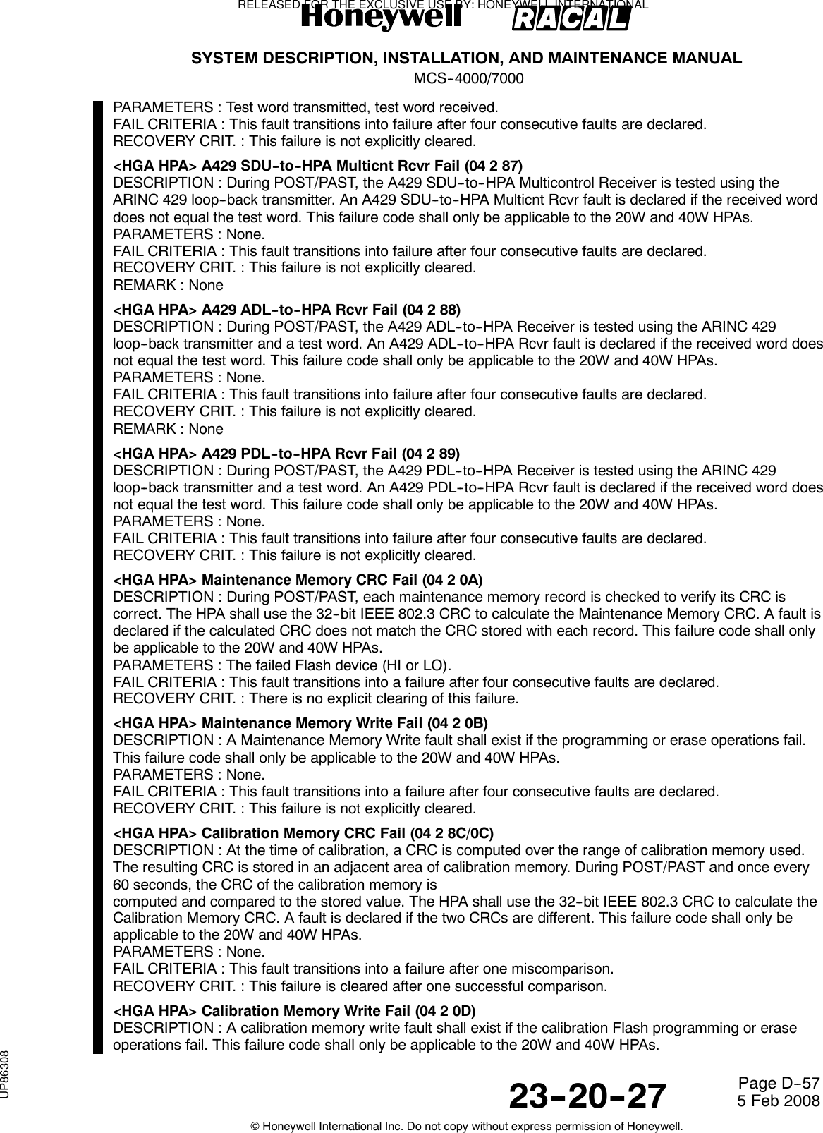
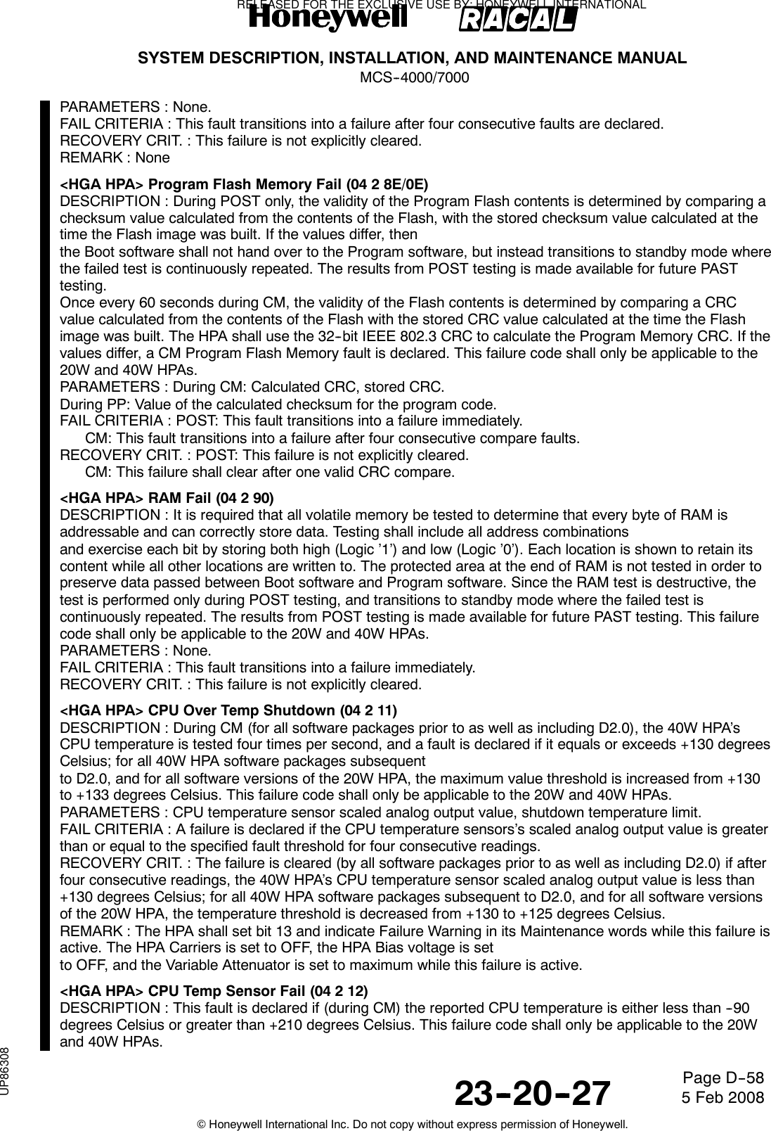
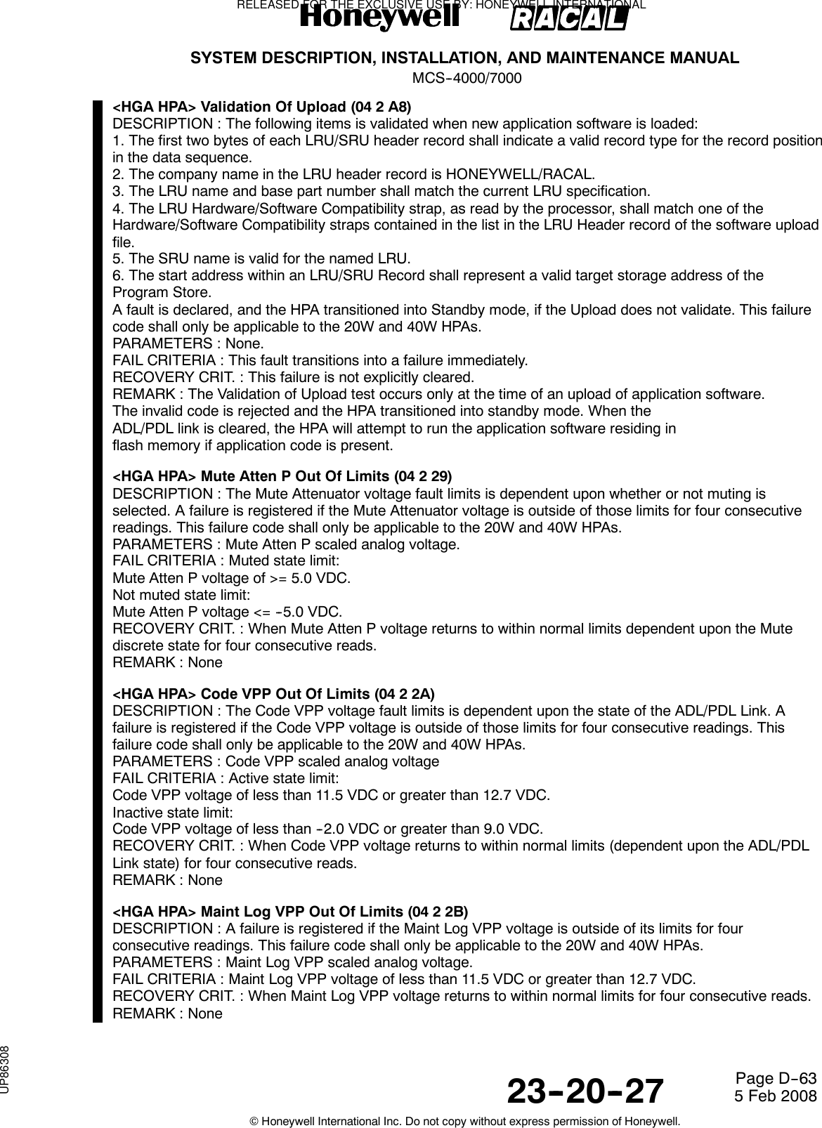
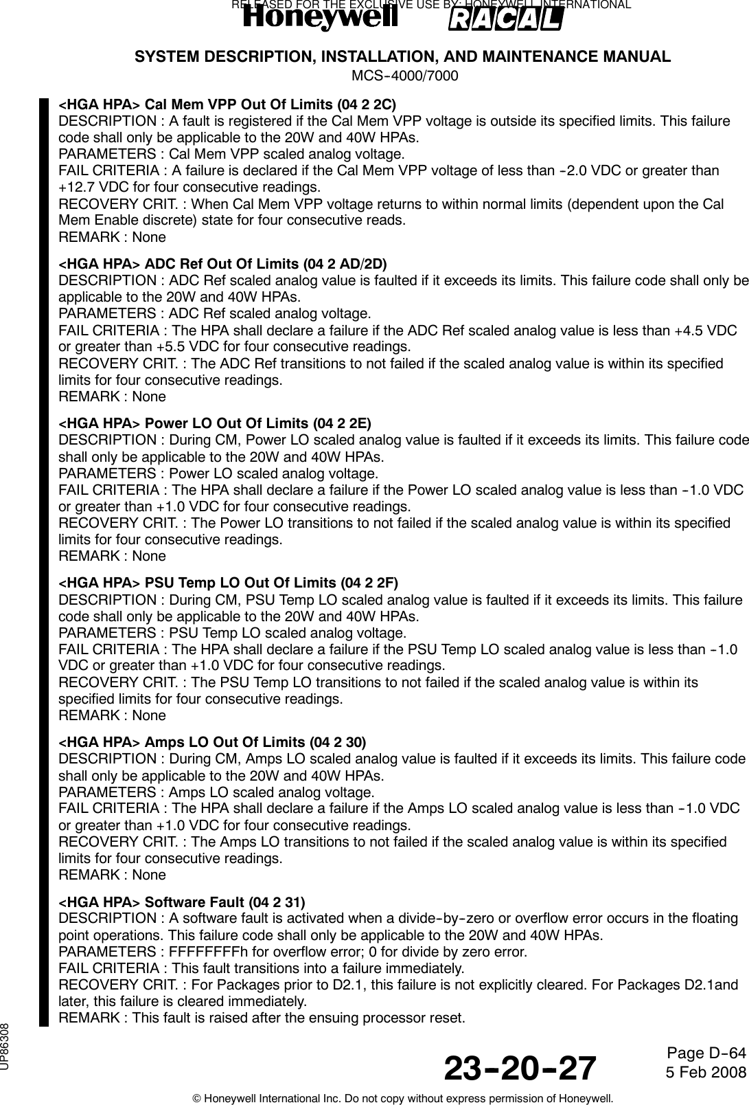
![SYSTEM DESCRIPTION, INSTALLATION, AND MAINTENANCE MANUALMCS--4000/700023--20--27 5 Feb 2008©Honeywell International Inc. Do not copy without express permission of Honeywell.Page D--65<HGA HPA> Discrete Output Test -- Fan (04 2 B3/33)DESCRIPTION : During POST/PAST, the discrete loop--back is read, and a failure is declared if the Fandiscrete value does not equal the loop--back value.During CM, the discrete loop--back is read, and a failure is declared if the Fandiscrete value does not equal the loop--back value.This failure code shall only be applicable to the 40W HPA.PARAMETERS : None.FAIL CRITERIA : POST/PAST:This fault transitions into a failure immediately.CM:This fault transitions into a failure after four consecutive mismatches.RECOVERY CRIT. : POST/PAST:This failure is not explicitly cleared.CM:This failure shall clear after four consecutive correct matches.REMARK : None<HGA HPA> RS--422 Internal Loopback Fail (04 2 B4)DESCRIPTION : This fault shall only be applicable to the 20W HPA (with IGA beam steering capabilities).During POST/PAST, the 82510 asynchronous serial controller is placed into internal loopback mode. A singlecharacter is transmitted and subsequently looped back tothe receive port, and the received and transmitted characters is compared; this is done four times. All fourtests must fail for this fault to be declared.PARAMETERS : Parameter: Transmitted Loopback character.Associated parameter: Received Loopback character.FAIL CRITERIA : This fault transitions to a failure immediatelyRECOVERY CRIT. : This failure is not explicitly cleared.REMARK : Declaration of this failure means that the 20W Honeywell HPA is not able to control anHPA--beam--steered IGA; however, this is only significant if such an IGA is installed. Ratherthan requiring the class and functional resource indictment of this failure to beconfiguration--dependent, the class is fixed at 3, no resource is indicted, and failure 1A 0 01(Top/Port HGA/IGA Maintenance Word Fail, which will subsequently trigger as well, and which isconfiguration dependent and is Class 1 and does indict [hga_subsys] if another antenna subsystem isinstalled) is depended upon to bring this condition to a class 1 level of awareness and to cause functionalresource--dependent reconfiguration to take place as necessary. If thisoccurs, the existence of failure 04 2 B4 will point to the HPA as a (if not the) cause of the Maintenance WordFail condition.<HGA HPA> IGA LNA/DIP On/Off Discrete Loopback Fail (04 2 35)DESCRIPTION : This fault shall only be applicable to the 20W HPA (with IGA beam steering capabilities).During CM, the loopback of the LNA/DIP on/off discrete output is compared with the commanded value. Afault is declared if the loopback logic state does not match the commanded state.PARAMETERS : LNA/DIP command wrap around discrete; commanded value.FAIL CRITERIA : For Packages prior to and not including D2.1, this fault transitions to a failure after fourconsecutive mismatches. For Package D2.1 and later software, This fault transitions to a failure after twelveconsecutive mismatches.RECOVERY CRIT. : For Packages prior to and not including D2.1, this failure shall clear after fourconsecutive matches. For Package D2.1 and later software, This failure shall clear immediately after onematch.REMARK : This test does not need to be performed during POST/PAST because of the system--widefunctional test, which toggles the LNA/DIP control in order to check whether the receivenoise floor rises when the LNA is turned on.<HGA HPA> I2C Interface Failure (04 2 C0)DESCRIPTION : During PP, the control processor fails to communicate with the backplane unit configurationor control processor discrete input devices on the I2C bus. This failure code shall only be applicable to the60W HPA.RELEASED FOR THE EXCLUSIVE USE BY: HONEYWELL INTERNATIONALUP86308](https://usermanual.wiki/Honeywell/SD-700A/User-Guide-3476924-Page-440.png)
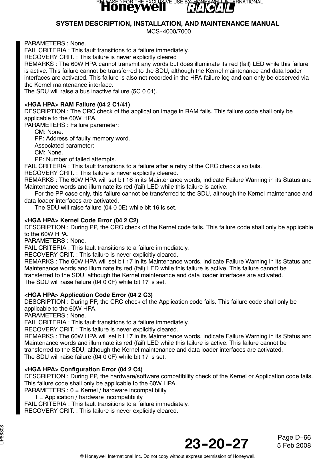
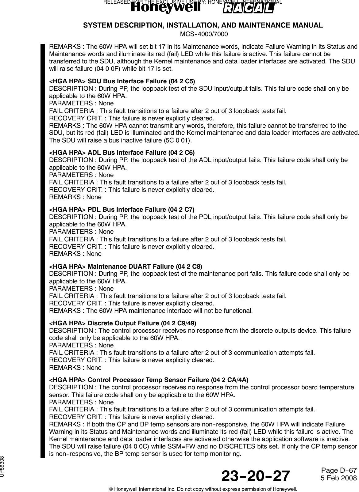
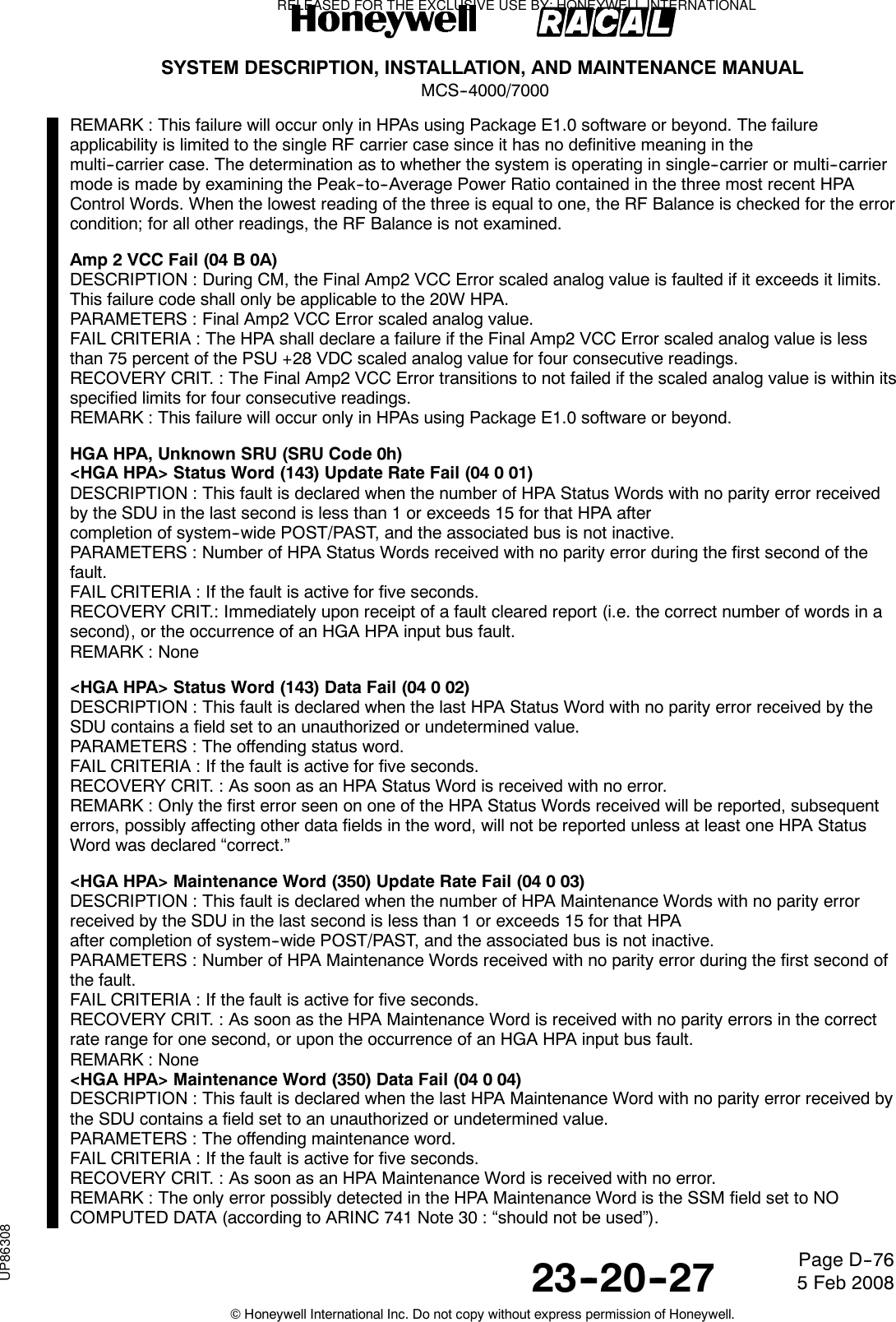
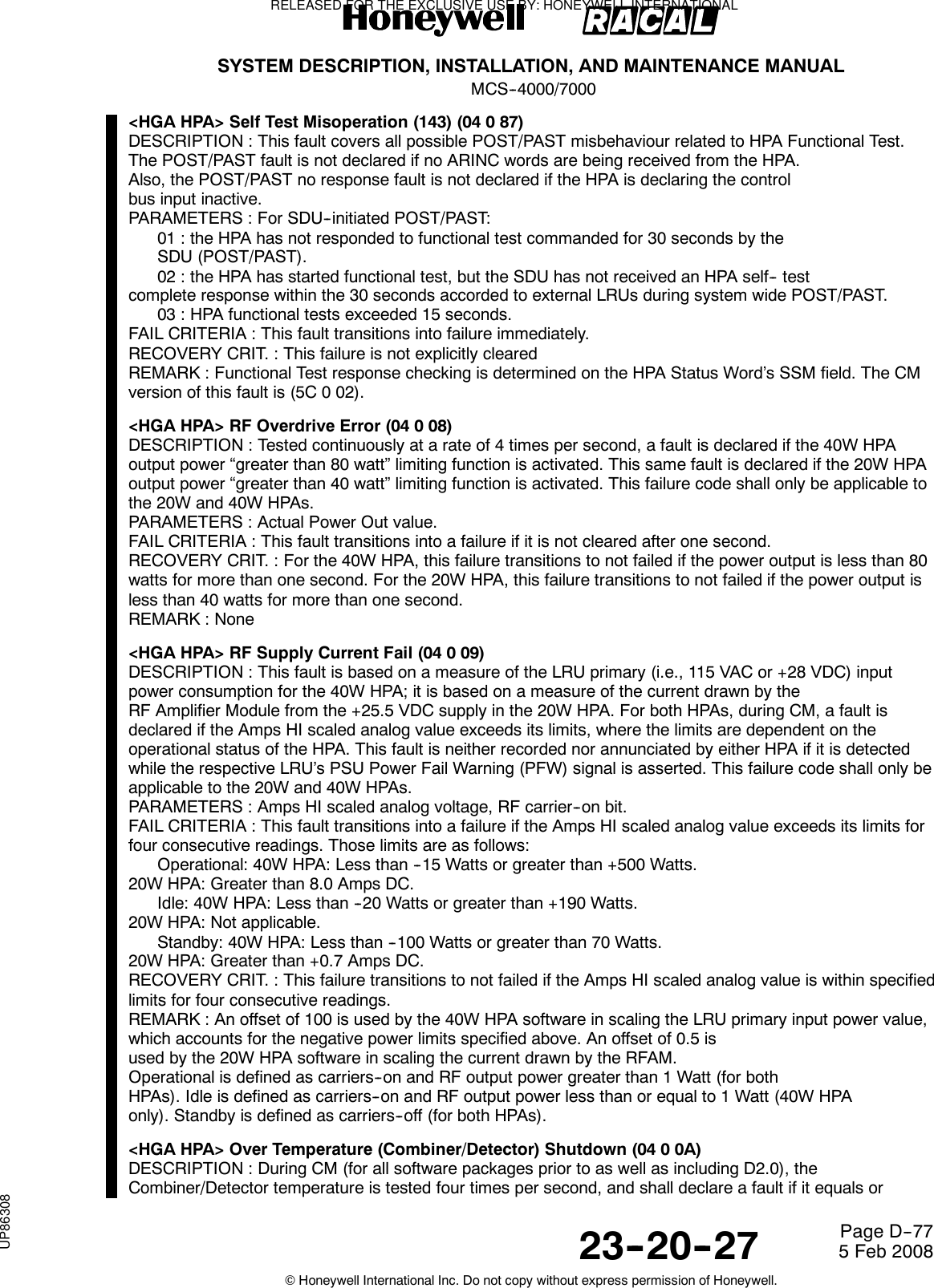
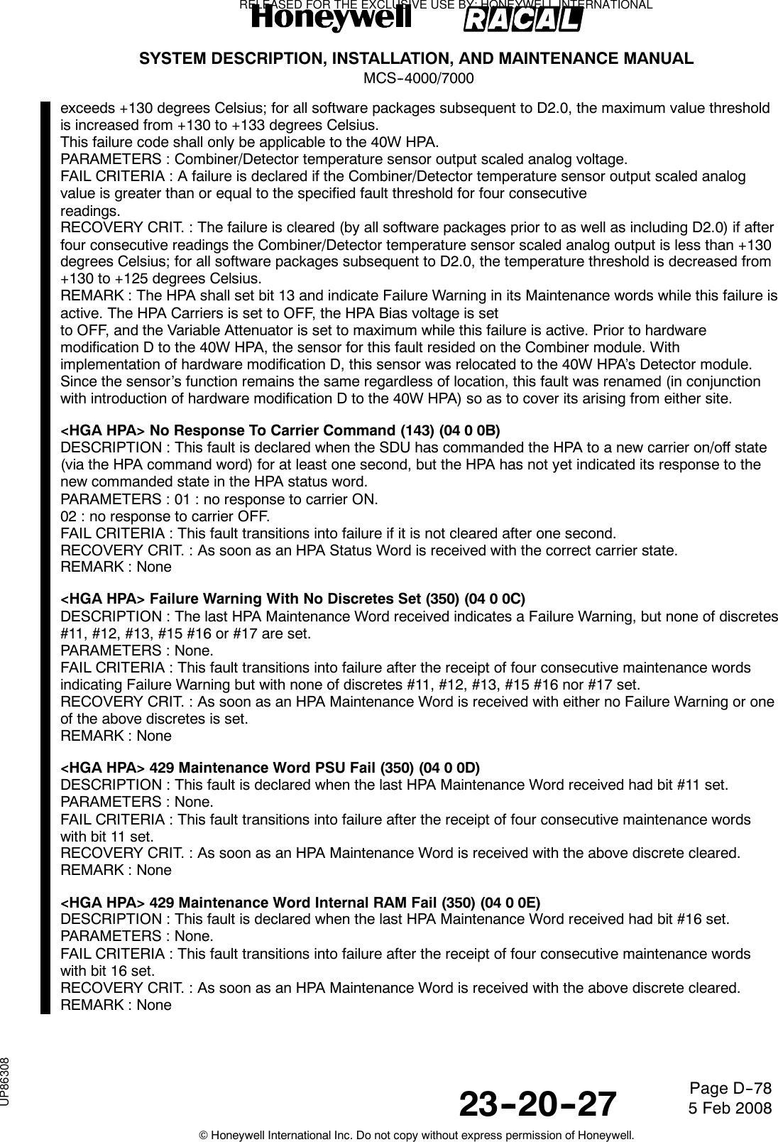
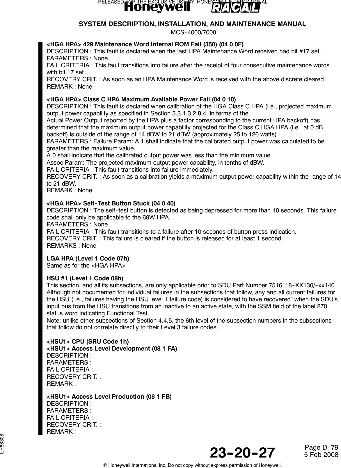
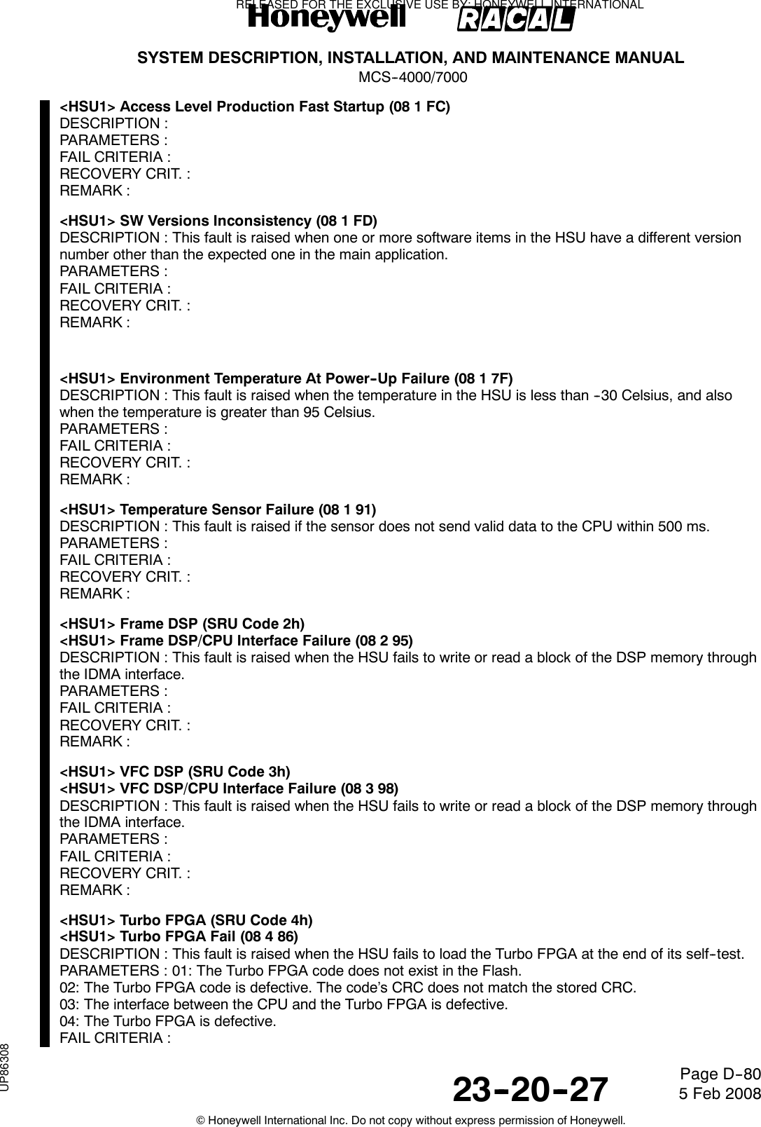
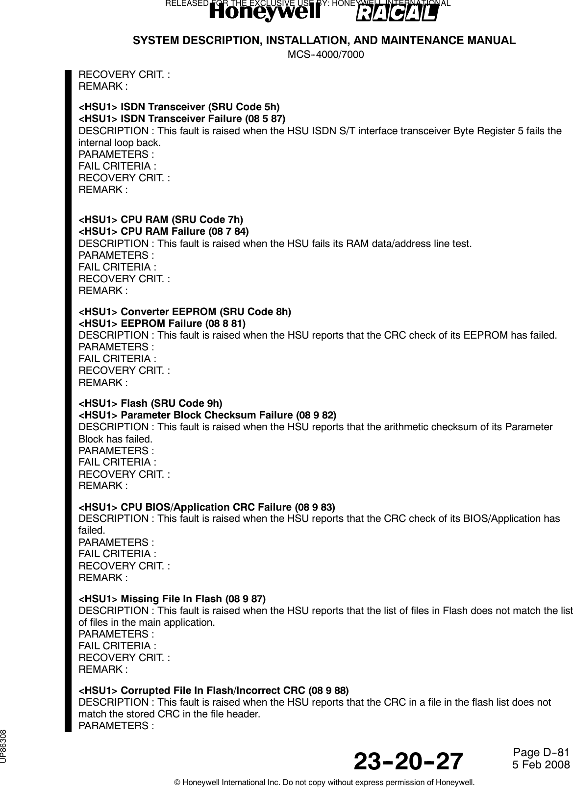
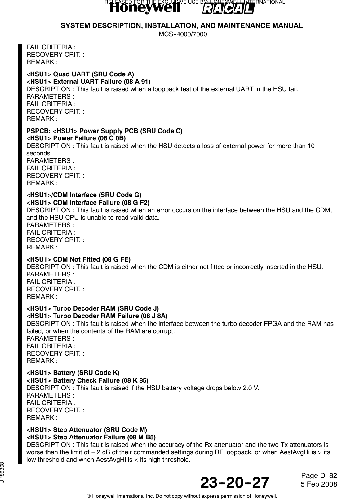
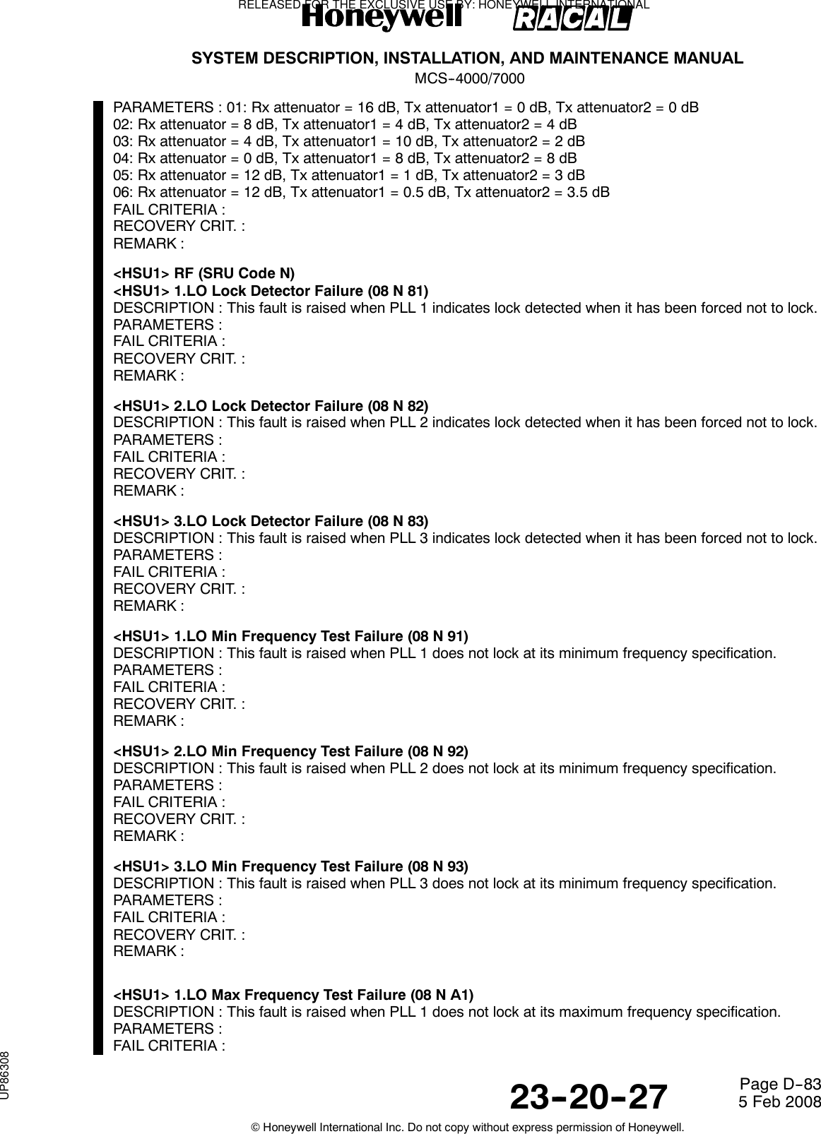
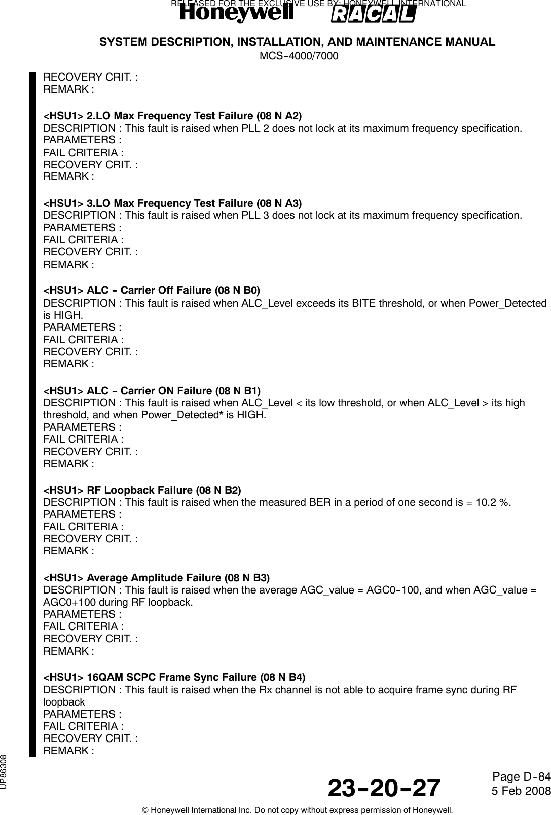
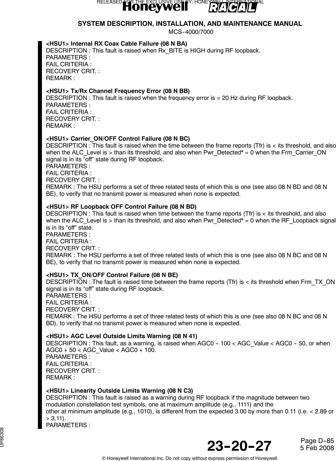
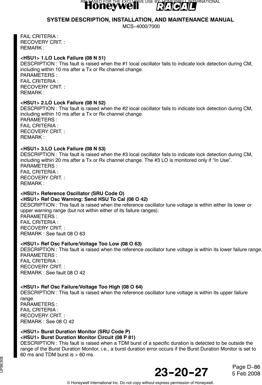
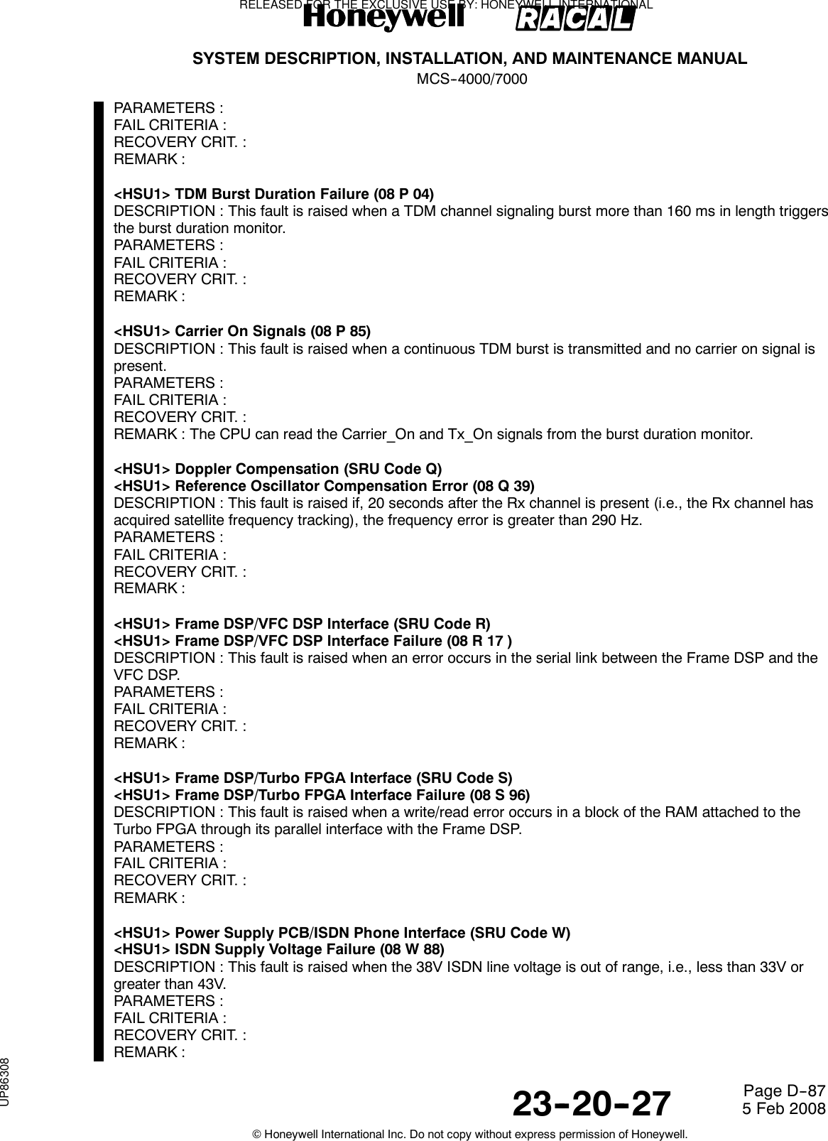
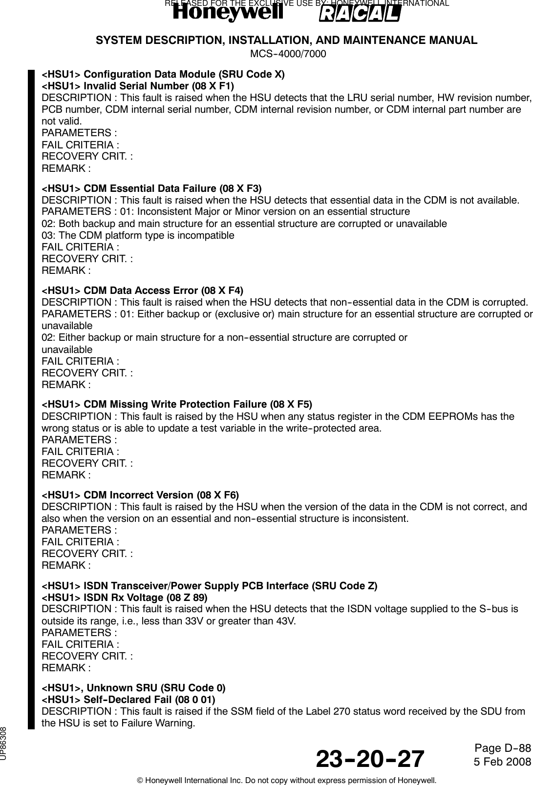
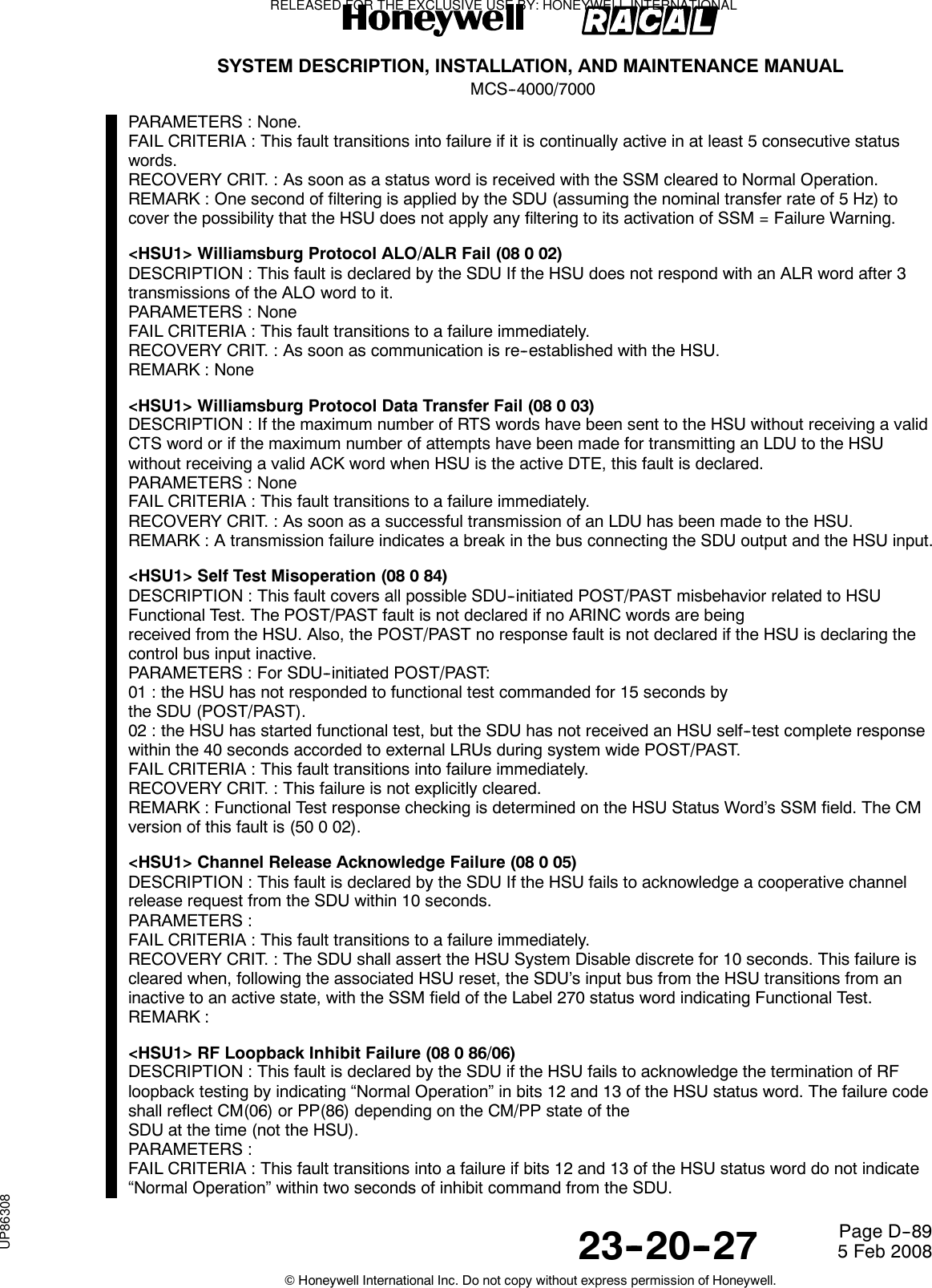
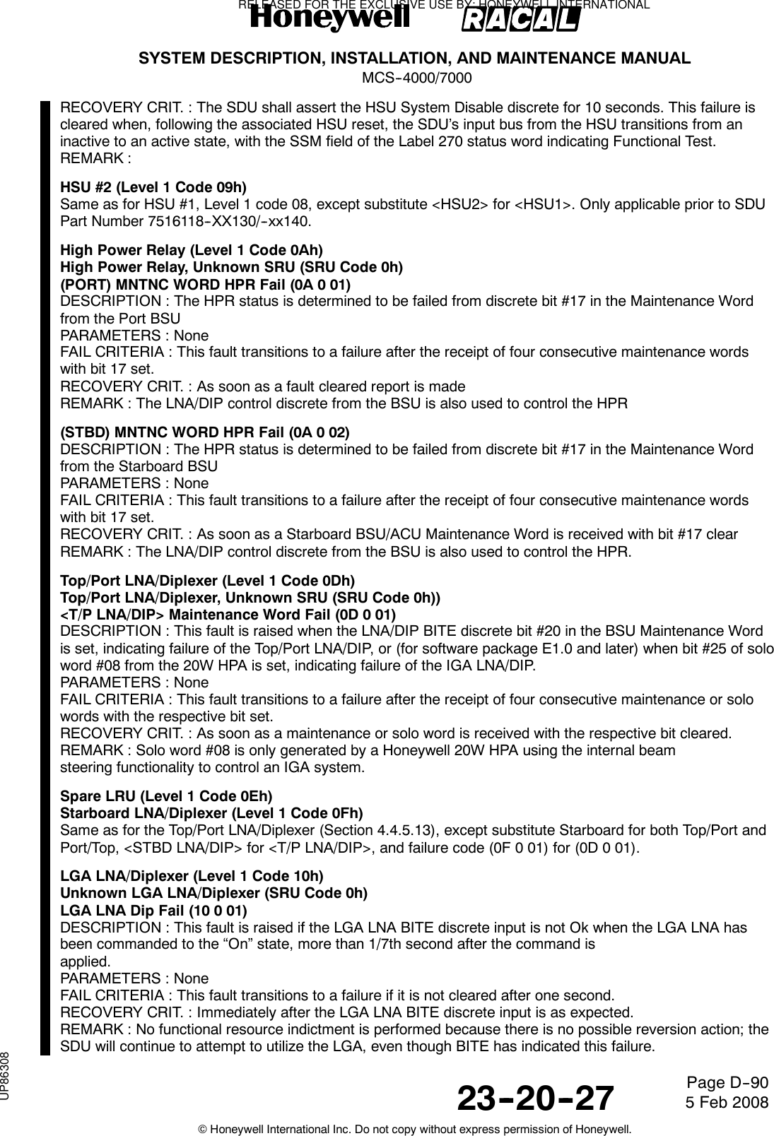
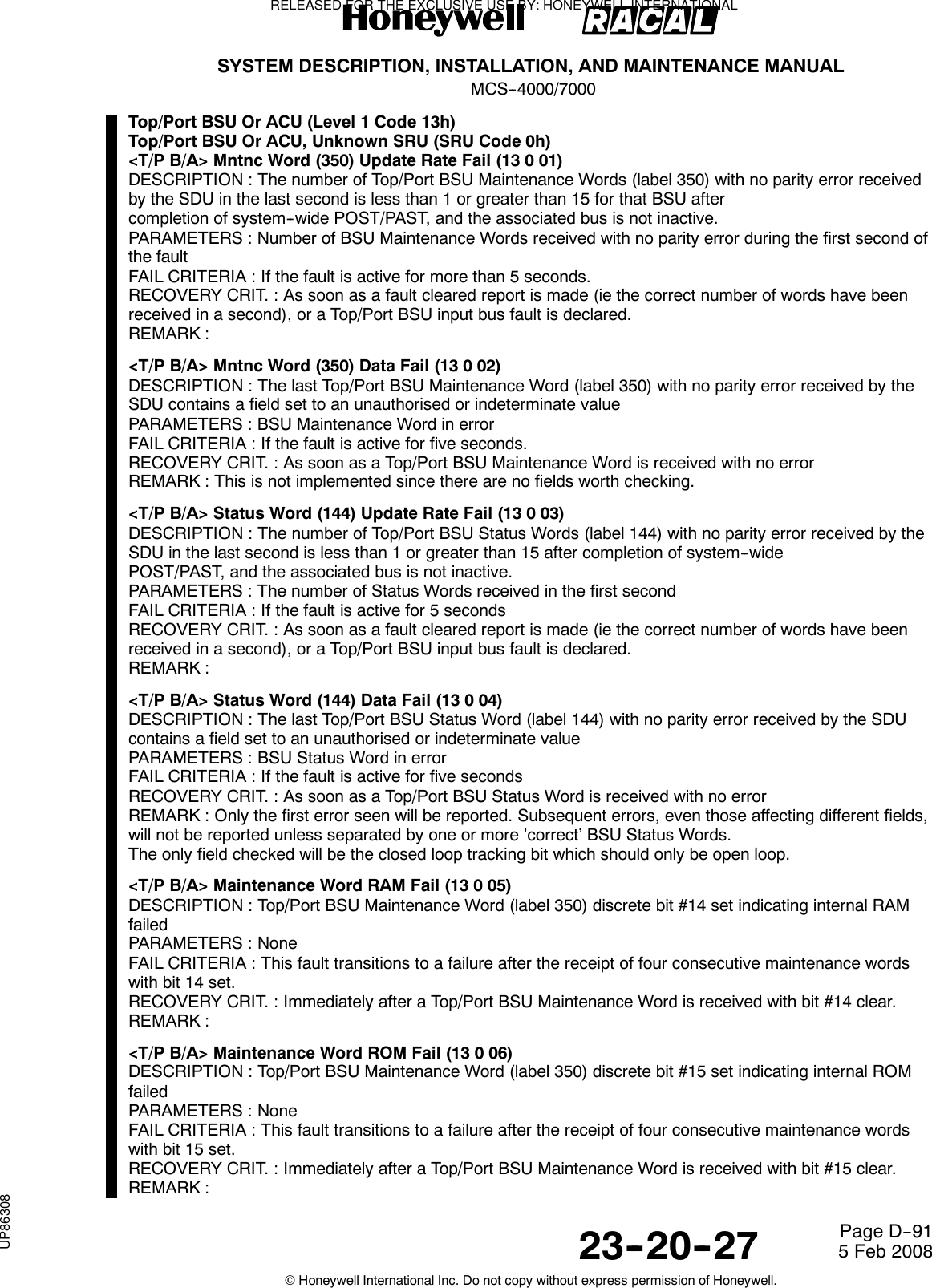
![SYSTEM DESCRIPTION, INSTALLATION, AND MAINTENANCE MANUALMCS--4000/700023--20--27 5 Feb 2008©Honeywell International Inc. Do not copy without express permission of Honeywell.Page D--93RECOVERY CRIT. : Immediately after a maintenance or solo word is received with the respective bit cleared.REMARK : Solo word #08 is only generated by a Honeywell 20W HPA using its internal beam steeringfunctionality to control an IGA system.Also note that, contrary to the norm, Level 1 failure code 1A is used for failures of the power and signalinterfaces between the IGA and the 20W HPA, as well as for the IGA itself.IGA Failure (1A 0 02)DESCRIPTION : This fault is raised by the 20W HPA whenever the BITE Data Word received from the IGAindicates Power Supply Fault [whose root cause could be in the IGA, or in the power feed from the HPA,including the HPA itself], and also when the IGA’s re--transmitted echo (also in the BITE Data Word from theIGA) of the HPA’s commanded Beam Steering Word byte #1 bit #0 does not match the commanded bit,indicating failure of the IGA or the interface between the HPA and the IGA. While this failure is currentlyactive, the HPA shall also set bit #24 of its solo word #8.PARAMETERS : For the failure parameter, the following codes apply:0=Reserved1 = CMC antenna2 = CAL antennaThe associated parameter is defined as follows:BIT Meaning0 Reserved1 Reserved21=CMCSteeringDataMismatch,0=OK3 1 = CMC Power Supply fault (--85V), 0 = OK4 Reserved5 ReservedFAIL CRITERIA : After four successive fault conditions are declared (any one or more of the conditionsspecified in the associated parameter value).RECOVERY CRIT. : Immediately after none of the conditions specified in the associated parameter value isdetected by the HPA nor indicated by the IGA.REMARK : The parameters stored with this failure will be pertinent to the 1A/0/01 failure stored by the SDU inresponse to the HPA’s solo word.IGA RS--422 Input Bus Link Fault (1A 0 03)DESCRIPTION : This fault is raised by the 20W HPA whenever the BITE Data Word received from the IGAhas its Link Fault bit set, indicating failure of the IGA or the RS--422 bus from the HPA to the IGA (whose rootcause could be in the IGA, or in the RS--422 interface from the HPA to the IGA, or in the HPA). While thisfailure is currently active, the HPA shall also set bit #24 of its solo word #8.PARAMETERS : None.FAIL CRITERIA : After four successive fault conditions are declared.RECOVERY CRIT. : Immediately after the IGA’s BITE Data Word is received with the Link Fault bit cleared.REMARK :IGA HPA RS--422 Input Bus Error/Inactive (1A 0 04)DESCRIPTION : This fault is raised by the 20W HPA if the IGA fails to respond to a steering command wordtransmitted from the HPA after 0.5 second, and also when the HPA detects interface errors on the associatedserial input port, indicating failure of the IGA or the RS--422 bus from the IGA to the HPA (whose root causecould be in the IGA, or in the RS--422 bus from the IGA to the HPA, or in the HPA). While this failure iscurrently active, the HPA shall also set bit #24 of its solo word #8.PARAMETERS : The associated parameter value is set to the last received character. The failure parameteris set as follows (with bits 0 through 7 obtained from the associated UART status register [and those specifiedas “Always 0” being masked out by the HPA software] ):Bit0:Always0.Bit 1: 1 = Receive data character framing error, 0 = OK.Bit 2: 1 = Break flag (twisted pair wiring probably reversed), 0 = OK.Bit3:Always0.Bit 4: 1 = Receive data character parity error, 0 = OK.Bit 5: 1 = Receive data noisy, 0 = OK.RELEASED FOR THE EXCLUSIVE USE BY: HONEYWELL INTERNATIONALUP86308](https://usermanual.wiki/Honeywell/SD-700A/User-Guide-3476924-Page-468.png)
![SYSTEM DESCRIPTION, INSTALLATION, AND MAINTENANCE MANUALMCS--4000/700023--20--27 5 Feb 2008©Honeywell International Inc. Do not copy without express permission of Honeywell.Page D--95<WSC--1> Master Protocol Error (21 0 03)DESCRIPTION : If WSC--1 is the first WSC to declare itself “active” after system initialization, and then itsubsequently does not respond with an ALR word after 3 transmissions of the ALO word toit, then this fault is raised if the SDU is configured as a single SDU or is the Master in a dual system.PARAMETERS : NoneFAIL CRITERIA : This fault transitions to a failure only if it persists for at least ten seconds.RECOVERY CRIT. : As soon as communication is re--established with WSC--1, or an SDU WSC--1 BusInactive fault is raised.REMARK :<WSC--1> Data Transmission Failure (21 0 04)DESCRIPTION : If the maximum number of RTS words have been sent to WSC--1 without receiving a validCTS word or the maximum number of attempts have been made for transmitting an LDU to WSC--1 withoutreceiving a valid ACK word when WSC--1 is the “active” WSC, this fault is raised.PARAMETERS : NoneFAIL CRITERIA : This fault transitions to a failure immediately.RECOVERY CRIT. : As soon as a successful transmission of an LDU has been made to WSC--1, or WSC--1responds to a SOLO TEST word, or when an SDU WSC--1 Bus Inactive failure is declared.REMARK : Whenever the SDU has a data file ready to transmit to WSC--1, it follows the transferprocedure.<WSC--1> Master TEST/LOOP Failure (21 0 07)DESCRIPTION : If WSC--1 fails to respond to two consecutive SOLO TEST words with the correct LOOPword, then this fault is raised if the SDU is either the sole SDU in a single system orthe Master in a dual system.PARAMETERS : None.FAIL CRITERIA : This fault transitions to a failure immediately.RECOVERY CRIT. : As soon as WSC--1 responds to a SOLO TEST word with the correct LOOP word, anSDU WSC--1 Bus Inactive fault is raised.REMARK :SCDU/WSC--2 (Level 1 Code 22h)Same as for SCDU/WSC--1 (Section 4.4.5.33), except substitute SCDU--2 for SCDU--1 and WSC--2 forWSC--1.SCDU/WSC--3 (Level 1 Code 23h)Same as for SCDU/WSC--1 (Section 4.4.5.33), except substitute SCDU--3 for SCDU--1 and WSC--3 forWSC--1.(C)MU--1 (Level 1 Code 33h)(C)MU--1, Unknown SRU (SRU Code 0h)COMMENTARYThe failure of a (C)MU to respond to ALO, SOLO TEST words or data transmissions is indicative of a brokenSDU to CMU bus. These faults will indict the [cmu] level--2 resource. This does not affect bit 11 of the SDUlabel 270 status word, but may initiate a handover of mastery in a dual system.(C)MU--1 Status (270) Bad SSM (33 0 02)DESCRIPTION : For Airbus, this fault is raised if a Label 270 Status word is received with the SSM field setto “Failure Warning” (11b). For other aircraft, this fault is raised if a Statusword is received with anything other than “Normal Operation” (00b) in the SSM field.PARAMETERS : NoneFAIL CRITERIA : For Airbus, if the fault is active for three seconds; for other aircraft, if the fault is active forfive seconds.RECOVERY CRIT. : For Airbus, this failure shall clear as soon as a Status word is received with its SSM fieldset to any state other than Failure Warning or when a CMU--1 Bus Inactive fault is declared. For otheraircraft, this failure shall clear as soon as a Status word is received with “Normal Operation” in its SSM fieldor when a CMU--1 Bus Inactive fault is declared.RELEASED FOR THE EXCLUSIVE USE BY: HONEYWELL INTERNATIONALUP86308](https://usermanual.wiki/Honeywell/SD-700A/User-Guide-3476924-Page-470.png)
![SYSTEM DESCRIPTION, INSTALLATION, AND MAINTENANCE MANUALMCS--4000/700023--20--27 5 Feb 2008©Honeywell International Inc. Do not copy without express permission of Honeywell.Page D--96REMARK : The failure criteria for this fault was changed to three seconds for Airbus in response to AirbusEPR 109, in order that such a fault would be reported on the Airbus CFDS Testpage upon completion of the Test (PAST) function.(C)MU--1 Master Protocol Error (33 0 03)DESCRIPTION : If this CMU is the first CMU to declare itself active after system init, and then itsubsequently does not respond with an ALR word after 3 transmissions of the ALO word to it, then this faultis declared if the SDU is configured as a single SDU or is the Master in a dual system.PARAMETERS : NoneFAIL CRITERIA : Prior to Package 2.0, this fault transitions to a failure immediately. For Package 2.0 andsubsequent, this fault transitions to a failure only if it persists for at least tenseconds.RECOVERY CRIT. : As soon as communication is re--established with this CMU, a CMU--1 Bus Inactive faultis declared, or a CMU--1 Slave Protocol Error is declared.REMARK :(C)MU--1 Data Transmission Failure (33 0 04)DESCRIPTION : If the maximum number of RTS words have been sent to the CMU without receiving a validCTS word or if the maximum number of attempts have been made for transmitting an LDU to the CMUwithout receiving a valid ACK word when CMU 1 is the active DTE, this fault is declared.PARAMETERS : NoneFAIL CRITERIA : This fault transitions to a failure immediatelyRECOVERY CRIT. : As soon as a successful transmission of an LDU has been made to the CMU, or theCMU responds to a SOLO TEST word, or when a CMU--1 Bus Inactive failure is declared.COMMENTARYA transmission failure indicates a break in the bus connecting the SDU output and the CMU input. It shouldindict the [cmu] resource because several back--to--back LDU transfers could prevent this being detected by aSOLO TEST/LOOP test. To make this failure recoverable it should be cleared once a SOLO TEST/LOOPtest succeeds (these are still carried out regardless of [cmu] indictment).REMARK : Whenever the SDU has a data file ready to transmit to the CMU, it follows the transferprocedure.(C)MU--1 Slave Protocol Error (33 0 05)DESCRIPTION : If this CMU is the first CMU to declare itself active after system init, and then itsubsequently does not respond with an ALR word after 3 transmissions of the ALO word to it, then this faultis declared if the SDU is the Slave in a dual system.PARAMETERS : None.FAIL CRITERIA : Prior to Package 2.0, this fault transitions to a failure immediately. For Package 2.0 andsubsequent, this fault transitions to a failure only if it persists for at least tenseconds.RECOVERY CRIT. : As soon as communication is re--established with this CMU, a CMU--1 Bus Inactive faultis declared, or a CMU--1 Master Protocol Error is declared.REMARK : See failure 33 0 03.(C)MU--1 Self--Declared Failure (33 0 06)DESCRIPTION : This fault is declared if the Fail bit (bit 16) of the Label 270 Status word received by the SDUfrom the (C)MU is set.PARAMETERS : None.FAIL CRITERIA : This fault transitions to the failure state if it is continuously active for at least three seconds.RECOVERY CRIT. : As soon as a Status word is received with bit 16 cleared or a CMU--1 Bus Inactive faultis declared.REMARK : The three seconds of filtering is applied by the SDU to cover the possibility that the (C)MU doesnot apply any time filtering to its activation of bit 16.(C)MU--1 Master TEST/LOOP Failure (33 0 07)DESCRIPTION : If this CMU fails to respond to two consecutive SOLO TEST words with the correct LOOPword, then this fault is declared if the SDU is either the sole SDU in a single system or the Master in a dualsystem.RELEASED FOR THE EXCLUSIVE USE BY: HONEYWELL INTERNATIONALUP86308](https://usermanual.wiki/Honeywell/SD-700A/User-Guide-3476924-Page-471.png)
![SYSTEM DESCRIPTION, INSTALLATION, AND MAINTENANCE MANUALMCS--4000/700023--20--27 5 Feb 2008©Honeywell International Inc. Do not copy without express permission of Honeywell.Page D--98monitored for test purposesREMARK : Reversion between IRS sources is discussed in Section 4.4.6, relating to the [nav]functional resource.4.4.5.53.20.3 <IRS--PRI> Spare (35 0 03)4.4.5.53.20.4 <IRS--PRI> Lon (311) Data Fail (35 0 04)DESCRIPTION : A data failure condition associated with longitude data has been detected. The possiblefailure conditions are; longitude data update rate failure (ARINC longitude words received at less than theminimum update rate or more than the maximum update rate if the associated bus is not inactive), a validARINC IRS data word (latitude, longitude, ground speed, track angle, true heading, pitch or roll) received withthe SSM status field set to the ’Failure Warning’ state or an ARINC longitude data word received with theSSM status field set to the ’No Computed Data’ state.The maximum update rate for ARINC longitude words is 15 words in a one second interval and the minimumis 3 words in a one second interval. Maximum and minimum update rates are derived from minimum andmaximum transmit intervals respectively with a tolerance margin added.PARAMETERS : Last Longitude word received and the number of words received in the last second.FAIL CRITERIA : A ’Failure Warning’ or ’No Computed Data’ SSM status field state failure will be reportedimmediately. Update rate failures will be reported within five seconds of occurrence if theIRS is selected or within seven seconds if the IRS is being monitored for test purposes.RECOVERY CRIT. : Failure recovery will be reported within one second of recovery from all possible failurecriteria for this fault if this IRS is selected or within seven seconds if the IRS is being monitored for testpurposes.REMARK : Reversion between IRS sources is discussed in Section 4.4.6, relating to the [nav]functional resource.<IRS--PRI> Spare (35 0 05)<IRS--PRI> Grd Spd (312) Data Fail (35 0 06)DESCRIPTION : A data failure condition associated with ground speed data has been detected. The possiblefailure conditions are; ground speed data update rate failure (ARINC ground speedwords received at less than the minimum update rate or more than the maximum update rate if theassociated bus is not inactive), a valid ARINC IRS data word (latitude, longitude, ground speed, track angle,true heading, pitch or roll) received with the SSM status field set to the ’Failure Warning’ state or an ARINCground speed data word received with the SSM status field set to the ’No Computed Data’ state. Themaximum update rate for ARINC ground speed words is 45 words in a one second interval and the minimumis 8 words in a one second interval. Maximum and minimum update rates are derived from minimum andmaximum transmit intervals respectively with a tolerance margin added.PARAMETERS : Last Ground Speed word received and the number of words received in the last second.FAIL CRITERIA : A ’Failure Warning’ or ’No Computed Data’ SSM status field state failure will be reportedimmediately. Update rate failures will be reported within five seconds of occurrence if theIRS is selected or within seven seconds if the IRS is being monitored for test purposes.RECOVERY CRIT. : Failure recovery will be reported within one second of recovery from all possible failurecriteria for this fault if this IRS is selected or within seven seconds if the IRS is being monitored for testpurposes.REMARK :<IRS--PRI> Spare (35 0 07)<IRS--PRI> Trk (313) Data Fail (35 0 08)DESCRIPTION : A data failure condition associated with track angle data has been detected. The possiblefailure conditions are; track angle data update rate failure (ARINC track angle wordsreceived at less than the minimum update rate or more than the maximum update rate if the associated busis not inactive), a valid ARINC IRS data word (latitude, longitude, ground speed, track angle, true heading,pitch or roll) received with the SSM status field set to the ’Failure Warning’ state or an ARINC track angledata word received with the SSM status field set to the ’No Computed Data’ state. Track angle wordsreceived with the SSM field set to the ’No Computed Data’ state shall only be considered as failure conditionsif the current ground speed indicates that the aircraft is airborne.RELEASED FOR THE EXCLUSIVE USE BY: HONEYWELL INTERNATIONALUP86308](https://usermanual.wiki/Honeywell/SD-700A/User-Guide-3476924-Page-473.png)
![SYSTEM DESCRIPTION, INSTALLATION, AND MAINTENANCE MANUALMCS--4000/700023--20--27 5 Feb 2008©Honeywell International Inc. Do not copy without express permission of Honeywell.Page D--99The maximum update rate for ARINC track angle words is 45 words in a one second interval and theminimum is 1 word in a one second interval. Maximum and minimum update rates are derived from minimumand maximum transmit intervals respectively with a tolerance margin added.COMMENTARYThe extremely low minimum update rate is specifically set to tolerate the Honeywell Laseref II Type HG 1075AE03, which outputs this word at only a 2 Hz rate. The preferred minimum rate is 18 words in a one secondinterval (which accommodates the minimum value of 20 words in a one second interval specified by ARINCCharacteristic 704).PARAMETERS : Last Track Angle word received and the number of words received in the last second.FAIL CRITERIA : A ’Failure Warning’ or ’No Computed Data’ SSM status field state failure will be reportedimmediately. Update rate failures will be reported within five seconds of occurrence if theIRS is selected or within seven seconds if the IRS is being monitored for test purposes.RECOVERY CRIT. : Failure recovery will be reported within one second of recovery from all possible failurecriteria for this fault if this IRS is selected or within seven seconds if the IRS is being monitored for testpurposes.REMARK : Reversion between IRS sources is discussed in Section 4.4.6, relating to the [nav]functional resource.<IRS--PRI> Spare (35 0 09)<IRS--PRI> True Hdg (314) Data Fail (35 0 0A)DESCRIPTION : A data failure condition associated with true heading data has been detected. The possiblefailure conditions are; true heading data update rate failure (ARINC true heading words received at less thanthe minimum update rate or more than the maximum update rate ifthe associated bus is not inactive), a valid ARINC IRS data word (latitude, longitude, ground speed, trackangle, true heading, pitch or roll) received with the SSM status field set to the ’Failure Warning’ state or anARINC true heading data word received with the SSM status field set to the ’No Computed Data’ state.The maximum update rate for ARINC true heading words is 45 words in a one second interval and theminimum is 18 words in a one second interval. Maximum and minimum update rates are derived fromminimum and maximum transmit intervals respectively with a tolerance marginadded.PARAMETERS : Last True Heading word received and the number of words received in the last second.FAIL CRITERIA : A ’Failure Warning’ or ’No Computed Data’ SSM status field state failure will be reportedimmediately. Update rate failures will be reported within five seconds of occurrence if theIRS is selected or within seven seconds if the IRS is being monitored for test purposes.RECOVERY CRIT. : Failure recovery will be reported within one second of recovery from all possible failurecriteria for this fault if this IRS is selected or within seven seconds if the IRS is being monitored for testpurposes.REMARK :<IRS--PRI>Spare(3500B)<IRS--PRI> Pitch (324) Data Fail (35 0 0C)DESCRIPTION : A data failure condition associated with pitch data has been detected. The possible failureconditions are; pitch data update rate failure (ARINC pitch words received at less than the minimum updaterate or more than the maximum update rate if the associated bus is notinactive), a valid ARINC IRS data word (latitude, longitude, ground speed, track angle, true heading, pitch orroll) received with the SSM status field set to the ’Failure Warning’ state oran ARINC pitch data word received with the SSM status field set to the ’No Computed Data’ state.The maximum update rate for ARINC pitch words is 120 words in a one second interval and the minimum is20 words in a one second interval. Maximum and minimum update rates are derived from minimum andmaximum transmit intervals respectively with a tolerance margin added.PARAMETERS : Last Pitch word received and the number of words received in the last second.FAIL CRITERIA : A ’Failure Warning’ or ’No Computed Data’ SSM status field state failure will be reportedimmediately. Update rate failures will be reported within five seconds of occurrence if theIRS is selected or within seven seconds if the IRS is being monitored for test purposes.RELEASED FOR THE EXCLUSIVE USE BY: HONEYWELL INTERNATIONALUP86308](https://usermanual.wiki/Honeywell/SD-700A/User-Guide-3476924-Page-474.png)
![SYSTEM DESCRIPTION, INSTALLATION, AND MAINTENANCE MANUALMCS--4000/700023--20--27 5 Feb 2008©Honeywell International Inc. Do not copy without express permission of Honeywell.Page D--100RECOVERY CRIT. : Failure recovery will be reported within one second of recovery from all possible failurecriteria for this fault if this IRS is selected or within seven seconds if the IRS is being monitored for testpurposes.REMARK :<IRS--PRI>Spare(3500D)<IRS--PRI> Roll (325) Data Fail (35 0 0E)DESCRIPTION : A data failure condition associated with roll data has been detected. The possible failureconditions are; roll data update rate failure (ARINC roll words received at less than the minimum update rateor more than the maximum update rate if the associated bus is notinactive), a valid ARINC IRS data word (latitude, longitude, ground speed, track angle, true heading, pitch orroll) received with the SSM status field set to the ’Failure Warning’ state oran ARINC roll data word received with the SSM status field set to the ’No Computed Data’ state.The maximum update rate for ARINC roll words is 120 words in a one second interval and the minimum is 20words in a one second interval. Maximum and minimum update rates are derived from minimum andmaximum transmit intervals respectively with a tolerance margin added.PARAMETERS : Last Roll word received and the number of words received in the last second.FAIL CRITERIA : A ’Failure Warning’ or ’No Computed Data’ SSM status field state failure will be reportedimmediately. Update rate failures will be reported within five seconds of occurrence if theIRS is selected or within seven seconds if the IRS is being monitored for test purposes.RECOVERY CRIT. : Failure recovery will be reported within one second of recovery from all possible failurecriteria for this fault if this IRS is selected or within seven seconds if the IRS is being monitored for testpurposes.REMARKIRS--SEC (Level 1 Code 36h)Same as for IRS--PRI except substitute IRS--SEC for IRS--PRI.CMC/CFDIU (Level 1 Code 39h)CMC/CFDIU, Unknown SRU (SRU Code 39h)Invalid OMS Data (39 0 01)DESCRIPTION : This fault is applicable prior to SDU Part Number 7516118--XX130/--xx140, and shall onlyapply to aircraft strapped for “Airbus” CFDS type. This fault is declared when any Airbus on--boardmaintenance system (OMS) “general parameter” data item (any one of labels 125, 126, 155--157, 227,233--237, 260, 301--303 [and 304 if processed] ---- is received with SSM = FW (where applicable) or the datais not received with an update period better than 10 times the period.PARAMETERS : The 32--bit Failure Parameter shall use single--bit coding per condition to indicate thespecific nature of the failure. The parameter is structured as follows:BIT NUMBER WEIGHT (HEX) MEANING0 0000 0001 Label 125 received with SSM = FW1 0000 0002 Label 126 “2 0000 0004 Label 155 “3 0000 0008 Label 156 “4 0000 0010 Label 157 “BIT NUMBER WEIGHT (HEX) MEANING5 0000 0020 Spare (0) [Label 227 has no SSM field]6 0000 0040 Label 233 received with SSM = FW7 0000 0080 Label 234 “8 0000 0100 Label 235 “9 0000 0200 Label 236 “10 0000 0400 Label 237 “11 0000 0800 Label 260 “12 0000 1000 Spare (0) [Label 301 has no SSM field]13 0000 2000 Spare (0) [Label 302 has no SSM field]14 0000 4000 Spare (0) [Label 303 has no SSM field]15 0000 8000 Spare (0)16 0001 0000 Label 125 received with update period > 10*NRELEASED FOR THE EXCLUSIVE USE BY: HONEYWELL INTERNATIONALUP86308](https://usermanual.wiki/Honeywell/SD-700A/User-Guide-3476924-Page-475.png)
![SYSTEM DESCRIPTION, INSTALLATION, AND MAINTENANCE MANUALMCS--4000/700023--20--27 5 Feb 2008©Honeywell International Inc. Do not copy without express permission of Honeywell.Page D--103CPDF Spare (43 0 01)CPDF Status (270) Bad SSM (43 0 02)DESCRIPTION : This fault is raised if a Status word is received with anything other than “Normal Operation”(00b) in the SSM field.PARAMETERS : NoneFAIL CRITERIA : If the fault is active for five seconds.RECOVERY CRIT. : This failure shall clear as soon as a Status word is received with “Normal Operation” inits SSM field.REMARK :CPDF Master Protocol Error (43 0 03)DESCRIPTION : If this CPDF is the first CPDF to declare itself active after system init, and then itsubsequently does not respond with an ALR word after 3 transmissions of the ALO word to it, then this faultis declared if the SDU is configured as a single SDU or is the Master in a dual system.PARAMETERS : NoneFAIL CRITERIA : This fault transitions to a failure immediately.RECOVERY CRIT. : As soon as communication is re--established with this CPDF, a CDPF Bus Inactive faultis declared, or a CPDF Slave Protocol Error is declared.REMARK :CDPF Data Transmission Failure (43 0 04)DESCRIPTION : If the maximum number of RTS words have been sent to the CPDF without receiving a validCTS word or if the maximum number of attempts have been made for transmitting an LDU to the CPDFwithout receiving a valid ACK word when CPDF is the active DTE, this fault is declared.PARAMETERS : NoneFAIL CRITERIA : This fault transitions to a failure immediatelyRECOVERY CRIT. : As soon as a successful transmission of an LDU has been made to the CPDF, or theCPDF responds to a SOLO TEST word, or when a CPDF Bus Inactive failure is declared.COMMENTARYA transmission failure indicates a break in the bus connecting the SDU output and the CPDF input. It shouldindict the [cpdf] resource because several back--to--back LDU transfers could prevent this being detected by aSOLO TEST/LOOP test. To make this failure recoverable it should be cleared once a SOLO TEST/LOOPtest succeeds (these are still carried out regardless of [cpdf] indictment).REMARK : Whenever the SDU has a data file ready to transmit to the CPDF, it follows the transferprocedure.CPDF Slave Protocol Error (43 0 05)DESCRIPTION : If this CPDF is the first CPDF to declare itself active after system init, and then itsubsequently does not respond with an ALR word after 3 transmissions of the ALO word to it, then this faultis declared if the SDU is the Slave in a dual system.PARAMETERS : None.FAIL CRITERIA : This fault transitions to a failure immediately.RECOVERY CRIT. : As soon as communication is re--established with this CPDF, a CPDF Bus Inactive faultis declared, or a CPDF Master Protocol Error is declared.REMARK :CPDF Self--Declared Failure (43 0 06)DESCRIPTION : This fault is declared if the Fail bit (bit 16) of the Label 270 Status word received by the SDUfrom the CPDF is set.PARAMETERS : None.FAIL CRITERIA : This fault transitions to the failure state if it is continuously active for at least three seconds.RECOVERY CRIT. : As soon as a Status word is received with bit 16 cleared or a CPDF Bus Inactive fault isdeclared.REMARK : The three seconds of filtering is applied by the SDU to cover the possibility that the CPDF doesnot apply any time filtering to its activation of bit 16.RELEASED FOR THE EXCLUSIVE USE BY: HONEYWELL INTERNATIONALUP86308](https://usermanual.wiki/Honeywell/SD-700A/User-Guide-3476924-Page-478.png)
![SYSTEM DESCRIPTION, INSTALLATION, AND MAINTENANCE MANUALMCS--4000/700023--20--27 5 Feb 2008©Honeywell International Inc. Do not copy without express permission of Honeywell.Page D--107Invalid OMS Data (59 0 02)DESCRIPTION : This fault is applicable for SDU Part Number 7516118--XX130/--xx140 and subsequent, andshall only apply to aircraft strapped for “Airbus” CFDS type. This fault is declared when any Airbus on--boardmaintenance system (OMS) “general parameter” data item (any one of labels 125, 126, 155--157, 233--237,260, 301--303 [and 304 if processed] ---- is received with SSM = FW (where applicable) or the data is notreceived with an update period better than 10 times the period specified for the data.PARAMETERS : The 32--bit Failure Parameter shall use single--bit coding per condition to indicate thespecific nature of the failure. The parameter is structured as follows:BIT NUMBER WEIGHT (HEX) MEANING0 0000 0001 Label 125 received with SSM = FW1 0000 0002 Label 126 “2 0000 0004 Label 155 “3 0000 0008 Label 156 “4 0000 0010 Label 157 “5 0000 0020 Spare (0) [Label 227 has no SSM field]6 0000 0040 Label 233 received with SSM = FW7 0000 0080 Label 234 “8 0000 0100 Label 235 “9 0000 0200 Label 236 “10 0000 0400 Label 237 “11 0000 0800 Label 260 “12 0000 1000 Spare (0) [Label 301 has no SSM field]13 0000 2000 Spare (0) [Label 302 has no SSM field]14 0000 4000 Spare (0) [Label 303 has no SSM field]15 0000 8000 Spare (0)16 0001 0000 Label 125 received with update period > 10*N17 0002 0000 Label 126 “18 0004 0000 Label 155 “19 0008 0000 Label 156 “20 0010 0000 Label 157 “21 0020 0000 Spare (0) [Label 227 is covered by 59/0/01]22 0040 0000 Label 233 received with update period > 10*N23 0080 0000 Label 234 “24 0100 0000 Label 235 “25 0200 0000 Label 236 “26 0400 0000 Label 237 “27 0800 0000 Label 260 “28 1000 0000 Label 301 “29 2000 0000 Label 302 “30 4000 0000 Label 303 “31 8000 0000 Spare (0)N = The nominal period specified for that label in Section 4.3.7.4.1.FAIL CRITERIA : This fault transitions to failure after any particular invalid condition persists for 60 secondsor 60 receipts of the OMS ARINC 429 label data (whichever occurs first), as longas (per Section 4.3.3) failure 59 0 01 (CFDS bus inactive) is not already being declared.RECOVERY CRIT. : Immediately after the previously invalid OMS ARINC 429 label data is received as valid.REMARK : E.g., after finding a 40 second or worse update period for label 301, that condition must persist forat least 60 additional seconds before declaring this failure; or, after receiving a label 125 word with SSM=FW,at least 60 additional such words must be received, or at least 60 seconds’ worth of such words must bereceived, whichever occurs first, before declaring this failure. Since the MCS ARINC 429 hardware handlesparity checking and does not interrupt the processor for data with parity errors, but rather discards any suchdata, parity error coverage (required by Airbus) is handled under the data update rate checks.Label 237 is not transmitted on A320s.RELEASED FOR THE EXCLUSIVE USE BY: HONEYWELL INTERNATIONALUP86308](https://usermanual.wiki/Honeywell/SD-700A/User-Guide-3476924-Page-482.png)
![SYSTEM DESCRIPTION, INSTALLATION, AND MAINTENANCE MANUALMCS--4000/700023--20--27 5 Feb 2008©Honeywell International Inc. Do not copy without express permission of Honeywell.Page D--108COMMENTARYThe 32--bit failure parameter specified above was originally intended to permit multiple OMS ARINC 429label data problems to share this single failure code, with the parameter field indicating the specificcondition(s) causing the failure, such that multiple data failures occurring at different times could becaptured by simply updating the stored parameter value. This proved to be impossible to properlyimplement in the software due to the way it is structured for dealing with other existing requirements, suchas the intermittent failure occurrence counter. The 32--bit failure parameter is retained, but it is notcapable of indicating multiple OMS data problems occurring at different times.SDU Pri IRS Bus Inactive (5A 0 01)DESCRIPTION : A primary IRS bus inactive fault is reported if no ARINC latitude(310), longitude(311),ground speed(312), track angle(313), true heading(314), pitch(324) or roll(325) data words are received withinthe last one second of operation outside of the system--widePOST/PAST period.PARAMETERS : None.FAIL CRITERIA : Primary IRS bus inactive failure is reported if the primary IRS input is selected and noARINC words are received during a three second interval. The same fault is also reported if the primary IRSinput is being monitored for test purposes and no ARINC words arereceived during a seven second interval.RECOVERY CRIT. : Recovery from primary IRS bus inactive failure is reported if the primary IRS input isselected and ARINC words are received during a two second interval. Recovery is alsoreported if the primary IRS input is being monitored for test purposes and ARINC words are received during aseven second interval.REMARK :SDU Sec IRS Bus Inactive (5B 0 01)Same as SDU Pri IRS Bus Inactive, except replace Pri with Sec throughout.SDU HGA/IGA HPA BITE Bus Inactive (5C 0 01)DESCRIPTION : No ARINC 429 words (labels 143, 171, 350) without parity problems have been receivedwithin the last two successive one--second periods.PARAMETERS : None.FAIL CRITERIA : This fault transitions to failure if the fault persists for at least two seconds.RECOVERY CRIT. : The fault is cleared after any data is received without parity errors in each of twosuccessive one--second periods; the failure is cleared after a further seven seconds.REMARK : The seven second recovery timer is applied by the SDU to ensure that the [hga_subsys]functional resource remains indicted during the HPA self--tests, since the “Self TestMisoperation” CM fault is not raised when it is preceded by a bus inactivity fault.HGA/IGA HPA Self--Test Misoperation (5C 0 02)DESCRIPTION : This fault covers all possible CM misbehaviour related to HPA Functional Test. This fault isnot declared if the HGA HPA bus inactivity fault is being raised.PARAMETERS : 04: The HPA indicated functional test active outside the system--wide POST/PAST period(i.e., the HPA spontaneously entered functional test, or remained in functional test beyond the end of SystemInitialization and Self--Test).FAIL CRITERIA : This fault transitions into failure immediately.RECOVERY CRIT. : This failure shall clear as soon as a fault clearance is declared, (i.e., if and when thespontaneous or extended self test finally completes).REMARK : Functional Test response checking is determined on the HPA Status Word’s SSM field. This faultis typically caused by the HPA breaker being pulled, which generates the (5C 0 01) failure; when power isrestored, the LRU self--test executes, which generates this selftest misoperation failure and clears the businactive failure (5C 0 01). Hence, this self test misoperation failure is typically not indicative of an LRU failure,so it uses this bus inactive level 1 code (5C) as opposed to the HPA level 1 code (04).SDU LGA HPA BITE Bus Inactive (5F 0 01)Same as HGA HPA BITE Bus Inactive.RELEASED FOR THE EXCLUSIVE USE BY: HONEYWELL INTERNATIONALUP86308](https://usermanual.wiki/Honeywell/SD-700A/User-Guide-3476924-Page-483.png)
![SYSTEM DESCRIPTION, INSTALLATION, AND MAINTENANCE MANUALMCS--4000/700023--20--27 5 Feb 2008©Honeywell International Inc. Do not copy without express permission of Honeywell.Page D--109LGA HPA Self--Test Misoperation (5F 0 02)Same as HGA/IGA HPA Self--Test Misoperation.SDU Top/Port BSU/ACU BITE Bus Inactive (62 0 01)DESCRIPTION : No ARINC 429 words (labels 144, 350) without parity problems, have been received on thisbus in the last two successive one--second periods.PARAMETERS : None.FAIL CRITERIA : This fault transitions to failure if the fault persists for at least two seconds.RECOVERY CRIT. : The fault is cleared after any data is received without parity errors in each of twosuccessive one--second periods; the failure is cleared after a further seven seconds.REMARK : The seven second recovery timer is applied by the SDU to ensure that the [hga_subsys]functional resource remains indicted during the HPA self--tests, since the “Self TestMisoperation” CM fault is not raised when it is preceded by a bus inactivity fault. This fault will only bereported if Top/Port BSU is configured as present in system.Top/Port BSU/ACU Self--Test Misoperation (62 0 02)DESCRIPTION : This fault covers all possible CM misbehaviour related to BSU Functional Test. This fault isnot declared if the bus inactivity fault is being raised.PARAMETERS : 01 : The BSU indicated functional test active outside the system--wide POST/PAST period(i.e., the BSU spontaneously entered functional test, or remained in functional test beyond the end of SystemInitialization and Self--Test).FAIL CRITERIA : This fault transitions into failure immediately.RECOVERY CRIT. : This failure shall clear as soon as a fault clearance is declared, i.e. if and when thespontaneous or extended self test finally completes.REMARK : Functional Test response checking is determined on the BSU Maintenance word’s SSM field. Thisfault is typically caused by the BSU breaker being pulled, which generates the(62 0 01) failure; when power is restored, the LRU self--test executes, which generates this self--testmisoperation failure and clears the bus inactive failure (62 0 01). Hence, this self test misoperation failure istypically not indicative of an LRU failure, so it uses this bus inactive level 1 code (62) as opposed to the BSUlevel 1 code (13).SDU Stbd BSU BITE Bus Inactive (64 0 01)Same as Top/Port BSU BITE Bus Inactive except substitute Stbd BSU for Top/Port BSU.Starboard BSU/ACU Self--Test Misoperation (64 0 02)Same as Top/Port BSU/ACU Self Test Misoperation.SDU SCDU/WSC--3 Bus Inactive (66 0 01)Same as fault 55 0 01, except substitute SCDU3 or WSC3 for SCDU1 or WSC1.SDU Cross--Talk Bus Inactive (71 0 01)DESCRIPTION : This fault is declared in a dual system after the completion of POST/PAST if the cross--talkbus becomes inactive, i.e., no valid DCS words are received from the other SDUfor a period of 0.3 second.PARAMETERS : None.FAIL CRITERIA : This fault transitions to a failure if it persists for 3 seconds or longer.RECOVERY CRIT. : As soon as any data with valid parity is received in each of two successive 0.1 secondperiods.REMARK :HGA/IGA HPA Multicontrol Bus Inactive (Level 1 Code 90)HGA/IGA HPA 429 Maintenance Word Control Bus Inactive (90 0 01)DESCRIPTION : The last HPA Maintenance Word was received with bit #15 set.PARAMETERS : None.FAIL CRITERIA : This fault transitions to failure after the receipt of at least four consecutive maintenancewords with bit 15 set, and if the fault persists for more than three seconds.RECOVERY CRIT. : As soon as an HPA Maintenance Word is received with bit #15 cleared.REMARK : The additional four--sample filtering is applied by the SDU to cover the possibility of othermanufacturers’ HPAs not applying any filtering to their activation of Maintenance Word bit 15.RELEASED FOR THE EXCLUSIVE USE BY: HONEYWELL INTERNATIONALUP86308](https://usermanual.wiki/Honeywell/SD-700A/User-Guide-3476924-Page-484.png)
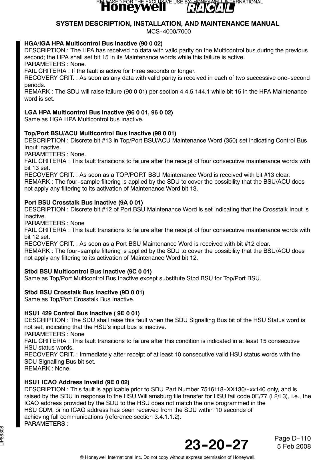
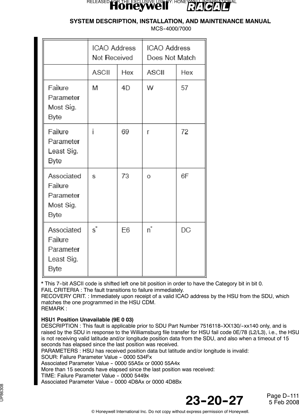
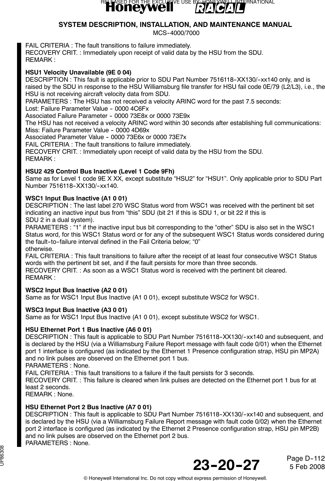
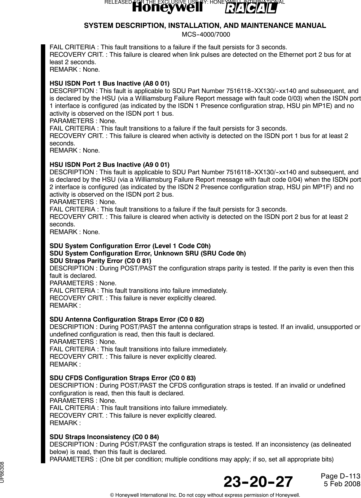
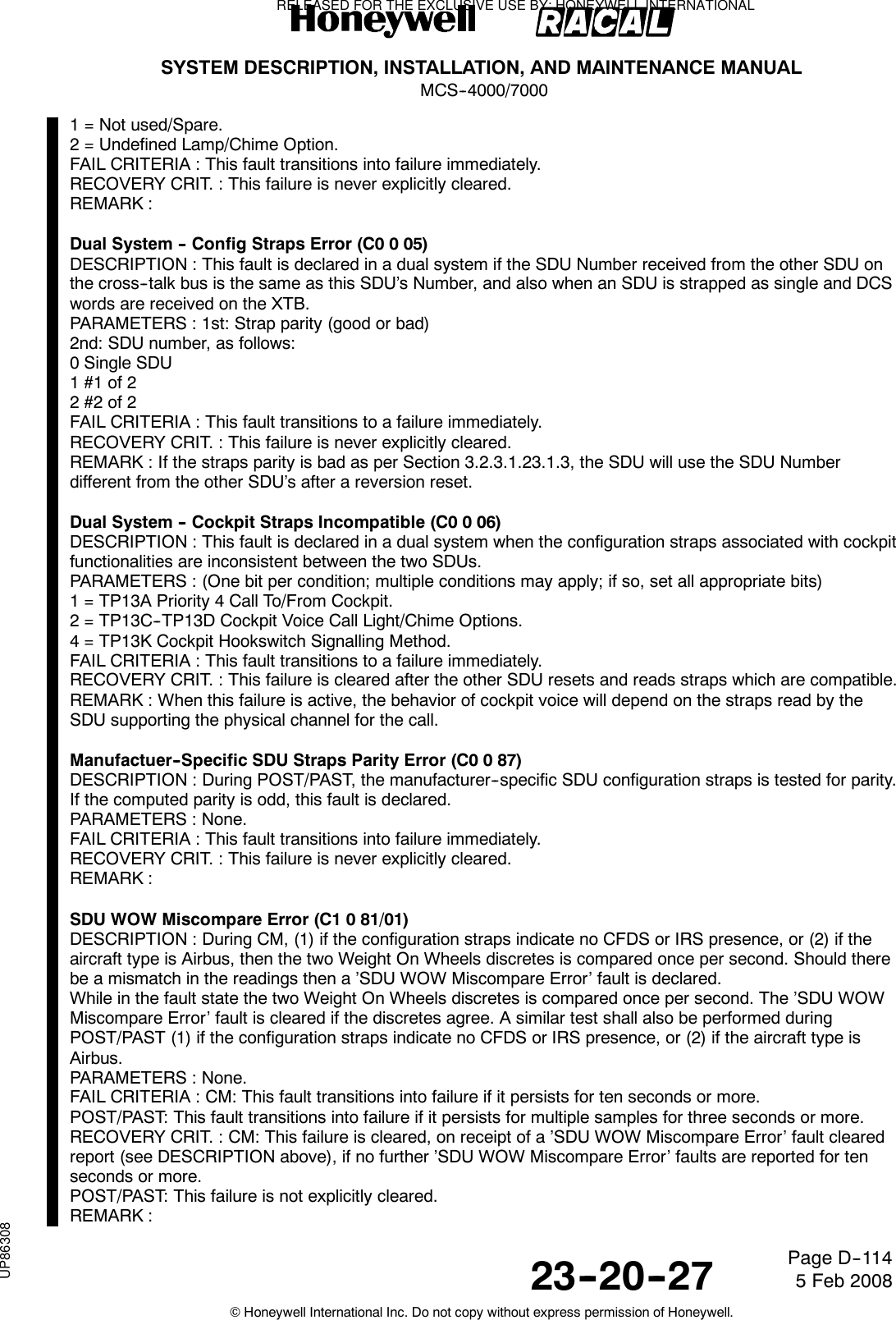
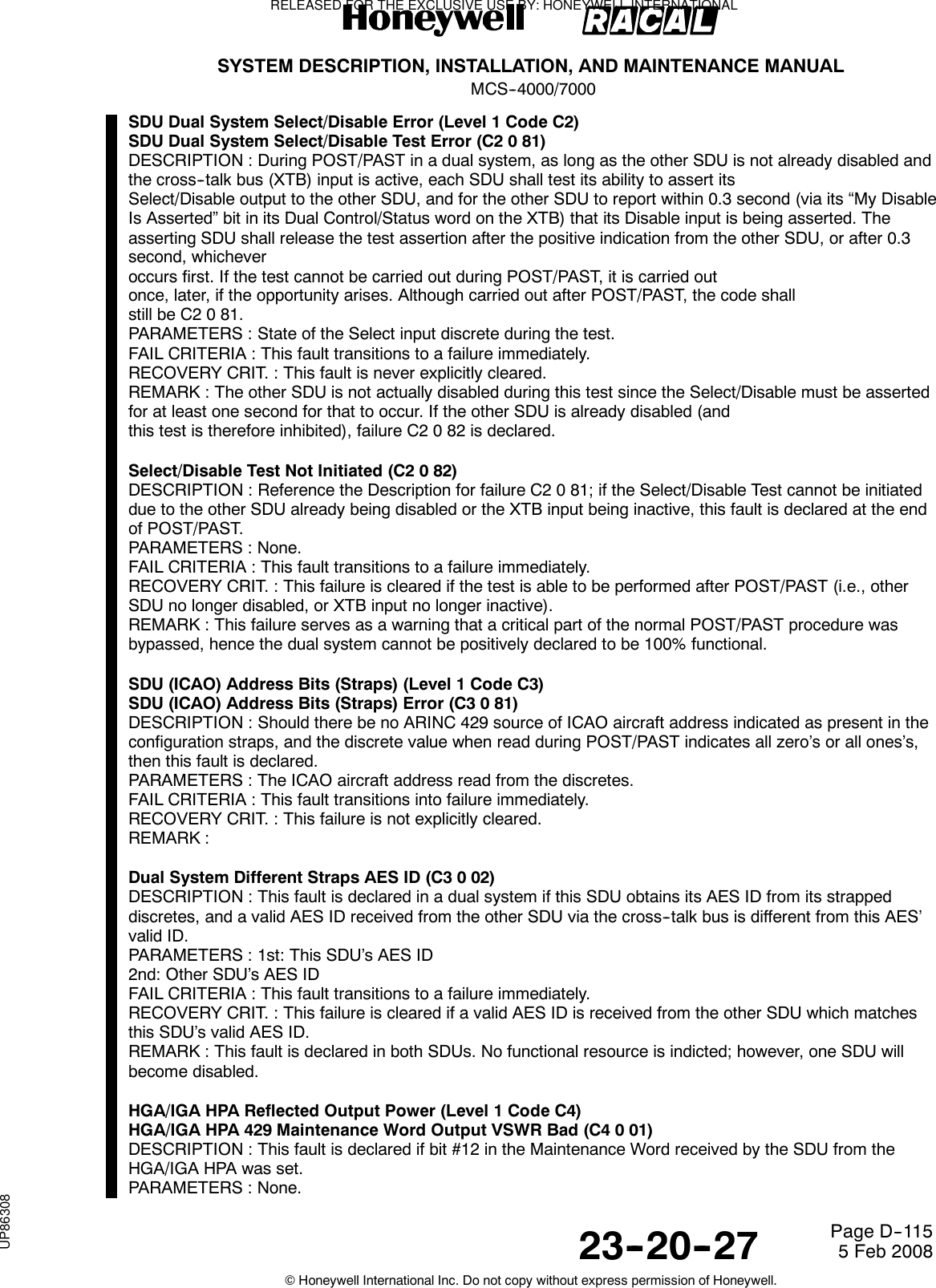
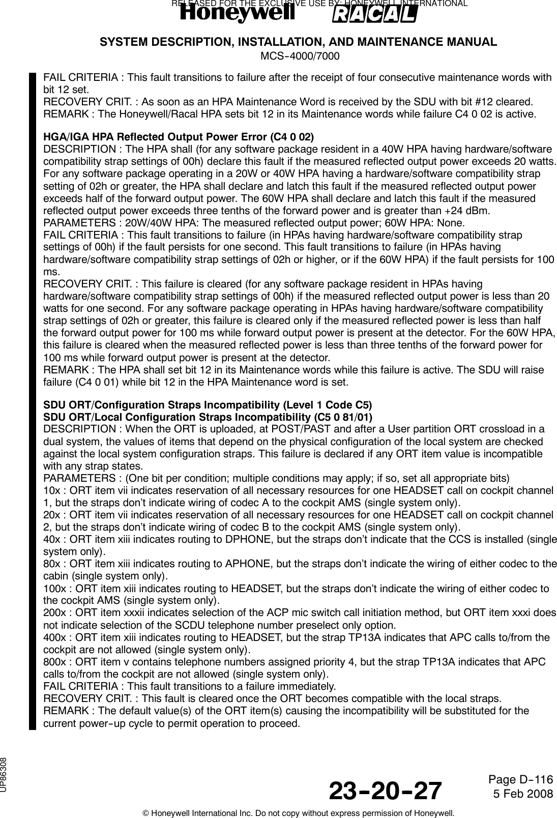
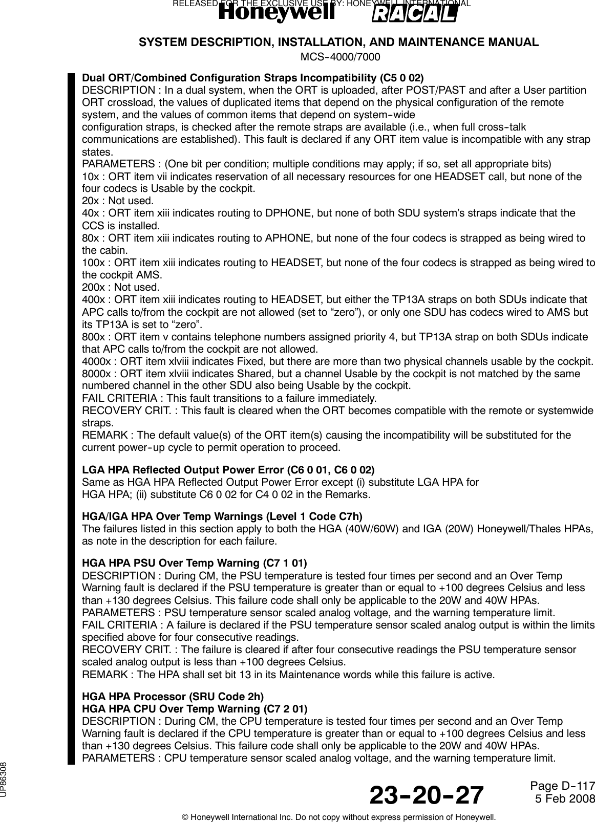
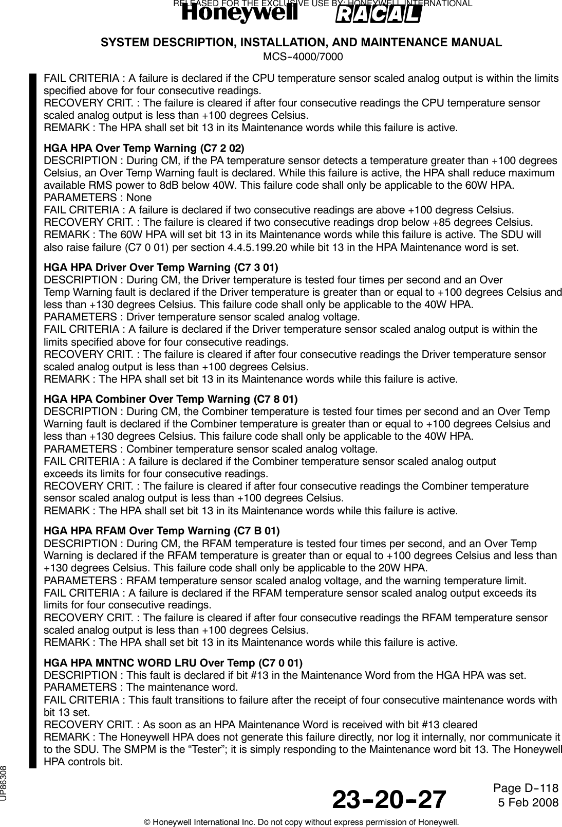
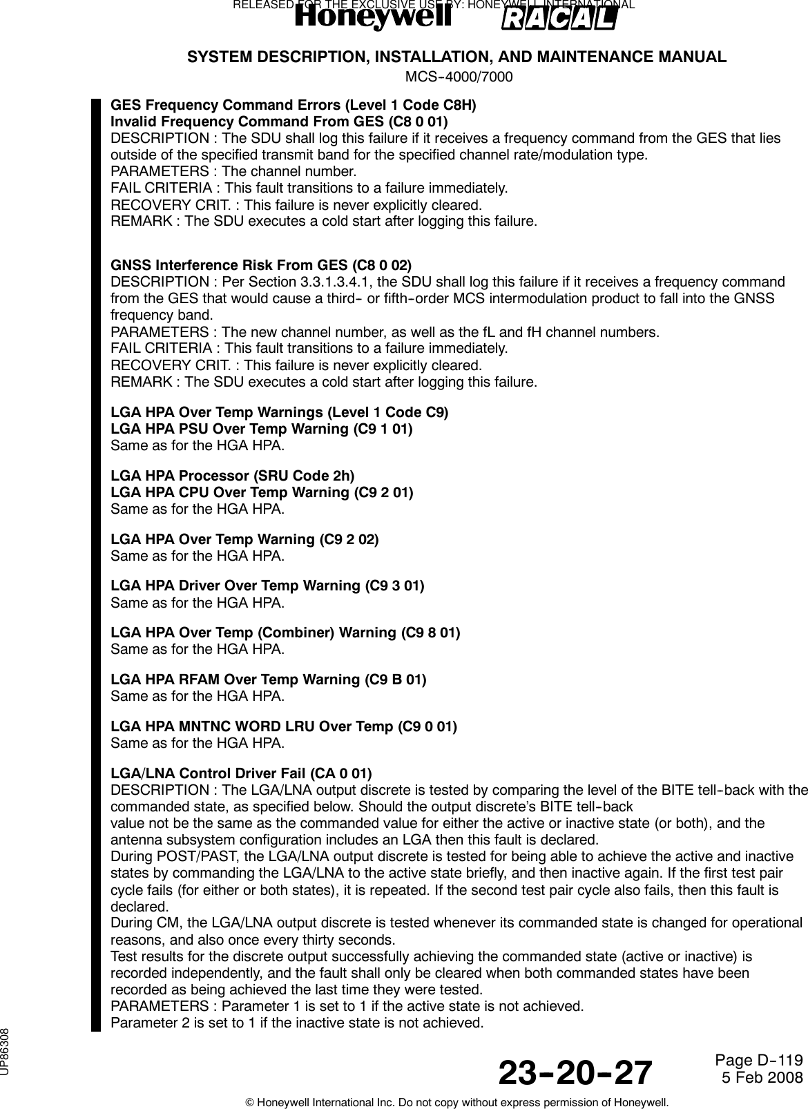
![SYSTEM DESCRIPTION, INSTALLATION, AND MAINTENANCE MANUALMCS--4000/700023--20--27 5 Feb 2008©Honeywell International Inc. Do not copy without express permission of Honeywell.Page D--120FAIL CRITERIA : This fault transitions to a failure if the fault persists continuously for one second.RECOVERY CRIT. : This failure is cleared as soon as the fault is cleared, i.e., as soon as both commandedstates have been recorded as being achieved the last time they were tested.REMARK : This failure is Class 2, and does not indict [lga_subsys] nor [hga_subsys], because the reasoncould as likely be failure in the SDU BITE circuitry, and because other, moredefinitive tests (LGA LNA diplexer and LGA LNA RF continuity) cover this functionality.Level 3 failure code 81 is not used for the POST/PAST case second commentary, fourth paragraph (i.e., thePOST/PAST and CM tests are identical).In the actual implementation, if an LGA is installed, this discrete is repetitively commanded to its currentlyrequired state (whether on or off) at a rate of ~ 15 Hz. The CM test is performed after each such command,hence continuously at ~ 15 Hz (which includes the case of whenever a state change is commanded) as wellas once every thirty seconds. Since there is no separate Level 3 failure code 81 for the POST/PAST case,even the POST/PAST case includes the one--second fail criteria. The POST/PAST case also requires theretest fail criteria in order to avoid nuisance failures because there is no guarantee that the CM testing (whichmight otherwise clear a POST/PAST--detected fault) will begin or resume within one second of POST/PAST.HGA/IGA HPA Invalid SDI Strapping (CB 0 01)DESCRIPTION : HPA perspective: The HPA shall read the programmed state of its SDI pins at each coldstartand each functional test (i.e., each POST/PAST). This fault is declared if theSDI pins are set to any invalid state (Reserved or Unused). When this occurs, the HPA shall, in softwarepackages D2.0 and subsequent, aside from logging the failure, behave in every way as though it wasstrapped to be the HGA/IGA HPA.SDU perspective: The HGA/IGA HPA has reported this failure using the manufacturer specificblock transfer protocol.PARAMETERS : The as--read invalid SDI code.FAIL CRITERIA : HPA perspective: This fault transitions to a failure immediately.SDU perspective: This fault transitions to a failure immediately.RECOVERY CRIT. : This failure is never explicitly cleared.REMARK : This failure results in the LGA HPA being unable to respond to all but all--call commands sent viathe ARINC 429 Multicontrol bus, which renders it virtually useless. Both HPAs shall use failure CB 0 01, sincethey cannot tell which HPA they are supposed to be.When the SDU receives a CB 0 01 block on the HGA/IGA HPA bus, it shall make the entry into the systemfailure log using code CB 0 01; conversely, it shall use code CC 0 01 if the CB 0 01 block is received on theLGA HPA bus (see below). Note that failure code 01 is used, even though the test is (only) performed duringPOST/PAST.Note: In HPA software packages prior to D2.0, upon detecting this failure, the HPA would use the “unused”SDI code (11b) in its transmitted ARINC 429 words, and would only respond to Command Words with SDIfields set to the “All Call” code.LGA HPA Invalid SDI Strapping (CC 0 01)DESCRIPTION : HPA perspective: Not used.SDU perspective: The LGA HPA has reported failure CB 0 01 using the manufacturer specificblock transfer protocol.PARAMETERS : The as--read invalid SDI code.FAIL CRITERIA : SDU perspective: This fault transitions to a failure immediately.RECOVERY CRIT. : This failure is never explicitly cleared.REMARK : The HPAs themselves do not use this failure ---- they use CB 0 01. When the SDU receives a CB0 01 block on the LGA HPA bus, it shall make the entry into the system failure logusing code CC 0 01. Note that failure code 01 is used, even though the test is (only) performed duringPOST/PAST.SDU POC/TOTC Reset (Level 1 Code CDh)SDU TOTC Auto/Manual Reset (CD 0 81/01)DESCRIPTION : The SDU has performed either an automatic (Level 3 code 81) or manual (code 01) TOTCreset.PARAMETERS : The value of the TOTC (in 10--minute increments) just prior to it being reset. This may bevalid, or it may be corrupted.RELEASED FOR THE EXCLUSIVE USE BY: HONEYWELL INTERNATIONALUP86308](https://usermanual.wiki/Honeywell/SD-700A/User-Guide-3476924-Page-495.png)
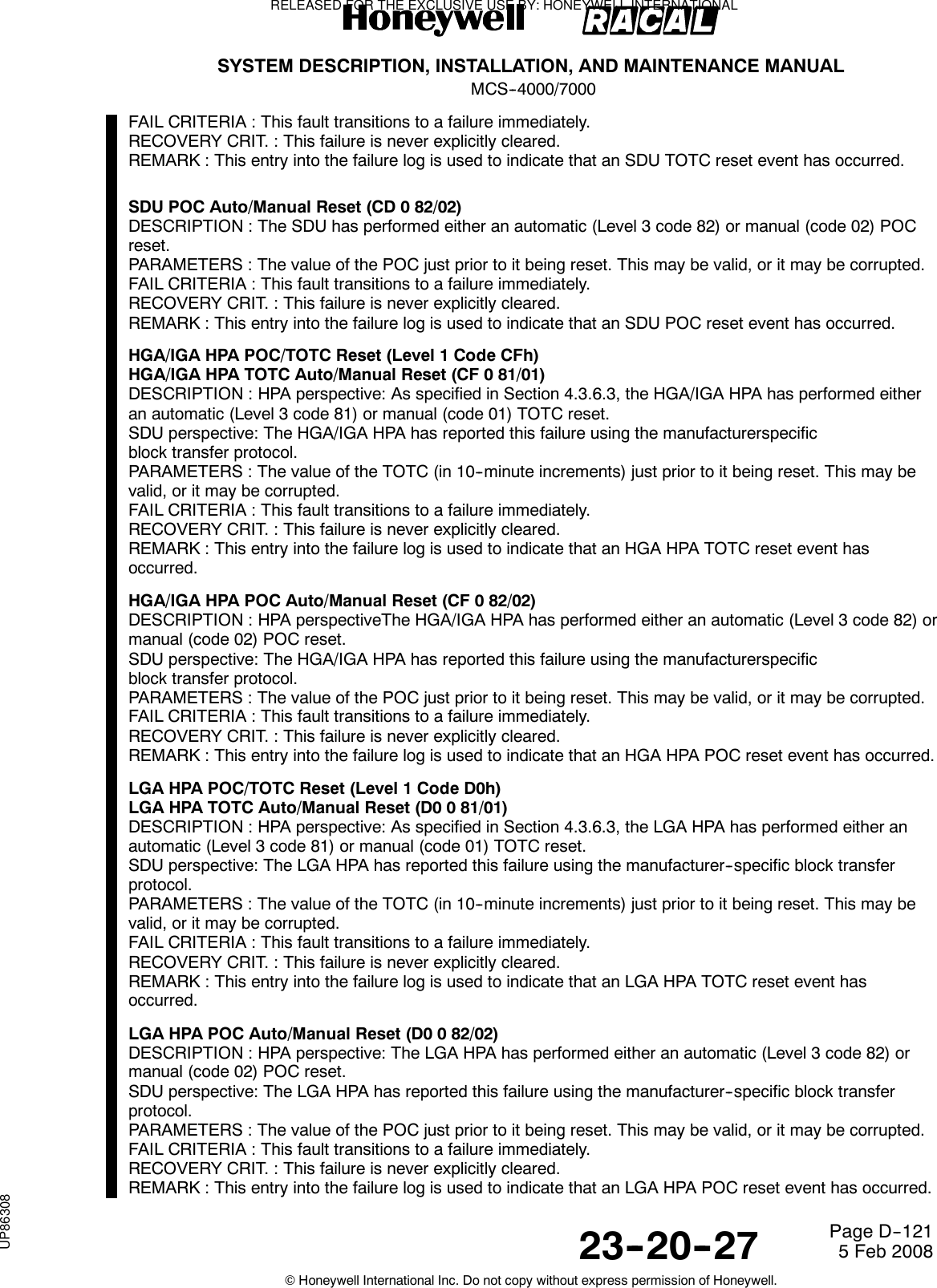
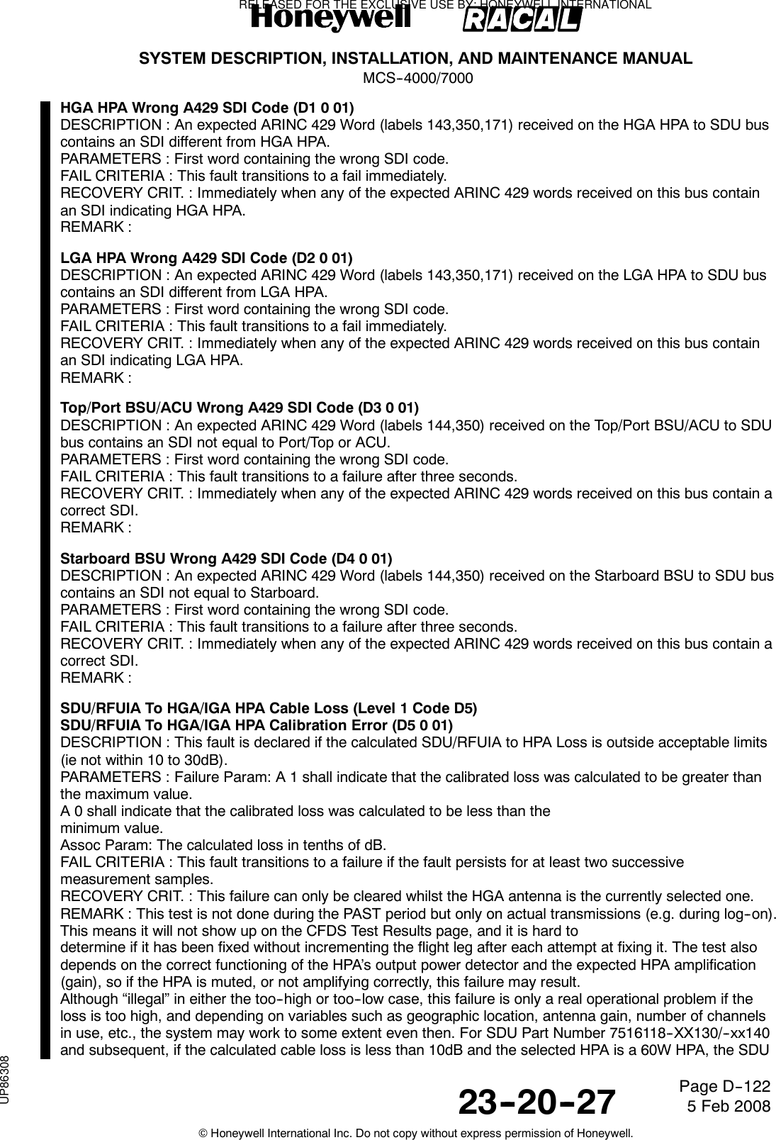
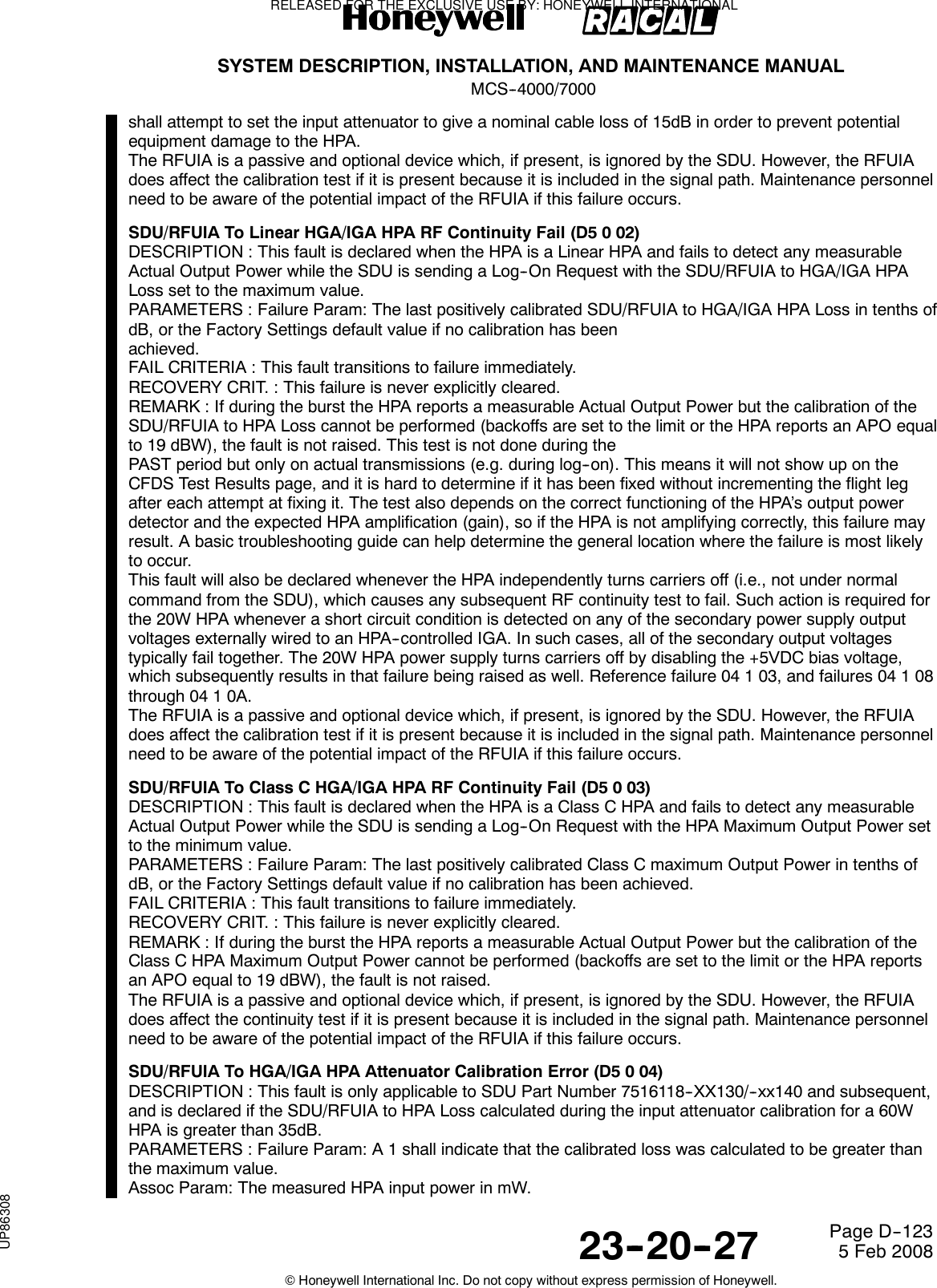
![SYSTEM DESCRIPTION, INSTALLATION, AND MAINTENANCE MANUALMCS--4000/700023--20--27 5 Feb 2008©Honeywell International Inc. Do not copy without express permission of Honeywell.Page D--124FAIL CRITERIA : This fault transitions to a failure immediately.RECOVERY CRIT. : This failure is never explicitly cleared.REMARK : This test is not done during the PAST period (refer to Section 3.3.1.3.2.8.6). This means it will notshow up on the CFDS Test Results page, and it is hard to determine if it has been fixed without incrementingthe flight leg after each attempt at fixing it. The RFUIA is a passive and optional device which, if present, isignored by the SDU. However, the RFUIA does affect the calibration test if it is present because it is includedin the signal path. Maintenance personnel need to be aware of the potential impact of the RFUIA if this failureoccurs.SDU/RFUIA To Linear HGA/IGA HPA Attenuator RF Continuity Fail (D5 0 05)DESCRIPTION : This fault is only applicable to SDU Part Number 7516118--XX130/--xx140 and subsequent,and is declared when the HPA is a Linear 60W HPA and fails to detect any measurable input power while theSDU is performing the HPA input attenuator calibration.PARAMETERS : NoneFAIL CRITERIA : This fault transitions to failure immediately.RECOVERY CRIT. : This failure is never explicitly cleared.REMARK : This test is not done during the PAST period. This means it will not show up on the CFDS TestResults page, and it is hard to determine if it has been fixed without incrementing the flight leg after eachattempt at fixing it. The test also depends on the correct functioning of the HPA’s input power detector andinput attenuator, so if these devices are not operating correctly, this failure may result. A basictroubleshooting guide (reference Section 4.4.5.233 Commentary) can help determine the general locationwhere the failure is most likely to occur.The RFUIA is a passive and optional device which, if present, is ignored by the SDU. However, the RFUIAdoes affect the calibration test if it is present because it is included in the signal path. Maintenance personnelneed to be aware of the potential impact of the RFUIA if this failure occurs.The HS--720 HSU may be installed in place of the RFUIA. It contains a passive combiner that does affect thecalibration test because it is included in the signal path. Maintenance personnel need to be aware of thepotential impact of the HSU if this failure occurs.SDU/RFUIA To LGA HPA Cable Loss (Level 1 Code D6)SDU/RFUIA To LGA HPA Calibration Error (D6 0 01)Same as SDU/RFUIA to HGA HPA Calibration Error except this fault shall only be declared if the LGA HPA isa linear HPA.SDU/RFUIA To Linear LGA HPA RF Continuity Fail (D6 0 02)Same as SDU/RFUIA to Linear HGA HPA RF Continuity Fail.SDU/RFUIA To Class C LGA HPA RF Continuity Fail (D6 0 03)Same as SDU/RFUIA to Class C HGA HPA RF Continuity Fail.SDU/RFUIA To LGA HPA Attenuator Calibration Error (D6 0 04)Same as SDU/RFUIA to HGA HPA Attenuator Calibration Error except this fault shall only be declared if theLGA HPA is a linear HPA.SDU/RFUIA To Linear LGA HPA Attenuator RF Continuity Fail (D6 0 05)Same as SDU/RFUIA to Linear HGA HPA Attenuator RF Continuity Fail.Top/Port HGA LNA To SDU/RFUIA RF Continuity Fail (D8 0 81)DESCRIPTION : This fault is declared if the SDU does not indicate (via RFM narrowband AGCmeasurement) a rising noise floor level from an active Top/Port HGA LNA on any one of its three receivechannels within five seconds of the Top/Port HGA LNA having been turned on. This test shall only beperformed if the Top/Port BSU to SDU input bus is active, the Top/Port LNA BITE is Ok, and the Top/PortBSU is declaring the SDU Control Bus input as active and the three AGCs are at their respective LNA Offstates. This test is not performed if any BSU self--test misoperation failures [13/0/8A, 13/0/0A, 15/0/8A,15/0/0A] are declared.PARAMETERS : None.FAIL CRITERIA : This fault transitions to a failure immediately.RECOVERY CRIT. : This failure is not explicitly cleared.RELEASED FOR THE EXCLUSIVE USE BY: HONEYWELL INTERNATIONALUP86308](https://usermanual.wiki/Honeywell/SD-700A/User-Guide-3476924-Page-499.png)
![SYSTEM DESCRIPTION, INSTALLATION, AND MAINTENANCE MANUALMCS--4000/700023--20--27 5 Feb 2008©Honeywell International Inc. Do not copy without express permission of Honeywell.Page D--125REMARK : A basic troubleshooting guide can help determine the general location where the failure is mostlikely to occur. The RFUIA is a passive and optional device which, if present, is ignored by the SDU.However, the RFUIA does affect the continuity test if it is present because it is included in the signal path.Maintenance personnel need to be aware of the potential impact of the RFUIA if this failure occurs.Starboard HGA LNA To SDU/RFUIA RF Continuity Fail (D9 0 81)DESCRIPTION : This fault is declared if the SDU does not indicate (via RFM narrowband AGCmeasurement) a rising noise floor level from an active Starboard HGA LNA on any one of its three receivechannels within five seconds of the Starboard HGA LNA having been turned on. This test shall only beperformed if the Starboard BSU to SDU input bus is active, the Starboard LNA BITE is Ok, the StarboardBSU is declaring the SDU Control Bus input as active, and the three AGCs are at their respective LNA Offstates. This test is not performed if any BSU self--test misoperation failures [13/0/8A, 13/0/0A, 15/0/8A,15/0/0A] are declared.PARAMETERS : None.FAIL CRITERIA : This fault transitions to a failure immediately.RECOVERY CRIT. : This failure is not explicitly cleared.REMARK : A basic troubleshooting guide can help determine the general location where the failure is mostlikely to occur. The RFUIA is a passive and optional device which, if present, is ignored by the SDU.However, the RFUIA does affect the continuity test if it is present because it is included in the signal path.Maintenance personnel need to be aware of the potential impact of the RFUIA if this failure occurs.LGA LNA To SDU/RFUIA RF Continuity Fail (DA 0 81)DESCRIPTION : This fault is declared if the SDU does not indicate (via RFM narrowband AGCmeasurement) a rising noise floor level from an active LGA LNA on any one of its three receive channelswithin five seconds of the LGA LNA having been turned on. This test shall only be performed if the LGA LNABITE is Ok and the three AGCs are at their respective LNA Off states. This test is not performed if any BSUself--test misoperation failures [13/0/8A, 13/0/0A, 15/0/8A, 15/0/0A] are declared.PARAMETERS : None.FAIL CRITERIA : This fault transitions to a failure immediately.RECOVERY CRIT. : This failure is not explicitly cleared.REMARK : The RFUIA is a passive and optional device which, if present, is ignored by the SDU. However,the RFUIA does affect the continuity test if it is present because it is included in the signal path. Maintenancepersonnel need to be aware of the potential impact of the RFUIA if this failure occurs.LGA Log--on Test (Level 1 Code DBh)LGA Log--on Test Failure (DB 0 01)COMMENTARYIn a single or dual system containing more than one antenna and at least one LGA, it is likely that longperiods may elapse without using that LGA for normal communication. In order to detect latent faults, it isnecessary for the SDU with that LGA to perform a test logon regularly, and for a fault to be declared if the testlog--on fails, with suitable checks to minimise the occurrence of misleading failure reports due to signalblockage, etc. In a single pseudo--dual system (HGA+LGA), no equivalent test is required for the HGA, sincean unreported failure in the HGA subsystem which results in the HGA being unusable would be self--evident.DESCRIPTION : If more than one antenna is installed and at least one is an LGA, and both the LGA and atleast one other antenna are not failed, and the system is in automatic antenna selection mode then the SDUshall perform an LGA log--on test.If the LGA to be tested is on the current master SDU in a dual system, or on a single SDU, and in either casethe antenna configuration is HGA+LGA, the SDU shall test by selecting its LGA, renewing the log--on, thenswitching back to its HGA and again renewing the logon. A fault is declared if the SDU does not achievelog--on via the LGA, but subsequently does achieve log--on via the HGA.If the LGA is on the current slave system in a dual system, the master SDU shall test by requesting the slaveSDU to perform a log--on test (via its LGA), and then switching back to the master and its antenna (HGA orLGA) and renewing the log--on. A fault is declared by the slave SDU if the system does not achieve log--onvia the slave’s LGA, but does subsequently achieve log--on via the master’s antenna.COMMENTARYThis requires that SATCOM transmissions not be restricted while the aircraft is on ground.RELEASED FOR THE EXCLUSIVE USE BY: HONEYWELL INTERNATIONALUP86308](https://usermanual.wiki/Honeywell/SD-700A/User-Guide-3476924-Page-500.png)
![SYSTEM DESCRIPTION, INSTALLATION, AND MAINTENANCE MANUALMCS--4000/700023--20--27 5 Feb 2008©Honeywell International Inc. Do not copy without express permission of Honeywell.Page D--126PARAMETERS : Cumulative count of sequential test failures since the last factory settings restart or testpassing.FAIL CRITERIA : This fault transitions to a failure immediately.RECOVERY CRIT. : Successful log--on via the LGA.REMARK : LGA log--on test failure is also reported in 270--28 and/or 276--11. If raised, this failure needs to beconsidered in conjunction with other failures, such as Rx continuity, Tx cable loss, etc. If no other failuresexist, the root cause must be cabling from HPA to DLNA, or the LGA itself, or the cable between LGA andDLNA.Note that it is not raised if the HGA system cannot log--on, so building blockage is not a likely cause.Slave LGA Log--on Test Not Initiated (DB 0 02)DESCRIPTION : This fault is declared if a slave LGA log--on test is not initiated because of equipment failure([r_sdu_min_op.X] OR [r_lga_subsys.X]), cross--talk bus (XTB) full communications not being established, orthe slave being disabled ([r_common.C]); or the master SDU attempts a test log--on via the slave, but noresponse is received from the slave via the XTBwithin five minutes; or if the test is aborted due to any of the reasons previously stated.PARAMETERS : 1 = slave LGA equipment not OK2 = XTB full communications not achieved3 = slave SDU is disabled4 = response timeoutFAIL CRITERIA : This fault transitions to a failure immediately.RECOVERY CRIT. : Performing a successful test log--on via the LGA, or upon a handover of mastery, orupon failure DB 0 01 (preceeding section) becoming active.REMARK : LGA slave log--on test not initiated is also reported in 276--11.No Declared Active (C)MU (DC 0 01)DESCRIPTION : This fault is declared when at least one (C)MU input bus is active, but no installed (C)MUindicates “Active” in its label 270 status words (bit 20).PARAMETERS : None.FAIL CRITERIA : This fault transitions to failure if the fault persists for 10 seconds.RECOVERY CRIT. : As soon as a label 270 status word is received from a (C)MU with an “Active” indicationin bit 20 or the busses from all installed (C)MUs are declared inactive.REMARK : This failure condition is reflected in the SDU’s label 270 status word (in bit 29) to the(C)MU, which is also read by the EICAS/ECAM/EDU.Secured ORT Error (Level 1 Code DDh)Item (i) -- Startup Logon Policy (DD 0 01)DESCRIPTION : Upon ORT upload, the Startup Log--on Policy setting is NOT within the acceptable rangedefined in Section 3.3.3.1.4.1 (i).PARAMETERS : The uploaded ORT item (i) value that has failed the range test.FAIL CRITERIA : This fault transitions to failure immediately.RECOVERY CRIT. : This failure is never explicitly cleared.REMARK : The default setting is used in place of the failed ORT setting.Item (viii) -- Response Capability To Log--On Interrogation (DD 0 03)DESCRIPTION : Upon ORT upload, the Log--On Interrogation Response setting is NOT within the acceptablerange.PARAMETERS : The uploaded ORT item (viii) value that has failed the range test.FAIL CRITERIA : This fault transitions to failure immediately.RECOVERY CRIT. : This failure is never explicitly cleared.REMARK : The default setting is used in place of the failed ORT setting.Item (xviii) -- Noise Insertion Level (DD 0 04)DESCRIPTION : Upon ORT upload, the Noise Insertion Level setting is NOT within the acceptable range.PARAMETERS : The uploaded ORT item (xviii) value that has failed the range test.FAIL CRITERIA : This fault transitions to failure immediately.RECOVERY CRIT. : This failure is never explicitly cleared.REMARK : The default setting is used in place of the failed ORT setting.RELEASED FOR THE EXCLUSIVE USE BY: HONEYWELL INTERNATIONALUP86308](https://usermanual.wiki/Honeywell/SD-700A/User-Guide-3476924-Page-501.png)
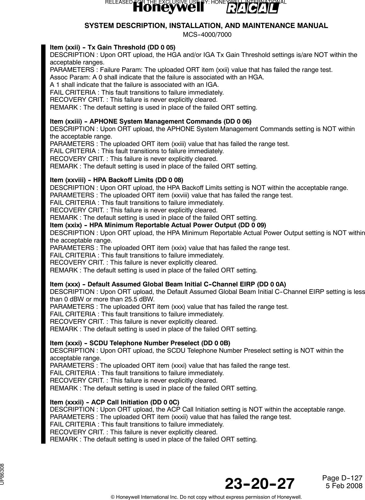
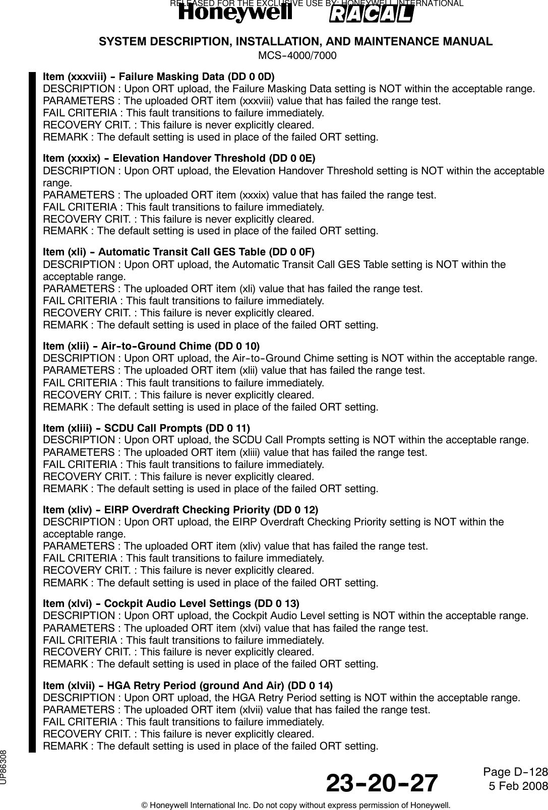
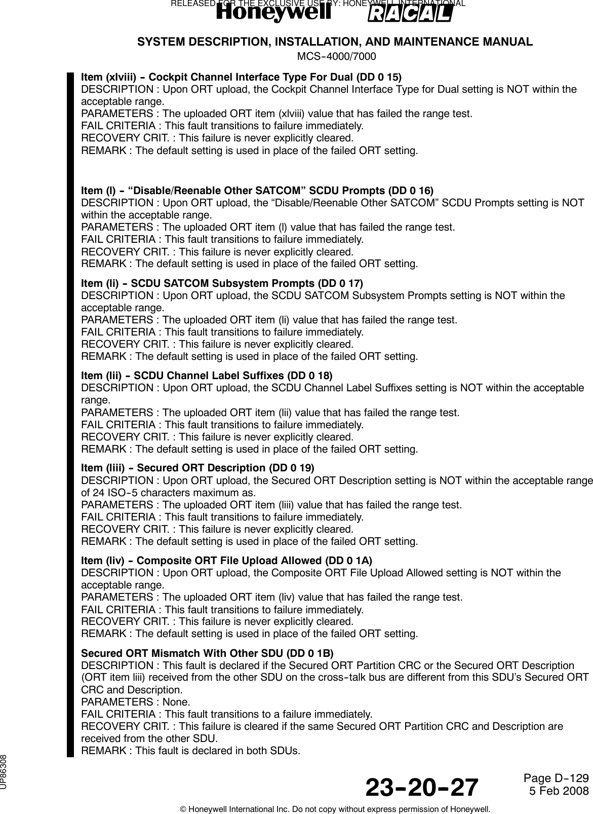
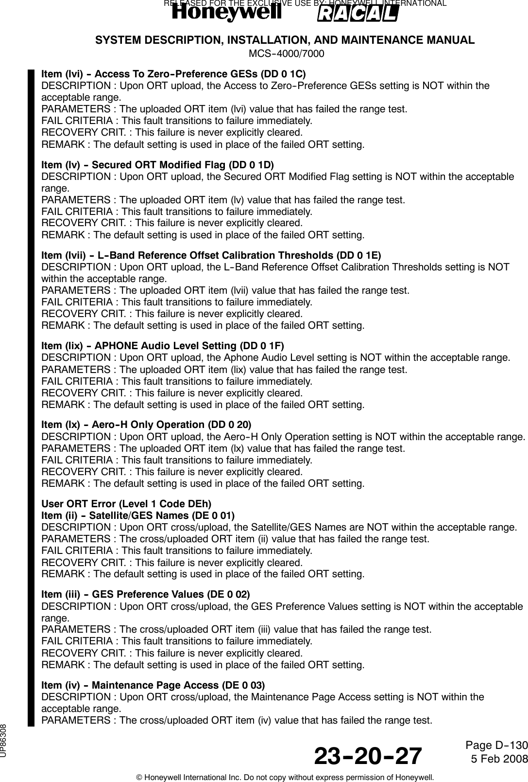
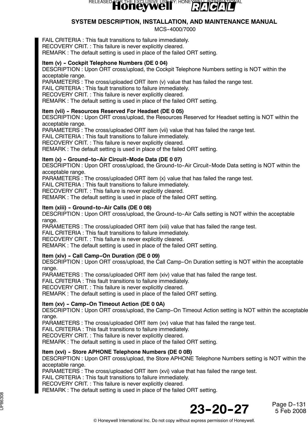
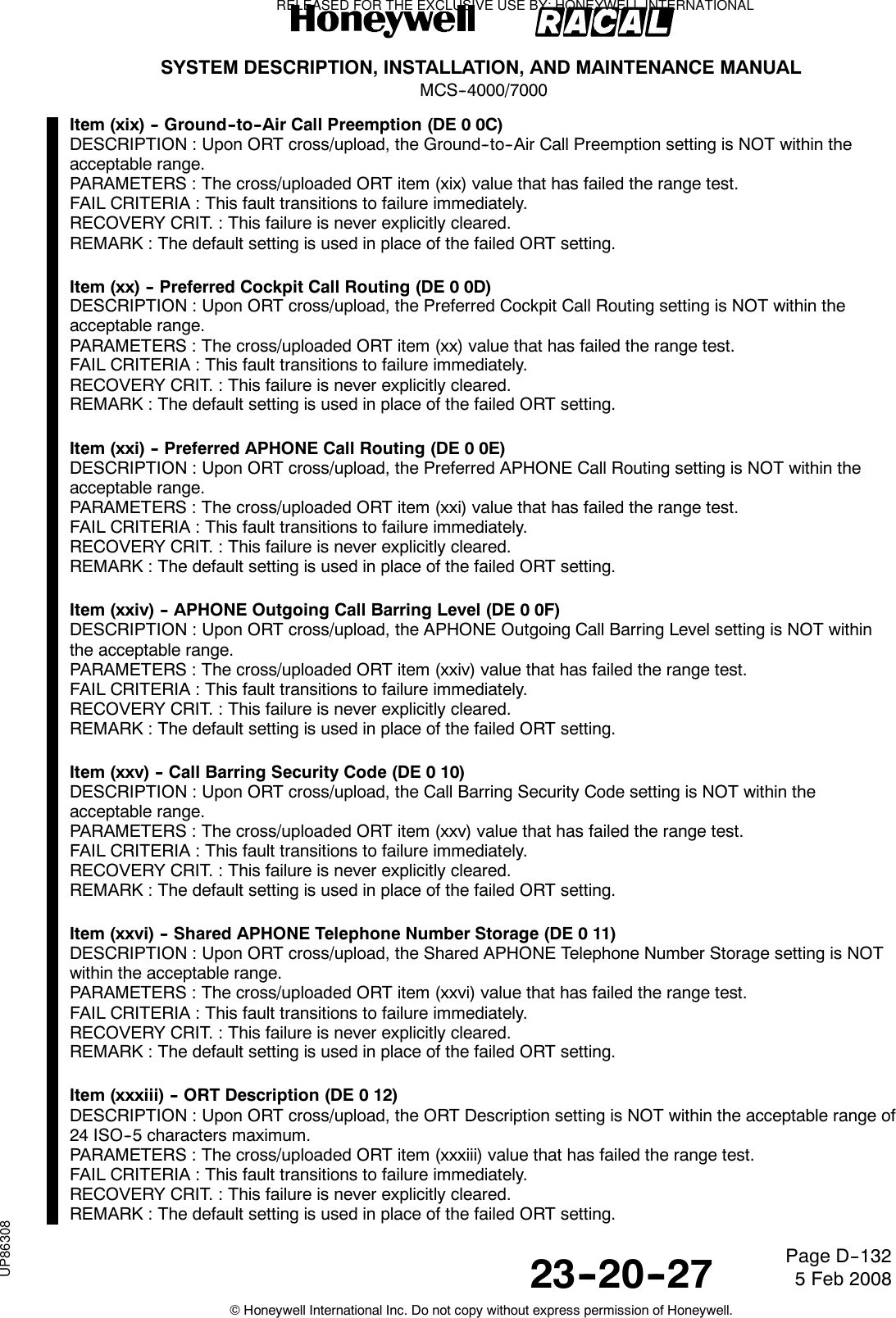
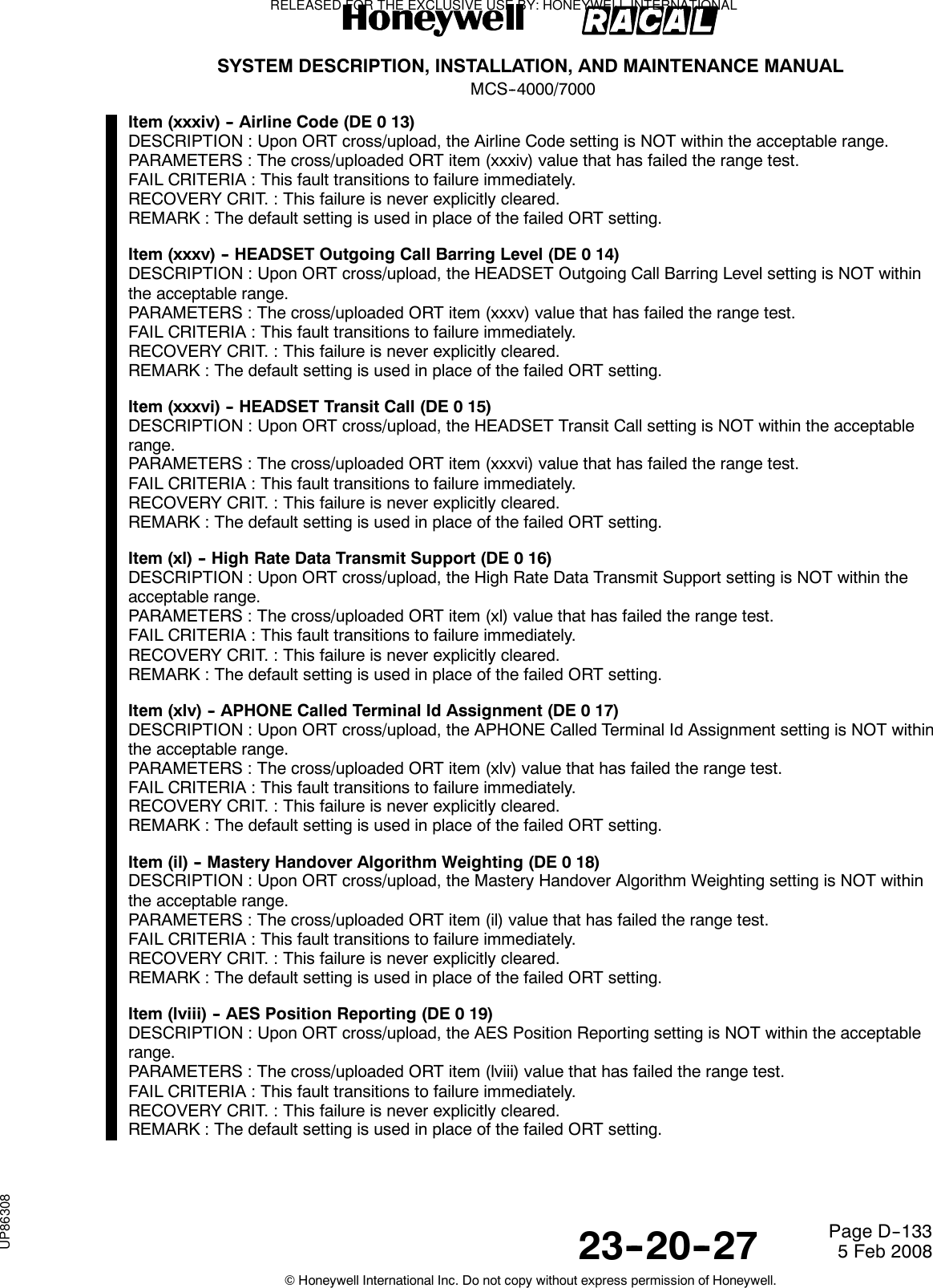
![SYSTEM DESCRIPTION, INSTALLATION, AND MAINTENANCE MANUALMCS--4000/700023--20--27 5 Feb 2008©Honeywell International Inc. Do not copy without express permission of Honeywell.Page D--137COMMENTARYThis assumes that an HGA/IGA slave is not tested if the master is logged--on via anLGA. The master SDU shall test by requesting the slave SDU to perform a log--on via itsHGA/IGA, then switching back to the original master’s HGA/IGA and renewing the log--on.A fault is declared by the slave SDU if it does not achieve log--on, but log--on is subsequently successful viathe original master’s HGA/IGA.PARAMETERS : Cumulative count of sequential test failures since the last factory settings restart or testpassing.FAIL CRITERIA : This fault transitions to a failure immediately.RECOVERY CRIT. : Successful log--on via this HGA/IGA, either due to a test log--on, or log--on beingachieved as master.REMARK : This failure condition is reported in 276--11.Slave HGA/IGA Log--on Test Not Initiated (DF 0 02)DESCRIPTION : This fault is declared if a slave HGA/IGA log--on test is not initiated because ofequipment failure ([r_sdu_min_op.X] OR [r_hga_subsys.X]) , cross--talk bus (XTB) full communications notbeing established, the slave being disabled ([r_common.C]), or the master only being logged--on via LGA; orif the master SDU attempts a test log--on via the slave, but no response is received from the slave via theXTB within five minutes; or if the test is aborted due to any of the reasons previously stated.PARAMETERS : 1 = slave HGA/IGA equipment not OK2 = XTB full communications not achieved3 = slave SDU is disabled4 = response timeout5=masterlog--onisLGAFAIL CRITERIA : This fault transitions to a failure immediately.RECOVERY CRIT. : Performing a successful test log--on, or handover of mastery, or upon failure DF 0becoming active.REMARK : This failure condition is reported in 276--11.HSU1 System Disable Discrete Failure (E1 0 01)DESCRIPTION : The SDU’s HSU disable discrete is tested by comparing the level of the BITE tellback withthe commanded state, as specified below. Should the output discrete’s BITE tellbackvalue not be the same as the commanded value for either the active or inactive state (or both) after twosuccessive checks, then this fault is declared.During POST/PAST, the HSU disable discrete output is tested for being able to achieve the active andinactive states by commanding the HSU to the active state briefly (i.e., 10 ms), and then inactive again.During CM, the HSU disable discrete is tested whenever its commanded state is changed for operationalreasons, and also monitored for its currently commanded state once every 30 seconds.Test results for the discrete output successfully achieving the commanded state (active or inactive) isrecorded independently, and the fault shall only be cleared when both commanded states have beenrecorded as being achieved the last time they were tested.PARAMETERS : Parameter 1 is set to 1 if the active state is not achieved.Parameter 2 is set to 1 if the inactive state is not achieved.FAIL CRITERIA : This fault transitions immediately to a failure.RECOVERY CRIT. : This failure is cleared as soon as the fault is cleared, i.e., as soon as both commandedstates have been recorded as being achieved the last time they were tested.REMARK : This failure is Class 2 (Class 3 for Airbus), and does not indict [HSU1]/[HSU], because the reasoncould as likely be failure in the SDU BITE circuitry.Level 3 failure code 81 is not used for the POST/PAST case (i.e., the POST/PAST and CM tests areidentical).In the actual implementation, if an HSU is installed, this discrete is repetitively commanded to its currentlyrequired state (whether on or off) at a rate of ~ 15 Hz. The CM test is performed after each such command,hence continuously at ~ 15 Hz (which includes the case of whenever a state change is commanded) as wellas once every thirty seconds.RELEASED FOR THE EXCLUSIVE USE BY: HONEYWELL INTERNATIONALUP86308](https://usermanual.wiki/Honeywell/SD-700A/User-Guide-3476924-Page-512.png)
![SYSTEM DESCRIPTION, INSTALLATION, AND MAINTENANCE MANUALMCS--4000/700023--20--27 5 Feb 2008©Honeywell International Inc. Do not copy without express permission of Honeywell.Page D--138Since there is no separate Level 3 failure code 81 for the POST/PAST case, even the POST/PAST caseincludes the one--second fail criteria. The POST/PAST case also requires the retest fail criteria in order toavoid nuisance failures because there is no guarantee that the CM testing (which might otherwise clear aPOST/PAST--detected fault) will begin or resume within one second of POST/PAST.HSU2 System Disable Discrete Failure (E2 0 01)Same as E1 0 01 except substitute “HSU2” for “HSU1”. Only applicable prior to SDU Part Number7516118--XX130/--xx140.Unsupported Configuration (Level 1 Code E3h)These failures are only applicable prior to SDU Part Number 7516118--XX130/--xx140.Unsupported HSU1 Configuration (E3 0 01)DESCRIPTION : The SDU shall raise this fault when it detects an HSU configuration that is not allowed, asspecified below. The HSU “number” is determined per the part number informationtransferred by the HSU in its Build Identity message.PARAMETERS : 01: A lone HS--702 is installed on either HSU port (i.e., SDU is strapped for only oneHSU, and it is HS--702).02: Two HS--702 units are installed (i.e., SDU is strapped for two HSUs, and both areHS--702).03: HS--700 is installed on the HSU2 port, and HS--702 is installed on the HSU1 port(i.e., the units are not wired to the correct ports).04: A lone HS--700 is installed on the HSU2 port.FAIL CRITERIA : This fault transitions to failure immediately.RECOVERY CRIT. : This failure is never explicitly cleared.REMARK : The SDU needs to be restarted to allow this failure to recover after the HSU configuration hasbeen corrected to a valid one. This is done in order to avoid the complexities of having to deal withunsupported configurations that might nonetheless be allowed to operate by the SDU due to an inactiveHSU1 input bus (i.e., a simultaneous unsupported configuration anda failure).Unsupported HSU2 Configuration (E3 0 02)Same as E3 0 01.COMMENTARYThis failure is raised when E3 0 01 is raised so that both functional resources [hsu1] and [hsu2] can beindicted when any of the unsupported configurations occur.HSU1/SDU Interface Version Incompatibility ( E4 0 81)DESCRIPTION : This fault is raised during the Initial Communications phase when the SDU determines thatthe bus interface version numbers between the HSU and SDU are incompatible (i.e., not identical). Prior toSDU Part Number 7516118--XX130/--xx140. For SDU Part Number 7516118--XX130/--xx140 and subsequent.PARAMETERS : The interface version number of the SDU as the least significant nibble of the parametervalue long word; the interface version number of the HSU as the least significant nibble of the associatedparameter value long word.FAIL CRITERIA : This fault transitions into failure after the receipt of 5 or more consecutive HSU statuswords containing the same incompatible version number.RECOVERY CRIT. : This failure is cleared after the receipt of 5 or more consecutive HSU status wordscontaining the same compatible version number.REMARK : Version 1 is the only acceptable value prior to SDU Part Number 7516118--XX130/--xx140, whileversion 2 is the only acceptable value for SDU Part Number 7516118--XX130/--xx140 and subsequent.HSU2/SDU Interface Version Incompatibility (E5 0 81)Same as for E4 0 01 except substitute “HSU2” for “HSU1”. Only applicable prior to SDU Part Number7516118--XX130/--xx140.RELEASED FOR THE EXCLUSIVE USE BY: HONEYWELL INTERNATIONALUP86308](https://usermanual.wiki/Honeywell/SD-700A/User-Guide-3476924-Page-513.png)
![SYSTEM DESCRIPTION, INSTALLATION, AND MAINTENANCE MANUALMCS--4000/700023--20--27 5 Feb 2008©Honeywell International Inc. Do not copy without express permission of Honeywell.Page D--140HSU2 To HGA/IGA HPA Calibration Error (E6 0 03)Same as for E6 0 02 except substitute “channel 2” for “channel 1”.HSU3 To HGA/IGA HPA Calibration Error (E6 0 04)Same as for E6 0 02 except substitute “channel 3” for “channel 1”.HSU4 To HGA/IGA HPA Calibration Error (E6 0 05)Same as for E6 0 02 except substitute “channel 4” for “channel 1”.HSU2/HPA Tx RF Signal Path Failure (E7 0 01)Same as for E6 0 01 except substitute “HSU2” for “HSU1”. Only applicable prior to SDU Part Number7516118--XX130/--xx140.DLNA/HSU1 Rx RF Signal Path Failure (E8 0 81)DESCRIPTION : For Packages 3.0 and subsequent, this fault is declared during POST/PAST when the HSUdoes not report to the SDU a valid (i.e., normal operation data, not NCD) RF input power measurement, viaLabel 277 prior to SDU Part Number 7516118--XX130/--xx140, or Label 306 for SDU Part Number7516118--XX130/--xx140 and subsequent that indicates a rising noise floor level from an active HGA LNAwithin five seconds of the HGA LNA having been turned on. This test shall only be performed if the BSU inputbus is active, the HGA LNA BITE is Ok, and the BSU is declaring the multi--control bus input as active. Thistest is not performed if any BSU self--test misoperation failures [13/0/8A, 13/0/0A, 15/0/8A, 15/0/0A] aredeclared or label 277/306 does not declare normal operation data.PARAMETERS : 16--bit Rx Power Level measurement.FAIL CRITERIA : This fault transitions to a failure immediately.RECOVERY CRIT. : This failure is not explicitly cleared.REMARK : The HSU only outputs valid data for this test between the completion of its own POST and theSDU removing SSM = Functional Test from its HSU control word transmissions. Abasic troubleshooting guide (reference Section 4.4.5.233 Commentary) can help determine the generallocation where the failure is most likely to occur.HSU2/LNA RX RF Coax Continuity Failure (E9 0 81)Same as for E8 0 01 except substitute “HSU2” for “HSU1”. Only applicable prior to SDU Part Number7516118--XX130/--xx140.COMMENTARYAssuming a single failure in the Tx or Rx signal path, the block diagrams and tables that follow can be helpfulin determining which signal path segment is the single root cause from the available current failureinformation.RELEASED FOR THE EXCLUSIVE USE BY: HONEYWELL INTERNATIONALUP86308](https://usermanual.wiki/Honeywell/SD-700A/User-Guide-3476924-Page-515.png)
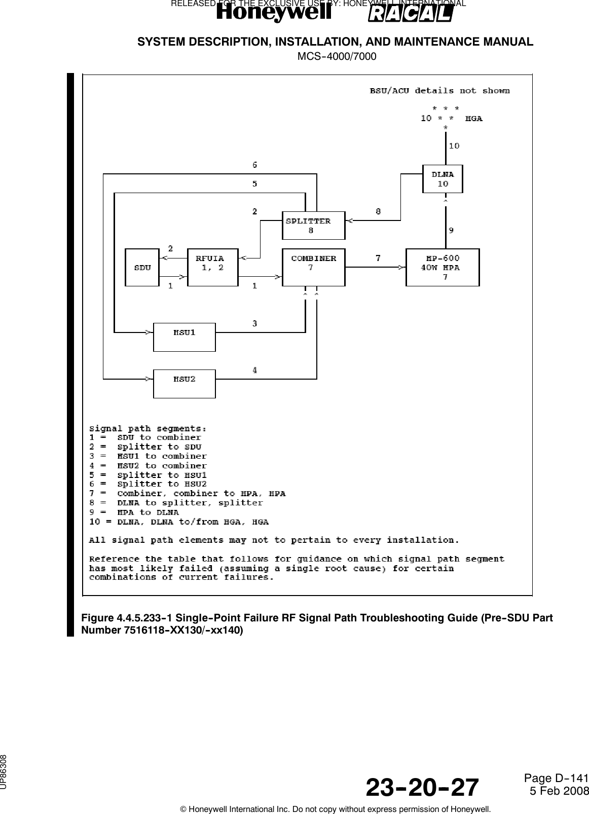
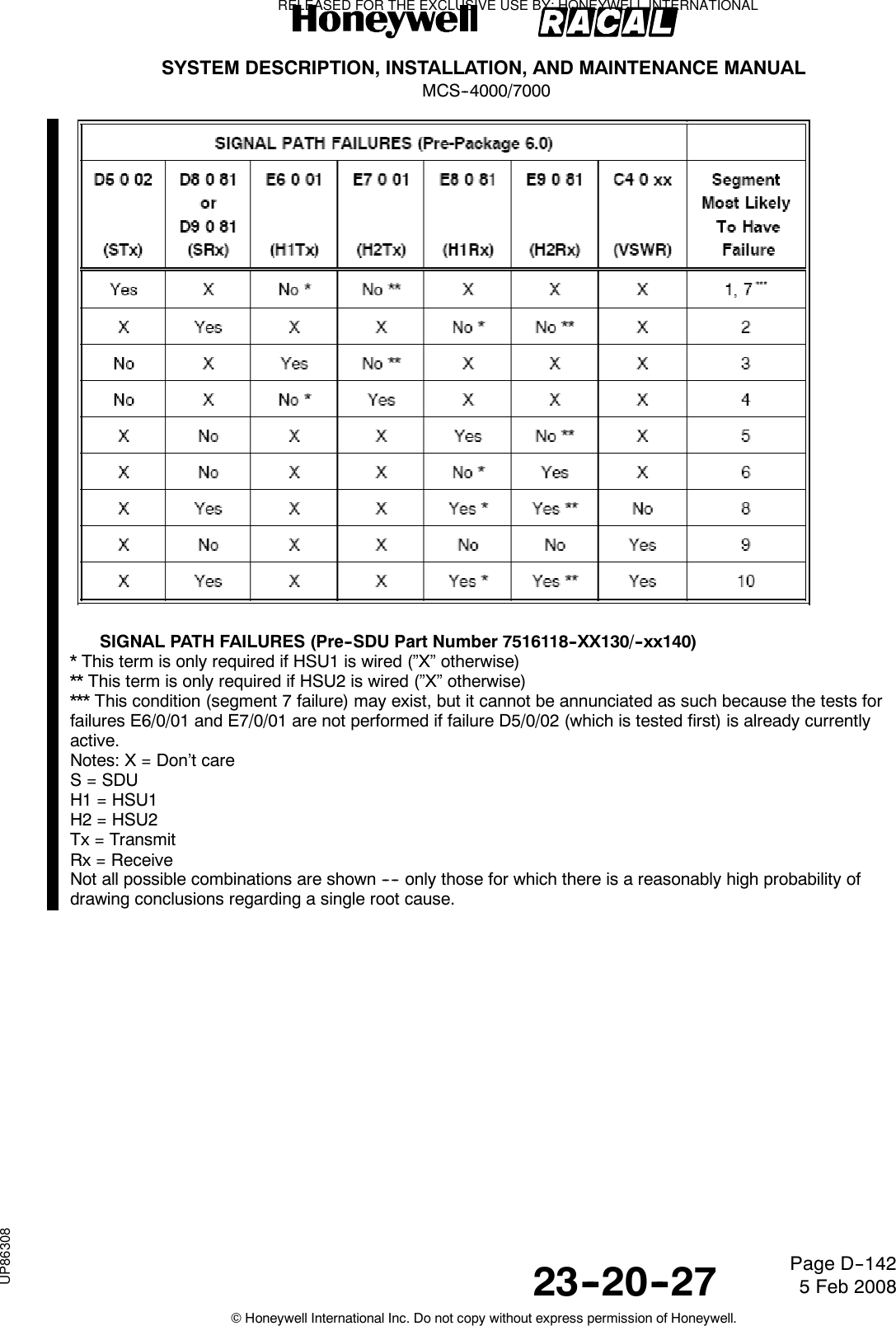
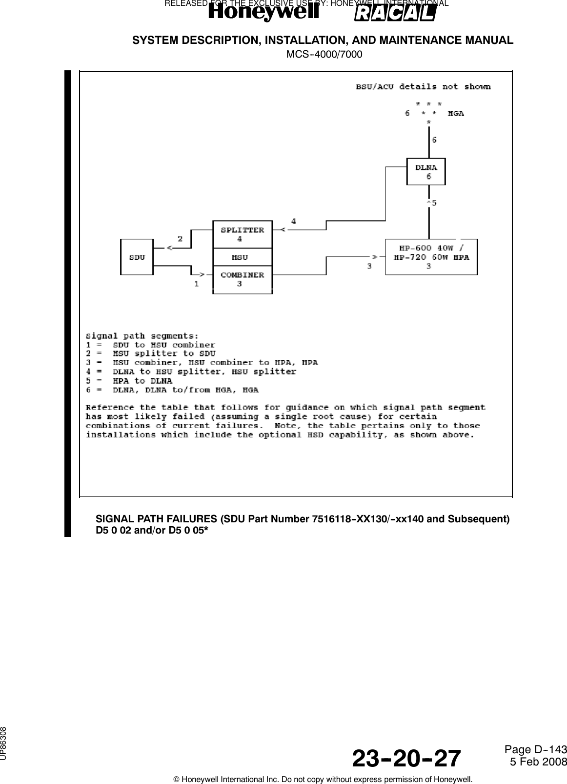
![SYSTEM DESCRIPTION, INSTALLATION, AND MAINTENANCE MANUALMCS--4000/700023--20--27 5 Feb 2008©Honeywell International Inc. Do not copy without express permission of Honeywell.Page D--144* This failure is only raised when the installed HPA is a linear 60W HPA (HP--720)** This condition (segment 3 failure) is annunciated by the tests associated with failures D5 0 05 and E6 081 when the installed HPA is a linear 60W HPA (HP--720). However, when the installed HPA is a linear 40WHPA (HP--600), this condition may exist, but it cannot be annunciated as such because the test for failureE6/0/01 is not performed if failure D5/0/02 (which is tested first) is already currently active.Notes: X = Don’t careS=SDUH=HSUTx = TransmitRx = ReceiveNot all possible combinations are shown ---- only those for which there is a reasonably highprobability of drawing conclusions regarding a single root cause.Dual HS--700 Config Warning (EA 0 01)DESCRIPTION : This warning is only applicable prior to SDU Part Number 7516118--XX130/--xx140, and israised when the SDU detects that two HS--700 units are installed when it is strapped for dual HSUconfiguration. The HSU “number” is determined per the part number information transferred by the HSU in itsBuild Identity message.PARAMETERS : NoneFAIL CRITERIA : ImmediatelyRECOVERY CRIT. : This warning is cleared when the HSU that is wired to the SDU’s HSU2 port reports thatit is an HS--702.REMARK : NoneNo Declared Active WSC (EB 0 01)DESCRIPTION : This fault is declared when at least one WSC input bus is active (which includesTP10H being strapped to the “WSC” state [reference Section 3.2.4.7], and at least one of TP12J, TP12K andTP13E being strapped for the respective WSC(s) “installed” as well as receipt of label 270 WSC statuswords), but no installed WSC indicates “Active” in its label 270 status words (bit 20).PARAMETERS : None.FAIL CRITERIA : This fault transitions to failure if the fault persists for 10 seconds.RECOVERY CRIT. : As soon as a label 270 status word is received from a WSC with an “Active” indication inbit 20, or the buses from all installed WSCs are declared inactive.RELEASED FOR THE EXCLUSIVE USE BY: HONEYWELL INTERNATIONALUP86308](https://usermanual.wiki/Honeywell/SD-700A/User-Guide-3476924-Page-519.png)
![SYSTEM DESCRIPTION, INSTALLATION, AND MAINTENANCE MANUALMCS--4000/700023--20--27 5 Feb 2008©Honeywell International Inc. Do not copy without express permission of Honeywell.Page D--145REMARK : [Related information] For the case of WSC Type = Honeywell MAU where only one MAU isexpected to be active at a time for the case of multiple MAUs, the SDU makes no attempt to deal with thepossible opposite condition of multiple MAUs declaring themselves to be active simultaneously [whereas itdoes maintain multiple Williamsburg sessions for WSC Type = Airbus RAIMP]. This includes no BIT for thatcondition.HSU Straps (Configuration Pins) Error (Level 1 Code ECh)HSU Configuration Straps Parity Error (EC 0 81)DESCRIPTION : This fault is applicable to SDU Part Number 7516118--XX130/--xx140 and subsequent.During POST/PAST, the HSU configuration straps (reference Section 3.4.2) is tested for parity. If thecomputed parity is even, this fault is declared by the HSU (via a Williamsburg Failure Report message withfault code 0/8C).PARAMETERS : The HSU configuration strap and parity settings.FAIL CRITERIA : This fault transitions to failure if the fault persists for two out of three consecutive tests.RECOVERY CRIT. : This failure is never explicitly cleared.REMARK : None.HSU Configuration Straps Error (EC 0 82)DESCRIPTION : This fault is applicable to SDU Part Number 7516118--XX130/--xx140 and subsequent, andis declared by the HSU during POST/PAST (via a Williamsburg Failure Report message with fault code 9/82)when there is no response from the hardware device used to access the HSU configuration straps.PARAMETERS : None.FAIL CRITERIA : This fault transitions to a failure if there is no response from the Configuration Strapshardware device on two out of three consecutive tests.RECOVERY CRIT. : This failure is never explicitly cleared.REMARK : HSU is declared unserviceable.SDU ORT / HSU Configuration Straps Incompatibility (Level 1 Code EDh)HSU BGAN Configuration Error (ED 0 01)DESCRIPTION : This fault is applicable to SDU Part Number 7516118--XX130/--xx140 and subsequent. It isdeclared by the HSU (via a Williamsburg Failure Report message with fault code 0/0F) when HSDRegistration Selection in the HSU configuration data passed to the HSU is set to “BGAN Always”, but theBGAN Enable HSU configuration strap (HSU pin MP 1B) is set to Disable”.PARAMETERS : None.FAIL CRITERIA : This fault transitions to a failure immediately.RECOVERY CRIT. : This failure is never explicitly cleared.REMARK : HSU is declared unserviceable.HSU Forward Id Address Bits (Straps) Error (Level 1 Code EEh)HSU Forward Id Address Bits (Straps) Error (EE 0 81)DESCRIPTION : This fault is applicable to SDU Part Number 7516118--XX130/--xx140 and subsequent, andis declared by the HSU during POST/PAST (via a Williamsburg Failure Report message with fault code 9/81)when there is no response from the hardware device used to access the strapped HSU Forward Id Address.PARAMETERS : The failure parameter indicates which hardware device failed and contains one of thefollowing values:1: PCA9554A I2C device2: PCA9555 I2C device3: Both I2C devices.FAIL CRITERIA : This fault transitions to a failure if there is no response from the hardware device used toaccess the HSU Forward Id Address Straps on two out of three consecutive tests.RECOVERY CRIT. : This failure is never explicitly cleared.REMARK : HSU is declared unserviceable.RELEASED FOR THE EXCLUSIVE USE BY: HONEYWELL INTERNATIONALUP86308](https://usermanual.wiki/Honeywell/SD-700A/User-Guide-3476924-Page-520.png)