Honeywell SD-700A Satcom Transceiver User Manual
Honeywell International Inc. Satcom Transceiver
User Manual

SYSTEM DESCRIPTION, INSTALLATION,
AND MAINTENANCE MANUAL
MCS-4000/7000
TEMPORARY REVISION NO. 23-2
23-20-27
Page 1 of 3
20 Jun 2017
© Honeywell International Inc. Do not copy without express permission of Honeywell.
TO HOLDERS OF MCS-4000/7000 MULTI-CHANNEL SATCOM SYSTEM SYSTEM DESCRIPTION,
INSTALLATION, AND MAINTENANCE MANUAL 23-20-27, REVISION 2, DATED 5 FEB 2008.
INSERT THIS PAGE AS THE FIRST PAGE OF THE MANUAL.
Temporary
Revision
Number
Applicable Page Number
23-2
1-13
4-5/(4-6 BLANK)
Honeywell – Confidential
THIS COPYRIGHTED WORK AND ALL INFORMATION ARE THE PROPERTY OF HONEYWELL
INTERNATIONAL INC., CONTAIN TRADE SECRETS AND MAY NOT, IN WHOLE OR IN PART, BE USED,
DUPLICATED, OR DISCLOSED FOR ANY PURPOSE WITHOUT PRIOR WRITTEN PERMISSION OF
HONEYWELL INTERNATIONAL INC. ALL RIGHTS RESERVED.
Copyright - Notice
Copyright 2017 Honeywell International Inc. All rights reserved.
Honeywell is a registered trademark of Honeywell International Inc.
All other marks are owned by their respective companies.
RELEASED FOR THE EXCLUSIVE USE BY: HONEYWELL INTERNATIONAL
UP86308

SYSTEM DESCRIPTION, INSTALLATION AND MAINTENANCE MANUAL
MCS-4000/7000
TEMPORARY REVISION NO. 23-1
23-20-27 Page 1 of 6
30 Oct 2009
Publication Number D200102000060
© Honeywell International Inc. Do not copy without express permission of Honeywell.
TO HOLDERS OF MCS-4000/7000 MULTI-CHANNEL SATCOM SYSTEM SYSTEM DESCRIPTION,
INSTALLATION, AND MAINTENANCE MANUAL 23-20-27, REVISION 2, DATED 5 FEB 2008.
INSERT THIS PAGE AS THE FIRST PAGE OF THE MANUAL.
Temporary
Revision
Number
Applicable Page Number
23-1 4-1
4-2
4-3
Copyright - Notice
Copyright 2009 Honeywell International Inc. All rights reserved.
Honeywell is a registered trademark of Honeywell International Inc.
All other marks are owned by their respective companies.
Honeywell – Confidential
THIS COPYRIGHTED WORK AND ALL INFORMATION ARE THE PROPERTY OF HONEYWELL
INTERNATIONAL INC., CONTAIN TRADE SECRETS AND MAY NOT, IN WHOLE OR IN PART, BE USED,
DUPLICATED, OR DISCLOSED FOR ANY PURPOSE WITHOUT PRIOR WRITTEN PERMISSION OF
HONEYWELL INTERNATIONAL INC. ALL RIGHTS RESERVED.
RELEASED FOR THE EXCLUSIVE USE BY: HONEYWELL INTERNATIONAL
UP86308

Honeywell International Inc.
21111 N. 19th Ave.
Phoenix, AZ 85027-2708
U.S.A.
CAGE: 58960
23--20--27
5 Feb 2008
©Honeywell International Inc. Do not copy without express permission of Honeywell.
Page HL--1
Telephone: (800) 601--3099 (U.S.A.)
Telephone: (602) 365--3099 (International)
TO HOLDERS OF SYSTEM DESCRIPTION, INSTALLATION, AND MAINTENANCE
MANUAL, PUB. NO. A15--5111--001, MCS 4000/7000 MULTI--CHANNEL
SATCOM SYSTEM
REVISION NO. 002 DATED 5FEB2008
This revision replaces some data in the manual. All changed pages have a new date, as identified
in the List of Effective Pages. Revision bars identify the changed data. An “R” adjacent to the
Fig./Item column identifies changes in the Detailed Parts List.
Put the changed pages in the manual and remove and discard all replaced pages. Write the
revision number, revision date, and replacement date on the Record of Revisions page.
Insert Page Description of Change
T--1 thru T--4 Changed to show the revision date. Expanded the proprietary notice. Changed the
publication number from A15--5111--001 to D200102000060. Added the export
control code.
LEP--1 thru LEP--8 Changed to show the changed pages in manual.
------ Removed the Business Reply Card (User Registration Card), Customer Response
form, and Report of Possible Data Error form because this data is available on the
Honeywell Online Technical Publications Web site. The location of the Web site is
included in the INTRODUCTION.
TC--1 thru TC--14 Changed to include Appendix D in the TESTING/FAULT ISOLATION section.
INTRO--1 thru
INTRO--10 Replaced all pages of the INTRODUCTION. Revision bars are not used in the
INTRODUCTION to show these changes. Removed the Proprietary Notice and
Export Notice data. Added a Customer Support paragraph. Changed the sequence
of the INTRODUCTION data. Changed References, Verification Data, and
Acronyms and Abbreviations data.
1--12, 1--14 Corrected references to Figure 1--6 and Figure 1--7.
6--1 Added statement in paragraph 1.A (1) to reference Appendix D system fault codes.
C--8 Corrected reference to Table C--1.
D--1 thru D--146 Added system fault codes as Appendix D.
INDEX--3 Added an index entry for fault codes.
RELEASED FOR THE EXCLUSIVE USE BY: HONEYWELL INTERNATIONAL
UP86308

SYSTEM DESCRIPTION, INSTALLATION, AND MAINTENANCE MANUAL
MCS--4000/7000
23--20--27 5 Feb 2008
©Honeywell International Inc. Do not copy without express permission of Honeywell.
Page HL--2
Blank Page
RELEASED FOR THE EXCLUSIVE USE BY: HONEYWELL INTERNATIONAL
UP86308

This document contains technical data and is subject to U.S. export regulations. These commodities,
technology, or software were exported from the United States in accordance with the export administration
regulations. Diversion contrary to U.S. law is prohibited.
ECCN: 7E994, no license required.
Honeywell International Inc.
21111 N. 19th Ave.
Phoenix, AZ 85027-2708
U.S.A.
CAGE: 58960
Publication Number D200102000060, Revision 002
(Formerly A15--5111--001)
23--20--27
Page T--1
Revised 5 Feb 2008
1 Feb 2001
©Honeywell International Inc. Do not copy without express permission of Honeywell.
Telephone: (800) 601--3099 (U.S.A.)
Telephone: (602) 365--3099 (International)
System Description, Installation, and
Maintenance Manual
MCS--4000/7000
Multi--Channel SATCOM System
RELEASED FOR THE EXCLUSIVE USE BY: HONEYWELL INTERNATIONAL
UP86308

SYSTEM DESCRIPTION, INSTALLATION, AND MAINTENANCE MANUAL
MCS--4000/7000
23--20--27 5 Feb 2008
©Honeywell International Inc. Do not copy without express permission of Honeywell.
Page T--2
Honeywell--Confidential
THIS COPYRIGHTED WORK AND ALL INFORMATION ARE THE PROPERTY OF HONEYWELL
INTERNATIONAL INC., CONTAIN TRADE SECRETS AND MAY NOT, IN WHOLE OR IN PART, BE
USED, DUPLICATED, OR DISCLOSED FOR ANY PURPOSE WITHOUT PRIOR WRITTEN
PERMISSION OF HONEYWELL INTERNATIONAL INC. ALL RIGHTS RESERVED.
Honeywell Materials License Agreement
The documents and information contained herein (“the Materials”) are the proprietary data of
Honeywell International Inc. and Honeywell Intellectual Properties Inc (collectively
“Honeywell”). These Materials are provided for the exclusive use of Honeywell Service Centers;
Honeywell--authorized repair facilities; operators of Honeywell aerospace products subject to an
applicable product support agreement, their wholly owned--subsidiaries or a formally
designated third party service provider; and direct recipients of Materials from Honeywell’s
Aerospace Technical Publication Distribution. The terms and conditions of this License
Agreement govern your use of these Materials, except to the extent that any terms and
conditions of another applicable agreement with Honeywell regarding the operation,
maintenance, or repair of Honeywell aerospace products conflict with the terms and conditions
of this License Agreement, in which case the terms and conditions of the other agreement will
govern. However, this License Agreement will govern in the event of a conflict between its
terms and conditions and those of a purchase order or acknowledgement.
1. License Grant -- If you are a party to an applicable product support agreement, a Honeywell Service Center
agreement, or an authorized repair facility agreement, Honeywell hereby grants you a limited, non--exclusive license
to use these Materials to operate, maintain, or repair Honeywell aerospace products only in accordance with that
agreement.
If you are a direct recipient of these Materials from Honeywell’s Aerospace Technical Publication Distribution and are
not a party to an agreement related to the operation, maintenance or repair of Honeywell aerospace products,
Honeywell hereby grants you a limited, non--exclusive license to use these Materials to maintain or repair the subject
Honeywell aerospace products only at the facility to which these Materials have been shipped (“the Licensed
Facility”). Transfer of the Materials to another facility owned by you is permitted only if the original Licensed Facility
retains no copies of the Materials and you provide prior written notice to Honeywell.
2. Rights In Materials -- Honeywell retains all rights in these Materials and in any copies thereof that are not
expressly granted to you, including all rights in patents, copyrights, trademarks, and trade secrets. No license to use
any Honeywell trademarks or patents is granted under this License Agreement.
3. Confidentiality -- You acknowledge that these Materials contain information that is confidential and proprietary to
Honeywell. You agree to take all reasonable efforts to maintain the confidentiality of these Materials.
4. Assignment And Transfer -- This License Agreement may be assigned to a formally designated service
designee or transferred to a subsequent owner or operator of an aircraft containing the subject Honeywell aerospace
products. However, the recipient of any such assignment or transfer must assume all of your obligations under this
License Agreement. No assignment or transfer shall relieve any party of any obligation that such party then has
hereunder.
5. Copies of Materials -- Unless you have the express written permission of Honeywell, you may not make or permit
making of copies of the Materials. Notwithstanding the foregoing, you may make copies of only portions of the
Material for your internal use. You agree to return the Materials and any copies thereof to Honeywell upon the
request of Honeywell.
RELEASED FOR THE EXCLUSIVE USE BY: HONEYWELL INTERNATIONAL
UP86308

SYSTEM DESCRIPTION, INSTALLATION, AND MAINTENANCE MANUAL
MCS--4000/7000
23--20--27 5 Feb 2008
©Honeywell International Inc. Do not copy without express permission of Honeywell.
Page T--3
6. Term -- This License Agreement is effective until terminated as set forth herein. This License Agreement will
terminate immediately, without notice from Honeywell, if you fail to comply with any provision of this License
Agreement or will terminate simultaneously with the termination or expiration of your applicable product support
agreement, authorized repair facility agreement, or your formal designation as a third party service provider. Upon
termination of this License Agreement, you will return these Materials to Honeywell without retaining any copies and
will have one of your authorized officers certify that all Materials have been returned with no copies retained.
7. Remedies -- Honeywell reserves the right to pursue all available remedies and damages resulting from a breach
of this License Agreement.
8. Limitation of Liability -- Honeywell does not make any representation regarding the use or sufficiency of the
Materials. THERE ARE NO OTHER WARRANTIES, WHETHER WRITTEN OR ORAL, EXPRESS, IMPLIED OR
STATUTORY, INCLUDING, BUT NOT LIMITED TO, (i) WARRANTIES ARISING FROM COURSE OF
PERFORMANCE, DEALING, USAGE, OR TRADE, WHICH ARE HEREBY EXPRESSLY DISCLAIMED, OR (ii)
WARRANTIES AGAINST INFRINGEMENT OF INTELLECTUAL PROPERTY RIGHTS OF THIRD PARTIES, EVEN
IF HONEYWELL HAS BEEN ADVISED OF ANY SUCH INFRINGEMENT. IN NO EVENT WILL HONEYWELL BE
LIABLE FOR ANY INCIDENTAL DAMAGES, CONSEQUENTIAL DAMAGES, SPECIAL DAMAGES, INDIRECT
DAMAGES, LOSS OF PROFITS, LOSS OF REVENUES, OR LOSS OF USE, EVEN IF INFORMED OF THE
POSSIBILITY OF SUCH DAMAGES. TO THE EXTENT PERMITTED BY APPLICABLE LAW, THESE LIMITATIONS
AND EXCLUSIONS WILL APPLY REGARDLESS OF WHETHER LIABILITY ARISES FROM BREACH OF
CONTRACT, WARRANTY, TORT (INCLUDING BUT NOT LIMITED TO NEGLIGENCE), BY OPERATION OF LAW,
OR OTHERWISE.
9. Controlling Law -- This License shall be governed and construed in accordance with the laws of the State of New
York without regard to the conflicts of laws provisions thereof. This license sets forth the entire agreement between
you and Honeywell and may only be modified by a writing duly executed by the duly authorized representatives of
the parties.
Copyright -- Notice
Copyright 2001, 2008, Honeywell International Inc. All rights reserved.
Honeywell is a registered trademark of Honeywell International Inc.
All other marks are owned by their respective companies.
RELEASED FOR THE EXCLUSIVE USE BY: HONEYWELL INTERNATIONAL
UP86308

SYSTEM DESCRIPTION, INSTALLATION, AND MAINTENANCE MANUAL
MCS--4000/7000
23--20--27 5 Feb 2008
©Honeywell International Inc. Do not copy without express permission of Honeywell.
Page T--4
Blank Page
RELEASED FOR THE EXCLUSIVE USE BY: HONEYWELL INTERNATIONAL
UP86308

SYSTEM DESCRIPTION, INSTALLATION, AND MAINTENANCE MANUAL
MCS--4000/7000
23--20--27 30 Aug 2002
©Honeywell International Inc. Do not copy without express permission of Honeywell.
Page RR--1
RECORD OF REVISIONS
For each revision, put the revised pages in your manual and discard the superseded pages. Write
the revision number and date, date put in manual, and the incorporator’s initials in the applicable
columns on the Record of Revisions. The initial H shows Honeywell is the incorporator.
Revision
Number Revision
Date Date Put
In Manual By Revision
Number Revision
Date Date Put
In Manual By
130 Aug 2002 30 Aug 2002 H
25 Feb 2008 5 Feb 2008 H
RELEASED FOR THE EXCLUSIVE USE BY: HONEYWELL INTERNATIONAL
UP86308

SYSTEM DESCRIPTION, INSTALLATION, AND MAINTENANCE MANUAL
MCS--4000/7000 Multi--Channel SATCOM System
23--20--27
30 Aug 2002
Use or disclosure of information on this page is subject to the restrictions in the proprietary notice of this document.
Page RR--2
Blank Page
RELEASED FOR THE EXCLUSIVE USE BY: HONEYWELL INTERNATIONAL
UP86308

SYSTEM DESCRIPTION, INSTALLATION, AND MAINTENANCE MANUAL
MCS--4000/7000 Multi--Channel SATCOM System
23--20--27
30 Aug 2002
Use or disclosure of information on this page is subject to the restrictions in the proprietary notice of this document.
Page RTR--1
RECORD OF TEMPORARY REVISIONS
Instructions on each page of a temporary revision tell you where to put the pages in your manual.
Remove temporary revision pages only when discard instructions are given. For each temporary
revision, put the applicable data in the record columns on this page.
Temporary
Revision
Number
Temporary
Revision
Date
Temporary
Revision
Status
Date Put
in Manual By *
Date
Removed
from Manual By *
* The initial H in this column shows Honeywell has done this task.
** Temporary revisions are incorporated in the manual by normal revision.
23-1 30 OCT 2017 30 OCT 2017 H
23-2 20 JUN 2017 20 JUN 2017 H
RELEASED FOR THE EXCLUSIVE USE BY: HONEYWELL INTERNATIONAL
UP86308

SYSTEM DESCRIPTION, INSTALLATION, AND MAINTENANCE MANUAL
MCS--4000/7000 Multi--Channel SATCOM System
23--20--27
30 Aug 2002
Use or disclosure of information on this page is subject to the restrictions in the proprietary notice of this document.
Page RTR--2
Blank Page
RELEASED FOR THE EXCLUSIVE USE BY: HONEYWELL INTERNATIONAL
UP86308

SYSTEM DESCRIPTION, INSTALLATION, AND MAINTENANCE MANUAL
MCS--4000/7000 Multi--Channel SATCOM System
23--20--27
30 Aug 2002
Use or disclosure of information on this page is subject to the restrictions in the proprietary notice of this document.
Page SBL--1
SERVICE BULLETIN LIST
Service Bulletin
Identified
Mod
Date Included
in this Manual Description
RELEASED FOR THE EXCLUSIVE USE BY: HONEYWELL INTERNATIONAL
UP86308

SYSTEM DESCRIPTION, INSTALLATION, AND MAINTENANCE MANUAL
MCS--4000/7000 Multi--Channel SATCOM System
23--20--27
30 Aug 2002
Use or disclosure of information on this page is subject to the restrictions in the proprietary notice of this document.
Page SBL--2
Blank Page
RELEASED FOR THE EXCLUSIVE USE BY: HONEYWELL INTERNATIONAL
UP86308

SYSTEM DESCRIPTION, INSTALLATION, AND MAINTENANCE MANUAL
MCS--4000/7000
23--20--27
5 Feb 2008
©Honeywell International Inc. Do not copy without express permission of Honeywell.
Page LEP--1
LIST OF EFFECTIVE PAGES
Subheading and Page Date Subheading and Page Date
Title
T--1 H5 Feb 2008
T--2 H5 Feb 2008
T--3 H5 Feb 2008
T--4 H5 Feb 2008
Record of Revisions
RR--1 30 Aug 2002
RR--2 30 Aug 2002
Record of Temporary Revisions
RTR--1 30 Aug 2002
RTR--2 30 Aug 2002
Service Bulletin List
SBL--1 30 Aug 2002
SBL--2 30 Aug 2002
List of Effective Pages
LEP--1 H5 Feb 2008
LEP--2 H5 Feb 2008
LEP--3 H5 Feb 2008
LEP--4 H5 Feb 2008
LEP--5 H5 Feb 2008
LEP--6 H5 Feb 2008
LEP--7 H5 Feb 2008
LEP--8 H5 Feb 2008
Table of Contents
TC--1 H5 Feb 2008
TC--2 H5 Feb 2008
TC--3 H5 Feb 2008
TC--4 H5 Feb 2008
TC--5 H5 Feb 2008
TC--6 H5 Feb 2008
TC--7 H5 Feb 2008
TC--8 H5 Feb 2008
TC--9 H5 Feb 2008
TC--10 H5 Feb 2008
TC--11 H5 Feb 2008
TC--12 H5 Feb 2008
TC--13 H5 Feb 2008
TC--14 H5 Feb 2008
Introduction
INTRO--1 H5 Feb 2008
INTRO--2 H5 Feb 2008
INTRO--3 H5 Feb 2008
INTRO--4 H5 Feb 2008
INTRO--5 H5 Feb 2008
INTRO--6 H5 Feb 2008
INTRO--7 H5 Feb 2008
INTRO--8 H5 Feb 2008
INTRO--9 H5 Feb 2008
INTRO--10 H5 Feb 2008
System Description
1--1 30 Aug 2002
1--2 30 Aug 2002
F
1--3/1--4 30 Aug 2002
1--5 30 Aug 2002
1--6 30 Aug 2002
1--7 30 Aug 2002
1--8 30 Aug 2002
1--9 30 Aug 2002
1--10 30 Aug 2002
1--11 30 Aug 2002
1--12 H5 Feb 2008
1--13 30 Aug 2002
1--14 H5 Feb 2008
1--15 30 Aug 2002
1--16 30 Aug 2002
F
1--17/1--18 30 Aug 2002
1--19 30 Aug 2002
1--20 30 Aug 2002
1--21 30 Aug 2002
Hindicates a changed or added page.
F indicates a foldout page.
RELEASED FOR THE EXCLUSIVE USE BY: HONEYWELL INTERNATIONAL
UP86308

SYSTEM DESCRIPTION, INSTALLATION, AND MAINTENANCE MANUAL
MCS--4000/7000
23--20--27 5 Feb 2008
©Honeywell International Inc. Do not copy without express permission of Honeywell.
Page LEP--2
Subheading and Page Date Subheading and Page Date
1--22 30 Aug 2002
1--23 30 Aug 2002
1--24 30 Aug 2002
1--25 30 Aug 2002
1--26 30 Aug 2002
1--27 30 Aug 2002
1--28 30 Aug 2002
1--29 30 Aug 2002
1--30 30 Aug 2002
F1--31/1--32 30 Aug 2002
1--33 30 Aug 2002
1--34 30 Aug 2002
1--35 30 Aug 2002
1--36 30 Aug 2002
1--37 30 Aug 2002
1--38 30 Aug 2002
1--39 30 Aug 2002
1--40 30 Aug 2002
1--41 30 Aug 2002
1--42 30 Aug 2002
1--43 30 Aug 2002
1--44 30 Aug 2002
1--45 30 Aug 2002
1--46 30 Aug 2002
System Operation
2--1 30 Aug 2002
2--2 30 Aug 2002
2--3 30 Aug 2002
2--4 30 Aug 2002
2--5 30 Aug 2002
2--6 30 Aug 2002
2--7 30 Aug 2002
2--8 30 Aug 2002
2--9 30 Aug 2002
2--10 30 Aug 2002
2--11 30 Aug 2002
2--12 30 Aug 2002
2--13 30 Aug 2002
2--14 30 Aug 2002
2--15 30 Aug 2002
2--16 30 Aug 2002
2--17 30 Aug 2002
2--18 30 Aug 2002
2--19 30 Aug 2002
2--20 30 Aug 2002
2--21 30 Aug 2002
2--22 30 Aug 2002
2--23 30 Aug 2002
2--24 30 Aug 2002
2--25 30 Aug 2002
2--26 30 Aug 2002
2--27 30 Aug 2002
2--28 30 Aug 2002
Cabin/Cockpit Communications
3--1 30 Aug 2002
3--2 30 Aug 2002
F3--3/3--4 30 Aug 2002
3--5 30 Aug 2002
3--6 30 Aug 2002
3--7 30 Aug 2002
3--8 30 Aug 2002
3--9 30 Aug 2002
3--10 30 Aug 2002
3--11 30 Aug 2002
3--12 30 Aug 2002
3--13 30 Aug 2002
3--14 30 Aug 2002
3--15 30 Aug 2002
3--16 30 Aug 2002
3--17 30 Aug 2002
3--18 30 Aug 2002
Mechanical Installation
4--1 30 Aug 2002
4--2 30 Aug 2002
4--3 30 Aug 2002
4--4 30 Aug 2002
F4--5/4--6 30 Aug 2002
Hindicates a changed or added page.
F indicates a foldout page.
RELEASED FOR THE EXCLUSIVE USE BY: HONEYWELL INTERNATIONAL
UP86308

SYSTEM DESCRIPTION, INSTALLATION, AND MAINTENANCE MANUAL
MCS--4000/7000
23--20--27 5 Feb 2008
©Honeywell International Inc. Do not copy without express permission of Honeywell.
Page LEP--3
Subheading and Page Date Subheading and Page Date
F4--7/4--8 30 Aug 2002
F4--9/4--10 30 Aug 2002
F4--11/4--12 30 Aug 2002
F4--13/4--14 30 Aug 2002
F4--15/4--16 30 Aug 2002
F4--17/4--18 30 Aug 2002
F4--19/4--20 30 Aug 2002
F4--21/4--22 30 Aug 2002
F4--23/4--24 30 Aug 2002
Electrical Installation
5--1 30 Aug 2002
5--2 30 Aug 2002
5--3 30 Aug 2002
5--4 30 Aug 2002
5--5 30 Aug 2002
5--6 30 Aug 2002
5--7 30 Aug 2002
5--8 30 Aug 2002
5--9 30 Aug 2002
5--10 30 Aug 2002
5--11 30 Aug 2002
5--12 30 Aug 2002
5--13 30 Aug 2002
5--14 30 Aug 2002
5--15 30 Aug 2002
5--16 30 Aug 2002
5--17 30 Aug 2002
5--18 30 Aug 2002
5--19 30 Aug 2002
5--20 30 Aug 2002
5--21 30 Aug 2002
5--22 30 Aug 2002
5--23 30 Aug 2002
5--24 30 Aug 2002
5--25 30 Aug 2002
5--26 30 Aug 2002
F5--27/5--28 30 Aug 2002
F5--29/5--30 30 Aug 2002
F5--31/5--32 30 Aug 2002
5--33 30 Aug 2002
5--34 30 Aug 2002
F5--35/5--36 30 Aug 2002
F5--37/5--38 30 Aug 2002
F5--39/5--40 30 Aug 2002
F5--41/5--42 30 Aug 2002
F5--43/5--44 30 Aug 2002
5--45 30 Aug 2002
5--46 30 Aug 2002
5--47 30 Aug 2002
5--48 30 Aug 2002
5--49 30 Aug 2002
5--50 30 Aug 2002
5--51 30 Aug 2002
5--52 30 Aug 2002
5--53 30 Aug 2002
5--54 30 Aug 2002
5--55 30 Aug 2002
5--56 30 Aug 2002
5--57 30 Aug 2002
5--58 30 Aug 2002
5--59 30 Aug 2002
5--60 30 Aug 2002
Testing/Fault Isolation
6--1 H5 Feb 2008
6--2 30 Aug 2002
6--3 30 Aug 2002
6--4 30 Aug 2002
6--5 30 Aug 2002
6--6 30 Aug 2002
6--7 30 Aug 2002
6--8 30 Aug 2002
6--9 30 Aug 2002
6--10 30 Aug 2002
6--11 30 Aug 2002
6--12 30 Aug 2002
6--13 30 Aug 2002
6--14 30 Aug 2002
6--15 30 Aug 2002
Hindicates a changed or added page.
F indicates a foldout page.
RELEASED FOR THE EXCLUSIVE USE BY: HONEYWELL INTERNATIONAL
UP86308

SYSTEM DESCRIPTION, INSTALLATION, AND MAINTENANCE MANUAL
MCS--4000/7000
23--20--27 5 Feb 2008
©Honeywell International Inc. Do not copy without express permission of Honeywell.
Page LEP--4
Subheading and Page Date Subheading and Page Date
6--16 30 Aug 2002
6--17 30 Aug 2002
6--18 30 Aug 2002
6--19 30 Aug 2002
6--20 30 Aug 2002
6--21 30 Aug 2002
6--22 30 Aug 2002
6--23 30 Aug 2002
6--24 30 Aug 2002
6--25 30 Aug 2002
6--26 30 Aug 2002
6--27 30 Aug 2002
6--28 30 Aug 2002
6--29 30 Aug 2002
6--30 30 Aug 2002
6--31 30 Aug 2002
6--32 30 Aug 2002
6--33 30 Aug 2002
6--34 30 Aug 2002
6--35 30 Aug 2002
6--36 30 Aug 2002
6--37 30 Aug 2002
6--38 30 Aug 2002
6--39 30 Aug 2002
6--40 30 Aug 2002
6--41 30 Aug 2002
6--42 30 Aug 2002
6--43 30 Aug 2002
6--44 30 Aug 2002
6--45 30 Aug 2002
6--46 30 Aug 2002
6--47 30 Aug 2002
6--48 30 Aug 2002
6--49 30 Aug 2002
6--50 30 Aug 2002
6--51 30 Aug 2002
6--52 30 Aug 2002
6--53 30 Aug 2002
6--54 30 Aug 2002
6--55 30 Aug 2002
6--56 30 Aug 2002
6--57 30 Aug 2002
6--58 30 Aug 2002
6--59 30 Aug 2002
6--60 30 Aug 2002
6--61 30 Aug 2002
6--62 30 Aug 2002
6--63 30 Aug 2002
6--64 30 Aug 2002
6--65 30 Aug 2002
6--66 30 Aug 2002
6--67 30 Aug 2002
6--68 30 Aug 2002
6--69 30 Aug 2002
6--70 30 Aug 2002
6--71 30 Aug 2002
6--72 30 Aug 2002
6--73 30 Aug 2002
6--74 30 Aug 2002
6--75 30 Aug 2002
6--76 30 Aug 2002
6--77 30 Aug 2002
6--78 30 Aug 2002
6--79 30 Aug 2002
6--80 30 Aug 2002
6--81 30 Aug 2002
6--82 30 Aug 2002
6--83 30 Aug 2002
6--84 30 Aug 2002
6--85 30 Aug 2002
6--86 30 Aug 2002
6--87 30 Aug 2002
6--88 30 Aug 2002
6--89 30 Aug 2002
6--90 30 Aug 2002
6--91 30 Aug 2002
6--92 30 Aug 2002
6--93 30 Aug 2002
Hindicates a changed or added page.
F indicates a foldout page.
RELEASED FOR THE EXCLUSIVE USE BY: HONEYWELL INTERNATIONAL
UP86308

SYSTEM DESCRIPTION, INSTALLATION, AND MAINTENANCE MANUAL
MCS--4000/7000
23--20--27 5 Feb 2008
©Honeywell International Inc. Do not copy without express permission of Honeywell.
Page LEP--5
Subheading and Page Date Subheading and Page Date
6--94 30 Aug 2002
6--95 30 Aug 2002
6--96 30 Aug 2002
6--97 30 Aug 2002
6--98 30 Aug 2002
6--99 30 Aug 2002
6--100 30 Aug 2002
6--101 30 Aug 2002
6--102 30 Aug 2002
6--103 30 Aug 2002
6--104 30 Aug 2002
6--105 30 Aug 2002
6--106 30 Aug 2002
6--107 30 Aug 2002
6--108 30 Aug 2002
6--109 30 Aug 2002
6--110 30 Aug 2002
6--111 30 Aug 2002
6--112 30 Aug 2002
Maintenance Practices
7--1 30 Aug 2002
7--2 30 Aug 2002
7--3 30 Aug 2002
7--4 30 Aug 2002
7--5 30 Aug 2002
7--6 30 Aug 2002
Appendix A
Vendor Equipment
A--1 30 Aug 2002
A--2 30 Aug 2002
A--3 30 Aug 2002
A--4 30 Aug 2002
FA--5/A--6 30 Aug 2002
A--7 30 Aug 2002
A--8 30 Aug 2002
A--9 30 Aug 2002
A--10 30 Aug 2002
A--11 30 Aug 2002
A--12 30 Aug 2002
FA--13/A--14 30 Aug 2002
A--15 30 Aug 2002
A--16 30 Aug 2002
A--17 30 Aug 2002
A--18 30 Aug 2002
A--19 30 Aug 2002
A--20 30 Aug 2002
A--21 30 Aug 2002
A--22 30 Aug 2002
A--23 30 Aug 2002
A--24 30 Aug 2002
A--25 30 Aug 2002
A--26 30 Aug 2002
A--27 30 Aug 2002
A--28 30 Aug 2002
A--29 30 Aug 2002
A--30 30 Aug 2002
Appendix B
Installation Procedures For SATCOM Air Filtration
Systems
B--1 30 Aug 2002
B--2 30 Aug 2002
B--3 30 Aug 2002
B--4 30 Aug 2002
B--5 30 Aug 2002
B--6 30 Aug 2002
B--7 30 Aug 2002
B--8 30 Aug 2002
Appendix C
Owner Requirements Table
C--1 30 Aug 2002
C--2 30 Aug 2002
C--3 30 Aug 2002
C--4 30 Aug 2002
C--5 30 Aug 2002
C--6 30 Aug 2002
C--7 30 Aug 2002
C--8 30 Aug 2002
C--9 30 Aug 2002
Hindicates a changed or added page.
F indicates a foldout page.
RELEASED FOR THE EXCLUSIVE USE BY: HONEYWELL INTERNATIONAL
UP86308

SYSTEM DESCRIPTION, INSTALLATION, AND MAINTENANCE MANUAL
MCS--4000/7000
23--20--27 5 Feb 2008
©Honeywell International Inc. Do not copy without express permission of Honeywell.
Page LEP--6
Subheading and Page Date Subheading and Page Date
C--10 30 Aug 2002
C--11 30 Aug 2002
C--12 30 Aug 2002
C--13 30 Aug 2002
C--14 30 Aug 2002
Appendix D
Fault Codes
D--1 H5 Feb 2008
D--2 H5 Feb 2008
D--3 H5 Feb 2008
D--4 H5 Feb 2008
D--5 H5 Feb 2008
D--6 H5 Feb 2008
D--7 H5 Feb 2008
D--8 H5 Feb 2008
D--9 H5 Feb 2008
D--10 H5 Feb 2008
D--11 H5 Feb 2008
D--12 H5 Feb 2008
D--13 H5 Feb 2008
D--14 H5 Feb 2008
D--15 H5 Feb 2008
D--16 H5 Feb 2008
D--17 H5 Feb 2008
D--18 H5 Feb 2008
D--19 H5 Feb 2008
D--20 H5 Feb 2008
D--21 H5 Feb 2008
D--22 H5 Feb 2008
D--23 H5 Feb 2008
D--24 H5 Feb 2008
D--25 H5 Feb 2008
D--26 H5 Feb 2008
D--27 H5 Feb 2008
D--28 H5 Feb 2008
D--29 H5 Feb 2008
D--30 H5 Feb 2008
D--31 H5 Feb 2008
D--32 H5 Feb 2008
D--33 H5 Feb 2008
D--34 H5 Feb 2008
D--35 H5 Feb 2008
D--36 H5 Feb 2008
D--37 H5 Feb 2008
D--38 H5 Feb 2008
D--39 H5 Feb 2008
D--40 H5 Feb 2008
D--41 H5 Feb 2008
D--42 H5 Feb 2008
D--43 H5 Feb 2008
D--44 H5 Feb 2008
D--45 H5 Feb 2008
D--46 H5 Feb 2008
D--47 H5 Feb 2008
D--48 H5 Feb 2008
D--49 H5 Feb 2008
D--50 H5 Feb 2008
D--51 H5 Feb 2008
D--52 H5 Feb 2008
D--53 H5 Feb 2008
D--54 H5 Feb 2008
D--55 H5 Feb 2008
D--56 H5 Feb 2008
D--57 H5 Feb 2008
D--58 H5 Feb 2008
D--59 H5 Feb 2008
D--61 H5 Feb 2008
D--62 H5 Feb 2008
D--63 H5 Feb 2008
D--64 H5 Feb 2008
D--65 H5 Feb 2008
D--66 H5 Feb 2008
D--67 H5 Feb 2008
D--68 H5 Feb 2008
D--69 H5 Feb 2008
D--70 H5 Feb 2008
D--71 H5 Feb 2008
D--72 H5 Feb 2008
Hindicates a changed or added page.
F indicates a foldout page.
RELEASED FOR THE EXCLUSIVE USE BY: HONEYWELL INTERNATIONAL
UP86308

SYSTEM DESCRIPTION, INSTALLATION, AND MAINTENANCE MANUAL
MCS--4000/7000
23--20--27 5 Feb 2008
©Honeywell International Inc. Do not copy without express permission of Honeywell.
Page LEP--7
Subheading and Page Date Subheading and Page Date
D--73 H5 Feb 2008
D--74 H5 Feb 2008
D--75 H5 Feb 2008
D--76 H5 Feb 2008
D--77 H5 Feb 2008
D--78 H5 Feb 2008
D--79 H5 Feb 2008
D--80 H5 Feb 2008
D--81 H5 Feb 2008
D--82 H5 Feb 2008
D--83 H5 Feb 2008
D--84 H5 Feb 2008
D--85 H5 Feb 2008
D--86 H5 Feb 2008
D--87 H5 Feb 2008
D--88 H5 Feb 2008
D--89 H5 Feb 2008
D--90 H5 Feb 2008
D--91 H5 Feb 2008
D--92 H5 Feb 2008
D--93 H5 Feb 2008
D--94 H5 Feb 2008
D--95 H5 Feb 2008
D--96 H5 Feb 2008
D--97 H5 Feb 2008
D--98 H5 Feb 2008
D--99 H5 Feb 2008
D--100 H5 Feb 2008
D--101 H5 Feb 2008
D--102 H5 Feb 2008
D--103 H5 Feb 2008
D--104 H5 Feb 2008
D--105 H5 Feb 2008
D--106 H5 Feb 2008
D--107 H5 Feb 2008
D--108 H5 Feb 2008
D--109 H5 Feb 2008
D--110 H5 Feb 2008
D--111 H5 Feb 2008
D--112 H5 Feb 2008
D--113 H5 Feb 2008
D--114 H5 Feb 2008
D--115 H5 Feb 2008
D--116 H5 Feb 2008
D--117 H5 Feb 2008
D--118 H5 Feb 2008
D--119 H5 Feb 2008
D--120 H5 Feb 2008
D--121 H5 Feb 2008
D--122 H5 Feb 2008
D--123 H5 Feb 2008
D--124 H5 Feb 2008
D--125 H5 Feb 2008
D--126 H5 Feb 2008
D--127 H5 Feb 2008
D--128 H5 Feb 2008
D--129 H5 Feb 2008
D--130 H5 Feb 2008
D--131 H5 Feb 2008
D--132 H5 Feb 2008
D--133 H5 Feb 2008
D--134 H5 Feb 2008
D--135 H5 Feb 2008
D--136 H5 Feb 2008
D--137 H5 Feb 2008
D--138 H5 Feb 2008
D--139 H5 Feb 2008
D--140 H5 Feb 2008
D--141 H5 Feb 2008
D--142 H5 Feb 2008
D--143 H5 Feb 2008
D--144 H5 Feb 2008
D--145 H5 Feb 2008
D--146 H5 Feb 2008
Hindicates a changed or added page.
F indicates a foldout page.
RELEASED FOR THE EXCLUSIVE USE BY: HONEYWELL INTERNATIONAL
UP86308

SYSTEM DESCRIPTION, INSTALLATION, AND MAINTENANCE MANUAL
MCS--4000/7000
23--20--27 5 Feb 2008
©Honeywell International Inc. Do not copy without express permission of Honeywell.
Page LEP--8
Subheading and Page Date Subheading and Page Date
Index
INDEX--1 30 Aug 2002
INDEX--2 30 Aug 2002
INDEX--3 H5 Feb 2008
INDEX--4 30 Aug 2002
INDEX--5 30 Aug 2002
INDEX--6 30 Aug 2002
INDEX--7 30 Aug 2002
INDEX--8 30 Aug 2002
Hindicates a changed or added page.
F indicates a foldout page.
RELEASED FOR THE EXCLUSIVE USE BY: HONEYWELL INTERNATIONAL
UP86308

SYSTEM DESCRIPTION, INSTALLATION, AND MAINTENANCE MANUAL
MCS--4000/7000
23--20--27 5 Feb 2008
©Honeywell International Inc. Do not copy without express permission of Honeywell.
Page TC--1
TABLE OF CONTENTS
Subject Page
INTRODUCTION INTRO--1...........................................................
1. How to Use this Manual INTRO--1.................................................
A. General INTRO--1...........................................................
B. Symbols INTRO--1..........................................................
C. Weights and Measurements INTRO--1.........................................
2. Customer Support INTRO--2......................................................
A. Honeywell Aerospace Online Technical Publications Web Site INTRO--2...........
B. Complete Customer Care Center INTRO--2.....................................
3. References INTRO--2............................................................
A. Honeywell Publications INTRO--2.............................................
B. Other Publications INTRO--2..................................................
4. Acronyms and Abbreviations INTRO--3............................................
A. General INTRO--3...........................................................
5. Maximum Permissible Exposure Level INTRO--8....................................
A. General INTRO--8...........................................................
SECTION 1
SYSTEM DESCRIPTION 1--1...................................................
1. Overview 1--1..............................................................
A. General 1--1...........................................................
B. Aircraft Earth Station 1--2................................................
C. Space Segment 1--9....................................................
D. Ground Earth Station 1--9...............................................
E. Terrestrial Data and Voice Networks 1--9..................................
2. System Components 1--12...................................................
A. General 1--12...........................................................
3. System Description 1--14.....................................................
A. General 1--14...........................................................
B. Satellite Data Unit 1--19..................................................
C. High Power Amplifier 1--24...............................................
D. Avionics Configurations 1--25.............................................
4. MCS Component Descriptions 1--25...........................................
A. Physical Description 1--25................................................
B. Satellite Data Unit (SDU) 1--26............................................
C. High--Power Amplifier (40 Watt) 1--30......................................
D. High--Power Amplifier (20 Watt) 1--35......................................
E. CMA--2200 Intermediate Gain Antenna 1--38...............................
F. CMA--2200 Diplexer/Low Noise Amplifier 1--40..............................
RELEASED FOR THE EXCLUSIVE USE BY: HONEYWELL INTERNATIONAL
UP86308

SYSTEM DESCRIPTION, INSTALLATION, AND MAINTENANCE MANUAL
MCS--4000/7000
23--20--27 5 Feb 2008
©Honeywell International Inc. Do not copy without express permission of Honeywell.
Page TC--2
Subject Page
G. Radio Frequency Unit Interface Adapter (RFUIA) 1--43.......................
H. ARINC 429 Data Requirements 1--44......................................
I. Nameplates 3 (SDU and HPA) 1--44.......................................
J. Software and Hardware Compatibility (SDU and HPA) 1--46..................
SECTION 2
SYSTEM OPERATION 2--1.....................................................
1. Overview 2--1..............................................................
A. General 2--1...........................................................
2. AES Management 2--1......................................................
A. General 2--1...........................................................
3. System Log-On/Log-Off 2--3.................................................
A. General 2--3...........................................................
B. Automatic Log-On 2--5..................................................
C. Constrained Log-On 2--6................................................
D. Log-On Mode Selection 2--6.............................................
E. Handover 2--7.........................................................
F. Log-Off 2--7...........................................................
4. System Software/Database Updates 2--8......................................
A. General 2--8...........................................................
B. Software Upload Process 2--8...........................................
C. Validation of the Software Upload File 2--9.................................
5. Owner Requirements Table 2--10..............................................
A. General 2--10...........................................................
6. ORT Upload/Download Process 2--11..........................................
A. General 2--11...........................................................
B. Startup 2--11............................................................
C. ORT Download 2--11....................................................
D. Control Mode ORT Upload Procedures 2--11................................
E. Auto Mode ORT Upload Procedure 2--13...................................
7. Circuit-Mode Services 2--13..................................................
A. Circuit-Mode Voice 2--13.................................................
B. Circuit-Mode Data 2--13..................................................
8. Packet-Data Services 2--15...................................................
A. General 2--15...........................................................
9. Dual SATCOM Configuration 2--16............................................
A. Overview 2--16..........................................................
B. Dual System Control/Status Interfaces 2--17................................
C. System Reversion 2--18..................................................
D. Antenna Configurations 2--19.............................................
RELEASED FOR THE EXCLUSIVE USE BY: HONEYWELL INTERNATIONAL
UP86308

SYSTEM DESCRIPTION, INSTALLATION, AND MAINTENANCE MANUAL
MCS--4000/7000
23--20--27 5 Feb 2008
©Honeywell International Inc. Do not copy without express permission of Honeywell.
Page TC--3
Subject Page
E. Cockpit Voice Configurations and Functionality 2--27.........................
10. ACARS/Aircraft Flight Information System (AFIS) Peripheral Function 2--28........
A. General 2--28...........................................................
SECTION 3
CABIN/COCKPIT COMMUNICATIONS 3--1.......................................
1. Cabin Communications 3--1.................................................
A. General 3--1...........................................................
B. Cabin Communications System 3--1......................................
C. Analog Audio Channels 3--2.............................................
2. Cockpit Communications 3--14................................................
A. General 3--14...........................................................
B. Headset Off-Hook Signaling 3--14.........................................
C. Headset On-Hook Signaling 3--15.........................................
D. Voice Codec Module Audio Switching 3--15.................................
E. Voice Codec Module Sidetone 3--15.......................................
F. Voice Interface Module Stored Audio Messages 3--15........................
G. Voice Interface Module Dedication 3--17....................................
SECTION 4
MECHANICAL INSTALLATION 4--1..............................................
1. Overview 4--1..............................................................
A. General 4--1...........................................................
2. Equipment and Materials 4--1................................................
A. General 4--1...........................................................
3. Mechanical Installation Design 4--1...........................................
A. LRU Mechanical Installation 4--1.........................................
B. Installation Dependent Considerations 4--2................................
C. Owner Requirements Table (ORT) Uploading 4--2..........................
D. Cable Loss Requirements 4--2...........................................
E. Cooling Requirements 4--3..............................................
F. Vendor Supplied Equipment 4--4.........................................
SECTION 5
ELECTRICAL INSTALLATION 5--1..............................................
1. Overview 5--1..............................................................
A. General 5--1...........................................................
2. Equipment and Materials 5--1................................................
A. General 5--1...........................................................
3. Electrical Installation Procedure 5--1..........................................
A. Connector Layout and Contact Arrangement 5--1...........................
B. Electrical Installation 5--16................................................
RELEASED FOR THE EXCLUSIVE USE BY: HONEYWELL INTERNATIONAL
UP86308

SYSTEM DESCRIPTION, INSTALLATION, AND MAINTENANCE MANUAL
MCS--4000/7000
23--20--27 5 Feb 2008
©Honeywell International Inc. Do not copy without express permission of Honeywell.
Page TC--4
Subject Page
4. Configuration Pins 5--45......................................................
A. General 5--45...........................................................
B. Availability of ARINC 429 SSR MODE S (AES ID) from CMU Ports 5--46.......
C. FMC Connection to SDU 5--48............................................
D. ARINC 429 Speed to/from CMU No. 1 and CMU No. 2 5--48..................
E. Cabin Packet Data Function (CPDF) 5--49..................................
F. ARINC 429 BUS Speed of AES ID Input 5--49..............................
G. Strap Parity (ODD) 5--49.................................................
H. Cabin Communications System (CCS) 5--50................................
I. Inertial Reference System (IRS) 5--51......................................
J. HPA/Antenna Subsystem Configuration 5--51...............................
K. CFDS/CMC 5--53........................................................
L. SDU Configuration 5--54.................................................
M. SDU Number 5--54......................................................
N. CMU No. 1 and No. 2 Configuration 5--55..................................
O. MCDU/SCDU No. 1 thru No. 3 Configuration 5--55...........................
P. Priority 4 Calls to/from Cockpit 5--56.......................................
Q. ARINC 429 BUS Speed to SCDU No. 1 / SCDU No. 2 / SCDU No. 3 5--57......
R. Cockpit Voice Call Light/Chime Option 5--57................................
S. SDU CODEC 1 and CODEC 2 Wiring 5--58.................................
T. Cockpit Hookswitch Signaling Method 5--58................................
SECTION 6
TESTING/FAULT ISOLATION 6--1...............................................
1. Overview 6--1..............................................................
A. General 6--1...........................................................
B. Definitions 6--2.........................................................
C. Failure Detection and Reporting Levels 6--3...............................
D. LRU Coverage 6--3.....................................................
E. Monitoring and Testing Functions 6--4.....................................
F. Failure Recording 6--7..................................................
G. Failure Reporting 6--8...................................................
H. Miscellaneous BITE Requirements 6--18...................................
I. Maintenance Activity Log 6--19............................................
2. SATCOM Control and Display Unit 6--20.......................................
A. General 6--20...........................................................
B. SCDU Display Terminology and Basic Operation 6--20.......................
C. SCDU Page Hierarchy 6--24..............................................
D. SCDU Pages 6--24......................................................
3. Maintenance Computer Interface 6--84.........................................
RELEASED FOR THE EXCLUSIVE USE BY: HONEYWELL INTERNATIONAL
UP86308

SYSTEM DESCRIPTION, INSTALLATION, AND MAINTENANCE MANUAL
MCS--4000/7000
23--20--27
5 Feb 2008
©Honeywell International Inc. Do not copy without express permission of Honeywell.
Page TC--5
Subject Page
A. General 6--84...........................................................
B. Boeing 747--400 CMC/777 OMS 6--84.....................................
C. Airbus/Douglas CFDS 6--87...............................................
D. Central Aircraft Information and Maintenance System 6--88...................
E. Level I Failure Messages and ATA Reference Numbers 6--89.................
4. SCDU for Dual SATCOM 6--110................................................
A. General 6--110...........................................................
B. SATCOM Logical Channels 6--110..........................................
C. SATCOM MAIN MENU (Cross-Talk Bus Failed) 6--110........................
D. SATCOM CHANNEL STATUS 6--110.......................................
E. SATCOM MAINTENANCE Menus 6--110....................................
5. Maintenance Panel Assembly 6--110............................................
A. General 6--110...........................................................
SECTION 7
MAINTENANCE PRACTICES 7--1...............................................
1. Overview 7--1..............................................................
A. General 7--1...........................................................
2. Equipment and Materials 7--1................................................
A. General 7--1...........................................................
3. Procedure for Antennas 7--2.................................................
A. General 7--2...........................................................
B. Antenna Weather Protection 7--2.........................................
C. Antenna Hardware 7--2.................................................
D. General Antenna Removal Instructions 7--3................................
4. Procedure for the LRUs 7--3.................................................
A. LRU Removal 7--3......................................................
B. LRU Installation 7--3....................................................
5. Owner Requirements Table Uploading 7--4....................................
A. General 7--4...........................................................
6. Instructions for Continued Airworthiness, FAR 25.1529 7--5......................
A. General 7--5...........................................................
APPENDIX A
VENDOR EQUIPMENT A--1.....................................................
1. Overview A--1..............................................................
A. General A--1...........................................................
2. Electronic Cable Specialists A--1.............................................
A. General A--1...........................................................
B. Radio Frequency Components A--1.......................................
C. Cable Assembly Fabrication A--1.........................................
RELEASED FOR THE EXCLUSIVE USE BY: HONEYWELL INTERNATIONAL
UP86308

SYSTEM DESCRIPTION, INSTALLATION, AND MAINTENANCE MANUAL
MCS--4000/7000
23--20--27 5 Feb 2008
©Honeywell International Inc. Do not copy without express permission of Honeywell.
Page TC--6
Subject Page
D. Cable Assembly Testing A--2.............................................
E. ARINC 600 Connectors A--2.............................................
F. SATCOM Avionics Unit Mounting Hardware A--4...........................
G. SATCOM Hardware Component Kits A--4..................................
H. Air Filtration Assemblies A--8.............................................
I. SATCOM Shelf Assemblies A--9..........................................
J. Additional Avionics Installation Components A--9...........................
K. Antenna System Provisions A--9..........................................
L. Cabin Communications System Provisions A--9............................
M. Wire Harnesses A--9....................................................
N. Complete Integrated SATCOM Installation Kits A--9.........................
3. Hollingsead International A--10................................................
A. General A--10...........................................................
B. Engineering Services A--10...............................................
C. LRU Mounting Requirements A--10........................................
D. Installation Kit Components A--11..........................................
4. Signal Conditioning Unit A--16.................................................
A. General A--16...........................................................
B. Operator Functions A--17.................................................
C. Control Functions A--18..................................................
D. System Functions A--19..................................................
E. ARINC 600 Connector Pin Assignments A--23...............................
APPENDIX B
INSTALLATION PROCEDURES FOR SATCOM AIR FILTRATION SYSTEMS B--1.....
1. Introduction B--1............................................................
A. General B--1...........................................................
2. Continued Airworthiness B--1................................................
A. General B--1...........................................................
3. Equipment and Materials B--2................................................
A. General B--2...........................................................
4. Installation Instructions B--4..................................................
A. Top Mount Assembly B--4...............................................
B. Body--Mounted Assembly B--6...........................................
C. Tray--Mounted Assembly B--7............................................
APPENDIX C
OWNER REQUIREMENTS TABLE C--1...........................................
1. Overview C--1..............................................................
A. General C--1...........................................................
APPENDIX D
FAULT CODES D--1............................................................
INDEX INDEX--1....................................................................
RELEASED FOR THE EXCLUSIVE USE BY: HONEYWELL INTERNATIONAL
UP86308

SYSTEM DESCRIPTION, INSTALLATION, AND MAINTENANCE MANUAL
MCS--4000/7000
23--20--27 5 Feb 2008
©Honeywell International Inc. Do not copy without express permission of Honeywell.
Page TC--7
List of Illustrations
Figure Page
Figure Intro--1. Symbols INTRO--1...................................................
Figure Intro--2. Radio Frequency Energy Levels INTRO--9..............................
Figure 1-1. Aviation Satellite Communications System 1--2.....................
Figure 1-2. Aircraft Earth Station Block Diagram 1--3..........................
Figure 1-3. INMARSAT Four-Region Satellite Coverage 1--11...................
Figure 1-4. MCS Avionics Block Diagram 1--17................................
Figure 1-5. MCS--4000/7000 SDU Equipment Description 1--19..................
Figure 1-6. Satellite Data Unit 1--27..........................................
Figure 1-7. High--Power Amplifier (40 and 20 Watt) 1--31........................
Figure 1-8. RFUIA System Interface Diagram 1--43.............................
Figure 2-1. Satellite Audio System 2--14......................................
Figure 2-2. Dual System Wiring Diagram 2--18.................................
Figure 2-3. HGA + LGA Configuration with Top-Mounted HGA 2--21..............
Figure 2-4. HGA + LGA Configuration with Side-Mounted HGA 2--21.............
Figure 2-5. HGA + HGA Configuration with Two Top-Mounted HGAs 2--22........
Figure 2-6. HGA + HGA Configuration with Two Side-Mounted HGAs 2--22.......
Figure 2-7. HGA + HGA Configuration with One Side-Mounted HGA + One
Top-Mounted HGA (Dissimilar HGA) 2--23..........................
Figure 2-8. LGA + LGA Configuration 2--23...................................
Figure 2-9. (HGA + LGA) + HGA Configuration with Two Side-Mounted HGAs 2--24
Figure 2-10. (HGA + LGA) + HGA Configuration with the LGA Paired with
One Side-Mounted HGA 2--25....................................
Figure 2-11. (HGA + LGA) + HGA Configuration with the LGA Paired with
One Top-Mounted HGA 2--26.....................................
Figure 2-12. (HGA + LGA) + HGA Configuration with Two Top-Mounted
HGAs 2--27.....................................................
Figure 3--1. Audio Interfaces 3--3............................................
Figure 4-1. Cable Attenuations 4--2.........................................
Figure 4-2. Satellite Data Unit Outline and Installation Diagram 4--5.............
Figure 4-3. 40 Watt High Power Amplifier Outline and Installation Diagram 4--7...
Figure 4-4. 20 Watt High Power Amplifier Outline and Installation Diagram 4--9...
Figure 4-5. Intermediate Gain Antenna Outline and Installation Diagram 4--13.....
Figure 4-6. D/LNA Outline and Installation Diagram 4--17.......................
RELEASED FOR THE EXCLUSIVE USE BY: HONEYWELL INTERNATIONAL
UP86308

SYSTEM DESCRIPTION, INSTALLATION, AND MAINTENANCE MANUAL
MCS--4000/7000
23--20--27 5 Feb 2008
©Honeywell International Inc. Do not copy without express permission of Honeywell.
Page TC--8
List of Illustrations (cont)
Figure Page
Figure 4-7. RFUIA Outline and Installation Diagram 4--21.......................
Figure 5-1. SDU ARINC 600 Connector Layout 5--4...........................
Figure 5-2. Contact Arrangements for Bottom Insert, SDU ARINC
600 Connector 5--7.............................................
Figure 5-3. HPA ARINC 600 Connector Layout 5--8...........................
Figure 5-4. Contact Arrangements for Top Insert, HPA (40 Watt) ARINC
600 Connector 5--9.............................................
Figure 5-5. Contact Arrangements for Middle Insert, HPA (40 Watt) ARINC
600 Connector 5--10.............................................
Figure 5-6. Contact Arrangements for Bottom Insert, HPA (40 Watt) ARINC
600 Connector 5--11.............................................
Figure 5-7. Contact Arrangements for Top Insert, HPA (20 Watt) ARINC
600 Connector 5--12.............................................
Figure 5-8. Contact Arrangements for Middle Insert, HPA (20 Watt) ARINC
600 Connector 5--13.............................................
Figure 5-9. Contact Arrangements for Bottom Insert, HPA (20 Watt) ARINC
600 Connector 5--14.............................................
Figure 5-10. RFUIA ARINC 600 Connector Layout 5--15.........................
Figure 5-11. Satellite Data Unit Interface Diagram 5--17..........................
Figure 5-12. WH--10 Handset Interface Diagram 5--20...........................
Figure 5-13. Four--to--Two Wire Interface Diagram 5--21.........................
Figure 5-14. Avtech Fax Interface Diagram 5--22................................
Figure 5-15. HF--SAT Transfer Panel Interface Diagram 5--23.....................
Figure 5-16. Signal Conditioning Unit Interface Diagram 5--24....................
Figure 5-17. Maintenance Panel Assembly Interface Diagram 5--25...............
Figure 5-18. Intermediate Gain Antenna Interface Diagram 5--27..................
Figure 5-19. CMC Top--Mount High Gain Antenna Interface Diagram 5--29.........
Figure 5-20. Tecom Top--Mount High Gain Antenna Interface Diagram 5--31........
Figure 5-21. Racal Mechanically Steered High Gain Antenna
Interface Diagram 5--33..........................................
Figure 5-22. AMT--50 Mechanically Steered High Gain Antenna
Interface Diagram 5--35..........................................
Figure 5-23. Dassault Conformal High Gain Antenna Interface Diagram 5--37......
Figure 5-24. Ball Conformal High Gain Antenna Interface Diagram 5--39...........
RELEASED FOR THE EXCLUSIVE USE BY: HONEYWELL INTERNATIONAL
UP86308

SYSTEM DESCRIPTION, INSTALLATION, AND MAINTENANCE MANUAL
MCS--4000/7000
23--20--27 5 Feb 2008
©Honeywell International Inc. Do not copy without express permission of Honeywell.
Page TC--9
List of Illustrations (cont)
Figure Page
Figure 5-25. Low Gain Antenna Interface Diagram 5--41.........................
Figure 5-26. Toyocom Top--Mount High Gain Antenna Interface Diagram 5--43......
Figure 6-1. System BITE Communication 6--1................................
Figure 6-2. SATCOM SCDU Page Hierarchy 6--25.............................
Figure 6-3. SATCOM SCDU Main Menu Page 6--26............................
Figure 6-4. SATCOM SUBMENU Page 6--28..................................
Figure 6-5. SATCOM MAINTENANCE Page 6--29.............................
Figure 6-6. TEST Page 6--31................................................
Figure 6-7. SATCOM SELF--TEST Page 6--36.................................
Figure 6-8. Configuration Data 6--39..........................................
Figure 6-10. DATA LOADER MENU 6--60......................................
Figure 6-11. LAST LEG REPORT Page 6--67...................................
Figure 6-12. PREVIOUS LEG REPORT Page 6--69.............................
Figure 6-13. LRU IDENTIFICATION Page 6--73.................................
Figure 6-14. TROUBLE SHOOTING DATA Page 6--76...........................
Figure 6-15. LAST LEG CLASS 3 FAULTS Page 6--78...........................
Figure 6-16. GROUND REPORT Page 6--80...................................
Figure 6-17. GROUND REPORT TROUBLE SHOOTING DATA Page 6--82........
Figure 6-18. Configuration Data Pages for Boeing 777 Installation 6--86...........
Figure A--1.1. ARINC Connectors A--3.........................................
Figure A--1.2. ARINC Assembly A--3...........................................
Figure A--1.3. Dimensions for ECS Tray Assemblies A--5.........................
Figure A--1.4. Dimensions for Hollingsead Tray Assemblies A--13...................
Figure B--1.1. ECS Top Mount Air Filtration Assembly B--5........................
Figure B--1.2. Front and Side Views Showing Filter Removal B--8.................
RELEASED FOR THE EXCLUSIVE USE BY: HONEYWELL INTERNATIONAL
UP86308

SYSTEM DESCRIPTION, INSTALLATION, AND MAINTENANCE MANUAL
MCS--4000/7000
23--20--27 5 Feb 2008
©Honeywell International Inc. Do not copy without express permission of Honeywell.
Page TC--10
List of Tables
Table Page
Table 1-1. Classes of Installations 1--8.....................................
Table 1-2. Types of RF Channels 1--8......................................
Table 1-3. Ground Earth Stations 1--10......................................
Table 1-4. System Components Supplied by Honeywell 1--12..................
Table 1-5. System Components Not Supplied by Honeywell 1--12..............
Table 1-6. SDU Configurations 1--13........................................
Table 1-7. HPA (40 Watt) Configurations 1--13...............................
Table 1-8. HPA (20 Watt) Configurations 1--14...............................
Table 1-9. SDU Leading Particulars 1--27....................................
Table 1-10. SDU DO--160D Environmental Categories 1--29....................
Table 1-11. HPA (40 Watt) Leading Particulars 1--33...........................
Table 1-12. HPA (40 Watt) DO--160C Environmental Categories 1--34............
Table 1-13. HPA (20 Watt) Leading Particulars 1--36...........................
Table 1-14. HPA (20 Watt) DO--160D Environmental Categories 1--37............
Table 1-15. CMA--2200 Intermediate Gain Antenna Features 1--38..............
Table 1-16. CMA--2200 IGA Leading Particulars 1--39..........................
Table 1-17. CMA--2200 IGA DO--160C Environmental Categories 1--40..........
Table 1-18. CMA--2200 D/LNA Features 1--41.................................
Table 1-19. CMA--2200 D/LNA Leading Particulars 1--41.......................
Table 1-20. CMA--2200 D/LNA DO--160C Environmental Categories 1--42........
Table 1-21. RFUIA Leading Particulars 1--44..................................
Table 2-1. Data Set Upload/Download 2--8.................................
Table 2-2. Basic Antenna Configurations 2--20...............................
Table 3-1. SDU to WH-10 Handset Actions 3--5.............................
Table 3-2. Global-Wulfsberg Flitephone WH-10 Commands 3--7...............
Table 3-3. Assignment of DTMF Digits in the APBX Interface 3--13.............
Table 3-4. SDU to APBX Off-Hook Actions 3--13..............................
Table 3-5. Stored Audio Messages 3--16....................................
Table 4-1. Cable Loss Requirements 4--3...................................
Table 4-2. Cooling Requirements 4--3......................................
Table 5-1. ARINC 615 Connector Pin Callouts 5--2..........................
Table 5-2. ARINC 600 Connector Requirements 5--3.........................
RELEASED FOR THE EXCLUSIVE USE BY: HONEYWELL INTERNATIONAL
UP86308

SYSTEM DESCRIPTION, INSTALLATION, AND MAINTENANCE MANUAL
MCS--4000/7000
23--20--27 5 Feb 2008
©Honeywell International Inc. Do not copy without express permission of Honeywell.
Page TC--11
List of Tables (cont)
Table Page
Table 5-3. Contact Arrangements for Top Insert, SDU ARINC
600 Connector 5--5.............................................
Table 5-4. Contact Arrangements for Middle Insert, SDU ARINC
600 Connector 5--6.............................................
Table 5-5. ICAO Block Strapping 5--19......................................
Table 5-6. Configuration Pins 5--45.........................................
Table 5-7. Availability of ARINC 429 SSR MODE S (AES ID) from
CMU Ports 5--46................................................
Table 5-8. FMC Connection to SDU 5--48....................................
Table 5-9. ARINC 429 Speed to/from CMU No. 1 and CMU No. 2 5--48.........
Table 5-10. Cabin Packet Data Function (CPDF) 5--49.........................
Table 5-11. ARINC 429 Bus Speed of AES ID Input 5--49.......................
Table 5-12. Call Light On (Air/Ground Calls) 5--49..............................
Table 5-13. Strap Parity (ODD) 5--49.........................................
Table 5-14. Cabin Communications System (CCS) 5--50........................
Table 5-15. Inertial Reference System (IRS) 5--51.............................
Table 5-16. HPA/Antenna Subsystem Configuration 5--52.......................
Table 5-17. CFDS/CMC 5--53...............................................
Table 5-18. SDU Configuration 5--54.........................................
Table 5-19. SDU Number 5--54..............................................
Table 5-20. CMU No. 1 5--55................................................
Table 5-21. CMU No. 2 5--55................................................
Table 5-22. MCDU/SCDU No. 1 5--55........................................
Table 5-23. MCDU/SCDU No. 2 5--55........................................
Table 5-24. MCDU/SCDU No. 3 5--56........................................
Table 5-25. Priority 4 Calls to/from Cockpit 5--56...............................
Table 5-26. ARINC 429 Bus Speed to SCDU No. 1 / SCDU No. 2/
SCDU No. 3 5--57...............................................
Table 5-27. Cockpit Voice Call Light/Chime Option 5--57........................
Table 5-28. SDU Analog Interface No. 1 Wiring 5--58...........................
Table 5-29. SDU Analog Interface No. 2 Wiring 5--58...........................
Table 5-30. Cockpit Hookswitch Signaling Method 5--58........................
Table 6-1. Levels of Failure 6--3...........................................
RELEASED FOR THE EXCLUSIVE USE BY: HONEYWELL INTERNATIONAL
UP86308

SYSTEM DESCRIPTION, INSTALLATION, AND MAINTENANCE MANUAL
MCS--4000/7000
23--20--27
5 Feb 2008
©Honeywell International Inc. Do not copy without express permission of Honeywell.
Page TC--12
List of Tables (cont)
Table Page
Table 6-2. HPA Indicators/Controls 6--9....................................
Table 6-3. SDU Indicators/Controls 6--10....................................
Table 6-4. Level 1 Failure Messages 6--12...................................
Table 6-5. List of Part Numbers 6--17.......................................
Table 6-6. MAR Information 6--19...........................................
Table 6-7. LS Key/Line Pair Relations 6--20..................................
Table 6-8. Special Symbols 6--23...........................................
Table 6-9. System Configuration Pin Mapping 6--39...........................
Table 6-10. Textual Message Display (Page 6 -- Lines 4 thru 9) 6--45.............
Table 6-11. Textual Message Display (Page 7 -- Lines 4, 5, an 6) 6--47...........
Table 6-12. Textual Message Display (Page 9 -- Lines 8 and 9) 6--51.............
Table 6-13. Textual Message Display (Page 10 -- Lines 4 and 5) 6--53............
Table 6-14. Textual Message Display (Page 10 -- Lines 8 and 9) 6--53............
Table 6-15. DATA LOADER MENU Page Prompts 6--64........................
Table 6-16. LRU Acronyms 6--72............................................
Table 6-17. Boeing Level I Failure Messages and ATA Reference Numbers 6--90..
Table 6-18. Airbus Level I (SDU No. 1) Failure Messages and ATA No. 6--93......
Table 6-19. Airbus Level I (SDU No. 2) Failure Messages and ATA No. 6--100......
Table 6-20. McDonnell Douglas Level I Failures Messages and
ATA Reference Numbers 6--106....................................
Table 6-21. Commissioning and Maintenance Terminal Panel Lamps 6--111........
Table 7-1. Materials 7--1..................................................
Table A--1.1. ECS Cables and Connectors A--2................................
Table A--1.2. ECS Attenuators A--2...........................................
Table A--1.3. HP--600 HPA (40W) Hardware Component Kit,
Part No. 998HQS--900--1XX A--7................................
Table A--1.4. HP--700 HPA (20W) Hardware Component Kit,
Part No. 998HQS--904--1XX A--7................................
Table A--1.5. SD--700 SDU Hardware Component Kit,
Part No. XXXXXX--XXX--1XX A--8................................
Table A--1.6. BSU Hardware Component Kit, Part No. 970HQS--903--1XX A--8....
Table A--1.7. Tray Assembly Part Numbers A--12................................
Table A--1.8. ARINC 429 Data Requirements A--17..............................
RELEASED FOR THE EXCLUSIVE USE BY: HONEYWELL INTERNATIONAL
UP86308

SYSTEM DESCRIPTION, INSTALLATION, AND MAINTENANCE MANUAL
MCS--4000/7000
23--20--27 5 Feb 2008
©Honeywell International Inc. Do not copy without express permission of Honeywell.
Page TC--13
List of Tables (cont)
Table Page
Table A--1.9. SCU Discrete Functions A--17....................................
Table A--1.10. SCU Error Code A--18...........................................
Table A--1.11. SCU Manual Signal Selection A--19...............................
Table A--1.12. ARINC 561 Binary Data A--20.....................................
Table A--1.13. ARINC 561 BCD Data A--20......................................
Table A--1.14. ARINC 571 Data, ARINC 429 Format A--21.........................
Table A--1.15. ARINC 571 Data, ARINC 419 Format A--21.........................
Table A--1.16. ARINC 404 Data, ARINC 429 Format A--21.........................
Table A--1.17. SCU Attitude Data Inputs A--22...................................
Table A--1.18. Contact Arrangements for SCU ARINC 600 Connector A--24.........
Table A--1.19. Signal Source Select Lines A--28..................................
Table A--1.20. SCU Program Pin Combinations A--29.............................
Table B--1.1. Materials B--2..................................................
Table B--1.2. Air Filtration Systems from ECS for a Top Mount Assembly B--2......
Table B--1.3. Air Filtration Systems from ECS for a Body--Mounted Design B--3....
Table B--1.4. Air Filtration Systems from ECS for a Tray--Mounted Design B--3.....
Table C--1.2. ORT Characteristics C--1........................................
RELEASED FOR THE EXCLUSIVE USE BY: HONEYWELL INTERNATIONAL
UP86308

SYSTEM DESCRIPTION, INSTALLATION, AND MAINTENANCE MANUAL
MCS--4000/7000
23--20--27 5 Feb 2008
©Honeywell International Inc. Do not copy without express permission of Honeywell.
Page TC--14
Blank Page
RELEASED FOR THE EXCLUSIVE USE BY: HONEYWELL INTERNATIONAL
UP86308

SYSTEM DESCRIPTION, INSTALLATION, AND MAINTENANCE MANUAL
MCS--4000/7000
23--20--27 5 Feb 2008
©Honeywell International Inc. Do not copy without express permission of Honeywell.
Page INTRO--1
INTRODUCTION
1. How to Use this Manual
A. General
(1) The purpose of this manual is to help you install, operate, maintain, and troubleshoot
the MCS--4000/7000 Multi--Channel SATCOM System. Common system
maintenance procedures are not presented in this manual. The best established
shop and flight line practices should be used.
(2) This manual gives general system description and installation information for the
MCS--4000/7000 Multi--Channel SATCOM System. It also gives block diagram and
interconnect information to permit a general understanding of the system interface.
(3) Warnings, cautions, and notes in this manual give the data that follows:
•A WARNING gives a condition that, if you do not obey, can cause injury or death.
•A CAUTION gives a condition that, if you do not obey, can cause damage to the
equipment.
•A NOTE gives data to make the work easier or gives direction to go to a
procedure.
(4) Warnings and cautions go before the applicable paragraph or step. Notes follow the
applicable paragraph or step.
(5) All personnel who operate equipment and do the specified maintenance must know
and obey the safety precautions.
B. Symbols
(1) The symbols in Figure Intro--1 identify ESDS and moisture sensitive devices in this
manual, if applicable.
ESDS Moisture Sensitive
Figure Intro--1. Symbols
C. Weights and Measurements
(1) All weights and measurements are in U.S. and SI (metric) values.
RELEASED FOR THE EXCLUSIVE USE BY: HONEYWELL INTERNATIONAL
UP86308

SYSTEM DESCRIPTION, INSTALLATION, AND MAINTENANCE MANUAL
MCS--4000/7000
23--20--27 5 Feb 2008
©Honeywell International Inc. Do not copy without express permission of Honeywell.
Page INTRO--2
2. Customer Support
A. Honeywell Aerospace Online Technical Publications Web Site
(1) If you have access to the Internet, go to the Honeywell Online Technical Publications
web site at http://portal.honeywell.com/wps/portal/aero to:
•Download or see publications online
•Make an order for a publication
•Tell Honeywell of a possible data error (report a discrepancy) in a publication.
B. Complete Customer Care Center
(1) If you do not have access to the Honeywell Online Technical Publications web site,
send an e--mail message or a fax, or speak to a person at the Complete Customer
Care Center:
•E--mail: cas--publications--distribution@honeywell.com
•Fax: 602--822--7272
•Phone: 800--601--3099 (U.S.A.)
•Phone: 602--365--3099 (International).
(2) Also, the Complete Customer Care Center is available if you need to:
•Identify a change of address, telephone number, or e--mail address
•Make sure that you get the next revision of this manual.
3. References
A. Honeywell Publications
(1) The list that follows identifies Honeywell publications that are related to this manual:
•ATA No. 23--20--03 (Pub. No. A32--5111--008), HP--600 High Power Amplifier
Component Maintenance Manual
•ATA No. 23--20--25 (Pub No. A09--5111--025), HP--700 Watt High Power Amplifier
Component Maintenance Manual
•ATA No. 23--20--26 (Pub. No. A09--5111--026), SD--700 Satellite Data Unit
Component Maintenance Manual
•Pub. No. A09--1100--001, Handling, Storage, and Shipping Procedures for
Honeywell Avionics Equipment Instruction Manual
B. Other Publications
(1) These publications are standard references:
•The United States Government Printing Office (GPO) Style Manual 2000
(available at http://www.gpoaccess.gov/stylemanual/browse.html)
RELEASED FOR THE EXCLUSIVE USE BY: HONEYWELL INTERNATIONAL
UP86308

SYSTEM DESCRIPTION, INSTALLATION, AND MAINTENANCE MANUAL
MCS--4000/7000
23--20--27 5 Feb 2008
©Honeywell International Inc. Do not copy without express permission of Honeywell.
Page INTRO--3
•ANSI/IEEE Std 260 (1978), Standard Letter Symbols for Units of Measurement
(available from the American National Standards Institute, New York, NY)
•ASME Y14.38--1999 (Formerly ASME Y1.1--1989), Abbreviations for Use on
Drawings and in Text (available from the American National Standards Institute,
New York, NY)
•ANSI/IEEE Std 315--1975 (Replaces ANSI Y32.2--1975), Graphic Symbols for
Electrical and Electronics Diagrams (available from the American National
Standards Institute, New York, NY)
•ANSI/IEEE Std 91 (1984), Graphic Symbols for Logic Functions (available from
the American National Standards Institute, New York, NY).
4. Acronyms and Abbreviations
A. General
(1) Refer to the list that follows for acronyms and abbreviations in this manual.
List of Acronyms and Abbreviations
Term Full Term
AAC Aeronautical Administrative Communications
ACARS Aircraft Communications Addressing and Reporting System
ACP audio control panel
ACU antenna control unit
ADL airborne data loader
ADS automatic dependent surveillance
APC Aeronautical passenger communications
AES aircraft earth station
AFIS aircraft flight information system
AMS audio management system
AMU audio managment unit
AOC Aeronautical Operational Control
AOR--E Atlantic Ocean Region--East
AOR--W Atlantic Ocean Region--West
APBX analog private branch exchange
APC Aeronautical passenger communications
APHONE analog telephone
APOS actual power out status
ARINC Aeronautical Radio, Inc.
RELEASED FOR THE EXCLUSIVE USE BY: HONEYWELL INTERNATIONAL
UP86308

SYSTEM DESCRIPTION, INSTALLATION, AND MAINTENANCE MANUAL
MCS--4000/7000
23--20--27 5 Feb 2008
©Honeywell International Inc. Do not copy without express permission of Honeywell.
Page INTRO--4
List of Acronyms and Abbreviations (cont)
Term Full Term
ATA Air Transport Association
ATC air traffic control
ATS air traffic services
BIT built--in test
BITE built--in test equipment
BSU beam steering unit
CAIMS central aircraft information and maintenance system
CCA circuit card assembly
CCS cabin communications system
CF/M cubic feet per minute
CFDIU centralized fault display interface unit
CFDS central fault display system
CGU communications gateway unit
CLR clear
CM continuous monitoring
CMC central maintenance computer
CMT commissioning and maintenance terminal
CMU communications management unit
CPDF cabin packet data function
CRC cyclic redundancy check
CTM cabin telecommunications
CTU cabin telecommunications unit
D/LNA diplexer/low noise amplifier
DEL delete
DIP dual in--line packaging
DIU data interface unit
DTE data terminal equipment
DTMF dual tone multifrequency
ECS electronic cable specialists
EIRP effective isotopic radiated power
RELEASED FOR THE EXCLUSIVE USE BY: HONEYWELL INTERNATIONAL
UP86308

SYSTEM DESCRIPTION, INSTALLATION, AND MAINTENANCE MANUAL
MCS--4000/7000
23--20--27 5 Feb 2008
©Honeywell International Inc. Do not copy without express permission of Honeywell.
Page INTRO--5
List of Acronyms and Abbreviations (cont)
Term Full Term
FAX facsimile
FMC flight management computer
FWP fault warning processor
GES ground earth station
GMT Greenwich Mean Time
GSDB GES--specific data broadcast
GSPD groundspeed
HGA high gain antenna
HMN Honeywell Material Number
HPA high power amplifier
HPR high power relay
I/O input/output
ICAO International Civil Aviation Organization
ID identification
IGA intermediate gain antenna
INMARSAT International Maritime Satellite Organization
INS inertial navigation system
IOR Indian Ocean Region
IPC illustrated parts catalog
IRS inertial reference system
ISO International Standards Organization
ISU initial signal unit
ITU International Telecommunications Union
LED light emitting diode
LGA low gain antenna
LRU line replaceable unit
LS line select
MAR maintenance activity record
MCDU multifunction control display unit
MCS MCS--4000/7000 Multi--Channel SATCOM
RELEASED FOR THE EXCLUSIVE USE BY: HONEYWELL INTERNATIONAL
UP86308

SYSTEM DESCRIPTION, INSTALLATION, AND MAINTENANCE MANUAL
MCS--4000/7000
23--20--27 5 Feb 2008
©Honeywell International Inc. Do not copy without express permission of Honeywell.
Page INTRO--6
List of Acronyms and Abbreviations (cont)
Term Full Term
MCU modular concept unit
MEL minimum equipment list
MTBF mean--time--between--failure
MU management unit
NVM non--volatile memory
OCXO oven controlled crystal oscillator
OEM Original Equipment Manufacturer
OMS onboard maintenance system
ORT owner requirements table
PABX private automatic branch exchange
PAST person--activated self--test
PDL portable data loader
PF power factor
PLO phase--locked oscillator
PMAT portable maintenance access terminal
POC power--on counter
POR Pacific Ocean Region
POST power--on self--test
PROM programmable read--only memory
PSTN Public Switched Telephone Network
PSU power supply unit
PTT push--to--talk
RFM radio frequency module
RFU radio frequency unit
RFUIA radio frequency unit interface adapter
RTC real--time clock
RTCA radio technical commission for aeronautics
SAL system address label
SCDU SATCOM control and display unit
SCPC single channel per carrier
RELEASED FOR THE EXCLUSIVE USE BY: HONEYWELL INTERNATIONAL
UP86308

SYSTEM DESCRIPTION, INSTALLATION, AND MAINTENANCE MANUAL
MCS--4000/7000
23--20--27 5 Feb 2008
©Honeywell International Inc. Do not copy without express permission of Honeywell.
Page INTRO--7
List of Acronyms and Abbreviations (cont)
Term Full Term
SCU signal conditioning unit
SDI source destination identifier
SDU satellite data unit
SITA Satellite Aircom
SMT surface mount technology
SRU shop replaceable unit
SSM sign--status matrix
TDM time division multiplex
TDMA time division multiple access
TIF terminal interface function
TOTC total on--time clock
TSPO time since power--on
TTCM triple transcoder modem
UTC universal time coordinated
VCM voice codec module
VSWR voltage standing wave ratio
XTB cross--talk bus
RELEASED FOR THE EXCLUSIVE USE BY: HONEYWELL INTERNATIONAL
UP86308

SYSTEM DESCRIPTION, INSTALLATION, AND MAINTENANCE MANUAL
MCS--4000/7000
23--20--27 5 Feb 2008
©Honeywell International Inc. Do not copy without express permission of Honeywell.
Page INTRO--8
5. Maximum Permissible Exposure Level
A. General
(1) The radio frequency energy generated by the MCS system may be hazardous to
personal health. To eliminate the potential danger, Honeywell recommends that
operators of the MCS system implement safety procedures.
(2) When the MCS system is in operation, personnel should remain at a distance from
the antenna that is greater than the maximum permissible exposure level (MPEL)
radius. Because there are many possible antenna locations, antenna gains, and
system output powers, it is the responsibility of the operator to ascertain the MPEL
radius for their MCS system configuration and train their personnel in safe ground
procedures. The following warnings state Honeywell’s MPEL recommendations for
both high and low gain antennas.
WARNING: TO AVOID POTENTIALLY DANGEROUS EXPOSURE TO RADIO
FREQUENCY ENERGY ABOVE THE ANSI C95.1 LIMIT AND OTHER
WORLD STANDARDS (SEE FIGURE INTRO--2) WHEN USING A HIGH
GAIN ANTENNA (12 dB NOMINAL ANTENNA), DO NOT OPERATE THE
MCS SYSTEM WHEN ANY PERSONNEL ARE WITHIN 8.5 FEET OF THE
ANTENNA OR WITHIN 20 FEET OF THE ANTENNA FOR PERIODS OF
LONGER THAN 3 MINUTES PER HOUR.
WARNING: TO AVOID POTENTIALLY DANGEROUS EXPOSURE TO RADIO
FREQUENCY ENERGY ABOVE THE ANSI C95.1 LIMIT AND OTHER
WORLD STANDARDS (SEE FIGURE INTRO--2) WHEN USING AN
INTERMEDIATE GAIN ANTENNA (6 dB NOMINAL ANTENNA), DO NOT
OPERATE THE MCS SYSTEM WHEN ANY PERSONNEL ARE WITHIN 3
FEET OF THE ANTENNA OR WITHIN 6 FEET OF THE ANTENNA FOR
PERIODS OF LONGER THAN 3 MINUTES PER HOUR.
WARNING: TO AVOID POTENTIALLY DANGEROUS EXPOSURE TO RADIO
FREQUENCY ENERGY ABOVE THE ANSI C95.1 LIMIT AND OTHER
WORLD STANDARDS (SEE FIGURE INTRO--2) WHEN USING A LOW
GAIN ANTENNA (0 dB NOMINAL ANTENNA), DO NOT OPERATE THE
MCS SYSTEM WHEN ANY PERSONNEL ARE WITHIN 1.5 FEET OF THE
ANTENNA OR WITHIN 3 FEET OF THE ANTENNA FOR PERIODS OF
LONGER THAN 3 MINUTES PER HOUR.
RELEASED FOR THE EXCLUSIVE USE BY: HONEYWELL INTERNATIONAL
UP86308
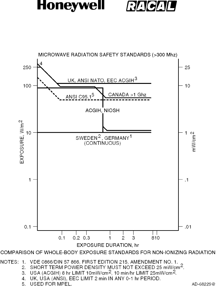
SYSTEM DESCRIPTION, INSTALLATION, AND MAINTENANCE MANUAL
MCS--4000/7000
23--20--27 5 Feb 2008
©Honeywell International Inc. Do not copy without express permission of Honeywell.
Page INTRO--9
Figure Intro--2. Radio Frequency Energy Levels
RELEASED FOR THE EXCLUSIVE USE BY: HONEYWELL INTERNATIONAL
UP86308

SYSTEM DESCRIPTION, INSTALLATION, AND MAINTENANCE MANUAL
MCS--4000/7000
23--20--27 5 Feb 2008
©Honeywell International Inc. Do not copy without express permission of Honeywell.
Page INTRO--10
Blank Page
RELEASED FOR THE EXCLUSIVE USE BY: HONEYWELL INTERNATIONAL
UP86308

SYSTEM DESCRIPTION, INSTALLATION, AND MAINTENANCE MANUAL
MCS--4000/7000 Multi--Channel SATCOM System
23--20--27
30 Aug 2002
Use or disclosure of information on this page is subject to the restrictions in the proprietary notice of this document.
Page 1--1
SECTION 1
SYSTEM DESCRIPTION
1. Overview
A. General
(1) The MCS--4000/7000 Multi-Channel SATCOM (MCS) system is a mobile avionics
communications system that supplies continuous worldwide voice and data
communications services to and from the aircraft through satellite. The MCS system
interfaces at baseband with various avionics data equipment, as well as with crew
and passenger voice equipment on–board the aircraft. It interfaces with the antenna
subsystem through L--band RF signals that emanate from (and are received by)
satellites in geostationary orbit. These satellites then convey the information to and
from ground stations that interface with the terrestrial telephone network.
(2) The MCS system augments and/or supersedes the present high frequency
transceiver by supplying higher quality voice service and by supplying data services
at higher bit rates needed by some future datalink (ATN) applications, such as
automatic dependent surveillance (ADS) and an international aircraft communications
addressing and reporting system (ACARS). Additional services include cockpit
communications with administrative and operational personnel and with
governmental bodies such as air traffic services (ATS). The system is designed to
ensure that communications for safety and regularity of flight are not delayed by the
transmission and reception of other types of messages.
(3) The MCS--4000/7000 system supports seven communication channels capable of
simultaneous full duplex voice communications and one channel of data
communications. The MCS--4000 system operates identically to the MCS--7000
except four communication channels rather than seven are supplied. Both the
MCS--7000 and MCS--4000 SATCOM systems supply one channel of data
communications. The MCS system accommodates the four categories of
communications:
•Air traffic control (ATC)
•Aeronautical operational control (AOC)
•Aeronautical administrative communications (AAC)
•Aeronautical passenger communications (APC).
(4) The four communication categories are recognized by the International Civil Aviation
Organization (ICAO) and the International Telecommunications Union (ITU), and
have been assigned priorities for communications purposes.
(5) The total aviation satellite communications system, shown in Figure 1-1, is made up
of the following:
•Aircraft earth station (airborne avionics subsystems and antenna subsystem)
•Space segment (satellite network)
•Ground earth stations
•Terrestrial data and voice networks.
RELEASED FOR THE EXCLUSIVE USE BY: HONEYWELL INTERNATIONAL
UP86308
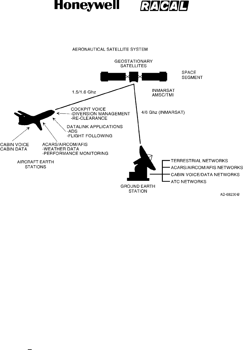
SYSTEM DESCRIPTION, INSTALLATION, AND MAINTENANCE MANUAL
MCS--4000/7000 Multi--Channel SATCOM System
23--20--27
30 Aug 2002
Use or disclosure of information on this page is subject to the restrictions in the proprietary notice of this document.
Page 1--2
Figure 1-1. Aviation Satellite Communications System
B. Aircraft Earth Station
(1) General
(a) The aircraft earth station (AES) is fully compliant with requirements of
Aeronautical Radio, Inc (ARINC) Characteristics 741/761. Standard interfaces
between the MCS avionics and other aircraft avionics enable the AES to accept
data and voice messages from various sources, encode and modulate this
information onto appropriate RF carrier frequencies, and transmit these carriers
to the space segment for relay to a ground earth station (GES). The AES also
receives RF signals from a GES through the satellite, demodulates these
signals, performs the necessary decoding of the encoded messages, and
outputs the data or voice message for use by either the pilot, copilot,or the
passengers.
(2) AES Components
(a) General
1A block diagram of the AES is shown in Figure 1-2. The AES is made up of
the following components:
•MCS avionics
•Antenna subsystem
•Cabin communications services
•Analog connected telephones
•Cockpit voice sources
•Aircraft avionics.
RELEASED FOR THE EXCLUSIVE USE BY: HONEYWELL INTERNATIONAL
UP86308
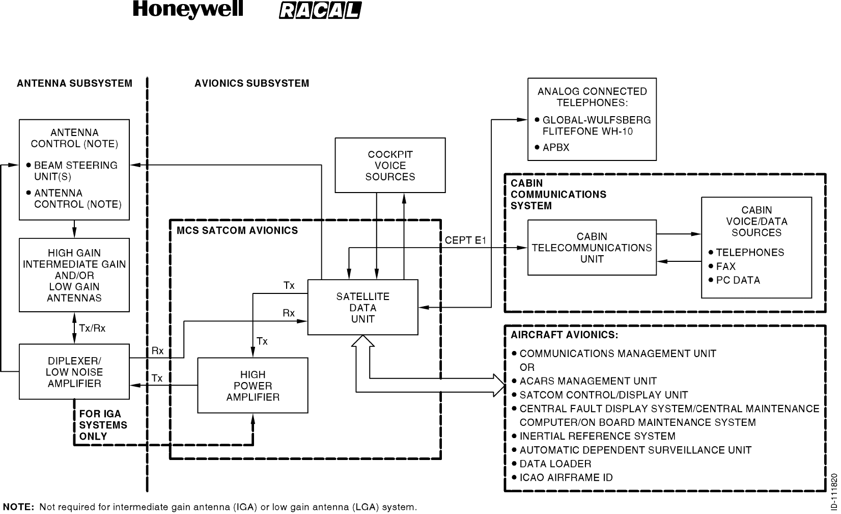
SYSTEM DESCRIPTION, INSTALLATION, AND MAINTENANCE MANUAL
MCS--4000/7000 Multi--Channel SATCOM System
23--20--27
30 Aug 2002
Use or disclosure of information on this page is subject to the restrictions in the proprietary notice of this document.
Page 1--3/(1--4 blank)
Figure 1-2. Aircraft Earth Station Block Diagram
RELEASED FOR THE EXCLUSIVE USE BY: HONEYWELL INTERNATIONAL
UP86308

SYSTEM DESCRIPTION, INSTALLATION, AND MAINTENANCE MANUAL
MCS--4000/7000 Multi--Channel SATCOM System
23--20--27
30 Aug 2002
Use or disclosure of information on this page is subject to the restrictions in the proprietary notice of this document.
Page 1--5
(b) MCS Avionics
1The MCS avionics are made up of the satellite data unit (SDU) and high
power amplifier (HPA). The SDU supplies the interface to all aircraft avionics,
and implements all functionality associated with modulation/demodulation,
error correction, channel rate/frequency selection, and RF translation for
seven communication channels. The SDU supports seven communication
channels capable of simultaneous full duplex voice and data communication
services. The SDU manages the RF link protocols on the satellite side and
supplies the system interface with communications management avionics.
The SDU interface to other aircraft avionics involves the exchange of ARINC
429 and discrete data.
2A cockpit audio system conveys cockpit voice to and from the SDU.
Messages requiring cockpit action or initiation appear on the multifunction
control display unit (MCDU) and/or other cockpit annunciators. The
communications management unit (CMU) or equivalent routes packet data
messages to and from the SDU. Cabin communications use either a cabin
communications system (CCS) or an analog equivalent (cabin unit) to supply
voice telephony communication. Enhancements supply facsimile (FAX)
service and secure voice and personal computer modem interfaces.
3The SDU supplies all essential services required to accommodate effective
air/ground communications through satellite using the antenna and related
RF components. Both the 40 Watt and 20 Watt HPAs supply linear power
amplification to boost the RF signals up to the power levels required for
transmitting to the satellite. In addition, the 20 Watt HPA (used primarily for
the intermediate gain antenna) supports a beam steering function which
converts tracking and pointing coordinates from the SDU into signals
needed to select the desired (beam) direction towards the satellite.
4Two additional LRUs may be required for some aircraft configurations:
•Radio frequency unit interface adapter (RFUIA)
•Signal conditioning unit (SCU).
5The RFUIA is used in place of the radio frequency unit (RFU) in the
MCS--7000 system.
6The SCU is used in MCS installations on older generation aircraft having an
inertial navigation system (INS) that does not output navigation data in an
ARINC 429 high speed format which is consistent with the ARINC 704
characteristic.
RELEASED FOR THE EXCLUSIVE USE BY: HONEYWELL INTERNATIONAL
UP86308

SYSTEM DESCRIPTION, INSTALLATION, AND MAINTENANCE MANUAL
MCS--4000/7000 Multi--Channel SATCOM System
23--20--27
30 Aug 2002
Use or disclosure of information on this page is subject to the restrictions in the proprietary notice of this document.
Page 1--6
(c) Antenna Subsystem
1The primary function of the antenna subsystem is to complete the
communication link between the GES, the space segment, and the AES.
The diplexer is a three-port RF device (antenna, transmit, and receive),
which supplies signal routing and filtering functions. Signals in the receive
band are routed from the antenna port to the receive port, and transmit
signals are routed from the transmit port to the antenna port. The low noise
amplifier establishes the noise floor of the communication system by
boosting the signals and noise received from the antenna to a level much
greater than the noise level of subsequent components in the receive path.
2The high gain antenna (HGA) and intermediate gain antenna (IGA) transmit
L--band RF signals from the HPA to a satellite, and receive L--band RF
signals from a satellite for the SDU. The low gain antenna (LGA) supplies
backup communications (packet data only) for the high gain antenna or
intermediate gain antenna by supplying low rate packet data communication
services.
3The beam steering unit used in the HGA system converts tracking and
pointing coordinates (aircraft relative azimuth and elevation) from the SDU
into signals needed to select the antenna array elements in combinations
that point the antenna beam in the desired direction towards the satellite. An
antenna control unit (ACU) is required for mechanically steered antenna
arrays. The antenna control unit translates digitized beam position data and
beam position change commands from the SDU into a format needed to
position the antenna beam in the desired direction toward the satellite. A
beam steering function is incorporated into the 20 Watt HPA for use with the
IGA.
(d) Cabin Communications System (CCS)
1The CCS, in conjunction with the MCS avionics and a worldwide network of
ground stations, supplies cabin services such as telephone, facsimile, and
other communication interfaces. The CCS is partitioned into two sections:
the cabin telecommunications unit (CTU) and cabin/passenger
communications equipment (digitally connected telephones).
2The CTU performs onboard private automatic branch exchange (PABX)
telephony functions letting the digitally connected telephones make the best
use of resources supplied by the MCS avionics. The CTU supplies the
interface between the digitally connected phones and the SDU. A
specialized interface conversion function supplies compatibility between the
ARINC 746 CTU and the ARINC 741/761 SDU. This interface is made up of
a high-speed (CEPT--E1) serial bus pair that accommodates up to 32
digitized voice channels along with status and control information.
3The digitally connected phones (handsets) are primarily supplied for
passenger use and can be located throughout the aircraft. The digital
handsets interface indirectly to the satellite communications equipment and
are controlled by the CCS.
RELEASED FOR THE EXCLUSIVE USE BY: HONEYWELL INTERNATIONAL
UP86308

SYSTEM DESCRIPTION, INSTALLATION, AND MAINTENANCE MANUAL
MCS--4000/7000 Multi--Channel SATCOM System
23--20--27
30 Aug 2002
Use or disclosure of information on this page is subject to the restrictions in the proprietary notice of this document.
Page 1--7
(e) Analog Connected Telephones
1The SDU has provisions to support up to two simultaneous analog audio
channels. Each analog channel supports two interface types:
Global-Wulfsberg Flitephone WH--10 and the analog private branch
exchange (APBX). The WH--10 is a stand-alone handset with a 12-button
keypad. The APBX has analog trunk lines and in-line dual tone
multifrequency (DTMF) signaling.
(f) Cockpit Voice Sources
1The SDU supports headset interfaces for cockpit use only. These interfaces
incorporate off-hook/on-hook signaling and dialing through the combination
of a control and display unit (either [SATCOM control and display unit] SCDU
or MCDU), and push-to-talk (PTT) or similar switches. When the PTT switch
is pushed, a microphone audio signal is sent to the selected voice channel
and a discrete signal is sent to the SDU. An audible chime and call lamps
announce call connections.
(g) Aircraft Avionics
1Standard interfaces between the MCS avionics and the other aircraft
avionics include the following:
•Communications management unit (CMU), or the management unit (MU)
of the Aircraft Communications Addressing and Reporting System
(ACARS), where installed.
•SATCOM control and display unit (SCDU), where installed, to supply an
interface to the MCS system for system log-on, GES selection, cockpit
voice call setup, data loading, and to access the SATCOM maintenance
pages including fault messages.
•Central fault display system (CFDS), central maintenance computer
(CMC), or on--board maintenance system (OMS), where installed, for fault
reporting.
•The inertial reference system (IRS), where installed, to supply the SDU
with navigation coordinates for positioning the antenna platform.
•Channels are also supplied for voice and data communication with ATC
to support departure clearances by datalink, as well as ADS for non radar
position reporting in oceanic regions.
•There is an ARINC 615 Airborne or portable data loader (ADL or PDL) for
uploading operational software and the owner requirements table (ORT).
Connections are made through front and back panel connectors on the
MCS avionics LRUs.
•The 24-bit ICAO address identifies the aircraft in which the SDU is
installed. Address pins identified to take on the binary one state must be
left open. Address pins identified to take on the binary zero state must be
wired to address common on the airframe side of the connector. ARINC
429 interface options for the ICAO address are also supplied.
RELEASED FOR THE EXCLUSIVE USE BY: HONEYWELL INTERNATIONAL
UP86308
SYSTEM DESCRIPTION, INSTALLATION, AND MAINTENANCE MANUAL
MCS--4000/7000 Multi--Channel SATCOM System
23--20--27
30 Aug 2002
Use or disclosure of information on this page is subject to the restrictions in the proprietary notice of this document.
Page 1--8
(3) AES Classifications
(a) Each AES is classified according to the configuration and dynamic capabilities of
its aircraft avionics and antenna subsystem. An AES can be fitted with any
combination of the classes of installations given in Table 1-1.
Table 1-1. Classes of Installations
Class Description
1A Class 1 AES installation uses a low gain antenna only and supplies low rate
packet-mode data services only.
2A Class 2 AES installation uses a high gain antenna or intermediate gain antenna,
and supplies telephony and optional circuit-mode services.
3A Class 3 AES installation uses a high gain antenna or intermediate gain antenna,
and supplies telephony services, packet-mode data services, and optional
circuit-mode data services.
4A Class 4 AES installation uses a high gain antenna or intermediate gain antenna,
and supplies packet-mode data services only.
(4) GES Communication Links
(a) The MCS avionics supply access to ground-based networks through the ground
earth stations. Each GES supplies system synchronization and coordination
through ground-to-aircraft transmissions. Four types of RF channels are defined
forusewiththeMCSavionicsasgiveninTable1-2.
Table 1-2. Types of RF Channels
RF Channel Description
P--Channel Packet-mode time division multiplex (TDM) channel used in the forward (outbound)
direction (ground-to-aircraft) to carry signaling and packet-mode data. The
transmission is continuous from each GES in the satellite network.
R--Channel Random access (slotted Aloha) channel used in the return (inbound) direction
(aircraft-to-ground) to carry signaling and packet-mode data, specifically the initial
signals of a transaction (typically request signals).
T--Channel Reservation time division multiple access (TDMA) channel used in the return
direction only. The receiving GES reserves time slots for transmissions requested
by an AES according to message length. The sending AES transmits the
messages in the reserved time slots.
C--Channel Circuit-mode single channel per carrier (SCPC) channel used in both forward and
return directions to carry digital voice or data/facsimile traffic. The use of the
channel is controlled by assignment and release signaling at the start and end of
each call or FAX transmission.
RELEASED FOR THE EXCLUSIVE USE BY: HONEYWELL INTERNATIONAL
UP86308

SYSTEM DESCRIPTION, INSTALLATION, AND MAINTENANCE MANUAL
MCS--4000/7000 Multi--Channel SATCOM System
23--20--27
30 Aug 2002
Use or disclosure of information on this page is subject to the restrictions in the proprietary notice of this document.
Page 1--9
C. Space Segment
(1) The space segment is made up of satellites placed in geostationary orbits to supply
air-ground packet-switched data services and voice communications, both of which
use worldwide standardized conventions and capabilities. The satellites function as
communication transponders to support L--band links to and from the aircraft, and
supply links to and from ground earth stations. The space segment supplier for airline
aeronautical satellite communications is the International Maritime Satellite
Organization (INMARSAT), whose system supplies worldwide coverage. The
four-region satellite system supplied by INMARSAT is shown in Figure 1-3.
D. Ground Earth Station
(1) Each GES has the necessary equipment to communicate with terrestrial networks
and communicate through satellites with the aircraft. The ground earth stations are
designed to supply the airline customer with a diverse routing of national and
international voice and data communications through submarine cable, satellite, and
microwave links to all destinations. Automatic traffic management systems ensure
efficient routing of communications by using optimum links into public switched
telephone networks (PSTN) and avoiding multiple satellite connections whenever
possible.
(2) Ground earth stations are located strategically around the globe to supply
redundancy and diversity in the terrestrial extension of communications. Aircraft are
connected to a GES through an in-view satellite depending on the service
preference settings encoded in the SDU ORT. Some problems may be encountered
when the aircraft flies in polar regions with a latitude greater than 75 degrees.
E. Terrestrial Data and Voice Networks
(1) Data and voice services available through satellites and ground earth stations include
9.6 and 4.8 kilobit/second digital voice, and packet-mode data at RF channel rates
ranging from 600 bit/second up to 10.5 kilobit/second. The present worldwide
complement of ground earth stations including location, operator, and coverage
region are summarized in Table 1-3. Aeronautical communications through the
INMARSAT satellites are transmitted to and from the terrestrial phone and data
networks through these ground earth stations. The satellite regions that service these
ground earth stations are shown in Figure 1-4.
RELEASED FOR THE EXCLUSIVE USE BY: HONEYWELL INTERNATIONAL
UP86308

SYSTEM DESCRIPTION, INSTALLATION, AND MAINTENANCE MANUAL
MCS--4000/7000 Multi--Channel SATCOM System
23--20--27
30 Aug 2002
Use or disclosure of information on this page is subject to the restrictions in the proprietary notice of this document.
Page 1--10
Table 1-3. Ground Earth Stations
GES Name GES ID SAT ID Service Provider
Goonhilly--AW 001 000 (AOR--W) Stratos
Southbury--AW 002 000 Telenor
Eik--AW 004 000 Telenor
Aussaguel--AW 005 000 Satellite Aircom (SITA)
Goonhilly--AE 101 001 (AOR--E) Stratos
Aussaguel--AE 103 001 SITA
Eik--AE 104 001 Telenor
Sentosa--P 201 002 (POR) Sing--Tel
Santa Paula--P 202 002 Telenor
Yamaguchi--P 203 002 KDD
Perth--P 205 002 SITA
Eik--I 301 003 (IOR) Telenor
Nunthaburi--I 302 003 Telenor
Perth--I 305 003 SITA
Yamaguchi--I 306 003 KDD
Sentosa--I 310 003 Sing--Tel
RELEASED FOR THE EXCLUSIVE USE BY: HONEYWELL INTERNATIONAL
UP86308
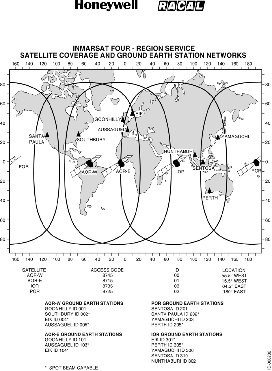
SYSTEM DESCRIPTION, INSTALLATION, AND MAINTENANCE MANUAL
MCS--4000/7000 Multi--Channel SATCOM System
23--20--27
30 Aug 2002
Use or disclosure of information on this page is subject to the restrictions in the proprietary notice of this document.
Page 1--11
Figure 1-4. INMARSAT Four-Region Satellite Coverage
RELEASED FOR THE EXCLUSIVE USE BY: HONEYWELL INTERNATIONAL
UP86308
SYSTEM DESCRIPTION, INSTALLATION, AND MAINTENANCE MANUAL
MCS--4000/7000
23--20--27 5 Feb 2008
©Honeywell International Inc. Do not copy without express permission of Honeywell.
Page 1--12
2. System Components
A. General
(1) The MCS avionics is comprised of the following components:
•Satellite data unit (SDU)
•High power amplifier (HPA).
(2) These components are compatible with ARINC Characteristic 741. Table 1-4 gives
the MCS system components supplied by Honeywell. Table 1-5 gives the MCS
system components not supplied by Honeywell. Table 1-6 thru Table 1-8 give system
component configuration information.
Table 1-4. System Components Supplied by Honeywell
Component Model No. Honeywell Part No.
Satellite Data Unit SD--700 7516118--xxyyy
Figure 1-6
High Power Amplifier (40 W) HP--600 7516250--xxyyy
Figure 1-7
High Power Amplifier (20 W) HP--700 7516251--xxyyy
Figure 1-7
Diplexer/Low Noise Amplifier -- Aero--I -- -- 7516193--901
Intermediate Gain Antenna -- -- 7516194--901
Radio Frequency Unit Interface Adapter (RFUIA) 1. -- -- 7516222--901
NOTES:
1. The five digit dash number (xxyyy) corresponds to the hardware/software version of the unit where the first two
digits correspond to the hardware version and the last three digits correspond to the software version.
2. The RFUIA is installed with the 115 V ac/400 Hz, 7--channel SDU (6 voice, 1 data), or 28 V dc.
Table 1-5. System Components Not Supplied by Honeywell
Component Comments
SDU Installation Equipment (See Note) ARINC 600 6--MCU tray, cables, connectors, assemblies,
mounting hardware, and kits
HPA (40 W) Installation Equipment
(See Note) ARINC 600 8--MCU tray, cables, connectors, assemblies,
mounting hardware, and kits
HPA (20 W) Installation Equipment
(See Note) ARINC 600 4--MCU tray, cables, connectors, assemblies,
mounting hardware, and kits
Signal Conditioning Unit (SCU) RACAL Part No. 56047--010XX
RELEASED FOR THE EXCLUSIVE USE BY: HONEYWELL INTERNATIONAL
UP86308

SYSTEM DESCRIPTION, INSTALLATION,
AND MAINTENANCE MANUAL
MCS-4000/7000
TEMPORARY REVISION NO. 23-2
23-20-27
Page 2 of 3
20 Jun 2017
© Honeywell International Inc. Do not copy without express permission of Honeywell.
INSERT PAGE 2 OF 3 FACING PAGE 1-13.
Reason: To add PN 7516118-77010 and PN 7516118-74010, and to change description for PNs
75166118-27020 and -24020 in Table 1-6.
Table 1-6 is changed as follows:
Table 1-6. SDU Configurations
SDU Part Number
Description
7516118-27010
115 V ac/400 Hz, 7-channel SOU (6 voice, 1 data)
7516118-77010
115 V ac/400 Hz, 7-channel SDU (6 voice, 1 data), Digital RFM
7516118-57010
+28 V dc, 7- channel SOU (6 voice, 1 data)
7516118-24010
115 V ac/400 Hz, 4-channel SOU (3 voice, 1 data)
7516118-74010
115 V ac/400 Hz, 4-channel SDU (3 voice, 1 data), Digital RFM
7516118-54010
+28 V dc, 4- channel SOU (3 voice, 1 data)
7516118-27020
115 V ac/400 Hz, 7-channel SDU (6 voice, 1 data) for Airbus
applications, (HW MOD J contains Digital RFM)
7516118-24020
115 V ac/400 Hz, 4-channel SDU (6 voice, 1 data) for EPIC
applications, (HW MOD J contains Digital RFM)
7516118-27011
115 V ac/400 Hz, 7-channel SOU (6 voice, 1 data) for EPIC
applications
7516118-57011
+28 V dc, 7-channel SOU (6 voice, 1 data) for EPIC applications
7516118-24011
115 V ac/400 Hz, 4-channel SOU (3 voice, 1 data) for EPIC
applications
7516118-54011
+28 V dc, 4- channel SOU (3 voice, 1 data) for EPIC applications
RELEASED FOR THE EXCLUSIVE USE BY: HONEYWELL INTERNATIONAL
UP86308
SYSTEM DESCRIPTION, INSTALLATION, AND MAINTENANCE MANUAL
MCS--4000/7000 Multi--Channel SATCOM System
23--20--27
30 Aug 2002
Use or disclosure of information on this page is subject to the restrictions in the proprietary notice of this document.
Page 1--13
Table 1-5. System Components Not Supplied by Honeywell (cont)
Component Comments
High Gain Antenna Equipment BAE Systems -- Canada
Ball Aerospace -- USA
Dassault Electroniq -- France
NOTE: Installation of this equipment is dependent on the specific requirements of the operator. Refer to
Appendix A, Vendor Equipment, for additional information.
Table 1-6. SDU Configurations
SDU Part Number Description
7516118--27010 115 V ac/400 Hz, 7--channel SDU (6 voice, 1 data)
7516118--57010 +28 V dc, 7--channel SDU (6 voice, 1 data)
7516118--24010 115 V ac/400 Hz, 4--channel SDU (3 voice, 1 data)
7516118--54010 +28 V dc, 4--channel SDU (3 voice, 1 data)
7516118--27020 115 V ac/400 Hz, 7--channel SDU (6 voice, 1 data) for Airbus
applications
7516118--24020 115 V ac/400 Hz, 4--channel SDU (3 voice, 1 data) for Airbus
applications
7516118--27011 115 V ac/400 Hz, 7--channel SDU (6 voice, 1 data) for EPIC
applications
7516118--57011 +28 V dc, 7--channel SDU (6 voice, 1 data) for EPIC applications
7516118--24011 115 V ac/400 Hz, 4--channel SDU (3 voice, 1 data) for EPIC
applications
7516118--54011 +28 V dc, 4--channel SDU (3 voice, 1 data) for EPIC applications
Table 1-7. HPA (40 Watt) Configurations
HPA Part No.
Software
Package Description
7516250--10001 A3--channel initial release
7516250--15020 B3--channel update with cabin voice
7516250--18033 C0.0 6--channel cabin voice and data (1--data, 5--voice) and fax
(2400/4800 bps)
7516250--18036 C2.0 6--channel cabin voice and data (1--data, 5--voice) and fax
(2400/4800 bps)
7516250--19034 C3.0 Improves log--on capability and reversion; adds maintenance
pages
7516250--19037 C3.5 Adds Boeing 777 capability
RELEASED FOR THE EXCLUSIVE USE BY: HONEYWELL INTERNATIONAL
UP86308
SeeTR
SYSTEM DESCRIPTION, INSTALLATION, AND MAINTENANCE MANUAL
MCS--4000/7000
23--20--27 5 Feb 2008
©Honeywell International Inc. Do not copy without express permission of Honeywell.
Page 1--14
Table 1-7. HPA (40 Watt) Configurations (cont)
HPA Part No. Description
Software
Package
7516250--19037 C3.5 Adds Boeing 777 capability
7516250--20050 D2.0 Adds several improvements to BITE, including antenna VSWR
detection reporting and compatibility with hardware Mod D
(Software Mod F); Uses 115 V ac primary power.
7516250--55050 D2.0 Adds several improvements to BITE, including antenna VSWR
detection reporting and compatibility with hardware Mod D
(Software Mod F); Uses 115 V ac primary power.
7516250--60001 A3--channel initial release
7516250--60020 B3--channel update with cabin voice
7516250--60033 C0.0 6--channel cabin voice and data (1--data, 5--voice) and fax
(2400/4800 bps)
7516250--60050 D2.0 Adds several improvements to BITE, including antenna VSWR
detection reporting and compatibility with hardware Mod D
(Software Mod F); Uses 28 V dc primary power.
NOTE: For the various part numbers, --1XXXX refers to an air transport LRU, while --55XXX and --6XXXX
refers to a business and commuter LRU. The functional descriptions are the same for both.
Table 1-8. HPA (20 Watt) Configurations
HPA Part Number Software
Package Description
7516251--20060 E1.5 20 Watt HPA with Aero--I IGA beam steering functionality; Uses
115 V ac or 28 V dc power supply.
7516251--60060 E1.5 20 Watt HPA with Aero--I IGA beam steering functionality; Uses
115 V ac or 28 V dc power supply.
NOTE: For the various part numbers, --2XXXX refers to an air transport LRU, while --6XXXX refers to a
business and commuter LRU. The functional descriptions are the same for both.
3. System Description
A. General
(1) The system description gives a general overview and summary of the features and
interfaces that the MCS implements. Figure 1-7 is a simplified block diagram of the
MCS system.
(2) The core of the AES avionics subsystem is the MCS avionics, supporting data, and
voice communications at rates from 600 to 21,000 bits per second. Interfaces to
various aircraft systems including cockpit voice, cabin voice/data, aircraft avionics,
and the antenna subsystem enable the MCS avionics to handle data and voice
messaging functions for the AES.
RELEASED FOR THE EXCLUSIVE USE BY: HONEYWELL INTERNATIONAL
UP86308

SYSTEM DESCRIPTION, INSTALLATION, AND MAINTENANCE MANUAL
MCS--4000/7000 Multi--Channel SATCOM System
23--20--27
30 Aug 2002
Use or disclosure of information on this page is subject to the restrictions in the proprietary notice of this document.
Page 1--15
(3) The SDU supplies all essential services required to accommodate effective
air/ground communications through satellite, using the antenna and related RF
components. The SDU manages the RF link protocols on the AES side and supplies
the system interface with communications management avionics. The HPA boosts
the signal to be transmitted up to the power levels required for transmission to the
satellite.
RELEASED FOR THE EXCLUSIVE USE BY: HONEYWELL INTERNATIONAL
UP86308

SYSTEM DESCRIPTION, INSTALLATION, AND MAINTENANCE MANUAL
MCS--4000/7000 Multi--Channel SATCOM System
23--20--27
30 Aug 2002
Use or disclosure of information on this page is subject to the restrictions in the proprietary notice of this document.
Page 1--16
Blank Page
RELEASED FOR THE EXCLUSIVE USE BY: HONEYWELL INTERNATIONAL
UP86308
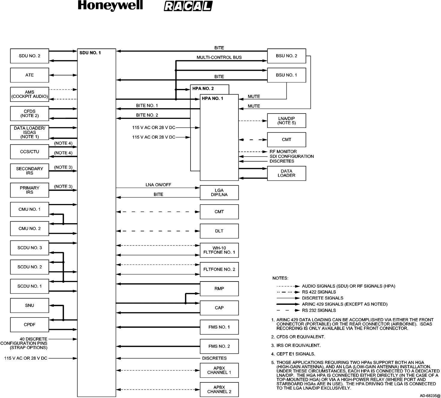
SYSTEM DESCRIPTION, INSTALLATION, AND MAINTENANCE MANUAL
MCS--4000/7000 Multi--Channel SATCOM System
23--20--27
30 Aug 2002
Use or disclosure of information on this page is subject to the restrictions in the proprietary notice of this document.
Page 1--17/(1--18 blank)
Figure 1--4. MCS Avionics Block Diagram
RELEASED FOR THE EXCLUSIVE USE BY: HONEYWELL INTERNATIONAL
UP86308
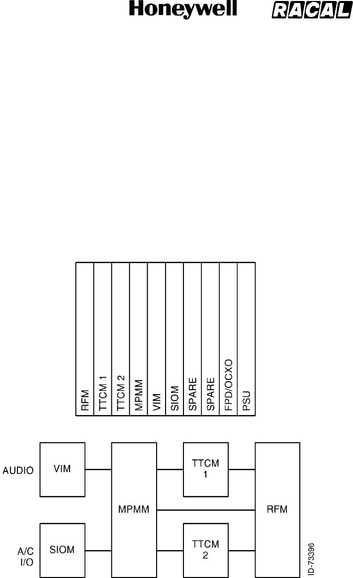
SYSTEM DESCRIPTION, INSTALLATION, AND MAINTENANCE MANUAL
MCS--4000/7000 Multi--Channel SATCOM System
23--20--27
30 Aug 2002
Use or disclosure of information on this page is subject to the restrictions in the proprietary notice of this document.
Page 1--19
B. Satellite Data Unit
(1) General
(a) The SDU is the core element of the MCS avionics and is responsible for overall
AES control and monitoring. The unit interfaces to many aircraft avionics (e.g.,
CFDS, primary/secondary IRS, CMU 1/2, MCDU 1/2/3, ADL, etc) and has
operational functionality, including coding and decoding all system voice and
data signals and defining system protocols. The SDU contains six channels
capable of supplying simultaneous full duplex voice communication, one channel
of data 2/3 communication, and RF circuitry sufficient to operate the AES.
Figure 1-5 shows the circuit card assembly (CCA) layout for the MCS--7000
SDU. Removal of one of the triple transcoder modem (TTCM) CCA results in the
MCS--4000 SDU.
Figure 1-5. MCS--4000/7000 SDU Equipment Description
RELEASED FOR THE EXCLUSIVE USE BY: HONEYWELL INTERNATIONAL
UP86308

SYSTEM DESCRIPTION, INSTALLATION, AND MAINTENANCE MANUAL
MCS--4000/7000 Multi--Channel SATCOM System
23--20--27
30 Aug 2002
Use or disclosure of information on this page is subject to the restrictions in the proprietary notice of this document.
Page 1--20
(b) The format for voice/data codes follows the INMARSAT system definitions for
voice and data transmission and reception. The INMARSAT system uses a
digital format for voice and data. The SDU digitizes the voice or data signal and
adds special codes to make the aircraft-to-ground station connection possible.
Voice signals are transmitted at a rate designed to supply high voice quality
(perceived quality is close to that of a good quality public telephone line). When
signal processing is complete, the coded voice/data signal is sent to HPA. The
SDU also controls the protocols for automatic call, setup, and clear-down.
System protocols are defined so the designated GES recognizes it is being
called by the AES.
(c) The SDU houses the voice interface modules and transcoder modems required
for voice and data service, and the RF transmit/receive circuitry needed to
convert modulated baseband signals to an L-band frequency (and vice versa).
All AES satellite signals use digital coding and modulation, which include the
voice circuits. The voice interface modules translate baseband analog voice
signals to and from the 9600 bps or 4800 bps digital coding standard. Efficient
information compression and coding techniques supply high voice quality at an
economical bit rate. The modems, one for each communication channel, perform
all of the physical layer signal processing functions, including
multiplexing/demultiplexing, interleaving/de--interleaving,
scrambling/unscrambling, modulation/demodulation, and Doppler effect
correction.
(d) The SDU system table memory contains the location of all satellites. When a
GES is selected, the SDU uses this location information and aircraft positional
information (through an ARINC 429 interface) from the IRS to compute the
position of the satellite relative to the aircraft. The SDU then transmits pointing
and tracking coordinates (aircraft relative azimuth and elevation) to the beam
steering unit (BSU) to permit optimum signal transmission and reception between
the high gain antenna subsystem and the satellite.
(e) The high gain antenna subsystem translates these steering commands into
control signals to the antenna(s). Once the beam has been steered toward the
satellite, the SDU receives the pilot tone from the satellite transponder through
its receive RF link from the antenna subsystem.
(f) The SDU is now free to route communications data over the satellite link. The
SDU accomplishes this by sending commands to the MU and the CTU. These
commands are sent through ARINC 429 and CEPT E1 interfaces between the
SDU and the MU/CTU. Data is then routed from the MU/CTU to the SDU. In the
SDU, the baseband data modulates RF carriers, which are sent to the HPA for
amplification, and then to the antenna subsystem for transmission to the satellite.
The SDU can adjust the transmission frequency in one-Hertz increments to
compensate for the Doppler shift caused by the speed of the aircraft. The
receive mode is handled in a similar manner. Since the MCS is a full-duplex
system, the transmit and receive signals are processed simultaneously as in
conventional terrestrial telephone equipment.
RELEASED FOR THE EXCLUSIVE USE BY: HONEYWELL INTERNATIONAL
UP86308

SYSTEM DESCRIPTION, INSTALLATION, AND MAINTENANCE MANUAL
MCS--4000/7000 Multi--Channel SATCOM System
23--20--27
30 Aug 2002
Use or disclosure of information on this page is subject to the restrictions in the proprietary notice of this document.
Page 1--21
(2) Output Power Control
(a) General
1The AES output power to the satellite, specified and calculated as effective
isotopic radiated power (EIRP) from the antenna in the direction of the
satellite, is controlled by the SDU as specified in the following paragraphs.
The SDU is capable of controlling up to one HGA HPA, one LGA HPA, or
one IGA HPA. These HPA(s) can be a linear or class C type in any
combination. The SDU does not establish a C-channel voice call using a
class C HGA HPA or through any LGA HPA.
(b) Assumed Initial C-Channel EIRP
1The SDU calculates the assumed initial C-channel EIRP as being the lowest
of the currently GES-commanded EIRPs for any/all C-channels in progress.
If there are no C-channels currently in progress, the SDU uses the value in
ORT item xxx, or the value in ORT item xxx reduced by 6 dB if the SDU is
currently logged on through a spot-beam.
(c) Current Reserved EIRP
1The SDU calculates the current reserved EIRP as the summation in Watts of
the following EIRPs:
•The power reserved for the R/T-channel transmission, for the highest bit
rate assigned, calculated from the EIRP assigned in the log-on confirm
signal, or the most recent data channel reassignment, if any.
•The GES-assigned EIRPs of all the currently active C-channel carriers, if
any.
•The cockpit reserved channel power if the reservation has been made
through ORT option vii and is not in use. This continuously tracks the
assumed initial C-channel EIRP. If it is in use, then the actual
GES-assigned EIRP is used.
•The power reserved for any C-channel calls in the process of being set
up (i.e., after resources have been allocated but no C-channel
assignment signal has been received). For each such channel, the
assumed initial C-channel EIRP is used.
(d) Current and Projected or Peak-To-Average Power Ratio
1If the HPA is linear, the SDU calculates the current peak-to-average power
ratio based on the EIRP levels for all the carriers considered in the current
reserved EIRP calculation. The current peak-to-average ratio value is sent to
the HPA periodically, alternating with the projected peak-to-average ratio
(i.e., what the peak-to-average ratio would be if one additional C-channel
were established).
RELEASED FOR THE EXCLUSIVE USE BY: HONEYWELL INTERNATIONAL
UP86308

SYSTEM DESCRIPTION, INSTALLATION, AND MAINTENANCE MANUAL
MCS--4000/7000 Multi--Channel SATCOM System
23--20--27
30 Aug 2002
Use or disclosure of information on this page is subject to the restrictions in the proprietary notice of this document.
Page 1--22
2The SDU waits at least 450 milliseconds after transmitting the HPA
command word before assuming the received HPA maximum available RMS
output power corresponds to the most recently sent peak-to-average ratio in
the HPA command words. The current peak-to-average ratio is sent in order
to calculate the current available EIRP from the returned maximum available
RMS power. The projected peak-to-average ratio is sent in order to
determine (along with other criteria) if an additional C-channel can be
established, if and when it is requested. If all carriers are at the same power
level (not true in general), the peak-to-average ratio is equal to the number
of carriers. If the HPA is class C, the SDU always sends a peak-to-average
ratio equal to 1.
(3) Installation Dependent Considerations
(a) General
1The SDU stores the following installation dependent values to enable it to
set the EIRPs accurately:
•SDUtoHPAloss(assumedcommonforbothLGAandHGAHPAs)
•HPA to antenna loss (two values are stored, one for the HGA HPA, and a
separate value for the LGA HPA)
•HPA in use is class C, the SDU stores the HPA maximum output power.
(b) SDU to HPA Loss
1The SDU stores the calibrated SDU to HPA loss in nonvolatile memory.
When the HPA is linear, this value is calculated once whenever there is an
R--or T--channel burst transmission in the absence of C--channel
transmission. This value is also calculated whenever there is a single
C--channel transmission in the absence of R-- or T--channel, unless the
reported actual power output value in the HPA status word:
•Matches or is less than the minimum reportable actual power value stored
in ORT item xxix
•Matches either the unique code 00100
B
for at/below measurable range
or 3 dB greater than 40 W or the flag was set indicating the HPA or
modem backoff was limited.
2When a single measurable carrier (R--/T--or C--channel) is present, the SDU
recalculates the SDU to HPA loss as the actual output power reported by the
HPA, less the HPA nominal gain, plus the HPA backoff, or SDU calculated
RFM power. This value includes the actual cable loss, plus any
uncompensated variation from nominal in the HPA gain, and any variation
from the calibrated RFM output power (due to temperature). This value also
lets the SDU accurately determine the common transmit gain. If the
calibration results in a value outside the range of 10 dB to 30 dB, a failure is
raised for the HGA HPA and LGA HPA.
RELEASED FOR THE EXCLUSIVE USE BY: HONEYWELL INTERNATIONAL
UP86308

SYSTEM DESCRIPTION, INSTALLATION, AND MAINTENANCE MANUAL
MCS--4000/7000 Multi--Channel SATCOM System
23--20--27
30 Aug 2002
Use or disclosure of information on this page is subject to the restrictions in the proprietary notice of this document.
Page 1--23
(c) HPA to Antenna Loss
1The SDU is capable of storing in nonvolatile memory the actual loss (to the
nearest tenth of a dB) between the HPA and the input to the antenna for use
in the power control computation. This loss is the sum of the HPA to diplexer
cable loss, the high power relay loss (if used), the diplexer loss, and the
diplexer to antenna cable loss in an ARINC 741 system. This value is
expected to be between 0.9 and 2.5 dB, but the SDU allows the entry of
values in the range of 0.0 to 5.0 dB. A separate value is maintained and
used for each antenna subsystem.
2This loss value is necessary to enable the SDU to accurately set the
antenna EIRPs, and to determine power availability for additional
C-channels. This value is not part of the ORT and is not an option. The
value is estimated/calibrated at the time of system installation or
commissioning, and can vary among otherwise identical installations. It is
inadequate to assume a default of either end of the range, since at the low
end the AES would not necessarily make the return link in marginal
conditions. At the high end, the SDU would radiate all carriers high, wasting
power and prematurely inhibiting further calls from being set up.
(d) Class C HPA Maximum Output Power
1When the HPA is class C, the SDU stores the calibrated HPA maximum
output power value in nonvolatile memory. This value is calculated once per
burst when there is a single measurable carrier present, unless the reported
actual power output value in the HPA status word:
•Matches or is less than the minimum reportable actual power value stored
in ORT item xxix
•Matches either the unique code 00100
B
for at/below measurable range
or 3 dB greater than 40 W; or the flag was set indicating the HPA or
modem backoff was limited.
2This value is the actual output power reported by the HPA, plus the HPA
backoff. If the calibration results in a value outside the range of 14 dBW to
21 dBW, a failure is raised for the HGA HPA and LGA HPA.
(4) Antenna Subsystem Selection
(a) The purpose of installing both HGA and LGA subsystems simultaneously is to
increase system availability and geographical orientation coverage. When the
SDU has the choice of antenna subsystems (HGA or LGA), either as part of a
single MCS system or in its role as half of a dual system, reversion from HGA to
LGA (and from LGA to HGA) is accomplished by automatic means. Automatic
reversion from the HGA to the LGA occurs only upon failure of the HGA
subsystem. The SDU automatically switches from the LGA to the HGA if the
HGA subsystem reverts to a normal state. In lieu of a physically separate LGA,
an HGA is also usable as a steered LGA when its gain drops below the level
specified by ORT item xxii.
RELEASED FOR THE EXCLUSIVE USE BY: HONEYWELL INTERNATIONAL
UP86308

SYSTEM DESCRIPTION, INSTALLATION, AND MAINTENANCE MANUAL
MCS--4000/7000 Multi--Channel SATCOM System
23--20--27
30 Aug 2002
Use or disclosure of information on this page is subject to the restrictions in the proprietary notice of this document.
Page 1--24
(b) Loss of reliable communications with a GES normally occurs as a result of
channel degradation. When channel degradation occurs, the AES considers
itself logged-off and searches for another GES. If no GES is found for
communications using the HGA subsystem, automatic switching to the LGA
subsystem does occur. Manual reversion through the SCDU is the only way the
SDU switches from the HGA subsystem to the LGA subsystem.
(c) The purpose of installing an IGA subsystem is to use the spot beam coverage.
The satellite spot beams supply a times 8 (x8) amplification. Less power is
required for C--channel (circuit mode) operation that equates to less cost per
minute of operation.
C. High Power Amplifier
(1) The SDU sends such information as power amplifier on/off commands and
amplification gain commands to the HPA. The bidirectional link carries status and
maintenance information to the SDU such as gain verification, standing wave ratio
data, and indication of dangerous system conditions such as temperature warnings
or power supply failures.
(2) The HPA supplies RF power amplification of the L-band signals generated by the
SDU to a power level required for transmission to the satellite. Because multiple
signals are transmitted through the HPA, the HPA is a linear device (i.e., operating
class AB) capable of amplifying more than one signal at a time. An average of 40
Watts RF output power is developed by the HPA (up to 25 Watts RF power by the 20
Watt HPA) while passing multiple signals without generating excessive
intermodulation products.
(3) In addition to providing RF power amplification, the HPA must control output power to
supply the desired EIRP from the AES. The SDU controls the gain of the Honeywell
HPA over a 25-dB range in 1-dB increments through the ARINC 429 interface. This
lets automatic adjustment of signal strength compensate for a wide variety of
conditions. The HPA also measures output power and available power and reports to
the SDU, which uses the information to determine if additional calls can be
accommodated.
(4) Under favorable propagation conditions, the full output power capability of the HPA is
not required. The HPA automatically consumes less power and dissipates less heat
when full power is not used.
(5) The 20 Watt HPA supplies beam steering capabilities previously implemented in the
antenna beam steering unit. Commands are generated to steer the antenna
elements based on the SDU, IRS information, and beam map data stored in the HPA.
RELEASED FOR THE EXCLUSIVE USE BY: HONEYWELL INTERNATIONAL
UP86308

SYSTEM DESCRIPTION, INSTALLATION, AND MAINTENANCE MANUAL
MCS--4000/7000 Multi--Channel SATCOM System
23--20--27
30 Aug 2002
Use or disclosure of information on this page is subject to the restrictions in the proprietary notice of this document.
Page 1--25
D. Avionics Configurations
(1) The SDU determines the configuration installed on the aircraft, including the
presence of optional peripherals, by examining the system configuration pins. The
SDU supports interaction only with those peripherals indicated as being present by
the configuration pins.
(2) The Aero H+ SATCOM system requires installation of an SDU and 40 Watt HPA, and
supports seven independent simultaneous channels for voice and data
communications. One channel is dedicated to data and system management
transactions. The remaining six channels are available for analog or digital voice
communications.
(3) The Aero I SATCOM system requires installation of an SDU and 20 Watt HPA, and
supports seven independent simultaneous channels for voice and data
communications. One channel is dedicated to data and system management
transactions. The remaining six channels are available for analog voice
communications.
4. MCS Component Descriptions
A. Physical Description
(1) The LRUs are designed to perform reliably under field conditions and to supply ease
of maintenance when required. Each LRU is designed as a modular concept unit
(MCU), as defined by ARINC Characteristic 600, to permit easy replacement of each
shop replaceable unit (SRU). The SRUs use both digital and analog solid state
circuitry constructed using a mixture of surface mount technology (SMT) and dual
in-line packaging (DIP) technology.
(2) All SRUs are built to standards that qualify them for both airline and business aircraft
usage. Adjustment mechanisms are accessible with the SRU installed in the LRU.
These SRUs can be removed to reduce the number of functional channels without
compromising the functionality of the remaining channels.
(3) The MCS system components meet the requirements specified in parts A and B of
the Minimum Operational Performance Standards for Aeronautical Mobile Satellite
Services Document, Document No. RTCA/DO--210.
RELEASED FOR THE EXCLUSIVE USE BY: HONEYWELL INTERNATIONAL
UP86308

SYSTEM DESCRIPTION, INSTALLATION, AND MAINTENANCE MANUAL
MCS--4000/7000 Multi--Channel SATCOM System
23--20--27
30 Aug 2002
Use or disclosure of information on this page is subject to the restrictions in the proprietary notice of this document.
Page 1--26
B. Satellite Data Unit (SDU)
(1) The SDU is packaged as an ARINC 600 6--MCU suitable for mounting in the
equipment bay. The mechanical chassis is constructed of lightweight aluminum alloy
sheet metal; forced air moving through the chassis in an upward or downward
direction supplies internal cooling. Two hold-down clamps enable the unit to be firmly
clamped in the mounting rack. The unit is carried by a fixed C-shaped handle
mounted to the front panel assembly.
(2) The front panel assembly contains a 20-character alphanumeric display for displaying
built-in test equipment (BITE) failure messages, system LRU part numbers, and the
ORT identification. The display remains inactive when its temperature is less than
-- 1 0 °C(+14°F) or greater than +50 °C(+122°F). The front panel also contains two
momentary action buttons labeled TEST and CM/SCROLL. The TEST button initiates
BITE in the SDU. The CM/SCROLL button lets the alphanumeric display scroll
through the BITE failure messages and the software confirmation numbers.
(3) The front panel also contains an ARINC 615 portable data loader connector and a
primary cell for the real-time clock/calendar function of the processor module.
(4) The rear connector receptacle is a size No. 2 shell assembly (in accordance with
ARINC 600) that engages a mating connector in the mounting rack when the SDU is
installed. The top and middle inserts are type 02 arrangements and the bottom insert
is a type 04 arrangement. Index pin code 04 is used on both the SDU and the
mounting rack connectors.
(5) The SDU is shown in Figure 1-6. The SDU leading particulars are given in Table 1-9.
DO--160D environmental categories for the SDU are given in Table 1-10.
RELEASED FOR THE EXCLUSIVE USE BY: HONEYWELL INTERNATIONAL
UP86308
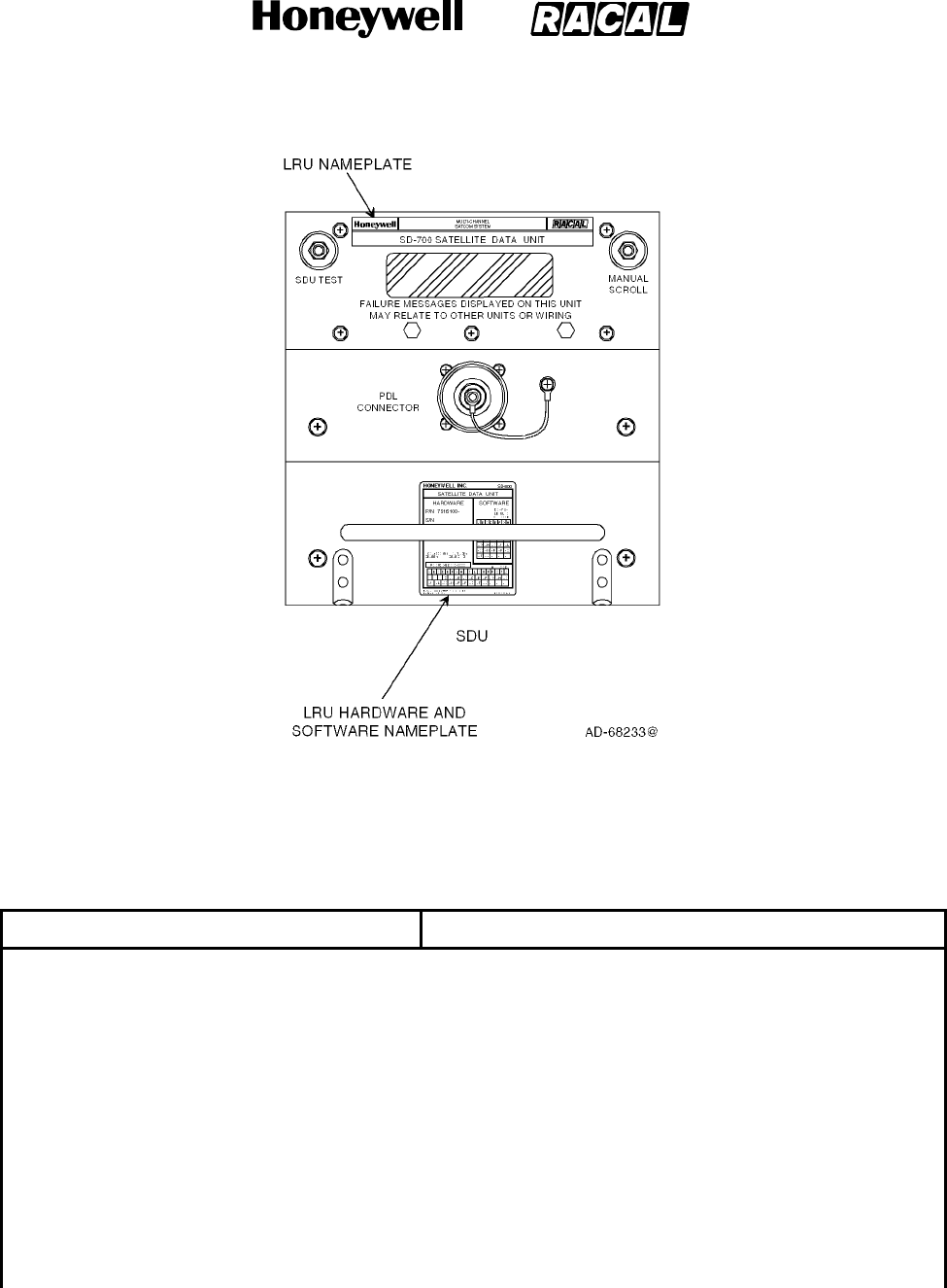
SYSTEM DESCRIPTION, INSTALLATION, AND MAINTENANCE MANUAL
MCS--4000/7000 Multi--Channel SATCOM System
23--20--27
30 Aug 2002
Use or disclosure of information on this page is subject to the restrictions in the proprietary notice of this document.
Page 1--27
Figure 1-6. Satellite Data Unit
Table 1-9. SDU Leading Particulars
Characteristic Specification
Dimensions (maximum):
•Height ................................ 7.624 in. (193.65 mm)
•Width ................................. 7.51 in. (190.75 mm)
•Length ................................ 15.26 in. (337.60 mm)
Weight (maximum) ....................... 21 lb (9.6 kg)
Power Requirements:
•ACVoltage ............................ 104 to 122 V ac, 380 to 420 Hz (normal operation)
97 V ac, 360 Hz minimum; 134 V ac, 440 Hz maximum
•DCVoltage ............................ 22.0 to 30.3 V dc (normal operation)
20.5 V dc minimum, 32.2 V dc maximum
RELEASED FOR THE EXCLUSIVE USE BY: HONEYWELL INTERNATIONAL
UP86308

SYSTEM DESCRIPTION, INSTALLATION, AND MAINTENANCE MANUAL
MCS--4000/7000 Multi--Channel SATCOM System
23--20--27
30 Aug 2002
Use or disclosure of information on this page is subject to the restrictions in the proprietary notice of this document.
Page 1--28
Table 1-9. SDU Leading Particulars (cont)
Characteristic Specification
AC Current Requirements
1.
:
•Nominal at 115 V ac (Current/Power Factor) 1.3 amps/0.70
•Maximum at 104 V ac (Current/Power
Factor)................................ 2.1 amps/0.91
DC Current Requirements:
•Nominal at 28 V dc ..................... 3.8 amps
•Maximumat20.5Vdc .................. 7.0 amps
Circuit Breaker Ratings:
•115VacCircuitBreaker ................ 3 amp TYPE A
•28VdcCircuitBreaker ................. 10 amp TYPE A
User Replaceable Parts ................... None
OperatingTemperature.................... -- 5 5 _C(--67_F) to +70 _C (158 _F)
OperatingAltitude ........................ to 70,000 ft (21.34 kilometers)
Cooling Requirements
2.
:
•Minimum .............................. 0.15 ±0.05 in. (3.81 ±1.27 mm) of water at a flow rate of
72.8 ±2.0 lb (33.0 ±0.9 kg) per hour
•Maximum ............................. 0.25 ±0.05 in. (6.35 ±1.27 mm) of water at a flow rate of
96.2 ±2.0 lb (43.6 ±0.9 kg) per hour
Power Dissipation
3.
:
•Nominal ............................... 105 W
•Maximum ............................. 198 W
Mating Connectors:
•J1 .................................... Radiall Part No. NSXN2P201X004
•J2 .................................... Honeywell Part No. 4004295--160, ITT Part No.
KJ6F18A53P
Mounting ................................ ARINC 600 6--MCU Tray Assembly
NOTES:
1. All power factors (PF) are leading.
2. Refer to Appendix A, Vendor Equipment, for mounting trays with integral cooling fans that meet the cooling
requirements.
3. The SDU draws an additional 20 W during the first 10 minutes (maximum) of operation at 25_C(77_F) because of
the OCXO. The OCXO continuously dissipates this additional 20 W at --55 _C(--67_F).
RELEASED FOR THE EXCLUSIVE USE BY: HONEYWELL INTERNATIONAL
UP86308

SYSTEM DESCRIPTION, INSTALLATION, AND MAINTENANCE MANUAL
MCS--4000/7000 Multi--Channel SATCOM System
23--20--27
30 Aug 2002
Use or disclosure of information on this page is subject to the restrictions in the proprietary notice of this document.
Page 1--29
Table 1-10. SDU DO--160D Environmental Categories
Environmental Condition Category
Temperature and Altitude Category A2E1/Z (E1)
1.
Temperature Variation Category B
Humidity Category A
Shock Category B
Vibration Category SB2
Explosion Category E
Waterproofness Category X
Fluids Susceptibility Category X
Sand and Dust Category X
Fungus Resistance Category X
Salt Spray Category X
Magnetic Effect Category Z
Power Input -- 115 V ac Category E
Power Input -- 28 V dc Category BZ
2.
Voltage Spike Category A
Audio Frequency Susceptibility -- 115 V ac Category E
Audio Frequency Susceptibility -- 28 V dc Category Z
Induced Signal Susceptibility Category Z
Radio Frequency Susceptibility Category RRR
Radio Frequency Emissions Category M
Lightning Induced Category A3E3
Lightning Direct Category X
Icing Category X
Electro Static Discharge Category A
NOTES:
1. E1 -- Operating High Temperature/High Short Time = 70 °C (158 °F).
2. Z -- The power input requirements for the 28 V dc LRU are category Z except for an emergency operation, in which
case the requirements of category B apply.
RELEASED FOR THE EXCLUSIVE USE BY: HONEYWELL INTERNATIONAL
UP86308

SYSTEM DESCRIPTION, INSTALLATION, AND MAINTENANCE MANUAL
MCS--4000/7000 Multi--Channel SATCOM System
23--20--27
30 Aug 2002
Use or disclosure of information on this page is subject to the restrictions in the proprietary notice of this document.
Page 1--30
C. High--Power Amplifier (40 Watt)
(1) The HPA is packaged as an ARINC 600 8--MCU suitable for mounting in the
equipment bay or near the antenna system. The mechanical chassis is constructed of
lightweight aluminum alloy sheet metal. Forced air moving through the chassis in an
upward or downward direction supplies internal cooling. Two hold-down clamps let
the unit be firmly clamped in the mounting rack. The unit is carried by a fixed
C-shaped handle mounted to the front panel assembly.
(2) The front panel assembly contains a PTT switch to initiate BITE and a red (FAIL) and
green (PASS) light emitting diode(LED) to indicate BITE status. The front panel also
contains an ARINC 615 portable data loader connector and an RF monitor port.
(3) The rear connector receptacle is a size No. 2 shell assembly (in accordance with
ARINC 600) that engages a mating connector in the mounting rack when the HPA is
installed. The top insert is a type 08 arrangement, the middle insert is a type 05
arrangement, and the bottom insert is a type 04 arrangement. Index pin code 08 is
used on both the HPA and mounting rack connectors.
(4) The HPA (40 Watt) is shown in Figure 1-7. The leading particulars for the HPA (40
Watt) are given in Table 1-11. DO--160C environmental categories for the HPA (40
Watt) are given in Table 1-12.
RELEASED FOR THE EXCLUSIVE USE BY: HONEYWELL INTERNATIONAL
UP86308
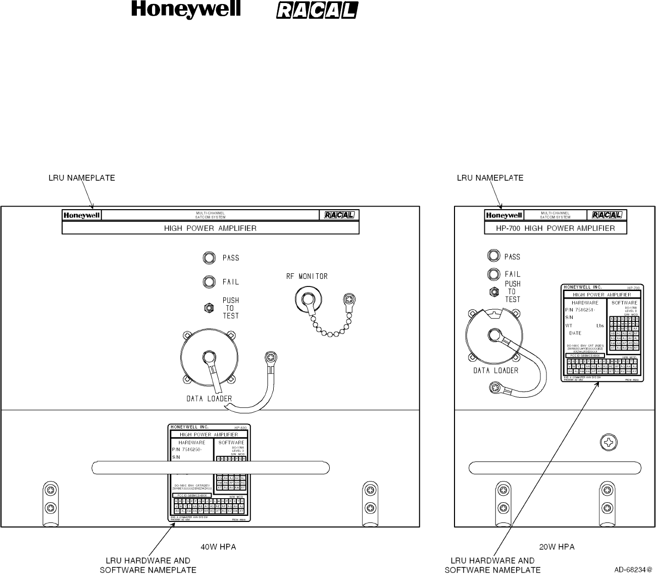
SYSTEM DESCRIPTION, INSTALLATION, AND MAINTENANCE MANUAL
MCS--4000/7000 Multi--Channel SATCOM System
23--20--27
30 Aug 2002
Use or disclosure of information on this page is subject to the restrictions in the proprietary notice of this document.
Page 1--31/(1--32 blank)
Figure 1-7. High--Power Amplifier (40 and 20 Watt)
RELEASED FOR THE EXCLUSIVE USE BY: HONEYWELL INTERNATIONAL
UP86308

SYSTEM DESCRIPTION, INSTALLATION, AND MAINTENANCE MANUAL
MCS--4000/7000 Multi--Channel SATCOM System
23--20--27
30 Aug 2002
Use or disclosure of information on this page is subject to the restrictions in the proprietary notice of this document.
Page 1--33
Table 1-11. HPA (40 Watt) Leading Particulars
Characteristic Specification
Dimensions (maximum):
•Height ................................ 7.813 in. (198.45 mm)
•Width ................................. 10.22 in. (259.59 mm)
•Length ................................ 15.20 in. (386.08 mm)
Weight (maximum) ....................... 29.15 lb (13.22 kg)
Power Requirements:
•ACVoltage ............................ 104 to 122 V ac, 380 to 420 Hz (normal operation)
97 V ac, 360 Hz minimum; 134 V ac,440 Hz maximum
•DCVoltage ............................ 22.0 to 30.3 V dc (normal operation)
20.5 V dc minimum, 32.2 V dc maximum
AC Current Requirements
1.
:
•Nominal at 115 V ac (Current/Power Factor) 1.94 amps/0.95
•Maximum at 104 V ac (Current/Power
Factor)................................ 2.2 amps/0.96
DC Current Requirements:
•Nominal at 28 V dc ..................... 7.3 amps
•Maximumat20.5Vdc .................. 8.2 amps
RF Power Output:
•Rated operating power .................. 40 W (multiple carriers)
•Maximumpower ....................... 80 W (short duration, single carrier)
Circuit Breaker Ratings:
•115VacCircuitBreaker ................ 7.5 amp TYPE A
•28 V dc Circuit Breaker
2.
................ 30 amp TYPE A
User Replaceable Parts ................... None
OperatingTemperature.................... -- 5 5 _C(--67_F) to +70 _C (158 _F)
OperatingAltitude ........................ to 70,000 ft (21.34 kilometers)
Cooling Requirements
3.
:
•Minimum .............................. 0.15 ±0.05 in. (3.81 ±1.27 mm) of water at a flow rate of
121.3 ±2.0 lb (55.0 ±0.9 kg) per hour
•Maximum ............................. 0.25 ±0.05 in. (6.35 ±1.27 mm) of water at a flow rate of
176.4 ±2.0 lb (80.0 ±0.9 kg) per hour
RELEASED FOR THE EXCLUSIVE USE BY: HONEYWELL INTERNATIONAL
UP86308

SYSTEM DESCRIPTION, INSTALLATION, AND MAINTENANCE MANUAL
MCS--4000/7000 Multi--Channel SATCOM System
23--20--27
30 Aug 2002
Use or disclosure of information on this page is subject to the restrictions in the proprietary notice of this document.
Page 1--34
Table 1-11. HPA (40 Watt) Leading Particulars (cont)
Characteristic Specification
Power Dissipation:
•Nominal ............................... 300 W
•Maximum ............................. 362 W
Mating Connectors:
•J1 .................................... Radiall Part No. NSXN2P221X0008
•J2 .................................... Honeywell Part No. 4004295--160,
ITT Part No. KJ6F18A53P
•J3 .................................... BNC Plug
Mounting ................................ ARINC 600 8--MCU Tray Assembly
NOTES:
1. All PF are leading.
2. Wiring can not exceed 18 V dc drop at 30 amps.
3. Refer to Appendix A, Vendor Equipment, for mounting trays with integral cooling fans that meet the cooling
requirements.
Table 1-12. HPA (40 Watt) DO--160C Environmental Categories
Environmental Condition Category
Temperature and Altitude Category A2E1/Z (E1)
1.
Temperature Variation Category B
Humidity Category A
Shock Category B
Vibration Category BLMY
Explosion Category E1
Waterproofness Category X
Fluids Susceptibility Category X
Sand and Dust Category X
Fungus Resistance Category X
Salt Spray Category X
Magnetic Effect Category Z
Power Input -- 115 V ac Category E
Power Input -- 28 V dc Category Z
2.
Voltage Spike Category A
RELEASED FOR THE EXCLUSIVE USE BY: HONEYWELL INTERNATIONAL
UP86308

SYSTEM DESCRIPTION, INSTALLATION, AND MAINTENANCE MANUAL
MCS--4000/7000 Multi--Channel SATCOM System
23--20--27
30 Aug 2002
Use or disclosure of information on this page is subject to the restrictions in the proprietary notice of this document.
Page 1--35
Table 1-12. HPA (40 Watt) DO--160C Environmental Categories (cont)
Environmental Condition Category
Audio Frequency Susceptibility -- 115 V ac Category E
Audio Frequency Susceptibility -- 28 V dc Category Z
Induced Signal Susceptibility Category Z
Radio Frequency Susceptibility Category W
3.
Radio Frequency Emissions Category Z
Lightning Induced Category K
Lightning Direct Category X
Icing Category X
NOTES:
1. E1 -- Operating High Temperature/High Short Time = 70 °C (158 °F).
2. Z -- The power input requirements for the 28 V dc LRU are category Z except for an emergency operation, in which
case the requirements of category B apply.
3. W -- Performance of this test is required to satisfy the HIRF requirements. The LRUs must survive a category W
event without degradation (i.e., regain normal operation at the termination of the HIRF event), and must operate
through (with performance degradation permitted) and after (without performance degradation) a category T event.
D. High--Power Amplifier (20 Watt)
(1) The HPA is packaged as an ARINC 600 4--MCU suitable for mounting in the
equipment bay or near the antenna system. The mechanical chassis is constructed of
lightweight aluminum alloy sheet metal. Forced air moving through the chassis in an
upward or downward direction supplies internal cooling. Two hold-down clamps let
the unit be firmly clamped in the mounting rack. The unit is carried by a fixed
C-shaped handle mounted to the front panel assembly.
(2) The front panel assembly contains a PTT switch to initiate BITE and a red (FAIL) and
green (PASS) LED to indicate BITE status. The front panel also contains an ARINC
615 portable data loader connector.
(3) The rear connector receptacle is a size No. 2 shell assembly (in accordance with
ARINC 600) that engages a mating connector in the mounting rack when the HPA is
installed. The top insert is a type 08 arrangement, the middle insert is a type 05
arrangement, and the bottom insert is a type 04 arrangement. Index pin code 08 is
used on both the HPA and mounting rack connectors.
(4) The HPA (20 Watt) is shown in Figure 1-7. The leading particulars for the HPA (20
Watt) are given in Table 1-13. DO--160D environmental categories for the HPA (20
Watt) are given in Table 1-14.
RELEASED FOR THE EXCLUSIVE USE BY: HONEYWELL INTERNATIONAL
UP86308

SYSTEM DESCRIPTION, INSTALLATION, AND MAINTENANCE MANUAL
MCS--4000/7000 Multi--Channel SATCOM System
23--20--27
30 Aug 2002
Use or disclosure of information on this page is subject to the restrictions in the proprietary notice of this document.
Page 1--36
Table 1-13. HPA (20 Watt) Leading Particulars
Characteristic Specification
Dimensions (maximum):
•Height ................................ 7.64 in. (194.056 mm)
•Width ................................. 4.90 in. (124.46 mm)
•Length ................................ 15.26 in. (387.604 mm)
Weight (maximum) ....................... 15.80 lb (7.17 kg)
Power Requirements:
•ACVoltage ............................ 104 to 122 V ac, 380 to 420 Hz (normal operation)
97 V ac, 360 Hz minimum; 134 V ac, 440 Hz maximum
•DCVoltage ............................ 22.0 to 30.3 V dc (normal operation)
20.5 V dc minimum, 32.2 V dc maximum
AC Current Requirements
1.
:
•Nominal at 115 V ac (Current/Power Factor) 1.94 amps/0.96
•Maximum at 104 V ac (Current/Power
Factor)................................
2.2 amps/0.96
DC Current Requirements:
•Nominal at 28 V dc ..................... 7.3 amps
•Maximumat20.5Vdc .................. 12 amps
RF Power Output:
•Rated operating power .................. 25.1 W (under all conditions)
•Maximumpower ....................... 25.1 W (under all conditions)
Circuit Breaker Ratings:
•115VacCircuitBreaker ................ 7.5 amp TYPE A
•28VdcCircuitBreaker ................. 15 amp TYPE A
User Replaceable Parts ................... None
OperatingTemperature.................... -- 1 5 _C(5_F) to +70 _C (158 _F)
OperatingAltitude ........................ to 55,000 ft (16.76 kilometers)
Cooling Requirements (Minimum)
2.
......... 0.20 ±0.12 in. (5 ±3 mm) of water at a flow rate of 72.8 ±
2.0 lb (33.0 ±0.9 kg) per hour
Power Dissipation:
•Nominal ............................... 150 W
•Maximum ............................. 219 W
RELEASED FOR THE EXCLUSIVE USE BY: HONEYWELL INTERNATIONAL
UP86308
SYSTEM DESCRIPTION, INSTALLATION, AND MAINTENANCE MANUAL
MCS--4000/7000 Multi--Channel SATCOM System
23--20--27
30 Aug 2002
Use or disclosure of information on this page is subject to the restrictions in the proprietary notice of this document.
Page 1--37
Table 1-13. HPA (20 Watt) Leading Particulars (cont)
Characteristic Specification
Mating Connectors:
•J1 .................................... Radiall Part No. NSXN2P221X0008
•J2 .................................... Honeywell Part No. 4004295--160, ITT Part No.
KJ6F18A53P
Mounting ................................ ARINC 600 4--MCU Tray Assembly
NOTES:
1. All PF are leading.
2. Refer to Appendix A, Vendor Equipment, for mounting trays with integral cooling fans that meet the cooling
requirements.
Table 1-14. HPA (20 Watt) DO--160D Environmental Categories
Environmental Condition Category
Temperature and Altitude Category A2E1/Z (E1)
1.
Temperature Variation Category B
Humidity Category A
Shock Category B
Vibration Category SB2
Explosion Category E
Waterproofness Category X
Fluids Susceptibility Category X
Sand and Dust Category X
Fungus Resistance Category X
Salt Spray Category X
Magnetic Effect Category Z
Power Input -- 115 V ac Category E
Power Input -- 28 V dc Category BZ
2.
Voltage Spike Category A
Audio Frequency Susceptibility -- 115 V ac Category E
Audio Frequency Susceptibility -- 28 V dc Category Z
Induced Signal Susceptibility Category Z
Radio Frequency Susceptibility Category RRR
3.
Radio Frequency Emissions Category M
RELEASED FOR THE EXCLUSIVE USE BY: HONEYWELL INTERNATIONAL
UP86308
SYSTEM DESCRIPTION, INSTALLATION, AND MAINTENANCE MANUAL
MCS--4000/7000 Multi--Channel SATCOM System
23--20--27
30 Aug 2002
Use or disclosure of information on this page is subject to the restrictions in the proprietary notice of this document.
Page 1--38
Table 1-14. HPA (20 Watt) DO--160D Environmental Categories (cont)
Environmental Condition Category
Lightning Induced Category A3E3
Lightning Direct Category X
Icing Category X
Electrostatic Discharge Category A
NOTES:
1. E1 -- Operating High Temperature/High Short Time = 70 °C (158 °F).
2. BZ -- The power input requirements for the 28 V dc version of the 20 Watt HPA are category Z except for an
emergency operation, in which case the requirements of category B apply.
3. RRR -- Performance of this test is required to satisfy the HIRF requirements.
E. CMA--2200 Intermediate Gain Antenna
(1) The Intermediate Gain Antenna supplies a minimum of 6 dB antenna gain (8 dB
nominal) and operates with the 20 W HPA. The IGA is manufactured by BAE
Systems Canada Inc. (formerly Canadian Marconi Company Aerospace) under both
BAE Systems -- Canada Part No. 100--602372--000 and Honeywell Part No.
7516194--901. Features of the IGA are given in Table 1-15.
Table 1-15. CMA--2200 Intermediate Gain Antenna Features
Characteristic Specification
Servicecoverage.........................
less than 95% of the Inmarsat hemisphere
•
Receive
..............................
1525.0 -- 1559.0 MHz
•
Transmit
.............................
1626.5 -- 1660.5 MHz
Polarization ..............................
Right hand circular
Receive figure of merit (G/T)
............
--15.5 dB/K typical, --19 dB/K minimum
Effective Isotropic Radiated Power (EIRP) 19.5 dBW typical, 16.5 dBW minimum
Phase discontinuity
.....................
2.5_typical, less than 30_for 99% of all beam
steering increments
Beam switching
.........................
50 µs maximum
Carrier/Multipath
........................
15 dB typical, 10 dB minimum at 5_elevation; 20 dB
typical,12 dB minimum at 20_elevation
Satellite discrimination
..................
16 dB typical, 7 dB minimum
Latitude global Inmarsat satellite
coverage
............................... ±
86 degrees
Required antenna gain
..................
6dB
RELEASED FOR THE EXCLUSIVE USE BY: HONEYWELL INTERNATIONAL
UP86308
SYSTEM DESCRIPTION, INSTALLATION, AND MAINTENANCE MANUAL
MCS--4000/7000 Multi--Channel SATCOM System
23--20--27
30 Aug 2002
Use or disclosure of information on this page is subject to the restrictions in the proprietary notice of this document.
Page 1--39
Table 1-15. CMA--2200 Intermediate Gain Antenna Features (cont)
Characteristic Specification
Support/Test equipment required
........
None at organizational level
Design characteristics
(RTCA/ARINC/TSO/etc.)
................
DO--160C, ARINC 761, MOPS, SARPS
(2) Other features of the CMA--2200 IGA include:
•Inmarsat Generation 3 Spot Beam coverage
•Proven compatibility with ARINC 761 intermediate--gain antenna subsystems
•BIT status reporting.
(3) The leading particulars for the CMA--2200 IGA are given in Table 1-16. DO--160C
environmental categories for the CMA--2200 IGA are given in Table 1-17.
Table 1-16. CMA--2200 IGA Leading Particulars
Characteristic Specification
Dimensions (maximum):
•Height ................................ 3.82 in. (97.0 mm)
•Width:
-- At radome ........................... 3.22 in. (81.8 mm)
-- Atbase ............................. 4.25 in. (108.0 mm)
•Length ................................ 29.92 in. (760.0 mm)
Weight (maximum) ....................... 6lb(2.7kg)
Power Requirements ..................... 15 V dc, 8 V dc and --80 V dc (7 Watts)
Operating Environment:
•Temperature range (operating) ........... -- 5 5 _to +70_C(--67_to +158_F)
•Temperature range (non--operating) ....... -- 5 5 _to +85_C(--67_to +158_F)
•Operatingaltitude ...................... to 70,000 ft (21.34 km)
Mating Connectors:
•J1 .................................... Circular Connector -- Part No. D38999/26FB35SN
•J2 .................................... TNC JACK -- Mates with TNC plug
RELEASED FOR THE EXCLUSIVE USE BY: HONEYWELL INTERNATIONAL
UP86308

SYSTEM DESCRIPTION, INSTALLATION, AND MAINTENANCE MANUAL
MCS--4000/7000 Multi--Channel SATCOM System
23--20--27
30 Aug 2002
Use or disclosure of information on this page is subject to the restrictions in the proprietary notice of this document.
Page 1--40
Table 1-17. CMA--2200 IGA DO--160C Environmental Categories
Environmental Condition Category
Temperature and Altitude E1
In--Flight Loss of Cooling X
Temperature Variation A
Humidity C
Operational Shock and Crash Safety -- --
Vibration E
Explosion Proofness X
Waterproofness S
Fluids Susceptibility F
Sand and Dust D
Fungus Resistance F
Salt Spray S
Magnetic Effect X
Power Input X
Voltage Spike X
Audio Frequency Conducted Susceptibility A
Induced Signal Susceptibility A
Radio Frequency Susceptibility U
Radio Frequency Emissions A
Lightning Induced XXE3
Lightning Direct Effects 2A
Icing C
F. CMA--2200 Diplexer/Low Noise Amplifier
(1) The CMA--2200 Diplexer/Low Noise Amplifier (D/LNA) supplies the RF transmit
(diplexer) and RF receive (low noise amplifier) paths between the HGA, IGA, or LGA
and the HPA and SDU, respectively. The D/LNA is manufactured by BAE Systems --
Canada (formerly Canadian Marconi Company Aerospace) under both BAE Systems
-- Canada Part No. 100--602200--001 and the Honeywell Part No. 7516193--901. The
features of the D/LNA are given in Table 1-18.
RELEASED FOR THE EXCLUSIVE USE BY: HONEYWELL INTERNATIONAL
UP86308

SYSTEM DESCRIPTION, INSTALLATION, AND MAINTENANCE MANUAL
MCS--4000/7000 Multi--Channel SATCOM System
23--20--27
30 Aug 2002
Use or disclosure of information on this page is subject to the restrictions in the proprietary notice of this document.
Page 1--41
Table 1-18. CMA--2200 D/LNA Features
Characteristic Specification
Frequency range:
•Receive ...............................
1525.0 -- 1559.0 MHz
•
Transmit
.............................
1626.5 -- 1660.5 MHz
Receive gain
...........................
53 dB minimum, 60 dB maximum
Noise figure
............................
0.8 dB maximum at 25_C.
Support/Test equipment required
........ N
one at organizational level
Design characteristics
..................
(RTCA/ARINC/TSO/etc)
DO--160C, ARINC 741/761, MOPS, SARPS
(2) Other features of the CMA--2200:
•Proven compatibility with:
-- ARINC 761 intermediate--gain antenna subsystems
-- ARINC 741 high--gain or low--gain antenna subsystems
•Self--test function.
(3) The leading particulars for the CMA--2200 D/LNA are given in Table 1-19. DO--160C
environmental categories for the CMA--2200 D/LNA are given in Table 1-20.
Table 1-19. CMA--2200 D/LNA Leading Particulars
Characteristic Specification
Dimensions (maximum):
•Height ................................ 2.00 in. (50.8 mm)
•Width ................................. 7.78 in. (197.6 mm)
•Length ................................ 11.59 in. (294.4 mm)
Weight (maximum) ....................... 6.5lb(3.0kg)
Power Requirements ..................... 115 V ac, 400 Hz, 150 milliamps maximum
Operating Environment:
•Temperature range (operating) ........... -- 5 5 _to +70_C(--67_F to +158_F)
•Temperature range (non--operating) ....... -- 5 5 _to +85_C(--67_F to +158_F)
•Operatingaltitude ...................... to 70,000 ft (21.34 km)
RELEASED FOR THE EXCLUSIVE USE BY: HONEYWELL INTERNATIONAL
UP86308

SYSTEM DESCRIPTION, INSTALLATION, AND MAINTENANCE MANUAL
MCS--4000/7000 Multi--Channel SATCOM System
23--20--27
30 Aug 2002
Use or disclosure of information on this page is subject to the restrictions in the proprietary notice of this document.
Page 1--42
Table 1-20. CMA--2200 D/LNA DO--160C Environmental Categories
Environmental Condition Category
Temperature and Altitude E1
In--Flight Loss of Cooling X
Temperature Variation B
Humidity A
Operational Shock and Crash Safety -- --
Vibration C
Explosion Proof E2
Waterproof W
Fluids Susceptibility X
Sand and Dust X
Fungus Resistance F
Salt Spray X
Magnetic Effect A
Power Input E
Voltage Spike A
Audio Frequency Conducted Susceptibility E
Induced Signal Susceptibility Z
Radio Frequency Susceptibility V
Radio Frequency Emissions Z
Lightning Induced XXE3
Lightning Direct Effects X
Icing X
RELEASED FOR THE EXCLUSIVE USE BY: HONEYWELL INTERNATIONAL
UP86308
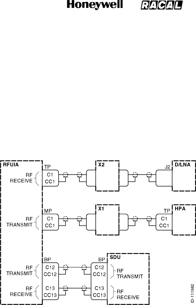
SYSTEM DESCRIPTION, INSTALLATION, AND MAINTENANCE MANUAL
MCS--4000/7000 Multi--Channel SATCOM System
23--20--27
30 Aug 2002
Use or disclosure of information on this page is subject to the restrictions in the proprietary notice of this document.
Page 1--43
G. Radio Frequency Unit Interface Adapter (RFUIA)
(1) The RFUIA is packaged as an ARINC 600 4--MCU suitable for mounting in the
equipment bay or near the antenna system. It consists of a housing assembly
integrated with an ARINC 600 connector on the back of the unit.
(2) The RFUIA is not an operational unit and it does not contain active internal electronic
components. No aircraft power is needed. This unit is installed in the aircraft in place
of the RFU to complete the RF receive and transmit paths for the MCS--7000 system.
(3) The housing is constructed of lightweight aluminum alloy sheet metal. No forced air
cooling is required. Two hold-down clamps let the unit be firmly clamped in the
mounting rack. The unit is carried by a fixed C-shaped handle mounted to the front
panel assembly.
(4) Figure 1-8 is a block diagram that shows how the RFUIA interfaces to the other
system LRUs. The leading particulars for the CMA--2200 D/LNA are given in
Table 1-21.
Figure 1-8. RFUIA System Interface Diagram
RELEASED FOR THE EXCLUSIVE USE BY: HONEYWELL INTERNATIONAL
UP86308

SYSTEM DESCRIPTION, INSTALLATION, AND MAINTENANCE MANUAL
MCS--4000/7000 Multi--Channel SATCOM System
23--20--27
30 Aug 2002
Use or disclosure of information on this page is subject to the restrictions in the proprietary notice of this document.
Page 1--44
Table 1-21. RFUIA Leading Particulars
Characteristic Specification
Dimensions (maximum):
•Length ................................
•Width .................................
•Height ................................
12.76 in. (324.1 mm)
4.90 in. (124.5 mm)
7.64 in. (194.1 mm)
Weight (maximum) 4lb(1.82kg)
Power requirements None
Cooling Convection, no forced air required
H. ARINC 429 Data Requirements
(1) The MCS system requires ARINC 429 data for antenna pointing, antenna
stabilization, and Doppler frequency correction. If the aircraft does not have an IRS
that supplies this ARINC data, the SCU can be used to convert INS data sources.
Refer to Appendix A, Vendor Equipment, for additional information about the SCU
and the ARINC 429 data requirements.
I. Nameplates 3 (SDU and HPA)
(1) General
(a) Each LRU has two externally mounted nameplates consisting of:
•Front panel--mounted LRU nameplate
•Second LRU nameplate that reflects the full hardware and software status of
the LRU.
(b) The details of these nameplates are specified in the following paragraphs. See
Figure 1-6 and Figure 1-7 for the location of each nameplate.
(2) Front Panel LRU Nameplate
(a) Each front panel LRU nameplate contains each company’s logo (Honeywell and
Racal), the name of the system, and the LRU equipment name.
RELEASED FOR THE EXCLUSIVE USE BY: HONEYWELL INTERNATIONAL
UP86308

SYSTEM DESCRIPTION, INSTALLATION, AND MAINTENANCE MANUAL
MCS--4000/7000 Multi--Channel SATCOM System
23--20--27
30 Aug 2002
Use or disclosure of information on this page is subject to the restrictions in the proprietary notice of this document.
Page 1--45
(3) LRU Hardware and Software Nameplate
(a) Each LRU hardware and software nameplate contains the following information:
•Name of the company responsible for manufacturing it
•Model number (e.g., SD700, HP600, or HP700)
•LRU equipment name
•LRU hardware part number
•LRU serial number
•Weight
•Applicable DO--160C/DO--160D categories
•FCC identifier
•LRU hardware modification level
•LRU end item part number
•LRU software part number
•Software modification level
•Applicable DO--178A or DO--178B software level.
(b) The model number is a five--digit alphanumeric sequence. The first two digits are
upper--case alphabetic characters in the range AA to ZZ and the last three digits
are numeric characters in the range 100 to 999. The LRU equipment name is
displayed with as many upper--case letters as are required to spell out the
equipment name. The LRU serial number consists of an eight--digit numeric
sequence; the first two digits indicate the year of manufacture, the second two
digits indicate the month of manufacture, and the final four digits indicate how
many LRUs of this type have been manufactured. The range of the last four
digits is 0100 to 9999.
(c) The DO--160C or DO--160D categories applicable to the MCS system consist of
a mix of numeric and upper--case alphabetic characters. See Table 1-10,
Table 1-12, or Table 1-14 for a list of environmental categories applicable to the
MCS LRUs.
(d) The FCC identifier applicable to all MCS LRUs is GB8MCS--4000 or
GB8MCS--7000. The LRU hardware modification level is indicated by the set of
all marked modification level identifiers. Each modification level identifier is a
maximum of two upper--case alphabetic characters that range from A to ZZ, with
letters I, O, Q, and X excluded.
(e) The LRU end item part number consists of a seven--digit base part number and a
five--digit dash number. The first two digits of the dash number indicate the LRU’s
hardware configuration and consist of numeric values ranging from 10 to 99. The
last three digits of the dash number reflect the LRU’s software configuration
number and consist of numeric values ranging from 001 to 999.
RELEASED FOR THE EXCLUSIVE USE BY: HONEYWELL INTERNATIONAL
UP86308

SYSTEM DESCRIPTION, INSTALLATION, AND MAINTENANCE MANUAL
MCS--4000/7000 Multi--Channel SATCOM System
23--20--27
30 Aug 2002
Use or disclosure of information on this page is subject to the restrictions in the proprietary notice of this document.
Page 1--46
(f) The software modification level consists of a maximum of two upper--case
alphabetic characters ranging from A (or “--”) to ZZ, with letters I, O, Q, and X
excluded. Usage of this nameplate characteristic reflects the implementation of
minor software changes.
(g) The DO--178A or DO--178B software levels applicable to the MCS LRUs is the
level an LRU was certified. This nameplate is capable of being removed and
replaced when a software change is significant enough to require the three--digit
software configuration number be incremented, or a hardware change is
significant enough to require that the two--digit hardware configuration number
be incremented.
J. Software and Hardware Compatibility (SDU and HPA)
(1) Provisions for a set of discrete wire jumpers (straps) are included in each MCS LRU
to ensure hardware and software compatibility. The code setting for these straps is
manually changed each time a hardware revision is made that is not compatible with
all previously released versions of software. The status of these straps is tested
every time an LRU undergoes a cold start (power--on self--test [POST], or
person--activated self--test [PAST] ), and every time a software load is attempted from
an ARINC 615 portable data loader.
(2) The LRU header records in the ARINC 615 data loader software upload file and in
the operational software itself, contain a list of hardware/software compatibility strap
codes with which the software is compatible. This list of codes is compared with the
wired hardware/software compatibility strap code in the LRU; if any of the codes in
the software upload file match the hardware/software compatibility strap code in the
LRU, then the software upload process is allowed (otherwise it is inhibited). Similarly,
if any of the codes in the software itself match the strap code in the LRU, normal LRU
operation is allowed (otherwise it remains in an inert state).
RELEASED FOR THE EXCLUSIVE USE BY: HONEYWELL INTERNATIONAL
UP86308

SYSTEM DESCRIPTION, INSTALLATION, AND MAINTENANCE MANUAL
MCS--4000/7000 Multi--Channel SATCOM System
23--20--27
30 Aug 2002
Use or disclosure of information on this page is subject to the restrictions in the proprietary notice of this document.
Page 2--1
SECTION 2
SYSTEM OPERATION
1. Overview
A. General
The AES accepts data and voice signals from various sources, encodes the signals,
modulates the information onto the appropriate RF carrier frequencies, and transmits these
carriers to a GES through satellite. The AES also receives RF signals from the satellites,
demodulates and decodes these signals, and outputs data or voice message for passengers
or flight crew members. System operation begins when the P--channel transmission from a
GES in the satellite region is received. The AES then logs onto the GES to establish the
uplink and exchange information. System operation terminates when the AES logs off from
the GES.
2. AES Management
A. General
(1) At any time, different satellite regions can have different satellite configurations. All
satellites have the global beam capability to receive the continuous Psmc--channel
transmission of every GES in view. For a spot beam satellite, each spot beam is
associated with at least one GES having a continuous P--channel transmission.
Selected channels from the Psmc-- and Pd--channels are designated by INMARSAT
for satellite and spot beam selection.
(2) An AES logs onto a GES to enter the satellite communications system and logs off to
terminate its operation in the system. Log-off is initiated automatically or by a user
command issued as part of normal operational procedures.
(3) The AES also logs off before initiating handover. The AES does not log off if
handover is initiated because of degradation or loss of the P--channel. Handover can
be initiated by the flight crew, or can be carried out automatically by the AES without
human intervention. A handover procedure is followed automatically when an AES
needs to change the log-on GES or to access a different satellite.
(4) When an AES receives a higher level instruction, for example a command from the
flight crew, to change its log-on to another GES operating in the same satellite
region, any previously established data communication channels are maintained until
clearing before the handover is carried out. In the case of a user command initiated
satellite-to-satellite handover, the AES ensures all communication channels are clear
prior to starting the handover procedure. If any connections are in progress, the AES
applies time supervision of three minutes and then clears any remaining connections.
(5) Automatic handover is initiated upon detection of Pd--channel link degradation
defined as:
•Error rate rises above 10
4
over an averaging period of 3 minutes
•More than 10 short--term interruptions (loss of P--channel clock synchronization for
less than 10 seconds) in any 3 minute period.
RELEASED FOR THE EXCLUSIVE USE BY: HONEYWELL INTERNATIONAL
UP86308

SYSTEM DESCRIPTION, INSTALLATION, AND MAINTENANCE MANUAL
MCS--4000/7000 Multi--Channel SATCOM System
23--20--27
30 Aug 2002
Use or disclosure of information on this page is subject to the restrictions in the proprietary notice of this document.
Page 2--2
(6) Automatic handover is also initiated upon detection of loss of the Pd--channel defined
as:
•Loss of clock synchronization for more than 10 seconds
•Log-on renewal procedure is unsuccessful.
(7) A GES-to-GES handover is carried out by logging onto a new GES in the same
satellite region. The required P--channel frequency can be found in the system table.
Each GES maintains an up-to-date status table of all AESs that have logged on.
Each GES also has an inter-GES signaling capability letting the GES set up calls with
any AES operating in the same satellite region as that GES, and manages the AESs
during handover.
(8) If the AES attempts to renew its log-on and fails to log on to its previous GES or to
the preferred alternative GES after a log-on prompt, loss of P--channel quality, or a
log-on renewal request from an application, the AES returns to the latter stages of
the initial search procedure and scans the spot beam primary Pd--channels on its
current satellite to identify an alternative spot beam. The required P--channel
frequencies are found in the system table. Once an alternative spot beam is
identified, the AES renews its log-on automatically to a preferred GES.
(9) During log-on renewal, if the AES is unable to log onto its previous GES or to another
GES in the same satellite region, then the AES enters the search mode to select the
Psmc--channel frequency of a GES operating in a new satellite region. The required
P--channel frequency is found in the system table. Having selected a new suitable
quality Psmc--channel (in another satellite region) and updating the system table for
the new satellite region (if necessary), the AES carries out a log-on procedure with
the new GES.
(10) Each AES maintains a system table stored in nonvolatile memory in the SDU. The
system table contains the satellite and GES identifying information, such as satellite
Psid--channel frequencies, satellite locations and associated GES IDs, and GES
Psmc--channel frequencies. The system table does not lose its contents because of
loss of primary power.
(11) The SDU also maintains a bootstrap system table containing a default set of satellite
and GES identifying information. This information includes satellite Psid--channel
frequencies, satellite location and associated GES IDs, plus satellite inclination and
right ascension, spot beam support, and GES Psmc--channel frequencies that are set
to zero.
(12) The bootstrap system table is loaded into the SDU as an inseparable part of the
upload of executable software. The SDU defaults to the bootstrap system table in the
absence of a stored system table, or upon execution of a factory settings restart. The
default data for a satellite is used until that satellite is first accessed, where a
complete update of the data for that satellite takes place. Satellite region blocks that
have not yet been updated over the air are marked with a null revision number.
RELEASED FOR THE EXCLUSIVE USE BY: HONEYWELL INTERNATIONAL
UP86308

SYSTEM DESCRIPTION, INSTALLATION, AND MAINTENANCE MANUAL
MCS--4000/7000 Multi--Channel SATCOM System
23--20--27
30 Aug 2002
Use or disclosure of information on this page is subject to the restrictions in the proprietary notice of this document.
Page 2--3
3. System Log-On/Log-Off
A. General
(1) Two operational modes are available for AES log-on:
•Automatic
•User commanded (constrained).
(2) In the automatic mode, the AES operation is fully automatic with satellite log-on and
handover procedures occurring without external control. In the user commanded
mode, the flight crew or flight control system is able to select the satellite and GES for
log-on and handover, and can initiate handovers at any time. The automatic mode is
considered the normal mode of operation.
(3) The log-on/log-off of an AES to/from the satellite communications system lets the
GES manage the number of AESs that can receive a P--channel (Pd) and transmit on
each R--channel (Rd). This controls the queuing delays and burst collision
probabilities that can be experienced. When an AES is powered up, it enters a GES
selection mode if the log-on policy is set to automatic. This permits the AES to select
the most preferred GES operating in its visible satellite region (there may be one or
two satellites visible to the AES), and that GES is selected for log-on. If the log-on
policy is not set to automatic, the AES waits for the GES to be selected through the
user commanded mode (or for a reversion to the automatic mode).
(4) After selecting a GES, the AES tries to acquire one of the identifying Psmc--channel
frequencies of the satellite contained in the initial system table. Typically there are
two frequencies per satellite (or group of satellites if several satellites supply service
to essentially one region). The AES receives that Psmc--channel until one of the
system table’s broadcast signal units is received, which permits the AES to determine
whether the revision number of the system table currently stored in the SDU is valid.
If the revision number for the AES is out-of-date, an AES updating procedure is
implemented.
(5) When the revision number is verified as correct, the AES checks for any entries in the
satellite spot beam search table. If an entry exists, the AES checks the Pd--channel
frequencies of all spot beams supported by the selected GES to identify the most
applicable spot beam. The AES then determines which Pd--channel has the highest
signal quality. Once this task is complete, the AES is ready to log-on to the satellite
communications system using the selected GES and the optimum spot beam, or the
global beam if the GES does not operate a P--channel in the required spot beam.
RELEASED FOR THE EXCLUSIVE USE BY: HONEYWELL INTERNATIONAL
UP86308

SYSTEM DESCRIPTION, INSTALLATION, AND MAINTENANCE MANUAL
MCS--4000/7000 Multi--Channel SATCOM System
23--20--27
30 Aug 2002
Use or disclosure of information on this page is subject to the restrictions in the proprietary notice of this document.
Page 2--4
(6) The AES initiates the log-on procedure by tuning to the Psmc--channel (global beam)
of the selected GES and sending a log-on request signal unit on one of the
corresponding Rsmc--channels. If the log-on request signal unit cannot be accepted
by the GES, because of reasons like GES overload, invalid message, unauthorized
access, etc, the GES responds with a log-on reject signal unit, which includes the
cause of the rejection. By returning a log-on confirm signal unit with a different AES
class value, the GES can offer log-on in a different AES class than originally
requested. The AES can either accept log-on in the offered class by continuing the
log-on signaling procedure, or reject log-on by discontinuing the log-on signaling
procedure.
(7) The AES uses the log-on request signal unit to supply the selected GES with its own
identification (a 24-bit ICAO aircraft identification code), plus the identification of the
spot beam where the AES is located. A zero value is used in the spot beam
identification field of the log-on message if:
•No spot beam on the selected satellite
•AES is out of any spot beam coverage area
•Selected GES does not operate a Pd--channel in the required spot beam.
(8) The AES also informs the GES of the number of C--channels the AES is equipped to
handle, the bit rate/coding algorithm in use on the voice channels, and the data bit
rate capability for the R--channels, P--channels, and T--channels. Except for the
number of C--channels and the data bit rate capability, this information is repeated in
the log-on confirm signal unit for use by other GESs.
(9) An AES having circuit-mode data service capability and desiring allocation of
circuit-mode data capable channel units at the GES for every ground-to-air call,
informs the GES of the type of interface required. The interface is either analog
interconnect or digital interconnect. If the GES does not support circuit-mode data
service, it ignores the information. If the GES supports the service, it registers the
information in its log-on AES table and retransmits the information for use by other
GESs.
(10) The AES supplies the GES with its flight identification number at log-on, if the
owner/operator of the AES desires to use the aircraft flight identification as the
address for ground originated calls. The use of this information in the GES depends
upon the services being offered, and therefore is at the discretion of the GES
operator.
(11) The AES is given an EIRP setting for Rd--channels in the log-on confirm signal. If a
T--channel is assigned, the AES determines the EIRP for the T--channel in
accordance with the assigned R--channel EIRP and the ratio of the R--channel and
T--channel bit rates. The GES assigns a Pd--channel from the available channels,
taking into account the loadings on the channels, the need to use a P--channel of low
power if possible, and the need to supply some means of recovery from P--channel
degradation or failure. The ability to work with a low power P--channel is determined
by the AES class. If the GES assigns a Pd--channel different than the Psmc--channel,
the GES transmits the new channel frequency to the AES using the P/R--channel
control signaling message following the log-on confirm.
RELEASED FOR THE EXCLUSIVE USE BY: HONEYWELL INTERNATIONAL
UP86308

SYSTEM DESCRIPTION, INSTALLATION, AND MAINTENANCE MANUAL
MCS--4000/7000 Multi--Channel SATCOM System
23--20--27
30 Aug 2002
Use or disclosure of information on this page is subject to the restrictions in the proprietary notice of this document.
Page 2--5
(12) If the GES is using more than one set of R--channel frequencies and assigns new
Rd--channels to the aircraft, the GES transmits the new channel frequencies (up to
eight) to the AES using the signaling message(s) that follow the log-on confirm. In
addition, the GES transmits from one to four T--channel frequencies to the AES if
data services are supplied. The GES uses the following criteria to determine the
channel and EIRP assignments for data services:
•Satellite in use (its return link sensitivity)
•Class of AES
•Bit rate capability of the AES.
(13) The GES assigns data channels at the highest agreeable bit rate supplied in both the
AES and GES, and supported by the combination of the satellite in use and the class
of AES. Subsequent log-on transactions for handover use Rsmc-- and
Psmc--channels in the same manner as the initial log-on transaction.
B. Automatic Log-On
(1) The SDU supports two types of log-on:
•Automatic
•Constrained mode.
(2) The SDU implements the automatic log-on mode upon user command if the AES is
currently logged-off, AES is logging-on, or AES is logged-on in the constrained mode.
Automatic log-on is also implemented by the SDU, if ORT item i (log-on policy)
indicates automatic at startup. The user command can originate from either the
SCDU, from the analog connected telephone handsets, or from the commissioning
and maintenance terminal (CMT).
(3) When the AES is in the automatic mode, the log-on GES/satellite/spot beam chosen
is based on the GES preference (ORT item iii). A GES with a preference level of zero
is not considered for automatic log-on. The SDU allows the use of tied GES
preferences. The SDU resolves tied preferences by selecting the GESs in
descending order of satellite elevation. During GES selection, the set (as yet untied)
of GESs with the highest preference are initially processed to exclude those GESs
associated with satellites not in view.
(4) Satellites are deemed in view if they are above the elevation handover threshold
specified in ORT item xxxix, or their elevation is higher than 1 degree less than the
elevation of the highest satellite. If no IRS data is available and the currently selected
antenna is the low gain antenna, then all satellites are deemed to be in view. The
remainder of the GESs in the preference group are then sorted into a list by satellite
elevation and GES on the highest elevation satellite chosen for initial access. If more
than one GES in the preference group have the same satellite elevation, then those
GESs are ordered by a pseudo-random choice algorithm with a uniform probability
density.
RELEASED FOR THE EXCLUSIVE USE BY: HONEYWELL INTERNATIONAL
UP86308

SYSTEM DESCRIPTION, INSTALLATION, AND MAINTENANCE MANUAL
MCS--4000/7000 Multi--Channel SATCOM System
23--20--27
30 Aug 2002
Use or disclosure of information on this page is subject to the restrictions in the proprietary notice of this document.
Page 2--6
C. Constrained Log-On
(1) Constrained log-on is where the user manually selects the specific GES to be used
for log-on. The user command can originate from either the SCDU, from the
analog-connected telephone handsets, or from the CMT. The GES preferences
specified in ORT item iii have no effect in the constrained log-on mode, and it is
possible to execute a constrained log-on to a GES with a preference level of zero.
(2) If the user has manually selected the log-on GES, and therefore also selecting the
satellite, the SDU is constrained to search for the specific GES-related satellite Psid
frequency (or frequencies), the set of spot beam Pd frequencies where the selected
GES radiates P--channels, and the selected GES Psmc frequency during the log-on
sequences. If the specific GESs satellite Psid frequencies cannot be acquired, the
SDU takes no action other than to reattempt the acquisition with alternate modems. If
none of the GES-related spot beam Pd frequencies can be acquired, the SDU starts
the GES Psmc frequency search as it would normally do after acquiring a spot beam
frequency. If the GES Psmc frequency cannot be acquired, the SDU reattempts the
acquisition indefinitely. This state of unsuccessful satellite/GES Psmc frequency
acquisition is exited either by the frequency being acquired, or by a user command to
select automatic log-on, by selection of a different satellite/GES, or to log-off.
(3) Once logged-on in this mode with the GES constrained, only spot beam handover
takes place. The user is able to exit this constrained log-on mode by commanding
log-off, by selecting the automatic log-on mode, or by cycling SDU primary power (if
ORT item i log--on policy is auto log--on..
D. Log-On Mode Selection
(1) User selection of the automatic log-on mode while the AES is logging-on in the
constrained mode causes the SDU to abort the current log-on attempt and revert to
the automatic mode. User selection of the automatic log-on mode while the AES is
logged-on in the constrained mode causes the SDU to log-off from the current
constrained GES, and to revert to the automatic mode if there are GESs in view with
higher preference levels than the current log-on GES. User selection of the automatic
mode when the AES is logged-off causes the SDU to implement automatic log-on.
The SDU lets the user command log-off while the AES is logging-on or logged-on in
the constrained or automatic mode.
(2) The user is able to change the selected GES if the AES is logging-on or is logged on
in the constrained mode. The user can enter the constrained mode by selecting a
specified GES while the SDU is logging-on or is logged-on in the automatic mode. In
both cases, providing the constrained GES selection is different from the
automatically chosen GES, the SDU either aborts the current log-on attempt or
logs-off from the current GES before attempting to log-on to the new GES, depending
upon the current status.
RELEASED FOR THE EXCLUSIVE USE BY: HONEYWELL INTERNATIONAL
UP86308

SYSTEM DESCRIPTION, INSTALLATION, AND MAINTENANCE MANUAL
MCS--4000/7000 Multi--Channel SATCOM System
23--20--27
30 Aug 2002
Use or disclosure of information on this page is subject to the restrictions in the proprietary notice of this document.
Page 2--7
E. Handover
(1) The SDU causes the AES to initiate a handover procedure for the following reasons:
•Automatic handover when the AES is logged-on in the automatic or constrained
mode, because of P--channel degradation.
•Automatic handover when the AES is logged-on in the automatic mode, because
of the log-on satellite being below the elevation handover threshold specified in
ORT item xxxix, with another satellite being at least 1 degree higher than the
log-on satellite for more than 10 seconds.
•Automatic handover as specified in ORT item xxii for 10 seconds because of the
reported HGA Tx gain being less than the threshold value when the AES is
logged-on in the automatic or constrained mode.
•User command to select the constrained mode when the AES is logged-on (or
awaiting log-on acknowledge) in the automatic mode if the constrained selection is
different from the current, automatically selected GES.
•User command to select the constrained mode for a particular GES when the AES
is currently logged-on (or awaiting log-on acknowledge) to a different GES, but
also in the constrained mode.
•User command to select the automatic mode when the AES is logged-on (or
awaiting log-on acknowledge) in the constrained mode if a GES exists with a
higher preference level than the current log-on GES.
•User command to adjust the GES preference levels if the AES is logged-on (or
awaiting log-on acknowledge) in the automatic mode, and the adjustment results
in any GES having a higher preference level than the current log-on GES.
(2) The SDU logs off from the current log-on GES before logging onto the new GES for
all of the above handover stimuli, except for automatic handover because of
P--channel degradation and automatic handover because of the reported HGA Tx
gain being less than the threshold value.
(3) If any modems are being used for circuit--mode voice when a handover to a GES in a
different satellite region occurs, then the SDU terminates the current C--channel calls
with an SLCV cause of 1221x. The SDU also causes a suitable voice pacifier
message (Sorry, your call can no longer be sustained) to be sent to each currently
in-use digital or analog headset to inform each user of the reason for the call
termination. The SDU does not clear down any ongoing C--channel calls if the
handover is local to the current satellite region.
F. Log-Off
(1) Log-off is initiated in the AES by a user command, either from the SCDU, from the
analog-connected telephone handset, or from the CMT. Log-off is also initiated by the
SDU as part of the handover sequence, except for handovers implemented because
of P--channel degradation.
RELEASED FOR THE EXCLUSIVE USE BY: HONEYWELL INTERNATIONAL
UP86308
SYSTEM DESCRIPTION, INSTALLATION, AND MAINTENANCE MANUAL
MCS--4000/7000 Multi--Channel SATCOM System
23--20--27
30 Aug 2002
Use or disclosure of information on this page is subject to the restrictions in the proprietary notice of this document.
Page 2--8
4. System Software/Database Updates
A. General
(1) Each MCS LRU (SDU and HPA) has an ARINC 615 Airborne Data Loader (ADL) and
PDL port. The SDU and HPA are capable of transferring the data sets listed in
Table 2-1 through these ports.
Table 2-1. Data Set Upload/Download
LRU Data Set Upload/Download
SDU Operational Software Upload Only
Owner Requirements Table Upload and Download
Event and Failure Logs Download Only
Maintenance Activity Log Download Only
Periodic Data Logging (SDU system and
operational parameters)
Download Only
HPA Operational Software Upload Only
(2) In Table 2-1, upload is defined as the transfer of a data set from the ARINC 615 data
loader to the appropriate LRU. A download is defined as the transfer of a data set
from an appropriate LRU to the ARINC 615 data loader. The data set to be
transferred is independent of the port used. If during a data transfer session the other
port becomes active, the session associated with the initially activated port continues
to completion before initiating any session with the other port. The software upload
function is resident in the bootstrap program and functions independently of any
uploadable software in the LRU.
B. Software Upload Process
(1) The uploading of the software is done by either connecting a PDL to the ARINC 615
connector port on the LRU to be programmed, or (in the case of an ADL) by the user
selecting the LRU to be programmed. With the data loader connected, the Link A
connection is completed.
(2) The diskette containing a configuration file and a file containing the software to be
uploaded is inserted into the disk drive of the data loader. The configuration file
contains information for the data loader (ADL or PDL) to configure itself for operation.
All MCS ORT download/upload diskettes contain a configuration file located in the
root directory of the diskette with the filename CONFIG.LDR. The data loader reads
the configuration file and initializes itself according to the parameters read. The data
loader then repeatedly transmits an RTS word.
RELEASED FOR THE EXCLUSIVE USE BY: HONEYWELL INTERNATIONAL
UP86308

SYSTEM DESCRIPTION, INSTALLATION, AND MAINTENANCE MANUAL
MCS--4000/7000 Multi--Channel SATCOM System
23--20--27
30 Aug 2002
Use or disclosure of information on this page is subject to the restrictions in the proprietary notice of this document.
Page 2--9
(3) With the operational software running, the SDU software upload is initiated only after:
•SDU senses the low impedance state on Link A.
•SDU determines it is not airborne (unless the operational software is not valid
where the on-ground/airborne state is ignored).
•SDU detects receiving an RTS word with a system address label (SAL) equal to
307.
(4) The HPA software is similarly initiated only after the requirements mentioned are
satisfied, except software uploading is also enabled when a valid air/ground status
from the SDU is not available to the LRU.
(5) For the LRUs, the software upload is a single pass process. Upload validation checks
both the LRU and SRU header records for applicability. Each data loader block is
then transferred directly to the program store. When the software upload is
completed, the program store CRC is checked over defined regions of the program
store. If either validation process fails, the software upload process aborts. Further
upload attempts can only be initiated by resetting both the data loader and the LRU.
When successfully validated, the LRU causes the data loader to initiate the transfer
complete function and the LRU remains in the data load state, while the Link A
connection remains intact. When the Link A connection is removed, the HPA
performs a POST and the SDU performs a factory settings restart. A factory settings
restart results in Category C nonvolatile data being set to default values followed by
execution of POST/PAST.
C. Validation of the Software Upload File
(1) The following items are validated when software is loaded:
•First two bytes of each LRU/SRU header record indicates a valid record type for
the record position in the data sequence.
•Company name in the LRU header record must be HONEYWELL/RACAL.
•LRU name and base part number must match the current LRU specification as
given on the LRU nameplates.
•Software compatibility codes in each SRU ID PROM must appear in the list of
compatible hardware/software codes for every SRU listed in the LRU header.
RELEASED FOR THE EXCLUSIVE USE BY: HONEYWELL INTERNATIONAL
UP86308

SYSTEM DESCRIPTION, INSTALLATION, AND MAINTENANCE MANUAL
MCS--4000/7000 Multi--Channel SATCOM System
23--20--27
30 Aug 2002
Use or disclosure of information on this page is subject to the restrictions in the proprietary notice of this document.
Page 2--10
5. Owner Requirements Table
A. General
(1) The ORT is stored in nonvolatile memory in the SDU. The ORT contains information
relating to different areas of functionality like log-on and telephony. The ORT does
not lose its contents because of the loss of SDU primary power or as a result of
PAST. All ORT contents are set to default values by a factory settings restart. The
ORT contains all pilot and aircraft operator entered information preserved when the
SDU is powered-down.
(2) Validity of the ORT content is determined by the SDU using a checksum process.
This verification is performed at the time of each power-up. An invalid checksum
results in the SDU reverting to the default values specified in TESTING/FAULT
ISOLATION, ORT default value usage. The contents of the ORT are specified in
Appendix C.
(3) The ORT items are organized into two distinct partitions:
•Secured
•User.
(4) The individual ORT items defined in Table C--1.1 are assigned to a partition by the
designation of secured or user in the attributes column.
(5) The secured partition contains those items the equipment manufacturer, aircraft
manufacturers, and certification authorities have determined to be
configuration-dependent and crucial to the proper operation of the SATCOM system.
The user partition contains all other items of the ORT. The user partition typically
includes items the aircraft operator is able to set or modify, enabling the efficient use
of the equipment in normal operation. A composite ORT file contains all items (both
partitions) in the ORT. This version of ORT is defined to supply a consistent interface
(single ORT file) to those users that do not require the additional security supplied by
the management of two partitions for essential certification.
(6) The content of the ORTs in both SDUs in a dual system is intended to be identical.
For the sake of ORT requirements that must be capable of being different in SDUs 1
and 2, the ORT items affected are duplicated withintheORT.Eachofthoseitemsis
capable of storing separate, independent entries for SDUs 1 and 2, to be used by
each particular SDU as appropriate based on the strapping of its system
configuration pins TP13E/F. The lone SDU in a single system uses the entry for SDU
1 for duplicated items. ORT items not duplicated are said to be common,wherethe
single entry applies to SDUs 1 and 2 in dual systems as well as to the lone SDU in a
single system.
RELEASED FOR THE EXCLUSIVE USE BY: HONEYWELL INTERNATIONAL
UP86308

SYSTEM DESCRIPTION, INSTALLATION, AND MAINTENANCE MANUAL
MCS--4000/7000 Multi--Channel SATCOM System
23--20--27
30 Aug 2002
Use or disclosure of information on this page is subject to the restrictions in the proprietary notice of this document.
Page 2--11
6. ORT Upload/Download Process
A. General
(1) Each ORT download/upload diskette contains a configuration file. The configuration
file contains information for the data loader (ADL or PDL) to configure itself for
operation. All MCS ORT download/upload diskettes contain a configuration file
located in the root directory of the diskette with the filename CONFIG.LDR.
(2) The ORT upload/download file is named SDU_ORT.TAB. This file is made up of an
ORT header record followed by the ORT data. The ORT format version in the ORT
header record is an indication of the ORT data contained in the upload/download file.
B. Startup
(1) ORT downloading/uploading is initiated through the SCDU page or the CMT page.
The diskette containing a configuration file is inserted into the data loader, which
reads the configuration files and initializes itself according to the parameters read.
The data loader then repeatedly transmits a POLL word. The LRU detects receiving a
POLL word and initiates the ORT download/upload.
(2) In the event no configuration file is present or the diskette is not formatted, the data
loader solicits a subsystem identification. The SDU does not respond to the
command and the data loader performs a change disk or a read/write fail.
C. ORT Download
(1) The ORT file is transferred using the control mode download sequence. If insufficient
space exists to contain an ORT, the transfer operation terminates. A file name
SDU_ORT.TAB is created on the ORT diskette. This file replaces any existing file with
the same name. An ORT header is written at the head of the file. The ORT format
version written into the header is the latest version supported by the installed
software build. After transferring the header record, the ORT data is written to the file
until the whole data table is transferred. The file is then closed and a load complete
function is commanded. When an error is detected during the ORT download (i.e.,
unable to create file, ARINC 615 transfer failure, etc.) the download process aborts
and an ADL/PDL error status is indicated on the SCDU/CMT.
D. Control Mode ORT Upload Procedures
(1) Upload the ORT through the MCDU (SCDU)
(a) Make sure the ADL switch in the cockpit has SDU (SAT or SATCOM) selected, or
a PDL is connected to the SDU and the MCS system is logged off.
(b) Insert an ORT diskette containing the ORT file SDU_ORT.TAB, plus the
CONFIG.LDR file into the ADL/PDL.
RELEASED FOR THE EXCLUSIVE USE BY: HONEYWELL INTERNATIONAL
UP86308

SYSTEM DESCRIPTION, INSTALLATION, AND MAINTENANCE MANUAL
MCS--4000/7000 Multi--Channel SATCOM System
23--20--27
30 Aug 2002
Use or disclosure of information on this page is subject to the restrictions in the proprietary notice of this document.
Page 2--12
(c) Access the SDU data loader menu from the MCDU through the following path:
•MCDU main menu
•SATCOM main menu
•Submenu
•Maintenance (Boeing Aircraft Only)
•Data loader.
(d) Make sure line 1L indicates ready.
(e) Select line 2L (*UPLD OWNER REQS).
(f) When the MCDU displays CONNECTED, the data upload is complete. Remove
the diskette from the ADL/PDL. Disconnect the ADL/PDL from the SDU and
initiate PAST in the SDU.
(2) Upload the ORT through the CMT
(a) Make sure the PDL is connected to the SDU through the appropriate connector
on the interface cable, and the MCS system is logged off.
(b) Insert an ORT diskette containing the ORT file SDU_ORT.TAB, plus the
CONFIG.LDR file into the PDL.
(c) Access the SDU data loader menu from the CMT by performing the following key
entries from the CMT main menu:
•D (SDU maintenance menu)
•B (data loader menu).
(d) Make sure the data loader menu screen indicates PDL ready.
(e) Select G (load owner requirements table from diskette).
(f) When the PDL diskette activity stops, push enter and make sure the CMT
displays ADL or PDL CONNECTED. The data upload is complete. Remove the
diskette from the ADL/PDL. Disconnect the PDL from the SDU and initiate PAST
in the SDU.
(3) Upload the ORT through the CMTI (Windows)
(a) Make sure the PDL is connected to the SDU through the appropriate connector
on the interface cable, and the MCS system is logged off.
(b) Insert an ORT diskette containing the ORT file SDU_ORT.TAB, plus the
CONFIG.LDR file into the PDL.
(c) Access the SDU data loader menu from the CMT by performing the following
from the CMTI main menu:
•Select the ORT menu
•Select the ORT Transfer menu
•Select the PDL to SDU option.
RELEASED FOR THE EXCLUSIVE USE BY: HONEYWELL INTERNATIONAL
UP86308

SYSTEM DESCRIPTION, INSTALLATION, AND MAINTENANCE MANUAL
MCS--4000/7000 Multi--Channel SATCOM System
23--20--27
30 Aug 2002
Use or disclosure of information on this page is subject to the restrictions in the proprietary notice of this document.
Page 2--13
(d) Make sure the status line indicates Data Transfer in Progress.
(e) When the PDL diskette activity stops, the status line should indicate Transfer
Complete. Remove the diskette from the ADL/PDL. Disconnect the PDL from the
SDU and initiate PAST in the SDU.
E. Auto Mode ORT Upload Procedure
(1) Make sure the PDL is connected to the SDU through the appropriate connector on
the interface cable, and the MCS system is logged off.
(2) Insert into the PDL an ORT diskette containing a CONFIG.LDR file and a ORT file
created by the ORTool as an Auto Mode,Boeing Mode,orB777 Mode Loader File
Type.
(3) Make sure the status line indicates Data Transfer in Progress.
(4) When the PDL diskette activity stops, the status line should indicate Transfer
Complete. Remove the diskette from the ADL/PDL. Disconnect the PDL from the
SDU and initiate PAST in the SDU.
7. Circuit-Mode Services
A. Circuit-Mode Voice
(1) The SDU supports cockpit and cabin voice services (refer to SYSTEM
DESCRIPTION for a description of cabin/cockpit communications) that use the
INMARSAT aeronautical satellite system. Cockpit voice services use the equipment
currently found on the flight deck (i.e., headsets, call lamps, chime, chime reset,
push-to-talk switches, and audio control panels and audio management systems) as
shown in Figure 2-1. Cabin voice services are accommodated by the following:
•CCS including a CTU interfacing with the SDU.
•Standard interwiring interfaces reserved for cabin audio to supply priority 4
services. These SDU interfaces support analog voice with in-band DTMF dialing
and some discrete signaling.
B. Circuit-Mode Data
(1) General
(a) Once a call is established and two-way communication exists using a C--channel,
the C--channel can be used for purposes other than the initial (default) purpose
of carrying real-time voice signals using the defined codec standard.
Circuit-mode data services can be used to support a variety of communication
applications like interactive or bulk data communication, encrypted voice/data
communication, and facsimile transmission.
RELEASED FOR THE EXCLUSIVE USE BY: HONEYWELL INTERNATIONAL
UP86308
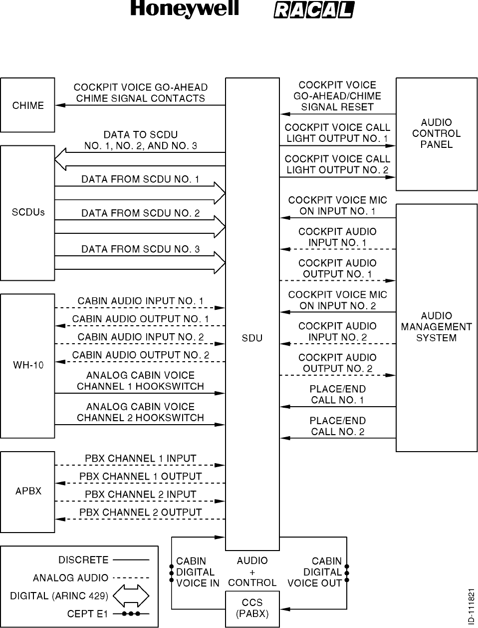
SYSTEM DESCRIPTION, INSTALLATION, AND MAINTENANCE MANUAL
MCS--4000/7000 Multi--Channel SATCOM System
23--20--27
30 Aug 2002
Use or disclosure of information on this page is subject to the restrictions in the proprietary notice of this document.
Page 2--14
Figure 2-1. Satellite Audio System
RELEASED FOR THE EXCLUSIVE USE BY: HONEYWELL INTERNATIONAL
UP86308

SYSTEM DESCRIPTION, INSTALLATION, AND MAINTENANCE MANUAL
MCS--4000/7000 Multi--Channel SATCOM System
23--20--27
30 Aug 2002
Use or disclosure of information on this page is subject to the restrictions in the proprietary notice of this document.
Page 2--15
(2) Sub-Band Signaling
(a) Support of circuit-mode data services is achieved through the use of sub-band
signaling, and/or primary-band signaling. The call setup sequence for a
circuit-mode data call is identical to a standard telephone call setup sequence,
except when the AES must indicate to the GES circuit-mode data operation can
be invoked at some point during the call. Sub-band signaling circuit-mode data is
implemented using the data interface unit (DIU) technique, which is a
nontransparent design that uses sub-band C--channel capacity for end-to-end
signaling. These signaling transactions require diversion of the input/output (I/O)
bit-stream from the SDU codecs to either a DIU (for PC modem applications) or a
secure voice coding unit.
(3) Primary-Band Signaling
(a) Primary-band circuit-mode data is implemented using the terminal interface
function (TIF) technique, which uses primary-band C--channel capacity for
end-to-end signaling. The TIF is integrated within the SDU codec. All
circuit-mode data activation and deactivation procedures relating to circuit-mode
data operation are automatically performed within the TIF. The TIF
encodes/decodes circuit-mode PC modem data and facsimile data using an
algorithm.
8. Packet-Data Services
A. General
(1) Data services are available in the form of a standard data interface that supports
Data-2 and Data-3 as defined by INMARSAT. Data-3 complies with International
Standards Organization (ISO) standard 8208 for open systems interconnection.
Data-3 permits the operator to connect to the MCS system any data terminal
equipment (DTE) compatible with this international standard. The transmission rate
available to the operator depends on the aircraft equipment, and in particular on the
antenna gain. It also depends on the capabilities of the satellite serving that particular
region of the earth and the GES logged-on to the satellite.
(2) Within the scope of the normal mode of operation, packet mode data messages are
handled by two basic types of data service. Small messages (up to 128 bytes) are
handled by one self-contained message that includes the information required to set
up and clear the circuit as well as the data itself. This connectionless message
traverses the communication link autonomously and quickly.
(3) Longer messages must be divided into a string of shorter messages for which a
connection-oriented circuit is set up. When the connection is established, all
subsequent data packets carry abbreviated address and control information. This
supplies more efficiency for longer messages and inquiry/response data dialogues
with no limit set on the length of individual messages.
RELEASED FOR THE EXCLUSIVE USE BY: HONEYWELL INTERNATIONAL
UP86308

SYSTEM DESCRIPTION, INSTALLATION, AND MAINTENANCE MANUAL
MCS--4000/7000 Multi--Channel SATCOM System
23--20--27
30 Aug 2002
Use or disclosure of information on this page is subject to the restrictions in the proprietary notice of this document.
Page 2--16
9. Dual SATCOM Configuration
A. Overview
(1) General
(a) Dual SATCOM configuration is one where two SDUs work together in a
master/slave relationship. This configuration also uses dual antenna systems.
(b) Dual SATCOM systems can be used to supply backup redundancy for
circuit-mode and packet-mode safety communications, or for additional
circuit-mode channel capability, or both. Each system in a dual system has the
capability to function without the other if necessary (as a sole single system while
the other has failed or is disabled), or to work with the other system as a
coordinated pair. There are three distinctions made for dual systems regarding
the SDUs:
(2) No. 1 versus No. 2
(a) This is a static distinction as determined by the programmed state of the SDU
system configuration pin. (No. 1 and No. 2 can also be referred to as left and
right, respectively, on Boeing aircraft.)
(3) Master versus Slave
(a) This is a logical and potentially dynamic distinction. Because an aircraft can have
only one ICAO address assigned to it, dual MCS systems operate with a single
master SDU and the other as slave SDU. Each SDU is capable of providing its
services with no assistance from the other SDU (e.g., when the other SDU is
powered-down). Each SDU is capable of being the master or the slave. There
are never two masters or two slaves (except during brief switching transients and
certain failure plus manual override conditions). The master does not depend on
the slave for any of the services supplied directly by the master.
(b) The master is in control. Only the master is allowed to use the P, R, and T
packet-mode channels for log-on and other satellite system management,
Data--2, Data--3, and GES--specific data broadcast (GSDB) packet-mode data
services, and circuit-mode call setups. The slave (which must be equipped with
an HGA in order to be a true slave from the perspective of offering additional
channel capacity) does not perform log-on or any packet-mode data function, but
is only used to supply additional C-channels for circuit-mode services under
control of the master. The master controls all circuit-mode call setups,
preemptions, and selective releases; normal ongoing slave system call
management (e.g., power control) and call termination are controlled by the
slave SDU.
(c) In a dual system made up of an HGA and an LGA, if the LGA-equipped SDU is
the master, it cannot use the HGA-equipped system as a slave. The LGA master
must be capable of operation through its LGA and must log-on as a Class 1
AES. If the slave is only equipped with an LGA, it cannot function as a true slave,
but only as a standby backup system for low-rate packet-mode data services,
ready to take over as master in case the original master fails.
RELEASED FOR THE EXCLUSIVE USE BY: HONEYWELL INTERNATIONAL
UP86308

SYSTEM DESCRIPTION, INSTALLATION, AND MAINTENANCE MANUAL
MCS--4000/7000 Multi--Channel SATCOM System
23--20--27
30 Aug 2002
Use or disclosure of information on this page is subject to the restrictions in the proprietary notice of this document.
Page 2--17
(d) A system is said to be disabled when it is inhibited from making any RF
transmissions. This disabling can be because of a failure or being manually
inhibited through the control interfaces. Any disabled SDU indicates this in bit 12
of its label 276 status word. If a system is not disabled, it is enabled. When one
system is disabled, the other is usually selected, i.e., the selected system is
essentially a single system and cannot use any potential slave resources in the
disabled system. It is possible both systems can be manually disabled for special
purposes like when maintenance or deicing personnel are in close proximity to
the antennas. The master controls the system functional capability indicators and
indicates itself as the master to the MU, cabin packet data function (CPDF), and
CTU. This is true even when both SDUs are disabled (there must still be a
designated master).
(4) This versus Other
(a) This is a relational distinction where this refers to any and all SDUs in dual
systems, and other refers to the companion SDU interfaced to this SDU ARINC
429 cross-talk bus (XTB) and select/disable discretes.
B. Dual System Control/Status Interfaces
(1) Manual and automatic control of the master/slave/select/disable attributes of the two
systems are done by using the XTB between the two SDUs (one high-speed ARINC
429 bus in each direction), and by the dual system select discrete I/O and dual
system disable discrete input discretes, which are cross-wired between the two
SDUs. Figure 2-2 shows a classic wiring diagram.
(2) The select and disable discretes are normally in a high-impedance state. The select
output supplies a low-impedance to ground when it is asserting, and the select and
disable inputs are pulled low to be asserted. An optional external switch can also be
supplied to manually select one system while disabling the other. A switch normally
leaves both discretes open-circuited, enabling fully automatic control. The optional
switch can additionally have the enhanced capability of simultaneously disabling both
systems while selecting neither. Manual control is also supplied through the SCDUs
for cases where the optional external switch is not supplied.
(3) The disable discrete is an input only. It is automatically asserted by the other SDU
select output when attempting to perform an aggressive handover of mastery; it can
also be manually asserted when the crew has determined this system has failed.
(4) The select discrete is a combination input and open-collector-type output. Activation
of this discrete by the crew indicates this system should be the sole master and it
must not attempt to use the other as a slave. If an SDU detects the other system has
failed, it can activate its own select output, which disables the other system and
typically becomes the sole master.
RELEASED FOR THE EXCLUSIVE USE BY: HONEYWELL INTERNATIONAL
UP86308
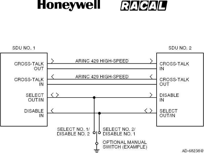
SYSTEM DESCRIPTION, INSTALLATION, AND MAINTENANCE MANUAL
MCS--4000/7000 Multi--Channel SATCOM System
23--20--27
30 Aug 2002
Use or disclosure of information on this page is subject to the restrictions in the proprietary notice of this document.
Page 2--18
Figure 2-2. Dual System Wiring Diagram
C. System Reversion
(1) General
(a) The dual MCS system can change which SDU is master automatically or
manually. Automatic system reversion of handover of mastery from the current
master to the current slave is done through cooperative, aggressive, and special
handovers.
(2) Automatic System Reversion
(a) Cooperative handover of mastery is performed through the XTB and does not
make use of the select/disable discretes. The current master continually
assesses the potential service capabilities of each system, including the usage of
the other’s resources as a slave for providing additional voice services. Since
different aircraft owners/operators can value the individual assessed service
capabilities differently, weighting factors are selected in the ORT to reflect the
relative importance of the various capabilities. This flexibility allows all
capabilities to be compared equally, or for any one capability to outweigh all of
the others combined, or any combination between these extremes. When the
current master determines the current slave should become the new master, the
current master indicates it is abdicating its mastery. The slave detects the
abdication of the master and takes over as master.
RELEASED FOR THE EXCLUSIVE USE BY: HONEYWELL INTERNATIONAL
UP86308

SYSTEM DESCRIPTION, INSTALLATION, AND MAINTENANCE MANUAL
MCS--4000/7000 Multi--Channel SATCOM System
23--20--27
30 Aug 2002
Use or disclosure of information on this page is subject to the restrictions in the proprietary notice of this document.
Page 2--19
(b) Aggressive handover of mastery (used when cooperation is impossible because
of XTB failure, manual intervention, or other reasons) makes use of the
select/disable discretes for mastery handover. An SDU asserts its select output
(connected to the Disable input of the other SDU) and commands Disable Other
SATCOM on its XTB output to the other SDU (in its Dual Control/Status word).
When an SDU detects its disable discrete input has been asserted, or it has
received a Disable Other SATCOM command through the XTB, it immediately
asserts its My Disable Is Asserted bit in its dual control/status word on its XTB
output, and after being so disabled for 1 second or longer, it then inhibits RF
transmissions and asserts its This SDU Is Disabled bit in its dual control/status
word.
(c) If the master SDU main processor resets itself, handover of mastery occurs
when the slave detects XTB inactive (unless the slave is externally disabled).
(3) Manual System Reversion
(a) The cockpit crew can manually select one system as the sole master and disable
the other system using an external select/disable switch or through the SCDU
disable other SATCOM line select key. This permits manual system reversion for
special cases, like undetected failures. Some external select/disable switches
may permit both systems to be disabled simultaneously for special cases
involving close proximity to the SATCOM antennas of maintenance or deicing
personnel.
(b) The SCDU line select key makes use of the XTB as well as the select/disable
discretes to send the appropriate command to the other SDU, thus optimizing the
robustness of this function.
D. Antenna Configurations
(1) A number of dual system antenna configurations can be assembled to address
various user requirements for availability and channel capability, containing various
combinations of LGA--, HGA-- or IGA--equipped systems — i.e., HGA(IGA) +
HGA(IGA), HGA(IGA) + LGA, or LGA + LGA. The IGA equipment can be used
interchangeably (when airplane installation supports) with the HGA equipment. Any
HGA in a dual (or single) system can function as a logically distinct steered LGA
when its gain drops below 7 dB. Also possible is one pseudo-dual system plus one
HGA system —i.e., (HGA+LGA) + HGA.
(2) The basic configurations supported by the MCS dual system design are as given in
Table 2-2.
RELEASED FOR THE EXCLUSIVE USE BY: HONEYWELL INTERNATIONAL
UP86308

SYSTEM DESCRIPTION, INSTALLATION, AND MAINTENANCE MANUAL
MCS--4000/7000 Multi--Channel SATCOM System
23--20--27
30 Aug 2002
Use or disclosure of information on this page is subject to the restrictions in the proprietary notice of this document.
Page 2--20
Table 2-2. Basic Antenna Configurations
SDU No. 1 SDU No. 2 Notes
HGA LGA Original ARINC 741 dual system architecture
HGA HGA MD--11 and 777 dual standard
LGA LGA -- --
HGA + LGA HGA SDU No. 1 is pseudo--dual
(3) Some specific examples of these configurations are shown in the following figures .
Only unique combinations (as opposed to permutations) are shown.
(4) Figure 2-3 and Figure 2-4 show the two types of the HGA + LGA configuration. This
configuration is normally capable of providing five circuit-mode channels plus one
(potentially) high-rate packet-mode data channel. It supplies single-point failure
tolerance for low--rate packet-mode data services. Channel unit redundancy within
the HGA system supplies a limited but very flexible degree of failure tolerance for
circuit-mode and high-rate packet-mode services.
(5) Figure 2-5, Figure 2-6, and Figure 2-7 shows the three types of the HGA + HGA
configuration. This configuration is normally capable of providing 10 circuit-mode
channels plus one (potentially) high-rate packet-mode data channel. It supplies
single-point failure tolerance for all grades of all services. Channel unit redundancy
within each half of the dual system supplies a limited but very flexible degree of
failure tolerance for all grades of all services before more serious failures force a
handover of mastery.
(6) Figure 2-8 shows the LGA + LGA configuration. This configuration is capable of
providing only one low-rate packet-mode data channel, and supplies single-point
failure tolerance for that capability.
(7) Figure 2-9 thru Figure 2-12 shows the different types of the pseudo-dual (HGA +
LGA) + HGA configuration. This configuration contains all of the normal and
failure-tolerance capabilities as the HGA + HGA configuration, and adds the
capability of one low-rate packet-mode data channel in instances where both HGAs
are unusable because of trying to point into keyholes. (The use of dissimilar dual
HGAs, like those shown in Figure 2-7, helps to minimize the need for such a
configuration.)
RELEASED FOR THE EXCLUSIVE USE BY: HONEYWELL INTERNATIONAL
UP86308
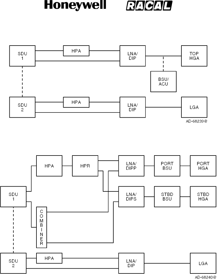
SYSTEM DESCRIPTION, INSTALLATION, AND MAINTENANCE MANUAL
MCS--4000/7000 Multi--Channel SATCOM System
23--20--27
30 Aug 2002
Use or disclosure of information on this page is subject to the restrictions in the proprietary notice of this document.
Page 2--21
Figure 2-3. HGA + LGA Configuration with Top-Mounted HGA
Figure 2-4. HGA + LGA Configuration with Side-Mounted HGA
RELEASED FOR THE EXCLUSIVE USE BY: HONEYWELL INTERNATIONAL
UP86308
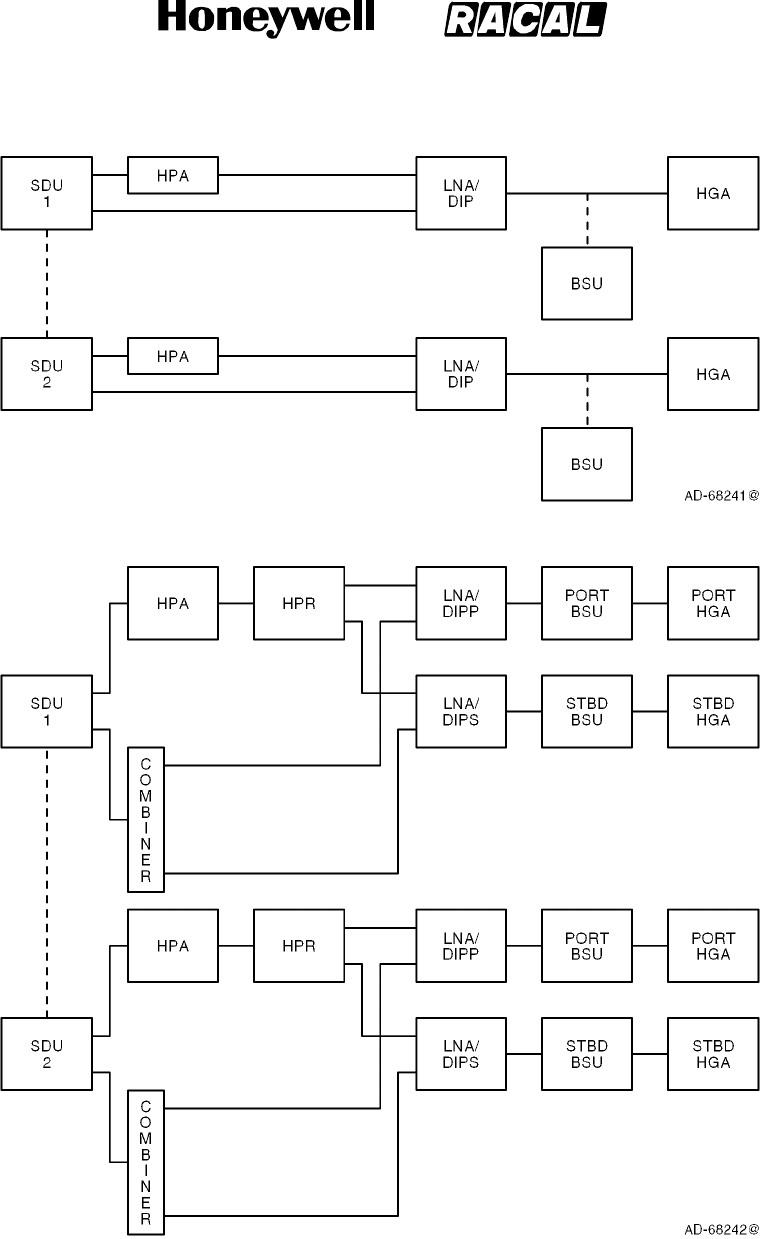
SYSTEM DESCRIPTION, INSTALLATION, AND MAINTENANCE MANUAL
MCS--4000/7000 Multi--Channel SATCOM System
23--20--27
30 Aug 2002
Use or disclosure of information on this page is subject to the restrictions in the proprietary notice of this document.
Page 2--22
Figure 2-5. HGA + HGA Configuration with Two Top-Mounted HGAs
Figure 2-6. HGA + HGA Configuration with Two Side-Mounted HGAs
RELEASED FOR THE EXCLUSIVE USE BY: HONEYWELL INTERNATIONAL
UP86308
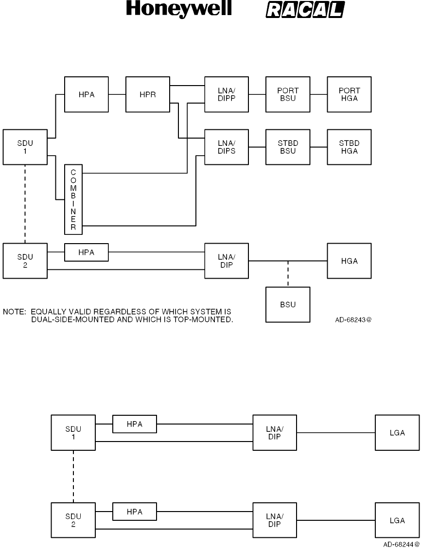
SYSTEM DESCRIPTION, INSTALLATION, AND MAINTENANCE MANUAL
MCS--4000/7000 Multi--Channel SATCOM System
23--20--27
30 Aug 2002
Use or disclosure of information on this page is subject to the restrictions in the proprietary notice of this document.
Page 2--23
Figure 2-7. HGA + HGA Configuration with One Side-Mounted HGA + One Top-Mounted
HGA (Dissimilar HGA)
Figure 2-8. LGA + LGA Configuration
RELEASED FOR THE EXCLUSIVE USE BY: HONEYWELL INTERNATIONAL
UP86308
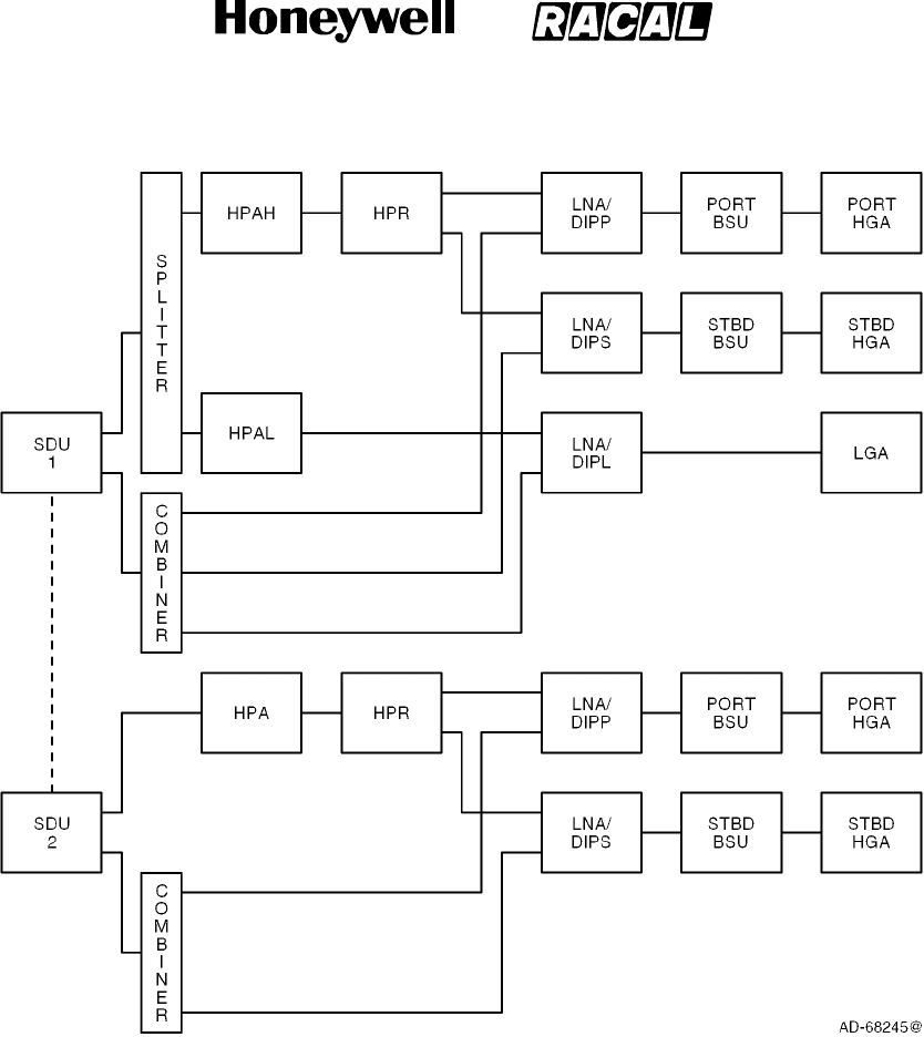
SYSTEM DESCRIPTION, INSTALLATION, AND MAINTENANCE MANUAL
MCS--4000/7000 Multi--Channel SATCOM System
23--20--27
30 Aug 2002
Use or disclosure of information on this page is subject to the restrictions in the proprietary notice of this document.
Page 2--24
Figure 2-9. (HGA + LGA) + HGA Configuration with Two Side-Mounted HGAs
RELEASED FOR THE EXCLUSIVE USE BY: HONEYWELL INTERNATIONAL
UP86308
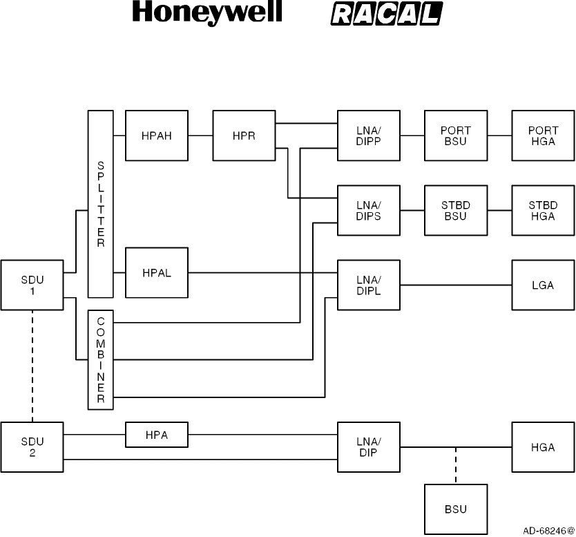
SYSTEM DESCRIPTION, INSTALLATION, AND MAINTENANCE MANUAL
MCS--4000/7000 Multi--Channel SATCOM System
23--20--27
30 Aug 2002
Use or disclosure of information on this page is subject to the restrictions in the proprietary notice of this document.
Page 2--25
Figure 2-10. (HGA + LGA) + HGA Configuration with the LGA Paired with
One Side-Mounted HGA
RELEASED FOR THE EXCLUSIVE USE BY: HONEYWELL INTERNATIONAL
UP86308
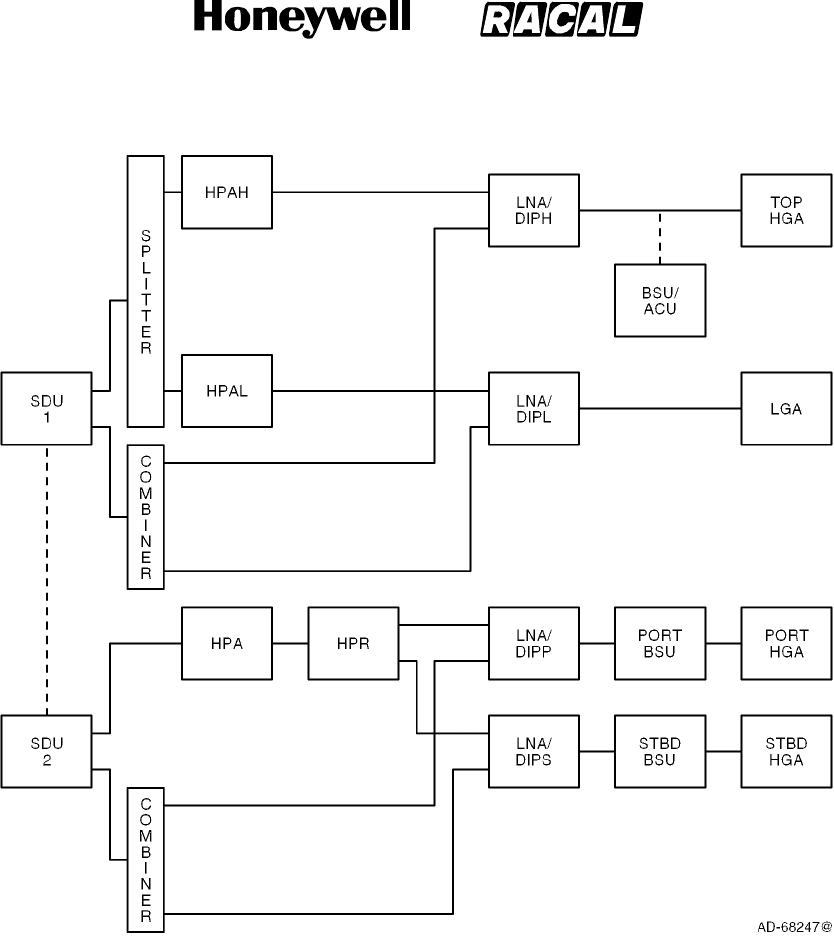
SYSTEM DESCRIPTION, INSTALLATION, AND MAINTENANCE MANUAL
MCS--4000/7000 Multi--Channel SATCOM System
23--20--27
30 Aug 2002
Use or disclosure of information on this page is subject to the restrictions in the proprietary notice of this document.
Page 2--26
Figure 2-11. (HGA + LGA) + HGA Configuration with the LGA Paired with
One Top-Mounted HGA
RELEASED FOR THE EXCLUSIVE USE BY: HONEYWELL INTERNATIONAL
UP86308
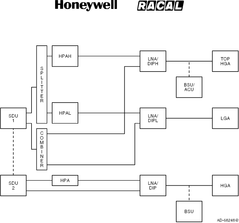
SYSTEM DESCRIPTION, INSTALLATION, AND MAINTENANCE MANUAL
MCS--4000/7000 Multi--Channel SATCOM System
23--20--27
30 Aug 2002
Use or disclosure of information on this page is subject to the restrictions in the proprietary notice of this document.
Page 2--27
Figure 2-12. (HGA + LGA) + HGA Configuration with Two Top-Mounted HGAs
E. Cockpit Voice Configurations and Functionality
(1) System configuration pins TP13F and TP13J specify the physical wiring for the
codecs of each SDU to the possible interfaces -- a codec/channel can only be
available to the cockpit if the wiring strap is set to Cockpit or Both (and not if the
wiring is to Cabin or Neither).
(2) An additional issue with dual systems is how to map the potentially available four
physical SDU cockpit voice channels with the one or two (maximum) usable logical
cockpit channels controllable through the audio control panels (ACPs) and the
SCDUs (i.e., as seen by the audio management system [AMS] user). Two
configurations are defined, which are identified by ORT item xlviii (Cockpit Channel
Interface Type for Dual): (1) interfacing each ACP/SCDU logical channel to one
physical channel on one SDU only (fixed),and(2)interfacinganACP/SCDUlogical
channel to one physical channel on each of the two SDUs (shared). Note the
interfacing referred to is conceptual and not necessarily physical -- i.e., for shared,
the physical wiring can be literally paralleled, or it can be simple point-to-point, with
some form of signal splitting/combining or paralleling being performed within the AMS
itself. The system configuration straps for codec wiring let the SDU determine the
physical channels which are candidate channels for each logical channel.
RELEASED FOR THE EXCLUSIVE USE BY: HONEYWELL INTERNATIONAL
UP86308

SYSTEM DESCRIPTION, INSTALLATION, AND MAINTENANCE MANUAL
MCS--4000/7000 Multi--Channel SATCOM System
23--20--27
30 Aug 2002
Use or disclosure of information on this page is subject to the restrictions in the proprietary notice of this document.
Page 2--28
10. ACARS/Aircraft Flight Information System (AFIS) Peripheral Function
A. General
(1) The ACARS/AFIS peripheral function lets the SATCOM SDU act like any other
ACARS/AFIS peripheral to receive or send blocks of data from/to ground terminals
on the ARINC/SITA network, e.g., uplink ORTs, and downlink ORTs, call event logs,
data event logs, system management event logs, and failure logs. This functionality
integrates with the satellite subnetwork transfer capability. The requirements are
taken from ARINC 618 for the air-to-ground link and ARINC 620 for the data link
service provider requirements.
RELEASED FOR THE EXCLUSIVE USE BY: HONEYWELL INTERNATIONAL
UP86308

SYSTEM DESCRIPTION, INSTALLATION, AND MAINTENANCE MANUAL
MCS--4000/7000 Multi--Channel SATCOM System
23--20--27
30 Aug 2002
Use or disclosure of information on this page is subject to the restrictions in the proprietary notice of this document.
Page 3--1
SECTION 3
CABIN/COCKPIT COMMUNICATIONS
1. Cabin Communications
A. General
(1) Cabin communications are done with both digitally connected phones and analog
connected phones (see Figure 3-1). The user interface with digitally connected
phones is handled by the cabin communications system (CCS). The SDU has
provisions to support up to two analog connected channels, one per installed codec.
Each analog channel supports two interface types:
•Global-Wulfsberg Flitephone WH--10
•Analog Private Branch Exchange (APBX).
B. Cabin Communications System
(1) The CCS, in conjunction with the MCS avionics and a worldwide network of ground
stations, supply cabin services like telephone, facsimile, and PC data interfaces. The
CCS is partitioned into two sections:
•Cabin telecommunications unit (CTU)
•Cabin/passenger communications equipment (digitally connected telephones).
(2) The CTU performs on-board PABX telephone functions that let the digitally
connected telephones make the best use of resources supplied by the MCS avionics.
Other functions supplied by the CTU include signal processing (for example,
analog-to-digital and digital-to-analog), dial tone generation, call queuing, call
transfer, call conferencing, and generating pacifier messages (like please hold, your
call is being processed).
(3) The CTU supplies the interface between the digitally connected phones and the
SDU. The digital phones (handsets) are primarily supplied for passenger use and
may be located throughout the aircraft. The digital handsets interface indirectly to the
satellite communications equipment and they are controlled by the CCS. Each digital
handset supplies all the normal functions of a domestic telephone. Some handset
types are battery powered and can be used anywhere in the aircraft. When not in
use, handsets are stowed in a holster with a built-in battery charger for recharging the
batteries.
RELEASED FOR THE EXCLUSIVE USE BY: HONEYWELL INTERNATIONAL
UP86308

SYSTEM DESCRIPTION, INSTALLATION, AND MAINTENANCE MANUAL
MCS--4000/7000 Multi--Channel SATCOM System
23--20--27
30 Aug 2002
Use or disclosure of information on this page is subject to the restrictions in the proprietary notice of this document.
Page 3--2
C. Analog Audio Channels
(1) General
(a) The SDU has provisions to support up to two analog channels. Each audio
channel supports two interface types:
•Global-Wulfsberg Flitephone WH--10
•Analog private branch exchange (APBX).
(b) The WH--10 is a stand-alone handset with a 12-button keypad. The APBX CTU
or handset has analog trunk lines and in-line DTMF signaling. The SDU can
support both analog handsets being connected simultaneously.
(c) Two in-use discrete outputs are supplied for analog channels 1 and 2. These
discretes are asserted (i.e., turn on the call lamps) while the voice codec
associated with that analog channel is in use (off-hook) by the analog handset.
(d) These interfaces can be connected to individual or up to five parallel
aircraft-suitable handsets. The interface presented to the SDU must emulate a
single handset. The analog handsets, which can be located in the cabin or
cockpit areas, supply only APC priority (priority 4) level service. This does not
preclude their use for other communications, but the SDU assigns an APC
priority to the call.
RELEASED FOR THE EXCLUSIVE USE BY: HONEYWELL INTERNATIONAL
UP86308
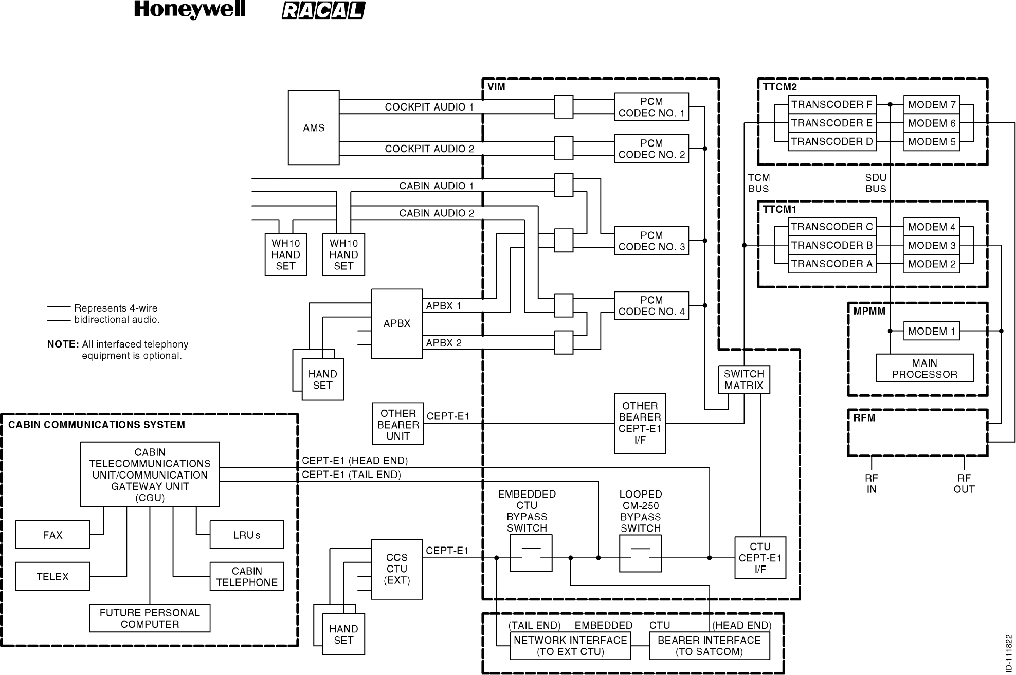
SYSTEM DESCRIPTION, INSTALLATION, AND MAINTENANCE MANUAL
MCS--4000/7000 Multi--Channel SATCOM System
23--20--27
30 Aug 2002
Use or disclosure of information on this page is subject to the restrictions in the proprietary notice of this document.
Page 3--3/(3--4 blank)
Figure 3--1. Audio Interfaces
RELEASED FOR THE EXCLUSIVE USE BY: HONEYWELL INTERNATIONAL
UP86308

SYSTEM DESCRIPTION, INSTALLATION, AND MAINTENANCE MANUAL
MCS--4000/7000 Multi--Channel SATCOM System
23--20--27
30 Aug 2002
Use or disclosure of information on this page is subject to the restrictions in the proprietary notice of this document.
Page 3--5
(2) Global-Wulfsberg Flitephone WH--10 Interface
(a) Taking an analog WH--10 handset off-hook results in the following processes.
The SDU to WH--10 handset actions are defined in Table 3-1.
•If the voice codec is being used by another analog phone user, the handset
may be placed in parallel with the other analog phone. Buffering and sidetone
arrangements are supplied by the analog connected phone, not by the
SATCOM equipment.
•If the voice codec is reserved by a headset user, is dedicated to a headset, or
is failed, the analog phone user hears silence.
•If the SDU is not logging-on, logged-on, or in the idle (standby) state, the
analog phone user hears silence.
•If the call barring level is 2 (ORT item xxiv), the SDU performs action 1.
•If sufficient resources are not available due to equipment failure, the SDU
performs action 2.
•If the SDU is logging-on, the SDU performs action 3.
•If the SDU is in the idle (standby) state, the SDU performs action 4.
•If a SDU modem is not available or there is not sufficient power to sustain a
new voice call, or the AES class is currently 1 or 4, the SDU performs action
5.
•Or else the SDU performs action 6 and the respective analog phone channel
is deemed usable for placing a call.
(b) If the system condition, as determined by the SDU, changes from usable (action
6) to unusable while the analog phone is off-hook and a call is not in progress,
then the appropriate handset action is performed to annunciate the new
condition. An analog channel does not change from unusable to usable while the
analog phone is off-hook unless there is a call termination on that channel.
Table 3-1. SDU to WH-10 Handset Actions
Action
1Play message 10 as defined in Table 3-5 outgoing calls have been disallowed) followed by
an interrupted dial tone.
2Play message 1 as defined in Table 3-5 (equipment failure) followed by an interrupted dial
tone.
3Play message 2 as defined in Table 3-5 (attempting satellite access) followed by an
interrupted dial tone.
4Play message 3 as defined in Table 3-5 (log-on disabled) followed by an interrupted dial
tone.
5Play message 4 as defined in Table 3-5 (channel not available) followed by an interrupted
dial tone.
6Play the dial tone.
RELEASED FOR THE EXCLUSIVE USE BY: HONEYWELL INTERNATIONAL
UP86308

SYSTEM DESCRIPTION, INSTALLATION, AND MAINTENANCE MANUAL
MCS--4000/7000 Multi--Channel SATCOM System
23--20--27
30 Aug 2002
Use or disclosure of information on this page is subject to the restrictions in the proprietary notice of this document.
Page 3--6
(c) The commands given in Table 3-2 are executable from the analog WH--10
handset. The inter-key push time-out is 15 seconds. After this time, a # sign is
automatically appended to the end of the keyed sequence by the SDU, and the
command given by the user is parsed and executed. Commands shown in the
table as not being terminated by a # sign are parsed and executed as soon as
the valid key sequence has been entered. An invalid sequence only generates
voicemessage18(Commandrejected)whena#isappended, either by the user
or by the SDU after the 15-second time-out (Table 3-5).
(d) Codec-generated pacifiers or messages issued as a direct result of the user
keying a command start with one second of silence to allow the user enough
time to bring the handset to their ear. During the playing of any codec-generated
messages and pacifiers, receipt of the # key immediately mutes the codec,
aborting the current message sequence. The voice codec plays the appropriate
dial tone (normal or interrupted) as specified in Table 3-2.
(e) An inactivity check is implemented so the SDU considers an off-hook channel to
be in the on-hook state if no call has been in progress on that channel and no
DTMF digits have been received for at least 120 seconds, except where
indicated in Table 3-2. A WH--10 handset in this state must have its hookswitch
cycled (i.e., go on-hook, then off-hook) to signal the off-hook state to the SDU.
RELEASED FOR THE EXCLUSIVE USE BY: HONEYWELL INTERNATIONAL
UP86308
SYSTEM DESCRIPTION, INSTALLATION, AND MAINTENANCE MANUAL
MCS--4000/7000 Multi--Channel SATCOM System
23--20--27
30 Aug 2002
Use or disclosure of information on this page is subject to the restrictions in the proprietary notice of this document.
Page 3--7
Table 3-2. Global-Wulfsberg Flitephone WH-10 Commands
Command Sequence Command Description
dddd...# Dial a short phone number (between 2 and 6 digits – the first two can not be 00).
00dddd...# Dial a long phone number (between 6 and 18 digits including the two leading
zeros).
*0 Redial the last called phone number
(refer to NOTE).
*m Dial a stored phone number from memory location m (refer to NOTE).
There are 10 memory locations assigned to each of the two analog (APHONE) channels (ORT item xvi).
Memory location 0 of each channel holds the last number called on that channel. Memory locations 1 thru 9
are user-programmable. If ORT item xxvi is set to TRUE, then the channel memory locations are separate
(i.e., modifying memory locations from a handset connected to channel 1 does not affect the memory
locations assigned to channel 2). However, if ORT item xxvi is set to FALSE, then modifying memory
locations from a handset connected to channel 1 causes channel 2 memory locations to also be modified.
The store phone number memory commands are specified as follows:
**1mdddd...# This store phone number memory command causes the phone number (dddd...) to
be stored in memory location m. If the call barring level (ORT item xxiv) is 1 or 2,
then message 9 or 10 (dialed calls have been disallowed/outgoing calls have been
disallowed) are played; otherwise, the entered data is checked. A valid command
causes message 17 (command accepted) to be played and the number stored. An
invalid command causes message 18 (command rejected) to be played.
**2# This announce phone number memory command causes the phone numbers
stored in memory locations 1 thru 9 to be read out using a series of message 19s
(the phone number stored in memory...) for non empty locations, and message 5s
(phone number memory ... is empty.) for empty locations. If this command is
entered through the WH--10 handset, the inactivity check is disabled until the next
key-push or until the next on-hook/off-hook transition.
**2m This announce phone number memory command causes the phone number in
memory location m to be read out using message 19 (the phone number stored in
memory ...) or message 5 (phone number memory ... is empty.). If m is not
between 1 and 9, then message 18 (command rejected) is played instead. The
digit 0 is announced as oh, not as zero.
If the call barring level is 1 or 2 (ORT item xxiv), the SDU plays messages 9 or 10 (dialed calls have been
disallowed/outgoing calls have been disallowed) if an attempt is made to place a call. For all the following
call barring commands, an invalid security code (cccc) causes the command to be rejected and message
18 (command rejected) to be played. If the command is valid, then the action is performed and message 17
(command accepted) is played. The call barring commands are specified as follows:
**30cccc This command sets the call barring level (ORT item xxiv) to 0, which allows all
outgoing calls.
**31cccc This command sets the call barring level (ORT item xxiv) to 1, which disallows all
manual dialing of full-length phone numbers (6 to 18 digits starting with 00). No
memory locations can be updated using the store phone number memory
command.
RELEASED FOR THE EXCLUSIVE USE BY: HONEYWELL INTERNATIONAL
UP86308
SYSTEM DESCRIPTION, INSTALLATION, AND MAINTENANCE MANUAL
MCS--4000/7000 Multi--Channel SATCOM System
23--20--27
30 Aug 2002
Use or disclosure of information on this page is subject to the restrictions in the proprietary notice of this document.
Page 3--8
Table 3-2. Global-Wulfsberg Flitephone WH-10 Commands (cont)
Command Sequence Command Description
**32cccc This command sets the call barring level (ORT item xxiv) to 2, which disallows all
outgoing calls, both manual and stored number. No memory locations can be
updated using the store phone number memory command.
**39cccc nnn nnnn This command changes the security code to nnnn unless the first four n’s are not
the same as the second four n’s, in which case message 18 (command rejected) is
played.
**4ggg# This command causes ggg to be the GES ID used in the access request signal unit
for any calls initiated on that channel until the next on-hook.
If ORT item xxiii is set to disable the analog (APHONE) system management commands, the following
commands are rejected; i.e., the SDU responds to the commands with message 18 (Command rejected).
The APHONE system management commands are specified as follows:
**50 This log-off/standby command sets the log-on policy (ORT item i) to User
Commanded Log-on. If already logged-on, the SDU logs off (refer to SYSTEM
OPERATION). If logging-on, the SDU terminates the logging on procedure. If the
command is valid, message 17 (command accepted) is played immediately without
waiting for the log-off to be achieved. If the SDU is already in the standby state,
then message 18 (command rejected) is played.
**51 This auto log-on command sets the log-on policy (ORT item i) to Automatic
Log-on. If the SDU is in the standby state, the SDU initiates the automatic log-on
procedure (refer to SYSTEM OPERATION). If the SDU is in the constrained log-on
mode, a handover stimulus is generated to initiate automatic satellite/GES
selection. If the command is valid, message 17 (command accepted) is played
immediately without waiting for the log-on to be achieved. If the SDU is already in
the automatic mode, message 18 (command rejected) is played.
**52ggg#
**52gggsss#
These commands set the SDU to the constrained log-on mode for selection of a
specified GES. The log-on policy (ORT item i) is set to Manual Log-on.IftheSDU
is not logged-on to the GES ggg (or gggsss as appropriate), the SDU attempts a
log-on to that GES alone. Any other number of digits cause message 18
(command rejected) to be played. If the specified GES does exist in the system
table, then the command is rejected. If the command is valid, message 17
(command accepted) is played immediately without waiting for the log-on to be
achieved. If the SDU is already constrained to GES ggg (or gggsss as
appropriate), then message 18 (command rejected) is played.
**59 This log-on status command causes the SDU log-on status to be announced using
message 20 (the SATCOM is in ...). If the SDU is logged-on, message 21
(logged-on to ...) is also played. Digit 0 for the GES and satellite ID is announced
as oh.
If any of the following GES preference commands are determined to be invalid, the SDU plays messages
18 (command rejected); otherwise, if a specific message is not specified, then message 17 (command
accepted) is played. If ORT item xxiii is set to disable the APHONE system management commands, the
next three commands (the preference changing commands) are rejected; i.e., the SDU responds to the
commands with message 18 (command rejected). The GES preference commands are specified as follows.
**60 This command sets the preference levels for all GESs to 1.
RELEASED FOR THE EXCLUSIVE USE BY: HONEYWELL INTERNATIONAL
UP86308

SYSTEM DESCRIPTION, INSTALLATION, AND MAINTENANCE MANUAL
MCS--4000/7000 Multi--Channel SATCOM System
23--20--27
30 Aug 2002
Use or disclosure of information on this page is subject to the restrictions in the proprietary notice of this document.
Page 3--9
Table 3-2. Global-Wulfsberg Flitephone WH-10 Commands (cont)
Command Sequence Command Description
**61gggp#
**61gggsssp#
These commands cause the GES with ID ggg (or ggg and assigned to satellite sss)
to be set to preference level p in the system table. The SDU accepts either four or
seven digits following the **61... and preceding the # sign. Any other number of
digits is interpreted to be an invalid command. If no GES listed in the system table
matches the one specified in the command, the command is invalid and the user is
so informed through message 18 (command rejected).
**62ggg#
**62gggsss#
These commands cause all current GES preference levels of 9 to be lowered to 8.
The GES with ID ggg (or ggg and assigned to satellite sss) has its preference level
set to 9. The SDU accepts either three or six digits following the 62... and
preceding the # sign. Any other number of digits is interpreted to be an invalid
command. If no GES listed in the system table matches the one specified in the
command, the command is invalid and the user is so informed through message 18
(command rejected).
**69# This command causes all GES preference levels to be announced using a
sequence of message 22s (The preference level of GES ID...). If this command is
entered through the WH--10 handset, the inactivity check is disabled until the next
key-push, or until the next on-hook/off-hook transition.
**69ggg#
**69gggsss#
These commands cause the SDU to announce the preference level of GES ggg or
(ggg and assigned to satellite sss) using message 22 (The preference level of GES
ID...). The SDU accepts either three or six digits following the **69... and preceding
the # sign. Any other number of digits is interpreted to be an invalid command. If no
GES listed in the ORT (item iii) matches the one specified in the command, the
command is invalid and the user is so informed through message 18 (command
rejected).
If any of the following incoming call management commands are rejected, the SDU plays messages 18
(command rejected); otherwise, if a specific message is not specified, then message 17 (command
accepted) is played. If ORT item xxiii is set to disable the APHONE system management commands, the
following commands are rejected; i.e., the SDU responds to the commands with message 18 (command
rejected). The four DDI CTid commands allow ddd to be up to three decimal digits (including leading zeros,
e.g., 02), validating the number to be within the range of 0 to 999. The incoming call management
commands are specified as follows.
**70# This command sets ORT item xlv for APHONE Channel 1 to the default value; i.e.,
no CTid assigned.
**70ddd# This command sets ORT item xlv for APHONE Channel 1 to ddd, Nonexclusive,
unless the configuration straps indicate Channel 1 is not wired for APHONE, or ddd
is already assigned as the CTid for Channel 2, or (in a dual system) ddd is already
assigned to one of the other SDU APHONE channels, in which case, the command
is rejected. Additionally, if ORT item xiii indicates ground-to-air Priority 4 calls are
disallowed, it is adjusted to specify routing to APHONE.
**71ddd# This command sets ORT item xlv for APHONE Channel 1 to ddd, Exclusive, unless
the configuration straps indicate Channel 1 is not wired for APHONE, or ddd is
already assigned as the CTid for Channel 2, or (in a dual system) ddd is already
assigned to one of the other SDU APHONE channels, in which case, the command
is rejected. Additionally, if ORT item xiii indicates ground-to-air Priority 4 calls are
disallowed, it is adjusted to specify routing to APHONE.
RELEASED FOR THE EXCLUSIVE USE BY: HONEYWELL INTERNATIONAL
UP86308

SYSTEM DESCRIPTION, INSTALLATION, AND MAINTENANCE MANUAL
MCS--4000/7000 Multi--Channel SATCOM System
23--20--27
30 Aug 2002
Use or disclosure of information on this page is subject to the restrictions in the proprietary notice of this document.
Page 3--10
Table 3-2. Global-Wulfsberg Flitephone WH-10 Commands (cont)
Command Sequence Command Description
**72# This command sets ORT item xlv for APHONE Channel 2 to the default value; i.e.,
no CTid assigned.
**72ddd# This command sets ORT item xlv for APHONE Channel 2 to ddd, Nonexclusive,
unless the configuration straps indicate Channel 2 is not wired for APHONE, or ddd
is already assigned as the CTid for Channel 1, or (in a dual system) ddd is already
assigned to one of the other SDU APHONE channels, in which case, the command
is rejected. Additionally, if ORT item xiii indicates ground-to-air Priority 4 calls are
disallowed, it is adjusted to specify routing to APHONE.
**73ddd# This command sets ORT item xlv for APHONE Channel 2 to ddd, Exclusive, unless
the configuration straps indicate Channel 2 is not wired for APHONE, or ddd is
already assigned as the CTid for Channel 1, or (in a dual system) ddd is already
assigned to one of the other SDU APHONE channels, in which case, the command
is rejected. Additionally, if ORT item xiii indicates ground-to-air Priority 4 calls are
disallowed, it is adjusted to specify routing to APHONE.
**740# This command sets ORT item xiii to disallowed and causes message 33 to be
played with the destination announced as disallowed.
**741# This command sets ORT item xiii to APHONE and causes message 33 to be
played with the destination announced as APHONE, unless no codec channel is
wired for APHONE (as defined by the configuration straps), in which case, the
command is rejected and the ORT item is set to Disallowed.
**742# This command sets ORT item xiii to DPHONE and causes message 33 to be
played with the destination announced as DPHONE, unless no codec channel is
wired for CCS (as defined by the configuration straps), in which case, the
command is rejected and the ORT item is set to Disallowed.
**743# This command sets ORT item xiii to headset and causes message 33 to be played
with the destination announced as headset, unless no codec channel is wired for
AMS (as defined by the configuration straps), or if configuration pin TP13A is zero,
in which case, the command is rejected and the ORT item is set to Disallowed.
**750# This command sets ORT item x to disallow incoming circuit mode data calls and
causes message 34 to be played to announce such calls as disallowed, unless
the SDU is logging on or logged on, in which case, the command is rejected.
**751# This command sets ORT item x to allow incoming circuit mode data calls and
causes message 34 to be played to announce such calls as allowed, unless the
SDU is logging on or logged on, in which case, the command is rejected.
**79# This command causes the SDU to announce the DDI CTid assignment for
channels 1 and 2 using message 31, if no ID is assigned, and message 32 if an ID
is assigned, where the type of ID assignment is announced as exclusive or
nonexclusive.
RELEASED FOR THE EXCLUSIVE USE BY: HONEYWELL INTERNATIONAL
UP86308
SYSTEM DESCRIPTION, INSTALLATION, AND MAINTENANCE MANUAL
MCS--4000/7000 Multi--Channel SATCOM System
23--20--27
30 Aug 2002
Use or disclosure of information on this page is subject to the restrictions in the proprietary notice of this document.
Page 3--11
Table 3-2. Global-Wulfsberg Flitephone WH-10 Commands (cont)
Command Sequence Command Description
Legend: cSecurity code digit (0 thru 9)
dDecimal digit (0 thru 9)
gGES ID octal digit, where ggg is in range (000 thru 377)
mMemory location (1 thru 9)
nNew security code digit (0 thru 9)
pGES preference level (0 thru 9), where 1 is the least preferred and
9 is the most preferred, and 0 indicates never to be selected for
automatic log-on
sSatellite ID octal digit, where sss is in range (000 thru 076)
NOTE: There are 10 memory locations for each channel to store phone numbers (0 thru 9). Memory number 0 is used
by the SDU to store the last called phone number.
(3) Call Initiation from Analog (WH--10) Phone
(a) The analog phone user can initiate a call using any of the following commands:
•Short number manual dialing (dd...#). Between two and six digits can be
specified, with the first two digits not 00. The 00 digits are used as the
called–party address.
•Long number manual dialing (00dddd...#). Between seven and 18 digits can
be specified including the leading 00. The 00 digits are used as the
called–party address.
•Last call redial (*0). The last phone number called by an analog phone user
on a channel is used as the called–party address. If the phone number stored
in memory location 0 (i.e., last number called location) is not defined (length
field set to zero), then message 5 (phone number memory ... is empty.) is
played. Otherwise, the phone number is used as the called–party address.
•Stored phone dialing (*m). Parameter m specifies a memory location between
1 and 9. If the phone number stored in memory location m is not defined
(length field set to zero), then message 5 (phone number memory ... is
empty.) is played. Otherwise, the phone number is used as the called–party
address.
(4) Analog Private Branch Exchange (APBX) Interface
(a) General
1The APBX/SATCOM avionics interface protocol is based on the bidirectional
DTMF tones being signaled in-band. In the APBX-to-SATCOM direction, the
DTMF digits are assigned to the on- and off-hook transitions as specified in
Table 3-3, and are valid only from the APBX handset. All other DTMF digits
are common to both the WH--10 and APBX interfaces.
RELEASED FOR THE EXCLUSIVE USE BY: HONEYWELL INTERNATIONAL
UP86308

SYSTEM DESCRIPTION, INSTALLATION, AND MAINTENANCE MANUAL
MCS--4000/7000 Multi--Channel SATCOM System
23--20--27
30 Aug 2002
Use or disclosure of information on this page is subject to the restrictions in the proprietary notice of this document.
Page 3--12
2Taking an APBX handset off-hook results in the same decisions as specified
for the WH--10 handset. However, the SDU to APBX off--hook actions are
specified in Table 3-4, where the DTMF tone sequence <DTMF--C>,
<DTMF--n> (n is 0, 1, 2, or 4) sent to the APBX handset indicates the
SATCOM channel status:
•An outgoing call cannot be supported (n = 1, 2, or 4) or
•An outgoing call can be attempted (n = 0).
3If the channel status indicates a call can be attempted, the SDU accepts any
command determined to be valid from an APBX interface, including the
on-hook DTMF tone. If the channel status indicates a call can not be
attempted, the APBX handset is expected to send the on-hook DTMF tone.
Otherwise, the SDU still accepts any command determined to be valid from
an APBX interface; though the checked B-party address transfer command
is guaranteed to produce a call setup failure. Subsequent to call setup
commands sent to the SDU, call setup progress, failure, and termination
DTMF tone sequences are sent to the APBX handset.
4The SDU considers an off-hook channel to be in the on-hook state if no call
has been in progress on that channel and no DTMF signals have been
received for at least 120 seconds. A channel in the on hook state must issue
another DTMF off-hook signal to enable the reentry into the off-hook state.
(b) Checked Credit Card Data Transfer Command
1The *2284*c*ddd# command, if valid, loads the transferred three-digit value
into the SDU calling terminal ID buffer. This data is used in place of the
default 000 in the calling terminal field of the call information service address
initial signal unit (ISU) (S5) for any outgoing call setups on this channel until
the next APBX on-hook is received. The command is accepted only if the
modulo 10 sum of all the decimal digits in the command, including 2284, the
three-digit calling terminal ID, and the check digit c is zero.
(c) Checked B-Party Address Transfer Command
1The *2262*cdddd....# command, if valid, initiates a call setup request to the
GES using the transferred digits dddd... as the B-party address and any
track 2 credit card data stored since the previous on-hook transition on this
channel. The command is only accepted if the modulo 10 sum of all decimal
digits in the command, including 2262 and the check digit c is zero. A valid
command causes the SDU to send the DTMF sequence <DTMF--C>,
<DTMF--8> to the APBX handset. An invalid command causes the SDU to
send the DTMF sequence <DTMF--C>, <DTMF--9> to the APBX handset.
RELEASED FOR THE EXCLUSIVE USE BY: HONEYWELL INTERNATIONAL
UP86308
SYSTEM DESCRIPTION, INSTALLATION, AND MAINTENANCE MANUAL
MCS--4000/7000 Multi--Channel SATCOM System
23--20--27
30 Aug 2002
Use or disclosure of information on this page is subject to the restrictions in the proprietary notice of this document.
Page 3--13
Table 3-3. Assignment of DTMF Digits in the APBX Interface
DTMF Digit Low (Hz) High (Hz) Meaning To/From SDU
1697 1209 1Both
2697 1336 2Both
3697 1477 3Both
4770 1209 4Both
5770 1336 5Both
6770 1477 6Both
7852 1209 7Both
8852 1336 8Both
9852 1477 9Both
0941 1336 0Both
*941 1209 */STX To
#941 1477 #/ETX To
A697 1633 FS/Answer Both
B770 1633 Off--Hook To
C852 1633 Status From
D941 1633 On--Hook To
NOTE: STX (start sentinel), ETX (end sentinel), and FS (frame separator) are used in the transfer of ISO 7813 track 2
data from the APBX to the SDU.
Table 3-4. SDU to APBX Off-Hook Actions
Action Description
1Play <DTMF--C>, <DTMF--2> followed by silence (idle).
2Play <DTMF--C>, <DTMF--1> followed by silence (failure).
3Play <DTMF--C>, <DTMF--4> followed by silence (accessing).
4Play <DTMF--C>, <DTMF--2> followed by silence (idle).
5Play <DTMF--C>, <DTMF--4> followed by silence (accessing).
6Play <DTMF--C>, <DTMF--0> followed by silence (available).
RELEASED FOR THE EXCLUSIVE USE BY: HONEYWELL INTERNATIONAL
UP86308

SYSTEM DESCRIPTION, INSTALLATION, AND MAINTENANCE MANUAL
MCS--4000/7000 Multi--Channel SATCOM System
23--20--27
30 Aug 2002
Use or disclosure of information on this page is subject to the restrictions in the proprietary notice of this document.
Page 3--14
2. Cockpit Communications
A. General
(1) The SDU codecs support headset interfaces for cockpit use only. These interfaces
incorporate 600-ohm, 4-wire, off-hook/on-hook signaling and dialing through the
combination of a control and display unit (either SCDU or MCDU), and (at the user’s
option) PTT, mic-on, or place/end call switches. If used, when the PTT button is
pushed, the microphone audio signal is sent to the selected voice channel; activation
of one of the discretes is signalled to the SDU. Also, an off-hook signal can be sent to
the SDU through the SCDU. An audible chime and call lamps announce a
ground-to-air call.
(2) The cockpit headsets interface with the codecs in the SDU through an audio
management unit (AMU), which is also connected to other aircraft radios. The ACP
associated with the AMU can be capable of selecting either a single or dual voice
channels for the MCS system. When single-channel AMUs are installed, voice
channel 1 is wired to AMU No. 1 and voice channel 2 is wired to AMU No. 2. This
permits operation of two independent channels. When dual-channel AMUs are
installed, voice channels No. 1 and No. 2 are wired in parallel to each AMU, enabling
two voice channels to be shared by the cockpit users.
(3) Two functionally identical voice codec modules (VCM) are installed in the SDU and
designated Codec A and Codec B.
(4) Associated with the SATCOM channels are SCDU pages, call lamps, channel
selection switches, a chime, and a chime reset. The SDU hookswitch signaling can
be supplied:
•When the ACP SATCOM channel select switch is activated
•When a PTT switch is activated
•When signaling through the SCDU, where the SDU hookswitch signaling discrete
is inactive.
(5) Once off-hook, microphone audio is supplied to the selected SATCOM voice channel
and the appropriate signaling is exchanged for call lamp and chime reset.
Conversely, once on-hook, microphone audio is removed from the selected SATCOM
voice channel and the call lamp is turned off.
B. Headset Off-Hook Signaling
(1) The headset is capable of going off-hook (to connect the call and to acknowledge the
call signaling) if the cockpit voice call light output has transitioned for either the
flashing or steady light activation, at which time:
•If the latched ACP hookswitch signaling is strapped, the headset is considered
off-hook whenever the cockpit voice mic-on input is activated (connected to
ground).
•If the switched PTT hookswitch signaling is strapped, the headset is considered
off-hook whenever the cockpit voice mic-on input is activated for the first time after
the call light activation for an incoming call, or when the place/end call input is
activated to initiate an outgoing call.
RELEASED FOR THE EXCLUSIVE USE BY: HONEYWELL INTERNATIONAL
UP86308

SYSTEM DESCRIPTION, INSTALLATION, AND MAINTENANCE MANUAL
MCS--4000/7000 Multi--Channel SATCOM System
23--20--27
30 Aug 2002
Use or disclosure of information on this page is subject to the restrictions in the proprietary notice of this document.
Page 3--15
(2) If ORT item xliii is enabled, the headset is capable of going off-hook when ANSWER
CALL is selected on the SATCOM main menu page (TESTING/FAULT ISOLATION)
after the call light activation and irrespective of hookswitch signaling.
C. Headset On-Hook Signaling
(1) If latched ACP hookswitch signaling is strapped, the headset is placed on-hook when
an open is present on the cockpit voice mic-on input. Regardless of the hookswitch
signaling, the cockpit voice place/end call 1 and 2 discrete inputs place the headset
interface on-hook for cockpit audio channels 1 and 2, respectively, when a call clear
event occurs. If ORT item xliii is enabled, the selection of END CALL or REJECT on
the SATCOM main menu page (TESTING/FAULT ISOLATION) places the headset
interface on-hook. Placing the headset on-hook results in normal call termination.
D. Voice Codec Module Audio Switching
(1) Headsets and analog connected phones interface to the SDU through the VCMs.
Using a switch internal to the modules, each VCM can be connected to one of the
cabin audio interfaces, or to one of the cockpit audio interfaces (or to both). Each
VCM can be switched between either of its audio interfaces as follows:
•CodecAcanbeusedinconjunctionwitheithercabinaudioNo.1(WH--10or
APBX) or cockpit audio No. 1
•CodecBcanbeusedinconjunctionwitheithercabinaudioNo.2(WH--10or
APBX) or cockpit audio No. 2.
E. Voice Codec Module Sidetone
(1) Sidetone is supplied by each VCM. The sidetone level is adjustable for the cockpit
audio, and is set to off for cabin audio. The adjustment range for cockpit sidetone is
from 0 dB below the receive audio to off, with the default value set to 14.1 dB below
the receive audio level. This setting is stored in nonvolatile memory within the SDU.
F. Voice Interface Module Stored Audio Messages
(1) The VIMs are capable of playing standard telephony supervisory lone signals, DTMF
tones, and voice messages to the headset and analog phone users. These pacifiers
are only sent to the analog interfaces:
•Headset
•WH--10 handsets
•APBX handsets.
(2) Stored audio messages are summarized in Table 3-5.
RELEASED FOR THE EXCLUSIVE USE BY: HONEYWELL INTERNATIONAL
UP86308

SYSTEM DESCRIPTION, INSTALLATION, AND MAINTENANCE MANUAL
MCS--4000/7000 Multi--Channel SATCOM System
23--20--27
30 Aug 2002
Use or disclosure of information on this page is subject to the restrictions in the proprietary notice of this document.
Page 3--16
Table 3-5. Stored Audio Messages
Message No. Message
1Sorry, equipment failure, please refer to the user guide.
2Sorry, attempting satellite access, please try later.
3Sorry, log-on disabled, please refer to the user guide.
4Sorry, no channel available, please try later.
5Phone number memory <one> is empty.
6Sorry, your call can no longer be sustained, please try later.
7Sorry, your call has been preempted, please try later.
8Sorry, connection failure, please try later.
9Sorry, dialed calls have been disallowed, please refer to the user guide.
10 Sorry, outgoing calls have been disallowed, please refer to the user guide.
11 Sorry, number unobtainable.
12 Sorry, number busy, please try later.
13 Sorry, network congestion, please try later.
14 Sorry, credit card not honored at the ground station.
15 Sorry, access unauthorized.
16 Please wait, connecting your call.
17 Command accepted.
18 Command rejected.
19 The phone stored in memory <one> is <oh> <oh> <one>...
20 The SATCOM is in <standby> |<auto log-on| <constrained log-on> mode.
21 Logged on to GES ID <one> <oh> <three>.
22 The preference level of GES ID <three> <oh> <two> on satellite <oh> <oh> <three> is
<six>.
23 Equipment failure, equipment failure.
24 No channel available, no channel available.
25 Your call can no longer be sustained.
26 Your call has been preempted.
27 Connection failure, connection failure.
28 Number unobtainable, number unobtainable.
29 Number busy, number busy.
30 Network congestion, network congestion.
31 Channel <one> terminal ID is not assigned.
32 Channel <two> terminal ID is <oh> <one> <three> <nonexclusive>.
RELEASED FOR THE EXCLUSIVE USE BY: HONEYWELL INTERNATIONAL
UP86308

SYSTEM DESCRIPTION, INSTALLATION, AND MAINTENANCE MANUAL
MCS--4000/7000 Multi--Channel SATCOM System
23--20--27
30 Aug 2002
Use or disclosure of information on this page is subject to the restrictions in the proprietary notice of this document.
Page 3--17
Table 3-5. Stored Audio Messages (cont)
Message No. Message
33 Ground-to-air public calls destination set to <disallowed>.
34 Ground-to-air circuit mode data calls are <allowed>.
G. Voice Interface Module Dedication
(1) Each voice interface module (VIM) has the property of dedication, which is different
from the codec wiring. This property is of value on aircraft that have both headset
and cabin (analog and digital) interface wiring, where contention for codec use can
arise. Each VIM dedication is set to cabin, headset, or automatic through ORT item
vi.
(2) A VIM with its dedication set to automatic can be allocated to a headset call or a
cabin call, and is allocated on a first-come, first-served basis. A VIM can be
reallocated to a headset call of priority 1, 2, or 3 through the preemption mechanism.
A VIM with its dedication set to cabin is dedicated to its cabin (WH--10 or APBX)
interface.
(3) A VIM with its dedication set to headset is unusable by the cabin interface. A VIM can
be reallocated to a different headset call of priority 1, 2, or 3 through the preemption
mechanism. ORT item vii (Appendix C) specifies whether a modem and HPA power
should be reserved for a VIM dedicated to headset. This lets the pilot reserve one
channel for cockpit use only.
RELEASED FOR THE EXCLUSIVE USE BY: HONEYWELL INTERNATIONAL
UP86308

SYSTEM DESCRIPTION, INSTALLATION, AND MAINTENANCE MANUAL
MCS--4000/7000 Multi--Channel SATCOM System
23--20--27
30 Aug 2002
Use or disclosure of information on this page is subject to the restrictions in the proprietary notice of this document.
Page 3--18
Blank Page
RELEASED FOR THE EXCLUSIVE USE BY: HONEYWELL INTERNATIONAL
UP86308

SYSTEM DESCRIPTION, INSTALLATION AND MAINTENANCE MANUAL
MCS-4000/7000
TEMPORARY REVISION NO. 23-1
23-20-27 Page 2 of 6
30 Oct 2009
© Honeywell International Inc. Do not copy without express permission of Honeywell.
INSERT PAGE 2 OF 6 FACING PAGE 4-1.
Reason: To add cooling information and to update applicable equipment and figure references.
Steps 1.A.(1), 3.A.(1), and 3.A.(2) are changed as follows:
1. Overview
A. General
(1) This section contains information on how and where to mount each component of the MCS
system. For new installations, plan the installation in three stages. First, determine the location of
the LRUs in the aircraft. Next, determine the length of RF and electrical interconnections for
selected locations and finally, determine how the LRUs are to be cooled in regards to the
placement of the LRUs.
3. Mechanical Installation Design
A. LRU Mechanical Installation
(1) The SDU and HPA are installed in mounting racks (ARINC 600) typically in the equipment bay of
the aircraft. For a SATCOM installation, the primary installation dependent parameter is the RF
coax cable loss requirements identified in Table 4-1 and cooling requirements identified in
Section E and Table 4-2 of this document. To make sure these requirements are met, some
installations require the HPA(s) be installed in close proximity to the antenna subsystem
components. Refer to the aircraft installation drawings for the location of the SATCOM
equipment. For new installations, refer to Table 4-1 to determine the location of the SATCOM
equipment to make sure the cable loss requirements are met as well as the cooling specifications
in Section E are met.
(2) Mechanical installation data for the SDU, HPA, HSDU, and RFUIA are shown in Figure 4-2 thru
Figure 4-5.
RELEASED FOR THE EXCLUSIVE USE BY: HONEYWELL INTERNATIONAL
UP86308

SYSTEM DESCRIPTION, INSTALLATION, AND MAINTENANCE MANUAL
MCS--4000/7000 Multi--Channel SATCOM System
23--20--27
30 Aug 2002
Use or disclosure of information on this page is subject to the restrictions in the proprietary notice of this document.
Page 4--1
SECTION 4
MECHANICAL INSTALLATION
1. Overview
A. General
(1) This section contains information on how and where to mount each component of the
MCS system. For new installations, plan the installation in two stages. First,
determine the location of the LRUs in the aircraft. Next, determine the length of RF
and electrical interconnections for selected locations.
2. Equipment and Materials
A. General
(1) Refer to SYSTEM DESCRIPTION for mounting tray and mating connector
information. For all other components, refer to the applicable Outline and Installation
Diagram in this section.
(2) No additional special equipment or materials, other than those commonly used in the
shop, are required to install the units in existing trays and clamps, and to adjust the
system. Do not over tighten mounting screws. Where torque values are not given, it
is acceptable to finger tighten the mounting screws.
3. Mechanical Installation Design
A. LRU Mechanical Installation
(1) The SDU and HPA are installed in mounting racks (ARINC 600) typically in the
equipment bay of the aircraft. For a SATCOM installation, the primary installation
dependent parameter is the RF coax cable loss requirements identified in Table 4-1.
To make sure these requirements are met, some installations require the HPA(s) be
installed in close proximity to the antenna subsystem components. Refer to the
aircraft installation drawings for the location of the SATCOM equipment For new
installations, refer to Table 4-1 to determine the location of the SATCOM equipment
to make sure the cable loss requirements are met.
(2) Mechanical installation data for the SDU, HPA (40 Watt), HPA (20 Watt), IGA ,
D/LNA, and RFUIA are shown in Figure 4-2 thru Figure 4-7.
RELEASED FOR THE EXCLUSIVE USE BY: HONEYWELL INTERNATIONAL
UP86308
SeeTR
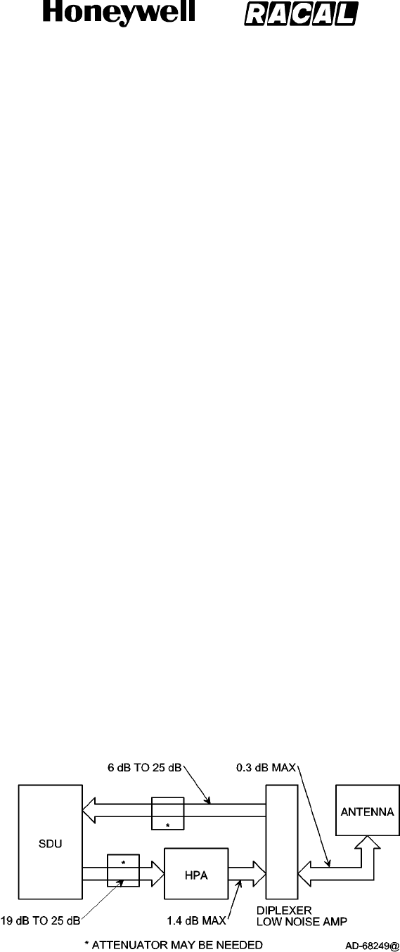
SYSTEM DESCRIPTION, INSTALLATION, AND MAINTENANCE MANUAL
MCS--4000/7000 Multi--Channel SATCOM System
23--20--27
30 Aug 2002
Use or disclosure of information on this page is subject to the restrictions in the proprietary notice of this document.
Page 4--2
CAUTION: BEFORE AN LRU IS INSTALLED, PULL THE CIRCUIT BREAKERS THAT
SUPPLY POWER TO THE LRU TO REMOVE POWER.
CAUTION: MOISTURE AND DIRT CAUSE DAMAGE TO LRUs.
CAUTION: LRU FAILURE RATES INCREASE WITH A RISE IN TEMPERATURE.
INSTALL THE LRUsWITH CLEARANCE; LET THE AIR FLOW ON TOP
AND BOTTOM OF LRUsTO PREVENT OVERHEATING.
CAUTION: MAKE SURE THAT THE LATEST ORT DATABASE SOFTWARE IS
INSTALLED IN THE SDU BEFORE PERFORMING SYSTEM
OPERATIONS.
NOTE: Honeywell/Racal recommend the MCS LRUs be installed so their installation
is level (zero degrees) to the horizontal plane of the aircraft. Compliance with
RTCA/DO--160C has been demonstrated with this orientation.
NOTE: Ambient temperature at the LRU location must be less than 40 °C (104 °F)
during operation for best reliability.
B. Installation Dependent Considerations
(1) Refer to the SYSTEM DESCRIPTION section for the installation dependent
considerations for the SDU.
C. Owner Requirements Table (ORT) Uploading
(1) When the SDU is changed, the ORT needs to be uploaded before normal operation
can begin. Refer to the SYSTEM OPERATION section for the ORT upload
procedures.
D. Cable Loss Requirements
(1) The attenuation and voltage standing wave ratio (VSWR) of coaxial cable used in the
MCS system must meet the requirements specified in Table 4-1 to make sure the
system operates correctly. Figure 4-1 shows the specific cable attenuations for the
SATCOM equipment. All specified cable attenuations include connector losses, which
are assumed to be 0.1 dB each. Honeywell recommends each cable assembly be
sweep tested for loss and VSWR.
Figure 4-1. Cable Attenuations
RELEASED FOR THE EXCLUSIVE USE BY: HONEYWELL INTERNATIONAL
UP86308
SeeTR

SYSTEM DESCRIPTION, INSTALLATION AND MAINTENANCE MANUAL
MCS-4000/7000
TEMPORARY REVISION NO. 23-1
23-20-27 Page 3 of 6
30 Oct 2009
© Honeywell International Inc. Do not copy without express permission of Honeywell.
INSERT PAGE 3 OF 6 AND PAGE 4 OF 6 FACING PAGE 4-2.
Reason: To update the third CAUTION and the first NOTE and to delete the second NOTE before
Paragraph 3.B., and to change Figure 4-1.
The third CAUTION and the NOTES are updated and deleted, and Figure 4-1 is changed as follows:
CAUTION: BEFORE AN LRU IS INSTALLED, PULL THE CIRCUIT BREAKERS THAT
SUPPLY POWER TO THE LRU TO REMOVE POWER.
CAUTION: MOISTURE AND DIRT CAUSE DAMAGE TO LRUs.
CAUTION: LRU FAILURE RATES INCREASE WITH A RISE IN OPERATIONAL
TEMPERATURE BEYOND LRU-SPECIFIED COOLING LEVELS. INSTALL THE
LRUs WITH CLEARANCE. LET THE AIR FLOW ON TOP AND BOTTOM OF LRUs
TO PREVENT OVERHEATING.
CAUTION: MAKE SURE THAT THE LATEST ORT DATABASE SOFTWARE IS INSTALLED IN
THE SDU BEFORE PERFORMING SYSTEM OPERATIONS.
NOTE: Honeywell/Thales recommends the MCS LRUs be installed so their installation is level
(zero degrees) to the horizontal plane of the aircraft. Compliance with RTCA/DO-160D
has been demonstrated with this orientation.
B. Installation Dependent Considerations
RELEASED FOR THE EXCLUSIVE USE BY: HONEYWELL INTERNATIONAL
UP86308
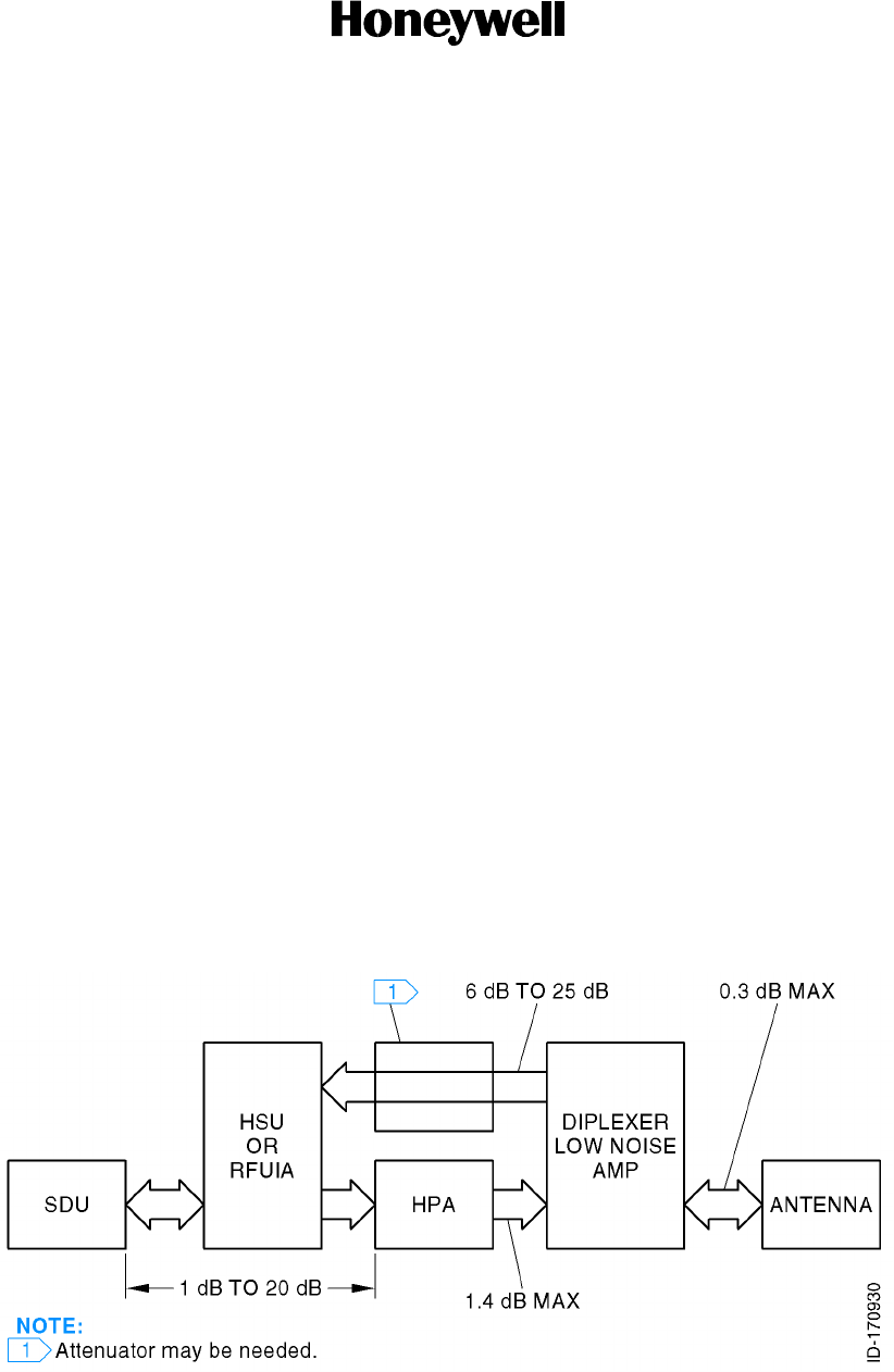
SYSTEM DESCRIPTION, INSTALLATION AND MAINTENANCE MANUAL
MCS-4000/7000
TEMPORARY REVISION NO. 23-1
23-20-27 Page 4 of 6
30 Oct 2009
© Honeywell International Inc. Do not copy without express permission of Honeywell.
Figure 4-1. Cable Attenuations
RELEASED FOR THE EXCLUSIVE USE BY: HONEYWELL INTERNATIONAL
UP86308

SYSTEM DESCRIPTION, INSTALLATION AND MAINTENANCE MANUAL
MCS-4000/7000
TEMPORARY REVISION NO. 23-1
23-20-27 Page 5 of 6
30 Oct 2009
© Honeywell International Inc. Do not copy without express permission of Honeywell.
INSERT PAGE 5 OF 6 AND PAGE 6 OF 6 FACING PAGE 4-3.
Reason: To update Table 4-1, to update the cooling requirements in Step 3.E., and to update Table 4-2.
Table 4-1, Step 3.E., and Table 4-2 are changed as follows:
Table 4-1. Cable Loss Requirements
Cable Assembly Location Minimum Loss Maximum Loss Maximum VSWR
TX Cable Between SDU, HSU,
and HPA
1 dB 20 dB 2.0
RX Cable Between Diplexer/LNA
and SDU
6 dB 25 dB 2.0
TX Cable Between HPA and
Diplexer/LNA
N/A 1.4 dB
1. 1.3
RX Cable Between Diplexer/LNA
and Antenna
N/A 0.3 dB 1.3
NOTES:
1. In installations that use a high power relay (HPR), the HPR loss must be included. The maximum Tx cable loss
between the HGA and the antenna must not exceed 2.5 dB.
2. N/A = Not applicable.
E. Cooling Requirements
(1) The cooling requirements for the MCS avionics are specified in Table 4-2 as follows:
• Power dissipation is in Watts
• Mass airflow is in pounds per hour
• CF/M is cubic feet per minute at sea level and 104°F (40°C)
• Pressure drop is in inches of water.
(2) If the LRUs are to be operated above an altitude where the flow rates defined in Table 4-2 cannot
be met, then the units must be installed in a pressurized compartment that provides a means to
meet the Table 4-2 cooling requirements.
(3) The temperature of the cooling air for the LRUs must not exceed 104°F (40°C).
RELEASED FOR THE EXCLUSIVE USE BY: HONEYWELL INTERNATIONAL
UP86308

SYSTEM DESCRIPTION, INSTALLATION AND MAINTENANCE MANUAL
MCS-4000/7000
TEMPORARY REVISION NO. 23-1
23-20-27 Page 6 of 6
30 Oct 2009
© Honeywell International Inc. Do not copy without express permission of Honeywell.
Table 4-2. Cooling Requirements
Power Dissipation Mass Airflow CF/M Pressure Drop
LRU Max. Nom. Max. Min. Max. Min. Max. Min.
SDU 150 105 96
(44 kg/hr)
73
(33 kg/hr)
23 18 0.25
(6.35 mm)
0.15
(3.81 mm)
HPA (60W) 425 250 176
(80 kg/hr)
121
(55 kg/hr)
42 29 0.25
(6.35 mm)
0.2
(5.0 mm)
HSU 100 55 63
(29 kg/hr)
49
(22 kg/hr)
15 11 0.25
(6.35 mm)
0.15
(3.81 mm)
NOTE: The SDU draws an additional 20 W during the first 10 minutes (maximum) of operation at 25°C because of the
oven controlled crystal oscillator (OCXO). The OCXO continuously dissipates this additional 20 W at −55°C.
RELEASED FOR THE EXCLUSIVE USE BY: HONEYWELL INTERNATIONAL
UP86308
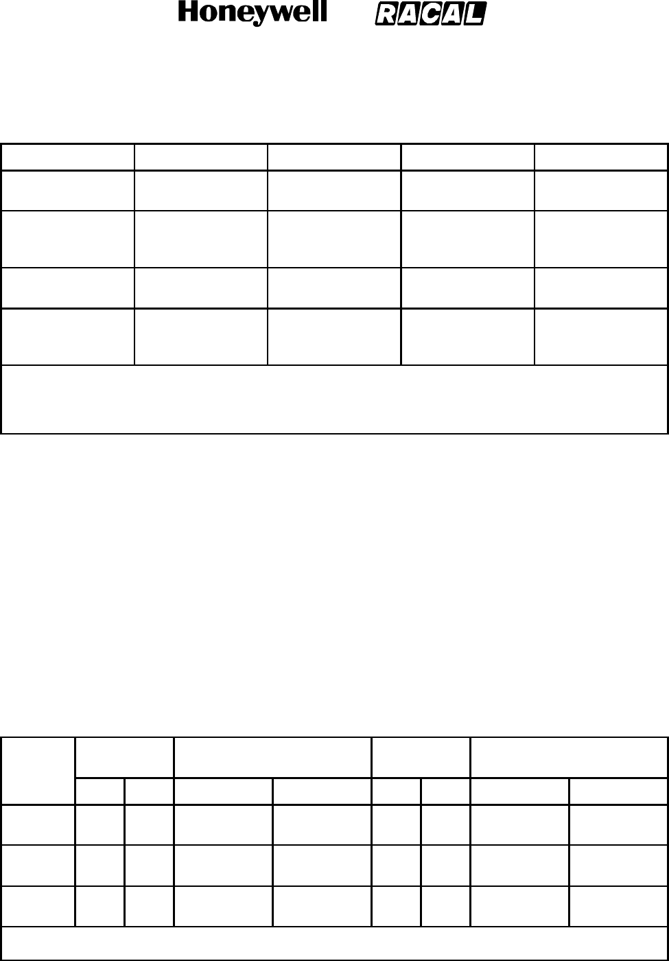
SYSTEM DESCRIPTION, INSTALLATION, AND MAINTENANCE MANUAL
MCS--4000/7000 Multi--Channel SATCOM System
23--20--27
30 Aug 2002
Use or disclosure of information on this page is subject to the restrictions in the proprietary notice of this document.
Page 4--3
Table 4-1. Cable Loss Requirements
Cable Assembly Location Minimum Loss Maximum Loss Maximum VSWR
TX Cable Between SDU and
HPA
19 dB 25 dB
1.
TBD
RX Cable Between
Diplexer/LNA and
SDU
6dB 25 dB
2.
TBD
TX Cable Between HPA and
Diplexer/LNA
1.4 dB TBD
RF Cable Between
Diplexer/LNA and
Antenna
0.3 dB TBD
NOTES:
1. In installations that use a combiner, the combiner loss must be included.
2. In installations that use a high power relay (HPR), the HPR loss must be included. The maximum Tx cable loss
between the HGA and the antenna must not exceed 2.5 dB.
E. Cooling Requirements
(1) The cooling requirements for the MCS avionics are specified in Table 4-2 as follows:
•PowerdissipationisinWatts
•Mass airflow is in pounds per hour
•CF/M is cubic feet per minute at sea level and 40 °C(104°F)
•Pressure drop is in inches of water.
(2) In most cases, a cooling system that meets the sea level requirements also meets
the cooling requirements at --55 °C(--67°F) and 70,000 feet.
Table 4-2. Cooling Requirements
Power
Dissipation Mass Airflow CF/M Pressure Drop
LRU Max. Nom. Max. Min. Max. Min. Max. Min.
SDU 198 105 96 (44 kg/hr) 73 (33 kg/hr) 23 18 0.25
(6.35 mm)
0.15
(3.81 mm)
HPA
(40W)
362 300 176 (80 kg/hr) 121 (44 kg/hr) 42 29 0.25
(6.35 mm)
0.15
(3.81 mm)
HPA
(20W)
180 150 96 (44 kg/hr) 73 (33 kg/hr) 23 18 0.3
(7.62 mm)
0.2
(5.08 mm)
NOTE: The SDU draws an additional 20 W during the first 10 minutes (maximum) of operation at 25 _C because of the
oven controlled crystal oscillator (OCXO). The OCXO continuously dissipates this additional 20 W at --55 _C.
RELEASED FOR THE EXCLUSIVE USE BY: HONEYWELL INTERNATIONAL
UP86308
SeeTR

SYSTEM DESCRIPTION, INSTALLATION, AND MAINTENANCE MANUAL
MCS--4000/7000 Multi--Channel SATCOM System
23--20--27
30 Aug 2002
Use or disclosure of information on this page is subject to the restrictions in the proprietary notice of this document.
Page 4--4
F. Vendor Supplied Equipment
(1) Installation equipment like mounting trays, connectors, and cables can be obtained
from various vendors. Refer to Appendix A for additional information about vendor
manufactured equipment. For vendor supplied avionics, refer to the vendor
documentation.
RELEASED FOR THE EXCLUSIVE USE BY: HONEYWELL INTERNATIONAL
UP86308
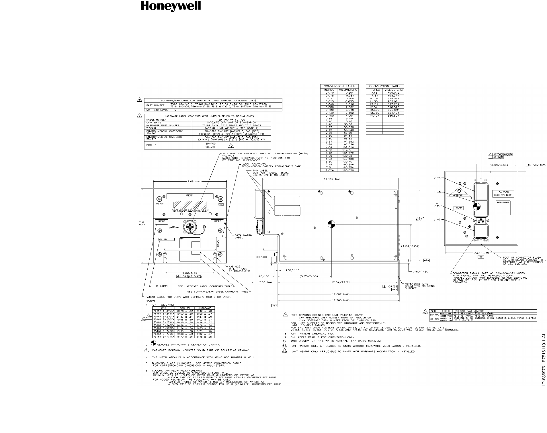
SYSTEM DESCRIPTION, INSTALLATION,
AND MAINTENANCE MANUAL
MCS-4000/7000
TEMPORARY REVISION NO. 23-2
23-20-27
Page 3 of 3
20 Jun 2017
© Honeywell International Inc. Do not copy without express permission of Honeywell.
INSERT PAGE 3 OF 3 FACING PAGE 4-5/(4-6 BLANK).
Reason: To change drawing data for Figure 4-2.
Figure 4-2 is changed as follows:
RELEASED FOR THE EXCLUSIVE USE BY: HONEYWELL INTERNATIONAL
UP86308
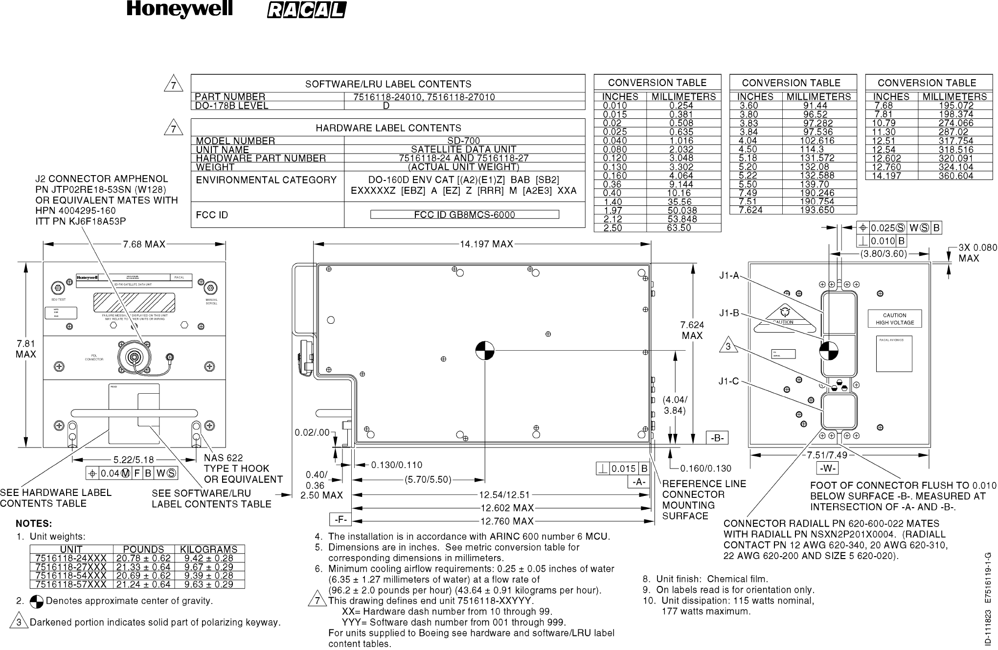
SYSTEM DESCRIPTION, INSTALLATION, AND MAINTENANCE MANUAL
MCS--4000/7000 Multi--Channel SATCOM System
23--20--27
30 Aug 2002
Use or disclosure of information on this page is subject to the restrictions in the proprietary notice of this document.
Page 4--5/(4--6 blank)
Figure 4-2. Satellite Data Unit Outline and Installation Diagram
RELEASED FOR THE EXCLUSIVE USE BY: HONEYWELL INTERNATIONAL
UP86308
SeeTR
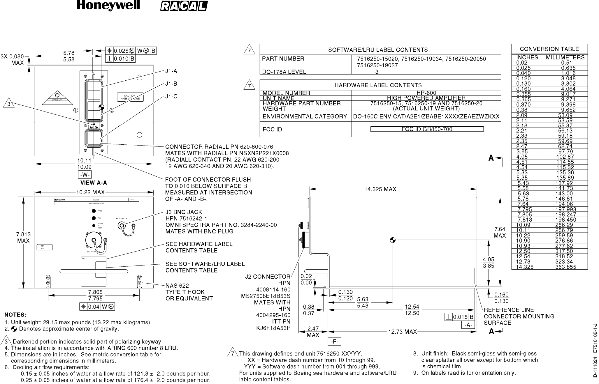
SYSTEM DESCRIPTION, INSTALLATION, AND MAINTENANCE MANUAL
MCS--4000/7000 Multi--Channel SATCOM System
23--20--27
30 Aug 2002
Use or disclosure of information on this page is subject to the restrictions in the proprietary notice of this document.
Page 4--7/(4--8 blank)
Figure 4-3. 40 Watt High Power Amplifier Outline and Installation Diagram
RELEASED FOR THE EXCLUSIVE USE BY: HONEYWELL INTERNATIONAL
UP86308
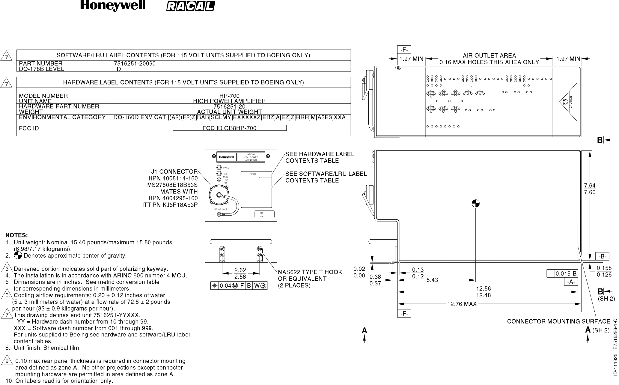
SYSTEM DESCRIPTION, INSTALLATION, AND MAINTENANCE MANUAL
MCS--4000/7000 Multi--Channel SATCOM System
23--20--27
30 Aug 2002
Use or disclosure of information on this page is subject to the restrictions in the proprietary notice of this document.
Page 4--9/(4--10 blank)
Figure 4-4 (Sheet 1). 20 Watt High Power Amplifier Outline and Installation Diagram
RELEASED FOR THE EXCLUSIVE USE BY: HONEYWELL INTERNATIONAL
UP86308
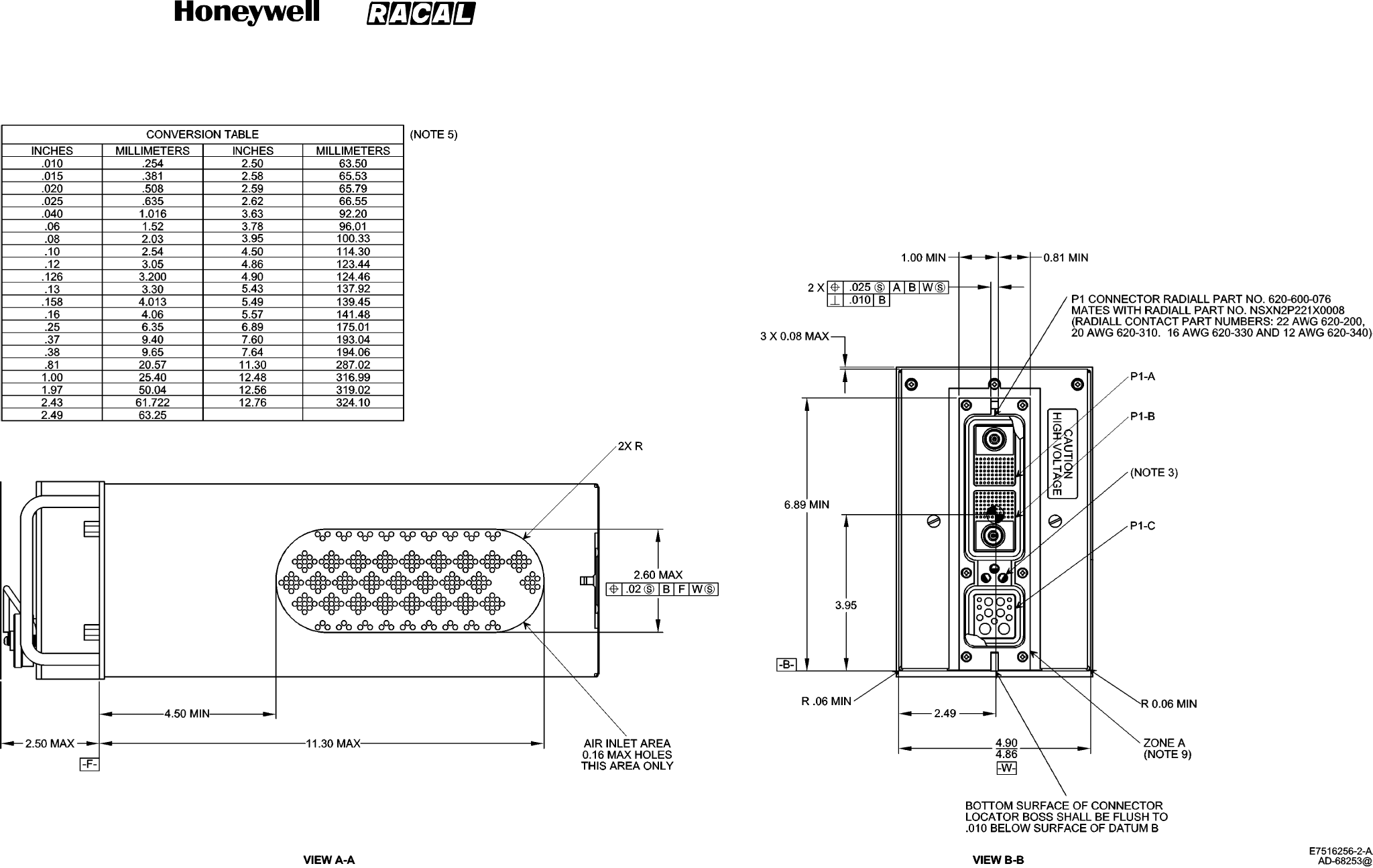
SYSTEM DESCRIPTION, INSTALLATION, AND MAINTENANCE MANUAL
MCS--4000/7000 Multi--Channel SATCOM System
23--20--27
30 Aug 2002
Use or disclosure of information on this page is subject to the restrictions in the proprietary notice of this document.
Page 4--11/(4--12 blank)
Figure 4-4 (Sheet 2). 20 Watt High Power Amplifier Outline and Installation Diagram
RELEASED FOR THE EXCLUSIVE USE BY: HONEYWELL INTERNATIONAL
UP86308
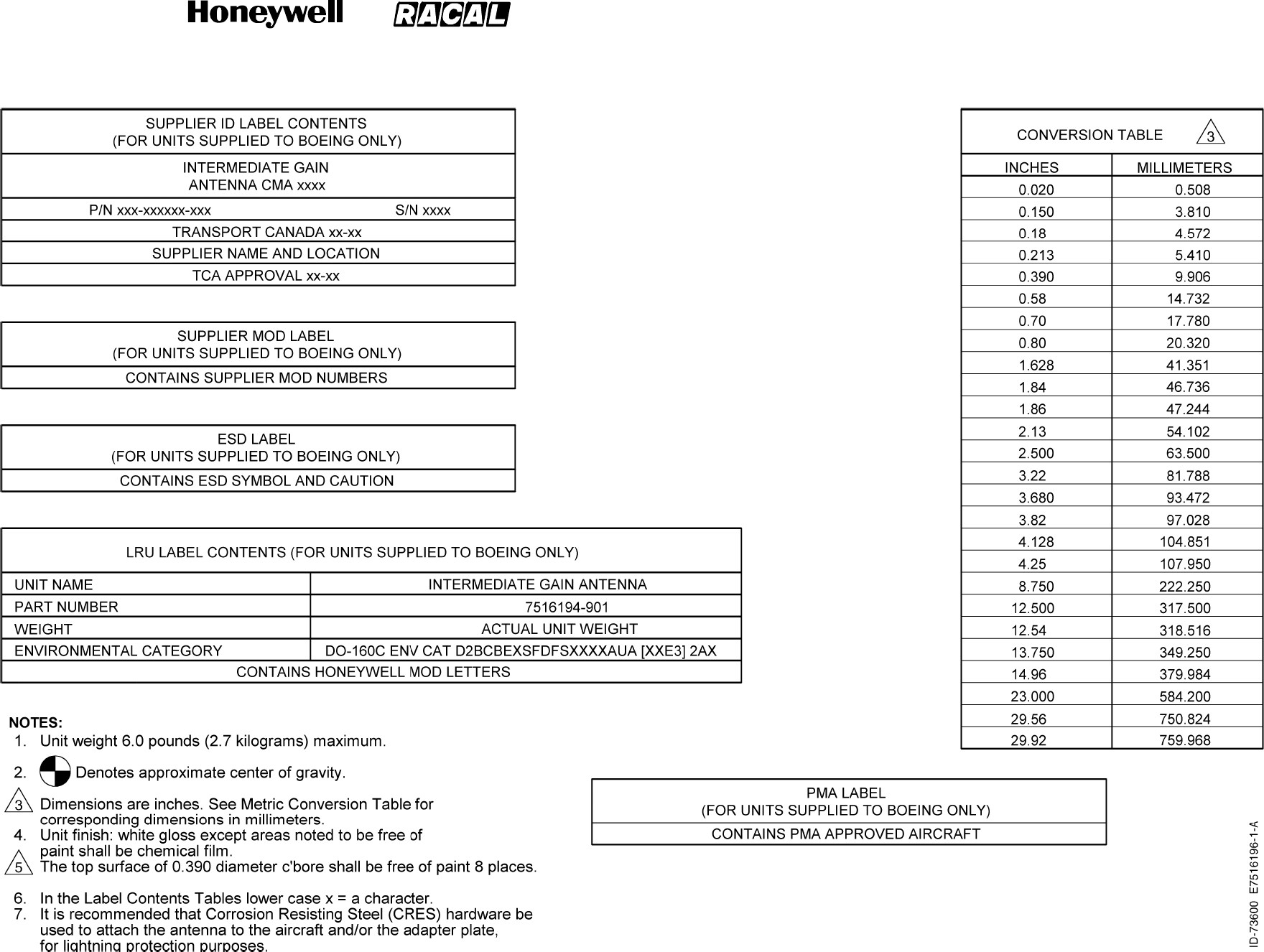
SYSTEM DESCRIPTION, INSTALLATION, AND MAINTENANCE MANUAL
MCS--4000/7000 Multi--Channel SATCOM System
23--20--27
30 Aug 2002
Use or disclosure of information on this page is subject to the restrictions in the proprietary notice of this document.
Page 4--13/(4--14 blank)
Figure 4-5 (Sheet 1). Intermediate Gain Antenna Outline and Installation Diagram
RELEASED FOR THE EXCLUSIVE USE BY: HONEYWELL INTERNATIONAL
UP86308
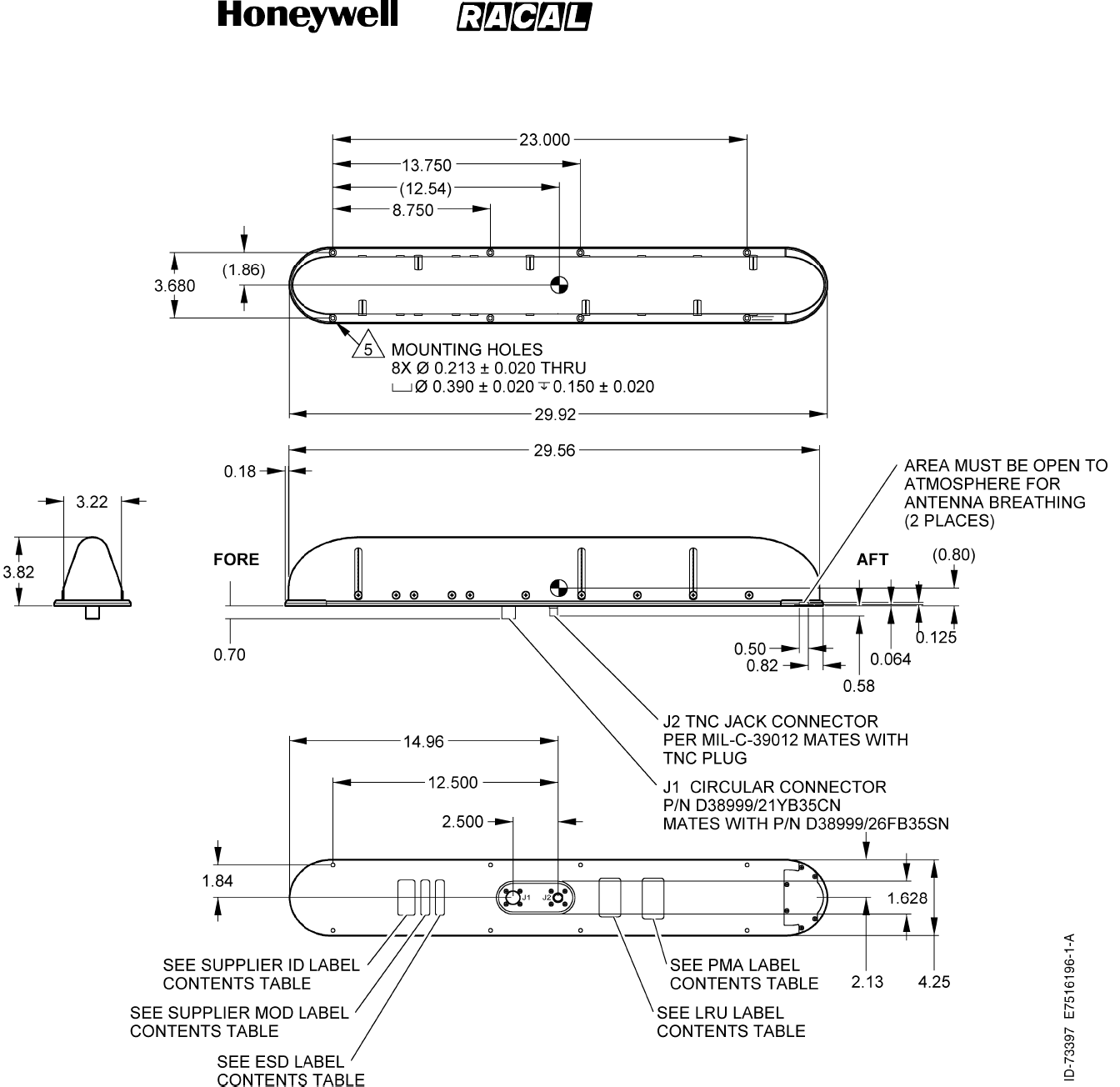
SYSTEM DESCRIPTION, INSTALLATION, AND MAINTENANCE MANUAL
MCS--4000/7000 Multi--Channel SATCOM System
23--20--27
30 Aug 2002
Use or disclosure of information on this page is subject to the restrictions in the proprietary notice of this document.
Page 4--15/(4--16 blank)
Figure 4-5 (Sheet 2). Intermediate Gain Antenna Outline and Installation Diagram
RELEASED FOR THE EXCLUSIVE USE BY: HONEYWELL INTERNATIONAL
UP86308
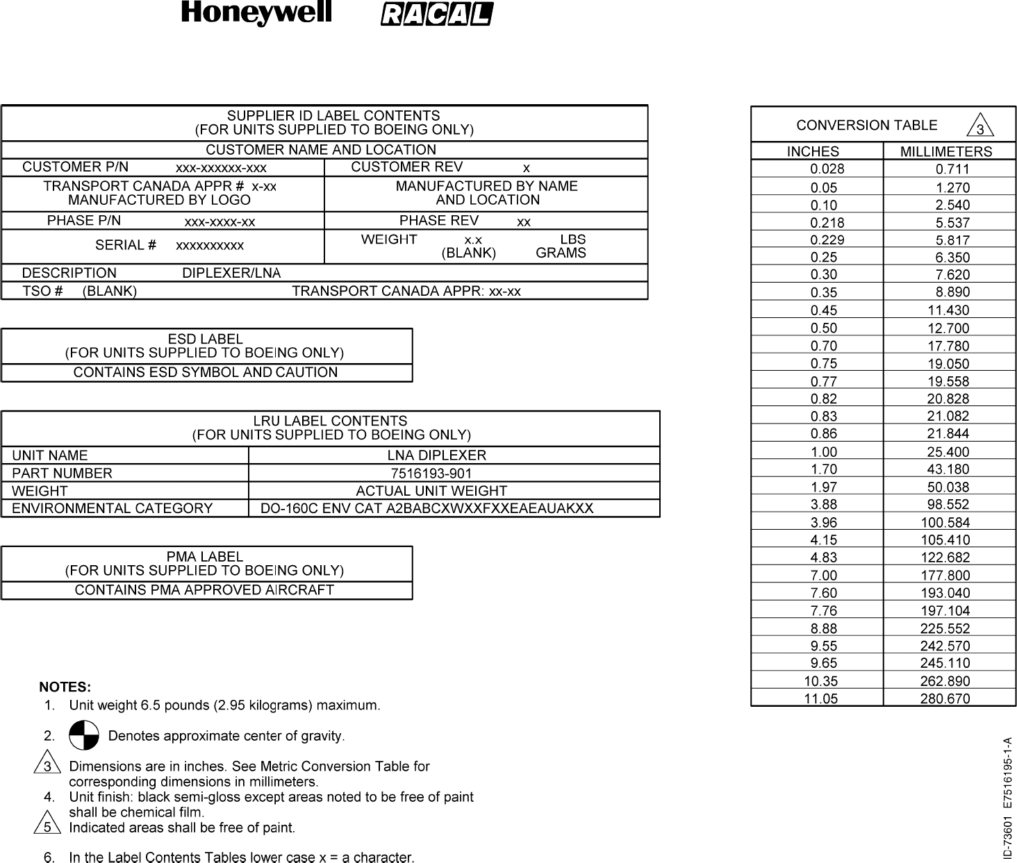
SYSTEM DESCRIPTION, INSTALLATION, AND MAINTENANCE MANUAL
MCS--4000/7000 Multi--Channel SATCOM System
23--20--27
30 Aug 2002
Use or disclosure of information on this page is subject to the restrictions in the proprietary notice of this document.
Page 4--17/(4--18 blank)
Figure 4-6 (Sheet 1). D/LNA Outline and Installation Diagram
RELEASED FOR THE EXCLUSIVE USE BY: HONEYWELL INTERNATIONAL
UP86308
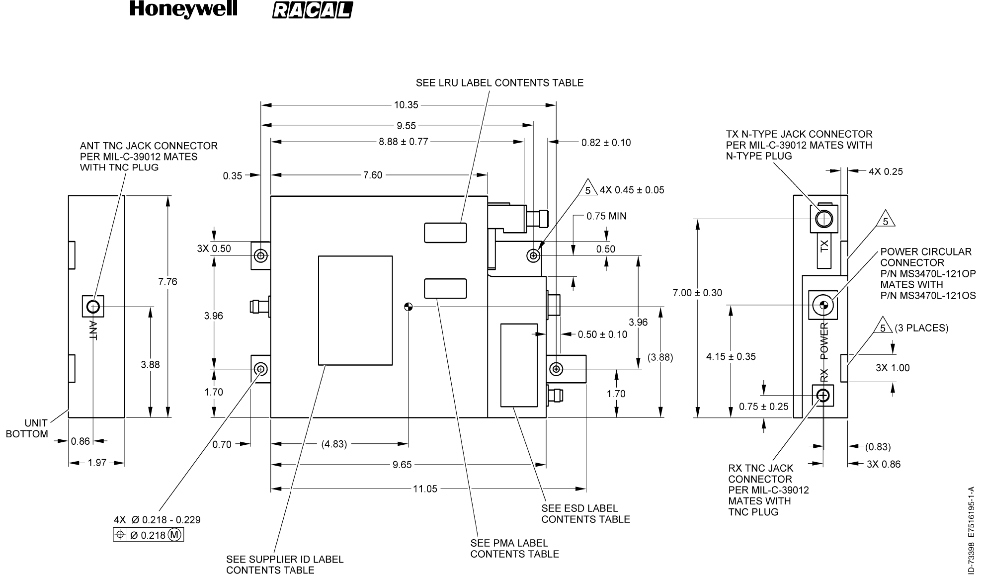
SYSTEM DESCRIPTION, INSTALLATION, AND MAINTENANCE MANUAL
MCS--4000/7000 Multi--Channel SATCOM System
23--20--27
30 Aug 2002
Use or disclosure of information on this page is subject to the restrictions in the proprietary notice of this document.
Page 4--19/(4--20 blank)
Figure 4-6 (Sheet 2). D/LNA Outline and Installation Diagram
RELEASED FOR THE EXCLUSIVE USE BY: HONEYWELL INTERNATIONAL
UP86308
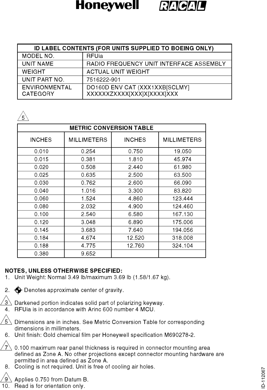
SYSTEM DESCRIPTION, INSTALLATION, AND MAINTENANCE MANUAL
MCS--4000/7000 Multi--Channel SATCOM System
23--20--27
30 Aug 2002
Use or disclosure of information on this page is subject to the restrictions in the proprietary notice of this document.
Page 4--21/(4--22 blank)
Figure 4-7 (Sheet 1). RFUIA Outline and Installation Diagram
RELEASED FOR THE EXCLUSIVE USE BY: HONEYWELL INTERNATIONAL
UP86308
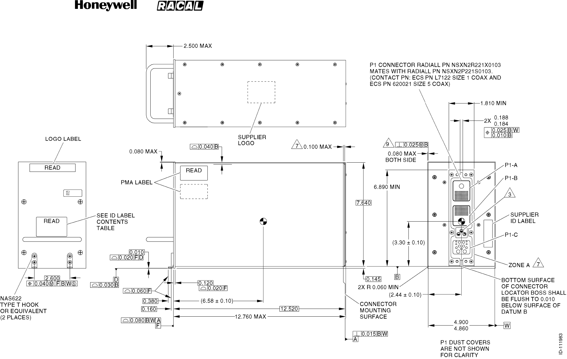
SYSTEM DESCRIPTION, INSTALLATION, AND MAINTENANCE MANUAL
MCS--4000/7000 Multi--Channel SATCOM System
23--20--27
30 Aug 2002
Use or disclosure of information on this page is subject to the restrictions in the proprietary notice of this document.
Page 4--23/(4--24 blank)
Figure 4-7 (Sheet 2). RFUIA Outline and Installation Diagram
RELEASED FOR THE EXCLUSIVE USE BY: HONEYWELL INTERNATIONAL
UP86308

SYSTEM DESCRIPTION, INSTALLATION, AND MAINTENANCE MANUAL
MCS--4000/7000 Multi--Channel SATCOM System
23--20--27
30 Aug 2002
Use or disclosure of information on this page is subject to the restrictions in the proprietary notice of this document.
Page 5--1
SECTION 5
ELECTRICAL INSTALLATION
1. Overview
A. General
(1) This section supplies electrical installation procedures, power distribution, and
interconnect diagrams for each component of the MCS system.
2. Equipment and Materials
A. General
(1) None.
3. Electrical Installation Procedure
A. Connector Layout and Contact Arrangement
(1) Each front panel connector of the SDU and HPA complies with ARINC characteristic
615, and is used to interface the LRU with an ARINC 615 portable data loader for
software uploads. Pin callouts are specified in Table 5-1. See the MECHANICAL
INSTALLATION section for specifics regarding connector part numbers for the ARINC
615 connector for each LRU and the corresponding mating connector.
(2) The rear connectors of the SDU ,HPA, and RFUIA comply with ARINC characteristic
600 as specified in Table 5-2. The ARINC 600 connector layouts and contact
arrangement for the various connector plugs for each LRU of the MCS system are
shown in Figure 5-1 thru Figure 5-10.
RELEASED FOR THE EXCLUSIVE USE BY: HONEYWELL INTERNATIONAL
UP86308

SYSTEM DESCRIPTION, INSTALLATION, AND MAINTENANCE MANUAL
MCS--4000/7000 Multi--Channel SATCOM System
23--20--27
30 Aug 2002
Use or disclosure of information on this page is subject to the restrictions in the proprietary notice of this document.
Page 5--2
Table 5-1. ARINC 615 Connector Pin Callouts
Pin SDU Signal Name HPA Signal Name
1PDL 429 A IN PDL TO HPA 429 A
2PDL 429 B IN PDL TO HPA 429 B
5SHIELD GND CHASSIS GND
8PDL 429 A OUT HPA TO PDL 429 A
9PDL 429 B OUT HPA TO PDL 429 B
11 SPARE RX RS232 -- --
13 SPARE TX RS232 -- --
16 SHIELD GND COMMON GND
18 PDL LINK A PDLLINKANO
19 GND (PDL LINK B) GND (PDL LINK B)
20 115 VAC HOT 115 VAC HOT
21 CHASSIS GND CHASSIS GND
22 115 VAC COLD 115 VAC GND
25 CTU RX RS232 FUTURE USE -- --
27 CTU TX RS232 FUTURE USE -- --
32 WH10 MIC HI -- --
33 WH10 MIC LO -- --
34 WH10 SPEAKER HI -- --
35 WH10 SPEAKER LO -- --
36 WH10 HOOKSWITCH -- --
40 RS232 A RX--DLT -- --
41 RS232 A TX--DLT -- --
42 RS232 B RX--CMT RS232 TO HPA
43 RS232 B TX--CMT RS232 TO DEBUG
48 LOGIC COMMON COMMON GROUND
49 LOGIC COMMON COMMON GROUND
50 DL FUNCTION DISC 1 -- --
51 DL FUNCTION DISC 2 -- --
RELEASED FOR THE EXCLUSIVE USE BY: HONEYWELL INTERNATIONAL
UP86308

SYSTEM DESCRIPTION, INSTALLATION, AND MAINTENANCE MANUAL
MCS--4000/7000 Multi--Channel SATCOM System
23--20--27
30 Aug 2002
Use or disclosure of information on this page is subject to the restrictions in the proprietary notice of this document.
Page 5--3
Table 5-2. ARINC 600 Connector Requirements
LRU Connector Description
LRU Rear
Connector Part
No.
Rack Mounting
Connector Part No. Outline Diagram
SDU ARINC 600 -- Size 6
MCU No. 2 Shell
•Type 02 Top Insert
•Type 02 Middle Insert
•Type 04 Bottom Insert
•Index Pin Code 04
620--600--022
(Radiall)
NSXN2P201X0004
(Radiall)
Figure 4-2,
Figure 5-1,
Figure 5-2,
Table 5-3, and
Table 5-4
HPA
(40 W)
ARINC 600 -- Size 8
MCU No. 2 Shell
•Type 08 Top Insert
•Type 05 Middle Insert
•Type 04 Bottom Insert
•Index Pin Code 08
620--600--076
(Radiall)
NSXN2P221X0008
(Radiall)
Figure 4-3
Figure 5-3 thru
Figure 5-6
HPA
(20 W)
ARINC 600 -- Size 4
MCU No. 2 Shell
•Type 08 Top Insert
•Type 05 Middle Insert
•Type 04 Bottom Insert
•Index Pin Code 08
620--600--076
(Radiall)
NSXN2P221X0008
(Radiall)
Figure 4-4,
Figure 5-3,
Figure 5-7,
Figure 5-8, and
Figure 5-9
RFUIA ARINC 600 -- Size 4
MCU No. 2 Shell
•Type 08 Top Insert
•Type 05 Middle Insert
•Type 04 Bottom Insert
•Index Pin Code 03
NSXNR221X0103
(Radiall)
NSXNP221S0103
(Radiall)
Figure 4-7 and
Figure 5-10
RELEASED FOR THE EXCLUSIVE USE BY: HONEYWELL INTERNATIONAL
UP86308
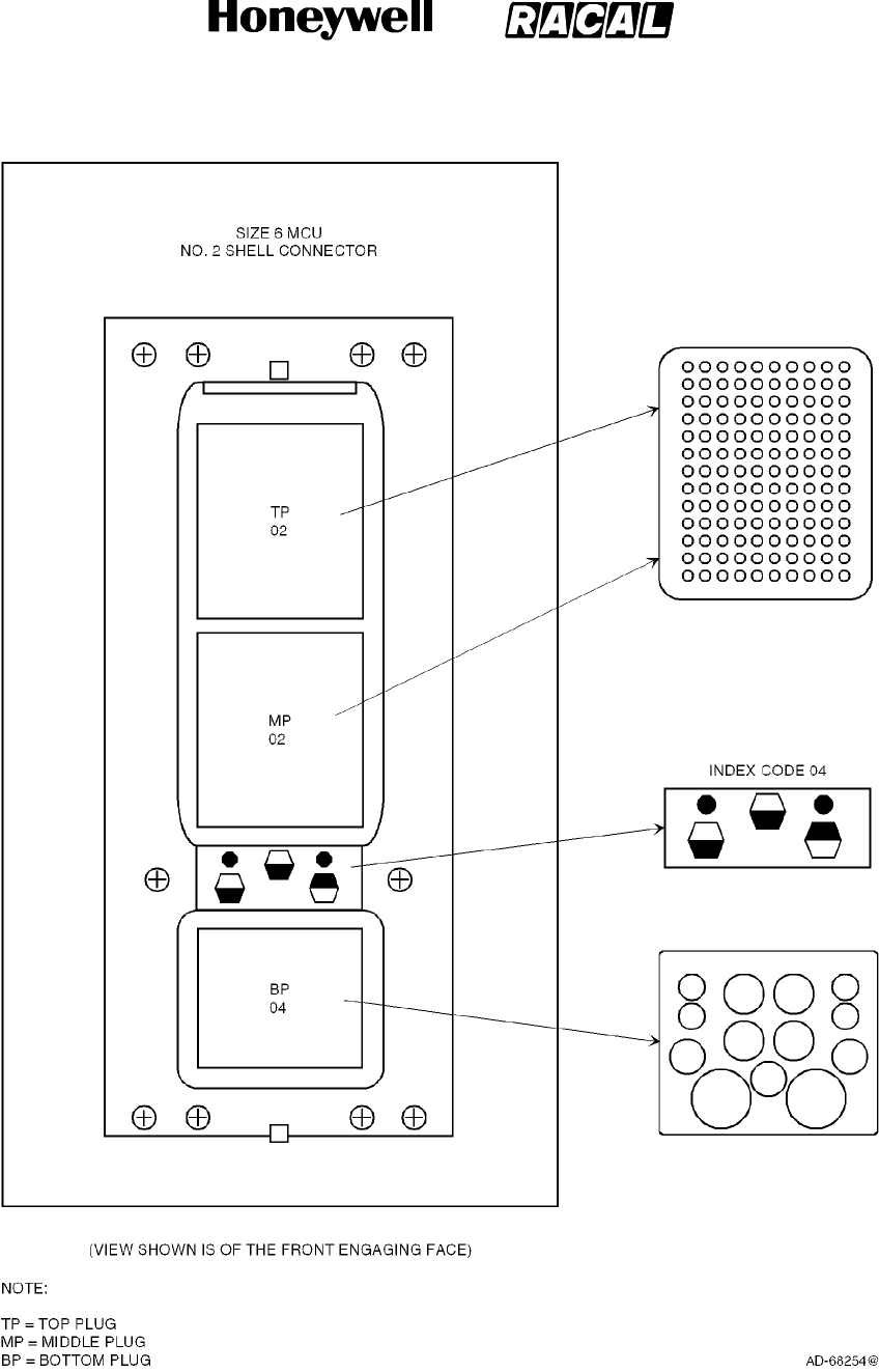
SYSTEM DESCRIPTION, INSTALLATION, AND MAINTENANCE MANUAL
MCS--4000/7000 Multi--Channel SATCOM System
23--20--27
30 Aug 2002
Use or disclosure of information on this page is subject to the restrictions in the proprietary notice of this document.
Page 5--4
Figure 5-1. SDU ARINC 600 Connector Layout
RELEASED FOR THE EXCLUSIVE USE BY: HONEYWELL INTERNATIONAL
UP86308

SYSTEM DESCRIPTION, INSTALLATION, AND MAINTENANCE MANUAL
MCS--4000/7000 Multi--Channel SATCOM System
23--20--27
30 Aug 2002
Use or disclosure of information on this page is subject to the restrictions in the proprietary notice of this document.
Page 5--5
Table 5-3. Contact Arrangements for Top Insert, SDU ARINC 600 Connector
A B C D E F G H J K
1
ANALOG
CABIN
VOICE
CHANNEL 1
HOOK--
SWITCH
ANALOG
CABIN
VOICE
CHANNEL 2
HOOK--
SWITCH
WH10--1
STATUS
A
(RINGER)
WH10--1
STATUS
B
(RINGER)
WH10--2
STATUS
A
(RINGER)
WH10--2
STATUS
B
(RINGER)
AVIONICS
SUB--
SYSTEM
SATCOM
FAIL
WARNING
(NON MCS
FAIL)
ANALOG
CABIN
VOICE
CHANNEL 1
IN--USE
SATELLITE
LINK NOT
READY
ANALOG
CABIN
VOICE
CHANNEL 2
IN--USE
2
ANALOG
PBX
CHANNEL 1
INPUT HI
ANALOG
PBX
CHANNEL 1
INPUT LO
ANALOG
PBX
CHANNEL 1
OUTPUT HI
ANALOG
PBX
CHANNEL 1
OUTPUT LO
ANALOG
PBX
CHANNEL 2
INPUT HI
ANALOG
PBX
CHANNEL 2
INPUT LO
ANALOG
PBX
CHANNEL 2
OUTPUT HI
ANALOG
PBX
CHANNEL 2
OUTPUT LO
O O
3
COCKPIT
VOICE UN--
AVAILABLE
ANALOG
CABIN
VOICE UN--
AVAILABLE
PACKET
DATA UN--
AVAILABLE
PACKET
DATA LOW
SPEED ONLY
AVAILABLE
SATCOM IN--
OPERABLE
(MCS FAIL)
CEPT--E1
0V SHIELD
(GND)
CEPT--E1 to
BRIDGED
CTU
(CM--250) 1A
CEPT--E1 to
BRIDGED
CTU
(CM--250) 1B
CEPT--E1 to
BRIDGED
CTU
(CM--250) 2A
CEPT--E1 to
BRIDGED
CTU
(CM--250) 2B
4
APM PWR
OUT FUTURE
USE
APM PWR
RTN FUTURE
USE
APM CLK
OUT FUTURE
USE
APM DATA
OUT FUTURE
USE
APM DATA IN
FUTURE USE
APM WE
OUT 1
FUTURE USE
APM WE
OUT 2
FUTURE USE
APM EN1
FUTURE USE
APM EN2
FUTURE USE
CEPT--E1
0V
5CTU SLOOP CTU SLOOP CTU SLOOP CTU SLOOP CTU SLOOP CTU SLOOP CTU SLOOP CTU SLOOP CTU SLOOP CTU SLOOP
6
RESERVED
BY ARINC
741
RESERVED
BY ARINC
741
RESERVED
BY ARINC
741
RESERVED
BY ARINC
741
RESERVED
BY ARINC
741
RESERVED
BY ARINC
741
RESERVED
BY ARINC
741
RESERVED
BY ARINC
741
RESERVED
BY ARINC
741
RESERVED
BY ARINC
741
7
RESERVED
BY ARINC
741
RESERVED
BY ARINC
741
RESERVED
BY ARINC
741
RESERVED
BY ARINC
741
RESERVED
BY ARINC
741
RESERVED
BY ARINC
741
RESERVED
BY ARINC
741
RESERVED
BY ARINC
741
RESERVED
BY ARINC
741
RESERVED
BY ARINC
741
8 O O O O O O O O O O
9
SPARE
DISCRETE
INPUT
CONFIG
STRAP TYPE
SPARE
DISCRETE
INPUT
CONFIG
STRAP TYPE
O O O O O O O O
10
AVAIL OF
429 SSR
MODE S
ADDRESS
RESERVED
FOR FMC
CONFIG
RESERVED
FOR FMC
CONFIG
CMU
BUS
SPEED
CPDF
CONFIG
RESERVED
FOR STRAP
OPTION
RESERVED
FOR STRAP
OPTION
RESERVED
FOR STRAP
OPTION
RESERVED
FOR STRAP
OPTION
CALL LIGHT
ACTIVATOR
CONFIGU--
RATION
11
STRAP
PARITY
(ODD)
CCS
PRESENCE
IRS
CONFIG
IRS
CONFIG
HPR/HPA/
BSU/LGA
CONFIG
HPR/HPA/
BSU/LGA
CONFIG
HPR/HPA/
BSU/LGA
CONFIG
HPR/HPA/
BSU/LGA
CONFIG
HPR/HPA/
BSU/LGA
CONFIG
HPR/HPA/
BSU/LGA
CONFIG
12 CFDS/CMC
TYPE
CFDS/CMC
TYPE
CFDS/CMC
TYPE
RESERVED
A/C ID
OR CFDS/
SDU
CONFIG
SDU
CONFIG
SDU
NUMBER
CMU
NO. 1
CONFIG
CMU
NO. 2
CONFIG
MCDU/
SCDU
NO. 1
CONFIG
MCDU/
SCDU
NO. 2
CONFIG
13 PRIORITY
4 CALLS
MCDU/
SCDU
BUS SPEED
LIGHT/
CHIME
CODE
LIGHT/
CHIME
CODE
MCDU/
SCDU
NO. 3
CONFIG
SDU
CODEC 1
WIRING
SDU
CODEC 1
WIRING
SDU
CODEC 2
WIRING
SDU
CODEC 2
WIRING
COCKPIT
SIGNALING
METHOD
14 5V
POS_MON
9V
POS_MON
RESERVED
ATE
RESET--
MON_N PEIT_SEL_N RESERVED
ATE
RESERVED
ATE
RESERVED
ATE
CEPT--E1
FROM
BRIDGED
CTU
(CM--250)1A
CEPT--E1
FROM
BRIDGED
CTU
(CM--250)1A
15 15 V
POS_MON
15 V
NEG_MON
GND (ATE
COMMON)
CEPT--E1
FROM
BRIDGED
CTU
(CM--250) 2A
CEPT--E1
FROM
BRIDGED
CTU
(CM--250) 2A
DLT_RX
(RS232
RX--SDU)
DLT_TX
(RS232
TX--SDU)
CMT_RX
(RS232
RX--SDU)
CMT_TX
(RS232
TX--SDU)
CMT_DLT_
RTN
RELEASED FOR THE EXCLUSIVE USE BY: HONEYWELL INTERNATIONAL
UP86308

SYSTEM DESCRIPTION, INSTALLATION, AND MAINTENANCE MANUAL
MCS--4000/7000 Multi--Channel SATCOM System
23--20--27
30 Aug 2002
Use or disclosure of information on this page is subject to the restrictions in the proprietary notice of this document.
Page 5--6
Table 5-4. Contact Arrangements for Middle Insert, SDU ARINC 600 Connector
A B C D E F G H J K
1
WH10 CABIN
NO. 1
AUDIO IN HI
WH10 CABIN
No. 1
AUDIO IN LO
WH10 CABIN
No. 1
AUDIO OUT
HI
WH10 CABIN
No. 1
AUDIO OUT
LO
DATA BUS
FROM CABIN
PACKET
DATA A
DATA BUS
FROM CABIN
PACKET
DATA B
FROM CMU
NO. 1
429
A
FROM CMU
NO. 1
429
B
TO CMU
NO. 1 AND
NO. 2
429 A
TO CMU
NO. 1 AND
NO. 2
429 B
2
COCKPIT
AUDIO CH 1
INPUT HI
COCKPIT
AUDIO CH 1
INPUT LO
COCKPIT
AUDIO CH 1
OUTPUT HI
COCKPIT
AUDIO CH 1
OUTPUT LO
COCKPIT
AUDIO CH 2
INPUT HI
COCKPIT
AUDIO CH 2
INPUT LO
COCKPIT
AUDIO CH 2
OUTPUT HI
COCKPIT
AUDIO CH 2
OUTPUT LO
CEPT--E1
FROM CTU
INPUT A
CEPT--E1
FROM CTU
INPUT B
3
CEPT--E1 TO
CTU OUTPUT
A
CEPT--E1 TO
CTU OUTPUT
B
DATA FROM
SCDU
NO. 1
A
DATA FROM
SCDU
NO. 1
B
DATA FROM
SCDU
NO. 2
A
DATA FROM
SCDU
NO. 2
B
DATA FROM
CMU
NO. 2
A
DATA FROM
CMU
NO. 2
B
DATA TO
SCDU NO. 1,
NO.2,AND
NO. 3
A
DATA TO
SCDU NO. 1,
NO.2,AND
NO. 3
B
4
AES
ID
INPUT
A
AES
ID
INPUT
B
FROM
CFDS
A
FROM
CFDS
B
TO
CFDS
A
TO
CFDS
B
MULTI--
CONTROL
OUTPUT
A
MULTI--
CONTROL
OUTPUT
B
WH10 CABIN
NO. 2
AUDIO IN
HI
WH10 CABIN
NO. 2
AUDIO IN
LO
L
G
A
LN
A
W E I G H T -- O N -- W H E E L S WH10 CABIN
N
O
.
2
WH10 CABIN
N
O
.
2
BITE INPUT
FROM LG
A
CHIME/
LIGHT
DUAL
S
Y
STEM
DUAL
S
Y
STEM
5
L
G
A
L
N
A
ON/OFF
CONTROL INPUT
NO. 1
INPUT
NO. 2
PROGRAM
SELECT
N
O
.
2
AUDIO OUT
HI
N
O
.
2
AUDIO OUT
LO
F
R
O
M
L
G
A
LNA
L
I
G
H
T
INHIBIT
S
Y
S
T
E
M
SELECT
DISCRETE
I/O
S
Y
S
T
E
M
SELECT
DISCRETE
INHIBIT
6
DATA FROM
PRIMARY
IRS A
DATA FROM
PRIMARY
IRS B
DATA FROM
SECONDARY
IRS A
DATA FROM
SECONDARY
IRS B
BITE INPUT
FROM
HGA/HPA A
BITE INPUT
FROM
HGA/HPA B
SPARE 429
INPUT
A
SPARE 429
INPUT
B
BITE INPUT
FROM
LGA/HPA A
BITE INPUT
FROM
LGA/HPA B
7
DATA BUS
FROM
AIRBORNE
LOADER
A
DATA BUS
FROM
AIRBORNE
LOADER
B
DATA BUS
TO
AIRBORNE
LOADER
A
DATA BUS
TO
AIRBORNE
LOADER
B
BSU NO. 1
AND NO. 2
STEER
INHIBIT
A
BSU NO. 1
AND NO. 2
STEER
INHIBIT
B
BITE INPUT
FROM ACU
OR
TOP--PORT
BSU A
BITE INPUT
FROM ACU
OR
TOP--PORT
BSU B
BITE INPUT
FROM STBD
BSU
A
BITE INPUT
FROM STBD
BSU
B
8
DATA
LOADER
LINK A
DATA
LOADER
LINK B
RESERVED
FOR DATA
BUS FROM
RMP A
RESERVED
FOR DATA
BUS FROM
RMP B
CP VOICE
CALL LGT
OUTPUT
NO. 1
CP VOICE
MIC ON
INPUT
NO. 1
CP VOICE
CALL LGT
OUTPUT
NO. 2
CP VOICE
MIC ON
INPUT
NO. 2
DATA FROM
SCDU
NO. 3
A
DATA FROM
SCDU
NO. 3
B
9
DATA BUS
TO SNU OR
CPDF A
DATA BUS
TO SNU OR
CPDF B
RESERVED
FOR DATA
TO RMP A
RESERVED
FOR DATA
TO RMP B
RESERVED
DATA BUS
RESERVED
DATA BUS
RESERVED
DATA BUS
RESERVED
DATA BUS
CEPT--E1
FROM 0BE1
A
CEPT--E1
FROM 0BE1
B
10 CEPT--E1 TO
0BE1 A
CEPT--E1 TO
0BE1 B RESERVED RESERVED RESERVED RESERVED RESERVED RESERVED RESERVED RESERVED
11
FROM
MOTION
SENSOR
NO. 1
MOTION
SENSOR
NO. 1
PROGRAM
SELECT
CALL
CANCEL
DISCRETE
INPUT
NO. 1
CALL
CANCEL
DISCRETE
INPUT
NO. 2
RESERVED
UNSPEC
PROGRAM
RESERVED
UNSPEC
PROGRAM
RESERVED
UNSPEC
PROGRAM
RESERVED
UNSPEC
PROGRAM
RESERVED
UNSPEC
PROGRAM
RESERVED
UNSPEC
PROGRAM
12
CROSSTALK
FROM
OTHERSDU
A
CROSSTALK
FROM
OTHERSDU
B
CROSSTALK
TO
OTHERSDU
A
CROSSTALK
TO
OTHERSDU
B
SPARE
O
SPARE
O
RESERVED
FOR DATA
FROM
FMC 1
A
RESERVED
FOR DATA
FROM
FMC 1
B
RESERVED
FOR DATA
FROM
FMC 2
A
RESERVED
FOR DATA
FROM
FMC 2
B
13
SPARE
DISCRETE
OUTPUT
28 VDC CALL
LAMP TYPE
SPARE
O
ICAO
ADDRESS
BIT NO. 1
(MSB)
ICAO
ADDRESS
BIT NO. 2
ICAO
ADDRESS
BIT NO. 3
ICAO
ADDRESS
BIT NO. 4
ICAO
ADDRESS
BIT NO. 5
ICAO
ADDRESS
BIT NO. 6
ICAO
ADDRESS
BIT NO. 7
ICAO
ADDRESS
BIT NO. 8
14
CP VOICE
GO--AHEAD
CHIME
RESET
NO. 1
CP VOICE
CHIME
CONTACT
1
CP VOICE
CONTACT
2
ICAO
ADDRESS
BIT NO. 9
ICAO
ADDRESS
BIT NO. 10
ICAO
ADDRESS
BIT NO. 11
ICAO
ADDRESS
BIT NO. 12
ICAO
ADDRESS
BIT NO. 13
ICAO
ADDRESS
BIT NO. 14
ICAO
ADDRESS
BIT NO. 15
15
ICAO
ADDRESS
BIT NO. 16
ICAO
ADDRESS
BIT NO. 17
ICAO
ADDRESS
BIT NO. 18
ICAO
ADDRESS
BIT NO. 19
ICAO
ADDRESS
BIT NO. 20
ICAO
ADDRESS
BIT NO. 21
ICAO
ADDRESS
BIT NO. 22
ICAO
ADDRESS
BIT NO. 23
ICAO
ADDRESS
BIT NO. 24
(LSB)
ICAO
ADDRESS
COMMON
RELEASED FOR THE EXCLUSIVE USE BY: HONEYWELL INTERNATIONAL
UP86308
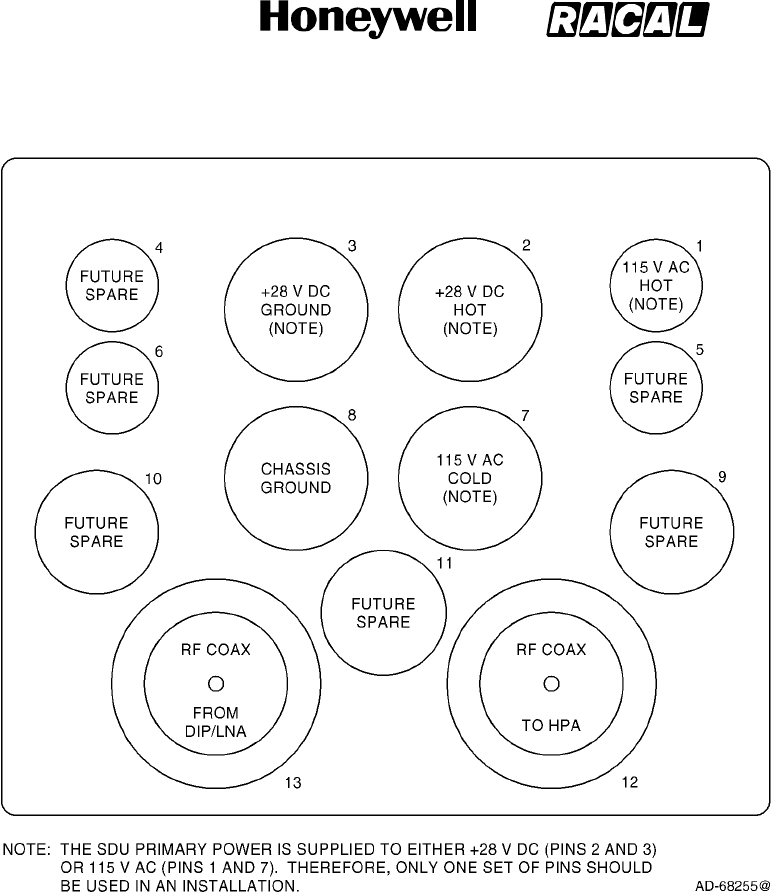
SYSTEM DESCRIPTION, INSTALLATION, AND MAINTENANCE MANUAL
MCS--4000/7000 Multi--Channel SATCOM System
23--20--27
30 Aug 2002
Use or disclosure of information on this page is subject to the restrictions in the proprietary notice of this document.
Page 5--7
Figure 5-2. Contact Arrangements for Bottom Insert, SDU ARINC 600 Connector
RELEASED FOR THE EXCLUSIVE USE BY: HONEYWELL INTERNATIONAL
UP86308
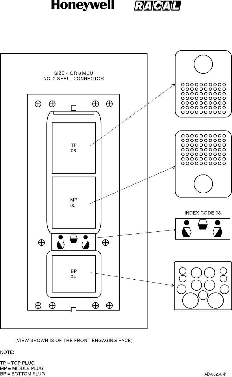
SYSTEM DESCRIPTION, INSTALLATION, AND MAINTENANCE MANUAL
MCS--4000/7000 Multi--Channel SATCOM System
23--20--27
30 Aug 2002
Use or disclosure of information on this page is subject to the restrictions in the proprietary notice of this document.
Page 5--8
Figure 5-3. HPA ARINC 600 Connector Layout
RELEASED FOR THE EXCLUSIVE USE BY: HONEYWELL INTERNATIONAL
UP86308
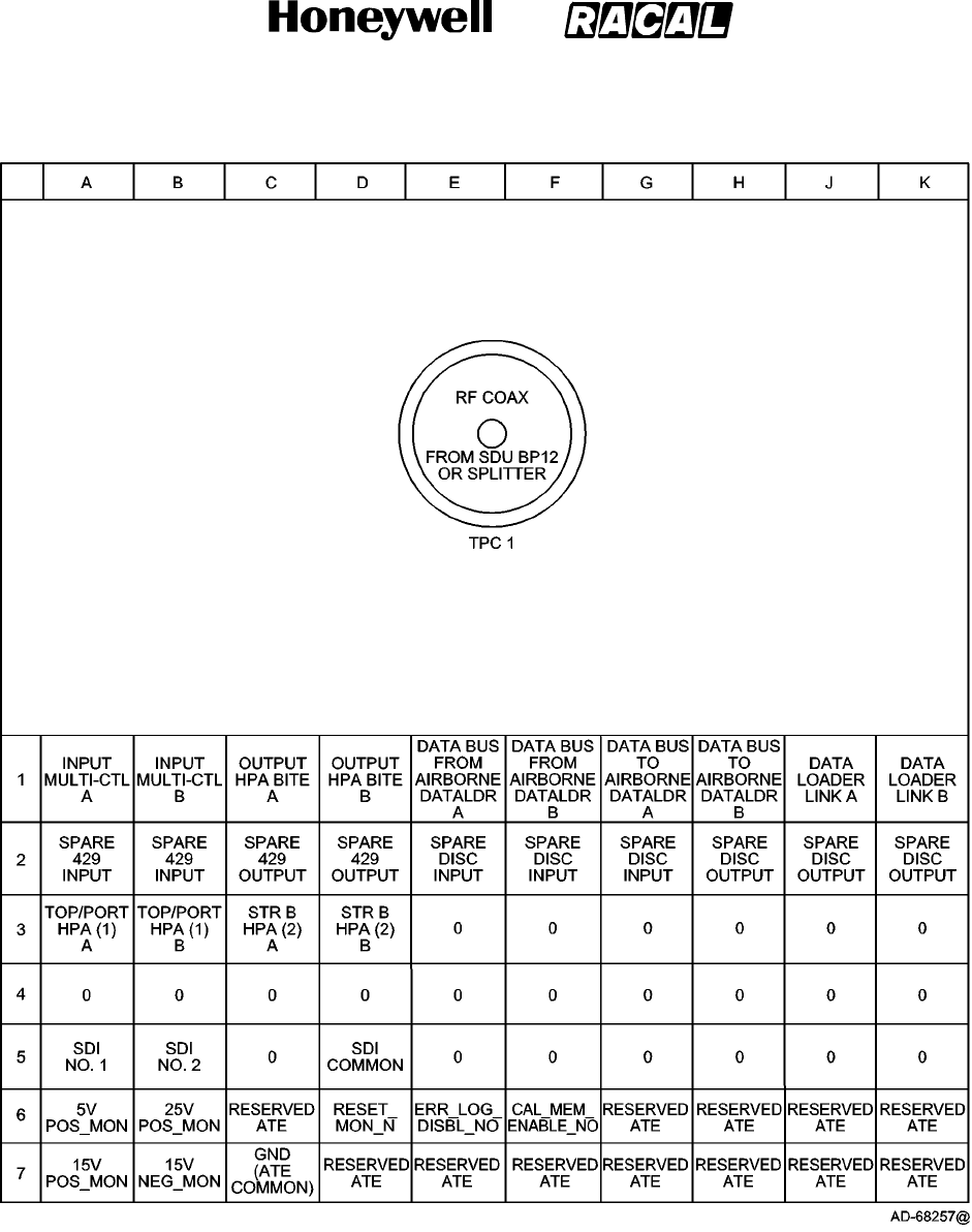
SYSTEM DESCRIPTION, INSTALLATION, AND MAINTENANCE MANUAL
MCS--4000/7000 Multi--Channel SATCOM System
23--20--27
30 Aug 2002
Use or disclosure of information on this page is subject to the restrictions in the proprietary notice of this document.
Page 5--9
Figure 5-4. Contact Arrangements for Top Insert, HPA (40 Watt) ARINC 600 Connector
RELEASED FOR THE EXCLUSIVE USE BY: HONEYWELL INTERNATIONAL
UP86308
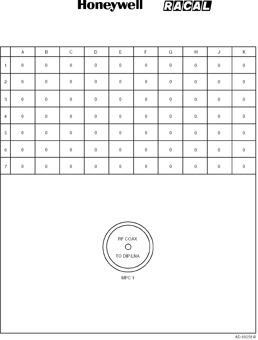
SYSTEM DESCRIPTION, INSTALLATION, AND MAINTENANCE MANUAL
MCS--4000/7000 Multi--Channel SATCOM System
23--20--27
30 Aug 2002
Use or disclosure of information on this page is subject to the restrictions in the proprietary notice of this document.
Page 5--10
Figure 5-5. Contact Arrangements for Middle Insert, HPA (40 Watt) ARINC 600 Connector
RELEASED FOR THE EXCLUSIVE USE BY: HONEYWELL INTERNATIONAL
UP86308
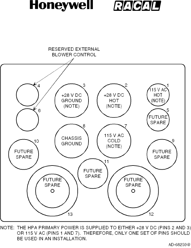
SYSTEM DESCRIPTION, INSTALLATION, AND MAINTENANCE MANUAL
MCS--4000/7000 Multi--Channel SATCOM System
23--20--27
30 Aug 2002
Use or disclosure of information on this page is subject to the restrictions in the proprietary notice of this document.
Page 5--11
Figure 5-6. Contact Arrangements for Bottom Insert, HPA (40 Watt) ARINC 600 Connector
RELEASED FOR THE EXCLUSIVE USE BY: HONEYWELL INTERNATIONAL
UP86308

SYSTEM DESCRIPTION, INSTALLATION, AND MAINTENANCE MANUAL
MCS--4000/7000 Multi--Channel SATCOM System
23--20--27
30 Aug 2002
Use or disclosure of information on this page is subject to the restrictions in the proprietary notice of this document.
Page 5--12
Figure 5-7. Contact Arrangements for Top Insert, HPA (20 Watt) ARINC 600 Connector
RELEASED FOR THE EXCLUSIVE USE BY: HONEYWELL INTERNATIONAL
UP86308
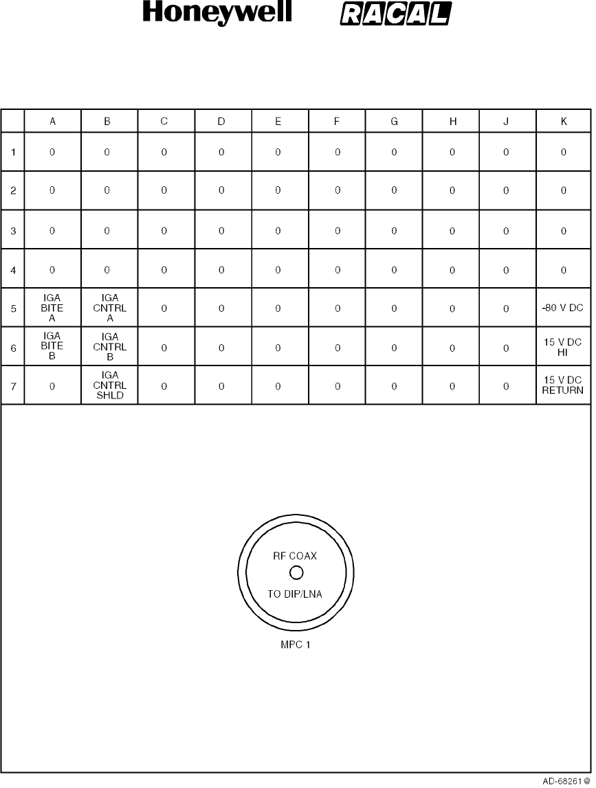
SYSTEM DESCRIPTION, INSTALLATION, AND MAINTENANCE MANUAL
MCS--4000/7000 Multi--Channel SATCOM System
23--20--27
30 Aug 2002
Use or disclosure of information on this page is subject to the restrictions in the proprietary notice of this document.
Page 5--13
Figure 5-8. Contact Arrangements for Middle Insert, HPA (20 Watt) ARINC 600 Connector
RELEASED FOR THE EXCLUSIVE USE BY: HONEYWELL INTERNATIONAL
UP86308
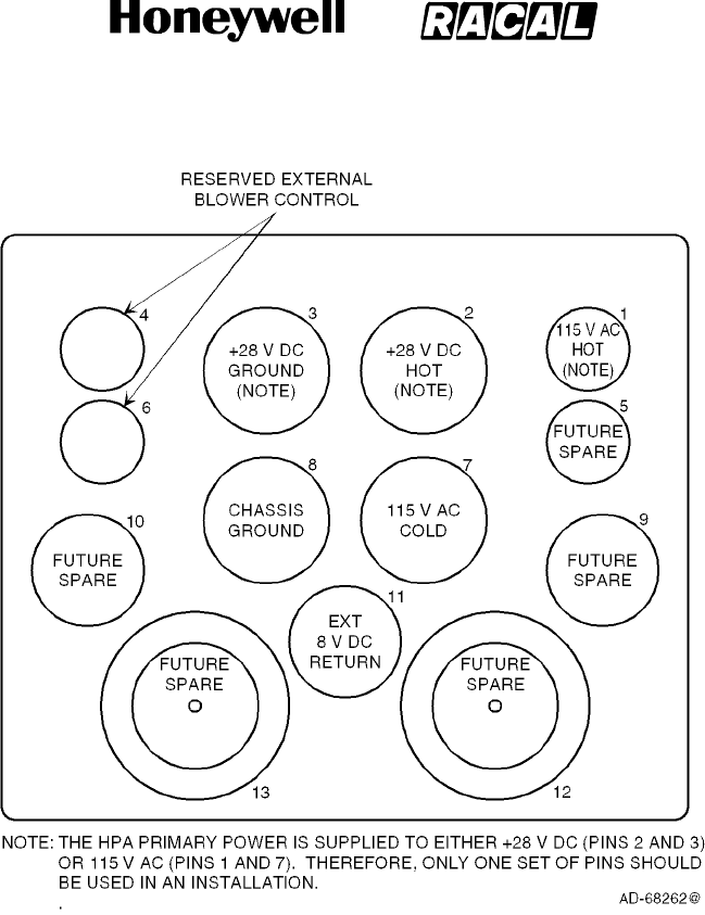
SYSTEM DESCRIPTION, INSTALLATION, AND MAINTENANCE MANUAL
MCS--4000/7000 Multi--Channel SATCOM System
23--20--27
30 Aug 2002
Use or disclosure of information on this page is subject to the restrictions in the proprietary notice of this document.
Page 5--14
Figure 5-9. Contact Arrangements for Bottom Insert, HPA (20 Watt) ARINC 600 Connector
RELEASED FOR THE EXCLUSIVE USE BY: HONEYWELL INTERNATIONAL
UP86308
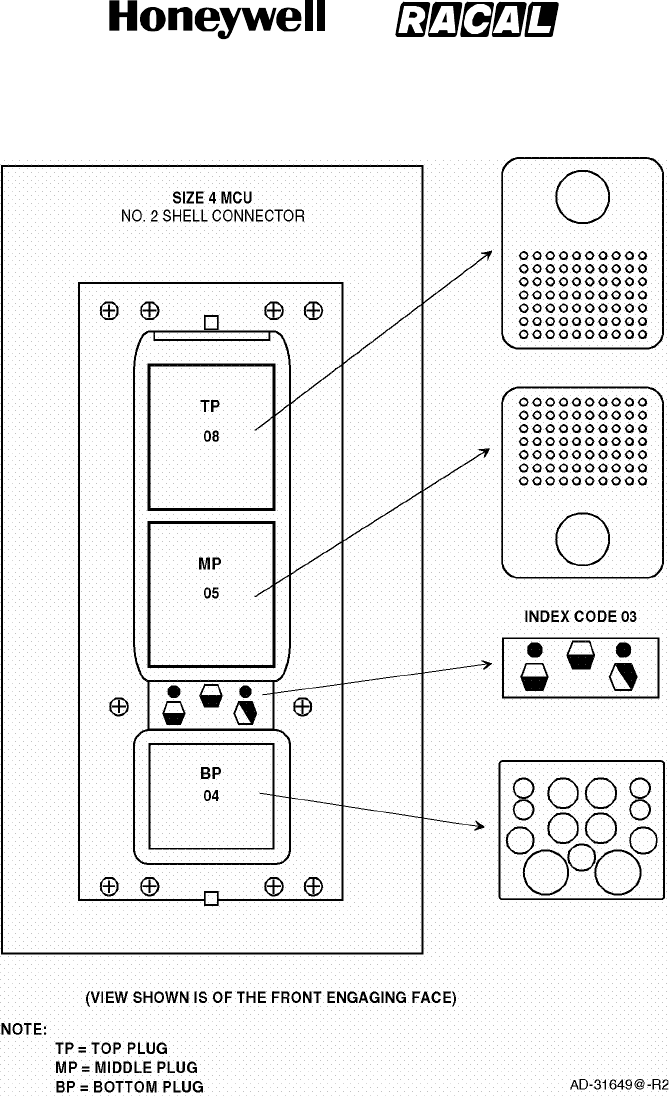
SYSTEM DESCRIPTION, INSTALLATION, AND MAINTENANCE MANUAL
MCS--4000/7000 Multi--Channel SATCOM System
23--20--27
30 Aug 2002
Use or disclosure of information on this page is subject to the restrictions in the proprietary notice of this document.
Page 5--15
Figure 5-10. RFUIA ARINC 600 Connector Layout
RELEASED FOR THE EXCLUSIVE USE BY: HONEYWELL INTERNATIONAL
UP86308

SYSTEM DESCRIPTION, INSTALLATION, AND MAINTENANCE MANUAL
MCS--4000/7000 Multi--Channel SATCOM System
23--20--27
30 Aug 2002
Use or disclosure of information on this page is subject to the restrictions in the proprietary notice of this document.
Page 5--16
B. Electrical Installation
(1) The information necessary to supply the electrical interconnects is shown in
Figure 5-11 thru Figure 5-26. Interconnect diagrams are as follows:
•Figure 5-11. Satellite Data Unit Interface Diagram
•Figure 5-12. WH--10 Handset Interface Diagram
•Figure 5-13. Four--to--Two Wire Interface Diagram
•Figure 5-14. Avtech Fax Interface Diagram
•Figure 5-15. HF--SAT Transfer Panel Interface Diagram
•Figure 5-16. Signal Conditioning Unit Interface Diagram
•Figure 5-17. Maintenance Panel Assembly Interface Diagram
•Figure 5-18. Intermediate Gain Antenna Interface Diagram
•Figure 5-19. CMC Top--Mount High Gain Antenna Interface Diagram
•Figure 5-20. Tecom Top--Mount High Gain Antenna Interface Diagram
•Figure 5-21. Racal Mechanically Steered High Gain Antenna Interface Diagram
•Figure 5-22. AMT--50 Mechanically Steered High Gain Antenna Interface Diagram
•Figure 5-23. Dassault Conformal High Gain Antenna Interface Diagram
•Figure 5-24. Ball Conformal High Gain Antenna Interface Diagram
•Figure 5-25. Low Gain Antenna Interface Diagram
•Figure 5-26. Toyocom Top--Mount High Gain Antenna Interface Diagram.
(2) The applicable configuration pins in the aircraft wiring must be connected to make the
MCS system functional. The SDU receives and sends 30 system configuration
discrete inputs through the configuration pins to properly match the avionics
equipment installed on the aircraft (see Figure 5-11 and Paragraph 4. to identify the
configuration pins).
(3) The SDU receives a 24-bit ICAO address that identifies the aircraft in which the SDU
is installed (Figure 5-11). Continuity is defined as a resistance of 10 ohms or less
between a configuration pin or address pin and the common. Continuity is broken
when the resistance between a configuration pin or address pin and common
measures 100k ohms or greater.
RELEASED FOR THE EXCLUSIVE USE BY: HONEYWELL INTERNATIONAL
UP86308
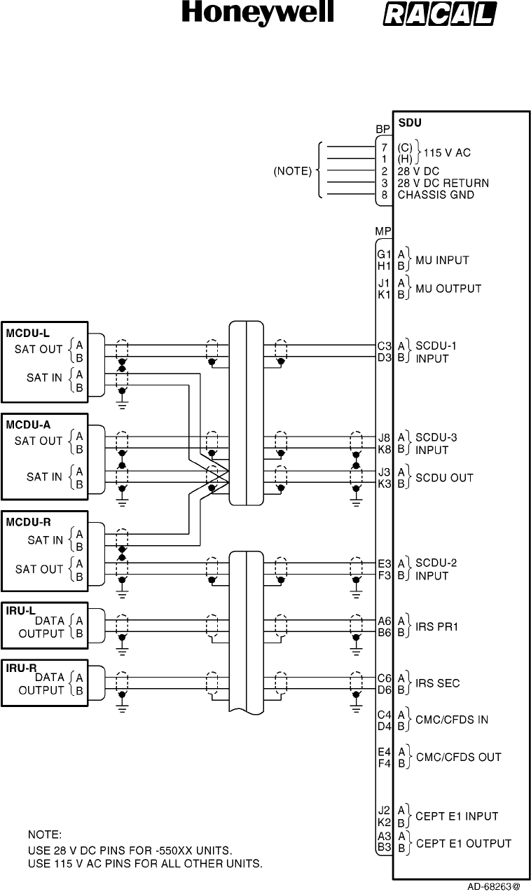
SYSTEM DESCRIPTION, INSTALLATION, AND MAINTENANCE MANUAL
MCS--4000/7000 Multi--Channel SATCOM System
23--20--27
30 Aug 2002
Use or disclosure of information on this page is subject to the restrictions in the proprietary notice of this document.
Page 5--17
Figure 5-11 (Sheet 1). Satellite Data Unit Interface Diagram
RELEASED FOR THE EXCLUSIVE USE BY: HONEYWELL INTERNATIONAL
UP86308
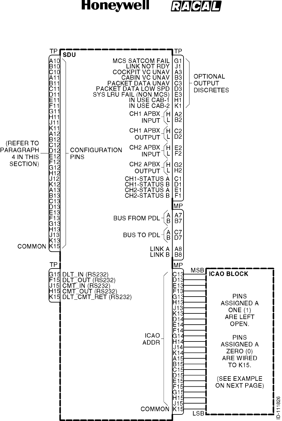
SYSTEM DESCRIPTION, INSTALLATION, AND MAINTENANCE MANUAL
MCS--4000/7000 Multi--Channel SATCOM System
23--20--27
30 Aug 2002
Use or disclosure of information on this page is subject to the restrictions in the proprietary notice of this document.
Page 5--18
Figure 5-11 (Sheet 2). Satellite Data Unit Interface Diagram
RELEASED FOR THE EXCLUSIVE USE BY: HONEYWELL INTERNATIONAL
UP86308
SYSTEM DESCRIPTION, INSTALLATION, AND MAINTENANCE MANUAL
MCS--4000/7000 Multi--Channel SATCOM System
23--20--27
30 Aug 2002
Use or disclosure of information on this page is subject to the restrictions in the proprietary notice of this document.
Page 5--19
Table 5-5. ICAO Block Strapping
Example: AES ID 53375006 (Octal)
Octal Binary SDU Connector Pin (MP)
1C13
5 0 D13
1E13
0F13
3 1 G13
1H13
0J13
3 1 K13
1D14
1E14
7 1 F14
1G14
1H14
5 0 J14
1K14
0A15
0 0 B15
0C15
0D15
0 0 E15
0F15
1G15
6 1 H15
0J15
Common K15
NOTES:
1. 53375006 (Octal) = 101011011111101000000110 (Binary).
2. Binary 1 = Open; Binary 0 = Ground.
3. Pins assigned a zero (0) are wired to SDU connector pin MP--K15 (common).
RELEASED FOR THE EXCLUSIVE USE BY: HONEYWELL INTERNATIONAL
UP86308
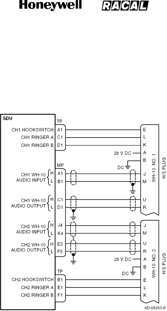
SYSTEM DESCRIPTION, INSTALLATION, AND MAINTENANCE MANUAL
MCS--4000/7000 Multi--Channel SATCOM System
23--20--27
30 Aug 2002
Use or disclosure of information on this page is subject to the restrictions in the proprietary notice of this document.
Page 5--20
Figure 5-12. WH--10 Handset Interface Diagram
RELEASED FOR THE EXCLUSIVE USE BY: HONEYWELL INTERNATIONAL
UP86308
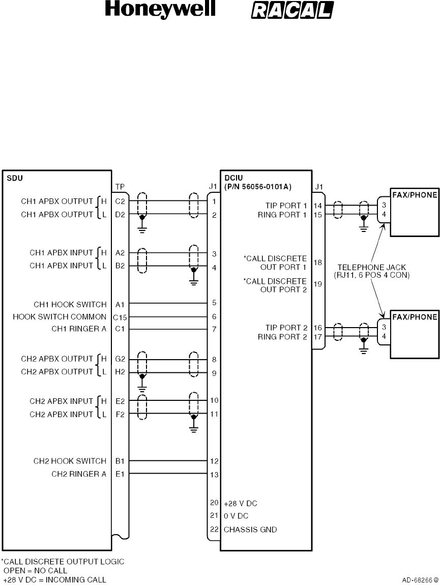
SYSTEM DESCRIPTION, INSTALLATION, AND MAINTENANCE MANUAL
MCS--4000/7000 Multi--Channel SATCOM System
23--20--27
30 Aug 2002
Use or disclosure of information on this page is subject to the restrictions in the proprietary notice of this document.
Page 5--21
Figure 5-13. Four--to--Two Wire Interface Diagram
RELEASED FOR THE EXCLUSIVE USE BY: HONEYWELL INTERNATIONAL
UP86308
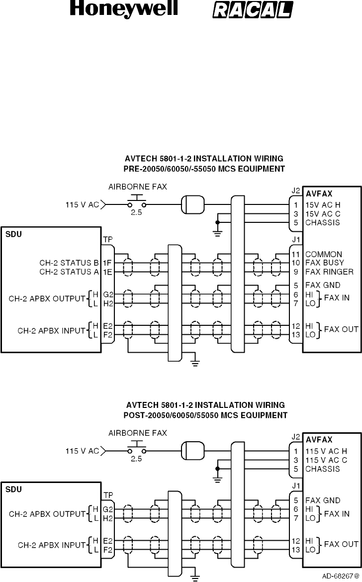
SYSTEM DESCRIPTION, INSTALLATION, AND MAINTENANCE MANUAL
MCS--4000/7000 Multi--Channel SATCOM System
23--20--27
30 Aug 2002
Use or disclosure of information on this page is subject to the restrictions in the proprietary notice of this document.
Page 5--22
Figure 5-14. Avtech Fax Interface Diagram
RELEASED FOR THE EXCLUSIVE USE BY: HONEYWELL INTERNATIONAL
UP86308
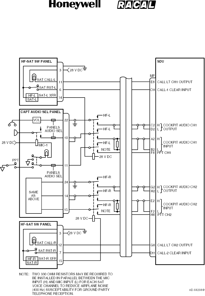
SYSTEM DESCRIPTION, INSTALLATION, AND MAINTENANCE MANUAL
MCS--4000/7000 Multi--Channel SATCOM System
23--20--27
30 Aug 2002
Use or disclosure of information on this page is subject to the restrictions in the proprietary notice of this document.
Page 5--23
Figure 5-15. HF--SAT Transfer Panel Interface Diagram
RELEASED FOR THE EXCLUSIVE USE BY: HONEYWELL INTERNATIONAL
UP86308
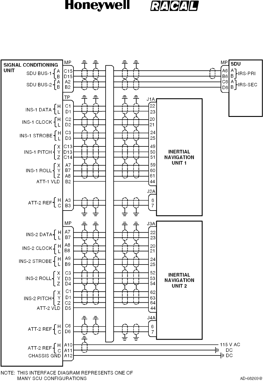
SYSTEM DESCRIPTION, INSTALLATION, AND MAINTENANCE MANUAL
MCS--4000/7000 Multi--Channel SATCOM System
23--20--27
30 Aug 2002
Use or disclosure of information on this page is subject to the restrictions in the proprietary notice of this document.
Page 5--24
Figure 5-16. Signal Conditioning Unit Interface Diagram
RELEASED FOR THE EXCLUSIVE USE BY: HONEYWELL INTERNATIONAL
UP86308
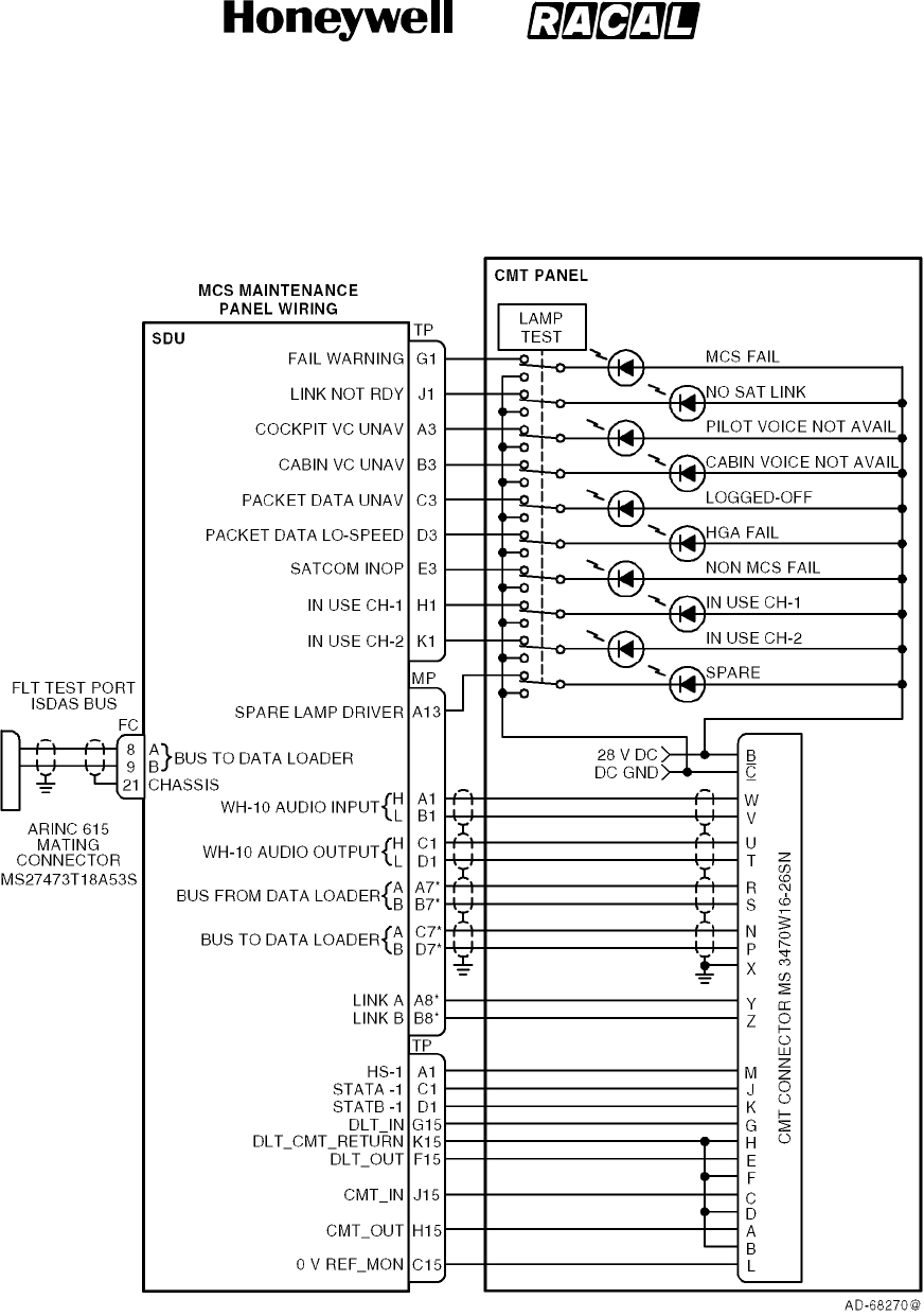
SYSTEM DESCRIPTION, INSTALLATION, AND MAINTENANCE MANUAL
MCS--4000/7000 Multi--Channel SATCOM System
23--20--27
30 Aug 2002
Use or disclosure of information on this page is subject to the restrictions in the proprietary notice of this document.
Page 5--25
Figure 5-17. Maintenance Panel Assembly Interface Diagram
RELEASED FOR THE EXCLUSIVE USE BY: HONEYWELL INTERNATIONAL
UP86308

SYSTEM DESCRIPTION, INSTALLATION, AND MAINTENANCE MANUAL
MCS--4000/7000 Multi--Channel SATCOM System
23--20--27
30 Aug 2002
Use or disclosure of information on this page is subject to the restrictions in the proprietary notice of this document.
Page 5--26
Blank Page
RELEASED FOR THE EXCLUSIVE USE BY: HONEYWELL INTERNATIONAL
UP86308
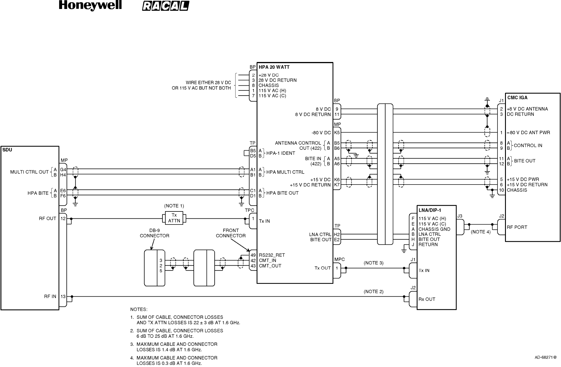
SYSTEM DESCRIPTION, INSTALLATION, AND MAINTENANCE MANUAL
MCS--4000/7000 Multi--Channel SATCOM System
23--20--27
30 Aug 2002
Use or disclosure of information on this page is subject to the restrictions in the proprietary notice of this document.
Page 5--27/(5--28 blank)
Figure 5-18. Intermediate Gain Antenna Interface Diagram
RELEASED FOR THE EXCLUSIVE USE BY: HONEYWELL INTERNATIONAL
UP86308
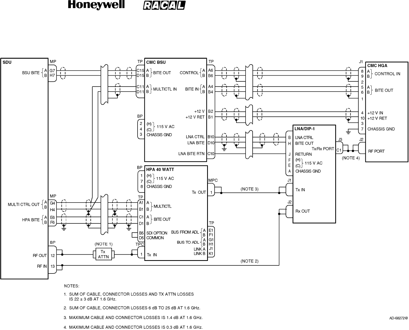
SYSTEM DESCRIPTION, INSTALLATION, AND MAINTENANCE MANUAL
MCS--4000/7000 Multi--Channel SATCOM System
23--20--27
30 Aug 2002
Use or disclosure of information on this page is subject to the restrictions in the proprietary notice of this document.
Page 5--29/(5--30 blank)
Figure 5-19. CMC Top--Mount High Gain Antenna Interface Diagram
RELEASED FOR THE EXCLUSIVE USE BY: HONEYWELL INTERNATIONAL
UP86308
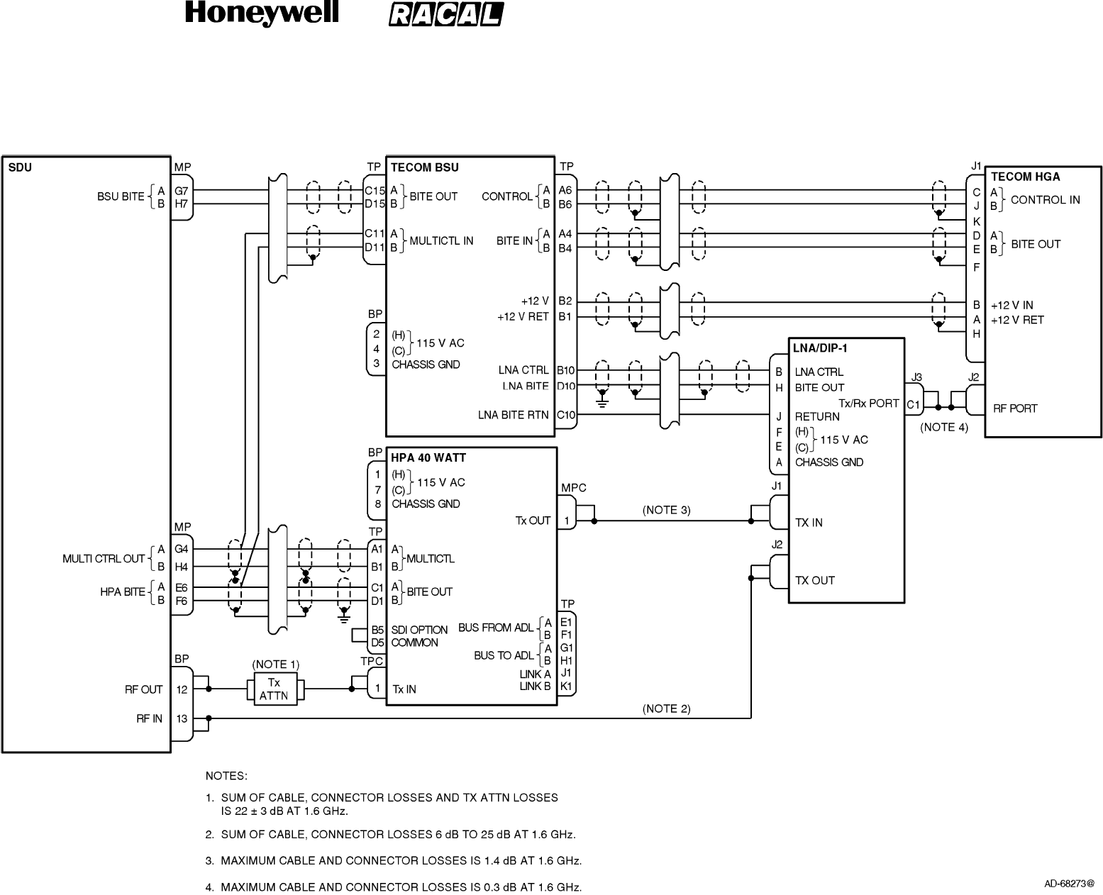
SYSTEM DESCRIPTION, INSTALLATION, AND MAINTENANCE MANUAL
MCS--4000/7000 Multi--Channel SATCOM System
23--20--27
30 Aug 2002
Use or disclosure of information on this page is subject to the restrictions in the proprietary notice of this document.
Page 5--31/(5--32 blank)
Figure 5-20. Tecom Top--Mount High Gain Antenna Interface Diagram
RELEASED FOR THE EXCLUSIVE USE BY: HONEYWELL INTERNATIONAL
UP86308
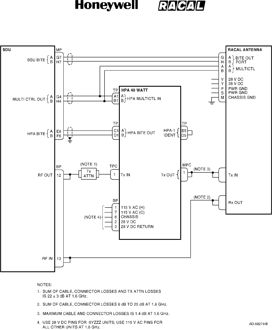
SYSTEM DESCRIPTION, INSTALLATION, AND MAINTENANCE MANUAL
MCS--4000/7000 Multi--Channel SATCOM System
23--20--27
30 Aug 2002
Use or disclosure of information on this page is subject to the restrictions in the proprietary notice of this document.
Page 5--33
Figure 5-21. Racal Mechanically Steered High Gain Antenna Interface Diagram
RELEASED FOR THE EXCLUSIVE USE BY: HONEYWELL INTERNATIONAL
UP86308

SYSTEM DESCRIPTION, INSTALLATION, AND MAINTENANCE MANUAL
MCS--4000/7000 Multi--Channel SATCOM System
23--20--27
30 Aug 2002
Use or disclosure of information on this page is subject to the restrictions in the proprietary notice of this document.
Page 5--34
Blank Page
RELEASED FOR THE EXCLUSIVE USE BY: HONEYWELL INTERNATIONAL
UP86308
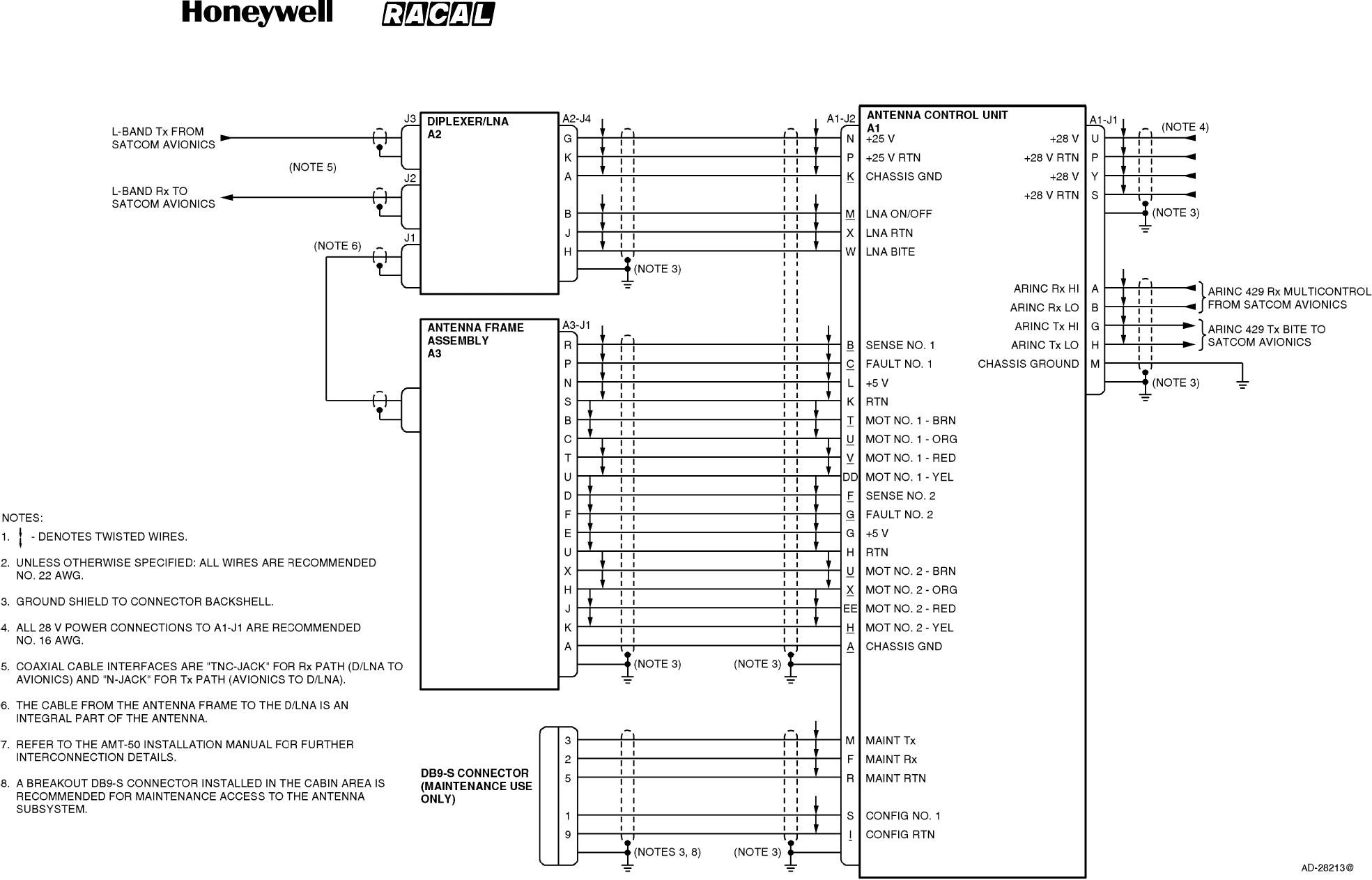
SYSTEM DESCRIPTION, INSTALLATION, AND MAINTENANCE MANUAL
MCS--4000/7000 Multi--Channel SATCOM System
23--20--27
30 Aug 2002
Use or disclosure of information on this page is subject to the restrictions in the proprietary notice of this document.
Page 5--35/(5--36 blank)
Figure 5-22. AMT--50 Mechanically Steered High Gain Antenna Interface Diagram
RELEASED FOR THE EXCLUSIVE USE BY: HONEYWELL INTERNATIONAL
UP86308
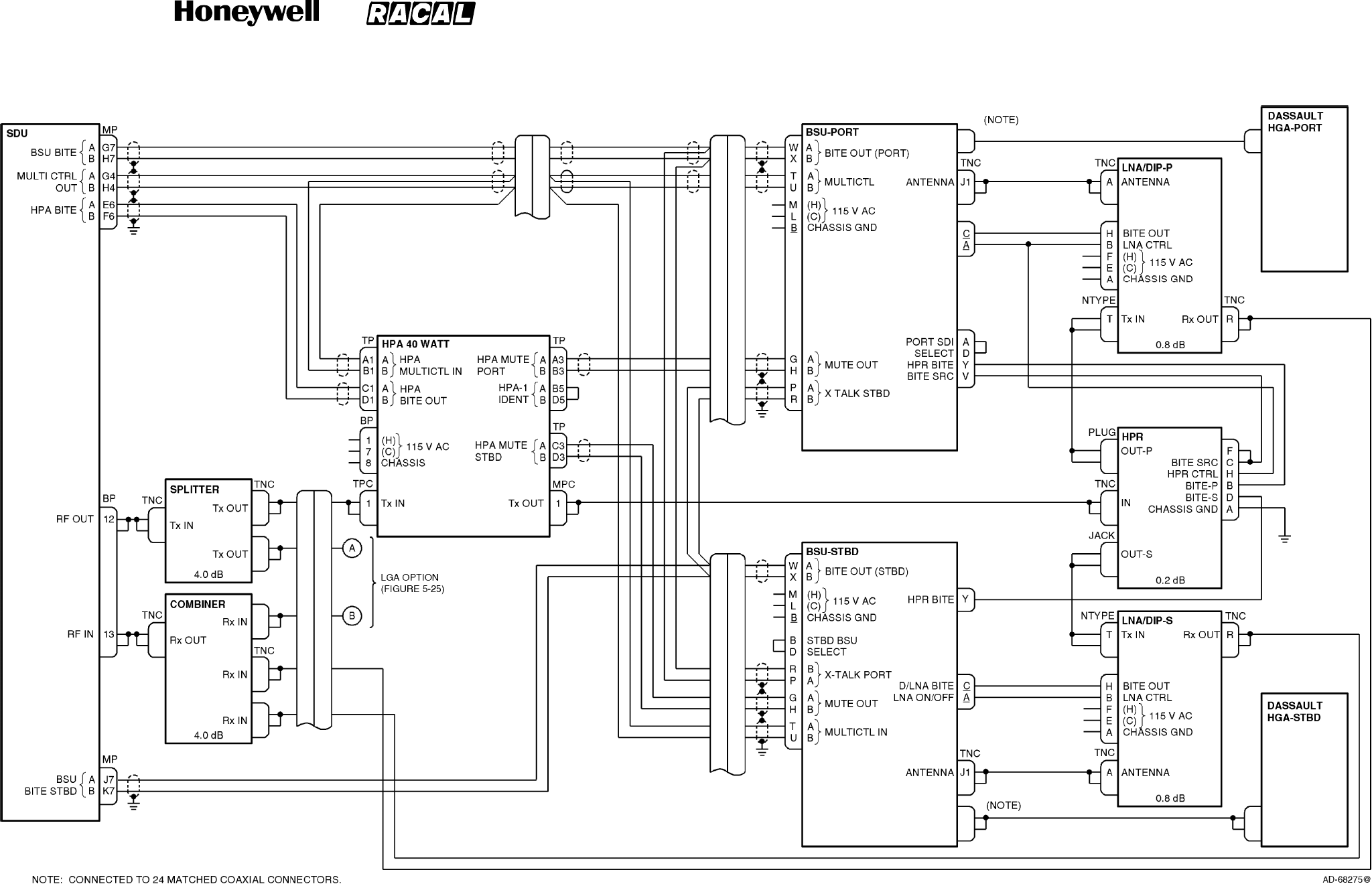
SYSTEM DESCRIPTION, INSTALLATION, AND MAINTENANCE MANUAL
MCS--4000/7000 Multi--Channel SATCOM System
23--20--27
30 Aug 2002
Use or disclosure of information on this page is subject to the restrictions in the proprietary notice of this document.
Page 5--37/(5--38 blank)
Figure 5-23. Dassault Conformal High Gain Antenna Interface Diagram
RELEASED FOR THE EXCLUSIVE USE BY: HONEYWELL INTERNATIONAL
UP86308
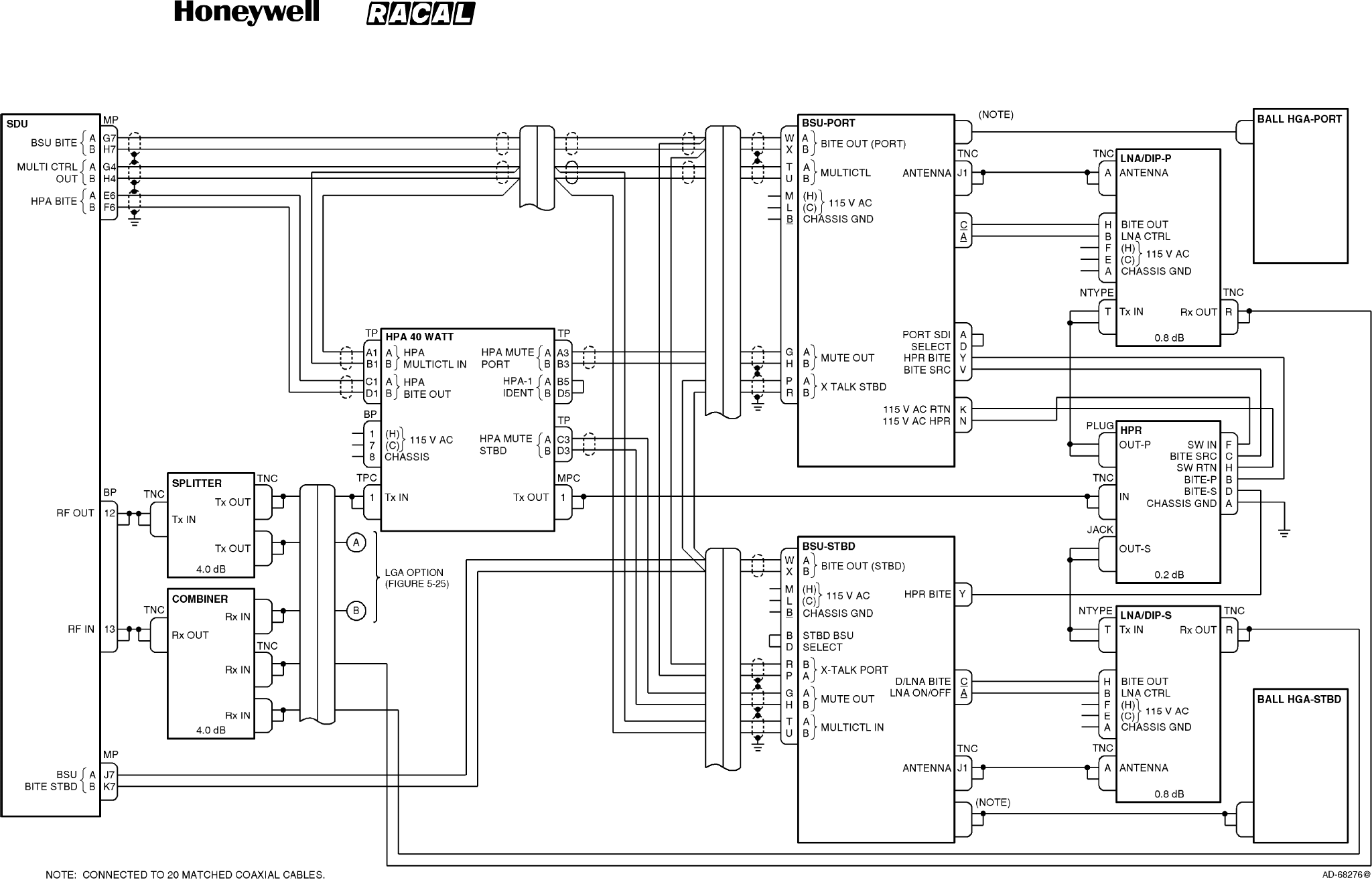
SYSTEM DESCRIPTION, INSTALLATION, AND MAINTENANCE MANUAL
MCS--4000/7000 Multi--Channel SATCOM System
23--20--27
30 Aug 2002
Use or disclosure of information on this page is subject to the restrictions in the proprietary notice of this document.
Page 5--39/(5--40 blank)
Figure 5-24. Ball Conformal High Gain Antenna Interface Diagram
RELEASED FOR THE EXCLUSIVE USE BY: HONEYWELL INTERNATIONAL
UP86308
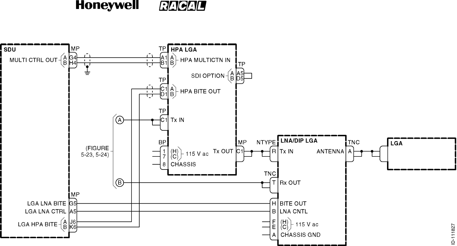
SYSTEM DESCRIPTION, INSTALLATION, AND MAINTENANCE MANUAL
MCS--4000/7000 Multi--Channel SATCOM System
23--20--27
30 Aug 2002
Use or disclosure of information on this page is subject to the restrictions in the proprietary notice of this document.
Page 5--41/(5--42 blank)
Figure 5-25. Low Gain Antenna Interface Diagram
RELEASED FOR THE EXCLUSIVE USE BY: HONEYWELL INTERNATIONAL
UP86308
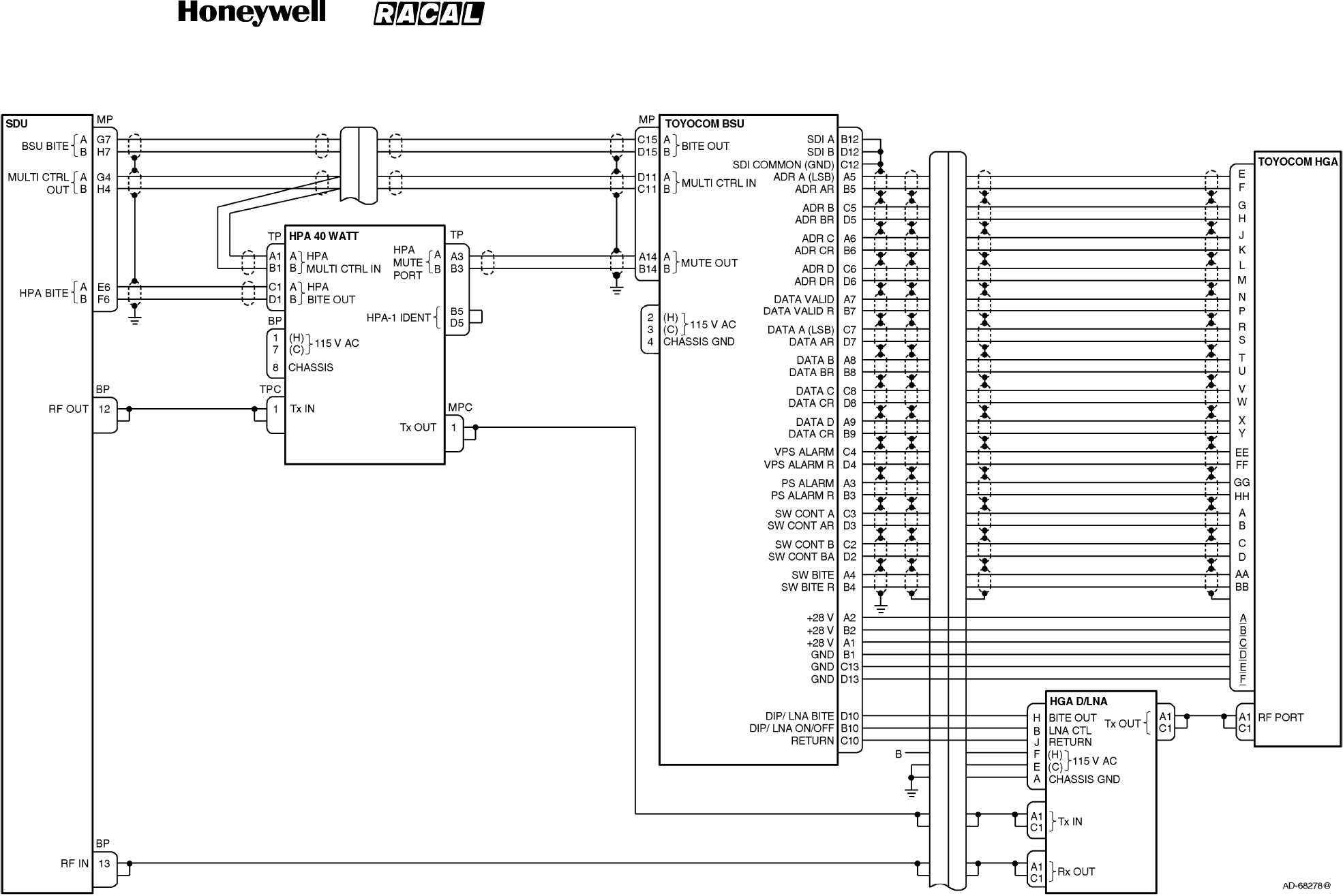
SYSTEM DESCRIPTION, INSTALLATION, AND MAINTENANCE MANUAL
MCS--4000/7000 Multi--Channel SATCOM System
23--20--27
30 Aug 2002
Use or disclosure of information on this page is subject to the restrictions in the proprietary notice of this document.
Page 5--43/(5--44 blank)
Figure 5-26. Toyocom Top--Mount High Gain Antenna Interface Diagram
RELEASED FOR THE EXCLUSIVE USE BY: HONEYWELL INTERNATIONAL
UP86308

SYSTEM DESCRIPTION, INSTALLATION, AND MAINTENANCE MANUAL
MCS--4000/7000 Multi--Channel SATCOM System
23--20--27
30 Aug 2002
Use or disclosure of information on this page is subject to the restrictions in the proprietary notice of this document.
Page 5--45
4. Configuration Pins
A. General
(1) The following paragraphs supply system configuration pins definition and
interpretation information. Pins assigned to take on the binary one stateinagiven
code should be left as an open circuit. Pins assigned to take on the binary zero state
in the code should be wired to SDU connector pin MP15K (address common) on the
airframe side of the connection. The configuration pins are listed in Table 5-6.
Table 5-6. Configuration Pins
Pin Definition
TP10A AVAILABILITY OF ARINC 429 SSR MODE S ADDRESS (AES ID) FROM 429 PORTS
TP10B FMC CONNECTION TO SDU
TP10C FMC CONNECTION TO SDU
TP10D ARINC 429 BUS SPEED TO/FROM CMU NO. 1 AND CMU NO. 2
TP10E CPDF CONFIGURATION
TP10F 429 BUS SPEED OF AES ID INPUT
TP10G RESERVED FOR STRAP OPTION
TP10H RESERVED FOR STRAP OPTION
TP10J RESERVED FOR STRAP OPTION
TP10K CALL LIGHT ACTIVATION
TP11A STRAP PARITY (ODD: COVERING THE OTHER 39 STRAP PINS)
TP11B CCS PRESENCE
TP11C IRS CONFIGURATION
TP11D IRS CONFIGURATION
TP11E HPR/HPA/BSU/LGA CONFIGURATION
TP11F HPR/HPA/BSU/LGA CONFIGURATION
TP11G HPR/HPA/BSU/LGA CONFIGURATION
TP11H HPR/HPA/BSU/LGA CONFIGURATION
TP11J HPR/HPA/BSU/LGA CONFIGURATION
TP11K HPR/HPA/BSU/LGA CONFIGURATION
TP12A CFDS TYPE
TP12B CFDS TYPE
TP12C CFDS TYPE
TP12D PAD FOR CFDS/SDU CONFIGURATION
RELEASED FOR THE EXCLUSIVE USE BY: HONEYWELL INTERNATIONAL
UP86308
SYSTEM DESCRIPTION, INSTALLATION, AND MAINTENANCE MANUAL
MCS--4000/7000 Multi--Channel SATCOM System
23--20--27
30 Aug 2002
Use or disclosure of information on this page is subject to the restrictions in the proprietary notice of this document.
Page 5--46
Table 5-6. Configuration Pins (cont)
Pin Definition
TP12E SDU CONFIGURATION
TP12F SDU NUMBER
TP12G CMU NO. 1 CONFIGURATION
TP12H CMU NO. 2 CONFIGURATION
TP12J MCDU/SCDU NO. 1 CONFIGURATION
TP12K MCDU/SCDU NO. 2 CONFIGURATION
TP13A PRIORITY 4 CALLS TO/FROM COCKPIT
TP13B ARINC 429 BUS SPEED TO MCDU/SCDU NO. 1, NO. 2, AND NO. 3
TP13C COCKPIT VOICE CALL LIGHT/CHIME OPTIONS
TP13D COCKPIT VOICE CALL LIGHT/CHIME OPTIONS
TP13E MCDU/SCDU NO. 3 CONFIGURATION
TP13F SDU CODEC 1 WIRING
TP13G SDU CODEC 1 WIRING
TP13H SDU CODEC 2 WIRING
TP13J SDU CODEC 2 WIRING
TP13K COCKPIT HOOKSWITCH SIGNALING METHOD
B. Availability of ARINC 429 SSR MODE S (AES ID) from CMU Ports
(1) The interpretation of this configuration pin is given in Table 5-7.
Table 5-7. Availability of ARINC 429 SSR MODE S (AES ID) from CMU Ports
TP10 Pin A Interpretation
1SSR MODE S ADDRESS (AES ID) NOT AVAILABLE FROM CMU NO. 1 NOR
RESERVED AES ID INPUT
0SSR MODE S ADDRESS (AES ID) IS AVAILABLE FROM CMU NO. 1 AND/OR CMU
NO. 2 AND/OR AES ID INPUT
RELEASED FOR THE EXCLUSIVE USE BY: HONEYWELL INTERNATIONAL
UP86308

SYSTEM DESCRIPTION, INSTALLATION, AND MAINTENANCE MANUAL
MCS--4000/7000 Multi--Channel SATCOM System
23--20--27
30 Aug 2002
Use or disclosure of information on this page is subject to the restrictions in the proprietary notice of this document.
Page 5--47
(2) When wired to the zero state, the TP10A configuration pin indicates the SSR mode S
address (AES ID) is available in the ARINC 429 label 275/276 format from one or
both of the SDU CMU input ports or the AES ID input port, and that one of those
ARINC 429 sources of the address is used with no specific preference for CMU 1,
CMU 2, CMU 3, or the AES ID input. In this state, the discrete inputs on SDU pins
MP13C thru MP13K and MP14D thru MP14J are not assumed to be wired and the
SDU does not use the discretes, even if the ARINC 429 sources fail or remain
inactive.
(3) In the zero state, the SDU monitors the CMU 1, CMU 2, and AES ID input buses until
a valid ICAO address is received. Bits 1 thru 16 of the AES ID are obtained from the
label 275 word and bits 17 thru 24 are obtained from the label 276 word. The SDU
only constructs a full 24-bit address from labels 275 and 276 words received from the
same input port (e.g., label 275 from CMU 1 can not be combined with label 276 from
CMU 2 or the AES ID input). The address is only considered valid if it does not
consist of all zeros or ones, and has been received in ARINC 429 words with their
sign--status matrix (SSM) indicating normal operation.
(4) If address words containing either all zeros or ones are received, followed by address
words with a valid address (i.e., not all zeros or ones), the SDU verifies the receipt of
both labels 275 and 276 at least twice with the same address bits content in each
respective word before declaring the address valid. This is to preclude the SDU from
inadvertently and prematurely assuming the address is valid after only one of the two
labels has yielded a valid segment of the overall address, but the most previously
received copy of the other label has not yet been updated to its intended code. The
root problem is that the 24 correlated address bits are transmitted in two separate
asynchronous words that are not inherently correlated/paired. This requirement is
intended to effectively pair the label 275 and 276 transmissions.
(5) Once a valid ICAO address is received on any bus, the SDU ignores further data
received on any of the buses until the next POST/PAST. This requirement relieves
the SDU of having to deal with the possibility that the ICAO technical address might
change while the SDU is logged-on. The AES ID (ICAO address) is determined at
startup and cannot change until the next POST/PAST. The SDU does not log-on until
it has a valid AES ID. The SDU waits indefinitely to receive a valid address from an
available ARINC 429 source rather than giving up at the end of POST/PAST, since it
cannot proceed as an AES without the address. If the configuration pin indicates the
ARINC 429 source is available, the discretes are not wired. The SDU should not
revert to the discretes at the end of POST/PAST as the CMU may not yet be
operational.
(6) If configuration pin TP10A is wired to the one state, then neither CMU input port nor
the AES ID input port is capable of supplying the AES ID in the ARINC 429 format
and the SDU reads the AES ID from the discrete inputs.
(7) With either the ARINC 429 or discrete inputs source, an AES ID of all zeros or all
ones (binary) is invalid (typically indicative of an unprogrammed address) which
constitutes a failure. The SDU does not attempt to log-on to a GES with an invalid
AES ID.
RELEASED FOR THE EXCLUSIVE USE BY: HONEYWELL INTERNATIONAL
UP86308
SYSTEM DESCRIPTION, INSTALLATION, AND MAINTENANCE MANUAL
MCS--4000/7000 Multi--Channel SATCOM System
23--20--27
30 Aug 2002
Use or disclosure of information on this page is subject to the restrictions in the proprietary notice of this document.
Page 5--48
C. FMC Connection to SDU
(1) The interpretation of these configuration pins is given in Table 5-8.
Table 5-8. FMC Connection to SDU
TP10 Pins
B C Interpretation
0 0 FMC NO. 1 CONNECTED, FMC NO. 2 CONNECTED
0 1 FMC NO. 1 CONNECTED, FMC NO. 2 NOT CONNECTED
1 0 FMC NO. 1 NOT CONNECTED, FMC NO. 2 CONNECTED
1 1 NEITHER FMC CONNECTED
NOTE: SATCOM does not support the FMC interface.
(2) When individually wired to the zero state, configuration pins TP10B and TP10C
indicate respectively that the inputs designated for FMC No. 1 and FMC No. 2 (pins
MP12G/MP12H and MP12J/MP12K, respectively) are connected to a ARINC 429
source of flight plan information (next way point, etc.). The SDU only
logs/reports/indicates bus inactivity on either bus if the respective configuration pin
indicates the bus is supposed to be connected to an ARINC source. The SDU can
assume (for functional purposes) the presence of the flight management computer
(FMC) connections from the state of these configuration pins.
D. ARINC 429 Speed to/from CMU No. 1 and CMU No. 2
(1) The interpretation of this configuration pin is given in Table 5-9.
Table 5-9. ARINC 429 Speed to/from CMU No. 1 and CMU No. 2
TP10 Pin D Interpretation
1LOW SPEED ARINC 429 DATA BUS
0HIGH SPEED ARINC 429 DATA BUS
(2) When this configuration pin is wired to the zero state, the SDU operates its input and
output ARINC 429 buses for the CMUs No. 1 and No. 2 at high speed. When wired to
the one state, the SDU operates these buses at the low speed.
RELEASED FOR THE EXCLUSIVE USE BY: HONEYWELL INTERNATIONAL
UP86308
SYSTEM DESCRIPTION, INSTALLATION, AND MAINTENANCE MANUAL
MCS--4000/7000 Multi--Channel SATCOM System
23--20--27
30 Aug 2002
Use or disclosure of information on this page is subject to the restrictions in the proprietary notice of this document.
Page 5--49
E. Cabin Packet Data Function (CPDF)
(1) The interpretation of this configuration pin is given in Table 5-10.
Table 5-10. Cabin Packet Data Function (CPDF)
TP10 Pin E Interpretation
0CPDF CONNECTED
1CPDF NOT CONNECTED
(2) When wired to the zero state, this configuration pin indicates the input designated for
the CPDF (MP1E and MP1F) is connected to an ARINC 429 source of data--3 packet
data and that the SDU output (pins MP9A and MP9B) is wired to the CPDF. The SDU
only logs/reports/ indicates CPDF failures and bus inactivity on the CPDF input bus if
this configuration pin indicates the bus is supposed to be connected to an ARINC
source. The SDU can assume (for functional purposes) the presence of the CPDF
connections from the state of this pin.
F. ARINC 429 BUS Speed of AES ID Input
(1) The interpretation of these configuration pins is given in Table 5-11 and Table 5-12.
Table 5-11. ARINC 429 Bus Speed of AES ID Input
TP10 Pin F Interpretation
0HIGH SPEED ARINC 429 BUS
1LOW SPEED ARINC 429 BUS
Table 5-12. Call Light On (Air/Ground Calls)
TP10 Pin K Interpretation
0CALL LIGHT ON AT CALL INITIATION (FOR AIR/GROUND CALLS)
1CALL LIGHT ON AT CALL CONNECTION (FOR AIR/GROUND CALLS)
G. Strap Parity (ODD)
(1) The interpretation of this configuration pin is given in Table 5-13.
Table 5-13. Strap Parity (ODD)
TP11 Pin A Interpretation
0SUM OF ALL OTHER STRAPS SET TO 1 IS ODD
1SUM OF ALL OTHER STRAPS SET TO 1 IS EVEN
RELEASED FOR THE EXCLUSIVE USE BY: HONEYWELL INTERNATIONAL
UP86308

SYSTEM DESCRIPTION, INSTALLATION, AND MAINTENANCE MANUAL
MCS--4000/7000 Multi--Channel SATCOM System
23--20--27
30 Aug 2002
Use or disclosure of information on this page is subject to the restrictions in the proprietary notice of this document.
Page 5--50
(2) The coverage of the parity pin is SDU connector pins TP10A thru TP10K and TP11B
thru TP13K (39 pins other than itself). The parity pin is programmed to a zero or one
to yield an odd number of strap bits set to the one state, including the parity pin itself.
(3) The parity pin is wired to yield odd parity over all 40 configuration pins (i.e., the parity
pin is programmed to the zero or one state to yield an odd number of configuration
pins wired to the one state, including itself. The SDU verifies the state of the parity
pin is correct when the configuration pins are read (typically once per power cycle just
after power-up). An invalid state of the parity pin is logged/reported/indicated; the
states of the other configuration pins are used as read despite the parity error.
H. Cabin Communications System (CCS)
(1) The interpretation of this configuration pin is given in Table 5-14.
Table 5-14. Cabin Communications System (CCS)
TP11 Pin B Interpretation
0CCS INSTALLED
1CCS NOT INSTALLED
(2) The state of this configuration pin is ignored. The SDU can assume (for functional
purposes) the presence of the CCS connections from the state of this pin.
(3) Before the availability of software package C, aircraft can be fitted with interim
versions of the CCS that make use of the analog PBX interface. These installations
set the configuration pin to the zero state, but other analog PBX installations can not
so its state should be ignored in such prepackage C systems.
RELEASED FOR THE EXCLUSIVE USE BY: HONEYWELL INTERNATIONAL
UP86308
SYSTEM DESCRIPTION, INSTALLATION, AND MAINTENANCE MANUAL
MCS--4000/7000 Multi--Channel SATCOM System
23--20--27
30 Aug 2002
Use or disclosure of information on this page is subject to the restrictions in the proprietary notice of this document.
Page 5--51
I. Inertial Reference System (IRS)
(1) The interpretation of these configuration pins is given in Table 5-15.
Table 5-15. Inertial Reference System (IRS)
TP11 Pins
C D Interpretation
0 0 PRIMARY IRS INSTALLED, SECONDARY IRS INSTALLED
0 1 PRIMARY IRS INSTALLED, SECONDARY IRS NOT INSTALLED
1 0 PRIMARY IRS NOT INSTALLED, SECONDARY IRS INSTALLED
1 1 PRIMARY IRS NOT INSTALLED, SECONDARY IRS NOT INSTALLED
(2) When individually wired to the zero state, configuration pins TP11C and TP11D
indicate, respectively, that the inputs designated for the primary and secondary IRSs
(MP6A/MP6B and MP6C/MP6D, respectively) are connected to an ARINC 429
source of IRS label 310, 311, 312, 314, 324, 325, and 361 information (although label
361, Inertial Altitude, is not required for SATCOM). The actual IRS (i.e., IRS No. 1,
IRS No. 2, or IRS No. 3) driving either SDU input is determined from the source
destination identifier (SDI) bits of the received ARINC words. The SDU only
logs/reports/indicates bus inactivity on either bus if the respective configuration pin
indicates that the bus is supposed to be connected to an ARINC 429 source. The
SDU can assume (for functional purposes) the presence of the IRS connections from
the state of these pins.
J. HPA/Antenna Subsystem Configuration
(1) The interpretation of these configuration pins is given in Table 5-16.
RELEASED FOR THE EXCLUSIVE USE BY: HONEYWELL INTERNATIONAL
UP86308
SYSTEM DESCRIPTION, INSTALLATION, AND MAINTENANCE MANUAL
MCS--4000/7000 Multi--Channel SATCOM System
23--20--27
30 Aug 2002
Use or disclosure of information on this page is subject to the restrictions in the proprietary notice of this document.
Page 5--52
Table 5-16. HPA/Antenna Subsystem Configuration
TP11 Pins
L
G
A
+
L
N
A
T
O
P
/
P
O
R
S
T
A
R
B
O
A
R
D
R
E
S
E
R
V
E
D
F
R
E
S
E
R
V
E
E F G H J K
A
/
D
I
P
L
E
X
E
R
L
G
A
H
P
A
R
T
B
S
U
+
H
G
A
D
B
S
U
+
H
G
A
H
G
A
H
P
A
H
P
R
F
O
R
F
U
T
U
R
E
E
D
F
O
R
M
F
R
I
G
A
H
P
A
111111
✱ ✱
011111
✱ ✱
101111
✱ ✱ ✱ ✱
001111
✱✱✱✱✱✱
110111
✱
010111
✱
100111
✱ ✱ ✱ ✱
Note 1.
000111
✱✱✱✱ ✱
Note 1.
111011
✱✱✱✱
0
1
1
0
1
0
0
1
1
0
1
0
t
o
✱
1
0
1
0
1
0
0
0
0
0
1
0
t
o
✱
111000
✱
NOTES:
1. Not defined at this time.
2. Other configurations are possible and can be added at a later date.
RELEASED FOR THE EXCLUSIVE USE BY: HONEYWELL INTERNATIONAL
UP86308
SYSTEM DESCRIPTION, INSTALLATION, AND MAINTENANCE MANUAL
MCS--4000/7000 Multi--Channel SATCOM System
23--20--27
30 Aug 2002
Use or disclosure of information on this page is subject to the restrictions in the proprietary notice of this document.
Page 5--53
(2) For functional purposes, the SDU assumes the HPA and antenna subsystem
configuration of its particular installation from states of these configuration pins.
However, configurations 100111 and 000111 are not supported. Both of the
nonsupported configurations involve the sharing of a single HPA between an LGA
and HGA, by using a high power relay (HPR). No control or BITE signal interfaces
are specified for the HPR, the MCS system does not accommodate these
configurations.
(3) The SDU commands the system, uses its resources, and logs/reports/indicates
failures in the HPAs and antenna subsystem based on the determined HPA and
antenna subsystem configuration. Inactivity on the SDU input buses from the HPA(s)
and ACU/BSU(s) and failures against the diplexer/LNA and HPR are
logged/reported/indicated if the respective LRU is specified to be connected
according to these pins. If these configuration pins are set to a nonsupported,
reserved for future, or reserved for Mfr state, the SDU logs/reports/indicates the
appropriate strap failure(s) and does not attempt any satellite communication
functions.
K. CFDS/CMC
(1) The interpretation of these configuration pins is given in Table 5-17.
Table 5-17. CFDS/CMC
TP12 Pins
ABC Interpretation
000UNDEFINED
001McDONNELL--DOUGLAS TYPE CFDS
010AIRBUS TYPE CFDS
011HONEYWELL CAIMS
100BOEING TYPE CMC
101UNDEFINED
110UNDEFINED
111CFDS NOT INSTALLED
(2) For functional purposes, the SDU can assume the type of central fault/maintenance
system (if any) that is connected from the state of these configuration pins. The
CMC/CFDS interface operates according to the determined type. The appropriate
strap failure(s) is(are) logged/indicated if an undefined code is present. The SDU only
logs/reports/indicates bus inactivity for the MP4C/MP4D CFDS interface input bus if
the configuration pins indicate the CMC/CFDS is supposed to be installed.
RELEASED FOR THE EXCLUSIVE USE BY: HONEYWELL INTERNATIONAL
UP86308
SYSTEM DESCRIPTION, INSTALLATION, AND MAINTENANCE MANUAL
MCS--4000/7000 Multi--Channel SATCOM System
23--20--27
30 Aug 2002
Use or disclosure of information on this page is subject to the restrictions in the proprietary notice of this document.
Page 5--54
L. SDU Configuration
(1) The interpretation of this configuration pin is given in Table 5-18.
Table 5-18. SDU Configuration
TP12 Pin E Interpretation
0SECOND SDU INSTALLED
1SECOND SDU NOT INSTALLED
(2) When wired to the zero state, this configuration pin indicates a second SDU is
present as part of the MCS system installation. The zero state also indicates pins
MP12C/MP12D and MP12A/MP12B (cross talk to and from the other SDU,
respectively) and MP5j/MP5K (dual system select and dual system disable discretes,
respectively) are connected to the second SDU. When this pin is in the zero state, it
also indicates these signals are used to determine dual SATCOM operation as
specified in SYSTEM OPERATION. The SDU only logs/reports/indicates inactivity on
its input cross--talk bus from the second SDU when this pin is in the zero state. The
SDU can assume (for functional purposes) the presence of a second SDU from the
state of this configuration pin. The SDU also uses the state of this pin (and for dual
SATCOM installations, the state of SDU number pin TP12F) to determine the state of
its output word SDI fields.
M. SDU Number
(1) The interpretation of this configuration pin is given in Table 5-19.
Table 5-19. SDU Number
TP12 Pin F Interpretation
0SDU NO. 2
1SDU NO. 1
NOTE: The state of this strap is Don’t Care for a single SDU configuration.
(2) When wired to the zero state, this configuration pin indicates this SDU is No. 2 in a
dual MCS system installation. The one state indicates this SDU is No. 1 in a dual
installation. The SDU uses the state of this pin and the SDU configuration pin TP12E
to determine the state of its output word SDI fields. In a single MCS system
installation, the status of this configuration pin is ignored.
RELEASED FOR THE EXCLUSIVE USE BY: HONEYWELL INTERNATIONAL
UP86308
SYSTEM DESCRIPTION, INSTALLATION, AND MAINTENANCE MANUAL
MCS--4000/7000 Multi--Channel SATCOM System
23--20--27
30 Aug 2002
Use or disclosure of information on this page is subject to the restrictions in the proprietary notice of this document.
Page 5--55
N. CMU No. 1 and No. 2 Configuration
(1) The interpretation of these configuration pins is given in Table 5-20 and Table 5-21.
Table 5-20. CMU No. 1
TP12 Pin G Interpretation
0CMU NO. 1 INSTALLED
1CMU NO. 1 NOT INSTALLED
Table 5-21. CMU No. 2
TP12 Pin H Interpretation
0CMU NO. 2 INSTALLED
1CMU NO. 2 NOT INSTALLED
(2) When individually wired to the zero state, configuration pins TP12G and TP12H
indicate, respectively, that the inputs designated for CMU No. 1 and CMU No. 2 (pins
MP1G/MP1H and MP3G/MP3H, respectively) are connected to an ARINC 429
source of CMU information (e.g., CMU label 270 and SAL 304), and also the single
SDU output (pins MP1J/MP1K) is wired to the appropriate CMU(s). The SDU only
logs/reports/indicates bus inactivity on either CMU input bus if the respective
configuration pin indicates the bus is supposed to be connected to an ARINC source.
The SDU can assume (for functional purposes) the presence of the CMU
connections from the state of these configuration pins.
O. MCDU/SCDU No. 1 thru No. 3 Configuration
(1) The interpretation of these configuration pins is given in Table 5-22 thru Table 5-24.
Table 5-22. MCDU/SCDU No. 1
TP12 Pin J Interpretation
0MCDU/SCDU NO. 1 INSTALLED
1MCDU/SCDU NO. 1 NOT INSTALLED
Table 5-23. MCDU/SCDU No. 2
TP12 Pin K Interpretation
0MCDU/SCDU NO. 2 INSTALLED
1MCDU/SCDU NO. 2 NOT INSTALLED
RELEASED FOR THE EXCLUSIVE USE BY: HONEYWELL INTERNATIONAL
UP86308
SYSTEM DESCRIPTION, INSTALLATION, AND MAINTENANCE MANUAL
MCS--4000/7000 Multi--Channel SATCOM System
23--20--27
30 Aug 2002
Use or disclosure of information on this page is subject to the restrictions in the proprietary notice of this document.
Page 5--56
Table 5-24. MCDU/SCDU No. 3
TP13 Pin E Interpretation
0MCDU/SCDU NO. 3 INSTALLED
1MCDU/SCDU NO. 3 NOT INSTALLED
(2) When individually wired to the zero state, configuration pins TP12J, TP12K, and
TP13E indicate, respectively, that the inputs designated for MCDU/SCDU No. 1, No.
2, and No. 3 (pins MP3C/MP3D, MP3E/MP3F, and MP8J/MP8K, respectively) are
connected to an ARINC 429 source of line select/keypad control information, and
also the single SDU output (MP3J/MP3K) is wired to all appropriate MCDU/SCDU(s).
The SDU only logs/reports/indicates bus inactivity on any of the three buses if the
respective configuration pin indicates the bus is supposed to be connected to an
ARINC source. The SDU can assume (for functional purposes) the presence of the
MCDU/SCDU connections from the state of these configuration pins.
P. Priority 4 Calls to/from Cockpit
(1) The interpretation of this configuration pin is given in Table 5-25.
Table 5-25. Priority 4 Calls to/from Cockpit
TP13 Pin A Interpretation
0DISALLOW PRIORITY 4 CALLS
1ALLOWS PRIORITY 4 CALLS
(2) When this configuration pin is wired to the zero state, the SDU disallows priority 4
calls from being routed to or initiated from the cockpit. This state prevents ORT item
xiii (Appendix C) from being set to allow routing of ground-to-air priority 4 calls to the
cockpit headset. When this configuration is wired to the one state, the SDU lets
priority 4 calls be initiated from the cockpit and lets ground-to-air calls be routed to
the cockpit based upon ORT item xiii.
RELEASED FOR THE EXCLUSIVE USE BY: HONEYWELL INTERNATIONAL
UP86308
SYSTEM DESCRIPTION, INSTALLATION, AND MAINTENANCE MANUAL
MCS--4000/7000 Multi--Channel SATCOM System
23--20--27
30 Aug 2002
Use or disclosure of information on this page is subject to the restrictions in the proprietary notice of this document.
Page 5--57
Q. ARINC 429 BUS Speed to SCDU No. 1 / SCDU No. 2 / SCDU No. 3
(1) The interpretation of this configuration pin is given in Table 5-26.
Table 5-26. ARINC 429 Bus Speed to SCDU No. 1 / SCDU No. 2 / SCDU No. 3
TP13 Pin B Interpretation
0LOW SPEED ARINC 429 BUS
1HIGH SPEED ARINC 429 BUS
(2) When this configuration pin is wired to the zero state, the SDU operates its ARINC
429 output bus for MCDU/SCDUs No. 1, No. 2, and No. 3 at the low speed. When
wired to the one state, the SDU operates this bus at the high speed.
R. Cockpit Voice Call Light/Chime Option
(1) The interpretation of these configuration pins is given in Table 5-27.
Table 5-27. Cockpit Voice Call Light/Chime Option
TP13 Pins
C D Interpretation
0 0 SPARE
0 1 STEADY LIGHTS AND MULTISTROKE CHIME
1 0 FLASHING LIGHTS AND SINGLE STROKE CHIME
1 1 STEADY LIGHTS AND SINGLE STROKE CHIME
(2) The SDU determines the mode of cockpit call annunciation (flashing vs. steady voice
call lamp, multistroke vs single stroke chime) from the states of these configuration
pins. The functionality of the cockpit call annunciation interface (pins MP8E and
MP8G for the call lights, and MP14B and MP14C for the chime) operate according to
the configuration pin connections selected. The selected state of pins TP13C and
TP13D applies to both air- and ground-initiated calls; it only applies to the call
annunciation phase (i.e., following connection acknowledgement by receipt of the
off-hook state as specified by the state of TP13K, a multistroke chime is silenced and
the call lamp remains on steady). The appropriate strap failure(s) is logged/indicated
if an undefined code is present. The SDU defaults to the steady lights and single
stroke chime state if an undefined code is present.
(3) The steady versus flashing light option applies to the call annunciation phase only.
The light remains on (steady) for the duration of the call after the acknowledgement
of the annunciation for either the steady or flashing light option.
RELEASED FOR THE EXCLUSIVE USE BY: HONEYWELL INTERNATIONAL
UP86308
SYSTEM DESCRIPTION, INSTALLATION, AND MAINTENANCE MANUAL
MCS--4000/7000 Multi--Channel SATCOM System
23--20--27
30 Aug 2002
Use or disclosure of information on this page is subject to the restrictions in the proprietary notice of this document.
Page 5--58
S. SDU CODEC 1 and CODEC 2 Wiring
(1) The interpretation of these configuration pins is given in Table 5-28 and Table 5-29.
Table 5-28. SDU Analog Interface No. 1 Wiring
TP13 Pins
F G Interpretation
0 0 AMS WIRED, CABIN AUDIO WIRED
0 1 AMS WIRED, CABIN AUDIO NOT WIRED
1 0 AMS NOT WIRED, CABIN AUDIO WIRED
1 1 AMS NOT WIRED, CABIN AUDIO NOT WIRED
Table 5-29. SDU Analog Interface No. 2 Wiring
TP13 Pins
H J Interpretation
0 0 AMS WIRED, CABIN AUDIO WIRED
0 1 AMS WIRED, CABIN AUDIO NOT WIRED
1 0 AMS NOT WIRED, CABIN AUDIO WIRED
1 1 AMS NOT WIRED, CABIN AUDIO NOT WIRED
(2) The SDU determines the extent and nature of the analog cockpit and cabin voice
connections from the states of these configuration pins. The functionality of the
analog cockpit and cabin voice interface (pins MP1A/MP1B, MP1C/MP1D,
MP2A/MP2B, MP2C/MP2D, MP2E/MP2F, MP2G/MP2H, MP4J/MP4K, and
MP5E/MP5F) operate according to the connections selected. ORT item vi for codec
dedication (Appendix C) is related to the SDU codec configuration pins; dedication or
automatic sharing of a codec to or with a particular interface is only possible if the
SDU codec wiring straps indicate the codec is wired to that interface.
T. Cockpit Hookswitch Signaling Method
(1) General
(a) The interpretation of this configuration pin is given in Table 5-30.
Table 5-30. Cockpit Hookswitch Signaling Method
TP13 Pin K Interpretation
1SWITCHED PTT AND/OR SCDU LINE SWITCH(ES)
0LATCHED AUDIO CONTROL PANEL SATCOM MICROPHONE SWITCH
RELEASED FOR THE EXCLUSIVE USE BY: HONEYWELL INTERNATIONAL
UP86308

SYSTEM DESCRIPTION, INSTALLATION, AND MAINTENANCE MANUAL
MCS--4000/7000 Multi--Channel SATCOM System
23--20--27
30 Aug 2002
Use or disclosure of information on this page is subject to the restrictions in the proprietary notice of this document.
Page 5--59
(b) This configuration pin specifies the functionality of the SDU Cockpit Voice
Mic-On Input No. 1 (and No. 2) discrete inputs (referred to as the mic-on
inputs). When TP13K is wired to the one state, the SDU utilizes the switched
PTT and/or SCDU line switch(es) (referred to as switched PTT) method for
cockpit hookswitch signaling on the mic-on inputs. When TP13K is wired to the
zero state, the SDU utilizes the latched audio control panel SATCOM
microphone switch (referred to as the latched ACP) method. These two
methods are described below.
(2) Switched PTT Method
(a) With the switched PTT method, the SDU assumes the mic-on inputs are wired to
conventional microphone momentary push-to-talk switches (i.e., they are
dynamically active [on/off] throughout the duration of the call). The SDU
assumes the air- or ground-initiated call annunciation to have been
acknowledged (i.e., the call to in the off-hook state) when the appropriate mic-on
input is activated (connected to ground) for the first time after the call
annunciation for a particular channel. Successive activations of that mic-on input
for the duration of that call have no effect on the status of that call until the call
has been cleared.
(b) With the switched PTT method, the off-hook state is also entered following
activation of the Answer Call line select switch on the SCDU. The on-hook state
is entered following activation of the End Call lineselectswitchontheSCDU
that results in call clearing.
(c) This method also allows usage of the place/end call discrete input and
associated switch to initiate calls to preselected numbers, as well as to terminate
existing calls.
(3) Latched ACP Method
(a) With the latched ACP method, the SDU assumes the mic-on inputs are wired to
SATCOM microphone select switches on the ACP that are latched on
(connected to ground) for the entire duration of a call. The SDU considers the
air- or ground-initiated call annunciation to have been acknowledged (i.e., the
call to be in the off-hook state) when the appropriate mic-on input is active
(connected to ground) for a particular channel. The call is cleared and the
channel is considered to be in the on-hook state when the mic-on input is in the
open-circuit state.
(b) With the latched ACP method, all hookswitch signaling for answering and
terminating all air- and ground-initiated calls is handled by the mic-on inputs; the
SCDU Answer Call and End Call options are blanked (the SCDU is only
necessary for specifying the called-party number and initiating the call process
for air-to-ground calls).
(c) This method also allows usage of the mic--on discrete input and switch to initiate
calls to preselected numbers.
RELEASED FOR THE EXCLUSIVE USE BY: HONEYWELL INTERNATIONAL
UP86308

SYSTEM DESCRIPTION, INSTALLATION, AND MAINTENANCE MANUAL
MCS--4000/7000 Multi--Channel SATCOM System
23--20--27
30 Aug 2002
Use or disclosure of information on this page is subject to the restrictions in the proprietary notice of this document.
Page 5--60
Blank Page
RELEASED FOR THE EXCLUSIVE USE BY: HONEYWELL INTERNATIONAL
UP86308
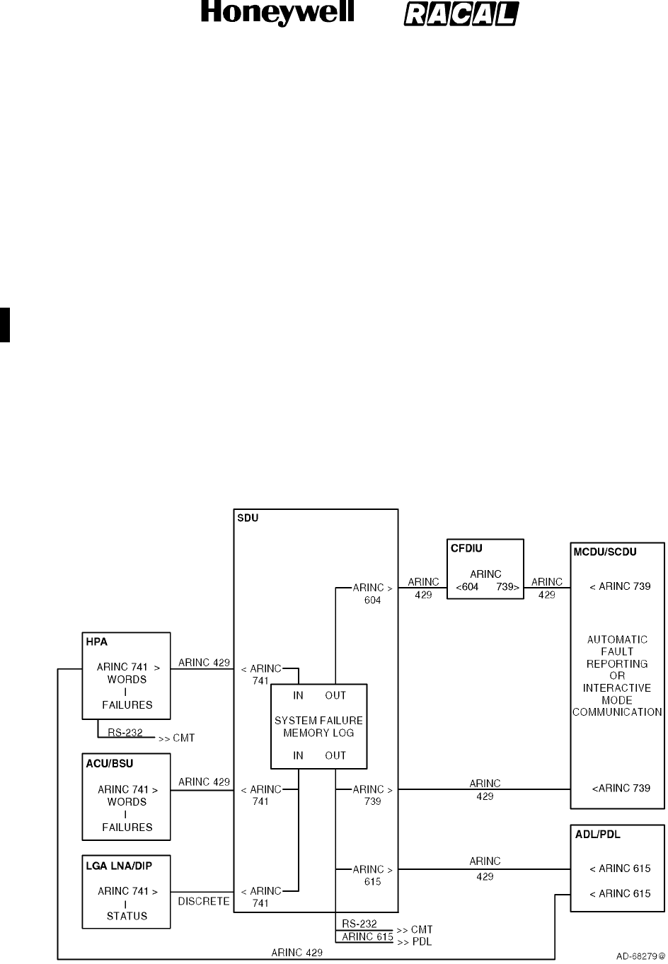
SYSTEM DESCRIPTION, INSTALLATION, AND MAINTENANCE MANUAL
MCS--4000/7000
23--20--27 5 Feb 2008
©Honeywell International Inc. Do not copy without express permission of Honeywell.
Page 6--1
SECTION 6
TESTING/FAULT ISOLATION
1. Overview
A. General
(1) This section defines the built-in test equipment (BITE) requirements for the MCS
system (i.e., SDU and HPA). Information supplied in this section describes how MCS
system failures are detected, recorded, and reported. See Figure 6-1 for an overview
of the BITE system communications. Refer to Appendix D for an explanation of the
fault codes obtained by any troubleshooting process.
(2) System BITE contributes to a number of maintenance functions:
•Detection of internal and external failures
•Storage of in-flight failure data
•Reporting failure status in the air and on the ground
•Ground test capability for isolating faulty LRUs, performance verification, and
system level testing.
Figure 6-1. System BITE Communication
RELEASED FOR THE EXCLUSIVE USE BY: HONEYWELL INTERNATIONAL
UP86308

SYSTEM DESCRIPTION, INSTALLATION, AND MAINTENANCE MANUAL
MCS--4000/7000 Multi--Channel SATCOM System
23--20--27
30 Aug 2002
Use or disclosure of information on this page is subject to the restrictions in the proprietary notice of this document.
Page 6--2
B. Definitions
(1) Degraded Operation
(a) Degraded operation is defined as the condition when the MCS system is
operating with a failure that results in diminished capability (e.g., some, but not
all channel units available, or less than nominal HPA power available).
(2) Failure
(a) A failure is defined as a fault that persists for a predetermined amount of time or
for a predetermined number of samples. The tolerance on all failure timing
criteria is ±0.5 second.
(3) Intermittent Failure
(a) An intermittent failure is defined as a fault that had been declared a failure,
recovered to its normal valid state, and then is declared to have failed again. A
failure occurrence counter is maintained for each entry in the LRU and system
failure logs to identify intermittent failures.
(4) Fault
(a) A fault is defined as the result of a measurement or comparison that does not
satisfy the test or monitoring result requirements. The test or monitoring result
requirements can require a time element.
(5) Reversion
(a) Reversion is defined as the system response to a failure condition that results in
continued system operation in the presence of the failure, and can result in
degraded system capability.
(6) MCS LRU
(a) The following are defined as the MCS LRUs (i.e., those manufactured by
Honeywell/Racal):
•SDU
•HPA.
RELEASED FOR THE EXCLUSIVE USE BY: HONEYWELL INTERNATIONAL
UP86308
SYSTEM DESCRIPTION, INSTALLATION, AND MAINTENANCE MANUAL
MCS--4000/7000 Multi--Channel SATCOM System
23--20--27
30 Aug 2002
Use or disclosure of information on this page is subject to the restrictions in the proprietary notice of this document.
Page 6--3
C. Failure Detection and Reporting Levels
(1) Failures are detected in the MCS system by a wide variety of tests. The immediate
result of failure detection is usually diagnosis of the failure to a specific component or
functional circuit group, on a specific SRU, in a specific LRU. However, some
detected failures may only be able to be diagnosed to a suspect SRU, or only to a
suspect LRU, or only to a pair or group of LRUs and the physical or logical
interface(s) between them. Three enumerated levels of failure diagnosis are defined
in Table 6-1.
Table 6-1. Levels of Failure
Level Description
Level I
Diagnosis to the LRU level or its equivalent (e.g., a specific inactive bus, error, or
warning)
Level II
Diagnosis to the SRU (module or circuit card) level
Level III
Diagnosis to the component or functional circuit group level or equivalent (e.g., a
very specific error condition)
(2) All MCS LRUs implement Level I and, where possible, Level II failure detection. Level
I diagnosis primarily supports line maintenance. Front panel displays and automatic
reports to central fault/maintenance systems are only performed to Level I resolution
because they are primarily used to support line maintenance, which is typically limited
to LRU replacement. Level II and Level III diagnosis primarily support shop and
factory maintenance. Level II and Level III failure detection information is stored in
the LRU and system failure logs, and can be displayed on the commissioning and
maintenance terminal (CMT) pages.
D. LRU Coverage
(1) The LRU coverage is defined as the sum of all component failure rates covered by
the BITE circuitry within an LRU, divided by the total of the component failure rates
within that LRU. This coverage is greater than or equal to 0.95 as defined. The LRU
probability of false detection is defined as the sum of all component failure rates of
the BITE circuitry within an LRU divided by the total of the component failure rates
within that LRU. This coverage is greater than 0.01 as defined. The LRU coverage
includes the following:
•All SDU to avionic interfaces, where possible
•All MCS inter-LRU interfaces
•All power supply voltages
•All battery voltages
•All microprocessors/microcontrollers
•All memory devices (RAM, ROM, etc).
(2) All discrete drivers between the SDU and the avionics LRUs have over current
protection and open-circuit detection.
RELEASED FOR THE EXCLUSIVE USE BY: HONEYWELL INTERNATIONAL
UP86308

SYSTEM DESCRIPTION, INSTALLATION, AND MAINTENANCE MANUAL
MCS--4000/7000 Multi--Channel SATCOM System
23--20--27
30 Aug 2002
Use or disclosure of information on this page is subject to the restrictions in the proprietary notice of this document.
Page 6--4
E. Monitoring and Testing Functions
(1) General
(a) The declaration of an inactive input bus takes precedence over declaration of
one or more data word failures against the LRU driving that bus (i.e., if the bus is
inactive, additional logging and reporting of low-rate failures of individual data
words on that bus are precluded). The failure and recovery criteria is set to make
sure individual data word failures are not declared when the bus is inactive. This
is typically done by setting inactive bus failure criteria (e.g., three seconds) to be
faster than word update rate failure criteria (e.g., five seconds), and inactive bus
recovery criteria (e.g., two seconds) to be longer than word update rate recovery
criteria (e.g., one second).
(b) Unless an LRU providing ARINC 429 data declares itself to have failed, a fault is
declared against that LRU when the ARINC 429 data is faulty. This is determined
by checking (as appropriate for each word) for data inconsistencies, data
out-of-range, uses of undefined or reserved values, and occurrences of the
failure warning state in the sign/status matrix (SSM) field.
(c) Two basic types of failure detection testing performed are: functional tests and
continuous monitoring (CM). The purpose of functional testing in the form of
power-on self test and person-activated self test is to exercise the equipment in a
manner as closely as possible to its normal operation. Failures detected during
functional testing are declared to be current failures until a subsequent functional
test shows the failure condition has recovered.
(d) The purpose of continuous monitoring is to test the equipment in a nondisruptive
manner while it is performing its normal operations. Such testing usually includes
monitoring the power supply voltages, temperature sensors, bias currents, input
bus activity, buffer overflow, input data failures, etc. This testing can also include
abnormal failures that cannot be tested as part of the functional testing, such as
protocol failures, processor instruction traps, data loader problems, etc.
(2) Power-On Self-Test
(a) General
1The power-on self-test (POST) is a series of functional tests for individual
LRUs; each MCS LRU performs its own internal POST upon a cold start. A
cold start is defined as the response of an LRU where no retention of any
previously stored information in any volatile memory is assumed. The power
supply provides signals to help an orderly power-down and power-up
process for the LRU during power interrupts of any length. Primary power
interrupts of less than 5 milliseconds duration have no effect on system
operation. For primary power interrupts longer than 5 milliseconds and up to
200 milliseconds duration, the LRU maintains normal operation, except the
RF transmit and receive processes do not need to be supported in any LRU
during this interval. For primary power interrupts greater than 200
milliseconds duration that causes normal operation to cease, the LRU
performs a cold start following restoration of primary power.
RELEASED FOR THE EXCLUSIVE USE BY: HONEYWELL INTERNATIONAL
UP86308

SYSTEM DESCRIPTION, INSTALLATION, AND MAINTENANCE MANUAL
MCS--4000/7000 Multi--Channel SATCOM System
23--20--27
30 Aug 2002
Use or disclosure of information on this page is subject to the restrictions in the proprietary notice of this document.
Page 6--5
2The POST sequence of tests does not terminate when an out-of-tolerance
condition is encountered. Instead, the sequence continues to complete as
many tests as possible to record all available information regarding existing
failures. An individual LRU that successfully passes POST is declared to be
fully functional. POST must take into account failures detected by
continuous monitoring (i.e., if POST passes, but testing unique to
continuous monitoring has detected and logged a current failure, then the
POST result is logged as a failure).
3After executing its own POST, the SDU commands a system-wide functional
test of the HPA(s) and ACU/BSU(s) (including the HGAs, HGA diplexer/LNA,
and HPR) as applicable for the installed equipment in accordance with the
system configuration pins (see MECHANICAL INSTALLATION). The SDU
then processes the results of the functional tests from these LRUs. The SDU
commands the functional test as follows through:
•SSM field of the HPA command word(s) for the HPA
•SSM field(s) for the ACU/BSU control word(s) for the ACU/BSU(s).
4The BITE status from the LGA diplexer/LNA is continuously sent to the SDU,
with no functional test command necessary or possible. Test results from the
HGA(s), HGA diplexer/LNA, and HPR are reported by the ACU/BSU(s).
5The SDU allows up to 30 ±1 seconds for other system LRUs to report their
POST results following initiation of a system-wide functional test. If an LRU
fails to report its functional test results within this time period, but otherwise
meets the ARINC 429 bus communication rate requirements, the SDU
considers that LRU to have failed. If no ARINC 429 bus communication is
received on a particular bus, the SDU considers that bus to be inactive.
(b) Test Initiation
1The correct operation of much of the internal circuitry of the SDU depends
on clocks derived from the high-stability frequency reference generated by
the oven-controlled crystal oscillator (OCXO). Therefore, it is inappropriate to
perform BITE tests until this clock frequency has achieved gross stability. If
the SDU is powered on after having stabilized at a cold external temperature
(e.g., --55°C), it can take several tens of seconds for the frequency drift rate
to be low enough before the phase locked oscillators (PLO) that derive the
dependent clocks can lock onto the OCXO frequency reference.
RELEASED FOR THE EXCLUSIVE USE BY: HONEYWELL INTERNATIONAL
UP86308

SYSTEM DESCRIPTION, INSTALLATION, AND MAINTENANCE MANUAL
MCS--4000/7000 Multi--Channel SATCOM System
23--20--27
30 Aug 2002
Use or disclosure of information on this page is subject to the restrictions in the proprietary notice of this document.
Page 6--6
2The SDU defers testing of sensitive equipment until a positive indication of
settling is detected, or sufficient time passes so the lack of settling itself can
be classified as a failure. Deferral of these sections of POST also result in
normal operation being deferred, including access to the user interfaces
(SCDU, CFDS, and CMT) and all automatic calibration processing.
Consequently, the SDU suspends POST until the SDU detects the first of
the following conditions:
•OCXO heater monitor indicates it has achieved operating temperature
•Power supply unit (PSU) temperature sensor indicates a reading above
25 °C
•Channel filter module transmit and receive PLO lock detectors both
indicate that lock has been achieved
•More than 4 minutes have elapsed since primary power was applied.
(c) LRU Front Panel LED and Alphanumeric Display Tests
1A test of the HPA front panel LEDs is performed as a part of each POST. At
a minimum, this is made up of flashing the LEDs on and off. The LED
flashing continues until POST is completed or for 3 ±0.5 seconds. During
the test, the SDU tests its alphanumeric display by incorporating one or
more occurrences of the word TESTING into its display sequence to make
sure all display elements are tested.
(d) RF Loop Back Tests
1As part of the system-wide POST, the SDU implements a RF loop back test.
The RF loop back occurs in the radio frequency module (RFM) installed in
the SDU.
2The SDU delays initiating the RF loop back test until it receives an indication
the RF loop back has been activated. If the SDU fails to receive a valid
indication within 30 seconds following the RF loop back request, then the
SDU completes its POST without executing the RF loop back test. The SDU
cancels the RF loop back request when the loop back test is completed, or if
the 30 second timer expires while waiting for verification of an active RF loop
back.
(3) Person-Activated Self-Test
(a) The person-activated self-test (PAST) performs the same functions as POST.
PAST is initiated in the HPA by pushing the PUSH-TO-TEST (PTT) switch on the
respective LRU front panel. PAST can also be initiated any time through:
•Respective CMT interface to the LRU
•SSM field of the HPA command word sent to the HPA from the SDU.
(b) A stuck switch on the CMT or LRU front panel does not cause PAST to remain
active. Any switch activity is ignored while PAST (or POST) is executing.
RELEASED FOR THE EXCLUSIVE USE BY: HONEYWELL INTERNATIONAL
UP86308

SYSTEM DESCRIPTION, INSTALLATION, AND MAINTENANCE MANUAL
MCS--4000/7000 Multi--Channel SATCOM System
23--20--27
30 Aug 2002
Use or disclosure of information on this page is subject to the restrictions in the proprietary notice of this document.
Page 6--7
(c) The HPA inhibits PAST while the aircraft is airborne, except when PAST is
initiated through the CMT that is permitted at any time. The HPA cannot properly
function if it is not receiving valid command words from the SDU containing the
air/ground status and command information. Under these conditions, the HPA is
not usable by the SDU. PAST is only permitted while the aircraft is on the
ground, or when the airborne/on-ground status is unknown. In lieu of the
airborne/on-ground status information from the SDU, the HPA permits PAST as
though the aircraft is on the ground.
(d) A system-wide PAST is initiated in the SDU when commanded by:
•Entry through the SATCOM control and display unit (SCDU)
•Entry through the central maintenance computer (CMC)
•Entry through the central fault display system (CFDS)
•Command from the CMT
•Activating the PTT switch (SDU TEST) on the front panel.
(e) A stuck switch on the SDU front panel does not cause PAST to remain active.
Any switch activity is ignored while PAST (or POST) is executing.
(4) Continuous Monitoring
(a) Continuous monitoring (CM) of the BITE circuitry does not interfere with the
normal operation of the system. Instead any failure condition is recorded and
reported. Continuous monitoring operates as a background task at all times,
even during functional testing. Functional test failure codes that are identical to
the continuous monitoring codes (except for the MSB of the level 3 code)
indicate cases where the functional test differs in some way from the companion
CM test. Those CM failures detected during functional testing (e.g., maintenance
and status word failures) are logged as CM failures, not functional failures.
F. Failure Recording
(1) The SDU records CFDS internal failures at all times. The SDU only records CFDS
external failures while receiving a valid All Call DC1 Command if a Douglas or Airbus
CFDS is installed. Internal failures are defined as those internal to the SATCOM
subsystem. External failures are defined as those external to the SATCOM
subsystem. If a Boeing CMC (or no CFDS) is installed or if valid DC commands are
not available, then the air/ground status is used to generate pseudo DC states of
DC0 (aircraft on-ground) and DC1 (aircraft airborne).
(2) The HPA records internal failures at all times. The HPA only records external failures
while the aircraft is airborne, based on the status of the weight-on-wheels discrete
(on-ground vs. airborne). Internal failures are defined as those that have the same
Level I code as the LRU recording the failure (i.e., 01 for the SDU, 04 for the HGA
HPA, and 07 for the LGA HPA). External failures are defined as those failures not
having the same level 1 code as the LRU recording the failure.
RELEASED FOR THE EXCLUSIVE USE BY: HONEYWELL INTERNATIONAL
UP86308

SYSTEM DESCRIPTION, INSTALLATION, AND MAINTENANCE MANUAL
MCS--4000/7000 Multi--Channel SATCOM System
23--20--27
30 Aug 2002
Use or disclosure of information on this page is subject to the restrictions in the proprietary notice of this document.
Page 6--8
(3) The HPA stores their functional test and CM failure records in nonvolatile memory
designated as the LRU failure memory log. Each LRU failure memory log is capable
of being interrogated and cleared. The SDU contains a nonvolatile memory that
serves as a system failure memory log. Functional test results supplied by the
HPA(s), ACU/BSU(s), LGA diplexer/LNA, and the SDU itself are recorded in this
system failure memory log. The system failure memory log is capable of being
interrogated and cleared for each LRU individually. Each LRU failure memory log and
the system failure memory log is capable of recording at least 1000 failures.
(4) The HPA and other system LRUs supply failure information to the SDU for storage in
the system failure memory log. In the absence of any detected failures during a flight
leg, the SDU records the flight leg counter, flight number, ICAO address, date, and
Greenwich Mean Time (GMT) at the flight leg transition. The SDU also records the
aircraft identification for display on the SCDU and CFDS maintenance pages.
(5) Class -- The SDU declares and stores the classification (Airbus/Douglas CFDS) of
failure (one, two, three) for each entry in this field.
•Class 1 failures are indicated in flight to the crew by the CFDS because they have
operational consequences for the current or next flight(s).
•Class 2 failures are not automatically indicated in flight to the crew by the CFDS
because they have no operational consequences for the current or next flight(s),
but are indicated to the crew on the ground because they cannot be left
uncorrected until the next routine scheduled maintenance check.
•Class 3 failures are not indicated to the flight crew because they can be left
uncorrected until a routine scheduled maintenance check. An accumulation of
Class 3 failures can lead to a Class 2 or Class 1 failure.
•Aircraft Identification -- The aircraft identification (i.e., the tail number) is made up
of nine alphanumeric characters. The SDU obtains the aircraft identification from
the CMC or CFDS through ARINC labels 301, 302, and 303 (if available).
G. Failure Reporting
(1) General
(a) Active failures include those internal and external failures deemed to be currently
failing while the aircraft is on the ground or airborne. Unlike failure recording that
excludes recording external failures while on the ground, failure reporting has its
own set of criteria as specified in the following paragraphs.
(2) HPA Failure Reporting
(a) General
1The HPA reports its functional test/CM failure status by lighting its front panel
LEDs, and through communication to the SDU.
(b) HPA Front Panel Indicators and Controls
1The HPA indicators and controls are given in Table 6-2.
RELEASED FOR THE EXCLUSIVE USE BY: HONEYWELL INTERNATIONAL
UP86308

SYSTEM DESCRIPTION, INSTALLATION, AND MAINTENANCE MANUAL
MCS--4000/7000 Multi--Channel SATCOM System
23--20--27
30 Aug 2002
Use or disclosure of information on this page is subject to the restrictions in the proprietary notice of this document.
Page 6--9
Table 6-2. HPA Indicators/Controls
Indicator/Control Description
PASS LED Shows green after a test, if no failures are detected in the HPA
FAIL LED Shows red after a test, if failures are detected in the HPA
PUSH--TO--TEST (PTT) Push this button to start a test of the HPA
(c) HPA Front Panel LEDs
1Functional testing effectively controls the on/off state of the front panel LEDs
during the period beginning with initiation of the functional testing
(POST/PAST), through execution of the functional test sequences (including
LED testing), and up to and including the indication of the test results on the
LEDs. Continuous monitoring exclusively controls the LEDs at all other
times.
2The green LED (PASS) lights for 30 ±5 seconds at the conclusion of the
functional test sequences if both of the following are true:
•The HPA determines there are no currently active CM failures having its
own Level I code (i.e., 04 or 07, as applicable)
•No functional test failures have been detected with its own Level I code.
3There must be no known failures in order to light the green LED as the
functional test indication.
4The red LED (FAIL) lights continuously during the functional test indication
phase and through the transition to the CM indication phase, if the HPA
detects at least one currently active CM failure with its own Level I code. If
the HPA detects only functional test failures (i.e., no CM failures are
currently active), the red LED lights for 30 ±5 seconds and is then turned
off.
5The red LED also lights as long as the failure persists, if the HPA detects
any CM failure that has its own Level I code while continuous monitoring is
controlling the LEDs. Otherwise, both LEDs are turned off. Continuous
monitoring itself never causes the green LED to light. The presence or
absence of functional test failures does not affect the CM indication.
(d) HPA-SDU Communication
1The HPA communicates its functional testing/CM failure status to the SDU
through the HPA maintenance and status words. The HPA only indicates a
FW SSM state in its maintenance and status words, and active discrete
failure bits in its maintenance word. Since no failures unique to functional
testing activate the SSM FW state or the discrete failure bits in the
maintenance word, no functional test failures need to be latched until the
next functional testing sequence.
RELEASED FOR THE EXCLUSIVE USE BY: HONEYWELL INTERNATIONAL
UP86308
SYSTEM DESCRIPTION, INSTALLATION, AND MAINTENANCE MANUAL
MCS--4000/7000 Multi--Channel SATCOM System
23--20--27
30 Aug 2002
Use or disclosure of information on this page is subject to the restrictions in the proprietary notice of this document.
Page 6--10
2For certain failures detected during continuous monitoring, the appropriate
discrete failure bits and the SSM FW state are set within the maintenance
and status words as long as the failure persists.
(3) SDU Failure Reporting
(a) General
1The SDU reports its functional testing/CM failure status and all other system
LRUs by:
•Activating its alphanumeric display
•Communicating to the SCDU, CMC, CFDS, and CMT interfaces.
2The alphanumeric display indicates all applicable failure conditions with no
regard to:
•Any type of internal/external failure differentiation
•Any CFDS failure class distinctions
•Which LRU detected a failure (either the SDU itself or one of the reporting
LRUs in the SATCOM subsystem).
3The SDU delays reporting the results of the functional test sequence for a
period of 5 seconds. This gives continuous monitoring the opportunity to
perform its unique tests during the delay period, and include any current CM
failures in the test report. The SDU takes a snapshot at the end of the
functional test delay period to include all currently active CM failures in
addition to all failures detected during functional testing. The functional test
delay period applies to the SDU alphanumeric display, the SCDU
maintenance pages, the CFDS pages, and the CAIMS and CMC fault
summary words, but not to the CMT.
(b) SDU Front Panel Indicators and Controls
1The SDU indicators and controls are given in Table 6-3.
Table 6-3. SDU Indicators/Controls
Indicator/Control Description
SDU TEST Push this button to initiate a system--wide SATCOM test
SYSTEM STATUS DISPLAY Shows data defining the SATCOM system configuration and the
identification of all SATCOM components that are not operating as required
MANUAL SCROLL Push this button to scroll through the messages on the system status
display
RELEASED FOR THE EXCLUSIVE USE BY: HONEYWELL INTERNATIONAL
UP86308

SYSTEM DESCRIPTION, INSTALLATION, AND MAINTENANCE MANUAL
MCS--4000/7000 Multi--Channel SATCOM System
23--20--27
30 Aug 2002
Use or disclosure of information on this page is subject to the restrictions in the proprietary notice of this document.
Page 6--11
(c) Front Panel Alphanumeric Display and MANUAL SCROLL Button
1General
aThe alphanumeric display makes it easy for the maintenance personnel
to identify which system LRU has failed. The alphanumeric display is
blank unless specifically activated for temporary display of failure
messages and other status information. The alphanumeric display is
also kept blank under conditions of extreme temperatures. The display
is not intended to be started when its temperature is less than --5 °C, or
greater than +30 °C. The alphanumeric display is started during the LED
test portion of the functional test sequence. After the functional test
delay period, and any time during continuous monitoring, the
alphanumeric display can be started by pushing the MANUAL SCROLL
button.
bThe operator can scroll the alphanumeric display through the entire
applicable message sequence by repeatedly pushing the MANUAL
SCROLL button within 30 5 seconds after the display is started. One
left-justified 20-character (or less) message is displayed each time the
MANUAL SCROLL button is pushed. When the end of the display
sequence is reached (i.e., END OF LIST), the next actuation of the
MANUAL SCROLL button returns the alphanumeric display to the top of
the display sequence, enabling the operator to scroll through the
sequence again. Message scrolling is performed according to the
following sequence:
•One of four possible system/SDU pass/fail messages
•All applicable Level I failure messages
•LRU part number messages (up to four lines)
•ORT identification message
•ENDOFLISTmessage.
cIftheMANUALSCROLLbuttonisinactivatefor30±5 seconds at any
point during the display sequence, the alphanumeric display is blanked
and any display sequence in progress is aborted. At the same time, one
or both of the front panel LEDs (as appropriate) are turned off if they
were exclusively indicating functional test failures with no current CM
failures.
2SYSTEM/SDU PASS/FAIL Message
aThis one-line message, which summarizes the overall functional test or
CM status, takes on one of four possible states:
•SDU PASS SYS PASS
•SDU PASS SYS FAIL
•SDU FAIL SYS PASS
•SDU FAIL SYS FAIL.
RELEASED FOR THE EXCLUSIVE USE BY: HONEYWELL INTERNATIONAL
UP86308
SYSTEM DESCRIPTION, INSTALLATION, AND MAINTENANCE MANUAL
MCS--4000/7000 Multi--Channel SATCOM System
23--20--27
30 Aug 2002
Use or disclosure of information on this page is subject to the restrictions in the proprietary notice of this document.
Page 6--12
3Level I Failure Messages
aThis section lists all the applicable Level I failure messages that can be
displayed on the alphanumeric display, along with the appropriate LRU
or control bus input. These messages are listed in failure code order in
Table 6-4. For the functional test display, the message list includes all
the active failures in the snapshot and the list is static.
bFor continuous monitoring, the message list includes all currently active
CM failures. The presence or absence of functional test failures does
not affect the CM message list. The failure message list for the CM
display is potentially dynamic.
cDuring continuous monitoring, if a new CM failure becomes active
during the scroll sequence, the respective message appears at its
proper location in the sequence according to its Level I code. This
occurs either during the current scroll sequence if that Level I code has
not yet been reached, or during the next scroll sequence if the failure is
still active. If a CM failure recovers during a scroll sequence, its
message does not appear in any subsequent scroll sequence, even if it
had appeared earlier. If a CM failure recovers while its particular
message is currently being displayed, the message continues to be
displayed until the MANUAL SCROLL button is activated or until the
time-out period expires.
Table 6-4. Level 1 Failure Messages
Level 1
Code Failure Message Description
AES LRU Failures:
00 (not applicable) Unknown Level I failure
01 SDU SDU failed
02 OTHER SDU Other SDU (of a dual system) failed
04 HPA--HI GAIN High Gain Antenna HPA failed
07 HPA--LO GAIN Low Gain Antenna HPA failed
0A HI POWER RELAY HPR (antenna system) failed
0D DLNA--(TOP/L) Top/Port Diplexer/Low Noise Amplifier failed
0F DLNA--R Starboard Diplexer/Low Noise Amplifier failed
10 DLNA--LO GAIN LGA Diplexer/Low Noise Amplifier failed
13 BSU--(TOP/L) Top/Port BSU or ACU failed
15 BSU--R Starboard BSU failed
1A HI GAIN ANT--(TOP/L) Top/Port HGA failed
RELEASED FOR THE EXCLUSIVE USE BY: HONEYWELL INTERNATIONAL
UP86308

SYSTEM DESCRIPTION, INSTALLATION, AND MAINTENANCE MANUAL
MCS--4000/7000 Multi--Channel SATCOM System
23--20--27
30 Aug 2002
Use or disclosure of information on this page is subject to the restrictions in the proprietary notice of this document.
Page 6--13
Table 6-4. Level 1 Failure Messages (cont)
Level 1
Code DescriptionFailure Message
1C HI GAIN ANTENNA--R Starboard HGA failed
1F LO GAIN ANTENNA LGA failed
21 SCDU1 No. 1 SCDU failed
22 SCDU2 No. 2 SCDU failed
23 SCDU3 No. 3 SCDU failed
Non-AES LRU Failures:
33 (ACARS MU/CMU)1 No. 1 AFIS/ACARS unit failed
34 (ACARS MU/CMU)2 No. 2 AFIS/ACARS unit failed
35 IRS1 No. 1 IRS failed
36 IRS2 No. 2 IRS failed
37 IRS3 No. 3 IRS failed
38 IRS4 No. 4 IRS failed
39 (CFDIU/CMC) CFDS/CMC failed
3D FMC1 No. 1 FMC failed
3E FMC2 No. 2 FMC failed
40 ARINC 429 ICAO ADDR 429 ICAO address source failed
41 (not applicable) Discrete cockpit indicators failed
42 CTU Cabin file server/cabin packet data function failed
43 (CFS/CPDF) Cabin telecommunications unit failed
Inactive BITE Bus Input to SDU from other LRU:
52 (CFS/CPDF)/SDU Cabin file server/cabin packet data function bus
53 (ACARS MU/CMU)1/SDU No. 1 AFIS/ACARS unit bus
54 CTU/SDU CEPT--E1 bus from the CCS
55 SCDU1/SDU No. 1 SCDU bus
56 SCDU2/SDU No. 2 SCDU bus
57 (ACARS MU/CMU)2/SDU No. 2 AFIS/ACARS unit bus
59 (CFDIU/CMC)/SDU CFDS bus
5A IRS--PRI/SDU Primary IRS bus
5B IRS--SEC/SDU Secondary IRS bus
RELEASED FOR THE EXCLUSIVE USE BY: HONEYWELL INTERNATIONAL
UP86308

SYSTEM DESCRIPTION, INSTALLATION, AND MAINTENANCE MANUAL
MCS--4000/7000 Multi--Channel SATCOM System
23--20--27
30 Aug 2002
Use or disclosure of information on this page is subject to the restrictions in the proprietary notice of this document.
Page 6--14
Table 6-4. Level 1 Failure Messages (cont)
Level 1
Code DescriptionFailure Message
5C HPA--HI GAIN/SDU High Gain Antenna HPA bus
5F HPA--LO GAIN/SDU Low Gain Antenna HPA bus
62 BSU--(TOP/L)/SDU Top/port BSU bus
64 BSU--R/SDU Starboard BSU bus
65 (not applicable) Radio Management Panel bus
66 SCDU3/SDU No. 3 SCDU bus
67 TP1AB/SDU MP9EF Data bus from RFU to SDU (BITE signaling)
68 TP1EF/SDU MP9JK CEPT--E1 from RFU to CTU through SDU
6A TP1JK/SDU MP10CD ST--Bus data from RFU to SDU (overflow digital audio)
6C TP3CD/SDU MP10GH ST--Bus C
2
clock from RFU to SDU (overflow digital audio)
6D TP3EF/SDU MP10JK ST--Bus F
0
frame from RFU to SDU (overflow digital audio)
71 OTHER SDU/THIS SDU Bus from other SDU in a dual system
73 FMC1/SDU No. 1 FMC bus
74 FMC2/SDU No. 2 FMC bus
Inactive Bus Inputs to other LRU:
80 SDU MP9GH/RFU TP1CD Data bus to RFU from SDU (control)
82 CTU/SDU MP10AB CEPT--E1 bus from CTU to RFU through SDU
88 SDU MP10EF TP3A/B ST--Bus data from SDU to RFU (overflow digital audio)
90 SDU M--CTRL/HPA--HI Multicontrol bus to HGA HPA from SDU
96 SDU M--CTRL/HPA--LO Multicontrol bus to LGA HPA from SDU
98 SDU M--CTRL/BSU--(T/L) Multicontrol bus to top/port BSU from SDU
9A BSU--R XTALK/BSU--L Crosstalk bus to port BSU from starboard BSU
9C SDU M--CTRL/BSU--R Multicontrol bus to starboard BSU from SDU
9D BSU--L XTALK/BSU--R Crosstalk bus to starboard BSU from port BSU
Miscellaneous Failures:
C0 WRG:STRAPS/SDU System configuration pins error
C1 WOW1/WOW2/SDU Weight on wheels discrete inputs disagree
C2 SDU DUAL SEL/DISABLE Dual system discrete inputs disagree
C3 WRG:ICAO ADDR/SDU ICAO address straps error
RELEASED FOR THE EXCLUSIVE USE BY: HONEYWELL INTERNATIONAL
UP86308

SYSTEM DESCRIPTION, INSTALLATION, AND MAINTENANCE MANUAL
MCS--4000/7000 Multi--Channel SATCOM System
23--20--27
30 Aug 2002
Use or disclosure of information on this page is subject to the restrictions in the proprietary notice of this document.
Page 6--15
Table 6-4. Level 1 Failure Messages (cont)
Level 1
Code DescriptionFailure Message
C4 TX PATH VSWR--HI GAIN Excessive VSWR load at HGA HPA output
C5 WRG:STRAPS/SDU ORT Configuration pins and ORT settings disagree
C6 TX PATH VSWR--LO GAIN Excessive VSWR load at LGA HPA output
C7 HPA--HI GAIN
OVERTEMP
Over temperature in HGA HPA
C8 BAD GROUND STATION Invalid GES frequency command
C9 HPA--LO GAIN
OVERTEMP
Over temperature in LGA HPA
CA SDU/DLNA--LO GAIN LGA LNA control driver SDU
CB WRG:SDI/HPA--HI GAIN
(see NOTE)
HGA HPA identification strapped incorrectly
CC WRG:SDI/HPA--LO GAIN
(see NOTE)
LGA HPA identification strapped incorrectly
CD SDU (POC/TOTC) SDU power-on counter or total-on-time counter has been reset
CE RFU (POC/TOTC) RFU power-on counter or total-on-time counter has been reset
CF HPA--HI (POC/TOTC) HGA HPA power-on counter or total-on-time counter has been
reset
D0 HPA--LO (POC/TOTC) LGA HPA power-on counter or total-on-time counter has been
reset
D1 WRG:SDI/HPA--HI GAIN
(see NOTE)
HGA HPA identification strapped incorrectly
D2 WRG:SDI/HPA--LO GAIN
(see NOTE)
LGA HPA identification strapped incorrectly
D3 WRG:SDI/BSU--(T/L) Top/Port BSU identification strapped incorrectly
D4 WRG:SDI/BSU--R Starboard BSU identification strapped incorrectly
D5 HPA--HI GAIN COAX HGA HPA input coax cable
D6 HPA--LO GAIN COAX LGA HPA input coax cable
D7 SDU COAX RFU input coax cable
D8 DLNA/(SDU)--(T/L) Top/Port HGA LNA coax cable output to RFU or SDU
D9 DLNA/(SDU)--R Starboard HGA LNA coax cable output to RFU or SDU
DA DLNA/(SDU)--LO GN LGA LNA coax cable output to RFU or SDU
DB LO GAIN SUBSYSTEM LGA log--on functional test failure or could not initiate test
RELEASED FOR THE EXCLUSIVE USE BY: HONEYWELL INTERNATIONAL
UP86308
SYSTEM DESCRIPTION, INSTALLATION, AND MAINTENANCE MANUAL
MCS--4000/7000 Multi--Channel SATCOM System
23--20--27
30 Aug 2002
Use or disclosure of information on this page is subject to the restrictions in the proprietary notice of this document.
Page 6--16
Table 6-4. Level 1 Failure Messages (cont)
Level 1
Code DescriptionFailure Message
DC NO ACTIVE MU/CMU At least one (C)MU is communicating, but none have declared
themselves active
DD SDU OWNER
REQS--SECD
Error in the secured ORT partition
DE SDU OWNER
REQS--USER
Error in the user ORT partition
DF HI GAIN SUBSYSTEM Slave HGA log--on functional test failure or could not initiate test
E0 COAX/SDU SDU input coax cable from RFU
FE PWR SUPPLY
INTERRUPT
SDU had an in-flight primary power interrupt
Undefined:
Others LEVEL 1 FAULT XX XX is the Level 1 failure code (undefined)
NOTE: The front panel display messages associated with failure codes CBx and CCx (WRG:SDI/HPA HI--GAIN and
WRG:SDI/HPA LO--GAIN, respectively) are identical to the messages raised for failure codes D1x and D2x,
respectively. This use of a single front panel display message for multiple failure codes (where the CB/CCx
codes reflect detection by the HGA/LGA HPA of an invalid HPA SDI strap condition, while the D1/D2x codes are
generated by the SDU in response to a report from the HGA/LGA HPA of having detected an unexpected SDI
code) is deliberate, and results from alignment of the front panel display messages with their CFDS/CMC
counterparts. Because of this approach, it is possible (in this specific case) for an operator to receive two
consecutive front panel display messages that are the same.
4LRU Identification (Part Numbers) Electronically
aFollowing the display of all Level I failure messages, a list of the
available LRU end-item part numbers is displayed. This list only includes
part numbers for those LRUs present in the given installation as defined
by the system configuration pins (see MECHANICAL INSTALLATION).
For an installed LRU whose end-item part number is not available,
dashes are displayed in place of the part number (e.g., HPL______
_____). The list of part numbers are displayed in the order given in
Table 6-5.
RELEASED FOR THE EXCLUSIVE USE BY: HONEYWELL INTERNATIONAL
UP86308
SYSTEM DESCRIPTION, INSTALLATION, AND MAINTENANCE MANUAL
MCS--4000/7000 Multi--Channel SATCOM System
23--20--27
30 Aug 2002
Use or disclosure of information on this page is subject to the restrictions in the proprietary notice of this document.
Page 6--17
Table6-5. ListofPartNumbers
LRU Part No.
SDU SDbbbbbbb--hhsss--nn
HGA HPA HHbbbbbbb--hhsss--nn
IGA HPA IHbbbbbbb--hhsss--nn
LGA HPA LHbbbbbbb--hhsss--nn
NOTES:
1. bbbbbbb represents the seven-digit LRU end-item base part number.
2. hh represents the two-digit LRU end-item hardware configuration number.
3. sss represents the three-digit LRU end-item software configuration number.
4. nn represents the two-character LRU end-item software modification level (possibly including space, dash
characters, and alpha characters).
bFor Honeywell/Racal LRUs, the three-digit LRU hardware configuration
number must be entered manually through the CMT interface for valid
data to be available for display. This data is stored during LRU end-item
testing. All other numbers reside within the LRU software. All numbers
are communicated to the SDU by Honeywell/Racal HPA(s) through the
part number block transfer. For non-Honeywell/Racal interfacing HPAs,
no such data is available to the SDU, therefore, dashes are displayed
for the HPA end-item part number.
5Part Number Block Format
aThe information contained in the part number block is required for
display on the CMC/CFDS MCDU, SCDU, CMT, and the SDU
alphanumeric display. The information must be in the specified format
(i.e., character restrictions or only digits and field length) for proper
display. The part number block transfer is made up of:
•Seven-digit end-item base part number
•Two-digit end-item hardware configuration number (the first part of
the end-item dash number, which also reflects the boot PROM
software version).
•Three-digit software configuration number (the latter part of the
end-item dash number, which only reflects the version of uploaded
software)
•Two-letter (uppercase) hardware modification level
•Two-letter (uppercase) software modification level
•Eight-digit LRU serial number
•Four-hexadecimal character LRU program store CRC code
•Two-hexadecimal character hardware/software compatibility strap.
RELEASED FOR THE EXCLUSIVE USE BY: HONEYWELL INTERNATIONAL
UP86308

SYSTEM DESCRIPTION, INSTALLATION, AND MAINTENANCE MANUAL
MCS--4000/7000 Multi--Channel SATCOM System
23--20--27
30 Aug 2002
Use or disclosure of information on this page is subject to the restrictions in the proprietary notice of this document.
Page 6--18
6ORT Identification
aFollowing the display of the LRU end-item part numbers, the user ORT
identification is displayed as specified:
•ORT ID--XXXXXXXXXXXXX (first line)
•XXXXXXXXXXX--MODIFIED (second line, after another activation of
the MANUAL SCROLL button).
bWhere XXXXXXXXXXXXXXXXXXXXXXXX represents the 24-character
description contained in the user ORT description field. The user ORT
description field is used to annotate a particular set of ORT items to
identify one from another (e.g., NORTH PACIFIC ROUTE, SOUTH
ATLANTIC ROUTE, 747--400 ASIAN ROUTE, 777 ASIAN ROUTE).
Alternatively, this item could contain a software identification (e.g., a
software part number for the user ORT as a released entity).
cThe MODIFIED flag is only displayed if the state of the user ORT
modified flag indicates any item in the user ORT has been modified
since the user ORT was created. When any user ORT item is modified
by the SDU software, either directly or indirectly, the user ORT modified
flag is set to MODIFIED. If the state of the user ORT modified flag is
unmodified, the MODIFIED flag is not displayed. The state of the user
ORT modified flag is never set to unmodified by the SDU software.
dThe next two pushes of the MANUAL SCROLL button present the same
information for the Secured ORT partition.
7EndOfListMessage
aThe END OF LIST message is displayed at the end of the display list
after the ORT identification.
H. Miscellaneous BITE Requirements
(1) The typical retention period for the BITE memory is at least five years at 25 °C. The
worst case retention period is at least one year at 50 °C. If batteries are used to
supply backup power for the BITE memory, the typical battery lifetime should be at
least 10 years at 25 °C. The worst case lifetime is at least two years at 50 °C.
(2) Each system LRU has a total on-time clock (TOTC) to accumulate and record the
amount of time the LRU has been powered up. The TOTC has a 10 minute
resolution, and is capable of accumulating and recording a count of at least 200,000
hours.
(3) The TOTC value is capable of being examined, and of being reset to 0:00 through
the CMT. Any manual TOTC reset, or any automatic TOTC reset (e.g., upon
detection of corruption of its value), results in an automatic entry of the event into the
LRU failure memory log and the SDU system failure memory log. The TOTC hours
are capable of being automatically entered into the LRUs maintenance activity log.
RELEASED FOR THE EXCLUSIVE USE BY: HONEYWELL INTERNATIONAL
UP86308
SYSTEM DESCRIPTION, INSTALLATION, AND MAINTENANCE MANUAL
MCS--4000/7000 Multi--Channel SATCOM System
23--20--27
30 Aug 2002
Use or disclosure of information on this page is subject to the restrictions in the proprietary notice of this document.
Page 6--19
I. Maintenance Activity Log
(1) A maintenance activity log is stored in each system LRU. The maintenance activity
log is made up of the six most recent maintenance activity records (MAR). Each MAR
can be entered through the CMT. Information is stored in the MAR as shown in
Table 6-6 and in the order listed.
Table 6-6. MAR Information
Field Size Range
Document Number 16 ASCII Characters a--z, A--Z, 0--9
Date (yymmdd) 6 ASCII Numerics yy 00--99
mm 01--12
dd 01--31
Location 32 ASCII Characters a--z, A--Z, 0--9
Phone Number 18 ASCII Numerics 0--9
Total On-Time Clock (Hours) 6 ASCII Numerics 0--200,000
(2) The fields are defined as follows:
•Document number -- The document number has up to 16 alphanumeric
characters. The intent of this field is to supply maintenance activity traceability.
•Date field -- The date field is made up of six numeric characters in the format of
yymmdd, where yy represents the year, mm represents the month, and dd
represents the day. This field is entered automatically by the SDU as determined
by its internal real-time clock (RTC); it is entered manually for the HPA. The intent
of this field is to record the date the maintenance activity was performed.
•Location field -- The location field has up to 32 alphanumeric characters. The
intent of this field is to indicate the place where the LRU maintenance service was
performed.
•Phone number field -- The phone number field is made up of 18 numeric
characters. The intent of this field is to supply a phone number of who performed
the LRU maintenance. This phone number should include the combination of
country code, area code, and local phone number.
•Total on-time clock field -- The TOTC field is made up of six numeric characters
representing hours. This field is entered automatically by the LRU as determined
by the internal TOTC.
RELEASED FOR THE EXCLUSIVE USE BY: HONEYWELL INTERNATIONAL
UP86308

SYSTEM DESCRIPTION, INSTALLATION, AND MAINTENANCE MANUAL
MCS--4000/7000 Multi--Channel SATCOM System
23--20--27
30 Aug 2002
Use or disclosure of information on this page is subject to the restrictions in the proprietary notice of this document.
Page 6--20
2. SATCOM Control and Display Unit
A. General
(1) The SATCOM Control and Display Unit (SCDU) menu formats obey the accepted
industry standards for multifunction (multipurpose) control and display units (MCDU).
The following paragraphs describe the SCDU display layout and terminology used to
describe the display, font size conventions, scratchpad usage, format, keyboard
usage, display symbols, and update rates.
B. SCDU Display Terminology and Basic Operation
(1) General
(a) The SCDU display is made up of 14 lines of 24 characters. The top line (line 1) is
referredtoasthetitlelineandthebottomline(line14)isreferredtoasthe
scratchpad. Lines 2 thru 13 are arranged into six pairs having a label line and
data line. The SDU communicates to the SCDU for all data to be displayed in
green. The color displayed on the MCDU depends on how the MCDU responds
to this communication.
(b) There are six line select (LS) keys on each side of the SCDU display designated
left (L) and right (R) and numbered 1 to 6 from top to bottom. The LS keys are
associated with a pair of display lines where the upper line of a pair is the label
line and the lower line is the data line. The LS key/line pair relations are given in
Table 6-7.
(c) The SCDU can display a large and small font size. Different character fonts are
not shown in the example SCDU page figures given in this section. The use of
large font is indicated by the presence of uppercase letters in the SCDU page
figures, while the use of small fonts are demonstrated by lowercase letters. In
general, page names displayed in the title line are in large font. For pages where
p/t is specified to be displayed in the title line, the p/t is in small font. Data
entered into the scratchpad is displayed in large font. Data in the label lines is
displayed in small font, while data in the data lines is displayed in large font.
Numerical character font sizes cannot be shown in the figures, but their font
sizes follow the same conventions.
Table 6-7. LS Key/Line Pair Relations
LS Keys Display Lines
1L -- 1R 2 and 3
2L -- 2R 4 and 5
3L -- 3R 6 and 7
4L -- 4R 8 and 9
5L -- 5R 10 and 11
6L -- 6R 12 and 13
RELEASED FOR THE EXCLUSIVE USE BY: HONEYWELL INTERNATIONAL
UP86308

SYSTEM DESCRIPTION, INSTALLATION, AND MAINTENANCE MANUAL
MCS--4000/7000 Multi--Channel SATCOM System
23--20--27
30 Aug 2002
Use or disclosure of information on this page is subject to the restrictions in the proprietary notice of this document.
Page 6--21
(d) Labels on the left side of the SCDU display are displayed beginning in column 2
of the label line. Data on the left side is left-justified in the data line. Labels and
data on the right side of the SCDU display is right-justified. This is the case
unless specified otherwise.
(2) Scratchpad
(a) General
1The scratchpad is used for data entry and displaying SDU generated
messages. Pushing an alphanumeric key on the keypad (0 through 9, A
through Z, +/-- [plus or minus], / [slash, space]) enters that character into the
scratchpad. The scratchpad is not used for fixed format display purposes.
The mechanism used for data entry is described below.
(b) Data Entry
1When the user types the appropriate characters using the SCDU keypad,
the characters are echoed on the scratchpad. After data entry, the user must
push the appropriate LS key adjacent to the data field where the data is to
be displayed. The SDU then checks the data for format and acceptability
(out-of-range, entry not permitted into the field, etc). If the data is incorrect,
the SDU leaves the previous data in the field and displays the appropriate
error message in the scratchpad. If any LS key is pushed adjacent to a
blank or nonselectable field, the scratchpad message 1 (i.e., NOT
ALLOWED) is issued. If the entry was rejected because an incorrect LS key
was pushed, the entry is accepted if the correct LS key is subsequently
pushed.
(c) Scratchpad Message
1If the SDU determines a data entry does not conform to format or
acceptability requirements after an entry is attempted, the SDU issues a
scratchpad message prompting the user for the correct data. The user can
clear a scratchpad message by using the clear (CLR) key, or by entering
data into the scratchpad over the message.
(d) CLR and DEL Keys
1General
aThe CLR and delete (DEL) keys are used to clear the scratchpad and
alter the data fields. Generally, for MCDUs that have only a CLR key
(e.g., Airbus and Douglas) the scratchpad is cleared and the data fields
are altered by using this key. For MCDUs that have both CLR and DEL
keys (e.g., Boeing), the scratchpad is cleared using the CLR key, while
thedatafieldsarealteredusingtheDELkey.
2CLR Key
aPushing the CLR key clears the scratchpad message. When the
scratchpad contains user-entered characters, momentary actuation of
the CLR key clears the last entered character, while continual actuation
of the CLR key clears the entire contents of the scratchpad.
RELEASED FOR THE EXCLUSIVE USE BY: HONEYWELL INTERNATIONAL
UP86308

SYSTEM DESCRIPTION, INSTALLATION, AND MAINTENANCE MANUAL
MCS--4000/7000 Multi--Channel SATCOM System
23--20--27
30 Aug 2002
Use or disclosure of information on this page is subject to the restrictions in the proprietary notice of this document.
Page 6--22
bWhen the scratchpad is empty, pushing the CLR key causes CLR to be
displayed in the scratchpad indented five spaces. If an LS key is pushed
and the field adjacent to the LS key is specified to be either erasable
(e.g., an unprotected number) or a default maintained value (e.g.,
protected number priorities), the field is cleared or reverts back to its
default value, as applicable.
cFor compatibility with the Boeing 777 AIMS/CDU, the SDU clears the
entire scratchpad when the CLR command is received with the repeat
bit set.
3DEL Key
aTheDELkey(ifavailable)canbeusedtoclearorrevertthedatafields.
Pushing the DEL key causes no response when the scratchpad is not
empty, except for either an SDU issued error message or pilot-entered
characters.
bWhen the scratchpad is empty, pushing the DEL key causes DELETE to
be displayed in the scratchpad.
NOTE: Pushing the DEL key again does not clear DELETE from the
scratchpad. Instead, pushing the CLR key when DELETE is
displayed in the scratchpad clears DELETE.
cIf an LS key is pushed and the field adjacent to the LS key is specified
to be either erasable (e.g., an unprotected number) or a default
maintained value (e.g., protected number priorities), the field is cleared
or reverts back to its default value, as applicable.
dWhen the scratchpad contains CLR indented five spaces as the result of
the CLR key being pushed with an empty scratchpad and the DEL key
is subsequently pushed, the SDU replaces CLR with DELETE in the
scratchpad.
(e) NEXT PAGE and PREV PAGE Keys
1General
aPushing the NEXT PAGE and PREV PAGE (if available) function keys
on the SCDU keypad causes the SDU to display the next page, or
previous page of the display sequence where appropriate (i.e., when p/t
is displayed in the title line).
2NEXT PAGE Key
aPushing this key causes the next page in the sequence to be displayed.
If the last page in a multiple page sequence is displayed and the NEXT
PAGE key is pushed, the first page is displayed. The SDU ignores this
key if the key is pushed when p/t is not displayed, or if a p/t display is
the value 1/1.
RELEASED FOR THE EXCLUSIVE USE BY: HONEYWELL INTERNATIONAL
UP86308
SYSTEM DESCRIPTION, INSTALLATION, AND MAINTENANCE MANUAL
MCS--4000/7000 Multi--Channel SATCOM System
23--20--27
30 Aug 2002
Use or disclosure of information on this page is subject to the restrictions in the proprietary notice of this document.
Page 6--23
3PREV PAGE Key
aPushing this key causes the previous page in the sequence to be
displayed. If the first page in a multiple page sequence is displayed and
the PREV PAGE key is pushed, the last page is displayed. The SDU
ignores this key if the key is pushed when p/t is not displayed, or if a p/t
displayisthevalue1/1.
(f) Special Symbols
1When displayed, special symbols are defined as given in Table 6-8.
Table 6-8. Special Symbols
Symbol Description
* (Asterik)
Pushing the LS key adjacent to this symbol (when it appears) causes an
action of some kind to occur (e.g., making a phone call, sorting a phone
list, or initiating log-off).
[](Brackets)
Empty brackets prompt the user for data entry into the field. However, data
entry is not mandatory. Brackets surrounding data indicate the data is
unprotected and can be modified or deleted. Not all fields modifiable are
surrounded by brackets. When brackets are used to enclose existing data,
as opposed to prompting entry of data into an empty field, they are
intended as an indication the data is unprotected (i.e., an unprotected
phone number). Conversely, protected phone numbers do not have
brackets, indicating the phone number cannot be modified or deleted.
<,>(Carets)
A caret adjacent to an LS key indicates if the key is pushed the display
changes to a new page. The new page is either the one indicated next to
the caret or, in case of RETURN>, the higher level page.
<SEL>
Indicates the data in the field is currently selected (e.g., the selected GES
or antenna).
(g) Updates
1Dynamically generated display fields, whose contents have changed, are
updated by the SDU both periodically (at a rate of at least 1 Hz), and upon
completion of an LS key action that could have caused the display or the
display field to change. With multiple SCDU configurations, the SDU only
maintains one version of each page for display. The SDU responds to LS
key actuations from all SCDUs in a serial fashion and updates the display
page(s). Each SCDU scratchpad and the channel selection fields are
independent from all others, allowing each user to perform independent
actions.
RELEASED FOR THE EXCLUSIVE USE BY: HONEYWELL INTERNATIONAL
UP86308

SYSTEM DESCRIPTION, INSTALLATION, AND MAINTENANCE MANUAL
MCS--4000/7000 Multi--Channel SATCOM System
23--20--27
30 Aug 2002
Use or disclosure of information on this page is subject to the restrictions in the proprietary notice of this document.
Page 6--24
C. SCDU Page Hierarchy
(1) The SCDU page hierarchy is shown in Figure 6-2. The SATCOM MAIN MENU page
is accessed by pushing the LS key adjacent to <SAT for single SDU installations.
Highlighted blocks in Figure 6-2 represent maintenance pages that are discussed in
detail in paragraph D. Refer to the appropriate MCS SATCOM System Guide for
additional non highlighted SATCOM displays.
D. SCDU Pages
(1) SATCOM MAIN MENU Page
(a) Access to this page is from the MCDU MAIN MENU page. The purpose of this
page is to display call status information, to make, answer, and terminate calls,
and to supply access to lower level pages. See Figure 6-3 for example pages.
RELEASED FOR THE EXCLUSIVE USE BY: HONEYWELL INTERNATIONAL
UP86308
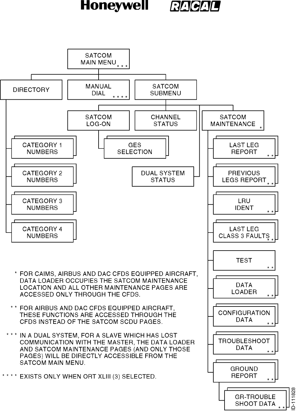
SYSTEM DESCRIPTION, INSTALLATION, AND MAINTENANCE MANUAL
MCS--4000/7000 Multi--Channel SATCOM System
23--20--27
30 Aug 2002
Use or disclosure of information on this page is subject to the restrictions in the proprietary notice of this document.
Page 6--25
Figure 6-2. SATCOM SCDU Page Hierarchy
RELEASED FOR THE EXCLUSIVE USE BY: HONEYWELL INTERNATIONAL
UP86308
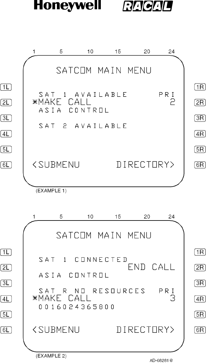
SYSTEM DESCRIPTION, INSTALLATION, AND MAINTENANCE MANUAL
MCS--4000/7000 Multi--Channel SATCOM System
23--20--27
30 Aug 2002
Use or disclosure of information on this page is subject to the restrictions in the proprietary notice of this document.
Page 6--26
Figure 6-3. SATCOM SCDU Main Menu Page
RELEASED FOR THE EXCLUSIVE USE BY: HONEYWELL INTERNATIONAL
UP86308

SYSTEM DESCRIPTION, INSTALLATION, AND MAINTENANCE MANUAL
MCS--4000/7000 Multi--Channel SATCOM System
23--20--27
30 Aug 2002
Use or disclosure of information on this page is subject to the restrictions in the proprietary notice of this document.
Page 6--27
(2) SATCOM SUBMENU Page
(a) Access to this page is from the SATCOM MAIN MENU page. The purpose of this
page is to display the current log-on state, to supply a way of entering and
displaying flight identifier, and to supply access to the SATCOM LOG-ON,
SATCOM CHANNEL STATUS, and SATCOM MAINTENANCE (or, if applicable,
DATA LOADER MENU) pages. When in a dual system, access to the DUAL
SYSTEM STATUS menu page is supplied. See Figure 6-4 for example pages.
(3) SATCOM MAINTENANCE Pages
(a) General
1An example SATCOM MAINTENANCE page for non-Airbus/Douglas CFDS
equipped aircraft is shown Figure 6-5.
2The SATCOM MAINTENANCE pages menu selection, subject to ORT item
iv (refer to SYSTEM OPERATION), is accessible from the SATCOM
SUBMENU page only on non-Airbus/Douglas CFDS equipped aircraft. In
Airbus and Douglas configurations, these pages are accessed through the
CFDS.
3The purpose of these pages are to display SATCOM maintenance data. In a
dual system, the maintenance data pertains to the system from which the
display pages are being supplied (SAT 1 or SAT 2).
4The display format and functionality for the SATCOM maintenance pages
(i.e., for the SAT--N, LAST LEG REPORT, PREVIOUS LEGS REPORT, LRU
IDENTIFICATION, LAST LEG CLASS 3 FAULTS, TEST, TROUBLESHOOT
DATA, GROUND TROUBLESHOOT DATA, GROUND REPORT, and
CONFIGURATION DATA pages) is the same as defined for the CFDS
interactive mode maintenance pages with the exception of the following:
•The RETURN> prompt is displayed on the right adjacent to the 6R key,
as opposed to the left.
•The SDU issues scratchpad message 1 (i.e., NOT ALLOWED) if any LS
key is pushed adjacent to a blank or display-only field.
RELEASED FOR THE EXCLUSIVE USE BY: HONEYWELL INTERNATIONAL
UP86308
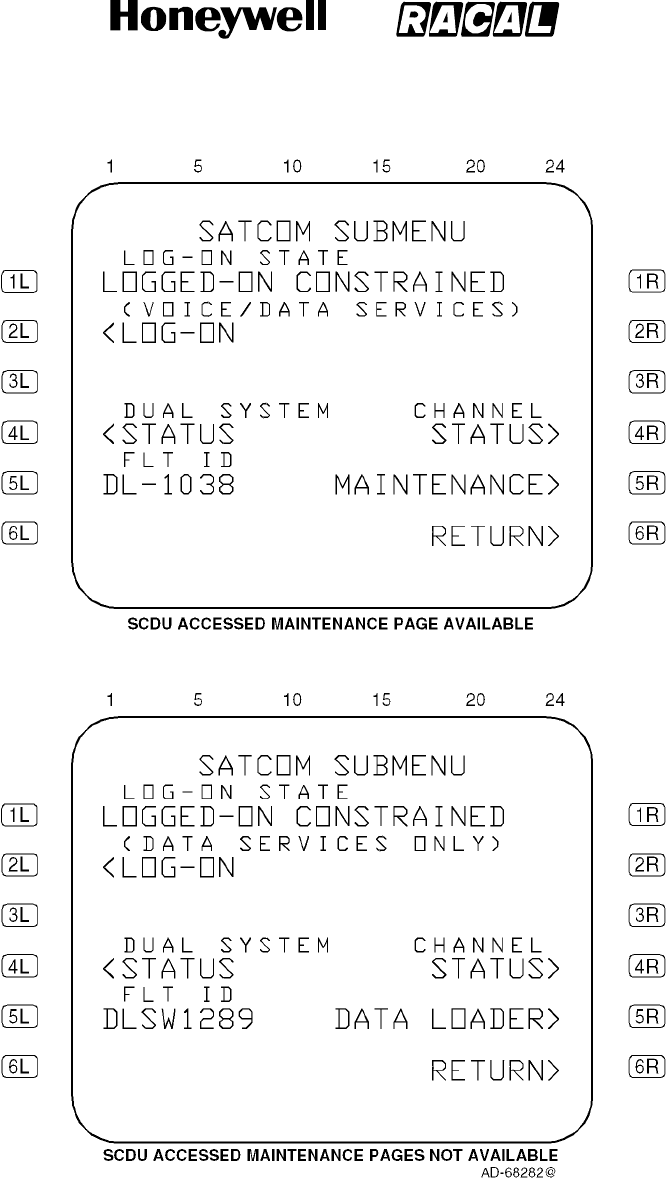
SYSTEM DESCRIPTION, INSTALLATION, AND MAINTENANCE MANUAL
MCS--4000/7000 Multi--Channel SATCOM System
23--20--27
30 Aug 2002
Use or disclosure of information on this page is subject to the restrictions in the proprietary notice of this document.
Page 6--28
Figure 6-4. SATCOM SUBMENU Page
RELEASED FOR THE EXCLUSIVE USE BY: HONEYWELL INTERNATIONAL
UP86308
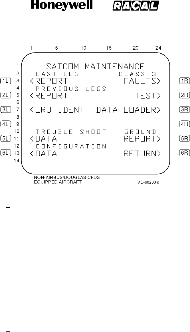
SYSTEM DESCRIPTION, INSTALLATION, AND MAINTENANCE MANUAL
MCS--4000/7000 Multi--Channel SATCOM System
23--20--27
30 Aug 2002
Use or disclosure of information on this page is subject to the restrictions in the proprietary notice of this document.
Page 6--29
Figure 6-5. SATCOM MAINTENANCE Page
5Access to SATCOM maintenance displays are as follows:
•Push LS key 1L to show the Last Leg Report page (see Figure 6-10)
•Push LS key 2L to show the Previous Leg Report page (see Figure 6-11)
•Push LS key 3Lto show the LRU Identification page (see Figure 6-12)
•Push LS key 5L to show the Trouble Shooting Data page (see
Figure 6-13)
•Push LS key 6L to show the Configuration Data page (see Figure 6-8)
•Push LS key1R to show the Last Leg Class 3 Faults page (see
Figure 6-14)
•Push LS key 2R to show the Test page (see Figure 6-6)
•Push LS key 3R to show the Data Loader Menu page (see Figure 6-9)
•Push LS key 5R to show the Ground Report page (see Figure 6-15).
(b) TEST page
1For software packages prior to D2.0, if a system-wide functional test (i.e.,
PAST) is initiated from the SCDU interface (i.e., by pushing the 2R key on
the SATCOM MAINTENANCE page), the first access of the SATCOM
subsystem from an SCDU MAIN MENU page after the POST/PAST Results
Delay period causes the TEST page to be shown with the status of the
current failures. However, the TEST page shows the TEST IN PROGRESS
60S message if this first access occurs during the POST/PAST Results
Delay period. If the SATCOM subsystem is not accessed within 5 minutes of
the completion of an SCDU-initiated PAST, the page hierarchy is reset to its
original structure as shown in Figure 6-2.
RELEASED FOR THE EXCLUSIVE USE BY: HONEYWELL INTERNATIONAL
UP86308

SYSTEM DESCRIPTION, INSTALLATION, AND MAINTENANCE MANUAL
MCS--4000/7000 Multi--Channel SATCOM System
23--20--27
30 Aug 2002
Use or disclosure of information on this page is subject to the restrictions in the proprietary notice of this document.
Page 6--30
2When the 2R key is pushed on the SATCOM MAINTENANCE (i.e., SAT--N)
page, the SDU initiates a PAST and the page display temporarily goes to the
TEST page where TEST IN PROGRESS 60S is displayed. However, the
SCDU eventually times out the SATCOM subsystem and takes back control
of the display. This is due to the fact that for SCDU-accessed maintenance
pages, the SDU interfaces directly with the SCDU (as opposed to going
through the CFDIU) and is unable to maintain proper bus activity (which the
CFDIU normally does) during initial execution of the PAST.
3To display the test results, the user must reselect the SATCOM system by
pushing the LS key adjacent to the <SAT prompt on the SCDU MAIN MENU
page, where the initial page shown is the TEST page. If the user does not
reselect the SATCOM system on the SCDU MAIN MENU page after 5
minutes of completion of PAST, the page hierarchy resets to its original
structure as shown in Figure 6-2.
4The TEST IN PROGRESS 60S message during the POST/PAST Results
Delay period is required to prevent the display of premature test results, i.e.,
to permit continuous monitoring sufficient time to add its contribution to the
POST/PAST results.
(4) TEST Menu Page
(a) General
1Access to this page is from the SAT--N (i.e., SATCOM MAINTENANCE)
page by pushing LS key 2R. The purpose of this page is to initiate a PAST,
to enable/disable a voice loopback on a selected (physical) channel, to
enable/disable a test of the cockpit voice call light for a selected (logical)
channel, and activation of the cockpit voice go-ahead chime test. See
Figure 6-6 for example pages.
(b) Data Fields
1Line 3
aThis line displays SELF-TEST beginning in column 1. The asterisk
prompt is not displayed if the aircraft is airborne.
bIf the LS key 1L is pushed when the SELF-TEST asterisk prompt is
shown, the system activates a PAST.
2Line 4
aThis line displays MP2ABCD VOICE LOOPBACK beginning in column
2. Pushing LS key 2l configures the SATCOM system to perform an
audio loopback test of flight deck channel 1.
RELEASED FOR THE EXCLUSIVE USE BY: HONEYWELL INTERNATIONAL
UP86308
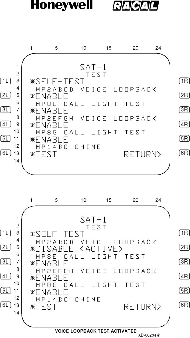
SYSTEM DESCRIPTION, INSTALLATION, AND MAINTENANCE MANUAL
MCS--4000/7000 Multi--Channel SATCOM System
23--20--27
30 Aug 2002
Use or disclosure of information on this page is subject to the restrictions in the proprietary notice of this document.
Page 6--31
Figure 6-6 (Sheet 1). TEST Page
RELEASED FOR THE EXCLUSIVE USE BY: HONEYWELL INTERNATIONAL
UP86308
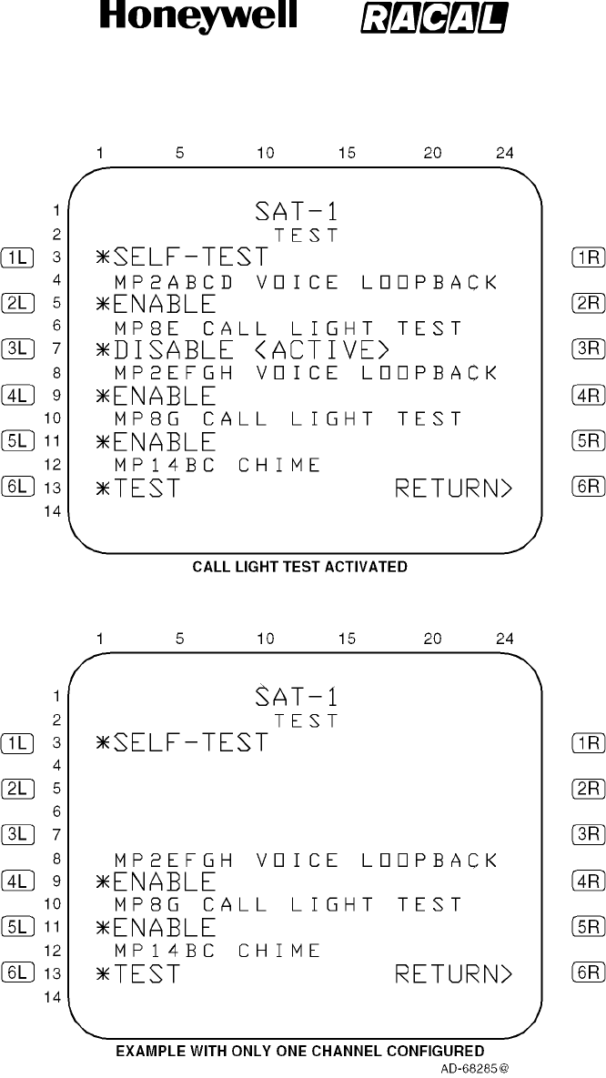
SYSTEM DESCRIPTION, INSTALLATION, AND MAINTENANCE MANUAL
MCS--4000/7000 Multi--Channel SATCOM System
23--20--27
30 Aug 2002
Use or disclosure of information on this page is subject to the restrictions in the proprietary notice of this document.
Page 6--32
Figure 6-6 (Sheet 2). TEST Page
RELEASED FOR THE EXCLUSIVE USE BY: HONEYWELL INTERNATIONAL
UP86308

SYSTEM DESCRIPTION, INSTALLATION, AND MAINTENANCE MANUAL
MCS--4000/7000 Multi--Channel SATCOM System
23--20--27
30 Aug 2002
Use or disclosure of information on this page is subject to the restrictions in the proprietary notice of this document.
Page 6--33
3Line 5
aThis line displays the message ENABLE beginning in column 1 when
the test is not active. The asterisk prompt is displayed and the test
allowed only if the log--on state is Standby. This line displays *DISABLE
<ACTIVE> beginning in column 1 when the test is active. If the log--on
state changes from Standby to any other state while the test is active,
thetestisterminated.Thecommandsonlines4and5areshownonlyif
the configuration straps indicate this channel is wired for headset use.
bPushing LS key 2L when the ENABLE asterisk prompt is shown causes
the voice channel selected to be activated into an analog loopback test
state. Pushing LS key 2L when the DISABLE prompt is shown causes
the voice loopback test state to be terminated.
4Line 6
aThislinedisplaysMP8ECALLLIGHTTESTbeginningincolumn2.
Pushing LS key 3L initiates a lamp test of the flight deck channel 1 call
lamp.
5Line 7
aThis line displays *ENABLE beginning in column 1 when the test is not
active. The asterisk prompt is shown and the test allowed only if the
log--on state is Standby. This line displays *DISABLE <ACTIVE>
beginning in column 1 when the test is active. If the log--on state
changes from Standby to any other state while the test is active, the test
is terminated. The commands on lines 6 and 7 are shown only if the
configuration straps indicate this channel is wired for headset use.
bPushing LS key 3L when the ENABLE asterisk prompt is shown causes
the cockpit voice call light to be activated for a steady indication
(regardless of the state of configuration pin TP13C). Pushing LS key 3L
when the DISABLE prompt is displayed causes the cockpit voice call
light test to be terminated.
6LIne 8
aThis line displays MP2EFGH VOICE LOOPBACK beginning in column
2. Pushing LS key 4L configures the SATCOM system to perform an
audio loopback test of flight deck channel 2.
7Line 9
aThis line displays ENABLE beginning in column 1 when the test is not
active. The asterisk prompt is shown and the test allowed only if the
log--on state is Standby. This line displays *DISABLE <ACTIVE>
beginning in column 1 when the test is active. If the log--on state
changes from Standby to any other state while the test is active, the test
is terminated. The commands on lines 8 and 9 are displayed only if the
configuration straps indicate this channel is wired for headset use.
RELEASED FOR THE EXCLUSIVE USE BY: HONEYWELL INTERNATIONAL
UP86308

SYSTEM DESCRIPTION, INSTALLATION, AND MAINTENANCE MANUAL
MCS--4000/7000 Multi--Channel SATCOM System
23--20--27
30 Aug 2002
Use or disclosure of information on this page is subject to the restrictions in the proprietary notice of this document.
Page 6--34
bPushing LS key 4L when the ENABLE asterisk prompt is displayed
causes the voice channel selected to be activated into an analog
loopback test state. Pushing LS key 4L when the DISABLE prompt is
displayed causes the voice loopback test state to be terminated.
8Line 10
aThis line displays MP8G CALL LIGHT TEST beginning in column 2.
Pushing LS key 5L initiates a lamp test of the flight deck channel 2 call
lamp.
9Line 11
aThis line displays *ENABLE beginning in column 1 when the test is not
active. The asterisk prompt is displayed and the test allowed only if the
log--on state is Standby. This line displays *DISABLE <ACTIVE>
beginning in column 1 when the test is active. If the log--on state
changes from Standby to any other state while the test is active, the test
is terminated. The commands on lines 10 and 11 are displayed only if
the configuration straps indicate this channel is wired for headset use.
bPushing LS key 5L when the ENABLE asterisk prompt is displayed
causes the cockpit voice call light to be activated for a steady indication
(regardless of the state of configuration pin TP13C). Pushing LS key 5L
when the DISABLE prompt is displayed causes the cockpit voice call
light test to be terminated.
10 Line 12
aThis line displays MP14BC CHIME beginning in column 2. Pushing LS
key 6L initiates the channel test.
11 Line 13
aThis line displays TEST beginning in column 1. The asterisk prompt is
displayed and the test allowed only if the log--on state is Standby.
bPushing LS key 6L when the asterisk prompt is displayed causes the
cockpit voice go-ahead chime to be activated for a single stroke.
RELEASED FOR THE EXCLUSIVE USE BY: HONEYWELL INTERNATIONAL
UP86308

SYSTEM DESCRIPTION, INSTALLATION, AND MAINTENANCE MANUAL
MCS--4000/7000 Multi--Channel SATCOM System
23--20--27
30 Aug 2002
Use or disclosure of information on this page is subject to the restrictions in the proprietary notice of this document.
Page 6--35
(5) SATCOM SELF--TEST (PAST) Page
(a) General
1The purpose of this page is to initiate a PAST, to enable/disable a voice
loopback on a selected (physical) channel, to enable/disable a test of the
cockpit voice call light for a selected (logical) channel, and activation of the
cockpit voice go-ahead chime test. See Figure 6-7 for example pages.
(b) Data Fields
1Line 1
aThis line displays the title of the page, SAT--N, beginning in column 10,
whereNrepresents1or2toindicateasingleSDU(N=1),SDUNo.1
(N = 1), or SDU No. 2 (N = 2) as determined by the settings of
configuration pins TP12E and TP12F.
bIf there are current failures to report after the execution of a PAST,
columns 20 thru 24 display p/t in small font, where p represents the
current displayed page, and t represents the total number of pages
needed to show the current failures. The display of the slash is always
in column 22, with p right-justified to the slash and t left-justified to the
slash.
2Line 3
aThis line displays headers ATA beginning in column 1 and CLASS
beginning in column 20 if there are current failures to report after
execution of a PAST. This line is blank if there are no failures to report.
bIn addition to the above, for CFDS type none, the header ATA is not
displayed (CLASS is still displayed as specified).
3Line 5
aThis line displays the message TEST IN PROGRESS 60S beginning in
column 3 within one second of a PAST being initiated on the SAT--N
(i.e., SATCOM MAINTENANCE) page, and then throughout the duration
of PAST. If there are no current failures to report at the conclusion of the
PAST (including the POST/PAST results delay period), the message
TEST OK is displayed. If there are current failures to report at the
conclusion of the PAST (including the POST/PAST results delay period),
refer to paragraph 4 for line requirements.
RELEASED FOR THE EXCLUSIVE USE BY: HONEYWELL INTERNATIONAL
UP86308
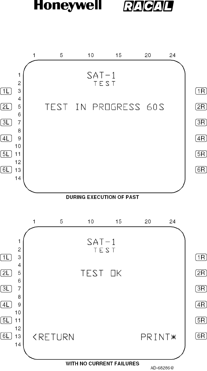
SYSTEM DESCRIPTION, INSTALLATION, AND MAINTENANCE MANUAL
MCS--4000/7000 Multi--Channel SATCOM System
23--20--27
30 Aug 2002
Use or disclosure of information on this page is subject to the restrictions in the proprietary notice of this document.
Page 6--36
Figure 6-7 (Sheet 1). SATCOM SELF--TEST Page
RELEASED FOR THE EXCLUSIVE USE BY: HONEYWELL INTERNATIONAL
UP86308
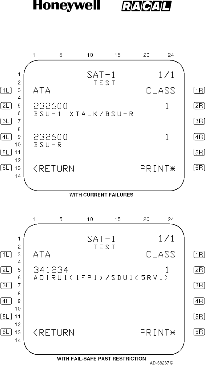
SYSTEM DESCRIPTION, INSTALLATION, AND MAINTENANCE MANUAL
MCS--4000/7000 Multi--Channel SATCOM System
23--20--27
30 Aug 2002
Use or disclosure of information on this page is subject to the restrictions in the proprietary notice of this document.
Page 6--37
Figure 6-7 (Sheet 2). SATCOM SELF--TEST Page
RELEASED FOR THE EXCLUSIVE USE BY: HONEYWELL INTERNATIONAL
UP86308

SYSTEM DESCRIPTION, INSTALLATION, AND MAINTENANCE MANUAL
MCS--4000/7000 Multi--Channel SATCOM System
23--20--27
30 Aug 2002
Use or disclosure of information on this page is subject to the restrictions in the proprietary notice of this document.
Page 6--38
4Other Information
aThe SELF--TEST page lists two failures per page if failures are detected
during the PAST(self--test). These two sets of lines (lines 5, 6, and 7
and lines 9, 10, and 11) display Level 1 diagnosed current failures.
Failures are shown in chronological order (i.e., the most recent detected
failure last) with no more than two failures displayed per page.
bThe number of TEST pages depends on the number of current failures
to report (up to a maximum of 99 pages). When there is an odd number
of current failures to report, the odd failure is displayed on a separate
page in lines 5, 6, and 7, and lines 9, 10, and 11 are blank. If there are
no failures to report, lines 5, 6, 7, 9, 10, and 11 are blank except as
noted in paragraph 3.
cLine 5 and, if applicable, line 9 display the ATA number beginning in
column 1 and the class number beginning in column 23. The ATA
number is displayed as aaaaaa, where aaaaaa represents the ATA
reference number of the reported failure as specified in paragraph 3.E.
for each type of CFDS. For CFDS type none, no ATA number is
displayed. The class number is displayed as c, where c represents the
class (1, 2, or 3) of the failure.
dLines 6 and 7 and, if applicable, lines 10 and 11 display a text message,
as specified in paragraph 3.E. for each CFDS type, for the reported
failure beginning in column 1.
(6) CONFIGURATION DATA Pages
(a) General
1Access to these pages is from the SAT--N (i.e., SATCOM MAINTENANCE)
page. The purpose of these pages is to display the status of SATCOM
configuration input parameters. See Figure 6-8 for example pages.
(b) CONFIGURATION DATA Page 1 (Figure 6-8, sheet 1):
1Data Fields
aLine 3
(1) This line displays the ICAO address of eight octal characters, as
determined by discrete inputs from the ICAO address straps. This
display is not derived from any ARINC 429 version of the ICAO
address.
bLine 5
(1) This line displays CONFIG as determined by the setting of the
system configuration pins, followed by (HEX). The configuration pin
settings are mapped into hexadecimal digits as shown in Table 6-9.
In the figure, digits 0 thru 9 correlate to hexadecimal digits 0 thru 9
in the table.
RELEASED FOR THE EXCLUSIVE USE BY: HONEYWELL INTERNATIONAL
UP86308
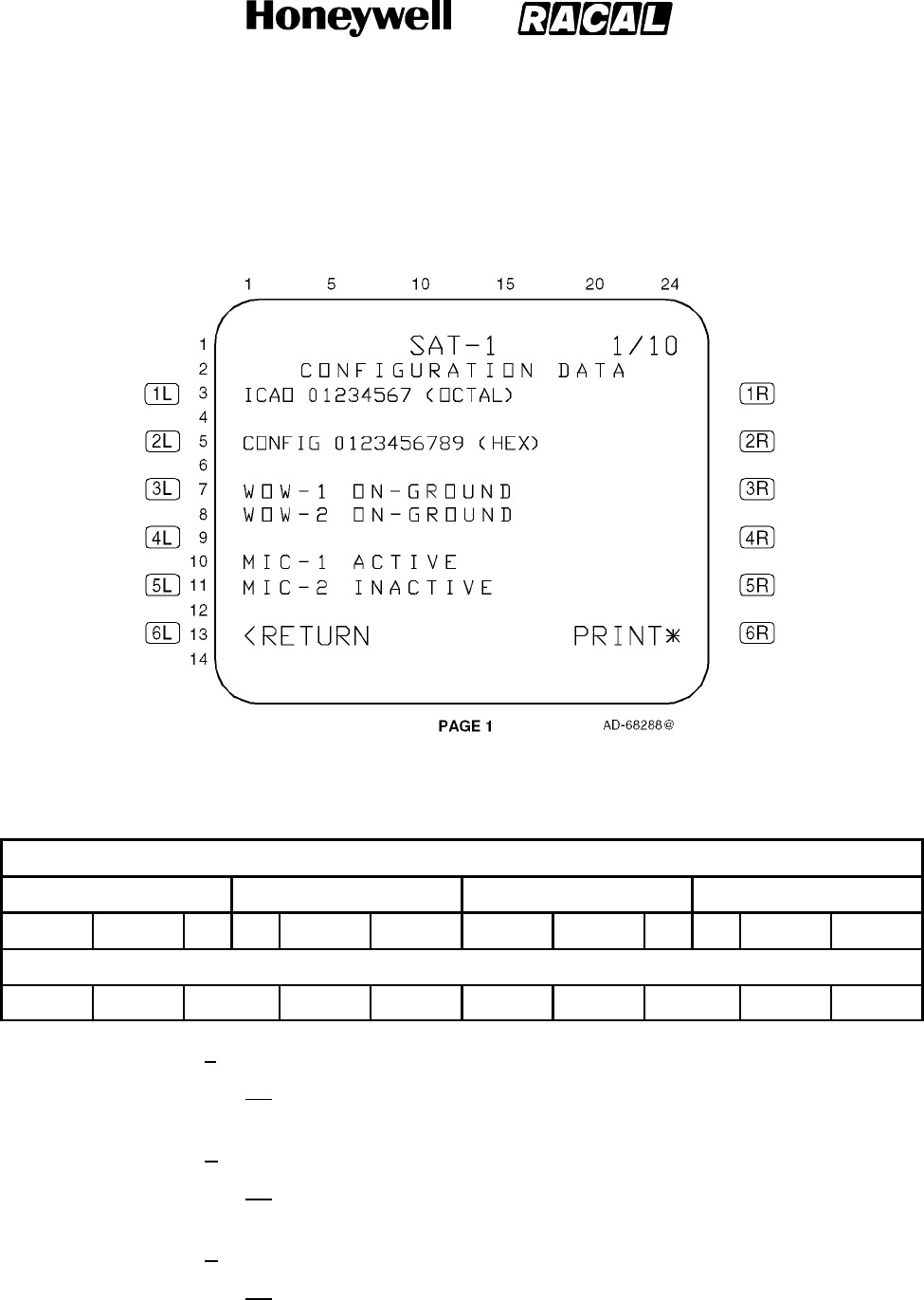
SYSTEM DESCRIPTION, INSTALLATION, AND MAINTENANCE MANUAL
MCS--4000/7000 Multi--Channel SATCOM System
23--20--27
30 Aug 2002
Use or disclosure of information on this page is subject to the restrictions in the proprietary notice of this document.
Page 6--39
Figure 6-8 (Sheet 1). Configuration Data
Table 6-9. System Configuration Pin Mapping
Configuration Pins
TP10 TP11 TP12 TP13
ABCD EFGH JK AB CDEF GHJK ABCD EFGH JK AB CDEF GHJK
Hex Digits
0 1 2 3 4 5 6 7 8 9
cLine 7
(1) This line displays the WOW--1 status of SDU weight-on-wheels
discrete input No. 1 as IN-AIR/NOT WIRED or ON-GROUND.
dLine 8
(1) This line displays the WOW--2 status of the SDU weight-on-wheels
discrete input No. 2 as IN-AIR/NOT WIRED or ON-GROUND.
eLine 10
(1) This line displays the MIC--1 status of the SDU cockpit voice
microphone On discrete input No. 1 as ACTIVE or INACTIVE.
RELEASED FOR THE EXCLUSIVE USE BY: HONEYWELL INTERNATIONAL
UP86308

SYSTEM DESCRIPTION, INSTALLATION, AND MAINTENANCE MANUAL
MCS--4000/7000 Multi--Channel SATCOM System
23--20--27
30 Aug 2002
Use or disclosure of information on this page is subject to the restrictions in the proprietary notice of this document.
Page 6--40
fLine 11
(1) This line displays the MIC--2 status of the SDU cockpit voice
microphone On discrete input No. 2 as ACTIVE or INACTIVE.
(c) CONFIGURATION DATA Page 2 (Figure 6-8, sheet 2):
1Data Fields
aLine 3
(1) This line displays the CHIME RESET status of the SDU cockpit
voice go-ahead chime signal reset discrete input as ACTIVE or
INACTIVE.
bLine 5
(1) This line displays the DUAL SYS SELECT status of the SDU dual
system select discrete input as ACTIVE or INACT.
cLine 6
(1) This line displays the DUAL SYS DISABLE status of the SDU dual
system disable discrete input as ACTIVE or INACT.
dLine 8
(1) This line displays IRS SOURCE as determined by which IRS input
bus the SDU is using. A dash is displayed for the IRS source if a
429 source of IRS is not connected to the SDU.
eLine 10
(1) This line displays the PLACE/END CALL 1 status of the SDU
cockpit voice place/end call 1 discrete input as ACTIVE or INACT.
fLine 11
(1) This line displays the PLACE/END CALL 2 status of the SDU
cockpit voice place/end call 2 discrete input as ACTIVE or INACT.
RELEASED FOR THE EXCLUSIVE USE BY: HONEYWELL INTERNATIONAL
UP86308
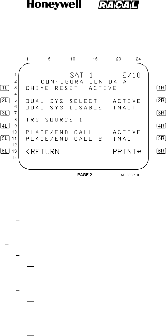
SYSTEM DESCRIPTION, INSTALLATION, AND MAINTENANCE MANUAL
MCS--4000/7000 Multi--Channel SATCOM System
23--20--27
30 Aug 2002
Use or disclosure of information on this page is subject to the restrictions in the proprietary notice of this document.
Page 6--41
Figure 6-8 (Sheet 2). Configuration Data
(d) CONFIGURATION DATA Page 3 (Figure 6-8, sheet 3):
1General
aFor CONFIGURATION DATA pages 3 thru 10, the strap setting value 0
or 1 in parentheses is as follows: 1= open circuit; and 0 = tied to
common.
2Data Fields
aLine 4
(1) This line displays A(0) ICAO ADRS AVAIL or A(1) ICAO ADRS NOT
AVAIL left-justified as determined by the state of system
configuration pin TP10A.
bLine 6
(1) This line displays B(0) FMC1 CONNECTED or B(1) FMC1 NOT
CONNECTED left-justified as determined by the state of system
configuration pin TP10B.
cLine 8
(1) This line displays C(0) FMC2 CONNECTED or C(1) FMC2 NOT
CONNECTED left-justified as determined by the state of system
configuration pin TP10C.
RELEASED FOR THE EXCLUSIVE USE BY: HONEYWELL INTERNATIONAL
UP86308
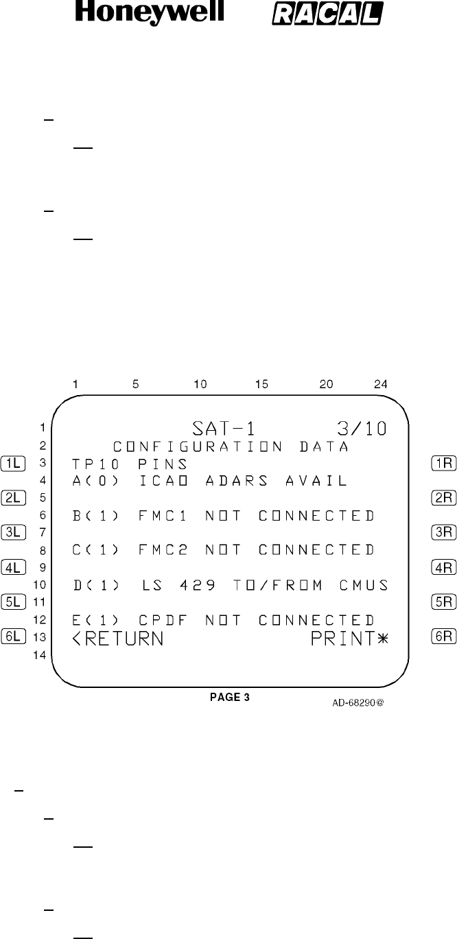
SYSTEM DESCRIPTION, INSTALLATION, AND MAINTENANCE MANUAL
MCS--4000/7000 Multi--Channel SATCOM System
23--20--27
30 Aug 2002
Use or disclosure of information on this page is subject to the restrictions in the proprietary notice of this document.
Page 6--42
dLine 10
(1) This line displays D(0) HS 429 TO/FROM CMUS or D(1) LS 429
TO/FROM CMUS left-justified as determined by the state of system
configuration pin TP10D.
eLine 12
(1) This line displays E(0) CPDF CONNECTED or E(1) CPDF NOT
CONNECTED left-justified as determined by the state of system
configuration pin TP10E.
Figure 6-8 (Sheet 3). Configuration Data
(e) CONFIGURATION DATA Page 4 (Figure 6-8, sheet 4):
1Data Fields
aLine 4
(1) This line displays F(0) HS 429 ICAO ADRS or F(1) LS 429 ICAO
ADRS left-justified as determined by the state of system
configuration pin TP10F.
bLine 6
(1) This line displays G(0) SPARE or G(1) SPARE left-justified as
determined by the state of system configuration pin TP10G.
RELEASED FOR THE EXCLUSIVE USE BY: HONEYWELL INTERNATIONAL
UP86308
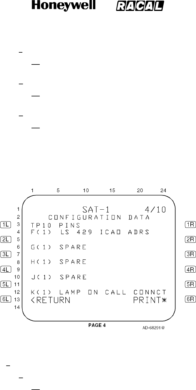
SYSTEM DESCRIPTION, INSTALLATION, AND MAINTENANCE MANUAL
MCS--4000/7000 Multi--Channel SATCOM System
23--20--27
30 Aug 2002
Use or disclosure of information on this page is subject to the restrictions in the proprietary notice of this document.
Page 6--43
cLine 8
(1) This line displays H(0) SPARE or H(1) SPARE left-justified as
determined by the state of system configuration pin TP10H.
dLine 10
(1) This line displays J(0) SPARE or J(1) SPARE left-justified as
determined by the state of system configuration pin TP10J.
eLine 12
(1) This line displays K(0) LAMP ON CALL INIT or K(1) LAMP ON
CALL CONNCT left-justified as determined by the state of system
configuration pin TP10K.
Figure 6-8 (Sheet 4). Configuration Data
(f) CONFIGURATION DATA Page 5 (Figure 6-8, sheet 5):
1Data Fields
aLine 4
(1) This line displays A(0) PARITY: GOOD, A(1) PARITY: GOOD, A(0)
PARITY: BAD, or A(1) PARITY: BAD left-justified as determined by
the state of system configuration pin TP11A and the result of the
parity validation test.
RELEASED FOR THE EXCLUSIVE USE BY: HONEYWELL INTERNATIONAL
UP86308
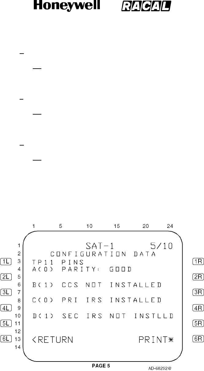
SYSTEM DESCRIPTION, INSTALLATION, AND MAINTENANCE MANUAL
MCS--4000/7000 Multi--Channel SATCOM System
23--20--27
30 Aug 2002
Use or disclosure of information on this page is subject to the restrictions in the proprietary notice of this document.
Page 6--44
bLine 6
(1) This line displays B(0) CCS INSTALLED or B(1) CCS NOT
INSTALLED left-justified as determined by the state of system
configuration pin TP11B.
cLine 8
(1) This line displays C(0) PRI IRS INSTALLED or C(1) PRI IRS NOT
INSTLLD left-justified as determined by the state of system
configuration pin TP11C.
dLine 10
(1) This line displays D(0) SEC IRS INSTALLED or D(1) SEC IRS NOT
INSTLLD left-justified as determined by the state of system
configuration pin TP11D.
Figure 6-8 (Sheet 5). Configuration Data
RELEASED FOR THE EXCLUSIVE USE BY: HONEYWELL INTERNATIONAL
UP86308
SYSTEM DESCRIPTION, INSTALLATION, AND MAINTENANCE MANUAL
MCS--4000/7000 Multi--Channel SATCOM System
23--20--27
30 Aug 2002
Use or disclosure of information on this page is subject to the restrictions in the proprietary notice of this document.
Page 6--45
(g) CONFIGURATION DATA Page 6 (Figure 6-8, sheet 6):
1Data Fields
aLines 4 thru 9
(1) These lines display X(0)* or X(1)* left-justified as shown in the
figure, where X represents E, F, G, H, J, and K, respectively. X(0)*
or X(1)* is determined by the states of system configuration pins
TP11E, TP11F, TP11G, TP11H, TP11J, and TP11K. Asterisks are
displayedincolumn5toindicatethesepinsareacodedgroup.
(2) Beginning in column 6, textual messages are displayed (refer to
Table 6-10) in lines 4 thru 9 (as needed), where an x indicates the
message(s) to be displayed based on the state of system
configuration pins TP11E, TP11F, TP11G, TP11H, TP11J, and
TP11K.
Table 6-10. Textual Message Display (Page 6 -- Lines 4 thru 9)
System Configuration Pin
System Configuration Pin Settings
(1 = open circuit / 0 = tied to common)
TP11E 101011 All Other Pin Combinations
TP11F 110011
TP11G 111111
TP11H 111100
TP11J 111110
TP11K 111110
Textual Message Textual Messages To Display Based On System Configuration Pin
Settings
LO GAIN ANT+DLNA X X X
HPA--LO GAIN X X X
HI GAIN ANT+BSU--T/L XXXX
HI GAIN ANT+BSU--R X X
HPA--HI GAIN XXXX
HI POWER RELAY X X
HPA--IGA X
ERROR/UNDEFINED X
RELEASED FOR THE EXCLUSIVE USE BY: HONEYWELL INTERNATIONAL
UP86308
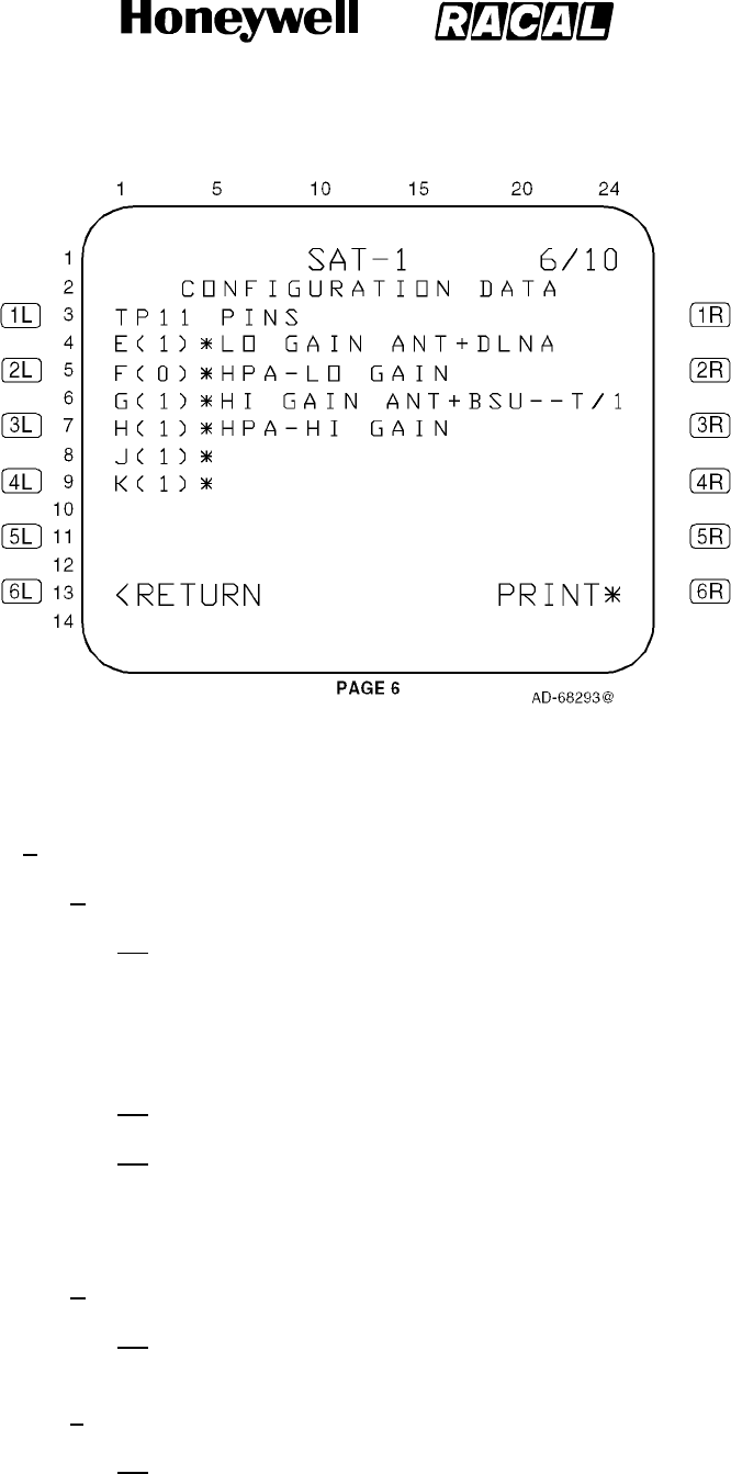
SYSTEM DESCRIPTION, INSTALLATION, AND MAINTENANCE MANUAL
MCS--4000/7000 Multi--Channel SATCOM System
23--20--27
30 Aug 2002
Use or disclosure of information on this page is subject to the restrictions in the proprietary notice of this document.
Page 6--46
Figure 6-8 (Sheet 6). Configuration Data
(h) CONFIGURATION DATA Page 7 (Figure 6-8, sheet 7):
1Data Fields
aLines 4 thru 6
(1) These lines display X(0)* or X(1)* left-justified as shown in the
figure, where X represents A, B and C, respectively. X(0)* or X(1)*
are determined by the state of system configuration pins TP12A,
TP12B, and TP12C. Asterisks are displayed in column 5 to indicate
these pins are a coded group.
(2) CFDS/CMC TYPE = is displayed in line 4 beginning in column 6.
(3) Beginning in column 6, a textual message is displayed according to
Table 6-11, where an x indicates the message to be displayed,
based on the state of system configuration pins TP12A, TP12B and
TP12C.
bLine 10
(1) This line displays D(0) RESERVED or D(1) RESERVED left-justified
as determined by the state of system configuration pin TP12D.
cLine 12
(1) This line displays E(0) OTHER SDU INSTALLED or E(1) OTHER
SDU NOT INSTD left-justified as determined by the state of system
configuration pin TP12E.
RELEASED FOR THE EXCLUSIVE USE BY: HONEYWELL INTERNATIONAL
UP86308
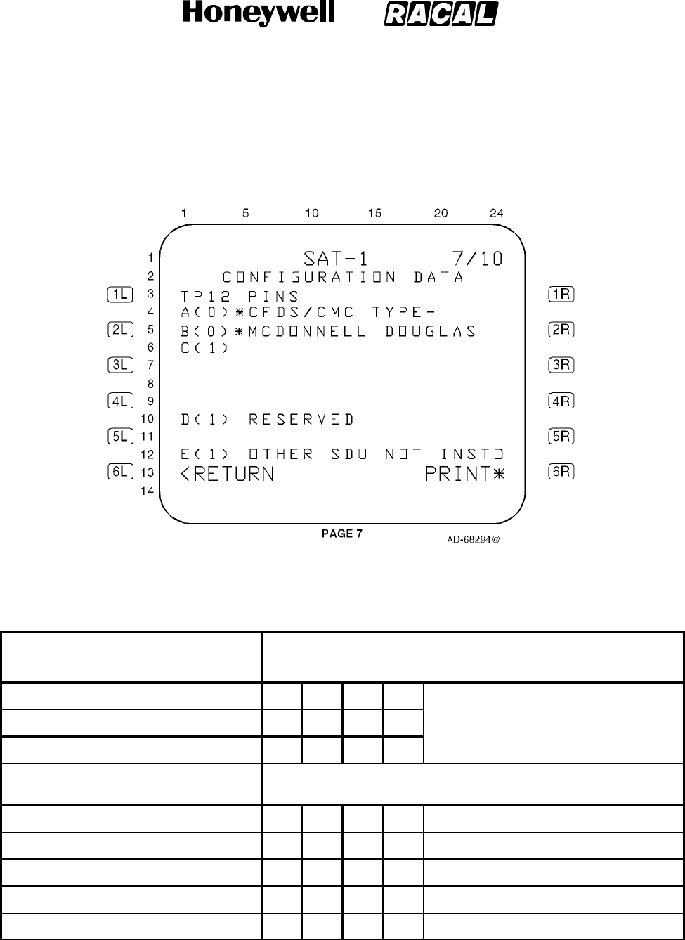
SYSTEM DESCRIPTION, INSTALLATION, AND MAINTENANCE MANUAL
MCS--4000/7000 Multi--Channel SATCOM System
23--20--27
30 Aug 2002
Use or disclosure of information on this page is subject to the restrictions in the proprietary notice of this document.
Page 6--47
Figure 6-8 (Sheet 7). Configuration Data
Table 6-11. Textual Message Display (Page 7 -- Lines 4, 5, an 6)
System Configuration Pin
System Configuration Pin Settings
(1 = open circuit / 0 = tied to common)
TP12A 0011 All Other Pin Combinations
TP12B 0101
TP12C 1001
Textual Message Textual Messages To Display Based On System Configuration Pin
Settings
MCDONNELL--DOUGLAS X
AIRBUS X
BOEING X
NOT INSTALLED X
ERROR/UNDEFINED X
RELEASED FOR THE EXCLUSIVE USE BY: HONEYWELL INTERNATIONAL
UP86308

SYSTEM DESCRIPTION, INSTALLATION, AND MAINTENANCE MANUAL
MCS--4000/7000 Multi--Channel SATCOM System
23--20--27
30 Aug 2002
Use or disclosure of information on this page is subject to the restrictions in the proprietary notice of this document.
Page 6--48
(i) CONFIGURATION DATA Page 8 (Figure 6-8, sheet 8):
1Data Fields
aLine 4
(1) This line displays F(0) THIS IS SDU2 or F(1) THIS IS SDU1
left-justified as determined by the state of system configuration pin
TP12F.
bLine 6
(1) This line displays G(0) CMU1 INSTALLED or G(1) CMU1 NOT
INSTALLED left-justified as determined by the state of system
configuration pin TP12G.
cLine 8
(1) This line displays H(0) CMU2 INSTALLED or H(1) CMU2 NOT
INSTALLED left-justified as determined by the state of system
configuration pin TP12H.
dLine 10
(1) This line displays J(0) SCDU1 INSTALLED or J(1) SCDU1 NOT
INSTALLED left-justified as determined by the state of system
configuration pin TP12J.
eLine 12
(1) This line displays K(0) SCDU2 INSTALLED or K(1) SCDU2 NOT
INSTALLED left-justified as determined by the state of system
configuration pin TP12K.
RELEASED FOR THE EXCLUSIVE USE BY: HONEYWELL INTERNATIONAL
UP86308
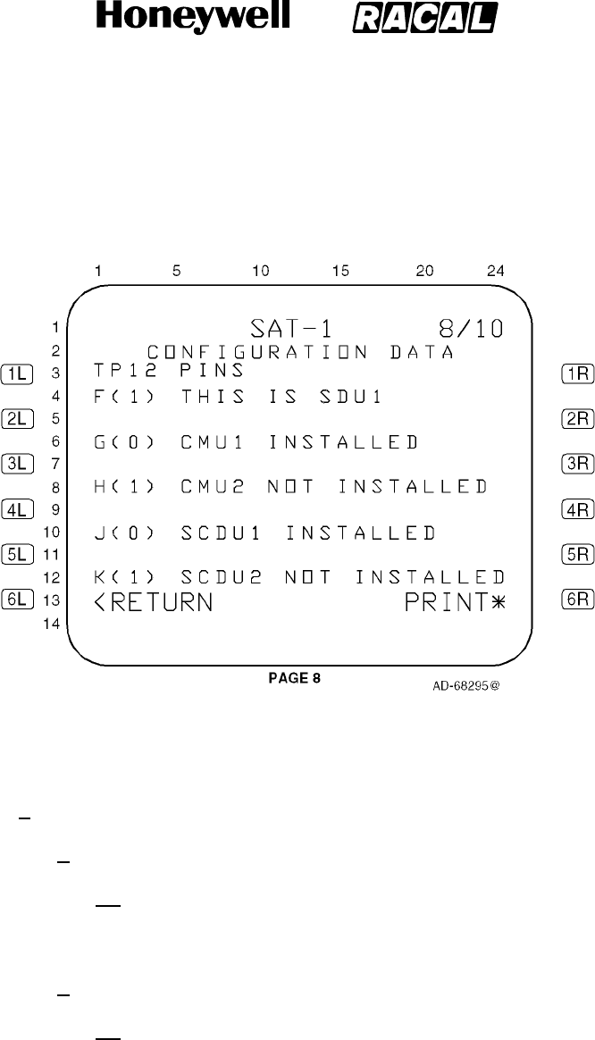
SYSTEM DESCRIPTION, INSTALLATION, AND MAINTENANCE MANUAL
MCS--4000/7000 Multi--Channel SATCOM System
23--20--27
30 Aug 2002
Use or disclosure of information on this page is subject to the restrictions in the proprietary notice of this document.
Page 6--49
Figure 6-8 (Sheet 8). Configuration Data
(j) CONFIGURATION DATA Page 9 (Figure 6-8, sheet 9):
1Data Fields
aLine 4
(1) This line displays A(0) NO HSET PRI 4 CALLS or A(1) HSET PRI 4
CALLS OK left-justified as determined by the state of system
configuration pin TP13A.
bLine 6
(1) This line displays B(0) LS 429 TO SCDUS or B(1) HS 429 TO
SCDUS left-justified as determined by the state of system
configuration pin TP13B.
RELEASED FOR THE EXCLUSIVE USE BY: HONEYWELL INTERNATIONAL
UP86308
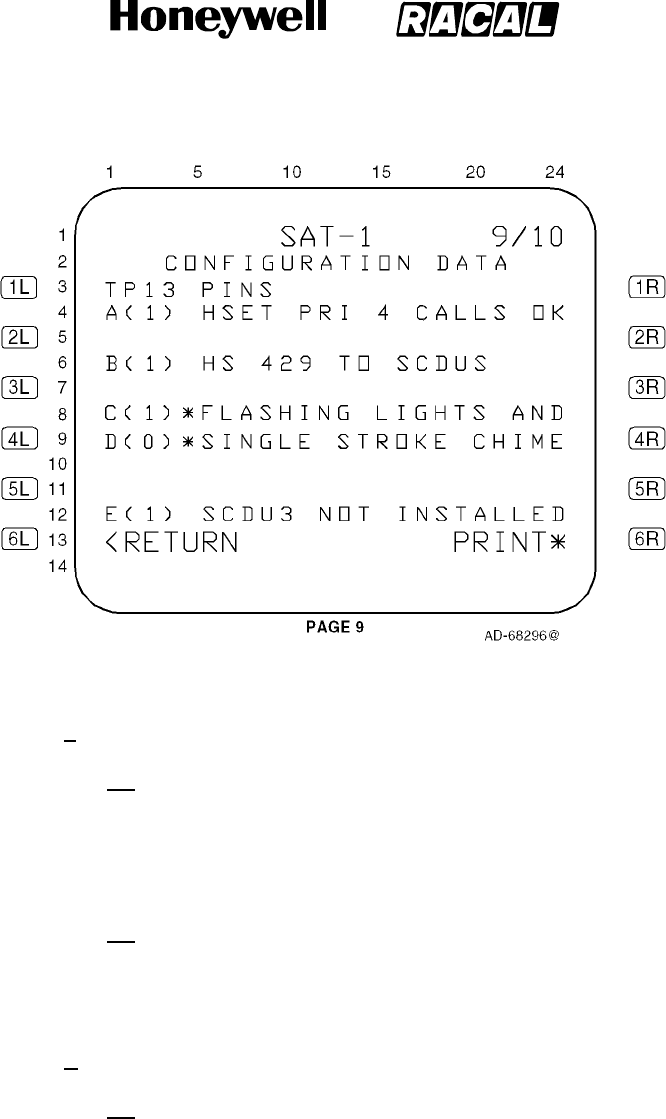
SYSTEM DESCRIPTION, INSTALLATION, AND MAINTENANCE MANUAL
MCS--4000/7000 Multi--Channel SATCOM System
23--20--27
30 Aug 2002
Use or disclosure of information on this page is subject to the restrictions in the proprietary notice of this document.
Page 6--50
Figure 6-8 (Sheet 9). Configuration Data
cLines 8 and 9
(1) These lines display X(0)* or X(1)* left-justified as shown in the
figure, where X represents C and D, respectively. X(0)* or X(1)* are
determined by the state of system configuration pins TP13C and
TP13D. Asterisks are displayed in column 5 to indicate these pins
are a coded group.
(2) Beginning in column 6, a textual message is shown in line 8 and
according to Table 6-12, where an x indicates the message to be
displayed, based on the state of system configuration pins TP13C
and TP13D.
dLine 12
(1) This line displays E(0) SCDU3 INSTALLED or E(1) SCDU3 NOT
INSTALLED left-justified as determined by the state of system
configuration pin TP13E.
RELEASED FOR THE EXCLUSIVE USE BY: HONEYWELL INTERNATIONAL
UP86308
SYSTEM DESCRIPTION, INSTALLATION, AND MAINTENANCE MANUAL
MCS--4000/7000 Multi--Channel SATCOM System
23--20--27
30 Aug 2002
Use or disclosure of information on this page is subject to the restrictions in the proprietary notice of this document.
Page 6--51
Table 6-12. Textual Message Display (Page 9 -- Lines 8 and 9)
System Configuration Pin
System Configuration Pin Settings
(1 = open circuit / 0 = tied to common)
TP13C 0011
TP13D 0101
Textual Message Textual Messages to Display Based on System Configuration
Pin Settings
LIGHTS AND CHIME
UNDEFINED
(Line 8)
(Line 9)
X
STEADY LIGHTS AND
MULTISTROKE CHIME
(Line 8)
(Line 9)
X
FLASHING LIGHTS AND
SINGLE STROKE CHIME
(Line 8)
(Line 9)
X
STEADY LIGHTS AND
SINGLE STROKE CHIME
(Line 8)
(Line 9)
X
(k) CONFIGURATION DATA Page 10 (Figure 6-8, sheet 10):
1Data Fields
aLines 4 and 5
(1) These lines display X(0)* or X(1)* left-justified as shown in the
figure, where X represents F and G, respectively. X(0)* or X(1)* are
determined by the state of system configuration pins TP13F and
TP13G.
(2) Beginning in column 6, a textual message is displayed in lines 4
and 5 according to Table 6-13, where an x indicates the message to
be displayed based on the state of system configuration pins
TP13F and TP13G.
bLines 8 and 9
(1) These lines display X(0)* or X(1)* left-justified, where X represents
H and J, respectively. X(0)* or X(1)* are determined by the state of
system configuration pins TP13H and TP13J. Asterisks are
displayedincolumn5toindicatethesepinsareacodedgroup.
(2) Beginning in column 6, a textual message is displayed in lines 8
and 9 according to Table 6-14, where an x indicates the message to
be displayed based on the state of system configuration pins
TP13H and TP13J.
RELEASED FOR THE EXCLUSIVE USE BY: HONEYWELL INTERNATIONAL
UP86308
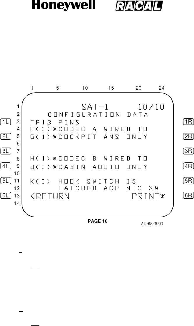
SYSTEM DESCRIPTION, INSTALLATION, AND MAINTENANCE MANUAL
MCS--4000/7000 Multi--Channel SATCOM System
23--20--27
30 Aug 2002
Use or disclosure of information on this page is subject to the restrictions in the proprietary notice of this document.
Page 6--52
Figure 6-8 (Sheet 10). Configuration Data
cLines 11 and 12
(1) Line 11 displays K(0) HOOK SWITCH IS left-justified and line 12
displays LATCHED ACP MIC SW beginning in column 6; or line 11
displays K(1) HOOK SWITCH IS left-justified and line 12 displays
SWITCHED PTT/SCDU beginning in column 6, as determined by
the state of system configuration pin TP13K.
dLine 13 (LS Key 6L)
(1) This line displays <RETURN left-justified and PRINT* right-justified
(if applicable). The PRINT* prompt is only displayed if bit 11 of
ARINC label 155 is set to 1. Pushing the 6L key causes the page
display to revert to the SAT--N (i.e., SATCOM MAINTENANCE)
page.
RELEASED FOR THE EXCLUSIVE USE BY: HONEYWELL INTERNATIONAL
UP86308
SYSTEM DESCRIPTION, INSTALLATION, AND MAINTENANCE MANUAL
MCS--4000/7000 Multi--Channel SATCOM System
23--20--27
30 Aug 2002
Use or disclosure of information on this page is subject to the restrictions in the proprietary notice of this document.
Page 6--53
Table 6-13. Textual Message Display (Page 10 -- Lines 4 and 5)
System Configuration Pin
System Configuration Pin Settings
(1 = open circuit / 0 = tied to common)
TP13F 0011
TP13G 0101
Textual Message Textual Messages to Display Based on System Configuration
Pin Settings
CODEC A WIRED TO AMS
AND CABIN
(Line 4)
(Line 5)
X
CODEC A WIRED TO
COCKPIT AMS ONLY
(Line 4)
(Line 5)
X
CODEC A WIRED TO CABIN
AUDIO ONLY
(Line 4)
(Line 5)
X
CODEC A NOT WIRED
BLANK
(Line 4)
(Line 5)
X
Table 6-14. Textual Message Display (Page 10 -- Lines 8 and 9)
System Configuration Pin
System Configuration Pin Settings
(1 = open circuit / 0 = tied to common)
TP13H 0011
TP13J 0101
Textual Message Textual Messages to Display Based on System Configuration
Pin Settings
CODEC B WIRED TO AMS
AND CABIN
(Line 8)
(Line 9)
X
CODEC B WIRED TO
COCKPIT AMS ONLY
(Line 8)
(Line 9)
X
CODEC B WIRED TO CABIN
AUDIO ONLY
(Line 8)
(Line 9)
X
CODEC B NOT WIRED
BLANK
(Line 8)
(Line 9)
X
RELEASED FOR THE EXCLUSIVE USE BY: HONEYWELL INTERNATIONAL
UP86308
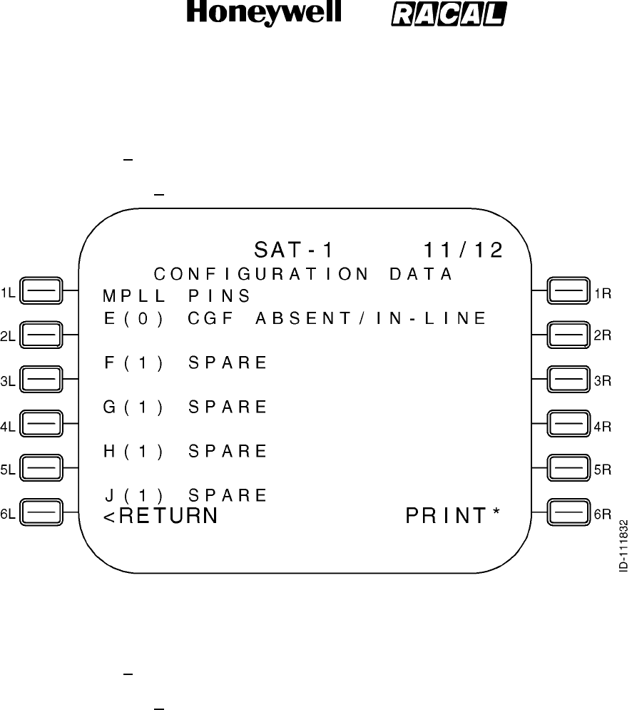
SYSTEM DESCRIPTION, INSTALLATION, AND MAINTENANCE MANUAL
MCS--4000/7000 Multi--Channel SATCOM System
23--20--27
30 Aug 2002
Use or disclosure of information on this page is subject to the restrictions in the proprietary notice of this document.
Page 6--54
(l) CONFIGURATION DATA Page 11 (Figure 6-8, Sheet 11):
1General
aPage 11 of the CONFIGURATION DATA page is shown below.
Figure 6-8 (Sheet 11). Configuration Data
(m) CONFIGURATION DATA Page 12 (Figure 6-8, Sheet 12):
1General
aPage 12 of the CONFIGURATION DATA page is shown below.
RELEASED FOR THE EXCLUSIVE USE BY: HONEYWELL INTERNATIONAL
UP86308
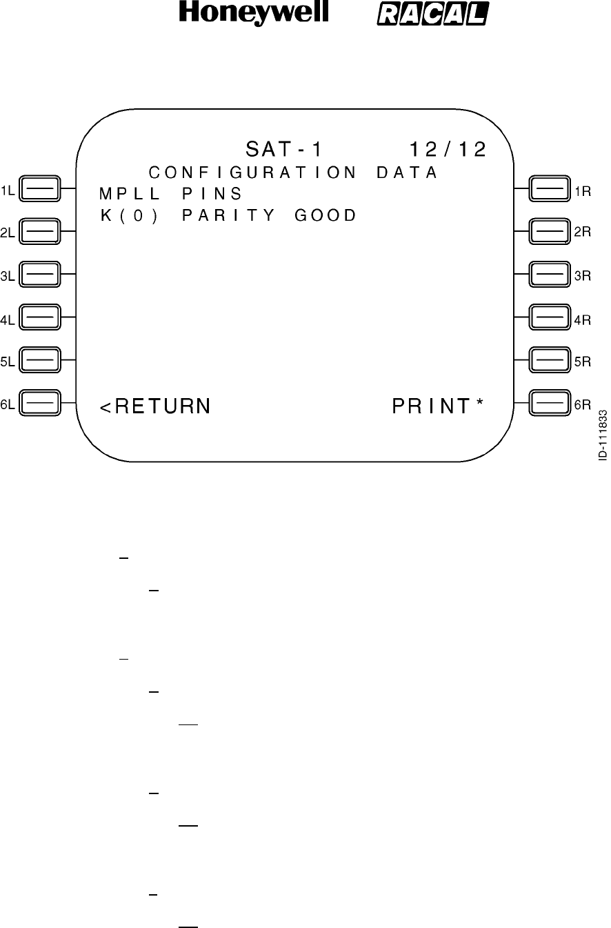
SYSTEM DESCRIPTION, INSTALLATION, AND MAINTENANCE MANUAL
MCS--4000/7000 Multi--Channel SATCOM System
23--20--27
30 Aug 2002
Use or disclosure of information on this page is subject to the restrictions in the proprietary notice of this document.
Page 6--55
Figure 6-8 (Sheet 12). Configuration Data
(n) CONFIGURATION DATA Page 13 (Figure 6-8, Sheet 13):
1General
aThese configuration data pages are only available on the
non-Airbus/Douglas SCDU maintenance pages, in which case the 12
pages shown in the previous paragraphs are 1/12 thru 10/12.
2Data Fields
aLine 3
(1) This line displays the CALL LAMP 1 status of the SDU Cockpit
Voice-Call Lamp Discrete Output as ACTIVE or INACT as
appropriate.
bLine 4
(1) This line displays the CALL LAMP 2 status of the SDU Cockpit
Voice-Call Lamp Discrete Output as ACTIVE or INACT as
appropriate.
cLine 6
(1) This line displays the DUAL SYS SELECT status of SDU Dual
System Select Discrete Output as ACTIVE or INACT as
appropriate.
RELEASED FOR THE EXCLUSIVE USE BY: HONEYWELL INTERNATIONAL
UP86308
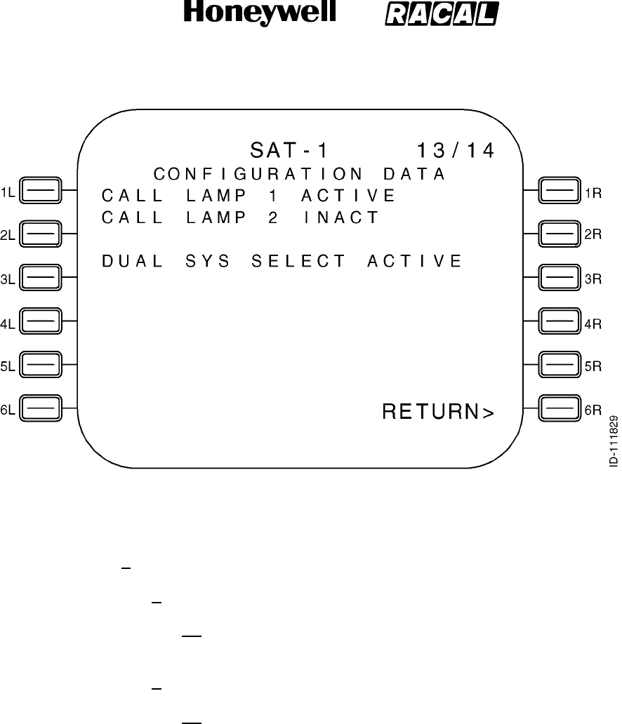
SYSTEM DESCRIPTION, INSTALLATION, AND MAINTENANCE MANUAL
MCS--4000/7000 Multi--Channel SATCOM System
23--20--27
30 Aug 2002
Use or disclosure of information on this page is subject to the restrictions in the proprietary notice of this document.
Page 6--56
Figure 6-8 (Sheet 13). Configuration Data
(o) CONFIGURATION DATA Page 14 (Figure 6-8, sheet 14):
1Data Fields
aLine 3
(1) This line displays HPA CMND/STAT beginning in column 1, HGA
beginning in column 15, and LGA beginning in column 22.
bLine 4
(1) This line displays BACKOFF(DB) beginning in column 1. The HGA
HPA commanded backoff power level (in dB) is displayed (if
configured) right-justified in column 17 (as determined from the
HGA HPA command word Label 143). The LGA HPA commanded
backoff power level (in dB) is displayed (if configured) right-justified
in column 24 (as determined from the HGA HPA command word
Label 143. The ranged allowed for display of the backoff is 0 to 31
dB in increments of 1 dB.
RELEASED FOR THE EXCLUSIVE USE BY: HONEYWELL INTERNATIONAL
UP86308
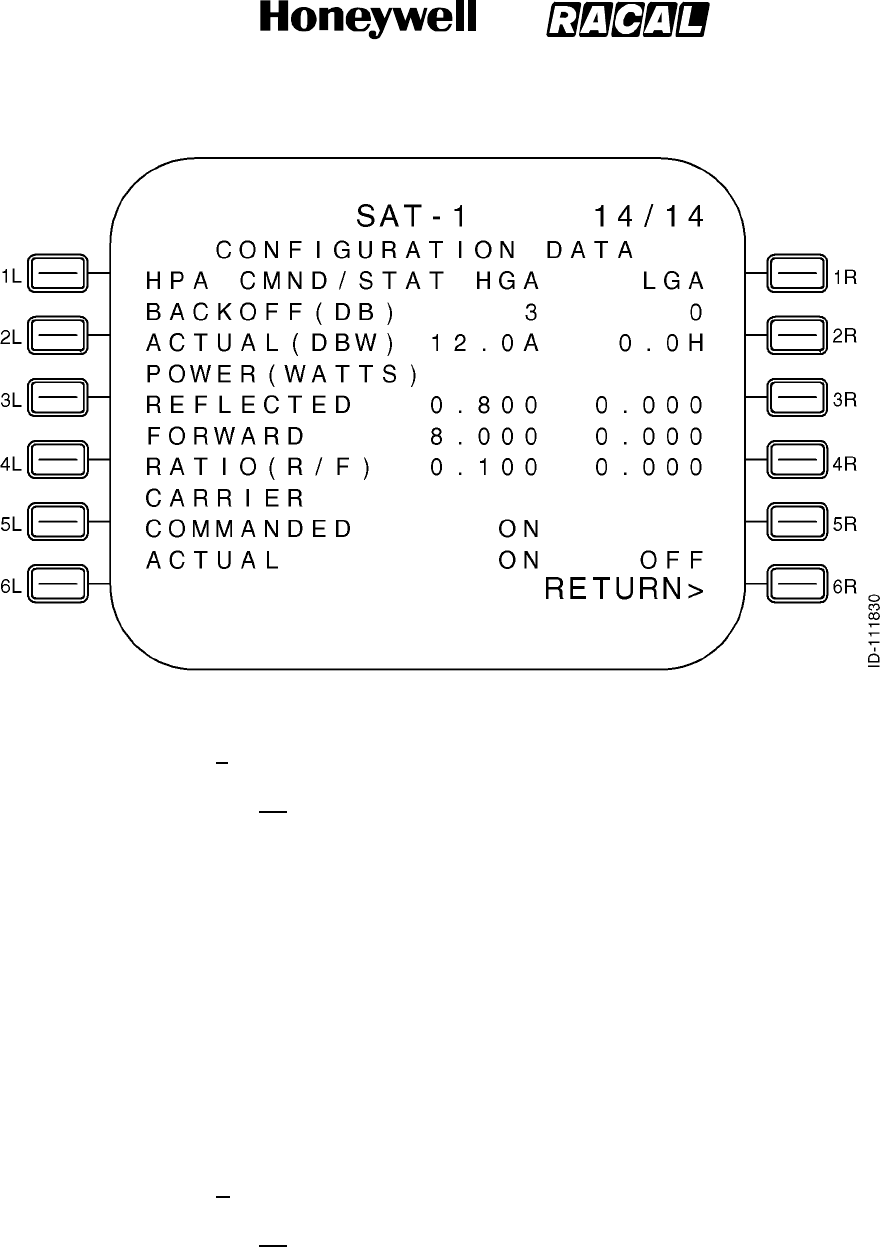
SYSTEM DESCRIPTION, INSTALLATION, AND MAINTENANCE MANUAL
MCS--4000/7000 Multi--Channel SATCOM System
23--20--27
30 Aug 2002
Use or disclosure of information on this page is subject to the restrictions in the proprietary notice of this document.
Page 6--57
Figure 6-8 (Sheet 14). Configuration Data
cLine 5
(1) This line displays ACTUAL(DBW) beginning in column 1. The HGA
HPA reported power level (in dB Watts) is displayed (if configured)
right-justified in column 16 (as determined from the HGA HPA
status word Label 144). The state of the actual power out status
(APOS) bit is indicated as either A for actual or H for held and is
displayed in column 17. The LGA HPA commanded backoff power
level (in dB Watts) is displayed (if configured) right-justified in
column 23 (as determined from the LGA HPA status word Label
144). The state of the APOS status bit is displayed in column 24 as
previously stated. The allowable range for display of the actual
power is --11.5 to 19.0 dBW in increments of 0.5 dBW. If the actual
power value is outside the measurable range, dashes are displayed
for the actual power value. If valid data is not available for the HPA
status label, dashes are displayed to indicate the unknown data.
dLine 6
(1) This line displays POWER(WATTS) beginning in column 1.
RELEASED FOR THE EXCLUSIVE USE BY: HONEYWELL INTERNATIONAL
UP86308

SYSTEM DESCRIPTION, INSTALLATION, AND MAINTENANCE MANUAL
MCS--4000/7000 Multi--Channel SATCOM System
23--20--27
30 Aug 2002
Use or disclosure of information on this page is subject to the restrictions in the proprietary notice of this document.
Page 6--58
eLine 7
(1) This line displays REFLECTED beginning in column 1. The HGA
HPA reflected power level (in Watts) is displayed (if configured)
right-justified in column 17 (as determined from the HGA HPA ). The
LGA HPA reflected power level (in Watts) is displayed (if configured)
right-justified in column 24 (as determined from the LGA HPA ). The
allowable range for the display of the reflected power value is 0.000
to 25.056 Watts. If the power level is unavailable, dashes are
displayed.
fLine 8
(1) This line displays FORWARD beginning in column 1. The HGA HPA
reflected power level (in Watts) is displayed (if configured)
right-justified in column 17 (as determined from the HGA HPA). The
LGA HPA reflected power level (in Watts) is displayed (if configured)
right-justified in column 24 (as determined from the LGA HPA). The
allowable range for the display of the reflected power value is 0.000
to 80.000 Watts. If the power level is unavailable, dashes are
displayed.
gLine 9
(1) This line displays RATIO(R/F) beginning in column 1. The HGA
HPA reflected power to forward power ratio is displayed (if
configured) right-justified in column 17 (as determined from the
HGA HPA). The LGA HPA reflected power to forward power ratio is
displayed (if configured) right-justified in column 24 (as determined
from the LGA HPA). The allowable range for the display of the
reflected power to forward power ratio is 0.000 to 1.000 Watts. If the
reported ratio is over-range, the text OVER is displayed. If the ratio
number is unavailable, dashes are displayed.
NOTE: The over-range condition occurs when the forward power
is more than 50 Watts while the reflected power is at the
maximum of 25.056 Watts. The HPA indicates the
over-range condition through the solo word ratio value of
FF
H.
hLine 10
(1) This line displays CARRIER beginning in column 1.
iLine 11
(1) This line displays COMMANDED beginning in column 1. The HGA
HPA commanded carrier state is displayed (if configured)
right-justified in column 17 (as determined from the HGA HPA). The
LGA HPA commanded carrier state is displayed (if configured)
right-justified in column 24 (as determined from the LGA HPA). The
commanded carrier state is displayed as either ON or OFF.
RELEASED FOR THE EXCLUSIVE USE BY: HONEYWELL INTERNATIONAL
UP86308

SYSTEM DESCRIPTION, INSTALLATION, AND MAINTENANCE MANUAL
MCS--4000/7000 Multi--Channel SATCOM System
23--20--27
30 Aug 2002
Use or disclosure of information on this page is subject to the restrictions in the proprietary notice of this document.
Page 6--59
jLine 12
(1) This line displays ACTUAL beginning in column 1. The HGA HPA
actual carrier state is displayed (if configured) right-justified in
column 17 (as determined from the HGA HPA). The LGA HPA
commanded carrier state is displayed (if configured) right-justified in
column 24 (as determined from the LGA HPA). The actual carrier
state is displayed as either ON or OFF.
kLine 13
(1) This line displays RETURN> right-justified. Pushing LS key 6L
causes the page display to revert to the SAT--N (SATCOM
MAINTENANCE) page.
(7) DATA LOADER MENU Page
(a) General
1Access to this page is from SATCOM SUBMENU page (or the SATCOM
MAINTENANCE page). The access page depends on the configuration of
the aircraft as defined in Figure 6-2. The purpose of this page is to supply a
means of commanding data loader actions. See Figure 6-9 for example
pages.
(b) Data Fields
1Field 1L
aThis field displays DATA LOADER in the label line and the data loader
status in the data line. Possible status displays depend on the data
loader status as follows:
•NOT CONNECTED -- Displayed when the status of both data loader
is absent.
•CONNECTED -- Displayed when at least one data loader status is
CONNECTED, and the status of neither data loaders is READY,
BUSY, or ERROR.
•READY -- Displayed when a data loader status is READY.
•BUSY -- Displayed when a data loader status is BUSY.
RELEASED FOR THE EXCLUSIVE USE BY: HONEYWELL INTERNATIONAL
UP86308
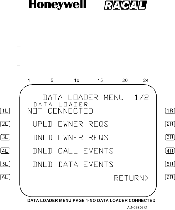
SYSTEM DESCRIPTION, INSTALLATION, AND MAINTENANCE MANUAL
MCS--4000/7000 Multi--Channel SATCOM System
23--20--27
30 Aug 2002
Use or disclosure of information on this page is subject to the restrictions in the proprietary notice of this document.
Page 6--60
bREADY must be displayed before data uploading or downloading can
be performed.
cAsterisks are only displayed adjacent to the left LS keys when the data
loader status is READY.
Figure 6-9 (Sheet 1). DATA LOADER MENU
RELEASED FOR THE EXCLUSIVE USE BY: HONEYWELL INTERNATIONAL
UP86308
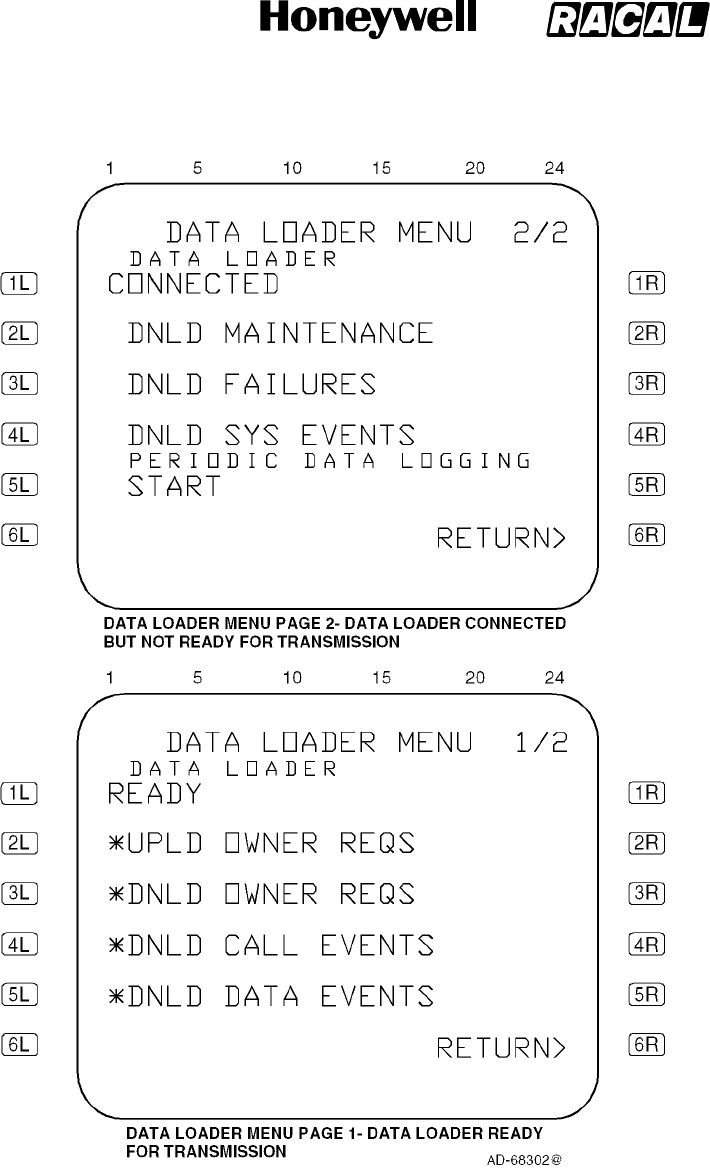
SYSTEM DESCRIPTION, INSTALLATION, AND MAINTENANCE MANUAL
MCS--4000/7000 Multi--Channel SATCOM System
23--20--27
30 Aug 2002
Use or disclosure of information on this page is subject to the restrictions in the proprietary notice of this document.
Page 6--61
Figure 6-9 (Sheet 2). DATA LOADER MENU
RELEASED FOR THE EXCLUSIVE USE BY: HONEYWELL INTERNATIONAL
UP86308
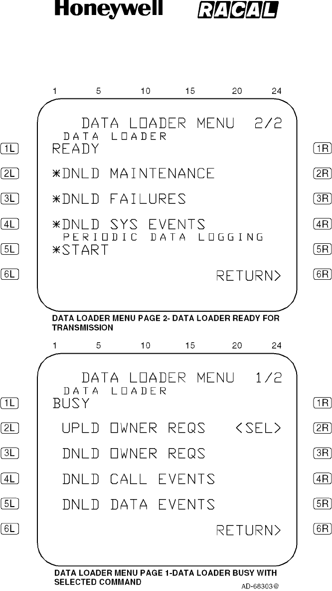
SYSTEM DESCRIPTION, INSTALLATION, AND MAINTENANCE MANUAL
MCS--4000/7000 Multi--Channel SATCOM System
23--20--27
30 Aug 2002
Use or disclosure of information on this page is subject to the restrictions in the proprietary notice of this document.
Page 6--62
Figure 6-9 (Sheet 3). DATA LOADER MENU
RELEASED FOR THE EXCLUSIVE USE BY: HONEYWELL INTERNATIONAL
UP86308
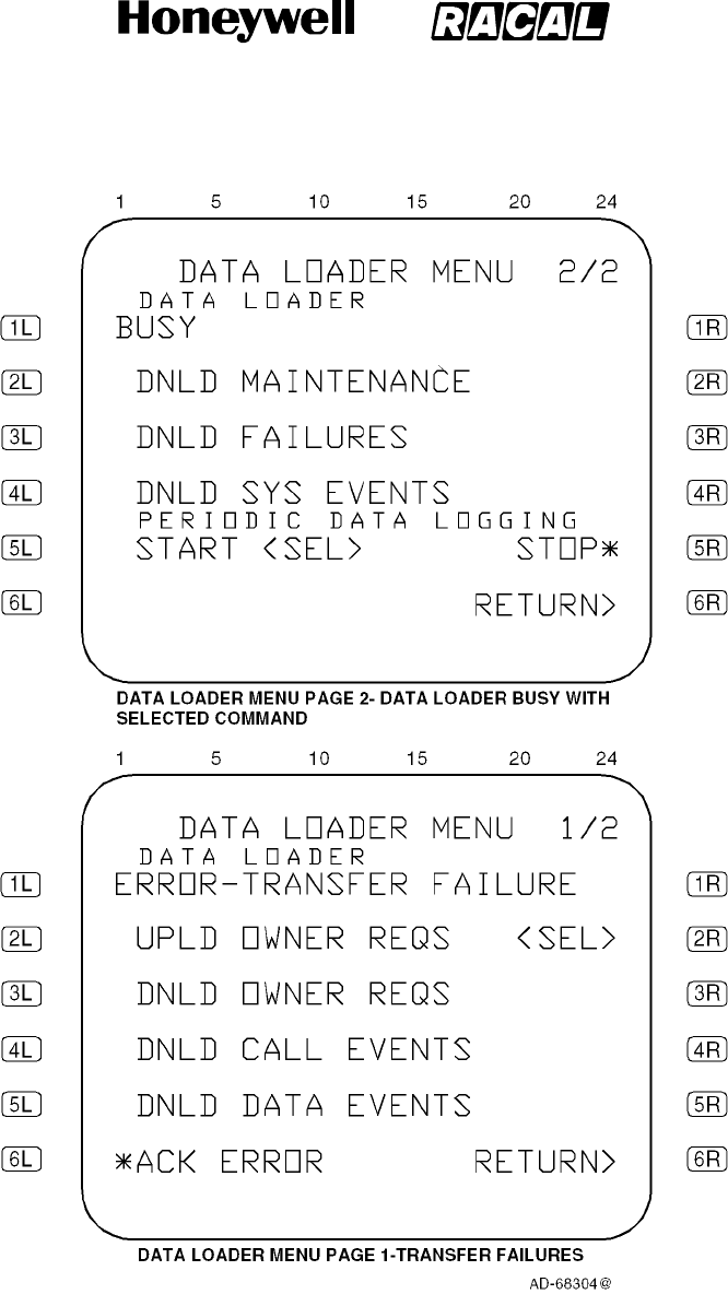
SYSTEM DESCRIPTION, INSTALLATION, AND MAINTENANCE MANUAL
MCS--4000/7000 Multi--Channel SATCOM System
23--20--27
30 Aug 2002
Use or disclosure of information on this page is subject to the restrictions in the proprietary notice of this document.
Page 6--63
Figure 6-9 (Sheet 4). DATA LOADER MENU
RELEASED FOR THE EXCLUSIVE USE BY: HONEYWELL INTERNATIONAL
UP86308
SYSTEM DESCRIPTION, INSTALLATION, AND MAINTENANCE MANUAL
MCS--4000/7000 Multi--Channel SATCOM System
23--20--27
30 Aug 2002
Use or disclosure of information on this page is subject to the restrictions in the proprietary notice of this document.
Page 6--64
dSeveral messages are displayed when the status of a data loader is
ERROR . If the status becomes ERROR, an appropriate error message
is appended to ERROR, separated by a dash. Possible error messages
are displayed as follows:
•DISK FULL
•TRANSFER FAILURE
•FILE NOT FOUND
•CRC FAILURE
•BAD FILE HEADER
•BAD OWNER REQS VER
•OPEN DISK
•CLOSE DISK
•WRITE PROTECT
•COMPOSITE ORT NOT ALLOW.
eThe TRANSFER FAILURE error message indicates an ARINC 615
protocol transfer failure (e.g., loss of communications). The OPEN DISK
and CLOSE DISK error messages are displayed when an undefined
disk command completion code is received. COMP ORT NOT ALLOW
is indicated when a composite ORT version upload is attempted and the
setting for ORT item liv does not allow it.
2Fields 2L thru 5L
aThese fields display prompts in the data line for commanding data
loader actions. The prompts that can be displayed for the indicated
DATA LOADER MENU page (1 or 2) are as given in Table 6-15.
Table 6-15. DATA LOADER MENU Page Prompts
LS Key Display Prompt (Page 1) Display Prompt (Page 2)
2L
UPLD OWNER REQS DNLD MAINTENANCE
3L
DNLD OWNER REQS DNLD FAILURES
4L
DNLD CALL EVENTS DNLD SYS EVENTS
5L
DNLD DATA EVENTS Refer to the description for the 5L
and 5R keys
RELEASED FOR THE EXCLUSIVE USE BY: HONEYWELL INTERNATIONAL
UP86308

SYSTEM DESCRIPTION, INSTALLATION, AND MAINTENANCE MANUAL
MCS--4000/7000 Multi--Channel SATCOM System
23--20--27
30 Aug 2002
Use or disclosure of information on this page is subject to the restrictions in the proprietary notice of this document.
Page 6--65
bThe display prompts given in Table 6-15 command the following actions:
•UPLD OWNER REQS -- upload owner requirements table
•DNLD OWNER REQS -- download owner requirements table
•DNLD CALL EVENTS -- download call event log
•DNLD DATA EVENTS -- download data event log
•DNLD MAINTENANCE -- download maintenance activity log
•DNLD FAILURES -- download SDU/system failure log
•DNLD SYS EVENTS -- download system management event log.
cAsterisks are only displayed beside the adjacent left LS key when the
data loader status is READY (except as stated below). When asterisks
are displayed, pushing the left LS key adjacent to the desired action
commands the data loader to initiate that action. Prior to software
package D2.0, asterisks are not displayed when the data loader status
is either NOT CONNECTED, CONNECTED, BUSY, or ERROR.
dIn addition, if the data loader status is READY but the log-on state is
LOGGING-ON INOP, LOGGING-ON, LOGGED-ON AUTO, or
LOGGED-ON CONSTRAINED; an asterisk is not displayed beside the
UPLD OWNER REQS prompt. Scratchpad message 1 is issued if an LS
key is pushed when no asterisks are displayed. For software packages
D2.0 and after, uploads are allowed regardless of the log-on state
(composite uploads are inhibited only by ORT item liv and not the log-on
state).
eOnce a left LS key is pushed, the <SEL> message is displayed to the
right of the selected data loader action, right-justified. The data loader
status changes to BUSY and data transfers occur. There is only one
data loader command selected at a time. The <SEL> message remains
displayed until the 6L key is pushed if the data loader status becomes
ERROR after a left LS key is pushed. When the data transfer is
completed, or after an error has been acknowledged, the <SEL>
message is removed and the data loader status changes appropriately.
3Fields 5L and 5R
aPERIODIC DATA LOGGING is displayed on page 2 in the label line
beginning in column 2. In the data line, START is displayed adjacent to
the5Lkey.Noasteriskisdisplayedbesidethe5Lkeywhenthedata
loader status is either NOT CONNECTED, CONNECTED, BUSY, or
ERROR.
bWhen the START prompt is selected by pushing the 5L key when the
data loader status is READY:
•Periodic data logging starts
•TheasterisknexttoSTARTisremoved
•The <SEL> message is displayed beginning in column 8
•STOP is displayed adjacent to the 5R key.
RELEASED FOR THE EXCLUSIVE USE BY: HONEYWELL INTERNATIONAL
UP86308

SYSTEM DESCRIPTION, INSTALLATION, AND MAINTENANCE MANUAL
MCS--4000/7000 Multi--Channel SATCOM System
23--20--27
30 Aug 2002
Use or disclosure of information on this page is subject to the restrictions in the proprietary notice of this document.
Page 6--66
cPeriodic data logging continues until the 5R key is pushed, at that time
the data line display reverts to its original state (i.e., only the START
prompt with or without an asterisk as appropriate).
dThe <SEL> message remains displayed and the STOP prompt is
blanked if the data loader status changes to ERROR after periodic data
logging has started. This condition remains until the error is
acknowledged by pushing the 6L key and/or the data loader status
changes, at that time the data line display changes as appropriate.
4Field 6L
a6L -- This data line displays the *ACK ERROR prompt. This prompt is
displayed when the data loader status is ERROR. Pushing the 6L key
causes the SDU to remove the ERROR status and display the current
data loader status (i.e., NOT CONNECTED or CONNECTED) in the 1L
data line.
bThe SDU completes the upload/download data transfer by commanding
the data loader transfer complete function. The data loader responds
with a TRANSFER COMPLETE indication and enters a no loop. To
return the data loader to the READY state, the user must cause the
data loader to read the configuration file on the diskette (i.e., cycle data
loader power or remove/insert the diskette).
5Field 6R
a6R -- This data line displays the RETURN> prompt. Pushing the 6R key
causes the display to revert to the SATCOM SUBMENU page (or
SATCOM MAINTENANCE page) as appropriate.
(8) LAST LEG REPORT Page
(a) Access to this page is from the SAT--N (i.e., SATCOM MAINTENANCE) page.
The purpose of this page is to display Class 1 and 2, Level 1 diagnosed, failures
reported during the last leg. See Figure 6-10 for example pages.
(b) The Last Leg Report lists two failures per page if a failure is present during the
last leg. These two sets of lines display Class 1 and 2, Level 1 diagnosed, last
leg failures. Failures are displayed in chronological order (i.e., the most recent
detected failure last) with no more than two failures displayed per page. The
number of LAST LEG REPORT pages depends on the number of failures to
report (up to a maximum of 99 pages). When there is an odd number of failures
to report, the odd failure is displayed on a page of its own in lines 5, 6, and 7,
and lines 9, 10, and 11 are blank. If there are no failures to report, lines 6, 7, 9,
10, and 11 are blank. Line 5 displays NO FAULT DETECTED beginning in
column 4 if there are no failures to report.
RELEASED FOR THE EXCLUSIVE USE BY: HONEYWELL INTERNATIONAL
UP86308

SYSTEM DESCRIPTION, INSTALLATION, AND MAINTENANCE MANUAL
MCS--4000/7000 Multi--Channel SATCOM System
23--20--27
30 Aug 2002
Use or disclosure of information on this page is subject to the restrictions in the proprietary notice of this document.
Page 6--67
Figure 6-10. LAST LEG REPORT Page
RELEASED FOR THE EXCLUSIVE USE BY: HONEYWELL INTERNATIONAL
UP86308

SYSTEM DESCRIPTION, INSTALLATION, AND MAINTENANCE MANUAL
MCS--4000/7000 Multi--Channel SATCOM System
23--20--27
30 Aug 2002
Use or disclosure of information on this page is subject to the restrictions in the proprietary notice of this document.
Page 6--68
(c) Line 5 and, if applicable, line 9 display the universal time coordinated (UTC)
beginning in column 1, and ATA beginning in column 6, and the class number in
column 23.
(d) The UTC is displayed as hhmm, where hh represents the UTC hours from 00 to
23, and mm represents the UTC minutes from 00 to 59. The UTC is the time of
the failure reporting as stored in the SDU system failure memory log. Dashes are
displayed if no valid UTC data is available.
(e) The ATA number is displayed as aaaaaa, where aaaaaa represents the ATA
reference number of the reported failure as specified in paragraph 3.E. for each
type of CFDS. For CFDS type none, no ATA number is displayed.
(f) The class number is displayed as c, where c represents the class (1 or 2) of the
failure.
(9) PREVIOUS LEGS REPORT Page
(a) Access to this page is from the SAT--N (i.e., SATCOM MAINTENANCE) page.
The purpose of this page is to display Class 1 and 2, Level 1 diagnosed, failures
reported during previous legs. See Figure 6-11 for example pages.
(b) The Previous Leg Report lists two failures per page if a failure was present
during the previous leg. These two sets of lines display Class 1 and 2, Level 1
diagnosed, last leg failures. Failures within each flight leg are displayed in
chronological order (i.e., the most recent detected failure last) with no more than
two failures displayed per page. However, the flight leg display is in reverse
chronological order (i.e., flights go back in time while failures for each individual
flight go forward in time).
(c) The number of PREVIOUS LEGS REPORT pages depends on the number of
failures to report (up to a maximum of 99 pages). If there are no failures to
report, lines 6, 7, 9, 10, and 11 are blank. Line 5 displays NO FAULT DETECTED
beginning in column 4 if there are no failures to report.
(d) Failures from different flight legs with the same aircraft identification are mixed on
the same page. When the last leg falls in lines 5, 6, and 7, failures from the
previous flight leg are displayed on the same page in lines 9, 10, and 11.
(e) When the given flight leg has a different aircraft identification recorded than the
flight leg before it, the failure display begins in lines 5, 6, and 7 on the next page
of the multiple page sequence. When there are no failures to report for a given
flight leg, nothing is reported for that flight leg (i.e., the flight leg is skipped).
RELEASED FOR THE EXCLUSIVE USE BY: HONEYWELL INTERNATIONAL
UP86308
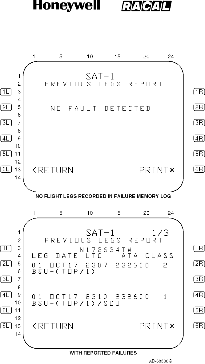
SYSTEM DESCRIPTION, INSTALLATION, AND MAINTENANCE MANUAL
MCS--4000/7000 Multi--Channel SATCOM System
23--20--27
30 Aug 2002
Use or disclosure of information on this page is subject to the restrictions in the proprietary notice of this document.
Page 6--69
Figure 6-11 (Sheet 1). PREVIOUS LEG REPORT Page
RELEASED FOR THE EXCLUSIVE USE BY: HONEYWELL INTERNATIONAL
UP86308
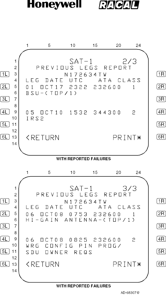
SYSTEM DESCRIPTION, INSTALLATION, AND MAINTENANCE MANUAL
MCS--4000/7000 Multi--Channel SATCOM System
23--20--27
30 Aug 2002
Use or disclosure of information on this page is subject to the restrictions in the proprietary notice of this document.
Page 6--70
Figure 6-11 (Sheet 2). PREVIOUS LEG REPORT Page
RELEASED FOR THE EXCLUSIVE USE BY: HONEYWELL INTERNATIONAL
UP86308

SYSTEM DESCRIPTION, INSTALLATION, AND MAINTENANCE MANUAL
MCS--4000/7000 Multi--Channel SATCOM System
23--20--27
30 Aug 2002
Use or disclosure of information on this page is subject to the restrictions in the proprietary notice of this document.
Page 6--71
(f) Line 5 and line 9 (if applicable) display the flight leg number beginning in column
1, the UTC beginning in column 10, and the ATA number beginning in column
15.
(g) The flight leg is displayed as fl, where fl represents the flight leg number from 01
to either:
•The number of flight legs recorded in the SDU system failure memory log
•63 flight legs
•From 01 to the maximum number of flight legs that can be displayed given the
PREVIOUS LEGS REPORT page limit of 99.
(h) The date is displayed as mmmdd, where mmm represents the month of the year
as JAN, FEB, MAR, APR, MAY, JUN, JUL, AUG, SEP, OCT, NOV, or DEC, and
dd represents the day of the month from 01 to 31. The date is the date of the
flight leg number as stored in the SDU system failure memory log. Dashes are
displayed if no valid UTC data is available.
(i) The UTC time is displayed as hhmm, where hh represents the UTC hours from
00 to 23, and mm represents the UTC minutes from 00 to 59. The UTC is the
time of the failure reporting as stored in the SDU system failure memory log.
Dashes are displayed if no valid UTC data is available.
(j) The ATA number is displayed as aaaaaa, where aaaaaa represents the ATA
reference number of the reported failure as specified in paragraph 3.E. for each
type of CFDS. For CFDS type none, no ATA number is displayed.
(k) The class number is displayed as c, where c represents the class (1 or 2) of the
failure.
(10) LRU IDENTIFICATION Page
(a) Access to this page is from the SAT--N (i.e., SATCOM MAINTENANCE) page.
The purpose of this page is to display a list of all installed LRUs with their
associated part numbers, modification levels, and serial numbers, and to display
ORT identification data. See Figure 6-12 for example pages.
(b) If a Honeywell/Racal HPA is installed, the associated part/serial number is
displayed; otherwise the HPA display entry is removed. The number of LRU
IDENTIFICATION pages depends on the number of LRUs to list.
(c) For the LRUs, line 4 and, if applicable, line 9 display a three letter acronym
representing the installed LRU. The possible LRU acronyms are given in
Table 6-16.
RELEASED FOR THE EXCLUSIVE USE BY: HONEYWELL INTERNATIONAL
UP86308

SYSTEM DESCRIPTION, INSTALLATION, AND MAINTENANCE MANUAL
MCS--4000/7000 Multi--Channel SATCOM System
23--20--27
30 Aug 2002
Use or disclosure of information on this page is subject to the restrictions in the proprietary notice of this document.
Page 6--72
Table 6-16. LRU Acronyms
LRU Acronym LRU Name
SDU
Satellite Data Unit
HPH
High Power Amplifier -- High Gain Antenna
HPL
High Power Amplifier -- Low Gain Antenna
(d) For the LRUs, line 5 and, if applicable, line 10 display P/N beginning in column 1,
the LRU end-item part number beginning in column 6, and the software
modification level in columns 23 and 24.
(e) The P/N is displayed as bbbbbbb--hhsss, where bbbbbbb--hhsss represents the
LRU end-item part number consisting of a seven-digit LRU base part number
(i.e., bbbbbbb), a two-digit hardware configuration number (i.e., hh), and a
three-digit software configuration number (i.e., sss). Dashes are displayed if no
valid data is available.
(f) The software modification level is displayed as nn, where nn represents up to a
two-character LRU software modification level.
(g) Line 6 and, if applicable, line 11 display S/N beginning in column 1 and the LRU
serial number beginning in column 5. The S/N is diplayed as ssssssss, where
ssssssss represents the LRU serial number. Dashes are displayed if no valid
data is available.
(h) For the Honeywell/Racal MCS system, the two-digit LRU hardware and LRU
serial number must be manually entered through the CMT interface for valid data
to be available for display. This data is stored during an LRU end-item test. All
other numbers reside within the LRU software. For non-Honeywell/Racal
interfacing HPAs, no such data is available to the SDU, therefore, dashes are
displayed for the HPA part/serial numbers.
RELEASED FOR THE EXCLUSIVE USE BY: HONEYWELL INTERNATIONAL
UP86308
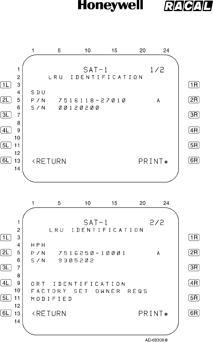
SYSTEM DESCRIPTION, INSTALLATION, AND MAINTENANCE MANUAL
MCS--4000/7000 Multi--Channel SATCOM System
23--20--27
30 Aug 2002
Use or disclosure of information on this page is subject to the restrictions in the proprietary notice of this document.
Page 6--73
Figure 6-12 (Sheet 1). LRU IDENTIFICATION Page
RELEASED FOR THE EXCLUSIVE USE BY: HONEYWELL INTERNATIONAL
UP86308
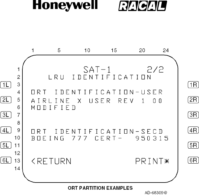
SYSTEM DESCRIPTION, INSTALLATION, AND MAINTENANCE MANUAL
MCS--4000/7000 Multi--Channel SATCOM System
23--20--27
30 Aug 2002
Use or disclosure of information on this page is subject to the restrictions in the proprietary notice of this document.
Page 6--74
Figure 6-12 (Sheet 2). LRU IDENTIFICATION Page
(i) The ORT identification is displayed in either lines 4, 5, and 6, or in lines 9, 10,
and 11 depending on where the LRU list falls. Line 4 or line 9, as appropriate,
displays the header ORT IDENTIFICATION left-justified. If the ORT is a
partitioned version, the text, --USER, is added to the end of the header text. Line
5 or line 10, as appropriate, displays the ORT 24-character description as
contained in ORT item xxxiii (refer to Appendix B). Line 6 or line 11, as
appropriate, displays MODIFIED left-justified, if the state of ORT item xxxvii (refer
to Appendix C) is modified. If the state of ORT item xxxvii is unmodified, the
MODIFIED flag is not displayed.
(j) If the ORT is loaded as separate partitions, the secured ORT identification is
displayed in either lines 4, 5, and 6, or in lines 9, 10, and 11 depending on where
the first ORT ident falls. Line 4 or line 9, as appropriate, displays the header ORT
IDENTIFICATION--SECD left-justified. Line 5 or line 10, as appropriate, displays
the ORT 24-character description as contained in ORT item liii (refer to Appendix
C) for the secured partition. Line 6 or line 11, as appropriate, displays MODIFIED
left-justified, if the state of the ORT secured partition modified flag (refer to
Appendix C) is modified. If the state of the ORT secured partition modified flag is
unmodified, the MODIFIED flag is not displayed.
RELEASED FOR THE EXCLUSIVE USE BY: HONEYWELL INTERNATIONAL
UP86308

SYSTEM DESCRIPTION, INSTALLATION, AND MAINTENANCE MANUAL
MCS--4000/7000 Multi--Channel SATCOM System
23--20--27
30 Aug 2002
Use or disclosure of information on this page is subject to the restrictions in the proprietary notice of this document.
Page 6--75
(11) TROUBLE SHOOTING DATA Page
(a) General
1Access to this page is from the SAT--N (i.e., SATCOM MAINTENANCE)
page. The purpose of this page is to display Class 1 and 2, Level 1,
diagnosed failures reported during the last leg and previous legs. See
Figure 6-13 for example pages.
2The Trouble Shooting Data pages display the class 1 and 2 last leg and
previous legs failure details. Failures are displayed in chronological order
(i.e., the most recent detected failure last) with one failure displayed per
page. Flight leg display order is reverse chronological (i.e., flights go back in
time while failures for each individual flight go forward in time). The number
of pages depends on the number of failures to report (up to 64 flight legs or
99 pages).
(b) Data Fields
1Line 4
aLine 4 displays the date beginning in column 2 and the UTC beginning
in column 8. The date and time are displayed as follows.
bThe month is displayed as mmm, where mmm represents the month of
the year as JAN, FEB, MAR, APR, MAY JUN, JUL, AUG, SEP, OCT,
NOV, or DEC.
cThe day is displayed as dd, where dd represents the day of the month
from 01 to 31.
dThe UTC is displayed as hh:mm, where hh represents the UTC hours
from 00 to 23 and mmm represents the UTC minutes from 00 to 59. The
UTCisthetimethefailurewasstoredinthefailurememorylogonthis
flight leg. Dashes are displayed if no valid UTC data is available.
eLine 4 displays the header, LEG, beginning in column 15 and the flight
leg count right-justified from column 23.
2Line 5
aLine 5 displays beginning in column 2 the LRU abbreviated name of up
to five characters that corresponds to the level 1 failure code. The SRU
abbreviated name of up to five characters is displayed beginning in
column 8. If the SRU designation in the failure code is 0, no SRU
abbreviation is displayed. The LRU failure code is displayed as two
hexadecimal digits beginning in column 17. The SRU failure code is
displayed as one hexadecimal digit beginning in column 20. The failure
code is displayed as two hexadecimal digits beginning in column 22.
RELEASED FOR THE EXCLUSIVE USE BY: HONEYWELL INTERNATIONAL
UP86308
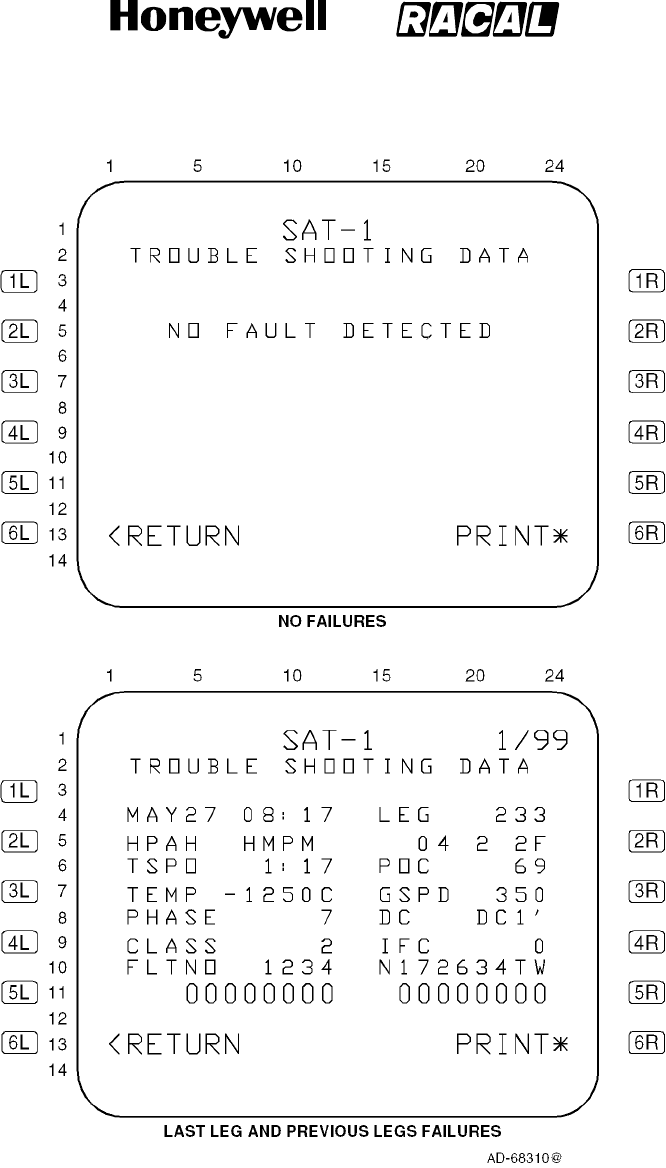
SYSTEM DESCRIPTION, INSTALLATION, AND MAINTENANCE MANUAL
MCS--4000/7000 Multi--Channel SATCOM System
23--20--27
30 Aug 2002
Use or disclosure of information on this page is subject to the restrictions in the proprietary notice of this document.
Page 6--76
Figure 6-13. TROUBLE SHOOTING DATA Page
RELEASED FOR THE EXCLUSIVE USE BY: HONEYWELL INTERNATIONAL
UP86308

SYSTEM DESCRIPTION, INSTALLATION, AND MAINTENANCE MANUAL
MCS--4000/7000 Multi--Channel SATCOM System
23--20--27
30 Aug 2002
Use or disclosure of information on this page is subject to the restrictions in the proprietary notice of this document.
Page 6--77
3Line 6
aLine 6 displays the time since power--on (TSPO) header beginning in
column 2, and the LRU power--on counter (POC) header beginning in
column 15. The LRU time since power-on is displayed right-justified
from column 12.
bThe TSPO is displayed as hhh:mm, where hhh represents the hours of
the elapsed time since the unit powered up from 0 to 999, and mm
represents the minutes portion of the elapsed time from 0 to 59.
cLine 6 displays the power-on count value from 0 to 65535 right-justified
from column 23.
4Line 7
aLine 7 displays the headers, TEMP, beginning in column 2, and
groundspeed (GSPD), beginning in column 15. The LRU-failed SRU (or
PSU) temperature is displayed right-justified from column 12. Dashes
are displayed if no valid temperature data is available. The GSPD is
displayed right-justified from column 23.
5Line 8
aLine 8 displays the headers, PHASE, beginning in column 2, and DC,
beginning in column 15. The flight phase is displayed right-justified from
column 12. If a numbered flight phase is not available, then an aor gis
shown in column 12, as appropriate. The DC state is displayed as DC0,
DC0’, DC1, DC1’, or DC2 right-justified from column 23.
6Line 9
aLine 9 displays the headers, CLASS, beginning in column 2, and IFC,
beginning in column 15. The failure class is displayed in column 12. The
intermittent failure count is displayed in column 23.
7Line 10
aLine 10 displays the header FLTNO beginning in column 2. The flight
number is displayed right-justified from column 12. The aircraft tail
number is displayed right-justified from column 23. Dashes are
displayed if no valid flight number or tail number data is available.
8Line 11
aLine 11 displays the failure parameter as eight hexadecimal digits
beginning in column 5. The associated parameter is displayed as eight
hexadecimal digits beginning in column 16.
(12) LAST LEG CLASS 3 FAULTS Page
(a) Access to this page is from the SAT--N (CFDS SATCOM Maintenance Menu)
page. The purpose of this page is to display Class 3, Level 1 diagnosed, failures
reported during the last leg. See Figure 6-14 for example pages.
RELEASED FOR THE EXCLUSIVE USE BY: HONEYWELL INTERNATIONAL
UP86308

SYSTEM DESCRIPTION, INSTALLATION, AND MAINTENANCE MANUAL
MCS--4000/7000 Multi--Channel SATCOM System
23--20--27
30 Aug 2002
Use or disclosure of information on this page is subject to the restrictions in the proprietary notice of this document.
Page 6--78
Figure 6-14. LAST LEG CLASS 3 FAULTS Page
(b) The Last Leg Class 3 Faults lists two Class 3 faults per page if Class 3 faults are
present during the last leg. These two sets of lines display Class 3, Level 1
diagnosed, last leg failures. Failures are displayed in chronological order (i.e.,
the most recent detected failure last) with no more than two failures displayed
per page.
RELEASED FOR THE EXCLUSIVE USE BY: HONEYWELL INTERNATIONAL
UP86308

SYSTEM DESCRIPTION, INSTALLATION, AND MAINTENANCE MANUAL
MCS--4000/7000 Multi--Channel SATCOM System
23--20--27
30 Aug 2002
Use or disclosure of information on this page is subject to the restrictions in the proprietary notice of this document.
Page 6--79
(c) The number of LAST LEG CLASS 3 FAULTS pages depends on the number of
failures to report (up to a maximum of 99 pages). When there is an odd number
of failures to report, the odd failure is displayed on a separate page in lines 5, 6,
and 7, and lines 9, 10, and 11 are blank. If there are no failures to report, lines 6,
7, 9, 10, and 11 are blank. Line 5 displays NO FAULT DETECTED beginning in
column 4 if there are no failures to report.
(d) Line 5 and, if applicable, line 9 display the UTC beginning in column 1 and the
ATA number beginning in column 6.
(e) The UTC number is displayed as hh:mm, where hh represents the UTC hours
from 00 to 23, and mm represents the UTC minutes from 00 to 59. The UTC is
the time of the failure reporting as stored in the SDU system failure memory log.
Dashes are displayed if no valid UTC data is available.
(f) The ATA number is displayed as aaaaaa, where aaaaaa represents the ATA
reference number of the reported failure as specified in paragraph 3.E. for each
type of CFDS. For CFDS type none, no ATA number is displayed.
(13) GROUND REPORT Page
(a) Access to this page is from the SAT--N (i.e., SATCOM MAINTENANCE) page.
The purpose of this page is to display Class 1, 2, or 3, Level 1 diagnosed ground
failures that occurred during the last leg. See Figure 6-15 for example pages.
(b) The Ground Report lists two failures per page if failures are detected during the
last leg. These two sets of lines display Class 1, 2, and 3, Level 1 diagnosed,
last leg failures. Failures are displayed in chronological order (i.e., the most
recent detected failure last) with no more than two failures displayed per page.
(c) The number of GROUND REPORT pages depends on the number of failures to
report (up to 99 pages). When there is an odd number of failures to report, the
odd failure is displayed on a separate page in lines 5, 6, and 7, and lines 9, 10,
and 11 are blank. If there are no failures to report, lines 6, 7, 9, 10, and 11 are
blank. Line 5 displays NO FAULT DETECTED beginning in column 4 if there are
no failures to report.
RELEASED FOR THE EXCLUSIVE USE BY: HONEYWELL INTERNATIONAL
UP86308
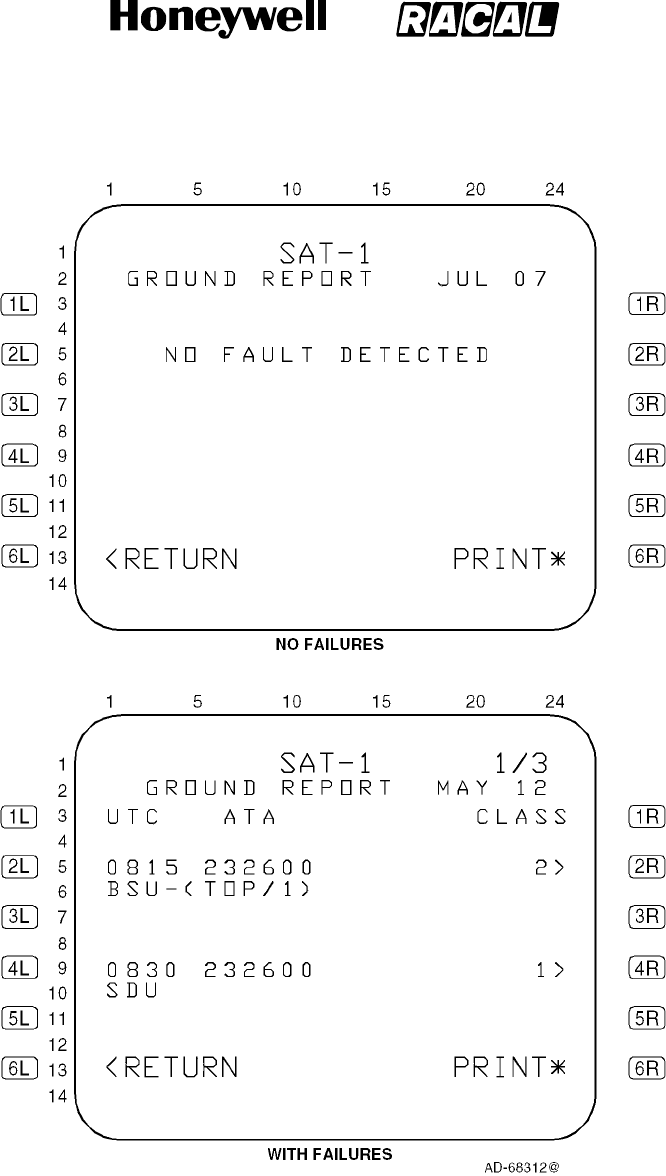
SYSTEM DESCRIPTION, INSTALLATION, AND MAINTENANCE MANUAL
MCS--4000/7000 Multi--Channel SATCOM System
23--20--27
30 Aug 2002
Use or disclosure of information on this page is subject to the restrictions in the proprietary notice of this document.
Page 6--80
Figure 6-15. GROUND REPORT Page
RELEASED FOR THE EXCLUSIVE USE BY: HONEYWELL INTERNATIONAL
UP86308

SYSTEM DESCRIPTION, INSTALLATION, AND MAINTENANCE MANUAL
MCS--4000/7000 Multi--Channel SATCOM System
23--20--27
30 Aug 2002
Use or disclosure of information on this page is subject to the restrictions in the proprietary notice of this document.
Page 6--81
(14) GROUND REPORT (TROUBLE SHOOTING DATA) Page
(a) General
1Access to this page is from the GROUND REPORT page. The purpose of
this page is to display Class 1, 2, or 3, Level 1 diagnosed ground failures
that occurred during the last leg ground report. See Figure 6-16 for example
pages.
2One failure is listed per page if a failure is present. These lines display Class
1, 2, and 3, Level 1 diagnosed, last leg ground report failure details
corresponding to the Level 1 failures from which the troubleshooting data
was initiated. Failures are displayed in chronological order (i.e., the most
recent detected failure last) with one failure displayed per page.
(b) Data Fields
1Line 4
aLine 4 displays the date beginning in column 2 and the UTC beginning
in column 8. The date and time are displayed as follows.
bThe month is displayed as mmm, where mmm represents the month of
the year as JAN, FEB, MAR, APR, MAY, JUN, JUL, AUG, SEP, OCT,
NOV, or DEC.
cThe day is displayed as dd, where dd represents the day of the month
from 01 to 31.
dThe UTC is displayed as hh:mm, where hh represents the UTC hours
from 00 to 23 and mm represents the UTC minutes from 00 to 59. The
UTCisthetimethefailurewasstoredinthefailurememorylogonthis
flight leg. Dashes are displayed if no valid UTC data is available.
2Line 5
aLine 5 displays the LRU abbreviated name of up to five characters that
corresponds to the Level 1 failure code. The SRU abbreviated name of
up to five characters is displayed beginning in column 8. If the SRU
designation in the failure code is 0, no SRU abbreviation is displayed.
The LRU failure code is displayed as two hexadecimal digits beginning
in column 17. The SRU failure code is displayed as one hexadecimal
digit beginning in column 20. The failure code is displayed as two
hexadecimal digits beginning in column 22.
RELEASED FOR THE EXCLUSIVE USE BY: HONEYWELL INTERNATIONAL
UP86308

SYSTEM DESCRIPTION, INSTALLATION, AND MAINTENANCE MANUAL
MCS--4000/7000 Multi--Channel SATCOM System
23--20--27
30 Aug 2002
Use or disclosure of information on this page is subject to the restrictions in the proprietary notice of this document.
Page 6--82
Figure 6-16. GROUND REPORT TROUBLE SHOOTING DATA Page
RELEASED FOR THE EXCLUSIVE USE BY: HONEYWELL INTERNATIONAL
UP86308

SYSTEM DESCRIPTION, INSTALLATION, AND MAINTENANCE MANUAL
MCS--4000/7000 Multi--Channel SATCOM System
23--20--27
30 Aug 2002
Use or disclosure of information on this page is subject to the restrictions in the proprietary notice of this document.
Page 6--83
3Line 6
aLine 6 displays the headers, TSPO, beginning in column 2 and, POC,
beginning in column 15. The LRU time since power-on is displayed
right-justified from column 12.
bThe UTC is displayed as hh:mm, where hh represents the UTC hours
from 00 to 23 and mm represents the UTC minutes from 00 to 59. The
UTCisthetimethefailurewasstoredinthefailurememorylogonthis
flight leg. Dashes are displayed if no valid UTC data is available.
cLine 6 displays the power-on count value from 0 to 65535 right-justified
from
column 23.
4Line 7
aLine 7 displays the headers, TEMP, beginning in column 2, and GSPD,
beginning in column 15. The LRU-failed SRU (or PSU) temperature is
displayed right-justified from column 12. Dashes are displayed if no valid
temperature data is available. The groundspeed is displayed
right-justified from column 23.
5Line 8
aLine 8 displays the headers, PHASE, beginning in column 2, and DC,
beginning in column 15. The flight phase is displayed right-justified from
column 12. If a numbered flight phase is not available, then an aor gis
shown in column 12, as appropriate. The DC state is displayed as DC0,
DC0’, DC1, DC1’, or DC2 right-justified from column 23.
RELEASED FOR THE EXCLUSIVE USE BY: HONEYWELL INTERNATIONAL
UP86308

SYSTEM DESCRIPTION, INSTALLATION, AND MAINTENANCE MANUAL
MCS--4000/7000 Multi--Channel SATCOM System
23--20--27
30 Aug 2002
Use or disclosure of information on this page is subject to the restrictions in the proprietary notice of this document.
Page 6--84
3. Maintenance Computer Interface
A. General
(1) The SDU is designed to interface with the Boeing 747--400 Central Maintenance
Computer (CMC) or the Boeing 777 On--board Maintenance System (OMS), the
Airbus Central Fault Display System (CFDS), and the McDonnell Douglas CFDS in
accordance with guidelines outlined in Boeing documents D220U050 (747--400 CMC
-- release date 3 June 1991) and D243W201--1 (777 OMS -- release date 30 October
1992) and Airbus document ABD0048 issue C, all of which supersede ARINC 604 for
their respective applications.
(2) The Boeing maintenance computers (i.e., 747--400 CMC and 777 OMS) are virtually
indistinguishable to the SDU. The operations to support these two systems are very
similar and, therefore, are presented together. The operations to support the Airbus
and McDonnell Douglas maintenance computers are very similar and, therefore, are
presented together. The SDU determines the aircraft type on which the SDU is
installed, and then supports only the functionality required by that particular system.
B. Boeing 747--400 CMC/777 OMS
(1) General
(a) The CMC and SDU communicate with each other through an ARINC 429 data
bus using ARINC 429 words.
(b) When the SDU receives the standard ground test command containing its
equipment ID and source destination identifier (SDI), the SDU responds by
setting the command word (ARINC label 350) acknowledge bit to ACK for four
seconds. The SDU initiates a system-wide functional test. As soon as possible
during the execution of the functional test, the SDU sets the SSM for ARINC
label 350 to functional test.
(2) CMC to SDU Communication -- Automatic Fault Reporting
(a) The CMC and SDU communicate with each other through an ARINC 429 data
bus using ARINC 429 words.
(b) When the SDU receives the standard ground test command containing its
equipment ID and source destination identifier (SDI), the SDU responds by
setting the command word (ARINC label 350) acknowledge bit to ACK for 4
seconds. The SDU then initiates a system-wide functional test. As soon as
possible during the execution of the functional test, the SDU sets the SSM for
ARINC label 350 to functional test.
(c) At the conclusion of the functional test, the SDU builds the fault summary words
using ARINC labels 350 thru 354 by mapping currently active failures to the
appropriate bits in the words. Once the words are built they are latched for 30
seconds, then the SDU returns to automatic fault reporting. The SDU
continuously transmits the fault summary words to the CMC at a rate of 1 to 2
Hz, with the SSM bits set to normal operation during reporting of the test results.
RELEASED FOR THE EXCLUSIVE USE BY: HONEYWELL INTERNATIONAL
UP86308

SYSTEM DESCRIPTION, INSTALLATION, AND MAINTENANCE MANUAL
MCS--4000/7000 Multi--Channel SATCOM System
23--20--27
30 Aug 2002
Use or disclosure of information on this page is subject to the restrictions in the proprietary notice of this document.
Page 6--85
(3) CMC Interactive Mode
(a) The SDU supports configuration data in CMC interactive mode for a Boeing 777
installation. If the CMC transmits a configuration data interactive mode command
addressed to the SDU on ARINC label 227, the SDU processes the command by
supplying the first page of configuration information and then resumes automatic
mode processing. The configuration data command is used to display
configuration information for the SATCOM LRUs (SDU and HPAs). The SDU
responds to the configuration data command from the automatic mode.
(b) The SDU does not support ground test and shop faults in CMC interactive mode.
If the CMC transmits a ground test or shop faults interactive mode command
addressed to the SDU on label 227, the SDU ignores the command.
(4) Configuration Data Messages
(a) General
1When configuration data is commanded, the MCS configuration data
page(s) is(are) displayed. These data pages display installed LRUs as
determined by the SDU system configuration pin settings with their
associated part/serial number data. These lines also display the ORT
identification along with modification status. Figure 6-17 supplies an
example of the configuration data page.
2The ORT 24-character description as contained in ORT item xxxiii is
displayed. For non-777 installations, the text is limited to 20 characters per
line.
(b) USER ORT STATUS
1This displays MODIFIED if the state of the ORT user partition is modified,
otherwise no status or header is displayed.
(c) SECD ORT IDENTIFICATION
1This is the 24-character description as contained in ORT item liii. For
non-777 installations, the text is limited to 20 characters per line.
(d) SECURED ORT STATUS
1This displays MODIFIED if the state of the ORT secured partition is modified,
otherwise, no status or header is displayed. For software package C3.5, the
ORT is not partitioned so only a single ORT IDENTIFICATION is supplied for
the ORT display lines.
RELEASED FOR THE EXCLUSIVE USE BY: HONEYWELL INTERNATIONAL
UP86308
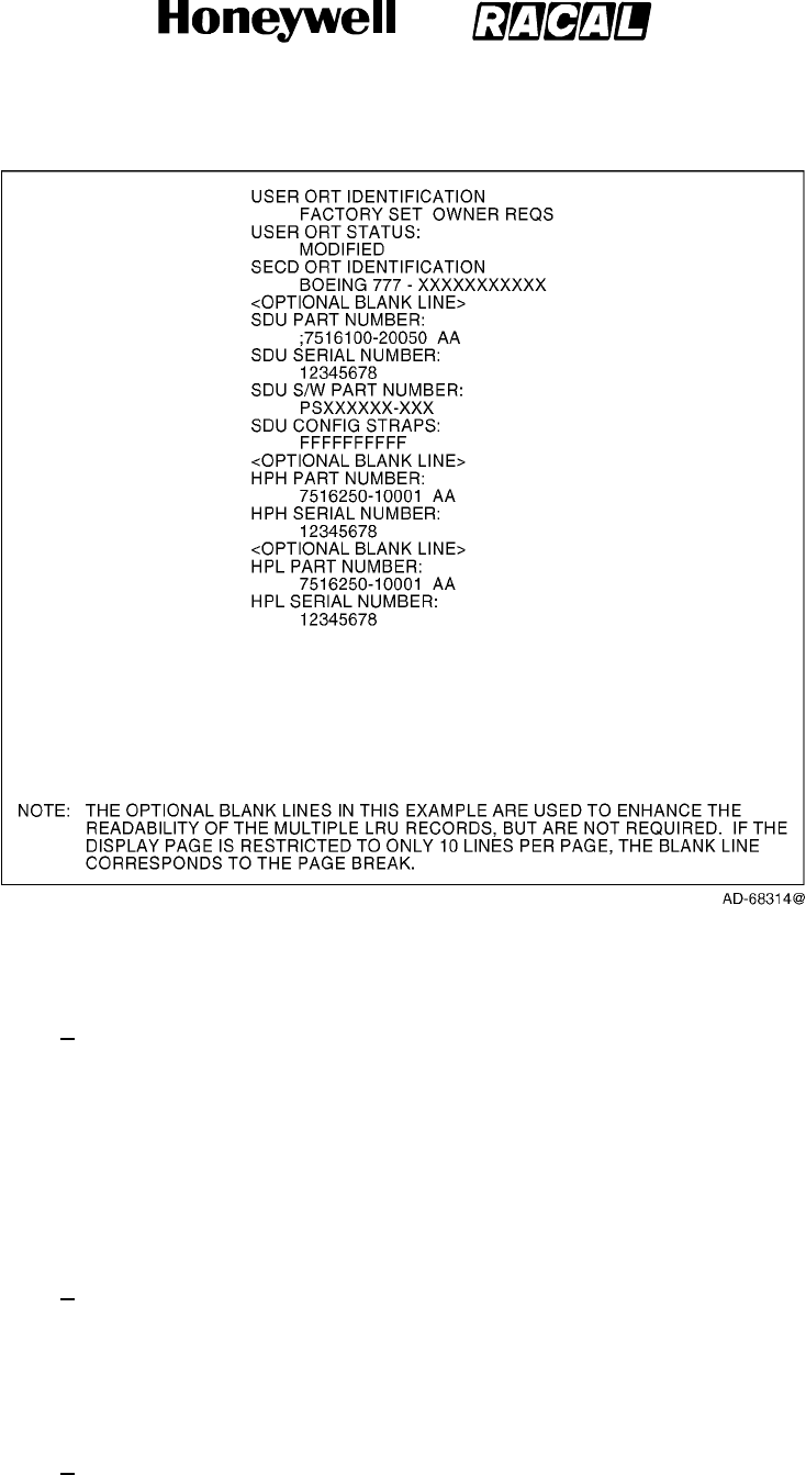
SYSTEM DESCRIPTION, INSTALLATION, AND MAINTENANCE MANUAL
MCS--4000/7000 Multi--Channel SATCOM System
23--20--27
30 Aug 2002
Use or disclosure of information on this page is subject to the restrictions in the proprietary notice of this document.
Page 6--86
Figure 6-17. Configuration Data Pages for Boeing 777 Installation
(e) LRU PART NUMBER
1The part numbers for the LRUs installed are displayed as follows. The word
LRU is displayed, which is substituted with the appropriate LRU acronym.
The LRU part number is displayed as bbbbbbb-hhsss, where
bbbbbbb-hhsss represents the LRU end item part number consisting of a
seven-digit LRU base part number (bbbbbbb), a two-digit hardware
configuration number (hh), and a three-digit software configuration number
(sss). Dashes are displayed if no valid data is available.
(f) LRU SERIAL NUMBER
1The serial numbers of the LRUs installed are displayed as follows. The word
LRU is displayed, which is substituted with the appropriate LRU acronym.
The LRU serial number is displayed as ssssssss, where ssssssss represents
the LRU serial number. Dashes are displayed if no valid data is available.
(g) SDU S/W PART NUMBER
1This displays the software part number that corresponds to the software
load. The configuration data page includes the header SDU CONFIG
STRAPS and the raw strap setting for the current installation.
RELEASED FOR THE EXCLUSIVE USE BY: HONEYWELL INTERNATIONAL
UP86308

SYSTEM DESCRIPTION, INSTALLATION, AND MAINTENANCE MANUAL
MCS--4000/7000 Multi--Channel SATCOM System
23--20--27
30 Aug 2002
Use or disclosure of information on this page is subject to the restrictions in the proprietary notice of this document.
Page 6--87
(5) Standard Ground Test (Non--interactive)
(a) When a standard test on a CMC ground test menu is selected, the CMC
commands the SDU to start a standard ground test. The SDU prevents the CMC
commanded standard ground test while the aircraft is airborne. The SDU starts a
system-wide PAST after it has responded to the receipt of a standard ground test
command from the CMC.
(b) At the end of the CMC-commanded PAST, the SDU builds labels 350 thru 354
fault summary words by mapping PAST-detected SATCOM subsystem failures to
the appropriate bits. The SDU continuously transmits these fault summary words
totheCMCatarateof1to2Hz,withtheSSMsettoNormalOperation,during
reporting of the test results.
C. Airbus/Douglas CFDS
(1) General
(a) The CFDS uses a centralized fault display interface unit (CFDIU) as an interface
between the SDU and the SCDU. Throughout these paragraphs the acronym
CFDIU is used to include both the A320 CFDS and the A340 CMC.
(b) When the SDU is installed on an Airbus or McDonnell Douglas aircraft with a
CFDS, it supports the normal mode and interactive mode as required by the
CFDS.
(2) CFDIU to SDU Communication
(a) The CFDIU communicates with the SDU through an ARINC 429 data bus using
ARINC 429 words.
(3) SDU to CFDIU Communication
(a) The SDU supports both the normal mode and the interactive mode, as required
by the CFDS. The SDU also transmits the LRU part number and serial number
and ORT identification data blocks to the CFDIU.
(b) The LRU/ORT identification data records make up the LRU/ORT identification
data blocks. Each LRU data record contains the LRU acronym, part number, and
serial number. Each ORT identification data record contains the ORT
IDENTIFICATION header, the ORT 24 character description, and the state of the
modified flag.
(4) Normal Mode Failure Messages
(a) As specified, the SDU transmits failure messages and LRU/ORT identification
information while operating in the normal mode. The following paragraphs
defined the contents of these reports.
(b) Once a failure is reported in the normal mode, the failure remains in the report
for that entire flight, regardless of whether the failure is cleared. As new failures
are reported, they are added to the beginning of the report (i.e., the report is in
reverse chronological order, bearing in mind the CFDS considers the time of the
failure to be the time it is first reported on this flight leg rather than when it first
occurs).
RELEASED FOR THE EXCLUSIVE USE BY: HONEYWELL INTERNATIONAL
UP86308

SYSTEM DESCRIPTION, INSTALLATION, AND MAINTENANCE MANUAL
MCS--4000/7000 Multi--Channel SATCOM System
23--20--27
30 Aug 2002
Use or disclosure of information on this page is subject to the restrictions in the proprietary notice of this document.
Page 6--88
(c) In addition to latching the failures, the contents of the normal mode report
depend on the failure class and when it occurs in relationship to other failures
against the same LRU. Level I failures against the same LRU reported in the
normal mode are not to be transmitted more than once unless they are an upper
class and the upper class failure occurs after the lower class failure(s). Once a
report is sent to the CFDIU during the normal mode for the current flight, the
SDU does not change the content or order except to add new failure messages,
as appropriate to the beginning of the report.
(d) The McDonnell Douglas CFDIU does not decode the normal mode report until
the CFDIU detects an increase in the block word count. However, unlike the
Airbus CFDIU, the McDonnell Douglas CFDIU decodes the entire report. After
sending an All Call DC2 command for a new flight leg, the Airbus CFDIU delays
processing the normal mode report for about 30 seconds before regarding the
report as pertaining to the new flight leg.
(e) The SDU transmits the names of the installed LRUs, as determined by the
system configuration pin settings, along with their associated part/serial
numbers. At the end of this LRU transmission, the SDU transmits the ORT
identification with a modification status. The LRU names can be transmitted in
any order. Transmission of an HPA LRU part/serial number uses the same
criteria as the display of HPA data.
(5) Interactive Mode
(a) The CFDIU supplies for two-way communication between the SCDU and the
SDU, which is referred to as the interactive mode. When the SDU operates in the
interactive mode, it is responsible for all information displayed on the CFDS
maintenance pages, with exception of the scratchpad. The SDU enters the
interactive mode upon receiving an ENQ command from the CFDIU when the
aircraft is on the ground.
D. Central Aircraft Information and Maintenance System
(1) The central aircraft information and maintenance system (CAIMS) is a distributive
maintenance system where each member system performs its own built--in test (BIT)
and stores its own faults. Also, each system supplies real--time status information on
the health of each of its LRUs and their interfaces. The member systems support
CAIMS during normal operation and during on--ground maintenance.
(2) In the normal operation mode, member systems gather and store fault data when
equipment failure occurs during normal operation. This is typically performed by
continuous BIT and power--up BIT, with identified faults stored in the member
systems non--volatile memory (NVM). The CAIMS does not store fault information for
member systems, but the fault warning processor (FWP) supplies fault event data,
such as: flight leg, date, time, fault zone, and aircraft serial number information that is
stored with the fault in the member systems NVM.
RELEASED FOR THE EXCLUSIVE USE BY: HONEYWELL INTERNATIONAL
UP86308

SYSTEM DESCRIPTION, INSTALLATION, AND MAINTENANCE MANUAL
MCS--4000/7000 Multi--Channel SATCOM System
23--20--27
30 Aug 2002
Use or disclosure of information on this page is subject to the restrictions in the proprietary notice of this document.
Page 6--89
(3) In the maintenance mode, the CAIMS is active and is called the on--board
maintenance system (CAIMS OMS). The CAIMS OMS is the ground maintenance
function and is accessible through communication link to a portable maintenance
access terminal (PMAT). With the PMAT, the aircraft maintenance crew can retrieve
stored fault data from a member system. For member systems, the CAIMS OMS
displays fault information, commands BITE test, and displays real--time data for
status displays, and commands the download of NVM fault data.
E. Level I Failure Messages and ATA Reference Numbers
(1) The Level I failure messages and ATA reference numbers that are available for
transmittal in the CFDS normal mode, for display in the CFDS interactive mode, and
for display on SCDU accessed maintenance pages are specified in the following
paragraphs for each CFDS type installed. Level I failure messages are intended for
use by line maintenance crews. Therefore, the failure messages are designed to be
LRU-based and only supply LRU-level identification.
(2) The Level 1 failure codes are two-digit hexadecimal numbers that define the LRU,
data communication bus, or miscellaneous interface signal where a failure, bus
inactivity, or signal error has been determined to have occurred. When multiple LRUs
are suspect, the most likely LRU is listed first followed by the next most likely LRU,
separated by a slash. The ATA number listed is for the first suspect LRU. Additional
text can be supplied at the end to help clarify the failure message.
•Table 6-17 describes the Level I failure messages and ATA reference numbers to
use for display on the SCDU accessed maintenance pages when the installed
CFDS type is a Boeing CMC. Also shown is the CMC message ID which is
displayed by the CMC in response to the Level I failure messages (refer to the
OEM’s maintenance manual and fault isolation manual).
•Table 6-18 and Table 6-19 describe the Level I failure messages and ATA
reference numbers to use for transmittal in the CFDS normal mode, and the CFDS
interactivemodepagesdisplayedwhentheinstalledCFDStypeisanAirbus.
Table 6-18 is for the SDU (single configuration) or SDU No. 1 (dual configuration),
and Table 6-19 is for SDU No. 2 (dual configuration) as determined by the settings
of configuration pins TP12E and TP12F.
•Table 6-20 describes the Level I failure messages and ATA reference numbers to
use for transmittal in the CFDS normal mode, and the CFDS interactive mode
pages displayed when the installed CFDS type is a McDonnell Douglas.
•For CFDS type none, the Level I failure messages displayed on the SCDU
accessed maintenance pages are the same as those specified for Boeing (refer to
Table 6-17). However, no ATA reference numbers are displayed.
(3) For Level I codes identified as not applicable in the tables, the SDU does not report
the failure on that particular interface (i.e., CFDS normal and interactive modes or
SCDU accessed maintenance pages as appropriate). Where TBD is used in the
Level I failure message column, it is coded as literally read. For failures that occur
that are undefined in the tables, the SDU does not report the failure on that particular
interface.
RELEASED FOR THE EXCLUSIVE USE BY: HONEYWELL INTERNATIONAL
UP86308

SYSTEM DESCRIPTION, INSTALLATION, AND MAINTENANCE MANUAL
MCS--4000/7000 Multi--Channel SATCOM System
23--20--27
30 Aug 2002
Use or disclosure of information on this page is subject to the restrictions in the proprietary notice of this document.
Page 6--90
Table 6-17. Boeing Level I Failure Messages and ATA Reference Numbers
Failure
Code SCDU Accessed Maintenance Pages ATA Number
CMC
Message ID
01 SDU 232500 23205
02 OTHER SDU INCOMPATIBILITY 232500 23205
03 RESERVED
04 HPA--HI GAIN
HPA--HI GAIN
[IGA]
[HGA] 232500 23207
07 HPA--LO GAIN 232500 23209
0A HI POWER RELAY 232500 23218
0D LNA/DIP--(TOP/PORT) 232500 23210
0F LNA/DIP--STBD 232500 23211
10 LNA/DIP--LO GAIN 232500 23212
13 BSU--(TOP/PORT) 232500 23213
15 BSU--STBD 232500 23214
1A IN GAIN ANTENNA--TOP
HI GAIN ANTENNA--(TOP/PORT)
[IGA]
[HGA] 232500 23215
1C HI GAIN ANTENNA--STBD 232500 23216
1F LO GAIN ANTENNA 232500 23225
21 MCDU1 346100
22 MCDU2 346100
23 MCDU3 346100
33 (ACARS MU/CMU)1 232700 23219
34 (ACARS MU/CMU)2 232700 23219
35 IRS--PRI 342100 34222
36 IRS--SEC 342100 34224
37 RESERVED
38 RESERVED
39 CMC 454500 23201
3D FMC1 346100
3E FMC2 346100
40 ARINC 429 ICAO ADDRESS None 23251
RELEASED FOR THE EXCLUSIVE USE BY: HONEYWELL INTERNATIONAL
UP86308

SYSTEM DESCRIPTION, INSTALLATION, AND MAINTENANCE MANUAL
MCS--4000/7000 Multi--Channel SATCOM System
23--20--27
30 Aug 2002
Use or disclosure of information on this page is subject to the restrictions in the proprietary notice of this document.
Page 6--91
Table 6-17. Boeing Level I Failure Messages and ATA Reference Numbers (cont)
Failure
Code
CMC
Message ID
ATA NumberSCDU Accessed Maintenance Pages
42 CTU 231900 23235
43 (CFS/CPDF) 233200
52 (CFS/CPDF)/SDU 233200
53 (ACARS MU/CMU)1/SDU 232700 23219
54 CTU/SDU 231900 23235
55 MCDU1/SDU 346100
56 MCDU2/SDU 346100
57 (ACARS MU/CMU)2/SDU 232700 23235
59 CMC/SDU 454500 23201
5A IRS--PRI/SDU 342100 23222
5B IRS--SEC/SDU 342100 23224
5C HPA--IN GAIN/SDU
HPA--HI GAIN/SDU
[IGA]
[HGA] 232500 23226
5F HPA--LO GAIN/SDU 232500 23225
62 BSU--(TOP/PORT)/SDU 232500 23213
64 BSU--STBD/SDU 232500 23214
66 MCDU3/SDU 346100
67 RESERVED
68 RESERVED
6A RESERVED
6C RESERVED
6D RESERVED
6E RESERVED
6F RESERVED
71 OTHER SDU/THIS SDU 232500
73 FMC1/SDU 346100
74 FMC2/SDU 346100
80 RESERVED
82 RESERVED
RELEASED FOR THE EXCLUSIVE USE BY: HONEYWELL INTERNATIONAL
UP86308
SYSTEM DESCRIPTION, INSTALLATION, AND MAINTENANCE MANUAL
MCS--4000/7000 Multi--Channel SATCOM System
23--20--27
30 Aug 2002
Use or disclosure of information on this page is subject to the restrictions in the proprietary notice of this document.
Page 6--92
Table 6-17. Boeing Level I Failure Messages and ATA Reference Numbers (cont)
Failure
Code
CMC
Message ID
ATA NumberSCDU Accessed Maintenance Pages
88 RESERVED
90 SDU M--CTRL/HPA--IN GAIN
SDU M--CTRL/HPA--HI GAIN
[IGA]
[HGA] 232500 23246
96 SDU M--CTRL/HPA--LO GAIN 232500 23248
98 SDU M--CTRL/BSU--(TOP/PORT) 232500 23249
9A BSU--STBD XTALK/BSU--PORT 232500 23252
9C SDU M--CTRL/BSU--STBD 232500 23250
9D BSU--PORT XTALK/BSU--STBD 232500 23253
C0 WRG:CONFIG PIN PROG/SDU 232500 23236
C1 SDU WOW MISCOMPARE N/A
C2 SDU/OTHER SDU SELECT--DISABLE DISCRETE 232500
C3 WRG:ICAO ADDRESS PIN PROG/SDU 232500 23251
C4 TX PATH VSWR--IN GAIN
TX PATH VSWR--HI GAIN
[IGA]
[HGA] 232500 23257
C5 WRG:CONFIG PIN PROG/SDU OWNER REQS 232500
C6 TX PATH VSWR--LO GAIN 232500 23216
C7 HPA--HI GAIN/OVER TEMPERATURE
HPA--HI GAIN/OVER TEMPERATURE
[IGA]
[HGA] 232500 23247
C8 BAD DATA FROM GROUND EARTH STATION None
C9 HPA--LO GAIN/OVER TEMPERATURE 232500 23254
CA SDU/LNA/DIP--LO GAIN 232500 23237
CB WRG:SDI PIN PROG/HPA--IN GAIN
WRG:SDI PIN PROG/HPA--HI GAIN
[IGA]
[HGA] 232500
CC WRG:SDI PIN PROG/HPA--HI GAIN 232500
CD SDU (POC/TOTC) DATA RESET None
CE RESERVED
CF HPA--IN GAIN (POC/TOTC) DATA RESET
HPA--HI GAIN (POC/TOTC)DATA RESET
[IGA]
[HGA] None
D0 HPA--LO GAIN (POC/TOTC) DATA RESET None
RELEASED FOR THE EXCLUSIVE USE BY: HONEYWELL INTERNATIONAL
UP86308
SYSTEM DESCRIPTION, INSTALLATION, AND MAINTENANCE MANUAL
MCS--4000/7000 Multi--Channel SATCOM System
23--20--27
30 Aug 2002
Use or disclosure of information on this page is subject to the restrictions in the proprietary notice of this document.
Page 6--93
Table 6-17. Boeing Level I Failure Messages and ATA Reference Numbers (cont)
Failure
Code
CMC
Message ID
ATA NumberSCDU Accessed Maintenance Pages
D1 WRG:SDI PIN PROG/HPA--IN GAIN
WRG:SDI PIN PROG/HPA--HI GAIN
[IGA]
[HGA] 232500
D2 WRG:SDI PIN PROG/HPA--LO GAIN 232500
D3 WRG:SDI PIN PROG/BSU--(TOP/PORT) 232500
D4 WRG:SDI PIN PROG/BSU--STBD 232500
D5 SDU COAX/HPA--IN GAIN
SDU COAX/HPA--HI GAIN
[IGA]
[HGA] 232500 23237
D6 SDU COAX/HPA--LO GAIN 232500 23237
D7 RESERVED
D8 LNA/DIP/ (SDU)--(TOP/PORT) 232500 23236
D9 LNA/DIP/ (SDU)--STBD 232500 23236
DA LNA/DIP/ (SDU)--LO GAIN 232500 23236
DB LO GAIN SUBSYSTEM 232500
DC NO ACTIVE ACARS MU/CMU 232700
DD SDU OWNER REQS -- SECURED None
DE SDU OWNER REQS -- USER None
DF IN GAIN SUBSYSTEM
HI GAIN SUBSYSTEM
[IGA]
[HGA] 232500
E0 RESERVED
FE POWER SUPPLY INTERRUPT None
Table 6-18. Airbus Level I (SDU No. 1) Failure Messages and ATA No.
Failure
Code SDU/SDU No. 1 -- CFDS Normal and Interactive Modes ATA Number
01 SDU1(105RV1)
SDU1(5RV1)
[IGA]
[HGA]
232834
232834
02 SDU2(105RV2)
SDU2(5RV2) INCOMPATIBILITY
[IGA]
[HGA]
232834
232834
03 RESERVED
RELEASED FOR THE EXCLUSIVE USE BY: HONEYWELL INTERNATIONAL
UP86308
SYSTEM DESCRIPTION, INSTALLATION, AND MAINTENANCE MANUAL
MCS--4000/7000 Multi--Channel SATCOM System
23--20--27
30 Aug 2002
Use or disclosure of information on this page is subject to the restrictions in the proprietary notice of this document.
Page 6--94
Table 6-18. Airbus Level I (SDU No. 1) Failure Messages and ATA No. (cont)
Failure
Code ATA NumberSDU/SDU No. 1 -- CFDS Normal and Interactive Modes
04 HPA1(107RV1)
HPA--HIGAIN(7RV1)
[IGA]
[HGA]
232835
232831
07 HPA--LO GAIN(9RV) 232835
0A HI POWER RELAY(21RV) 232842
0D DLNA1(119RV1)
DLNA--TOP(19RV1)
DLNA--L(20RV1)
[IGA]
[Top Mount]
[Conformal]
232837
232838
232837
0F DLNA--R(20RV2) [Conformal] 232837
10 DLNA--LO GAIN(14RV) 232836
13 BSU(8RV1)
BSU--L(15RV1)
[Top Mount]
[Conformal]
232846
232844
15 BSU--R(15RV2) [Conformal] 232844
1A ANTENNA1(116RV1)
HI GAIN ANTENNA--TOP(16RV1)
HI GAIN ANTENNA--L(17RV)
[IGA]
[Top Mount]
[Conformal]
232813
232813
232812
1C HI GAIN ANTENNA--R(18RV) [Conformal] 232812
1F LO GAIN ANTENNA(13RV) 232811
21 MCDU1(2CA1) 228212
22 MCDU2(2CA2) 228212
23 MCDU3(2CA3) 228212
33 ATSU1(1TX1) [A320/A330/A340 ATSU] 462100
ACARS MU(1RB) [A320 ACARS] 232434
ACARS MU1(1RB1) [A330/A340 ACARS] 232434
34 ATSU2 (1TX2) [A320/1A330/A340 ATSU] 462100
ACARS MU2 [A320 ACARS] N/A
ACARS MU2(1RB2) [A330/A340 ACARS] 232434
35 ADIRU1(1FP1) 341234
36 ADIRU2(1FP2) 341234
37 RESERVED N/A
38 RESERVED N/A
RELEASED FOR THE EXCLUSIVE USE BY: HONEYWELL INTERNATIONAL
UP86308

SYSTEM DESCRIPTION, INSTALLATION, AND MAINTENANCE MANUAL
MCS--4000/7000 Multi--Channel SATCOM System
23--20--27
30 Aug 2002
Use or disclosure of information on this page is subject to the restrictions in the proprietary notice of this document.
Page 6--95
Table 6-18. Airbus Level I (SDU No. 1) Failure Messages and ATA No. (cont)
Failure
Code ATA NumberSDU/SDU No. 1 -- CFDS Normal and Interactive Modes
39 CFDIU(1TW)
CMC1(1TM1)
[A320]
[A320/A340]
313234
451334
3D FMGC1(1CA1)
FMGEC1(1CA1)
[A320]
[A330/A340]
228334
228334
3E FMGC2(1CA2)
FMGEC2(1CA2)
[A320]
[A330/A340]
228334
228334
40 ARINC 429 ICAO N/A
42 CTU(303RD)
CTU(3RY)
[A320]
[A330/A340]
233534
239234
43 CPDF N/A
52 CPDF/SDU1 N/A
53 ATSU1 (1TX1)/SDU1(105RV1) [IGA A320/A330/A340 ATSU] 462100
ATSU1 (1TX1)/SDU1(5RV1) [HGA A320/A330/A340 ATSU] 462100
ACARS MU (1RB)/SDU1(105RV1) [IGA A320 ACARS] 232434
ACARS MU1 (1RB1)/SDU1(105RV1) [IGA A330/A340 ACARS] 232434
ACARS MU (1RB)/SDU1(5RV1) [HGA A320 ACARS] 232434
ACARS MU1 (1RB1)/SDU1(5RV1) [HGA A330/A340 ACARS] 232434
54 CTU (303RD)/SDU1(105RV1) [IGA A320] 233534
CTU (3RY)/SDU1(105RV1) [IGA A330/A340] 239234
CTU (303RD)/SDU1(5RV1) [HGA A320] 233534
CTU (3RY)/SDU1(5RV1) [HGA A330/A340] 239234
55 MCDU1(2CA1)/SDU1(105RV1)
MCDU1(2CA1)/SDU1(5RV1)
[IGA]
[HGA]
228212
228212
56 MCDU2(2CA2)/SDU1(105RV1)
MCDU2(2CA2)/SDU1(5RV1)
[IGA]
[HGA]
228212
228212
RELEASED FOR THE EXCLUSIVE USE BY: HONEYWELL INTERNATIONAL
UP86308
SYSTEM DESCRIPTION, INSTALLATION, AND MAINTENANCE MANUAL
MCS--4000/7000 Multi--Channel SATCOM System
23--20--27
30 Aug 2002
Use or disclosure of information on this page is subject to the restrictions in the proprietary notice of this document.
Page 6--96
Table 6-18. Airbus Level I (SDU No. 1) Failure Messages and ATA No. (cont)
Failure
Code ATA NumberSDU/SDU No. 1 -- CFDS Normal and Interactive Modes
57 ATSU2 (1TX2)/SDU1(105RV1) [IGA A320/A330/A340 ATSU] 462100
ATSU2 (1TX2)/SDU1(5RV1) [HGA A320/A330/A340 ATSU] 462100
ACARS MU2/SDU1(105RV1) [IGA A320 ACARS] 232434
ACARS MU2 (1RB2)/SDU1(105RV1) [IGA A330/A340 ACARS] 232434
ACARS MU2/SDU1(5RV1) [HGA A320 ACARS] 232434
ACARS MU2 (1RB2)/SDU1(5RV1) [HGA A330/A340 ACARS] 232434
59 CFDIU(1TW)/SDU1(105RV1) [IGA A320] 313243
CMC1(1TM1)/SDU1(105RV1) [IGA A330/A340] 451334
CFDIU(1TW)/SDU1(5RV1) [HGA A320] 313243
CMC1(1TM1)/SDU1(5RV1) [HGA A330/A340] 451334
5A ADIRU1(1FP1)/SDU1(105RV1)
ADIRU1(1FP1)/SDU1(5RV1)
[IGA]
[HGA]
341234
341234
5B ADIRU2(1FP2)/SDU1(105RV1)
ADIRU2(1FP2)/SDU1(5RV1)
[IGA]
[HGA]
341234
341234
5C HPA1 (107RV1)/SDU1(105RV1)
HPA--HI GAIN(7RV1)/SDU1(5RV1)
[IGA]
[HGA]
232835
232831
5F HPA--LO GAIN(9RV)/SDU1(5RV1) 232835
62 BSU(8RV1)/SDU1(5RV1)
BSU--L(15RV1)/SDU1(5RV1)
[Top Mount]
[Conformal]
232846
232844
64 BSU--R(15RV2)/SDU1(5RV1) [Conformal] 232844
66 MCDU3(2CA3)/SDU1(105RV1)
MCDU3(2CA3)/SDU1(5RV1)
[IGA]
[HGA]
228212
228212
67 RESERVED
68 RESERVED
6A RESERVED
6C RESERVED
6D RESERVED
6E RESERVED
6F RESERVED
RELEASED FOR THE EXCLUSIVE USE BY: HONEYWELL INTERNATIONAL
UP86308

SYSTEM DESCRIPTION, INSTALLATION, AND MAINTENANCE MANUAL
MCS--4000/7000 Multi--Channel SATCOM System
23--20--27
30 Aug 2002
Use or disclosure of information on this page is subject to the restrictions in the proprietary notice of this document.
Page 6--97
Table 6-18. Airbus Level I (SDU No. 1) Failure Messages and ATA No. (cont)
Failure
Code ATA NumberSDU/SDU No. 1 -- CFDS Normal and Interactive Modes
71
SDU2(105RV2)/SDU1(105RV1)
SDU2(5RV2)/SDU1(5RV1)
[IGA]
[HGA]
232834
232834
73 FMGC1(1CA1)/SDU1(105RV1) [IGA A320] 228334
FMGEC1(1CA1)/SDU1(105RV1) [IGA A330/A340] 228334
FMGC1(1CA1)/SDU1(5RV1) [HGA A320] 228334
FMGEC1(1CA1)/SDU1(5RV1) [HGA A330/A340] 228334
74 FMGC2(1CA2)/SDU1(105RV1) [IGA A320] 228334
FMGEC2(1CA2)/SDU1(105RV1) [IGA A330/A340] 228334
FMGC2(1CA2)/SDU1(5RV1) [HGA A320] 228334
FMGEC2(1CA2)/SDU1(5RV1) [HGA A330/A340] 228334
80 RESERVED
82 RESERVED
88 RESERVED
90 SDU1(105RV1) BUS M--CTRL/HPA1(107RV1) [IGA] 232834
SDU1(5RV1) BUS M--CTRL/HPA--HI
GAIN(7RV1)
[HGA]
232834
96 SDU1(5RV1) BUS M--CTRL/HPA--LO GAIN(9RV) 232834
98 SDU1(5RV1) BUS M--CTRL/BSU(8RV1)
SDU1(5RV1) BUS M--CTRL/BSU--L(15RV1)
[Top Mount]
[Conformal]
232834
232834
9A BSU--R XTALK/BSU--L [Conformal] N/A
9C SDU1(5RV1) BUS M--CTRL/BSU--R(15RV2) [Conformal] 232834
9D BSU--L XTALK/BSU--R [Conformal] N/A
C0 WRG:CONFIG PIN PROG/SDU1(105RV1) [IGA] 232834
C0 WRG:CONFIG PIN PROG/SDU1(5RV1) [HGA] 232834
C1 LGCIU1(5GA1)/LGCIU2(5GA2)/SDU1(105RV1) [IGA] 323171
LGCIU1(5GA1)/LGCIU2(5GA2)/SDU1(5RV1) [HGA] 323171
C2 SDU1(105RV1) SEL--DISABLE
DISCRETE/SDU2(105RV2)
[IGA] 232834
SDU1(5RV1) SEL--DISABLE
DISCRETE/SDU2(5RV2)
[HGA] 232834
RELEASED FOR THE EXCLUSIVE USE BY: HONEYWELL INTERNATIONAL
UP86308

SYSTEM DESCRIPTION, INSTALLATION, AND MAINTENANCE MANUAL
MCS--4000/7000 Multi--Channel SATCOM System
23--20--27
30 Aug 2002
Use or disclosure of information on this page is subject to the restrictions in the proprietary notice of this document.
Page 6--98
Table 6-18. Airbus Level I (SDU No. 1) Failure Messages and ATA No. (cont)
Failure
Code ATA NumberSDU/SDU No. 1 -- CFDS Normal and Interactive Modes
C3 WRG:ICAO ADDRESS PIN
PROG/SDU1(105RV1)
[IGA] 232834
WRG:ICAO ADDRESS PIN
PROG/SDU1(5RV1)
[HGA] 232834
C4 HPA1 (107RV1)/VSWR [IGA] 232835
HPA--HI GAIN(7RV1)/VSWR [HGA] 232831
C5 WRG:CONFIG PIN PROG/SDU1(105RV1)
OWNER REQS DB
[IGA] 232834
WRG:CONFIG PIN PROG/SDU1(5RV1)
OWNER REQS DB
[HGA] 232834
C6 HPA--LO GAIN(9RV)/VSWR 232835
C7 HPA(107RV1)/OVER TEMPERATURE [IGA] 232835
HPA--HI GAIN(7RV1)/OVER TEMPERATURE [HGA] 232831
C8 SDU1(105RV1)/BAD DATA FROM GROUND
STATION
[IGA] 232834
SDU1(5RV1)/BAD DATA FROM GROUND
EARTH STATION
[HGA] 232834
C9 HPA--LO GAIN(9RV)/OVER TEMPERATURE 232835
CA SDU1(5RV1)/DLNA--LO GAIN(14RV) 232834
CB WRG:SDI PIN PROG/HPA1(107RV1) [IGA] 232835
WRG:SDI PIN PROG/HPA--HI GAIN(7RV1) [HGA] 232831
CC WRG:SDI PIN PROG/HPA--LO GAIN(9RV) 232835
CD DATA:SDU1 POC/TOTC RESET N/A
CE RESERVED
CF DATA:HPA1 POC/TOTC RESET [IGA] N/A
DATA:HPA--HI GAIN POC/TOTC RESET [HGA] N/A
D0 DATA:HPA--LO GAIN POC/TOTC RESET N/A
D1 WRG:SDI PIN PROG/HPA1 (107RV1) [IGA] 232835
WRG:SDI PIN PROG/HPA--HI GAIN(7RV1) [HGA] 232831
D2 WRG:SDI PIN PROG/HPA--LO GAIN(9RV) 232835
D3 WRG:SDI PIN PROG/BSU(8RV1)
WRG:SDI PIN PROG/BSU--L(15RV1)
[Top Mount]
[Conformal]
232846
232844
RELEASED FOR THE EXCLUSIVE USE BY: HONEYWELL INTERNATIONAL
UP86308
SYSTEM DESCRIPTION, INSTALLATION, AND MAINTENANCE MANUAL
MCS--4000/7000 Multi--Channel SATCOM System
23--20--27
30 Aug 2002
Use or disclosure of information on this page is subject to the restrictions in the proprietary notice of this document.
Page 6--99
Table 6-18. Airbus Level I (SDU No. 1) Failure Messages and ATA No. (cont)
Failure
Code ATA NumberSDU/SDU No. 1 -- CFDS Normal and Interactive Modes
D4 WRG:SDI PIN PROG/BSU--R(15RV2) [Conformal] 232844
D5 SDU1(105RV1) COAX/HPA1(107RV1) [IGA] 232833
SDU1(5RV1) COAX/HPA--HI GAIN (7RV1) [HGA] 232833
D6 SDU1 (5RV1) COAX/HPA--LO GAIN (9RV) 232833
D7 RESERVED
D8 DLNA1(119RV1)/SDU1(105RV1)
DLNA--TOP(19RV1)/SDU1(5RV1)
DLNA--L(20RV1)/SDU1(5RV1)
[IGA]
[Top Mount]
[Conformal]
232838
232838
232837
D9 DLNA--R(20RV2)/SDU1(5RV1) [Conformal] 232837
DA DLNA--LO GAIN(14RV)/SDU1(5RV1) 232836
DB DLNA--LO GAIN(14RV)/LO GAIN ANTENNA(13RV) 232836
DC ATSU1(1TX1)/NO ACTIVE ATSU [A320/A330/A340 ATSU] 462100
ACARS MU(1RB)/NO ACTIVE MU [A320 ACARS] 232434
ACARS MU(1RB1/2)/NO ACTIVE MU [A330/A340 ACARS] 232434
DD SDU1(105RV1) OWNER REQS DB SECURED
PARTITION
[IGA] N/A
SDU1(5RV1) OWNER REQS DB SECURED
PARTITION
[HGA] N/A
DE SDU1(105RV1) OWNER REQS DS USER
PARTITION
[IGA] N/A
SDU1(5RV1) OWNER REQS DB USER
PARTITION
[HGA] N/A
DF DLNA--T(19RV1)/BSU(8RV1)/HI GAIN
ANT--TOP(16RV)
[Top Mount] 232838
HI PWR RELAY(21RV)/BSU--L(15RV1)/BSU--R
(15RV2)
[Conformal] 232842
E0 RESERVED
FE POWER SUPPLY INTERRUPT 240000
RELEASED FOR THE EXCLUSIVE USE BY: HONEYWELL INTERNATIONAL
UP86308
SYSTEM DESCRIPTION, INSTALLATION, AND MAINTENANCE MANUAL
MCS--4000/7000 Multi--Channel SATCOM System
23--20--27
30 Aug 2002
Use or disclosure of information on this page is subject to the restrictions in the proprietary notice of this document.
Page 6--100
Table 6-19. Airbus Level I (SDU No. 2) Failure Messages and ATA No.
Failure
Code SDU/SDU No. 2 -- CFDS Normal and Interactive Modes ATA Number
01 SDU2(105RV2)
SDU2(5RV2)
[IGA]
[HGA]
232834
232834
02 SDU1(105RV1) INCOMPATIBILITY
SDU1(5RV1) INCOMPATIBILITY
[IGA]
[HGA]
232834
232834
03 RESERVED
04 HPA2(107RV2)
HPA--HI GAIN(7RV1)
[IGA]
[HGA]
232835
232831
07 HPA--LO GAIN(9RV) 232835
0A HI POWER RELAY(21RV) 232842
0D DLNA2 (119RV2)
DLNA--TOP(19RV1)
DLNA--L(20RV1)
[IGA]
[Top Mount]
[Conformal]
232837
232838
232837
0F DLNA--R(20RV2) [Conformal] 232837
10 DLNA--LO GAIN(14RV) 232836
13 BSU(8RV1)
BSU--L(15RV1)
[Top Mount]
[Conformal]
232846
232844
15 BSU--R(15RV2) [Conformal] 232844
1A ANTENNA2(116RV2)
HI GAIN ANTENNA--TOP(16RV1)
HI GAIN ANTENNA--L(17RV)
[IGA]
[Top Mount]
[Conformal]
232813
232813
232812
1C HI GAIN ANTENNA--R(18RV) [Conformal] 232812
1F LO GAIN ANTENNA(13RV) 232811
21 MCDU1(2CA1) 228212
22 MCDU2(2CA2) 228212
23 MCDU3(2CA3) 228212
33 ATSU1(1TX1) [A320/A330/A340 ATSU] 462100
ACARS MU(1RB) [A320 ACARS] 232434
ACARS MU1(1RB1) [A330/A340 ACARS] 232434
RELEASED FOR THE EXCLUSIVE USE BY: HONEYWELL INTERNATIONAL
UP86308
SYSTEM DESCRIPTION, INSTALLATION, AND MAINTENANCE MANUAL
MCS--4000/7000 Multi--Channel SATCOM System
23--20--27
30 Aug 2002
Use or disclosure of information on this page is subject to the restrictions in the proprietary notice of this document.
Page 6--101
Table 6-19. Airbus Level I (SDU No. 2) Failure Messages and ATA No. (cont)
Failure
Code ATA NumberSDU/SDU No. 2 -- CFDS Normal and Interactive Modes
34 ATSU2 (1TX2) [A320/A330/A340 ATSU] 462100
ACARS MU2 [A320 ACARS] 232434
ACARS MU2(1RB2) [A320/A340 ACARS] 232434
35 ADIRU1(1FP1) 341234
36 ADIRU2(1FP2) 341234
37 RESERVED N/A
38 RESERVED N/A
39 CFDIU(1TW)
CMC1(1TM1)
[A320]
[A330/A340]
313234
451334
3D FMGC1(1CA1)
FMGEC1(1CA1)
[A320]
[A330/A340]
228334
228334
3E FMGC2(1CA2)
FMGEC2(1CA2)
[A320]
[A330/A340]
228334
228334
40 ARINC 429 ICAO N/A
42 CTU(303RD)
CTU(3RY)
[A320]
[A330/A340]
233534
239234
43 CPDF N/A
52 CPDF/SDU1 N/A
53 ATSU1 (1TX1)/SDU2(105RV2) [IGA A320/A330/A340 ATSU] 462100
ATSU1 (1TX1)/SDU2(5RV2) [HGA A320/A330/A340 ATSU] 462100
ACARS MU(1RB)/SDU2(105RV2) [IGA A320 ACARS] 232434
ACARS MU1(1RB1)/SDU2(105RV2) [IGA A330/A340 ACARS] 232434
ACARS MU(1RB)/SDU2(5RV2) [HGA A320 ACARS] 232434
ACARS MU1(1RB1)/SDU2(5RV2) [HGA A330/A340 ACARS] 232434
54 CTU(303RD)/SDU2(105RV2) [IGA A320] 233534
CTU(3RY)/SDU2(105RV2) [IGA A330/A340] 239234
CTU(303RD)/SDU2(5RV2) [HGA A320] 233534
CTU(3RY)/SDU2(5RV2) [HGA A330/A340] 239234
55 MCDU1(2CA1)/SDU2(105RV2)
MCDU1(2CA1)/SDU2(5RV2)
[IGA]
[HGA]
228212
228212
RELEASED FOR THE EXCLUSIVE USE BY: HONEYWELL INTERNATIONAL
UP86308

SYSTEM DESCRIPTION, INSTALLATION, AND MAINTENANCE MANUAL
MCS--4000/7000 Multi--Channel SATCOM System
23--20--27
30 Aug 2002
Use or disclosure of information on this page is subject to the restrictions in the proprietary notice of this document.
Page 6--102
Table 6-19. Airbus Level I (SDU No. 2) Failure Messages and ATA No. (cont)
Failure
Code ATA NumberSDU/SDU No. 2 -- CFDS Normal and Interactive Modes
56 MCDU2(2CA2)/SDU2(105RV2)
MCDU2(2CA2)/SDU2(5RV2)
[IGA]
[HGA]
228212
228212
57 ATSU2 (1TX2)/SDU2(105RV2) [IGA A320/A330/A340 ATSU] 462100
ATSU2 (1TX2)/SDU2(5RV2) [HGA A320/A330/A340 ATSU] 462100
ACARS MU2/SDU2(105RV2) [IGA A320 ACARS] 232434
ACARS MU2 (1RB2)/SDU2(105RV2) [IGA A330/A340 ACARS] 232434
ACARS MU2/SDU2(5RV2) [HGA A320 ACARS] 232434
ACARS MU2(1RB2)/SDU2(5RV2) [HGA A330/A340 ACARS] 232434
59 CFDIU(1TW)/SDU2(105RV2) [IGA A320] 313234
CMC1(1TM1)/SDU2(105RV2) [IGA A330/A340] 451334
CFDIU(1TW)/SDU2(5RV2) [HGA A320] 313234
CMC1(1TM1)/SDU2(5RV2) [HGA A330/A340] 451334
5A ADIRU1(1FP1)/SDU2(105RV2) [IGA] 341234
ADIRU1(1FP1)/SDU2(5RV2) [HGA] 341234
5B ADIRU2(1FP2)/SDU2(105RV2) [IGA] 341234
ADIRU2(1FP2)/SDU2(5RV2) [HGA] 341234
5C HPA2(107RV2)/SDU2(105RV2) [IGA] 232835
HPA--HI GAIN(7RV1)/SDU2(5RV2) [HGA] 232831
5F HPA--LO GAIN(9RV)/SDU2(5RV2) 232835
62 BSU(8RV1)/SDU2(5RV2)
BSU--L(15RV1)/SDU2(5RV2)
[Top Mount]
[Conformal]
232846
232844
64 BSU--R(15RV2)/SDU2(5RV2) [Conformal] 232844
66 MCDU3(2CA3)/SDU2(105RV2)
MCDU3(2CA3)/SDU2(5RV2)
[IGA]
[HGA]
228212
228212
67 RESERVED
68 RESERVED
6A RESERVED
6C RESERVED
6D RESERVED
RELEASED FOR THE EXCLUSIVE USE BY: HONEYWELL INTERNATIONAL
UP86308

SYSTEM DESCRIPTION, INSTALLATION, AND MAINTENANCE MANUAL
MCS--4000/7000 Multi--Channel SATCOM System
23--20--27
30 Aug 2002
Use or disclosure of information on this page is subject to the restrictions in the proprietary notice of this document.
Page 6--103
Table 6-19. Airbus Level I (SDU No. 2) Failure Messages and ATA No. (cont)
Failure
Code ATA NumberSDU/SDU No. 2 -- CFDS Normal and Interactive Modes
6E RESERVED
6F RESERVED
71 SDU1(105RV1)/SDU2(105RV2)
SDU1(5RV1)/SDU2(5RV2)
[IGA]
[HGA]
232834
232834
73 FMGC1(1CA1)/SDU2(105RV2) [IGA A320] 228334
FMGEC1(1CA1)/SDU2(105RV2) [IGA A330/A340] 228334
FMGC1(1CA1)/SDU2(5RV2) [HGA A320] 228334
FMGEC1(1CA1)/SDU2(5RV2) [HGA A330/A340] 228334
74 FMGC2(1CA2)/SDU2(105RV2) [IGA A320] 228334
FMGEC2(1CA2)/SDU2(105RV2) [IGA A330/A340] 228334
FMGC2(1CA2)/SDU2(5RV2) [HGA A320] 228334
FMGEC2(1CA2)/SDU2(5RV2) [HGA A330/A340] 228334
80 RESERVED
82 RESERVED
88 RESERVED
90 SDU2(105RV2) BUS M--CTRL/HPA2(107RV2) [IGA] 232834
SDU2(5RV2) BUS M--CTRL/HPA--HI
GAIN(7RV1)
[HGA] 232834
96 SDU2(5RV2) BUS M--CTRL/HPA--LO GAIN(9RV) 232834
98 SDU2(5RV2) BUS M--CTRL/BSU(8RV1) [Top Mount] 232834
SDU2(5RV2) BUS M--CTRL/BSU--L(15RV1) [Conformal] 232834
9A BSU--R XTALK/BSU--L [Conformal] N/A
9C SDU2(5RV2) BUS M--CTRL/BSU--R(15RV2) [Conformal] 232834
9D NBSU--L XTALK/BSU--R [Conformal] N/A
C0 WRG:CONFIG PIN PROG/SDU2(105RV2)
WRG:CONFIG PIN PROG/SDU2(5RV2)
[IGA]
[HGA]
232834
232834
C1 LGCIU1(5GA1)/LGCIU2(5GA2)/SDU2(105RV2) [IGA] 323171
LGCIU1(5GA1)/LGCIU2(5GA2)/SDU2(5RV2) [HGA] 323171
RELEASED FOR THE EXCLUSIVE USE BY: HONEYWELL INTERNATIONAL
UP86308
SYSTEM DESCRIPTION, INSTALLATION, AND MAINTENANCE MANUAL
MCS--4000/7000 Multi--Channel SATCOM System
23--20--27
30 Aug 2002
Use or disclosure of information on this page is subject to the restrictions in the proprietary notice of this document.
Page 6--104
Table 6-19. Airbus Level I (SDU No. 2) Failure Messages and ATA No. (cont)
Failure
Code ATA NumberSDU/SDU No. 2 -- CFDS Normal and Interactive Modes
C2 SDU2(105RV2) SEL--DISABLE
DISCRETE/SDU1(105RV1)
[IGA] 232834
SDU2(5RV2) SELECT--DISABLE
DISCRETE/SDU1(5RV1)
[HGA] 232834
C3 WRG:ICAO ADDRESS PIN PROG/
SDU2(105RV2)
[IGA] 232834
WRG:ICAO ADDRESS PIN PROG/
SDU2(5RV2)
[HGA] 232834
C4 HPA2(107RV2)/VSWR [IGA] 232835
HPA--HI GAIN(7RV1)/VSWR [HGA] 232831
C5 WRG:CONFIG PIN PROG/SDU2(105RV2)
OWNER REQS DB
[IGA] 232834
WRG:CONFIG PIN PROG/SDU2(5RV2)
OWNER REQS DB
[HGA] 232834
C6 LPA--LO GAIN(9RV)/VSWR 232835
C7 HPA--HI GAIN(107RV2)/OVER
TEMPERATURE
[IGA] 232835
HPA--HI GAIN(7RV1)/OVER TEMPERATURE [HGA] 232831
C8 SDU2(105RV2)/BAD DATA FROM GROUND
STATION
[IGA] 232834
SDU2(5RV2)/BAD DATA FROM GROUND
EARTH STATION
[HGA] 232834
C9 HPA--LO GAIN(9RV)/OVER TEMPERATURE 232835
CA SDU2(5RV2)/DLNA--LO GAIN(14RV) 232834
CB WRG:SDI PIN PROG/HPA2(107RV1) [IGA] 232835
WRG:SDI PIN PROG/HPA--HI GAIN(7RV1) [HGA] 232831
CC WRG:SDI PIN PROG/HPA--LO GAIN(9RV) 232835
CD DATA:SDU1 POC/TOTC RESET N/A
CE RESERVED
CF DATA:HPA2 POC/TOTC RESET [IGA] N/A
DATA:HPA--HI GAIN POC/TOTC RESET [HGA] N/A
D0 DATA:HPA--LO GAIN POC/TOTC RESET N/A
RELEASED FOR THE EXCLUSIVE USE BY: HONEYWELL INTERNATIONAL
UP86308
SYSTEM DESCRIPTION, INSTALLATION, AND MAINTENANCE MANUAL
MCS--4000/7000 Multi--Channel SATCOM System
23--20--27
30 Aug 2002
Use or disclosure of information on this page is subject to the restrictions in the proprietary notice of this document.
Page 6--105
Table 6-19. Airbus Level I (SDU No. 2) Failure Messages and ATA No. (cont)
Failure
Code ATA NumberSDU/SDU No. 2 -- CFDS Normal and Interactive Modes
D1 WRG:SDI PIN PROG/HPA2(107RV2) [IGA] 232835
WRG:SDI PIN PROG/HPA--HI GAIN(7RV1) [HGA] 232831
D2 WRG:SDI PIN PROG/HPA--LO GAIN(9RV) 232835
D3 WRG:SDI PIN PROG/BSU(8RV1)
WRG:SDI PIN PROG/BSU--L(15RV1)
[Top Mount]
[Conformal]
232846
232844
D4 WRG:SDI PIN PROG/BSU--R(15RV2) [Conformal] 232844
D5 SDU2(105RV2) COAX/HPA2(107RV2) [IGA] 232833
SDU2(105RV2) COAX/HPA--HI GAIN(7RV1) [HGA] 232833
D6 SDU2(105RV2) COAX/HPA--LO GAIN(9RV) 232833
D7 RESERVED
D8 DLNA2(119RV2)/SDU2(105RV2) [IGA Top Mount] 232838
DLNA--TOP(19RV1)/SDU2(5RV2) [HGA Top Mount] 232838
DLNA--L(20RV1)/SDU2(5RV2) [Conformal] 232837
D9 DLNA--R(20RV2)/SDU2(5RV2) [Conformal] 232837
DA DLNA--LO GAIN(14RV)/SDU2(5RV2) 232836
DB DLNA--LO GAIN(14RV)/LO GAIN ANTENNA(13RV) 232836
DC ATSU1 (1TX1)/ NO ACTIVE ATSU [A320/A330/A340 ATSU] 462100
ACARS MU(1RB)/ NO ACTIVE MU [A320 ACARS] 232434
ACARS MU(1RB1/2) NO ACTIVE MU [A330/A340 ACARS] 232434
DD SDU2 (105RV2) OWNER REQS DB SECURED
PORTITION
[IGA] N/A
SDU2 (5RV2) OWNER REQS DB SECURED
PORTITION
[HGA] N/A
DE SDU2 (105RV2) OWNER REQS DB USER
PORTITION
[IGA] N/A
SDU2 (5RV2) OWNER REQS DB USER
PORTITION
[HGA] N/A
DF DLNA--T(19RV1)/BSU(8RV1)/HI GAIN
ANT--TOP(16RV)
[Top Mount] 232838
HI PWR RELAY(21RV)/BSU--L
(15RV1)/BSU--R(15RV2)
[Conformal] 232842
RELEASED FOR THE EXCLUSIVE USE BY: HONEYWELL INTERNATIONAL
UP86308
SYSTEM DESCRIPTION, INSTALLATION, AND MAINTENANCE MANUAL
MCS--4000/7000 Multi--Channel SATCOM System
23--20--27
30 Aug 2002
Use or disclosure of information on this page is subject to the restrictions in the proprietary notice of this document.
Page 6--106
Table 6-19. Airbus Level I (SDU No. 2) Failure Messages and ATA No. (cont)
Failure
Code ATA NumberSDU/SDU No. 2 -- CFDS Normal and Interactive Modes
E0 RESERVED
FE POWER SUPPLY INTERRUPT 240000
Table 6-20. McDonnell Douglas Level I Failures Messages and
ATA Reference Numbers
Failure
Code CFDS Normal and Interactive Modes ATA Number
01 SDU 232610
02 OTHER SDU INCOMPATIBILITY 232611
03 RESERVED
04 HPA--IN GAIN [IGA] 232600
HPA--HI GAIN [HGA] 232613
07 HPA--LO GAIN 232614
0A HI POWER RELAY 232615
0D DLNA--(TOP/L) 232616
0F DLNA--R 232618
10 DLNA--LO GAIN 232619
13 BSU--(TOP/L) 23261B
15 BSU--R 23261C
1A IN GAIN ANTENNA--TOP [IGA] 232600
HI GAIN ANTENNA--(TOP/L) [HGA] 23261D
1C HI GAIN ANTENNA--R 23261F
1F LO GAIN ANTENNA 232620
21 MCDU1 232635
22 MCDU2 232636
23 MCDU3 232637
33 (ACARS MU/CMU) 23243C
34 (ACARS MU/CMU)2 N/A
35 (IRS/ADIRU)--PRI 23263E
36 (IRS/ADIRU)--SEC 23263F
RELEASED FOR THE EXCLUSIVE USE BY: HONEYWELL INTERNATIONAL
UP86308
SYSTEM DESCRIPTION, INSTALLATION, AND MAINTENANCE MANUAL
MCS--4000/7000 Multi--Channel SATCOM System
23--20--27
30 Aug 2002
Use or disclosure of information on this page is subject to the restrictions in the proprietary notice of this document.
Page 6--107
Table 6-20. McDonnell Douglas Level I Failures Messages and
ATA Reference Numbers (cont)
Failure
Code ATA NumberCFDS Normal and Interactive Modes
37 RESERVED
38 RESERVED
39 CFDIU 454500
3D (FMC/VIA)1 232642
3E (FMC/VIA)2 232643
40 ARINC 429 ICAO ADDRESS N/A
42 CTU 232644
43 (CFS/CPDF) TBD
52 (CFS/CPDF)/SDU TBD
53 (ACARS MU/CMU)/SDU 23263C
54 CTU/SDU 232644
55 MCDU1/SDU 232635
56 MCDU2/SDU 232636
57 (ACARS MU/CMU)2/SDU N/A
59 CFDIU/SDU 232641
5A (IRS/ADIRU)--PRI/SDU 23263E
5B (IRS/ADIRU)--SEC/SDU 23263F
5C HPA--IN GAIN/SDU [IGA] 232600
HPA--HI GAIN/SDU [HGA] 232600
5F HPA--LO GAIN/SDU 232623
62 BSU--(TOP/L)/SDU 232626
64 BSU--R/SDU 232627
66 MCDU3/SDU 232637
67 RESERVED
68 RESERVED
6A RESERVED
6C RESERVED
6D RESERVED
RELEASED FOR THE EXCLUSIVE USE BY: HONEYWELL INTERNATIONAL
UP86308

SYSTEM DESCRIPTION, INSTALLATION, AND MAINTENANCE MANUAL
MCS--4000/7000 Multi--Channel SATCOM System
23--20--27
30 Aug 2002
Use or disclosure of information on this page is subject to the restrictions in the proprietary notice of this document.
Page 6--108
Table 6-20. McDonnell Douglas Level I Failures Messages and
ATA Reference Numbers (cont)
Failure
Code ATA NumberCFDS Normal and Interactive Modes
6E RESERVED
6F RESERVED
71 OTHER SDU/THIS SDU 232600
73 (FMC/VIA)1/SDU 232642
74 (FMC/VIA)2/SDU 232643
80 RESERVED
82 RESERVED
88 RESERVED
90 SDU M--CTRL/HPA--IN GAIN
SDU M--CTRL/HPA--HI GAIN
[IGA]
[HGA]
232600
232600
96 SDU M--CTRL/HPA--LO GAIN 23262D
98 SDU M--CTRL/BSU--(TOP/L) 232600
9A BSU--R XTALK/BSU--L 232600
9C SDU M--CTRL/BSU--R 232630
9D BSU--L XTALK/BSU--R 232600
C0 WRG:CONFIG PIN PROG/SDU 232600
C1 SDU WOW MISCOMPARE N/A
C2 SDU/OTHER SDU SELECT--DISABLE DISCRETE 232600
C3 WRG:ICAO ADDRESS PIN PROG/SDU 232631
C4 TX PATH VSWR--IN GAIN
TX PATH VSWR--HI GAIN
[IGA]
[HGA]
232600
232600
C5 WRG:CONFIG PIN PROG/SDU OWNER REQS 232600
C6 TX PATH VSWR--LO GAIN 232600
C7 HPA--IN GAIN/OVER TEMPERATURE
HPA--HI GAIN/OVER TEMPERATURE
[IGA]
[HGA]
232600
23262C
C8 BAD DATA FROM GROUND EARTH STATION None
C9 HPA--LO GAIN/OVER TEMPERATURE 232634
CA SDU/DLNA--LO GAIN 232619
RELEASED FOR THE EXCLUSIVE USE BY: HONEYWELL INTERNATIONAL
UP86308
SYSTEM DESCRIPTION, INSTALLATION, AND MAINTENANCE MANUAL
MCS--4000/7000 Multi--Channel SATCOM System
23--20--27
30 Aug 2002
Use or disclosure of information on this page is subject to the restrictions in the proprietary notice of this document.
Page 6--109
Table 6-20. McDonnell Douglas Level I Failures Messages and
ATA Reference Numbers (cont)
Failure
Code ATA NumberCFDS Normal and Interactive Modes
CB WRG:SDI PIN PROG/HPA--IN GAIN
WRG:SDI PIN PROG/HPA--HI GAIN
[IGA]
[HGA]
232600
232600
CC WRG:SDI PIN PROG/HPA--LO GAIN 232600
CD SDU (POC/TOTC) DATA RESET None
CE RESERVED
CF HPA--IN GAIN (POC/TOTC) DATA RESET
HPA--HI GAIN (POC/TOTC) DATA RESET
[IGA]
[HGA]
None
None
D0 HPA--LO GAIN (POC/TOTC) None
D1 WRG:SDI PIN PROG/HPA--IN GAIN
WRG:SDI PIN PROG/HPA--HI GAIN
[IGA]
[HGA]
232600
232600
D2 WRG:SDI PIN PROG/HPA--LO GAIN 232600
D3 WRG:SDI PIN PROG/BSU--(TOP/L) 232600
D4 WRG:SDI PIN PROG/BSU--R 232600
D5 SDU COAX/HPA--IN GAIN
SDU COAX/HPA--HI GAIN
[IGA]
[HGA]
232600
232600
D6 SDU COAX/HPA--LO GAIN 232600
D7 RESERVED
D8 DLNA/(SDU)--(TOP/L) 232600
D9 DLNA/(SDU)--R 232600
DA DLNA/(SDU)--LO GAIN 232600
DB LO GAIN SUBSYSTEM 232600
DC NO ACTIVE ACARS MU/CMU 232400
DD SDU OWNER REQS -- SECURED None
DE SDU OWNER REQS -- USER None
DF IN GAIN SUBSYSTEM
HI GAIN SUBSYSTEM
[IGA]
[HGA]
232600
232600
E0 RESERVED
FE POWER SUPPLY INTERRUPT None
RELEASED FOR THE EXCLUSIVE USE BY: HONEYWELL INTERNATIONAL
UP86308

SYSTEM DESCRIPTION, INSTALLATION, AND MAINTENANCE MANUAL
MCS--4000/7000 Multi--Channel SATCOM System
23--20--27
30 Aug 2002
Use or disclosure of information on this page is subject to the restrictions in the proprietary notice of this document.
Page 6--110
4. SCDU for Dual SATCOM
A. General
(1) The SDU supports SCDU page displays for dual systems. All pages are as specified
in paragraph 2.D. (SCDU pages) with the following exceptions.
B. SATCOM Logical Channels
(1) The SATCOM channels for HEADSET calls in a dual system can be supplied by
several combinations of physical channels within both SDUs. These combinations are
determined by the configuration strap settings for cockpit wiring and ORT items
regarding the use of SDU channel resources (items vi, vii, and xlviii). The display of
channel status and selections as reported on menus MAIN, DIRECTORY, and
CATEGORY-n reflect the logical channel status.
C. SATCOM MAIN MENU (Cross-Talk Bus Failed)
(1) The SDU designated as the slave unit in a dual system must receive most of the
system status information from the master over the SDU cross-talk bus. If full
communication is not established, the slave unit cannot receive the necessary data
for the display pages. The default SATCOM MAIN MENU display page THIS UNIT
UNAVAILABLE is displayed in this case.
D. SATCOM CHANNEL STATUS
(1) The channel status page reflects the physical channels within the SDU that is
providing the display page.
E. SATCOM MAINTENANCE Menus
(1) The maintenance menus reflect the maintenance data for the SATCOM system that
is providing the display page.
5. Maintenance Panel Assembly
A. General
(1) The maintenance panel assembly interface diagram (Figure 5-17) supplies remote
monitoring of MCS system operation. The maintenance panel assembly is made up
of two parts: the cabin telecommunications (CTM) panel and the Commissioning and
Maintenance Terminal (CMT) panel. The CTM panel is used for monitoring the cabin
telecommunications equipment. The panel contains six lamps to indicate the
availability of the telephone handsets. A keyed on/off switch arms the system when
the key is turned to the ON position.
(2) The CMT panel is used primarily to debug, detect, isolate software and/or hardware
integration, LRU and system integration, formal testing, and system access approval,
as well as general performance analysis. The CMT data connector supplies an
access port for a commissioning and maintenance terminal that can be a personal
computer, a dumb terminal, or a modem. The SDU interface connector on the panel
supplies a remote access port for testing the SDU. The panel also contains lamps to
indicate the status of the MCS system. These lamps are defined in Table 6-21.
RELEASED FOR THE EXCLUSIVE USE BY: HONEYWELL INTERNATIONAL
UP86308

SYSTEM DESCRIPTION, INSTALLATION, AND MAINTENANCE MANUAL
MCS--4000/7000 Multi--Channel SATCOM System
23--20--27
30 Aug 2002
Use or disclosure of information on this page is subject to the restrictions in the proprietary notice of this document.
Page 6--111
Table 6-21. Commissioning and Maintenance Terminal Panel Lamps
Lamp Definition
IN USE CH--1 (SDU pin TPH1) This lamp lights to show channel 1 is in use.
IN USE CH--2 (SDU pin TPK1) This lamp lights to show channel 2 is in use.
PILOT VCE NOT AVAIL (SDU pin TP3A) This lamp lights to show no additional voice channels can be
established. This can be because no resources are available, or all available
resources being allocated to existing calls.
LOG OFF (SDU pin TPC3) This lamp lights to show no packet mode data service
capability exists at any data rate; system not logged on.
CABIN VCE NOT AVAIL (SDU pin TPB3) This lamp lights to show no additional channels can be
established for analog or digital cabin voice, or circuit--mode data. This can be
because no resources are available, or all available resources being allocated
to existing calls.
MCS FAIL (SDU pin TPG1) This lamp lights to show a total loss of all SATCOM voice and
data services, and at least one cause can be attributable to the MCS system
LRUs themselves. Replacement of the appropriate LRU (SDU, HPA) is
necessary to restore partial or complete service. It is possible for this indicator
and the MCS inoperable indicator (NON-MCS FAIL) to be active
simultaneously, indicating failure in both the MCS system LRUs and nonsystem
LRUs.
NON-MCS FAIL (SDU pin TPE3) This lamp lights to show total loss of all SATCOM voice and
data services, and at least one cause is attributable to the non-MCS system
LRUs, or interfaces to those LRUs. Replacement of the appropriate non MCS
LRU(s), or correction of the interface failure is necessary to restore partial or
complete service. It is possible for this indicator and the SATCOM fail indicator
(MCS FAIL) to be active simultaneously, indicating failure in both the MCS
system LRUs and the nonsystem LRUs or interfaces.
NO SAT LINK (SDU pin TPJ1) This lamp lights to show no SATCOM voice or data services
are available because of the AES not being successfully logged-on, and the
cause is definitely not due to reported failures (MCS or non-MCS). If there is a
MCS or non-MCS failure, the NO SAT LINK lamp will not light.
HGA FAIL (SDU pin TPD3) This lamp lights to show packet-mode data service capability
exists, but only at the lowest channel rates (600 and 1200 bps). This indicator
is assumed to only be present in high gain antennas installations that have a
low gain antenna backup system. The lamp indicates an HGA failure due to the
reduction from normal high speed capability.
RELEASED FOR THE EXCLUSIVE USE BY: HONEYWELL INTERNATIONAL
UP86308

SYSTEM DESCRIPTION, INSTALLATION, AND MAINTENANCE MANUAL
MCS--4000/7000 Multi--Channel SATCOM System
23--20--27
30 Aug 2002
Use or disclosure of information on this page is subject to the restrictions in the proprietary notice of this document.
Page 6--112
Blank Page
RELEASED FOR THE EXCLUSIVE USE BY: HONEYWELL INTERNATIONAL
UP86308

SYSTEM DESCRIPTION, INSTALLATION, AND MAINTENANCE MANUAL
MCS--4000/7000 Multi--Channel SATCOM System
23--20--27
30 Aug 2002
Use or disclosure of information on this page is subject to the restrictions in the proprietary notice of this document.
Page 7--1
SECTION 7
MAINTENANCE PRACTICES
1. Overview
A. General
(1) This section supplies instructions for removing, reinstalling, and adjusting each LRU
of the MCS that has been installed by the aircraft manufacturer or completion center.
Where applicable, instructions for replacing lamps, knobs, and set screws are
included. Adjustment information is called out as required.
CAUTION: SHOULD ANY INSTALLATION CRITICAL CASES ARISE WITH THE
REINSTALLATION OF ANY UNIT, YOU MUST COMPLY 100 PERCENT
WITH THE INSTRUCTION.
CAUTION: TO PREVENT DAMAGE TO EQUIPMENT, TURN AIRCRAFT POWER OFF
WHEN REMOVING OR INSTALLING LRUS.
2. Equipment and Materials
A. General
WARNING: BEFORE YOU USE A MATERIAL, KNOW THE HAZARD CODE AND GET THE
NECESSARY PROTECTION. REFER TO THE PAGE ABOUT HAZARD CODES
FOR MATERIALS IN THE FRONT OF THIS MANUAL.
(1) Maintenance materials identified with a Honeywell Material Number (HMN) are given
in Table 7-1.
(2) No additional special equipment or materials other than those commonly used in the
shop are required to install the units in existing trays and clamps, and to adjust the
system. Do not over tighten mounting screws. Where torque values are not given, it
is acceptable to finger tighten the mounting screws.
Table 7-1. Materials
Item Description Source
HMN 97P5778 RTV silicone, No. 3145,
translucent, per MIL--A--46146,
Group II, Type I military
designation M4614621XTN.
Dow Corning Corp, Midland, MI
(05AJ8)
HMN 98C0978 Sealant, corrosion inhibitive
(MIL--S--81733, Type II--1/2 -- for
extrusion application in the time of
1/2 hour) — Pro--Seal 870B--1/2
Courtaulds Aerospace, Glendale,
CA (83574)
NOTES: NOTES:
1. Equivalent alternatives are permitted for materials in this list.
2. The HMN codes in the list of materials identify the Honeywell Material Number (HMN) given to each material.
RELEASED FOR THE EXCLUSIVE USE BY: HONEYWELL INTERNATIONAL
UP86308

SYSTEM DESCRIPTION, INSTALLATION, AND MAINTENANCE MANUAL
MCS--4000/7000 Multi--Channel SATCOM System
23--20--27
30 Aug 2002
Use or disclosure of information on this page is subject to the restrictions in the proprietary notice of this document.
Page 7--2
3. Procedure for Antennas
A. General
(1) The following paragraphs describe general information when removing or installing
antennas.
NOTE: For all antennas not supplied by Honeywell, removal and installation should
be done according to installation instructions from the manufacturer.
B. Antenna Weather Protection
(1) Some antennas require gaskets and others have O--rings. When reinstalling
antennas, new gaskets or O--rings should be used.
(2) A weather sealant should be applied around the periphery of the antenna base to
prevent seepage of water and condensation and preclude corrosion. If a sealant or
aerodynamic smoother is used around the periphery of the antenna base, it should
be applied after the antenna has been bolted down. The sealant used should be
nonadhering so the antenna can be removed at a later time, if necessary. Chromatic
tape is recommended.
NOTE: When mounting antennas on a pressurized fuselage, a leveling and sealing
compound like Pro-Seal 870B--1/2 should be used between the entire
mounting surface of the antenna and the fuselage. Use of this compound, in
addition to the installation gasket, compensates for surface irregularities and
voids between the antenna and the fuselage. A mold releasing agent can be
used on the fuselage prior to installation to prevent the leveling compound
from adhering to the fuselage.
(3) To prevent water seepage on top mounted antennas, it can be necessary to apply
Silastic sealant (RTV--3145 or equivalent) to the mounting screw heads.
C. Antenna Hardware
(1) Clean the airframe at the antenna mounting area to remove any foreign material.
(2) Because of the insulation qualities of gaskets and leveling compounds, the mounting
screws are required to supply the electrical bonding between the antennas and the
aircraft (typically 15 milliohms or less is required). The technician doing the
reinstallation must be sure any hardware being reused is clean and free of corrosion.
If in doubt, use new hardware.
(3) Gaskets and O--rings deform during initial installation. While it is possible to reuse
gaskets and O--rings, it is highly recommended new gaskets or O--rings be used.
RELEASED FOR THE EXCLUSIVE USE BY: HONEYWELL INTERNATIONAL
UP86308

SYSTEM DESCRIPTION, INSTALLATION, AND MAINTENANCE MANUAL
MCS--4000/7000 Multi--Channel SATCOM System
23--20--27
30 Aug 2002
Use or disclosure of information on this page is subject to the restrictions in the proprietary notice of this document.
Page 7--3
D. General Antenna Removal Instructions
NOTE: These procedures apply to all antennas. To prevent damage to the
antennas, do not apply pressure to the plastic housings or pry on plastic
housings.
(1) Pull the appropriate circuit breakers.
(2) After removing and saving the hardware, cut the bond line of any installer--applied
sealant between the antenna and the aircraft skin.
(3) Pull the antenna away from the aircraft skin far enough to disconnect the cable
connector(s).
4. Procedure for the LRUs
CAUTION: BEFORE AN LRU IS INSTALLED OR REMOVED, PULL THE CIRCUIT
BREAKERS THAT SUPPLY POWER TO THE LRU TO REMOVE POWER.
CAUTION: MOISTURE AND DIRT CAUSE DAMAGE TO LRUs.
CAUTION: LRU FAILURE RATES INCREASE WITH A RISE IN TEMPERATURE. INSTALL
THE LRUs WITH CLEARANCE; LET THE AIR FLOW ON TOP AND BOTTOM
OF LRUS TO PREVENT OVERHEATING.
A. LRU Removal
(1) Remove an LRU as follows:
(a) Disconnect the circuit breakers that supply power to the LRU.
(b) Tag the circuit breakers with DO-NOT-OPERATE identifiers.
(c) Loosen the clamp knobs and let them drop out of the way.
(d) Pull the LRU forward a minimum of 1/2 inch to clear the rear connector pins.
(e) Lift the LRU free of the cooling air-duct gasket on the mounting rack.
B. LRU Installation
(1) Install an LRU as follows:
(a) Determine the location of each LRU in the aircraft.
(b) Check the LRU to be installed and make sure all connector pins are straight and
ready for connection.
(c) Make sure the index pin coding on the rear connector is correct for the mating
connector.
RELEASED FOR THE EXCLUSIVE USE BY: HONEYWELL INTERNATIONAL
UP86308

SYSTEM DESCRIPTION, INSTALLATION, AND MAINTENANCE MANUAL
MCS--4000/7000 Multi--Channel SATCOM System
23--20--27
30 Aug 2002
Use or disclosure of information on this page is subject to the restrictions in the proprietary notice of this document.
Page 7--4
(d) Place the LRU in the appropriate mounting rack and align the connectors. Push
the LRU back to make contact with the connector pins. Push the LRU into place
and rock the LRU sideways slightly.
CAUTION: DO NOT OVER TIGHTEN THE CLAMP. EXCESSIVE TORQUE CAN
CAUSE BRACKETS AND CONNECTORS TO WARP AND BEND.
(e) Put the hold-down clamps in place and tighten the knobs finger-tight.
5. Owner Requirements Table Uploading
A. General
(1) When the SDU is replaced, the ORT needs to be uploaded before normal operation
can begin. Refer to SYSTEM OPERATION, for the ORT uploading procedure.
RELEASED FOR THE EXCLUSIVE USE BY: HONEYWELL INTERNATIONAL
UP86308

SYSTEM DESCRIPTION, INSTALLATION, AND MAINTENANCE MANUAL
MCS--4000/7000 Multi--Channel SATCOM System
23--20--27
30 Aug 2002
Use or disclosure of information on this page is subject to the restrictions in the proprietary notice of this document.
Page 7--5
6. Instructions for Continued Airworthiness, FAR 25.1529
A. General
(1) Maintenance requirements and instructions for continued airworthiness of the MCS
components are contained in the paragraphs that follow.
(2) Installation of the MCS on an aircraft by supplemental type certificate or Form 337
obligates the aircraft operator to include the maintenance information supplied by this
manual in the operator’s Aircraft Maintenance Manual and the operator’s Aircraft
Scheduled Maintenance Program.
(a) Maintenance information for the MCS (system description, removal, installation,
testing, etc.) is contained in this manual.
(b) LRU part numbers and other necessary part numbers contained in this manual
should be placed into the aircraft operator’s appropriate aircraft illustrated parts
catalog (IPC).
(c) Wiring diagram information contained in this manual should be placed into the
aircraft operator’s appropriate aircraft Wiring Diagram Manuals.
(d) The MCS system components are considered on--condition units and no
additional maintenance is required other than a check for security and operation
at normal inspection intervals.
(e) If a system component is inoperative, remove unit, secure cables and wiring,
collar applicable switches and circuit breakers, and placard them inoperative.
Revise equipment list and weight and balance as applicable prior to flight and
make a log book entry that unit was removed (refer to section 91.213 of the FAR
or the aircraft’s minimum equipment list (MEL).
(f) The MCS components can be repaired at a factory authorized repair center or an
appropriately rated FAA Part 145 repair station.
(g) Once repaired, reinstall the LRU in the aircraft in accordance with the original
Form 337 approved data or instructions in this manual. Do a Return to Service
test of the system and approve it for return to service with a log book entry
required by section 43.9.
(h) Scheduled maintenance program tasks to be added to the aircraft operator’s
appropriate aircraft maintenance program are as follows:
1Recommended periodic scheduled servicing tasks: None required.
2Recommended periodic inspections: None required.
NOTE: The (applicable LRUs) used with this system have test and
inspections that are required by FAR 91.413 to be completed every
24 calender months.
3Recommended periodic scheduled preventative maintenance tests (Tests to
determine system condition and/or latent failures): None required.
RELEASED FOR THE EXCLUSIVE USE BY: HONEYWELL INTERNATIONAL
UP86308

SYSTEM DESCRIPTION, INSTALLATION, AND MAINTENANCE MANUAL
MCS--4000/7000 Multi--Channel SATCOM System
23--20--27
30 Aug 2002
Use or disclosure of information on this page is subject to the restrictions in the proprietary notice of this document.
Page 7--6
Blank Page
RELEASED FOR THE EXCLUSIVE USE BY: HONEYWELL INTERNATIONAL
UP86308

SYSTEM DESCRIPTION, INSTALLATION, AND MAINTENANCE MANUAL
MCS--4000/7000 Multi--Channel SATCOM System
23--20--27
30 Aug 2002
Use or disclosure of information on this page is subject to the restrictions in the proprietary notice of this document.
Page A--1
APPENDIX A
VENDOR EQUIPMENT
1. Overview
A. General
(1) Appendix A contains information on vendor-manufactured equipment that can be
installed on an aircraft configured for MCS system. Installation of this equipment
depends on the specific requirements of the operator. Therefore, information in this
section is supplied as a courtesy to the MCS equipment operators.
2. Electronic Cable Specialists
A. General
(1) This paragraph contains information on how to select installation provisions offered
by electronic cable specialists (ECS) for the Honeywell MCS--4000/7000 system.
ECS designs and manufactures the installation provisions described here and can
supply either individual components or complete installation kits. The address for
Electronic Cable Specialists is as follows:
Electronic Cable Specialists
5300 W. Franklin Drive
Franklin, WI 53132
U.S.A.
Telephone: (414) 421--5300
FAX: (414) 421--5301
B. Radio Frequency Components
(1) All RF components (cable, connectors, and attenuators) supplied to interface the
SATCOM Avionics and Antenna Subsystems have been designed to meet the strict
usage and attenuation requirements of the Honeywell MCS--4000/7000 system and
ARINC 741/761. A selected list of RF components offered by ECS for SATCOM
installations is shown in Table A--1 and Table A--2.
C. Cable Assembly Fabrication
(1) ECS fabricates cable assemblies guaranteed to meet SATCOM system requirements
and ARINC 741 specifications.
•Each cable assembly is fabricated with an individual part number, which is
permanently affixed to each end of the assembly.
•Each set of cable assemblies is assigned a serial number, which is printed on the
part number label. Serialization makes sure each cable assembly is traceable and
repeatable.
RELEASED FOR THE EXCLUSIVE USE BY: HONEYWELL INTERNATIONAL
UP86308
SYSTEM DESCRIPTION, INSTALLATION, AND MAINTENANCE MANUAL
MCS--4000/7000 Multi--Channel SATCOM System
23--20--27
30 Aug 2002
Use or disclosure of information on this page is subject to the restrictions in the proprietary notice of this document.
Page A--2
Table A--1. ECS Cables and Connectors
ECS Cable Part No. 310801 310201 311501 311601 311901 3C142B*
Nominal Attenuation
@ 1.6 GHz (dB/100 ft)
4.7 6.9 8.7 10.7 15.5 18.4
Overall Diameter 0.45 in. 0.32 in. 0.245 in. 0.23 in. 0.195 in. 0.195 in.
Pounds/100 ft 15.0 8.6 5.2 5.0 4.3 5.0
Male TNC 180°CTS022 CTS122 CTS922 CTS922 CTS722 CTS722
Male TNC 90°CTR022 CTR122 CTR922 CTR922 CTR722 CTR722
Male N 180°CNS022 CNS122 CNS922 CNS922 CNS722 CNS722
Male N 90°CNR022 CNR122 CNR922 CNR922 CNR722 CNR722
Female N 180°FNS022 FNS122 FNS922 FNS922 FNS722 FNS722
ARINC 600 Size 1 L0122 L1122 L9122 L9122 L7122 L7122
ARINC 600 Size 5 N/A N/A A650922 A650922 225791--2 225791--2
Table A--2. ECS Attenuators
Attenuator (Transmit Path) Attenuator (Receive Path)
Fixed or Variable Fixed or Variable
D. Cable Assembly Testing
(1) Testing is done on Hewlett-Packard 8753 network analyzers to verify insertion loss
and VSWR. The results become part of a test database and are shipped with each
cable assembly. Each cable assembly is tested across the SATCOM system
frequency bandwidth (1530 MHz to 1660.5 MHz). Received path cable assemblies
are test swept from 1530 MHz to 1559 MHz. Customers have the option of having
cable assemblies tested with or without attenuators.
E. ARINC 600 Connectors
(1) ECS supplies ARINC 600 connectors for ARINC 741 style avionic electrical
interfaces. The SATCOM rack-side connectors (Figure A--1) are described in this
paragraph. Connector part numbers are:
•HPA -- NIC66H20A00AA0
•SDU -- NIC66H21A00AA0
•SCU/BSU -- NIC66F11A00AA0.
(2) ECS supplies ARINC 600 Size 1 coaxial connectors with the requisite termination kit
and assembly instructions (Figure A--2).
RELEASED FOR THE EXCLUSIVE USE BY: HONEYWELL INTERNATIONAL
UP86308
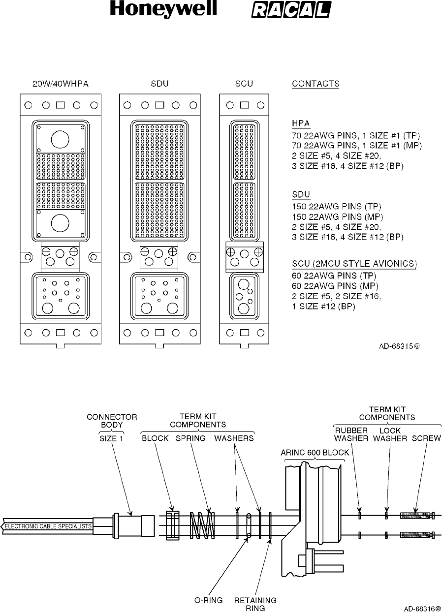
SYSTEM DESCRIPTION, INSTALLATION, AND MAINTENANCE MANUAL
MCS--4000/7000 Multi--Channel SATCOM System
23--20--27
30 Aug 2002
Use or disclosure of information on this page is subject to the restrictions in the proprietary notice of this document.
Page A--3
Figure A--1. ARINC Connectors
Figure A--2. ARINC Assembly
RELEASED FOR THE EXCLUSIVE USE BY: HONEYWELL INTERNATIONAL
UP86308

SYSTEM DESCRIPTION, INSTALLATION, AND MAINTENANCE MANUAL
MCS--4000/7000 Multi--Channel SATCOM System
23--20--27
30 Aug 2002
Use or disclosure of information on this page is subject to the restrictions in the proprietary notice of this document.
Page A--4
F. SATCOM Avionics Unit Mounting Hardware
(1) SATCOM avionics mounting hardware is made up of the HPA, SDU, and SCU and
will be mounted in ARINC 600 style tray assemblies. The HPA and SDU each require
forced air cooling during normal operation, whereas the SCU can function properly
with convection cooling alone. Refer to MECHANICAL INSTALLATION, for LRU
cooling requirements.
G. SATCOM Hardware Component Kits
(1) This paragraph contains information on how to select SATCOM hardware component
kits offered by ECS for the Honeywell MCS--4000/7000 avionic units in Table A--3
thru Table A--6. ECS supplies several options for each kit to accommodate the variety
of mounting requirements specific to each aircraft installation. ECS tray assemblies
come with and without independent cooling systems to ensure installation flexibility.
(2) The tray assemblies have been specially designed to meet Honeywell and ARINC
600 LRU cooling requirements. Tray assemblies are supplied with insertion/extraction
front hold-downs as standard, but are available with other front hold-down options.
For tray assembly dimensions refer to Figure A--3.
(3) The hardware component kits for the HPAs, SDU, and BSU are listed in Table A--3
thru Table A--6, respectively.
RELEASED FOR THE EXCLUSIVE USE BY: HONEYWELL INTERNATIONAL
UP86308
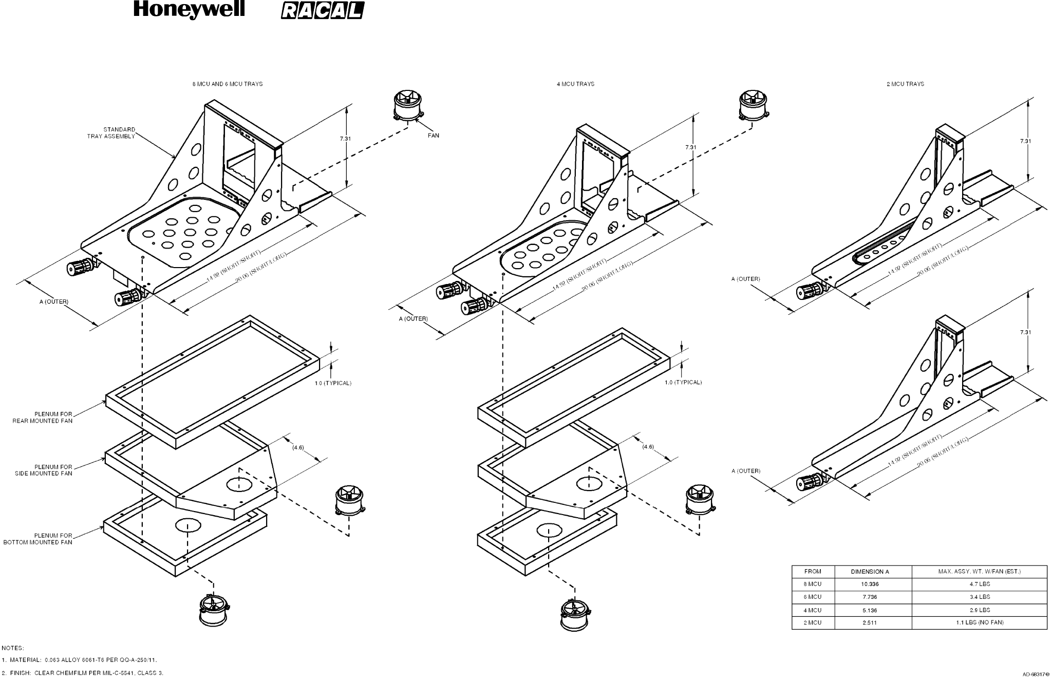
SYSTEM DESCRIPTION, INSTALLATION, AND MAINTENANCE MANUAL
MCS--4000/7000 Multi--Channel SATCOM System
23--20--27
30 Aug 2002
Use or disclosure of information on this page is subject to the restrictions in the proprietary notice of this document.
Page A--5/(A--6 blank)
Figure A--3. Dimensions for ECS Tray Assemblies
RELEASED FOR THE EXCLUSIVE USE BY: HONEYWELL INTERNATIONAL
UP86308
SYSTEM DESCRIPTION, INSTALLATION, AND MAINTENANCE MANUAL
MCS--4000/7000 Multi--Channel SATCOM System
23--20--27
30 Aug 2002
Use or disclosure of information on this page is subject to the restrictions in the proprietary notice of this document.
Page A--7
Table A--3. HP--600 HPA (40W) Hardware Component Kit,
Part No. 998HQS--900--1XX
Kit Part No. * Item Part Number Description Quantity
998HQS--900--102 6292--101 8 MCU S/S standard tray 1
998HQS--900--103 6288--101 8 MCU S/S tray w/bottom
fan
1
998HQS--900--104 6290--101 8 MCU S/S tray w/left side
fan
1
998HQS--900--106 6284--101 8 MCU S/S tray w/right side
fan
1
998HQS--900--107 6286--101 8 MCU S/L standard tray 1
* Parts supplied with each kit NIC66H20A00AA0 HPA ARINC connector
22 AWG pins
20 AWG sockets
16 AWG sockets
12 AWG sockets
Size 5 coaxicons
1
140
4
3
4
2
Table A--4. HP--700 HPA (20W) Hardware Component Kit,
Part No. 998HQS--904--1XX
Kit Part No. * Item Part Number Description Quantity
998HQS--904--102 6280--101 4 MCU S/S standard tray 1
998HQS--904--103 6278--101 4 MCU S/S tray w/bottom
fan
1
998HQS--904--104 6279--101 4 MCU S/S tray w/left side
fan
1
998HQS--904--106 6302--101 4 MCU S/S tray w/right side
fan
1
998HQS--904--107 6277--101 4 MCU S/L standard tray 1
* Parts supplied with each kit NIC66H20A00AA0 HPA ARINC connector
22 AWG pins
20 AWG sockets
16 AWG sockets
12 AWG sockets
Size 5 coaxicons
1
140
4
3
4
2
RELEASED FOR THE EXCLUSIVE USE BY: HONEYWELL INTERNATIONAL
UP86308
SYSTEM DESCRIPTION, INSTALLATION, AND MAINTENANCE MANUAL
MCS--4000/7000 Multi--Channel SATCOM System
23--20--27
30 Aug 2002
Use or disclosure of information on this page is subject to the restrictions in the proprietary notice of this document.
Page A--8
Table A--5. SD--700 SDU Hardware Component Kit, Part No. XXXXXX--XXX--1XX
Kit Part No. * Item Part Number Description Quantity
998HQS--901--102 6283--101 6 MCU S/S standard tray 1
998HQS--901--103 6232--101 6 MCU S/S tray w/bottom
fan
1
998HQS--901--104 6282--101 6 MCU S/S tray w/left side
fan
1
998HQS--901--106 6045--109 6 MCU S/S tray w/right side
fan
1
998HQS--901--107 6281--101 6 MCU S/L standard tray 1
* Parts supplied with each kit NIC66H21A00AA0 SDU ARINC connector
22 AWG pins
20 AWG sockets
16 AWG sockets
12 AWG sockets
Size 5 coaxicons
1
300
4
3
4
2
Table A--6. BSU Hardware Component Kit, Part No. 970HQS--903--1XX
Kit Part No. * Item Part Number Description Quantity
970HQS--903--101 6064--101 2 MCU S/S standard tray 1
970HQS--903--102 6074--101 2 MCU S/S flat bottom tray 1
970HQS--903--103 6051--101 2 MCU S/L standard tray 1
970HQS--903--104 6120--101 2 MCU S/L flat bottom tray 1
* Parts supplied with each kit NIC66F11A00AA0 SCU/BSU ARINC connector
22 AWG pins
16 AWG sockets
12 AWG sockets
Size 5 coaxicons
1
140
2
1
2
H. Air Filtration Assemblies
(1) ECS can supply air filtration assemblies for the HPA, SDU, and BSU tray assemblies
described in Table A--3 thru Table A--6. These filter assemblies offer protection
against airborne contaminants, such as dust and cigarette smoke. System
mean--time--between--failures (MTBF) can be significantly increased. Appendix B
supplies installation procedures for air filtration hardware.
RELEASED FOR THE EXCLUSIVE USE BY: HONEYWELL INTERNATIONAL
UP86308

SYSTEM DESCRIPTION, INSTALLATION, AND MAINTENANCE MANUAL
MCS--4000/7000 Multi--Channel SATCOM System
23--20--27
30 Aug 2002
Use or disclosure of information on this page is subject to the restrictions in the proprietary notice of this document.
Page A--9
I. SATCOM Shelf Assemblies
(1) ECS supplies customized and standard turnkey plenum shelf assemblies to
accommodate either single or dual SATCOM installations. A shelf assembly can
incorporate equipment trays, racking, and additional support structures, such as
disconnect panels, cover plates, and mounting brackets. ECS can supply
components that are compatible with all types of air transport aircraft.
NOTE: Some SATCOM system installation locations render the aircraft cooling
system inadequate. ECS has designed a self-contained cooling system for
theSATCOMshelfassemblythatcanbeusedinthistypeofinstallation.
J. Additional Avionics Installation Components
(1) ECS supplies a variety of additional components to support a SATCOM installation.
These include RF splitters, combiners, high power relays, maintenance panels,
placards, circuit breakers, and control annunciator panels.
K. Antenna System Provisions
(1) SATCOM antenna systems are available in numerous configurations. ECS supplies
installation provisions for each of these configurations.
•Some high-gain top-mounted antenna systems require a 2-MCU tray assembly
and an ARINC 600 connector (Part No. NIC66F11A00AA0) for the BSU. Others
require mounting bracketry for the BSU. ECS supplies both BSU 2-MCU tray
assembly, and connector and mounting bracketry as required.
•ECS supplies trays and ARINC connectors for various SCUs in the market place.
•ECS supplies other antenna mounting hardware, such as mounting brackets for
the diplexer/low noise amplifier (D/LNA) and high- and low-gain antenna doublers.
L. Cabin Communications System Provisions
(1) ECS supplies ARINC 746 compliant air-to-ground communication systems installation
provisions. These provisions include mounting hardware and connectors, shelves,
racks, brackets, placards, cover plates, RF cable, connectors, cable assemblies, and
wire harness assemblies.
M. Wire Harnesses
(1) ECS can supply wire harness provisions that interface the SATCOM avionics with the
cabin communication units, the cabin communications units with the cabin phones,
and both the SATCOM avionics and cabin communication units with other aircraft
systems.
(2) ECS wire harness assemblies can be custom designed and fabricated to meet
system installation requirements.
N. Complete Integrated SATCOM Installation Kits
(1) Complete system integration packages are available for ECS for virtually any given
installation requirements. These integration packages can include any of the
installation provisions discussed in this section, along with other customer-specified
components. ECS can also support Honeywell’s customers with systems installation
design engineering and certification design data packaging.
RELEASED FOR THE EXCLUSIVE USE BY: HONEYWELL INTERNATIONAL
UP86308

SYSTEM DESCRIPTION, INSTALLATION, AND MAINTENANCE MANUAL
MCS--4000/7000 Multi--Channel SATCOM System
23--20--27
30 Aug 2002
Use or disclosure of information on this page is subject to the restrictions in the proprietary notice of this document.
Page A--10
3. Hollingsead International
A. General
(1) This information aids you in selecting the engineering services and installation
provisions offered by Hollingsead International for the various MCS systems.
Hollingsead International is rapidly transforming into a world-class avionics and
aircraft systems integration leader, providing the capability to perform any or all of the
following:
•Design and manufacturing of the structural mounting for the MCS and all
associated avionics.
•Design and manufacturing of all wire and cable harness assembly interface
connections between the MCS and all associated avionics.
•Development of all engineering design substantiation, documentation, and testing
in support of FAA approval.
•Complete on-site support of a full installation team for the entire MCS installation
kit.
(2) You can contact them at the following address regarding your specific MCS program
requirements:
Hollingsead International
13701 Excelsior Drive
Santa Fe Springs, CA 90670
U.S.A.
Telephone: (310) 921-3438
FAX: (310) 921-6313
Telex: 691-462
B. Engineering Services
(1) As addressed in the previous paragraph, Hollingsead International supplies any level
of engineering support from minimal consultation to full turn-key. Full turn-key support
is defined as Hollingsead International undertaking the entire systems integration
from initial design through procurement and manufacture of parts to final installation
and certification on behalf on the customer.
C. LRU Mounting Requirements
(1) MCS avionics are made up of the HPA, SDU, and BSU, which are mounted in ARINC
600 style tray assemblies. The HPA and SDU each require forced air cooling during
normal operation. The BSU and CMU, which are mounted in an ARINC 404 tray,
function properly with convection cooling alone.
RELEASED FOR THE EXCLUSIVE USE BY: HONEYWELL INTERNATIONAL
UP86308

SYSTEM DESCRIPTION, INSTALLATION, AND MAINTENANCE MANUAL
MCS--4000/7000 Multi--Channel SATCOM System
23--20--27
30 Aug 2002
Use or disclosure of information on this page is subject to the restrictions in the proprietary notice of this document.
Page A--11
D. Installation Kit Components
(1) General
(a) Complete system installation kits are available from Hollingsead International for
virtually any given installation requirement. These installation kits can include any
of the installation provisions discussed herein along with other
customer-specified components.
(2) Coaxial Cables
(a) All coaxial cables, connectors, and attenuators have been designed to fulfill the
MCS system and the ARINC 741 usage and attenuation requirements.
Hollingsead International supplies immediate access to several types and
manufacturers of coaxial cable, appropriate N or TNC connectors, and
attenuators to make sure the specific attenuation profiles for each aircraft
installation is achieved. These cables range in nominal attenuation from 1.27 to
16.3 dB per 100 feet at 1.6 GHz. The cable outer diameter range is from 0.206
inch to 1.55 inches. Each cable assembly is fabricated with an individual part
number and, where necessary, is assigned a serial number, which is
permanently affixed to each end. Serialization insures traceability and
reproducibility.
(b) Testing of each cable assembly is performed to verify insertion loss and VSWR.
The results become part of a test database and are shipped with each cable
assembly. Each cable assembly is tested across the MCS system frequency
bandwidth. Transmit path cable assemblies are test swept from 1626.5 MHz to
1660.5 MHz and receive path cable assemblies are test swept from 1530 MHz to
1559 MHz. Customers have the option of having cable assemblies tested with or
without attenuators.
(3) Connectors
(a) Hollingsead International supplies the appropriate ARINC connectors for ARINC
Characteristic 741 style avionics electrical interfaces. The SATCOM rack-side
connector blocks are appropriately mounted on each tray assembly. Hollingsead
International supplies ARINC 600 Size 1 coaxial connectors with the necessary
termination kit assembly instructions.
(b) The connector part numbers are as follows:
•SDU -- C--06B3--0204--0100
•HPA (40W) -- C--06B3--0708--0100
•HPA (20W) -- C--06B3--0708--0100
•BSU -- C--06B1--0101--0100
•CMU -- DPX2MA--A106PA106P--33B--0001.
RELEASED FOR THE EXCLUSIVE USE BY: HONEYWELL INTERNATIONAL
UP86308
SYSTEM DESCRIPTION, INSTALLATION, AND MAINTENANCE MANUAL
MCS--4000/7000 Multi--Channel SATCOM System
23--20--27
30 Aug 2002
Use or disclosure of information on this page is subject to the restrictions in the proprietary notice of this document.
Page A--12
(4) Tray Assemblies
(a) Hollingsead International manufactures several tray assemblies for the MCS
avionics. These tray assemblies come with or without independent cooling
systems to ensure installation flexibility. Where forced air cooling is required,
these tray assemblies have been specially designed to meet the cooling
requirements of each LRU using a single fan. Tray assemblies are supplied with
insertion/extraction front hold-downs as standard, but are available with other
front hold-down options. Table A--7 identifies the various tray options and
Figure A--4 identifies the dimensions for each tray assembly.
Table A -- 7.
Tray Assembly Part Numbers
Standard
T
a
Assembly Fan Location
Type
Tray
Assembly Bottom Left Side Right Side Left Rear Right Rear
8MCUS/S 1708006--101 1708007--101 1708008--101 1708008--102 N/A N/A
8MCUS/L 1708006--201 1708007--201 1708008--201 1708008--202 1708009--101 1708009--102
6MCUS/S 1706007--101 1706008--101 1706009--101 1706009--102 N/A N/A
6MCUS/L 1706007--201 1706008--201 1706009--201 1706009--202 1706010--101 1706010--102
4MCUS/S 1704008--101 1704009--101 1704010--101 1704010--102 N/A N/A
4MCUS/L 1704008--201 1704009--201 1704010--201 1704010--202 1704011--101 1704011--102
2MCUS/S 1702002--101 1702003--101
2MCUS/L 1702002--201 1702003--201
RELEASED FOR THE EXCLUSIVE USE BY: HONEYWELL INTERNATIONAL
UP86308
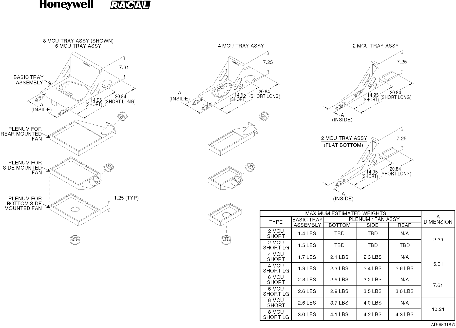
SYSTEM DESCRIPTION, INSTALLATION, AND MAINTENANCE MANUAL
MCS--4000/7000 Multi--Channel SATCOM System
23--20--27
30 Aug 2002
Use or disclosure of information on this page is subject to the restrictions in the proprietary notice of this document.
Page A--13/(A--14 blank)
Figure A--4. Dimensions for Hollingsead Tray Assemblies
RELEASED FOR THE EXCLUSIVE USE BY: HONEYWELL INTERNATIONAL
UP86308

SYSTEM DESCRIPTION, INSTALLATION, AND MAINTENANCE MANUAL
MCS--4000/7000 Multi--Channel SATCOM System
23--20--27
30 Aug 2002
Use or disclosure of information on this page is subject to the restrictions in the proprietary notice of this document.
Page A--15
(5) Plenum Shelf Assemblies
(a) Hollingsead International supplies customized and standard turnkey plenum
shelf assemblies to accommodate either single or dual MCS system installations.
A shelf assembly can incorporate equipment trays, racking, and additional
support structures such as disconnect panels, cover plates, and mounting
brackets. Hollingsead International can supply components that are compatible
with all types of air transport aircraft.
(6) Additional Components
(a) Hollingsead International supplies a variety of additional components to support
an MCS installation, including RF splitters, combiners, high power relays,
maintenance panels, placards, circuit breakers, and control enunciator panels.
(7) Antenna System Provisions
(a) The antenna subsystems for the MCS system are available in numerous
configurations. Hollingsead International supplies installation provisions for each
of these configurations. Some high-gain, top-mounted antenna systems use a
2-MCU tray assembly and ARINC 600 connector for the BSU. Others use
mounting bracket hardware for the BSU. Hollingsead International supplies both
BSU 2-MCU tray assemblies and mounting bracket hardware as necessary.
Hollingsead International supplies other antenna mounting hardware such as
mounting brackets for the diplexer/LNA and high-gain and low-gain antenna
doublers.
(8) Cabin Communications System Provisions
(a) Hollingsead International supplies ARINC 746 compliant air-to-ground
communications system installation provisions. These provisions include
mounting hardware and connectors, shelves, racks, brackets, placards, cover
plates, RF cable, connectors, cable assemblies, and wire harness assemblies.
(9) Wire Harness Assemblies
(a) Hollingsead International wire harness assemblies are custom designed and
fabricated to meet each customer’s specific system installation requirements.
Hollingsead International supplies wire harness assemblies for the following
interfaces:
•MCS avionics and cabin communication units
•MCS avionics and flight deck data and voice communication sources
•Cabin communications units and cabin telephones
•Both the SATCOM avionics and cabin communication units with other aircraft
systems.
RELEASED FOR THE EXCLUSIVE USE BY: HONEYWELL INTERNATIONAL
UP86308

SYSTEM DESCRIPTION, INSTALLATION, AND MAINTENANCE MANUAL
MCS--4000/7000 Multi--Channel SATCOM System
23--20--27
30 Aug 2002
Use or disclosure of information on this page is subject to the restrictions in the proprietary notice of this document.
Page A--16
4. Signal Conditioning Unit
A. General
(1) The SCU (Racal Part No. 56047--010XX) is manufactured by Racal Avionics in the
U.S.A. Contact the project manager at the following address for additional information
not supplied in this section:
Racal Avionics Incorporated
8851 Monard Drive
Silver Spring, MD 20910
U.S.A.
Telephone: (301) 495-6695
FAX: (301) 585-7578
Telex: 898316
(2) The MCS system requires ARINC 429 data for antenna pointing, antenna
stabilization, and Doppler frequency correction. These requirements are defined in
Table A--8. If the aircraft does not have an IRS that supplies this ARINC data, the
SCU can be used to supply the data.
(3) The SCU is packaged as an ARINC 600 2 MCU and weighs a maximum of 5.95
pounds (2.70 kilograms). The outer case of the SCU is constructed from two
half-shells identical in dimensions, which are made of an aluminum alloy 1.6
millimeters thick. The front and rear panels are made of the same alloy 3.3
millimeters thick. Both panels attach to the outer half-shells with corner brackets. Two
divider plates mount between the half-shells of the outer case to supply additional
rigidity and electrical shielding.
(4) The SCU translates and consolidates various input data formats into a two-wire
differential ARINC 429 high speed output for latitude and longitude position, true
heading, track angle, ground speed, and pitch and roll attitude. Program pins define
the particular type of data being received. These pins are interrogated at power on by
the software to determine the required configuration.
(5) The SCU operates from a nominal 115 V ac, 400 Hz single phase supply and/or from
28 V dc primary power. Input pins are supplied for both power sources in the ARINC
600 connector, and both power inputs can be connected to the aircraft power.
Current consumption depends on the input voltage and temperature, but is typically
0.25 amperes at 115 V ac or 0.40 amperes at 28 V dc.
RELEASED FOR THE EXCLUSIVE USE BY: HONEYWELL INTERNATIONAL
UP86308
SYSTEM DESCRIPTION, INSTALLATION, AND MAINTENANCE MANUAL
MCS--4000/7000 Multi--Channel SATCOM System
23--20--27
30 Aug 2002
Use or disclosure of information on this page is subject to the restrictions in the proprietary notice of this document.
Page A--17
Table A--8. ARINC 429 Data Requirements
Label Definition
Minimum
Rate (MS)
Maximum
Rate (ms)
310 Latitude of present position 334 67
311 Longitude of present position 334 67
312 Ground speed 125 22
313 Track angle 55 22
314 True heading 55 22
324 Pitch 40 8
325 Roll 40 8
B. Operator Functions
(1) The front panel contains six LED indicators to allow monitoring of the SCU status.
However, these indicators are intended for use during repair by maintenance
personnel rather than by the operator during normal flight operation. Discrete outputs
representing the state of each LED indicator are also supplied for remote monitoring.
The functions of these discretes are defined in Table A--9.
Table A--9. SCU Discrete Functions
Color Nomenclature Function
Green Power Indicates SCU is on and all voltages are correct when lit.
Green SCU Valid Indicates correct operation of the SCU logic and processing
circuits when lit.
Red BIT Fail •Indicates normal operation when off.
•Indicates BIT is running repetitively when flashing slowly.
Indicates the SCU has failed BIT when steadily lit.
•Indicates the SCU has failed BIT when steadily lit.
Amber Signal 1 Indicates selection of input channel 1 when lit.
Amber Signal 2 Indicates selection of input channel 2 when lit.
Amber Signal 3 Indicates selection of input channel 3 when lit.
(2) Three amber LED indicators supply an error code that is displayed when the SCU
fails in the BIT mode. The red indicator lights and a three-bit code is continuously
displayed on the amber LEDs as indicated in Table A--10. BIT is interruptive and all
normal operation ceases during the time when the SCU is in the BIT mode.
RELEASED FOR THE EXCLUSIVE USE BY: HONEYWELL INTERNATIONAL
UP86308
SYSTEM DESCRIPTION, INSTALLATION, AND MAINTENANCE MANUAL
MCS--4000/7000 Multi--Channel SATCOM System
23--20--27
30 Aug 2002
Use or disclosure of information on this page is subject to the restrictions in the proprietary notice of this document.
Page A--18
Table A--10. SCU Error Code
Failure Code LED 1 LED 2 LED 3
ARINC 429 translator not programmed 1ON OFF OFF
RAM read/write failed 2OFF ON OFF
ARINC 561 translator failed 3ON ON OFF
PROM checksum failed 4OFF OFF ON
ARINC 561 translator not programmed 5ON OFF ON
Discrete input failed 6OFF ON ON
ARINC 429 translator failed 7ON ON ON
C. Control Functions
(1) Normal operation of the SCU is fully automatic and does not require operator
intervention. Some control functions are supplied through the main ARINC 600
connector. These functions include:
•Remote SCU on/off control
•BIT initiate control
•Signal select A
•Signal select B
•Program pin A
•Program pin B
•Program pin C.
(2) The remote SCU on/off control line enables the operation of the SCU power supply.
Thecontrollineisactivelowandmustbeconnectedtogroundtoenableoperationof
the SCU. An open circuit or 28 V dc on this line shuts down operation of the SCU.
(3) The BIT initiate control line is an active low input used to enable BIT in the SCU. The
BIT mode is an optional function that supplies a pre/post-flight confidence check and
is intended for use by maintenance personnel as a diagnostic tool. The SCU remains
in the BIT mode as long as the BIT initiate control line is grounded. An open circuit or
28 V dc on this control causes the SCU to return to normal operation.
(4) Signal selection is normally an automatic function under control of the internal SCU
program and is based on the validity of the received data. The signal select control
lines supply an override of this automatic function to allow manual selection of one
input from three available sources. The signal select control lines are active low and
are internally pulled high. Manual selection is accomplished by applying a ground to
the control lines as given in Table A--11.
RELEASED FOR THE EXCLUSIVE USE BY: HONEYWELL INTERNATIONAL
UP86308
SYSTEM DESCRIPTION, INSTALLATION, AND MAINTENANCE MANUAL
MCS--4000/7000 Multi--Channel SATCOM System
23--20--27
30 Aug 2002
Use or disclosure of information on this page is subject to the restrictions in the proprietary notice of this document.
Page A--19
Table A--11. SCU Manual Signal Selection
Signal Select Control Lines
Function A B
Automatic Selection High High
Select Input No. 1 Low High
Select Input No. 2 High Low
Select Input No. 3 Low Low
D. System Functions
(1) Initialization
(a) Operation begins with BIT when the SCU is activated by applying aircraft power
and grounding the on/off control line. Testing normally takes approximately 0.5
second and when BIT passes normal operation begins. If the SCU fails the initial
BIT check, the unit latches in the BIT mode and displays an error code with the
amber LED indicators.
(2) Automatic Input Selection Mode
(a) There are three available data input channels. Unless a channel is manually
selected, the input to be used by the SCU is selected automatically. After initially
selecting Channel 1, the SCU checks for the presence of the required valid
words in the input data stream and the status of the attitude warning discrete
from the selected synchro channel. If all validity conditions are met within 1.6
seconds from the initial channel selection, the SCU locks on to the current
channel and continues to operate from that data source. The appropriate amber
LED indicator lights to indicate the selected channel to operator. If any of the
required data is invalid, the SCU cycles to the next input channel until a channel
providing a complete frame of valid data is received.
(3) Valid Channel Condition
(a) Conditions that must exist to let the SCU accept the current input channel
include:
•At least one new data word for each of the required labels is received within
the specified time period.
•The sign/status matrix (SSM) of all words for all required labels must be valid.
•The primary attitude warning input discrete must be in a valid state to indicate
the synchro inputs for attitude are usable.
RELEASED FOR THE EXCLUSIVE USE BY: HONEYWELL INTERNATIONAL
UP86308
SYSTEM DESCRIPTION, INSTALLATION, AND MAINTENANCE MANUAL
MCS--4000/7000 Multi--Channel SATCOM System
23--20--27
30 Aug 2002
Use or disclosure of information on this page is subject to the restrictions in the proprietary notice of this document.
Page A--20
(4) Channel Switching Timing
(a) The SCU allows 1.6 seconds for the selected input channel to receive a valid
data frame. However, if 1.6 seconds has passed and the valid channel
conditions have not been satisfied, the input channel cycles to the next
sequential channel. If all three input channels have been checked and none are
valid, the SCU prevents further cycling of the input channel selection for 1
minute. This prevents the SCU from continuously cycling when the inertial
navigation units or other sources of navigation data have not been initialized.
After the 1-minute delay, the SCU again initiates the checking cycle.
(5) Data Input
(a) A data subset made up of present latitude and longitude, true heading, track
angle, and ground speed is received through either the ARINC 561--6 wire inputs
or the ARINC 571--2 wire inputs as defined by the program pin selections. When
used as a selector of ARINC 404 data inputs, pitch and roll labels are also
included. The words are selected from the data stream by their octal labels while
other words are ignored. Program pin selections and associated data formats
and labels are defined in Table A--12 thru Table A--16.
Table A--12. ARINC 561 Binary Data
Program Pin
Octal Label Coded ABC Definition
310 Binary 000Latitude of present position
311 Binary 000Longitude of present position
212 Binary 000Ground speed
213 Binary 000Track angle
214 Binary 000True heading
Table A--13. ARINC 561 BCD Data
Program Pin
Octal Label Coded ABC Definition
010 BCD 100Latitude of present position
011 BCD 100Longitude of present position
012 BCD 100Ground speed
013 BCD 100Track angle
014 BCD 100True heading
RELEASED FOR THE EXCLUSIVE USE BY: HONEYWELL INTERNATIONAL
UP86308
SYSTEM DESCRIPTION, INSTALLATION, AND MAINTENANCE MANUAL
MCS--4000/7000 Multi--Channel SATCOM System
23--20--27
30 Aug 2002
Use or disclosure of information on this page is subject to the restrictions in the proprietary notice of this document.
Page A--21
Table A--14. ARINC 571 Data, ARINC 429 Format
Program Pin
Octal Label ABC Definition
310 010Latitude of present position
311 010Longitude of present position
212 010Ground speed
213 010Track angle
214 010True heading
Table A--15. ARINC 571 Data, ARINC 419 Format
Program Pin
Octal Label ABC Definition
210 110Latitude of present position
211 110Longitude of present position
212 110Ground speed
213 110Track angle
214 110True heading
Table A--16. ARINC 404 Data, ARINC 429 Format
Program Pin
Octal Label ABC Definition
310 001Latitude of present position
311 001Longitude of present position
312 001Ground speed
313 001Track angle
314 001True heading
324 001Pitch
325 001Roll
(b) The SSM of each received data word is checked. Valid words are converted to
ARINC 429 data. Invalid words are discarded.
RELEASED FOR THE EXCLUSIVE USE BY: HONEYWELL INTERNATIONAL
UP86308
SYSTEM DESCRIPTION, INSTALLATION, AND MAINTENANCE MANUAL
MCS--4000/7000 Multi--Channel SATCOM System
23--20--27
30 Aug 2002
Use or disclosure of information on this page is subject to the restrictions in the proprietary notice of this document.
Page A--22
(c) With exception of the ARINC 404 input, the SCU also receives attitude data from
an associated attitude source. The attitude data is in the form of ARINC 407
pitch and roll synchro channels and an attitude warning flag. Attitude data is
selected from a source associated with the source selected for digital data. The
attitude inputs used are given in Table A--17.
Table A--17. SCU Attitude Data Inputs
Data Line Function
Roll Synchro X
Roll Synchro Y
Roll Synchro Z
Pitch Synchro X
Pitch Synchro Y
Pitch Synchro Z
Roll/Pitch Reference HI
Roll/Pitch Reference LO
Warning Flag HI Flag (HI = Good)
(d) The pitch and roll synchro inputs are read every 20 milliseconds. The attitude
warning flag is sampled before each computation to check the validity of the
input data before the data is accepted.
(6) Data Output
(a) The SCU transmits ARINC 429 serial words at a rate of one complete
seven-word message every 20 milliseconds. The SSMs in the navigation data
words are based on those supplied by the digital input words. The SSM data for
the attitude words is derived from computations and from the primary warning
flag.
(b) The data output is in accordance with ARINC 429 high speed data (100 kHz
clock speed). The SCU outputs ARINC 429 data on two separate ports operating
in parallel. Data from both ports is identical, but independent output buffers are
used to supply redundancy.
RELEASED FOR THE EXCLUSIVE USE BY: HONEYWELL INTERNATIONAL
UP86308

SYSTEM DESCRIPTION, INSTALLATION, AND MAINTENANCE MANUAL
MCS--4000/7000 Multi--Channel SATCOM System
23--20--27
30 Aug 2002
Use or disclosure of information on this page is subject to the restrictions in the proprietary notice of this document.
Page A--23
E. ARINC 600 Connector Pin Assignments
(1) The rear connector (ARINC Part No. NIC66F11A00AA0) of the SCU complies with
ARINC Characteristic 600 as specified in the following:
•ARINC 600 -- Size MCU 2 no. 2 shell
•Type 0X top insert
•Type 0X middle insert
•Type 0X bottom insert
•Index pin code 0X.
(2) The contact arrangements for the connector are specified in Table A--18. An example
pin designation of BC12 for the table is given below.
Pin Designation Example: Pin BC12
Connector Cavity Identifier
Top Cavity = A
Middle Cavity = B
Bottom Cavity = C
Column Identifier
(A,B,C,orD)
Row Identifier
(1 thru 15)
B--C --12
RELEASED FOR THE EXCLUSIVE USE BY: HONEYWELL INTERNATIONAL
UP86308

SYSTEM DESCRIPTION, INSTALLATION, AND MAINTENANCE MANUAL
MCS--4000/7000 Multi--Channel SATCOM System
23--20--27
30 Aug 2002
Use or disclosure of information on this page is subject to the restrictions in the proprietary notice of this document.
Page A--24
Table A--18. Contact Arrangements for SCU ARINC 600 Connector
Pin Function Remarks
AC1 ARINC 561 Data No. 1 (HI) Note 1.
AD1 ARINC 561 Data No. 1 (LO) Note 1.
AC2 ARINC 561 Clock No. 1 (HI) Note 1.
AD2 ARINC 561 Clock No. 1 (LO) Note 1.
AC3 ARINC 561 Strobe No. 1 (HI) or ARINC 429/419 Data No. 1 (HI) Note 1.
AD3 ARINC 561 Strobe No. 1 (LO) or ARINC 429/419 Data No. 1 (LO) Note 1.
AC4 Spare
AD4 Spare
AC5 Spare
AD5 Spare
AC6 Spare
AD6 Spare
AC7 Spare
AD7 Spare
AC8 Spare
AD8 Spare
AC9 ARINC 561 Data No. 3 (HI) Note 1.
AD9 ARINC 561 Data No. 3 (LO) Note 1.
AC10 ARINC 561 Clock No. 3 (HI) Note 1.
AD10 ARINC 561 Clock No. 3 (LO) Note 1.
AC11 ARINC 561 Strobe No. 3 (HI) or ARINC 429/419 Data No. 3 (HI) Note 1.
AD11 ARINC 561 Strobe No. 3 (LO) or ARINC 429/419 Data No. 3 (LO) Note 1.
AC12 Spare
AD12 Spare
AC13 ARINC 407 Pitch No. 1 X Note 2.
AD13 ARINC 407 Pitch No. 1 Y Note 2.
AC14 ARINC 407 Pitch No. 1 Z Note 2.
AD14 ARINC 407 Heading X Reserved
AC15 ARINC 407 Heading Y Reserved
AD15 ARINC 407 Heading Z Reserved
RELEASED FOR THE EXCLUSIVE USE BY: HONEYWELL INTERNATIONAL
UP86308

SYSTEM DESCRIPTION, INSTALLATION, AND MAINTENANCE MANUAL
MCS--4000/7000 Multi--Channel SATCOM System
23--20--27
30 Aug 2002
Use or disclosure of information on this page is subject to the restrictions in the proprietary notice of this document.
Page A--25
Table A--18. Contact Arrangements for SCU ARINC 600 Connector (cont)
Pin RemarksFunction
AA1 ARINC 407 Pitch No. 3 X Note 2.
AB1 ARINC 407 Pitch No. 3 Y Note 2.
AA2 ARINC 407 Pitch No. 3 Z Note 2.
AB2 Attitude Warning No. 1 (From Attitude Source) Note 2.
AA3 ARINC 407 Reference No. 1 (HI)
AB3 ARINC 407 Reference No. 1 (LO)
AA4 ARINC 407 Heading Reference (HI) Reserved
AB4 ARINC 407 Heading Reference (LO) Reserved
AA5 ARINC 407 Reference No. 3 (HI)
AB5 ARINC 407 Reference No. 3 (LO)
AA6 Attitude Warning No. 3 (From Attitude Source) Note 2.
AB6 Spare
AA7 ARINC 407 Roll No. 1 X Note 2.
AB7 ARINC 407 Roll No. 1 Y Note 2.
AA8 ARINC 407 Roll No. 1 Z Note 2.
AB8 Spare
AA9 Spare
AB9 Spare
AA10 Spare
AB10 Spare
AA11 ARINC 407 Roll No. 3 X Note 2.
AB11 ARINC 407 Roll No. 3 Y Note 2.
AA12 ARINC 407 Roll No. 3 Z Note 2.
AB12 Spare
AA13 ARINC 404 Echo (HI) Note 3.
AB13 ARINC 404 Echo (LO) Note 3.
AA14 Spare
AB14 Spare
AA15 Spare
AB15 Spare
RELEASED FOR THE EXCLUSIVE USE BY: HONEYWELL INTERNATIONAL
UP86308

SYSTEM DESCRIPTION, INSTALLATION, AND MAINTENANCE MANUAL
MCS--4000/7000 Multi--Channel SATCOM System
23--20--27
30 Aug 2002
Use or disclosure of information on this page is subject to the restrictions in the proprietary notice of this document.
Page A--26
Table A--18. Contact Arrangements for SCU ARINC 600 Connector (cont)
Pin RemarksFunction
BC1 ARINC 407 Pitch No. 2 X Note 2.
BD1 ARINC 407 Pitch No. 2 Y Note 2.
BC2 ARINC 407 Pitch No. 2 Z Note 2.
BD2 Spare
BC3 ARINC 407 Roll No. 2 X Note 2.
BD3 ARINC 407 Roll No. 2 Y Note 2.
BC4 Spare
BD4 ARINC 407 Roll No. 2 Z Note 2.
BC5 Spare
BD5 Attitude Warning No. 2 (From Attitude Source) Note 2.
BC6 ARINC 407 Reference No. 2 (HI)
BD6 ARINC 407 Reference No. 2 (LO)
BC7 Signal Source Select A (Input No. 1) Note 4.
BD7 Signal Source Select (Input No. 2) Note 4.
BC8 BIT initiate (Input No. 3) Note 5.
BD8 Spare
BC9 BIT Failed (Output No. 2) Reserved
BD9 SCU Valid Reserved
BC10 Superflag (+28 V dc = Output Valid) Note 6.
BD10 /Superflag (<1 V dc = Output Valid) Note 6.
BC11 Program Pin A (Input No. 5) Note 7.
BD11 Program Pin B (Input No. 6) Note 7.
BC12 Program Pin C (Input No. 7) Note 7.
BD12 Spare
BC13 Spare
BD13 Spare
BC14 Spare
BD14 Spare
BC15 ARINC 429 Out No. 1 (HI)
BD15 ARINC 429 Out No. 1 (LO)
RELEASED FOR THE EXCLUSIVE USE BY: HONEYWELL INTERNATIONAL
UP86308

SYSTEM DESCRIPTION, INSTALLATION, AND MAINTENANCE MANUAL
MCS--4000/7000 Multi--Channel SATCOM System
23--20--27
30 Aug 2002
Use or disclosure of information on this page is subject to the restrictions in the proprietary notice of this document.
Page A--27
Table A--18. Contact Arrangements for SCU ARINC 600 Connector (cont)
Pin RemarksFunction
BA1 Spare
BB1 Spare
BA2 ARINC 429 Out No. 2 (HI)
BB2 ARINC 429 Out No. 2 (LO)
BA3 Spare
BB3 Spare
BA4 Discrete Out No. 3 (Select No. 2 LED) Reserved
BB4 Discrete Out No. 4 (Select No. 3 LED) Reserved
BA5 Discrete Out No. 5 (Select No. 1 LED) Reserved
BB5 Discrete Out No. 6 Reserved
BA6 Discrete Out No. 7 Reserved
BB6 Discrete Out No. 8 Reserved
BA7 ARINC 561 Data No. 2 (HI) Note 1.
BB7 ARINC 561 Data No. 2 (LO) Note 1.
BA8 ARINC 561 Clock No. 2 (HI) Note 1.
BB8 ARINC 561 Clock No. 2 (LO) Note 1.
BA9 ARINC 561 Strobe No. 2 (HI) or ARINC 429/419 Data No. 2 (HI) Note 1.
BB9 ARINC 561 Strobe No. 2 (LO) or ARINC 429/419 Data No. 2 (LO) Note 1.
BA10 +28 V dc Power Aircraft Power (Note 8.)
BB10 +28 V dc Power Aircraft Power (Note 8.)
BA11 0 V dc Power Return Aircraft Power (Note 8.)
BB11 0 V dc Power Return Aircraft Power (Note 8.)
BA12 Chassis Ground
BB12 Remote SCU On/Off Control Note 9.
BA13 Shield return Connected to Chassis
BB13 Shield Return Connected to Chassis
BA14 115 V ac Power 400 Hz (HI) Aircraft Power (Note 8.)
BB14 Chassis Ground
BA15 115 V ac Power 400 Hz (LO) Aircraft Power (Note 8.)
RELEASED FOR THE EXCLUSIVE USE BY: HONEYWELL INTERNATIONAL
UP86308
SYSTEM DESCRIPTION, INSTALLATION, AND MAINTENANCE MANUAL
MCS--4000/7000 Multi--Channel SATCOM System
23--20--27
30 Aug 2002
Use or disclosure of information on this page is subject to the restrictions in the proprietary notice of this document.
Page A--28
Table A--18. Contact Arrangements for SCU ARINC 600 Connector (cont)
Pin RemarksFunction
BB15 Chassis Ground
NOTES:
1. The 6-wire ARINC 561 or 2-wire ARINC 429/419 (ARINC 571/404) data can be routed from up to three sources.
However, if a single input is supplied, it should be connected to the No. 1 inputs as indicated. Inputs No. 2 and 3
should be left open. The type of data being used, either ARINC 561 or ARINC 571/404, must be indicated by
selecting the proper program pins as specified in NOTE 7. Also, refer to NOTE 4. for more information on selecting
a specific input as the data source.
2. The synchro pitch and roll data can be routed from up to three sources. However, sources of attitude data must be
paired with sources of ARINC 561 or ARINC 571 data. Thus, if only one source of ARINC 561 or ARINC 571 data
is available, then only one source of attitude data can be used. An attitude warning flag for each source of attitude
that is active must be supplied. +28 V dc = valid. Ground or open = invalid.
3. When the SCU is used as a selector/controller of multiple ARINC 404 compatible data sources, the receiving
equipment should be connected to the ARINC 404 echo outputs. In this configuration, the input as valid by the
SCU is routed back out of the unit on these pins. Since attitude data is embedded in the ARINC 404 data stream,
no attitude inputs are used.
4. When multiple sources of data are available and routed to the SCU, it automatically searches for an input with valid
attitude data and ARINC 561/571 data. If only one source of ARINC 561/571 data and attitude data is available, the
SCU should be connected to only one input and the signal source select lines should be linked as applicable for
the selected input as given in Table A--19.
5. Grounding the BIT initiate input forces the SCU to enter the interruptive BIT mode and repetitively do its BIT
routines until ground is removed. BIT is automatically done at each power-up cycle. This input should be an open, if
not used.
6. The superflag output is +28 V dc whenever the SCU is operating normally and the output data is valid. If a portion
of the input data is invalid or the SCU detects an internal fault, then the superflag output is 0 V dc. The /superflag
output is the inverse of the superflag output.
7. The data format and characteristics accepted by the SCU are programmable through pins A, B, and C. The
combinations supported by the SCU are specified in Table A--20.
8. The SCU operates from either +28 V dc or 115 V ac, 400 Hz power. The power source not used should remain
unconnected.
9. The remote SCU on/off control can be used to power down the SCU from a remote location. A ground activates the
unit and an open switches the unit off. If remote control is not required, this pin should be permanently grounded at
the connector.
Table A--19. Signal Source Select Lines
Signal Source Select A B
Auto Open Open
Input No.1 Ground Open
Input No. 2 Open Ground
Input No. 3 Ground Ground
RELEASED FOR THE EXCLUSIVE USE BY: HONEYWELL INTERNATIONAL
UP86308
SYSTEM DESCRIPTION, INSTALLATION, AND MAINTENANCE MANUAL
MCS--4000/7000 Multi--Channel SATCOM System
23--20--27
30 Aug 2002
Use or disclosure of information on this page is subject to the restrictions in the proprietary notice of this document.
Page A--29
Table A--20. SCU Program Pin Combinations
Program Pins
ABC Input Description
000ARINC 561 data, binary labels, synchro attitude
100ARINC 561 data, BCD labels, synchro attitude
010ARINC 571 data with ARINC 429 format, synchro attitude
110ARINC 571 data with ARINC 419 format, synchro attitude
NOTE: Ground = 1; open = 0.
RELEASED FOR THE EXCLUSIVE USE BY: HONEYWELL INTERNATIONAL
UP86308

SYSTEM DESCRIPTION, INSTALLATION, AND MAINTENANCE MANUAL
MCS--4000/7000 Multi--Channel SATCOM System
23--20--27
30 Aug 2002
Use or disclosure of information on this page is subject to the restrictions in the proprietary notice of this document.
Page A--30
Blank Page
RELEASED FOR THE EXCLUSIVE USE BY: HONEYWELL INTERNATIONAL
UP86308

SYSTEM DESCRIPTION, INSTALLATION, AND MAINTENANCE MANUAL
MCS--4000/7000 Multi--Channel SATCOM System
23--20--27
30 Aug 2002
Use or disclosure of information on this page is subject to the restrictions in the proprietary notice of this document.
Page B--1
APPENDIX B
INSTALLATION PROCEDURES FOR SATCOM AIR FILTRATION
SYSTEMS
1. Introduction
A. General
(1) Appendix B contains information on the different air filtration systems available for the
SATCOM installations. Procedures for installing these air filtration systems are also
supplied. After you have determined the proper air filtration system for your needs,
follow the appropriate procedures in paragraph 4.
(2) The SATCOM system (SDU and HPA) is designed to ARINC 600 standards including
ARINC 600 cooling requirements. ARINC 600 calls for the cooling air to contain no
contamination particles in excess of 400 microns. Several installation designs do not
supply cooling air in accordance with ARINC 600. The OEM installation design for the
B747, B767, and B777 supply unfiltered cooling air (cabin air) to the SATCOM LRUs.
As a result, contaminants in the air tend to accumulate on and inside the LRUs
sometimes blocking off the cooling air passages. This leads to units operating at a
higher temperature, which can result in decreasing the MTBF of the units.
(3) Filter assemblies have been designed that attach to the SATCOM LRUs or to the
LRU trays. These filter assemblies contain filter media that filter out contaminants
before entering the LRUs. This design is for installations where the cooling air is
drawn through the LRU top to bottom, and where there is at least 1 inch of clearance
above the LRUs to allow for the assembly itself. Thus, the air filtration units included
in this appendix are acceptable for installation on the B747 and B777 aircraft, but
because of clearance problems, are not acceptable for installation on the
OEM-provisioned B767 aircraft.
2. Continued Airworthiness
A. General
CAUTION: THE FILTER MEDIA MUST BE REPLACED (OR CLEANED) APPROXIMATELY
EVERY 4000 FLIGHT HOURS OR EVERY C CHECK, WHICHEVER COMES
FIRST, OR THE EFFECTIVENESS OF THE AIR FILTRATION ASSEMBLY CAN
BE DEGRADED.
(1) The selection of the type of filter media cartridge is based on the following:
•Effectiveness of the filter media in removing contaminants from the cooling air
before entering the SATCOM LRUs.
•Impact of the filter media on the cooling air mass flow rate through the units.
•Time between removals.
RELEASED FOR THE EXCLUSIVE USE BY: HONEYWELL INTERNATIONAL
UP86308
SYSTEM DESCRIPTION, INSTALLATION, AND MAINTENANCE MANUAL
MCS--4000/7000 Multi--Channel SATCOM System
23--20--27
30 Aug 2002
Use or disclosure of information on this page is subject to the restrictions in the proprietary notice of this document.
Page B--2
3. Equipment and Materials
A. General
WARNING: BEFORE YOU USE A MATERIAL, KNOW THE HAZARD CODE AND GET THE
NECESSARY PROTECTION. REFER TO THE PAGE ABOUT HAZARD CODES
FOR MATERIALS IN THE FRONT OF THIS MANUAL.
(1) Refer to Table B--1 for a list of materials.
Table B -- 1. Materials
Item Description Source
HMN 9730178 Retaining compound
(MIL--S--22473, grade A) — Grade
A
Loctite Corp, Rocky Hill, CT
(05972)
HMN 9731178 Primer for retaining compound,
ready--to--use, quick
(MIL--S--22473, grade T, form R)
— Locquic Grade T
NOTES: NOTES:
1. Equivalent alternatives are permitted for equipment and materials in this list.
2. The HMN codes in the list of materials identify the Honeywell Material Number (HMN) given to each material.
(2) The equipment listed in Table B--2, Table B--3, and Table B--4 supplies the necessary
hardware to install air filtration systems on the aircraft. Find the air filtration system
and filter that best fits your needs and contact the company that manufacturers that
particular equipment.
Table B--2. Air Filtration Systems from ECS for a Top Mount Assembly
Equipment Quantity LRU Part No. SATCOM System
SATCOM Filter Assembly 1SDU 10919--101 6--MCU assembly
SATCOM Filter Assembly 1HPA (20W) 10968--101 4--MCU assembly
SATCOM Filter Assembly 1HPA (40W) 10923--101 8--MCU assembly
Filter Cartridge Assembly 1SDU 10907--105 6--MCU assembly
Filter Cartridge Assembly 1HPA (20W) 10907--104 4--MCU assembly
Filter Cartridge Assembly 1HPA (40W) 10907--106 8--MCU assembly
RELEASED FOR THE EXCLUSIVE USE BY: HONEYWELL INTERNATIONAL
UP86308
SYSTEM DESCRIPTION, INSTALLATION, AND MAINTENANCE MANUAL
MCS--4000/7000 Multi--Channel SATCOM System
23--20--27
30 Aug 2002
Use or disclosure of information on this page is subject to the restrictions in the proprietary notice of this document.
Page B--3
Table B--3. Air Filtration Systems from ECS for a Body--Mounted Design
Equipment Quantity LRU Part No. SATCOM System
SATCOM Filter Assembly 1SDU P0329--106 6--MCU assembly
SATCOM Filter Assembly 1HPA (20W) P0329--104 4--MCU assembly
SATCOM Filter Assembly 1HPA (40W) P0329--108 8--MCU assembly
Filter Cartridge Assembly 1SDU 20008--05 6--MCU assembly
Filter Cartridge Assembly 1HPA (20W) 20008--04 4--MCU assembly
Filter Cartridge Assembly 1HPA (40W) 20008--06 8--MCU assembly
Table B--4. Air Filtration Systems from ECS for a Tray--Mounted Design
Equipment Quantity LRU Part No. SATCOM System
SATCOM Filter Assembly 1SDU 20005--103 6--MCU assembly
SATCOM Filter Assembly 1HPA (20W) 20005--102 4--MCU assembly
SATCOM Filter Assembly 1HPA (40W) 20005--104 8--MCU assembly
Filter Cartridge Assembly 1SDU 20008--05 6--MCU assembly
Filter Cartridge Assembly 1HPA (20W) 20008--04 4--MCU assembly
Filter Cartridge Assembly 1HPA (40W) 20008--06 8--MCU assembly
RELEASED FOR THE EXCLUSIVE USE BY: HONEYWELL INTERNATIONAL
UP86308

SYSTEM DESCRIPTION, INSTALLATION, AND MAINTENANCE MANUAL
MCS--4000/7000 Multi--Channel SATCOM System
23--20--27
30 Aug 2002
Use or disclosure of information on this page is subject to the restrictions in the proprietary notice of this document.
Page B--4
4. Installation Instructions
A. Top Mount Assembly
(1) The ECS top mount air filtration assembly is designed to clamp to the top of the
SATCOM LRUs so it does not come off the LRU. Once attached to the top of the
LRU, it forms a seal letting only filtered air enter the LRU. The assembly is held to the
top of the LRU by friction from the sides of the assembly and by the clamps that
supply friction to the front and rear panels of the unit. Figure B--1 shows the location
of the components for the following procedures.
(2) Install the filter assembly to an SDU or HPA using the following steps.
(a) Make sure the correct size assembly is selected for the given LRU (refer to
Table B--2).
(b) OPTIONAL — Remove the SATCOM LRU from its tray and set it on a secure
surface. (The assembly can be installed while the unit is in the rack.)
(c) Install the air filtration media inside the air filtration assembly in the rectangular
filter frame.
(d) Place the filter assembly over the top of the LRU with the clamps in the up
(thumb lever over the top of the filter assembly) position and pointing toward you.
(e) Push down on the air filtration unit until it fits over the top of the SATCOM LRU.
The sides of the air filtration assembly may need to be spread open slightly prior
to sliding over the sides of the LRU.
(f) Once the air filtration unit is firmly seated to the top of the LRU, clamp the
assembly to the unit by pushing down on the two thumb levers until they lock into
position. The thumb levers pass through approximately 180 degrees of rotation
for the clamping process.
(g) Make sure the air filtration assembly remains seated firmly against the top of the
LRU to maintain the air seal.
(h) Make sure the air filtration assembly is held tightly to the unit by gently lifting up
on the assembly; making sure the assembly does not pull off of the LRU.
(i) OPTIONAL -- Install the SATCOM LRU back into its tray if removed in step
4.A.(2)(b).
RELEASED FOR THE EXCLUSIVE USE BY: HONEYWELL INTERNATIONAL
UP86308
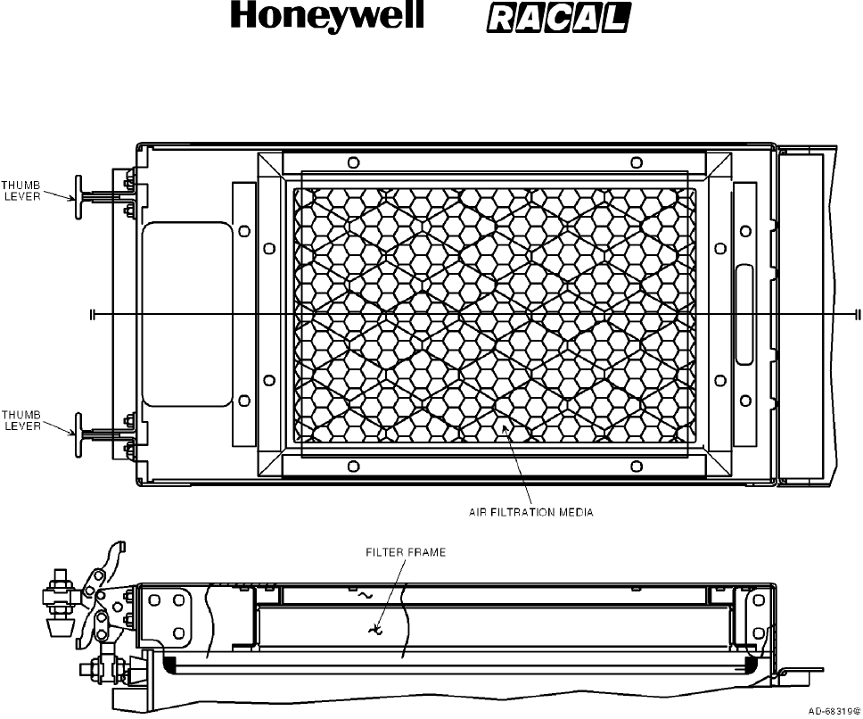
SYSTEM DESCRIPTION, INSTALLATION, AND MAINTENANCE MANUAL
MCS--4000/7000 Multi--Channel SATCOM System
23--20--27
30 Aug 2002
Use or disclosure of information on this page is subject to the restrictions in the proprietary notice of this document.
Page B--5
Figure B--1. ECS Top Mount Air Filtration Assembly
(3) Replace the filter media according to the following steps.
(a) Gain access to the SATCOM LRUs.
(b) Lift up on the two thumb levers (approximately 180 degrees).
(c) Pull up on the air filtration unit until it lifts off the top of the SATCOM LRU. The
sides of the air filtration assembly may need to be spread open slightly prior to
sliding up the sides of the LRU.
(d) Remove the air filtration media from the air filtration assembly in the rectangular
filter frame.
(e) Once the assembly is removed, pull the filter assembly out of its retaining fixture
and discard the filter appropriately.
(f) Obtain a new filter.
(g) Make sure the correct size filter assembly is selected for the given LRU (refer to
Table B--2).
(h) Install the new filter media into the filter assembly retaining fixture.
RELEASED FOR THE EXCLUSIVE USE BY: HONEYWELL INTERNATIONAL
UP86308

SYSTEM DESCRIPTION, INSTALLATION, AND MAINTENANCE MANUAL
MCS--4000/7000 Multi--Channel SATCOM System
23--20--27
30 Aug 2002
Use or disclosure of information on this page is subject to the restrictions in the proprietary notice of this document.
Page B--6
(i) OPTIONAL — Remove the SATCOM LRU from its tray and set on a secure
surface. (The assembly can be installed while the unit is in the rack.)
(j) Install the air filtration media inside the air filtration assembly in the rectangular
filter frame.
(k) Place the filter assembly over the top of the LRU with the clamps in the up
(thumb lever over the top of the filter assembly) position and pointing toward you.
(l) Push down on the air filtration unit until it fits over the top of the SATCOM LRU.
The sides of the air filtration assembly may need to be spread open slightly prior
to sliding over the sides of the LRU.
(m) Once the air filtration unit is firmly seated to the top of the LRU, clamp the
assembly to the unit by pushing down on the two thumb levers until they lock into
position. The thumb levers will pass through approximately 180 degrees of
rotation for the clamping process.
(n) Make sure the air filtration assembly remains seated firmly against the top of the
LRU to maintain the air seal.
(o) Make sure the air filtration assembly is held tightly to the unit by gently lifting up
on the assembly to verify the assembly does not pull off the LRU.
(p) OPTIONAL -- Install the SATCOM LRU back into its tray if removed in step
4.A.(3)(i).
B. Body--Mounted Assembly
(1) The ECS body-mounted air filtration assembly is designed to strap around the body
of the SATCOM LRUs in a way that it will not come off the LRU. Once attached to the
LRU, it forms a seal allowing only filtered air to enter the LRU. The assembly is held
to the top of the LRU with a strap that fits securely around the body of the unit. The
filtration unit sits on top of the SATCOM LRU. The strap runs down the side,
underneath, and up the other side of the LRU. By way of a clamping system on top of
the LRU, the strap is pulled tight, which firmly secures the filter assembly to the top of
the unit.
(2) Install the filter assembly to an SDU or HPA according to the following steps.
(a) Make sure the correct size assembly is selected for the given LRU
(refer to Table B--3).
(b) Remove the SATCOM LRU from its tray and set it on a secure surface.
(c) Slide the filter strap around the front of the LRU so the strap is underneath and
coming up each side of the LRU.
(d) Place the filter assembly on top of the LRU so the back lip of the assembly unit
fits over the back of the LRU.
RELEASED FOR THE EXCLUSIVE USE BY: HONEYWELL INTERNATIONAL
UP86308

SYSTEM DESCRIPTION, INSTALLATION, AND MAINTENANCE MANUAL
MCS--4000/7000 Multi--Channel SATCOM System
23--20--27
30 Aug 2002
Use or disclosure of information on this page is subject to the restrictions in the proprietary notice of this document.
Page B--7
(e) Pull the strap around the top of the filter assembly unit so the two ends of the
strap overlap. The strap should come over the top of the filter assembly on the
front end of the assembly (dog-house end of the LRU). A channel is built into the
filter assembly for the strap.
(f) With the strap in place, latch the strap together by inserting the lips of the strap
ends together so they latch together. With the LRU facing you, the strap on the
left-hand side should latch over the top of the strap on the right-hand side.
(g) Once the strap is latched, make sure the lip on the rear of the filter assembly is
seated firmly just over the rear of the LRU.
(h) Make sure the filter retainer mechanism is latched closed.
(3) Replace the filter media according to the following steps. Figure B--2 shows the
location of the components used.
(a) Gain access to the SATCOM LRUs.
(b) Locate the filter retaining clips located on the forward end of the filter assembly
mechanism.
(c) Slide the retainer clips (one on the left and one on the right) out to disengage the
clips from the latching pins.
(d) Lift the filter retaining tray up, (hinged on the rear side) remove the filter media
cartridge and discard the filter appropriately.
(e) Install the new filter media by placing a new filter media cartridge in the filter
retaining tray chamber.
(f) Lower the filter retaining tray down until the locating pins protrude through the
clearance holes on the filter retaining tray.
(g) Slide the retaining clips (left and right) in until they latch around the latching pins.
C. Tray--Mounted Assembly
(1) The ECS tray-mounted air filtration assembly is designed as an integral part of the
equipment tray and does not attach to the LRU itself. The SATCOM LRU slides into
the tray, sandwiched between the tray and plenum below, and the air filtration
assembly above. Since the air filtration assembly is an integral part of the equipment
tray, in order to install this type of assembly, a modified equipment tray must be
purchased for each LRU.
(2) Replace the filter media according to the following steps. Figure B--2 shows the
location of the components used.
(a) Gain access to the SATCOM LRUs.
(b) Locate the filter retaining clips located on the forward end of the filter assembly
mechanism.
RELEASED FOR THE EXCLUSIVE USE BY: HONEYWELL INTERNATIONAL
UP86308
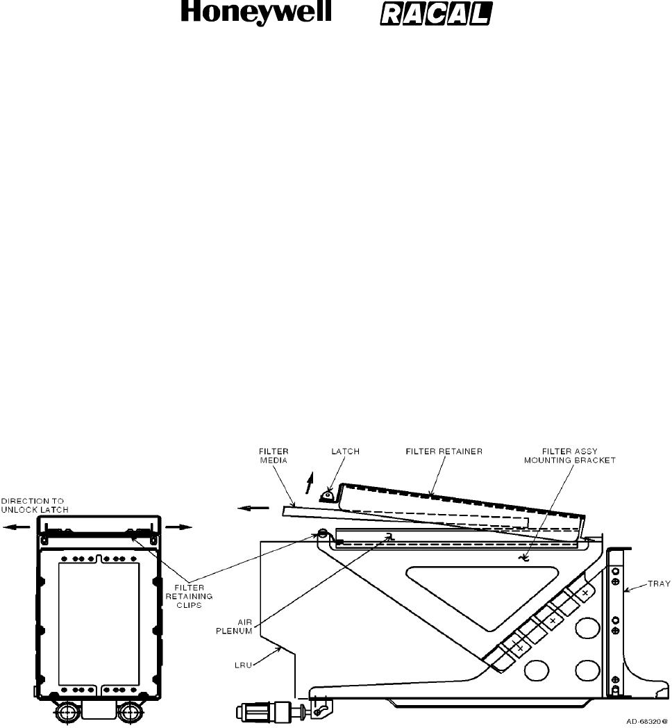
SYSTEM DESCRIPTION, INSTALLATION, AND MAINTENANCE MANUAL
MCS--4000/7000 Multi--Channel SATCOM System
23--20--27
30 Aug 2002
Use or disclosure of information on this page is subject to the restrictions in the proprietary notice of this document.
Page B--8
(c) Slide the retainer clips (one on the left and one on the right) out to disengage the
clips from the latching pins.
(d) Lift the filter retaining tray up (hinged on the rear side) and remove the filter
media cartridge. Discard the filter media cartridge appropriately.
(e) Install the new filter media by placing a new filter media cartridge in the filter
retaining tray chamber.
(f) Make sure the filter cartridge is supported on the air plenum seals. The direction
of airflow through the filter is not important.
(g) Lower the filter retaining tray until the locating pins protrude through the
clearance holes on the filter retaining tray.
(h) Slide the retaining clips (left and right) in until they latch around the latching pins.
Figure B--2. Front and Side Views Showing Filter Removal
RELEASED FOR THE EXCLUSIVE USE BY: HONEYWELL INTERNATIONAL
UP86308

SYSTEM DESCRIPTION, INSTALLATION, AND MAINTENANCE MANUAL
MCS--4000/7000 Multi--Channel SATCOM System
23--20--27
30 Aug 2002
Use or disclosure of information on this page is subject to the restrictions in the proprietary notice of this document.
Page C--1
APPENDIX C
OWNER REQUIREMENTS TABLE
1. Overview
A. General
(1) Appendix C contains information on the owner requirements table (ORT) and is
stored in non--volatile memory in the SDU. The ORT contains information relating to
different areas of functionality, such as log-on and telephony. The ORT does not lose
its contents because of the loss of SDU primary power or as a result of PAST. All
ORT contents are set to default values by a factory settings restart. The ORT
contains all pilot and aircraft operator entered information preserved when the SDU is
powered-down. The characteristics of the ORT are specified in Table C--1.
NOTE: Honeywell supplies Windows--based software (ORT editor) that is used to
generate the ORT files for upload. Contact your Honeywell representative for
a copy of this software.
Table C--1. ORT Characteristics
ORT Item Characteristic Attributes Description
iLog-On Policy Secured,
common
This item defines the log-on procedure. When the SDU has
power applied, the SDU either starts the automatic log-on
procedure at the earliest opportunity (automatic), or the SDU
goes to an inert standby state, even if the SDU is entirely
failure free, where the SDU then waits for user stimulus to
start logging-on (commanded).
ii Satellite/GES
Names
User,
common
This item defines associated names for the satellites and
GESs. Satellite names are up to five characters long. GES
names are up to 14 characters long. Names made up of
upper case letters, decimal digits, hyphens, and spaces are
allowed. A GES name can include satellite and service
identifying strings; e.g., GOON A--E SKY takes 12 characters
and identifies Goonhilly, the United Kingdom GES servicing
the Skyphone consortium and using the Atlantic ocean region
east satellite.
iii GES Preference
Values
User,
common
This item defines the automatic log-on preference values for
GESs from 0 to 9, where 9 corresponds to the most preferred
GES. The interpretation of preference value 0 is determined
by item lvi, 0 is either the least preferred GES or it is not used
for automatic log-on. GESs with preference level 0 can still be
used for a constrained log-on. When all GESs on a particular
satellite have a preference level of 0 and this satellite
becomes the candidate for logon, the logon processing
considers all of these GESs to have a preference level of 1 to
facilitate continued SATCOM operation.
iv Maintenance
Page Access
User,
common
This item defines whether the SCDU maintenance pages are
accessible as: a) never; b) always; or c) only when the aircraft
is on the ground.
RELEASED FOR THE EXCLUSIVE USE BY: HONEYWELL INTERNATIONAL
UP86308

SYSTEM DESCRIPTION, INSTALLATION, AND MAINTENANCE MANUAL
MCS--4000/7000 Multi--Channel SATCOM System
23--20--27
30 Aug 2002
Use or disclosure of information on this page is subject to the restrictions in the proprietary notice of this document.
Page C--2
Table C--1. ORT Characteristics (cont)
ORT Item DescriptionAttributesCharacteristic
vCockpit
Telephone
Numbers
User,
common
This item defines up to 100 telephone numbers as follows:
•Each made up of up to 18 numeric characters (including
optional spaces and/or trailing network ID preceded by a
slash)
•Each number having an associated priority value
(i.e., 1 thru 4), protection (i.e., protected or unprotected),
and a mnemonic of up to 14 characters
•All are located in four user-definable categories of no more
than 25 telephone numbers each.
If configuration pin TP13A is set to the zero state, every entry
with a priority 4 is modified to a priority 3 following an ORT
upload or following a POST/PAST where priority 4 numbers
existed prior to TP13A being set to the zero state. In a dual
system, this modification takes place only if strap TP13A is in
the zero state on both SDU systems. This item includes
manually entered telephones from the SCDU CATEGORY
NUMBERS pages.
vi Deleted
vii Resources
Reserved for
Headset
User,
common
When enabled, this item reserves the following resources for
cockpit headset use at all times: one codec, one modem, and
sufficient HPA power to support an extra C--channel in all
prevailing circumstances. These resources are capable of
being reserved for either of the cockpit audio channels. In a
dual system, channel refers to logical channel.
viii Response
Capability to
Log-On
Interrogation
N/A This item is not considered part of the MCS ORT, since the
AES always supports log-on interrogation. There is always
one SDU modem dedicated to P--channel reception and
capable of R--channel and T--channel transmission.
ix Use and Value of
Flight
Identification
N/A This item is not considered part of the MCS ORT since the
value is dynamic and is obtained from the CFDS/CMC/OMS
or SCDU (along with item xxxiv).
xGround-to-Air
Circuit-Mode
Data
User,
common
This item defines the allowing/disallowing of analog
interconnect circuit-mode data on ground-to-air calls. It lets
the AES identify itself to the GES as being data capable and
the owner/operator anticipates receiving ground-to-air calls
that need circuit-mode data service, thereby directing the
GES to assign data capable channels to all ground-to-air
calls.
xi Deleted
xii Deleted
RELEASED FOR THE EXCLUSIVE USE BY: HONEYWELL INTERNATIONAL
UP86308

SYSTEM DESCRIPTION, INSTALLATION, AND MAINTENANCE MANUAL
MCS--4000/7000 Multi--Channel SATCOM System
23--20--27
30 Aug 2002
Use or disclosure of information on this page is subject to the restrictions in the proprietary notice of this document.
Page C--3
Table C--1. ORT Characteristics (cont)
ORT Item DescriptionAttributesCharacteristic
xiii Ground-to-Air
Calls
User,
common
This item defines the allowing/disallowing and routing of
ground-to-air priority 4 calls. If calls are allowed and if two or
more of the AES voice user interfaces (i.e., digital phones,
analog handset, or headset) are fitted, this item specifies
which destination (digital phone, analog handset, or headset)
incoming priority 4 calls are routed. However, routing to the
headset is only possible if configuration pin TP13A is set to
the one state. If TP13A is set to the zero state, the ORT
setting is modified to Disallowed following a factory setting
restart, an ORT upload with headset selected, or a
POST/PAST if headset was selected prior to TP13A being set
to the zero state. In a dual system, ground-to-air priority 4
calls can be routed to an interface that is installed on at least
one of the SDU systems. Routing to HEADSET is only
possible if at least one SDU system has a codec wired to
AMS with TP13A strap in the one state (on this same SDU
system).
xiv Call Camp-On
Duration
User,
common
This item defines the camp-on duration be either indefinite, or
a specified time-out period in the range of 1 to 15 minutes, or
a time--out period of zero minutes (immediate time--out).
xv Camp-On
Time-out Action
User,
common
This item defines whether the camp-on time-out action is to
(a) preempt (if a candidate call exists) or to cancel camp-on
(if no candidate call exists), or (b) to cancel camp-on.
xvi Stored APHONE
(WH--10)
Telephone
Numbers
User,
duplicated
This item defines up to 10 stored telephone numbers (9
numbers plus last number redial), with each telephone
number made up of up to 18 digits, for each of the two analog
(APHONE) WH--10 channels. All such telephone numbers are
priority 4 and the priority is not modifiable. These two sets of
stored telephone numbers can be separate (distinct) or
shared as specified in ORT item xxvi.
xvii Deleted
xviii Noise Insertion
Level
Secured,
common
This item defines whether to enable or disable noise insertion
on ground-to-air circuit-mode telephone calls. When noise
insertion is enabled, this item also defines the level, as
selected. Noise insertion minimizes annoying noise
modulation when the GES drops the carrier in the forward
(to--aircraft) direction during speech pauses.
xix Ground-to-Air
Preemption
User,
common
This item defines whether or not incoming calls of priority 2
and/or 3 automatically preempt (as necessary) a candidate
call as specified in SYSTEM DESCRIPTION. Priority 1
ground-to-air calls unconditionally preempt other calls of lower
priority as necessary.
xx Preferred Cockpit
Call Routing
User,
common
This item defines the routing of ground-initiated cockpit voice
calls to a particular channel when two channels are available.
This item does not affect which channel should be preempted
if both channels are not available. In a dual system, channel
refers to logical channel.
RELEASED FOR THE EXCLUSIVE USE BY: HONEYWELL INTERNATIONAL
UP86308

SYSTEM DESCRIPTION, INSTALLATION, AND MAINTENANCE MANUAL
MCS--4000/7000 Multi--Channel SATCOM System
23--20--27
30 Aug 2002
Use or disclosure of information on this page is subject to the restrictions in the proprietary notice of this document.
Page C--4
Table C--1. ORT Characteristics (cont)
ORT Item DescriptionAttributesCharacteristic
xxi Preferred
APHONE Call
Routing
User,
duplicated
When allowed by item xiii, this item defines the routing of
ground-to-air priority 4 calls, when allowed in accordance with
item xiii, to a particular channel when two APHONE channels
are available. In a dual system, this item specifies the
preferred physical channel on each SDU system, or None
when there is no channel wired to APHONE on that system.
xxii HGATxGain
Threshold
Secured,
common
This item specifies the threshold on the reported HGA Tx gain
for stimulating log-on renewal at Class 1 or automatic
handover.
xxiii Analog telephone
(APHONE)
System
Management
Commands
Secured,
duplicated
This item defines the allowing/disallowing of system
management commands from the analog phone (APHONE)
interface (WH--10 or APBX).
xxiv Analog telephone
(APHONE)
Outgoing Call
Barring Level
User,
duplicated
This item defines one of three levels for analog phone call
barring. Level 0 allows all outgoing calls and the Store Phone
Number Memory command specified in SYSTEM
DESCRIPTION, but disallows six-digit numbers between
42XXXX and 47XXXX if accompanied by credit card data.
Level 1 allows only stored phone numbers, directly dialed
short-code phone numbers, and long dialed numbers from the
APBX accompanied with credit card data to initiate outgoing
calls. Level 1 disallows manually dialed full-length phone
numbers not accompanied with credit card data, six-digit
numbers between 42XXXX and 47XXXX if accompanied by
credit card data, and the Store Phone Number Memory
command. Level 2 disallows all outgoing calls, both manual
and stored numbers, and the Store Phone Number Memory
command.
NOTE: The six-digit numbers between 42XXXX and
47XXXX have been designated air traffic control
(ATC) destinations. These numbers may be dialed
at any priority and are assigned a network ID of 1.
In order to prevent unauthorized use of these
numbers once they become publicly available, the
AES filters these numbers appropriately. The
filtering specified prohibits these numbers from
being dialed with credit card data present based on
the assumption anyone making a call to one of
these numbers using a credit card is not an
authorized user (i.e., a passenger).
xxv Call Barring
Security Code
User,
duplicated
This item defines a four-digit password that, if entered
through the analog phone (APHONE), allows call barring
commands (SYSTEM DESCRIPTION) to be accepted.
RELEASED FOR THE EXCLUSIVE USE BY: HONEYWELL INTERNATIONAL
UP86308

SYSTEM DESCRIPTION, INSTALLATION, AND MAINTENANCE MANUAL
MCS--4000/7000 Multi--Channel SATCOM System
23--20--27
30 Aug 2002
Use or disclosure of information on this page is subject to the restrictions in the proprietary notice of this document.
Page C--5
Table C--1. ORT Characteristics (cont)
ORT Item DescriptionAttributesCharacteristic
xxvi Shared Analog
Telephone
(WH--10)
(APHONE)
Number Storage
User,
duplicated
This item defines whether the 10 stored numbers (9 numbers
plus the last number redial) maintained for each of the analog
phone (APHONE) channels are separate or shared (i.e.,
whether a phone number stored on a channel is accessible
by the dial stored phone number command on the other
channel).
xxvii Deleted
xxviii Default HPA
Backoff Limits
Secured,
duplicated
This item defines the maximum backoff values for the linear
and class C HPAs. The working (volatile) values are
automatically updated by non zero values (i.e., other than
16 dB) received in the HPA backoff range fields of valid HPA
status words. The nonvolatile entries are not modified with
the received values.
xxix HPA Minimum
Reportable
Actual Power
Output
Secured,
duplicated
This item defines the minimum values of actual power output
capable of being reported through the HPA status words by
the linear and class C HPAs. When this value or a lower value
is reported in the HPA status word, calibration is inhibited.
xxx Default Assumed
Global Beam
Initial C--Channel
EIRP
Secured,
common
This item defines the default assumed global beam initial
C--channel EIRP. This value is used to assess the power
availability for a C--channel call in the absence of any existing
C--channels.
xxxi SCDU Telephone
Number
Preselect
Secured,
common
This item defines whether selection of a phone number on
one of the CATEGORY NUMBERS pages preselects the
phone number or initiates a call using the phone number. If
this item is enabled, the selection of a phone number on one
of the CATEGORY NUMBERS pages or manual entry of a
phone number on the DIRECTORY page retrieves the
selected number to the SATCOM MAIN MENU page
(TESTING/FAULT ISOLATION), where the number can then
be dialed by selecting the MAKE CALL prompt or by any of
the call initiation methods triggered by activation of an input
discrete.
RELEASED FOR THE EXCLUSIVE USE BY: HONEYWELL INTERNATIONAL
UP86308

SYSTEM DESCRIPTION, INSTALLATION, AND MAINTENANCE MANUAL
MCS--4000/7000 Multi--Channel SATCOM System
23--20--27
30 Aug 2002
Use or disclosure of information on this page is subject to the restrictions in the proprietary notice of this document.
Page C--6
Table C--1. ORT Characteristics (cont)
ORT Item DescriptionAttributesCharacteristic
xxxii ACP Call
Initiation
Secured,
common
This item enables/disables ACP call initiation. This item can
only be enabled when item xxxi is enabled. If enabled, one of
the following two pairs of SDU discretes are capable of being
used for call initiation (when the associated cockpit voice call
light outputs are open), based on the state of program pin
TP13K:
•Cockpit voice mic on inputs — if the latched ACP
hookswitch signaling method is strapped.
•Place/End call discrete inputs — if the switched PTT
hookswitch signaling method is strapped.
In either case, this item specifies whether the number dialed
should come from the ATC phone number register rather than
the SCDU MAIN menu. If the MAIN menu is selected, the
phone number displayed on the SATCOM MAIN MENU (3L
label line for channel 1, or 5L label line for channel 2) is used
for call initiation. If the ATC menu is selected, the phone
number displayed on the ATC menu is used for call initiation
on either cockpit channel. In a dual system, this item is
enabled if the straps of both SDU systems are identical.
xxxiii User (or
Composite)
Partition ORT
Description
User,
common
This item defines the 24-character field to describe the ORT.
The ORT description is a 24-character field that annotates a
particular set of options, in order to distinguish one set from
another (e.g., NORTH PACIFIC ROUTE, SOUTH ATLANTIC
ROUTE, 747--400 ASIAN ROUTE, 777 ASIAN ROUTE).
Alternatively, this item could contain a software identification
(e.g., a software part number for the ORT as a released
entity). If the ORT version is for a composite file, the
description field is for the entire ORT and item liii is not used.
See item liii also.
xxxiv Airline Code User,
common
This item defines an airline code made up of up to four ISO--5
characters to be used with a four-digit BCD flight number
received from a McDonnell Douglas CFDIU (SYSTEM
DESCRIPTION) in constructing a flight identifier for log-on.
This is only used if the CFDS/CMC/OMS does not supply the
airline code.
xxxv Headset
Outgoing Call
Barring Level
User,
common
This item defines one of two levels for headset call barring.
Level 0 allows all outgoing calls. Level 1 allows only stored
phone numbers, manually dialed short-code numbers, and
manually dialed numbers with a network ID other than 1. For
Level 1 call barring, all cockpit stored numbers are treated as
protected (i.e., they cannot be modified from the SCDU).
xxxvi Headset Transit
Call
User,
common
This item either enables or disables transit calls from the
headset for line select key 4L.
RELEASED FOR THE EXCLUSIVE USE BY: HONEYWELL INTERNATIONAL
UP86308

SYSTEM DESCRIPTION, INSTALLATION, AND MAINTENANCE MANUAL
MCS--4000/7000 Multi--Channel SATCOM System
23--20--27
30 Aug 2002
Use or disclosure of information on this page is subject to the restrictions in the proprietary notice of this document.
Page C--7
Table C--1. ORT Characteristics (cont)
ORT Item DescriptionAttributesCharacteristic
xxxvii User ORT
Partition Modified
Flag
User,
common
This item indicates whether any item in the nonvolatile copy
of the user partition of the ORT partition has been modified
since the ORT was created in a configured state by the
PC-based off-line ORT editing tool. When any user-partition
ORT item is modified in nonvolatile memory by the SDU
software, either directly or indirectly, this flag is set to
modified. This value is never set to unmodified by the SDU
software. Its value is displayed on the SCDU, on the CFDS,
on the front panel display of the SDU, and on the CMT.
xxxviii Failure Masking
Data
Secured,
common
This item is made up of a list of up to 50 failures (Level I
code, SRU code, and failure code) whose operation is
masked or suppressed. A switch is stored with each specified
failure to indicate whether that failure should never be raised
(i.e., the failure annunciation and reversion should be
suppressed completely), or whether the failure should be
annunciated normally (i.e., recorded and reported as
specified in TESTING/FAULT ISOLATION) when declared,
but not indict the appropriate functional resource specified for
the failure (i.e., not take any other action in response to the
failure, such as reconfiguring redundant resources). Unused
entries in this table are represented by the Level I code, SRU
code, and failure code all set to zero.
xxxix Elevation
Handover
Threshold
Secured,
common
This item, ranging in integer degrees between 0°and 90°,is
used in combination with calculated elevation of the highest
satellite to determine at what elevation to initiate a handover
from the current satellite. This item is also used to determine
when a satellite is not high enough in elevation to be
considered in view for acquisition purposes by the automatic
log-on process.
xl High Rate Data
Transmit Support
User,
common
This item made up of two flags that specify (by being set to
enabled or disabled) whether the SDU indicates support for
10,500 bps R-- and T--channels in its log-on request of class
2, 3, and 4 (i.e., when using a high gain antenna), for the
global beam and spot beam log-on requests, respectively.
RELEASED FOR THE EXCLUSIVE USE BY: HONEYWELL INTERNATIONAL
UP86308

SYSTEM DESCRIPTION, INSTALLATION, AND MAINTENANCE MANUAL
MCS--4000/7000
23--20--27
5 Feb 2008
©Honeywell International Inc. Do not copy without express permission of Honeywell.
Page C--8
Table C--1. ORT Characteristics (cont)
ORT Item DescriptionAttributesCharacteristic
xli Automatic Transit
Call GES Table Secured,
common This item indicates the transit GES ID to be specified in an
air-to-ground call setup request (SYSTEM DESCRIPTION) if
no transit GES ID has been explicitly specified through the
initiating user interface (APHONE, Headset, DPHONE). If the
GES ID in the table is 377 octal (indicating null), then the
log-on GES is used in the call setup request. For each
satellite ID of 0, 1, 2, and 3, the table stores a GES ID to be
used with the following types of calls:
•Any PSTN long number call (i.e., with network ID 1, with
between 7 and 18 digits, beginning with 00) with country
code beginning with 1 (i.e., North America)
•Any PSTN long number call with a country code beginning
with 2 (i.e., Africa)
•Any PSTN long number call with a country code beginning
with 3 (i.e., South and West Europe)
•Any PSTN long number call with a country code beginning
witha4(i.e.,NorthandEastEurope)
•Any PSTN long number call with a country code beginning
witha5(i.e.,SouthAmerica)
•Any PSTN long number call with a country code beginning
witha6(i.e.,SouthEastAsiaandAustralia)
•Any PSTN long number call with a country code beginning
witha7(i.e.,SovietUnion)
•Any PSTN long number call with a country code beginning
with an 8 (i.e., Far East)
•Any PSTN long number call with a country code beginning
witha9(i.e.,India and Middle East)
•Any PSTN short number call (i.e., network ID of 1, with
between 2 and 6 digits not beginning with 00)
The geographical region associated with each zone is
approximate; refer to Table C--1 for details of individual
country codes.
xlii Air-to-Ground
Chime Secured,
common This item defines one of three chime options. These options
only affect air-to-ground chime activation for call annunciation
and the setting of SDU-to-ACARS MU/CMU status word bits.
The first option is to always chime and always set the
appropriate bits. The second option is to chime and set the
appropriate bits only if the call was camped-on. The third
option is to never chime and never set the bits.
RELEASED FOR THE EXCLUSIVE USE BY: HONEYWELL INTERNATIONAL
UP86308

SYSTEM DESCRIPTION, INSTALLATION, AND MAINTENANCE MANUAL
MCS--4000/7000 Multi--Channel SATCOM System
23--20--27
30 Aug 2002
Use or disclosure of information on this page is subject to the restrictions in the proprietary notice of this document.
Page C--9
Table C--1. ORT Characteristics (cont)
ORT Item DescriptionAttributesCharacteristic
xliii SCDU Call
Prompts
Secured,
common
This item defines one of three levels of SCDU call prompt
display. Level 0 causes all SCDU call prompts to be
displayed. Level 1 causes the ANSWER CALL, REJECT, and
END CALL prompts to not be displayed. Level 2 causes the
MAKE CALL prompt and the Level 1 prompts to not be
displayed. Level 2 is selectable only if ORT item xxxii is
enabled.
xliv EIRP Overdraft
Checking Priority
Secured,
common
This item defines the call priority level where at least one call
must be in progress when considering if an EIRP overdraft is
allowed.
xlv Analog
Telephone
(APHONE)
Called Terminal
ID Assignment
User,
duplicated
This item provides for the assignment of a three-digit called
terminal identification (CTid) code to each APHONE channel
routing ground-to-air priority 4 calls to the APHONE interface,
based on the called terminal field in the call announcement
signal unit. The CTid assigned can be any decimal value
between --1 and 999. A CTid value of --1 represents no
specific routing.
This item also specifies a CTid assignment type of exclusive
or nonexclusive for each channel. The assignment type
defaults to nonexclusive if no CTid is assigned. An
assignment type of exclusive with no CTid assigned is
undefined and is not selectable. With a CTid assigned, an
assignment type of exclusive inhibits all incoming calls from
being routed to the associated channel unless the call
announcement contains a CTid that matches the assigned
value. An assignment type of nonexclusive allows all
incoming calls to be routed to the associated channel unless
the call announcement contains a CTid that matches the
assigned value of the other channel. Regardless of the
assignment type, an incoming call with a matching CTid is
rejected if the associated channel is unavailable.
Modifications of this item through the APHONE or CMT are
checked for duplication with the other APHONE channel in
the SDU and, in a dual system, with the APHONE channels in
the other SDU.
The primary use of this ORT item is to let incoming facsimile
calls be routed to the channel connected to the facsimile
machine.
xlvi Cockpit Audio
Level Settings
Secured,
common
This item defines the level settings for the cockpit
microphone, sidetone, and receive audio.
xlvii HGA Retry
Period (ground
and air)
Secured,
common
This item defines the time interval for ground and airborne
cases after which SATCOM (when logged on through the
LGA) is to make attempts to logon through the HGA. A value
of 0 disables the periodic retry for each case. The time
interval is in integer minutes ranging from 0 to 255.
RELEASED FOR THE EXCLUSIVE USE BY: HONEYWELL INTERNATIONAL
UP86308

SYSTEM DESCRIPTION, INSTALLATION, AND MAINTENANCE MANUAL
MCS--4000/7000 Multi--Channel SATCOM System
23--20--27
30 Aug 2002
Use or disclosure of information on this page is subject to the restrictions in the proprietary notice of this document.
Page C--10
Table C--1. ORT Characteristics (cont)
ORT Item DescriptionAttributesCharacteristic
xlviii Cockpit Channel
Interface Type for
Dual
Secured,
common
This item defines the functional mapping of the one to four
potentially available physical SDU cockpit voice channels in a
dual system to the one or two logical cockpit voice channels
(as viewed from the perspective of the ACP and SCDU). It is
used in combination with ORT item vi and system
configuration pins TP13F and TP13J to determine the
number of logical channels and which physical channel(s)
is/are potentially available for each logical channel.
This item is capable of taking on the states of fixed and
shared. Fixed interfacing is interfacing each ACP/SCDU
(logical) channel to one physical channel on one SDU only.
Shared interfacing is interfacing each ACP/SCDU logical
channel to one physical channel on each of the two SDUs.
The fixed or shared interfacing declaration refers to the
functional channel mapping, and not necessarily to the
physical interwiring, e.g., the interwiring can be independent
but the interface can be effectively shared by virtue of
splitting/combining/paralleling within the AMS (as in the
Boeing 777), or the interwiring can be literally paralleled,
forcing the interface type to shared.
In the case of two logical channels, it is assumed the single
value for this item applies to both channels (i.e., both fixed or
both shared). For the case of shared (for one or two logical
channels), it is assumed each logical channel shares the
same numbered physical channel on each SDU.
The state of this item is checked for compatibility with the
state of pins TP13F and TP13J of both SDUs and the state of
ORTitemviofbothSDUs.
RELEASED FOR THE EXCLUSIVE USE BY: HONEYWELL INTERNATIONAL
UP86308

SYSTEM DESCRIPTION, INSTALLATION, AND MAINTENANCE MANUAL
MCS--4000/7000 Multi--Channel SATCOM System
23--20--27
30 Aug 2002
Use or disclosure of information on this page is subject to the restrictions in the proprietary notice of this document.
Page C--11
Table C--1. ORT Characteristics (cont)
ORT Item DescriptionAttributesCharacteristic
il Mastery
Handover
Algorithm
Weighting
User,
common
This item stores the relative weighting factors for each of the
six functional capability items that form the criteria for
determining which system should automatically become the
master in a dual system. Each of the six weighting factors is a
non-negative integer ranging from 0 to 99. Higher factors
indicate more important criteria; however, only the relative
values of the factors is significant. Zero is used to indicate a
capability factor not installed, not used, or is a don’t care. The
functional capability items are as follows:
•CoV -- Cockpit voice (for any number of channels).
•CaV -- Cabin circuit-mode voice/fax/data
(any number of channels, any cabin interface).
•CoL -- Cockpit packet-mode data
(through [C]MU) at low-rate only.
•CoH -- Cockpit packet-mode data
(through [C]MU) at (potentially) high-rate.
•CaL -- Cabin packet-mode data
(through CPDF or CTU) at low rate only.
•CaH -- Cabin packet-mode data (through CPDF or CTU) at
(potentially) high-rate.
CoL and CoH are mutually exclusive, as are CaL and
CaH — i.e., regardless of the weighting factors assigned, no
more than one of the cockpit data (or cabin data) capabilities
canbetrueatatime.
The primary practical use of this ORT item is for determining
which SDU in a dual system should be the master when the
choice is down to one system which only has voice capability
vs one which only has data capability, or one with only cockpit
services capabilities vs one with only cabin services
capabilities.
lDisable/Reenable
Other SATCOM
SCDU Prompts
Secured,
common
This item determines if the disable other SATCOM and
re--enable other SATCOM toggling SCDU prompts are
presented or suppressed. The SCDU prompts are usually
suppressed if the optional external manual switch (that
controls the dual system select and disable discretes) is
supplied so there is only one means of performing any
function at a time and the possibility of inadvertently disabling
both systems is avoided.
li SCDU SATCOM
Subsystem
Prompts
Secured,
duplicated
This item defines up to six ISO--5 characters used for the
SCDU main menu SATCOM subsystem selection LSK
prompts. The owner/operator is able to select any ISO--5
characters and any length up to six characters. Example
character strings would be SAT L and SAT R, or <SDU--1 and
<SDU--2.
RELEASED FOR THE EXCLUSIVE USE BY: HONEYWELL INTERNATIONAL
UP86308

SYSTEM DESCRIPTION, INSTALLATION, AND MAINTENANCE MANUAL
MCS--4000/7000 Multi--Channel SATCOM System
23--20--27
30 Aug 2002
Use or disclosure of information on this page is subject to the restrictions in the proprietary notice of this document.
Page C--12
Table C--1. ORT Characteristics (cont)
ORT Item DescriptionAttributesCharacteristic
lii SCDU Channel
Label Suffixes
Secured,
common
This item defines the one-character suffix for each cockpit
voice channel label on the SCDU displays. The choices are 1
and 2, or L and R for channels 1 and 2, respectively. These
suffixes are used for the channel identifiers on the SATCOM
Main Menu, Directory, and Category Numbers pages.
liii Secured ORT
Description
Secured,
common
This items defines a 24-character (ISO--5) field to describe
the secured ORT partition. The description field is used to
write a particular set of secured ORT items to distinguish one
from another (e.g., B777 DUAL 950901, B747--400 DUAL
951001, B747--300 STC 951225). Alternatively, this item can
contain a software identification (e.g., a software part number
for the ORT as a released entity). If the ORT version is for a
composite file, description field xxxiii is for the entire ORT, so
item liii is not used in that case.
liv Composite ORT
File Upload
Capability
Secured,
common
This item defines whether or not the uploading of a composite
ORT file version is to be allowed. This option is required to
prevent the unintentional overwriting of the secured partition
with a composite ORT file that contains both user and
secured ORT items.
lv Secured ORT
Modified Flag
Secured,
common
This item indicates whether any item in the nonvolatile copy
of the secured ORT partition has been modified since the
ORT was created in a configured state by the PC-based
off-line ORT editing tool. When any secured ORT item is
modified in nonvolatile memory by the SDU software, directly
or indirectly, this flag is set to Modified. This value is never set
to Unmodified by SDU software. Its value is displayed on the
SCDU, the CFDS, the front panel display, and the CMT.
lvi Access to
Zero-Preference
GESs
Secured,
common
This item defines whether automatic log-on is allowed or
disallowed to GESs with preference values set to zero by
ORT item iii. This is intended to be set to allowed in Essential
certified systems so at least two GESs are selectable for
automatic log-on on each satellite. It can be set to disallowed
in nonessential certified systems to intentionally preclude
automatic log-on to particular GESs, e.g., those with the AES
owner/operator have no contractual arrangements. See ORT
item iii for additional information.
lvii L--Band
Reference Offset
Calibration
Thresholds
Secured,
common
This item defines (in Hz) the thresholds of the L--Band
reference offset calibration for both the with IRS and without
IRS cases. These thresholds are used to determine whether
to adjust the L--Band reference offsets. These values are
displayed on the CMT.
lviii Suppress AES
Position
Reporting
User,
common
This item enables or disables the AES position reporting sent
across each active C--channel.
RELEASED FOR THE EXCLUSIVE USE BY: HONEYWELL INTERNATIONAL
UP86308

SYSTEM DESCRIPTION, INSTALLATION, AND MAINTENANCE MANUAL
MCS--4000/7000 Multi--Channel SATCOM System
23--20--27
30 Aug 2002
Use or disclosure of information on this page is subject to the restrictions in the proprietary notice of this document.
Page C--13
Table C--1. ORT Characteristics (cont)
ORT Item DescriptionAttributesCharacteristic
lix APHONE Audio
Level Setting
Secured,
common
This item defines the output level setting for the receive
audio.
lx AERO H Only
Operation
Secured,
common
This item defines the service mode when an HGA is installed.
RELEASED FOR THE EXCLUSIVE USE BY: HONEYWELL INTERNATIONAL
UP86308

SYSTEM DESCRIPTION, INSTALLATION, AND MAINTENANCE MANUAL
MCS--4000/7000 Multi--Channel SATCOM System
23--20--27
30 Aug 2002
Use or disclosure of information on this page is subject to the restrictions in the proprietary notice of this document.
Page C--14
Blank Page
RELEASED FOR THE EXCLUSIVE USE BY: HONEYWELL INTERNATIONAL
UP86308

SYSTEM DESCRIPTION, INSTALLATION, AND MAINTENANCE MANUAL
MCS--4000/7000
23--20--27 5 Feb 2008
©Honeywell International Inc. Do not copy without express permission of Honeywell.
Page D--1
APPENDIX D
FAULT CODES
LEVEL 1 SRU FAILURE MONITORING TESTER FAILURE DESCRIPTION
Failure Overview
SDU
UNKNOWN SDU SRU
01 0 02 CM HMPM HPA CMD WORD (143) UPDATE RATE FAIL
01 0 03 CM HMPM HPA CMD WORD (143) DATA FAIL
01 0 07 CM SMPM HSU1--SDU W’BURG DATA TX FAIL
01 0 08 CM SMPM HSU1--SDU W’BURG SOLO WORD ACK FAIL
01 0 0B CM SMPM HSU2--SDU W’BURG DATA TX FAIL
01 0 0C CM SMPM HSU2--SDU W’BURG SOLO WORD ACK FAIL
01 0 10 CM SMPM HGA HPA COMMAND WORD (NCD)
01 0 12 CM SMPM LGA HPA COMMAND WORD (NCD)
01 0 96 PP SMPM INCOMPLETE ID PROM RESPONSES
SMPM: SDU MAIN PROCESSOR MODULE
01 1 81 PP SMPM SDU H/W--S/W COMPATIBILITY FAIL
01 1 82 PP SMPM BATTERY VOLTAGE LOW
01 1 83 PP SMPM WATCHDOG TIMEOUT FAIL
01 1 84 PP SMPM MICRO BOOT ROM FAIL
01 1 85/05 PP/CM SMPM EEPROM FAIL
01 1 86/06 PP/CM SMPM FLASH FAIL
01 1 87/07 PP/CM SMPM SRAM FAIL]
01 1 88/08 PP/CM SMPM REAL TIME CLOCK FAIL
01 1 89 PP SMPM QUART FAIL
01 1 0A CM SMPM SOFTWARE ERROR (SYSFAIL)
01 1 0B CM SMPM FLASH--PSRAM MISCOMPARE
01 1 0C CM SMPM FLASH--PSRAM MISCOMPARE EXTENSION
01 1 0D CM SMPM FLASH--PSRAM MISCOMPARE EXTENSION
CODA: SDU VOICE CODEC MODULE A
01 2 81/01 PP/CM CODA <CODEC--A> PROGRAM MEMORY CRC FAIL
01 2 87/07 PP/CM CODA <CODEC--A> TIMING GENERATOR FAIL
01 2 88 PP CODA <CODEC--A> DUAL PORT RAM FAIL CODEC SIDE
01 2 8A/0A PP/CM CODA <CODEC--A> PROGRAM MEMORY W/R FAIL
01 2 8B PP CODA <CODEC--A> DSP INTERNAL MEMORY W/R FAIL
01 2 8C/0C PP/CM CODA <CODEC--A> DSP COMPREHENSIVE FAIL
01 2 0D CM SMPM <CODEC--A> HEALTH COUNT UPDATE
01 2 8E PP SMPM <CODEC--A> DUAL PORT RAM FAIL SMPM SIDE
01 2 90 PP SMPM <CODEC--A> BUS ERROR
01 2 91 PP SMPM <CODEC--A> SELF TEST MISOPERATION
01 2 12 CM SMPM <CODEC--A> COMMUNICATION PROBLEM
01 2 94 PP SMPM <CODEC--A> ST BUS AUDIO LOOPBACK FAIL
01 2 95 PP SMPM <CODEC--A> SW DOWNLOAD FAIL
CODB: SDU VOICE CODEC MODULE B
01 3 Same entries as for CODA above except substitute CODB for CODA, SRU code 3 for code 2, [CODEC_B] for [CODEC_A] and
<CODEC--B> for <CODEC--A>.
Fault codes for codecs C--F have Level 2 (SRU) codes E--H. They are listed in the appropriate section of this table for those SRU codes.
SIOM: SDU INPUT/OUTPUT MODULE (EXCLUSIVE TO SIOM)
01 4 81 PP SMPM A429 XMTR LOOP--BACK TO OTHER SDU FAIL
01 4 82 PP SMPM A429 XMTR LOOP--BACK TO CFDS FAIL
01 4 83 PP SMPM A429 XMTR LOOP--BACK TO ADL FAIL
01 4 84 PP SMPM A429 XMTR LOOP--BACK TO PDL FAIL
01 4 85 PP SMPM A429 XMTR LOOP--BACK TO (C)MUs FAIL
01 4 86 PP SMPM A429 XMTR LOOP--BACK TO SCDUs FAIL
01 4 87 PP SMPM A429 XMTR LOOP--BACK TO MULTI--CNTRL FAIL
01 4 89 PP SMPM A429 XMTR LOOP--BACK TO RMP/CAP FAIL
01 4 8A PP SMPM A429 XMTR LOOP--BACK TO SNU/CPDF FAIL
01 4 8B PP SMPM A429 XMTR LOOP--BACK TO HSU1 FAIL
01 4 8C PP SMPM A429 XMTR LOOP--BACK TO HSU2 FAIL
01 4 8D PP SMPM A429 XMTR LOOP--BACK SPARE
01 4 8E PP SMPM A429 XMTR LOOP--BACK SPARE
01 4 8F PP SMPM A429 XMTR LOOP--BACK SPARE
01 4 90 PP SMPM A429 XMTR LOOP--BACK SPARE
01 4 AB PP SMPM SIOM BUS ERROR
01 4 2C CM SMPM A429 TX TO OTHER SDU BUFFER FULL
01 4 2D CM SMPM A429 TX TO CFDS BUFFER FULL
01 4 2E CM SMPM A429 TX TO ADL BUFFER FULL
01 4 2F CM SMPM A429 TX TO PDL BUFFER FULL
RELEASED FOR THE EXCLUSIVE USE BY: HONEYWELL INTERNATIONAL
UP86308

SYSTEM DESCRIPTION, INSTALLATION, AND MAINTENANCE MANUAL
MCS--4000/7000
23--20--27 5 Feb 2008
©Honeywell International Inc. Do not copy without express permission of Honeywell.
Page D--2
LEVEL 1 SRU FAILURE MONITORING TESTER FAILURE DESCRIPTION
01 4 30 CM SMPM A429 TX TO (C)MUs BUFFER FULL
01 4 31 CM SMPM A429 TX TO SCDUs BUFFER FULL
01 4 32 CM SMPM A429 TX TO MULTI--CTRL BUFFER FULL
01 4 34 CM SMPM A429 TX TO RMP/CAP BUFFER FULL
01 4 35 CM SMPM A429 TX TO SNU/CPDF BUFFER FULL
01 4 36 CM SMPM A429 TX TO HSU1 BUFFER FULL
01 4 37 CM SMPM A429 TX TO HSU2 BUFFER FULL
01 4 38 CM SMPM A429 TX BUFFER FULL SPARE
01 4 39 CM SMPM A429 TX BUFFER FULL SPARE
01 4 3A CM SMPM A429 TX BUFFER FULL SPARE
01 4 3B CM SMPM A429 TX BUFFER FULL SPARE
01 4 BC PP SMPM SIOM INTERRUPT FAIL
01 4 3D CM SMPM IRS ASIC MATCHING PROBLEM
SMDM1: SDU MODEM MODULE #1
01 5 81 PP SMDM1 <MODEM--1> PROCESSOR FAIL
01 5 84/04 PP/CM SMDM1 <MODEM--1> PROGRAM CRC FAIL
01 5 0A CM SMDM1 <MODEM--1>MODEM TO RFM INTERFACE FAIL
01 5 8B PP SMDM1 <MODEM--1> TIMER/INTERRUPT FAIL
01 5 8E PP SMDM1 <MODEM--1> EXTERNAL MEMORY FAIL
01 5 91 PP SMDM1 <MODEM--1> MODEM DPR FAIL
01 5 95 PP SMPM <MODEM--1> SMPM SIDE DPR FAIL
01 5 16 CM SMPM <MODEM--1> SW DOWNLOAD FAIL
01 5 17 CM SMPM <MODEM--1> HEALTH COUNT UPDATE FAIL
01 5 99 PP SMPM <MODEM--1> BUS ERROR
01 5 9A PP SMPM <MODEM--1> SELF TEST MISOPERATION
01 5 1B CM SMDM1 <MODEM--1> SOFTWARE FAIL
01 5 1C CM SMPM <MODEM--1> COMMUNICATIONS PROBLEM
01 5 9E PP SMPM <MODEM--1> RFM SSI LOOPBACK FAIL
SMDM2: SDU MODEM MODULE #2
01 6 Same entries as for SMDM1 above except substitute SMDM2 for SMDM1, SRU code 6 for code 5, [MODEM_2] for [MODEM_1] and
<MODEM--2> for <MODEM--1>.
SMDM3: SDU MODEM MODULE #3
01 7 Same entries as for SMDM1 above except substitute SMDM3 for SMDM1, SRU code 7 for code 5, [MODEM_3] for [MODEM_1] and
<MODEM--3> for <MODEM--1>.
Fault codes for modems 4--7 have Level 2 (SRU) codes J, L, M and N. They are listed in this table in the appropriate section for those SRU
codes.
SRFM: SDU RADIO FREQUENCY MODULE
01 8 8E/0E PP/CM SMPM RF SYNTH CHAN1 LOCK DETECT FAIL
01 8 90/10 PP/CM SMPM RF SYNTH CHAN2 LOCK DETECT FAIL
01 8 92/12 PP/CM SMPM RF SYNTH CHAN3 LOCK DETECT FAIL
01 8 96/16 PP/CM SMPM RF SYNTH CHAN4 LOCK DETECT FAIL
01 8 97/17 PP/CM SMPM RF SYNTH CHAN5 LOCK DETECT FAIL
01 8 98/18 PP/CM SMPM RF SYNTH CHAN6 LOCK DETECT FAIL
01 8 99/19 PP/CM SMPM RF SYNTH CHAN7 LOCK DETECT FAIL
01 8 9A/1A PP/CM SMPM RF SYNTH CHAN8 LOCK DETECT FAIL
01 8 9B/1B PP/CM SMPM RF SYNTH TX BLOCK PLO LOCK DETECT FAIL
01 8 9C/1C PP/CM SMPM RF SYNTH RX BLOCK PLO LOCK DETECT FAIL
01 8 9D/1D PP/CM SMPM RF SYNTH RX CHAN PLO LOCK DETECT FAIL
01 8 9E/1E PP/CM SMPM RF SYNTH TX DOPPLER PLO LOCK DETECT FAIL
01 8 A0 PP SMPM RFM CHAN 1 L--BAND LOOP--BACK (TX) FAIL
01 8 A1 PP SMPM RFM CHAN 1 L--BAND LOOP--BACK (RX) FAIL
01 8 A2 PP SMPM RFM CHAN 2 L--BAND LOOP--BACK (TX) FAIL
01 8 A3 PP SMPM RFM CHAN 2 L--BAND LOOP--BACK (RX) FAIL
01 8 A4 PP SMPM RFM CHAN 3 L--BAND LOOP--BACK (TX) FAIL
01 8 A5 PP SMPM RFM CHAN 3 L--BAND LOOP--BACK (RX) FAIL
01 8 A6 PP SMPM RFM CHAN 4 L--BAND LOOP--BACK (TX) FAIL
01 8 A7 PP SMPM RFM CHAN 4 L--BAND LOOP--BACK (RX) FAIL
01 8 A8 PP SMPM RFM CHAN 5 L--BAND LOOP--BACK (TX) FAIL
01 8 A9 PP SMPM RFM CHAN 5 L--BAND LOOP--BACK (RX) FAIL
01 8 AA PP SMPM RFM CHAN 6 L--BAND LOOP--BACK (TX) FAIL
01 8 AB PP SMPM RFM CHAN 6 L--BAND LOOP--BACK (RX) FAIL
01 8 AC PP SMPM RFM CHAN 7 L--BAND LOOP--BACK (TX) FAIL
01 8 AD PP SMPM RFM CHAN 7 L--BAND LOOP--BACK (RX) FAIL
01 8 AE PP SMPM RFM CHAN 8 L--BAND LOOP--BACK (TX) FAIL
01 8 AF PP SMPM RFM CHAN 8 L--BAND LOOP--BACK (RX) FAIL
01 8 30 CM SMPM RFM CHAN 1 TX CALIBRATION ERROR
01 8 31 CM SMPM RFM CHAN 2 TX CALIBRATION ERROR
01 8 32 CM SMPM RFM CHAN 3 TX CALIBRATION ERROR
RELEASED FOR THE EXCLUSIVE USE BY: HONEYWELL INTERNATIONAL
UP86308

SYSTEM DESCRIPTION, INSTALLATION, AND MAINTENANCE MANUAL
MCS--4000/7000
23--20--27 5 Feb 2008
©Honeywell International Inc. Do not copy without express permission of Honeywell.
Page D--3
LEVEL 1 SRU FAILURE MONITORING TESTER FAILURE DESCRIPTION
01 8 33 CM SMPM RFM CHAN 4 TX CALIBRATION ERROR
01 8 34 CM SMPM RFM CHAN 5 TX CALIBRATION ERROR
01 8 35 CM SMPM RFM CHAN 6 TX CALIBRATION ERROR
01 8 36 CM SMPM RFM CHAN 7 TX CALIBRATION ERROR
01 8 37 CM SMPM RFM CHAN 8 TX CALIBRATION ERROR
01 8 38 CM SMPM RFM CHAN 1 RX CALIBRATION ERROR
01 8 39 CM SMPM RFM CHAN 2 RX CALIBRATION ERROR
01 8 3A CM SMPM RFM CHAN 3 RX CALIBRATION ERROR
01 8 3B CM SMPM RFM CHAN 4 RX CALIBRATION ERROR
01 8 3C CM SMPM RFM CHAN 5 RX CALIBRATION ERROR
01 8 3D CM SMPM RFM CHAN 6 RX CALIBRATION ERROR
01 8 3E CM SMPM RFM CHAN 7 RX CALIBRATION ERROR
01 8 3F CM SMPM RFM CHAN 8 RX CALIBRATION ERROR
01 8 C0/40 PP/CM SMPM RFM CHAN 1 AGC TELLBACK FAIL
01 8 C1/41 PP/CM SMPM RFM CHAN 2 AGC TELLBACK FAIL
01 8 C2/42 PP/CM SMPM RFM CHAN 3 AGC TELLBACK FAIL
01 8 C3/43 PP/CM SMPM RFM CHAN 4 AGC TELLBACK FAIL
01 8 C4/44 PP/CM SMPM RFM CHAN 5 AGC TELLBACK FAIL
01 8 C5/45 PP/CM SMPM RFM CHAN 6 AGC TELLBACK FAIL
01 8 C6/46 PP/CM SMPM RFM CHAN 7 AGC TELLBACK FAIL
01 8 C7/47 PP/CM SMPM RFM CHAN 8 AGC TELLBACK FAIL
01 8 C8/48 PP/CM SMPM RFM BLOCK AGC TELLBACK FAIL
01 8 C9 PP SMPM I/Q CALIBRATION FAIL
01 8 D0 PP SMPM RFM CHAN 1 AGC CALIBRATION ERROR
01 8 D1 PP SMPM RFM CHAN 2 AGC CALIBRATION ERROR
01 8 D2 PP SMPM RFM CHAN 3 AGC CALIBRATION ERROR
01 8 D3 PP SMPM RFM CHAN 4 AGC CALIBRATION ERROR
01 8 D4 PP SMPM RFM CHAN 5 AGC CALIBRATION ERROR
01 8 D5 PP SMPM RFM CHAN 6 AGC CALIBRATION ERROR
01 8 D6 PP SMPM RFM CHAN 7 AGC CALIBRATION ERROR
01 8 D7 PP SMPM RFM CHAN 8 AGC CALIBRATION ERROR
01 8 D8 PP SMPM RFM BLOCK AGC CALIBRATION ERROR
OCXO: SDU OVEN CONTROLLED CRYSTAL OSCILLATOR
01 A 01 CM SMPM OVEN READY FAIL
SMB: SDU MOTHER BOARD
01 B NONE
SPSU: SDU AC OR DC POWER SUPPLY UNIT
01 C 01 CM SMPM PSU TEMP LIMITS FAIL
01 C 03 CM SMPM PSU SECONDARY VOLTAGE FAIL
SFPDM: SDU FRONT PANEL DISPLAY MODULE
01 D 01 CM SMPM TEST (PAST) SWITCH STUCK
01 D 02 CM SMPM MANUAL SCROLL SWITCH STUCK
CODC: SDU VOICE CODEC MODULE C
01 E Same entries as for CODA (01 2 xx) above except substitute CODC for CODA, SRU code E for code 2, [CODEC_C] for [CODEC_A]
and <CODEC--C> for <CODEC--A>.
CODD: SDU VOICE CODEC MODULE D
01 F Same entries as for CODA (01 2 xx) above except substitute CODD for CODA, SRU code F for code 2, [CODEC_D] for [CODEC_A]
and <CODEC--D> for <CODEC--A>.
CODE: SDU VOICE CODEC MODULE E
01 G Same entries as for CODA (01 2 xx) above except substitute CODE for CODA, SRU code G for code 2, [CODEC_E] for [CODEC_A]
and <CODEC--E> for <CODEC--A>.
CODF: SDU VOICE CODEC MODULE F
01 H Same entries as for CODA (01 2 xx) above except substitute CODF for CODA, SRU code H for code 2, [CODEC_F] for [CODEC_A]
and <CODEC--F> for <CODEC--A>.
01 I Not used.
SMDM4: SDU MODEM MODULE #4
01 J Same entries as for SMDM1 (01 5 xx) above except substitute SMDM4 for SMDM1, SRU code J for code 5, [MODEM_4] for
[MODEM_1] and <MODEM--4> for <MODEM--1>.
01 K Not used.
SMDM5: SDU MODEM MODULE #5
01 L Same entries as for SMDM1 (01 5 xx) above except substitute SMDM5 for SMDM1, SRU code L for code 5, [MODEM_5] for
[MODEM_1] and <MODEM--5> for <MODEM--1>.
SMDM6: SDU MODEM MODULE #6
01 M Same entries as for SMDM1 (01 5 xx) above except substitute SMDM6 for SMDM1, SRU code M for code 5, [MODEM_6] for
[MODEM_1] and <MODEM--6> for <MODEM--1>.
SMDM7: SDU MODEM MODULE #7
01 N Same entries as for SMDM1 (01 5 xx) above except substitute SMDM7 for SMDM1, SRU code N for code 5, [MODEM_7] for
[MODEM_1] and <MODEM--7> for <MODEM--1>.
RELEASED FOR THE EXCLUSIVE USE BY: HONEYWELL INTERNATIONAL
UP86308

SYSTEM DESCRIPTION, INSTALLATION, AND MAINTENANCE MANUAL
MCS--4000/7000
23--20--27 5 Feb 2008
©Honeywell International Inc. Do not copy without express permission of Honeywell.
Page D--4
LEVEL 1 SRU FAILURE MONITORING TESTER FAILURE DESCRIPTION
VIM: VOICE INTERFACE MODULE
01 P 81 PP SMPM CABIN INTERFACE 1 AUDIO LOOPBACK FAIL
01 P 82 PP SMPM CABIN INTERFACE 2 AUDIO LOOPBACK FAIL
01 P 83 PP SMPM COCKPIT INTERFACE 1 AUDIO LOOPBACK FAIL
01 P 84 PP SMPM COCKPIT INTERFACE 2 AUDIO LOOPBACK FAIL
01 P 85 PP SMPM CTU CEPT--E1 AUDIO LOOPBACK FAIL
01 P 07 CM SMPM CABIN AUDIO DISCRETE OUTPUTS LOOPBACK FAIL
01 P 08 CM SMPM COCKPIT AUDIO DISCRETE OUTPUTS LOOPBACK FAIL
01 P 89 PP SMPM CTU CEPT--E1 HDLC LOOPBACK FAIL
01 P 8A PP SMPM CABIN INTERFACE 1 BUS ERROR
01 P 8B PP SMPM CABIN INTERFACE 2 BUS ERROR
01 P 8C PP SMPM COCKPIT INTERFACE 1 BUS ERROR
01 P 8D PP SMPM COCKPIT INTERFACE 2 BUS ERROR
01 P 8E PP SMPM CTU CEPT--E1 BUS ERROR
“OTHER” SATCOM SYSTEM
02 0 01 CM SMPM PROTOCOL VERSION NUMBER INCOMPATIBLE
02 0 02 CM SMPM SDU/SDU MESSAGE PROTOCOL ERROR
HSU
Only applicable to SDU Part Number 7516118--XX130/--xx140 and subsequent.
UNKNOWN HSU SRU
03 0 01 CM SMPM HSU SELF--DECLARED FAILURE
03 0 02 CM SMPM HSU WILLIAMSBURG PROTOCOL ALO/ALR FAIL
03 0 03 CM SMPM HSU WILLIAMSBURG PROTOCOL DATA XFER FAIL
03 0 84 PP SMPM HSU SELF--TEST MISOPERATION
03 0 05 CM HSCP HSU SERIAL PORT MIS--WIRING
03 0 86/06 PP/CM HSCP HSU TOTC RESET
03 0 87/07 PP/CM HSCP HSU POC RESET
03 0 0C CM SMPM HSU CHANNEL 1 FAILURE
03 0 0D CM SMPM HSU CHANNEL RELEASE ACKNOWLEDGE FAILURE
03 0 8E/0E PP/CM SMPM HSU RF LOOPBACK INHIBIT FAILURE
03 0 0F CM SMPM HSU CHANNEL 2 FAILURE
03 0 10 CM SMPM HSU CHANNEL 3 FAILURE
03 0 11 CM SMPM HSU CHANNEL 4 FAILURE
HSCC1: HSU CHANNEL CARD 1
03 1 01 CM HSCP HSU CC1 MODEM FAULT
03 1 02 CM HSCP HSU CC1 MODEM FAILURE
03 1 03 CM HSCP HSU CC1 PERIPHERAL ERROR
03 1 04 CM HSCP HSU CC1 PERIPHERAL FAILURE
03 1 05 CM HSCP HSU CC1 CP SW INCOMPATIBILITY
03 1 07 CM HSCP HSU CC1 RF FAULT
03 1 08 CM HSCP HSU CC1 RF FAILURE
03 1 09 CM HSCP HSU CC1 TAL ERROR
03 1 0A CM HSCP HSU CC1 MODEM CALIBRATION MISSING
03 1 0B CM HSCP HSU CC1 TEMPERATURE UNREADABLE
03 1 0C CM HSCP HSU CC1 OVER TEMPERATURE
03 1 0E CM HSCP HSU CC1 TURBO FAULT
03 1 0F CM HSCP HSU CC1 TURBO FAILURE
03 1 11 CM HSCP HSU CC1 VCODEC FAULT
03 1 12 CM HSCP HSU CC1 VCODEC FAILURE
03 1 93 PP HSCP HSU CC1 APPLICATION CODE ERROR
HSCC2: HSU CHANNEL CARD 2
03 2 01 CM HSCP HSU CC2 MODEM FAULT
03 2 02 CM HSCP HSU CC2 MODEM FAILURE
03 2 03 CM HSCP HSU CC2 PERIPHERAL ERROR
03 2 04 CM HSCP HSU CC2 PERIPHERAL FAILURE
03 2 05 CM HSCP HSU CC2 CP SW INCOMPATIBILITY
03 2 07 CM HSCP HSU CC2 RF FAULT
03 2 08 CM HSCP HSU CC2 RF FAILURE
03 2 09 CM HSCP HSU CC2 TAL ERROR
03 2 0A CM HSCP HSU CC2 MODEM CALIBRATION MISSING
03 2 0B CM HSCP HSU CC2 TEMPERATURE UNREADABLE
03 2 0C CM HSCP HSU CC2 OVER TEMPERATURE
03 2 0E CM HSCP HSU CC2 TURBO FAULT
03 2 0F CM HSCP HSU CC2 TURBO FAILURE
03 2 11 CM HSCP HSU CC2 VCODEC FAULT
03 2 12 CM HSCP HSU CC2 VCODEC FAILURE
03 2 93 PP HSCP HSU CC2 APPLICATION CODE ERROR
RELEASED FOR THE EXCLUSIVE USE BY: HONEYWELL INTERNATIONAL
UP86308

SYSTEM DESCRIPTION, INSTALLATION, AND MAINTENANCE MANUAL
MCS--4000/7000
23--20--27 5 Feb 2008
©Honeywell International Inc. Do not copy without express permission of Honeywell.
Page D--5
LEVEL 1 SRU FAILURE MONITORING TESTER FAILURE DESCRIPTION
HSDIO: HSU DATA I/O CARD
03 3 02 CM HSCP HSU UNRECOVERABLE SW / PROTOCOL ERROR
03 3 03 CM HSCP HSU I/O CHANNEL CARD 1 UNSERVICEABLE
03 3 04 CM HSCP HSU I/O CHANNEL CARD 2 UNSERVICEABLE
03 3 85 PP HSCP HSU CONFIGURATION ERROR
03 3 86 PP HSCP HSU I/O PERIPHERAL FAILURE
03 3 07 CM HSCP HSU I/O BOTH CHANNEL CARDS UNSERVICEABLE
03 3 08 CM HSCP HSU I/O RAM FAULT
03 3 09 CM HSCP HSU I/O ROM FAULT
03 3 0A CM HSCP HSU SW CONFIGURATION ERROR
03 3 0B CM HSCP HSU PPPoE SESSION FAILURE
HSCP: HSU CONTROL PROCESSOR
03 4 87/07 PP/CM HSCP HSU CP CHANNEL CARD 1 UNRESPONSIVE
03 4 88/08 PP/CM HSCP HSU CP CHANNEL CARD 2 UNRESPONSIVE
03 4 89/09 PP/CM HSCP HSU CP BOTH CHANNEL CARDS UNRESPONSIVE
03 4 8A/0A PP/CM HSCP HSU DATA I/O CARD UNRESPONSIVE
03 4 0B CM HSCP HSU CP RAM FAULT
03 4 0C CM HSCP HSU CP ROM FAULT
03 4 0D CM HSCP HSU OVER TEMPERATURE
03 4 0E CM HSCP HSU CHANNEL CARD 1 OVER TEMPERATURE
03 4 0F CM HSCP HSU CHANNEL CARD 2 OVER TEMPERATURE
03 4 10 CM HSCP HSU BOTH CHANNEL CARDS OVER TEMPERATURE
03 4 91 PP HSCP HSU ADL BUS INTERFACE FAILURE
03 4 92 PP HSCP HSU PDL BUS INTERFACE FAILURE
03 4 93 PP HSCP HSU DATA I/O DUART FAILURE
03 4 94 PP HSCP HSU CHANNEL CARD 1 DUART FAILURE
03 4 95 PP HSCP HSU CHANNEL CARD 2 DUART FAILURE
03 4 96 PP HSCP HSU BOTH CHANNEL CARDS DUART FAILURE
03 4 97 PP HSCP HSU MAINTENANCE INTERFACE DUART FAILURE
03 4 98 PP HSCP HSU DISCRETE OUTPUT FAILURE
03 4 99 PP HSCP HSU BOARD CONFIGURATION/REVISION FAILURE
HOCXO: HSU OVEN--CONTROLLED 10 MHZ OSCILLATOR
03 5 01 CM HSCP HSU OCXO TIMEOUT
03 5 02 CM HSCP HSU OCXO TEMPERATURE UNSTABLE
HSPSU: HSU POWER SUPPLY UNIT
03 6 01 CM HSCP HSU POWER SUPPLY FAIL
03 6 02 CM HSCP HSU PSU OVER TEMPERATURE
HSCDM: HSU CONFIGURATION DATA MODULE
03 7 NONE
HSFP: HSU FRONT PANEL
03 8 81 PP HSCP HSU SELF--TEST BUTTON STUCK
HSBP: HSU BACKPLANE
03 9 NONE
HGA/IGA HPA
This section lists failure codes inclusive of all HPA designs. Each HPA uses the SRU codes appropriate to its design.
UNKNOWN HGA/IGA HPA SRU
04 0 01 CM SMPM <HGA HPA> STATUS WORD (143) UPDATE RATE FAIL
04 0 02 CM SMPM <HGA HPA> STATUS WORD (143) DATA FAIL
04 0 03 CM SMPM <HGA HPA> MNTNC WORD (350) UPDATE RATE FAIL
04 0 04 CM SMPM <HGA HPA> MNTNC WORD (350) DATA FAIL
04 0 87 PP SMPM <HGA HPA> SELF--TEST MISOPERATION
04 0 08 CM HMPM <HGA HPA> RF OVERDRIVE ERROR
04 0 09 CM HMPM <HGA HPA> RF SUPPLY CURRENT FAIL
04 0 0A CM HMPM <HGA HPA> OVER TEMP (COMB/DET) SHUTDOWN
04 0 0B CM SMPM <HGA HPA> NO RESPONSE TO CARRIER COMMAND
04 0 0C CM SMPM <HGA HPA> FAILURE WARNING W/NO DISC’S SET
04 0 0D CM SMPM <HGA HPA> 429 MNTNC WORD PSU FAIL (350)
04 0 0E CM SMPM <HGA HPA> 429 MNTNC WORD INTERNAL RAM FAIL
04 0 0F CM SMPM <HGA HPA> 429 MNTNC WORD INTERNAL ROM FAIL
04 0 10 CM SMPM <HGA HPA> CLASS C HPA MAX AVAIL PWR FAIL
04 0 40 CM HMPM <HGA HPA> SELF--TEST BUTTON STUCK
04 0 41 -- -- <HGA HPA> RESERVED (HP--720 “RF Power Input Low”)
HPSU: HPA AC OR DC POWER SUPPLY UNIT
04 1 01 CM HMPM <HGA HPA> PSU OVER TEMP SHUTDOWN
04 1 02 CM HMPM <HGA HPA> PSU TEMP SENSOR FAIL
04 1 03 CM HMPM <HGA HPA> PSU BIAS +5VDC FAIL
04 1 04 CM HMPM <HGA HPA> PSU +28/+25.5 VDC FAIL
04 1 05 CM HMPM <HGA HPA> PSU +5 VDC FAIL
04 1 06 CM HMPM <HGA HPA> PSU +15 VDC FAIL
RELEASED FOR THE EXCLUSIVE USE BY: HONEYWELL INTERNATIONAL
UP86308

SYSTEM DESCRIPTION, INSTALLATION, AND MAINTENANCE MANUAL
MCS--4000/7000
23--20--27 5 Feb 2008
©Honeywell International Inc. Do not copy without express permission of Honeywell.
Page D--6
LEVEL 1 SRU FAILURE MONITORING TESTER FAILURE DESCRIPTION
04 1 07 CM HMPM <HGA HPA> PSU --15 VDC FAIL
04 1 08 CM HMPM <HGA HPA> PSU --85 VDC FAIL
04 1 09 CM HMPM <HGA HPA> PSU +8 VDC FAIL
04 1 0A CM HMPM <HGA HPA> PSU +16 VDC FAIL
04 1 40 CM HMPM <HGA HPA> INTERNAL POWER SUPPLY FAIL
04 1 41 CM HMPM <HGA HPA> PSU OVER TEMP
HMPM: HPA MAIN PROCESSOR MODULE
04 2 81 PP HMPM <HGA HPA> H/W--S/W COMPATIBILITY FAIL
04 2 83/03 PP/CM HMPM <HGA HPA> BOOT FLASH MEMORY FAIL
04 2 04 CM HMPM <HGA HPA> A429 SDU XMTR LOOP--BACK FAIL
04 2 87 PP HMPM <HGA HPA> A429 MULTICNT RCVR FAIL
04 2 88 PP HMPM <HGA HPA> A429 ADL RCVR FAIL
04 2 89 PP HMPM <HGA HPA> A429 PDL--TO--HPA RCVR FAIL
04 2 0A CM HMPM <HGA HPA> MAINTENANCE MEMORY CRC FAIL
04 2 0B CM HMPM <HGA HPA> MAINTENANCE MEMORY WRITE FAIL
04 2 8C/0C PP/CM HMPM <HGA HPA> CALIBRATION MEMORY CRC FAIL
04 2 0D CM HMPM <HGA HPA> CALIBRATION MEMORY WRITE FAIL
04 2 8E/0E PP/CM HMPM <HGA HPA> PROGRAM FLASH MEMORY FAIL
04 2 90 PP HMPM <HGA HPA> RAM FAIL
04 2 11 CM HMPM <HGA HPA> CPU OVER TEMP SHUTDOWN
04 2 12 CM HMPM <HGA HPA> CPU TEMP SENSOR FAIL
04 2 93/13 PP/CM HMPM <HGA HPA> CPU GND REF FAIL
04 2 94/14 PP/CM HMPM <HGA HPA> FAN RELAY DRIVER FAIL
04 2 95/15 PP/CM HMPM <HGA HPA> BIAS ENABLE LOOPBACK FAIL
04 2 96/16 PP/CM HMPM <HGA HPA> VAR ATTN DRIVER FAIL
04 2 17 CM HMPM <HGA HPA> FRONT PANEL TEST SWITCH STUCK
04 2 98 PP HMPM <HGA HPA> WATCHDOG TIMEOUT FAIL
04 2 19 CM HMPM <HGA HPA> DRIVER GND FAIL
04 2 9C/1C PP/CM HMPM <HGA HPA> DRIVER TEST -- MUX
04 2 9D PP HMPM <HGA HPA> DRIVER TEST -- GREEN LED
04 2 9E PP HMPM <HGA HPA> DRIVER TEST -- RED LED
04 2 A0 PP HMPM <HGA HPA> DRIVER TEST--MUTE ATTENUATOR
04 2 A2 PP HMPM <HGA HPA> DRIVER TEST -- SER DATA CONCATENATE
04 2 A5 PP HMPM <HGA HPA> MUTE INPUT TEST
04 2 A6 PP HMPM <HGA HPA> CPU DEVICE TEST
04 2 A7 PP HMPM <HGA HPA> ACTUAL POWER CALIBRATION
04 2 A8 PP HMPM <HGA HPA> VALIDATION OF UPLOAD
04 2 29 CM HMPM <HGA HPA> MUTE ATTEN P OUT OF LIMITS
04 2 2A CM HMPM <HGA HPA> CODE VPP OUT OF LIMITS
04 2 2B CM HMPM <HGA HPA> MAINT LOG VPP OUT OF LIMITS
04 2 2C CM HMPM <HGA HPA> CAL MEM VPP OUT OF LIMITS
04 2 AD/2D PP/CM HMPM HGA HPA> ADC REF OUT OF LIMITS
04 2 2E CM HMPM <HGA HPA> PWR LO OUT OF LIMITS
04 2 2F CM HMPM <HGA HPA> PSU TEMP LO OUT OF LIMITS
04 2 30 CM HMPM <HGA HPA> AMPS LO OUT OF LIMITS
04 2 31 CM HMPM <HGAHPA>SOFTWAREFAULT
04 2 B3/33 PP/CM HMPM <HGA HPA> DISC OUTPUT TEST -- FAN
04 2 B4 PP HMPM <HGA HPA> RS--422 INTERNAL LOOPBACK FAIL
04 2 35 CM HMPM <HGA HPA> IGA LNA/DIP ON/OFF DISC LOOP FAIL
04 2 C0 PP HMPM <HGA HPA> I2C INTERFACE FAILURE
04 2 C1/41 PP/CM HMPM <HGA HPA> RAM FAILURE
04 2 C2 PP HMPM <HGA HPA> KERNAL CODE ERROR
04 2 C3 PP HMPM <HGA HPA> APPLICATION CODE ERROR
04 2 C4 PP HMPM <HGA HPA> CONFIGURATION ERROR
04 2 C5 PP HMPM <HGA HPA> SDU BUS I/F FAILURE
04 2 C6 PP HMPM <HGA HPA> ADL BUS I/F FAILURE
04 2 C7 PP HMPM <HGA HPA> PDL BUS I/F FAILURE
04 2 C8 PP HMPM <HGA HPA> MAINTENANCE DUART FAILURE
04 2 C9/49 PP/CM HMPM <HGA HPA> DISCRETE OUTPUTS FAILURE
04 2 CA/4A PP/CM HMPM <HGA HPA> CP TEMP SENSOR FAILURE
04 2 CB PP HMPM <HGA HPA> BOARD CONFIG/REV FAILURE
04 2 4C CM HMPM <HGA HPA> I2C INTERFACE FAILURE
04 2 4D CM HMPM <HGA HPA> ROM FAILURE
DRIV: HPA RF DRIVER
04 3 01 CM HMPM <HGA HPA> DRIVER RF OUTPUT FAIL
04 3 02 CM HMPM <HGA HPA> DRIVER TEMP SENSOR FAIL
04 3 03 CM HMPM <HGA HPA> DRIVER OVER TEMP SHUTDOWN
04 3 04 CM HMPM <HGA HPA> DRIVER VCC FAIL
RELEASED FOR THE EXCLUSIVE USE BY: HONEYWELL INTERNATIONAL
UP86308

SYSTEM DESCRIPTION, INSTALLATION, AND MAINTENANCE MANUAL
MCS--4000/7000
23--20--27 5 Feb 2008
©Honeywell International Inc. Do not copy without express permission of Honeywell.
Page D--7
LEVEL 1 SRU FAILURE MONITORING TESTER FAILURE DESCRIPTION
PWR1: HPA RF POWER AMPLIFIER (1)
04 5 01 CM HMPM <HGA HPA> <AMP 1> RF BALANCE FAIL
04 5 02 CM HMPM <HGAHPA><AMP1>VCCFAIL
PWR2: HPA RF POWER AMPLIFIER (2)
04 6 Same as for PWR1 except sub. SRU code 6 for 5 and <AMP--2> for <AMP--1>.
PWR3: HPA RF POWER AMPLIFIER (3)
04 7 Same as for PWR1 except sub. SRU code 7 for 5 and <AMP--3> for <AMP--1>.
C/DET: HPA RF POWER COMBINER/DETECTOR
04 8 01 CM HMPM <HGA HPA> FORWARD OUTPUT POWER DET 1 FAIL
04 8 02 CM HMPM <HGA HPA> FORWARD OUTPUT POWER DET 2 FAIL
04 8 03 CM HMPM <HGA HPA> FORWARD OUTPUT PWR COMPARE FAIL
04 8 04 CM HMPM <HGA HPA> REFLECTED OUTPUT PWR DET FAIL
04 8 05 CM HMPM <HGA HPA> COMBINER TEMP SENSOR FAIL
FPAMP: HPA RF FINAL POWER AMPLIFIER
04 9 01 CM HMPM <HGA HPA> FINAL AMP 1 RF BALANCE FAIL
04 9 02 CM HMPM <HGA HPA> FINAL AMP 1 VCC FAIL
04 9 04 CM HMPM <HGA HPA> FINAL AMP 2 RF BALANCE FAIL
04 9 05 CM HMPM <HGA HPA> FINAL AMP 2 VCC FAIL
04 9 C0/40 PP/CM HMPM <HGA HPA> PA UNRESPONSIVE
04 9 42 CM HMPM <HGA HPA> OVER CURRENT FAILURE
04 9 43 CM HMPM <HGA HPA> DRIVER AMPLIFIER DC VOLTAGE FAILURE
04 9 44 CM HMPM <HGA HPA> DRIVER AMPLIFIER CURRENT FAILURE
04 9 45 CM HMPM <HGA HPA> 12 VDC FAILURE
04 9 46 CM HMPM <HGA HPA> PA MUTE FAILURE
04 9 47 CM HMPM <HGAHPA>PAOVERTEMP
04 9 48 CM HMPM <HGAHPA>PASTATUSFAILURE
04 9 49 CM HMPM <HGA HPA> PA TEMP SENSOR FAILURE
HMB: HPA MOTHER BOARD
04 A 40 CM HMPM <HGA HPA> BP TEMP SENSOR FAILURE
RFAM: 20W HPA RF AMPLIFIER MODULE
04 B 01 CM HMPM <HGA HPA> OVER TEMP SHUTDOWN
04 B 02 CM HMPM <HGA HPA> RFAM VCC FAIL
04 B 03 CM HMPM <HGA HPA> AMP 1 VCC FAIL
04 B 04 CM HMPM <HGA HPA> FORWARD OUTPUT POWER DET 1 FAIL
04 B 05 CM HMPM <HGA HPA> FORWARD OUTPUT POWER DET 2 FAIL
04 B 06 CM HMPM <HGA HPA> REFLECTED OUTPUT PWR DET FAIL
04 B 07 CM HMPM <HGA HPA> TEMP SENSOR FAIL
04 B 08 CM HMPM <HGA HPA> FORWARD OUTPUT POWER FAIL
04 B 09 CM HMPM <HGA HPA> AMP 2 RF BALANCE FAIL
04 B 0A CM HMPM <HGA HPA> AMP 2 VCC FAIL
LGA HPA
07 Same entries as for HGA/IGA HPA above except substitute LRU code 7 for code 4, <LGA HPA> for <HGA HPA>, and [LGA_SUBSYS]
for [HGA_SUBSYS]. For the cases of conditional HGA subsystem indictments ([cond_HGA_SUBSYS]), the equivalent LGA HPA failures
shall UNconditionally indict [LGA_SUBSYS].
HSU #1
Only applicable prior to SDU Part Number 7516118--XX130/--xx140.
UNKNOWN <HSU1> SRU
08 0 01 CM SMPM <HSU1> SELF--DECLARED FAILURE
08 0 02 CM SMPM <HSU1> WILLIAMSBURG PROTOCOL ALO/ALR FAIL
08 0 03 CM SMPM <HSU1> WILLIAMSBURG PROTOCOL DATA XFER FAIL
08 0 84 PP SMPM <HSU1> SELF--TEST MISOPERATION
08 0 05 CM SMPM <HSU1> CHANNEL RELEASE ACKNOWLEDGE FAILURE
08 0 86/06 PP/CM SMPM <HSU1> RF LOOPBACK INHIBIT FAILURE
HSCPU: <HSU1> CPU
08 1 FA PP HSCPU <HSU1> ACCESS LEVEL DEVELOPMENT
08 1 FB PP HSCPU <HSU1> ACCESS LEVEL PRODUCTION
08 1 FC PP HSCPU <HSU1> ACCESS LEVEL PRODUCTION FAST STARTUP
08 1 FD PP HSCPU <HSU1> SW VERSIONS INCONSISTENCY
08 1 7F CM HSCPU <HSU1> ENVIRONMENT TEMP AT POWER--UP FAIL
08 1 91 PP HSCPU <HSU1> TEMP SENSOR FAILURE
FDSMP: <HSU1> FRAME DSP (AND INTERFACES)
08 2 95 PP HSCPU <HSU1> FRAME DSP/CPU INTERFACE FAILURE
VSDPM: <HSU1> VFC DSP (AND INTERFACES)
08 3 98 PP HSCPU <HSU1> VFC DSP/CPU INTERFACE FAILURE
TFPGA: <HSU1> TURBO FPGA
08 4 86 PP HSCPU <HSU1> TURBO FPGA FAIL
ISDNT: <HSU1> ISDN TRANSCEIVER
08 5 87 PP HSCPU <HSU1> ISDN TRANSCEIVER FAILURE
RELEASED FOR THE EXCLUSIVE USE BY: HONEYWELL INTERNATIONAL
UP86308

SYSTEM DESCRIPTION, INSTALLATION, AND MAINTENANCE MANUAL
MCS--4000/7000
23--20--27 5 Feb 2008
©Honeywell International Inc. Do not copy without express permission of Honeywell.
Page D--8
LEVEL 1 SRU FAILURE MONITORING TESTER FAILURE DESCRIPTION
AFPGA: <HSU1> ARINC 429 FPGA
08 6 NONE
CPURM: <HSU1> CPU RAM
08 7 84 PP HSCPU <HSU1> CPU RAM FAILURE
CEM: <HSU1> CONVERTER EEPROM
08 8 81 PP HSCPU <HSU1> EEPROM FAILURE
FLASH: <HSU1> FLASH
08 9 82 PP HSCPU <HSU1> PARAMETER BLOCK CHECKSUM FAILURE
08 9 83 PP HSCPU <HSU1> CPU BIOS/APPLICATION CRC FAILURE
08 9 87 PP HSCPU <HSU1> MISSING FILE IN FLASH
08 9 88 PP HSCPU <HSU1> CORRUPTED FILE IN FLASH/INCORRECT CRC
QUART: <HSU1> QUAD UART
08 A 91 PP HSCPU <HSU1> EXTERNAL UART FAILURE
ETHER: <HSU1> ETHERNET
08 B NONE
PSPCB: <HSU1> POWER SUPPLY PCB
08 C 0B CM HSCPU <HSU1> POWER FAILURE
HCDMI: <HSU1>/CDM INTERFACE
08 G F2 PP HSCPU <HSU1> CDM INTERFACE FAILURE
08 G FE PP HSCPU <HSU1> CDM NOT FITTED
TDRAM: <HSU1> TURBO DECODER RAM
08 J 8A PP HSCPU <HSU1> TURBO DECODER RAM FAILURE
BATTM: <HSU1> BATTERY
08 K 85 PP HSCPU <HSU1> BATTERY CHECK FAILURE
STAM: <HSU1> STEP ATTENUATOR
08 M B5 PP HSCPU <HSU1> STEP ATTENUATOR FAILURE
HRFM: <HSU1> RF
08 N 81 PP HSCPU <HSU1> 1.LO LOCK DETECTOR FAILURE
08 N 82 PP HSCPU <HSU1> 2.LO LOCK DETECTOR FAILURE
08 N 83 PP HSCPU <HSU1> 3.LO LOCK DETECTOR FAILURE
08 N 91 PP HSCPU <HSU1> 1.LO MIN FREQUENCY TEST FAILURE
08 N 92 PP HSCPU <HSU1> 2.LO MIN FREQUENCY TEST FAILURE
08 N 93 PP HSCPU <HSU1> 3.LO MIN FREQUENCY TEST FAILURE
08 N A1 PP HSCPU <HSU1> 1.LO MAX FREQUENCY TEST FAILURE
08 N A2 PP HSCPU <HSU1> 2.LO MAX FREQUENCY TEST FAILURE
08 N A3 PP HSCPU <HSU1> 3.LO MAX FREQUENCY TEST FAILURE
08 N B0 PP HSCPU <HSU1> ALC -- CARRIER OFF FAILURE
08 N B1 PP HSCPU <HSU1> ALC -- CARRIER ON FAILURE
08 N B2 PP HSCPU <HSU1> RF LOOPBACK FAILURE
08 N B3 PP HSCPU <HSU1> AVERAGE AMPLITUDE FAILURE
08 N B4 PP HSCPU <HSU1> 16QAM SCPC FRAME SYNC FAILURE
08 N BA PP HSCPU <HSU1> INTERNAL RX COAX CABLE FAILURE
08 N BB PP HSCPU <HSU1> TX/RX CHANNEL FREQUENCY ERROR
08 N BC PP HSCPU <HSU1> CARRIER_ON OFF CONTROL FAILURE
08 N BD PP HSCPU <HSU1> RF LOOP_BACK OFF CONTROL FAILURE
08 N BE PP HSCPU <HSU1> TX_ON/OFF CONTROL FAILURE
08 N 41 CM HSCPU <HSU1> AGC LEVEL OUTSIDE LIMITS WARNING
08 N C3 PP HSCPU <HSU1> LINEARITY OUTSIDE LIMITS WARNING
08 N 51 CM HSCPU <HSU1> 1.LO LOCK FAILURE
08 N 52 CM HSCPU <HSU1> 2.LO LOCK FAILURE
08 N 53 CM HSCPU <HSU1> 3.LO LOCK FAILURE
REOSM: <HSU1> REFERENCE OSCILLATOR
08 O 42 CM HSCPU <HSU1> REF OSC WARNING: SEND HSU TO CAL
08 O 63 CM HSCPU <HSU1> REF OSC FAILURE/VOLTAGE TOO LOW
08 O 64 CM HSCPU <HSU1> REF OSC FAILURE/VOLTAGE TOO HIGH
BMONM: <HSU1> BURST DURATION MONITOR
08 P 81 PP HSCPU <HSU1> BURST DURATION MONITOR CIRCUIT
08 P 04 CM HSCPU <HSU1> TDM BURST DURATION FAILURE
08 P 85 PP HSCPU <HSU1> CARRIER ON SIGNALS
DCOMM: <HSU1> DOPPLER COMPENSATION
08 Q 39 CM HSCPU <HSU1> REF OSC COMPENSATION ERROR
FVFCI: <HSU1> FRAME DSP/VFC DSP INTERFACE
08 R 17 CM HSCPU <HSU1> FRAME DSP/VFC DSP FAILURE
FDTFI: <HSU1> FRAME DSP/TURBO FPGA INTERFACE
08 S 96 PP HSCPU <HSU1> FRAME TURBO FPGA INTERFACE FAILURE
PSIPI: <HSU1> POWER SUPPLY PCB/ISDN PHONE INTERFACE
08 W 88 PP HSCPU <HSU1> ISDN SUPPLY VOLTAGE FAILURE
RELEASED FOR THE EXCLUSIVE USE BY: HONEYWELL INTERNATIONAL
UP86308

SYSTEM DESCRIPTION, INSTALLATION, AND MAINTENANCE MANUAL
MCS--4000/7000
23--20--27 5 Feb 2008
©Honeywell International Inc. Do not copy without express permission of Honeywell.
Page D--9
LEVEL 1 SRU FAILURE MONITORING TESTER FAILURE DESCRIPTION
CDM: <HSU1> CONFIGURATION DATA MODULE
08 X F1 PP HSCPU <HSU1> INVALID SERIAL NUMBER
08 X F3 PP HSCPU <HSU1> CDM ESSENTIAL DATA FAILURE
08 X F4 PP HSCPU <HSU1> CDM DATA ACCESS ERROR
08 X F5 PP HSCPU <HSU1> CDM MISSING WRITE PROTECTION
08 X F6 PP HSCPU <HSU1> CDM INCORRECT VERSION
ITPSI: <HSU1> ISDN TRANSCEIVER/POWER SUPPLY PCB INTERFACE
08 Z 89 PP HSCPU <HSU1> ISDN RX VOLTAGE
HSU #2
09 Same entries as for HSU #1 above except substitute LRU code 09 for code 08, <HSU2> for <HSU1>, and [HSU2] for [HSU1]. Only
applicable prior to SDU Part Number 7516118--XX130/--xx140.
HIGH POWER RELAY
UNKNOWN HPR SRU
0A 0 01 CM SMPM (PORT) MNTNC WORD HPR FAIL
0A 0 02 CM SMPM (STBD) MNTNC WORD HPR FAIL
TOP/PORT LNA/DIPLEXER
UNKNOWN TOP/PORT LNA/DIPLEXER SRU
0D 0 01 CM SMPM <T/P LNA/DIP> MNTNC WORD FAIL
STARBOARD LNA/DIPLEXER
0F Same entries as for TOP/PORT LNA/Diplexer above except substitute STBD BSU for T/P BSU, LRU code 0F for code 0D and <STBD
LNA/DIP> for <T/P LNA/DIP>.
LGA LNA/DIPLEXER
UNKNOWN LGA LNA/DIPLEXER SRU
10 0 01 CM SMPM LGA LNA/DIP FAIL
TOP/PORT BSU OR ACU
UNKNOWN TOP/PORT BSU OR ACU SRU
13 0 01 CM SMPM <T/P B/A> MNTNC WORD (350) UPDATE RATE FAIL
13 0 02 CM SMPM <T/P B/A> MNTNC WORD (350) DATA FAIL
13 0 03 CM SMPM <T/P B/A> STATUS WORD (144) UPDATE RATE FAIL
13 0 04 CM SMPM <T/P B/A> STATUS WORD (144) DATA FAIL
13 0 05 CM SMPM <T/P B/A> MNTNC WORD RAM FAIL
13 0 06 CM SMPM <T/P B/A> MNTNC WORD ROM FAIL
13 0 07 CM SMPM <T/P B/A> MNTNC WORD PSU FAIL
13 0 08 CM SMPM <T/P B/A> MNTNC WORD PARAMETER FAIL
13 0 09 CM SMPM <T/P B/A> MNTNC WORD TEMP FAIL
13 0 8A PP SMPM <T/P B/A> SELF--TEST MISOPERATION
STARBOARD BSU
15 Same entries as for TOP/PORT BSU or ACU above except substitute LRU code 15 for code 13 and <STBD BSU> for <T/P B/A>.
TOP/PORT HGA/IGA
UNKNOWN TOP/PORT HGA/IGA SRU
1A 0 01 CM SMPM <T/P HGA/IGA> MNTNC WORD FAIL
1A 0 02 CM HMPM IGA FAILURE
1A 0 03 CM HMPM IGA RS--422 INPUT BUS LINK FAULT
1A 0 04 CM HMPM IGA HPA RS--422 INPUT BUS ERROR/INACTIVE
STARBOARD HGA
1C Same entries as for TOP/PORT HGA above except substitute LRU code 1C for code 1A, <STBD BSU> for <T/P B/A>, and <STBD
HGA> for <T/P HGA>.
LGA
UNKNOWN LGA SRU
SCDU/WSC #1
UNKNOWN SCDU/WSC #1 SRU
21 0 01 CM SMPM <SCDU--1> PROTOCOL ERROR
21 0 02 CM SMPM <WSC--1> STATUS (270) BAD SSM
21 0 03 CM SMPM <WSC--1> MASTER PROTOCOL ERROR
21 0 04 CM SMPM <WSC--1> DATA TRANSMISSION FAILURE
21 0 07 CM SMPM <WSC--1> MASTER TEST LOOP FAILURE
SCDU/WSC #2
22 Same entries as for SCDU/WSC #1 above except substitute LRU code 22 for code 21, <WSC--2> for <WSC--1>, and <SCDU--2> for
<SCDU--1>.
SCDU/WSC #3
23 Same entries as for SCDU/WSC #1 above except substitute LRU code 23 for code 21, <WSC--3> for <WSC--1>, and <SCDU--3> for
<SCDU--1>.
(C)MU #1
UNKNOWN (C)MU #1 SRU
33 0 02 CM SMPM <(C)MU--1> STATUS (270) BAD SSM
33 0 03 CM SMPM <(C)MU--1> MASTER PROTOCOL ERROR
33 0 04 CM SMPM <(C)MU--1> DATA TRANSMISSION FAILURE
33 0 05 CM SMPM <(C)MU--1> SLAVE PROTOCOL ERROR
33 0 06 CM SMPM <(C)MU--1> SELF--DECLARED FAILURE
RELEASED FOR THE EXCLUSIVE USE BY: HONEYWELL INTERNATIONAL
UP86308

SYSTEM DESCRIPTION, INSTALLATION, AND MAINTENANCE MANUAL
MCS--4000/7000
23--20--27 5 Feb 2008
©Honeywell International Inc. Do not copy without express permission of Honeywell.
Page D--10
LEVEL 1 SRU FAILURE MONITORING TESTER FAILURE DESCRIPTION
33 0 07 CM SMPM <(C)MU--1> MASTER TEST LOOP FAILURE
33 0 08 CM SMPM <(C)MU--1> SLAVE TEST LOOP FAILURE
(C)MU #2
34 Same entries as for CMU #1 above except substitute LRU code 34 for code 33 and <(C)MU--2> for <(C)MU--1>.
IRS--PRI
UNKNOWN IRS--PRI SRU
35 0 02 CM SMPM <IRS--PRI> LAT DATA (310) FAIL
35 0 04 CM SMPM <IRS--PRI> LON DATA (311) FAIL
35 0 06 CM SMPM <IRS--PRI> GND SPD DATA (312) FAIL
35 0 08 CM SMPM <IRS--PRI> TRK DATA (313) FAIL
35 0 0A CM SMPM <IRS--PRI> TRUE HDG DATA (314) FAIL
35 0 0C CM SMPM <IRS--PRI> PITCH DATA (324) FAIL
35 0 0E CM SMPM <IRS--PRI> ROLL DATA (325) FAIL
IRS--SEC
36 Same entries as for IRS--PRI above except substitute LRU code 36 for code 35 and <IRS--SEC> for <IRS--PRI>.
CFDS/CMC
UNKNOWN CFDS/CMC SRU
39 0 01 CM SMPM INVALID OMS PARAMETER(S)
429 ICAO ADDRESS SOURCE
UNKNOWN 429 ICAO ADDRESS SOURCE SRU
40 0 01 CM SMPM 429 ICAO ADDRESS FAIL
40 0 02 CM SMPM DUAL SYSTEM DIFFERENT 429 AES ID
CABIN TELECOMMUNICATIONS UNIT
UNKNOWN CABIN TELECOMMUNICATIONS UNIT SRU
42 0 01 CM SMPM CCS ECL NOT ESTABLISHED
42 0 02 CM SMPM CCS CCL NOT ESTABLISHED
42 0 03 CM SMPM CCS CTU NOT AVAILABLE
42 0 04 CM SMPM CCS PDL NOT ESTABLISHED
CPDF
43 Same entries as for CMU #1 above except substitute LRU code 43 for code 33, <CPDF> for <(C)MU--1> and make the class of all CPDF
failure 2.
SDU INPUT BUSES AND RELATED
50 0 01 CM SMPM SDU HSU1 BUS INACTIVE
50 0 02 CM SMPM HSU1 SELF--TEST MISOPERATION
50 0 03 CM SMPM HSU1 PERIODIC DATA RATE FAIL
50 0 04 CM SMPM HSU1 SOLO WORD DATA RATE FAIL
50 0 05 CM SMPM HSU1 W’BURG DATA RATE FAIL
51 0 01 CM SMPM SDU HSU2 BUS INACTIVE
51 0 02 CM SMPM HSU2 SELF--TEST MISOPERATION
51 0 03 CM SMPM HSU2 PERIODIC DATA RATE FAIL
51 0 04 CM SMPM HSU2 SOLO WORD DATA RATE FAIL
51 0 05 CM SMPM HSU2 W’BURG DATA RATE FAIL
52 0 01 CM SMPM SDU CPDF BUS INACTIVE
53 0 01 CM SMPM SDU CMU--1 BUS INACTIVE
54 0 01 CM SMPM SDU CTU CEPT--E1 BUS INACTIVE
55 0 01 CM SMPM SDU SCDU/WSC--1 BUS INACTIVE
56 0 01 CM SMPM SDU SCDU/WSC--2 BUS INACTIVE
57 0 01 CM SMPM SDU CMU--2 BUS INACTIVE
59 0 01 CM SMPM SDU CFDS BUS INACTIVE
59 0 02 CM SMPM INVALID OMS PARAMETER(S)
5A 0 01 CM SMPM SDU PRI IRS BUS INACTIVE
5B 0 01 CM SMPM SDU SEC IRS BUS INACTIVE
5C 0 01 CM SMPM SDU HGA/IGA HPA BITE BUS INACTIVE
5C 0 02 CM SMPM HGA/IGA HPA SELF--TEST MISOPERATION
5F 0 01 CM SMPM SDU LGA HPA BITE BUS INACTIVE
5F 0 02 CM SMPM LGA HPA SELF--TEST MISOPERATION
62 0 01 CM SMPM SDU TOP/PORT BSU/ACU BITE BUS INACTIVE
62 0 02 CM SMPM TOP/PORT BSU/ACU SELF--TEST MISOPERATION
64 0 01 CM SMPM SDU STBD BSU BITE BUS INACTIVE
64 0 02 CM SMPM STBD BSU/ACU SELF--TEST MISOPERATION
65 0 01 CM SMPM SDU RMP BUS INACTIVE
66 0 01 CM SMPM SDU SCDU/WSC--3 BUS INACTIVE
71 0 01 CM SMPM SDU CROSS--TALK BUS INACTIVE
73 0 01 CM SMPM SDU FMC--1 BUS INACTIVE
74 0 01 CM SMPM SDU FMC--2 BUS INACTIVE
HGA/IGA HPA INPUT BUSES
90 0 01 CM SMPM HGA/IGA HPA 429 MNTNC WORD CTL BUS INACTIVE
90 0 02 CM HMPM HGA/IGA HPA MULTICONTROL BUS INACTIVE
RELEASED FOR THE EXCLUSIVE USE BY: HONEYWELL INTERNATIONAL
UP86308

SYSTEM DESCRIPTION, INSTALLATION, AND MAINTENANCE MANUAL
MCS--4000/7000
23--20--27 5 Feb 2008
©Honeywell International Inc. Do not copy without express permission of Honeywell.
Page D--11
LEVEL 1 SRU FAILURE MONITORING TESTER FAILURE DESCRIPTION
LGA HPA INPUT BUSES
96 0 01 CM SMPM LGA HPA 429 MNTNC WORD CONTROL BUS INACTIVE
96 0 02 CM HMPM LGA HPA MULTICONTROL BUS INACTIVE
TOP/PORT BSU/ACU INPUT BUSES
98 0 01 CM SMPM MNTNC WORD T/P BSU/ACU MULTICTL BUS INACTIVE
PORT BSU INPUT BUSES
9A 0 01 CM SMPM MNTNC WORD PORT BSU CROSSTALK BUS INACTIVE
STARBOARD BSU INPUT BUSES
9C 0 01 CM SMPM MNTNC WORD STBD BSU MULTICTL BUS INACTIVE
9D 0 01 CM SMPM MNTNC WORD STBD BSU CROSSTALK BUS INACTIVE
HSU #1 INPUT BUS
9E 0 01 CM SMPM <HSU1> 429 CONTROL BUS INACTIVE
9E 0 02 CM SMPM <HSU1> ICAO ADDRESS INVALID
9E 0 03 CM SMPM <HSU1> POSITION UNAVAILABLE
9E 0 04 CM SMPM <HSU1> VELOCITY UNAVAILABLE
HSU #2 INPUT BUS
9F Same as entries for HSU #1 above except substitute Level 1 code 9F for code 9E and <HSU2> for <HSU1>. Only applicable prior to
SDU Part Number 7516118--XX130/--xx140.
WSC INPUT BUSES
A1 0 01 CM SMPM WSC1 429 CNTRL BUS FROM THIS SDU INACTIVE
A2 0 01 CM SMPM WSC2 429 CNTRL BUS FROM THIS SDU INACTIVE
A3 0 01 CM SMPM WSC3 429 CNTRL BUS FROM THIS SDU INACTIVE
HSU USER INTERFACES
A6 0 01 CM HSCP HSU ETHERNET PORT 1 BUS INACTIVE
A7 0 01 CM HSCP HSU ETHERNET PORT 2 BUS INACTIVE
A8 0 01 CM HSCP HSU ISDN PORT 1 BUS INACTIVE
A9 0 01 CM HSCP HSU ISDN PORT 2 BUS INACTIVE
MISCELLANEOUS ERRORS, FAILURES AND WARNINGS
SDU SYSTEM CONFIGURATION STRAP ERRORS
C0 0 81 PP SMPM SDU STRAPS PARITY ERROR
C0 0 82 PP SMPM SDU ANT CONFIG STRAPS ERROR
C0 0 83 PP SMPM SDU CFDS CONFIG STRAPS ERROR
C0 0 84 PP SMPM SDU STRAPS INCONSISTENCY
C0 0 05 CM SMPM DUAL SYSTEM CONFIG STRAPS ERROR
C0 0 06 CM SMPM DUAL REMOTE COCKPIT STRAPS INCOMPATIBLE
C0 0 87 PP SMPM MANUFACTURER--SPECIFIC STRAPS PARITY ERROR
MISC
C1 0 81/01 PP/CM SMPM SDU WOW MISCOMPARE ERROR
C2 0 81 PP SMPM SDU DUAL SYSTEM SELECT/DISABLE TEST ERROR
C2 0 82 PP SMPM SDU DUAL SYSTEM SEL/DIS TEST NOT INITIATED
C3 0 81 PP SMPM SDU (ICAO) ADDRESS BITS (STRAPS) ERROR
C3 0 02 CM SMPM DUAL SYSTEM DIFFERENT STRAPS AES ID
C4 0 01 CM SMPM HGA/IGA HPA 429 MNTNC WORD OUTPUT VSWR BAD
C4 0 02 CM HMPM HGA/IGA HPA REFLECTED OUTPUT POWER ERROR
C5 0 81/01 PP/CM SMPM ORT/LOCAL CONFIG STRAPS INCOMPATIBILITY
C5 0 02 CM SMPM DUAL ORT/COMBINED CONFIG STRAPS INCOMP
C6 0 01 CM SMPM LGA HPA 429 MNTNC WORD OUTPUT VSWR BAD
C6 0 02 CM HMPM LGA HPA REFLECTED OUTPUT POWER ERROR
HGA/IGA HPA OVER TEMP WARNINGS
C7 0 01 CM SMPM HGA HPA MNTNC WORD LRU OVER TEMP
C7 1 01 CM HMPM HGA HPA PSU OVER TEMP WARNING
C7 2 01 CM HMPM HGA HPA CPU OVER TEMP WARNING
C7 2 02 CM HMPM HGA HPA OVER TEMP WARNING
C7 3 01 CM HMPM HGA HPA DRIVER OVER TEMP WARNING
C7 8 01 CM HMPM HGA HPA OVER TEMP (COMBINER) WARNING
C7 B 01 CM HMPM HGA HPA RFAM OVER TEMP WARNING
MISC
C8 0 01 CM SMPM INVALID FREQ CMD FROM GES
C8 0 02 CM SMPM GNSS INTERFERENCE RISK FROM GES
LGA HPA OVER TEMP WARNINGS
C9 0 01 CM SMPM LGA HPA MNTNC WORD LRU OVER TEMP
C9 1 01 CM HMPM LGA HPA PSU OVER TEMP WARNING
C9 2 01 CM HMPM LGA HPA CPU OVER TEMP WARNING
C9 2 02 CM HMPM LGA HPA OVER TEMP WARNING
C9 3 01 CM HMPM LGA HPA DRIVER OVER TEMP WARNING
C9 8 01 CM HMPM LGA HPA OVER TEMP (COMBINER) WARNING
C9 B 01 CM HMPM LGA HPA RFAM OVER TEMP WARNING
RELEASED FOR THE EXCLUSIVE USE BY: HONEYWELL INTERNATIONAL
UP86308

SYSTEM DESCRIPTION, INSTALLATION, AND MAINTENANCE MANUAL
MCS--4000/7000
23--20--27 5 Feb 2008
©Honeywell International Inc. Do not copy without express permission of Honeywell.
Page D--12
LEVEL 1 SRU FAILURE MONITORING TESTER FAILURE DESCRIPTION
MISC
CA 0 01 CM SMPM LGA LNA CONTROL DRIVER FAIL
CB 0 01 PP HMPM HGA/IGA HPA INVALID SDI STRAPPING
CC 0 01 PP HMPM LGA HPA INVALID SDI STRAPPING
TOTC/POC RESETS
CD 0 81/01 PP/CM SMPM SDU TOTC AUTO/MANUAL RESET
CD 0 82/02 PP/CM SMPM SDU POC AUTO/MANUAL RESET
CF 0 81/01 PP/CM HMPM HGA/IGA HPA TOTC AUTO/MANUAL RESET
CF 0 82/02 PP/CM HMPM HGA/IGA HPA POC AUTO/MANUAL RESET
D0 0 81/01 PP/CM HMPM LGA HPA TOTC AUTO/MANUAL RESET
D0 0 82/02 PP/CM HMPM LGA HPA POC AUTO/MANUAL RESET
WRONG SDI CODES
D1 0 01 CM SMPM HGA/IGA HPA WRONG A429 SDI CODE
D2 0 01 CM SMPM LGA HPA WRONG A429 SDI CODE
D3 0 01 CM SMPM TOP/PORT BSU/ACU WRONG A429 SDI CODE
D4 0 01 CM SMPM STARBOARD BSU WRONG A429 SDI CODE
RF INTER--LRU FAILURES
D5 0 01 CM SMPM SDU TO HGA/IGA HPA CALIBRATION ERROR
D5 0 02 CM SMPM SDU TO LINEAR HGA/IGA HPA RF CONTIN. FAIL
D5 0 03 CM SMPM SDU TO CLASS C HGA/IGA HPA RF CONTIN. FAIL
D5 0 04 CM SMPM SDU TO HGA/IGA HPA ATTEN. CALIBRATION ERROR
D5 0 05 CM SMPM SDU TO LINEAR HGA/IGA HPA ATTEN. RF CONTIN. FAIL
D6 0 01 CM SMPM SDU TO LGA HPA CALIBRATION ERROR
D6 0 02 CM SMPM SDU TO LINEAR LGA HPA RF CONTINUITY FAIL
D6 0 03 CM SMPM SDU TO CLASS C LGA HPA RF CONTINUITY FAIL
D6 0 04 CM SMPM SDU TO LGA HPA ATTEN. CALIBRATION ERROR
D6 0 05 CM SMPM SDU TO LINEAR LGA HPA ATTEN. RF CONTIN. FAIL
D8 0 81 PP SMPM T/P HGA LNA TO SDU RF CONTINUITY FAIL
D9 0 81 PP SMPM STBD HGA LNA TO SDU RF CONTINUITY FAIL
DA 0 81 PP SMPM LGA LNA TO SDU RF CONTINUITY FAIL
MISC
DB 0 01 CM SMPM LGA LOG--ON TEST FAILURE
DB 0 02 CM SMPM SLAVE LGA LOG--ON TEST NOT INITIATED
DC 0 01 CM SMPM NO DECLARED ACTIVE (C)MU
SDU ORT ERRORS
SDU SECURED ORT ERRORS
DD 0 01 CM SMPM (I) STARTUP LOG--ON POLICY
DD 0 03 CM SMPM (VIII) RESPONSE CAPABILITY TO LOG--ON INTRRGTN
DD 0 04 CM SMPM (XVIII) NOISE INSERTION LEVEL
DD 0 05 CM SMPM (XXII) TX GAIN THRESHOLD
DD 0 06 CM SMPM (XXIII) APHONE SYSTEM MANAGEMENT COMMANDS
DD 0 08 CM SMPM (XXVIII) HPA BACKOFF LIMITS
DD 0 09 CM SMPM (XXIX) HPA MIN REPORTABLE ACTUAL PWR OUT
DD 0 0A CM SMPM (XXX) DEFAULT ASSUMED GLOBAL INITIAL C--CH EIRP
DD 0 0B CM SMPM (XXXI) SCDU TELEPHONE NUMBER PRESELECT
DD 0 0C CM SMPM (XXXII) ACP CALL INITIATION
DD 0 0D CM SMPM (XXXVIII) FAILURE MASKING DATA
DD 0 0E CM SMPM (XXXIX) ELEVATION HANDOVER THRESHOLD
DD 0 0F CM SMPM (XLI) AUTOMATIC TRANSIT CALL GES TABLE
DD 0 10 CM SMPM (XLII) AIR--TO--GROUND CHIME
DD 0 11 CM SMPM (XLIII) SCDU CALL PROMPTS
DD 0 12 CM SMPM (XLIV) EIRP OVERDRAFT CHECKING PRIORITY
DD 0 13 CM SMPM (XLVI) COCKPIT AUDIO LEVEL SETTINGS
DD 0 14 CM SMPM (XLVII) HGA RETRY PERIOD
DD 0 15 CM SMPM (XLVIII) COCKPIT CHAN INTERFACE TYPE FOR DUAL
DD 0 16 CM SMPM (L) “DIS/REENABLE OTHER SATCOM” SCDU PROMPTS
DD 0 17 CM SMPM (LI) SCDU SATCOM SUBSYSTEM PROMPTS
DD 0 18 CM SMPM (LII) SCDU CHANNEL LABEL SUFFIXES
DD 0 19 CM SMPM (LIII) SECURED ORT DESCRIPTION
DD 0 1A CM SMPM (LIV) COMPOSITE ORT FILE UPLOAD ALLOWED
DD 0 1B CM SMPM SECURED ORT MISMATCH WITH OTHER SDU
DD 0 1C CM SMPM (LVI) ACCESS TO ZERO--PREFERENCE GESS
DD 0 1D CM SMPM (LV) SECURED ORT MODIFIED FLAG
DD 0 1E CM SMPM (LVII) L--BAND REFERENCE OFFSET CAL THRESHOLDS
DD 0 1F CM SMPM (LIX) APHONE AUDIO LEVEL SETTING
DD 0 20 CM SMPM (LX) AERO--H ONLY OPERATION
SDU USER ORT ERRORS
DE 0 01 CM SMPM (II) SATELLITE/GES NAMES
DE 0 02 CM SMPM (III) GES PREFERENCE VALUES
RELEASED FOR THE EXCLUSIVE USE BY: HONEYWELL INTERNATIONAL
UP86308

SYSTEM DESCRIPTION, INSTALLATION, AND MAINTENANCE MANUAL
MCS--4000/7000
23--20--27 5 Feb 2008
©Honeywell International Inc. Do not copy without express permission of Honeywell.
Page D--13
LEVEL 1 SRU FAILURE MONITORING TESTER FAILURE DESCRIPTION
DE 0 03 CM SMPM (IV) MAINTENANCE PAGE ACCESS
DE 0 04 CM SMPM (V) COCKPIT TELEPHONE NUMBERS
DE 0 05 CM SMPM (VII) RESOURCES RESERVED FOR HEADSET
DE 0 07 CM SMPM (X) GROUND--TO--AIR CIRCUIT--MODE DATA
DE 0 08 CM SMPM (XIII) GROUND--TO--AIR CALLS
DE 0 09 CM SMPM (XIV) CALL CAMP--ON DURATION
DE 0 0A CM SMPM (XV) CAMP--ON TIMEOUT ACTION
DE 0 0B CM SMPM (XVI) STORE APHONE TELEPHONE NUMBERS
DE 0 0C CM SMPM (XIX) GROUND--TO--AIR CALL PREEMPTION
DE 0 0D CM SMPM (XX) PREFERRED COCKPIT CALL ROUTING
DE 0 0E CM SMPM (XXI) PREFERRED APHONE CALL ROUTING
DE 0 0F CM SMPM (XXIV) APHONE OUTGOING CALL BARRING LEVEL
DE 0 10 CM SMPM (XXV) CALL BARRING SECURITY CODE
DE 0 11 CM SMPM (XXVI) SHARED APHONE PHONE NUMBER STORAGE
DE 0 12 CM SMPM (XXXIII) ORT DESCRIPTION
DE 0 13 CM SMPM (XXXIV) AIRLINE CODE
DE 0 14 CM SMPM (XXXV) HEADSET OUTGOING CALL BARRING LEVEL
DE 0 15 CM SMPM (XXXVI) HEADSET TRANSIT CALL
DE 0 16 CM SMPM (XL) HIGH RATE DATA TRANSMIT SUPPORT
DE 0 17 CM SMPM (XLV) APHONE CALLED TERMINAL ID ASSIGNMENT
DE 0 18 CM SMPM (IL) MASTERY HANDOVER ALGORITHM WEIGHTING
DE 0 19 CM SMPM (LVIII) AES POSITION REPORTING
DE 0 1A CM SMPM (LXI) HSD PREEMPTION FOR PRIORITY 4 CALLS
DE 0 1B CM SMPM (LXII) ONGOING HSD CALL EIRP
DE 0 1C CM SMPM (XXXVII) ORT MODIFIED FLAG
DE 0 1D CM SMPM (LXIII) WSC MANUAL DIALING
DE 0 1E CM SMPM (LXIV) MINIMUM HSD CALL EIRP
DE 0 1F CM SMPM (LXV) HSD REGISTRATION PREFERENCE
DE 0 20 CM SMPM (LXVI) SWIFT64 M--ISDN LES PREFERENCE VALUES
DE 0 21 CM SMPM (LXVII) SWIFT64 MPDS LES PREFERENCE VALUES
DE 0 22 CM SMPM (LXVIII) ETHERNET MAC ADDRESS ASSIGNMENT
DE 0 23 CM SMPM (LXIX) PPPoE ACCESS--CONCENTRATOR NAME
DE 0 24 CM SMPM (LXX) TELNET SERVER ACCESS
DE 0 25 CM SMPM (LXXI) DHCP SERVER ACCESS
DE 0 26 CM SMPM (LXXII) TELNET IP ADDRESS ASSIGNMENT
DE 0 27 CM SMPM (LXXIII) TELNET SUBNET MASK ASSIGNMENT
DE 0 28 CM SMPM (LXXIV) TELNET DEFAULT GATEWAY ASSIGNMENT
DE 0 29 CM SMPM (LXXV) DHCP IP ADDRESS ASSIGNMENT
DE 0 2A CM SMPM (LXXVI) DHCP IP ADDRESS POOL ALLOCATION
DE 0 2B CM SMPM (LXXVII) BGAN PDP SESSION PARAMETERS
DE 0 2C CM SMPM (LXXVIII) PSID SUPPLEMENTARY FREQUENCIES
MISC
DF 0 01 CM SMPM SLAVE HGA/IGA LOG--ON TEST FAILURE
DF 0 02 CM SMPM SLAVE HGA/IGA LOG--ON TEST NOT INITIATED
E1 0 01 CM SMPM HSU1 SYSTEM DISABLE DISCRETE FAILURE
E1 0 01 CM SMPM HSU SYSTEM DISABLE DISCRETE FAILURE
E2 0 01 CM SMPM HSU2 SYSTEM DISABLE DISCRETE FAILURE
E3 0 01 CM SMPM UNSUPPORTED HSU1 CONFIGURATION
E3 0 02 CM SMPM UNSUPPORTED HSU2 CONFIGURATION
E4 0 81 PP SMPM HSU1/SDU INTERFACE VERSION INCOMPATIBILITY
E5 0 81 PP SMPM HSU2/SDU INTERFACE VERSION INCOMPATIBILITY
E6 0 81/01 PP/CM SMPM HSU1/HPA TX RF SIGNAL PATH FAILURE
E6 0 02 CM SMPM HSU1 to HGA/IGA HPA CALIBRATION ERROR
E6 0 03 CM SMPM HSU2 to HGA/IGA HPA CALIBRATION ERROR
E6 0 04 CM SMPM HSU3 to HGA/IGA HPA CALIBRATION ERROR
E6 0 05 CM SMPM HSU4 to HGA/IGA HPA CALIBRATION ERROR
E7 0 01 CM SMPM HSU2/HPA TX RF SIGNAL PATH FAILURE
E8 0 81 PP SMPM DLNA/HSU1 RX RF SIGNAL PATH FAILURE
E9 0 81 PP SMPM DLNA/HSU2 RX RF SIGNAL PATH FAILURE
EA 0 01 CM SMPM DUAL HSU--700 CONFIG WARNING
EB 0 01 CM SMPM NO DECLARED ACTIVE WSC
EC 0 81 PP HSCP HSU CONFIGURATION STRAPS PARITY ERROR
EC 0 82 PP HSCP HSU CONFIGURATION STRAPS ERROR
ED 0 01 CM HSCP SDU ORT/HSU CONFIG STRAPS INCOMPATIBILITY
EE 0 81 PP HSCP HSU FORWARD ID ADDRESS BITS (STRAPS) ERROR
EE 0 82 PP HSCP ILLEGAL HSU FORWARD ID ADDRESS
FD 0 01--16 N/A SMPM EXTERNAL PILOT EVENT MARKER TO SDU
FE 0 01 POST SMPM EXTERNAL POWER SUPPLY INTERRUPT TO SDU
RELEASED FOR THE EXCLUSIVE USE BY: HONEYWELL INTERNATIONAL
UP86308

SYSTEM DESCRIPTION, INSTALLATION, AND MAINTENANCE MANUAL
MCS--4000/7000
23--20--27 5 Feb 2008
©Honeywell International Inc. Do not copy without express permission of Honeywell.
Page D--14
COMMENTARY
The following information is applicable prior to SDU Part Number 7516118--XX130/--xx140, and translates the
HSU failure codes to their “original” codes (for correlation with non--SYP documentation).
HSU FAILURES ORIGINAL CODE
08001--
08002--
08003--
08084--
081FAUH7A
081FBUH7B
081FCUH7C
081FDUH7D
0817FUHB0
08191UHB1
08295UH95
08398UH98
08486UHA6
08587UHA7
08784UH84
08881UHEU
08982UH82
08983UH83
08987UH87
08988UH88
08 A 91 UH91
08 C 0B UHAB
08 G F2 UH72
08 G FE UH7E
08 J 8A UHAA
08 K 85 UH85
08 M B5 UH35
08 N 81 UH01
08 N 82 UH02
08 N 83 UH03
08 N 91 UH11
08 N 92 UH12
08 N 93 UH13
08 N A1 UH21
08 N A2 UH22
08 N A3 UH23
08 N B0 UH30
08 N B1 UH31
08 N B2 UH32
08 N B3 UH33
08 N B4 UH34
08 N BA UE01
08 N BB UH3B
08NBCUH3C
08NBDUH3D
08 N BE UH3E
08 N 40 UHW0
08 N 41 UHW1
08 N C3 UHW3
08 N 51 UH51
08 N 52 UH52
08 N 53 UH53
RELEASED FOR THE EXCLUSIVE USE BY: HONEYWELL INTERNATIONAL
UP86308

SYSTEM DESCRIPTION, INSTALLATION, AND MAINTENANCE MANUAL
MCS--4000/7000
23--20--27 5 Feb 2008
©Honeywell International Inc. Do not copy without express permission of Honeywell.
Page D--15
08 O 42 UHW2
08 O 63 UH63
08 O 64 UH64
08 P 81 UHA1
08 P 04 UHA4
08 P 85 UHA5
08 Q 39 UH39
08 R 17 UH97
08 S 96 UH96
08 W 88 UHA8
08 X F1 UH71
08 X F3 UH73
08 X F4 UH74
08 X F5 UH75
08 X F6 UH76
08 Z 89 UHA9
9E002UH77
9E003UH78
9E004UH79
COMMENTARY
The following information is applicable to SDU Part Number 7516118--XX130/--xx140 and subsequent, and
translates the remapped HSU failure codes back to their “original” codes (as reported by the HSU via
Williamsburg messages).
HSU FAILURES ORIGINAL CODE
A6001001
A7001002
A8001003
A9001004
EC08108C
EC082982
ED00100F
EE081981
EE082090
NOTES:
1. This note not used for MCS7000.
2. Not implemented.
3. To preclude the possibility of ongoing failure indications in case the “OK” flag block transfer (which clears a
failure when it is no longer currently active) is not received for any reason, failure codes 04/07 1 40, 04/07 2
41/4D, 90/96 0 02, C4/C6 0 02 are implemented only in the HPA (i.e., they are ignored by the SDU and are
not copied into the system failure log) since they are redundant to failures raised by the SDU in response to
certain HPA Maintenance Word DISCRETES bits being set.
4. This note not applicable for MCS7000.
5. This failure is declared “Internal,” even though it is believed to be caused by the GES, in order to permit it
to be logged if it occurs while the aircraft is on the ground (since the defined response is to reset the SDU,
whereupon the failure is lost while on the ground due to external failure logging being inhibited at that time).
6. Failure CB 0 01 is used by either the SDU in the system failure log (”HGA HPA INVALID ...”) or generically
by either HPA in its LRU failure log (”HPA INVALID ...”), hence the bracketed “[HGA]” in the failure description
entry (because the “HGA” part only applies to the SDU usage). Failure CC 0 01 is used exclusively by the
SDU, hence “LGA” is not bracketed. Contrary to the usual convention, the CM failure code 01 is used (rather
than the POST/PAST code 81) even though the failures are only detected during POST/PAST.
7. This note not applicable to MCS7000.
8. This note not applicable to MCS7000.
9. If the 40W HGA (or LGA) HPA’s hardware/software compatibility strap setting is 00h (indicating the
presence of the original 40W HPA hardware configuration), then regardless of the software package resident
in the HPA, failure codes 04 (or 07)/4/xx (for the splitter SRU [A4]), 04 (or 07)/6/xx (for the power amplifier #2
SRU [A6]), and 04 (or 07)/7/xx (for the power amplifier #3 SRU [A7]) is reported to the SDU as well as stored
RELEASED FOR THE EXCLUSIVE USE BY: HONEYWELL INTERNATIONAL
UP86308

SYSTEM DESCRIPTION, INSTALLATION, AND MAINTENANCE MANUAL
MCS--4000/7000
23--20--27 5 Feb 2008
©Honeywell International Inc. Do not copy without express permission of Honeywell.
Page D--16
in the HPA when the respective failures occur. If the HPA’s HW/SW compatibility strap setting is 02h or
beyond (indicating the inclusion of Hardware Mod D, in which the functions of the former A4, A6, and A7
SRUs, as well as the combiner portion of the former A8 SRU, are integrated into a single new final power
amplifier SRU [A9]), and if the resident HPA software package is any one prior to D2.0, then the HPA shall
transmit 04 (or 07)/7/xx (the code for SRU A7 [power amplifier #3]) to the SDU whenever 04 (or 07)/9/xx (the
code for SRU A9 [final power amplifier]) is recorded in the HPA’s internal failure log; under these conditions,
the other codes (for A4 and A6) are never transmitted to the SDU.
10. Failure codes 04 (or 07)/9/xx is reported to the SDU as well as stored in the HPA when the HPA’s resident
software package is D2.0 or beyond and the HPA has a hardware/software compatibility strap setting of 02h
or beyond.
11. All other HPA block--transfer failures that are redundant to those covered by the HPA Maintenance Word
are not implemented in the SDU (per Note 3 above). The overtemp warnings and shutdowns covered by this
note, however, (04/07 0 0A/42, 04/07 1 01/41, 04/07 2 11, 04/07 3 03, 04/07 9 47, 04/07 B 01, C7/C9
1/2/3/8/B 01, C7/C9 2 02), which do map to HPA Maintenance Word bit #13 (which is covered by failure
C7/C9 0 01), are nonetheless still implemented by the SDU.
12. Code 35 is designated IRS--PRI, code 36 is designated IRS--SEC.
13. This note not applicable to MCS7000.
14. This is a pseudo--failure.
15. This failure is only generated by the Honeywell 20W HPA.
16. This failure is only generated by the Honeywell 40W HPA.
17. The PSU +25.5 VDC failure is only applicable to the Honeywell 20W HPA and the +28 VDC failure is only
applicable to the Honeywell 40W HPA.
18. Not used.
19. These BSU Maintenance Word--related failures can also be raised due to Solo Word #8 transmitted from
a Honeywell 20W HPA that is steering an IGA.
20. This fault, if it does not transition to a failure, will cause the modem software to be reloaded.
21. This note not applicable to MCS7000.
22. This note not applicable to MCS7000.
23. This note not applicable to MCS7000.
24. This note not applicable to MCS7000.
25. This failure is only applicable to Modems 2 and 5.
26. Code not used in MCS7000, reserved due to use in MCS 3000/6000.
27. The indicted functional resource is conditional ---- [hga_subsys] if another antenna subsystem is installed
(including the case of a dual system), and NONE if the HGA is the only antenna subsystem installed.
28. These failures shall not apply to aircraft strapped for “Airbus” CFDS type.
29. These failures shall only apply to aircraft strapped for “Airbus” CFDS type.
30. Resource indictment prior to package 2.0 is (unconditional) [hga_subsys].
31. HSU failures reported by the HSU via Williamsburg message type code 4Dx do not directly indict the
[hsu1] or [hsu2] functional resources (hence the “NONE” entries in this table for these failures). HSU
functional resource indictment for these failures is handled indirectly, as necessary, via the SSM = Failure
Warning state of the HSU’s label 270 status word, as follows:
Within the HSU, errors (failures) are classified as either fatal, essential or non--essential, depending on their
operational impact. (”Fatal” means that one or more HSD services are unavailable and that the HSU is not
allowed to continue to operate in normal mode, else it may be harmful to itself or other LRUs; “essential”
means that one or more services are unavailable, but the HSU can run in normal mode without any risk of
harm to itself or other LRUs; “non--essential” means that there is no definite service unavailability, but that
there is some kind of service degradation, and that the HSU can run in normal mode without any risk of harm
to itself or other LRUs). The HSU sets its label 270 status word SSM to Failure Warning [and also asserts its
HSU Failure discrete output, and also sets its Category field to 1 (indicting) in its code 4Dx failure messages]
for all current fatal errors. Depending on the HSU user data interface configuration as specified by the HSU’s
CDM programming (MPDS {Ethernet or 232}, or M--ISDN, or both), the HSU may set its label 270 status
word SSM to Failure Warning for current essential errors (it will if all configured user data interfaces {one or
the other or both sets} are rendered unavailable by the essential error(s)). [The HSU also sets the HSU
Failure discrete output if its label 270 status word SSM is set to Failure Warning, and sets its Category field to
1 (indicting) in its code 4Dx failure messages, for all current essential errors.] The HSU does not set its label
RELEASED FOR THE EXCLUSIVE USE BY: HONEYWELL INTERNATIONAL
UP86308

SYSTEM DESCRIPTION, INSTALLATION, AND MAINTENANCE MANUAL
MCS--4000/7000
23--20--27 5 Feb 2008
©Honeywell International Inc. Do not copy without express permission of Honeywell.
Page D--17
270 status word SSM to Failure Warning [nor does it set its HSU Failure discrete output, nor does it set its
Category field to 1 (indicting) in its code 4Dx failure messages] for any current non--essential errors.
When the SDU receives HSU label 270 status words with the SSM = Failure Warning, the SDU raises the
HSU Self--Declared Failure (08/0/01 or 09/0/01), and indicts the respective HSU functional resource ([hsu1]
or [hsu2]).
Through this indirect process, the SDU thus indicts the HSU functional resources as required for the HSU’s
self--reported failures.
In this table, an asterisk following the note “31” entry indicates the failures which may (depending on the
HSU’s user data interface configuration) or definitely do result in HSU functional resource indictment via this
indirect process.
32. These failures is not implemented in software packages 3.0 and subsequent. These failure codes is not
used for any other purpose in packages 3.0 and subsequent in order to maintain compatibility with their
pre--package 3.0 usage.
33. Although no functional resource is indicted for this condition, there is grave operational impact
34. These failures are applicable prior to SDU Part Number 7516118--XX130/--xx140.
35. These failures are applicable to SDU Part Number 7516118--XX130/--xx140 and subsequent.
36. HSU failures reported by the HSU (via Williamsburg message type code 6Dx) shall never directly indict
the [hsu] functional resource. If an HSU failure requires indictment, the SSM field will be set to Failure
Warning in the label 270 status word sent from the HSU (see Commentary below for details). The SDU shall
then raise the HSU Self--Declared Failure (03/0/01), and indict the HSU functional resource. Failures which
can cause HSU functional resource indictment via this indirect process are indicated in the table by an
asterisk * next to “36” in the NOTES column.
The HS--720 (supported from SDU Part Number 7516118--XX130/--xx140) provides Channel Failure
information in the label 270 status word, in addition to the SSM Failure Warning indication. When an HSU
failure results in the loss of one or more individual HSD channels, the HSU will set the associated Channel
Failure bit(s) in the status word. The SDU shall then raise the appropriate non--indicting HSU Channel
Failure(s) (03/0/0C, 03/0/OF, 03/0/10, 03/0/11), as specified in COMMENTARY
For failures with major operational impact, the HSU will set the Category field to 1 (indicting) in the
corresponding Williamsburg failure message, will set SSM to Failure Warning in the label 270 status word,
and will assert the HSU Failure discrete output. For failures with no/limited operational impact, the HSU will
set the Category field to 0 (non--indicting) in the corresponding Williamsburg failure message, but will not set
the SSM to Failure Warning in the label 270 status word, and will not assert the HSU Failure discrete output.
37. This failure is only generated by the Honeywell 60W HPA.
38. The HP--720 60W HPA has several failures that do not map to the DISCRETES bits in the HPA
Maintenance word but which do cause SSM=FW in Maintenance and the Status words. When the HP--720
raises such failures, the SDU will raise this failure (04 0 0C), resulting in both failures appearing in the failure
logs.
39. HP--720 failure codes 04/07 2 C0/C1/C2/C3/C4/C will never be transferred to the SDU via the HPA block
transfer for various reasons, which are detailed in the Remarks block for the respective failure.
40. Prior to SDU Part Number 7516118--XX130/--xx140, these failures shall indict the [hsu1] functional
resource, whereas for SDU Part Number 7516118--XX130/--xx140 and subsequent, these failures shall indict
the [hsu] functional resource.
41. The POST/PAST failure is applicable to SDU Part Number 7516118--XX130/--xx140 and subsequent only.
42. These failures are not currently implemented in the HS--720.
43. Prior to SDU Part Number 7516118--XX130/--xx140, these failures shall indict the [hsu1] functional
resource, whereas for SDU Part Number 7516118--XX130/--xx140 and subsequent, these failures is non
indicting.
44. This failure code (04 0 41) is used by the HP--720 to indicate when the RF power at the HPA input is less
than --32 dBm. In addition to transferring this failure with the label 171 manufacturer--specific status word, the
HP--720 also sets DISCRETES bit 14 in the label 350 maintenance word. Since the SDU completely ignores
this failure code and the state of bit 14, this failure code is not defined, but is reserved so that it not be used
for anything else.
RELEASED FOR THE EXCLUSIVE USE BY: HONEYWELL INTERNATIONAL
UP86308

SYSTEM DESCRIPTION, INSTALLATION, AND MAINTENANCE MANUAL
MCS--4000/7000
23--20--27 5 Feb 2008
©Honeywell International Inc. Do not copy without express permission of Honeywell.
Page D--18
Failure Details
This section provides a further level of detail to the failure. Each failure has the following associated
information:
DESCRIPTION : A thorough description of the fault condition. Whether stated explicitly in the following
subsections or not, an implicit requirement for every failure is that it shall only be declared if the associated
Level 1 equipment has been installed, as defined by the system
configuration straps; LRU failures and inactive buses is not declared if the associated LRU is not installed.
PARAMETERS : The data parameter(s) that are required to be saved as part of the failure information. This
data will provide the exact nature of the error, e.g., a voltage value for a power fault.
FAIL CRITERIA : The time limit or other criteria for which the fault condition must exist before it is declared a
failure. The tolerance on all failure timing criteria is + 0.5 second.
RECOVERY CRIT. : The time or other criteria for which a normal condition must exist before a failure
condition will be considered to have been “healed” and the current failure status removed. The tolerance on
all failure timing criteria is + 0.5 second.
REMARK : Any information that is important in understanding the fault condition or affect on other fault
conditions that may seem important to remember.
With the exception of the Level 1 code 01, the hex equivalent of the Level 1, SRU and Failure codes are
added to each title for ease of comparison.
COMMENTARY
Failures that are described as not being explicitly cleared, may be cleared at the next cold or factory settings
start. Not explicitly clearing means that during the power cycle when the failure occurred, no tests on the
failed component will be carried out and thus the failure will not be cleared from the current failures list.
SDU (Level 1 Code 01h)
SMPM: SDU Main Processor Module (SRU Code 1)
SDU H/W--S/W Compatibility Fail (01 1 81)
DESCRIPTION : During POST/PAST the SMP Hardware/Software Compatibility Codes as read from the ID
PROMs of each physical SRU is compared against the list of ardware/Software Compatibility Codes for each
SRU contained in the SDU LRU Header record (stored as part of the SDU software image). If a conflict is
found then a ’H/W--S/W COMPATIBILITY FAIL’ is declared.
PARAMETERS : None
FAIL CRITERIA : This fault transitions to a fail immediately
RECOVERY CRIT. : This failure is never explicitly cleared.
REMARK :
Battery Voltage Low (01 1 82)
DESCRIPTION : During POST/PAST the voltage of the battery is read. If the battery voltage is below the
threshold required to maintain the contents of battery backed RAM then the test is repeated. If the second
test also fails, then a ’BATTERY VOLTAGE LOW’ fault is declared.
PARAMETERS : None
FAIL CRITERIA : This fault transitions to a fail immediately
RECOVERY CRIT. : This failure is never explicitly cleared
REMARK :
Watchdog Timeout Fail (01 1 83)
DESCRIPTION : During POST the watchdog is interrogated to determine if the reason for the Cold Start was
the watchdog timer not being strobed. If there is a watchdog timer reset and no other failure or PAST request
is declared then a ’WATCHDOG TIMEOUT FAIL’ fault shall
be declared.
PARAMETERS : None
FAIL CRITERIA : This fault transitions into a failure immediately
RECOVERY CRIT. : This failure is cleared immediately.
REMARK : All failures and PAST requests will result in transition to the POST/PAST state via a
watchdog timeout failure, however the battery backed RAM will contain an indication of the
failure cause/PAST request. Watchdog timeout fail will only be regarded as a fault when it
occurs in isolation from any other failure or PAST request.
RELEASED FOR THE EXCLUSIVE USE BY: HONEYWELL INTERNATIONAL
UP86308

SYSTEM DESCRIPTION, INSTALLATION, AND MAINTENANCE MANUAL
MCS--4000/7000
23--20--27 5 Feb 2008
©Honeywell International Inc. Do not copy without express permission of Honeywell.
Page D--19
Micro Boot ROM Fail (01 1 84)
DESCRIPTION : During POST/PAST the validity of the Micro Boot Image in Flash is determined by
comparing a value calculated from the contents of the Micro Boot, with the stored value calculated at the time
the Micro Boot image was built. If the values differ during the first
comparison then the calculation and the comparison is repeated. If the values still differ after the second
comparison then a failure is declared.
PARAMETERS : None
FAIL CRITERIA : This fault transitions into a failure immediately
RECOVERY CRIT. : This failure is never explicitly cleared.
REMARK :
EEPROM Fail (01 1 85/05)
DESCRIPTION : If CM detects a corruption of EEPROM, then a Cold Start is initiated indicating
Unrecoverable Failure -- EEPROM Fail. During the resulting POST/PAST the EEPROM
is non--destructively tested. If the test passes, only the CM fault is declared. If the POST/PAST test fails, it is
repeated. If both the first and second tests fail, the POST/PAST fault is declared.
PARAMETERS : If this is a CM fault, an identifier indicating which section of EEPROM has failed is stored.
FAIL CRITERIA : This fault transitions to a failure immediately
RECOVERY CRIT. : This failure is not explicitly cleared.
REMARK : After detection of EEPROM Fail, a Factory Settings start is initiated.
FLASH Fail (01 1 86/06)
DESCRIPTION : During POST/PAST the validity of the FLASH contents is determined by comparing a
checksum value calculated from the contents of the FLASH, with the stored checksum value calculated at the
time the FLASH image was built. If no match is found during the first comparison then the comparison is
repeated. If the values differ during both the first and second comparisons then a ’FLASH FAIL’ fault is
declared.
During CM the validity of the FLASH contents is determined by periodically comparing a CRC value
calculated from the contents of the FLASH with the stored CRC value calculated at the time the FLASH
image was built. If the values differ, a CM ’FLASH FAIL’ fault is declared.
PARAMETERS : None
FAIL CRITERIA : This fault transitions into a failure immediately
RECOVERY CRIT. : This failure is never explicitly cleared.
REMARK :
SRAM Fail (01 1 87/07)
DESCRIPTION : During POST/PAST the SRAM is tested by a method capable of detecting addressing
faults. If the test fails the first attempt, it is repeated. If both the first and second test results indicate a failure
then a ’SRAM FAIL’ is raised.
During CM each location of category A and B data is tested at least once every thirty
minutes by saving the current contents, writing/reading a binary pattern, checking that the value read equals
the value written and then restoring the original value. Should there be any variation between the two values
then a CM ’SRAM FAIL’ fault is declared.
PARAMETERS : For the CM failure, the SRAM address where the fault occurred.
FAIL CRITERIA : This fault transitions into failure immediately
RECOVERY CRIT. : This failure is never explicitly cleared.
REMARK :
Real Time Clock Fail (01 1 88/08)
DESCRIPTION : During POST/PAST tests is conducted on the Real Time Clock as appropriate to the device
selected. Once the Real Time Clock is operating, a comparison between Real Time Clock elapsed time and
the micro processor operating speed is conducted. If any of these tests fail, they is repeated. If any of these
tests fail both the first and second attempts then a ’REAL TIME CLOCK FAIL’ fault is declared.
During CM the Real Time Clock (RTC) is tested once per second to ensure it is still ticking. While in the fault
state the RTC is tested once per second, to see if the fault has cleared.
PARAMETERS : For the POST/PAST case, an indication of which of the above RTC tests it was that failed is
stored. For the CM tests the value shall indicate the time that it failed.
RELEASED FOR THE EXCLUSIVE USE BY: HONEYWELL INTERNATIONAL
UP86308

SYSTEM DESCRIPTION, INSTALLATION, AND MAINTENANCE MANUAL
MCS--4000/7000
23--20--27 5 Feb 2008
©Honeywell International Inc. Do not copy without express permission of Honeywell.
Page D--20
FAIL CRITERIA : The POST/PAST fault transitions to a failure immediately. The CM fault transitions into
failure if it persists for ten seconds or more. For the case of the gross update check, since it is not explicitly
cleared, the failure will be logged ten seconds after the offending
update.
RECOVERY CRIT. : For the POST/PAST or gross CM check the failure is not explicitly cleared. In the case
of the CM 1 second update test, this failure is cleared if the cleared condition persists for more than 10
seconds.
REMARK : If the POST/PAST RTC versus micro processor operating speed fault condition is found the fault
may be in either device.
QUART Fail (01 1 89)
DESCRIPTION : During POST/PAST the QUART is tested for asynchronous transmit and receive on all
channels, and its timer is tested against the microprocesser operating speed. If any test fails it is repeated. A
second failure of any of the transmit/receive tests shall
result in a ’QUART FAIL’ being declared. If the timer test fails the second test the Boot software shall not
hand over to the Application software, but shall initiate a Cold Start indicating Unrecoverable Failure --
QUART Fail. If on a subsequent attempt the test does not fail, then on the successful Application startup a
QUART Fail fault is declared.
PARAMETERS : An indication of which of the above tests it was that failed is stored.
FAIL CRITERIA : This fault transitions into a failure immediately
RECOVERY CRIT. : The timer failure is cleared immediately. The transmit and receive failure is not explicitly
cleared.
REMARK : Note that the QUART timer failure is only logged after the problem has recovered;
therefore, the information logged with the failure (e.g., date, time, power--on count, etc.) Is
not necessarily accurate.
Software Error (SYSFAIL) (01 1 0A)
DESCRIPTION : Any unexpected interrupt, trap or exception (other than Bus Error while accessing SIOM,
Codec, or Modem during POST/PAST), or any internal software inconsistency being detected shall result in a
’S/W SYS FAIL’ fault being declared (SRU Bus Error during
POST/PAST has a separate fault for each SRU).
PARAMETERS : The address of a string which gives an indication of the cause of S/W SYS FAIL (e.g.,
unexpected interrupt) and a data item which helps diagnose the problem (e.g., the
exception which caused the S/W SYS FAIL, or the failed address for a Bus Error trap).
FAIL CRITERIA : This fault transitions into a failure immediately
RECOVERY CRIT. : This failure transitions to normal immediately
REMARK : A software SYS FAIL results in a Cold start. The fault will be logged after the reset. In
order to prevent erroneous display of this event, the failure condition is immediately
removed from the current failures list after it has been logged. This prevents the failure
condition from appearing in multiple flight leg reports until a subsequent system reset.
Flash--PSRAM Miscompare (01 1 0B)
DESCRIPTION : CM shall periodically compare the copy of the SMP Application Program in SRAM (i.e.
PSRAM) with the contents of Flash memory. If no match is found during the first
comparison then the comparison is repeated. If discrepancies are found on both the
first and second comparisons, then a Cold Start is initiated indicating Unrecoverable
Failure -- Flash--PSRAM Miscompare. If the resulting POST/PAST does not result in a different
Unrecoverable Failure restart occuring (e.g. due to an SRAM Fail or a Flash Fail) then a Flash--PSRAM
Miscompare fault is declared.
PARAMETERS : None
FAIL CRITERIA : This fault transitions to a failure immediately
RECOVERY CRIT. : This failure is cleared immediately.
REMARK : See failures (01/1/0C) and (01/1/0D) for storage of additional diagnostic information for this
failure.
Flash--PSRAM Miscompare Extension 1 (01 1 0C)
DESCRIPTION : This failure is raised with the Flash--PSRAM Miscompare failure (01/1/0B) as a vehicle to
store additional diagnostic information in its parameters.
RELEASED FOR THE EXCLUSIVE USE BY: HONEYWELL INTERNATIONAL
UP86308

SYSTEM DESCRIPTION, INSTALLATION, AND MAINTENANCE MANUAL
MCS--4000/7000
23--20--27 5 Feb 2008
©Honeywell International Inc. Do not copy without express permission of Honeywell.
Page D--21
PARAMETERS : The first parameter holds the address in SRAM of the 32--bit longword in which the first
Flash--PSRAM Miscompare was detected. The second parameter holds the length (in
bytes) of the first contiguous block of corruption.
FAIL CRITERIA : This fault transitions to a failure immediately
RECOVERY CRIT. : This failure is explicitly cleared immediately.
REMARK :
Flash--PSRAM Miscompare Extension 2 (01 1 0D)
DESCRIPTION : This failure is raised with the Flash--PSRAM Miscompare failure (01/1/0B) as a vehicle to
store additional diagnostic information in its parameters.
PARAMETERS : The first parameter holds the contents of the first 32--bit longword of SRAM in which
corruption was detected. The second parameter holds the second 32--bit longword of
SRAM in which corruption was detected, unless only 4 bytes or less of corruption were
detected.
FAIL CRITERIA : This fault transitions to a failure immediately
RECOVERY CRIT. : This failure is cleared immediately.
REMARK :
<CODEC--A> SRU (SRU Code 2)
Program Memory CRC Fail (01 2 81/01)
DESCRIPTION : During POST/PAST and CM, a CRC is calculated on Program memory and compared
against the stored CRC in the memory being tested.
PARAMETERS : None for POST/PAST.
Event code (001) for CM.
FAIL CRITERIA : This fault transitions to a failure immediately.
RECOVERY CRIT. : This failure is not explicitly cleared.
REMARK :
Timing Generator Fail (01 2 87/07)
DESCRIPTION : During POST/PAST and CM, a timing generator (serial input/output) test is performed. This
fault is declared if the codec detects loss of timing generator
synchronization.
PARAMETERS : None for POST/PAST.
Event code (006) for CM.
FAIL CRITERIA : This fault transitions to a failure immediately.
RECOVERY CRIT. : This failure is not explicitly cleared.
REMARK : The codec declares a timing generator failure when the audio samples are not clocked into and
out of the DSP’s serial port.
Dual Port RAM Fail Codec Side (01 2 88)
DESCRIPTION : During POST/PAST, a Dual Port RAM test is performed. The test is a nondestructive RAM
test.
PARAMETERS : None
FAIL CRITERIA : This fault transitions to a failure immediately.
RECOVERY CRIT. : This failure is not explicitly cleared.
REMARK :
Program Memory W/R Fail (01 2 8A/0A)
DESCRIPTION : During POST/PAST and CM, a Program Memory (RAM) test is performed. This test is a
non--destructive RAM test.
PARAMETERS : None for POST/PAST.
For CM the following code applies:
(00B) = Program Memory W/R failure.
FAIL CRITERIA : This fault transitions to a failure immediately.
RECOVERY CRIT. : This failure is not explicitly cleared.
REMARK :
RELEASED FOR THE EXCLUSIVE USE BY: HONEYWELL INTERNATIONAL
UP86308

SYSTEM DESCRIPTION, INSTALLATION, AND MAINTENANCE MANUAL
MCS--4000/7000
23--20--27 5 Feb 2008
©Honeywell International Inc. Do not copy without express permission of Honeywell.
Page D--22
DSP Internal Memory W/R Fail (01 2 8B)
DESCRIPTION : During POST/PAST, a DSP Internal Memory (RAM) test is performed. This test is a
non--destructive RAM test.
PARAMETERS : None
FAIL CRITERIA : This fault transitions to a failure immediately.
RECOVERY CRIT. : This failure is not explicitly cleared.
REMARK :
DSP Comprehensive Fail (01 2 8C/0C)
DESCRIPTION : During POST/PAST and CM, a DSP comprehensive/instruction test is performed. A
representative sample of the DSP instructions is tested. These tests is
performed such that they do not interfere with other operations.
During CM, a DSP Internal Memory (RAM) test is performed. This test is a
non--invasive RAM test.
PARAMETERS : None for POST/PAST.
For CM the following codes apply:
(00C) = DSP Internal Memory W/R failure,
(00D) = DSP Instruction failure.
FAIL CRITERIA : This fault transitions to a failure immediately.
RECOVERY CRIT. : This failure is not explicitly cleared.
REMARK :
Health Count Update (01 2 0D)
DESCRIPTION : During CM <CODEC--A> is supplied with a value (Codec Health Count) once per second
and must echo it back within the next second. Should the Codec fail to echo the
value within the time limit or echo an incorrect value then a ’<CODEC--A> Health Count
Update’ fault is declared. Once faulted, the test is not continued.
PARAMETERS : Codec Health Count Echo, Codec Health Count
FAIL CRITERIA : This fault transitions into failure immediately
RECOVERY CRIT. : This failure is never explicitly cleared
REMARK : Should this failure occur, the Codec will be held in reset until the next power cycle.
Dual Port RAM Fail SMPM Side (01 2 8E)
DESCRIPTION : During POST/PAST the Dual Port RAM of <CODEC--A> is tested for read and write access
while the codec is held in reset. If any value read from the DPR differs from the
value written, then the test is repeated. A ’<CODEC--A> Dual Port RAM SMPM Side
Fail’ fault is declared if, during the second test, any value read from the DPR differs
from the value written, and if ID Prom information relating to this SRU has successfully
been received.
PARAMETERS : None
FAIL CRITERIA : This fault transitions into failure immediately
RECOVERY CRIT. : This failure is never explicitly cleared
REMARK : Should this failure occur, the Codec will be held in reset until the next power cycle.
BusError(01290)
DESCRIPTION : If a bus error occurs during POST/PAST while accessing <CODEC--A> then this test is
repeated. If a bus error occurs during the second test, and ID Prom information relating to this SRU has
successfully been received, then a ’<CODEC--A> Bus Error’ fault is
declared.
PARAMETERS : The address where the bus error occured.
FAIL CRITERIA : This fault transitions into failure immediately.
RECOVERY CRIT. : This failure is never explicitly cleared.
REMARK : Should this failure occur, the Codec will be held in reset. If a Bus Error occurs during
normal operation, a S/W SYSFAIL failure is raised whatever the failed address.
Self Test Misoperation (01 2 91)
DESCRIPTION : During POST/PAST <CODEC--A> is commanded to perform a self--test. Should the Codec
fail to return a bit response within 2 seconds then a ’<CODEC--A> Self Test
RELEASED FOR THE EXCLUSIVE USE BY: HONEYWELL INTERNATIONAL
UP86308

SYSTEM DESCRIPTION, INSTALLATION, AND MAINTENANCE MANUAL
MCS--4000/7000
23--20--27 5 Feb 2008
©Honeywell International Inc. Do not copy without express permission of Honeywell.
Page D--23
Misoperation’ fault is declared.
PARAMETERS : None
FAIL CRITERIA : This fault transitions into failure immediately
RECOVERY CRIT. : This failure is never explicitly cleared
REMARK : This failure occuring, might indicate software download to the Codec had been
unsuccessful. Codec Self test is a part of the Codec booting up activity, ie it will be done
immediately after code download and before any other commands are sent to the Codec.
Communication Problem (01 2 12)
DESCRIPTION : This fault is declared if the Communication across the Dual Port Ram interface to the Codec
becomes inconsistent.
PARAMETERS : An enumeration of the possible cause is stored.
FAIL CRITERIA : This fault transitions into failure immediately
RECOVERY CRIT. : This failure is never explicitly cleared
REMARK : An example would be the command buffer to the Codec filling up, indicating the Codec was not
servicing the buffer.
ST Bus Audio Loopback Fail (01 2 94)
DESCRIPTION : During POST/PAST, the codec is tested.
PARAMETERS : Param 1 : Actual DTMF digit received, or zero for no DTMF digit received
Param 2 : Expected DTMF digit
FAIL CRITERIA : This fault transitions into failure immediately.
RECOVERY CRIT. : This failure is never explicitly cleared.
REMARK :
SW Download Fail (01 2 95)
DESCRIPTION : This fault is declared if the codec does not behave as expected at any point during the
downloading of its code.
PARAMETERS : Parameter 1
Bits 31--28 Failure Type
1 Not used.
2 Timeout waiting for codec to clear buffer full flag.
3 Response from codec is unexpected.
4 The codec has not sent a codec ready event at startup.
When the failure type is set to 3 then the following additional bits of parameter 1 together
with parameter 2 are also given.
Bits 27--24 Identity of the code segment read from the codec.
Bits 23--20 Last block flag read from the codec.
Bits 15--0 Block number read from the codec.
Parameter 2
Bits 27--24 Identity of the code segment passed to the codec.
Bits 23--20 Last block flag passed to the codec.
Bits 15--0 Block number passed to the codec.
FAIL CRITERIA : This fault transitions into failure immediately.
RECOVERY CRIT. : This failure is never explicitly cleared.
REMARK : If at startup the SMP is not able to load the codec code into the codec this failure is raised with
parameters indicating at what point during the download the problem occured.
Codec B SRU (SRU Code 3)
As for Codec A above except substitute SRU code 3 for code 2 and <CODEC--B> for <CODEC--A>
SIOM: SDU Input/Output Module (Exclusive To SIOM) (SRU Code 4)
A429 XMTR Loop--Back To Other SDU Fail (01 4 81)
DESCRIPTION : During POST/PAST the A429 XMTR transmitter is tested by using the BITE ARINC loop
back receiver. An ’A429 XMTR Loop--Back To Other SDU Fail’ fault is declared if, after two consecutive
attempts, no messages are received via the loop back input. This fault shall only be raised after the
configuration straps have been read and the pertinent
RELEASED FOR THE EXCLUSIVE USE BY: HONEYWELL INTERNATIONAL
UP86308

SYSTEM DESCRIPTION, INSTALLATION, AND MAINTENANCE MANUAL
MCS--4000/7000
23--20--27 5 Feb 2008
©Honeywell International Inc. Do not copy without express permission of Honeywell.
Page D--24
interface has been found to be wired.
PARAMETERS : None
FAIL CRITERIA : This fault transitions into failure immediately
RECOVERY CRIT. : This failure is never explicitly cleared
REMARK :
A429 XMTR Loop--Back To CFDS Fail (01 4 82)
DESCRIPTION : During POST/PAST the A429 XMTR transmitter is tested by using the BITE ARINC loop
back receiver. An ’A429 XMTR Loop--Back To CFDS Fail’ fault is declared if, after two consecutive attempts,
no messages are received via the loop back input. This fault shall only be raised after the configuration straps
have been read and the pertinent
interface has been found to be wired.
PARAMETERS : None
FAIL CRITERIA : This fault transitions into failure immediately
RECOVERY CRIT. : This failure is never explicitly cleared
REMARK :
A429 XMTR Loop--Back To ADL Fail (01 4 83)
DESCRIPTION : During POST/PAST the A429 XMTR transmitter is tested by using the BITE ARINC loop
back receiver. An ’A429 XMTR Loop--Back To ADL Fail’ fault is declared if, after two consecutive attempts, no
messages are received via the loop back input.
PARAMETERS : None
FAIL CRITERIA : This fault transitions into failure immediately
RECOVERY CRIT. : This failure is never explicitly cleared
REMARK :
A429 XMTR Loop--Back To PDL Fail (01 4 84)
DESCRIPTION : During POST/PAST the A429 XMTR transmitter is tested by using the BITE ARINC loop
back receiver. An ’A429 XMTR Loop--Back To PDL Fail’ fault is declared if, after two consecutive attempts, no
messages are received via the loop back input.
PARAMETERS : None
FAIL CRITERIA : This fault transitions into failure immediately
RECOVERY CRIT. : This failure is never explicitly cleared
REMARK :
A429 XMTR Loop--Back To (C)MUs Fail (01 4 85)
DESCRIPTION : During POST/PAST the A429 XMTR transmitter is tested by using the BITE ARINC loop
back receiver. An ’A429 XMTR Loop--Back To (C)MUs Fail’ fault is declared if, after two attempts, no
messages are received via the loop back input. This fault shall only be raised after the configuration straps
have been read and at least one CMU has been
found to be wired.
PARAMETERS : None
FAIL CRITERIA : This fault transitions into failure immediately
RECOVERY CRIT. : This failure is never explicitly cleared
REMARK :
A429 XMTR Loop--Back To SCDUs Fail (01 4 86)
DESCRIPTION : During POST/PAST the A429 XMTR transmitter is tested by using the BITE ARINC loop
back receiver. An ’A429 XMTR Loop--Back To SCDUs Fail’ fault is declared if, after two consecutive attempts,
no messages are received via the loop back input. This fault shall only be raised after the configuration straps
have been read and at least one
SCDU has been found to be wired, as specified in section 3.2.4.19.
PARAMETERS : None
FAIL CRITERIA : This fault transitions into failure immediately
RECOVERY CRIT. : This failure is never explicitly cleared
REMARK :
RELEASED FOR THE EXCLUSIVE USE BY: HONEYWELL INTERNATIONAL
UP86308

SYSTEM DESCRIPTION, INSTALLATION, AND MAINTENANCE MANUAL
MCS--4000/7000
23--20--27 5 Feb 2008
©Honeywell International Inc. Do not copy without express permission of Honeywell.
Page D--25
A429 XMTR Loop--Back To Multi--Cntrl Fail (01 4 87)
DESCRIPTION : During POST/PAST the A429 XMTR transmitter is tested by using the BITE ARINC loop
back receiver. An ’A429 XMTR Loop--Back To Multi--Cntrl Fail’ fault is declared if, after two consecutive
attempts, no messages are received via the loop back input.
PARAMETERS : None
FAIL CRITERIA : This fault transitions into failure immediately
RECOVERY CRIT. : This failure is never explicitly cleared
REMARK :
A429 XMTR Loop--Back To RMP/CAP Fail (01 4 89)
DESCRIPTION : This failure is not implemented since Boeing and Airbus have not implemented CAP/RMP. If
implemented, then during POST/PAST the A429 XMTR transmitter is tested by using the BITE ARINC loop
back receiver. If implemented, an ’A429 XMTR
Loop--Back To RMP/CAP Fail’ fault is declared if, after two consecutive attempts, no
messages are received via the loop back input.
PARAMETERS : None
FAIL CRITERIA : If implemented, this fault transitions into failure immediately
RECOVERY CRIT. : If implemented, this failure is never explicitly cleared
REMARK : This failure is only pertinent if software is in place to communicate operational information to the
RMP or CAP on this output; if no such software exists (e.g., in early builds), this
failure should be ignored.
A429 XMTR Loop--Back SNU/CPDF (01 4 8A)
DESCRIPTION : During POST/PAST the A429 XMTR transmitter is tested by using the BITE ARINC loop
back receiver. An ’A429 XMTR Loop--Back To SNU/CPDF Fail’ fault is declared if, after two consecutive
attempts, no messages are received via the loop back input.
PARAMETERS : None.
FAIL CRITERIA : This fault transitions into failure immediately.
RECOVERY CRIT. : This failure is never explicitly cleared
REMARK : This failure is only pertinent if an SNU/CPDF is fitted; if an SNU/CPDF is not fitted, this failure
should be ignored.
A429 XMTR Loop--Back HSU1 (01 4 8B)
DESCRIPTION : During POST/PAST the A429 XMTR transmitter is tested by using the BITE ARINC loop
back receiver. An ’A429 XMTR Loop--Back To HSU Fail’ fault is declared if, after two consecutive attempts,
no messages are received via the loop back input.
PARAMETERS : None.
FAIL CRITERIA : This fault transitions into failure immediately.
RECOVERY CRIT. : This failure is never explicitly cleared
REMARK : This failure is only pertinent if HSU1 is fitted; if HSU1 is not fitted, this failure should be ignored.
A429 XMTR Loop--Back HSU2 (01 4 8C)
Same as for 01 4 8B except substitute “HSU2” for “HSU1”. Only applicable prior to SDU Part Number
7516118--XX130/--xx140.
SIOM Bus Error (01 4 AB)
DESCRIPTION : During POST/PAST all SIOM devices is tested for read write access. An ’SIOM Bus Error’
is declared if any of the tests result in a bus error.
PARAMETERS : None
FAIL CRITERIA : This fault transitions into failure immediately
RECOVERY CRIT. : This failure is never explicitly cleared
REMARK : If a Bus Error occurs during normal operation, a S/W SYSFAIL failure is raised whatever the failed
address.
A429 Tx To Other SDU Buffer Full (01 4 2C)
DESCRIPTION : The ARINC 429 Hardware is not accepting data for transmission, and the Tx buffer has
become full.
RELEASED FOR THE EXCLUSIVE USE BY: HONEYWELL INTERNATIONAL
UP86308

SYSTEM DESCRIPTION, INSTALLATION, AND MAINTENANCE MANUAL
MCS--4000/7000
23--20--27 5 Feb 2008
©Honeywell International Inc. Do not copy without express permission of Honeywell.
Page D--26
PARAMETERS : None
FAIL CRITERIA : This fault transitions into failure immediately
RECOVERY CRIT. : This failure is never explicitly cleared
REMARK : This would indicate that a specific ASIC had failed.
A429 Tx To CFDS Buffer Full (01 4 2D)
DESCRIPTION : The ARINC 429 Hardware is not accepting data for transmission, and the Tx buffer has
become full.
PARAMETERS : None
FAIL CRITERIA : This fault transitions into failure immediately
RECOVERY CRIT. : This failure is never explicitly cleared
REMARK : This would indicate that a specific ASIC had failed.
A429 Tx To ADL Buffer Full (01 4 2E)
DESCRIPTION : The ARINC 429 Hardware is not accepting data for transmission, and the Tx buffer has
become full.
PARAMETERS : None
FAIL CRITERIA : This fault transitions into failure immediately
RECOVERY CRIT. : This failure is never explicitly cleared
REMARK : This would indicate that a specific ASIC had failed.
A429 Tx To PDL Buffer Full (01 4 2F)
DESCRIPTION : The ARINC 429 Hardware is not accepting data for transmission, and the Tx buffer has
become full.
PARAMETERS : None
FAIL CRITERIA : This fault transitions into failure immediately
RECOVERY CRIT. : This failure is never explicitly cleared
REMARK : This would indicate that a specific ASIC had failed.
A429 Tx To (C)MUs Buffer Full (01 4 30)
DESCRIPTION : The ARINC 429 Hardware is not accepting data for transmission, and the Tx buffer has
become full.
PARAMETERS : None
FAIL CRITERIA : This fault transitions into failure immediately
RECOVERY CRIT. : This failure is never explicitly cleared
REMARK : This would indicate that a specific ASIC had failed.
A429 Tx To SCDUs Buffer Full (01 4 31)
DESCRIPTION : The ARINC 429 Hardware is not accepting data for transmission, and the Tx buffer has
become full.
PARAMETERS : None
FAIL CRITERIA : This fault transitions into failure immediately
RECOVERY CRIT. : This failure is never explicitly cleared
REMARK : This would indicate that a specific ASIC had failed.
A429 Tx To MULTI_CTRL Buffer Full (01 4 32)
DESCRIPTION : The ARINC 429 Hardware is not accepting data for transmission, and the Tx buffer has
become full.
PARAMETERS : None
FAIL CRITERIA : This fault transitions into failure immediately
RECOVERY CRIT. : This failure is never explicitly cleared
REMARK : This would indicate that a specific ASIC had failed.
A429 Tx To RMP/CAP Buffer Full (01 4 34)
DESCRIPTION : The ARINC 429 Hardware is not accepting data for transmission, and the Tx buffer has
become full.
PARAMETERS : None
RELEASED FOR THE EXCLUSIVE USE BY: HONEYWELL INTERNATIONAL
UP86308

SYSTEM DESCRIPTION, INSTALLATION, AND MAINTENANCE MANUAL
MCS--4000/7000
23--20--27 5 Feb 2008
©Honeywell International Inc. Do not copy without express permission of Honeywell.
Page D--27
FAIL CRITERIA : This fault transitions into failure immediately
RECOVERY CRIT. : This failure is never explicitly cleared
REMARK : This would indicate that a specific ASIC had failed.
A429 Tx To SNU/CPDF Buffer Full (01 4 35)
DESCRIPTION : The ARINC 429 Hardware is not accepting data for transmission, and the Tx buffer has
become full.
PARAMETERS : None.
FAIL CRITERIA : This fault transitions into failure immediately.
RECOVERY CRIT. : This failure is never explicitly cleared.
REMARK : This would indicate that a specific ASIC had failed.
A429 Tx To HSU1 Buffer Full (01 4 36)
DESCRIPTION : The ARINC 429 Hardware is not accepting data for transmission, and the Tx buffer has
become full.
PARAMETERS : None.
FAIL CRITERIA : This fault transitions into failure immediately.
RECOVERY CRIT. : This failure is never explicitly cleared.
REMARK : This would indicate that a specific ASIC had failed.
A429 Tx To HSU2 Buffer Full (01 4 37)
Same as for 01 4 36 except substitute “HSU2” for “HSU1”. Only applicable prior to SDU Part Number
7516118--XX130/--xx140.
SIOM Interrupt Fail (01 4 BC)
DESCRIPTION : The SIOM is forced to interrupt the SMPM; if this does not occur within the expected time,
then the attempt to interrupt the SMPM is repeated. If this does not occur within the expected time during the
second attempt then a fault is declared.
PARAMETERS : None
FAIL CRITERIA : This fault transitions into failure immediately
RECOVERY CRIT. : This failure is never explicitly cleared
REMARK : Without this interrupt, no ARINC communication can take place.
IRS ASIC Matching Problem (01 4 3D)
DESCRIPTION : This fault is declared if any unexpected data is received whilst the label matching algorithm
is enabled.
PARAMETERS : None.
FAIL CRITERIA : This fault transitions into failure immediately
RECOVERY CRIT. : This failure is not explicitly cleared in the unexpected label match case
REMARK :
SMDM1: SDU Modem Module #1 (SRU Code 05)
<MODEM--1> Processor Fail (01 5 81)
DESCRIPTION : A subset of the DSP56300 processor instruction set is tested, along with associated
condition flags. Following the instruction set test, the processor internal memory is tested. If either of these
tests fail, the Processor fail condition is reported to the SMP. If this test or
any other Modem Start--up Built--in Test (SBIT) fails during POST/PAST, SBIT is requested a second time. If
this test fails on the second attempt, a failure is raised.
PARAMETERS : Parameter 1 bit 1 -- Set when Internal Memory test Failed bit 0 -- Set when Instruction Set
test Failed
FAIL CRITERIA : This fault transitions into failure immediately
RECOVERY CRIT. : This failure is never explicitly cleared
REMARK : It is noteworthy that not all of the DSP56300 instructions are tested, as this would take an
inordinate time to complete. The subset of instructions chosen are deemed to test all addressing modes of
the processor, and all of the condition flags, thus exercising the
RELEASED FOR THE EXCLUSIVE USE BY: HONEYWELL INTERNATIONAL
UP86308

SYSTEM DESCRIPTION, INSTALLATION, AND MAINTENANCE MANUAL
MCS--4000/7000
23--20--27 5 Feb 2008
©Honeywell International Inc. Do not copy without express permission of Honeywell.
Page D--28
processor in the most time efficient manner.
<MODEM--1> Program CRC Fail (01 5 84/04)
DESCRIPTION : A Cyclic Redundancy Check is performed on the external program memory segments, to
check for program corruption. The CRC algorithm used is that described in the CCITT Redbook
recommendation X.25, Section 3.2.1.2.7. The Continuous Monitoring fault is raised only if the CRC check
fails twice within a 10 second period. This fault shall only transition into failure if it satisfies the conditions
specified in section 4.3.6.7. If this test or any other Modem Start--up Built--in Test (SBIT) fails during
POST/PAST, SBIT is requested a second time. If this test fails on the second attempt, a failure is raised.
PARAMETERS : Parameter 1 #bit 28 -- 31 Corrupted Segment Number
bit 24 -- 27 Unused
*bit 0 -- 23 Start Address of Corrupt Data
Parameter 2 *bit 24 -- 31 Number of Corrupt Words (FFx if >= FFx)
*bit 0 -- 23 Contents of First Corrupt Address
’*’ -- These diagnostics shall only provided if there is enough available memory in the
modem to store a ’shadow’ copy of the program segments to check against.
’#’ -- This information shall only be provided by a POST/PAST test failure, as the CM test
has no knowledge of the segment which it is currently checking.
FAIL CRITERIA : This fault transitions into failure immediately
RECOVERY CRIT. : This failure is never explicitly cleared
REMARK : The program segment CRC values against which the modem checks will have been
calculated by the code build tools, and inserted into the program segment memory as the last entry. If enough
free memory exists in the modem, a ’shadow’ copy of the program segments is stored, enabling a word by
word comparison to be made, and further diagnostics provided to the main processor for inclusion in Failure
Parameter words.
<MODEM--1> Modem To RFM Interface Fail (01 5 0A)
DESCRIPTION : The Modem/RFM Interface is continuously monitored to ensure that the I and Q samples
are transmitted under interrupt. If no samples are transmitted for 100ms whilst the Tx
Channel is active, the modem reports a failure to the SMP via the DPR interface. This fault shall only
transition into failure if it satisfies the conditions specified in section 4.3.6.7.
PARAMETERS : None
FAIL CRITERIA : This fault transitions into failure immediately
RECOVERY CRIT. : This failure is never explicitly cleared
REMARK :
<MODEM--1> Timer Interrupt Fail (01 5 8B)
DESCRIPTION : The internal timers 0 and 1 (both 128Hz) and the IRQB input are tested on the Modem
processor. The TIO0 external input (10.08MHz) is implicitly tested by testing the internal
timers 0 and 1. IRQB is a general purpose 1KHz timer signal generated by external hardware logic. The
purpose of this test is twofold, as follows;
1. To verify that the internal timers 0 and 1 are present.
2. To verify that the frequency of the external IRQB input signal is accurate to 1000 parts
per million.
If this test or any other Modem Start--up Built--in Test (SBIT) fails during POST/PAST, SBIT
is requested a second time. If this test fails on the second attempt, a failure is
raised.
PARAMETERS : Parameter 1 bit 2 IRQB Failure
bit 1 Timer 1 Failure
bit 0 Timer 0 Failure
FAIL CRITERIA : This fault transitions into failure immediately
RECOVERY CRIT. : This failure is never explicitly cleared
REMARK : The full details on this test are available in section 3.4.6 of the MDM DDD. The following is a brief
outline of the test method. Depending on which timer is under test, interrupts should be generated at a known
frequency. The processor performs a count in background,
following the first detected interrupt. The count is checked following the next interrupt, and
should be within a known range. The count is reset for the next count sequence. If the
RELEASED FOR THE EXCLUSIVE USE BY: HONEYWELL INTERNATIONAL
UP86308

SYSTEM DESCRIPTION, INSTALLATION, AND MAINTENANCE MANUAL
MCS--4000/7000
23--20--27 5 Feb 2008
©Honeywell International Inc. Do not copy without express permission of Honeywell.
Page D--29
count value is out of range a failure is reported to the SMP in the DPR interface.
<MODEM--1> External Memory Fail (01 5 8E)
DESCRIPTION : The Modem Processor’s external Y--RAM is tested. External X--RAM is the DPR and is
tested elsewhere. The external P--RAM is tested by the CRC test. The test is performed by
writing words with alternating bit patterns (AAAAAAx, 555555x), and also with incrementing bit patterns to all
Y--RAM locations, reading the values back and checking for errors. If this test or any other Modem Start--up
Built--in Test (SBIT) fails during POST/PAST, SBIT is requested a second time. If this test fails on the second
attempt, a failure is raised.
PARAMETERS : Parameter 1 bit 28 -- 31 Test Type (’1’ -- Incrementing, ’A’ or ’5’ -- Alternating)
bit 24 -- 27 Unused
bit 0 -- 23 Address of First Location which failed test
FAIL CRITERIA : This fault transitions into failure immediately
RECOVERY CRIT. : This failure is never explicitly cleared
REMARK :
<MODEM--1> Modem DPR Fail (01 5 91)
DESCRIPTION : The DPR is decoded as X--RAM space in the modem address space. The Modem
Processor tests each location by writing alternating bit patterns (AAAAx, 5555x), and also
with incrementing bit patterns, reading them back and checking for errors. If this test or any other Modem
Start--up Built--in Test (SBIT) fails during POST/PAST, SBIT is requested a second time. If this test fails on
the second attempt, a failure is raised.
PARAMETERS : Parameter 1 bit 28 -- 31 Test Type (’1’ -- Incrementing, ’A’ or ’5’ -- Alternating)
bit 24 -- 27 Unused
bit 0 -- 23 Address of First Location which failed test
FAIL CRITERIA : This fault transitions into failure immediately
RECOVERY CRIT. : This failure is never explicitly cleared
REMARK : As the DPR is the mechanism for communications between the Modem Processor and the SMP,
and the DPR test is destructive, the SMP is not allowed access to the DPR until the
end of DPR testing. The modem indicates to the SMP that the test is finished by interrupting the SMP.
<MODEM--1> SMPM Side DPR Fail (01 5 95)
DESCRIPTION : During POST/PAST the Dual Port RAM of <MODEM--1> is tested by the SMP for read and
write access. The modem is held in reset during the test. If any value read from the DPR differs from the
value written, the test is repeated. If the test fails on the second attempt, and Id Prom information from the
associated physical SRU has been received successfully, a ’<MODEM--1> SMPM Side DPR Fail’ fault is
declared.
PARAMETERS : The address in the DPR where the error occured.
FAIL CRITERIA : This fault transitions into failure immediately
RECOVERY CRIT. : This failure is never explicitly cleared
REMARK :
<MODEM--1> SW Download Fail (01 5 16)
DESCRIPTION : During POST/PAST the modem code is downloaded to <MODEM--1>. A ’<MODEM--1> SW
Download Fail’ fault is declared if any errors occur during the download
process.
PARAMETERS : Parameter 1 bit 28 -- 31 Segment Id
bit 24 -- 27 Destination Memory
bit 20 -- 23 SRU Identity
bit 4 -- 19 Sent Block Number
bit 3 Last Block of Segment Flag
bit 2 Last Segment Flag
bit 1 SMPM to Modem Buffer Full Flag
bit 0 if set, indicates a timeout error
Parameter 2 bit 28 -- 31 Response Block Number
bit 27 Set if last Block of Segment
bit 26 Set if last Segment
RELEASED FOR THE EXCLUSIVE USE BY: HONEYWELL INTERNATIONAL
UP86308

SYSTEM DESCRIPTION, INSTALLATION, AND MAINTENANCE MANUAL
MCS--4000/7000
23--20--27 5 Feb 2008
©Honeywell International Inc. Do not copy without express permission of Honeywell.
Page D--30
bit 25 Buffer Full Flag (Set if block processed okay)
bit 1 -- 24 Unused
bit0Setiffailureoccured
FAIL CRITERIA : This fault transitions into failure immediately
RECOVERY CRIT. : This failure is never explicitly cleared
REMARK : Refer to Section 3.2 of the SMP DDD for further details of diagnostic parameters.
<MODEM--1> Health Count Update Fail (01 5 17)
DESCRIPTION : During CM <MODEM--1> is supplied with three values (Modem Health Counts) once
per second. Each Modem virtual processor must echo its Health Count back within the next
second. Should a Modem virtual processor fail to echo the value within the time limit or
echo an incorrect value then a ’<MODEM--1> Health Count Update’ fault is declared.
This fault shall only transition into failure if it satisfies the conditions specified in section
4.3.6.7.
Once faulted, the test is not continued for the failed Modem virtual Processor.
PARAMETERS : Parameter 1 bit 2 Modem Decoder Process Fail
bit 1 Modem Receiver Process Fail
bit 0 Modem Controller Process Fail
FAIL CRITERIA : This fault transitions into failure immediately
RECOVERY CRIT. : This failure is never explicitly cleared
REMARK :
<MODEM--1> Bus Error (01 5 99)
DESCRIPTION : During POST/PAST if a bus error occurs during the Dual Port RAM test on <MODEM--1>,
the test is repeated. If the test fails on the second attempt. and Id Prom information relating to this physical
SRU has been received successfully, then a ’<MODEM--1> Bus Error’ fault is declared.
PARAMETERS : The address where the bus error occured
FAIL CRITERIA : This fault transitions into failure immediately
RECOVERY CRIT. : This failure is never explicitly cleared
REMARK : If a Bus Error occurs during normal operation, a S/W SYSFAIL failure is raised whatever the failed
address.
<MODEM--1> Self Test Misoperation (01 5 9A)
DESCRIPTION : During POST/PAST <MODEM--1> is commanded to perform a self--test. Should the modem
fail to return a bit response within 1 second or any Modem Start--up Built--in Test (SBIT) fails during
POST/PAST, SBIT is requested a second time. Should the modem
fail to return a bit response within 1 second on the second attempt, a ’<MODEM--1> Self Test Misoperation’
fault is declared.
During a Factory Setting Start, and once every 24 hours, <MODEM--1> is commanded to perform the I/Q
calibration of the selected RFM channels. Should the modem fail to return a response to the I/Q calibration
request within 30 seconds or any initial calibration fails, <MODEM--1> is commanded to repeat the
calibration. Should the modem fail to return a response to the repeated I/Q calibration request within 30
seconds, a ’<MODEM--1> Self Test Misoperation’ fault is declared.
PARAMETERS : None
FAIL CRITERIA : This fault transitions into failure immediately
RECOVERY CRIT. : This failure is never explicitly cleared
REMARK :
<MODEM--1> Software Fail (01 5 1B)
DESCRIPTION : If the modem detects a fatal internal software problem during normal operation, this fault is
declared.
PARAMETERS :
FAIL CRITERIA : This fault transitions into failure immediately
RECOVERY CRIT. : This failure is never explicitly cleared
REMARK :
<MODEM--1> Communication Problem (01 5 1C)
RELEASED FOR THE EXCLUSIVE USE BY: HONEYWELL INTERNATIONAL
UP86308

SYSTEM DESCRIPTION, INSTALLATION, AND MAINTENANCE MANUAL
MCS--4000/7000
23--20--27 5 Feb 2008
©Honeywell International Inc. Do not copy without express permission of Honeywell.
Page D--31
DESCRIPTION : If the SMP detects a problem with communication to the Modem through the DPR (such as
it filling up with commands from the SMP, receiving an unknown Modem Event or
Response, or receiving a ’Last SMP Command Invalid’ Event), then this fault is declared.
PARAMETERS : Parameter 1 bit 31 SMP to Modem DPR Full
bit 30 Unknown/Invalid Modem Event received
bit 29 Last SMP (to Modem) Command Invalid
bit 0 -- 23 Offending Command/Event Value
FAIL CRITERIA : This fault transitions into failure immediately
RECOVERY CRIT. : This failure is never explicitly cleared
REMARK :
<Modem--1> RFM SSI Loopback Fail (01 5 9E)
DESCRIPTION : During POST/PAST, the modem and its connection to the RFM is tested.
PARAMETERS : None
FAIL CRITERIA : This fault transitions into failure immediately
RECOVERY CRIT. : This failure is never explicitly cleared
REMARK :
SMDM2:SDU Modem Module #2 (SRU Code 6)
As for SMDM1 except substitute SRU code 6 for code 5 and <MODEM--2> for <MODEM--1>.
SMDM3:SDU Modem Module #3 (SRU Code 7)
As for SMDM1 except substitute SRU code 7 for code 5 and <MODEM--3> for <MODEM--1>.
SRFM: SDU Radio Frequency Module (SRU Code 8)
<SRFM> RF Synth Chan 1 Lock Detect Fail (01 8 8E/0E)
DESCRIPTION : During POST/PAST the RFM Synth Chan 1 lock is tested. A ’RF Synth Chan 1 Lock Detect
Fail’ fault is declared if the synthesizer lock discrete indicates a loss of lock after 2 succesive tests.
During CM the RFM Synth Chan 1 lock is tested at least once every second, and after each time it is tuned.
An ’RF Synth Chan 1 Lock Detect Fail’ fault is declared if the synthesizer lock discrete indicates a loss of
lock.
While in the fault state the RFM Synth Chan 1 lock is tested at least once every second. The ’RF Synth Chan
1 Lock Detect Fail’ fault is cleared if the synthesizer lock discrete indicates lock has been regained.
PARAMETERS : None
FAIL CRITERIA : This fault transitions into failure if it persists for 3 seconds or more.
RECOVERY CRIT. : This failure is cleared immediately
REMARK :
<SRFM> RF Synth Chan 2 Lock Detect Fail (01 8 90/10)
As RF Synth Chan 1 Lock Detect Fail except substitute ’Chan 2’ for ’Chan 1’.
<SRFM> RF Synth Chan 3 Lock Detect Fail (01 8 92/12)
As RF Synth Chan 1 Lock Detect Fail except substitute Chan 3 for ’Chan 1’.
<SRFM> RF Synth Chan 4 Lock Detect Fail (01 8 96/16)
As RF Synth Chan 1 Lock Detect Fail except substitute ’Chan 4’ for ’Chan 1’.
<SRFM> RF Synth Chan 5 Lock Detect Fail (01 8 97/17)
As RF Synth Chan 1 Lock Detect Fail except substitute ’Chan 5’ for ’Chan 1’.
<SRFM> RF Synth Chan 6 Lock Detect Fail (01 8 98/18)
As RF Synth Chan 1 Lock Detect Fail except substitute ’Chan 6’ for ’Chan 1’.
<SRFM> RF Synth Chan 7 Lock Detect Fail (01 8 99/19)
As RF Synth Chan 1 Lock Detect Fail except substitute ’Chan 7’ for ’Chan 1’.
<SRFM> RF Synth Chan 8 Lock Detect Fail (01 8 9A/1A)
RELEASED FOR THE EXCLUSIVE USE BY: HONEYWELL INTERNATIONAL
UP86308

SYSTEM DESCRIPTION, INSTALLATION, AND MAINTENANCE MANUAL
MCS--4000/7000
23--20--27 5 Feb 2008
©Honeywell International Inc. Do not copy without express permission of Honeywell.
Page D--32
As RF Synth Chan 1 Lock Detect Fail except substitute ’Chan 8’ for ’Chan 1’.
<SRFM> RF Synth TX Block PLO Lock Detect Fail (01 8 9B/1B)
As RF Synth Chan 1 Lock Detect Fail except substitute ’TX Block PLO’ for ’Chan 1’.
<SRFM> RF Synth RX Block PLO Lock Detect Fail (01 8 9C/1C)
As RF Synth Chan 1 Lock Detect Fail except substitute ’RX Block PLO’ for ’Chan 1’.
<SRFM> RF Synth RX Channel PLO Lock Detect Fail (01 8 9D/1D)
As RF Synth Chan 1 Lock Detect Fail except substitute ’RX Channel PLO’ for ’Chan 1’.
<SRFM> RF Synth TX Doppler PLO Lock Detect Fail (01 8 9E/1E)
DESCRIPTION : During POST/PAST the RF Synth TX Doppler PLO lock is tested. A ’RF Synth TX Doppler
PLO Lock Detect Fail’ fault is declared if the synthesizer lock discrete
indicates a loss of lock after 2 succesive tests.
During CM the RF Synth TX Doppler PLO lock is tested at least once every second, and after each time it is
tuned. An ’RF Synth TX Doppler PLO Lock Detect Fail’ fault is declared if the synthesizer lock discrete
indicates a loss of lock.
While in the fault state the RF Synth TX Doppler PLO lock is tested at least once every second. The ’RF
Synth TX Doppler PLO Lock Detect Fail’ fault is cleared if the synthesizer lock discrete indicates lock has
been regained.
PARAMETERS : bit 0: Failure Reference Lock
bit 1: Failure Main Lock
FAIL CRITERIA : This fault transitions into failure if it persists for 3 seconds or more.
RECOVERY CRIT. : This failure is cleared immediately
REMARK :
<SRFM> RFM Chan 1 L--Band Loop--back (TX) Fail (01 8 A0)
DESCRIPTION : During POST/PAST, the RFM channel is tested. This fault is raised if the LNA Continuity
tests (D8--DA 0 81) for all installed LNAs have passed.
PARAMETERS : None
FAIL CRITERIA : This fault transitions into failure immediately
RECOVERY CRIT. : This failure is never explicitly cleared
REMARK :
<SRFM> RFM Chan 1 L--Band Loop--back (RX) Fail (01 8 A1)
DESCRIPTION : During POST/PAST, the RFM channel is tested. This fault is raised if the LNA Continuity
tests (D8--DA 0 81) for all installed LNAs have passed.
PARAMETERS : None
FAIL CRITERIA : This fault transitions into failure immediately
RECOVERY CRIT. : This failure is never explicitly cleared
REMARK :
<SRFM> RFM Chan 2 L--Band Loop--back (TX) Fail (01 8 A2)
As RFM Chan 1 L--Band Loop--back (TX) Fail except substitute ’Chan 2’ for ’Chan 1’.
<SRFM> RFM Chan 2 L--Band Loop--back (RX) Fail (01 8 A3)
As RFM Chan 1 L--Band Loop--back (RX) Fail except substitute ’Chan 2’ for ’Chan 1’.
<SRFM> RFM Chan 3 L--Band Loop--back (TX) Fail (01 8 A4)
As RFM Chan 1 L--Band Loop--back (TX) Fail except substitute ’Chan 3’ for ’Chan 1’.
<SRFM> RFM Chan 3 L--Band Loop--back (RX) Fail (01 8 A5)
As RFM Chan 1 L--Band Loop--back (RX) Fail except substitute ’Chan 3’ for ’Chan 1’.
<SRFM> RFM Chan 4 L--Band Loop--back (TX) Fail (01 8 A6)
As RFM Chan 1 L--Band Loop--back (TX) Fail except substitute ’Chan 4’ for ’Chan 1’.
<SRFM> RFM Chan 4 L--Band Loop--back (RX) Fail (01 8 A7)
RELEASED FOR THE EXCLUSIVE USE BY: HONEYWELL INTERNATIONAL
UP86308

SYSTEM DESCRIPTION, INSTALLATION, AND MAINTENANCE MANUAL
MCS--4000/7000
23--20--27 5 Feb 2008
©Honeywell International Inc. Do not copy without express permission of Honeywell.
Page D--33
As RFM Chan 1 L--Band Loop--back (RX) Fail except substitute ’Chan 4’ for ’Chan 1’.
<SRFM> RFM Chan 5 L--Band Loop--back (TX) Fail (01 8 A8)
As RFM Chan 1 L--Band Loop--back (TX) Fail except substitute ’Chan 5’ for ’Chan 1’.
<SRFM> RFM Chan 5 L--Band Loop--back (RX) Fail (01 8 A9)
As RFM Chan 1 L--Band Loop--back (RX) Fail except substitute ’Chan 5’ for ’Chan 1’.
<SRFM> RFM Chan 6 L--Band Loop--back (TX) Fail (01 8 AA)
As RFM Chan 1 L--Band Loop--back (TX) Fail except substitute ’Chan 6’ for ’Chan 1’.
<SRFM> RFM Chan 6 L--Band Loop--back (RX) Fail (01 8 AB)
As RFM Chan 1 L--Band Loop--back (RX) Fail except substitute ’Chan 6’ for ’Chan 1’.
<SRFM> RFM Chan 7 L--Band Loop--back (TX) Fail (01 8 AC)
As RFM Chan 1 L--Band Loop--back (TX) Fail except substitute ’Chan 7’ for ’Chan 1’.
<SRFM> RFM Chan 7 L--Band Loop--back (RX) Fail (01 8 AD)
As RFM Chan 1 L--Band Loop--back (RX) Fail except substitute ’Chan 7’ for ’Chan 1’.
<SRFM> RFM Chan 8 L--Band Loop--back (TX) Fail (01 8 AE)
As RFM Chan 1 L--Band Loop--back (TX) Fail except substitute ’Chan 8’ for ’Chan 1’.
<SRFM> RFM Chan 8 L--Band Loop--back (RX) Fail (01 8 AF)
As RFM Chan 1 L--Band Loop--back (RX) Fail except substitute ’Chan 8’ for ’Chan 1’.
RFM Chan 1 TX Calibration Error (01 8 30)
DESCRIPTION : During a Factory Setting Start, and once every 24 hours, RFM channel 1 is calibrated in TX
for power variation over the frequency range. This fault is declared if the RFM channel cannot achieve the
commanded frequency or power setting.
PARAMETERS : Param 1 : Bit 0 1 = Lock error during RFM Synth tuning
Bit 16 1 = Back off error during power setting
Param 2 : (used only if there was an error during power setting)
0 = Low power setting not achieved
1 = High power setting not achieved.
FAIL CRITERIA : This fault transitions to failure immediately
RECOVERY CRIT. : This failure is not explicitly cleared
REMARK :
RFM Chan 2 TX Calibration Error (01 8 31)
Same as RFM Chan 1 TX Calibration Error
RFM Chan 3 TX Calibration Error (01 8 32)
Same as RFM Chan 1 TX Calibration Error
RFM Chan 4 TX Calibration Error (01 8 33)
Same as RFM Chan 1 TX Calibration Error except substitute chan 4 for chan 1
RFM Chan 5 TX Calibration Error (01 8 34)
Same as RFM Chan 1 TX Calibration Error except substitute chan 5 for chan 1
RFM Chan 6 TX Calibration Error (01 8 35)
Same as RFM Chan 1 TX Calibration Error except substitute chan 6 for chan 1
RFM Chan 7 TX Calibration Error (01 8 36)
Same as RFM Chan 1 TX Calibration Error except substitute chan 7 for chan 1
RFM Chan 8 TX Calibration Error (01 8 37)
Same as RFM Chan 1 TX Calibration Error except substitute chan 8 for chan 1
RELEASED FOR THE EXCLUSIVE USE BY: HONEYWELL INTERNATIONAL
UP86308

SYSTEM DESCRIPTION, INSTALLATION, AND MAINTENANCE MANUAL
MCS--4000/7000
23--20--27 5 Feb 2008
©Honeywell International Inc. Do not copy without express permission of Honeywell.
Page D--34
RFM Chan 1 RX Calibration Error (01 8 38)
DESCRIPTION : During a Factory Setting Start, and once every 24 hours, RFM channel 1 is calibrated in RX
for power variation over the frequency range. This fault is declared if the RFM channel cannot achieve the
commanded frequency or if the incoming power is out of range.
PARAMETERS : Param 1 : Bit 0 1 = Lock error during RFM Synth tuning
Bit 16 1 = Incoming ADC power out of range
Param 2 : (used only if power was out of range)
Measured incoming power (16 bits, tenths of dB with respect to Full Scale (dBFS))
FAIL CRITERIA : This fault transitions into failure immediately
RECOVERY CRIT. : This failure is never explicitly cleared
REMARK :
RFM Chan 2 RX Calibration Error (01 8 39)
Same as RFM Chan 1 RX Calibration Error except substitute chan 2 for chan 1
RFM Chan 3 RX Calibration Error (01 8 3A)
Same as RFM Chan 1 RX Calibration Error except substitute chan 3 for chan 1
RFM Chan 4 RX Calibration Error (01 8 3B)
Same as RFM Chan 1 RX Calibration Error except substitute chan 4 for chan 1
RFM Chan 5 RX Calibration Error (01 8 3C)
Same as RFM Chan 1 RX Calibration Error except substitute chan 5 for chan 1
RFM Chan 6 RX Calibration Error (01 8 3D)
Same as RFM Chan 1 RX Calibration Error except substitute chan 6 for chan 1
RFM Chan 7 RX Calibration Error (01 8 3E)
Same as RFM Chan 1 RX Calibration Error except substitute chan 7 for chan 1
RFM Chan 8 RX Calibration Error (01 8 3F)
Same as RFM Chan 1 RX Calibration Error except substitute chan 8 for chan 1
RFM Chan 1 AGC Tellback Fail (01 8 C0/40)
DESCRIPTION : This failure (and failures 01 8 C1/41 through 01 8 C8/48, which reference this section) is
only implemented in software packages prior to 3.0. During POST/PAST following programming and during
CM at a rate of 1 Hz the RFM channel 1 AGC value is checked to ensure that it lies within 5 dB of the
programmed value. The fault is declared if, after two attempts, the programmed value has not been achieved.
The POST/PAST fault is not raised if a factory setting restart has been performed.
COMMENTARY
A wide tolerance range has been chosen as the tellback is intended as a gross
indication that the command has been received at the RFM rather than an accurate
measure of the gain value.
The POST/PAST fault is not raised following a factory setting restart as the channel
AGC calibration will not have been performed.
PARAMETERS : Param 1 : Expected AGC value in units of 1/10 dB.
Param 2 : Actual AGC value in units of 1/10 dB.
FAIL CRITERIA : This fault transitions into failure immediately.
RECOVERY CRIT. : This failure is never explicitly cleared.
REMARK :
RFM Chan 2 AGC Tellback Fail (01 8 C1/41)
Same as RFM Chan 1 AGC Fail except substitute chan 2 for chan 1.
RFM Chan 3 AGC Tellback Fail (01 8 C2/42)
Same as RFM Chan 1 AGC Fail except substitute chan 3 for chan 1.
RFM Chan 4 AGC Tellback Fail (01 8 C3/43)
Same as RFM Chan 1 AGC Fail except substitute chan 4 for chan 1.
RELEASED FOR THE EXCLUSIVE USE BY: HONEYWELL INTERNATIONAL
UP86308

SYSTEM DESCRIPTION, INSTALLATION, AND MAINTENANCE MANUAL
MCS--4000/7000
23--20--27 5 Feb 2008
©Honeywell International Inc. Do not copy without express permission of Honeywell.
Page D--35
RFM Chan 5 AGC Tellback Fail (01 8 C4/44)
Same as RFM Chan 1 AGC Fail except substitute chan 5 for chan 1.
RFM Chan 6 AGC Tellback Fail (01 8 C5/45)
Same as RFM Chan 1 AGC Fail except substitute chan 6 for chan 1.
RFM Chan 7 AGC Tellback Fail (01 8 C6/46)
Same as RFM Chan 1 AGC Fail except substitute chan 7 for chan 1.
RFM Chan 8 AGC Tellback Fail (01 8 C7/47)
Same as RFM Chan 1 AGC Fail except substitute chan 8 for chan 1.
RFM Block AGC Tellback Fail (01 8 C8/48)
As RFM Chan1 AGC Fail except substitute ’Block’ for ’Channel 1’.
I/Q Calibration Fail (01 8 C9)
DESCRIPTION : During a Factory Setting Start, and once every 24 hours, I/Q calibration is performed on all
RFM transmit and receive channels to compensate for errors introduced by the quadrature sections of the
hardware. If the modem controlling the calibration of a transmit/receive channel pair reports a failure to
calibrate or fails to respond to the SMP within 30 seconds, then it is commanded to repeat the calibration.
Should the Modem report a failure to the repeated calibration request, an ’I/Q Calibration Fail’ fault is
declared.
PARAMETERS : Param 1 : 1 = Power level insufficient for I/Q Calibration
2 = RFM channels have failed to converge on a result
Param 2 : Bit 0--15 RFM Transmit Channel Id
Bit 16--31 RFM Receive Channel Id
FAIL CRITERIA : This fault transitions into failure immediately
RECOVERY CRIT. : This failure is never explicitly cleared
REMARK :
RFM Chan 1 AGC Calibration Error (01 8 D0)
DESCRIPTION : During a Factory Setting Start, and once every 24 hours, RFM channel 1 AGC is calibrated
for DAC and ADC values over a variable gain range (the default being a range
of 5 to 35 dB). Prior to calibrating the channel AGC, the block AGC is adjusted from an initial 0 dB gain such
that the power level as measured at the modem ADC is less than --10 dB relative to full scale, with the
channel AGC at 35 dB gain. This fault is declared if the block AGC cannot be adjusted sufficiently to achieve
the required ADC power level threshold, or if the initial value of the measured ADC power with the channel
AGC at 35 dB gain and the block AGC at 0 dB gain is below --30 dB relative to full scale.
PARAMETERS : Param 1 : Final modem ADC power level in units of 1/10 dB relative to full scale
Param 2 : None
FAIL CRITERIA : This fault transitions into failure immediately
RECOVERY CRIT. : This failure is never explicitly cleared
REMARK :
RFM Chan 2 AGC Calibration Error (01 8 D1)
Same as RFM Chan 1 AGC Calibration Error except substitute chan 2 for chan 1
RFM Chan 3 AGC Calibration Error (01 8 D2)
Same as RFM Chan 1 AGC Calibration Error except substitute chan 3 for chan 1
RFM Chan 4 AGC Calibration Error (01 8 D3)
Same as RFM Chan 1 AGC Calibration Error except substitute chan 4 for chan 1
RFM Chan 5 AGC Calibration Error (01 8 D4)
Same as RFM Chan 1 AGC Calibration Error except substitute chan 5 for chan 1
RFM Chan 6 AGC Calibration Error (01 8 D5)
Same as RFM Chan 1 AGC Calibration Error except substitute chan 6 for chan 1
RFM Chan 7 AGC Calibration Error (01 8 D6)
Same as RFM Chan 1 AGC Calibration Error except substitute chan 7 for chan 1
RELEASED FOR THE EXCLUSIVE USE BY: HONEYWELL INTERNATIONAL
UP86308

SYSTEM DESCRIPTION, INSTALLATION, AND MAINTENANCE MANUAL
MCS--4000/7000
23--20--27 5 Feb 2008
©Honeywell International Inc. Do not copy without express permission of Honeywell.
Page D--36
RFM Chan 8 AGC Calibration Error (01 8 D7)
Same as RFM Chan 1 AGC Calibration Error except substitute chan 8 for chan 1
RFM Block AGC Calibration Error (01 8 D8)
DESCRIPTION : During a Factory Setting Start, and once every 24 hours, the RFM block AGC is calibrated
for DAC and ADC values over a 0 to --28 dB gain range. Prior to calibrating the
block AGC, the channel AGC is adjusted such that the power level as measured at the modem ADC is in the
range --10 to --15 dB relative to full scale, with the block AGC at 0 dB gain. This fault is declared if the
required range cannot be achieved following adjustment of the channel AGC.
PARAMETERS : Param 1 : Final modem ADC power level in units of 1/10 dB relative to full scale
Param 2 : None
FAIL CRITERIA : This fault transitions into failure immediately
RECOVERY CRIT. : This failure is never explicitly cleared
REMARK :
SCFM SRU (SRU Code 9)
OCXO SRU (SRU Code A)
Oven Ready Fail (01 A 01)
DESCRIPTION : During CM no tests is carried out on the OCXO Oven Ready discrete during the first 12
minutes after power on to allow the device time to reach operating temperature.
After the 12 minute delay the OCXO Oven Ready discrete is tested once per second. Should the discrete
indicate that the oven has not maintained temperature then an ’OVEN
READY FAIL’ fault is declared. While in the fault state the OCXO Oven Ready discrete is tested once per
second. The ’OVEN READY FAIL’ fault is cleared if the discrete indicates that the oven temperature is
achieved again.
PARAMETERS : None
FAIL CRITERIA : This fault transitions into failure if it persists for ten seconds or more.
RECOVERY CRIT. : This failure is cleared, on receipt of an ’OVEN READY FAIL’ fault cleared report, if no
further ’OVEN READY FAIL’ faults are reported for ten seconds or more.
REMARK :
SPSU SRU (SRU Code C)
PSU Temp Limits Fail (01 C 01)
DESCRIPTION : During CM the PSU temperature sensor is read once per second. A ’PSU Temp Limits Fail’
fault is declared if the temperature sensor has a reading below --55 deg. C or above +125 deg.C.
While in the fault state the PSU temperature sensor is read once per second. The ’PSU Temp Limits Fail’
fault is cleared if the PSU temperature sensor has a reading equal to or above --55 deg. C and less than or
equal to +125 deg C.
PARAMETERS : The PSU temperature sensor reading
FAIL CRITERIA : This fault transitions into failure if it persists for ten seconds or more
RECOVERY CRIT. : This failure is cleared, on receipt of a ’PSU Temp Limits Fail’ fault cleared report, if no
further ’PSU Temp Limits Fail’ faults are reported for ten seconds or more
REMARK :
PSU Secondary Voltage Fail (01 C 03)
DESCRIPTION : The PSU secondary voltage supply discrete is tested every second. A ’PSU Secondary
Voltage Fail’ fault is declared if the discrete indicates the secondary voltage supply is not operational.
While in the fault state the PSU secondary voltage discrete is not tested and the fault
is not explicitly cleared.
PARAMETERS : None
FAIL CRITERIA : This fault transitions into failure immediately
RECOVERY CRIT. : This failure is never explicitly cleared
REMARK : Should this fault occur, but the 5 Volt rail still remain up, then this failure can be logged because
the SMPM will be active, but it is unlikely to be able to be communicated outside of the SDU as the other
voltage rails typically provide the power for the I/O device drivers.
RELEASED FOR THE EXCLUSIVE USE BY: HONEYWELL INTERNATIONAL
UP86308

SYSTEM DESCRIPTION, INSTALLATION, AND MAINTENANCE MANUAL
MCS--4000/7000
23--20--27 5 Feb 2008
©Honeywell International Inc. Do not copy without express permission of Honeywell.
Page D--37
SFPDM SRU (SRU Code D)
Test (PAST) Switch Stuck (01 D 01)
DESCRIPTION : Should the Test (PAST) switch become stuck on, i.e. have become activated and remained
activated for a period greater than 10 seconds without going inactive, then this fault is declared.
PARAMETERS : None
FAIL CRITERIA : This fault transitions into failure after 80 seconds.
RECOVERY CRIT. : Cleared if it goes good for greater than 10 seconds.
REMARK : The 10 second delay required for the fault to be declared, combined with the 80 second delay
required to transition to failure, result in a total period of 90 seconds the test switch
must be on before a failure is declared.
Manual Scroll Switch Fail (01 D 02)
DESCRIPTION : Should the Manual Scroll switch become stuck on, i.e. have become activated and
remained activated for a period greater than 90 seconds without going inactive, then this fault is declared.
PARAMETERS : None
FAIL CRITERIA : This fault transitions into failure immediately
RECOVERY CRIT. : This failure is cleared when the switch returns to the inactive state.
REMARK :
CODEC C SRU (SRU Code E)
As for Codec A above except substitute SRU code E for code 2 and <CODEC--C> for <CODEC--A>.
CODEC D SRU (SRU Code F)
As for Codec A above except substitute SRU code F for code 2 and <CODEC--D> for <CODEC--A>.
CODECESRU(SRUCodeG)
As for Codec A above except substitute SRU code G for code 2 and <CODEC--E> for <CODEC--A>.
CODECFSRU(SRUCodeH)
As for Codec A above except substitute SRU code H for code 2 and <CODEC--F> for <CODEC--A>.
SMDM4:SDU Modem Module #4 (SRU Code J)
As for SMDM1 above except substitute SRU code J for code 5 and <MODEM--4> for <MODEM--1>.
SMDM5:SDU Modem Module #5 (SRU Code L)
As for SMDM1 above except substitute SRU code L for code 5 and <MODEM--5> for <MODEM--1>.
SMDM6:SDU Modem Module #6 (SRU Code M)
As for SMDM1 above except substitute SRU code M for code 5 and <MODEM--6> for <MODEM--1>.
SMDM7:SDU Modem Module #7 (SRU Code N)
As for SMDM1 above except substitute SRU code N for code 5 and <MODEM--7> for <MODEM--1>.
VIM SRU (SRU Code P)
Cabin Interface 1 Audio Loopback Fail (01 P 81)
DESCRIPTION : During POST/PAST, Cabin Analogue Audio Interface 1 and its connection to the Codecs is
tested.
PARAMETERS : None
FAIL CRITERIA : This fault transitions into failure immediately
RECOVERY CRIT. : This failure is never explicitly cleared
REMARK :
Cabin Interface 2 Audio Loopback Fail (01 P 82)
As for Cabin Interface 1 Audio Loopback Fail but substitute ’Interface 2’ for ’Interface 1’.
Cockpit Interface 1 Audio Loopback Fail (01 P 83)
DESCRIPTION : During POST/PAST, Cockpit Analogue Audio Interface 1 and its connection to the Codecs is
tested.
PARAMETERS : None
RELEASED FOR THE EXCLUSIVE USE BY: HONEYWELL INTERNATIONAL
UP86308

SYSTEM DESCRIPTION, INSTALLATION, AND MAINTENANCE MANUAL
MCS--4000/7000
23--20--27 5 Feb 2008
©Honeywell International Inc. Do not copy without express permission of Honeywell.
Page D--38
FAIL CRITERIA : This fault transitions into failure immediately
RECOVERY CRIT. : This failure is never explicitly cleared
REMARK :
Cockpit Interface 2 Audio Loopback Fail (01 P 84)
As for Cockpit Interface 1 Audio Loopback Fail but substitute ’Interface 2’ for ’Interface 1’.
CTU CEPT--E1 Audio Loopback Fail (01 P 85)
DESCRIPTION : During POST/PAST, the CTU CEPT--E1 Interface and its connection to the Codecs is
tested.
PARAMETERS : None
FAIL CRITERIA : This fault transitions into failure immediately
RECOVERY CRIT. : This failure is never explicitly cleared
REMARK :
Cabin Audio Discrete Outputs Loopback Fail (01 P 07)
DESCRIPTION : During CM, a test of each of the four WH--10 Status discrete outputs is performed 10 times
a second (Status A and B discrete outputs on each of Cabin Audio Interfaces #1 and #2). If a discrete output
is being driven to the active state it is verified to be at the
active state.
PARAMETERS : The following codes apply:
(001) = WH--10 Status A #1 output failure,
(002) = WH--10 Status A #2 output failure,
(003) = WH--10 Status B #1 output failure,
(004) = WH--10 Status B #2 output failure,
FAIL CRITERIA : The CM fault transitions to a failure if the fault persists for 1 second.
RECOVERY CRIT. : This failure is cleared immediately.
REMARK : The fault to failure timer is included to prevent the annunciation of spurious failures
detected as the various SDU PSU buses decay on loss of primary power.
Cockpit Audio Discrete Outputs Loopback Fail (01 P 08)
During CM, a test of each of the Cockpit Call Lamp discrete outputs (on Cockpit Audio Interfaces #1 and #2)
and the Cockpit Chime discrete output is performed 10 times a second. If the Cockpit Chime discrete output
is being driven to the active state it is verified to be at the active state. If the Cockpit Call Lamp discrete
output is being driven to the active state it is verified to be at the active state.
PARAMETERS : The following codes apply:
(001) = Cockpit Call Lamp #1 output failure,
(002) = Cockpit Call Lamp #2 output failure,
(003) = Cockpit Chime output failure.
FAIL CRITERIA : The CM fault transitions to a failure if the fault persists for 1 second.
RECOVERY CRIT. : This failure shall recover immediately.
REMARK : The fault to failure timer is included to prevent the annunciation of spurious failures
detected as the various SDU PSU busses decay on loss of primary power.
When MP11F=0, the discretes associated with this failure map to the CD1/2 discretes.
CTU CEPT--E1 HDLC Loopback Fail (01 P 89)
DESCRIPTION : During POST/PAST, the HDLC controller within CEPT--E1 framer chip is tested by looping
back the transmitter to the receiver on the chip. This fault is declared if the received frame does not match
the transmitted frame after two successive tests.
PARAMETERS : None
FAIL CRITERIA : This fault transitions into a failure immediately.
RECOVERY CRIT. : This failure is never explicitly cleared.
REMARK :
Cabin Interface 1 Bus Error (01 P 8A)
DESCRIPTION : During POST/PAST all VIM devices is tested for read write access. A ’VIM Bus Error’ is
declared if any of the tests result in a bus error.
PARAMETERS : None
FAIL CRITERIA : This fault transitions into failure immediately
RELEASED FOR THE EXCLUSIVE USE BY: HONEYWELL INTERNATIONAL
UP86308

SYSTEM DESCRIPTION, INSTALLATION, AND MAINTENANCE MANUAL
MCS--4000/7000
23--20--27 5 Feb 2008
©Honeywell International Inc. Do not copy without express permission of Honeywell.
Page D--39
RECOVERY CRIT. : This failure is never explicitly cleared
REMARK : If a Bus Error occurs during normal operation, a S/W SYSFAIL failure is raised whatever the failed
address. Faults (01 P 8A)--(01 P 8E) are identical, and have been split out due to the desire to indict all
applicable resources.
Cabin Interface 2 Bus Error (01 P 8B)
DESCRIPTION : During POST/PAST all VIM devices is tested for read write access. A ’VIM Bus Error’ is
declared if any of the tests result in a bus error.
PARAMETERS : None
FAIL CRITERIA : This fault transitions into failure immediately
RECOVERY CRIT. : This failure is never explicitly cleared
REMARK : If a Bus Error occurs during normal operation, a S/W SYSFAIL failure is raised whatever the failed
address. Faults (01 P 8A)--(01 P 8E) are identical, and have been split out due to the desire to indict all
applicable resources.
Cockpit Interface 1 Bus Error (01 P 8C)
DESCRIPTION : During POST/PAST all VIM devices is tested for read write access. A ’VIM Bus Error’ is
declared if any of the tests result in a bus error.
PARAMETERS : None
FAIL CRITERIA : This fault transitions into failure immediately
RECOVERY CRIT. : This failure is never explicitly cleared
REMARK : If a Bus Error occurs during normal operation, a S/W SYSFAIL failure is raised whatever the failed
address. Faults (01 P 8A)--(01 P 8E) are identical, and have been split out due to the desire to indict all
applicable resources.
Cockpit Interface 2 Bus Error (01 P 8D)
DESCRIPTION : During POST/PAST all VIM devices is tested for read write access. A ’VIM Bus Error’ is
declared if any of the tests result in a bus error.
PARAMETERS : None
FAIL CRITERIA : This fault transitions into failure immediately
RECOVERY CRIT. : This failure is never explicitly cleared
REMARK : If a Bus Error occurs during normal operation, a S/W SYSFAIL failure is raised whatever the failed
address. Faults (01 P 8A)--(01 P 8E) are identical, and have been split out due to the desire to indict all
applicable resources.
CTU CEPT--E1 Bus Error (01 P 8E)
DESCRIPTION : During POST/PAST all VIM devices is tested for read write access. A ’VIM Bus Error’ is
declared if any of the tests result in a bus error.
PARAMETERS : None
FAIL CRITERIA : This fault transitions into failure immediately
RECOVERY CRIT. : This failure is never explicitly cleared
REMARK : If a Bus Error occurs during normal operation, a S/W SYSFAIL failure is raised whatever the failed
address. Faults (01 P 8A)--(01 P 8E) are identical, and have been split out due to the desire to indict all
applicable resources.
HPA Command Word (143) Update Rate Fail (01 0 02)
DESCRIPTION : The number of HPA Command Words with no parity error received by the HPA in the last
second is less than 1 after completion of POST/PAST, and the associated bus is not
inactive.
PARAMETERS : Number of HPA Command Words received with no parity error during the 1st second of the
fault. None for 60W HPA.
FAIL CRITERIA : This fault transitions to a failure if the fault persists for at least five seconds but other words
are being received on the Multi--Control bus (i.e., the bus is not inactive).
RECOVERY CRIT. : The fault is cleared if the word is received in the range specified for at least one second.
REMARK : This fault can only be reported with a Honeywell HPA, as the fault report is made using the
manufacturer specific protocol. “No Computed Data” will be indicated in the HPA Status words. The 60W HPA
will set bit 15 in its Maintenance words. The SDU will raise failure (90 0 01), section 4.4.5.144.1 while bit 15 is
set.
RELEASED FOR THE EXCLUSIVE USE BY: HONEYWELL INTERNATIONAL
UP86308

SYSTEM DESCRIPTION, INSTALLATION, AND MAINTENANCE MANUAL
MCS--4000/7000
23--20--27 5 Feb 2008
©Honeywell International Inc. Do not copy without express permission of Honeywell.
Page D--40
HPA Command Word (143) Data Fail (01 0 03)
DESCRIPTION : The last HPA Command Word with no parity error received by the HPA contains a field set
to an unauthorised or undetermined value.
PARAMETERS : HPA Command Word in error.
FAIL CRITERIA : This fault transitions to a failure if the fault persists for at least five seconds.
RECOVERY CRIT. : The fault is cleared if the valid word is received for at least five seconds.
REMARK : Only the first error seen on one of the HPA Command Words received will be reported;
subsequent errors, possibly affecting other data fields in the word, will not be reported
unless the first error disappears. This fault can only be reported with a Honeywell HPA, as the fault report is
made using the manufacturer specific protocol.
HSU1--SDU Williamsburg Data TX Fail (01 0 07)
DESCRIPTION : The SDU shall raise this fault when bit 15 of the HSU’s label 270 status word is set, i.e., the
SDU has failed to transfer data to the HSU or any of the Williamsburg timers/retries
have been exceeded, unless the HSU input bus inactive failure is currently active (reference 9E 0 01, Section
4.4.5.158).
PARAMETERS : None
FAIL CRITERIA : This fault transitions into failure if bit 15 is set in at least 5 consecutive words.
RECOVERY CRIT. : This fault is cleared when the SDU’s input bus from the HSU transitions from an inactive
to an active state, with the SSM field of the label 270 HSU Status word indicating Functional Test.
REMARK:
HSU1--SDU Williamsburg Solo Word Ack Fail (01 0 08)
DESCRIPTION : The SDU shall raise this fault when bit 16 of the HSU’s label 270 status word is set, i.e., the
HSU has not received an acknowledgment back from the SDU within 25 ms after
sending a solo word transmission.
PARAMETERS : None
FAIL CRITERIA : This fault transitions into failure if bit 16 is set in at least 5 consecutive status words.
RECOVERY CRIT. : This fault is cleared when the SDU’s input bus from the HSU transitions from an inactive
to an active state, with the SSM field of the label 270 HSU Status word indicating Functional Test.
REMARK :
HSU2--SDU Williamsburg Data TX Fail (01 0 0B)
Same as 01 0 07 except substitute “HSU2” for “HSU1”. Only applicable prior to SDU Part Number
7516118--XX130/--xx140.
HSU2--SDU Williamsburg Solo Word Ack Fail (01 0 0C)
Same as 01 0 08 except substitute “HSU2” for “HSU1”. Only applicable prior to SDU Part Number
7516118--XX130/--xx140.
<HGA HPA> Command Word (NCD) (01 0 10)
DESCRIPTION : This fault is declared if the SSM of Status words from the HGA HPA show No Computed
Data (due to not receiving valid Command words for at least one second), but the Multi--Control bus is not
inactive.
PARAMETERS : None
FAIL CRITERIA : This fault transitions to a failure if the fault persists for at least three seconds.
RECOVERY CRIT. : Cleared as soon as the first status word is received without SSM = NCD or the control
bus is declared inactive.
REMARK :
<LGA HPA> Command Word (NCD) (01 0 12)
Same as <HGA HPA> Command Word (NCD).
Incomplete ID Prom Responses (01 0 96)
DESCRIPTION : During Power Up or Factory Setting Start, the Id Prom on each physical SRU is interrogated
as specified in Section 3.2.1.2.3.5.1. The response is held in category B storage. On each subsequent PAST
or system reset, the preserved response is checked to verify that, for each mandatory SRU and each optional
SRU determined to be present, the Id Prom responds correctly. This fault is raised if any Id Prom fails to give
a response.
RELEASED FOR THE EXCLUSIVE USE BY: HONEYWELL INTERNATIONAL
UP86308

SYSTEM DESCRIPTION, INSTALLATION, AND MAINTENANCE MANUAL
MCS--4000/7000
23--20--27 5 Feb 2008
©Honeywell International Inc. Do not copy without express permission of Honeywell.
Page D--41
PARAMETERS : The SRUs which failed to respond is identified as follows:
Bit SRU
0MPMM
1 SIOM
2VIM
3RFM
4MBD
5FPD
6IFM
7 TTCM in slot #1
8 TTCM in slot #2
FAIL CRITERIA : This fault transitions into failure immediately.
RECOVERY CRIT. : This failure is never explicitly cleared.
REMARK : Also reference Section 3.2.1.3.1.5.4, which defines the cases of depopulation, faulty (but
populated) SRUs, and unprogrammed Id Proms. Section 3.2.1.2.3.5.1 requires that if an Id
Prom is found to have not been programmed, software upload processes are allowed to proceed, assuming
(hoping for) hardware/software compatibility; and it also requires that this failure be raised under such
conditions. For any logic in the SDU main processor that is dependent upon Id Prom information (e.g., the
front panel display type), default values are assumed when the relevant data is unavailable.
“Other” SATCOM System (Level 1 Code 02h)
”Other” SATCOM System, Unknown SRU (SRU Code 0h)
Protocol Version Number Incompatible (02 0 01)
DESCRIPTION : This fault is declared in a dual system if the Protocol Version Number (PVN) received from
the other SDU is lower than this SDU’s PVN, and this SDU is not capable of operating with the lower PVN.
PARAMETERS : 1st parameter: Last 8 decimal digits of this SDU’s PVN (presented as BCD) 2nd parameter:
Last 8 decimal digits of the other SDU’s PVN (presented as BCD)
FAIL CRITERIA : This fault transitions to a failure immediately.
RECOVERY CRIT. : This failure is cleared if a compatible PVN is received from the other SDU.
REMARK : This failure is only declared in the SDU disabling the other one.
SDU/SDU Message Protocol Error (02 0 02)
DESCRIPTION : This fault is declared if an SDU/SDU Message Transfer protocol error is detected by this
SDU. This fault is not declared if the cross--talk bus is inactive.
PARAMETERS : Error discriminator:
1: Transmission Buffer Overflow in this SDU
2: Retransmission Retry Limit exceeded (from this SDU)
3: Invalid Message Received by this SDU
FAIL CRITERIA : This fault transitions to a failure immediately.
RECOVERY CRIT. : This failure is cleared after one second.
REMARK : When this failure is detected, the XTB falls back to initial communications status.
HSU (Level 1 Code 03h)
This section, and all its subsections, are only applicable to SDU Part Number 7516118--XX130/--xx140 and
subsequent, for the HS--720. Although not documented for individual failures in the subsections that follow,
any and all current failures for the HSU (i.e., failures having the HSU level 1 failure code) is considered to
have “recovered” when the SDU’s input bus from the HSU transitions from an inactive to an active state, with
the SSM field of the label 270 status word indicating Functional Test.
In the subsections below, the statement “HSU is declared unserviceable” indicates that the following actions
are taken by the HSU: in the HSU Status Word (Label 270), all four Channel Failure bits are set to 1 and
SSM is set to Failure Warning; all four HSD Service Available discretes are set to 0; the HSU Failure discrete
is set to 1.
HSCC1: HSU Channel Card 1 (SRU Code 1h)
COMMENTARY
Error reporting for the HS--720 channel cards is performed by the TAL (Terminal Adaption Layer) ----the
common interface to access the top layer of the different protocol stacks (i.e. Swift64 Circuit
RELEASED FOR THE EXCLUSIVE USE BY: HONEYWELL INTERNATIONAL
UP86308

SYSTEM DESCRIPTION, INSTALLATION, AND MAINTENANCE MANUAL
MCS--4000/7000
23--20--27 5 Feb 2008
©Honeywell International Inc. Do not copy without express permission of Honeywell.
Page D--42
Switched, Swift64 MPDS or BGAN). There are two instances of the TAL in each channel card (one per
modem). When a TAL error is reported, the HS--720 translates the hexadecimal TAL error code into the
appropriate HSU failure, which is then reported to the SDU via a Williamsburg Failure Report message in the
usual manner.
Certain channel card faults, mainly software and communication errors, are transitory and normal
operation may resume if the TAL is commanded to the ’Idle’ state. Other faults are more likely to
reoccur. For such errors, the TAL will first be commanded to ’Idle’. If the fault reoccurs, then a reboot of the
entire channel card will be performed. For faults that are considered more likely to be hardware related,
recovery from a transition to ’Idle’ is unlikely and therefore a reboot of the
channel card will be performed immediately.
HSU Channel Card 1 Modem Fault (03 1 01)
DESCRIPTION : This fault is declared by the HSU when channel card 1 TAL reports error B090h (modem
burst overflow), B091h (modem data overflow) or B093h (modem burst sent too late).
PARAMETERS : TAL error code in failure parameter; TAL ID in associated failure parameter.
FAIL CRITERIA : This fault transitions to a failure if the fault reoccurs within one minute of the associated
TAL being commanded to the ’Idle’ state following the initial TAL report.
RECOVERY CRIT. : This failure is cleared if there is no reoccurrence within one minute of the reboot of the
channel card (refer to Remark below).
REMARK : When this failure is declared, the HSU control processor will reboot channel card 1.
HSU Channel Card 1 Modem Failure (03 1 02)
DESCRIPTION : This fault is declared by the HSU when channel card 1 TAL reports error B0B3h--B0B6h
(DSP not responding), B493h (DSP failed to boot), B49Ah (modem not sending messages), B090h (modem
burst overflow), B091h (modem data overflow) or B093h (modem burst sent too late).
PARAMETERS : TAL error code in failure parameter; TAL ID in associated failure parameter.
FAIL CRITERIA : This fault transitions to a failure if the fault reoccurs following a reboot of the associated
channel card.
RECOVERY CRIT. : This failure is never explicitly cleared.
REMARK : When this failure is declared, the HSU sets the appropriate Channel Failure bit (1 or 2) to 1 in the
HSU Status Word (Label 270), and the appropriate HSD Service Available discrete (1 or 2) to 0.
HSU Channel Card 1 Peripheral Error (03 1 03)
DESCRIPTION : This fault is declared by the HSU when channel card 1 TAL reports error B922h (invalid
peripheral request), B923h (peripheral acknowledgement lost), B940h (peripheral data overflow), B941h
(peripheral not in correct mode) or B942h (peripheral parameter error).
PARAMETERS : TAL error code in failure parameter; TAL ID in associated failure parameter.
FAIL CRITERIA : This fault transitions to a failure immediately.
RECOVERY CRIT. : This failure is cleared if there is no reoccurrence within one minute of the associated
TAL being commanded to the ’Idle’ state (refer to Remark below).
REMARK : When this failure is declared, the HSU control processor will command the TAL reporting the error
to the ’Idle’ state.
HSU Channel Card 1 Peripheral Failure (03 1 04)
DESCRIPTION : This fault is declared by the HSU when channel card 1 TAL reports error B924h (peripheral
not responding).
PARAMETERS : TAL error code in failure parameter; TAL ID in associated failure parameter.
FAIL CRITERIA : This fault transitions to a failure if the fault reoccurs following a reboot of the associated
channel card.
RECOVERY CRIT. : This failure is never explicitly cleared.
REMARK : When this failure is declared, the HSU sets the appropriate Channel Failure bit (1 or 2) to 1 in the
HSU Status Word (Label 270), and the appropriate HSD Service Available discrete (1or 2) to 0.
HSU Channel Card 1 Control Processor SW Incompatibility (03 1 05)
DESCRIPTION : This fault is declared by the HSU when channel card 1 TAL reports error B590h (unknown
processor parameter), B591h (processor function not implemented) or B592h (incorrect
processor parameter).
RELEASED FOR THE EXCLUSIVE USE BY: HONEYWELL INTERNATIONAL
UP86308

SYSTEM DESCRIPTION, INSTALLATION, AND MAINTENANCE MANUAL
MCS--4000/7000
23--20--27 5 Feb 2008
©Honeywell International Inc. Do not copy without express permission of Honeywell.
Page D--43
PARAMETERS : TAL error code in failure parameter; TAL ID in associated failure parameter.
FAIL CRITERIA : This fault transitions to a failure immediately.
RECOVERY CRIT. : This failure is never explicitly cleared.
REMARK : None.
HSU Channel Card 1 RF Fault (03 1 07)
DESCRIPTION : This fault is declared by the HSU when channel card 1 TAL reports one of 24 specific errors
relating to RF (B660h, B661h, B662h, B663h, B664h, B666h, B667h, B668h, B669h, B66Bh, B66Fh, B670h,
B672h, B673h, B674h, B675h, B676h, B677h, B678h, B679h,
B67Ah, B67Bh, B67Ch, B67Dh).
PARAMETERS : TAL error code in failure parameter; TAL ID in associated failure parameter.
FAIL CRITERIA : This fault transitions to a failure if the fault reoccurs within one minute of the associated
TAL being commanded to the ’Idle’ state following the initial TAL report.
RECOVERY CRIT. : This failure is cleared if there is no reoccurrence within one minute of the reboot of the
channel card (refer to Remark below).
REMARK : When this failure is declared, the HSU control processor will reboot channel card 1.
HSU Channel Card 1 RF Failure (03 1 08)
DESCRIPTION : This fault is declared by the HSU when channel card 1 TAL reports error B492h (RF failed
to boot), B494h (RF failed to calibrate), B49Bh (RF not sending messages), or one of the 24 errors relating to
RF.
PARAMETERS : TAL error code in failure parameter; TAL ID in associated failure parameter.
FAIL CRITERIA : This fault transitions to a failure if the fault reoccurs following a reboot of the associated
channel card.
RECOVERY CRIT. : This failure is never explicitly cleared.
REMARK : When this failure is declared, the HSU sets the appropriate Channel Failure bit (1 or 2) to 1 in the
HSU Status Word (Label 270), and the appropriate HSD Service Available discrete (1or 2) to 0.
HSU Channel Card 1 TAL Error (03 1 09)
DESCRIPTION : This fault is declared by the HSU when channel card 1 TAL reports error B490h (TAL
smartcard not responding) or B491h (TAL PPD late).
PARAMETERS : TAL error code in failure parameter; TAL ID in associated failure parameter.
FAIL CRITERIA : This fault transitions to a failure immediately.
RECOVERY CRIT. : This failure is cleared if there is no reoccurrence within one minute of the associated
TAL being commanded to the ’Idle’ state (refer to Remark below).
REMARK : When this failure is declared, the HSU control processor will command the TAL reporting the error
to the ’Idle’ state.
HSU Channel Card 1 Modem Calibration Missing (03 1 0A)
DESCRIPTION : This fault is declared by the HSU when channel card 1 TAL reports error B49Ch (calibration
modem values missing).
PARAMETERS : TAL error code in failure parameter; TAL ID in associated failure parameter.
FAIL CRITERIA : This fault transitions to a failure if the fault reoccurs following a reboot of the associated
channel card.
RECOVERY CRIT. : This failure is never explicitly cleared.
REMARK : When this failure is declared, the HSU sets the appropriate Channel Failure bit (1 or 2) to 1 in the
HSU Status Word (Label 270), and the appropriate HSD Service Available discrete (1 or 2) to 0.
HSU Channel Card 1 Temperature Unreadable (03 1 0B)
DESCRIPTION : This fault is declared by the HSU when channel card 1 TAL reports error B49Dh
(temperature sensor not reading).
PARAMETERS : TAL error code in failure parameter; TAL ID in associated failure parameter.
FAIL CRITERIA : This fault transitions to a failure if the fault reoccurs following a reboot of the associated
channel card.
RECOVERY CRIT. : This failure is never explicitly cleared.
REMARK : When this failure is declared, the HSU sets the appropriate Channel Failure bit (1 or 2) to 1 in the
HSU Status Word (Label 270), and the appropriate HSD Service Available discrete (1 or 2) to 0.
RELEASED FOR THE EXCLUSIVE USE BY: HONEYWELL INTERNATIONAL
UP86308

SYSTEM DESCRIPTION, INSTALLATION, AND MAINTENANCE MANUAL
MCS--4000/7000
23--20--27 5 Feb 2008
©Honeywell International Inc. Do not copy without express permission of Honeywell.
Page D--44
HSU Channel Card 1 Over Temperature (03 1 0C)
DESCRIPTION : This fault is declared by the HSU when channel card 1 TAL reports error B400h
(temperature over limit).
PARAMETERS : TAL error code in failure parameter; TAL ID in associated failure parameter.
FAIL CRITERIA : This fault transitions to a failure immediately.
RECOVERY CRIT. : This failure is never explicitly cleared.
REMARK : None.
HSU Channel Card 1 TURBO Fault (03 1 0E)
DESCRIPTION : This fault is declared by the HSU when channel card 1 TAL reports error B800h (TURBO
busy, cannot accept message) or B801h (bad TURBO parameters).
PARAMETERS : TAL error code in failure parameter; TAL ID in associated failure parameter.
FAIL CRITERIA : This fault transitions to a failure if the fault reoccurs within one minute of the associated
TAL being commanded to the ’Idle’ state.
RECOVERY CRIT. : This failure is cleared if there is no reoccurrence within one minute of the reboot of the
channel card (refer to Remark below).
REMARK : When this failure is declared, the HSU control processor will reboot channel card 1.
HSU Channel Card 1 TURBO Failure (03 1 0F)
DESCRIPTION : This fault is declared by the HSU when channel card 1 TAL reports error B800h (TURBO
busy, cannot accept message) or B801h (bad TURBO parameters).
PARAMETERS : TAL error code in failure parameter; TAL ID in associated failure parameter.
FAIL CRITERIA : This fault transitions to a failure if the fault reoccurs following a reboot of the associated
channel card.
RECOVERY CRIT. : This failure is never explicitly cleared.
REMARK : When this failure is declared, the HSU sets the appropriate Channel Failure bit (1 or 2) to 1 in the
HSU Status Word (Label 270), and the appropriate HSD Service Available discrete (1 or 2) to 0.
HSU Channel Card 1 VCODEC Fault (03 1 11)
DESCRIPTION : This fault is declared by the HSU when channel card 1 TAL reports error B880h (VCODEC
busy, cannot accept message) or B881h (bad VCODEC parameters).
PARAMETERS : TAL error code in failure parameter; TAL ID in associated failure parameter.
FAIL CRITERIA : This fault transitions to a failure if the fault reoccurs within one minute of the associated
TAL being commanded to the ’Idle’ state following the initial report.
RECOVERY CRIT. : This failure is cleared if there is no reoccurrence within one minute of the reboot of the
channel card (refer to Remark below).
REMARK : When this failure is declared, the HSU control processor will reboot Channel Card 1.
HSU Channel Card 1 VCODEC Failure (03 1 12)
DESCRIPTION : This fault is declared by the HSU when channel card 1 TAL reports error B880h (VCODEC
busy, cannot accept message) or B881h (bad VCODEC parameters).
PARAMETERS : TAL error code in failure parameter; TAL ID in associated failure parameter.
FAIL CRITERIA : This fault transitions to a failure if the fault reoccurs following a reboot of the associated
channel card.
RECOVERY CRIT. : This failure is never explicitly cleared.
REMARK : When this failure is declared, the HSU sets the appropriate Channel Failure bit (1 or 2) to 1 in the
HSU Status Word (Label 270), and the appropriate HSD Service Available discrete (1 or 2) to 0.
HSU Channel Card 1 Application Code Error (03 1 93)
DESCRIPTION : This fault is declared by the HSU when channel card 1 TAL reports error B593h (PROM
corrupted).
PARAMETERS : TAL error code in failure parameter; TAL ID in associated failure parameter.
FAIL CRITERIA : This fault transitions to a failure immediately.
RECOVERY CRIT. : This failure is never explicitly cleared.
REMARK : When this failure is declared, the HSU sets the Channel 1 Failure and Channel 2 Failure bits to 1
in the HSU Status Word (Label 270), and the HSD 1 Service Available and HSD 2 Service Available discretes
to 0. Thus, the HSU declares channel card 1 unserviceable.
RELEASED FOR THE EXCLUSIVE USE BY: HONEYWELL INTERNATIONAL
UP86308

SYSTEM DESCRIPTION, INSTALLATION, AND MAINTENANCE MANUAL
MCS--4000/7000
23--20--27 5 Feb 2008
©Honeywell International Inc. Do not copy without express permission of Honeywell.
Page D--45
HSCC2: HSU Channel Card 2 (SRU Code 2h)
Same as for HSCC1, but make the following substitutions:
SRU Code 2 instead of SRU Code 1,
Channel card 2 instead of channel card 1,
Channel 3/4 Failure instead of Channel 1/2 Failure,
HSD 3/4 Service Available instead of HSD 1/2 Service Available.
HSDIO: HSU Data I/O Card (SRU Code 3h)
HSU Unrecoverable SW / Protocol Error (03 3 02)
DESCRIPTION : This fault is declared by the HSU when an unrecoverable software or protocol error occurs
in the Data I/O Card.
PARAMETERS : Data I/O Card error code in failure parameter; associated Data I/O error code in associated
failure parameter.
FAIL CRITERIA : This fault transitions to a failure immediately.
RECOVERY CRIT. : This failure is cleared immediately.
REMARK : When this failure is declared, the Data I/O card automatically reboots.
HSU Channel Card 1 Unresponsive / Unserviceable (03 3 03)
DESCRIPTION : This fault is declared by the HSU when channel card 1 is observed to be unresponsive or
unserviceable via an associated interface (identified by the failure parameter).
PARAMETERS : The failure parameter contains one of the following values:
01: ISDN interface
02: Serial interface
03: Ethernet interface
FAIL CRITERIA : This fault transitions to a failure if the fault persists through one retry of the affected
interface.
RECOVERY CRIT. : This failure is never explicitly cleared.
REMARK : When this failure is declared, the HSU sets the Channel 1 Failure and Channel 2 Failure bits to 1
in the HSU Status Word (Label 270), and the HSD 1 Service Available and HSD 2 Service Available discretes
to 0. Thus, the HSU declares channel card 1 unserviceable.
HSU Channel Card 2 Unresponsive / Unserviceable (03 3 04)
DESCRIPTION : This fault is declared by the HSU when channel card 2 is observed to be unresponsive or
unserviceable via an associated interface (identified by the failure parameter).
PARAMETERS : The failure parameter contains one of the following values:
01: ISDN interface
02: Serial interface
03: Ethernet interface
FAIL CRITERIA : This fault transitions to a failure if the fault persists through one retry of the affected
interface.
RECOVERY CRIT. : This failure is never explicitly cleared.
REMARK : When this failure is declared, the HSU sets the Channel 3 Failure and Channel 4 Failure bits to 1
in the HSU Status Word (Label 270), and the HSD 3 Service Available and HSD 4 Service Available discretes
to 0. Thus, the HSU declares channel card 2 unserviceable.
HSU Configuration Error (03 3 85)
DESCRIPTION : This fault is declared by the HSU when the Boot or Application fails a software/hardware
compatibility check.
PARAMETERS : The failure parameter contains one of the following values:
00: Boot / hardware incompatibility
01: Application / hardware incompatibility
FAIL CRITERIA : This fault transitions to a failure immediately.
RECOVERY CRIT. : This failure is never explicitly cleared.
REMARK : When this failure is detected, the HSU is declared unserviceable.
HSU Peripheral Failure (03 3 86)
DESCRIPTION : This fault is declared by the HSU when at least one of the peripherals fails an integrity
check.
RELEASED FOR THE EXCLUSIVE USE BY: HONEYWELL INTERNATIONAL
UP86308

SYSTEM DESCRIPTION, INSTALLATION, AND MAINTENANCE MANUAL
MCS--4000/7000
23--20--27 5 Feb 2008
©Honeywell International Inc. Do not copy without express permission of Honeywell.
Page D--46
PARAMETERS : The failure parameter contains one of the following values:
00: MPC 862 (Serial Communication Controllers for Ethernet 1 and 2, MPDS, Control Processor interface
(RS--232), debug port (RS--232) and TDM bus for E1 and POTS.
01: ST16C654 (Quad. UART for communications with the channel card MPDS ports)
02: PSB21150 #1 (ISDN transceiver)
03: PSB21150 #2 (ISDN transceiver)
04: DS21354LN (E1 transceiver)
The associated failure parameter contains the number of loopback test faults for the failed
peripheral.
FAIL CRITERIA : This fault transitions to a failure if two out of three consecutive loopback tests for a specific
peripheral fail.
RECOVERY CRIT. : This failure is never explicitly cleared.
REMARK : When this failure is detected, the HSU is declared unserviceable.
HSU Both Channel Cards Unresponsive / Unserviceable (03 3 07)
DESCRIPTION : This fault is declared by the HSU when both channel card 1 and channel card 2 are
unresponsive or unserviceable.
PARAMETERS : None.
FAIL CRITERIA : This fault transitions to a failure immediately.
RECOVERY CRIT. : This failure is never explicitly cleared.
REMARK : When this failure is detected, the HSU is declared unserviceable.
HSU RAM Fault (03 3 08)
DESCRIPTION : This fault is declared by the HSU when a CRC check of the Data I/O Application image in
RAM fails.
PARAMETERS : None.
FAIL CRITERIA : This fault transitions to a failure when the fault is reported more than twice since the HSU
powered up.
RECOVERY CRIT. : This failure is never explicitly cleared.
REMARK : When this failure is detected, the HSU is declared unserviceable and the Data I/O card
automatically reboots.
HSU ROM Fault (03 3 09)
DESCRIPTION : This fault is declared by the HSU when a CRC check of the configuration information stored
in EEPROM or Flash fails.
PARAMETERS : None.
FAIL CRITERIA : This fault transitions to a failure when the fault is reported more than twice since the HSU
powered up.
RECOVERY CRIT. : This failure is never explicitly cleared.
REMARK : When this failure is detected, the HSU is declared unserviceable and the Data I/O card
automatically resets the configuration information to factory defaults.
HSU SW Configuration Error (03 3 0A)
DESCRIPTION : This fault is declared by the HSU when an illegal configuration parameter value is received
from the SDU.
PARAMETERS : The failure parameter contains the relevant parameter number if the parameter is contained
in the HSU Configuration Data Part 1 message sent from the SDU. The associated parameter contains the
relevant parameter number if the parameter is contained in the HSU Configuration Data Part 2 message sent
from the SDU.
FAIL CRITERIA : This fault transitions to a failure immediately.
RECOVERY CRIT. : This failure is cleared when all Data I/O configuration parameters received from the SDU
are valid.
REMARK : None.
HSU PPPoE Session Failure (03 3 0B)
DESCRIPTION : This fault is declared by the HSU when the PPPoE client has been unresponsive.
PARAMETERS : None.
RELEASED FOR THE EXCLUSIVE USE BY: HONEYWELL INTERNATIONAL
UP86308

SYSTEM DESCRIPTION, INSTALLATION, AND MAINTENANCE MANUAL
MCS--4000/7000
23--20--27 5 Feb 2008
©Honeywell International Inc. Do not copy without express permission of Honeywell.
Page D--47
FAIL CRITERIA : This fault transitions to a failure if the PPPoE client has been unresponsive for at least five
seconds.
RECOVERY CRIT. : This failure is cleared immediately.
REMARK : When this failure is declared, the HSU will clear the PPPoE session.
HSU Channel Card 1 Unresponsive (03 4 87/07)
DESCRIPTION : This fault is declared by the HSU when channel card 1 is observed to be unresponsive (or
unserviceable).
PARAMETERS : None.
FAIL CRITERIA : This fault transitions to a failure if the fault persists through a reboot of the channel card.
RECOVERY CRIT. : This failure is never explicitly cleared.
REMARK : When this failure is declared, the HSU sets the Channel 1 Failure and Channel 2 Failure bits to 1
in the HSU Status Word (Label 270), and the HSD 1 Service Available and HSD 2 Service Available discretes
to 0. Thus, the HSU declares channel card 1 unserviceable.
HSU Channel Card 2 Unresponsive (03 4 88/08)
DESCRIPTION : This fault is declared by the HSU when channel card 2 is observed to be unresponsive (or
unserviceable).
PARAMETERS : None.
FAIL CRITERIA : This fault transitions to a failure if the fault persists through a reboot of the channel card.
RECOVERY CRIT. : This failure is never explicitly cleared.
REMARK : When this failure is declared, the HSU sets the Channel 3 Failure and Channel 4 Failure bits to 1
in the HSU Status Word (Label 270), and the HSD 3 Service Available and HSD 4 Service Available discretes
to 0. Thus, the HSU declares channel card 2 unserviceable.
HSU Both Channel Cards Unresponsive (03 4 89/09)
DESCRIPTION : This fault is declared by the HSU when both channel card 1 and channel card 2 are
observed to be unresponsive (or unserviceable or both channel cards are reporting unrecoverable errors on
all TALs.
PARAMETERS : None.
FAIL CRITERIA : This fault transitions to a failure immediately .
RECOVERY CRIT. : This failure is never explicitly cleared.
REMARK : When this failure is detected, the HSU is declared unserviceable.
HSU Data I/O Card Unresponsive (03 4 8A/0A)
DESCRIPTION : This fault is declared by the HSU when the Data I/O Card is observed to be unresponsive.
PARAMETERS : None.
FAIL CRITERIA : This fault transitions to a failure if the fault persists through a reboot of the Data I/O card.
RECOVERY CRIT. : This failure is never explicitly cleared.
REMARK : When this failure is detected, the HSU is declared unserviceable.
HSU Control Processor RAM Fault (03 4 0B)
DESCRIPTION : This fault is declared by the HSU when a CRC check of the control processor Application
image in RAM fails.
PARAMETERS : None.
FAIL CRITERIA : This fault transitions to a failure after a retry of the CRC check also fails.
RECOVERY CRIT. : This failure is never explicitly cleared.
REMARK : When this failure is detected, the HSU is declared.
HSU Control Processor ROM Fault (03 4 0C)
DESCRIPTION : This fault is declared by the HSU when a CRC check of the configuration information stored
in EEPROM or Flash fails.
PARAMETERS : None.
FAIL CRITERIA : This fault transitions to a failure after a retry of the CRC check also fails.
RECOVERY CRIT. : This failure is never explicitly cleared.
REMARK : When this failure is detected, the HSU is declared.
RELEASED FOR THE EXCLUSIVE USE BY: HONEYWELL INTERNATIONAL
UP86308

SYSTEM DESCRIPTION, INSTALLATION, AND MAINTENANCE MANUAL
MCS--4000/7000
23--20--27 5 Feb 2008
©Honeywell International Inc. Do not copy without express permission of Honeywell.
Page D--48
HSU Control Processor Over Temperature (03 4 0D)
DESCRIPTION : This fault is declared by the HSU when the control processor on--board temperature sensor
reaches 85°C.
PARAMETERS : None.
FAIL CRITERIA : This fault transitions to a failure immediately.
RECOVERY CRIT. : This failure is cleared when the control processor on--board temperature sensor drops to
below 60°C.
REMARK : When this failure is detected, the HSU is declared.
HSU Channel Card 1 Over Temperature (03 4 0E)
DESCRIPTION : This fault is declared by the HSU when the control processor detects channel card 1
reporting a temperature that exceeds the over--temperature threshold (indicating a
temperature of at least 85°C).
PARAMETERS : None.
FAIL CRITERIA : This fault transitions to a failure when channel card 1 reports a temperature that exceeds
the over--temperature threshold for at least five seconds.
RECOVERY CRIT. : This failure is cleared if channel card 1 reports a temperature below the over
temperature threshold for at least five seconds following the repowering of the channel card (refer to Remark
below).
REMARK : When this failure is declared, channel card 1 is powered--down and then powered--up again after
five minutes. The HSU also sets the Channel 1 Failure and Channel 2 Failure bits to 1
in the HSU Status Word (Label 270), and the HSD 1 Service Available and HSD 2 Service Available discretes
to 0. Thus, the HSU declares Channel Card 1 unserviceable.
HSU Channel Card 2 Over Temperature (03 4 0F)
DESCRIPTION : This fault is declared by the HSU when the control processor detects channel card 2
reporting a temperature that exceeds the over--temperature threshold (indicating a temperature of at least
85°C).
PARAMETERS : None.
FAIL CRITERIA : This fault transitions to a failure when channel card 2 reports a temperature that exceeds
the over--temperature threshold for at least five seconds.
RECOVERY CRIT. : This failure is cleared if channel card 2 reports a temperature below the over
temperature threshold for at least five seconds following the repowering of the channel card (refer to Remark
below).
REMARK : When this failure is declared, channel card 2 is powered--down and then powered--up again after
five minutes. The HSU also sets the Channel 3 Failure and Channel 4 Failure bits to 1
in the HSU Status Word (Label 270), and the HSD 3 Service Available and HSD 3 Service Available discretes
to 0. Thus, the HSU declares Channel Card 2 unserviceable.
HSU Both Channel Cards Over Temperature (03 4 10)
DESCRIPTION : This fault is declared by the HSU when the control processor detects both channel cards
reporting a temperature exceeding the over--temperature threshold.
PARAMETERS : None.
FAIL CRITERIA : This fault transitions to a failure immediately.
RECOVERY CRIT. : This failure is cleared if both channel cards report a temperature below the over
temperature threshold for at least five seconds following the repowering of the channel cards (refer to Remark
below).
REMARK : When this failure is declared, both channel cards are powered--down and then powered--up again
after five minutes. The HSU is also declared unserviceable.
HSU ADL Bus Interface Failure (03 4 91)
DESCRIPTION : This fault is declared by the HSU during PP when the loopback test of the ARINC 429
transceiver used for the ADL fails.
PARAMETERS : None.
FAIL CRITERIA : This fault transitions to a failure if two out of three consecutive loopback tests fail.
RECOVERY CRIT. : This failure is never explicitly cleared.
REMARK : None.
RELEASED FOR THE EXCLUSIVE USE BY: HONEYWELL INTERNATIONAL
UP86308

SYSTEM DESCRIPTION, INSTALLATION, AND MAINTENANCE MANUAL
MCS--4000/7000
23--20--27 5 Feb 2008
©Honeywell International Inc. Do not copy without express permission of Honeywell.
Page D--49
HSU PDL Bus Interface Failure (03 4 92)
DESCRIPTION : This fault is declared by the HSU during PP when the loopback test of the ARINC 429
transceiver used for the PDL fails.
PARAMETERS : None.
FAIL CRITERIA : This fault transitions to a failure if two out of three consecutive loopback tests fail.
RECOVERY CRIT. : This failure is never explicitly cleared.
REMARK : None.
HSU Data I/O DUART Failure (03 4 93)
DESCRIPTION : This fault is declared by the HSU during PP when the loopback test for channel 1 of DUART
1 fails. This channel is used for communications with the Data I/O card.
PARAMETERS : None.
FAIL CRITERIA : This fault transitions to a failure if two out of three consecutive loopback tests fail.
RECOVERY CRIT. : This failure is never explicitly cleared.
REMARK : When this failure is detected, the HSU is declared unserviceable.
HSU Channel Card 1 DUART Failure (03 4 94)
DESCRIPTION : This fault is declared by the HSU during PP when the loopback test for channel 1 of DUART
2 fails. This channel is used for communications with channel card 1.
PARAMETERS : None.
FAIL CRITERIA : This fault transitions to a failure if two out of three consecutive loopback tests fail.
RECOVERY CRIT. : This failure is never explicitly cleared.
REMARK : When this failure is declared, the HSU sets the Channel 1 Failure and Channel 2 Failure bits to 1
in the HSU Status Word (Label 270), and the HSD 1 Service Available and HSD 2 Service Available discretes
to 0. Thus, the HSU declares Channel Card 1 unserviceable.
HSU Channel Card 2 DUART Failure (03 4 95)
DESCRIPTION : This fault is declared by the HSU during PP when the loopback test for channel 2 of DUART
2 fails. This channel is used for communications with channel card 2.
PARAMETERS : None.
FAIL CRITERIA : This fault transitions to a failure if two out of three consecutive loopback tests fail.
RECOVERY CRIT. : This failure is never explicitly cleared.
REMARK : When this failure is declared, the HSU sets the Channel 3 Failure and Channel 4 Failure bits to 1
in the HSU Status Word (Label 270), and the HSD 3 Service Available and HSD 4 Service Available discretes
to 0. Thus, the HSU declares Channel Card 2 unserviceable.
HSU Both Channel Cards DUART Failure (03 4 96)
DESCRIPTION : This fault is declared by the HSU during PP when the loopback tests for channels 1 and 2 of
DUART 2 fail.
PARAMETERS : None.
FAIL CRITERIA : This fault transitions to a failure immediately.
RECOVERY CRIT. : This failure is never explicitly cleared.
REMARK : When this failure is detected, the HSU is declared unserviceable.
HSU Maintenance Interface DUART Failure (03 4 97)
DESCRIPTION : This fault is declared by the HSU during PP when the loopback test for DUART 3 fails. This
device is used for communications with the maintenance interface.
PARAMETERS : None.
FAIL CRITERIA : This fault transitions to a failure if two out of three consecutive loopback tests fail.
RECOVERY CRIT. : This failure is never explicitly cleared.
REMARK : None.
HSU Discrete Output Failure (03 4 98)
DESCRIPTION : This fault is declared by the HSU during PP when there is no response from the Discrete
Outputs device.
PARAMETERS : None.
FAIL CRITERIA : This fault transitions to a failure if there is no response from the Discrete Outputs hardware
for two out of three consecutive tests.
RELEASED FOR THE EXCLUSIVE USE BY: HONEYWELL INTERNATIONAL
UP86308

SYSTEM DESCRIPTION, INSTALLATION, AND MAINTENANCE MANUAL
MCS--4000/7000
23--20--27 5 Feb 2008
©Honeywell International Inc. Do not copy without express permission of Honeywell.
Page D--50
RECOVERY CRIT. : This failure is never explicitly cleared.
REMARK : None.
HSU Board Configuration/Revision Failure (03 4 99)
DESCRIPTION : This fault is declared by the HSU during PP when there is no response from the Board
Configuration/Revision device.
PARAMETERS : None.
FAIL CRITERIA : This fault transitions to a failure if there is no response from the Board
Configuration/Revision hardware for two out of three consecutive tests.
RECOVERY CRIT. : This failure is never explicitly cleared.
REMARK : None.
HOCXO: HSU Oven--Controlled 10 MHz Oscillator (SRU Code 5h)
HSU OCXO Timeout (03 5 01)
DESCRIPTION : This fault is declared by the HSU when the “OCXO Ready” discrete signal remains de
asserted.
PARAMETERS : None.
FAIL CRITERIA : This fault transitions to a failure if the “OCXO Ready” signal remains de--asserted for at
least 15 minutes after powering--up the HSU.
RECOVERY CRIT. : This failure is cleared if the “OCXO Ready” signal is asserted for five seconds.
REMARK : When this failure is detected, the HSU is declared unserviceable.
HSU OCXO Temperature Unstable (03 5 02)
DESCRIPTION : This fault is declared by the HSU when the “OCXO Ready” signal transitions from the
asserted to de--asserted state.
PARAMETERS : None.
FAIL CRITERIA : This fault transitions to a failure if the “OCXO Ready” signal remains de--asserted for at
least five seconds.
RECOVERY CRIT. : This failure is cleared if the “OCXO Ready” signal is asserted for five seconds.
REMARK : None.
HSPSU: HSU Power Supply Unit (SRU Code 6h)
HSU Power Supply Fail (03 6 01)
DESCRIPTION : This fault is declared by the HSU when the PSU “Power Good” signal is de--asserted.
PARAMETERS : None.
FAIL CRITERIA : This fault transitions to a failure if the “Power Good” signal remains de--asserted for at least
250 ms.
RECOVERY CRIT. : This failure is cleared if the “Power Good” signal is asserted for five seconds.
REMARK : None.
HSU PSU Over Temperature (03 6 02)
DESCRIPTION : This fault is declared by the HSU when PSU “Over Temperature” signal is asserted.
PARAMETERS : None.
FAIL CRITERIA : This fault transitions to a failure if the PSU “Over Temperature” signal is asserted for at
least 5 ms.
RECOVERY CRIT. : This failure is cleared if the PSU “Over Temperature” signal is de--asserted for at least
five seconds.
REMARK : When this failure is detected, both channel cards are powered--down and the HSU is
declared unserviceable.
HSFP: HSU Front Panel (SRU Code 8h)
HSU Self--Test Button Stuck (03 8 81)
DESCRIPTION : This fault is declared by the HSU when the self--test button becomes stuck on, i.e. has
become activated and remained activated for an abnormally long period of time without
going inactive.
PARAMETERS : None.
FAIL CRITERIA : This fault transitions to a failure if the self--test button remains active for at least 10
seconds.
RELEASED FOR THE EXCLUSIVE USE BY: HONEYWELL INTERNATIONAL
UP86308

SYSTEM DESCRIPTION, INSTALLATION, AND MAINTENANCE MANUAL
MCS--4000/7000
23--20--27 5 Feb 2008
©Honeywell International Inc. Do not copy without express permission of Honeywell.
Page D--51
RECOVERY CRIT. : This failure is cleared if the self--test button becomes de--activated for at least one
second.
REMARK : None.
HSU Self--Declared Failure (03 0 01)
DESCRIPTION : This fault is declared by the SDU if the SSM field of the Label 270 status word received
from the HSU is set to Failure Warning.
PARAMETERS : None.
FAIL CRITERIA : This fault transitions to a failure if it is continually active in at least 5 consecutive status
words.
RECOVERY CRIT. : This failure is cleared as soon as a status word is received with the SSM set to Normal
Operation.
REMARK: One second of filtering is applied by the SDU (assuming the nominal transfer rate of 5 Hz) to cover
the possibility that the HSU does not apply any filtering to its activation of SSM = Failure Warning.
HSU Williamsburg Protocol ALO/ALR Fail (03 0 02)
DESCRIPTION : This fault is declared by the SDU if, after 3 transmissions of an ALO word to the HSU, the
SDU has not received a responding ALR word.
PARAMETERS : None.
FAIL CRITERIA : This fault transitions to a failure immediately.
RECOVERY CRIT. : This failure is cleared as soon as communication is re--established with the HSU.
REMARK : None.
HSU Williamsburg Protocol Data Transfer Fail (03 0 03)
DESCRIPTION : This fault is declared by the SDU if the maximum number of RTS words have been sent to
the HSU without receiving a valid CTS word, or if the maximum number of attempts have been made for
transmitting an LDU to the HSU without receiving a valid ACK word when HSU is the active DTE.
PARAMETERS : None.
FAIL CRITERIA : This fault transitions to a failure immediately.
RECOVERY CRIT. : This failure is cleared as soon as a successful transmission of an LDU has been made
to the HSU.
REMARK : A transmission failure indicates a break in the bus connecting the SDU output and the HSU input.
HSU Self Test Misoperation (03 0 84)
DESCRIPTION : This fault is declared by the SDU, and covers all possible SDU--initiated POST/PAST
misbehavior related to HSU Functional Test. If no ARINC words are being received from the HSU, the
POST/PAST fault is not declared. Also, if the HSU is declaring the control bus input inactive, the POST/PAST
no response fault is not declared.
PARAMETERS : For SDU--initiated POST/PAST:
01: The HSU has not responded to functional test commanded for 15 seconds by the
SDU (POST/PAST).
02: The HSU has started functional test, but the SDU has not received an HSU self--test
complete response within the 60 seconds accorded to external LRUs during
system--wide POST/PAST.
FAIL CRITERIA : This fault transitions to a failure immediately.
RECOVERY CRIT. : This failure is never explicitly cleared.
REMARK : Functional Test response checking is determined on the HSU Status Word. The CM
version of this fault is (50 0 02).
HSU Serial Port Mis--wiring (03 0 05)
DESCRIPTION : This fault is declared by the HSU when inconsistent behaviour of RTS, CTS, DTR and Tx is
detected in communications from the User.
PARAMETERS : None.
FAIL CRITERIA : This fault transitions to a failure when the behaviour persists for at least five seconds.
RECOVERY CRIT. : This failure is cleared when a PPPoE session is successfully established on the serial
port.
REMARK : None.
RELEASED FOR THE EXCLUSIVE USE BY: HONEYWELL INTERNATIONAL
UP86308

SYSTEM DESCRIPTION, INSTALLATION, AND MAINTENANCE MANUAL
MCS--4000/7000
23--20--27 5 Feb 2008
©Honeywell International Inc. Do not copy without express permission of Honeywell.
Page D--52
HSU TOTC Reset (03 0 86/06)
DESCRIPTION : This fault is declared by the HSU when the TOTC has been reset (either with or without
user intervention).
PARAMETERS : The failure parameter contains the value of TOTC prior to being reset.
The associated failure parameter contains one of the following values:
0: Auto Reset ---- TOTC has been reset without user intervention (rollover, or
automatic clearing of EEPROM due to corruption).
1: Manual Reset ---- TOTC has been reset through user intervention.
FAIL CRITERIA : This fault transitions to a failure immediately.
RECOVERY CRIT. : This failure is never explicitly cleared.
REMARK : When this failure occurs during PP (ie. 03 0 86), the associated failure parameter will
always contain the value 0 (Auto Reset).
HSU POC Reset (03 0 87/07)
DESCRIPTION : This fault is declared by the HSU when the POC has been reset (either with or without user
intervention).
PARAMETERS : The failure parameter contains the value of POC prior to being reset.
The associated failure parameter contains one of the following values:
0: Auto Reset ---- POC has been reset without user intervention (rollover, or
automatic clearing of EEPROM due to corruption).
1: Manual Reset ---- POC has been reset through user intervention.
FAIL CRITERIA : This fault transitions to a failure immediately.
RECOVERY CRIT. : This failure is never explicitly cleared.
REMARK : When this failure occurs during PP (ie. 03 0 87), the associated failure parameter will
always contain the value 0 (Auto Reset).
HSU Channel 1 Failure (03 0 0C)
DESCRIPTION : This fault is declared by the SDU if bit 17 of the HSU’s label 270 status word is set, i.e. the
HSU has detected one or more “fatal” or “essential” errors that prevent the use of channel 1.
PARAMETERS : None.
FAIL CRITERIA : This fault transitions to a failure if bit 17 is set in at least 5 consecutive status words.
RECOVERY CRIT. : This failure is cleared as soon as a status word is received with bit 17 cleared.
REMARK : None.
HSU Channel Release Acknowledge Failure (03 0 0D)
DESCRIPTION : This fault is declared by the SDU if the HSU fails to acknowledge a cooperative channel
release request from the SDU within 20 seconds.
PARAMETERS : None.
FAIL CRITERIA : This fault transitions to a failure immediately.
RECOVERY CRIT. : The SDU shall assert the HSU System Disable discrete for 10 seconds. This failure is
cleared when, following the associated HSU reset, the SDU bus from the HSU transitions from an inactive to
an active state, with the SSM field of the Label 270 status word indicating Functional Test.
REMARK : None.
HSU RF Loopback Inhibit Failure (03 0 8E/0E)
DESCRIPTION : This fault is declared by the SDU if the HSU fails to acknowledge the termination of RF
loopback testing by indicating “Normal Operation” in bits 12 and 13 of the HSU status word. The failure code
shall reflect CM(0E) or PP(8E) depending on the CM/PP state of
the SDU at the time the failure was declared.
PARAMETERS : None.
FAIL CRITERIA : This fault transitions to a failure if bits 12 and 13 of the HSU status word do not indicate
“Normal Operation” within two seconds of inhibit command from the SDU.
RECOVERY CRIT. : The SDU shall assert the HSU System Disable discrete for 10 seconds. This failure is
cleared when, following the associated HSU reset, the SDUbus from the HSU transitions from an inactive to
an active state, with the SSM field of the Label 270 status word indicating Functional Test.
REMARK : None.
RELEASED FOR THE EXCLUSIVE USE BY: HONEYWELL INTERNATIONAL
UP86308

SYSTEM DESCRIPTION, INSTALLATION, AND MAINTENANCE MANUAL
MCS--4000/7000
23--20--27 5 Feb 2008
©Honeywell International Inc. Do not copy without express permission of Honeywell.
Page D--53
HSU Channel 2 Failure (03 0 0F)
DESCRIPTION : This fault is declared by the SDU if bit 18 of the HSU’s label 270 status word is set, i.e. the
HSU has detected one or more “fatal” or “essential” errors that prevent the use of channel 2.
PARAMETERS : None.
FAIL CRITERIA : This fault transitions to a failure if bit 18 is set in at least 5 consecutive status words.
RECOVERY CRIT. : This failure is cleared as soon as a status word is received with bit 18 cleared.
REMARK : None.
HSU Channel 3 Failure (03 0 10)
DESCRIPTION : This fault is declared by the SDU if bit 19 of the HSU’s label 270 status word is set, i.e. the
HSU has detected one or more “fatal” or “essential” errors that prevent the use of channel 3.
PARAMETERS : None.
FAIL CRITERIA : This fault transitions to a failure if bit 19 is set in at least 5 consecutive status words.
RECOVERY CRIT. : This failure is cleared as soon as a status word is received with bit 19 cleared.
REMARK : None.
HSU Channel 4 Failure (03 0 11)
DESCRIPTION : This fault is declared by the SDU if bit 20 of the HSU’s label 270 status word is set, i.e. the
HSU has detected one or more “fatal” or “essential” errors that prevent the use of channel 4.
PARAMETERS : None.
FAIL CRITERIA : This fault transitions to a failure if bit 20 is set in at least 5 consecutive status words.
RECOVERY CRIT. : This failure is cleared as soon as a status word is received with bit 20 cleared.
REMARK : None.
HGA/IGA HPA (Level 1 Code 04h)
Failures listed in this section apply to both the HGA (40W/60W) and IGA (20W) Honeywell/Thales HPAs, as
noted in the description for each failure.
HPSU: HPA (AC Or DC) Power Supply Unit (SRU Code 1h)
<HGA HPA> PSU Over Temp Shutdown (04 1 01)
DESCRIPTION : During CM (for all software packages prior to as well as including D2.0), the 40W HPA’s
PSU temperature is tested four times per second and a fault is declared if it equals or exceeds +130 degrees
Celsius; for all 40W HPA software packages subsequent
to D2.0, and for all software versions of the 20W HPA, the maximum value threshold shall
be increased from +130 to +133 degrees Celsius. This failure code shall only be applicable to the 20W and
40W HPAs.
PARAMETERS : PSU temperature sensor scaled analog output, shutdown temperature limit.
FAIL CRITERIA : A failure is declared if the PSU temperature sensor scaled analog output is greater than or
equal to the specified fault threshold for four consecutive readings.
RECOVERY CRIT. : The failure is cleared (by all software packages prior to as well as including D2.0) if after
four consecutive readings the 40W HPA’s PSU temperature sensor scaled analog output is less than +130
degrees Celsius; for all 40W HPA software packages subsequent
to D2.0, and for all software versions of the 20W HPA, the temperature threshold is
decreased from +130 to +125 degrees Celsius.
REMARK : The HPA shall set bit 13 and indicate Failure Warning in its Maintenance words while this failure is
active (reference also Section 4.3.5.1). The HPA Carriers is set to OFF, the
HPA Bias voltage is set to OFF, and the Variable Attenuator is set to maximum while this failure is active.
<HGA HPA> PSU Temp Sensor Fail (04 1 02)
DESCRIPTION : This fault is declared if (during CM) the reported PSU temperature is either less than --90
degrees Celsius or greater than +210 degrees Celsius. This failure code shall only be applicable to the 20W
and 40W HPAs.
PARAMETERS : PSU temperature sensor scaled analog output.
FAIL CRITERIA : PSU temperature sensor scaled analog output either less than --90 degrees Celsius or
greater than +210 degrees Celsius for four consecutive reads.
RECOVERY CRIT. : PSU temperature sensor scaled analog output greater than or equal to --90 degrees
Celsius and less than or equal to +210 degrees Celsius for four consecutive reads.
RELEASED FOR THE EXCLUSIVE USE BY: HONEYWELL INTERNATIONAL
UP86308

SYSTEM DESCRIPTION, INSTALLATION, AND MAINTENANCE MANUAL
MCS--4000/7000
23--20--27 5 Feb 2008
©Honeywell International Inc. Do not copy without express permission of Honeywell.
Page D--54
REMARK : It is assumed that the PSU temperature sensor is faulty if the reported PSU
temperature is either less than --90 degrees Celsius or exceeds +210 degrees Celsius. The
HPA Carriers, the HPA Bias, and the Variable Attenuator is restored to normal operation, and a temperature
of +25 degrees Celsius reported while this fault is active.
<HGA HPA> PSU +5VDC Bias Fail (04 1 03)
DESCRIPTION : The PSU +5VDC Bias voltage fault limits is dependent upon the logic state of the Bias
discrete. A failure is registered if the PSU +5VDC Bias voltage is outside of those limits for four consecutive
readings. This failure code shall only be applicable to the
20W and 40W HPAs.
PARAMETERS : PSU +5VDC Bias scaled analog voltage
FAIL CRITERIA : Bias discrete OFF--state limits:
PSU +5VDC Bias voltage of less than --1.0 VDC or greater than 1.0 VDC.
Bias discrete ON--state limits:
PSU +5VDC Bias voltage of less than 3.0 VDC or greater than 7.0 VDC.
RECOVERY CRIT. : When the PSU +5VDC Bias voltage returns to within normal limits (dependent upon the
Bias discrete state) for four consecutive reads.
REMARK : The 20W HPA power supply hardware can independently disable the +5VDC bias voltage as a
protective measure, e.g., when a short--circuit condition is detected on a secondary output voltage. This will
result in failure 04 1 03 being raised.
<HGA HPA> PSU +28/+25.5 VDC Fail (04 1 04)
DESCRIPTION : For the 40W Honeywell HPA, during CM, the PSU +28 VDC scaled analog value is faulted if
it exceeds its limits. For the 20W Honeywell HPA, during CM, the PSU +25.5 VDC scaled analog value is
faulted if it exceeds its limits. This fault is neither
recorded nor annunciated by either HPA if it is detected while the respective LRU’s Power Fail Warning signal
(PFW) is asserted; note that this requirement shall only be implemented in software packages subsequent to
D2.0 where the 40W HPA is concerned; and subsequent to E1.0 for the 20W HPA. This failure code shall
only be applicable to the 20W
and 40W HPAs.
PARAMETERS : In the 40W HPA the PSU +28 VDC scaled analog voltage is the parameter. In the 20W HPA
the PSU +25.5 VDC scaled analog voltage is the parameter.
FAIL CRITERIA : For all software packages prior to as well as including D2.0, the 40W HPA shall declare a
failure if the PSU +28 VDC scaled analog value is less than +20.0 VDC or greater than
+30.0 VDC for four consecutive reads; in all software packages subsequent to D2.0, the upper threshold is
increased from +30.0 to +35.0 VDC. The 20W HPA shall declare a failure if the PSU +25.5 VDC scaled
analog value is not within +20% of 25.5 VDC for four consecutive reads.
RECOVERY CRIT. : The 40W HPA PSU +28 VDC transitions to not failed if the scaled analog value is within
its specified limits for four consecutive reads. The 20W HPA PSU +25.5 VDC transitions to not failed if the
scaled analog value is within its specified limits for four
consecutive reads.
REMARK : None
<HGA HPA> PSU +5 VDC Fail (04 1 05)
DESCRIPTION : During CM, the PSU +5 VDC scaled analog value is faulted if it exceeds its limits. This
failure code shall only be applicable to the 20W and 40W HPAs.
PARAMETERS : PSU +5 VDC scaled analog voltage.
FAIL CRITERIA : The 40W HPA shall (for all software packages prior to as well as including D2.0) declare a
failure if the PSU +5 VDC scaled analog value is less than +4.0 VDC or greater than +7.0 VDC for four
consecutive reads. For all software packages subsequent to D2.0 in the 40W HPA, and for all software
versions of the 20W HPA, the upper threshold is decreased
from +7.0 to +6.0 VDC.
RECOVERY CRIT. : The PSU +5 VDC transitions to not failed if the scaled analog value is within its specified
limits for four consecutive reads.
<HGA HPA> PSU +15 VDC Fail (04 1 06)
DESCRIPTION : During CM, the PSU +15 VDC scaled analog value is faulted if it exceeds its limits. This
failure code shall only be applicable to the 20W and 40W HPAs.
RELEASED FOR THE EXCLUSIVE USE BY: HONEYWELL INTERNATIONAL
UP86308

SYSTEM DESCRIPTION, INSTALLATION, AND MAINTENANCE MANUAL
MCS--4000/7000
23--20--27 5 Feb 2008
©Honeywell International Inc. Do not copy without express permission of Honeywell.
Page D--55
PARAMETERS : PSU +15 VDC scaled analog voltage.
FAIL CRITERIA : The HPA shall declare a failure if the PSU +15 VDC scaled analog value is less than +10.0
VDC or greater than +20.0 VDC for four consecutive readings.
RECOVERY CRIT. : The PSU +15 VDC transitions to not failed if the scaled analog value is within its
specified limits for four consecutive readings.
<HGA HPA> PSU --15 VDC Fail (04 1 07)
DESCRIPTION : During CM, the PSU --15 VDC scaled analog value is faulted if it exceeds its limits. This
failure code shall only be applicable to the 20W and 40W HPAs.
PARAMETERS : PSU --15 VDC scaled analog voltage.
FAIL CRITERIA : The HPA shall declare a failure if the PSU --15 VDC scaled analog value is less than --20
VDC or greater than --10.0 VDC for four consecutive readings.
RECOVERY CRIT. : The PSU --15 VDC transitions to not failed if the scaled analog value is within its
specified limits for four consecutive readings.
<HGA HPA> PSU --85 VDC Fail (04 1 08)
DESCRIPTION : During CM, the 20W HPA PSU --85 VDC scaled analog value is faulted if it exceeds its
limits. This fault is neither recorded nor annunciated by the 20W HPA if it is detected while the Power Fail
Warning signal (PFW) is asserted. This failure code shall only be applicable to the 20W HPA.
PARAMETERS : 20W HPA PSU --85 VDC scaled analog voltage.
FAIL CRITERIA : The 20W HPA shall declare a failure if the PSU --85 VDC scaled analog value is less than
--100 VDC or greater than --70 VDC for four consecutive readings.
RECOVERY CRIT. : The 20W HPA PSU --85 VDC transitions to not failed if the scaled analog value is within
its specified limits for 4 consecutive readings.
REMARKS : If the 25.5V power supply fails and is = 22.95 VDC, then a failure in the final RF Power amp
(failure code 04 9 XX) may be the root cause.
If any one of the +8V, +16V or the --85V power supply failures is currently active in a “low voltage” state, the
root cause may be a short circuit in the external cabling to the IGA or in the IGA itself. The definition of “low
voltage” is as follows: = 1VDC for the +8V and +16V power supplies, and = --4VDC for the --85V power
supply.
Also see failure D5 0 02.
<HGA HPA> PSU +8 VDC Fail (04 1 09)
DESCRIPTION : During CM, the 20W HPA PSU +8 VDC scaled analog value is faulted if it exceeds its limits.
This fault is neither recorded nor annunciated by the 20W HPA if it is detected while the Power Fail Warning
signal (PFW) is asserted. This failure code shall only be applicable to the 20W HPA.
PARAMETERS : 20W HPA PSU +8 VDC scaled analog voltage.
FAIL CRITERIA : The 20W HPA shall declare a failure if the PSU +8 VDC scaled analog value is less than
+6.5 VDC or greater than +9.5 VDC for four consecutive readings.
RECOVERY CRIT. : The 20W HPA PSU +8 VDC transitions to not failed if the scaled analog value is within
its specified limits for 4 consecutive readings.
REMARKS : See remarks for Failure (04 1 08).
<HGA HPA> PSU +16 VDC Fail (04 1 0A)
DESCRIPTION : During CM, the 20W HPA PSU +16 VDC scaled analog value is faulted if it exceeds its
limits. This fault is neither recorded nor annunciated by the 20W HPA if it is detected while the Power Fail
Warning signal (PFW) is asserted. This failure code shall only be applicable to the 20W HPA.
PARAMETERS : 20W HPA PSU +16 VDC scaled analog voltage.
FAIL CRITERIA : The 20W HPA shall declare a failure if the PSU +16 VDC scaled analog value is less than
+12.0 VDC or greater than +20.0 VDC for four consecutive readings.
RECOVERY CRIT. : The 20W HPA PSU +16 VDC transitions to not failed if the scaled analog value is within
its specified limits for 4 consecutive readings.
REMARKS : See remarks for Failure (04 1 08).
<HGA HPA> Internal Power Supply Fail (04 1 40)
DESCRIPTION : During CM, the PSU “Power Good” signal is de--asserted. This fault is applicable to the
60W HPA only.
RELEASED FOR THE EXCLUSIVE USE BY: HONEYWELL INTERNATIONAL
UP86308

SYSTEM DESCRIPTION, INSTALLATION, AND MAINTENANCE MANUAL
MCS--4000/7000
23--20--27 5 Feb 2008
©Honeywell International Inc. Do not copy without express permission of Honeywell.
Page D--56
PARAMETERS : None.
FAIL CRITERIA : Two consecutive readings with “Power Good” signal de--asserted, followed by 5 seconds
more with Maximum Available Power reduced by 3 dB.
RECOVERY CRIT. : The “Power Good” is asserted for 5 seconds.
REMARKS : The 60W HPA will set bit 11 in its Maintenance words, indicate Failure Warning in its Status and
Maintenance words, illuminate its red (fail) LED and command PA “carriers off” while this failure is active.
The SDU will raise failure (04 0 0D) while bit 11 is set.
<HGA HPA> PSU Over Temp (04 1 41)
DESCRIPTION : During CM, the PSU temperature detector measures a value over the threshold of 89 to 94
degrees celsius. This fault is applicable to the 60W HPA only.
PARAMETERS : None.
FAIL CRITERIA : The PSU temperature exceeds the threshold for at least 5 ms.
RECOVERY CRIT. : The PSU temperature drops below the threshold for at least 5 seconds.
REMARKS : The 60W HPA will set bit 13 in its Maintenance words, indicate Failure Warning in its Status and
Maintenance words, report Actual Power Out = “At/Below Measurable Range” in its Status words and
illuminate its red (fail) LED while this failure is active. The HPA control processor will also command carriers
off to the PA while this failure is active.
HMPM: HPA Main Processor Module (SRU Code 2h)
<HGA HPA> H/W--S/W Compatibility Fail (04 2 81)
DESCRIPTION : A variable in the LRU header contains the Hardware/Software Compatibility bits from the
Upload file stored in HPA flash memory. This variable is compared to the H/W--S/W Compatibility straps once
during POST/PAST, and if different, a fault shall exist. The parity of the HW/SW straps shall also be checked.
This failure code shall only be applicable to the 20W and 40W HPAs.
PARAMETERS : Parameter is none. Associated parameter: H/W--S/W Compatibility straps parity=1, LRU
Header H/W--S/W Compatibility mismatch=0.
FAIL CRITERIA : A failure is declared if the H/W--S/W Compatibility bits and the LRU Header H/W--S/W
Compatibility value do not match.
RECOVERY CRIT. : This failure is not explicitly cleared.
REMARK : This failure shall cause the HPA to transition to standby mode only when tested during POST.
<HGA HPA> Boot Flash Memory Fail (04 2 83/03)
DESCRIPTION : During POST only, the validity of the Flash contents is determined by comparing the
checksum value calculated from the contents of the Boot Flash, with the stored checksum calculated at the
time the Flash image was built. If the values differ, then the Boot software shall not hand over to the Program
software, but instead transitions to standby mode where the failed test is continuously repeated. The results
from POST testing is
made available for future PAST testing.
Once every sixty seconds during CM, the validity of the Flash contents is determined by comparing a CRC
value calculated from the contents of the Flash with the stored CRC value calculated at the time the Flash
image was built. The HPA shall use the 32--bit IEEE 802.3 CRC to calculate the Boot Memory CRC. If the
values differ, a CM Boot Flash Memory fault is declared. This failure code shall only be applicable to the 20W
and 40W HPAs.
PARAMETERS : During CM: Calculated CRC, stored CRC.
During PP: Value of the calculated checksum for the boot code.
FAIL CRITERIA : POST: This fault transitions into a failure immediately.
CM: This fault transitions into a failure after four consecutive compare faults.
RECOVERY CRIT. : POST: This failure is not explicitly cleared.
CM: This failure shall clear after one valid CRC compare.
REMARK : None
<HGA HPA> A429 HPA--to--SDU Xmtr Loop--Back Fail (04 2 04)
DESCRIPTION : The A429 HPA--to--SDU Xmtr is tested using the ARINC 429 loop--back receiver. An A429
HPA--to--SDU Xmtr Loop--Back fault is declared if no messages are received via the loop back input. This
failure code shall only be applicable to the 20W and 40W HPAs.
RELEASED FOR THE EXCLUSIVE USE BY: HONEYWELL INTERNATIONAL
UP86308

SYSTEM DESCRIPTION, INSTALLATION, AND MAINTENANCE MANUAL
MCS--4000/7000
23--20--27 5 Feb 2008
©Honeywell International Inc. Do not copy without express permission of Honeywell.
Page D--57
PARAMETERS : Test word transmitted, test word received.
FAIL CRITERIA : This fault transitions into failure after four consecutive faults are declared.
RECOVERY CRIT. : This failure is not explicitly cleared.
<HGA HPA> A429 SDU--to--HPA Multicnt Rcvr Fail (04 2 87)
DESCRIPTION : During POST/PAST, the A429 SDU--to--HPA Multicontrol Receiver is tested using the
ARINC 429 loop--back transmitter. An A429 SDU--to--HPA Multicnt Rcvr fault is declared if the received word
does not equal the test word. This failure code shall only be applicable to the 20W and 40W HPAs.
PARAMETERS : None.
FAIL CRITERIA : This fault transitions into failure after four consecutive faults are declared.
RECOVERY CRIT. : This failure is not explicitly cleared.
REMARK : None
<HGA HPA> A429 ADL--to--HPA Rcvr Fail (04 2 88)
DESCRIPTION : During POST/PAST, the A429 ADL--to--HPA Receiver is tested using the ARINC 429
loop--back transmitter and a test word. An A429 ADL--to--HPA Rcvr fault is declared if the received word does
not equal the test word. This failure code shall only be applicable to the 20W and 40W HPAs.
PARAMETERS : None.
FAIL CRITERIA : This fault transitions into failure after four consecutive faults are declared.
RECOVERY CRIT. : This failure is not explicitly cleared.
REMARK : None
<HGA HPA> A429 PDL--to--HPA Rcvr Fail (04 2 89)
DESCRIPTION : During POST/PAST, the A429 PDL--to--HPA Receiver is tested using the ARINC 429
loop--back transmitter and a test word. An A429 PDL--to--HPA Rcvr fault is declared if the received word does
not equal the test word. This failure code shall only be applicable to the 20W and 40W HPAs.
PARAMETERS : None.
FAIL CRITERIA : This fault transitions into failure after four consecutive faults are declared.
RECOVERY CRIT. : This failure is not explicitly cleared.
<HGA HPA> Maintenance Memory CRC Fail (04 2 0A)
DESCRIPTION : During POST/PAST, each maintenance memory record is checked to verify its CRC is
correct. The HPA shall use the 32--bit IEEE 802.3 CRC to calculate the Maintenance Memory CRC. A fault is
declared if the calculated CRC does not match the CRC stored with each record. This failure code shall only
be applicable to the 20W and 40W HPAs.
PARAMETERS : The failed Flash device (HI or LO).
FAIL CRITERIA : This fault transitions into a failure after four consecutive faults are declared.
RECOVERY CRIT. : There is no explicit clearing of this failure.
<HGA HPA> Maintenance Memory Write Fail (04 2 0B)
DESCRIPTION : A Maintenance Memory Write fault shall exist if the programming or erase operations fail.
This failure code shall only be applicable to the 20W and 40W HPAs.
PARAMETERS : None.
FAIL CRITERIA : This fault transitions into a failure after four consecutive faults are declared.
RECOVERY CRIT. : This failure is not explicitly cleared.
<HGA HPA> Calibration Memory CRC Fail (04 2 8C/0C)
DESCRIPTION : At the time of calibration, a CRC is computed over the range of calibration memory used.
The resulting CRC is stored in an adjacent area of calibration memory. During POST/PAST and once every
60 seconds, the CRC of the calibration memory is
computed and compared to the stored value. The HPA shall use the 32--bit IEEE 802.3 CRC to calculate the
Calibration Memory CRC. A fault is declared if the two CRCs are different. This failure code shall only be
applicable to the 20W and 40W HPAs.
PARAMETERS : None.
FAIL CRITERIA : This fault transitions into a failure after one miscomparison.
RECOVERY CRIT. : This failure is cleared after one successful comparison.
<HGA HPA> Calibration Memory Write Fail (04 2 0D)
DESCRIPTION : A calibration memory write fault shall exist if the calibration Flash programming or erase
operations fail. This failure code shall only be applicable to the 20W and 40W HPAs.
RELEASED FOR THE EXCLUSIVE USE BY: HONEYWELL INTERNATIONAL
UP86308

SYSTEM DESCRIPTION, INSTALLATION, AND MAINTENANCE MANUAL
MCS--4000/7000
23--20--27 5 Feb 2008
©Honeywell International Inc. Do not copy without express permission of Honeywell.
Page D--58
PARAMETERS : None.
FAIL CRITERIA : This fault transitions into a failure after four consecutive faults are declared.
RECOVERY CRIT. : This failure is not explicitly cleared.
REMARK : None
<HGA HPA> Program Flash Memory Fail (04 2 8E/0E)
DESCRIPTION : During POST only, the validity of the Program Flash contents is determined by comparing a
checksum value calculated from the contents of the Flash, with the stored checksum value calculated at the
time the Flash image was built. If the values differ, then
the Boot software shall not hand over to the Program software, but instead transitions to standby mode where
the failed test is continuously repeated. The results from POST testing is made available for future PAST
testing.
Once every 60 seconds during CM, the validity of the Flash contents is determined by comparing a CRC
value calculated from the contents of the Flash with the stored CRC value calculated at the time the Flash
image was built. The HPA shall use the 32--bit IEEE 802.3 CRC to calculate the Program Memory CRC. If the
values differ, a CM Program Flash Memory fault is declared. This failure code shall only be applicable to the
20W and 40W HPAs.
PARAMETERS : During CM: Calculated CRC, stored CRC.
During PP: Value of the calculated checksum for the program code.
FAIL CRITERIA : POST: This fault transitions into a failure immediately.
CM: This fault transitions into a failure after four consecutive compare faults.
RECOVERY CRIT. : POST: This failure is not explicitly cleared.
CM: This failure shall clear after one valid CRC compare.
<HGA HPA> RAM Fail (04 2 90)
DESCRIPTION : It is required that all volatile memory be tested to determine that every byte of RAM is
addressable and can correctly store data. Testing shall include all address combinations
and exercise each bit by storing both high (Logic ’1’) and low (Logic ’0’). Each location is shown to retain its
content while all other locations are written to. The protected area at the end of RAM is not tested in order to
preserve data passed between Boot software and Program software. Since the RAM test is destructive, the
test is performed only during POST testing, and transitions to standby mode where the failed test is
continuously repeated. The results from POST testing is made available for future PAST testing. This failure
code shall only be applicable to the 20W and 40W HPAs.
PARAMETERS : None.
FAIL CRITERIA : This fault transitions into a failure immediately.
RECOVERY CRIT. : This failure is not explicitly cleared.
<HGA HPA> CPU Over Temp Shutdown (04 2 11)
DESCRIPTION : During CM (for all software packages prior to as well as including D2.0), the 40W HPA’s
CPU temperature is tested four times per second, and a fault is declared if it equals or exceeds +130 degrees
Celsius; for all 40W HPA software packages subsequent
to D2.0, and for all software versions of the 20W HPA, the maximum value threshold is increased from +130
to +133 degrees Celsius. This failure code shall only be applicable to the 20W and 40W HPAs.
PARAMETERS : CPU temperature sensor scaled analog output value, shutdown temperature limit.
FAIL CRITERIA : A failure is declared if the CPU temperature sensors’s scaled analog output value is greater
than or equal to the specified fault threshold for four consecutive readings.
RECOVERY CRIT. : The failure is cleared (by all software packages prior to as well as including D2.0) if after
four consecutive readings, the 40W HPA’s CPU temperature sensor scaled analog output value is less than
+130 degrees Celsius; for all 40W HPA software packages subsequent to D2.0, and for all software versions
of the 20W HPA, the temperature threshold is decreased from +130 to +125 degrees Celsius.
REMARK : The HPA shall set bit 13 and indicate Failure Warning in its Maintenance words while this failure is
active. The HPA Carriers is set to OFF, the HPA Bias voltage is set
to OFF, and the Variable Attenuator is set to maximum while this failure is active.
<HGA HPA> CPU Temp Sensor Fail (04 2 12)
DESCRIPTION : This fault is declared if (during CM) the reported CPU temperature is either less than --90
degrees Celsius or greater than +210 degrees Celsius. This failure code shall only be applicable to the 20W
and 40W HPAs.
RELEASED FOR THE EXCLUSIVE USE BY: HONEYWELL INTERNATIONAL
UP86308

SYSTEM DESCRIPTION, INSTALLATION, AND MAINTENANCE MANUAL
MCS--4000/7000
23--20--27 5 Feb 2008
©Honeywell International Inc. Do not copy without express permission of Honeywell.
Page D--59
PARAMETERS : CPU temperature sensor scaled analog output value.
FAIL CRITERIA : CPU temperature sensor scaled analog output value is either less than --90 degrees
Celsius or greater than +210 degrees Celsius for four consecutive readings.
RECOVERY CRIT. : CPU temperature sensor scaled analog output value is greater than or equal to --90
degrees Celsius and less than or equal to +210 degrees Celsius for four consecutive
readings.
REMARK : It is assumed that the CPU temperature sensor is faulty if the reported CPU temperature is either
less than --90 degrees Celsius or exceeds +210 degrees Celsius. The HPA Carriers, the HPA Bias voltage,
and the Variable Attenuator voltage is restored to normal operation, and a temperature of +25 degrees
Celsius reported while this failure is active.
<HGA HPA> CPU Gnd Ref Fail (04 2 93/13)
DESCRIPTION : During CM, CPU Gnd Ref scaled analog value is faulted if it exceeds its limits. This failure
code shall only be applicable to the 20W and 40W HPAs.
PARAMETERS : CPU Gnd Ref scaled analog value.
FAIL CRITERIA : The HPA shall declare a failure if the CPU Gnd Ref scaled analog value is less than --0.3
VDC or greater than +0.3 VDC for four consecutive readings.
RECOVERY CRIT. : The CPU Gnd Ref transitions to not failed if the scaled analog value is within its
specified limits for four consecutive readings.
REMARK : None
<HGA HPA> Fan Relay Driver Fail (04 2 94/14)
DESCRIPTION : The Fan Relay Driver voltage fault limits is dependent upon the logic state of the Fan
discrete. A failure is registered if the Fan Relay Driver voltage is outside of those limits for four consecutive
readings. This failure code shall only be applicable to the 40W HPA.
PARAMETERS : HMPM Fan discrete, Fan Relay Driver scaled analog voltage.
FAIL CRITERIA : Fan discrete OFF state limit:
Fan Relay Driver voltage of less than 8.0 VDC.
Fan discrete ON state limit:
Fan Relay Driver voltage greater than 12.0 VDC.
RECOVERY CRIT. : When the Fan Relay Driver voltage returns to within normal limits dependent upon the
Bias discrete state for four consecutive reads.
REMARK : None
<HGA HPA> Bias Enable Loop--back Fail (04 2 95/15)
DESCRIPTION : The Bias Enable discrete is measured at the loop--back discrete input, and a fault is
declared if the loop--back discrete value does not match the last Bias Enable value set. This failure code shall
only be applicable to the 20W and 40W HPAs.
PARAMETERS : During CM: Carriers off: parameter=0; assoc. parameter=1.
Carriers on: parameter=1; assoc. parameter=0.
Parameter during PP: Concatenated HPACPU and Arinc429 discrete input words. Upper 16 bits contain the
arinc port discrete input word. Lower 16 bits contain the hw/sw port discrete input word.
Assoc. parameter during PP: Mux port discrete input word.
FAIL CRITERIA : POST/PAST:
The Bias Enable discrete is set to 1. The discrete loop--back is read, and a failure is declared if the Bias
Enable discrete value does not equal the loop--back value.
CM: As the Bias Enable is set, the loop--back discrete value is compared to the
Bias Enable. A failure is declared if the Bias Enable value does not equal the discrete loop--back value.
RECOVERY CRIT. : POST/PAST:
This failure is not explicitly cleared.
CM: This failure transitions to not failed after four successful comparisons.
REMARK : None
<HGA HPA> Var Atten Driver Fail (04 2 96/16)
DESCRIPTION : During POST/PAST, the Bias voltage is set to off and the DAC output set to 0fffh (for +10.0
VDC out), 0800h (for +5.0 VDC out), and 007h (for +17 mVDC out). A fault is declared if the Var Atten Driver
voltage is not the voltage specified (plus or minus 10 mVDC).
RELEASED FOR THE EXCLUSIVE USE BY: HONEYWELL INTERNATIONAL
UP86308

SYSTEM DESCRIPTION, INSTALLATION, AND MAINTENANCE MANUAL
MCS--4000/7000
23--20--27 5 Feb 2008
©Honeywell International Inc. Do not copy without express permission of Honeywell.
Page D--60
During CM, a fault is declared if the Variable Attenuator Driver voltage, as measured at the analog loop--back
input, is not within the range of the voltage specified plus or minus 10 mVDC.
A fault is declared if the Variable Attenuator Driver analog value exceeds the absolute limits of less than --0.7
mVDC or greater than +18.0 VDC.
This failure code shall only be applicable to the 20W and 40W HPAs.
PARAMETERS : Parameter: Variable Attenuator Driver scaled analog output value.
Associated parameter: 2 possible values 0x00050000 = DAC output was set to +5.0 VDC out
0x000A0000 = DAC output was set to +10.0 VDC out.
FAIL CRITERIA : POST: This fault transitions into a failure immediately.
CM: A failure is declared if the Variable Attenuator Driver scaled analog value exceeds its limits for four
consecutive readings.
RECOVERY CRIT. : POST: This failure is not explicitly cleared.
CM: The Variable Attenuator Driver transitions to not failed if the scaled analog value is within its specified
limits for four consecutive readings.
<HGA HPA> Front Panel Test Switch Stuck (04 2 17)
DESCRIPTION : A fault is declared if the Front Panel Test Switch is stuck in the depressed state. The switch
is considered stuck if it is detected as depressed for the entire duration of PAST, including the 30 second
display of the PAST results. This failure code shall only be applicable to the 20W and 40W HPAs.
PARAMETERS : None.
FAIL CRITERIA : A failure is declared if (after the 30 second display of PAST results) the Front Panel Test
Switch is closed for 5 consecutive readings of the discrete.
RECOVERY CRIT. : The failure transitions to not failed if the Front Panel Test switch is in the open position
for 5 consecutive readings of the discrete.
<HGA HPA> Watchdog Timeout Fail (04 2 98)
DESCRIPTION : When the HPA receives a hardware reset, the discrete input WDO (WatchDog Output) is
tested. If the WDO discrete is TRUE, a Watchdog timeout fault is recorded. This failure code shall only be
applicable to the 20W and 40W HPAs.
PARAMETERS : None.
FAIL CRITERIA : This fault transitions into a failure immediately.
RECOVERY CRIT. : For Packages prior to E1.0, this failure is not explicitly cleared. For Package E1.0 and
later software, this failure is cleared immediately.
<HGA HPA> Driver Gnd Fail (04 2 19)
DESCRIPTION : During CM, Driver Gnd scaled analog value is faulted if it exceeds its limits. This failure
code shall only be applicable to the 20W and 40W HPAs.
PARAMETERS : Driver Gnd scaled analog value.
FAIL CRITERIA : The HPA shall declare a failure if the Driver Gnd scaled analog value is less than --1.0 VDC
or greater than +1.0 VDC for four consecutive readings.
RECOVERY CRIT. : The Driver Gnd transitions to not failed if the scaled analog value is within its specified
limits for four consecutive readings.
REMARK : This fault is raised after the ensuing processor reset.
<HGA HPA> Driver Test -- Mux (04 2 9C/1C)
DESCRIPTION : The Analog Multiplexer Status is a partially decoded version of the Analog Multiplexer
Channel Latch output. During POST/PAST, the Analog Multiplexer Latch address bits are sequentially
toggled. A fault is recorded if the Analog Multiplexer Status’ bits do not match the Analog Multiplexer Latch
bits. This failure code shall only be applicable to the 20W and 40W HPAs.
During CM, the Analog Multiplexer Status bits shall match those of the most recent Analog Multiplexer
Channel Latch.
PARAMETERS : Parameter during CM: Analog Multiplexer Status bits, Analog Multiplexer bits.
Parameter during PP: Concatenated HPACPU and Arinc429 discrete input words. Upper 16 bits contain the
arinc port discrete input word. Lower 16 bits contain the hw/sw port discrete input word.
Assoc. parameter during PP: Mux port discrete input word.
FAIL CRITERIA : POST/PAST:
This fault transitions into a failure immediately.
RELEASED FOR THE EXCLUSIVE USE BY: HONEYWELL INTERNATIONAL
UP86308

SYSTEM DESCRIPTION, INSTALLATION, AND MAINTENANCE MANUAL
MCS--4000/7000
23--20--27 5 Feb 2008
©Honeywell International Inc. Do not copy without express permission of Honeywell.
Page D--61
CM:
This fault transitions into a failure after four consecutive mismatches.
RECOVERY CRIT. : POST/PAST:
This failure is not explicitly cleared.
CM:
This failure shall clear after four consecutive correct matches.
<HGA HPA> Driver Test -- Green LED (04 2 9D)
DESCRIPTION : During POST/PAST the Green LED is turned on and off with a 2.0 +/-- 1 Hz frequency, with
the ratio of on--time to off--time equal to .5 +/-- .25. In the 40W HPA (for all software packages prior to as well
as including D2.0), the discrete loop--back is read, and a
failure is declared if the Green LED Driver discrete value does not equal the loopback value. For all software
packages subsequent to D2.0 in the 40W HPA, and for all software versions of the 20W HPA, this test is not
implemented. This failure code shall only be applicable to the 20W and 40W HPAs.
PARAMETERS : Parameter: Concatenated HPACPU and Arinc429 discrete input words. Upper 16 bits
contain the arinc port discrete input w=rd. =ower 16 bits contain the hw/sw port discrete input word.
Assoc. parameter: Mux port discrete input word.
FAIL CRITERIA : This fault transitions into a failure immediately.
RECOVERY CRIT. : This failure is not explicitly cleared.
REMARK : The Green LED indicator on the front of the HPA is tested by turning on and off. No results are
recorded by the HPA, therefore operator observation is required to detect an indicator
failure.
<HGA HPA> Driver Test -- Red LED (04 2 9E)
DESCRIPTION : During POST/PAST, the Red LED is turned on and off with a 2.0 +/-- 1 Hz frequency, with
the ratio of on--time to off--time equal to .5 +/-- .25. In the 40W HPA (for all software
packages prior to as well as including D2.0), the discrete loop--back is read, and a failure is declared if the
Red LED Driver discrete value does not equal the loop--back value.
For all software packages subsequent to D2.0 in the 40W HPA, and for all software versions of the 20W HPA,
this test is not implemented. This failure code shall only be applicable to the 20W and 40W HPAs.
PARAMETERS : Parameter: Concatenated HPACPU and Arinc429 discrete input words. Upper 16 bits
contain the arinc port discrete input word. Lower 16 bits contain the hw/sw port discrete
input word.
Assoc. parameter: Mux port discrete input word.
FAIL CRITERIA : This fault transitions into a failure immediately.
RECOVERY CRIT. : This failure is not explicitly cleared.
REMARK : The Red LED indicator on the front of the HPA is tested by turning on and off. No results are
recorded by the HPA, therefore operator observation is required to detect an indicator
failure.
<HGA HPA> Driver Test -- Mute Atten (04 2 A0)
DESCRIPTION : During POST/PAST, the discrete loop--back is read, and a failure is declared if the Mute
Attenuator Driver discrete value does not equal the loop--back value. This failure code shall only be applicable
to the 20W and 40W HPAs.
PARAMETERS : Failure Parameter: Two types of inputs:
1) Concatenated Top Mute Discrete Input Word and the Starboard Mute Discrete Input Word. Upper 16 bits
contain the Starboard Mute Discrete Input word. Lower 16 bits contain the top Mute Discrete Input Word.
2) Concatenated HPACPU and Arinc429 discrete input words. Upper 16 bits contain the arinc port discrete
input word. Lower 16 bits contain the hw/sw port discrete input word.
Associated failure parameter: Two types of inputs:
1) Values used to distinguish types of mute test. Possible values are 0--3, 5--7. Mute test 4
can be ignored.
2) Mux port discrete input word.
FAIL CRITERIA : This fault transitions into a failure immediately.
RECOVERY CRIT. : This failure is not explicitly cleared.
REMARK : None
RELEASED FOR THE EXCLUSIVE USE BY: HONEYWELL INTERNATIONAL
UP86308

SYSTEM DESCRIPTION, INSTALLATION, AND MAINTENANCE MANUAL
MCS--4000/7000
23--20--27 5 Feb 2008
©Honeywell International Inc. Do not copy without express permission of Honeywell.
Page D--62
<HGA HPA> Driver Test -- Ser Data Concatenate (04 2 A2)
DESCRIPTION : During POST/PAST, the discrete loop--back is read, and a failure is declared if the Serial
Data Concatenate discrete value does not equal the loop--back value. This failure code shall only be
applicable to the 20W and 40W HPAs.
PARAMETERS : Parameter: Concatenated HPACPU and Arinc429 discrete input words. Upper 16 bits
contain the arinc port discrete input word. Lower 16 bits contain the hw/sw port discrete input word.
Assoc. parameter: Mux port discrete input word.
FAIL CRITERIA : This fault transitions into a failure immediately.
RECOVERY CRIT. : This failure is not explicitly cleared.
REMARK : None
<HGA HPA> Mute Input Test (04 2 A5)
DESCRIPTION : During POST/PAST, the BSU Mute Buffers is tested by writing the INPUTS and verifying the
OUTPUTS. During these tests the Variable Attenuator is set to maximum attenuation. The software shall set
the inputs (”Mute test data bit 1” and “Mute test data bit 2”) low while the buffers are not being tested so that
the buffers will receive BSU mute data. This failure code shall only be applicable to the 20W and 40W HPAs.
PARAMETERS :
FAIL CRITERIA : This fault transitions into a failure immediately.
RECOVERY CRIT. : This failure is not explicitly cleared.
REMARK : None
<HGA HPA> CPU Device Test (04 2 A6)
DESCRIPTION : The CPU is tested by executing selected instruction sets, which shall exercise the internal
pathways of the INTEL 80C186 device. The outputs is compared to predefined results, and if in error, a fault
shall exist. This failure code shall only be applicable to the 20W and 40W HPAs.
PARAMETERS : None.
FAIL CRITERIA : This fault transitions into a failure immediately.
RECOVERY CRIT. : This failure is not explicitly cleared.
REMARK : None
<HGA HPA> Actual Power Calibration (04 2 A7)
DESCRIPTION : The criteria for valid calibration data is as follows:
1. The CRC for the calibration data must be valid.
2. Actual Power 1 and Actual Power 2 tables must have at least 3 entries in each
table.
3. The entries for Forward Power--volts and Forward Power--watts in the Actual Power 1 and Actual Power 2
tables shall increase monotonically, whereby each table data point is larger than the previous one.
4. Attenuator Cal table shall have at least 20 entries.
5. Attenuator Cal table shall increase monotonically.
If upon hardware reset the Actual Power calibration tables are found to be invalid, the default calibration
tables is used and a fault declared. This failure code shall only be applicable to the 20W and 40W HPAs.
PARAMETERS : Parameter: 3 possible values.
1 -- Fault related to Power Table 1
2 -- Fault related to Power Table 2
3 -- Fault related to Attenuator Table
Associated Parameters: 3 possible values
0 -- Used in conjunction with failure parameter of 1 (calibrated with different software, version failure).
-- used in conjunction with failure parameter of 3 (There has to be > 20 entries in the attenuator table).
11 -- Used in conjunction with failure parameter of 1 (Values are not monotonically increasing in Power
Table 1).
-- used in conjunction with Failure parameter of 2 (Values are not monotonically increasing in Power
Table 2).
12 -- Used in conjunction with failure parameter of 1 (there has to be >= 3 entries in Power Table 1).
-- Used in conjunction with Failure parameter of 2 (there has to be >= 3 entries in power Table 2).
FAIL CRITERIA : This fault transitions into a failure immediately.
RECOVERY CRIT. : This failure is not explicitly cleared.
REMARK : None
RELEASED FOR THE EXCLUSIVE USE BY: HONEYWELL INTERNATIONAL
UP86308

SYSTEM DESCRIPTION, INSTALLATION, AND MAINTENANCE MANUAL
MCS--4000/7000
23--20--27 5 Feb 2008
©Honeywell International Inc. Do not copy without express permission of Honeywell.
Page D--63
<HGA HPA> Validation Of Upload (04 2 A8)
DESCRIPTION : The following items is validated when new application software is loaded:
1. The first two bytes of each LRU/SRU header record shall indicate a valid record type for the record position
in the data sequence.
2. The company name in the LRU header record is HONEYWELL/RACAL.
3. The LRU name and base part number shall match the current LRU specification.
4. The LRU Hardware/Software Compatibility strap, as read by the processor, shall match one of the
Hardware/Software Compatibility straps contained in the list in the LRU Header record of the software upload
file.
5. The SRU name is valid for the named LRU.
6. The start address within an LRU/SRU Record shall represent a valid target storage address of the
Program Store.
A fault is declared, and the HPA transitioned into Standby mode, if the Upload does not validate. This failure
code shall only be applicable to the 20W and 40W HPAs.
PARAMETERS : None.
FAIL CRITERIA : This fault transitions into a failure immediately.
RECOVERY CRIT. : This failure is not explicitly cleared.
REMARK : The Validation of Upload test occurs only at the time of an upload of application software.
The invalid code is rejected and the HPA transitioned into standby mode. When the
ADL/PDL link is cleared, the HPA will attempt to run the application software residing in
flash memory if application code is present.
<HGA HPA> Mute Atten P Out Of Limits (04 2 29)
DESCRIPTION : The Mute Attenuator voltage fault limits is dependent upon whether or not muting is
selected. A failure is registered if the Mute Attenuator voltage is outside of those limits for four consecutive
readings. This failure code shall only be applicable to the 20W and 40W HPAs.
PARAMETERS : Mute Atten P scaled analog voltage.
FAIL CRITERIA : Muted state limit:
Mute Atten P voltage of >= 5.0 VDC.
Not muted state limit:
Mute Atten P voltage <= --5.0 VDC.
RECOVERY CRIT. : When Mute Atten P voltage returns to within normal limits dependent upon the Mute
discrete state for four consecutive reads.
REMARK : None
<HGA HPA> Code VPP Out Of Limits (04 2 2A)
DESCRIPTION : The Code VPP voltage fault limits is dependent upon the state of the ADL/PDL Link. A
failure is registered if the Code VPP voltage is outside of those limits for four consecutive readings. This
failure code shall only be applicable to the 20W and 40W HPAs.
PARAMETERS : Code VPP scaled analog voltage
FAIL CRITERIA : Active state limit:
Code VPP voltage of less than 11.5 VDC or greater than 12.7 VDC.
Inactive state limit:
Code VPP voltage of less than --2.0 VDC or greater than 9.0 VDC.
RECOVERY CRIT. : When Code VPP voltage returns to within normal limits (dependent upon the ADL/PDL
Link state) for four consecutive reads.
REMARK : None
<HGA HPA> Maint Log VPP Out Of Limits (04 2 2B)
DESCRIPTION : A failure is registered if the Maint Log VPP voltage is outside of its limits for four
consecutive readings. This failure code shall only be applicable to the 20W and 40W HPAs.
PARAMETERS : Maint Log VPP scaled analog voltage.
FAIL CRITERIA : Maint Log VPP voltage of less than 11.5 VDC or greater than 12.7 VDC.
RECOVERY CRIT. : When Maint Log VPP voltage returns to within normal limits for four consecutive reads.
REMARK : None
RELEASED FOR THE EXCLUSIVE USE BY: HONEYWELL INTERNATIONAL
UP86308

SYSTEM DESCRIPTION, INSTALLATION, AND MAINTENANCE MANUAL
MCS--4000/7000
23--20--27 5 Feb 2008
©Honeywell International Inc. Do not copy without express permission of Honeywell.
Page D--64
<HGA HPA> Cal Mem VPP Out Of Limits (04 2 2C)
DESCRIPTION : A fault is registered if the Cal Mem VPP voltage is outside its specified limits. This failure
code shall only be applicable to the 20W and 40W HPAs.
PARAMETERS : Cal Mem VPP scaled analog voltage.
FAIL CRITERIA : A failure is declared if the Cal Mem VPP voltage of less than --2.0 VDC or greater than
+12.7 VDC for four consecutive readings.
RECOVERY CRIT. : When Cal Mem VPP voltage returns to within normal limits (dependent upon the Cal
Mem Enable discrete) state for four consecutive reads.
REMARK : None
<HGA HPA> ADC Ref Out Of Limits (04 2 AD/2D)
DESCRIPTION : ADC Ref scaled analog value is faulted if it exceeds its limits. This failure code shall only be
applicable to the 20W and 40W HPAs.
PARAMETERS : ADC Ref scaled analog voltage.
FAIL CRITERIA : The HPA shall declare a failure if the ADC Ref scaled analog value is less than +4.5 VDC
or greater than +5.5 VDC for four consecutive readings.
RECOVERY CRIT. : The ADC Ref transitions to not failed if the scaled analog value is within its specified
limits for four consecutive readings.
REMARK : None
<HGA HPA> Power LO Out Of Limits (04 2 2E)
DESCRIPTION : During CM, Power LO scaled analog value is faulted if it exceeds its limits. This failure code
shall only be applicable to the 20W and 40W HPAs.
PARAMETERS : Power LO scaled analog voltage.
FAIL CRITERIA : The HPA shall declare a failure if the Power LO scaled analog value is less than --1.0 VDC
or greater than +1.0 VDC for four consecutive readings.
RECOVERY CRIT. : The Power LO transitions to not failed if the scaled analog value is within its specified
limits for four consecutive readings.
REMARK : None
<HGA HPA> PSU Temp LO Out Of Limits (04 2 2F)
DESCRIPTION : During CM, PSU Temp LO scaled analog value is faulted if it exceeds its limits. This failure
code shall only be applicable to the 20W and 40W HPAs.
PARAMETERS : PSU Temp LO scaled analog voltage.
FAIL CRITERIA : The HPA shall declare a failure if the PSU Temp LO scaled analog value is less than --1.0
VDC or greater than +1.0 VDC for four consecutive readings.
RECOVERY CRIT. : The PSU Temp LO transitions to not failed if the scaled analog value is within its
specified limits for four consecutive readings.
REMARK : None
<HGA HPA> Amps LO Out Of Limits (04 2 30)
DESCRIPTION : During CM, Amps LO scaled analog value is faulted if it exceeds its limits. This failure code
shall only be applicable to the 20W and 40W HPAs.
PARAMETERS : Amps LO scaled analog voltage.
FAIL CRITERIA : The HPA shall declare a failure if the Amps LO scaled analog value is less than --1.0 VDC
or greater than +1.0 VDC for four consecutive readings.
RECOVERY CRIT. : The Amps LO transitions to not failed if the scaled analog value is within its specified
limits for four consecutive readings.
REMARK : None
<HGA HPA> Software Fault (04 2 31)
DESCRIPTION : A software fault is activated when a divide--by--zero or overflow error occurs in the floating
point operations. This failure code shall only be applicable to the 20W and 40W HPAs.
PARAMETERS : FFFFFFFFh for overflow error; 0 for divide by zero error.
FAIL CRITERIA : This fault transitions into a failure immediately.
RECOVERY CRIT. : For Packages prior to D2.1, this failure is not explicitly cleared. For Packages D2.1and
later, this failure is cleared immediately.
REMARK : This fault is raised after the ensuing processor reset.
RELEASED FOR THE EXCLUSIVE USE BY: HONEYWELL INTERNATIONAL
UP86308

SYSTEM DESCRIPTION, INSTALLATION, AND MAINTENANCE MANUAL
MCS--4000/7000
23--20--27 5 Feb 2008
©Honeywell International Inc. Do not copy without express permission of Honeywell.
Page D--65
<HGA HPA> Discrete Output Test -- Fan (04 2 B3/33)
DESCRIPTION : During POST/PAST, the discrete loop--back is read, and a failure is declared if the Fan
discrete value does not equal the loop--back value.
During CM, the discrete loop--back is read, and a failure is declared if the Fan
discrete value does not equal the loop--back value.
This failure code shall only be applicable to the 40W HPA.
PARAMETERS : None.
FAIL CRITERIA : POST/PAST:
This fault transitions into a failure immediately.
CM:
This fault transitions into a failure after four consecutive mismatches.
RECOVERY CRIT. : POST/PAST:
This failure is not explicitly cleared.
CM:
This failure shall clear after four consecutive correct matches.
REMARK : None
<HGA HPA> RS--422 Internal Loopback Fail (04 2 B4)
DESCRIPTION : This fault shall only be applicable to the 20W HPA (with IGA beam steering capabilities).
During POST/PAST, the 82510 asynchronous serial controller is placed into internal loopback mode. A single
character is transmitted and subsequently looped back to
the receive port, and the received and transmitted characters is compared; this is done four times. All four
tests must fail for this fault to be declared.
PARAMETERS : Parameter: Transmitted Loopback character.
Associated parameter: Received Loopback character.
FAIL CRITERIA : This fault transitions to a failure immediately
RECOVERY CRIT. : This failure is not explicitly cleared.
REMARK : Declaration of this failure means that the 20W Honeywell HPA is not able to control an
HPA--beam--steered IGA; however, this is only significant if such an IGA is installed. Rather
than requiring the class and functional resource indictment of this failure to be
configuration--dependent, the class is fixed at 3, no resource is indicted, and failure 1A 0 01
(Top/Port HGA/IGA Maintenance Word Fail, which will subsequently trigger as well, and which is
configuration dependent and is Class 1 and does indict [hga_subsys] if another antenna subsystem is
installed) is depended upon to bring this condition to a class 1 level of awareness and to cause functional
resource--dependent reconfiguration to take place as necessary. If this
occurs, the existence of failure 04 2 B4 will point to the HPA as a (if not the) cause of the Maintenance Word
Fail condition.
<HGA HPA> IGA LNA/DIP On/Off Discrete Loopback Fail (04 2 35)
DESCRIPTION : This fault shall only be applicable to the 20W HPA (with IGA beam steering capabilities).
During CM, the loopback of the LNA/DIP on/off discrete output is compared with the commanded value. A
fault is declared if the loopback logic state does not match the commanded state.
PARAMETERS : LNA/DIP command wrap around discrete; commanded value.
FAIL CRITERIA : For Packages prior to and not including D2.1, this fault transitions to a failure after four
consecutive mismatches. For Package D2.1 and later software, This fault transitions to a failure after twelve
consecutive mismatches.
RECOVERY CRIT. : For Packages prior to and not including D2.1, this failure shall clear after four
consecutive matches. For Package D2.1 and later software, This failure shall clear immediately after one
match.
REMARK : This test does not need to be performed during POST/PAST because of the system--wide
functional test, which toggles the LNA/DIP control in order to check whether the receive
noise floor rises when the LNA is turned on.
<HGA HPA> I2C Interface Failure (04 2 C0)
DESCRIPTION : During PP, the control processor fails to communicate with the backplane unit configuration
or control processor discrete input devices on the I2C bus. This failure code shall only be applicable to the
60W HPA.
RELEASED FOR THE EXCLUSIVE USE BY: HONEYWELL INTERNATIONAL
UP86308

SYSTEM DESCRIPTION, INSTALLATION, AND MAINTENANCE MANUAL
MCS--4000/7000
23--20--27 5 Feb 2008
©Honeywell International Inc. Do not copy without express permission of Honeywell.
Page D--66
PARAMETERS : None.
FAIL CRITERIA : This fault transitions to a failure immediately.
RECOVERY CRIT. : This failure is never explicitly cleared
REMARKS : The 60W HPA cannot transmit any words but does illuminate its red (fail) LED while this failure
is active. This failure cannot be transferred to the SDU, although the Kernel maintenance and data loader
interfaces are activated. This failure is also not recorded in the HPA failure log and can only be observed via
the Kernel maintenance interface.
The SDU will raise a bus inactive failure (5C 0 01).
<HGA HPA> RAM Failure (04 2 C1/41)
DESCRIPTION : The CRC check of the application image in RAM fails. This failure code shall only be
applicable to the 60W HPA.
PARAMETERS : Failure parameter:
CM: None.
PP: Address of faulty memory word.
Associated parameter:
CM: None.
PP: Number of failed attempts.
FAIL CRITERIA : This fault transitions to a failure after a retry of the CRC check also fails.
RECOVERY CRIT. : This failure is never explicitly cleared.
REMARKS : The 60W HPA will set bit 16 in its Maintenance words, indicate Failure Warning in its Status and
Maintenance words and illuminate its red (fail) LED while this failure is active.
For the PP case only, this failure cannot be transferred to the SDU, although the Kernel maintenance and
data loader interfaces are activated.
The SDU will raise failure (04 0 0E) while bit 16 is set.
<HGA HPA> Kernel Code Error (04 2 C2)
DESCRIPTION : During PP, the CRC check of the Kernel code fails. This failure code shall only be applicable
to the 60W HPA.
PARAMETERS : None.
FAIL CRITERIA : This fault transitions to a failure immediately.
RECOVERY CRIT. : This failure is never explicitly cleared.
REMARKS : The 60W HPA will set bit 17 in its Maintenance words, indicate Failure Warning in its Status and
Maintenance words and illuminate its red (fail) LED while this failure is active. This failure cannot be
transferred to the SDU, although the Kernel maintenance and data loader interfaces are activated.
The SDU will raise failure (04 0 0F) while bit 17 is set.
<HGA HPA> Application Code Error (04 2 C3)
DESCRIPTION : During PP, the CRC check of the Application code fails. This failure code shall only be
applicable to the 60W HPA.
PARAMETERS : None.
FAIL CRITERIA : This fault transitions to a failure immediately.
RECOVERY CRIT. : This failure is never explicitly cleared.
REMARKS : The 60W HPA will set bit 17 in its Maintenance words, indicate Failure Warning in its Status and
Maintenance words and illuminate its red (fail) LED while this failure is active. This failure cannot be
transferred to the SDU, although the Kernel maintenance and data loader interfaces are activated.
The SDU will raise failure (04 0 0F) while bit 17 is set.
<HGA HPA> Configuration Error (04 2 C4)
DESCRIPTION : During PP, the hardware/software compatibility check of the Kernel or Application code fails.
This failure code shall only be applicable to the 60W HPA.
PARAMETERS : 0 = Kernel / hardware incompatibility
1 = Application / hardware incompatibility
FAIL CRITERIA : This fault transitions to a failure immediately.
RECOVERY CRIT. : This failure is never explicitly cleared.
RELEASED FOR THE EXCLUSIVE USE BY: HONEYWELL INTERNATIONAL
UP86308

SYSTEM DESCRIPTION, INSTALLATION, AND MAINTENANCE MANUAL
MCS--4000/7000
23--20--27 5 Feb 2008
©Honeywell International Inc. Do not copy without express permission of Honeywell.
Page D--67
REMARKS : The 60W HPA will set bit 17 in its Maintenance words, indicate Failure Warning in its Status and
Maintenance words and illuminate its red (fail) LED while this failure is active. This failure cannot be
transferred to the SDU, although the Kernel maintenance and data loader interfaces are activated. The SDU
will raise failure (04 0 0F) while bit 17 is set.
<HGA HPA> SDU Bus Interface Failure (04 2 C5)
DESCRIPTION : During PP, the loopback test of the SDU input/output fails. This failure code shall only be
applicable to the 60W HPA.
PARAMETERS : None
FAIL CRITERIA : This fault transitions to a failure after 2 out of 3 loopback tests fail.
RECOVERY CRIT. : This failure is never explicitly cleared.
REMARKS : The 60W HPA cannot transmit any words, therefore, this failure cannot be transferred to the
SDU, but its red (fail) LED is illuminated and the Kernel maintenance and data loader interfaces are activated.
The SDU will raise a bus inactive failure (5C 0 01).
<HGA HPA> ADL Bus Interface Failure (04 2 C6)
DESCRIPTION : During PP, the loopback test of the ADL input/output fails. This failure code shall only be
applicable to the 60W HPA.
PARAMETERS : None
FAIL CRITERIA : This fault transitions to a failure after 2 out of 3 loopback tests fail.
RECOVERY CRIT. : This failure is never explicitly cleared.
REMARKS : None
<HGA HPA> PDL Bus Interface Failure (04 2 C7)
DESCRIPTION : During PP, the loopback test of the PDL input/output fails. This failure code shall only be
applicable to the 60W HPA.
PARAMETERS : None
FAIL CRITERIA : This fault transitions to a failure after 2 out of 3 loopback tests fail.
RECOVERY CRIT. : This failure is never explicitly cleared.
REMARKS : None
<HGA HPA> Maintenance DUART Failure (04 2 C8)
DESCRIPTION : During PP, the loopback test of the maintenance port fails. This failure code shall only be
applicable to the 60W HPA.
PARAMETERS : None
FAIL CRITERIA : This fault transitions to a failure after 2 out of 3 loopback tests fail.
RECOVERY CRIT. : This failure is never explicitly cleared.
REMARKS : The 60W HPA maintenance interface will not be functional.
<HGA HPA> Discrete Output Failure (04 2 C9/49)
DESCRIPTION : The control processor receives no response from the discrete outputs device. This failure
code shall only be applicable to the 60W HPA.
PARAMETERS : None
FAIL CRITERIA : This fault transitions to a failure after 2 out of 3 communication attempts fail.
RECOVERY CRIT. : This failure is never explicitly cleared.
REMARKS : None
<HGA HPA> Control Processor Temp Sensor Failure (04 2 CA/4A)
DESCRIPTION : The control processor receives no response from the control processor board temperature
sensor. This failure code shall only be applicable to the 60W HPA.
PARAMETERS : None
FAIL CRITERIA : This fault transitions to a failure after 2 out of 3 communication attempts fail.
RECOVERY CRIT. : This failure is never explicitly cleared.
REMARKS : If both the CP and BP temp sensors are non--responsive, the 60W HPA will indicate Failure
Warning in its Status and Maintenance words and illuminate its red (fail) LED while this failure is active. The
Kernel maintenance and data loader interfaces are activated otherwise the application software is inactive.
The SDU will raise failure (04 0 0C) while SSM=FW and no DISCRETES bits set. If only the CP temp sensor
is non--responsive, the BP temp sensor is used for temp monitoring.
RELEASED FOR THE EXCLUSIVE USE BY: HONEYWELL INTERNATIONAL
UP86308

SYSTEM DESCRIPTION, INSTALLATION, AND MAINTENANCE MANUAL
MCS--4000/7000
23--20--27 5 Feb 2008
©Honeywell International Inc. Do not copy without express permission of Honeywell.
Page D--68
<HGA HPA> Board Config/Rev Failure (04 2 CB)
DESCRIPTION : During PP, the control processor receives no response from the board config/rev device.
This failure code shall only be applicable to the 60W HPA.
PARAMETERS : None
FAIL CRITERIA : This fault transitions to a failure after 2 out of 3 communication attempts fail.
RECOVERY CRIT. : This failure is never explicitly cleared.
REMARKS : If the software is sensitive to board config/rev, the 60W HPA will indicate Failure Warning in its
Status and Maintenance words and illuminate its red (fail) LED while this failure is active. The Kernel
maintenance and data loader interfaces are activated, otherwise the application software is inactive. The
SDU will raise failure (04 0 0C) while SSM=FW and no DISCRETES bits set.
<HGA HPA> I2C Interface Failure (04 2 4C)
DESCRIPTION : During CM, the control processor fails to communicate with the power amplifier (PA),
discrete output devices and temperature sensors on the I2C bus. This failure code shall only be applicable to
the 60W HPA.
PARAMETERS : None.
FAIL CRITERIA : This fault transitions to a failure after two attempts to reset the I2C bus.
RECOVERY CRIT. : This failure is never explicitly cleared
REMARKS : The 60W HPA will indicate Failure Warning in its Status and Maintenance words and illuminate
its red (fail) LED while this failure is active. The application software effectively becomes inactive since the
CP cannot control the PA. The SDU will raise failure (04 0 0C) while SSM=FW and no DISCRETES bits set.
<HGA HPA> ROM Failure (04 2 4D)
DESCRIPTION : During CM, the CRC check of the configuration information stored in EEPROM or Flash
fails. This failure code shall only be applicable to the 60W HPA.
PARAMETERS : None.
FAIL CRITERIA : This fault transitions to a failure after a retry of the CRC check also fails.
RECOVERY CRIT. : This failure is never explicitly cleared
REMARKS : The 60W HPA will set bit 17 in its Maintenance words, indicate Failure Warning in its Status and
Maintenance words and illuminate its red (fail) LED while this failure is active. The SDU will raise failure (04 0
0F, while bit 17 is set.
DRIV: HPA RF Driver (SRU Code 3h)
<HGA HPA> Driver RF Output Fail (04 3 01)
DESCRIPTION : During CM, Driver Pwr HI scaled analog value is faulted if it exceeds its limits. This failure
code shall only be applicable to the 40W HPA.
PARAMETERS : Driver Pwr HI scaled analog voltage.
FAIL CRITERIA : The HPA shall declare a failure if the Driver Pwr HI scaled analog value is less than --1.0
VDC or greater than +6.0 VDC for four consecutive readings.
RECOVERY CRIT. : The Driver Pwr HI transitions to not failed if the scaled analog value is within its specified
limits for four consecutive readings.
REMARK : None
<HGA HPA> Driver Temp Sensor Fail (04 3 02)
DESCRIPTION : This fault is declared if (during CM) the reported Driver temperature is either less than --90
degrees Celsius or greater than +210 degrees Celsius. This failure code shall
only be applicable to the 40W HPA.
PARAMETERS : Driver temperature sensor scaled analog voltage.
FAIL CRITERIA : Driver temperature sensor scaled analog output value is either less than --90 degrees
Celsius or greater than +210 degrees Celsius for four consecutive readings.
RECOVERY CRIT. : Driver temperature sensor scaled analog output value is greater than or equal to --90
degrees Celsius and less than or equal to +210 degrees Celsius for four consecutive readings.
REMARK : It is assumed that the Driver temperature sensor is faulty if the reported Driver
temperature is either less than --90 degrees Celsius or exceeds +210 degrees Celsius. The HPA Carriers, the
HPA Bias, and the Variable Attenuator is restored to normal operation, and a temperature of +25 degrees
Celsius reported while this fault is active.
RELEASED FOR THE EXCLUSIVE USE BY: HONEYWELL INTERNATIONAL
UP86308

SYSTEM DESCRIPTION, INSTALLATION, AND MAINTENANCE MANUAL
MCS--4000/7000
23--20--27 5 Feb 2008
©Honeywell International Inc. Do not copy without express permission of Honeywell.
Page D--69
<HGA HPA> Driver Over Temp Shutdown (04 3 03)
DESCRIPTION : During CM (for all software packages prior to as well as including D2.0), the Driver
temperature is tested four times per second, and fault is declared if it equals or
exceeds the maximum value of +130 degrees Celsius; for all software packages subsequent to D2.0, the
maximum value threshold is increased from +130 to +133 degrees Celsius. This failure code shall only be
applicable to the 40W HPA.
PARAMETERS : Driver temperature sensor scaled analog voltage, shutdown temperature limit.
FAIL CRITERIA : A failure is declared if the Driver temperature sensor output scaled analog value is greater
than or equal to the specified fault threshold for four consecutive readings.
RECOVERY CRIT. : The failure is cleared (by all software packages prior to as well as including D2.0) if after
four consecutive readings the Driver temperature sensor scaled analog output is less than +130 degrees
Celsius; for all software packages subsequent to D2.0, the temperature threshold is decreased from +130 to
+125 degrees Celsius.
REMARK : The HPA shall set bit 13 and indicate Failure Warning in its Maintenance words while this failure is
active. The HPA Carriers is set to OFF, the HPA Bias voltage is set
to OFF, and the Variable Attenuator is set to maximum while this failure is active.
<HGA HPA> Driver VCC Fail (04 3 04)
DESCRIPTION : During CM, Driver VCC scaled analog value is faulted if it exceeds its limits. This failure
code shall only be applicable to the 40W HPA.
PARAMETERS : Driver VCC scaled analog voltage.
FAIL CRITERIA : The HPA shall declare a failure if the Driver VCC scaled analog value is less than 50
percent of the PSU +15 VDC scaled analog value for four consecutive readings.
RECOVERY CRIT. : The Driver VCC transitions to not failed if the scaled analog value is within its specified
limits for four consecutive readings.
REMARK : None
PWR1: HPA RF Power Amplifier (1) (SRU Code 5h)
<HGA HPA> Amp 1 RF Balance Fail (04 5 01)
DESCRIPTION : During CM, the Amp1 RF Balance Error scaled analog value is faulted if it exceeds its limits.
This failure shall only be raised when a single RF carrier is operating. This
failure code shall only be applicable to the 40W HPA.
PARAMETERS : Amp1 RF Balance Error scaled analog value.
FAIL CRITERIA : The HPA shall declare a failure if the Amp1 RF Balance Error scaled analog value is
greater than +3.0 VDC for four consecutive readings.
RECOVERY CRIT. : The Amp1 RF Balance Error transitions to not failed if the scaled analog value is within
its specified limits for four consecutive readings.
REMARK : The applicability of this failure is limited to single--carrier operation since this failure has no
definitive meaning in the multi--carrier case. The determination as to whether the system is
operating in single--carrier or multi--carrier mode is made by examining the Peak--to--Average Power Ratio
contained in the three most recent HPA Control Words. When the lowest reading of the three is equal to one,
the RF Balance is checked for the error condition; for all other readings, the RF Balance is not examined.
<HGA HPA> Amp 1 VCC Fail (04 5 02)
DESCRIPTION : During CM, Amp1 VCC Error scaled analog value is faulted if it exceeds its limits. This
failure code shall only be applicable to the 40W HPA.
PARAMETERS : Amp1 VCC Error scaled analog voltage.
FAIL CRITERIA : The HPA shall declare a failure if the Amp1 VCC Error scaled analog value is less than 75
percent of the PSU +28 VDC scaled analog value for four consecutive readings.
RECOVERY CRIT. : The Amp1 VCC Error transitions to not failed if the scaled analog value is within its
specified limits for four consecutive readings.
REMARK : None
<HGA HPA> Spare (04 5 03)
PWR2: HPA RF Power Amplifier (2) (SRU Code 6h)
Same as for PWR1, except substitute Amp2 for Amp1. This failure code is only reported for HPAs with a
hardware/software strap setting of 00h.
RELEASED FOR THE EXCLUSIVE USE BY: HONEYWELL INTERNATIONAL
UP86308

SYSTEM DESCRIPTION, INSTALLATION, AND MAINTENANCE MANUAL
MCS--4000/7000
23--20--27 5 Feb 2008
©Honeywell International Inc. Do not copy without express permission of Honeywell.
Page D--70
PWR3: HPA RF Power Amplifier (3) (SRU Code 7h)
Same as for PWR1, except substitute Amp3 for Amp1. This failure code is only reported for HPAs with a
hardware/software strap setting of 00h; it is reported to the SDU in lieu of failure code 04 (or 07)/9/xx for
HPAs having a hardware/software strap setting of 02h or greater, although the HPA will record internally the
correct failure code for the hardware present.
HPA RF Power Combiner/Detector (SRU Code 8h)
<HGA HPA> Forward Output Power Det 1 Fail (04 8 01)
DESCRIPTION : During CM, Range 1 Forward Power detector scaled analog value is faulted if it exceeds its
limits. This failure code shall only be applicable to the 40W HPA.
PARAMETERS : Range 1 Forward Power detector scaled analog voltage.
FAIL CRITERIA : The HPA shall declare a failure if the Range 1 Forward Power detector scaled analog value
is less than --2.0 VDC for four consecutive readings.
RECOVERY CRIT. : The Range 1 Forward detector transitions to not failed if the scaled analog value is
greater than or equal to --2.0 VDC for four consecutive readings.
REMARK : None
<HGA HPA> Forward Output Power Det 2 Fail (04 8 02)
DESCRIPTION : During CM, Range 2 Forward Power detector scaled analog value is faulted if it exceeds its
limits. This failure code shall only be applicable to the 40W HPA.
PARAMETERS : Range 2 Forward Power detector scaled analog voltage.
FAIL CRITERIA : The HPA shall declare a failure if the Range 2 Forward Power detector scaled analog value
is less than --2.0 VDC for four consecutive readings.
RECOVERY CRIT. : The Range 2 Forward detector transitions to not failed if the scaled analog value is
greater than or equal to --2.0 VDC for four consecutive readings.
REMARK : None
<HGA HPA> Forward Output Power Compare Fail (04 8 03)
DESCRIPTION : During CM, a fault is declared if the forward powers detected by the two sensors do not
agree to within 10 dB. This failure code shall only be applicable to the 40W HPA.
PARAMETERS : None.
FAIL CRITERIA : This fault transitions into a failure after four consecutive miscompares of the two forward
power sensors.
RECOVERY CRIT. : This failure transitions to not failed if the two forward power sensors compare
successfully for four consecutive readings.
REMARK : These two sensors are used to independently measure two different output power ranges, and
are not compared in any other way than for this detection of a gross failure of one
sensor.
<HGA HPA> Reflected Output Power Det Fail (04 8 04)
DESCRIPTION : During CM, Reflected Output Power detector scaled analog value is faulted if it exceeds its
limits. This failure code shall only be applicable to the 40W HPA.
PARAMETERS : Reflected Output Power detector scaled analog voltage.
FAIL CRITERIA : The HPA shall declare a failure if the Reflected Output Power detector scaled analog value
is less than --2.0 VDC for four consecutive readings.
RECOVERY CRIT. : The Reflected Output Power detector transitions to not failed if the scaled analog value
is greater than or equal to --2.0 VDC for four consecutive readings.
REMARK : None
<HGA HPA> Combiner Temp Sensor Fail (04 8 05)
DESCRIPTION : This fault is declared if (during CM) the reported Combiner temperature is either less than
--90 degrees Celsius or greater than +210 degrees Celsius. This failure code shall
only be applicable to the 40W HPA.
PARAMETERS : Combiner temperature sensor scaled analog voltage.
FAIL CRITERIA : Combiner temperature sensor scaled analog output value is either less than --90 degrees
Celsius or greater than +210 degrees Celsius for four consecutive readings.
RECOVERY CRIT. : Combiner temperature sensor scaled analog output value is greater than or equal to --90
degrees Celsius and less than or equal to +210 degrees Celsius for four consecutive readings.
RELEASED FOR THE EXCLUSIVE USE BY: HONEYWELL INTERNATIONAL
UP86308

SYSTEM DESCRIPTION, INSTALLATION, AND MAINTENANCE MANUAL
MCS--4000/7000
23--20--27 5 Feb 2008
©Honeywell International Inc. Do not copy without express permission of Honeywell.
Page D--71
REMARK : It is assumed that the Combiner temperature sensor is faulty if the reported Driver temperature is
either less than --90 degrees Celsius or exceeds +210 degrees Celsius. The
HPA Carriers, the HPA Bias, and the Variable Attenuator is restored to normal operation, and a temperature
of +25 degrees Celsius reported while this fault is active.
HPA Final RF Power Amplifier (SRU Code 9h)
<HGA HPA> Final Amp 1 RF Balance Fail (04 9 01)
DESCRIPTION : During CM, the Final Amp1 RF Balance Error scaled analog value is faulted if it exceeds its
limits while only a single RF carrier is in use; this fault is not raised if
multiple RF carriers are operating. This failure code shall only be applicable to the 40W HPA.
PARAMETERS : Final Amp1 RF Balance Error scaled analog voltage.
FAIL CRITERIA : The HPA shall declare a failure if the Final Amp1 RF Balance Error scaled analog value is
greater than +3.0 VDC for four consecutive readings.
RECOVERY CRIT. : The Final Amp1 RF Balance Error transitions to not failed if the scaled analog value is
within its specified limits for four consecutive readings.
REMARK : This failure will occur only in HPAs using Package D2.0 software (or beyond) in conjunction with a
hardware/software compatibility strap setting of 02h (or greater). In HPAs having a hardware/software
compatibility strap setting of 02h or greater for which the resident
software package is any one prior to D2.0, the HPA shall report failure code 04 7 01 to the SDU (although
failure code 04 9 01 is recorded by the HPA in its internal failure log). The failure applicability is limited to the
single--RF carrier case since it has no definitive meaning in the multi--carrier case. The determination as to
whether the system is operating in single--carrier or multi--carrier mode is made by examining the
Peak--to--Average Power Ratio contained in the three most recent HPA Control Words. When the lowest
reading of the three is equal to one, the RF Balance is checked for the error condition; for all other readings,
the RF Balance is not examined.
<HGA HPA> Final Amp 1 VCC Fail (04 9 02)
DESCRIPTION : During CM, the Final Amp1 VCC Error scaled analog value is faulted if it exceeds its limits.
This failure code shall only be applicable to the 40W HPA.
PARAMETERS : Final Amp1 VCC Error scaled analog value.
FAIL CRITERIA : The HPA shall declare a failure if the Final Amp1 VCC Error scaled analog value is less
than 75 percent of the PSU +28 VDC scaled analog value for four consecutive readings.
RECOVERY CRIT. : The Final Amp1 VCC Error transitions to not failed if the scaled analog value is within its
specified limits for four consecutive readings.
REMARK : This failure will occur only in HPAs using Package D2.0 software (or beyond) in conjunction with a
hardware/software compatibility strap setting of 02h (or greater). In HPAs having a hardware/software
compatibility strap setting of 02h or greater for which the resident
software package is any one prior to D2.0, the HPA shall report failure code 04 7 02 to the SDU (although
failure code 04 9 02 is recorded by the HPA in its internal failure log).
<HGA HPA> Final Amp 2 RF Balance Fail (04 9 04)
DESCRIPTION : During CM, the Final Amp2 RF Balance Error scaled analog value is faulted if it exceeds its
limits while only a single RF carrier is in use; this fault is not raised if
multiple RF carriers are operating. This failure code shall only be applicable to the 40W HPA.
PARAMETERS : Final Amp2 RF Balance Error scaled analog value.
FAIL CRITERIA : The HPA shall declare a failure if the Final Amp2 RF Balance Error scaled analog value is
greater than +3.0 VDC for four consecutive readings.
RECOVERY CRIT. : The Final Amp2 RF Balance Error transitions to not failed if the scaled analog value is
within its specified limits for four consecutive readings.
REMARK : This failure will occur only in HPAs using Package D2.0 software (or beyond) in conjunction with a
hardware/software compatibility strap setting of 02h (or greater). In HPAs having a hardware/software
compatibility strap setting of 02h or greater for which the resident
software package is any one prior to D2.0, the HPA shall report failure code 04 7 01 to the SDU (although
failure code 04 9 04 is recorded by the HPA in its internal failure log). The failure applicability is limited to the
single RF carrier case since it has no definitive meaning in the multi--carrier case. The determination as to
whether the system is operating in single--carrier or multi--carrier mode is made by examining the
Peak--to--Average Power Ratio contained in the three most recent HPA Control Words. When the lowest
RELEASED FOR THE EXCLUSIVE USE BY: HONEYWELL INTERNATIONAL
UP86308

SYSTEM DESCRIPTION, INSTALLATION, AND MAINTENANCE MANUAL
MCS--4000/7000
23--20--27 5 Feb 2008
©Honeywell International Inc. Do not copy without express permission of Honeywell.
Page D--72
reading of the three is equal to one, the RF Balance is checked for the error condition; for all other readings,
the RF Balance is not examined.
<HGA HPA> Final Amp 2 VCC Fail (04 9 05)
DESCRIPTION : During CM, the Final Amp2 VCC Error scaled analog value is faulted if it exceeds it limits.
This failure code shall only be applicable to the 40W HPA.
PARAMETERS : Final Amp2 VCC Error scaled analog value.
FAIL CRITERIA : The HPA shall declare a failure if the Final Amp2 VCC Error scaled analog value is less
than 75 percent of the PSU +28 VDC scaled analog value for four consecutive readings.
RECOVERY CRIT. : The Final Amp2 VCC Error transitions to not failed if the scaled analog value is within its
specified limits for four consecutive readings.
REMARK : This failure will occur only in HPAs using Package D2.0 software (or beyond) in conjunction with a
hardware/software compatibility strap setting of 02h (or greater). In HPAs having a hardware/software
compatibility strap setting of 02h or greater for which the resident
software package is any one prior to D2.0, the HPA shall report failure code 04 7 02 to the SDU (although
failure code 04 9 05 is recorded by the HPA in its internal failure log).
<HGA HPA> PA Unresponsive (04 9 C0/40)
DESCRIPTION : The control processor receives no response from the power amplifier (PA) module. This
failure code shall only be applicable to the 60W HPA.
PARAMETERS : Number of failed attempts.
FAIL CRITERIA : This fault transitions to a failure after 2 out of 3 communication attempts fail.
RECOVERY CRIT. : This failure is cleared when all devices on the I2C bus are responsive.
REMARKS : The 60W HPA will indicate Failure Warning in its Status and Maintenance words and illuminate
its red (fail) LED while this failure is active. The Kernel maintenance and data loader interfaces are activated
and the PA is reset.
The SDU will raise failure (04 0 0C) per section 4.4.5.4.20.12 while SSM=FW and no DISCRETES bits set.
<HGA HPA> Over Current Failure (04 9 42)
DESCRIPTION : The control processor receives an over current failure indication from the power amplifier
(PA). This failure code shall only be applicable to the 60W HPA.
PARAMETERS : PA status word.
FAIL CRITERIA : This fault transitions to a failure after two consecutive PA status readings reporting over
current failure.
RECOVERY CRIT. : This failure is cleared if the PA failure indication clears for at least 5 seconds.
REMARKS : The 60W HPA will indicate Failure Warning in its Status and Maintenance words and illuminate
its red (fail) LED while this failure is active. The PA is reset.
The SDU will raise failure (04 0 0C) per section 4.4.5.4.20.12 while SSM=FW and no DISCRETES bits set.
<HGA HPA> Driver Amplifier DC Voltage Failure (04 9 43)
DESCRIPTION : The control processor receives a driver amplifier DC voltage failure indication from the
power amplifier (PA). This failure code shall only be applicable to the 60W HPA.
PARAMETERS : PA status word.
FAIL CRITERIA : This fault transitions to a failure after two consecutive PA status readings reporting Driver
Amplifier DC Voltage failure.
RECOVERY CRIT. : This failure is cleared if the PA failure indication clears for at least 5 seconds.
REMARKS : The 60W HPA will indicate Failure Warning in its Status and Maintenance words and illuminate
its red (fail) LED while this failure is active. The PA is reset
The SDU will raise failure (04 0 0C) per section 4.4.5.4.20.12 while SSM=FW and no DISCRETES bits set.
<HGA HPA> Driver Amplifier Current Failure (04 9 44)
DESCRIPTION : The control processor receives a driver amplifier current failure indication from the power
amplifier (PA). This failure code shall only be applicable to the 60W HPA.
PARAMETERS : PA status word.
FAIL CRITERIA : This fault transitions to a failure after two consectuive PA status readings reporting Driver
Amplifier Current failure.
RECOVERY CRIT. : This failure is cleared if the PA failure indication clears for at least 5 seconds.
RELEASED FOR THE EXCLUSIVE USE BY: HONEYWELL INTERNATIONAL
UP86308

SYSTEM DESCRIPTION, INSTALLATION, AND MAINTENANCE MANUAL
MCS--4000/7000
23--20--27 5 Feb 2008
©Honeywell International Inc. Do not copy without express permission of Honeywell.
Page D--73
REMARKS : The 60W HPA will indicate Failure Warning in its Status and Maintenance words and illuminate
its red (fail) LED while this failure is active. The PA is reset.
The SDU will raise failure (04 0 0C) per section 4.4.5.4.20.12 while SSM=FW and no DISCRETES bits set.
<HGA HPA> 12 VDC Failure (04 9 45)
DESCRIPTION : The control processor receives a 12 VDC failure indication from the power amplifier (PA).
This failure code shall only be applicable to the 60W HPA.
PARAMETERS : None
FAIL CRITERIA : This fault transitions to a failure after two consecutive PA BITE discrete readings reporting
12 Vdc failure.
RECOVERY CRIT. : This failure is cleared if the PA failure indication clears for at least 5 seconds.
REMARKS : The 60W HPA will indicate Failure Warning in its Status and Maintenance words and illuminate
its red (fail) LED while this failure is active. The PA is reset.
The SDU will raise failure (04 0 0C) per section 4.4.5.4.20.12 while SSM=FW and no DISCRETES bits set.
<HGA HPA> PA Mute Failure (04 9 46)
DESCRIPTION : The output power detector measures power greater than +24 dBm when the PA mute is
asserted. This failure code shall only be applicable to the 60W HPA.
PARAMETERS : None
FAIL CRITERIA : This fault transitions to a failure if fault persists for 3 ms.
RECOVERY CRIT. : This failure is cleared when output power is less than or equal to +24 dBm while the PA
mute is asserted for at least 8 ms.
REMARKS : The 60W HPA will indicate Failure Warning in its Status and Maintenance words and illuminate
its red (fail) LED while this failure is active.
The SDU will raise failure (04 0 0C) per section 4.4.5.4.20.12 while SSM=FW and no DISCRETES bits set.
<HGA HPA> Over Temp Failure (04 9 47)
DESCRIPTION : The control processor receives an over temperature indication from the power amplifier
(PA). This failure code shall only be applicable to the 60W HPA.
PARAMETERS : PA status word.
FAIL CRITERIA : This fault transitions to a failure if fault persists for two consecutive PA status reports.
RECOVERY CRIT. : This failure is cleared if the PA failure indication clears for at least two consecutive PA
status reports.
REMARKS : The 60W HPA will set bit 13 in its Maintenance words, indicate Failure Warning in its Status and
Maintenance words, report Maximum Available RMS Power = “8 dB less than 40W” in its Status words and
illuminate its red (fail) LED while this failure is active. The PA is shut down.
<HGA HPA> PA Status Failure (04 9 48)
DESCRIPTION : The control processor receives no response from the I2C PA Status device. This failure
code shall only be applicable to the 60W HPA.
PARAMETERS : None.
FAIL CRITERIA : This fault transitions to a failure after no response from PA status device in two out of three
tests.
RECOVERY CRIT. : This failure is cleared if the PA status device responds to tests for at least 5 seconds.
REMARKS : The 60W HPA will indicate Failure Warning in its Status and Maintenance words and illuminate
its red (fail) LED while this failure is active. The PA is reset.
<HGA HPA> PA Temp Sensor Failure (04 9 49)
DESCRIPTION : The control processor receives no response from the I2C PA temperature sensor device.
This failure code shall only be applicable to the 60W HPA.
PARAMETERS : None.
FAIL CRITERIA : This fault transitions to a failure after no response from PA temperature sensor device in
two out of three tests.
RECOVERY CRIT. : This failure is cleared if the PA temperature sensor device responds to tests for at least
5 seconds.
REMARKS : The PA is reset.
RELEASED FOR THE EXCLUSIVE USE BY: HONEYWELL INTERNATIONAL
UP86308

SYSTEM DESCRIPTION, INSTALLATION, AND MAINTENANCE MANUAL
MCS--4000/7000
23--20--27 5 Feb 2008
©Honeywell International Inc. Do not copy without express permission of Honeywell.
Page D--74
HPA Mother Board (SRU Code Ah)
<HGA HPA> Backplane Temp Sensor Failure (04 A 40)
DESCRIPTION : The control processor receives no response from the backplane (BP) temperature sensor.
This failure code shall only be applicable to the 60W HPA.
PARAMETERS : None
FAIL CRITERIA : This fault transitions to a failure after 2 out of 3 communication attempts fail.
RECOVERY CRIT. : This failure is never explicitly cleared.
REMARKS : If both the CP and BP temp sensors are non--responsive, the 60W HPA will indicate Failure
Warning in its Status and Maintenance words and illuminate its red (fail) LED while this failure is active. The
Kernel maintenance and data loader interfaces are activated otherwise the application software is inactive.
The SDU will raise failure (04 0 0C) while SSM=FW and no DISCRETES bits set.
If only the BP temp sensor is non--responsive, the CP temp sensor is used for temp monitoring.
<HGA HPA> RFAM: 20W HPA RF Amplifier Module (SRU Code Bh)
Over Temp Shutdown (04 B 01)
DESCRIPTION : During CM, the RFAM temperature is tested four times per second, and a fault is declared if
it equals or exceeds the maximum value of +133 degrees Celsius. This
failure code shall only be applicable to the 20W HPA.
PARAMETERS : RFAM temperature sensor scaled analog voltage.
FAIL CRITERIA : A failure is declared if the RFAM temperature sensor output scaled analog value is greater
than or equal to +133 degrees Celsius for four consecutive readings.
RECOVERY CRIT. : The failure is cleared if after four consecutive readings the RFAM temperature sensor
scaled analog output is less than +125 degrees Celsius.
REMARK : The HPA shall set bit 13 and indicate Failure Warning in its Maintenance words while this failure is
active. The HPA Carriers is set to OFF, the HPA Bias voltage is set
to OFF, and the Variable Attenuator is set to maximum while this failure is active.
RFAM VCC Fail (04 B 02)
DESCRIPTION : During CM, RFAM VCC scaled analog value is faulted if it exceeds its limits. This failure
code shall only be applicable to the 20W HPA.
PARAMETERS : RFAM VCC scaled analog voltage.
FAIL CRITERIA : The HPA shall declare a failure if the RFAM VCC scaled analog value is less than 50
percent of the PSU +15 VDC scaled analog value for four consecutive readings.
RECOVERY CRIT. : The RFAM VCC failure transitions to not failed if the scaled analog value is within its
specified limits for four consecutive readings.
REMARK : None
Amp 1 VCC Fail (04 B 03)
DESCRIPTION : During CM, Amp1 VCC Error scaled analog value is faulted if it exceeds its limits. This
failure code shall only be applicable to the 20W HPA.
PARAMETERS : Amp1 VCC Error scaled analog voltage.
FAIL CRITERIA : The HPA shall declare a failure if the Amp1 VCC Error scaled analog value is less than 75
percent of the PSU +28 VDC scaled analog value for four consecutive readings.
RECOVERY CRIT. : The Amp1 VCC Error transitions to not failed if the scaled analog value is within its
specified limits for four consecutive readings.
REMARK : None
Forward Output Power Det 1 Fail (04 B 04)
DESCRIPTION : During CM, Range 1 Forward Power detector scaled analog value is faulted if it exceeds its
limits. This failure code shall only be applicable to the 20W HPA.
PARAMETERS : Range 1 Forward Power detector scaled analog voltage.
FAIL CRITERIA : The HPA shall declare a failure if the Range 1 Forward Power detector scaled analog value
is less than --2.0 VDC for four consecutive readings.
RECOVERY CRIT. : The Range 1 Forward detector transitions to not failed if the scaled analog value is
greater than or equal to --2.0 VDC for four consecutive readings.
REMARK : None
RELEASED FOR THE EXCLUSIVE USE BY: HONEYWELL INTERNATIONAL
UP86308

SYSTEM DESCRIPTION, INSTALLATION, AND MAINTENANCE MANUAL
MCS--4000/7000
23--20--27 5 Feb 2008
©Honeywell International Inc. Do not copy without express permission of Honeywell.
Page D--75
Forward Output Power Det 2 Fail (04 B 05)
DESCRIPTION : During CM, Range 2 Forward Power detector scaled analog value is faulted if it exceeds its
limits. This failure code shall only be applicable to the 20W HPA.
PARAMETERS : Range 2 Forward Power detector scaled analog voltage.
FAIL CRITERIA : The HPA shall declare a failure if the Range 2 Forward Power detector scaled analog value
is less than --2.0 VDC for four consecutive readings.
RECOVERY CRIT. : The Range 2 Forward detector transitions to not failed if the scaled analog value is
greater than or equal to --2.0 VDC for four consecutive readings.
REMARK : None
Reflected Output Pwr Det Fail (04 B 06)
DESCRIPTION : During CM, Reflected Output Power detector scaled analog value is faulted if it exceeds its
limits. This failure code shall only be applicable to the 20W HPA.
PARAMETERS : Reflected Output Power detector scaled analog voltage.
FAIL CRITERIA : The HPA shall declare a failure if the Reflected Output Power detector scaled analog value
is less than --2.0 VDC for four consecutive readings.
RECOVERY CRIT. : The Reflected Output Power detector transitions to not failed if the scaled analog value
is greater than or equal to --2.0 VDC for four consecutive readings.
REMARK : None
Temp Sensor Fail (04 B 07)
DESCRIPTION : This fault is declared if (during CM) the reported RFAM temperature is either less than --90
degrees Celsius or greater than +210 degrees Celsius. This failure code shall
only be applicable to the 20W HPA.
PARAMETERS : RFAM temperature sensor scaled analog voltage.
FAIL CRITERIA : The RFAM temperature sensor scaled analog output value is either less than --90 degrees
Celsius or greater than +210 degrees Celsius for four consecutive readings.
RECOVERY CRIT. : The RFAM temperature sensor scaled analog output value is greater than or equal to
--90 degrees Celsius and less than or equal to +210 degrees Celsius for four consecutive readings.
REMARK : This sensor is located in the Driver portion of the RFAM; therefore, it is assumed that the RFAM
temperature sensor is faulty if the reported Driver temperature is either less than --90 degrees Celsius or
exceeds +210 degrees Celsius. The HPA Carriers, the HPA Bias, and the Variable Attenuator is restored to
normal operation, and a temperature of
+25 degrees Celsius reported while this fault is active.
<HGA HPA> Forward Output Power Compare Fail (04 B 08)
DESCRIPTION : During CM, a fault is declared if the forward powers detected by the two sensors do not
agree to within 10 dB. This failure code shall only be applicable to the 20W HPA.
PARAMETERS : Forward power voltage 1; forward power voltage 2.
FAIL CRITERIA : This fault transitions into a failure after four consecutive miscompares of the two forward
power sensors.
RECOVERY CRIT. : This failure transitions to not failed if the two forward power sensors compare
successfully for four consecutive readings.
REMARK : These two sensors are used to independently measure two different output power ranges, and
are not compared in any other way than for this detection of a gross failure of one
sensor.
Amp 2 RF Balance Fail (04 B 09)
DESCRIPTION : During CM, the Final Amp2 RF Balance Error scaled analog value is faulted if it exceeds its
limits while only a single RF carrier is in use; this fault is not raised if
multiple RF carriers are operating. This failure code shall only be applicable to the 20W
HPA.
PARAMETERS : Final Amp2 RF Balance Error scaled analog value.
FAIL CRITERIA : The HPA shall declare a failure if the Final Amp2 RF Balance Error scaled analog value is
greater than +3.0 VDC for four consecutive readings.
RECOVERY CRIT. : The Final Amp2 RF Balance Error transitions to not failed if the scaled analog value is
within its specified limits for four consecutive readings.
RELEASED FOR THE EXCLUSIVE USE BY: HONEYWELL INTERNATIONAL
UP86308

SYSTEM DESCRIPTION, INSTALLATION, AND MAINTENANCE MANUAL
MCS--4000/7000
23--20--27 5 Feb 2008
©Honeywell International Inc. Do not copy without express permission of Honeywell.
Page D--76
REMARK : This failure will occur only in HPAs using Package E1.0 software or beyond. The failure
applicability is limited to the single RF carrier case since it has no definitive meaning in the
multi--carrier case. The determination as to whether the system is operating in single--carrier or multi--carrier
mode is made by examining the Peak--to--Average Power Ratio contained in the three most recent HPA
Control Words. When the lowest reading of the three is equal to one, the RF Balance is checked for the error
condition; for all other readings, the RF Balance is not examined.
Amp 2 VCC Fail (04 B 0A)
DESCRIPTION : During CM, the Final Amp2 VCC Error scaled analog value is faulted if it exceeds it limits.
This failure code shall only be applicable to the 20W HPA.
PARAMETERS : Final Amp2 VCC Error scaled analog value.
FAIL CRITERIA : The HPA shall declare a failure if the Final Amp2 VCC Error scaled analog value is less
than 75 percent of the PSU +28 VDC scaled analog value for four consecutive readings.
RECOVERY CRIT. : The Final Amp2 VCC Error transitions to not failed if the scaled analog value is within its
specified limits for four consecutive readings.
REMARK : This failure will occur only in HPAs using Package E1.0 software or beyond.
HGA HPA, Unknown SRU (SRU Code 0h)
<HGA HPA> Status Word (143) Update Rate Fail (04 0 01)
DESCRIPTION : This fault is declared when the number of HPA Status Words with no parity error received
by the SDU in the last second is less than 1 or exceeds 15 for that HPA after
completion of system--wide POST/PAST, and the associated bus is not inactive.
PARAMETERS : Number of HPA Status Words received with no parity error during the first second of the
fault.
FAIL CRITERIA : If the fault is active for five seconds.
RECOVERY CRIT.: Immediately upon receipt of a fault cleared report (i.e. the correct number of words in a
second), or the occurrence of an HGA HPA input bus fault.
REMARK : None
<HGA HPA> Status Word (143) Data Fail (04 0 02)
DESCRIPTION : This fault is declared when the last HPA Status Word with no parity error received by the
SDU contains a field set to an unauthorized or undetermined value.
PARAMETERS : The offending status word.
FAIL CRITERIA : If the fault is active for five seconds.
RECOVERY CRIT. : As soon as an HPA Status Word is received with no error.
REMARK : Only the first error seen on one of the HPA Status Words received will be reported, subsequent
errors, possibly affecting other data fields in the word, will not be reported unless at least one HPA Status
Word was declared “correct.”
<HGA HPA> Maintenance Word (350) Update Rate Fail (04 0 03)
DESCRIPTION : This fault is declared when the number of HPA Maintenance Words with no parity error
received by the SDU in the last second is less than 1 or exceeds 15 for that HPA
after completion of system--wide POST/PAST, and the associated bus is not inactive.
PARAMETERS : Number of HPA Maintenance Words received with no parity error during the first second of
the fault.
FAIL CRITERIA : If the fault is active for five seconds.
RECOVERY CRIT. : As soon as the HPA Maintenance Word is received with no parity errors in the correct
rate range for one second, or upon the occurrence of an HGA HPA input bus fault.
REMARK : None
<HGA HPA> Maintenance Word (350) Data Fail (04 0 04)
DESCRIPTION : This fault is declared when the last HPA Maintenance Word with no parity error received by
the SDU contains a field set to an unauthorized or undetermined value.
PARAMETERS : The offending maintenance word.
FAIL CRITERIA : If the fault is active for five seconds.
RECOVERY CRIT. : As soon as an HPA Maintenance Word is received with no error.
REMARK : The only error possibly detected in the HPA Maintenance Word is the SSM field set to NO
COMPUTED DATA (according to ARINC 741 Note 30 : “should not be used”).
RELEASED FOR THE EXCLUSIVE USE BY: HONEYWELL INTERNATIONAL
UP86308

SYSTEM DESCRIPTION, INSTALLATION, AND MAINTENANCE MANUAL
MCS--4000/7000
23--20--27 5 Feb 2008
©Honeywell International Inc. Do not copy without express permission of Honeywell.
Page D--77
<HGA HPA> Self Test Misoperation (143) (04 0 87)
DESCRIPTION : This fault covers all possible POST/PAST misbehaviour related to HPA Functional Test.
The POST/PAST fault is not declared if no ARINC words are being received from the HPA.
Also, the POST/PAST no response fault is not declared if the HPA is declaring the control
bus input inactive.
PARAMETERS : For SDU--initiated POST/PAST:
01 : the HPA has not responded to functional test commanded for 30 seconds by the
SDU (POST/PAST).
02 : the HPA has started functional test, but the SDU has not received an HPA self-- test
complete response within the 30 seconds accorded to external LRUs during system wide POST/PAST.
03 : HPA functional tests exceeded 15 seconds.
FAIL CRITERIA : This fault transitions into failure immediately.
RECOVERY CRIT. : This failure is not explicitly cleared
REMARK : Functional Test response checking is determined on the HPA Status Word’s SSM field. The CM
version of this fault is (5C 0 02).
<HGA HPA> RF Overdrive Error (04 0 08)
DESCRIPTION : Tested continuously at a rate of 4 times per second, a fault is declared if the 40W HPA
output power “greater than 80 watt” limiting function is activated. This same fault is declared if the 20W HPA
output power “greater than 40 watt” limiting function is activated. This failure code shall only be applicable to
the 20W and 40W HPAs.
PARAMETERS : Actual Power Out value.
FAIL CRITERIA : This fault transitions into a failure if it is not cleared after one second.
RECOVERY CRIT. : For the 40W HPA, this failure transitions to not failed if the power output is less than 80
watts for more than one second. For the 20W HPA, this failure transitions to not failed if the power output is
less than 40 watts for more than one second.
REMARK : None
<HGA HPA> RF Supply Current Fail (04 0 09)
DESCRIPTION : This fault is based on a measure of the LRU primary (i.e., 115 VAC or +28 VDC) input
power consumption for the 40W HPA; it is based on a measure of the current drawn by the
RF Amplifier Module from the +25.5 VDC supply in the 20W HPA. For both HPAs, during CM, a fault is
declared if the Amps HI scaled analog value exceeds its limits, where the limits are dependent on the
operational status of the HPA. This fault is neither recorded nor annunciated by either HPA if it is detected
while the respective LRU’s PSU Power Fail Warning (PFW) signal is asserted. This failure code shall only be
applicable to the 20W and 40W HPAs.
PARAMETERS : Amps HI scaled analog voltage, RF carrier--on bit.
FAIL CRITERIA : This fault transitions into a failure if the Amps HI scaled analog value exceeds its limits for
four consecutive readings. Those limits are as follows:
Operational: 40W HPA: Less than --15 Watts or greater than +500 Watts.
20W HPA: Greater than 8.0 Amps DC.
Idle: 40W HPA: Less than --20 Watts or greater than +190 Watts.
20W HPA: Not applicable.
Standby: 40W HPA: Less than --100 Watts or greater than 70 Watts.
20W HPA: Greater than +0.7 Amps DC.
RECOVERY CRIT. : This failure transitions to not failed if the Amps HI scaled analog value is within specified
limits for four consecutive readings.
REMARK : An offset of 100 is used by the 40W HPA software in scaling the LRU primary input power value,
which accounts for the negative power limits specified above. An offset of 0.5 is
used by the 20W HPA software in scaling the current drawn by the RFAM.
Operational is defined as carriers--on and RF output power greater than 1 Watt (for both
HPAs). Idle is defined as carriers--on and RF output power less than or equal to 1 Watt (40W HPA
only). Standby is defined as carriers--off (for both HPAs).
<HGA HPA> Over Temperature (Combiner/Detector) Shutdown (04 0 0A)
DESCRIPTION : During CM (for all software packages prior to as well as including D2.0), the
Combiner/Detector temperature is tested four times per second, and shall declare a fault if it equals or
RELEASED FOR THE EXCLUSIVE USE BY: HONEYWELL INTERNATIONAL
UP86308

SYSTEM DESCRIPTION, INSTALLATION, AND MAINTENANCE MANUAL
MCS--4000/7000
23--20--27 5 Feb 2008
©Honeywell International Inc. Do not copy without express permission of Honeywell.
Page D--78
exceeds +130 degrees Celsius; for all software packages subsequent to D2.0, the maximum value threshold
is increased from +130 to +133 degrees Celsius.
This failure code shall only be applicable to the 40W HPA.
PARAMETERS : Combiner/Detector temperature sensor output scaled analog voltage.
FAIL CRITERIA : A failure is declared if the Combiner/Detector temperature sensor output scaled analog
value is greater than or equal to the specified fault threshold for four consecutive
readings.
RECOVERY CRIT. : The failure is cleared (by all software packages prior to as well as including D2.0) if after
four consecutive readings the Combiner/Detector temperature sensor scaled analog output is less than +130
degrees Celsius; for all software packages subsequent to D2.0, the temperature threshold is decreased from
+130 to +125 degrees Celsius.
REMARK : The HPA shall set bit 13 and indicate Failure Warning in its Maintenance words while this failure is
active. The HPA Carriers is set to OFF, the HPA Bias voltage is set
to OFF, and the Variable Attenuator is set to maximum while this failure is active. Prior to hardware
modification D to the 40W HPA, the sensor for this fault resided on the Combiner module. With
implementation of hardware modification D, this sensor was relocated to the 40W HPA’s Detector module.
Since the sensor’s function remains the same regardless of location, this fault was renamed (in conjunction
with introduction of hardware modification D to the 40W HPA) so as to cover its arising from either site.
<HGA HPA> No Response To Carrier Command (143) (04 0 0B)
DESCRIPTION : This fault is declared when the SDU has commanded the HPA to a new carrier on/off state
(via the HPA command word) for at least one second, but the HPA has not yet indicated its response to the
new commanded state in the HPA status word.
PARAMETERS : 01 : no response to carrier ON.
02 : no response to carrier OFF.
FAIL CRITERIA : This fault transitions into failure if it is not cleared after one second.
RECOVERY CRIT. : As soon as an HPA Status Word is received with the correct carrier state.
REMARK : None
<HGA HPA> Failure Warning With No Discretes Set (350) (04 0 0C)
DESCRIPTION : The last HPA Maintenance Word received indicates a Failure Warning, but none of discretes
#11, #12, #13, #15 #16 or #17 are set.
PARAMETERS : None.
FAIL CRITERIA : This fault transitions into failure after the receipt of four consecutive maintenance words
indicating Failure Warning but with none of discretes #11, #12, #13, #15 #16 nor #17 set.
RECOVERY CRIT. : As soon as an HPA Maintenance Word is received with either no Failure Warning or one
of the above discretes is set.
REMARK : None
<HGA HPA> 429 Maintenance Word PSU Fail (350) (04 0 0D)
DESCRIPTION : This fault is declared when the last HPA Maintenance Word received had bit #11 set.
PARAMETERS : None.
FAIL CRITERIA : This fault transitions into failure after the receipt of four consecutive maintenance words
with bit 11 set.
RECOVERY CRIT. : As soon as an HPA Maintenance Word is received with the above discrete cleared.
REMARK : None
<HGA HPA> 429 Maintenance Word Internal RAM Fail (350) (04 0 0E)
DESCRIPTION : This fault is declared when the last HPA Maintenance Word received had bit #16 set.
PARAMETERS : None.
FAIL CRITERIA : This fault transitions into failure after the receipt of four consecutive maintenance words
with bit 16 set.
RECOVERY CRIT. : As soon as an HPA Maintenance Word is received with the above discrete cleared.
REMARK : None
RELEASED FOR THE EXCLUSIVE USE BY: HONEYWELL INTERNATIONAL
UP86308

SYSTEM DESCRIPTION, INSTALLATION, AND MAINTENANCE MANUAL
MCS--4000/7000
23--20--27 5 Feb 2008
©Honeywell International Inc. Do not copy without express permission of Honeywell.
Page D--79
<HGA HPA> 429 Maintenance Word Internal ROM Fail (350) (04 0 0F)
DESCRIPTION : This fault is declared when the last HPA Maintenance Word received had bit #17 set.
PARAMETERS : None.
FAIL CRITERIA : This fault transitions into failure after the receipt of four consecutive maintenance words
with bit 17 set.
RECOVERY CRIT. : As soon as an HPA Maintenance Word is received with the above discrete cleared.
REMARK : None
<HGA HPA> Class C HPA Maximum Available Power Fail (04 0 10)
DESCRIPTION : This fault is declared when calibration of the HGA Class C HPA (i.e., projected maximum
output power capability as specified in Section 3.3.1.3.2.8.4, in terms of the
Actual Power Output reported by the HPA plus a factor corresponding to the current HPA backoff) has
determined that the maximum output power capability projected for the Class C HGA HPA (i.e., at 0 dB
backoff) is outside of the range of 14 dBW to 21 dBW (approximately 25 to 126 watts).
PARAMETERS : Failure Param: A 1 shall indicate that the calibrated output power was calculated to be
greater than the maximum value.
A 0 shall indicate that the calibrated output power was less than the minimum value.
Assoc Param: The projected maximum output power capability, in tenths of dBW.
FAIL CRITERIA : This fault transitions into failure immediately.
RECOVERY CRIT. : As soon as a calibration yields a maximum output power capability within the range of 14
to 21 dBW.
REMARK : None.
<HGA HPA> Self--Test Button Stuck (04 0 40)
DESCRIPTION : The self--test button is detected as being depressed for more than 10 seconds. This failure
code shall only be applicable to the 60W HPA.
PARAMETERS : None
FAIL CRITERIA : This fault transitions to a failure after 10 seconds of button press indication.
RECOVERY CRIT. : This failure is cleared if the button is released for at least 1 second.
REMARKS : None
LGA HPA (Level 1 Code 07h)
Same as for the <HGA HPA>
HSU #1 (Level 1 Code 08h)
This section, and all its subsections, are only applicable prior to SDU Part Number 7516118--XX130/--xx140.
Although not documented for individual failures in the subsections that follow, any and all current failures for
the HSU (i.e., failures having the HSU level 1 failure code) is considered to have recovered” when the SDU’s
input bus from the HSU transitions from an inactive to an active state, with the SSM field of the label 270
status word indicating Functional Test.
Note: unlike other subsections of Section 4.4.5, the 6th level of the subsection numbers in the subsections
that follow do not correlate directly to their Level 3 failure codes.
<HSU1> CPU (SRU Code 1h)
<HSU1> Access Level Development (08 1 FA)
DESCRIPTION :
PARAMETERS :
FAIL CRITERIA :
RECOVERY CRIT. :
REMARK :
<HSU1> Access Level Production (08 1 FB)
DESCRIPTION :
PARAMETERS :
FAIL CRITERIA :
RECOVERY CRIT. :
REMARK :
RELEASED FOR THE EXCLUSIVE USE BY: HONEYWELL INTERNATIONAL
UP86308

SYSTEM DESCRIPTION, INSTALLATION, AND MAINTENANCE MANUAL
MCS--4000/7000
23--20--27 5 Feb 2008
©Honeywell International Inc. Do not copy without express permission of Honeywell.
Page D--80
<HSU1> Access Level Production Fast Startup (08 1 FC)
DESCRIPTION :
PARAMETERS :
FAIL CRITERIA :
RECOVERY CRIT. :
REMARK :
<HSU1> SW Versions Inconsistency (08 1 FD)
DESCRIPTION : This fault is raised when one or more software items in the HSU have a different version
number other than the expected one in the main application.
PARAMETERS :
FAIL CRITERIA :
RECOVERY CRIT. :
REMARK :
<HSU1> Environment Temperature At Power--Up Failure (08 1 7F)
DESCRIPTION : This fault is raised when the temperature in the HSU is less than --30 Celsius, and also
when the temperature is greater than 95 Celsius.
PARAMETERS :
FAIL CRITERIA :
RECOVERY CRIT. :
REMARK :
<HSU1> Temperature Sensor Failure (08 1 91)
DESCRIPTION : This fault is raised if the sensor does not send valid data to the CPU within 500 ms.
PARAMETERS :
FAIL CRITERIA :
RECOVERY CRIT. :
REMARK :
<HSU1> Frame DSP (SRU Code 2h)
<HSU1> Frame DSP/CPU Interface Failure (08 2 95)
DESCRIPTION : This fault is raised when the HSU fails to write or read a block of the DSP memory through
the IDMA interface.
PARAMETERS :
FAIL CRITERIA :
RECOVERY CRIT. :
REMARK :
<HSU1> VFC DSP (SRU Code 3h)
<HSU1> VFC DSP/CPU Interface Failure (08 3 98)
DESCRIPTION : This fault is raised when the HSU fails to write or read a block of the DSP memory through
the IDMA interface.
PARAMETERS :
FAIL CRITERIA :
RECOVERY CRIT. :
REMARK :
<HSU1> Turbo FPGA (SRU Code 4h)
<HSU1> Turbo FPGA Fail (08 4 86)
DESCRIPTION : This fault is raised when the HSU fails to load the Turbo FPGA at the end of its self--test.
PARAMETERS : 01: The Turbo FPGA code does not exist in the Flash.
02: The Turbo FPGA code is defective. The code’s CRC does not match the stored CRC.
03: The interface between the CPU and the Turbo FPGA is defective.
04: The Turbo FPGA is defective.
FAIL CRITERIA :
RELEASED FOR THE EXCLUSIVE USE BY: HONEYWELL INTERNATIONAL
UP86308

SYSTEM DESCRIPTION, INSTALLATION, AND MAINTENANCE MANUAL
MCS--4000/7000
23--20--27 5 Feb 2008
©Honeywell International Inc. Do not copy without express permission of Honeywell.
Page D--81
RECOVERY CRIT. :
REMARK :
<HSU1> ISDN Transceiver (SRU Code 5h)
<HSU1> ISDN Transceiver Failure (08 5 87)
DESCRIPTION : This fault is raised when the HSU ISDN S/T interface transceiver Byte Register 5 fails the
internal loop back.
PARAMETERS :
FAIL CRITERIA :
RECOVERY CRIT. :
REMARK :
<HSU1> CPU RAM (SRU Code 7h)
<HSU1> CPU RAM Failure (08 7 84)
DESCRIPTION : This fault is raised when the HSU fails its RAM data/address line test.
PARAMETERS :
FAIL CRITERIA :
RECOVERY CRIT. :
REMARK :
<HSU1> Converter EEPROM (SRU Code 8h)
<HSU1> EEPROM Failure (08 8 81)
DESCRIPTION : This fault is raised when the HSU reports that the CRC check of its EEPROM has failed.
PARAMETERS :
FAIL CRITERIA :
RECOVERY CRIT. :
REMARK :
<HSU1> Flash (SRU Code 9h)
<HSU1> Parameter Block Checksum Failure (08 9 82)
DESCRIPTION : This fault is raised when the HSU reports that the arithmetic checksum of its Parameter
Block has failed.
PARAMETERS :
FAIL CRITERIA :
RECOVERY CRIT. :
REMARK :
<HSU1> CPU BIOS/Application CRC Failure (08 9 83)
DESCRIPTION : This fault is raised when the HSU reports that the CRC check of its BIOS/Application has
failed.
PARAMETERS :
FAIL CRITERIA :
RECOVERY CRIT. :
REMARK :
<HSU1> Missing File In Flash (08 9 87)
DESCRIPTION : This fault is raised when the HSU reports that the list of files in Flash does not match the list
of files in the main application.
PARAMETERS :
FAIL CRITERIA :
RECOVERY CRIT. :
REMARK :
<HSU1> Corrupted File In Flash/Incorrect CRC (08 9 88)
DESCRIPTION : This fault is raised when the HSU reports that the CRC in a file in the flash list does not
match the stored CRC in the file header.
PARAMETERS :
RELEASED FOR THE EXCLUSIVE USE BY: HONEYWELL INTERNATIONAL
UP86308

SYSTEM DESCRIPTION, INSTALLATION, AND MAINTENANCE MANUAL
MCS--4000/7000
23--20--27 5 Feb 2008
©Honeywell International Inc. Do not copy without express permission of Honeywell.
Page D--82
FAIL CRITERIA :
RECOVERY CRIT. :
REMARK :
<HSU1> Quad UART (SRU Code A)
<HSU1> External UART Failure (08 A 91)
DESCRIPTION : This fault is raised when a loopback test of the external UART in the HSU fail.
PARAMETERS :
FAIL CRITERIA :
RECOVERY CRIT. :
REMARK :
PSPCB: <HSU1> Power Supply PCB (SRU Code C)
<HSU1> Power Failure (08 C 0B)
DESCRIPTION : This fault is raised when the HSU detects a loss of external power for more than 10
seconds.
PARAMETERS :
FAIL CRITERIA :
RECOVERY CRIT. :
REMARK :
<HSU1>/CDM Interface (SRU Code G)
<HSU1> CDM Interface Failure (08 G F2)
DESCRIPTION : This fault is raised when an error occurs on the interface between the HSU and the CDM,
and the HSU CPU is unable to read valid data.
PARAMETERS :
FAIL CRITERIA :
RECOVERY CRIT. :
REMARK :
<HSU1> CDM Not Fitted (08 G FE)
DESCRIPTION : This fault is raised when the CDM is either not fitted or incorrectly inserted in the HSU.
PARAMETERS :
FAIL CRITERIA :
RECOVERY CRIT. :
REMARK :
<HSU1> Turbo Decoder RAM (SRU Code J)
<HSU1> Turbo Decoder RAM Failure (08 J 8A)
DESCRIPTION : This fault is raised when the interface between the turbo decoder FPGA and the RAM has
failed, or when the contents of the RAM are corrupt.
PARAMETERS :
FAIL CRITERIA :
RECOVERY CRIT. :
REMARK :
<HSU1> Battery (SRU Code K)
<HSU1> Battery Check Failure (08 K 85)
DESCRIPTION : This fault is raised if the HSU battery voltage drops below 2.0 V.
PARAMETERS :
FAIL CRITERIA :
RECOVERY CRIT. :
REMARK :
<HSU1> Step Attenuator (SRU Code M)
<HSU1> Step Attenuator Failure (08 M B5)
DESCRIPTION : This fault is raised when the accuracy of the Rx attenuator and the two Tx attenuators is
worse than the limit of ±2 dB of their commanded settings during RF loopback, or when AestAvgHi is > its
low threshold and when AestAvgHi is < its high threshold.
RELEASED FOR THE EXCLUSIVE USE BY: HONEYWELL INTERNATIONAL
UP86308

SYSTEM DESCRIPTION, INSTALLATION, AND MAINTENANCE MANUAL
MCS--4000/7000
23--20--27 5 Feb 2008
©Honeywell International Inc. Do not copy without express permission of Honeywell.
Page D--83
PARAMETERS : 01: Rx attenuator = 16 dB, Tx attenuator1 = 0 dB, Tx attenuator2 = 0 dB
02: Rx attenuator = 8 dB, Tx attenuator1 = 4 dB, Tx attenuator2 = 4 dB
03: Rx attenuator = 4 dB, Tx attenuator1 = 10 dB, Tx attenuator2 = 2 dB
04: Rx attenuator = 0 dB, Tx attenuator1 = 8 dB, Tx attenuator2 = 8 dB
05: Rx attenuator = 12 dB, Tx attenuator1 = 1 dB, Tx attenuator2 = 3 dB
06: Rx attenuator = 12 dB, Tx attenuator1 = 0.5 dB, Tx attenuator2 = 3.5 dB
FAIL CRITERIA :
RECOVERY CRIT. :
REMARK :
<HSU1> RF (SRU Code N)
<HSU1> 1.LO Lock Detector Failure (08 N 81)
DESCRIPTION : This fault is raised when PLL 1 indicates lock detected when it has been forced not to lock.
PARAMETERS :
FAIL CRITERIA :
RECOVERY CRIT. :
REMARK :
<HSU1> 2.LO Lock Detector Failure (08 N 82)
DESCRIPTION : This fault is raised when PLL 2 indicates lock detected when it has been forced not to lock.
PARAMETERS :
FAIL CRITERIA :
RECOVERY CRIT. :
REMARK :
<HSU1> 3.LO Lock Detector Failure (08 N 83)
DESCRIPTION : This fault is raised when PLL 3 indicates lock detected when it has been forced not to lock.
PARAMETERS :
FAIL CRITERIA :
RECOVERY CRIT. :
REMARK :
<HSU1> 1.LO Min Frequency Test Failure (08 N 91)
DESCRIPTION : This fault is raised when PLL 1 does not lock at its minimum frequency specification.
PARAMETERS :
FAIL CRITERIA :
RECOVERY CRIT. :
REMARK :
<HSU1> 2.LO Min Frequency Test Failure (08 N 92)
DESCRIPTION : This fault is raised when PLL 2 does not lock at its minimum frequency specification.
PARAMETERS :
FAIL CRITERIA :
RECOVERY CRIT. :
REMARK :
<HSU1> 3.LO Min Frequency Test Failure (08 N 93)
DESCRIPTION : This fault is raised when PLL 3 does not lock at its minimum frequency specification.
PARAMETERS :
FAIL CRITERIA :
RECOVERY CRIT. :
REMARK :
<HSU1> 1.LO Max Frequency Test Failure (08 N A1)
DESCRIPTION : This fault is raised when PLL 1 does not lock at its maximum frequency specification.
PARAMETERS :
FAIL CRITERIA :
RELEASED FOR THE EXCLUSIVE USE BY: HONEYWELL INTERNATIONAL
UP86308

SYSTEM DESCRIPTION, INSTALLATION, AND MAINTENANCE MANUAL
MCS--4000/7000
23--20--27 5 Feb 2008
©Honeywell International Inc. Do not copy without express permission of Honeywell.
Page D--84
RECOVERY CRIT. :
REMARK :
<HSU1> 2.LO Max Frequency Test Failure (08 N A2)
DESCRIPTION : This fault is raised when PLL 2 does not lock at its maximum frequency specification.
PARAMETERS :
FAIL CRITERIA :
RECOVERY CRIT. :
REMARK :
<HSU1> 3.LO Max Frequency Test Failure (08 N A3)
DESCRIPTION : This fault is raised when PLL 3 does not lock at its maximum frequency specification.
PARAMETERS :
FAIL CRITERIA :
RECOVERY CRIT. :
REMARK :
<HSU1> ALC -- Carrier Off Failure (08 N B0)
DESCRIPTION : This fault is raised when ALC_Level exceeds its BITE threshold, or when Power_Detected
is HIGH.
PARAMETERS :
FAIL CRITERIA :
RECOVERY CRIT. :
REMARK :
<HSU1> ALC -- Carrier ON Failure (08 N B1)
DESCRIPTION : This fault is raised when ALC_Level < its low threshold, or when ALC_Level > its high
threshold, and when Power_Detected* is HIGH.
PARAMETERS :
FAIL CRITERIA :
RECOVERY CRIT. :
REMARK :
<HSU1> RF Loopback Failure (08 N B2)
DESCRIPTION : This fault is raised when the measured BER in a period of one second is = 10.2 %.
PARAMETERS :
FAIL CRITERIA :
RECOVERY CRIT. :
REMARK :
<HSU1> Average Amplitude Failure (08 N B3)
DESCRIPTION : This fault is raised when the average AGC_value = AGC0--100, and when AGC_value =
AGC0+100 during RF loopback.
PARAMETERS :
FAIL CRITERIA :
RECOVERY CRIT. :
REMARK :
<HSU1> 16QAM SCPC Frame Sync Failure (08 N B4)
DESCRIPTION : This fault is raised when the Rx channel is not able to acquire frame sync during RF
loopback
PARAMETERS :
FAIL CRITERIA :
RECOVERY CRIT. :
REMARK :
RELEASED FOR THE EXCLUSIVE USE BY: HONEYWELL INTERNATIONAL
UP86308

SYSTEM DESCRIPTION, INSTALLATION, AND MAINTENANCE MANUAL
MCS--4000/7000
23--20--27 5 Feb 2008
©Honeywell International Inc. Do not copy without express permission of Honeywell.
Page D--85
<HSU1> Internal RX Coax Cable Failure (08 N BA)
DESCRIPTION : This fault is raised when Rx_BITE is HIGH during RF loopback.
PARAMETERS :
FAIL CRITERIA :
RECOVERY CRIT. :
REMARK :
<HSU1> Tx/Rx Channel Frequency Error (08 N BB)
DESCRIPTION : This fault is raised when the frequency error is = 20 Hz during RF loopback.
PARAMETERS :
FAIL CRITERIA :
RECOVERY CRIT. :
REMARK :
<HSU1> Carrier_ON/OFF Control Failure (08 N BC)
DESCRIPTION : This fault is raised when the time between the frame reports (Tfr) is < its threshold, and also
when the ALC_Level is > than its threshold, and also when Pwr_Detected* = 0 when the Frm_Carrier_ON
signal is in its “off” state during RF loopback.
PARAMETERS :
FAIL CRITERIA :
RECOVERY CRIT. :
REMARK : The HSU performs a set of three related tests of which this is one (see also 08 N BD and 08 N
BE), to verify that no transmit power is measured when none is expected.
<HSU1> RF Loopback OFF Control Failure (08 N BD)
DESCRIPTION : This fault is raised when time between the frame reports (Tfr) is < its threshold, and also
when the ALC_Level is > than its threshold, and also when Pwr_Detected* = 0 when the RF_Loopback signal
is in its “off” state.
PARAMETERS :
FAIL CRITERIA :
RECOVERY CRIT. :
REMARK : The HSU performs a set of three related tests of which this is one (see also 08 N BC and 08 N
BE), to verify that no transmit power is measured when none is expected.
<HSU1> TX_ON/OFF Control Failure (08 N BE)
DESCRIPTION : The fault is raised time between the frame reports (Tfr) is < its threshold when Frm_TX_ON
signal is in its “off” state during RF loopback.
PARAMETERS :
FAIL CRITERIA :
RECOVERY CRIT. :
REMARK : The HSU performs a set of three related tests of which this is one (see also 08 N BC and 08 N
BD), to verify that no transmit power is measured when none is expected.
<HSU1> AGC Level Outside Limits Warning (08 N 41)
DESCRIPTION : This fault, as a warning, is raised when AGC0 -- 100 < AGC_Value < AGC0 -- 50, or when
AGC0 + 50 < AGC_Value < AGC0 + 100.
PARAMETERS :
FAIL CRITERIA :
RECOVERY CRIT. :
REMARK :
<HSU1> Linearity Outside Limits Warning (08 N C3)
DESCRIPTION : This fault is raised as a warning during RF loopback if the magnitude between two
modulation constellation test symbols, one at maximum amplitude (e.g., 1111) and the
other at minimum amplitude (e.g., 1010), is different from the expected 3.00 by more than 0.11 (i.e. < 2.89 or
>3.11).
PARAMETERS :
RELEASED FOR THE EXCLUSIVE USE BY: HONEYWELL INTERNATIONAL
UP86308

SYSTEM DESCRIPTION, INSTALLATION, AND MAINTENANCE MANUAL
MCS--4000/7000
23--20--27 5 Feb 2008
©Honeywell International Inc. Do not copy without express permission of Honeywell.
Page D--86
FAIL CRITERIA :
RECOVERY CRIT. :
REMARK :
<HSU1> 1.LO Lock Failure (08 N 51)
DESCRIPTION : This fault is raised when the #1 local oscillator fails to indicate lock detection during CM,
including within 10 ms after a Tx or Rx channel change.
PARAMETERS :
FAIL CRITERIA :
RECOVERY CRIT. :
REMARK :
<HSU1> 2.LO Lock Failure (08 N 52)
DESCRIPTION : This fault is raised when the #2 local oscillator fails to indicate lock detection during CM,
including within 10 ms after a Tx or Rx channel change.
PARAMETERS :
FAIL CRITERIA :
RECOVERY CRIT. :
REMARK :
<HSU1> 3.LO Lock Failure (08 N 53)
DESCRIPTION : This fault is raised when the #3 local oscillator fails to indicate lock detection during CM,
including within 20 ms after a Tx or Rx channel change. The #3 LO is monitored only if “In Use”.
PARAMETERS :
FAIL CRITERIA :
RECOVERY CRIT. :
REMARK :
<HSU1> Reference Oscillator (SRU Code O)
<HSU1> Ref Osc Warning: Send HSU To Cal (08 O 42)
DESCRIPTION : This fault is raised when the reference oscillator tune voltage is within either its lower or
upper warning range (but not within either of its failure ranges).
PARAMETERS :
FAIL CRITERIA :
RECOVERY CRIT. :
REMARK : See fault 08 O 63
<HSU1> Ref Osc Failure/Voltage Too Low (08 O 63)
DESCRIPTION : This fault is raised when the reference oscillator tune voltage is within its lower failure range.
PARAMETERS :
FAIL CRITERIA :
RECOVERY CRIT. :
REMARK : See fault 08 O 42
<HSU1> Ref Osc Failure/Voltage Too High (08 O 64)
DESCRIPTION : This fault is raised when the reference oscillator tune voltage is within its upper failure
range.
PARAMETERS :
FAIL CRITERIA :
RECOVERY CRIT. :
REMARK : See 08 O 42
<HSU1> Burst Duration Monitor (SRU Code P)
<HSU1> Burst Duration Monitor Circuit (08 P 81)
DESCRIPTION : This fault is raised when a TDM burst of a specific duration is detected to be outside the
range of the Burst Duration Monitor, i.e., a burst duration error occurs if the Burst Duration Monitor is set to
60 ms and TDM burst is > 60 ms.
RELEASED FOR THE EXCLUSIVE USE BY: HONEYWELL INTERNATIONAL
UP86308

SYSTEM DESCRIPTION, INSTALLATION, AND MAINTENANCE MANUAL
MCS--4000/7000
23--20--27 5 Feb 2008
©Honeywell International Inc. Do not copy without express permission of Honeywell.
Page D--87
PARAMETERS :
FAIL CRITERIA :
RECOVERY CRIT. :
REMARK :
<HSU1> TDM Burst Duration Failure (08 P 04)
DESCRIPTION : This fault is raised when a TDM channel signaling burst more than 160 ms in length triggers
the burst duration monitor.
PARAMETERS :
FAIL CRITERIA :
RECOVERY CRIT. :
REMARK :
<HSU1> Carrier On Signals (08 P 85)
DESCRIPTION : This fault is raised when a continuous TDM burst is transmitted and no carrier on signal is
present.
PARAMETERS :
FAIL CRITERIA :
RECOVERY CRIT. :
REMARK : The CPU can read the Carrier_On and Tx_On signals from the burst duration monitor.
<HSU1> Doppler Compensation (SRU Code Q)
<HSU1> Reference Oscillator Compensation Error (08 Q 39)
DESCRIPTION : This fault is raised if, 20 seconds after the Rx channel is present (i.e., the Rx channel has
acquired satellite frequency tracking), the frequency error is greater than 290 Hz.
PARAMETERS :
FAIL CRITERIA :
RECOVERY CRIT. :
REMARK :
<HSU1> Frame DSP/VFC DSP Interface (SRU Code R)
<HSU1> Frame DSP/VFC DSP Interface Failure (08 R 17 )
DESCRIPTION : This fault is raised when an error occurs in the serial link between the Frame DSP and the
VFC DSP.
PARAMETERS :
FAIL CRITERIA :
RECOVERY CRIT. :
REMARK :
<HSU1> Frame DSP/Turbo FPGA Interface (SRU Code S)
<HSU1> Frame DSP/Turbo FPGA Interface Failure (08 S 96)
DESCRIPTION : This fault is raised when a write/read error occurs in a block of the RAM attached to the
Turbo FPGA through its parallel interface with the Frame DSP.
PARAMETERS :
FAIL CRITERIA :
RECOVERY CRIT. :
REMARK :
<HSU1> Power Supply PCB/ISDN Phone Interface (SRU Code W)
<HSU1> ISDN Supply Voltage Failure (08 W 88)
DESCRIPTION : This fault is raised when the 38V ISDN line voltage is out of range, i.e., less than 33V or
greater than 43V.
PARAMETERS :
FAIL CRITERIA :
RECOVERY CRIT. :
REMARK :
RELEASED FOR THE EXCLUSIVE USE BY: HONEYWELL INTERNATIONAL
UP86308

SYSTEM DESCRIPTION, INSTALLATION, AND MAINTENANCE MANUAL
MCS--4000/7000
23--20--27 5 Feb 2008
©Honeywell International Inc. Do not copy without express permission of Honeywell.
Page D--88
<HSU1> Configuration Data Module (SRU Code X)
<HSU1> Invalid Serial Number (08 X F1)
DESCRIPTION : This fault is raised when the HSU detects that the LRU serial number, HW revision number,
PCB number, CDM internal serial number, CDM internal revision number, or CDM internal part number are
not valid.
PARAMETERS :
FAIL CRITERIA :
RECOVERY CRIT. :
REMARK :
<HSU1> CDM Essential Data Failure (08 X F3)
DESCRIPTION : This fault is raised when the HSU detects that essential data in the CDM is not available.
PARAMETERS : 01: Inconsistent Major or Minor version on an essential structure
02: Both backup and main structure for an essential structure are corrupted or unavailable
03: The CDM platform type is incompatible
FAIL CRITERIA :
RECOVERY CRIT. :
REMARK :
<HSU1> CDM Data Access Error (08 X F4)
DESCRIPTION : This fault is raised when the HSU detects that non--essential data in the CDM is corrupted.
PARAMETERS : 01: Either backup or (exclusive or) main structure for an essential structure are corrupted or
unavailable
02: Either backup or main structure for a non--essential structure are corrupted or
unavailable
FAIL CRITERIA :
RECOVERY CRIT. :
REMARK :
<HSU1> CDM Missing Write Protection Failure (08 X F5)
DESCRIPTION : This fault is raised by the HSU when any status register in the CDM EEPROMs has the
wrong status or is able to update a test variable in the write--protected area.
PARAMETERS :
FAIL CRITERIA :
RECOVERY CRIT. :
REMARK :
<HSU1> CDM Incorrect Version (08 X F6)
DESCRIPTION : This fault is raised by the HSU when the version of the data in the CDM is not correct, and
also when the version on an essential and non--essential structure is inconsistent.
PARAMETERS :
FAIL CRITERIA :
RECOVERY CRIT. :
REMARK :
<HSU1> ISDN Transceiver/Power Supply PCB Interface (SRU Code Z)
<HSU1> ISDN Rx Voltage (08 Z 89)
DESCRIPTION : This fault is raised when the HSU detects that the ISDN voltage supplied to the S--bus is
outside its range, i.e., less than 33V or greater than 43V.
PARAMETERS :
FAIL CRITERIA :
RECOVERY CRIT. :
REMARK :
<HSU1>, Unknown SRU (SRU Code 0)
<HSU1> Self--Declared Fail (08 0 01)
DESCRIPTION : This fault is raised if the SSM field of the Label 270 status word received by the SDU from
the HSU is set to Failure Warning.
RELEASED FOR THE EXCLUSIVE USE BY: HONEYWELL INTERNATIONAL
UP86308

SYSTEM DESCRIPTION, INSTALLATION, AND MAINTENANCE MANUAL
MCS--4000/7000
23--20--27 5 Feb 2008
©Honeywell International Inc. Do not copy without express permission of Honeywell.
Page D--89
PARAMETERS : None.
FAIL CRITERIA : This fault transitions into failure if it is continually active in at least 5 consecutive status
words.
RECOVERY CRIT. : As soon as a status word is received with the SSM cleared to Normal Operation.
REMARK : One second of filtering is applied by the SDU (assuming the nominal transfer rate of 5 Hz) to
cover the possibility that the HSU does not apply any filtering to its activation of SSM = Failure Warning.
<HSU1> Williamsburg Protocol ALO/ALR Fail (08 0 02)
DESCRIPTION : This fault is declared by the SDU If the HSU does not respond with an ALR word after 3
transmissions of the ALO word to it.
PARAMETERS : None
FAIL CRITERIA : This fault transitions to a failure immediately.
RECOVERY CRIT. : As soon as communication is re--established with the HSU.
REMARK : None
<HSU1> Williamsburg Protocol Data Transfer Fail (08 0 03)
DESCRIPTION : If the maximum number of RTS words have been sent to the HSU without receiving a valid
CTS word or if the maximum number of attempts have been made for transmitting an LDU to the HSU
without receiving a valid ACK word when HSU is the active DTE, this fault is declared.
PARAMETERS : None
FAIL CRITERIA : This fault transitions to a failure immediately.
RECOVERY CRIT. : As soon as a successful transmission of an LDU has been made to the HSU.
REMARK : A transmission failure indicates a break in the bus connecting the SDU output and the HSU input.
<HSU1> Self Test Misoperation (08 0 84)
DESCRIPTION : This fault covers all possible SDU--initiated POST/PAST misbehavior related to HSU
Functional Test. The POST/PAST fault is not declared if no ARINC words are being
received from the HSU. Also, the POST/PAST no response fault is not declared if the HSU is declaring the
control bus input inactive.
PARAMETERS : For SDU--initiated POST/PAST:
01 : the HSU has not responded to functional test commanded for 15 seconds by
the SDU (POST/PAST).
02 : the HSU has started functional test, but the SDU has not received an HSU self--test complete response
within the 40 seconds accorded to external LRUs during system wide POST/PAST.
FAIL CRITERIA : This fault transitions into failure immediately.
RECOVERY CRIT. : This failure is not explicitly cleared.
REMARK : Functional Test response checking is determined on the HSU Status Word’s SSM field. The CM
version of this fault is (50 0 02).
<HSU1> Channel Release Acknowledge Failure (08 0 05)
DESCRIPTION : This fault is declared by the SDU If the HSU fails to acknowledge a cooperative channel
release request from the SDU within 10 seconds.
PARAMETERS :
FAIL CRITERIA : This fault transitions to a failure immediately.
RECOVERY CRIT. : The SDU shall assert the HSU System Disable discrete for 10 seconds. This failure is
cleared when, following the associated HSU reset, the SDU’s input bus from the HSU transitions from an
inactive to an active state, with the SSM field of the Label 270 status word indicating Functional Test.
REMARK :
<HSU1> RF Loopback Inhibit Failure (08 0 86/06)
DESCRIPTION : This fault is declared by the SDU if the HSU fails to acknowledge the termination of RF
loopback testing by indicating “Normal Operation” in bits 12 and 13 of the HSU status word. The failure code
shall reflect CM(06) or PP(86) depending on the CM/PP state of the
SDU at the time (not the HSU).
PARAMETERS :
FAIL CRITERIA : This fault transitions into a failure if bits 12 and 13 of the HSU status word do not indicate
“Normal Operation” within two seconds of inhibit command from the SDU.
RELEASED FOR THE EXCLUSIVE USE BY: HONEYWELL INTERNATIONAL
UP86308

SYSTEM DESCRIPTION, INSTALLATION, AND MAINTENANCE MANUAL
MCS--4000/7000
23--20--27 5 Feb 2008
©Honeywell International Inc. Do not copy without express permission of Honeywell.
Page D--90
RECOVERY CRIT. : The SDU shall assert the HSU System Disable discrete for 10 seconds. This failure is
cleared when, following the associated HSU reset, the SDU’s input bus from the HSU transitions from an
inactive to an active state, with the SSM field of the Label 270 status word indicating Functional Test.
REMARK :
HSU #2 (Level 1 Code 09h)
Same as for HSU #1, Level 1 code 08, except substitute <HSU2> for <HSU1>. Only applicable prior to SDU
Part Number 7516118--XX130/--xx140.
High Power Relay (Level 1 Code 0Ah)
High Power Relay, Unknown SRU (SRU Code 0h)
(PORT) MNTNC WORD HPR Fail (0A 0 01)
DESCRIPTION : The HPR status is determined to be failed from discrete bit #17 in the Maintenance Word
from the Port BSU
PARAMETERS : None
FAIL CRITERIA : This fault transitions to a failure after the receipt of four consecutive maintenance words
with bit 17 set.
RECOVERY CRIT. : As soon as a fault cleared report is made
REMARK : The LNA/DIP control discrete from the BSU is also used to control the HPR
(STBD) MNTNC WORD HPR Fail (0A 0 02)
DESCRIPTION : The HPR status is determined to be failed from discrete bit #17 in the Maintenance Word
from the Starboard BSU
PARAMETERS : None
FAIL CRITERIA : This fault transitions to a failure after the receipt of four consecutive maintenance words
with bit 17 set.
RECOVERY CRIT. : As soon as a Starboard BSU/ACU Maintenance Word is received with bit #17 clear
REMARK : The LNA/DIP control discrete from the BSU is also used to control the HPR.
Top/Port LNA/Diplexer (Level 1 Code 0Dh)
Top/Port LNA/Diplexer, Unknown SRU (SRU Code 0h))
<T/P LNA/DIP> Maintenance Word Fail (0D 0 01)
DESCRIPTION : This fault is raised when the LNA/DIP BITE discrete bit #20 in the BSU Maintenance Word
is set, indicating failure of the Top/Port LNA/DIP, or (for software package E1.0 and later) when bit #25 of solo
word #08 from the 20W HPA is set, indicating failure of the IGA LNA/DIP.
PARAMETERS : None
FAIL CRITERIA : This fault transitions to a failure after the receipt of four consecutive maintenance or solo
words with the respective bit set.
RECOVERY CRIT. : As soon as a maintenance or solo word is received with the respective bit cleared.
REMARK : Solo word #08 is only generated by a Honeywell 20W HPA using the internal beam
steering functionality to control an IGA system.
Spare LRU (Level 1 Code 0Eh)
Starboard LNA/Diplexer (Level 1 Code 0Fh)
Same as for the Top/Port LNA/Diplexer (Section 4.4.5.13), except substitute Starboard for both Top/Port and
Port/Top, <STBD LNA/DIP> for <T/P LNA/DIP>, and failure code (0F 0 01) for (0D 0 01).
LGA LNA/Diplexer (Level 1 Code 10h)
Unknown LGA LNA/Diplexer (SRU Code 0h)
LGA LNA Dip Fail (10 0 01)
DESCRIPTION : This fault is raised if the LGA LNA BITE discrete input is not Ok when the LGA LNA has
been commanded to the “On” state, more than 1/7th second after the command is
applied.
PARAMETERS : None
FAIL CRITERIA : This fault transitions to a failure if it is not cleared after one second.
RECOVERY CRIT. : Immediately after the LGA LNA BITE discrete input is as expected.
REMARK : No functional resource indictment is performed because there is no possible reversion action; the
SDU will continue to attempt to utilize the LGA, even though BITE has indicated this failure.
RELEASED FOR THE EXCLUSIVE USE BY: HONEYWELL INTERNATIONAL
UP86308

SYSTEM DESCRIPTION, INSTALLATION, AND MAINTENANCE MANUAL
MCS--4000/7000
23--20--27 5 Feb 2008
©Honeywell International Inc. Do not copy without express permission of Honeywell.
Page D--91
Top/Port BSU Or ACU (Level 1 Code 13h)
Top/Port BSU Or ACU, Unknown SRU (SRU Code 0h)
<T/P B/A> Mntnc Word (350) Update Rate Fail (13 0 01)
DESCRIPTION : The number of Top/Port BSU Maintenance Words (label 350) with no parity error received
by the SDU in the last second is less than 1 or greater than 15 for that BSU after
completion of system--wide POST/PAST, and the associated bus is not inactive.
PARAMETERS : Number of BSU Maintenance Words received with no parity error during the first second of
the fault
FAIL CRITERIA : If the fault is active for more than 5 seconds.
RECOVERY CRIT. : As soon as a fault cleared report is made (ie the correct number of words have been
received in a second), or a Top/Port BSU input bus fault is declared.
REMARK :
<T/P B/A> Mntnc Word (350) Data Fail (13 0 02)
DESCRIPTION : The last Top/Port BSU Maintenance Word (label 350) with no parity error received by the
SDU contains a field set to an unauthorised or indeterminate value
PARAMETERS : BSU Maintenance Word in error
FAIL CRITERIA : If the fault is active for five seconds.
RECOVERY CRIT. : As soon as a Top/Port BSU Maintenance Word is received with no error
REMARK : This is not implemented since there are no fields worth checking.
<T/P B/A> Status Word (144) Update Rate Fail (13 0 03)
DESCRIPTION : The number of Top/Port BSU Status Words (label 144) with no parity error received by the
SDU in the last second is less than 1 or greater than 15 after completion of system--wide
POST/PAST, and the associated bus is not inactive.
PARAMETERS : The number of Status Words received in the first second
FAIL CRITERIA : If the fault is active for 5 seconds
RECOVERY CRIT. : As soon as a fault cleared report is made (ie the correct number of words have been
received in a second), or a Top/Port BSU input bus fault is declared.
REMARK :
<T/P B/A> Status Word (144) Data Fail (13 0 04)
DESCRIPTION : The last Top/Port BSU Status Word (label 144) with no parity error received by the SDU
contains a field set to an unauthorised or indeterminate value
PARAMETERS : BSU Status Word in error
FAIL CRITERIA : If the fault is active for five seconds
RECOVERY CRIT. : As soon as a Top/Port BSU Status Word is received with no error
REMARK : Only the first error seen will be reported. Subsequent errors, even those affecting different fields,
will not be reported unless separated by one or more ’correct’ BSU Status Words.
The only field checked will be the closed loop tracking bit which should only be open loop.
<T/P B/A> Maintenance Word RAM Fail (13 0 05)
DESCRIPTION : Top/Port BSU Maintenance Word (label 350) discrete bit #14 set indicating internal RAM
failed
PARAMETERS : None
FAIL CRITERIA : This fault transitions to a failure after the receipt of four consecutive maintenance words
with bit 14 set.
RECOVERY CRIT. : Immediately after a Top/Port BSU Maintenance Word is received with bit #14 clear.
REMARK :
<T/P B/A> Maintenance Word ROM Fail (13 0 06)
DESCRIPTION : Top/Port BSU Maintenance Word (label 350) discrete bit #15 set indicating internal ROM
failed
PARAMETERS : None
FAIL CRITERIA : This fault transitions to a failure after the receipt of four consecutive maintenance words
with bit 15 set.
RECOVERY CRIT. : Immediately after a Top/Port BSU Maintenance Word is received with bit #15 clear.
REMARK :
RELEASED FOR THE EXCLUSIVE USE BY: HONEYWELL INTERNATIONAL
UP86308

SYSTEM DESCRIPTION, INSTALLATION, AND MAINTENANCE MANUAL
MCS--4000/7000
23--20--27 5 Feb 2008
©Honeywell International Inc. Do not copy without express permission of Honeywell.
Page D--92
<T/P B/A> Maintenance Word PSU Fail (13 0 07)
DESCRIPTION : Top/Port BSU Maintenance Word (label 350) discrete bit #16 set indicating internal PSU
failed
PARAMETERS : None
FAIL CRITERIA : This fault transitions to a failure after the receipt of four consecutive maintenance words
with bit 16 set.
RECOVERY CRIT. : Immediately after a Top/Port BSU Maintenance Word is received with bit #16 clear
REMARK :
<T/P B/A> Maintenance Word Parameter Fail (13 0 08)
DESCRIPTION : Top/Port BSU Maintenance Word (350) discrete bit #18 is set indicating internal Parameter
failure
PARAMETERS : None
FAIL CRITERIA : This fault transitions to a failure after the receipt of four consecutive maintenance words
with bit 18 set.
RECOVERY CRIT. : Immediately after a Top/Port BSU Maintenance Word is received with bit #18 clear
REMARK :
<T/P B/A> Maintenance Word Temp Fail (13 0 09)
DESCRIPTION : Top/Port BSU Maintenance Word (350) discrete bit #22 is set indicating BSU
Over temperature
PARAMETERS : None
FAIL CRITERIA : This fault transitions to a failure after the receipt of four consecutive maintenance words
with bit 22 set.
RECOVERY CRIT. : Immediately after a Top/Port BSU Maintenance Word is received with bit #22 clear
REMARK : None
<T/P B/A> Self--Test Misoperation (13 0 8A)
DESCRIPTION : This fault covers all possible POST/PAST misbehaviour related to BSU Functional Test.
This fault is not declared if no ARINC words are being received from the BSU.
PARAMETERS : 01 : the BSU has not responded to functional test commanded for 30 seconds by the SDU
(POST/PAST)
02 : the BSU has started functional test, but the SDU has not received a BSU self test response complete
within the 30 seconds accorded to external LRUs during system wide POST/PAST
03 : BSU functional tests exceeded 15 seconds
FAIL CRITERIA : This fault transitions into failure immediately.
RECOVERY CRIT. : This failure is not explicitly cleared for cases 1,2 and 3
REMARK : Functional Test response checking is determined on the BSU Maintenance word’s SSM field. The
CM version of this failure is (62 0 02).
<T/P B/A> Spare (13 0 0B)
Spare LRU (Level 1 Code 14h)
Starboard BSU (Level 1 Code 15h)
Same as for the Top/Port BSU or ACU (Section 4.4.5.19)
Top/Port HGA/IGA (Level 1 Code 1A)
Unknown Top/Port HGA/IGA (SRU Code 0h)
Top/Port HGA/IGA Maintenance Word Fail (1A 0 01)
DESCRIPTION : This fault is raised when the Top/Port BSU Maintenance Word (label 350) discrete bit #11 is
set indicating HGA Failed, or in an IGA system when bit #24 of solo word #08 from the 20W HPA is set,
indicating failure of the IGA or the interface between the HPA and the
IGA.
PARAMETERS : None. However, for the case of this failure being triggered by the 20W IGA HPA setting solo
word #8 bit #24, the HPA will be declaring one or more of failures 1A/0/02, 1A/0/03 or
1A/0/04, which do contain parameter information relevant to this failure.
FAIL CRITERIA : This fault transitions to a failure after the receipt of four consecutive maintenance or solo
words with the respective bit set.
RELEASED FOR THE EXCLUSIVE USE BY: HONEYWELL INTERNATIONAL
UP86308

SYSTEM DESCRIPTION, INSTALLATION, AND MAINTENANCE MANUAL
MCS--4000/7000
23--20--27 5 Feb 2008
©Honeywell International Inc. Do not copy without express permission of Honeywell.
Page D--93
RECOVERY CRIT. : Immediately after a maintenance or solo word is received with the respective bit cleared.
REMARK : Solo word #08 is only generated by a Honeywell 20W HPA using its internal beam steering
functionality to control an IGA system.
Also note that, contrary to the norm, Level 1 failure code 1A is used for failures of the power and signal
interfaces between the IGA and the 20W HPA, as well as for the IGA itself.
IGA Failure (1A 0 02)
DESCRIPTION : This fault is raised by the 20W HPA whenever the BITE Data Word received from the IGA
indicates Power Supply Fault [whose root cause could be in the IGA, or in the power feed from the HPA,
including the HPA itself], and also when the IGA’s re--transmitted echo (also in the BITE Data Word from the
IGA) of the HPA’s commanded Beam Steering Word byte #1 bit #0 does not match the commanded bit,
indicating failure of the IGA or the interface between the HPA and the IGA. While this failure is currently
active, the HPA shall also set bit #24 of its solo word #8.
PARAMETERS : For the failure parameter, the following codes apply:
0=Reserved
1 = CMC antenna
2 = CAL antenna
The associated parameter is defined as follows:
BIT Meaning
0 Reserved
1 Reserved
21=CMCSteeringDataMismatch,0=OK
3 1 = CMC Power Supply fault (--85V), 0 = OK
4 Reserved
5 Reserved
FAIL CRITERIA : After four successive fault conditions are declared (any one or more of the conditions
specified in the associated parameter value).
RECOVERY CRIT. : Immediately after none of the conditions specified in the associated parameter value is
detected by the HPA nor indicated by the IGA.
REMARK : The parameters stored with this failure will be pertinent to the 1A/0/01 failure stored by the SDU in
response to the HPA’s solo word.
IGA RS--422 Input Bus Link Fault (1A 0 03)
DESCRIPTION : This fault is raised by the 20W HPA whenever the BITE Data Word received from the IGA
has its Link Fault bit set, indicating failure of the IGA or the RS--422 bus from the HPA to the IGA (whose root
cause could be in the IGA, or in the RS--422 interface from the HPA to the IGA, or in the HPA). While this
failure is currently active, the HPA shall also set bit #24 of its solo word #8.
PARAMETERS : None.
FAIL CRITERIA : After four successive fault conditions are declared.
RECOVERY CRIT. : Immediately after the IGA’s BITE Data Word is received with the Link Fault bit cleared.
REMARK :
IGA HPA RS--422 Input Bus Error/Inactive (1A 0 04)
DESCRIPTION : This fault is raised by the 20W HPA if the IGA fails to respond to a steering command word
transmitted from the HPA after 0.5 second, and also when the HPA detects interface errors on the associated
serial input port, indicating failure of the IGA or the RS--422 bus from the IGA to the HPA (whose root cause
could be in the IGA, or in the RS--422 bus from the IGA to the HPA, or in the HPA). While this failure is
currently active, the HPA shall also set bit #24 of its solo word #8.
PARAMETERS : The associated parameter value is set to the last received character. The failure parameter
is set as follows (with bits 0 through 7 obtained from the associated UART status register [and those specified
as “Always 0” being masked out by the HPA software] ):
Bit0:Always0.
Bit 1: 1 = Receive data character framing error, 0 = OK.
Bit 2: 1 = Break flag (twisted pair wiring probably reversed), 0 = OK.
Bit3:Always0.
Bit 4: 1 = Receive data character parity error, 0 = OK.
Bit 5: 1 = Receive data noisy, 0 = OK.
RELEASED FOR THE EXCLUSIVE USE BY: HONEYWELL INTERNATIONAL
UP86308

SYSTEM DESCRIPTION, INSTALLATION, AND MAINTENANCE MANUAL
MCS--4000/7000
23--20--27 5 Feb 2008
©Honeywell International Inc. Do not copy without express permission of Honeywell.
Page D--94
Bit6:Always0.
Bit7:Always0.
Bit 8: Bus inactive (response data timeout fault).
FAIL CRITERIA : For bus inactive: after 10 expected responses are missed. (The word
transmission/response rate is not fixed, but varies with the rate of change of commanded beam steering data;
this criteria equates to approximately 0.5 to 5 seconds, depending on the actual command word transmission
rate.) For all other indicated fault causes: after four consecutive indications of any one or more of the causes
listed for the failure parameter.
RECOVERY CRIT. : As soon as valid data is received.
REMARK :
Starboard HGA (Level 1 Code 1C)
Same as for the Top/Port HGA
SCDU/WSC--1 (Level 1 Code 21h)
The SDU may be wired to ARINC 739 SCDUs/MCDUs or to ARINC 741 Williamsburg SDU controllers
(WSCs) for similar functionality on the same physical SDU ARINC 429 interfaces (but with only one controller
type at a time). Due to this similarity, the same Level 1 failure codes are used for both controller types.
Different Level 3 failures shall apply as appropriate to the controller type. The failures defined below for the
WSC are patterned after those for the (C)MU (Level 1 code 33).
SCDU/WSC--1, Unknown SRU (SRU Code 0h)
<SCDU--1> Protocol Error (21 0 01)
DESCRIPTION : The SDU shall declare this failure in response to specifically defined errors occuring in the
communication protocol between the SDU and the SCDU. For expedience, the specific errors are defined
below along with their respective stored parameter codes.
PARAMETERS : Each detected protocol error shall result in its respective parameter value bit being set to
the one state (with unused and inactive bits cleared to zero). The bits (decimal weighted) and their error
definitions is as follows:
1 CTS Timeout: After transmitting an RTS word, if a CTS word is not received within 200 ms, the SDU
repeats the RTS/Wait--For--CTS cycle up to 10 times if necessary. If no CTS word is received within 200 ms
after the 10th repeat, this error is declared.
4 Transmit ACK Timeout: After transmission of a message transfer block, the SDU waits for an ACK or NAK
for up to 1.5 seconds; if none is received, the SDU repeats the Transmit/Wait--For--ACK--or--NAK cycle up to
nine times if necessary, repeating the sequence of sending RTS and awaiting CTS after every three
transmissions. If no ACK or NAK is received within 1.5 seconds of the ninth transmission, this error is
declared.
8 Transmit NAK: During or after a message transfer block, a SYN or NAK word may be received from the
SCDU, at which time the SDU discontinues transmission of the block and repeats the transmission sequence
(beginning with the RTS word), up to two times if necessary. If a SYN or NAK word is received again on the
second repeat, this error is declared.
16 Discrete Timeout: The SDU transmits SCDU Discrete word updates to the SCDU; if no ACK is received
within one second, the SDU repeats the Transmit/Wait--For--ACK cycle up to 3 times if necessary. If no ACK
is received within one second after the 3rd repeat, this error is declared.
FAIL CRITERIA : This fault transitions to a failure if it persists for between three to six seconds (ensuring that
the cause is not an inactive input bus).
RECOVERY CRIT. : Successful receipt of an ENQ word from the SCDU.
REMARK :
<WSC--1> Status (270) Bad SSM (21 0 02)
DESCRIPTION : This fault is raised if a label 270 WSC--1 Status word is received with “Failure Warning”
(11b) indicated in the SSM field.
PARAMETERS : None
FAIL CRITERIA : If the fault persists for three seconds.
RECOVERY CRIT. : As soon as a WSC--1 Status word is received with “Normal Operation” (00b) in its SSM
field or when an SDU WSC--1 Bus Inactive fault is raised.
REMARK :
RELEASED FOR THE EXCLUSIVE USE BY: HONEYWELL INTERNATIONAL
UP86308

SYSTEM DESCRIPTION, INSTALLATION, AND MAINTENANCE MANUAL
MCS--4000/7000
23--20--27 5 Feb 2008
©Honeywell International Inc. Do not copy without express permission of Honeywell.
Page D--95
<WSC--1> Master Protocol Error (21 0 03)
DESCRIPTION : If WSC--1 is the first WSC to declare itself “active” after system initialization, and then it
subsequently does not respond with an ALR word after 3 transmissions of the ALO word to
it, then this fault is raised if the SDU is configured as a single SDU or is the Master in a dual system.
PARAMETERS : None
FAIL CRITERIA : This fault transitions to a failure only if it persists for at least ten seconds.
RECOVERY CRIT. : As soon as communication is re--established with WSC--1, or an SDU WSC--1 Bus
Inactive fault is raised.
REMARK :
<WSC--1> Data Transmission Failure (21 0 04)
DESCRIPTION : If the maximum number of RTS words have been sent to WSC--1 without receiving a valid
CTS word or the maximum number of attempts have been made for transmitting an LDU to WSC--1 without
receiving a valid ACK word when WSC--1 is the “active” WSC, this fault is raised.
PARAMETERS : None
FAIL CRITERIA : This fault transitions to a failure immediately.
RECOVERY CRIT. : As soon as a successful transmission of an LDU has been made to WSC--1, or WSC--1
responds to a SOLO TEST word, or when an SDU WSC--1 Bus Inactive failure is declared.
REMARK : Whenever the SDU has a data file ready to transmit to WSC--1, it follows the transfer
procedure.
<WSC--1> Master TEST/LOOP Failure (21 0 07)
DESCRIPTION : If WSC--1 fails to respond to two consecutive SOLO TEST words with the correct LOOP
word, then this fault is raised if the SDU is either the sole SDU in a single system or
the Master in a dual system.
PARAMETERS : None.
FAIL CRITERIA : This fault transitions to a failure immediately.
RECOVERY CRIT. : As soon as WSC--1 responds to a SOLO TEST word with the correct LOOP word, an
SDU WSC--1 Bus Inactive fault is raised.
REMARK :
SCDU/WSC--2 (Level 1 Code 22h)
Same as for SCDU/WSC--1 (Section 4.4.5.33), except substitute SCDU--2 for SCDU--1 and WSC--2 for
WSC--1.
SCDU/WSC--3 (Level 1 Code 23h)
Same as for SCDU/WSC--1 (Section 4.4.5.33), except substitute SCDU--3 for SCDU--1 and WSC--3 for
WSC--1.
(C)MU--1 (Level 1 Code 33h)
(C)MU--1, Unknown SRU (SRU Code 0h)
COMMENTARY
The failure of a (C)MU to respond to ALO, SOLO TEST words or data transmissions is indicative of a broken
SDU to CMU bus. These faults will indict the [cmu] level--2 resource. This does not affect bit 11 of the SDU
label 270 status word, but may initiate a handover of mastery in a dual system.
(C)MU--1 Status (270) Bad SSM (33 0 02)
DESCRIPTION : For Airbus, this fault is raised if a Label 270 Status word is received with the SSM field set
to “Failure Warning” (11b). For other aircraft, this fault is raised if a Status
word is received with anything other than “Normal Operation” (00b) in the SSM field.
PARAMETERS : None
FAIL CRITERIA : For Airbus, if the fault is active for three seconds; for other aircraft, if the fault is active for
five seconds.
RECOVERY CRIT. : For Airbus, this failure shall clear as soon as a Status word is received with its SSM field
set to any state other than Failure Warning or when a CMU--1 Bus Inactive fault is declared. For other
aircraft, this failure shall clear as soon as a Status word is received with “Normal Operation” in its SSM field
or when a CMU--1 Bus Inactive fault is declared.
RELEASED FOR THE EXCLUSIVE USE BY: HONEYWELL INTERNATIONAL
UP86308

SYSTEM DESCRIPTION, INSTALLATION, AND MAINTENANCE MANUAL
MCS--4000/7000
23--20--27 5 Feb 2008
©Honeywell International Inc. Do not copy without express permission of Honeywell.
Page D--96
REMARK : The failure criteria for this fault was changed to three seconds for Airbus in response to Airbus
EPR 109, in order that such a fault would be reported on the Airbus CFDS Test
page upon completion of the Test (PAST) function.
(C)MU--1 Master Protocol Error (33 0 03)
DESCRIPTION : If this CMU is the first CMU to declare itself active after system init, and then it
subsequently does not respond with an ALR word after 3 transmissions of the ALO word to it, then this fault
is declared if the SDU is configured as a single SDU or is the Master in a dual system.
PARAMETERS : None
FAIL CRITERIA : Prior to Package 2.0, this fault transitions to a failure immediately. For Package 2.0 and
subsequent, this fault transitions to a failure only if it persists for at least ten
seconds.
RECOVERY CRIT. : As soon as communication is re--established with this CMU, a CMU--1 Bus Inactive fault
is declared, or a CMU--1 Slave Protocol Error is declared.
REMARK :
(C)MU--1 Data Transmission Failure (33 0 04)
DESCRIPTION : If the maximum number of RTS words have been sent to the CMU without receiving a valid
CTS word or if the maximum number of attempts have been made for transmitting an LDU to the CMU
without receiving a valid ACK word when CMU 1 is the active DTE, this fault is declared.
PARAMETERS : None
FAIL CRITERIA : This fault transitions to a failure immediately
RECOVERY CRIT. : As soon as a successful transmission of an LDU has been made to the CMU, or the
CMU responds to a SOLO TEST word, or when a CMU--1 Bus Inactive failure is declared.
COMMENTARY
A transmission failure indicates a break in the bus connecting the SDU output and the CMU input. It should
indict the [cmu] resource because several back--to--back LDU transfers could prevent this being detected by a
SOLO TEST/LOOP test. To make this failure recoverable it should be cleared once a SOLO TEST/LOOP
test succeeds (these are still carried out regardless of [cmu] indictment).
REMARK : Whenever the SDU has a data file ready to transmit to the CMU, it follows the transfer
procedure.
(C)MU--1 Slave Protocol Error (33 0 05)
DESCRIPTION : If this CMU is the first CMU to declare itself active after system init, and then it
subsequently does not respond with an ALR word after 3 transmissions of the ALO word to it, then this fault
is declared if the SDU is the Slave in a dual system.
PARAMETERS : None.
FAIL CRITERIA : Prior to Package 2.0, this fault transitions to a failure immediately. For Package 2.0 and
subsequent, this fault transitions to a failure only if it persists for at least ten
seconds.
RECOVERY CRIT. : As soon as communication is re--established with this CMU, a CMU--1 Bus Inactive fault
is declared, or a CMU--1 Master Protocol Error is declared.
REMARK : See failure 33 0 03.
(C)MU--1 Self--Declared Failure (33 0 06)
DESCRIPTION : This fault is declared if the Fail bit (bit 16) of the Label 270 Status word received by the SDU
from the (C)MU is set.
PARAMETERS : None.
FAIL CRITERIA : This fault transitions to the failure state if it is continuously active for at least three seconds.
RECOVERY CRIT. : As soon as a Status word is received with bit 16 cleared or a CMU--1 Bus Inactive fault
is declared.
REMARK : The three seconds of filtering is applied by the SDU to cover the possibility that the (C)MU does
not apply any time filtering to its activation of bit 16.
(C)MU--1 Master TEST/LOOP Failure (33 0 07)
DESCRIPTION : If this CMU fails to respond to two consecutive SOLO TEST words with the correct LOOP
word, then this fault is declared if the SDU is either the sole SDU in a single system or the Master in a dual
system.
RELEASED FOR THE EXCLUSIVE USE BY: HONEYWELL INTERNATIONAL
UP86308

SYSTEM DESCRIPTION, INSTALLATION, AND MAINTENANCE MANUAL
MCS--4000/7000
23--20--27 5 Feb 2008
©Honeywell International Inc. Do not copy without express permission of Honeywell.
Page D--97
PARAMETERS : None.
FAIL CRITERIA : This fault transitions to a failure immediately
RECOVERY CRIT. : As soon as the CMU responds to a SOLO TEST word with the correct LOOP word, a
CMU--1 Bus Inactive fault is declared, or a CMU--1 Slave Protocol Error is declared.
REMARK : A nuisance case of this failure may occur on Airbus aircraft when the CFDS is not powered on or
is otherwise not functioning properly, due to the fact that the CFDS is used to inform the ATSU of the SDU’s
presence or absence. If the CFDS does not inform the ATSU that
the SDU is installed, then the ATSU will ignore the SDU’s TEST words, resulting in this failure being raised.
Such nuisance failure should not occur if the CFDS is powered on and is operating normally.
(C)MU--1 Slave TEST/LOOP Failure (33 0 08)
DESCRIPTION : If this CMU fails to respond to two consecutive SOLO TEST words with the correct LOOP
word, then this fault is declared if the SDU is the Slave in a dual system.
PARAMETERS : None.
FAIL CRITERIA : This fault transitions to a failure immediately
RECOVERY CRIT. : As soon as the CMU responds to a SOLO TEST word with the correct LOOP word, a
CMU--1 Bus Inactive fault is declared, or a CMU--1 Master Protocol Error is declared.
REMARK : See the Remark in Section 4.4.5.51.20.7 regarding failure 33 0 07.
(C)MU--2 (Level 1 Code 34h)
Same as for (C)MU--1, except (C)MU--2 for (C)MU--1.
IRS--PRI (Level 1 Code 35h)
IRS--PRI, Unknown SRU (SRU Code 0h)
COMMENTARY
If the SDU is strapped for both IRSs being installed (Primary and Secondary), the SDU software
uses the IRS inputs as follows:
The Primary IRS is initially selected to be the active IRS data source. The Secondary IRS is monitored for its
health status, such that the SDU can revert to the Secondary IRS if the Secondary is healthy and the Primary
fails. Such reversions can thereafter occur in either direction if the currently selected IRS fails and the other
IRS is healthy.
The ARINC 429 receiver used for the IRS interface is programmed to constantly detect the seven 429 labels
used by the SDU software on seven of its input channels (one label per channel) from the currently selected
IRS interface. A single channel of an ARINC 429 receiver is used to monitor the IRS input that is NOT
currently selected, by dynamically programming the label--matching register to input one different label (of the
seven labels used) every second ---- i.e., on the monitored bus, each label is examined for validity and
presence every seven seconds.
<IRS--PRI> Spare (35 0 01)
<IRS--PRI> Lat (310) Data Fail (35 0 02)
DESCRIPTION : A data failure condition associated with latitude data has been detected. The possible
failure conditions are; latitude data update rate failure (ARINC latitude words received at
less than the minimum update rate or more than the maximum update rate if the associated
bus is not inactive), a valid ARINC IRS data word (latitude, longitude, ground speed, track
angle, true heading, pitch or roll) received with the SSM status field set to the ’Failure
Warning’ state or an ARINC latitude data word received with the SSM status field set to the
’No Computed Data’ state.
The maximum update rate for ARINC latitude words is 15 words in a one second interval
and the minimum is 3 words in a one second interval. Maximum and minimum update rates
are derived from minimum and maximum transmit intervals respectively as defined in
Section 14 Attachment 2 Table 2 of this document, with a tolerance margin added.
PARAMETERS : Last Latitude word received and the number of words received in the last second.
FAIL CRITERIA : A ’Failure Warning’ or ’No Computed Data’ SSM status field state failure will be reported
immediately. Update rate failures will be reported within five seconds of occurrence if the
IRS is selected or within seven seconds if the IRS is being monitored for test purposes.
RECOVERY CRIT. : Failure recovery will be reported within one second of recovery from all possible failure
criteria for this fault if this IRS is selected or within seven seconds if the IRS is being
RELEASED FOR THE EXCLUSIVE USE BY: HONEYWELL INTERNATIONAL
UP86308

SYSTEM DESCRIPTION, INSTALLATION, AND MAINTENANCE MANUAL
MCS--4000/7000
23--20--27 5 Feb 2008
©Honeywell International Inc. Do not copy without express permission of Honeywell.
Page D--98
monitored for test purposes
REMARK : Reversion between IRS sources is discussed in Section 4.4.6, relating to the [nav]
functional resource.
4.4.5.53.20.3 <IRS--PRI> Spare (35 0 03)
4.4.5.53.20.4 <IRS--PRI> Lon (311) Data Fail (35 0 04)
DESCRIPTION : A data failure condition associated with longitude data has been detected. The possible
failure conditions are; longitude data update rate failure (ARINC longitude words received at less than the
minimum update rate or more than the maximum update rate if the associated bus is not inactive), a valid
ARINC IRS data word (latitude, longitude, ground speed, track angle, true heading, pitch or roll) received with
the SSM status field set to the ’Failure Warning’ state or an ARINC longitude data word received with the
SSM status field set to the ’No Computed Data’ state.
The maximum update rate for ARINC longitude words is 15 words in a one second interval and the minimum
is 3 words in a one second interval. Maximum and minimum update rates are derived from minimum and
maximum transmit intervals respectively with a tolerance margin added.
PARAMETERS : Last Longitude word received and the number of words received in the last second.
FAIL CRITERIA : A ’Failure Warning’ or ’No Computed Data’ SSM status field state failure will be reported
immediately. Update rate failures will be reported within five seconds of occurrence if the
IRS is selected or within seven seconds if the IRS is being monitored for test purposes.
RECOVERY CRIT. : Failure recovery will be reported within one second of recovery from all possible failure
criteria for this fault if this IRS is selected or within seven seconds if the IRS is being monitored for test
purposes.
REMARK : Reversion between IRS sources is discussed in Section 4.4.6, relating to the [nav]
functional resource.
<IRS--PRI> Spare (35 0 05)
<IRS--PRI> Grd Spd (312) Data Fail (35 0 06)
DESCRIPTION : A data failure condition associated with ground speed data has been detected. The possible
failure conditions are; ground speed data update rate failure (ARINC ground speed
words received at less than the minimum update rate or more than the maximum update rate if the
associated bus is not inactive), a valid ARINC IRS data word (latitude, longitude, ground speed, track angle,
true heading, pitch or roll) received with the SSM status field set to the ’Failure Warning’ state or an ARINC
ground speed data word received with the SSM status field set to the ’No Computed Data’ state. The
maximum update rate for ARINC ground speed words is 45 words in a one second interval and the minimum
is 8 words in a one second interval. Maximum and minimum update rates are derived from minimum and
maximum transmit intervals respectively with a tolerance margin added.
PARAMETERS : Last Ground Speed word received and the number of words received in the last second.
FAIL CRITERIA : A ’Failure Warning’ or ’No Computed Data’ SSM status field state failure will be reported
immediately. Update rate failures will be reported within five seconds of occurrence if the
IRS is selected or within seven seconds if the IRS is being monitored for test purposes.
RECOVERY CRIT. : Failure recovery will be reported within one second of recovery from all possible failure
criteria for this fault if this IRS is selected or within seven seconds if the IRS is being monitored for test
purposes.
REMARK :
<IRS--PRI> Spare (35 0 07)
<IRS--PRI> Trk (313) Data Fail (35 0 08)
DESCRIPTION : A data failure condition associated with track angle data has been detected. The possible
failure conditions are; track angle data update rate failure (ARINC track angle words
received at less than the minimum update rate or more than the maximum update rate if the associated bus
is not inactive), a valid ARINC IRS data word (latitude, longitude, ground speed, track angle, true heading,
pitch or roll) received with the SSM status field set to the ’Failure Warning’ state or an ARINC track angle
data word received with the SSM status field set to the ’No Computed Data’ state. Track angle words
received with the SSM field set to the ’No Computed Data’ state shall only be considered as failure conditions
if the current ground speed indicates that the aircraft is airborne.
RELEASED FOR THE EXCLUSIVE USE BY: HONEYWELL INTERNATIONAL
UP86308

SYSTEM DESCRIPTION, INSTALLATION, AND MAINTENANCE MANUAL
MCS--4000/7000
23--20--27 5 Feb 2008
©Honeywell International Inc. Do not copy without express permission of Honeywell.
Page D--99
The maximum update rate for ARINC track angle words is 45 words in a one second interval and the
minimum is 1 word in a one second interval. Maximum and minimum update rates are derived from minimum
and maximum transmit intervals respectively with a tolerance margin added.
COMMENTARY
The extremely low minimum update rate is specifically set to tolerate the Honeywell Laseref II Type HG 1075
AE03, which outputs this word at only a 2 Hz rate. The preferred minimum rate is 18 words in a one second
interval (which accommodates the minimum value of 20 words in a one second interval specified by ARINC
Characteristic 704).
PARAMETERS : Last Track Angle word received and the number of words received in the last second.
FAIL CRITERIA : A ’Failure Warning’ or ’No Computed Data’ SSM status field state failure will be reported
immediately. Update rate failures will be reported within five seconds of occurrence if the
IRS is selected or within seven seconds if the IRS is being monitored for test purposes.
RECOVERY CRIT. : Failure recovery will be reported within one second of recovery from all possible failure
criteria for this fault if this IRS is selected or within seven seconds if the IRS is being monitored for test
purposes.
REMARK : Reversion between IRS sources is discussed in Section 4.4.6, relating to the [nav]
functional resource.
<IRS--PRI> Spare (35 0 09)
<IRS--PRI> True Hdg (314) Data Fail (35 0 0A)
DESCRIPTION : A data failure condition associated with true heading data has been detected. The possible
failure conditions are; true heading data update rate failure (ARINC true heading words received at less than
the minimum update rate or more than the maximum update rate if
the associated bus is not inactive), a valid ARINC IRS data word (latitude, longitude, ground speed, track
angle, true heading, pitch or roll) received with the SSM status field set to the ’Failure Warning’ state or an
ARINC true heading data word received with the SSM status field set to the ’No Computed Data’ state.
The maximum update rate for ARINC true heading words is 45 words in a one second interval and the
minimum is 18 words in a one second interval. Maximum and minimum update rates are derived from
minimum and maximum transmit intervals respectively with a tolerance margin
added.
PARAMETERS : Last True Heading word received and the number of words received in the last second.
FAIL CRITERIA : A ’Failure Warning’ or ’No Computed Data’ SSM status field state failure will be reported
immediately. Update rate failures will be reported within five seconds of occurrence if the
IRS is selected or within seven seconds if the IRS is being monitored for test purposes.
RECOVERY CRIT. : Failure recovery will be reported within one second of recovery from all possible failure
criteria for this fault if this IRS is selected or within seven seconds if the IRS is being monitored for test
purposes.
REMARK :
<IRS--PRI>Spare(3500B)
<IRS--PRI> Pitch (324) Data Fail (35 0 0C)
DESCRIPTION : A data failure condition associated with pitch data has been detected. The possible failure
conditions are; pitch data update rate failure (ARINC pitch words received at less than the minimum update
rate or more than the maximum update rate if the associated bus is not
inactive), a valid ARINC IRS data word (latitude, longitude, ground speed, track angle, true heading, pitch or
roll) received with the SSM status field set to the ’Failure Warning’ state or
an ARINC pitch data word received with the SSM status field set to the ’No Computed Data’ state.
The maximum update rate for ARINC pitch words is 120 words in a one second interval and the minimum is
20 words in a one second interval. Maximum and minimum update rates are derived from minimum and
maximum transmit intervals respectively with a tolerance margin added.
PARAMETERS : Last Pitch word received and the number of words received in the last second.
FAIL CRITERIA : A ’Failure Warning’ or ’No Computed Data’ SSM status field state failure will be reported
immediately. Update rate failures will be reported within five seconds of occurrence if the
IRS is selected or within seven seconds if the IRS is being monitored for test purposes.
RELEASED FOR THE EXCLUSIVE USE BY: HONEYWELL INTERNATIONAL
UP86308

SYSTEM DESCRIPTION, INSTALLATION, AND MAINTENANCE MANUAL
MCS--4000/7000
23--20--27 5 Feb 2008
©Honeywell International Inc. Do not copy without express permission of Honeywell.
Page D--100
RECOVERY CRIT. : Failure recovery will be reported within one second of recovery from all possible failure
criteria for this fault if this IRS is selected or within seven seconds if the IRS is being monitored for test
purposes.
REMARK :
<IRS--PRI>Spare(3500D)
<IRS--PRI> Roll (325) Data Fail (35 0 0E)
DESCRIPTION : A data failure condition associated with roll data has been detected. The possible failure
conditions are; roll data update rate failure (ARINC roll words received at less than the minimum update rate
or more than the maximum update rate if the associated bus is not
inactive), a valid ARINC IRS data word (latitude, longitude, ground speed, track angle, true heading, pitch or
roll) received with the SSM status field set to the ’Failure Warning’ state or
an ARINC roll data word received with the SSM status field set to the ’No Computed Data’ state.
The maximum update rate for ARINC roll words is 120 words in a one second interval and the minimum is 20
words in a one second interval. Maximum and minimum update rates are derived from minimum and
maximum transmit intervals respectively with a tolerance margin added.
PARAMETERS : Last Roll word received and the number of words received in the last second.
FAIL CRITERIA : A ’Failure Warning’ or ’No Computed Data’ SSM status field state failure will be reported
immediately. Update rate failures will be reported within five seconds of occurrence if the
IRS is selected or within seven seconds if the IRS is being monitored for test purposes.
RECOVERY CRIT. : Failure recovery will be reported within one second of recovery from all possible failure
criteria for this fault if this IRS is selected or within seven seconds if the IRS is being monitored for test
purposes.
REMARK
IRS--SEC (Level 1 Code 36h)
Same as for IRS--PRI except substitute IRS--SEC for IRS--PRI.
CMC/CFDIU (Level 1 Code 39h)
CMC/CFDIU, Unknown SRU (SRU Code 39h)
Invalid OMS Data (39 0 01)
DESCRIPTION : This fault is applicable prior to SDU Part Number 7516118--XX130/--xx140, and shall only
apply to aircraft strapped for “Airbus” CFDS type. This fault is declared when any Airbus on--board
maintenance system (OMS) “general parameter” data item (any one of labels 125, 126, 155--157, 227,
233--237, 260, 301--303 [and 304 if processed] ---- is received with SSM = FW (where applicable) or the data
is not received with an update period better than 10 times the period.
PARAMETERS : The 32--bit Failure Parameter shall use single--bit coding per condition to indicate the
specific nature of the failure. The parameter is structured as follows:
BIT NUMBER WEIGHT (HEX) MEANING
0 0000 0001 Label 125 received with SSM = FW
1 0000 0002 Label 126 “
2 0000 0004 Label 155 “
3 0000 0008 Label 156 “
4 0000 0010 Label 157 “
BIT NUMBER WEIGHT (HEX) MEANING
5 0000 0020 Spare (0) [Label 227 has no SSM field]
6 0000 0040 Label 233 received with SSM = FW
7 0000 0080 Label 234 “
8 0000 0100 Label 235 “
9 0000 0200 Label 236 “
10 0000 0400 Label 237 “
11 0000 0800 Label 260 “
12 0000 1000 Spare (0) [Label 301 has no SSM field]
13 0000 2000 Spare (0) [Label 302 has no SSM field]
14 0000 4000 Spare (0) [Label 303 has no SSM field]
15 0000 8000 Spare (0)
16 0001 0000 Label 125 received with update period > 10*N
RELEASED FOR THE EXCLUSIVE USE BY: HONEYWELL INTERNATIONAL
UP86308

SYSTEM DESCRIPTION, INSTALLATION, AND MAINTENANCE MANUAL
MCS--4000/7000
23--20--27 5 Feb 2008
©Honeywell International Inc. Do not copy without express permission of Honeywell.
Page D--101
17 0002 0000 Label 126 “
18 0004 0000 Label 155 “
19 0008 0000 Label 156 “
20 0010 0000 Label 157 “
21 0020 0000 Spare (0) (Label 227 is covered by 59/0/01)
22 0040 0000 Label 233 received with update period > 10*N
23 0080 0000 Label 234 “
24 0100 0000 Label 235 “
25 0200 0000 Label 236 “
26 0400 0000 Label 237 “
27 0800 0000 Label 260 “
28 1000 0000 Label 301 “
29 2000 0000 Label 302 “
30 4000 0000 Label 303 “
31 8000 0000 Spare (0)
BIT NUMBER WEIGHT (HEX) MEANING
N = The nominal period specified for that label.
FAIL CRITERIA : This fault transitions to failure after any particular invalid condition persists for 60 seconds
or 60 receipts of the OMS ARINC 429 label data (whichever occurs first), as long
as failure 59 0 01 (CFDS bus inactive) is not already being declared.
RECOVERY CRIT. : Immediately after the previously invalid OMS ARINC 429 label data is received as valid.
REMARK : E.g., after finding a 40 second or worse update period for label 301, that condition must persist for
at least 60 additional seconds before declaring this failure; or, after receiving a
label 125 word with SSM=FW, at least 60 additional such words must be received, or at least 60 seconds’
worth of such words must be received, whichever occurs first, before declaring this failure. Since the MCS
ARINC 429 hardware handles parity checking and does not interrupt the processor for data with parity errors,
but rather discards any such data, parity error coverage (required by Airbus) is handled under the data
update rate checks.
Label 237 is not transmitted on A320s.
COMMENTARY
The 32--bit failure parameter specified above was originally intended to permit multiple OMS ARINC 429 label
data problems to share this single failure code, with the parameter field indicating the specific condition(s)
causing the failure, such that multiple data failures occurring at different times could be captured by simply
updating the stored parameter value. This proved to be impossible to properly implement in the software due
to the way it is structured for dealing with other existing requirements, such as the intermittent failure
occurrence counter. The 32--bit failure parameter is retained, but it is not capable of indicating multiple OMS
data problems occurring at different times.
429 ICAO Address Source (Level 1 Code 40h)
Unknown 429 ICAO Address Source SRU (SRU Code 0H)
429 ICAO Address Fail (40 0 01)
DESCRIPTION : This fault shall cover all problems with the SDU attempting to obtain the AES ID from a 429
source of the ICAO Address, as directed by system configuration pin TP10A when it is in the “zero” state
(reference Section 3.2.4.1). Once POST/PAST is complete, this fault shall
be declared if a valid ICAO address has not been obtained for any reason after a period of four seconds,
including no activity on all three of the possible input buses, or if the received address is all zeros or all ones,
or if the address cannot be determined because the SSM associated with either label shows other than
normal operation or no computed data.
PARAMETERS : None.
FAIL CRITERIA : This fault transitions to failure immediately.
RECOVERY CRIT. : As soon as a valid AES ID can be constructed by the SDU from any of the 429 inputs.
REMARK :
Dual System Different 429 AES ID (40 0 02)
DESCRIPTION : This fault is declared in a dual system if this SDU’s AES ID is obtained from an ARINC 429
source, and a valid AES ID received from the other SDU on the cross--talk bus is different from this SDU’s
valid AES ID.
RELEASED FOR THE EXCLUSIVE USE BY: HONEYWELL INTERNATIONAL
UP86308

SYSTEM DESCRIPTION, INSTALLATION, AND MAINTENANCE MANUAL
MCS--4000/7000
23--20--27 5 Feb 2008
©Honeywell International Inc. Do not copy without express permission of Honeywell.
Page D--102
PARAMETERS : 1st: This SDU’s AES ID
2nd: Other SDU’s AES ID
FAIL CRITERIA : This fault transitions to a failure immediately.
RECOVERY CRIT. : This failure is cleared if a valid AES ID is received from the other SDU which matches
this SDU’s valid AES ID.
REMARK : This fault is declared in both SDUs. No functional resource is indicted; however, one SDU will
become disabled.
CTU: Unknown SRU (SRU Code 0h)
CCS ECL Not Established (42 0 01)
DESCRIPTION : This fault is declared if the SDU cannot achieve full communications with the CTU on the
ECL link.
Full communications have not been achieved when:
-- the layer 2 SAPI 2 data link fails to establish after one second; or
-- the layer 2 SAPI 2 data link is established but the CTU fails to respond to an ECL Request message
after 10 seconds; or
-- the layer 2 SAPI 2 data link is released.
PARAMETERS : None
FAIL CRITERIA : This fault transitions to a failure immediately (with the confirmation criteria included in the
failure description above).
RECOVERY CRIT. : This failure is cleared when the SDU attains full communications on the ECL link.
REMARK :
CCS CCL Not Established (42 0 02)
DESCRIPTION : This fault is declared if the SDU cannot achieve full communications with the CTU on the
CCL link.
Full communications have not been achieved when the layer 2 SAPI 0 data link fails to
establish within one second or is released.
PARAMETERS : None
FAIL CRITERIA : This fault transitions to a failure immediately (with the confirmation criteria included in the
failure description above).
RECOVERY CRIT. : This failure is cleared when the layer 2 SAPI 0 data link is established.
REMARK :
CCS CTU Not Available (42 0 03)
DESCRIPTION : This fault is declared if the CTU responds to an ECL ’Get CTU Availability’ request with a
parameter other than ’Normal Operation’.
PARAMETERS : None
FAIL CRITERIA : This fault transitions to a failure if it is not cleared after 3 seconds.
RECOVERY CRIT. : This failure is cleared when the CTU responds with ’Normal operation’.
REMARK :
CCS PDL Not Established (42 0 04)
DESCRIPTION : This fault is declared if the SDU cannot achieve full communications with a packet
data--capable CTU on the PDL link, unless the SDU CEPT--E1 bus is inactive.
Full communications have not been achieved when the layer 2 SAPI 16 data link fails to
establish after four retries or is released.
PARAMETERS : None
FAIL CRITERIA : This fault transitions to a failure immediately (with the confirmation criteria included in the
failure description above).
RECOVERY CRIT. : This failure is cleared when the layer 2 SAPI 16 data link is established.
REMARK :
CPDF (Level 1 Code 43H)
Same as for (C)MU--1, except substitute CPDF for (C)MU--1 and CMU, and remove
Airbus references. In the failure descriptions, reference is made to the CMU declaring itself ’active’.
RELEASED FOR THE EXCLUSIVE USE BY: HONEYWELL INTERNATIONAL
UP86308

SYSTEM DESCRIPTION, INSTALLATION, AND MAINTENANCE MANUAL
MCS--4000/7000
23--20--27 5 Feb 2008
©Honeywell International Inc. Do not copy without express permission of Honeywell.
Page D--103
CPDF Spare (43 0 01)
CPDF Status (270) Bad SSM (43 0 02)
DESCRIPTION : This fault is raised if a Status word is received with anything other than “Normal Operation”
(00b) in the SSM field.
PARAMETERS : None
FAIL CRITERIA : If the fault is active for five seconds.
RECOVERY CRIT. : This failure shall clear as soon as a Status word is received with “Normal Operation” in
its SSM field.
REMARK :
CPDF Master Protocol Error (43 0 03)
DESCRIPTION : If this CPDF is the first CPDF to declare itself active after system init, and then it
subsequently does not respond with an ALR word after 3 transmissions of the ALO word to it, then this fault
is declared if the SDU is configured as a single SDU or is the Master in a dual system.
PARAMETERS : None
FAIL CRITERIA : This fault transitions to a failure immediately.
RECOVERY CRIT. : As soon as communication is re--established with this CPDF, a CDPF Bus Inactive fault
is declared, or a CPDF Slave Protocol Error is declared.
REMARK :
CDPF Data Transmission Failure (43 0 04)
DESCRIPTION : If the maximum number of RTS words have been sent to the CPDF without receiving a valid
CTS word or if the maximum number of attempts have been made for transmitting an LDU to the CPDF
without receiving a valid ACK word when CPDF is the active DTE, this fault is declared.
PARAMETERS : None
FAIL CRITERIA : This fault transitions to a failure immediately
RECOVERY CRIT. : As soon as a successful transmission of an LDU has been made to the CPDF, or the
CPDF responds to a SOLO TEST word, or when a CPDF Bus Inactive failure is declared.
COMMENTARY
A transmission failure indicates a break in the bus connecting the SDU output and the CPDF input. It should
indict the [cpdf] resource because several back--to--back LDU transfers could prevent this being detected by a
SOLO TEST/LOOP test. To make this failure recoverable it should be cleared once a SOLO TEST/LOOP
test succeeds (these are still carried out regardless of [cpdf] indictment).
REMARK : Whenever the SDU has a data file ready to transmit to the CPDF, it follows the transfer
procedure.
CPDF Slave Protocol Error (43 0 05)
DESCRIPTION : If this CPDF is the first CPDF to declare itself active after system init, and then it
subsequently does not respond with an ALR word after 3 transmissions of the ALO word to it, then this fault
is declared if the SDU is the Slave in a dual system.
PARAMETERS : None.
FAIL CRITERIA : This fault transitions to a failure immediately.
RECOVERY CRIT. : As soon as communication is re--established with this CPDF, a CPDF Bus Inactive fault
is declared, or a CPDF Master Protocol Error is declared.
REMARK :
CPDF Self--Declared Failure (43 0 06)
DESCRIPTION : This fault is declared if the Fail bit (bit 16) of the Label 270 Status word received by the SDU
from the CPDF is set.
PARAMETERS : None.
FAIL CRITERIA : This fault transitions to the failure state if it is continuously active for at least three seconds.
RECOVERY CRIT. : As soon as a Status word is received with bit 16 cleared or a CPDF Bus Inactive fault is
declared.
REMARK : The three seconds of filtering is applied by the SDU to cover the possibility that the CPDF does
not apply any time filtering to its activation of bit 16.
RELEASED FOR THE EXCLUSIVE USE BY: HONEYWELL INTERNATIONAL
UP86308

SYSTEM DESCRIPTION, INSTALLATION, AND MAINTENANCE MANUAL
MCS--4000/7000
23--20--27 5 Feb 2008
©Honeywell International Inc. Do not copy without express permission of Honeywell.
Page D--104
CPDF Master TEST/LOOP Failure (43 0 07)
DESCRIPTION : If this CPDF fails to respond to two consecutive SOLO TEST words with the correct LOOP
word, then this fault is declared if the SDU is either the sole SDU in a single system or the Master in a dual
system.
PARAMETERS : None.
FAIL CRITERIA : This fault transitions to a failure immediately
RECOVERY CRIT. : As soon as the CPDF responds to a SOLO TEST word with the correct LOOP word, a
CPDF Bus Inactive fault is declared, or a CPDF Slave Protocol Error is declared.
REMARK :
CPDF Slave TEST/LOOP Failure (43 0 08)
DESCRIPTION : If this CPDF fails to respond to two consecutive SOLO TEST words with the correct LOOP
word, then this fault is declared if the SDU is the Slave in a dual system.
PARAMETERS : None.
FAIL CRITERIA : This fault transitions to a failure immediately
RECOVERY CRIT. : As soon as the CPDF responds to a SOLO TEST word with the correct LOOP word, a
CPDF Bus Inactive fault is declared, or a CPDF Master Protocol Error is declared.
REMARK :
SDU HSU1 Bus Inactive (50 0 01)
DESCRIPTION : This fault is raised if no label 270 words have been received from the HSU in the last three
seconds of operation outside of the system--wide POST/PAST period.
PARAMETERS : None.
FAIL CRITERIA : This fault transitions to failure immediately when the HSU is outside the POST/PAST, and
shall also transition to failure 15 seconds after HSU PAST has been requested.
RECOVERY CRIT. : Immediately after receipt of a valid Label 270 word in each of two successive 1--second
periods.
REMARK : None
HSU1 Self--Test Misoperation (50 0 02)
DESCRIPTION : This fault covers all possible misbehaviour related to HSU Functional Test outside the
system--wide POST/PAST period (i.e., SDU--initiated during CM, HSU POST, HSU PAST, or HSU
spontaneously entering functional test during SDU CM). This fault is not
declared if the HSU bus inactive fault is active.
PARAMETERS : 01: The HSU has not responded to functional test commanded for 15 seconds by the SDU
(CM), i.e., as a result of the raising of an HSU specific CM.
02: The HSU has started functional test commanded by the SDU (CM), but the SDU has not
received an HSU self--test complete response within 40 seconds prior to SDU Part Number
7516118--XX130/--xx140 or within 60 seconds for SDU Part Number 7516118--XX130/--xx140
and subsequent.
03: The HSU has not entered functional test within 15 seconds of the PAST Requested bit in
the HSU Status Word being set.
04: The HSU has entered un--commanded functional test as a result of an HSU POST.
05: The HSU has spontaneously entered un--commanded functional test for an unknown
reason.
FAIL CRITERIA : This fault transitions into failure immediately.
RECOVERY CRIT. : This failure shall clear as soon as a fault clearance is declared, (i.e., if and when the
HSU self--test finally completes).
REMARK : Functional Test response checking is determined on the HSU Status Word’s SSM field. This fault
is typically caused by the HSU breaker being pulled, which generates the (50 0
01) failure; when power is restored, the SDU will clear the Bus Inactivity failure (50 0 01), and the LRU
self--test executes, which generates this self--test misoperation failure. Hence, this self test misoperation
failure is typically not indicative of an LRU failure, so it uses this bus inactive level 1 code (50) as opposed to
the HSU level 1 code (08 or 09 prior to SDU Part Number 7516118--XX130/--xx140, or 03 for SDU Part
Number 7516118--XX130/--xx140 and subsequent). The POST/PAST version of this fault is (08 0 84) prior to
SDU Part Number 7516118--XX130/--xx140, or (03 0 84) for SDU Part Number 7516118--XX130/--xx140 and
subsequent.
RELEASED FOR THE EXCLUSIVE USE BY: HONEYWELL INTERNATIONAL
UP86308

SYSTEM DESCRIPTION, INSTALLATION, AND MAINTENANCE MANUAL
MCS--4000/7000
23--20--27 5 Feb 2008
©Honeywell International Inc. Do not copy without express permission of Honeywell.
Page D--105
HSU1 Periodic Data Rate Fail (50 0 03)
DESCRIPTION : This fault is declared when the rate at which periodic ARINC 429 words are received from
the HSU exceeds 22 words over a period of 1 second prior to SDU Part Number 7516118--XX130/--xx140 or
48 words over a period of 1 second for SDU Part Number 7516118--XX130/--xx140 and subsequent. All
periodic ARINC word transmissions by the HSU (labels 172, 270, 271, 272, 273, 274, 275 prior to SDU Part
Number 7516118--XX130/--xx140 and labels 172, 301 -- 306, 351, 352 for SDU Part Number
7516118--XX130/--xx140 and subsequent) is monitored to generate the required word count.
PARAMETERS : Monitored periodic word data rate.
FAIL CRITERIA : This fault transitions into failure if the fault persists for at least 3 seconds.
RECOVERY CRIT. : The SDU shall assert the HSU System Disable discrete for 10 seconds. This failure is
cleared when, following the associated HSU reset, the SDU’s input bus from the HSU transitions from an
inactive to an active state, with the SSM field of the Label 270 status word indicating Functional Test.
REMARK : Under normal conditions, the SDU is expected to receive 11 periodic words per second prior to
SDU Part Number 7516118--XX130/--xx140 and up to 24 periodic words per second for SDU Part Number
7516118--XX130/--xx140 and subsequent; the failure threshold is double this value.
4.4.5.80.3 HSU1 Solo Word Data Rate Fail (50 0 04)
DESCRIPTION : This fault is declared when the rate at which solo words are received from the HSU exceeds
200 words over a period of 1 second. ARINC label 276 (prior to SDU Part Number 7516118--XX130/--xx140)
or label 300 (for SDU Part Number 7516118--XX130/--xx140 and subsequent) transmissions by the HSU is
monitored to generate the required word count.
PARAMETERS : Monitored solo word data rate.
FAIL CRITERIA : This fault transitions into failure if the fault persists for at least 3 seconds.
RECOVERY CRIT. : The SDU shall assert the HSU System Disable discrete for 10 seconds. This failure is
cleared when, following the associated HSU reset, the SDU’s input bus from the HSU transitions from an
inactive to an active state, with the SSM field of the Label 270 status word indicating Functional Test.
REMARK : Under normal conditions prior to SDU Part Number 7516118--XX130/--xx140, the SDU is required
to receive no more than 200 words per second based on its use for Carrier On/Off commands (in 5--word
bursts), which should be separated by at least 25ms.
HSU1 Williamsburg Data Rate Fail (50 0 05)
DESCRIPTION : This fault is declared when the rate at which Williamsburg words are received from the HSU
exceeds 120 words over a period of 1 second. ARINC label 307 (173 for SDU #2) transmissions by the HSU
is monitored to generate the required word count.
PARAMETERS : Monitored Williamsburg word data rate.
FAIL CRITERIA : This fault transitions into failure if the fault persists for at least 3 seconds.
RECOVERY CRIT. : The SDU shall assert the HSU System Disable discrete for 10 seconds. This failure is
cleared when, following the associated HSU reset, the SDU’s input bus from the HSU transitions from an
inactive to an active state, with the SSM field of the Label 270 status word indicating Functional Test.
REMARK :
SDU HSU2 Bus Inactive (Level 1 Code 51h)
Same as for Level 1 code 50 X XX, except substitute “HSU2” for “HSU1”. Only applicable prior to SDU Part
Number 7516118--XX130/--xx140.
CPDF To SDU Bus Inactive (52 0 01)
Same as for (C)MU--1 Bus Inactive (Section 4.4.5.83).
SDU CMU--1 Bus Inactive (53 0 01)
DESCRIPTION : This fault is declared if no CMU status word has been received in the last three seconds of
operation outside of the system--wide POST/PAST period prior to SDU Part Number 7516118--XX130/--xx140
and in the last 10 seconds for packages 6.0 and beyond.
PARAMETERS : None.
FAIL CRITERIA : This fault transitions to failure immediately.
RECOVERY CRIT. : If at least one status word is received with no parity errors in each of two successive one
second periods.
REMARK : The status word nominally arrives at 1Hz.
RELEASED FOR THE EXCLUSIVE USE BY: HONEYWELL INTERNATIONAL
UP86308

SYSTEM DESCRIPTION, INSTALLATION, AND MAINTENANCE MANUAL
MCS--4000/7000
23--20--27 5 Feb 2008
©Honeywell International Inc. Do not copy without express permission of Honeywell.
Page D--106
SDU CTU CEPT--E1 Bus Inactive (54 0 01)
DESCRIPTION : This fault is declared if the CTU CEPT--E1 interface circuitry detects that the bus is not
synchronised and the CCS configuration strap indicates that the CTU is present.
PARAMETERS : None.
FAIL CRITERIA : Prior to SDU Part Number 7516118--XX130/--xx140, this fault transitions to failure if not
cleared after 3 seconds. For SDU Part Number 7516118--XX130/--xx140 and subsequent, this fault transitions
to failure if not cleared after 120 seconds.
RECOVERY CRIT. : When the CTU CEPT--E1 interface achieves synchronisation.
REMARK :
SDU SCDU/WSC--1 Bus Inactive (55 0 01)
DESCRIPTION : Prior to Package 4.0, this fault is declared if no Label 377 Equipment Identification word has
been received from SCDU1 in the last three seconds of operation outside of the system--wide POST/PAST
period.
For Packages 4.0 and subsequent, this fault is used for an inactive bus on the SDU’s MP3C/D input, whether
interfaced to an ARINC 739 SCDU or an ARINC 741 WSC, with the
controller type indicated by the programming state of system configuration pin TP10H as specified in Section
3.2.4.7. For the SCDU case, the definition is unchanged from
that for prior software packages. For the WSC case, this fault is declared if no Label 270 status words have
been received from WSC1 in the last three seconds of operation outside of the system--wide POST/PAST
period.
For Packages 6.0 and subsequent, for WSC configurations only (not for SCDU configurations), the criteria for
the period of label 270 inactivity is increased to 10 seconds.
PARAMETERS : None.
FAIL CRITERIA : This fault transitions to the failure state immediately.
RECOVERY CRIT. : Prior to Package 4.0, if at least one Equipment Identification word is received from
SCDU1 with no parity errors.
For Packages 4.0 and subsequent, for the SCDU case, the same as for prior software packages; for the
WSC case, if at least one Label 270 Status word is received from WSC1 with no parity errors in each of two
successive one--second periods.
REMARK : The SCDU Equipment Identification and WSC Status words are nominally received from their
respective sources (depending on the installation configuration) at a rate of 1 Hz.
SDU SCDU/WSC--2 Bus Inactive (56 0 01)
Same as fault 55 0 01, except substitute SCDU2 or WSC2 for SCDU1 or WSC1.
SDU CMU--2 Bus Inactive (57 0 01)
Same as SDU CMU--1 Bus Inactive.
SDU CFDS Bus Inactive (59 0 01)
DESCRIPTION : This fault is declared if no label 227 words are received in the last 3 to 7 seconds of
operation outside of the system--wide POST/PAST period prior to SDU Part Number
7516118--XX130/--xx140, and in the last 10 seconds for packages 6.0 and beyond. This requirement applies
to all aircraft configurations and modes of operation, except for the “CAIMS wait” state of Maintenance Mode
in the CAIMS configuration (refer to SYP 4.3.7.3.2.2.6) ---- in this special case, the fault is declared if no label
227 words are received in the last 3 minutes of operation.
COMMENTARY
The pre--SDU Part Number 7516118--XX130/--xx140 software implementation has an indeterminate
nature such that the declaration of this fault will occur after a minimum of 3 seconds and a maximum of 7
seconds after receipt of the last label 227 word.
PARAMETERS : None.
FAIL CRITERIA : This fault transitions into failure immediately.
RECOVERY CRIT. : This failure is cleared if at least one label 227 word is received without any parity errors
in each of two successive one--second periods.
REMARK : This fault shall clear any current rate, protocol or data failures associated with the SDU’s input
from the CFDS. The nominal rate of arrival of label 227 words is 1Hz.
RELEASED FOR THE EXCLUSIVE USE BY: HONEYWELL INTERNATIONAL
UP86308

SYSTEM DESCRIPTION, INSTALLATION, AND MAINTENANCE MANUAL
MCS--4000/7000
23--20--27 5 Feb 2008
©Honeywell International Inc. Do not copy without express permission of Honeywell.
Page D--107
Invalid OMS Data (59 0 02)
DESCRIPTION : This fault is applicable for SDU Part Number 7516118--XX130/--xx140 and subsequent, and
shall only apply to aircraft strapped for “Airbus” CFDS type. This fault is declared when any Airbus on--board
maintenance system (OMS) “general parameter” data item (any one of labels 125, 126, 155--157, 233--237,
260, 301--303 [and 304 if processed] ---- is received with SSM = FW (where applicable) or the data is not
received with an update period better than 10 times the period specified for the data.
PARAMETERS : The 32--bit Failure Parameter shall use single--bit coding per condition to indicate the
specific nature of the failure. The parameter is structured as follows:
BIT NUMBER WEIGHT (HEX) MEANING
0 0000 0001 Label 125 received with SSM = FW
1 0000 0002 Label 126 “
2 0000 0004 Label 155 “
3 0000 0008 Label 156 “
4 0000 0010 Label 157 “
5 0000 0020 Spare (0) [Label 227 has no SSM field]
6 0000 0040 Label 233 received with SSM = FW
7 0000 0080 Label 234 “
8 0000 0100 Label 235 “
9 0000 0200 Label 236 “
10 0000 0400 Label 237 “
11 0000 0800 Label 260 “
12 0000 1000 Spare (0) [Label 301 has no SSM field]
13 0000 2000 Spare (0) [Label 302 has no SSM field]
14 0000 4000 Spare (0) [Label 303 has no SSM field]
15 0000 8000 Spare (0)
16 0001 0000 Label 125 received with update period > 10*N
17 0002 0000 Label 126 “
18 0004 0000 Label 155 “
19 0008 0000 Label 156 “
20 0010 0000 Label 157 “
21 0020 0000 Spare (0) [Label 227 is covered by 59/0/01]
22 0040 0000 Label 233 received with update period > 10*N
23 0080 0000 Label 234 “
24 0100 0000 Label 235 “
25 0200 0000 Label 236 “
26 0400 0000 Label 237 “
27 0800 0000 Label 260 “
28 1000 0000 Label 301 “
29 2000 0000 Label 302 “
30 4000 0000 Label 303 “
31 8000 0000 Spare (0)
N = The nominal period specified for that label in Section 4.3.7.4.1.
FAIL CRITERIA : This fault transitions to failure after any particular invalid condition persists for 60 seconds
or 60 receipts of the OMS ARINC 429 label data (whichever occurs first), as long
as (per Section 4.3.3) failure 59 0 01 (CFDS bus inactive) is not already being declared.
RECOVERY CRIT. : Immediately after the previously invalid OMS ARINC 429 label data is received as valid.
REMARK : E.g., after finding a 40 second or worse update period for label 301, that condition must persist for
at least 60 additional seconds before declaring this failure; or, after receiving a label 125 word with SSM=FW,
at least 60 additional such words must be received, or at least 60 seconds’ worth of such words must be
received, whichever occurs first, before declaring this failure. Since the MCS ARINC 429 hardware handles
parity checking and does not interrupt the processor for data with parity errors, but rather discards any such
data, parity error coverage (required by Airbus) is handled under the data update rate checks.
Label 237 is not transmitted on A320s.
RELEASED FOR THE EXCLUSIVE USE BY: HONEYWELL INTERNATIONAL
UP86308

SYSTEM DESCRIPTION, INSTALLATION, AND MAINTENANCE MANUAL
MCS--4000/7000
23--20--27 5 Feb 2008
©Honeywell International Inc. Do not copy without express permission of Honeywell.
Page D--108
COMMENTARY
The 32--bit failure parameter specified above was originally intended to permit multiple OMS ARINC 429
label data problems to share this single failure code, with the parameter field indicating the specific
condition(s) causing the failure, such that multiple data failures occurring at different times could be
captured by simply updating the stored parameter value. This proved to be impossible to properly
implement in the software due to the way it is structured for dealing with other existing requirements, such
as the intermittent failure occurrence counter. The 32--bit failure parameter is retained, but it is not
capable of indicating multiple OMS data problems occurring at different times.
SDU Pri IRS Bus Inactive (5A 0 01)
DESCRIPTION : A primary IRS bus inactive fault is reported if no ARINC latitude(310), longitude(311),
ground speed(312), track angle(313), true heading(314), pitch(324) or roll(325) data words are received within
the last one second of operation outside of the system--wide
POST/PAST period.
PARAMETERS : None.
FAIL CRITERIA : Primary IRS bus inactive failure is reported if the primary IRS input is selected and no
ARINC words are received during a three second interval. The same fault is also reported if the primary IRS
input is being monitored for test purposes and no ARINC words are
received during a seven second interval.
RECOVERY CRIT. : Recovery from primary IRS bus inactive failure is reported if the primary IRS input is
selected and ARINC words are received during a two second interval. Recovery is also
reported if the primary IRS input is being monitored for test purposes and ARINC words are received during a
seven second interval.
REMARK :
SDU Sec IRS Bus Inactive (5B 0 01)
Same as SDU Pri IRS Bus Inactive, except replace Pri with Sec throughout.
SDU HGA/IGA HPA BITE Bus Inactive (5C 0 01)
DESCRIPTION : No ARINC 429 words (labels 143, 171, 350) without parity problems have been received
within the last two successive one--second periods.
PARAMETERS : None.
FAIL CRITERIA : This fault transitions to failure if the fault persists for at least two seconds.
RECOVERY CRIT. : The fault is cleared after any data is received without parity errors in each of two
successive one--second periods; the failure is cleared after a further seven seconds.
REMARK : The seven second recovery timer is applied by the SDU to ensure that the [hga_subsys]
functional resource remains indicted during the HPA self--tests, since the “Self Test
Misoperation” CM fault is not raised when it is preceded by a bus inactivity fault.
HGA/IGA HPA Self--Test Misoperation (5C 0 02)
DESCRIPTION : This fault covers all possible CM misbehaviour related to HPA Functional Test. This fault is
not declared if the HGA HPA bus inactivity fault is being raised.
PARAMETERS : 04: The HPA indicated functional test active outside the system--wide POST/PAST period
(i.e., the HPA spontaneously entered functional test, or remained in functional test beyond the end of System
Initialization and Self--Test).
FAIL CRITERIA : This fault transitions into failure immediately.
RECOVERY CRIT. : This failure shall clear as soon as a fault clearance is declared, (i.e., if and when the
spontaneous or extended self test finally completes).
REMARK : Functional Test response checking is determined on the HPA Status Word’s SSM field. This fault
is typically caused by the HPA breaker being pulled, which generates the (5C 0 01) failure; when power is
restored, the LRU self--test executes, which generates this selftest misoperation failure and clears the bus
inactive failure (5C 0 01). Hence, this self test misoperation failure is typically not indicative of an LRU failure,
so it uses this bus inactive level 1 code (5C) as opposed to the HPA level 1 code (04).
SDU LGA HPA BITE Bus Inactive (5F 0 01)
Same as HGA HPA BITE Bus Inactive.
RELEASED FOR THE EXCLUSIVE USE BY: HONEYWELL INTERNATIONAL
UP86308

SYSTEM DESCRIPTION, INSTALLATION, AND MAINTENANCE MANUAL
MCS--4000/7000
23--20--27 5 Feb 2008
©Honeywell International Inc. Do not copy without express permission of Honeywell.
Page D--109
LGA HPA Self--Test Misoperation (5F 0 02)
Same as HGA/IGA HPA Self--Test Misoperation.
SDU Top/Port BSU/ACU BITE Bus Inactive (62 0 01)
DESCRIPTION : No ARINC 429 words (labels 144, 350) without parity problems, have been received on this
bus in the last two successive one--second periods.
PARAMETERS : None.
FAIL CRITERIA : This fault transitions to failure if the fault persists for at least two seconds.
RECOVERY CRIT. : The fault is cleared after any data is received without parity errors in each of two
successive one--second periods; the failure is cleared after a further seven seconds.
REMARK : The seven second recovery timer is applied by the SDU to ensure that the [hga_subsys]
functional resource remains indicted during the HPA self--tests, since the “Self Test
Misoperation” CM fault is not raised when it is preceded by a bus inactivity fault. This fault will only be
reported if Top/Port BSU is configured as present in system.
Top/Port BSU/ACU Self--Test Misoperation (62 0 02)
DESCRIPTION : This fault covers all possible CM misbehaviour related to BSU Functional Test. This fault is
not declared if the bus inactivity fault is being raised.
PARAMETERS : 01 : The BSU indicated functional test active outside the system--wide POST/PAST period
(i.e., the BSU spontaneously entered functional test, or remained in functional test beyond the end of System
Initialization and Self--Test).
FAIL CRITERIA : This fault transitions into failure immediately.
RECOVERY CRIT. : This failure shall clear as soon as a fault clearance is declared, i.e. if and when the
spontaneous or extended self test finally completes.
REMARK : Functional Test response checking is determined on the BSU Maintenance word’s SSM field. This
fault is typically caused by the BSU breaker being pulled, which generates the
(62 0 01) failure; when power is restored, the LRU self--test executes, which generates this self--test
misoperation failure and clears the bus inactive failure (62 0 01). Hence, this self test misoperation failure is
typically not indicative of an LRU failure, so it uses this bus inactive level 1 code (62) as opposed to the BSU
level 1 code (13).
SDU Stbd BSU BITE Bus Inactive (64 0 01)
Same as Top/Port BSU BITE Bus Inactive except substitute Stbd BSU for Top/Port BSU.
Starboard BSU/ACU Self--Test Misoperation (64 0 02)
Same as Top/Port BSU/ACU Self Test Misoperation.
SDU SCDU/WSC--3 Bus Inactive (66 0 01)
Same as fault 55 0 01, except substitute SCDU3 or WSC3 for SCDU1 or WSC1.
SDU Cross--Talk Bus Inactive (71 0 01)
DESCRIPTION : This fault is declared in a dual system after the completion of POST/PAST if the cross--talk
bus becomes inactive, i.e., no valid DCS words are received from the other SDU
for a period of 0.3 second.
PARAMETERS : None.
FAIL CRITERIA : This fault transitions to a failure if it persists for 3 seconds or longer.
RECOVERY CRIT. : As soon as any data with valid parity is received in each of two successive 0.1 second
periods.
REMARK :
HGA/IGA HPA Multicontrol Bus Inactive (Level 1 Code 90)
HGA/IGA HPA 429 Maintenance Word Control Bus Inactive (90 0 01)
DESCRIPTION : The last HPA Maintenance Word was received with bit #15 set.
PARAMETERS : None.
FAIL CRITERIA : This fault transitions to failure after the receipt of at least four consecutive maintenance
words with bit 15 set, and if the fault persists for more than three seconds.
RECOVERY CRIT. : As soon as an HPA Maintenance Word is received with bit #15 cleared.
REMARK : The additional four--sample filtering is applied by the SDU to cover the possibility of other
manufacturers’ HPAs not applying any filtering to their activation of Maintenance Word bit 15.
RELEASED FOR THE EXCLUSIVE USE BY: HONEYWELL INTERNATIONAL
UP86308

SYSTEM DESCRIPTION, INSTALLATION, AND MAINTENANCE MANUAL
MCS--4000/7000
23--20--27 5 Feb 2008
©Honeywell International Inc. Do not copy without express permission of Honeywell.
Page D--110
HGA/IGA HPA Multicontrol Bus Inactive (90 0 02)
DESCRIPTION : The HPA has received no data with valid parity on the Multicontrol bus during the previous
second; the HPA shall set bit 15 in its Maintenance words while this failure is active.
PARAMETERS : None.
FAIL CRITERIA : If the fault is active for three seconds or longer.
RECOVERY CRIT. : As soon as any data with valid parity is received in each of two successive one--second
periods.
REMARK : The SDU will raise failure (90 0 01) per section 4.4.5.144.1 while bit 15 in the HPA Maintenance
word is set.
LGA HPA Multicontrol Bus Inactive (96 0 01, 96 0 02)
Same as HGA HPA Multicontrol bus Inactive.
Top/Port BSU/ACU Multicontrol Bus Inactive (98 0 01)
DESCRIPTION : Discrete bit #13 in Top/Port BSU/ACU Maintenance Word (350) set indicating Control Bus
Input inactive.
PARAMETERS : None.
FAIL CRITERIA : This fault transitions to failure after the receipt of four consecutive maintenance words with
bit 13 set.
RECOVERY CRIT. : As soon as a TOP/PORT BSU Maintenance Word is received with bit #13 clear.
REMARK : The four--sample filtering is applied by the SDU to cover the possibility that the BSU/ACU does
not apply any filtering to its activation of Maintenance Word bit 13.
Port BSU Crosstalk Bus Inactive (9A 0 01)
DESCRIPTION : Discrete bit #12 of Port BSU Maintenance Word is set indicating that the Crosstalk Input is
inactive.
PARAMETERS : None
FAIL CRITERIA : This fault transitions to failure after the receipt of four consecutive maintenance words with
bit 12 set.
RECOVERY CRIT. : As soon as a Port BSU Maintenance Word is received with bit #12 clear.
REMARK : The four--sample filtering is applied by the SDU to cover the possibility that the BSU/ACU does
not apply any filtering to its activation of Maintenance Word bit 12.
Stbd BSU Multicontrol Bus Inactive (9C 0 01)
Same as Top/Port Multicontrol Bus Inactive except substitute Stbd BSU for Top/Port BSU.
Stbd BSU Crosstalk Bus Inactive (9D 0 01)
Same as Top/Port Crosstalk Bus Inactive.
HSU1 429 Control Bus Inactive ( 9E 0 01)
DESCRIPTION : The SDU shall raise this fault when the SDU Signalling Bus bit of the HSU Status word is
not set, indicating that the HSU’s input bus is inactive.
PARAMETERS : None
FAIL CRITERIA : This fault transitions to failure after this condition is indicated in at least 15 consecutive
HSU status words.
RECOVERY CRIT. : Immediately after receipt of at least 10 consecutive valid HSU status words with the
SDU Signalling Bus bit set.
REMARK : None.
HSU1 ICAO Address Invalid (9E 0 02)
DESCRIPTION : This fault is applicable prior to SDU Part Number 7516118--XX130/--xx140 only, and is
raised by the SDU in response to the HSU Williamsburg file transfer for HSU fail code 0E/77 (L2/L3), i.e., the
ICAO address provided by the SDU to the HSU does not match the one programmed in the
HSU CDM, or no ICAO address has been received from the SDU within 10 seconds of
achieving full communications (reference section 3.4.1.1.2).
PARAMETERS :
RELEASED FOR THE EXCLUSIVE USE BY: HONEYWELL INTERNATIONAL
UP86308
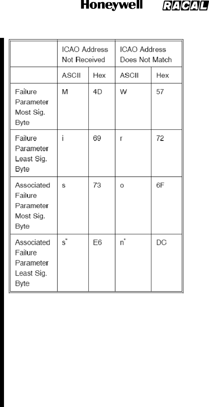
SYSTEM DESCRIPTION, INSTALLATION, AND MAINTENANCE MANUAL
MCS--4000/7000
23--20--27 5 Feb 2008
©Honeywell International Inc. Do not copy without express permission of Honeywell.
Page D--111
* This 7--bit ASCII code is shifted left one bit position in order to have the Category bit in bit 0.
FAIL CRITERIA : The fault transitions to failure immediately.
RECOVERY CRIT. : Immediately upon receipt of a valid ICAO address by the HSU from the SDU, which
matches the one programmed in the HSU CDM.
REMARK :
HSU1 Position Unavailable (9E 0 03)
DESCRIPTION : This fault is applicable prior to SDU Part Number 7516118--XX130/--xx140 only, and is
raised by the SDU in response to the Williamsburg file transfer for HSU fail code 0E/78 (L2/L3), i.e., the HSU
is not receiving valid latitude and/or longitude position data from the SDU, and also when a timeout of 15
seconds has elapsed since the last position was received.
PARAMETERS : HSU has received position data but latitude and/or longitude is invalid:
SOUR: Failure Parameter Value -- 0000 534Fx
Associated Parameter Value -- 0000 55A5x or 0000 55A4x
More than 15 seconds have elapsed since the last position was received:
TIME: Failure Parameter Value -- 0000 5449x
Associated Parameter Value -- 0000 4D8Ax or 0000 4D8Bx
RELEASED FOR THE EXCLUSIVE USE BY: HONEYWELL INTERNATIONAL
UP86308

SYSTEM DESCRIPTION, INSTALLATION, AND MAINTENANCE MANUAL
MCS--4000/7000
23--20--27 5 Feb 2008
©Honeywell International Inc. Do not copy without express permission of Honeywell.
Page D--112
FAIL CRITERIA : The fault transitions to failure immediately.
RECOVERY CRIT. : Immediately upon receipt of valid data by the HSU from the SDU.
REMARK :
HSU1 Velocity Unavailable (9E 0 04)
DESCRIPTION : This fault is applicable prior to SDU Part Number 7516118--XX130/--xx140 only, and is
raised by the SDU in response to the HSU Williamsburg file transfer for HSU fail code 0E/79 (L2/L3), i.e., the
HSU is not receiving aircraft velocity data from SDU.
PARAMETERS : The HSU has not received a velocity ARINC word for the past 7.5 seconds:
Lost: Failure Parameter Value -- 0000 4C6Fx
Associated Failure Parameter -- 0000 73E8x or 0000 73E9x
The HSU has not received a velocity ARINC word within 30 seconds after establishing full communications:
Miss: Failure Parameter Value -- 0000 4D69x
Associated Parameter Value -- 0000 73E6x or 0000 73E7x
FAIL CRITERIA : The fault transitions to failure immediately.
RECOVERY CRIT. : Immediately upon receipt of valid data by the HSU from the SDU.
REMARK :
HSU2 429 Control Bus Inactive (Level 1 Code 9Fh)
Same as for Level 1 code 9E X XX, except substitute “HSU2” for “HSU1”. Only applicable prior to SDU Part
Number 7516118--XX130/--xx140.
WSC1 Input Bus Inactive (A1 0 01)
DESCRIPTION : The last label 270 WSC Status word from WSC1 was received with the pertinent bit set
indicating an inactive input bus from “this” SDU (bit 21 if this is SDU 1, or bit 22 if this is
SDU 2 in a dual system).
PARAMETERS : “1” if the inactive input bus bit corresponding to the “other” SDU is also set in the WSC1
Status word, for this WSC1 Status word or for any of the subsequent WSC1 Status words considered during
the fault--to--failure interval defined in the Fail Criteria below; “0”
otherwise.
FAIL CRITERIA : This fault transitions to failure after the receipt of at least four consecutive WSC1 Status
words with the pertinent bit set, and if the fault persists for more than three seconds.
RECOVERY CRIT. : As soon as a WSC1 Status word is received with the pertinent bit cleared.
REMARK :
WSC2 Input Bus Inactive (A2 0 01)
Same as for WSC1 Input Bus Inactive (A1 0 01), except substitute WSC2 for WSC1.
WSC3 Input Bus Inactive (A3 0 01)
Same as for WSC1 Input Bus Inactive (A1 0 01), except substitute WSC2 for WSC1.
HSU Ethernet Port 1 Bus Inactive (A6 0 01)
DESCRIPTION : This fault is applicable to SDU Part Number 7516118--XX130/--xx140 and subsequent, and
is declared by the HSU (via a Williamsburg Failure Report message with fault code 0/01) when the Ethernet
port 1 interface is configured (as indicated by the Ethernet 1 Presence configuration strap, HSU pin MP2A)
and no link pulses are observed on the Ethernet port 1 bus.
PARAMETERS : None.
FAIL CRITERIA : This fault transitions to a failure if the fault persists for 3 seconds.
RECOVERY CRIT. : This failure is cleared when link pulses are detected on the Ethernet port 1 bus for at
least 2 seconds.
REMARK : None.
HSU Ethernet Port 2 Bus Inactive (A7 0 01)
DESCRIPTION : This fault is applicable to SDU Part Number 7516118--XX130/--xx140 and subsequent, and
is declared by the HSU (via a Williamsburg Failure Report message with fault code 0/02) when the Ethernet
port 2 interface is configured (as indicated by the Ethernet 2 Presence configuration strap, HSU pin MP2B)
and no link pulses are observed on the Ethernet port 2 bus.
PARAMETERS : None.
RELEASED FOR THE EXCLUSIVE USE BY: HONEYWELL INTERNATIONAL
UP86308

SYSTEM DESCRIPTION, INSTALLATION, AND MAINTENANCE MANUAL
MCS--4000/7000
23--20--27 5 Feb 2008
©Honeywell International Inc. Do not copy without express permission of Honeywell.
Page D--113
FAIL CRITERIA : This fault transitions to a failure if the fault persists for 3 seconds.
RECOVERY CRIT. : This failure is cleared when link pulses are detected on the Ethernet port 2 bus for at
least 2 seconds.
REMARK : None.
HSUISDNPort1BusInactive(A8001)
DESCRIPTION : This fault is applicable to SDU Part Number 7516118--XX130/--xx140 and subsequent, and
is declared by the HSU (via a Williamsburg Failure Report message with fault code 0/03) when the ISDN port
1 interface is configured (as indicated by the ISDN 1 Presence configuration strap, HSU pin MP1E) and no
activity is observed on the ISDN port 1 bus.
PARAMETERS : None.
FAIL CRITERIA : This fault transitions to a failure if the fault persists for 3 seconds.
RECOVERY CRIT. : This failure is cleared when activity is detected on the ISDN port 1 bus for at least 2
seconds.
REMARK : None.
HSUISDNPort2BusInactive(A9001)
DESCRIPTION : This fault is applicable to SDU Part Number 7516118--XX130/--xx140 and subsequent, and
is declared by the HSU (via a Williamsburg Failure Report message with fault code 0/04) when the ISDN port
2 interface is configured (as indicated by the ISDN 2 Presence configuration strap, HSU pin MP1F) and no
activity is observed on the ISDN port 2 bus.
PARAMETERS : None.
FAIL CRITERIA : This fault transitions to a failure if the fault persists for 3 seconds.
RECOVERY CRIT. : This failure is cleared when activity is detected on the ISDN port 2 bus for at least 2
seconds.
REMARK : None.
SDU System Configuration Error (Level 1 Code C0h)
SDU System Configuration Error, Unknown SRU (SRU Code 0h)
SDU Straps Parity Error (C0 0 81)
DESCRIPTION : During POST/PAST the configuration straps parity is tested. If the parity is even then this
fault is declared.
PARAMETERS : None.
FAIL CRITERIA : This fault transitions into failure immediately.
RECOVERY CRIT. : This failure is never explicitly cleared.
REMARK :
SDU Antenna Configuration Straps Error (C0 0 82)
DESCRIPTION : During POST/PAST the antenna configuration straps is tested. If an invalid, unsupported or
undefined configuration is read, then this fault is declared.
PARAMETERS : None.
FAIL CRITERIA : This fault transitions into failure immediately.
RECOVERY CRIT. : This failure is never explicitly cleared.
REMARK :
SDU CFDS Configuration Straps Error (C0 0 83)
DESCRIPTION : During POST/PAST the CFDS configuration straps is tested. If an invalid or undefined
configuration is read, then this fault is declared.
PARAMETERS : None.
FAIL CRITERIA : This fault transitions into failure immediately.
RECOVERY CRIT. : This failure is never explicitly cleared.
REMARK :
SDU Straps Inconsistency (C0 0 84)
DESCRIPTION : During POST/PAST the configuration straps is tested. If an inconsistency (as delineated
below) is read, then this fault is declared.
PARAMETERS : (One bit per condition; multiple conditions may apply; if so, set all appropriate bits)
RELEASED FOR THE EXCLUSIVE USE BY: HONEYWELL INTERNATIONAL
UP86308

SYSTEM DESCRIPTION, INSTALLATION, AND MAINTENANCE MANUAL
MCS--4000/7000
23--20--27 5 Feb 2008
©Honeywell International Inc. Do not copy without express permission of Honeywell.
Page D--114
1 = Not used/Spare.
2 = Undefined Lamp/Chime Option.
FAIL CRITERIA : This fault transitions into failure immediately.
RECOVERY CRIT. : This failure is never explicitly cleared.
REMARK :
Dual System -- Config Straps Error (C0 0 05)
DESCRIPTION : This fault is declared in a dual system if the SDU Number received from the other SDU on
the cross--talk bus is the same as this SDU’s Number, and also when an SDU is strapped as single and DCS
words are received on the XTB.
PARAMETERS : 1st: Strap parity (good or bad)
2nd: SDU number, as follows:
0SingleSDU
1#1of2
2#2of2
FAIL CRITERIA : This fault transitions to a failure immediately.
RECOVERY CRIT. : This failure is never explicitly cleared.
REMARK : If the straps parity is bad as per Section 3.2.3.1.23.1.3, the SDU will use the SDU Number
different from the other SDU’s after a reversion reset.
Dual System -- Cockpit Straps Incompatible (C0 0 06)
DESCRIPTION : This fault is declared in a dual system when the configuration straps associated with cockpit
functionalities are inconsistent between the two SDUs.
PARAMETERS : (One bit per condition; multiple conditions may apply; if so, set all appropriate bits)
1 = TP13A Priority 4 Call To/From Cockpit.
2 = TP13C--TP13D Cockpit Voice Call Light/Chime Options.
4 = TP13K Cockpit Hookswitch Signalling Method.
FAIL CRITERIA : This fault transitions to a failure immediately.
RECOVERY CRIT. : This failure is cleared after the other SDU resets and reads straps which are compatible.
REMARK : When this failure is active, the behavior of cockpit voice will depend on the straps read by the
SDU supporting the physical channel for the call.
Manufactuer--Specific SDU Straps Parity Error (C0 0 87)
DESCRIPTION : During POST/PAST, the manufacturer--specific SDU configuration straps is tested for parity.
If the computed parity is odd, this fault is declared.
PARAMETERS : None.
FAIL CRITERIA : This fault transitions into failure immediately.
RECOVERY CRIT. : This failure is never explicitly cleared.
REMARK :
SDU WOW Miscompare Error (C1 0 81/01)
DESCRIPTION : During CM, (1) if the configuration straps indicate no CFDS or IRS presence, or (2) if the
aircraft type is Airbus, then the two Weight On Wheels discretes is compared once per second. Should there
be a mismatch in the readings then a ’SDU WOW Miscompare Error’ fault is declared.
While in the fault state the two Weight On Wheels discretes is compared once per second. The ’SDU WOW
Miscompare Error’ fault is cleared if the discretes agree. A similar test shall also be performed during
POST/PAST (1) if the configuration straps indicate no CFDS or IRS presence, or (2) if the aircraft type is
Airbus.
PARAMETERS : None.
FAIL CRITERIA : CM: This fault transitions into failure if it persists for ten seconds or more.
POST/PAST: This fault transitions into failure if it persists for multiple samples for three seconds or more.
RECOVERY CRIT. : CM: This failure is cleared, on receipt of a ’SDU WOW Miscompare Error’ fault cleared
report (see DESCRIPTION above), if no further ’SDU WOW Miscompare Error’ faults are reported for ten
seconds or more.
POST/PAST: This failure is not explicitly cleared.
REMARK :
RELEASED FOR THE EXCLUSIVE USE BY: HONEYWELL INTERNATIONAL
UP86308

SYSTEM DESCRIPTION, INSTALLATION, AND MAINTENANCE MANUAL
MCS--4000/7000
23--20--27 5 Feb 2008
©Honeywell International Inc. Do not copy without express permission of Honeywell.
Page D--115
SDU Dual System Select/Disable Error (Level 1 Code C2)
SDU Dual System Select/Disable Test Error (C2 0 81)
DESCRIPTION : During POST/PAST in a dual system, as long as the other SDU is not already disabled and
the cross--talk bus (XTB) input is active, each SDU shall test its ability to assert its
Select/Disable output to the other SDU, and for the other SDU to report within 0.3 second (via its “My Disable
Is Asserted” bit in its Dual Control/Status word on the XTB) that its Disable input is being asserted. The
asserting SDU shall release the test assertion after the positive indication from the other SDU, or after 0.3
second, whichever
occurs first. If the test cannot be carried out during POST/PAST, it is carried out
once, later, if the opportunity arises. Although carried out after POST/PAST, the code shall
still be C2 0 81.
PARAMETERS : State of the Select input discrete during the test.
FAIL CRITERIA : This fault transitions to a failure immediately.
RECOVERY CRIT. : This fault is never explicitly cleared.
REMARK : The other SDU is not actually disabled during this test since the Select/Disable must be asserted
for at least one second for that to occur. If the other SDU is already disabled (and
this test is therefore inhibited), failure C2 0 82 is declared.
Select/Disable Test Not Initiated (C2 0 82)
DESCRIPTION : Reference the Description for failure C2 0 81; if the Select/Disable Test cannot be initiated
due to the other SDU already being disabled or the XTB input being inactive, this fault is declared at the end
of POST/PAST.
PARAMETERS : None.
FAIL CRITERIA : This fault transitions to a failure immediately.
RECOVERY CRIT. : This failure is cleared if the test is able to be performed after POST/PAST (i.e., other
SDU no longer disabled, or XTB input no longer inactive).
REMARK : This failure serves as a warning that a critical part of the normal POST/PAST procedure was
bypassed, hence the dual system cannot be positively declared to be 100% functional.
SDU (ICAO) Address Bits (Straps) (Level 1 Code C3)
SDU (ICAO) Address Bits (Straps) Error (C3 0 81)
DESCRIPTION : Should there be no ARINC 429 source of ICAO aircraft address indicated as present in the
configuration straps, and the discrete value when read during POST/PAST indicates all zero’s or all ones’s,
then this fault is declared.
PARAMETERS : The ICAO aircraft address read from the discretes.
FAIL CRITERIA : This fault transitions into failure immediately.
RECOVERY CRIT. : This failure is not explicitly cleared.
REMARK :
Dual System Different Straps AES ID (C3 0 02)
DESCRIPTION : This fault is declared in a dual system if this SDU obtains its AES ID from its strapped
discretes, and a valid AES ID received from the other SDU via the cross--talk bus is different from this AES’
valid ID.
PARAMETERS : 1st: This SDU’s AES ID
2nd: Other SDU’s AES ID
FAIL CRITERIA : This fault transitions to a failure immediately.
RECOVERY CRIT. : This failure is cleared if a valid AES ID is received from the other SDU which matches
this SDU’s valid AES ID.
REMARK : This fault is declared in both SDUs. No functional resource is indicted; however, one SDU will
become disabled.
HGA/IGA HPA Reflected Output Power (Level 1 Code C4)
HGA/IGA HPA 429 Maintenance Word Output VSWR Bad (C4 0 01)
DESCRIPTION : This fault is declared if bit #12 in the Maintenance Word received by the SDU from the
HGA/IGA HPA was set.
PARAMETERS : None.
RELEASED FOR THE EXCLUSIVE USE BY: HONEYWELL INTERNATIONAL
UP86308

SYSTEM DESCRIPTION, INSTALLATION, AND MAINTENANCE MANUAL
MCS--4000/7000
23--20--27 5 Feb 2008
©Honeywell International Inc. Do not copy without express permission of Honeywell.
Page D--116
FAIL CRITERIA : This fault transitions to failure after the receipt of four consecutive maintenance words with
bit 12 set.
RECOVERY CRIT. : As soon as an HPA Maintenance Word is received by the SDU with bit #12 cleared.
REMARK : The Honeywell/Racal HPA sets bit 12 in its Maintenance words while failure C4 0 02 is active.
HGA/IGA HPA Reflected Output Power Error (C4 0 02)
DESCRIPTION : The HPA shall (for any software package resident in a 40W HPA having hardware/software
compatibility strap settings of 00h) declare this fault if the measured reflected output power exceeds 20 watts.
For any software package operating in a 20W or 40W HPA having a hardware/software compatibility strap
setting of 02h or greater, the HPA shall declare and latch this fault if the measured reflected output power
exceeds half of the forward output power. The 60W HPA shall declare and latch this fault if the measured
reflected output power exceeds three tenths of the forward power and is greater than +24 dBm.
PARAMETERS : 20W/40W HPA: The measured reflected output power; 60W HPA: None.
FAIL CRITERIA : This fault transitions to failure (in HPAs having hardware/software compatibility strap
settings of 00h) if the fault persists for one second. This fault transitions to failure (in HPAs having
hardware/software compatibility strap settings of 02h or higher, or if the 60W HPA) if the fault persists for 100
ms.
RECOVERY CRIT. : This failure is cleared (for any software package resident in HPAs having
hardware/software compatibility strap settings of 00h) if the measured reflected output power is less than 20
watts for one second. For any software package operating in HPAs having hardware/software compatibility
strap settings of 02h or greater, this failure is cleared only if the measured reflected power is less than half
the forward output power for 100 ms while forward output power is present at the detector. For the 60W HPA,
this failure is cleared when the measured reflected power is less than three tenths of the forward power for
100 ms while forward output power is present at the detector.
REMARK : The HPA shall set bit 12 in its Maintenance words while this failure is active. The SDU will raise
failure (C4 0 01) while bit 12 in the HPA Maintenance word is set.
SDU ORT/Configuration Straps Incompatibility (Level 1 Code C5)
SDU ORT/Local Configuration Straps Incompatibility (C5 0 81/01)
DESCRIPTION : When the ORT is uploaded, at POST/PAST and after a User partition ORT crossload in a
dual system, the values of items that depend on the physical configuration of the local system are checked
against the local system configuration straps. This failure is declared if any ORT item value is incompatible
with any strap states.
PARAMETERS : (One bit per condition; multiple conditions may apply; if so, set all appropriate bits)
10x : ORT item vii indicates reservation of all necessary resources for one HEADSET call on cockpit channel
1, but the straps don’t indicate wiring of codec A to the cockpit AMS (single system only).
20x : ORT item vii indicates reservation of all necessary resources for one HEADSET call on cockpit channel
2, but the straps don’t indicate wiring of codec B to the cockpit AMS (single system only).
40x : ORT item xiii indicates routing to DPHONE, but the straps don’t indicate that the CCS is installed (single
system only).
80x : ORT item xiii indicates routing to APHONE, but the straps don’t indicate the wiring of either codec to the
cabin (single system only).
100x : ORT item xiii indicates routing to HEADSET, but the straps don’t indicate the wiring of either codec to
the cockpit AMS (single system only).
200x : ORT item xxxii indicates selection of the ACP mic switch call initiation method, but ORT item xxxi does
not indicate selection of the SCDU telephone number preselect only option.
400x : ORT item xiii indicates routing to HEADSET, but the strap TP13A indicates that APC calls to/from the
cockpit are not allowed (single system only).
800x : ORT item v contains telephone numbers assigned priority 4, but the strap TP13A indicates that APC
calls to/from the cockpit are not allowed (single system only).
FAIL CRITERIA : This fault transitions to a failure immediately.
RECOVERY CRIT. : This fault is cleared once the ORT becomes compatible with the local straps.
REMARK : The default value(s) of the ORT item(s) causing the incompatibility will be substituted for the
current power--up cycle to permit operation to proceed.
RELEASED FOR THE EXCLUSIVE USE BY: HONEYWELL INTERNATIONAL
UP86308

SYSTEM DESCRIPTION, INSTALLATION, AND MAINTENANCE MANUAL
MCS--4000/7000
23--20--27 5 Feb 2008
©Honeywell International Inc. Do not copy without express permission of Honeywell.
Page D--117
Dual ORT/Combined Configuration Straps Incompatibility (C5 0 02)
DESCRIPTION : In a dual system, when the ORT is uploaded, after POST/PAST and after a User partition
ORT crossload, the values of duplicated items that depend on the physical configuration of the remote
system, and the values of common items that depend on system--wide
configuration straps, is checked after the remote straps are available (i.e., when full cross--talk
communications are established). This fault is declared if any ORT item value is incompatible with any strap
states.
PARAMETERS : (One bit per condition; multiple conditions may apply; if so, set all appropriate bits)
10x : ORT item vii indicates reservation of all necessary resources for one HEADSET call, but none of the
four codecs is Usable by the cockpit.
20x : Not used.
40x : ORT item xiii indicates routing to DPHONE, but none of both SDU system’s straps indicate that the
CCS is installed.
80x : ORT item xiii indicates routing to APHONE, but none of the four codecs is strapped as being wired to
the cabin.
100x : ORT item xiii indicates routing to HEADSET, but none of the four codecs is strapped as being wired to
the cockpit AMS.
200x : Not used.
400x : ORT item xiii indicates routing to HEADSET, but either the TP13A straps on both SDUs indicate that
APC calls to/from the cockpit are not allowed (set to “zero”), or only one SDU has codecs wired to AMS but
its TP13A is set to “zero”.
800x : ORT item v contains telephone numbers assigned priority 4, but TP13A strap on both SDUs indicate
that APC calls to/from the cockpit are not allowed.
4000x : ORT item xlviii indicates Fixed, but there are more than two physical channels usable by the cockpit.
8000x : ORT item xlviii indicates Shared, but a channel Usable by the cockpit is not matched by the same
numbered channel in the other SDU also being Usable by the cockpit.
FAIL CRITERIA : This fault transitions to a failure immediately.
RECOVERY CRIT. : This fault is cleared when the ORT becomes compatible with the remote or systemwide
straps.
REMARK : The default value(s) of the ORT item(s) causing the incompatibility will be substituted for the
current power--up cycle to permit operation to proceed.
LGA HPA Reflected Output Power Error (C6 0 01, C6 0 02)
Same as HGA HPA Reflected Output Power Error except (i) substitute LGA HPA for
HGAHPA;(ii)substituteC6002forC4002intheRemarks.
HGA/IGA HPA Over Temp Warnings (Level 1 Code C7h)
The failures listed in this section apply to both the HGA (40W/60W) and IGA (20W) Honeywell/Thales HPAs,
as note in the description for each failure.
HGA HPA PSU Over Temp Warning (C7 1 01)
DESCRIPTION : During CM, the PSU temperature is tested four times per second and an Over Temp
Warning fault is declared if the PSU temperature is greater than or equal to +100 degrees Celsius and less
than +130 degrees Celsius. This failure code shall only be applicable to the 20W and 40W HPAs.
PARAMETERS : PSU temperature sensor scaled analog voltage, and the warning temperature limit.
FAIL CRITERIA : A failure is declared if the PSU temperature sensor scaled analog output is within the limits
specified above for four consecutive readings.
RECOVERY CRIT. : The failure is cleared if after four consecutive readings the PSU temperature sensor
scaled analog output is less than +100 degrees Celsius.
REMARK : The HPA shall set bit 13 in its Maintenance words while this failure is active.
HGA HPA Processor (SRU Code 2h)
HGA HPA CPU Over Temp Warning (C7 2 01)
DESCRIPTION : During CM, the CPU temperature is tested four times per second and an Over Temp
Warning fault is declared if the CPU temperature is greater than or equal to +100 degrees Celsius and less
than +130 degrees Celsius. This failure code shall only be applicable to the 20W and 40W HPAs.
PARAMETERS : CPU temperature sensor scaled analog voltage, and the warning temperature limit.
RELEASED FOR THE EXCLUSIVE USE BY: HONEYWELL INTERNATIONAL
UP86308

SYSTEM DESCRIPTION, INSTALLATION, AND MAINTENANCE MANUAL
MCS--4000/7000
23--20--27 5 Feb 2008
©Honeywell International Inc. Do not copy without express permission of Honeywell.
Page D--118
FAIL CRITERIA : A failure is declared if the CPU temperature sensor scaled analog output is within the limits
specified above for four consecutive readings.
RECOVERY CRIT. : The failure is cleared if after four consecutive readings the CPU temperature sensor
scaled analog output is less than +100 degrees Celsius.
REMARK : The HPA shall set bit 13 in its Maintenance words while this failure is active.
HGA HPA Over Temp Warning (C7 2 02)
DESCRIPTION : During CM, if the PA temperature sensor detects a temperature greater than +100 degrees
Celsius, an Over Temp Warning fault is declared. While this failure is active, the HPA shall reduce maximum
available RMS power to 8dB below 40W. This failure code shall only be applicable to the 60W HPA.
PARAMETERS : None
FAIL CRITERIA : A failure is declared if two consecutive readings are above +100 degress Celsius.
RECOVERY CRIT. : The failure is cleared if two consecutive readings drop below +85 degrees Celsius.
REMARK : The 60W HPA will set bit 13 in its Maintenance words while this failure is active. The SDU will
also raise failure (C7 0 01) per section 4.4.5.199.20 while bit 13 in the HPA Maintenance word is set.
HGA HPA Driver Over Temp Warning (C7 3 01)
DESCRIPTION : During CM, the Driver temperature is tested four times per second and an Over
Temp Warning fault is declared if the Driver temperature is greater than or equal to +100 degrees Celsius and
less than +130 degrees Celsius. This failure code shall only be applicable to the 40W HPA.
PARAMETERS : Driver temperature sensor scaled analog voltage.
FAIL CRITERIA : A failure is declared if the Driver temperature sensor scaled analog output is within the
limits specified above for four consecutive readings.
RECOVERY CRIT. : The failure is cleared if after four consecutive readings the Driver temperature sensor
scaled analog output is less than +100 degrees Celsius.
REMARK : The HPA shall set bit 13 in its Maintenance words while this failure is active.
HGA HPA Combiner Over Temp Warning (C7 8 01)
DESCRIPTION : During CM, the Combiner temperature is tested four times per second and an Over Temp
Warning fault is declared if the Combiner temperature is greater than or equal to +100 degrees Celsius and
less than +130 degrees Celsius. This failure code shall only be applicable to the 40W HPA.
PARAMETERS : Combiner temperature sensor scaled analog voltage.
FAIL CRITERIA : A failure is declared if the Combiner temperature sensor scaled analog output
exceeds its limits for four consecutive readings.
RECOVERY CRIT. : The failure is cleared if after four consecutive readings the Combiner temperature
sensor scaled analog output is less than +100 degrees Celsius.
REMARK : The HPA shall set bit 13 in its Maintenance words while this failure is active.
HGA HPA RFAM Over Temp Warning (C7 B 01)
DESCRIPTION : During CM, the RFAM temperature is tested four times per second, and an Over Temp
Warning is declared if the RFAM temperature is greater than or equal to +100 degrees Celsius and less than
+130 degrees Celsius. This failure code shall only be applicable to the 20W HPA.
PARAMETERS : RFAM temperature sensor scaled analog voltage, and the warning temperature limit.
FAIL CRITERIA : A failure is declared if the RFAM temperature sensor scaled analog output exceeds its
limits for four consecutive readings.
RECOVERY CRIT. : The failure is cleared if after four consecutive readings the RFAM temperature sensor
scaled analog output is less than +100 degrees Celsius.
REMARK : The HPA shall set bit 13 in its Maintenance words while this failure is active.
HGAHPAMNTNCWORDLRUOverTemp(C7001)
DESCRIPTION : This fault is declared if bit #13 in the Maintenance Word from the HGA HPA was set.
PARAMETERS : The maintenance word.
FAIL CRITERIA : This fault transitions to failure after the receipt of four consecutive maintenance words with
bit 13 set.
RECOVERY CRIT. : As soon as an HPA Maintenance Word is received with bit #13 cleared
REMARK : The Honeywell HPA does not generate this failure directly, nor log it internally, nor communicate it
to the SDU. The SMPM is the “Tester”; it is simply responding to the Maintenance word bit 13. The Honeywell
HPA controls bit.
RELEASED FOR THE EXCLUSIVE USE BY: HONEYWELL INTERNATIONAL
UP86308

SYSTEM DESCRIPTION, INSTALLATION, AND MAINTENANCE MANUAL
MCS--4000/7000
23--20--27 5 Feb 2008
©Honeywell International Inc. Do not copy without express permission of Honeywell.
Page D--119
GES Frequency Command Errors (Level 1 Code C8H)
Invalid Frequency Command From GES (C8 0 01)
DESCRIPTION : The SDU shall log this failure if it receives a frequency command from the GES that lies
outside of the specified transmit band for the specified channel rate/modulation type.
PARAMETERS : The channel number.
FAIL CRITERIA : This fault transitions to a failure immediately.
RECOVERY CRIT. : This failure is never explicitly cleared.
REMARK : The SDU executes a cold start after logging this failure.
GNSS Interference Risk From GES (C8 0 02)
DESCRIPTION : Per Section 3.3.1.3.4.1, the SDU shall log this failure if it receives a frequency command
from the GES that would cause a third-- or fifth--order MCS intermodulation product to fall into the GNSS
frequency band.
PARAMETERS : The new channel number, as well as the fL and fH channel numbers.
FAIL CRITERIA : This fault transitions to a failure immediately.
RECOVERY CRIT. : This failure is never explicitly cleared.
REMARK : The SDU executes a cold start after logging this failure.
LGA HPA Over Temp Warnings (Level 1 Code C9)
LGA HPA PSU Over Temp Warning (C9 1 01)
Same as for the HGA HPA.
LGA HPA Processor (SRU Code 2h)
LGA HPA CPU Over Temp Warning (C9 2 01)
Same as for the HGA HPA.
LGA HPA Over Temp Warning (C9 2 02)
Same as for the HGA HPA.
LGA HPA Driver Over Temp Warning (C9 3 01)
Same as for the HGA HPA.
LGA HPA Over Temp (Combiner) Warning (C9 8 01)
Same as for the HGA HPA.
LGA HPA RFAM Over Temp Warning (C9 B 01)
Same as for the HGA HPA.
LGAHPAMNTNCWORDLRUOverTemp(C9001)
Same as for the HGA HPA.
LGA/LNA Control Driver Fail (CA 0 01)
DESCRIPTION : The LGA/LNA output discrete is tested by comparing the level of the BITE tell--back with the
commanded state, as specified below. Should the output discrete’s BITE tell--back
value not be the same as the commanded value for either the active or inactive state (or both), and the
antenna subsystem configuration includes an LGA then this fault is declared.
During POST/PAST, the LGA/LNA output discrete is tested for being able to achieve the active and inactive
states by commanding the LGA/LNA to the active state briefly, and then inactive again. If the first test pair
cycle fails (for either or both states), it is repeated. If the second test pair cycle also fails, then this fault is
declared.
During CM, the LGA/LNA output discrete is tested whenever its commanded state is changed for operational
reasons, and also once every thirty seconds.
Test results for the discrete output successfully achieving the commanded state (active or inactive) is
recorded independently, and the fault shall only be cleared when both commanded states have been
recorded as being achieved the last time they were tested.
PARAMETERS : Parameter 1 is set to 1 if the active state is not achieved.
Parameter 2 is set to 1 if the inactive state is not achieved.
RELEASED FOR THE EXCLUSIVE USE BY: HONEYWELL INTERNATIONAL
UP86308

SYSTEM DESCRIPTION, INSTALLATION, AND MAINTENANCE MANUAL
MCS--4000/7000
23--20--27 5 Feb 2008
©Honeywell International Inc. Do not copy without express permission of Honeywell.
Page D--120
FAIL CRITERIA : This fault transitions to a failure if the fault persists continuously for one second.
RECOVERY CRIT. : This failure is cleared as soon as the fault is cleared, i.e., as soon as both commanded
states have been recorded as being achieved the last time they were tested.
REMARK : This failure is Class 2, and does not indict [lga_subsys] nor [hga_subsys], because the reason
could as likely be failure in the SDU BITE circuitry, and because other, more
definitive tests (LGA LNA diplexer and LGA LNA RF continuity) cover this functionality.
Level 3 failure code 81 is not used for the POST/PAST case second commentary, fourth paragraph (i.e., the
POST/PAST and CM tests are identical).
In the actual implementation, if an LGA is installed, this discrete is repetitively commanded to its currently
required state (whether on or off) at a rate of ~ 15 Hz. The CM test is performed after each such command,
hence continuously at ~ 15 Hz (which includes the case of whenever a state change is commanded) as well
as once every thirty seconds. Since there is no separate Level 3 failure code 81 for the POST/PAST case,
even the POST/PAST case includes the one--second fail criteria. The POST/PAST case also requires the
retest fail criteria in order to avoid nuisance failures because there is no guarantee that the CM testing (which
might otherwise clear a POST/PAST--detected fault) will begin or resume within one second of POST/PAST.
HGA/IGA HPA Invalid SDI Strapping (CB 0 01)
DESCRIPTION : HPA perspective: The HPA shall read the programmed state of its SDI pins at each coldstart
and each functional test (i.e., each POST/PAST). This fault is declared if the
SDI pins are set to any invalid state (Reserved or Unused). When this occurs, the HPA shall, in software
packages D2.0 and subsequent, aside from logging the failure, behave in every way as though it was
strapped to be the HGA/IGA HPA.
SDU perspective: The HGA/IGA HPA has reported this failure using the manufacturer specific
block transfer protocol.
PARAMETERS : The as--read invalid SDI code.
FAIL CRITERIA : HPA perspective: This fault transitions to a failure immediately.
SDU perspective: This fault transitions to a failure immediately.
RECOVERY CRIT. : This failure is never explicitly cleared.
REMARK : This failure results in the LGA HPA being unable to respond to all but all--call commands sent via
the ARINC 429 Multicontrol bus, which renders it virtually useless. Both HPAs shall use failure CB 0 01, since
they cannot tell which HPA they are supposed to be.
When the SDU receives a CB 0 01 block on the HGA/IGA HPA bus, it shall make the entry into the system
failure log using code CB 0 01; conversely, it shall use code CC 0 01 if the CB 0 01 block is received on the
LGA HPA bus (see below). Note that failure code 01 is used, even though the test is (only) performed during
POST/PAST.
Note: In HPA software packages prior to D2.0, upon detecting this failure, the HPA would use the “unused”
SDI code (11b) in its transmitted ARINC 429 words, and would only respond to Command Words with SDI
fields set to the “All Call” code.
LGA HPA Invalid SDI Strapping (CC 0 01)
DESCRIPTION : HPA perspective: Not used.
SDU perspective: The LGA HPA has reported failure CB 0 01 using the manufacturer specific
block transfer protocol.
PARAMETERS : The as--read invalid SDI code.
FAIL CRITERIA : SDU perspective: This fault transitions to a failure immediately.
RECOVERY CRIT. : This failure is never explicitly cleared.
REMARK : The HPAs themselves do not use this failure ---- they use CB 0 01. When the SDU receives a CB
0 01 block on the LGA HPA bus, it shall make the entry into the system failure log
using code CC 0 01. Note that failure code 01 is used, even though the test is (only) performed during
POST/PAST.
SDU POC/TOTC Reset (Level 1 Code CDh)
SDU TOTC Auto/Manual Reset (CD 0 81/01)
DESCRIPTION : The SDU has performed either an automatic (Level 3 code 81) or manual (code 01) TOTC
reset.
PARAMETERS : The value of the TOTC (in 10--minute increments) just prior to it being reset. This may be
valid, or it may be corrupted.
RELEASED FOR THE EXCLUSIVE USE BY: HONEYWELL INTERNATIONAL
UP86308

SYSTEM DESCRIPTION, INSTALLATION, AND MAINTENANCE MANUAL
MCS--4000/7000
23--20--27 5 Feb 2008
©Honeywell International Inc. Do not copy without express permission of Honeywell.
Page D--121
FAIL CRITERIA : This fault transitions to a failure immediately.
RECOVERY CRIT. : This failure is never explicitly cleared.
REMARK : This entry into the failure log is used to indicate that an SDU TOTC reset event has occurred.
SDU POC Auto/Manual Reset (CD 0 82/02)
DESCRIPTION : The SDU has performed either an automatic (Level 3 code 82) or manual (code 02) POC
reset.
PARAMETERS : The value of the POC just prior to it being reset. This may be valid, or it may be corrupted.
FAIL CRITERIA : This fault transitions to a failure immediately.
RECOVERY CRIT. : This failure is never explicitly cleared.
REMARK : This entry into the failure log is used to indicate that an SDU POC reset event has occurred.
HGA/IGA HPA POC/TOTC Reset (Level 1 Code CFh)
HGA/IGA HPA TOTC Auto/Manual Reset (CF 0 81/01)
DESCRIPTION : HPA perspective: As specified in Section 4.3.6.3, the HGA/IGA HPA has performed either
an automatic (Level 3 code 81) or manual (code 01) TOTC reset.
SDU perspective: The HGA/IGA HPA has reported this failure using the manufacturerspecific
block transfer protocol.
PARAMETERS : The value of the TOTC (in 10--minute increments) just prior to it being reset. This may be
valid, or it may be corrupted.
FAIL CRITERIA : This fault transitions to a failure immediately.
RECOVERY CRIT. : This failure is never explicitly cleared.
REMARK : This entry into the failure log is used to indicate that an HGA HPA TOTC reset event has
occurred.
HGA/IGA HPA POC Auto/Manual Reset (CF 0 82/02)
DESCRIPTION : HPA perspectiveThe HGA/IGA HPA has performed either an automatic (Level 3 code 82) or
manual (code 02) POC reset.
SDU perspective: The HGA/IGA HPA has reported this failure using the manufacturerspecific
block transfer protocol.
PARAMETERS : The value of the POC just prior to it being reset. This may be valid, or it may be corrupted.
FAIL CRITERIA : This fault transitions to a failure immediately.
RECOVERY CRIT. : This failure is never explicitly cleared.
REMARK : This entry into the failure log is used to indicate that an HGA HPA POC reset event has occurred.
LGA HPA POC/TOTC Reset (Level 1 Code D0h)
LGA HPA TOTC Auto/Manual Reset (D0 0 81/01)
DESCRIPTION : HPA perspective: As specified in Section 4.3.6.3, the LGA HPA has performed either an
automatic (Level 3 code 81) or manual (code 01) TOTC reset.
SDU perspective: The LGA HPA has reported this failure using the manufacturer--specific block transfer
protocol.
PARAMETERS : The value of the TOTC (in 10--minute increments) just prior to it being reset. This may be
valid, or it may be corrupted.
FAIL CRITERIA : This fault transitions to a failure immediately.
RECOVERY CRIT. : This failure is never explicitly cleared.
REMARK : This entry into the failure log is used to indicate that an LGA HPA TOTC reset event has
occurred.
LGA HPA POC Auto/Manual Reset (D0 0 82/02)
DESCRIPTION : HPA perspective: The LGA HPA has performed either an automatic (Level 3 code 82) or
manual (code 02) POC reset.
SDU perspective: The LGA HPA has reported this failure using the manufacturer--specific block transfer
protocol.
PARAMETERS : The value of the POC just prior to it being reset. This may be valid, or it may be corrupted.
FAIL CRITERIA : This fault transitions to a failure immediately.
RECOVERY CRIT. : This failure is never explicitly cleared.
REMARK : This entry into the failure log is used to indicate that an LGA HPA POC reset event has occurred.
RELEASED FOR THE EXCLUSIVE USE BY: HONEYWELL INTERNATIONAL
UP86308

SYSTEM DESCRIPTION, INSTALLATION, AND MAINTENANCE MANUAL
MCS--4000/7000
23--20--27 5 Feb 2008
©Honeywell International Inc. Do not copy without express permission of Honeywell.
Page D--122
HGA HPA Wrong A429 SDI Code (D1 0 01)
DESCRIPTION : An expected ARINC 429 Word (labels 143,350,171) received on the HGA HPA to SDU bus
contains an SDI different from HGA HPA.
PARAMETERS : First word containing the wrong SDI code.
FAIL CRITERIA : This fault transitions to a fail immediately.
RECOVERY CRIT. : Immediately when any of the expected ARINC 429 words received on this bus contain
an SDI indicating HGA HPA.
REMARK :
LGA HPA Wrong A429 SDI Code (D2 0 01)
DESCRIPTION : An expected ARINC 429 Word (labels 143,350,171) received on the LGA HPA to SDU bus
contains an SDI different from LGA HPA.
PARAMETERS : First word containing the wrong SDI code.
FAIL CRITERIA : This fault transitions to a fail immediately.
RECOVERY CRIT. : Immediately when any of the expected ARINC 429 words received on this bus contain
an SDI indicating LGA HPA.
REMARK :
Top/Port BSU/ACU Wrong A429 SDI Code (D3 0 01)
DESCRIPTION : An expected ARINC 429 Word (labels 144,350) received on the Top/Port BSU/ACU to SDU
bus contains an SDI not equal to Port/Top or ACU.
PARAMETERS : First word containing the wrong SDI code.
FAIL CRITERIA : This fault transitions to a failure after three seconds.
RECOVERY CRIT. : Immediately when any of the expected ARINC 429 words received on this bus contain a
correct SDI.
REMARK :
Starboard BSU Wrong A429 SDI Code (D4 0 01)
DESCRIPTION : An expected ARINC 429 Word (labels 144,350) received on the Starboard BSU to SDU bus
contains an SDI not equal to Starboard.
PARAMETERS : First word containing the wrong SDI code.
FAIL CRITERIA : This fault transitions to a failure after three seconds.
RECOVERY CRIT. : Immediately when any of the expected ARINC 429 words received on this bus contain a
correct SDI.
REMARK :
SDU/RFUIA To HGA/IGA HPA Cable Loss (Level 1 Code D5)
SDU/RFUIA To HGA/IGA HPA Calibration Error (D5 0 01)
DESCRIPTION : This fault is declared if the calculated SDU/RFUIA to HPA Loss is outside acceptable limits
(ie not within 10 to 30dB).
PARAMETERS : Failure Param: A 1 shall indicate that the calibrated loss was calculated to be greater than
the maximum value.
A 0 shall indicate that the calibrated loss was calculated to be less than the
minimum value.
Assoc Param: The calculated loss in tenths of dB.
FAIL CRITERIA : This fault transitions to a failure if the fault persists for at least two successive
measurement samples.
RECOVERY CRIT. : This failure can only be cleared whilst the HGA antenna is the currently selected one.
REMARK : This test is not done during the PAST period but only on actual transmissions (e.g. during log--on).
This means it will not show up on the CFDS Test Results page, and it is hard to
determine if it has been fixed without incrementing the flight leg after each attempt at fixing it. The test also
depends on the correct functioning of the HPA’s output power detector and the expected HPA amplification
(gain), so if the HPA is muted, or not amplifying correctly, this failure may result.
Although “illegal” in either the too--high or too--low case, this failure is only a real operational problem if the
loss is too high, and depending on variables such as geographic location, antenna gain, number of channels
in use, etc., the system may work to some extent even then. For SDU Part Number 7516118--XX130/--xx140
and subsequent, if the calculated cable loss is less than 10dB and the selected HPA is a 60W HPA, the SDU
RELEASED FOR THE EXCLUSIVE USE BY: HONEYWELL INTERNATIONAL
UP86308

SYSTEM DESCRIPTION, INSTALLATION, AND MAINTENANCE MANUAL
MCS--4000/7000
23--20--27 5 Feb 2008
©Honeywell International Inc. Do not copy without express permission of Honeywell.
Page D--123
shall attempt to set the input attenuator to give a nominal cable loss of 15dB in order to prevent potential
equipment damage to the HPA.
The RFUIA is a passive and optional device which, if present, is ignored by the SDU. However, the RFUIA
does affect the calibration test if it is present because it is included in the signal path. Maintenance personnel
need to be aware of the potential impact of the RFUIA if this failure occurs.
SDU/RFUIA To Linear HGA/IGA HPA RF Continuity Fail (D5 0 02)
DESCRIPTION : This fault is declared when the HPA is a Linear HPA and fails to detect any measurable
Actual Output Power while the SDU is sending a Log--On Request with the SDU/RFUIA to HGA/IGA HPA
Loss set to the maximum value.
PARAMETERS : Failure Param: The last positively calibrated SDU/RFUIA to HGA/IGA HPA Loss in tenths of
dB, or the Factory Settings default value if no calibration has been
achieved.
FAIL CRITERIA : This fault transitions to failure immediately.
RECOVERY CRIT. : This failure is never explicitly cleared.
REMARK : If during the burst the HPA reports a measurable Actual Output Power but the calibration of the
SDU/RFUIA to HPA Loss cannot be performed (backoffs are set to the limit or the HPA reports an APO equal
to 19 dBW), the fault is not raised. This test is not done during the
PAST period but only on actual transmissions (e.g. during log--on). This means it will not show up on the
CFDS Test Results page, and it is hard to determine if it has been fixed without incrementing the flight leg
after each attempt at fixing it. The test also depends on the correct functioning of the HPA’s output power
detector and the expected HPA amplification (gain), so if the HPA is not amplifying correctly, this failure may
result. A basic troubleshooting guide can help determine the general location where the failure is most likely
to occur.
This fault will also be declared whenever the HPA independently turns carriers off (i.e., not under normal
command from the SDU), which causes any subsequent RF continuity test to fail. Such action is required for
the 20W HPA whenever a short circuit condition is detected on any of the secondary power supply output
voltages externally wired to an HPA--controlled IGA. In such cases, all of the secondary output voltages
typically fail together. The 20W HPA power supply turns carriers off by disabling the +5VDC bias voltage,
which subsequently results in that failure being raised as well. Reference failure 04 1 03, and failures 04 1 08
through 04 1 0A.
The RFUIA is a passive and optional device which, if present, is ignored by the SDU. However, the RFUIA
does affect the calibration test if it is present because it is included in the signal path. Maintenance personnel
need to be aware of the potential impact of the RFUIA if this failure occurs.
SDU/RFUIA To Class C HGA/IGA HPA RF Continuity Fail (D5 0 03)
DESCRIPTION : This fault is declared when the HPA is a Class C HPA and fails to detect any measurable
Actual Output Power while the SDU is sending a Log--On Request with the HPA Maximum Output Power set
to the minimum value.
PARAMETERS : Failure Param: The last positively calibrated Class C maximum Output Power in tenths of
dB, or the Factory Settings default value if no calibration has been achieved.
FAIL CRITERIA : This fault transitions to failure immediately.
RECOVERY CRIT. : This failure is never explicitly cleared.
REMARK : If during the burst the HPA reports a measurable Actual Output Power but the calibration of the
Class C HPA Maximum Output Power cannot be performed (backoffs are set to the limit or the HPA reports
an APO equal to 19 dBW), the fault is not raised.
The RFUIA is a passive and optional device which, if present, is ignored by the SDU. However, the RFUIA
does affect the continuity test if it is present because it is included in the signal path. Maintenance personnel
need to be aware of the potential impact of the RFUIA if this failure occurs.
SDU/RFUIA To HGA/IGA HPA Attenuator Calibration Error (D5 0 04)
DESCRIPTION : This fault is only applicable to SDU Part Number 7516118--XX130/--xx140 and subsequent,
and is declared if the SDU/RFUIA to HPA Loss calculated during the input attenuator calibration for a 60W
HPA is greater than 35dB.
PARAMETERS : Failure Param: A 1 shall indicate that the calibrated loss was calculated to be greater than
the maximum value.
Assoc Param: The measured HPA input power in mW.
RELEASED FOR THE EXCLUSIVE USE BY: HONEYWELL INTERNATIONAL
UP86308

SYSTEM DESCRIPTION, INSTALLATION, AND MAINTENANCE MANUAL
MCS--4000/7000
23--20--27 5 Feb 2008
©Honeywell International Inc. Do not copy without express permission of Honeywell.
Page D--124
FAIL CRITERIA : This fault transitions to a failure immediately.
RECOVERY CRIT. : This failure is never explicitly cleared.
REMARK : This test is not done during the PAST period (refer to Section 3.3.1.3.2.8.6). This means it will not
show up on the CFDS Test Results page, and it is hard to determine if it has been fixed without incrementing
the flight leg after each attempt at fixing it. The RFUIA is a passive and optional device which, if present, is
ignored by the SDU. However, the RFUIA does affect the calibration test if it is present because it is included
in the signal path. Maintenance personnel need to be aware of the potential impact of the RFUIA if this failure
occurs.
SDU/RFUIA To Linear HGA/IGA HPA Attenuator RF Continuity Fail (D5 0 05)
DESCRIPTION : This fault is only applicable to SDU Part Number 7516118--XX130/--xx140 and subsequent,
and is declared when the HPA is a Linear 60W HPA and fails to detect any measurable input power while the
SDU is performing the HPA input attenuator calibration.
PARAMETERS : None
FAIL CRITERIA : This fault transitions to failure immediately.
RECOVERY CRIT. : This failure is never explicitly cleared.
REMARK : This test is not done during the PAST period. This means it will not show up on the CFDS Test
Results page, and it is hard to determine if it has been fixed without incrementing the flight leg after each
attempt at fixing it. The test also depends on the correct functioning of the HPA’s input power detector and
input attenuator, so if these devices are not operating correctly, this failure may result. A basic
troubleshooting guide (reference Section 4.4.5.233 Commentary) can help determine the general location
where the failure is most likely to occur.
The RFUIA is a passive and optional device which, if present, is ignored by the SDU. However, the RFUIA
does affect the calibration test if it is present because it is included in the signal path. Maintenance personnel
need to be aware of the potential impact of the RFUIA if this failure occurs.
The HS--720 HSU may be installed in place of the RFUIA. It contains a passive combiner that does affect the
calibration test because it is included in the signal path. Maintenance personnel need to be aware of the
potential impact of the HSU if this failure occurs.
SDU/RFUIA To LGA HPA Cable Loss (Level 1 Code D6)
SDU/RFUIA To LGA HPA Calibration Error (D6 0 01)
Same as SDU/RFUIA to HGA HPA Calibration Error except this fault shall only be declared if the LGA HPA is
a linear HPA.
SDU/RFUIA To Linear LGA HPA RF Continuity Fail (D6 0 02)
Same as SDU/RFUIA to Linear HGA HPA RF Continuity Fail.
SDU/RFUIA To Class C LGA HPA RF Continuity Fail (D6 0 03)
Same as SDU/RFUIA to Class C HGA HPA RF Continuity Fail.
SDU/RFUIA To LGA HPA Attenuator Calibration Error (D6 0 04)
Same as SDU/RFUIA to HGA HPA Attenuator Calibration Error except this fault shall only be declared if the
LGA HPA is a linear HPA.
SDU/RFUIA To Linear LGA HPA Attenuator RF Continuity Fail (D6 0 05)
Same as SDU/RFUIA to Linear HGA HPA Attenuator RF Continuity Fail.
Top/Port HGA LNA To SDU/RFUIA RF Continuity Fail (D8 0 81)
DESCRIPTION : This fault is declared if the SDU does not indicate (via RFM narrowband AGC
measurement) a rising noise floor level from an active Top/Port HGA LNA on any one of its three receive
channels within five seconds of the Top/Port HGA LNA having been turned on. This test shall only be
performed if the Top/Port BSU to SDU input bus is active, the Top/Port LNA BITE is Ok, and the Top/Port
BSU is declaring the SDU Control Bus input as active and the three AGCs are at their respective LNA Off
states. This test is not performed if any BSU self--test misoperation failures [13/0/8A, 13/0/0A, 15/0/8A,
15/0/0A] are declared.
PARAMETERS : None.
FAIL CRITERIA : This fault transitions to a failure immediately.
RECOVERY CRIT. : This failure is not explicitly cleared.
RELEASED FOR THE EXCLUSIVE USE BY: HONEYWELL INTERNATIONAL
UP86308

SYSTEM DESCRIPTION, INSTALLATION, AND MAINTENANCE MANUAL
MCS--4000/7000
23--20--27 5 Feb 2008
©Honeywell International Inc. Do not copy without express permission of Honeywell.
Page D--125
REMARK : A basic troubleshooting guide can help determine the general location where the failure is most
likely to occur. The RFUIA is a passive and optional device which, if present, is ignored by the SDU.
However, the RFUIA does affect the continuity test if it is present because it is included in the signal path.
Maintenance personnel need to be aware of the potential impact of the RFUIA if this failure occurs.
Starboard HGA LNA To SDU/RFUIA RF Continuity Fail (D9 0 81)
DESCRIPTION : This fault is declared if the SDU does not indicate (via RFM narrowband AGC
measurement) a rising noise floor level from an active Starboard HGA LNA on any one of its three receive
channels within five seconds of the Starboard HGA LNA having been turned on. This test shall only be
performed if the Starboard BSU to SDU input bus is active, the Starboard LNA BITE is Ok, the Starboard
BSU is declaring the SDU Control Bus input as active, and the three AGCs are at their respective LNA Off
states. This test is not performed if any BSU self--test misoperation failures [13/0/8A, 13/0/0A, 15/0/8A,
15/0/0A] are declared.
PARAMETERS : None.
FAIL CRITERIA : This fault transitions to a failure immediately.
RECOVERY CRIT. : This failure is not explicitly cleared.
REMARK : A basic troubleshooting guide can help determine the general location where the failure is most
likely to occur. The RFUIA is a passive and optional device which, if present, is ignored by the SDU.
However, the RFUIA does affect the continuity test if it is present because it is included in the signal path.
Maintenance personnel need to be aware of the potential impact of the RFUIA if this failure occurs.
LGA LNA To SDU/RFUIA RF Continuity Fail (DA 0 81)
DESCRIPTION : This fault is declared if the SDU does not indicate (via RFM narrowband AGC
measurement) a rising noise floor level from an active LGA LNA on any one of its three receive channels
within five seconds of the LGA LNA having been turned on. This test shall only be performed if the LGA LNA
BITE is Ok and the three AGCs are at their respective LNA Off states. This test is not performed if any BSU
self--test misoperation failures [13/0/8A, 13/0/0A, 15/0/8A, 15/0/0A] are declared.
PARAMETERS : None.
FAIL CRITERIA : This fault transitions to a failure immediately.
RECOVERY CRIT. : This failure is not explicitly cleared.
REMARK : The RFUIA is a passive and optional device which, if present, is ignored by the SDU. However,
the RFUIA does affect the continuity test if it is present because it is included in the signal path. Maintenance
personnel need to be aware of the potential impact of the RFUIA if this failure occurs.
LGA Log--on Test (Level 1 Code DBh)
LGA Log--on Test Failure (DB 0 01)
COMMENTARY
In a single or dual system containing more than one antenna and at least one LGA, it is likely that long
periods may elapse without using that LGA for normal communication. In order to detect latent faults, it is
necessary for the SDU with that LGA to perform a test logon regularly, and for a fault to be declared if the test
log--on fails, with suitable checks to minimise the occurrence of misleading failure reports due to signal
blockage, etc. In a single pseudo--dual system (HGA+LGA), no equivalent test is required for the HGA, since
an unreported failure in the HGA subsystem which results in the HGA being unusable would be self--evident.
DESCRIPTION : If more than one antenna is installed and at least one is an LGA, and both the LGA and at
least one other antenna are not failed, and the system is in automatic antenna selection mode then the SDU
shall perform an LGA log--on test.
If the LGA to be tested is on the current master SDU in a dual system, or on a single SDU, and in either case
the antenna configuration is HGA+LGA, the SDU shall test by selecting its LGA, renewing the log--on, then
switching back to its HGA and again renewing the logon. A fault is declared if the SDU does not achieve
log--on via the LGA, but subsequently does achieve log--on via the HGA.
If the LGA is on the current slave system in a dual system, the master SDU shall test by requesting the slave
SDU to perform a log--on test (via its LGA), and then switching back to the master and its antenna (HGA or
LGA) and renewing the log--on. A fault is declared by the slave SDU if the system does not achieve log--on
via the slave’s LGA, but does subsequently achieve log--on via the master’s antenna.
COMMENTARY
This requires that SATCOM transmissions not be restricted while the aircraft is on ground.
RELEASED FOR THE EXCLUSIVE USE BY: HONEYWELL INTERNATIONAL
UP86308

SYSTEM DESCRIPTION, INSTALLATION, AND MAINTENANCE MANUAL
MCS--4000/7000
23--20--27 5 Feb 2008
©Honeywell International Inc. Do not copy without express permission of Honeywell.
Page D--126
PARAMETERS : Cumulative count of sequential test failures since the last factory settings restart or test
passing.
FAIL CRITERIA : This fault transitions to a failure immediately.
RECOVERY CRIT. : Successful log--on via the LGA.
REMARK : LGA log--on test failure is also reported in 270--28 and/or 276--11. If raised, this failure needs to be
considered in conjunction with other failures, such as Rx continuity, Tx cable loss, etc. If no other failures
exist, the root cause must be cabling from HPA to DLNA, or the LGA itself, or the cable between LGA and
DLNA.
Note that it is not raised if the HGA system cannot log--on, so building blockage is not a likely cause.
Slave LGA Log--on Test Not Initiated (DB 0 02)
DESCRIPTION : This fault is declared if a slave LGA log--on test is not initiated because of equipment failure
([r_sdu_min_op.X] OR [r_lga_subsys.X]), cross--talk bus (XTB) full communications not being established, or
the slave being disabled ([r_common.C]); or the master SDU attempts a test log--on via the slave, but no
response is received from the slave via the XTB
within five minutes; or if the test is aborted due to any of the reasons previously stated.
PARAMETERS : 1 = slave LGA equipment not OK
2 = XTB full communications not achieved
3 = slave SDU is disabled
4 = response timeout
FAIL CRITERIA : This fault transitions to a failure immediately.
RECOVERY CRIT. : Performing a successful test log--on via the LGA, or upon a handover of mastery, or
upon failure DB 0 01 (preceeding section) becoming active.
REMARK : LGA slave log--on test not initiated is also reported in 276--11.
No Declared Active (C)MU (DC 0 01)
DESCRIPTION : This fault is declared when at least one (C)MU input bus is active, but no installed (C)MU
indicates “Active” in its label 270 status words (bit 20).
PARAMETERS : None.
FAIL CRITERIA : This fault transitions to failure if the fault persists for 10 seconds.
RECOVERY CRIT. : As soon as a label 270 status word is received from a (C)MU with an “Active” indication
in bit 20 or the busses from all installed (C)MUs are declared inactive.
REMARK : This failure condition is reflected in the SDU’s label 270 status word (in bit 29) to the
(C)MU, which is also read by the EICAS/ECAM/EDU.
Secured ORT Error (Level 1 Code DDh)
Item (i) -- Startup Logon Policy (DD 0 01)
DESCRIPTION : Upon ORT upload, the Startup Log--on Policy setting is NOT within the acceptable range
defined in Section 3.3.3.1.4.1 (i).
PARAMETERS : The uploaded ORT item (i) value that has failed the range test.
FAIL CRITERIA : This fault transitions to failure immediately.
RECOVERY CRIT. : This failure is never explicitly cleared.
REMARK : The default setting is used in place of the failed ORT setting.
Item (viii) -- Response Capability To Log--On Interrogation (DD 0 03)
DESCRIPTION : Upon ORT upload, the Log--On Interrogation Response setting is NOT within the acceptable
range.
PARAMETERS : The uploaded ORT item (viii) value that has failed the range test.
FAIL CRITERIA : This fault transitions to failure immediately.
RECOVERY CRIT. : This failure is never explicitly cleared.
REMARK : The default setting is used in place of the failed ORT setting.
Item (xviii) -- Noise Insertion Level (DD 0 04)
DESCRIPTION : Upon ORT upload, the Noise Insertion Level setting is NOT within the acceptable range.
PARAMETERS : The uploaded ORT item (xviii) value that has failed the range test.
FAIL CRITERIA : This fault transitions to failure immediately.
RECOVERY CRIT. : This failure is never explicitly cleared.
REMARK : The default setting is used in place of the failed ORT setting.
RELEASED FOR THE EXCLUSIVE USE BY: HONEYWELL INTERNATIONAL
UP86308

SYSTEM DESCRIPTION, INSTALLATION, AND MAINTENANCE MANUAL
MCS--4000/7000
23--20--27 5 Feb 2008
©Honeywell International Inc. Do not copy without express permission of Honeywell.
Page D--127
Item (xxii) -- Tx Gain Threshold (DD 0 05)
DESCRIPTION : Upon ORT upload, the HGA and/or IGA Tx Gain Threshold settings is/are NOT within the
acceptable ranges.
PARAMETERS : Failure Param: The uploaded ORT item (xxii) value that has failed the range test.
Assoc Param: A 0 shall indicate that the failure is associated with an HGA.
A 1 shall indicate that the failure is associated with an IGA.
FAIL CRITERIA : This fault transitions to failure immediately.
RECOVERY CRIT. : This failure is never explicitly cleared.
REMARK : The default setting is used in place of the failed ORT setting.
Item (xxiii) -- APHONE System Management Commands (DD 0 06)
DESCRIPTION : Upon ORT upload, the APHONE System Management Commands setting is NOT within
the acceptable range.
PARAMETERS : The uploaded ORT item (xxiii) value that has failed the range test.
FAIL CRITERIA : This fault transitions to failure immediately.
RECOVERY CRIT. : This failure is never explicitly cleared.
REMARK : The default setting is used in place of the failed ORT setting.
Item (xxviii) -- HPA Backoff Limits (DD 0 08)
DESCRIPTION : Upon ORT upload, the HPA Backoff Limits setting is NOT within the acceptable range.
PARAMETERS : The uploaded ORT item (xxviii) value that has failed the range test.
FAIL CRITERIA : This fault transitions to failure immediately.
RECOVERY CRIT. : This failure is never explicitly cleared.
REMARK : The default setting is used in place of the failed ORT setting.
Item (xxix) -- HPA Minimum Reportable Actual Power Output (DD 0 09)
DESCRIPTION : Upon ORT upload, the HPA Minimum Reportable Actual Power Output setting is NOT within
the acceptable range.
PARAMETERS : The uploaded ORT item (xxix) value that has failed the range test.
FAIL CRITERIA : This fault transitions to failure immediately.
RECOVERY CRIT. : This failure is never explicitly cleared.
REMARK : The default setting is used in place of the failed ORT setting.
Item (xxx) -- Default Assumed Global Beam Initial C--Channel EIRP (DD 0 0A)
DESCRIPTION : Upon ORT upload, the Default Assumed Global Beam Initial C--Channel EIRP setting is less
than 0 dBW or more than 25.5 dBW.
PARAMETERS : The uploaded ORT item (xxx) value that has failed the range test.
FAIL CRITERIA : This fault transitions to failure immediately.
RECOVERY CRIT. : This failure is never explicitly cleared.
REMARK : The default setting is used in place of the failed ORT setting.
Item (xxxi) -- SCDU Telephone Number Preselect (DD 0 0B)
DESCRIPTION : Upon ORT upload, the SCDU Telephone Number Preselect setting is NOT within the
acceptable range.
PARAMETERS : The uploaded ORT item (xxxi) value that has failed the range test.
FAIL CRITERIA : This fault transitions to failure immediately.
RECOVERY CRIT. : This failure is never explicitly cleared.
REMARK : The default setting is used in place of the failed ORT setting.
Item (xxxii) -- ACP Call Initiation (DD 0 0C)
DESCRIPTION : Upon ORT upload, the ACP Call Initiation setting is NOT within the acceptable range.
PARAMETERS : The uploaded ORT item (xxxii) value that has failed the range test.
FAIL CRITERIA : This fault transitions to failure immediately.
RECOVERY CRIT. : This failure is never explicitly cleared.
REMARK : The default setting is used in place of the failed ORT setting.
RELEASED FOR THE EXCLUSIVE USE BY: HONEYWELL INTERNATIONAL
UP86308

SYSTEM DESCRIPTION, INSTALLATION, AND MAINTENANCE MANUAL
MCS--4000/7000
23--20--27 5 Feb 2008
©Honeywell International Inc. Do not copy without express permission of Honeywell.
Page D--128
Item (xxxviii) -- Failure Masking Data (DD 0 0D)
DESCRIPTION : Upon ORT upload, the Failure Masking Data setting is NOT within the acceptable range.
PARAMETERS : The uploaded ORT item (xxxviii) value that has failed the range test.
FAIL CRITERIA : This fault transitions to failure immediately.
RECOVERY CRIT. : This failure is never explicitly cleared.
REMARK : The default setting is used in place of the failed ORT setting.
Item (xxxix) -- Elevation Handover Threshold (DD 0 0E)
DESCRIPTION : Upon ORT upload, the Elevation Handover Threshold setting is NOT within the acceptable
range.
PARAMETERS : The uploaded ORT item (xxxix) value that has failed the range test.
FAIL CRITERIA : This fault transitions to failure immediately.
RECOVERY CRIT. : This failure is never explicitly cleared.
REMARK : The default setting is used in place of the failed ORT setting.
Item (xli) -- Automatic Transit Call GES Table (DD 0 0F)
DESCRIPTION : Upon ORT upload, the Automatic Transit Call GES Table setting is NOT within the
acceptable range.
PARAMETERS : The uploaded ORT item (xli) value that has failed the range test.
FAIL CRITERIA : This fault transitions to failure immediately.
RECOVERY CRIT. : This failure is never explicitly cleared.
REMARK : The default setting is used in place of the failed ORT setting.
Item (xlii) -- Air--to--Ground Chime (DD 0 10)
DESCRIPTION : Upon ORT upload, the Air--to--Ground Chime setting is NOT within the acceptable range.
PARAMETERS : The uploaded ORT item (xlii) value that has failed the range test.
FAIL CRITERIA : This fault transitions to failure immediately.
RECOVERY CRIT. : This failure is never explicitly cleared.
REMARK : The default setting is used in place of the failed ORT setting.
Item (xliii) -- SCDU Call Prompts (DD 0 11)
DESCRIPTION : Upon ORT upload, the SCDU Call Prompts setting is NOT within the acceptable range.
PARAMETERS : The uploaded ORT item (xliii) value that has failed the range test.
FAIL CRITERIA : This fault transitions to failure immediately.
RECOVERY CRIT. : This failure is never explicitly cleared.
REMARK : The default setting is used in place of the failed ORT setting.
Item (xliv) -- EIRP Overdraft Checking Priority (DD 0 12)
DESCRIPTION : Upon ORT upload, the EIRP Overdraft Checking Priority setting is NOT within the
acceptable range.
PARAMETERS : The uploaded ORT item (xliv) value that has failed the range test.
FAIL CRITERIA : This fault transitions to failure immediately.
RECOVERY CRIT. : This failure is never explicitly cleared.
REMARK : The default setting is used in place of the failed ORT setting.
Item (xlvi) -- Cockpit Audio Level Settings (DD 0 13)
DESCRIPTION : Upon ORT upload, the Cockpit Audio Level setting is NOT within the acceptable range.
PARAMETERS : The uploaded ORT item (xlvi) value that has failed the range test.
FAIL CRITERIA : This fault transitions to failure immediately.
RECOVERY CRIT. : This failure is never explicitly cleared.
REMARK : The default setting is used in place of the failed ORT setting.
Item (xlvii) -- HGA Retry Period (ground And Air) (DD 0 14)
DESCRIPTION : Upon ORT upload, the HGA Retry Period setting is NOT within the acceptable range.
PARAMETERS : The uploaded ORT item (xlvii) value that has failed the range test.
FAIL CRITERIA : This fault transitions to failure immediately.
RECOVERY CRIT. : This failure is never explicitly cleared.
REMARK : The default setting is used in place of the failed ORT setting.
RELEASED FOR THE EXCLUSIVE USE BY: HONEYWELL INTERNATIONAL
UP86308

SYSTEM DESCRIPTION, INSTALLATION, AND MAINTENANCE MANUAL
MCS--4000/7000
23--20--27 5 Feb 2008
©Honeywell International Inc. Do not copy without express permission of Honeywell.
Page D--129
Item (xlviii) -- Cockpit Channel Interface Type For Dual (DD 0 15)
DESCRIPTION : Upon ORT upload, the Cockpit Channel Interface Type for Dual setting is NOT within the
acceptable range.
PARAMETERS : The uploaded ORT item (xlviii) value that has failed the range test.
FAIL CRITERIA : This fault transitions to failure immediately.
RECOVERY CRIT. : This failure is never explicitly cleared.
REMARK : The default setting is used in place of the failed ORT setting.
Item (l) -- “Disable/Reenable Other SATCOM” SCDU Prompts (DD 0 16)
DESCRIPTION : Upon ORT upload, the “Disable/Reenable Other SATCOM” SCDU Prompts setting is NOT
within the acceptable range.
PARAMETERS : The uploaded ORT item (l) value that has failed the range test.
FAIL CRITERIA : This fault transitions to failure immediately.
RECOVERY CRIT. : This failure is never explicitly cleared.
REMARK : The default setting is used in place of the failed ORT setting.
Item (li) -- SCDU SATCOM Subsystem Prompts (DD 0 17)
DESCRIPTION : Upon ORT upload, the SCDU SATCOM Subsystem Prompts setting is NOT within the
acceptable range.
PARAMETERS : The uploaded ORT item (li) value that has failed the range test.
FAIL CRITERIA : This fault transitions to failure immediately.
RECOVERY CRIT. : This failure is never explicitly cleared.
REMARK : The default setting is used in place of the failed ORT setting.
Item (lii) -- SCDU Channel Label Suffixes (DD 0 18)
DESCRIPTION : Upon ORT upload, the SCDU Channel Label Suffixes setting is NOT within the acceptable
range.
PARAMETERS : The uploaded ORT item (lii) value that has failed the range test.
FAIL CRITERIA : This fault transitions to failure immediately.
RECOVERY CRIT. : This failure is never explicitly cleared.
REMARK : The default setting is used in place of the failed ORT setting.
Item (liii) -- Secured ORT Description (DD 0 19)
DESCRIPTION : Upon ORT upload, the Secured ORT Description setting is NOT within the acceptable range
of 24 ISO--5 characters maximum as.
PARAMETERS : The uploaded ORT item (liii) value that has failed the range test.
FAIL CRITERIA : This fault transitions to failure immediately.
RECOVERY CRIT. : This failure is never explicitly cleared.
REMARK : The default setting is used in place of the failed ORT setting.
Item (liv) -- Composite ORT File Upload Allowed (DD 0 1A)
DESCRIPTION : Upon ORT upload, the Composite ORT File Upload Allowed setting is NOT within the
acceptable range.
PARAMETERS : The uploaded ORT item (liv) value that has failed the range test.
FAIL CRITERIA : This fault transitions to failure immediately.
RECOVERY CRIT. : This failure is never explicitly cleared.
REMARK : The default setting is used in place of the failed ORT setting.
Secured ORT Mismatch With Other SDU (DD 0 1B)
DESCRIPTION : This fault is declared if the Secured ORT Partition CRC or the Secured ORT Description
(ORT item liii) received from the other SDU on the cross--talk bus are different from this SDU’s Secured ORT
CRC and Description.
PARAMETERS : None.
FAIL CRITERIA : This fault transitions to a failure immediately.
RECOVERY CRIT. : This failure is cleared if the same Secured ORT Partition CRC and Description are
received from the other SDU.
REMARK : This fault is declared in both SDUs.
RELEASED FOR THE EXCLUSIVE USE BY: HONEYWELL INTERNATIONAL
UP86308

SYSTEM DESCRIPTION, INSTALLATION, AND MAINTENANCE MANUAL
MCS--4000/7000
23--20--27 5 Feb 2008
©Honeywell International Inc. Do not copy without express permission of Honeywell.
Page D--130
Item (lvi) -- Access To Zero--Preference GESs (DD 0 1C)
DESCRIPTION : Upon ORT upload, the Access to Zero--Preference GESs setting is NOT within the
acceptable range.
PARAMETERS : The uploaded ORT item (lvi) value that has failed the range test.
FAIL CRITERIA : This fault transitions to failure immediately.
RECOVERY CRIT. : This failure is never explicitly cleared.
REMARK : The default setting is used in place of the failed ORT setting.
Item (lv) -- Secured ORT Modified Flag (DD 0 1D)
DESCRIPTION : Upon ORT upload, the Secured ORT Modified Flag setting is NOT within the acceptable
range.
PARAMETERS : The uploaded ORT item (lv) value that has failed the range test.
FAIL CRITERIA : This fault transitions to failure immediately.
RECOVERY CRIT. : This failure is never explicitly cleared.
REMARK : The default setting is used in place of the failed ORT setting.
Item (lvii) -- L--Band Reference Offset Calibration Thresholds (DD 0 1E)
DESCRIPTION : Upon ORT upload, the L--Band Reference Offset Calibration Thresholds setting is NOT
within the acceptable range.
PARAMETERS : The uploaded ORT item (lvii) value that has failed the range test.
FAIL CRITERIA : This fault transitions to failure immediately.
RECOVERY CRIT. : This failure is never explicitly cleared.
REMARK : The default setting is used in place of the failed ORT setting.
Item (lix) -- APHONE Audio Level Setting (DD 0 1F)
DESCRIPTION : Upon ORT upload, the Aphone Audio Level setting is NOT within the acceptable range.
PARAMETERS : The uploaded ORT item (lix) value that has failed the range test.
FAIL CRITERIA : This fault transitions to failure immediately.
RECOVERY CRIT. : This failure is never explicitly cleared.
REMARK : The default setting is used in place of the failed ORT setting.
Item (lx) -- Aero--H Only Operation (DD 0 20)
DESCRIPTION : Upon ORT upload, the Aero--H Only Operation setting is NOT within the acceptable range.
PARAMETERS : The uploaded ORT item (lx) value that has failed the range test.
FAIL CRITERIA : This fault transitions to failure immediately.
RECOVERY CRIT. : This failure is never explicitly cleared.
REMARK : The default setting is used in place of the failed ORT setting.
User ORT Error (Level 1 Code DEh)
Item (ii) -- Satellite/GES Names (DE 0 01)
DESCRIPTION : Upon ORT cross/upload, the Satellite/GES Names are NOT within the acceptable range.
PARAMETERS : The cross/uploaded ORT item (ii) value that has failed the range test.
FAIL CRITERIA : This fault transitions to failure immediately.
RECOVERY CRIT. : This failure is never explicitly cleared.
REMARK : The default setting is used in place of the failed ORT setting.
Item (iii) -- GES Preference Values (DE 0 02)
DESCRIPTION : Upon ORT cross/upload, the GES Preference Values setting is NOT within the acceptable
range.
PARAMETERS : The cross/uploaded ORT item (iii) value that has failed the range test.
FAIL CRITERIA : This fault transitions to failure immediately.
RECOVERY CRIT. : This failure is never explicitly cleared.
REMARK : The default setting is used in place of the failed ORT setting.
Item (iv) -- Maintenance Page Access (DE 0 03)
DESCRIPTION : Upon ORT cross/upload, the Maintenance Page Access setting is NOT within the
acceptable range.
PARAMETERS : The cross/uploaded ORT item (iv) value that has failed the range test.
RELEASED FOR THE EXCLUSIVE USE BY: HONEYWELL INTERNATIONAL
UP86308

SYSTEM DESCRIPTION, INSTALLATION, AND MAINTENANCE MANUAL
MCS--4000/7000
23--20--27 5 Feb 2008
©Honeywell International Inc. Do not copy without express permission of Honeywell.
Page D--131
FAIL CRITERIA : This fault transitions to failure immediately.
RECOVERY CRIT. : This failure is never explicitly cleared.
REMARK : The default setting is used in place of the failed ORT setting.
Item (v) -- Cockpit Telephone Numbers (DE 0 04)
DESCRIPTION : Upon ORT cross/upload, the Cockpit Telephone Numbers setting is NOT within the
acceptable range.
PARAMETERS : The cross/uploaded ORT item (v) value that has failed the range test.
FAIL CRITERIA : This fault transitions to failure immediately.
RECOVERY CRIT. : This failure is never explicitly cleared.
REMARK : The default setting is used in place of the failed ORT setting.
Item (vii) -- Resources Reserved For Headset (DE 0 05)
DESCRIPTION : Upon ORT cross/upload, the Resources Reserved for Headset setting is NOT within the
acceptable range.
PARAMETERS : The cross/uploaded ORT item (vii) value that has failed the range test.
FAIL CRITERIA : This fault transitions to failure immediately.
RECOVERY CRIT. : This failure is never explicitly cleared.
REMARK : The default setting is used in place of the failed ORT setting.
Item (x) -- Ground--to--Air Circuit--Mode Data (DE 0 07)
DESCRIPTION : Upon ORT cross/upload, the Ground--to--Air Circuit--Mode Data setting is NOT within the
acceptable range.
PARAMETERS : The cross/uploaded ORT item (x) value that has failed the range test.
FAIL CRITERIA : This fault transitions to failure immediately.
RECOVERY CRIT. : This failure is never explicitly cleared.
REMARK : The default setting is used in place of the failed ORT setting.
Item (xiii) -- Ground--to--Air Calls (DE 0 08)
DESCRIPTION : Upon ORT cross/upload, the Ground--to--Air Calls setting is NOT within the acceptable
range.
PARAMETERS : The cross/uploaded ORT item (xiii) value that has failed the range test.
FAIL CRITERIA : This fault transitions to failure immediately.
RECOVERY CRIT. : This failure is never explicitly cleared.
REMARK : The default setting is used in place of the failed ORT setting.
Item (xiv) -- Call Camp--On Duration (DE 0 09)
DESCRIPTION : Upon ORT cross/upload, the Call Camp--On Duration setting is NOT within the acceptable
range.
PARAMETERS : The corss/uploaded ORT item (xiv) value that has failed the range test.
FAIL CRITERIA : This fault transitions to failure immediately.
RECOVERY CRIT. : This failure is never explicitly cleared.
REMARK : The default setting is used in place of the failed ORT setting.
Item (xv) -- Camp--On Timeout Action (DE 0 0A)
DESCRIPTION : Upon ORT cross/upload, the Camp--On Timeout Action setting is NOT within the acceptable
range.
PARAMETERS : The cross/uploaded ORT item (xv) value that has failed the range test.
FAIL CRITERIA : This fault transitions to failure immediately.
RECOVERY CRIT. : This failure is never explicitly cleared.
REMARK : The default setting is used in place of the failed ORT setting.
Item (xvi) -- Store APHONE Telephone Numbers (DE 0 0B)
DESCRIPTION : Upon ORT cross/upload, the Store APHONE Telephone Numbers setting is NOT within the
acceptable range.
PARAMETERS : The cross/uploaded ORT item (xvi) value that has failed the range test.
FAIL CRITERIA : This fault transitions to failure immediately.
RECOVERY CRIT. : This failure is never explicitly cleared.
REMARK : The default setting is used in place of the failed ORT setting.
RELEASED FOR THE EXCLUSIVE USE BY: HONEYWELL INTERNATIONAL
UP86308

SYSTEM DESCRIPTION, INSTALLATION, AND MAINTENANCE MANUAL
MCS--4000/7000
23--20--27 5 Feb 2008
©Honeywell International Inc. Do not copy without express permission of Honeywell.
Page D--132
Item (xix) -- Ground--to--Air Call Preemption (DE 0 0C)
DESCRIPTION : Upon ORT cross/upload, the Ground--to--Air Call Preemption setting is NOT within the
acceptable range.
PARAMETERS : The cross/uploaded ORT item (xix) value that has failed the range test.
FAIL CRITERIA : This fault transitions to failure immediately.
RECOVERY CRIT. : This failure is never explicitly cleared.
REMARK : The default setting is used in place of the failed ORT setting.
Item (xx) -- Preferred Cockpit Call Routing (DE 0 0D)
DESCRIPTION : Upon ORT cross/upload, the Preferred Cockpit Call Routing setting is NOT within the
acceptable range.
PARAMETERS : The cross/uploaded ORT item (xx) value that has failed the range test.
FAIL CRITERIA : This fault transitions to failure immediately.
RECOVERY CRIT. : This failure is never explicitly cleared.
REMARK : The default setting is used in place of the failed ORT setting.
Item (xxi) -- Preferred APHONE Call Routing (DE 0 0E)
DESCRIPTION : Upon ORT cross/upload, the Preferred APHONE Call Routing setting is NOT within the
acceptable range.
PARAMETERS : The cross/uploaded ORT item (xxi) value that has failed the range test.
FAIL CRITERIA : This fault transitions to failure immediately.
RECOVERY CRIT. : This failure is never explicitly cleared.
REMARK : The default setting is used in place of the failed ORT setting.
Item (xxiv) -- APHONE Outgoing Call Barring Level (DE 0 0F)
DESCRIPTION : Upon ORT cross/upload, the APHONE Outgoing Call Barring Level setting is NOT within
the acceptable range.
PARAMETERS : The cross/uploaded ORT item (xxiv) value that has failed the range test.
FAIL CRITERIA : This fault transitions to failure immediately.
RECOVERY CRIT. : This failure is never explicitly cleared.
REMARK : The default setting is used in place of the failed ORT setting.
Item (xxv) -- Call Barring Security Code (DE 0 10)
DESCRIPTION : Upon ORT cross/upload, the Call Barring Security Code setting is NOT within the
acceptable range.
PARAMETERS : The cross/uploaded ORT item (xxv) value that has failed the range test.
FAIL CRITERIA : This fault transitions to failure immediately.
RECOVERY CRIT. : This failure is never explicitly cleared.
REMARK : The default setting is used in place of the failed ORT setting.
Item (xxvi) -- Shared APHONE Telephone Number Storage (DE 0 11)
DESCRIPTION : Upon ORT cross/upload, the Shared APHONE Telephone Number Storage setting is NOT
within the acceptable range.
PARAMETERS : The cross/uploaded ORT item (xxvi) value that has failed the range test.
FAIL CRITERIA : This fault transitions to failure immediately.
RECOVERY CRIT. : This failure is never explicitly cleared.
REMARK : The default setting is used in place of the failed ORT setting.
Item (xxxiii) -- ORT Description (DE 0 12)
DESCRIPTION : Upon ORT cross/upload, the ORT Description setting is NOT within the acceptable range of
24 ISO--5 characters maximum.
PARAMETERS : The cross/uploaded ORT item (xxxiii) value that has failed the range test.
FAIL CRITERIA : This fault transitions to failure immediately.
RECOVERY CRIT. : This failure is never explicitly cleared.
REMARK : The default setting is used in place of the failed ORT setting.
RELEASED FOR THE EXCLUSIVE USE BY: HONEYWELL INTERNATIONAL
UP86308

SYSTEM DESCRIPTION, INSTALLATION, AND MAINTENANCE MANUAL
MCS--4000/7000
23--20--27 5 Feb 2008
©Honeywell International Inc. Do not copy without express permission of Honeywell.
Page D--133
Item (xxxiv) -- Airline Code (DE 0 13)
DESCRIPTION : Upon ORT cross/upload, the Airline Code setting is NOT within the acceptable range.
PARAMETERS : The cross/uploaded ORT item (xxxiv) value that has failed the range test.
FAIL CRITERIA : This fault transitions to failure immediately.
RECOVERY CRIT. : This failure is never explicitly cleared.
REMARK : The default setting is used in place of the failed ORT setting.
Item (xxxv) -- HEADSET Outgoing Call Barring Level (DE 0 14)
DESCRIPTION : Upon ORT cross/upload, the HEADSET Outgoing Call Barring Level setting is NOT within
the acceptable range.
PARAMETERS : The cross/uploaded ORT item (xxxv) value that has failed the range test.
FAIL CRITERIA : This fault transitions to failure immediately.
RECOVERY CRIT. : This failure is never explicitly cleared.
REMARK : The default setting is used in place of the failed ORT setting.
Item (xxxvi) -- HEADSET Transit Call (DE 0 15)
DESCRIPTION : Upon ORT cross/upload, the HEADSET Transit Call setting is NOT within the acceptable
range.
PARAMETERS : The cross/uploaded ORT item (xxxvi) value that has failed the range test.
FAIL CRITERIA : This fault transitions to failure immediately.
RECOVERY CRIT. : This failure is never explicitly cleared.
REMARK : The default setting is used in place of the failed ORT setting.
Item (xl) -- High Rate Data Transmit Support (DE 0 16)
DESCRIPTION : Upon ORT cross/upload, the High Rate Data Transmit Support setting is NOT within the
acceptable range.
PARAMETERS : The cross/uploaded ORT item (xl) value that has failed the range test.
FAIL CRITERIA : This fault transitions to failure immediately.
RECOVERY CRIT. : This failure is never explicitly cleared.
REMARK : The default setting is used in place of the failed ORT setting.
Item (xlv) -- APHONE Called Terminal Id Assignment (DE 0 17)
DESCRIPTION : Upon ORT cross/upload, the APHONE Called Terminal Id Assignment setting is NOT within
the acceptable range.
PARAMETERS : The cross/uploaded ORT item (xlv) value that has failed the range test.
FAIL CRITERIA : This fault transitions to failure immediately.
RECOVERY CRIT. : This failure is never explicitly cleared.
REMARK : The default setting is used in place of the failed ORT setting.
Item (il) -- Mastery Handover Algorithm Weighting (DE 0 18)
DESCRIPTION : Upon ORT cross/upload, the Mastery Handover Algorithm Weighting setting is NOT within
the acceptable range.
PARAMETERS : The cross/uploaded ORT item (il) value that has failed the range test.
FAIL CRITERIA : This fault transitions to failure immediately.
RECOVERY CRIT. : This failure is never explicitly cleared.
REMARK : The default setting is used in place of the failed ORT setting.
Item (lviii) -- AES Position Reporting (DE 0 19)
DESCRIPTION : Upon ORT cross/upload, the AES Position Reporting setting is NOT within the acceptable
range.
PARAMETERS : The cross/uploaded ORT item (lviii) value that has failed the range test.
FAIL CRITERIA : This fault transitions to failure immediately.
RECOVERY CRIT. : This failure is never explicitly cleared.
REMARK : The default setting is used in place of the failed ORT setting.
RELEASED FOR THE EXCLUSIVE USE BY: HONEYWELL INTERNATIONAL
UP86308

SYSTEM DESCRIPTION, INSTALLATION, AND MAINTENANCE MANUAL
MCS--4000/7000
23--20--27 5 Feb 2008
©Honeywell International Inc. Do not copy without express permission of Honeywell.
Page D--134
Item (lxi) -- HSD Preemption Preferences (DE 0 1A)
DESCRIPTION : Upon ORT cross/upload, the HSD Preemption Preferences setting is NOT within the
acceptable range.
PARAMETERS : The cross/uploaded ORT item (lxi) value that has failed the range test.
FAIL CRITERIA : This fault transitions to failure immediately, and the default setting is used in place of the
failed ORT setting.
RECOVERY CRIT. : This failure is never explicitly cleared.
REMARK : The ORTool does not allow undefined selections of this parameter code.
Item (lxii) -- Ongoing HSD Call EIRP (DE 0 1B)
DESCRIPTION : Upon ORT cross/upload, the HSU Call Progress Reserved EIRP setting is NOT within the
acceptable range defined in Section 3.3.3.1.4.1 (lxii).
PARAMETERS : The cross/uploaded ORT item (lxii) value that has failed the range test.
FAIL CRITERIA : This fault transitions to failure immediately.
RECOVERY CRIT. : This failure is never explicitly cleared.
REMARK : The default setting specified in Section 3.3.3.1.4.3.2 (lxii) is used in place of the failed ORT
setting.
Item (xxxvii) -- ORT Modified Flag (DE 0 1C)
DESCRIPTION : Upon ORT cross/upload, the ORT Modified Flag setting is NOT within the acceptable range.
PARAMETERS : The cross/uploaded ORT item (xxxvii) value that has failed the range test.
FAIL CRITERIA : This fault transitions to failure immediately.
RECOVERY CRIT. : This failure is never explicitly cleared.
REMARK : The default setting is used in place of the failed ORT setting.
Item (lxiii) -- WSC Manual Dialing (DE 0 1D)
DESCRIPTION : Upon ORT cross/upload, the WSC Manual Dialing setting is NOT within the acceptable
range.
PARAMETERS : The cross/uploaded ORT item (lxiii) value that has failed the range test.
FAIL CRITERIA : This fault transitions to failure immediately.
RECOVERY CRIT. : This failure is never explicitly cleared.
REMARK : The default setting is used in place of the failed ORT setting.
Item (lxiv) -- Minimum HSD Call EIRP (DE 0 1E)
DESCRIPTION : Applicable to SDU Part Number 7516118--XX130/--xx140 and subsequent. Upon ORT
cross/upload, the Minimum HSD Call EIRP setting is NOT within the acceptable range.
PARAMETERS : The cross/uploaded ORT item (lxiv) value that has failed the range test.
FAIL CRITERIA : This fault transitions to failure immediately.
RECOVERY CRIT. : This failure is never explicitly cleared.
REMARK : The default setting is used in place of the failed ORT setting.
Item (lxv) -- HSD Registration Preference (DE 0 1F)
DESCRIPTION : Applicable to SDU Part Number 7516118--XX130/--xx140 and subsequent. Upon ORT
cross/upload, the HSD Registration Preference setting is NOT within the acceptable range.
PARAMETERS : The cross/uploaded ORT item (lxv) value that has failed the range test.
FAIL CRITERIA : This fault transitions to failure immediately.
RECOVERY CRIT. : This failure is never explicitly cleared.
REMARK : The default setting is used in place of the failed ORT setting.
Item (lxvi) -- Swift64 M--ISDN LES Preference Values (DE 0 20)
DESCRIPTION : Applicable to SDU Part Number 7516118--XX130/--xx140 and subsequent. Upon ORT
cross/upload, the Swift64 M--ISDN LES Preference Values setting is NOT within the acceptable range.
PARAMETERS : Param 1: 01 = Satellite Id out of range
02 = LES Id out of range
03 = LES preference out of range
Param 2: The cross/uploaded ORT item (lxvi) value that has failed the range test.
RELEASED FOR THE EXCLUSIVE USE BY: HONEYWELL INTERNATIONAL
UP86308

SYSTEM DESCRIPTION, INSTALLATION, AND MAINTENANCE MANUAL
MCS--4000/7000
23--20--27 5 Feb 2008
©Honeywell International Inc. Do not copy without express permission of Honeywell.
Page D--135
FAIL CRITERIA : This fault transitions to failure immediately.
RECOVERY CRIT. : This failure is never explicitly cleared.
REMARK : The default setting is used in place of the failed ORT setting.
Item (lxvii) -- Swift64 MPDS LES Preference Values (DE 0 21)
DESCRIPTION : Applicable to SDU Part Number 7516118--XX130/--xx140 and subsequent. Upon ORT
cross/upload, the Swift64 MPDS LES Preference Values setting is NOT within the acceptable range.
PARAMETERS : Param 1: 01 = Satellite Id out of range
02 = LES Id out of range
03 = LES preference out of range
Param 2: The cross/uploaded ORT item (lxvii) value that has failed the range test.
FAIL CRITERIA : This fault transitions to failure immediately.
RECOVERY CRIT. : This failure is never explicitly cleared.
REMARK : The default setting is used in place of the failed ORT setting.
Item (lxviii) -- Ethernet MAC Address Assignment (DE 0 22)
DESCRIPTION : Applicable to SDU Part Number 7516118--XX130/--xx140 and subsequent. Upon ORT
cross/upload, the Ethernet MAC Address Assignment setting is NOT within the acceptable range.
PARAMETERS : 01:The uploaded ORT duplicated item (lxviii) has identical non--zero values for SDU 1 and
SDU 2.
FAIL CRITERIA : This fault transitions to failure immediately.
RECOVERY CRIT. : This failure is never explicitly cleared.
REMARK : The default setting is used in place of the failed ORT setting.
Item (lxix) -- PPPoE Access--Concentrator Name (DE 0 23)
DESCRIPTION : Applicable to SDU Part Number 7516118--XX130/--xx140 and subsequent. Upon ORT
cross/upload, the PPPoE Access--Concentrator Name setting is NOT within the acceptable range.
PARAMETERS : Param 1: 01 = The uploaded ORT duplicated item (lxix) has identical values for SDU 1 and
SDU 2
Any value other than 1 = The cross/uploaded ORT item (lxix) value that has
failed the range test.
FAIL CRITERIA : This fault transitions to failure immediately.
RECOVERY CRIT. : This failure is never explicitly cleared.
REMARK : The default setting is used in place of the failed ORT setting.
Item (lxx) -- Telnet Server Access (DE 0 24)
DESCRIPTION : Applicable to SDU Part Number 7516118--XX130/--xx140 and subsequent. Upon ORT
cross/upload, the Telnet Server Access setting is NOT within the acceptable range.
PARAMETERS : The cross/uploaded ORT item (lxx) value that has failed the range test.
FAIL CRITERIA : This fault transitions to failure immediately.
RECOVERY CRIT. : This failure is never explicitly cleared.
REMARK : The default setting is used in place of the failed ORT setting.
Item (lxxi) -- DHCP Server Access (DE 0 25)
DESCRIPTION : Applicable to SDU Part Number 7516118--XX130/--xx140 and subsequent. Upon ORT
cross/upload, the DHCP Server Access setting is NOT within the acceptable range.
PARAMETERS : The cross/uploaded ORT item (lxxi) value that has failed the range test.
FAIL CRITERIA : This fault transitions to failure immediately.
RECOVERY CRIT. : This failure is never explicitly cleared.
REMARK : The default setting is used in place of the failed ORT setting.
Item (lxxii) -- Telnet IP Address Assignment (DE 0 26)
DESCRIPTION : Applicable to SDU Part Number 7516118--XX130/--xx140 and subsequent. Upon ORT
cross/upload, the Telnet IP Address Assignment setting is NOT within the acceptable range.
PARAMETERS : 01:The uploaded ORT duplicated item (lxxii) has identical values for SDU 1 and SDU 2.
FAIL CRITERIA : This fault transitions to failure immediately.
RECOVERY CRIT. : This failure is never explicitly cleared.
REMARK : The default setting is used in place of the failed ORT setting.
RELEASED FOR THE EXCLUSIVE USE BY: HONEYWELL INTERNATIONAL
UP86308

SYSTEM DESCRIPTION, INSTALLATION, AND MAINTENANCE MANUAL
MCS--4000/7000
23--20--27 5 Feb 2008
©Honeywell International Inc. Do not copy without express permission of Honeywell.
Page D--136
Item (lxxiii) -- Telnet Subnet Mask Assignment (DE 0 27)
DESCRIPTION : Applicable to SDU Part Number 7516118--XX130/--xx140 and subsequent. Upon ORT
cross/upload, the Telnet Subnet Mask Assignment setting is NOT within the acceptable range.
PARAMETERS : The cross/uploaded ORT item (lxxiii) value that has failed the range test.
FAIL CRITERIA : This fault transitions to failure immediately.
RECOVERY CRIT. : This failure is never explicitly cleared.
REMARK : The default setting is used in place of the failed ORT setting.
Item (lxxiv) -- Telnet Default Gateway Assignment (DE 0 28)
DESCRIPTION : Applicable to SDU Part Number 7516118--XX130/--xx140 and subsequent. Upon ORT
cross/upload, the Telnet Default Gateway Assignment setting is NOT within the acceptable range.
PARAMETERS : The cross/uploaded ORT item (lxxiv) value that has failed the range test.
FAIL CRITERIA : This fault transitions to failure immediately.
RECOVERY CRIT. : This failure is never explicitly cleared.
REMARK : The default setting is used in place of the failed ORT setting.
Item (lxxv) -- DHCP IP Address Assignment (DE 0 29)
DESCRIPTION : Applicable to SDU Part Number 7516118--XX130/--xx140 and subsequent. Upon ORT
cross/upload, the DHCP IP Address Assignment setting is NOT within the acceptable range.
PARAMETERS : The cross/uploaded ORT item (lxxv) value that has failed the range test.
FAIL CRITERIA : This fault transitions to failure immediately.
RECOVERY CRIT. : This failure is never explicitly cleared.
REMARK : The default setting is used in place of the failed ORT setting.
Item (lxxvi) -- DHCP IP Address Pool Allocation (DE 0 2A)
DESCRIPTION : Applicable to SDU Part Number 7516118--XX130/--xx140 and subsequent. Upon ORT
cross/upload, the DHCP IP Address Pool Allocation setting is NOT within the acceptable range.
PARAMETERS : The cross/uploaded ORT item (lxxvi) value that has failed the range test.
FAIL CRITERIA : This fault transitions to failure immediately.
RECOVERY CRIT. : This failure is never explicitly cleared.
REMARK : The default setting is used in place of the failed ORT setting.
Item (lxxvii) -- BGAN PDP Session Parameters (DE 0 2B)
DESCRIPTION : Applicable to SDU Part Number 7516118--XX130/--xx140 and subsequent. Upon ORT
cross/upload, the BGAN PDP Session Parameters setting is NOT within the acceptable range.
PARAMETERS : The cross/uploaded ORT item (lxxvii) value that has failed the range test.
FAIL CRITERIA : This fault transitions to failure immediately.
RECOVERY CRIT. : This failure is never explicitly cleared.
REMARK : The default setting is used in place of the failed ORT setting.
Item (lxxviii) -- PSID Supplementary Frequencies (DE 0 2C)
DESCRIPTION : Applicable to SDU Part Number 7516118--XX130/--xx140 and subsequent. Upon ORT
cross/upload, the PSID Supplementary Frequencies setting is NOT within the acceptable range.
PARAMETERS : Param 1: 01 = Satellite Id out of range
02 = Psid frequency out of range
03 = Table revision out of range
Param 2: The cross/uploaded ORT item (lxxviii) value that has failed the range test.
FAIL CRITERIA : This fault transitions to failure immediately.
RECOVERY CRIT. : This failure is never explicitly cleared.
REMARK : The default setting is used in place of the failed ORT setting.
Slave HGA/IGA Log--on Test (Level 1 Code DFh)
Slave HGA/IGA Log--on Test Failure (DF 0 01)
DESCRIPTION : If two HGAs and/or IGAs are installed in a dual system and not failed, and the system is in
automatic antenna selection mode the SDU shall perform an HGA/IGA log--on test. The conditions for the
test is the same as for the LGA log--on test.
RELEASED FOR THE EXCLUSIVE USE BY: HONEYWELL INTERNATIONAL
UP86308

SYSTEM DESCRIPTION, INSTALLATION, AND MAINTENANCE MANUAL
MCS--4000/7000
23--20--27 5 Feb 2008
©Honeywell International Inc. Do not copy without express permission of Honeywell.
Page D--137
COMMENTARY
This assumes that an HGA/IGA slave is not tested if the master is logged--on via an
LGA. The master SDU shall test by requesting the slave SDU to perform a log--on via its
HGA/IGA, then switching back to the original master’s HGA/IGA and renewing the log--on.
A fault is declared by the slave SDU if it does not achieve log--on, but log--on is subsequently successful via
the original master’s HGA/IGA.
PARAMETERS : Cumulative count of sequential test failures since the last factory settings restart or test
passing.
FAIL CRITERIA : This fault transitions to a failure immediately.
RECOVERY CRIT. : Successful log--on via this HGA/IGA, either due to a test log--on, or log--on being
achieved as master.
REMARK : This failure condition is reported in 276--11.
Slave HGA/IGA Log--on Test Not Initiated (DF 0 02)
DESCRIPTION : This fault is declared if a slave HGA/IGA log--on test is not initiated because of
equipment failure ([r_sdu_min_op.X] OR [r_hga_subsys.X]) , cross--talk bus (XTB) full communications not
being established, the slave being disabled ([r_common.C]), or the master only being logged--on via LGA; or
if the master SDU attempts a test log--on via the slave, but no response is received from the slave via the
XTB within five minutes; or if the test is aborted due to any of the reasons previously stated.
PARAMETERS : 1 = slave HGA/IGA equipment not OK
2 = XTB full communications not achieved
3 = slave SDU is disabled
4 = response timeout
5=masterlog--onisLGA
FAIL CRITERIA : This fault transitions to a failure immediately.
RECOVERY CRIT. : Performing a successful test log--on, or handover of mastery, or upon failure DF 0
becoming active.
REMARK : This failure condition is reported in 276--11.
HSU1 System Disable Discrete Failure (E1 0 01)
DESCRIPTION : The SDU’s HSU disable discrete is tested by comparing the level of the BITE tellback with
the commanded state, as specified below. Should the output discrete’s BITE tellback
value not be the same as the commanded value for either the active or inactive state (or both) after two
successive checks, then this fault is declared.
During POST/PAST, the HSU disable discrete output is tested for being able to achieve the active and
inactive states by commanding the HSU to the active state briefly (i.e., 10 ms), and then inactive again.
During CM, the HSU disable discrete is tested whenever its commanded state is changed for operational
reasons, and also monitored for its currently commanded state once every 30 seconds.
Test results for the discrete output successfully achieving the commanded state (active or inactive) is
recorded independently, and the fault shall only be cleared when both commanded states have been
recorded as being achieved the last time they were tested.
PARAMETERS : Parameter 1 is set to 1 if the active state is not achieved.
Parameter 2 is set to 1 if the inactive state is not achieved.
FAIL CRITERIA : This fault transitions immediately to a failure.
RECOVERY CRIT. : This failure is cleared as soon as the fault is cleared, i.e., as soon as both commanded
states have been recorded as being achieved the last time they were tested.
REMARK : This failure is Class 2 (Class 3 for Airbus), and does not indict [HSU1]/[HSU], because the reason
could as likely be failure in the SDU BITE circuitry.
Level 3 failure code 81 is not used for the POST/PAST case (i.e., the POST/PAST and CM tests are
identical).
In the actual implementation, if an HSU is installed, this discrete is repetitively commanded to its currently
required state (whether on or off) at a rate of ~ 15 Hz. The CM test is performed after each such command,
hence continuously at ~ 15 Hz (which includes the case of whenever a state change is commanded) as well
as once every thirty seconds.
RELEASED FOR THE EXCLUSIVE USE BY: HONEYWELL INTERNATIONAL
UP86308

SYSTEM DESCRIPTION, INSTALLATION, AND MAINTENANCE MANUAL
MCS--4000/7000
23--20--27 5 Feb 2008
©Honeywell International Inc. Do not copy without express permission of Honeywell.
Page D--138
Since there is no separate Level 3 failure code 81 for the POST/PAST case, even the POST/PAST case
includes the one--second fail criteria. The POST/PAST case also requires the retest fail criteria in order to
avoid nuisance failures because there is no guarantee that the CM testing (which might otherwise clear a
POST/PAST--detected fault) will begin or resume within one second of POST/PAST.
HSU2 System Disable Discrete Failure (E2 0 01)
Same as E1 0 01 except substitute “HSU2” for “HSU1”. Only applicable prior to SDU Part Number
7516118--XX130/--xx140.
Unsupported Configuration (Level 1 Code E3h)
These failures are only applicable prior to SDU Part Number 7516118--XX130/--xx140.
Unsupported HSU1 Configuration (E3 0 01)
DESCRIPTION : The SDU shall raise this fault when it detects an HSU configuration that is not allowed, as
specified below. The HSU “number” is determined per the part number information
transferred by the HSU in its Build Identity message.
PARAMETERS : 01: A lone HS--702 is installed on either HSU port (i.e., SDU is strapped for only one
HSU, and it is HS--702).
02: Two HS--702 units are installed (i.e., SDU is strapped for two HSUs, and both are
HS--702).
03: HS--700 is installed on the HSU2 port, and HS--702 is installed on the HSU1 port
(i.e., the units are not wired to the correct ports).
04: A lone HS--700 is installed on the HSU2 port.
FAIL CRITERIA : This fault transitions to failure immediately.
RECOVERY CRIT. : This failure is never explicitly cleared.
REMARK : The SDU needs to be restarted to allow this failure to recover after the HSU configuration has
been corrected to a valid one. This is done in order to avoid the complexities of having to deal with
unsupported configurations that might nonetheless be allowed to operate by the SDU due to an inactive
HSU1 input bus (i.e., a simultaneous unsupported configuration and
a failure).
Unsupported HSU2 Configuration (E3 0 02)
Same as E3 0 01.
COMMENTARY
This failure is raised when E3 0 01 is raised so that both functional resources [hsu1] and [hsu2] can be
indicted when any of the unsupported configurations occur.
HSU1/SDU Interface Version Incompatibility ( E4 0 81)
DESCRIPTION : This fault is raised during the Initial Communications phase when the SDU determines that
the bus interface version numbers between the HSU and SDU are incompatible (i.e., not identical). Prior to
SDU Part Number 7516118--XX130/--xx140. For SDU Part Number 7516118--XX130/--xx140 and subsequent.
PARAMETERS : The interface version number of the SDU as the least significant nibble of the parameter
value long word; the interface version number of the HSU as the least significant nibble of the associated
parameter value long word.
FAIL CRITERIA : This fault transitions into failure after the receipt of 5 or more consecutive HSU status
words containing the same incompatible version number.
RECOVERY CRIT. : This failure is cleared after the receipt of 5 or more consecutive HSU status words
containing the same compatible version number.
REMARK : Version 1 is the only acceptable value prior to SDU Part Number 7516118--XX130/--xx140, while
version 2 is the only acceptable value for SDU Part Number 7516118--XX130/--xx140 and subsequent.
HSU2/SDU Interface Version Incompatibility (E5 0 81)
Same as for E4 0 01 except substitute “HSU2” for “HSU1”. Only applicable prior to SDU Part Number
7516118--XX130/--xx140.
RELEASED FOR THE EXCLUSIVE USE BY: HONEYWELL INTERNATIONAL
UP86308

SYSTEM DESCRIPTION, INSTALLATION, AND MAINTENANCE MANUAL
MCS--4000/7000
23--20--27 5 Feb 2008
©Honeywell International Inc. Do not copy without express permission of Honeywell.
Page D--139
HSU/HPA Tx RF Signal Path (Level 1 Code E6)
HSU1/HPA Tx RF Signal Path Failure (E6 0 81/01)
DESCRIPTION : For SDU Part Number 7516118--XX130/--xx140 and subsequent, the POST/PAST fault is
declared when the SDU fails to detect a transition in the reported HPA input power level when the HSU
transmits a CW test signal. This POST/PAST test shall only be performed when the installed HPA is a linear
60W HPA.
For Packages 3.0 and subsequent, the CM fault is declared when the HPA fails to report to the SDU any
detected output power while the HSU is transmitting its ocean region registration request. This CM test shall
only be performed if failure D5 0 02 is not currently active and only when the HSU carrier is the only one
present.
PARAMETERS : None.
FAIL CRITERIA : The POST/PAST fault transitions to a failure if there is no transition in the reported HPA
input power level for two consecutive tests. The CM fault transitions to a failure after 5 consecutive attempts
by the HSU result in no measurable HPA output power level.
RECOVERY CRIT. : Neither the POST/PAST or CM failure is explicitly cleared.
REMARK : POST/PAST fault: For SDU Part Number 7516118--XX130/--xx140 and subsequent, the
POST/PAST test (combined with the SDU/HPA Tx RF continuity check) allows RF transmit continuity failures
to be isolated to either the HSU to HPA cable or the SDU to HSU cable without the need for the SDU to be
logged on.
CM fault: This test is not done during the PAST period but only on actual transmissions (e.g. during EIRP
request for M--ISDN registration, for SDU Part Number 7516118--XX130/--xx140 and subsequent). This
means it will not show up on the CFDS Test Results page, and it is hard to determine if it has been fixed
without incrementing the flight leg after each attempt at fixing it. The test also depends on the correct
functioning of the HPA’s output power detector and the expected HPA amplification (gain), so if the HPA is not
amplifying correctly, this failure may result. A basic troubleshooting guide can help determine the general
location where the failure is most likely to occur.
This CM fault will also be declared whenever the HPA independently turns carriers off (i.e., not under normal
command from the SDU), which causes any subsequent RF signal path test to fail.
Prior to SDU Part Number 7516118--XX130/--xx140: In order to facilitate the independent calibration of HSU
to HPA cable losses and HSU/HPA Transmit RF continuity checks in dual HSU configurations, the SDU will
delay for 15 seconds the satellite data link availability indicator for HSU2 after the availability for HSU1 has
been established.
COMMENTARY
For SDU Part Number 7516118--XX130/--xx140 and subsequent, the HSU shall delay the registration of all
remaining HSD channels for 15 seconds following the registration of the first HSD channel, to allow the SDU
to perform calibration of HSU to HPA cable loss and HSU/HPA Transmit RF continuity testing.
HSU1 To HGA/IGA HPA Calibration Error (E6 0 02)
DESCRIPTION : This fault is declared if the calculated HSU to HPA Loss for HSU channel 1 is outside
acceptable limits (ie not within 10 to 30dB).
PARAMETERS : Failure Param: A 1 shall indicate that the calibrated loss was calculated to be greater than
the maximum value.
A 0 shall indicate that the calibrated loss was calculated to be less than the minimum value.
Assoc Param: The calculated loss in tenths of dB.
FAIL CRITERIA : This fault transitions to a failure immediately.
RECOVERY CRIT. : This failure is cleared following the first successful calibration (i.e. within the specified
range) of the HSU to HPA loss for HSU channel 1.
REMARK : This test is not done during the PAST period but only on actual transmissions (e.g. during EIRP
request for M--ISDN registration for SDU Part Number 7516118--XX130/--xx140 and subsequent). This means
it will not show up on the CFDS Test Results page, and it is hard to determine if it has been fixed without
incrementing the flight leg after each attempt at fixing it. The test also depends on the correct functioning of
the HPA’s output power detector and the expected HPA amplification (gain), so if the HPA is not amplifying
correctly, this failure may result.(e.g. during log--on).
RELEASED FOR THE EXCLUSIVE USE BY: HONEYWELL INTERNATIONAL
UP86308

SYSTEM DESCRIPTION, INSTALLATION, AND MAINTENANCE MANUAL
MCS--4000/7000
23--20--27 5 Feb 2008
©Honeywell International Inc. Do not copy without express permission of Honeywell.
Page D--140
HSU2 To HGA/IGA HPA Calibration Error (E6 0 03)
Same as for E6 0 02 except substitute “channel 2” for “channel 1”.
HSU3 To HGA/IGA HPA Calibration Error (E6 0 04)
Same as for E6 0 02 except substitute “channel 3” for “channel 1”.
HSU4 To HGA/IGA HPA Calibration Error (E6 0 05)
Same as for E6 0 02 except substitute “channel 4” for “channel 1”.
HSU2/HPA Tx RF Signal Path Failure (E7 0 01)
Same as for E6 0 01 except substitute “HSU2” for “HSU1”. Only applicable prior to SDU Part Number
7516118--XX130/--xx140.
DLNA/HSU1 Rx RF Signal Path Failure (E8 0 81)
DESCRIPTION : For Packages 3.0 and subsequent, this fault is declared during POST/PAST when the HSU
does not report to the SDU a valid (i.e., normal operation data, not NCD) RF input power measurement, via
Label 277 prior to SDU Part Number 7516118--XX130/--xx140, or Label 306 for SDU Part Number
7516118--XX130/--xx140 and subsequent that indicates a rising noise floor level from an active HGA LNA
within five seconds of the HGA LNA having been turned on. This test shall only be performed if the BSU input
bus is active, the HGA LNA BITE is Ok, and the BSU is declaring the multi--control bus input as active. This
test is not performed if any BSU self--test misoperation failures [13/0/8A, 13/0/0A, 15/0/8A, 15/0/0A] are
declared or label 277/306 does not declare normal operation data.
PARAMETERS : 16--bit Rx Power Level measurement.
FAIL CRITERIA : This fault transitions to a failure immediately.
RECOVERY CRIT. : This failure is not explicitly cleared.
REMARK : The HSU only outputs valid data for this test between the completion of its own POST and the
SDU removing SSM = Functional Test from its HSU control word transmissions. A
basic troubleshooting guide (reference Section 4.4.5.233 Commentary) can help determine the general
location where the failure is most likely to occur.
HSU2/LNA RX RF Coax Continuity Failure (E9 0 81)
Same as for E8 0 01 except substitute “HSU2” for “HSU1”. Only applicable prior to SDU Part Number
7516118--XX130/--xx140.
COMMENTARY
Assuming a single failure in the Tx or Rx signal path, the block diagrams and tables that follow can be helpful
in determining which signal path segment is the single root cause from the available current failure
information.
RELEASED FOR THE EXCLUSIVE USE BY: HONEYWELL INTERNATIONAL
UP86308
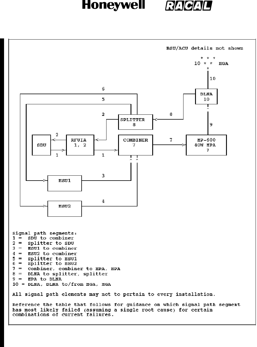
SYSTEM DESCRIPTION, INSTALLATION, AND MAINTENANCE MANUAL
MCS--4000/7000
23--20--27 5 Feb 2008
©Honeywell International Inc. Do not copy without express permission of Honeywell.
Page D--141
Figure 4.4.5.233--1 Single--Point Failure RF Signal Path Troubleshooting Guide (Pre--SDU Part
Number 7516118--XX130/--xx140)
RELEASED FOR THE EXCLUSIVE USE BY: HONEYWELL INTERNATIONAL
UP86308
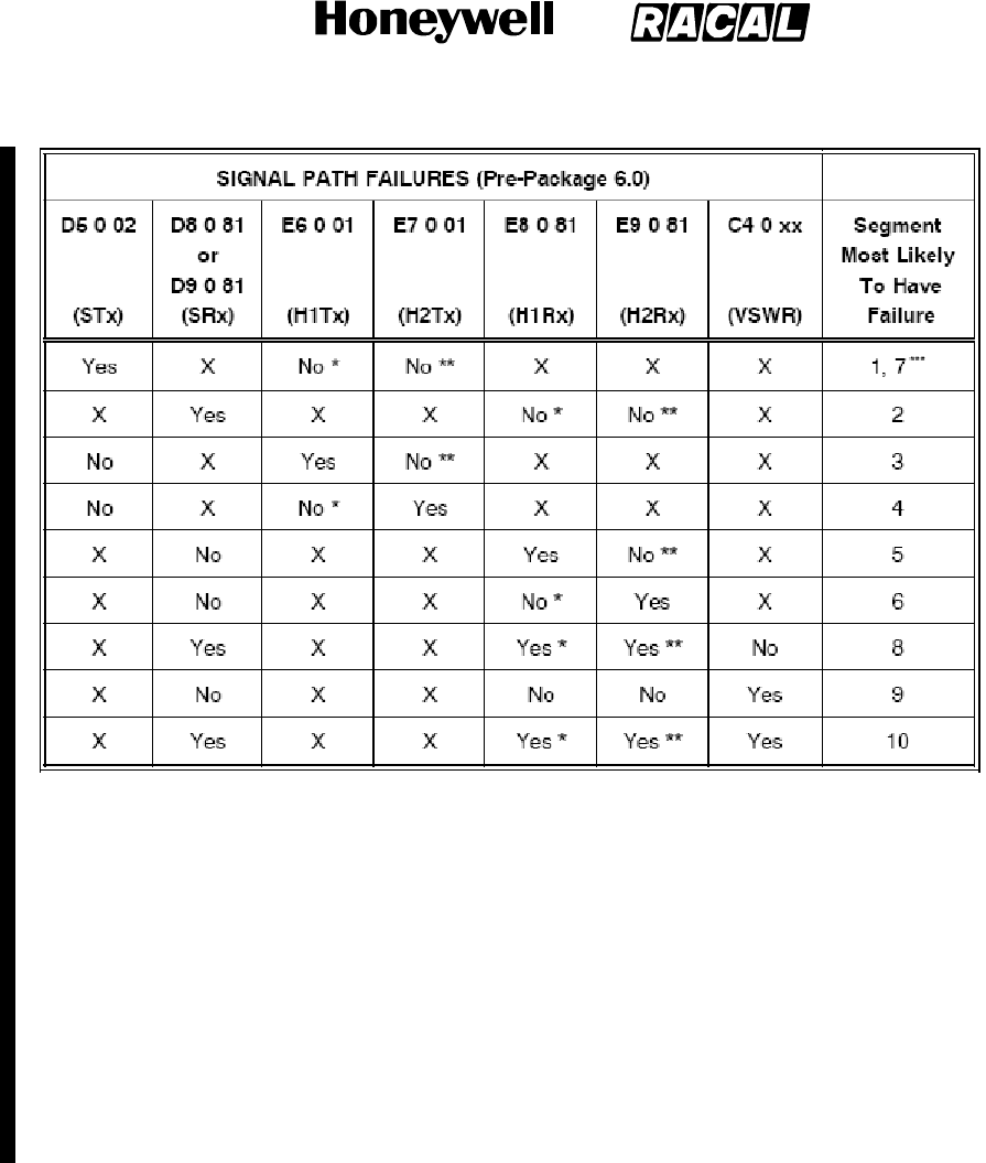
SYSTEM DESCRIPTION, INSTALLATION, AND MAINTENANCE MANUAL
MCS--4000/7000
23--20--27 5 Feb 2008
©Honeywell International Inc. Do not copy without express permission of Honeywell.
Page D--142
SIGNAL PATH FAILURES (Pre--SDU Part Number 7516118--XX130/--xx140)
* This term is only required if HSU1 is wired (”X” otherwise)
** This term is only required if HSU2 is wired (”X” otherwise)
*** This condition (segment 7 failure) may exist, but it cannot be annunciated as such because the tests for
failures E6/0/01 and E7/0/01 are not performed if failure D5/0/02 (which is tested first) is already currently
active.
Notes: X = Don’t care
S=SDU
H1 = HSU1
H2 = HSU2
Tx = Transmit
Rx = Receive
Not all possible combinations are shown ---- only those for which there is a reasonably high probability of
drawing conclusions regarding a single root cause.
RELEASED FOR THE EXCLUSIVE USE BY: HONEYWELL INTERNATIONAL
UP86308
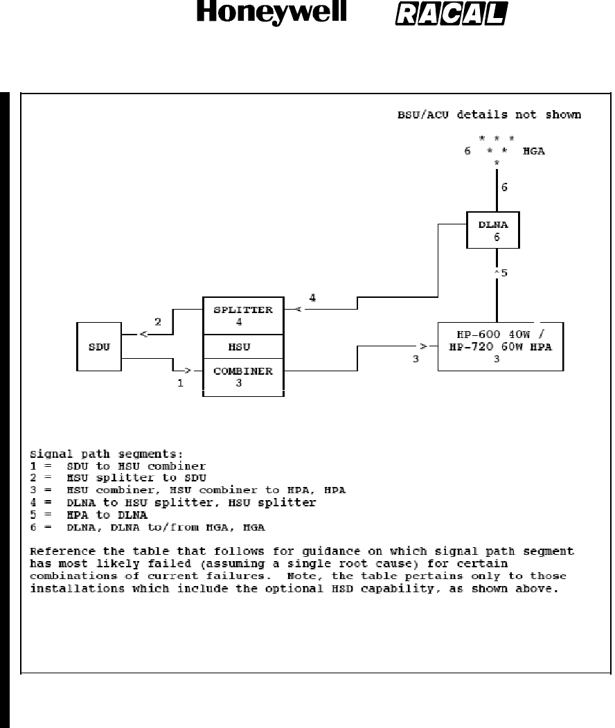
SYSTEM DESCRIPTION, INSTALLATION, AND MAINTENANCE MANUAL
MCS--4000/7000
23--20--27 5 Feb 2008
©Honeywell International Inc. Do not copy without express permission of Honeywell.
Page D--143
SIGNAL PATH FAILURES (SDU Part Number 7516118--XX130/--xx140 and Subsequent)
D5002and/orD5005*
RELEASED FOR THE EXCLUSIVE USE BY: HONEYWELL INTERNATIONAL
UP86308
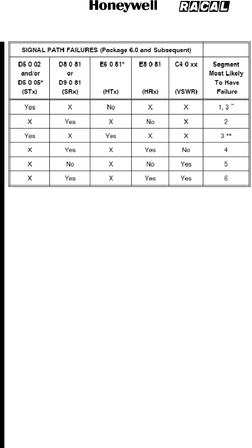
SYSTEM DESCRIPTION, INSTALLATION, AND MAINTENANCE MANUAL
MCS--4000/7000
23--20--27 5 Feb 2008
©Honeywell International Inc. Do not copy without express permission of Honeywell.
Page D--144
* This failure is only raised when the installed HPA is a linear 60W HPA (HP--720)
** This condition (segment 3 failure) is annunciated by the tests associated with failures D5 0 05 and E6 0
81 when the installed HPA is a linear 60W HPA (HP--720). However, when the installed HPA is a linear 40W
HPA (HP--600), this condition may exist, but it cannot be annunciated as such because the test for failure
E6/0/01 is not performed if failure D5/0/02 (which is tested first) is already currently active.
Notes: X = Don’t care
S=SDU
H=HSU
Tx = Transmit
Rx = Receive
Not all possible combinations are shown ---- only those for which there is a reasonably high
probability of drawing conclusions regarding a single root cause.
Dual HS--700 Config Warning (EA 0 01)
DESCRIPTION : This warning is only applicable prior to SDU Part Number 7516118--XX130/--xx140, and is
raised when the SDU detects that two HS--700 units are installed when it is strapped for dual HSU
configuration. The HSU “number” is determined per the part number information transferred by the HSU in its
Build Identity message.
PARAMETERS : None
FAIL CRITERIA : Immediately
RECOVERY CRIT. : This warning is cleared when the HSU that is wired to the SDU’s HSU2 port reports that
it is an HS--702.
REMARK : None
No Declared Active WSC (EB 0 01)
DESCRIPTION : This fault is declared when at least one WSC input bus is active (which includes
TP10H being strapped to the “WSC” state [reference Section 3.2.4.7], and at least one of TP12J, TP12K and
TP13E being strapped for the respective WSC(s) “installed” as well as receipt of label 270 WSC status
words), but no installed WSC indicates “Active” in its label 270 status words (bit 20).
PARAMETERS : None.
FAIL CRITERIA : This fault transitions to failure if the fault persists for 10 seconds.
RECOVERY CRIT. : As soon as a label 270 status word is received from a WSC with an “Active” indication in
bit 20, or the buses from all installed WSCs are declared inactive.
RELEASED FOR THE EXCLUSIVE USE BY: HONEYWELL INTERNATIONAL
UP86308

SYSTEM DESCRIPTION, INSTALLATION, AND MAINTENANCE MANUAL
MCS--4000/7000
23--20--27 5 Feb 2008
©Honeywell International Inc. Do not copy without express permission of Honeywell.
Page D--145
REMARK : [Related information] For the case of WSC Type = Honeywell MAU where only one MAU is
expected to be active at a time for the case of multiple MAUs, the SDU makes no attempt to deal with the
possible opposite condition of multiple MAUs declaring themselves to be active simultaneously [whereas it
does maintain multiple Williamsburg sessions for WSC Type = Airbus RAIMP]. This includes no BIT for that
condition.
HSU Straps (Configuration Pins) Error (Level 1 Code ECh)
HSU Configuration Straps Parity Error (EC 0 81)
DESCRIPTION : This fault is applicable to SDU Part Number 7516118--XX130/--xx140 and subsequent.
During POST/PAST, the HSU configuration straps (reference Section 3.4.2) is tested for parity. If the
computed parity is even, this fault is declared by the HSU (via a Williamsburg Failure Report message with
fault code 0/8C).
PARAMETERS : The HSU configuration strap and parity settings.
FAIL CRITERIA : This fault transitions to failure if the fault persists for two out of three consecutive tests.
RECOVERY CRIT. : This failure is never explicitly cleared.
REMARK : None.
HSU Configuration Straps Error (EC 0 82)
DESCRIPTION : This fault is applicable to SDU Part Number 7516118--XX130/--xx140 and subsequent, and
is declared by the HSU during POST/PAST (via a Williamsburg Failure Report message with fault code 9/82)
when there is no response from the hardware device used to access the HSU configuration straps.
PARAMETERS : None.
FAIL CRITERIA : This fault transitions to a failure if there is no response from the Configuration Straps
hardware device on two out of three consecutive tests.
RECOVERY CRIT. : This failure is never explicitly cleared.
REMARK : HSU is declared unserviceable.
SDU ORT / HSU Configuration Straps Incompatibility (Level 1 Code EDh)
HSU BGAN Configuration Error (ED 0 01)
DESCRIPTION : This fault is applicable to SDU Part Number 7516118--XX130/--xx140 and subsequent. It is
declared by the HSU (via a Williamsburg Failure Report message with fault code 0/0F) when HSD
Registration Selection in the HSU configuration data passed to the HSU is set to “BGAN Always”, but the
BGAN Enable HSU configuration strap (HSU pin MP 1B) is set to Disable”.
PARAMETERS : None.
FAIL CRITERIA : This fault transitions to a failure immediately.
RECOVERY CRIT. : This failure is never explicitly cleared.
REMARK : HSU is declared unserviceable.
HSU Forward Id Address Bits (Straps) Error (Level 1 Code EEh)
HSU Forward Id Address Bits (Straps) Error (EE 0 81)
DESCRIPTION : This fault is applicable to SDU Part Number 7516118--XX130/--xx140 and subsequent, and
is declared by the HSU during POST/PAST (via a Williamsburg Failure Report message with fault code 9/81)
when there is no response from the hardware device used to access the strapped HSU Forward Id Address.
PARAMETERS : The failure parameter indicates which hardware device failed and contains one of the
following values:
1: PCA9554A I2C device
2: PCA9555 I2C device
3: Both I2C devices.
FAIL CRITERIA : This fault transitions to a failure if there is no response from the hardware device used to
access the HSU Forward Id Address Straps on two out of three consecutive tests.
RECOVERY CRIT. : This failure is never explicitly cleared.
REMARK : HSU is declared unserviceable.
RELEASED FOR THE EXCLUSIVE USE BY: HONEYWELL INTERNATIONAL
UP86308

SYSTEM DESCRIPTION, INSTALLATION, AND MAINTENANCE MANUAL
MCS--4000/7000
23--20--27 5 Feb 2008
©Honeywell International Inc. Do not copy without express permission of Honeywell.
Page D--146
Illegal HSU Forward Id Address (EE 0 82)
DESCRIPTION : This fault is applicable to SDU Part Number 7516118--XX130/--xx140 and subsequent, and
is declared by the HSU during POST/PAST (via a Williamsburg Failure Report message with fault code 0/90)
when the strapped HSU Forward Id address is set to all zero’s, all one’s or to an invalid value as determined
by comparison with the internal look--up table held by the HSU.
PARAMETERS : The HSU Forward Id address read from the discrete straps.
FAIL CRITERIA : This fault transitions to a failure if the fault persists on two out of three consecutive tests.
RECOVERY CRIT. : This failure is never explicitly cleared.
REMARK : HSU is declared unserviceable.
Pilot Event Marker (FD 0 01--16)
DESCRIPTION : While either airborne or on the ground, the pilot observes an ’event’ and desires to have a
snapshot of all system states and therefore presses the PEM switch in the cockpit. This
condition is flagged with a failure when the PEM is received from the CAIMS OMS.
PARAMETERS : None.
FAIL CRITERIA : This fault transitions to a failure immediately upon receipt of CAIMS Label 226 with bit 29
set to one when CAIMS is inactive.
RECOVERY CRIT. : This failure transitions to normal when Label 226 bit 29 transitions to zero.
REMARK : This condition is used to synchronize the log to a special event observed by the pilot while either
in--flight or on the ground. This is unique in that subsequent activations of this fault in
a specific flight leg increments the Failure index so that a specific time stamp can be assigned each time.
External Power Supply Interrupt In--Flight (FE 0 01)
DESCRIPTION : While airborne, the power to the SDU is interrupted. This condition is flagged with a failure
when the POC is incremented and the current DC state is DC1 or DC1’.
PARAMETERS : None.
FAIL CRITERIA : This fault transitions to a failure immediately
RECOVERY CRIT. : This failure transitions to normal immediately.
REMARK : This condition is used to annunciate a special case of SDU power--up while in--flight. The failure
message will preclude the unnecessary removal of the SDU when a power interrupt
occurs and other LRUs indict the SDU. The failure is immediately removed from the current failures list to
avoid an erroneous failure indication on the front panel alphanumeric display.
RELEASED FOR THE EXCLUSIVE USE BY: HONEYWELL INTERNATIONAL
UP86308

SYSTEM DESCRIPTION, INSTALLATION, AND MAINTENANCE MANUAL
MCS--4000/7000 Multi--Channel SATCOM System
23--20--27
30 Aug 2002
Use or disclosure of information on this page is subject to the restrictions in the proprietary notice of this document.
Page INDEX--1
INDEX
A
AAC. See aeronautical administratiive communications
ACARS. See aircraft communications addressing and
reporting system
ACP. See audio control panel
acronyms and abbreviations, INTRO--3
actual power out status, 6--57
ACU. See antenna control unit
ADL. See airborne data loader
ADS. See automatic dependent surveillance
aeronautical administrative communications, 1--1
aeronautical operational control, 1--1
aeronautical passenger communications, 1--1, 3--2
Aeronautical Radio, Inc., 1--2, 2--28
AES. See aircraft earth station
AFIS. See aircraft flight information system
air filtration systems, B--1
installation instructions, B--4
air traffic
control, 1--1
services, 1--1
Air Transport Association, reference numbers, 6--89
Airbus, 6--93, 6--94, 6--96, 6--98, 6--100, 6--101, 6--103,
6--105
Boeing, 6--90, 6--91, 6--92, 6--93
McDonnell Douglas, 6--106, 6--107, 6--108, 6--109
air--to--ground calls, 5--59
airborne data loader, 1--8, 2--8, 2--11, 2--12, 2--13
aircraft avionics, 1--8
aircraft communications addressing and reporting system,
1--1, 1--8
peripheral function, 2--28
aircraft earth station, 1--1, 1--2, 2--1, 2--2, 2--15, 2--16
classifications, 1--9
components, 1--2
identification, 5--47
management, 2--1
operational modes for log--on, 2--3
aircraft identification, 6--8, 6--68
aircraft flight information system, 2--28
alphanumeric display test, 6--6
AMS. See audio management system
AMU. See audio management unit
analog
audio channel, 3--2
connected telephone(s), 1--7, 3--1, 3--1, 3--11
call barring level, 3--1, 3--3, C--4
handset, 2--5, 2--6, 2--7
stored telephone numbers, 3--3, C--5
system management commands, 3--4, 3--5, C--4
private branch exchange, 1--7, 3--1, 5--50
interfaces, 3--7
trunk lines, 3--2
antenna
general removal instructions, 7--3
hardware, 7--2
removal and installation, 7--2
weather protection, 7--2
antenna control unit, 1--6, 5--53, 6--5, 6--8
antenna subsystem, 1--6, 5--51, 5--52, 5--53
AOC. See aeronautical operational control
APBX. See analog private branch exchange
APC. See aeronautical passenger communications
APHONE. See channels, analog
APOS. See actual power out status
ARINC. See Aeronautical Radio, Inc.
ARINC 600 connector
layouts and contact arrangement, 5--1
pin assignments, A--9
requirements, 5--3
ATA. See Air Transport Association
ATC. See air traffic, control
ATS. See air traffic, services
audio control panel, 2--27, 3--10, 5--59
audio interfaces, 3--3
audio management system, 2--27
audio management unit, 3--10
automatic dependent surveillance, 1--1, 1--8
aviation satellite communications system, 1--1
B
beam steering
function, 1--5
unit, 1--6, 1--20, 1--24, 5--53, 6--5, 6--8, A--4, A--3, A--4,
A--1
BIT. See built--in test
BITE. See built--in test equipment
bootstrap
program, 2--8
system table, 2--2
BSU. See beam steering unit
b u i l t -- i n t e s t , 6 -- 8 8 , A -- 3 , A -- 5
built--in test equipment, 1--26, 1--30, 1--35, 5--53, 6--3,
6--5, 6--7, 6--89
requirements, 6--1, 6--18
system communication, 6--1
bulk data communication, 2--13
RELEASED FOR THE EXCLUSIVE USE BY: HONEYWELL INTERNATIONAL
UP86308

SYSTEM DESCRIPTION, INSTALLATION, AND MAINTENANCE MANUAL
MCS--4000/7000 Multi--Channel SATCOM System
23--20--27
30 Aug 2002
Use or disclosure of information on this page is subject to the restrictions in the proprietary notice of this document.
Page INDEX--2
C
C--channel. See RF channels, C--channel
cabin
communications, 1--5, 3--1
communications system, 1--5, 1--6, 3--1, 5--50, A--3,
A--1
packet data function, 2--17, 5--49
telecommunications panel, 6--110
telecommunications unit, 1--6, 2--17, 3--1
voice services, 2--13
cabin/passenger communications equipment, 1--6, 3--1
cable
attenuation, 4--2
loss requirements, 4--2
CAIMS. See central aircraft information and maintenance
system
call
initiation from analog phone, 3--7
termination, 2--7, 2--16, 3--1, 3--11
CCS. See cabin, communications system
central aircraft information and maintenance system,
6--10, 6--88
central fault display system, 1--8, 5--53, 6--6, 6--7, 6--10,
6--16, 6--17, 6--27, 6--38, 6--46, 6--68, 6--71, 6--79, 6--89
Airbus, 6--84, 6--87
McDonnell--Douglas, 6--84, 6--87
pages, 6--10, 6--88
central maintenance computer, 1--8, 5--53, 6--7, 6--10,
6--16, 6--17, 6--46, 6--87
Boeing 747--400, 6--84
to SDU communication, 6--84
centralized fault display interface unit, 6--87, 6--88
communication with SDU, 6--87
CFDIU. See centralized fault display interface unit
CFDS. See central fault display system
CGU. See communications, gateway unit
channels, analog, C--3
circuit--mode, 2--16, 2--20
call setup, 2--15, 2--16
data, 2--4, 2--13, 2--15, 3--6, 6--111
services, 2--13, 2--16
voice, 2--7, 2--13
CM. See continuous monitoring
CMC. See central maintenance computer
CMT. See commissioning and maintenance terminal
co--ordinated universal time, 6--68, 6--71, 6--75, 6--79,
6--81
cockpit
communications, 3--10
hookswitch signaling, 5--59
voice, 1--5
call light test, 6--33, 6--34
call light/chime, 5--57
channels, 2--27
configurations, 2--27
functionality, 2--27
services, 2--13
sources, 1--7
codec dedication, 5--58
codec--generated
messages, 3--2
pacifiers, 3--2, 3--11
commissioning and maintenance terminal, 2--5, 2--7,
2--12, 6--6, 6--10, 6--18, 6--72, 6--110
interface, 6--17
page, 2--11, 6--3
panel lamps, 6--111
communications
gateway unit, 3--3
management unit, 1--5, 5--47, 5--48, 5--55, A--4
communications management unit, 5--47
configuration data messages, 6--85
configuration pins, 5--16, 5--45, 5--46, 5--47, 5--48, 5--49,
5--51, 5--53, 5--54, 5--55, 5--56, 5--57, 5--58, 6--39, 6--45,
6--46, 6--48, 6--49, 6--51, 6--85, 6--88, 6--89
continued airworthiness, 7--5, B--1
continuity, 5--16
continuous monitoring, 6--4, 6--5, 6--7, 6--8, 6--9, 6--11,
6--30
failure, 6--11
failure records, 6--8
cooling requirements, 4--3, B--1
CPDF. See cabin, packet data function
CRC. See cyclic redundancy check
cross talk, 5--54
cross--talk bus, 2--17, 2--18, 2--19, 6--110
CTM panel. See cabin, telecommunications panel
CTU. See cabin, telecommunications unit
customer assistance, INTRO--6
cyclic redundancy check, 2--9, 6--17
D
data
interface unit, 2--15
set
download, 2--8
upload, 2--8
terminal equipment, 2--15
digitally connected phones, 1--7, 3--1
DIP. See dual in--line packaging
diplexer, 1--6, 1--23, 5--53, 6--5, 6--8, A--3, A--1
DIU. See data, interface unit
DTE. See data, terminal equipment
DTMF. See dual tone multifrequency
dual in--line packaging, 1--25
RELEASED FOR THE EXCLUSIVE USE BY: HONEYWELL INTERNATIONAL
UP86308

SYSTEM DESCRIPTION, INSTALLATION, AND MAINTENANCE MANUAL
MCS--4000/7000
23--20--27 5 Feb 2008
©Honeywell International Inc. Do not copy without express permission of Honeywell.
Page INDEX--3
dual SATCOM system, 2--10, 2--16, 5--54, 6--27
antenna configurations, 2--19
cockpit voice configurations, 2--27
control/status, 2--17
reversion, 2--18
automatic, 2--18
manual, 2--19
SCDU page displays, 6--110
wiring diagram, 2--18
dual tone multifrequency, 1--7, 3--2, 3--2, 3--7, 3--8, 3--11
E
effective isotopic radiated power, 1--21, 1--23, 1--24, 2--5
Electronic Cable Specialists
air filtration assemblies, A--2
ARINC 600 connectors
beam steering unit, A--2
high power amplifier, A--2
satellite data unit, A--2
signal conditioning unit, A--2
attenuators, A--1, A--2
cabin communications system provisions, A--3
cable, A--1, A--2
connectors, A--1, A--2
hardware component kits, A--4, A--1, A--2
plenum shelf assemblies, A--3
tray assemblies, A--4, 7--5, A--2
elevation handover threshold, 2--5, 2--7
encrypted voice/data communication, 2--13
F
facsimile, 1--5, 2--13, 2--15, 3--1
failure
detection and reporting level, 6--3
memory log, 6--8, 6--18, 6--68, 6--71, 6--75, 6--79, 6--81,
6--83
messages in normal mode, 6--87
recording, 6--7
reporting, 6--8
fault codes, D--1
fault warning processor, 6--88
flight
identification number, 2--4
leg, 6--8
management computer, 5--48
plan information, 5--48
FMC. See flight, management computer
functional tests, 6--4, 6--5, 6--8, 6--9, 6--11, 6--84
failure, 6--12
failure records, 6--8
FWP. See fault warning processor
G
GES. See ground earth station
GES--specific data broadcast, 2--16
global beam, 2--1, 2--3
Global--Wulfsberg Flitephone WH--10, 1--7, 3--1
commands, 3--3
interface, 3--1
Greenwich Mean Time, 6--8
ground earth station, 1--1, 1--2, 1--10, 2--1, 2--2, 2--15,
3--5, 3--8, 5--47
communication links, 1--9
preference, 2--5, 2--6, 2--7, 3--5
tied preferences, 2--5
ground speed, 6--77, 6--83
ground--to--air calls, 2--4, 3--5, 3--6, 3--10, 5--56, C--3
GSDB. See GES--specific data broadcast
GSPD. See ground speed
H
handover, 2--1, 2--2, 2--7
automatic, 2--1, 2--2, 2--7
of mastery, 2--17, 2--18, 2--20
user command, 2--1, 2--7
high gain antenna, 1--6, 1--23, 2--16, 2--19, 2--21, 2--22,
2--23, 2--24, 2--25, 2--26, 2--27, 4--3, 5--53, 6--5, 6--7,
6--16, 6--56, 6--58
maximum permissible exposure level, INTRO--4
high power amplifier, 1--5, 1--13, 1--15, 1--24, 3--13, 5--51,
5--52, 5--53, 6--1, 6--2, 6--5, 6--6, 6--7, 6--9, 6--16, 6--17,
6--19, 6--56, 6--58, 6--71, 6--85, 6--88, 6--111, A--4, A--4,
B--1, B--4, B--6
20 watt, 1--13, 1--31, 1--35
ARINC 600 connector requirements, 5--3
configurations, 1--15
cooling requirements, 4--3
environmental categories, 1--37
front panel, 1--35
front panel connector, 5--1
installation equipment, 1--13
leading particulars, 1--36
mechanical installation data, 4--1
nameplates, 1--44
portable data loader connector, 1--35
rear connector, 1--35, 5--1
40 watt, 1--13, 1--30, 1--31
ARINC 600 connector requirements, 5--3
configurations, 1--14
cooling requirements, 4--3
environmental categories, 1--34
front panel, 1--30
front panel connector, 5--1
installation equipment, 1--13
leading particulars, 1--33
mechanical installation data, 4--1
RELEASED FOR THE EXCLUSIVE USE BY: HONEYWELL INTERNATIONAL
UP86308

SYSTEM DESCRIPTION, INSTALLATION, AND MAINTENANCE MANUAL
MCS--4000/7000 Multi--Channel SATCOM System
23--20--27
30 Aug 2002
Use or disclosure of information on this page is subject to the restrictions in the proprietary notice of this document.
Page INDEX--4
nameplates, 1--44
portable data loader connector, 1--30
rear connector, 1--30, 5--1
failure reporting, 6--8
front panel
indicators and controls, 6--8
light emitting diodes, 6--9
software upload, 2--9
software/database updates, 2--8
high power relay, 4--3, 5--53, 6--5, A--3, A--1
Hollingsead International, A--4
ARINC 600 connectors
beam steering unit, A--5
communications management unit, A--5
high power amplifier, A--5
satellite data unit, A--5
cabin communications system provisions, A--1
engineering support, A--4
installation kit components, A--5
cables, A--5
connectors, A--5
tray assemblies, A--6, 7--7
plenum shelf assemblies, A--1
HPA. See high power amplifier
HPR. See high power relay
I
ICAO. See International Civil Aviation Organization
IGA. See intermediate gain antenna
inertial navigation system, 1--5
inertial reference system, 1--8, 1--24, 2--5, 5--51, 6--40,
A--2
initial signal unit, 3--8
INMARSAT. See International Maritime Satellite
Organization
INS. See inertial navigation system
installation, new, 4--1
instructions for continued airworthiness, 7--5
interactive data communication, 2--13
intermediate gain antenna, 1--6, 1--24, 2--19
maximum permissible exposure level, INTRO--4
International Civil Aviation Organization, 1--1
address, 2--16, 5--16, 5--47, 6--8, 6--38
aircraft identification code, 2--4
block strapping, 5--19
International Maritime Satellite Organization, 1--10, 1--20,
2--1, 2--13, 2--15
four--region satellite coverage, 1--12
International Organization for Standardization, 2--15, 3--9
International Telecommunications Union, 1--1
IRS. See inertial reference system
ISO. See International Organization for Standardization
ISU. See initial signal unit
ITU. See International Telecommunications Union
L
level I failure messages, 6--12, 6--13, 6--14, 6--16, 6--89
Airbus, 6--93, 6--94, 6--96, 6--98, 6--100, 6--101, 6--103,
6--105
Boeing, 6--90, 6--91, 6--92, 6--93
McDonnell Douglas, 6--106, 6--107, 6--108, 6--109
LGA. See low gain antenna
light emitting diode, 1--30, 1--35, 6--8, A--3, A--5
test, 6--6, 6--11
line replaceable unit, 2--8, 6--4, 6--5, 6--75, 6--77, 6--81,
6--86, 6--88, 6--89, 6--111, 7--1, 7--5, B--1, B--4, B--5, B--6,
B--7
coverage, 6--3
data record, 6--87
header record, 2--9
identification, 6--16, 6--71
installation, 7--3
mechanical installation, 4--1
removal, 7--3
log--off, 2--1, 2--3, 2--6, 2--7, 6--23
log--on, 2--1, 2--2, 2--3, 2--4, 2--5, 2--10, 2--16, 6--27, 6--33,
6--34, 6--65
automatic, 2--5, 2--6, 2--7
constrained, 2--6, 2--7
mode selection, 2--6
policy, 2--3, 2--5, 3--4, C--1
user command, 2--3
low gain antenna, 1--6, 1--23, 2--5, 2--16, 2--19, 2--21,
2--23, 2--24, 2--25, 2--26, 2--27, 5--53, 6--5, 6--7, 6--16,
6--56, 6--58
maximum permissible exposure level, INTRO--4
low noise amplifier, 1--6, 5--53, 6--5, 6--8, A--3, A--1
LRU. See line replaceable unit
M
maintenance
activity log, 6--18, 6--19
activity record, 6--19
panel assembly, 6--110
management unit, 1--8, 1--20, 2--17
MAR. See maintenance, activity record
maximum permissible exposure level, INTRO--3
high gain antenna, INTRO--4
intermediate gain antenna, INTRO--4
low gain antenna, INTRO--4
radio frequency energy levels, INTRO--5
MCDU. See multifunction control and display unit
MCU. See modular concept unit
modular concept unit, 1--25
MPEL. See maximum permissible exposure level
MU. See management unit
RELEASED FOR THE EXCLUSIVE USE BY: HONEYWELL INTERNATIONAL
UP86308

SYSTEM DESCRIPTION, INSTALLATION, AND MAINTENANCE MANUAL
MCS--4000/7000 Multi--Channel SATCOM System
23--20--27
30 Aug 2002
Use or disclosure of information on this page is subject to the restrictions in the proprietary notice of this document.
Page INDEX--5
multi--channel SATCOM system
ARINC 429 data requirements, 1--44, A--2, A--3
avionics, 1--5, 1--13, 3--1
block diagram, 1--17
configurations, 1--25
cooling requirements, 4--3
physical description, 1--25
software and hardware compatibility, 1--46
failures, 6--1
multifunction control and display unit, 1--5, 1--7, 2--11,
3--10, 5--55, 5--57, 6--17, 6--20, 6--21
N
non--volatile memory, 6--88, C--1
O
OCXO. See oven--controlled crystal oscillator
off--hook, 1--7, 3--2, 3--1, 3--3, 3--5, 3--7, 3--9, 3--10, 5--59
OMS. See onboard maintenance system
on--board maintenance system, 1--8
Boeing 777, 6--84
CAIMS, 6--89
on--hook, 1--7, 3--2, 3--3, 3--4, 3--5, 3--7, 3--8, 3--11, 5--59
operational software, 2--8, 2--9
ORT. See owner requirements table
oven--controlled crystal oscillator, 4--3, 6--5, 6--6
owner requirements table, 1--8, 1--21, 1--23, 1--26, 3--3,
3--4, 3--5, 3--6, 3--11, 3--13, 4--2, 5--56, 5--58, 6--27,
6--64, 6--65, 6--110, C--1
download/upload diskettes, 2--8, 2--11
identification, 6--18, 6--71, 6--74, 6--85, 6--87, 6--88
identification message, 6--11
upload, 4--2, 7--4
upload/download, 2--11
P
P--channel. See RF channels, P--channel
PABX. See private automatic branch exchange
packet data, 1--6, 5--49
messages, 1--5, 2--15
services, 2--15, 2--16, 2--20
packet--mode channels, 2--16
part number block, 6--17
PAST. See person--activated self--test
Pd--channel, 2--1, 2--2, 2--3, 2--4
frequency, 2--3
PDL. See portable data loader
peripherals, 1--25
person--activated self--test, 1--46, 2--9, 2--10, 2--12, 2--13,
5--47, 6--4, 6--6, 6--9, 6--29, 6--35, 6--38, 6--87
personal computer, modem interface, 1--5
phase--locked oscillator, 6--5, 6--6
PMAT. See portable maintenance access terminal
POC. See power--on counter
portable data loader, 1--8, 1--46, 2--8, 2--11, 2--12, 2--13,
5--1
connector, 1--26, 1--30, 1--35
portable maintenance access terminal, 6--89
POST. See power--on self--test
power interrupts, 6--4
power supply unit, 6--6, 6--77, 6--83
power--on counter, 6--77, 6--83
power--on self--test, 1--46, 2--9, 5--47, 6--4, 6--5, 6--6, 6--9,
6--29, 6--35
priority 4 calls, 5--56
private automatic branch exchange, 1--6, 3--1
Psid--channel frequencies, 2--2, 2--6
Psmc--channel, 2--1, 2--4, 2--5
frequency, 2--2, 2--3, 2--6
PSTN. See public switched telephone network
PSU. See power supply unit
PTT. See push--to--talk
public switched telephone network, 1--10
push--to--talk, 1--7, 3--10, 6--6
switched, 5--59
R
R--channel. See RF channels, R--channel
radio frequency module, 6--6
radio frequency unit interface adapter, 1--5, 1--13, 1--43
ARINC 600 connector requirements, 5--3
leading particulars, 1--44
Rd--channel, 2--4, 2--5
real--time clock, 6--19
RF channels, 1--9
C--channel, 1--9, 1--21, 1--22, 2--4, 2--7, 2--13, 2--15,
2--16
P--channel, 1--9, 2--1, 2--2, 2--3, 2--4, 2--6, 2--7
R--channel, 1--9, 1--21, 1--22, 2--3, 2--4, 2--5
T--channel, 1--9, 1--21, 1--22, 2--4, 2--5
RF loop back test, 6--6
RFM. See radio frequency module
RFUIA. See radio frequency unit interface adapter
Rsmc--channel, 2--4, 2--5
RTC. See real--time clock
RELEASED FOR THE EXCLUSIVE USE BY: HONEYWELL INTERNATIONAL
UP86308

SYSTEM DESCRIPTION, INSTALLATION, AND MAINTENANCE MANUAL
MCS--4000/7000 Multi--Channel SATCOM System
23--20--27
30 Aug 2002
Use or disclosure of information on this page is subject to the restrictions in the proprietary notice of this document.
Page INDEX--6
S
SATCOM control and display unit, 1--7, 1--24, 2--6, 2--17,
2--19, 2--27, 3--10, 5--55, 5--57, 5--59, 6--6, 6--7, 6--8,
6--10, 6--17, 6--20, 6--22, 6--87, 6--88
display, 6--20, 6--21
page, 2--11
displays for dual systems, 6--110
hierarchy, 6--25, 6--29
pages, 6--10, 6--20, 6--24, 6--89
configuration data, 6--27, 6--38, 6--39, 6--40, 6--41,
6--42, 6--43, 6--44, 6--45, 6--46, 6--47, 6--48, 6--49,
6--50, 6--51, 6--52, 6--54, 6--55, 6--56, 6--57, 6--59
data loader, 6--59, 6--60, 6--61, 6--62, 6--63, 6--64,
6--65, 6--66
ground report, 6--27, 6--79, 6--80
ground report troubleshooting data, 6--27, 6--81,
6--82
last leg class 3 faults, 6--27, 6--77, 6--78
last leg report, 6--27, 6--66, 6--67
LRU identification, 6--27, 6--71, 6--73, 6--74
previous legs report, 6--27, 6--68, 6--69, 6--70, 6--71
SATCOM main menu, 6--24, 6--26, 6--29, 6--110
SATCOM maintenance, 6--27, 6--29, 6--59, 6--66,
6--110
SATCOM self--test, 6--35, 6--36, 6--37, 6--38
SATCOM submenu, 6--27, 6--28, 6--66
test, 6--27, 6--29, 6--30, 6--31, 6--32
troubleshooting data, 6--27, 6--75, 6--76
SATCOM main menu page, 3--11
satellite data unit, 1--5, 1--13, 1--19, 1--26, 1--27, 2--5, 2--6,
2--7, 2--10, 2--11, 2--12, 2--13, 2--16, 2--17, 2--18, 3--1,
3--2, 3--1, 3--5, 3--8, 3--11, 5--47, 5--48, 5--49, 5--50,
5--51, 5--53, 5--55, 5--56, 5--57, 5--59, 6--1, 6--3, 6--5,
6--6, 6--7, 6--8, 6--9, 6--18, 6--19, 6--20, 6--22, 6--66,
6--72, 6--84, 6--85, 6--87, 6--88, 6--89, 6--110, A--4, A--4,
B--1, B--4, B--6, C--1
portable data loader connector, 1--26
ARINC 600 connector requirements, 5--3
codec, 2--15, 2--27, 3--1, 3--10, 5--58
configuration pin, 5--54
cooling requirements, 4--3
environmental categories, 1--29
failure reporting, 6--10
front panel, 1--26
connector, 5--1
indicators and controls, 6--10
light emitting diodes, 6--11
installation dependent considerations, 1--22, 4--2
installation equipment, 1--13
leading particulars, 1--27
master, 2--16, 2--17, 2--18, 2--19
mechanical installation data, 4--1
modem, 1--20, 3--1
nameplates, 1--44
number, 5--54
rear connector, 1--26, 5--1
slave, 2--16, 2--17, 2--18, 2--19
software upload, 2--9
software/database updates, 2--8
to WH10 handset actions, 3--1
voice codec, 3--1, 3--2
voice interface module, 1--20
SCDU. See SATCOM control and display unit
SCPC. See single channel per carrier
scratchpad, 6--20, 6--21, 6--23, 6--65, 6--88
SCU. See signal conditioning unit
SDI. See source destination identifer
SDU. See satellite data unit
secure voice
coding unit, 2--15
interface, 1--5
shop replaceable unit, 1--25, 6--3, 6--75, 6--77, 6--81
sign/status matrix, 5--47, 6--4, 6--5, 6--6, 6--9, 6--84, 6--87,
A--5, A--7, A--8
signal conditioning unit, 1--5, 1--13, 1--44, A--4, A--3, A--2,
A--3, A--4, A--5, A--7, A--8
automatic input selection, A--5
built--in test, A--3, A--5
control functions, A--4
front panel, A--3
light emitting diode, A--3, A--5
manual signal selection, A--4
single channel per carrier, 1--9
SMT. See surface--mount technology
software, upload, 2--8, 2--9
validation, 2--9
source destination identifier, 5--51, 5--54, 6--16, 6--84
space segment, 1--1, 1--10
spot beam, 1--12, 1--21, 1--24, 2--1, 2--2, 2--4, 2--5, 2--6
handover, 2--6
satellite, 2--1
search table, 2--3
SRU. See shop replaceable unit
SSM. See sign/status matrix
standard ground test, 6--87
strap parity, 5--49
surface--mount technology, 1--25
system address label, 2--9
system components. See multi--channel SATCOM system
avionics
system table, 2--2, 2--3, 3--5
T
T--channel. See RF channels, T--channel
TDM. See time division multiplex
TDMA. See time division multiple access
terminal interface function, 2--15
terrestrial data and voice networks, 1--1, 1--10
RELEASED FOR THE EXCLUSIVE USE BY: HONEYWELL INTERNATIONAL
UP86308

SYSTEM DESCRIPTION, INSTALLATION, AND MAINTENANCE MANUAL
MCS--4000/7000 Multi--Channel SATCOM System
23--20--27
30 Aug 2002
Use or disclosure of information on this page is subject to the restrictions in the proprietary notice of this document.
Page INDEX--7
time division
multiple access, 1--9
multiplex, 1--9
time since power--on, 6--77, 6--83
total on--time clock, 6--18, 6--19
U
UTC. See co--ordinated universal time
V
VCM. See voice codec module
vendor equipment, 1--28, 1--34, 4--4, A--1
voice codec module, 3--10
audio switching, 3--11
dedication, 3--13
sidetone, 3--11
stored audio messages, 3--11
voltage standing wave ratio, 4--2, A--2
W
weight--on--wheels discrete, 6--7, 6--39
X
XTB. See cross--talk bus
RELEASED FOR THE EXCLUSIVE USE BY: HONEYWELL INTERNATIONAL
UP86308

SYSTEM DESCRIPTION, INSTALLATION, AND MAINTENANCE MANUAL
MCS--4000/7000 Multi--Channel SATCOM System
23--20--27
30 Aug 2002
Use or disclosure of information on this page is subject to the restrictions in the proprietary notice of this document.
Page INDEX--8
Blank Page
RELEASED FOR THE EXCLUSIVE USE BY: HONEYWELL INTERNATIONAL
UP86308