Honeywell VM2C02 Vehicle Mount Terminal User Manual Thor VM2 User s Guide
Honeywell International, Inc. Vehicle Mount Terminal Thor VM2 User s Guide
UserManual.wiki
>
Honeywell
>
VM2C02 User Manual
>
user manual
Contents
1.
user manual
2.
User Manual
user manual
Navigation menu
Upload a User Manual
Namespaces
Wiki Guide
HTML
PDF
Info
Views
User Manual
Discussion / Help
Navigation


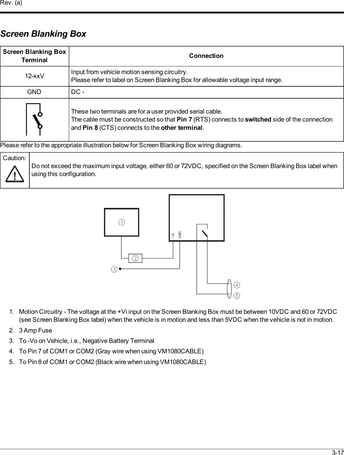
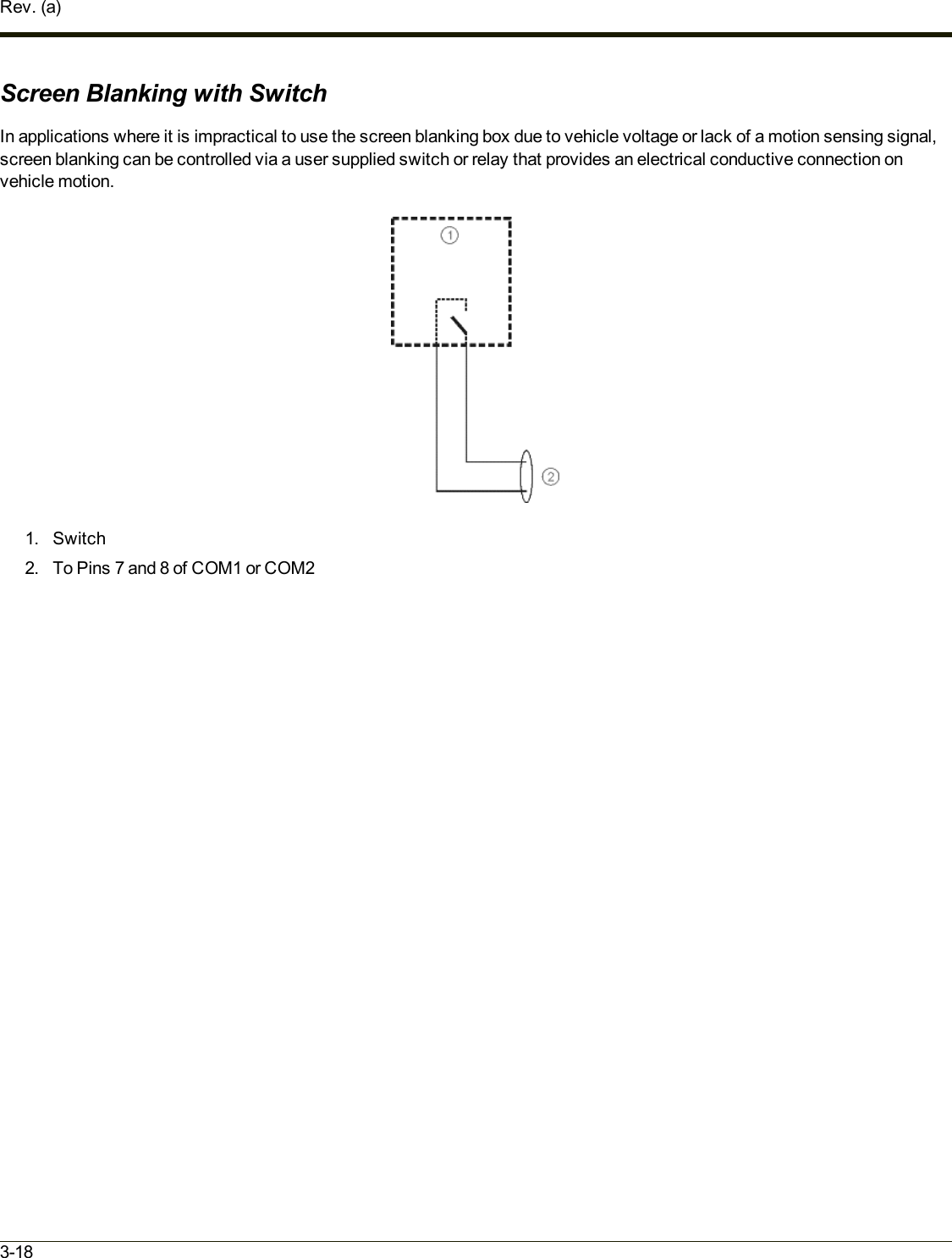
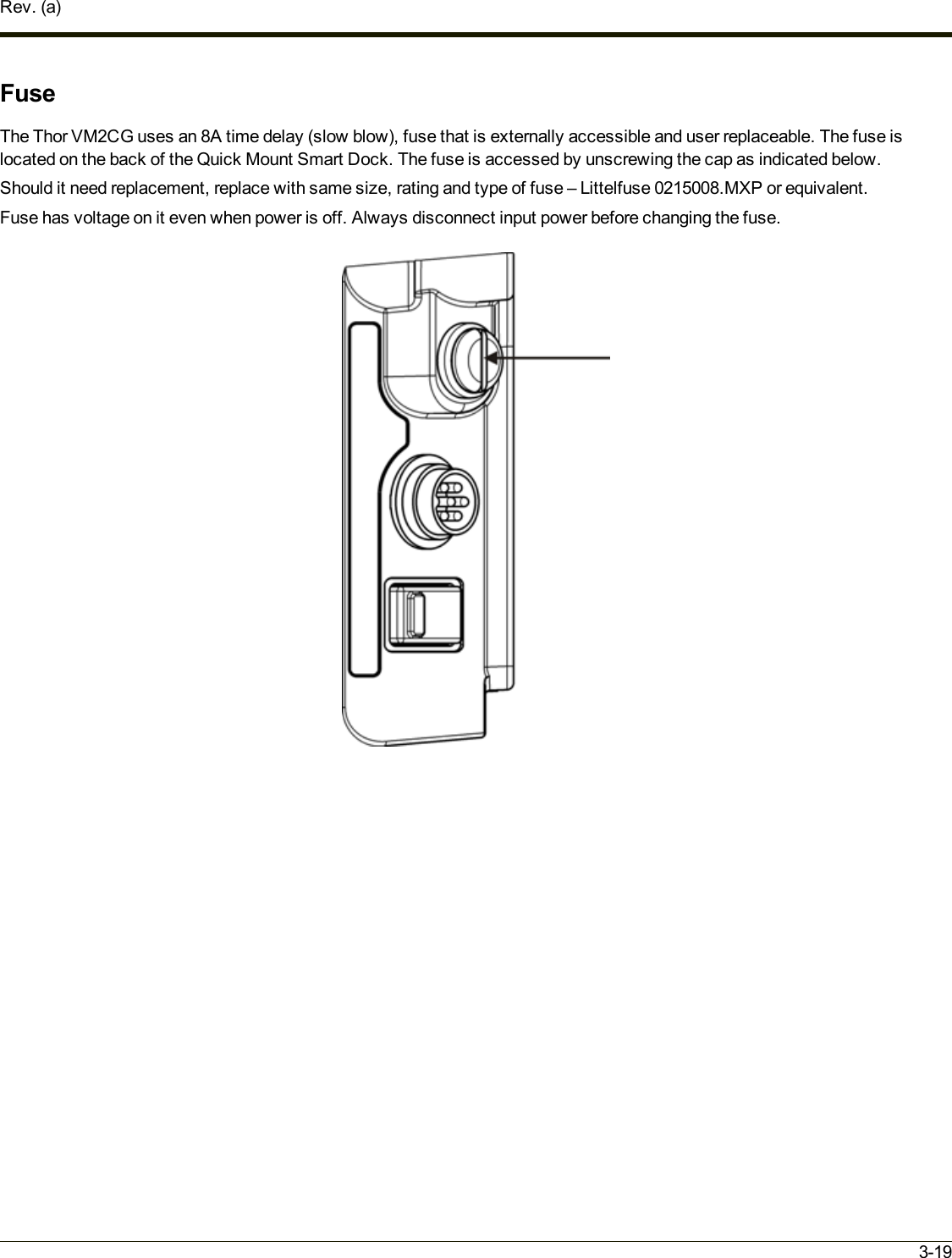

![Chapter 4 - Product Agency Compliance - Thor VM2CGClass B Digital DeviceFCC Rules, Part 15This device complies with Part 15 of the FCC Rules [and with RSS-210 of Industry Canada]. Operation is subject to thefollowing two conditions:1. This device may not cause harmful interference, and2. This device must accept any interference received, including interference that may cause undesired operation.NOTE: This equipment has been tested and found to comply with the limits for a Class B digital device, pursuant to Part 15 ofthe FCC Rules. These limits are designed to provide reasonable protection against harmful interference in a residentialinstallation. This equipment generates, uses and can radiate radio frequency energy and, if not installed and used inaccordance with the instructions, may cause harmful interference to radio communications. However, there is no guaranteethat interference will not occur in a particular installation. If this equipment does cause harmful interference to radio or televisionreception, which can be determined by turning the equipment off and on, the user is encouraged to try to correct theinterference by one or more of the following measures:lReorient or relocate the receiving antenna.lIncrease the separation between the equipment and the receiver.lConnect the equipment into an outlet on a circuit different from that to which the receiver is connected.lConsult the dealer or an experienced radio/TV technician for help.NoticeChanges or modifications made to this equipment not expressly approved by Honeywell may void the FCC authorization tooperate this equipment.EMC Directive RequirementsThis is a Class B product. In a domestic environment this product may cause radio interference in which case the user may berequired to take adequate measures.Canada, Industry Canada (IC) NoticesThis Class B digital apparatus complies with Canadian ICES-003This device complies with Industry Canada licence-exempt RSS standard(s). Operation is subject to the following twoconditions: (1) this device may not cause interference, and (2) this device must accept any interference, including interferencethat may cause undesired operation of theExposure of humans to RF fields (RSS-102)The computers employ low gain integral antennas that do not emit RF field in excess of Health Canada limits for the generalpopulation; consult Safety Code 6, obtainable from Health Canada's Web site at http://www.hc-sc.gc.ca/The radiated energy from the antennas connected to the wireless adapters conforms to the IC limit of the RF exposurerequirement regarding IC RSS-102, Issue 4 clause 4.1.4-1](https://usermanual.wiki/Honeywell/VM2C02.user-manual/User-Guide-1943623-Page-59.png)