Honeywell VM2C02 Vehicle Mount Terminal User Manual Thor VM2 User s Guide
Honeywell International, Inc. Vehicle Mount Terminal Thor VM2 User s Guide
Contents
- 1. user manual
- 2. User Manual
user manual

Thor™ VM2CG
Vehicle-Mount Computer
Microsoft® Windows® Embedded CE 6 Operating System
User's Guide

Disclaimer
Honeywell International Inc. (“HII”) reserves the right to make changes in specifications and other information contained in this
document without prior notice, and the reader should in all cases consult HII to determine whether any such changes have
been made. The information in this publication does not represent a commitment on the part of HII.
HII shall not be liable for technical or editorial errors or omissions contained herein; nor for incidental or consequential damages
resulting from the furnishing, performance, or use of this material.
This document contains proprietary information that is protected by copyright. All rights are reserved. No part of this document
may be photocopied, reproduced, or translated into another language without the prior written consent of HII.
© 2012-2013 Honeywell International Inc. All rights reserved.
Web Address: www.honeywellaidc.com
RFTerm is a trademark or registered trademark of EMS Technologies, Inc. in the United States and/or other countries.
Microsoft®Windows, ActiveSync®, MSN, Outlook®, Windows Mobile®, the Windows logo, and Windows Media are
registered trademarks or trademarks of Microsoft Corporation.
Intel®and Atom™ are trademarks or registered trademarks of Intel Corporation or its subsidiaries in the United States and
other countries.
Summit Data Communications, the Laird Technologies Logo, the Summit logo, and "Connected. No Matter What" are
trademarks of Laird Technologies, Inc.
The Bluetooth®word mark and logos are owned by the Bluetooth SIG, Inc.
Symbol®is a registered trademark of Symbol Technologies. MOTOROLA, MOTO, MOTOROLA SOLUTIONS and the
Stylized M Logo are trademarks or registered trademarks of Motorola Trademark Holdings, LLC and are used under license.
Wavelink®, the Wavelink logo and tagline, Wavelink Studio™, Avalanche Management Console™, Mobile Manager™, and
Mobile Manager Enterprise™ are trademarks of Wavelink Corporation, Kirkland.
RAM®and RAM Mount™ are both trademarks of National Products Inc., 1205 S. Orr Street, Seattle, WA 98108.
Verizon®is a registered trademark of Verizon Trademark Services LLC.
T-MOBILE®is a registered trademark of Deutsche Telekom AG.
AT&T®is a registered trademark of AT&T Intellectual Property.
Acrobat®Reader © 2013with express permission from Adobe Systems Incorporated.
Other product names or marks mentioned in this document may be trademarks or registered trademarks of other companies
and are the property of their respective owners.
Patents
For patent information, please refer to www.honeywellaidc.com/patents.
Limited Warranty
Refer to www.honeywellaidc.com/warranty_information for your product’s warranty information.

Table of Contents
Chapter 1 - Introduction 1-1
About this Guide 1-1
End User License Agreement (EULA) 1-1
Components 1-2
Front View 1-2
Back View Quick Mount Smart Dock 1-3
Access Panels 1-3
Keyboard Options 1-4
Integrated Keypad 1-4
Blue Key 1-4
Orange Key 1-5
95-Key External Keyboard 1-6
Keyboard Backlight 1-6
USB Keyboard / Mouse 1-6
Chapter 2 - Set Up A New Thor VM2CG 2-1
Hardware Setup 2-1
Software Setup 2-1
Quick Mount Smart Dock 2-2
Preparing the Dock 2-3
Place the Thor VM2CG in the Dock 2-4
Removing the Thor VM2CG from the Dock 2-4
Backlights and Indicators 2-5
Display Backlight 2-5
Power Management 2-5
Backlight Brightness 2-5
Screen Blanking 2-5
Keypad Backlight 2-5
LED Functions 2-6
System LEDs 2-7
SYS (System Status) LED 2-7
UPS Status LED 2-8
Charge Level 2-8
Charging State 2-8
SSD (Solid State Drive) LED 2-8
Connection LEDs 2-9
WWAN LED 2-9
WiFi LED 2-9
Bluetooth LED 2-9
i

Rev. (a)
Keyboard LEDs 2-10
Blue LED 2-10
Orange LED 2-10
Programmable LED 2-10
Power Up 2-11
Tapping the Touch Screen with a Stylus 2-12
Set Power Scheme Timers 2-13
UPS Power Scheme 2-13
AC/DC Power Scheme 2-13
Ignition Control Power Scheme, Ignition On 2-13
Ignition Control Power Scheme, Ignition Off 2-14
Auto On Power Scheme 2-14
Adjust Speaker Volume 2-15
Using the Keypad 2-15
Using the Control Panel 2-15
Set Date and Time Zone 2-16
Grab Time Utility 2-16
Autolaunch Time-Sync 2-16
Synchronize with a Local Time Server 2-16
Touch Screen 2-17
Calibrating the Touch Screen 2-17
Apply the Touch Screen Protective Film 2-17
Installation 2-17
Removal 2-18
Using the Input Panel / Virtual Keyboard 2-19
Setup Terminal Emulation Parameters 2-20
Using the AppLock Switchpad 2-21
Using the Keypad 2-21
Using the Touch Screen 2-21
Connecting Bluetooth Devices 2-22
Taskbar Connection Indicator 2-22
Reboot 2-23
Warmboot 2-23
Restart 2-23
Cleaning the Touch Screen 2-24
Startup Help 2-25
Chapter 3 - Connecting Cables to the Thor VM2CG 3-1
Connect External Keyboard 3-1
Connect Cable - USB Client 3-2
ii

Rev. (a)
Connect Cable - USB Host 3-2
Connect Cable - Serial 3-3
Connect a Tethered Scanner 3-3
Connecting the Headset Cable 3-4
Adjust Headset / Microphone and Secure Cable 3-5
Connecting an AC/DC Power Supply 3-6
Connecting Vehicle Power 3-7
Vehicle 10-60VDC Power Connection 3-7
Connect Vehicle 10-60VDC 3-8
Ignition Control 3-9
Auto-On Control 3-10
Manual Control 3-11
VX6 / VX7 Adapter Cable 3-12
Vehicle 72-144VDC Power Connection 3-13
Connect Vehicle 72-144VDC 3-14
Wiring Diagram 3-15
Thor VM2CG Screen Blanking 3-16
Screen Blanking Box 3-17
Screen Blanking with Switch 3-18
Fuse 3-19
Chapter 4 - Product Agency Compliance - Thor VM2CG 4-1
Lithium Battery Safety Statement 4-5
Vehicle Power Supply Connection Safety Statement 4-7
Chapter 5 - Technical Assistance 5-1
iii

Rev. 01
iv

Chapter 1 - Introduction
The Honeywell Thor VM2CG Vehicle Mount Computer (VMC) is a rugged, vehicle mounted computer running a Microsoft
Windows®CE 6 operating system and capable of wireless data communications from a fork-lift truck or any properly configured
vehicle.
The optional Bluetooth®module supports Honeywell Bluetooth printers and scanners. The Thor VM2CG provides the power
and functionality of a desktop computer in a vehicle mounted unit, with a wide range of options.
The Thor VM2CG is designed for use with a vehicle Quick Mount Smart Dock. The dock installs in the vehicle and connects to
vehicle power. The dock provides conditioned input power for the Thor VM2CG. Peripheral connections are on the dock. The
Thor VM2CG is designed to easily be removed from the dock with a latch on the lower rear of the Thor VM2CG housing. Since
the dock remains attached to the vehicle, the Thor VM2CG computer can easily be moved from one vehicle equipped with a
Quick Mount Smart Dock to another vehicle equipped with a Quick Mount Smart Dock.
The Thor VM2CG contains a UPS battery which, when fully charged, can power the Thor VM2CG for a minimum of 30
minutes. This can be when the Thor VM2CG is not attached to a Quick Mount Smart Dock or when the Thor VM2CG is
attached to a dock but the vehicle power is interrupted, such as when the vehicle battery is being changed.
About this Guide
This Thor VM2CG User's Guide provides instruction for the end-user or system administrator to follow when setting up a new
Thor VM2CG.
This user's guide has been developed for aThor VM2CGwith a Microsoft® Windows® Embedded CE 6operating system.
End User License Agreement (EULA)
When a new Thor VM2CG starts up a EULA is displayed on the touch screen. It remains on the screen until the Accept or
Decline button is tapped with a stylus.
Tap the Accept button to accept the EULA terms and the Thor VM2CG continues the startup process. The EULA is not
presented to the user again.
Tap the Decline button to decline the EULA and the Thor VM2CG will reboot. It will continue to reboot until the Accept button is
tapped with the stylus.
Note: The EULA will be presented after any operating system upgrade or re-installation, including language-specific
operating systems.
1-1
Rev. (a)
Components
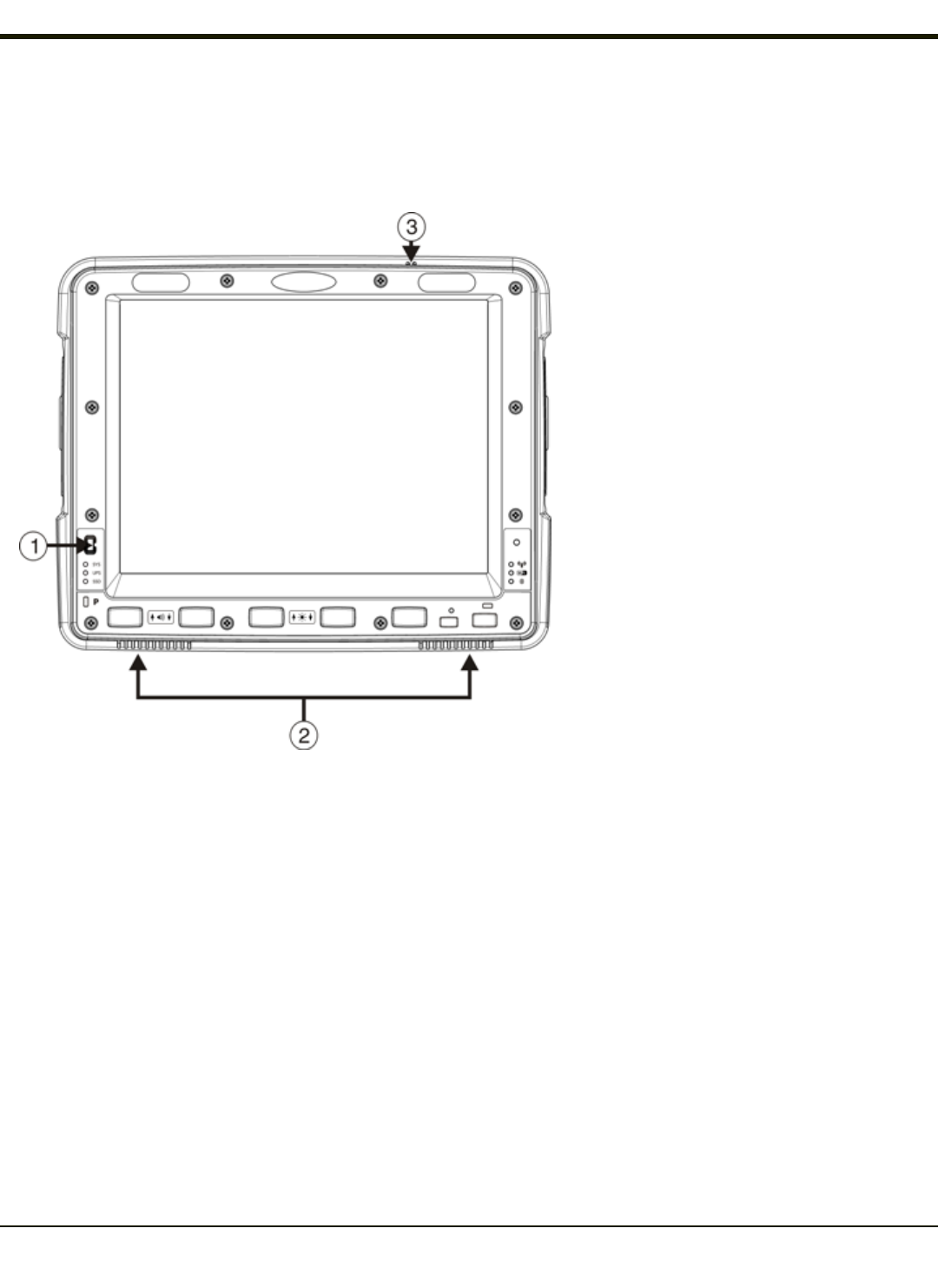
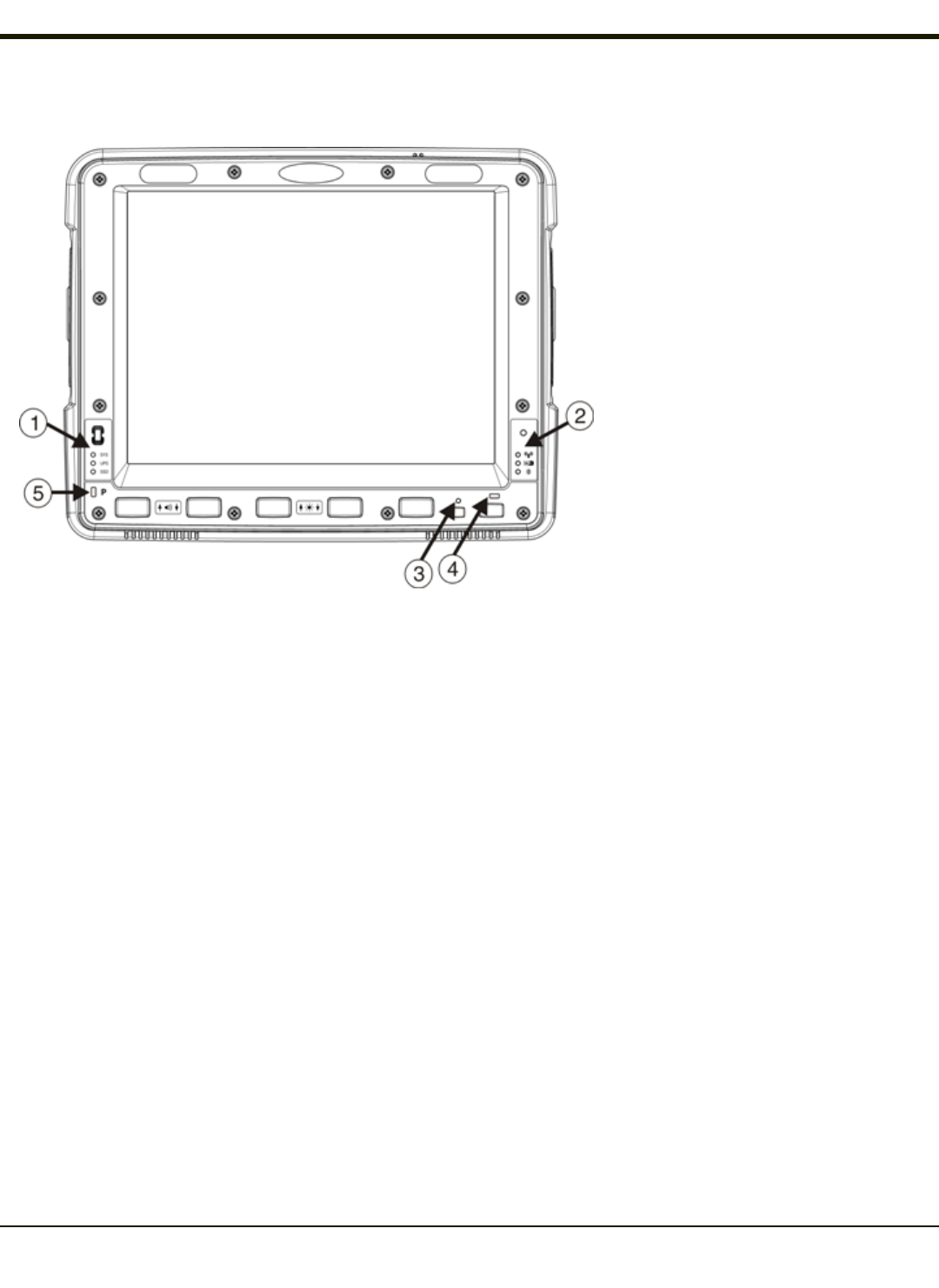
Front View
1. Power Button
2. Speakers
3. Microphone
1-2
Rev. (a)
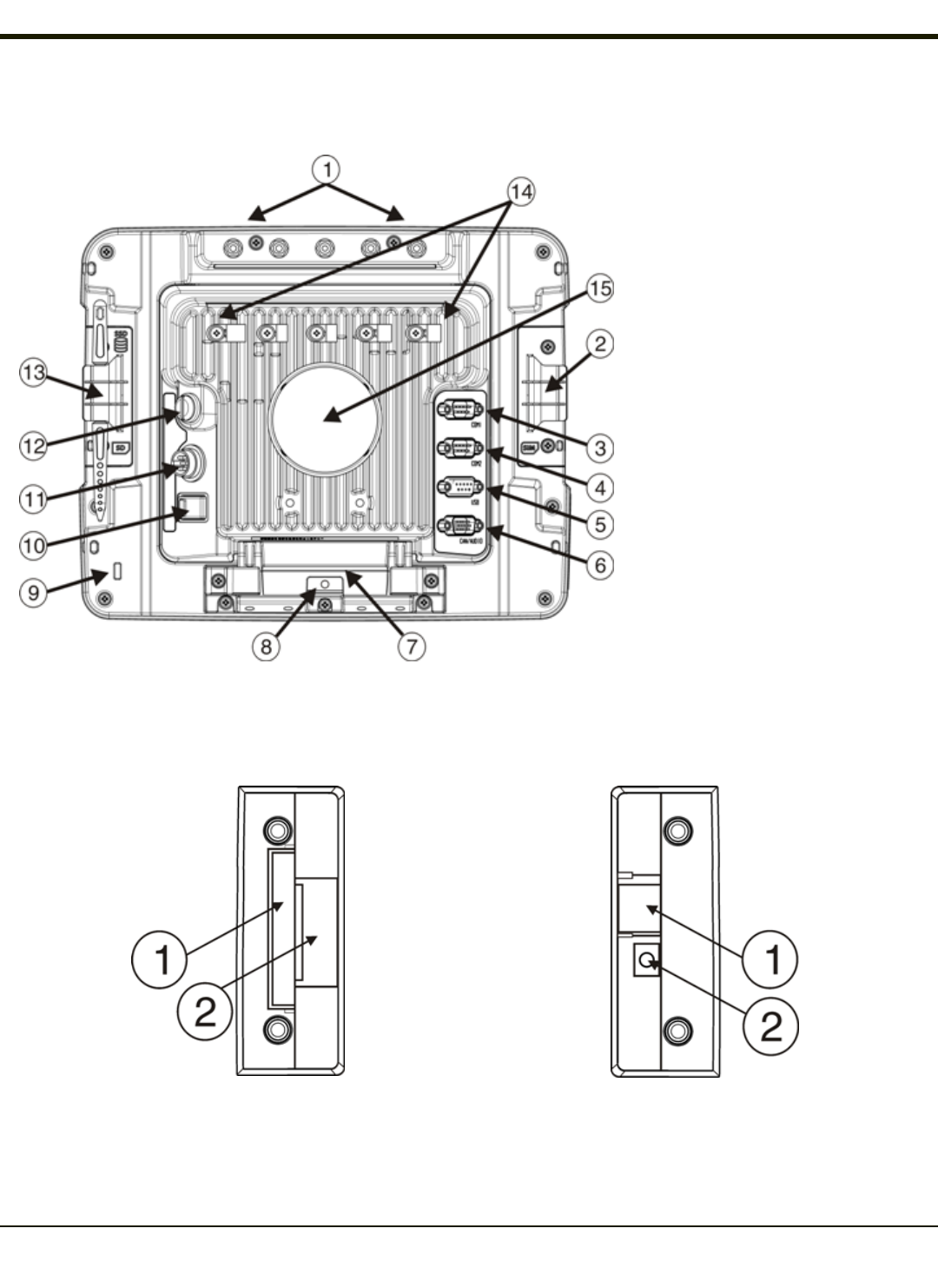
Back View Quick Mount Smart Dock
1. Antenna Connectors (on Thor
VM2CG)
2. SIM card Access Panel (on Thor
VM2CG)
3. COM1 Connector (on Dock)
4. COM2 Connector (on Dock)
5. USB Connector (on Dock)
6. CAN/Audio Connector (on Dock)
7. Quick Release Handle (On Thor
VM2CG)
8. Provision for Padlock (on Thor
VM2CG)
9. Provision for Laptop Security Cable
(on Thor VM2CG)
10. Power Switch (on Dock)
11. Power Connector (on Dock)
12. Fuse (on Dock)
13. SD Card Access Panel (On Thor
VM2CG)
14. Strain Relief Clamps (on Dock)
15. RAM Ball (on Dock)
Access Panels
Access Panel Door is labeled with SSD and SD.
1. CompactFlash Hard Drive
2. SD (Secure Digital) Memory Card Slot
Access Panel Door is labeled with SIM.
1. SIM card slot for WWAN radio
2. UPS battery disconnect
1-3
Rev. (a)
Keyboard Options
The Thor VM2CG has an integrated keypad with five programmable keys and an available external keyboard.
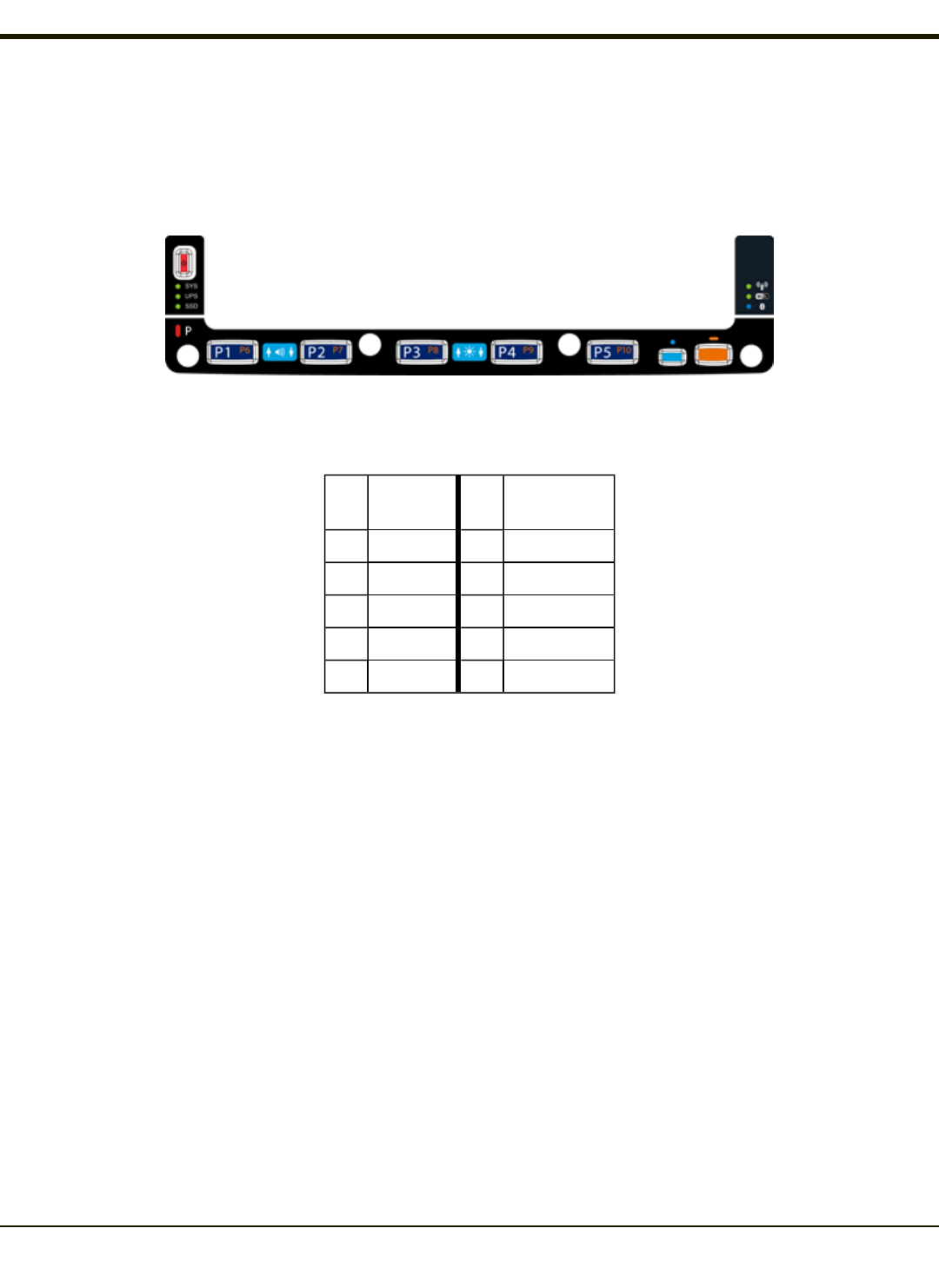
Integrated Keypad
The integrated keypad contains five progammable keys, a blue modifier key and an orange modifier key. Press Orange plus
P1-P5 to access P6-P10. The default programmable key functions are described below. Default functions may be overridden
by custom settings. Consult your system administrator.
Key Assigned
Function Key Assigned
Function
P1 F1 P6 Not assigned
P2 F2 P7 Not assigned
P3 F3 P8 Not assigned
P4 F4 P9 Not assigned
P5 F5 P10 Not assigned
Blue Key
When the Blue LEDis illuminated, the programmable keys are used to adjust speaker volume and display brightness. Press
the Blue key to enter Blue mode and then press
lP1 to Increase speaker volume
lP2 to Decrease speaker volume
lP3 to Increase display brightness
lP4 to Decrease display brightness
lNo function is assigned to P5 in Blue mode
The Blue key has a five second timeout. If the Blue key is pressed and no additional key is pressed within the five second
timeout period, the Blue modifier mode is exited and the Blue LEDis turned off.
When the Blue modifier key is active, the LED located next to the key is illuminated. The modifier key remains active until:
lThe Blue modifier key is pressed again, or
lThe Orange modifier key is pressed, or
lA five second timeout with no keypress occurs.
1-4

Rev. (a)
Orange Key
When the Orange LED is illuminated, the programmable keys provide the secondary function.
lOrange + P1 = P6
lOrange + P2 = P7, etc.
When the Orange modifier key is active, the LED located next to the key is illuminated. The modifier key remains active until:
lThe Orange modifier key is pressed again, or
lA non-modifier key is pressed (i.e.: P1-P5), or
lThe Blue modifier key is pressed.
1-5
Rev. (a)
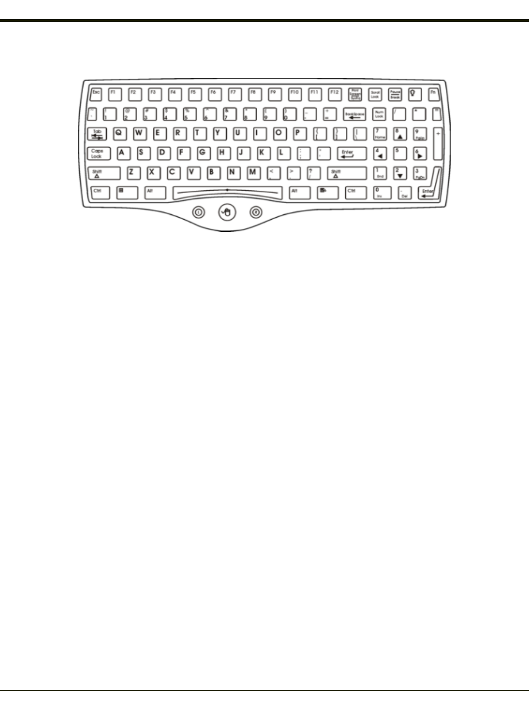
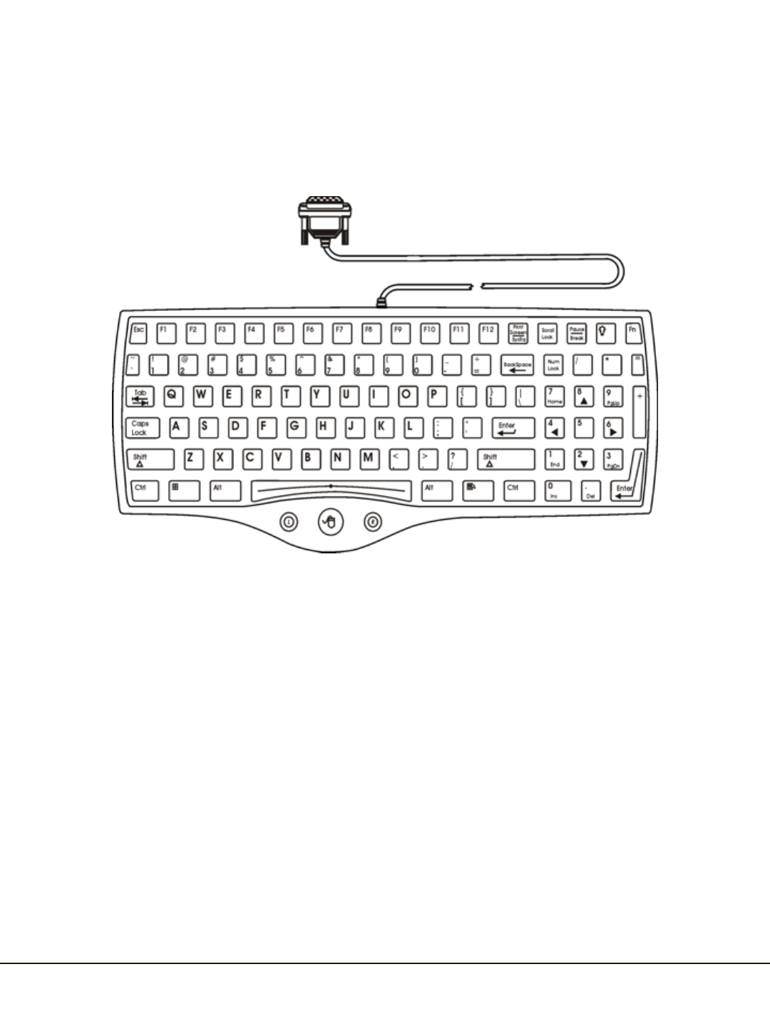
95-Key External Keyboard
The Thor VM2CG uses an optional rugged QWERTY 95 key keyboard, designed for ease of use with the Windows CE
operating system. The keyboard connects directly to the D9 USB connector on the Thor VM2CG Quick Mount Smart Dock.
lThe 95 key keyboard supports all 104 keyboard functions (101 standard keyboard plus Windows keys) and includes an
integrated pointing device and left and right mouse buttons. However, because the keyboard only has 95 keys, all
functions are not visible (or printed on the keyboard). Therefore the keyboard supports what is called hidden keys - keys
that are accessible but not visible on the keyboard.
lThe 95 key keyboard keys are backlit. The keyboard backlight is manually controlled.
Keyboard Backlight
The keyboard backlight key in the top right hand corner has a light bulb icon.
The keyboard keys are backlit. The keyboard backlight is manually controlled using the backlight key in the upper right hand
corner of the keyboard. Pressing the backlight key cycles the keyboard backlight through the levels of backlight intensity: Off,
Low intensity, Medium intensity, Maximum intensity, Off, etc. When the Thor VM2CG is powered on, the keyboard backlight
defaults to Off.
By default, the external keypad backlight turns off when the Thor VM2CG enters Suspend.
USB Keyboard / Mouse
A standard USB keyboard or mouse can be attached to the Thor VM2CG using the appropriate dongle cable.
The dongle cable attaches to the Thor VM2CG and provides a USB connector. Please refer to documentation provided with the
USB keyboard or mouse for more information on their operation.
1-6

Chapter 2 - Set Up A New Thor VM2CG
This page lists a quick outline of the steps you might take when setting up a new Thor VM2CG. More instruction for each step
is listed later in this guide. Please refer to the Thor VM2CGReference Guide for additional information and instruction.
Contact Technical Assistance if you need additional help.
Note: Installing or removing accessories should be performed on a clean, well-lit surface. When necessary, protect the work
surface, the Thor VM2CG, and components from electrostatic discharge.
Caution
Before shipping, the internal UPS battery must be disconnected.
Please refer to the Thor VM2CG Reference Guide for details.
Hardware Setup
1. Connect accessories to the Quick Mount Smart Dock.
2. Connect cables.
3. Connect power cable to the dock.
4. Secure all cables to the dock with the Strain Relief Cable Clamps.
5. Secure the Thor VM2CG in the dock.
6. Press the power switch on the dock.
7. Press the Power key.
Software Setup
Hardware setup should be completed before starting software setup.
1. Calibrate Touch screen
2. Set Date and Time Zone
3. Set Power Schemes Timers
4. Adjust Speaker Volume
5. Pair Bluetooth devices
6. Setup Wireless client parameters
7. Setup terminal emulation parameters
8. Save changed settings to the registry
9. Setup the AppLock parameters
10. Set the DC Wedge parameters
Please refer to the Thor VM2CGReference Guide for additional information and instruction.
2-1

Rev. (a)
Quick Mount Smart Dock
The Thor VM2CG assembly consists of two parts, the Thor VM2CG computer and the Quick Mount Smart Dock.
The Thor VM2CG contains an internal UPS battery that, once fully charged, powers the Thor VM2CG for a minimum of 30
minutes when the unit is not mounted in the dock.
The Dock provides:
lA mount for the Thor VM2CG computer. The Dock attaches to a vehicle via a RAM or U-bracket mount.
lConditioned power for the Thor VM2CG. The Dock accepts 10-60VDC power input directly or 72-144VDC power input
with a DC/DC converter.
lCOM1 and COM2 serial connections for a tethered scanner, printer, PC connection, etc.
lUSB host and client connections via an adapter cable.
lCANbus connection via an adapter cable.
lHeadset connection via an adapter cable. When a headset is not attached, the microphone and speakers on the Thor
VM2CG are active.
lStrain relief cable mounts.
lMobility of the Thor VM2CG, since the Dock remains attached to the vehicle the Thor VM2CG computer can easily be
moved from one vehicle equipped with a Dock to another.
External antenna connectors may be present on the back of the Thor VM2CG. The connectors may include:
l802.11 antenna connectors, used when the Thor VM2CG is not equipped with internal antennas.
lExternal GPS antenna connector, when the Thor VM2CG is equipped with GPS.
lExternal WWAN antenna connectors, when the Thor VM2CG is equipped with WWAN.
Optional WWAN radio (available in North America, Europe, New Zealand,and Australia only).
2-2
Rev. (a)
Preparing the Dock
1. Attach RAM mount to vehicle (see Thor VM2CG Vehicle Mounting Reference Guide).
2. Attach accessories to dock.
3. Attach power cable, 10-60VDC or 72-144VDC.
4. If the tethered I/O port cover is in place, lift the cover to expose the I/O port on the dock. The tether allows the cover to
be swung over the back of the dock.
2-3
Rev. (a)
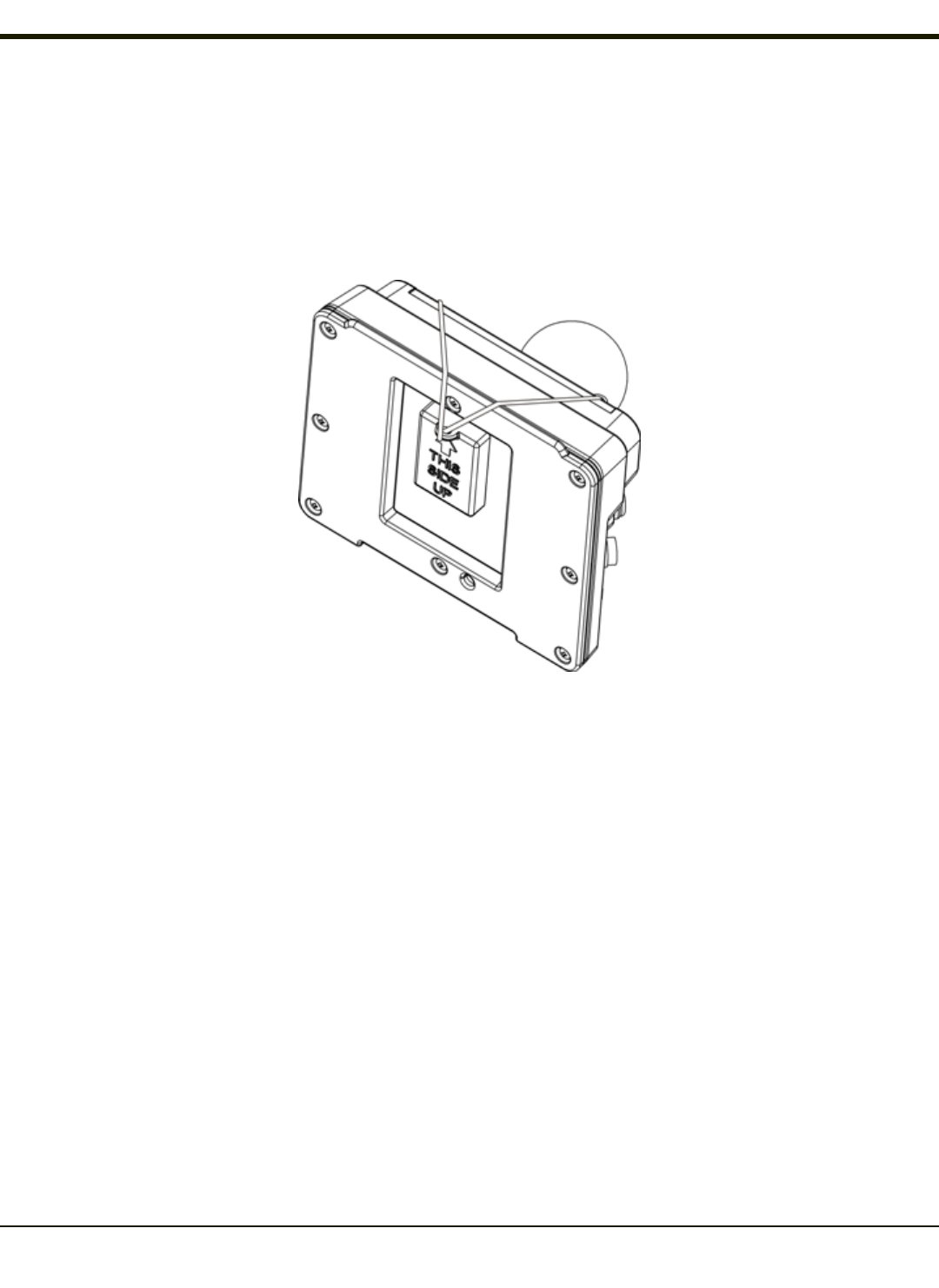
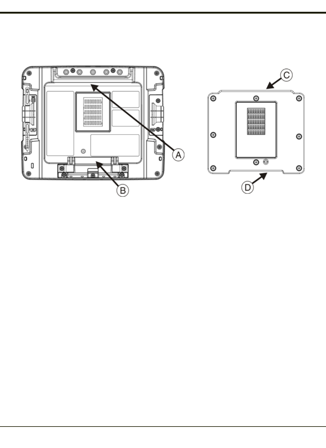
Place the Thor VM2CG in the Dock
Back of Thor VM2CG Front of Quick Mount Smart Dock
A. Notch on Thor VM2CG
B. Release lever
C. Upper Lip on Dock
D. Lower Lip on Dock
1. Locate the notch on the upper rear of the Thor VM2CG (item A above).
2. Slide this notch over the top lip (C)of the Dock. Slide the Thor VM2CG from side to side on the Dock to make sure it
fully engages on the lip of the Dock. If the Thor VM2CG cannot be slid side to side, the lip is engaged.
3. Pull the quick release lever (B) on the Thor VM2CG down and push the Thor VM2CG against the Dock.
4. Release the quick release lever. The quick release lever catches the lower lip on the Dock and secures the Thor
VM2CG to the Dock.
5. If necessary, adjust the viewing angle of the Thor VM2CG.
Removing the Thor VM2CG from the Dock
The Thor VM2CG may be removed from the Quick Mount for limited periods of use or the transfer from vehicle to vehicle.
The UPS battery inside the Thor VM2CG powers a fully functional Thor VM2CG for a minimum of 30 minutes.
To remove the Thor VM2CG from the Dock:
1. Pull the quick release lever (item B) downward on the back of the Thor VM2CG.
2. Pull the bottom of the Thor VM2CG away from the Dock.
3. Lift the Thor VM2CG away from the Dock.
2-4

Rev. (a)
Backlights and Indicators
Display Backlight
There are several configuration options for the Thor VM2CG display backlight:
Power Management
The display backlight is controlled by power management. When the user activity timer expires, the display backlight is turned
off. Different timeouts can be set for when the Thor VM2CG is operating in the following power configuration modes:
lAC/DC Mode
lIgnition Mode (ignition on)
lIgnition Mode (ignition off)
lAuto-on Mode
lUPS.
Please refer to the Thor VM2CG Reference Guide for details.
Backlight Brightness
The intensity of the display backlight can be manually configured:
Brightness control does not “roll-over” from minimum to maximum or from maximum to minimum. Continuously holding down
the up or down arrow keys does not cause an automatic repeat of the up (or down) arrow key.
Screen Blanking
The Thor VM2CG can be configured to blank (blackout) the display while the vehicle is in motion.
Please refer to the Thor VM2CG Reference Guide for details.
Keypad Backlight
By default, the integrated keypad backlight follows the display backlight. The integrated keypad backlight can be disabled.
Please refer to the Thor VM2CG Reference Guide for details.
The external USB keyboard backlight is manually controlled.
2-5
Rev. (a)
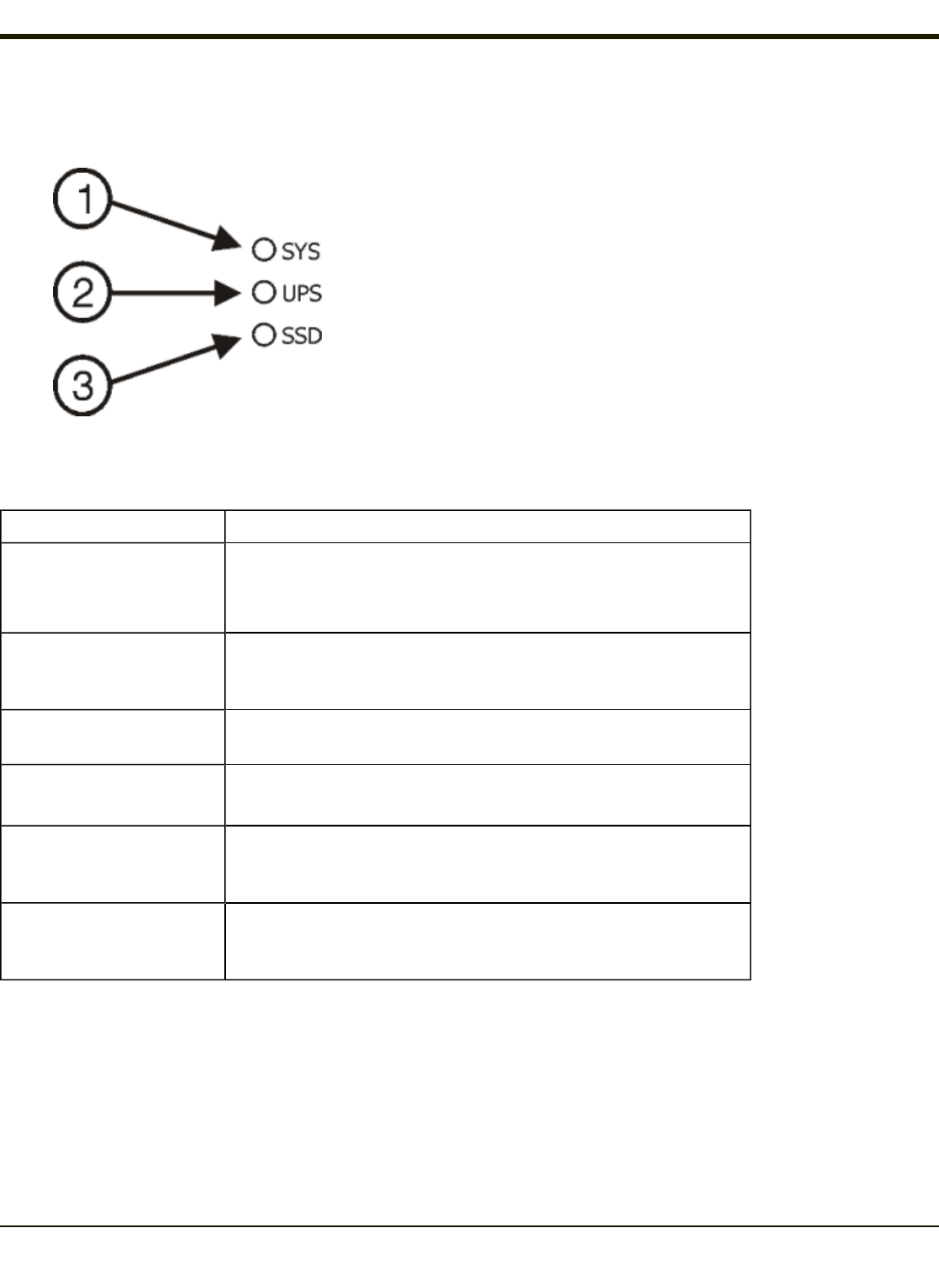
System LEDs
1. SYS (System Status) LED
2. UPS (Uninterruptible Power Supply) LED
3. SSD (Solid State Drive) LED
SYS (System Status) LED
LED Behavior System State
Solid Green
lOn
lOn but Backlight Off
lOn but Display Off
Green blinking very slowly
External power present
(1/2 sec. on, 4 1/2 sec. off)
lSuspend
Off
External power present lOff
Off
External power not present
lOff,
lSuspend
Green blinking slowly
External power present
(1/2 sec. on, 1 1/2 sec. off)
CPU temperature less than -20ºC,
Heater warming CPU for 30 sec.
Green blinking slowly
External power not present
(1/2 sec. on, 1 1/2 sec. off)
CPU temperature less than -20ºC,
Need to move unit to warmer environment
2-7

Rev. (a)
UPS Status LED
The color of the UPS LED identifies the charge level and the behavior of the LED identifies the charging state.
Charge Level
LED Color Status
Green Fully charged (>90%)
Amber
lLess than fully charged, but more than 2 minutes runtime
remaining,
lOut of charging temperature range,
lNo UPS present,
lCharge timeout.
Red Low battery, less than 2 minutes runtime until shutdown
Charging State
LED Behavior Status
Slow Blink
(1 sec. on, 3 sec. off) Charging.
Fast Blink
(1/2 sec. on, 1/2 sec. off) UPS supplying power and discharging.
On Neither charging or discharging.
Off Unit is off or is in Suspend.
SSD (Solid State Drive) LED
LED Behavior Status
Flashing Green SSD read or write activity.
Off No SSD read or write activity.
2-8
Rev. (a)
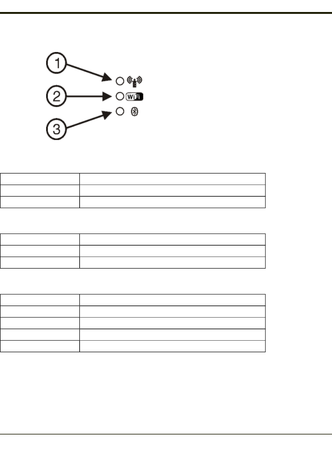
Connection LEDs
1. WWAN LED
2. WiFi LED
3. Bluetooth LED
WWAN LED
LED Behavior Status
Solid Green Indicates a WWAN connection to a network.
Off Indicates no WWAN connection.
WiFi LED
LED Behavior Status
Solid Green Indicates a connection with an IP address to an Access Point
Off Indicates no connection to an Access Point.
Bluetooth LED
LED Behavior Status
Blue Blinking Slowly Bluetooth is paired but not connected to a device.
Blue Blinking Medium Bluetooth is paired and connected to a device.
Blue Blinking Fast Bluetooth is discovering Bluetooth devices.
Off Bluetooth hardware has been turned off.
2-9

Rev. (a)
Keyboard LEDs
The keyboard LEDs are located near the specified key.
Blue LED
LED Behavior Status
Solid Blue
lIndicates the Blue modifier key is active. Blue modifier mode is invoked for the
next keypress.
lPressing the Blue key a second time exits this modifier mode and turns off the
LED.
lPressing the Orange key exits the Blue mode and turns off the Blue LED.
lWhen Blue mode is active, keys P1 through P4 provide volume and brightness
adjustment functions.
Off Blue mode is not invoked.
Orange LED
LED Behavior Status
Solid Orange
lIndicates the Orange modifier key is active. Orange mode is invoked for the
next keypress only.
lPressing the Orange key a second time exits this modifier mode and turns off
the LED.
lPressing the Blue key exits the Orange mode and turns off the Orange LED.
Off Orange mode is not invoked.
Programmable LED
LED Behavior Status
Controlled by application Refer to application developer for LED behavior details
Off Default mode. Refer to application developer for LED behavior details
2-10
Rev. (a)
Power Up
If a USB drive, such as a thumb drive is attached to the Thor VM2CG, the device attempts to boot from the USB
drive and cannot. Please remove the USB drive and power up the Thor VM2CG again.
The Quick Mount Smart Dock has a power switch on the back.
The "On" side of this rocker switch has a raised bump to allow the state of the switch to be determined when the switch may
not be easily viewed, for example, after the Dock is mounted in a vehicle.
After external power has been connected and the Thor VM2CG has been mounted in the Dock, press the side of the power
switch with the raised bump to pass power from the Dock to the Thor VM2CG. Generally, once the Dock is powered On, there
is no need to power if Off.
Next locate the power button on the front of the Thor VM2CG.
Press the power button to turn the Thor VM2CG on. When the Windows desktop is displayed or an application begins, the
power up sequence is complete.
2-11

Rev. (a)
Tapping the Touch Screen with a Stylus
Note: Always use the point of the stylus for tapping or making strokes on the touch screen.
Never use an actual pen, pencil, or sharp/abrasive object to write on the touch screen.
Hold the stylus as if it were a pen or pencil. Touch an element on the screen with the tip of the stylus then remove the stylus
from the screen.
Firmly press the stylus into the stylus holder when the stylus is not in use.
Using a stylus is similar to moving the mouse pointer then left-clicking icons on a desktop computer screen.
Using the stylus to tap icons on the touch screen is the basic action that can:
lOpen applications
lChoose menu commands
lSelect options in dialog boxes or drop-down boxes
lDrag the slider in a scroll bar
lSelect text by dragging the stylus across the text
lPlace the cursor in a text box prior to typing in data
lPlace the cursor in a text box prior to retrieving data using a scanner/imager or an input/output device connected to a
serial port.
A stylus replacement kit is available.
2-12

Rev. (a)
Set Power Scheme Timers
Start > Settings > Control Panel > Power > Schemes
Change the parameter values and tap OK to save the changes.
User Idle
An amount of time has passed, set by the User Idle timer, and the device shuts down a minimum
number of services e.g., backlights. The System Idle timer and the Suspend timer have not expired
yet.
System Idle
An amount of time has passed, set by the System Idle timer, and the device shuts down a few more
services e.g., display. The System Idle timer has expired and the Suspend timer has not expired
yet.
Suspend
Suspend mode is entered when (1) the unit is inactive for a predetermined period of time, (2) the
user taps the Power key, or (3) Start > Suspend is chosen. Inactivity means that internal devices
that reset the power state are not active and the Suspend Timer has expired.
Shutdown An amount of time has passed, set by the Shutdown timer, and the Thor VM2CG performs an
orderly shutdown.
UPS Power Scheme
This power scheme is automatically selected any time the Thor VM2CG is operating from UPSpower. This scheme overrides
any user selected power configuration mode.
Switch state to User Idle Default is After 30 seconds
Switch state to System Idle Default is After 1 minute
Switch state to Suspend Default is After 10 minutes
Shutdown Default is After 20 minutes
AC/DC Power Scheme
This power scheme is used when the AC/DC power configuration mode is selected.
Switch state to User Idle Default is After 15 minutes
Switch state to System Idle Default is After 1 hour
Switch state to Suspend Default is After 8 hours
Shutdown Default is Never
Ignition Control Power Scheme, Ignition On
This power scheme is used when the Ignition Control power configuration mode is selected and the vehicle ignition is On.
Switch state to User Idle Default is After 15 minutes
Switch state to System Idle Default is After 1 hour
Switch state to Suspend Default is After 8 hours
Shutdown Default is Never
2-13
Rev. (a)
Ignition Control Power Scheme, Ignition Off
This power scheme is used when the Ignition Control power configuration mode is selected and the vehicle ignition is Off.
Switch state to User Idle Default is After 1 minute
Switch state to System Idle Default is After 5 minutes
Switch state to Suspend Default is After 1 hour
Shutdown Default is After 8 hours
Auto On Power Scheme
This power scheme is used when the Auto On power configuration mode is selected.
Switch state to User Idle Default is After 1 minute
Switch state to System Idle Default is After 1 hour
Switch state to Suspend Default is After 8 hours
Shutdown Default is Never
The timers are cumulative. The System Idle timer begins the countdown after the User Idle timer has expired and the Suspend
timer begins the countdown after the System Idle timer has expired. When the User Idle timer is set to “Never”, the power
scheme timers never place the Thor VM2CG in User Idle, System Idle, Suspend or Shutdown modes (even when the Thor
VM2CG is idle).
Using the UPS Power Scheme Defaults listed above, the cumulative effect results in the following:
lThe backlight turns off after 30 seconds of no activity,
lThe display turns off after 90 seconds of no activity (1 minute + 30 seconds),
lThe Thor VM2CG enters Suspend after 11 minutes and 30 seconds of no activity,
lAnd the Thor VM2CG shuts down after 31 minutes and 30 seconds of no activity.
2-14

Rev. (a)
Adjust Speaker Volume
The Thor VM2CG has two speakers, located on the bottom of the unit.
Speaker volume can be adjusted to a comfortable level for the listener by using the keypad or by changing parameters in the
Volume & Sounds control panel.
Using the Keypad
Note: Sounds must be enabled (Settings > Control Panel > Volume & Sounds) before the following key sequences can
adjust the volume.
The volume is increased or decreased one step each time the volume key sequence is pressed.
To adjust speaker volume, locate the Blue key located below the display. Press the Blue key.
Adjust the speaker volume :
lUse the P1 key for volume Up and P2 key for volume Down.
lAdjust volume until the speaker volume is satisfactory.
lPress the Blue again key to exit this mode. The Blue modifier also times out after 5 seconds of inactivity.
The LED for the Blue key is lit as long as the blue modifier mode is active.
Volume control using a keypad key press has volume setting increments that match those supported by the Volume and
Sounds control panel. Volume does not “roll-over” from minimum to maximum or from maximum to minimum. Continuously
holding down the up or down arrow keys does not cause an automatic repeat of the up (or down) arrow key.
Using the Control Panel
Start > Settings > Control Panel > Volume & Sounds > Volume
Change the volume setting and tap OK to save the change.
You can also select / deselect sounds for key clicks and screen taps and whether each is loud or soft.
As the volume scrollbar is moved between Loud and Soft, the Thor VM2CG emits a tone each time the volume increases or
decreases in decibel range.
2-15

Rev. (a)
Set Date and Time Zone
Tap Start > Settings > Control Panel > Date/Time icon or tap the Date/Time in the taskbar.
Set Date, Time, Time Zone, and assign a Daylight Savings location on the Thor VM2CG after a warm boot or anytime.
There is very little functional change from standard desktop PC Date/Time Properties options. Adjust the settings and tap the
OK button or the Apply button to save changes to the registry. Any changes take effect immediately.
Double-tapping the time displayed in the Taskbar causes the Date/Time Properties screen to appear.
Grab Time Utility
The GrabTime utility can be configured to synchronize the time with a local server during each reboot function.
Tap the Sync button to synchronize date and time with a networked time server. By default, the Thor VM2CG operating system
first searches for a time server on the local intranet. If not found, it then searches the Internet for a time server. A connection to
the Internet is required for this option.
Autolaunch Time-Sync
Start > Settings > Control Panel > Options > Communication
By default, TimeSync does not automatically run on the Thor VM2CG. To enable TimeSync to run automatically on the Thor
VM2CG using the GrabTime utility, check this checkbox.
Synchronize with a Local Time Server
By default, GrabTime synchronizes via an Internet connection. To synchronize with a local time server:
1. Use ActiveSync to copy GrabTime.ini from the My Device > Windows folder on the Thor VM2CG to the host PC.
2. Edit the copy of GrabTime.ini on the host PC. Add the local time server’s domain name to the beginning of the list of
servers. You can optionally delete the remainder of the list.
3. Copy the modified GrabTime.ini file to the My Device > System folder on the Thor VM2CG. The System/GrabTime.ini
file takes precedence over the Windows/GrabTime.ini file. System/Grabtime.ini also persists after a coldboot;
Windows/Grabtime.ini does not persist.
2-16
Rev. (a)
Touch Screen
Calibrating the Touch Screen
If the touch screen is not responding properly to stylus taps, you may need to recalibrate the touch screen.
Recalibration involves tapping the center of a target. If you miss the center, keep the stylus on the screen, slide it over the
target's center, and then lift the stylus.
To recalibrate the screen, select Start > Settings > Control Panel > Stylus > Calibration tab.
Follow the instructions on the screen. Tap the OK button when complete, if necessary.
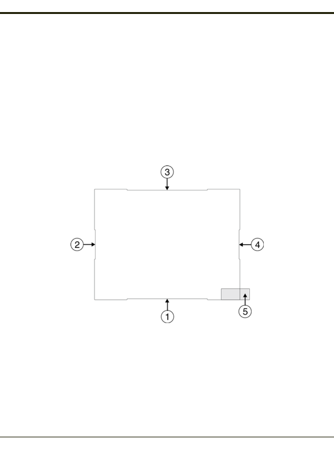
Apply the Touch Screen Protective Film
The Thor VM2CG touch screen protective film is shipped in packs of 10. The protective film is flexible and treated with an anti-
glare coating on the outer surface.
The protective film is slightly larger than the Thor VM2CG touch screen, however the notches on the edge of the protective film
(indicated by arrows 1 - 4 above) correspond to the display size of the Thor VM2CG. The protective film is not adhesive. The
corner edges are designed to fit between the Thor VM2CG display and the display housing to hold the protective film in place.
A protective backing is applied to the rear surface of the protective film. A pull tab (item 5 above) is attached to the protective
backing for easy removal of the protective backing from the film.
Installation
1. Make sure the touch screen is clean and dry before installation. Please review Cleaning the Display for instructions on
suitable cleaning agents.
2-17

Rev. (a)
2. Pull the release tab to separate the protective backing from the rear of the protective film. Avoid touching the rear side of
the protective film while removing the liner.
3. Place the rear side of the protective film against the Thor VM2CG display, roughly centering the protective film over the
display.
4. Slide the protective film until one corner can be slid back between the touch screen and the display housing as the
protective film is re-centered on the display. It may be necessary to press the edges of the protective film against the
display to ensure the entire edge slides under the display housing. It is easiest to start with one of the bottom corners.
5. Slide the protective film away from the other bottom corner. The film may bulge sligthly away from the User's Guide as it
is being slid. Only slide the protective film enough so that the protective film can slide under the display housing on that
corner when the protective film is returned to center.
6. Repeat with each of the top corners, sliding the protective film away from the corner just enough that the protective film
can slide under the display housing when the protective film is returned to center.
7. It may be necessary to flex the protective film during the install, however use care not to flex the protective film so much
that the protective film kinks.
8. Once all corners are secure under the display housing, adjust the protective film, if necessary, so it is centered on the
touch screen.
Removal
1. To remove the protective film, slide the protective film in one direction until the edge clears.
2. Lift up on the edge of the protective film so it does not slide between the touch screen and display housing when the
protective film is slid back to the center.
3. Repeat until all edges are free and remove the protective film.
Contact Technical Assistance about protective film packs designed specifically for your Thor VM2CG touch screen.
2-18

Rev. (a)
Using the Input Panel / Virtual Keyboard
The virtual keyboard is always available when needed e.g., text entry.
Place the cursor in the text entry field and, using the stylus:
lTap the Shift key to type one capital letter.
lTap the CAPS key to type all capital letters.
lTap the áü key to access symbols.
Some applications do not automatically display the Input Panel. In this case, do the following to use the Input Panel:
Input Panel icon in the taskbar
Keyboard icon in the taskbar
lTap the Input Panel or Keyboard icon in the taskbar.
lSelect Keyboard from the menu.
lMove the cursor into the text entry field when you want to enter data using the Input Panel.
When finished entering data, tap the icon in the Taskbar again. Select Hide Input Panel.
2-19

Rev. (a)
Setup Terminal Emulation Parameters
Before you make a host connection, you will, at a minimum, need to know:
lthe alias name or IP address (Host Address) and
lthe port number (Telnet Port) of the host system to properly set up your host session.
1. Make sure the mobile client network settings are configured and functional. If you are connecting over wireless LAN
(802.11x), make sure your mobile client is communicating with the Access Point.
2. From Start > Program, run RFTerm or tap the RFTerm icon on the desktop.
3. Select Session > Configure from the application menu and select the "host type" that you require. This will depend on
the type of host system that you are going to connect to; i.e., 3270 mainframe, AS/400 5250 server or VT host.
4. Enter the "Host Address" of the host system that you wish to connect to. This may either be a DNS name or an IP
address of the host system.
5. Update the telnet port number, if your host application is configured to listen on a specific port. If not, just use the
default telnet port.
6. Select OK.
7. Select Session > Connect from the application menu or tap the "Connect" button on the Tool Bar. Upon a successful
connection, you should see the host application screen displayed.
To change options such as Display, Colors, Cursor, Bar Code, etc., please refer to these sections in the RFTerm Reference
Guide for complete descriptions of these and other features.
2-20

Rev. (a)
Using the AppLock Switchpad
Note: The touch screen must be enabled. Select Start > Settings > Control Panel > Options > Misc. tab to verify touch
screen status.
Click the switchpad icon in the taskbar.
A checkmark on the switchpad menu indicates applications currently active or available for Launching by the Thor VM2CG
user. When Keyboard, on the Switchpad Menu, is selected, the default input method (Input Panel, Transcriber, or custom input
method) is activated.
Using the Keypad
One switch key sequence (or hotkey) is defined by the Administrator for the end-user to use when switching between locked
applications. This is known as the Activation key.
When the switch key sequence is pressed on the keypad, the next application in the AppLock configuration is moved to the
foreground and the previous application moves to the background. The previous application continues to run in the background.
Thor VM2CG key presses affect the application in focus only.
Using the Touch Screen
The figure shown above is an example and is shown only to aid in describing how the user can switch between applications
using a stylus.
When the user taps the Switchpad icon with the stylus, a menu pops up listing the applications available to the user. The user
can tap an application name in the popup menu and the selected application is brought to the foreground. The previous
application continues to run in the background. Stylus taps affect the application in focus only. When the user needs to use the
Input Panel, they tap the Keyboard option. Input Panel taps affect the application in focus only.
2-21
Rev. (a)
Connecting Bluetooth Devices
Before connecting to Bluetooth Devices:
lThe system administrator has discovered, paired, connected and disconnected (using EZPair ) Bluetooth devices for
each Thor VM2CG.
lThe system administrator has enabled and disabled EZPair parameters for the Thor VM2CG.
lThe system administrator has also assigned a Computer Friendly Name using EZPair for the Thor VM2CG.
To connect Bluetooth devices, the Thor VM2CG should be as close as possible and in direct line of sight (distances up to 32.8
feet or 10 meters) with the targeted Bluetooth device during the discovery and pairing process.
If the devices are in Suspend, tap the power key to wake the Thor VM2CG.
Using the correct procedure, wake the targeted Bluetooth device if necessary.
There may be audible or visual signals as both devices discover and pair with each other.
Taskbar Connection Indicator
Thor VM2CG is connected to one or more of the targeted Bluetooth device(s).
Thor VM2CG is not connected to any Bluetooth device.
Thor VM2CG is ready to connect with any Bluetooth device.
Thor VM2CG is out of range of all paired Bluetooth device(s). Connection is inactive.
There may be audible or visual signals from paired devices as they move back into range and re-connect with the Bluetooth
hardware in the Thor VM2CG.
2-22

Rev. (a)
Reboot
When the Windows desktop is displayed or an application begins, the power up (or reboot) sequence is complete.
Warmboot
A warmboot reboots the computer without erasing any registry data. Configuration settings and data in RAM are preserved
during a warmboot. Network and ActiveSync sessions are lost and any data in running applications that had not been
previously saved may be lost. CAB files already installed remain installed.
There are several methods available:
lUsing the Registry, select Start > Settings > Control Panel > Registry and tap the Warmboot button. The Thor
VM2CG immediately warmboots.
lUsing the Start menu, select Start > Run and type WARMBOOT in the text box. Press Enter. The Thor VM2CG
immediately warmboots. The WARMBOOT text command is not case-sensitive.
lUse the P1 +P5 +Orange keypress sequence to reboot the Thor VM2CG. The keys may be pressed in sequence; they
do not need to be held down simultaneously.
lIf an external keyboard is attached use the Ctrl +Alt +Del keypress sequence to reboot the Thor VM2CG. The keys
may be pressed in sequence; they do not need to be held down simultaneously.
Restart
A restart reboots the computer without erasing any registry data. Configuration settings are preserved during a restart. The
contents of RAMare erased. Network and ActiveSync sessions are lost and any data in running applications that had not been
previously saved may be lost. The OS and CAB files are reloaded.
To restart, select Start > Settings > Control Panel > Registry and tap the Restart button.
2-23

Rev. (a)
Cleaning the Touch Screen
Note: These instructions are for components made of glass. If there is a removable protective film sheet on the display,
remove the film sheet before cleaning the screen.
Keep fingers and rough or sharp objects away from the bar code reader scanning aperture and the mobile device touch screen.
If the glass becomes soiled or smudged, clean only with a standard household cleaner such as Windex® without vinegar or
use Isopropyl Alcohol. Dampen the cloth with the cleaner and then wipe the surface.
Do not use paper towels or harsh-chemical-based cleaning fluids since they may result in damage to the glass surface. Use a
clean, damp, lint-free cloth.
Do not scrub optical surfaces. If possible, clean only those areas which are soiled. Lint and particulates can be removed with
clean, filtered canned air.
2-24

Rev. (a)
Startup Help
Contact Technical Assistance if you need more help.
Touch screen is not accepting
stylus taps or needs recal-
ibration.
See Also: "Calibrating the Touch Screen"when the touch screen needs recalibration,
orPress Ctrl+Esc to force the Start Menu to appear. Use the tab, backtab and arrow keys
to move the cursor from element to element.
Thor VM2CG seems to lockup
as soon as it is rebooted.
There may be slight delays while the wireless client connects to the network, authorization
for voice-enabled applications complete, and Bluetooth relationships establish or re-estab-
lish.
When an application begins, the Thor VM2CG is ready for use.
2-25

Rev. 01
2-26
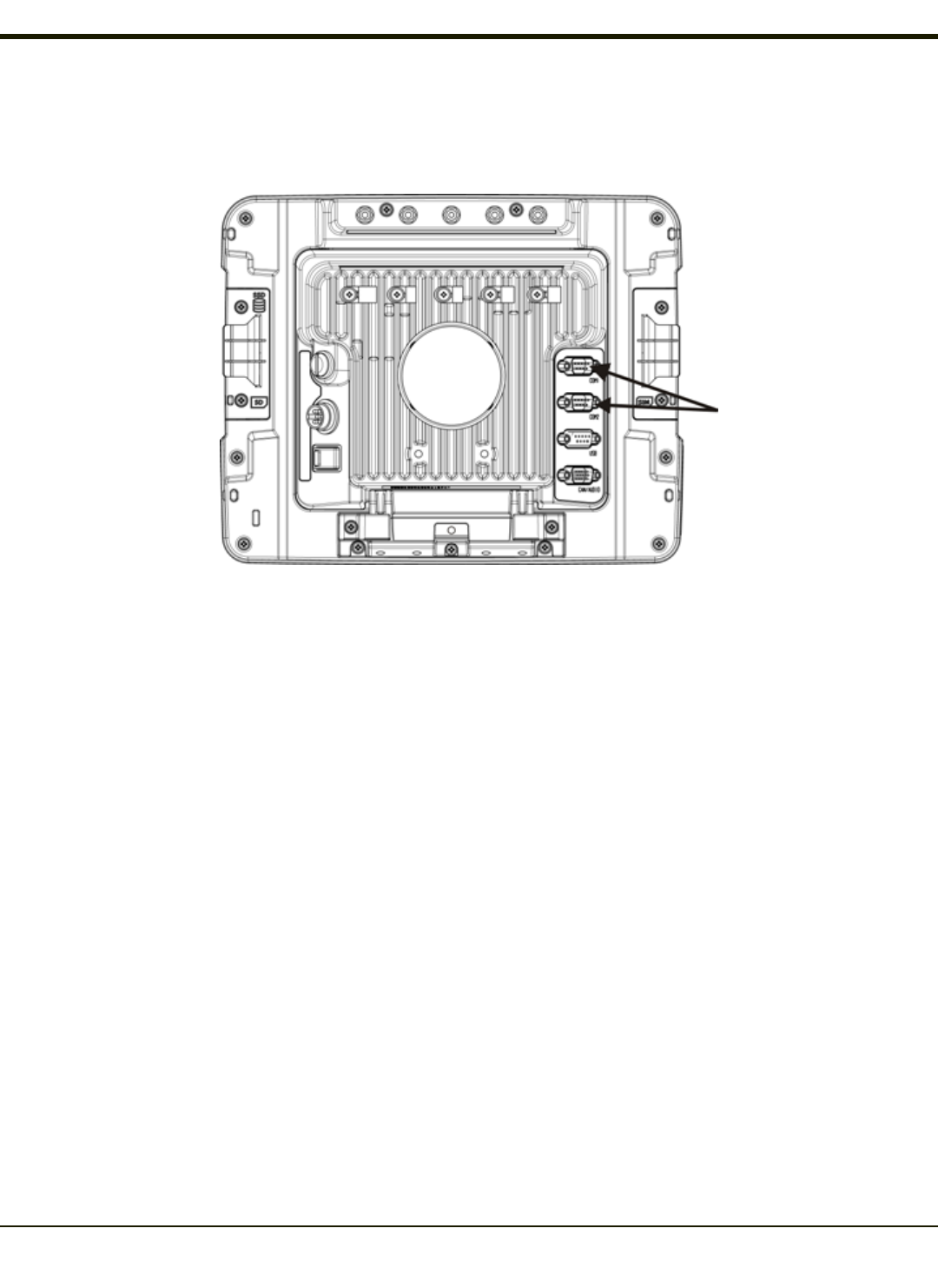
Chapter 3 - Connecting Cables to the Thor VM2CG
Connect External Keyboard
The Thor VM2CG supports an optional external 95-key USB keyboard. The external keyboard has a D9 connector to connect
to the USB port on the Thor VM2CG Quick Mount Smart Dock.
1. Seat the keyboard cable end connector over the USB connector on the Thor VM2CG Quick Mount Smart Dock.
2. Tighten the thumbscrews in a clockwise direction. Do not over tighten.
3-1
Rev. (a)
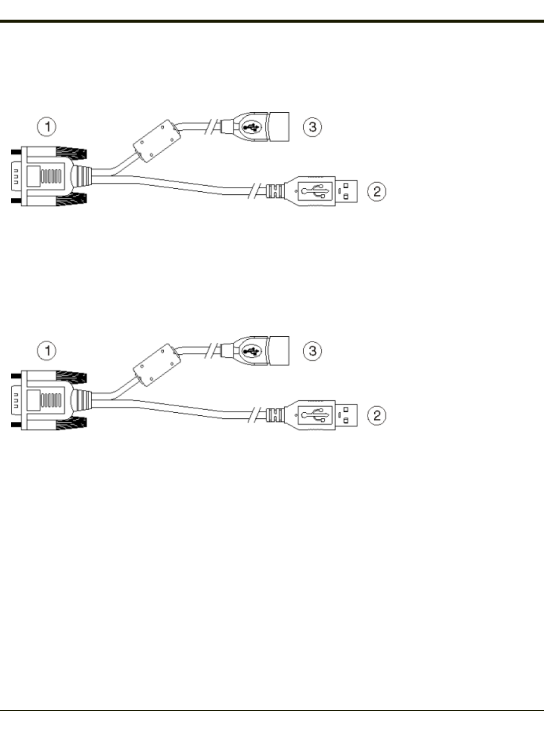
Connect Cable - USB Client
USB-C Cable Assembly
1. D9 Connector
2. USB Client Connector (for
connecting to a USB host)
3. USB Host Connector (for
connecting to a USB device)
1. Seat the cable end connector (connector 1) firmly over the USB Cable Connector on the Quick Mount Smart Dock.
2. Tighten the thumbscrews in a clockwise direction. Do not over tighten.
3. Connector 2 on the cable provides a USB-Client connection. Connector 3 (USB-Host) is not used for the USB-C
connection.
Connect Cable - USB Host
1. D9 Connector
2. USB Client Connector (for
connecting to a USB host)
3. USB Host Connector (for
connecting to a USB device)
1. Seat the cable end connector (connector 1) firmly over the USB Cable Connector on the Quick Mount Smart Dock.
2. Tighten the thumbscrews in a clockwise direction. Do not over tighten.
3. Connector 3 on the cable provides a USB-Host connection. Connector 2 (USB-Client) is not used for the USB-H
connection.
3-2
Rev. (a)
Connect Cable - Serial
Note: Pin 9 of the desired COM port must be configured to provide +5V or RI as needed for the connected device. See the
Thor VM2CG Reference Guide for details.
1. Seat the cable end connector firmly over the serial COM port on the Quick Mount Smart Dock.
2. Turn the thumbscrews in a clockwise direction. Do not over tighten.
3. Use a strain relief clamp to secure the cable to the Thor VM2CG.
4. Connect the other cable end to the desired serial device.
Connect a Tethered Scanner
1. The scanner cable is attached to either the COM1 or COM2 port on the Quick Mount Smart Dock.
2. Connect the serial cable for the scanner as directed above.
3. When the Thor VM2CG is powered on, it provides power to the serial scanner.
3-3
Rev. (a)
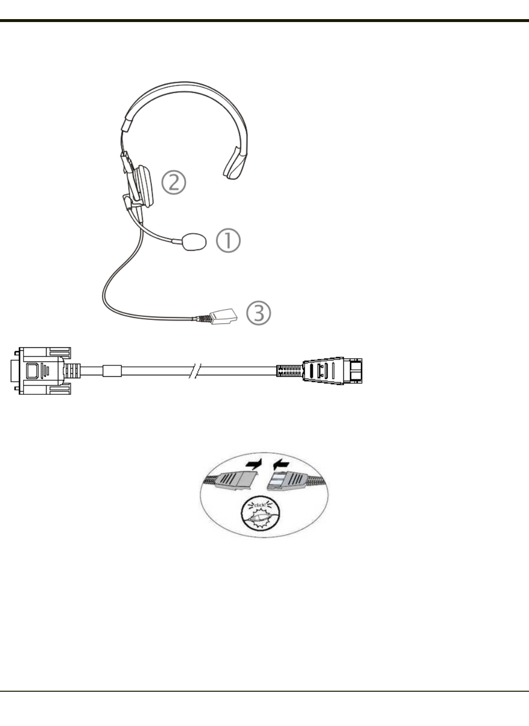
Connecting the Headset Cable
Headset
1. Microphone
2. Headphones
3. Connects to end of voice
cable
Thor VM2CG Audio Cable
1. Seat the D15 cable end connector firmly over the CANbus/Audio Connector on the Quick Mount Smart Dock.
2. Tighten the thumbscrews in a clockwise direction. Do not over tighten.
3. Slide the cable ends together until they click shut. Do not twist or bend the connectors. The Thor VM2CG internal
microphone and speakers are automatically disabled when the headset is connected.
The Thor VM2CG is ready for voice-enabled applications.
3-4
Rev. (a)
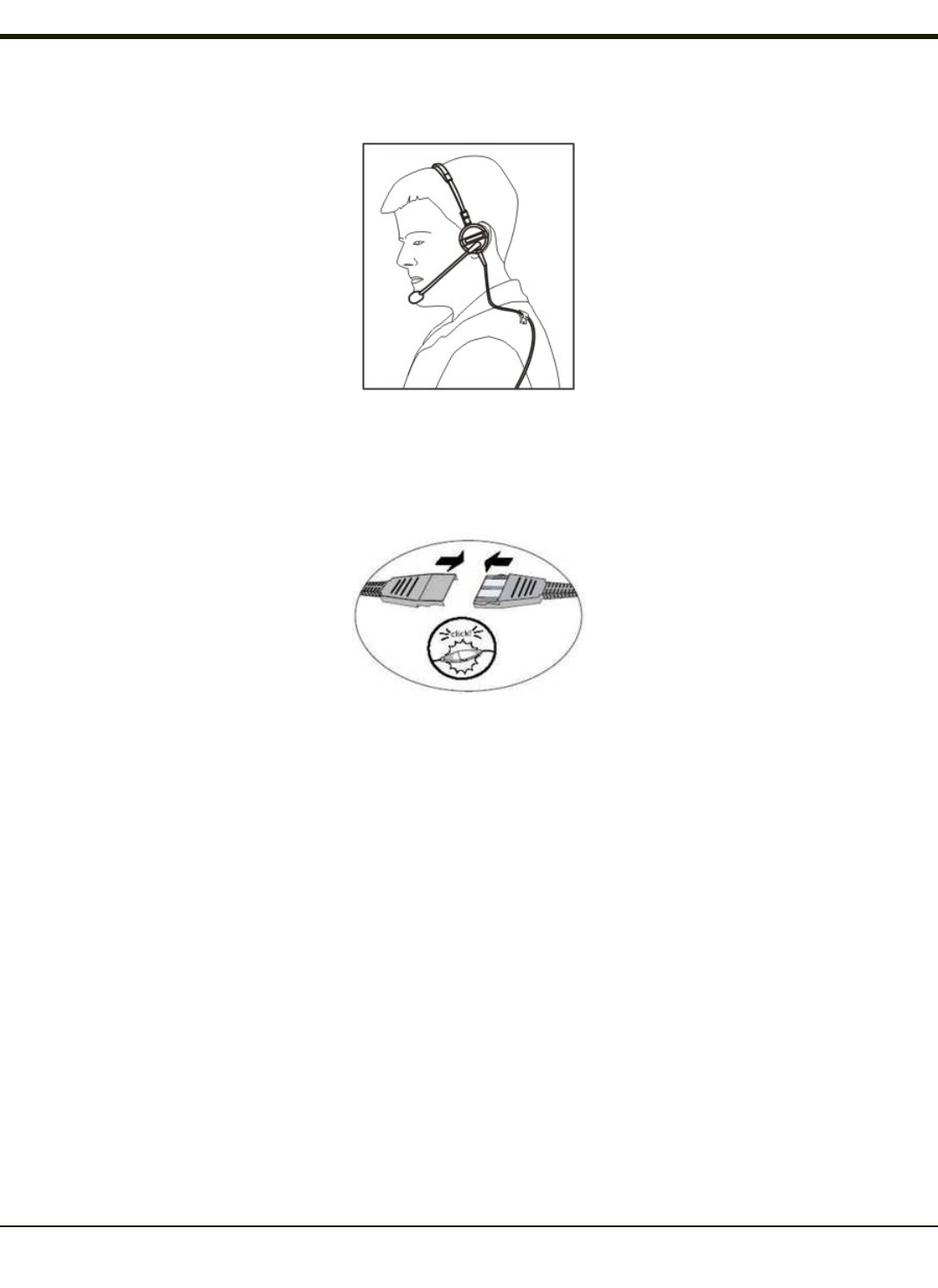
Adjust Headset / Microphone and Secure Cable
The headset consists of an earpiece, a microphone, a clothing clip and a cable. The headset attaches to the audio cable end of
the voice cable which attaches to the Thor VM2CG.
Align the audio connector and the headset quick connect cable end. Firmly push the cable ends together until they click and
lock in place.
Do not twist the microphone boom when adjusting the microphone. The microphone should be adjusted to be about two finger
widths from your mouth.
Make sure the microphone is pointed at your mouth. Note the small “Talk” label near the mouthpiece. Make sure the Talk label
is in front of your mouth. The microphone cable can be routed over or under clothing.
Under Clothing
lLeave the cable exposed only at the top of the collar.
lBe sure to leave a small loop of cable to allow movement of your head.
Over Clothing
lUse clothing clips to hold the cable close to your body.
lTuck the cable under the belt, but leave a small loop where it goes under the belt.
lDo not wear the cable on the front of your body. It may get in your way or get caught on protruding objects.
3-5
Rev. (a)
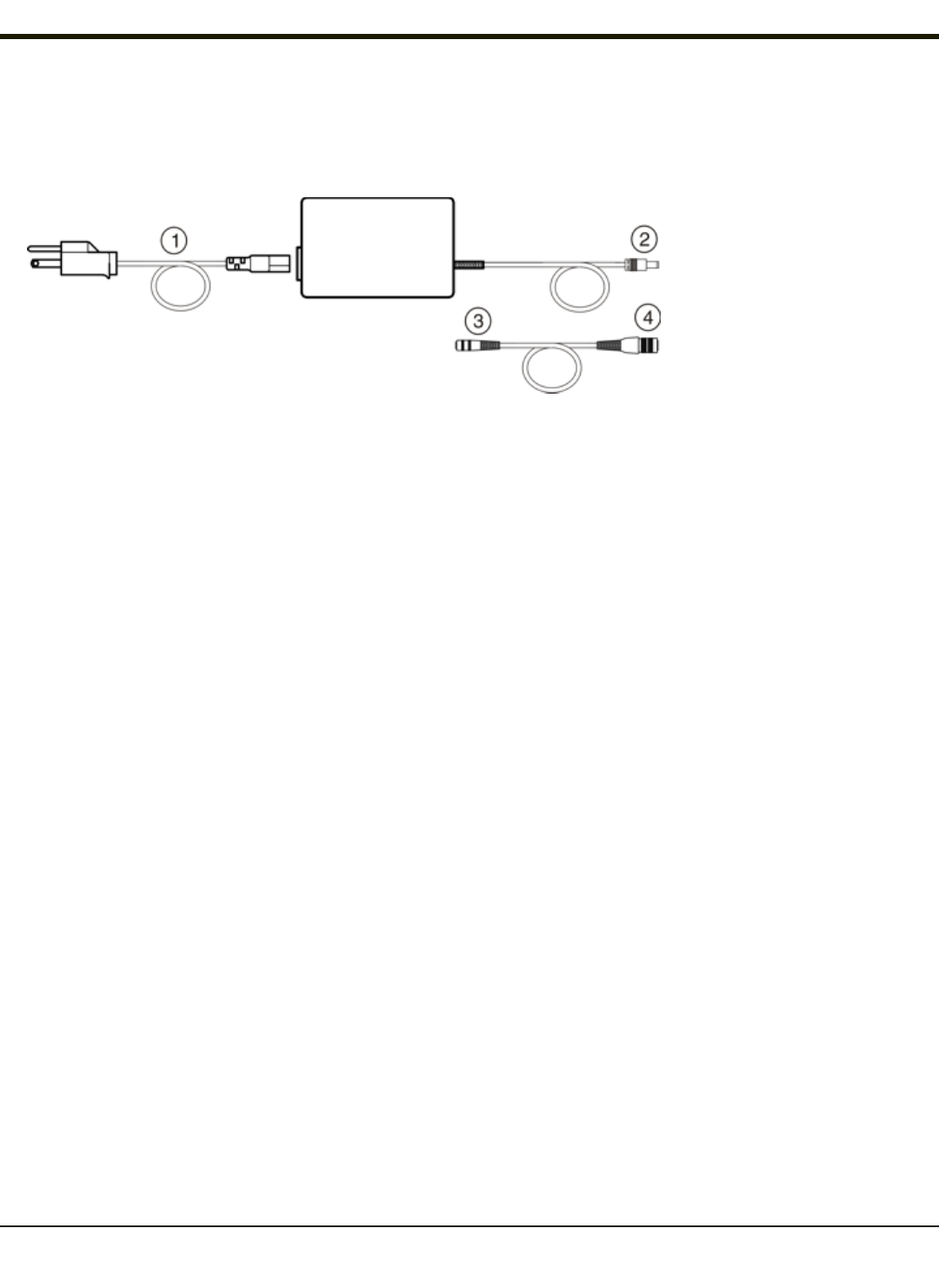
Connecting an AC/DC Power Supply
Note: The Honeywell-approved AC Power Supply and Adapter Cable are only intended for use in a 25ºC (77ºF) maximum
ambient temperature environment.
1. AC Input Cable (US only)
2. DC Output Cable
3. To DC Output Cable (see
above)
4. To Thor VM2CG
In North America, this unit is intended for use with a UL Listed ITE power supply with output rated 12 – 80VDC, minimum 60W.
Outside North America, this unit is intended for use with an IEC certified ITE power supply with output rated 12 – 80VDC,
minimum 60W.
The external power supply may be connected to either a 120V, 60Hz supply or, outside North America, to a 230V, 50Hz
supply, using the appropriate detachable cordset. In all cases, connect to a properly grounded source of supply provided with
maximum 15 Amp overcurrent protection (10 Amp for 230V circuits).
1. Turn the Thor VM2CG off.
2. Connect the detachable cordset provided by Honeywell (US only, all others must provide their own cable) to the
external power supply (IEC 320 connector).
3. Plug cordset into appropriate, grounded, electrical supply receptacle (AC mains).
4. Connect the DC Output Cable end to the power connector on the Thor VM2CG Quick Mount.
5. Turn the Thor VM2CG on.
3-6
Rev. (a)
Connecting Vehicle Power
Complete vehicle cradle mounting and power instruction is contained in the Thor VM2CG Vehicle Mounting Reference Guide.
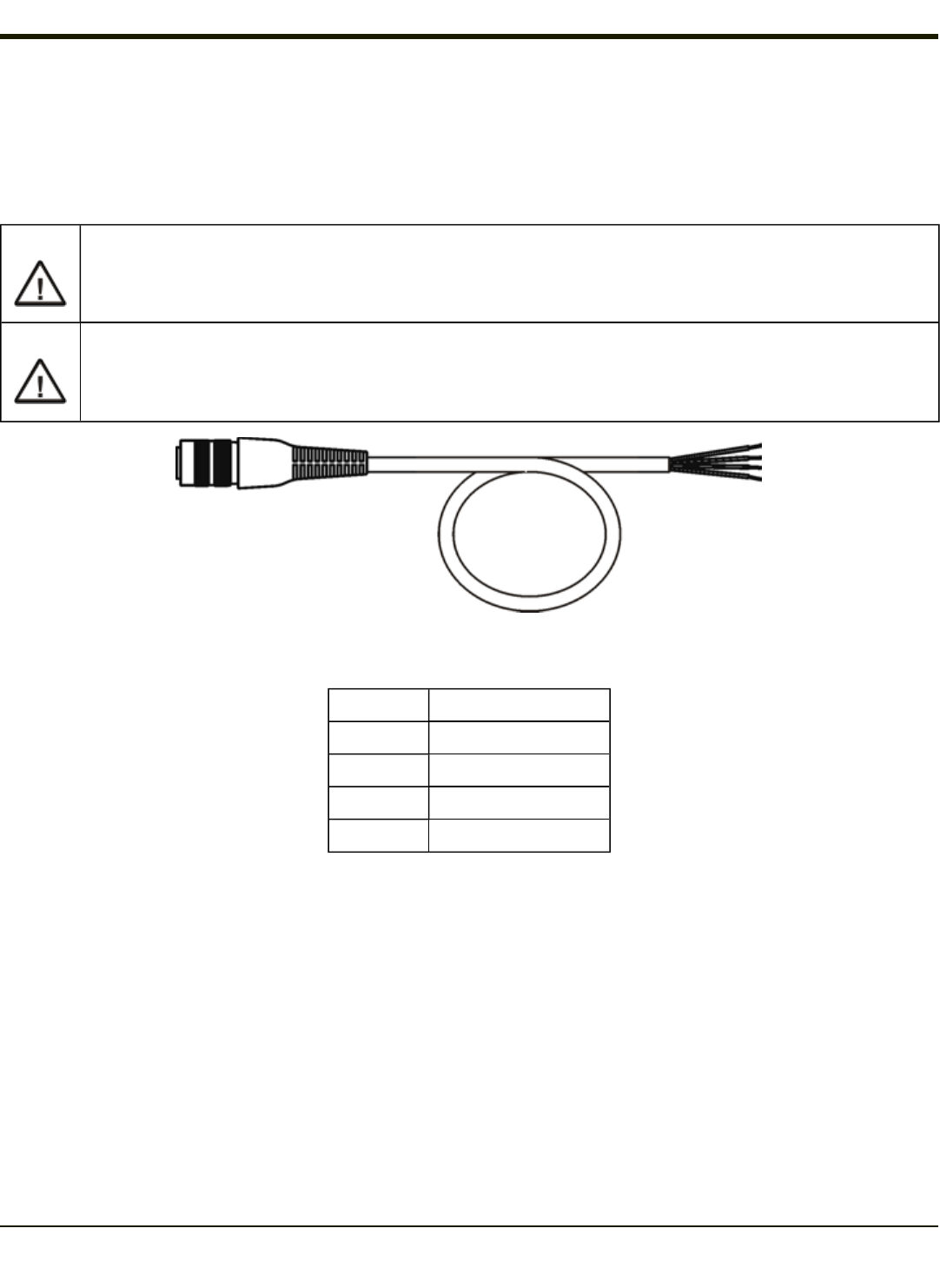
Vehicle 10-60VDC Power Connection
Caution:
For installation by trained service personnel only.
Caution: For proper and safe installation, the input power cable must be connected to a fused circuit on the vehicle. This
fused circuit requires a 10 Amp maximum time delay (slow blow) high interrupting rating fuse. If the supply con-
nection is made directly to the battery, the fuse should be installed in the positive lead within 5 inches of the battery
positive (+) terminal. Note: For North America, a UL Listed fuse is to be used.
VM1054CABLE
Wire Color Connection
Red DC + (10-60VDC)
Black DC -
Green Ground
Blue Ignition Input (optional)
Note: Correct electrical polarity is required for safe and proper installation. See the figures below for additional wire color-
coding specifics.
The Thor VM2CG DC input wires (Red DC+ and Black DC-) and the Blue ignition input wire are galvanically isolated. The
Green ground input is used for electrostatic discharge (ESD) protection.
3-7

Rev. (a)
Connect Vehicle 10-60VDC
1. The Thor VM2CG must not be mounted in the Quick Mount Smart Dock. The power switch on the Dock must be turned
Off. The power cable must be UNPLUGGED from the Dock.
2. While observing the fuse requirements specified above, connect the power cable as close as possible to the actual
battery terminals of the vehicle (if using unswitched power).
3. Wiring installation
lUse proper electrical and mechanical fastening means for terminating the cable. Properly sized “crimp” type
electrical terminals are an accepted method of termination. Please select electrical connectors sized for use with
20AWG (0.81mm2) conductors.
lRefer to the diagrams following this section for wire colors and connections:
nIgnition Control
nAuto-On Control
nManual Control
nVX6/VX7 Adapter Cable
5. Route the power cable:
lRoute the power cable the shortest way possible removing any left-over cable
lThe cable is rated for a maximum temperature of 105°C (221°F). Therefore, routing this cable it should be
protected from physical damage and from surfaces that might exceed this temperature.
lCable should be protected from physical damage from moving parts
lDo not expose the cable to chemicals or oil that may cause the wiring insulation to deteriorate
lAlways route the cable so that it does not interfere with safe operation and maintenance of the vehicle.
lProvide mechanical support for the cable by securing it to the vehicle structure at approximately one foot
intervals, taking care not to over tighten and pinch conductors or penetrate outer cable jacket.
5. Connect the DC power cable to the input connector on the back of the Dock.
6. Flip the power switch on the back of the Dock to On.
7. The Thor VM2CG can be installed in the Dock.
8. If using the optional screen blanking feature, install the screen blanking box or switch.
Once installation is complete, remember to start the Thor VM2CG and configure the Power Mode. Please see the Thor VM2CG
Reference Guide for details: Start > Settings > Control Panel > Power Configuration Mode.
3-8
Rev. (a)
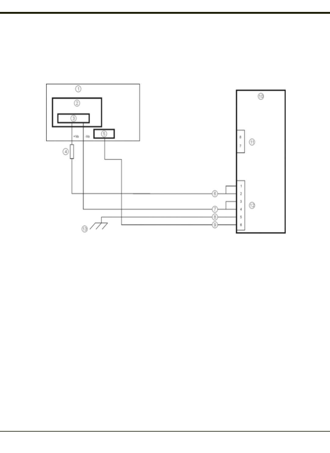
Ignition Control
Ignition wire must be connected and the Ignition Control power mode must be selected. When switched vehicle power is
available the Thor VM2CG ignition signal wire can be connected (less than 1mA over input voltage range) to the switched
circuit to allow the Thor VM2CG to power on when the vehicle is switched on. When the vehicle is switched off, more
aggressive power management settings are enabled to preserve the vehicle battery charge.
1. Existing Circuitry on Vehicle
2. Forklift Battery
3. Main Switch
4. 10A Slow blow Fuse close to power source
5. Ignition
6. Red Wire (DC +)
7. Black Wire (DC -)
8. Green Wire (Ground)
9. Blue Wire (Ignition Signal)
10. Thor VM2CG Computer in Quick Mount Smart Dock
11. COM1 or COM2 Connector on Dock
12. Circular Power Connector on Dock
13. If the vehicle chassis is not a suitable ground, connect
the Green wire to the negative terminal (-Vo) of the
power source.
3-9
Rev. (a)
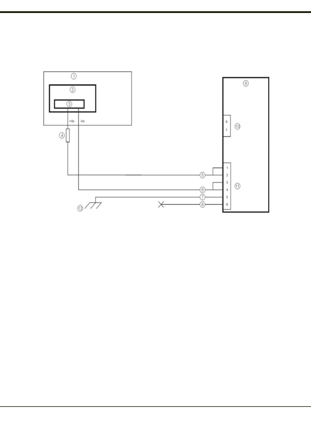
Auto-On Control
Auto-On power mode must be selected. The vehicle supply connections should be made to vehicle switched power to allow
the terminal to automatically power-up when vehicle power is switched on or when the power switch on the back of the Dock is
placed in the On position. The Ignition wire is not used and should be left disconnected.
1. Existing Circuitry on Vehicle
2. Forklift Battery
3. Main Switch
4. 10A Slow blow Fuse close to power source
5. Red Wire (DC +)
6. Black Wire (DC -)
7. Green Wire (Ground)
8. Blue Wire (not connected)
9. Thor VM2CG Computer in Quick Mount Smart Dock
10. COM1 or COM2 Connector on Dock
11. Circular Power Connector on Dock
12. If the vehicle chassis is not a suitable ground, connect
the Green wire to the negative terminal (-Vo) of the
power source.
3-10
Rev. (a)
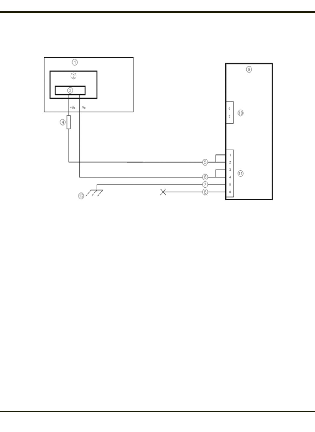
Manual Control
Ignition wire must be left unconnected and AC/DC power mode must be selected.
1. Existing Circuitry on Vehicle
2. Forklift Battery
3. Main Switch
4. 10A Slow blow Fuse close to power source
5. Red Wire (DC +)
6. Black Wire (DC -)
7. Green Wire (Ground)
8. Blue Wire (not connected)
9. Thor VM2CG Computer in Quick Mount Smart Dock
10. COM1 or COM2 Connector on Dock
11. Circular Power Connector on Dock
12. If the vehicle chassis is not a suitable ground, connect
the Green wire to the negative terminal (-Vo) of the
power source.
3-11
Rev. (a)
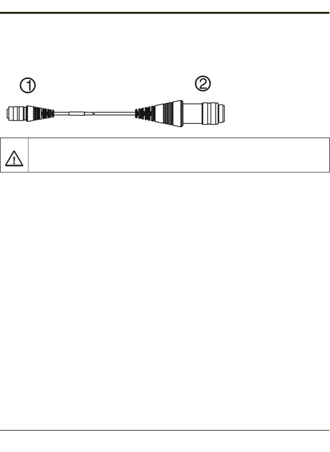
VX6 / VX7 Adapter Cable
An adapter cable is available to attach the Thor VM2CG to a vehicle previously equipped with a VX6/VX7 DC power cable. The
adapter cable has a 5-pin connector to match with the VX6/VX7 power supply cable on one end and a 6-pin connector to match
to the Thor VM2CG on the other.
1. To Thor VM2CG
2. To VX6/VX7 Power Supply
Cable
Caution:
Because the Thor VM2CG supports 10-60VDC power input, verify input voltages before using this adapter cable
with an existing VX6 or VX7 power connection installation.
When this adapter cable is used there is no provision for an ignition switch input. Therefore the vehicle ignition control function
is not available when using this cable.
3-12
Rev. (a)
Vehicle 72-144VDC Power Connection
This option requires DC/DC external power supply Part no. VX89303PWRSPLY.
Caution:
For installation by trained service personnel only.
Caution: For proper and safe installation, the input power cable must be connected to a fused circuit on the vehicle. This
fused circuit requires a 10 Amp maximum time delay (slow blow) high interrupting rating fuse. If the supply con-
nection is made directly to the battery, the fuse should be installed in the positive lead within 5 inches of the battery
positive (+) terminal. Note: For North America, a UL Listed fuse is to be used.
Caution: The VX89303PWRSPLY power supply is sealed per IPXX. Usage in areas where moisture can affect the power
supply connections should be avoided. The power supply should be mounted in a dry location within the vehicle or
placed in a suitable protective enclosure.
VX89303PWRSPLY
3-13
Rev. (a)
VM1054CABLE
Wire Color Connection
Red DC + output from DC/DCPower Supply
Black DC - output from DC/DCPower Supply
Green Ground output from DC/DC Power Supply
Blue Ignition Input (not connected)
Note: Correct electrical polarity is required for safe and proper installation. See the figure below for additional wire color-
coding specifics.
The Thor VM2CG DC input wires (Red DC+ and Black DC-) and the Blue ignition input wire are galvanically isolated. The
Green ground input is used for electrostatic discharge (ESD) protection.
Connect Vehicle 72-144VDC
1. The Thor VM2CG must not be mounted in the Quick Mount Smart Dock. The power switch on the Dock must be turned
Off. The power cable must be UNPLUGGED from the Dock.
2. While observing the fuse requirements specified above, connect the power cable as close as possible to the actual
battery terminals of the vehicle.
3. Wiring installation:
lThe user must supply wiring from the vehicle to the DC/DC power supply.
lUse proper electrical and mechanical fastening means for terminating the cable. Properly sized “crimp” type
electrical terminals are an accepted method of termination. Please select electrical connectors sized for use with
20AWG (0.81mm2) conductors.
lRemove the lid from the DC to DC converter. Attach the stripped wire ends to the output side of the DC to DC
converter. Attach stripped wire ends to the input side of the DC to DC converter.
lThe input and output blocks each have two + and two – minus connectors. Either connector in the block can be
used to connect the matching polarity wire.
lUse the looms and wire ties to secure all wiring then reattach the cover with the screws.
lConnect as shown in wiring diagram.
4. Route the power cable:
lRoute the power cable the shortest way possible removing any left-over cable
lThe cable is rated for a maximum temperature of 105°C (221°F). Therefore, routing this cable it should be protected
from physical damage and from surfaces that might exceed this temperature.
lCable should be protected from physical damage from moving parts
lDo not expose the cable to chemicals or oil that may cause the wiring insulation to deteriorate
3-14
Rev. (a)
lAlways route the cable so that it does not interfere with safe operation and maintenance of the vehicle.
lProvide mechanical support for the cable by securing it to the vehicle structure at approximately one foot intervals,
taking care not to over tighten and pinch conductors or penetrate outer cable jacket.
5. Connect the DC power cable to the input connector on the back of the Dock.
6. Flip the power switch on the back of the Dock to On.
7. The Thor VM2CG can be installed in the Dock.
8. If using the optional screen blanking feature, install the screen blanking box or switch.
Once installation is complete, remember to start the Thor VM2CG and configure the Auto-On behavior. Please see the Thor
VM2CG Reference Guide for details: Start > Settings > Control Panel > Options > Misc tab.
Wiring Diagram
1. Existing Circuitry on Vehicle
2. Forklift Battery
3. MainSwitch
4. 10A Slow blow Fuse close to power source
5. Isolated DC/DCPower Supply
6. Red Wire (DC +)
7. Black Wire (DC -)
8. Green Wire (Ground)
9. Blue Wire (not connected)
10. Thor VM2CG Computer in Quick Mount
Smart Dock
11. COM1 or COM2 Connector on Dock
12. Circular Power Connector on Dock
3-15

Rev. (a)
Thor VM2CG Screen Blanking
Note: Before this process begins, the steps outlined in Power Cable Connection need to be performed for either the 10-
60VDC Connection or the 72-144VDC Connection.
Caution:
For installation by trained service personnel only.
Caution:
For proper and safe installation, the input power lead to the Screen Blanking Box requires a 3 Amp maximum time
delay (slow blow) high interrupting rating fuse. Note: For North America, a UL Listed fuse is to be used.
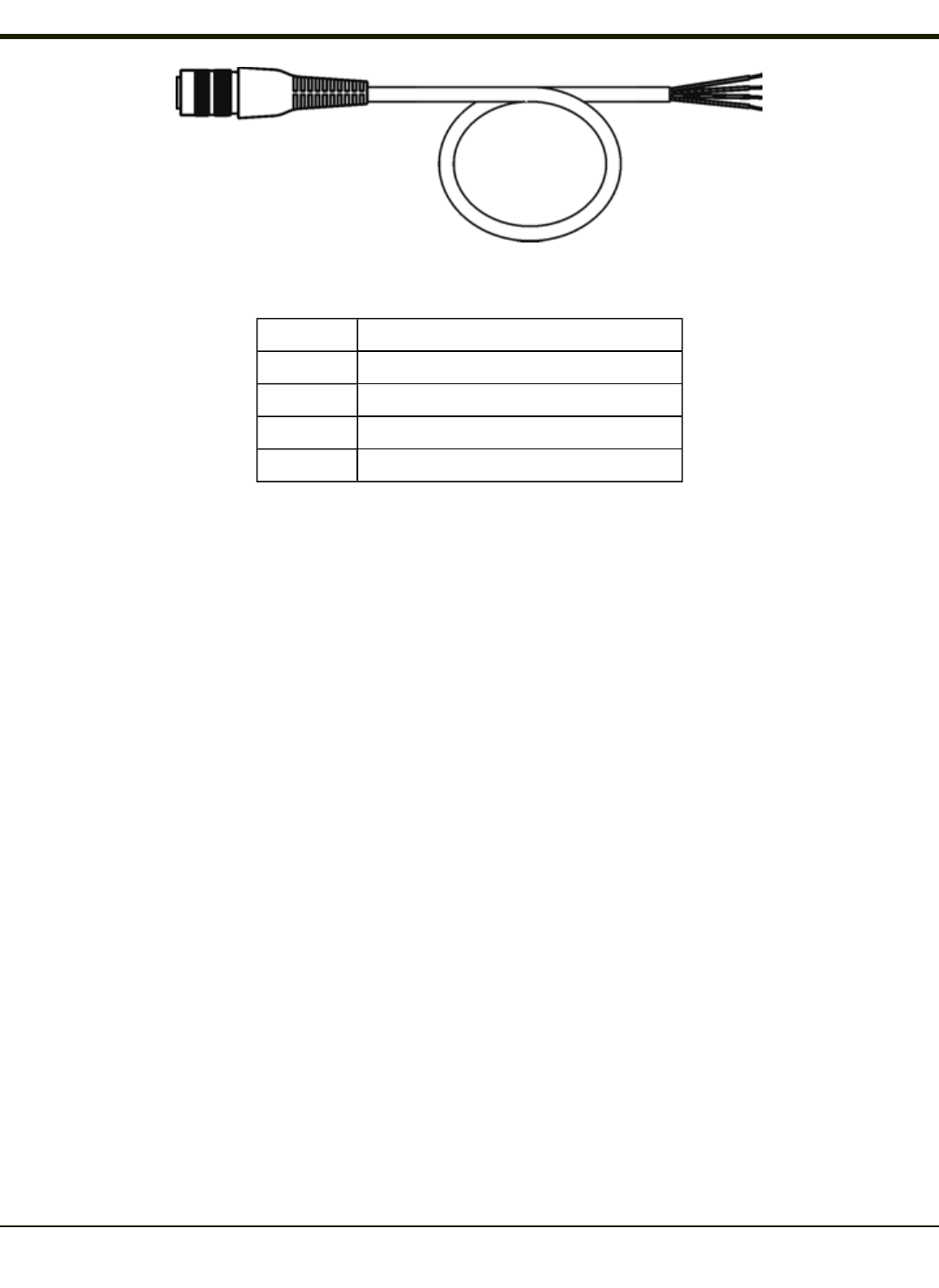
An optional Screen Blanking Box Cable (VM1080CABLE) is available from Thor VM2CG to connect the Screen Blanking Box
to the COM port on the Thor VM2CG. A user-supplied cable can also be used.
Please refer to the Thor VM2CG Reference Guide for specifications on building a serial cable for the screen blanking feature
and Screen Control (in the Windows Control Panel) to configure the Thor VM2CG for screen blanking.
When routing any additional cables for screen blanking:
lRoute the cable the shortest way possible removing any left-over cable
lFuses and cabling are user supplied. Therefore, route these cables so they are protected from physical damage and
from surfaces that might exceed the cable's rated temperature threshold.
lCable should be protected from physical damage from moving parts
lDo not expose the cable to chemicals or oil that may cause the wiring insulation to deteriorate
lAlways route the cable so that it does not interfere with safe operation and maintenance of the vehicle.
lProvide mechanical support for the cable by securing it to the vehicle structure at approximately one foot intervals,
taking care not to over tighten and pinch conductors or penetrate outer cable jacket.
3-16
Rev. (a)
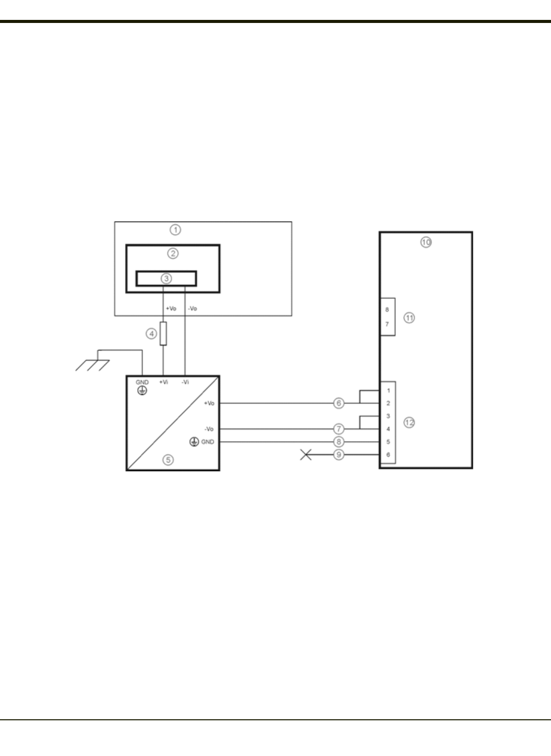
Screen Blanking Box
Screen Blanking Box
Terminal Connection
12-xxV Input from vehicle motion sensing circuitry.
Please refer to label on Screen Blanking Box for allowable voltage input range.
GND DC -
These two terminals are for a user provided serial cable.
The cable must be constructed so that Pin 7 (RTS) connects to switched side of the connection
and Pin 8 (CTS) connects to the other terminal.
Please refer to the appropriate illustration below for Screen Blanking Box wiring diagrams.
Caution:
Do not exceed the maximum input voltage, either 60 or 72VDC, specified on the Screen Blanking Box label when
using this configuration.
1. Motion Circuitry - The voltage at the +Vi input on the Screen Blanking Box must be between 10VDC and 60 or 72VDC
(see Screen Blanking Box label) when the vehicle is in motion and less than 5VDC when the vehicle is not in motion.
2. 3 Amp Fuse
3. To -Vo on Vehicle, i.e., Negative Battery Terminal
4. To Pin 7 of COM1 or COM2 (Gray wire when using VM1080CABLE)
5. To Pin 8 of COM1 or COM2 (Black wire when using VM1080CABLE)
3-17
Rev. (a)
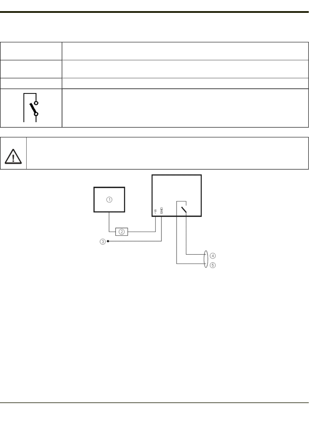
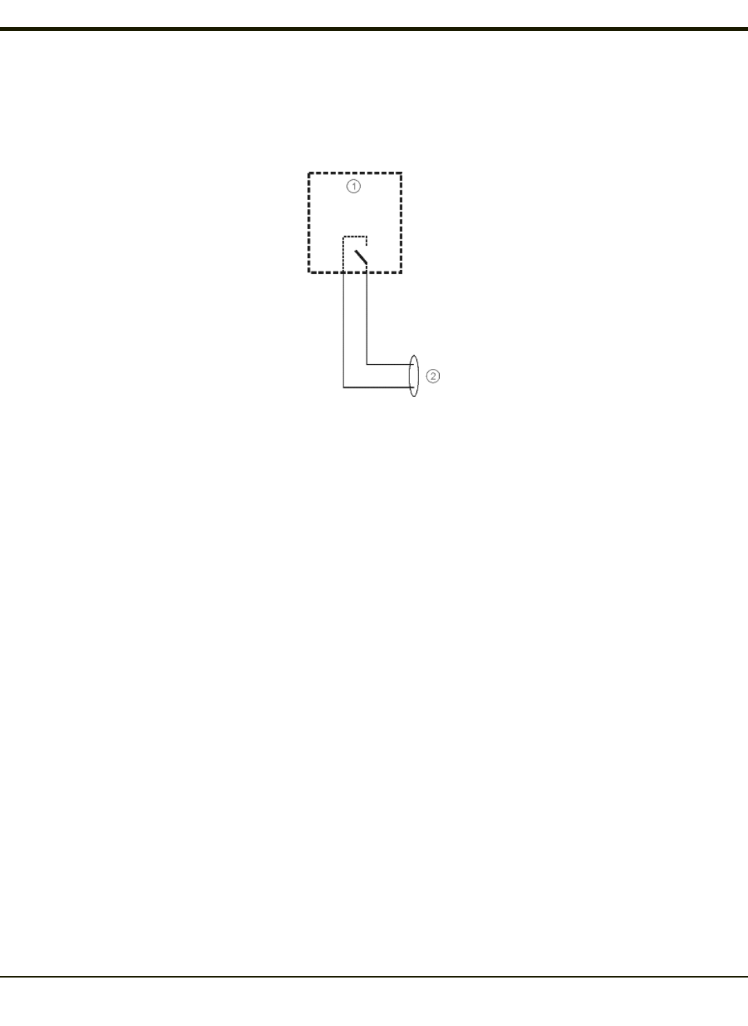
Screen Blanking with Switch
In applications where it is impractical to use the screen blanking box due to vehicle voltage or lack of a motion sensing signal,
screen blanking can be controlled via a user supplied switch or relay that provides an electrical conductive connection on
vehicle motion.
1. Switch
2. To Pins 7 and 8 of COM1 or COM2
3-18
Rev. (a)
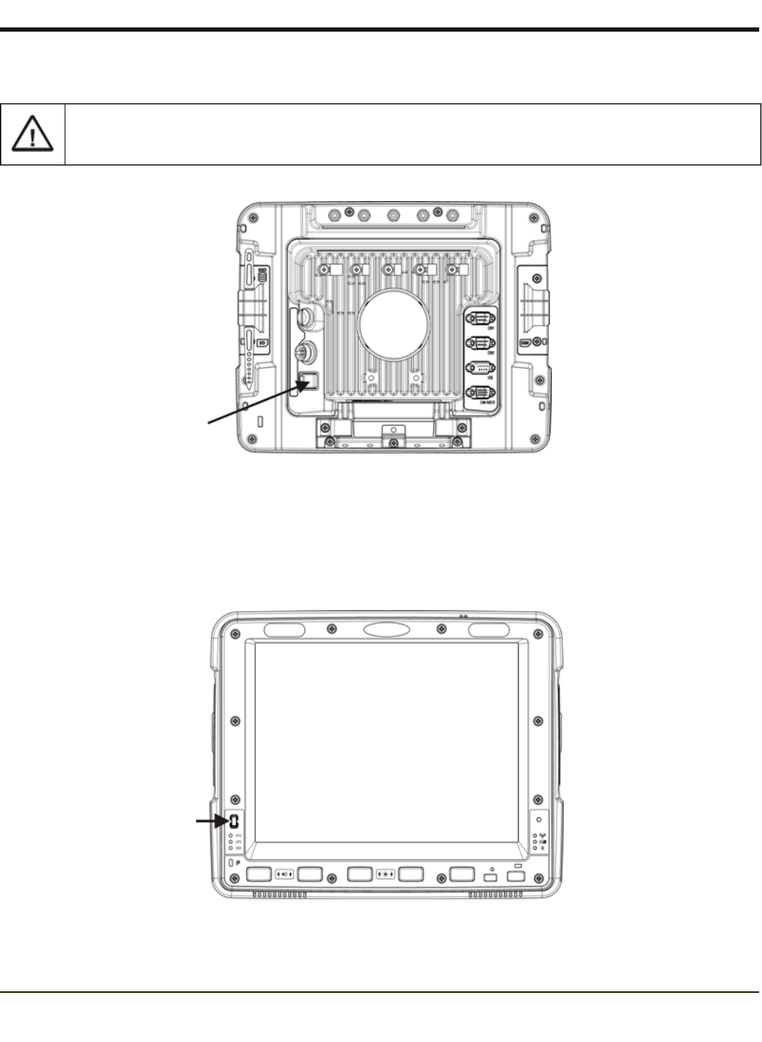
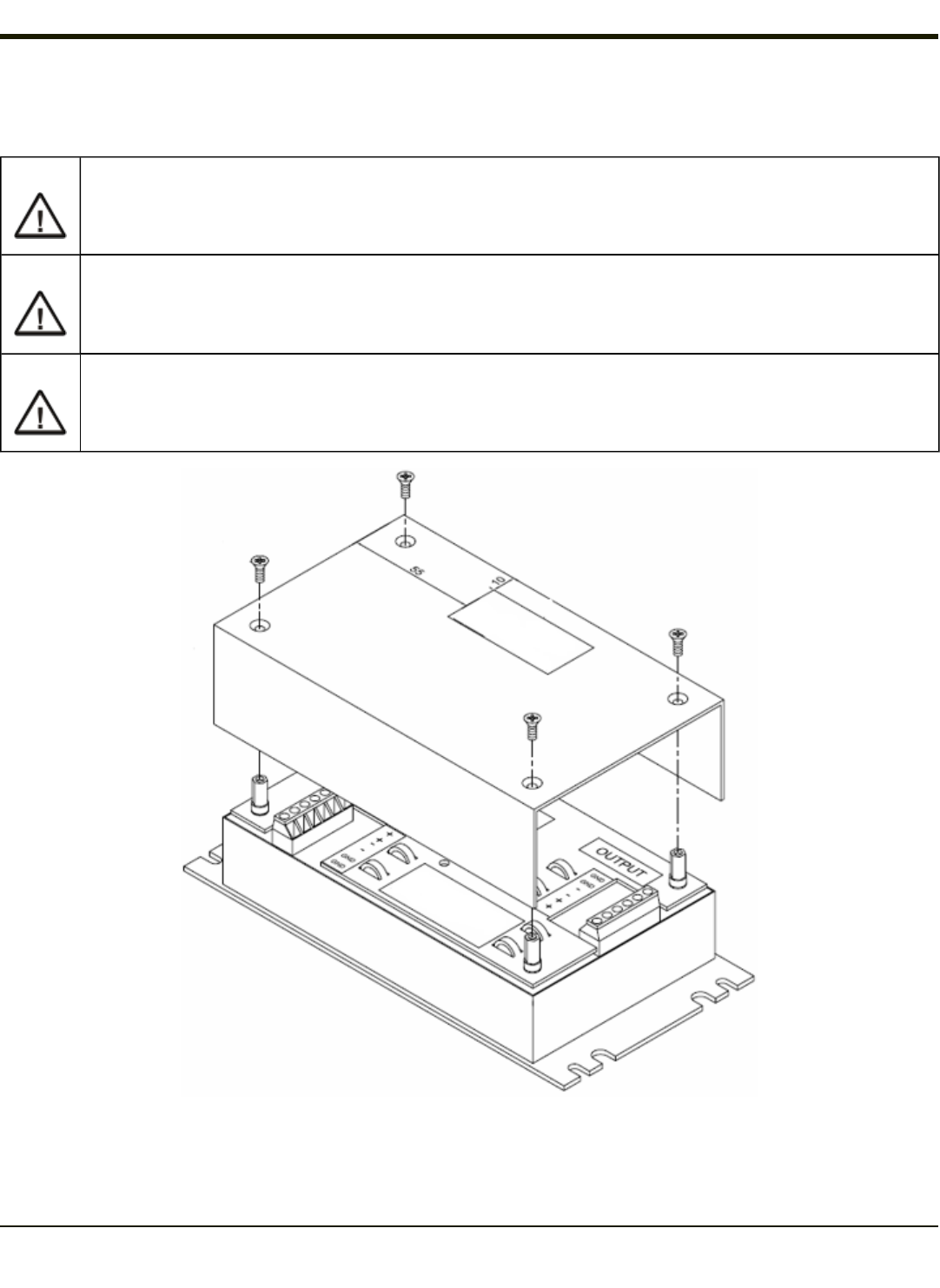
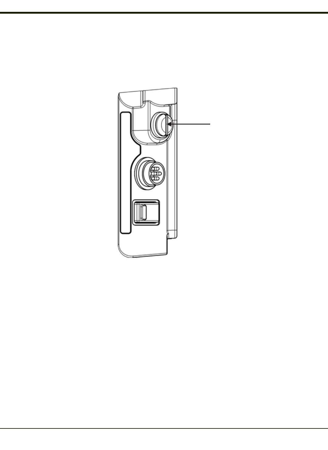
Fuse
The Thor VM2CG uses an 8A time delay (slow blow), fuse that is externally accessible and user replaceable. The fuse is
located on the back of the Quick Mount Smart Dock. The fuse is accessed by unscrewing the cap as indicated below.
Should it need replacement, replace with same size, rating and type of fuse – Littelfuse 0215008.MXP or equivalent.
Fuse has voltage on it even when power is off. Always disconnect input power before changing the fuse.
3-19

Rev. 01
3-20

Chapter 4 - Product Agency Compliance - Thor VM2CG
Class B Digital Device
FCC Rules, Part 15
This device complies with Part 15 of the FCC Rules [and with RSS-210 of Industry Canada]. Operation is subject to the
following two conditions:
1. This device may not cause harmful interference, and
2. This device must accept any interference received, including interference that may cause undesired operation.
NOTE: This equipment has been tested and found to comply with the limits for a Class B digital device, pursuant to Part 15 of
the FCC Rules. These limits are designed to provide reasonable protection against harmful interference in a residential
installation. This equipment generates, uses and can radiate radio frequency energy and, if not installed and used in
accordance with the instructions, may cause harmful interference to radio communications. However, there is no guarantee
that interference will not occur in a particular installation. If this equipment does cause harmful interference to radio or television
reception, which can be determined by turning the equipment off and on, the user is encouraged to try to correct the
interference by one or more of the following measures:
lReorient or relocate the receiving antenna.
lIncrease the separation between the equipment and the receiver.
lConnect the equipment into an outlet on a circuit different from that to which the receiver is connected.
lConsult the dealer or an experienced radio/TV technician for help.
Notice
Changes or modifications made to this equipment not expressly approved by Honeywell may void the FCC authorization to
operate this equipment.
EMC Directive Requirements
This is a Class B product. In a domestic environment this product may cause radio interference in which case the user may be
required to take adequate measures.
Canada, Industry Canada (IC) Notices
This Class B digital apparatus complies with Canadian ICES-003
This device complies with Industry Canada licence-exempt RSS standard(s). Operation is subject to the following two
conditions: (1) this device may not cause interference, and (2) this device must accept any interference, including interference
that may cause undesired operation of the
Exposure of humans to RF fields (RSS-102)
The computers employ low gain integral antennas that do not emit RF field in excess of Health Canada limits for the general
population; consult Safety Code 6, obtainable from Health Canada's Web site at http://www.hc-sc.gc.ca/
The radiated energy from the antennas connected to the wireless adapters conforms to the IC limit of the RF exposure
requirement regarding IC RSS-102, Issue 4 clause 4.1.
4-1

Rev. (a)
Canada, avis d'Industry Canada (IC)
Cet appareil numérique de classe B est conforme à la norme NMB-003.
Le présent appareil est conforme aux CNR d'Industrie Canada applicables auxappareils radio exempts de
licence.L'exploitation est autorisée aux deux conditions suivantes: (1) l'appareil ne doit pas produire de brouillage, et (2)
l'utilisateur de l'appareil doit accepter tout brouillage adioélectrique subi, même si le brouillage est susceptible d'en
compromettre le fonctionnement.
Conformité des appareils de radiocommunication aux limites d'exposition humaine aux radiofréquences (CNR-102)
L'ordinateur utilise des antennes intégrales à faible gain qui n'émettent pas un champ électromagnétique supérieur aux normes
imposées par Santé Canada pour la population. Consultez le Code de sécurité 6 sur le site Internet de Santé Canada à
l'adresse suivante : http://www.hc-sc.gc.ca/
L'énergie émise par les antennes reliées aux cartes sans fil respecte la limite d'exposition aux radiofréquences telle que définie
par Industrie Canada dans la clause 4.1 du document CNR-102, version 4.
ANATEL (Brazil)
Este equipamento opera em caráter secundário, isto é, não tem direito a proteção contra interferência prejudicial, mesmo de
estações do mesmo tipo, e não causar interferência a sistema operando em caráter primário.
Cofetel
La operación de este equipo está sujeta a las siguientes dos condiciones: (1) es posible que este equipo o dispositivo no cause
interferencia perjudicial y (2) este equipo o dispositivo debe aceptar cualquier interferencia, incluyendo la que pueda causar su
operación no deseada.
Li-Ion Battery
When disposing of the Thor VM2CG UPS battery, the following precautions should be observed: The battery should be
disposed of properly. The battery should not be disassembled or crushed. The battery should not be heated above 212°F
(100°C) or incinerated.
RF Safety Notice
This device is intended to transmit RF energy. For protection against RF exposure to humans and in accordance
with FCC rules and Industry Canada rules, this transmitter should be installed such that a minimum separation dis-
tance of at least 20 cm (7.8 in.) is maintained between the antenna and the general population. This device can only
be co-located with FCC ID:TWG-SDCMSD30G.
FCC 5GHz Statement
LAN devices are restricted to indoor use only in the band 5150-5250 MHz.
For the band 5600-5650 MHz, no operation is permitted.
When using IEEE 802.11a wireless LAN, this product is restricted to.indoor use, due to its operation in the 5.15- to
5.25-GHz Frequency range. The FCCrequires this product to used indoors for the frequency range of 5.15 GHz to
5.25 GHz to reduce the potential for harmful interference to co-channel mobile satellite systems. High-power radar is
allocated as the primary user of the 5.25- to 5.35-GHz and 5.65- to 5.85-GHz bands. These radar stations can cause
interference with and/or damage to this device.
4-2

Rev. (a)
Waste Electrical and Electronic Equipment (WEEE)
Important:
This symbol is placed on the product to remind users to dispose of Waste Electrical and Electronic Equipment
(WEEE) appropriately, per Directive 2002-96-EC. In most areas, this product can be recycled, reclaimed and re-
used when properly discarded. Do not discard labeled units with trash. For information about proper disposal, visit
www honeywellaidc com.
4-3
Rev. (a)
R&TTE Directive Requirements
This device bearing the CE marking is in compliance with the essential requirements and other relevant provisions of Directive
1999/5/EC. This device complies with the following harmonized European Standards:
Health: EN63211:2008
Safety: EN60950-1:2006 + A1:2010 + A11:2009 + A12:2011
EMC: EN301 489-1 V1.9.2:2011, EN301 489-17 V2.1.1:2009
Radio: EN300 328 V1.7.1:2006
The following CE marking is valid for EU harmonized telecommunications products.
EN300328 V1.7.1:2006
EN301893 V1.6.1:2011
EN301511 V9.0.2:2003
EN301908-1 V5.2.1:2011
EN300440-2 V1.4.1:2010
EN62311: 2008
EN301489-1 V1.9.2:2011
EN301489-3 V1.4.1:2002
EN301489-7 V1.3.1:2005
EN301489-17 V2.1.1:2009
EN301489-24 V1.5.1:2010
EN55022/EN55024: 2010
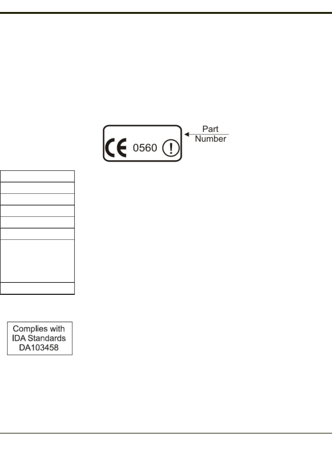
Dealer License - Republic of Singapore
Republic of Singapore - LXE Dealer License Number DA103458 complies with IDA
Standards.
4-4

Rev. (a)
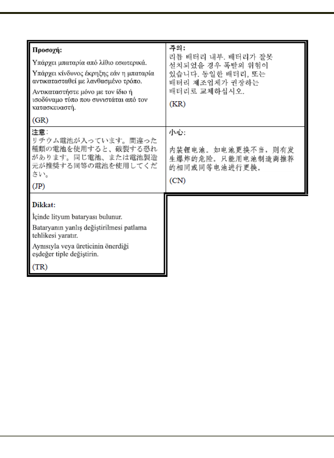
Lithium Battery Safety Statement
Caution: Lithium battery inside. Danger of explosion if battery is incorrectly replaced. Replace only with same or equivalent
type recommended by battery manufacturer. (US)
Attention: Contient une pile de lithium. Risque d’explosion dans le cas où la pile ne serait pas correctement remplacée.
Remplacer uniquement avec une pile semblable ou equivalente au type de pile recommandé par le fabricant. (FR)
Forsigtig: Indeholder lithiumbattterier. Risiko for eksplosion, hvis batteriet udskiftes forkert. Må kun udskiftes med samme eller
tilsvarende type, som anbefalet af fabikanten. (DK)
Varoitus: Tämä tuote käyttää laservaloa. Skannerissa on jokin seuraavista tarroista. Lue Huomio-kohta. (FI)
Vorsicht: Enthält Lithium-Batterie. Bei unsachgemäßem Ersatz besteht Explosionsgefahr. Nur durch gleichen oder vom
Hersteller empfohlenen Typ ersetzen. (DE)
Attenzione: Batteria al litio. Pericolo di esplosione qualora la batteria venga sostituita in maniera scorretta. Sostituire solo con
lo stesso tipo o equivalente consigliato per il fabbricante. (IT)
Atenção: Contém pilha de lítio. Há perigo de explosão no caso de uma substituição incorreta. Substitua somente pelo mesmo
tipo, ou equivalente, recomendado pelo fabricante. (PT)
Varning: Innehåller litiumbatteri. Fara för explosion om batteriet är felaktigt placerat eller av fel typ. Använd endast samma eller
motsvarande typ batterier rekommenderade av tillverkaren. (SE)
Advarsel: Innmontert Lithium batteri. Eksplosjonsfare ved feil montering av batteri. Benytt kun batteri anbefalt av produsent.
(NO)
Cuidado: Pila de litio adentro. Peligro de explosión si la pila se reemplaza incorrectamente. Reemplace solamente con el
mismo tipo o equivalente recomendado por el fabricante. (ES)
Oppassen: Bevat Lithium-batterij. Incorrrecte plaatsing van batterij kan leiden tot explosiegevaar. Alleen vervangen door
hetzelfde of door fabrikant aanbevolen gelijkwaardig type. (NL)
4-5
Rev. (a)
Lithium Battery Safety Statement, continued
Legend: Chinese – CN; Danish – DK; Dutch – NL; English – US; Finnish – FI; French- - FR; German – DE; Greek – GR; Italian
– IT; Japanese – JP; Korean – KR; Norwegian – NO; Portuguese – PT; Spanish – ES; Swedish – SE; Turkish – TR.
4-6

Rev. (a)
Vehicle Power Supply Connection Safety Statement
Vehicle Power Supply Connection: If the supply connection is made directly to the battery, a 10A slow-blow fuse should be
installed in the positive lead within 5 inches (12.7 cm.) of the battery positive (+) terminal. (US)
Raccordement de l’alimentation du véhicule Si l’alimentation est raccordée directement à la batterie, un fusible à action
retardée de 10A doit être installé sur le câble positif à moins de 12,7 cm de la borne positive (+) de la batterie. (FR)
EL forsyning af køretøjet. Er forsyningsforbindelsen direkte tilknyttet til batteriet og og tilsluttet til den positive part indenfor
12,7 cm (+ delen). vil der være en langsom tændelse af 10 ampere. (DK)
Kytkentä ajoneuvon virtalähteeseen Jos virtaa otetaan suoraan akusta, 10 ampeerin hidas sulake on asennettava
positiiviseen johtoon enintään 12 cm:n etäisyydelle akun positiivisesta (+) navasta. (FI)
Anschluss an Fahrzeugbatterie Bei direktem Anschluss an die Fahrzeugbatterie sollte eine träge 10A-Sicherung in die
positive Leitung zwischengeschaltet werden, und zwar nicht weiter als ca. 13 cm von der positiven (+) Batterieklemme
entfernt. (DE)
Σύνδεση Τροφοδοτικού Ισχύος Οχήματος Αν η σύνδεση του τροφοδοτικού γίνει κατευθείαν στη μπαταρία, μια ασφάλεια
βραδείας τήξης των 10A θα πρέπει να τοποθετηθεί στο θετικό καλώδιο εντός 5 ιντσών (12,7 εκ.) του θετικού (+) ακροδέκτη
της μπαταρίας. (GR)
Collegamento dell’alimentazione del veicolo Se il collegamento dell’alimentazione viene stabilito direttamente con la batteria, è
necessario installare un fusibile ad azione lenta da 10A nel conduttore positivo a meno di 5 in. (12,7 cm) dal terminale positivo
(+) della batteria. (IT)
Tilkople strømforsyningen til kjøretøyet Hvis strømforsyningen koples direkte til batteriet, skal det installeres en 10A treg
sikring i den positive ledningen innen 12,7 cm fra plusspolen (+) på batteriet. (NO)
Ligação do fornecimento de corrente do veículo Se a ligação de fornecimento de corrente for ligada directamente à bateria,
deve instalar-se um fusível de 10A no terminal positivo, a 12,7 cm. do terminal positivo (+) da bateria. (PT)
Conexión de suministro eléctrico para el vehículo Si el suministro eléctrico se proporciona directamente a la batería, se debe
instalar un fusible de retardo de 10A en el conductor positivo, como máximo a 12,7 cm (5 pulgadas) del terminal positivo (+).
(ES)
Fordonets strömförsörjningskoppling Om strömkopplingen görs direkt till batteriet, måste en 10A-säkring installeras i den
positivt laddade ledningen inom 12.7 cm från batteriets pluspol (+). (SE)
Taşıt Güç Kaynağı Bağlantısı Kaynak bağlantısı doğrudan aküye yapılırsa, pozitif bağlantı kablosu üzerinde akünün pozitif (+)
kutbuna 12.7 cm mesafede 10A’lık yavaş atan bir sigorta monte edilmelidir. (TR)
Legend: Danish – DK; English – US; Finnish – FI; French- - FR; German – DE; Greek – GR; Italian – IT; Norwegian – NO;
Portuguese – PT; Spanish – ES; Swedish – SE; Turkish – TR.
4-7

Rev. 01
4-8

Chapter 5 - Technical Assistance
If you need assistance installing or troubleshooting your device, please contact us by using one of the methods below:
Knowledge Base: www.hsmknowledgebase.com
Our Knowledge Base provides thousands of immediate solutions. If the Knowledge Base cannot help, our Technical Support
Portal (see below) provides an easy way to report your problem or ask your question.
Technical Support Portal: www.hsmsupportportal.com
The Technical Support Portal not only allows you to report your problem, but it also provides immediate solutions to your
technical issues by searching our Knowledge Base. With the Portal, you can submit and track your questions online and send
and receive attachments.
Web form: www.hsmcontactsupport.com
You can contact our technical support team directly by filling out our online support form. Enter your contact details and the
description of the question/problem.
Telephone: www.honeywellaidc.com/locations
For our latest contact information, please check our website at the link above.
Product Service and Repair
Honeywell International Inc. provides service for all of its products through service centers throughout the world. To obtain
warranty or non-warranty service, please visit www.honeywellaidc.comand select Support > Contact Service and Repair
to see your region’s instructions on how to obtain a Return Material Authorization number (RMA #). You should do this prior to
returning the product.
Limited Warranty
Honeywell International Inc. ("HII") warrants its products to be free from defects in materials and workmanship and to conform
to HII’s published specifications applicable to the products purchased at the time of shipment. This warranty does not cover
any HII product which is (i) improperly installed or used; (ii) damaged by accident or negligence, including failure to follow the
proper maintenance, service, and cleaning schedule; or (iii) damaged as a result of (A) modification or alteration by the
purchaser or other party, (B) excessive voltage or current supplied to or drawn from the interface connections, (C) static
electricity or electro-static discharge, (D) operation under conditions beyond the specified operating parameters, or (E) repair or
service of the product by anyone other than HII or its authorized representatives.
This warranty shall extend from the time of shipment for the duration published by HII for the product at the time of purchase
("Warranty Period"). Any defective product must be returned (at purchaser’s expense) during the Warranty Period to HII factory
or authorized service center for inspection. No product will be accepted by HII without a Return Materials Authorization, which
may be obtained by contacting HII. In the event that the product is returned to HII or its authorized service center within the
Warranty Period and HII determines to its satisfaction that the product is defective due to defects in materials or workmanship,
HII, at its sole option, will either repair or replace the product without charge, except for return shipping to HII.
EXCEPT AS MAY BE OTHERWISE PROVIDED BY APPLICABLE LAW, THE FOREGOING WARRANTY IS IN LIEU OF
ALL OTHER COVENANTS OR WARRANTIES, EITHER EXPRESSED OR IMPLIED, ORAL OR WRITTEN, INCLUDING,
WITHOUT LIMITATION, ANY IMPLIED WARRANTIES OF MERCHANTABILITY OR FITNESS FOR A PARTICULAR
PURPOSE, OR NON-INFRINGEMENT.
HII’S RESPONSIBILITY AND PURCHASER’S EXCLUSIVE REMEDY UNDER THIS WARRANTY IS LIMITED TO THE
REPAIR OR REPLACEMENT OF THE DEFECTIVE PRODUCT WITH NEW OR REFURBISHED PARTS. IN NO EVENT
5-1

Rev. (a)
SHALL HII BE LIABLE FOR INDIRECT, INCIDENTAL, OR CONSEQUENTIAL DAMAGES, AND, IN NO EVENT, SHALL
ANY LIABILITY OF HII ARISING IN CONNECTION WITH ANY PRODUCT SOLD HEREUNDER (WHETHER SUCH
LIABILITY ARISES FROM A CLAIM BASED ON CONTRACT, WARRANTY, TORT, OR OTHERWISE) EXCEED THE
ACTUAL AMOUNT PAID TO HII FOR THE PRODUCT. THESE LIMITATIONS ON LIABILITY SHALL REMAIN IN FULL
FORCE AND EFFECT EVEN WHEN HII MAY HAVE BEEN ADVISED OF THE POSSIBILITY OF SUCH INJURIES,
LOSSES, OR DAMAGES. SOME STATES, PROVINCES, OR COUNTRIES DO NOT ALLOW THE EXCLUSION OR
LIMITATIONS OF INCIDENTAL OR CONSEQUENTIAL DAMAGES, SO THE ABOVE LIMITATION OR EXCLUSION MAY
NOT APPLY TO YOU.
All provisions of this Limited Warranty are separate and severable, which means that if any provision is held invalid and
unenforceable, such determination shall not affect the validity of enforceability of the other provisions hereof. Use of any
peripherals not provided by the manufacturer may result in damage not covered by this warranty. This includes but is not
limited to: cables, power supplies, cradles, and docking stations. HII extends these warranties only to the first end-users of the
products. These warranties are non-transferable.
The duration of the limited warranty for the Thor VM2CGis 1 year.
The duration of the limited warranty for the Thor VM2CG Quick Mount Smart Dock is 1 year.
The duration of the limited warranty for the Thor VM2CG Vehicle Mount Assembly is 1 year.
The duration of the limited warranty for the Thor VM2CG internal UPS battery is 1 year.
The duration of the limited warranty for the Thor VM2CGAC power supply and cables is 1 year.
The duration of the limited warranty for the Thor VM2CGDC-DC Converter is 1 year.
The duration of the limited warranty for the Thor VM2CGcables (USB, Serial, Communication, Power) is 1 year.
5-2

Rev. (a)
5-3
