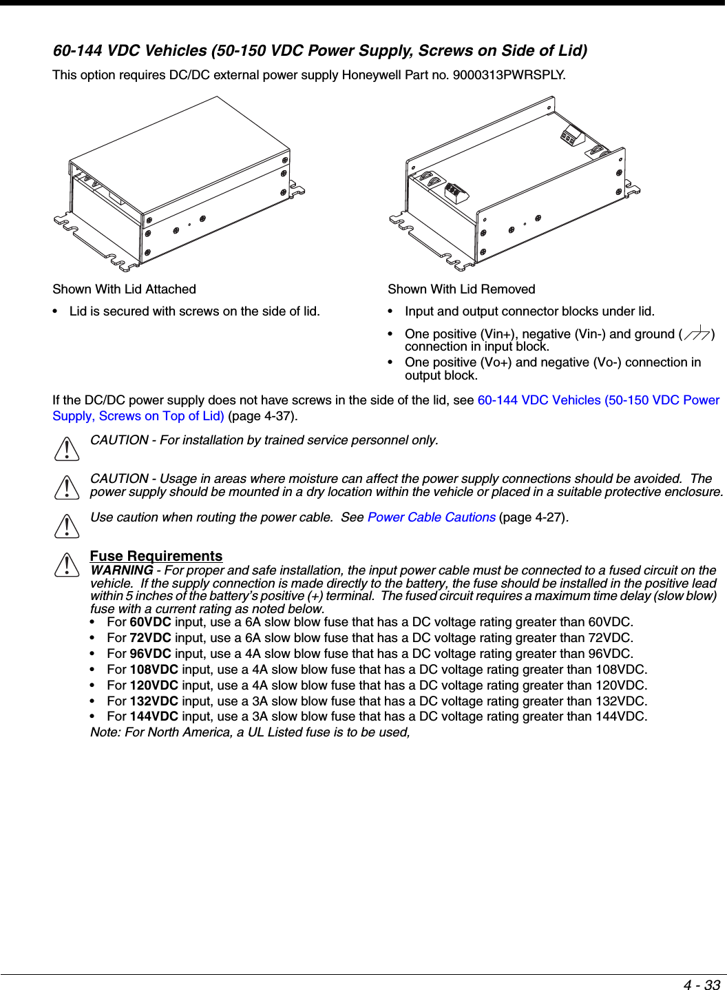
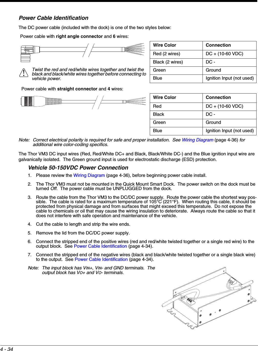
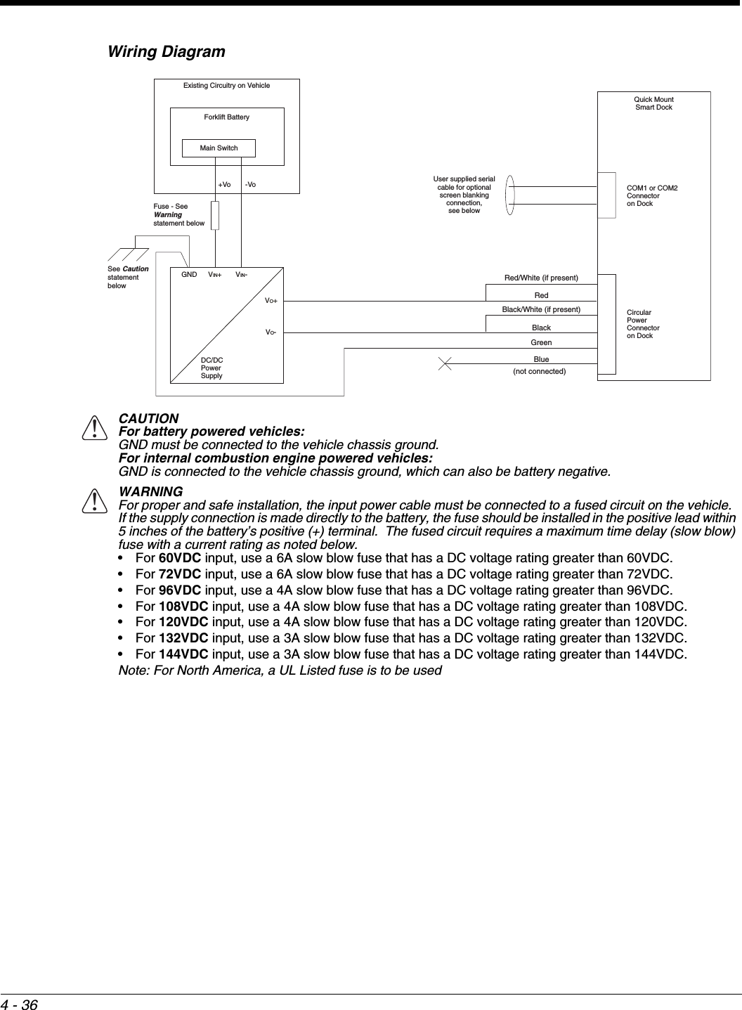
Honeywell VM3WWANA Vehicle Mount Computer User Manual VM3 W7 UG
Honeywell International Inc Vehicle Mount Computer VM3 W7 UG
UserManual.wiki
>
Honeywell
>
VM3WWANA User Manual
>
User manual_1
Contents
1.
User manual_1
2.
User manual_2
3.
User manua_1
4.
User manua_2
5.
Users Manual-1
6.
Users Manual-2
User manual_1
Navigation menu
Upload a User Manual
Namespaces
Wiki Guide
HTML
PDF
Info
Views
User Manual
Discussion / Help
Navigation


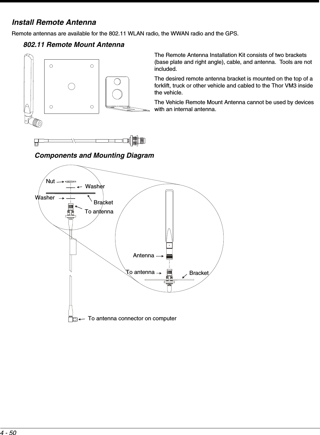
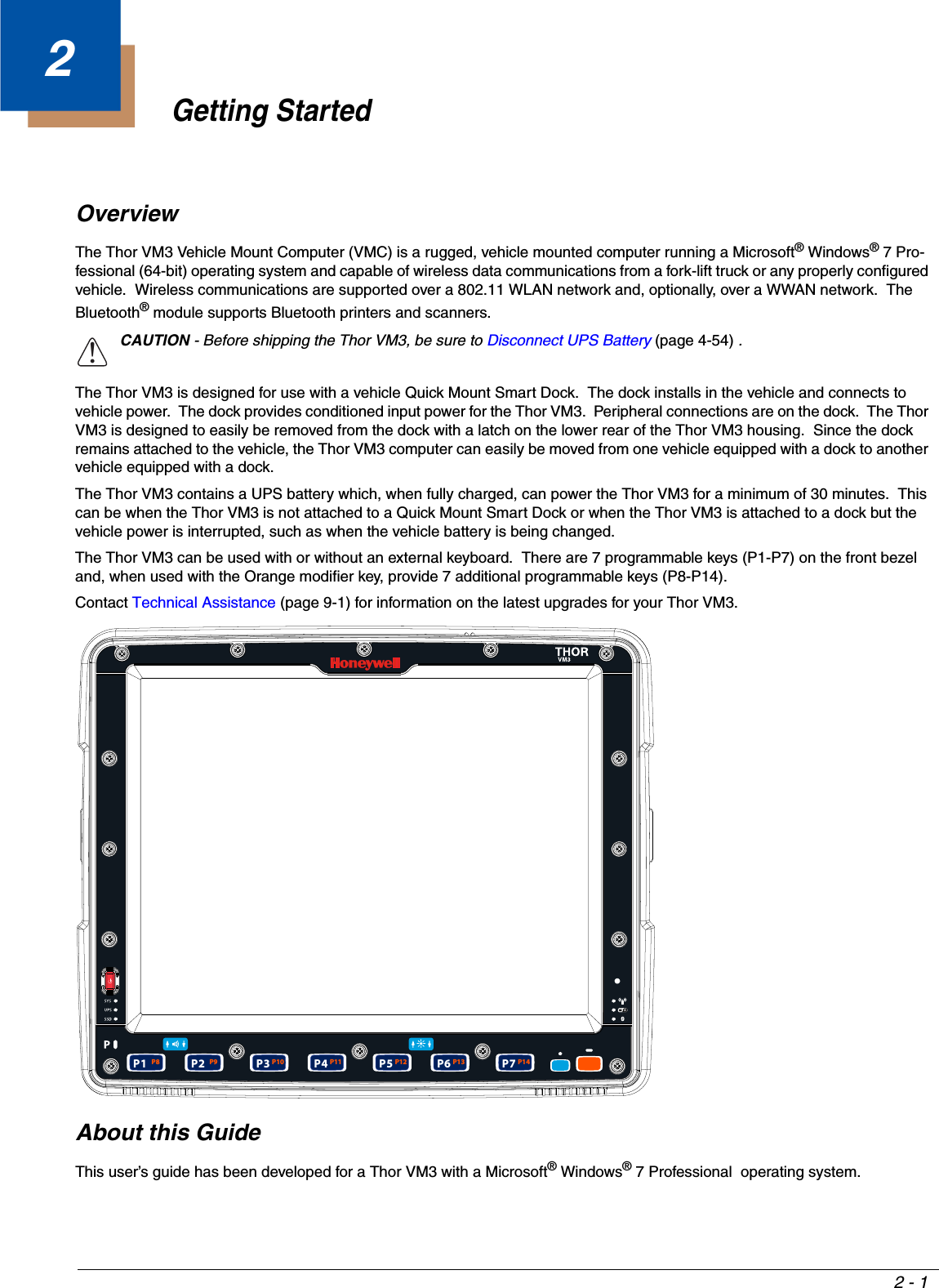
![1 - 11Thor VM3 Agency InformationThor VM3 mobile computers meet or exceed the requirements of all applicable standards organizations for safe operation. However as with any electrical equipment, the best way to ensure safe operation is to operate them according to the agency guidelines that follow. Read these guidelines before using your Thor VM3.This documentation is relevant for the following Thor models: VM3.FCC Part 15 StatementThis device complies with Part 15 of the FCC Rules [and with RSS-210 of Industry Canada]. Operation is subject to the follow-ing two conditions:1. This device may not cause harmful interference, and2. This device must accept any interference received, including interference that may cause undesired operation.NOTE - This equipment has been tested and found to comply with the limits for a Class B digital device, pursuant to Part 15 of the FCC Rules. These limits are designed to provide reasonable protection against harmful interference in a residential installa-tion. This equipment generates, uses and can radiate radio frequency energy and, if not installed and used in accordance with the instructions, may cause harmful interference to radio communications. However, there is no guarantee that interference will not occur in a particular installation. If this equipment does cause harmful interference to radio or television reception, which can be determined by turning the equipment off and on, the user is encouraged to try to correct the interference by one or more of the following measures:• Reorient or relocate the receiving antenna.• Increase the separation between the equipment and the receiver.• Connect the equipment into an outlet on a circuit different from that to which the receiver is connected.Consult the dealer or an experienced radio/TV technician for help.Caution - Changes or modifications made to this equipment not expressly approved by Honeywell may void the FCC authoriza-tion to operate this equipment.FCC 5GHz StatementFor the band 5600-5650 MHz, no operation is permitted.EMC Directive RequirementsThis is a Class B product. In a domestic environment this product may cause radio interference in which case the user may be required to take adequate measures. Canada, Industry Canada (IC) NoticesThis Class B digital apparatus complies with Canadian ICES-003 This device complies with Industry Canada licence-exempt RSS standard(s). Operation is subject to the following two condi-tions: (1) this device may not cause interference, and (2) this device must accept any interference, including interference that may cause undesired operation of the device.Exposure of humans to RF fields (RSS-102)The computers employ low gain integral antennas that do not emit RF field in excess of Health Canada limits for the general population; consult Safety Code 6, obtainable from Health Canada's Web site at http://www.hc-sc.gc.ca/The radiated energy from the antennas connected to the wireless adapters conforms to the IC limit of the RF exposure require-ment regarding IC RSS-102, Issue 4 clause 4.1.Cet appareil numérique de classe B est conforme à la norme NMB-003.High-power radar is allocated as the primary user of the 5.25- to 5.35-GHz and 5.65- to 5.85-GHz bands. These radar stations can cause interference with and/or damage to this device.!](https://usermanual.wiki/Honeywell/VM3WWANA.User-manual-1/User-Guide-2582426-Page-15.png)


![3 - 8Keyboard Options••Integrated KeypadThe integrated keypad contains seven programmable keys, a blue modifier key and an orange modifier key.The P1 though P7 keys are user programmable.• When used with no modifier key, P1 through P7 can be configured for a user programmable function.• When used with the Orange modifier key, P1 through P7 provide secondary programmable keys, P8 through P14, and can be configured for a user programmable function.• The programmable keys can be remapped to provide a single keypress, a string of keypresses or to execute an application or command. Key remapping is configured via the Programmable Key (page 5-41) option in the Control Panel.• Programmable keys persist across a warmboot or power cycle.• When used with the Blue modifier key, P1 and P2 keys are used to adjust speaker volume and P5 and P6 keys are used to adjust display brightness.The Thor VM3 integrated keypad is backlit.• By default, the integrated keypad backlight follows the display backlight. When the display backlight is on, the integrated keypad backlight is on.• If the display backlight brightness is increased (or decreased) the integrated keypad backlight brightness is increased (or decreased).The integrated keypad backlight and the display share the same timer, which is configured in the Power Options (page 5-6) control panel.• The integrated keypad backlight can be disabled via the Options (page 5-23) control panel.Keypad LEDsSee Keyboard LEDs (page 3-12) for details.95-Key USB KeyboardThe Thor VM3 uses an optional rugged QWERTY 95 key keyboard, designed for ease of use with the Windows CE operat-ing system. The USB keyboard connects directly to the D9 USB connector on the Thor VM3 Quick Mount Smart Dock.• The 95 key keyboard supports all 104 keyboard functions (101 standard keyboard plus Windows keys) and includes an integrated pointing device and left and right mouse buttons. However, because the keyboard only has 95 keys, all functions are not visible (or printed on the keyboard). Therefore the keyboard supports what is called hidden keys - keys that are accessible but not visible on the keyboard.• The 95 key keyboard keys are backlit. The keyboard backlight is manually controlled.Keyboard BacklightThe keyboard backlight key in the top right hand corner has a light bulb icon.P8P1 P14P7P13P6P12P5P11P4P10P3P9P2PrintScreenSysRqScrollLockPauseBreak67 BackSpace NumLockERTYUI OP]\[{}|7410HomeDF GHJ K L ;':"EnterAltCV BNM,<.>/?ShiftAlt CtrlInsEnd4$5%^&9(0)-_=+LRXEsc F3 F4 F5 F6 F7 F8 F9 F10 F11 F12F1 F2 Fn123 /*-Tab QW895623PgUpCapsLock ASShiftCtrlPgDn+`~!@#Enter.Del8*Z](https://usermanual.wiki/Honeywell/VM3WWANA.User-manual-1/User-Guide-2582426-Page-38.png)