Honeywell WFSLCDUI Wireless Display Driver User Manual SLC Gateway Firelite
Honeywell International Inc. Wireless Display Driver SLC Gateway Firelite
Exhibit D Users Manual per 2 1033 b3

FL
P/N LS10036-000FL-E:FLRev ECN FLECN
Document LS10036-000FL-E
10/10/FLite
Firelite Wireless Sensor Network
LS10036-000FL-E
User Manual
PRELIMINARY
2 PRELIMINARY: Firelite Wireless Sensor Network — P/N LS10036-000FL-E:N0 10/10/2013
Fire Alarm & Emergency Communication System Limitations
While a life safety system may lower insurance rates, it is not a substitute for life and property
insurance!
An automatic fire alarm system—typically made up of smoke
detectors, heat detectors, manual pull stations, audible warning
devices, and a fire alarm control panel (FACP) with remote notifi-
cation capability—can provide early warning of a developing fire.
Such a system, however, does not assure protection against
property damage or loss of life resulting from a fire.
An emergency communication system—typically made up of
an automatic fire alarm system (as described above) and a life
safety communication system that may include an autonomous
control unit (ACU), local operating console (LOC), voice commu-
nication, and other various interoperable communication meth-
ods—can broadcast a mass notification message. Such a
system, however, does not assure protection against property
damage or loss of life resulting from a fire or life safety event.
The Manufacturer recommends that smoke and/or heat
detectors be located throughout a protected premises following
the recommendations of the current edition of the National Fire
Protection Association Standard 72 (NFPA 72), manufacturer's
recommendations, State and local codes, and the
recommendations contained in the Guide for Proper Use of
System Smoke Detectors, which is made available at no charge
to all installing dealers. This document can be found at http://
www.systemsensor.com/appguides/. A study by the Federal
Emergency Management Agency (an agency of the United
States government) indicated that smoke detectors may not go
off in as many as 35% of all fires. While fire alarm systems are
designed to provide early warning against fire, they do not
guarantee warning or protection against fire. A fire alarm system
may not provide timely or adequate warning, or simply may not
function, for a variety of reasons:
Smoke detectors may not sense fire where smoke cannot
reach the detectors such as in chimneys, in or behind walls, on
roofs, or on the other side of closed doors. Smoke detectors
also may not sense a fire on another level or floor of a building.
A second-floor detector, for example, may not sense a first-floor
or basement fire.
Particles of combustion or “smoke” from a developing fire
may not reach the sensing chambers of smoke detectors
because:
• Barriers such as closed or partially closed doors, walls, chim-
neys, even wet or humid areas may inhibit particle or smoke
flow.
• Smoke particles may become “cold,” stratify, and not reach
the ceiling or upper walls where detectors are located.
• Smoke particles may be blown away from detectors by air
outlets, such as air conditioning vents.
• Smoke particles may be drawn into air returns before reach-
ing the detector.
The amount of “smoke” present may be insufficient to alarm
smoke detectors. Smoke detectors are designed to alarm at var-
ious levels of smoke density. If such density levels are not cre-
ated by a developing fire at the location of detectors, the
detectors will not go into alarm.
Smoke detectors, even when working properly, have sensing
limitations. Detectors that have photoelectronic sensing cham-
bers tend to detect smoldering fires better than flaming fires,
which have little visible smoke. Detectors that have ionizing-type
sensing chambers tend to detect fast-flaming fires better than
smoldering fires. Because fires develop in different ways and
are often unpredictable in their growth, neither type of detector is
necessarily best and a given type of detector may not provide
adequate warning of a fire.
Smoke detectors cannot be expected to provide adequate warn-
ing of fires caused by arson, children playing with matches
(especially in bedrooms), smoking in bed, and violent explosions
(caused by escaping gas, improper storage of flammable materi-
als, etc.).
Heat detectors do not sense particles of combustion and alarm
only when heat on their sensors increases at a predetermined
rate or reaches a predetermined level. Rate-of-rise heat detec-
tors may be subject to reduced sensitivity over time. For this
reason, the rate-of-rise feature of each detector should be tested
at least once per year by a qualified fire protection specialist.
Heat detectors are designed to protect property, not life.
IMPORTANT! Smoke detectors must be installed in the same
room as the control panel and in rooms used by the system for
the connection of alarm transmission wiring, communications,
signaling, and/or power. If detectors are not so located, a devel-
oping fire may damage the alarm system, compromising its abil-
ity to report a fire.
Audible warning devices such as bells, horns, strobes,
speakers and displays may not alert people if these devices
are located on the other side of closed or partly open doors or
are located on another floor of a building. Any warning device
may fail to alert people with a disability or those who have
recently consumed drugs, alcohol, or medication. Please note
that:
• An emergency communication system may take priority over
a fire alarm system in the event of a life safety emergency.
• Voice messaging systems must be designed to meet intelligi-
bility requirements as defined by NFPA, local codes, and
Authorities Having Jurisdiction (AHJ).
• Language and instructional requirements must be clearly dis-
seminated on any local displays.
• Strobes can, under certain circumstances, cause seizures in
people with conditions such as epilepsy.
• Studies have shown that certain people, even when they hear
a fire alarm signal, do not respond to or comprehend the
meaning of the signal. Audible devices, such as horns and
bells, can have different tonal patterns and frequencies. It is
the property owner's responsibility to conduct fire drills and
other training exercises to make people aware of fire alarm
signals and instruct them on the proper reaction to alarm sig-
nals.
• In rare instances, the sounding of a warning device can cause
temporary or permanent hearing loss.
A life safety system will not operate without any electrical
power. If AC power fails, the system will operate from standby
batteries only for a specified time and only if the batteries have
been properly maintained and replaced regularly.
Equipment used in the system may not be technically compat-
ible with the control panel. It is essential to use only equipment
listed for service with your control panel.
Telephone lines needed to transmit alarm signals from a prem-
ises to a central monitoring station may be out of service or tem-
porarily disabled. For added protection against telephone line
failure, backup radio transmission systems are recommended.
The most common cause of life safety system malfunction is
inadequate maintenance. To keep the entire life safety system in
excellent working order, ongoing maintenance is required per the
manufacturer's recommendations, and UL and NFPA stan-
dards. At a minimum, the requirements of NFPA 72 shall be fol-
lowed. Environments with large amounts of dust, dirt, or high air
velocity require more frequent maintenance. A maintenance
agreement should be arranged through the local manufacturer's
representative. Maintenance should be scheduled monthly or as
required by National and/or local fire codes and should be per-
formed by authorized professional life saftety system installers
only. Adequate written records of all inspections should be kept.
Limit-D-1-2013
PRELIMINARY: Firelite Wireless Sensor Network — P/N LS10036-000FL-E:N0 10/10/2013 3
Installation Precautions
Adherence to the following will aid in problem-free installation with long-term reliability:
WARNING - Several different sources of power can be
connected to the fire alarm control panel. Disconnect all
sources of power before servicing. Control unit and associ-
ated equipment may be damaged by removing and/or insert-
ing cards, modules, or interconnecting cables while the unit is
energized. Do not attempt to install, service, or operate this
unit until manuals are read and understood.
CAUTION - System Re-acceptance Test after Software
Changes: To ensure proper system operation, this product
must be tested in accordance with NFPA 72 after any pro-
gramming operation or change in site-specific software. Re-
acceptance testing is required after any change, addition or
deletion of system components, or after any modification,
repair or adjustment to system hardware or wiring. All compo-
nents, circuits, system operations, or software functions known
to be affected by a change must be 100% tested. In addition,
to ensure that other operations are not inadvertently affected,
at least 10% of initiating devices that are not directly affected
by the change, up to a maximum of 50 devices, must also be
tested and proper system operation verified.
This system meets NFPA requirements for operation at 0-49º
C/32-120º F and at a relative humidity 93% ± 2% RH (non-
condensing) at 32°C ± 2°C (90°F ± 3°F). However, the useful
life of the system's standby batteries and the electronic com-
ponents may be adversely affected by extreme temperature
ranges and humidity. Therefore, it is recommended that this
system and its peripherals be installed in an environment with
a normal room temperature of 15-27º C/60-80º F.
Verify that wire sizes are adequate for all initiating and indi-
cating device loops. Most devices cannot tolerate more than a
10% I.R. drop from the specified device voltage.
Like all solid state electronic devices, this system may
operate erratically or can be damaged when subjected to light-
ning induced transients. Although no system is completely
immune from lightning transients and interference, proper
grounding will reduce susceptibility. Overhead or outside aerial
wiring is not recommended, due to an increased susceptibility
to nearby lightning strikes. Consult with the Technical Ser-
vices Department if any problems are anticipated or encoun-
tered.
Disconnect AC power and batteries prior to removing or
inserting circuit boards. Failure to do so can damage circuits.
Remove all electronic assemblies prior to any drilling, filing,
reaming, or punching of the enclosure. When possible, make
all cable entries from the sides or rear. Before making modifi-
cations, verify that they will not interfere with battery, trans-
former, or printed circuit board location.
Do not tighten screw terminals more than 9 in-lbs. Over-
tightening may damage threads, resulting in reduced terminal
contact pressure and difficulty with screw terminal removal.
This system contains static-sensitive components.
Always ground yourself with a proper wrist strap before han-
dling any circuits so that static charges are removed from the
body. Use static suppressive packaging to protect electronic
assemblies removed from the unit.
Follow the instructions in the installation, operating, and pro-
gramming manuals. These instructions must be followed to
avoid damage to the control panel and associated equipment.
FACP operation and reliability depend upon proper installation.
Precau-D1-9-2005
HARSH™, NIS™, and NOTI•FIRE•NET™ are all trademarks; and Acclimate® Plus, FlashScan®, NION®, NOTIFIER®, ONYX®, ONYXWorks®, UniNet®,
VeriFire®, and VIEW® are all registered trademarks of Honeywell International Inc.HARSH™ is a trademark; and Acclimate®, FlashScan®, NION®, and
VIEW® are all registered trademarks of Honeywell International Inc. MULTI-NET™, Multi-Net Manager™, Unimode Network™, Unimode Network
Manager™, and Uni-Tility™ are trademarks of Tyco Integrated Security. Echelon® is a registered trademark and LonWorks™ is a trademark of Echelon
Corporation. ARCNET® is a registered trademark of Datapoint Corporation. Microsoft® and Windows® are registered trademarks of the Microsoft
Corporation.
©2013 by Honeywell International Inc. All rights reserved. Unauthorized use of this document is strictly prohibited.
4 PRELIMINARY: Firelite Wireless Sensor Network — P/N LS10036-000FL-E:N0 10/10/2013
Software Downloads
In order to supply the latest features and functionality in fire alarm and life safety technology to our customers, we make
frequent upgrades to the embedded software in our products. To ensure that you are installing and programming the latest
features, we strongly recommend that you download the most current version of software for each product prior to
commissioning any system. Contact Technical Support with any questions about software and the appropriate version for a
specific application.
Documentation Feedback
Your feedback helps us keep our documentation up-to-date and accurate. If you have any comments or suggestions about our
online Help or printed manuals, you can email us.
Please include the following information:
•Product name and version number (if applicable)
•Printed manual or online Help
•Topic Title (for online Help)
•Page number (for printed manual)
•Brief description of content you think should be improved or corrected
•Your suggestion for how to correct/improve documentation
Send email messages to:
FireSystems.TechPubs@honeywell.com
Please note this email address is for documentation feedback only. If you have any technical issues, please contact Technical
Services.
PRELIMINARY: Firelite Wireless Sensor Network P/N LS10036-000FL-E:N0 10/10/2013 5
Table of Contents
Section 1: About This Guide..................................................................................................10
1.1: Purpose ........................................................................................................................................................10
1.2: Assumed Knowledge...................................................................................................................................10
1.2.1: Additional References .......................................................................................................................10
1.3: Site Survey...................................................................................................................................................10
1.4: Abbreviations and Meanings.......................................................................................................................11
Section 2: W-GATE .................................................................................................................12
2.1: Description...................................................................................................................................................12
2.2: Agency Approvals .......................................................................................................................................12
2.2.1: FCC....................................................................................................................................................12
2.3: Specifications...............................................................................................................................................13
2.3.1: Environmental Specification .............................................................................................................13
2.4: Installing W-GATE ......................................................................................................................................13
2.4.1: Before Installing ................................................................................................................................13
2.5: Mounting & Wiring .....................................................................................................................................14
2.5.1: Mounting ...........................................................................................................................................14
2.5.2: Wiring................................................................................................................................................16
2.5.3: W-GATE Powered from SLC ...........................................................................................................17
2.5.4: W-GATE Powered from an External +24VDC source .....................................................................18
2.6: Configuration and Programming.................................................................................................................19
2.6.1: Without a PC-based Configuration Tool...........................................................................................19
Create a New Profile ............................................................................................................................19
Assign a Previously Created Profile Using a Distributor.....................................................................20
Removing a Profile...............................................................................................................................20
Create Mesh Network...........................................................................................................................20
2.6.2: With a PC-based Configuration Tool................................................................................................21
Assign Profile with PC Tools...............................................................................................................21
Removing Profile with PC Tools .........................................................................................................22
Mesh Formation with PC Tools ...........................................................................................................23
2.6.3: Profile Distribution............................................................................................................................23
2.6.4: SLC Configuration ............................................................................................................................24
2.7: Operations....................................................................................................................................................25
2.7.1: W-GATE Modes of Operation ..........................................................................................................25
Start Up.................................................................................................................................................25
Factory Default.....................................................................................................................................25
Profile Configured................................................................................................................................25
Mesh Formation....................................................................................................................................26
Initial Mesh Optimization.....................................................................................................................26
Normal Mode........................................................................................................................................26
Rescue Mode ........................................................................................................................................26
Mesh Optimization...............................................................................................................................27
Bootloader ............................................................................................................................................27
2.7.2: Magnet Sensor Activations................................................................................................................27
Profile Magnetic Sensor .......................................................................................................................27
Mesh Formation Magnetic Sensor........................................................................................................27
2.7.3: LED Indications.................................................................................................................................27
2.7.4: Lock/Unlock W-GATE .....................................................................................................................31
Lock/Unlock W-GATE through PC tools............................................................................................31
Password Reset.....................................................................................................................................31
2.7.5: Weak Link Trouble Reporting...........................................................................................................32
Disabling Trouble Reporting at the W-GATE Using PC Tools...........................................................32
2.7.6: Collapse Network Command.............................................................................................................33
Collapsing Mesh Network Using PC Tools .........................................................................................33

Table of Contents
6 PRELIMINARY: Firelite Wireless Sensor Network P/N LS10036-000FL-E:N0 10/10/2013
2.7.7: Silence Network Command...............................................................................................................34
Silencing Mesh Network Using PC Tools............................................................................................34
2.7.8: Multiple Wireless Sensor Network Installation Restrictions.............................................................35
2.7.9: Avoiding RF Interference..................................................................................................................35
Section 3: Wireless Display Driver (W-DIS-D)......................................................................36
3.1: Description...................................................................................................................................................36
3.2: Agency Approvals ......................................................................................................................................37
3.2.1: FCC....................................................................................................................................................37
3.3: Specifications...............................................................................................................................................37
W-DIS-D...............................................................................................................................................37
ANN-80 ................................................................................................................................................38
3.3.1: Environmental Specification .............................................................................................................38
3.4: Features........................................................................................................................................................38
W-DIS-D...............................................................................................................................................38
Listed to UL standard ANSI/UL 864 edition. ......................................................................................38
ANN-80 ................................................................................................................................................38
3.5: Mounting & Wiring......................................................................................................................................39
3.5.1: Mounting W-DIS-D...........................................................................................................................39
3.5.2: Wiring................................................................................................................................................41
3.5.3: ANN-80 .............................................................................................................................................41
Mounting ..............................................................................................................................................41
Wiring ..................................................................................................................................................41
3.6: W-DIS-D Configuration...............................................................................................................................42
3.6.1: Assigning Profiles..............................................................................................................................42
Assign Profile with PC Tools ...............................................................................................................42
Assigning a Profile to a W-DIS-D with W-GATE or Distributor........................................................43
3.6.2: Mesh Formation.................................................................................................................................43
3.6.3: Removing Profiles .............................................................................................................................44
Restoring a W-DIS-D to Factory Default Without Using the PC-based Configuration Tool..............44
Restoring a W-DIS-D to Factory Default with the PC-based Configuration Tool...............................44
3.7: ANN-80 Configuration................................................................................................................................45
3.8: W-DIS-D Operations ...................................................................................................................................46
3.8.1: W-DIS-D Operations.........................................................................................................................46
Modes of Operation Not in a Mesh Network .......................................................................................46
Modes of Operation as a Mesh Participant...........................................................................................47
SLC Operation......................................................................................................................................47
3.8.2: W-DIS-D LED Indications................................................................................................................47
3.8.3: Switches.............................................................................................................................................51
3.9: ANN-80 Operations.....................................................................................................................................52
3.9.1: Buttons and Switches.........................................................................................................................52
3.9.2: Visual Indicators................................................................................................................................53
3.9.3: Audible Indicators .............................................................................................................................54
3.9.4: Event Messaging................................................................................................................................54
LCD UI Not in Network.......................................................................................................................54
Mesh Formation In Progress.................................................................................................................54
Low Battery Event................................................................................................................................55
Trouble Jamming Event........................................................................................................................55
Duplicate Address.................................................................................................................................55
Degraded Connection ...........................................................................................................................56
System Initialization.............................................................................................................................56
System Normal .....................................................................................................................................56
Tamper Event........................................................................................................................................56
Weak Link ............................................................................................................................................57
Key Bus Trouble...................................................................................................................................57
Capacity Exceeded................................................................................................................................57
Maximum Gateways.............................................................................................................................57

Table of Contents
PRELIMINARY: Firelite Wireless Sensor Network P/N LS10036-000FL-E:N0 10/10/2013 7
3.9.5: Clearing messages .............................................................................................................................57
3.9.6: LED Indications.................................................................................................................................58
Section 4: Devices..................................................................................................................60
4.1: Description...................................................................................................................................................60
Subsystem Overview............................................................................................................................60
4.2: Agency Approvals ......................................................................................................................................60
4.2.1: FCC....................................................................................................................................................60
4.3: Specifications...............................................................................................................................................61
4.4: Installing Devices ........................................................................................................................................61
4.5: Mounting & Wiring .....................................................................................................................................61
4.6: Configuration and Programming.................................................................................................................61
4.6.1: Assigning Profiles .............................................................................................................................62
Assigning Profile Using PC Tools .......................................................................................................62
Assigning a Profile to a Detector with a W-GATE or Distributor.......................................................63
4.6.2: Distributor Mode ...............................................................................................................................64
Converting a Device into a Distributor ................................................................................................64
Converting a Distributor Back into a Device .......................................................................................65
4.6.3: Mesh Formation.................................................................................................................................65
4.6.4: Restoring a Device to Factory Default..............................................................................................65
Removing Profiles Without PC-based Configuration Tool..................................................................65
Removing a Profile with PC Tools.......................................................................................................66
4.7: Device Operations .......................................................................................................................................66
4.7.1: Modes of Operation...........................................................................................................................66
Factory Default.....................................................................................................................................66
Profile Assigned ...................................................................................................................................66
Bootloader ............................................................................................................................................67
Distributor.............................................................................................................................................67
Mesh Participant...................................................................................................................................67
4.7.2: LED Indications.................................................................................................................................67
Section 5: USB Adapter..........................................................................................................72
5.1: Introduction..................................................................................................................................................72
5.2: Agency Approvals ......................................................................................................................................72
5.2.1: FCC....................................................................................................................................................72
5.3: Specifications...............................................................................................................................................73
5.3.1: Electrical Specifications...................................................................................................................73
5.3.2: Serial Communication Specification................................................................................................73
5.3.3: Mechanical Specifications................................................................................................................73
5.3.4: Environmental Specifications............................................................................................................73
5.4: Driver Installation........................................................................................................................................74
Appendix A: Site Survey ........................................................................................................78
A.1: Description..................................................................................................................................................78
A.1.1: Conducting Site Survey at the Job Site ............................................................................................78
Link Quality Test..................................................................................................................................78
Results of Link Test..............................................................................................................................79
Link Quality Test and RF Scan Test ....................................................................................................80
Conduct a Link Test .............................................................................................................................80
Results of Link Test..............................................................................................................................81
Results of RF Scan Test .......................................................................................................................81
Appendix B: PC tools .............................................................................................................82
B.1: Description..................................................................................................................................................82
B.1.1: Launching PC Tools .........................................................................................................................82
B.1.2: Creating Jobsite.................................................................................................................................83
B.1.3: Opening Jobsite.................................................................................................................................84

Table of Contents
8 PRELIMINARY: Firelite Wireless Sensor Network P/N LS10036-000FL-E:N0 10/10/2013
Appendix C: Troubleshooting and Testing..........................................................................86
C.1: Troubleshooting...........................................................................................................................................86
C.2: Testing W-GATE and Devices ....................................................................................................................86
C.2.1: Testing LED Indications...................................................................................................................86
C.3: Testing Wireless Network ...........................................................................................................................86
C.3.1: Network Topology............................................................................................................................87
Parent-Child Devices............................................................................................................................87
Orphan Devices ....................................................................................................................................87
Class A Compliance .............................................................................................................................87
C.3.2: History Events...................................................................................................................................88
C.3.3: Network Snapshots ...........................................................................................................................88
C.3.4: Network Statistics .............................................................................................................................88
C.3.5: Device Attributes ..............................................................................................................................88
Index ........................................................................................................................................ 90

Table of Contents
PRELIMINARY: Firelite Wireless Sensor Network P/N LS10036-000FL-E:N0 10/10/2013 9

10 PRELIMINARY: Firelite Wireless Sensor Network — P/N LS10036-000FL-E:N0 10/09/2013
About This Guide Purpose
Section 1: About This Guide
1.1 Purpose
The Firelite Wireless Sensor Network user’s manual provides an overview of the following:
• Wireless fire alarm system
• Instructions for installing and configuring the wireless devices
• Information on monitoring the status of the wireless devices
• Removal and replacement procedures of the W-GATE and W-DIS-D
• Testing, maintenance and firmware upgrade information of the W-GATE and W-DIS-D.
1.2 Assumed Knowledge
The document is created with the assumption that all users are familiar with working on a PC and
laptop for configuration purposes. Installers should be familiar with the Fire Alarm and Related
Service Standards.
The terminology and level of details of this document reflect this assumption.
1.2.1 Additional References
1.3 Site Survey
A site survey is recommended to assess and qualify the site prior to installing the Wireless Fire
Alarm system. The site survey utility allows you to perform the Link quality test and radio fre-
quency (RF) assessment of the site. This information is used for site qualification, maximum device
spacing identification, and configuring the network. This helps to optimize the reliability and per-
formance of the wireless network in the wireless fire alarm system. Conduct a site survey, and
ensure there are no obstructions for using RF communications. For more information on a site sur-
vey, refer to Appendix A:, "Site Survey".
Model Description Manual
W-SD355 Wireless LiteSpeed
Detector, Photo
W-SD355 and W-SD355T Intelligent Wireless
Photoelectric Smoke Sensors.
Manual part number for the above devices- I56-
4081-000
W-SD355T Wireless LiteSpeed
Detector, Photo/Heat
W-H355R Wireless LiteSpeed Heat
sensorHeat, Rate Of Rise
135
W-H355R and W-H355 and Intelligent Wireless
Temperature Sensors.
Manual part number for the above devices- I56-
4082-000
W-H355 Wireless LiteSpeed Heat
sensor Heat, Fixed
Temp135
W-MMF Monitor Module W-MMF Wireless Monitor Module. Manual Part
number - I56-4083-000

PRELIMINARY: Firelite Wireless Sensor Network — P/N LS10036-000FL-E:N0 10/09/2013 11
Abbreviations and Meanings About This Guide
1.4 Abbreviations and Meanings
The following table lists the abbreviations and their definitions used in this manual.
Abbreviation Definition
AHJ Authority Having Jurisdiction
ANSI American National Standards Institute
dBm Milli Decibel
FACP Fire Alarm control Panel
FCC Federal Communications Commission
ISM Industrial, Scientific and Medical Radio
Bands.
LCD Liquid Crystal Display
LED Light Emitting Diode
mA Milliampere
MHz Megahertz
NFPA National Fire Protection Association
PC Personal Computer
RF Radio Frequency
SLC Signaling Line Circuit
UI User Interface
UL Underwriters Labaratories
W-DIS-D Wireless Display Driver
W-GATE Wireless Gateway
12 PRELIMINARY: Firelite Wireless Sensor Network P/N LS10036-000FL-E:N0 10/10/2013
W-GATE Description
Section 2: W-GATE
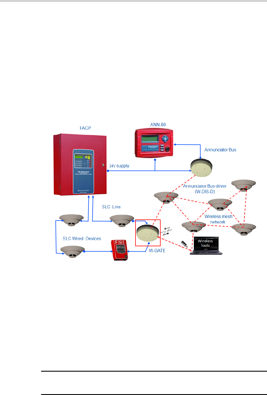
2.1 Description
The W-GATE is a device in a wireless fire system that acts as a bridge between fire alarm control
panels and wireless fire devices. All wireless fire devices communicate with the W-GATE over the
wireless network formed by the devices and the W-GATE.
The Wireless Sensor Network includes a W-DIS-D (Wireless Display Driver). The W-DIS-D and
ANN-80 are required for the display of wireless specific events. W-DIS-D and ANN-80 are
explained in detail in Chapter 3.
The W-GATE is powered by either the SLC loop or from any external 24VDC UL listed power
supply. The W-GATE uses LiteSpeed protocol on the SLC to communicate with the panel and a
proprietary wireless protocol to communicate with wireless fire devices. The following graphic is
an illustration of the components of the Firelite Wireless Sensor Network.
Figure 2.1 Firelite Wireless Sensor Network
2.2 Agency Approvals
2.2.1 FCC
This device complies with part 15 of the FCC Rules. Operation is subject to the following two con-
ditions:
1. This device may not cause harmful interference, and
2. This device must accept any interference received, including interference that may cause
undesired operation.
FCC ID PV3WFSGW
WARNING: CHANGES OR MODIFICATIONS NOT EXPRESSLY APPROVED BY THE
MANUFACTURER COULD VOID THE USER’S AUTHORITY TO OPERATE THE EQUIPMENT.

PRELIMINARY: Firelite Wireless Sensor Network P/N LS10036-000FL-E:N0 10/10/2013 13
Specifications W-GATE
2.3 Specifications
Following are the specifications of the W-GATE.
NOTE: Devices that do not meet the minimum signal strength or have an ambient noise level
that exceeds the limit are not allowed to join the mesh network.
2.3.1 Environmental Specification
2.4 Installing W-GATE
2.4.1 Before Installing
Choose a location for the W-GATE that is clean, dry, and vibration-free. The area should be readily
accessible with sufficient room to easily install and maintain the W-GATE. Metal obstructions
impede the radio frequency communication and should be avoided. Carefully unpack the system
and inspect for shipping damage if any. All wiring must comply with the national and local codes
for fire alarm systems.
Specifications Data
External Supply Electrical Ratings 18V-30V
SLC Electrical Ratings 15V-30V
Maximum current when using the external supply 40mA
Maximum current when using the SLC power supply 24mA
Maximum SLC Resistance 50 Ohms
Minimum signal strength level needed at the receiver for a
primary path with weak link trouble reporting enabled.
-50dBm
Minimum signal strength level needed at the receiver for a
secondary path or primary path with weak link trouble
reporting disabled.
Must be 15 dBm higher than the noise
floor down to a minimum of -87dBm*
Maximum ambient noise level -90dBm*
Maximum RF Power Output +17dBm (Tx power level without
antenna)
Radio Frequency Lower ISM Band (915MHz).
System Operating
Temperature Storage
Temperature Humidity
W-GATE 0°C-49°C / 32°F-120°F -10°C- 60°C / 14°F-140°F 10 to 93% RH
Non-
condensing
14 PRELIMINARY: Firelite Wireless Sensor Network P/N LS10036-000FL-E:N0 10/10/2013
W-GATE Mounting & Wiring
2.5 Mounting & Wiring
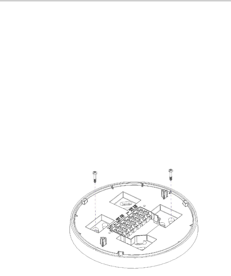
2.5.1 Mounting
The W-GATE has two major pieces, the cover and the mounting plate. The mounting plate is
mounted to the wall or ceiling, and field wiring is connected to it. The cover contains the PC board
and is fastened to the mounting plate once the wiring is connected.
Mount the mounting plate directly to an electrical box on the ceiling or wall. The plate mounts
directly to 4˝ square (with and without plaster ring), 4˝ octagon, 3 1/2˝octagon, single gang or dou-
ble gang junction boxes. If an electrical box is not available, the mounting plate can be mounted to
any flat surface and the wiring can be connected via the knockout points in the mounting plate.
To mount the W-GATE, do the following:
1. Pull the wiring through the opening in the mounting plate.
2. Mount the mounting plate to the junction box or ceiling. See figure 2.2.
3. Connect field wiring to the terminals, as described in section 2.5.2, "Wiring".
4. Connect necessary jumpers where applicable, as described in section 2.5.3, "W-GATE
Powered from SLC".
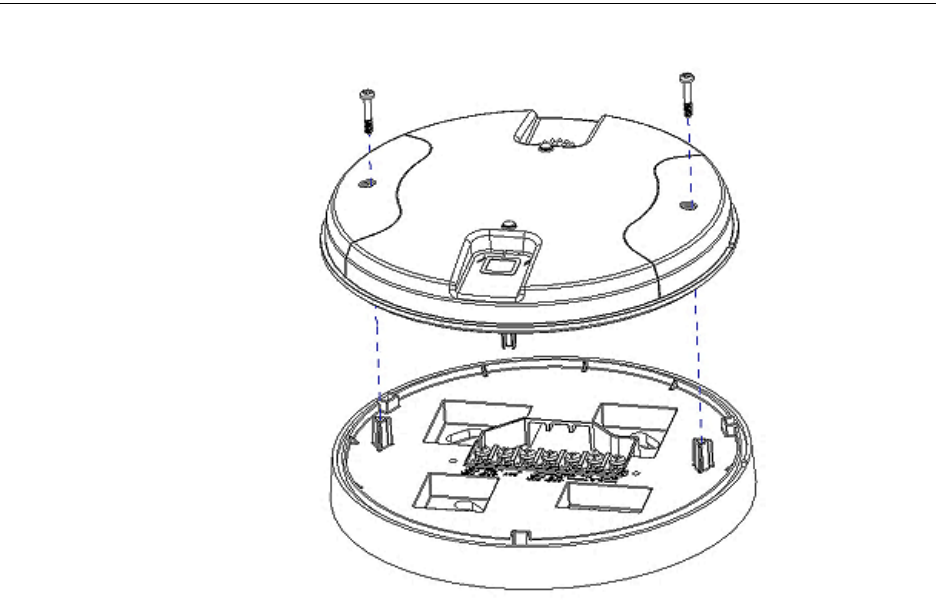
5. To mount the cover, align the locating pins on the cover to the corresponding slots in the
mounting plate. See Figure 2.3, "Cover Attaching to Mounting Plate".
6. Secure the cover by tightening the mounting screws.
Figure 2.2 Mounting Plate
PRELIMINARY: Firelite Wireless Sensor Network P/N LS10036-000FL-E:N0 10/10/2013 15
Mounting & Wiring W-GATE
Figure 2.3 Cover Attaching to Mounting Plate
16 PRELIMINARY: Firelite Wireless Sensor Network P/N LS10036-000FL-E:N0 10/10/2013
W-GATE Mounting & Wiring
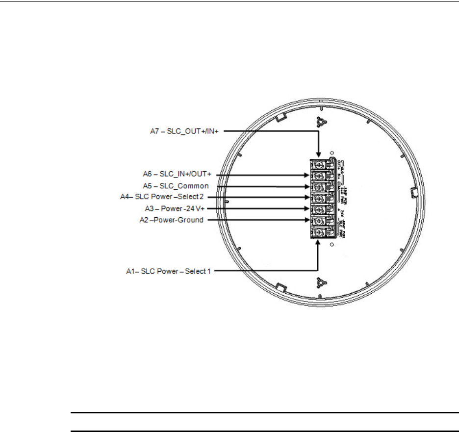
2.5.2 Wiring
• All wiring must be installed in compliance with the National Electrical Code and the local
codes having jurisdiction.
• 12-18 AWG is recommended.
Figure 2.4 (Wiring diagram with terminal descriptions)
For wiring connections, follow this procedure:
• Strip about 3/8” of insulation from the end of the wire.
• Then, to make the wire connection, slide the bare end of the wire under the appropriate
clamping plate, and tighten the clamping plate screw.
NOTE: Do not loop the wire under the clamping plate.
PRELIMINARY: Firelite Wireless Sensor Network P/N LS10036-000FL-E:N0 10/10/2013 17
Mounting & Wiring W-GATE
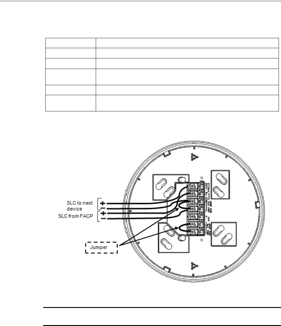
2.5.3 W-GATE Powered from SLC
To power the W-GATE using the signal line circuit, connect it as described in table 2.1 below:
Figure 2.5 Wiring Connections (W-GATE powered from SLC)
NOTE: It is recommended to use the same wire gauge if there are multiple connections to the
same terminal.
The W-GATE provides isolation of short circuits on the SLC in class A installations, that use the
A6 and A7 connections as an in and out connection. A5 is common for SLC wiring that enters and
leaves. Class B wiring that terminates at the W-GATE can use either the A6 or A7 connection for
the SLC positive. SLC connections are power limited by the panel. An interruption in the SLC that
causes a loss of power at the W-GATE for more than 100ms may result in a trouble condition and
loss of fire protection provided by the wireless devices for up to 15 minutes. Using an external 24V
power source (not SLC power) is recommended for installations that require fire protection in the
presence of short circuits, including class A applications and applications that utilize isolator mod-
ules.
Terminal Pins Description
A5 & A7 SLC Common & SLC Output/Input
A5& A6 SLC Common & SLC Input/Output
A4 & A5 Jumper selection to enable power from the SLC supply (Insert Jumper when using
SLC power)
A3 Unused
A1 & A2 Jumper selection to disable power from the external supply. (Insert Jumper when
using SLC power)
Table 2.1
18 PRELIMINARY: Firelite Wireless Sensor Network P/N LS10036-000FL-E:N0 10/10/2013
W-GATE Mounting & Wiring
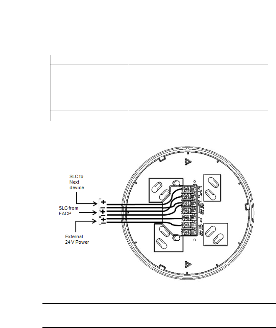
2.5.4 W-GATE Powered from an External +24VDC source
To power the W-GATE using a +24VDC source, connect the W-GATE as described in table 2.2
below.
Figure 2.6 Wiring Connections -W-GATE Powered from an External +24VDC source
NOTE: Terminal A5 is referenced more than once in the above connections. It is recommended
to use wire of the same gauge for all connections to A5 and use the same wire gauge if there are
multiple connections to the same terminal.
The W-GATE provides isolation of short circuits of the SLC in class A installations that use the A6
and A7 as an in and out connection. A5 is common for in and out SLC wiring. Class B SLC wiring
that terminates at the W-GATE can use either the A6 or A7 connection for the SLC positive. SLC
connections are power limited by the panel. 24VDC must be power limited by the source.
Terminal Pins Devices Powered
A5 & A7 SLC Input/output
A5 & A6 SLC Input/output
A4 Unused
A2 & A3 +24VDC input. Voltage range from 18VDC to 30VDC. Use only
power limited device circuits.
A1 Unused
Table 2.2
PRELIMINARY: Firelite Wireless Sensor Network P/N LS10036-000FL-E:N0 10/10/2013 19
Configuration and Programming W-GATE
2.6 Configuration and Programming
The goal of configuring and/or programming the W-GATE is to:
1. Create a profile - A profile is a set of parameters that binds together a W-GATE and the devices
in a mesh network.
2. Distribute the profile to every device that will be a part of the mesh.
3. Form the mesh - The mesh cannot be formed until the profile is assigned to the W-GATE. The
profile contains a mesh ID and, if required, a password, that are used when forming the
associations. Creating and distributing the profile will enable all the devices that have that
profile to form associative links when the mesh is formed. All devices, including the W-GATE,
require a common profile.
This section shows how to configure/program an W-GATE with a profile, how to distribute that
profile to other devices, and how to form all these devices into a mesh. These processes may be per-
formed with or without using PC-based configuration tool.
2.6.1 Without a PC-based Configuration Tool
This section shows the configuration of the W-GATE using only a magnet and a screw driver. For
configuration instructions using the PC-based configuration tool, refer to 2.6.2, "With a PC-based
Configuration Tool".
There are two ways to provide a W-GATE with a profile without using a configuration tool.
• Create a new profile using the W-GATE
• Assign a previously created profile to the W-GATE using a distributor.
Create a New Profile
To create a unique profile in the W-GATE without using the PC-based configuration tool, perform
the following steps.
1. Start with the device powered off. The process is performed during the start-up.
2. Power on the W-GATE using SLC power or external +24V. This can be done either by
attaching the W-GATE to its mounting plate with the terminals already energized, or by
connecting the SLC or external source wiring to a W-GATE that is already installed in its
mounting plate.
3. Verify if the W-GATE is in the factory default state; if it is in the factory default state, both the
LEDs on the W-GATE flash red (double blink) every second for ten seconds. If the LEDs are
yellow, refer to section below on removing a profile.
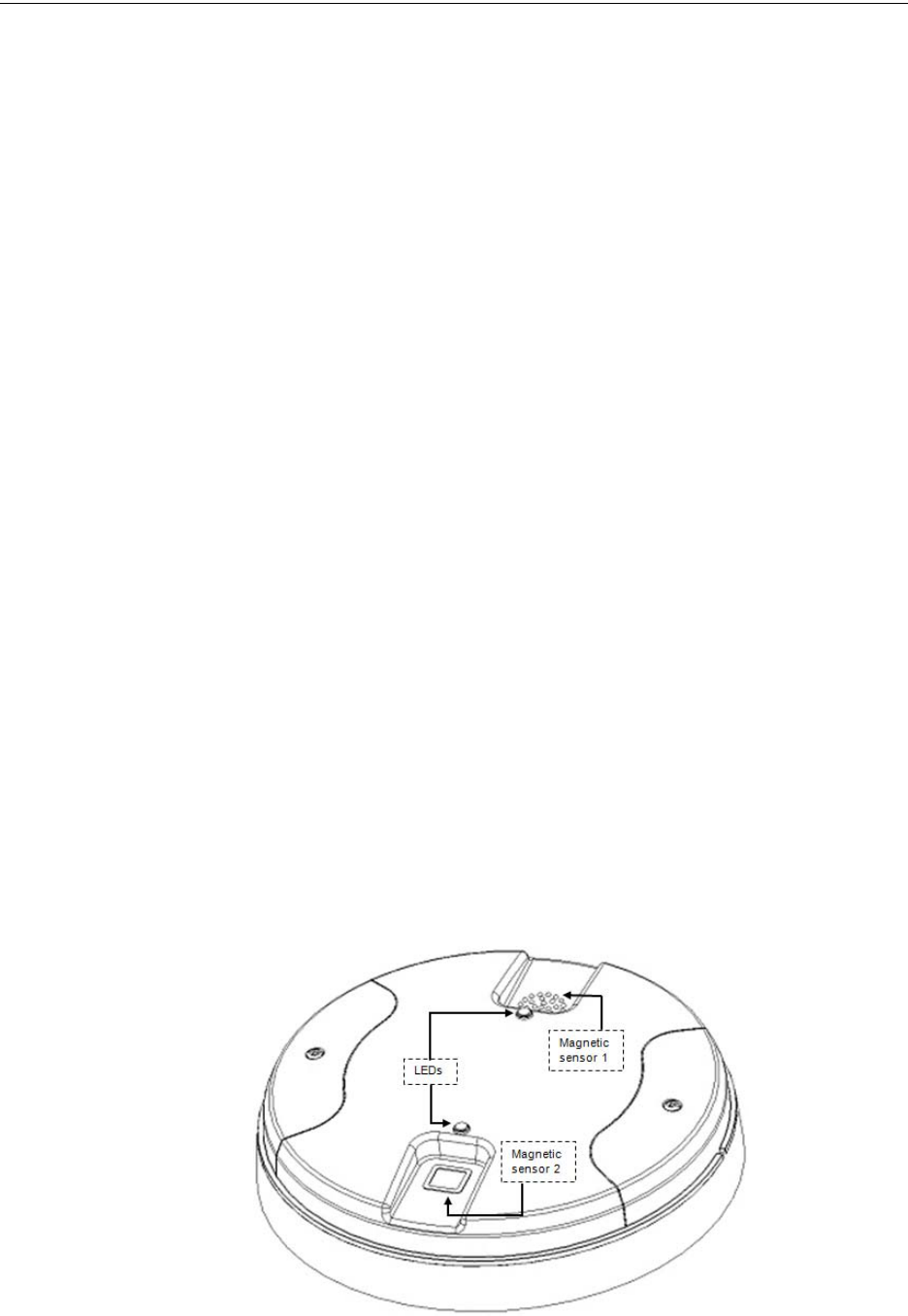
Figure 2.7 W-GATE with LEDs and Magnetic sensors

20 PRELIMINARY: Firelite Wireless Sensor Network P/N LS10036-000FL-E:N0 10/10/2013
W-GATE Configuration and Programming
4. Activate either magnetic sensor with a magnet within ten secoands of starting up the W-GATE
while the double red blink is active in the W-GATE. (If you miss this ten-second window,
power down the W-GATE and repeat step 1). The LED next to the magnetic sensor emits a red
light for one second when it is activated.
When the profile is successfully created, the LEDs on the W-GATE emit green light for five sec-
onds (Refer to 2.7.2, "Magnet Sensor Activations" for further information on activating magnetic
sensors). A default profile has been created, containing a mesh ID, and a password. The default
password is ‘12345’ and is needed if the W-GATE is locked by the FACP and later accessed by the
PC-based configuration tool.
Assign a Previously Created Profile Using a Distributor
To assign an existing profile to the W-GATE (as you would do during a replacement), use the W-
GATE that has the profile, or a device in the mesh that contains the profile, to distribute that profile
to the W-GATE that requires it. Perform the following steps:
1. Ensure that the W-GATE or other mesh device with the profile is set for distribution (Refer to
2.6.3, "Profile Distribution"" or 4.6.2, "Distributor Mode").
2. Start with the device powered off. The process is performed during the start-up.
3. Power on the W-GATE and ensure it is in the factory default state (Refer to steps 1 and 2 in the
above topic, "Create a New Profile").
4. Bring the profile distributor within 20 feet of the W-GATE.
5. Wait until the W-GATE blinks only a single red blink (ten seconds after startup).
6. Use a magnet to activate either of the magnetic sensors. The LED blinks a single red every
half-second indicating that it is searching for a profile.
When the profile is successfully received from the distributor, the LEDs on the W-GATE emit
green light for five seconds. If the profile is rejected, the W-GATE LEDs emit red light for five sec-
onds.
Removing a Profile
To remove the profile from a W-GATE, perform the following steps:
1. Start with the device powered off. The process is performed during the start-up.
2. Power on the W-GATE using SLC power or external +24V. This can be done either by
attaching the W-GATE to its mounting plate with the terminals already energized, or by
connecting the SLC or external source wiring to a W-GATE that is already installed in its
mounting plate.
3. Verify the W-GATE is in the profile modification state; if it is in the profile modification state,
both the LEDs on the W-GATE flash yellow (double blink) every second for ten seconds.
4. Activate both the magnetic sensors within ten seconds of starting up the W-GATE (while the
double yellow blink is active on the W-GATE) or repeat step 1 (If you miss the ten second
window, power down the W-GATE and repeat steps 1 and 2).
The W-GATE LEDs blink green every second for five seconds indicating that the profile is
removed.
Create Mesh Network
Mesh formation forms a wireless communication mesh around the W-GATE. The W-GATE com-
municates with all devices in range that have a common profile and establishes communication
links with all the devices. Once a device joins the mesh, it acts as a repeater for devices out of the
range of the W-GATE. All devices must be in their final mounting locations prior to initiating the
mesh formation. The mesh formation is initiated and terminated by the W-GATE.
To form a mesh network, ensure that the W-GATE is powered on and contains a profile. (Refer to
2.7.3, "LED Indications" for information on how the W-GATE indicates its status). Activate the
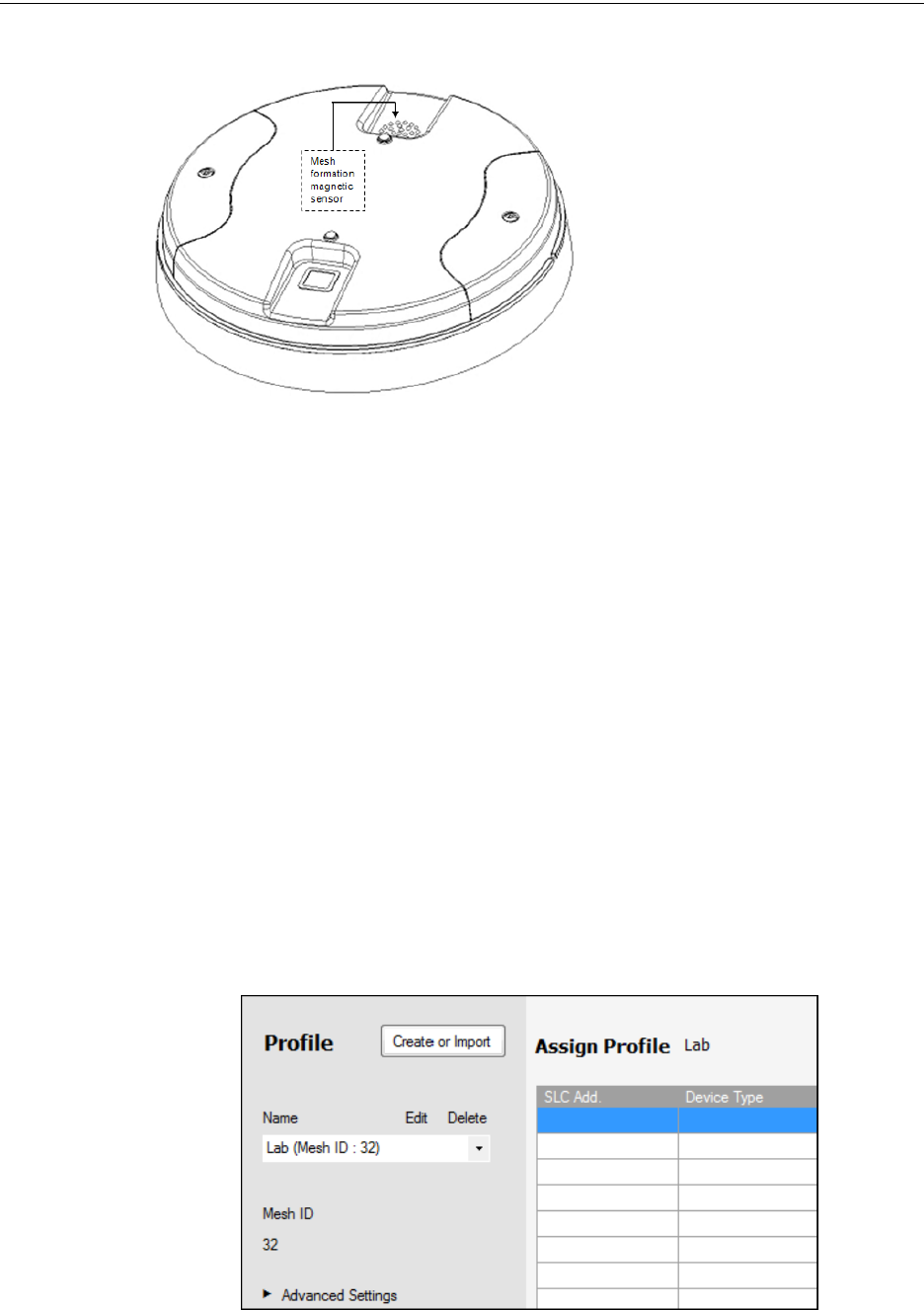
“Mesh Formation” magnet switch on the W-GATE with a magnet.
PRELIMINARY: Firelite Wireless Sensor Network P/N LS10036-000FL-E:N0 10/10/2013 21
Configuration and Programming W-GATE
Figure 2.8 Mesh Formation
Magnetic Sensor on a W-GATE
The W-GATE transitions to the mesh for-
mation mode and establishes communica-
tion with all the devices containing a
common profile. The blink pattern in W-
GATE indicates that it is in mesh forma-
tion mode.
•At this stage, both the LEDs on the W-
GATE blinks twice every 3.4 seconds.
•The first blink is green and the second
blink is red when the W-GATE is acting
as a profile distributor and forming the
mesh.
• The first blink is green and the second blink is yellow when the W-GATE is only forming the
mesh.
Mesh formation typically takes one minute for each device in the mesh. Mesh formation automati-
cally terminates 10 minutes after the last device joins the mesh. The mesh formation can be termi-
nated manually by the user by activating the mesh formation magnetic sensor again.
Once the mesh formation is complete, the network transitions to optimize the mesh. For further
operating instructions, refer to 2.7, "Operations".
2.6.2 With a PC-based Configuration Tool
Assign Profile with PC Tools
To assign a profile to the W-GATE using the PC Tools application, do the following:
1. Connect the W-USB dongle device to your computer. For more information on USB dongle,
refer to Section 5:, "USB Adapter".
2. Launch the PC Tools application. Refer to Appendix B:, "PC tools" to know about launching
the PC Tools application.
3. Go to the Create Mesh Network step.
4. Create a new profile or import an existing profile as required.
5. Select and open the profile to be assigned to the W-GATE from the Name drop-down list in the
left panel.
6. Power on the W-GATE in range of the PC Tools.
22 PRELIMINARY: Firelite Wireless Sensor Network P/N LS10036-000FL-E:N0 10/10/2013
W-GATE Configuration and Programming
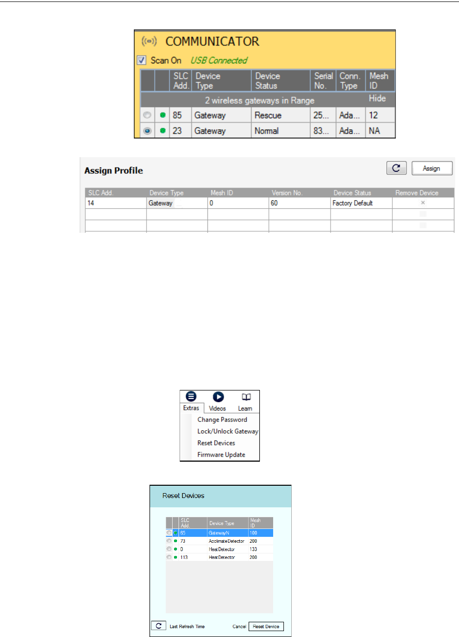
7. Select the W-GATE from the Communicator panel.
8. Click Assign.
The W-GATE is now included in the list of devices with a profile assigned.
Removing Profile with PC Tools
To remove a profile in a W-GATE using the PC Tools application, do the following:
1. Connect the W-USB dongle device to your computer. For more information on USB dongle,
refer to Section 5:, "USB Adapter".
2. Launch the PC Tools application. Refer to Appendix B:, "PC tools" to know about launching
the PC Tools application.
3. Go to Site Survey, Create Mesh Network, or Diagnostics step.
4. Click Extras and select Reset Devices. The Reset Devices screen appears, displaying the W-
GATE and other devices that have a profile assigned.
5. Click to select the W-GATE and click Reset Device to remove the profile.
The profile is removed and the W-GATE is reset to factory default state.
PRELIMINARY: Firelite Wireless Sensor Network P/N LS10036-000FL-E:N0 10/10/2013 23
Configuration and Programming W-GATE
Mesh Formation with PC Tools
To create a mesh network using the PC Tools, perform the following steps.
1. Connect the W-USB dongle device to your computer. For more information on USB dongle,
refer to Section 5:, "USB Adapter".
2. Launch the PC tools application. Refer to Appendix B:, "PC tools" to know about launching
the PC tools application.
3. Go to Create Mesh Network step.
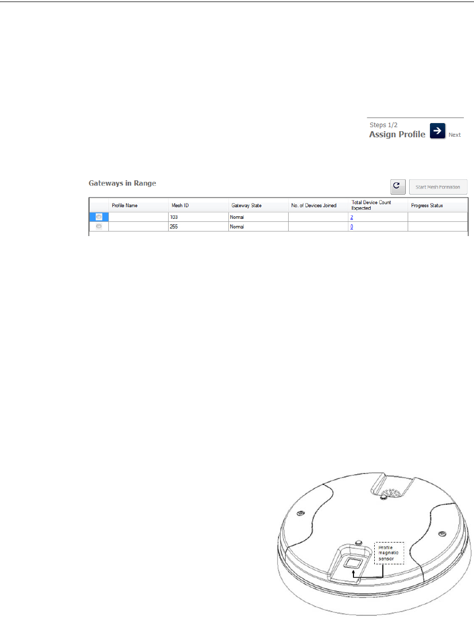
4. Navigate to the second step of Create Mesh Network by clicking
on top of the screen.
5. Click to select the W-GATE displayed in the Gateways in Range table, and click 'Start Mesh
Formation'.
When the mesh is formed, the tool helps you to track the number of devices that have joined the
mesh, and view the progress. The mesh formation terminates 10 minutes after the last device joins
the mesh. In addition, it can be terminated by the user by clicking Stop Mesh Formation.
Once mesh formation is complete, the network transitions to optimize the mesh. For further operat-
ing instructions, refer to 2.7, "Operations".
2.6.3 Profile Distribution
There are two ways to initiate profile distribution from the W-GATE.
• Automatically after creating a profile,
• Activating the profile creating magnetic sensor when it has a profile.
After Creating a Profile
Profile distribution is automatically enabled from the W-GATE after creating a profile. The profile
distribution automatically terminates after 10 minutes.
Activating the Profile Magnetic Sensor When it has a Profile
Activating the profile magnetic sensor while it
has profile will put the W-GATE in a mode of
distributing the profile to any device that
requests a profile. The W-GATE’s LED pattern
will be altered when it is distributing a profile
for easy identification. Profile distribution will
automatically terminate after 10 minutes. For
more information on W-GATE LED patterns,
refer to the table in 2.7.3, "LED Indications".
Figure 2.9 Profile Magnetic
Sensor on a W-GATE

24 PRELIMINARY: Firelite Wireless Sensor Network P/N LS10036-000FL-E:N0 10/10/2013
W-GATE Configuration and Programming
2.6.4 SLC Configuration
The W-GATE,
• Communicates with the control panel via the SLC circuit.
• Is a LiteSpeed only device.
• CLIP mode is not supported.
• FACPs have limited support for displaying all troubles from the wireless device, and requires
the use of an ANN-80 for event details. Refer to the appropriate section below for
configuration steps.
Three consecutive SLC addresses are used for a W-GATE. Set the base address using the rotary
dials on the W-GATE prior to installation. Ensure the address and the next two addresses on the
SLC loop are available.
The base address uses the following configuration parameters:
• Module Type: Monitor
• Type Code Label: Monitor
The W-GATE does not cause any alarms at this address, but the point is used for supervision of the
W-GATE.
The base address +1 uses the following configuration parameters:
• Module Type: Monitor
• Type Code Label: Tamper
This address is a latching supervisory condition that goes active whenever a wireless detector in the
mesh is removed from its base or a module has its cover plate removed (tamper). This point does
not show the address of the tampered device. The ANN-80 displays the device address information.
The base address +2 uses the following configuration parameters:
• Module Type: Monitor
• Type Code Label: Trouble Mon
This address is a tracking trouble condition that goes active whenever a wireless device in the mesh
is in a trouble condition. Refer to 3.9.4, "Event Messaging"for the message displayed at the ANN-
80 for the trouble event.
The specific address and trouble condition is displayed on the ANN-80.
PRELIMINARY: Firelite Wireless Sensor Network P/N LS10036-000FL-E:N0 10/10/2013 25
Operations W-GATE
2.7 Operations
2.7.1 W-GATE Modes of Operation
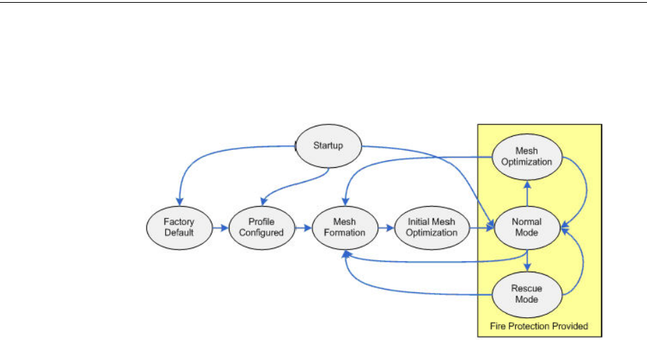
Figure 2.10 W-GATE Modes Of Operation
Start Up
Startup is a temporary mode of operation. It is during the startup mode, that a profile can be created
or removed. The startup period lasts for 10 seconds. If a particular unit contains a profile, the LEDs
blink yellow twice every second. If the unit does not contain a profile, the LEDs blink red twice
every second.
During startup, the W-GATE does not provide fire protection.
After startup, the W-GATE proceeds to the factory default state if a profile was removed or miss-
ing. In the presence of a profile, the W-GATE will proceed to mesh formation if it was previously
part of a mesh network or normal mode if it was not previously part of a mesh network.
The W-GATE does not respond to the panel during startup. All the three SLC addresses will be an
INVALID REPLY.
Factory Default
Factory default is the initial state of the W-GATE. The W-GATE and peripheral devices do not pro-
vide any fire protection when they are in factory default mode. The W-GATE does not communi-
cate with wireless devices. The only wireless communication is with the configuration tool. The
configuration tool needs to be within 20 feet of the W-GATE for communication. The W-GATE
needs to be assigned a profile before continuing the installation.
The W-GATE reports “Factory Default” to the communicator display of the PC Tools application.
The W-GATE’s base address will be normal and the supervisory point (base address + 1) will also
be normal. The trouble point (base address + 2) will indicate open circuit.
Profile Configured
The W-GATE enters the profile configured mode after getting assigned a profile from the tool or a
distributor or creating a profile. Profile configured is a temporary mode before the W-GATE transi-
tions to mesh formation or normal mode.
The W-GATE does not provide fire protection in the profile configured mode. The W-GATE
reports “Profile Assigned” to the communicator display of the PC Tools application.
The W-GATE’s base address will be normal and the supervisory point (base address + 1) will also
be normal. The trouble point (base address + 2) will indicate open circuit.

26 PRELIMINARY: Firelite Wireless Sensor Network P/N LS10036-000FL-E:N0 10/10/2013
W-GATE Operations
Mesh Formation
The W-GATE must have a profile before entering mesh formation. The W-GATE and the peripheral
devices do not provide any fire protection in mesh formation. The W-GATE automatically enters
mesh formation in the following ways:
• After creating a profile using the mesh formation sensor.
• After activating the mesh formation sensor with a magnet when the W-GATE contains a
profile.
• Automatically after startup when the W-GATE previously was part of a mesh
• By command from the PC Tools application
A W-GATE in mesh formation mode instructs all devices in the mesh to also transition to mesh for-
mation. The W-GATE and all communicating devices search for new or lost devices with the same
profile to join the network.
If the W-GATE automatically entered mesh formation after startup, then mesh formation terminates
after all existing devices are recovered. If new devices are found or if mesh formation was initiated
by the user, then mesh formation terminates after a period of 10 minutes without any new devices
joining the mesh. At any point Mesh formation can be terminated by user interaction by activating
the magnet sensor again, or by using the PC Tools application.
The W-GATE reports “Mesh Formation” to the communicator display of the PC Tools application.
The W-GATE’s base address will be normal and the supervisory point (base address + 1) will also
be normal. The trouble point (base address + 2) will indicate open circuit.
Initial Mesh Optimization
The initial mesh optimization mode automatically runs after each mesh formation. The W-GATE
and peripheral devices do not provide fire protection during the initial mesh optimization. Mesh
optimization analyzes the signal strengths between devices. The W-GATE designates the primary
and secondary communication paths between devices that provide a redundant path for all trans-
missions. Mesh Optimization terminates automatically once all devices have a redundant commu-
nication path and signal strengths that meet the requirements of primary and secondary
transmission paths. Any device that does not have a redundant path or meet the requirements for
signal strength will report a fault.
The W-GATE reports “Optimization” to the communicator display of the PC tools application.
The W-GATE’s base address will be normal and the supervisory point (base address + 1) will also
be normal. The trouble point (base address + 2) will indicate open circuit.
Normal Mode
Normal mode can be described as a standard operating state. The mesh network is formed, provid-
ing fire protection. The mesh network continuously searches for additional devices with a match-
ing profile to join the mesh. To avoid interference, the mesh network periodically checks for
adjacent mesh networks created by Honeywell. The W-GATE reports “Normal” to the communica-
tor display of the PC Tools application.
Rescue Mode
During normal mode, when a device loses communication to the network, the W-GATE triggers
rescue mode in all communicating devices. All devices in communication continue to provide fire
protection during rescue mode, but also searches for a lost or added device. The rescue mode termi-
nates automatically 6 minutes after the last device is rescued and returns to the normal mode. The
W-GATE reports “Rescue” to the communicator display of the PC Tools application.

PRELIMINARY: Firelite Wireless Sensor Network P/N LS10036-000FL-E:N0 10/10/2013 27
Operations W-GATE
Mesh Optimization
In addition to the initial mesh optimization, the routine executes after any restoration of communi-
cation to a device or to recover from a link failure (class A fault). Mesh optimization that occurs
during the normal mode does not generate a trouble and provides fire protection from all devices
that are participating in the mesh communication. The W-GATE reports “Optimization” to the com-
municator display of the PC Tools application.
Bootloader
The W-GATE enters the bootloader mode when it is being updated using the PC Tools application.
The W-GATE does not communicate with the FACP during bootloader mode. The W-GATE
reports “Bootloader” to the communicator display of the PC Tools application.
2.7.2 Magnet Sensor Activations
Profile Magnetic Sensor
The profile magnetic sensor (Figure 2.9, "Profile Magnetic Sensor on a W-GATE") is used to create
a unique profile on startup. It can also be used to start profile distribution for a W-GATE that con-
tains a profile. The LED next to the profile magnet sensor emits solid red light for ½ a second
when the sensor is activated.
Mesh Formation Magnetic Sensor
The mesh formation magnetic sensor (Figure 2.8, "Mesh Formation Magnetic Sensor on a W-
GATE") toggles the W-GATE, in and out of mesh formation mode. The initial activation of the sen-
sor puts the W-GATE in mesh formation mode (as long as it contains a profile). A subsequent acti-
vation of the magnetic sensor toggles the W-GATE out of mesh formation and into the initial mesh
optimization and normal mode. The W-GATE can be placed back into mesh formation by activat-
ing the magnet sensor once again. The Mesh formation magnetic sensor can also be used to create
a profile on startup for a W-GATE that does not already contain a profile.
The LED next to the mesh formation magnetic sensor emits solid red light for ½ a second when the
sensor is activated.
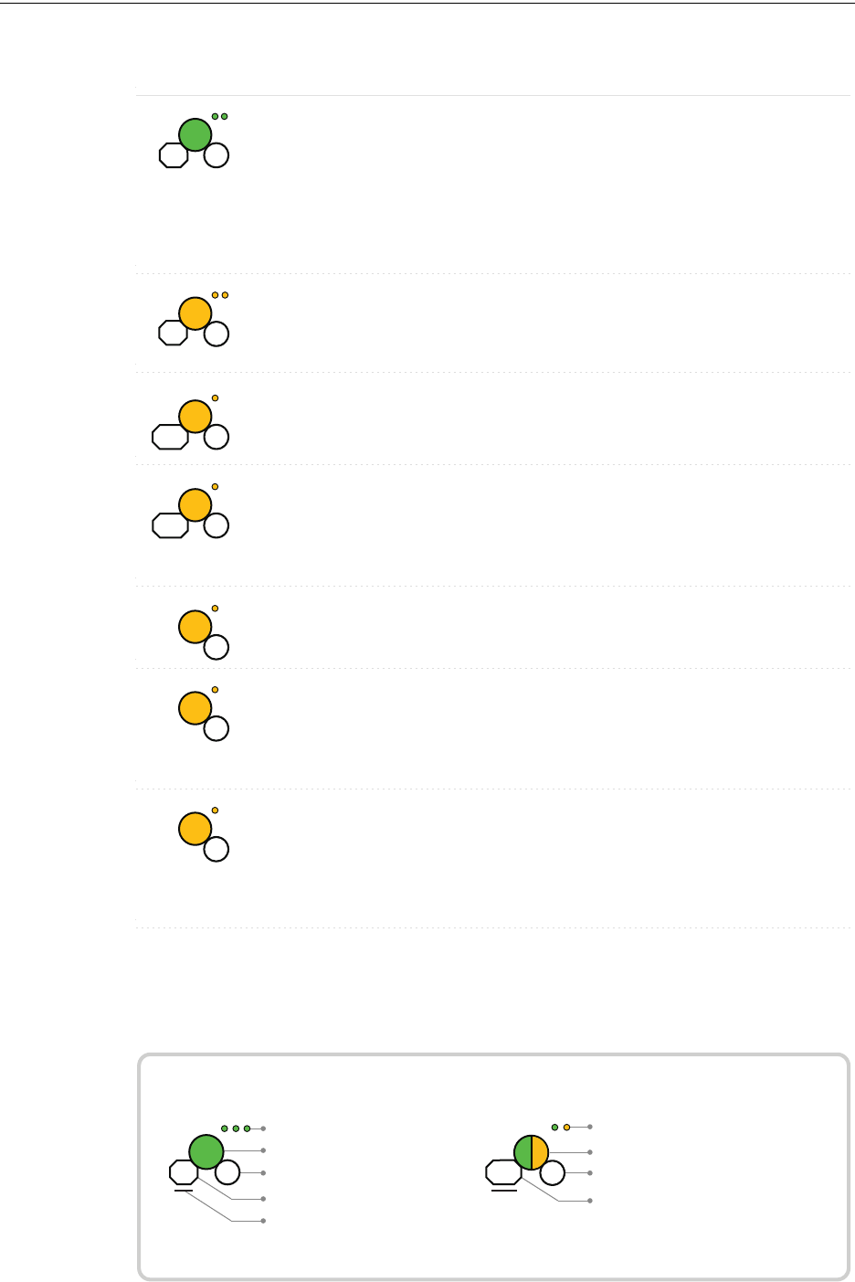
2.7.3 LED Indications
The two LEDs on the W-GATE blink in the same pattern to allow the LED to be viewed from any
angle. The LED indications are provided in the table below.
28 PRELIMINARY: Firelite Wireless Sensor Network P/N LS10036-000FL-E:N0 10/10/2013
W-GATE Operations
Duration of LED state
All units are in seconds. Minute is indicated by M.
Example:
Legend
LED color
No. of blinks
Interval between blink patterns
Approximate duration
Will transition to next state after
30 min (approx)
First blink is green. Second is yellow
Two blinks in this pattern
7 sec between blink patterns
7
M
30
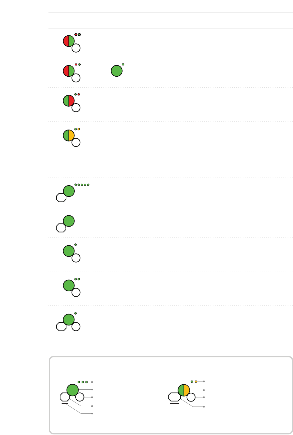
Condition Action Required
Device is ready to update
LED Pattern
Prole removed Gateway has returned to the
factory default state
Mesh formation Gateway is forming the
mesh & looking for
devices that are not in the
mesh
Wait until all devices join
the mesh, and then
terminate mesh forma-
tion
Use PC based congura-
tion tool to initiate the
download
Mesh formation
with prole
distribution
Gateway is forming the
mesh & looking for
devices that are not in the
mesh. The gateway is also
distributing a prole to
any device that requests a
prole
Wait until all devices join
the mesh, and then
terminate mesh forma-
tion
App
erase
App
loading
New application code is
being downloaded
7
7
2
5
14
14
Normal Mode /
Background
mesh optimiza-
tion
Normal operation of the
gateway
Normal Mode/Back-
ground mesh
optimization with
prole distribution
Normal operation of the
gateway. The gateway is also
distributing a prole to any
device that requests a prole
Prole accepted Gateway is now prole
assigned
5
Rescue Mode Gateway and the mesh
network are searching for any
device that is not in the mesh
network with the same prole
7
6M
Bootloader
5
PRELIMINARY: Firelite Wireless Sensor Network P/N LS10036-000FL-E:N0 10/10/2013 29
Operations W-GATE
Duration of LED state
All units are in seconds. Minute is indicated by M.
Example:
Legend
LED color
No. of blinks
Interval between blink patterns
Approximate duration
Will transition to next state after
30 min (approx)
First blink is green. Second is yellow
Two blinks in this pattern
7 sec between blink patterns
7
M
30
7
Rescue Mode
with prole
distribution
Gateway and the mesh
network are searching for
any device that is not in
the mesh network with the
same prole. The gateway
is also distributing a prole
to any device that requests
a prole
Prole assigned;
pending hall sensor
activations
starting up with a prole Activate both hall sensors
simultaneously within 10
seconds to remove a
prole
1st mesh
optimization
Mesh is formed and
initializing
Ensure all devices in the
mesh have a valid
address.
7
10 1
6M
15M
Condition Action RequiredLED Pattern
7
4
14
14
Refer to the panel to
identify the trouble and
possible resolution
1st mesh optimization
with prole distribu-
tion
Mesh is formed and
initializing. The gateway
is also distributing a
prole to any device that
requests a prole
Generic Trouble The gateway has a
trouble condition.
Refer to the panel to
identify the trouble and
possible resolution
Generic Trouble with
prole distribution
The gateway has a
trouble condition. The
gateway is also distribut-
ing a prole to any device
that requests a prole.
Ensure all devices in the
mesh have a valid
address.
Address Trouble The gateway is in a dual
address condition with
another wireless module
in the mesh or there is a
device in the mesh set to
address 0.
15M
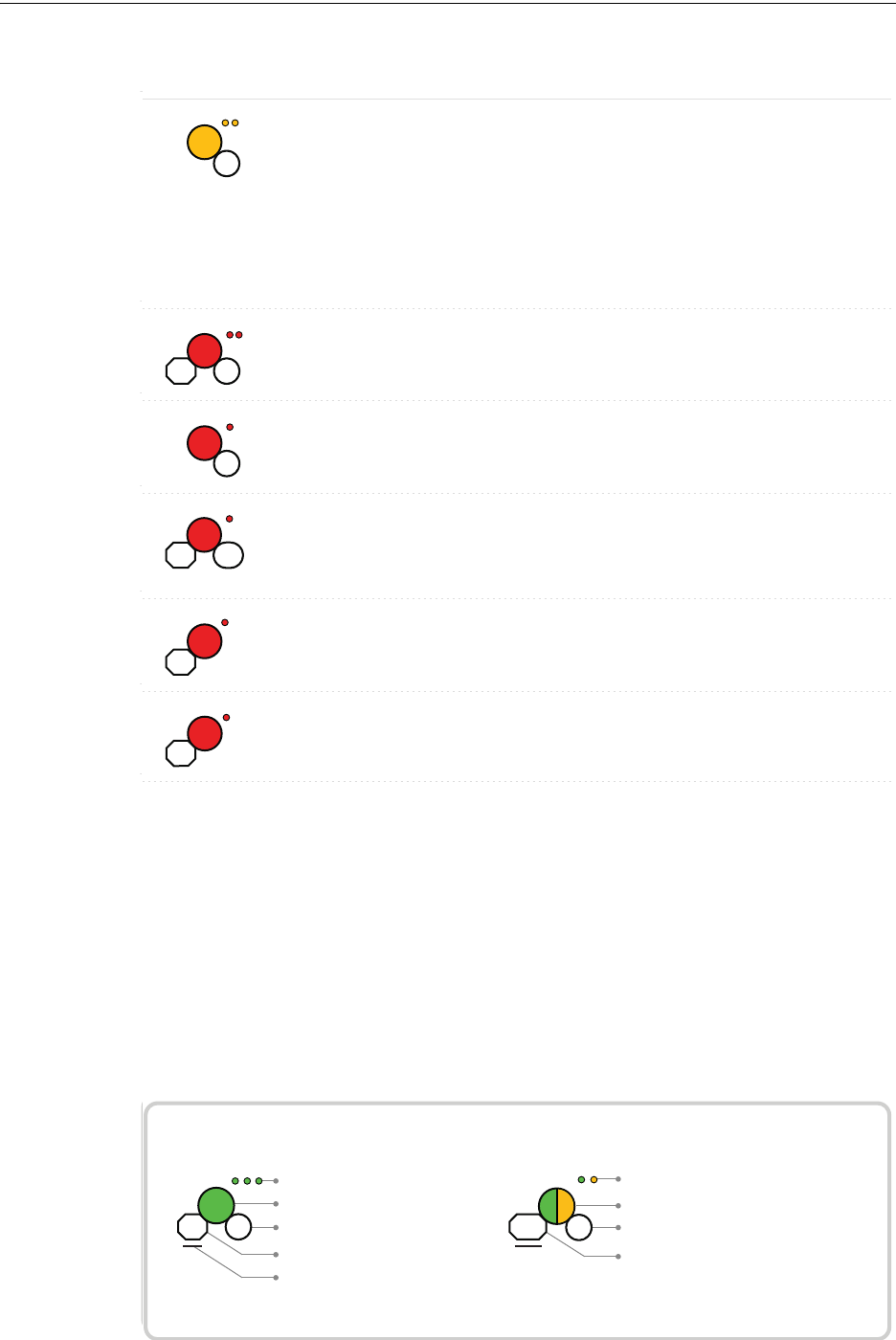
30 PRELIMINARY: Firelite Wireless Sensor Network P/N LS10036-000FL-E:N0 10/10/2013
W-GATE Operations
Duration of LED state
All units are in seconds. Minute is indicated by M.
Example:
Legend
LED color
No. of blinks
Interval between blink patterns
Approximate duration
Will transition to next state after
30 min (approx)
First blink is green. Second is yellow
Two blinks in this pattern
7 sec between blink patterns
7
M
30
4
Ensure all devices in the
mesh have a valid
address.
Address Trouble
with prole
distribution
The gateway is in a dual
address condition with
another wireless module in
the mesh or there is a
device in the mesh set to
address 0. The gateway is
also distributing a prole
to any device that requests
a prole.
Condition Action RequiredLED Pattern
Factory default;
pending hall
sensor activation
Starting up without a
prole
Activate either hall
sensors within 10 seconds
to create a default prole
Waiting for
prole
Gateway is factory default Use PC tool to assign
prole or activate switch
to search for prole
Searching for
prole
Gateway is factory default
and requesting a prole
from a distributor or
another gateway
Prole rejected;
incompatible
device
There is a mismatch
between the prole and
the gateway.
Recreate the prole or
update the gateway
Create prole Gateway is creating a
default prole
1
5
1
10
10
0.5
1M
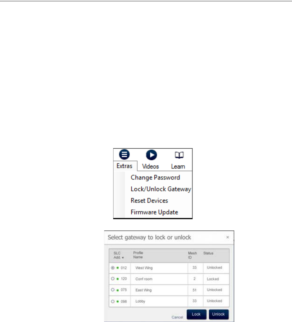
PRELIMINARY: Firelite Wireless Sensor Network P/N LS10036-000FL-E:N0 10/10/2013 31
Operations W-GATE
2.7.4 Lock/Unlock W-GATE
The W-GATE can be locked to prevent access to the magnetic sensors and to password-protect all
wireless interactions. The lock function can be performed by the PC tool. When the PC tool is
used to lock the W-GATE, a password must be provided for all future interactions, including
unlocking the W-GATE. If the W-GATE was previously locked with a password from the PC tools,
the previous password will be applied. Use this password for all future interactions from the PC
Tools application.
Lock/Unlock W-GATE through PC tools
To lock/unlock the W-GATE, perform the following steps.
1. Connect the W-USB dongle device to your computer. For more information on USB dongle,
refer to Section 5:, "USB Adapter".
2. Launch the PC tools application. Refer to Appendix B:, "PC tools" to know about launching
the PC tools application.
3. Go to Site Survey, Create Mesh Network, or Diagnostics step.
4. Click Extras. The following screen is displayed.
5. Select Lock/Unlock Gateway.
6. To lock or unlock the gateway, click Lock or Unlock as required.
•Lock - The Lock Gateway screen is displayed. Create a password and click Lock. The
gateway is locked.
•Unlock - The Enter password for Gateway screen is displayed. Enter the password and
click Unlock. The W-GATE is unlocked.
Password Reset
To reset the password, contact technical support.
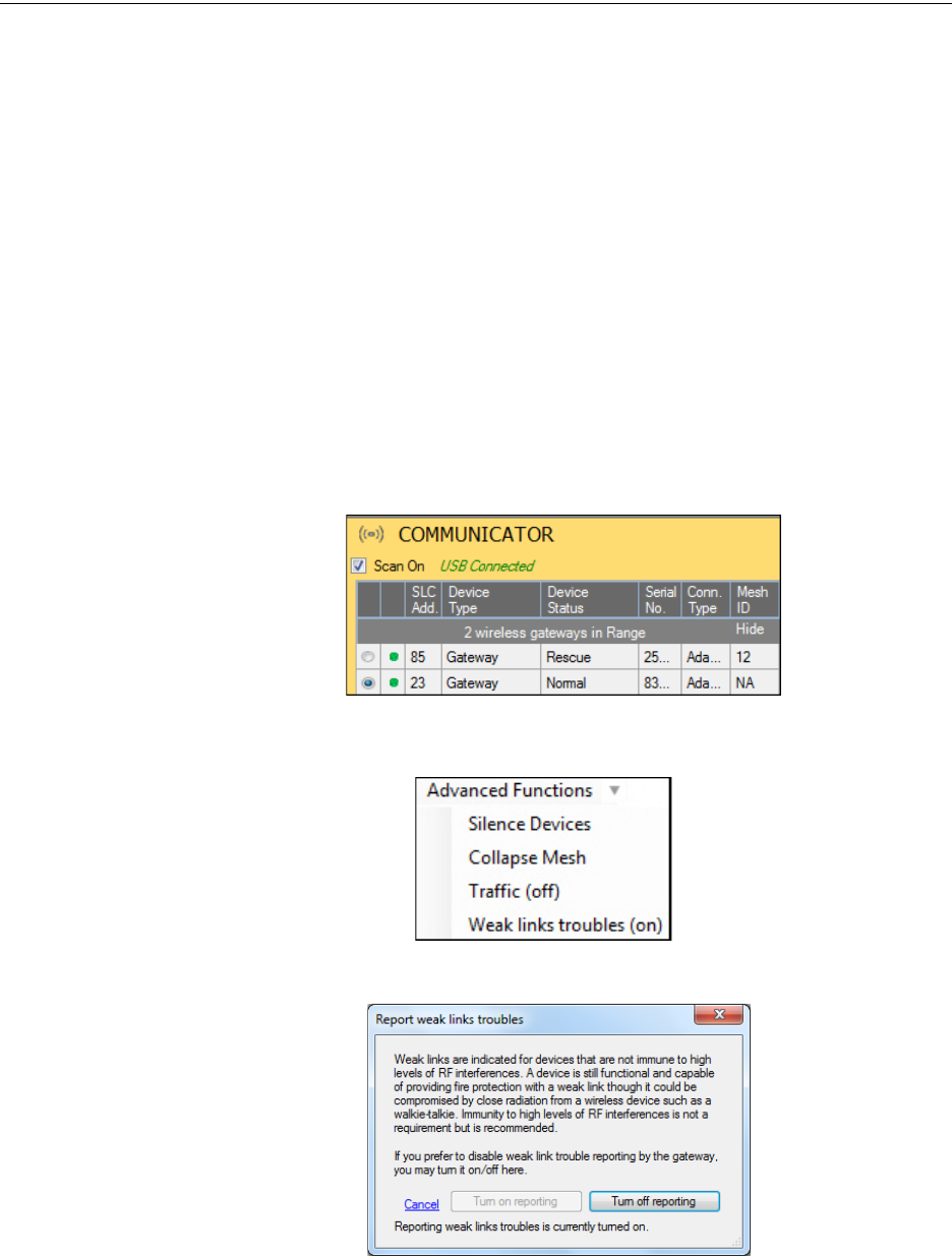
32 PRELIMINARY: Firelite Wireless Sensor Network P/N LS10036-000FL-E:N0 10/10/2013
W-GATE Operations
2.7.5 Weak Link Trouble Reporting
The Firelite Wireless Sensor Network uses two paths of communication for each device. To estab-
lish the link between devices as a viable communication path, the signal strengths must meet the
limits provided in 2.3, "Specifications". The Wireless Sensor Network implements a higher thresh-
old for primary connections to provide an extra layer of robustness and immunity from interfer-
ence. A weak link trouble condition is initiated for any device that does not have at least one
connection at the primary threshold. This is an optional setting that can be disabled to ignore the
weak link trouble condition. The trouble can be disabled at the W-GATE.
Disabling Trouble Reporting at the W-GATE Using PC Tools
To disable trouble reporting at the W-GATE through PC tools, perform the following steps:
1. Connect the W-USB dongle device to your computer. For more information on USB dongle,
refer to Section 5:, "USB Adapter".
2. Launch the PC tools application. Refer to Appendix B:, "PC tools" to know about launching
the PC tools application.
3. Go to Diagnostics step.
4. Choose the W-GATE from the communicator pane.
5. Click View Mesh.
6. Click Advanced Functions. A drop-down list is displayed.
7. Click Weak links troubles (On). The Report weak links troubles screen is displayed.
8. Click Turn off reporting.
The trouble reporting is disabled.
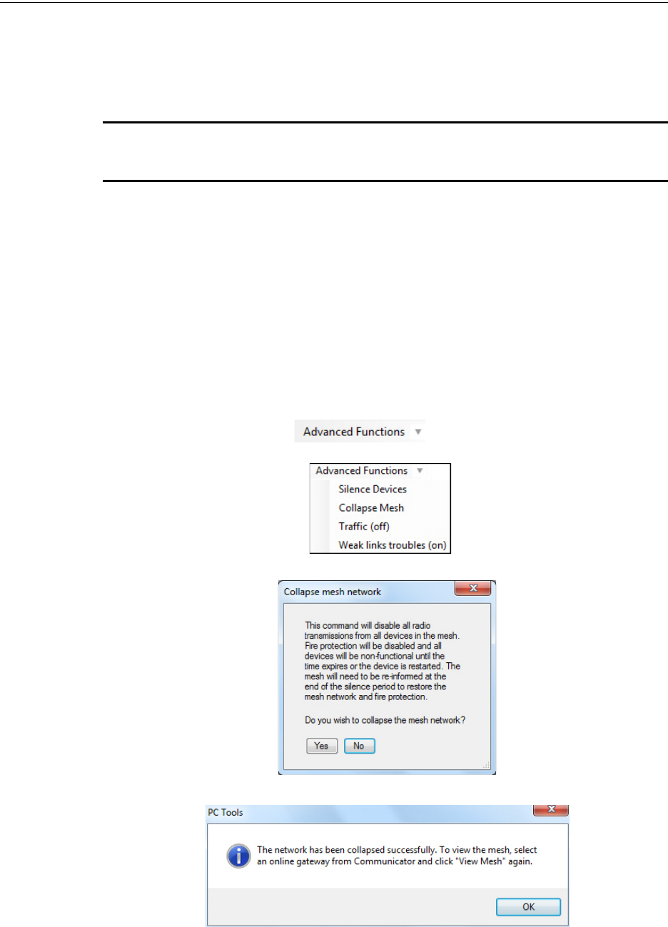
PRELIMINARY: Firelite Wireless Sensor Network P/N LS10036-000FL-E:N0 10/10/2013 33
Operations W-GATE
2.7.6 Collapse Network Command
The collapse command is a diagnostic function to break the mesh network. All devices will retain
the profile information but will be removed from the mesh. The mesh can be immediately reformed
by activating mesh formation.
CAUTION: FIRE PROTECTION FROM WIRELESS DEVICES WILL BE LOST WHEN A
COLLAPSE COMMAND IS ISSUED.
The mesh network can be collapsed using the PC-based configuration tool.
Collapsing Mesh Network Using PC Tools
To collapse the mesh network using the PC based configuration tool, perform the following steps:
1. Connect the W-USB dongle device to your computer. For more information on USB dongle,
refer to Section 5:, "USB Adapter".
2. Launch the PC tools application. Refer to Appendix B:, "PC tools" to know about launching
the PC tools application.
3. Go to Diagnostics step.
4. Select a Gateway from the communicator pane.
5. Click View Mesh. The mesh is displayed.
6. Click Advanced Functions on top of the mesh display. A drop down
list is displayed.
7. Click Collapse Mesh. The Collapse mesh network screen is displayed.
8. Click Yes. The network is collapsed and a confirmation is displayed as shown below.
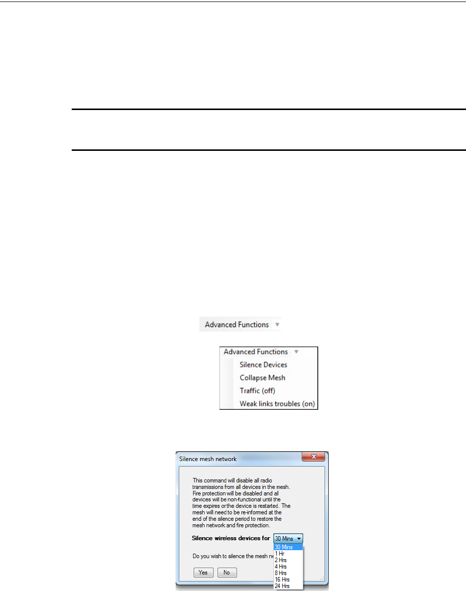
34 PRELIMINARY: Firelite Wireless Sensor Network P/N LS10036-000FL-E:N0 10/10/2013
W-GATE Operations
2.7.7 Silence Network Command
The silence network command is a diagnostic function to turn off all radio communication from the
wireless devices for the set amount of time. All devices will retain the profile information but will
be removed from the mesh. The devices will not send or receive any wireless communication until
the set time expires or the device is rebooted. The mesh network can be reformed at the end of the
silence period or after the device is restarted.
CAUTION: FIRE PROTECTION FROM WIRELESS DEVICES WILL BE LOST WHEN A
SILENCE COMMAND IS ISSUED
The mesh network can be silenced using the PC-based configuration tool.
Silencing Mesh Network Using PC Tools
To silence the mesh network using the PC based configuration tool, perform the following steps:
1. Connect the W-USB dongle device to your computer. For more information on USB dongle,
refer to Section 5:, "USB Adapter".
2. Launch the PC tools application. Refer to Appendix B:, "PC tools" to know about launching
the PC tools application.
3. Go to Diagnostics step.
4. Select a Gateway from the communicator pane.
5. Click View Mesh. The mesh is displayed.
6. Click Advanced Functions on top of the mesh display. A dropdown list is
displayed.
7. Click Silence Devices. The Silence mesh network screen is displayed.
8. Select the time interval to silence the wireless devices from the dropdown list and click Yes.

PRELIMINARY: Firelite Wireless Sensor Network P/N LS10036-000FL-E:N0 10/10/2013 35
Operations W-GATE
9. Enter the Verification Password in the Gateway Password screen. The network is silenced and
confirmation is displayed as shown below.
2.7.8 Multiple Wireless Sensor Network Installation Restrictions
Firelite’s Wireless Sensor Network technology shares the RF spectrum with other Honeywell Wire-
less Sensor Network systems. Honeywell has established a limit of 4 overlapping networks to
avoid congestion in the RF spectrum. If the limit of overlapping systems is exceeded, a system
trouble will be generated for the system that detects 4 or more adjacent networks. To resolve this
situation, the instances of overlap need to be removed. Refer to Appendix C:, "Troubleshooting
and Testing"for suggestions on removing overlap between wireless networks. The trouble will be
self restoring up to 36 hours after the condition is resolved. To expedite the trouble resolution, tog-
gle the network that is reporting the trouble in and out of mesh formation mode.
2.7.9 Avoiding RF Interference
The Firelite wireless mesh network uses radio frequency hopping spread spectrum technology to
communicate in the 900 MHz ISM band (902MHz to 928MHz). Other commercial and industrial
products also operate in this band. If two-way radios or other wireless communication devices are
used during the installation process it is recommended that they be kept at least 4 feet away fromthe
Firelite wireless devices or that they operate on a different frequency band to ensure rapid mesh
formation. A properly installed Firelite wireless mesh network with primary link reporting enabled
will be highly immune to RF interference from other wireless products even when they are nearby.
The use of the primary link reporting feature is highly recommended. If the system is installed in a
controlled environment where other 900 MHz ISM band devices will not be present, the primary
link reporting feature may be disabled to permit greater distances between installed devices if
required. The Firelite wireless mesh network will be able to automatically detect and avoid certain
types of in-band channel interference (often caused by two-way radios) by using an alternate chan-
nel set. The system will log detection and avoidance of this kind interference in the W-GATE his-
tory as "Walkie Talkie Mode" Entry or Exit and in the NFS2-3030 history as Alternate Channel Set
or Normal Channel Set.
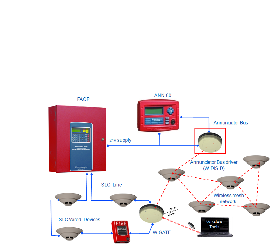
36 PRELIMINARY: Firelite Wireless Sensor Network P/N LS10036-000FL-E:N0 10/10/2013
Wireless Display Driver (W-DIS-D) Description
Section 3: Wireless Display Driver (W-DIS-D)
This section describes the wireless user interface display driver and how it is connected to the
ANN-80. In addition, this section provides information on how to install, configure and monitor the
messages on the ANN-80.
3.1 Description
The W-DIS-D and ANN-80 are required for the display of wireless specific events.
Figure 3.1
The W-DIS-D is a part of the wireless network and has a specific SLC module address. The W-
DIS-D and ANN-80 display the wireless specific events that cannot be displayed on the FACP.
These wireless events are related to the trouble and supervisory conditions that are specific to the
W-GATE and devices. The wireless events are indicated at the FACP as a generic trouble or a
supervisory event via the W-GATE utilizing the base address +1 and the base address +2 for super-
visory and trouble events respectively. The specific event details are sent to the ANN-80 via an
EIA-485 communication line from the W-DIS-D. The following conditions lead to the trouble and
supervisory events.
Trouble Events
• Jamming (device communication loss due to RF interference)
• Duplicate address
•Battery low
• Class A missing second link
• Weak link low signal strength
• Mesh Optimization
• Wireless mesh formation in progress
• RF comm loss
• Illegal address

PRELIMINARY: Firelite Wireless Sensor Network P/N LS10036-000FL-E:N0 10/10/2013 37
Agency Approvals Wireless Display Driver (W-DIS-D)
• Maximum Gateway
• Maximum devices
Supervisory Event
• Tamper
3.2 Agency Approvals
3.2.1 FCC
This device complies with part 15 of the FCC Rules. Operation is subject to the following two con-
ditions:
1. This device may not cause harmful interference, and
2. This device must accept any interference received, including interference that may cause
undesired operation.
FCC ID PV3WFSLCDUI
WARNING: CHANGES OR MODIFICATIONS NOT EXPRESSLY APPROVED BY THE
MANUFACTURER COULD VOID THE USER’S AUTHORITY TO OPERATE THE EQUIPMENT.
3.3 Specifications
W-DIS-D
The following are the specifications for the W-DIS-D device.
NOTE: All connections are power limited and supervised.
Specification Data
Operating Voltage Range 18VDC to 30VDC
Maximum current draw 30 mA
ANN-BUS Driver: 1.5V - 3.4V and 60 mA max.
Receiver: 0.2V - 6V
Radio Frequency Lower ISM band (915 MHz)
Maximum power output +17 dBm
Minimum signal strength level needed at the
receiver for a primary path with weak link reporting
enabled
-63 dBm
Minimum signal strength level needed at the
receiver for a secondary path (minimum signal to
noise point) or a primary path with weak link trouble
reporting disabled
Must be 15 dBm higher than the noise floor down
to -87dBm
Table 3.1 W-DIS-D specifications

38 PRELIMINARY: Firelite Wireless Sensor Network P/N LS10036-000FL-E:N0 10/10/2013
Wireless Display Driver (W-DIS-D) Features
ANN-80
Table 3.2 ANN-80 Specifications
NOTE: All connections are power limited and supervised.
3.3.1 Environmental Specification
3.4 Features
W-DIS-D
The W-DIS-D has the following features.
Listed to UL standard ANSI/UL 864 edition.
ANN-80
The ANN-80 has the following features.
• Listed to UL standard ANSI/UL 864 edition.
• Control switch ACK for acknowledging the piezo.
• Scrolling keys to scroll up or down when there are multiple events.
• Enclosure supervised for tamper.
• LEDs for trouble and supervisory events.
• Surface mount directly to wall or single, double or 4” square junction box.
Specification Data
Operating Voltage Range
(TB1 Terminals 1 & 2)
18VDC to 28VDC
Maximum current drawn Normal / Standby (no activity): 37.0 mA
trouble condition: 39.0 mA
TBI Terminals 3 & 4 ANN-BUS Driver: 1.5V - 5.5V and 60 mA max.
Receiver: 0.2V - 6V
Dimensions 6 7/8”Wx 5 3/8”H x 1 3/8”D
System Operating
Temperature Storage
Temperature Humidity
W-DIS-D 0°C-50°C -10°C-50°C 10 to 93% RH Non condensing
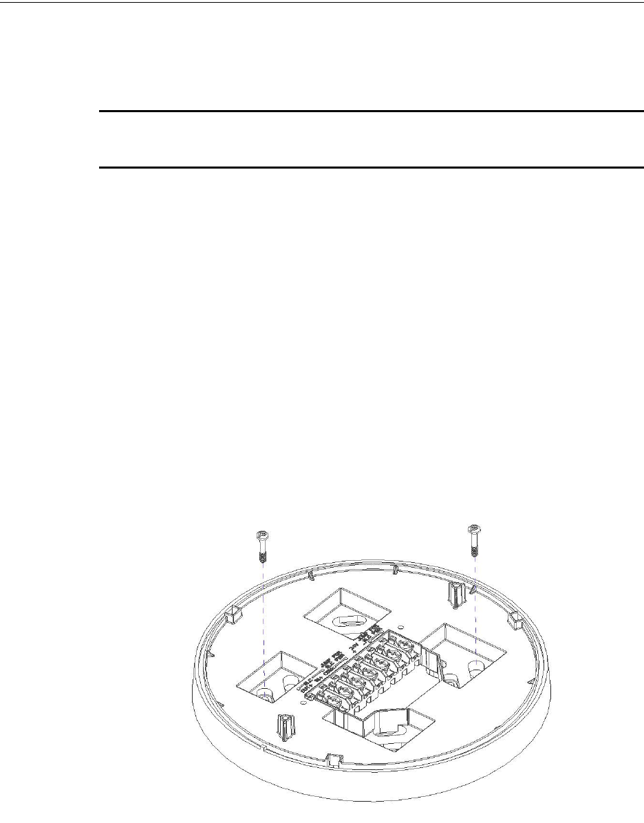
PRELIMINARY: Firelite Wireless Sensor Network P/N LS10036-000FL-E:N0 10/10/2013 39
Mounting & Wiring Wireless Display Driver (W-DIS-D)
3.5 Mounting & Wiring
3.5.1 Mounting W-DIS-D
WARNING: ENSURE THAT THE FORMEX SHEET INSIDE THE W-GATE IS NOT REMOVED OR
TAMPERED WHILE INSTALLING OR CLEANING.
The W-DIS-D has two major pieces, the cover and the mounting plate. The mounting plate is
mounted to the wall or ceiling and field wiring is connected to it. The cover contains the PC board
and is fastened to the mounting plate once the wiring is connected.
Mount the mounting plate directly to an electrical box on the ceiling or wall. The plate mounts
directly to 4˝ square (with and without plaster ring), 4˝ octagon, 3 1/2˝octagon, single gang or dou-
ble gang junction boxes. If an electrical box is not available, the mounting plate can be mounted to
any flat surface and the wiring can be connected via the knockout points in the mounting plate.
To mount the W-DIS-D, do the following:
1. Pull the wiring through the opening in the mounting plate.
2. Mount the mounting plate to the junction box or ceiling. See figure 3.2.
3. Connect field wiring to the terminals, as described in 3.5.2, "Wiring".
4. Connect necessary jumpers where applicable. Refer to section 2.5.3, "W-GATE Powered
from SLC".
5. To mount the cover, align the locating pins on the cover to the corresponding slots in the
mounting plate. See Figure 3.3, “Cover Attaching to Mounting Plate” .
Secure the cover by tightening the mounting screws.
Figure 3.2 Mounting Plate
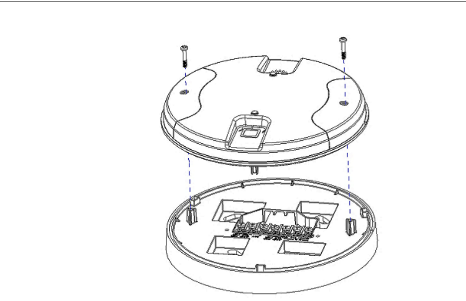
40 PRELIMINARY: Firelite Wireless Sensor Network P/N LS10036-000FL-E:N0 10/10/2013
Wireless Display Driver (W-DIS-D) Mounting & Wiring
Figure 3.3 Cover Attaching to Mounting Plate
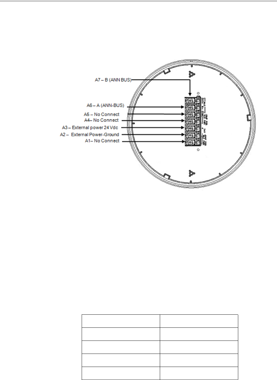
PRELIMINARY: Firelite Wireless Sensor Network P/N LS10036-000FL-E:N0 10/10/2013 41
Mounting & Wiring Wireless Display Driver (W-DIS-D)
3.5.2 Wiring
• All wiring must be installed in compliance with the National Electrical Code and the local
codes having jurisdiction.
• 12-18 AWG is recommended.
Figure 3.4 Wiring Diagram with Terminal Descriptions
For wiring connections, follow this procedure:
• Strip about 3/8” of insulation from the end of the wire.
• Then, to make the wire connection, slide the bare end of the wire under the appropriate
clamping plate, and tighten the clamping plate screw.
3.5.3 ANN-80
Mounting
The ANN-80 has to be mounted next to the Fire Alarm Control Panel. For further instructions on
mounting and wiring of ANN-80, refer to ANN-80-series product installation document.
Wiring
Table 3.3 ANN-80 series to power source
ANN-80 Series Terminals (TB1) ANN-BUS Terminals
Terminal 1 (-) External power ground
Terminal 2 (+) External power 24VDC
Terminal 3 (A) A (ANN-BUS)
Terminal 4 (B) B (ANN-BUS)

42 PRELIMINARY: Firelite Wireless Sensor Network P/N LS10036-000FL-E:N0 10/10/2013
Wireless Display Driver (W-DIS-D) W-DIS-D Configuration
Notes
•12-18 AWG wire for must be used for the 24VDC circuit.
•The maximum wiring distance is 6000 ft.
The ANN-80 and ANN-BUS requires 24VDC power supply; powered by 24VDC from the host
FACP or by remote power supply.
NOTE: Installation and wiring must be done in accordance with the NFPA 72 and local
ordinances.
3.6 W-DIS-D Configuration
The configuration of a W-DIS-D starts with assigning a profile. There are two ways to assign a pro-
file.
• Assign profiles using PC Tools.
• Assign profile to a W-DIS-D with W-GATE or Distributor.
NOTE: To assign a profile, the W-DIS-D must be in a factory default state. This is confirmed by
a single red light that flashes on the LED. To restore the W-DIS-D to factory default state, refer to
section 3.3.3
3.6.1 Assigning Profiles
Assign Profile with PC Tools
To assign a profile to the W-DIS-D using the PC Tools application, do the following:
1. Connect the W-USB dongle device to your computer. For more information on USB dongle,
refer to Section 5:, "USB Adapter".
2. Launch the PC Tools application. Refer to Appendix B:, "PC tools" to know about launching
the PC Tools application.
3. Go to the Create Mesh Network step.
4. Create a new profile or import an existing profile as required.
5. Select and open the profile to be assigned to the W-DIS-D from the Name drop-down list in
the left panel.
6. Switch on the W-DIS-D in range of the USB adapter, which is connected to the laptop or PC
where PC tool is installed.
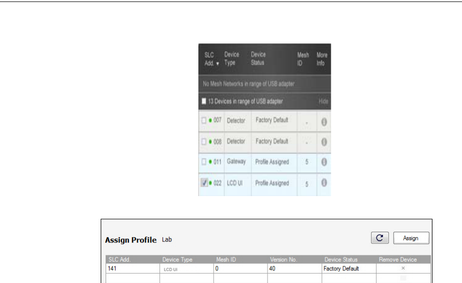
PRELIMINARY: Firelite Wireless Sensor Network P/N LS10036-000FL-E:N0 10/10/2013 43
W-DIS-D Configuration Wireless Display Driver (W-DIS-D)
7. Select the W-DIS-D from the Communicator panel. The W-DIS-D is listed by its generic
name, “LCD UI”.
8. Click Assign.
The W-DIS-D is now included in the list of devices with a profile assigned. When the profile is
assigned, the LED emits a solid green light for 10 seconds.
Assigning a Profile to a W-DIS-D with W-GATE or Distributor
A W-GATE that has a profile can be used to distribute the profile to a W-DIS-D. The W-GATE
must be in a state where it can distribute a profile. For further information on profile distribution
from a W-GATE, refer to 2.6.3, "Profile Distribution". A device that has a profile can be used to
distribute the profile by using distributor mode. For more information on distributor mode of a
device refer to 4.6.2, "Distributor Mode".
To transfer profile from W-GATE/distributor to W-DIS-D, do the following:
1. Bring the W-DIS-D within the range of the W-GATE or the distributor device.
2. Power on the W-DIS-D. Ensure the W-DIS-D is in the factory default state. A single or double
red light flashes on the LED confirming that the W-DIS-D is in the default state.
3. Activate either magnet sensors to make the W-DIS-D request the profile.
Once a magnet sensor is activated, the LED flashes red light every half second indicating that it is
requesting a profile. If the profile is successfully received, the LED emits a solid green light for 10
seconds. If the profile is not received within a minute, the LED flashes a red light every ten seconds
indicating that it has stopped requesting for a profile.
3.6.2 Mesh Formation
To add a W-DIS-D to a mesh, refer to , "Mesh Formation with PC Tools" or “, "Mesh Formation".

44 PRELIMINARY: Firelite Wireless Sensor Network P/N LS10036-000FL-E:N0 10/10/2013
Wireless Display Driver (W-DIS-D) W-DIS-D Configuration
3.6.3 Removing Profiles
Restoring a W-DIS-D to Factory Default Without Using the PC-based
Configuration Tool
To remove a profile from a W-DIS-D without using the PC-based configuration tool, perform the
following steps:
1. Start with the device powered off. The process is performed during the start-up
2. Power on the W-DIS-D using external +24V. This can be done either by attaching the W-DIS-
D to its mounting plate with the terminals already energized, or by connecting the external
source wiring to a W-DIS-D that is already installed in its mounting plate.
3. Verify the W-DIS-D is in the profile modification state; if it is in the profile modification state,
both the LEDs on the W-DIS-D flash yellow (double blink) every second for ten seconds.
4. Activate both the magnetic sensors within ten seconds of starting up the W-DIS-D (while the
double yellow blink is active in the W-DIS-D) or repeat step 1.
5. The W-DIS-D LEDs blink green every second for five seconds indicating that the profile is
removed.
NOTE: After following the above steps, the profile is erased and the device returns to factory
default state. This is indicated by five green blinks every 0.5 seconds.
Restoring a W-DIS-D to Factory Default with the PC-based Configuration Tool
To restore a W-DIS-D to factory default state with the PC-based configuration tool, perform the fol-
lowing steps:
1. To remove a profile in a device using the PC Tools application, do the following:
2. Connect the W-USB dongle device to your computer. For more information on USB dongle,
refer to Section 5:, "USB Adapter".
3. Launch the PC Tools application. Refer to Appendix B:, "PC tools" to know about launching
the PC Tools application.
4. Go to Site Survey, Create Mesh Network or Diagnostics step.
5. Click Extras and select Reset Devices. The Reset Devices screen appears, displaying the W-
DIS-D and other devices that have the profile assigned.
6. Click to select the required device and click Reset Device to remove the profile.
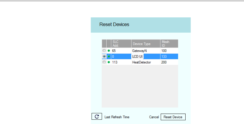
PRELIMINARY: Firelite Wireless Sensor Network P/N LS10036-000FL-E:N0 10/10/2013 45
ANN-80 Configuration Wireless Display Driver (W-DIS-D)
The profile is removed and the device is reset to factory default state.
3.7 ANN-80 Configuration
To configure the ANN-80, set the serial address of ANN-80 to 1 when it is connected to W-DIS-D.
To set the serial address of the ANN-80, refer to the ANN-80 series product installation document.

46 PRELIMINARY: Firelite Wireless Sensor Network P/N LS10036-000FL-E:N0 10/10/2013
Wireless Display Driver (W-DIS-D) W-DIS-D Operations
3.8 W-DIS-D Operations
Table 3.4 outlines the wireless related events and the location of display.
Table 3.4 Event Display Location Table
NOTE: One W-DIS-D is required for one W-GATE. Multiple W-GATE installations require a W-
DIS-D for each W-GATE.
3.8.1 W-DIS-D Operations
Modes of Operation Not in a Mesh Network
Bootloader
In this mode, the W-DIS-D cannot participate in a mesh and cannot provide fire protection. The W-
DIS-D will be available in the communicator window of the PC Tool with a status “Bootloader”.
To get a device out of bootloader, refer to the troubleshooting section.
Factory Default
In this mode, the W-DIS-D is not associated with the W-GATE. For further information on assign-
ing a profile, refer to section 3.6.1. In this mode, the W-DIS-D will be viewable in the communica-
tor window of the PC tool with a state of “Factory Default”. The ANN-80 will display RF COMM
LOSS when the W-DIS-D is at Factory Default state.
Events FACP Annunciator
Alarm (Detector or Module
activations)
YES (Address specific to the
initiating device)
NO (No Display)
Tamper YES (Generic Supervisory at GW
+1 address)
YES (Detailed display with SLC
address)
RF related trouble conditions -
Jamming, Battery Low, Duplicate
address, Class-A missing second
link, Weak link low signal
strength.
YES (Generic Trouble GW +2
address)
YES (Detailed display with SLC
address)
Wireless Device Missing from
network
YES (No Answer/Invalid response
for the specific SLC Address)
NO
W-GATE initializing, wireless
mesh formation in progress.
YES (Generic Trouble GW +2
address)
YES (no address specified)
Illegal address YES (Generic Trouble GW +2
address)
YES (address zero)
Mesh capacity exceeded YES (Generic Trouble GW +2
address)
YES (W-GATE base address)
RF comm loss YES (No Answer/Invalid response
for the W-DIS-D SLC Address)
YES
Normal None Mesh ID number

PRELIMINARY: Firelite Wireless Sensor Network P/N LS10036-000FL-E:N0 10/10/2013 47
W-DIS-D Operations Wireless Display Driver (W-DIS-D)
Profile Configured
In this mode, the W-DIS-D is associated with the W-GATE but is not an active participant in the
mesh network. For further information on mesh formation, refer to, “4.6.3, "Mesh Formation". To
remove a profile from a W-DIS-D, refer to section, “3.6.3, "Removing Profiles".
In this mode, the W-DIS-D will be viewable in the communicator window of the PC tool with a
state of profile configured. The ANN-80 will display RF COMM LOSS when the W-DIS-D is at
factory default state.
Modes of Operation as a Mesh Participant
Mesh Formation Mode
In this mode, the W-DIS-D is an active participant in a mesh that is forming. The LED flashes in
the following pattern: First blink green, second blink yellow for every 6.8 seconds. For further
information on mesh formation mode, refer to, “4.6.3, "Mesh Formation". The W-DIS-D will not
communicate directly with the tool for display in the communicator. The status of the W-DIS-D
must be obtained via the W-GATE. The ANN-80 will display ‘Mesh Formation in Progress’ during
mesh formation mode.
Initial Mesh Optimization Mode
In this mode, the mesh network is formed and is in the process of establishing stronger communica-
tion paths. The LED pattern flashes in the following pattern: A single yellow blink every 6.8 sec-
onds. For further information on initial mesh optimization mode, refer to the topic, "Initial Mesh
Optimization". The W-DIS-D will not communicate directly with the tool for display in the com-
municator. The status of the W-DIS-D must be obtained via the W-GATE. The ANN-80 will dis-
play Gateway Initializing during the initial mesh optimization mode.
Normal Mode
In this mode, the mesh network formation is complete. The LED flashes in the following pattern: A
single green blink every 13.6 seconds. The LED flash can be disabled by panel configuration. If a
device is in trouble, it will be displayed at the ANN-80 or the FACP. For information, refer to
3.9.4, "Event Messaging". The W-DIS-D will not communicate directly with the tool for display in
the communicator. The status of the W-DIS-D must be obtained via the W-GATE. The ANN-80
will display the mesh ID when the system is normal, or will display a wireless event as specified in
3.9.4, "Event Messaging".
Rescue Mode
In this mode, devices that are active participants in the mesh search and retrieve the devices that
have lost the communication link. The rescue mode is indicated by the following LED pattern: One
green blink every 6.8 seconds. For more information on rescue mode refer to “2.7.1, "W-GATE
Modes of Operation" The W-DIS-D will not communicate directly with the tool for display in the
communicator. The status of the W-DIS-D must be obtained via the W-GATE.
The ANN-80 will display the mesh ID when the system is normal, or will display a wireless event
as specified in 3.9.4, "Event Messaging".
SLC Operation
Program the point as a monitor point. When the communication to the ANN-80 is missing or dis-
rupted, the point will indicate open circuit. The monitor point will not initiate an alarm condition.
3.8.2 W-DIS-D LED Indications
The two LEDs on the devices blink in the same pattern to allow the LED to be viewed from any
angle. The LED indications are provided in the table below.
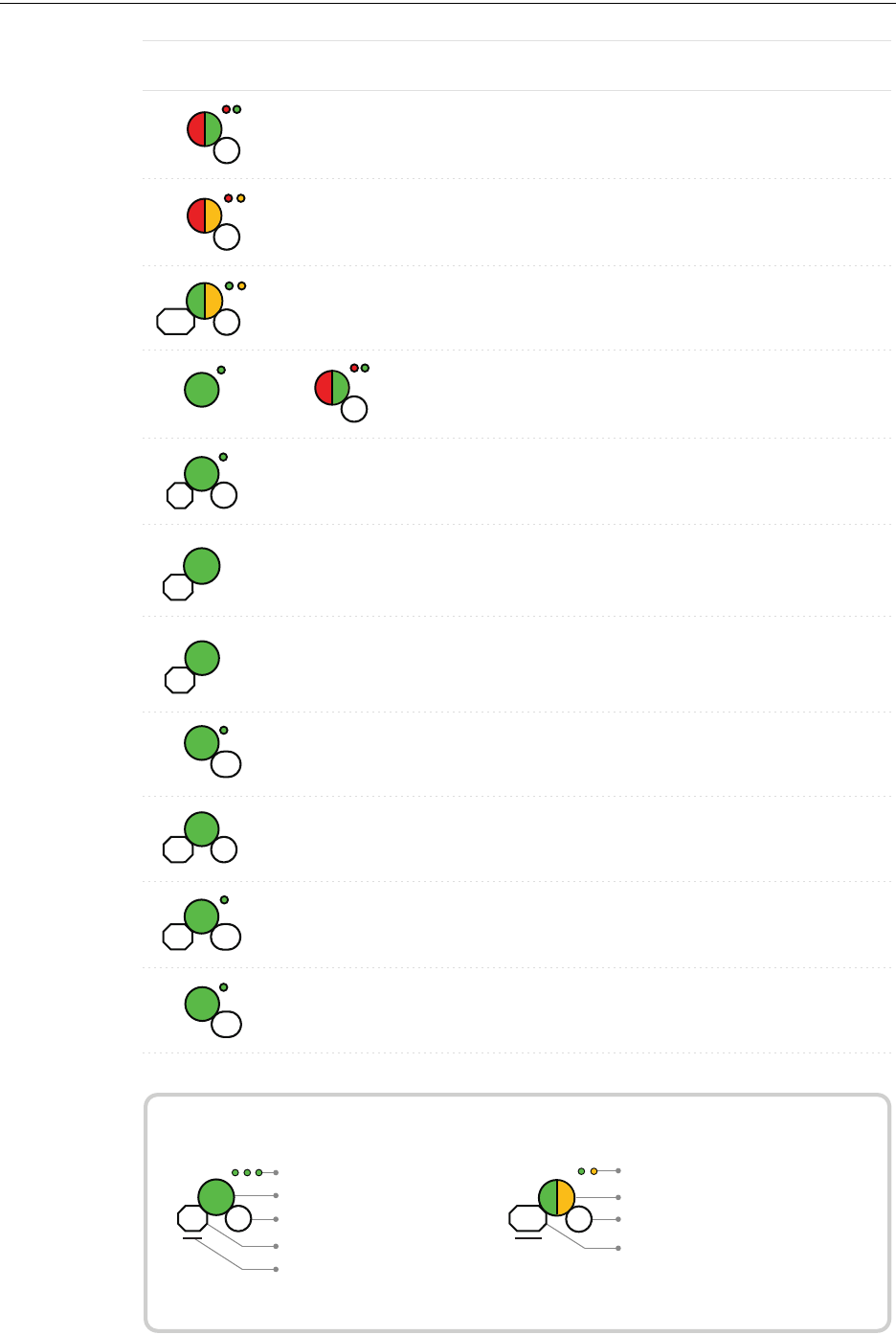
48 PRELIMINARY: Firelite Wireless Sensor Network P/N LS10036-000FL-E:N0 10/10/2013
Wireless Display Driver (W-DIS-D) W-DIS-D Operations
Duration of LED state
All units are in seconds. Minute is indicated by M.
Example:
Legend
LED color
No. of blinks
Interval between blink patterns
Approximate duration
Will transition to next state after
30 min (approx)
First blink is green. Second is yellow
Two blinks in this pattern
7 sec between blink patterns
7
M
30
Condition Action Required
Device is ready to update
Bootloader
LED Pattern
5
Device not permitted into
the mesh
Conrm device count and
software version
Device is in the mesh &
looking for devices that
are not in the mesh
7
Slot request
rejected
Mesh
Forming
App
erase
App
loading
2
New application code is
being downloaded
7
30M
Device has returned to
factory default state
Device is now prole
assigned.
Minimum of 2.5 years
battery life remaining
Device is distributing its
prole to other devices
which requested prole
Prole
removed
1
5
Prole
received
10
Solid
Battery Check
- All batteries
are fresh
Solid
2.5
Distributor
mode
0.5
Device is functioning as
normal and searching for
lost devices
Device is functioning as
normal and optimizing
parent-child connectivity
Device is functioning as
normal
Rescue
mode
M7
6
Background
mesh
optimization
5M14
Normal
mode
14
Use PC based congura-
tion tool to initiate the
download
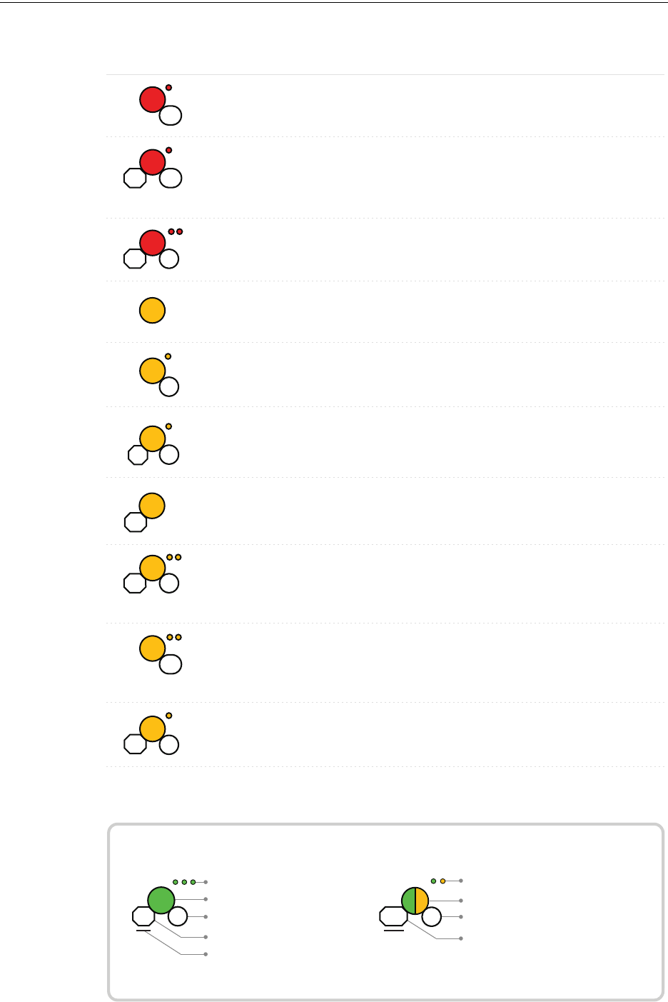
PRELIMINARY: Firelite Wireless Sensor Network P/N LS10036-000FL-E:N0 10/10/2013 49
W-DIS-D Operations Wireless Display Driver (W-DIS-D)
Duration of LED state
All units are in seconds. Minute is indicated by M.
Example:
Legend
LED color
No. of blinks
Interval between blink patterns
Approximate duration
Will transition to next state after
30 min (approx)
First blink is green. Second is yellow
Two blinks in this pattern
7 sec between blink patterns
7
M
30
Condition Action RequiredLED Pattern
Device is factory default Use PC tool to assign
prole or activate switch
to search for prole
Device is factory default
and requesting a prole
from a distributor or
gateway
Clear the tamper
condition within 1 minute
to enter site survey
Device is factory default
and is ready to enter site
survey
Pending site survey
5
1M
Waiting for prole
10
Searching for prole
0.5
1M
Device has failed internal
self diagnostics
Self test fail
Device is in a congura-
tion state.
Restart the device. If
problem persists. Contact
customer support
Restart the device. If
problem persists. Contact
customer support
Device has a prole and
can be set as distributor or
have prole removed
Set code wheel pattern to
enter the desired mode
Minimum of 6 months
battery life remaining
Prole is assigned and
device is searching for the
mesh
Ensure the mesh is in
rescue mode or wait for
timeout to search mesh in
formation mode
Solid
Factory
Command
1
Prole
modication
51
Battery Check - All
batteries are present
Solid
2.5
Searching for mesh
(in rescue mode)
90 3
Ensure the mesh is in
formation mode
Prole is assigned and
device is searching for the
mesh
Mesh is formed and
initializing
Searching for
mesh (in formation
mode)
20
1st Mesh
optimization
2.5 7
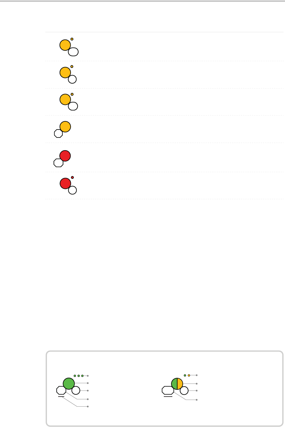
50 PRELIMINARY: Firelite Wireless Sensor Network P/N LS10036-000FL-E:N0 10/10/2013
Wireless Display Driver (W-DIS-D) W-DIS-D Operations
Duration of LED state
All units are in seconds. Minute is indicated by M.
Example:
Legend
LED color
No. of blinks
Interval between blink patterns
Approximate duration
Will transition to next state after
30 min (approx)
First blink is green. Second is yellow
Two blinks in this pattern
7 sec between blink patterns
7
M
30
Condition Action RequiredLED Pattern
Device is in the mesh and
in trouble condition.
Device is in the mesh but
has a incorrect SLC
address
Refer to the panel to
identify the trouble and
possible resolution
Verify the address is non
duplicate and non zero
Device has just been
tampered
Ensure detector is in the
base and module has the
face-plate on
Ensure detector is in the
base and module has the
face-plate on
Device is tampered
Device generic trouble
(Eg: Low battery, Partial
link condition)
14
Device address
trouble (Eg: Dual
address, Zero address)
3
Battery Check
- Weak
Less than 6 months or not
all 4 batteries present
Solid
2.5
Device is functioning as
normal and has been
activated
Alarm state
3
Sustained
tamper
12
Tamper
entry
Solid
4
Ensure all 4 batteries are
present or replace the
batteries.
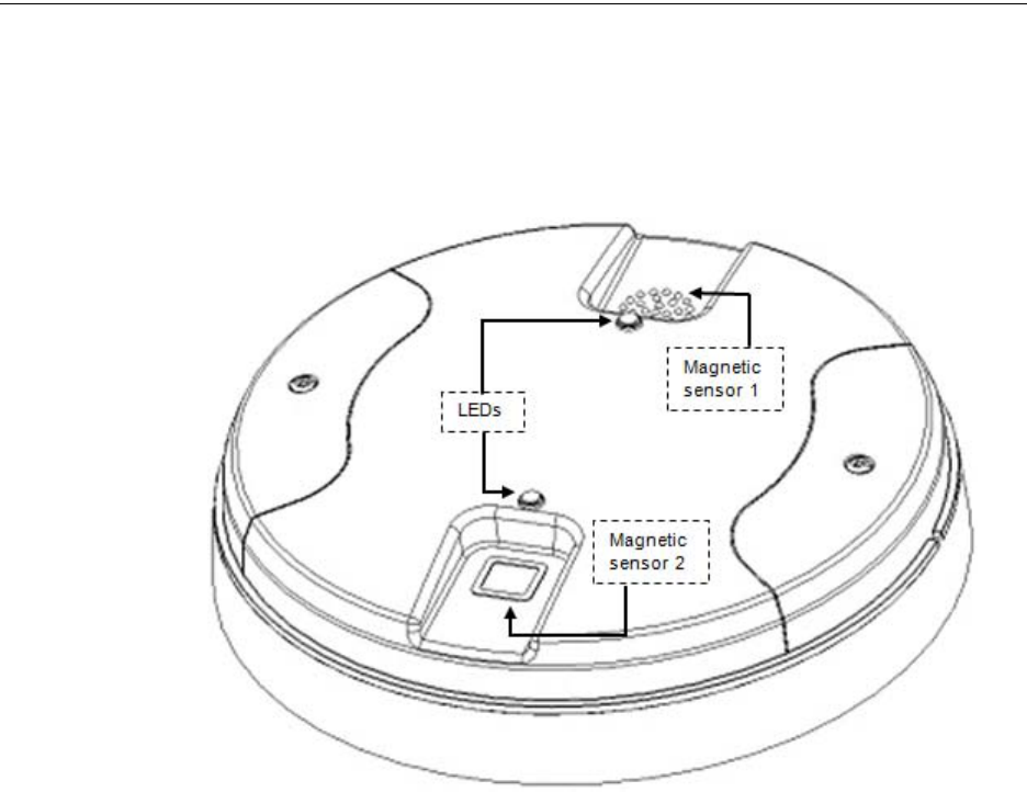
PRELIMINARY: Firelite Wireless Sensor Network P/N LS10036-000FL-E:N0 10/10/2013 51
W-DIS-D Operations Wireless Display Driver (W-DIS-D)
3.8.3 Switches
The W-DIS-D has two magnetic sensor switches. The switches are used to remove a profile as
described in 3.6.3, "Removing Profiles" or to request a profile as described in 3.6.1, "Assigning
Profiles".
Figure 3.5 W-DIS-D
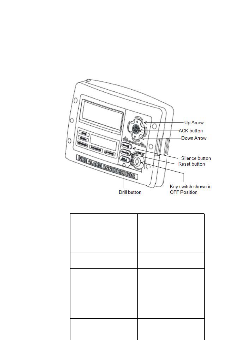
52 PRELIMINARY: Firelite Wireless Sensor Network P/N LS10036-000FL-E:N0 10/10/2013
Wireless Display Driver (W-DIS-D) ANN-80 Operations
3.9 ANN-80 Operations
The ANN-80 displays wireless specific events for the associated mesh network. Alarm conditions
and trouble events that are displayed by the FACP are not displayed at the ANN-80. The ANN-80
incorporates an automatic resound of the piezo and trouble indicator every 4 hours for active
events.
3.9.1 Buttons and Switches
The buttons and switches in the ANN-80 are displayed below in the image and are explained in the
Table 3.5 .
Figure 3.6 Buttons in ANN-80
Table 3.5
Button Action
Drill button Not Used
Up Arrow Press the UP Arrow to scroll up
through the messages
Ack button Press the ACK button to
acknowledge the messages
Down Arrow Press the Down Arrow to scroll
down through the messages
Silence button Not Used
Reset button Press the Reset button
to clear latching wireless
events
Key switch Use the Key switch to switch on
and switch off, to enable the
Reset button
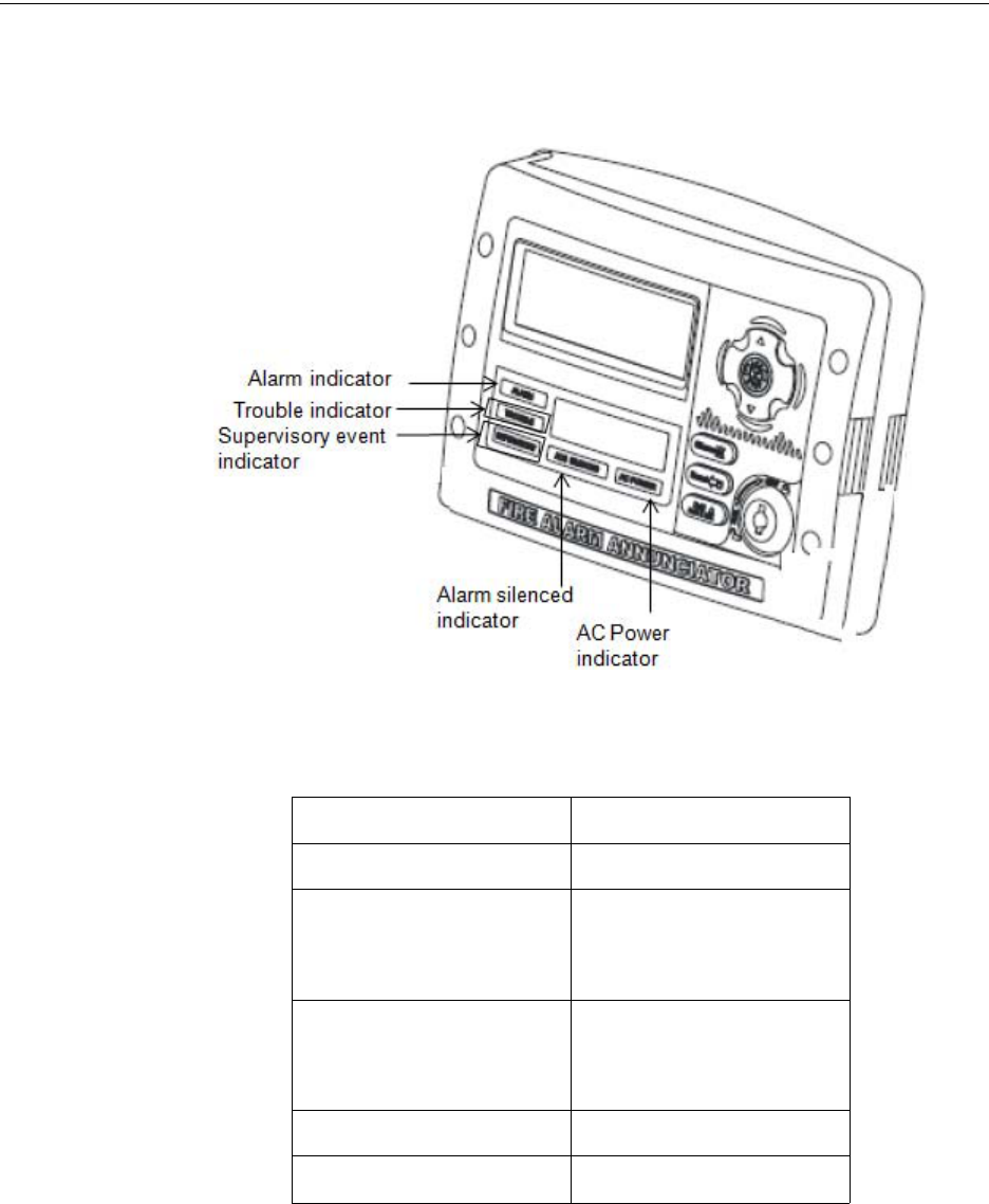
PRELIMINARY: Firelite Wireless Sensor Network P/N LS10036-000FL-E:N0 10/10/2013 53
ANN-80 Operations Wireless Display Driver (W-DIS-D)
3.9.2 Visual Indicators
The visual indicators in the ANN-80 are displayed in the below image and are explained in the
Table 3.6.
Figure 3.7 Visual Indicators in ANN-80
Table 3.6
Indicator buttons Action
Alarm Not Used
Trouble The trouble LED blinks yellow for
any unacknowledged trouble
event, and it glows steady for
acknowledged trouble events
Supervisory The Supervisory LED blinks
yellow for any unacknowledged
tamper event, and it glows steady
for acknowledged tamper events
Alarm Silenced Not Used
AC Power Not used
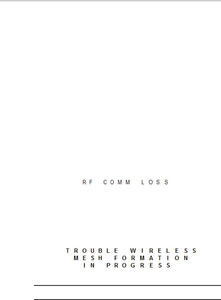
54 PRELIMINARY: Firelite Wireless Sensor Network P/N LS10036-000FL-E:N0 10/10/2013
Wireless Display Driver (W-DIS-D) ANN-80 Operations
3.9.3 Audible Indicators
The wireless events are sent to the FACP as generic trouble or supervisory events by the W-GATE
and the details of the specific events are sent to the ANN-80 by the W-DIS-D. The FACP piezo
activates for the first trouble event and the first supervisory event. The FACP piezo will not acti-
vate for additional trouble events or supervisory events when the initial event is still active. The
ANN-80 piezo will not activate for the first event but will sound for each event after the initial
event.
Use the ACK button to acknowledge the piezo. The reset function can be enabled in the ANN-80
using the key switch. To enable the reset button, insert the key into the key switch and turn the key
switch counter clockwise to the ON position.
To silence the buzzer, press the ACK key on the ANN-80 (Figure 3.6).
3.9.4 Event Messaging
The wireless specific events are related to the wireless W-GATE and devices. These events are dis-
played and notified on the FACP and N-ANN 80 in the form of messages. These messages are dis-
played based on their occurrences. You can scroll through the messages using the up arrow and
down arrow buttons.
LCD UI Not in Network
The message, ‘RF COMM LOSS’ is displayed when the W-DIS-D is not in the network. The mes-
sage displayed is if the W-DIS-D is in Bootloader, factory default, or profile assigned state but not
a part of a mesh network. RF COMM LOSS is a tracking event that will clear once the W-DIS-D
joins a mesh network.
Mesh Formation In Progress
The message, ‘MESH FORMATION IN PROGRESS’ is displayed when the network is in mesh
formation mode. Mesh Formation in Progress is a tracking trouble that will clear once the W-
GATE exits mesh formation mode.
NOTE: The ANN-80 must join the network to show this message. If it is not present in the
network, ‘RF Comm Loss’ message is displayed.
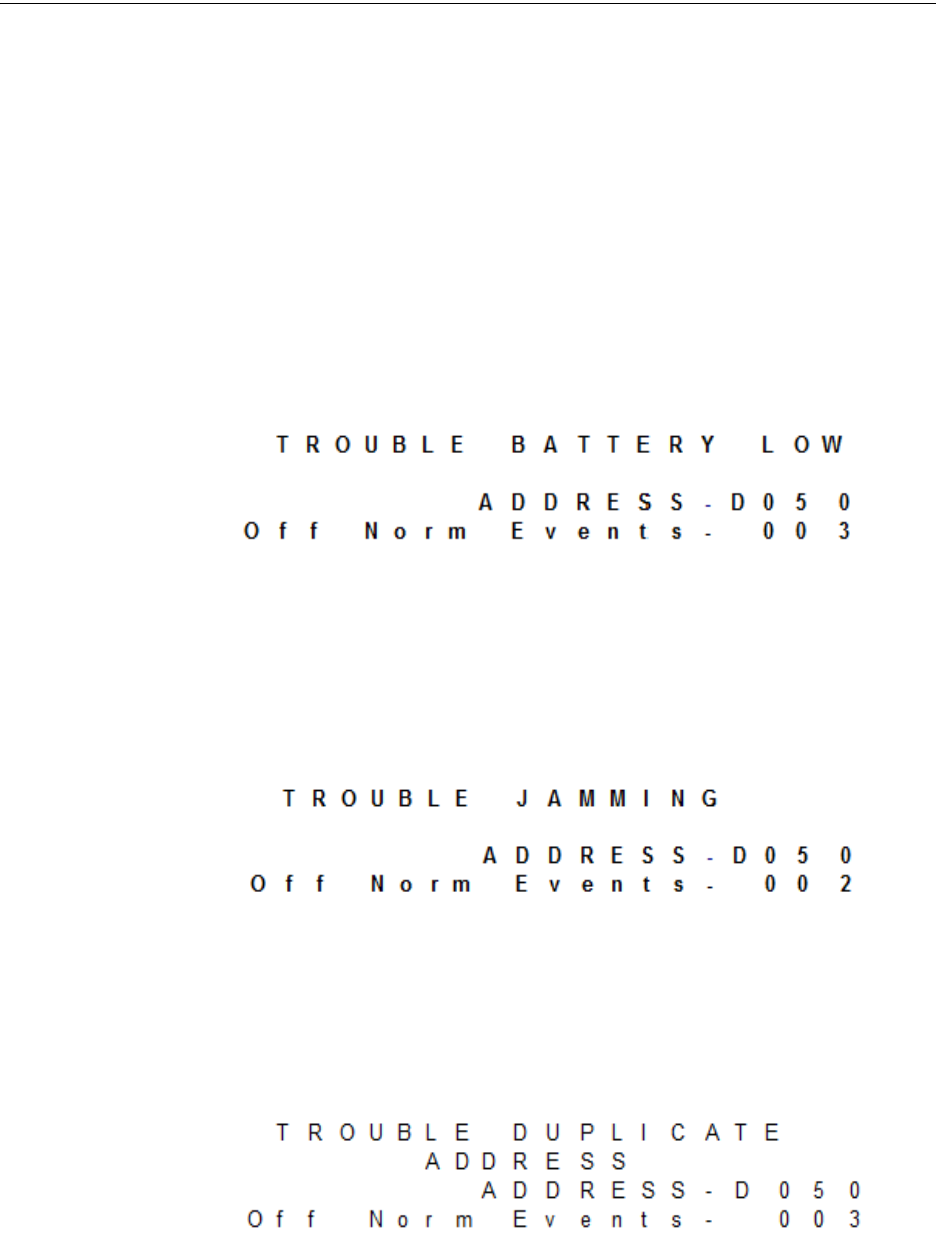
PRELIMINARY: Firelite Wireless Sensor Network P/N LS10036-000FL-E:N0 10/10/2013 55
ANN-80 Operations Wireless Display Driver (W-DIS-D)
Low Battery Event
The low battery event denotes that:
• The device has less than one month power left to perform the required operations.
Or
• Presence of less than four viable batteries.
The low battery event is a latching condition. To clear the low battery event, tamper the device and
replace all the four batteries. When a device is tampered, it drops out of the mesh network and
attempts to rejoin as soon as the batteries are replaced and the tamper event is cleared. The low bat-
tery levels on the wireless devices are displayed as a trouble in the ANN-80 and generic trouble on
the FACP. Initiate a RESET at the ANN-80 to clear the low battery event.
It is displayed as the following ASCII text on the ANN-80.
Trouble Jamming Event
Jamming occurs when a device is overloaded with an interfering RF signal; but is able to send the
messages out. A jamming event is detected after 20 seconds of exposure to the jamming signal.The
jamming event is displayed as a trouble event in the ANN-80 and generic trouble event on the
FACP. Jamming is a tracking trouble. To clear the jamming trouble, remove any interference
sources near the point that is reporting the trouble.
Duplicate Address
Two wireless devices on the same mesh network that are set to the same address reports a duplicate
address trouble. Duplicate address is a tracking trouble that will self restore once the conflict has
been resolved.
The following graphic illustrates the duplicate address trouble.
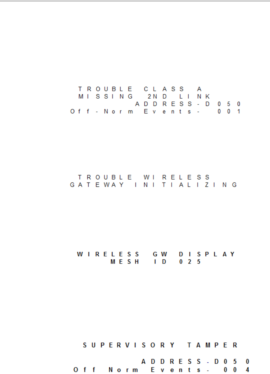
56 PRELIMINARY: Firelite Wireless Sensor Network P/N LS10036-000FL-E:N0 10/10/2013
Wireless Display Driver (W-DIS-D) ANN-80 Operations
Degraded Connection
The class A fault denotes a single connection path from the device. The wireless system is a class A
system requiring two communication paths for normal operations. To remedy the class A fault,
ensure adequate device spacing or the use of a repeater may be required. The wireless mesh is a self
healing network. If the trouble is not cleared within 5 minutes, additional actions may be required.
Refer to the troubleshooting section for tips on resolving class A fault conditions.
The following graphic illustrates the Class A trouble.
System Initialization
ANN-80 displays the below displayed message when it initializes. Gateway initializing is a track-
ing trouble that is active during the first mesh optimization. Once the first mesh optimization rou-
tine executes, the trouble will clear.
System Normal
ANN-80 displays the below displayed message when the system is functioning normally and there
are no wireless troubles in the system.
Tamper Event
A tamper trouble indicates that a detector is not firmly attached to the base or, cover plate is not
properly attached in a module. The Tamper events are displayed as supervisory events in the ANN-
80 and generic supervisory events on the FACP. Tamper is a latching condition that requires a
reset at the ANN-80 to clear.
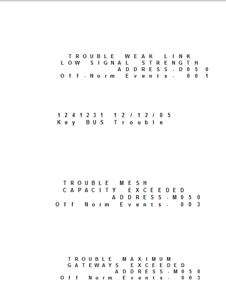
PRELIMINARY: Firelite Wireless Sensor Network P/N LS10036-000FL-E:N0 10/10/2013 57
ANN-80 Operations Wireless Display Driver (W-DIS-D)
Weak Link
A weak link trouble indicates that the connection of a device with its parent device is weak, since
the signal strength fails to meet the minimum RSSI threshold. The threshold is -50 dB during com-
missioning mode and -58 dB during normal mode. The trouble will be cleared only if the parent-
child signal strength goes above the required RSSI threshold, or if a mesh optimization is triggered.
Key Bus Trouble
A Key bus trouble indicates that the ANN-80 has lost connection with W-DIS-D.
Capacity Exceeded
A device count trouble indicates that there are fifty devices that are already present in the mesh and
one more device is trying to join the network.
Maximum Gateways
Gateways Exceeded trouble indicates that the number of overlapping gateways exceeds the limit of
4 gateways. The trouble will be cleared only when the number of overlapping gateways is reduced
to 4.
3.9.5 Clearing messages
The events that are tracking will clear once the event returns to the normal state. Events that are
latching require a reset at the ANN-80. To reset messages, press the Reset button in the ANN-80
Refer Figure 3.5. To reset messages in the panel, initiate a system reset in the FACP.

58 PRELIMINARY: Firelite Wireless Sensor Network P/N LS10036-000FL-E:N0 10/10/2013
Wireless Display Driver (W-DIS-D) ANN-80 Operations
3.9.6 LED Indications
The LED Indications in the ANN-80 are provided below.
DEVICE/MOD
ULES LED COLOR FUNCTION
Annunciator Yellow The trouble button blinks yellow
until it is acknowledged, to indicate
trouble state.
Yellow The supervisory button blinks
yellow until it is acknowledged, to
indicate supervisory state.

PRELIMINARY: Firelite Wireless Sensor Network P/N LS10036-000FL-E:N0 10/10/2013 59
ANN-80 Operations Wireless Display Driver (W-DIS-D)

60 PRELIMINARY: Firelite Wireless Sensor Network P/N LS10036-000FL-E:N0 10/10/2013
Devices Description
Section 4: Devices
4.1 Description
Subsystem Overview
The Wireless Sensor Network consists of the following devices:
W-SD355 - Wireless Photoelectric Smoke Detector - FCC ID AUBWFSSD
The wireless photoelectric smoke detector is powered by four CR123A batteries. It has a sensor
head to detect smoke and LEDs to indicate the activation & trouble status. For further details, refer
to the table in 4.7.2, "LED Indications".
W-SD355T- Wireless Photo/Heat Detector - FCC ID AUBWFSSD
The wireless Photo/Heat detector is powered by four CR123A batteries. It has a sensor head to
detect heat and LEDs to indicate activation & trouble status. For further details, refer to the table
in 4.7.2, "LED Indications".
W-H355R- Wireless Rate of Rise Heat Detector - FCC ID AUBWFSSD
The Rate of Rise heat detectors are powered by four CR123A batteries. The detectors have LEDs,
to indicate the activation & trouble status. For further details, refer to the table in 4.7.2, "LED Indi-
cations".
W-H355- FIX135 Wireless Fixed Heat Detector - FCC ID AUBWFSSD
The Fixed heat detectors are powered by four CR123A batteries. The detectors have LEDs, to indi-
cate the activation & trouble status. For further details, refer to the table in 4.7.2, "LED Indica-
tions".
W-MMF- Wireless Monitor Module - FCC ID AUBWFSMM
The wireless monitor module is powered by four CR123A batteries. It can be connected to a switch
within three feet of its location or wired directly to the pull station. The module has LEDs, to indi-
cate the activation & trouble status. For further details, refer to the table in 4.7.2, "LED Indica-
tions".
4.2 Agency Approvals
4.2.1 FCC
This device complies with part 15 of the FCC Rules. Operation is subject to the following two con-
ditions:
1. This device may not cause harmful interference, and
2. This device must accept any interference received, including interference that may cause
undesired operation.
WARNING: CHANGES OR MODIFICATIONS NOT EXPRESSLY APPROVED BY THE
MANUFACTURER COULD VOID THE USER’S AUTHORITY TO OPERATE THE EQUIPMENT.

PRELIMINARY: Firelite Wireless Sensor Network P/N LS10036-000FL-E:N0 10/10/2013 61
Specifications Devices
4.3 Specifications
The following are the specifications for the devices.
Table 4.1 Device Specifications
The below table provides details on the device references.
4.4 Installing Devices
For information on installing the devices, refer to the manuals mentioned in the above table.
4.5 Mounting & Wiring
For information on mounting and wiring, refer to the manuals mentioned in the table 4.2.
4.6 Configuration and Programming
The configuration of a device starts with assigning a profile. Refer to the instructions below for
assigning a profile.
• Assiging profiles using PC Tools.
• Assigning profile to a detector with a W-GATE or distributor.
• Assigning profile to a module with a W-GATE or distributor.
Specification Data
Radio Frequency Lower ISM Band (915 MHz)
Maximum power output +17dBm
Minimum signal strength level needed at the receiver for a primary path
with weak link trouble reporting enabled.
-50dBm
Minimum signal strength level needed at the receiver for a secondary
path or primary path with weak link trouble reporting disabled.
Must be 15 dBm higher than
the noise floor down to -
87dBm
Maximum ambient noise level -90dBm
Minimum battery life 1 year
Model Description Manual
W-SD355 Wireless LiteSpeed Detector, Photo W-SD355 and W-SD355T Intelligent
Wireless Photoelectric Smoke Sensors.
Manual part number for the above
devices- I56-4081-000
W-SD355T Wireless LiteSpeed Detector,
Photo/Heat
W-H355R Wireless LiteSpeed Heat
sensorHeat, Rate Of Rise 135
W-H355R and W-H355 and Intelligent
Wireless Temperature Sensors.
Manual part number for the above
devices- I56-4082-000
W-H355 Wireless LiteSpeed Heat sensor
Heat, Fixed Temp135
W-MMF Monitor Module W-MMF Wireless Monitor Module
Manual part number - I56-4083-000
Table 4.2 Device References
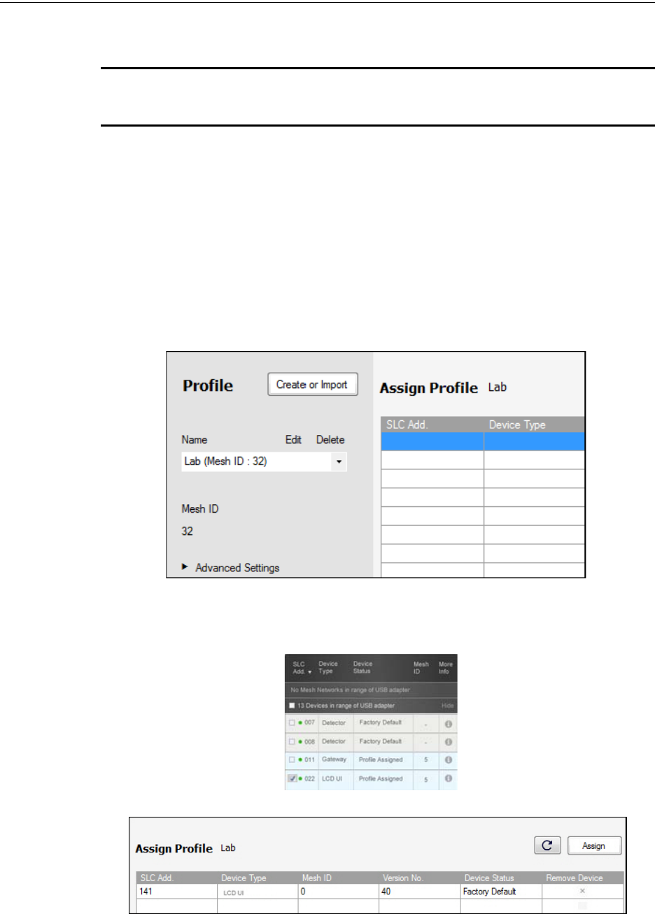
62 PRELIMINARY: Firelite Wireless Sensor Network P/N LS10036-000FL-E:N0 10/10/2013
Devices Configuration and Programming
4.6.1 Assigning Profiles
NOTE: To assign a profile, the device must be in a factory default state. A single red light flashes
on the LED confirming that the device is in the default state. To restore the device to factory
default state, refer to 4.6.4, "Restoring a Device to Factory Default".
Assigning Profile Using PC Tools
To assign a profile to the device using the PC Tools application, do the following:
1. Connect the W-USB dongle device to your computer. For more information on USB dongle,
refer to Section 5:, "USB Adapter".
2. Launch the PC tools application. Refer to Appendix B:, "PC tools" to know about launching
the PC tools application.
3. Go to the Create Mesh Network step.
4. Create a new profile or import an existing profile as required.
5. Select and open the profile to be assigned to the device from the Name drop down list in the
left panel.
6. Switch on the device in range of the USB adapter, which is connected to the laptop or PC
where PC tool is installed.
7. Select the device from the Communicator panel.
8. Click Assign.
The device is now included in the list of devices with a profile assigned. When the profile is
assigned, the LEDs emit a solid green light for 10 seconds.
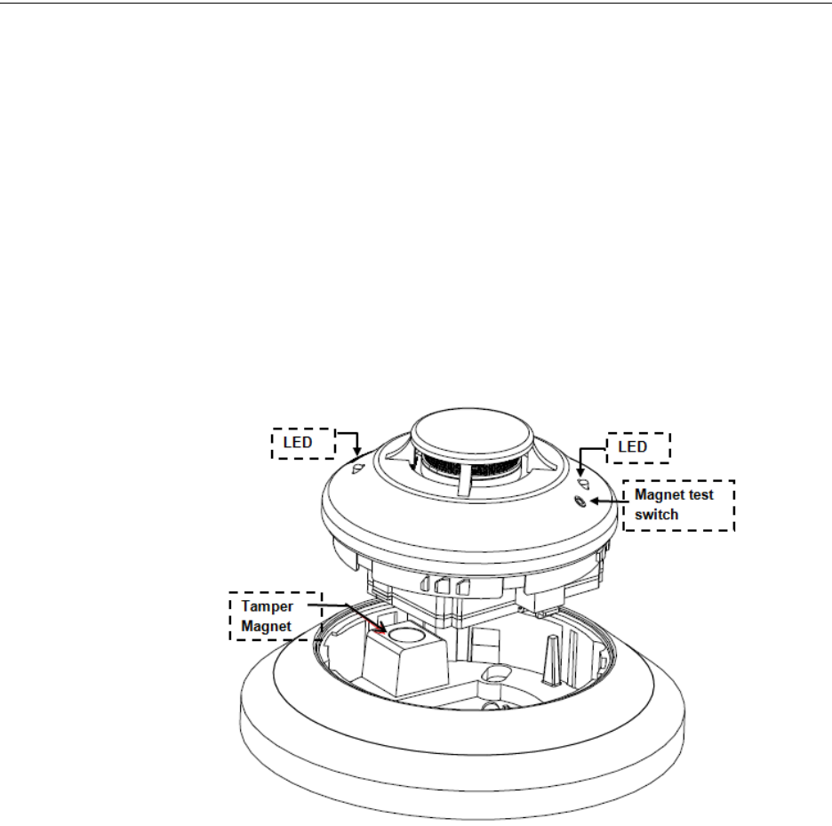
PRELIMINARY: Firelite Wireless Sensor Network P/N LS10036-000FL-E:N0 10/10/2013 63
Configuration and Programming Devices
Assigning a Profile to a Detector with a W-GATE or Distributor
A W-GATE that has a profile can be used to distribute the profile to other devices. The W-GATE
must be in a state where it can distribute a profile. For more information on converting a W-GATE
to a distributor, refer to 2.6.3, "Profile Distribution". A device with a profile can be used to distrib-
ute the profile. To put a device into distributor mode, refer to topic, “Converting a Device into a
Distributor”.
Transfer Profile from W-GATE/Distributor to Detector
To transfer profile from W-GATE/distributor to the detector, do the following:
1. Bring the detector within the range of the W-GATE/distributor.
2. Power on the detector. Ensure the detector is in factory default state. A single or double red
light flashes on the detector confirming that the detector is in the default state.
3. To make the detector request the profile, activate the magnetic test switch shown in the below
figure.
Figure 4.1 Magnet in a detector
Once the magnet test switch is activated, the LED flashes red light every half second indicating that
it is requesting a profile. If the profile is successfully received, the LED emits a solid green light for
10 seconds. If the profile is not received within a minute, the LED flashes a red light every ten sec-
onds indicating that it has stopped requesting for a profile.
Transfer Profile from W-GATE/Distributor to Module
To assign a profile to a module, perform the following steps:
1. Bring the module in range of the W-GATE or the distributor.
2. Power on the module. Ensure the module is in factory default state. If the module is in factory
default state, the LED blinks red once.
3. To make the module request the profile, toggle the state of the tamper condition. To toggle the
tamper condition state, start with the faceplate removed.
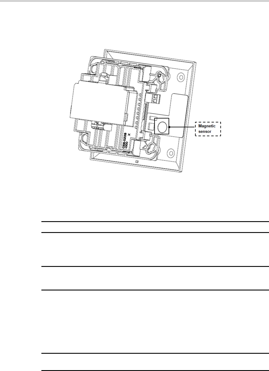
64 PRELIMINARY: Firelite Wireless Sensor Network P/N LS10036-000FL-E:N0 10/10/2013
Devices Configuration and Programming
4. Place the faceplate over the module temporarily, and remove the faceplate again in less than 1
second. Do not attach the mounting screws for the faceplate during this step. The LED flashes
red light every half a second indicating that it is requesting a profile. The LEDs blink solid
green for ten seconds indicating that the profile is assigned.
Figure 4.2 Magnetic sensor in a module
4.6.2 Distributor Mode
Converting a Device into a Distributor
NOTE: Only a device with a profile can be made as a distributor.
To turn a device into a distributor, do the following:
1. Power up the device with one battery.
NOTE: Ensure that the device is in the profile modification mode. This is indicated by a single
yellow blink every 5 seconds. The profile modification mode times out if it has not received a
command in one minute.
2. Toggle the SLC code wheel address to pattern of 0-1-0-1. To toggle the SLC code wheel
address,
• Set the address to 0.
• Change the address to 1.
• Change the address back to 0.
• Change the address back to 1.
NOTE: The LED flashes a single green every half a second when the device is functioning as a
distributor.
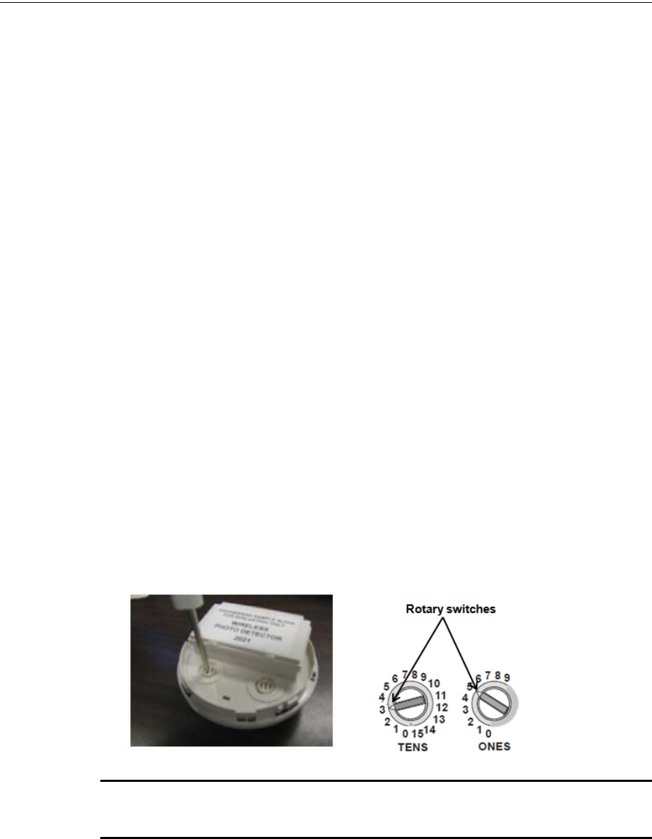
PRELIMINARY: Firelite Wireless Sensor Network P/N LS10036-000FL-E:N0 10/10/2013 65
Configuration and Programming Devices
Converting a Distributor Back into a Device
To turn a distributor device back to a network device, replace the battery and provide a proper code
wheel address. A normal device requires four batteries for trouble-free operation. It is recom-
mended to use fresh batteries after the distributor mode.
4.6.3 Mesh Formation
To add a device to a mesh, refer to the topic, "Mesh Formation with PC Tools" or, to form a mesh
network, ensure that the W-GATE is powered on and contains a profile. Activate the mesh forma-
tion” (Figure 2.8, “Mesh Formation Magnetic Sensor on a W-GATE”) magnet sensor on the W-
GATE.
Repeater
The Firelite Wireless Sensor Network does not require the use of a dedicated repeater; all wireless
devices act as repeaters. When the repeater function is needed in a location where there is no spe-
cific fire function is required, a wireless monitor module or another device can be installed to fulfill
the function as a repeater.
4.6.4 Restoring a Device to Factory Default
Removing Profiles Without PC-based Configuration Tool
A device can be restored to factory default state by following the below steps.
1. Start with the device powered off. The process is performed during the start-up.
2. Power on the device by inserting a single battery into any slot in the device. The LEDs blink
yellow twice every five seconds for one minute continuously after inserting the battery.
3. Toggle the code wheel address pattern to 0-159-0. To toggle the SLC code wheel address,
• Set the address to 0.
• Change the address to 159.
• Change the address back to 0.
NOTE: The above illustration depicts the rotary switches being set at address 35 (rotary switch
on 'TENS' set at 3 and rotary switch on 'ONES’ set at 5. Ensure that the code wheel address
pattern is toggled within 1 minute of inserting the battery.
After the code wheel pattern is set, the LEDs in the device blink green five times followed by a sin-
gle or double red blink confirming that the device has been reverted back to factory default condi-
tion.
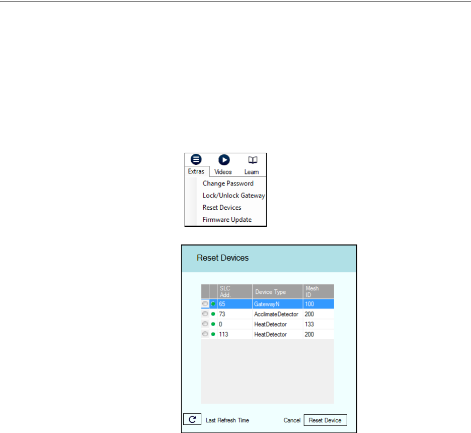
66 PRELIMINARY: Firelite Wireless Sensor Network P/N LS10036-000FL-E:N0 10/10/2013
Devices Device Operations
Removing a Profile with PC Tools
To remove a profile in a device using the PC Tools application, do the following:
1. Connect the W-USB dongle device to your computer. For more information on USB dongle,
refer to Section 5:, "USB Adapter".
2. Launch the PC tools application. Refer to Appendix B:, "PC tools" to know about launching
the PC tools application.
3. Go to Site Survey, Create Mesh Network or Diagnostics step.
4. Click Extras and select Reset Devices. The Reset Devices screen appears, displaying the W-
GATE and other devices that have the profile assigned.
5. Click to select the required device and click Reset Device to remove the profile.
The profile is removed and the device is reset to factory default state.
4.7 Device Operations
4.7.1 Modes of Operation
Factory Default
In this mode, the devices are not associated with the W-GATE. A profile must be assigned to asso-
ciate the device with the W-GATE. For further information on assigning a profile, refer to,
"Assigning a Profile to a Detector with a W-GATE or Distributor". A device in factory default can
be used for site survey. Refer to Appendix A:, "Site Survey".
The device cannot perform any fire protection in the factory default state. In this mode, the devices
will be viewable in the communicator window of the PC tool with the state displayed as “Factory
Default”.
Profile Assigned
In this mode, the devices are associated with the W-GATE but are not an active participant in the
mesh network. A device that is not in the tampered state can join the mesh network in formation or
in the rescue mode. For further information on mesh formation, refer to “Mesh Formation Mode”
and for further information on rescue mode, refer to “Rescue Mode”. A device in the profile con-

PRELIMINARY: Firelite Wireless Sensor Network P/N LS10036-000FL-E:N0 10/10/2013 67
Device Operations Devices
figured state can also be used to distribute profiles. For further information on distributing a profile,
refer to “4.6.2, "Distributor Mode"”. To remove a profile from a device, refer to the topic ,
"Removing Profiles Without PC-based Configuration Tool".
A device cannot perform any fire protection until it becomes a part of the mesh network. The
device will be an invalid reply or no answer at the FACP.
In this mode, the devices will be viewable in the communicator window of the PC tool and indi-
cates a status of “Profile Assigned”.
Bootloader
In this mode, the device cannot participate in a mesh and cannot provide fire protection. The
device will be viewable in the communicator window of the PC Tool with a status “Bootloader”.
To get a device out of bootloader, refer to Appendix C:, "Troubleshooting and Testing".
Distributor
In this mode the device is functioning as a profile distributor. The device cannot participate in a
mesh and cannot provide fire protection. It can be used to share the profile with any device that
requests a profile. The device will be viewable in the communicator window of the PC Tool with a
status “Distributor”.
Mesh Participant
Devices that are in the mesh network, no longer communicates directly with the PC Tools applica-
tion. The PC Tools application must communicate with the W-GATE for status information from
the device. The W-GATE will respond to the FACP for the device at the address set with the code
wheels. The following states are applicable for a device in a mesh network.
Mesh Formation Mode
In this mode, the devices are active participants in a mesh that is forming. The LED flashes in the
following pattern. First blink green, second blink yellow every 6.8 seconds. The device cannot per-
form any fire protection in this state.
For further information on this state (mesh formation), refer to the topic “Mesh Formation”.
Initial Mesh Optimization Mode
In this mode, the mesh network is formed and is in the process of establishing stronger communica-
tion paths. The LED pattern flashes in the following pattern. Single yellow blink every 6.8 seconds.
The device cannot perform any fire protection in this state.
For further information on initial mesh optimization mode, refer to the topic, “Initial Mesh Optimi-
zation Mode”.
Normal Mode
In the normal mode, the mesh network is formed and provides fire protection. The LED pattern is
single green blink every 13.6 seconds. The LED flash can be disabled by panel configuration. If a
device is in trouble, it is indicated by the trouble states.
Rescue Mode
In the rescue mode, devices that are active participant in the mesh search and retrieve the devices
that have lost the communication link. The rescue mode is indicated by the LED pattern of 1 green
blink every 6.8 seconds. For more information on rescue mode, refer to the topic, “Rescue Mode”.
4.7.2 LED Indications
The two LEDs on the devices blink in the same pattern to allow the LED to be viewed from any
angle. The LED indications are provided in the table below.
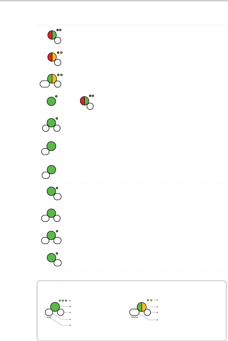
68 PRELIMINARY: Firelite Wireless Sensor Network P/N LS10036-000FL-E:N0 10/10/2013
Devices Device Operations
Duration of LED state
All units are in seconds. Minute is indicated by M.
Example:
Legend
LED color
No. of blinks
Interval between blink patterns
Approximate duration
Will transition to next state after
30 min (approx)
First blink is green. Second is yellow
Two blinks in this pattern
7 sec between blink patterns
7
M
30
Condition Action RequiredLED Pattern
Device is factory default Use PC tool to assign
prole or activate switch
to search for prole
Device is factory default
and requesting a prole
from a distributor or
gateway
Clear the tamper
condition within 1 minute
to enter site survey
Device is factory default
and is ready to enter site
survey
Pending site survey
5
1M
Waiting for prole
10
Searching for prole
0.5
1M
Device has failed internal
self diagnostics
Self test fail
Device is in a congura-
tion state.
Restart the device. If
problem persists. Contact
customer support
Restart the device. If
problem persists. Contact
customer support
Device has a prole and
can be set as distributor or
have prole removed
Set code wheel pattern to
enter the desired mode
Minimum of 6 months
battery life remaining
Prole is assigned and
device is searching for the
mesh
Ensure the mesh is in
rescue mode or wait for
timeout to search mesh in
formation mode
Solid
Factory
Command
1
Prole
modication
51
Battery Check - All
batteries are present
Solid
2.5
Searching for mesh
(in rescue mode)
90 3
Ensure the mesh is in
formation mode
Prole is assigned and
device is searching for the
mesh
Mesh is formed and
initializing
Searching for
mesh (in formation
mode)
20
1st Mesh
optimization
2.5 7
Duration of LED state
All units are in seconds. Minute is indicated by M.
Example:
Legend
LED color
No. of blinks
Interval between blink patterns
Approximate duration
Will transition to next state after
30 min (approx)
First blink is green. Second is yellow
Two blinks in this pattern
7 sec between blink patterns
7
M
30
Condition Action Required
Device is ready to update
Bootloader
LED Pattern
5
Device not permitted into
the mesh
Conrm device count and
software version
Device is in the mesh &
looking for devices that
are not in the mesh
7
Slot request
rejected
Mesh
Forming
App
erase
App
loading
2
New application code is
being downloaded
7
30M
Device has returned to
factory default state
Device is now prole
assigned.
Minimum of 2.5 years
battery life remaining
Device is distributing its
prole to other devices
which requested prole
Prole
removed
1
5
Prole
received
10
Solid
Battery Check
- All batteries
are fresh
Solid
2.5
Distributor
mode
0.5
Device is functioning as
normal and searching for
lost devices
Device is functioning as
normal and optimizing
parent-child connectivity
Device is functioning as
normal
Rescue
mode
M7
6
Background
mesh
optimization
5M14
Normal
mode
14
Use PC based congura-
tion tool to initiate the
download
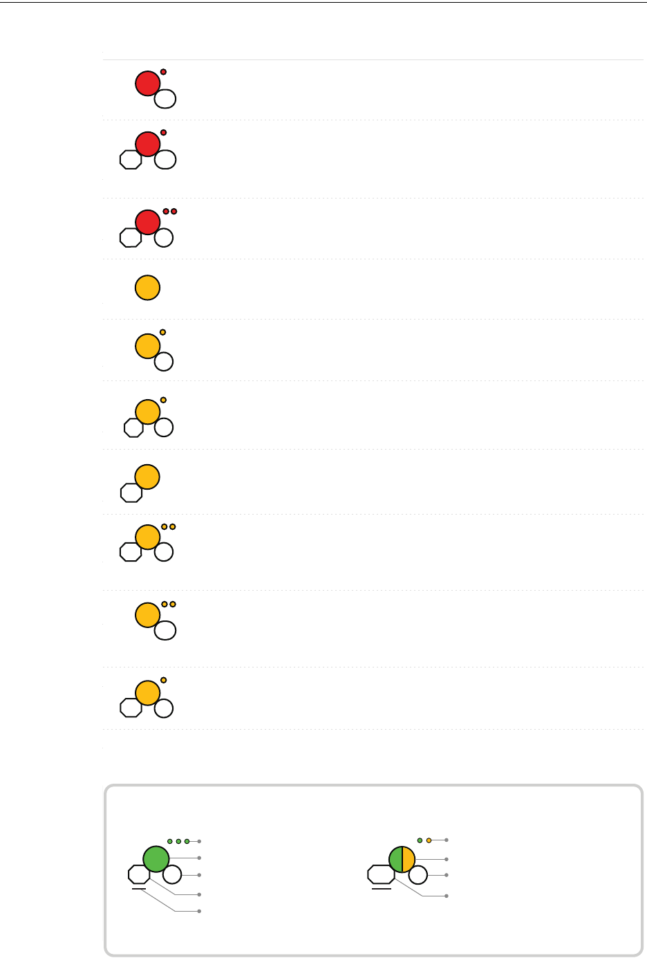
PRELIMINARY: Firelite Wireless Sensor Network P/N LS10036-000FL-E:N0 10/10/2013 69
Device Operations Devices
Duration of LED state
All units are in seconds. Minute is indicated by M.
Example:
Legend
LED color
No. of blinks
Interval between blink patterns
Approximate duration
Will transition to next state after
30 min (approx)
First blink is green. Second is yellow
Two blinks in this pattern
7 sec between blink patterns
7
M
30
Condition Action Required
Device is ready to update
Bootloader
LED Pattern
5
Device not permitted into
the mesh
Conrm device count and
software version
Device is in the mesh &
looking for devices that
are not in the mesh
7
Slot request
rejected
Mesh
Forming
App
erase
App
loading
2
New application code is
being downloaded
7
30M
Device has returned to
factory default state
Device is now prole
assigned.
Minimum of 2.5 years
battery life remaining
Device is distributing its
prole to other devices
which requested prole
Prole
removed
1
5
Prole
received
10
Solid
Battery Check
- All batteries
are fresh
Solid
2.5
Distributor
mode
0.5
Device is functioning as
normal and searching for
lost devices
Device is functioning as
normal and optimizing
parent-child connectivity
Device is functioning as
normal
Rescue
mode
M7
6
Background
mesh
optimization
5M14
Normal
mode
14
Use PC based congura-
tion tool to initiate the
download
Duration of LED state
All units are in seconds. Minute is indicated by M.
Example:
Legend
LED color
No. of blinks
Interval between blink patterns
Approximate duration
Will transition to next state after
30 min (approx)
First blink is green. Second is yellow
Two blinks in this pattern
7 sec between blink patterns
7
M
30
Condition Action RequiredLED Pattern
Device is factory default Use PC tool to assign
prole or activate switch
to search for prole
Device is factory default
and requesting a prole
from a distributor or
gateway
Clear the tamper
condition within 1 minute
to enter site survey
Device is factory default
and is ready to enter site
survey
Pending site survey
5
1M
Waiting for prole
10
Searching for prole
0.5
1M
Device has failed internal
self diagnostics
Self test fail
Device is in a congura-
tion state.
Restart the device. If
problem persists. Contact
customer support
Restart the device. If
problem persists. Contact
customer support
Device has a prole and
can be set as distributor or
have prole removed
Set code wheel pattern to
enter the desired mode
Minimum of 6 months
battery life remaining
Prole is assigned and
device is searching for the
mesh
Ensure the mesh is in
rescue mode or wait for
timeout to search mesh in
formation mode
Solid
Factory
Command
1
Prole
modication
51
Battery Check - All
batteries are present
Solid
2.5
Searching for mesh
(in rescue mode)
90 3
Ensure the mesh is in
formation mode
Prole is assigned and
device is searching for the
mesh
Mesh is formed and
initializing
Searching for
mesh (in formation
mode)
20
1st Mesh
optimization
2.5 7
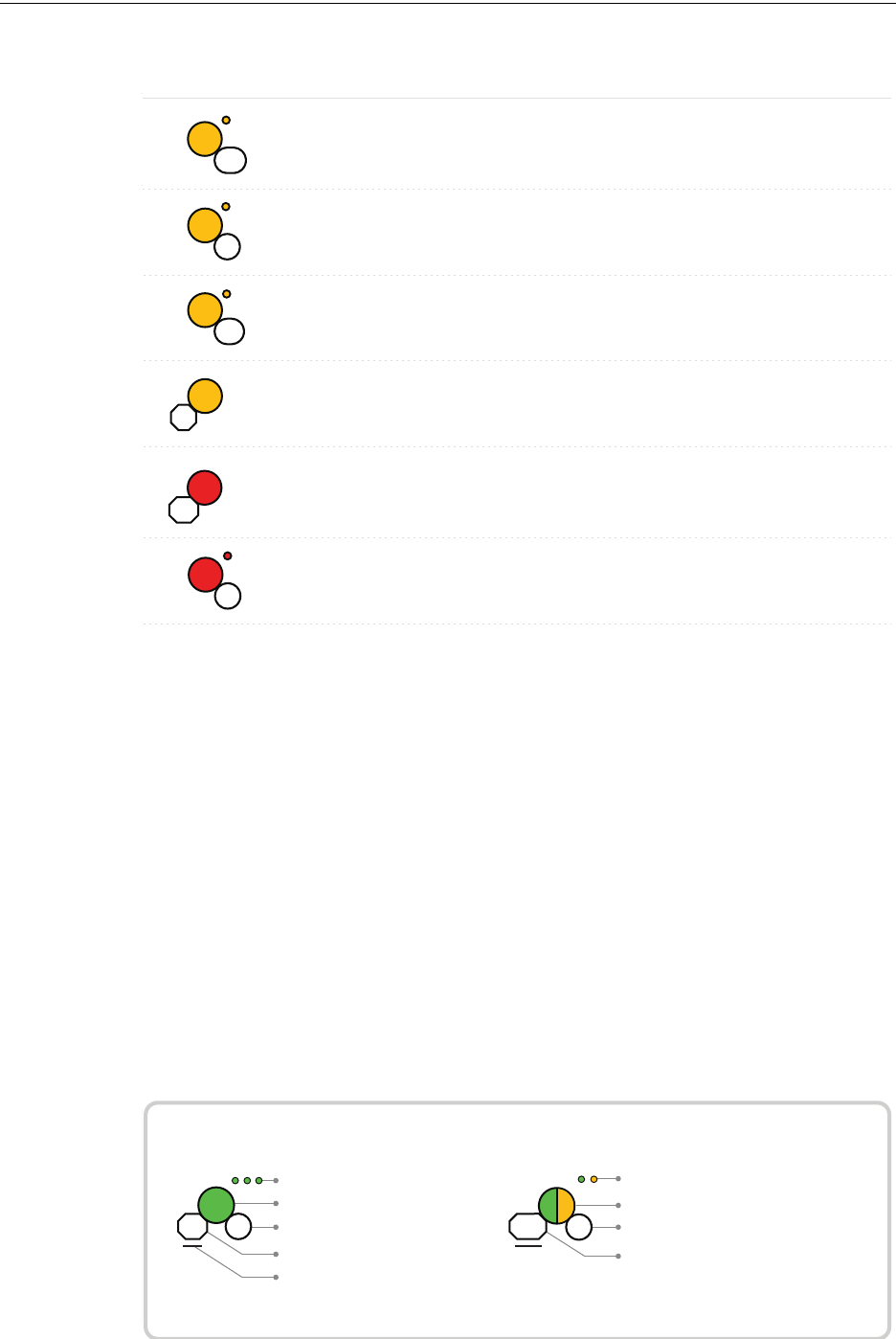
70 PRELIMINARY: Firelite Wireless Sensor Network P/N LS10036-000FL-E:N0 10/10/2013
Devices Device Operations
Duration of LED state
All units are in seconds. Minute is indicated by M.
Example:
Legend
LED color
No. of blinks
Interval between blink patterns
Approximate duration
Will transition to next state after
30 min (approx)
First blink is green. Second is yellow
Two blinks in this pattern
7 sec between blink patterns
7
M
30
Condition Action RequiredLED Pattern
Device is in the mesh and
in trouble condition.
Device is in the mesh but
has a incorrect SLC
address
Refer to the panel to
identify the trouble and
possible resolution
Verify the address is non
duplicate and non zero
Device has just been
tampered
Ensure detector is in the
base and module has the
face-plate on
Ensure detector is in the
base and module has the
face-plate on
Device is tampered
Device generic trouble
(Eg: Low battery, Partial
link condition)
14
Device address
trouble (Eg: Dual
address, Zero address)
3
Battery Check
- Weak
Less than 6 months or not
all 4 batteries present
Solid
2.5
Device is functioning as
normal and has been
activated
Alarm state
3
Sustained
tamper
12
Tamper
entry
Solid
4
Ensure all 4 batteries are
present or replace the
batteries.

PRELIMINARY: Firelite Wireless Sensor Network P/N LS10036-000FL-E:N0 10/10/2013 71
Device Operations Devices
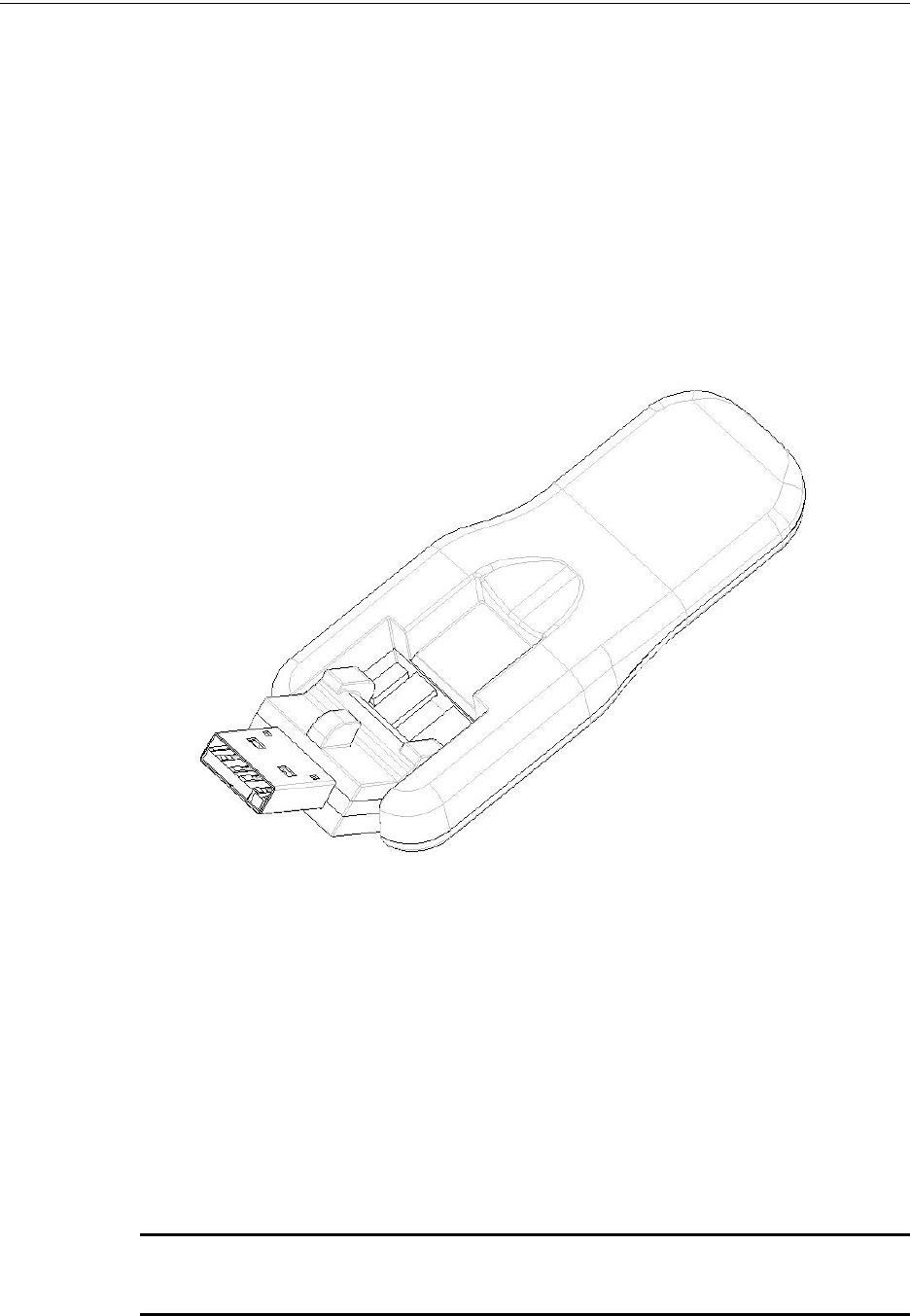
72 PRELIMINARY: Firelite Wireless Sensor Network P/N LS10036-000FL-E:N0 10/10/2013
USB Adapter Introduction
Section 5: USB Adapter
5.1 Introduction
The W-USB is an interface that can be connected to a PC through USB. It communicates with the
RF devices using the same frequencies as the mesh protocol. This device is powered directly by
the USB port.
The LED gives an indication of power and initialization status.
The W-USB has an adjustable USB connector to facilitate the connection by reducing the size
when connected to a laptop/tablet.
Figure 5.1 USB Adapter
5.2 Agency Approvals
5.2.1 FCC
This device complies with part 15 of the FCC Rules. Operation is subject to the following two con-
ditions:
1. This device may not cause harmful interference, and
2. This device must accept any interference received, including interference that may cause
undesired operation.
FCC ID PV3WFSADPT
WARNING: CHANGES OR MODIFICATIONS NOT EXPRESSLY APPROVED BY THE
MANUFACTURER COULD VOID THE USER’S AUTHORITY TO OPERATE THE EQUIPMENT.

PRELIMINARY: Firelite Wireless Sensor Network P/N LS10036-000FL-E:N0 10/10/2013 73
Specifications USB Adapter
5.3 Specifications
5.3.1 Electrical Specifications
5.3.2 Serial Communication Specification
5.3.3 Mechanical Specifications
5.3.4 Environmental Specifications
ITEM TYP MIN MAX UNITS Comments
Operating Voltage 5 4.3 5.5 VDC
Supply Current 33 25 85 mA
ITEM Comments
USB Standard USB 2.0 full speed
ITEM TYP UNITS Comments
USB connector type A
Length 76.2 mm Connector
closed
Length 96.2 mm Connector
open
Thickness 13 mm Connector
side
Thickness 8.4 mm Antenna side
Width 31.2 mm
Weight 19.5 g
Specification MIN MAX UNITS Comments
Humidity 10 93 %RH Non Condensing
Temperature 0°C/32°F 49°C/
120°F
Maximum operating temperature range
Storage Temperature -10°C 60°C
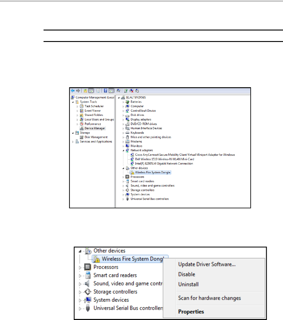
74 PRELIMINARY: Firelite Wireless Sensor Network P/N LS10036-000FL-E:N0 10/10/2013
USB Adapter Driver Installation
5.4 Driver Installation
NOTE: Install PC Tools application before attempting to install the driver.
To install a driver, perform the following steps:
1. Insert the adapter into the PC. The adapter is detected and is displayed in the Computer
Management screen as a Wireless Fire System Dongle.
2. Right click on Wireless Fire System Dongle and select Update Driver Software.
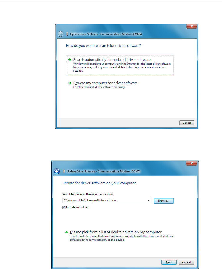
PRELIMINARY: Firelite Wireless Sensor Network P/N LS10036-000FL-E:N0 10/10/2013 75
Driver Installation USB Adapter
3. Select Browse my computer for driver software option.
4. Browse to the location of the driver software by clicking Browse. Select the file and click
Next. To locate the driver software, go to c:\Program Files\Honeywell\Device Driver. The
file resides inside the Device Driver folder.
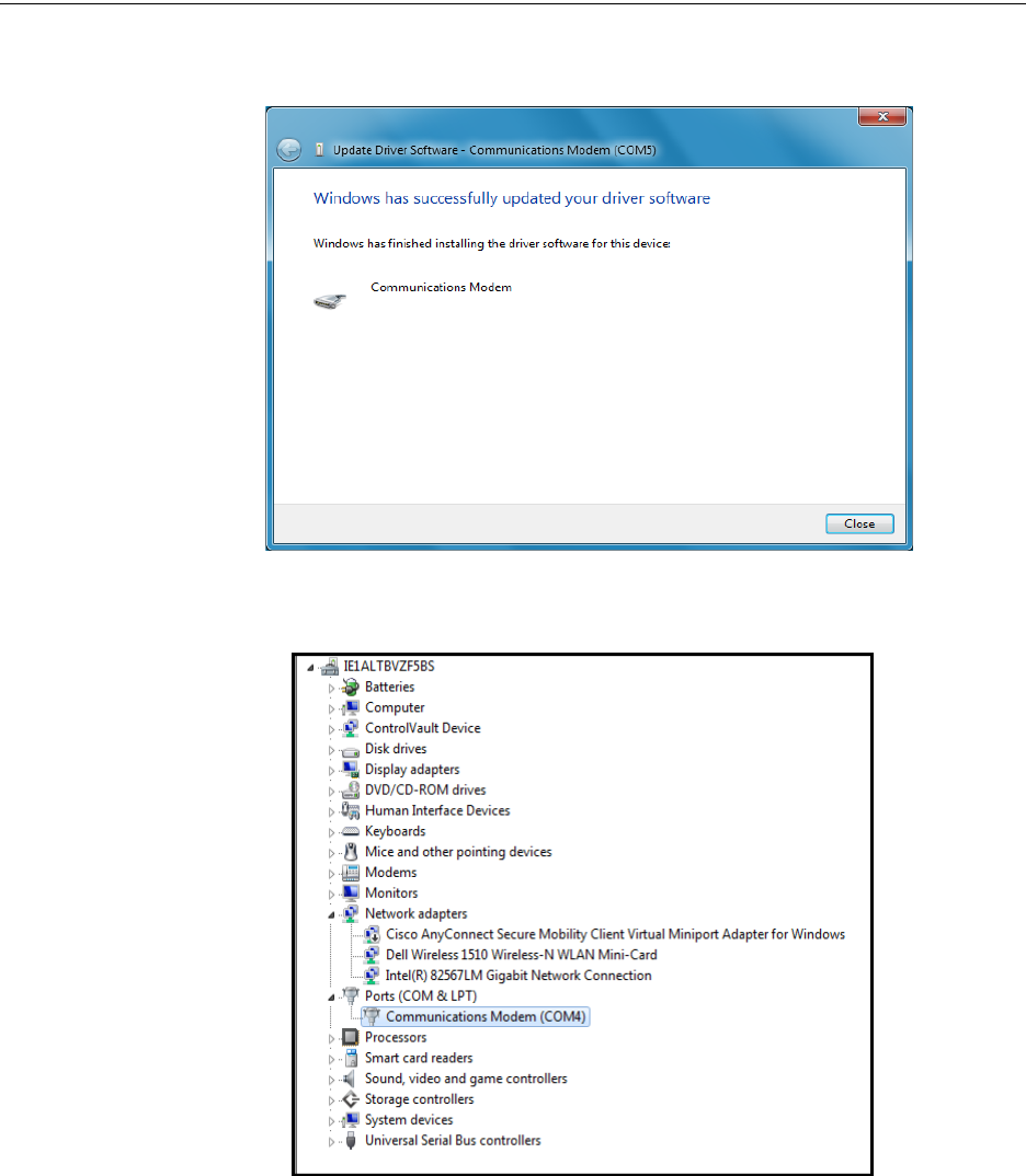
76 PRELIMINARY: Firelite Wireless Sensor Network P/N LS10036-000FL-E:N0 10/10/2013
USB Adapter Driver Installation
5. The confirmation message is displayed that the driver software is updated.
6. The device is displayed under ports.
The driver is installed.

PRELIMINARY: Firelite Wireless Sensor Network P/N LS10036-000FL-E:N0 10/10/2013 77
Driver Installation USB Adapter

78 PRELIMINARY: Firelite Wireless Sensor Network P/N LS10036-000FL-E:N0 10/10/2013
Site Survey Description
Appendix A: Site Survey
A.1 Description
The site survey allows you to assess and qualify the site for installing the wireless fire alarm sys-
tem. The site survey view in the PC tool allows you to view the Radio Frequency (RF) assessment
of the site. The tool reports the suggested device spacing based on the data collected during the site
survey. This helps to optimize the reliability and performance of the wireless network in the wire-
less fire alarm system.
A.1.1 Conducting Site Survey at the Job Site
The site survey includes two tests:
• Link quality test
• RF Scan Test
The link test can be conducted individually or it can be done followed by the RF Scan test. This
section explains the steps for a link quality test and a link quality test followed by RF Scan test.
Link Quality Test
A link quality test is a quick and repeatable test that provides immediate feedback on the device
connectivity. It is conducted primarily to check if there is an event of pocket loss during data trans-
mission between devices. In a link test, the device addresses are set in the range of 001 to 100.
Basic Requirements
To conduct a link test, ensure that
• You possess two or more devices.
• The devices are in factory default condition.
NOTE: The LEDs in the device blink red (single or double blink) upon starting the device if it is in
a factory default condition. Refer to 4.6.4, "Restoring a Device to Factory Default" for more
information on setting the device to factory default state.
Conduct a Link Test
NOTE: The below procedure lists the steps for conducting only a link test. Hence, examples on
the setting the address on devices is explained considering only link test.
To conduct a link test, perform the following steps.
1. Remove the batteries if any present, from the devices and set the address of the first device as
001.
NOTE: For each subsequent device, use the next highest SLC address. For example, set the
first device address as 001, second device as 002 and third device as 003. The upper address
limit for a device address is 100 while doing a link test.
2. Bring the first device to the required location to conduct the test.
3. Insert one battery in to the factory fresh device. After inserting the battery, the LEDs in the
device blink red twice every five seconds, if the device is ready for site survey.
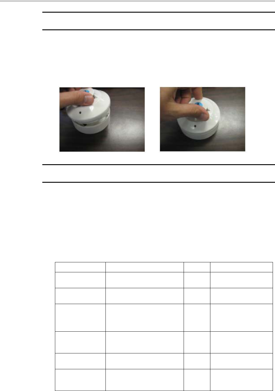
PRELIMINARY: Firelite Wireless Sensor Network P/N LS10036-000FL-E:N0 10/10/2013 79
Description Site Survey
NOTE: You could insert the battery into any available slot. Inserting more than one battery
deters the device from entering the site survey mode.
4. Clear the tamper condition within one minute of the device startup, to enter the site survey
mode. To clear the tamper condition, position the decorative ring around the base of the
detector and rotate it in either direction until the ring snaps to its place (Refer to the below
image). When you clear the tamper, the device starts the transmission that is denoted by LEDs.
Refer to the Table A.1, "Link Test Results-LED Pattern"
NOTE: Due to the absence of the second device that is yet to be introduced, the transmission
fails. Hence, the LEDs in the first device emits solid red.
5. Bring the second device to the required location and repeat the steps 3 and 4. The LEDs in the
second device emit yellow light while the test is being conducted.
Results of Link Test
Once you have introduced the two devices, the devices start communicating and the link quality
test is started. The blinking pattern of the LEDs in the device 002 communicates the results of the
link test. To repeat the test, follow the steps 1 to 4 listed under “Conduct a Link Test”
The following table explains the LED patterns during a link test.
Table A.1 Link Test Results-LED Pattern
State Pattern LED Results & Description
LInk Test in progress Single blink every 0.5 seconds. Yellow Transmission of data
packets to another device.
Solid Red Failure - No Packets
received
Single blink every 5 seconds. Red Poor -Received only half of
the total transmission of
data packets or poor signal
strength
2 blinks every 5 seconds. Red Marginal - Packets partially
received or marginal signal
strength.
3 blinks every 5 seconds. Green Good - All packets received
and good signal strength
4 blinks every 5 seconds. Green Excellent - All packets
received and excellent
signal strength

80 PRELIMINARY: Firelite Wireless Sensor Network P/N LS10036-000FL-E:N0 10/10/2013
Site Survey Description
Tasks After Link test
• Reboot the devices of the link test. To do this, remove and insert the batteries.
• After rebooting, do not push the detector back in the base.
• The devices can be moved around different locations in the site to optimize the results.
• The results of the link quality test (or) the LED indications will exist until the battery lasts in
the devices.
• Upon completion of the link test using the devices numbered 001 and 002, you can test the link
quality using different set of devices in other required locations. To do so, follow the steps 1 to
5 listed under “Conduct a Link Test”
• Retrieve the site survey results. To retrieve the site survey results, refer to the topic “Retrieving
Site Survey Results”at the end of this section.
Link Quality Test and RF Scan Test
An RF Scan test can be conducted following a link test. A Radio Frequency scan test is conducted
to assess and measure the background noise and interference, from other wireless systems if any, in
the site. The RF Scan test is conducted following the link test. While doing a RF Scan test, the
device addresses are set starting from 100 till 159.
The below procedure lists the steps for conducting a link test followed by a RF Scan test. Hence,
examples on the setting the address on devices is explained considering both the tests.
Conduct a Link Test
To understand the basic requirements of a link test, refer to the section A.1.1.
To conduct a link test, perform the following steps.
1. Remove the batteries if any present, from the devices and set the address of the first device as
101. For each subsequent device, use the next highest SLC address. For example, set the first
device address as 101, second device as 102 and third device as 103. The upper address limit
for a device address is 100 while doing a link test.
2. Bring the first device to the required location to conduct the test.
3. Insert one battery in to the factory fresh device in any available slot. Inserting more than one
battery deters the device from entering the site survey mode. If the device is ready for site
survey, after inserting the battery, the LEDs in the device blink red twice every five seconds.
4. Clear the tamper condition within one minute of the device startup to enter the site survey
mode. To clear the tamper condition, position the decorative ring around the base of the
detector and rotate it in either direction until the ring snaps to its place. Refer to the below
image. At this stage, the device starts the transmission. Due to the absence of the second
device that is yet to be introduced, the transmission fails. Hence, the LEDs in the first device
emits solid red. For more information, Refer to table A.2.
5. Bring the second device to the required location and repeat the steps 3 and 4. The LEDs in the
second device emit yellow light while the test is being conducted.

PRELIMINARY: Firelite Wireless Sensor Network P/N LS10036-000FL-E:N0 10/10/2013 81
Description Site Survey
Results of Link Test
Once you have introduced the two devices, the devices start communicating and the link quality
test is started. The blinking pattern of the LEDs in the device 102 communicates the results of the
link test. To repeat the test, follow the steps 1 to 4. The link test results stay for 5 minutes and then
the RF test begins. You can repeat the test any number of times; the only condition being that the
next test should be conducted within five minutes of the last concluded test. Refer to Table A.1,
"Link Test Results-LED Pattern" for LED patterns that convey the link quality results.
This concludes the link test and the RF Scan test starts. The devices addressed 101 or higher,
transition to RF Scan test. On devices addressed below 100, the link test results stay until the bat-
tery last. If you are conducting the link test with several devices started in various time frames, it is
possible that the devices that start and complete the link test first can transition to RF Scan test,
when the devices that began later are still in the link test mode. The RF Scan test may take up to 70
minutes and you have to check the LED patterns for results. The LED patterns are given below.
Results of RF Scan Test
Table A.2 RF Scan Test Results - LED Pattern
Retrieving Site Survey Results
To retrieve the site survey results, do the following:
1. Reboot the devices by removing and inserting the battery back in to the device.
2. Plug in the USB adapter in to the laptop/PC where you have installed the PC tool.
3. Bring the devices within a range of 20ft from the USB adapter.
4. Launch PC tools application and retrieve the data.
State Pattern LED Result
In Progress- 70 minutes
remaining
7 short blinks (Solid) every 30
seconds
Red Bad
In Progress- 70 minutes
remaining
7 short blinks (Solid) every 30
seconds
Yellow Marginal
In progress- 70 minutes
remaining
7 short blinks (Solid) every 30
second
Green Good
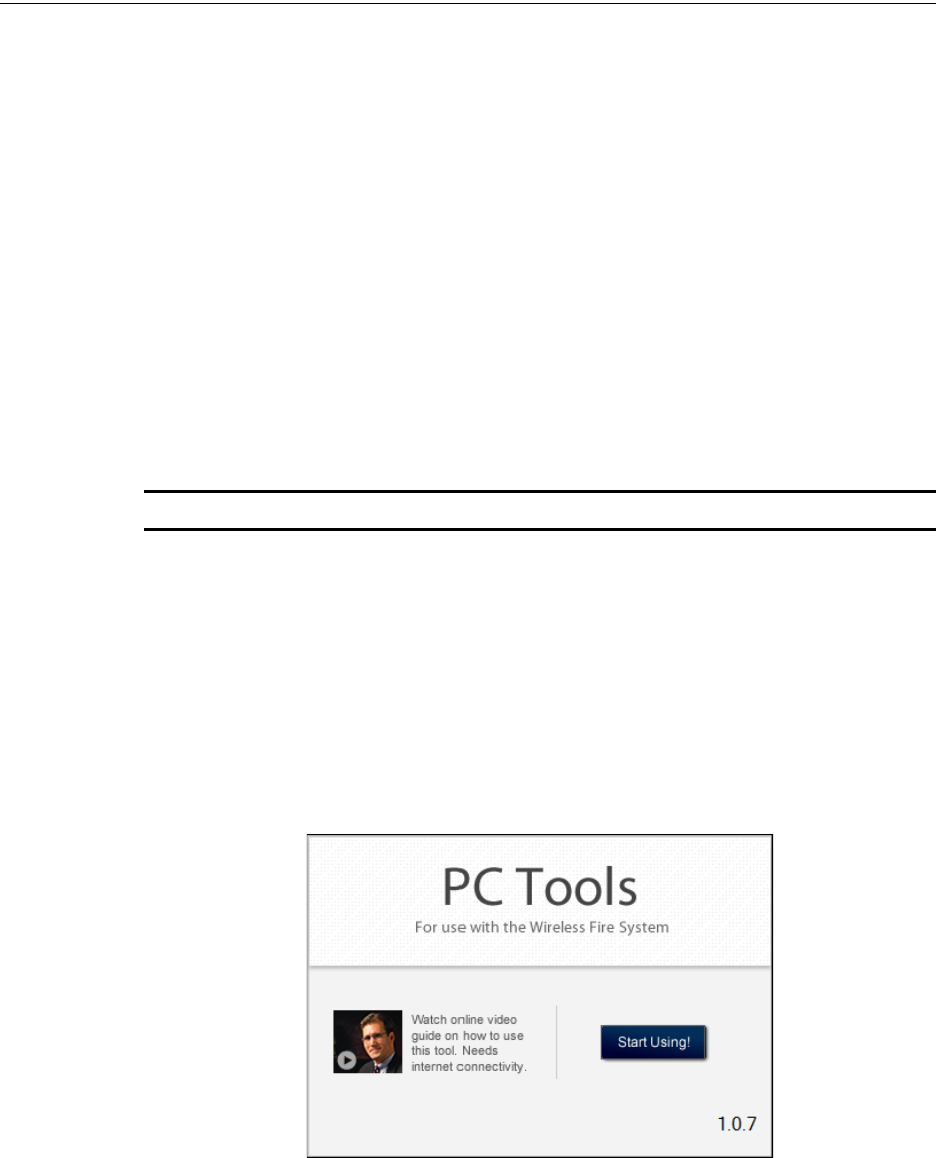
82 PRELIMINARY: Firelite Wireless Sensor Network P/N LS10036-000FL-E:N0 10/10/2013
PC tools Description
Appendix B: PC tools
B.1 Description
The PC Tool is a standalone desktop windows application. It is a configuration and maintenance
tool for the W-GATE and devices of the Wireless Sensor Network. It allows you to survey the site,
configure the devices and diagnose the wireless network of the Wireless Sensor Network. This tool
can be installed on a PC or a laptop. The tool communicates with the W-GATE and wireless
devices through USB based user interface. You have to connect the USB adapter to the computer
to invoke the PC tools application. At any point of time, only one instance of PC Tool can run on a
laptop or PC.
The tool has the following utilities.
• Site Survey view
• Creating Mesh Network
• Diagnostic view
NOTE: At any point of time, only one instance of PC Tool can run on a laptop or PC.
The PC tool works in a wireless environment with the W-GATE and devices within the range of 25
feet.
B.1.1 Launching PC Tools
To Launch PC Tools application,
1. Click Start, point to All Programs, click Wireless Tool, and then Wireless Tool. The
following screen is displayed. Alternatively, you can double click the Wireless Tool shortcut
in your desktop.
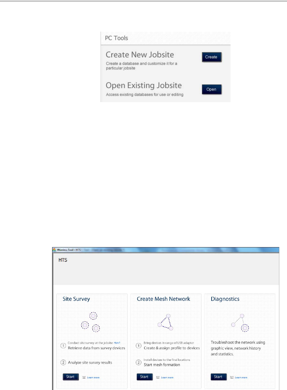
PRELIMINARY: Firelite Wireless Sensor Network P/N LS10036-000FL-E:N0 10/10/2013 83
Description PC tools
2. Click Start Using. The PC Tools screen is displayed.
B.1.2 Creating Jobsite
You can create a new jobsite or open an existing one.
To create a new jobsite,
1. Perform the steps listed to launch the PC Tools application.
2. Click Create from PC Tools screen.
3. Enter the name of the new jobsite in the Jobsite Name field.
4. Enter the Location/Description if any, and click Create.
5. The Create Project window opens and displays the name of the jobsite that you created.
6. Click Save.
The jobsite is created, and the following screen is displayed. You can go to the required function
that you want to perform by clicking the Start button in the respective function.
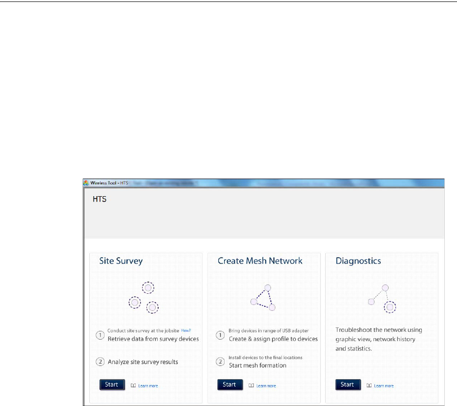
84 PRELIMINARY: Firelite Wireless Sensor Network P/N LS10036-000FL-E:N0 10/10/2013
PC tools Description
B.1.3 Opening Jobsite
If you have a jobsite already created, you can open the existing jobsite.
To open an existing jobsite,
1. Perform the steps listed to launch the PC Tools application.
2. Click Open from the PC tools screen.
3. Choose the required file from your local drive and click Open against Open Existing Jobsite
option. Enter the name of the new jobsite in the Jobsite Name field.
The following screen is displayed. You can go to the required function that you want to perform
byclicking the Start button in the respective function.

PRELIMINARY: Firelite Wireless Sensor Network P/N LS10036-000FL-E:N0 10/10/2013 85
Description PC tools

86 PRELIMINARY: Firelite Wireless Sensor Network P/N LS10036-000FL-E:N0 10/10/2013
Troubleshooting and Testing Troubleshooting
Appendix C: Troubleshooting and Testing
C.1 Troubleshooting
C.2 Testing W-GATE and Devices
The W-GATE must be tested after installation and as an integral part of a periodic maintenance pro-
gram. The testing methods must satisfy the Authority Having Jurisdiction (AHJ). The W-GATE
provides optimum performance when tested and maintained in compliance with NFPA 72 ordi-
nances.
NOTE: The W-GATE used with this base must be tested and maintained regularly following the
NFPA 72 ordinances. The W-GATE should be cleaned at least once a year.
C.2.1 Testing LED Indications
For more information on LED indications, refer to the respective chapters and the attachments pro-
vided for LED indications.
C.3 Testing Wireless Network
The PC Tools application allows you to,
• Diagnose and troubleshoot the wireless network and connectivity of the devices.
• Monitor the wireless network topology, quality of the communication links between the
devices, live and historical event reports for the troubleshooting purpose.
• View the parent-child relationship and the signal strength between the two devices, and
identifies the device that has lost the communication link with the wireless network.
Trouble Type Trouble Description Action
Weak link condition The weak link trouble denotes a
connection of insufficient primary
signal strength.
Ensure spacing between devices, or use
repeaters.
Class A fault condition Device loses the connection with
any of the parent devices.
Ensure spacing between devices, or use
repeaters.
Jamming Jamming occurs when a device is
overloaded with an interfering RF
signal; but is able to send the
messages out.
If any jammers are installed in the vicinity of
the devices, remove them.
Low battery The low battery event denotes
that the device has less than one
month power left to perform the
required operations.
Or presence of less than four
viable batteries.
To clear the low battery event, tamper the
device and replace all the four batteries.
When a device is tampered, it drops out of
the mesh network and attempts to rejoin as
soon as the batteries are replaced and the
tamper event is cleared.
Duplicate address Two wireless devices on the
same mesh network that are set
to the same address reports a
duplicate address trouble.
Change the address of a device to avoid
duplication.

PRELIMINARY: Firelite Wireless Sensor Network P/N LS10036-000FL-E:N0 10/10/2013 87
Testing Wireless Network Troubleshooting and Testing
In addition to the above, the PC tools application
• Communicates with the W-GATE to retrieve the live information about the connectivity and
status of the devices.
• Stores the wireless network data such as network map, parent-child information, device
information, history events, and network statistics.
The PC Tools application allows you to retrieve the following information for diagnosing and trou-
bleshooting purpose.
• Network Topology
• History Events
• Network Snapshots
• Network Statistics
• Device Attributes
C.3.1 Network Topology
Parent-Child Devices
The parent child relationship between the devices in the wireless network is displayed using the
directional arrows.
Orphan Devices
The device that is not linked with any other device in the wireless topology is an orphan device.
The device is represented as an orphan device due to one of the following reasons:
• The device was originally a part of the wireless network and due to a 'Device Connected' live
event, the device sets out of wireless network range.
• The device was system configured with the same network ID and hence it was a part of the
same wireless network. When the network topology was retrieved, the device detail was not
retrieved.
• The network connections are saturated and hence parent-child connection with the device is
not established.
Class A Compliance
Each device must comply with Class A guidelines. The guidelines provide instructions on the
required number of parent device for each device to be compliant with the guideline. Following are
the compliance requirements.
• Class A guideline requirement:
Every device must have two parent devices.
NOTE: The device image is changed to depict that it does not meet the required guidelines.
NOTE: The Class A guidelines are not applicable for the W-GATE.
Selecting a device from the graphical representation and clicking either left or right allows you to
view the following details. The Network Topology window allows you to click either left or right
on any connected or orphan device.

88 PRELIMINARY: Firelite Wireless Sensor Network P/N LS10036-000FL-E:N0 10/10/2013
Troubleshooting and Testing Testing Wireless Network
C.3.2 History Events
The PC Tools application allows you to retrieve and view the history events of the wireless network
for troubleshooting purpose. This report provides information on when the device gets connected
with the wireless network, mode change, and the slot change details.
C.3.3 Network Snapshots
The PC Tools application allows you to retrieve and view the network snapshot for troubleshooting
purpose. The network snapshot helps you to analyze on how the wireless network is functioning
over a period of time.
C.3.4 Network Statistics
The PC Tools application allows you to retrieve and view the network statistics for troubleshooting
purpose. The network statistics provides information on the attributes and RSSI of a device. The
attributes provide information on the retransmission count and device re-join events. The retrans-
mission count is a value equal to the number of times a device retransmits the wireless signal. The
device re-join events is a value equal to the number of times the devices gets disconnected from the
wireless network and gets connected with the wireless network. The RSSI of a device displays the
parent-child relationship between the devices.
C.3.5 Device Attributes
The PC Tools application allows you to retrieve and view the attributes of a device for trouble-
shooting purpose. The attributes of a device such as low indication, removal indication, level, tam-
per fault and others are retrieved.

PRELIMINARY: Firelite Wireless Sensor Network P/N LS10036-000FL-E:N0 10/10/2013 89
Testing Wireless Network Troubleshooting and Testing
90 PRELIMINARY: Firelite Wireless Sensor Network P/N LS10036-000FL-E:N0 10/10/2013
Index
A
Abbreviations 11
Abbreviations and Meanings 13
Activations 27
Additional References 10
adjacent 26
ambient 13
Assign a profile to the Gateway 19
Assumed Knowledge 10
B
background 80
basic 80
Bootloader 27
C
Class 17
Class A 86
Clearing 57
code 64
Collapse 33
Configuration 19
configuration 33
CR123A 60
Creating Jobsite 83
D
ddress 24
Device Attributes 87
device spacing 10
Devices 60
Configuration and Programming 61
dongle 42
Driver 36
Duplicate 36
E
Excellent 79
F
faceplate 63
Factory 65
FCC 60
First blink 67
future 31
G
Gateway 12, 23, 31
Description 12
Installing Gateway 13
Specification Sheet 13
gateway 31
Gateway Powered from SLC 17
green 20
green light 20
I
Initialization 56
initiate 57
installing 78
Installing Devices 61
isolator 17
J
Jamming 36, 46, 55
Jobsite 83
jumper 14
K
Key Bus Trouble 57
L
latching 24
LCD UI 36
Features 38
LED indications 27
Link 32
LiteSpeed 61
Lock 31
M
magnet 21
Magnet switch activations 27
magnetic 20, 23
mesh 24, 25
Mesh Formation 20
mesh formation 25
Mesh Optimization 27
Mounting 14
N
Normal Mode 26
P
Purpose 10

PRELIMINARY: Firelite Wireless Sensor Network P/N LS10036-000FL-E:N0 10/10/2013 91
Index R–Y
R
Recommended Installation and Best Practices 10
Rescue Mode 26
S
SLC Configuration 23, 24
slot 14
spectrum 35
T
Tamper 24
tamper 24
toggles 27
transmission 26
Trouble 32
trouble 27, 32
trouble-free 65
U
unique 19
USB Adapter 72
USB adapter 42, 62
W
Walkie Talkie 35
weak 13
Weak Link 57
Weak link 32
Wiring 16
with 14, 19
Without 19
Y
yellow 19

92 PRELIMINARY: Firelite Wireless Sensor Network P/N LS10036-000FL-E:N0 10/10/2013
Y–Y Index

PRELIMINARY: Firelite Wireless Sensor Network P/N LS10036-000FL-E:N0 10/10/2013 93
Changes & Comments LS10036-000FL-E:N0
Revise to: UL change? Brief description:
Changes & Comments LS10036-000FL-E:N0
94 PRELIMINARY: Firelite Wireless Sensor Network P/N LS10036-000FL-E:N0 10/10/2013
Manufacturer Warranties and Limitation of Liability
Manufacturer Warranties. Subject to the limitations set forth herein,
Manufacturer warrants that the Products manufactured by it in its
Northford, Connecticut facility and sold by it to its authorized
Distributors shall be free, under normal use and service, from defects
in material and workmanship for a period of thirty six months (36)
months from the date of manufacture (effective Jan. 1, 2009). The
Products manufactured and sold by Manufacturer are date stamped at
the time of production. Manufacturer does not warrant Products that
are not manufactured by it in its Northford, Connecticut facility but
assigns to its Distributor, to the extent possible, any warranty offered
by the manufacturer of such product. This warranty shall be void if a
Product is altered, serviced or repaired by anyone other than
Manufacturer or its authorized Distributors. This warranty shall also
be void if there is a failure to maintain the Products and the systems in
which they operate in proper working conditions.
MANUFACTURER MAKES NO FURTHER WARRANTIES, AND
DISCLAIMS ANY AND ALL OTHER WARRANTIES, EITHER
EXPRESSED OR IMPLIED, WITH RESPECT TO THE PRODUCTS,
TRADEMARKS, PROGRAMS AND SERVICES RENDERED BY
MANUFACTURER INCLUDING WITHOUT LIMITATION,
INFRINGEMENT, TITLE, MERCHANTABILITY, OR FITNESS FOR
ANY PARTICULAR PURPOSE. MANUFACTURER SHALL NOT BE
LIABLE FOR ANY PERSONAL INJURY OR DEATH WHICH MAY
ARISE IN THE COURSE OF, OR AS A RESULT OF, PERSONAL,
COMMERCIAL OR INDUSTRIAL USES OF ITS PRODUCTS.
This document constitutes the only warranty made by Manufacturer
with respect to its products and replaces all previous warranties and is
the only warranty made by Manufacturer. No increase or alteration,
written or verbal, of the obligation of this warranty is authorized.
Manufacturer does not represent that its products will prevent any loss
by fire or otherwise.
Warranty Claims. Manufacturer shall replace or repair, at
Manufacturer's discretion, each part returned by its authorized
Distributor and acknowledged by Manufacturer to be defective,
provided that such part shall have been returned to Manufacturer with
all charges prepaid and the authorized Distributor has completed
Manufacturer's Return Material Authorization form. The replacement
part shall come from Manufacturer's stock and may be new or
refurbished. THE FOREGOING IS DISTRIBUTOR'S SOLE AND
EXCLUSIVE REMEDY IN THE EVENT OF A WARRANTY CLAIM.
Warn-HL-08-2009.fm
PRELIMINARY: Firelite Wireless Sensor Network — P/N LS10036-000FL-E:N0 10/09/2013 95

World Headquarters
1 Firelite Place
Northford, CT 06472-1653 USA
203-484-7161
fax 203-484-7118
www.firelite.com