Honeywell WLUWIFIM010 Wireless LAN Unit User Manual APPLICATION
Honeywell International Inc. Wireless LAN Unit APPLICATION
UserManual.wiki
>
Honeywell
>
WLUWIFIM010 User Manual
Users Manual
Navigation menu
Upload a User Manual
Namespaces
Wiki Guide
HTML
PDF
Info
Views
User Manual
Discussion / Help
Navigation
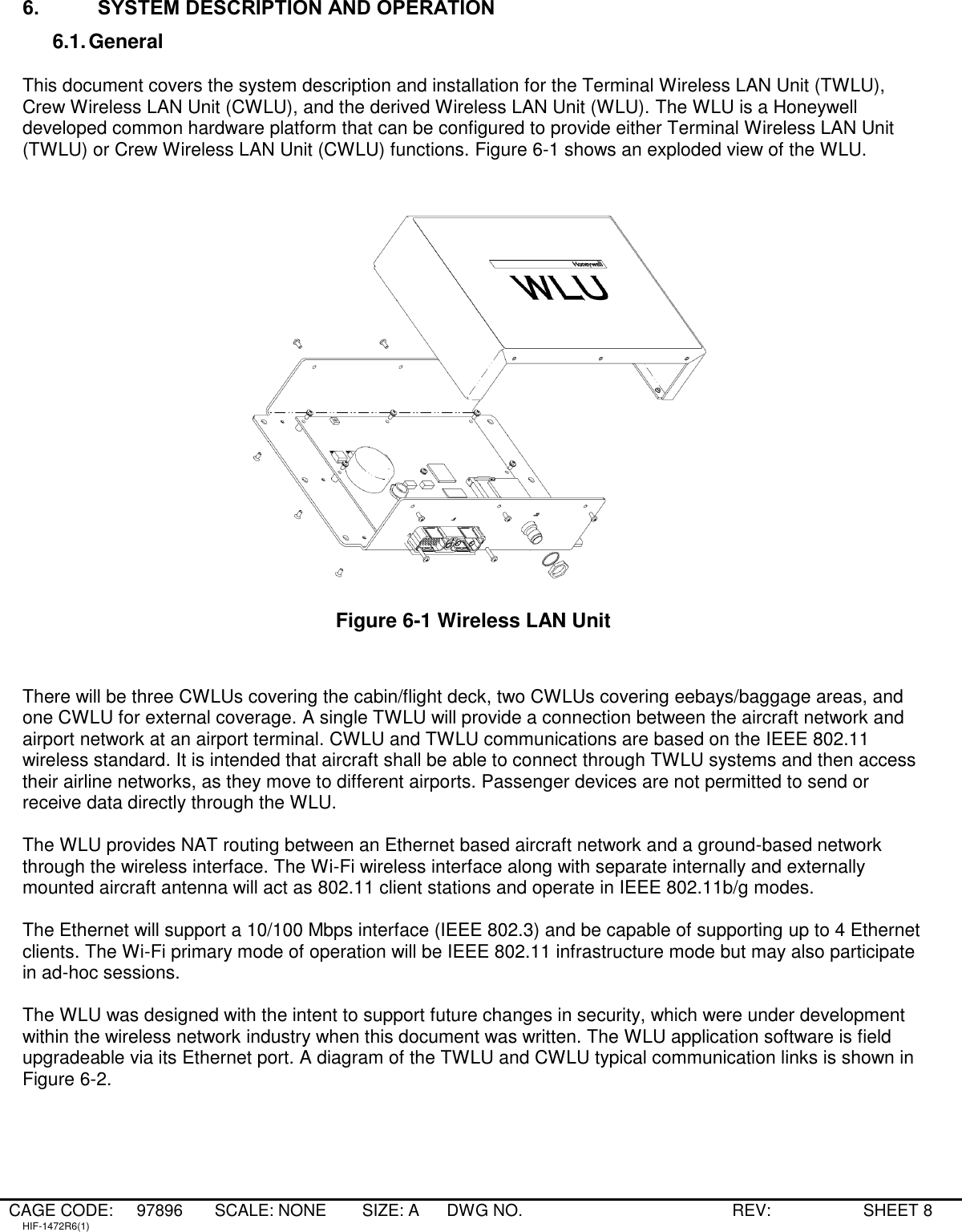
![CAGE CODE: 97896 SCALE: NONE SIZE: A DWG NO. REV: SHEET 7 HIF-1472R6(1) 5. CUSTOMER ASSISTANCE For assistance with installation, operation, or maintenance of the WLU contact your local Honeywell Dealer or regional Honeywell Customer Support Engineer. Additional assistance can be obtained from Honeywell at the following locations: Honeywell Aerospace Electronic Systems CES -- Phoenix Customer Support Engineering P. O. Box 21111 Phoenix, AZ 85036--1111 U.S.A. TEL: (602) 436--3234 FAX: (602) 436—3165 Honeywell Business, Regional and General Aviation (BRGA) [formerly Business and Commuter Aviation Systems (BCAS)] Customer Support Engineering 5353 W. Bell Road Glendale, AZ 85308--9000 U.S.A. TEL: (602) 436--4400 FAX: (602) 436--4100](https://usermanual.wiki/Honeywell/WLUWIFIM010/User-Guide-901785-Page-7.png)