Honeywell WLUWIFIM010 Wireless LAN Unit User Manual APPLICATION
Honeywell International Inc. Wireless LAN Unit APPLICATION
Users Manual
APPLICATION
TITLE SHEET
DASH NO.
NEXT ASSY
USED ON
INDEX
SHEET NO.
TITLE SHEET (INCLUDES REVISION DESCRIPTION) 1
TABLE OF CONTENTS 2
DOCUMENT 4
REVISIONS - ALL SHEETS ARE SAME REVISION STATUS
SH
REV
DESCRIPTION
DATE
APPROVED
This document is an unpublished work. Copyright 2008 Honeywell International Inc. All rights reserved
Typed signatures constitute approval. Actual
signatures on file at Honeywell in Redmond WA.
CAD Prepared Drawing Using MSWord Software.
Not to be manually altered.
CONTRACT NO.
-----------------
PRECIOUS METAL
INDICATOR CODE:
NA
Honeywell International Inc.
Redmond, WA 98073-9701
DRAWN
Patrick Ludwig
Wireless LAN Unit (WLU)
System Description and Installation Manual
CHECK
ENGR
Glenn Waddell
MFG
QA
SIZE
CAGE CODE
DWG NO.
REV.
APVD
A
97896
xxx-xxxx-xxx
-
APVD
SCALE: NONE
SHEET 1 OF 20
HIF-1472/R6 1472R6.DOT
document4

CAGE CODE:
97896
SCALE: NONE
SIZE: A
DWG NO.
REV:
SHEET 2
HIF-1472R6(1)
1. INTRODUCTION ......................................................................................................................................................................... 4
2. REFERENCE DOCUMENTS .......................................................................................................................................................... 4
3. ACRONYMS AND ABBREVIATIONS............................................................................................................................................. 4
4. SPECIAL PRECAUTIONS .............................................................................................................................................................. 6
5. CUSTOMER ASSISTANCE ............................................................................................................................................................ 7
6. SYSTEM DESCRIPTION AND OPERATION .................................................................................................................................... 8
6.1. GENERAL ..................................................................................................................................................................................... 8
7. SYSTEM COMPONENTS ............................................................................................................................................................. 9
7.1. SYSTEM FUNCTIONAL DESCRIPTION .................................................................................................................................................. 9
7.1.1. TWLU Functional Description ........................................................................................................................................... 9
7.1.2. CWLU Functional Description .......................................................................................................................................... 9
7.2. COMPONENT DESCRIPTION ........................................................................................................................................................... 10
7.3. SYSTEM OPERATION .................................................................................................................................................................... 11
7.3.1. TWLU Operation ............................................................................................................................................................ 12
7.3.2. CWLU Operation ............................................................................................................................................................ 12
8. SYSTEM INTERFACES ............................................................................................................................................................... 13
8.1. HIGH LEVEL FUNCTIONALITY .......................................................................................................................................................... 13
8.1.1. Wireless Interface .......................................................................................................................................................... 13
8.1.2. Protocol .......................................................................................................................................................................... 13
8.1.3. Data Rate ....................................................................................................................................................................... 13
8.1.4. Frequency Assignment ................................................................................................................................................... 13
8.1.5. Power Input.................................................................................................................................................................... 13
8.1.6. Ethernet ......................................................................................................................................................................... 13
8.2. DISCRETE INTERFACES .................................................................................................................................................................. 13
8.3. POSITION PIN DISCRETES .............................................................................................................................................................. 14
8.4. ANTENNA .................................................................................................................................................................................. 14
8.5. ELECTRICAL SPECIFICATIONS .......................................................................................................................................................... 14
8.5.1. Main Connector ............................................................................................................................................................. 15
8.5.2. Signals, Power and Ground ............................................................................................................................................ 15
9. MECHANICAL INSTALLATION ................................................................................................................................................... 16
9.1. GENERAL ................................................................................................................................................................................... 16
9.2. EQUIPMENT AND MATERIALS ........................................................................................................................................................ 17
10. ELECTRICAL INSTALLATION .................................................................................................................................................. 17
10.1. GENERAL ................................................................................................................................................................................... 17
10.2. POWER REQUIREMENTS ................................................................................................................................................................ 17
10.2.1. DC Power........................................................................................................................................................................ 18
10.2.2. Ground Requirements .................................................................................................................................................... 18
11. ANTENNA INSTALLATION .................................................................................................................................................... 18
11.1. GENERAL ................................................................................................................................................................................... 18
12. FAULT ISOLATION................................................................................................................................................................ 19
12.1. GENERAL ................................................................................................................................................................................... 19
12.2. FAULT DETECTION ....................................................................................................................................................................... 19
13. DATA LOADING ................................................................................................................................................................... 20
13.1. GENERAL ................................................................................................................................................................................ 20

CAGE CODE:
97896
SCALE: NONE
SIZE: A
DWG NO.
REV:
SHEET 3
HIF-1472R6(1)
Table of Figures
FIGURE 6-1 WIRELESS LAN UNIT ............................................................................................................................................................ 8
FIGURE 6-2 WLU SYSTEM DIAGRAM ....................................................................................................................................................... 9
FIGURE 8-1 LRU CONNECTOR (J1) PHYSICAL PINOUT ......................................................................................................................... 15
FIGURE 9-1 MECHANICAL OUTLINE OF WLU ......................................................................................................................................... 17
FIGURE 11-1 EXAMPLE ERP OF THE WLU WITH SENSOR SYSTEM WI-FI ANTENNA .......................................................................... 19
Table of Tables
TABLE 2-1 GOVERNMENT AND REGULATORY DOCUMENTS ..................................................................................................................... 4
TABLE 2-2 INDUSTRY STANDARDS OR SPECIFICATIONS .......................................................................................................................... 4
TABLE 3-1 ACRONYMS AND ABBREVIATIONS ........................................................................................................................................... 4
TABLE 7-1 COMPONENTS/PARTS NOT SUPPLIED BY HONEYWELL .......................................................................................................... 9
TABLE 7-2 WLU LEADING PARTICULARS ............................................................................................................................................... 10
TABLE 7-3 ENVIRONMENTAL CATEGORIES ............................................................................................................................................. 10
TABLE 7-4 POWER AND EMC CATEGORIES ........................................................................................................................................... 10
TABLE 7-5 FCC LICENSE ........................................................................................................................................................................ 11
TABLE 8-1 WLU POSITION PIN FUNCTIONS ........................................................................................................................................... 14
TABLE 8-2 CONNECTOR NAMES AND PART NUMBERS FOR WLU ......................................................................................................... 15
TABLE 8-3 LRU CONNECTOR (J1-B) PIN ASSIGN ................................................................................................................................. 15
TABLE 8-4 J1-A QUADRAX INSERT POSITIONS ...................................................................................................................................... 16
TABLE 8-5 J1-A INSERT QUADRAX PINOUT ........................................................................................................................................... 16

CAGE CODE:
97896
SCALE: NONE
SIZE: A
DWG NO.
REV:
SHEET 4
HIF-1472R6(1)
1. INTRODUCTION
This manual gives installation instructions and theory of operation for the Wireless LAN Unit (WLU), part
number 965-1702-001. It also provides interface information and interconnects diagrams to permit a general
understanding of the overall system.
The purpose of this manual is to help the user install, operate, maintain, and troubleshoot the WLU in the
aircraft. Common system maintenance procedures are not presented in this manual. The best established
shop and flight line practices should be used.
2. REFERENCE DOCUMENTS
Table 2-1 Government and Regulatory Documents
Publication Number
Document Title
Title 14 CFR
Code of Federal Regulations Title 14 Program Regulations
Title 47 CFR
Code of Federal Regulations Title 47 which contains Federal Communication
Commission Part 15, 22, and 24
Title 29 CFR
Code of Federal Regulations Title 29 Program Regulations
Table 2-2 Industry Standards or Specifications
Publication Number
Document Title
ARINC-664
Aircraft Data Network
ARINC-763-2
Network Server System
IEEE 802.11
Part 11: Wireless LAN Medium Access Control (MAC) and Physical Layer (PHY) Specifications.
1999
IEEE 802.11b
Part 11: Wireless LAN Medium Access Control (MAC) and Physical Layer (PHY) Specifications:
Higher-Speed Physical Layer Extension in the 2.4 GHz Band. 1999
IEEE 802.11d
Part 11: Wireless LAN Medium Access Control (MAC) and Physical Layer (PHY) Specifications:
Amendment 3: Specification for operation in additional regulatory domains. June 14, 2001
IEEE 802.11g
Part 11: Wireless LAN Medium Access Control (MAC) and Physical Layer (PHY) Specifications:
Amendment 4: Further Higher Data Rate Extension in the 2.4 GHz Band
June 12, 2003
IEEE 802.11i Draft 3.0
Part 11: Wireless LAN Medium Access Control (MAC) and Physical Layer (PHY) Specifications:
Specifications for Enhanced Security. November 2003
RTCA DO-160D
Environmental Conditions and Test Procedures. July 1997, Change 1 December 2000, Change 2
June 2001, Change 3 December 2002
RTCA/EUROCAE
DO-178B/ED-12B
Software Considerations in Airborne Systems and Equipment Certification
December 1, 1992
Wi-Fi Protected Access
Version 2.0
WPA Implemented Features of IEEE 802.11i Draft 3
3. ACRONYMS AND ABBREVIATIONS
Table 3-1 Acronyms and Abbreviations
Abbreviation
Definition
ACARS
Aircraft Communication Addressing and Reporting System
AEEC
Airlines Electronic Engineering Committee
AMG
ACARS Messaging over Gatelink
AMI
Airline Modifiable Information
ARINC
Aeronautical Radio, Incorporated
BITE
Built-In Test Equipment
CDU
Control Display Unit
CFR
Code of Federal Regulations
CIS
Crew Information System
CMCF
Central Maintenance Computer Function
CMU
Communications Management Unit
COTS
Commercial Off The Shelf
CRN
Current Return Network
CWLU
Crew Wireless LAN Unit

CAGE CODE:
97896
SCALE: NONE
SIZE: A
DWG NO.
REV:
SHEET 5
HIF-1472R6(1)
dB
Decibel
DiffServ
Differentiated Services (IP)
DSSS
Direct-sequence-spread-spectrum
EAP
Extensible Authentication Protocol
ESD
Electrostatic discharge
FAA
Federal Aviation Administration
FCC
Federal Communications Commission
FL
Flight Level
FSM
File Server Module
FTS
File Transfer Service
GDLM
Gatelink Dataloading Manager
HIRF
high intensity radiated electromagnetic frequencies
IEEE
Institute of Electrical and Electronic Engineers
IP
Internet Protocol
IPSec
IP Security
ISM
Industrial, Scientific and Medical
ISP
Internet Service Provider
JTAG
Joint Test Action Group
LAN
Local Area Network
LED
Light emitting diode
LRU
Line-Replaceable-Unit
LSAP
Loadable Software Airplane Part
MAC
Medium Access Control
MCDU
Multi-purpose Control & Display Unit
MS
Maintenance System
NAT
Network Address Translation
OHMF
On-board Health Management Function
OMS
On-board Maintenance System
PAT
Port Address Translation
PCS
Personal Communication Service
PHY
Physical Layer
QARF
FOQA Data Download
RADIUS
Remote Authentication Dial In User Service
RAM
Random Access Memory
RF
Radio Frequency
RPDU
Remote Power Distribution Unit
RTCA
Radio Technical Commission for Aeronautics
SDRAM
Synchronous Dynamic Random Access Memory
S.I.
Standard International
SMA
SubMiniature version A
SW
Software
TCP
Transport Control Protocol
TLS
Transport Layer Security
TNC
Threaded Neill-Concelman
TOS
Type of Service (IP)
TWLU
Terminal Wireless LAN Unit
UDP
User Datagram Protocol
uP
Microprocessor
VAC
Volts AC
VDC
Volts DC
VPN
Virtual Private Network
WLAN
Wireless Local Area Network
WLU
Wireless LAN Unit
Wi-Fi
Wireless Fidelity (Alliance)
WPA
Wi-Fi Protected Access
WPA2
Wi-Fi Protected Access 2
WOW
Weight on Wheels

CAGE CODE:
97896
SCALE: NONE
SIZE: A
DWG NO.
REV:
SHEET 6
HIF-1472R6(1)
4. SPECIAL PRECAUTIONS
Warnings, cautions, and notes in this manual give the data that follows:
A WARNING is an operation or maintenance procedure or condition, which, if not obeyed, can cause
injury or death.
A CAUTION is an operation or maintenance procedure or condition, which, if not obeyed, can cause
damage to the equipment.
A NOTE gives data to make the work easier or gives directions to go to a procedure.
All personnel who operate and do maintenance on the WLU and applicable test equipment must know and
obey the safety precautions. The warnings and cautions that follow apply to all parts of this manual:
WARNING: HIGH VOLTAGES MAY BE PRESENT ON SYSTEM INTERCONNECT CABLES. MAKE SURE
THAT SYSTEM POWER IS OFF BEFORE YOU DISCONNECT LRU MATING CONNECTORS.
CAUTION: THE SYSTEM CONTAINS ITEMS THAT ARE ELECTROSTATIC DISCHARGE SENSITIVE
(ESDS). IF YOU DO NOT OBEY THE NECESSARY CONTROLS, A FAILURE OR UNSATISFACTORY
OPERATION OF THE UNIT CAN OCCUR FROM ELECTROSTATIC DISCHARGE. USE APPROVED
INDUSTRY PRECAUTIONS TO KEEP THE RISK OF DAMAGE TO A MINIMUM WHEN YOU TOUCH,
REMOVE, OR INSERT PARTS OR ASSEMBLIES.
WARNING: THIS EQUIPMENT HAS BEEN TESTED AND FOUND TO COMPLY WITH THE LIMITS FOR A
CLASS A DIGITAL DEVICE, PURSUANT TO PART 15 OF THE FCC RULES. THESE LIMITS ARE
DESIGNED TO PROVIDE REASONABLE PROTECTION AGAINST HARMFUL INTERFERENCE WHEN
THE EQUIPMENT IS OPERATED IN A COMMERCIAL ENVIRONMENT. THIS EQUIPMENT GENERATES,
USES, AND CAN RADIATE RADIO FREQUENCY ENERGY AND, IF NOT INSTALLED AND USED IN
ACCORDANCE WITH THE INSTRUCTION MANUAL, MAY CAUSE HARMFUL INTERFERENCE TO RADIO
COMMUNICATIONS. OPERATION OF THIS EQUIPMENT IN A RESIDENTIAL AREA IS LIKELY TO CAUSE
HARMFUL INTERFERENCE IN WHICH CASE THE USER WILL BE REQUIRED TO CORRECT THE
INTERFERENCE AT HIS OWN EXPENSE.
WARNING: THIS EQUIPMENT HAS BEEN TESTED AND FOUND TO COMPLY WITH THE LIMITS FOR A
CLASS A DIGITAL DEVICE, PURSUANT TO PART 15 OF THE FCC RULES. ACCORDING TO FCC PART
15.203, THE DEVICE AND ANTENNAS MUST BE PROFESSIONALLY INSTALLED ACCORDING TO
THESE INSTRUCTIONS OUTLINED IN THIS DOCUMENT. THE ANTENNAS OUTLINED IN THIS
DOCUMENT MUST BE USED WHEN INSTALLING THE EQUIPMENT. OTHERWISE, THIS DEVICE MAY
CAUSE HARMFUL INTERFERENCE TO RADIO COMMUNICATIONS.
NOTE: THE TESTS IN THE FAULT ISOLATION SECTION SHOULD BE DONE BEFORE THE UNIT IS
DISASSEMBLED. THESE TESTS CAN TELL THE CONDITION OF THE WLU OR MOST PROBABLE
CAUSE OF ANY MALFUNCTION. SHOULD ANY MALFUNCTION OCCUR, REPAIR AS NECESSARY.

CAGE CODE:
97896
SCALE: NONE
SIZE: A
DWG NO.
REV:
SHEET 7
HIF-1472R6(1)
5. CUSTOMER ASSISTANCE
For assistance with installation, operation, or maintenance of the WLU contact your local Honeywell Dealer or
regional Honeywell Customer Support Engineer. Additional assistance can be obtained from Honeywell at the
following locations:
Honeywell
Aerospace Electronic Systems
CES -- Phoenix
Customer Support Engineering
P. O. Box 21111
Phoenix, AZ 85036--1111
U.S.A.
TEL: (602) 436--3234
FAX: (602) 436—3165
Honeywell
Business, Regional and General Aviation (BRGA)
[formerly Business and Commuter Aviation Systems (BCAS)]
Customer Support Engineering
5353 W. Bell Road
Glendale, AZ 85308--9000
U.S.A.
TEL: (602) 436--4400
FAX: (602) 436--4100
CAGE CODE:
97896
SCALE: NONE
SIZE: A
DWG NO.
REV:
SHEET 8
HIF-1472R6(1)
6. SYSTEM DESCRIPTION AND OPERATION
6.1. General
This document covers the system description and installation for the Terminal Wireless LAN Unit (TWLU),
Crew Wireless LAN Unit (CWLU), and the derived Wireless LAN Unit (WLU). The WLU is a Honeywell
developed common hardware platform that can be configured to provide either Terminal Wireless LAN Unit
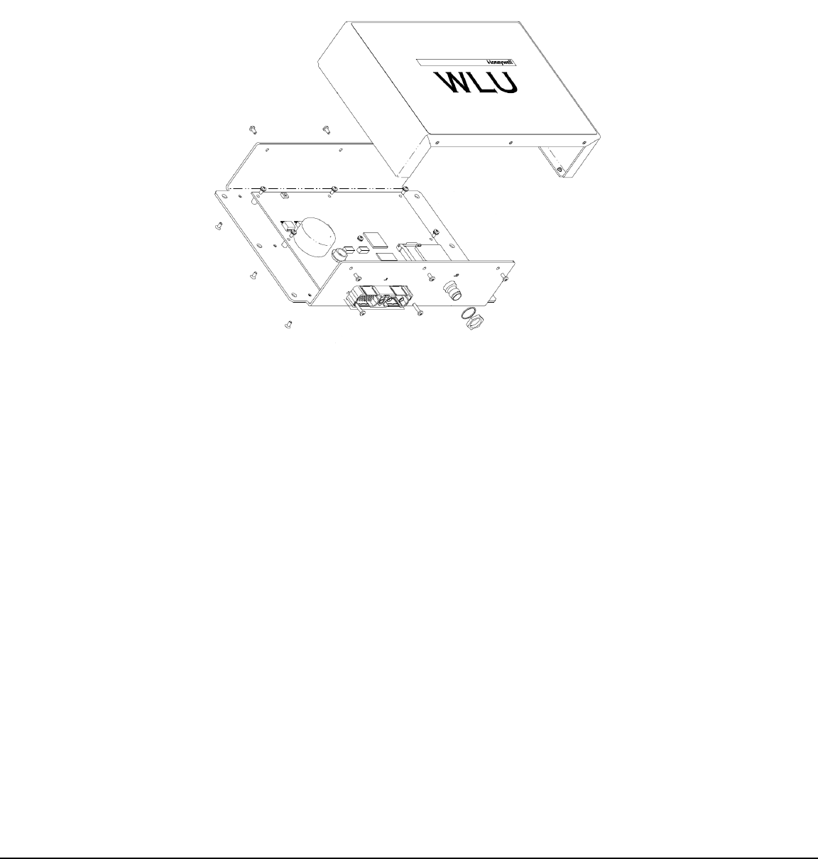
(TWLU) or Crew Wireless LAN Unit (CWLU) functions. Figure 6-1 shows an exploded view of the WLU.
Figure 6-1 Wireless LAN Unit
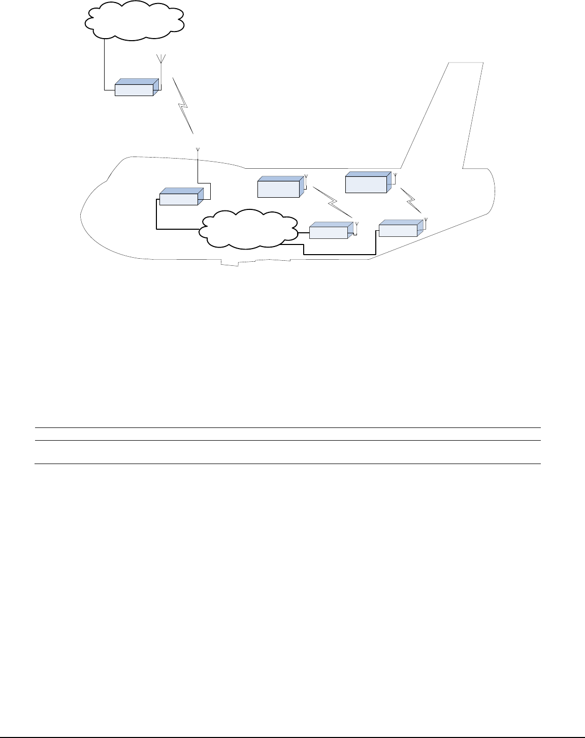
There will be three CWLUs covering the cabin/flight deck, two CWLUs covering eebays/baggage areas, and
one CWLU for external coverage. A single TWLU will provide a connection between the aircraft network and
airport network at an airport terminal. CWLU and TWLU communications are based on the IEEE 802.11
wireless standard. It is intended that aircraft shall be able to connect through TWLU systems and then access
their airline networks, as they move to different airports. Passenger devices are not permitted to send or
receive data directly through the WLU.
The WLU provides NAT routing between an Ethernet based aircraft network and a ground-based network
through the wireless interface. The Wi-Fi wireless interface along with separate internally and externally
mounted aircraft antenna will act as 802.11 client stations and operate in IEEE 802.11b/g modes.
The Ethernet will support a 10/100 Mbps interface (IEEE 802.3) and be capable of supporting up to 4 Ethernet
clients. The Wi-Fi primary mode of operation will be IEEE 802.11 infrastructure mode but may also participate
in ad-hoc sessions.
The WLU was designed with the intent to support future changes in security, which were under development
within the wireless network industry when this document was written. The WLU application software is field
upgradeable via its Ethernet port. A diagram of the TWLU and CWLU typical communication links is shown in
Figure 6-2.
CAGE CODE:
97896
SCALE: NONE
SIZE: A
DWG NO.
REV:
SHEET 9
HIF-1472R6(1)
CWLU
CWLU
TWLU
...
AP
Aircraft Network
Airport Network
Aircraft
System
...
Aircraft
System
Figure 6-2 WLU System Diagram
7. SYSTEM COMPONENTS
The part numbers of the components that are not supplied by Honeywell but are required for proper setup of
the WLU are given in Table 7-1.
Table 7-1 Components/Parts Not Supplied by Honeywell
Component
Manufacturer
Manufacturer Part Number
Honeywell Part Number
Wi-Fi Antenna CWLU
Sensor Systems
S65-5366-715
956-0033-002
Wi-Fi Antenna TWLU
Sensor Systems
S65-5366-71S
956-0033-001
7.1. System Functional Description
7.1.1. TWLU Functional Description
The wireless connection established between the airplane and airport networks is referred to as Gatelink.
Gatelink is a ground based WLAN network designed to connect aircraft. Gatelink networks can connect to
airline networks, etc. Gatelink is intended to be implemented at airports but may also be applied at aircraft
support facilities. Gatelink is described in the AEEC standard, ARINC 763, Aircraft Network Server System. It
is based on the IEEE 802.11 wireless standard. It is intended that aircraft shall be able to connect to Gatelink
systems and then access their airline networks, as they move to different airports. Gatelink may be
implemented by an airport authority, which then shares the resource across all airlines.
7.1.2. CWLU Functional Description
The CWLU provides wireless connectivity to crew and maintenance applications within the aircraft.
Enforcement of which wireless users can use the CWLU system is performed by a combination of CWLUs and
an aircraft On-board Authentication Server that supports the RADIUS protocol with WPA2 extensions. The
CWLU is configured and radio enabled after landing or after reaching altitude threshold. The CWLU begins
sending IEEE802.11 beacons. Wireless computers detect CWLU beacons and initiate association.

CAGE CODE:
97896
SCALE: NONE
SIZE: A
DWG NO.
REV:
SHEET 10
HIF-1472R6(1)
7.2. Component Description
The WLU is shown in Figure 6-1 and the WLU specifications and tolerances are listed below in Tables 7-2.
Table 7-3 gives the environmental categories that the WLU is tested to. Table 7-4 gives the electromagnetic
categories that the WLU is tested to. Table 7-4 gives the FCC license requirements this equipment meets or
exceeds.
Table 7-2 WLU Leading Particulars
Parameter
Specification
Dimensions (maximum):
Height
2.5 in. (68.5 mm)
Width.
6.85 in. (174.0 mm)
Length
11.5 in. (292.1 mm)
Weight (maximum)
4.0 lb (2.3 kg)
Power Requirements:
Nominal
28 V dc
Maximum
29.5 V dc
Minimum
22 V dc
Average Power Dissipation (DC)
Less than 10 W
Cooling Requirements:
The WLU is passively cooled
Max Operating Temp = 80 degree C
Connectors:
J1
See SYSTEM INTERFACES
J2
See SYSTEM INTERFACES
Mounting:
See MECHANICAL INSTALLATION
The WLU is a bolt-down package
Table 7-3 Environmental Categories
Test Name
DO-160D
Category
Boeing Requirements
Ground Survival Low Temperature
Test
4.5.1
A1
-55°C, non-powered.
Short-Time Operating Low
Temperature Test
4.5.1
A1
-40°C to -15°C, over a period of 30 Minutes. Degraded
operation may include no RF Tx.
Operating Low Temperature Test
4.5.2
A1
-15°C
Ground Survival High Temperature
Test
4.5.2
A1
+85°C, unpowered.
Short-Time Operating High
Temperature Test
4.5.3
A1
+70°C
Operating High Temperature Test
4.5.4
A1
+70°C
Altitude Test
4.6.1
A1
-2,000 ft to +25,000 ft, 2 hours.
Decompression Test
4.6.2
A1
+6,000 ft to +25,000 ft, reduction within 15 seconds,
maintain for 10 minutes.
Overpressure Test
4.6.3
A2
28 PSIA ( 196 kPa)
Temperature Variation
5.0
C
-15°C to +70°C; +2°C/min; 24 cycles.
Humidity
6.0
A
DO-160E Standard Humidity Environment, 2 cycles.
Bench Handling Shock
N/A
N/A
D6-81926 Rev G, Section 3.1
Shipping Container Shock
N/A
N/A
D6-81926 Rev G, Section 3.2
Acceleration
N/A
N/A
D6-81926 Rev G
Section 4.1, Zone 1 (Acceleration Load Factors)
Section 4.2 (Emergency Landing Loads)
Vibration
Boeing
Req.
Boeing
Req.
D6-81926 Section 6, Zone 4, Category C
Waterproofness
10.0
W
DO-160E
Table 7-4 Power and EMC Categories

CAGE CODE:
97896
SCALE: NONE
SIZE: A
DWG NO.
REV:
SHEET 11
HIF-1472R6(1)
Test Name
Source
Category
Boeing Requirements
Normal Steady State Voltage
Boeing 787B3-0147 Rev C, Sect
3.3.3.1.B.5.5.1
QTPR Sect 8.2.
Test (32.8VDC) exceeds SCD WLANU180
(29.5VDC)
Voltage Ripple
Boeing 787B3-0147 Rev C, Sect
3.3.3.1.B.5.5.2
QTPR Sect 8.4.
Normal Voltage Transients
Boeing 787B3-0147 Rev C, Sect
3.3.3.1.B.6.1
QTPR Sect 8.5.
SCD WLANU181 requires longer transient
(150mS) than Boeing 787B3-0147 Rev-C
(50mS).
Voltage Spike
Boeing 787B3-0147 Rev C, Sect
3.3.3.1.B.6.2 which is equivalent to DO-160
(E)
QTPR Sect 8.6.
Supplementary Voltage
Transients
Boeing 787B3-0147 Rev C, Sect 3.3.3.1.1.
QTPR Sect 8.7
Supplementary Trapezoidal
Transients
Boeing 787B3-0147 Rev C, Sect
3.3.3.2.B.7.1.
QTPR Sect 8.8
Abnormal Steady-State And
Abnormal Transients
Boeing 787B3-0147 Rev C, Sect
3.3.3.2.B.8.1.
QTPR Sect 8.9 and 8.10
DC Reverse Polarity
Boeing 787B3-0147 Rev C, Sect 3.4.2.
QTPR Sect 8.11
Load Equipment Influence
Boeing 787B3-0147 Rev C, Sect 3.4.3.
QTPR Sect 8.12
EME Related Tests
Electrostatic Discharge (ESD)
Susceptibility
Boeing D6-16050-5 Rev C, Section 7.1
QTPR Sect 11
AF Electric Field Susceptibility
- Wiring
Boeing D6-16050-5 Rev C, Section 7.2.1
QTPR Sect 9.4
AF Magnetic Field
Susceptibility - Wiring
Boeing D6-16050-5 Rev C, Section 7.2.2
QTPR Sect 9.3
AF Magnetic Field
Susceptibility - Equipment
Boeing D6-16050-5 Rev C, Section 7.2.3
QTPR Sect 9.2
Conducted RF Susceptibility
Boeing D6-16050-5 Rev C, Section 7.3.1
QTPR Sect 9.6
Radiated RF Susceptibility
Boeing D6-16050-5 Rev C, Section 7.3.2
QTPR Sect 9.7
Ground Injected Transient
Susceptibility
Boeing D6-16050-5 Rev C, Section 7.4.1
QTPR Sect 10.3
Pin-Injected Transient
Susceptibility
Boeing D6-16050-5 Rev C, Section 7.4.2
QTPR Sect 10.1
Cable-Injected Transient
Susceptibility
Boeing D6-16050-5 Rev C, Section 7.4.3
QTPR Sect 10.2
Lightning Induced Multiple-
Burst Transient Susceptibility
Boeing D6-16050-5 Rev C, Section 7.4.4
QTPR Sect 10.4
Induced Spikes Susceptibility
Boeing D6-16050-5 Rev C, Section 7.5
QTPR Sect 9.5
AF Capacitive Coupling
Boeing D6-16050-5 Rev C, Section 8.1.1.
QTPR Sect 9.9
AF Inductive Coupling
Boeing D6-16050-5 Rev C, Section 8.1.2
QTPR Sect 9.10
RF Conducted Emissions
Boeing D6-16050-5 Rev C, Section 8.2.1
X
QTPR Sect 9.11
RF Radiated Emissions
Boeing D6-16050-5 Rev C, Section 8.2.2
X
QTPR Sect 9.12
Table 7-5 FCC License
Description
FCC CFR
Wi-Fi Operation
47 CFR 15.247
7.3. System Operation
There are no user controls located on the WLU. The TWLU and CWLUs are managed, monitored, configured,
and controlled by the WLAN Manager function. WLAN Manager is hosted on the CIS-MS Server. These
wireless devices need to be configured dynamically so that they comply with country regulations when the
aircraft lands.

CAGE CODE:
97896
SCALE: NONE
SIZE: A
DWG NO.
REV:
SHEET 12
HIF-1472R6(1)
Boeing decides what the correct country settings need to be and agree on the parameters and rules
Honeywell uses to decide when to change the configurations. Airport identifiers shall map to configuration
settings. Airlines need be able to configure parameters that vary based on where the aircraft is used and
security. Examples of this include which airports provide Gatelink to the airline, what the associated ESSID
are, TWLU and CWLU digital certificate keys. An overview of the two modes of operation is given below.
7.3.1. TWLU Operation
The TWLU radio is enabled when the aircraft is on the ground, at approved airports, that the airline has
Gatelink agreements with. It is disabled while the aircraft is in the air. The WLAN Manager monitors,
configures, and controls the TWLU.
After an aircraft lands, the WLAN Manager:
detects aircraft is on ground (Aircraft parameter:: in air)
determines which airport the aircraft is at (Aircraft parameter: airport identifier parameter)
looks up the airport settings in the CISS AMI
configures the TWLU at that airport with:
o ESSID, RF power/mode, encryption setting, etc.
o Uploads necessary Gatelink public key certificate trust anchor
verifies TWLU configuration and enables RF radio
An aircraft lands at a Gatelink enabled airport that it is registered to use. The TWLU is configured and radio
enabled after landing. The TWLU begins sending IEEE802.11 probes. Gatelink APs send beacons and probe
responses. The TWLU associates with a Gatelink Access Point. IEEE802.11i/WPA2 authentication and
encryption is performed. Upon successful completion, the TWLU obtains an IP address from Gatelink and
begins its operation as a NAT/PAT network router. The wireless connection can roam to other Gatelink Access
Points as the aircraft moves.
7.3.2. CWLU Operation
The CWLAN is available during ground and cruising flight phases. CWLUs are configured to their default
country settings, for operation in the air. They are disabled when the aircraft is below an altitude threshold
level (e.g. 10,000 AGL).
After aircraft landing, the WLAN Manager:
detects aircraft is on ground (CDN parameter In Air)
determines which airport the aircraft is at (CDN avionics airport identifier parameter)
looks up the airport in its tables
configures the CWLU:
o RF power/mode, encryption setting, etc.
verifies CWLU configuration
enables RF radio
After aircraft take off, the WLAN Manager:
detects aircraft is in the air (CDN parameter In Air)
disables the CWLU RF outputs
configures the CWLUs to default settings:
o RF power/mode, encryption setting, etc.
verifies CWLU configuration
after reaching altitude threshold (CDN altitude parameter, 10,000 AGL), enables CWLU RF radios

CAGE CODE:
97896
SCALE: NONE
SIZE: A
DWG NO.
REV:
SHEET 13
HIF-1472R6(1)
An aircraft lands at an airport in a country that allows CWLAN operation. The CWLU is configured and radio
enabled after landing. The CWLU begins sending IEEE802.11 beacons. Wireless computers detect CWLU
beacons and initiate association.
IEEE802.11i/WPA2 authentication and encryption is performed. Upon successful completion, the CWLU
permits valid Wireless computers CWLAN access.
8. SYSTEM INTERFACES
8.1. High Level Functionality
8.1.1. Wireless Interface
The WLU supports an 802.11b/g interface.
8.1.2. Protocol
The WLU Wi-Fi interface is compatible with IEEE 802.11b/g mode.
8.1.3. Data Rate
The WLU Wi-Fi interface supports all data rates specified in IEEE 802.11b and 802.11g up to a 54 mbps raw
data rate.
8.1.4. Frequency Assignment
The WLU Wi-Fi interface operates in the ISM Band in accordance with IEEE 802.11 specifications.
8.1.5. Power Input
The power supply accommodates 28 VDC sources that meet the requirements in Table 2-3.
The TWLU is capable of operating through a 300 millisecond power interrupt on the 28VDC input.
8.1.6. Ethernet
The WLU provides two IEEE802.3 10/100BTX Ethernet interfaces capable of switching Ethernet traffic
between them.The WLU Ethernet interfaces meet LRU link budget guidance per ARINC 664 Part 2.
8.2. Discrete Interfaces
8.2.1. The WLU supports three input discretes to configure itself. (See 8.3, Position Pin Discretes)
8.2.2. The WLU provides an open/ground discrete input interface for Default Reset. The Default
Reset discrete will command the WLU to be returned to factory defaults if grounded when the
WLU starts up.
8.2.3. The WLU provides an open/ground discrete input interface for powering the unit on and off
with ON being the OPEN state.
8.2.4. The WLU provides an open/ground discrete output interface for indicating microprocessor
valid status.
8.2.5. The WLU provides an open/ground discrete output interface for indicating Ethernet activity.

CAGE CODE:
97896
SCALE: NONE
SIZE: A
DWG NO.
REV:
SHEET 14
HIF-1472R6(1)
8.2.6. The WLU indicates that each IEEE 802.3 interface is operational and electrically connected to
another IEEE 802.3 device (or compatible) by setting to a logic high state the Ethernet Activity
Discrete.
8.2.7. The WLU indicates that the selected RF Interface is operational and connected to a ground
station by setting to a logic high state the RF Activity Discrete.
8.2.8. When the selected RF Interface is operational and connected to a ground device the WLU
momentarily sets the RF Activity Discrete to ground to indicate network traffic on this interface.
8.2.9. The WLU provide an open/ground discrete output interface for indicating internal power rail
status.
8.3. Position Pin Discretes
The WLU shall have three position pins defined. The WLU shall select its IP address and core
functionality (TWLU or CWLU), based on position pin grounding. Table 8-1 shows function and IP
address assignments by position pin settings.
Table 8-1 WLU Position Pin Functions
Pin3
Pin2
Pin1
OP mode
IP addr/nmask
Functional Behavior
open
open
open
off-airplane
10.128.0.1
Target loader and diagnostic
interfaces only
open
open
gnd
Factory Test
F10.128.0.1
Factory Test Functionality
open
gnd
open
CWLU-FWD CABIN
172.20.30.2
full aircraft functions
open
gnd
gnd
CWLU-AFT CABIN
172.20.30.3
full aircraft functions
gnd
open
open
CWLU-FWD CARGO
172.20.30.4
full aircraft functions
gnd
open
gnd
CWLU-AFT CARGO
172.20.30.5
full aircraft functions
gnd
gnd
open
CWLU-AFT EXTERNAL
172.20.30.6
full aircraft functions
gnd
gnd
gnd
TWLU
172.27.60.2
full aircraft functions
8.4. Antenna
The WLU uses one standard TNC female type connector for the 802.11 antenna interface. The WLU is FCC
certified with multiple Wi-Fi antennas listed in Table 7-1. The RF cables used to connect the unit to the
antennas should be chosen to minimize weight and signal attenuation. The Wi-Fi RF connector is labeled J2.
8.5. Electrical Specifications
CAGE CODE:
97896
SCALE: NONE
SIZE: A
DWG NO.
REV:
SHEET 15
HIF-1472R6(1)
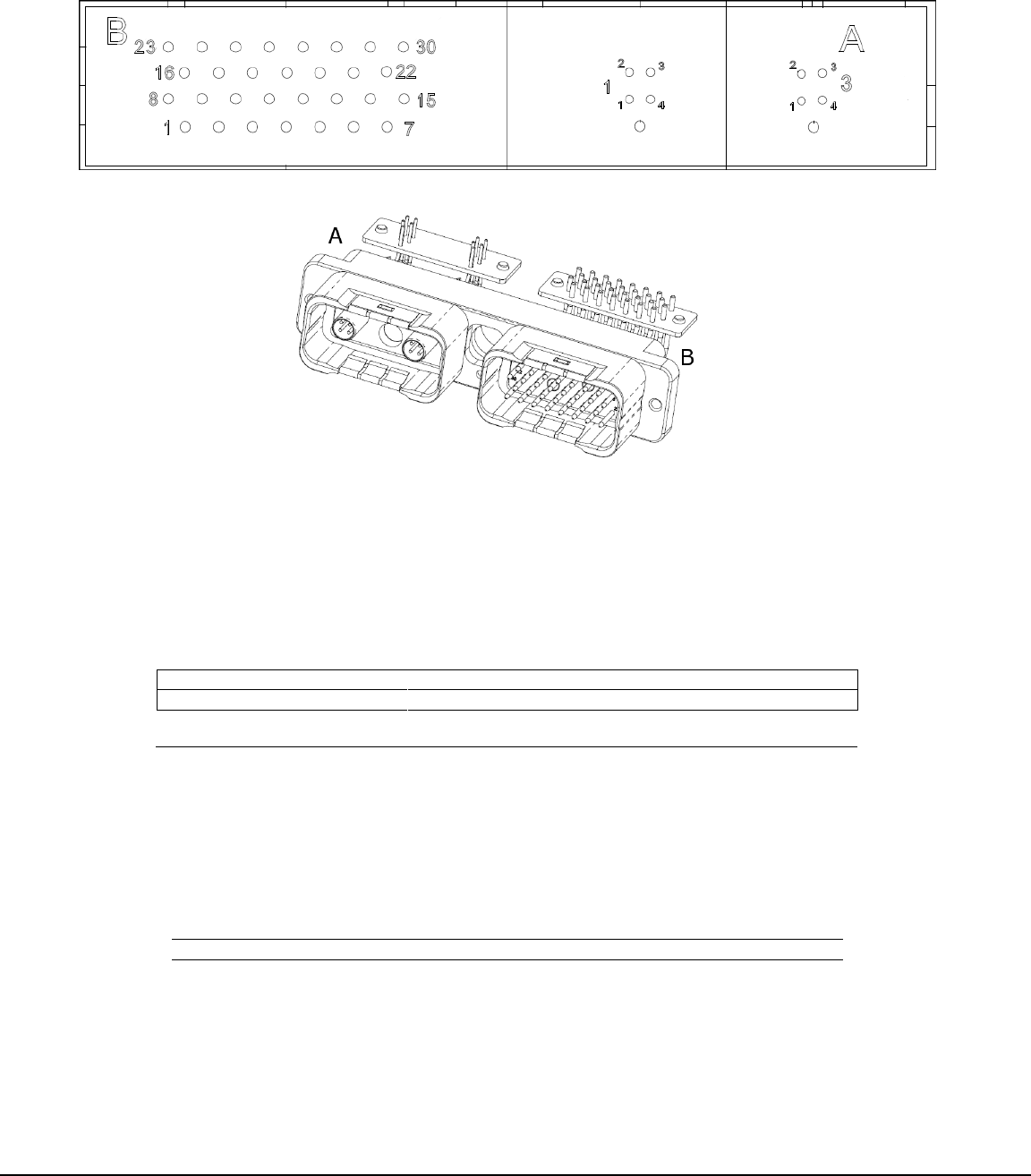
8.5.1. Main Connector
The WLU uses a single connector for signal and power. The connector is labeled, J1. Figure 8-1 shows the
physical pinout of the main connector from the rear view.
Figure 8-1 LRU Connector (J1) Physical Pinout
The WLU has a main connector to provide power/ground pins, discrete pins, and quadrax inserts for two
Ethernets. The baseline connector is Radiall RP58736. Power and signal wires have physical separation within
the connector by using spare pins as a spatial separator.
Table 8-2 Connector Names and Part Numbers for WLU
965-1702-001 Connectors
Name
Honeywell P/N
Type
Mating Connector Type
J1
440-2042-002
EPX, Male
EPX, Female
J2
315-5186-001
TNC Female
TNC Male
8.5.2. Signals, Power and Ground
Table 3-2 gives a description, lists the pin number, and labels the pin as an input or output. Refer to Figure 8-1
for a diagram of the connector.
Table 8-3 LRU Connector (J1-B) Pin Assign
Pin Number
Signal Name
Comments
I/O
1
Spare
2
Spare
I
3
DISC_IN
Spare
I
4
FACTORY_DEFAULT_RST
I
5
POSITION 1
I
6
POSITION 2
I
7
POSITION 3
I
8
POWER_SUPPLY_OFF
I
9
uP_GOOD
O
10
PRI_LAN_LINK_STAT
O
11
SEC_LAN_LINK_STAT
O

CAGE CODE:
97896
SCALE: NONE
SIZE: A
DWG NO.
REV:
SHEET 16
HIF-1472R6(1)
12
WLAN_LINK_STAT
O
13
POWER_GOOD
O
14
DISC_OUT_1
Spare
O
15
DISC_OUT_2
Spare
O
16
DISC_OUT_3
Spare
O
17
JTAG_EXT_EN
I
18
FL_UNPROTECT
I
19
EE_UNPROTECT
I
20
JTAG_AW_EXT
I
21
+28VDC RTN
GND
22
+28VDC
I
23
CHASSIS_GND
GND
24
JTAG_TDO_EXT
O
25
GND
26
JTAG_TCK_EXT
I
27
GND
28
JTAG_TDI_EXT
I
29
GND
30
JTAG_TMS_EXT
I
Table 3-3 gives the name and position and describes where the Ethernets are located on the main connector.
Table 8-4 J1-A Quadrax Insert Positions
Position
Name
Description
1
Eth1 (Primary)
CIS Server Port
2
(Filled with alum. Plug)
3
Eth2 (Secondary)
CWLU Port
Table 3-4 gives the name and position of the Ethernet pins to describe how they will be electrically connected.
Table 8-5 J1-A Insert Quadrax Pinout
Quadrax Pin
Signal
Labels
1
TX+
PRI_10_100_TX_A/SEC_10_100_TX_A
2
RX+
PRI_10_100_RX_A/SEC_10_100_RX_A
3
TX-
PRI_10_100_TX_B/SEC_10_100_TX_B
4
RX-
PRI_10_100_RX_B/SEC_10_100_RX_B
Shell
Shield
Ground
9. MECHANICAL INSTALLATION
9.1. General
This section contains information on the necessary information to mount the WLU.
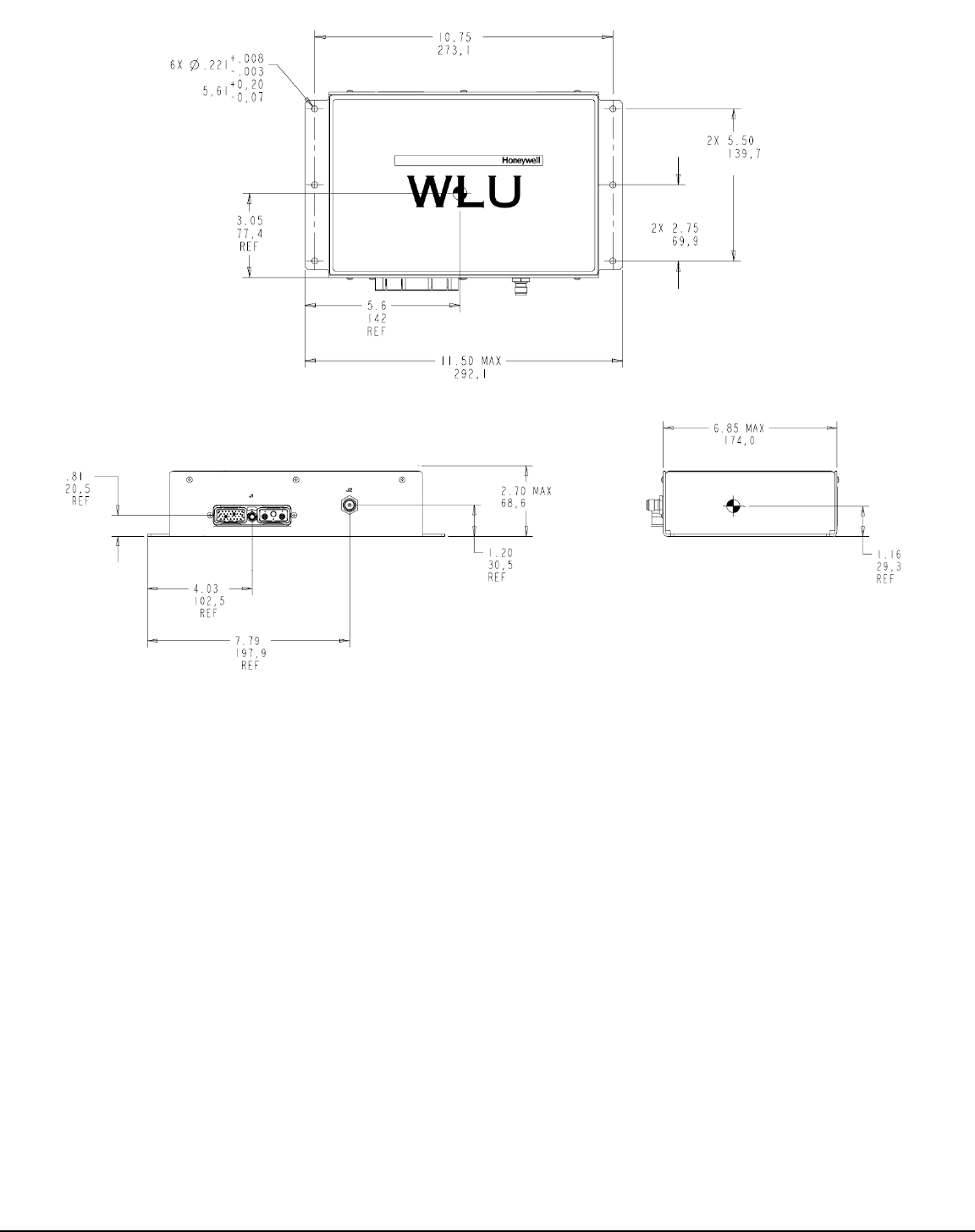
Figure 9-1 shows the WLU mounting hole dimensions, as well as the mechanical outline. The depth or
protrusion of the J1 and J2 connectors are 0.78 inches maximum. The WLU is a bolt-down low profile package
with the footprint defined in ARINC 763.
CAGE CODE:
97896
SCALE: NONE
SIZE: A
DWG NO.
REV:
SHEET 17
HIF-1472R6(1)
Figure 9-1 Mechanical Outline of WLU
9.2. Equipment and Materials
The TWLU should be mounted with six screws and washers. The necessary screws and washers will be
certified by Boeing to be flight worthy.
10. ELECTRICAL INSTALLATION
10.1. General
These sections give electrical installation procedures, power distribution, and interconnect information for the
WLU. Procedures for proper shield, power, and signal grounding are also provided in this section. In addition,
procedures for the various buses are included.
10.2. Power requirements
The information necessary to provide the electrical interconnects is contained in the following paragraphs.

CAGE CODE:
97896
SCALE: NONE
SIZE: A
DWG NO.
REV:
SHEET 18
HIF-1472R6(1)
10.2.1. DC Power
The aircraft DC power supply must be 28 V DC (nominal). The normal minimum and maximum voltages
permitted are 22 and 29.5 V DC respectively. The maximum current drawn by WLU is 0.32 +/- 0.03 Amps at
28 VDC, equivalent to a maximum power consumption of 10 watts.
10.2.2. Ground Requirements
Proper grounding is a key factor in ensuring proper system operation under normal conditions, high intensity
radiated electromagnetic frequencies (HIRF), and lightning environments. You must obey this section to
satisfy these requirements.
NOTE: HIRF and lightning requirements dictate that the shielded wires meet the requirements of Shielded
Grounds. Installation of this system into aircraft manufactured prior to the FAA requirements adheres to
these practices whenever feasible.
All electrical conductors, terminals posts and component parts that are not at ground potential shall be
insulated or otherwise protected to prevent hardware from creating a short circuit or a spark ignition source.
The WLU is designed to be grounded by the chassis to the ground structure directly. The WLU allows a total
DC voltage drop of less than or equal to 0.7VDC for the 28V DC return path to the RPDU.
11. ANTENNA INSTALLATION
11.1. General
WARNING: This equipment complies with FCC radiation exposure limits set forth for uncontrolled
environment. This equipment must be installed and operated with a minimum distance of 20 cm between the
radiator/antenna and your body.
This section provides general guidelines for installing Wi-Fi antennas with the WLU. Due to the wide variation
of wireless regulations from country to country, the exact model antennas to be used with the WLU are left to
the customer/installer and country regulations. Honeywell has certified the Sensor Systems antennas listed in
Table 7-1.
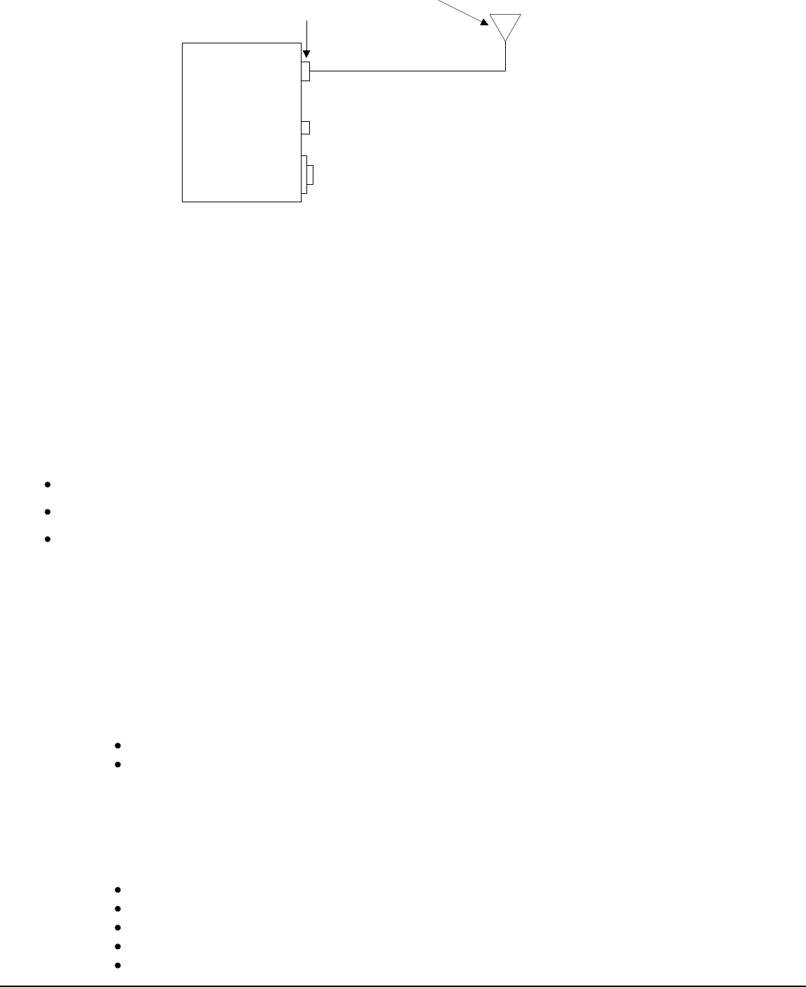
The maximum power output of the TWLU before cable loss is equal to 18 dBm. The RF cable used between
the TWLU and antenna is should have insertion of approximately 3 dB. The maximum gain of the Wi-Fi
Antenna listed in Table 7-1 is equal to 5 dBi. Figure 11-1 shows an overall diagram representing the gain and
loss of the system. The maximum Effective Radiated Power (ERP) at the antenna should be 20 dBm if
installing an antenna other than the Wi-Fi antennas listed in Table 7-1.
CAGE CODE:
97896
SCALE: NONE
SIZE: A
DWG NO.
REV:
SHEET 19
HIF-1472R6(1)
WLU
18 dBm output
3 dB cable loss
{
5 dB antenna gain
ERP = 20 dBm
Figure 11-1 Example ERP of the WLU with Sensor System Wi-Fi antenna
12. FAULT ISOLATION
12.1. General
This section describes the built-in test equipment (BITE) function for the WLU.
System BITE contributes to a number of maintenance functions:
Detection of internal and external faults
Reporting failure status in the air and on the ground
Ground test capability for isolating faults, performance verification, and system level testing.
12.2. Fault Detection
The WLU detects faults using continuous monitors in all system modes where the fault is
detectable. The WLU continuously monitors for internal hardware, software and interface faults and
sends fault messages via WLAN Manager, when they occur.
The WLU automatically detects each fault condition that causes either:
One or more digital output signals to be identified as failed or invalid
Loss or significant degradation in other outputs to other systems.
A fault is defined and set for each of the test components. Fault Monitor Data may include up to 600
characters of free text to add details relevant to failures. The continually monitored tests cover the
following components:
Power Supply (fault if power supply output is outside accepted range)
Processor (fault if processor error or overheat condition occurs)
Memory (volatile and non-volatile, fault if memory error occurs)
Software execution (fault is software error occurs)
Configuration (fault if configuration is corrupted)

CAGE CODE:
97896
SCALE: NONE
SIZE: A
DWG NO.
REV:
SHEET 20
HIF-1472R6(1)
Radio Functional (fault if Radio doesn’t respond to processor)
Ethernet interface (fault if interface is down)
Discrete interfaces (fault is interfaces are in invalid configuration)
WLAN Manager Authentication State (fault if Manager authentication fails)
WLAN Authentication State (fault if WLAN authentication fails)
WLAN Encryption State (fault if encryption fails)
WLAN Connection State (fault if connection fails)
Gatelink Connection State (fault if connection fails when Gatelink is available)
Router State(fault if router function fails in TWLU when Gatelink is connected)
DHCP State (fault if DHCP client in TWLU does not get IP address from Gatelink
Bridge State (fault if bridge function in CWLU fails)
13. DATA LOADING
13.1. General
The WLU applications are data loaded on to the WLU directly by a ARINC 615A data loader. The WLAN
Manager must first notify the TWLU that the aircraft is in Maintenance Mode, before an aircraft data load is
accepted. Data loading is performed on the aircraft by the CIS Server Data Loader application, while in
maintenance mode. It can also be performed off the aircraft with a Data Loader.