Honeywell WNMNFHSS Multinode FHSS radio User Manual Users Guide
Honeywell International Inc. Multinode FHSS radio Users Guide
UserManual.wiki
>
Honeywell
>
WNMNFHSS User Manual
>
Users Guide
Contents
1.
User Manual
2.
User Manual 2
3.
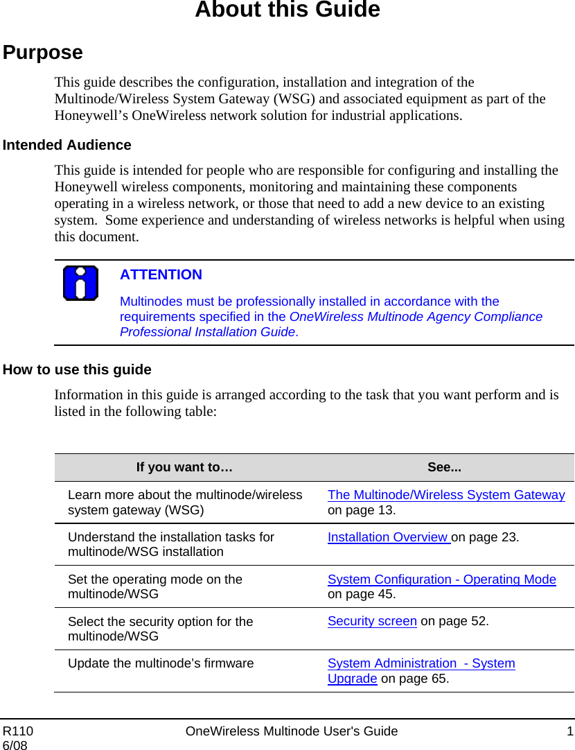
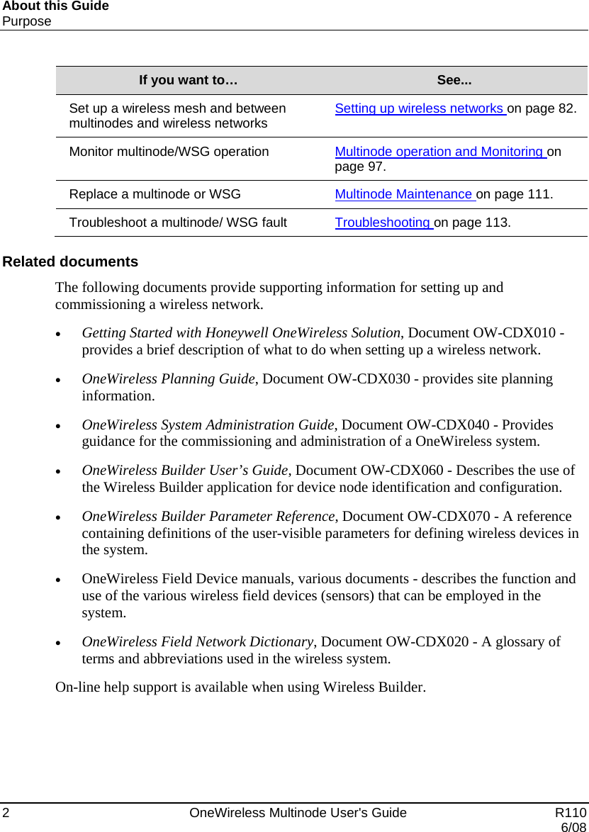
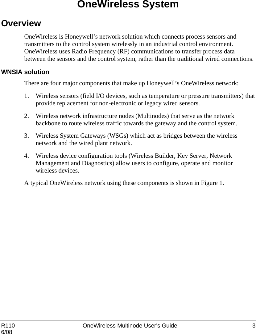
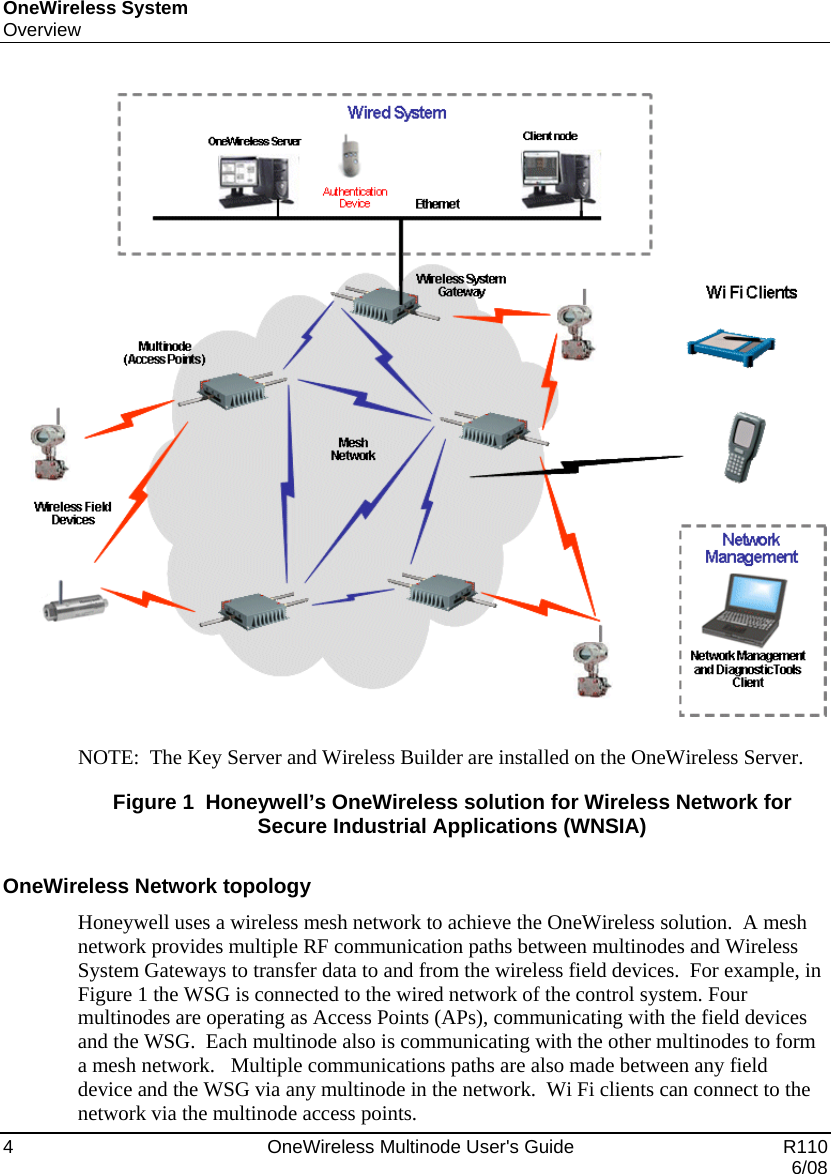
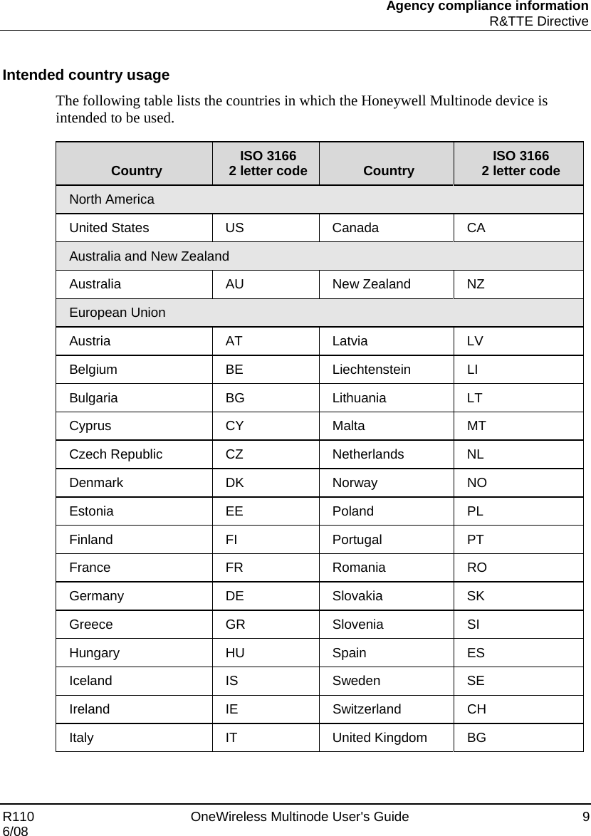
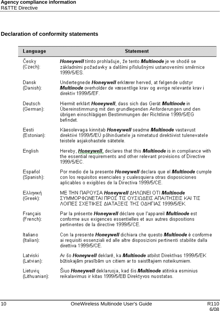
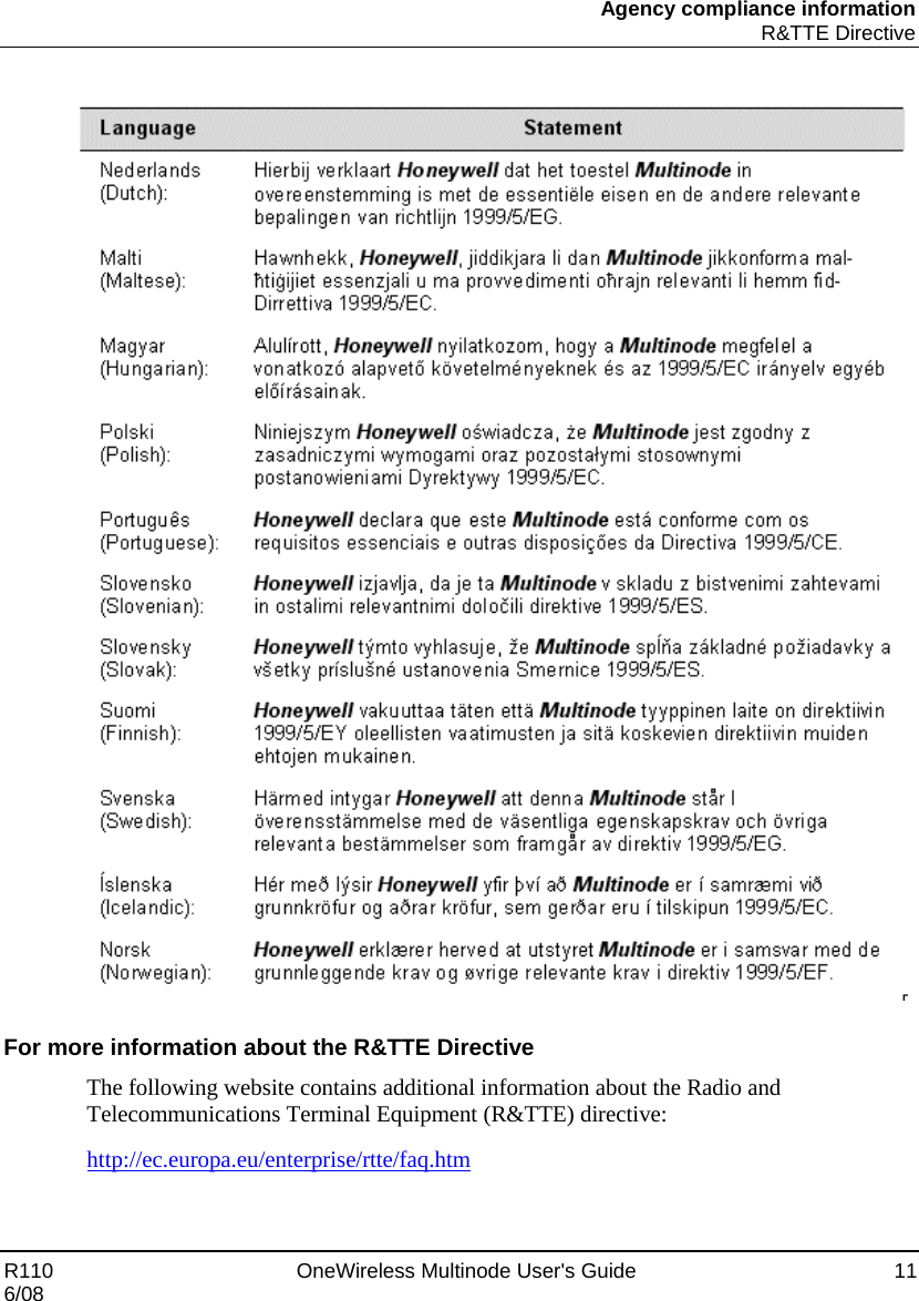
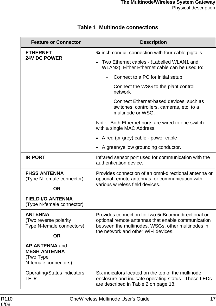
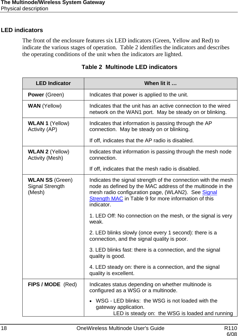
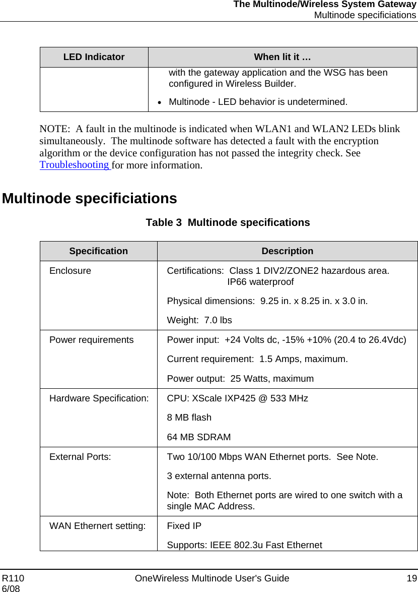
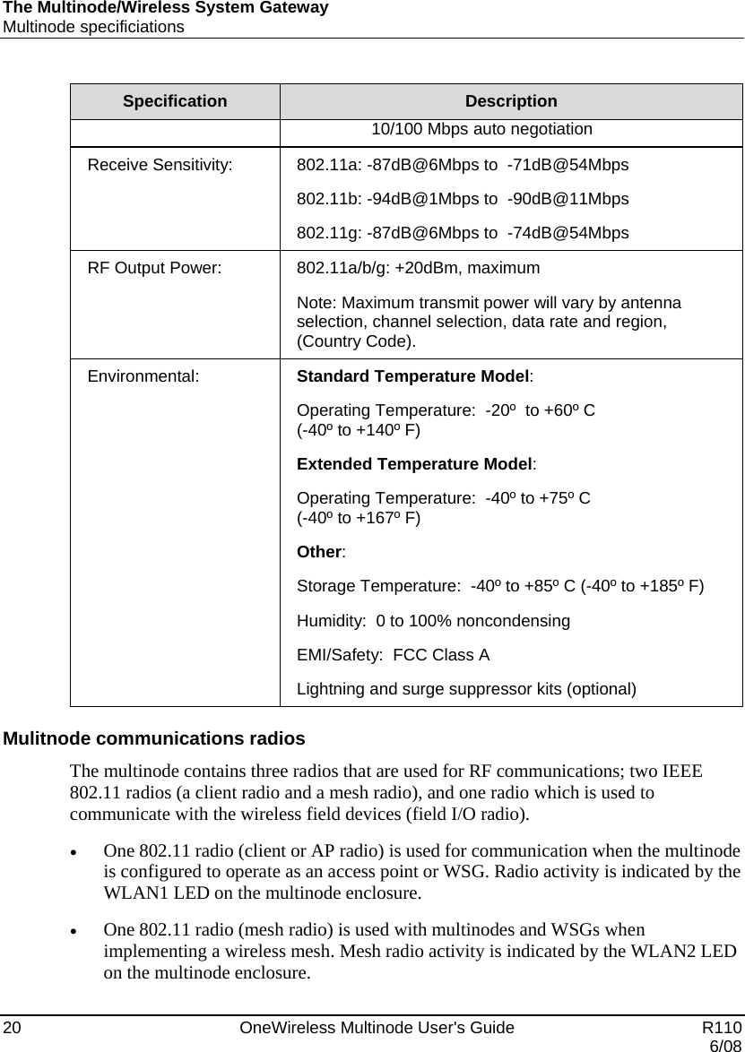
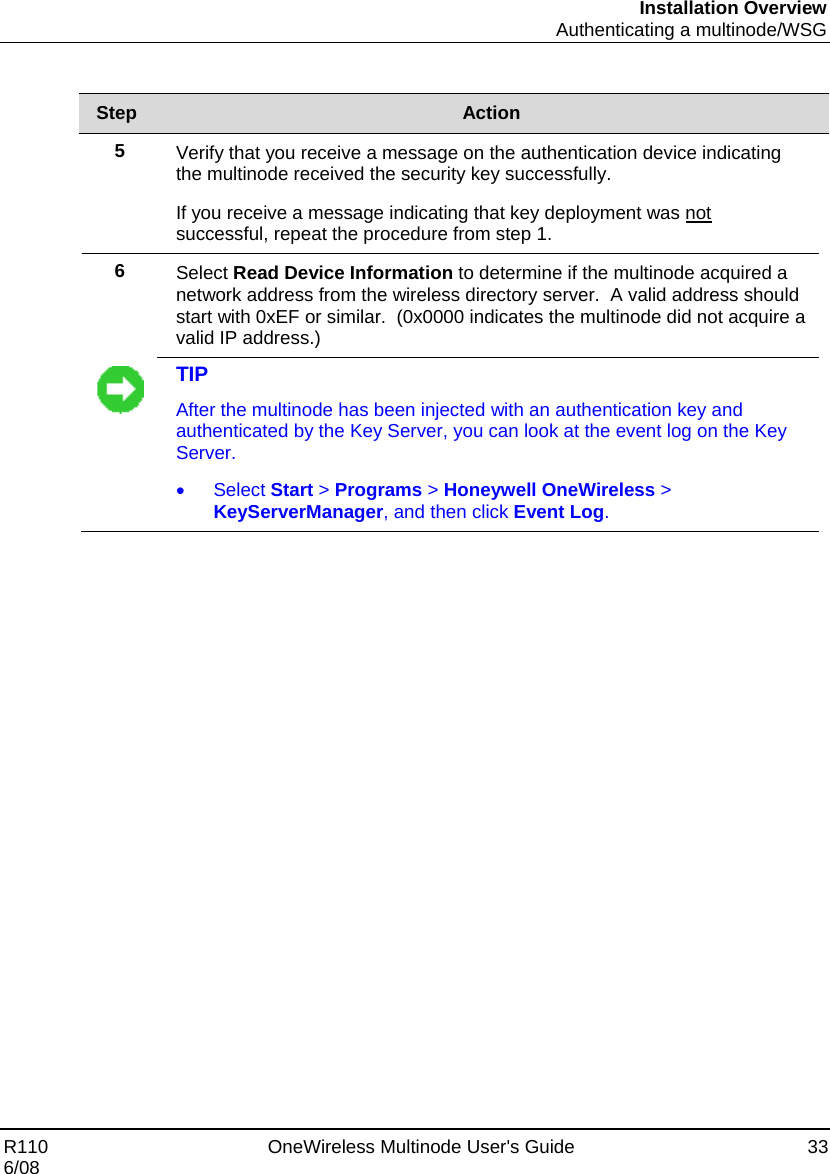
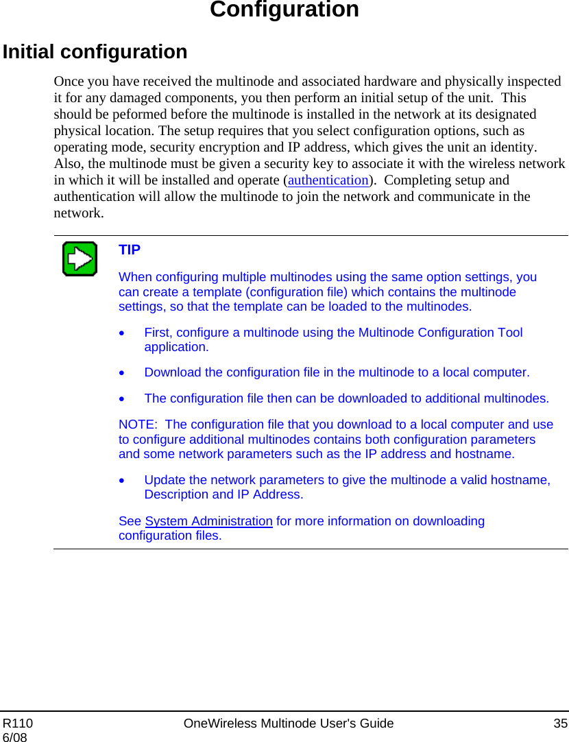
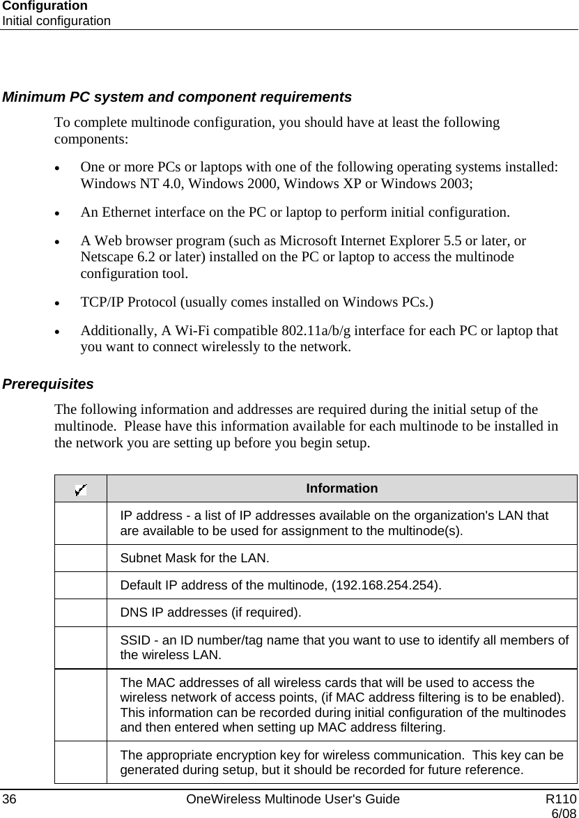
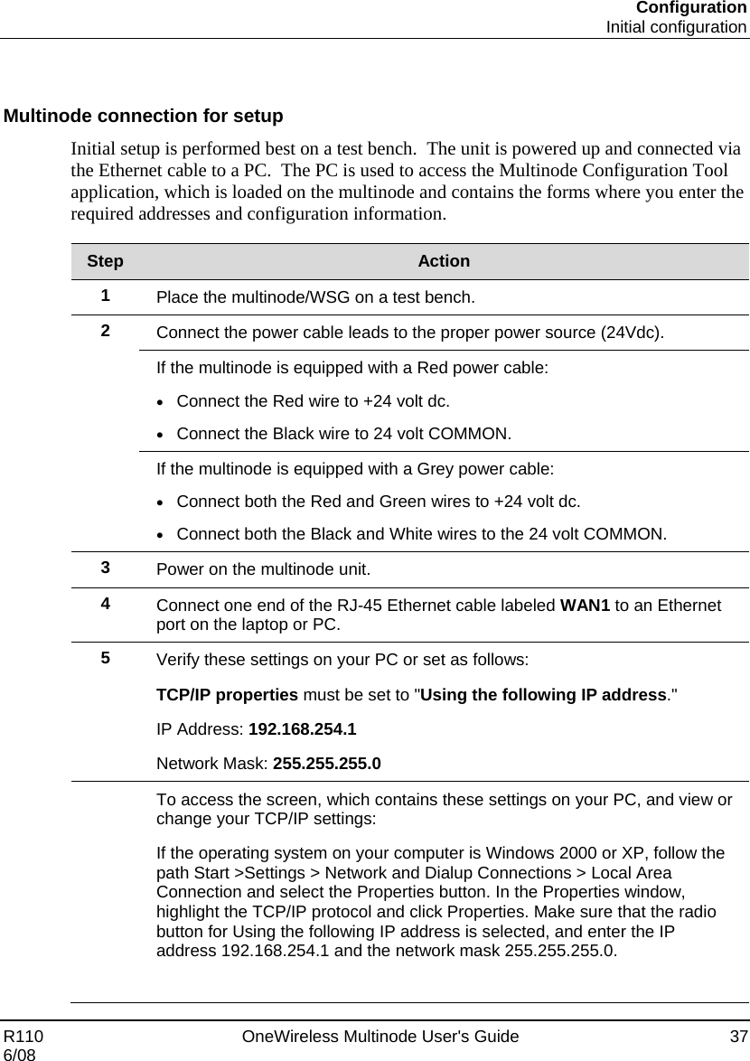
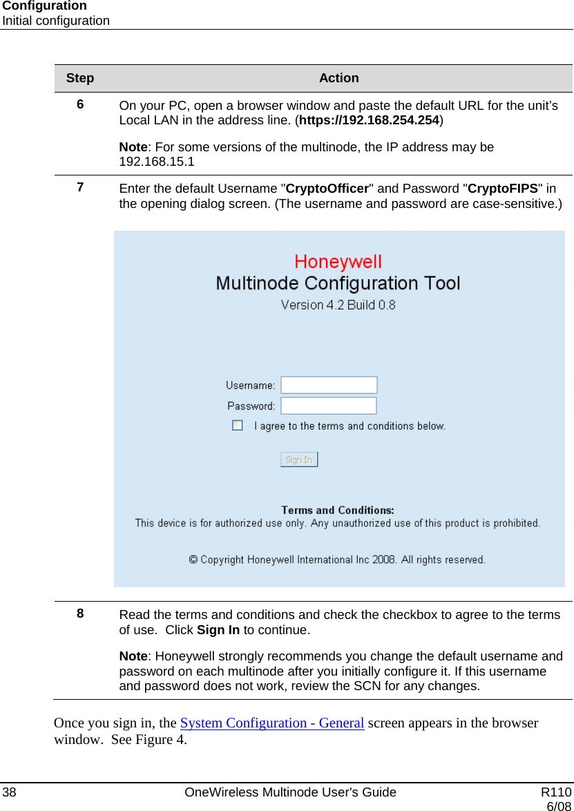
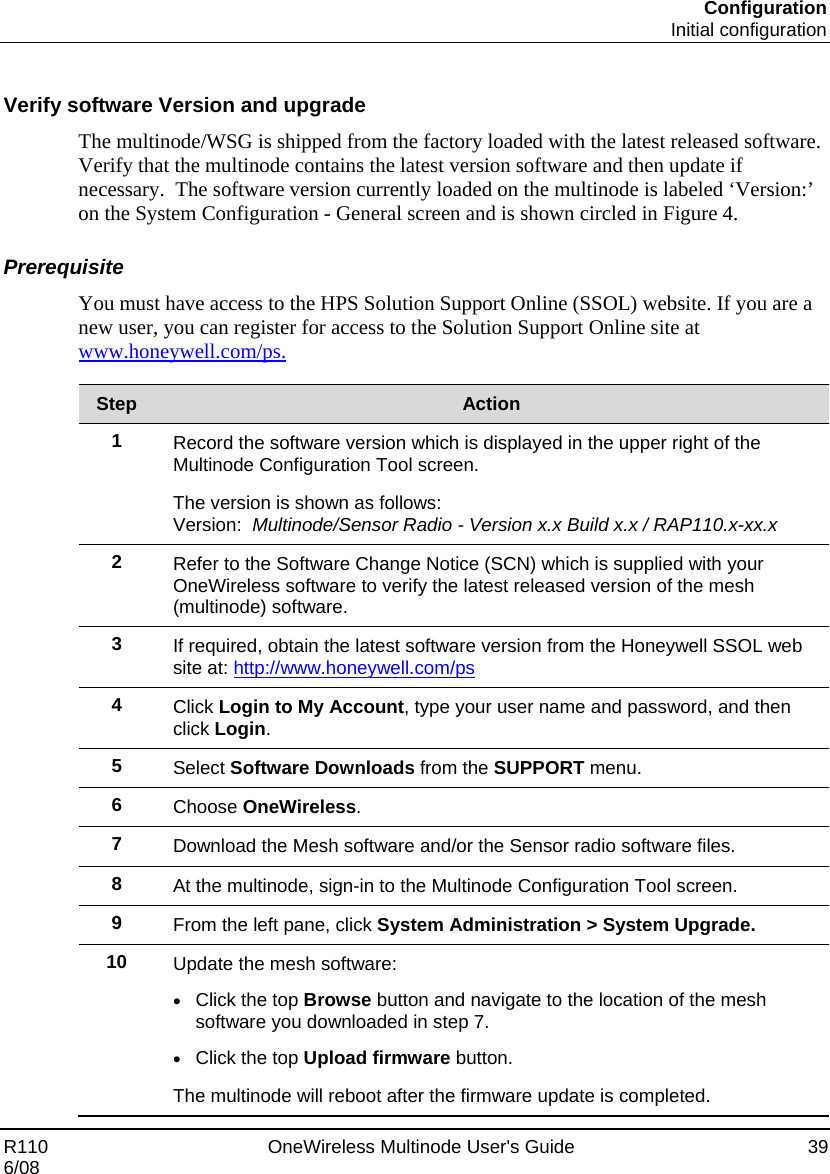
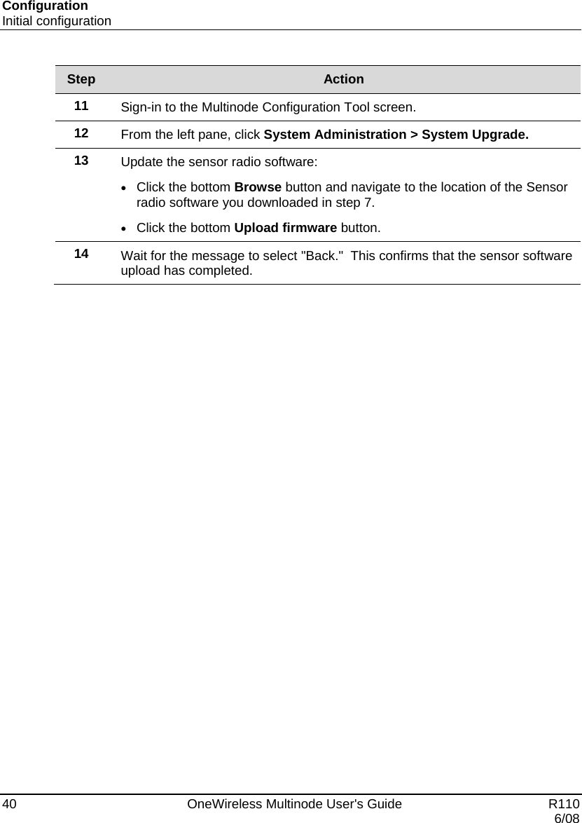
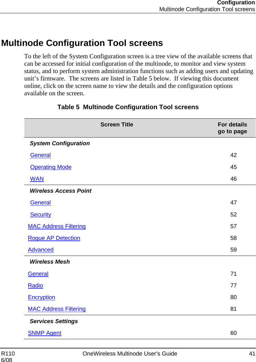
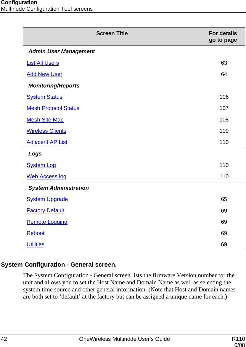
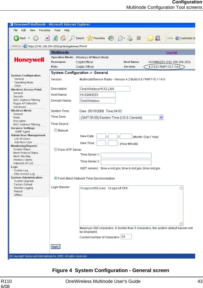
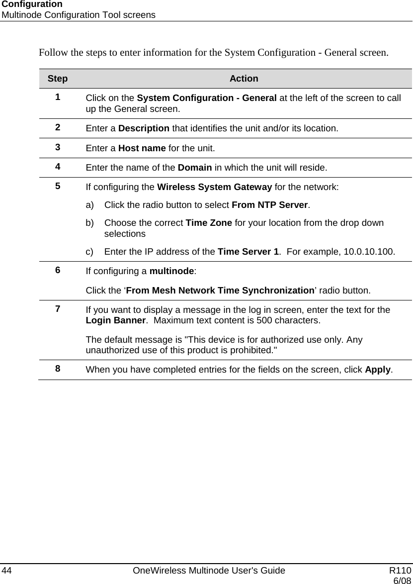
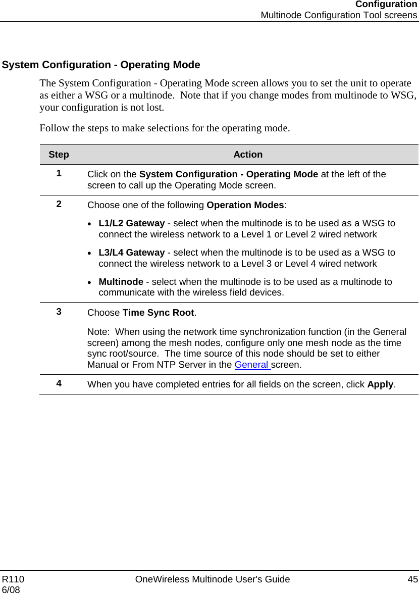
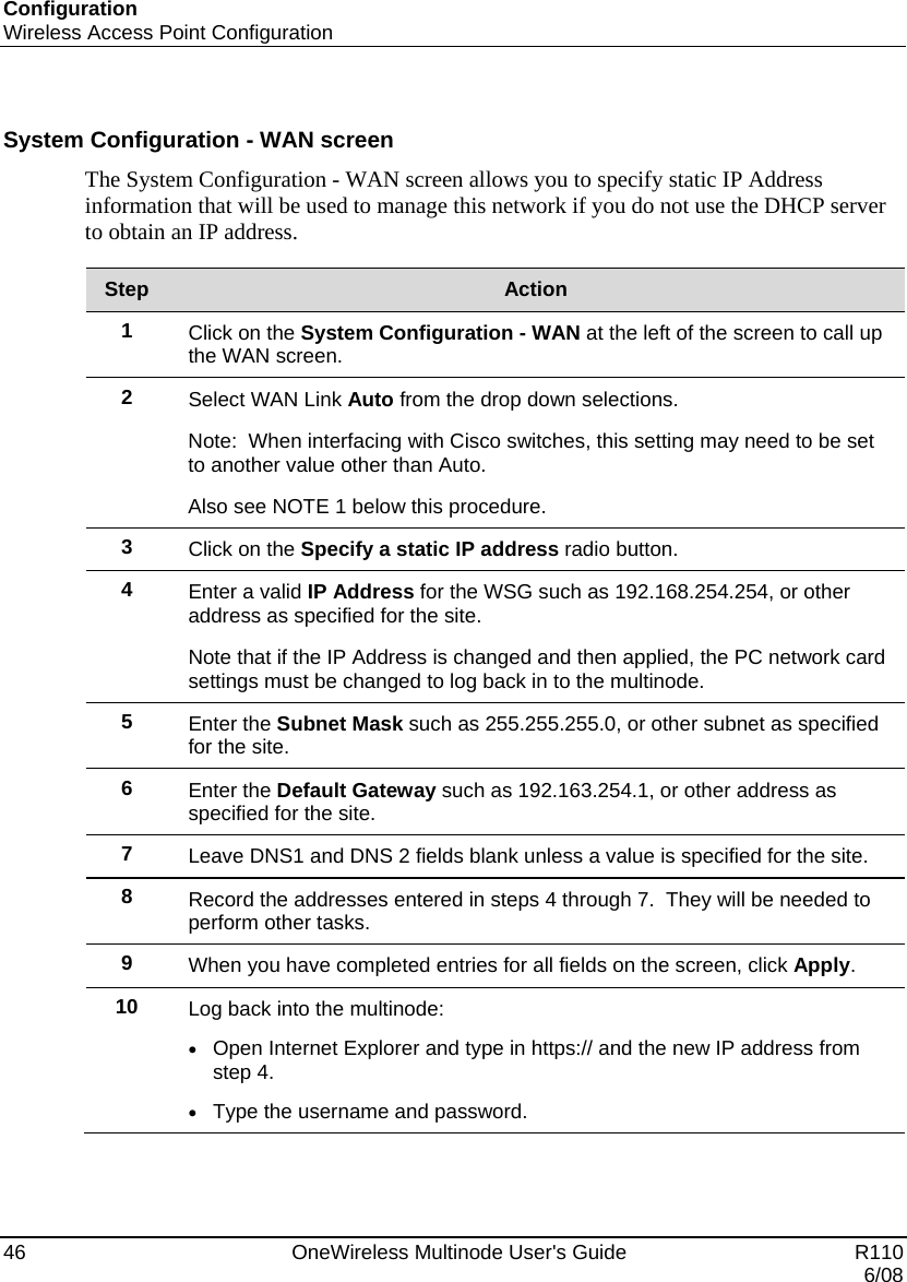
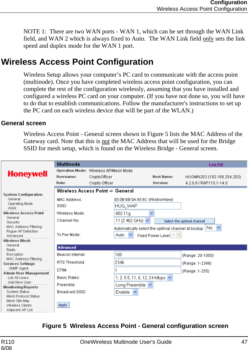
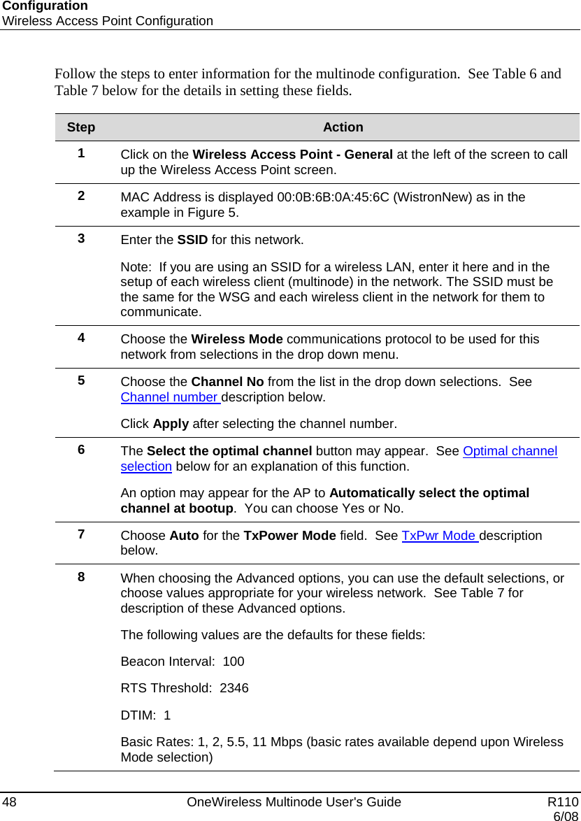
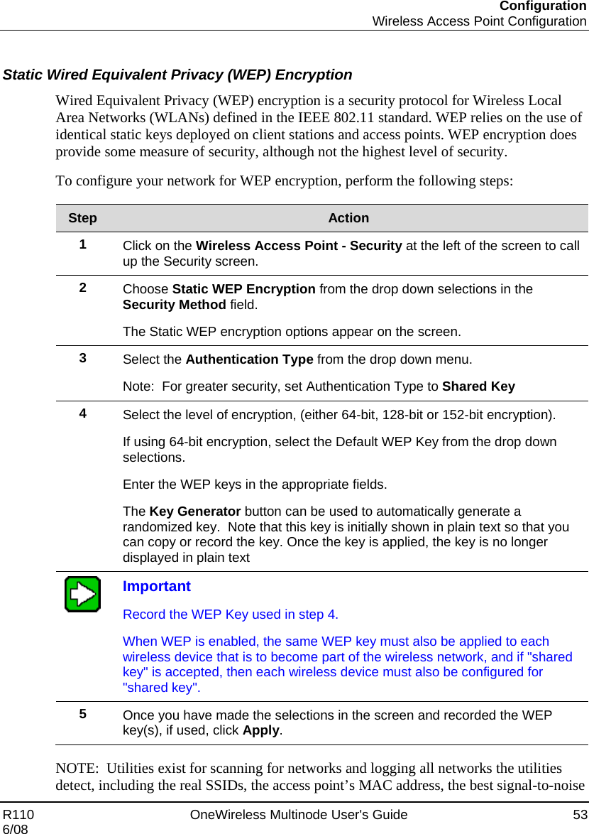
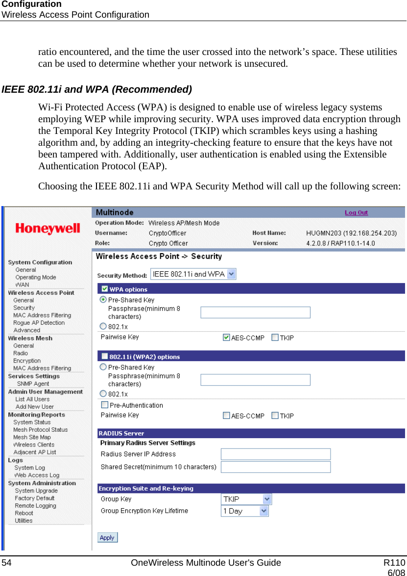
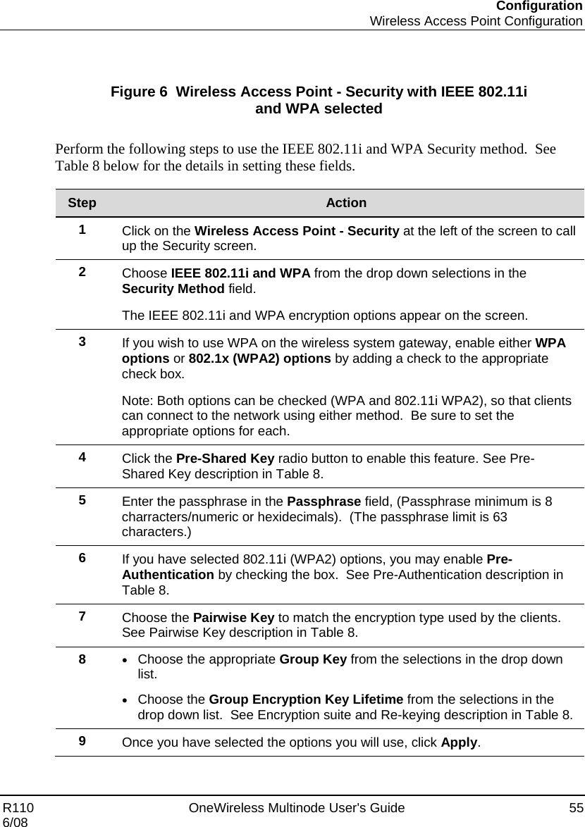
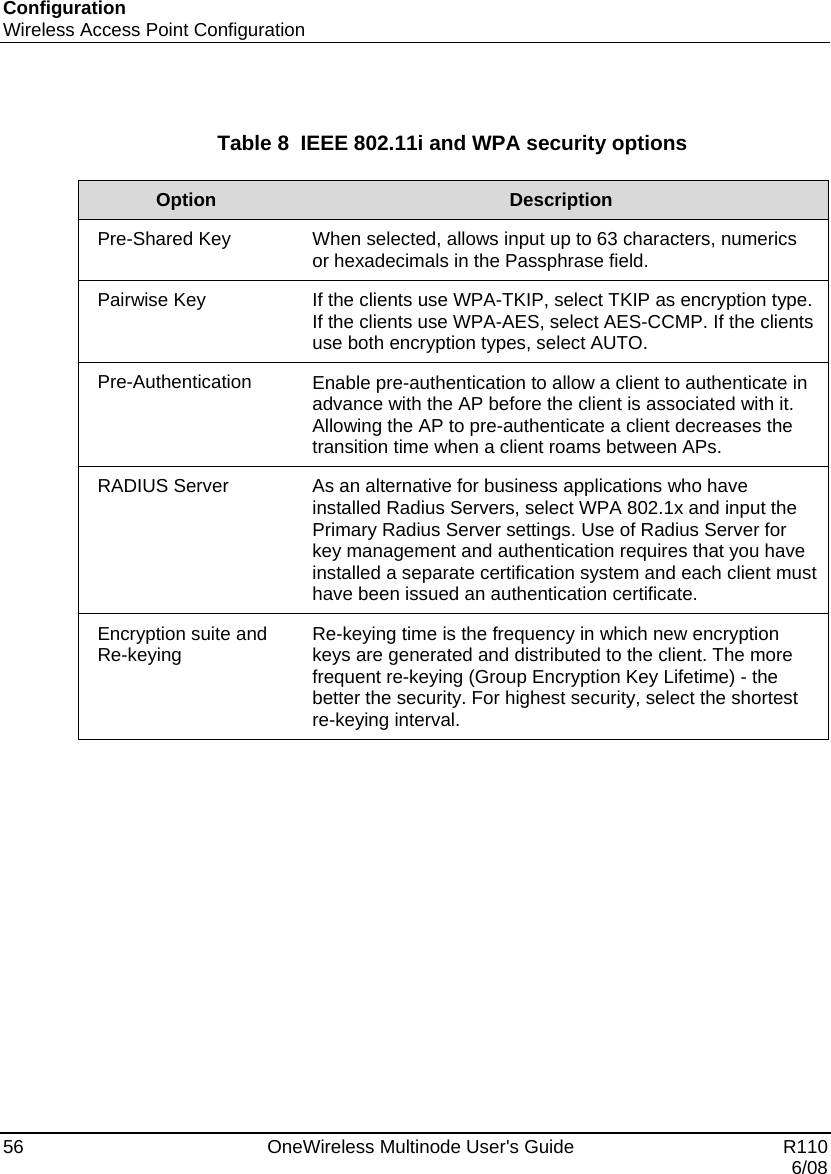
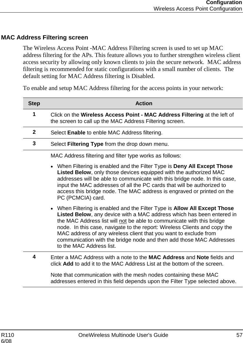
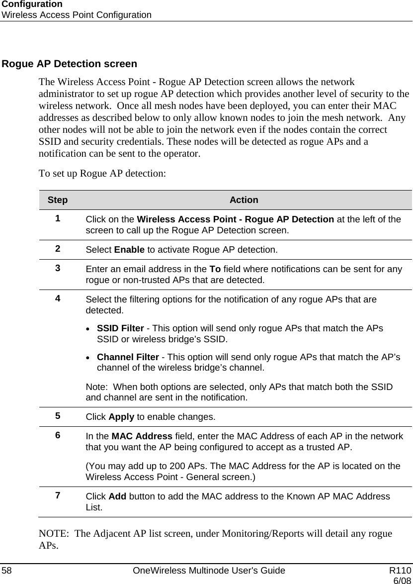
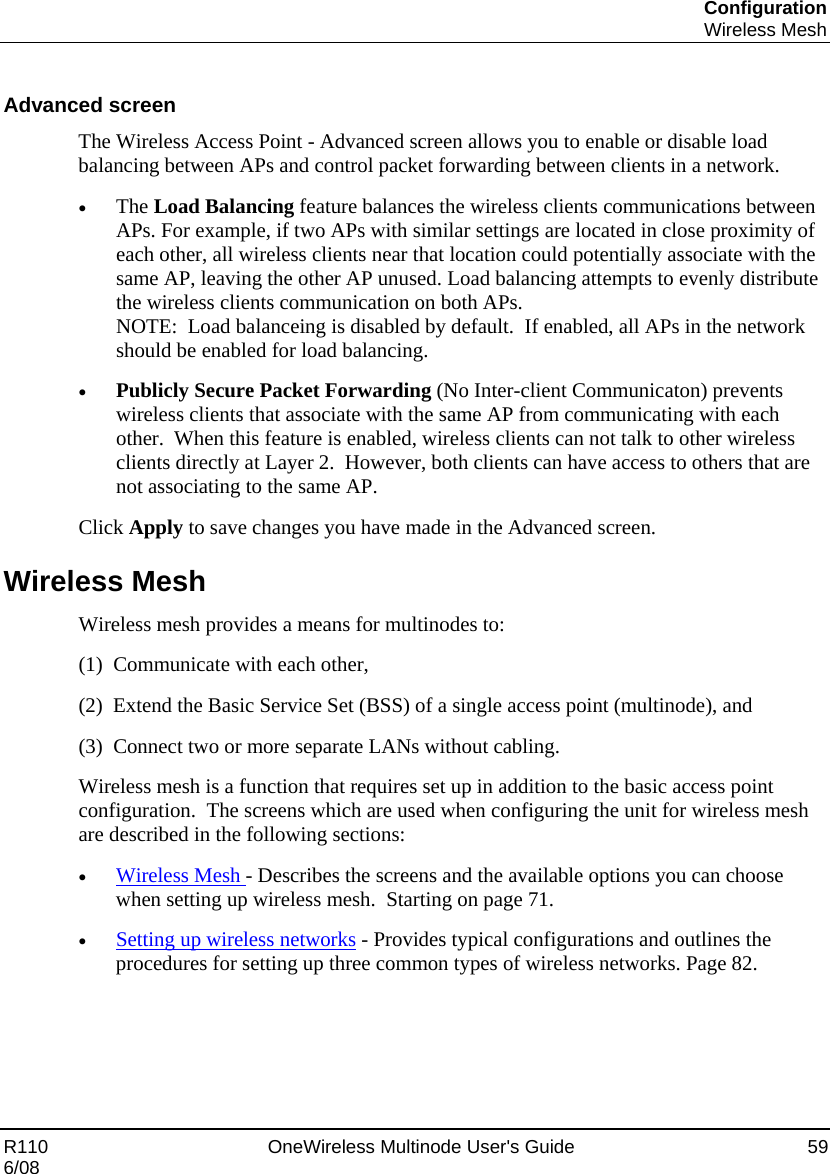
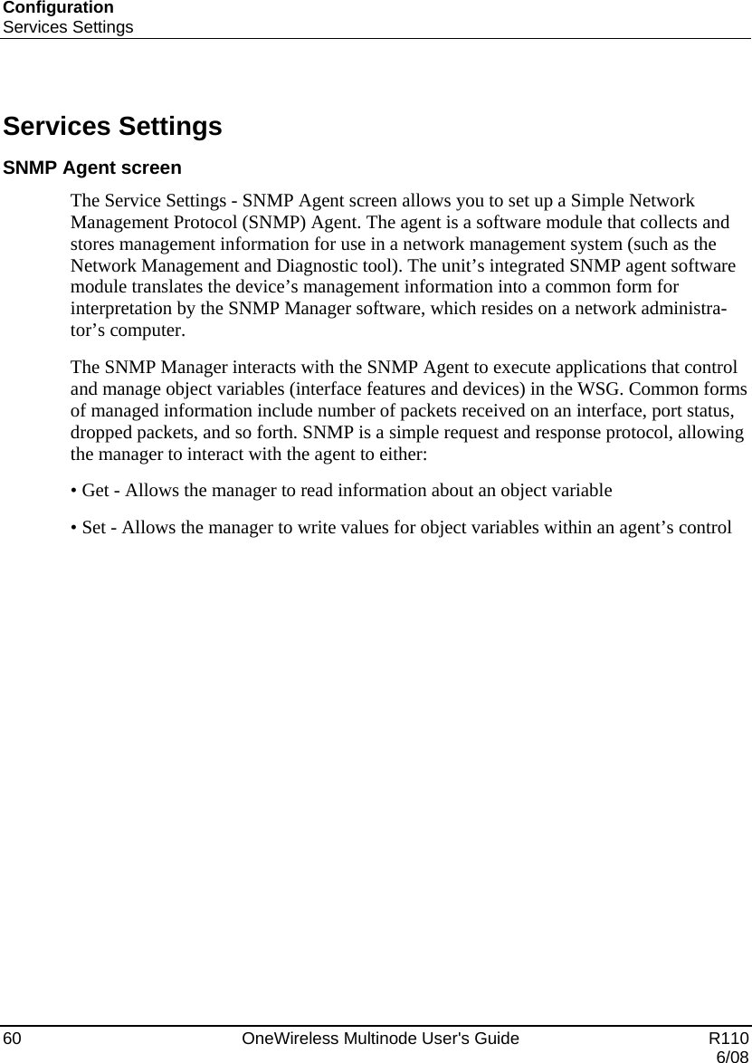
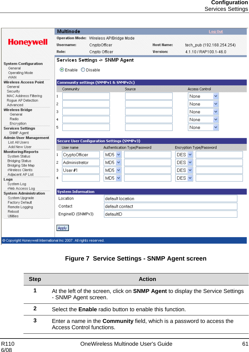
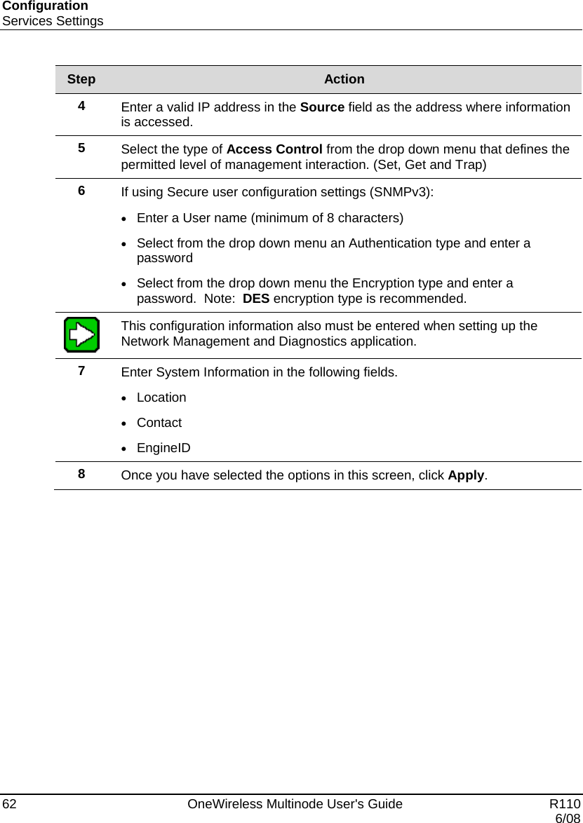
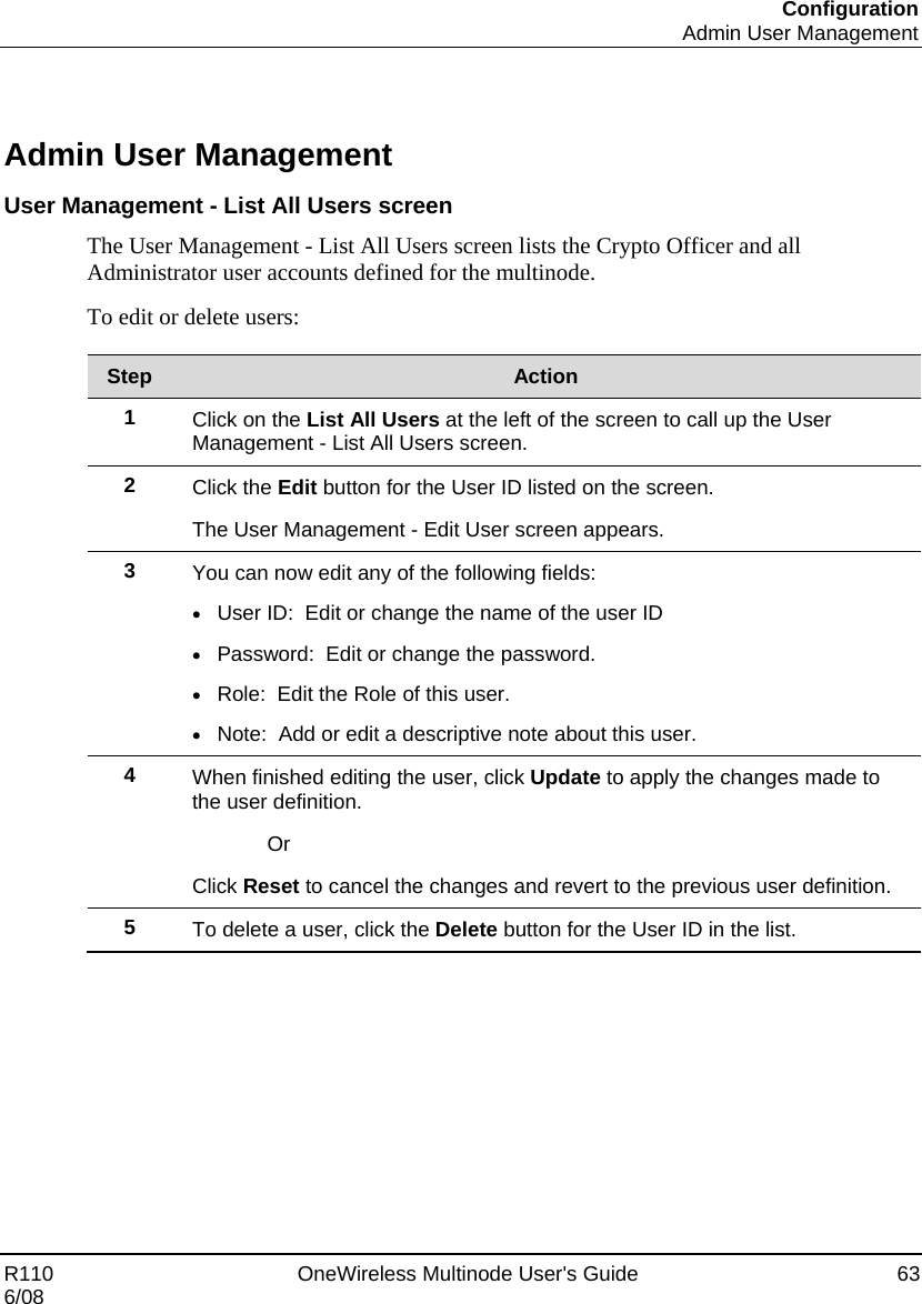
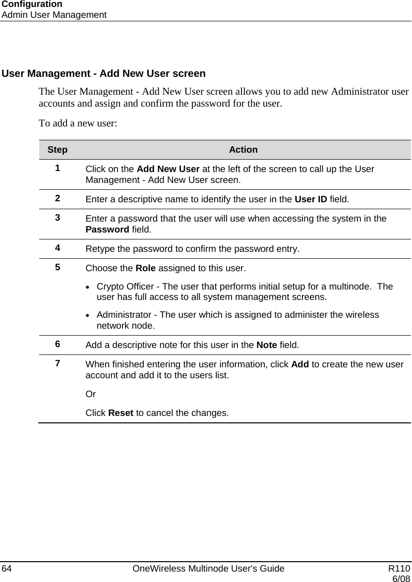
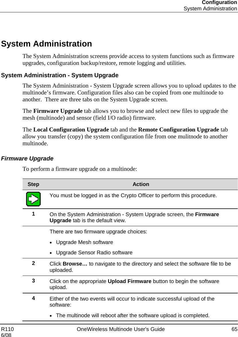
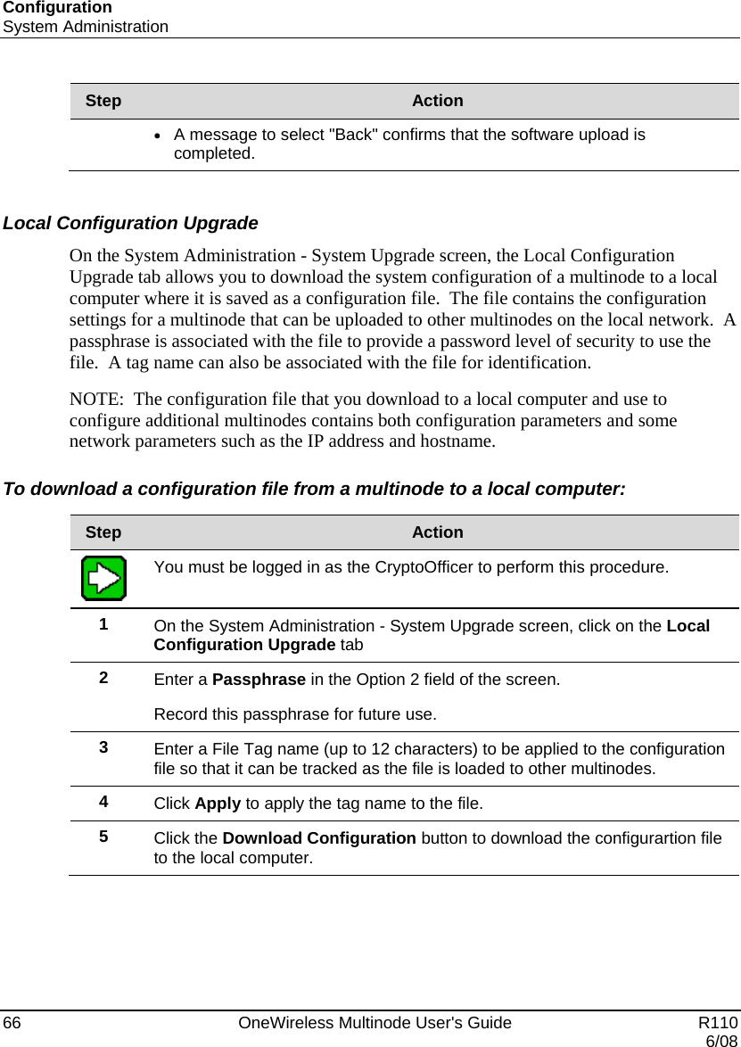
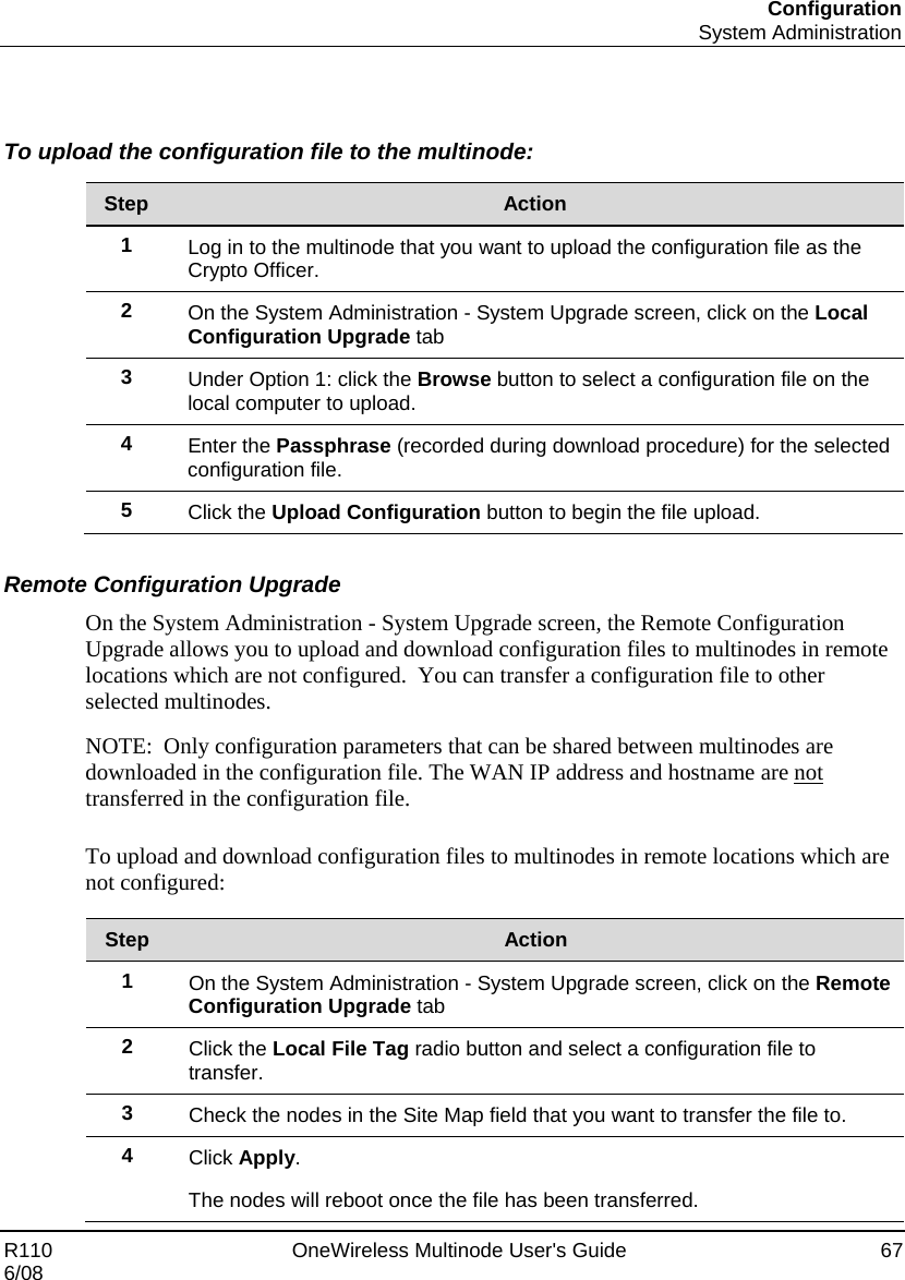
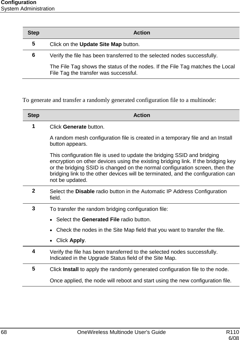
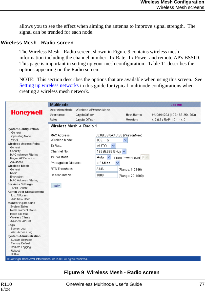
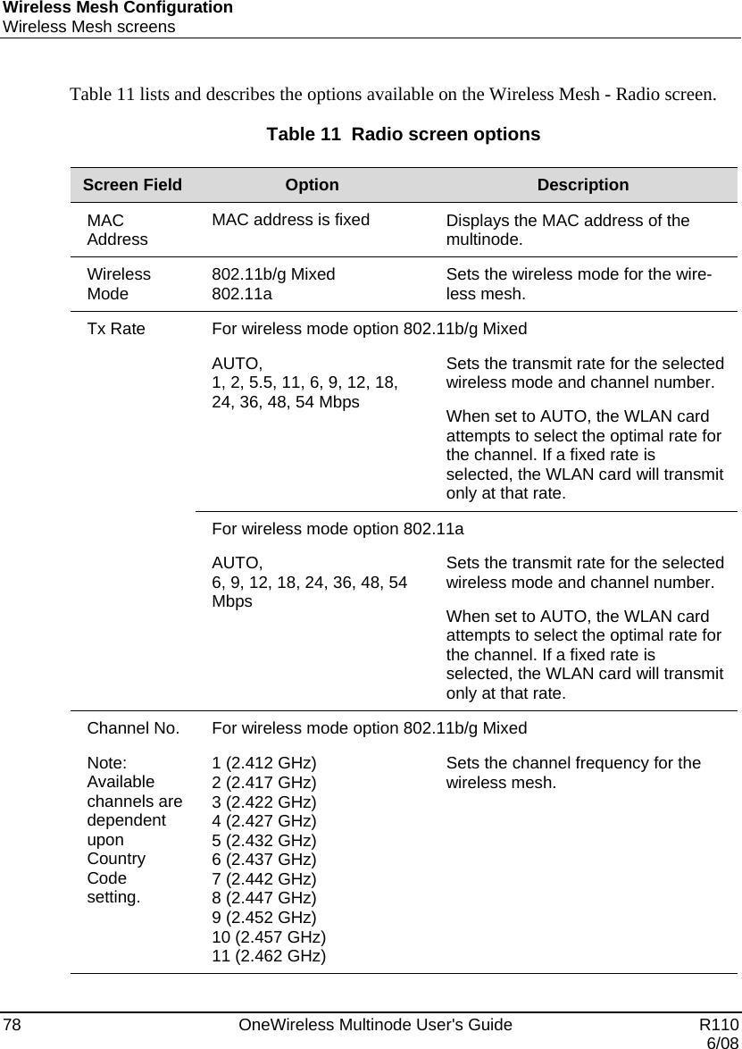
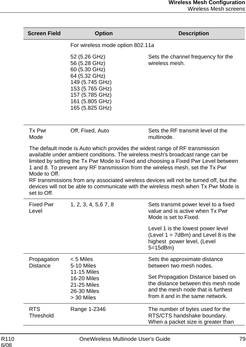
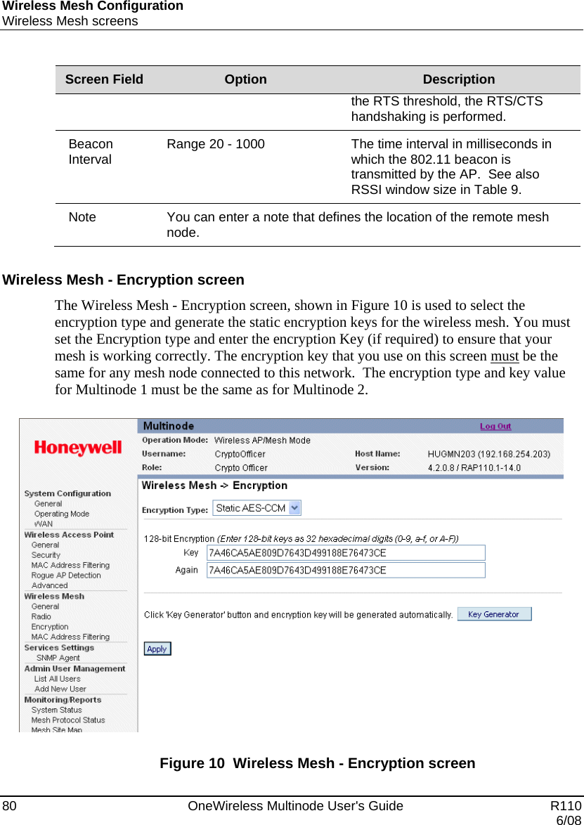
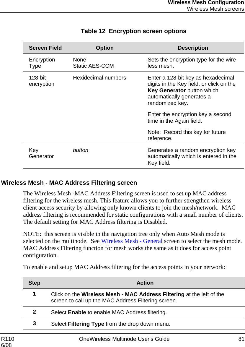
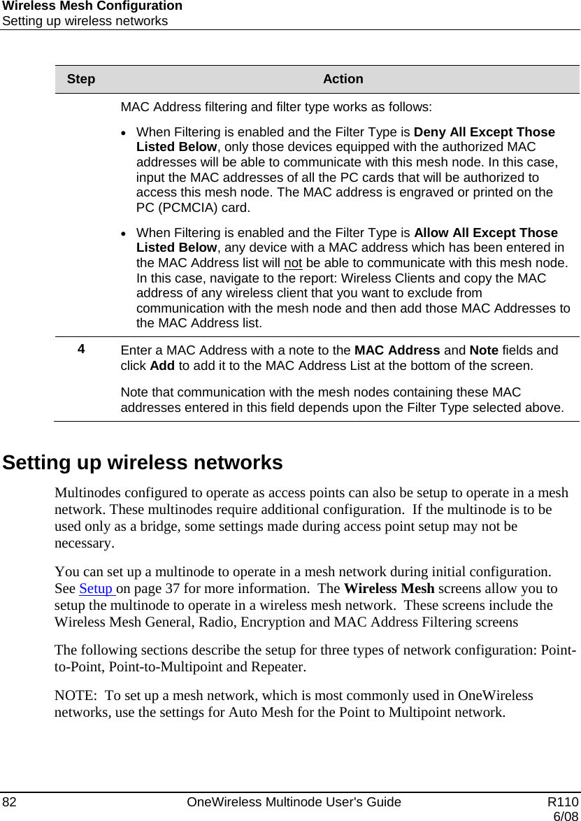
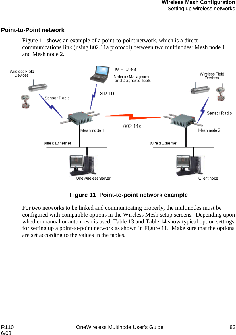
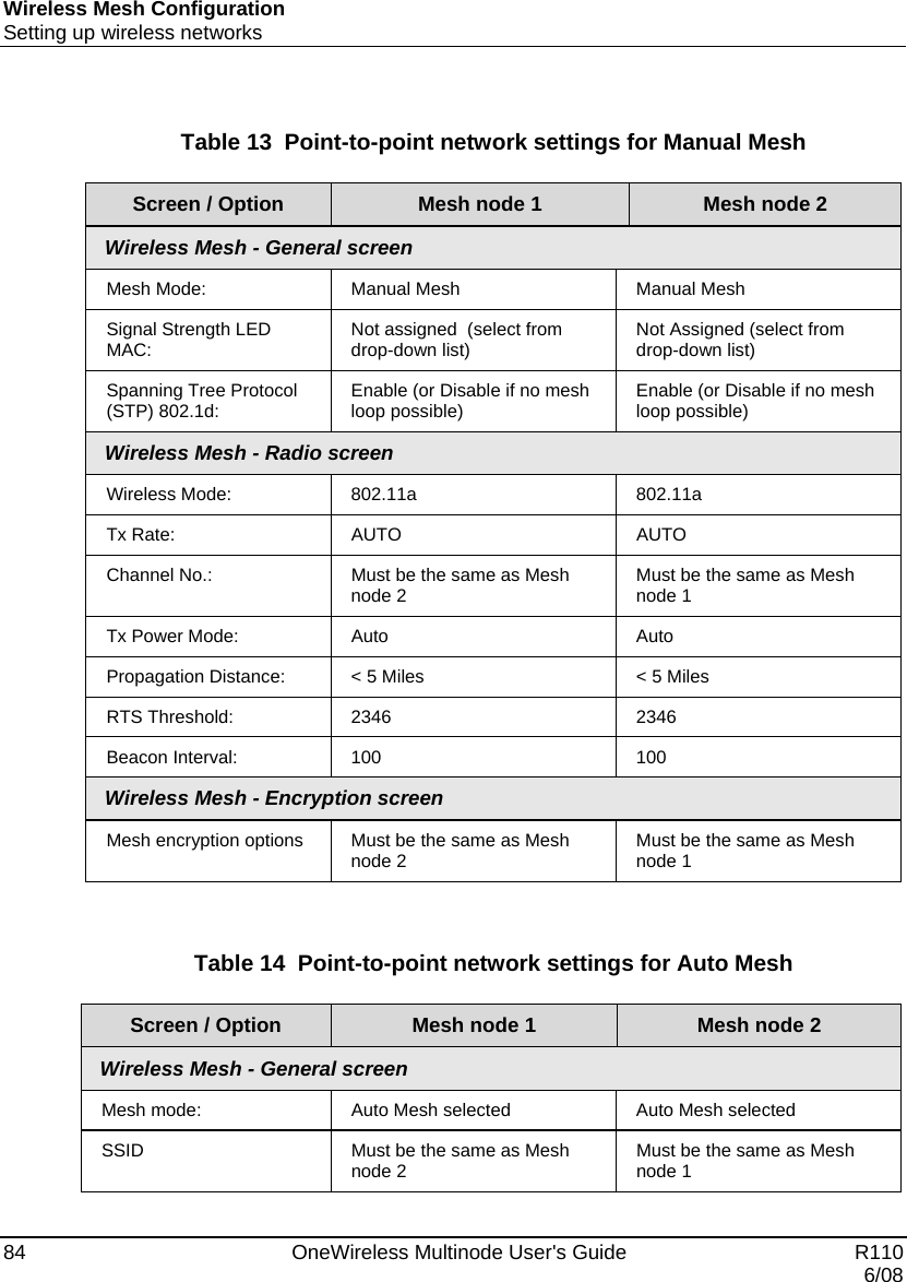
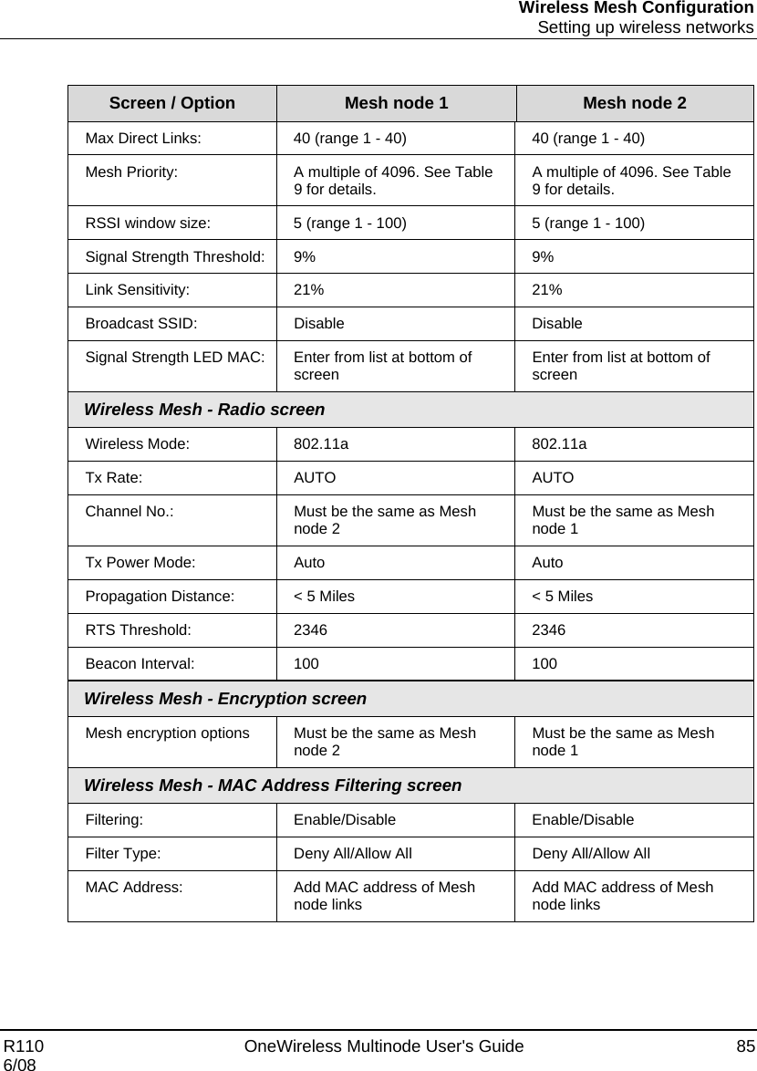
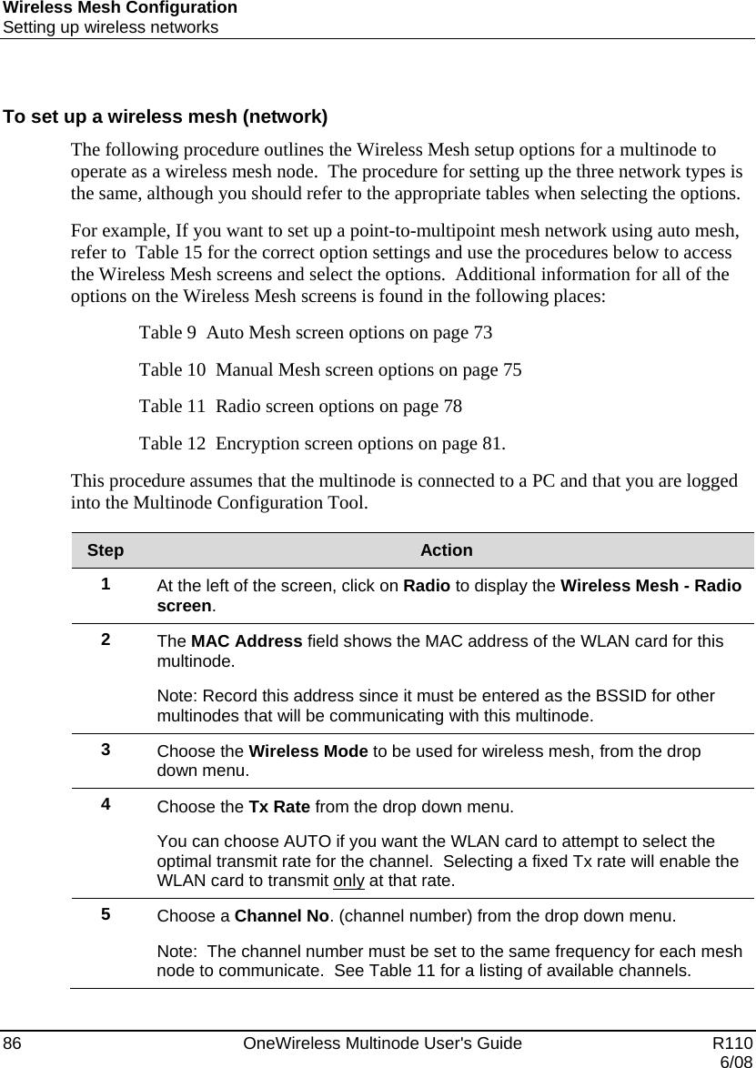
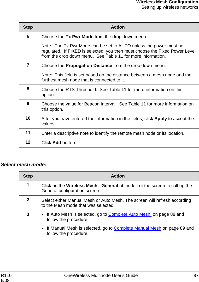
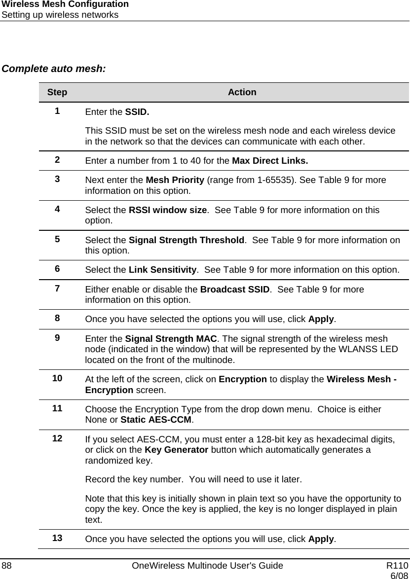
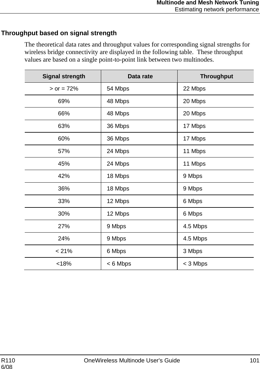
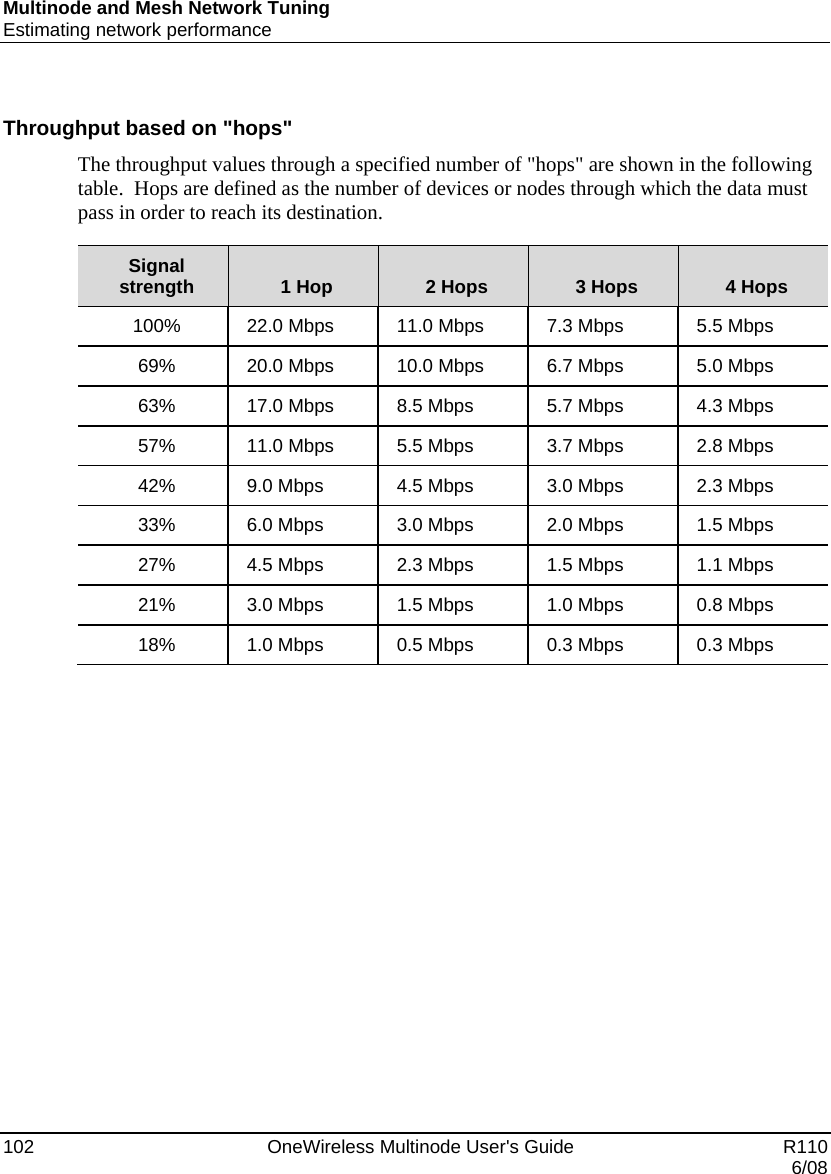
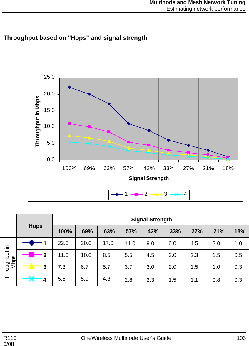
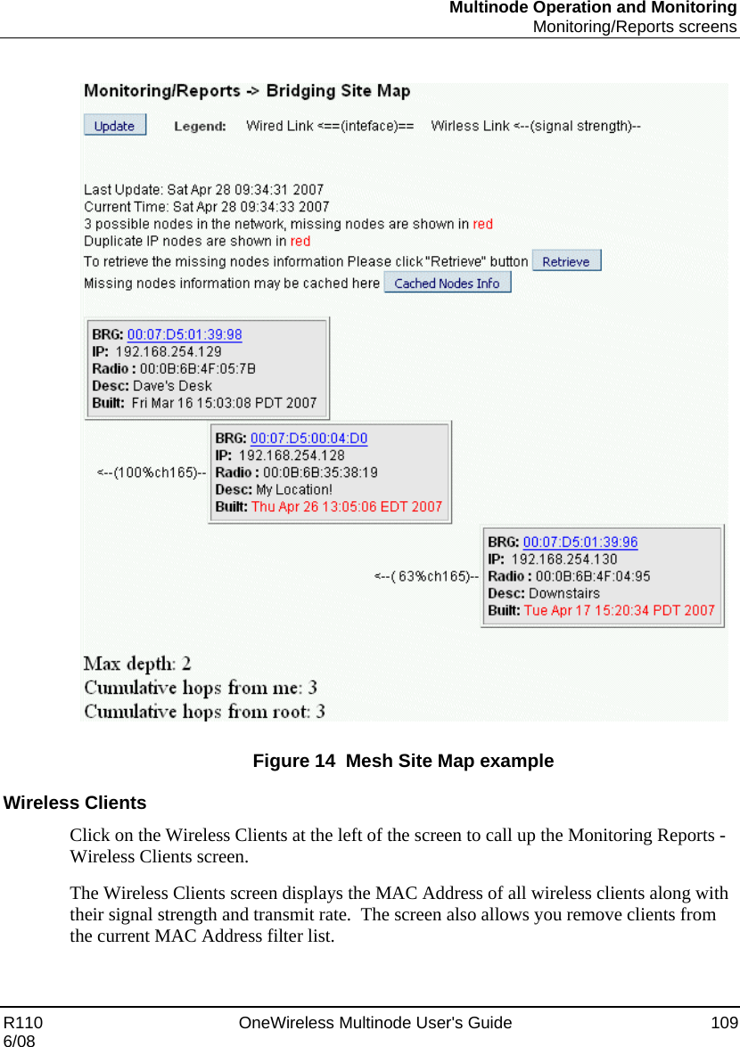
Users Guide
4.
Ext Temp Pro Install Guide revised Nov 2008
Users Guide
Navigation menu
Upload a User Manual
Namespaces
Wiki Guide
HTML
PDF
Info
Views
User Manual
Discussion / Help
Navigation