Hongdian H8956 Cellular Wi-Fi Router User Manual
Hongdian Corporation Cellular Wi-Fi Router
UserManual.wiki
>
Hongdian
>
H8956 User Manual
User manual
Navigation menu
Upload a User Manual
Namespaces
Wiki Guide
HTML
PDF
Info
Views
User Manual
Discussion / Help
Navigation

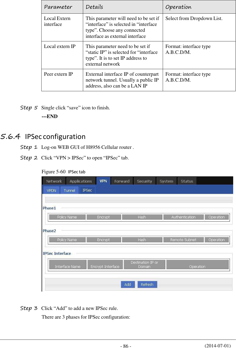
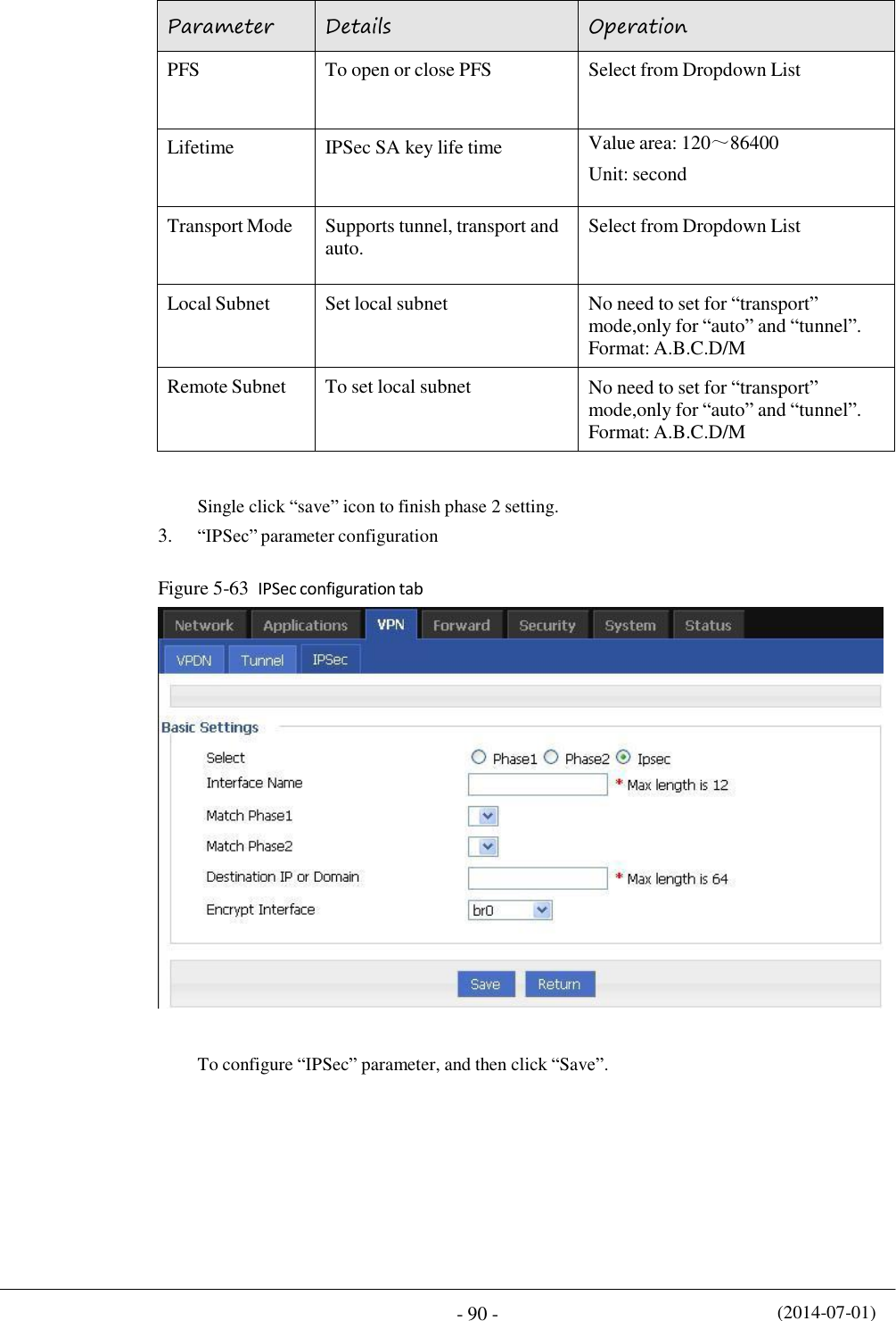
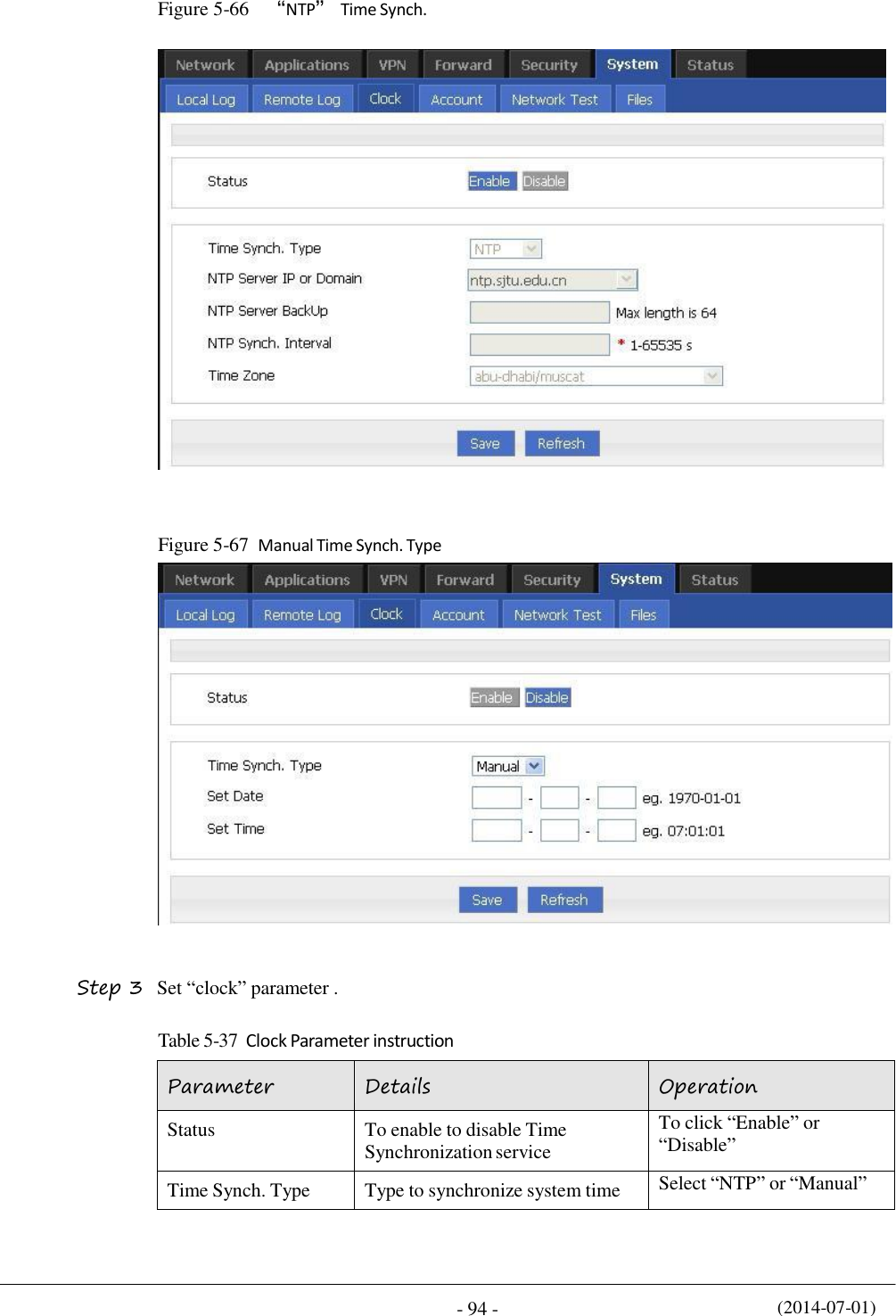
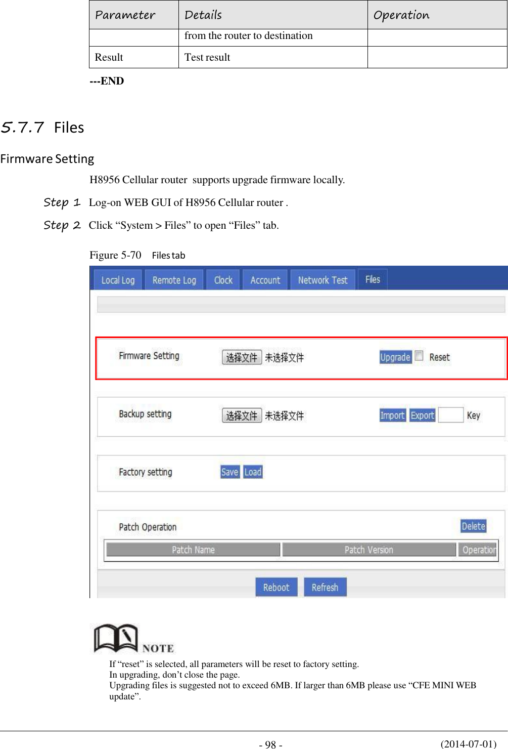
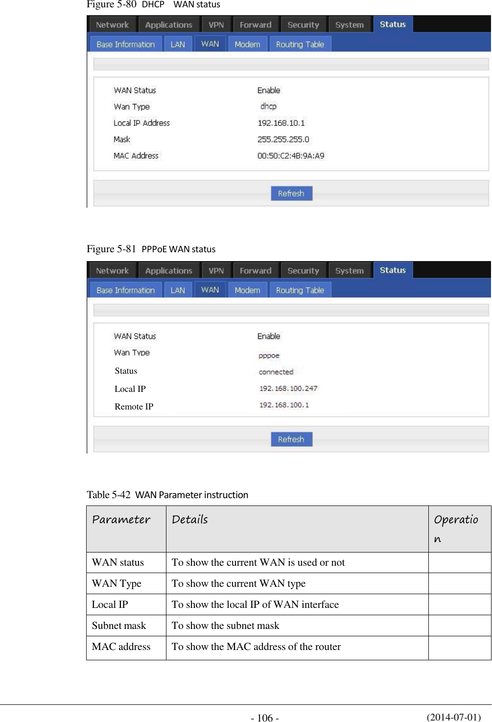
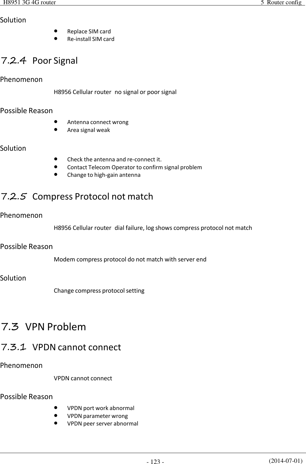
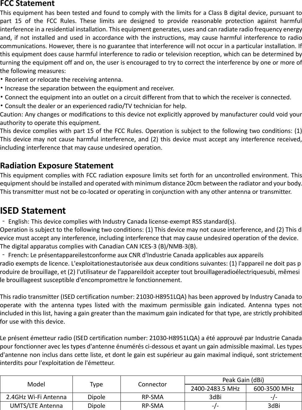
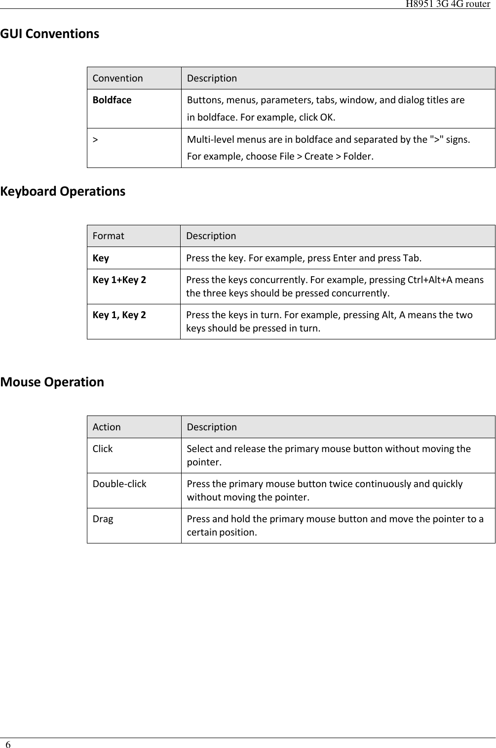
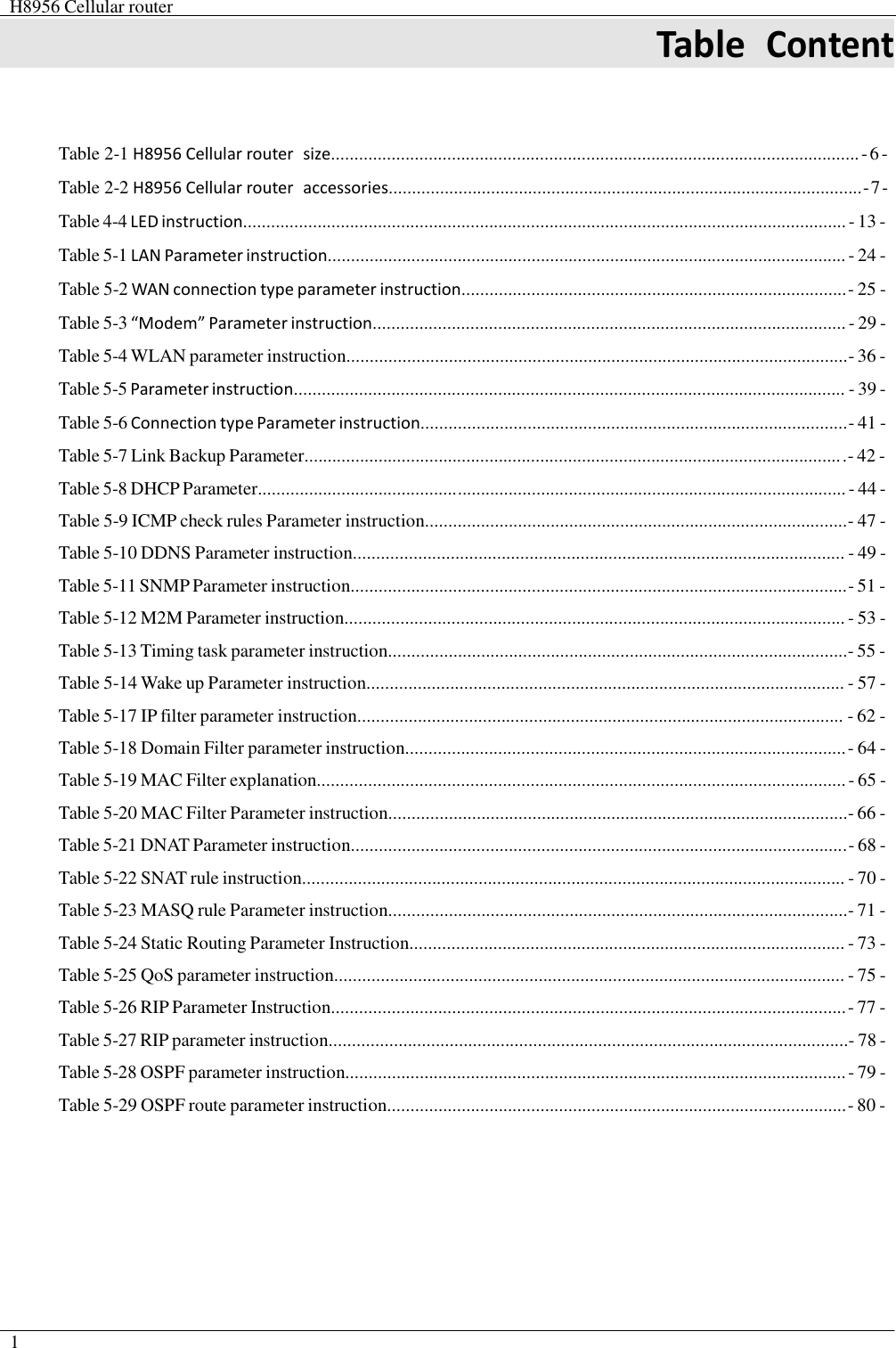
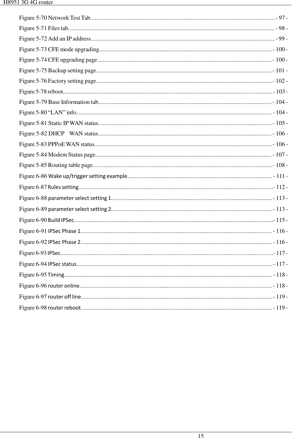
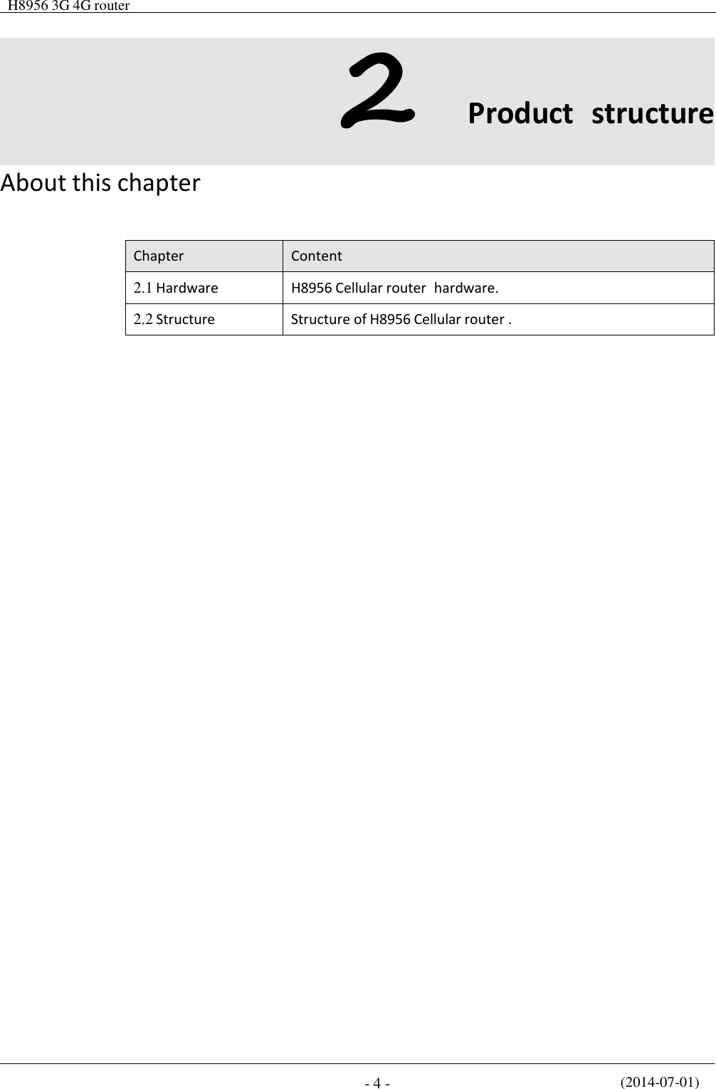
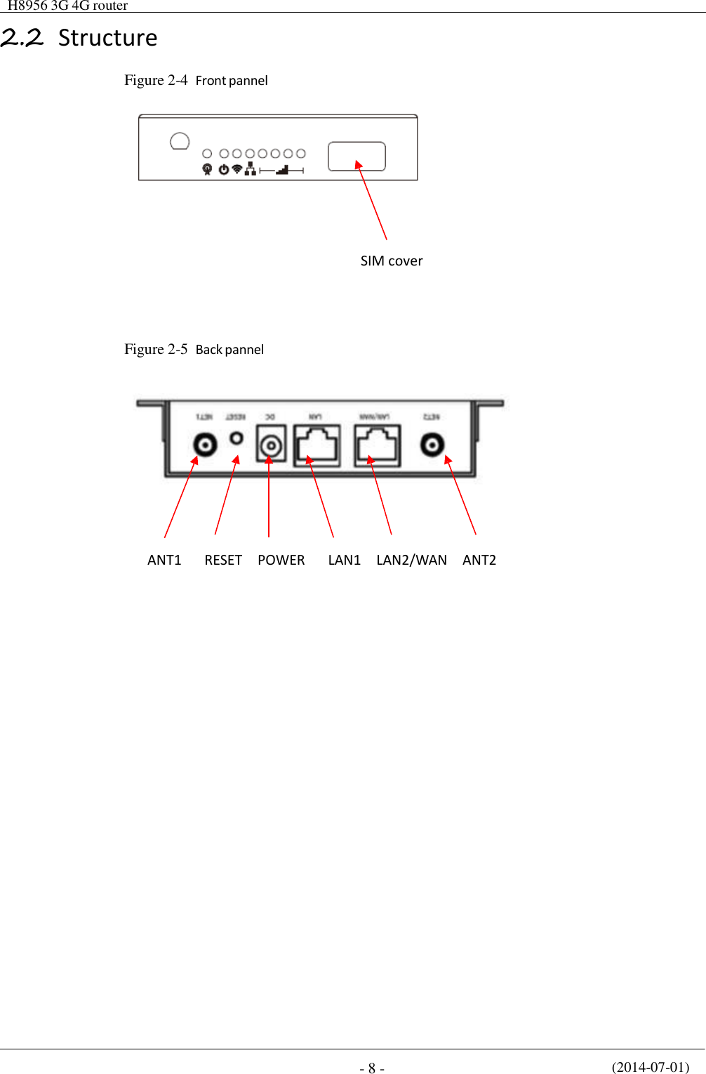
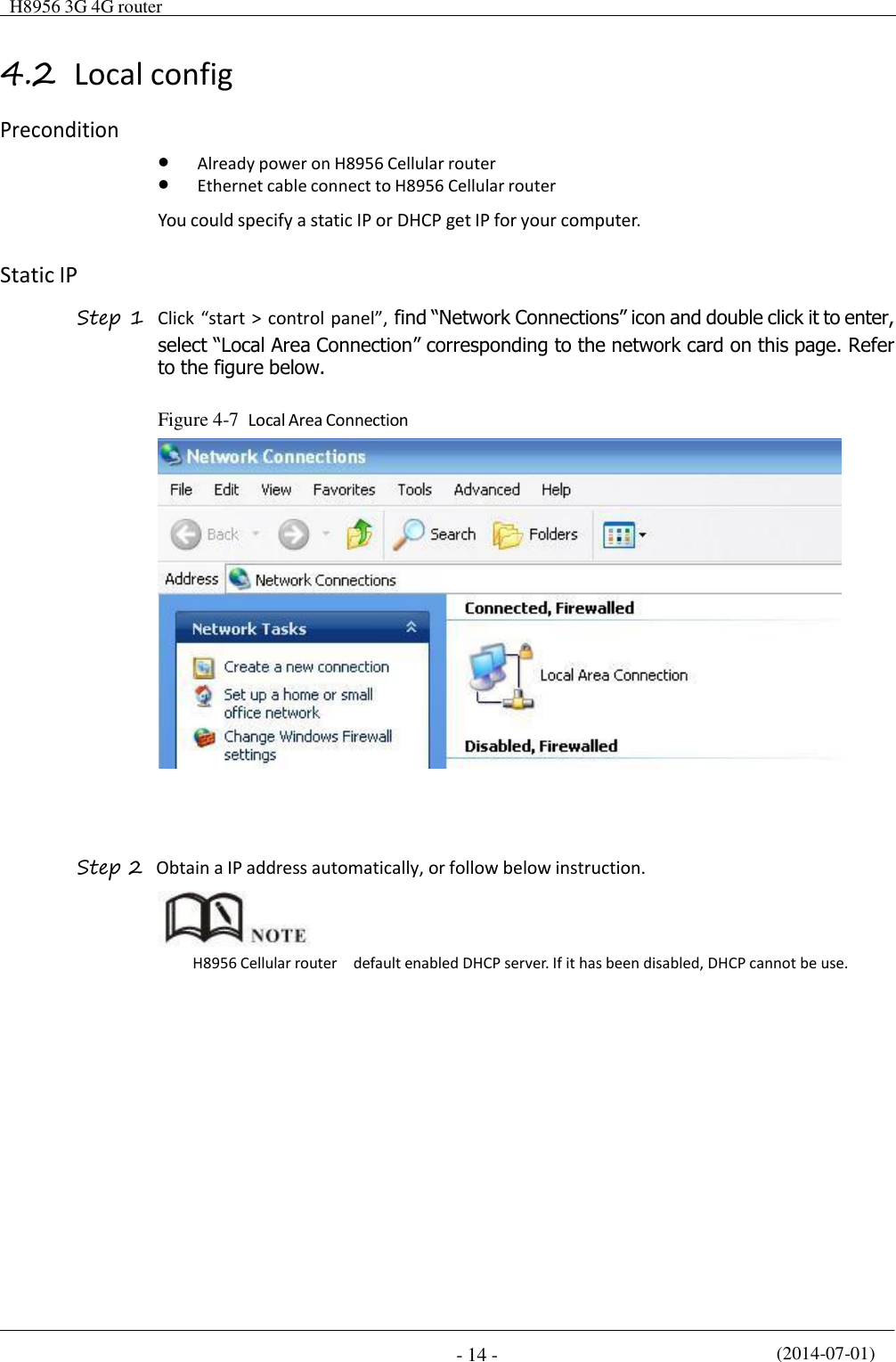
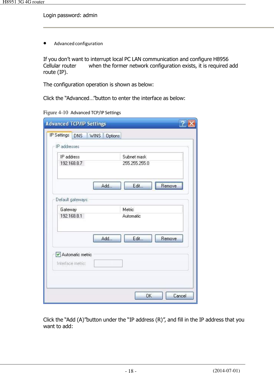
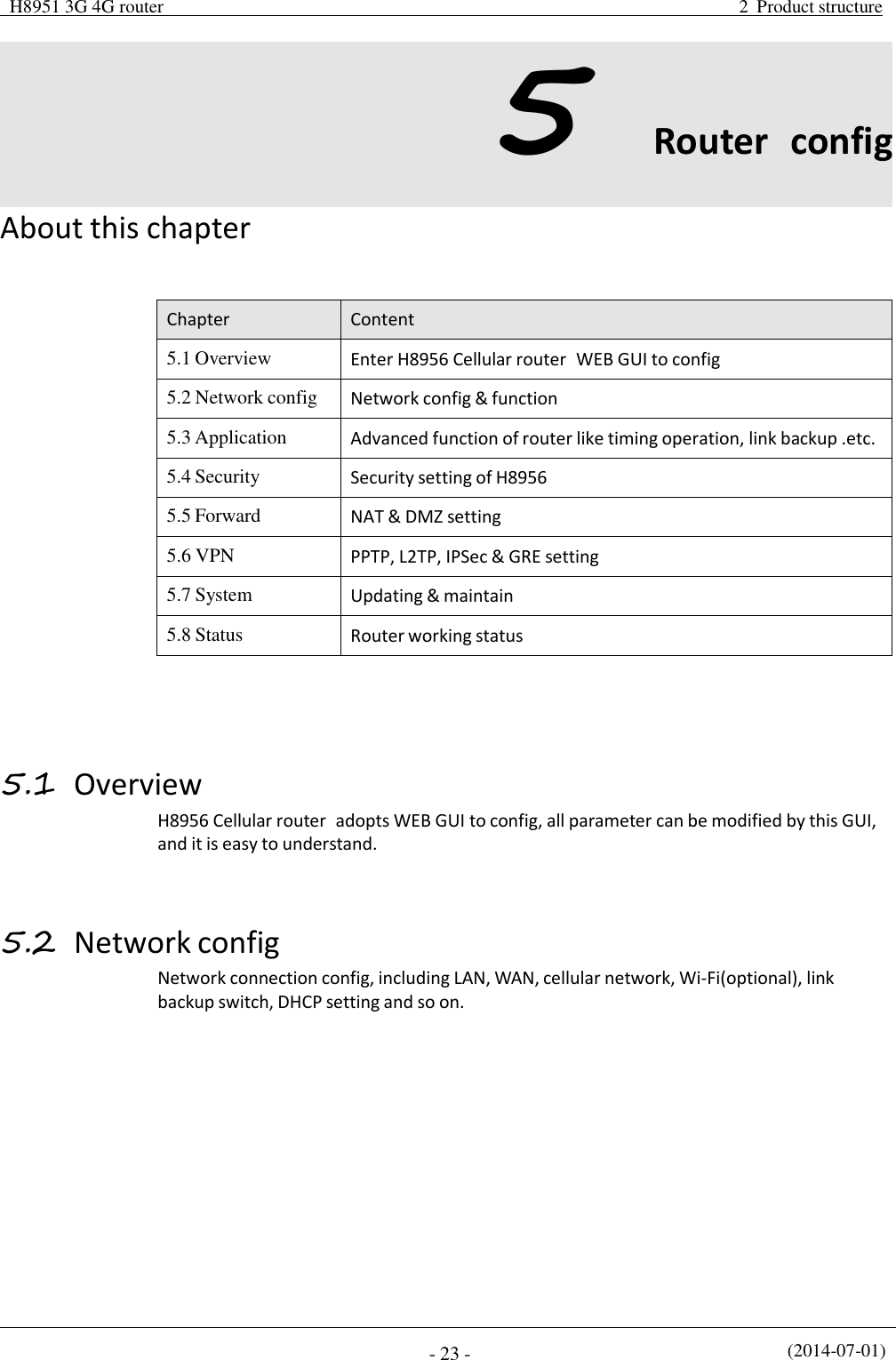
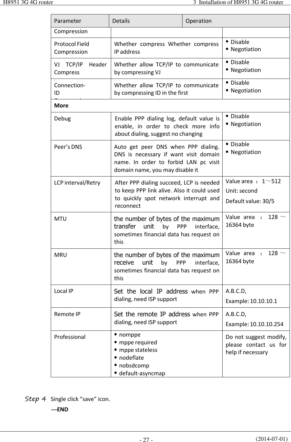
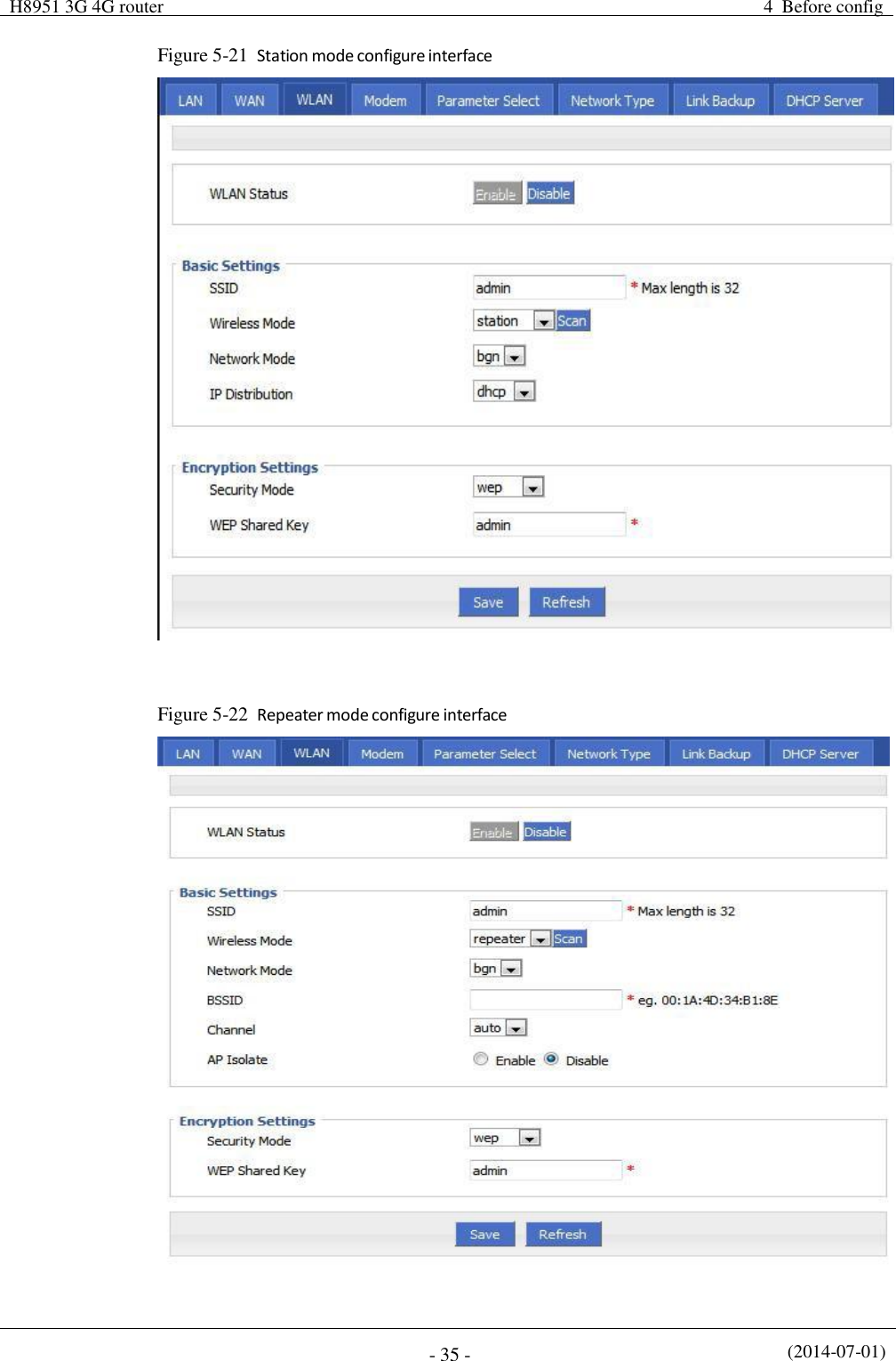
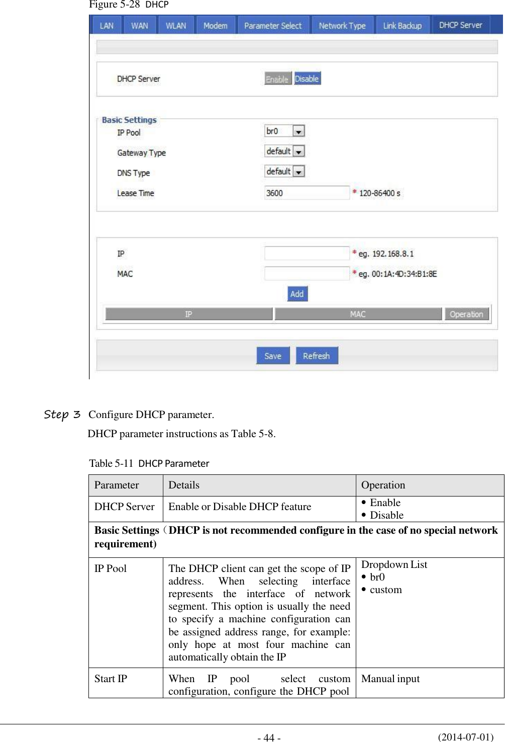
![H8956 3G 4G router Content 5 Conventions Symbol Conventions The symbols that may be found in this document are defined as follows. Symbol Description Indicates a potentially hazardous situation, which if not avoided, could result in equipment damage, data loss, performance degradation, or unexpected results. Indicates a tip that may help you address a problem or save your time. Provides additional information to emphasize or supplement important points of the main text. Command Conventions Convention Description Boldface The keywords of a command line are in boldface. Italic Command arguments are in italics. [ ] Items (keywords or arguments) in brackets [ ] are optional. { x | y | ... } Optional items are grouped in braces and separated by vertical ars. One item is selected. [ x | y | ... ] Optional items are grouped in brackets and separated by vertical bars. One item is selected or no item is selected. { x | y | ... } * Optional items are grouped in braces and separated by vertical ars. A minimum of one item or a maximum of all items can be selected. [ x | y | ... ] * Optional items are grouped in brackets and separated by vertical ars. Several items or no item can be selected. &<1-n> The parameter before the & sign can be repeated 1 to n times. # A line starting with the # sign is comments.](https://usermanual.wiki/Hongdian/H8956/User-Guide-3841899-Page-4.png)
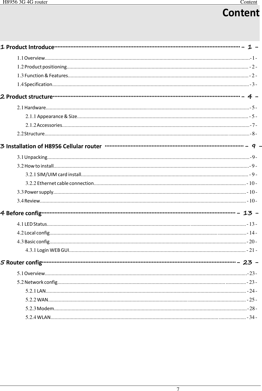
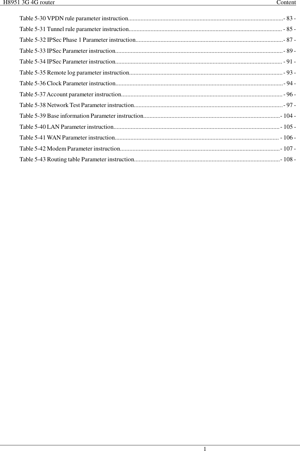
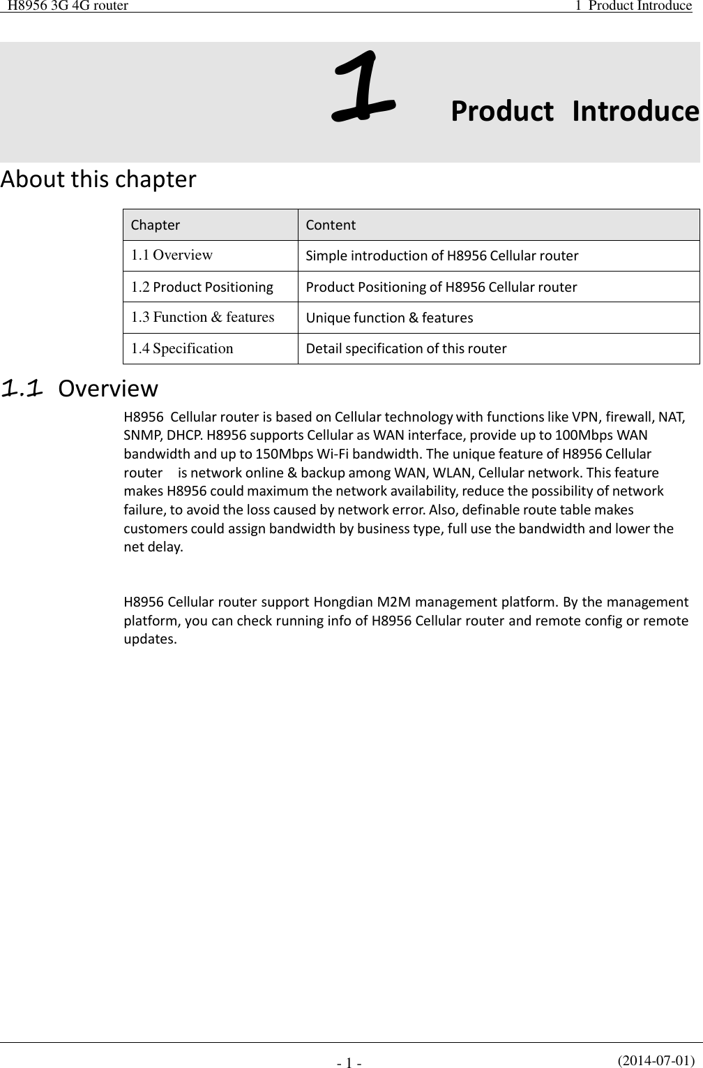
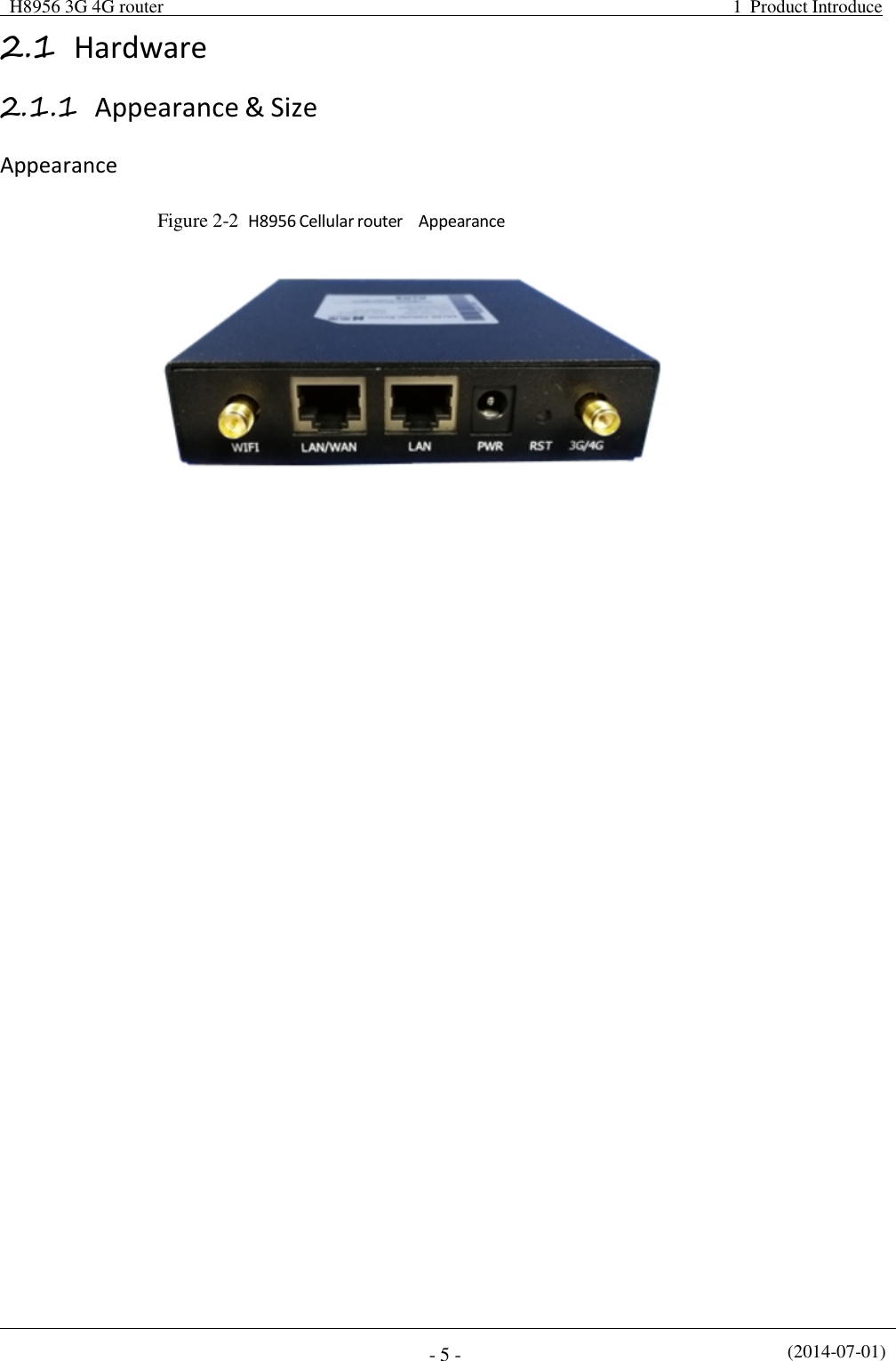
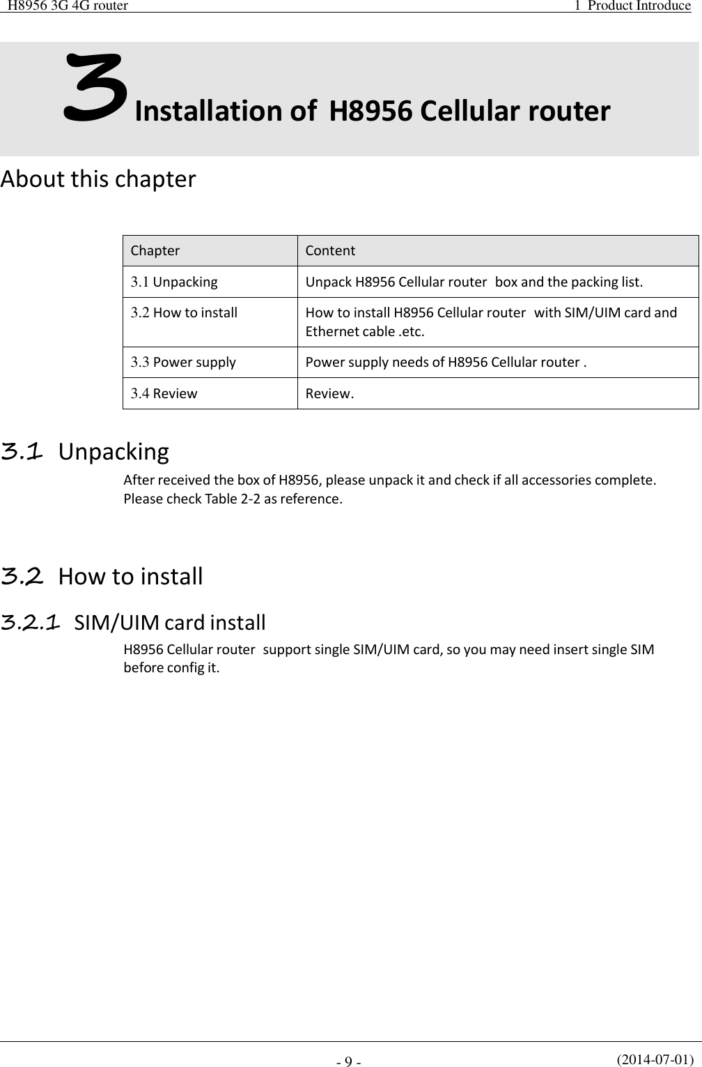
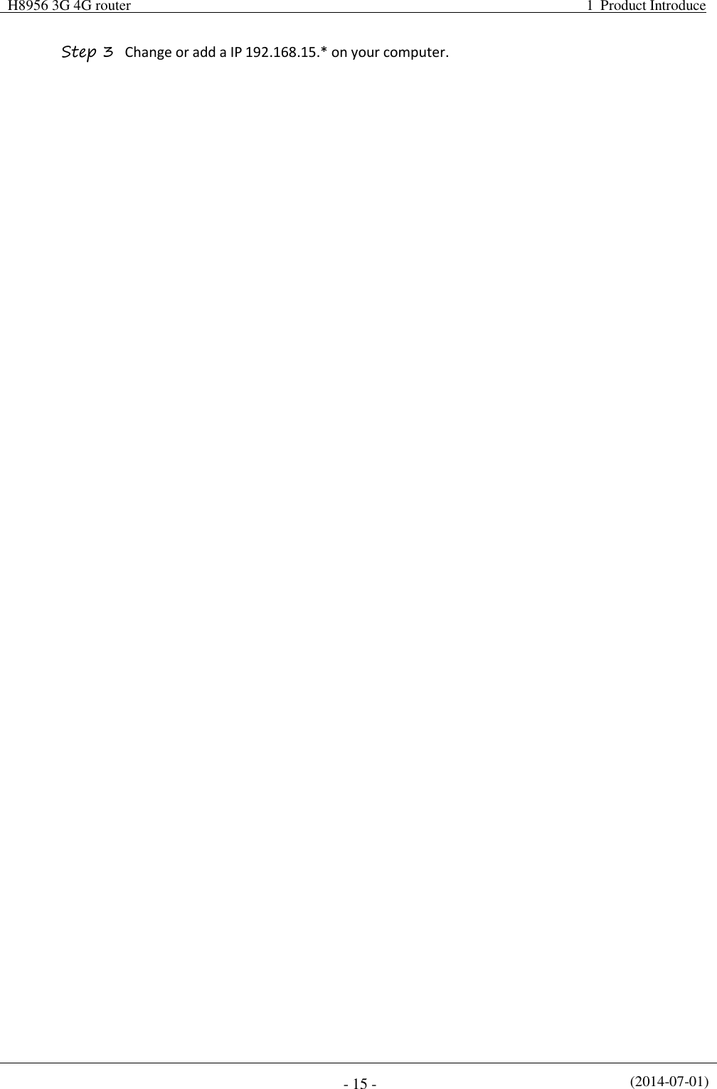
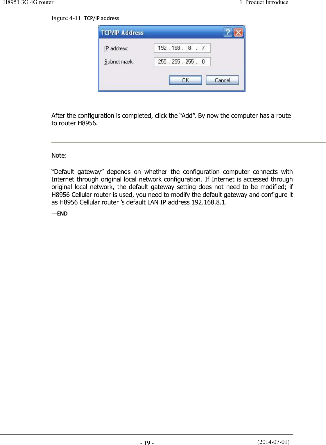
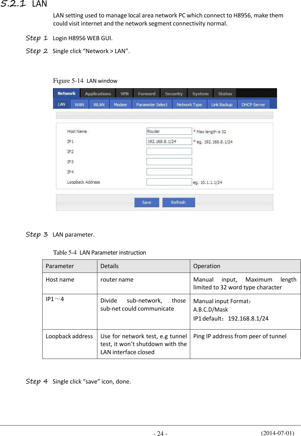
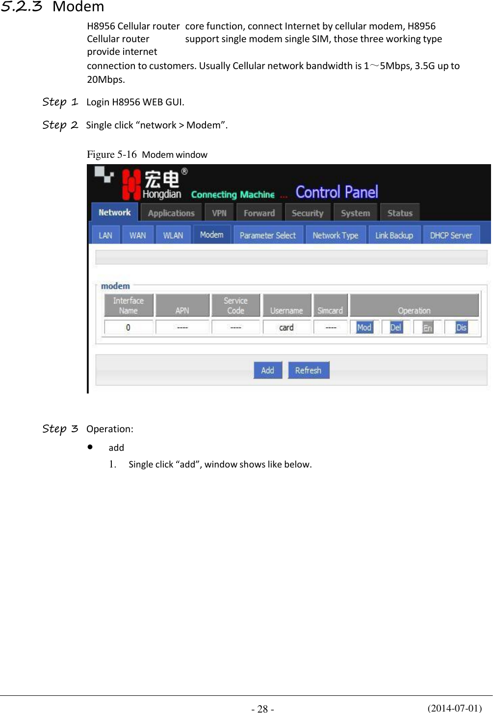
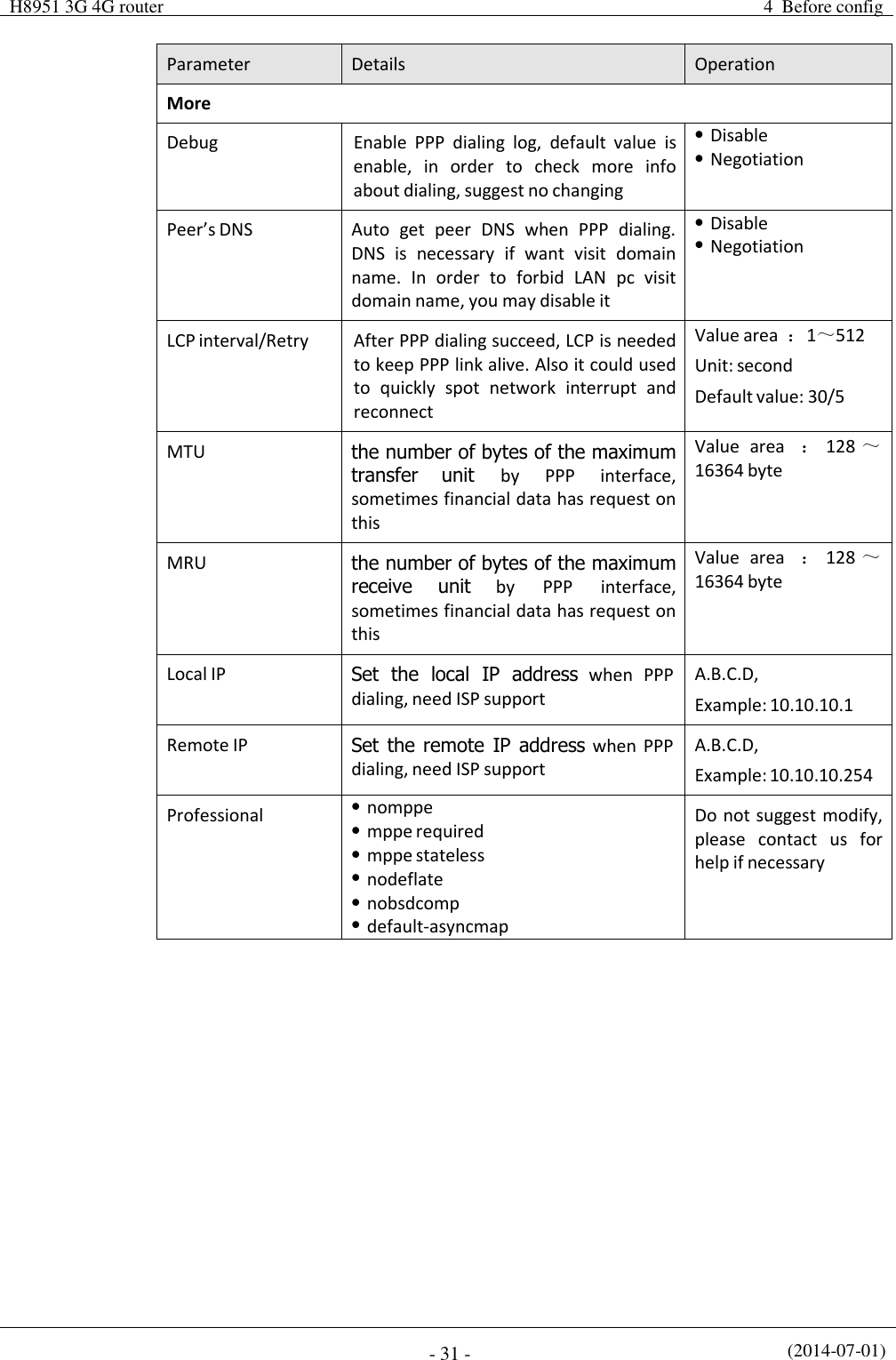
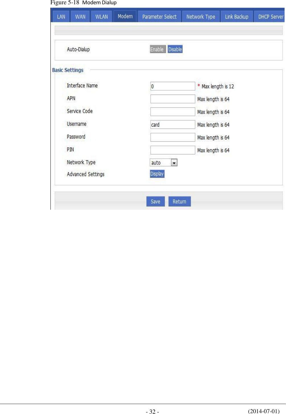
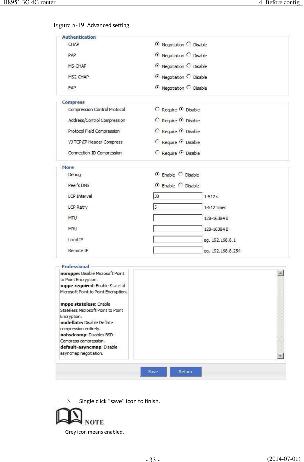
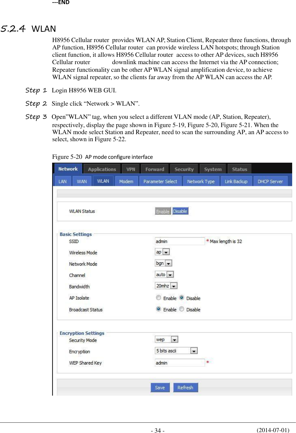
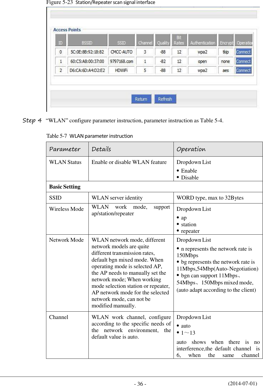
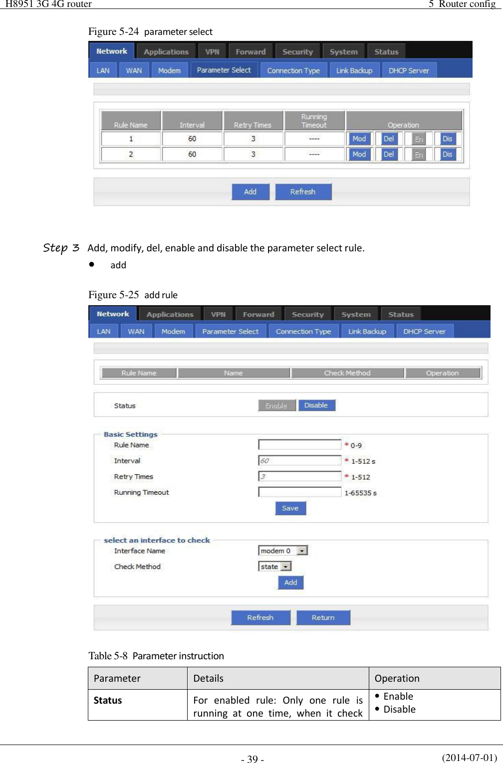
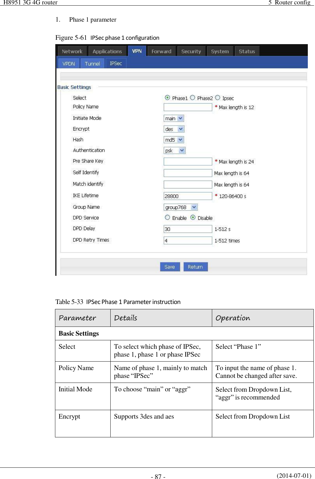
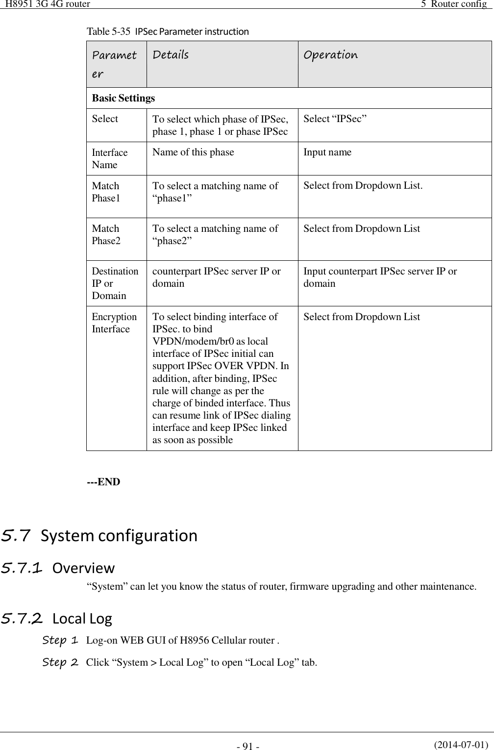
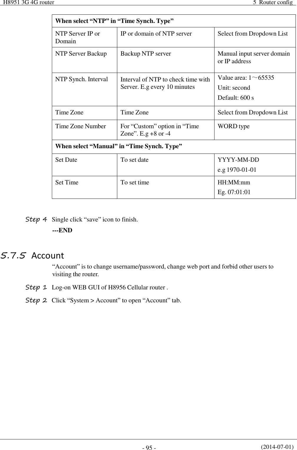
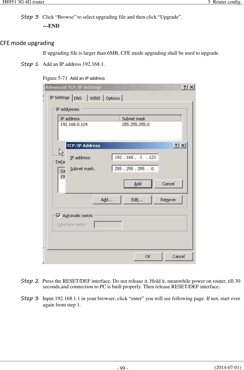
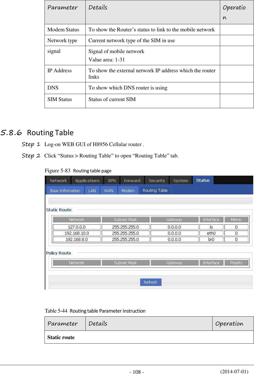
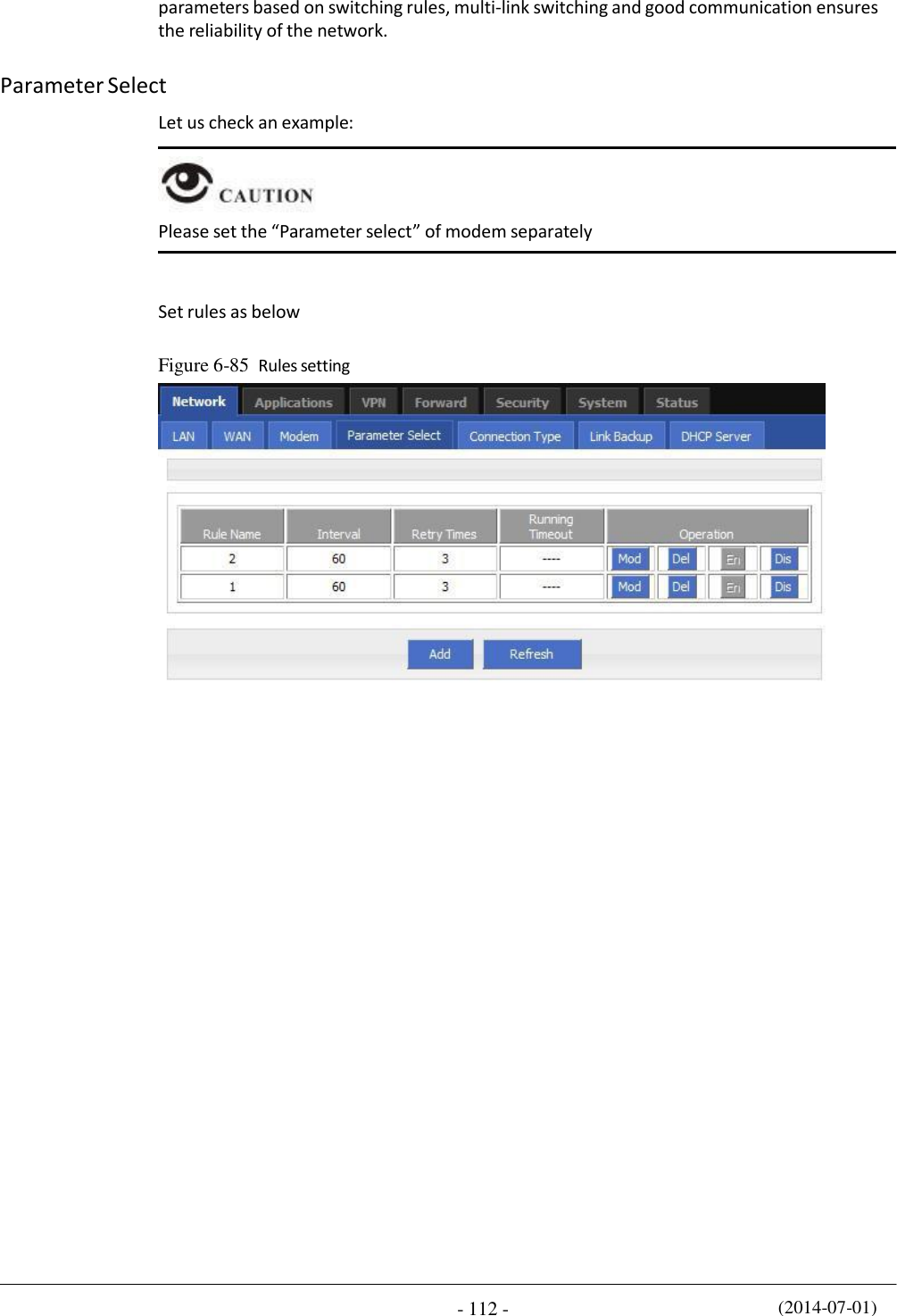
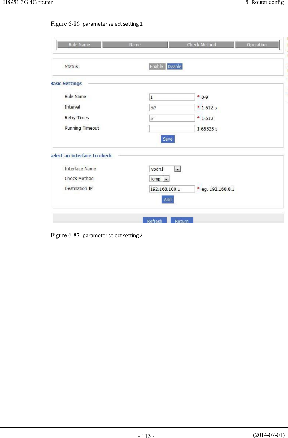
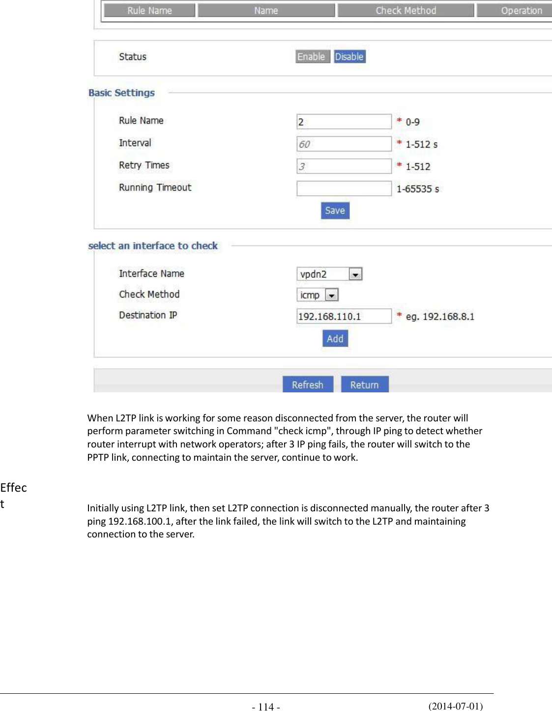
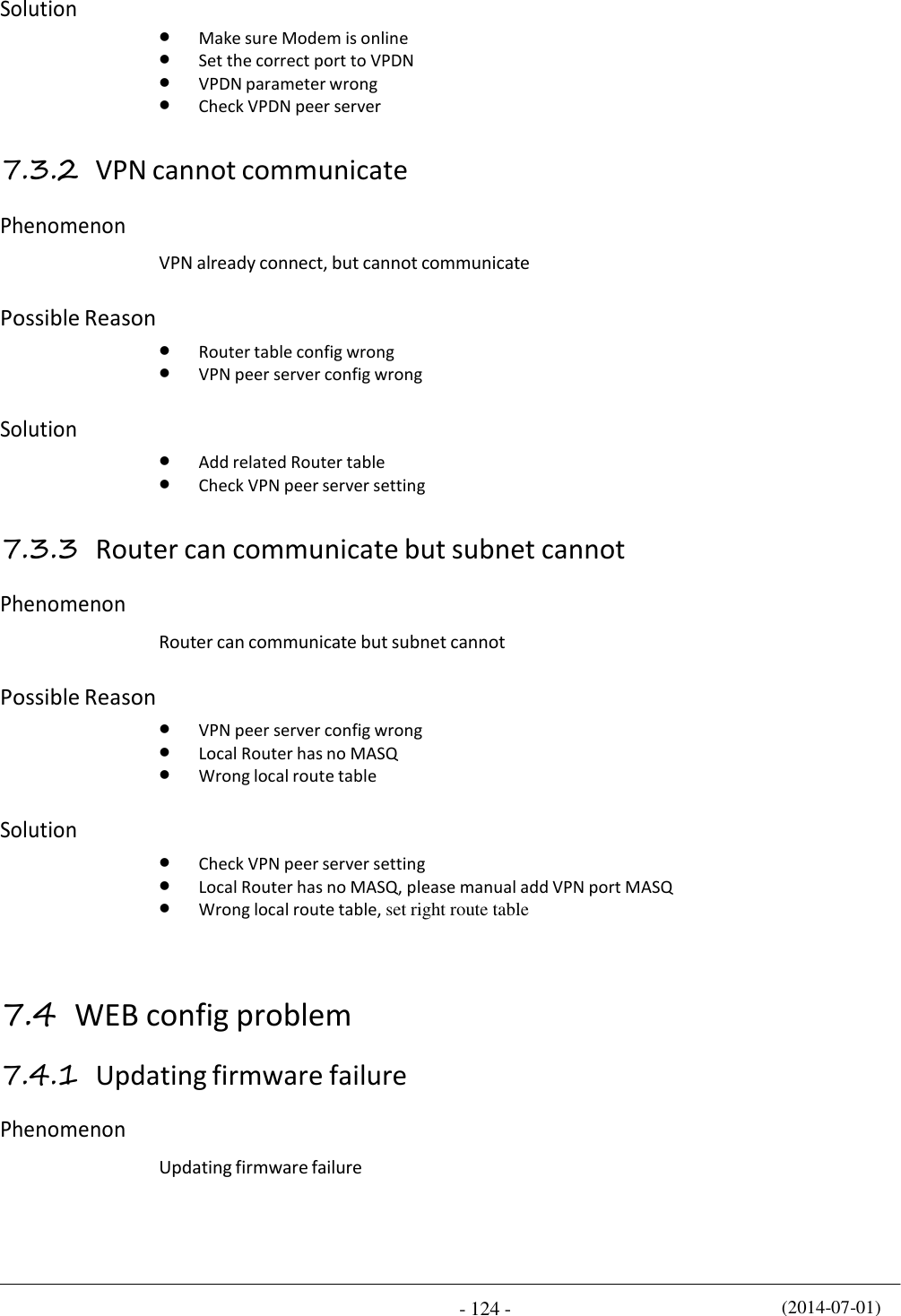
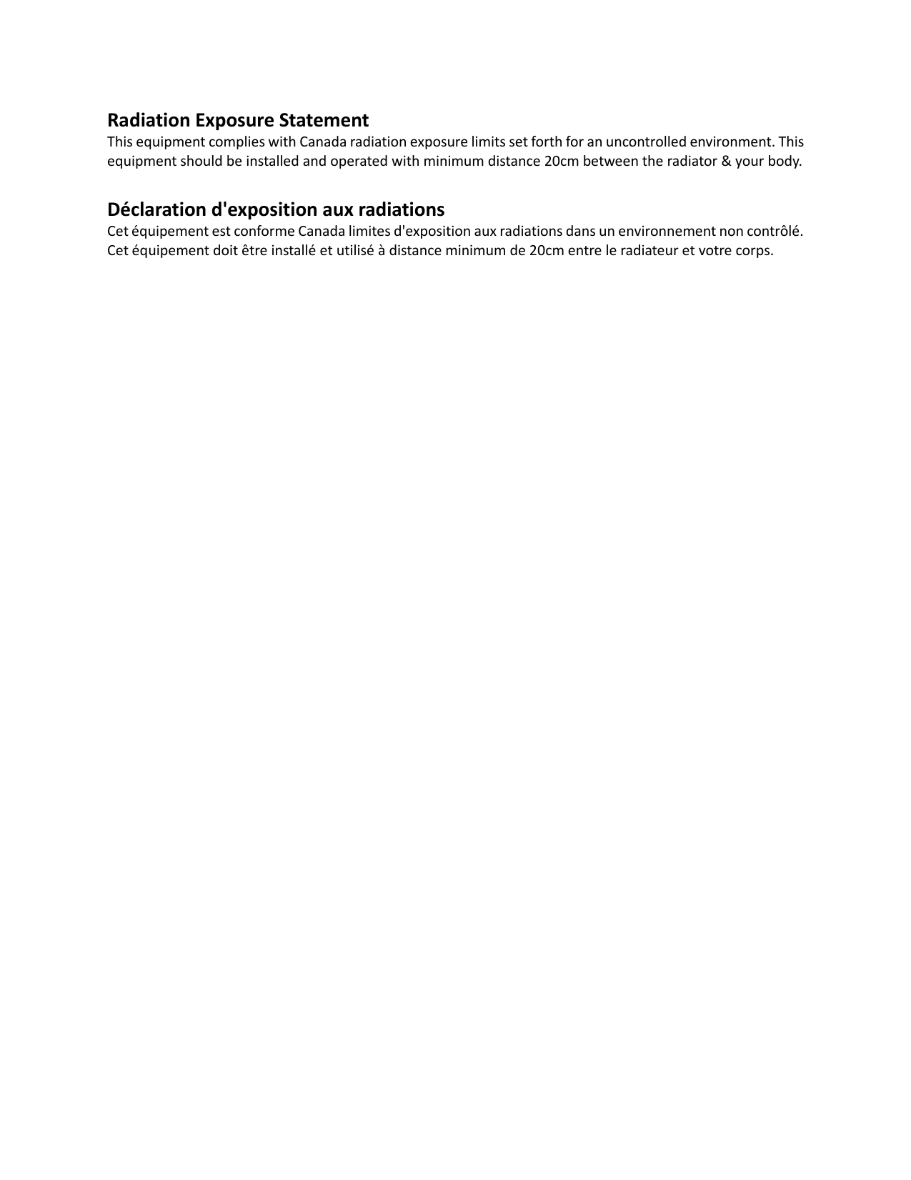
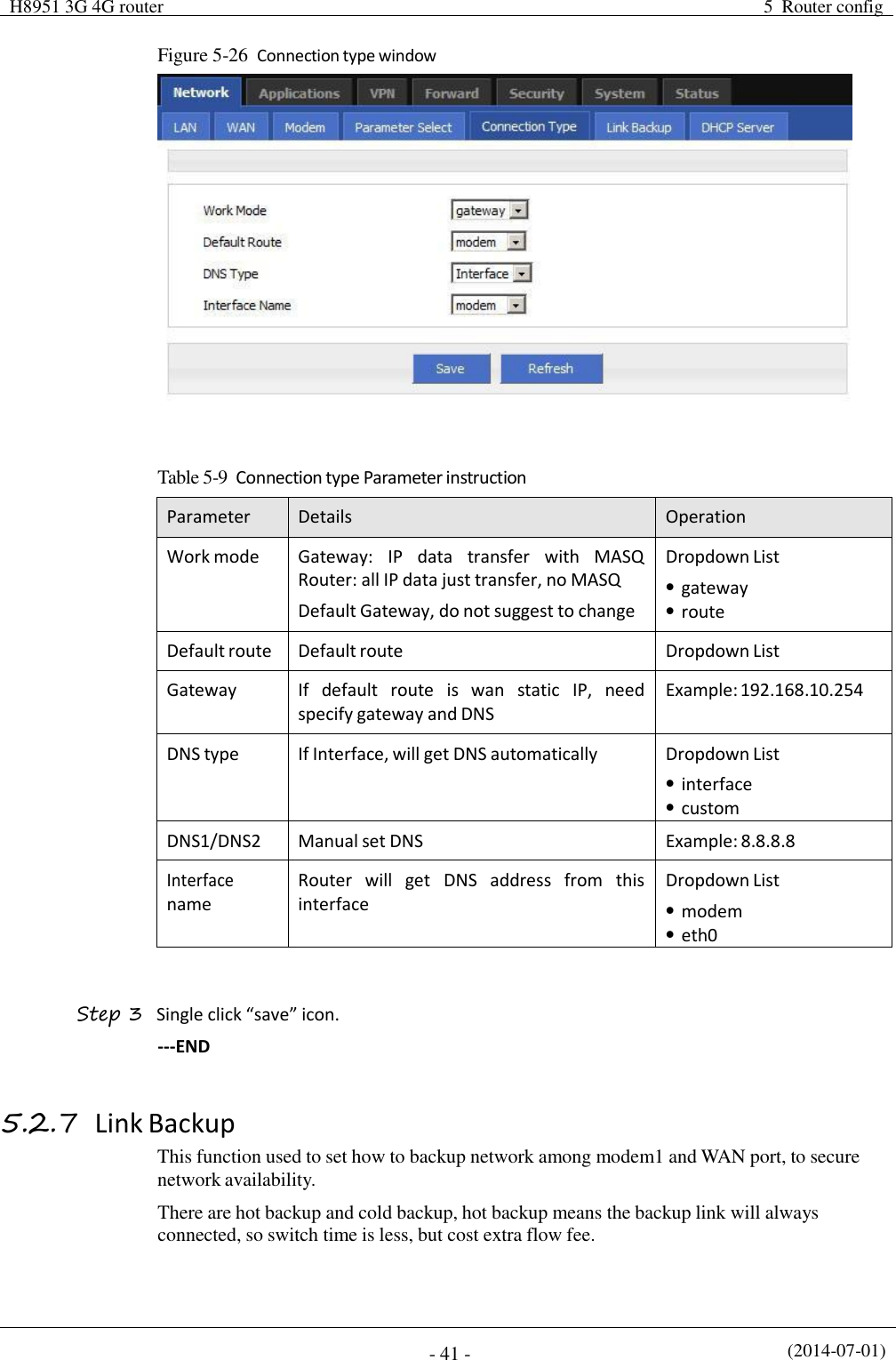
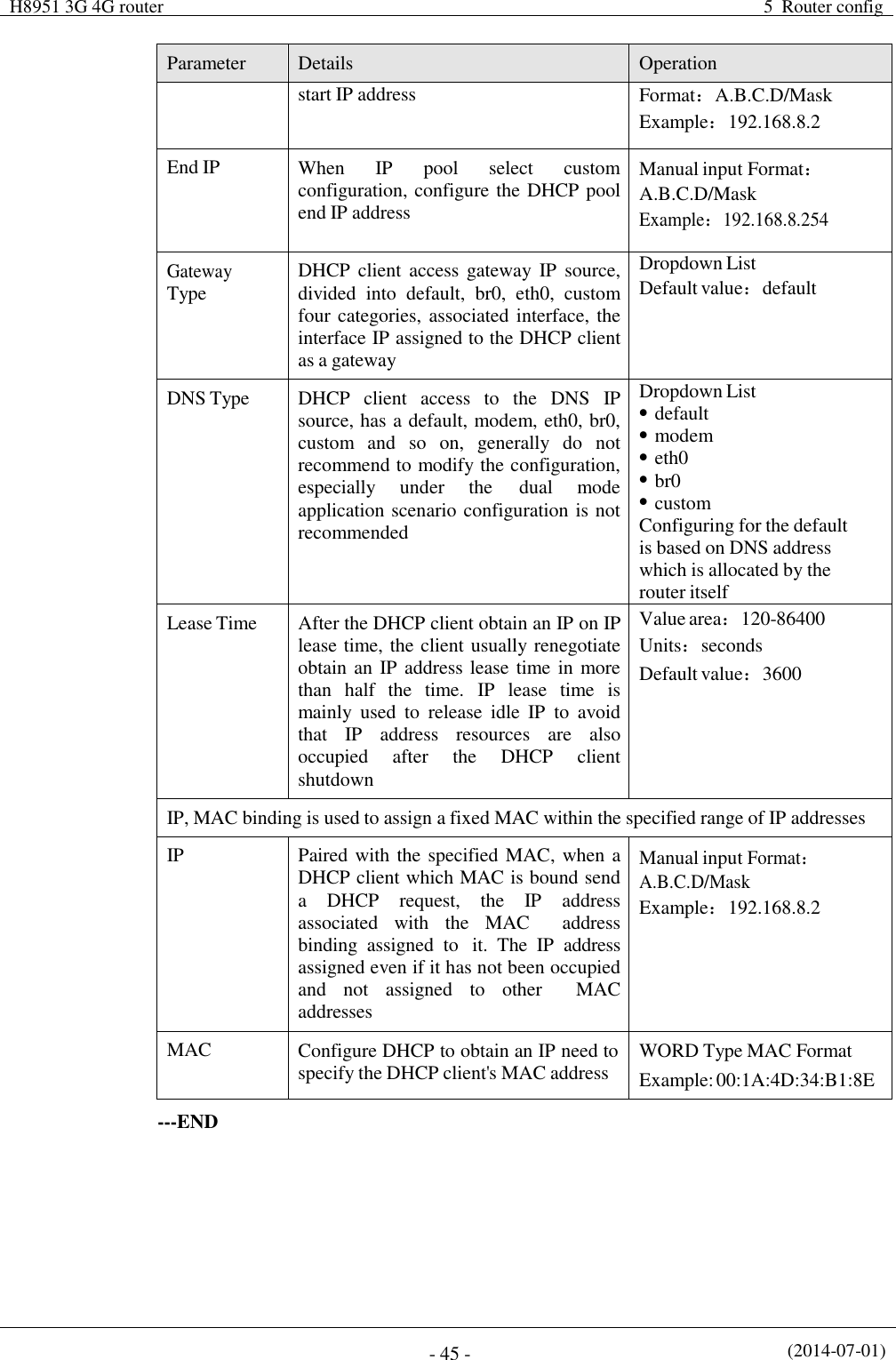
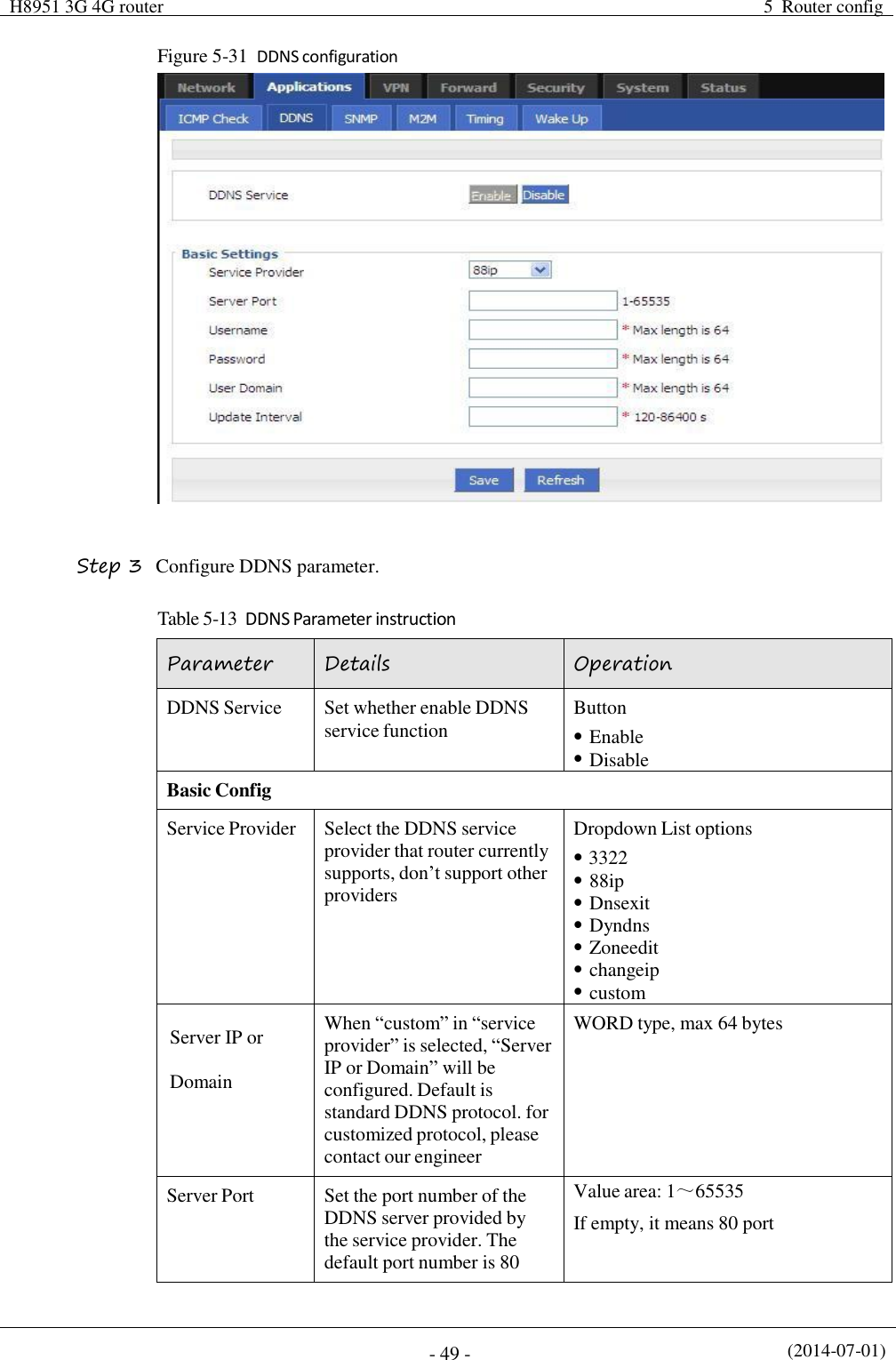
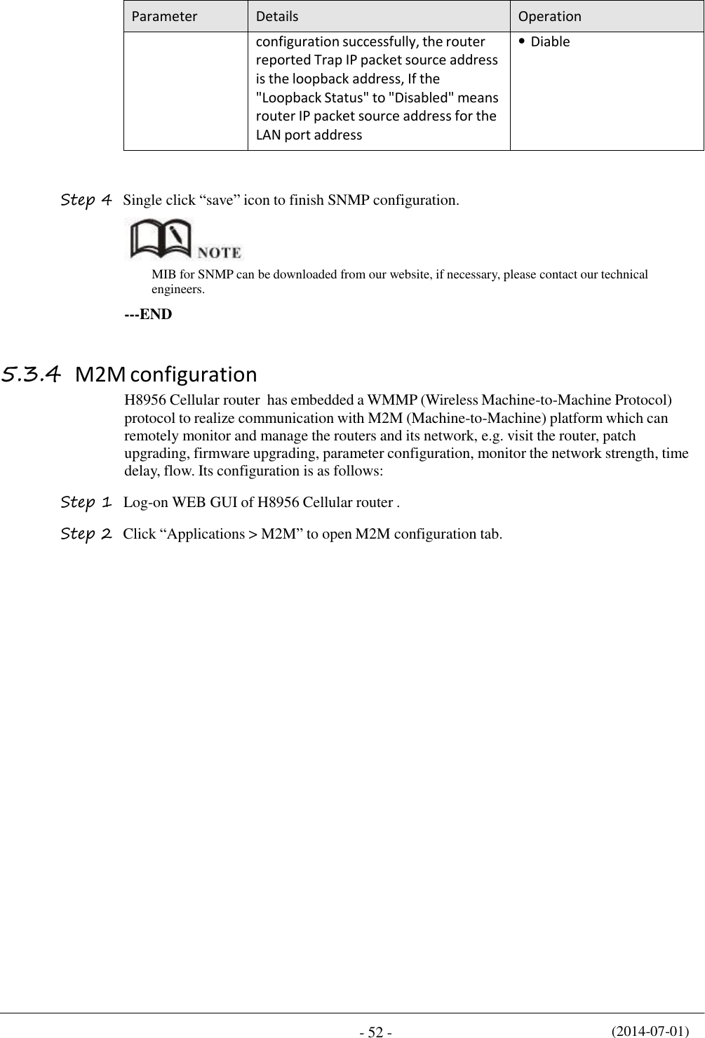
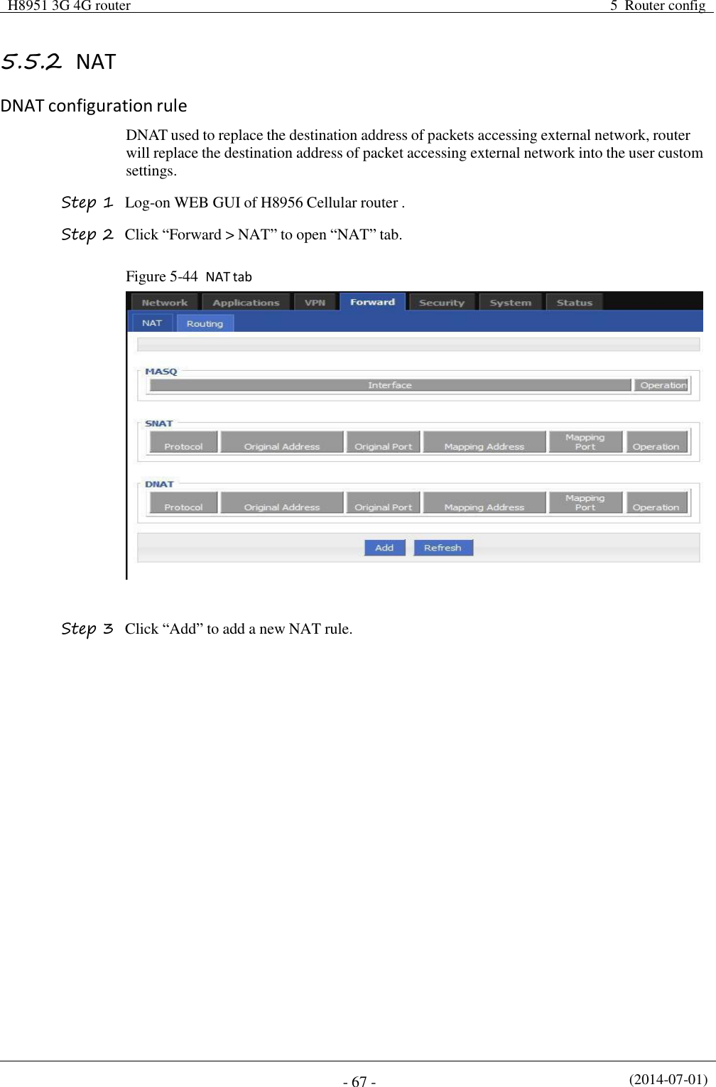
![(2014-07-01) - 40 - Parameter Details Operation failed, next rule start running For disabled rule: all related interface also disabled Basic settings Rule name Name value decided running order Value area :[0,9] Interval/Retry Times Check interval and retry time, if all check failed, switch to next rule Value area :1~512 Units: seconds/time Default: 60/3 Running timeout Not available for rule 0 This parameter restrict current rule running time, when timeout, switch to rule0, if do not set, switch to next rule Value area :1~65535 Units: seconds Select a interface to check Interface name Set related modem interface Dropdown List to choose, current available option will show below Check method If state, router will check link state If ICMP, router will ping the ICMP IP address to check Dropdown List state icmp This function is control how the router online & offline, and use which modem to online. Please notice timing task is execute a operation and keep the status, but parameter select only execute a operation. So they do not conflict. But Link backup function may conflict with parameter select function , if you set both, final running result may not as you presume. ---END 5.2.6 Connection type Step 1 Login H8956 WEB GUI. Step 2 Single click “Network > Connection type”.](https://usermanual.wiki/Hongdian/H8956/User-Guide-3841899-Page-50.png)
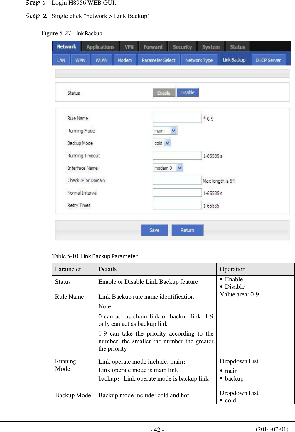
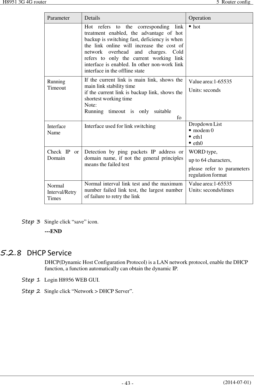
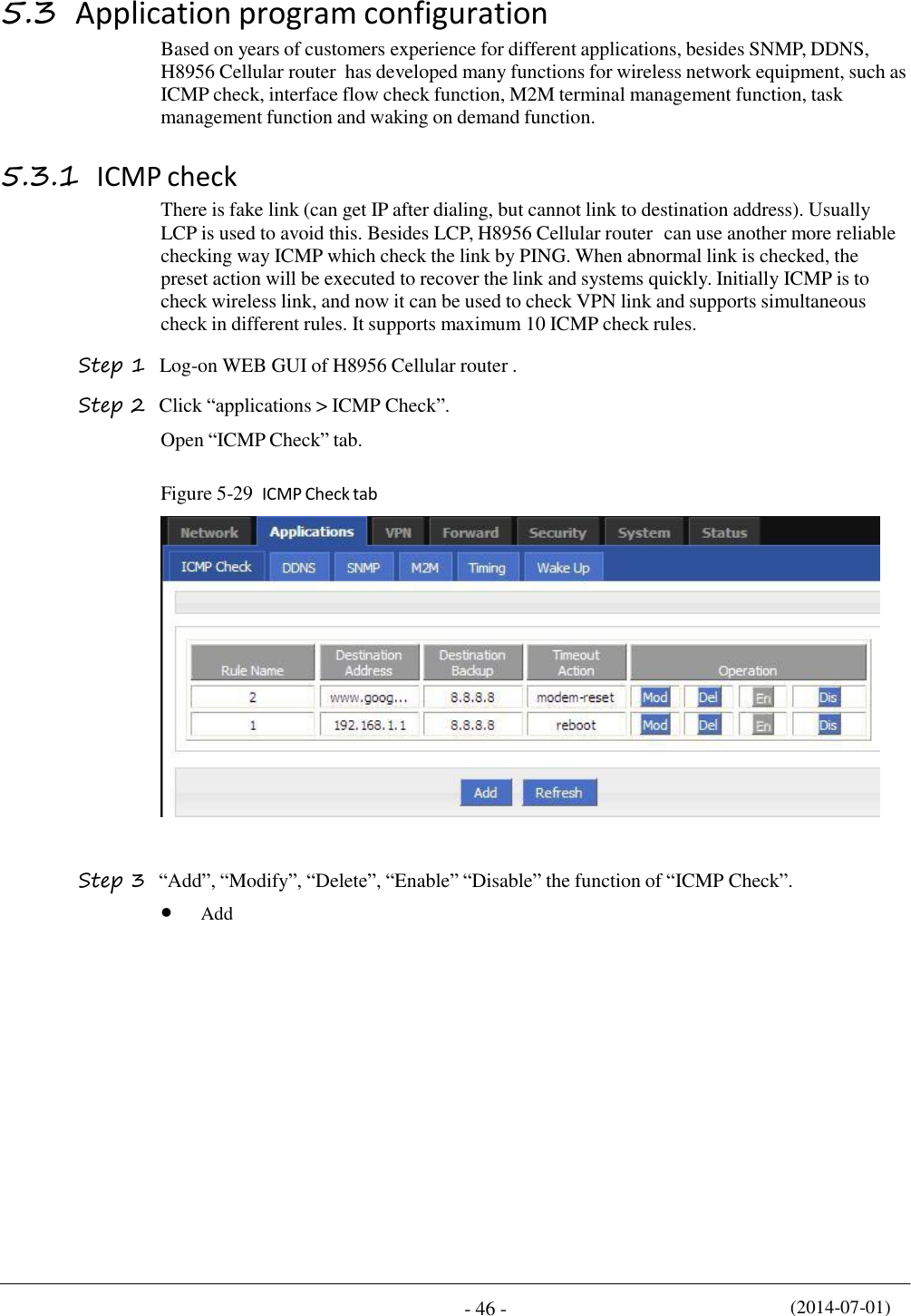
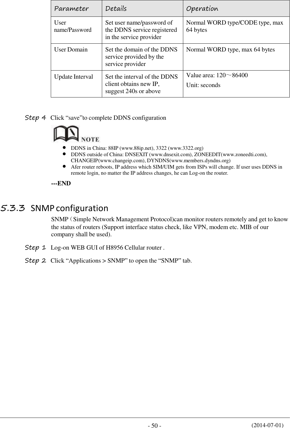
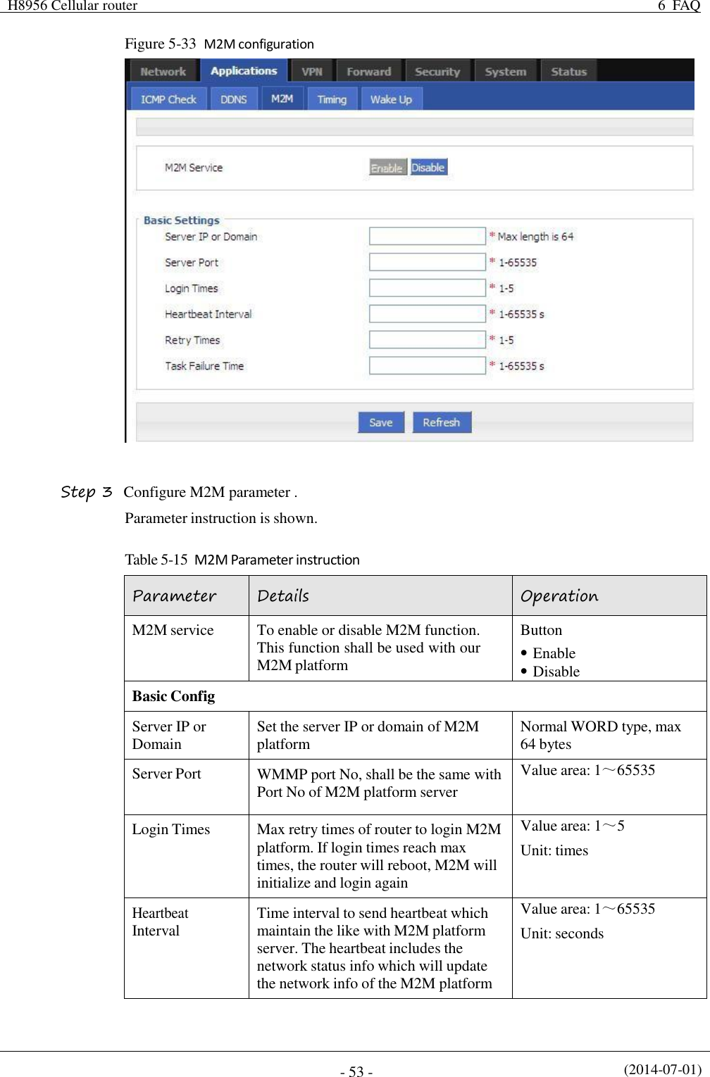
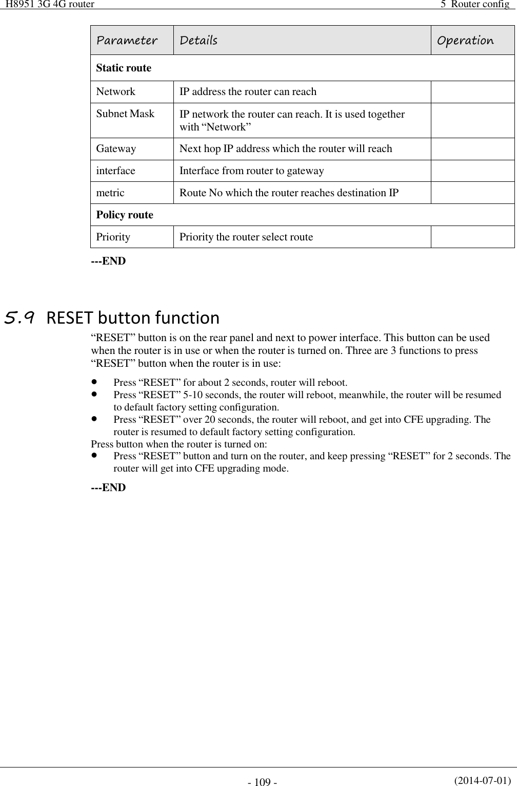
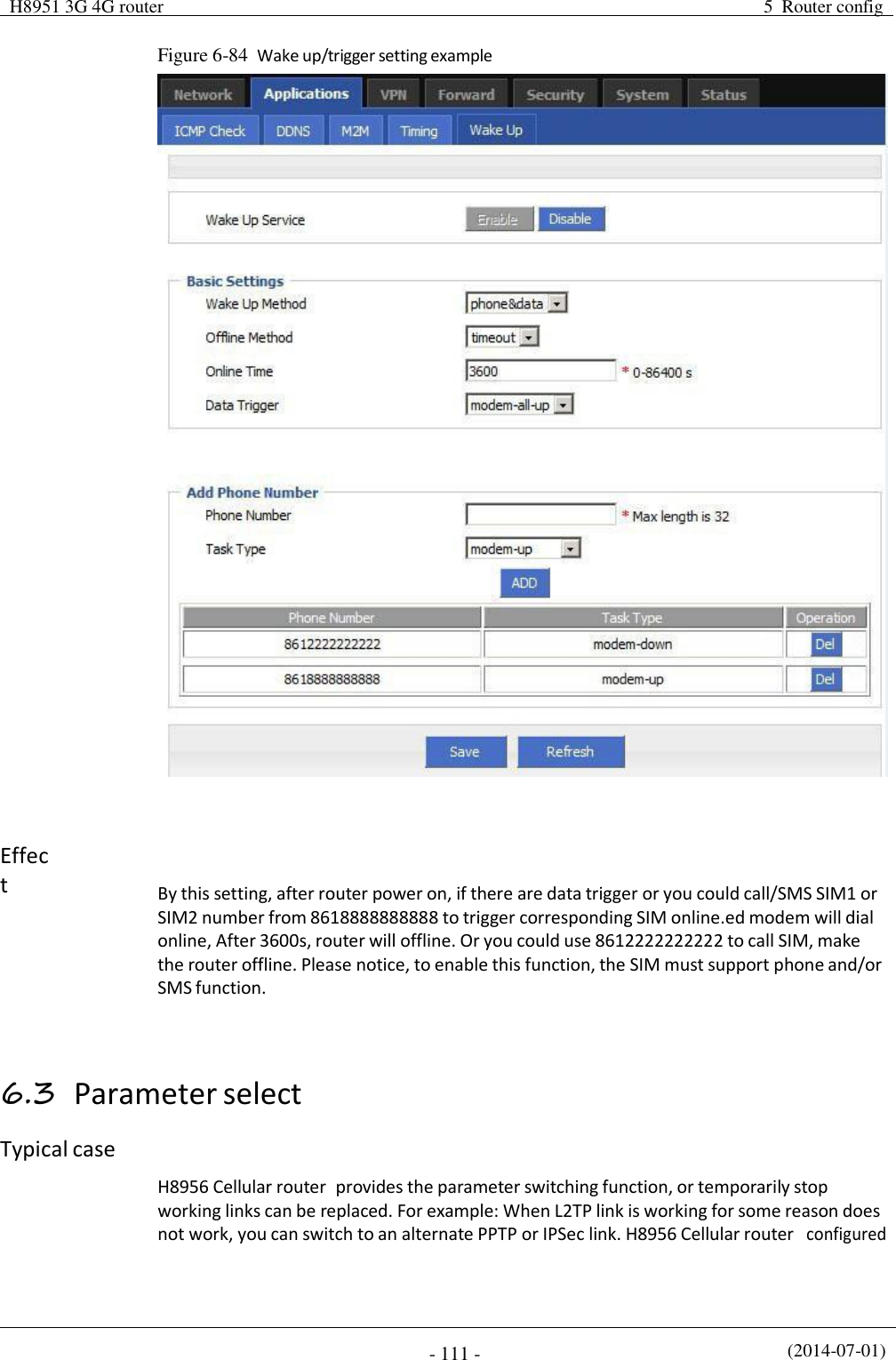
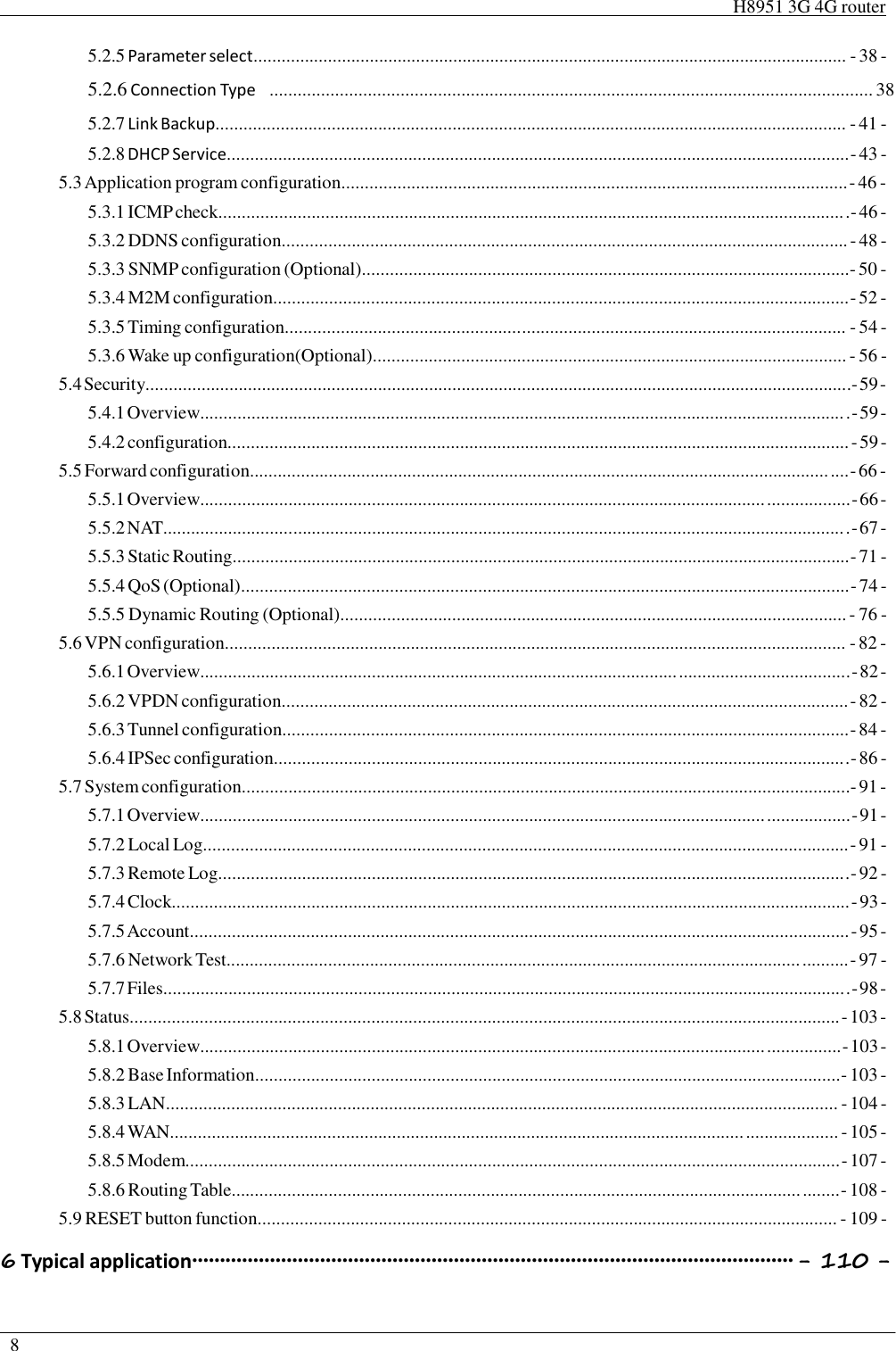
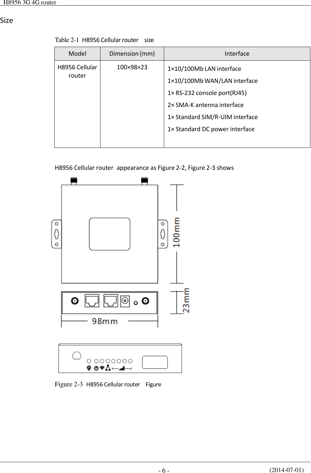
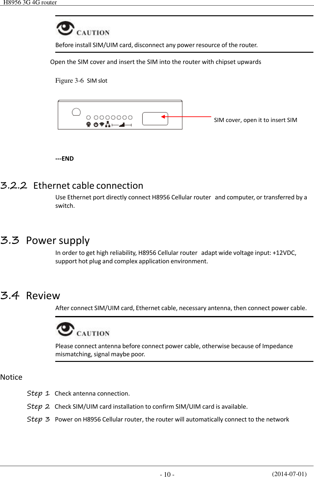
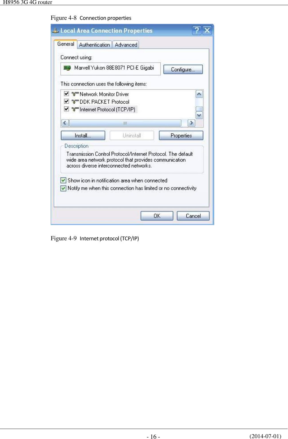
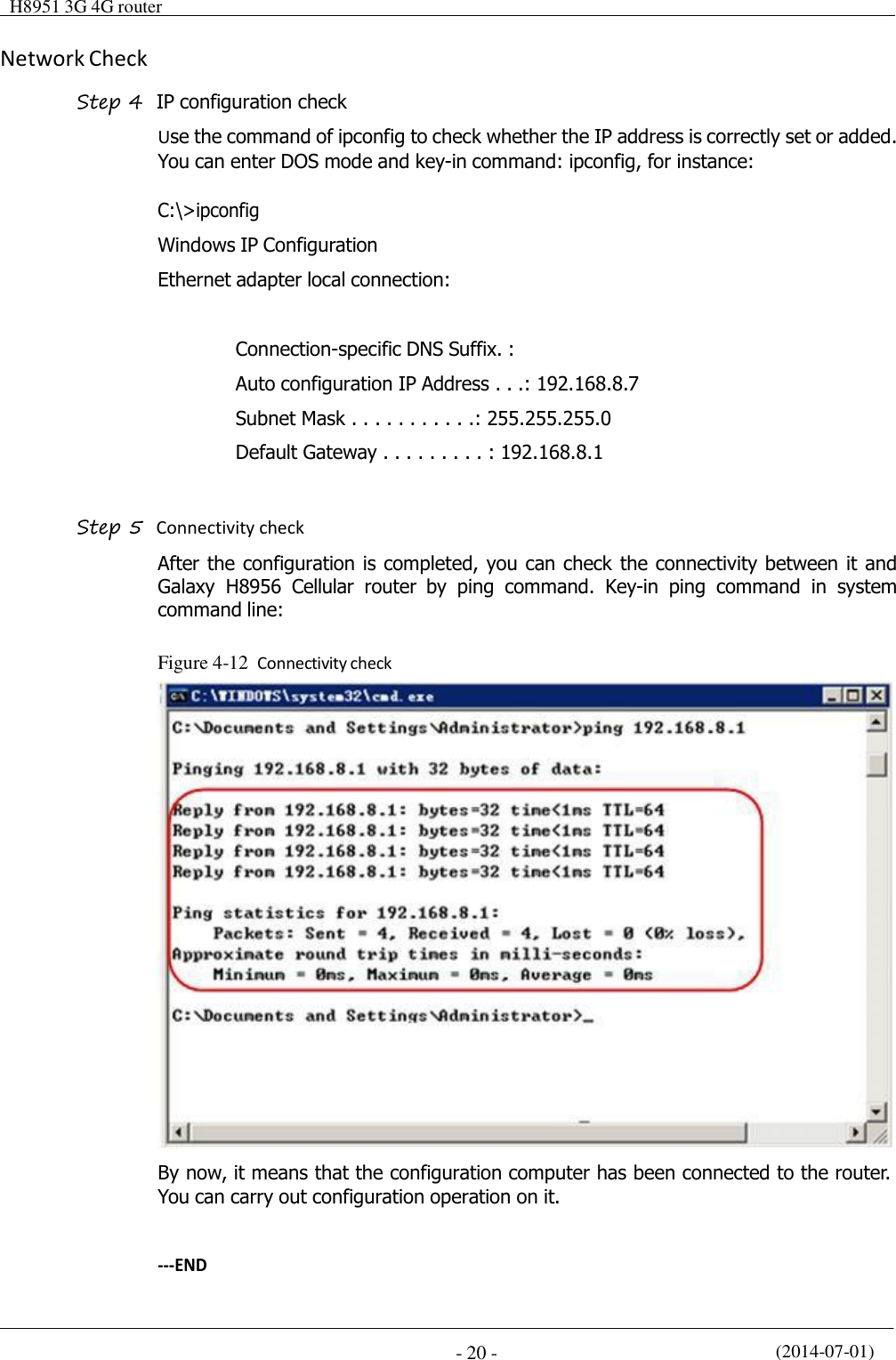
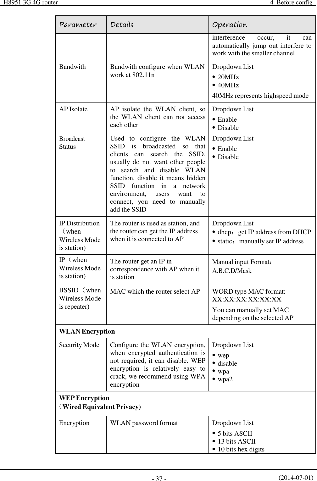
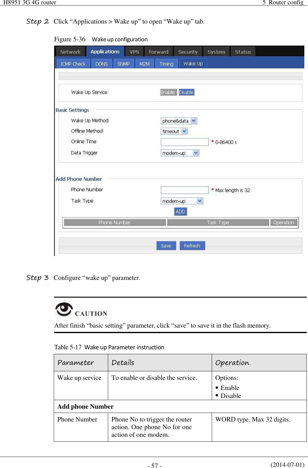
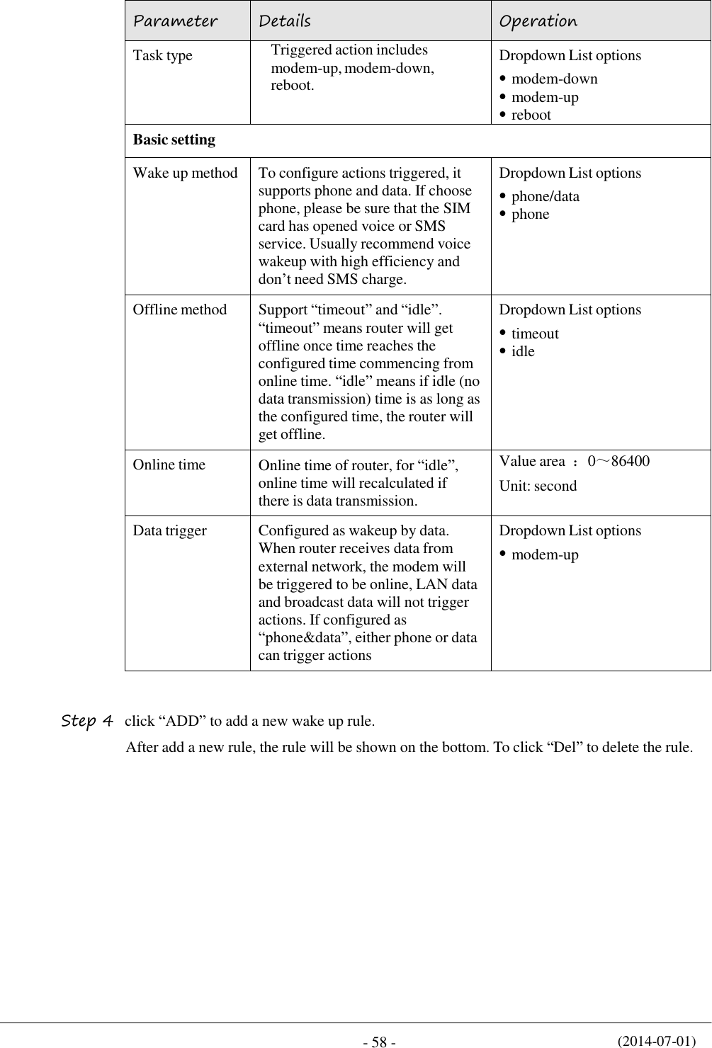
![(2014-07-01) - 56 - Parameter Details Operation offline (no dialing) for other time Schedule This is linux shell command. Usually suggested not to use it. In case of need, please contact our technical engineers WORD type. Max 64 digits Set time Time type Range or interval for status task or action task Dropdown List options: range interval When “time type” select “range” Clock To input hour and minute. When beginning and end hour and minute are the same, it means a time point for action task Value area: [00:00,23:59] Format: HH:mm-HH:mm Day Days in a month for task Value area: [01,31] Format: XX-XX Week Days in a week for task. When “day” and “week” are both input, it means only if both conditions meet, the task will begin Value area: [1,7] Format: X-X 1 for Monday When “time type” select “Interval” Interval Time interval for action task Value area: 1~65535 Unit: minutes Step 5 Single click “save” icon to finish “Timing” configuration When “range” is selected, NTP shall be enabled . when “interval” is selected, no such requirement. For “NTP” configuration ---END 5.3.6 Wake up configuration(Optional) Cellular fee is mostly based on flow. H8956 Cellular router can get on/off line on demand. It supports on/offline or reboot triggered by voice, SMS or data. It supports max 10 cellphone Nos. Step 1 Log-on WEB GUI of H8956 Cellular router .](https://usermanual.wiki/Hongdian/H8956/User-Guide-3841899-Page-66.png)
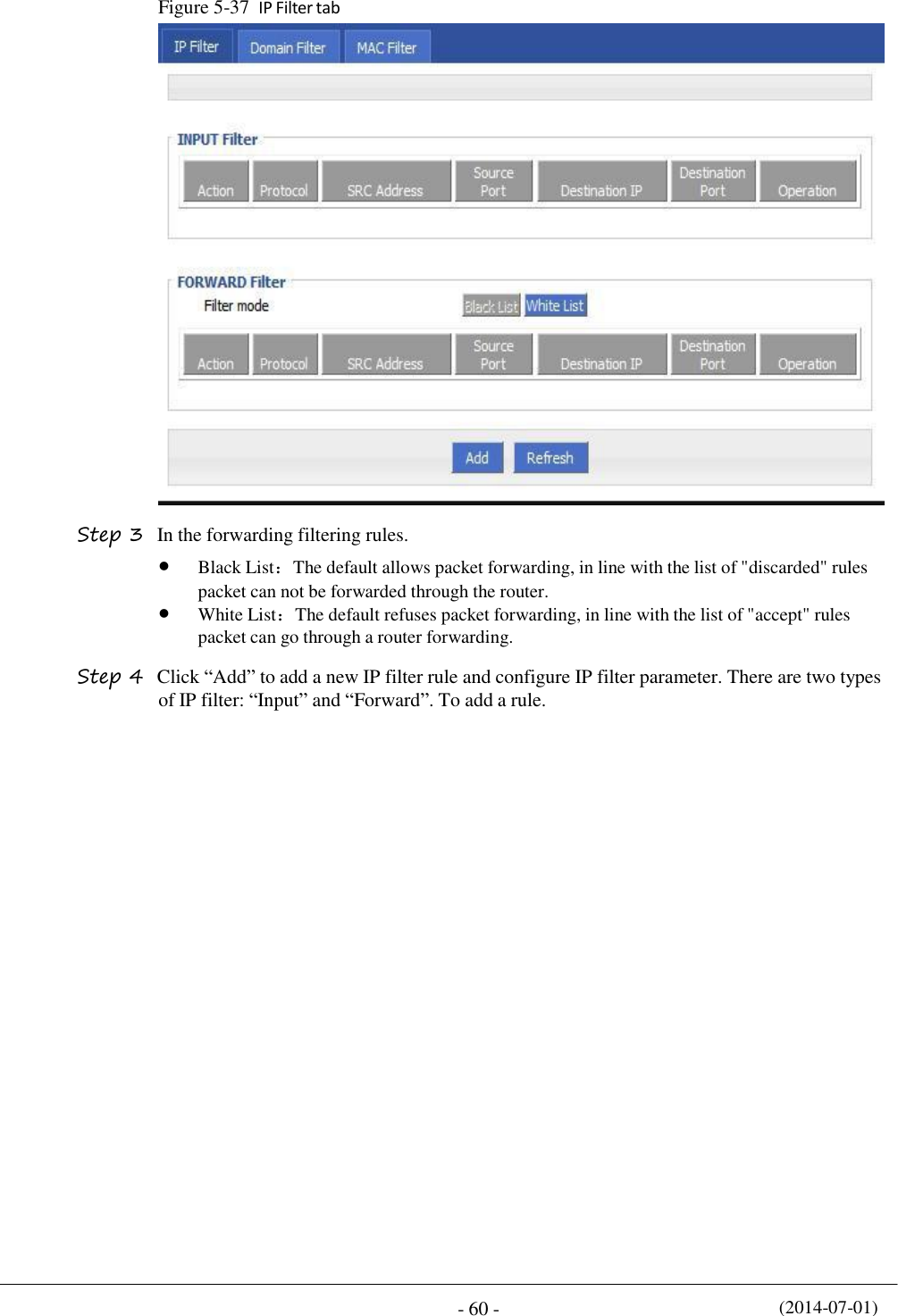
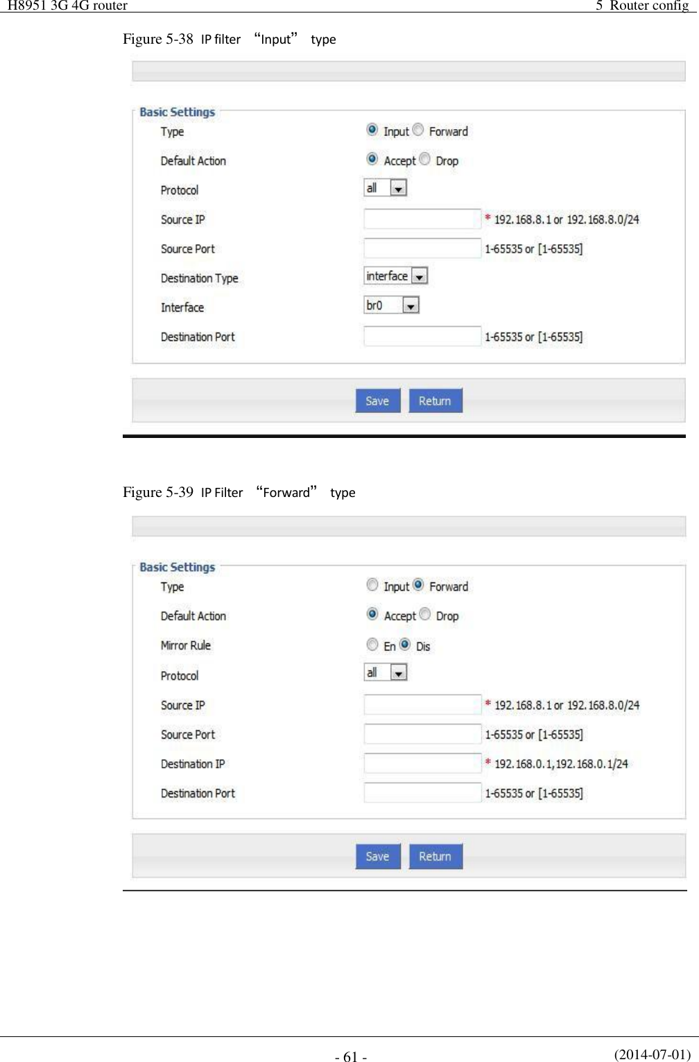
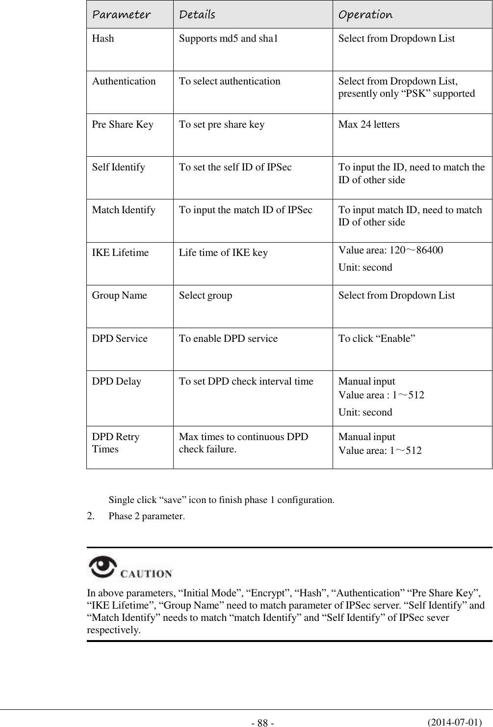
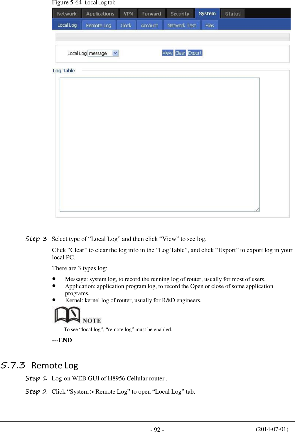
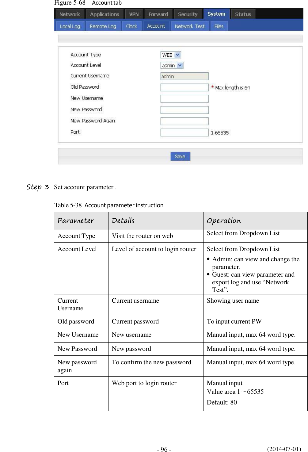
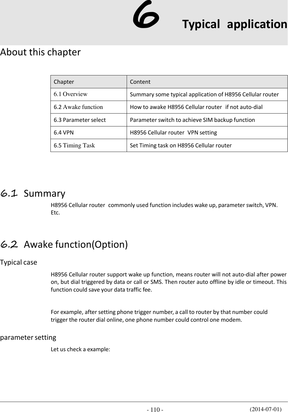
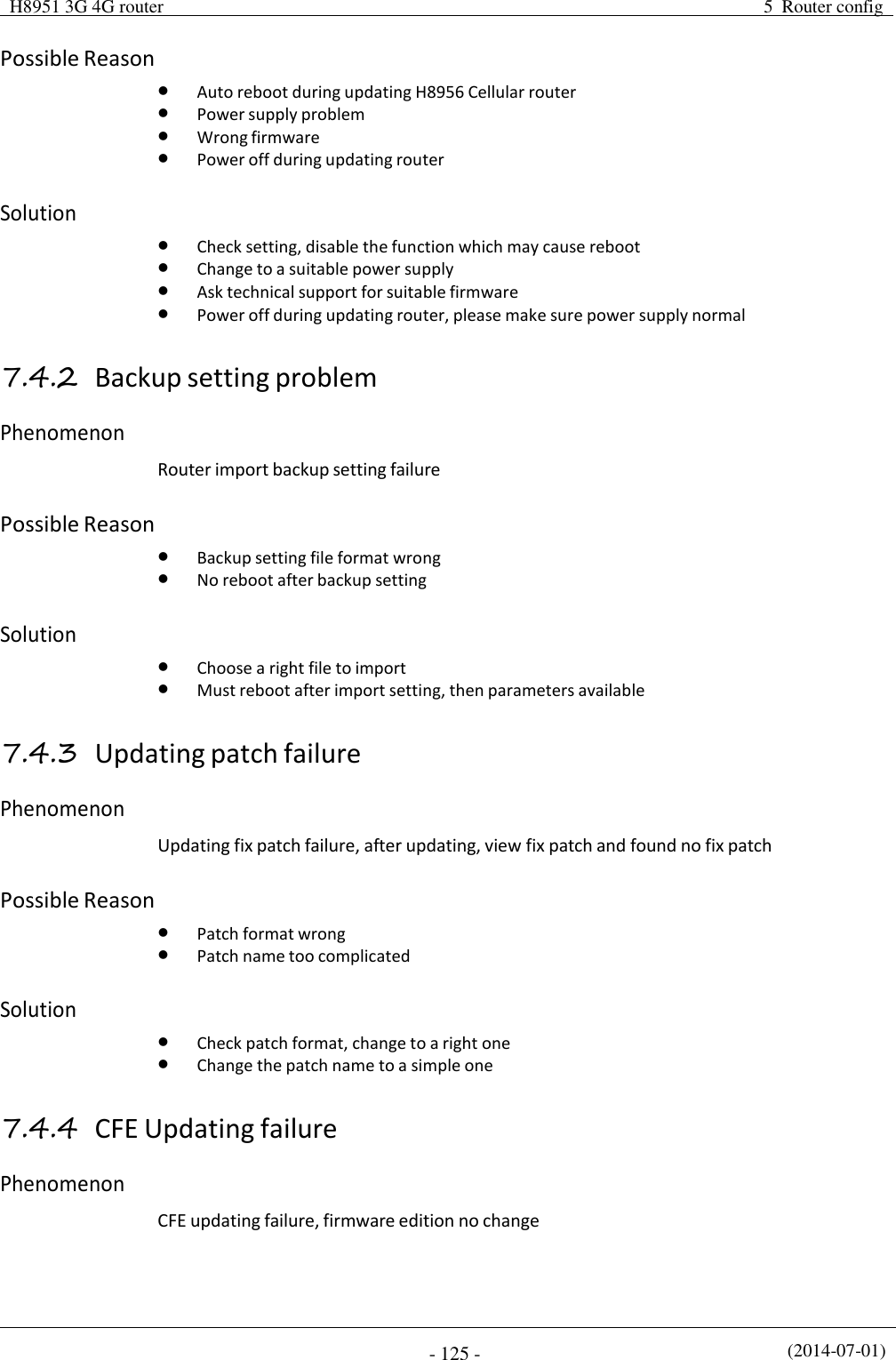
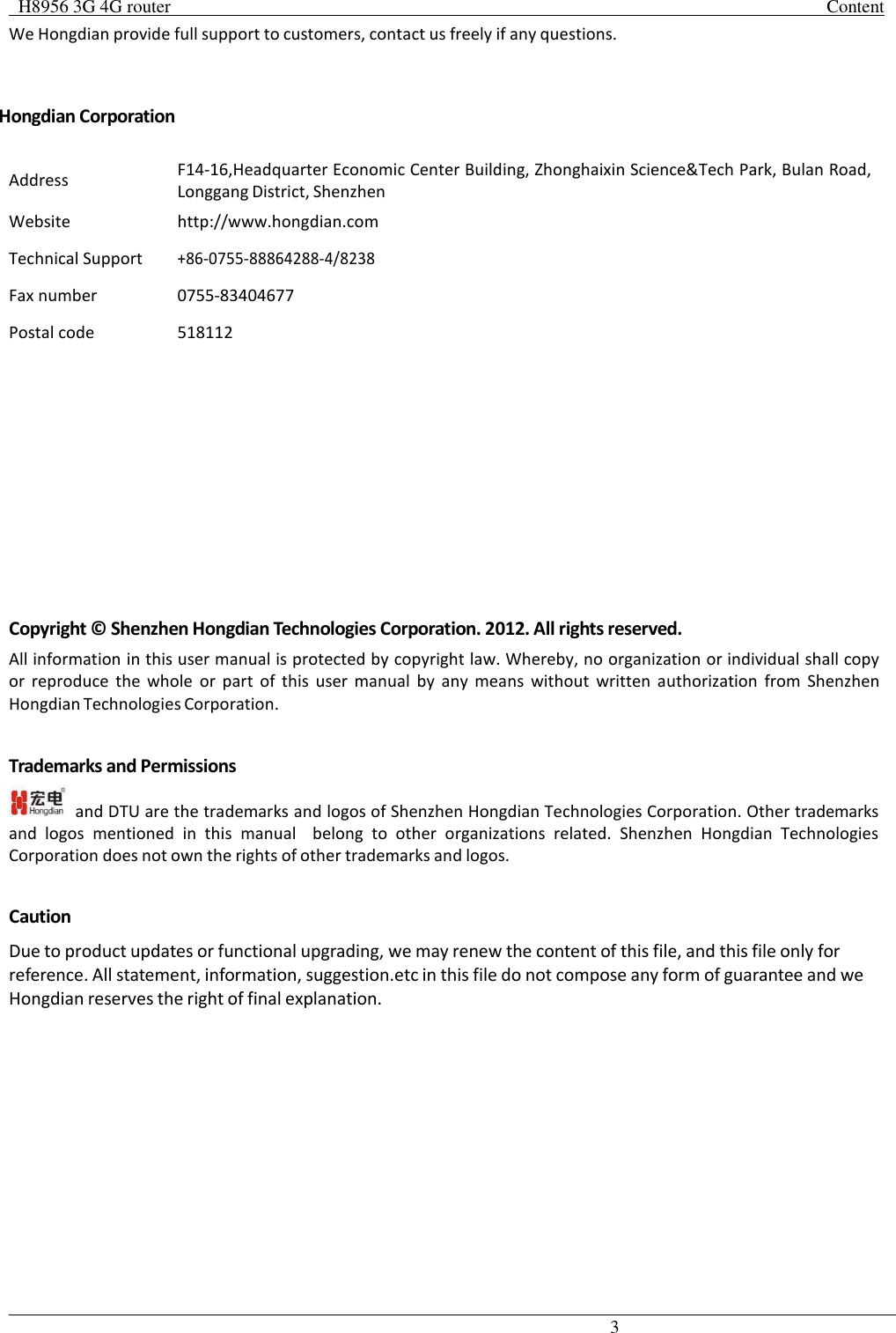
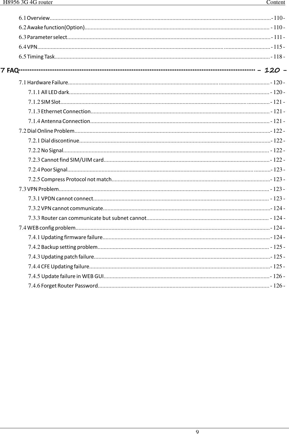
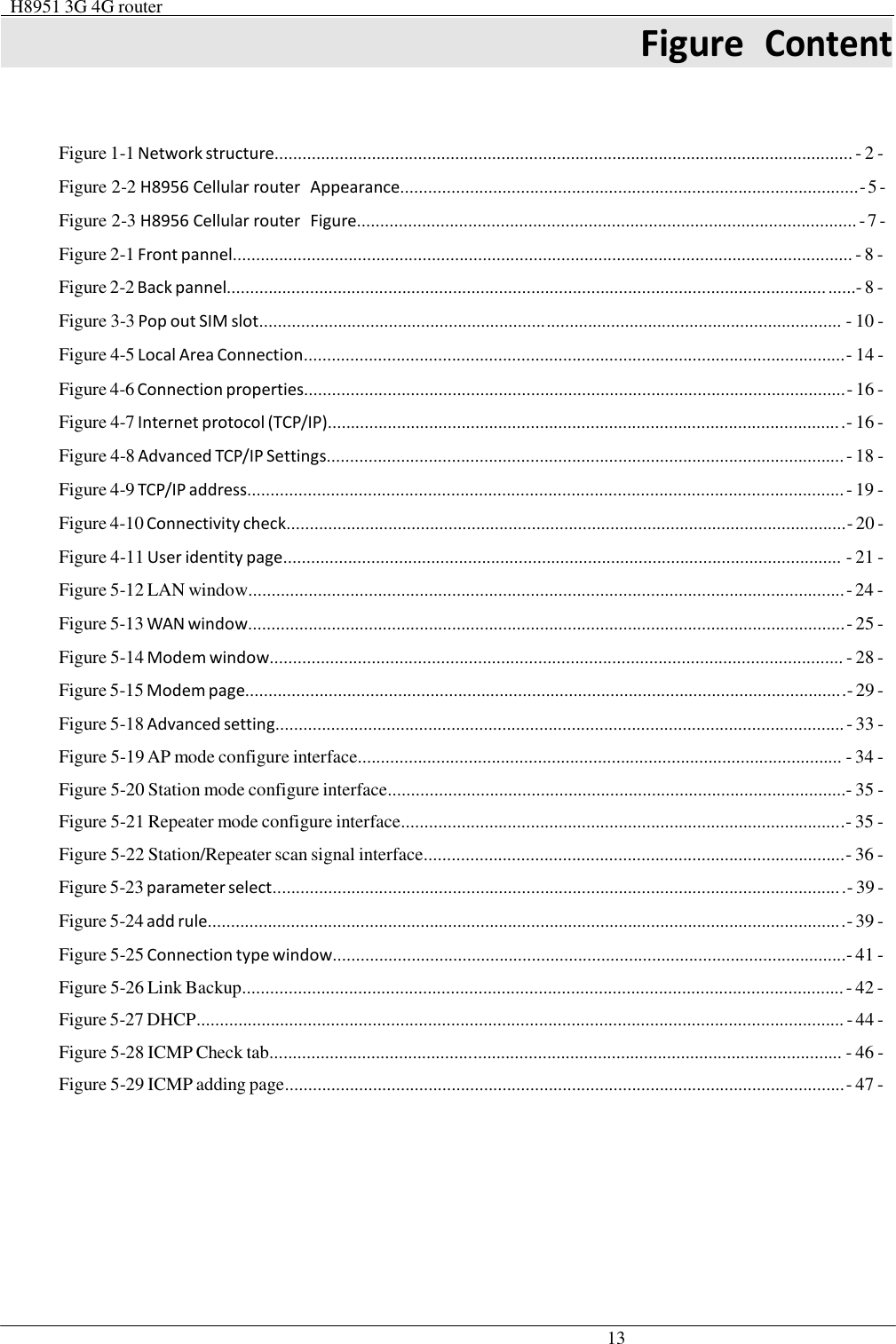
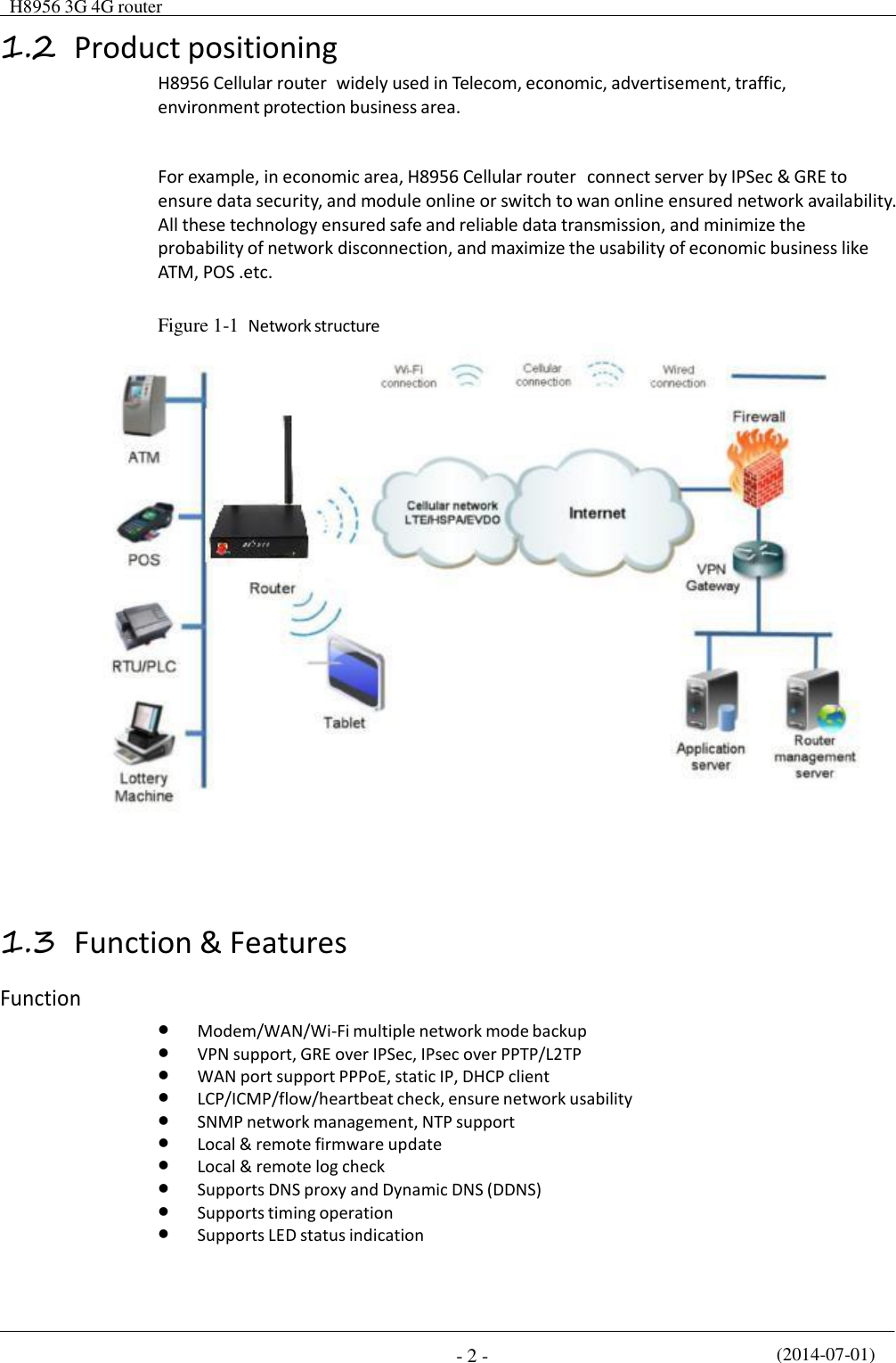
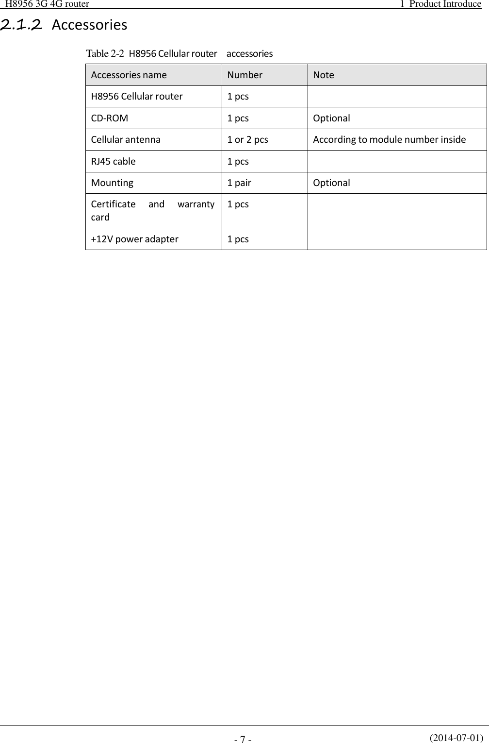
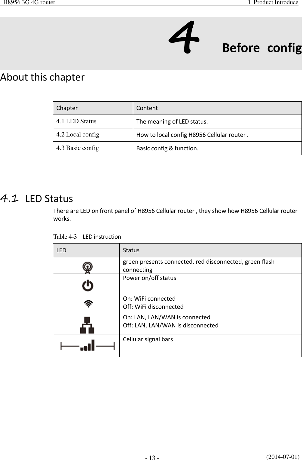
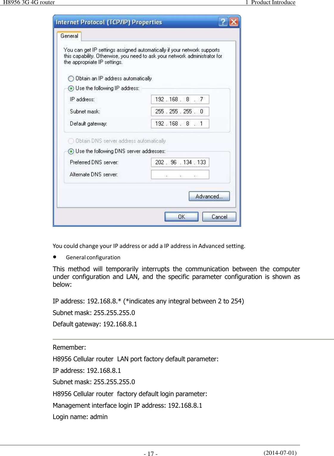
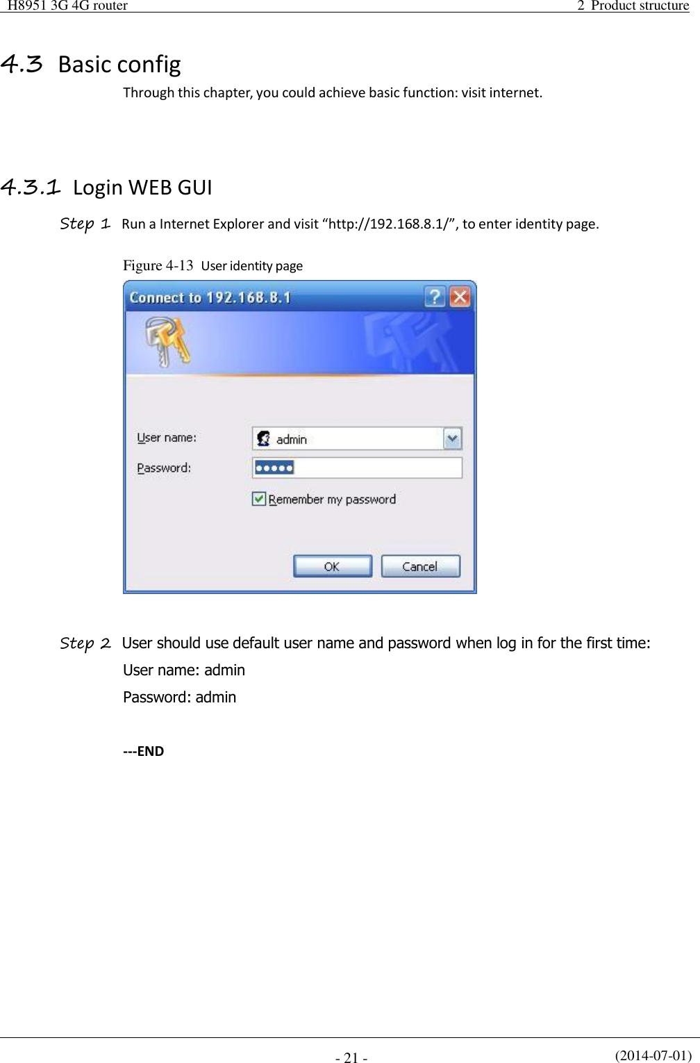
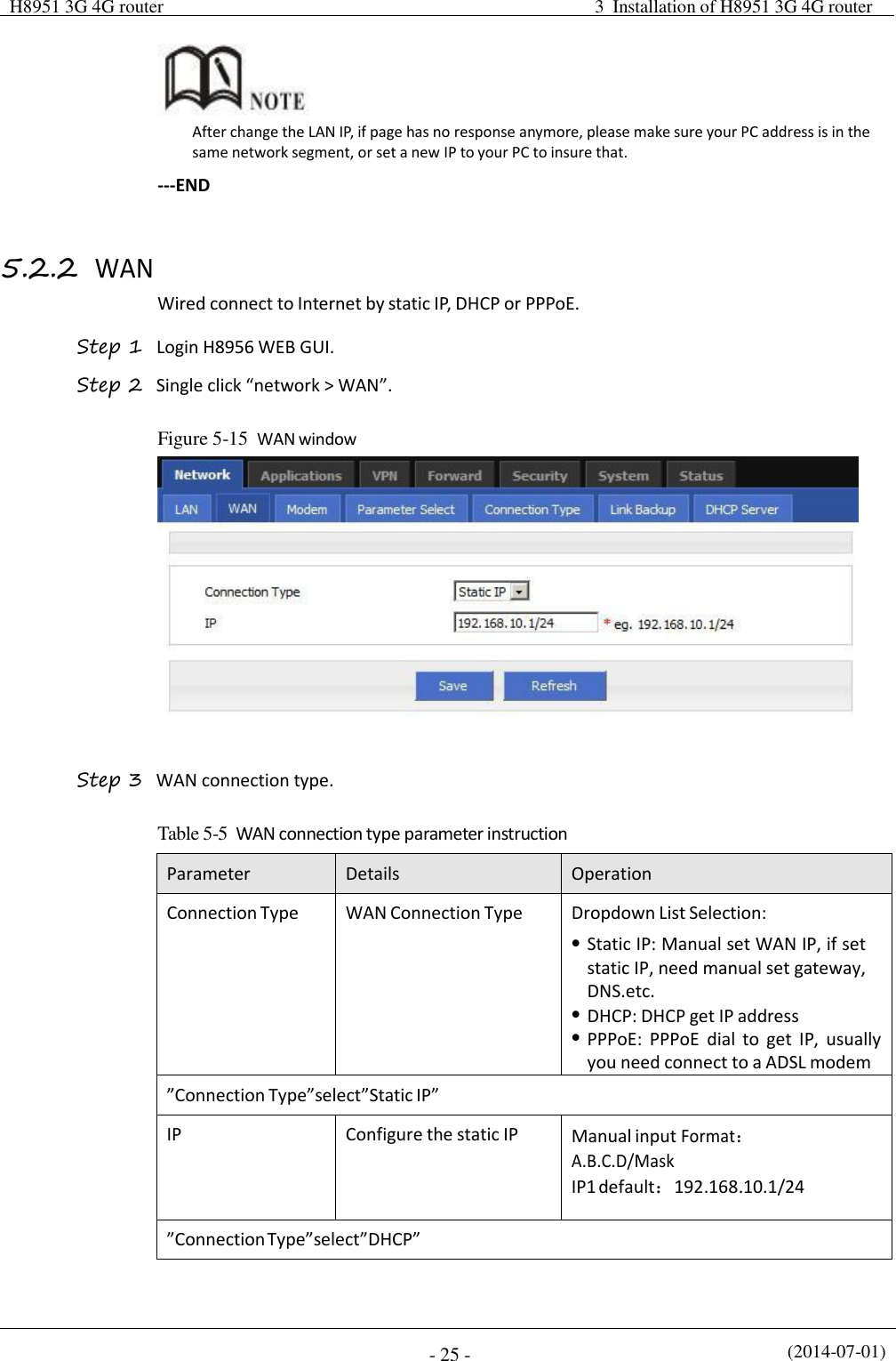
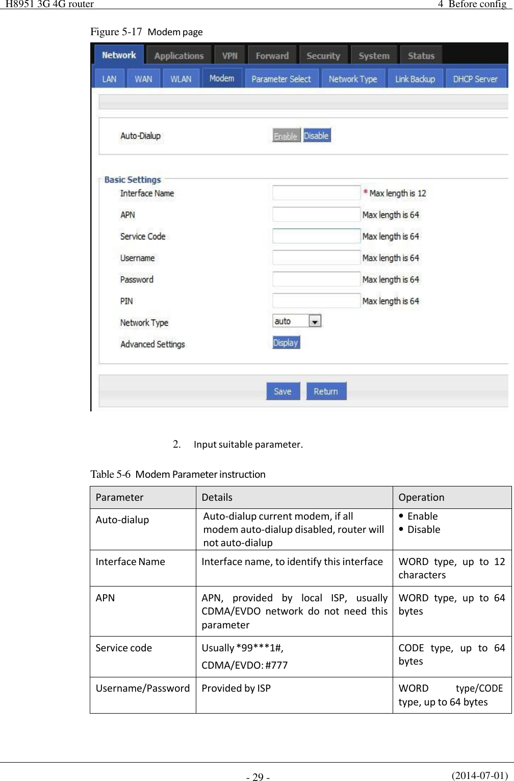
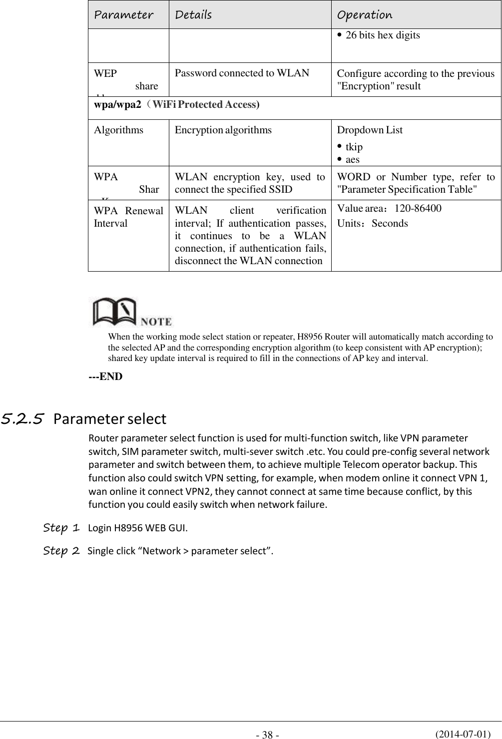
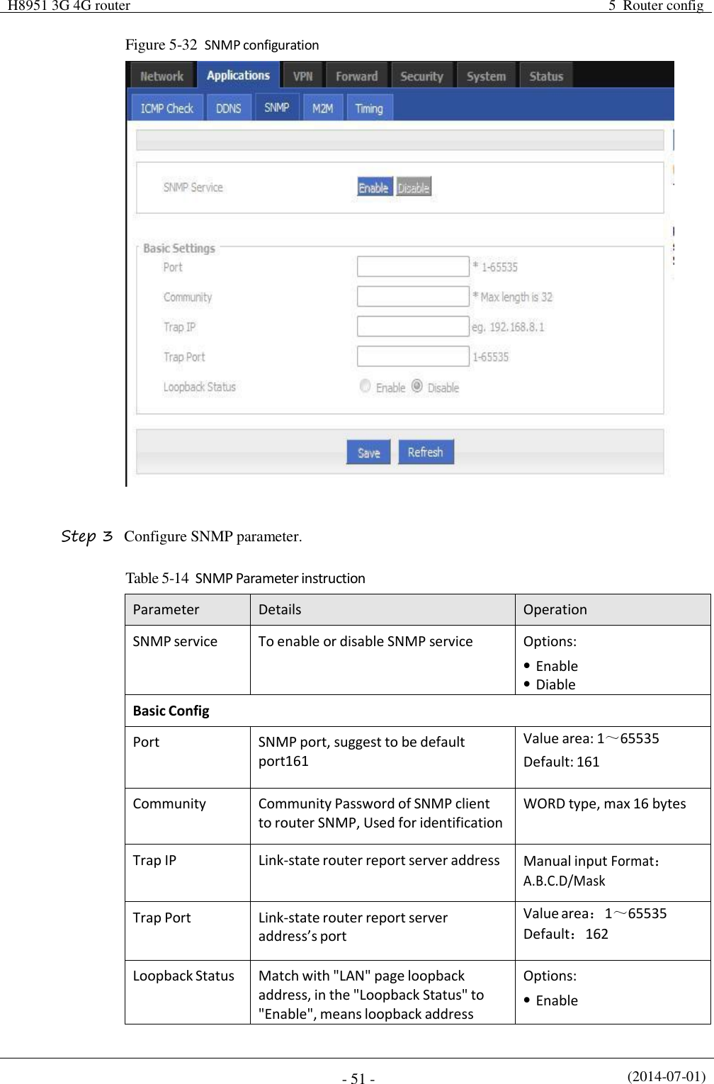
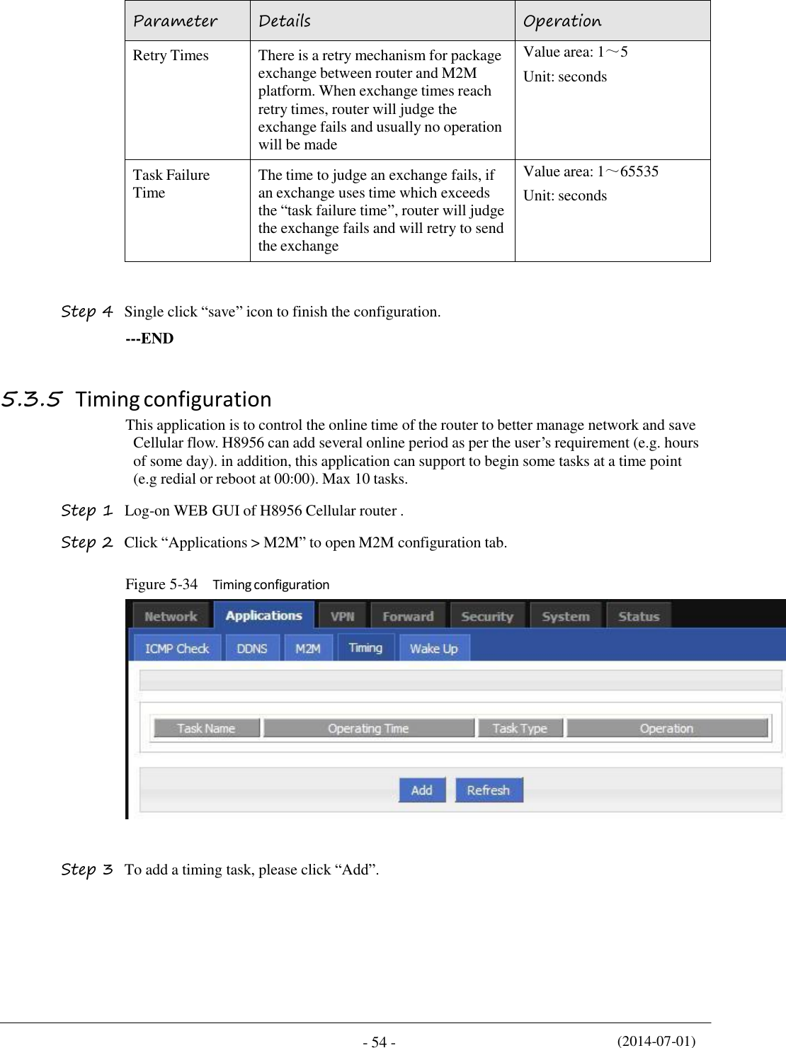
![(2014-07-01) - 62 - Table 5-18 IP filter parameter instruction Parameter Details Operation Type Select a filter type, you can choose according to their needs, "Input" or "Forward" Input: whether to allow access to the router Forward: whether to allow the router forwarding Dropdown List options Default Action The default action rule. You can select "Accept" or "discard" Accept: firewall to accept the package, which can be passed Discard: firewall discards the packet directly Dropdown List options Mirror Rule When the filter type select "Forward", it needs to be configured Enable: On the basis of the configuration rules to add an extra source address/port and destination address/port reverse the rules Disabled: no treatment Dropdown List options Protocol Protocol used by IP packets Dropdown List options all tcp udp icmp Source IP The source IP address of the packet Manual input Format:A.B.C.D/Mask Source Port The source Port of the packet, when the protocol choose "icmp", it don’t need to configure Value area: 1-65535 or [1-65535], it can be a range, or a single port When the IP Filter type select “Input” Destination Type Design an IP packet access router interface Dropdown List options interface any Interface Configure when Destination Type select “Interface”, means the IP packet access the router interface Dropdown List options br0 modem eth0 eth1](https://usermanual.wiki/Hongdian/H8956/User-Guide-3841899-Page-72.png)
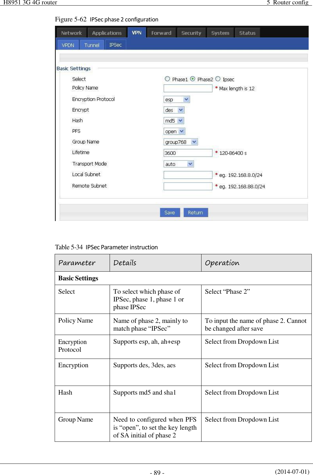
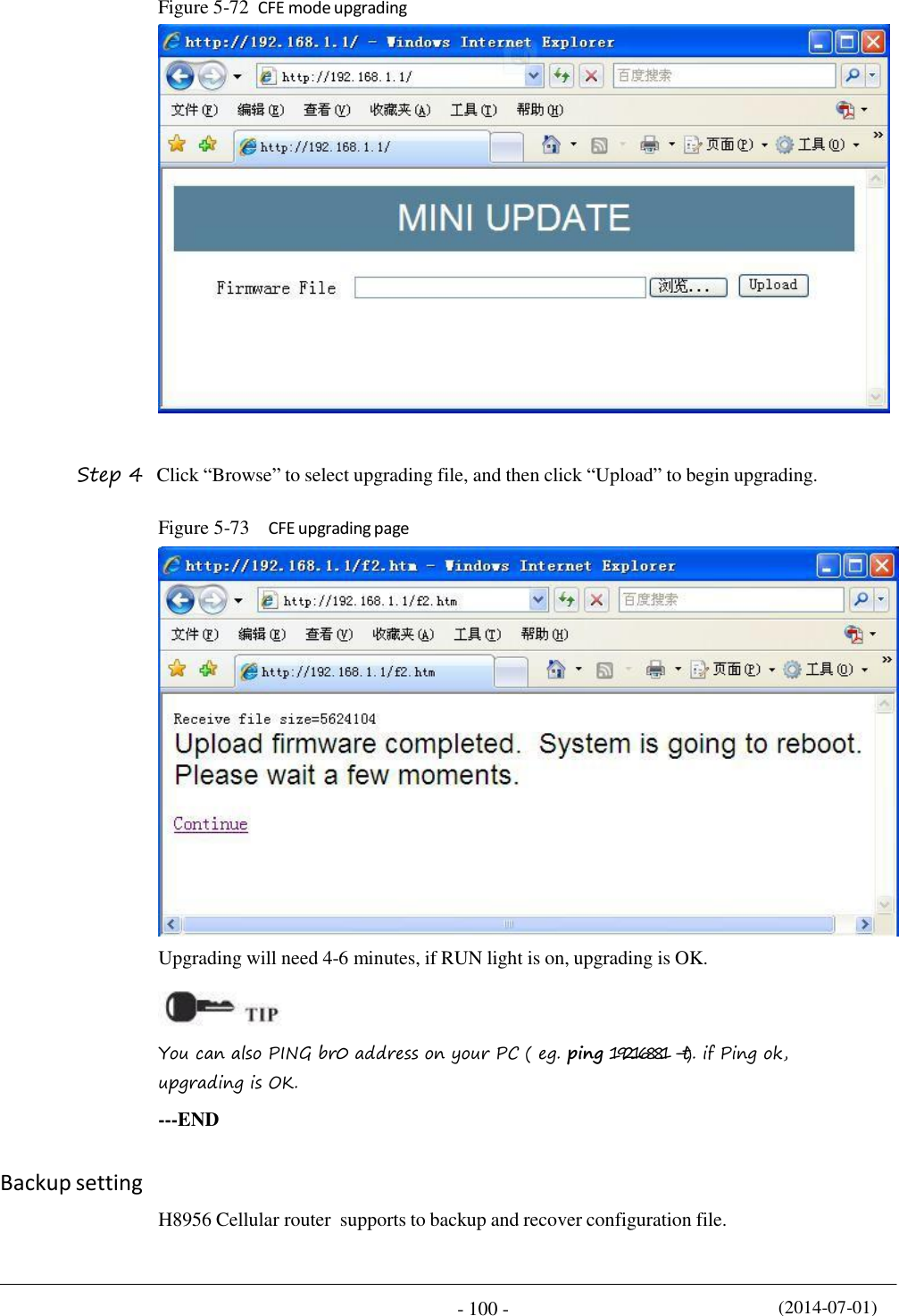
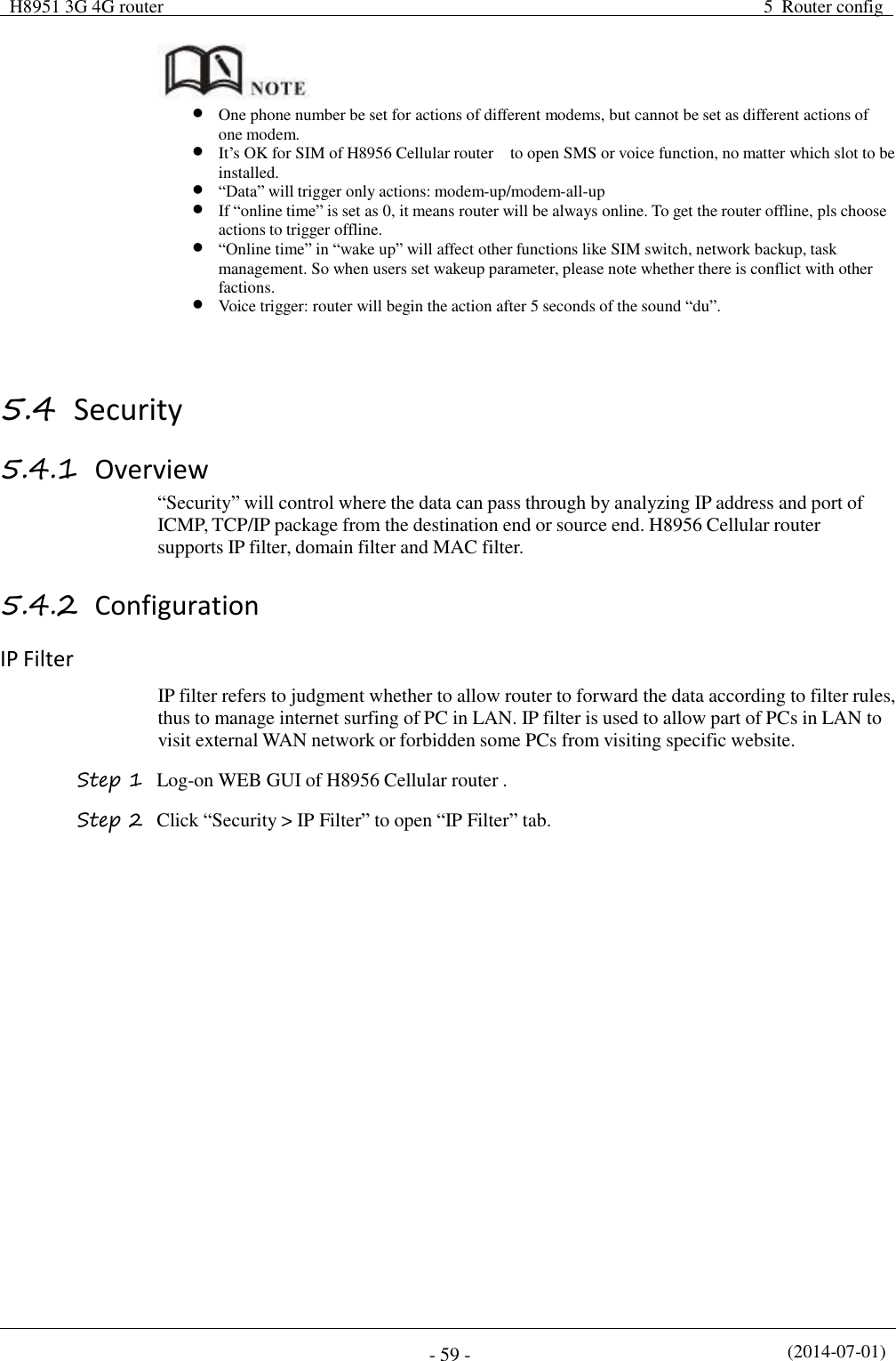
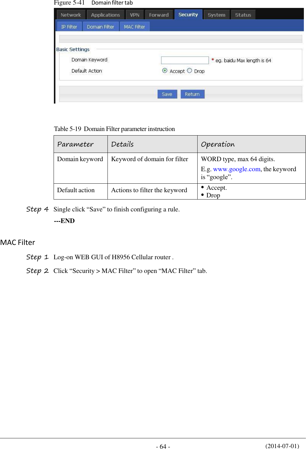
![(2014-07-01) - 63 - H8951 3G 4G router 5 Router config Parameter Details Operation Destination Port IP packet access router ports (when the protocol select "icmp", requires no configuration) Value area: 1-65535 or [1-65535], it can be a range, or a single port When the IP Filter type select “Forward” Destination IP IP packet destination IP Manual input Format:A.B.C.D/Mask Destination Port IP packet destination port Value area: 1-65535 or [1-65535], it can be a range, or a single port Step 5 Single click “save” to finish. --END Domain Filter Domain filter support black list and white list. It is used to forbid PCs in LAN from visit some websites or allows them to visit specific websites. Step 1 Log-on WEB GUI of H8956 Cellular router . Step 2 Click “Security > Domain Filter” to open “Domain Filter” tab. Figure 5-40 Domain filter tab Black list: websites in the blacklist cannot be visited. Click “black list” to forbid visiting the websites in the list. White lis: only the websites in the white list can be visited, while other websites cannot be visited. Click “White list” to activate it. Step 3 Click “ADD” to add a new domain filter rule and configure domain filtering parameter.](https://usermanual.wiki/Hongdian/H8956/User-Guide-3841899-Page-73.png)
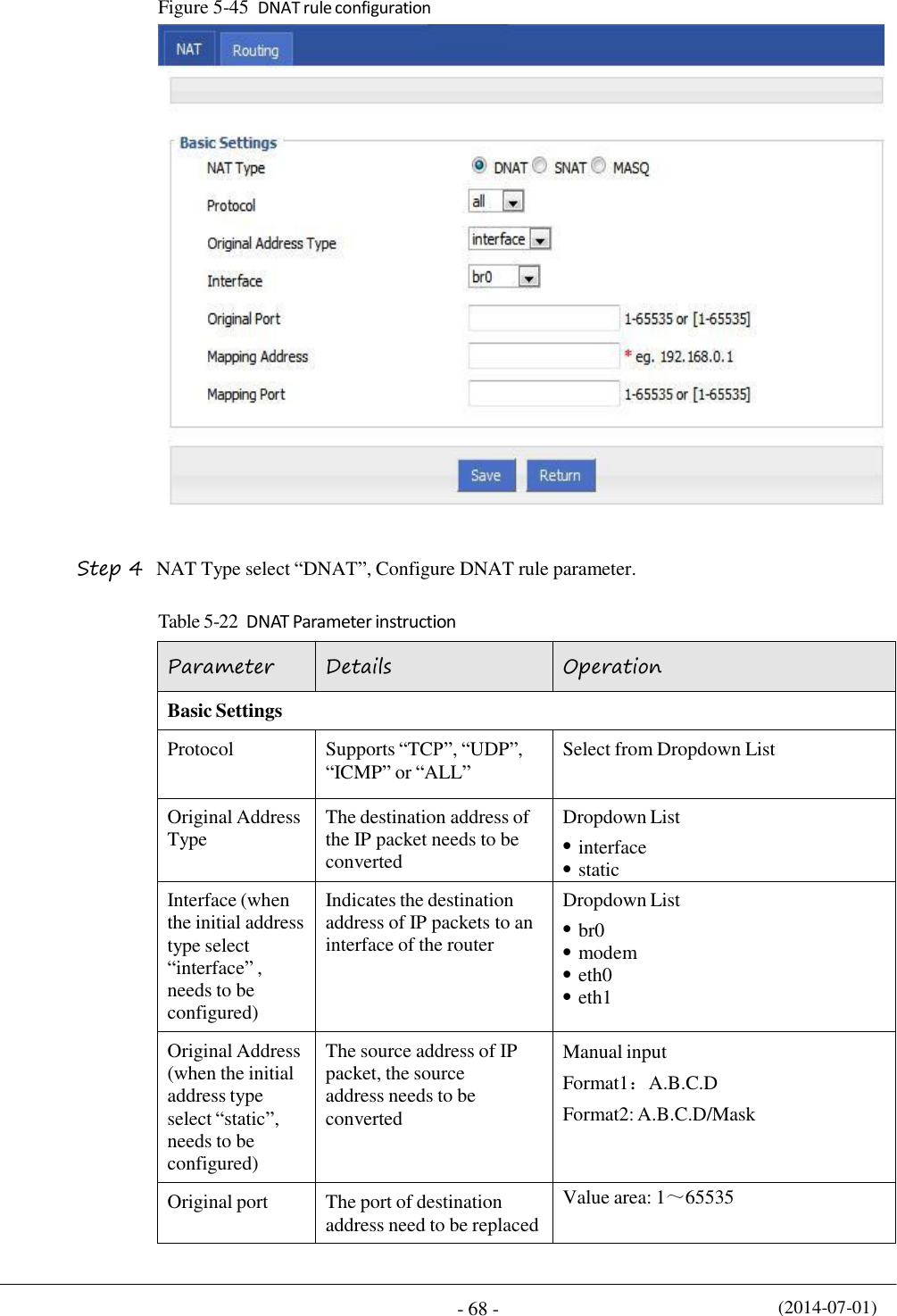
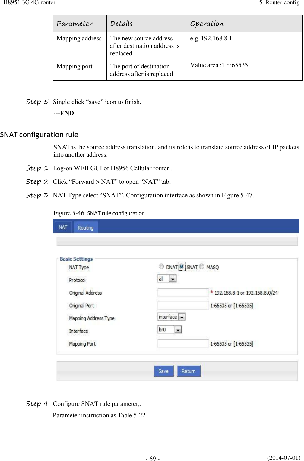
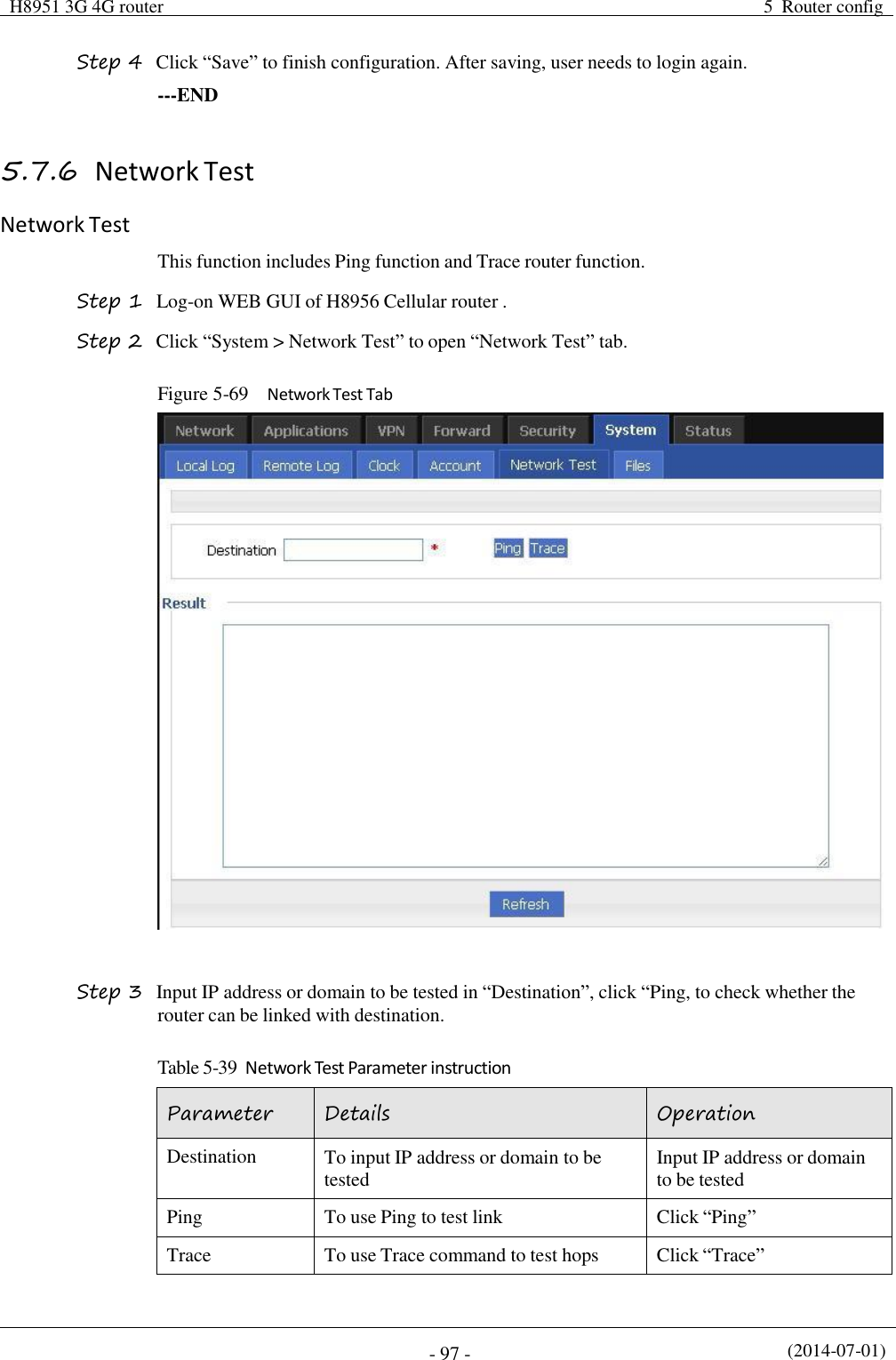
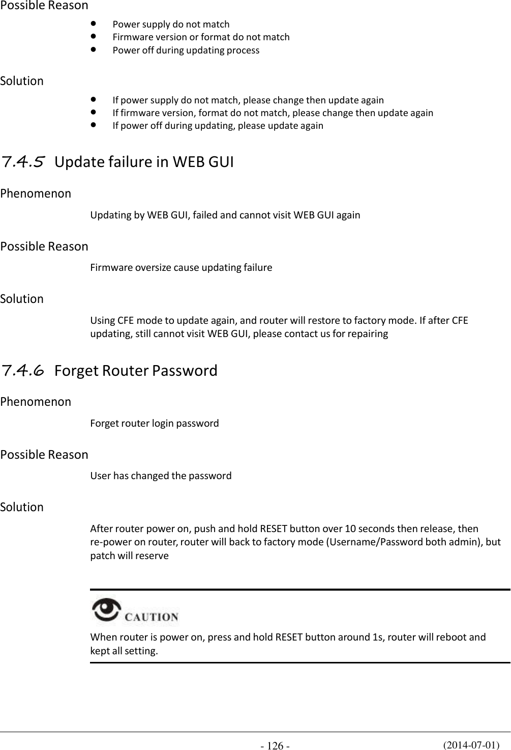
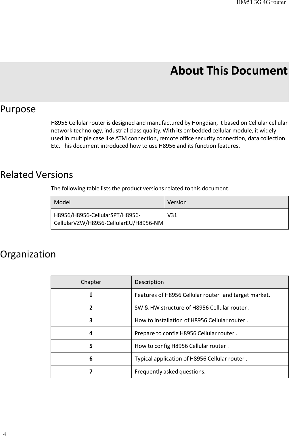
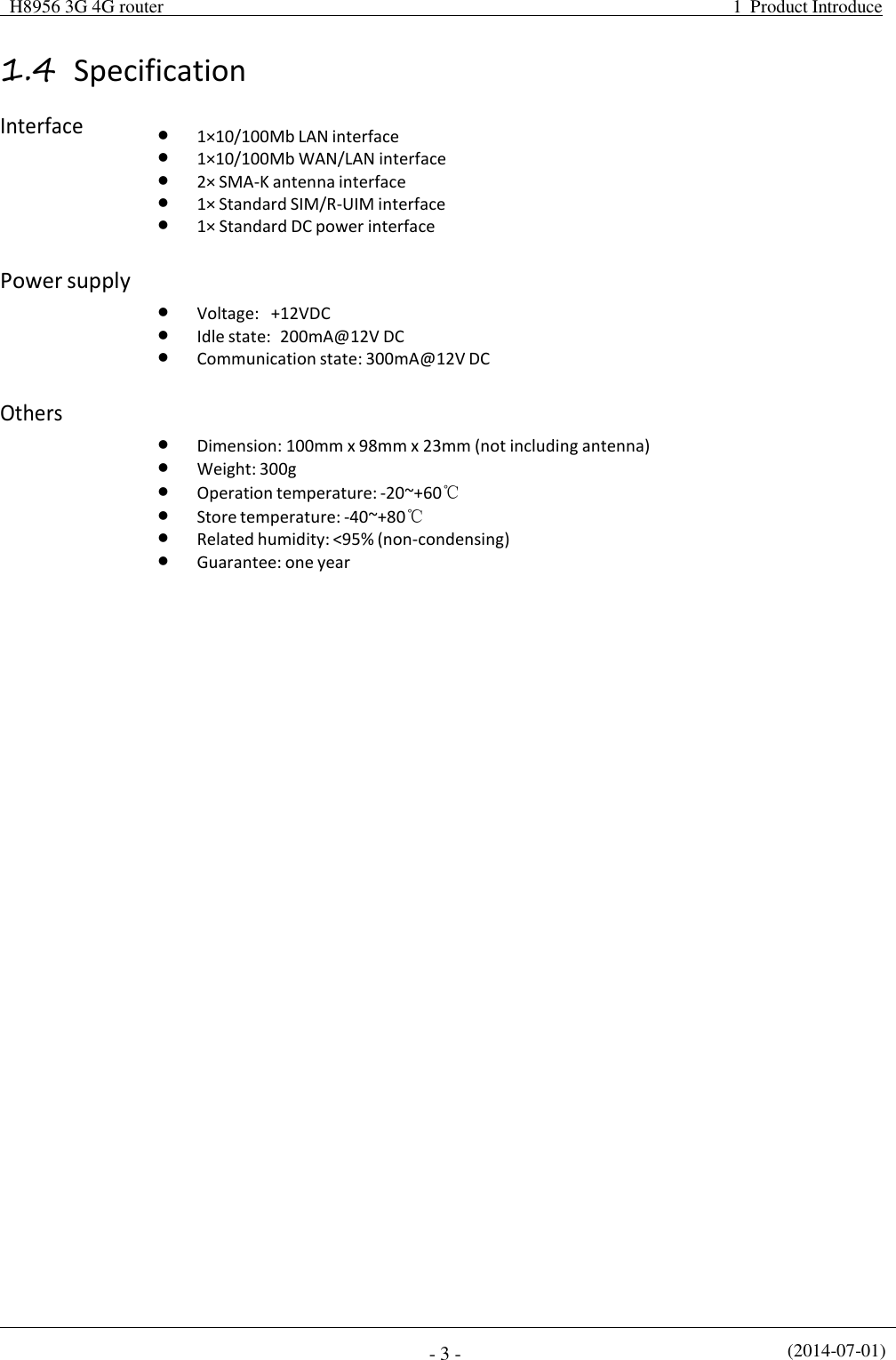
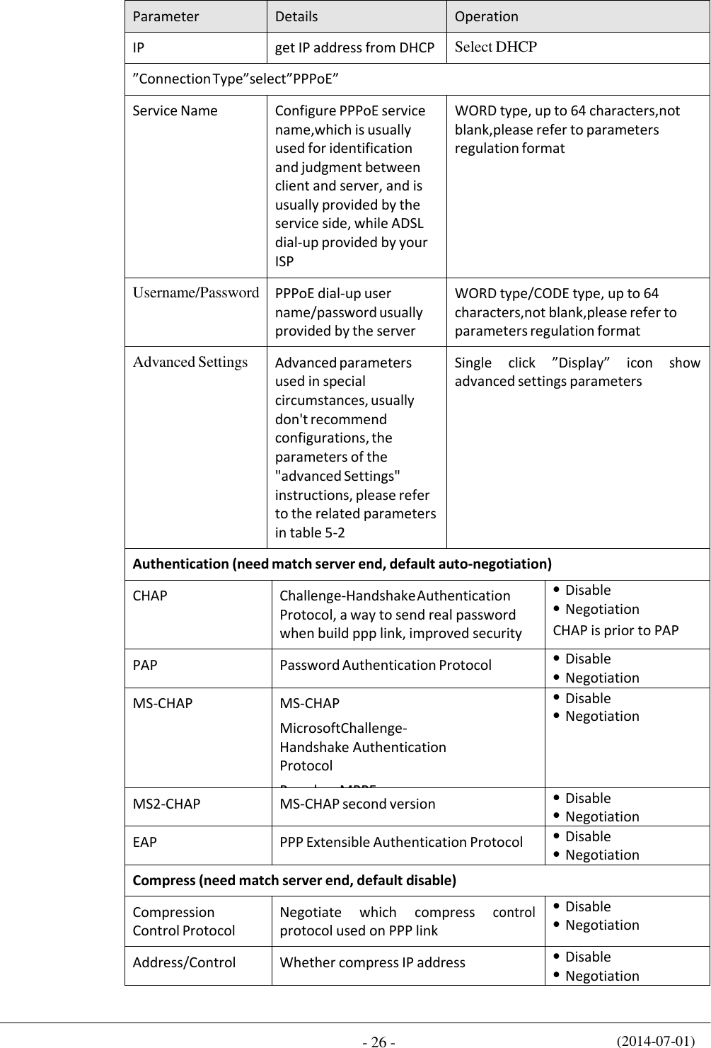
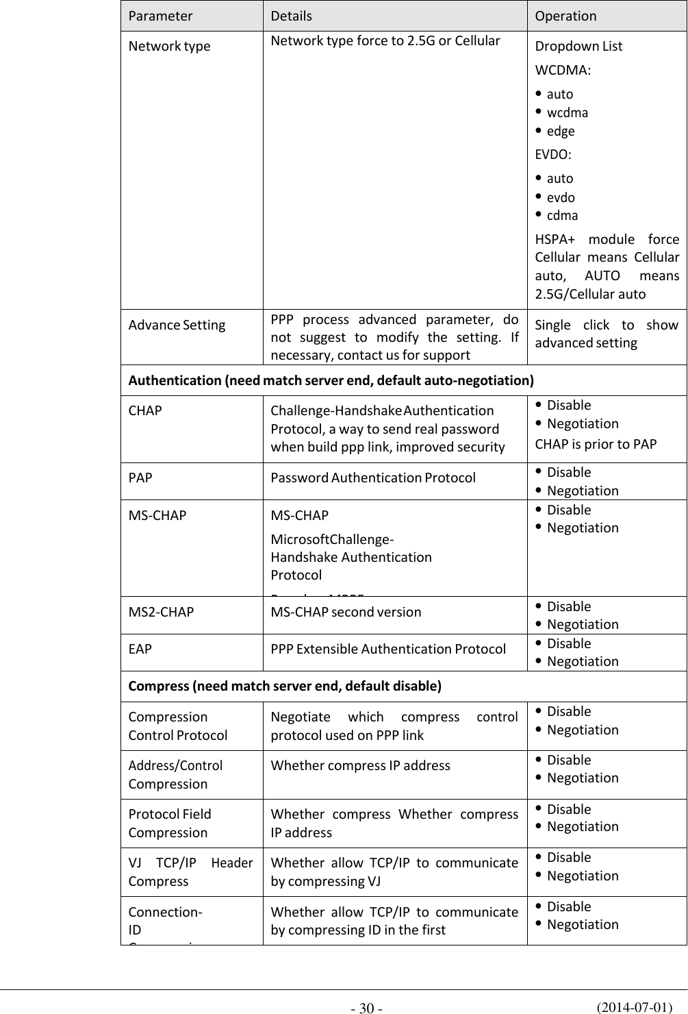
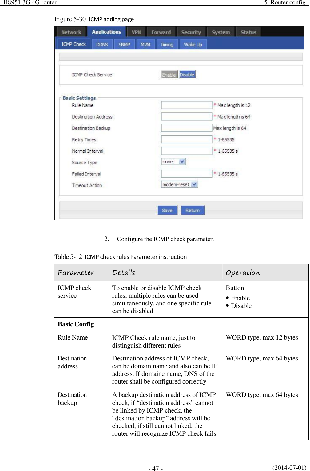
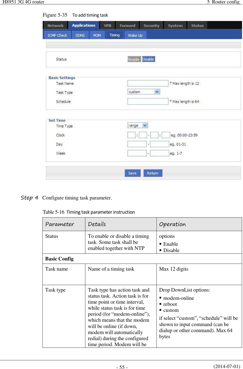
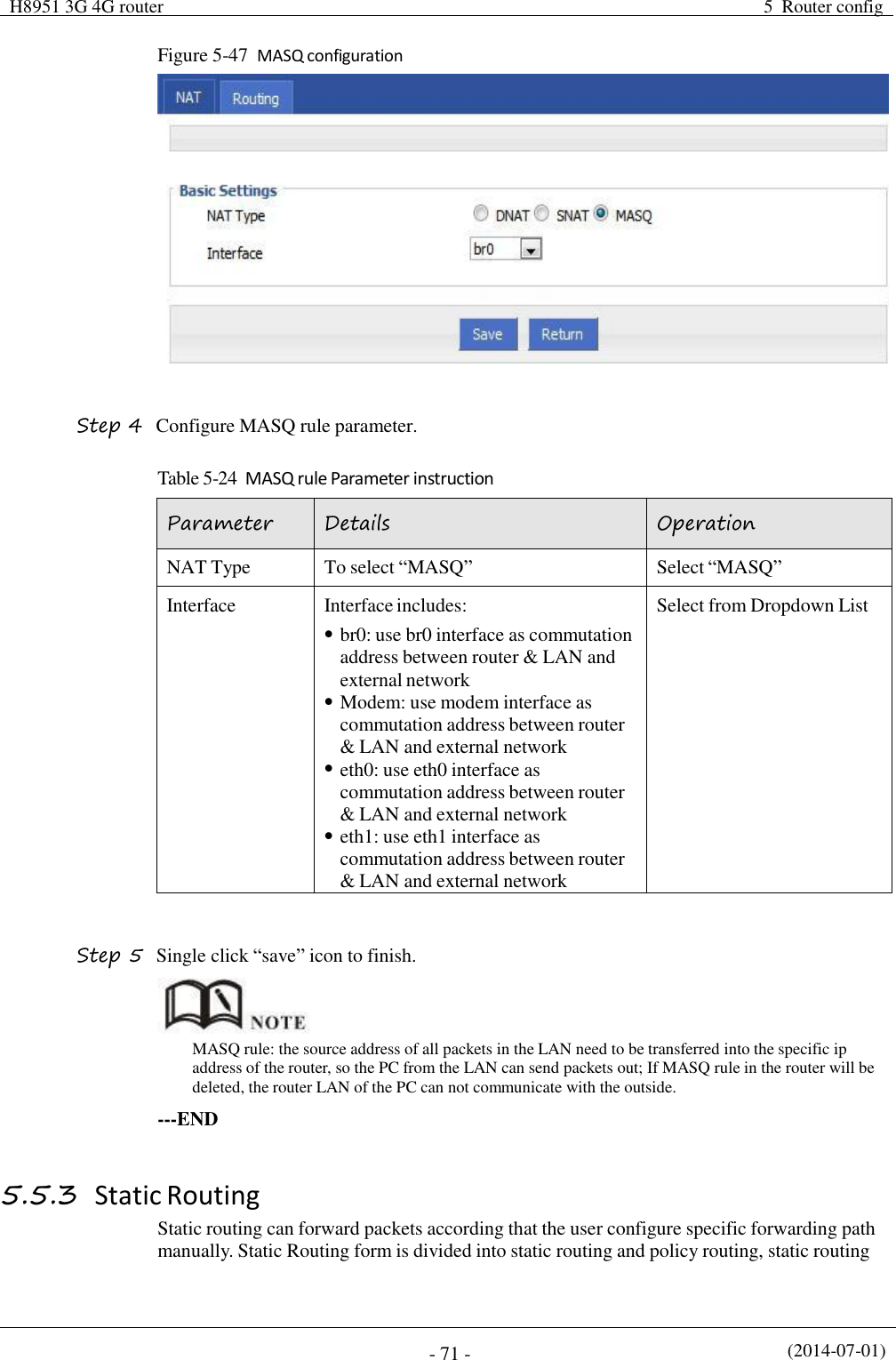
![Table 5-23 SNAT rule instruction (2014-07-01) - 70 - Parameter Details Operation Protocol Convert some kind of protocol packets into address Dropdown List all tcp udp icmp Original Address The source address need to be replaced Manual input Format1:A.B.C.D Format2: A.B.C.D/Mask Original Port The port of source address need to be replaced Value area: 1-65535 or [1-65535], it can be a range, or a single port Mapping Address Type The new source address type after source address is replaced Dropdown List interface static Interface Select the interface of the router as source address after replacement Dropdown List br0 modem eth0 eth1 Mapping Port The port of source address after is replaced Value area: 1-65535 or [1-65535], it can be a range, or a single port Step 5 Single click “save” icon to finish. When SNAT rule is configured port, protocol select "all", said select "tcp", "udp" two protocols; when SNAT rule is not configured port, protocol select "all", said select "tcp", "udp","icmp" three protocols. ---END MASQ rule configuration MASQ is MASQUREADE. Step 1 Log-on WEB GUI of H8956 Cellular router . Step 2 Click “Forward > NAT” to open “NAT” tab. Step 3 NAT Type select “MASQ”, Configuration interface as shown in Figure 5-48.](https://usermanual.wiki/Hongdian/H8956/User-Guide-3841899-Page-80.png)
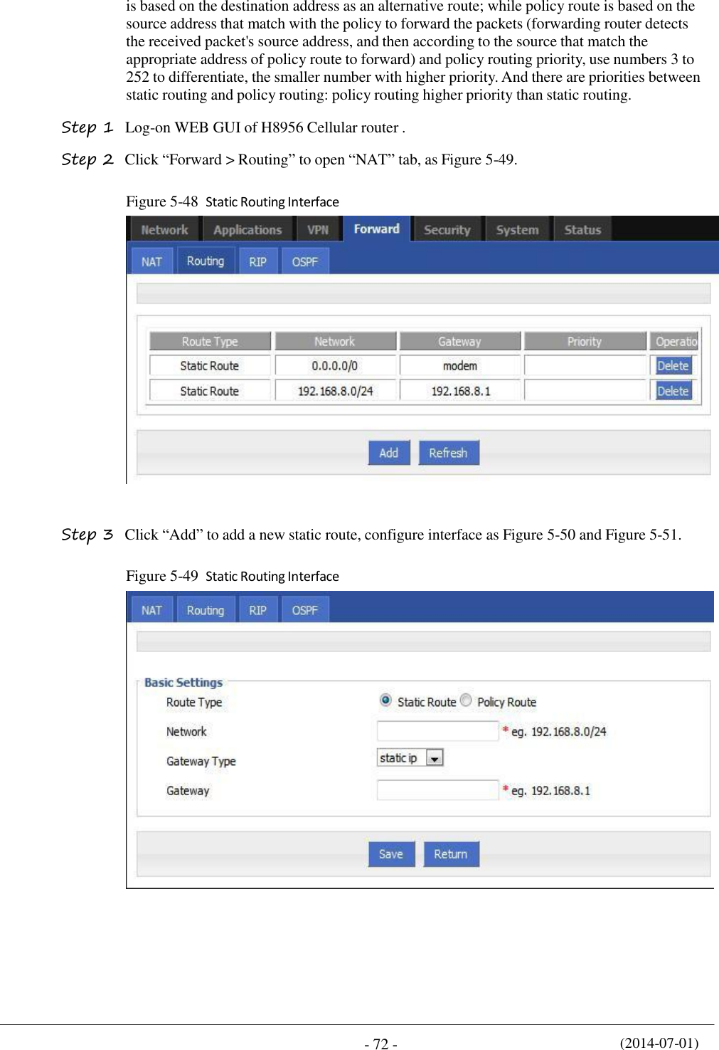
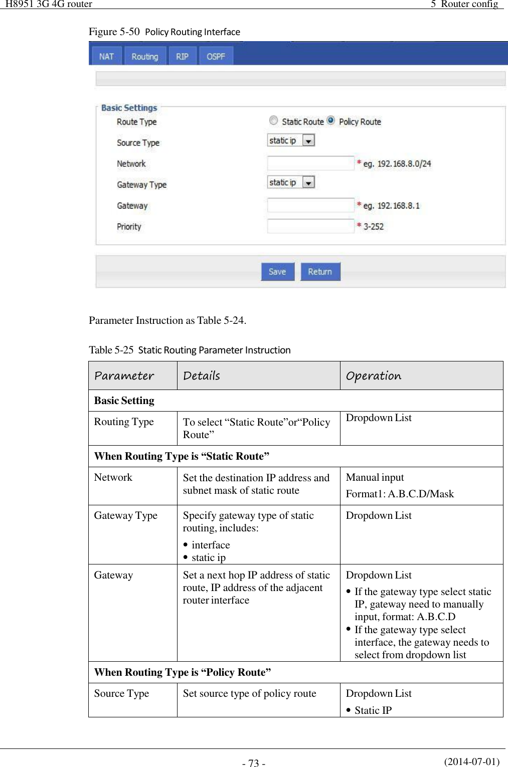
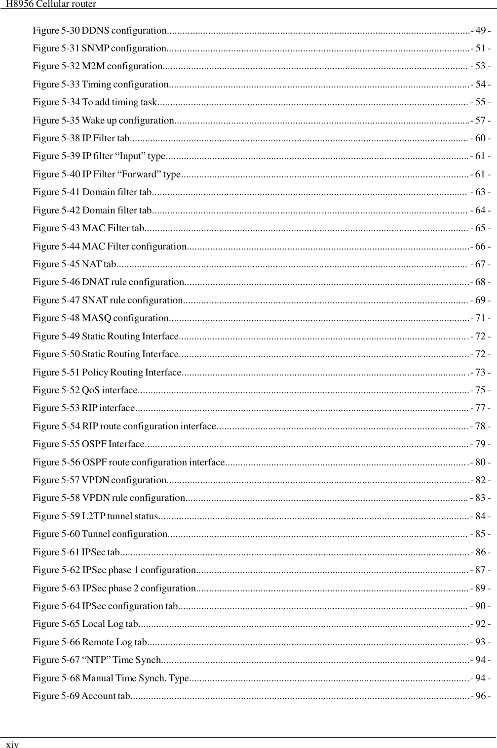
![(2014-07-01) - 74 - Parameter Details Operation Interface Network When source type is static route, need to manually set network address Manual input Format1: A.B.C.D/Mask Source Interface When source type is policy route, need to manually set source network address of policy router Dropdown List modem eth0 eth1 Gateway Type Set the next hop IP of policy route Dropdown List static ip interface Gateway When the gateway type select "Static IP" to fill in the IP address, when gateway type select the "interface", it will select the interfaces as gateway Manual input Format1: A.B.C.D/Mask Prority Set policy routing priority, the priority lower the number, the higher the priority Value area:[3,252] Step 4 Single click “save” icon to finish the static routing setting. Static routing will select the route to forward according to the destination address of the packet receive from the router, if the router received the packet(source address is 1.1.1.1 destination address is 2.2.2.2), It will forward the packet to next hop according to the route which meet with the destination address(2.2.2.2). Policy routing will forward according to the source address of the packet, if the router received the packet(source address is 1.1.1.1 destination address is 2.2.2.2), it will forward the packet to next hop according to the route which meet with the source address(1.1.1.1). Policy routing higher priority than static routing, policy-based routing priority regardless of how much. ---END 5.5.4 QoS (Optional) QoS (Quality of Service) quality of service, is a security mechanism for the network, is a technique to solve the network bandwidth allocation and network priority and other issues. When the network is overloaded or congested, QoS to ensure that critical traffic is not delayed or dropped, while ensuring the efficient operation of the network, our H8956 Cellular Router supports custom QoS services. Step 1 Log-on WEB GUI of H8956 Cellular router . Step 2 Click “Forward > QoS” to open “QoS” tab, as Figure 5-52.](https://usermanual.wiki/Hongdian/H8956/User-Guide-3841899-Page-84.png)
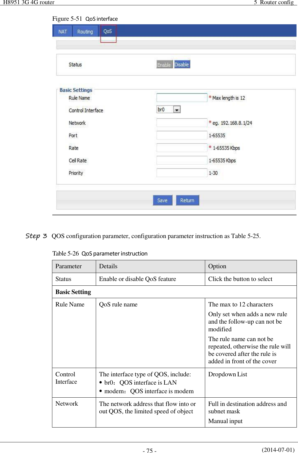
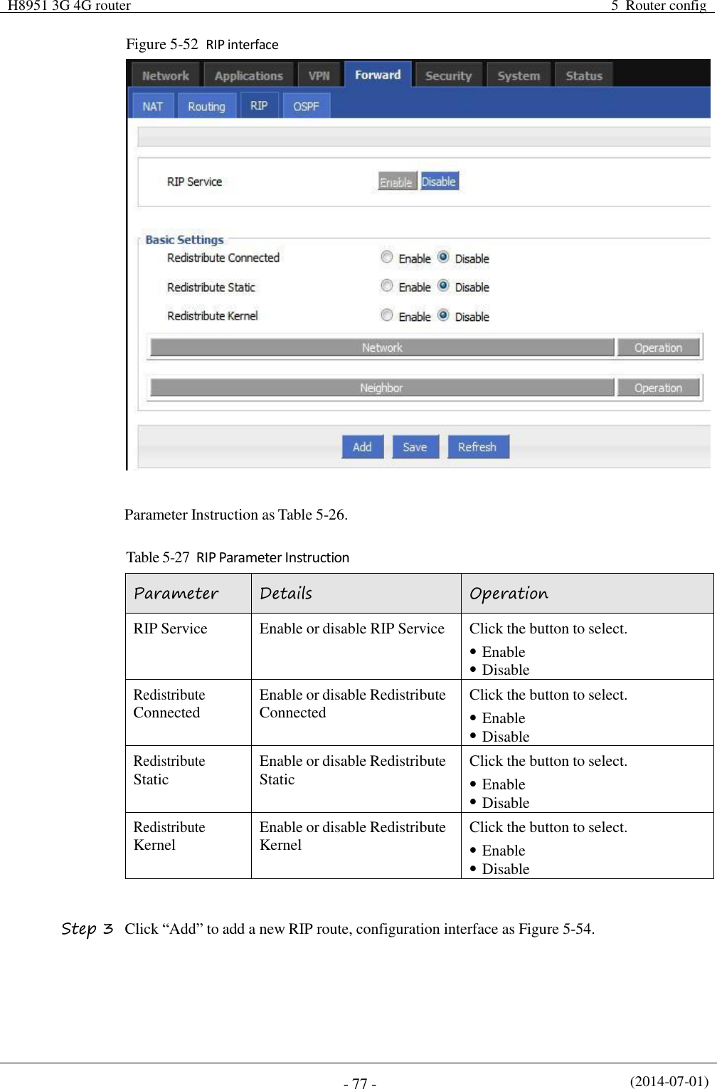
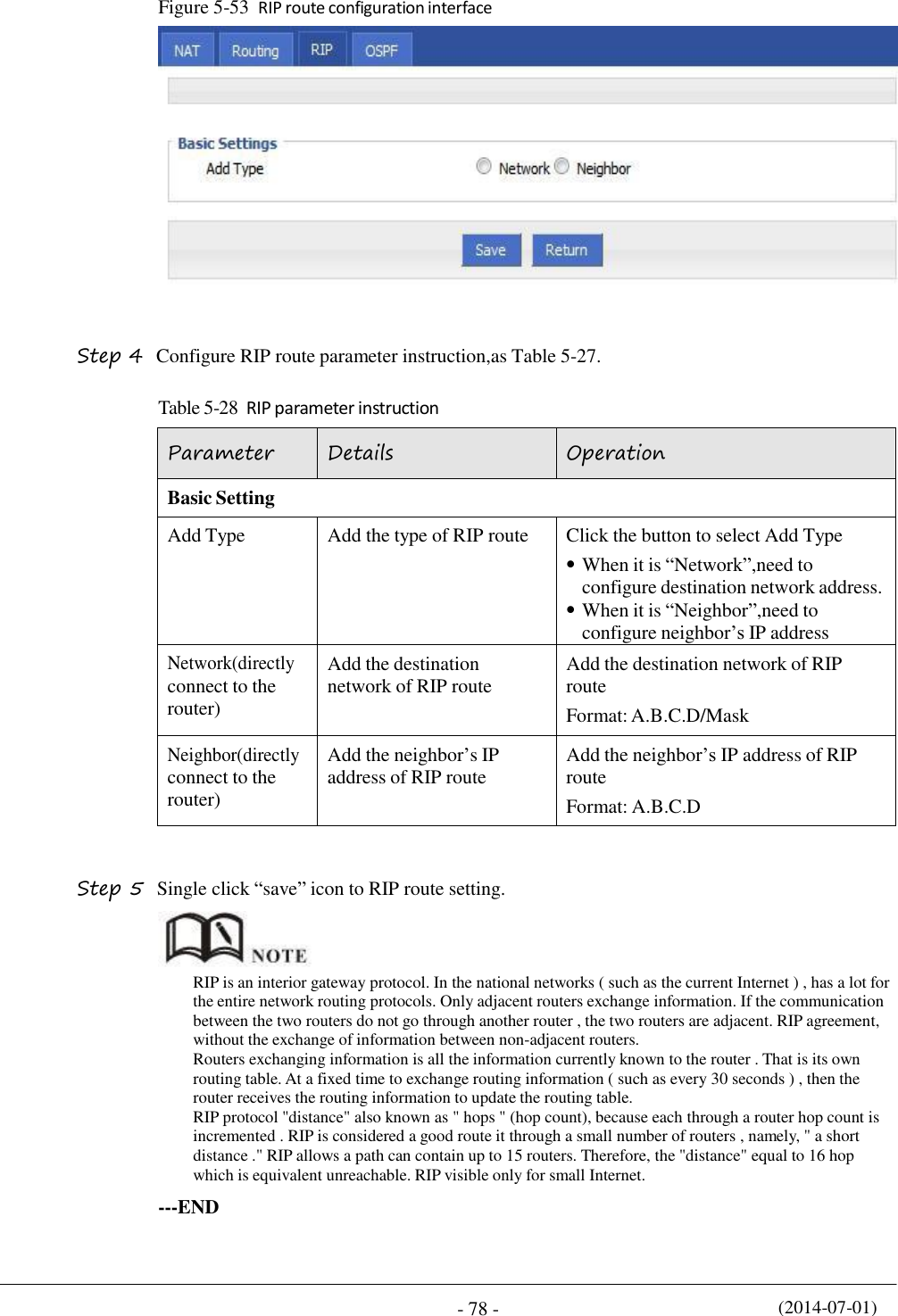
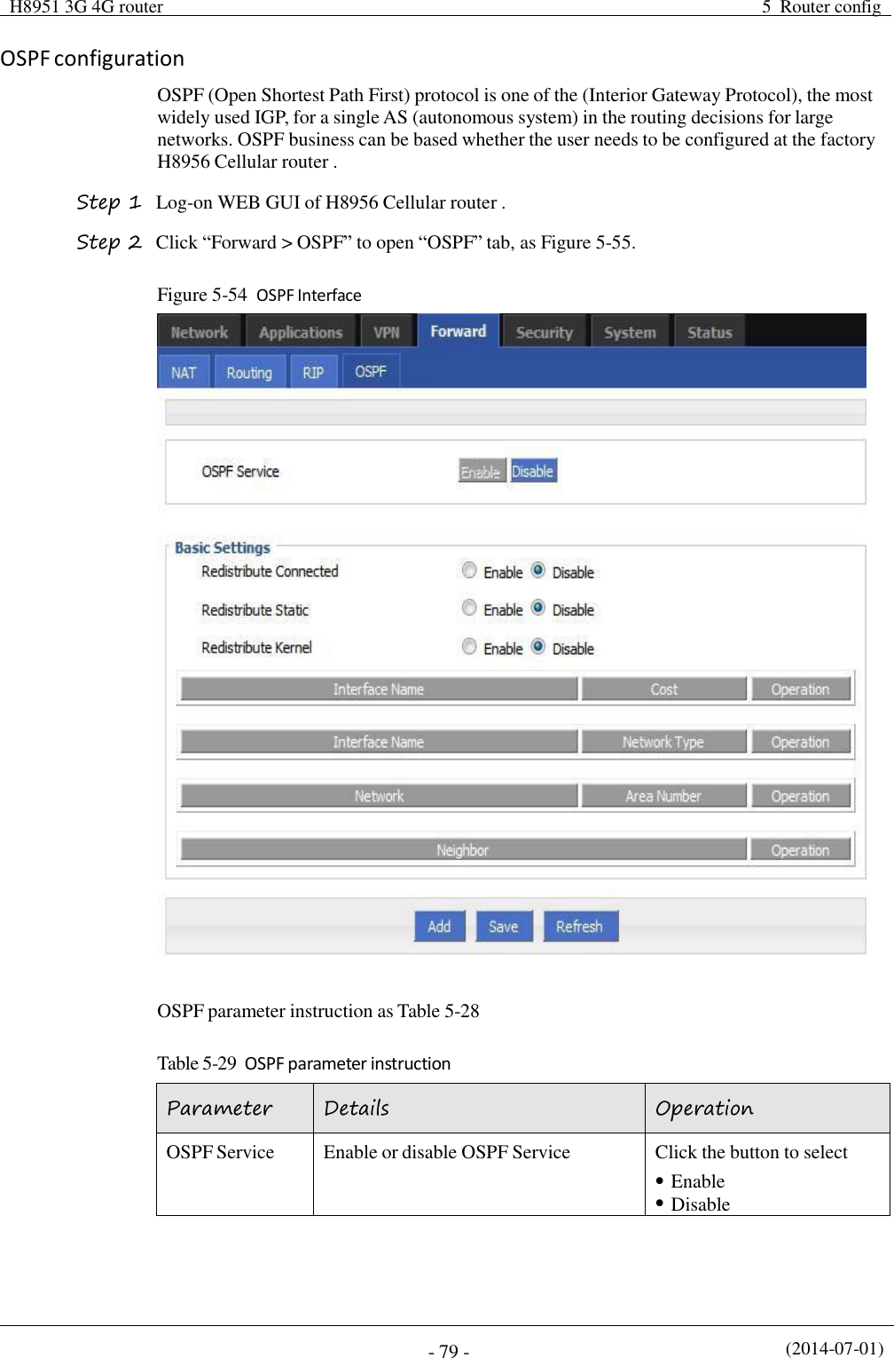
![(2014-07-01) - 76 - Parameter Details Option Format1: A.B.C.D/Mask Port The network interface of QOS Value area: 1-65535 You can not configure the port, if not the configuration represents all ports Rate Transmission rate of the network address settings Value area:1~65535 Units:Kbps Ceil Rate In ensuring the basic rate and the spare bandwidth, the maximum bandwidth of the network address of the communication can be obtained with higher priority will be given priority redundant bandwidth Value area:1~65535 Units:Kbps Priority Set the precedence of the rules Value area:[1,30] Step 4 Single click “save” icon to QOS setting. QOS is mainly for the average of user priority assigned route or a bandwidth of Internet users. If the router is connected with two subnets: 192.168.8.1/24 and 192.168.9.1/24, the router QOS can control the rate of these two subnets; If the router's bandwidth is relatively well-off, the router can be based on two subnets redundant bandwidth is first priority and high priority redundancy to meet the bandwidth, then meet low priority subnet redundancy bandwidth. ---END 5.5.5 Dynamic Routing(Optional) RIP configuration RIP protocol (Routing Information Protocol) is the most widely IGP (Interior Gateway Protocol) , it was designed for the same technology used in small networks, and therefore adapt to most of the campus network and used in a continuous regional networks that the rate change is not big, H8956 Cellular router supports RIP v2 protocol. For more complex environments, generally do not use the RIP protocol. RIP business is based on whether the user needs the RIP at the factory H8956 Cellular router . Step 1 Log-on WEB GUI of H8956 Cellular router . Step 2 Click “Forward > RIP” to open “RIP” tab, as Figure 5-53.](https://usermanual.wiki/Hongdian/H8956/User-Guide-3841899-Page-86.png)
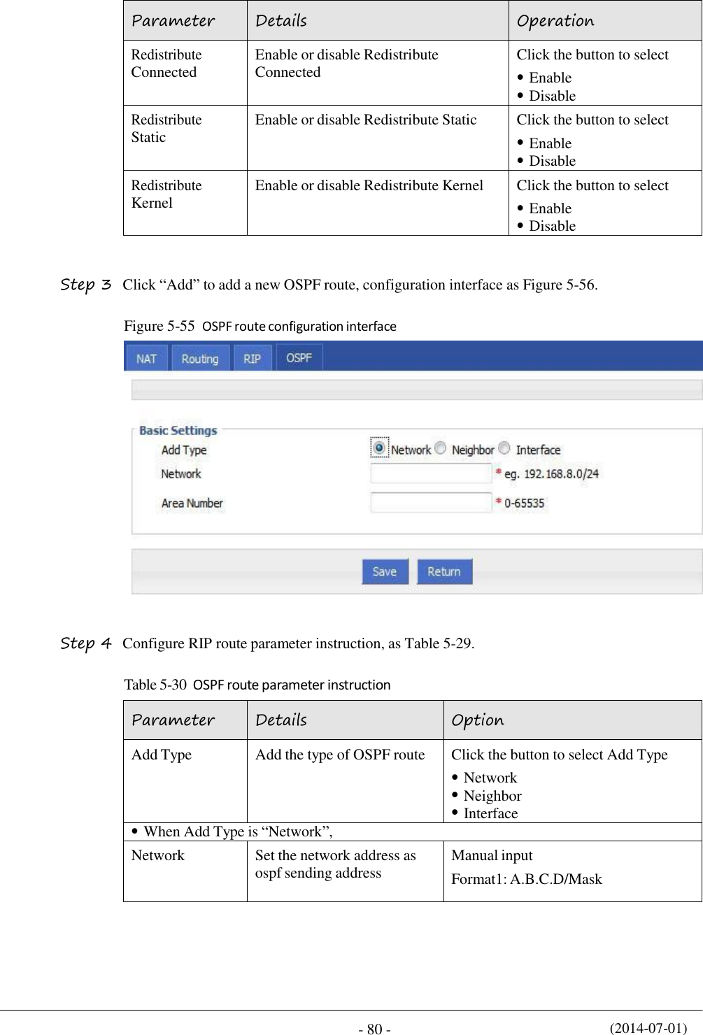
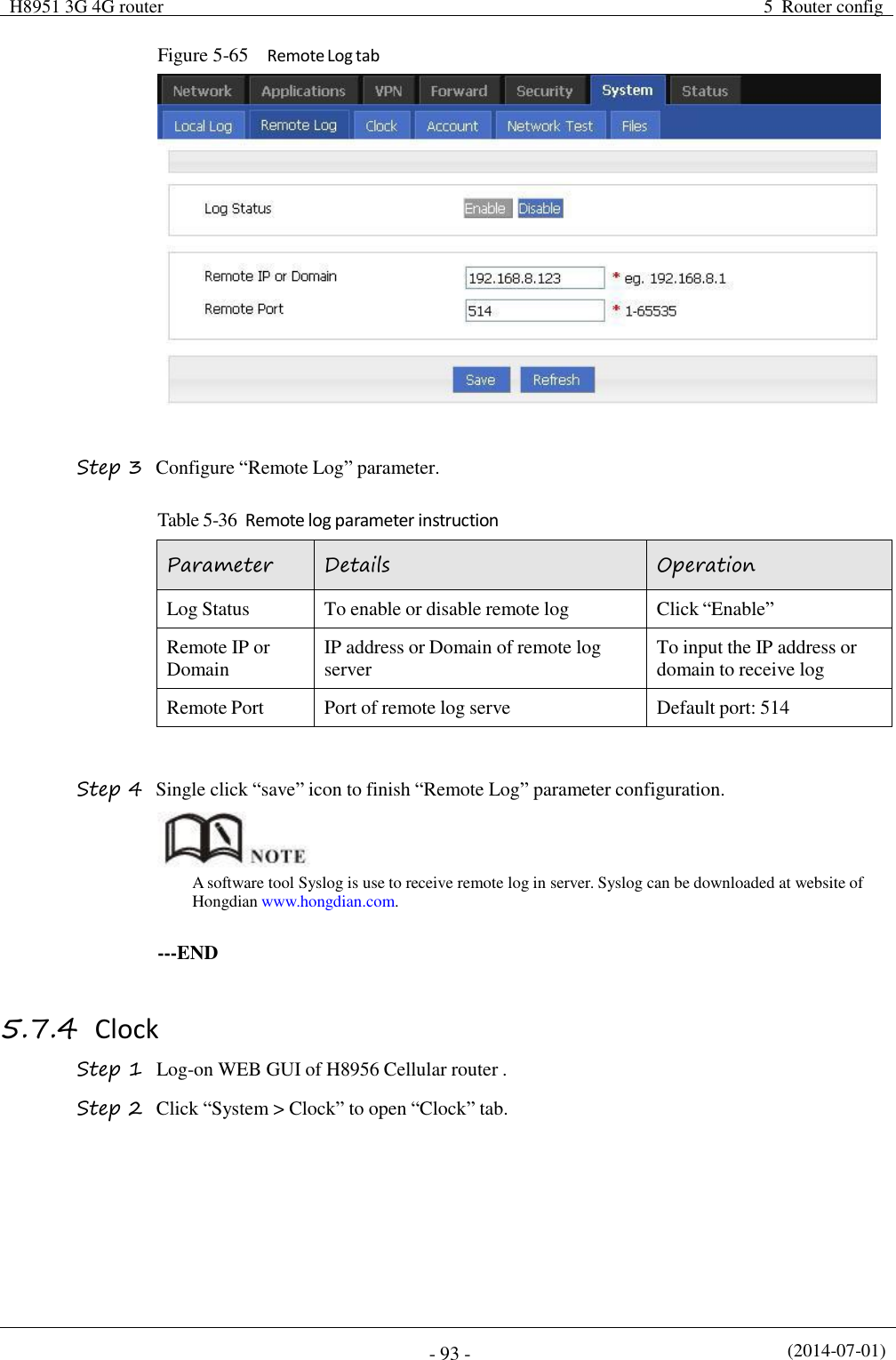
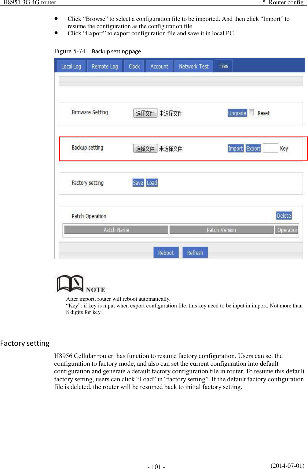
![H8951 3G 4G router 5 Router config (2014-07-01) - 81 - AS Number Used to identify the network (only the routers with the same domain address can exchange routing information) Manual input Value area:[0,65535] When Add Type is “Neighbor”, Neighbor The router can reach in the next hop Manual input Format1: A.B.C.D/Mask When Add Type is “Interface”, Interface Name The interface of the router Dropdown List br0 modem eth1 eth0 Interface Attribute Configure the router interface attribute, include cost and network Click the button to select cost network Cost Configure the cost of the router interface, used to learn routing table Manual input Value area:1-65535 Network Type (when the interface attribute is network) Configure the network type of the router interface Dropdown List broadcast non-broad point-to-multipoint point-to-point Step 5 Single click “save” icon to OSPF route setting. Step 6 Single click “save” icon to finish. OSPF is a link-state (Link-state) routing protocol, commonly used for the same routing domain. Here, the routing domain is an autonomous system, which refers to the routers can switch routing information through a unified network switching or routing protocol routing policy in the AS, all OSPF routers maintains an identical description of the database structure AS, which is stored in the database link status information corresponding routing domain, OSPF router is through this database to calculate its OSPF routing table. As a link-state routing protocol, OSPF link state broadcast data LSA (Link State Advertisement) sent to all routers in an area, which is different from the distance vector routing protocols. Distance vector routing protocol passed some or all rouing information of the routing table to the adjacent routers. ---END](https://usermanual.wiki/Hongdian/H8956/User-Guide-3841899-Page-91.png)