Horizon Hobby AR20300T AR20300T 20Ch PowerSafe Receiver User Manual Users manual
Horizon Hobby, LLC AR20300T 20Ch PowerSafe Receiver Users manual
UserManual.wiki
>
Horizon Hobby
>
AR20300T User Manual
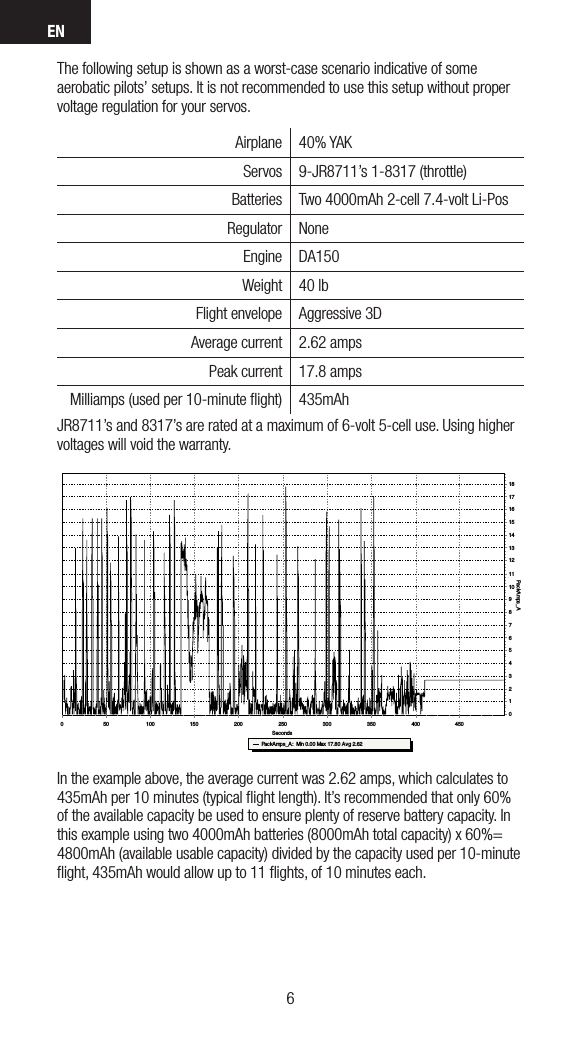
Users manual
Navigation menu
Upload a User Manual
Namespaces
Wiki Guide
HTML
PDF
Info
Views
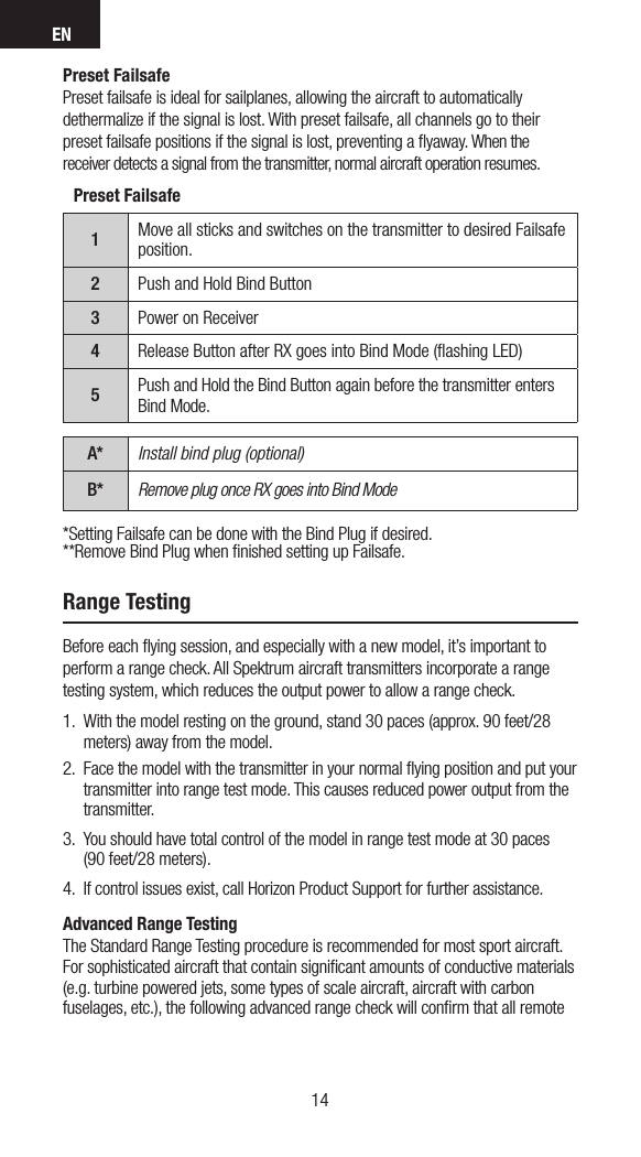
User Manual
Discussion / Help
Navigation