Horizon Hobby QUATTRO J-Line Quattro 4 Channel FM Radio SystemPasr User Manual J line Quattro Manual
Horizon Hobby, LLC J-Line Quattro 4 Channel FM Radio SystemPasr J line Quattro Manual
UserManual.wiki
>
Horizon Hobby
>
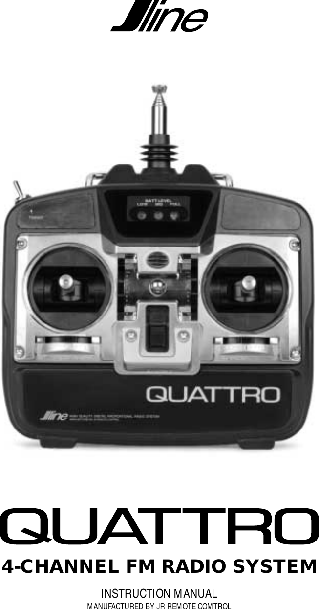
QUATTRO User Manual
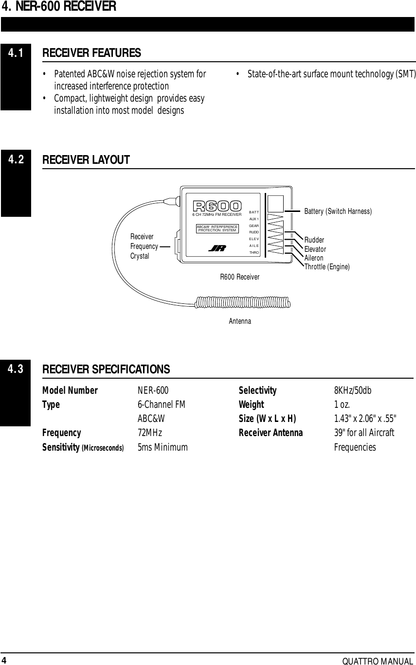
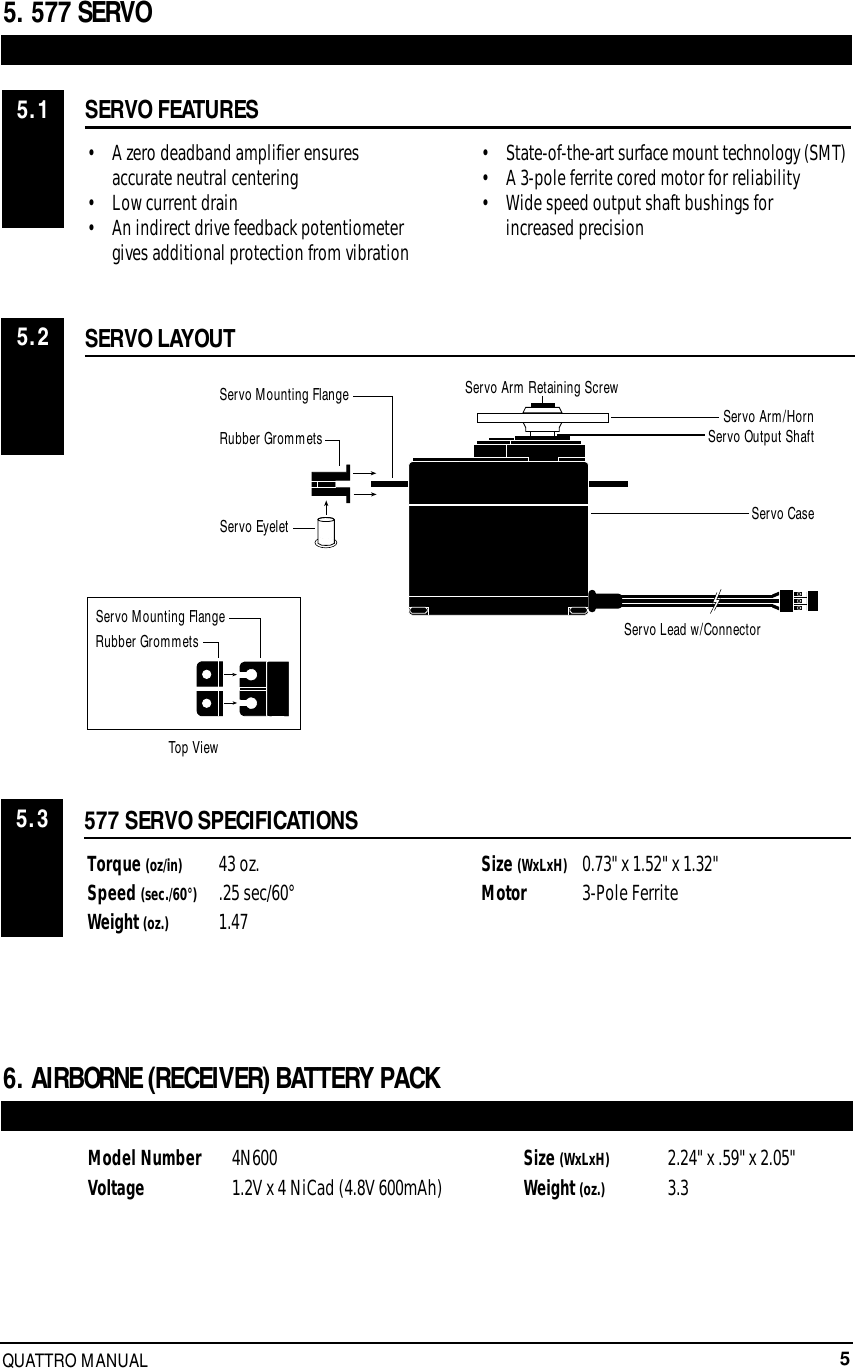
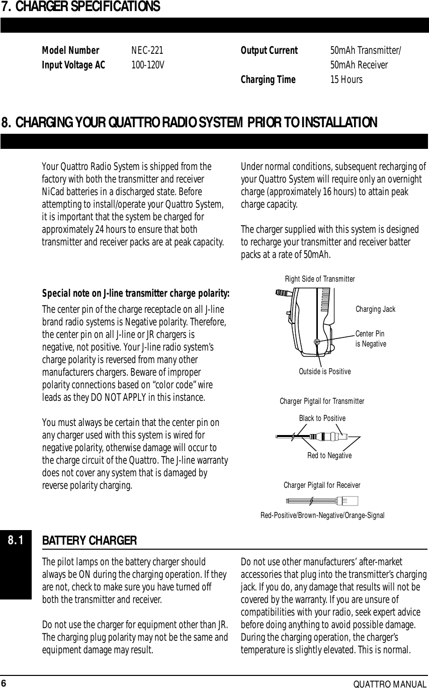
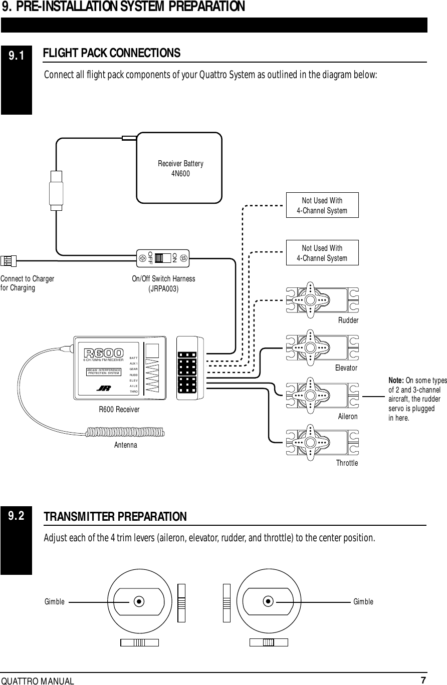
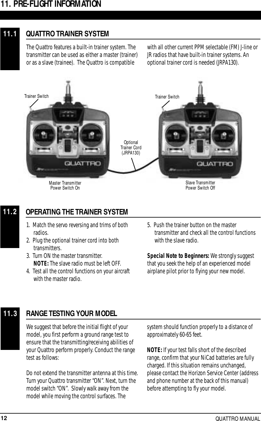
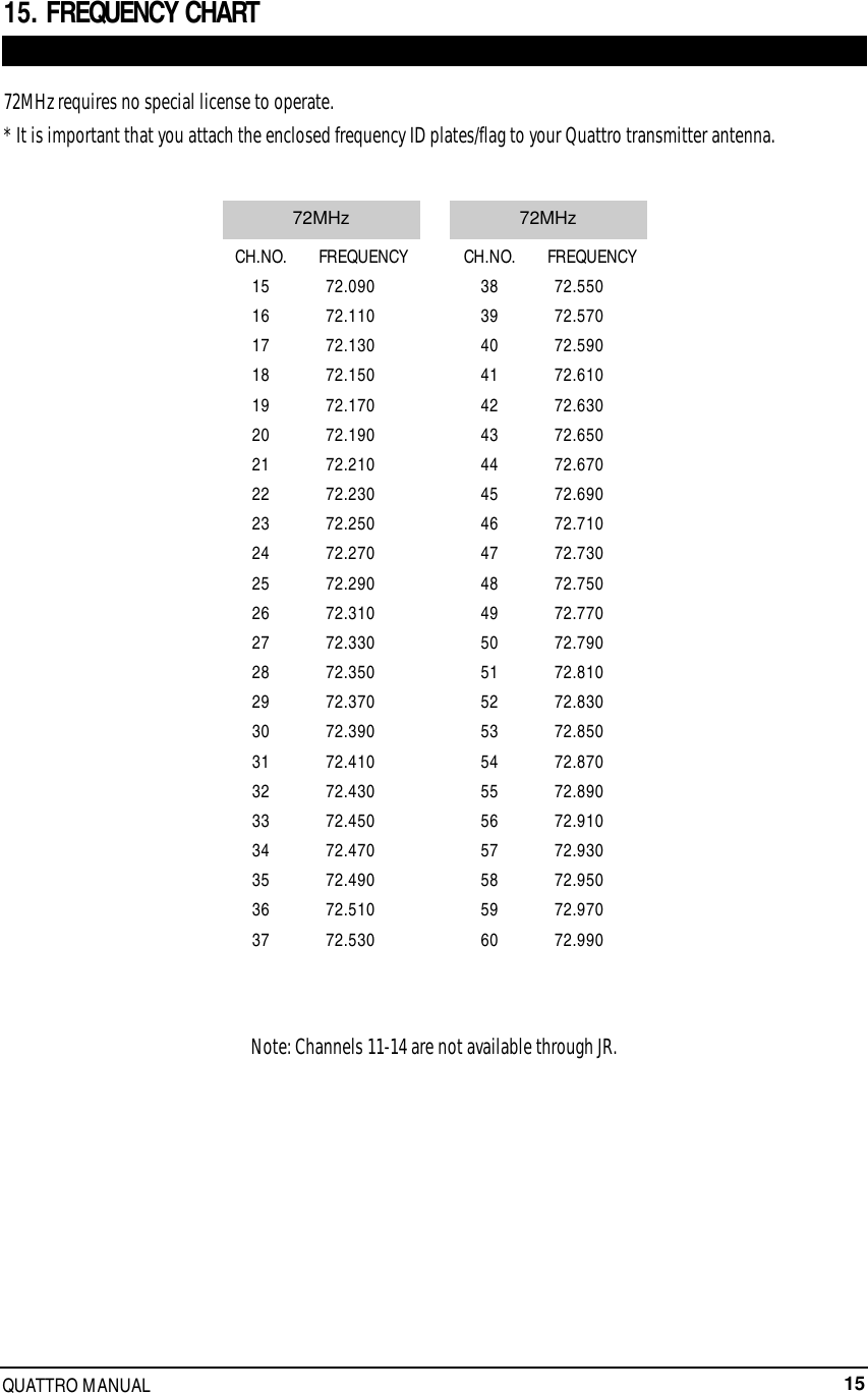
Quattro Manual
Navigation menu
Upload a User Manual
Namespaces
Wiki Guide
HTML
PDF
Info
Views
User Manual
Discussion / Help
Navigation