Horizon Hobby QUATTRO J-Line Quattro 4 Channel FM Radio SystemPasr User Manual J line Quattro Manual
Horizon Hobby, LLC J-Line Quattro 4 Channel FM Radio SystemPasr J line Quattro Manual
Quattro Manual

4-CHANNEL FM RADIO SYSTEM
INSTRUCTION MANUAL
MANUFACTURED BY JR REMOTE COMTROL


1
QUATTRO MANUAL
1. Introduction to the Quattro Radio System. . . . 1
2. System Specifications . . . . . . . . . . . . . . . . . . . . . 2
3. Quattro Transmitter
3.1 Transmitter Features . . . . . . . . . . . . . . . . . . . . 2
3.2 Transmitter Layout . . . . . . . . . . . . . . . . . . . . 2-3
3.3 Transmitter Specifications. . . . . . . . . . . . . . . . 3
3.4 Control Stick Length Adjustment . . . . . . . . . . 3
3.5 Neck Strap Attachment . . . . . . . . . . . . . . . . . . 3
4. NER-600 Receiver
4.1 Receiver Features . . . . . . . . . . . . . . . . . . . . . . . 4
4.2 Receiver Layout . . . . . . . . . . . . . . . . . . . . . . . . 4
4.3 Receiver Specifications . . . . . . . . . . . . . . . . . . 4
5. 577 Servo
5.1 Servo Features . . . . . . . . . . . . . . . . . . . . . . . . . 5
5.2 Servo Layout. . . . . . . . . . . . . . . . . . . . . . . . . . . 5
5.3 577 Servo Specifications . . . . . . . . . . . . . . . . . 5
6. Airborne (Receiver) Battery Pack. . . . . . . . . . . . . 5
7. Charger Specifications. . . . . . . . . . . . . . . . . . . . . . 6
8. Charging Your Quattro Radio System
Prior to Installation
8.1 Battery Charger. . . . . . . . . . . . . . . . . . . . . . . . . 6
TABLE OF CONTENTS
1. INTRODUCTION TO THE J-LINE QUATTRO RADIO SYSTEM
Thank you for purchasing the J-line Quattro 4-Channel
FM Radio System. This unit has been designed to provide
the modeler with a high quality, user-friendly radio
system that can be depended upon for years to come.
It is important that you carefully read this manual before
attempting to operate your Quattro System. Please pay
particular attention to Section 8, Charging Your Quattro
Radio System Prior to Installing.
9. Pre-Installation System Preparation
9.1 Flight Pack Connections. . . . . . . . . . . . . . . . . . 7
9.2 Transmitter Preparation. . . . . . . . . . . . . . . . . . 7
9.3 577 Servo Preparation . . . . . . . . . . . . . . . . . . . 8
9.4 System Check . . . . . . . . . . . . . . . . . . . . . . . . . . 8
10. Flight Pack Installation
10.1 Installation Suggestions . . . . . . . . . . . . . . . . 9
10.2 Servo Reversing . . . . . . . . . . . . . . . . . . . . . . 10
10.3 Setting Reversing Switches . . . . . . . . . . . . . 10
10.4 Adjusting Control Surface Travel. . . . . . . . . 11
11. Pre-Flight Information
11.1 Quattro Trainer System . . . . . . . . . . . . . . . . 12
11.2 Operating the Trainer System . . . . . . . . . . . 12
11.3 Range Testing Your Model . . . . . . . . . . . . . 12
12. General Notes. . . . . . . . . . . . . . . . . . . . . . . . . . . . 13
13. Daily Flight Checks. . . . . . . . . . . . . . . . . . . . . . . . 13
14. Warranty and Service Information
14.1 Warranty Coverage . . . . . . . . . . . . . . . . . . . . 14
14.2 Repair Service Instructions . . . . . . . . . . . . . 14
15. Frequency Chart. . . . . . . . . . . . . . . . . . . . . . . . . . 15
2QUATTRO MANUAL
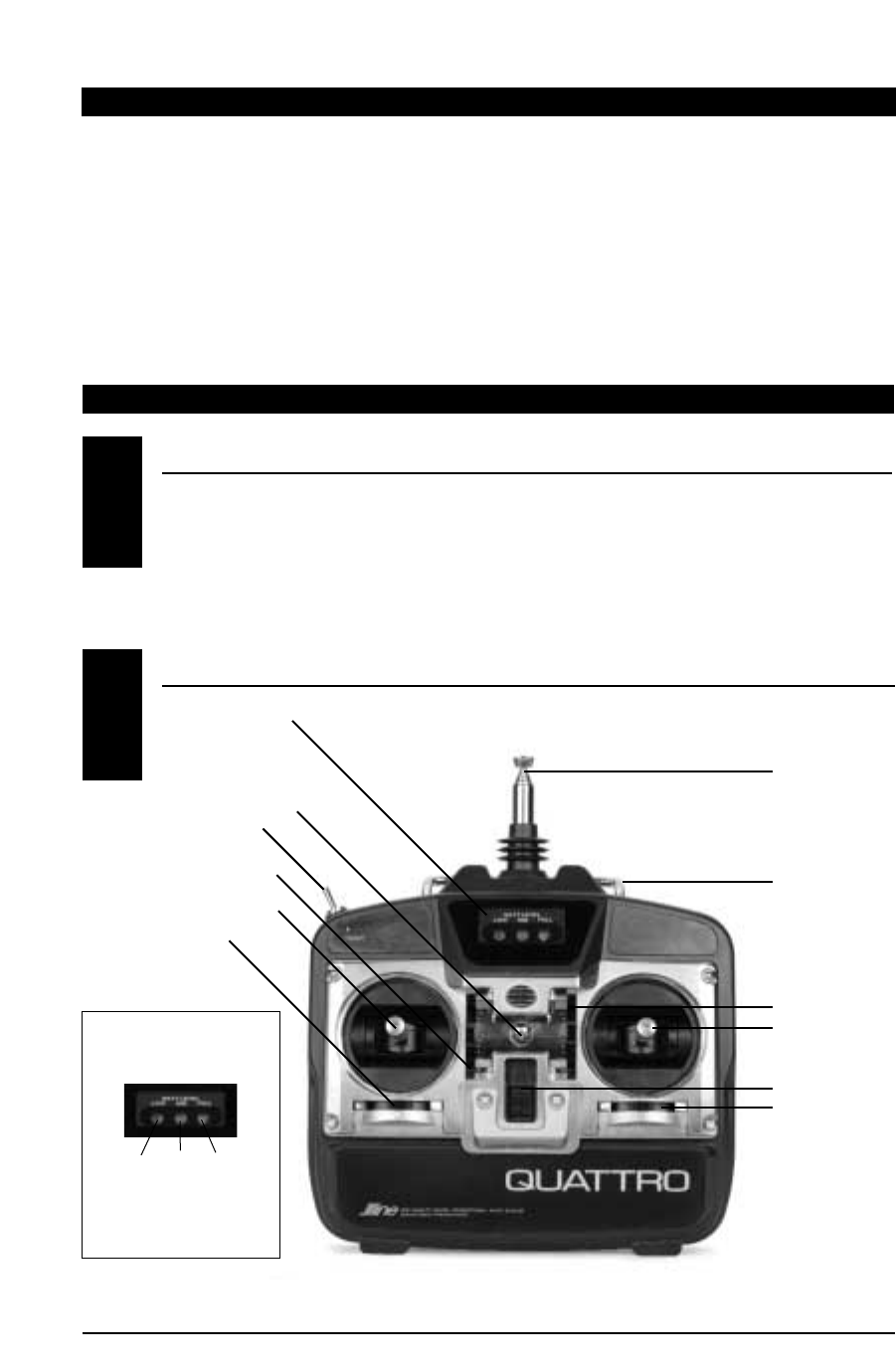
3. QUATTRO TRANSMITTER
TRANSMITTER FEATURES
TRANSMITTER LAYOUT
• Computer-designed, ergonomically styled case
• Servo reversing on all 4 channels (page 12)
• Adjustable control stick length (page 5)
• Trainer system feature compatible with all
current JR radio systems
• Easy-to-read transmitter LED battery
voltage indicator
• 9.6V 600mAh NiCad transmitter battery pack
• Power output approximately 750mw
System Name Quattro
Transmitter Body NET-E104
Receiver NER-600
Charger NEC-221
Airborne Battery 4.8V 600mAh NiCad
Servos NES-577 x 4
Accessories Mini Switch
Servo Accessories
12" Aileron Extension
Instruction Manual
2. SYSTEM SPECIFICATIONS
3.1
3.2
Transmitter LED Battery
Voltage Indicator
Neck Strap Attachment
(JRPA023 Optional JR Neck Strap)
Throttle/Rudder Stick
Trainer Button
Transmitter Antenna
Carrying Bar
Elevator Trim
Aileron Trim
Elevator/Aileron Stick
Power Switch
Throttle Trim
Rudder Trim
IMPORTANT
Transmiter Battery Voltage
LED Indicator
Low: Do not fly
Mid: System should be recharged
Full: System OK to fly
Low Mid Full
Red Orange Green
3
QUATTRO MANUAL
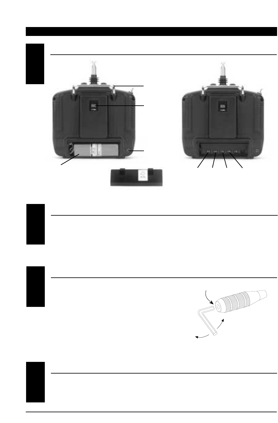
TRANSMITTER LAYOUT
3.2
TRANSMITTER SPECIFICATIONS
CONTROL STICK LENGTH ADJUSTMENT
NECK STRAP ATTACHMENT
Model Number NET-E104
RF 72MHz
Modulation PPM (FM)
There is an eye hook on the front of the transmitter
for attaching an optional neck strap (JRPA023). The
eye hook is precisely positioned (see Section 3.2)
so that the transmitter will be perfectly balanced
when a neck strap is used.
To adjust the control stick length, use a 2mm Allen
wrench to unlock the set screw located inside the
end of the control stick. Turn the set screw
counterclockwise to loosen it, then turn the knurled
portion of the stick to adjust the length.
Counterclockwise will lengthen the stick and
clockwise will shorten it. After the control stick(s)
has been adjusted to suit your flying style, tighten
the set screw.
LOOSEN
TIGHTEN
SET SCREW
3.3
3.4
3.5
9.6V 600mAh NiCad
Transmitter Battery Pack
Trainer Cord Jack
Transmitter
Frequency Crystal
Set Screw
Loosen
Tighten
RudderElevator
Aileron
Throttle
Carrying Bar
Servo Reversing Switches
(Located behind Transmitter Battery Pack)
Output Power Approximately 750mw
Current Drain 150mAh
Power Source 1.2V x 8 NiCad (9.6V 600mAh)
Output Pulse 1.0 –2.0ms
Back Cover
4QUATTRO MANUAL
RECEIVER SPECIFICATIONS
Model Number NER-600
Type 6-Channel FM
ABC&W
Frequency 72MHz
Sensitivity
(Microseconds
)
5ms Minimum
Selectivity 8KHz/50db
Weight 1 oz.
Size (W x L x H) 1.43" x 2.06" x .55"
Receiver Antenna 39" for all Aircraft
Frequencies
RECEIVER FEATURES
• Patented ABC&W noise rejection system for
increased interference protection
• Compact, lightweight design provides easy
installation into most model designs
• State-of-the-art surface mount technology (SMT)
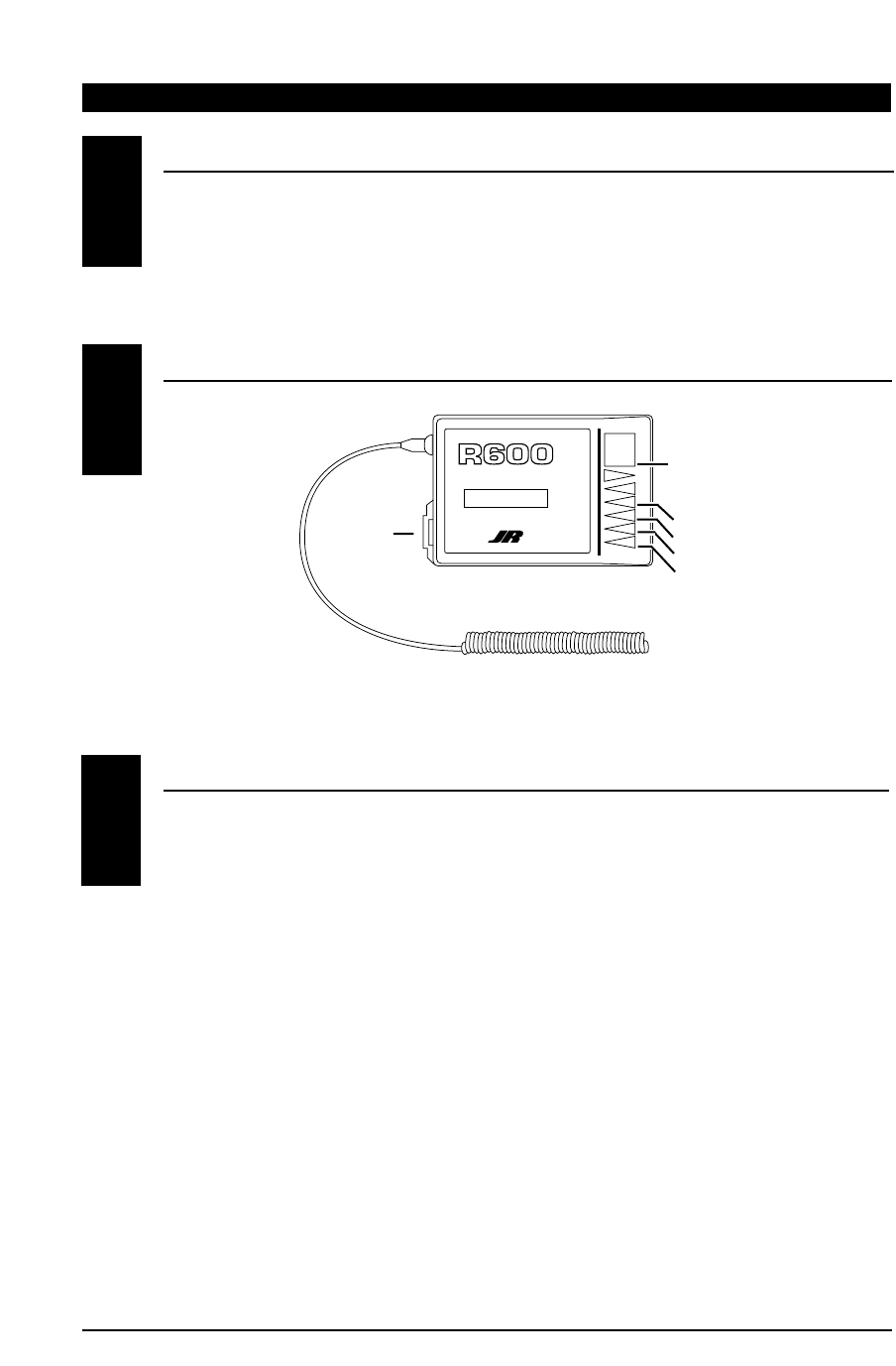
RECEIVER LAYOUT
4. NER-600 RECEIVER
BATT
AUX 1
GEAR
RUDD
ELEV
AILE
THRO
6 CH 72MHz FM RECEIVER
ABC&W INTERFERENCE
PROTECTION SYSTEM
4.1
4.2
4.3
Antenna
R600 Receiver
Battery (Switch Harness)
Rudder
Receiver
Frequency
Crystal Elevator
Aileron
Throttle (Engine)
5
QUATTRO MANUAL
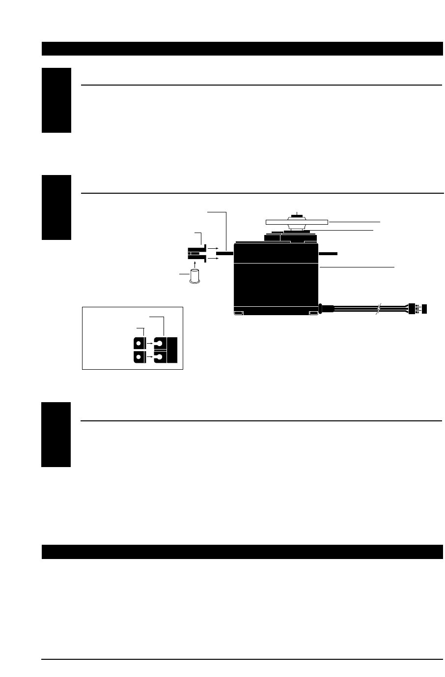
5. 577 SERVO
SERVO FEATURES
• A zero deadband amplifier ensures
accurate neutral centering
• Low current drain
• An indirect drive feedback potentiometer
gives additional protection from vibration
• State-of-the-art surface mount technology (SMT)
• A 3-pole ferrite cored motor for reliability
• Wide speed output shaft bushings for
increased precision
577 SERVO SPECIFICATIONS
Torque (oz/in) 43 oz.
Speed (sec./60°) .25 sec/60°
Weight (oz.) 1.47
Size (WxLxH) 0.73" x 1.52" x 1.32"
Motor 3-Pole Ferrite
SERVO LAYOUT
5.1
5.2
5.3
6. AIRBORNE (RECEIVER) BATTERY PACK
Model Number 4N600
Voltage 1.2V x 4 NiCad (4.8V 600mAh) Size (WxLxH) 2.24" x .59" x 2.05"
Weight (oz.) 3.3
Servo Mounting Flange
Rubber Grommets
Rubber Grommets
Servo Case
Servo Lead w/Connector
Servo Output Shaft
Servo Mounting Flange
Servo Arm/Horn
Servo Arm Retaining Screw
Servo Eyelet
Top View
6QUATTRO MANUAL
BATTERY CHARGER
The pilot lamps on the battery charger should
always be ON during the charging operation. If they
are not, check to make sure you have turned off
both the transmitter and receiver.
Do not use the charger for equipment other than JR.
The charging plug polarity may not be the same and
equipment damage may result.
Do not use other manufacturers’ after-market
accessories that plug into the transmitter’s charging
jack. If you do, any damage that results will not be
covered by the warranty. If you are unsure of
compatibilities with your radio, seek expert advice
before doing anything to avoid possible damage.
During the charging operation, the charger’s
temperature is slightly elevated. This is normal.
Special note on J-line transmitter charge polarity:
8. CHARGING YOUR QUATTRO RADIO SYSTEM PRIOR TO INSTALLATION
Your Quattro Radio System is shipped from the
factory with both the transmitter and receiver
NiCad batteries in a discharged state. Before
attempting to install/operate your Quattro System,
it is important that the system be charged for
approximately 24 hours to ensure that both
transmitter and receiver packs are at peak capacity.
Under normal conditions, subsequent recharging of
your Quattro System will require only an overnight
charge (approximately 16 hours) to attain peak
charge capacity.
The charger supplied with this system is designed
to recharge your transmitter and receiver batter
packs at a rate of 50mAh.
The center pin of the charge receptacle on all J-line
brand radio systems is Negative polarity. Therefore,
the center pin on all J-line or JR chargers is
negative, not positive. Your J-line radio system’s
charge polarity is reversed from many other
manufacturers chargers. Beware of improper
polarity connections based on “color code” wire
leads as they DO NOT APPLY in this instance.
You must always be certain that the center pin on
any charger used with this system is wired for
negative polarity, otherwise damage will occur to
the charge circuit of the Quattro. The J-line warranty
does not cover any system that is damaged by
reverse polarity charging.
7. CHARGER SPECIFICATIONS
Model Number NEC-221
Input Voltage AC 100-120V Output Current 50mAh Transmitter/
50mAh Receiver
Charging Time 15 Hours
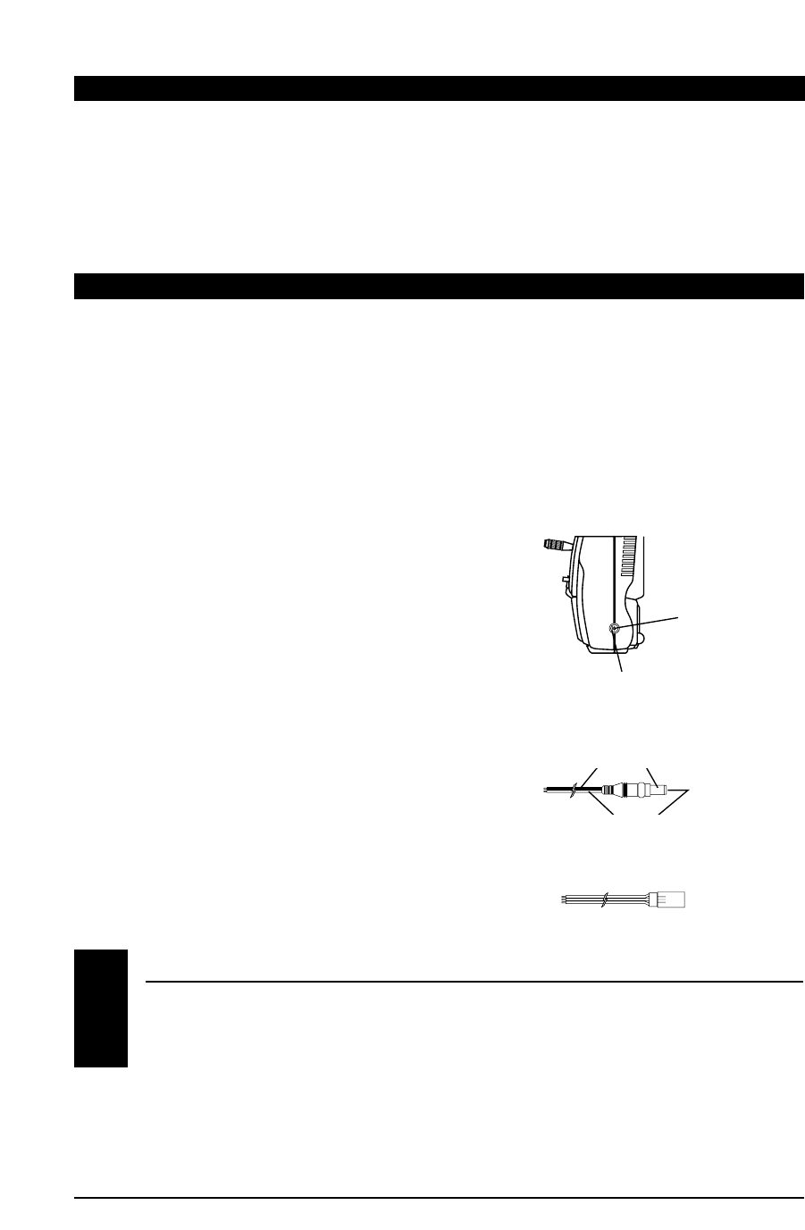
8.1
Right Side of Transmitter
Charging Jack
Center Pin
is Negative
Outside is Positive
Charger Pigtail for Transmitter
Black to Positive
Red to Negative
Charger Pigtail for Receiver
Red-Positive/Brown-Negative/Orange-Signal
7
QUATTRO MANUAL
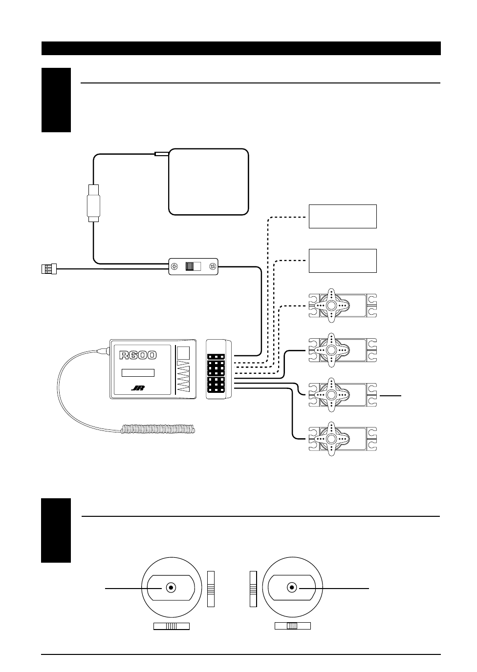
FLIGHT PACK CONNECTIONS
Connect all flight pack components of your Quattro System as outlined in the diagram below:
9. PRE-INSTALLATION SYSTEM PREPARATION
ON
OFF
BATT
AUX 1
GEAR
RUDD
ELEV
AILE
THRO
6 CH 72MHz FM RECEIVER
ABC&W INTERFERENCE
PROTECTION SYSTEM
9.1
Receiver Battery
4N600
Not Used With
4-Channel System
Not Used With
4-Channel System
Rudder
Elevator
Aileron
Throttle
Note: On some types
of 2 and 3-channel
aircraft, the rudder
servo is plugged
in here.
On/Off Switch Harness
(JRPA003)
Connect to Charger
for Charging
R600 Receiver
Antenna
TRANSMITTER PREPARATION
Adjust each of the 4 trim levers (aileron, elevator, rudder, and throttle) to the center position.
9.2
Gimble Gimble
8QUATTRO MANUAL
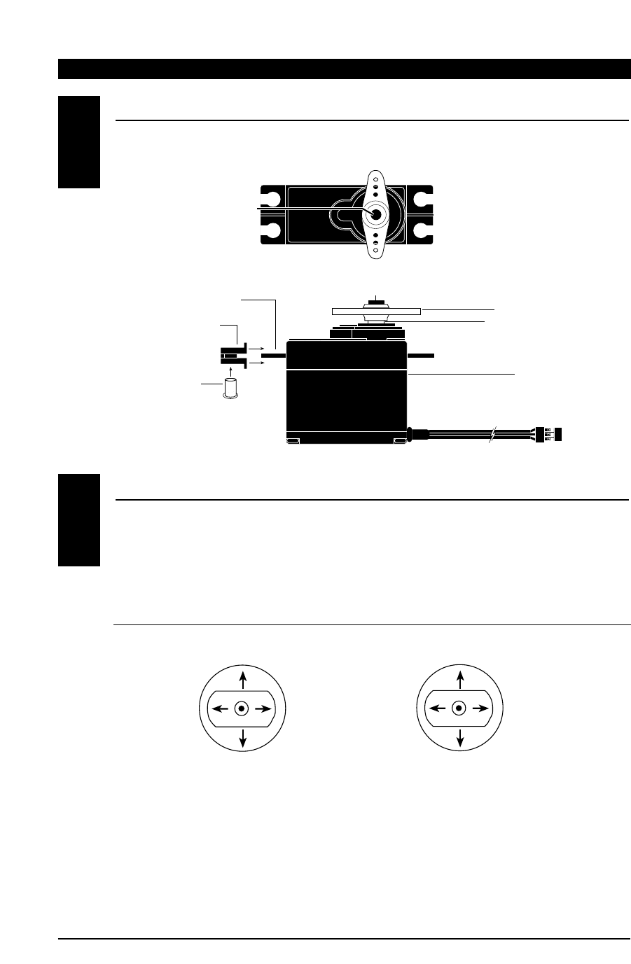
577 SERVO PREPARATION
Using a Phillips screwdriver, remove the servo arm retaining screws from each of the 577 servos as shown
in Figure 1. Next, install 4 servo grommets and 4 servo eyelets to each 577 servo as shown in Figure 2.
SYSTEM CHECK
Slide the power ON/OFF switch on your Quattro
Transmitter to the “ON” position.
Next, slide the ON/OFF switch on your flight pack
switch harness to the “ON” position.
By moving each of the two transmitter sticks in a
fore-aft, left-right motion, the corresponding
throttle, rudder, elevator, and aileron (optional)
servo arm/wheel will rotate. Please refer to the
transmitter stick function chart below.
With the system still activated (ON), move the
throttle stick to the neutral (center) position.
Double check to be sure that the four transmitter
trim levers are still in their neutral position.
Next, with the power still activated to the
transmitter and flight pack, remove the servo
arm/horn from each of the 577 servos. Then, turn
the power “OFF” to the flight pack first, then the
transmitter. By doing this, the 577 servos will be left
in their neutral position, and they are now ready to
be installed into your model.
NOTE: Save the servo arms/horns; they will be
reattached to the servos after installation.
9.3
9.4
Throttle
Throttle
Rudder
Elevator
Elevator
Aileron
(w/optional servo)
Aileron
(w/optional servo)
Rudder
Rubber Grommet
Servo Case
Servo Lead w/Connector
Servo Output Shaft
Servo Mounting Flange Servo Arm/Horn
Servo Arm Retaining Screw
Servo Eyelet
Figure 2
Figure 1
Servo Arm Retaining Screw
(Phillips Head).
9
QUATTRO MANUAL
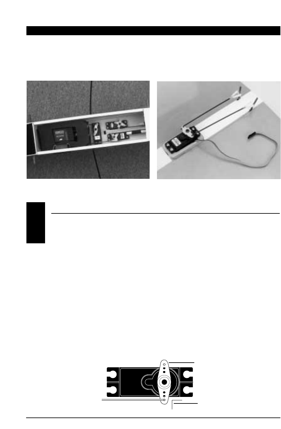
INSTALLATION SUGGESTIONS
Flight pack installation varies greatly from one
model to another. For your convenience, we have
included the photograph below outlining a typical
flight pack installation in a standard 4-channel
trainer type model airplane.
It is important to correctly install the radio system
in your model. Please read and carefully follow the
suggestions listed below:
1. For added protection, wrap the receiver and the
receiver NiCad in foam rubber that is at least
1/4" thick.
2. Run the receiver antenna through the fuselage
and make sure it is fully extended. Never cut or
bundle your receiver antenna — this will
decrease range and performance.
3. Rubber servo grommets are included with your
radio system and should be installed in the
servo flanges. The servos should then be
mounted on either hardwood rails or a plywood
tray with the mounting screws provided. Do not
overtighten the mounting screws. The flange of
the brass eyelets should face down (toward the
wood). See Section 9.3.
4. With the servo at neutral, install the required
servo arm/horn exactly 90° to the servo
case as shown in the diagram below.
5. Before installing the servo output arms, make
sure the servo is in its neutral position.
6. All servos must be able to move freely over the
full range of their travel. Make sure the linkages
do not impede servo travel. A stalled servo will
drain the battery pack within a few minutes.
7. In the case of gas-powered model aircraft,
mount the receiver power switch on the side of
the fuselage opposite the muffler to protect the
switch from exhaust residue. With other types of
models, mount the switch in the most
convenient place. Make sure the switch operates
freely and is capable of traveling its full distance.
10. FLIGHT PACK INSTALLATION
10.1
Servo Horn
Fuselage Servo, Receiver, Battery Installation Aileron (Wing) Servo Installation
Control Rod 90° with Servo at
Neutral/Center Position
10 QUATTRO MANUAL
SERVO REVERSING
After radio installation, it is imperative that the
proper servo/control system direction be
established. Servo reversing allows you to alter the
direction of the servo/control surface movement to
match the direction of the transmitter stick. Please
refer to the chart in the following section below to
determine the proper control surface direction.
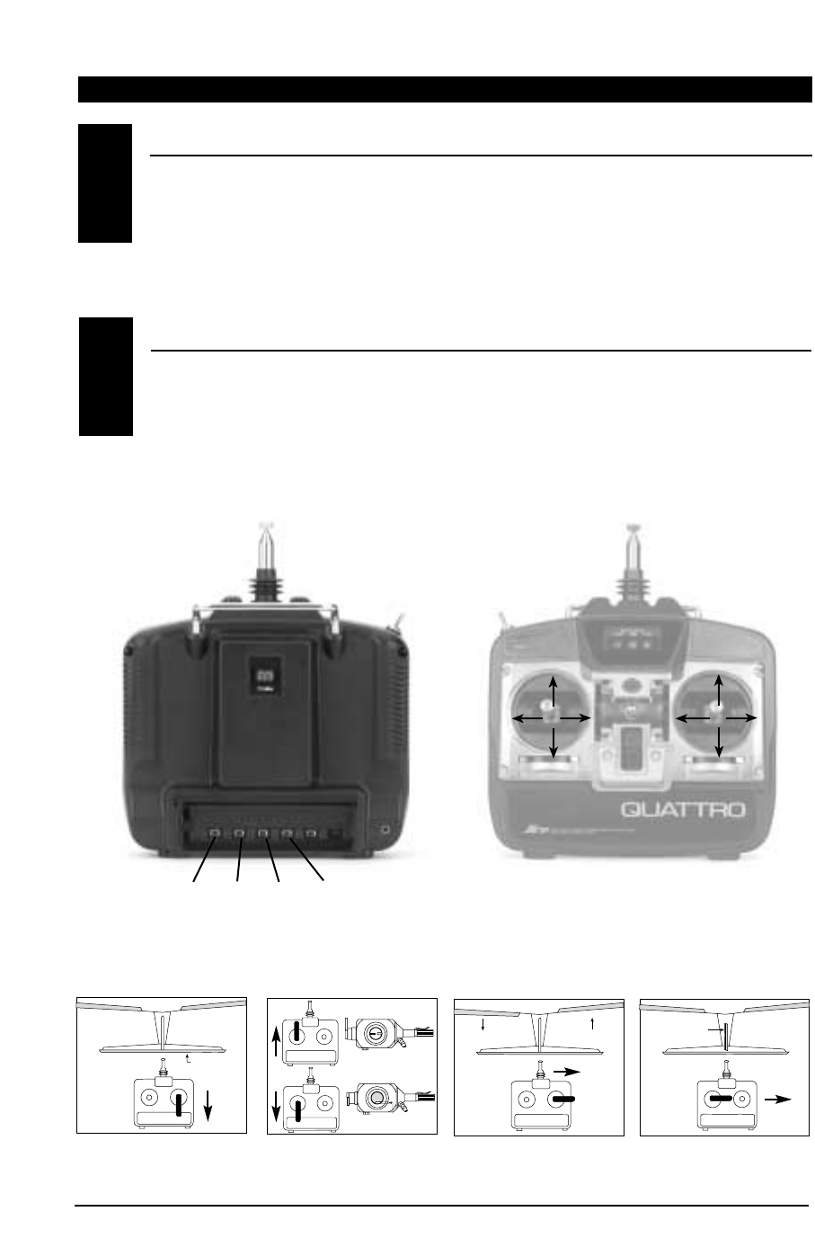
SETTING REVERSING SWITCHES
1. Connect all control linkages and check to see
that all servos move freely.
2. While standing directly behind the airplane, go
through the steps shown in the charts below to
check proper direction of the control surface.
3. Using the Servo Reversing Switches located
behind the Transmitter Battery Pack, adjust the
direction of each servo for proper operation.
10.2
10.3
Left
Rudder
Full Throttle Down Elevator
Right
Aileron
Up Elevator
Left
Aileron
Idle
Right
Rudder
Full Throttle
Left
Rudder
Idle
Right
Rudder
Down Elevator
Right
Aileron
Left
Aileron
Up Elevator
RudderElevator
Aileron
Throttle
Servo Reversing Switches
(Located behind Transmitter Battery Pack)
(Mode II Transmitter Shown)
Carburetor
Low (Idle)
High (Full)
1/16"
Elevator
Aileron Up
Aileron Down Rudder
Up Elevator Throttle Right Aileron Right Rudder
11
QUATTRO MANUAL
The final step in your flight pack installation will be
to determine the amount each control surface will
move on your model at full transmitter stick
deflection. Please refer to your aircraft’s instruction
manual for suggested travel limits.
It is possible to increase/decrease the amount that
your control surface moves at full stick deflection
by mechanical adjustments.
It is imperative that the servo does not attempt to
push/pull the control surface past its mechanical
limits. This condition is called “binding.” When a
servo moves a control surface into a “binding”
position, the servo itself then becomes “stalled,”
unable to reach its full deflection. This condition is
both harmful to your control linkage and to your
servo. This “stalled” condition will also force the
servo to drain power more quickly from your flight
pack battery, thereby reducing your usable flying
time. Fortunately, servo “stalling” is usually easy to
detect by either a “buzzing” or “humming” sound
which comes from the stalled servo.
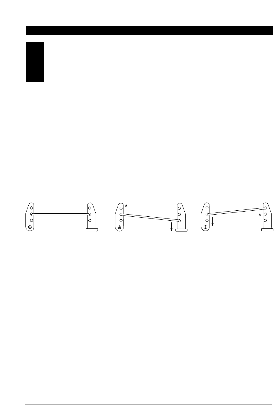
The following diagram is designed to help clarify
how to increase or decrease control surface travel
mechanically to eliminate control surface “binding”
and servo “stalling.”
To increase control surface travel, select a linkage
attachment point further outward on the servo arm
or further inward on the control horn closer to the
control surface (Figure 2).
To reduce control surface travel, select the linkage
attachment point close to the center of the servo
area or further out on the control horn on the
control surface (Figure 3).
Quite simply, by moving the control rod in on the
servo arm/wheel, control surface travel will be
reduced, and by moving the control rod out on the
servo arm, the control surface travel will be
increased. The opposite holds true for the control
surface arm (horn) as well. You may also use any
combination of these positions to achieve proper
control surface/servo travel.
NOTE: Once the appropriate servo arm/wheel and
control rod location has been established, secure
the servo arm to the servo output shaft using the
original servo horn screw.
Control Rod
Figure 1 Normal (Linear)
Linkage Set Up Figure 2 Increased Control
Surface Movement Figure 3 Reduced Control
Surface Movement
Servo Arm Control Surface
Arm (Horn) Control Surface
Arm (Horn) Control Surface
Arm (Horn)
Servo Arm Servo Arm
Control Rod Control Rod
ADJUSTING CONTROL SURFACE TRAVEL
10.4
12 QUATTRO MANUAL
11. PRE-FLIGHT INFORMATION
QUATTRO TRAINER SYSTEM
The Quattro features a built-in trainer system. The
transmitter can be used as either a master (trainer)
or as a slave (trainee). The Quattro is compatible
with all other current PPM selectable (FM) J-line or
JR radios that have built-in trainer systems. An
optional trainer cord is needed (JRPA130).
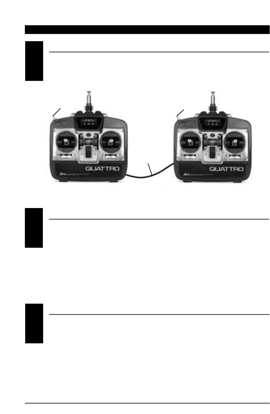
OPERATING THE TRAINER SYSTEM
1. Match the servo reversing and trims of both
radios.
2. Plug the optional trainer cord into both
transmitters.
3. Turn ON the master transmitter.
NOTE: The slave radio must be left OFF.
4. Test all the control functions on your aircraft
with the master radio.
5. Push the trainer button on the master
transmitter and check all the control functions
with the slave radio.
Special Note to Beginners: We strongly suggest
that you seek the help of an experienced model
airplane pilot prior to flying your new model.
RANGE TESTING YOUR MODEL
We suggest that before the initial flight of your
model, you first perform a ground range test to
ensure that the transmitting/receiving abilities of
your Quattro perform properly. Conduct the range
test as follows:
Do not extend the transmitter antenna at this time.
Turn your Quattro transmitter “ON”. Next, turn the
model switch “ON”. Slowly walk away from the
model while moving the control surfaces. The
system should function properly to a distance of
approximately 60-65 feet.
NOTE: If your test falls short of the described
range, confirm that your NiCad batteries are fully
charged. If this situation remains unchanged,
please contact the Horizon Service Center (address
and phone number at the back of this manual)
before attempting to fly your model.
11.1
11.2
11.3
Trainer Switch
Slave Transmitter
Power Switch Off
Master Transmitter
Power Switch On
Trainer Switch
Optional
Trainer Cord
(JRPA130)

13
QUATTRO MANUAL
12. GENERAL NOTES
13. DAILY FLIGHT CHECKS
Radio controlled models are a great source of
pleasure. Unfortunately, they can also pose a
potential hazard if not maintained and operated
properly. It is imperative that you install your radio
control system correctly. Additionally, your level of
piloting competency must be high enough to
ensure that you are able to control your aircraft
under all conditions. If you are a newcomer to radio
controlled flying, please seek help from an
experience pilot or your local hobby shop.
Safety Do’s and Don’ts
• Ensure that your batteries have been properly
charged prior to initial flight.
• Keep track of the time that the system is turned
on so that you will have an idea of how long you
can safely operate your system.
• Perform a ground range check prior to the initial
flight of the day. See the “Daily Flight Checks”
section for information on how to do so.
• Check all control surfaces prior to each takeoff.
• Use frequency flags.
• Do not fly your model near spectators, parking
areas, or at any other area that could result in
injury to people or damage of property.
• Do not fly during adverse weather conditions.
Poor visibility can cause disorientation and loss
of control of your aircraft. Strong winds can
cause similar problems.
• Do not fly unless your frequency is clear.
Warning: Only one transmitter at a time can
operate on a given frequency. If you turn on your
transmitter while someone else is operating a
model on your frequency, both pilots will lose
control of their models. Only one person can
use a given frequency at a time. It does not
matter if it is AM, FM or PCM — only one
frequency at a time.
• Do not point the transmitter antenna directly
toward the model. The radiation pattern from
the tip of the antenna is inherently low.
• Do not take chances. If at any time during flight
you observe any erratic or abnormal operation,
land immediately, and do not resume flight
until the cause of the problem has been
ascertained and corrected.
1. Check the battery voltage on both the
transmitter and the receiver battery packs. Don’t
fly below 9.0 volts on the transmitter or below
4.7 volts on the receiver. To do so can cause a
crash of your aircraft.
NOTE: When you check the receiver battery, be
sure that you have polarities correct on your
expanded scale voltmeter (optional).
2. Check all hardware (linkages, screws, nuts,
bolts) prior to each day’s flight. Be sure that
binding does not occur and that everything is
properly secured.
3. Ensure that all surfaces are moving in the
proper manner.
4. Perform the following ground range check
before each day’s flying session:
• Do not extend the transmitter antenna at this
time. Turn the transmitter “ON.”
• Turn the model “ON.”
• Slowly walk away from the model while moving
the control surfaces. The aircraft should
function properly at a distance of 60-75 feet.
5. Ensure that all trim levers are in the proper
location.
6. Check to be sure that all servo pigtails and
switch harness plugs are secure in the receiver.
Also, make sure that the switch harness moves
completely in both directions.

14 QUATTRO MANUAL
14. WARRANTY AND SERVICE INFORMATION
WARRANTY COVERAGE
REPAIR SERVICE INSTRUCTIONS
Your new equipment is warranted to the original
purchaser against manufacturer defects in material
and workmanship for one year from the date of
purchase. During this period, Horizon Service
Center will repair or replace, at our discretion, any
component that is found to be factory defective at
no cost to the purchaser. This warranty is limited to
the original purchaser and is not transferable.
This warranty does not apply to any unit which has
been improperly installed, mishandled, abused, or
damaged in a crash, or to any unit which has been
repaired or altered by any unauthorized agencies.
Under no circumstances will the buyer be entitled
to consequential or incidental damages. This
limited warranty gives you specific legal rights; you
also have other rights which may vary from state to
state. As with all fine electronic equipment, do not
subject your unit to extreme temperatures,
humidity or moisture. Do not leave it in direct
sunlight for long periods of time.
In the event that your equipment needs service,
please follow the instructions listed below:
1. Check all ON/OFF switches to be sure they are
off. This will speed the repair process of checking
battery condition.
2. Return your system components only
(transmitter, receiver, servos, etc.) Do not return
your system installed in a model car, boat,
plane, etc.
3. Use the original carton/packaging (molded foam
container), or equivalent, to ship your unit. Do
not use the carton itself as a shipping carton;
you should package the equipment carton within
a sturdy shipping container using additional
packing material to safeguard against damage
during transit. Include complete name and
address inside the carton, as well as clearly
writing it on the outer label/return address
area. Ship your equipment fully insured and
prepaid. Horizon Service Center is not
responsible for any damages incurred
during shipping.
4. Include detailed information explaining your
operation of the equipment and problem(s)
encountered. Provide an itemized list of
equipment enclosed and identify any particular
area/function which may better assist our
technicians in addressing your concerns. Date
your correspondence, and include your name,
mailing address, and a phone number where
you can be reached during the business day.
5. Warranty Repairs. To receive warranty service
you must include a legible photocopy of your
original dated sales receipt to verify your proof-
of-purchase date. Providing that warranty
conditions have been met, your radio will be
repaired without charge.
6. Normal Non-Warranty Repairs. Should your
repair cost exceed 50% of the retail purchase
cost, you will be provided with an estimate
advising you of your options.
Within your letter, advise us of the payment
method you prefer to use. Horizon Service Center
accepts VISA or MasterCard. Please include your
card number and expiration date.
Mail your system to:
Horizon Service Center
4105 Fieldstone Road
Champaign, Illinois 61822
(217) 355-9511
14.1
14.2

15
QUATTRO MANUAL
15. FREQUENCY CHART
72MHz requires no special license to operate.
* It is important that you attach the enclosed frequency ID plates/flag to your Quattro transmitter antenna.
CH.NO. FREQUENCY
15 72.090
16 72.110
17 72.130
18 72.150
19 72.170
20 72.190
21 72.210
22 72.230
23 72.250
24 72.270
25 72.290
26 72.310
27 72.330
28 72.350
29 72.370
30 72.390
31 72.410
32 72.430
33 72.450
34 72.470
35 72.490
36 72.510
37 72.530
CH.NO. FREQUENCY
38 72.550
39 72.570
40 72.590
41 72.610
42 72.630
43 72.650
44 72.670
45 72.690
46 72.710
47 72.730
48 72.750
49 72.770
50 72.790
51 72.810
52 72.830
53 72.850
54 72.870
55 72.890
56 72.910
57 72.930
58 72.950
59 72.970
60 72.990
72MHz 72MHz
Note: Channels 11-14 are not available through JR.

16 QUATTRO MANUAL
NOTES


DISTRIBUTED EXCLUSIVELY BY HORIZON HOBBY, INC. CHAMPAIGN, IL 61822
www.horizonhobby.com
MANUFACTURED BY JR REMOTE COMTROL