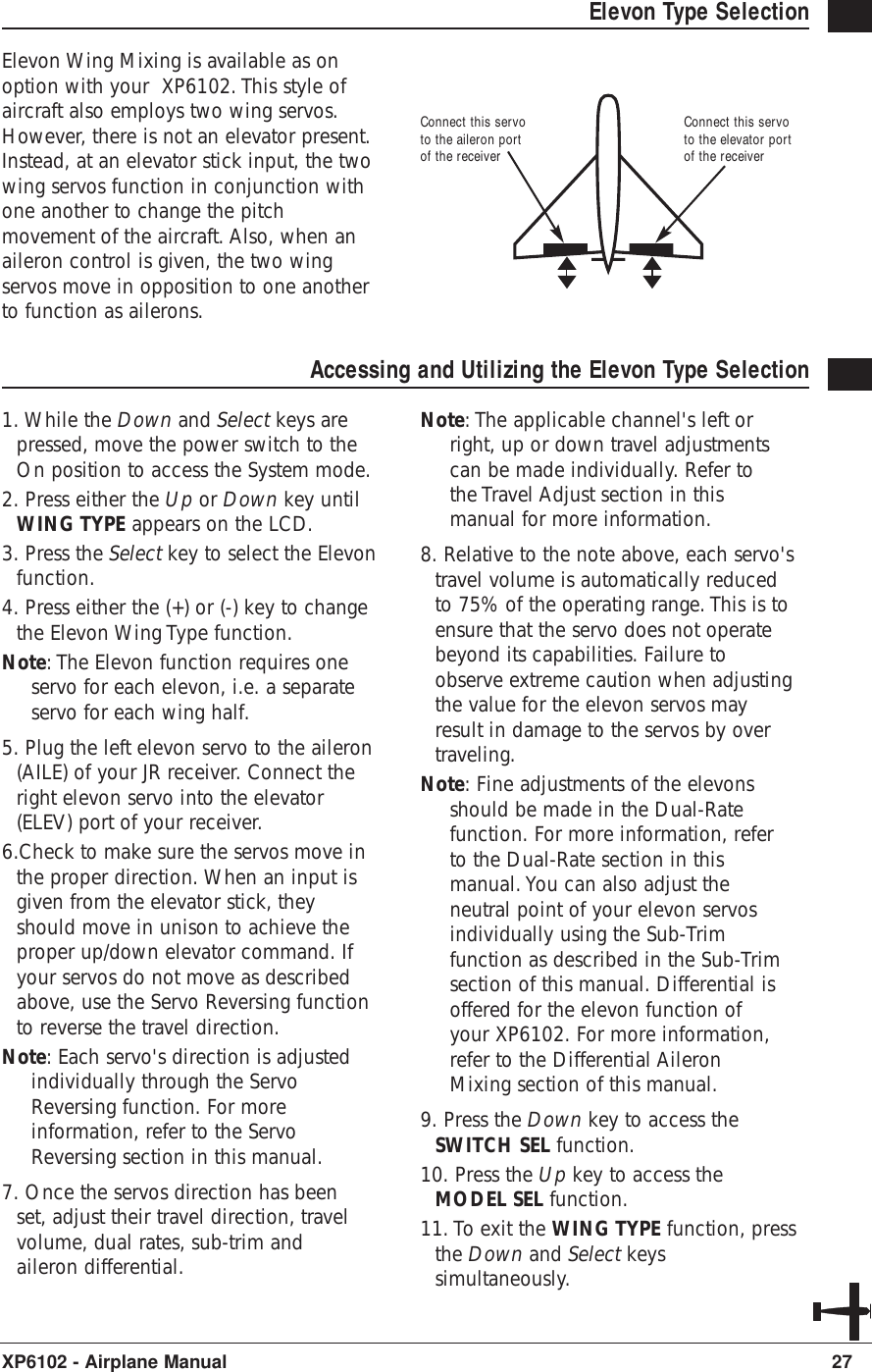
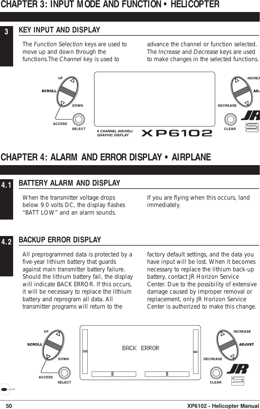
Horizon Hobby XP6102 JR XP6102 FM 6 channel radio system User Manual XP6102 Section 1
Horizon Hobby, LLC JR XP6102 FM 6 channel radio system XP6102 Section 1
UserManual.wiki
>
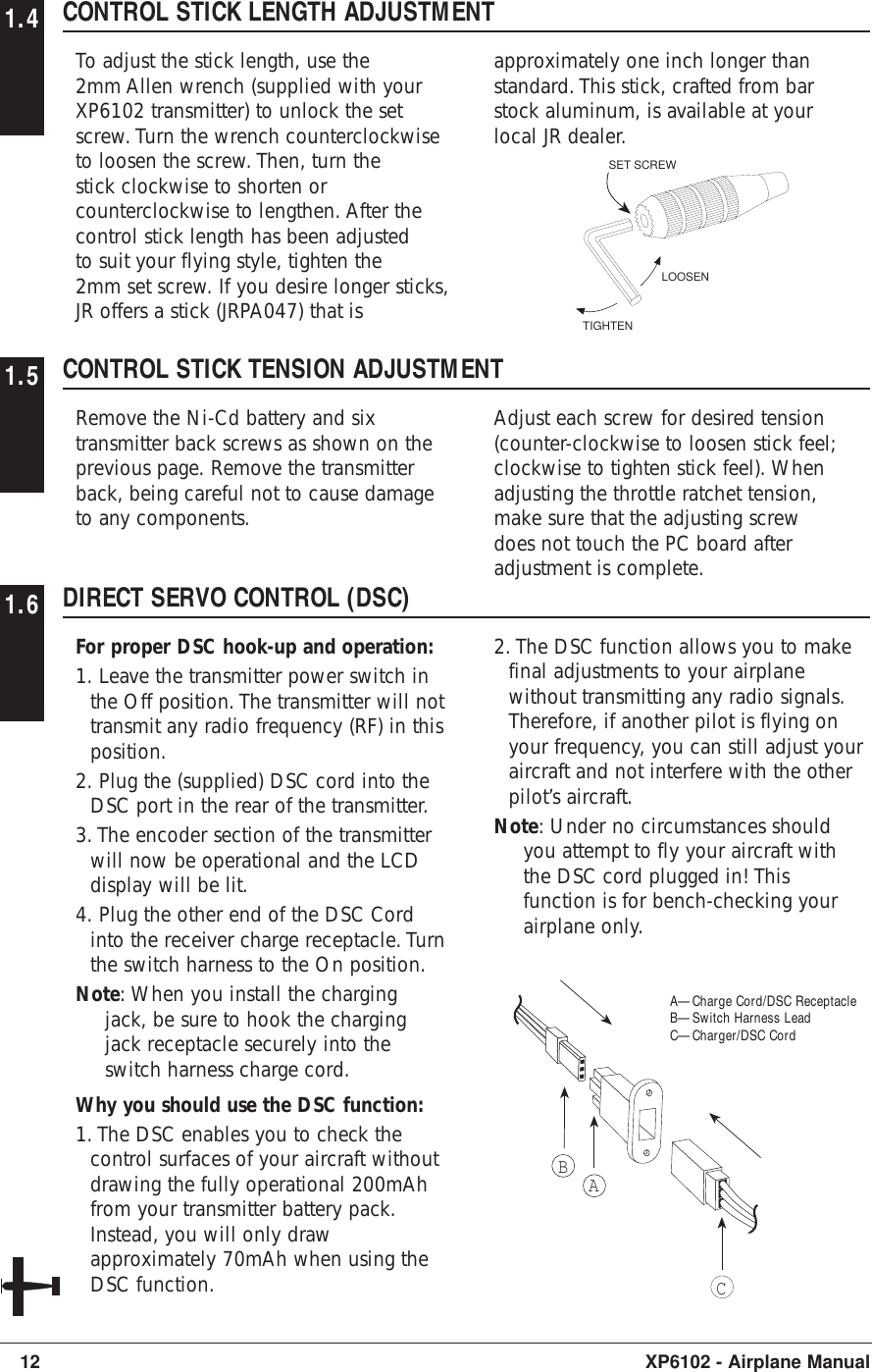
Horizon Hobby
>
XP6102 User Manual
XP6102 User Manual
Navigation menu
Upload a User Manual
Namespaces
Wiki Guide
HTML
PDF
Info
Views
User Manual
Discussion / Help
Navigation


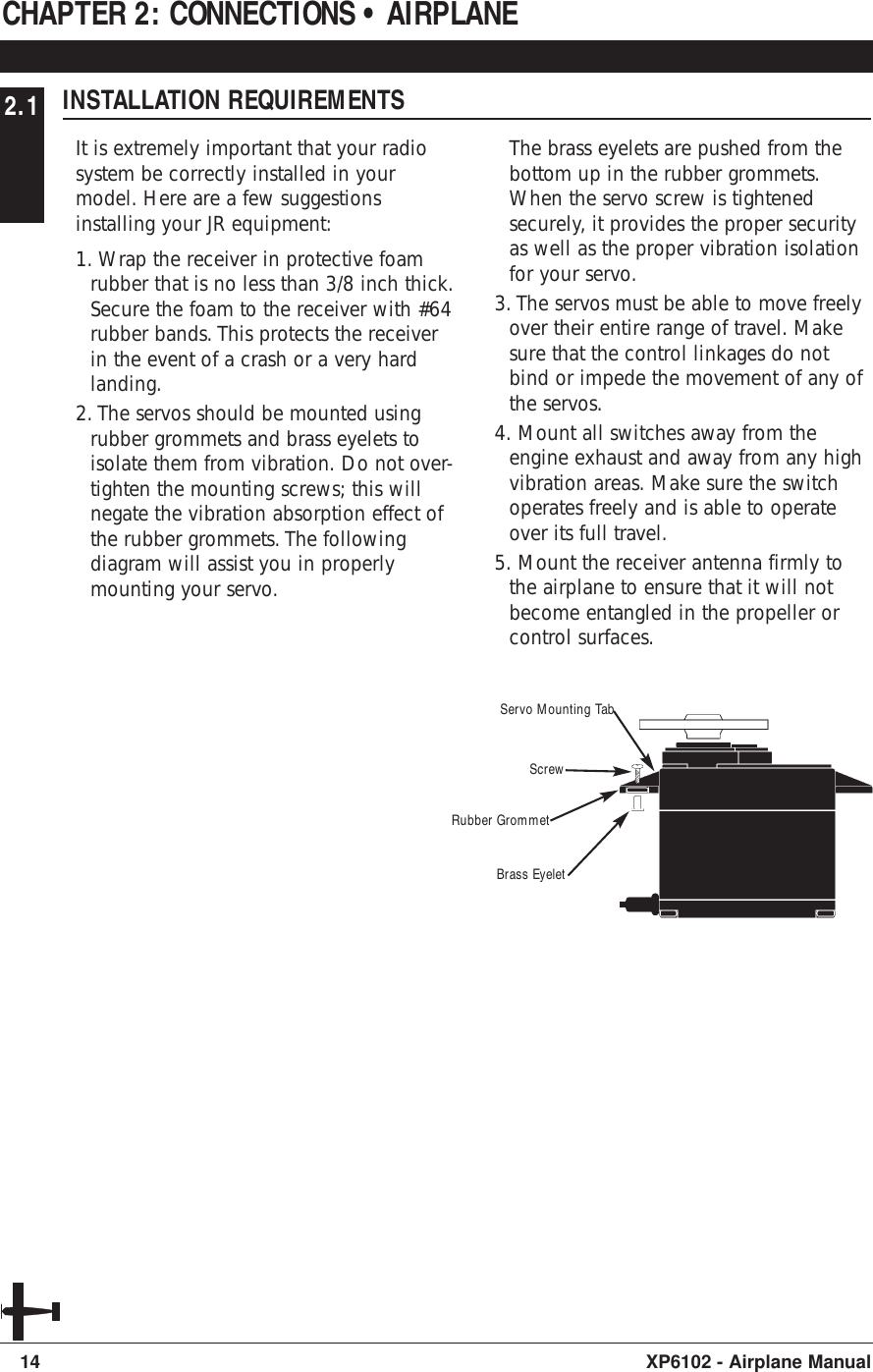
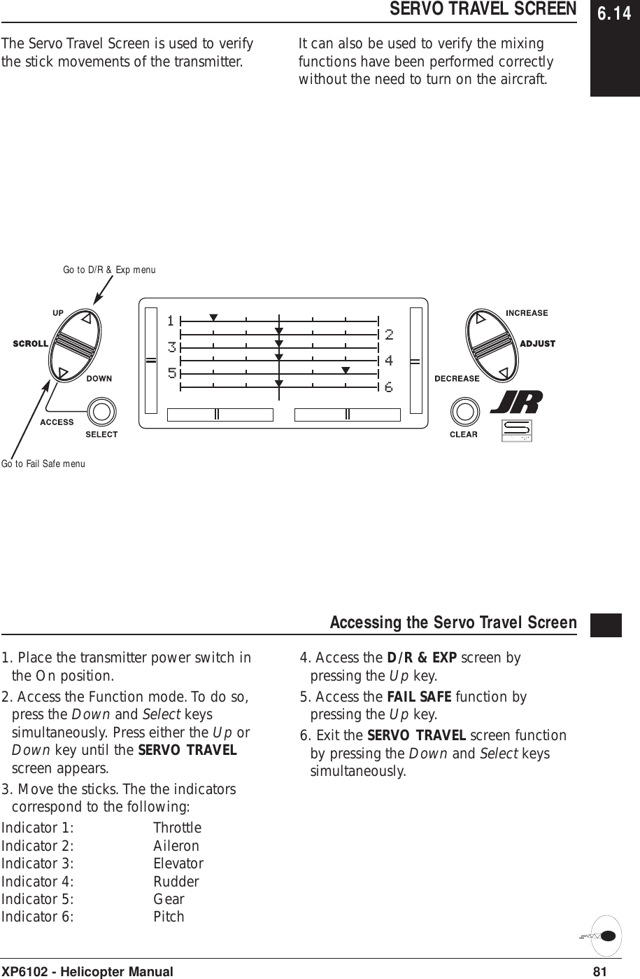
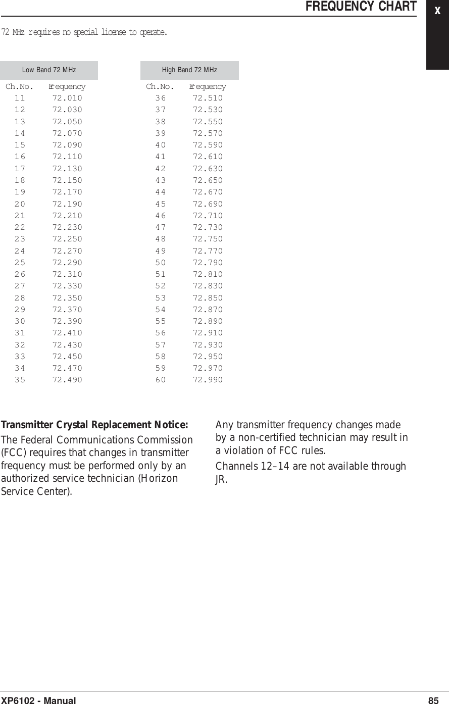
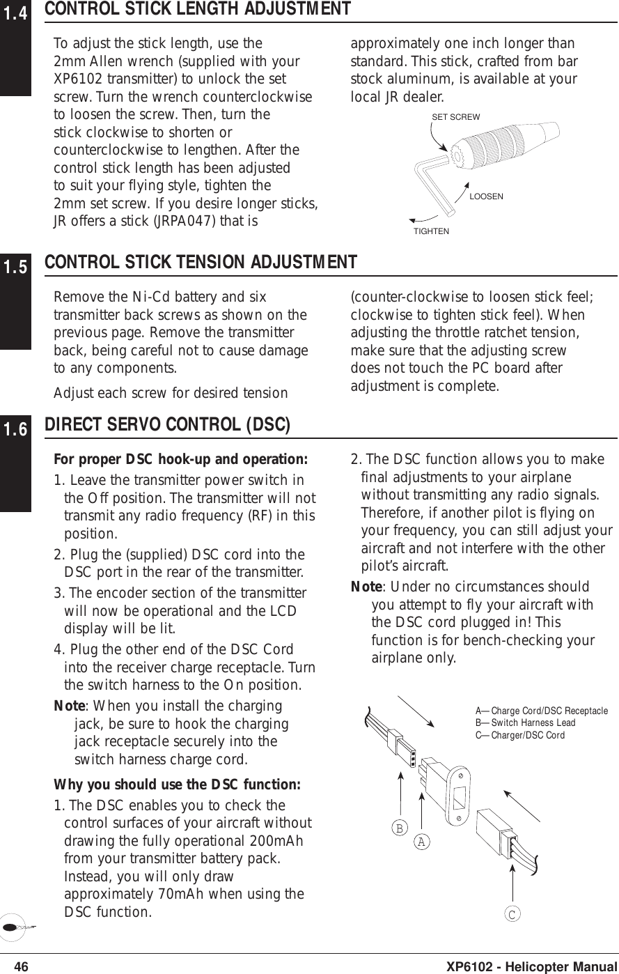
![CHAPTER 5: SYSTEM MODE • AIRPLANENORMAL MODE 5.1When the power switch is in the Onposition, the display will read as follows:17XP6102 - Airplane Manual[MODEL SEL] #4 PLANE SPCM ALPHA 40 TOTAL T 0:05:27To enter and exit the System mode, presssimultaneously then turn on the power switch.To enter and exit the Function model, turn onthe power switch, then press simultaneously.Elevator TrimAileron TrimRudder TrimThrottle Trim Modulation TypeModel TypeModel NumberTransmitter"On Time"Model NameSYSTEM MODE 5.2To enter the System mode, press theDown and Select keys simultaneously,then turn the power switch to the onposition. The display will show the lastactive program. Pressing either the Up orDown key then scrolls through thefunctions one by one, according to thesystem mode flowchart shown to the right.Once the appropriate function isdisplayed, changes can be made bypressing the (+) or (-) keys.System Mode FlowchartInformation pertaining to each function isexplained on the page listed next to thefunction name. Functions will appear inthe same order they are shown onthis chart.Accessing the System Mode1. Press the Down and Select keyssimultaneously. 2. Move the power switch to the On(upper) position. 3. Use either the Up or Down key toscroll through the menu and access theapplicable function.[MODEL SEL] #4 PLANE SPCM ALPHA .40 TOTAL T 0:05:27[MODEL NAME]#5 PLANE SPCMALPHA 40[MODEL TYPE]#5 ALPHA 40AIRPLANEDATA RESET[MODEL COPY]#5 ALPHA 40#6 PLANE SPCM[MODULATION]#5 ALPHA 40SPCM[TRAINER]#5 ALPHA 40NORMAL[SWITCH SEL]D/R INDIVIDGEAR RIGHT SWFLAP FLAP LVR[WING TYPE]FLAPERON OFFELEVON OFFV-TAIL OFFModelSelectionpg 18ModelNameEntrypg 19ModelTypepg 20ModelCopypg 21Modu-lationpg 22Trainerpg 23SwitchSelectpg 24WingTypepg 25](https://usermanual.wiki/Horizon-Hobby/XP6102/User-Guide-361509-Page-19.png)
![5.3 MODEL SELECTIONThe XP6102 system offers memory for tencompletely separate models. Therefore,it is possible to have a mixture ofhelicopter and airplane setups retainedin memory. It is also recommended thatthe Model Name Entry function be usedin conjunction with each model setup.Another very useful function of the ModelSelection function is the ability to setone aircraft up several different ways.This is helpful when multi-taskperformance is desired.18 XP6102 - Airplane Manual[MODEL SEL] #4 PLANE SPCM ALPHA 40 TOTAL T 0:05:27Model Name (if programmed)Model Number and TypeToggle between Modeland TimerClear Timer (when selected)Go to Model Name menuGo to Wing Type menuChange model selectionAccessing the Model Select Function1. While pressing the Down and Selectkeys, switch the transmitter to the Onposition to enter the Model Select mode.2. Model Select will be displayed on theupper left portion of the LCD. If not,press the Up or Down key until MODELSEL is displayed.3. Pressing the (+) or (-) key will selectamong each of the ten models available.Notice that as each model is selected, itsname appears in the LCD.4. Once the desired model is displayed onthe left, pressing the Down and Channelkeys simultaneously will exit the ModelSelection function and establish themodel displayed as the new currentmodel.5. Press the Select key to select the timerfunction to clear the Total Timer. Pressthe Clear key to clear the Total timer.6. Press the Down key to access theWING TYPE function.7. Press the Up key to access the MODELNAME function.8. Press the Down and Select keyssimultaneously to exit the MODEL SELfunction.](https://usermanual.wiki/Horizon-Hobby/XP6102/User-Guide-361509-Page-20.png)
![MODEL NAME ENTRY 5.4The XP6102 allows an 8-digit name to beinput for each of the ten models available.The current model will be displayed in theNormal display.19XP6102 - Airplane ManualAccessing the Model Name Entry Function1. While pressing the Down and Selectkeys, switch the transmitter to the On(upper) position to enter the ModelSetup mode.2. press the Up or Down key untilMODEL NAME is displayed.2. Press either the Up or Down key toselect the first character for the modelname.4. Press the Select key to advance thecharacter selection to the next character.5. Repeat this procedure until all eightcharacters have been selected.6. Press the Down key to access theMODEL SEL function.7. Press the Up key to access the MODELTYPE Selection function.8. Press the Down and Select keyssimultaneously to exit the MODELNAME function.[MODEL NAME]#5 PLANE SPCMALPHA 40Model name beingprogrammedModel Number and TypeSelect character Reset selectedcharacter to blankspaceGo to Model Type menuGo to Model Select menuChange selectedcharacter](https://usermanual.wiki/Horizon-Hobby/XP6102/User-Guide-361509-Page-21.png)
![5.5 MODEL TYPE SELECTIONThe XP6102 is capable of performingas a helicopter or airplane radio withfull functions for each.20 XP6102 - Airplane ManualAccessing the Type Selection Function1. While pressing the Down and Selectkeys, switch the transmitter to the Onposition to enter the Model Setup mode. 2. Press either the Up or Down keys untilMODEL TYPE is displayed in the leftportion of the LCD.3. Pressing either the (+) or (-) key willchange the type of model.4. Press the Select key to move the cursorto the Data Reset position.5. Press the Clear key to reset the memoryto the factory defaults.6. Press the Down key to access theMODEL NAME function.5. Press the Up key to access the MODELCOPY function.6. Press the Down and Select keyssimultaneously to exit the MODEL TYPEfunction.[MODEL TYPE]#5 ALPHA 40AIRPLANEDATA RESETModel Type functionModel Number and NameToggle between ModelType and Data Reset Reset Data (when selected)Go to Model Copy menuGo to Model Name menuChange modeltype selection](https://usermanual.wiki/Horizon-Hobby/XP6102/User-Guide-361509-Page-22.png)
![21XP6102 - Airplane ManualMODEL COPY FUNCTION 5.6The Copy Selection function enables youto copy all of the settings of the currentmodel to another model within the sametransmitter. This is very useful when settingup one aircraft several different ways orwhen trying an alternative setup of yourcurrent model.Accessing the Model Copy Function1. While pressing the Down and Selectkeys, move the transmitter’s powerswitch to the On position. 2. Press either the Up or Down key untilMODEL COPY appears on the top leftof the LCD.3. The upper number that appears is thecurrent model. This is important to noteas only the current model will be thecopied. Press the (+) or (-) keys to selectthe desired program (lower number) tocopy the current model to.4. Next, press the Clear key. The currentmodel will then be copied to theselected model.Note: Always make sure that theaccepting model is either free ofinput or one which you no longerwant to retain in your transmitter’smemory. Once the copying processhas been completed, the informationof the accepting model is lost and thecurrent model is input as the newdata.5. Press the Up key to access theMODULATION function.6. Press the Down key to access theMODEL TYPE function.7. Press the Down and Select keyssimultaneously to exit the MODELCOPY function.[MODEL COPY]#5 ALPHA 40#6 PLANE SPCMModel number tobe copied toModel number and nameto be copiedPerform copyfunctionGo to Modulation menuGo to Model Type menuChange model tocopy to](https://usermanual.wiki/Horizon-Hobby/XP6102/User-Guide-361509-Page-23.png)
![22 XP6102 - Airplane Manual5.7 MODULATION SELECTIONThe Modulation Selection functionenables your XP6102 to transmit to avariety of JR receivers. You can select fromeither S-PCM or from linear PPM (PulsePosition Modulation [FM]).Accessing the Modulation Function1. Move the power switch to the Onposition while pressing the Down andSelect key to access the System mode.2. Press either the Up or Down key untilMODULATION appears at the top of theLCD.3. Press either the (+) or (-) keys to changethe modulation type.4. Pressing the Clear key will also resetthe modulation selection to the factorypreset S-PCM.5. Press the Down key to access theMODEL COPY function.6. Press the Up key to access theTRAINER function.7. To exit the MODULATION function,press the Down and Select keyssimultaneously.Note: In the normal display, the selectedmodulation type will appear in theupper right of the LCD.[MODULATION]#5 ALPHA 40SPCMModulationModel Number and NameSelect S-PCMGo to Trainer menuGo to Model Copy menuToggle betweenPPM and S-PCM](https://usermanual.wiki/Horizon-Hobby/XP6102/User-Guide-361509-Page-24.png)
![23XP6102 - Airplane ManualTRAINER FUNCTION 5.8The XP6102 offers a programmable trainerfunction with three trainer options:Normal mode - In this mode thetransmitter acts as a conventional buddy-box system. The transmitter can be used asa slave or as a master: however in thismode, the reversing switches and trimsmust be adjusted so the slave transmittermatches the master transmitter. In normalmode, when the trainer switch isactivated, the student has control of allfunctions and switches.Pilot Link - When pilot link mode is usedwith the master transmitter, it allows theslave transmitter to be adjusted to factorydefaults. The slave transmitter can simplybe programmed in a model memory notbeing used and reset to factory defaults,thus preventing the need to synchronizethe trims and reversing switches on theslave transmitter.Also, when Pilot Link is used, the studentonly has control of the 4 basic channels(throttle, aileron, elevator, rudder) whilethe trainer (master) retains control of allother functions like gear, dual rate,programmed mixes, etc. This allows apilot to have a test flight on a morecomplex airplane without having toremember complex switch positions.Pilot Link + Slave - This mode is usedonly when the XP6102 is being used as aslave transmitter and the other Mastertransmitter has a Pilot Link programactive. By selecting Pilot Link + Slave thetransmitter is automatically in the correctprogramming mode to work as a slave inconjunction with another Pilot Linkequipped transmitter.Accessing the Trainer Function1. Move the power switch to the Onposition while pressing the Down andSelect keys to access the System mode.2. Press either the Up or Down key untilTRAINER appears at the top of the LCD.3. Press either the (+) or (-) keys to changethe Trainer Type type.4. Pressing the Clear key will return thetrainer function to the "normal" setting.5. Press the Down key to access theMODULATION function.6. Press the Up key to access the SWITCHSEL function.7. To exit the TRAINER function, press theDown and Select keys simultaneously.Note: The slave transmitter must alwaysbe in PPM modulation to operate.Pilot Link + Slave automatically selectsPPM modulation when activated.With other transmitters it will benecessary to be in PPM mode for theXP6102 to operate properly as a slave.[TRAINER]#5 ALPHA 40NORMALTrainer mode selectedModel number and nameReturn to Normal modeGo to Switch Select menuGo to Modulation menuChange trainermode](https://usermanual.wiki/Horizon-Hobby/XP6102/User-Guide-361509-Page-25.png)
![5.9 SWITCH SELECTThe XP6102 allows the several options tobe programmed for the dual rate, gear andflap switches.Aileron and elevator dual rates can beprogrammed to be individually selectedvia it's own switch (Individ) or the aileron,elevator and rudder functions can becombined to operate from one of 4switches.The gear channel can be programmed tooperate on one of 4 switched or rockersor it can be inhibited, helpful for sometypes of mixing. Plus the flap channel canbe programmed to operate from switchesor levers.24 XP6102 - Airplane Manual[SWITCH SEL]D/R INDIVIDGEAR LEFT SWFLAP RIGHT SWGear indicatorDual Rate indicatorReset selection to defaultGo to Wing Type menuGo toTrainer menuSwitch selectionAccessing the Modulation FunctionDual RatesD/R INDIVID (default) - In this modethe aileron and elevator rates areindependently selected using theELEV D/R and AILE D/R switches.Note: In this mode the rudder D/R isalways in the 0 position and is notselectable. This is the default setting.COM AILE - In this mode the aileron,elevator and rudder dual rates arecombined on the AILE D/R switch.COM ELEV - In this mode the aileron,elevator and rudder dual rates arecombined on the ELEV D/R switch.COM R-SW - In this mode the aileron,elevator and rudder dual rates arecombined on the upper right (flap) switch.COM L-SW - In this mode the aileron,elevator and rudder dual rates arecombined on the upper left (gear) switch.Gear ChannelLEFT SW (default) - The gear channeloperates from the left upper (gear) switch.AILE D/R - The gear channel operatesfrom the aileron dual rate switch.ROCKER - The gear channel operatesfrom the right rocker switch and offersthree positions.INHIBIT - The gear channel is inhibitedand is centered making it useful as a slavechannel for mixing.RIGHT SW - The gear channel operatesfrom the right upper (flap) switch.Flap ChannelRIGHT SW (default) - The flapchannel operates from the right upper(flap) switch.LEFT SW - The flap channel operates fromthe left upper (gear) switch.ELEV D/R - The flap channel operatesfrom the elevator dual rate switch.FLAP LVR - The flap channel operatesfrom the left flap lever and is proportional.Flap indicatorSelect function](https://usermanual.wiki/Horizon-Hobby/XP6102/User-Guide-361509-Page-26.png)
![WING TYPE SELECTION 5.10There are three different wing types tochoose from; select the one that will bestsuit your R/C aircraft. Flaperon, Elevonand V-Tail are available selections forWing Type and will be covered in thefollowing pages.25XP6102 - Airplane Manual[WING TYPE]FLAPERON OFFELEVON OFFV-TAIL OFFV-Tail indicatorFlaperon indicatorReturn to Default modeGo to Model Select menuGo to Switch Select menuTurn selectedtype on or offElevon indicatorDefinition of Wing TypesNormal- This is used with aircraft withone servo operating both ailerons. Thismode is the default setting and is activewhen the Flaperon, Elevon and V-Tailmodes are off.Flaperon- This mode is used when twoservos are used to operated the ailerons.Flaperons allow each aileron to beindependently adjusted. In addition, theycan be programmed to move in the samedirection for use as flaps or spoilersElevon- This mode is used for some typesof delta wing aircraft where the controlsurfaces function as both ailerons andelevators.V-Tail- Used for V-tailed airplanes.Note: Some function will be unavailablewhen certain functions are active.With Flaperon active, Elevon will beunavailable. With Elevon active, bothFlaperon and V-Tail will beunavailable. Finally, with V-Tailactive, Elevon will be unavailable.](https://usermanual.wiki/Horizon-Hobby/XP6102/User-Guide-361509-Page-27.png)
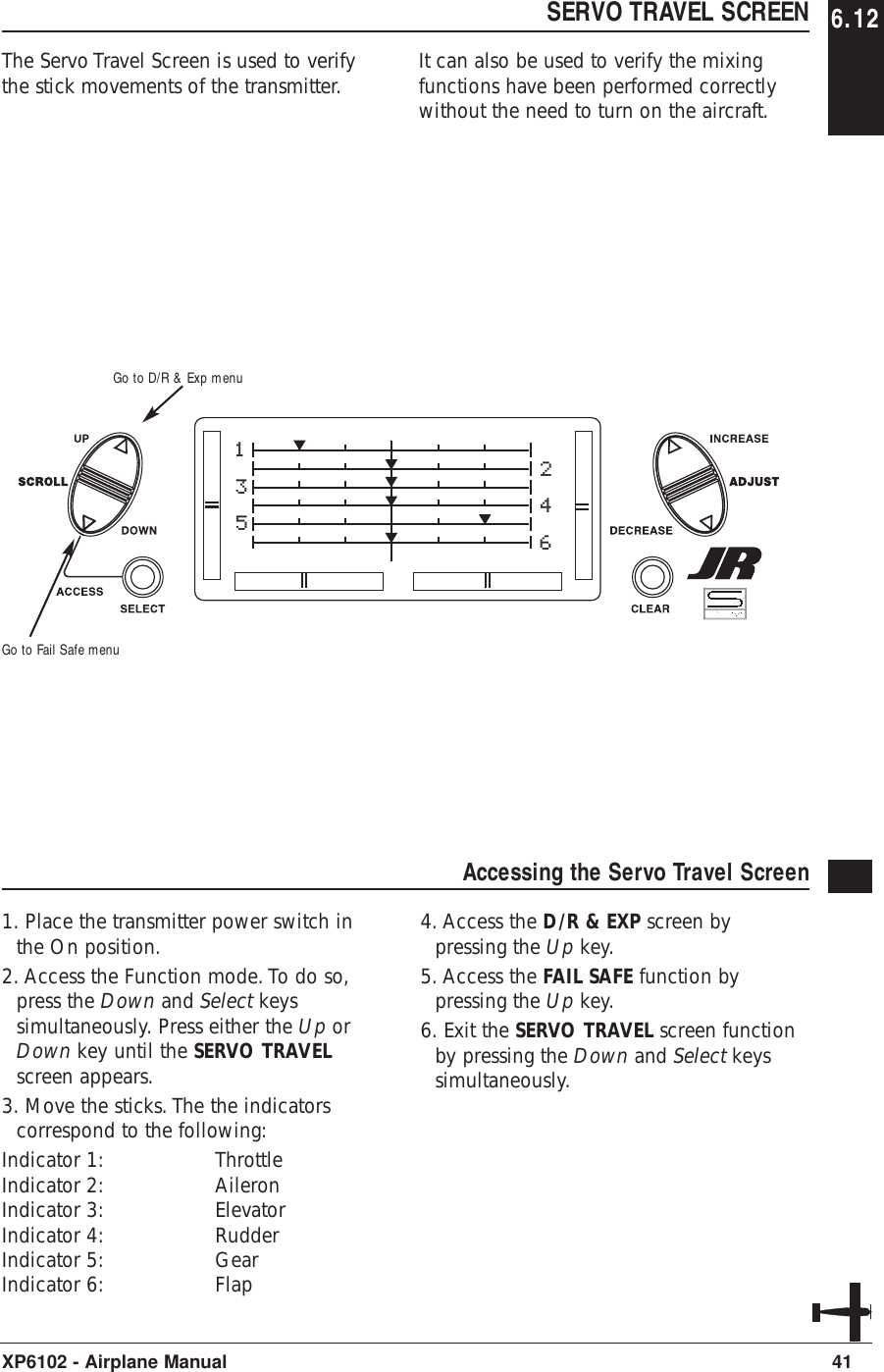
![29XP6102 - Airplane ManualCHAPTER 6: FUNCTIONS (FUNCTION MODE ) • AIRPLANE FUNCTION MODE 6.1To enter the Function mode, switch thetransmitter power switch to the Onposition. Press the Down and Select keyssimultaneously, and the display will show the last active program. Pressingeither the Up or Down key then scrollsthrough the functions one by one,according to the Function ModeFlowchart shown on the right. Once theappropriate function is displayed, changescan be made by pressing the (+) or (-)Accessing the Mode Function1. Move the power switch to the Onposition.2. Press the Down and Select keyssimultaneously.[D/R & EXP]AILE POS 0EXP LIND/R 100%Dual Rate and Expo pg 30[TRAVEL ADJ]THRO AILEH100% L100%L100% R100%Travel Adjustment pg 33[THRO CUT] INHIBITThrottle Cut pg 36[FAIL SAFE]TH HLD AI HLDEL HLD RU HLDGE HLD FL HLDFail Safe pg 40[REVERSING SW]THR:N AIL:NELE:N RUD:NGEA:N FLA:NReversing Switches pg 31[ELE F MX] ONE-DN 0%E-UP 0%SW ALWAYS ONEle➔F Mix pg 34[FLAP SYSTEM]FLAP DN100%ELEV 0%Flap System pg 37135246Servo Travel Screen pg 41[SUB TRIM]TH 0 AI 0EL 0 RU 0GE 0 FL 0Sub Trim pg 32[AIL RUD MIX]ONVAL 0%SW ALWAYS ONAil➔Rud Mix pg 35[MX1] THR THRON OFFSET 0 0% 0% SW ALWAYS ONProgrammable Mix 1-4 pg 383. Use either the Up or Down to scrollthrough the menu and access theapplicable function.keys. To select another channel of aparticular function, press the Select key.The Function mode is the most often usedsystem to input data.Function Mode FlowchartInformation pertaining to each function isexplained on the page listed next to thefunction name. Functions will appear inthe same order they are shown on thischart.Navigate forwardthrough menusNavigate backwardsthrough menus](https://usermanual.wiki/Horizon-Hobby/XP6102/User-Guide-361509-Page-31.png)
![6.2 DUAL RATES AND EXPONENTIALDual rates are available for the aileron,elevator and rudder channels of your R/Caircraft. There is also an automatic dualrate setting to link your aileron, elevator,and rudder dual rates to the flight modelswitch. This automatic Dual-Rate functionis discussed in a separate section thatfollows. Dual rates may be defined as theability to vary the travel or throw rate of aservo from a switch. Due to the differingtravel rates, you will find that thesensitivity of the control either increasesor decreases accordingly. A higher rate, ortravel, yields a higher overall sensitivity.You may find it easier to think of the Dual-Rate function as double-ratesor half-rates.The Dual-Rate function worksin conjunction with the Exponentialfunction to allow you to precisely tailoryour control throws. You may want toconsult the section defining exponentialfor further information.30 XP6102 - Airplane ManualAccessing the Dual Rate and Exponential Function1. Place the transmitter power switch inthe on position.2. Access the Function mode by pressingthe Down and Select keyssimultaneously.3. Press either the Up or Down key untilD/R & EXP appears in the upper leftcorner of the LCD.4. Press the Channel key until the desiredchannel (aileron, elevator, rudder orautomatic dual rates) appears.5. Select the switch position for which youwant to adjust the rate. The number tothe upper right of the current rate valueon the display indicates the currentposition of the Dual-Rate switch for thechannel that you have selected. Either a0 or a 1 will be shown, corresponding tothe position of the switch. To select theopposite switch position, move theappropriate Dual-Rate switch to theopposite position. The number thatappears above the current rate valuereflects the change.6. Adjust the rate for the channel and theswitch position just selected. Todecrease the throw rate, press the (-) key.To increase the throw rate, press the (+)key. As stated previously, the adjustablerate is from 0-125% for each switchposition and channel.7. Press the Up arrow key to access theREVERSING SW menu.8. Press the Down arrow key to access theSERVO TRAVEL SCREEN.9. Press the Down arrow and Select keyssimultaneously to exit the functionmode.The amount of travel is adjustable from0-125% in 1% increments. The factorysetting, or default value, for both the0 and 1 switch positions is 100%.Either switch position may be selected asthe low or high rate by placing the switchin the desired position and adjustingthe value accordingly.[D/R & EXP]AILE POS 0EXP LIND/R 100%Go to Reversing SW menuGo to Servo Travel Screen Select channel, EXP or D/RChange channel or valueReset selection to default](https://usermanual.wiki/Horizon-Hobby/XP6102/User-Guide-361509-Page-32.png)
![SERVO REVERSING 6.3The Reverse Switch function is anelectronic means of reversing the throwof a given channel (servo). All six channelsof the XP6102 offer reversible servodirection. This will ease setup duringthe servo installation into your aircraft.31XP6102 - Airplane ManualAccessing the Servo Reversing Function 1. Place the transmitter switch in the onposition.2. Access the Function mode by pressingthe Down and Select keyssimultaneously.3. Press either the Up or Down key untilthe REVERSING SW appears in theupper portion of the LCD.4. Using your transmitter’s control sticks,switches and potentiometers, move thecontrol surfaces of your aircraft. Notethe travel direction of each of thecorresponding control surfaces.5. After you have determined whichchannel(s) need to have the throwdirections reversed, use the Select key tocall up the appropriate channel.6. Press either the (+) or (-) keys to changethe travel direction of the servo. Pressingthe Clear key returns the travel directionto Normal.7. You can observe the change in thetravel direction by moving theappropriate control at this time.8. Access the D/R & EXP function bypressing the Down key.9. Access the SUB TRIM function bypressing the Up key.10. Exit the Servo Reversing function bypressing the Down and Select keys[REVERSING SW]THR:N AIL:NELE:N RUD:NGEA:N FLA:NGo to Sub Trim menuGo to D/R & Exp menuChange servo directionReset direction to normalSelect channel to reverse](https://usermanual.wiki/Horizon-Hobby/XP6102/User-Guide-361509-Page-33.png)
![6.4 SUB TRIMThe Sub Trim Adjustment function allowsyou to electronically fine-tune thecentering of your servos. Individuallyadjustable for all six channels with arange of ±125% (+/-30 degrees servotravel).The sub trim functions provides preciseservo arm neutral positioning if rotatingthe servo arm will not allow the desiredservo arm position.32 XP6102 - Airplane ManualAccessing the Sub Trim Function1. Place the transmitter power switch inthe On position.2. To Access the Function mode, press theDown and Select keys simultaneously.3. Press either the Up or Down key untilSUB TRIM appears in the upper middleportion of the LCD.4. Press the Select key until the desiredchannel appears.5. Press the (+) or (-) key to establish thedesired amount and direction of Sub-Trim. Caution: Do not use excessive sub-trimadjustments since it is possible tooverrun your servo’s maximum SubTrim. Remember that it is a trimconvenience function. It is notintended to take the place of theproper mechanical trim adjustmentsthat are necessary on any R/C model.6. Access the REVERSING SW function bypressing the Down key.7. Access the TRAVEL ADJ function bypressing the Up key.8. Exit the SUB TRIM function by pressingthe Down and Select keyssimultaneously.[SUB TRIM]TH 0 AI 0EL 0 RU 0GE 0 FL 0Go to Travel Adj menuGo to reversing SW menu Select channelChange valueReset selection to default](https://usermanual.wiki/Horizon-Hobby/XP6102/User-Guide-361509-Page-34.png)
![TRAVEL ADJUST 6.5The purpose of Travel Adjust is to offeryou precise servo control deflection ineither direction of servo operation. TheXP6102 offers travel adjust for all sixchannels. The Travel Adjust range is from0-150% (0 degrees to 60 degrees) fromneutral, or center, and it can be adjustedfor each direction individually. The factorydefault (Data Reset) value is 100% foreach direction of servo travel.33XP6102 - Airplane ManualAccessing the Travel Adjust Function 1. Place the transmitter power switch inthe On position.2. Access the Function mode by pressingthe Down and Select keyssimultaneously.3. Press either the Up or Down key untilTRAVEL ADJ appears in the upperportion of the LCD.4. Press the Select key until the desiredchannel is highlighted.5. Move the appropriate control stick(lever, switch, etc) to the right or left ofcenter to the direction of travel you wantto adjust. An arrow to the left of thetravel adjust value will reflect the currentposition to be adjusted.6. After the control stick or switch isplaced in the direction of travel to beadjusted, press the (+) or (-) key until theproper amount of servo travel is shownon the LCD. Press the (+) key to increasethe amount of servo travel. Press the (-)key to decrease the amount of servotravel.7. Follow the same procedure for theremaining channels.8. Access the SUB TRIM function bypressing the Down key.9. Access the ELE ➔F MX function bypressing the Up key.10. Exit the TRAVEL ADJ function bypressing the Down and Select keys[TRAVEL ADJ]THRO AILEH100% L100%L100% R100%Go to Ele➔ F MX menuGo to Sub Trim menuChange valueReset value to normalSelect channel to adjust](https://usermanual.wiki/Horizon-Hobby/XP6102/User-Guide-361509-Page-35.png)
![6.6 ELEVATOR TO FLAP MIXINGWhen this system is active and a value offlaps is input, the flaps will be deflectedeach time the elevator stick is used. Theactual flap movement is adjustable forboth up and down elevator. The mostfrequently used application is upelevator/down flaps and down elevator/upflaps. When used in this manner, theaircraft pitches much more quickly thannormal. The upper-most position of theFlap Mixing switch activates the Elevator-to-Flap Mixing circuitry.34 XP6102 - Airplane ManualAccessing the Elevator to Flap Function1. Place the transmitter power switch inthe On position.2. Access the Function mode. To do so,press the Down and Select keyssimultaneously.Press either the Up or Down key untilELE ➔F MX appears in the upperportion of your LCD.3. Move the elevator stick in the directionyou want to mix with flaps. Note: The position indicator will reflectthis change by highlighting the up ordown arrow.5. Press the (+) or (-) key to increase ordecrease the amount of flaps to bemixed. If you want to reverse the flaptravel, press the Clear key, bringing themixing value to the factory default (0%),and increase the value using theopposite key (+) or (-) from the keyoriginally selected. 6. Once you have adjusted the firstmixing position (up or down), place theelevator stick in the opposite directionand follow Step 5 above to adjust thesecond elevator mixing value.7. Access the switch position by pressingthe Select key. Use the (+) or (-) keys toselect from the one of six switches, orfrom always on.8. Access the TRAVEL ADJ function bypressing the Down key.9. Access the AIL ➔RUD MIX Mixingfunction by pressing the Up key.10. Exit the ELE ➔F MX function bypressing the Down and Channel keyssimultaneously.[ELE F MX] ONE-DN 0%E-UP 0%SW ALWAYS ONGo to Go to Ail ➔ Rud Mix menuGo to Travel Adj menu Change selectionChange value/Select switchReset selection to default](https://usermanual.wiki/Horizon-Hobby/XP6102/User-Guide-361509-Page-36.png)
![AILERON TO RUDDER MIXING 6.7This form of mixing is designed so thatwhen input to the aileron stick is given,the rudder servo will also move,eliminating the need to coordinate thesecontrols manually.When adjusting, if an opposite mixingdirection of the rudder servo is required,simply press the (+) or (-) keys to changethe mixing value from a (+) to (-) or a(-) to a (+). This will reverse the mixingdirection of the rudder from its originaldirection. The switch used to activate thismix can also be selected as explainedbelow. The factory default is always onwith a value of 0%.35XP6102 - Airplane ManualAccessing the Aileron to Rudder Mixing Function 1. Place the transmitter power switch inthe On position.2. Access the Function mode. To do so,press the Down and Select keyssimultaneously. Press either the Up orDown key until AIL ➔RUD MIXappears in the center portion of yourLCD. 3. Press the (+) or (-) key to increase ordecrease the amount of rudder to bemixed with aileron. If you want toreverse the Rudder Mix direction, pressthe Clear key, bringing the mixing valueto the factory default (0%), and increasethe value using the opposite key (+) or (-) from the key originally selected. 4. Press the Select key to access theswitch assignment function.5. Press the (+) or (-) key to select thedesired switch/function to activate theAileron-to-Rudder Mixing function.6. Access the ELE ➔FLP MX mixingfunction by pressing the Down key.7. Access the THRO CUT function bypressing the Up key.8. Exit the AIL ➔RUD MIX function bypressing the Down and Select keyssimultaneously.[AIL RUD MIX]ONVAL 0%SW ALWAYS ONGo to Ele ➔ Flp Mx menuGo to Throttle Cut menuChange selectionChange value/Select switchReset selection to default](https://usermanual.wiki/Horizon-Hobby/XP6102/User-Guide-361509-Page-37.png)
![6.8 THROTTLE CUT SWITCHThis is the function to assign Throttle Cutswitch to the push button located onupper right front of the transmitter. TheThrottle Cut function is designed to returnthe throttle trim to the lowest positioninstantly and keep this position while thebutton is pressed. This feature is used to“cut” or stop the engine without changingthe position of digital throttle trim.36 XP6102 - Airplane ManualAccessing the Throttle Cut Function1. Place the transmitter power switch inthe On position.2. Access the Function mode. To do so,press the Down and Select keyssimultaneously. Press either the Up orDown key until THRO CUT appears inthe upper portion of the LCD screen.3. Use the (+) and (-) keys to change thevalue of the Throttle cut function.Note: Pressing the Clear key will Inhibitthe Throttle Cut, turning it off until ithas been reactivated.4. Access the FLAP SYSTEM mixingfunction by pressing the Down key.5. Access the AIL ➔RUD MIX functionby pressing the Up key.6. Exit the THRO CUT function bypressing the Down and Select keyssimultaneously.[THRO CUT] INHIBITGo to Ail ➔ Rud Mix menuGo to Flap System menu Change valueSet function to Inhibit](https://usermanual.wiki/Horizon-Hobby/XP6102/User-Guide-361509-Page-38.png)
![FLAP SYSTEM 6.9The Flap System function automaticallycouples the elevator to the flaps.37XP6102 - Airplane ManualAccessing the Flap System Function1. Place the transmitter switch in the Onposition.2. Press the Down and Select keyssimultaneously to enter the Functionmode.3 .Press either the Up or Down key untilFLAP SYSTEM appears in the top of theLCD.5. Press the Select key to select thedesired channels to be adjusted. 6. Use the (+) or (-) keys to set the desiredlanding mode surface positions.4. Access the THRO CUT mixing functionby pressing the Down key.5. Access the MIX 1 function by pressingthe Up key.6. Exit the FLAP SYSTEM function bypressing the Down and Select keyssimultaneously.[FLAP SYSTEM]FLAP DN100%ELEV 0%Go to Thro Cut menuGo to MX1 menuChange selectionChange valueReset selection to default](https://usermanual.wiki/Horizon-Hobby/XP6102/User-Guide-361509-Page-39.png)
![6.10 PROGRAMMABLE MIXING (1-6)The XP6102 offers four programmablemixes to be used for any number ofdifferent purposes. This function allowsmixing any one channel to any otherchannel. This mix can remain on at alltimes or be switched on and off in flightusing a number of different switches.Mix numbers 1-3 are of the standardvariety, in that the digital trim for themaster channel only affect the masterchannel, and not the slave channel. Mixnumber 4 is of the "Trim Include" variety.This mix is used any time the mix requiresthe slave channels trim position to bevaried when the master channels digitaltrim position is varied. An example for thistype of mix would be when dual elevatoror dual aileron servos are used andconnected to two separate channels of thesystem, rather than using a single channelwith a Y-harness.Each channel of this radio is identified byan abbreviated name. The chart belowindicates the channel and itscorresponding abbreviation. The channelname appearing first is known as the"master channel" or the channel to whichyou want to mix. The second number isknown as the "slave channel" or thechannel that is being mixed into themaster channel. For example, AIL ➔ RUDwould indicate aileron-to-rudder mixing.Each time the aileron stick is moved, theaileron will deflect, and the rudder willautomatically move in the direction andto the value input.Mixing is proportional, so small inputs ofthe master channel will produce smalloutputs of the slave channel. Eachprogrammable mix has a mixing "offset."The purpose of the mixing offset is to re-define the neutral position of the slavechannel.38 XP6102 - Airplane Manual[MX1] THR THRON OFFSET 0 0% 0% SW ALWAYS ONGo to Flap System menuGo to Flap System menu Change selected valueReset selection to defaultMaster Channel Slave ChannelMix numberSwitch selection Switch conditionMix percentagesOffset valueChange highlighted selectionTHR: ThrottleAIL: AileronELE: ElevatorRUD: RudderGEA: GearFLA: Flap](https://usermanual.wiki/Horizon-Hobby/XP6102/User-Guide-361509-Page-40.png)
![FAIL SAFEThe Fail-Safe/Hold function is availableonly when you use the XP6102 transmitterin PCM modulations. This function isdesigned to help minimize damage toyour aircraft during a loss of signal to thereceiver. The servos either assume the fail-safe presets or hold their last good signalposition.As noted earlier, if you are in the PPMmodulation, the Fail-Safe/Hold functionis not applicable. Therefore, the Fail-Safe/Hold function will not appear onyour LCD screen menu while in thePPM mode. Refer to the ModulationSelection section for more informationpertaining to the broadcast signal ofyour XP6102 transmitter.40 XP6102 - Airplane ManualAccessing the Fail Safe Function1. Place the transmitter power switch inthe On position.2. Access the Function mode. To do so,press the Down and Select keyssimultaneously. Press either the Up orDown key until FAIL SAFE appears inthe upper portion of the LCD screen.3. Use the Select key to highlight theservo function to set.4. Use the (+) or (-) keys to togglebetween servo hold or setting the servoposition.5. When using the servo setting position,move the corresponding control stick tothe position where you want the servo ifthe radio enters into the fail safe mode.Press the Clear key to have thetransmitter memorize the stick position.6. Repeat steps 4 and 5 until all sixcontrols have been set.7. Access the SERVO TRAVEL screen bypressing the Up key.8. Access the MIXING FUNCTIONSfunction by pressing the Up key.9. Exit the FAIL SAFE function by pressingthe Down and Select keyssimultaneously.[FAIL SAFE]TH HLD AI HLDEL HLD RU HLDGE HLD FL HLDGo to ProgrammableMixing menuGo to Servo Travel Screen Change from servohold to stick selectionInvoke stick selectionChange highlighted selection6.11](https://usermanual.wiki/Horizon-Hobby/XP6102/User-Guide-361509-Page-42.png)
![51XP6102 - Helicopter ManualCHAPTER 5: SYSTEM MODE • HELICOPTERNORMAL MODE 5.1When the power switch is in the Onposition, the display will read as follows:[MODEL SEL] #5 HELI SPCM VENTURE TOTAL T 0:22:42To enter and exit the System mode, presssimultaneously then turn on the power switch.To enter and exit the Function model, turn onthe power switch, then press simultaneously.Elevator TrimAileron TrimRudder TrimThrottle Trim Modulation TypeModel TypeModel NumberTransmitter"On Time"Model NameSYSTEM MODE 5.2To enter the System mode, press theDown and Channel keys simultaneously,then turn the power switch to the onposition. The display will show the lastactive program. Pressing either the Up orDown key then scrolls through thefunctions one by one, according to thesystem mode flowchart shown to the right.Once the appropriate function isdisplayed, changes can be made bypressing the (+) or (-) keys.System Mode FlowchartInformation pertaining to each function isexplained on the page listed next to thefunction name. Functions will appear inthe same order they are shown onthis chart.Accessing the System Mode1. Press the Down and Channel keyssimultaneously. 2. Move the power switch to the On(upper) position. 3. Use either the Up or Down key toscroll through the menu and access theapplicable function.[MODEL SEL] #5 HELI SPCM VENTURE TOTAL T 0:22:42[MODEL NAME]#5 HELI SPCMVENTURE[MODEL TYPE]#3 VENTUREHELICOPTERDATA RESET[MODEL COPY]#3 VENTURE#2 HELI SPCM[MODULATION]#5 VENTURESPCM[TRAINER]#3 VENTURENORMAL[SWITCH SEL]D/R INDIVIDGEAR LEFT SWFL-M LEFT SW[SWASH TYPE]NORMAL1SERVOModelSelectionpg 52ModelNameEntrypg 53ModelTypepg 54ModelCopypg 55Modu-lationpg 56Trainerpg 57SwitchSelectpg 58SwashTypepg 59](https://usermanual.wiki/Horizon-Hobby/XP6102/User-Guide-361509-Page-53.png)
![52 XP6102 - Helicopter Manual5.3 MODEL SELECTIONThe XP6102 system offers memory for tencompletely separate models. Therefore,it is possible to have a mixture ofhelicopter and airplane setups retainedin memory. It is also recommended thatthe Model Name Entry function be usedin conjunction with each model setup.Another very useful function of the ModelSelection function is the ability to setone aircraft up several different ways.This is helpful when multi-taskperformance is desired.[MODEL SEL] #5 HELI SPCM VENTURE TOTAL T 0:22:42Model Name (if programmed)Model Number and TypeToggle between Modeland TimerClear Timer (when selected)Go to Model Name menuGo to Swashplate Type menuChange model selectionAccessing the Model Select Function1. While pressing the Down and Selectkeys, switch the transmitter to the Onposition to enter the Model Select mode.2. Model Select will be displayed on theupper left portion of the LCD. If not,press the Up or Down key until MODELSEL is displayed.3. Pressing the (+) or (-) key will selectamong each of the ten models available.Notice that as each model is selected, itsname appears in the LCD.4. Once the desired model is displayed onthe left, pressing the Down and Channelkeys simultaneously will exit the ModelSelection function and establish themodel displayed as the new currentmodel.5. Press the Select key to select the timerfunction to clear the Total Timer. Pressthe Clear key to clear the Total timer.6. Press the Down key to access theSWASH TYPE function.7. Press the Up key to access the MODELNAME function.8. Press the Down and Select keyssimultaneously to exit the MODEL SELfunction.](https://usermanual.wiki/Horizon-Hobby/XP6102/User-Guide-361509-Page-54.png)
![53XP6102 - Helicopter ManualMODEL NAME ENTRY 5.4The XP6102 allows an 8-digit name to beinput for each of the ten models available.The current model will be displayed in theNormal display.Accessing the Model Name Entry Function1. While pressing the Down and Selectkeys, switch the transmitter to the On(upper) position to enter the ModelSetup mode.2. press the Up or Down key untilMODEL NAME is displayed.2. Press either the Up or Down key toselect the first character for the modelname.4. Press the Select key to advance thecharacter selection to the next character.5. Repeat this procedure until all eightcharacters have been selected.6. Press the Down key to access theMODEL SEL function.7. Press the Up key to access the MODELTYPE Selection function.8. Press the Down and Select keyssimultaneously to exit the MODELNAME function.[MODEL NAME]#5 HELI SPCMVENTUREModel name beingprogrammedModel Number and TypeSelect character Reset selectedcharacter to blankspaceGo to Model Type menuGo to Model Select menuChange selectedcharacter](https://usermanual.wiki/Horizon-Hobby/XP6102/User-Guide-361509-Page-55.png)
![54 XP6102 - Helicopter Manual5.5 MODEL TYPE SELECTIONThe XP6102 is capable of performingas a helicopter or airplane radio withfull functions for each.Accessing the Type Selection Function1. While pressing the Down and Selectkeys, switch the transmitter to the Onposition to enter the Model Setup mode. 2. Press either the Up or Down keys untilMODEL TYPE is displayed in the leftportion of the LCD.3. Pressing either the (+) or (-) key willchange the type of model.4. Press the Select key to move the cursorto the Data Reset position.5. Press the Clear key to reset the memoryto the factory defaults.6. Press the Down key to access theMODEL NAME function.5. Press the Up key to access the MODELCOPY function.6. Press the Down and Select keyssimultaneously to exit the MODEL TYPEfunction.[MODEL TYPE]#3 VENTUREHELICOPTERDATA RESETModel Type functionModel Number and NameToggle between ModelType and Data Reset Reset Data (when selected)Go to Model Copy menuGo to Model Name menuChange modeltype selection](https://usermanual.wiki/Horizon-Hobby/XP6102/User-Guide-361509-Page-56.png)
![55XP6102 - Helicopter ManualMODEL COPY FUNCTION 5.6The Copy Selection function enables youto copy all of the settings of the currentmodel to another model within the sametransmitter. This is very useful when settingup one aircraft several different ways orwhen trying an alternative setup of yourcurrent model.Accessing the Model Copy Function1. While pressing the Down and Selectkeys, move the transmitter’s powerswitch to the On position. 2. Press either the Up or Down key untilMODEL COPY appears on the top leftof the LCD.3. The upper number that appears is thecurrent model. This is important to noteas only the current model will be thecopied. Press the (+) or (-) keys to selectthe desired program (lower number) tocopy the current model to.4. Next, press the Clear key. The currentmodel will then be copied to theselected model.Note: Always make sure that theaccepting model is either free ofinput or one which you no longerwant to retain in your transmitter’smemory. Once the copying processhas been completed, the informationof the accepting model is lost and thecurrent model is input as the newdata.5. Press the Up key to access theMODULATION function.6. Press the Down key to access theMODEL TYPE function.7. Press the Down and Select keyssimultaneously to exit the MODELCOPY function.[MODEL COPY]#3 VENTURE#2 HELI SPCMModel number tobe copied toModel number and nameto be copiedPerform copyfunctionGo to Modulation menuGo to Model Type menuChange model tocopy to](https://usermanual.wiki/Horizon-Hobby/XP6102/User-Guide-361509-Page-57.png)
![56 XP6102 - Helicopter Manual5.7 MODULATION SELECTIONThe Modulation Selection functionenables your XP6102 to transmit to avariety of JR receivers. You can select fromeither S-PCM or from linear PPM (PulsePosition Modulation [FM]).Accessing the Modulation Function1. Move the power switch to the Onposition while pressing the Down andSelect key to access the System mode.2. Press either the Up or Down key untilMODULATION appears at the top of theLCD.3. Press either the (+) or (-) keys to changethe modulation type.4. Pressing the Clear key will also resetthe modulation selection to the factorypreset S-PCM.5. Press the Down key to access theMODEL COPY function.6. Press the Up key to access theTRAINER function.7. To exit the MODULATION function,press the Down and Select keyssimultaneously.Note: In the normal display, the selectedmodulation type will appear in theupper right of the LCD.[MODULATION]#5 VENTURESPCMModulationModel Number and NameSelect S-PCMGo to Trainer menuGo to Model Copy menuToggle betweenPPM and S-PCM](https://usermanual.wiki/Horizon-Hobby/XP6102/User-Guide-361509-Page-58.png)
![57XP6102 - Helicopter ManualTRAINER FUNCTION 5.8The XP6102 offers a programmable trainerfunction with three trainer options:Normal mode - In this mode thetransmitter acts as a conventional buddy-box system. The transmitter can be used asa slave or as a master: however in thismode, the reversing switches and trimsmust be adjusted so the slave transmittermatches the master transmitter. In normalmode, when the trainer switch isactivated, the student has control of allfunctions and switches.Pilot Link - When pilot link mode is usedwith the master transmitter, it allows theslave transmitter to be adjusted to factorydefaults. The slave transmitter can simplybe programmed in a model memory notbeing used and reset to factory defaults,thus preventing the need to synchronizethe trims and reversing switches on theslave transmitter.Also, when Pilot Link is used, the studentonly has control of the 4 basic channels(throttle, aileron, elevator, rudder) whilethe trainer (master) retains control of allother functions like gear, dual rate,programmed mixes, etc. This allows apilot to have a test flight on a morecomplex airplane without having toremember complex switch positions.Pilot Link + Slave - This mode is usedonly when the XP6102 is being used as aslave transmitter and the other Mastertransmitter has a Pilot Link programactive. By selecting Pilot Link + Slave thetransmitter is automatically in the correctprogramming mode to work as a slave inconjunction with another Pilot Linkequipped transmitter.Accessing the Trainer Function1. Move the power switch to the Onposition while pressing the Down andSelect keys to access the System mode.2. Press either the Up or Down key untilTRAINER appears at the top of the LCD.3. Press either the (+) or (-) keys to changethe Trainer Type type.4. Pressing the Clear key will return thetrainer function to the "normal" setting.5. Press the Down key to access theMODULATION function.6. Press the Up key to access the SWITCHSEL function.7. To exit the TRAINER function, press theDown and Select keys simultaneously.Note: The slave transmitter must alwaysbe in PPM modulation to operate.Pilot Link + Slave automatically selectsPPM modulation when activated.With other transmitters it will benecessary to be in PPM mode for theXP6102 to operate properly as a slave.[TRAINER]#3 VENTURENORMALTrainer mode selectedModel number and nameReturn to Normal modeGo to Switch Select menuGo to Modulation menuChange trainermode](https://usermanual.wiki/Horizon-Hobby/XP6102/User-Guide-361509-Page-59.png)
![58 XP6102 - Helicopter Manual5.9 SWITCH SELECTThe XP6102 allows the several options tobe programmed for the dual rate, gear andflap switches.Aileron and elevator dual rates can beprogrammed to be individually selectedvia it's own switch (Individ) or the aileron,elevator and rudder functions can becombined to operate from one of 4switches.The gear channel can be programmed tooperate on one of 4 switched or rockersor it can be inhibited, helpful for sometypes of mixing. Plus the flap channel canbe programmed to operate from switchesor levers.[SWITCH SEL]D/R INDIVIDGEAR LEFT SWFL-M LEFT SWGear indicatorDual Rate indicatorReset selection to defaultGo to Swashplate Type menuGo toTrainer menuSwitch selectionAccessing the Modulation FunctionDual RatesD/R INDIVID (default) - In this modethe aileron and elevator rates areindependently selected using theELEV D/R and AILE D/R switches.Note: In this mode the rudder D/R isalways in the 0 position and is notselectable. This is the default setting.COM AILE - In this mode the aileron,elevator and rudder dual rates arecombined on the AILE D/R switch.COM ELEV - In this mode the aileron,elevator and rudder dual rates arecombined on the ELEV D/R switch.COM R-SW - In this mode the aileron,elevator and rudder dual rates arecombined on the upper right (flap) switch.COM L-SW - In this mode the aileron,elevator and rudder dual rates arecombined on the upper left (gear) switch.Gear ChannelLEFT SW (default) - The gear channeloperates from the left upper (gear) switch.AILE D/R - The gear channel operatesfrom the aileron dual rate switch.ELEV D/R - The gear channel operatesfrom the elevator dual rate switch.INHIBIT - The gear channel is inhibitedand is centered making it useful as a slavechannel for mixing.RIGHT SW - The gear channel operatesfrom the right upper (flap) switch.Flight ModeLEFT SW - The flight mode operates fromthe left upper (gear) switch.AILE D/R - The flight mode operates fromthe aileron dual rate switch.ELEV D/R - The flight mode operates fromthe elevator dual rate switch.RIGHT SW (default) - The flight modechannel operates from the rightupper switch.Flight mode indicatorSelect function](https://usermanual.wiki/Horizon-Hobby/XP6102/User-Guide-361509-Page-60.png)
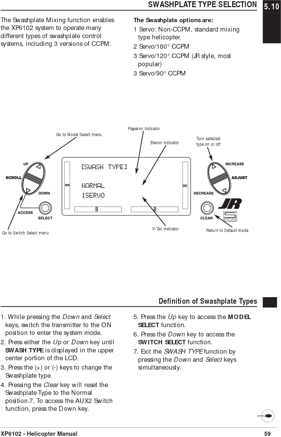
![59XP6102 - Helicopter ManualSWASHPLATE TYPE SELECTION 5.10The Swashplate Mixing function enablesthe XP6102 system to operate manydifferent types of swashplate controlsystems, including 3 versions of CCPM.The Swashplate options are:1 Servo: Non-CCPM, standard mixingtype helicopter.2 Servo/180° CCPM3 Servo/120° CCPM (JR style, mostpopular)3 Servo/90° CCPM[SWASH TYPE]NORMAL1SERVOV-Tail indicatorFlaperon indicatorReturn to Default modeGo to Model Select menuGo to Switch Select menuTurn selectedtype on or offElevon indicatorDefinition of Swashplate Types1. While pressing the Down and Selectkeys, switch the transmitter to the ONposition to enter the system mode.2. Press either the Up or Down key untilSWASH TYPE is displayed in the uppercenter portion of the LCD.3. Press the (+) or (-) keys to change theSwashplate type.4. Pressing the Clear key will reset theSwashplate Type to the Normalposition.7. To access the AUX2 Switchfunction, press the Down key.5. Press the Up key to access the MODELSELECT function.6. Press the Down key to access theSWITCH SELECT function.7. Exit the SWASH TYPE function bypressing the Down and Select keyssimultaneously.](https://usermanual.wiki/Horizon-Hobby/XP6102/User-Guide-361509-Page-61.png)
![61XP6102 - Helicopter ManualCHAPTER 6: FUNCTIONS (FUNCTION MODE ) • HELICOPTER FUNCTION MODE 6.1To enter the Function mode, switch thetransmitter power switch to the Onposition. Press the Down and Select keyssimultaneously, and the display will show the last active program. Pressingeither the Up or Down key then scrollsthrough the functions one by one,according to the Function ModeFlowchart shown on the right. Once theappropriate function is displayed, changescan be made by pressing the (+) or (-)Accessing the Mode Function1. Move the power switch to the Onposition.2. Press the Down and Select keyssimultaneously.[D/R & EXP]AILE POS 0EXP LIND/R 100%Dual Rate and Expo pg 62[TRAVEL ADJ]THRO AILEH100% L100%L100% R100%Travel Adjustment pg 65[THROTTLE HOLD] POS O OFF SW RIGHTThrottle Hold pg 69[REVO MX] NORMAL UP 0% DN 0%Revo MX pg 75[REVERSING SW]THR:N AIL:NELE:N RUD:NGEA:N FLA:NReversing Switches pg 63[120o CCPM] REVAILE 60% NELEV 60% NPIT 60% NCCPM Swashplate Mixing pg 66[THRO] NORMI 1O 1Throttle Curve pg 70[MX1] THR THRON OFFSET 0 0% 0% SW ALWAYS ONProgrammable Mix 1&2 pg 77[SUB TRIM]TH 0 AI 0EL 0 RU 0GE 0 FL 0Sub Trim pg 64[THRO CUT] INHIBITThrottle Cut pg 68[PITCH] NORMI 1O 1Pitch Curve pg 733. Use either the Up or Down to scrollthrough the menu and access theapplicable function.keys. To select another channel of aparticular function, press the Select key.The Function mode is the most often usedsystem to input data.Function Mode FlowchartInformation pertaining to each function isexplained on the page listed next to thefunction name. Functions will appear inthe same order they are shown on thischart.Navigate forwardthrough menusNavigate backwardsthrough menus[FAIL SAFE]TH HLD AI HLDEL HLD RU HLDGE HLD FL HLDFail Safe pg 80135246Servo Travel Screen pg 81](https://usermanual.wiki/Horizon-Hobby/XP6102/User-Guide-361509-Page-63.png)
![6.2 DUAL RATES AND EXPONENTIALDual rates are available for the aileron,elevator and rudder channels of your R/Caircraft. There is also an automatic dualrate setting to link your aileron, elevator,and rudder dual rates to the flight modelswitch. This automatic Dual-Rate functionis discussed in a separate section thatfollows. Dual rates may be defined as theability to vary the travel or throw rate of aservo from a switch. Due to the differingtravel rates, you will find that thesensitivity of the control either increasesor decreases accordingly. A higher rate, ortravel, yields a higher overall sensitivity.You may find it easier to think of the Dual-Rate function as double-ratesor half-rates.The Dual-Rate function worksin conjunction with the Exponentialfunction to allow you to precisely tailoryour control throws. You may want toconsult the section defining exponentialfor further information.62 XP6102 - Helicopter ManualAccessing the Dual Rate and Exponential Function1. Place the transmitter power switch inthe on position.2. Access the Function mode by pressingthe Down and Select keyssimultaneously.3. Press either the Up or Down key untilD/R & EXP appears in the upper leftcorner of the LCD.4. Press the Channel key until the desiredchannel (aileron, elevator, rudder orautomatic dual rates) appears.5. Select the switch position for which youwant to adjust the rate. The number tothe upper right of the current rate valueon the display indicates the currentposition of the Dual-Rate switch for thechannel that you have selected. Either a0 or a 1 will be shown, corresponding tothe position of the switch. To select theopposite switch position, move theappropriate Dual-Rate switch to theopposite position. The number thatappears above the current rate valuereflects the change.6. Adjust the rate for the channel and theswitch position that you have justselected. To decrease the throw rate,press the (-) key. To increase the throwrate, press the (+) key. As statedpreviously, the adjustable rate is from 0-125% for each switch position andchannel.7. Press the Up arrow key to access theREVERSING SW menu.8. Press the Down arrow key to access theSERVO TRAVEL SCREEN.9. Press the Down arrow and Select keyssimultaneously to exit the functionmode.The amount of travel is adjustable from0-125% in 1% increments. The factorysetting, or default value, for both the0 and 1 switch positions is 100%.Either switch position may be selected asthe low or high rate by placing the switchin the desired position and adjustingthe value accordingly.[D/R & EXP]AILE POS 0EXP LIND/R 100%Go to Reversing SW menuGo to Servo Travel Screen Select channel, EXP or D/RChange channel or valueReset selection to default](https://usermanual.wiki/Horizon-Hobby/XP6102/User-Guide-361509-Page-64.png)
![SERVO REVERSING 6.3The Reverse Switch function is anelectronic means of reversing the throwof a given channel (servo). All six channelsof the XP6102 offer reversible servodirection. This will ease setup duringthe servo installation into your aircraft.63XP6102 - Helicopter ManualAccessing the Servo Reversing Function 1. Place the transmitter switch in the onposition.2. Access the Function mode by pressingthe Down and Select keyssimultaneously.3. Press either the Up or Down key untilthe REVERSING SW appears in theupper portion of the LCD.4. Using your transmitter’s control sticks,switches and potentiometers, move thecontrol surfaces of your aircraft. Notethe travel direction of each of thecorresponding control surfaces.5. After determining which channel(s)need to have the throw directionsreversed, use the Select key to call upthe appropriate channel.6. Press either the (+) or (-) keys to changethe travel direction of the servo. Pressingthe Clear key returns the travel directionto Normal.7. You can observe the change in thetravel direction by moving theappropriate control at this time.8. Access the D/R & EXP function bypressing the Down key.9. Access the SUB TRIM function bypressing the Up key.10. Exit the Servo Reversing function bypressing the Down and Select keyssimultaneously.[REVERSING SW]THR:N AIL:NELE:N RUD:NGEA:N FLA:NGo to Sub Trim menuGo to D/R & Exp menuChange servo directionReset direction to normalSelect channel to reverse](https://usermanual.wiki/Horizon-Hobby/XP6102/User-Guide-361509-Page-65.png)
![6.4 SUB TRIMThe Sub Trim Adjustment function allowsyou to electronically fine-tune thecentering of your servos. Individuallyadjustable for all six channels with arange of ±125% (+/-30 degrees servotravel).The sub trim functions provides preciseservo arm neutral positioning if rotatingthe servo arm will not allow the desiredservo arm position.64 XP6102 - Helicopter ManualAccessing the Sub Trim Function1. Place the transmitter power switch inthe On position.2. To Access the Function mode, press theDown and Select keys simultaneously.3. Press either the Up or Down key untilSUB TRIM appears in the upper middleportion of the LCD.4. Press the Select key until the desiredchannel appears.5. Press the (+) or (-) key to establish thedesired amount and direction of Sub-Trim. Caution: Do not use excessive sub-trimadjustments since it is possible tooverrun your servo’s maximum SubTrim. Remember that it is a trimconvenience function. It is notintended to take the place of theproper mechanical trim adjustmentsthat are necessary on any R/C model.6. Access the REVERSING SW function bypressing the Down key.7. Access the TRAVEL ADJ function bypressing the Up key.8. Exit the SUB TRIM function by pressingthe Down and Select keyssimultaneously.[SUB TRIM]TH 0 AI 0EL 0 RU 0GE 0 FL 0Go to Travel Adj menuGo to Reversing SW menu Select channelChange valueReset selection to default](https://usermanual.wiki/Horizon-Hobby/XP6102/User-Guide-361509-Page-66.png)
![TRAVEL ADJUST 6.5The purpose of Travel Adjust is to offeryou precise servo control deflection ineither direction of servo operation. TheXP6102 offers travel adjust for all sixchannels. The Travel Adjust range is from0-150% (0 degrees to 60 degrees) fromneutral, or center, and it can be adjustedfor each direction individually. The factorydefault (Data Reset) value is 100% foreach direction of servo travel.65XP6102 - Helicopter ManualAccessing the Travel Adjust Function 1. Place the transmitter power switch inthe On position.2. Access the Function mode by pressingthe Down and Select keyssimultaneously.3. Press either the Up or Down key untilTRAVEL ADJ appears in the upperportion of the LCD.4. Press the Select key until the desiredchannel is highlighted.5. Move the appropriate control stick(lever, switch, etc) to the right or left ofcenter to the direction of travel you wantto adjust. An arrow to the left of thetravel adjust value will reflect the currentposition to be adjusted.6. After the control stick or switch isplaced in the direction of travel to beadjusted, press the (+) or (-) key until theproper amount of servo travel is shownon the LCD. Press the (+) key to increasethe amount of servo travel. Press the (-)key to decrease the amount of servotravel.7. Follow the same procedure for theremaining channels.8. Access the SUB TRIM function bypressing the Down key.9. Access the THROTTLE CUT function bypressing the Up key.10. Exit the TRAVEL ADJ function bypressing the Down and Select keyssimultaneously.[TRAVEL ADJ]THRO AILEH100% L100%L100% R100%Go to Throttle cut menuGo to Sub Trim menuChange valueReset value to normalSelect channel to adjust](https://usermanual.wiki/Horizon-Hobby/XP6102/User-Guide-361509-Page-67.png)
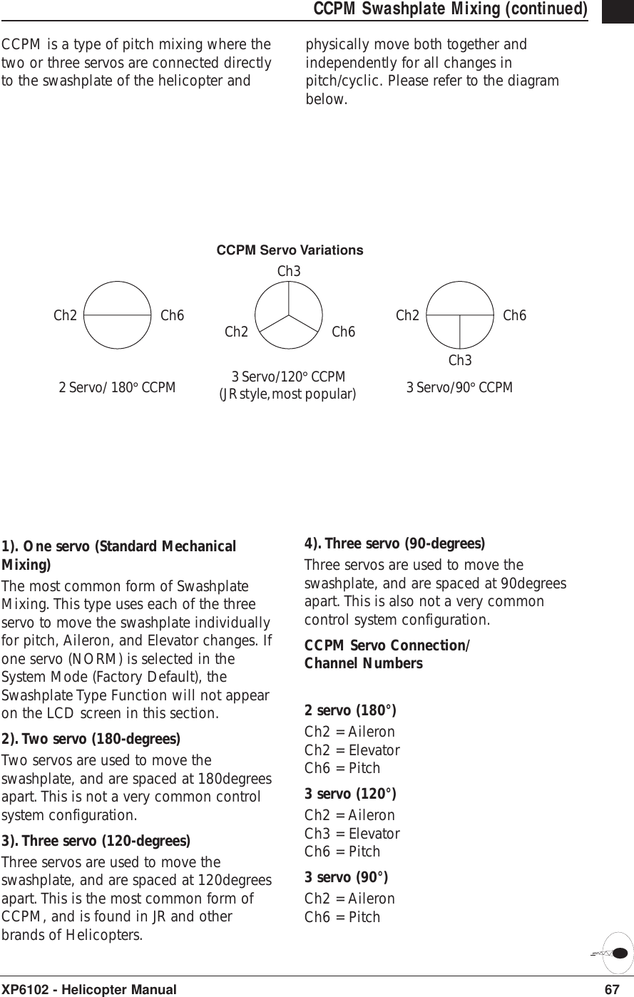
![6.6 CCPM SWASHPLATE MIXINGNote: The CCPM Swashplate Mixingscreen is only displayed whenSwashplate types 2Serv, 3Serv or4Serv CCPM are selected in theSwashplate type Selection in SystemMode.The CCPM Swashplate MixingFunction(Cyclic Collective Pitch Mixing)of the XP6102 is designed to be used inmodel helicopters that utilize 2-servo(180°), 3-servo(120°) and 3-servo(90°) type swashplate control system.The desired swashplate mixing type mustfirst be selected at the Swash TypeSelection in System Mode.If The Swashplate Type option has notbeen selected, proceed to Throttle Cutsection.66 XP6102 - Helicopter ManualAccessing the Swashplate Type1. Place the transmitter power switch inthe ON position.2. Access the Function Mode by pressingthe Down and Select keyssimultaneously.3. Press either the Up or Down key until90° CCPM, 120° CCPM or 180° CCPMappears in the middle leftportion of the LCD.Note: The swash plate type selectionis selected in the System mode onPage. 58.4. Press the Select key until the desiredfunction is highlighted.5. Press the (+) or (-) Keys to Increase orDecrease the CCPM Values.6. Follow the same procedure for theremaining channels.8. Access the TRAVEL ADJ function bypressing the Down key.9. Access the THROTTLE CUT function bypressing the Up key.10. Exit the CCPM SETUP screen bypressing the Down and Select keyssimultaneously.[120o CCPM] REVAILE 60% NELEV 60% NPIT 60% NGo to the Throttle Cut menuGo to the Travel Adjustment menuIndicates the CCPM type selected Indicates servo reversingChange highlighted function Return highlighted value to defaultIncrease/decrease valueorchange reversing valueScreen showing 120° CCPM Swashplate selection](https://usermanual.wiki/Horizon-Hobby/XP6102/User-Guide-361509-Page-68.png)
![68 XP6102 - Helicopter Manual6.7 THROTTLE CUT SWITCHThis is the function to assign Throttle Cutswitch to the push button located onupper right front of the transmitter. TheThrottle Cut function is designed to returnthe throttle trim to the lowest positioninstantly and keep this position while thebutton is pressed. This feature is used to“cut” or stop the engine without changingthe position of digital throttle trim.Accessing the Throttle Cut Function1. Place the transmitter power switch inthe On position.2. Access the Function mode. To do so,press the Down and Select keyssimultaneously. Press either the Up orDown key until THRO CUT appears inthe upper portion of the LCD screen.3. Use the (+) and (-) keys to change thevalue of the Throttle cut function.Note: Pressing the Clear key will Inhibitthe Throttle Cut, turning it off until ithas been reactivated.4. Access the TRAVEL ADJ mixingfunction by pressing the Down key.5. Access the THROTTLE HOLD functionby pressing the Up key.6. Exit the THRO CUT function bypressing the Down and Select keyssimultaneously.[THRO CUT] INHIBITGo to Travel Adjust menuGo to throttle Hold menu Change valueSet function to Inhibit](https://usermanual.wiki/Horizon-Hobby/XP6102/User-Guide-361509-Page-70.png)
![THROTTLE HOLD 6.8The Throttle Hold function is designed tohold the throttle servo in a specificposition during an autorotation. This isvery useful for practicing autorotationlandings. The throttle hold switch can beprogrammed to one of the four toggleswitches. Throttle hold will always be"On" in the forward switch position and"Off" in the rear position.69XP6102 - Helicopter ManualAccessing the Throttle Hold Function 1. Place the transmitter switch in the Onposition.2. Press the Down and Select keyssimultaneously to enter the Functionmode.3. Press either the Up or Down key untilTHROTTLE HOLD appears across thetop of the LCD.4. The factory setting for the throttle holdis inhibit. Pressing either the (+) or (-)key will activate Throttle Hold anddisplay the current throttle hold value.5. Using the (+) or (-) key, adjust thethrottle hold value to deliver the properengine idle rpm for your helicopter. Theadjustable range is (-20%-+50%). Onceyou establish the proper idle value foryour engine, you can use this value forthrottle hold as well. To shut the engineoff for autorotation, a negative or zerovalue should be input.Note: When the throttle hold isactivated, and the switch is on, theindicator on the LCD will changefrom Off to On. In addition, thethrottle trim indicator will beinhibited.6. Access the THROTTLE CURVE functionby pressing the Up key.7. Access the THROTTLE CUT function bypressing the Down key.8. To exit the THROTTLE HOLD function,press the Down and Select keyssimultaneously.[THROTTLE HOLD] POS O OFF SW RIGHTGo to Throttle Curve menuGo to Throttle Cut menuChange value/Switch selectionReset POS value to OorInhibit functionSelect function to change](https://usermanual.wiki/Horizon-Hobby/XP6102/User-Guide-361509-Page-71.png)
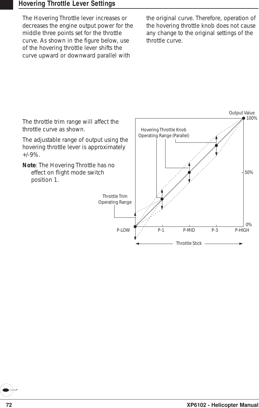
![6.9 THROTTLE CURVESThe XP6102 offers two (2) separate throttlecurves with five adjustable points percurve. This function allows you tocustomize the throttle curve and pitchcurve together to maximize engineperformance at a particular pitch setting.Once the throttle curves are established,each can be activated in flight using thetwo (2) position flight mode switch.The flight mode switch offers twoselectable ranges: Normal and Stunt. TheNormal position should be used as thehover throttle curve. The Stunt positionshould be used for aerobatic maneuversand forward flight.Note: The throttle trim and hoveringthrottle levers are only operable whenthe flight mode switch is in thenormal position. Thus, in normalfunction it will have no effect. Also,adjusting the hovering throttle leverand throttle trim has no effect on theinput values of the throttle curve.Each of the five points of the throttle curveare independently adjustable from 0-100%. These five points correspond to theposition of the throttle stick. Theillustration below shows the normalthrottle curve setting for the dead slowposition with throttle trim at default.70 XP6102 - Helicopter ManualThe throttle trim lever position will affectthe low-point position as shown when inthe Normal mode Throttle Curve.[THRO] NORMI 1O 1Go to Throttle Cut menuGo to Pitch Curve menuChange value/Switch selectionReset value to 0orSet function to InhibitPress to access the P-LOW,P-1, P-MID, P-3 and P-HIGHcurve points.Stick PositionServo position aftercurve is applied Note: This screen is availablewhen not entering curve valuesThrottle StickThrottle TrimOperating RangeHovering ThrottleOperating RangeOutput Value100%50%0%P-LOW P-1 P-MID P-3 P-HIGHThe transmitter is factory preset to thethrottle curve as indicated by the solidline in the figure at right. Individualmiddle points can be increased ordecreased to suit your specific needs.Throttle curve graph](https://usermanual.wiki/Horizon-Hobby/XP6102/User-Guide-361509-Page-72.png)
![71XP6102 - Helicopter ManualAccessing the Throttle Curve Function 1. Place the transmitter switch in the Onposition.2. Press the Down and Select keyssimultaneously to enter the FunctionMode.3. Press either the Up or Down key untilTHRO appears in the upper portion ofthe LCD.Note: Use NORM for hover curves andSTUNT for aerobatics. We willconcentrate on the hovering curveduring this example.4. Press the Select key to select the pointof the curve you want to change.5. Press either the (+) or (-) key to changethe value of the current curve point. Therange of each point is 0-100% in .5%intervals.Note: In each curve, the factory settingindicates INH for points 1 and 3.These values are 25% and 75%respectively if no value changes aremade to any other points. If any ofthe other points have been changedwhile these points were inhibited, theinhibited points will also change toplot a smooth curve. If you want tokeep this from happening, press theSelect key until the display indicatesP-1 or P-3 at the upper right portionof the LCD. Press either the (+) or (-)key to activate the points 1 (25%) or3 (75%). The values for each of thesecurves can then be fully adjusted bypressing either the (+) or (-) key.6. To set curves for STUNT mode, pressthe Select to highlight the NORMfunction, then press the (+) or (-) key toselect the STUNT function. Repeat Steps4 and 5 to complete the procedure.7. Access the PITCH CURVE function bypressing the Up key.8. Access the THROTTLE HOLD functionby pressing the Down key.9. Exit the THROTTLE CURVE function bypressing the Down and Select keyssimultaneously.Throttle Time SettingsThe throttle trim lever is only active whenthe flight mode switch is in the normalposition. The throttle trim is used toincrease or decrease the engine powerwhen the flight mode switch is in theNormal mode. The throttle trim lever hasno effect on positions 1 or throttle hold.Note: Making changes to the throttletrim lever does not change the inputvalues for any of the points on thethrottle curve; it merely makesadjustments to the engine idlespeed position.[THRO] NORMP-3 INHScreen showing setting the Mid-Point of the Normal Throttle Curve](https://usermanual.wiki/Horizon-Hobby/XP6102/User-Guide-361509-Page-73.png)
![PITCH CURVES 6.10Adjustment of the pitch curve is verysimilar to the throttle curve adjustmentdescribed in the preceding section. Athorough understanding of the ThrottleCurve Section will make pitch curveadjustment easier to understand. There arethree independent types of pitch curvesavailable: Normal, Stunt, and Hold. Eachpitch curve contains five adjustable points:LOW, 1, MID, 3 and HIGH.Note: The pitch curve for the ThrottleHold function can only be set if thissystem is activated.73XP6102 - Helicopter ManualAccessing the Pitch Curve Function 1. Place the transmitter switch in the Onposition.2. Press the Down and Select keyssimultaneously to enter the Functionmode.3. Press either the Up or Down key untilPITCH appears in the top of the LCD.Note: Use NORMAL for hover curvesand STUNT for stunt curves. We willconcentrate on the hovering curveduring this example.4. Press the Select key to select the pointof the curve you want to change.5. Press either the (+) or (-) key to changethe value of the current curve point. Therange of each point is 0-100% in .5%intervals.Note: In each curve, the factory settingINH indicates Inhibited for points 1and 3. These values are 25% and75% respectively, if no value changesare made to any other points. If anyof the other points have beenchanged while these points wereinhibited, the inhibited points willchange to plot a smooth curve. If youwant to keep this from happening,press the Select key to display thepositions 1 and 3, then press the (+)or (-) key to activate each point.6. To set curves for STUNT mode, pressthe Select to highlight the NORMfunction, then press the (+) or (-) key toselect the STUNT function. Repeat Steps4 and 5 to complete the procedure.7. To set the curves for the Throttle Holdmode ‘’H’’, press the Up key once againuntil ‘’H’’ is displayed, and repeat steps4 and 5.8. Access the REVO MX function bypressing the Up key.9. Access the THROTTLE CURVE functionby pressing the Down key.10. Exit the PITCH CURVE function bypressing the Down and Select keyssimultaneously.[PITCH] NORMI 1O 1Go to Throttle Curve menuGo to Throttle Cut menuChange value/Switch selectionReset POS value to OorInhibit functionSelect function to change](https://usermanual.wiki/Horizon-Hobby/XP6102/User-Guide-361509-Page-75.png)
![REVOLUTION MIXING (HEADING LOCK GYROS ONLY)The Revolution Mixing function mixes tailrotor with the Throttle and Pitch Curvefunctions to counteract torque from themain rotor blades. When set up correctly,the helicopter should climb and descendwithout a tendency to yaw in eitherdirection. Because torque reaction varieswith different power settings, it isnecessary to vary the tail rotor pitch at thesame time. The XP6102 offers twoseparate revolution mixing programs, withindependent up and down mixing foreach - one for Flight mode positionNormal and the other for Stunt. The upmixing adjusts the tail rotor compensationfor the mid to high throttle setting and thedown, mixing adjusts the tail rotorcompensation for the mid to low throttlesetting.75XP6102 - Helicopter ManualAccessing the Revolution Mixing Function 1. Place the transmitter switch in the Onposition.2. Press the Down and Select keyssimultaneously to enter the FunctionMode.3. Press the Up or Down keys untilREVO MX appears at the top of the LCD.4. Pressing the Select key will highlighteither the Up mix, Down mix, or theflight mode switch position. When theflight mode switch is in the displayedposition and the throttle stick is in thedisplayed position, the flight mode willbe underlined.5. Press the (+) key to increase the righttail compensation or press the (-) key toincrease the left compensation. Press theClear key to reset to 0%.6. This setup procedure can be used forrevolution mixing for either flight modeswitch position Normal or Stunt. TheStunt position should be used forforward and/or inverted compensation.7. Access the PITCH CURVE function bypressing the Down key.8. Access the MX1 function by pressingthe Up key.9. Exit the REVO MX function by pressingthe Down and Select keyssimultaneously.[REVO MX] NORMAL UP 0% DN 0%Go to Programmable Mixing menuGo to Pitch curve menuChange value/Switch selectionReset selection to defaulthighlight function to change6.11](https://usermanual.wiki/Horizon-Hobby/XP6102/User-Guide-361509-Page-77.png)
![PROGRAMMABLE MIXINGThe XP6102 offers two programmablemixes to be used for any number ofdifferent purposes. This function allowsmixing any one channel to any otherchannel. This mix can remain on at alltimes or be switched on and off in flightusing a number of different switches.Mix number 1 is of the standard variety, inthat the digital trim for the master channelonly affect the master channel, and notthe slave channel. Mix number 2 is of the"Trim Include" variety. This mix is usedany time the mix requires the slavechannels trim position to be varied whenthe master channels digital trim position isvaried. An example for this type of mixwould be when dual elevator or dualaileron servos are used and connected totwo separate channels of the system,rather than using a single channel with aY-harness.Each channel of this radio is identified byan abbreviated name. The chart belowindicates the channel and itscorresponding abbreviation. The channelname appearing first is known as the"master channel" or the channel to whichyou want to mix. The second number isknown as the "slave channel" or thechannel that is being mixed into themaster channel. For example, AIL ➔ RUDwould indicate aileron-to-rudder mixing.Each time the aileron stick is moved, theaileron will deflect, and the rudder willautomatically move in the direction and tothe value input.Mixing is proportional, so small inputs ofthe master channel will produce smalloutputs of the slave channel. Eachprogrammable mix has a mixing "offset."The purpose of the mixing offset is to re-define the neutral position of the slavechannel.77XP6102 - Helicopter Manual[MX1] THR THRON OFFSET 0 0% 0% SW ALWAYS ONGo to Flap System menuGo to Flap System menu Change selected valueReset selection to defaultMaster Channel Slave ChannelMix numberSwitch selection Switch conditionMix percentagesOffset valueChange highlighted selectionTHR: ThrottleAIL: AileronELE: ElevatorRUD: RudderGEA: GearPIT: Pitch6.12](https://usermanual.wiki/Horizon-Hobby/XP6102/User-Guide-361509-Page-79.png)
![80 XP6102 - Helicopter ManualFAIL SAFEThe Fail-Safe/Hold function is availableonly when you use the XP6102 transmitterin PCM modulations. This function isdesigned to help minimize damage toyour aircraft during a loss of signal to thereceiver. The servos either assume the fail-safe presets or hold their last good signalposition.As noted earlier, if you are in the PPMmodulation, the Fail-Safe/Hold functionis not applicable. Therefore, the Fail-Safe/Hold function will not appear onyour LCD screen menu while in thePPM mode. Refer to the ModulationSelection section for more informationpertaining to the broadcast signal ofyour XP6102 transmitter.Accessing the Fail Safe Function1. Place the transmitter power switch inthe On position.2. Access the Function mode. To do so,press the Down and Select keyssimultaneously. Press either the Up orDown key until FAIL SAFE appears inthe upper portion of the LCD screen.3. Use the Select key to highlight theservo function to set.4. Use the (+) or (-) keys to togglebetween servo hold or setting the servoposition.5. When using the servo setting position,move the corresponding control stick tothe position where you want the servo ifthe radio enters into the fail safe mode.Press the Clear key to have thetransmitter memorize the stick position.6. Repeat steps 4 and 5 until all sixcontrols have been set.7. Access the SERVO TRAVEL screen bypressing the Up key.8. Access the MIXING FUNCTIONSfunction by pressing the Up key.9. Exit the FAIL SAFE function by pressingthe Down and Select keyssimultaneously.[FAIL SAFE]TH HLD AI HLDEL HLD RU HLDGE HLD FL HLDGo to ProgrammableMixing menuGo to Servo Travel Screen Change from servohold to stick selectionInvoke stick selectionChange highlighted selection6.13](https://usermanual.wiki/Horizon-Hobby/XP6102/User-Guide-361509-Page-82.png)